Kubernetes is an open source container orchestration engine for automating deployment, scaling, and management of containerized applications. The open source project is hosted by the Cloud Native Computing Foundation.
1.1 - Available Documentation Versions
This website contains documentation for the current version of Kubernetes
and the four previous versions of Kubernetes.
The availability of documentation for a Kubernetes version is separate from whether
that release is currently supported.
Read Support period to learn about
which versions of Kubernetes are officially supported, and for how long.
2 - Getting started
This section lists the different ways to set up and run Kubernetes.
When you install Kubernetes, choose an installation type based on: ease of maintenance, security,
control, available resources, and expertise required to operate and manage a cluster.
You can download Kubernetes to deploy a Kubernetes cluster
on a local machine, into the cloud, or for your own datacenter.
It is recommended to run Kubernetes components as container images wherever
that is possible, and to have Kubernetes manage those components.
Components that run containers - notably, the kubelet - can't be included in this category.
If you don't want to manage a Kubernetes cluster yourself, you could pick a managed service, including
certified platforms.
There are also other standardized and custom solutions across a wide range of cloud and
bare metal environments.
Learning environment
If you're learning Kubernetes, use the tools supported by the Kubernetes community,
or tools in the ecosystem to set up a Kubernetes cluster on a local machine.
See Learning environment
Production environment
When evaluating a solution for a
production environment, consider which aspects of
operating a Kubernetes cluster (or abstractions) you want to manage yourself and which you
prefer to hand off to a provider.
For a cluster you're managing yourself, the officially supported tool
for deploying Kubernetes is kubeadm.
Kubernetes is designed for its control plane to
run on Linux. Within your cluster you can run applications on Linux or other operating systems, including
Windows.
If you are learning Kubernetes, you need a place to practice. This page explains your options for setting up a Kubernetes environment where you can experiment and learn.
Installing kubectl
Before you set up a cluster, you need the kubectl command-line tool. This tool lets you communicate with a Kubernetes cluster and run commands against it.
Running Kubernetes locally gives you a safe environment to learn and experiment. You can set up and tear down clusters without worrying about costs or affecting production systems.
kind
kind (Kubernetes IN Docker) runs Kubernetes clusters using Docker containers as nodes. It is lightweight and designed specifically for testing Kubernetes itself, but works great for learning too.
🛇 This item links to a third party project or product that is not part of Kubernetes itself. More information
There are several third-party tools that can also run Kubernetes locally. Kubernetes does not provide support for these tools, but they may work well for your learning needs:
Refer to each tool's documentation for setup instructions and support.
Using online playgrounds
🛇 This item links to a third party project or product that is not part of Kubernetes itself. More information
Online Kubernetes playgrounds let you try Kubernetes without installing anything on your computer. These environments run in your web browser:
Killercoda provides interactive Kubernetes scenarios and a playground environment
These platforms are useful for quick experiments and following tutorials without local setup.
Practicing with production-like clusters
If you want to practice setting up a more production-like cluster, you can use kubeadm. Setting up a cluster with kubeadm is an advanced task that requires multiple machines (physical or virtual) and careful configuration.
Setting up a production-like cluster is significantly more complex than the learning environments described above. Start with kind, minikube, or an online playground first.
What's next
Follow the Hello Minikube tutorial to deploy your first application
A production-quality Kubernetes cluster requires planning and preparation.
If your Kubernetes cluster is to run critical workloads, it must be configured to be resilient.
This page explains steps you can take to set up a production-ready cluster,
or to promote an existing cluster for production use.
If you're already familiar with production setup and want the links, skip to
What's next.
Production considerations
Typically, a production Kubernetes cluster environment has more requirements than a
personal learning, development, or test environment Kubernetes. A production environment may require
secure access by many users, consistent availability, and the resources to adapt
to changing demands.
As you decide where you want your production Kubernetes environment to live
(on premises or in a cloud) and the amount of management you want to take
on or hand to others, consider how your requirements for a Kubernetes cluster
are influenced by the following issues:
Availability: A single-machine Kubernetes learning environment
has a single point of failure. Creating a highly available cluster means considering:
Separating the control plane from the worker nodes.
Replicating the control plane components on multiple nodes.
Load balancing traffic to the cluster’s API server.
Having enough worker nodes available, or able to quickly become available, as changing workloads warrant it.
Scale: If you expect your production Kubernetes environment to receive a stable amount of
demand, you might be able to set up for the capacity you need and be done. However,
if you expect demand to grow over time or change dramatically based on things like
season or special events, you need to plan how to scale to relieve increased
pressure from more requests to the control plane and worker nodes or scale down to reduce unused
resources.
Security and access management: You have full admin privileges on your own
Kubernetes learning cluster. But shared clusters with important workloads, and
more than one or two users, require a more refined approach to who and what can
access cluster resources. You can use role-based access control
(RBAC) and other
security mechanisms to make sure that users and workloads can get access to the
resources they need, while keeping workloads, and the cluster itself, secure.
You can set limits on the resources that users and workloads can access
by managing policies and
container resources.
Before building a Kubernetes production environment on your own, consider
handing off some or all of this job to
Turnkey Cloud Solutions
providers or other Kubernetes Partners.
Options include:
Serverless: Just run workloads on third-party equipment without managing
a cluster at all. You will be charged for things like CPU usage, memory, and
disk requests.
Managed control plane: Let the provider manage the scale and availability
of the cluster's control plane, as well as handle patches and upgrades.
Managed worker nodes: Configure pools of nodes to meet your needs,
then the provider makes sure those nodes are available and ready to implement
upgrades when needed.
Integration: There are providers that integrate Kubernetes with other
services you may need, such as storage, container registries, authentication
methods, and development tools.
Whether you build a production Kubernetes cluster yourself or work with
partners, review the following sections to evaluate your needs as they relate
to your cluster’s control plane, worker nodes, user access, and
workload resources.
Production cluster setup
In a production-quality Kubernetes cluster, the control plane manages the
cluster from services that can be spread across multiple computers
in different ways. Each worker node, however, represents a single entity that
is configured to run Kubernetes pods.
Production control plane
The simplest Kubernetes cluster has the entire control plane and worker node
services running on the same machine. You can grow that environment by adding
worker nodes, as reflected in the diagram illustrated in
Kubernetes Components.
If the cluster is meant to be available for a short period of time, or can be
discarded if something goes seriously wrong, this might meet your needs.
If you need a more permanent, highly available cluster, however, you should
consider ways of extending the control plane. By design, one-machine control
plane services running on a single machine are not highly available.
If keeping the cluster up and running
and ensuring that it can be repaired if something goes wrong is important,
consider these steps:
Choose deployment tools: You can deploy a control plane using tools such
as kubeadm, kops, and kubespray. See
Installing Kubernetes with deployment tools
to learn tips for production-quality deployments using each of those deployment
methods. Different Container Runtimes
are available to use with your deployments.
Manage certificates: Secure communications between control plane services
are implemented using certificates. Certificates are automatically generated
during deployment or you can generate them using your own certificate authority.
See PKI certificates and requirements for details.
Configure load balancer for apiserver: Configure a load balancer
to distribute external API requests to the apiserver service instances running on different nodes. See
Create an External Load Balancer
for details.
Separate and backup etcd service: The etcd services can either run on the
same machines as other control plane services or run on separate machines, for
extra security and availability. Because etcd stores cluster configuration data,
backing up the etcd database should be done regularly to ensure that you can
repair that database if needed.
See the etcd FAQ for details on configuring and using etcd.
See Operating etcd clusters for Kubernetes
and Set up a High Availability etcd cluster with kubeadm
for details.
Create multiple control plane systems: For high availability, the
control plane should not be limited to a single machine. If the control plane
services are run by an init service (such as systemd), each service should run on at
least three machines. However, running control plane services as pods in
Kubernetes ensures that the replicated number of services that you request
will always be available.
The scheduler should be fault tolerant,
but not highly available. Some deployment tools set up Raft
consensus algorithm to do leader election of Kubernetes services. If the
primary goes away, another service elects itself and take over.
Span multiple zones: If keeping your cluster available at all times is
critical, consider creating a cluster that runs across multiple data centers,
referred to as zones in cloud environments. Groups of zones are referred to as regions.
By spreading a cluster across
multiple zones in the same region, it can improve the chances that your
cluster will continue to function even if one zone becomes unavailable.
See Running in multiple zones for details.
Manage on-going features: If you plan to keep your cluster over time,
there are tasks you need to do to maintain its health and security. For example,
if you installed with kubeadm, there are instructions to help you with
Certificate Management
and Upgrading kubeadm clusters.
See Administer a Cluster
for a longer list of Kubernetes administrative tasks.
Production-quality workloads need to be resilient and anything they rely
on needs to be resilient (such as CoreDNS). Whether you manage your own
control plane or have a cloud provider do it for you, you still need to
consider how you want to manage your worker nodes (also referred to
simply as nodes).
Configure nodes: Nodes can be physical or virtual machines. If you want to
create and manage your own nodes, you can install a supported operating system,
then add and run the appropriate
Node services. Consider:
The demands of your workloads when you set up nodes by having appropriate memory, CPU, and disk speed and storage capacity available.
Whether generic computer systems will do or you have workloads that need GPU processors, Windows nodes, or VM isolation.
Validate nodes: See Valid node setup
for information on how to ensure that a node meets the requirements to join
a Kubernetes cluster.
Add nodes to the cluster: If you are managing your own cluster you can
add nodes by setting up your own machines and either adding them manually or
having them register themselves to the cluster’s apiserver. See the
Nodes section for information on how to set up Kubernetes to add nodes in these ways.
Scale nodes: Have a plan for expanding the capacity your cluster will
eventually need. See Considerations for large clusters
to help determine how many nodes you need, based on the number of pods and
containers you need to run. If you are managing nodes yourself, this can mean
purchasing and installing your own physical equipment.
Autoscale nodes: Read Node Autoscaling to learn about the
tools available to automatically manage your nodes and the capacity they
provide.
Set up node health checks: For important workloads, you want to make sure
that the nodes and pods running on those nodes are healthy. Using the
Node Problem Detector
daemon, you can ensure your nodes are healthy.
Production user management
In production, you may be moving from a model where you or a small group of
people are accessing the cluster to where there may potentially be dozens or
hundreds of people. In a learning environment or platform prototype, you might have a single
administrative account for everything you do. In production, you will want
more accounts with different levels of access to different namespaces.
Taking on a production-quality cluster means deciding how you
want to selectively allow access by other users. In particular, you need to
select strategies for validating the identities of those who try to access your
cluster (authentication) and deciding if they have permissions to do what they
are asking (authorization):
Authentication: The apiserver can authenticate users using client
certificates, bearer tokens, an authenticating proxy, or HTTP basic auth.
You can choose which authentication methods you want to use.
Using plugins, the apiserver can leverage your organization’s existing
authentication methods, such as LDAP or Kerberos. See
Authentication
for a description of these different methods of authenticating Kubernetes users.
Authorization: When you set out to authorize your regular users, you will probably choose
between RBAC and ABAC authorization. See Authorization Overview
to review different modes for authorizing user accounts (as well as service account access to
your cluster):
Role-based access control (RBAC): Lets you
assign access to your cluster by allowing specific sets of permissions to authenticated users.
Permissions can be assigned for a specific namespace (Role) or across the entire cluster
(ClusterRole). Then using RoleBindings and ClusterRoleBindings, those permissions can be attached
to particular users.
Attribute-based access control (ABAC): Lets you
create policies based on resource attributes in the cluster and will allow or deny access
based on those attributes. Each line of a policy file identifies versioning properties (apiVersion
and kind) and a map of spec properties to match the subject (user or group), resource property,
non-resource property (/version or /apis), and readonly. See
Examples for details.
As someone setting up authentication and authorization on your production Kubernetes cluster, here are some things to consider:
Set the authorization mode: When the Kubernetes API server
(kube-apiserver)
starts, supported authorization modes must be set using an --authorization-config file or the --authorization-mode
flag. For example, that flag in the kube-adminserver.yaml file (in /etc/kubernetes/manifests)
could be set to Node,RBAC. This would allow Node and RBAC authorization for authenticated requests.
Create user certificates and role bindings (RBAC): If you are using RBAC
authorization, users can create a CertificateSigningRequest (CSR) that can be
signed by the cluster CA. Then you can bind Roles and ClusterRoles to each user.
See Certificate Signing Requests
for details.
Create policies that combine attributes (ABAC): If you are using ABAC
authorization, you can assign combinations of attributes to form policies to
authorize selected users or groups to access particular resources (such as a
pod), namespace, or apiGroup. For more information, see
Examples.
Consider Admission Controllers: Additional forms of authorization for
requests that can come in through the API server include
Webhook Token Authentication.
Webhooks and other special authorization types need to be enabled by adding
Admission Controllers
to the API server.
Set limits on workload resources
Demands from production workloads can cause pressure both inside and outside
of the Kubernetes control plane. Consider these items when setting up for the
needs of your cluster's workloads:
Prepare for DNS demand: If you expect workloads to massively scale up,
your DNS service must be ready to scale up as well. See
Autoscale the DNS service in a Cluster.
Create additional service accounts: User accounts determine what users can
do on a cluster, while a service account defines pod access within a particular
namespace. By default, a pod takes on the default service account from its namespace.
See Managing Service Accounts
for information on creating a new service account. For example, you might want to:
Add secrets that a pod could use to pull images from a particular container registry. See
Configure Service Accounts for Pods
for an example.
If you choose to build your own cluster, plan how you want to
handle certificates
and set up high availability for features such as
etcd
and the
API server.
Note: Dockershim has been removed from the Kubernetes project as of release 1.24. Read the Dockershim Removal FAQ for further details.
You need to install a
container runtime
into each node in the cluster so that Pods can run there. This page outlines
what is involved and describes related tasks for setting up nodes.
Kubernetes releases before v1.24 included a direct integration with Docker Engine,
using a component named dockershim. That special direct integration is no longer
part of Kubernetes (this removal was
announced
as part of the v1.20 release).
You can read
Check whether Dockershim removal affects you
to understand how this removal might affect you. To learn about migrating from using dockershim, see
Migrating from dockershim.
If you are running a version of Kubernetes other than v1.36,
check the documentation for that version.
Install and configure prerequisites
Network configuration
By default, the Linux kernel does not allow IPv4 packets to be routed
between interfaces. Most Kubernetes cluster networking implementations
will change this setting (if needed), but some might expect the
administrator to do it for them. (Some might also expect other sysctl
parameters to be set, kernel modules to be loaded, etc; consult the
documentation for your specific network implementation.)
Enable IPv4 packet forwarding
To manually enable IPv4 packet forwarding:
# sysctl params required by setup, params persist across rebootscat <<EOF | sudo tee /etc/sysctl.d/k8s.conf
net.ipv4.ip_forward = 1
EOF# Apply sysctl params without rebootsudo sysctl --system
Verify that net.ipv4.ip_forward is set to 1 with:
sysctl net.ipv4.ip_forward
cgroup drivers
On Linux, control groups
are used to constrain resources that are allocated to processes.
Both the kubelet and the
underlying container runtime need to interface with control groups to enforce
resource management for pods and containers
and set resources such as cpu/memory requests and limits. To interface with control
groups, the kubelet and the container runtime need to use a cgroup driver.
It's critical that the kubelet and the container runtime use the same cgroup
driver and are configured the same.
The cgroupfs driver is the default cgroup driver in the kubelet.
When the cgroupfs driver is used, the kubelet and the container runtime directly interface with
the cgroup filesystem to configure cgroups.
The cgroupfs driver is not recommended when
systemd is the
init system because systemd expects a single cgroup manager on
the system. Additionally, if you use cgroup v2, use the systemd
cgroup driver instead of cgroupfs.
systemd cgroup driver
When systemd is chosen as the init
system for a Linux distribution, the init process generates and consumes a root control group
(cgroup) and acts as a cgroup manager.
systemd has a tight integration with cgroups and allocates a cgroup per systemd
unit. As a result, if you use systemd as the init system with the cgroupfs
driver, the system gets two different cgroup managers.
Two cgroup managers result in two views of the available and in-use resources in
the system. In some cases, nodes that are configured to use cgroupfs for the
kubelet and container runtime, but use systemd for the rest of the processes become
unstable under resource pressure.
The approach to mitigate this instability is to use systemd as the cgroup driver for
the kubelet and the container runtime when systemd is the selected init system.
To set systemd as the cgroup driver, edit the
KubeletConfiguration
option of cgroupDriver and set it to systemd. For example:
Starting with v1.22 and later, when creating a cluster with kubeadm, if the user does not set
the cgroupDriver field under KubeletConfiguration, kubeadm defaults it to systemd.
If you configure systemd as the cgroup driver for the kubelet, you must also
configure systemd as the cgroup driver for the container runtime. Refer to
the documentation for your container runtime for instructions. For example:
In Kubernetes 1.36, with the KubeletCgroupDriverFromCRIfeature gate
enabled and a container runtime that supports the RuntimeConfig CRI RPC,
the kubelet automatically detects the appropriate cgroup driver from the runtime,
and ignores the cgroupDriver setting within the kubelet configuration.
However, older versions of container runtimes (specifically,
containerd 1.y and below) do not support the RuntimeConfig CRI RPC, and
may not respond correctly to this query, and thus the Kubelet falls back to using the
value in its own --cgroup-driver flag.
In Kubernetes 1.38, this fallback behavior will be dropped, and older versions
of containerd will fail with newer kubelets.
Caution:
Changing the cgroup driver of a Node that has joined a cluster is a sensitive operation.
If the kubelet has created Pods using the semantics of one cgroup driver, changing the container
runtime to another cgroup driver can cause errors when trying to re-create the Pod sandbox
for such existing Pods. Restarting the kubelet may not solve such errors.
If you have automation that makes it feasible, replace the node with another using the updated
configuration, or reinstall it using automation.
Migrating to the systemd driver in kubeadm managed clusters
If you wish to migrate to the systemd cgroup driver in existing kubeadm managed clusters,
follow configuring a cgroup driver.
CRI version support
Your container runtime must support v1 of the container runtime interface.
Kubernetes starting v1.26only works with v1 of the CRI API. If a container runtime does not support the v1 API,
the kubelet will not register as a node.
Container runtimes
Note: This section links to third party projects that provide functionality required by Kubernetes. The Kubernetes project authors aren't responsible for these projects, which are listed alphabetically. To add a project to this list, read the content guide before submitting a change. More information.
containerd
This section outlines the necessary steps to use containerd as CRI runtime.
To install containerd on your system, follow the instructions on
getting started with containerd.
Return to this step once you've created a valid config.toml configuration file.
You can find this file under the path /etc/containerd/config.toml.
You can find this file under the path C:\Program Files\containerd\config.toml.
On Linux the default CRI socket for containerd is /run/containerd/containerd.sock.
On Windows the default CRI endpoint is npipe://./pipe/containerd-containerd.
Configuring the systemd cgroup driver
To use the systemd cgroup driver in /etc/containerd/config.toml with runc,
set the following config based on your Containerd version
The systemd cgroup driver is recommended if you use cgroup v2.
Note:
If you installed containerd from a package (for example, RPM or .deb), you may find
that the CRI integration plugin is disabled by default.
You need CRI support enabled to use containerd with Kubernetes. Make sure that cri
is not included in thedisabled_plugins list within /etc/containerd/config.toml;
if you made changes to that file, also restart containerd.
If you experience container crash loops after the initial cluster installation or after
installing a CNI, the containerd configuration provided with the package might contain
incompatible configuration parameters. Consider resetting the containerd configuration
with containerd config default > /etc/containerd/config.toml as specified in
getting-started.md
and then set the configuration parameters specified above accordingly.
If you apply this change, make sure to restart containerd:
CRI-O uses the systemd cgroup driver per default, which is likely to work fine
for you. To switch to the cgroupfs cgroup driver, either edit
/etc/crio/crio.conf or place a drop-in configuration in
/etc/crio/crio.conf.d/02-cgroup-manager.conf, for example:
You should also note the changed conmon_cgroup, which has to be set to the value
pod when using CRI-O with cgroupfs. It is generally necessary to keep the
cgroup driver configuration of the kubelet (usually done via kubeadm) and CRI-O
in sync.
In Kubernetes v1.28, you can enable automatic detection of the
cgroup driver as an alpha feature. See systemd cgroup driver
for more details.
For CRI-O, the CRI socket is /var/run/crio/crio.sock by default.
Overriding the sandbox (pause) image
In your CRI-O config you can set the following
config value:
This config option supports live configuration reload to apply this change: systemctl reload crio or by sending
SIGHUP to the crio process.
Docker Engine
Note:
These instructions assume that you are using the
cri-dockerd adapter to integrate
Docker Engine with Kubernetes.
On each of your nodes, install Docker for your Linux distribution as per
Install Docker Engine.
Install cri-dockerd, following the directions in the install section of the documentation.
For cri-dockerd, the CRI socket is /run/cri-dockerd.sock by default.
Mirantis Container Runtime
Mirantis Container Runtime (MCR) is a commercially
available container runtime that was formerly known as Docker Enterprise Edition.
You can use Mirantis Container Runtime with Kubernetes using the open source
cri-dockerd component, included with MCR.
To learn more about how to install Mirantis Container Runtime,
visit MCR Deployment Guide.
Check the systemd unit named cri-docker.socket to find out the path to the CRI
socket.
Overriding the sandbox (pause) image
The cri-dockerd adapter accepts a command line argument for
specifying which container image to use as the Pod infrastructure container (“pause image”).
The command line argument to use is --pod-infra-container-image.
What's next
As well as a container runtime, your cluster will need a working
network plugin.
2.2.2 - Installing Kubernetes with deployment tools
There are many methods and tools for setting up your own production Kubernetes cluster.
For example:
Cluster API: A Kubernetes sub-project focused on
providing declarative APIs and tooling to simplify provisioning, upgrading, and operating
multiple Kubernetes clusters.
kops: An automated cluster provisioning tool.
For tutorials, best practices, configuration options and information on
reaching out to the community, please check the
kOps website for details.
kubespray:
A composition of Ansible playbooks,
inventory,
provisioning tools, and domain knowledge for generic OS/Kubernetes clusters configuration
management tasks. You can reach out to the community on Slack channel
#kubespray.
2.2.2.1 - Bootstrapping clusters with kubeadm
2.2.2.1.1 - Installing kubeadm
This page shows how to install the kubeadm toolbox.
For information on how to create a cluster with kubeadm once you have performed this installation process,
see the Creating a cluster with kubeadm page.
This installation guide is for Kubernetes v1.36. If you want to use a different Kubernetes version, please refer to the following pages instead:
A compatible Linux host. The Kubernetes project provides generic instructions for Linux distributions
based on Debian and Red Hat, and those distributions without a package manager.
2 GB or more of RAM per machine (any less will leave little room for your apps).
2 CPUs or more for control plane machines.
Full network connectivity between all machines in the cluster (public or private network is fine).
Unique hostname, MAC address, and product_uuid for every node. See here for more details.
Certain ports are open on your machines. See here for more details.
Note:
The kubeadm installation is done via binaries that use dynamic linking and assumes that your target system provides glibc.
This is a reasonable assumption on many Linux distributions (including Debian, Ubuntu, Fedora, CentOS, etc.)
but it is not always the case with custom and lightweight distributions which don't include glibc by default, such as Alpine Linux.
The expectation is that the distribution either includes glibc or a
compatibility layer
that provides the expected symbols.
Check your OS version
Note: This section links to third party projects that provide functionality required by Kubernetes. The Kubernetes project authors aren't responsible for these projects, which are listed alphabetically. To add a project to this list, read the content guide before submitting a change. More information.
A Kubernetes cluster created by kubeadm depends on software that use kernel features.
This software includes, but is not limited to the
container runtime,
the kubelet, and a Container Network Interface plugin.
To help you avoid unexpected errors as a result of an unsupported kernel version, kubeadm runs the SystemVerification
pre-flight check. This check fails if the kernel version is not supported.
You may choose to skip the check, if you know that your kernel
provides the required features, even though kubeadm does not support its version.
Verify the MAC address and product_uuid are unique for every node
You can get the MAC address of the network interfaces using the command ip link or ifconfig -a
The product_uuid can be checked by using the command sudo cat /sys/class/dmi/id/product_uuid
It is very likely that hardware devices will have unique addresses, although some virtual machines may have
identical values. Kubernetes uses these values to uniquely identify the nodes in the cluster.
If these values are not unique to each node, the installation process
may fail.
Check network adapters
If you have more than one network adapter, and your Kubernetes components are not reachable on the default
route, we recommend you add IP route(s) so Kubernetes cluster addresses go via the appropriate adapter.
Check required ports
These required ports
need to be open in order for Kubernetes components to communicate with each other.
You can use tools like netcat to check if a port is open. For example:
nc 127.0.0.1 6443 -zv -w 2
The pod network plugin you use may also require certain ports to be
open. Since this differs with each pod network plugin, please see the
documentation for the plugins about what port(s) those need.
Swap configuration
The default behavior of a kubelet is to fail to start if swap memory is detected on a node.
This means that swap should either be disabled or tolerated by kubelet.
To tolerate swap, add failSwapOn: false to kubelet configuration or as a command line argument.
Note: even if failSwapOn: false is provided, workloads wouldn't have swap access by default.
This can be changed by setting a swapBehavior, again in the kubelet configuration file. To use swap,
set a swapBehavior other than the default NoSwap setting.
See Swap memory management for more details.
To disable swap, sudo swapoff -a can be used to disable swapping temporarily.
To make this change persistent across reboots, make sure swap is disabled in
config files like /etc/fstab, systemd.swap, depending how it was configured on your system.
Docker Engine does not implement the CRI
which is a requirement for a container runtime to work with Kubernetes.
For that reason, an additional service cri-dockerd
has to be installed. cri-dockerd is a project based on the legacy built-in
Docker Engine support that was removed from the kubelet in version 1.24.
The tables below include the known endpoints for supported operating systems:
Linux container runtimes
Runtime
Path to Unix domain socket
containerd
unix:///var/run/containerd/containerd.sock
CRI-O
unix:///var/run/crio/crio.sock
Docker Engine (using cri-dockerd)
unix:///var/run/cri-dockerd.sock
Windows container runtimes
Runtime
Path to Windows named pipe
containerd
npipe:////./pipe/containerd-containerd
Docker Engine (using cri-dockerd)
npipe:////./pipe/cri-dockerd
Installing kubeadm, kubelet and kubectl
You will install these packages on all of your machines:
kubeadm: the command to bootstrap the cluster.
kubelet: the component that runs on all of the machines in your cluster
and does things like starting pods and containers.
kubectl: the command line util to talk to your cluster.
kubeadm will not install or manage kubelet or kubectl for you, so you will
need to ensure they match the version of the Kubernetes control plane you want
kubeadm to install for you. If you do not, there is a risk of a version skew occurring that
can lead to unexpected, buggy behaviour. However, one minor version skew between the
kubelet and the control plane is supported, but the kubelet version may never exceed the API
server version. For example, the kubelet running 1.7.0 should be fully compatible with a 1.8.0 API server,
but not vice versa.
These instructions exclude all Kubernetes packages from any system upgrades.
This is because kubeadm and Kubernetes require
special attention to upgrade.
Note: The legacy package repositories (apt.kubernetes.io and yum.kubernetes.io) have been
deprecated and frozen starting from September 13, 2023.
Using the new package repositories hosted at pkgs.k8s.io
is strongly recommended and required in order to install Kubernetes versions released after September 13, 2023.
The deprecated legacy repositories, and their contents, might be removed at any time in the future and without
a further notice period. The new package repositories provide downloads for Kubernetes versions starting with v1.24.0.
Note:
There's a dedicated package repository for each Kubernetes minor version. If you want to install
a minor version other than v1.36, please see the installation guide for
your desired minor version.
These instructions are for Kubernetes v1.36.
Update the apt package index and install packages needed to use the Kubernetes apt repository:
sudo apt-get update
# apt-transport-https may be a dummy package; if so, you can skip that packagesudo apt-get install -y apt-transport-https ca-certificates curl gpg
Download the public signing key for the Kubernetes package repositories.
The same signing key is used for all repositories so you can disregard the version in the URL:
# If the directory `/etc/apt/keyrings` does not exist, it should be created before the curl command, read the note below.# sudo mkdir -p -m 755 /etc/apt/keyringscurl -fsSL https://pkgs.k8s.io/core:/stable:/v1.36/deb/Release.key | sudo gpg --dearmor -o /etc/apt/keyrings/kubernetes-apt-keyring.gpg
Note:
In releases older than Debian 12 and Ubuntu 22.04, directory /etc/apt/keyrings does not
exist by default, and it should be created before the curl command.
Add the appropriate Kubernetes apt repository. Please note that this repository have packages
only for Kubernetes 1.36; for other Kubernetes minor versions, you need to
change the Kubernetes minor version in the URL to match your desired minor version
(you should also check that you are reading the documentation for the version of Kubernetes
that you plan to install).
# This overwrites any existing configuration in /etc/apt/sources.list.d/kubernetes.listecho'deb [signed-by=/etc/apt/keyrings/kubernetes-apt-keyring.gpg] https://pkgs.k8s.io/core:/stable:/v1.36/deb/ /'| sudo tee /etc/apt/sources.list.d/kubernetes.list
Update the apt package index, install kubelet, kubeadm and kubectl, and pin their version:
(Optional) Enable the kubelet service before running kubeadm:
sudo systemctl enable --now kubelet
Set SELinux to permissive mode:
These instructions are for Kubernetes 1.36.
# Set SELinux in permissive mode (effectively disabling it)sudo setenforce 0sudo sed -i 's/^SELINUX=enforcing$/SELINUX=permissive/' /etc/selinux/config
Caution:
Setting SELinux in permissive mode by running setenforce 0 and sed ...
effectively disables it. This is required to allow containers to access the host
filesystem; for example, some cluster network plugins require that. You have to
do this until SELinux support is improved in the kubelet.
You can leave SELinux enabled if you know how to configure it but it may require
settings that are not supported by kubeadm.
Add the Kubernetes yum repository. The exclude parameter in the
repository definition ensures that the packages related to Kubernetes are
not upgraded upon running yum update as there's a special procedure that
must be followed for upgrading Kubernetes. Please note that this repository
have packages only for Kubernetes 1.36; for other
Kubernetes minor versions, you need to change the Kubernetes minor version
in the URL to match your desired minor version (you should also check that
you are reading the documentation for the version of Kubernetes that you
plan to install).
# This overwrites any existing configuration in /etc/yum.repos.d/kubernetes.repocat <<EOF | sudo tee /etc/yum.repos.d/kubernetes.repo
[kubernetes]
name=Kubernetes
baseurl=https://pkgs.k8s.io/core:/stable:/v1.36/rpm/
enabled=1
gpgcheck=1
gpgkey=https://pkgs.k8s.io/core:/stable:/v1.36/rpm/repodata/repomd.xml.key
exclude=kubelet kubeadm kubectl cri-tools kubernetes-cni
EOF
Optionally, enable the kubelet service before running kubeadm:
sudo systemctl enable --now kubelet
Note:
The Flatcar Container Linux distribution mounts the /usr directory as a read-only filesystem.
Before bootstrapping your cluster, you need to take additional steps to configure a writable directory.
See the Kubeadm Troubleshooting guide
to learn how to set up a writable directory.
The kubelet is now restarting every few seconds, as it waits in a crashloop for
kubeadm to tell it what to do.
Configuring a cgroup driver
Both the container runtime and the kubelet have a property called
"cgroup driver", which is important
for the management of cgroups on Linux machines.
Warning:
Matching the container runtime and kubelet cgroup drivers is required or otherwise the kubelet process will fail.
As with any program, you might run into an error installing or running kubeadm.
This page lists some common failure scenarios and have provided steps that can help you understand and fix the problem.
If your problem is not listed below, please follow the following steps:
If no issue exists, please open one and follow the issue template.
If you are unsure about how kubeadm works, you can ask on Slack in #kubeadm,
or open a question on StackOverflow. Please include
relevant tags like #kubernetes and #kubeadm so folks can help you.
Not possible to join a v1.18 Node to a v1.17 cluster due to missing RBAC
In v1.18 kubeadm added prevention for joining a Node in the cluster if a Node with the same name already exists.
This required adding RBAC for the bootstrap-token user to be able to GET a Node object.
However this causes an issue where kubeadm join from v1.18 cannot join a cluster created by kubeadm v1.17.
To workaround the issue you have two options:
Execute kubeadm init phase bootstrap-token on a control-plane node using kubeadm v1.18.
Note that this enables the rest of the bootstrap-token permissions as well.
or
Apply the following RBAC manually using kubectl apply -f ...:
ebtables or some similar executable not found during installation
If you see the following warnings while running kubeadm init
[preflight] WARNING: ebtables not found in system path
[preflight] WARNING: ethtool not found in system path
Then you may be missing ebtables, ethtool or a similar executable on your node.
You can install them with the following commands:
For Ubuntu/Debian users, run apt install ebtables ethtool.
For CentOS/Fedora users, run yum install ebtables ethtool.
kubeadm blocks waiting for control plane during installation
If you notice that kubeadm init hangs after printing out the following line:
[apiclient] Created API client, waiting for the control plane to become ready
This may be caused by a number of problems. The most common are:
network connection problems. Check that your machine has full network connectivity before continuing.
the cgroup driver of the container runtime differs from that of the kubelet. To understand how to
configure it properly, see Configuring a cgroup driver.
control plane containers are crashlooping or hanging. You can check this by running docker ps
and investigating each container by running docker logs. For other container runtime, see
Debugging Kubernetes nodes with crictl.
kubeadm blocks when removing managed containers
The following could happen if the container runtime halts and does not remove
any Kubernetes-managed containers:
sudo kubeadm reset
[preflight] Running pre-flight checks
[reset] Stopping the kubelet service
[reset] Unmounting mounted directories in "/var/lib/kubelet"
[reset] Removing kubernetes-managed containers
(block)
A possible solution is to restart the container runtime and then re-run kubeadm reset.
You can also use crictl to debug the state of the container runtime. See
Debugging Kubernetes nodes with crictl.
Pods in RunContainerError, CrashLoopBackOff or Error state
Right after kubeadm init there should not be any pods in these states.
If there are pods in one of these states right afterkubeadm init, please open an
issue in the kubeadm repo. coredns (or kube-dns) should be in the Pending state
until you have deployed the network add-on.
If you see Pods in the RunContainerError, CrashLoopBackOff or Error state
after deploying the network add-on and nothing happens to coredns (or kube-dns),
it's very likely that the Pod Network add-on that you installed is somehow broken.
You might have to grant it more RBAC privileges or use a newer version. Please file
an issue in the Pod Network providers' issue tracker and get the issue triaged there.
coredns is stuck in the Pending state
This is expected and part of the design. kubeadm is network provider-agnostic, so the admin
should install the pod network add-on
of choice. You have to install a Pod Network
before CoreDNS may be deployed fully. Hence the Pending state before the network is set up.
HostPort services do not work
The HostPort and HostIP functionality is available depending on your Pod Network
provider. Please contact the author of the Pod Network add-on to find out whether
HostPort and HostIP functionality are available.
Calico, Canal, and Flannel CNI providers are verified to support HostPort.
If your network provider does not support the portmap CNI plugin, you may need to use the
NodePort feature of services
or use HostNetwork=true.
Pods are not accessible via their Service IP
Many network add-ons do not yet enable hairpin mode
which allows pods to access themselves via their Service IP. This is an issue related to
CNI. Please contact the network
add-on provider to get the latest status of their support for hairpin mode.
If you are using VirtualBox (directly or via Vagrant), you will need to
ensure that hostname -i returns a routable IP address. By default, the first
interface is connected to a non-routable host-only network. A work around
is to modify /etc/hosts, see this
Vagrantfile
for an example.
TLS certificate errors
The following error indicates a possible certificate mismatch.
# kubectl get pods
Unable to connect to the server: x509: certificate signed by unknown authority (possibly because of "crypto/rsa: verification error" while trying to verify candidate authority certificate "kubernetes")
Verify that the $HOME/.kube/config file contains a valid certificate, and
regenerate a certificate if necessary. The certificates in a kubeconfig file
are base64 encoded. The base64 --decode command can be used to decode the certificate
and openssl x509 -text -noout can be used for viewing the certificate information.
Unset the KUBECONFIG environment variable using:
unset KUBECONFIG
Or set it to the default KUBECONFIG location:
exportKUBECONFIG=/etc/kubernetes/admin.conf
Another workaround is to overwrite the existing kubeconfig for the "admin" user:
By default, kubeadm configures a kubelet with automatic rotation of client certificates by using the
/var/lib/kubelet/pki/kubelet-client-current.pem symlink specified in /etc/kubernetes/kubelet.conf.
If this rotation process fails you might see errors such as x509: certificate has expired or is not yet valid
in kube-apiserver logs. To fix the issue you must follow these steps:
Backup and delete /etc/kubernetes/kubelet.conf and /var/lib/kubelet/pki/kubelet-client* from the failed node.
From a working control plane node in the cluster that has /etc/kubernetes/pki/ca.key execute
kubeadm kubeconfig user --org system:nodes --client-name system:node:$NODE > kubelet.conf.
$NODE must be set to the name of the existing failed node in the cluster.
Modify the resulted kubelet.conf manually to adjust the cluster name and server endpoint,
or pass kubeconfig user --config (see Generating kubeconfig files for additional users). If your cluster does not have
the ca.key you must sign the embedded certificates in the kubelet.conf externally.
Copy this resulted kubelet.conf to /etc/kubernetes/kubelet.conf on the failed node.
Restart the kubelet (systemctl restart kubelet) on the failed node and wait for
/var/lib/kubelet/pki/kubelet-client-current.pem to be recreated.
Manually edit the kubelet.conf to point to the rotated kubelet client certificates, by replacing
client-certificate-data and client-key-data with:
Default NIC When using flannel as the pod network in Vagrant
The following error might indicate that something was wrong in the pod network:
Error from server (NotFound): the server could not find the requested resource
If you're using flannel as the pod network inside Vagrant, then you will have to
specify the default interface name for flannel.
Vagrant typically assigns two interfaces to all VMs. The first, for which all hosts
are assigned the IP address 10.0.2.15, is for external traffic that gets NATed.
This may lead to problems with flannel, which defaults to the first interface on a host.
This leads to all hosts thinking they have the same public IP address. To prevent this,
pass the --iface eth1 flag to flannel so that the second interface is chosen.
Non-public IP used for containers
In some situations kubectl logs and kubectl run commands may return with the
following errors in an otherwise functional cluster:
Error from server: Get https://10.19.0.41:10250/containerLogs/default/mysql-ddc65b868-glc5m/mysql: dial tcp 10.19.0.41:10250: getsockopt: no route to host
This may be due to Kubernetes using an IP that can not communicate with other IPs on
the seemingly same subnet, possibly by policy of the machine provider.
DigitalOcean assigns a public IP to eth0 as well as a private one to be used internally
as anchor for their floating IP feature, yet kubelet will pick the latter as the node's
InternalIP instead of the public one.
Use ip addr show to check for this scenario instead of ifconfig because ifconfig will
not display the offending alias IP address. Alternatively an API endpoint specific to
DigitalOcean allows to query for the anchor IP from the droplet:
The workaround is to tell kubelet which IP to use using --node-ip.
When using DigitalOcean, it can be the public one (assigned to eth0) or
the private one (assigned to eth1) should you want to use the optional
private network. The kubeletExtraArgs section of the kubeadm
NodeRegistrationOptions structure
can be used for this.
Then restart kubelet:
systemctl daemon-reload
systemctl restart kubelet
coredns pods have CrashLoopBackOff or Error state
If you have nodes that are running SELinux with an older version of Docker, you might experience a scenario
where the coredns pods are not starting. To solve that, you can try one of the following options:
Modify the coredns deployment to set allowPrivilegeEscalation to true:
kubectl -n kube-system get deployment coredns -o yaml |\
sed 's/allowPrivilegeEscalation: false/allowPrivilegeEscalation: true/g'|\
kubectl apply -f -
Another cause for CoreDNS to have CrashLoopBackOff is when a CoreDNS Pod deployed in Kubernetes detects a loop.
A number of workarounds
are available to avoid Kubernetes trying to restart the CoreDNS Pod every time CoreDNS detects the loop and exits.
Warning:
Disabling SELinux or setting allowPrivilegeEscalation to true can compromise
the security of your cluster.
etcd pods restart continually
If you encounter the following error:
rpc error: code = 2 desc = oci runtime error: exec failed: container_linux.go:247: starting container process caused "process_linux.go:110: decoding init error from pipe caused \"read parent: connection reset by peer\""
This issue appears if you run CentOS 7 with Docker 1.13.1.84.
This version of Docker can prevent the kubelet from executing into the etcd container.
To work around the issue, choose one of these options:
Roll back to an earlier version of Docker, such as 1.13.1-75
Not possible to pass a comma separated list of values to arguments inside a --component-extra-args flag
kubeadm init flags such as --component-extra-args allow you to pass custom arguments to a control-plane
component like the kube-apiserver. However, this mechanism is limited due to the underlying type used for parsing
the values (mapStringString).
If you decide to pass an argument that supports multiple, comma-separated values such as
--apiserver-extra-args "enable-admission-plugins=LimitRanger,NamespaceExists" this flag will fail with
flag: malformed pair, expect string=string. This happens because the list of arguments for
--apiserver-extra-args expects key=value pairs and in this case NamespacesExists is considered
as a key that is missing a value.
Alternatively, you can try separating the key=value pairs like so:
--apiserver-extra-args "enable-admission-plugins=LimitRanger,enable-admission-plugins=NamespaceExists"
but this will result in the key enable-admission-plugins only having the value of NamespaceExists.
kube-proxy scheduled before node is initialized by cloud-controller-manager
In cloud provider scenarios, kube-proxy can end up being scheduled on new worker nodes before
the cloud-controller-manager has initialized the node addresses. This causes kube-proxy to fail
to pick up the node's IP address properly and has knock-on effects to the proxy function managing
load balancers.
The following error can be seen in kube-proxy Pods:
server.go:610] Failed to retrieve node IP: host IP unknown; known addresses: []
proxier.go:340] invalid nodeIP, initializing kube-proxy with 127.0.0.1 as nodeIP
A known solution is to patch the kube-proxy DaemonSet to allow scheduling it on control-plane
nodes regardless of their conditions, keeping it off of other nodes until their initial guarding
conditions abate:
On Linux distributions such as Fedora CoreOS or Flatcar Container Linux, the directory /usr is mounted as a read-only filesystem.
For flex-volume support,
Kubernetes components like the kubelet and kube-controller-manager use the default path of
/usr/libexec/kubernetes/kubelet-plugins/volume/exec/, yet the flex-volume directory must be writeable
for the feature to work.
Note:
FlexVolume was deprecated in the Kubernetes v1.23 release.
To workaround this issue, you can configure the flex-volume directory using the kubeadm
configuration file.
On the primary control-plane Node (created using kubeadm init), pass the following
file using --config:
Alternatively, you can modify /etc/fstab to make the /usr mount writeable, but please
be advised that this is modifying a design principle of the Linux distribution.
kubeadm upgrade plan prints out context deadline exceeded error message
This error message is shown when upgrading a Kubernetes cluster with kubeadm in
the case of running an external etcd. This is not a critical bug and happens because
older versions of kubeadm perform a version check on the external etcd cluster.
You can proceed with kubeadm upgrade apply ....
This issue is fixed as of version 1.19.
kubeadm reset unmounts /var/lib/kubelet
If /var/lib/kubelet is being mounted, performing a kubeadm reset will effectively unmount it.
To workaround the issue, re-mount the /var/lib/kubelet directory after performing the kubeadm reset operation.
This is a regression introduced in kubeadm 1.15. The issue is fixed in 1.20.
Cannot use the metrics-server securely in a kubeadm cluster
In a kubeadm cluster, the metrics-server
can be used insecurely by passing the --kubelet-insecure-tls to it. This is not recommended for production clusters.
If you want to use TLS between the metrics-server and the kubelet there is a problem,
since kubeadm deploys a self-signed serving certificate for the kubelet. This can cause the following errors
on the side of the metrics-server:
x509: certificate signed by unknown authority
x509: certificate is valid for IP-foo not IP-bar
Only applicable to upgrading a control plane node with a kubeadm binary v1.28.3 or later,
where the node is currently managed by kubeadm versions v1.28.0, v1.28.1 or v1.28.2.
Here is the error message you may encounter:
[upgrade/etcd] Failed to upgrade etcd: couldn't upgrade control plane. kubeadm has tried to recover everything into the earlier state. Errors faced: static Pod hash for component etcd on Node kinder-upgrade-control-plane-1 did not change after 5m0s: timed out waiting for the condition
[upgrade/etcd] Waiting for previous etcd to become available
I0907 10:10:09.109104 3704 etcd.go:588] [etcd] attempting to see if all cluster endpoints ([https://172.17.0.6:2379/ https://172.17.0.4:2379/ https://172.17.0.3:2379/]) are available 1/10
[upgrade/etcd] Etcd was rolled back and is now available
static Pod hash for component etcd on Node kinder-upgrade-control-plane-1 did not change after 5m0s: timed out waiting for the condition
couldn't upgrade control plane. kubeadm has tried to recover everything into the earlier state. Errors faced
k8s.io/kubernetes/cmd/kubeadm/app/phases/upgrade.rollbackOldManifests
cmd/kubeadm/app/phases/upgrade/staticpods.go:525
k8s.io/kubernetes/cmd/kubeadm/app/phases/upgrade.upgradeComponent
cmd/kubeadm/app/phases/upgrade/staticpods.go:254
k8s.io/kubernetes/cmd/kubeadm/app/phases/upgrade.performEtcdStaticPodUpgrade
cmd/kubeadm/app/phases/upgrade/staticpods.go:338
...
The reason for this failure is that the affected versions generate an etcd manifest file with
unwanted defaults in the PodSpec. This will result in a diff from the manifest comparison,
and kubeadm will expect a change in the Pod hash, but the kubelet will never update the hash.
There are two way to workaround this issue if you see it in your cluster:
The etcd upgrade can be skipped between the affected versions and v1.28.3 (or later) by using:
More information can be found in the
tracking issue for this bug.
2.2.2.1.3 - Creating a cluster with kubeadm
Using kubeadm, you can create a minimum viable Kubernetes cluster that conforms to best practices.
In fact, you can use kubeadm to set up a cluster that will pass the
Kubernetes Conformance tests.
kubeadm also supports other cluster lifecycle functions, such as
bootstrap tokens and cluster upgrades.
The kubeadm tool is good if you need:
A simple way for you to try out Kubernetes, possibly for the first time.
A way for existing users to automate setting up a cluster and test their application.
A building block in other ecosystem and/or installer tools with a larger
scope.
You can install and use kubeadm on various machines: your laptop, a set
of cloud servers, a Raspberry Pi, and more. Whether you're deploying into the
cloud or on-premises, you can integrate kubeadm into provisioning systems such
as Ansible or Terraform.
Before you begin
To follow this guide, you need:
One or more machines running a deb/rpm-compatible Linux OS; for example: Ubuntu or CentOS.
2 GiB or more of RAM per machine--any less leaves little room for your apps.
At least 2 CPUs on the machine that you use as a control-plane node.
Full network connectivity among all machines in the cluster. You can use either a
public or a private network.
You also need to use a version of kubeadm that can deploy the version
of Kubernetes that you want to use in your new cluster.
Kubernetes' version and version skew support policy
applies to kubeadm as well as to Kubernetes overall.
Check that policy to learn about what versions of Kubernetes and kubeadm
are supported. This page is written for Kubernetes v1.36.
The kubeadm tool's overall feature state is General Availability (GA). Some sub-features are
still under active development. The implementation of creating the cluster may change
slightly as the tool evolves, but the overall implementation should be pretty stable.
Note:
Any commands under kubeadm alpha are, by definition, supported on an alpha level.
Objectives
Install a single control-plane Kubernetes cluster
Install a Pod network on the cluster so that your Pods can
talk to each other
If you have already installed kubeadm, see the first two steps of the
Upgrading Linux nodes
document for instructions on how to upgrade kubeadm.
When you upgrade, the kubelet restarts every few seconds as it waits in a crashloop for
kubeadm to tell it what to do. This crashloop is expected and normal.
After you initialize your control-plane, the kubelet runs normally.
Network setup
kubeadm similarly to other Kubernetes components tries to find a usable IP on
the network interfaces associated with a default gateway on a host. Such
an IP is then used for the advertising and/or listening performed by a component.
To find out what this IP is on a Linux host you can use:
ip route show # Look for a line starting with "default via"
Note:
If two or more default gateways are present on the host, a Kubernetes component will
try to use the first one it encounters that has a suitable global unicast IP address.
While making this choice, the exact ordering of gateways might vary between different
operating systems and kernel versions.
Kubernetes components do not accept custom network interface as an option,
therefore a custom IP address must be passed as a flag to all components instances
that need such a custom configuration.
Note:
If the host does not have a default gateway and if a custom IP address is not passed
to a Kubernetes component, the component may exit with an error.
To configure the API server advertise address for control plane nodes created with both
init and join, the flag --apiserver-advertise-address can be used.
Preferably, this option can be set in the kubeadm API
as InitConfiguration.localAPIEndpoint and JoinConfiguration.controlPlane.localAPIEndpoint.
For kubelets on all nodes, the --node-ip option can be passed in
.nodeRegistration.kubeletExtraArgs inside a kubeadm configuration file
(InitConfiguration or JoinConfiguration).
The IP addresses that you assign to control plane components become part of their X.509 certificates'
subject alternative name fields. Changing these IP addresses would require
signing new certificates and restarting the affected components, so that the change in
certificate files is reflected. See
Manual certificate renewal
for more details on this topic.
Warning:
The Kubernetes project recommends against this approach (configuring all component instances
with custom IP addresses). Instead, the Kubernetes maintainers recommend to setup the host network,
so that the default gateway IP is the one that Kubernetes components auto-detect and use.
On Linux nodes, you can use commands such as ip route to configure networking; your operating
system might also provide higher level network management tools. If your node's default gateway
is a public IP address, you should configure packet filtering or other security measures that
protect the nodes and your cluster.
Preparing the required container images
This step is optional and only applies in case you wish kubeadm init and kubeadm join
to not download the default container images which are hosted at registry.k8s.io.
Kubeadm has commands that can help you pre-pull the required images
when creating a cluster without an internet connection on its nodes.
See Running kubeadm without an internet connection
for more details.
Kubeadm allows you to use a custom image repository for the required images.
See Using custom images
for more details.
Initializing your control-plane node
The control-plane node is the machine where the control plane components run, including
etcd (the cluster database) and the
API Server
(which the kubectl command line tool
communicates with).
(Recommended) If you have plans to upgrade this single control-plane kubeadm cluster
to high availability
you should specify the --control-plane-endpoint to set the shared endpoint for all control-plane nodes.
Such an endpoint can be either a DNS name or an IP address of a load-balancer.
Choose a Pod network add-on, and verify whether it requires any arguments to
be passed to kubeadm init. Depending on which
third-party provider you choose, you might need to set the --pod-network-cidr to
a provider-specific value. See Installing a Pod network add-on.
(Optional) kubeadm tries to detect the container runtime by using a list of well
known endpoints. To use different container runtime or if there are more than one installed
on the provisioned node, specify the --cri-socket argument to kubeadm. See
Installing a runtime.
To initialize the control-plane node run:
kubeadm init <args>
Considerations about apiserver-advertise-address and ControlPlaneEndpoint
While --apiserver-advertise-address can be used to set the advertised address for this particular
control-plane node's API server, --control-plane-endpoint can be used to set the shared endpoint
for all control-plane nodes.
--control-plane-endpoint allows both IP addresses and DNS names that can map to IP addresses.
Please contact your network administrator to evaluate possible solutions with respect to such mapping.
Here is an example mapping:
192.168.0.102 cluster-endpoint
Where 192.168.0.102 is the IP address of this node and cluster-endpoint is a custom DNS name that maps to this IP.
This will allow you to pass --control-plane-endpoint=cluster-endpoint to kubeadm init and pass the same DNS name to
kubeadm join. Later you can modify cluster-endpoint to point to the address of your load-balancer in a
high availability scenario.
Turning a single control plane cluster created without --control-plane-endpoint into a highly available cluster
is not supported by kubeadm.
To customize control plane components, including optional IPv6 assignment to liveness probe
for control plane components and etcd server, provide extra arguments to each component as documented in
custom arguments.
If you join a node with a different architecture to your cluster, make sure that your deployed DaemonSets
have container image support for this architecture.
kubeadm init first runs a series of prechecks to ensure that the machine
is ready to run Kubernetes. These prechecks expose warnings and exit on errors. kubeadm init
then downloads and installs the cluster control plane components. This may take several minutes.
After it finishes you should see:
Your Kubernetes control-plane has initialized successfully!
To start using your cluster, you need to run the following as a regular user:
mkdir -p $HOME/.kube
sudo cp -i /etc/kubernetes/admin.conf $HOME/.kube/config
sudo chown $(id -u):$(id -g) $HOME/.kube/config
You should now deploy a Pod network to the cluster.
Run "kubectl apply -f [podnetwork].yaml" with one of the options listed at:
/docs/concepts/cluster-administration/addons/
You can now join any number of machines by running the following on each node
as root:
kubeadm join <control-plane-host>:<control-plane-port> --token <token> --discovery-token-ca-cert-hash sha256:<hash>
To make kubectl work for your non-root user, run these commands, which are
also part of the kubeadm init output:
Alternatively, if you are the root user, you can run:
exportKUBECONFIG=/etc/kubernetes/admin.conf
Warning:
The kubeconfig file admin.conf that kubeadm init generates contains a certificate with
Subject: O = kubeadm:cluster-admins, CN = kubernetes-admin. The group kubeadm:cluster-admins
is bound to the built-in cluster-admin ClusterRole.
Do not share the admin.conf file with anyone.
kubeadm init generates another kubeconfig file super-admin.conf that contains a certificate with
Subject: O = system:masters, CN = kubernetes-super-admin.
system:masters is a break-glass, super user group that bypasses the authorization layer (for example RBAC).
Do not share the super-admin.conf file with anyone. It is recommended to move the file to a safe location.
Make a record of the kubeadm join command that kubeadm init outputs. You
need this command to join nodes to your cluster.
The token is used for mutual authentication between the control-plane node and the joining
nodes. The token included here is secret. Keep it safe, because anyone with this
token can add authenticated nodes to your cluster. These tokens can be listed,
created, and deleted with the kubeadm token command. See the
kubeadm reference guide.
Installing a Pod network add-on
Caution:
This section contains important information about networking setup and
deployment order.
Read all of this advice carefully before proceeding.
You must deploy a
Container Network Interface
(CNI) based Pod network add-on so that your Pods can communicate with each other.
Cluster DNS (CoreDNS) will not start up before a network is installed.
Take care that your Pod network must not overlap with any of the host
networks: you are likely to see problems if there is any overlap.
(If you find a collision between your network plugin's preferred Pod
network and some of your host networks, you should think of a suitable
CIDR block to use instead, then use that during kubeadm init with
--pod-network-cidr and as a replacement in your network plugin's YAML).
By default, kubeadm sets up your cluster to use and enforce use of
RBAC (role based access
control).
Make sure that your Pod network plugin supports RBAC, and so do any manifests
that you use to deploy it.
If you want to use IPv6--either dual-stack, or single-stack IPv6 only
networking--for your cluster, make sure that your Pod network plugin
supports IPv6.
IPv6 support was added to CNI in v0.6.0.
Note:
Kubeadm should be CNI agnostic and the validation of CNI providers is out of the scope of our current e2e testing.
If you find an issue related to a CNI plugin you should log a ticket in its respective issue
tracker instead of the kubeadm or kubernetes issue trackers.
Several external projects provide Kubernetes Pod networks using CNI, some of which also
support Network Policy.
Please refer to the Installing Addons
page for a non-exhaustive list of networking addons supported by Kubernetes.
You can install a Pod network add-on with the following command on the
control-plane node or a node that has the kubeconfig credentials:
kubectl apply -f <add-on.yaml>
Note:
Only a few CNI plugins support Windows. More details and setup instructions can be found
in Adding Windows worker nodes.
You can install only one Pod network per cluster.
Once a Pod network has been installed, you can confirm that it is working by
checking that the CoreDNS Pod is Running in the output of kubectl get pods --all-namespaces.
And once the CoreDNS Pod is up and running, you can continue by joining your nodes.
If your network is not working or CoreDNS is not in the Running state, check out the
troubleshooting guide
for kubeadm.
Managed node labels
By default, kubeadm enables the NodeRestriction
admission controller that restricts what labels can be self-applied by kubelets on node registration.
The admission controller documentation covers what labels are permitted to be used with the kubelet
--node-labels option.
Caution:
Because of the NodeRestriction admission controller, you cannot use the kubelet
--node-labels flag to apply restricted labels (such as node-role.kubernetes.io/*) during initialization.
If you attempt to add restricted labels by using this kubelet flag, the node will fail to register
with the API server.
To apply these labels manually, you must use kubectl label after the node has joined the cluster.
Ensure you are using a privileged kubeconfig, such as the kubeadm-managed /etc/kubernetes/admin.conf.
Control plane node isolation
By default, your cluster will not schedule Pods on the control plane nodes for security
reasons. If you want to be able to schedule Pods on the control plane nodes,
for example for a single machine Kubernetes cluster, run:
This will remove the node-role.kubernetes.io/control-plane:NoSchedule taint
from any nodes that have it, including the control plane nodes, meaning that the
scheduler will then be able to schedule Pods everywhere.
(Optional) Controlling your cluster from machines other than the control-plane node
In order to get a kubectl on some other computer (e.g. laptop) to talk to your
cluster, you need to copy the administrator kubeconfig file from your control-plane node
to your workstation like this:
scp root@<control-plane-host>:/etc/kubernetes/admin.conf .
kubectl --kubeconfig ./admin.conf get nodes
Note:
The example above assumes SSH access is enabled for root. If that is not the
case, you can copy the admin.conf file to be accessible by some other user
and scp using that other user instead.
The admin.conf file gives the user superuser privileges over the cluster.
This file should be used sparingly. For normal users, it's recommended to
generate an unique credential to which you grant privileges. You can do
this with the kubeadm kubeconfig user --client-name <CN>
command. That command will print out a KubeConfig file to STDOUT which you
should save to a file and distribute to your user. After that, grant
privileges by using kubectl create (cluster)rolebinding.
(Optional) Proxying API Server to localhost
If you want to connect to the API Server from outside the cluster, you can use
kubectl proxy:
You can now access the API Server locally at http://localhost:8001/api/v1
Clean up
If you used disposable servers for your cluster, for testing, you can
switch those off and do no further clean up. You can use
kubectl config delete-cluster to delete your local references to the
cluster.
However, if you want to deprovision your cluster more cleanly, you should
first drain the node
and make sure that the node is empty, then deconfigure the node.
Remove the node
Talking to the control-plane node with the appropriate credentials, run:
If you want to reset the IPVS tables, you must run the following command:
ipvsadm -C
Now remove the node:
kubectl delete node <node name>
If you wish to start over, run kubeadm init or kubeadm join with the
appropriate arguments.
Clean up the control plane
You can use kubeadm reset on the control plane host to trigger a best-effort
clean up.
See the kubeadm reset
reference documentation for more information about this subcommand and its
options.
Version skew policy
While kubeadm allows version skew against some components that it manages, it is recommended that you
match the kubeadm version with the versions of the control plane components, kube-proxy and kubelet.
kubeadm's skew against the Kubernetes version
kubeadm can be used with Kubernetes components that are the same version as kubeadm
or one version older. The Kubernetes version can be specified to kubeadm by using the
--kubernetes-version flag of kubeadm init or the
ClusterConfiguration.kubernetesVersion
field when using --config. This option will control the versions
of kube-apiserver, kube-controller-manager, kube-scheduler and kube-proxy.
Example:
kubeadm is at 1.36
kubernetesVersion must be at 1.36 or 1.35
kubeadm's skew against the kubelet
Similarly to the Kubernetes version, kubeadm can be used with a kubelet version that is
the same version as kubeadm or three versions older.
Example:
kubeadm is at 1.36
kubelet on the host must be at 1.36, 1.35,
1.34 or 1.33
kubeadm's skew against kubeadm
There are certain limitations on how kubeadm commands can operate on existing nodes or whole clusters
managed by kubeadm.
If new nodes are joined to the cluster, the kubeadm binary used for kubeadm join must match
the last version of kubeadm used to either create the cluster with kubeadm init or to upgrade
the same node with kubeadm upgrade. Similar rules apply to the rest of the kubeadm commands
with the exception of kubeadm upgrade.
Example for kubeadm join:
kubeadm version 1.36 was used to create a cluster with kubeadm init
Joining nodes must use a kubeadm binary that is at version 1.36
Nodes that are being upgraded must use a version of kubeadm that is the same MINOR
version or one MINOR version newer than the version of kubeadm used for managing the
node.
Example for kubeadm upgrade:
kubeadm version 1.35 was used to create or upgrade the node
The version of kubeadm used for upgrading the node must be at 1.35
or 1.36
To learn more about the version skew between the different Kubernetes component see
the Version Skew Policy.
Limitations
Cluster resilience
The cluster created here has a single control-plane node, with a single etcd database
running on it. This means that if the control-plane node fails, your cluster may lose
data and may need to be recreated from scratch.
Workarounds:
Regularly back up etcd. The
etcd data directory configured by kubeadm is at /var/lib/etcd on the control-plane node.
kubeadm deb/rpm packages and binaries are built for amd64, arm (32-bit), arm64, ppc64le, and s390x
following the multi-platform proposal.
Multiplatform container images for the control plane and addons are also supported since v1.12.
Only some of the network providers offer solutions for all platforms. Please consult the list of
network providers above or the documentation from each provider to figure out whether the provider
supports your chosen platform.
Troubleshooting
If you are running into difficulties with kubeadm, please consult our
troubleshooting docs.
What's next
Verify that your cluster is running properly with Sonobuoy
See the Cluster Networking page for a bigger list
of Pod network add-ons.
See the list of add-ons to
explore other add-ons, including tools for logging, monitoring, network policy, visualization &
control of your Kubernetes cluster.
Configure how your cluster handles logs for cluster events and from
applications running in Pods.
See Logging Architecture for
an overview of what is involved.
2.2.2.1.4 - Customizing components with the kubeadm API
This page covers how to customize the components that kubeadm deploys. For control plane components
you can use flags in the ClusterConfiguration structure or patches per-node. For the kubelet
and kube-proxy you can use KubeletConfiguration and KubeProxyConfiguration, accordingly.
All of these options are possible via the kubeadm configuration API.
For more details on each field in the configuration you can navigate to our
API reference pages.
Customizing the control plane with flags in ClusterConfiguration
The kubeadm ClusterConfiguration object exposes a way for users to override the default
flags passed to control plane components such as the APIServer, ControllerManager, Scheduler and Etcd.
The components are defined using the following structures:
apiServer
controllerManager
scheduler
etcd
These structures contain a common extraArgs field, that consists of name / value pairs.
To override a flag for a control plane component:
Add the appropriate extraArgs to your configuration.
Add flags to the extraArgs field.
Run kubeadm init with --config <YOUR CONFIG YAML>.
Note:
You can generate a ClusterConfiguration object with default values by running kubeadm config print init-defaults
and saving the output to a file of your choice.
Note:
The ClusterConfiguration object is currently global in kubeadm clusters. This means that any flags that you add,
will apply to all instances of the same component on different nodes. To apply individual configuration per component
on different nodes you can use patches.
Note:
Duplicate flags (keys), or passing the same flag --foo multiple times, is currently not supported.
To workaround that you must use patches.
Kubeadm allows you to pass a directory with patch files to InitConfiguration,
JoinConfiguration and UpgradeConfiguration.
on individual nodes. These patches can be used as the last customization step before component configuration
is written to disk.
You can pass this file to kubeadm init with --config <YOUR CONFIG YAML>:
If you are using kubeadm upgrade apply and kubeadm upgrade node to upgrade your kubeadm
nodes, you must again provide the same patches, so that the customization is preserved after upgrade.
The directory must contain files named target[suffix][+patchtype].extension.
For example, kube-apiserver0+merge.yaml or just etcd.json.
target can be one of kube-apiserver, kube-controller-manager, kube-scheduler, etcd,
kubeletconfiguration and corednsdeployment.
suffix is an optional string that can be used to determine which patches are applied first
alpha-numerically.
patchtype can be one of strategic, merge or json and these must match the patching formats
supported by kubectl.
The default patchtype is strategic.
extension must be either json or yaml.
Customizing the kubelet
To customize the kubelet you can add a KubeletConfiguration
next to the ClusterConfiguration or InitConfiguration separated by --- within the same configuration file.
This file can then be passed to kubeadm init and kubeadm will apply the same base KubeletConfiguration
to all nodes in the cluster.
Alternatively, you can use kubelet flags as overrides by passing them in the
nodeRegistration.kubeletExtraArgs field supported by both InitConfiguration and JoinConfiguration.
Some kubelet flags are deprecated, so check their status in the
kubelet reference documentation before using them.
Patches for other CoreDNS related API objects like the kube-system/corednsConfigMap are currently not supported.
You must manually patch any of these objects using kubectl and recreate the CoreDNS
Pods after that.
Alternatively, you can disable the kubeadm CoreDNS deployment by including the following
option in your ClusterConfiguration:
you can obtain the manifest file kubeadm would create for CoreDNS on your setup.
2.2.2.1.5 - Options for Highly Available Topology
This page explains the two options for configuring the topology of your highly available (HA) Kubernetes clusters.
You can set up an HA cluster:
With stacked control plane nodes, where etcd nodes are colocated with control plane nodes
With external etcd nodes, where etcd runs on separate nodes from the control plane
You should carefully consider the advantages and disadvantages of each topology before setting up an HA cluster.
Note:
kubeadm bootstraps the etcd cluster statically. Read the etcd
Clustering Guide
for more details.
Stacked etcd topology
A stacked HA cluster is a topology where the distributed
data storage cluster provided by etcd is stacked on top of the cluster formed by the nodes managed by
kubeadm that run control plane components.
Each control plane node runs an instance of the kube-apiserver, kube-scheduler, and kube-controller-manager.
The kube-apiserver is exposed to worker nodes using a load balancer.
Each control plane node creates a local etcd member and this etcd member communicates only with
the kube-apiserver of this node. The same applies to the local kube-controller-manager
and kube-scheduler instances.
This topology couples the control planes and etcd members on the same nodes. It is simpler to set up than a cluster
with external etcd nodes, and simpler to manage for replication.
However, a stacked cluster runs the risk of failed coupling. If one node goes down, both an etcd member and a control
plane instance are lost, and redundancy is compromised. You can mitigate this risk by adding more control plane nodes.
You should therefore run a minimum of three stacked control plane nodes for an HA cluster.
This is the default topology in kubeadm. A local etcd member is created automatically
on control plane nodes when using kubeadm init and kubeadm join --control-plane.
External etcd topology
An HA cluster with external etcd is a topology
where the distributed data storage cluster provided by etcd is external to the cluster formed by
the nodes that run control plane components.
Like the stacked etcd topology, each control plane node in an external etcd topology runs
an instance of the kube-apiserver, kube-scheduler, and kube-controller-manager.
And the kube-apiserver is exposed to worker nodes using a load balancer. However,
etcd members run on separate hosts, and each etcd host communicates with the
kube-apiserver of each control plane node.
This topology decouples the control plane and etcd member. It therefore provides an HA setup where
losing a control plane instance or an etcd member has less impact and does not affect
the cluster redundancy as much as the stacked HA topology.
However, this topology requires twice the number of hosts as the stacked HA topology.
A minimum of three hosts for control plane nodes and three hosts for etcd nodes are
required for an HA cluster with this topology.
2.2.2.1.6 - Creating Highly Available Clusters with kubeadm
This page explains two different approaches to setting up a highly available Kubernetes
cluster using kubeadm:
With stacked control plane nodes. This approach requires less infrastructure. The etcd members
and control plane nodes are co-located.
With an external etcd cluster. This approach requires more infrastructure. The
control plane nodes and etcd members are separated.
Before proceeding, you should carefully consider which approach best meets the needs of your applications
and environment. Options for Highly Available topology
outlines the advantages and disadvantages of each.
If you encounter issues with setting up the HA cluster, please report these
in the kubeadm issue tracker.
This page does not address running your cluster on a cloud provider. In a cloud
environment, neither approach documented here works with Service objects of type
LoadBalancer, or with dynamic PersistentVolumes.
Before you begin
The prerequisites depend on which topology you have selected for your cluster's
control plane:
You need:
Three or more machines that meet kubeadm's minimum requirements for
the control-plane nodes. Having an odd number of control plane nodes can help
with leader selection in the case of machine or zone failure.
Three or more machines that meet kubeadm's minimum requirements for
the control-plane nodes. Having an odd number of control plane nodes can help
with leader selection in the case of machine or zone failure.
including a container runtime, already set up and working
Full network connectivity between all machines in the cluster (public or
private network)
Superuser privileges on all machines using sudo
You can use a different tool; this guide uses sudo in the examples.
SSH access from one device to all nodes in the system
kubeadm and kubelet already installed on all machines.
And you also need:
Three or more additional machines, that will become etcd cluster members.
Having an odd number of members in the etcd cluster is a requirement for achieving
optimal voting quorum.
These machines again need to have kubeadm and kubelet installed.
These machines also require a container runtime, that is already set up and working.
Each host should have access read and fetch images from the Kubernetes container image registry,
registry.k8s.io. If you want to deploy a highly-available cluster where the hosts do not have
access to pull images, this is possible. You must ensure by some other means that the correct
container images are already available on the relevant hosts.
Command line interface
To manage Kubernetes once your cluster is set up, you should
install kubectl on your PC. It is also useful
to install the kubectl tool on each control plane node, as this can be
helpful for troubleshooting.
First steps for both methods
Create load balancer for kube-apiserver
Note:
There are many configurations for load balancers. The following example is only one
option. Your cluster requirements may need a different configuration.
Create a kube-apiserver load balancer with a name that resolves to DNS.
In a cloud environment you should place your control plane nodes behind a TCP
forwarding load balancer. This load balancer distributes traffic to all
healthy control plane nodes in its target list. The health check for
an apiserver is a TCP check on the port the kube-apiserver listens on
(default value :6443).
It is not recommended to use an IP address directly in a cloud environment.
The load balancer must be able to communicate with all control plane nodes
on the apiserver port. It must also allow incoming traffic on its
listening port.
Make sure the address of the load balancer always matches
the address of kubeadm's ControlPlaneEndpoint.
Add the first control plane node to the load balancer, and test the
connection:
nc -zv -w 2 <LOAD_BALANCER_IP> <PORT>
A connection refused error is expected because the API server is not yet
running. A timeout, however, means the load balancer cannot communicate
with the control plane node. If a timeout occurs, reconfigure the load
balancer to communicate with the control plane node.
Add the remaining control plane nodes to the load balancer target group.
You can use the --kubernetes-version flag to set the Kubernetes version to use.
It is recommended that the versions of kubeadm, kubelet, kubectl and Kubernetes match.
The --control-plane-endpoint flag should be set to the address or DNS and port of the load balancer.
The --upload-certs flag is used to upload the certificates that should be shared
across all the control-plane instances to the cluster. If instead, you prefer to copy certs across
control-plane nodes manually or using automation tools, please remove this flag and refer to Manual
certificate distribution section below.
Note:
The kubeadm init flags --config and --certificate-key cannot be mixed, therefore if you want
to use the kubeadm configuration
you must add the certificateKey field in the appropriate config locations
(under InitConfiguration and JoinConfiguration: controlPlane).
Note:
Some CNI network plugins require additional configuration, for example specifying the pod IP CIDR, while others do not.
See the CNI network documentation.
To add a pod CIDR pass the flag --pod-network-cidr, or if you are using a kubeadm configuration file
set the podSubnet field under the networking object of ClusterConfiguration.
The output looks similar to:
...
You can now join any number of control-plane node by running the following command on each as a root:
kubeadm join 192.168.0.200:6443 --token 9vr73a.a8uxyaju799qwdjv --discovery-token-ca-cert-hash sha256:7c2e69131a36ae2a042a339b33381c6d0d43887e2de83720eff5359e26aec866 --control-plane --certificate-key f8902e114ef118304e561c3ecd4d0b543adc226b7a07f675f56564185ffe0c07
Please note that the certificate-key gives access to cluster sensitive data, keep it secret!
As a safeguard, uploaded-certs will be deleted in two hours; If necessary, you can use kubeadm init phase upload-certs to reload certs afterward.
Then you can join any number of worker nodes by running the following on each as root:
kubeadm join 192.168.0.200:6443 --token 9vr73a.a8uxyaju799qwdjv --discovery-token-ca-cert-hash sha256:7c2e69131a36ae2a042a339b33381c6d0d43887e2de83720eff5359e26aec866
Copy this output to a text file. You will need it later to join control plane and worker nodes to
the cluster.
When --upload-certs is used with kubeadm init, the certificates of the primary control plane
are encrypted and uploaded in the kubeadm-certs Secret.
To re-upload the certificates and generate a new decryption key, use the following command on a
control plane
node that is already joined to the cluster:
You can also specify a custom --certificate-key during init that can later be used by join.
To generate such a key you can use the following command:
kubeadm certs certificate-key
The certificate key is a hex encoded string that is an AES key of size 32 bytes.
Note:
The kubeadm-certs Secret and the decryption key expire after two hours.
Caution:
As stated in the command output, the certificate key gives access to cluster sensitive data, keep it secret!
Apply the CNI plugin of your choice:
Follow these instructions
to install the CNI provider. Make sure the configuration corresponds to the Pod CIDR specified in the
kubeadm configuration file (if applicable).
Note:
You must pick a network plugin that suits your use case and deploy it before you move on to next step.
If you don't do this, you will not be able to launch your cluster properly.
Type the following and watch the pods of the control plane components get started:
kubectl get pod -n kube-system -w
Steps for the rest of the control plane nodes
For each additional control plane node you should:
Execute the join command that was previously given to you by the kubeadm init output on the first node.
It should look something like this:
The --control-plane flag tells kubeadm join to create a new control plane.
The --certificate-key ... will cause the control plane certificates to be downloaded
from the kubeadm-certs Secret in the cluster and be decrypted using the given key.
Note:
As the cluster nodes are usually initialized sequentially, the CoreDNS Pods are likely to all run
on the first control plane node. To provide higher availability, please rebalance the CoreDNS Pods
with kubectl -n kube-system rollout restart deployment coredns after at least one new node is joined.
External etcd nodes
Setting up a cluster with external etcd nodes is similar to the procedure used for stacked etcd
with the exception that you should setup etcd first, and you should pass the etcd information
in the kubeadm config file.
Set up the etcd cluster
Follow these instructions to set up the etcd cluster.
Replace the value of CONTROL_PLANE with the user@host of the first control-plane node.
Set up the first control plane node
Create a file called kubeadm-config.yaml with the following contents:
---apiVersion:kubeadm.k8s.io/v1beta4kind:ClusterConfigurationkubernetesVersion:stablecontrolPlaneEndpoint:"LOAD_BALANCER_DNS:LOAD_BALANCER_PORT"# change this (see below)etcd:external:endpoints:- https://ETCD_0_IP:2379# change ETCD_0_IP appropriately- https://ETCD_1_IP:2379# change ETCD_1_IP appropriately- https://ETCD_2_IP:2379# change ETCD_2_IP appropriatelycaFile:/etc/kubernetes/pki/etcd/ca.crtcertFile:/etc/kubernetes/pki/apiserver-etcd-client.crtkeyFile:/etc/kubernetes/pki/apiserver-etcd-client.key
Note:
The difference between stacked etcd and external etcd here is that the external etcd setup requires
a configuration file with the etcd endpoints under the external object for etcd.
In the case of the stacked etcd topology, this is managed automatically.
Replace the following variables in the config template with the appropriate values for your cluster:
LOAD_BALANCER_DNS
LOAD_BALANCER_PORT
ETCD_0_IP
ETCD_1_IP
ETCD_2_IP
The following steps are similar to the stacked etcd setup:
Run sudo kubeadm init --config kubeadm-config.yaml --upload-certs on this node.
Write the output join commands that are returned to a text file for later use.
Apply the CNI plugin of your choice.
Note:
You must pick a network plugin that suits your use case and deploy it before you move on to next step.
If you don't do this, you will not be able to launch your cluster properly.
Steps for the rest of the control plane nodes
The steps are the same as for the stacked etcd setup:
Make sure the first control plane node is fully initialized.
Join each control plane node with the join command you saved to a text file. It's recommended
to join the control plane nodes one at a time.
Don't forget that the decryption key from --certificate-key expires after two hours, by default.
Common tasks after bootstrapping control plane
Install workers
Worker nodes can be joined to the cluster with the command you stored previously
as the output from the kubeadm init command:
If you choose to not use kubeadm init with the --upload-certs flag this means that
you are going to have to manually copy the certificates from the primary control plane node to the
joining control plane nodes.
There are many ways to do this. The following example uses ssh and scp:
SSH is required if you want to control all nodes from a single machine.
Enable ssh-agent on your main device that has access to all other nodes in
the system:
eval$(ssh-agent)
Add your SSH identity to the session:
ssh-add ~/.ssh/path_to_private_key
SSH between nodes to check that the connection is working correctly.
When you SSH to any node, add the -A flag. This flag allows the node that you
have logged into via SSH to access the SSH agent on your PC. Consider alternative
methods if you do not fully trust the security of your user session on the node.
ssh -A 10.0.0.7
When using sudo on any node, make sure to preserve the environment so SSH
forwarding works:
sudo -E -s
After configuring SSH on all the nodes you should run the following script on the first
control plane node after running kubeadm init. This script will copy the certificates from
the first control plane node to the other control plane nodes:
In the following example, replace CONTROL_PLANE_IPS with the IP addresses of the
other control plane nodes.
USER=ubuntu # customizableCONTROL_PLANE_IPS="10.0.0.7 10.0.0.8"for host in ${CONTROL_PLANE_IPS};do scp /etc/kubernetes/pki/ca.crt "${USER}"@$host:
scp /etc/kubernetes/pki/ca.key "${USER}"@$host:
scp /etc/kubernetes/pki/sa.key "${USER}"@$host:
scp /etc/kubernetes/pki/sa.pub "${USER}"@$host:
scp /etc/kubernetes/pki/front-proxy-ca.crt "${USER}"@$host:
scp /etc/kubernetes/pki/front-proxy-ca.key "${USER}"@$host:
scp /etc/kubernetes/pki/etcd/ca.crt "${USER}"@$host:etcd-ca.crt
# Skip the next line if you are using external etcd scp /etc/kubernetes/pki/etcd/ca.key "${USER}"@$host:etcd-ca.key
done
Caution:
Copy only the certificates in the above list. kubeadm will take care of generating the rest of the certificates
with the required SANs for the joining control-plane instances. If you copy all the certificates by mistake,
the creation of additional nodes could fail due to a lack of required SANs.
Then on each joining control plane node you have to run the following script before running kubeadm join.
This script will move the previously copied certificates from the home directory to /etc/kubernetes/pki:
USER=ubuntu # customizablemkdir -p /etc/kubernetes/pki/etcd
mv /home/${USER}/ca.crt /etc/kubernetes/pki/
mv /home/${USER}/ca.key /etc/kubernetes/pki/
mv /home/${USER}/sa.pub /etc/kubernetes/pki/
mv /home/${USER}/sa.key /etc/kubernetes/pki/
mv /home/${USER}/front-proxy-ca.crt /etc/kubernetes/pki/
mv /home/${USER}/front-proxy-ca.key /etc/kubernetes/pki/
mv /home/${USER}/etcd-ca.crt /etc/kubernetes/pki/etcd/ca.crt
# Skip the next line if you are using external etcdmv /home/${USER}/etcd-ca.key /etc/kubernetes/pki/etcd/ca.key
2.2.2.1.7 - Set up a High Availability etcd Cluster with kubeadm
By default, kubeadm runs a local etcd instance on each control plane node.
It is also possible to treat the etcd cluster as external and provision
etcd instances on separate hosts. The differences between the two approaches are covered in the
Options for Highly Available topology page.
This task walks through the process of creating a high availability external
etcd cluster of three members that can be used by kubeadm during cluster creation.
Before you begin
Three hosts that can talk to each other over TCP ports 2379 and 2380. This
document assumes these default ports. However, they are configurable through
the kubeadm config file.
Each host must have systemd and a bash compatible shell installed.
Each host should have access to the Kubernetes container image registry (registry.k8s.io) or list/pull the required etcd image using
kubeadm config images list/pull. This guide will set up etcd instances as
static pods managed by a kubelet.
Some infrastructure to copy files between hosts. For example ssh and scp
can satisfy this requirement.
Setting up the cluster
The general approach is to generate all certs on one node and only distribute
the necessary files to the other nodes.
Note:
kubeadm contains all the necessary cryptographic machinery to generate
the certificates described below; no other cryptographic tooling is required for
this example.
Note:
The examples below use IPv4 addresses but you can also configure kubeadm, the kubelet and etcd
to use IPv6 addresses. Dual-stack is supported by some Kubernetes options, but not by etcd. For more details
on Kubernetes dual-stack support see Dual-stack support with kubeadm.
Configure the kubelet to be a service manager for etcd.
Note:
You must do this on every host where etcd should be running.
Since etcd was created first, you must override the service priority by creating a new unit file
that has higher precedence than the kubeadm-provided kubelet unit file.
cat << EOF > /etc/systemd/system/kubelet.service.d/kubelet.conf
# Replace "systemd" with the cgroup driver of your container runtime. The default value in the kubelet is "cgroupfs".
# Replace the value of "containerRuntimeEndpoint" for a different container runtime if needed.
#
apiVersion: kubelet.config.k8s.io/v1beta1
kind: KubeletConfiguration
authentication:
anonymous:
enabled: false
webhook:
enabled: false
authorization:
mode: AlwaysAllow
cgroupDriver: systemd
address: 127.0.0.1
containerRuntimeEndpoint: unix:///var/run/containerd/containerd.sock
staticPodPath: /etc/kubernetes/manifests
EOFcat << EOF > /etc/systemd/system/kubelet.service.d/20-etcd-service-manager.conf
[Service]
ExecStart=
ExecStart=/usr/bin/kubelet --config=/etc/systemd/system/kubelet.service.d/kubelet.conf
Restart=always
EOFsystemctl daemon-reload
systemctl restart kubelet
Check the kubelet status to ensure it is running.
systemctl status kubelet
Create configuration files for kubeadm.
Generate one kubeadm configuration file for each host that will have an etcd
member running on it using the following script.
# Update HOST0, HOST1 and HOST2 with the IPs of your hostsexportHOST0=10.0.0.6
exportHOST1=10.0.0.7
exportHOST2=10.0.0.8
# Update NAME0, NAME1 and NAME2 with the hostnames of your hostsexportNAME0="infra0"exportNAME1="infra1"exportNAME2="infra2"# Create temp directories to store files that will end up on other hostsmkdir -p /tmp/${HOST0}/ /tmp/${HOST1}/ /tmp/${HOST2}/
HOSTS=(${HOST0}${HOST1}${HOST2})NAMES=(${NAME0}${NAME1}${NAME2})for i in "${!HOSTS[@]}";doHOST=${HOSTS[$i]}NAME=${NAMES[$i]}cat << EOF > /tmp/${HOST}/kubeadmcfg.yaml
---
apiVersion: "kubeadm.k8s.io/v1beta4"
kind: InitConfiguration
nodeRegistration:
name: ${NAME}
localAPIEndpoint:
advertiseAddress: ${HOST}
---
apiVersion: "kubeadm.k8s.io/v1beta4"
kind: ClusterConfiguration
etcd:
local:
serverCertSANs:
- "${HOST}"
peerCertSANs:
- "${HOST}"
extraArgs:
- name: initial-cluster
value: ${NAMES[0]}=https://${HOSTS[0]}:2380,${NAMES[1]}=https://${HOSTS[1]}:2380,${NAMES[2]}=https://${HOSTS[2]}:2380
- name: initial-cluster-state
value: new
- name: name
value: ${NAME}
- name: listen-peer-urls
value: https://${HOST}:2380
- name: listen-client-urls
value: https://${HOST}:2379
- name: advertise-client-urls
value: https://${HOST}:2379
- name: initial-advertise-peer-urls
value: https://${HOST}:2380
EOFdone
Generate the certificate authority.
If you already have a CA then the only action that is copying the CA's crt and
key file to /etc/kubernetes/pki/etcd/ca.crt and
/etc/kubernetes/pki/etcd/ca.key. After those files have been copied,
proceed to the next step, "Create certificates for each member".
If you do not already have a CA then run this command on $HOST0 (where you
generated the configuration files for kubeadm).
kubeadm init phase certs etcd-ca
This creates two files:
/etc/kubernetes/pki/etcd/ca.crt
/etc/kubernetes/pki/etcd/ca.key
Create certificates for each member.
kubeadm init phase certs etcd-server --config=/tmp/${HOST2}/kubeadmcfg.yaml
kubeadm init phase certs etcd-peer --config=/tmp/${HOST2}/kubeadmcfg.yaml
kubeadm init phase certs etcd-healthcheck-client --config=/tmp/${HOST2}/kubeadmcfg.yaml
kubeadm init phase certs apiserver-etcd-client --config=/tmp/${HOST2}/kubeadmcfg.yaml
cp -R /etc/kubernetes/pki /tmp/${HOST2}/
# cleanup non-reusable certificatesfind /etc/kubernetes/pki -not -name ca.crt -not -name ca.key -type f -delete
kubeadm init phase certs etcd-server --config=/tmp/${HOST1}/kubeadmcfg.yaml
kubeadm init phase certs etcd-peer --config=/tmp/${HOST1}/kubeadmcfg.yaml
kubeadm init phase certs etcd-healthcheck-client --config=/tmp/${HOST1}/kubeadmcfg.yaml
kubeadm init phase certs apiserver-etcd-client --config=/tmp/${HOST1}/kubeadmcfg.yaml
cp -R /etc/kubernetes/pki /tmp/${HOST1}/
find /etc/kubernetes/pki -not -name ca.crt -not -name ca.key -type f -delete
kubeadm init phase certs etcd-server --config=/tmp/${HOST0}/kubeadmcfg.yaml
kubeadm init phase certs etcd-peer --config=/tmp/${HOST0}/kubeadmcfg.yaml
kubeadm init phase certs etcd-healthcheck-client --config=/tmp/${HOST0}/kubeadmcfg.yaml
kubeadm init phase certs apiserver-etcd-client --config=/tmp/${HOST0}/kubeadmcfg.yaml
# No need to move the certs because they are for HOST0# clean up certs that should not be copied off this hostfind /tmp/${HOST2} -name ca.key -type f -delete
find /tmp/${HOST1} -name ca.key -type f -delete
Copy certificates and kubeadm configs.
The certificates have been generated and now they must be moved to their
respective hosts.
Now that the certificates and configs are in place it's time to create the
manifests. On each host run the kubeadm command to generate a static manifest
for etcd.
root@HOST0 $ kubeadm init phase etcd local --config=/tmp/${HOST0}/kubeadmcfg.yaml
root@HOST1 $ kubeadm init phase etcd local --config=$HOME/kubeadmcfg.yaml
root@HOST2 $ kubeadm init phase etcd local --config=$HOME/kubeadmcfg.yaml
Optional: Check the cluster health.
If etcdctl isn't available, you can run this tool inside a container image.
You would do that directly with your container runtime using a tool such as
crictl run and not through Kubernetes
Set ${HOST0}to the IP address of the host you are testing.
What's next
Once you have an etcd cluster with 3 working members, you can continue setting up a
highly available control plane using the
external etcd method with kubeadm.
2.2.2.1.8 - Configuring each kubelet in your cluster using kubeadm
Note: Dockershim has been removed from the Kubernetes project as of release 1.24. Read the Dockershim Removal FAQ for further details.
FEATURE STATE:Kubernetes v1.11 [stable]
The lifecycle of the kubeadm CLI tool is decoupled from the
kubelet, which is a daemon that runs
on each node within the Kubernetes cluster. The kubeadm CLI tool is executed by the user when Kubernetes is
initialized or upgraded, whereas the kubelet is always running in the background.
Since the kubelet is a daemon, it needs to be maintained by some kind of an init
system or service manager. When the kubelet is installed using DEBs or RPMs,
systemd is configured to manage the kubelet. You can use a different service
manager instead, but you need to configure it manually.
Some kubelet configuration details need to be the same across all kubelets involved in the cluster, while
other configuration aspects need to be set on a per-kubelet basis to accommodate the different
characteristics of a given machine (such as OS, storage, and networking). You can manage the configuration
of your kubelets manually, but kubeadm now provides a KubeletConfiguration API type for
managing your kubelet configurations centrally.
Kubelet configuration patterns
The following sections describe patterns to kubelet configuration that are simplified by
using kubeadm, rather than managing the kubelet configuration for each Node manually.
Propagating cluster-level configuration to each kubelet
You can provide the kubelet with default values to be used by kubeadm init and kubeadm join
commands. Interesting examples include using a different container runtime or setting the default subnet
used by services.
If you want your services to use the subnet 10.96.0.0/12 as the default for services, you can pass
the --service-cidr parameter to kubeadm:
kubeadm init --service-cidr 10.96.0.0/12
Virtual IPs for services are now allocated from this subnet. You also need to set the DNS address used
by the kubelet, using the --cluster-dns flag. This setting needs to be the same for every kubelet
on every manager and Node in the cluster. The kubelet provides a versioned, structured API object
that can configure most parameters in the kubelet and push out this configuration to each running
kubelet in the cluster. This object is called
KubeletConfiguration.
The KubeletConfiguration allows the user to specify flags such as the cluster DNS IP addresses expressed as
a list of values to a camelCased key, illustrated by the following example:
For more details on the KubeletConfiguration have a look at this section.
Providing instance-specific configuration details
Some hosts require specific kubelet configurations due to differences in hardware, operating system,
networking, or other host-specific parameters. The following list provides a few examples.
The path to the DNS resolution file, as specified by the --resolv-conf kubelet
configuration flag, may differ among operating systems, or depending on whether you are using
systemd-resolved. If this path is wrong, DNS resolution will fail on the Node whose kubelet
is configured incorrectly.
The Node API object .metadata.name is set to the machine's hostname by default,
unless you are using a cloud provider. You can use the --hostname-override flag to override the
default behavior if you need to specify a Node name different from the machine's hostname.
Currently, the kubelet cannot automatically detect the cgroup driver used by the container runtime,
but the value of --cgroup-driver must match the cgroup driver used by the container runtime to ensure
the health of the kubelet.
To specify the container runtime you must set its endpoint with the
--container-runtime-endpoint=<path> flag.
It is possible to configure the kubelet that kubeadm will start if a custom
KubeletConfiguration
API object is passed with a configuration file like so kubeadm ... --config some-config-file.yaml.
By calling kubeadm config print init-defaults --component-configs KubeletConfiguration you can
see all the default values for this structure.
It is also possible to apply instance-specific patches over the base KubeletConfiguration.
Have a look at Customizing the kubelet
for more details.
Workflow when using kubeadm init
When you call kubeadm init, the kubelet configuration is marshalled to disk
at /var/lib/kubelet/config.yaml, and also uploaded to a kubelet-config
ConfigMap in the kube-system namespace of the cluster.
Additionally, the kubeadm tool detects the CRI socket on the node and writes its details
(including the socket path) into a local configuration, /var/lib/kubelet/instance-config.yaml.
A kubelet configuration file is also written to /etc/kubernetes/kubelet.conf
with the baseline cluster-wide configuration for all kubelets in the cluster. This configuration file
points to the client certificates that allow the kubelet to communicate with the API server. This
addresses the need to
propagate cluster-level configuration to each kubelet.
To address the second pattern of
providing instance-specific configuration details,
kubeadm writes an environment file to /var/lib/kubelet/kubeadm-flags.env, which contains a list of
flags to pass to the kubelet when it starts. The flags are presented in the file like this:
If the reload and restart are successful, the normal kubeadm init workflow continues.
Workflow when using kubeadm join
When you run kubeadm join, kubeadm uses the Bootstrap Token credential to perform
a TLS bootstrap, which fetches the credential needed to download the
kubelet-config ConfigMap and writes it to /var/lib/kubelet/config.yaml.
Additionally, the kubeadm tool detects the CRI socket on the node and writes its details
(including the socket path) into a local configuration, /var/lib/kubelet/instance-config.yaml.
The dynamic environment file is generated in exactly the same way as kubeadm init.
Next, kubeadm runs the following two commands to load the new configuration into the kubelet:
After the kubelet loads the new configuration, kubeadm writes the
/etc/kubernetes/bootstrap-kubelet.conf KubeConfig file, which contains a CA certificate and Bootstrap
Token. These are used by the kubelet to perform the TLS Bootstrap and obtain a unique
credential, which is stored in /etc/kubernetes/kubelet.conf.
When the /etc/kubernetes/kubelet.conf file is written, the kubelet has finished performing the TLS Bootstrap.
Kubeadm deletes the /etc/kubernetes/bootstrap-kubelet.conf file after completing the TLS Bootstrap.
The kubelet drop-in file for systemd
kubeadm ships with configuration for how systemd should run the kubelet.
Note that the kubeadm CLI command never touches this drop-in file.
This configuration file installed by the kubeadmpackage is written to
/usr/lib/systemd/system/kubelet.service.d/10-kubeadm.conf and is used by systemd.
It augments the basic
kubelet.service.
If you want to override that further, you can make a directory /etc/systemd/system/kubelet.service.d/
(not /usr/lib/systemd/system/kubelet.service.d/) and put your own customizations into a file there.
For example, you might add a new local file /etc/systemd/system/kubelet.service.d/local-overrides.conf
to override the unit settings configured by kubeadm.
Here is what you are likely to find in /usr/lib/systemd/system/kubelet.service.d/10-kubeadm.conf:
Note:
The contents below are just an example. If you don't want to use a package manager
follow the guide outlined in the (Without a package manager)
section.
[Service]
Environment="KUBELET_KUBECONFIG_ARGS=--bootstrap-kubeconfig=/etc/kubernetes/bootstrap-kubelet.conf --kubeconfig=/etc/kubernetes/kubelet.conf"
Environment="KUBELET_CONFIG_ARGS=--config=/var/lib/kubelet/config.yaml"
# This is a file that "kubeadm init" and "kubeadm join" generate at runtime, populating
# the KUBELET_KUBEADM_ARGS variable dynamically
EnvironmentFile=-/var/lib/kubelet/kubeadm-flags.env
# This is a file that the user can use for overrides of the kubelet args as a last resort. Preferably,
# the user should use the .NodeRegistration.KubeletExtraArgs object in the configuration files instead.
# KUBELET_EXTRA_ARGS should be sourced from this file.
EnvironmentFile=-/etc/default/kubelet
ExecStart=
ExecStart=/usr/bin/kubelet $KUBELET_KUBECONFIG_ARGS $KUBELET_CONFIG_ARGS $KUBELET_KUBEADM_ARGS $KUBELET_EXTRA_ARGS
This file specifies the default locations for all of the files managed by kubeadm for the kubelet.
The KubeConfig file to use for the TLS Bootstrap is /etc/kubernetes/bootstrap-kubelet.conf,
but it is only used if /etc/kubernetes/kubelet.conf does not exist.
The KubeConfig file with the unique kubelet identity is /etc/kubernetes/kubelet.conf.
The file containing the kubelet's ComponentConfig is /var/lib/kubelet/config.yaml.
The dynamic environment file that contains KUBELET_KUBEADM_ARGS is sourced from /var/lib/kubelet/kubeadm-flags.env.
The file that can contain user-specified flag overrides with KUBELET_EXTRA_ARGS is sourced from
/etc/default/kubelet (for DEBs), or /etc/sysconfig/kubelet (for RPMs). KUBELET_EXTRA_ARGS
is last in the flag chain and has the highest priority in the event of conflicting settings.
Kubernetes binaries and package contents
The DEB and RPM packages shipped with the Kubernetes releases are:
Package name
Description
kubeadm
Installs the /usr/bin/kubeadm CLI tool and the kubelet drop-in file for the kubelet.
Your Kubernetes cluster includes dual-stack
networking, which means that cluster networking lets you use either address family.
In a cluster, the control plane can assign both an IPv4 address and an IPv6 address to a single
Pod or a Service.
For each server that you want to use as a node,
make sure it allows IPv6 forwarding.
Enable IPv6 packet forwarding
To check if IPv6 packet forwarding is enabled:
sysctl net.ipv6.conf.all.forwarding
If the output is net.ipv6.conf.all.forwarding = 1 it is already enabled.
Otherwise it is not enabled yet.
To manually enable IPv6 packet forwarding:
# sysctl params required by setup, params persist across rebootscat <<EOF | sudo tee -a /etc/sysctl.d/k8s.conf
net.ipv6.conf.all.forwarding = 1
EOF# Apply sysctl params without rebootsudo sysctl --system
You need to have an IPv4 and and IPv6 address range to use. Cluster operators typically
use private address ranges for IPv4. For IPv6, a cluster operator typically chooses a global
unicast address block from within 2000::/3, using a range that is assigned to the operator.
You don't have to route the cluster's IP address ranges to the public internet.
The size of the IP address allocations should be suitable for the number of Pods and
Services that you are planning to run.
Note:
If you are upgrading an existing cluster with the kubeadm upgrade command,
kubeadm does not support making modifications to the pod IP address range
(“cluster CIDR”) nor to the cluster's Service address range (“Service CIDR”).
Create a dual-stack cluster
To create a dual-stack cluster with kubeadm init you can pass command line arguments
similar to the following example:
# These address ranges are exampleskubeadm init --pod-network-cidr=10.244.0.0/16,2001:db8:42:0::/56 --service-cidr=10.96.0.0/16,2001:db8:42:1::/112
To make things clearer, here is an example kubeadm
configuration filekubeadm-config.yaml for the primary dual-stack control plane node.
advertiseAddress in InitConfiguration specifies the IP address that the API Server
will advertise it is listening on. The value of advertiseAddress equals the
--apiserver-advertise-address flag of kubeadm init.
Run kubeadm to initiate the dual-stack control plane node:
kubeadm init --config=kubeadm-config.yaml
The kube-controller-manager flags --node-cidr-mask-size-ipv4|--node-cidr-mask-size-ipv6
are set with default values. See configure IPv4/IPv6 dual stack.
Note:
The --apiserver-advertise-address flag does not support dual-stack.
Join a node to dual-stack cluster
Before joining a node, make sure that the node has IPv6 routable network interface and allows IPv6 forwarding.
Here is an example kubeadm configuration filekubeadm-config.yaml for joining a worker node to the cluster.
apiVersion:kubeadm.k8s.io/v1beta4kind:JoinConfigurationdiscovery:bootstrapToken:apiServerEndpoint:10.100.0.1:6443token:"clvldh.vjjwg16ucnhp94qr"caCertHashes:- "sha256:a4863cde706cfc580a439f842cc65d5ef112b7b2be31628513a9881cf0d9fe0e"# change auth info above to match the actual token and CA certificate hash for your clusternodeRegistration:kubeletExtraArgs:- name:"node-ip"value:"10.100.0.2,fd00:1:2:3::3"
Also, here is an example kubeadm configuration filekubeadm-config.yaml for joining another control plane node to the cluster.
apiVersion:kubeadm.k8s.io/v1beta4kind:JoinConfigurationcontrolPlane:localAPIEndpoint:advertiseAddress:"10.100.0.2"bindPort:6443discovery:bootstrapToken:apiServerEndpoint:10.100.0.1:6443token:"clvldh.vjjwg16ucnhp94qr"caCertHashes:- "sha256:a4863cde706cfc580a439f842cc65d5ef112b7b2be31628513a9881cf0d9fe0e"# change auth info above to match the actual token and CA certificate hash for your clusternodeRegistration:kubeletExtraArgs:- name:"node-ip"value:"10.100.0.2,fd00:1:2:3::4"
advertiseAddress in JoinConfiguration.controlPlane specifies the IP address that the
API Server will advertise it is listening on. The value of advertiseAddress equals
the --apiserver-advertise-address flag of kubeadm join.
kubeadm join --config=kubeadm-config.yaml
Create a single-stack cluster
Note:
Dual-stack support doesn't mean that you need to use dual-stack addressing.
You can deploy a single-stack cluster that has the dual-stack networking feature enabled.
To make things more clear, here is an example kubeadm
configuration filekubeadm-config.yaml for the single-stack control plane node.
This page provides a list of Kubernetes certified solution providers. From each
provider page, you can learn how to install and setup production
ready clusters.
2.3 - Best practices
2.3.1 - Considerations for large clusters
A cluster is a set of nodes (physical
or virtual machines) running Kubernetes agents, managed by the
control plane.
Kubernetes v1.36 supports clusters with up to 5,000 nodes. More specifically,
Kubernetes is designed to accommodate configurations that meet all of the following criteria:
No more than 110 pods per node
No more than 5,000 nodes
No more than 150,000 total pods
No more than 300,000 total containers
You can scale your cluster by adding or removing nodes. The way you do this depends
on how your cluster is deployed.
Cloud provider resource quotas
To avoid running into cloud provider quota issues, when creating a cluster with many nodes,
consider:
Requesting a quota increase for cloud resources such as:
Computer instances
CPUs
Storage volumes
In-use IP addresses
Packet filtering rule sets
Number of load balancers
Network subnets
Log streams
Gating the cluster scaling actions to bring up new nodes in batches, with a pause
between batches, because some cloud providers rate limit the creation of new instances.
Control plane components
For a large cluster, you need a control plane with sufficient compute and other
resources.
Typically you would run one or two control plane instances per failure zone,
scaling those instances vertically first and then scaling horizontally after reaching
the point of falling returns to (vertical) scale.
You should run at least one instance per failure zone to provide fault-tolerance. Kubernetes
nodes do not automatically steer traffic towards control-plane endpoints that are in the
same failure zone; however, your cloud provider might have its own mechanisms to do this.
For example, using a managed load balancer, you configure the load balancer to send traffic
that originates from the kubelet and Pods in failure zone A, and direct that traffic only
to the control plane hosts that are also in zone A. If a single control-plane host or
endpoint failure zone A goes offline, that means that all the control-plane traffic for
nodes in zone A is now being sent between zones. Running multiple control plane hosts in
each zone makes that outcome less likely.
etcd storage
To improve performance of large clusters, you can store Event objects in a separate
dedicated etcd instance.
When creating a cluster, you can (using custom tooling):
start and configure additional etcd instance
configure the API server to use it for storing events
Kubernetes resource limits
help to minimize the impact of memory leaks and other ways that pods and containers can
impact on other components. These resource limits apply to
addon resources just as they apply to application workloads.
For example, you can set CPU and memory limits for a logging component:
Addons' default limits are typically based on data collected from experience running
each addon on small or medium Kubernetes clusters. When running on large
clusters, addons often consume more of some resources than their default limits.
If a large cluster is deployed without adjusting these values, the addon(s)
may continuously get killed because they keep hitting the memory limit.
Alternatively, the addon may run but with poor performance due to CPU time
slice restrictions.
To avoid running into cluster addon resource issues, when creating a cluster with
many nodes, consider the following:
Some addons scale vertically - there is one replica of the addon for the cluster
or serving a whole failure zone. For these addons, increase requests and limits
as you scale out your cluster.
Many addons scale horizontally - you add capacity by running more pods - but with
a very large cluster you may also need to raise CPU or memory limits slightly.
The Vertical Pod Autoscaler can run in recommender mode to provide suggested
figures for requests and limits.
Some addons run as one copy per node, controlled by a DaemonSet: for example, a node-level log aggregator. Similar to
the case with horizontally-scaled addons, you may also need to raise CPU or memory
limits slightly.
Prioritizing cluster-essential components
To ensure cluster-essential components (such as CoreDNS, metrics-server, and other critical add-ons) are scheduled ahead of other workloads and are not preempted by lower-priority pods, run them with a system PriorityClass, such as system-cluster-critical or system-node-critical.
What's next
VerticalPodAutoscaler is a custom resource that you can deploy into your cluster
to help you manage resource requests and limits for pods. Learn more about Vertical Pod Autoscaler
and how you can use it to scale cluster
components, including cluster-critical addons.
The addon resizer
helps you in resizing the addons automatically as your cluster's scale changes.
2.3.2 - Running in multiple zones
This page describes running Kubernetes across multiple zones.
Background
Kubernetes is designed so that a single Kubernetes cluster can run
across multiple failure zones, typically where these zones fit within
a logical grouping called a region. Major cloud providers define a region
as a set of failure zones (also called availability zones) that provide
a consistent set of features: within a region, each zone offers the same
APIs and services.
Typical cloud architectures aim to minimize the chance that a failure in
one zone also impairs services in another zone.
Control plane behavior
All control plane components
support running as a pool of interchangeable resources, replicated per
component.
When you deploy a cluster control plane, place replicas of
control plane components across multiple failure zones. If availability is
an important concern, select at least three failure zones and replicate
each individual control plane component (API server, scheduler, etcd,
cluster controller manager) across at least three failure zones.
If you are running a cloud controller manager then you should
also replicate this across all the failure zones you selected.
Note:
Kubernetes does not provide cross-zone resilience for the API server
endpoints. You can use various techniques to improve availability for
the cluster API server, including DNS round-robin, SRV records, or
a third-party load balancing solution with health checking.
Node behavior
Kubernetes automatically spreads the Pods for
workload resources (such as Deployment
or StatefulSet)
across different nodes in a cluster. This spreading helps
reduce the impact of failures.
When nodes start up, the kubelet on each node automatically adds
labels to the Node object
that represents that specific kubelet in the Kubernetes API.
These labels can include
zone information.
If your cluster spans multiple zones or regions, you can use node labels
in conjunction with
Pod topology spread constraints
to control how Pods are spread across your cluster among fault domains:
regions, zones, and even specific nodes.
These hints enable the
scheduler to place
Pods for better expected availability, reducing the risk that a correlated
failure affects your whole workload.
For example, you can set a constraint to make sure that the
3 replicas of a StatefulSet are all running in different zones to each
other, whenever that is feasible. You can define this declaratively
without explicitly defining which availability zones are in use for
each workload.
Distributing nodes across zones
Kubernetes' core does not create nodes for you; you need to do that yourself,
or use a tool such as the Cluster API to
manage nodes on your behalf.
Using tools such as the Cluster API you can define sets of machines to run as
worker nodes for your cluster across multiple failure domains, and rules to
automatically heal the cluster in case of whole-zone service disruption.
Manual zone assignment for Pods
You can apply node selector constraints
to Pods that you create, as well as to Pod templates in workload resources
such as Deployment, StatefulSet, or Job.
Storage access for zones
When persistent volumes are created, Kubernetes automatically adds zone labels
to any PersistentVolumes that are linked to a specific zone.
The scheduler then ensures,
through its NoVolumeZoneConflict predicate, that pods which claim a given PersistentVolume
are only placed into the same zone as that volume.
Please note that the method of adding zone labels can depend on your
cloud provider and the storage provisioner you’re using. Always refer to the specific
documentation for your environment to ensure correct configuration.
You can specify a StorageClass
for PersistentVolumeClaims that specifies the failure domains (zones) that the
storage in that class may use.
To learn about configuring a StorageClass that is aware of failure domains or zones,
see Allowed topologies.
Networking
By itself, Kubernetes does not include zone-aware networking. You can use a
network plugin
to configure cluster networking, and that network solution might have zone-specific
elements. For example, if your cloud provider supports Services with
type=LoadBalancer, the load balancer might only send traffic to Pods running in the
same zone as the load balancer element processing a given connection.
Check your cloud provider's documentation for details.
For custom or on-premises deployments, similar considerations apply.
Service and
Ingress behavior, including handling
of different failure zones, does vary depending on exactly how your cluster is set up.
Fault recovery
When you set up your cluster, you might also need to consider whether and how
your setup can restore service if all the failure zones in a region go
off-line at the same time. For example, do you rely on there being at least
one node able to run Pods in a zone? Make sure that any cluster-critical repair work does not rely
on there being at least one healthy node in your cluster. For example: if all nodes
are unhealthy, you might need to run a repair Job with a special
toleration so that the repair
can complete enough to bring at least one node into service.
Kubernetes doesn't come with an answer for this challenge; however, it's
something to consider.
What's next
To learn how the scheduler places Pods in a cluster, honoring the configured constraints,
visit Scheduling and Eviction.
2.3.3 - Validate node setup
Node Conformance Test
Node conformance test is a containerized test framework that provides a system
verification and functionality test for a node. The test validates whether the
node meets the minimum requirements for Kubernetes; a node that passes the test
is qualified to join a Kubernetes cluster.
Node Prerequisite
To run node conformance test, a node must satisfy the same prerequisites as a
standard Kubernetes node. At a minimum, the node should have the following
daemons installed:
CRI-compatible container runtimes such as Docker, containerd and CRI-O
kubelet
Running Node Conformance Test
To run the node conformance test, perform the following steps:
Work out the value of the --kubeconfig option for the kubelet; for example:
--kubeconfig=/var/lib/kubelet/config.yaml.
Because the test framework starts a local control plane to test the kubelet,
use http://localhost:8080 as the URL of the API server.
There are some other kubelet command line parameters you may want to use:
--cloud-provider: If you are using --cloud-provider=gce, you should
remove the flag to run the test.
Run the node conformance test with command:
# $CONFIG_DIR is the pod manifest path of your kubelet.# $LOG_DIR is the test output path.sudo docker run -it --rm --privileged --net=host \
-v /:/rootfs -v $CONFIG_DIR:$CONFIG_DIR -v $LOG_DIR:/var/result \
registry.k8s.io/node-test:0.2
Running Node Conformance Test for Other Architectures
Kubernetes also provides node conformance test docker images for other
architectures:
Arch
Image
amd64
node-test-amd64
arm
node-test-arm
arm64
node-test-arm64
Running Selected Test
To run specific tests, overwrite the environment variable FOCUS with the
regular expression of tests you want to run.
sudo docker run -it --rm --privileged --net=host \
-v /:/rootfs:ro -v $CONFIG_DIR:$CONFIG_DIR -v $LOG_DIR:/var/result \
-e FOCUS=MirrorPod \ # Only run MirrorPod test registry.k8s.io/node-test:0.2
To skip specific tests, overwrite the environment variable SKIP with the
regular expression of tests you want to skip.
sudo docker run -it --rm --privileged --net=host \
-v /:/rootfs:ro -v $CONFIG_DIR:$CONFIG_DIR -v $LOG_DIR:/var/result \
-e SKIP=MirrorPod \ # Run all conformance tests but skip MirrorPod test registry.k8s.io/node-test:0.2
Node conformance test is a containerized version of
node e2e test.
By default, it runs all conformance tests.
Theoretically, you can run any node e2e test if you configure the container and
mount required volumes properly. But it is strongly recommended to only run conformance
test, because it requires much more complex configuration to run non-conformance test.
Caveats
The test leaves some docker images on the node, including the node conformance
test image and images of containers used in the functionality
test.
The test leaves dead containers on the node. These containers are created
during the functionality test.
2.3.4 - Enforcing Pod Security Standards
This page provides an overview of best practices when it comes to enforcing
Pod Security Standards.
Using the built-in Pod Security Admission Controller
Namespaces that lack any configuration at all should be considered significant gaps in your cluster
security model. We recommend taking the time to analyze the types of workloads occurring in each
namespace, and by referencing the Pod Security Standards, decide on an appropriate level for
each of them. Unlabeled namespaces should only indicate that they've yet to be evaluated.
In the scenario that all workloads in all namespaces have the same security requirements,
we provide an example
that illustrates how the PodSecurity labels can be applied in bulk.
Embrace the principle of least privilege
In an ideal world, every pod in every namespace would meet the requirements of the restricted
policy. However, this is not possible nor practical, as some workloads will require elevated
privileges for legitimate reasons.
Namespaces allowing privileged workloads should establish and enforce appropriate access controls.
For workloads running in those permissive namespaces, maintain documentation about their unique
security requirements. If at all possible, consider how those requirements could be further
constrained.
Adopt a multi-mode strategy
The audit and warn modes of the Pod Security Standards admission controller make it easy to
collect important security insights about your pods without breaking existing workloads.
It is good practice to enable these modes for all namespaces, setting them to the desired level
and version you would eventually like to enforce. The warnings and audit annotations generated in
this phase can guide you toward that state. If you expect workload authors to make changes to fit
within the desired level, enable the warn mode. If you expect to use audit logs to monitor/drive
changes to fit within the desired level, enable the audit mode.
When you have the enforce mode set to your desired value, these modes can still be useful in a
few different ways:
By setting warn to the same level as enforce, clients will receive warnings when attempting
to create Pods (or resources that have Pod templates) that do not pass validation. This will help
them update those resources to become compliant.
In Namespaces that pin enforce to a specific non-latest version, setting the audit and warn
modes to the same level as enforce, but to the latest version, gives visibility into settings
that were allowed by previous versions but are not allowed per current best practices.
Third-party alternatives
Note: This section links to third party projects that provide functionality required by Kubernetes. The Kubernetes project authors aren't responsible for these projects, which are listed alphabetically. To add a project to this list, read the content guide before submitting a change. More information.
Other alternatives for enforcing security profiles are being developed in the Kubernetes
ecosystem:
The decision to go with a built-in solution (e.g. PodSecurity admission controller) versus a
third-party tool is entirely dependent on your own situation. When evaluating any solution,
trust of your supply chain is crucial. Ultimately, using any of the aforementioned approaches
will be better than doing nothing.
2.3.5 - PKI certificates and requirements
Kubernetes requires PKI certificates for authentication over TLS.
If you install Kubernetes with kubeadm, the certificates
that your cluster requires are automatically generated.
You can also generate your own certificates -- for example, to keep your private keys more secure
by not storing them on the API server.
This page explains the certificates that your cluster requires.
How certificates are used by your cluster
Kubernetes requires PKI for the following operations:
To establish a secure connection and authenticate itself to the kubelet, the API Server
requires a client certificate and key pair.
In this scenario, there are two approaches for certificate usage:
Shared Certificates: The kube-apiserver can utilize the same certificate and key pair it uses
to authenticate its clients. This means that the existing certificates, such as apiserver.crt
and apiserver.key, can be used for communicating with the kubelet servers.
Separate Certificates: Alternatively, the kube-apiserver can generate a new client certificate
and key pair to authenticate its communication with the kubelet servers. In this case,
a distinct certificate named kubelet-client.crt and its corresponding private key,
kubelet-client.key are created.
Note:
front-proxy certificates are required only when using the API server aggregation layer
to support an extension API server.
etcd also implements mutual TLS to authenticate clients and peers.
Where certificates are stored
If you install Kubernetes with kubeadm, most certificates are stored in /etc/kubernetes/pki.
All paths in this documentation are relative to that directory, with the exception of user account
certificates which kubeadm places in /etc/kubernetes.
Configure certificates manually
If you don't want kubeadm to generate the required certificates, you can create them using a
single root CA or by providing all certificates. See Certificates
for details on creating your own certificate authority. See
Certificate Management with kubeadm
for more on managing certificates.
Single root CA
You can create a single root CA, controlled by an administrator. This root CA can then create
multiple intermediate CAs, and delegate all further creation to Kubernetes itself.
On top of the above CAs, it is also necessary to get a public/private key pair for service account
management, sa.key and sa.pub.
The following example illustrates the CA key and certificate files shown in the previous table:
Instead of using the super-user group system:masters for kube-apiserver-kubelet-client
a less privileged group can be used. kubeadm uses the kubeadm:cluster-admins group for
that purpose.
where kind maps to one or more of the x509 key usage, which is also documented in the
.spec.usages of a CertificateSigningRequest
type:
kind
Key usage
server
digital signature, key encipherment, server auth
client
digital signature, key encipherment, client auth
Note:
Hosts/SAN listed above are the recommended ones for getting a working cluster; if required by a
specific setup, it is possible to add additional SANs on all the server certificates.
Note:
For kubeadm users only:
The scenario where you are copying to your cluster CA certificates without private keys is
referred as external CA in the kubeadm documentation.
If you are comparing the above list with a kubeadm generated PKI, please be aware that
kube-etcd, kube-etcd-peer and kube-etcd-healthcheck-client certificates are not generated
in case of external etcd.
Certificate paths
Certificates should be placed in a recommended path (as used by kubeadm).
Paths should be specified using the given argument regardless of location.
Same considerations apply for the service account key pair:
private key path
public key path
command
argument
sa.key
kube-controller-manager
--service-account-private-key-file
sa.pub
kube-apiserver
--service-account-key-file
The following example illustrates the file paths from the previous tables
you need to provide if you are generating all of your own keys and certificates:
You must manually configure these administrator accounts and service accounts:
Filename
Credential name
Default CN
O (in Subject)
admin.conf
default-admin
kubernetes-admin
<admin-group>
super-admin.conf
default-super-admin
kubernetes-super-admin
system:masters
kubelet.conf
default-auth
system:node:<nodeName> (see note)
system:nodes
controller-manager.conf
default-controller-manager
system:kube-controller-manager
scheduler.conf
default-scheduler
system:kube-scheduler
Note:
The value of <nodeName> for kubelet.confmust match precisely the value of the node name
provided by the kubelet as it registers with the apiserver. For further details, read the
Node Authorization.
Note:
In the above example <admin-group> is implementation specific. Some tools sign the
certificate in the default admin.conf to be part of the system:masters group.
system:masters is a break-glass, super user group can bypass the authorization
layer of Kubernetes, such as RBAC. Also some tools do not generate a separate
super-admin.conf with a certificate bound to this super user group.
kubeadm generates two separate administrator certificates in kubeconfig files.
One is in admin.conf and has Subject: O = kubeadm:cluster-admins, CN = kubernetes-admin.
kubeadm:cluster-admins is a custom group bound to the cluster-admin ClusterRole.
This file is generated on all kubeadm managed control plane machines.
Another is in super-admin.conf that has Subject: O = system:masters, CN = kubernetes-super-admin.
This file is generated only on the node where kubeadm init was called.
For each configuration, generate an x509 certificate/key pair with the
given Common Name (CN) and Organization (O).
any other IP or DNS name you contact your cluster on (as used by kubeadm
the load balancer stable IP and/or DNS name, kubernetes, kubernetes.default, kubernetes.default.svc,
kubernetes.default.svc.cluster, kubernetes.default.svc.cluster.local) ↩︎
3 - Concepts
The Concepts section helps you learn about the parts of the Kubernetes system and the abstractions Kubernetes uses to represent your cluster, and helps you obtain a deeper understanding of how Kubernetes works.
3.1 - Overview
Kubernetes is a portable, extensible, open source platform for managing containerized workloads and services that facilitate both declarative configuration and automation. It has a large, rapidly growing ecosystem. Kubernetes services, support, and tools are widely available.
This page is an overview of Kubernetes.
The name Kubernetes originates from Greek, meaning helmsman or pilot. K8s as an abbreviation
results from counting the eight letters between the "K" and the "s". Google open sourced the
Kubernetes project in 2014. Kubernetes combines
over 15 years of Google's experience running
production workloads at scale with best-of-breed ideas and practices from the community.
Why you need Kubernetes and what it can do
Containers are a good way to bundle and run your applications. In a production
environment, you need to manage the containers that run the applications and
ensure that there is no downtime. For example, if a container goes down, another
container needs to start. Wouldn't it be easier if this behavior was handled by a system?
That's how Kubernetes comes to the rescue! Kubernetes provides you with a framework
to run distributed systems resiliently. It takes care of scaling and failover for
your application, provides deployment patterns, and more. For example: Kubernetes
can easily manage a canary deployment for your system.
Kubernetes provides you with:
Service discovery and load balancing
Kubernetes can expose a container using a DNS name or its own IP address.
If traffic to a container is high, Kubernetes is able to load balance and distribute
the network traffic so that the deployment is stable.
Storage orchestration
Kubernetes allows you to automatically mount a storage system of your choice, such as
local storage, public cloud providers, and more.
Automated rollouts and rollbacks
You can describe the desired state for your deployed containers using Kubernetes,
and it can change the actual state to the desired state at a controlled rate.
For example, you can automate Kubernetes to create new containers for your
deployment, remove existing containers and adopt all their resources to the new container.
Automatic bin packing
You provide Kubernetes with a cluster of nodes that it can use to run containerized tasks.
You tell Kubernetes how much CPU and memory (RAM) each container needs. Kubernetes can fit
containers onto your nodes to make the best use of your resources.
Self-healing
Kubernetes restarts containers that fail, replaces containers, kills containers that don't
respond to your user-defined health check, and doesn't advertise them to clients until they
are ready to serve.
Secret and configuration management
Kubernetes lets you store and manage sensitive information, such as passwords, OAuth tokens,
and SSH keys. You can deploy and update secrets and application configuration without
rebuilding your container images, and without exposing secrets in your stack configuration.
Batch execution
In addition to services, Kubernetes can manage your batch and CI workloads, replacing containers that fail, if desired.
Horizontal scaling
Scale your application up and down with a simple command, with a UI, or automatically based on CPU usage.
IPv4/IPv6 dual-stack
Allocation of IPv4 and IPv6 addresses to Pods and Services.
Designed for extensibility
Add features to your Kubernetes cluster without changing upstream source code.
What Kubernetes is not
Kubernetes is not a traditional, all-inclusive PaaS (Platform as a Service) system.
Since Kubernetes operates at the container level rather than at the hardware level,
it provides some generally applicable features common to PaaS offerings, such as
deployment, scaling, load balancing, and lets users integrate their logging, monitoring,
and alerting solutions. However, Kubernetes is not monolithic, and these default solutions
are optional and pluggable. Kubernetes provides the building blocks for building developer
platforms, but preserves user choice and flexibility where it is important.
Kubernetes:
Does not limit the types of applications supported. Kubernetes aims to support an
extremely diverse variety of workloads, including stateless, stateful, and data-processing
workloads. If an application can run in a container, it should run great on Kubernetes.
Does not deploy source code and does not build your application. Continuous Integration,
Delivery, and Deployment (CI/CD) workflows are determined by organization cultures and
preferences as well as technical requirements.
Does not provide application-level services, such as middleware (for example, message buses),
data-processing frameworks (for example, Spark), databases (for example, MySQL), caches, nor
cluster storage systems (for example, Ceph) as built-in services. Such components can run on
Kubernetes, and/or can be accessed by applications running on Kubernetes through portable
mechanisms, such as the Open Service Broker.
Does not dictate logging, monitoring, or alerting solutions. It provides some integrations
as proof of concept, and mechanisms to collect and export metrics.
Does not provide nor mandate a configuration language/system (for example, Jsonnet). It provides
a declarative API that may be targeted by arbitrary forms of declarative specifications.
Does not provide nor adopt any comprehensive machine configuration, maintenance, management,
or self-healing systems.
Additionally, Kubernetes is not a mere orchestration system. In fact, it eliminates the need
for orchestration. The technical definition of orchestration is execution of a defined workflow:
first do A, then B, then C. In contrast, Kubernetes comprises a set of independent, composable
control processes that continuously drive the current state towards the provided desired state.
It shouldn't matter how you get from A to C. Centralized control is also not required. This
results in a system that is easier to use and more powerful, robust, resilient, and extensible.
Historical context for Kubernetes
Let's take a look at why Kubernetes is so useful by going back in time.
Traditional deployment era:
Early on, organizations ran applications on physical servers. There was no way to define
resource boundaries for applications in a physical server, and this caused resource
allocation issues. For example, if multiple applications run on a physical server, there
can be instances where one application would take up most of the resources, and as a result,
the other applications would underperform. A solution for this would be to run each application
on a different physical server. But this did not scale as resources were underutilized, and it
was expensive for organizations to maintain many physical servers.
Virtualized deployment era:
As a solution, virtualization was introduced. It allows you
to run multiple Virtual Machines (VMs) on a single physical server's CPU. Virtualization
allows applications to be isolated between VMs and provides a level of security as the
information of one application cannot be freely accessed by another application.
Virtualization allows better utilization of resources in a physical server and allows
better scalability because an application can be added or updated easily, reduces
hardware costs, and much more. With virtualization you can present a set of physical
resources as a cluster of disposable virtual machines.
Each VM is a full machine running all the components, including its own operating
system, on top of the virtualized hardware.
Container deployment era:
Containers are similar to VMs, but they have relaxed
isolation properties to share the Operating System (OS) among the applications.
Therefore, containers are considered lightweight. Similar to a VM, a container
has its own filesystem, share of CPU, memory, process space, and more. As they
are decoupled from the underlying infrastructure, they are portable across clouds
and OS distributions.
Containers have become popular because they provide extra benefits, such as:
Agile application creation and deployment: increased ease and efficiency of
container image creation compared to VM image use.
Continuous development, integration, and deployment: provides reliable
and frequent container image build and deployment with quick and efficient
rollbacks (due to image immutability).
Dev and Ops separation of concerns: create application container images at
build/release time rather than deployment time, thereby decoupling
applications from infrastructure.
Observability: not only surfaces OS-level information and metrics, but also
application health and other signals.
Environmental consistency across development, testing, and production: runs
the same on a laptop as it does in the cloud.
Cloud and OS distribution portability: runs on Ubuntu, RHEL, CoreOS, on-premises,
on major public clouds, and anywhere else.
Application-centric management: raises the level of abstraction from running an
OS on virtual hardware to running an application on an OS using logical resources.
Loosely coupled, distributed, elastic, liberated micro-services: applications are
broken into smaller, independent pieces and can be deployed and managed dynamically –
not a monolithic stack running on one big single-purpose machine.
Kubernetes allows for flexibility in how these components are deployed and managed.
The architecture can be adapted to various needs, from small development environments
to large-scale production deployments.
For more detailed information about each component and various ways to configure your
cluster architecture, see the Cluster Architecture page.
3.1.2 - Objects In Kubernetes
Kubernetes objects are persistent entities in the Kubernetes system. Kubernetes uses these entities to represent the state of your cluster. Learn about the Kubernetes object model and how to work with these objects.
This page explains how Kubernetes objects are represented in the Kubernetes API, and how you can
express them in .yaml format.
Understanding Kubernetes objects
Kubernetes objects are persistent entities in the Kubernetes system. Kubernetes uses these
entities to represent the state of your cluster. Specifically, they can describe:
What containerized applications are running (and on which nodes)
The resources available to those applications
The policies around how those applications behave, such as restart policies, upgrades, and fault-tolerance
A Kubernetes object is a "record of intent"--once you create the object, the Kubernetes system
will constantly work to ensure that the object exists. By creating an object, you're effectively
telling the Kubernetes system what you want your cluster's workload to look like; this is your
cluster's desired state.
To work with Kubernetes objects—whether to create, modify, or delete them—you'll need to use the
Kubernetes API. When you use the kubectl command-line
interface, for example, the CLI makes the necessary Kubernetes API calls for you. You can also use
the Kubernetes API directly in your own programs using one of the
Client Libraries.
Object spec and status
Almost every Kubernetes object includes two nested object fields that govern
the object's configuration: the object spec and the object status.
For objects that have a spec, you have to set this when you create the object,
providing a description of the characteristics you want the resource to have:
its desired state.
The status describes the current state of the object, supplied and updated
by the Kubernetes system and its components. The Kubernetes
control plane continually
and actively manages every object's actual state to match the desired state you
supplied.
For example: in Kubernetes, a Deployment is an object that can represent an
application running on your cluster. When you create the Deployment, you
might set the Deployment spec to specify that you want three replicas of
the application to be running. The Kubernetes system reads the Deployment
spec and starts three instances of your desired application--updating
the status to match your spec. If any of those instances should fail
(a status change), the Kubernetes system responds to the difference
between spec and status by making a correction--in this case, starting
a replacement instance.
When you create an object in Kubernetes, you must provide the object spec that describes its
desired state, as well as some basic information about the object (such as a name). When you use
the Kubernetes API to create the object (either directly or via kubectl), that API request must
include that information as JSON in the request body.
Most often, you provide the information to kubectl in a file known as a manifest.
By convention, manifests are YAML (you could also use JSON format).
Tools such as kubectl convert the information from a manifest into JSON or another supported
serialization format when making the API request over HTTP.
Here's an example manifest that shows the required fields and object spec for a Kubernetes
Deployment:
apiVersion:apps/v1kind:Deploymentmetadata:name:nginx-deploymentspec:selector:matchLabels:app:nginxreplicas:2# tells deployment to run 2 pods matching the templatetemplate:metadata:labels:app:nginxspec:containers:- name:nginximage:nginx:1.14.2ports:- containerPort:80
One way to create a Deployment using a manifest file like the one above is to use the
kubectl apply command
in the kubectl command-line interface, passing the .yaml file as an argument. Here's an example:
In the manifest (YAML or JSON file) for the Kubernetes object you want to create, you'll need to set values for
the following fields:
apiVersion - Which version of the Kubernetes API you're using to create this object
kind - What kind of object you want to create
metadata - Data that helps uniquely identify the object, including a name string, UID, and optional namespace
spec - What state you desire for the object
The precise format of the object spec is different for every Kubernetes object, and contains
nested fields specific to that object. The Kubernetes API Reference
can help you find the spec format for all of the objects you can create using Kubernetes.
For example, see the spec field
for the Pod API reference.
For each Pod, the .spec field specifies the pod and its desired state (such as the container image name for
each container within that pod).
Another example of an object specification is the
spec field
for the StatefulSet API. For StatefulSet, the .spec field specifies the StatefulSet and
its desired state.
Within the .spec of a StatefulSet is a template
for Pod objects. That template describes Pods that the StatefulSet controller will create in order to
satisfy the StatefulSet specification.
Different kinds of objects can also have different .status; again, the API reference pages
detail the structure of that .status field, and its content for each different type of object.
Starting with Kubernetes v1.25, the API server offers server side
field validation
that detects unrecognized or duplicate fields in an object. It provides all the functionality
of kubectl --validate on the server side.
The kubectl tool uses the --validate flag to set the level of field validation. It accepts the
values ignore, warn, and strict while also accepting the values true (equivalent to strict)
and false (equivalent to ignore). The default validation setting for kubectl is --validate=true.
Strict
Strict field validation, errors on validation failure
Warn
Field validation is performed, but errors are exposed as warnings rather than failing the request
Ignore
No server side field validation is performed
When kubectl cannot connect to an API server that supports field validation it will fall back
to using client-side validation. Kubernetes 1.27 and later versions always offer field validation;
older Kubernetes releases might not. If your cluster is older than v1.27, check the documentation
for your version of Kubernetes.
What's next
If you're new to Kubernetes, read more about the following:
Pods which are the most important basic Kubernetes objects.
To learn about objects in Kubernetes in more depth, read other pages in this section:
3.1.2.1 - Kubernetes Object Management
The kubectl command-line tool supports several different ways to create and manage
Kubernetes objects. This document provides an overview of the different
approaches. Read the Kubectl book for
details of managing objects by Kubectl.
Management techniques
Warning:
A Kubernetes object should be managed using only one technique. Mixing
and matching techniques for the same object results in undefined behavior.
Management technique
Operates on
Recommended environment
Supported writers
Learning curve
Imperative commands
Live objects
Development projects
1+
Lowest
Imperative object configuration
Individual files
Production projects
1
Moderate
Declarative object configuration
Directories of files
Production projects
1+
Highest
Imperative commands
When using imperative commands, a user operates directly on live objects
in a cluster. The user provides operations to
the kubectl command as arguments or flags.
This is the recommended way to get started or to run a one-off task in
a cluster. Because this technique operates directly on live
objects, it provides no history of previous configurations.
Examples
Run an instance of the nginx container by creating a Deployment object:
kubectl create deployment nginx --image nginx
Trade-offs
Advantages compared to object configuration:
Commands are expressed as a single action word.
Commands require only a single step to make changes to the cluster.
Disadvantages compared to object configuration:
Commands do not integrate with change review processes.
Commands do not provide an audit trail associated with changes.
Commands do not provide a source of records except for what is live.
Commands do not provide a template for creating new objects.
Imperative object configuration
In imperative object configuration, the kubectl command specifies the
operation (create, replace, etc.), optional flags and at least one file
name. The file specified must contain a full definition of the object
in YAML or JSON format.
See the API reference
for more details on object definitions.
Warning:
The imperative replace command replaces the existing
spec with the newly provided one, dropping all changes to the object missing from
the configuration file. This approach should not be used with resource
types whose specs are updated independently of the configuration file.
Services of type LoadBalancer, for example, have their externalIPs field updated
independently from the configuration by the cluster.
Examples
Create the objects defined in a configuration file:
kubectl create -f nginx.yaml
Delete the objects defined in two configuration files:
kubectl delete -f nginx.yaml -f redis.yaml
Update the objects defined in a configuration file by overwriting
the live configuration:
kubectl replace -f nginx.yaml
Trade-offs
Advantages compared to imperative commands:
Object configuration can be stored in a source control system such as Git.
Object configuration can integrate with processes such as reviewing changes before push and audit trails.
Object configuration provides a template for creating new objects.
Disadvantages compared to imperative commands:
Object configuration requires basic understanding of the object schema.
Object configuration requires the additional step of writing a YAML file.
Advantages compared to declarative object configuration:
Imperative object configuration behavior is simpler and easier to understand.
As of Kubernetes version 1.5, imperative object configuration is more mature.
Disadvantages compared to declarative object configuration:
Imperative object configuration works best on files, not directories.
Updates to live objects must be reflected in configuration files, or they will be lost during the next replacement.
Declarative object configuration
When using declarative object configuration, a user operates on object
configuration files stored locally, however the user does not define the
operations to be taken on the files. Create, update, and delete operations
are automatically detected per-object by kubectl. This enables working on
directories, where different operations might be needed for different objects.
Note:
Declarative object configuration retains changes made by other
writers, even if the changes are not merged back to the object configuration file.
This is possible by using the patch API operation to write only
observed differences, instead of using the replace
API operation to replace the entire object configuration.
Examples
Process all object configuration files in the configs directory, and create or
patch the live objects. You can first diff to see what changes are going to be
made, and then apply:
Advantages compared to imperative object configuration:
Changes made directly to live objects are retained, even if they are not merged back into the configuration files.
Declarative object configuration has better support for operating on directories and automatically detecting operation types (create, patch, delete) per-object.
Disadvantages compared to imperative object configuration:
Declarative object configuration is harder to debug and understand results when they are unexpected.
Partial updates using diffs create complex merge and patch operations.
Each object in your cluster has a Name that is unique for that type of resource.
Every Kubernetes object also has a UID that is unique across your whole cluster.
For example, you can only have one Pod named myapp-1234 within the same namespace, but you can have one Pod and one Deployment that are each named myapp-1234.
For non-unique user-provided attributes, Kubernetes provides labels and annotations.
Names
A client-provided string that refers to an object in a resource
URL, such as /api/v1/pods/some-name.
Only one object of a given kind can have a given name at a time. However, if you delete the object, you can make a new object with the same name.
Names must be unique across all API versions of the same resource.
Kubernetes uniquely identifies objects using a combination of four attributes:
API group (e.g., apps)
Resource type (e.g., deployments)
Namespace (for namespaced resources)
Name
While you can access a resource through different API versions (such as v1 or v1beta1), the version is simply a different representation of the same underlying object. Because the version is not part of the unique identification, you cannot create two objects with the same name and resource type in the same namespace by using different API versions.
Note:
In cases when objects represent a physical entity, like a Node representing a physical host, when the host is re-created under the same name without deleting and re-creating the Node, Kubernetes treats the new host as the old one, which may lead to inconsistencies.
The server may generate a name when generateName is provided instead of name in a resource create request.
When generateName is used, the provided value is used as a name prefix, which server appends a generated suffix
to. Even though the name is generated, it may conflict with existing names resulting in an HTTP 409 response. This
became far less likely to happen in Kubernetes v1.31 and later, since the server will make up to 8 attempts to generate a
unique name before returning an HTTP 409 response.
Below are four types of commonly used name constraints for resources.
DNS Subdomain Names
Most resource types require a name that can be used as a DNS subdomain name
as defined in RFC 1123.
This means the name must:
contain no more than 253 characters
contain only lowercase alphanumeric characters, '-' or '.'
start with an alphanumeric character
end with an alphanumeric character
RFC 1123 Label Names
Some resource types require their names to follow the DNS
label standard as defined in RFC 1123.
This means the name must:
contain at most 63 characters
contain only lowercase alphanumeric characters or '-'
start with an alphabetic character
end with an alphanumeric character
Note:
When the RelaxedServiceNameValidation feature gate is enabled,
Service object names are allowed to start with a digit.
RFC 1035 Label Names
Some resource types require their names to follow the DNS
label standard as defined in RFC 1035.
This means the name must:
contain at most 63 characters
contain only lowercase alphanumeric characters or '-'
start with an alphabetic character
end with an alphanumeric character
Note:
While RFC 1123 technically allows labels to start with digits, the current
Kubernetes implementation requires both RFC 1035 and RFC 1123 labels to start
with an alphabetic character. The exception is when the RelaxedServiceNameValidation
feature gate is enabled for Service objects, which allows Service names to start with digits.
Path Segment Names
Some resource types require their names to be able to be safely encoded as a
path segment. In other words, the name may not be "." or ".." and the name may
not contain "/" or "%".
Here's an example manifest for a Pod named nginx-demo.
Some resource types have additional restrictions on their names.
UIDs
A Kubernetes systems-generated string to uniquely identify objects.
Every object created over the whole lifetime of a Kubernetes cluster has a distinct UID. It is intended to distinguish between historical occurrences of similar entities.
Kubernetes UIDs are universally unique identifiers (also known as UUIDs).
UUIDs are standardized as ISO/IEC 9834-8 and as ITU-T X.667.
Labels are key/value pairs that are attached to
objects such as Pods.
Labels are intended to be used to specify identifying attributes of objects
that are meaningful and relevant to users, but do not directly imply semantics
to the core system. Labels can be used to organize and to select subsets of
objects. Labels can be attached to objects at creation time and subsequently
added and modified at any time. Each object can have a set of key/value labels
defined. Each Key must be unique for a given object.
Labels allow for efficient queries and watches and are ideal for use in UIs
and CLIs. Non-identifying information should be recorded using
annotations.
Motivation
Labels enable users to map their own organizational structures onto system objects
in a loosely coupled fashion, without requiring clients to store these mappings.
Service deployments and batch processing pipelines are often multi-dimensional entities
(e.g., multiple partitions or deployments, multiple release tracks, multiple tiers,
multiple micro-services per tier). Management often requires cross-cutting operations,
which breaks encapsulation of strictly hierarchical representations, especially rigid
hierarchies determined by the infrastructure rather than by users.
These are examples of
commonly used labels;
you are free to develop your own conventions.
Keep in mind that label Key must be unique for a given object.
Syntax and character set
Labels are key/value pairs. Valid label keys have two segments: an optional
prefix and name, separated by a slash (/). The name segment is required and
must be 63 characters or less, beginning and ending with an alphanumeric
character ([a-z0-9A-Z]) with dashes (-), underscores (_), dots (.),
and alphanumerics between. The prefix is optional. If specified, the prefix
must be a DNS subdomain: a series of DNS labels separated by dots (.),
not longer than 253 characters in total, followed by a slash (/).
If the prefix is omitted, the label Key is presumed to be private to the user.
Automated system components (e.g. kube-scheduler, kube-controller-manager,
kube-apiserver, kubectl, or other third-party automation) which add labels
to end-user objects must specify a prefix.
The kubernetes.io/ and k8s.io/ prefixes are
reserved for Kubernetes core components.
Valid label value:
must be 63 characters or less (can be empty),
unless empty, must begin and end with an alphanumeric character ([a-z0-9A-Z]),
could contain dashes (-), underscores (_), dots (.), and alphanumerics between.
For example, here's a manifest for a Pod that has two labels
environment: production and app: nginx:
Unlike names and UIDs, labels
do not provide uniqueness. In general, we expect many objects to carry the same label(s).
Via a label selector, the client/user can identify a set of objects.
The label selector is the core grouping primitive in Kubernetes.
The API currently supports two types of selectors: equality-based and set-based.
A label selector can be made of multiple requirements which are comma-separated.
In the case of multiple requirements, all must be satisfied so the comma separator
acts as a logical AND (&&) operator.
The semantics of empty or non-specified selectors are dependent on the context,
and API types that use selectors should document the validity and meaning of
them.
Note:
For some API types, such as ReplicaSets, the label selectors of two instances must
not overlap within a namespace, or the controller can see that as conflicting
instructions and fail to determine how many replicas should be present.
Caution:
For both equality-based and set-based conditions there is no logical OR (||) operator.
Ensure your filter statements are structured accordingly.
Equality-based requirement
Equality- or inequality-based requirements allow filtering by label keys and values.
Matching objects must satisfy all of the specified label constraints, though they may
have additional labels as well. Three kinds of operators are admitted =,==,!=.
The first two represent equality (and are synonyms), while the latter represents inequality.
For example:
environment = production
tier != frontend
The former selects all resources with key equal to environment and value equal to production.
The latter selects all resources with key equal to tier and value distinct from frontend,
and all resources with no labels with the tier key. One could filter for resources in production
excluding frontend using the comma operator: environment=production,tier!=frontend
One usage scenario for equality-based label requirement is for Pods to specify
node selection criteria. For example, the sample Pod below selects nodes where
the accelerator label exists and is set to nvidia-tesla-p100.
Set-based label requirements allow filtering keys according to a set of values.
Three kinds of operators are supported: in,notin and exists (only the key identifier).
For example:
environment in (production, qa)
tier notin (frontend, backend)
partition
!partition
The first example selects all resources with key equal to environment and value
equal to production or qa.
The second example selects all resources with key equal to tier and values other
than frontend and backend, and all resources with no labels with the tier key.
The third example selects all resources including a label with key partition;
no values are checked.
The fourth example selects all resources without a label with key partition;
no values are checked.
Similarly the comma separator acts as an AND operator. So filtering resources
with a partition key (no matter the value) and with environment different
than qa can be achieved using partition,environment notin (qa).
The set-based label selector is a general form of equality since
environment=production is equivalent to environment in (production);
similarly for != and notin.
Set-based requirements can be mixed with equality-based requirements.
For example: partition in (customerA, customerB),environment!=qa.
API
LIST and WATCH filtering
For list and watch operations, you can specify label selectors to filter the sets of objects
returned; you specify the filter using a query parameter.
(To learn in detail about watches in Kubernetes, read
efficient detection of changes).
Both requirements are permitted
(presented here as they would appear in a URL query string):
Both label selector styles can be used to list or watch resources via a REST client.
For example, targeting apiserver with kubectl and using equality-based one may write:
kubectl get pods -l environment=production,tier=frontend
or using set-based requirements:
kubectl get pods -l 'environment in (production),tier in (frontend)'
As already mentioned set-based requirements are more expressive.
For instance, they can implement the OR operator on values:
kubectl get pods -l 'environment in (production, qa)'
or restricting negative matching via notin operator:
kubectl get pods -l 'environment,environment notin (frontend)'
Set references in API objects
Some Kubernetes objects, such as services
and replicationcontrollers,
also use label selectors to specify sets of other resources, such as
pods.
Service and ReplicationController
The set of pods that a service targets is defined with a label selector.
Similarly, the population of pods that a replicationcontroller should
manage is also defined with a label selector.
Label selectors for both objects are defined in json or yaml files using maps,
and only equality-based requirement selectors are supported:
"selector":{"component":"redis",}
or
selector:component:redis
This selector (respectively in json or yaml format) is equivalent to
component=redis or component in (redis).
matchLabels is a map of {key,value} pairs. A single {key,value} in the
matchLabels map is equivalent to an element of matchExpressions, whose key
field is "key", the operator is "In", and the values array contains only "value".
matchExpressions is a list of pod selector requirements. Valid operators include
In, NotIn, Exists, and DoesNotExist. The values set must be non-empty in the case of
In and NotIn. All of the requirements, from both matchLabels and matchExpressions
are ANDed together -- they must all be satisfied in order to match.
Selecting sets of nodes
One use case for selecting over labels is to constrain the set of nodes onto which
a pod can schedule. See the documentation on
node selection for more information.
Using labels effectively
You can apply a single label to any resources, but this is not always the
best practice. There are many scenarios where multiple labels should be used to
distinguish resource sets from one another.
For instance, different applications would use different values for the app label, but a
multi-tier application, such as the guestbook example,
would additionally need to distinguish each tier.
In the following examples, the app label is included for convenience in manual queries
and simple CLI usage. The app.kubernetes.io/name label follows the recommended Kubernetes
labeling conventions and is better suited for tooling and automation.
NAME READY STATUS RESTARTS AGE
guestbook-redis-replica-2q2yf 1/1 Running 0 3m
guestbook-redis-replica-qgazl 1/1 Running 0 3m
Updating labels
Sometimes you may want to relabel existing pods and other resources before creating
new resources. This can be done with kubectl label.
For example, if you want to label all your NGINX Pods as frontend tier, run:
This first filters all pods with the label "app=nginx", and then labels them with the "tier=fe".
To see the pods you labeled, run:
kubectl get pods -l app=nginx -L tier
NAME READY STATUS RESTARTS AGE TIER
my-nginx-2035384211-j5fhi 1/1 Running 0 23m fe
my-nginx-2035384211-u2c7e 1/1 Running 0 23m fe
my-nginx-2035384211-u3t6x 1/1 Running 0 23m fe
This outputs all "app=nginx" pods, with an additional label column of pods' tier
(specified with -L or --label-columns).
In Kubernetes, namespaces provide a mechanism for isolating groups of resources within a single cluster. Names of resources need to be unique within a namespace, but not across namespaces. Namespace-based scoping is applicable only for namespaced objects(e.g. Deployments, Services, etc.) and not for cluster-wide objects (e.g. StorageClass, Nodes, PersistentVolumes, etc.).
When to Use Multiple Namespaces
Namespaces are intended for use in environments with many users spread across multiple
teams, or projects. For clusters with a few to tens of users, you should not
need to create or think about namespaces at all. Start using namespaces when you
need the features they provide.
Namespaces provide a scope for names. Names of resources need to be unique within a namespace,
but not across namespaces. Namespaces cannot be nested inside one another and each Kubernetes
resource can only be in one namespace.
Namespaces are a way to divide cluster resources between multiple users (via resource quota).
It is not necessary to use multiple namespaces to separate slightly different
resources, such as different versions of the same software: use
labels to distinguish
resources within the same namespace.
Note:
For a production cluster, consider not using the default namespace. Instead, make other namespaces and use those.
Initial namespaces
Kubernetes starts with four initial namespaces:
default
Kubernetes includes this namespace so that you can start using your new cluster without first creating a namespace.
kube-node-lease
This namespace holds Lease objects associated with each node. Node leases allow the kubelet to send heartbeats so that the control plane can detect node failure.
kube-public
This namespace is readable by all clients (including those not authenticated). This namespace is mostly reserved for cluster usage, in case that some resources should be visible and readable publicly throughout the whole cluster. The public aspect of this namespace is only a convention, not a requirement.
kube-system
The namespace for objects created by the Kubernetes system.
When you create a Service,
it creates a corresponding DNS entry.
This entry is of the form <service-name>.<namespace-name>.svc.cluster.local, which means
that if a container only uses <service-name>, it will resolve to the service which
is local to a namespace. This is useful for using the same configuration across
multiple namespaces such as Development, Staging and Production. If you want to reach
across namespaces, you need to use the fully qualified domain name (FQDN).
By creating namespaces with the same name as public top-level
domains, Services in these
namespaces can have short DNS names that overlap with public DNS records.
Workloads from any namespace performing a DNS lookup without a trailing dot will
be redirected to those services, taking precedence over public DNS.
To mitigate this, limit privileges for creating namespaces to trusted users. If
required, you could additionally configure third-party security controls, such
as admission
webhooks,
to block creating any namespace with the name of public
TLDs.
Not all objects are in a namespace
Most Kubernetes resources (e.g. Pods, Services, Deployments, and others) are in some namespaces. However namespace resources are not themselves in a namespace. And low-level resources, such as
Nodes and
PersistentVolumes, are not in any namespace.
To see which Kubernetes resources are and aren't in a namespace:
# In a namespacekubectl api-resources --namespaced=true# Not in a namespacekubectl api-resources --namespaced=false
Automatic labelling
FEATURE STATE:Kubernetes 1.22 [stable]
The Kubernetes control plane sets an immutable labelkubernetes.io/metadata.name on all namespaces.
The value of the label is the namespace name.
You can use Kubernetes annotations to attach arbitrary non-identifying metadata
to objects.
Clients such as tools and libraries can retrieve this metadata.
Attaching metadata to objects
You can use either labels or annotations to attach metadata to Kubernetes
objects. Labels can be used to select objects and to find
collections of objects that satisfy certain conditions. In contrast, annotations
are not used to identify and select objects. The metadata
in an annotation can be small or large, structured or unstructured, and can
include characters not permitted by labels. It is possible to use labels as
well as annotations in the metadata of the same object.
The keys and the values in the map must be strings. In other words, you cannot use
numeric, boolean, list or other types for either the keys or the values.
Here are some examples of information that could be recorded in annotations:
Fields managed by a declarative configuration layer. Attaching these fields
as annotations distinguishes them from default values set by clients or
servers, and from auto-generated fields and fields set by
auto-sizing or auto-scaling systems.
Build, release, or image information like timestamps, release IDs, git branch,
PR numbers, image hashes, and registry address.
Pointers to logging, monitoring, analytics, or audit repositories.
Client library or tool information that can be used for debugging purposes:
for example, name, version, and build information.
User or tool/system provenance information, such as URLs of related objects
from other ecosystem components.
Lightweight rollout tool metadata: for example, config or checkpoints.
Phone or pager numbers of persons responsible, or directory entries that
specify where that information can be found, such as a team web site.
Directives from the end-user to the implementations to modify behavior or
engage non-standard features.
Instead of using annotations, you could store this type of information in an
external database or directory, but that would make it much harder to produce
shared client libraries and tools for deployment, management, introspection,
and the like.
Syntax and character set
Annotations are key/value pairs. Valid annotation keys have two segments: an optional prefix and name, separated by a slash (/). The name segment is required and must be 63 characters or less, beginning and ending with an alphanumeric character ([a-z0-9A-Z]) with dashes (-), underscores (_), dots (.), and alphanumerics between. The prefix is optional. If specified, the prefix must be a DNS subdomain: a series of DNS labels separated by dots (.), not longer than 253 characters in total, followed by a slash (/).
If the prefix is omitted, the annotation Key is presumed to be private to the user. Automated system components (e.g. kube-scheduler, kube-controller-manager, kube-apiserver, kubectl, or other third-party automation) which add annotations to end-user objects must specify a prefix.
The kubernetes.io/ and k8s.io/ prefixes are reserved for Kubernetes core components.
Valid annotation values have no character set restrictions — unlike label values, annotation values may contain any string, including special characters, whitespace, and structured data such as JSON or YAML.
If you plan to store binary data (such as CBOR),
the Kubernetes project recommends that you base64 encode it.
However, the total size of all annotations on a single object (keys and values combined) must not exceed 256 KiB.
For example, here's a manifest for a Pod that has the annotation imageregistry: https://hub.docker.com/ :
Field selectors let you select Kubernetes objects based on the
value of one or more resource fields. Here are some examples of field selector queries:
metadata.name=my-service
metadata.namespace!=default
status.phase=Pending
This kubectl command selects all Pods for which the value of the status.phase field is Running:
kubectl get pods --field-selector status.phase=Running
Note:
Field selectors are essentially resource filters. By default, no selectors/filters are applied, meaning that all resources of the specified type are selected. This makes the kubectl queries kubectl get pods and kubectl get pods --field-selector "" equivalent.
Supported fields
Supported field selectors vary by Kubernetes resource type. All resource types support the metadata.name and metadata.namespace fields. Using unsupported field selectors produces an error. For example:
kubectl get ingress --field-selector foo.bar=baz
Error from server (BadRequest): Unable to find "ingresses" that match label selector "", field selector "foo.bar=baz": "foo.bar" is not a known field selector: only "metadata.name", "metadata.namespace"
All custom resource types support the metadata.name and metadata.namespace fields.
Additionally, the spec.versions[*].selectableFields field of a CustomResourceDefinition
declares which other fields in a custom resource may be used in field selectors. See selectable fields for custom resources
for more information about how to use field selectors with CustomResourceDefinitions.
Supported operators
You can use the =, ==, and != operators with field selectors (= and == mean the same thing). This kubectl command, for example, selects all Kubernetes Services that aren't in the default namespace:
kubectl get services --all-namespaces --field-selector metadata.namespace!=default
Note:
Set-based operators
(in, notin, exists) are not supported for field selectors.
Chained selectors
As with label and other selectors, field selectors can be chained together as a comma-separated list. This kubectl command selects all Pods for which the status.phase does not equal Running and the spec.restartPolicy field equals Always:
kubectl get pods --field-selector=status.phase!=Running,spec.restartPolicy=Always
Multiple resource types
You can use field selectors across multiple resource types. This kubectl command selects all Statefulsets and Services that are not in the default namespace:
kubectl get statefulsets,services --all-namespaces --field-selector metadata.namespace!=default
3.1.2.7 - Finalizers
Finalizers are namespaced keys that tell Kubernetes to wait until specific
conditions are met before it fully deletes resources
that are marked for deletion.
Finalizers alert controllers
to clean up resources the deleted object owned.
When you tell Kubernetes to delete an object that has finalizers specified for
it, the Kubernetes API marks the object for deletion by populating .metadata.deletionTimestamp,
and returns a 202 status code (HTTP "Accepted"). The target object remains in a terminating state while the
control plane, or other components, take the actions defined by the finalizers.
After these actions are complete, the controller removes the relevant finalizers
from the target object. When the metadata.finalizers field is empty,
Kubernetes considers the deletion complete and deletes the object.
You can use finalizers to control garbage collection
of resources. For example, you can define a finalizer to clean up related
API resources or infrastructure before the controller
deletes the object being finalized.
You can use finalizers to control garbage collection
of objects by alerting controllers
to perform specific cleanup tasks before deleting the target resource.
Finalizers don't usually specify the code to execute. Instead, they are
typically lists of keys on a specific resource similar to annotations.
Kubernetes specifies some finalizers automatically, but you can also specify
your own.
How finalizers work
When you create a resource using a manifest file, you can specify finalizers in
the metadata.finalizers field. When you attempt to delete the resource, the
API server handling the delete request notices the values in the finalizers field
and does the following:
Modifies the object to add a metadata.deletionTimestamp field with the
time you started the deletion.
Prevents the object from being removed until all items are removed from its metadata.finalizers field
Returns a 202 status code (HTTP "Accepted")
The controller managing that finalizer notices the update to the object setting the
metadata.deletionTimestamp, indicating deletion of the object has been requested.
The controller then attempts to satisfy the requirements of the finalizers
specified for that resource. Each time a finalizer condition is satisfied, the
controller removes that key from the resource's finalizers field. When the
finalizers field is emptied, an object with a deletionTimestamp field set
is automatically deleted. You can also use finalizers to prevent deletion of unmanaged resources.
A common example of a finalizer is kubernetes.io/pv-protection, which prevents
accidental deletion of PersistentVolume objects. When a PersistentVolume
object is in use by a Pod, Kubernetes adds the pv-protection finalizer. If you
try to delete the PersistentVolume, it enters a Terminating status, but the
controller can't delete it because the finalizer exists. When the Pod stops
using the PersistentVolume, Kubernetes clears the pv-protection finalizer,
and the controller deletes the volume.
Note:
When you DELETE an object, Kubernetes adds the deletion timestamp for that object and then
immediately starts to restrict changes to the .metadata.finalizers field for the object that is
now pending deletion. You can remove existing finalizers (deleting an entry from the finalizers
list) but you cannot add a new finalizer. You also cannot modify the deletionTimestamp for an
object once it is set.
After the deletion is requested, you can not resurrect this object. The only way is to delete it and make a new similar object.
Note:
Custom finalizer names must be publicly qualified finalizer names, such as example.com/finalizer-name.
Kubernetes enforces this format; the API server rejects writes to objects where the change does not use qualified finalizer names for any custom finalizer.
Owner references, labels, and finalizers
Like labels,
owner references
describe the relationships between objects in Kubernetes, but are used for a
different purpose. When a
controller manages objects
like Pods, it uses labels to track changes to groups of related objects. For
example, when a Job creates one or
more Pods, the Job controller applies labels to those pods and tracks changes to
any Pods in the cluster with the same label.
The Job controller also adds owner references to those Pods, pointing at the
Job that created the Pods. If you delete the Job while these Pods are running,
Kubernetes uses the owner references (not labels) to determine which Pods in the
cluster need cleanup.
Kubernetes also processes finalizers when it identifies owner references on a
resource targeted for deletion.
In some situations, finalizers can block the deletion of dependent objects,
which can cause the targeted owner object to remain for
longer than expected without being fully deleted. In these situations, you
should check finalizers and owner references on the target owner and dependent
objects to troubleshoot the cause.
Note:
In cases where objects are stuck in a deleting state, avoid manually
removing finalizers to allow deletion to continue. Finalizers are usually added
to resources for a reason, so forcefully removing them can lead to issues in
your cluster. This should only be done when the purpose of the finalizer is
understood and is accomplished in another way (for example, manually cleaning
up some dependent object).
In Kubernetes, some objects are
owners of other objects. For example, a
ReplicaSet is the owner
of a set of Pods. These owned objects are dependents of their owner.
Ownership is different from the labels and selectors
mechanism that some resources also use. For example, consider a Service that
creates EndpointSlice objects. The Service uses labels to allow the control plane to
determine which EndpointSlice objects are used for that Service. In addition
to the labels, each EndpointSlice that is managed on behalf of a Service has
an owner reference. Owner references help different parts of Kubernetes avoid
interfering with objects they don’t control.
Owner references in object specifications
Dependent objects have a metadata.ownerReferences field that references their
owner object. A valid owner reference consists of the object name and a UID
within the same namespace as the dependent object. Kubernetes sets the value of
this field automatically for objects that are dependents of other objects like
ReplicaSets, DaemonSets, Deployments, Jobs and CronJobs, and ReplicationControllers.
You can also configure these relationships manually by changing the value of
this field. However, you usually don't need to and can allow Kubernetes to
automatically manage the relationships.
Dependent objects also have an ownerReferences.blockOwnerDeletion field that
takes a boolean value and controls whether specific dependents can block garbage
collection from deleting their owner object. Kubernetes automatically sets this
field to true if a controller
(for example, the Deployment controller) sets the value of the
metadata.ownerReferences field. You can also set the value of the
blockOwnerDeletion field manually to control which dependents block garbage
collection.
A Kubernetes admission controller controls user access to change this field for
dependent resources, based on the delete permissions of the owner. This control
prevents unauthorized users from delaying owner object deletion.
Note:
Cross-namespace owner references are disallowed by design.
Namespaced dependents can specify cluster-scoped or namespaced owners.
A namespaced owner must exist in the same namespace as the dependent.
If it does not, the owner reference is treated as absent, and the dependent
is subject to deletion once all owners are verified absent.
Cluster-scoped dependents can only specify cluster-scoped owners.
In v1.20+, if a cluster-scoped dependent specifies a namespaced kind as an owner,
it is treated as having an unresolvable owner reference, and is not able to be garbage collected.
In v1.20+, if the garbage collector detects an invalid cross-namespace ownerReference,
or a cluster-scoped dependent with an ownerReference referencing a namespaced kind, a warning Event
with a reason of OwnerRefInvalidNamespace and an involvedObject of the invalid dependent is reported.
You can check for that kind of Event by running
kubectl get events -A --field-selector=reason=OwnerRefInvalidNamespace.
Ownership and finalizers
When you tell Kubernetes to delete a resource, the API server allows the
managing controller to process any finalizer rules
for the resource. Finalizers
prevent accidental deletion of resources your cluster may still need to function
correctly. For example, if you try to delete a PersistentVolume that is still
in use by a Pod, the deletion does not happen immediately because the
PersistentVolume has the kubernetes.io/pv-protection finalizer on it.
Instead, the volume remains in the Terminating status until Kubernetes clears
the finalizer, which only happens after the PersistentVolume is no longer
bound to a Pod.
Kubernetes also adds finalizers to an owner resource when you use either
foreground or orphan cascading deletion.
In foreground deletion, it adds the foreground finalizer so that the
controller must delete dependent resources that also have
ownerReferences.blockOwnerDeletion=true before it deletes the owner. If you
specify an orphan deletion policy, Kubernetes adds the orphan finalizer so
that the controller ignores dependent resources after it deletes the owner
object.
You can visualize and manage Kubernetes objects with more tools than kubectl and
the dashboard. A common set of labels allows tools to work interoperably, describing
objects in a common manner that all tools can understand.
In addition to supporting tooling, the recommended labels describe applications
in a way that can be queried.
The metadata is organized around the concept of an application. Kubernetes is not
a platform as a service (PaaS) and doesn't have or enforce a formal notion of an application.
Instead, applications are informal and described with metadata. The definition of
what an application contains is loose.
Note:
These are recommended labels. They make it easier to manage applications
but aren't required for any core tooling.
Shared labels and annotations share a common prefix: app.kubernetes.io. Labels
without a prefix are private to users. The shared prefix ensures that shared labels
do not interfere with custom user labels.
Labels
In order to take full advantage of using these labels, they should be applied
on every resource object.
Key
Description
Example
Type
app.kubernetes.io/name
The name of the application
mysql
string
app.kubernetes.io/instance
A unique name identifying the instance of an application
mysql-abcxyz
string
app.kubernetes.io/version
The current version of the application (e.g., a SemVer 1.0, revision hash, etc.)
5.7.21
string
app.kubernetes.io/component
The component within the architecture
database
string
app.kubernetes.io/part-of
The name of a higher level application this one is part of
wordpress
string
app.kubernetes.io/managed-by
The tool being used to manage the operation of an application
Helm
string
To illustrate these labels in action, consider the following StatefulSet object:
# This is an excerptapiVersion:apps/v1kind:StatefulSetmetadata:labels:app.kubernetes.io/name:mysqlapp.kubernetes.io/instance:mysql-abcxyzapp.kubernetes.io/version:"5.7.21"app.kubernetes.io/component:databaseapp.kubernetes.io/part-of:wordpressapp.kubernetes.io/managed-by:Helm
Applications And Instances Of Applications
An application can be installed one or more times into a Kubernetes cluster and,
in some cases, the same namespace. For example, WordPress can be installed more
than once where different websites are different installations of WordPress.
The name of an application and the instance name are recorded separately. For
example, WordPress has a app.kubernetes.io/name of wordpress while it has
an instance name, represented as app.kubernetes.io/instance with a value of
wordpress-abcxyz. This enables the application and instance of the application
to be identifiable. Every instance of an application must have a unique name.
Examples
To illustrate different ways to use these labels the following examples have varying complexity.
A Simple Stateless Service
Consider the case for a simple stateless service deployed using Deployment and Service objects. The following two snippets represent how the labels could be used in their simplest form.
The Deployment is used to oversee the pods running the application itself.
Consider a slightly more complicated application: a web application (WordPress)
using a database (MySQL), installed using Helm. The following snippets illustrate
the start of objects used to deploy this application.
The start to the following Deployment is used for WordPress:
With the MySQL StatefulSet and Service you'll notice information about both MySQL and WordPress, the broader application, are included.
3.1.2.10 - Storage Versions
The Kubernetes API server stores objects, relying on an etcd-compatible backing
store (often, the backing storage is etcd itself). Each object is serialized
using a particular version of that API type; for example, the v1 representation
of a ConfigMap. Kubernetes uses the term storage version to describe how an
object is stored in your cluster.
The Kubernetes API also relies on automatic conversion; for example, if you have
a HorizontalPodAutoscaler, then you can interact with that
HorizontalPodAutoscaler using any mix of the v1 and v2 versions of the
HorizontalPodAutoscaler API. Kubernetes is responsible for converting each API
call so that clients do not see what version is actually serialized.
For cluster administrators, object storage version is an important concept to
understand since it is what links the API representation of the object to the
actual encoding in the storage backend. This can be important for when the
underlying binary encodings of the object matter, such as for encryption at
rest, or API deprecation.
The same API may have multiple storage versions that the API Server can then
convert to an object schema. A single object that is part of that resource must
only have one storage version at any time. This means that the API Server is
aware of the binary encodings of the objects and is able to convert between all
the stored versions to the API Representation of the object dynamically.
The version of an object is separate from the storage version entirely. For
example, a v1alpha1 and v1beta1 API Object for the same Resource will be
encoded the same in storage as long as the storage version has not been updated
between the two objects.
Storage version to resource mapping
Every resource will have 1 active storage version at any point in time, meaning
that any write to an object will store the object at that storage version. The
storage version can be updated however, making it so that objects can be stored
at differing versions. One object will only be stored at one storage version at
any time.
Reads from the API Server will convert the stored data to the API representation
of the object. This makes it so that old storage versions can sit indefinitely
as long as no updates occur to the object. Writes, on the other hand, will
convert the stored object to the new representation upon update.
Storage versions for custom resources
Custom
resources are
defined dynamically, and as such differ from built in Kubernetes types with
their storage version. Builtin objects generally have their storage encoding
defined separately from their API types, where the stored object acts as a hub
and the specific version of the resource does not matter apart from being a
field in the object schema.
However, for custom resources, a certain version of the resource must be set as
the storage version. The schema defined by that specific version of the custom
resource will be used as the encoding of the resource in the storage layer. See
the advanced CRD
featureset
for more detailed information on the API setup and versioning.
For example see this CustomResourceDefinition for crontabs:
apiVersion:apiextensions.k8s.io/v1kind:CustomResourceDefinitionmetadata:name:crontabs.example.comspec:group:example.com# list of versions supported by this CustomResourceDefinitionversions:- name:v1beta1# Each version can be enabled/disabled by Served flag.served:true# One and only one version must be marked as the storage version.storage:trueschema:openAPIV3Schema:type:objectproperties:host:type:stringport:type:string- name:v1served:truestorage:falseschema:openAPIV3Schema:type:objectproperties:host:type:stringport:type:stringtime:type:stringconversion:strategy:Nonescope:Namespacednames:plural:crontabssingular:crontabkind:CronTabshortNames:- ct
The v1beta1 API definition is used as the storage version, meaning that any
updates or creation of crontabs will be stored with the object schema of the
v1beta1 api. In this case it actually would mean that the v1 API object
would never be able to store the time field since it is not part of the
storage definition. This schema is used in the storage layer as the binary
encoding of the object itself. Trying to set two versions as the stored version
at the same time is considered invalid, since that would mean that two data
schemes would be considered valid ways to store the objects at the same time.
Upon modification of the version that is used for storage, that version of the
API will be used to store any new or update CRs. Watching or getting the object
will have the object be in use but will just convert the object from the old
storage version and not affect the object. Only updating or creating will have
an effect and use the newly defined storage version.
How storage versions are relevant to encryption at rest
There are tools to encrypt the at rest
storage of a cluster, especially
for cluster secrets. This adds an additional layer of protection for data
exfiltration since the actual stored data in the cluster is encrypted. This
means that the API Server is actually decrypting the data as it retrieves them
from storage. The APIServer must have the key for that
storage version in order to decode the object properly.
The storage version in this case is more than just the binary encoding of the
object. As long as what is stored can be somehow converted into the API object,
it can be used as a storage version.
Migrating to a different storage version
Multiple storage versions for a single resource can pose problems for cluster
administrators. A cluster administrator may not remove old versions of an API
for CRDs which may be unsupported until they are sure that all objects are no
longer using the storage version associated with it. With a large number of
objects and an opaque view into which ones are new and which ones still are
backed by old storage versions, it makes it difficult to tell when a version can
be safely removed. If a version is removed prematurely, it can mean being unable
to read the object entirely.
Another important issue is the use of encryption keys as defined in the section
above. Since a resource must be actively in use to update the storage version,
when a key rotation is done, both the old encryption key and the new encryption
key must remain in use until the administrator is sure all objects have been
written to at least once. This poses both security risks and usability issues,
since a key cannot be fully removed from use until then.
See storage version
migration on
examples of how to run a migration to ensure that all objects are using a newer
storage version without manual intervention.
3.1.3 - The Kubernetes API
The Kubernetes API lets you query and manipulate the state of objects in Kubernetes. The core of Kubernetes' control plane is the API server and the HTTP API that it exposes. Users, the different parts of your cluster, and external components all communicate with one another through the API server.
The core of Kubernetes' control plane
is the API server. The API server
exposes an HTTP API that lets end users, different parts of your cluster, and
external components communicate with one another.
The Kubernetes API lets you query and manipulate the state of API objects in Kubernetes
(for example: Pods, Namespaces, ConfigMaps, and Events).
Most operations can be performed through the kubectl
command-line interface or other command-line tools, such as
kubeadm, which in turn use the API.
However, you can also access the API directly using REST calls. Kubernetes
provides a set of client libraries
for those looking to
write applications using the Kubernetes API.
Each Kubernetes cluster publishes the specification of the APIs that the cluster serves.
There are two mechanisms that Kubernetes uses to publish these API specifications; both are useful
to enable automatic interoperability. For example, the kubectl tool fetches and caches the API
specification for enabling command-line completion and other features.
The two supported mechanisms are as follows:
The Discovery API provides information about the Kubernetes APIs:
API names, resources, versions, and supported operations. This is a Kubernetes
specific term as it is a separate API from the Kubernetes OpenAPI.
It is intended to be a brief summary of the available resources and it does not
detail specific schema for the resources. For reference about resource schemas,
please refer to the OpenAPI document.
The Kubernetes OpenAPI Document provides (full)
OpenAPI v2.0 and 3.0 schemas for all Kubernetes API
endpoints.
The OpenAPI v3 is the preferred method for accessing OpenAPI as it
provides
a more comprehensive and accurate view of the API. It includes all the available
API paths, as well as all resources consumed and produced for every operations
on every endpoints. It also includes any extensibility components that a cluster supports.
The data is a complete specification and is significantly larger than that from the
Discovery API.
Discovery API
Kubernetes publishes a list of all group versions and resources supported via
the Discovery API. This includes the following for each resource:
Name
Cluster or namespaced scope
Endpoint URL and supported verbs
Alternative names
Group, version, kind
The API is available in both aggregated and unaggregated form. The aggregated
discovery serves two endpoints, while the unaggregated discovery serves a
separate endpoint for each group version.
Aggregated discovery
FEATURE STATE:Kubernetes v1.30 [stable](enabled by default)
Kubernetes offers stable support for aggregated discovery, publishing
all resources supported by a cluster through two endpoints (/api and
/apis). Requesting this
endpoint drastically reduces the number of requests sent to fetch the
discovery data from the cluster. You can access the data by
requesting the respective endpoints with an Accept header indicating
the aggregated discovery resource:
Accept: application/json;v=v2;g=apidiscovery.k8s.io;as=APIGroupDiscoveryList.
Without indicating the resource type using the Accept header, the default
response for the /api and /apis endpoint is an unaggregated discovery
document.
The discovery document
for the built-in resources can be found in the Kubernetes GitHub repository.
This Github document can be used as a reference of the base set of the available resources
if a Kubernetes cluster is not available to query.
The endpoint also supports ETag and protobuf encoding.
Unaggregated discovery
Without discovery aggregation, discovery is published in levels, with the root
endpoints publishing discovery information for downstream documents.
A list of all group versions supported by a cluster is published at
the /api and /apis endpoints. Example:
Additional requests are needed to obtain the discovery document for each group version at
/apis/<group>/<version> (for example:
/apis/rbac.authorization.k8s.io/v1alpha1), which advertises the list of
resources served under a particular group version. These endpoints are used by
kubectl to fetch the list of resources supported by a cluster.
Kubernetes serves both OpenAPI v2.0 and OpenAPI v3.0. OpenAPI v3 is the
preferred method of accessing the OpenAPI because it offers a more comprehensive
(lossless) representation of Kubernetes resources. Due to limitations of OpenAPI
version 2, certain fields are dropped from the published OpenAPI including but not
limited to default, nullable, oneOf.
OpenAPI V2
The Kubernetes API server serves an aggregated OpenAPI v2 spec via the
/openapi/v2 endpoint. You can request the response format using
request headers as follows:
Valid request header values for OpenAPI v2 queries
The validation rules published as part of OpenAPI schemas may not be complete, and usually aren't.
Additional validation occurs within the API server. If you want precise and complete verification,
a kubectl apply --dry-run=server runs all the applicable validation (and also activates admission-time
checks).
OpenAPI V3
FEATURE STATE:Kubernetes v1.27 [stable](enabled by default)
Kubernetes supports publishing a description of its APIs as OpenAPI v3.
A discovery endpoint /openapi/v3 is provided to see a list of all
group/versions available. This endpoint only returns JSON. These
group/versions are provided in the following format:
The relative URLs are pointing to immutable OpenAPI descriptions, in
order to improve client-side caching. The proper HTTP caching headers
are also set by the API server for that purpose (Expires to 1 year in
the future, and Cache-Control to immutable). When an obsolete URL is
used, the API server returns a redirect to the newest URL.
The Kubernetes API server publishes an OpenAPI v3 spec per Kubernetes
group version at the /openapi/v3/apis/<group>/<version>?hash=<hash>
endpoint.
Refer to the table below for accepted request headers.
Valid request header values for OpenAPI v3 queries
A Golang implementation to fetch the OpenAPI V3 is provided in the package
k8s.io/client-go/openapi3.
Kubernetes 1.36 publishes
OpenAPI v2.0 and v3.0; there are no plans to support 3.1 in the near future.
Protobuf serialization
Kubernetes implements an alternative Protobuf based serialization format that
is primarily intended for intra-cluster communication. For more information
about this format, see the Kubernetes Protobuf serialization
design proposal and the
Interface Definition Language (IDL) files for each schema located in the Go
packages that define the API objects.
Persistence
Kubernetes stores the serialized state of objects by writing them into
etcd.
API groups and versioning
To make it easier to eliminate fields or restructure resource representations,
Kubernetes supports multiple API versions, each at a different API path, such
as /api/v1 or /apis/rbac.authorization.k8s.io/v1alpha1.
Versioning is done at the API level rather than at the resource or field level
to ensure that the API presents a clear, consistent view of system resources
and behavior, and to enable controlling access to end-of-life and/or
experimental APIs.
To make it easier to evolve and to extend its API, Kubernetes implements
API groups that can be
enabled or disabled.
API resources are distinguished by their API group, resource type, namespace
(for namespaced resources), and name. The API server handles the conversion between
API versions transparently: all the different versions are actually representations
of the same persisted data. The API server may serve the same underlying data
through multiple API versions.
For example, suppose there are two API versions, v1 and v1beta1, for the same
resource. If you originally created an object using the v1beta1 version of its
API, you can later read, update, or delete that object using either the v1beta1
or the v1 API version, until the v1beta1 version is deprecated and removed.
At that point you can continue accessing and modifying the object using the v1 API.
API changes
Any system that is successful needs to grow and change as new use cases emerge or existing ones change.
Therefore, Kubernetes has designed the Kubernetes API to continuously change and grow.
The Kubernetes project aims to not break compatibility with existing clients, and to maintain that
compatibility for a length of time so that other projects have an opportunity to adapt.
In general, new API resources and new resource fields can be added often and frequently.
Elimination of resources or fields requires following the
API deprecation policy.
Kubernetes makes a strong commitment to maintain compatibility for official Kubernetes APIs
once they reach general availability (GA), typically at API version v1. Additionally,
Kubernetes maintains compatibility with data persisted via beta API versions of official Kubernetes APIs,
and ensures that data can be converted and accessed via GA API versions when the feature goes stable.
If you adopt a beta API version, you will need to transition to a subsequent beta or stable API version
once the API graduates. The best time to do this is while the beta API is in its deprecation period,
since objects are simultaneously accessible via both API versions. Once the beta API completes its
deprecation period and is no longer served, the replacement API version must be used.
Note:
Although Kubernetes also aims to maintain compatibility for alpha APIs versions, in some
circumstances this is not possible. If you use any alpha API versions, check the release notes
for Kubernetes when upgrading your cluster, in case the API did change in incompatible
ways that require deleting all existing alpha objects prior to upgrade.
Learn about API endpoints, resource types and samples by reading
API Reference.
Learn about what constitutes a compatible change, and how to change the API, from
API changes.
3.1.4 - The kubectl command-line tool
kubectl is the primary command-line tool for communicating with a Kubernetes cluster. This page provides an overview of kubectl and its role in the Kubernetes ecosystem.
Kubernetes provides a command line tool for communicating with a Kubernetes cluster's
control plane,
using the Kubernetes API.
The kubectl tool communicates with your cluster through the Kubernetes API.
For configuration, kubectl looks for a file named config in the $HOME/.kube directory.
You can specify other kubeconfig
files by setting the KUBECONFIG environment variable or by setting the
--kubeconfig flag.
Role of kubectl
The kubectl tool is the primary interface for creating, inspecting, updating, and deleting Kubernetes objects.
It complements the Kubernetes Components that run inside your cluster
and the Kubernetes API that those components implement.
Whether you run kubectl from your laptop or from a Pod inside the cluster, it sends requests to the API server.
Other clients, such as client libraries and web dashboards
like Headlamp, also communicate through the same API.
How kubectl works
The kubectl tool connects to the API server and authenticates using the cluster, user, and context defined in your
kubeconfig file.
When you run kubectl from outside a cluster, it uses the kubeconfig file to find the API server address and credentials.
When kubectl runs inside a Pod (for example, in a CI/CD pipeline), it can use in-cluster authentication
based on the ServiceAccount token mounted in the Pod.
When you run a command, kubectl translates your intent into one or more HTTP requests to the
Kubernetes API. The API server validates each request,
applies it to the cluster state stored in etcd, and
returns the result. This means every kubectl action, whether creating a Deployment or reading logs,
follows the same API-driven path.
Because your kubeconfig can define multiple clusters, users, and contexts, you can use kubectl to
switch between clusters without reconfiguring your environment. Run kubectl config use-context to
change the active context.
What you can do with kubectl
The kubectl tool supports many operations, which fall into these broad categories:
Manage resources – Create, update, and delete objects such as Pods, Deployments, and Services.
Use kubectl apply for declarative management from configuration files.
Inspect cluster state – List and describe objects, view events, and check resource usage.
Debug – View logs from containers, execute commands inside a running container, or port-forward to a Pod.
Cluster operations – Drain nodes for maintenance, cordon nodes to prevent new workloads, and manage cluster configuration.
Script and automate – Format output as JSON, YAML, or custom columns using JSONPath for use in scripts and pipelines.
For production workloads, prefer declarative object management
using kubectl apply with version-controlled configuration files.
Declarative management helps you track changes, collaborate, and integrate with GitOps workflows.
Imperative commands (such as kubectl create or kubectl run) are useful for development and experimentation,
but are harder to reproduce and audit.
Extending kubectl with plugins
You can extend kubectl with plugins that add new
sub-commands. Plugins are standalone binaries that follow the kubectl-<plugin-name> naming convention.
The Kubernetes community maintains many plugins, and you can manage them with the
Krew plugin manager.
Version compatibility
The kubectl tool supports a version skew of plus-or-minus one minor version relative to the cluster's
control plane. For example, kubectl v1.32 works with control planes at v1.31, v1.32, and v1.33.
Using a compatible version avoids unexpected behavior. See the
version skew policy for details.
A Kubernetes cluster consists of a control plane plus a set of worker machines, called nodes,
that run containerized applications. Every cluster needs at least one worker node in order to run Pods.
The worker node(s) host the Pods that are the components of the application workload.
The control plane manages the worker nodes and the Pods in the cluster. In production
environments, the control plane usually runs across multiple computers and a cluster
usually runs multiple nodes, providing fault-tolerance and high availability.
This document outlines the various components you need to have for a complete and working Kubernetes cluster.
Figure 1. Kubernetes cluster components.
About this architecture
The diagram in Figure 1 presents an example reference architecture for a Kubernetes cluster.
The actual distribution of components can vary based on specific cluster setups and requirements.
In the diagram, each node runs the kube-proxy component. You need a
network proxy component on each node to ensure that the
Service API and associated behaviors
are available on your cluster network. However, some network plugins provide their own,
third party implementation of proxying. When you use that kind of network plugin,
the node does not need to run kube-proxy.
Control plane components
The control plane's components make global decisions about the cluster (for example, scheduling),
as well as detecting and responding to cluster events (for example, starting up a new
pod when a Deployment's
replicas field is unsatisfied).
Control plane components can be run on any machine in the cluster. However, for simplicity, setup scripts
typically start all control plane components on the same machine, and do not run user containers on this machine.
See Creating Highly Available clusters with kubeadm
for an example control plane setup that runs across multiple machines.
kube-apiserver
The API server is a component of the Kubernetes
control plane that exposes the Kubernetes API.
The API server is the front end for the Kubernetes control plane.
The main implementation of a Kubernetes API server is kube-apiserver.
kube-apiserver is designed to scale horizontally—that is, it scales by deploying more instances.
You can run several instances of kube-apiserver and balance traffic between those instances.
etcd
Consistent and highly-available key value store used as Kubernetes' backing store for all cluster data.
If your Kubernetes cluster uses etcd as its backing store, make sure you have a
back up plan
for the data.
You can find in-depth information about etcd in the official documentation.
kube-scheduler
Control plane component that watches for newly created
Pods with no assigned
node, and selects a node for them
to run on.
Factors taken into account for scheduling decisions include:
individual and collective resource
requirements, hardware/software/policy constraints, affinity and anti-affinity specifications,
data locality, inter-workload interference, and deadlines.
kube-controller-manager
Control plane component that runs controller processes.
Logically, each controller is a separate process, but to reduce complexity, they are all compiled into a single binary and run in a single process.
There are many different types of controllers. Some examples of them are:
Node controller: Responsible for noticing and responding when nodes go down.
Job controller: Watches for Job objects that represent one-off tasks, then creates Pods to run those tasks to completion.
EndpointSlice controller: Populates EndpointSlice objects (to provide a link between Services and Pods).
ServiceAccount controller: Create default ServiceAccounts for new namespaces.
The above is not an exhaustive list.
cloud-controller-manager
A Kubernetes control plane component
that embeds cloud-specific control logic. The cloud controller manager lets you link your
cluster into your cloud provider's API, and separates out the components that interact
with that cloud platform from components that only interact with your cluster.
The cloud-controller-manager only runs controllers that are specific to your cloud provider.
If you are running Kubernetes on your own premises, or in a learning environment inside your
own PC, the cluster does not have a cloud controller manager.
As with the kube-controller-manager, the cloud-controller-manager combines several logically
independent control loops into a single binary that you run as a single process. You can scale
horizontally (run more than one copy) to improve performance or to help tolerate failures.
The following controllers can have cloud provider dependencies:
Node controller: For checking the cloud provider to determine if a node has been
deleted in the cloud after it stops responding
Route controller: For setting up routes in the underlying cloud infrastructure
Service controller: For creating, updating and deleting cloud provider load balancers
Node components
Node components run on every node, maintaining running pods and providing the Kubernetes runtime environment.
kubelet
An agent that runs on each node in the cluster. It makes sure that containers are running in a Pod.
The kubelet takes a set of PodSpecs that
are provided through various mechanisms and ensures that the containers described in those
PodSpecs are running and healthy. The kubelet doesn't manage containers which were not created by
Kubernetes.
kube-proxy (optional)
kube-proxy is a network proxy that runs on each
node in your cluster,
implementing part of the Kubernetes
Service concept.
kube-proxy
maintains network rules on nodes. These network rules allow network
communication to your Pods from network sessions inside or outside of
your cluster.
kube-proxy uses the operating system packet filtering layer if there is one
and it's available. Otherwise, kube-proxy forwards the traffic itself.
If you use a network plugin that implements packet forwarding for Services
by itself, and providing equivalent behavior to kube-proxy, then you do not need to run
kube-proxy on the nodes in your cluster.
Container runtime
A fundamental component that empowers Kubernetes to run containers effectively.
It is responsible for managing the execution and lifecycle of containers within the Kubernetes environment.
Addons use Kubernetes resources (DaemonSet,
Deployment, etc) to implement cluster features.
Because these are providing cluster-level features, namespaced resources for
addons belong within the kube-system namespace.
Selected addons are described below; for an extended list of available addons,
please see Addons.
DNS
While the other addons are not strictly required, all Kubernetes clusters should have
cluster DNS, as many examples rely on it.
Cluster DNS is a DNS server, in addition to the other DNS server(s) in your environment,
which serves DNS records for Kubernetes services.
Containers started by Kubernetes automatically include this DNS server in their DNS searches.
Web UI (Dashboard)
Dashboard is a general purpose,
web-based UI for Kubernetes clusters. It allows users to manage and troubleshoot applications
running in the cluster, as well as the cluster itself.
Container resource monitoring
Container Resource Monitoring
records generic time-series metrics about containers in a central database, and provides a UI for browsing that data.
Cluster-level Logging
A cluster-level logging mechanism is responsible
for saving container logs to a central log store with a search/browsing interface.
Network plugins
Network plugins
are software components that implement the container network interface (CNI) specification.
They are responsible for allocating IP addresses to pods and enabling them to communicate
with each other within the cluster.
Architecture variations
While the core components of Kubernetes remain consistent, the way they are deployed and
managed can vary. Understanding these variations is crucial for designing and maintaining
Kubernetes clusters that meet specific operational needs.
Control plane deployment options
The control plane components can be deployed in several ways:
Traditional deployment
Control plane components run directly on dedicated machines or VMs, often managed as systemd services.
Static Pods
Control plane components are deployed as static Pods, managed by the kubelet on specific nodes.
This is a common approach used by tools like kubeadm.
Self-hosted
The control plane runs as Pods within the Kubernetes cluster itself, managed by Deployments
and StatefulSets or other Kubernetes primitives.
Managed Kubernetes services
Cloud providers often abstract away the control plane, managing its components as part of their service offering.
Workload placement considerations
The placement of workloads, including the control plane components, can vary based on cluster size,
performance requirements, and operational policies:
In smaller or development clusters, control plane components and user workloads might run on the same nodes.
Larger production clusters often dedicate specific nodes to control plane components,
separating them from user workloads.
Some organizations run critical add-ons or monitoring tools on control plane nodes.
Cluster management tools
Tools like kubeadm, kops, and Kubespray offer different approaches to deploying and managing clusters,
each with its own method of component layout and management.
Customization and extensibility
Kubernetes architecture allows for significant customization:
Custom schedulers can be deployed to work alongside the default Kubernetes scheduler or to replace it entirely.
API servers can be extended with CustomResourceDefinitions and API Aggregation.
Cloud providers can integrate deeply with Kubernetes using the cloud-controller-manager.
The flexibility of Kubernetes architecture allows organizations to tailor their clusters to specific needs,
balancing factors such as operational complexity, performance, and management overhead.
Kubernetes runs your workload
by placing containers into Pods to run on Nodes.
A node may be a virtual or physical machine, depending on the cluster. Each node
is managed by the
control plane
and contains the services necessary to run
Pods.
Typically you have several nodes in a cluster; in a learning or resource-limited
environment, you might have only one node.
There are two main ways to have Nodes added to the
API server:
The kubelet on a node self-registers to the control plane
You (or another human user) manually add a Node object
After you create a Node object,
or the kubelet on a node self-registers, the control plane checks whether the new Node object
is valid. For example, if you try to create a Node from the following JSON manifest:
Kubernetes creates a Node object internally (the representation). Kubernetes checks
that a kubelet has registered to the API server that matches the metadata.name
field of the Node. If the node is healthy (i.e. all necessary services are running),
then it is eligible to run a Pod. Otherwise, that node is ignored for any cluster activity
until it becomes healthy.
Note:
Kubernetes keeps the object for the invalid Node and continues checking to see whether
it becomes healthy.
You, or a controller, must explicitly
delete the Node object to stop that health checking.
The name identifies a Node. Two Nodes
cannot have the same name at the same time. Kubernetes also assumes that a resource with the same
name is the same object. In the case of a Node, it is implicitly assumed that an instance using the
same name will have the same state (e.g. network settings, root disk contents) and attributes like
node labels. This may lead to inconsistencies if an instance was modified without changing its name.
If the Node needs to be replaced or updated significantly, the existing Node object needs to be
removed from API server first and re-added after the update.
Self-registration of Nodes
When the kubelet flag --register-node is true (the default), the kubelet will attempt to
register itself with the API server. This is the preferred pattern, used by most distros.
For self-registration, the kubelet is started with the following options:
--kubeconfig - Path to credentials to authenticate itself to the API server.
--cloud-provider - How to talk to a cloud provider
to read metadata about itself.
--register-node - Automatically register with the API server.
--register-with-taints - Register the node with the given list of
taints (comma separated <key>=<value>:<effect>).
No-op if register-node is false.
--node-ip - Optional comma-separated list of the IP addresses for the node.
You can only specify a single address for each address family.
For example, in a single-stack IPv4 cluster, you set this value to be the IPv4 address that the
kubelet should use for the node.
See configure IPv4/IPv6 dual stack
for details of running a dual-stack cluster.
If you don't provide this argument, the kubelet uses the node's default IPv4 address, if any;
if the node has no IPv4 addresses then the kubelet uses the node's default IPv6 address.
As mentioned in the Node name uniqueness section,
when Node configuration needs to be updated, it is a good practice to re-register
the node with the API server. For example, if the kubelet is being restarted with
a new set of --node-labels, but the same Node name is used, the change will
not take effect, as labels are only set (or modified) upon Node registration with the API server.
Pods already scheduled on the Node may misbehave or cause issues if the Node
configuration will be changed on kubelet restart. For example, an already running
Pod may be tainted against the new labels assigned to the Node, while other
Pods, that are incompatible with that Pod will be scheduled based on this new
label. Node re-registration ensures all Pods will be drained and properly
re-scheduled.
Manual Node administration
You can create and modify Node objects using
kubectl.
When you want to create Node objects manually, set the kubelet flag --register-node=false.
You can modify Node objects regardless of the setting of --register-node.
For example, you can set labels on an existing Node or mark it unschedulable.
You can set optional node role(s) for nodes by adding one or more node-role.kubernetes.io/<role>: <role> labels to the node where characters of <role>
are limited by the syntax rules for labels.
Kubernetes ignores the label value for node roles; by convention, you can set it to the same string you used for the node role in the label key.
You can use labels on Nodes in conjunction with node selectors on Pods to control
scheduling. For example, you can constrain a Pod to only be eligible to run on
a subset of the available nodes.
Marking a node as unschedulable prevents the scheduler from placing new pods onto
that Node but does not affect existing Pods on the Node. This is useful as a
preparatory step before a node reboot or other maintenance.
Pods that are part of a DaemonSet tolerate
being run on an unschedulable Node. DaemonSets typically provide node-local services
that should run on the Node even if it is being drained of workload applications.
Node status
A Node's status contains the following information:
Lease objects
within the kube-node-leasenamespace.
Each Node has an associated Lease object.
Node controller
The node controller is a
Kubernetes control plane component that manages various aspects of nodes.
The node controller has multiple roles in a node's life. The first is assigning a
CIDR block to the node when it is registered (if CIDR assignment is turned on).
The second is keeping the node controller's internal list of nodes up to date with
the cloud provider's list of available machines. When running in a cloud
environment and whenever a node is unhealthy, the node controller asks the cloud
provider if the VM for that node is still available. If not, the node
controller deletes the node from its list of nodes.
The third is monitoring the nodes' health. The node controller is
responsible for:
In the case that a node becomes unreachable, updating the Ready condition
in the Node's .status field. In this case the node controller sets the
Ready condition to Unknown.
If a node remains unreachable: triggering
API-initiated eviction
for all of the Pods on the unreachable node. By default, the node controller
waits 5 minutes between marking the node as Unknown and submitting
the first eviction request.
By default, the node controller checks the state of each node every 5 seconds.
This period can be configured using the --node-monitor-period flag on the
kube-controller-manager component.
Rate limits on eviction
In most cases, the node controller limits the eviction rate to
--node-eviction-rate (default 0.1) per second, meaning it won't evict pods
from more than 1 node per 10 seconds.
The node eviction behavior changes when a node in a given availability zone
becomes unhealthy. The node controller checks what percentage of nodes in the zone
are unhealthy (the Ready condition is Unknown or False) at the same time:
If the fraction of unhealthy nodes is at least --unhealthy-zone-threshold
(default 0.55), then the eviction rate is reduced.
If the cluster is small (i.e. has less than or equal to
--large-cluster-size-threshold nodes - default 50), then evictions are stopped.
Otherwise, the eviction rate is reduced to --secondary-node-eviction-rate
(default 0.01) per second.
The reason these policies are implemented per availability zone is because one
availability zone might become partitioned from the control plane while the others remain
connected. If your cluster does not span multiple cloud provider availability zones,
then the eviction mechanism does not take per-zone unavailability into account.
A key reason for spreading your nodes across availability zones is so that the
workload can be shifted to healthy zones when one entire zone goes down.
Therefore, if all nodes in a zone are unhealthy, then the node controller evicts at
the normal rate of --node-eviction-rate. The corner case is when all zones are
completely unhealthy (none of the nodes in the cluster are healthy). In such a
case, the node controller assumes that there is some problem with connectivity
between the control plane and the nodes, and doesn't perform any evictions.
(If there has been an outage and some nodes reappear, the node controller does
evict pods from the remaining nodes that are unhealthy or unreachable).
The node controller is also responsible for evicting pods running on nodes with
NoExecute taints, unless those pods tolerate that taint.
The node controller also adds taints
corresponding to node problems like node unreachable or not ready. This means
that the scheduler won't place Pods onto unhealthy nodes.
Resource capacity tracking
Node objects track information about the Node's resource capacity: for example, the amount
of memory available and the number of CPUs.
Nodes that self register report their capacity during
registration. If you manually add a Node, then
you need to set the node's capacity information when you add it.
The Kubernetes scheduler ensures that
there are enough resources for all the Pods on a Node. The scheduler checks that the sum
of the requests of containers on the node is no greater than the node's capacity.
That sum of requests includes all containers managed by the kubelet, but excludes any
containers started directly by the container runtime, and also excludes any
processes running outside of the kubelet's control.
3.2.2 - Communication between Nodes and the Control Plane
This document catalogs the communication paths between the API server
and the Kubernetes cluster.
The intent is to allow users to customize their installation to harden the network configuration
such that the cluster can be run on an untrusted network (or on fully public IPs on a cloud
provider).
Node to Control Plane
Kubernetes has a "hub-and-spoke" API pattern. All API usage from nodes (or the pods they run)
terminates at the API server. None of the other control plane components are designed to expose
remote services. The API server is configured to listen for remote connections on a secure HTTPS
port (typically 443) with one or more forms of client
authentication enabled.
One or more forms of authorization should be
enabled, especially if anonymous requests
or service account tokens
are allowed.
Nodes should be provisioned with the public root certificate for the cluster such that they can
connect securely to the API server along with valid client credentials. A good approach is that the
client credentials provided to the kubelet are in the form of a client certificate. See
kubelet TLS bootstrapping
for automated provisioning of kubelet client certificates.
Pods that wish to connect to the API server can do so securely by leveraging a service account so
that Kubernetes will automatically inject the public root certificate and a valid bearer token
into the pod when it is instantiated.
The kubernetes service (in default namespace) is configured with a virtual IP address that is
redirected (via kube-proxy) to the HTTPS endpoint on the API server.
The control plane components also communicate with the API server over the secure port.
As a result, the default operating mode for connections from the nodes and pod running on the
nodes to the control plane is secured by default and can run over untrusted and/or public
networks.
Control plane to node
There are two primary communication paths from the control plane (the API server) to the nodes.
The first is from the API server to the kubelet process which runs on each node in the cluster.
The second is from the API server to any node, pod, or service through the API server's proxy
functionality.
API server to kubelet
The connections from the API server to the kubelet are used for:
Fetching logs for pods.
Attaching (usually through kubectl) to running pods.
Providing the kubelet's port-forwarding functionality.
These connections terminate at the kubelet's HTTPS endpoint. By default, the API server does not
verify the kubelet's serving certificate, which makes the connection subject to man-in-the-middle
attacks and unsafe to run over untrusted and/or public networks.
To verify this connection, use the --kubelet-certificate-authority flag to provide the API
server with a root certificate bundle to use to verify the kubelet's serving certificate.
If that is not possible, use SSH tunneling between the API server and kubelet if
required to avoid connecting over an
untrusted or public network.
The connections from the API server to a node, pod, or service default to plain HTTP connections
and are therefore neither authenticated nor encrypted. They can be run over a secure HTTPS
connection by prefixing https: to the node, pod, or service name in the API URL, but they will
not validate the certificate provided by the HTTPS endpoint nor provide client credentials. So
while the connection will be encrypted, it will not provide any guarantees of integrity. These
connections are not currently safe to run over untrusted or public networks.
SSH tunnels
Kubernetes supports SSH tunnels to protect the control plane to nodes communication paths. In this
configuration, the API server initiates an SSH tunnel to each node in the cluster (connecting to
the SSH server listening on port 22) and passes all traffic destined for a kubelet, node, pod, or
service through the tunnel.
This tunnel ensures that the traffic is not exposed outside of the network in which the nodes are
running.
Note:
SSH tunnels are currently deprecated, so you shouldn't opt to use them unless you know what you
are doing. The Konnectivity service is a replacement for this
communication channel.
Konnectivity service
FEATURE STATE:Kubernetes v1.18 [beta]
As a replacement to the SSH tunnels, the Konnectivity service provides TCP level proxy for the
control plane to cluster communication. The Konnectivity service consists of two parts: the
Konnectivity server in the control plane network and the Konnectivity agents in the nodes network.
The Konnectivity agents initiate connections to the Konnectivity server and maintain the network
connections.
After enabling the Konnectivity service, all control plane to nodes traffic goes through these
connections.
In robotics and automation, a control loop is
a non-terminating loop that regulates the state of a system.
Here is one example of a control loop: a thermostat in a room.
When you set the temperature, that's telling the thermostat
about your desired state. The actual room temperature is the
current state. The thermostat acts to bring the current state
closer to the desired state, by turning equipment on or off.
In Kubernetes, controllers are control loops that watch the state of your
cluster, then make or request
changes where needed.
Each controller tries to move the current cluster state closer to the desired
state.
Controller pattern
A controller tracks at least one Kubernetes resource type.
These objects
have a spec field that represents the desired state. The
controller(s) for that resource are responsible for making the current
state come closer to that desired state.
The controller might carry the action out itself; more commonly, in Kubernetes,
a controller will send messages to the
API server that have
useful side effects. You'll see examples of this below.
Control via API server
The Job controller is an example of a
Kubernetes built-in controller. Built-in controllers manage state by
interacting with the cluster API server.
Job is a Kubernetes resource that runs a
Pod, or perhaps several Pods, to carry out
a task and then stop.
(Once scheduled, Pod objects become part of the
desired state for a kubelet).
When the Job controller sees a new task it makes sure that, somewhere
in your cluster, the kubelets on a set of Nodes are running the right
number of Pods to get the work done.
The Job controller does not run any Pods or containers
itself. Instead, the Job controller tells the API server to create or remove
Pods.
Other components in the
control plane
act on the new information (there are new Pods to schedule and run),
and eventually the work is done.
After you create a new Job, the desired state is for that Job to be completed.
The Job controller makes the current state for that Job be nearer to your
desired state: creating Pods that do the work you wanted for that Job, so that
the Job is closer to completion.
Controllers also update the objects that configure them.
For example: once the work is done for a Job, the Job controller
updates that Job object to mark it Finished.
(This is a bit like how some thermostats turn a light off to
indicate that your room is now at the temperature you set).
Direct control
In contrast with Job, some controllers need to make changes to
things outside of your cluster.
For example, if you use a control loop to make sure there
are enough Nodes
in your cluster, then that controller needs something outside the
current cluster to set up new Nodes when needed.
Controllers that interact with external state find their desired state from
the API server, then communicate directly with an external system to bring
the current state closer in line.
(There actually is a controller
that horizontally scales the nodes in your cluster.)
The important point here is that the controller makes some changes to bring about
your desired state, and then reports the current state back to your cluster's API server.
Other control loops can observe that reported data and take their own actions.
In the thermostat example, if the room is very cold then a different controller
might also turn on a frost protection heater. With Kubernetes clusters, the control
plane indirectly works with IP address management tools, storage services,
cloud provider APIs, and other services by
extending Kubernetes to implement that.
Desired versus current state
Kubernetes takes a cloud-native view of systems, and is able to handle
constant change.
Your cluster could be changing at any point as work happens and
control loops automatically fix failures. This means that,
potentially, your cluster never reaches a stable state.
As long as the controllers for your cluster are running and able to make
useful changes, it doesn't matter if the overall state is stable or not.
Design
As a tenet of its design, Kubernetes uses lots of controllers that each manage
a particular aspect of cluster state. Most commonly, a particular control loop
(controller) uses one kind of resource as its desired state, and has a different
kind of resource that it manages to make that desired state happen. For example,
a controller for Jobs tracks Job objects (to discover new work) and Pod objects
(to run the Jobs, and then to see when the work is finished). In this case
something else creates the Jobs, whereas the Job controller creates Pods.
It's useful to have simple controllers rather than one, monolithic set of control
loops that are interlinked. Controllers can fail, so Kubernetes is designed to
allow for that.
Note:
There can be several controllers that create or update the same kind of object.
Behind the scenes, Kubernetes controllers make sure that they only pay attention
to the resources linked to their controlling resource.
For example, you can have Deployments and Jobs; these both create Pods.
The Job controller does not delete the Pods that your Deployment created,
because there is information (labels)
the controllers can use to tell those Pods apart.
Ways of running controllers
Kubernetes comes with a set of built-in controllers that run inside
the kube-controller-manager. These
built-in controllers provide important core behaviors.
The Deployment controller and Job controller are examples of controllers that
come as part of Kubernetes itself ("built-in" controllers).
Kubernetes lets you run a resilient control plane, so that if any of the built-in
controllers were to fail, another part of the control plane will take over the work.
You can find controllers that run outside the control plane, to extend Kubernetes.
Or, if you want, you can write a new controller yourself.
You can run your own controller as a set of Pods,
or externally to Kubernetes. What fits best will depend on what that particular
controller does.
Distributed systems often have a need for leases, which provide a mechanism to lock shared resources
and coordinate activity between members of a set.
In Kubernetes, the lease concept is represented by Lease
objects in the coordination.k8s.ioAPI Group,
which are used for system-critical capabilities such as node heartbeats and component-level leader election.
Node heartbeats
Kubernetes uses the Lease API to communicate kubelet node heartbeats to the Kubernetes API server.
For every Node , there is a Lease object with a matching name in the kube-node-lease
namespace. Under the hood, every kubelet heartbeat is an update request to this Lease object, updating
the spec.renewTime field for the Lease. The Kubernetes control plane uses the time stamp of this field
to determine the availability of this Node.
Kubernetes also uses Leases to ensure only one instance of a component is running at any given time.
This is used by control plane components like kube-controller-manager and kube-scheduler in
HA configurations, where only one instance of the component should be actively running while the other
instances are on stand-by.
Read coordinated leader election
to learn about how Kubernetes builds on the Lease API to select which component instance
acts as leader.
Kube controller manager lock release on exit
FEATURE STATE:Kubernetes v1.36 [alpha](disabled by default)
When the ControllerManagerReleaseLeaderElectionLockOnExit feature gate is enabled,
the kube-controller-manager actively releases its leader election lock during
leader transitions, rather than waiting for the lock's TTL to expire. This allows
a new leader to be elected more quickly, reducing leader transition latency.
API server identity
FEATURE STATE:Kubernetes v1.26 [beta](enabled by default)
Starting in Kubernetes v1.26, each kube-apiserver uses the Lease API to publish its identity to the
rest of the system. While not particularly useful on its own, this provides a mechanism for clients to
discover how many instances of kube-apiserver are operating the Kubernetes control plane.
Existence of kube-apiserver leases enables future capabilities that may require coordination between
each kube-apiserver.
You can inspect Leases owned by each kube-apiserver by checking for lease objects in the kube-system namespace
with the name apiserver-<sha256-hash>. Alternatively you can use the label selector apiserver.kubernetes.io/identity=kube-apiserver:
kubectl -n kube-system get lease -l apiserver.kubernetes.io/identity=kube-apiserver
NAME HOLDER AGE
apiserver-07a5ea9b9b072c4a5f3d1c3702 apiserver-07a5ea9b9b072c4a5f3d1c3702_0c8914f7-0f35-440e-8676-7844977d3a05 5m33s
apiserver-7be9e061c59d368b3ddaf1376e apiserver-7be9e061c59d368b3ddaf1376e_84f2a85d-37c1-4b14-b6b9-603e62e4896f 4m23s
apiserver-1dfef752bcb36637d2763d1868 apiserver-1dfef752bcb36637d2763d1868_c5ffa286-8a9a-45d4-91e7-61118ed58d2e 4m43s
The SHA256 hash used in the lease name is based on the OS hostname as seen by that API server. Each kube-apiserver should be
configured to use a hostname that is unique within the cluster. New instances of kube-apiserver that use the same hostname
will take over existing Leases using a new holder identity, as opposed to instantiating new Lease objects. You can check the
hostname used by kube-apiserver by checking the value of the kubernetes.io/hostname label:
kubectl -n kube-system get lease apiserver-07a5ea9b9b072c4a5f3d1c3702 -o yaml
Expired leases from kube-apiservers that no longer exist are garbage collected by new kube-apiservers after 1 hour.
You can disable API server identity leases by disabling the APIServerIdentityfeature gate.
Workloads
Your own workload can define its own use of Leases. For example, you might run a custom
controller where a primary or leader member
performs operations that its peers do not. You define a Lease so that the controller replicas can select
or elect a leader, using the Kubernetes API for coordination.
If you do use a Lease, it's a good practice to define a name for the Lease that is obviously linked to
the product or component. For example, if you have a component named Example Foo, use a Lease named
example-foo.
If a cluster operator or another end user could deploy multiple instances of a component, select a name
prefix and pick a mechanism (such as hash of the name of the Deployment) to avoid name collisions
for the Leases.
You can use another approach so long as it achieves the same outcome: different software products do
not conflict with one another.
3.2.5 - Cloud Controller Manager
FEATURE STATE:Kubernetes v1.11 [beta]
Cloud infrastructure technologies let you run Kubernetes on public, private, and hybrid clouds.
Kubernetes believes in automated, API-driven infrastructure without tight coupling between
components.
The cloud-controller-manager is a Kubernetes control plane component
that embeds cloud-specific control logic. The cloud controller manager lets you link your
cluster into your cloud provider's API, and separates out the components that interact
with that cloud platform from components that only interact with your cluster.
By decoupling the interoperability logic between Kubernetes and the underlying cloud
infrastructure, the cloud-controller-manager component enables cloud providers to release
features at a different pace compared to the main Kubernetes project.
The cloud-controller-manager is structured using a plugin
mechanism that allows different cloud providers to integrate their platforms with Kubernetes.
Design
The cloud controller manager runs in the control plane as a replicated set of processes
(usually, these are containers in Pods). Each cloud-controller-manager implements
multiple controllers in a single
process.
Note:
You can also run the cloud controller manager as a Kubernetes
addon rather than as part
of the control plane.
Cloud controller manager functions
The controllers inside the cloud controller manager include:
Node controller
The node controller is responsible for updating Node objects
when new servers are created in your cloud infrastructure. The node controller obtains information about the
hosts running inside your tenancy with the cloud provider. The node controller performs the following functions:
Update a Node object with the corresponding server's unique identifier obtained from the cloud provider API.
Annotating and labelling the Node object with cloud-specific information, such as the region the node
is deployed into and the resources (CPU, memory, etc) that it has available.
Obtain the node's hostname and network addresses.
Verifying the node's health. In case a node becomes unresponsive, this controller checks with
your cloud provider's API to see if the server has been deactivated / deleted / terminated.
If the node has been deleted from the cloud, the controller deletes the Node object from your Kubernetes
cluster.
Some cloud provider implementations split this into a node controller and a separate node
lifecycle controller.
Route controller
The route controller is responsible for configuring routes in the cloud
appropriately so that containers on different nodes in your Kubernetes
cluster can communicate with each other.
Depending on the cloud provider, the route controller might also allocate blocks
of IP addresses for the Pod network.
Service controller
Services integrate with cloud
infrastructure components such as managed load balancers, IP addresses, network
packet filtering, and target health checking. The service controller interacts with your
cloud provider's APIs to set up load balancers and other infrastructure components
when you declare a Service resource that requires them.
Authorization
This section breaks down the access that the cloud controller manager requires
on various API objects, in order to perform its operations.
Node controller
The Node controller only works with Node objects. It requires full access
to read and modify Node objects.
v1/Node:
get
list
create
update
patch
watch
delete
Route controller
The route controller listens to Node object creation and configures
routes appropriately. It requires Get access to Node objects.
v1/Node:
get
Service controller
The service controller watches for Service object create, update and delete events and then
configures load balancers for those Services appropriately.
To access Services, it requires list, and watch access. To update Services, it requires
patch and update access to the status subresource.
v1/Service:
list
get
watch
patch
update
Others
The implementation of the core of the cloud controller manager requires access to create Event
objects, and to ensure secure operation, it requires access to create ServiceAccounts.
v1/Event:
create
patch
update
v1/ServiceAccount:
create
The RBAC ClusterRole for the cloud
controller manager looks like:
Want to know how to implement your own cloud controller manager, or extend an existing project?
The cloud controller manager uses Go interfaces, specifically, CloudProvider interface defined in
cloud.go
from kubernetes/cloud-provider to allow
implementations from any cloud to be plugged in.
The implementation of the shared controllers highlighted in this document (Node, Route, and Service),
and some scaffolding along with the shared cloudprovider interface, is part of the Kubernetes core.
Implementations specific to cloud providers are outside the core of Kubernetes and implement
the CloudProvider interface.
On Linux, control groups
constrain resources that are allocated to processes.
The kubelet and the
underlying container runtime need to interface with cgroups to enforce
resource management for pods and containers which
includes cpu/memory requests and limits for containerized workloads.
There are two versions of cgroups in Linux: cgroup v1 and cgroup v2. cgroup v2 is
the new generation of the cgroup API.
What is cgroup v2?
FEATURE STATE:Kubernetes v1.25 [stable]
cgroup v2 is the next version of the Linux cgroup API. cgroup v2 provides a
unified control system with enhanced resource management
capabilities.
cgroup v2 offers several improvements over cgroup v1, such as the following:
Enhanced resource allocation management and isolation across multiple resources
Unified accounting for different types of memory allocations (network memory, kernel memory, etc)
Accounting for non-immediate resource changes such as page cache write backs
Some Kubernetes features exclusively use cgroup v2 for enhanced resource
management and isolation. For example, the
MemoryQoS feature improves memory QoS
and relies on cgroup v2 primitives.
Using cgroup v2
The recommended way to use cgroup v2 is to use a Linux distribution that
enables and uses cgroup v2 by default.
You can also enable cgroup v2 manually on your Linux distribution by modifying
the kernel cmdline boot arguments. If your distribution uses GRUB,
systemd.unified_cgroup_hierarchy=1 should be added in GRUB_CMDLINE_LINUX
under /etc/default/grub, followed by sudo update-grub. However, the
recommended approach is to use a distribution that already enables cgroup v2 by
default.
Migrating to cgroup v2
To migrate to cgroup v2, ensure that you meet the requirements, then upgrade
to a kernel version that enables cgroup v2 by default.
The kubelet automatically detects that the OS is running on cgroup v2 and
performs accordingly with no additional configuration required.
There should not be any noticeable difference in the user experience when
switching to cgroup v2, unless users are accessing the cgroup file system
directly, either on the node or from within the containers.
cgroup v2 uses a different API than cgroup v1, so if there are any
applications that directly access the cgroup file system, they need to be
updated to newer versions that support cgroup v2. For example:
Some third-party monitoring and security agents may depend on the cgroup filesystem.
Update these agents to versions that support cgroup v2.
If you run cAdvisor as a stand-alone
DaemonSet for monitoring pods and containers, update it to v0.43.0 or later.
If you deploy Java applications, prefer to use versions which fully support cgroup v2:
If you are using the uber-go/automaxprocs package, make sure
the version you use is v1.5.1 or higher.
If you deploy Node.js applications, prefer to use versions that detect cgroup v2
memory limits. Node.js reads cgroup v2 memory limits (through libuv)
starting with Node.js v20.3.0. The v18 release line does not reliably detect cgroup v2 memory limits.
Versions without this support may read the host's total memory instead of the
limit applied to the pod, which can lead to an incorrectly sized heap and out-of-memory (OOM)
terminations. On affected versions, set the heap size explicitly, for example with the
--max-old-space-size flag.
Identify the cgroup version on Linux Nodes
The cgroup version depends on the Linux distribution being used and the
default cgroup version configured on the OS. To check which cgroup version your
distribution uses, run the stat -fc %T /sys/fs/cgroup/ command on
the node:
Kubelet will no longer start on a cgroup v1 node by default.
To disable this setting a cluster admin should set failCgroupV1 to false in the kubelet configuration file.
Kubernetes is designed with self-healing capabilities that help maintain the health and availability of workloads.
It automatically replaces failed containers, reschedules workloads when nodes become unavailable, and ensures that the desired state of the system is maintained.
Self-Healing capabilities
Container-level restarts: If a container inside a Pod fails, Kubernetes restarts it based on the restartPolicy.
Replica replacement: If a Pod in a Deployment or StatefulSet fails, Kubernetes creates a replacement Pod to maintain the specified number of replicas.
If a Pod that is part of a DaemonSet fails, the control plane
creates a replacement Pod to run on the same node.
Persistent storage recovery: If a node is running a Pod with a PersistentVolume (PV) attached, and the node fails, Kubernetes can reattach the volume to a new Pod on a different node.
Load balancing for Services: If a Pod behind a Service fails, Kubernetes automatically removes it from the Service's endpoints to route traffic only to healthy Pods.
Here are some of the key components that provide Kubernetes self-healing:
kubelet: Ensures that containers are running, and restarts those that fail.
Deployment (via ReplicaSet), ReplicaSet, StatefulSet and DaemonSet controllers: Maintain the desired number of Pod replicas.
PersistentVolume controller: Manages volume attachment and detachment for stateful workloads.
Considerations
Storage Failures: If a persistent volume becomes unavailable, recovery steps may be required.
Application Errors: Kubernetes can restart containers, but underlying application issues must be addressed separately.
Read about node autoscaling. Node autoscaling
also provides automatic healing if or when nodes fail in your cluster.
3.2.8 - Garbage Collection
Garbage collection is a collective term for the various mechanisms Kubernetes uses to clean up
cluster resources. This
allows the clean up of resources like the following:
Many objects in Kubernetes link to each other through owner references.
Owner references tell the control plane which objects are dependent on others.
Kubernetes uses owner references to give the control plane, and other API
clients, the opportunity to clean up related resources before deleting an
object. In most cases, Kubernetes manages owner references automatically.
Ownership is different from the labels and selectors
mechanism that some resources also use. For example, consider a
Service that creates
EndpointSlice objects. The Service uses labels to allow the control plane to
determine which EndpointSlice objects are used for that Service. In addition
to the labels, each EndpointSlice that is managed on behalf of a Service has
an owner reference. Owner references help different parts of Kubernetes avoid
interfering with objects they don’t control.
Note:
Cross-namespace owner references are disallowed by design.
Namespaced dependents can specify cluster-scoped or namespaced owners.
A namespaced owner must exist in the same namespace as the dependent.
If it does not, the owner reference is treated as absent, and the dependent
is subject to deletion once all owners are verified absent.
Cluster-scoped dependents can only specify cluster-scoped owners.
In v1.20+, if a cluster-scoped dependent specifies a namespaced kind as an owner,
it is treated as having an unresolvable owner reference, and is not able to be garbage collected.
In v1.20+, if the garbage collector detects an invalid cross-namespace ownerReference,
or a cluster-scoped dependent with an ownerReference referencing a namespaced kind, a warning Event
with a reason of OwnerRefInvalidNamespace and an involvedObject of the invalid dependent is reported.
You can check for that kind of Event by running
kubectl get events -A --field-selector=reason=OwnerRefInvalidNamespace.
Cascading deletion
Kubernetes checks for and deletes objects that no longer have owner
references, like the pods left behind when you delete a ReplicaSet. When you
delete an object, you can control whether Kubernetes deletes the object's
dependents automatically, in a process called cascading deletion. There are
two types of cascading deletion, as follows:
Foreground cascading deletion
Background cascading deletion
You can also control how and when garbage collection deletes resources that have
owner references using Kubernetes finalizers.
Foreground cascading deletion
In foreground cascading deletion, the owner object you're deleting first enters
a deletion in progress state. In this state, the following happens to the
owner object:
The Kubernetes API server sets the object's metadata.deletionTimestamp
field to the time the object was marked for deletion.
The Kubernetes API server also sets the metadata.finalizers field to
foregroundDeletion.
The object remains visible through the Kubernetes API until the deletion
process is complete.
After the owner object enters the deletion in progress state, the controller
deletes dependents it knows about. After deleting all the dependent objects it knows about,
the controller deletes the owner object. At this point, the object is no longer visible in the
Kubernetes API.
During foreground cascading deletion, the only dependents that block owner
deletion are those that have the ownerReference.blockOwnerDeletion=true field
and are in the garbage collection controller cache. The garbage collection controller
cache may not contain objects whose resource type cannot be listed / watched successfully,
or objects that are created concurrent with deletion of an owner object.
See Use foreground cascading deletion
to learn more.
Background cascading deletion
In background cascading deletion, the Kubernetes API server deletes the owner
object immediately and the garbage collector controller (custom or default)
cleans up the dependent objects in the background.
If a finalizer exists, it ensures that objects are not deleted until all necessary clean-up tasks are completed.
By default, Kubernetes uses background cascading deletion unless
you manually use foreground deletion or choose to orphan the dependent objects.
When Kubernetes deletes an owner object, the dependents left behind are called
orphan objects. By default, Kubernetes deletes dependent objects. To learn how
to override this behaviour, see Delete owner objects and orphan dependents.
Garbage collection of unused containers and images
The kubelet performs garbage
collection on unused images every five minutes and on unused containers every
minute. You should avoid using external garbage collection tools, as these can
break the kubelet behavior and remove containers that should exist.
To configure options for unused container and image garbage collection, tune the
kubelet using a configuration file
and change the parameters related to garbage collection using the
KubeletConfiguration
resource type.
Container image lifecycle
Kubernetes manages the lifecycle of all images through its image manager,
which is part of the kubelet, with the cooperation of
cadvisor. The kubelet
considers the following disk usage limits when making garbage collection
decisions:
HighThresholdPercent
LowThresholdPercent
Disk usage above the configured HighThresholdPercent value triggers garbage
collection, which deletes images in order based on the last time they were used,
starting with the oldest first. The kubelet deletes images
until disk usage reaches the LowThresholdPercent value.
Garbage collection for unused container images
You can specify the maximum time a local image can be unused for,
regardless of disk usage. This is a kubelet setting that you configure for each node.
To configure the setting, you need to set a value for the imageMaximumGCAge
field in the kubelet configuration file.
The value is specified as a Kubernetes duration.
See duration in the glossary
for more details.
For example, you can set the configuration field to 12h45m,
which means 12 hours and 45 minutes.
Note:
This feature does not track image usage across kubelet restarts. If the kubelet
is restarted, the tracked image age is reset, causing the kubelet to wait the full
imageMaximumGCAge duration before qualifying images for garbage collection
based on image age.
Container garbage collection
The kubelet garbage collects unused containers based on the following variables,
which you can define:
MinAge: the minimum age at which the kubelet can garbage collect a
container. Disable by setting to 0.
MaxPerPodContainer: the maximum number of dead containers each Pod
can have. Disable by setting to less than 0.
MaxContainers: the maximum number of dead containers the cluster can have.
Disable by setting to less than 0.
In addition to these variables, the kubelet garbage collects unidentified and
deleted containers, typically starting with the oldest first.
MaxPerPodContainer and MaxContainers may potentially conflict with each other
in situations where retaining the maximum number of containers per Pod
(MaxPerPodContainer) would go outside the allowable total of global dead
containers (MaxContainers). In this situation, the kubelet adjusts
MaxPerPodContainer to address the conflict. A worst-case scenario would be to
downgrade MaxPerPodContainer to 1 and evict the oldest containers.
Additionally, containers owned by pods that have been deleted are removed once
they are older than MinAge.
Note:
The kubelet only garbage collects the containers it manages.
Configuring garbage collection
You can tune garbage collection of resources by configuring options specific to
the controllers managing those resources. The following pages show you how to
configure garbage collection:
Learn about the TTL controller that cleans up finished Jobs.
3.2.9 - Mixed Version Proxy
FEATURE STATE:Kubernetes v1.36 [beta](enabled by default)
Kubernetes 1.36 includes a beta feature that lets an
API Server
proxy resource requests to other peer API servers. It also lets clients get
a holistic view of resources served across the entire cluster through discovery.
This is useful when there are multiple
API servers running different versions of Kubernetes in one cluster
(for example, during a long-lived rollout to a new release of Kubernetes).
This enables cluster administrators to configure highly available clusters that can be upgraded
more safely, by :
ensuring that controllers relying on discovery to show a comprehensive list of resources
for important tasks always get the complete view of all resources. We call this complete cluster-wide
discovery Peer-aggregated discovery.
directing resource requests (made during the upgrade) to the correct kube-apiserver.
This proxying prevents users from seeing unexpected 404 Not Found errors that stem
from the upgrade process. This mechanism is called the Mixed Version Proxy.
Enabling Peer-aggregated Discovery and Mixed Version Proxy
Ensure that UnknownVersionInteroperabilityProxyfeature gate
is enabled when you start the API Server:
kube-apiserver \
--feature-gates=UnknownVersionInteroperabilityProxy=true\
# required command line arguments for this feature--peer-ca-file=<path to kube-apiserver CA cert>
--proxy-client-cert-file=<path to aggregator proxy cert>,
--proxy-client-key-file=<path to aggregator proxy key>,
--requestheader-client-ca-file=<path to aggregator CA cert>,
# requestheader-allowed-names can be set to blank to allow any Common Name--requestheader-allowed-names=<valid Common Names to verify proxy client cert against>,
# optional flags for this feature--peer-advertise-ip=`IP of this kube-apiserver that should be used by peers to proxy requests`--peer-advertise-port=`port of this kube-apiserver that should be used by peers to proxy requests`# …and other flags as usual
Proxy transport and authentication between API servers
The source kube-apiserver reuses the
existing APIserver client authentication flags--proxy-client-cert-file and --proxy-client-key-file to present its identity that
will be verified by its peer (the destination kube-apiserver). The destination API server
verifies that peer connection based on the configuration you specify using the
--requestheader-client-ca-file command line argument.
To authenticate the destination server's serving certs, you must configure a certificate
authority bundle by specifying the --peer-ca-file command line argument to the source API server.
Configuration for peer API server connectivity
To set the network location of a kube-apiserver that peers will use to proxy requests, use the
--peer-advertise-ip and --peer-advertise-port command line arguments to kube-apiserver or specify
these fields in the API server configuration file.
If these flags are unspecified, peers will use the value from either --advertise-address or
--bind-address command line argument to the kube-apiserver.
If those too, are unset, the host's default interface is used.
Peer-aggregated discovery
When you enable the feature, discovery requests are automatically enabled to serve
a comprehensive discovery document (listing all resources served by any apiserver in the cluster)
by default.
If you would like to request
a non peer-aggregated discovery document, you can indicate so by adding the following Accept header to the discovery request:
When you enable mixed version proxying, the aggregation layer
loads a special filter that does the following:
When a resource request reaches an API server that cannot serve that API
(either because it is at a version pre-dating the introduction of the API or the API is turned off on the API server)
the API server attempts to send the request to a peer API server that can serve the requested API.
It does so by identifying API groups / versions / resources that the local server doesn't recognise,
and tries to proxy those requests to a peer API server that is capable of handling the request.
If the peer API server fails to respond, the source API server responds with 503 ("Service Unavailable") error.
How it works under the hood
When an API Server receives a resource request, it first checks which API servers can
serve the requested resource. This check happens using the non peer-aggregated discovery document.
If the resource is listed in the non peer-aggregated discovery document retrieved from the API server that received the request(for example, GET /api/v1/pods/some-pod), the request is handled locally.
If the resource in a request (for example, GET /apis/resource.k8s.io/v1beta1/resourceclaims) is not found in the non peer-aggregated discovery document retrieved from the API server trying to handle the request (the handling API server), likely because the resource.k8s.io/v1beta1 API was introduced in a newer Kubernetes version and the handling API server is running an older version that does not support it, then the handling API server fetches the peer API servers that do serve the relevant API group / version / resource (resource.k8s.io/v1beta1/resourceclaims in this case) by checking the non peer-aggregated discovery documents from all peer API servers. The handling API server then proxies the request to one of the matching peer kube-apiservers that are aware of the requested resource.
If there is no peer known for that API group / version / resource, the handling API server
passes the request to its own handler chain which should eventually return a 404 ("Not Found") response.
If the handling API server has identified and selected a peer API server, but that peer fails
to respond (for reasons such as network connectivity issues, or a data race between the request
being received and a controller registering the peer's info into the control plane), then the handling
API server responds with a 503 ("Service Unavailable") error.
3.3 - Containers
Technology for packaging an application along with its runtime dependencies.
This page will discuss containers and container images, as well as their use in operations and solution development.
The word container is an overloaded term. Whenever you use the word, check whether your audience uses the same definition.
Each container that you run is repeatable; the standardization from having
dependencies included means that you get the same behavior wherever you
run it.
Containers decouple applications from the underlying host infrastructure.
This makes deployment easier in different cloud or OS environments.
Each node in a Kubernetes
cluster runs the containers that form the
Pods assigned to that node.
Containers in a Pod are co-located and co-scheduled to run on the same node.
Container images
A container image is a ready-to-run
software package containing everything needed to run an application:
the code and any runtime it requires, application and system libraries,
and default values for any essential settings.
Containers are intended to be stateless and
immutable:
you should not change
the code of a container that is already running. If you have a containerized
application and want to make changes, the correct process is to build a new
image that includes the change, then recreate the container to start from the
updated image.
Container runtimes
A fundamental component that empowers Kubernetes to run containers effectively.
It is responsible for managing the execution and lifecycle of containers within the Kubernetes environment.
Usually, you can allow your cluster to pick the default container runtime
for a Pod. If you need to use more than one container runtime in your cluster,
you can specify the RuntimeClass
for a Pod to make sure that Kubernetes runs those containers using a
particular container runtime.
You can also use RuntimeClass to run different Pods with the same container
runtime but with different settings.
3.3.1 - Images
A container image represents binary data that encapsulates an application and all its
software dependencies. Container images are executable software bundles that can run
standalone and that make very well-defined assumptions about their runtime environment.
You typically create a container image of your application and push it to a registry
before referring to it in a Pod.
This page provides an outline of the container image concept.
Note:
If you are looking for the container images for a Kubernetes
release (such as v1.36, the latest minor release),
visit Download Kubernetes.
Image names
Container images are usually given a name such as pause, example/mycontainer, or kube-apiserver.
Images can also include a registry hostname; for example: fictional.registry.example/imagename,
and possibly a port number as well; for example: fictional.registry.example:10443/imagename.
If you don't specify a registry hostname, Kubernetes assumes that you mean the Docker public registry.
You can change this behavior by setting a default image registry in the
container runtime configuration.
After the image name part you can add a tag or digest (in the same way you would when using with commands
like docker or podman). Tags let you identify different versions of the same series of images.
Digests are a unique identifier for a specific version of an image. Digests are hashes of the image's content,
and are immutable. Tags can be moved to point to different images, but digests are fixed.
Image tags consist of lowercase and uppercase letters, digits, underscores (_),
periods (.), and dashes (-). A tag can be up to 128 characters long, and must
conform to the following regex pattern: [a-zA-Z0-9_][a-zA-Z0-9._-]{0,127}.
You can read more about it and find the validation regex in the
OCI Distribution Specification.
If you don't specify a tag, Kubernetes assumes you mean the tag latest.
Image digests consists of a hash algorithm (such as sha256) and a hash value. For example:
sha256:1ff6c18fbef2045af6b9c16bf034cc421a29027b800e4f9b68ae9b1cb3e9ae07.
You can find more information about the digest format in the
OCI Image Specification.
Some image name examples that Kubernetes can use are:
busybox — Image name only, no tag or digest. Kubernetes will use the Docker
public registry and latest tag. Equivalent to docker.io/library/busybox:latest.
busybox:1.32.0 — Image name with tag. Kubernetes will use the Docker
public registry. Equivalent to docker.io/library/busybox:1.32.0.
registry.k8s.io/pause:latest — Image name with a custom registry and latest tag.
registry.k8s.io/pause:3.5 — Image name with a custom registry and non-latest tag.
registry.k8s.io/pause@sha256:1ff6c18fbef2045af6b9c16bf034cc421a29027b800e4f9b68ae9b1cb3e9ae07 —
Image name with digest.
registry.k8s.io/pause:3.5@sha256:1ff6c18fbef2045af6b9c16bf034cc421a29027b800e4f9b68ae9b1cb3e9ae07 —
Image name with tag and digest. Only the digest will be used for pulling.
Updating images
When you first create a Deployment,
StatefulSet, Pod, or other
object that includes a PodTemplate, and a pull policy was not explicitly specified,
then by default the pull policy of all containers in that Pod will be set to
IfNotPresent. This policy causes the
kubelet to skip pulling an
image if it already exists.
Image pull policy
The imagePullPolicy for a container and the tag of the image both affect when the
kubelet attempts to pull
(download) the specified image.
Here's a list of the values you can set for imagePullPolicy and the effects
these values have:
IfNotPresent
the image is pulled only if it is not already present locally.
Always
every time the kubelet launches a container, the kubelet requests the
container runtime
to pull the image. The container runtime contacts the registry, resolves
the image tag or name to a
digest,
and downloads any layers that are not already cached locally.
If all layers are already present, the container runtime uses the cached
image without downloading it again. The kubelet itself does not check
whether the image is cached locally; it always delegates to the container
runtime.
Never
the kubelet does not try fetching the image. If the image is somehow already present
locally, the kubelet attempts to start the container; otherwise, startup fails.
See pre-pulled images for more details.
The caching semantics of the container runtime make even
imagePullPolicy: Always efficient, as long as the registry is reliably accessible.
The container runtime can notice that the image layers already exist on the node
so that they don't need to be downloaded again.
Note:
You should avoid using the :latest tag when deploying containers in production as
it is harder to track which version of the image is running and more difficult to
roll back properly.
Instead, specify a meaningful tag such as v1.42.0 and/or a digest.
To make sure the Pod always uses the same version of a container image, you can specify
the image's digest;
replace <image-name>:<tag> with <image-name>@<digest>
(for example, image@sha256:45b23dee08af5e43a7fea6c4cf9c25ccf269ee113168c19722f87876677c5cb2).
When using image tags, if the image registry were to change the code that the tag on that image
represents, you might end up with a mix of Pods running the old and new code. An image digest
uniquely identifies a specific version of the image, so Kubernetes runs the same code every time
it starts a container with that image name and digest specified. Specifying an image by digest
pins the code that you run so that a change at the registry cannot lead to that mix of versions.
There are third-party admission controllers
that mutate Pods (and PodTemplates) when they are created, so that the
running workload is defined based on an image digest rather than a tag.
That might be useful if you want to make sure that your entire workload is
running the same code no matter what tag changes happen at the registry.
Default image pull policy
When you (or a controller) submit a new Pod to the API server, your cluster sets the
imagePullPolicy field when specific conditions are met:
if you omit the imagePullPolicy field, and you specify the digest for the
container image, the imagePullPolicy is automatically set to IfNotPresent.
if you omit the imagePullPolicy field, and the tag for the container image is
:latest, imagePullPolicy is automatically set to Always.
if you omit the imagePullPolicy field, and you don't specify the tag for the
container image, imagePullPolicy is automatically set to Always.
if you omit the imagePullPolicy field, and you specify a tag for the container
image that isn't :latest, the imagePullPolicy is automatically set to
IfNotPresent.
Note:
The value of imagePullPolicy of the container is always set when the object is
first created, and is not updated if the image's tag or digest later changes.
For example, if you create a Deployment with an image whose tag is not:latest, and later update that Deployment's image to a :latest tag, the
imagePullPolicy field will not change to Always. You must manually change
the pull policy of any object after its initial creation.
Required image pull
If you would like to always force a pull, you can do one of the following:
Set the imagePullPolicy of the container to Always.
Omit the imagePullPolicy and use :latest as the tag for the image to use;
Kubernetes will set the policy to Always when you submit the Pod.
Omit the imagePullPolicy and the tag for the image to use;
Kubernetes will set the policy to Always when you submit the Pod.
When a kubelet starts creating containers for a Pod using a container runtime,
it might be possible the container is in Waiting
state because of ImagePullBackOff.
The status ImagePullBackOff means that a container could not start because Kubernetes
could not pull a container image (for reasons such as invalid image name, or pulling
from a private registry without imagePullSecret). The BackOff part indicates
that Kubernetes will keep trying to pull the image, with an increasing back-off delay.
Kubernetes raises the delay between each attempt until it reaches a compiled-in limit,
which is 300 seconds (5 minutes).
Image pull per runtime class
FEATURE STATE:Kubernetes v1.29 [alpha](disabled by default)
Kubernetes includes alpha support for performing image pulls based on the RuntimeClass of a Pod.
If you enable the RuntimeClassInImageCriApifeature gate,
the kubelet references container images by a tuple of image name and runtime handler
rather than just the image name or digest. Your
container runtime
may adapt its behavior based on the selected runtime handler.
Pulling images based on runtime class is useful for VM-based containers, such as
Windows Hyper-V containers.
Serial and parallel image pulls
By default, the kubelet pulls images serially. In other words, the kubelet sends
only one image pull request to the image service at a time. Other image pull
requests have to wait until the one being processed is complete.
Nodes make image pull decisions in isolation. Even when you use serialized image
pulls, two different nodes can pull the same image in parallel.
If you would like to enable parallel image pulls, you can set the field
serializeImagePulls to false in the kubelet configuration.
With serializeImagePulls set to false, image pull requests will be sent to the image service immediately,
and multiple images will be pulled at the same time.
When enabling parallel image pulls, ensure that the image service of your container
runtime can handle parallel image pulls.
The kubelet never pulls multiple images in parallel on behalf of one Pod. For example,
if you have a Pod that has an init container and an application container, the image
pulls for the two containers will not be parallelized. However, if you have two
Pods that use different images, and the parallel image pull feature is enabled,
the kubelet will pull the images in parallel on behalf of the two different Pods.
Maximum parallel image pulls
FEATURE STATE:Kubernetes v1.35 [stable]
When serializeImagePulls is set to false, the kubelet defaults to no limit on
the maximum number of images being pulled at the same time. If you would like to
limit the number of parallel image pulls, you can set the field maxParallelImagePulls
in the kubelet configuration. With maxParallelImagePulls set to n, only n
images can be pulled at the same time, and any image pull beyond n will have to
wait until at least one ongoing image pull is complete.
Limiting the number of parallel image pulls prevents image pulling from consuming
too much network bandwidth or disk I/O, when parallel image pulling is enabled.
You can set maxParallelImagePulls to a positive number that is greater than or
equal to 1. If you set maxParallelImagePulls to be greater than or equal to 2,
you must set serializeImagePulls to false. The kubelet will fail to start
with an invalid maxParallelImagePulls setting.
Multi-architecture images with image indexes
As well as providing binary images, a container registry can also serve a
container image index.
An image index can point to multiple image manifests
for architecture-specific versions of a container. The idea is that you can have
a name for an image (for example: pause, example/mycontainer, kube-apiserver)
and allow different systems to fetch the right binary image for the machine
architecture they are using.
The Kubernetes project typically creates container images for its releases with
names that include the suffix -$(ARCH). For backward compatibility, generate
older images with suffixes. For instance, an image named as pause would be a
multi-architecture image containing manifests for all supported architectures,
while pause-amd64 would be a backward-compatible version for older configurations,
or for YAML files with hardcoded image names containing suffixes.
Using a private registry
Private registries may require authentication to be able to discover and/or pull
images from them.
Credentials can be provided in several ways:
If you're using a custom node configuration, you (or your cloud provider) can
implement your mechanism for authenticating the node to the container registry.
These options are explained in more detail below.
Specifying imagePullSecrets on a Pod
Note:
This is the recommended approach to run containers based on images
in private registries.
Kubernetes supports specifying container image registry keys on a Pod.
All imagePullSecrets must be Secrets that exist in the same
Namespace as the
Pod. These Secrets must be of type kubernetes.io/dockercfg or kubernetes.io/dockerconfigjson.
Configuring nodes to authenticate to a private registry
Specific instructions for setting credentials depends on the container runtime and registry you
chose to use. You should refer to your solution's documentation for the most accurate information.
For an example of configuring a private container image registry, see the
Pull an Image from a Private Registry
task. That example uses a private registry in Docker Hub.
Kubelet credential provider for authenticated image pulls
You can configure the kubelet to invoke a plugin binary to dynamically fetch
registry credentials for a container image. This is the most robust and versatile
way to fetch credentials for private registries, but also requires kubelet-level
configuration to enable.
This technique can be especially useful for running static Pods
that require container images hosted in a private registry.
Using a ServiceAccount or a
Secret to provide private registry credentials
is not possible in the specification of a static Pod, because it cannot
have references to other API resources in its specification.
The interpretation of config.json varies between the original Docker
implementation and the Kubernetes interpretation. In Docker, the auths keys
can only specify root URLs, whereas Kubernetes allows glob URLs as well as
prefix-matched paths. The only limitation is that glob patterns (*) have to
include the dot (.) for each subdomain. The amount of matched subdomains has
to be equal to the amount of glob patterns (*.), for example:
*.kubernetes.io will not match kubernetes.io, but will match
abc.kubernetes.io.
*.*.kubernetes.io will not match abc.kubernetes.io, but will match
abc.def.kubernetes.io.
prefix.*.io will match prefix.kubernetes.io.
*-good.kubernetes.io will match prefix-good.kubernetes.io.
Image pull operations pass the credentials to the CRI container runtime for every
valid pattern. For example, the following container image names would match
successfully:
my-registry.example/images
my-registry.example/images/my-image
my-registry.example/images/another-image
sub.my-registry.example/images/my-image
However, these container image names would not match:
a.sub.my-registry.example/images/my-image
a.b.sub.my-registry.example/images/my-image
The kubelet performs image pulls sequentially for every found credential. This
means that multiple entries in config.json for different paths are possible, too:
If now a container specifies an image my-registry.example/images/subpath/my-image
to be pulled, then the kubelet will try to download it using both authentication
sources if one of them fails.
Pre-pulled images
Note:
This approach is suitable if you can control node configuration. It
will not work reliably if your cloud provider manages nodes and replaces
them automatically.
By default, the kubelet tries to pull each image from the specified registry.
However, if the imagePullPolicy property of the container is set to IfNotPresent or Never,
then a local image is used (preferentially or exclusively, respectively).
If you want to rely on pre-pulled images as a substitute for registry authentication,
you must ensure all nodes in the cluster have the same pre-pulled images.
This can be used to preload certain images for speed or as an alternative to
authenticating to a private registry.
Similar to the usage of the kubelet credential provider,
pre-pulled images are also suitable for launching
static Pods that depend
on images hosted in a private registry.
Note:
FEATURE STATE:Kubernetes v1.35 [beta](enabled by default)
FEATURE STATE:Kubernetes v1.35 [beta](enabled by default)
If the KubeletEnsureSecretPulledImages feature gate is enabled for your cluster,
Kubernetes will validate image credentials for every image that requires credentials
to be pulled, even if that image is already present on the node. This validation
ensures that images in a Pod request which have not been successfully pulled
with the provided credentials must re-pull the images from the registry.
Additionally, image pulls that re-use the same credentials
which previously resulted in a successful image pull will not need to re-pull from
the registry and are instead validated locally without accessing the registry
(provided the image is available locally).
This is controlled by theimagePullCredentialsVerificationPolicy field in the
Kubelet configuration.
This configuration controls when image pull credentials must be verified if the
image is already present on the node:
NeverVerify: Mimics the behavior of having this feature gate disabled.
If the image is present locally, image pull credentials are not verified.
NeverVerifyPreloadedImages: Images pulled outside the kubelet are not verified,
but all other images will have their credentials verified. This is the default behavior.
NeverVerifyAllowListedImages: Images pulled outside the kubelet and mentioned within the
preloadedImagesVerificationAllowlist specified in the kubelet config are not verified.
AlwaysVerify: All images will have their credentials verified
before they can be used.
This verification applies to pre-pulled images,
images pulled using node-wide secrets, and images pulled using Pod-level secrets.
Note:
In the case of credential rotation, the credentials previously used to pull the image
will continue to verify without the need to access the registry. New or rotated credentials
will require the image to be re-pulled from the registry.
Enabling KubeletEnsureSecretPulledImages for the first time
When the KubeletEnsureSecretPulledImages gets enabled for the first time, either
by a kubelet upgrade or by explicitly enabling the feature, if a kubelet is able to
access any images at that time, these will all be considered pre-pulled. This happens
because in this case the kubelet has no records about the images being pulled.
The kubelet will only be able to start making image pull records as any image gets
pulled for the first time.
If this is a concern, it is advised to clean up nodes of all images that should not
be considered pre-pulled before enabling the feature.
Note that removing the directory holding the image pulled records will have the same
effect on kubelet restart, particularly the images currently cached in the nodes by
the container runtime will all be considered pre-pulled.
Creating a Secret with a Docker config
You need to know the username, registry password and client email address for authenticating
to the registry, as well as its hostname.
Run the following command, substituting placeholders with the appropriate values:
This is particularly useful if you are using multiple private container
registries, as kubectl create secret docker-registry creates a Secret that
only works with a single private registry.
Note:
Pods can only reference image pull secrets in their own namespace,
so this process needs to be done one time per namespace.
Referring to imagePullSecrets on a Pod
Now, you can create pods which reference that secret by adding the imagePullSecrets
section to a Pod definition. Each item in the imagePullSecrets array can only
reference one Secret in the same namespace.
Run a private registry with authorization required.
Generate registry credentials for each tenant, store into a Secret, and propagate
the Secret to every tenant namespace.
The tenant then adds that Secret to imagePullSecrets of each namespace.
If you need access to multiple registries, you can create one Secret per registry.
Legacy built-in kubelet credential provider
In older versions of Kubernetes, the kubelet had a direct integration with cloud
provider credentials. This provided the ability to dynamically fetch credentials
for image registries.
There were three built-in implementations of the kubelet credential provider
integration: ACR (Azure Container Registry), ECR (Elastic Container Registry),
and GCR (Google Container Registry).
Starting with version 1.26 of Kubernetes, the legacy mechanism has been removed,
so you would need to either:
configure a kubelet image credential provider on each node; or
specify image pull credentials using imagePullSecrets and at least one Secret.
This page describes the resources available to Containers in the Container environment.
Container environment
The Kubernetes Container environment provides several important resources to Containers:
A filesystem, which is a combination of an image and one or more volumes.
Information about the Container itself.
Information about other objects in the cluster.
Container information
The hostname of a Container is the name of the Pod in which the Container is running.
It is available through the hostname command or the
gethostname
function call in libc.
The Pod name and namespace are available as environment variables through the
downward API.
User-defined environment variables from the Pod definition are also available to the Container,
as are any environment variables specified statically in the container image.
Cluster information
A list of all services that were running when a Container was created is available to that Container as environment variables.
This list is limited to services within the same namespace as the new Container's Pod and Kubernetes control plane services.
For a service named foo that exposes a set of Pods, each running a container named bar,
the following variables are defined:
FOO_SERVICE_HOST=<the host the service is running on>
FOO_SERVICE_PORT=<the port the service is running on>
Services have dedicated IP addresses and are available to the Container via DNS,
if DNS addon is enabled.
This page describes the RuntimeClass resource and runtime selection mechanism.
RuntimeClass is a feature for selecting the container runtime configuration. The container runtime
configuration is used to run a Pod's containers.
Motivation
You can set a different RuntimeClass between different Pods to provide a balance of
performance versus security. For example, if part of your workload deserves a high
level of information security assurance, you might choose to schedule those Pods so
that they run in a container runtime that uses hardware virtualization. You'd then
benefit from the extra isolation of the alternative runtime, at the expense of some
additional overhead.
You can also use RuntimeClass to run different Pods with the same container runtime
but with different settings.
Setup
Configure the CRI implementation on nodes (runtime dependent)
Create the corresponding RuntimeClass resources
1. Configure the CRI implementation on nodes
The configurations available through RuntimeClass are Container Runtime Interface (CRI)
implementation dependent. See the corresponding documentation (below) for your
CRI implementation for how to configure.
Note:
RuntimeClass assumes a homogeneous node configuration across the cluster by default (which means
that all nodes are configured the same way with respect to container runtimes). To support
heterogeneous node configurations, see Scheduling below.
The configurations have a corresponding handler name, referenced by the RuntimeClass. The
handler must be a valid DNS label name.
2. Create the corresponding RuntimeClass resources
The configurations setup in step 1 should each have an associated handler name, which identifies
the configuration. For each handler, create a corresponding RuntimeClass object.
The RuntimeClass resource currently only has 2 significant fields: the RuntimeClass name
(metadata.name) and the handler (handler). The object definition looks like this:
# RuntimeClass is defined in the node.k8s.io API groupapiVersion:node.k8s.io/v1kind:RuntimeClassmetadata:# The name the RuntimeClass will be referenced by.# RuntimeClass is a non-namespaced resource.name:myclass # The name of the corresponding CRI configurationhandler:myconfiguration
It is recommended that RuntimeClass write operations (create/update/patch/delete) be
restricted to the cluster administrator. This is typically the default. See
Authorization Overview for more details.
Usage
Once RuntimeClasses are configured for the cluster, you can specify a
runtimeClassName in the Pod spec to use it. For example:
This will instruct the kubelet to use the named RuntimeClass to run this pod. If the named
RuntimeClass does not exist, or the CRI cannot run the corresponding handler, the pod will enter the
Failed terminal phase. Look for a
corresponding event for an
error message.
If no runtimeClassName is specified, the default RuntimeHandler will be used, which is equivalent
to the behavior when the RuntimeClass feature is disabled.
CRI Configuration
For more details on setting up CRI runtimes, see CRI installation.
Runtime handlers are configured through containerd's configuration at
/etc/containerd/config.toml. Valid handlers are configured under the runtimes section:
By specifying the scheduling field for a RuntimeClass, you can set constraints to
ensure that Pods running with this RuntimeClass are scheduled to nodes that support it.
If scheduling is not set, this RuntimeClass is assumed to be supported by all nodes.
To ensure pods land on nodes supporting a specific RuntimeClass, that set of nodes should have a
common label which is then selected by the runtimeclass.scheduling.nodeSelector field. The
RuntimeClass's nodeSelector is merged with the pod's nodeSelector in admission, effectively taking
the intersection of the set of nodes selected by each. If there is a conflict, the pod will be
rejected.
If the supported nodes are tainted to prevent other RuntimeClass pods from running on the node, you
can add tolerations to the RuntimeClass. As with the nodeSelector, the tolerations are merged
with the pod's tolerations in admission, effectively taking the union of the set of nodes tolerated
by each.
To learn more about configuring the node selector and tolerations, see
Assigning Pods to Nodes.
Pod Overhead
FEATURE STATE:Kubernetes v1.24 [stable]
You can specify overhead resources that are associated with running a Pod. Declaring overhead allows
the cluster (including the scheduler) to account for it when making decisions about Pods and resources.
Pod overhead is defined in RuntimeClass through the overhead field. Through the use of this field,
you can specify the overhead of running pods utilizing this RuntimeClass and ensure these overheads
are accounted for in Kubernetes.
This page describes how kubelet managed Containers can use the Container lifecycle hook framework
to run code triggered by events during their management lifecycle.
Overview
Analogous to many programming language frameworks that have component lifecycle hooks, such as Angular,
Kubernetes provides Containers with lifecycle hooks.
The hooks enable Containers to be aware of events in their management lifecycle
and run code implemented in a handler when the corresponding lifecycle hook is executed.
Container hooks
There are two hooks that are exposed to Containers:
PostStart
This hook is executed immediately after a container is created.
It runs concurrently with the container's ENTRYPOINT (main process),
meaning the hook may run before, during, or after the main process starts.
No parameters are passed to the handler.
Note:
While the hook runs concurrently with the container process,
it can delay container status updates;
the container may not transition to Running until the hook completes.
PreStop
This hook is called immediately before a container is terminated due to an API request or management
event such as a liveness/startup probe failure, preemption, resource contention and others. A call
to the PreStop hook fails if the container is already in a terminated or completed state and the
hook must complete before the TERM signal to stop the container can be sent. The Pod's termination
grace period countdown begins before the PreStop hook is executed, so regardless of the outcome of
the handler, the container will eventually terminate within the Pod's termination grace period. No
parameters are passed to the handler.
A more detailed description of the termination behavior can be found in
Termination of Pods.
StopSignal
The StopSignal lifecycle can be used to define a stop signal which would be sent to the container when it is
stopped. If you set this, it overrides any STOPSIGNAL instruction defined within the container image.
A more detailed description of termination behaviour with custom stop signals can be found in
Stop Signals.
Hook handler implementations
Containers can access a hook by implementing and registering a handler for that hook.
There are three types of hook handlers that can be implemented for Containers:
Exec - Executes a specific command, such as pre-stop.sh, inside the cgroups and namespaces of the Container.
Resources consumed by the command are counted against the Container.
HTTP - Executes an HTTP request against a specific endpoint on the Container.
Sleep - Pauses the container for a specified duration.
Hook handler execution
When a Container lifecycle management hook is called,
the Kubernetes management system executes the handler according to the hook action,
httpGet, tcpSocket (deprecated)
and sleep are executed by the kubelet process, and exec is executed in the container.
The PostStart hook handler call is initiated when a container is created,
meaning the container ENTRYPOINT and the PostStart hook are triggered simultaneously.
(This means it generally doesn't make sense to use an HTTP hook for PostStart, since
there is no guarantee that the container's process will have fully started up when the
hook runs.)
If the PostStart hook takes too long to execute or if it hangs,
it can prevent the container from transitioning to a running state.
PreStop hooks are not executed asynchronously from the signal to stop the Container; the hook must
complete its execution before the TERM signal can be sent. If a PreStop hook hangs during
execution, the Pod's phase will be Terminating and remain there until the Pod is killed after its
terminationGracePeriodSeconds expires. This grace period applies to the total time it takes for
both the PreStop hook to execute and for the Container to stop normally. If, for example,
terminationGracePeriodSeconds is 60, and the hook takes 55 seconds to complete, and the Container
takes 10 seconds to stop normally after receiving the signal, then the Container will be killed
before it can stop normally, since terminationGracePeriodSeconds is less than the total time
(55+10) it takes for these two things to happen.
If either a PostStart or PreStop hook fails,
it kills the Container.
Users should make their hook handlers as lightweight as possible.
There are cases, however, when long running commands make sense,
such as when saving state prior to stopping a Container.
Hook delivery guarantees
Hook delivery is intended to be at least once,
which means that a hook may be called multiple times for any given event,
such as for PostStart or PreStop.
It is up to the hook implementation to handle this correctly.
Generally, only single deliveries are made.
If, for example, an HTTP hook receiver is down and is unable to take traffic,
there is no attempt to resend.
In some rare cases, however, double delivery may occur.
For instance, if a kubelet restarts in the middle of sending a hook,
the hook might be resent after the kubelet comes back up.
Debugging Hook handlers
The logs for a Hook handler are not exposed in Pod events.
If a handler fails for some reason, it broadcasts an event.
For PostStart, this is the FailedPostStartHook event,
and for PreStop, this is the FailedPreStopHook event.
To generate a failed FailedPostStartHook event yourself, modify the
lifecycle-events.yaml
file to change the postStart command to "badcommand" and apply it.
Here is some example output of the resulting events you see from running kubectl describe pod lifecycle-demo:
Events:
Type Reason Age From Message
---- ------ ---- ---- -------
Normal Scheduled 7s default-scheduler Successfully assigned default/lifecycle-demo to ip-XXX-XXX-XX-XX.us-east-2...
Normal Pulled 6s kubelet Successfully pulled image "nginx" in 229.604315ms
Normal Pulling 4s (x2 over 6s) kubelet Pulling image "nginx"
Normal Created 4s (x2 over 5s) kubelet Created container lifecycle-demo-container
Normal Started 4s (x2 over 5s) kubelet Started container lifecycle-demo-container
Warning FailedPostStartHook 4s (x2 over 5s) kubelet Exec lifecycle hook ([badcommand]) for Container "lifecycle-demo-container" in Pod "lifecycle-demo_default(30229739-9651-4e5a-9a32-a8f1688862db)" failed - error: command 'badcommand' exited with 126: , message: "OCI runtime exec failed: exec failed: container_linux.go:380: starting container process caused: exec: \"badcommand\": executable file not found in $PATH: unknown\r\n"
Normal Killing 4s (x2 over 5s) kubelet FailedPostStartHook
Normal Pulled 4s kubelet Successfully pulled image "nginx" in 215.66395ms
Warning BackOff 2s (x2 over 3s) kubelet Back-off restarting failed container
The CRI is a plugin interface which enables the kubelet to use a wide variety of
container runtimes, without having a need to recompile the cluster components.
You need a working
container runtime on
each Node in your cluster, so that the
kubelet can launch
Pods and their containers.
The Container Runtime Interface (CRI) is the main protocol for the communication between the kubelet and Container Runtime.
The kubelet acts as a client when connecting to the container runtime via gRPC.
The runtime and image service endpoints have to be available in the container
runtime, which can be configured separately within the kubelet by using the
--container-runtime-endpointcommand line flag.
For Kubernetes v1.26 and later, the kubelet requires that the container runtime
supports the v1 CRI API. If a container runtime does not support the v1 API,
the kubelet will not register the node.
Upgrading
When upgrading the Kubernetes version on a node, the kubelet restarts. If the
container runtime does not support the v1 CRI API, the kubelet will fail to
register and report an error. If a gRPC re-dial is required because the container
runtime has been upgraded, the runtime must support the v1 CRI API for the
connection to succeed. This might require a restart of the kubelet after the
container runtime is correctly configured.
List streaming
FEATURE STATE:Kubernetes v1.36 [alpha](disabled by default)
The standard CRI list RPCs (ListContainers, ListPodSandbox, ListImages) return
all results in a single unary response. On nodes with a large number of containers
(for example, more than roughly 10,000 including both running and stopped), these
responses can exceed gRPC's default 16 MiB message size limit, causing the kubelet
to fail when reconciling state with the container runtime.
With the CRIListStreaming feature gate enabled, the kubelet uses server-side
streaming RPCs (such as StreamContainers, StreamPodSandboxes,
StreamImages) that allow the container runtime to divide results across
multiple response messages, bypassing the per-message size limit. This is
particularly useful for:
High container churn environments (CI/CD systems)
Large-scale batch processing workloads
If the container runtime does not support streaming RPCs, the kubelet
automatically falls back to the standard unary RPCs for backward
compatibility.
Understand Pods, the smallest deployable compute object in Kubernetes, and the higher-level abstractions that help you to run them.
A workload is an application running on Kubernetes.
Whether your workload is a single component or several that work together, on Kubernetes you run
it inside a set of pods.
In Kubernetes, a Pod represents a set of one or more running
containers on your cluster.
Kubernetes pods have a defined lifecycle.
For example, once a pod is running in your cluster then a critical fault on the
node where that pod is running means that
all the pods on that node fail. Kubernetes treats that level of failure as final: you
would need to create a new Pod to recover, even if the node later becomes healthy.
However, to make life considerably easier, you don't need to manage each Pod directly.
Instead, you can use workload resources that manage a set of pods on your behalf.
These resources configure controllers
that make sure the right number of the right kind of pod are running, to match the state
you specified.
Kubernetes provides several built-in workload resources:
Deployment and ReplicaSet
(replacing the legacy resource
ReplicationController).
Deployment is a good fit for managing a stateless application workload on your cluster,
where any Pod in the Deployment is interchangeable and can be replaced if needed.
StatefulSet lets you
run one or more related Pods that do track state somehow. For example, if your workload
records data persistently, you can run a StatefulSet that matches each Pod with a
PersistentVolume. Your code, running in the
Pods for that StatefulSet, can replicate data to other Pods in the same StatefulSet
to improve overall resilience.
DaemonSet defines Pods that provide
facilities that are local to nodes.
Every time you add a node to your cluster that matches the specification in a DaemonSet,
the control plane schedules a Pod for that DaemonSet onto the new node.
Each pod in a DaemonSet performs a job similar to a system daemon on a classic Unix / POSIX
server. A DaemonSet might be fundamental to the operation of your cluster, such as
a plugin to run cluster networking,
it might help you to manage the node,
or it could provide optional behavior that enhances the container platform you are running.
Job and
CronJob provide different ways to
define tasks that run to completion and then stop.
You can use a Job to
define a task that runs to completion, just once. You can use a
CronJob to run
the same Job multiple times according a schedule.
In the wider Kubernetes ecosystem, you can find third-party workload resources that provide
additional behaviors. Using a
custom resource definition,
you can add in a third-party workload resource if you want a specific behavior that's not part
of Kubernetes' core. For example, if you wanted to run a group of Pods for your application but
stop work unless all the Pods are available (perhaps for some high-throughput distributed task),
then you can implement or install an extension that does provide that feature.
Workload placement
FEATURE STATE:Kubernetes v1.35 [alpha](disabled by default)
While standard workload resources (like Deployments and Jobs) manage the lifecycle of Pods,
you may have complex scheduling requirements where groups of Pods must be treated as a single unit.
The Workload API allows you to define PodGroupTemplates to group Pods and apply advanced scheduling policies to them,
such as gang scheduling.
Controllers create PodGroup objects from these templates at runtime,
and Pods reference their PodGroup via the
spec.schedulingGroup field. This is particularly useful for batch processing and machine
learning workloads where "all-or-nothing" placement is required.
What's next
As well as reading about each API kind for workload management, you can read how to
do specific tasks:
Once your application is running, you might want to make it available on the internet as
a Service or, for web application only,
using an Ingress.
3.4.1 - Pods
Pods are the smallest deployable units of computing that you can create and manage in Kubernetes.
A Pod (as in a pod of whales or pea pod) is a group of one or more
containers, with shared storage and network resources, and a specification for how to run the containers. A Pod's contents are always co-located and
co-scheduled, and run in a shared context. A Pod models an
application-specific "logical host": it contains one or more application
containers which are relatively tightly coupled.
In non-cloud contexts, applications executed on the same physical or virtual machine are analogous to cloud applications executed on the same logical host.
As well as application containers, a Pod can contain
init containers that run
during Pod startup. You can also inject
ephemeral containers
for debugging a running Pod.
What is a Pod?
Note:
You need to install a container runtime
into each node in the cluster so that Pods can run there.
The shared context of a Pod is a set of Linux namespaces, cgroups, and
potentially other facets of isolation - the same things that isolate a container. Within a Pod's context, the individual applications may have
further sub-isolations applied.
A Pod is similar to a set of containers with shared namespaces and shared filesystem volumes.
Pods in a Kubernetes cluster are used in two main ways:
Pods that run a single container. The "one-container-per-Pod" model is the
most common Kubernetes use case; in this case, you can think of a Pod as a
wrapper around a single container; Kubernetes manages Pods rather than managing
the containers directly.
Pods that run multiple containers that need to work together. A Pod can
encapsulate an application composed of
multiple co-located containers that are
tightly coupled and need to share resources. These co-located containers
form a single cohesive unit.
Grouping multiple co-located and co-managed containers in a single Pod is a
relatively advanced use case. You should use this pattern only in specific
instances in which your containers are tightly coupled.
You don't need to run multiple containers to provide replication (for resilience
or capacity); if you need multiple replicas, see
Workload management.
Using Pods
The following is an example of a Pod which consists of a container running the image nginx:1.14.2.
Pods are generally not created directly and are created using workload resources.
See Working with Pods for more information on how Pods are used
with workload resources.
Workload resources for managing pods
Usually you don't need to create Pods directly, even singleton Pods. Instead, create them using workload resources such as Deployment or Job.
If your Pods need to track state, consider the
StatefulSet resource.
Each Pod is meant to run a single instance of a given application. If you want to
scale your application horizontally (to provide more overall resources by running
more instances), you should use multiple Pods, one for each instance. In
Kubernetes, this is typically referred to as replication.
Replicated Pods are usually created and managed as a group by a workload resource
and its controller.
See Pods and controllers for more information on how
Kubernetes uses workload resources, and their controllers, to implement application
scaling and auto-healing.
Pods natively provide two kinds of shared resources for their constituent containers:
networking and storage.
Working with Pods
You'll rarely create individual Pods directly in Kubernetes—even singleton Pods. This
is because Pods are designed as relatively ephemeral, disposable entities. When
a Pod gets created (directly by you, or indirectly by a
controller), the new Pod is
scheduled to run on a Node in your cluster.
The Pod remains on that node until the Pod finishes execution, the Pod object is deleted,
the Pod is evicted for lack of resources, or the node fails.
Note:
Restarting a container in a Pod should not be confused with restarting a Pod. A Pod
is not a process, but an environment for running container(s). A Pod persists until
it is deleted.
The name of a Pod must be a valid
DNS subdomain
value, but this can produce unexpected results for the Pod hostname. For best compatibility,
the name should follow the more restrictive rules for a
DNS label.
Pod OS
FEATURE STATE:Kubernetes v1.25 [stable]
You should set the .spec.os.name field to either windows or linux to indicate the OS on
which you want the pod to run. These two are the only operating systems supported for now by
Kubernetes. In the future, this list may be expanded.
In Kubernetes v1.36, the value of .spec.os.name does not affect
how the kube-scheduler
picks a node for the Pod to run on. In any cluster where there is more than one operating system for
running nodes, you should set the
kubernetes.io/os
label correctly on each node, and define pods with a nodeSelector based on the operating system
label. The kube-scheduler assigns your pod to a node based on other criteria and may or may not
succeed in picking a suitable node placement where the node OS is right for the containers in that Pod.
The Pod security standards also use this
field to avoid enforcing policies that aren't relevant to the operating system.
Pods and controllers
You can use workload resources to create and manage multiple Pods for you. A controller
for the resource handles replication and rollout and automatic healing in case of
Pod failure. For example, if a Node fails, a controller notices that Pods on that
Node have stopped working and creates a replacement Pod. The scheduler places the
replacement Pod onto a healthy Node.
Here are some examples of workload resources that manage one or more Pods:
FEATURE STATE:Kubernetes v1.35 [alpha](disabled by default)
By default, Kubernetes schedules every Pod individually. However, some tightly-coupled applications
need a group of Pods to be scheduled simultaneously to function correctly.
You can link a Pod to a PodGroup using the
scheduling group field
(spec.schedulingGroup). This tells the kube-scheduler that the Pod belongs to a specific
group, enabling it to apply group-level coordinated placement decisions for the entire group at once.
Pod templates
Controllers for workload resources create Pods
from a pod template and manage those Pods on your behalf.
PodTemplates are specifications for creating Pods, and are included in workload resources such as
Deployments,
Jobs, and
DaemonSets.
Each controller for a workload resource uses the PodTemplate inside the workload
object to make actual Pods. The PodTemplate is part of the desired state of whatever
workload resource you used to run your app.
When you create a Pod, you can include
environment variables
in the Pod template for the containers that run in the Pod.
The sample below is a manifest for a simple Job with a template that starts one
container. The container in that Pod prints a message then pauses.
apiVersion:batch/v1kind:Jobmetadata:name:hellospec:template:# This is the pod templatespec:containers:- name:helloimage:busybox:1.28command:['sh','-c','echo "Hello, Kubernetes!" && sleep 3600']restartPolicy:OnFailure# The pod template ends here
Modifying the pod template or switching to a new pod template has no direct effect
on the Pods that already exist. If you change the pod template for a workload
resource, that resource needs to create replacement Pods that use the updated template.
For example, the StatefulSet controller ensures that the running Pods match the current
pod template for each StatefulSet object. If you edit the StatefulSet to change its pod
template, the StatefulSet starts to create new Pods based on the updated template.
Eventually, all of the old Pods are replaced with new Pods, and the update is complete.
Each workload resource implements its own rules for handling changes to the Pod template.
If you want to read more about StatefulSet specifically, read
Update strategy in the StatefulSet Basics tutorial.
On Nodes, the kubelet does not
directly observe or manage any of the details around pod templates and updates; those
details are abstracted away. That abstraction and separation of concerns simplifies
system semantics, and makes it feasible to extend the cluster's behavior without
changing existing code.
Pod update and replacement
As mentioned in the previous section, when the Pod template for a workload
resource is changed, the controller creates new Pods based on the updated
template instead of updating or patching the existing Pods.
Kubernetes doesn't prevent you from managing Pods directly. It is possible to
update some fields of a running Pod, in place. However, Pod update operations
like
patch, and
replace
have some limitations:
Most of the metadata about a Pod is immutable. For example, you cannot
change the namespace, name, uid, or creationTimestamp fields.
If the metadata.deletionTimestamp is set, no new entry can be added to the
metadata.finalizers list.
Pod updates may not change fields other than spec.containers[*].image,
spec.initContainers[*].image, spec.activeDeadlineSeconds, spec.terminationGracePeriodSeconds,
spec.tolerations or spec.schedulingGates. For spec.tolerations, you can only add new entries.
When updating the spec.activeDeadlineSeconds field, two types of updates
are allowed:
setting the unassigned field to a positive number;
updating the field from a positive number to a smaller, non-negative
number.
Pod subresources
The above update rules apply to regular pod updates, but other pod fields can be updated through subresources.
Resize: The resize subresource allows container resources (spec.containers[*].resources) to be updated.
See Resize Container Resources for more details.
Status: The status subresource allows the pod status to be updated.
This is typically only used by the Kubelet and other system controllers.
Binding: The binding subresource allows setting the pod's spec.nodeName via a Binding request.
This is typically only used by the scheduler.
Pod generation
The metadata.generation field is unique. It will be automatically set by the
system such that new pods have a metadata.generation of 1, and every update to
mutable fields in the pod's spec will increment the metadata.generation by 1.
FEATURE STATE:Kubernetes v1.35 [stable](enabled by default)
observedGeneration is a field that is captured in the status section of the Pod
object. The Kubelet will set status.observedGeneration
to track the pod state to the current pod status. The pod's status.observedGeneration will reflect the
metadata.generation of the pod at the point that the pod status is being reported.
Note:
The status.observedGeneration field is managed by the kubelet and external controllers should not modify this field.
Different status fields may either be associated with the metadata.generation of the current sync loop, or with the
metadata.generation of the previous sync loop. The key distinction is whether a change in the spec is reflected
directly in the status or is an indirect result of a running process.
Direct Status Updates
For status fields where the allocated spec is directly reflected, the observedGeneration will
be associated with the current metadata.generation (Generation N).
This behavior applies to:
Resize Status: The status of a resource resize operation.
Allocated Resources: The resources allocated to the Pod after a resize.
Ephemeral Containers: When a new ephemeral container is added, and it is in Waiting state.
Indirect Status Updates
For status fields that are an indirect result of running the spec, the observedGeneration will be associated
with the metadata.generation of the previous sync loop (Generation N-1).
This behavior applies to:
Container Image: The ContainerStatus.ImageID reflects the image from the previous generation until the new image
is pulled and the container is updated.
Actual Resources: During an in-progress resize, the actual resources in use still belong to the previous generation's
request.
Container state: During an in-progress resize, with require restart policy reflects the previous generation's
request.
activeDeadlineSeconds & terminationGracePeriodSeconds & deletionTimestamp: The effects of these fields on the
Pod's status are a result of the previously observed specification.
Resource sharing and communication
Pods enable data sharing and communication among their constituent
containers.
Storage in Pods
A Pod can specify a set of shared storage
volumes. All containers
in the Pod can access the shared volumes, allowing those containers to
share data. Volumes also allow persistent data in a Pod to survive
in case one of the containers within needs to be restarted. See
Storage for more information on how
Kubernetes implements shared storage and makes it available to Pods.
Pod networking
Each Pod is assigned a unique IP address for each address family. Every
container in a Pod shares the network namespace, including the IP address and
network ports. Inside a Pod (and only then), the containers that belong to the Pod
can communicate with one another using localhost. When containers in a Pod communicate
with entities outside the Pod,
they must coordinate how they use the shared network resources (such as ports).
Within a Pod, containers share an IP address and port space, and
can find each other via localhost. The containers in a Pod can also communicate
with each other using standard inter-process communications like SystemV semaphores
or POSIX shared memory. Containers in different Pods have distinct IP addresses
and can not communicate by OS-level IPC without special configuration.
Containers that want to interact with a container running in a different Pod can
use IP networking to communicate.
Containers within the Pod see the system hostname as being the same as the configured
name for the Pod. There's more about this in the networking
section.
Pod security settings
To set security constraints on Pods and containers, you use the
securityContext field in the Pod specification. This field gives you
granular control over what a Pod or individual containers can do. See Advanced Pod Configuration for more details.
For basic security configuration, you should meet the Baseline Pod security standard and run containers as non-root. You can set simple security contexts:
For advanced security context configuration including capabilities, seccomp profiles, and detailed security options, see the security concepts section.
When you specify a Pod, you can optionally specify how much of each resource
a container needs. The most common resources to specify are CPU and memory (RAM).
When you specify the resource request for containers in a Pod, the
kube-scheduler uses this information to decide which node to place the Pod on.
When you specify a resource limit for a container, the kubelet enforces
those limits so that the running container is not allowed to use more of that
resource than the limit you set.
CPU limits are enforced by CPU throttling. When a container approaches its
CPU limit, the kernel restricts its access to CPU. Memory limits are enforced
by the kernel with out-of-memory (OOM) kills when a container exceeds its limit.
Note:
Setting CPU limits involves a trade-off. CPU limits help prevent noisy neighbor
problems where a single workload starves others on the same node. This is
especially important in multi-tenant environments. However, CPU limits can cause
throttling even when the node has spare CPU capacity, potentially degrading
latency-sensitive workload performance. Whether to set CPU limits depends on
your environment, workload characteristics, and isolation requirements.
Static Pods are managed directly by the kubelet daemon on a specific node,
without the API server
observing them.
Whereas most Pods are managed by the control plane (for example, a
Deployment), for static
Pods, the kubelet directly supervises each static Pod (and restarts it if it fails).
Static Pods are always bound to one Kubelet on a specific node.
The main use for static Pods is to run a self-hosted control plane: in other words,
using the kubelet to supervise the individual control plane components.
Pods are designed to support multiple cooperating processes (as containers) that form
a cohesive unit of service. The containers in a Pod are automatically co-located and
co-scheduled on the same physical or virtual machine in the cluster. The containers
can share resources and dependencies, communicate with one another, and coordinate
when and how they are terminated.
Pods in a Kubernetes cluster are used in two main ways:
Pods that run a single container. The "one-container-per-Pod" model is the
most common Kubernetes use case; in this case, you can think of a Pod as a
wrapper around a single container; Kubernetes manages Pods rather than managing
the containers directly.
Pods that run multiple containers that need to work together. A Pod can
encapsulate an application composed of
multiple co-located containers that are
tightly coupled and need to share resources. These co-located containers
form a single cohesive unit of service—for example, one container serving data
stored in a shared volume to the public, while a separate
sidecar container
refreshes or updates those files.
The Pod wraps these containers, storage resources, and an ephemeral network
identity together as a single unit.
For example, you might have a container that
acts as a web server for files in a shared volume, and a separate
sidecar container
that updates those files from a remote source, as in the following diagram:
Some Pods have init containers
as well as app containers.
By default, init containers run and complete before the app containers are started.
You can also have sidecar containers
that provide auxiliary services to the main application Pod (for example: a service mesh).
FEATURE STATE:Kubernetes v1.33 [stable](enabled by default)
Enabled by default, the SidecarContainersfeature gate
allows you to specify restartPolicy: Always for init containers.
Setting the Always restart policy ensures that the containers where you set it are
treated as sidecars that are kept running during the entire lifetime of the Pod.
Containers that you explicitly define as sidecar containers
start up before the main application Pod and remain running until the Pod is
shut down.
Container probes
A probe is a diagnostic performed periodically by the kubelet on a container.
To perform a diagnostic, the kubelet can invoke different actions:
ExecAction (performed with the help of the container runtime)
TCPSocketAction (checked directly by the kubelet)
HTTPGetAction (checked directly by the kubelet)
You can read more about probes
in the Pod Lifecycle documentation.
Read Advanced Pod Configuration to learn the topic in detail.
That page covers aspects of Pod configuration beyond the essentials, including:
PriorityClasses
RuntimeClasses
advanced ways to configure scheduling: the way that Kubernetes decides which node a Pod should run on.
To understand the context for why Kubernetes wraps a common Pod API in other resources
(such as StatefulSets or
Deployments),
you can read about the prior art, including:
This page describes the lifecycle of a Pod. Pods follow a defined lifecycle, starting
in the Pendingphase, moving through Running if at least one
of its primary containers starts OK, and then through either the Succeeded or
Failed phases depending on whether any container in the Pod terminated in failure.
While a Pod runs, the kubelet manages containers and translates the Pod's spec
for the container runtime. The kubelet also manages executing
probes that track the health of your application.
Like individual application containers, Pods are considered to be relatively
ephemeral (rather than durable) entities. Pods are created, assigned a unique
ID (UID), and scheduled
to run on nodes where they remain until termination (according to restart policy) or
deletion.
If a Node dies, the Pods running on (or scheduled
to run on) that node are marked for deletion. The control
plane marks the Pods for removal after a timeout period.
Pod lifetime
While a Pod is running, the kubelet is able to restart containers to handle
some kind of faults. Within a Pod, Kubernetes tracks different container
states and determines what action to take to make the Pod
healthy again. This is done in a polling
loop that periodically reconciles the
desired state (a Pod spec) with the actual state of the running containers.
In the Kubernetes API, Pods have both a specification and an actual status. The
status for a Pod object consists of a set of Pod conditions.
You can also inject custom readiness information into the
condition data for a Pod, if that is useful to your application.
Pods are only scheduled once in their lifetime;
assigning a Pod to a specific node is called binding, and the process of selecting
which node to use is called scheduling.
Once a Pod has been scheduled and is bound to a node, Kubernetes tries
to run that Pod on the node. The Pod runs on that node until it stops, or until the Pod
is terminated; if Kubernetes isn't able to start the Pod on the selected
node (for example, if the node crashes before the Pod starts), then that particular Pod
never starts.
You can use Pod Scheduling Readiness
to delay scheduling for a Pod until all its scheduling gates are removed. For example,
you might want to define a set of Pods but only trigger scheduling once all the Pods
have been created.
Pods and fault recovery
If one of the containers in the Pod fails, then Kubernetes may try to restart that
specific container.
Read How Pods handle problems with containers to learn more.
Pods can however fail in a way that the cluster cannot recover from, and in that case
Kubernetes does not attempt to heal the Pod further; instead, Kubernetes deletes the
Pod and relies on other components to provide automatic healing.
If a Pod is scheduled to a node and that
node then fails, the Pod is treated as unhealthy and Kubernetes eventually deletes the Pod.
A Pod won't survive an eviction due to
a lack of resources or Node maintenance.
Kubernetes uses a higher-level abstraction, called a
controller, that handles the work of
managing the relatively disposable Pod instances.
A given Pod (as defined by a UID) is never "rescheduled" to a different node; instead,
that Pod can be replaced by a new, near-identical Pod. If you make a replacement Pod, it can
even have same name (as in .metadata.name) that the old Pod had, but the replacement
would have a different .metadata.uid from the old Pod.
Kubernetes does not guarantee that a replacement for an existing Pod would be scheduled to
the same node as the old Pod that was being replaced.
Associated lifetimes
When something is said to have the same lifetime as a Pod, such as a
volume,
that means that the thing exists as long as that specific Pod (with that exact UID)
exists. If that Pod is deleted for any reason, and even if an identical replacement
is created, the related thing (a volume, in this example) is also destroyed and
created anew.
Figure 1.
A multi-container Pod that contains a file puller sidecar and a web server. The Pod uses an ephemeral emptyDir volume for shared storage between the containers.
Pod phase
A Pod's status field is a
PodStatus
object, which has a phase field.
The phase of a Pod is a simple, high-level summary of where the Pod is in its
lifecycle. The phase is not intended to be a comprehensive rollup of observations
of container or Pod state, nor is it intended to be a comprehensive state machine.
The number and meanings of Pod phase values are tightly guarded.
Other than what is documented here, nothing should be assumed about Pods that
have a given phase value.
Here are the possible values for phase:
Value
Description
Pending
The Pod has been accepted by the Kubernetes cluster, but one or more of the containers has not been set up and made ready to run. This includes time a Pod spends waiting to be scheduled as well as the time spent downloading container images over the network.
Running
The Pod has been bound to a node, and all of the containers have been created. At least one container is still running, or is in the process of starting or restarting.
Succeeded
All containers in the Pod have terminated in success, and will not be restarted.
Failed
All containers in the Pod have terminated, and at least one container has terminated in failure. That is, the container either exited with non-zero status or was terminated by the system, and is not set for automatic restarting.
Unknown
For some reason the state of the Pod could not be obtained. This phase typically occurs due to an error in communicating with the node where the Pod should be running.
Note:
When a pod is failing to start repeatedly, CrashLoopBackOff may appear in the Status field of some kubectl commands.
Similarly, when a pod is being deleted, Terminating may appear in the Status field of some kubectl commands.
Make sure not to confuse Status, a kubectl display field for user intuition, with the pod's phase.
Pod phase is an explicit part of the Kubernetes data model and of the
Pod API.
NAMESPACE NAME READY STATUS RESTARTS AGE
alessandras-namespace alessandras-pod 0/1 CrashLoopBackOff 200 2d9h
A Pod is granted a term to terminate gracefully, which defaults to 30 seconds.
You can use the flag --force to terminate a Pod by force.
Since Kubernetes 1.27, the kubelet transitions deleted Pods to a terminal phase
(Failed or Succeeded depending on the exit statuses of the pod containers)
before their deletion from the API server, with two exceptions:
If a node dies or is disconnected from the rest of the cluster, Kubernetes
applies a policy for setting the phase of all Pods on the lost node to Failed.
Container states
As well as the phase of the Pod overall, Kubernetes tracks the state of
each container inside a Pod. You can use
container lifecycle hooks to
trigger events to run at certain points in a container's lifecycle.
Once the scheduler
assigns a Pod to a Node, the kubelet starts creating containers for that Pod
using a container runtime.
There are three possible container states: Waiting, Running, and Terminated.
To check the state of a Pod's containers, you can use
kubectl describe pod <name-of-pod>. The output shows the state for each container
within that Pod.
Each state has a specific meaning:
Waiting
If a container is not in either the Running or Terminated state, it is Waiting.
A container in the Waiting state is still running the operations it requires in
order to complete start up: for example, pulling the container image from a container
image registry, or applying Secret
data.
When you use kubectl to query a Pod with a container that is Waiting, you also see
a Reason field to summarize why the container is in that state.
Running
The Running status indicates that a container is executing without issues. If there
was a postStart hook configured, it has already executed and finished. When you use
kubectl to query a Pod with a container that is Running, you also see information
about when the container entered the Running state.
Terminated
A container in the Terminated state began execution and then either ran to
completion or failed for some reason. When you use kubectl to query a Pod with
a container that is Terminated, you see a reason, an exit code, and the start and
finish time for that container's period of execution.
If a container has a preStop hook configured, this hook runs before the container enters
the Terminated state.
How Pods handle problems with containers
Kubernetes manages container failures within Pods using a restartPolicy defined
in the Pod spec. This policy determines how Kubernetes reacts to containers exiting due to errors
or other reasons, which falls in the following sequence:
Initial crash: Kubernetes attempts an immediate restart based on the Pod restartPolicy.
Repeated crashes: After the initial crash Kubernetes applies an exponential
backoff delay for subsequent restarts, described in restartPolicy.
This prevents rapid, repeated restart attempts from overloading the system.
CrashLoopBackOff state: This indicates that the backoff delay mechanism is currently
in effect for a given container that is in a crash loop, failing and restarting repeatedly.
Backoff reset: If a container runs successfully for a certain duration
(e.g., 10 minutes), Kubernetes resets the backoff delay, treating any new crash
as the first one.
In practice, a CrashLoopBackOff is a condition or event that might be seen as output
from the kubectl command, while describing or listing Pods, when a container in the Pod
fails to start properly and then continually tries and fails in a loop.
In other words, when a container enters the crash loop, Kubernetes applies the
exponential backoff delay mentioned in the Container restart policy.
This mechanism prevents a faulty container from overwhelming the system with continuous
failed start attempts.
The CrashLoopBackOff can be caused by issues like the following:
Application errors that cause the container to exit.
Configuration errors, such as incorrect environment variables or missing
configuration files.
Resource constraints, where the container might not have enough memory or CPU
to start properly.
Health checks failing if the application doesn't start serving within the
expected time.
Container liveness probes or startup probes returning a Failure result
as mentioned in the probes section.
To investigate the root cause of a CrashLoopBackOff issue, a user can:
Check logs: Use kubectl logs <name-of-pod> to check the logs of the container.
This is often the most direct way to diagnose the issue causing the crashes.
Inspect events: Use kubectl describe pod <name-of-pod> to see events
for the Pod, which can provide hints about configuration or resource issues.
Review configuration: Ensure that the Pod configuration, including
environment variables and mounted volumes, is correct and that all required
external resources are available.
Check resource limits: Make sure that the container has enough CPU
and memory allocated. Sometimes, increasing the resources in the Pod definition
can resolve the issue.
Debug application: There might exist bugs or misconfigurations in the
application code. Running this container image locally or in a development
environment can help diagnose application specific issues.
Container restarts
When a container in your Pod stops, or experiences failure, Kubernetes can restart it.
A restart isn't always appropriate; for example,
init containers run only once (if successful),
during Pod startup.
You can configure restarts as a policy that applies to all Pods, or using container-level configuration (for example: when you define a
sidecar container) or define container-level override.
Container restarts and resilience
The Kubernetes project recommends following cloud-native principles, including resilient
design that accounts for unannounced or arbitrary restarts. You can achieve this either
by failing the Pod and relying on automatic
replacement, or you can design for container-level resilience.
Either approach helps to ensure that your overall workload remains available despite
partial failure.
Pod-level container restart policy
The spec of a Pod has a restartPolicy field with possible values Always, OnFailure,
and Never. The default value is Always.
The restartPolicy for a Pod applies to app containers
in the Pod and to regular init containers.
Sidecar containers
ignore the Pod-level restartPolicy field: in Kubernetes, a sidecar is defined as an
entry inside initContainers that has its container-level restartPolicy set to Always.
For init containers that exit with an error, the kubelet restarts the init container if
the Pod level restartPolicy is either OnFailure or Always:
Always: Automatically restarts the container after any termination.
OnFailure: Only restarts the container if it exits with an error (non-zero exit status).
Never: Does not automatically restart the terminated container.
Restart behavior comparison
The following table shows how containers behave under different restart policies and exit codes:
Exit Code
restartPolicy: Always
restartPolicy: OnFailure
restartPolicy: Never
Sidecar Containers
0 (Success)
Restarts
Does not restart
Does not restart
Always restarts
Non-zero (Failure)
Restarts
Restarts
Does not restart
Always restarts
Note:
The restart behavior is particularly important when choosing between Deployments and Jobs:
Deployments typically use restartPolicy: Always (the only allowed value) to keep applications running continuously
Jobs commonly use restartPolicy: OnFailure or restartPolicy: Never to handle batch processing tasks appropriately
Sidecar containers are init containers that always restart regardless of the Pod's restartPolicy because they have their own container-level restartPolicy: Always
Example scenarios
Here are concrete examples demonstrating the different restart behaviors:
Example 1: Web server with restartPolicy: Always (typical for Deployments)
apiVersion:v1kind:Podmetadata:name:web-serverspec:restartPolicy:Always # Container restarts regardless of exit codecontainers:- name:nginximage:nginx:1.14.2# If this container crashes or exits for any reason, it will be restarted
Example 2: Batch job with restartPolicy: OnFailure
apiVersion:batch/v1kind:Jobmetadata:name:data-processorspec:template:spec:restartPolicy:OnFailure # Only restart on non-zero exit codescontainers:- name:processorimage:busybox:1.28command:['sh','-c','echo "Processing data..."; exit 0']# Exit code 0: Job completes successfully, no restart# Exit code 1+: Container restarts to retry the task
Example 3: One-time task with restartPolicy: Never
apiVersion:v1kind:Podmetadata:name:migration-taskspec:restartPolicy:Never # Never restart, regardless of exit codecontainers:- name:migrateimage:busybox:1.28command:['sh','-c','echo "Running migration..."; exit 1']# Even with exit code 1 (failure), the container will not restart# The Pod will remain in Failed state
Sidecar containers and restart policies
Sidecar containers have special restart behavior that differs from regular app containers:
Sidecar containers ignore Pod-level restartPolicy: They use their own container-level restartPolicy field, which is always set to Always
Independent lifecycle: Sidecar containers can restart independently of the main application container
Persistent operation: Sidecar containers remain running throughout the Pod's lifetime to provide supporting services
Example: Pod with sidecar container
apiVersion:v1kind:Podmetadata:name:app-with-sidecarspec:restartPolicy:OnFailure # Applies to main container onlyinitContainers:- name:logging-sidecar # This is a sidecar containerimage:fluent/fluent-bit:1.8restartPolicy:Always # Sidecar always restarts regardless of exit code# Provides logging services throughout Pod lifetimecontainers:- name:main-app # This follows Pod-level restartPolicyimage:nginx:1.14.2# Will only restart on failure (non-zero exit) due to Pod's OnFailure policy
Note:
While the main application container follows the Pod's restartPolicy: OnFailure, the sidecar container will restart regardless of its exit code because sidecar containers always have restartPolicy: Always at the container level.
When the kubelet is handling container restarts according to the configured restart
policy, that only applies to restarts that make replacement containers inside the
same Pod and running on the same node. After containers in a Pod exit, the kubelet
restarts them with an exponential backoff delay (10s, 20s, 40s, …), that is capped at
300 seconds (5 minutes). Once a container has executed for 10 minutes without any
problems, the kubelet resets the restart backoff timer for that container.
Sidecar containers and Pod lifecycle
explains the behaviour of init containers when specify restartPolicy field on it.
Individual container restart policy and rules
FEATURE STATE:Kubernetes v1.35 [beta](enabled by default)
If your cluster has the feature gate ContainerRestartRules enabled, you can specify
restartPolicy and restartPolicyRules on individual containers to override the Pod
restart policy. Container restart policy and rules applies to app containers
in the Pod and to regular init containers.
A Kubernetes-native sidecar container
has its container-level restartPolicy set to Always.
The container restarts will follow the same exponential backoff as pod restart policy described above.
Supported container restart policies:
Always: Automatically restarts the container after any termination.
OnFailure: Only restarts the container if it exits with an error (non-zero exit status).
Never: Does not automatically restart the terminated container.
Additionally, individual containers can specify restartPolicyRules. If the restartPolicyRules
field is specified, then container restartPolicymust also be specified. The restartPolicyRules
define a list of rules to apply on container exit. Each rule will consist of a condition
and an action. The supported condition is exitCodes, which compares the exit code of the container
with a list of given values. The supported action is Restart, which means the container will be
restarted. The rules will be evaluated in order. On the first match, the action will be applied.
If none of the rules’ conditions matched, Kubernetes fallback to container’s configured
restartPolicy.
For example, a Pod with OnFailure restart policy that have a try-once container. This allows
Pod to only restart certain containers:
apiVersion:v1kind:Podmetadata:name:on-failure-podspec:restartPolicy:OnFailurecontainers:- name:try-once-container # This container will run only once because the restartPolicy is Never.image:registry.k8s.io/busybox:1.27.2command:['sh','-c','echo "Only running once" && sleep 10 && exit 1']restartPolicy:Never - name:on-failure-container # This container will be restarted on failure.image:registry.k8s.io/busybox:1.27.2command:['sh','-c','echo "Keep restarting" && sleep 1800 && exit 1']
A Pod with Always restart policy with an init container that only execute once. If the init
container fails, the Pod fails. This allows the Pod to fail if the initialization failed,
but also keep running once the initialization succeeds:
apiVersion:v1kind:Podmetadata:name:fail-pod-if-init-failsspec:restartPolicy:AlwaysinitContainers:- name:init-once # This init container will only try once. If it fails, the pod will fail.image:registry.k8s.io/busybox:1.27.2command:['sh','-c','echo "Failing initialization" && sleep 10 && exit 1']restartPolicy:Nevercontainers:- name:main-container# This container will always be restarted once initialization succeeds.image:registry.k8s.io/busybox:1.27.2command:['sh','-c','sleep 1800 && exit 0']
A Pod with Never restart policy with a container that ignores and restarts on specific exit codes.
This is useful to differentiate between restartable errors and non-restartable errors:
apiVersion:v1kind:Podmetadata:name:restart-on-exit-codesspec:restartPolicy:Nevercontainers:- name:restart-on-exit-codesimage:registry.k8s.io/busybox:1.27.2command:['sh','-c','sleep 60 && exit 0']restartPolicy:Never # Container restart policy must be specified if rules are specifiedrestartPolicyRules:# Only restart the container if it exits with code 42- action:RestartexitCodes:operator:Invalues:[42]
Restart rules can be used for many more advanced lifecycle management scenarios. Note, restart rules
are affected by the same inconsistencies as the regular restart policy. The kubelet restarts, container
runtime garbage collection, intermitted connectivity issues with the control plane may cause the state
loss and containers may be re-run even when you expect a container not to be restarted.
Restart All Containers
FEATURE STATE:Kubernetes v1.36 [beta](enabled by default)
If your cluster has the feature gate RestartAllContainersOnContainerExits enabled, you can specify
RestartAllContainers as an action in restartPolicyRules at container level. When a container's exit
matches a rule with this action, the entire Pod is terminated and restarted in-place.
This "in-place" restart offers a more efficient way to reset a Pod's state compared to full deletion
and recreation. This is especially valuable for workloads where rescheduling is costly, such as
batch jobs or AI/ML training tasks.
How in-place Pod restarts work
When a RestartAllContainers action is triggered, the kubelet performs the following steps:
Fast Termination: All running containers in the Pod are terminated.
The configured terminationGracePeriodSeconds is not respected, and any configured preStop hooks
are not executed. This ensures a swift shutdown.
Preservation of Pod Resources: The Pod's essential resources are preserved:
Pod UID, IP address, and network namespace
Pod sandbox and any attached devices
All volumes, including emptyDir and mounted volumes
Pod Status Update: The Pod's status is updated with a PodRestartInPlace condition set to True.
This makes the restart process observable.
Full Restart Sequence: Once all containers are terminated, the PodRestartInPlace condition
is set to False, and the Pod begins the standard startup process:
Init containers are re-run in order.
Sidecar and regular containers are started.
A key aspect of this feature is that all containers are restarted, including those that
previously completed successfully or failed. The RestartAllContainers action overrides
any configured container-level or Pod-level restartPolicy.
This mechanism is useful in scenarios where a clean slate for all containers is necessary, such as:
When an init container sets up an environment that can become corrupted, this feature ensures
the setup process is re-executed.
A sidecar container can monitor the health of a main application and trigger a full Pod restart
if the application enters an unrecoverable state.
Consider a workload where a watcher sidecar is responsible for restarting the main application
from a known-good state if it encounters an error. The watcher can exit with a specific code
to trigger a full, in-place restart of the worker Pod.
apiVersion:v1kind:Podmetadata:name:ml-workerspec:restartPolicy:Never# The pod itself should not restart unless explicitly told to.initContainers:- name:setup-environmentimage:registry.k8s.io/busybox:1.27.2command:['sh','-c','echo "Setting up environment"']# This init container runs once to prepare the environment.# It will run again after a RestartAllContainers action.- name:watcher-sidecarimage:registry.k8s.io/busybox:1.27.2# In a real-world scenario, this would be a dedicated watcher image.# This command simulates the watcher exiting with a special code.command:['sh','-c','sleep 60; exit 88']restartPolicy:AlwaysrestartPolicyRules:- action:RestartAllContainersexitCodes:# Exit code 88 triggers a full pod restart.operator:Invalues:[88]containers:- name:main-applicationimage:registry.k8s.io/busybox:1.27.2command:['sh','-c','echo "Application is running"; sleep 3600']
In this example:
The Pod's overall restartPolicy is Never.
The watcher-sidecar runs a command and then exits with code 88.
The exit code matches the rule, triggering the RestartAllContainers action.
The entire Pod, including the setup-environment init container and the main-application container,
is then restarted in-place. The pod keeps its UID, sandbox, IP, and volumes.
Reduced container restart delay
FEATURE STATE:Kubernetes v1.33 [alpha](disabled by default)
With the alpha feature gate ReduceDefaultCrashLoopBackOffDecay enabled,
container start retries across your cluster will be reduced to begin at 1s
(instead of 10s) and increase exponentially by 2x each restart until a maximum
delay of 60s (instead of 300s which is 5 minutes).
If you use this feature along with the alpha feature
KubeletCrashLoopBackOffMax (described below), individual nodes may have
different maximum delays.
Configurable container restart delay
FEATURE STATE:Kubernetes v1.35 [beta](enabled by default)
With the feature gate KubeletCrashLoopBackOffMax enabled, you can
reconfigure the maximum delay between container start retries from the default
of 300s (5 minutes). This configuration is set per node using kubelet
configuration. In your kubelet configuration,
under crashLoopBackOff set the maxContainerRestartPeriod field between "1s" and
"300s". As described above in Container restart policy,
delays on that node will still start at 10s and increase exponentially by 2x
each restart, but will now be capped at your configured maximum. If the
maxContainerRestartPeriod you configure is less than the default initial value
of 10s, the initial delay will instead be set to the configured maximum.
See the following kubelet configuration examples:
# container restart delays will start at 10s, increasing# 2x each time they are restarted, to a maximum of 100skind:KubeletConfigurationcrashLoopBackOff:maxContainerRestartPeriod:"100s"
# delays between container restarts will always be 2skind:KubeletConfigurationcrashLoopBackOff:maxContainerRestartPeriod:"2s"
If you use this feature along with the alpha feature
ReduceDefaultCrashLoopBackOffDecay (described above), your cluster defaults
for initial backoff and maximum backoff will no longer be 10s and 300s, but 1s
and 60s. Per node configuration takes precedence over the defaults set by
ReduceDefaultCrashLoopBackOffDecay, even if this would result in a node having
a longer maximum backoff than other nodes in the cluster.
Pod conditions
A Pod has a PodStatus, which has an array of
PodConditions
through which the Pod has or has not passed. The kubelet manages the following
PodConditions:
PodScheduled: the Pod has been scheduled to a node.
PodReadyToStartContainers: (beta feature; enabled by default) the
Pod sandbox has been successfully created, networking configured, storage volumes mounted,
and any dynamic resources (if requested) allocated.
ContainersReady: all containers in the Pod are ready.
Initialized: all init containers
have completed successfully.
Ready: the Pod is able to serve requests and should be added to the load
balancing pools of all matching Services.
DisruptionTarget: the pod is about to be terminated due to a disruption (such as preemption, eviction or garbage-collection).
PodResizePending: a pod resize was requested but cannot be applied. See Pod resize status.
PodResizeInProgress: the pod is in the process of resizing. See
Pod resize status.
Field name
Description
type
Name of this Pod condition.
status
Indicates whether that condition is applicable, with possible values "True", "False", or "Unknown".
lastProbeTime
Timestamp of when the Pod condition was last probed.
lastTransitionTime
Timestamp for when the Pod last transitioned from one status to another.
reason
Machine-readable, UpperCamelCase text indicating the reason for the condition's last transition.
message
Human-readable message indicating details about the last status transition.
Pod readiness
FEATURE STATE:Kubernetes v1.14 [stable]
Your application can inject extra feedback or signals into PodStatus:
Pod readiness. To use this, set readinessGates in the Pod's spec to
specify a list of additional conditions that the kubelet evaluates for Pod readiness.
Readiness gates are determined by the current state of status.condition
fields for the Pod. If Kubernetes cannot find such a condition in the
status.conditions field of a Pod, the status of the condition
is defaulted to "False".
Here is an example:
kind:Pod...spec:readinessGates:- conditionType:"www.example.com/feature-1"status:conditions:- type:Ready # a built-in PodConditionstatus:"False"lastProbeTime:nulllastTransitionTime:2018-01-01T00:00:00Z- type:"www.example.com/feature-1"# an extra PodConditionstatus:"False"lastProbeTime:nulllastTransitionTime:2018-01-01T00:00:00ZcontainerStatuses:- containerID:docker://abcd...ready:true...
The Pod conditions you add must have names that meet the Kubernetes
label key format.
Status for Pod readiness
The kubectl patch command does not support patching object status.
To set these status.conditions for the Pod, applications and
operators should use
the PATCH action.
You can use a Kubernetes client library to
write code that sets custom Pod conditions for Pod readiness.
For a Pod that uses custom conditions, that Pod is evaluated to be ready only
when both the following statements apply:
All containers in the Pod are ready.
All conditions specified in readinessGates are True.
When a Pod's containers are Ready but at least one custom condition is missing or
False, the kubelet sets the Pod's condition to ContainersReady.
Pod readiness to start containers
FEATURE STATE:Kubernetes v1.29 [beta]
Note:
During its early development, this condition was named PodHasNetwork.
After a Pod gets scheduled on a node, it needs to be admitted by the kubelet and
to have any required storage volumes mounted. Once these phases are complete,
the kubelet works with
a container runtime (using Container Runtime Interface (CRI)) to set up a
runtime sandbox and configure networking for the Pod. If the Pod uses
Dynamic Resource Allocation,
those resources are also allocated during this phase.
If the PodReadyToStartContainersConditionfeature gate is enabled
(it is enabled by default for Kubernetes 1.36), the
PodReadyToStartContainers condition will be added to the status.conditions field of a Pod.
The PodReadyToStartContainers condition is set to False by the kubelet when it detects a
Pod does not have a runtime sandbox with networking configured. This occurs in
the following scenarios:
Early in the lifecycle of the Pod, when the kubelet has not yet begun to set up a sandbox for
the Pod using the container runtime.
Later in the lifecycle of the Pod, when the Pod sandbox has been destroyed due to either:
the node rebooting, without the Pod getting evicted
for container runtimes that use virtual machines for isolation, the Pod
sandbox virtual machine rebooting, which then requires creating a new sandbox and
fresh container network configuration.
After sandbox creation, network configuration, volume mounting, and (if requested) dynamic resource
allocation are complete, the kubelet sets the PodReadyToStartContainers condition to True.
Image pulling and container creation occur after this point.
For a Pod with init containers, the kubelet sets the Initialized condition to
True after the init containers have successfully completed (which happens
after successful sandbox creation and network configuration by the runtime
plugin). For a Pod without init containers, the kubelet sets the Initialized
condition to True before sandbox creation and network configuration starts.
Resizing Pods
FEATURE STATE:Kubernetes v1.35 [stable](enabled by default)
FEATURE STATE:Kubernetes v1.36 [beta](enabled by default)
Kubernetes supports changing the CPU and memory resources allocated to Pods
after they are created. (For other infrastructure resources, you would need to
use different techniques specific to those resources.) There are two main
approaches to resizing CPU and memory:
In-place Pod resize
You can resize a Pod's container-level CPU and memory resources without recreating the Pod.
This is also called in-place Pod vertical scaling. This allows you to adjust resource
allocation for running containers while potentially avoiding application disruption.
To perform an in-place resize, you update the Pod's desired state using the /resize
subresource. The kubelet then attempts to apply the new resource values to the running
containers. The Pod conditionsPodResizePending and PodResizeInProgress (described in Pod conditions)
indicate the status of the resize operation. For more details about resize status, see
Container Resize Status.
Key considerations for in-place resize:
Only CPU and memory resources can be resized in-place.
The more cloud native approach to changing a Pod's resources is through the
workload resource that manages it (such as a Deployment or StatefulSet).
When you update the resource specifications in the Pod template,
the workload's controller creates new Pods with the updated resources and terminates
the old Pods according to its update strategy.
This approach:
Works with any Kubernetes version.
Can change any Pod specification, not just resources.
Results in Pod replacement, so you should design your workload to handle
planned disruptions. Consider using a
PodDisruptionBudget to control availability.
Requires that your Pods are managed by a workload resource.
You can also use a
VerticalPodAutoscaler
to automatically manage Pod resource recommendations and updates.
Container probes
Kubernetes lets you define probes to continuously monitor the health
of containers in a Pod. A probe is a diagnostic performed periodically
by the kubelet on a container.
To perform a diagnostic, the kubelet either executes code within
the container or makes a network request.
Based on the probe results, Kubernetes can restart unhealthy containers
or stop sending traffic to containers that are not ready.
The kubelet can optionally perform and react to three kinds of probes on running
containers, each serving a different purpose. For probe mechanisms (exec,
grpc, httpGet, tcpSocket), configuration fields, and detailed usage
guidance, see Liveness, Readiness, and Startup Probes.
Startup probe
Startup probes verify whether the application within a container is started.
If a startup probe is configured, Kubernetes does not execute liveness or
readiness probes until the startup probe succeeds, allowing the application
time to finish its initialization.
This type of probe is only executed at startup, unlike liveness and readiness
probes, which are run periodically.
If the startup probe fails, the kubelet kills the container, and the container
is subjected to its restart policy.
Liveness probe
Liveness probes determine when to restart a container.
For example, liveness probes could catch a deadlock, where an application is
running, but unable to make progress. Restarting a container in such a state
can help to make the application more available despite bugs.
If a container fails its liveness probe more times than the configured tolerance,
the kubelet restarts that container.
Liveness probes do not wait for readiness probes to succeed. If you want to
wait before executing a liveness probe, you can either define
initialDelaySeconds or use a startup probe.
Readiness probe
Readiness probes determine when a container is ready to accept traffic.
This is useful when waiting for an application to perform time-consuming initial
tasks, such as establishing network connections, loading files, and warming
caches.
Readiness probes can also be useful later in the container's lifecycle,
for example, when recovering from temporary faults or overloads.
If the readiness probe returns a failed state, the
EndpointSlice
controller removes the Pod's IP address from the EndpointSlices of all Services
that match the Pod.
Readiness probes run on the container during its whole lifecycle.
Termination of Pods
Because Pods represent processes running on nodes in the cluster, it is important to
allow those processes to gracefully terminate when they are no longer needed (rather
than being abruptly stopped with a KILL signal and having no chance to clean up).
The design aim is for you to be able to request deletion and know when processes
terminate, but also be able to ensure that deletes eventually complete.
When you request deletion of a Pod, the cluster records and tracks the intended grace period
before the Pod is allowed to be forcefully killed. With that forceful shutdown tracking in
place, the kubelet attempts graceful
shutdown.
Typically, with this graceful termination of the pod, kubelet makes requests to the container runtime
to attempt to stop the containers in the pod by first sending a TERM (aka. SIGTERM) signal,
with a grace period timeout, to the main process in each container.
The requests to stop the containers are processed by the container runtime asynchronously.
There is no guarantee to the order of processing for these requests.
Many container runtimes respect the STOPSIGNAL value defined in the container image and,
if different, send the container image configured STOPSIGNAL instead of TERM.
Once the grace period has expired, the KILL signal is sent to any remaining
processes, and the Pod is then deleted from the
API Server. If the kubelet or the
container runtime's management service is restarted while waiting for processes to terminate, the
cluster retries from the start including the full original grace period.
Stop Signals
The stop signal used to kill the container can be defined in the container image with the STOPSIGNAL instruction.
If no stop signal is defined in the image, the default signal of the container runtime
(SIGTERM for both containerd and CRI-O) would be used to kill the container.
Defining custom stop signals
FEATURE STATE:Kubernetes v1.33 [alpha](disabled by default)
If the ContainerStopSignals feature gate is enabled, you can configure a custom stop signal
for your containers from the container Lifecycle. We require the Pod's spec.os.name field
to be present as a requirement for defining stop signals in the container lifecycle.
The list of signals that are valid depends on the OS the Pod is scheduled to.
For Pods scheduled to Windows nodes, we only support SIGTERM and SIGKILL as valid signals.
Here is an example Pod spec defining a custom stop signal:
If a stop signal is defined in the lifecycle, this will override the signal defined in the container image.
If no stop signal is defined in the container spec, the container would fall back to the default behavior.
Pod Termination Flow
Pod termination flow, illustrated with an example:
You use the kubectl tool to manually delete a specific Pod, with the default grace period
(30 seconds).
The Pod in the API server is updated with the time beyond which the Pod is considered "dead"
along with the grace period.
If you use kubectl describe to check the Pod you're deleting, that Pod shows up as "Terminating".
On the node where the Pod is running: as soon as the kubelet sees that a Pod has been marked
as terminating (a graceful shutdown duration has been set), the kubelet begins the local Pod
shutdown process.
If one of the Pod's containers has defined a preStophook and the terminationGracePeriodSeconds
in the Pod spec is not set to 0, the kubelet runs that hook inside of the container.
The default terminationGracePeriodSeconds setting is 30 seconds.
If the preStop hook is still running after the grace period expires, the kubelet requests
a small, one-off grace period extension of 2 seconds.
Note:
If the preStop hook needs longer to complete than the default grace period allows,
you must modify terminationGracePeriodSeconds to suit this.
The kubelet triggers the container runtime to send a TERM signal to process 1 inside each
container.
There is special ordering if the Pod has any
sidecar containers defined.
Otherwise, the containers in the Pod receive the TERM signal at different times and in
an arbitrary order. If the order of shutdowns matters, consider using a preStop hook
to synchronize (or switch to using sidecar containers).
At the same time as the kubelet is starting graceful shutdown of the Pod, the control plane
evaluates whether to remove that shutting-down Pod from EndpointSlice objects,
where those objects represent a Service
with a configured selector.
ReplicaSets and other workload resources
no longer treat the shutting-down Pod as a valid, in-service replica.
Pods that shut down slowly should not continue to serve regular traffic and should start
terminating and finish processing open connections. Some applications need to go beyond
finishing open connections and need more graceful termination, for example, session draining
and completion.
Any endpoints that represent the terminating Pods are not immediately removed from
EndpointSlices, and a status indicating terminating state
is exposed from the EndpointSlice API.
Terminating endpoints always have their ready status as false (for backward compatibility
with versions before 1.26), so load balancers will not use it for regular traffic.
If traffic draining on terminating Pod is needed, the actual readiness can be checked as a
condition serving. You can find more details on how to implement connections draining in the
tutorial Pods And Endpoints Termination Flow
The kubelet ensures the Pod is shut down and terminated
When the grace period expires, if there is still any container running in the Pod, the
kubelet triggers forcible shutdown.
The container runtime sends SIGKILL to any processes still running in any container in the Pod.
The kubelet also cleans up a hidden pause container if that container runtime uses one.
The kubelet transitions the Pod into a terminal phase (Failed or Succeeded depending on
the end state of its containers).
The kubelet triggers forcible removal of the Pod object from the API server, by setting grace period
to 0 (immediate deletion).
The API server deletes the Pod's API object, which is then no longer visible from any client.
Forced Pod termination
Caution:
Forced deletions can be potentially disruptive for some workloads and their Pods.
By default, all deletes are graceful within 30 seconds. The kubectl delete command supports
the --grace-period=<seconds> option which allows you to override the default and specify your
own value.
Setting the grace period to 0 forcibly and immediately deletes the Pod from the API
server. If the Pod was still running on a node, that forcible deletion triggers the kubelet to
begin immediate cleanup.
Using kubectl, You must specify an additional flag --force along with --grace-period=0
in order to perform force deletions.
When a force deletion is performed, the API server does not wait for confirmation
from the kubelet that the Pod has been terminated on the node it was running on. It
removes the Pod in the API immediately so a new Pod can be created with the same
name. On the node, Pods that are set to terminate immediately will still be given
a small grace period before being force killed.
Caution:
Immediate deletion does not wait for confirmation that the running resource has been terminated.
The resource may continue to run on the cluster indefinitely.
If you need to force-delete Pods that are part of a StatefulSet, refer to the task
documentation for
deleting Pods from a StatefulSet.
Pod shutdown and sidecar containers
If your Pod includes one or more
sidecar containers
(init containers with an Always restart policy), the kubelet will delay sending
the TERM signal to these sidecar containers until the last main container has fully terminated.
The sidecar containers will be terminated in the reverse order they are defined in the Pod spec.
This ensures that sidecar containers continue serving the other containers in the Pod until they
are no longer needed.
This means that slow termination of a main container will also delay the termination of the sidecar containers.
If the grace period expires before the termination process is complete, the Pod may enter forced termination.
In this case, all remaining containers in the Pod will be terminated simultaneously with a short grace period.
Similarly, if the Pod has a preStop hook that exceeds the termination grace period, emergency termination may occur.
In general, if you have used preStop hooks to control the termination order without sidecar containers, you can now
remove them and allow the kubelet to manage sidecar termination automatically.
Garbage collection of Pods
For failed Pods, the API objects remain in the cluster's API until a human or
controller process
explicitly removes them.
The Pod garbage collector (PodGC), which is a controller in the control plane, cleans up
terminated Pods (with a phase of Succeeded or Failed), when the number of Pods exceeds the
configured threshold (determined by terminated-pod-gc-threshold in the kube-controller-manager).
This avoids a resource leak as Pods are created and terminated over time.
Additionally, PodGC cleans up any Pods which satisfy any of the following conditions:
are orphan Pods - bound to a node which no longer exists,
Along with cleaning up the Pods, PodGC will also mark them as failed if they are in a non-terminal
phase. Also, PodGC adds a Pod disruption condition when cleaning up an orphan Pod.
See Pod disruption conditions
for more details.
Pod behavior during kubelet restarts
If you restart the kubelet, Pods (and their containers) continue to run
even during the restart.
When there are running Pods on a node, stopping or restarting the kubelet
on that node does not cause the kubelet to stop all local Pods
before the kubelet itself stops.
To stop the Pods on a node, you can use kubectl drain.
Detection of kubelet restarts
FEATURE STATE:Kubernetes v1.35 [deprecated](disabled by default)
When the kubelet starts, it checks to see if there is already a Node with bound Pods.
If the Node's Ready condition remains unchanged,
in other words the condition has not transitioned from true to false, Kubernetes detects this a kubelet restart.
(It's possible to restart the kubelet in other ways, for example to fix a node bug,
but in these cases, Kubernetes picks the safe option and treats this as if you
stopped the kubelet and then later started it).
When the kubelet restarts, the container statuses are managed differently based on the feature gate setting:
By default, the kubelet does not change container statuses after a restart.
Containers that were in set to ready: true state remain remain ready.
If you stop the kubelet long enough for it to fail a series of
node heartbeat checks,
and then you wait before you start the kubelet again, Kubernetes may begin to evict Pods from that Node.
However, even though Pod evictions begin to happen, Kubernetes does not mark the
individual containers in those Pods as ready: false. The Pod-level eviction
happens after the control plane taints the node as node.kubernetes.io/not-ready (due to the failed heartbeats).
In Kubernetes 1.36 you can opt in to a legacy behavior where the kubelet always modify
the containers ready value, after a kubelet restart, to be false.
This legacy behavior was the default for a long time, but caused issue for people using Kubernetes,
especially in large scale deployments. Although the feature gate allows reverting to this legacy
behavior temporarily, the Kubernetes project recommends that you file a bug report if you encounter problems.
The ChangeContainerStatusOnKubeletRestartfeature gate
will be removed in the future.
For detailed information about Pod and container status in the API, see
the API reference documentation covering
status for Pod.
3.4.1.2 - Pod Conditions
In Kubernetes, many objects have conditions.
Conditions are markers for some aspect of the actual state of the thing the object represents.
Pods have conditions, and Kubernetes Pod conditions are an important aspect of how controllers
(and people doing troubleshooting) can understand the health of a Pod.
A Pod's phase provides a high-level
summary of where the Pod is in its lifecycle, but a single value cannot capture the full
picture. For example, a Pod may be in the Running phase but not yet ready to serve traffic.
Pod conditions complement the phase by tracking multiple aspects of the Pod's state
independently, such as whether it has been scheduled, whether its containers are ready,
whether a resize is in progress, or whether the Pod is about to be disrupted due to a
taint.
Structure of a Pod condition
A Pod's status includes an array of
PodConditions
that indicate whether the Pod has passed certain checkpoints.
Each element of the PodCondition array has the following fields:
Fields of a PodCondition
Field name
Description
type
Name of this Pod condition.
status
Indicates whether that condition is applicable, with possible values "True", "False", or "Unknown".
lastProbeTime
Timestamp of when the Pod condition was last probed.
lastTransitionTime
Timestamp for when the Pod last transitioned from one status to another.
reason
Machine-readable, UpperCamelCase text indicating the reason for the condition's last transition.
message
Human-readable message indicating details about the last status transition.
observedGeneration
The .metadata.generation of the Pod at the time the condition was recorded. See Pod generation.
Built-in Pod conditions
Kubernetes manages the following Pod conditions:
Lifecycle conditions: set as a Pod progresses through its lifecycle, roughly in this order:
PodScheduled, PodReadyToStartContainers, Initialized, ContainersReady, Ready.
Other conditions: set in response to specific operations or events:
DisruptionTarget, PodResizePending, PodResizeInProgress.
In addition to the built-in conditions above, you can define custom conditions
using Pod readiness gates.
Lifecycle Pod conditions
As a Pod progresses through its lifecycle, the kubelet sets the following conditions roughly in this order:
PodScheduled: the Pod has been scheduled to a node.
PodReadyToStartContainers: the Pod sandbox has been successfully created and networking configured. The sandbox and network are set up by the container runtime and CNI plugin.
Initialized: all init containers have completed successfully. For a Pod without init containers, this is set to True before sandbox creation.
ContainersReady: all containers in the Pod are ready. A container's readiness is determined by its readiness probe, if configured.
Ready: the Pod is able to serve requests and should be added to the load balancing pools of all matching Services. Pods that are not Ready are removed from Service endpoints.
Note:
The Ready condition depends on more than just ContainersReady. If the Pod specifies readinessGates, all of those custom conditions must also be True for the Pod to be Ready. See Pod readiness for details.
You can inspect a Pod's conditions using kubectl:
kubectl get pod <pod-name> -o yaml
The following shows what status.conditions looks like for a running Pod:
FEATURE STATE:Kubernetes v1.29 [beta](enabled by default)
Note:
During its early development, this condition was named PodHasNetwork.
After a Pod gets scheduled on a node, it needs to be admitted by the kubelet
and to have any required storage volumes mounted. Once these phases are complete,
the kubelet works with a container runtime
(using Container Runtime Interface (CRI))
to set up a runtime sandbox and configure networking for the Pod.
If the PodReadyToStartContainersCondition feature gate is enabled
(it is enabled by default for Kubernetes 1.36),
the PodReadyToStartContainers condition will be added to the status.conditions field of a Pod.
The PodReadyToStartContainers condition is set to False by the kubelet
when it detects a Pod does not have a runtime sandbox with networking configured. This occurs in the following scenarios:
Early in the lifecycle of the Pod, when the kubelet has not yet begun to set up a sandbox for the Pod using the container runtime.
Later in the lifecycle of the Pod, when the Pod sandbox has been destroyed due to either:
the node rebooting, without the Pod getting evicted
for container runtimes that use virtual machines for isolation, the Pod sandbox virtual machine rebooting, which then requires creating a new sandbox and fresh container network configuration.
The PodReadyToStartContainers condition is set to True by the kubelet after the successful completion of sandbox creation and network configuration for the Pod by the runtime plugin. The kubelet can start pulling container images and create containers after PodReadyToStartContainers condition has been set to True.
For a Pod with init containers, the kubelet sets the Initialized condition to True after the init containers have successfully completed (which happens after successful sandbox creation and network configuration by the runtime plugin). For a Pod without init containers, the kubelet sets the Initialized condition to True before sandbox creation and network configuration starts.
Other Pod conditions
The following conditions are not part of the normal Pod lifecycle progression.
They are set in response to specific operations or events.
DisruptionTarget
A dedicated Pod DisruptionTarget condition is added to indicate that
the Pod is about to be deleted due to a disruption.
The reason field of the condition additionally
indicates one of the following reasons for the Pod termination:
PreemptionByScheduler
Pod is due to be preempted by a scheduler in order to accommodate a new Pod with a higher priority. For more information, see Pod priority preemption.
DeletionByTaintManager
Pod is due to be deleted by Taint Manager (which is part of the node lifecycle controller within kube-controller-manager) due to a NoExecute taint that the Pod does not tolerate; see taint-based evictions.
In all other disruption scenarios, like eviction due to exceeding
Pod container limits,
Pods don't receive the DisruptionTarget condition because the disruptions were
probably caused by the Pod and would reoccur on retry.
Note:
A Pod disruption might be interrupted. The control plane might re-attempt to
continue the disruption of the same Pod, but it is not guaranteed. As a result,
the DisruptionTarget condition might be added to a Pod, but that Pod might then not actually be
deleted. In such a situation, after some time, the
Pod disruption condition will be cleared.
Along with cleaning up the pods, the Pod garbage collector (PodGC) will also mark them as failed if they are in a non-terminal
phase (see also Pod garbage collection).
When using a Job (or CronJob), you may want to use these Pod disruption conditions as part of your Job's
Pod failure policy.
The kubelet updates the Pod's status conditions to indicate the state of a resize request:
type: PodResizePending: The kubelet cannot immediately grant the request. The message field provides an explanation of why.
reason: Infeasible: The requested resize is impossible on the current node (for example, requesting more resources than the node has).
reason: Deferred: The requested resize is currently not possible, but might become feasible later (for example if another pod is removed). The kubelet will retry the resize.
type: PodResizeInProgress: The kubelet has accepted the resize and allocated resources, but the changes are still being applied. This is usually brief but might take longer depending on the resource type and runtime behavior. Any errors during actuation are reported in the message field (along with reason: Error).
If the requested resize is Deferred, the kubelet will periodically re-attempt the resize, for example when another pod is removed or scaled down.
Your application can inject extra feedback or signals into the Pod's .status;
this is known as enhanced Pod readiness.
To use this, set readinessGates in the Pod's spec to specify a list of additional
conditions that the kubelet evaluates for Pod readiness.
You then implement, or install, a controller that manages these custom conditions,
and the kubelet uses that as an extra input to decide if the Pod is ready.
Readiness gates are determined by the current state of status.condition fields for the Pod.
If Kubernetes cannot find such a condition in the status.conditions field of a Pod, the status of the condition is defaulted to "False".
kind:Pod...spec:readinessGates:- conditionType:"www.example.com/feature-1"status:conditions:- type:Ready # a built-in PodConditionstatus:"False"lastProbeTime:nulllastTransitionTime:2018-01-01T00:00:00Z- type:"www.example.com/feature-1"# an extra PodConditionstatus:"False"lastProbeTime:nulllastTransitionTime:2018-01-01T00:00:00ZcontainerStatuses:- containerID:docker://abcd...ready:true...
The Pod conditions you add must have names that meet the Kubernetes label key format.
Status for Pod readiness
To set these status.conditions for the Pod, applications and
operators should use
the PATCH action on the Pod's status subresource. You can use kubectl patch
with --subresource=status, or a Kubernetes client library to write
code that sets custom Pod conditions for Pod readiness.
For a Pod that uses custom conditions, that Pod is evaluated to be ready only when both the following statements apply:
All containers in the Pod are ready.
All conditions specified in readinessGates are True.
When a Pod's containers are Ready but at least one custom condition is missing or False,
the kubelet sets the Pod's Ready condition to status: "False" with reason: ReadinessGatesNotReady.
This page provides an overview of init containers: specialized containers that run
before app containers in a Pod.
Init containers can contain utilities or setup scripts not present in an app image.
You can specify init containers in the Pod specification alongside the containers
array (which describes app containers).
In Kubernetes, a sidecar container is a container that
starts before the main application container and continues to run. This document is about init containers:
containers that run to completion during Pod initialization.
Understanding init containers
A Pod can have multiple containers
running apps within it, but it can also have one or more init containers, which are run
before the app containers are started.
Init containers are exactly like regular containers, except:
Init containers always run to completion.
Each init container must complete successfully before the next one starts.
If a Pod's init container fails, the kubelet repeatedly restarts that init container until it succeeds.
However, if the Pod has a restartPolicy of Never, and an init container fails during startup of that Pod, Kubernetes treats the overall Pod as failed.
To specify an init container for a Pod, add the initContainers field into
the Pod specification,
as an array of container items (similar to the app containers field and its contents).
See Container in the
API reference for more details.
The status of the init containers is returned in .status.initContainerStatuses
field as an array of the container statuses (similar to the .status.containerStatuses
field).
Differences from regular containers
Init containers support all the fields and features of app containers,
including resource limits, volumes, and security settings. However, the
resource requests and limits for an init container are handled differently,
as documented in Resource sharing within containers.
Regular init containers (in other words: excluding sidecar containers) do not support the
lifecycle, livenessProbe, readinessProbe, or startupProbe fields. Init containers
must run to completion before the Pod can be ready; sidecar containers continue running
during a Pod's lifetime, and do support some probes. See sidecar container
for further details about sidecar containers.
If you specify multiple init containers for a Pod, kubelet runs each init
container sequentially. Each init container must succeed before the next can run.
When all of the init containers have run to completion, kubelet initializes
the application containers for the Pod and runs them as usual.
Differences from sidecar containers
Init containers run and complete their tasks before the main application container starts.
Unlike sidecar containers,
init containers are not continuously running alongside the main containers.
Init containers run to completion sequentially, and the main container does not start
until all the init containers have successfully completed.
init containers do not support lifecycle, livenessProbe, readinessProbe, or
startupProbe whereas sidecar containers support all these probes to control their lifecycle.
Init containers share the same resources (CPU, memory, network) with the main application
containers but do not interact directly with them. They can, however, use shared volumes
for data exchange.
Using init containers
Because init containers have separate images from app containers, they
have some advantages for start-up related code:
Init containers can contain utilities or custom code for setup that are not present in an app
image. For example, there is no need to make an image FROM another image just to use a tool like
sed, awk, python, or dig during setup.
The application image builder and deployer roles can work independently without
the need to jointly build a single app image.
Init containers can run with a different view of the filesystem than app containers in the
same Pod. Consequently, they can be given access to
Secrets that app containers cannot access.
Because init containers run to completion before any app containers start, init containers offer
a mechanism to block or delay app container startup until a set of preconditions are met. Once
preconditions are met, all of the app containers in a Pod can start in parallel.
Init containers can securely run utilities or custom code that would otherwise make an app
container image less secure. By keeping unnecessary tools separate you can limit the attack
surface of your app container image.
Examples
Here are some ideas for how to use init containers:
Wait for a Service to
be created, using a shell one-line command like:
for i in {1..100};do sleep 1;if nslookup myservice;thenexit 0;fi;done;exit1
Register this Pod with a remote server from the downward API with a command like:
curl -X POST http://$MANAGEMENT_SERVICE_HOST:$MANAGEMENT_SERVICE_PORT/register -d 'instance=$(<POD_NAME>)&ip=$(<POD_IP>)'
Wait for some time before starting the app container with a command like
Place values into a configuration file and run a template tool to dynamically
generate a configuration file for the main app container. For example,
place the POD_IP value in a configuration and generate the main app
configuration file using Jinja.
Init containers in use
This example defines a simple Pod that has two init containers.
The first waits for myservice, and the second waits for mydb. Once both
init containers complete, the Pod runs the app container from its spec section.
apiVersion:v1kind:Podmetadata:name:myapp-podlabels:app.kubernetes.io/name:MyAppspec:containers:- name:myapp-containerimage:busybox:1.28command:['sh','-c','echo The app is running! && sleep 3600']initContainers:- name:init-myserviceimage:busybox:1.28command:['sh','-c',"until nslookup myservice.$(cat /var/run/secrets/kubernetes.io/serviceaccount/namespace).svc.cluster.local; do echo waiting for myservice; sleep 2; done"]- name:init-mydbimage:busybox:1.28command:['sh','-c',"until nslookup mydb.$(cat /var/run/secrets/kubernetes.io/serviceaccount/namespace).svc.cluster.local; do echo waiting for mydb; sleep 2; done"]
You can start this Pod by running:
kubectl apply -f myapp.yaml
The output is similar to this:
pod/myapp-pod created
And check on its status with:
kubectl get -f myapp.yaml
The output is similar to this:
NAME READY STATUS RESTARTS AGE
myapp-pod 0/1 Init:0/2 0 6m
or for more details:
kubectl describe -f myapp.yaml
The output is similar to this:
Name: myapp-pod
Namespace: default
[...]
Labels: app.kubernetes.io/name=MyApp
Status: Pending
[...]
Init Containers:
init-myservice:
[...]
State: Running
[...]
init-mydb:
[...]
State: Waiting
Reason: PodInitializing
Ready: False
[...]
Containers:
myapp-container:
[...]
State: Waiting
Reason: PodInitializing
Ready: False
[...]
Events:
FirstSeen LastSeen Count From SubObjectPath Type Reason Message
--------- -------- ----- ---- ------------- -------- ------ -------
16s 16s 1 {default-scheduler } Normal Scheduled Successfully assigned myapp-pod to 172.17.4.201
16s 16s 1 {kubelet 172.17.4.201} spec.initContainers{init-myservice} Normal Pulling pulling image "busybox"
13s 13s 1 {kubelet 172.17.4.201} spec.initContainers{init-myservice} Normal Pulled Successfully pulled image "busybox"
13s 13s 1 {kubelet 172.17.4.201} spec.initContainers{init-myservice} Normal Created Created container init-myservice
13s 13s 1 {kubelet 172.17.4.201} spec.initContainers{init-myservice} Normal Started Started container init-myservice
To see logs for the init containers in this Pod, run:
kubectl logs myapp-pod -c init-myservice # Inspect the first init containerkubectl logs myapp-pod -c init-mydb # Inspect the second init container
At this point, those init containers will be waiting to discover Services named
mydb and myservice.
Here's a configuration you can use to make those Services appear:
You'll then see that those init containers complete, and that the myapp-pod
Pod moves into the Running state:
kubectl get -f myapp.yaml
The output is similar to this:
NAME READY STATUS RESTARTS AGE
myapp-pod 1/1 Running 0 9m
This simple example should provide some inspiration for you to create your own
init containers. What's next contains a link to a more detailed example.
Detailed behavior
During Pod startup, the kubelet delays running init containers until the networking
and storage are ready. Then the kubelet runs the Pod's init containers in the order
they appear in the Pod's spec.
Each init container must exit successfully before
the next container starts. If a container fails to start due to the runtime or
exits with failure, it is retried according to the Pod restartPolicy. However,
if the Pod restartPolicy is set to Always, the init containers use
restartPolicy OnFailure.
A Pod cannot be Ready until all init containers have succeeded. The ports on an
init container are not aggregated under a Service. A Pod that is initializing
is in the Pending state but should have a condition Initialized set to false.
If the Pod restarts, or is restarted, all init containers
must execute again.
Changes to the init container spec are limited to the container image field.
Directly altering the image field of an init container does not restart the
Pod or trigger its recreation. If the Pod has yet to start, that change may
have an effect on how the Pod boots up.
For a pod template
you can typically change any field for an init container; the impact of making
that change depends on where the pod template is used.
Because init containers can be restarted, retried, or re-executed, init container
code should be idempotent. In particular, code that writes into any emptyDir volume
should be prepared for the possibility that an output file already exists.
Init containers have all of the fields of an app container. However, Kubernetes
prohibits readinessProbe from being used because init containers cannot
define readiness distinct from completion. This is enforced during validation.
Use activeDeadlineSeconds on the Pod to prevent init containers from failing forever.
The active deadline includes init containers.
However it is recommended to use activeDeadlineSeconds only if teams deploy their application
as a Job, because activeDeadlineSeconds has an effect even after initContainer finished.
The Pod which is already running correctly would be killed by activeDeadlineSeconds if you set.
The name of each app and init container in a Pod must be unique; a
validation error is thrown for any container sharing a name with another.
Resource sharing within containers
Given the order of execution for init, sidecar and app containers, the following rules
for resource usage apply:
The highest of any particular resource request or limit defined on all init
containers is the effective init request/limit. If any resource has no
resource limit specified this is considered as the highest limit.
The Pod's effective request/limit for a resource is the higher of:
the sum of all app containers request/limit for a resource
the effective init request/limit for a resource
Scheduling is done based on effective requests/limits, which means
init containers can reserve resources for initialization that are not used
during the life of the Pod.
The QoS (quality of service) tier of the Pod's effective QoS tier is the
QoS tier for init containers and app containers alike.
Quota and limits are applied based on the effective Pod request and
limit.
Init containers and Linux cgroups
On Linux, resource allocations for Pod level control groups (cgroups) are based on the effective Pod
request and limit, the same as the scheduler.
Pod restart reasons
A Pod can restart, causing re-execution of init containers, for the following
reasons:
The Pod infrastructure container is restarted. This is uncommon and would
have to be done by someone with root access to nodes.
All containers in a Pod are terminated while restartPolicy is set to Always,
forcing a restart, and the init container completion record has been lost due
to garbage collection.
The Pod will not be restarted when the init container image is changed, or the
init container completion record has been lost due to garbage collection. This
applies for Kubernetes v1.20 and later. If you are using an earlier version of
Kubernetes, consult the documentation for the version you are using.
FEATURE STATE:Kubernetes v1.33 [stable](enabled by default)
Sidecar containers are the secondary containers that run along with the main
application container within the same Pod.
These containers are used to enhance or to extend the functionality of the primary app
container by providing additional services, or functionality such as logging, monitoring,
security, or data synchronization, without directly altering the primary application code.
Typically, you only have one app container in a Pod. For example, if you have a web
application that requires a local webserver, the local webserver is a sidecar and the
web application itself is the app container.
Sidecar containers in Kubernetes
Kubernetes implements sidecar containers as a special case of
init containers; sidecar containers remain
running after Pod startup. This document uses the term regular init containers to clearly
refer to containers that only run during Pod startup.
Provided that your cluster has the SidecarContainersfeature gate enabled
(the feature is active by default since Kubernetes v1.29), you can specify a restartPolicy
for containers listed in a Pod's initContainers field.
These restartable sidecar containers are independent from other init containers and from
the main application container(s) within the same pod.
These can be started, stopped, or restarted without affecting the main application container
and other init containers.
You can also run a Pod with multiple containers that are not marked as init or sidecar
containers. This is appropriate if the containers within the Pod are required for the
Pod to work overall, but you don't need to control which containers start or stop first.
You could also do this if you need to support older versions of Kubernetes that don't
support a container-level restartPolicy field.
Example application
Here's an example of a Deployment with two containers, one of which is a sidecar:
Note:
In this example, the sidecar container is intentionally defined under initContainers
with restartPolicy: Always. Kubernetes treats such containers as sidecars that continue
running for the lifetime of the Pod.
apiVersion:apps/v1kind:Deploymentmetadata:name:myapplabels:app:myappspec:replicas:1selector:matchLabels:app:myapptemplate:metadata:labels:app:myappspec:containers:- name:myappimage:alpine:latestcommand:['sh','-c','while true; do echo "logging" >> /opt/logs.txt; sleep 1; done']volumeMounts:- name:datamountPath:/optinitContainers:- name:logshipperimage:alpine:latest# Setting restartPolicy: Always makes this a sidecar container.restartPolicy:Alwayscommand:['sh','-c','tail -F /opt/logs.txt']volumeMounts:- name:datamountPath:/optvolumes:- name:dataemptyDir:{}
Sidecar containers and Pod lifecycle
If an init container is created with its restartPolicy set to Always, it will
start and remain running during the entire life of the Pod. This can be helpful for
running supporting services separated from the main application containers.
If a readinessProbe is specified for this init container, its result will be used
to determine the ready state of the Pod.
Since these containers are defined as init containers, they benefit from the same
ordering and sequential guarantees as regular init containers, allowing you to mix
sidecar containers with regular init containers for complex Pod initialization flows.
Compared to regular init containers, sidecars defined within initContainers continue to
run after they have started. This is important when there is more than one entry inside
.spec.initContainers for a Pod. After a sidecar-style init container is running (the kubelet
has set the started status for that init container to true), the kubelet then starts the
next init container from the ordered .spec.initContainers list.
That status either becomes true because there is a process running in the
container and no startup probe defined, or as a result of its startupProbe succeeding.
Upon Pod termination,
the kubelet postpones terminating sidecar containers until the main application container has fully stopped.
The sidecar containers are then shut down in the opposite order of their appearance in the Pod specification.
This approach ensures that the sidecars remain operational, supporting other containers within the Pod,
until their service is no longer required.
Jobs with sidecar containers
If you define a Job that uses sidecar using Kubernetes-style init containers,
the sidecar container in each Pod does not prevent the Job from completing after the
main container has finished.
Here's an example of a Job with two containers, one of which is a sidecar:
apiVersion:batch/v1kind:Jobmetadata:name:myjobspec:template:spec:containers:- name:myjobimage:alpine:latestcommand:['sh','-c','echo "logging" > /opt/logs.txt']volumeMounts:- name:datamountPath:/optinitContainers:- name:logshipperimage:alpine:latest# Setting restartPolicy: Always makes this a sidecar container.restartPolicy:Alwayscommand:['sh','-c','tail -F /opt/logs.txt']volumeMounts:- name:datamountPath:/optrestartPolicy:Nevervolumes:- name:dataemptyDir:{}
Differences from application containers
Sidecar containers run alongside app containers in the same pod. However, they do not
execute the primary application logic; instead, they provide supporting functionality to
the main application.
Sidecar containers have their own independent lifecycles. They can be started, stopped,
and restarted independently of app containers. This means you can update, scale, or
maintain sidecar containers without affecting the primary application.
Sidecar containers share the same network and storage namespaces with the primary
container. This co-location allows them to interact closely and share resources.
From a Kubernetes perspective, the sidecar container's graceful termination is less important.
When other containers take all allotted graceful termination time, the sidecar containers
will receive the SIGTERM signal, followed by the SIGKILL signal, before they have time to terminate gracefully.
So exit codes different from 0 (0 indicates successful exit), for sidecar containers are normal
on Pod termination and should be generally ignored by the external tooling.
Differences from init containers
Sidecar containers work alongside the main container, extending its functionality and
providing additional services.
Sidecar containers run concurrently with the main application container. They are active
throughout the lifecycle of the pod and can be started and stopped independently of the
main container. Unlike init containers,
sidecar containers support probes to control their lifecycle.
Sidecar containers can interact directly with the main application containers, because
like init containers they always share the same network, and can optionally also share
volumes (filesystems).
Init containers stop before the main containers start up, so init containers cannot
exchange messages with the app container in a Pod. Any data passing is one-way
(for example, an init container can put information inside an emptyDir volume).
Changing the image of a sidecar container will not cause the Pod to restart, but will
trigger a container restart.
Resource sharing within containers
Given the order of execution for init, sidecar and app containers, the following rules
for resource usage apply:
The highest of any particular resource request or limit defined on all init
containers is the effective init request/limit. If any resource has no
resource limit specified this is considered as the highest limit.
The Pod's effective request/limit for a resource is the sum of
pod overhead and the higher of:
the sum of all non-init containers(app and sidecar containers) request/limit for a
resource
the effective init request/limit for a resource
Scheduling is done based on effective requests/limits, which means
init containers can reserve resources for initialization that are not used
during the life of the Pod.
The QoS (quality of service) tier of the Pod's effective QoS tier is the
QoS tier for all init, sidecar and app containers alike.
Quota and limits are applied based on the effective Pod request and
limit.
Sidecar containers and Linux cgroups
On Linux, resource allocations for Pod level control groups (cgroups) are based on the effective Pod
request and limit, the same as the scheduler.
This page provides an overview of ephemeral containers: a special type of container
that runs temporarily in an existing Pod to
accomplish user-initiated actions such as troubleshooting. You use ephemeral
containers to inspect services rather than to build applications.
Understanding ephemeral containers
Pods are the fundamental building
block of Kubernetes applications. Since Pods are intended to be disposable and
replaceable, you cannot add a container to a Pod once it has been created.
Instead, you usually delete and replace Pods in a controlled fashion using
deployments.
Sometimes it's necessary to inspect the state of an existing Pod, however, for
example to troubleshoot a hard-to-reproduce bug. In these cases you can run
an ephemeral container in an existing Pod to inspect its state and run
arbitrary commands.
What is an ephemeral container?
Ephemeral containers differ from other containers in that they lack guarantees
for resources or execution, and they will never be automatically restarted, so
they are not appropriate for building applications. Ephemeral containers are
described using the same ContainerSpec as regular containers, but many fields
are incompatible and disallowed for ephemeral containers.
Ephemeral containers may not have ports, so fields such as ports,
livenessProbe, readinessProbe are disallowed.
Pod resource allocations are immutable, so setting resources is disallowed.
Ephemeral containers are created using a special ephemeralcontainers handler
in the API rather than by adding them directly to pod.spec, so it's not
possible to add an ephemeral container using kubectl edit.
Like regular containers, you may not change or remove an ephemeral container
after you have added it to a Pod.
Note:
Ephemeral containers are not supported by static pods.
Uses for ephemeral containers
Ephemeral containers are useful for interactive troubleshooting when kubectl exec is insufficient because a container has crashed or a container image
doesn't include debugging utilities.
In particular, distroless images
enable you to deploy minimal container images that reduce attack surface
and exposure to bugs and vulnerabilities. Since distroless images do not include a
shell or any debugging utilities, it's difficult to troubleshoot distroless
images using kubectl exec alone.
When using ephemeral containers, it's helpful to enable process namespace
sharing so
you can view processes in other containers.
Kubernetes lets you define probes to continuously monitor the health
of containers in a Pod. A probe is a diagnostic performed periodically
by the kubelet on a container.
To perform a diagnostic, the kubelet either executes code within
the container or makes a network request.
Based on the probe results, Kubernetes can restart unhealthy containers
or stop sending traffic to containers that are not ready.
Types of probe
The kubelet can optionally perform and react to three kinds of probes on running
containers, each serving a different purpose:
Startup probes verify whether the application within a container is started.
If a startup probe is configured, Kubernetes does not execute liveness or
readiness probes until the startup probe succeeds, allowing the application
time to finish its initialization.
This type of probe is only executed at startup, unlike liveness and readiness
probes, which are run periodically.
If the startup probe fails, the kubelet kills the container, and the container
is subjected to its restart policy.
Liveness probe
Liveness probes determine when to restart a container.
For example, liveness probes could catch a deadlock, where an application is
running, but unable to make progress. Restarting a container in such a state
can help to make the application more available despite bugs.
If a container fails its liveness probe more times than the configured tolerance,
the kubelet restarts that container.
Liveness probes do not wait for readiness probes to succeed. If you want to
wait before executing a liveness probe, you can either define
initialDelaySeconds or use a startup probe.
Caution:
Liveness probes can be a powerful way to recover from application failures,
but they should be used with caution.
Liveness probes must be configured carefully to ensure that they truly indicate
unrecoverable application failure, for example a deadlock.
Incorrect implementation of liveness probes can lead to cascading failures.
This results in restarting of container under high load; failed client requests
as your application became less scalable; and increased workload on remaining
pods due to some failed pods. Understand the difference between liveness and
readiness probes and when to apply them for your app.
Readiness probe
Readiness probes determine when a container is ready to accept traffic.
This is useful when waiting for an application to perform time-consuming initial
tasks, such as establishing network connections, loading files, and warming
caches.
Readiness probes can also be useful later in the container’s lifecycle,
for example, when recovering from temporary faults or overloads.
If the readiness probe returns a failed state, the
EndpointSlice
controller removes the Pod's IP address from the EndpointSlices of all Services
that match the Pod.
Readiness probes run on the container during its whole lifecycle.
Note:
If you want to be able to drain requests when the Pod is deleted, you do not
necessarily need a readiness probe; when the Pod is deleted, the corresponding
endpoint in the EndpointSlice will update its conditions: the endpoint ready
condition will be set to false, so load balancers will not use the Pod for
regular traffic. See Pod termination
for more information about how the kubelet handles Pod deletion.
When to use each probe
When should you use a startup probe?
Startup probes are useful for Pods that have containers that take a long time to
come into service. Rather than set a long liveness interval, you can configure a
separate configuration for probing the container as it starts up, allowing a
time longer than the liveness interval would allow.
If your container usually starts in more than
\( initialDelaySeconds + failureThreshold \times periodSeconds \), you should specify a
startup probe that checks the same endpoint as the liveness probe. The default
for periodSeconds is 10s. You should then set its failureThreshold high
enough to allow the container to start, without changing the default values of
the liveness probe. This helps to protect against deadlocks.
When should you use a liveness probe?
If the process in your container is able to crash on its own whenever it
encounters an issue or becomes unhealthy, you do not necessarily need a liveness
probe; the kubelet will automatically perform the correct action in accordance
with the Pod's restartPolicy.
If you'd like your container to be killed and restarted if a probe fails, then
specify a liveness probe, and specify a restartPolicy of Always or
OnFailure.
A common pattern for liveness probes is to use the same low-cost HTTP endpoint
as for readiness probes, but with a higher failureThreshold. This ensures
that the pod is observed as not-ready for some period of time before it is hard
killed.
When should you use a readiness probe?
To start sending traffic to a Pod only when a probe succeeds, specify a
readiness probe. The readiness probe might be the same as the liveness probe,
but the existence of the readiness probe in the spec means that the Pod will
start without receiving any traffic and only start receiving traffic after the
probe starts succeeding.
You can also use a readiness probe to let a container take itself down for
maintenance, by checking an endpoint specific to readiness that is different
from the liveness probe.
When your app has a strict dependency on back-end services, you can implement
both a liveness and a readiness probe. The liveness probe passes when the app
itself is healthy, but the readiness probe additionally checks that each
required back-end service is available. This helps you avoid directing traffic
to Pods that can only respond with error messages.
For containers that need to work on loading large data, configuration files, or
migrations during startup, consider using a startup probe.
However, if you want to detect the difference between an app that has failed
and an app that is still processing its startup data, you might prefer a readiness probe.
Check mechanisms
There are four different ways to check a container using a probe. Each probe
must define exactly one of these four mechanisms:
exec
Executes a specified command inside the container. The diagnostic is
considered successful if the command exits with a status code of 0.
grpc
Performs a remote procedure call using gRPC. The target
should implement gRPC health checks.
The diagnostic is considered successful if the status of the response is
SERVING. For more details, see gRPC probes.
httpGet
Performs an HTTP GET request against the Pod's IP address on a specified
port and path. The diagnostic is considered successful if the response has a
status code greater than or equal to 200 and less than 400.
For more details, see HTTP probes.
tcpSocket
Performs a TCP check against the Pod's IP address on a specified port. The
diagnostic is considered successful if the port is open. If the remote system
(the container) closes the connection immediately after it opens, this counts
as healthy.
For more details, see TCP probes.
Caution:
Unlike the other mechanisms, exec probe's implementation involves the
creation/forking of multiple processes each time when executed. As a result, in
case of the clusters having higher pod densities, lower intervals of
initialDelaySeconds, periodSeconds, configuring any probe with exec
mechanism might introduce an overhead on the cpu usage of the node. In such
scenarios, consider using the alternative probe mechanisms to avoid the overhead.
Probe results
The kubelet evaluates the result of each probe execution and takes action
accordingly. Each probe has one of three results:
Success
The container passed the diagnostic.
Failure
The container failed the diagnostic. For liveness and startup probes, the
kubelet kills the container, and the container is subjected to its
restart policy.
For readiness probes, the kubelet marks the container as not ready, and the
Pod stops receiving traffic from matching Services.
Unknown
The diagnostic failed (no action should be taken, and the kubelet will make
further checks).
If a container does not provide a particular probe, the kubelet always
considers the result as Success. For readiness probes specifically,
the result is considered Failure before the initial delay.
Configuration fields
Probes
have a number of fields that you can use to more precisely control the behavior of startup,
liveness and readiness checks. For example:
Number of seconds after the container has started before startup, liveness or readiness probes are initiated. If a startup probe is defined, liveness and readiness probe delays do not begin until the startup probe has succeeded. In some older Kubernetes versions, the initialDelaySeconds might be ignored if periodSeconds was set to a value higher than initialDelaySeconds. However, in current versions, initialDelaySeconds is always honored and the probe will not start until after this initial delay. Defaults to 0 seconds. Minimum value is 0.
periodSeconds
How often (in seconds) to perform the probe. Default to 10 seconds. The minimum value is 1. While a container is not Ready, the readiness probe may be executed at times other than the configured periodSeconds interval. This is to make the Pod ready faster.
timeoutSeconds
Number of seconds after which the probe times out. Defaults to 1 second. Minimum value is 1.
successThreshold
Minimum consecutive successes for the probe to be considered successful after having failed. Defaults to 1. Must be 1 for liveness and startup Probes. Minimum value is 1.
failureThreshold
After a probe fails failureThreshold times in a row, Kubernetes considers that the overall check has failed: the container is not ready/healthy/live. Defaults to 3. Minimum value is 1. For the case of a startup or liveness probe, if at least failureThreshold probes have failed, Kubernetes treats the container as unhealthy and triggers a restart for that specific container. The kubelet honors the setting of terminationGracePeriodSeconds for that container. For a failed readiness probe, the kubelet continues running the container that failed checks, and also continues to run more probes; because the check failed, the kubelet sets the Readycondition on the Pod to false.
terminationGracePeriodSeconds
configure a grace period for the kubelet to wait between triggering a shut down of the failed container, and then forcing the container runtime to stop that container. The default is to inherit the Pod-level value for terminationGracePeriodSeconds (30 seconds if not specified), and the minimum value is 1. See probe-level terminationGracePeriodSeconds for more detail.
Caution:
Incorrect implementation of readiness probes may result in an ever growing
number of processes in the container, and resource starvation if this is left
unchecked.
Probe-level terminationGracePeriodSeconds
FEATURE STATE:Kubernetes v1.28 [stable]
In 1.25 and above, users can specify a probe-level terminationGracePeriodSeconds
as part of the probe specification. When both a pod- and probe-level
terminationGracePeriodSeconds are set, the kubelet will use the probe-level
value.
When setting the terminationGracePeriodSeconds, note the following:
The kubelet always honors the probe-level terminationGracePeriodSeconds
field if it is present on a Pod.
If you have existing Pods where the terminationGracePeriodSeconds field is
set and you no longer wish to use per-probe termination grace periods, you
must delete those existing Pods.
Probe-level terminationGracePeriodSecondscannot be set for readiness probes.
It will be rejected by the API server.
Probe mechanism details
HTTP probes
HTTP probes
have additional fields that can be set on httpGet:
host: Host name to connect to, defaults to the pod IP. You probably want to
set "Host" in httpHeaders instead.
scheme: Scheme to use for connecting to the host (HTTP or HTTPS). Defaults
to "HTTP".
path: Path to access on the HTTP server. Defaults to "/".
httpHeaders: Custom headers to set in the request. HTTP allows repeated
headers.
port: Name or number of the port to access on the container. Number must be
in the range 1 to 65535.
For an HTTP probe, the kubelet sends an HTTP request to the specified port and
path to perform the check. The kubelet sends the probe to the Pod's IP address,
unless the address is overridden by the optional host field in httpGet. If
scheme field is set to HTTPS, the kubelet sends an HTTPS request skipping
the certificate verification. In most scenarios, you do not want to set the
host field. Here's one scenario where you would set it. Suppose the container
listens on 127.0.0.1 and the Pod's hostNetwork field is true. Then host,
under httpGet, should be set to 127.0.0.1. If your pod relies on virtual
hosts, which is probably the more common case, you should not use host, but
rather set the Host header in httpHeaders.
For an HTTP probe, the kubelet sends two request headers in addition to the
mandatory Host header:
User-Agent, which defaults to kube-probe/1.36
where 1.36 is the version of the kubelet.
Accept, which defaults to */*.
You can override these headers by defining httpHeaders for the probe.
For example:
When the kubelet probes a container using HTTP, it follows redirects only if
the redirect is to the same host. This includes redirects that change the
protocol from HTTP to HTTPS, even if the probe is configured with
scheme: HTTP.
If the redirect is to a different hostname, the kubelet does not follow it.
Instead, the kubelet treats the probe as successful and records a
ProbeWarning event.
If the kubelet follows a redirect and receives 11 or more redirects in total, the probe
is considered successful and records a ProbeWarning event. For example:
Events:
Type Reason Age From Message
---- ------ ---- ---- -------
Normal Scheduled 29m default-scheduler Successfully assigned default/httpbin-7b8bc9cb85-bjzwn to daocloud
Normal Pulling 29m kubelet Pulling image "docker.io/kennethreitz/httpbin"
Normal Pulled 24m kubelet Successfully pulled image "docker.io/kennethreitz/httpbin" in 5m12.402735213s
Normal Created 24m kubelet Created container httpbin
Normal Started 24m kubelet Started container httpbin
Warning ProbeWarning 4m11s (x1197 over 24m) kubelet Readiness probe warning: Probe terminated redirects
Caution:
When processing an httpGet probe, the kubelet stops reading the response body after 10KiB.
The probe's success is determined solely by the response status code, which is found in the response headers.
If you probe an endpoint that returns a response body larger than 10KiB,
the kubelet will still mark the probe as successful based on the status code,
but it will close the connection after reaching the 10KiB limit.
This abrupt closure can cause connection reset by peer or broken pipe errors to appear in your application's logs,
which can be difficult to distinguish from legitimate network issues.
For reliable httpGet probes, it is strongly recommended to use dedicated health check endpoints
that return a minimal response body. If you must use an existing endpoint with a large payload,
consider using an exec probe to perform a HEAD request instead.
TCP probes
For a TCP probe, the kubelet makes the probe connection at the node, not in the
Pod, which means that you can not use a service name in the host parameter
since the kubelet is unable to resolve it.
gRPC probes
FEATURE STATE:Kubernetes v1.27 [stable]
If your application implements the
gRPC Health Checking Protocol,
you can configure Kubernetes to use it for application startup, liveness or readiness checks.
To use a gRPC probe, port must be configured. If you want to
distinguish probes of different types and probes for different features you can
use the service field. You can set service to the value liveness and make
your gRPC Health Checking endpoint respond to this request differently than when
you set service set to readiness. This lets you use the same endpoint for
different kinds of container health check rather than listening on two different
ports. If you want to specify your own custom service name and also specify a
probe type, the Kubernetes project recommends that you use a name that
concatenates those. For example: myservice-liveness (using - as a separator).
Note:
Unlike HTTP or TCP probes, you cannot specify the health check port by name,
and you cannot configure a custom hostname.
Configuration problems (for example: incorrect port or service, unimplemented
health checking protocol) are considered a probe failure, similar to HTTP and
TCP probes.
For the full specification of probe-related fields, see the API reference:
Pod,
Container,
Probe
3.4.1.7 - Disruptions
This guide is for application owners who want to build
highly available applications, and thus need to understand
what types of disruptions can happen to Pods.
It is also for cluster administrators who want to perform automated
cluster actions, like upgrading and autoscaling clusters.
Voluntary and involuntary disruptions
Pods do not disappear until someone (a person or a controller) destroys them, or
there is an unavoidable hardware or system software error.
We call these unavoidable cases involuntary disruptions to
an application. Examples are:
a hardware failure of the physical machine backing the node
cluster administrator deletes VM (instance) by mistake
cloud provider or hypervisor failure makes VM disappear
a kernel panic
the node disappears from the cluster due to cluster network partition
Except for the out-of-resources condition, all these conditions
should be familiar to most users; they are not specific
to Kubernetes.
We call other cases voluntary disruptions. These include both
actions initiated by the application owner and those initiated by a Cluster
Administrator. Typical application owner actions include:
deleting the deployment or other controller that manages the pod
updating a deployment's pod template causing a restart
Draining a node from a cluster to scale the cluster down (learn about
Node Autoscaling).
Removing a pod from a node to permit something else to fit on that node.
These actions might be taken directly by the cluster administrator, or by automation
run by the cluster administrator, or by your cluster hosting provider.
Ask your cluster administrator or consult your cloud provider or distribution documentation
to determine if any sources of voluntary disruptions are enabled for your cluster.
If none are enabled, you can skip creating Pod Disruption Budgets.
Caution:
Not all voluntary disruptions are constrained by Pod Disruption Budgets. For example,
deleting deployments or pods bypasses Pod Disruption Budgets.
Dealing with disruptions
Here are some ways to mitigate involuntary disruptions:
Replicate your application if you need higher availability. (Learn about running replicated
stateless
and stateful applications.)
For even higher availability when running replicated applications,
spread applications across racks (using
anti-affinity)
or across zones (if using a
multi-zone cluster.)
The frequency of voluntary disruptions varies. On a basic Kubernetes cluster, there are
no automated voluntary disruptions (only user-triggered ones). However, your cluster administrator or hosting provider
may run some additional services which cause voluntary disruptions. For example,
rolling out node software updates can cause voluntary disruptions. Also, some implementations
of cluster (node) autoscaling may cause voluntary disruptions to defragment and compact nodes.
Your cluster administrator or hosting provider should have documented what level of voluntary
disruptions, if any, to expect. Certain configuration options, such as
using PriorityClasses
in your pod spec can also cause voluntary (and involuntary) disruptions.
Pod disruption budgets
FEATURE STATE:Kubernetes v1.21 [stable]
Kubernetes offers features to help you run highly available applications even when you
introduce frequent voluntary disruptions.
As an application owner, you can create a PodDisruptionBudget (PDB) for each application.
A PDB limits the number of Pods of a replicated application that are down simultaneously from
voluntary disruptions. For example, a quorum-based application would
like to ensure that the number of replicas running is never brought below the
number needed for a quorum. A web front end might want to
ensure that the number of replicas serving load never falls below a certain
percentage of the total.
Cluster managers and hosting providers should use tools which
respect PodDisruptionBudgets by calling the Eviction API
instead of directly deleting pods or deployments.
For example, the kubectl drain subcommand lets you mark a node as going out of
service. When you run kubectl drain, the tool tries to evict all of the Pods on
the Node you're taking out of service. The eviction request that kubectl submits on
your behalf may be temporarily rejected, so the tool periodically retries all failed
requests until all Pods on the target node are terminated, or until a configurable timeout
is reached.
A PDB specifies the number of replicas that an application can tolerate having, relative to how
many it is intended to have. For example, a Deployment which has a .spec.replicas: 5 is
supposed to have 5 pods at any given time. If its PDB allows for there to be 4 at a time,
then the Eviction API will allow voluntary disruption of one (but not two) pods at a time.
The group of pods that comprise the application is specified using a label selector, the same
as the one used by the application's controller (deployment, stateful-set, etc).
The "intended" number of pods is computed from the .spec.replicas of the workload resource
that is managing those pods. The control plane discovers the owning workload resource by
examining the .metadata.ownerReferences of the Pod.
Involuntary disruptions cannot be prevented by PDBs; however they
do count against the budget.
Pods which are deleted or unavailable due to a rolling upgrade to an application do count
against the disruption budget, but workload resources (such as Deployment and StatefulSet)
are not limited by PDBs when doing rolling upgrades. Instead, the handling of failures
during application updates is configured in the spec for the specific workload resource.
It is recommended to set AlwaysAllowUnhealthy Pod Eviction Policy
to your PodDisruptionBudgets to support eviction of misbehaving applications during a node drain.
The default behavior is to wait for the application pods to become healthy
before the drain can proceed.
When a pod is evicted using the eviction API, it is gracefully
terminated, honoring the
terminationGracePeriodSeconds setting in its PodSpec.
PodDisruptionBudget example
Consider a cluster with 3 nodes, node-1 through node-3.
The cluster is running several applications. One of them has 3 replicas initially called
pod-a, pod-b, and pod-c. Another, unrelated pod without a PDB, called pod-x, is also shown.
Initially, the pods are laid out as follows:
node-1
node-2
node-3
pod-a available
pod-b available
pod-c available
pod-x available
All 3 pods are part of a deployment, and they collectively have a PDB which requires
there be at least 2 of the 3 pods to be available at all times.
For example, assume the cluster administrator wants to reboot into a new kernel version to fix a bug in the kernel.
The cluster administrator first tries to drain node-1 using the kubectl drain command.
That tool tries to evict pod-a and pod-x. This succeeds immediately.
Both pods go into the terminating state at the same time.
This puts the cluster in this state:
node-1 draining
node-2
node-3
pod-a terminating
pod-b available
pod-c available
pod-x terminating
The deployment notices that one of the pods is terminating, so it creates a replacement
called pod-d. Since node-1 is cordoned, it lands on another node. Something has
also created pod-y as a replacement for pod-x.
(Note: for a StatefulSet, pod-a, which would be called something like pod-0, would need
to terminate completely before its replacement, which is also called pod-0 but has a
different UID, could be created. Otherwise, the example applies to a StatefulSet as well.)
Now the cluster is in this state:
node-1 draining
node-2
node-3
pod-a terminating
pod-b available
pod-c available
pod-x terminating
pod-d starting
pod-y
At some point, the pods terminate, and the cluster looks like this:
node-1 drained
node-2
node-3
pod-b available
pod-c available
pod-d starting
pod-y
At this point, if an impatient cluster administrator tries to drain node-2 or
node-3, the drain command will block, because there are only 2 available
pods for the deployment, and its PDB requires at least 2. After some time passes, pod-d becomes available.
The cluster state now looks like this:
node-1 drained
node-2
node-3
pod-b available
pod-c available
pod-d available
pod-y
Now, the cluster administrator tries to drain node-2.
The drain command will try to evict the two pods in some order, say
pod-b first and then pod-d. It will succeed at evicting pod-b.
But, when it tries to evict pod-d, it will be refused because that would leave only
one pod available for the deployment.
The deployment creates a replacement for pod-b called pod-e.
Because there are not enough resources in the cluster to schedule
pod-e the drain will again block. The cluster may end up in this
state:
node-1 drained
node-2
node-3
no node
pod-b terminating
pod-c available
pod-e pending
pod-d available
pod-y
At this point, the cluster administrator needs to
add a node back to the cluster to proceed with the upgrade.
You can see how Kubernetes varies the rate at which disruptions
can happen, according to:
how many replicas an application needs
how long it takes to gracefully shutdown an instance
how long it takes a new instance to start up
the type of controller
the cluster's resource capacity
Pod disruption conditions
FEATURE STATE:Kubernetes v1.31 [stable](enabled by default)
A dedicated Pod DisruptionTargetcondition
is added to indicate
that the Pod is about to be deleted due to a disruption.
The reason field of the condition additionally
indicates one of the following reasons for the Pod termination:
PreemptionByScheduler
Pod is due to be preempted by a scheduler in order to accommodate a new Pod with a higher priority. For more information, see Pod priority preemption.
DeletionByTaintManager
Pod is due to be deleted by Taint Manager (which is part of the node lifecycle controller within kube-controller-manager) due to a NoExecute taint that the Pod does not tolerate; see taint-based evictions.
In all other disruption scenarios, like eviction due to exceeding
Pod container limits,
Pods don't receive the DisruptionTarget condition because the disruptions were
probably caused by the Pod and would reoccur on retry.
Note:
A Pod disruption might be interrupted. The control plane might re-attempt to
continue the disruption of the same Pod, but it is not guaranteed. As a result,
the DisruptionTarget condition might be added to a Pod, but that Pod might then not actually be
deleted. In such a situation, after some time, the
Pod disruption condition will be cleared.
Along with cleaning up the pods, the Pod garbage collector (PodGC) will also mark them as failed if they are in a non-terminal
phase (see also Pod garbage collection).
When using a Job (or CronJob), you may want to use these Pod disruption conditions as part of your Job's
Pod failure policy.
Separating Cluster Owner and Application Owner Roles
Often, it is useful to think of the Cluster Manager
and Application Owner as separate roles with limited knowledge
of each other. This separation of responsibilities
may make sense in these scenarios:
when there are many application teams sharing a Kubernetes cluster, and
there is natural specialization of roles
when third-party tools or services are used to automate cluster management
Pod Disruption Budgets support this separation of roles by providing an
interface between the roles.
If you do not have such a separation of responsibilities in your organization,
you may not need to use Pod Disruption Budgets.
How to perform Disruptive Actions on your Cluster
If you are a Cluster Administrator, and you need to perform a disruptive action on all
the nodes in your cluster, such as a node or system software upgrade, here are some options:
Accept downtime during the upgrade.
Failover to another complete replica cluster.
No downtime, but may be costly both for the duplicated nodes
and for human effort to orchestrate the switchover.
Write disruption tolerant applications and use PDBs.
No downtime.
Minimal resource duplication.
Allows more automation of cluster administration.
Writing disruption-tolerant applications is tricky, but the work to tolerate voluntary
disruptions largely overlaps with work to support autoscaling and tolerating
involuntary disruptions.
Learn about updating a deployment
including steps to maintain its availability during the rollout.
3.4.1.8 - Pod Hostname
This page explains how to set a Pod's hostname,
potential side effects after configuration, and the underlying mechanics.
Default Pod hostname
When a Pod is created, its hostname (as observed from within the Pod)
is derived from the Pod's metadata.name value.
Both the hostname and its corresponding fully qualified domain name (FQDN)
are set to the metadata.name value (from the Pod's perspective)
The Pod created by this manifest will have its hostname and fully qualified domain name (FQDN) set to busybox-1.
Hostname with pod's hostname and subdomain fields
The Pod spec includes an optional hostname field.
When set, this value takes precedence over the Pod's metadata.name as the
hostname (observed from within the Pod).
For example, a Pod with spec.hostname set to my-host will have its hostname set to my-host.
The Pod spec also includes an optional subdomain field,
indicating the Pod belongs to a subdomain within its namespace.
If a Pod has spec.hostname set to "foo" and spec.subdomain set
to "bar" in the namespace my-namespace, its hostname becomes foo and its
fully qualified domain name (FQDN) becomes
foo.bar.my-namespace.svc.cluster-domain.example (observed from within the Pod).
When both hostname and subdomain are set, the cluster's DNS server will
create A and/or AAAA records based on these fields.
Refer to: Pod's hostname and subdomain fields.
Hostname with pod's setHostnameAsFQDN fields
FEATURE STATE:Kubernetes v1.22 [stable]
When a Pod is configured to have fully qualified domain name (FQDN), its
hostname is the short hostname. For example, if you have a Pod with the fully
qualified domain name busybox-1.busybox-subdomain.my-namespace.svc.cluster-domain.example,
then by default the hostname command inside that Pod returns busybox-1 and the
hostname --fqdn command returns the FQDN.
When both setHostnameAsFQDN: true and the subdomain field is set in the Pod spec,
the kubelet writes the Pod's FQDN
into the hostname for that Pod's namespace. In this case, both hostname and hostname --fqdn
return the Pod's FQDN.
The Pod's FQDN is constructed in the same manner as previously defined.
It is composed of the Pod's spec.hostname (if specified) or metadata.name field,
the spec.subdomain, the namespace name, and the cluster domain suffix.
Note:
In Linux, the hostname field of the kernel (the nodename field of struct utsname) is limited to 64 characters.
If a Pod enables this feature and its FQDN is longer than 64 character, it will fail to start.
The Pod will remain in Pending status (ContainerCreating as seen by kubectl) generating
error events, such as "Failed to construct FQDN from Pod hostname and cluster domain".
This means that when using this field,
you must ensure the combined length of the Pod's metadata.name (or spec.hostname)
and spec.subdomain fields results in an FQDN that does not exceed 64 characters.
Hostname with pod's hostnameOverride
FEATURE STATE:Kubernetes v1.35 [beta](enabled by default)
Setting a value for hostnameOverride in the Pod spec causes the kubelet
to unconditionally set both the Pod's hostname and fully qualified domain name (FQDN)
to the hostnameOverride value.
The hostnameOverride field has a length limitation of 64 characters
and must adhere to the DNS subdomain names standard defined in RFC 1123.
This only affects the hostname within the Pod; it does not affect the Pod's A or AAAA records in the cluster DNS server.
If hostnameOverride is set alongside hostname and subdomain fields:
The hostname inside the Pod is overridden to the hostnameOverride value.
The Pod's A and/or AAAA records in the cluster DNS server are still generated based on the hostname and subdomain fields.
Note: If hostnameOverride is set, you cannot simultaneously set the hostNetwork and setHostnameAsFQDN fields.
The API server will explicitly reject any create request attempting this combination.
For details on behavior when hostnameOverride is set in combination with
other fields (hostname, subdomain, setHostnameAsFQDN, hostNetwork),
see the table in the KEP-4762 design details.
3.4.1.9 - Pod Quality of Service Classes
This page introduces Quality of Service (QoS) classes in Kubernetes, and explains
how Kubernetes assigns a QoS class to each Pod as a consequence of the resource
constraints that you specify for the containers in that Pod. Kubernetes relies on this
classification to make decisions about which Pods to evict when there are not enough
available resources on a Node.
Quality of Service classes
Kubernetes classifies the Pods that you run and allocates each Pod into a specific
quality of service (QoS) class. Kubernetes uses that classification to influence how different
pods are handled. Kubernetes does this classification based on the
resource requests
of the Containers in that Pod, along with
how those requests relate to resource limits.
This is known as Quality of Service
(QoS) class. Kubernetes assigns every Pod a QoS class based on the resource requests
and limits of its component Containers. QoS classes are used by Kubernetes to decide
which Pods to evict from a Node experiencing
Node Pressure. The possible
QoS classes are Guaranteed, Burstable, and BestEffort. When a Node runs out of resources,
Kubernetes will first evict BestEffort Pods running on that Node, followed by Burstable and
finally Guaranteed Pods. When this eviction is due to resource pressure, only Pods exceeding
resource requests are candidates for eviction.
Guaranteed
Pods that are Guaranteed have the strictest resource limits and are least likely
to face eviction. They are guaranteed not to be killed until they exceed their limits
or there are no lower-priority Pods that can be preempted from the Node. They may
not acquire resources beyond their specified limits. These Pods can also make
use of exclusive CPUs using the
static CPU management policy.
Criteria
For a Pod to be given a QoS class of Guaranteed:
Every Container in the Pod must have a memory limit and a memory request, both greater than zero.
For every Container in the Pod, the memory limit must equal the memory request.
Every Container in the Pod must have a CPU limit and a CPU request, both greater than zero.
For every Container in the Pod, the CPU limit must equal the CPU request.
FEATURE STATE:Kubernetes v1.34 [beta](enabled by default)
The Pod must have a Pod-level memory limit and memory request, and their values must be equal.
The Pod must have a Pod-level CPU limit and CPU request, and their values must be equal.
Burstable
Pods that are Burstable have some lower-bound resource guarantees based on the request, but
do not require a specific limit. If a limit is not specified, it defaults to a
limit equivalent to the capacity of the Node, which allows the Pods to flexibly increase
their resources if resources are available. In the event of Pod eviction due to Node
resource pressure, these Pods are evicted only after all BestEffort Pods are evicted.
Because a Burstable Pod can include a Container that has no resource limits or requests, a Pod
that is Burstable can try to use any amount of node resources.
Criteria
A Pod is given a QoS class of Burstable if:
The Pod does not meet the criteria for QoS class Guaranteed.
At least one Container in the Pod has a memory or CPU request or limit,
or the Pod has a Pod-level memory or CPU request or limit.
BestEffort
Pods in the BestEffort QoS class can use node resources that aren't specifically assigned
to Pods in other QoS classes. For example, if you have a node with 16 CPU cores available to the
kubelet, and you assign 4 CPU cores to a Guaranteed Pod, then a Pod in the BestEffort
QoS class can try to use any amount of the remaining 12 CPU cores.
The kubelet prefers to evict BestEffort Pods if the node comes under resource pressure.
Criteria
A Pod has a QoS class of BestEffort if it doesn't meet the criteria for either Guaranteed
or Burstable. In other words, a Pod is BestEffort only if none of the Containers in the Pod have a
memory limit or a memory request, and none of the Containers in the Pod have a
CPU limit or a CPU request, and the Pod does not have any Pod-level memory or CPU limits or requests.
Containers in a Pod can request other resources (not CPU or memory) and still be classified as
BestEffort.
Memory QoS with cgroup v2
FEATURE STATE:Kubernetes v1.22 [alpha](disabled by default)
Memory QoS uses the memory controller of cgroup v2 to manage memory throttling
and protection in Kubernetes. It uses the Pod's QoS class to decide which cgroup
settings to apply, but it is a separate opt-in feature. Disabling Memory QoS
does not change how Pods are classified.
Memory throttling
For Burstable pods, the kubelet sets memory.high to throttle memory allocation
before the workload hits its hard limit (memory.max). The throttling threshold
is calculated as:
where memoryThrottlingFactor defaults to 0.9. For example, a container with a
256 MiB request and a 1 GiB limit gets memory.high set to roughly 947 MiB.
If a Burstable container has no memory limit, node allocatable memory is used in
place of the limit.
Guaranteed pods do not get memory.high because their requests equal their
limits. BestEffort pods do not get memory.high because they have no requests
or limits.
Configuring memory reservation
Memory reservation is controlled via the kubelet configuration field
memoryReservationPolicy:
None (default): the kubelet does not set memory.min or memory.low for
containers and pods. No memory is hard-locked by the kernel.
TieredReservation: the kubelet sets tiered memory protection based on the
Pod's QoS class:
Guaranteed pods: memory.min is set to memory requests. The kernel
will not reclaim this memory under any circumstances.
Burstable pods: memory.low is set to memory requests. The kernel
preferentially retains this memory but may reclaim it under extreme pressure.
BestEffort pods: no memory protection is set.
System requirements
Memory QoS requires Linux with cgroup v2. Kernel 5.9 or higher is recommended
because memory.high throttling on older kernels can trigger a known
livelock bug.
If the MemoryQoS feature gate is enabled on an older kernel, the kubelet logs
a warning at startup.
Some behavior is independent of QoS class
Certain behavior is independent of the QoS class assigned by Kubernetes. For example:
Any Container exceeding a resource limit will be killed and restarted by the kubelet without
affecting other Containers in that Pod.
If a Container exceeds its resource request and the node it runs on faces
resource pressure, the Pod it is in becomes a candidate for eviction.
If this occurs, all Containers in the Pod will be terminated. Kubernetes may create a
replacement Pod, usually on a different node.
The resource request of a Pod is equal to the sum of the resource requests of
its component Containers, and the resource limit of a Pod is equal to the sum of
the resource limits of its component Containers.
The kube-scheduler does not consider QoS class when selecting which Pods to
preempt.
Preemption can occur when a cluster does not have enough resources to run all the Pods
you defined.
The QoS class is determined when the Pod is created and remains unchanged for the
lifetime of the Pod. If you later attempt an
in-place resize
that would result in a different QoS class, the resize is rejected by admission.
FEATURE STATE:Kubernetes v1.35 [alpha](disabled by default)
You can link a Pod to a PodGroup to indicate
that the Pod belongs to a group of Pods scheduled together. This enables the scheduler
to apply group-level policies such as gang scheduling rather than treating each Pod independently.
Specifying a scheduling group
When the GenericWorkload
feature gate is enabled,
you can set the spec.schedulingGroup field in your Pod manifest. This field establishes a link to a specific PodGroup object in the same namespace by name.
The schedulingGroup field is immutable. Once set, a Pod cannot be moved to a
different PodGroup.
Behavior
When you set spec.schedulingGroup, the scheduler looks up the referenced
PodGroup and applies the
scheduling policy defined in it:
If the PodGroup uses the basic policy, each Pod is scheduled independently using
standard Kubernetes behavior. The grouping is used as group-level label.
If the PodGroup uses the gang policy, the Pod enters an "all-or-nothing" scheduling
lifecycle. The scheduler tries to place at least minCountPods in the group
simultaneously; none of them bind to nodes unless the minimum is met.
Missing PodGroup reference
If a Pod references a PodGroup that does not yet exist, the Pod remains pending.
The scheduler automatically reconsiders the Pod once the PodGroup is created.
This applies regardless of whether the eventual policy is basic or gang,
because the scheduler requires the PodGroup to determine the policy.
Static Pods are managed directly by the kubelet daemon on a specific node,
without the API server
observing them.
Unlike Pods that are managed by the control plane (for example, a
Deployment),
the kubelet watches each static Pod and restarts it if it fails.
Static Pods are always bound to one kubelet on a specific node.
The main use for static Pods is to run a self-hosted control plane: in other words,
using the kubelet to supervise the individual
control plane components.
For example, kubeadm uses static Pods to run
kube-apiserver, kube-controller-manager, kube-scheduler, and etcd on control plane nodes.
Note:
If your cluster runs control plane components as Pods, they are likely
static Pods. You can recognize their mirror Pods in the kube-system namespace
by the kubernetes.io/config.mirror annotation.
Mirror Pods
The kubelet automatically tries to create a
mirror Pod
on the Kubernetes API server for each static Pod.
This means that the Pods running on a node are visible on the API server,
but cannot be controlled from there.
The Pod names will be suffixed with the node hostname with a leading hyphen.
The kubelet propagates labels
from the static Pod to the mirror Pod. You can use those labels as normal via
selectors.
If you try to use kubectl to delete the mirror Pod from the API server,
the kubelet does not remove the static Pod. The kubelet will recreate
the mirror Pod.
If you are running clustered Kubernetes and are using static Pods to run a Pod
on every node, you should probably be using a
DaemonSet instead.
Static Pods are not managed by the control plane, so they cannot be rolled out,
rolled back, or scaled using standard Kubernetes mechanisms. DaemonSets provide
these capabilities and are the recommended approach for running node-level workloads.
Static Pods are started by the kubelet before the API server is available, which
makes them suitable for bootstrapping control plane components. DaemonSets require
a running control plane.
Learn about DaemonSets as an alternative to static Pods.
3.4.1.12 - User Namespaces
FEATURE STATE:Kubernetes v1.36 [stable](enabled by default)
This page explains how user namespaces are used in Kubernetes pods. A user
namespace isolates the user running inside the container from the one
in the host.
A process running as root in a container can run as a different (non-root) user
in the host; in other words, the process has full privileges for operations
inside the user namespace, but is unprivileged for operations outside the
namespace.
You can use this feature to reduce the damage a compromised container can do to
the host or other pods in the same node. There are several security
vulnerabilities rated either HIGH or CRITICAL that were not
exploitable when user namespaces is active. It is expected user namespace will
mitigate some future vulnerabilities too.
Before you begin
Note: This section links to third party projects that provide functionality required by Kubernetes. The Kubernetes project authors aren't responsible for these projects, which are listed alphabetically. To add a project to this list, read the content guide before submitting a change. More information.
This is a Linux-only feature and support is needed in Linux for idmap mounts on
the filesystems used. This means:
On the node, the filesystem you use for /var/lib/kubelet/pods/, or the
custom directory you configure for this, needs idmap mount support.
All the filesystems used in the pod's volumes must support idmap mounts.
In practice this means you need at least Linux 6.3, as tmpfs started supporting
idmap mounts in that version. This is usually needed as several Kubernetes
features use tmpfs (the service account token that is mounted by default uses a
tmpfs, Secrets use a tmpfs, etc.)
Some popular filesystems that support idmap mounts in Linux 6.3 are: btrfs,
ext4, xfs, fat, tmpfs, overlayfs.
In addition, the container runtime and its underlying OCI runtime must support
user namespaces. The following OCI runtimes offer support:
crun version 1.9 or greater (it's recommend version 1.13+).
To use user namespaces with Kubernetes, you also need to use a CRI
container runtime
to use this feature with Kubernetes pods:
containerd: version 2.0 (and later) supports user namespaces for containers.
CRI-O: version 1.25 (and later) supports user namespaces for containers.
You can see the status of user namespaces support in cri-dockerd tracked in an issue
on GitHub.
Introduction
User namespaces is a Linux feature that allows to map users in the container to
different users in the host. Furthermore, the capabilities granted to a pod in
a user namespace are valid only in the namespace and void outside of it.
A pod can opt-in to use user namespaces by setting the pod.spec.hostUsers field
to false.
The kubelet will pick host UIDs/GIDs a pod is mapped to, and will do so in a way
to guarantee that no two pods on the same node use the same mapping.
The runAsUser, runAsGroup, fsGroup, etc. fields in the pod.spec always
refer to the user inside the container. These users will be used for volume
mounts (specified in pod.spec.volumes) and therefore the host UID/GID will not
have any effect on writes/reads from volumes the pod can mount. In other words,
the inodes created/read in volumes mounted by the pod will be the same as if the
pod wasn't using user namespaces.
This way, a pod can easily enable and disable user namespaces (without affecting
its volume's file ownerships) and can also share volumes with pods without user
namespaces by just setting the appropriate users inside the container
(RunAsUser, RunAsGroup, fsGroup, etc.). This applies to any volume the pod
can mount, including hostPath (if the pod is allowed to mount hostPath
volumes).
By default, the valid UIDs/GIDs when this feature is enabled is the range 0-65535.
This applies to files and processes (runAsUser, runAsGroup, etc.).
Files using a UID/GID outside this range will be seen as belonging to the
overflow ID, usually 65534 (configured in /proc/sys/kernel/overflowuid and
/proc/sys/kernel/overflowgid). However, it is not possible to modify those
files, even by running as the 65534 user/group.
If the range 0-65535 is extended with a configuration knob, the aforementioned
restrictions apply to the extended range.
Most applications that need to run as root but don't access other host
namespaces or resources, should continue to run fine without any changes needed
if user namespaces is activated.
Understanding user namespaces for pods
Several container runtimes with their default configuration (like Docker Engine,
containerd, CRI-O) use Linux namespaces for isolation. Other technologies exist
and can be used with those runtimes too (e.g. Kata Containers uses VMs instead of
Linux namespaces). This page is applicable for container runtimes using Linux
namespaces for isolation.
When creating a pod, by default, several new namespaces are used for isolation:
a network namespace to isolate the network of the container, a PID namespace to
isolate the view of processes, etc. If a user namespace is used, this will
isolate the users in the container from the users in the node.
This means containers can run as root and be mapped to a non-root user on the
host. Inside the container the process will think it is running as root (and
therefore tools like apt, yum, etc. work fine), while in reality the process
doesn't have privileges on the host. You can verify this, for example, if you
check which user the container process is running by executing ps aux from
the host. The user ps shows is not the same as the user you see if you
execute inside the container the command id.
This abstraction limits what can happen, for example, if the container manages
to escape to the host. Given that the container is running as a non-privileged
user on the host, it is limited what it can do to the host.
Furthermore, as users on each pod will be mapped to different non-overlapping
users in the host, it is limited what they can do to other pods too.
Capabilities granted to a pod are also limited to the pod user namespace and
mostly invalid out of it, some are even completely void. Here are two examples:
CAP_SYS_MODULE does not have any effect if granted to a pod using user
namespaces, the pod isn't able to load kernel modules.
CAP_SYS_ADMIN is limited to the pod's user namespace and invalid outside
of it.
Without using a user namespace a container running as root, in the case of a
container breakout, has root privileges on the node. And if some capability were
granted to the container, the capabilities are valid on the host too. None of
this is true when we use user namespaces.
If you want to know more details about what changes when user namespaces are in
use, see man 7 user_namespaces.
Set up a node to support user namespaces
By default, the kubelet assigns pods UIDs/GIDs above the range 0-65535, based on
the assumption that the host's files and processes use UIDs/GIDs within this
range, which is standard for most Linux distributions. This approach prevents
any overlap between the UIDs/GIDs of the host and those of the pods.
Avoiding the overlap is important to mitigate the impact of vulnerabilities such
as CVE-2021-25741, where a pod can potentially read arbitrary
files in the host. If the UIDs/GIDs of the pod and the host don't overlap, it is
limited what a pod would be able to do: the pod UID/GID won't match the host's
file owner/group.
The kubelet can use a custom range for user IDs and group IDs for pods. To
configure a custom range, the node needs to have:
A user kubelet in the system (you cannot use any other username here)
The binary getsubids installed (part of shadow-utils) and
in the PATH for the kubelet binary.
A configuration of subordinate UIDs/GIDs for the kubelet user (see
man 5 subuid and
man 5 subgid).
This setting only gathers the UID/GID range configuration and does not change
the user executing the kubelet.
You must follow some constraints for the subordinate ID range that you assign
to the kubelet user:
The subordinate user ID, that starts the UID range for Pods, must be a
multiple of 65536 and must also be greater than or equal to 65536. In other
words, you cannot use any ID from the range 0-65535 for Pods; the kubelet
imposes this restriction to make it difficult to create an accidentally insecure
configuration.
The subordinate ID count must be a multiple of 65536
The subordinate ID count must be at least 65536 x <maxPods> where <maxPods>
is the maximum number of pods that can run on the node.
You must assign the same range for both user IDs and for group IDs, It doesn't
matter if other users have user ID ranges that don't align with the group ID
ranges.
None of the assigned ranges should overlap with any other assignment.
The subordinate configuration must be only one line. In other words, you can't
have multiple ranges.
For example, you could define /etc/subuid and /etc/subgid to both have
these entries for the kubelet user:
# The format is
# name:firstID:count of IDs
# where
# - firstID is 65536 (the minimum value possible)
# - count of IDs is 110 * 65536
# (110 is the default limit for number of pods on the node)
kubelet:65536:7208960
ID count for each of Pods
Starting with Kubernetes v1.33, the ID count for each of Pods can be set in
KubeletConfiguration.
The value of idsPerPod (uint32) must be a multiple of 65536.
The default value is 65536.
This value only applies to containers created after the kubelet was started with
this KubeletConfiguration.
Running containers are not affected by this config.
In Kubernetes prior to v1.33, the ID count for each of Pods was hard-coded to
65536.
Integration with Pod security admission checks
For Linux Pods that enable user namespaces, Kubernetes relaxes the application of
Pod Security Standards in a controlled way.
If you create a Pod that uses user
namespaces, the following fields won't be constrained even in contexts that enforce the
Baseline or Restricted pod security standard. This behavior does not
present a security concern because root inside a Pod with user namespaces
actually refers to the user inside the container, that is never mapped to a
privileged user on the host. Here's the list of fields that are not checked for Pods in those
circumstances:
with the Restricted pod security standard, a pod still must only use the
default or empty ProcMount.
Limitations
When using a user namespace for the pod, it is disallowed to use other host
namespaces. In particular, if you set hostUsers: false then you are not
allowed to set any of:
hostNetwork: true
hostIPC: true
hostPID: true
No container can use volumeDevices (raw block volumes, like /dev/sda) either.
This includes all the container arrays in the pod spec:
containers
initContainers
ephemeralContainers
Filesystem support
Pods that use a user namespace require the filesystem to support idmap mounts.
Some filesystems don't support idmap mounts, and therefore cannot be used with user namespaces.
In such cases, the following events will be generated. Please note that the warning details depend on the container runtime you are using.
Warning Failed 1s kubelet Error: failed to create containerd task: failed to create shim task: OCI runtime create failed: runc create failed: unable to start container process: error during container init: failed to fulfil mount request: failed to set MOUNT_ATTR_IDMAP on ${your mount path} invalid argument (maybe the filesystem used doesn't support idmap mounts on this kernel?): unknown
NFS volumes cannot be mounted in a user-namespace pod because the Linux NFS client doesn't yet support idmap mounts.
For the current list of supported filesystems, see the Linux kernel’s mount_setattr(2) man page.
Metrics and observability
The kubelet exports two prometheus metrics specific to user-namespaces:
started_user_namespaced_pods_total: a counter that tracks the number of user namespaced pods that are attempted to be created.
started_user_namespaced_pods_errors_total: a counter that tracks the number of errors creating user namespaced pods.
There are two ways to expose Pod and container fields to a running container: environment variables, and as files that are populated by a special volume type. Together, these two ways of exposing Pod and container fields are called the downward API.
It is sometimes useful for a container to have information about itself, without
being overly coupled to Kubernetes. The downward API allows containers to consume
information about themselves or the cluster without using the Kubernetes client
or API server.
An example is an existing application that assumes a particular well-known
environment variable holds a unique identifier. One possibility is to wrap the
application, but that is tedious and error-prone, and it violates the goal of low
coupling. A better option would be to use the Pod's name as an identifier, and
inject the Pod's name into the well-known environment variable.
In Kubernetes, there are two ways to expose Pod and container fields to a running container:
Together, these two ways of exposing Pod and container fields are called the
downward API.
Available fields
Only some Kubernetes API fields are available through the downward API. This
section lists which fields you can make available.
You can pass information from available Pod-level fields using fieldRef.
At the API level, the spec for a Pod always defines at least one
Container.
You can pass information from available Container-level fields using
resourceFieldRef.
Information available via fieldRef
For some Pod-level fields, you can provide them to a container either as
an environment variable or using a downwardAPI volume. The fields available
via either mechanism are:
the primary IP address of the node to which the Pod is assigned
status.hostIPs
the IP addresses is a dual-stack version of status.hostIP, the first is always the same as status.hostIP.
status.podIP
the pod's primary IP address (usually, its IPv4 address)
status.podIPs
the IP addresses is a dual-stack version of status.podIP, the first is always the same as status.podIP
The following information is available through a downwardAPI volume
fieldRef, but not as environment variables:
metadata.labels
all of the pod's labels, formatted as label-key="escaped-label-value" with one label per line
metadata.annotations
all of the pod's annotations, formatted as annotation-key="escaped-annotation-value" with one annotation per line
Information available via resourceFieldRef
These container-level fields allow you to provide information about
requests and limits
for resources such as CPU and memory.
Note:
FEATURE STATE:Kubernetes v1.35 [stable](enabled by default)
Container CPU and memory resources can be resized while the container is running.
If this happens, a downward API volume will be updated,
but environment variables will not be updated unless the container restarts.
See Resize CPU and Memory Resources assigned to Containers
for more details.
resource: limits.cpu
A container's CPU limit
resource: requests.cpu
A container's CPU request
resource: limits.memory
A container's memory limit
resource: requests.memory
A container's memory request
resource: limits.hugepages-*
A container's hugepages limit
resource: requests.hugepages-*
A container's hugepages request
resource: limits.ephemeral-storage
A container's ephemeral-storage limit
resource: requests.ephemeral-storage
A container's ephemeral-storage request
Fallback information for resource limits
If CPU and memory limits are not specified for a container, and you use the
downward API to try to expose that information, then the
kubelet defaults to exposing the maximum allocatable value for CPU and memory
based on the node allocatable
calculation.
PriorityClasses allow you to set the importance of Pods relative to other Pods.
If you assign a priority class to a Pod, Kubernetes sets the .spec.priority field for that Pod
based on the PriorityClass you specified (you cannot set .spec.priority directly).
If or when a Pod cannot be scheduled, and the problem is due to a lack of resources, the kube-scheduler
tries to preempt lower priority
Pods, in order to make scheduling of the higher priority Pod possible.
A PriorityClass is a cluster-scoped API object that maps a priority class name to an integer priority value. Higher numbers indicate higher priority.
Defining a PriorityClass
apiVersion:scheduling.k8s.io/v1kind:PriorityClassmetadata:name:high-priorityvalue:10000globalDefault:falsedescription:"Priority class for high-priority workloads"
A RuntimeClass allows you to specify the low-level container runtime for a Pod. It is useful when you want to specify different container runtimes for different kinds of Pod, such as when you need different isolation levels or runtime features.
A RuntimeClass is a cluster-scoped object that represents a container runtime that is available on some or all of your node.
The cluster administrator installs and configures the concrete runtimes backing the RuntimeClass.
They might set up that special container runtime configuration on all nodes, or perhaps just on some of them.
For more information, see the RuntimeClass documentation.
Pod and container level security context configuration
The Security context field in the Pod specification provides granular control over security settings for Pods and containers.
Pod-wide securityContext
Some aspects of security apply to the whole Pod; for other aspects,
you might want to set a default, without any container-level overrides.
Here's an example of using securityContext at the Pod level:
Example Pod
apiVersion:v1kind:Podmetadata:name:security-context-demospec:securityContext:# This applies to the entire PodrunAsUser:1000runAsGroup:3000fsGroup:2000containers:- name:sec-ctx-demoimage:registry.k8s.io/e2e-test-images/agnhost:2.45command:["sh","-c","sleep 1h"]
Container-level security context
You can specify the security context just for a specific container.
Here's an example:
User and Group IDs: Control which user/group the container runs as
Capabilities: Add or drop Linux capabilities
Seccomp Profiles: Set security computing profiles
SELinux Options: Configure SELinux context
AppArmor: Configure AppArmor profiles for additional access control
Windows Options: Configure Windows-specific security settings
Caution:
You can also use the Pod securityContext to allow
privileged mode
in Linux containers. Privileged mode overrides many of the other security settings in the securityContext.
Avoid using this setting unless you can't grant the equivalent permissions by using other fields in the securityContext.
You can run Windows containers in a similarly
privileged mode by setting the windowsOptions.hostProcess flag on the
Pod-level security context. For details and instructions, see
Create a Windows HostProcess Pod.
Node affinity allows you to specify rules that constrain which nodes your Pod can be scheduled on. Here's an example of a Pod that prefers running on nodes labelled as being on a particular continent, selecting based on the value of topology.kubernetes.io/zone label.
In addition to node affinity, you can also constrain which nodes a Pod can be scheduled on based on the labels of other Pods that are already running on nodes. Pod affinity allows you to specify rules about where a Pod should be placed relative to other Pods.
FEATURE STATE:Kubernetes v1.35 [alpha](disabled by default)
The Workload API resource defines the scheduling requirements and structure of a multi-Pod
application. While workload controllers such as Job
manage the application's runtime state, the Workload specifies how groups of Pods
should be scheduled. The Job controller is the only built-in controller that creates
PodGroup objects from the Workload's
PodGroupTemplates at runtime.
What is a Workload?
The Workload API resource is part of the scheduling.k8s.io/v1alpha2API group
and your cluster must have that API group enabled, as well as the GenericWorkloadfeature gate,
before you can use this API.
A Workload is a static, long-lived policy template. It defines what scheduling
policies should be applied to groups of Pods, but does not track runtime state itself.
Runtime scheduling state is maintained by PodGroup
objects, which controllers create from the Workload's PodGroupTemplates.
API structure
A Workload consists of two fields: a list of PodGroupTemplates and an optional controller
reference. The entire Workload spec is immutable after creation: you cannot modify
existing templates, add new templates, or remove templates from podGroupTemplates.
PodGroupTemplates
The spec.podGroupTemplates list defines the distinct components of your workload.
For example, a machine learning job might have a driver template and a worker template.
Each entry in podGroupTemplates must have:
A unique name that will be used to reference the template in the PodGroup's spec.podGroupTemplateRef.
The maximum number of PodGroupTemplates in a single Workload is 8.
apiVersion:scheduling.k8s.io/v1alpha2kind:Workloadmetadata:name:training-job-workloadnamespace:some-nsspec:controllerRef:apiGroup:batchkind:Jobname:training-jobpodGroupTemplates:- name:workersschedulingPolicy:gang:# The gang is schedulable only if 4 pods can run at onceminCount:4priorityClassName:high-priority# Only applicable with WorkloadAwarePreemption feature gatedisruptionMode:PodGroup# Only applicable with WorkloadAwarePreemption feature gate
When a workload controller creates a PodGroup from one of these templates, it copies the
schedulingPolicy into the PodGroup's own spec. Changes to the Workload only affect
newly created PodGroups, not existing ones.
Referencing a workload controlling object
The controllerRef field links the Workload back to the specific high-level object defining the application,
such as a Job or a custom CRD. This is useful for observability and tooling.
This data is not used to schedule or manage the Workload.
Gang scheduling with Jobs
FEATURE STATE:Kubernetes v1.36 [alpha](disabled by default)
When the
WorkloadWithJob
feature gate is enabled, the
Job controller automatically
creates Workload and PodGroup objects for parallel indexed Jobs where
.spec.parallelism equals .spec.completions. The gang policy's minCount
is set to the Job's parallelism, so all Pods must be schedulable together
before any of them are bound to nodes.
This is the built-in path for using gang scheduling with Jobs.
You do not need to create Workload or PodGroup objects yourself as the Job
controller handles it automatically. Other workload controllers (such as
JobSet) may manage their own Workload and PodGroup objects independently.
FEATURE STATE:Kubernetes v1.36 [alpha](disabled by default)
PodGroup can declare a disruption mode. This mode dictates how
the scheduler can disrupt a running PodGroup, for example to accommodate
a higher priority PodGroup. A PodGroup also has a priority,
which overrides the priority of the individual pods from the group
for workload-aware preemption events.
Disruption mode types
Note:
As of 1.36, the priority or disruptionMode fields of the PodGroup are only respected
by workload-aware preemption.
During the pod scheduling phase, the scheduler does not take into account
the priority or disruptionMode fields of the PodGroup.
The API supports two disruption modes: Pod and PodGroup.
The default one is Pod.
Pod
The Pod mode instructs the scheduler to treat all Pods in the group as separate entities,
allowing independent disruption of a single pod from a PodGroup.
PodGroup
The PodGroup mode emphasizes "all-or-nothing" semantics for disruption.
It instructs the scheduler that all pods from the PodGroup have to be disrupted together.
Pod group priority
PodGroup uses the same concept of PriorityClass as single Pods.
Once you have created one or more PriorityClasses,
you can create a PodGroup that specifies one of those PriorityClass names in its specification.
The priority admission controller uses the priorityClassName field and populates the integer value of the priority.
If the priority class is not found, the PodGroup is rejected.
When priorityClassName is not set for a PodGroup, Kubernetes looks for a default (a PriorityClass with globalDefault set true)
If there is no PriorityClass with globalDefault set true, a PodGroup with no priorityClassName has priority zero.
The priority of the PodGroup is an authoritative priority for all pods in the group during workload-aware preemption events, even when priorities of individual pods forming this PodGroup differ.
The following YAML is an example of a PodGroup configuration that uses the high-priority PriorityClass,
which maps to the integer priority value of 1000000.
The priority admission controller checks the specification and resolves the priority of the PodGroup to 1000000.
FEATURE STATE:Kubernetes v1.35 [alpha](disabled by default)
Every PodGroup must declare a scheduling policy
in its spec.schedulingPolicy field. This policy dictates how the scheduler treats the
collection of Pods in the group.
Policy types
The schedulingPolicy field supports two policy types: basic and gang.
You must specify exactly one.
Basic policy
The basic policy instructs the scheduler to evaluate all Pods on a best-effort basis.
Unlike the gang policy, a PodGroup using the basic policy is considered feasible
regardless of how many of its Pods are currently schedulable.
The primary reason to use the basic policy is to organize Pods into a group for better
observability and management, while still evaluating them together within a single, atomic
PodGroup scheduling cycle.
This policy is suited for groups that do not require simultaneous startup but logically
belong together, or to open the way for group-level constraints that do not imply
"all-or-nothing" placement.
schedulingPolicy:basic:{}
Gang policy
The gang policy enforces "all-or-nothing" scheduling. This is essential for tightly-coupled
workloads where partial startup results in deadlocks or wasted resources.
This can be used for Jobs
or any other batch process where all workers must run concurrently to make progress.
The gang policy requires a minCount field, which is the minimum number of Pods that must be
schedulable simultaneously for the group to be feasible:
schedulingPolicy:gang:# The number of Pods that must be schedulable simultaneously# for the group to be admitted.minCount:4
Setting policies via PodGroupTemplates
When using the Workload API, you define scheduling
policies inside PodGroupTemplates. The workload controller copies the policy from the
template into each PodGroup it creates, making the PodGroup self-contained. Changes to the
Workload's templates only affect newly created PodGroups, not existing ones.
For standalone PodGroups (created without a Workload), you set spec.schedulingPolicy
directly on the PodGroup itself.
What's next
See the PodGroup API for how policies are carried at runtime.
Learn about the Workload API that defines PodGroupTemplates.
FEATURE STATE:Kubernetes v1.36 [alpha](disabled by default)
Topology-Aware Scheduling (TAS) is a feature of the Workload API that optimizes the placement of
pods within the cluster.
TAS ensures that all pods within a PodGroup are co-located into a specific topology domain,
such as a single server rack or zone. This minimizes inter-pod communication latency and prevents
workload fragmentation across the cluster infrastructure.
Topology-aware scheduling with gang scheduling policy
When applied to PodGroups with gang scheduling policy, TAS simulates the potential assignment
(placement) of the full group of pods at once. It guarantees that at least the specified
minCount pods can fit together into the same topology domain before committing resources.
If no feasible placement is found, the entire PodGroup becomes unschedulable.
This is the recommended approach for workloads like distributed AI and ML training that strictly
require proximity to minimize inter-pod communication latency.
If new pods are added to the PodGroup where some pods are already scheduled (for example, if pods
are recreated), the scheduler will force all new incoming pods to land on the exact same topology
domain where the existing pods currently reside. If that specific domain lacks sufficient capacity
for the new pods, the pods will remain pending - even if it means that less than minCount pods
are scheduled at this point.
Note:
As of v1.36 Topology-Aware Scheduling does not trigger workload or pod preemption. If no
feasible placement can be found without triggering preemption, the PodGroup becomes unschedulable.
Topology-aware scheduling with basic scheduling policy
Using TAS with basic scheduling policy may exhibit inconsistent behavior. The scheduler may only
observe a subset of pods when entering the PodGroup scheduling cycle - therefore placement
feasibility is only evaluated for the observed pods, rather than the entire PodGroup. To partially
mitigate this limitation, you can use scheduling gates to hold off PodGroup scheduling until all
pods within the PodGroup are in the scheduling queue.
If no feasible placement is found for the entire PodGroup, only a subset of pods may be scheduled,
and they are guaranteed to meet the scheduling constraints.
If new pods are added to the PodGroup where some pods are already scheduled, the scheduler will act
the same as in case of gang policy - forcing the new pods into the same domain, unless there is
insufficient capacity (in which case the new pods will remain pending).
API configuration: scheduling constraints
Every PodGroup (or PodGroupTemplate) may optionally declare the schedulingConstraints field,
which is interpreted by the placement-based PodGroup scheduling algorithm.
If constraints are defined in PodGroupTemplate, they will be copied to referencing PodGroups.
As of Kubernetes v1.36, the API supports topology constraints.
Note:
As of Kubernetes v1.36, you can specify only a single topology constraint in each PodGroup.
Topology constraint
To define a topology constraint for a PodGroup you need to set a key, which corresponds to
a Kubernetes node label, representing the target topology domain (for example, a rack or a zone).
The scheduler strictly enforces that all pods within the PodGroup are placed onto nodes that share
the exact same value for this specified label.
Here is an example of a PodGroup configured with a topology constraint:
Kubernetes provides several built-in APIs for declarative management of your
workloads
and the components of those workloads.
Ultimately, your applications run as containers inside
Pods; however, managing individual
Pods would be a lot of effort. For example, if a Pod fails, you probably want to
run a new Pod to replace it. Kubernetes can do that for you.
You use the Kubernetes API to create a workload
object that represents a higher abstraction level
than a Pod, and then the Kubernetes
control plane automatically manages
Pod objects on your behalf, based on the specification for the workload object you defined.
The built-in APIs for managing workloads are:
Deployment (and, indirectly, ReplicaSet),
the most common way to run an application on your cluster.
Deployment is a good fit for managing a stateless application workload on your cluster, where
any Pod in the Deployment is interchangeable and can be replaced if needed.
(Deployments are a replacement for the legacy
ReplicationController API).
A StatefulSet lets you
manage one or more Pods – all running the same application code – where the Pods rely
on having a distinct identity. This is different from a Deployment where the Pods are
expected to be interchangeable.
The most common use for a StatefulSet is to be able to make a link between its Pods and
their persistent storage. For example, you can run a StatefulSet that associates each Pod
with a PersistentVolume. If one of the Pods
in the StatefulSet fails, Kubernetes makes a replacement Pod that is connected to the
same PersistentVolume.
A DaemonSet defines Pods that provide
facilities that are local to a specific node;
for example, a driver that lets containers on that node access a storage system. You use a DaemonSet
when the driver, or other node-level service, has to run on the node where it's useful.
Each Pod in a DaemonSet performs a role similar to a system daemon on a classic Unix / POSIX
server.
A DaemonSet might be fundamental to the operation of your cluster,
such as a plugin to let that node access
cluster networking,
it might help you to manage the node,
or it could provide less essential facilities that enhance the container platform you are running.
You can run DaemonSets (and their pods) across every node in your cluster, or across just a subset (for example,
only install the GPU accelerator driver on nodes that have a GPU installed).
You can use a Job and / or
a CronJob to
define tasks that run to completion and then stop. A Job represents a one-off task,
whereas each CronJob repeats according to a schedule.
Other topics in this section:
3.4.3.1 - Deployments
A Deployment manages a set of Pods to run an application workload, usually one that doesn't maintain state.
A Deployment provides declarative updates for Pods and
ReplicaSets.
You describe a desired state in a Deployment, and the Deployment Controller changes the actual state to the desired state at a controlled rate. You can define Deployments to create new ReplicaSets, or to remove existing Deployments and adopt all their resources with new Deployments.
Note:
Do not manage ReplicaSets owned by a Deployment. Consider opening an issue in the main Kubernetes repository if your use case is not covered below.
Use Case
The following are typical use cases for Deployments:
Declare the new state of the Pods by updating the PodTemplateSpec of the Deployment. A new ReplicaSet is created, and the Deployment gradually scales it up while scaling down the old ReplicaSet, ensuring Pods are replaced at a controlled rate. Each new ReplicaSet updates the revision of the Deployment.
A Deployment named nginx-deployment is created, indicated by the
.metadata.name field. This name will become the basis for the ReplicaSets
and Pods which are created later. See Writing a Deployment Spec
for more details.
The Deployment creates a ReplicaSet that creates three replicated Pods, indicated by the .spec.replicas field.
The .spec.selector field defines how the created ReplicaSet finds which Pods to manage.
In this case, you select a label that is defined in the Pod template (app: nginx).
However, more sophisticated selection rules are possible,
as long as the Pod template itself satisfies the rule.
Note:
The .spec.selector.matchLabels field is a map of {key,value} pairs.
A single {key,value} in the matchLabels map is equivalent to an element of matchExpressions,
whose key field is "key", the operator is "In", and the values array contains only "value".
All of the requirements, from both matchLabels and matchExpressions, must be satisfied in order to match.
The .spec.template field contains the following sub-fields:
The Pods are labeled app: nginxusing the .metadata.labels field.
The Pod template's specification, or .spec field, indicates that
the Pods run one container, nginx, which runs the nginxDocker Hub image at version 1.14.2.
Create one container and name it nginx using the .spec.containers[0].name field.
Before you begin, make sure your Kubernetes cluster is up and running.
Follow the steps given below to create the above Deployment:
Create the Deployment by running the following command:
Run kubectl get deployments to check if the Deployment was created.
If the Deployment is still being created, the output is similar to the following:
NAME READY UP-TO-DATE AVAILABLE AGE
nginx-deployment 0/3 0 0 1s
When you inspect the Deployments in your cluster, the following fields are displayed:
NAME lists the names of the Deployments in the namespace.
READY displays how many replicas of the application are available to your users. It follows the pattern ready/desired.
UP-TO-DATE displays the number of replicas that have been updated to achieve the desired state.
AVAILABLE displays how many replicas of the application are available to your users.
AGE displays the amount of time that the application has been running.
Notice how the number of desired replicas is 3 according to .spec.replicas field.
To see the Deployment rollout status, run kubectl rollout status deployment/nginx-deployment.
The output is similar to:
Waiting for rollout to finish: 2 out of 3 new replicas have been updated...
deployment "nginx-deployment" successfully rolled out
Run the kubectl get deployments again a few seconds later.
The output is similar to this:
NAME READY UP-TO-DATE AVAILABLE AGE
nginx-deployment 3/3 3 3 18s
Notice that the Deployment has created all three replicas, and all replicas are up-to-date (they contain the latest Pod template) and available.
To see the ReplicaSet (rs) created by the Deployment, run kubectl get rs. The output is similar to this:
NAME DESIRED CURRENT READY AGE
nginx-deployment-75675f5897 3 3 3 18s
ReplicaSet output shows the following fields:
NAME lists the names of the ReplicaSets in the namespace.
DESIRED displays the desired number of replicas of the application, which you define when you create the Deployment. This is the desired state.
CURRENT displays how many replicas are currently running.
READY displays how many replicas of the application are available to your users.
AGE displays the amount of time that the application has been running.
Notice that the name of the ReplicaSet is always formatted as
[DEPLOYMENT-NAME]-[HASH]. This name will become the basis for the Pods
which are created.
The HASH string is the same as the pod-template-hash label on the ReplicaSet.
To see the labels automatically generated for each Pod, run kubectl get pods --show-labels.
The output is similar to:
NAME READY STATUS RESTARTS AGE LABELS
nginx-deployment-75675f5897-7ci7o 1/1 Running 0 18s app=nginx,pod-template-hash=75675f5897
nginx-deployment-75675f5897-kzszj 1/1 Running 0 18s app=nginx,pod-template-hash=75675f5897
nginx-deployment-75675f5897-qqcnn 1/1 Running 0 18s app=nginx,pod-template-hash=75675f5897
The created ReplicaSet ensures that there are three nginx Pods.
Note:
You must specify an appropriate selector and Pod template labels in a Deployment
(in this case, app: nginx).
Do not overlap labels or selectors with other controllers (including other Deployments and StatefulSets). Kubernetes doesn't stop you from overlapping, and if multiple controllers have overlapping selectors those controllers might conflict and behave unexpectedly.
Pod-template-hash label
Caution:
Do not change this label.
The pod-template-hash label is added by the Deployment controller to every ReplicaSet that a Deployment creates or adopts.
This label ensures that child ReplicaSets of a Deployment do not overlap. It is generated by hashing the PodTemplate of the ReplicaSet and using the resulting hash as the label value that is added to the ReplicaSet selector, Pod template labels,
and in any existing Pods that the ReplicaSet might have.
Updating a Deployment
Note:
A Deployment's rollout is triggered if and only if the Deployment's Pod template (that is, .spec.template)
is changed, for example if the labels or container images of the template are updated. Other updates, such as scaling the Deployment, do not trigger a rollout.
Follow the steps given below to update your Deployment:
Let's update the nginx Pods to use the nginx:1.16.1 image instead of the nginx:1.14.2 image.
kubectl set image deployment.v1.apps/nginx-deployment nginx=nginx:1.16.1
or use the following command:
kubectl set image deployment/nginx-deployment nginx=nginx:1.16.1
where deployment/nginx-deployment indicates the Deployment,
nginx indicates the Container the update will take place and
nginx:1.16.1 indicates the new image and its tag.
The output is similar to:
deployment.apps/nginx-deployment image updated
Alternatively, you can edit the Deployment and change .spec.template.spec.containers[0].image from nginx:1.14.2 to nginx:1.16.1:
kubectl edit deployment/nginx-deployment
The output is similar to:
deployment.apps/nginx-deployment edited
To see the rollout status, run:
kubectl rollout status deployment/nginx-deployment
The output is similar to this:
Waiting for rollout to finish: 2 out of 3 new replicas have been updated...
or
deployment "nginx-deployment" successfully rolled out
Get more details on your updated Deployment:
After the rollout succeeds, you can view the Deployment by running kubectl get deployments.
The output is similar to this:
NAME READY UP-TO-DATE AVAILABLE AGE
nginx-deployment 3/3 3 3 36s
Run kubectl get rs to see that the Deployment updated the Pods by creating a new ReplicaSet and scaling it
up to 3 replicas, as well as scaling down the old ReplicaSet to 0 replicas.
kubectl get rs
The output is similar to this:
NAME DESIRED CURRENT READY AGE
nginx-deployment-1564180365 3 3 3 6s
nginx-deployment-2035384211 0 0 0 36s
Running get pods should now show only the new Pods:
kubectl get pods
The output is similar to this:
NAME READY STATUS RESTARTS AGE
nginx-deployment-1564180365-khku8 1/1 Running 0 14s
nginx-deployment-1564180365-nacti 1/1 Running 0 14s
nginx-deployment-1564180365-z9gth 1/1 Running 0 14s
Next time you want to update these Pods, you only need to update the Deployment's Pod template again.
Deployment ensures that only a certain number of Pods are down while they are being updated. By default,
it ensures that at least 75% of the desired number of Pods are up (25% max unavailable).
Deployment also ensures that only a certain number of Pods are created above the desired number of Pods.
By default, it ensures that at most 125% of the desired number of Pods are up (25% max surge).
For example, if you look at the above Deployment closely, you will see that it first creates a new Pod,
then deletes an old Pod, and creates another new one. It does not kill old Pods until a sufficient number of
new Pods have come up, and does not create new Pods until a sufficient number of old Pods have been killed.
It makes sure that at least 3 Pods are available and that at max 4 Pods in total are available. In case of
a Deployment with 4 replicas, the number of Pods would be between 3 and 5.
Get details of your Deployment:
kubectl describe deployments
The output is similar to this:
Name: nginx-deployment
Namespace: default
CreationTimestamp: Thu, 30 Nov 2017 10:56:25 +0000
Labels: app=nginx
Annotations: deployment.kubernetes.io/revision=2
Selector: app=nginx
Replicas: 3 desired | 3 updated | 3 total | 3 available | 0 unavailable
StrategyType: RollingUpdate
MinReadySeconds: 0
RollingUpdateStrategy: 25% max unavailable, 25% max surge
Pod Template:
Labels: app=nginx
Containers:
nginx:
Image: nginx:1.16.1
Port: 80/TCP
Environment: <none>
Mounts: <none>
Volumes: <none>
Conditions:
Type Status Reason
---- ------ ------
Available True MinimumReplicasAvailable
Progressing True NewReplicaSetAvailable
OldReplicaSets: <none>
NewReplicaSet: nginx-deployment-1564180365 (3/3 replicas created)
Events:
Type Reason Age From Message
---- ------ ---- ---- -------
Normal ScalingReplicaSet 2m deployment-controller Scaled up replica set nginx-deployment-2035384211 to 3
Normal ScalingReplicaSet 24s deployment-controller Scaled up replica set nginx-deployment-1564180365 to 1
Normal ScalingReplicaSet 22s deployment-controller Scaled down replica set nginx-deployment-2035384211 to 2
Normal ScalingReplicaSet 22s deployment-controller Scaled up replica set nginx-deployment-1564180365 to 2
Normal ScalingReplicaSet 19s deployment-controller Scaled down replica set nginx-deployment-2035384211 to 1
Normal ScalingReplicaSet 19s deployment-controller Scaled up replica set nginx-deployment-1564180365 to 3
Normal ScalingReplicaSet 14s deployment-controller Scaled down replica set nginx-deployment-2035384211 to 0
Here you see that when you first created the Deployment, it created a ReplicaSet (nginx-deployment-2035384211)
and scaled it up to 3 replicas directly. When you updated the Deployment, it created a new ReplicaSet
(nginx-deployment-1564180365) and scaled it up to 1 and waited for it to come up. Then it scaled down the old ReplicaSet
to 2 and scaled up the new ReplicaSet to 2 so that at least 3 Pods were available and at most 4 Pods were created at all times.
It then continued scaling up and down the new and the old ReplicaSet, with the same rolling update strategy.
Finally, you'll have 3 available replicas in the new ReplicaSet, and the old ReplicaSet is scaled down to 0.
Note:
Kubernetes doesn't count terminating Pods when calculating the number of availableReplicas, which must be between
replicas - maxUnavailable and replicas + maxSurge. As a result, you might notice that there are more Pods than
expected during a rollout, and that the total resources consumed by the Deployment is more than replicas + maxSurge
until the terminationGracePeriodSeconds of the terminating Pods expires.
Rollover (aka multiple updates in-flight)
Each time a new Deployment is observed by the Deployment controller, a ReplicaSet is created to bring up
the desired Pods. If the Deployment is updated, the existing ReplicaSet that controls Pods whose labels
match .spec.selector but whose template does not match .spec.template is scaled down. Eventually, the new
ReplicaSet is scaled to .spec.replicas and all old ReplicaSets is scaled to 0.
If you update a Deployment while an existing rollout is in progress, the Deployment creates a new ReplicaSet
as per the update and start scaling that up, and rolls over the ReplicaSet that it was scaling up previously
-- it will add it to its list of old ReplicaSets and start scaling it down.
For example, suppose you create a Deployment to create 5 replicas of nginx:1.14.2,
but then update the Deployment to create 5 replicas of nginx:1.16.1, when only 3
replicas of nginx:1.14.2 had been created. In that case, the Deployment immediately starts
killing the 3 nginx:1.14.2 Pods that it had created, and starts creating
nginx:1.16.1 Pods. It does not wait for the 5 replicas of nginx:1.14.2 to be created
before changing course.
Label selector updates
It is generally discouraged to make label selector updates and it is suggested to plan your selectors up front.
A Deployment's label selector is immutable after creation;
it cannot be updated via kubectl patch, kubectl edit, kubectl apply, or tools like helm upgrade.
If you must change the selector, you have to delete the Deployment and recreate it.
By default, deleting the Deployment also deletes its running Pods, causing downtime; use
--cascade=orphan if you need those Pods to keep running while you recreate the Deployment
(see the implications below).
Exercise great caution and ensure you grasp the following implications:
Additions: When you create a new Deployment with a narrower selector, the new Deployment must also have a suitable Pod template.
If you have an existing manifest and you edit the manifest to narrow the selector, you need to edit the metadata of the Pod template inside that Deployment, adding the
new labels
to match, as otherwise the API server returns a validation error. This is a non-overlapping change:
the new Deployment will not "see" the old Pods (which lack the new label), causing the old
ReplicaSet to be orphaned and a brand-new ReplicaSet to be created.
Value Updates: Changing the existing value in a selector key (e.g., from v1 to v2)
results in the same behavior as additions (orphaning and recreation).
Removals: Removing an existing key from the Deployment selector does not require any changes
in the Pod template labels. This is an overlapping change: the new, broader selector would
match the old Pods. Existing ReplicaSets are not orphaned, and a new ReplicaSet is not created,
but note that the removed label still exists in any existing Pods and ReplicaSets.
You can clean that up by triggering a rollout for the Deployment.
Rolling Back a Deployment
Sometimes, you may want to rollback a Deployment; for example, when the Deployment is not stable, such as crash looping.
By default, all of the Deployment's rollout history is kept in the system so that you can rollback anytime you want
(you can change that by modifying revision history limit).
Note:
A Deployment's revision is created when a Deployment's rollout is triggered. This means that the
new revision is created if and only if the Deployment's Pod template (.spec.template) is changed,
for example if you update the labels or container images of the template. Other updates, such as scaling the Deployment,
do not create a Deployment revision, so that you can facilitate simultaneous manual- or auto-scaling.
This means that when you roll back to an earlier revision, only the Deployment's Pod template part is
rolled back.
Suppose that you made a typo while updating the Deployment, by putting the image name as nginx:1.161 instead of nginx:1.16.1:
kubectl set image deployment/nginx-deployment nginx=nginx:1.161
The output is similar to this:
deployment.apps/nginx-deployment image updated
The rollout gets stuck. You can verify it by checking the rollout status:
kubectl rollout status deployment/nginx-deployment
The output is similar to this:
Waiting for rollout to finish: 1 out of 3 new replicas have been updated...
Press Ctrl-C to stop the above rollout status watch. For more information on stuck rollouts,
read more here.
You see that the number of old replicas (adding the replica count from
nginx-deployment-1564180365 and nginx-deployment-2035384211) is 3, and the number of
new replicas (from nginx-deployment-3066724191) is 1.
kubectl get rs
The output is similar to this:
NAME DESIRED CURRENT READY AGE
nginx-deployment-1564180365 3 3 3 25s
nginx-deployment-2035384211 0 0 0 36s
nginx-deployment-3066724191 1 1 0 6s
Looking at the Pods created, you see that 1 Pod created by new ReplicaSet is stuck in an image pull loop.
kubectl get pods
The output is similar to this:
NAME READY STATUS RESTARTS AGE
nginx-deployment-1564180365-70iae 1/1 Running 0 25s
nginx-deployment-1564180365-jbqqo 1/1 Running 0 25s
nginx-deployment-1564180365-hysrc 1/1 Running 0 25s
nginx-deployment-3066724191-08mng 0/1 ImagePullBackOff 0 6s
Note:
The Deployment controller stops the bad rollout automatically, and stops scaling up the new ReplicaSet. This depends on the rollingUpdate parameters (maxUnavailable specifically) that you have specified. Kubernetes by default sets the value to 25%.
Get the description of the Deployment:
kubectl describe deployment
The output is similar to this:
Name: nginx-deployment
Namespace: default
CreationTimestamp: Tue, 15 Mar 2016 14:48:04 -0700
Labels: app=nginx
Selector: app=nginx
Replicas: 3 desired | 1 updated | 4 total | 3 available | 1 unavailable
StrategyType: RollingUpdate
MinReadySeconds: 0
RollingUpdateStrategy: 25% max unavailable, 25% max surge
Pod Template:
Labels: app=nginx
Containers:
nginx:
Image: nginx:1.161
Port: 80/TCP
Host Port: 0/TCP
Environment: <none>
Mounts: <none>
Volumes: <none>
Conditions:
Type Status Reason
---- ------ ------
Available True MinimumReplicasAvailable
Progressing True ReplicaSetUpdated
OldReplicaSets: nginx-deployment-1564180365 (3/3 replicas created)
NewReplicaSet: nginx-deployment-3066724191 (1/1 replicas created)
Events:
FirstSeen LastSeen Count From SubObjectPath Type Reason Message
--------- -------- ----- ---- ------------- -------- ------ -------
1m 1m 1 {deployment-controller } Normal ScalingReplicaSet Scaled up replica set nginx-deployment-2035384211 to 3
22s 22s 1 {deployment-controller } Normal ScalingReplicaSet Scaled up replica set nginx-deployment-1564180365 to 1
22s 22s 1 {deployment-controller } Normal ScalingReplicaSet Scaled down replica set nginx-deployment-2035384211 to 2
22s 22s 1 {deployment-controller } Normal ScalingReplicaSet Scaled up replica set nginx-deployment-1564180365 to 2
21s 21s 1 {deployment-controller } Normal ScalingReplicaSet Scaled down replica set nginx-deployment-2035384211 to 1
21s 21s 1 {deployment-controller } Normal ScalingReplicaSet Scaled up replica set nginx-deployment-1564180365 to 3
13s 13s 1 {deployment-controller } Normal ScalingReplicaSet Scaled down replica set nginx-deployment-2035384211 to 0
13s 13s 1 {deployment-controller } Normal ScalingReplicaSet Scaled up replica set nginx-deployment-3066724191 to 1
To fix this, you need to rollback to a previous revision of Deployment that is stable.
Checking Rollout History of a Deployment
Follow the steps given below to check the rollout history:
First, check the revisions of this Deployment:
kubectl rollout history deployment/nginx-deployment
CHANGE-CAUSE is copied from the Deployment annotation kubernetes.io/change-cause to its revisions upon creation. You can specify theCHANGE-CAUSE message by:
Annotating the Deployment with kubectl annotate deployment/nginx-deployment kubernetes.io/change-cause="image updated to 1.16.1"
Manually editing the manifest of the resource.
Using tooling that sets the annotation automatically.
Note:
In older versions of Kubernetes, you could use the --record flag with kubectl commands to automatically populate the CHANGE-CAUSE field. This flag is deprecated and will be removed in a future release.
To see the details of each revision, run:
kubectl rollout history deployment/nginx-deployment --revision=2
For more details about rollout related commands, read kubectl rollout.
The Deployment is now rolled back to a previous stable revision. As you can see, a DeploymentRollback event
for rolling back to revision 2 is generated from Deployment controller.
Check if the rollback was successful and the Deployment is running as expected, run:
kubectl get deployment nginx-deployment
The output is similar to this:
NAME READY UP-TO-DATE AVAILABLE AGE
nginx-deployment 3/3 3 3 30m
Get the description of the Deployment:
kubectl describe deployment nginx-deployment
The output is similar to this:
Name: nginx-deployment
Namespace: default
CreationTimestamp: Sun, 02 Sep 2018 18:17:55 -0500
Labels: app=nginx
Annotations: deployment.kubernetes.io/revision=4
Selector: app=nginx
Replicas: 3 desired | 3 updated | 3 total | 3 available | 0 unavailable
StrategyType: RollingUpdate
MinReadySeconds: 0
RollingUpdateStrategy: 25% max unavailable, 25% max surge
Pod Template:
Labels: app=nginx
Containers:
nginx:
Image: nginx:1.16.1
Port: 80/TCP
Host Port: 0/TCP
Environment: <none>
Mounts: <none>
Volumes: <none>
Conditions:
Type Status Reason
---- ------ ------
Available True MinimumReplicasAvailable
Progressing True NewReplicaSetAvailable
OldReplicaSets: <none>
NewReplicaSet: nginx-deployment-c4747d96c (3/3 replicas created)
Events:
Type Reason Age From Message
---- ------ ---- ---- -------
Normal ScalingReplicaSet 12m deployment-controller Scaled up replica set nginx-deployment-75675f5897 to 3
Normal ScalingReplicaSet 11m deployment-controller Scaled up replica set nginx-deployment-c4747d96c to 1
Normal ScalingReplicaSet 11m deployment-controller Scaled down replica set nginx-deployment-75675f5897 to 2
Normal ScalingReplicaSet 11m deployment-controller Scaled up replica set nginx-deployment-c4747d96c to 2
Normal ScalingReplicaSet 11m deployment-controller Scaled down replica set nginx-deployment-75675f5897 to 1
Normal ScalingReplicaSet 11m deployment-controller Scaled up replica set nginx-deployment-c4747d96c to 3
Normal ScalingReplicaSet 11m deployment-controller Scaled down replica set nginx-deployment-75675f5897 to 0
Normal ScalingReplicaSet 11m deployment-controller Scaled up replica set nginx-deployment-595696685f to 1
Normal DeploymentRollback 15s deployment-controller Rolled back deployment "nginx-deployment" to revision 2
Normal ScalingReplicaSet 15s deployment-controller Scaled down replica set nginx-deployment-595696685f to 0
Scaling a Deployment
You can scale a Deployment by using the following command:
Assuming horizontal Pod autoscaling is enabled
in your cluster, you can set up an autoscaler for your Deployment and choose the minimum and maximum number of
Pods you want to run based on the CPU utilization of your existing Pods.
RollingUpdate Deployments support running multiple versions of an application at the same time. When you
or an autoscaler scales a RollingUpdate Deployment that is in the middle of a rollout (either in progress
or paused), the Deployment controller balances the additional replicas in the existing active
ReplicaSets (ReplicaSets with Pods) in order to mitigate risk. This is called proportional scaling.
For example, you are running a Deployment with 10 replicas, maxSurge=3, and maxUnavailable=2.
Ensure that the 10 replicas in your Deployment are running.
kubectl get deploy
The output is similar to this:
NAME DESIRED CURRENT UP-TO-DATE AVAILABLE AGE
nginx-deployment 10 10 10 10 50s
You update to a new image which happens to be unresolvable from inside the cluster.
kubectl set image deployment/nginx-deployment nginx=nginx:sometag
The output is similar to this:
deployment.apps/nginx-deployment image updated
The image update starts a new rollout with ReplicaSet nginx-deployment-1989198191, but it's blocked due to the
maxUnavailable requirement that you mentioned above. Check out the rollout status:
kubectl get rs
The output is similar to this:
NAME DESIRED CURRENT READY AGE
nginx-deployment-1989198191 5 5 0 9s
nginx-deployment-618515232 8 8 8 1m
Then a new scaling request for the Deployment comes along. The autoscaler increments the Deployment replicas
to 15. The Deployment controller needs to decide where to add these new 5 replicas. If you weren't using
proportional scaling, all 5 of them would be added in the new ReplicaSet. With proportional scaling, you
spread the additional replicas across all ReplicaSets. Bigger proportions go to the ReplicaSets with the
most replicas and lower proportions go to ReplicaSets with less replicas. Any leftovers are added to the
ReplicaSet with the most replicas. ReplicaSets with zero replicas are not scaled up.
In our example above, 3 replicas are added to the old ReplicaSet and 2 replicas are added to the
new ReplicaSet. The rollout process should eventually move all replicas to the new ReplicaSet, assuming
the new replicas become healthy. To confirm this, run:
kubectl get deploy
The output is similar to this:
NAME DESIRED CURRENT UP-TO-DATE AVAILABLE AGE
nginx-deployment 15 18 7 8 7m
The rollout status confirms how the replicas were added to each ReplicaSet.
kubectl get rs
The output is similar to this:
NAME DESIRED CURRENT READY AGE
nginx-deployment-1989198191 7 7 0 7m
nginx-deployment-618515232 11 11 11 7m
Pausing and Resuming a rollout of a Deployment
When you update a Deployment, or plan to, you can pause rollouts
for that Deployment before you trigger one or more updates. When
you're ready to apply those changes, you resume rollouts for the
Deployment. This approach allows you to
apply multiple fixes in between pausing and resuming without triggering unnecessary rollouts.
For example, with a Deployment that was created:
Get the Deployment details:
kubectl get deploy
The output is similar to this:
NAME DESIRED CURRENT UP-TO-DATE AVAILABLE AGE
nginx 3 3 3 3 1m
Get the rollout status:
kubectl get rs
The output is similar to this:
NAME DESIRED CURRENT READY AGE
nginx-2142116321 3 3 3 1m
Pause by running the following command:
kubectl rollout pause deployment/nginx-deployment
The output is similar to this:
deployment.apps/nginx-deployment paused
Then update the image of the Deployment:
kubectl set image deployment/nginx-deployment nginx=nginx:1.16.1
The output is similar to this:
deployment.apps/nginx-deployment image updated
Notice that no new rollout started:
kubectl rollout history deployment/nginx-deployment
The initial state of the Deployment prior to pausing its rollout will continue its function, but new updates to
the Deployment will not have any effect as long as the Deployment rollout is paused.
Eventually, resume the Deployment rollout and observe a new ReplicaSet coming up with all the new updates:
NAME DESIRED CURRENT READY AGE
nginx-2142116321 0 0 0 2m
nginx-3926361531 3 3 3 28s
Note:
You cannot rollback a paused Deployment until you resume it.
Deployment status
A Deployment enters various states during its lifecycle. It can be progressing while
rolling out a new ReplicaSet, it can be complete, or it can fail to progress.
Progressing Deployment
Kubernetes marks a Deployment as progressing when one of the following tasks is performed:
The Deployment creates a new ReplicaSet.
The Deployment is scaling up its newest ReplicaSet.
The Deployment is scaling down its older ReplicaSet(s).
New Pods become ready or available (ready for at least MinReadySeconds).
When the rollout becomes “progressing”, the Deployment controller adds a condition with the following
attributes to the Deployment's .status.conditions:
You can monitor the progress for a Deployment by using kubectl rollout status.
Complete Deployment
Kubernetes marks a Deployment as complete when it has the following characteristics:
All of the replicas associated with the Deployment have been updated to the latest version you've specified, meaning any
updates you've requested have been completed.
All of the replicas associated with the Deployment are available.
No old replicas for the Deployment are running.
When the rollout becomes “complete”, the Deployment controller sets a condition with the following
attributes to the Deployment's .status.conditions:
type: Progressing
status: "True"
reason: NewReplicaSetAvailable
This Progressing condition will retain a status value of "True" until a new rollout
is initiated. The condition holds even when availability of replicas changes (which
does instead affect the Available condition).
You can check if a Deployment has completed by using kubectl rollout status. If the rollout completed
successfully, kubectl rollout status returns a zero exit code.
kubectl rollout status deployment/nginx-deployment
The output is similar to this:
Waiting for rollout to finish: 2 of 3 updated replicas are available...
deployment "nginx-deployment" successfully rolled out
and the exit status from kubectl rollout is 0 (success):
echo$?
0
Failed Deployment
Your Deployment may get stuck trying to deploy its newest ReplicaSet without ever completing. This can occur
due to some of the following factors:
Insufficient quota
Readiness probe failures
Image pull errors
Insufficient permissions
Limit ranges
Application runtime misconfiguration
One way you can detect this condition is to specify a deadline parameter in your Deployment spec:
(.spec.progressDeadlineSeconds). .spec.progressDeadlineSeconds denotes the
number of seconds the Deployment controller waits before indicating (in the Deployment status) that the
Deployment progress has stalled.
The following kubectl command sets the spec with progressDeadlineSeconds to make the controller report
lack of progress of a rollout for a Deployment after 10 minutes:
Once the deadline has been exceeded, the Deployment controller adds a DeploymentCondition with the following
attributes to the Deployment's .status.conditions:
type: Progressing
status: "False"
reason: ProgressDeadlineExceeded
This condition can also fail early and is then set to status value of "False" due to reasons as ReplicaSetCreateError.
Also, the deadline is not taken into account anymore once the Deployment rollout completes.
Kubernetes takes no action on a stalled Deployment other than to report a status condition with
reason: ProgressDeadlineExceeded. Higher level orchestrators can take advantage of it and act accordingly, for
example, rollback the Deployment to its previous version.
Note:
If you pause a Deployment rollout, Kubernetes does not check progress against your specified deadline.
You can safely pause a Deployment rollout in the middle of a rollout and resume without triggering
the condition for exceeding the deadline.
You may experience transient errors with your Deployments, either due to a low timeout that you have set or
due to any other kind of error that can be treated as transient. For example, let's suppose you have
insufficient quota. If you describe the Deployment you will notice the following section:
kubectl describe deployment nginx-deployment
The output is similar to this:
<...>
Conditions:
Type Status Reason
---- ------ ------
Available True MinimumReplicasAvailable
Progressing True ReplicaSetUpdated
ReplicaFailure True FailedCreate
<...>
If you run kubectl get deployment nginx-deployment -o yaml, the Deployment status is similar to this:
Eventually, once the Deployment progress deadline is exceeded, Kubernetes updates the status and the
reason for the Progressing condition:
Conditions:
Type Status Reason
---- ------ ------
Available True MinimumReplicasAvailable
Progressing False ProgressDeadlineExceeded
ReplicaFailure True FailedCreate
You can address an issue of insufficient quota by scaling down your Deployment, by scaling down other
controllers you may be running, or by increasing quota in your namespace. If you satisfy the quota
conditions and the Deployment controller then completes the Deployment rollout, you'll see the
Deployment's status update with a successful condition (status: "True" and reason: NewReplicaSetAvailable).
Conditions:
Type Status Reason
---- ------ ------
Available True MinimumReplicasAvailable
Progressing True NewReplicaSetAvailable
type: Available with status: "True" means that your Deployment has minimum availability. Minimum availability is dictated
by the parameters specified in the deployment strategy. type: Progressing with status: "True" means that your Deployment
is either in the middle of a rollout and it is progressing or that it has successfully completed its progress and the minimum
required new replicas are available (see the Reason of the condition for the particulars - in our case
reason: NewReplicaSetAvailable means that the Deployment is complete).
You can check if a Deployment has failed to progress by using kubectl rollout status. kubectl rollout status
returns a non-zero exit code if the Deployment has exceeded the progression deadline.
kubectl rollout status deployment/nginx-deployment
The output is similar to this:
Waiting for rollout to finish: 2 out of 3 new replicas have been updated...
error: deployment "nginx" exceeded its progress deadline
and the exit status from kubectl rollout is 1 (indicating an error):
echo$?
1
Operating on a failed deployment
All actions that apply to a complete Deployment also apply to a failed Deployment. You can scale it up/down, roll back
to a previous revision, or even pause it if you need to apply multiple tweaks in the Deployment Pod template.
Clean up Policy
You can set .spec.revisionHistoryLimit field in a Deployment to specify how many old ReplicaSets for
this Deployment you want to retain. The rest will be garbage-collected in the background. By default,
it is 10.
Note:
Explicitly setting this field to 0, will result in cleaning up all the history of your Deployment
thus that Deployment will not be able to roll back.
The cleanup only starts after a Deployment reaches a
complete state.
If you set .spec.revisionHistoryLimit to 0, any rollout nonetheless triggers creation of a new
ReplicaSet before Kubernetes removes the old one.
Even with a non-zero revision history limit, you can have more ReplicaSets than the limit
you configure. For example, if pods are crash looping, and there are multiple rolling updates
events triggered over time, you might end up with more ReplicaSets than the
.spec.revisionHistoryLimit because the Deployment never reaches a complete state.
Canary Deployment
If you want to roll out releases to a subset of users or servers using the Deployment, you
can create multiple Deployments, one for each release, following the canary pattern described in
managing resources.
Writing a Deployment Spec
As with all other Kubernetes configs, a Deployment needs .apiVersion, .kind, and .metadata fields.
For general information about working with config files, see
deploying applications,
configuring containers, and using kubectl to manage resources documents.
When the control plane creates new Pods for a Deployment, the .metadata.name of the
Deployment is part of the basis for naming those Pods. The name of a Deployment must be a valid
DNS subdomain
value, but this can produce unexpected results for the Pod hostnames. For best compatibility,
the name should follow the more restrictive rules for a
DNS label.
The .spec.template and .spec.selector are the only required fields of the .spec.
The .spec.template is a Pod template. It has exactly the same schema as a Pod, except it is nested and does not have an apiVersion or kind.
In addition to required fields for a Pod, a Pod template in a Deployment must specify appropriate
labels and an appropriate restart policy. For labels, make sure not to overlap with other controllers. See selector.
.spec.replicas is an optional field that specifies the number of desired Pods. It defaults to 1.
Should you manually scale a Deployment, example via kubectl scale deployment deployment --replicas=X, and then you update that Deployment based on a manifest
(for example: by running kubectl apply -f deployment.yaml),
then applying that manifest overwrites the manual scaling that you previously did.
If a HorizontalPodAutoscaler (or any
similar API for horizontal scaling) is managing scaling for a Deployment, don't set .spec.replicas.
Instead, allow the Kubernetes
control plane to manage the
.spec.replicas field automatically.
Selector
.spec.selector is a required field that specifies a label selector
for the Pods targeted by this Deployment.
.spec.selector must match .spec.template.metadata.labels, or it will be rejected by the API.
In API version apps/v1, .spec.selector and .metadata.labels do not default to .spec.template.metadata.labels if not set. So they must be set explicitly. Also note that .spec.selector is immutable after creation of the Deployment in apps/v1.
A Deployment may terminate Pods whose labels match the selector if their template is different
from .spec.template or if the total number of such Pods exceeds .spec.replicas. It brings up new
Pods with .spec.template if the number of Pods is less than the desired number.
Note:
You should not create other Pods whose labels match this selector, either directly, by creating
another Deployment, or by creating another controller such as a ReplicaSet or a ReplicationController. If you
do so, the first Deployment thinks that it created these other Pods. Kubernetes does not stop you from doing this.
If you have multiple controllers that have overlapping selectors, the controllers will fight with each
other and won't behave correctly.
Strategy
.spec.strategy specifies the strategy used to replace old Pods by new ones.
.spec.strategy.type can be "Recreate" or "RollingUpdate". "RollingUpdate" is
the default value.
Recreate Deployment
All existing Pods are killed before new ones are created when .spec.strategy.type==Recreate.
Note:
This will only guarantee Pod termination previous to creation for upgrades. If you upgrade a Deployment, all Pods
of the old revision will be terminated immediately. Successful removal is awaited before any Pod of the new
revision is created. If you manually delete a Pod, the lifecycle is controlled by the ReplicaSet and the
replacement will be created immediately (even if the old Pod is still in a Terminating state). If you need an
"at most" guarantee for your Pods, you should consider using a
StatefulSet.
Rolling Update Deployment
The Deployment updates Pods in a rolling update
fashion (gradually scale down the old ReplicaSets and scale up the new one) when .spec.strategy.type==RollingUpdate. You can specify maxUnavailable and maxSurge to control
the rolling update process.
Max Unavailable
.spec.strategy.rollingUpdate.maxUnavailable is an optional field that specifies the maximum number
of Pods that can be unavailable during the update process. The value can be an absolute number (for example, 5)
or a percentage of desired Pods (for example, 10%). The absolute number is calculated from percentage by
rounding down. The value cannot be 0 if .spec.strategy.rollingUpdate.maxSurge is 0. The default value is 25%.
For example, when this value is set to 30%, the old ReplicaSet can be scaled down to 70% of desired
Pods immediately when the rolling update starts. Once new Pods are ready, old ReplicaSet can be scaled
down further, followed by scaling up the new ReplicaSet, ensuring that the total number of Pods available
at all times during the update is at least 70% of the desired Pods.
Max Surge
.spec.strategy.rollingUpdate.maxSurge is an optional field that specifies the maximum number of Pods
that can be created over the desired number of Pods. The value can be an absolute number (for example, 5) or a
percentage of desired Pods (for example, 10%). The value cannot be 0 if maxUnavailable is 0. The absolute number
is calculated from the percentage by rounding up. The default value is 25%.
For example, when this value is set to 30%, the new ReplicaSet can be scaled up immediately when the
rolling update starts, such that the total number of old and new Pods does not exceed 130% of desired
Pods. Once old Pods have been killed, the new ReplicaSet can be scaled up further, ensuring that the
total number of Pods running at any time during the update is at most 130% of desired Pods.
Here are some Rolling Update Deployment examples that use the maxUnavailable and maxSurge:
.spec.progressDeadlineSeconds is an optional field that specifies the number of seconds you want
to wait for your Deployment to progress before the system reports back that the Deployment has
failed progressing - surfaced as a condition with type: Progressing, status: "False".
and reason: ProgressDeadlineExceeded in the status of the resource. The Deployment controller will keep
retrying the Deployment. This defaults to 600.
If specified, this field needs to be greater than .spec.minReadySeconds.
Min Ready Seconds
.spec.minReadySeconds is an optional field that specifies the minimum number of seconds for which a newly
created Pod should be ready without any of its containers crashing, for it to be considered available.
This defaults to 0 (the Pod will be considered available as soon as it is ready). To learn more about when
a Pod is considered ready, see Container Probes.
Terminating Pods
FEATURE STATE:Kubernetes v1.35 [beta](enabled by default)
Pods that become terminating due to deletion or scale down may take a long time to terminate, and may consume
additional resources during that period. As a result, the total number of all pods can temporarily exceed
.spec.replicas. Terminating pods can be tracked using the .status.terminatingReplicas field of the Deployment.
Revision History Limit
A Deployment's revision history is stored in the ReplicaSets it controls.
.spec.revisionHistoryLimit is an optional field that specifies the number of old ReplicaSets to retain
to allow rollback. These old ReplicaSets consume resources in etcd and crowd the output of kubectl get rs. The configuration of each Deployment revision is stored in its ReplicaSets; therefore, once an old ReplicaSet is deleted, you lose the ability to rollback to that revision of Deployment. By default, 10 old ReplicaSets will be kept, however its ideal value depends on the frequency and stability of new Deployments.
More specifically, setting this field to zero means that all old ReplicaSets with 0 replicas will be cleaned up.
In this case, a new Deployment rollout cannot be undone, since its revision history is cleaned up.
Paused
.spec.paused is an optional boolean field for pausing and resuming a Deployment. The only difference between
a paused Deployment and one that is not paused, is that any changes into the PodTemplateSpec of the paused
Deployment will not trigger new rollouts as long as it is paused. A Deployment is not paused by default when
it is created.
A ReplicaSet's purpose is to maintain a stable set of replica Pods running at any given time. Usually, you define a Deployment and let that Deployment manage ReplicaSets automatically.
A ReplicaSet's purpose is to maintain a stable set of replica Pods running at any given time. As such, it is often
used to guarantee the availability of a specified number of identical Pods.
How a ReplicaSet works
A ReplicaSet is defined with fields, including a selector that specifies how to identify Pods it can acquire, a number
of replicas indicating how many Pods it should be maintaining, and a pod template specifying the data of new Pods
it should create to meet the number of replicas criteria. A ReplicaSet then fulfills its purpose by creating
and deleting Pods as needed to reach the desired number. When a ReplicaSet needs to create new Pods, it uses its Pod
template.
A ReplicaSet is linked to its Pods via the Pods' metadata.ownerReferences
field, which specifies what resource the current object is owned by. All Pods acquired by a ReplicaSet have their owning
ReplicaSet's identifying information within their ownerReferences field. It's through this link that the ReplicaSet
knows of the state of the Pods it is maintaining and plans accordingly.
A ReplicaSet identifies new Pods to acquire by using its selector. If there is a Pod that has no
OwnerReference or the OwnerReference is not a Controller and it
matches a ReplicaSet's selector, it will be immediately acquired by said ReplicaSet.
When to use a ReplicaSet
A ReplicaSet ensures that a specified number of pod replicas are running at any given
time. However, a Deployment is a higher-level concept that manages ReplicaSets and
provides declarative updates to Pods along with a lot of other useful features.
Therefore, we recommend using Deployments instead of directly using ReplicaSets, unless
you require custom update orchestration or don't require updates at all.
This actually means that you may never need to manipulate ReplicaSet objects:
use a Deployment instead, and define your application in the spec section.
apiVersion:apps/v1kind:ReplicaSetmetadata:name:frontendlabels:app:guestbooktier:frontendspec:# modify replicas according to your casereplicas:3selector:matchLabels:tier:frontendtemplate:metadata:labels:tier:frontendspec:containers:- name:php-redisimage:us-docker.pkg.dev/google-samples/containers/gke/gb-frontend:v5
Saving this manifest into frontend.yaml and submitting it to a Kubernetes cluster will
create the defined ReplicaSet and the Pods that it manages.
While you can create bare Pods with no problems, it is strongly recommended to make sure that the bare Pods do not have
labels which match the selector of one of your ReplicaSets. The reason for this is because a ReplicaSet is not limited
to owning Pods specified by its template-- it can acquire other Pods in the manner specified in the previous sections.
Take the previous frontend ReplicaSet example, and the Pods specified in the following manifest:
As those Pods do not have a Controller (or any object) as their owner reference and match the selector of the frontend
ReplicaSet, they will immediately be acquired by it.
Suppose you create the Pods after the frontend ReplicaSet has been deployed and has set up its initial Pod replicas to
fulfill its replica count requirement:
You shall see that the ReplicaSet has acquired the Pods and has only created new ones according to its spec until the
number of its new Pods and the original matches its desired count. As fetching the Pods:
kubectl get pods
Will reveal in its output:
NAME READY STATUS RESTARTS AGE
frontend-hmmj2 1/1 Running 0 9s
pod1 1/1 Running 0 36s
pod2 1/1 Running 0 36s
In this manner, a ReplicaSet can own a non-homogeneous set of Pods
Writing a ReplicaSet manifest
As with all other Kubernetes API objects, a ReplicaSet needs the apiVersion, kind, and metadata fields.
For ReplicaSets, the kind is always a ReplicaSet.
When the control plane creates new Pods for a ReplicaSet, the .metadata.name of the
ReplicaSet is part of the basis for naming those Pods. The name of a ReplicaSet must be a valid
DNS subdomain
value, but this can produce unexpected results for the Pod hostnames. For best compatibility,
the name should follow the more restrictive rules for a
DNS label.
The .spec.template is a pod template which is also
required to have labels in place. In our frontend.yaml example we had one label: tier: frontend.
Be careful not to overlap with the selectors of other controllers, lest they try to adopt this Pod.
For the template's restart policy field,
.spec.template.spec.restartPolicy, the only allowed value is Always, which is the default.
Pod Selector
The .spec.selector field is a label selector. As discussed
earlier these are the labels used to identify potential Pods to acquire. In our
frontend.yaml example, the selector was:
matchLabels:tier:frontend
In the ReplicaSet, .spec.template.metadata.labels must match spec.selector, or it will
be rejected by the API.
Note:
For 2 ReplicaSets specifying the same .spec.selector but different
.spec.template.metadata.labels and .spec.template.spec fields, each ReplicaSet ignores the
Pods created by the other ReplicaSet.
Replicas
You can specify how many Pods should run concurrently by setting .spec.replicas. The ReplicaSet will create/delete
its Pods to match this number.
If you do not specify .spec.replicas, then it defaults to 1.
Working with ReplicaSets
Deleting a ReplicaSet and its Pods
To delete a ReplicaSet and all of its Pods, use
kubectl delete. The
Garbage collector automatically deletes all of
the dependent Pods by default.
When using the REST API or the client-go library, you must set propagationPolicy to
Background or Foreground in the -d option. For example:
You can delete a ReplicaSet without affecting any of its Pods using
kubectl delete
with the --cascade=orphan option.
When using the REST API or the client-go library, you must set propagationPolicy to Orphan.
For example:
Once the original is deleted, you can create a new ReplicaSet to replace it. As long
as the old and new .spec.selector are the same, then the new one will adopt the old Pods.
However, it will not make any effort to make existing Pods match a new, different pod template.
To update Pods to a new spec in a controlled way, use a
Deployment, as
ReplicaSets do not support a rolling update directly.
Terminating Pods
FEATURE STATE:Kubernetes v1.35 [beta](enabled by default)
Pods that become terminating due to deletion or scale down may take a long time to terminate, and may consume
additional resources during that period. As a result, the total number of all pods can temporarily exceed
.spec.replicas. Terminating pods can be tracked using the .status.terminatingReplicas field of the ReplicaSet.
Isolating Pods from a ReplicaSet
You can remove Pods from a ReplicaSet by changing their labels. This technique may be used to remove Pods
from service for debugging, data recovery, etc. Pods that are removed in this way will be replaced automatically (
assuming that the number of replicas is not also changed).
Scaling a ReplicaSet
A ReplicaSet can be easily scaled up or down by simply updating the .spec.replicas field. The ReplicaSet controller
ensures that a desired number of Pods with a matching label selector are available and operational.
When scaling down, the ReplicaSet controller chooses which pods to delete by sorting the available pods to
prioritize scaling down pods based on the following general algorithm:
Pending (and unschedulable) pods are scaled down first
If controller.kubernetes.io/pod-deletion-cost annotation is set, then
the pod with the lower value will come first.
Pods on nodes with more replicas come before pods on nodes with fewer replicas.
If the pods' creation times differ, the pod that was created more recently
comes before the older pod (the creation times are bucketed on an integer log scale).
If all of the above match, then selection is random.
The annotation should be set on the pod, the range is [-2147483648, 2147483647]. It represents the cost of
deleting a pod compared to other pods belonging to the same ReplicaSet. Pods with lower deletion
cost are preferred to be deleted before pods with higher deletion cost.
The implicit value for this annotation for pods that don't set it is 0; negative values are permitted.
Invalid values will be rejected by the API server.
This feature is beta and enabled by default. You can disable it using the
feature gatePodDeletionCost in both kube-apiserver and kube-controller-manager.
Note:
This is honored on a best-effort basis, so it does not offer any guarantees on pod deletion order.
Users should avoid updating the annotation frequently, such as updating it based on a metric value,
because doing so will generate a significant number of pod updates on the apiserver.
Example Use Case
The different pods of an application could have different utilization levels. On scale down, the application
may prefer to remove the pods with lower utilization. To avoid frequently updating the pods, the application
should update controller.kubernetes.io/pod-deletion-cost once before issuing a scale down (setting the
annotation to a value proportional to pod utilization level). This works if the application itself controls
the down scaling; for example, the driver pod of a Spark deployment.
ReplicaSet as a Horizontal Pod Autoscaler Target
A ReplicaSet can also be a target for
Horizontal Pod Autoscalers (HPA). That is,
a ReplicaSet can be auto-scaled by an HPA. Here is an example HPA targeting
the ReplicaSet we created in the previous example.
Saving this manifest into hpa-rs.yaml and submitting it to a Kubernetes cluster should
create the defined HPA that autoscales the target ReplicaSet depending on the CPU usage
of the replicated Pods.
Deployment is an object which can own ReplicaSets and update
them and their Pods via declarative, server-side rolling updates.
While ReplicaSets can be used independently, today they're mainly used by Deployments as a mechanism to orchestrate Pod
creation, deletion and updates. When you use Deployments you don't have to worry about managing the ReplicaSets that
they create. Deployments own and manage their ReplicaSets.
As such, it is recommended to use Deployments when you want ReplicaSets.
Bare Pods
Unlike the case where a user directly created Pods, a ReplicaSet replaces Pods that are deleted or
terminated for any reason, such as in the case of node failure or disruptive node maintenance,
such as a kernel upgrade. For this reason, we recommend that you use a ReplicaSet even if your
application requires only a single Pod. Think of it similarly to a process supervisor, only it
supervises multiple Pods across multiple nodes instead of individual processes on a single node. A
ReplicaSet delegates local container restarts to some agent on the node such as Kubelet.
Job
Use a Job instead of a ReplicaSet for Pods that are
expected to terminate on their own (that is, batch jobs).
DaemonSet
Use a DaemonSet instead of a ReplicaSet for Pods that provide a
machine-level function, such as machine monitoring or machine logging. These Pods have a lifetime that is tied
to a machine lifetime: the Pod needs to be running on the machine before other Pods start, and are
safe to terminate when the machine is otherwise ready to be rebooted/shutdown.
ReplicationController
ReplicaSets are the successors to ReplicationControllers.
The two serve the same purpose, and behave similarly, except that a ReplicationController does not support set-based
selector requirements as described in the labels user guide.
As such, ReplicaSets are preferred over ReplicationControllers
ReplicaSet is a top-level resource in the Kubernetes REST API.
Read the
ReplicaSet
object definition to understand the API for replica sets.
Read about PodDisruptionBudget and how
you can use it to manage application availability during disruptions.
3.4.3.3 - StatefulSets
A StatefulSet runs a group of Pods, and maintains a sticky identity for each of those Pods. This is useful for managing applications that need persistent storage or a stable, unique network identity.
StatefulSet is the workload API object used to manage stateful applications.
Manages the deployment and scaling of a set of Pods, and provides guarantees about the ordering and uniqueness of these Pods.
Like a Deployment, a StatefulSet manages Pods that are based on an identical container spec. Unlike a Deployment, a StatefulSet maintains a sticky identity for each of its Pods. These pods are created from the same spec, but are not interchangeable: each has a persistent identifier that it maintains across any rescheduling.
If you want to use storage volumes to provide persistence for your workload, you can use a StatefulSet as part of the solution. Although individual Pods in a StatefulSet are susceptible to failure, the persistent Pod identifiers make it easier to match existing volumes to the new Pods that replace any that have failed.
Using StatefulSets
StatefulSets are valuable for applications that require one or more of the
following:
Stable, unique network identifiers.
Stable, persistent storage.
Ordered, graceful deployment and scaling.
Ordered, automated rolling updates.
In the above, stable is synonymous with persistence across Pod (re)scheduling.
If an application doesn't require any stable identifiers or ordered deployment,
deletion, or scaling, you should deploy your application using a workload object
that provides a set of stateless replicas.
Deployment or
ReplicaSet may be better suited to your stateless needs.
Limitations
The storage for a given Pod must either be provisioned by a
PersistentVolume Provisioner
based on the requested storage class, or pre-provisioned by an admin.
Deleting and/or scaling a StatefulSet down will not delete the volumes associated with the
StatefulSet. This is done to ensure data safety, which is generally more valuable than an
automatic purge of all related StatefulSet resources.
StatefulSets currently require a Headless Service
to be responsible for the network identity of the Pods. You are responsible for creating this
Service.
StatefulSets do not provide any guarantees on the termination of pods when a StatefulSet is
deleted. To achieve ordered and graceful termination of the pods in the StatefulSet, it is
possible to scale the StatefulSet down to 0 prior to deletion.
The example below demonstrates the components of a StatefulSet.
apiVersion:v1kind:Servicemetadata:name:nginxlabels:app:nginxspec:ports:- port:80name:webclusterIP:Noneselector:app:nginx---apiVersion:apps/v1kind:StatefulSetmetadata:name:webspec:selector:matchLabels:app:nginx# has to match .spec.template.metadata.labelsserviceName:"nginx"replicas:3# by default is 1minReadySeconds:10# by default is 0template:metadata:labels:app:nginx# has to match .spec.selector.matchLabelsspec:terminationGracePeriodSeconds:10containers:- name:nginximage:registry.k8s.io/nginx-slim:0.24ports:- containerPort:80name:webvolumeMounts:- name:wwwmountPath:/usr/share/nginx/htmlvolumeClaimTemplates:- metadata:name:wwwspec:accessModes:["ReadWriteOnce"]storageClassName:"my-storage-class"resources:requests:storage:1Gi
Note:
This example uses the ReadWriteOnce access mode, for simplicity. For
production use, the Kubernetes project recommends using the ReadWriteOncePod
access mode instead.
In the above example:
A Headless Service, named nginx, is used to control the network domain.
The StatefulSet, named web, has a Spec that indicates that 3 replicas of the nginx container will be launched in unique Pods.
The volumeClaimTemplates will provide stable storage using
PersistentVolumes provisioned by a
PersistentVolume Provisioner.
The name of a StatefulSet object must be a valid
DNS label.
Pod Selector
You must set the .spec.selector field of a StatefulSet to match the labels of its
.spec.template.metadata.labels. Failing to specify a matching Pod Selector will result in a
validation error during StatefulSet creation.
Volume Claim Templates
You can set the .spec.volumeClaimTemplates field to create a
PersistentVolumeClaim.
This will provide stable storage to the StatefulSet if either:
The StorageClass specified for the volume claim is set up to use dynamic
provisioning.
The cluster already contains a PersistentVolume with the correct StorageClass
and sufficient available storage space.
Minimum ready seconds
FEATURE STATE:Kubernetes v1.25 [stable]
.spec.minReadySeconds is an optional field that specifies the minimum number of seconds for which a newly
created Pod should be running and ready without any of its containers crashing, for it to be considered available.
This is used to check progression of a rollout when using a Rolling Update strategy.
This field defaults to 0 (the Pod will be considered available as soon as it is ready). To learn more about when
a Pod is considered ready, see Container Probes.
Pod Identity
StatefulSet Pods have a unique identity that consists of an ordinal, a
stable network identity, and stable storage. The identity sticks to the Pod,
regardless of which node it's (re)scheduled on.
Ordinal Index
For a StatefulSet with N replicas, each Pod in the StatefulSet
will be assigned an integer ordinal, that is unique over the Set. By default,
pods will be assigned ordinals from 0 up through N-1. The StatefulSet controller
will also add a pod label with this index: apps.kubernetes.io/pod-index.
Start ordinal
FEATURE STATE:Kubernetes v1.31 [stable](enabled by default)
.spec.ordinals is an optional field that allows you to configure the integer
ordinals assigned to each Pod. It defaults to nil. Within the field, you can
configure the following options:
.spec.ordinals.start: If the .spec.ordinals.start field is set, Pods will
be assigned ordinals from .spec.ordinals.start up through
.spec.ordinals.start + .spec.replicas - 1.
Stable Network ID
Each Pod in a StatefulSet derives its hostname from the name of the StatefulSet
and the ordinal of the Pod. The pattern for the constructed hostname
is $(statefulset name)-$(ordinal). The example above will create three Pods
named web-0,web-1,web-2.
A StatefulSet can use a Headless Service
to control the domain of its Pods. The domain managed by this Service takes the form:
$(service name).$(namespace).svc.cluster.local, where "cluster.local" is the
cluster domain.
As each Pod is created, it gets a matching DNS subdomain, taking the form:
$(podname).$(governing service domain), where the governing service is defined
by the serviceName field on the StatefulSet.
Depending on how DNS is configured in your cluster, you may not be able to look up the DNS
name for a newly-run Pod immediately. This behavior can occur when other clients in the
cluster have already sent queries for the hostname of the Pod before it was created.
Negative caching (normal in DNS) means that the results of previous failed lookups are
remembered and reused, even after the Pod is running, for at least a few seconds.
If you need to discover Pods promptly after they are created, you have a few options:
Query the Kubernetes API directly (for example, using a watch) rather than relying on DNS lookups.
Decrease the time of caching in your Kubernetes DNS provider (typically this means editing the
config map for CoreDNS, which currently caches for 30 seconds).
As mentioned in the limitations section, you are responsible for
creating the Headless Service
responsible for the network identity of the pods.
Here are some examples of choices for Cluster Domain, Service name,
StatefulSet name, and how that affects the DNS names for the StatefulSet's Pods.
For each VolumeClaimTemplate entry defined in a StatefulSet, each Pod receives one
PersistentVolumeClaim. In the nginx example above, each Pod receives a single PersistentVolume
with a StorageClass of my-storage-class and 1 GiB of provisioned storage. If no StorageClass
is specified, then the default StorageClass will be used. When a Pod is (re)scheduled
onto a node, its volumeMounts mount the PersistentVolumes associated with its
PersistentVolume Claims. Note that, the PersistentVolumes associated with the
Pods' PersistentVolume Claims are not deleted when the Pods, or StatefulSet are deleted.
This must be done manually.
Pod Name Label
When the StatefulSet controller creates a Pod,
it adds a label, statefulset.kubernetes.io/pod-name, that is set to the name of
the Pod. This label allows you to attach a Service to a specific Pod in
the StatefulSet.
Pod index label
FEATURE STATE:Kubernetes v1.32 [stable](enabled by default)
When the StatefulSet controller creates a Pod,
the new Pod is labelled with apps.kubernetes.io/pod-index. The value of this label is the ordinal index of
the Pod. This label allows you to route traffic to a particular pod index, filter logs/metrics
using the pod index label, and more. Note the feature gate PodIndexLabel is enabled and locked by default for this
feature, in order to disable it, users will have to use server emulated version v1.31.
Deployment and Scaling Guarantees
For a StatefulSet with N replicas, when Pods are being deployed, they are created sequentially, in order from {0..N-1}.
When Pods are being deleted, they are terminated in reverse order, from {N-1..0}.
Before a scaling operation is applied to a Pod, all of its predecessors must be Running and Ready. If .spec.minReadySeconds is set, predecessors must be available (Ready for at least minReadySeconds).
Before a Pod is terminated, all of its successors must be completely shutdown.
The StatefulSet should not specify a pod.Spec.TerminationGracePeriodSeconds of 0. This practice
is unsafe and strongly discouraged. For further explanation, please refer to
force deleting StatefulSet Pods.
When the nginx example above is created, three Pods will be deployed in the order
web-0, web-1, web-2. web-1 will not be deployed before web-0 is
Running and Ready, and web-2 will not be deployed until
web-1 is Running and Ready. If web-0 should fail, after web-1 is Running and Ready, but before
web-2 is launched, web-2 will not be launched until web-0 is successfully relaunched and
becomes Running and Ready.
If a user were to scale the deployed example by patching the StatefulSet such that
replicas=1, web-2 would be terminated first. web-1 would not be terminated until web-2
is fully shutdown and deleted. If web-0 were to fail after web-2 has been terminated and
is completely shutdown, but prior to web-1's termination, web-1 would not be terminated
until web-0 is Running and Ready.
Pod Management Policies
StatefulSet allows you to relax its ordering guarantees while
preserving its uniqueness and identity guarantees via its .spec.podManagementPolicy field.
OrderedReady Pod Management
OrderedReady pod management is the default for StatefulSets. It implements the behavior
described in Deployment and Scaling Guarantees.
Parallel Pod Management
Parallel pod management tells the StatefulSet controller to launch or
terminate all Pods in parallel, and to not wait for Pods to become Running
and Ready or completely terminated prior to launching or terminating another
Pod.
For scaling operations, this means all Pods are created or terminated simultaneously.
For rolling updates when .spec.updateStrategy.rollingUpdate.maxUnavailable
is greater than 1, the StatefulSet controller terminates and creates up to maxUnavailable Pods
simultaneously (also known as "bursting"). This can speed up updates but may result in Pods becoming ready out of order, which might not be suitable for applications requiring strict ordering.
Update strategies
A StatefulSet's .spec.updateStrategy field allows you to configure
and disable automated rolling updates for containers, labels, resource request/limits, and
annotations for the Pods in a StatefulSet. There are two possible values:
OnDelete
When a StatefulSet's .spec.updateStrategy.type is set to OnDelete,
the StatefulSet controller will not automatically update the Pods in a
StatefulSet. Users must manually delete Pods to cause the controller to
create new Pods that reflect modifications made to a StatefulSet's .spec.template.
RollingUpdate
The RollingUpdate update strategy implements automated, rolling updates for the Pods in a
StatefulSet. This is the default update strategy.
Rolling Updates
When a StatefulSet's .spec.updateStrategy.type is set to RollingUpdate, the
StatefulSet controller will delete and recreate each Pod in the StatefulSet. It will proceed
in the same order as Pod termination (from the largest ordinal to the smallest), updating
each Pod one at a time.
The Kubernetes control plane waits until an updated Pod is Running and Ready prior
to updating its predecessor. If you have set .spec.minReadySeconds (see
Minimum Ready Seconds), the control plane additionally waits that
amount of time after the Pod turns ready, before moving on.
Partitioned rolling updates
The RollingUpdate update strategy can be partitioned, by specifying a
.spec.updateStrategy.rollingUpdate.partition. If a partition is specified, all Pods with an
ordinal that is greater than or equal to the partition will be updated when the StatefulSet's
.spec.template is updated. All Pods with an ordinal that is less than the partition will not
be updated, and, even if they are deleted, they will be recreated at the previous version. If a
StatefulSet's .spec.updateStrategy.rollingUpdate.partition is greater than its .spec.replicas,
updates to its .spec.template will not be propagated to its Pods.
In most cases you will not need to use a partition, but they are useful if you want to stage an
update, roll out a canary, or perform a phased roll out.
Maximum unavailable Pods
FEATURE STATE:Kubernetes v1.35 [beta]
You can control the maximum number of Pods that can be unavailable during an update
by specifying the .spec.updateStrategy.rollingUpdate.maxUnavailable field.
The value can be an absolute number (for example, 5) or a percentage of desired
Pods (for example, 10%). Absolute number is calculated from the percentage value
by rounding it up. This field cannot be 0. The default setting is 1.
This field applies to all Pods in the range 0 to replicas - 1. If there is any
unavailable Pod in the range 0 to replicas - 1, it will be counted towards
maxUnavailable.
Note:
The maxUnavailable field is in Beta stage and it is disabled by default.
Forced rollback
When using Rolling Updates with the default
Pod Management Policy (OrderedReady),
it's possible to get into a broken state that requires manual intervention to repair.
If you update the Pod template to a configuration that never becomes Running and
Ready (for example, due to a bad binary or application-level configuration error),
StatefulSet will stop the rollout and wait.
In this state, it's not enough to revert the Pod template to a good configuration.
Due to a known issue,
StatefulSet will continue to wait for the broken Pod to become Ready
(which never happens) before it will attempt to revert it back to the working
configuration.
After reverting the template, you must also delete any Pods that StatefulSet had
already attempted to run with the bad configuration.
StatefulSet will then begin to recreate the Pods using the reverted template.
Revision history
ControllerRevision is a Kubernetes API resource used by controllers, such as the StatefulSet controller, to track historical configuration changes.
StatefulSets use ControllerRevisions to maintain a revision history, enabling rollbacks and version tracking.
How StatefulSets track changes using ControllerRevisions
When you update a StatefulSet's Pod template (spec.template), the StatefulSet controller:
Prepares a new ControllerRevision object
Stores a snapshot of the Pod template and metadata
Assigns an incremental revision number
Key Properties
See ControllerRevision to learn more about key properties and other details.
Managing Revision History
Control retained revisions with .spec.revisionHistoryLimit:
apiVersion:apps/v1kind:StatefulSetmetadata:name:webappspec:revisionHistoryLimit:5# Keep last 5 revisions# ... other spec fields ...
Default: 10 revisions retained if unspecified
Cleanup: Oldest revisions are garbage-collected when exceeding the limit
Performing Rollbacks
You can revert to a previous configuration using:
# View revision historykubectl rollout history statefulset/webapp
# Rollback to a specific revisionkubectl rollout undo statefulset/webapp --to-revision=3
This will:
Apply the Pod template from revision 3
Create a new ControllerRevision with an updated revision number
Inspecting ControllerRevisions
To view associated ControllerRevisions:
# List all revisions for the StatefulSetkubectl get controllerrevisions -l app.kubernetes.io/name=webapp
# View detailed configuration of a specific revisionkubectl get controllerrevision/webapp-3 -o yaml
Best Practices
Retention Policy
Set revisionHistoryLimit between 5–10 for most workloads.
Increase only if deep rollback history is required.
Monitoring
Regularly check revisions with:
kubectl get controllerrevisions
Alert on rapid revision count growth.
Avoid
Manual edits to ControllerRevision objects.
Using revisions as a backup mechanism (use actual backup tools).
FEATURE STATE:Kubernetes v1.32 [stable](enabled by default)
The optional .spec.persistentVolumeClaimRetentionPolicy field controls if
and how PVCs are deleted during the lifecycle of a StatefulSet. You must enable the
StatefulSetAutoDeletePVCfeature gate
on the API server and the controller manager to use this field.
Once enabled, there are two policies you can configure for each StatefulSet:
whenDeleted
Configures the volume retention behavior that applies when the StatefulSet is deleted.
whenScaled
Configures the volume retention behavior that applies when the replica count of
the StatefulSet is reduced; for example, when scaling down the set.
For each policy that you can configure, you can set the value to either Delete or Retain.
Delete
The PVCs created from the StatefulSet volumeClaimTemplate are deleted for each Pod
affected by the policy. With the whenDeleted policy all PVCs from the
volumeClaimTemplate are deleted after their Pods have been deleted. With the
whenScaled policy, only PVCs corresponding to Pod replicas being scaled down are
deleted, after their Pods have been deleted.
Retain (default)
PVCs from the volumeClaimTemplate are not affected when their Pod is
deleted. This is the behavior before this new feature.
Bear in mind that these policies only apply when Pods are being removed due to the
StatefulSet being deleted or scaled down. For example, if a Pod associated with a StatefulSet
fails due to node failure, and the control plane creates a replacement Pod, the StatefulSet
retains the existing PVC. The existing volume is unaffected, and the cluster will attach it to
the node where the new Pod is about to launch.
The default for policies is Retain, matching the StatefulSet behavior before this new feature.
The StatefulSet controller adds
owner references
to its PVCs, which are then deleted by the garbage collector after the Pod is terminated. This enables the Pod to
cleanly unmount all volumes before the PVCs are deleted (and before the backing PV and
volume are deleted, depending on the retain policy). When you set the whenDeleted
policy to Delete, an owner reference to the StatefulSet instance is placed on all PVCs
associated with that StatefulSet.
The whenScaled policy must delete PVCs only when a Pod is scaled down, and not when a
Pod is deleted for another reason. When reconciling, the StatefulSet controller compares
its desired replica count to the actual Pods present on the cluster. Any StatefulSet Pod
whose id greater than the replica count is condemned and marked for deletion. If the
whenScaled policy is Delete, the condemned Pods are first set as owners to the
associated StatefulSet template PVCs, before the Pod is deleted. This causes the PVCs
to be garbage collected after only the condemned Pods have terminated.
This means that if the controller crashes and restarts, no Pod will be deleted before its
owner reference has been updated appropriate to the policy. If a condemned Pod is
force-deleted while the controller is down, the owner reference may or may not have been
set up, depending on when the controller crashed. It may take several reconcile loops to
update the owner references, so some condemned Pods may have set up owner references and
others may not. For this reason we recommend waiting for the controller to come back up,
which will verify owner references before terminating Pods. If that is not possible, the
operator should verify the owner references on PVCs to ensure the expected objects are
deleted when Pods are force-deleted.
Replicas
.spec.replicas is an optional field that specifies the number of desired Pods. It defaults to 1.
Should you manually scale a StatefulSet, via kubectl scale statefulset statefulset --replicas=X, and then you update that StatefulSet
based on a manifest (for example: by running kubectl apply -f statefulset.yaml), then applying that manifest overwrites the manual scaling
that you previously did.
If a HorizontalPodAutoscaler
(or any similar API for horizontal scaling) is managing scaling for a
Statefulset, don't set .spec.replicas. Instead, allow the Kubernetes
control plane to manage
the .spec.replicas field automatically.
StatefulSet is a top-level resource in the Kubernetes REST API.
Read the
StatefulSet
object definition to understand the API for stateful sets.
Read about PodDisruptionBudget and how
you can use it to manage application availability during disruptions.
3.4.3.4 - DaemonSet
A DaemonSet defines Pods that provide node-local facilities. These might be fundamental to the operation of your cluster, such as a networking helper tool, or be part of an add-on.
A DaemonSet ensures that all (or some) Nodes run a copy of a Pod. As nodes are added to the
cluster, Pods are added to them. As nodes are removed from the cluster, those Pods are garbage
collected. Deleting a DaemonSet will clean up the Pods it created.
Some typical uses of a DaemonSet are:
running a cluster storage daemon on every node
running a logs collection daemon on every node
running a node monitoring daemon on every node
In a simple case, one DaemonSet, covering all nodes, would be used for each type of daemon.
A more complex setup might use multiple DaemonSets for a single type of daemon, but with
different flags and/or different memory and cpu requests for different hardware types.
Writing a DaemonSet Spec
Create a DaemonSet
You can describe a DaemonSet in a YAML file. For example, the daemonset.yaml file below
describes a DaemonSet that runs the fluentd-elasticsearch Docker image:
apiVersion:apps/v1kind:DaemonSetmetadata:name:fluentd-elasticsearchnamespace:kube-systemlabels:k8s-app:fluentd-loggingspec:selector:matchLabels:name:fluentd-elasticsearchtemplate:metadata:labels:name:fluentd-elasticsearchspec:tolerations:# these tolerations are to have the daemonset runnable on control plane nodes# remove them if your control plane nodes should not run pods- key:node-role.kubernetes.io/control-planeoperator:Existseffect:NoSchedule- key:node-role.kubernetes.io/masteroperator:Existseffect:NoSchedulecontainers:- name:fluentd-elasticsearchimage:quay.io/fluentd_elasticsearch/fluentd:v5.0.1resources:limits:memory:200Mirequests:cpu:100mmemory:200MivolumeMounts:- name:varlogmountPath:/var/log# it may be desirable to set a high priority class to ensure that a DaemonSet Pod# preempts running Pods# priorityClassName: importantterminationGracePeriodSeconds:30volumes:- name:varloghostPath:path:/var/log
The .spec.template is one of the required fields in .spec.
The .spec.template is a pod template.
It has exactly the same schema as a Pod,
except it is nested and does not have an apiVersion or kind.
In addition to required fields for a Pod, a Pod template in a DaemonSet has to specify appropriate
labels (see pod selector).
A Pod Template in a DaemonSet must have a RestartPolicy
equal to Always, or be unspecified, which defaults to Always.
Pod Selector
The .spec.selector field is a pod selector. It works the same as the .spec.selector of
a Job.
You must specify a pod selector that matches the labels of the
.spec.template.
Also, once a DaemonSet is created,
its .spec.selector can not be mutated. Mutating the pod selector can lead to the
unintentional orphaning of Pods, and it was found to be confusing to users.
The .spec.selector is an object consisting of two fields:
matchExpressions - allows to build more sophisticated selectors by specifying key,
list of values and an operator that relates the key and values.
When the two are specified the result is ANDed.
The .spec.selector must match the .spec.template.metadata.labels.
Config with these two not matching will be rejected by the API.
Running Pods on select Nodes
If you specify a .spec.template.spec.nodeSelector, then the DaemonSet controller will
create Pods on nodes which match that node selector.
Likewise if you specify a .spec.template.spec.affinity,
then DaemonSet controller will create Pods on nodes which match that
node affinity.
If you do not specify either, then the DaemonSet controller will create Pods on all nodes.
How Daemon Pods are scheduled
A DaemonSet can be used to ensure that all eligible nodes run a copy of a Pod.
The DaemonSet controller creates a Pod for each eligible node and adds the
spec.affinity.nodeAffinity field of the Pod to match the target host. After
the Pod is created, the default scheduler typically takes over and then binds
the Pod to the target host by setting the .spec.nodeName field. If the new
Pod cannot fit on the node, the default scheduler may preempt (evict) some of
the existing Pods based on the
priority
of the new Pod.
Note:
If it's important that the DaemonSet pod run on each node, it's often desirable
to set the .spec.template.spec.priorityClassName of the DaemonSet to a
PriorityClass
with a higher priority to ensure that this eviction occurs.
The user can specify a different scheduler for the Pods of the DaemonSet, by
setting the .spec.template.spec.schedulerName field of the DaemonSet.
The original node affinity specified at the
.spec.template.spec.affinity.nodeAffinity field (if specified) is taken into
consideration by the DaemonSet controller when evaluating the eligible nodes,
but is replaced on the created Pod with the node affinity that matches the name
of the eligible node.
DaemonSet Pods can be scheduled onto nodes that are unreachable from the node controller. Any DaemonSet Pods running on such nodes will not be evicted.
Only added for DaemonSet Pods that request host networking, i.e., Pods having spec.hostNetwork: true. Such DaemonSet Pods can be scheduled onto nodes with unavailable network.
You can add your own tolerations to the Pods of a DaemonSet as well, by
defining these in the Pod template of the DaemonSet.
Because the DaemonSet controller sets the
node.kubernetes.io/unschedulable:NoSchedule toleration automatically,
Kubernetes can run DaemonSet Pods on nodes that are marked as unschedulable.
If you use a DaemonSet to provide an important node-level function, such as
cluster networking, it is
helpful that Kubernetes places DaemonSet Pods on nodes before they are ready.
For example, without that special toleration, you could end up in a deadlock
situation where the node is not marked as ready because the network plugin is
not running there, and at the same time the network plugin is not running on
that node because the node is not yet ready.
Communicating with Daemon Pods
Some possible patterns for communicating with Pods in a DaemonSet are:
Push: Pods in the DaemonSet are configured to send updates to another service, such
as a stats database. They do not have clients.
NodeIP and Known Port: Pods in the DaemonSet can use a hostPort, so that the pods
are reachable via the node IPs.
Clients know the list of node IPs somehow, and know the port by convention.
DNS: Create a headless service
with the same pod selector, and then discover DaemonSets using the endpoints
resource or retrieve multiple A records from DNS.
Service: Create a service with the same Pod selector, and use the service to reach a
daemon on a random node. Use Service Internal Traffic Policy
to limit to pods on the same node.
Updating a DaemonSet
If node labels are changed, the DaemonSet will promptly add Pods to newly matching nodes and delete
Pods from newly not-matching nodes.
You can modify the Pods that a DaemonSet creates. However, Pods do not allow all
fields to be updated. Also, the DaemonSet controller will use the original template the next
time a node (even with the same name) is created.
You can delete a DaemonSet. If you specify --cascade=orphan with kubectl, then the Pods
will be left on the nodes. If you subsequently create a new DaemonSet with the same selector,
the new DaemonSet adopts the existing Pods. If any Pods need replacing the DaemonSet replaces
them according to its updateStrategy.
It is certainly possible to run daemon processes by directly starting them on a node (e.g. using
init, upstartd, or systemd). This is perfectly fine. However, there are several advantages to
running such processes via a DaemonSet:
Ability to monitor and manage logs for daemons in the same way as applications.
Same config language and tools (e.g. Pod templates, kubectl) for daemons and applications.
Running daemons in containers with resource limits increases isolation between daemons from app
containers. However, this can also be accomplished by running the daemons in a container but not in a Pod.
Bare Pods
It is possible to create Pods directly which specify a particular node to run on. However,
a DaemonSet replaces Pods that are deleted or terminated for any reason, such as in the case of
node failure or disruptive node maintenance, such as a kernel upgrade. For this reason, you should
use a DaemonSet rather than creating individual Pods.
Static Pods
It is possible to create Pods by writing a file to a certain directory watched by Kubelet. These
are called static pods.
Unlike DaemonSet, static Pods cannot be managed with kubectl
or other Kubernetes API clients. Static Pods do not depend on the apiserver, making them useful
in cluster bootstrapping cases. Also, static Pods may be deprecated in the future.
Deployments
DaemonSets are similar to Deployments in that
they both create Pods, and those Pods have processes which are not expected to terminate (e.g. web servers,
storage servers).
Use a Deployment for stateless services, like frontends, where scaling up and down the
number of replicas and rolling out updates are more important than controlling exactly which host
the Pod runs on. Use a DaemonSet when it is important that a copy of a Pod always run on
all or certain hosts, if the DaemonSet provides node-level functionality that allows other Pods to run correctly on that particular node.
For example, network plugins often include a component that runs as a DaemonSet. The DaemonSet component makes sure that the node where it's running has working cluster networking.
DaemonSet is a top-level resource in the Kubernetes REST API.
Read the
DaemonSet
object definition to understand the API for daemon sets.
3.4.3.5 - Jobs
Jobs represent one-off tasks that run to completion and then stop.
A Job creates one or more Pods and will continue to retry execution of the Pods until a specified number of them successfully terminate.
As pods successfully complete, the Job tracks the successful completions. When a specified number
of successful completions is reached, the task (ie, Job) is complete. Deleting a Job will clean up
the Pods it created. Suspending a Job will delete its active Pods until the Job
is resumed again.
A simple case is to create one Job object in order to reliably run one Pod to completion.
The Job object will start a new Pod if the first Pod fails or is deleted (for example
due to a node hardware failure or a node reboot).
You can also use a Job to run multiple Pods in parallel.
If you want to run a Job (either a single task, or several in parallel) on a schedule,
see CronJob.
Running an example Job
Here is an example Job config. It computes π to 2000 places and prints it out.
It takes around 10s to complete.
To view completed Pods of a Job, use kubectl get pods.
To list all the Pods that belong to a Job in a machine readable form, you can use a command like this:
pods=$(kubectl get pods --selector=batch.kubernetes.io/job-name=pi --output=jsonpath='{.items[*].metadata.name}')echo$pods
The output is similar to this:
pi-5rwd7
Here, the selector is the same as the selector for the Job. The --output=jsonpath option specifies an expression
with the name from each Pod in the returned list.
As with all other Kubernetes config, a Job needs apiVersion, kind, and metadata fields.
When the control plane creates new Pods for a Job, the .metadata.name of the
Job is part of the basis for naming those Pods. The name of a Job must be a valid
DNS subdomain
value, but this can produce unexpected results for the Pod hostnames. For best compatibility,
the name should follow the more restrictive rules for a
DNS label.
Even when the name is a DNS subdomain, the name must be no longer than 63
characters.
Job labels will have batch.kubernetes.io/ prefix for job-name and controller-uid.
Pod Template
The .spec.template is the only required field of the .spec.
The .spec.template is a pod template.
It has exactly the same schema as a Pod,
except it is nested and does not have an apiVersion or kind.
In addition to required fields for a Pod, a pod template in a Job must specify appropriate
labels (see pod selector) and an appropriate restart policy.
Only a RestartPolicy
equal to Never or OnFailure is allowed.
Pod selector
The .spec.selector field is optional. In almost all cases you should not specify it.
See section specifying your own pod selector.
Parallel execution for Jobs
There are three main types of task suitable to run as a Job:
Non-parallel Jobs
normally, only one Pod is started, unless the Pod fails.
the Job is complete as soon as its Pod terminates successfully.
Parallel Jobs with a fixed completion count:
specify a non-zero positive value for .spec.completions.
the Job represents the overall task, and is complete when there are .spec.completions successful Pods.
when using .spec.completionMode="Indexed", each Pod gets a different index in the range 0 to .spec.completions-1.
Parallel Jobs with a work queue:
do not specify .spec.completions, default to .spec.parallelism.
the Pods must coordinate amongst themselves or an external service to determine
what each should work on. For example, a Pod might fetch a batch of up to N items from the work queue.
each Pod is independently capable of determining whether or not all its peers are done,
and thus that the entire Job is done.
when any Pod from the Job terminates with success, no new Pods are created.
once at least one Pod has terminated with success and all Pods are terminated,
then the Job is completed with success.
once any Pod has exited with success, no other Pod should still be doing any work
for this task or writing any output. They should all be in the process of exiting.
For a non-parallel Job, you can leave both .spec.completions and .spec.parallelism unset.
When both are unset, both are defaulted to 1.
For a fixed completion count Job, you should set .spec.completions to the number of completions needed.
You can set .spec.parallelism, or leave it unset and it will default to 1.
For a work queue Job, you must leave .spec.completions unset, and set .spec.parallelism to
a non-negative integer.
For more information about how to make use of the different types of job,
see the job patterns section.
Controlling parallelism
The requested parallelism (.spec.parallelism) can be set to any non-negative value.
If it is unspecified, it defaults to 1.
If it is specified as 0, then the Job is effectively paused until it is increased.
Actual parallelism (number of pods running at any instant) may be more or less than requested
parallelism, for a variety of reasons:
For fixed completion count Jobs, the actual number of pods running in parallel will not exceed the number of
remaining completions. Higher values of .spec.parallelism are effectively ignored.
For work queue Jobs, no new Pods are started after any Pod has succeeded -- remaining Pods are allowed to complete, however.
If the Job controller failed to create Pods for any reason (lack of ResourceQuota, lack of permission, etc.),
then there may be fewer pods than requested.
The Job controller may throttle new Pod creation due to excessive previous pod failures in the same Job.
When a Pod is gracefully shut down, it takes time to stop.
Completion mode
FEATURE STATE:Kubernetes v1.24 [stable]
Jobs with fixed completion count - that is, jobs that have non null
.spec.completions - can have a completion mode that is specified in .spec.completionMode:
NonIndexed (default): the Job is considered complete when there have been
.spec.completions successfully completed Pods. In other words, each Pod
completion is homologous to each other. Note that Jobs that have null
.spec.completions are implicitly NonIndexed.
Indexed: the Pods of a Job get an associated completion index from 0 to
.spec.completions-1. The index is available through four mechanisms:
The Pod annotation batch.kubernetes.io/job-completion-index.
The Pod label batch.kubernetes.io/job-completion-index (for v1.28 and later). Note
the feature gate PodIndexLabel must be enabled to use this label, and it is enabled
by default.
As part of the Pod hostname, following the pattern $(job-name)-$(index).
When you use an Indexed Job in combination with a
Service, Pods within the Job can use
the deterministic hostnames to address each other via DNS. For more information about
how to configure this, see Job with Pod-to-Pod Communication.
From the containerized task, in the environment variable JOB_COMPLETION_INDEX.
Although rare, more than one Pod could be started for the same index (due to various reasons such as node failures,
kubelet restarts, or Pod evictions). In this case, only the first Pod that completes successfully will
count towards the completion count and update the status of the Job. The other Pods that are running
or completed for the same index will be deleted by the Job controller once they are detected.
Integrate with Workload APIs
FEATURE STATE:Kubernetes v1.36 [alpha](disabled by default)
When the WorkloadWithJob feature gate is enabled,
the Job controller automatically creates
Workload and
PodGroup objects
for qualifying parallel Jobs before creating any Pods.
This enables native gang scheduling
where all Pods in a Job are scheduled together or none are scheduled.
Qualifying criteria
The Job controller creates a Workload with a
gang scheduling policy
when the Job meets all of the following conditions:
.spec.parallelism is greater than 1
.spec.completionMode is Indexed
.spec.parallelism equals .spec.completions
.spec.template.spec.schedulingGroup is not set
Jobs that do not match these criteria continue to schedule Pods independently,
with no Workload or PodGroup created.
For example, the following Job runs 8 parallel indexed workers. When the feature
is enabled, the Job controller creates a Workload and PodGroup with
minCount: 8 before creating any Pods, ensuring all 8 workers are
scheduled together:
When the Job controller processes this Job, it automatically:
Creates a Workload object in the same namespace. The Workload contains a
podGroupTemplate with a
gang scheduling policy
where minCount equals the Job's parallelism.
Creates a PodGroup
object based on that template.
The PodGroup is a standalone runtime scheduling unit that carries an inline copy
of the gang policy.
Creates Pods with spec.schedulingGroup.podGroupName set to the PodGroup name,
linking each Pod to its scheduling group.
Discovery of these objects is based on spec references (controllerRef and
podGroupTemplateRef).
The Workload and PodGroup are owned by the Job (via ownerReferences) and are
automatically garbage collected when the Job is deleted.
Opt-out for higher-level controllers
If a Job's Pod template already has spec.schedulingGroup set, the Job controller
does not create Workload or PodGroup objects. This allows higher-level controllers
such as JobSet to manage the Workload and PodGroup lifecycle themselves.
CronJob behavior
Jobs created by a CronJob do not have schedulingGroup set in the PodTemplate.
If a CronJob-created Job matches the gang scheduling criteria, the Job controller
creates a separate Workload and PodGroup for each Job instance.
Limitations for Alpha release
Each Job maps to exactly one PodGroup. All Pods in the Job belong to the same
scheduling group.
The minCount in the gang policy is immutable. Updates to .spec.parallelism
are rejected for Jobs that use gang scheduling. See
Elastic Indexed Jobs for details on this restriction.
Suspended Jobs retain their Workload and PodGroup objects; they are not deleted
on suspend or recreated on resume.
Handling Pod and container failures
A container in a Pod may fail for a number of reasons, such as because the process in it exited with
a non-zero exit code, or the container was killed for exceeding a memory limit, etc. If this
happens, and the .spec.template.spec.restartPolicy = "OnFailure", then the Pod stays
on the node, but the container is re-run. Therefore, your program needs to handle the case when it is
restarted locally, or else specify .spec.template.spec.restartPolicy = "Never".
See pod lifecycle for more information on restartPolicy.
An entire Pod can also fail, for a number of reasons, such as when the pod is kicked off the node
(node is upgraded, rebooted, deleted, etc.), or if a container of the Pod fails and the
.spec.template.spec.restartPolicy = "Never". When a Pod fails, then the Job controller
starts a new Pod. This means that your application needs to handle the case when it is restarted in a new
pod. In particular, it needs to handle temporary files, locks, incomplete output and the like
caused by previous runs.
By default, each pod failure is counted towards the .spec.backoffLimit limit,
see pod backoff failure policy. However, you can
customize handling of pod failures by setting the Job's pod failure policy.
Additionally, you can choose to count the pod failures independently for each
index of an Indexed Job by setting the .spec.backoffLimitPerIndex field
(for more information, see backoff limit per index).
Note that even if you specify .spec.parallelism = 1 and .spec.completions = 1 and
.spec.template.spec.restartPolicy = "Never", the same program may
sometimes be started twice.
If you do specify .spec.parallelism and .spec.completions both greater than 1, then there may be
multiple pods running at once. Therefore, your pods must also be tolerant of concurrency.
If you specify the .spec.podFailurePolicy field, the Job controller does not consider a terminating
Pod (a pod that has a .metadata.deletionTimestamp field set) as a failure until that Pod is
terminal (its .status.phase is Failed or Succeeded). However, the Job controller
creates a replacement Pod as soon as the termination becomes apparent. Once the
pod terminates, the Job controller evaluates .backoffLimit and .podFailurePolicy
for the relevant Job, taking this now-terminated Pod into consideration.
If either of these requirements is not satisfied, the Job controller counts
a terminating Pod as an immediate failure, even if that Pod later terminates
with phase: "Succeeded".
Pod backoff failure policy
There are situations where you want to fail a Job after some amount of retries
due to a logical error in configuration etc.
To do so, set .spec.backoffLimit to specify the number of retries before
considering a Job as failed.
The .spec.backoffLimit is set by default to 6, unless the
backoff limit per index (only Indexed Job) is specified.
When .spec.backoffLimitPerIndex is specified, then .spec.backoffLimit defaults
to 2147483647 (MaxInt32).
Failed Pods associated with the Job are recreated by the Job controller with an
exponential back-off delay (10s, 20s, 40s ...) capped at six minutes.
The number of retries is calculated in two ways:
The number of Pods with .status.phase = "Failed".
When using restartPolicy = "OnFailure", the number of retries in all the
containers of Pods with .status.phase equal to Pending or Running.
If either of the calculations reaches the .spec.backoffLimit, the Job is
considered failed.
Note:
If your Job has restartPolicy = "OnFailure", keep in mind that your Pod running the job
will be terminated once the job backoff limit has been reached. This can make debugging
the Job's executable more difficult. We suggest setting
restartPolicy = "Never" when debugging the Job or using a logging system to ensure output
from failed Jobs is not lost inadvertently.
Backoff limit per index
FEATURE STATE:Kubernetes v1.33 [stable](enabled by default)
When you run an indexed Job, you can choose to handle retries
for pod failures independently for each index. To do so, set the
.spec.backoffLimitPerIndex to specify the maximal number of pod failures
per index.
When the per-index backoff limit is exceeded for an index, Kubernetes considers the index as failed and adds it to the
.status.failedIndexes field. The succeeded indexes, those with a successfully
executed pods, are recorded in the .status.completedIndexes field, regardless of whether you set
the backoffLimitPerIndex field.
Note that a failing index does not interrupt execution of other indexes.
Once all indexes finish for a Job where you specified a backoff limit per index,
if at least one of those indexes did fail, the Job controller marks the overall
Job as failed, by setting the Failed condition in the status. The Job gets
marked as failed even if some, potentially nearly all, of the indexes were
processed successfully.
You can additionally limit the maximal number of indexes marked failed by
setting the .spec.maxFailedIndexes field.
When the number of failed indexes exceeds the maxFailedIndexes field, the
Job controller triggers termination of all remaining running Pods for that Job.
Once all pods are terminated, the entire Job is marked failed by the Job
controller, by setting the Failed condition in the Job status.
Here is an example manifest for a Job that defines a backoffLimitPerIndex:
apiVersion:batch/v1kind:Jobmetadata:name:job-backoff-limit-per-index-examplespec:completions:10parallelism:3completionMode:Indexed # required for the featurebackoffLimitPerIndex:1# maximal number of failures per indexmaxFailedIndexes:5# maximal number of failed indexes before terminating the Job executiontemplate:spec:restartPolicy:Never# required for the featurecontainers:- name:exampleimage:pythoncommand:# The jobs fails as there is at least one failed index# (all even indexes fail in here), yet all indexes# are executed as maxFailedIndexes is not exceeded.- python3- -c- | import os, sys
print("Hello world")
if int(os.environ.get("JOB_COMPLETION_INDEX")) % 2 == 0:
sys.exit(1)
In the example above, the Job controller allows for one restart for each
of the indexes. When the total number of failed indexes exceeds 5, then
the entire Job is terminated.
Once the job is finished, the Job status looks as follows:
kubectl get -o yaml job job-backoff-limit-per-index-example
status:completedIndexes:1,3,5,7,9failedIndexes:0,2,4,6,8succeeded:5# 1 succeeded pod for each of 5 succeeded indexesfailed:10# 2 failed pods (1 retry) for each of 5 failed indexesconditions:- message:Job has failed indexesreason:FailedIndexesstatus:"True"type:FailureTarget- message:Job has failed indexesreason:FailedIndexesstatus:"True"type:Failed
The Job controller adds the FailureTarget Job condition to trigger
Job termination and cleanup. When all of the
Job Pods are terminated, the Job controller adds the Failed condition
with the same values for reason and message as the FailureTarget Job
condition. For details, see Termination of Job Pods.
Additionally, you may want to use the per-index backoff along with a
pod failure policy. When using
per-index backoff, there is a new FailIndex action available which allows you to
avoid unnecessary retries within an index.
Pod failure policy
FEATURE STATE:Kubernetes v1.31 [stable](enabled by default)
A Pod failure policy, defined with the .spec.podFailurePolicy field, enables
your cluster to handle Pod failures based on the container exit codes and the
Pod conditions.
In some situations, you may want to have a better control when handling Pod
failures than the control provided by the Pod backoff failure policy,
which is based on the Job's .spec.backoffLimit. These are some examples of use cases:
To optimize costs of running workloads by avoiding unnecessary Pod restarts,
you can terminate a Job as soon as one of its Pods fails with an exit code
indicating a software bug.
To guarantee that your Job finishes even if there are disruptions, you can
ignore Pod failures caused by disruptions (such as preemption,
API-initiated eviction
or taint-based eviction) so
that they don't count towards the .spec.backoffLimit limit of retries.
You can configure a Pod failure policy, in the .spec.podFailurePolicy field,
to meet the above use cases. This policy can handle Pod failures based on the
container exit codes and the Pod conditions.
Here is a manifest for a Job that defines a podFailurePolicy:
apiVersion:batch/v1kind:Jobmetadata:name:job-pod-failure-policy-examplespec:completions:12parallelism:3template:spec:restartPolicy:Nevercontainers:- name:mainimage:docker.io/library/bash:5command:["bash"]# example command simulating a bug which triggers the FailJob actionargs:- -c- echo "Hello world!" && sleep 5 && exit 42backoffLimit:6podFailurePolicy:rules:- action:FailJobonExitCodes:containerName:main # optionaloperator: In # one of:In, NotInvalues:[42]- action: Ignore # one of:Ignore, FailJob, CountonPodConditions:- type:DisruptionTarget # indicates Pod disruption
In the example above, the first rule of the Pod failure policy specifies that
the Job should be marked failed if the main container fails with the 42 exit
code. The following are the rules for the main container specifically:
an exit code of 0 means that the container succeeded
an exit code of 42 means that the entire Job failed
any other exit code represents that the container failed, and hence the entire
Pod. The Pod will be re-created if the total number of restarts is
below backoffLimit. If the backoffLimit is reached the entire Job failed.
Note:
Because the Pod template specifies a restartPolicy: Never,
the kubelet does not restart the main container in that particular Pod.
The second rule of the Pod failure policy, specifying the Ignore action for
failed Pods with condition DisruptionTarget excludes Pod disruptions from
being counted towards the .spec.backoffLimit limit of retries.
Note:
If the Job failed, either by the Pod failure policy or Pod backoff
failure policy, and the Job is running multiple Pods, Kubernetes terminates all
the Pods in that Job that are still Pending or Running.
These are some requirements and semantics of the API:
if you want to use a .spec.podFailurePolicy field for a Job, you must
also define that Job's pod template with .spec.restartPolicy set to Never.
the Pod failure policy rules you specify under spec.podFailurePolicy.rules
are evaluated in order. Once a rule matches a Pod failure, the remaining rules
are ignored. When no rule matches the Pod failure, the default
handling applies.
you may want to restrict a rule to a specific container by specifying its name
inspec.podFailurePolicy.rules[*].onExitCodes.containerName. When not specified the rule
applies to all containers. When specified, it should match one the container
or initContainer names in the Pod template.
you may specify the action taken when a Pod failure policy is matched by
spec.podFailurePolicy.rules[*].action. Possible values are:
FailJob: use to indicate that the Pod's job should be marked as Failed and
all running Pods should be terminated.
Ignore: use to indicate that the counter towards the .spec.backoffLimit
should not be incremented and a replacement Pod should be created.
Count: use to indicate that the Pod should be handled in the default way.
The counter towards the .spec.backoffLimit should be incremented.
FailIndex: use this action along with backoff limit per index
to avoid unnecessary retries within the index of a failed pod.
Note:
When you use a podFailurePolicy, the job controller only matches Pods in the
Failed phase. Pods with a deletion timestamp that are not in a terminal phase
(Failed or Succeeded) are considered still terminating. This implies that
terminating pods retain a tracking finalizer
until they reach a terminal phase.
Since Kubernetes 1.27, Kubelet transitions deleted pods to a terminal phase
(see: Pod Phase). This
ensures that deleted pods have their finalizers removed by the Job controller.
Note:
Starting with Kubernetes v1.28, when Pod failure policy is used, the Job controller recreates
terminating Pods only once these Pods reach the terminal Failed phase. This behavior is similar
to podReplacementPolicy: Failed. For more information, see Pod replacement policy.
When you use the podFailurePolicy, and the Job fails due to the pod
matching the rule with the FailJob action, then the Job controller triggers
the Job termination process by adding the FailureTarget condition.
For more details, see Job termination and cleanup.
Success policy
When creating an Indexed Job, you can define when a Job can be declared as succeeded using a .spec.successPolicy,
based on the pods that succeeded.
By default, a Job succeeds when the number of succeeded Pods equals .spec.completions.
These are some situations where you might want additional control for declaring a Job succeeded:
When running simulations with different parameters,
you might not need all the simulations to succeed for the overall Job to be successful.
When following a leader-worker pattern, only the success of the leader determines the success or
failure of a Job. Examples of this are frameworks like MPI and PyTorch etc.
You can configure a success policy, in the .spec.successPolicy field,
to meet the above use cases. This policy can handle Job success based on the
succeeded pods. After the Job meets the success policy, the job controller terminates the lingering Pods.
A success policy is defined by rules. Each rule can take one of the following forms:
When you specify the succeededIndexes only,
once all indexes specified in the succeededIndexes succeed, the job controller marks the Job as succeeded.
The succeededIndexes must be a list of intervals between 0 and .spec.completions-1.
When you specify the succeededCount only,
once the number of succeeded indexes reaches the succeededCount, the job controller marks the Job as succeeded.
When you specify both succeededIndexes and succeededCount,
once the number of succeeded indexes from the subset of indexes specified in the succeededIndexes reaches the succeededCount,
the job controller marks the Job as succeeded.
Note that when you specify multiple rules in the .spec.successPolicy.rules,
the job controller evaluates the rules in order. Once the Job meets a rule, the job controller ignores remaining rules.
apiVersion:batch/v1kind:Jobmetadata:name:job-successspec:parallelism:10completions:10completionMode:Indexed# Required for the success policysuccessPolicy:rules:- succeededIndexes:0,2-3succeededCount:1template:spec:containers:- name:mainimage:pythoncommand:# Provided that at least one of the Pods with 0, 2, and 3 indexes has succeeded,# the overall Job is a success.- python3- -c- | import os, sys
if os.environ.get("JOB_COMPLETION_INDEX") == "2":
sys.exit(0)
else:
sys.exit(1)restartPolicy:Never
In the example above, both succeededIndexes and succeededCount have been specified.
Therefore, the job controller will mark the Job as succeeded and terminate the lingering Pods
when either of the specified indexes, 0, 2, or 3, succeed.
The Job that meets the success policy gets the SuccessCriteriaMet condition with a SuccessPolicy reason.
After the removal of the lingering Pods is issued, the Job gets the Complete condition.
Note that the succeededIndexes is represented as intervals separated by a hyphen.
The number are listed in represented by the first and last element of the series, separated by a hyphen.
Note:
When you specify both a success policy and some terminating policies such as .spec.backoffLimit and .spec.podFailurePolicy,
once the Job meets either policy, the job controller respects the terminating policy and ignores the success policy.
Job termination and cleanup
When a Job completes, no more Pods are created, but the Pods are usually not deleted either.
Keeping them around allows you to still view the logs of completed pods to check for errors, warnings, or other diagnostic output.
The job object also remains after it is completed so that you can view its status. It is up to the user to delete
old jobs after noting their status. Delete the job with kubectl (e.g. kubectl delete jobs/pi or kubectl delete -f ./job.yaml).
When you delete the job using kubectl, all the pods it created are deleted too.
By default, a Job will run uninterrupted unless a Pod fails (restartPolicy=Never)
or a Container exits in error (restartPolicy=OnFailure), at which point the Job defers to the
.spec.backoffLimit described above. Once .spec.backoffLimit has been reached the Job will
be marked as failed and any running Pods will be terminated.
Another way to terminate a Job is by setting an active deadline.
Do this by setting the .spec.activeDeadlineSeconds field of the Job to a number of seconds.
The activeDeadlineSeconds applies to the duration of the job, no matter how many Pods are created.
Once a Job reaches activeDeadlineSeconds, all of its running Pods are terminated and the Job status
will become type: Failed with reason: DeadlineExceeded.
Note that a Job's .spec.activeDeadlineSeconds takes precedence over its .spec.backoffLimit.
Therefore, a Job that is retrying one or more failed Pods will not deploy additional Pods once
it reaches the time limit specified by activeDeadlineSeconds, even if the backoffLimit is not yet reached.
Note that both the Job spec and the Pod template spec
within the Job have an activeDeadlineSeconds field. Ensure that you set this field at the proper level.
Keep in mind that the restartPolicy applies to the Pod, and not to the Job itself:
there is no automatic Job restart once the Job status is type: Failed.
That is, the Job termination mechanisms activated with .spec.activeDeadlineSeconds
and .spec.backoffLimit result in a permanent Job failure that requires manual intervention to resolve.
Terminal Job conditions
A Job has two possible terminal states, each of which has a corresponding Job
condition:
Succeeded: Job condition Complete
Failed: Job condition Failed
Jobs fail for the following reasons:
The number of Pod failures exceeded the specified .spec.backoffLimit in the Job
specification. For details, see Pod backoff failure policy.
The Job runtime exceeded the specified .spec.activeDeadlineSeconds
An indexed Job that used .spec.backoffLimitPerIndex has failed indexes.
For details, see Backoff limit per index.
The number of failed indexes in the Job exceeded the specified
spec.maxFailedIndexes. For details, see Backoff limit per index
A failed Pod matches a rule in .spec.podFailurePolicy that has the FailJob
action. For details about how Pod failure policy rules might affect failure
evaluation, see Pod failure policy.
Jobs succeed for the following reasons:
The number of succeeded Pods reached the specified .spec.completions
The criteria specified in .spec.successPolicy are met. For details, see
Success policy.
In Kubernetes v1.31 and later the Job controller delays the addition of the
terminal conditions,Failed or Complete, until all of the Job Pods are terminated.
In Kubernetes v1.30 and earlier, the Job controller added the Complete or the
Failed Job terminal conditions as soon as the Job termination process was
triggered and all Pod finalizers were removed. However, some Pods would still
be running or terminating at the moment that the terminal condition was added.
In Kubernetes v1.31 and later, the controller only adds the Job terminal conditions
after all of the Pods are terminated. You can control this behavior by using the
JobManagedBy and the JobPodReplacementPolicy (both enabled by default)
feature gates.
Termination of Job pods
The Job controller adds the FailureTarget condition or the SuccessCriteriaMet
condition to the Job to trigger Pod termination after a Job meets either the
success or failure criteria.
Factors like terminationGracePeriodSeconds might increase the amount of time
from the moment that the Job controller adds the FailureTarget condition or the
SuccessCriteriaMet condition to the moment that all of the Job Pods terminate
and the Job controller adds a terminal condition
(Failed or Complete).
You can use the FailureTarget or the SuccessCriteriaMet condition to evaluate
whether the Job has failed or succeeded without having to wait for the controller
to add a terminal condition.
For example, you might want to decide when to create a replacement Job
that replaces a failed Job. If you replace the failed Job when the FailureTarget
condition appears, your replacement Job runs sooner, but could result in Pods
from the failed and the replacement Job running at the same time, using
extra compute resources.
Alternatively, if your cluster has limited resource capacity, you could choose to
wait until the Failed condition appears on the Job, which would delay your
replacement Job but would ensure that you conserve resources by waiting
until all of the failed Pods are removed.
Clean up finished jobs automatically
Finished Jobs are usually no longer needed in the system. Keeping them around in
the system will put pressure on the API server. If the Jobs are managed directly
by a higher level controller, such as
CronJobs, the Jobs can be
cleaned up by CronJobs based on the specified capacity-based cleanup policy.
TTL mechanism for finished Jobs
FEATURE STATE:Kubernetes v1.23 [stable]
Another way to clean up finished Jobs (either Complete or Failed)
automatically is to use a TTL mechanism provided by a
TTL controller for
finished resources, by specifying the .spec.ttlSecondsAfterFinished field of
the Job.
When the TTL controller cleans up the Job, it will delete the Job cascadingly,
i.e. delete its dependent objects, such as Pods, together with the Job. Note
that when the Job is deleted, its lifecycle guarantees, such as finalizers, will
be honored.
The Job pi-with-ttl will be eligible to be automatically deleted, 100
seconds after it finishes.
If the field is set to 0, the Job will be eligible to be automatically deleted
immediately after it finishes. If the field is unset, this Job won't be cleaned
up by the TTL controller after it finishes.
Note:
It is recommended to set ttlSecondsAfterFinished field because unmanaged jobs
(Jobs that you created directly, and not indirectly through other workload APIs
such as CronJob) have a default deletion
policy of orphanDependents causing Pods created by an unmanaged Job to be left around
after that Job is fully deleted.
Even though the control plane eventually
garbage collects
the Pods from a deleted Job after they either fail or complete, sometimes those
lingering pods may cause cluster performance degradation or in worst case cause the
cluster to go offline due to this degradation.
You can use LimitRanges and
ResourceQuotas to place a
cap on the amount of resources that a particular namespace can
consume.
Job patterns
The Job object can be used to process a set of independent but related work items.
These might be emails to be sent, frames to be rendered, files to be transcoded,
ranges of keys in a NoSQL database to scan, and so on.
In a complex system, there may be multiple different sets of work items. Here we are just
considering one set of work items that the user wants to manage together — a batch job.
There are several different patterns for parallel computation, each with strengths and weaknesses.
The tradeoffs are:
One Job object for each work item, versus a single Job object for all work items.
One Job per work item creates some overhead for the user and for the system to manage
large numbers of Job objects.
A single Job for all work items is better for large numbers of items.
Number of Pods created equals number of work items, versus each Pod can process multiple work items.
When the number of Pods equals the number of work items, the Pods typically
requires less modification to existing code and containers. Having each Pod
process multiple work items is better for large numbers of items.
Several approaches use a work queue. This requires running a queue service,
and modifications to the existing program or container to make it use the work queue.
Other approaches are easier to adapt to an existing containerised application.
When the Job is associated with a
headless Service,
you can enable the Pods within a Job to communicate with each other to
collaborate in a computation.
The tradeoffs are summarized here, with columns 2 to 4 corresponding to the above tradeoffs.
The pattern names are also links to examples and more detailed description.
When you specify completions with .spec.completions, each Pod created by the Job controller
has an identical spec.
This means that all pods for a task will have the same command line and the same
image, the same volumes, and (almost) the same environment variables. These patterns
are different ways to arrange for pods to work on different things.
This table shows the required settings for .spec.parallelism and .spec.completions for each of the patterns.
Here, W is the number of work items.
When a Job is created, the Job controller will immediately begin creating Pods
to satisfy the Job's requirements and will continue to do so until the Job is
complete. However, you may want to temporarily suspend a Job's execution and
resume it later, or start Jobs in suspended state and have a custom controller
decide later when to start them.
To suspend a Job, you can update the .spec.suspend field of
the Job to true; later, when you want to resume it again, update it to false.
Creating a Job with .spec.suspend set to true will create it in the suspended
state.
When a Job is resumed from suspension, its .status.startTime field will be
reset to the current time. This means that the .spec.activeDeadlineSeconds
timer will be stopped and reset when a Job is suspended and resumed.
When you suspend a Job, any running Pods that don't have a status of Completed
will be terminated
with a SIGTERM signal. The Pod's graceful termination period will be honored and
your Pod must handle this signal in this period. This may involve saving
progress for later or undoing changes. Pods terminated this way will not count
towards the Job's completions count.
An example Job definition in the suspended state can be like so:
The Job's status can be used to determine if a Job is suspended or has been
suspended in the past:
kubectl get jobs/myjob -o yaml
apiVersion:batch/v1kind:Job# .metadata and .spec omittedstatus:conditions:- lastProbeTime:"2021-02-05T13:14:33Z"lastTransitionTime:"2021-02-05T13:14:33Z"status:"True"type:SuspendedstartTime:"2021-02-05T13:13:48Z"
The Job condition of type "Suspended" with status "True" means the Job is
suspended; the lastTransitionTime field can be used to determine how long the
Job has been suspended for. If the status of that condition is "False", then the
Job was previously suspended and is now running. If such a condition does not
exist in the Job's status, the Job has never been stopped.
Events are also created when the Job is suspended and resumed:
kubectl describe jobs/myjob
Name: myjob
...
Events:
Type Reason Age From Message
---- ------ ---- ---- -------
Normal SuccessfulCreate 12m job-controller Created pod: myjob-hlrpl
Normal SuccessfulDelete 11m job-controller Deleted pod: myjob-hlrpl
Normal Suspended 11m job-controller Job suspended
Normal SuccessfulCreate 3s job-controller Created pod: myjob-jvb44
Normal Resumed 3s job-controller Job resumed
The last four events, particularly the "Suspended" and "Resumed" events, are
directly a result of toggling the .spec.suspend field. In the time between
these two events, we see that no Pods were created, but Pod creation restarted
as soon as the Job was resumed.
Mutable Scheduling Directives
FEATURE STATE:Kubernetes v1.27 [stable]
In most cases, a parallel job will want the pods to run with constraints,
like all in the same zone, or all either on GPU model x or y but not a mix of both.
The suspend field is the first step towards achieving those semantics. Suspend allows a
custom queue controller to decide when a job should start; However, once a job is unsuspended,
a custom queue controller has no influence on where the pods of a job will actually land.
This feature allows updating a Job's scheduling directives before it starts, which gives custom queue
controllers the ability to influence pod placement while at the same time offloading actual
pod-to-node assignment to kube-scheduler.
The fields in a Job's pod template that can be updated are node affinity, node selector,
tolerations, labels, annotations and scheduling gates.
Mutable Scheduling Directives for suspended Jobs
FEATURE STATE:Kubernetes v1.36 [beta](enabled by default)
In Kubernetes 1.34 or earlier mutating of Pod's scheduling directives is allowed only for
suspended Jobs that have never been unsuspended before. In Kubernetes 1.35, this is allowed
for any suspended Jobs when the MutableSchedulingDirectivesForSuspendedJobs feature gate is enabled.
Additionally, this feature gate enables clearing of the .status.startTime field on Job suspension.
Mutable Pod resources for suspended Jobs
FEATURE STATE:Kubernetes v1.36 [beta](enabled by default)
A cluster administrator can define admission controls in Kubernetes, modifying the resource requests or limits for a Job, based on policy rules.
With this feature, Kubernetes also lets you modify the pod template of a suspended job, to change the resource requirements of the Pods in the Job.
This is different from in-place Pod resize which lets you update resources, one Pod at a time, for Pods that are already running.
The client that sets the new resource requests or limits can be different from the client that initially created the Job, and does not need to be a cluster administrator.
Specifying your own Pod selector
Normally, when you create a Job object, you do not specify .spec.selector.
The system defaulting logic adds this field when the Job is created.
It picks a selector value that will not overlap with any other jobs.
However, in some cases, you might need to override this automatically set selector.
To do this, you can specify the .spec.selector of the Job.
Be very careful when doing this. If you specify a label selector which is not
unique to the pods of that Job, and which matches unrelated Pods, then pods of the unrelated
job may be deleted, or this Job may count other Pods as completing it, or one or both
Jobs may refuse to create Pods or run to completion. If a non-unique selector is
chosen, then other controllers (e.g. ReplicationController) and their Pods may behave
in unpredictable ways too. Kubernetes will not stop you from making a mistake when
specifying .spec.selector.
Here is an example of a case when you might want to use this feature.
Say Job old is already running. You want existing Pods
to keep running, but you want the rest of the Pods it creates
to use a different pod template and for the Job to have a new name.
You cannot update the Job because these fields are not updatable.
Therefore, you delete Job old but leave its pods
running, using kubectl delete jobs/old --cascade=orphan.
Before deleting it, you make a note of what selector it uses:
Then you create a new Job with name new and you explicitly specify the same selector.
Since the existing Pods have label batch.kubernetes.io/controller-uid=a8f3d00d-c6d2-11e5-9f87-42010af00002,
they are controlled by Job new as well.
You need to specify manualSelector: true in the new Job since you are not using
the selector that the system normally generates for you automatically.
The new Job itself will have a different uid from a8f3d00d-c6d2-11e5-9f87-42010af00002. Setting
manualSelector: true tells the system that you know what you are doing and to allow this
mismatch.
Job tracking with finalizers
FEATURE STATE:Kubernetes v1.26 [stable]
The control plane keeps track of the Pods that belong to any Job and notices if
any such Pod is removed from the API server. To do that, the Job controller
creates Pods with the finalizer batch.kubernetes.io/job-tracking. The
controller removes the finalizer only after the Pod has been accounted for in
the Job status, allowing the Pod to be removed by other controllers or users.
Note:
See My pod stays terminating if you
observe that pods from a Job are stuck with the tracking finalizer.
Elastic Indexed Jobs
FEATURE STATE:Kubernetes v1.31 [stable](enabled by default)
You can scale Indexed Jobs up or down by mutating both .spec.parallelism
and .spec.completions together such that .spec.parallelism == .spec.completions.
When scaling down, Kubernetes removes the Pods with higher indexes.
Use cases for elastic Indexed Jobs include batch workloads which require
scaling an indexed Job, such as MPI, Horovod, Ray, and PyTorch training jobs.
Note:
When the WorkloadWithJob
feature gate is enabled and a Job matches the
gang scheduling criteria,
updates to .spec.parallelism are rejected because the Workload's minCount field
is immutable. To scale a gang-scheduled Job, delete and recreate it with the
new parallelism value.
Delayed creation of replacement pods
FEATURE STATE:Kubernetes v1.34 [stable](enabled by default)
By default, the Job controller recreates Pods as soon they either fail or are terminating (have a deletion timestamp).
This means that, at a given time, when some of the Pods are terminating, the number of running Pods for a Job
can be greater than parallelism or greater than one Pod per index (if you are using an Indexed Job).
You may choose to create replacement Pods only when the terminating Pod is fully terminal (has status.phase: Failed).
To do this, set the .spec.podReplacementPolicy: Failed.
The default replacement policy depends on whether the Job has a podFailurePolicy set.
With no Pod failure policy defined for a Job, omitting the podReplacementPolicy field selects the
TerminatingOrFailed replacement policy:
the control plane creates replacement Pods immediately upon Pod deletion
(as soon as the control plane sees that a Pod for this Job has deletionTimestamp set).
For Jobs with a Pod failure policy set, the default podReplacementPolicy is Failed, and no other
value is permitted.
See Pod failure policy to learn more about Pod failure policies for Jobs.
Provided your cluster has the feature gate enabled, you can inspect the .status.terminating field of a Job.
The value of the field is the number of Pods owned by the Job that are currently terminating.
kubectl get jobs/myjob -o yaml
apiVersion:batch/v1kind:Job# .metadata and .spec omittedstatus:terminating:3# three Pods are terminating and have not yet reached the Failed phase
Delegation of managing a Job object to external controller
FEATURE STATE:Kubernetes v1.35 [stable](enabled by default)
This feature allows you to disable the built-in Job controller, for a specific
Job, and delegate reconciliation of the Job to an external controller.
You indicate the controller that reconciles the Job by setting a custom value
for the spec.managedBy field - any value
other than kubernetes.io/job-controller. The value of the field is immutable.
Note:
When using this feature, make sure the controller indicated by the field is
installed, otherwise the Job may not be reconciled at all.
Note:
When developing an external Job controller be aware that your controller needs
to operate in a fashion conformant with the definitions of the API spec and
status fields of the Job object.
Please review these in detail in the Job API.
We also recommend that you run the e2e conformance tests for the Job object to
verify your implementation.
Finally, when developing an external Job controller make sure it does not use the
batch.kubernetes.io/job-tracking finalizer, reserved for the built-in controller.
Alternatives
Bare Pods
When the node that a Pod is running on reboots or fails, the pod is terminated
and will not be restarted. However, a Job will create new Pods to replace terminated ones.
For this reason, we recommend that you use a Job rather than a bare Pod, even if your application
requires only a single Pod.
Replication Controller
Jobs are complementary to Replication Controllers.
A Replication Controller manages Pods which are not expected to terminate (e.g. web servers), and a Job
manages Pods that are expected to terminate (e.g. batch tasks).
As discussed in Pod Lifecycle, Job is only appropriate
for pods with RestartPolicy equal to OnFailure or Never.
Note:
If RestartPolicy is not set, the default value is Always.
Single Job starts controller Pod
Another pattern is for a single Job to create a Pod which then creates other Pods, acting as a sort
of custom controller for those Pods. This allows the most flexibility, but may be somewhat
complicated to get started with and offers less integration with Kubernetes.
An advantage of this approach is that the overall process gets the completion guarantee of a Job
object, but maintains complete control over what Pods are created and how work is assigned to them.
Job is part of the Kubernetes REST API.
Read the
Job
object definition to understand the API for jobs.
Read about CronJob, which you
can use to define a series of Jobs that will run based on a schedule, similar to
the UNIX tool cron.
Practice how to configure handling of retriable and non-retriable pod failures
using podFailurePolicy, based on the step-by-step examples.
Learn about gang scheduling
for all-or-nothing scheduling of parallel Jobs.
3.4.3.6 - Automatic Cleanup for Finished Jobs
A time-to-live mechanism to clean up old Jobs that have finished execution.
FEATURE STATE:Kubernetes v1.23 [stable]
When your Job has finished, it's useful to keep that Job in the API (and not immediately delete the Job)
so that you can tell whether the Job succeeded or failed.
Kubernetes' TTL-after-finished controller provides a
TTL (time to live) mechanism to limit the lifetime of Job objects that
have finished execution.
Cleanup for finished Jobs
The TTL-after-finished controller is only supported for Jobs. You can use this mechanism to clean
up finished Jobs (either Complete or Failed) automatically by specifying the
.spec.ttlSecondsAfterFinished field of a Job, as in this
example.
The TTL-after-finished controller assumes that a Job is eligible to be cleaned up
TTL seconds after the Job has finished. The timer starts once the
status condition of the Job changes to show that the Job is either Complete or Failed; once the TTL has
expired, that Job becomes eligible for
cascading removal. When the
TTL-after-finished controller cleans up a job, it will delete it cascadingly, that is to say it will delete
its dependent objects together with it.
Kubernetes honors object lifecycle guarantees on the Job, such as waiting for
finalizers.
You can set the TTL seconds at any time. Here are some examples for setting the
.spec.ttlSecondsAfterFinished field of a Job:
Specify this field in the Job manifest, so that a Job can be cleaned up
automatically some time after it finishes.
Manually set this field of existing, already finished Jobs, so that they become eligible
for cleanup.
Use a
mutating admission webhook
to set this field dynamically at Job creation time. Cluster administrators can
use this to enforce a TTL policy for finished jobs.
Use a
mutating admission webhook
to set this field dynamically after the Job has finished, and choose
different TTL values based on job status, labels. For this case, the webhook needs
to detect changes to the .status of the Job and only set a TTL when the Job
is being marked as completed.
Write your own controller to manage the cleanup TTL for Jobs that match a particular
selector.
Caveats
Updating TTL for finished Jobs
You can modify the TTL period, e.g. .spec.ttlSecondsAfterFinished field of Jobs,
after the job is created or has finished. If you extend the TTL period after the
existing ttlSecondsAfterFinished period has expired, Kubernetes doesn't guarantee
to retain that Job, even if an update to extend the TTL returns a successful API
response.
Time skew
Because the TTL-after-finished controller uses timestamps stored in the Kubernetes jobs to
determine whether the TTL has expired or not, this feature is sensitive to time
skew in your cluster, which may cause the control plane to clean up Job objects
at the wrong time.
Clocks aren't always correct, but the difference should be
very small. Please be aware of this risk when setting a non-zero TTL.
CronJob is meant for performing regular scheduled actions such as backups, report generation,
and so on. One CronJob object is like one line of a crontab (cron table) file on a
Unix system. It runs a Job periodically on a given schedule, written in
Cron format.
CronJobs have limitations and idiosyncrasies.
For example, in certain circumstances, a single CronJob can create multiple concurrent Jobs. See the limitations below.
When the control plane creates new Jobs and (indirectly) Pods for a CronJob, the .metadata.name
of the CronJob is part of the basis for naming those Pods. The name of a CronJob must be a valid
DNS subdomain
value, but this can produce unexpected results for the Pod hostnames. For best compatibility,
the name should follow the more restrictive rules for a
DNS label.
Even when the name is a DNS subdomain, the name must be no longer than 52
characters. This is because the CronJob controller will automatically append
11 characters to the name you provide and there is a constraint that the
length of a Job name is no more than 63 characters.
Example
This example CronJob manifest prints the current time and a hello message every minute:
The .spec.schedule field is required. The value of that field follows the Cron syntax:
# ┌───────────── minute (0 - 59)
# │ ┌───────────── hour (0 - 23)
# │ │ ┌───────────── day of the month (1 - 31)
# │ │ │ ┌───────────── month (1 - 12)
# │ │ │ │ ┌───────────── day of the week (0 - 6) (Sunday to Saturday)
# │ │ │ │ │ OR sun, mon, tue, wed, thu, fri, sat
# │ │ │ │ │
# │ │ │ │ │
# * * * * *
For example, 0 3 * * 1 means this task is scheduled to run weekly on a Monday at 3 AM.
The format also includes extended "Vixie cron" step values. As explained in the
FreeBSD manual:
Step values can be used in conjunction with ranges. Following a range
with /<number> specifies skips of the number's value through the
range. For example, 0-23/2 can be used in the hours field to specify
command execution every other hour (the alternative in the V7 standard is
0,2,4,6,8,10,12,14,16,18,20,22). Steps are also permitted after an
asterisk, so if you want to say "every two hours", just use */2.
Note:
A question mark (?) in the schedule has the same meaning as an asterisk *, that is,
it stands for any of available value for a given field.
Other than the standard syntax, some macros like @monthly can also be used:
Entry
Description
Equivalent to
@yearly (or @annually)
Run once a year at midnight of 1 January
0 0 1 1 *
@monthly
Run once a month at midnight of the first day of the month
0 0 1 * *
@weekly
Run once a week at midnight on Sunday morning
0 0 * * 0
@daily (or @midnight)
Run once a day at midnight
0 0 * * *
@hourly
Run once an hour at the beginning of the hour
0 * * * *
To generate CronJob schedule expressions, you can also use web tools like crontab.guru.
Job template
The .spec.jobTemplate defines a template for the Jobs that the CronJob creates, and it is required.
It has exactly the same schema as a Job, except that
it is nested and does not have an apiVersion or kind.
You can specify common metadata for the templated Jobs, such as
labels or
annotations.
For information about writing a Job .spec, see Writing a Job Spec.
Deadline for delayed Job start
The .spec.startingDeadlineSeconds field is optional.
This field defines a deadline (in whole seconds) for starting the Job, if that Job misses its scheduled time
for any reason.
After missing the deadline, the CronJob skips that instance of the Job (future occurrences are still scheduled).
For example, if you have a backup Job that runs twice a day, you might allow it to start up to 8 hours late,
but no later, because a backup taken any later wouldn't be useful: you would instead prefer to wait for
the next scheduled run.
For Jobs that miss their configured deadline, Kubernetes treats them as failed Jobs.
If you don't specify startingDeadlineSeconds for a CronJob, the Job occurrences have no deadline.
If the .spec.startingDeadlineSeconds field is set (not null), the CronJob
controller measures the time between when a Job is expected to be created and
now. If the difference is higher than that limit, it will skip this execution.
For example, if it is set to 200, it allows a Job to be created for up to 200
seconds after the actual schedule.
Concurrency policy
The .spec.concurrencyPolicy field is also optional.
It specifies how to treat concurrent executions of a Job that is created by this CronJob.
The spec may specify only one of the following concurrency policies:
Allow (default): The CronJob allows concurrently running Jobs
Forbid: The CronJob does not allow concurrent runs; if it is time for a new Job run and the
previous Job run hasn't finished yet, the CronJob skips the new Job run. Also note that when the
previous Job run finishes, .spec.startingDeadlineSeconds is still taken into account and may
result in a new Job run.
Replace: If it is time for a new Job run and the previous Job run hasn't finished yet, the
CronJob replaces the currently running Job run with a new Job run
Note that concurrency policy only applies to the Jobs created by the same CronJob.
If there are multiple CronJobs, their respective Jobs are always allowed to run concurrently.
Schedule suspension
You can suspend execution of Jobs for a CronJob, by setting the optional .spec.suspend field
to true. The field defaults to false.
This setting does not affect Jobs that the CronJob has already started.
If you do set that field to true, all subsequent executions are suspended (they remain
scheduled, but the CronJob controller does not start the Jobs to run the tasks) until
you unsuspend the CronJob.
Caution:
Executions that are suspended during their scheduled time count as missed Jobs.
When .spec.suspend changes from true to false on an existing CronJob without a
starting deadline, the missed Jobs are scheduled immediately.
Jobs history limits
The .spec.successfulJobsHistoryLimit and .spec.failedJobsHistoryLimit fields specify
how many completed and failed Jobs should be kept. Both fields are optional.
.spec.successfulJobsHistoryLimit: This field specifies the number of successful finished
jobs to keep. The default value is 3. Setting this field to 0 will not keep any successful jobs.
.spec.failedJobsHistoryLimit: This field specifies the number of failed finished jobs to keep.
The default value is 1. Setting this field to 0 will not keep any failed jobs.
For CronJobs with no time zone specified, the kube-controller-manager
interprets schedules relative to its local time zone.
You can specify a time zone for a CronJob by setting .spec.timeZone to the name
of a valid time zone.
For example, setting .spec.timeZone: "Etc/UTC" instructs Kubernetes to interpret
the schedule relative to Coordinated Universal Time.
A time zone database from the Go standard library is included in the binaries and used as a fallback in case an external database is not available on the system.
CronJob limitations
Unsupported TimeZone specification
Specifying a timezone using CRON_TZ or TZ variables inside .spec.schedule
is not officially supported (and never has been). If you try to set a schedule
that includes TZ or CRON_TZ timezone specification, Kubernetes will fail to
create or update the resource with a validation error. You should specify time zones
using the time zone field, instead.
Modifying a CronJob
By design, a CronJob contains a template for new Jobs.
If you modify an existing CronJob, the changes you make will apply to new Jobs that
start to run after your modification is complete. Jobs (and their Pods) that have already
started continue to run without changes.
That is, the CronJob does not update existing Jobs, even if those remain running.
Job creation
A CronJob creates a Job object approximately once per execution time of its schedule.
The scheduling is approximate because there
are certain circumstances where two Jobs might be created, or no Job might be created.
Kubernetes tries to avoid those situations, but does not completely prevent them. Therefore,
the Jobs that you define should be idempotent.
Starting with Kubernetes v1.32, CronJobs apply an annotation
batch.kubernetes.io/cronjob-scheduled-timestamp to their created Jobs. This annotation
indicates the originally scheduled creation time for the Job and is formatted in RFC3339.
If startingDeadlineSeconds is set to a large value or left unset (the default)
and if concurrencyPolicy is set to Allow, the Jobs will always run
at least once.
Caution:
If startingDeadlineSeconds is set to a value less than 10 seconds, the CronJob may not be scheduled. This is because the CronJob controller checks things every 10 seconds.
For every CronJob, the CronJob Controller checks how many schedules it missed in the duration from its last scheduled time until now. If there are more than 100 missed schedules, then it does not start the Job and logs the error.
too many missed start times. Set or decrease .spec.startingDeadlineSeconds or check clock skew
This behavior is applicable for catch-up scheduling and does not mean the CronJob will stop running.
For example, when using concurrencyPolicy: Forbid, long-running Jobs may cause scheduled times to be skipped, but a new Job can be created once the previous Job completes.
It is important to note that if the startingDeadlineSeconds field is set (not nil), the controller counts how many missed Jobs occurred from the value of startingDeadlineSeconds until now rather than from the last scheduled time until now. For example, if startingDeadlineSeconds is 200, the controller counts how many missed Jobs occurred in the last 200 seconds.
A CronJob is counted as missed if it has failed to be created at its scheduled time. For example, if concurrencyPolicy is set to Forbid and a CronJob was attempted to be scheduled when there was a previous schedule still running, then it would count as missed.
For example, suppose a CronJob is set to schedule a new Job every one minute beginning at 08:30:00, and its
startingDeadlineSeconds field is not set. If the CronJob controller happens to
be down from 08:29:00 to 10:21:00, the Job will not start as the number of missed Jobs which missed their schedule is greater than 100.
To illustrate this concept further, suppose a CronJob is set to schedule a new Job every one minute beginning at 08:30:00, and its
startingDeadlineSeconds is set to 200 seconds. If the CronJob controller happens to
be down for the same period as the previous example (08:29:00 to 10:21:00,) the Job will still start at 10:22:00. This happens as the controller now checks how many missed schedules happened in the last 200 seconds (i.e., 3 missed schedules), rather than from the last scheduled time until now.
The CronJob is only responsible for creating Jobs that match its schedule, and
the Job in turn is responsible for the management of the Pods it represents.
What's next
Learn about Pods and
Jobs, two concepts
that CronJobs rely upon.
Read about the detailed format
of CronJob .spec.schedule fields.
CronJob is part of the Kubernetes REST API.
Read the
CronJob
API reference for more details.
3.4.3.8 - ReplicationController
Legacy API for managing workloads that can scale horizontally. Superseded by the Deployment and ReplicaSet APIs.
Note:
A Deployment that configures a ReplicaSet is now the recommended way to set up replication.
A ReplicationController ensures that a specified number of pod replicas are running at any one
time. In other words, a ReplicationController makes sure that a pod or a homogeneous set of pods is
always up and available.
How a ReplicationController works
If there are too many pods, the ReplicationController terminates the extra pods. If there are too few, the
ReplicationController starts more pods. Unlike manually created pods, the pods maintained by a
ReplicationController are automatically replaced if they fail, are deleted, or are terminated.
For example, your pods are re-created on a node after disruptive maintenance such as a kernel upgrade.
For this reason, you should use a ReplicationController even if your application requires
only a single pod. A ReplicationController is similar to a process supervisor,
but instead of supervising individual processes on a single node, the ReplicationController supervises multiple pods
across multiple nodes.
ReplicationController is often abbreviated to "rc" in discussion, and as a shortcut in
kubectl commands.
A simple case is to create one ReplicationController object to reliably run one instance of
a Pod indefinitely. A more complex use case is to run several identical replicas of a replicated
service, such as web servers.
Running an example ReplicationController
This example ReplicationController config runs three copies of the nginx web server.
To list all the pods that belong to the ReplicationController in a machine readable form, you can use a command like this:
pods=$(kubectl get pods --selector=app=nginx --output=jsonpath={.items..metadata.name})echo$pods
The output is similar to this:
nginx-3ntk0 nginx-4ok8v nginx-qrm3m
Here, the selector is the same as the selector for the ReplicationController (seen in the
kubectl describe output), and in a different form in replication.yaml. The --output=jsonpath option
specifies an expression with the name from each pod in the returned list.
Writing a ReplicationController Manifest
As with all other Kubernetes config, a ReplicationController needs apiVersion, kind, and metadata fields.
When the control plane creates new Pods for a ReplicationController, the .metadata.name of the
ReplicationController is part of the basis for naming those Pods. The name of a ReplicationController must be a valid
DNS subdomain
value, but this can produce unexpected results for the Pod hostnames. For best compatibility,
the name should follow the more restrictive rules for a
DNS label.
For general information about working with configuration files, see object management.
The .spec.template is the only required field of the .spec.
The .spec.template is a pod template. It has exactly the same schema as a Pod, except it is nested and does not have an apiVersion or kind.
In addition to required fields for a Pod, a pod template in a ReplicationController must specify appropriate
labels and an appropriate restart policy. For labels, make sure not to overlap with other controllers. See pod selector.
For local container restarts, ReplicationControllers delegate to an agent on the node,
for example the Kubelet.
Labels on the ReplicationController
The ReplicationController can itself have labels (.metadata.labels). Typically, you
would set these the same as the .spec.template.metadata.labels; if .metadata.labels is not specified
then it defaults to .spec.template.metadata.labels. However, they are allowed to be
different, and the .metadata.labels do not affect the behavior of the ReplicationController.
Pod Selector
The .spec.selector field is a label selector. A ReplicationController
manages all the pods with labels that match the selector. It does not distinguish
between pods that it created or deleted and pods that another person or process created or
deleted. This allows the ReplicationController to be replaced without affecting the running pods.
If specified, the .spec.template.metadata.labels must be equal to the .spec.selector, or it will
be rejected by the API. If .spec.selector is unspecified, it will be defaulted to
.spec.template.metadata.labels.
Also you should not normally create any pods whose labels match this selector, either directly, with
another ReplicationController, or with another controller such as Job. If you do so, the
ReplicationController thinks that it created the other pods. Kubernetes does not stop you
from doing this.
If you do end up with multiple controllers that have overlapping selectors, you
will have to manage the deletion yourself (see below).
Multiple Replicas
You can specify how many pods should run concurrently by setting .spec.replicas to the number
of pods you would like to have running concurrently. The number running at any time may be higher
or lower, such as if the replicas were just increased or decreased, or if a pod is gracefully
shutdown, and a replacement starts early.
If you do not specify .spec.replicas, then it defaults to 1.
Working with ReplicationControllers
Deleting a ReplicationController and its Pods
To delete a ReplicationController and all its pods, use kubectl delete. Kubectl will scale the ReplicationController to zero and wait
for it to delete each pod before deleting the ReplicationController itself. If this kubectl
command is interrupted, it can be restarted.
When using the REST API or client library, you need to do the steps explicitly (scale replicas to
0, wait for pod deletions, then delete the ReplicationController).
Deleting only a ReplicationController
You can delete a ReplicationController without affecting any of its pods.
Using kubectl, specify the --cascade=orphan option to kubectl delete.
When using the REST API or client library, you can delete the ReplicationController object.
Once the original is deleted, you can create a new ReplicationController to replace it. As long
as the old and new .spec.selector are the same, then the new one will adopt the old pods.
However, it will not make any effort to make existing pods match a new, different pod template.
To update pods to a new spec in a controlled way, use a rolling update.
Isolating pods from a ReplicationController
Pods may be removed from a ReplicationController's target set by changing their labels. This technique may be used to remove pods from service for debugging and data recovery. Pods that are removed in this way will be replaced automatically (assuming that the number of replicas is not also changed).
Common usage patterns
Rescheduling
As mentioned above, whether you have 1 pod you want to keep running, or 1000, a ReplicationController will ensure that the specified number of pods exists, even in the event of node failure or pod termination (for example, due to an action by another control agent).
Scaling
The ReplicationController enables scaling the number of replicas up or down, either manually or by an auto-scaling control agent, by updating the replicas field.
Rolling updates
The ReplicationController is designed to facilitate rolling updates to a service by replacing pods one-by-one.
As explained in #1353, the recommended approach is to create a new ReplicationController with 1 replica, scale the new (+1) and old (-1) controllers one by one, and then delete the old controller after it reaches 0 replicas. This predictably updates the set of pods regardless of unexpected failures.
Ideally, the rolling update controller would take application readiness into account, and would ensure that a sufficient number of pods were productively serving at any given time.
The two ReplicationControllers would need to create pods with at least one differentiating label, such as the image tag of the primary container of the pod, since it is typically image updates that motivate rolling updates.
Multiple release tracks
In addition to running multiple releases of an application while a rolling update is in progress, it's common to run multiple releases for an extended period of time, or even continuously, using multiple release tracks. The tracks would be differentiated by labels.
For instance, a service might target all pods with tier in (frontend), environment in (prod). Now say you have 10 replicated pods that make up this tier. But you want to be able to 'canary' a new version of this component. You could set up a ReplicationController with replicas set to 9 for the bulk of the replicas, with labels tier=frontend, environment=prod, track=stable, and another ReplicationController with replicas set to 1 for the canary, with labels tier=frontend, environment=prod, track=canary. Now the service is covering both the canary and non-canary pods. But you can mess with the ReplicationControllers separately to test things out, monitor the results, etc.
Using ReplicationControllers with Services
Multiple ReplicationControllers can sit behind a single service, so that, for example, some traffic
goes to the old version, and some goes to the new version.
A ReplicationController will never terminate on its own, but it isn't expected to be as long-lived as services. Services may be composed of pods controlled by multiple ReplicationControllers, and it is expected that many ReplicationControllers may be created and destroyed over the lifetime of a service (for instance, to perform an update of pods that run the service). Both services themselves and their clients should remain oblivious to the ReplicationControllers that maintain the pods of the services.
Writing programs for Replication
Pods created by a ReplicationController are intended to be fungible and semantically identical, though their configurations may become heterogeneous over time. This is an obvious fit for replicated stateless servers, but ReplicationControllers can also be used to maintain availability of master-elected, sharded, and worker-pool applications. Such applications should use dynamic work assignment mechanisms, such as the RabbitMQ work queues, as opposed to static/one-time customization of the configuration of each pod, which is considered an anti-pattern. Any pod customization performed, such as vertical auto-sizing of resources (for example, cpu or memory), should be performed by another online controller process, not unlike the ReplicationController itself.
Responsibilities of the ReplicationController
The ReplicationController ensures that the desired number of pods matches its label selector and are operational. Currently, only terminated pods are excluded from its count. In the future, readiness and other information available from the system may be taken into account, we may add more controls over the replacement policy, and we plan to emit events that could be used by external clients to implement arbitrarily sophisticated replacement and/or scale-down policies.
The ReplicationController is forever constrained to this narrow responsibility. It itself will not perform readiness nor liveness probes. Rather than performing auto-scaling, it is intended to be controlled by an external auto-scaler (as discussed in #492), which would change its replicas field. We will not add scheduling policies (for example, spreading) to the ReplicationController. Nor should it verify that the pods controlled match the currently specified template, as that would obstruct auto-sizing and other automated processes. Similarly, completion deadlines, ordering dependencies, configuration expansion, and other features belong elsewhere. We even plan to factor out the mechanism for bulk pod creation (#170).
The ReplicationController is intended to be a composable building-block primitive. We expect higher-level APIs and/or tools to be built on top of it and other complementary primitives for user convenience in the future. The "macro" operations currently supported by kubectl (run, scale) are proof-of-concept examples of this. For instance, we could imagine something like Asgard managing ReplicationControllers, auto-scalers, services, scheduling policies, canaries, etc.
API Object
Replication controller is a top-level resource in the Kubernetes REST API. More details about the
API object can be found at:
ReplicationController API object.
Alternatives to ReplicationController
ReplicaSet
ReplicaSet is the next-generation ReplicationController that supports the new set-based label selector.
It's mainly used by Deployment as a mechanism to orchestrate pod creation, deletion and updates.
Note that we recommend using Deployments instead of directly using Replica Sets, unless you require custom update orchestration or don't require updates at all.
Deployment (Recommended)
Deployment is a higher-level API object that updates its underlying Replica Sets and their Pods. Deployments are recommended if you want the rolling update functionality, because they are declarative, server-side, and have additional features.
Bare Pods
Unlike in the case where a user directly created pods, a ReplicationController replaces pods that are deleted or terminated for any reason, such as in the case of node failure or disruptive node maintenance, such as a kernel upgrade. For this reason, we recommend that you use a ReplicationController even if your application requires only a single pod. Think of it similarly to a process supervisor, only it supervises multiple pods across multiple nodes instead of individual processes on a single node. A ReplicationController delegates local container restarts to some agent on the node, such as the kubelet.
Job
Use a Job instead of a ReplicationController for pods that are expected to terminate on their own
(that is, batch jobs).
DaemonSet
Use a DaemonSet instead of a ReplicationController for pods that provide a
machine-level function, such as machine monitoring or machine logging. These pods have a lifetime that is tied
to a machine lifetime: the pod needs to be running on the machine before other pods start, and are
safe to terminate when the machine is otherwise ready to be rebooted/shutdown.
Learn about Deployment, the replacement
for ReplicationController.
ReplicationController is part of the Kubernetes REST API.
Read the
ReplicationController
object definition to understand the API for replication controllers.
3.4.4 - PodGroup API
FEATURE STATE:Kubernetes v1.35 [alpha](disabled by default)
A PodGroup is a runtime object that represents a group of Pods scheduled together as a single unit.
While the Workload API defines scheduling policy
templates, PodGroups are the runtime counterparts that carry both the policy and the scheduling status
for a specific instance of that group.
What is a PodGroup?
The PodGroup API resource is part of the scheduling.k8s.io/v1alpha2API group
and your cluster must have that API group enabled, as well as the GenericWorkloadfeature gate,
before you can use this API.
A PodGroup is a self-contained scheduling unit. It defines the group of Pods that should be scheduled together, carries the
scheduling policy that governs placement, and records the runtime status of that
scheduling decision.
API structure
A PodGroup consists of a spec that defines the desired scheduling behavior and
a status that reflects the current scheduling state.
Scheduling policy
Each PodGroup carries a scheduling policy
(basic or gang) in spec.schedulingPolicy. When a workload controller creates
the PodGroup, this policy is copied from the Workload's PodGroupTemplate at creation time.
For standalone PodGroups, you set the policy directly.
spec:schedulingPolicy:gang:minCount:4
Template reference
The optional spec.podGroupTemplateRef links the PodGroup back to the PodGroupTemplate
in the Workload it was created from. This is useful for observability and tooling.
ResourceClaims
associated with PodGroups can be shared by all Pods belonging to the group. With
only a reference to the PodGroup in the ResourceClaim's status.reservedFor
instead of each individual Pod, any number of Pods in the same PodGroup can
share a ResourceClaim. ResourceClaims can also be generated from
ResourceClaimTemplates
for each PodGroup, allowing the devices allocated to each generated
ResourceClaim to be shared by the Pods in each PodGroup.
For more details and a more complete example, see the
DRA documentation.
Status
The scheduler updates status.conditions to report whether the group has been
successfully scheduled. The primary condition is PodGroupScheduled, which is True
when all required Pods have been placed and False when scheduling fails.
Note:
The PodGroupScheduled condition reflects the initial scheduling decision only.
The scheduler does not update it if Pods later fail or are evicted. See
Limitations
for details.
See the PodGroup lifecycle
page for the full list of conditions and reasons.
Creating a PodGroup
A PodGroup API resource is part of the scheduling.k8s.io/v1alpha2API group.
(and your cluster must have that API group enabled, as well as the GenericWorkloadfeature gate,
before you can use this API).
The following manifest creates a PodGroup with a gang scheduling policy that requires
at least 4 Pods to be schedulable simultaneously:
To see the full status including scheduling conditions:
kubectl describe podgroup training-worker-0
How it fits together
The relationship between controllers, Workloads, PodGroups, and Pods follows this pattern:
The workload controller creates a Workload that defines PodGroupTemplates with scheduling policies.
For each runtime instance, the controller creates a PodGroup from one of the Workload's PodGroupTemplates.
The controller creates Pods that reference the PodGroup
via the spec.schedulingGroup.podGroupName field.
The Job controller is the only built-in
workload controller that follows this pattern for now.
Custom controllers can implement the same flow for their own workload types.
The Workload acts as a long-lived policy definition, while PodGroups handle the
transient, per-instance runtime state. This separation means that status updates for
individual PodGroups do not contend on the shared Workload object.
FEATURE STATE:Kubernetes v1.35 [alpha](disabled by default)
A PodGroup is scheduled as a unit and protected
from premature deletion while its Pods are still running.
Ownership and lifecycle
PodGroups are owned by the workload controller that created them (for example, a Job)
via standard ownerReferences. When the owning object is deleted, PodGroups are
automatically garbage collected.
PodGroup names must be unique within a namespace and must be valid
DNS subdomains.
Creation ordering
Controllers must create objects in this order:
Workload — the scheduling policy template.
PodGroup — the runtime instance.
Pods — with spec.schedulingGroup.podGroupName pointing to the PodGroup.
If a PodGroup includes a podGroupTemplateRef that points to a Workload that does
not exist (or is being deleted), the API server rejects the PodGroup creation request.
The referenced Workload must exist before the PodGroup can be created.
If a Pod references a PodGroup that does not yet exist, the Pod remains pending.
The scheduler automatically queues the Pod for scheduling once the PodGroup is created.
Deletion protection
A PodGroup cannot be fully deleted while any of its Pods are still running.
A dedicated finalizer ensures that deletion is blocked until all Pods referencing the
PodGroup have reached a terminal phase (Succeeded or Failed).
Controller-managed and user-managed PodGroups
In most cases, workload controllers (for example, Job) create PodGroups automatically
(controller-managed). The controller determines the podGroupName for each Pod
at creation time, similar to how a DaemonSet sets node affinity per Pod.
If you need more control over naming and lifecycle, you can create PodGroup objects directly and set
spec.schedulingGroup.podGroupName in your Pod templates yourself
(user-managed). This gives you full control over PodGroup creation and naming.
Limitations
All Pods in a PodGroup must use the same .spec.schedulerName.
If a mismatch is detected, the scheduler rejects all Pods in the group as unschedulable.
The spec.schedulingPolicy.gang.minCount field on a PodGroup is immutable.
Once created, you cannot change the minimum number of Pods that must be schedulable for the group to be admitted.
The spec.schedulingGroup field on a Pod is immutable.
Once set, a Pod cannot move to a different PodGroup.
The maximum number of PodGroupTemplates in a single Workload is 8.
The PodGroupScheduled condition reflects the outcome of the initial scheduling
attempt only. Once the condition is set to True, the scheduler does not update it
if Pods later fail, are evicted, or stop running.
What's next
Learn about the PodGroup API overview and structure.
Learn about the Workload API that provides PodGroupTemplates.
See how Pods reference their PodGroup via the scheduling group field.
You've deployed your application and exposed it via a Service. Now what? Kubernetes provides a
number of tools to help you manage your application deployment, including scaling and updating.
Organizing resource configurations
Many applications require multiple resources to be created, such as a Deployment along with a Service.
Management of multiple resources can be simplified by grouping them together in the same file
(separated by --- in YAML). For example:
service/my-nginx-svc created
deployment.apps/my-nginx created
The resources will be created in the order they appear in the manifest. Therefore, it's best to
specify the Service first, since that will ensure the scheduler can spread the pods associated
with the Service as they are created by the controller(s), such as Deployment.
It is a recommended practice to put resources related to the same microservice or application tier
into the same file, and to group all of the files associated with your application in the same
directory. If the tiers of your application bind to each other using DNS, you can deploy all of
the components of your stack together.
A URL can also be specified as a configuration source, which is handy for deploying directly from
manifests in your source control system:
If you need to define more manifests, such as adding a ConfigMap, you can do that too.
External tools
This section lists only the most common tools used for managing workloads on Kubernetes. To see a larger list, view
Application definition and image build
in the CNCF Landscape.
Helm
🛇 This item links to a third party project or product that is not part of Kubernetes itself. More information
Helm is a tool for managing packages of pre-configured
Kubernetes resources. These packages are known as Helm charts.
Kustomize
Kustomize traverses a Kubernetes manifest to add, remove or update configuration options.
It is available both as a standalone binary and as a native feature
of kubectl.
Bulk operations in kubectl
Resource creation isn't the only operation that kubectl can perform in bulk. It can also extract
resource names from configuration files in order to perform other operations, in particular to
delete the same resources you created:
For larger numbers of resources, you'll find it easier to specify the selector (label query)
specified using -l or --selector, to filter resources by their labels:
kubectl delete deployment,services -l app=nginx
deployment.apps "my-nginx" deleted
service "my-nginx-svc" deleted
Chaining and filtering
Because kubectl outputs resource names in the same syntax it accepts, you can chain operations
using $() or xargs:
kubectl get $(kubectl create -f docs/concepts/cluster-administration/nginx/ -o name | grep service/ )kubectl create -f docs/concepts/cluster-administration/nginx/ -o name | grep service/ | xargs -i kubectl get '{}'
The output might be similar to:
NAME TYPE CLUSTER-IP EXTERNAL-IP PORT(S) AGE
my-nginx-svc LoadBalancer 10.0.0.208 <pending> 80/TCP 0s
With the above commands, first you create resources under docs/concepts/cluster-administration/nginx/ and print
the resources created with -o name output format (print each resource as resource/name).
Then you grep only the Service, and then print it with kubectl get.
Recursive operations on local files
If you happen to organize your resources across several subdirectories within a particular
directory, you can recursively perform the operations on the subdirectories also, by specifying
--recursive or -R alongside the --filename/-f argument.
For instance, assume there is a directory project/k8s/development that holds all of the
manifests needed for the development environment,
organized by resource type:
By default, performing a bulk operation on project/k8s/development will stop at the first level
of the directory, not processing any subdirectories. If you had tried to create the resources in
this directory using the following command, we would have encountered an error:
kubectl apply -f project/k8s/development
error: you must provide one or more resources by argument or filename (.json|.yaml|.yml|stdin)
Instead, specify the --recursive or -R command line argument along with the --filename/-f argument:
configmap/my-config created
deployment.apps/my-deployment created
persistentvolumeclaim/my-pvc created
The --recursive argument works with any operation that accepts the --filename/-f argument such as:
kubectl create, kubectl get, kubectl delete, kubectl describe, or even kubectl rollout.
The --recursive argument also works when multiple -f arguments are provided:
namespace/development created
namespace/staging created
configmap/my-config created
deployment.apps/my-deployment created
persistentvolumeclaim/my-pvc created
At some point, you'll eventually need to update your deployed application, typically by specifying
a new image or image tag. kubectl supports several update operations, each of which is applicable
to different scenarios.
You can run multiple copies of your app, and use a rollout to gradually shift the traffic to
new healthy Pods. Eventually, all the running Pods would have the new software.
This section of the page guides you through how to create and update applications with Deployments.
Let's say you were running version 1.14.2 of nginx:
To update to version 1.16.1, change .spec.template.spec.containers[0].image from nginx:1.14.2
to nginx:1.16.1 using kubectl edit:
kubectl edit deployment/my-nginx
# Change the manifest to use the newer container image, then save your changes
That's it! The Deployment will declaratively update the deployed nginx application progressively
behind the scene. It ensures that only a certain number of old replicas may be down while they are
being updated, and only a certain number of new replicas may be created above the desired number
of pods. To learn more details about how this happens,
visit Deployment.
You can use rollouts with DaemonSets, Deployments, or StatefulSets.
Managing rollouts
You can use kubectl rollout to manage a
progressive update of an existing application.
For example:
kubectl apply -f my-deployment.yaml
# wait for rollout to finishkubectl rollout status deployment/my-deployment --timeout 10m # 10 minute timeout
or
kubectl apply -f backing-stateful-component.yaml
# don't wait for rollout to finish, just check the statuskubectl rollout status statefulsets/backing-stateful-component --watch=false
You can also pause, resume or cancel a rollout.
Visit kubectl rollout to learn more.
Canary deployments
Another scenario where multiple labels are needed is to distinguish deployments of different
releases or configurations of the same component. It is common practice to deploy a canary of a
new application release (specified via image tag in the pod template) side by side with the
previous release so that the new release can receive live production traffic before fully rolling
it out.
For instance, you can use a track label to differentiate different releases.
The primary, stable release would have a track label with value as stable:
and then you can create a new release of the guestbook frontend that carries the track label
with different value (i.e. canary), so that two sets of pods would not overlap:
The frontend service would span both sets of replicas by selecting the common subset of their
labels (i.e. omitting the track label), so that the traffic will be redirected to both
applications:
selector:app:guestbooktier:frontend
You can tweak the number of replicas of the stable and canary releases to determine the ratio of
each release that will receive live production traffic (in this case, 3:1).
Once you're confident, you can update the stable track to the new application release and remove
the canary one.
Updating annotations
Sometimes you would want to attach annotations to resources. Annotations are arbitrary
non-identifying metadata for retrieval by API clients such as tools or libraries.
This can be done with kubectl annotate. For example:
When load on your application grows or shrinks, use kubectl to scale your application.
For instance, to decrease the number of nginx replicas from 3 to 1, do:
kubectl scale deployment/my-nginx --replicas=1
deployment.apps/my-nginx scaled
Now you only have one pod managed by the deployment.
kubectl get pods -l app=my-nginx
NAME READY STATUS RESTARTS AGE
my-nginx-2035384211-j5fhi 1/1 Running 0 30m
To have the system automatically choose the number of nginx replicas as needed,
ranging from 1 to 3, do:
# This requires an existing source of container and Pod metricskubectl autoscale deployment/my-nginx --min=1 --max=3
Sometimes it's necessary to make narrow, non-disruptive updates to resources you've created.
kubectl apply
It is suggested to maintain a set of configuration files in source control
(see configuration as code),
so that they can be maintained and versioned along with the code for the resources they configure.
Then, you can use kubectl apply
to push your configuration changes to the cluster.
This command will compare the version of the configuration that you're pushing with the previous
version and apply the changes you've made, without overwriting any automated changes to properties
you haven't specified.
To learn more about the underlying mechanism, read server-side apply.
kubectl edit
Alternatively, you may also update resources with kubectl edit:
kubectl edit deployment/my-nginx
This is equivalent to first get the resource, edit it in text editor, and then apply the
resource with the updated version:
kubectl get deployment my-nginx -o yaml > /tmp/nginx.yaml
vi /tmp/nginx.yaml
# do some edit, and then save the filekubectl apply -f /tmp/nginx.yaml
deployment.apps/my-nginx configured
rm /tmp/nginx.yaml
This allows you to do more significant changes more easily. Note that you can specify the editor
with your EDITOR or KUBE_EDITOR environment variables.
In some cases, you may need to update resource fields that cannot be updated once initialized, or
you may want to make a recursive change immediately, such as to fix broken pods created by a
Deployment. To change such fields, use replace --force, which deletes and re-creates the
resource. In this case, you can modify your original configuration file:
With autoscaling, you can automatically update your workloads in one way or another. This allows your cluster to react to changes in resource demand more elastically and efficiently.
In Kubernetes, you can scale a workload depending on the current demand of resources.
This allows your cluster to react to changes in resource demand more elastically and efficiently.
When you scale a workload, you can either increase or decrease the number of replicas managed by
the workload, or adjust the resources available to the replicas in-place.
The first approach is referred to as horizontal scaling, while the second is referred to as
vertical scaling.
There are manual and automatic ways to scale your workloads, depending on your use case.
Scaling workloads manually
Kubernetes supports manual scaling of workloads. Horizontal scaling can be done
using the kubectl CLI.
For vertical scaling, you need to patch the resource definition of your workload.
Kubernetes also supports automatic scaling of workloads, which is the focus of this page.
The concept of Autoscaling in Kubernetes refers to the ability to automatically update an
object that manages a set of Pods (for example a
Deployment).
Scaling workloads horizontally
In Kubernetes, you can automatically scale a workload horizontally using a HorizontalPodAutoscaler (HPA).
It is implemented as a Kubernetes API resource and a controller
and periodically adjusts the number of replicas
in a workload to match observed resource utilization such as CPU or memory usage.
There is a walkthrough tutorial of configuring a HorizontalPodAutoscaler for a Deployment.
Scaling workloads vertically
FEATURE STATE:Kubernetes v1.25 [stable]
You can automatically scale a workload vertically using a VerticalPodAutoscaler (VPA).
Unlike the HPA, the VPA doesn't come with Kubernetes by default, but is a an add-on that you or a cluster administrator may need to deploy before you can use it.
Once installed, it allows you to create CustomResourceDefinitions
(CRDs) for your workloads which define how and when to scale the resources of the managed replicas.
Note:
You will need to have the Metrics Server
installed to your cluster for the VPA to work.
In-place pod vertical scaling
FEATURE STATE:Kubernetes v1.35 [stable](enabled by default)
As of Kubernetes 1.36, VPA does not support resizing pods in-place,
but this integration is being worked on.
For manually resizing pods in-place, see Resize Container Resources In-Place.
Autoscaling based on cluster size
For workloads that need to be scaled based on the size of the cluster (for example
cluster-dns or other system components), you can use the
Cluster Proportional Autoscaler.
Just like the VPA, it is not part of the Kubernetes core, but hosted as its
own project on GitHub.
The Cluster Proportional Autoscaler watches the number of schedulable nodes
and cores and scales the number of replicas of the target workload accordingly.
If the number of replicas should stay the same, you can scale your workloads vertically according to the cluster size using
the Cluster Proportional Vertical Autoscaler.
The project is currently in beta and can be found on GitHub.
While the Cluster Proportional Autoscaler scales the number of replicas of a workload,
the Cluster Proportional Vertical Autoscaler adjusts the resource requests for a workload
(for example a Deployment or DaemonSet) based on the number of nodes and/or cores in the cluster.
KEDA is a CNCF-graduated project enabling you to scale your workloads based on the number
of events to be processed, for example the amount of messages in a queue. There exists
a wide range of adapters for different event sources to choose from.
Autoscaling based on schedules
Another strategy for scaling your workloads is to schedule the scaling operations, for example in order to
reduce resource consumption during off-peak hours.
Similar to event driven autoscaling, such behavior can be achieved using KEDA in conjunction with
its Cron scaler.
The Cron scaler allows you to define schedules (and time zones) for scaling your workloads in or out.
Scaling cluster infrastructure
If scaling workloads isn't enough to meet your needs, you can also scale your cluster infrastructure itself.
Scaling the cluster infrastructure normally means adding or removing nodes.
Read Node autoscaling
for more information.
In Kubernetes, a HorizontalPodAutoscaler automatically updates a workload resource (such as
a Deployment or
StatefulSet), with the
aim of automatically scaling capacity to match demand.
Horizontal scaling means that the response to increased load is to deploy more
Pods.
This is different from vertical scaling, which for Kubernetes would mean
assigning more resources (for example: memory or CPU) to the Pods that are already
running for the workload.
If the load decreases, and the number of Pods is above the configured minimum,
the HorizontalPodAutoscaler instructs the workload resource (the Deployment, StatefulSet,
or other similar resource) to scale back down.
Horizontal pod autoscaling does not apply to objects that can't be scaled (for example:
a DaemonSet.)
The HorizontalPodAutoscaler is implemented as a Kubernetes API resource and a
controller.
The resource determines the behavior of the controller.
The horizontal pod autoscaling controller, running within the Kubernetes
control plane, periodically adjusts the
desired scale of its target (for example, a Deployment) to match observed metrics such as average
CPU utilization, average memory utilization, or any other custom metric you specify.
graph BT
hpa[HorizontalPodAutoscaler] --> scale[Scale]
subgraph rc[Deployment]
scale
end
scale -.-> pod1[Pod 1]
scale -.-> pod2[Pod 2]
scale -.-> pod3[Pod N]
classDef hpa fill:#D5A6BD,stroke:#1E1E1D,stroke-width:1px,color:#1E1E1D;
classDef rc fill:#F9CB9C,stroke:#1E1E1D,stroke-width:1px,color:#1E1E1D;
classDef scale fill:#B6D7A8,stroke:#1E1E1D,stroke-width:1px,color:#1E1E1D;
classDef pod fill:#9FC5E8,stroke:#1E1E1D,stroke-width:1px,color:#1E1E1D;
class hpa hpa;
class rc rc;
class scale scale;
class pod1,pod2,pod3 pod
Figure 1. HorizontalPodAutoscaler controls the scale of a Deployment and its ReplicaSet
Kubernetes implements horizontal pod autoscaling as a control loop that runs intermittently
(it is not a continuous process). The interval is set by the
--horizontal-pod-autoscaler-sync-period parameter to the
kube-controller-manager
(and the default interval is 15 seconds).
Once during each period, the controller manager queries the resource utilization against the
metrics specified in each HorizontalPodAutoscaler definition. The controller manager
finds the target resource defined by the scaleTargetRef,
then selects the pods based on the target resource's .spec.selector labels,
and obtains the metrics from either the resource metrics API (for per-pod resource metrics),
or the custom metrics API (for all other metrics).
For per-pod resource metrics (like CPU), the controller fetches the metrics
from the resource metrics API for each Pod targeted by the HorizontalPodAutoscaler.
Then, if a target utilization value is set, the controller calculates the utilization
value as a percentage of the equivalent
resource request
on the containers in each Pod. If a target raw value is set, the raw metric values are used directly.
The controller then takes the mean of the utilization or the raw value (depending on the type
of target specified) across all targeted Pods, and produces a ratio used to scale
the number of desired replicas.
Please note that if some of the Pod's containers do not have the relevant resource request set,
CPU utilization for the Pod will not be defined and the autoscaler will
not take any action for that metric. See the algorithm details section below
for more information about how the autoscaling algorithm works.
For per-pod custom metrics, the controller functions similarly to per-pod resource metrics,
except that it works with raw values, not utilization values.
For object metrics and external metrics, a single metric is fetched, which describes
the object in question. This metric is compared to the target
value, to produce a ratio as above. In the autoscaling/v2 API
version, this value can optionally be divided by the number of Pods before the
comparison is made.
The common use for HorizontalPodAutoscaler is to configure it to fetch metrics from
aggregated APIs
(metrics.k8s.io, custom.metrics.k8s.io, or external.metrics.k8s.io). The metrics.k8s.io API is
usually provided by an add-on named Metrics Server, which needs to be launched separately.
For more information about resource metrics, see
Metrics Server.
Support for metrics APIs explains the stability guarantees and support status for these
different APIs.
The HorizontalPodAutoscaler controller accesses corresponding workload resources that support scaling (such as Deployments
and StatefulSet). These resources each have a subresource named scale, an interface that allows you to dynamically set the
number of replicas and examine each of their current states.
For general information about subresources in the Kubernetes API, see
Kubernetes API Concepts.
Algorithm details
From the most basic perspective, the HorizontalPodAutoscaler controller
operates on the ratio between desired metric value and current metric
value:
For example, if the current metric value is 200m, and the desired value
is 100m, the number of replicas will be doubled, since
\( { 200.0 \div 100.0 } = 2.0 \). If the current value is instead 50m, you'll halve the number of
replicas, since \( { 50.0 \div 100.0 } = 0.5 \). The control plane skips any scaling
action if the ratio is sufficiently close to 1.0 (within a
configurable tolerance, 0.1 by default).
When a targetAverageValue or targetAverageUtilization is specified,
the currentMetricValue is computed by taking the average of the given
metric across all Pods in the HorizontalPodAutoscaler's scale target.
Before checking the tolerance and deciding on the final values, the control
plane also considers whether any metrics are missing, and how many Pods
are Ready.
For per-pod resource metrics, all Pods with a deletion timestamp set
(objects with a deletion timestamp are in the process of being shut
down / removed) are ignored, and all failed Pods are discarded.
For external and object metrics, the replica count is based on the
number of Running and Ready Pods; terminating Pods that are still Ready
continue to count toward that total.
If a particular Pod is missing metrics, it is set aside for later; Pods
with missing metrics will be used to adjust the final scaling amount.
When scaling on CPU, if any pod has yet to become ready (it's still
initializing, or possibly is unhealthy) or the most recent metric point for
the pod was before it became ready, that pod is set aside as well.
Due to technical constraints, the HorizontalPodAutoscaler controller
cannot exactly determine the first time a pod becomes ready when
determining whether to set aside certain CPU metrics. Instead, it
considers a Pod "not yet ready" if it's unready and transitioned to
ready within a short, configurable window of time since it started.
This value is configured with the --horizontal-pod-autoscaler-initial-readiness-delay
command line option, and its default is 30 seconds.
Once a pod has become ready, it considers any transition to
ready to be the first if it occurred within a longer, configurable time
since it started. This value is configured with the
--horizontal-pod-autoscaler-cpu-initialization-period command line option,
and its default is 5 minutes.
The \( currentMetricValue \over desiredMetricValue \) base scale ratio is then
calculated, using the remaining pods not set aside or discarded from above.
If there were any missing metrics, the control plane recomputes the average more
conservatively, assuming those pods were consuming 100% of the desired
value in case of a scale down, and 0% in case of a scale up. This dampens
the magnitude of any potential scale.
Furthermore, if any not-yet-ready pods were present, and the workload would have
scaled up without factoring in missing metrics or not-yet-ready pods,
the controller conservatively assumes that the not-yet-ready pods are consuming 0%
of the desired metric, further dampening the magnitude of a scale up.
After factoring in the not-yet-ready pods and missing metrics, the
controller recalculates the usage ratio. If the new ratio reverses the scale
direction, or is within the tolerance, the controller doesn't take any scaling
action. In other cases, the new ratio is used to decide any change to the
number of Pods.
Note that the original value for the average utilization is reported
back via the HorizontalPodAutoscaler status, without factoring in the
not-yet-ready pods or missing metrics, even when the new usage ratio is
used.
If multiple metrics are specified in a HorizontalPodAutoscaler, this
calculation is done for each metric, and then the largest of the desired
replica counts is chosen. If any of these metrics cannot be converted
into a desired replica count (e.g. due to an error fetching the metrics
from the metrics APIs) and a scale down is suggested by the metrics which
can be fetched, scaling is skipped. This means that the HPA is still capable
of scaling up if one or more metrics give a desiredReplicas greater than
the current value.
Finally, right before HPA scales the target, the scale recommendation is recorded. The
controller considers all recommendations within a configurable window choosing the
highest recommendation from within that window. You can configure this value using the
--horizontal-pod-autoscaler-downscale-stabilization command line option, which defaults to 5 minutes.
This means that scaledowns will occur gradually, smoothing out the impact of rapidly
fluctuating metric values.
Pod readiness and autoscaling metrics
The HorizontalPodAutoscaler (HPA) controller includes two command line options that influence how CPU metrics are collected from Pods during startup:
This defines the time window after a Pod starts during which its CPU usage is ignored unless:
- The Pod is in a Ready state and
- The metric sample was taken entirely during the period it was Ready.
This command line option helps exclude misleading high CPU usage from initializing Pods (for example: Java apps warming up) in HPA scaling decisions.
This defines a short delay period after a Pod starts during which the HPA controller treats Pods that are currently Unready as still initializing, even if they have previously transitioned to Ready briefly.
It is designed to:
- Avoid including Pods that rapidly fluctuate between Ready and Unready during startup.
- Ensure stability in the initial readiness signal before HPA considers their metrics valid.
You can only set these command line options cluster-wide.
Key behaviors for pod readiness
If a Pod is Ready and remains Ready, it can be counted as contributing metrics even within the delay.
If a Pod rapidly toggles between Ready and Unready, metrics are ignored until it’s considered stably Ready.
Good practice for pod readiness
Configure a startupProbe that doesn't pass until the high CPU usage has passed, or
Ensure your readinessProbe only reports Readyafter the CPU spike subsides, using initialDelaySeconds.
And ideally also set --horizontal-pod-autoscaler-cpu-initialization-period to cover the startup duration.
API object
The HorizontalPodAutoscaler is an API kind in the Kubernetes
autoscaling API group. The current stable version can be found in
the autoscaling/v2 API version which includes support for scaling on
memory and custom metrics. The new fields introduced in
autoscaling/v2 are preserved as annotations when working with
autoscaling/v1.
When you create a HorizontalPodAutoscaler API object, make sure the name specified is a valid
DNS subdomain name.
More details about the API object can be found at
HorizontalPodAutoscaler Object.
Stability of workload scale
When managing the scale of a group of replicas using the HorizontalPodAutoscaler,
it is possible that the number of replicas keeps fluctuating frequently due to the
dynamic nature of the metrics evaluated. This is sometimes referred to as thrashing,
or flapping. It's similar to the concept of hysteresis in cybernetics.
Autoscaling during rolling update
Kubernetes lets you perform a rolling update on a Deployment. In that
case, the Deployment manages the underlying ReplicaSets for you.
When you configure autoscaling for a Deployment, you bind a
HorizontalPodAutoscaler to a single Deployment. The HorizontalPodAutoscaler
manages the replicas field of the Deployment. The deployment controller is responsible
for setting the replicas of the underlying ReplicaSets so that they add up to a suitable
number during the rollout and also afterwards.
If you perform a rolling update of a StatefulSet that has an autoscaled number of
replicas, the StatefulSet directly manages its set of Pods (there is no intermediate resource
similar to ReplicaSet).
Support for resource metrics
Any HPA target can be scaled based on the resource usage of the pods in the scaling target.
When defining the pod specification the resource requests like cpu and memory should
be specified. This is used to determine the resource utilization and used by the HPA controller
to scale the target up or down. To use resource utilization based scaling specify a metric source
like this:
With this metric the HPA controller will keep the average utilization of the pods in the scaling
target at 60%. Utilization is the ratio between the current usage of resource to the requested
resources of the pod. See Algorithm for more details about how the utilization
is calculated and averaged.
Note:
Since the resource usages of all the containers are summed up the total pod utilization may not
accurately represent the individual container resource usage. This could lead to situations where
a single container might be running with high usage and the HPA will not scale out because the overall
pod usage is still within acceptable limits.
Container resource metrics
FEATURE STATE:Kubernetes v1.30 [stable](enabled by default)
The HorizontalPodAutoscaler API also supports a container metric source where the HPA can track the
resource usage of individual containers across a set of Pods, in order to scale the target resource.
This lets you configure scaling thresholds for the containers that matter most in a particular Pod.
For example, if you have a web application and a sidecar container that provides logging, you can scale based on the resource
use of the web application, ignoring the sidecar container and its resource use.
If you revise the target resource to have a new Pod specification with a different set of containers,
you should revise the HPA spec if that newly added container should also be used for
scaling. If the specified container in the metric source is not present or only present in a subset
of the pods then those pods are ignored and the recommendation is recalculated. See Algorithm
for more details about the calculation. To use container resources for autoscaling define a metric
source as follows:
In the above example the HPA controller scales the target such that the average utilization of the cpu
in the application container of all the pods is 60%.
Note:
If you change the name of a container that a HorizontalPodAutoscaler is tracking, you can
make that change in a specific order to ensure scaling remains available and effective
whilst the change is being applied. Before you update the resource that defines the container
(such as a Deployment), you should update the associated HPA to track both the new and
old container names. This way, the HPA is able to calculate a scaling recommendation
throughout the update process.
Once you have rolled out the container name change to the workload resource, tidy up by removing
the old container name from the HPA specification.
Scaling on custom metrics
FEATURE STATE:Kubernetes v1.23 [stable]
(the autoscaling/v2beta2 API version previously provided this ability as a beta feature)
Provided that you use the autoscaling/v2 API version, you can configure a HorizontalPodAutoscaler
to scale based on a custom metric (that is not built in to Kubernetes or any Kubernetes component).
The HorizontalPodAutoscaler controller then queries for these custom metrics from the Kubernetes
API.
(the autoscaling/v2beta2 API version previously provided this ability as a beta feature)
Provided that you use the autoscaling/v2 API version, you can specify multiple metrics for a
HorizontalPodAutoscaler to scale on. Then, the HorizontalPodAutoscaler controller evaluates each metric,
and proposes a new scale based on that metric. The HorizontalPodAutoscaler takes the maximum scale
recommended for each metric and sets the workload to that size (provided that this isn't larger than the
overall maximum that you configured).
Support for metrics APIs
By default, the HorizontalPodAutoscaler controller retrieves metrics from a series of APIs.
In order for it to access these APIs, cluster administrators must ensure that:
For resource metrics, this is the metrics.k8s.ioAPI,
generally provided by metrics-server.
It can be launched as a cluster add-on.
For custom metrics, this is the custom.metrics.k8s.ioAPI.
It's provided by "adapter" API servers provided by metrics solution vendors.
Check with your metrics pipeline to see if there is a Kubernetes metrics adapter available.
For external metrics, this is the external.metrics.k8s.ioAPI.
It may be provided by the custom metrics adapters provided above.
(the autoscaling/v2beta2 API version previously provided this ability as a beta feature)
If you use the v2 HorizontalPodAutoscaler API, you can use the behavior field
(see the API reference)
to configure separate scale-up and scale-down behaviors.
You specify these behaviors by setting scaleUp and / or scaleDown
under the behavior field.
Scaling policies let you control the rate of change of replicas while scaling.
Also two settings can be used to prevent flapping: you can specify a
stabilization window for smoothing replica counts, and a tolerance to ignore
minor metric fluctuations below a specified threshold.
Scaling policies
One or more scaling policies can be specified in the behavior section of the spec.
When multiple policies are specified the policy which allows the highest amount of
change is the policy which is selected by default. The following example shows this behavior
while scaling down:
periodSeconds indicates the length of time in the past for which the policy must hold true.
The maximum value that you can set for periodSeconds is 1800 (half an hour).
The first policy (Pods) allows at most 4 replicas to be scaled down in one minute. The second policy
(Percent) allows at most 10% of the current replicas to be scaled down in one minute.
Since by default the policy which allows the highest amount of change is selected, the second policy will
only be used when the number of pod replicas is more than 40. With 40 or less replicas, the first policy will be applied.
For instance if there are 80 replicas and the target has to be scaled down to 10 replicas
then during the first step 8 replicas will be reduced. In the next iteration when the number
of replicas is 72, 10% of the pods is 7.2 but the number is rounded up to 8. On each loop of
the autoscaler controller the number of pods to be change is re-calculated based on the number
of current replicas. When the number of replicas falls below 40 the first policy (Pods) is applied
and 4 replicas will be reduced at a time.
The policy selection can be changed by specifying the selectPolicy field for a scaling
direction. By setting the value to Min which would select the policy which allows the
smallest change in the replica count. Setting the value to Disabled completely disables
scaling in that direction.
Stabilization window
The stabilization window is used to restrict the flapping of
replica count when the metrics used for scaling keep fluctuating. The autoscaling algorithm
uses this window to infer a previous desired state and avoid unwanted changes to workload
scale.
For example, in the following example snippet, a stabilization window is specified for scaleDown.
behavior:scaleDown:stabilizationWindowSeconds:300
When the metrics indicate that the target should be scaled down the algorithm looks
into previously computed desired states, and uses the highest value from the specified
interval. In the above example, all desired states from the past 5 minutes will be considered.
This approximates a rolling maximum, and avoids having the scaling algorithm frequently
remove Pods only to trigger recreating an equivalent Pod just moments later.
Tolerance
FEATURE STATE:Kubernetes v1.35 [beta](enabled by default)
The tolerance field configures a threshold for metric variations, preventing the
autoscaler from scaling for changes below that value.
This tolerance is defined as the amount of variation around the desired metric value under
which no scaling will occur. For example, consider a HorizontalPodAutoscaler configured
with a target memory consumption of 100MiB and a scale-up tolerance of 5%:
behavior:scaleUp:tolerance:0.05# 5% tolerance for scale up
With this configuration, the HPA algorithm will only consider scaling up if the memory
consumption is higher than 105MiB (that is: 5% above the target).
If you don't set this field, the HPA applies the default cluster-wide tolerance of 10%. This
default can be updated for both scale-up and scale-down using the
kube-controller-manager--horizontal-pod-autoscaler-tolerance command line argument. (You can't use the Kubernetes API
to configure this default value.)
Default behavior
To use the custom scaling not all fields have to be specified. Only values which need to be
customized can be specified. These custom values are merged with default values. The default values
match the existing behavior in the HPA algorithm.
For scaling down the stabilization window is 300 seconds (or the value of the
--horizontal-pod-autoscaler-downscale-stabilization command line option, if provided). There is only a single policy
for scaling down which allows a 100% of the currently running replicas to be removed which
means the scaling target can be scaled down to the minimum allowed replicas.
For scaling up there is no stabilization window. When the metrics indicate that the target should be
scaled up the target is scaled up immediately. There are 2 policies where 4 pods or a 100% of the currently
running replicas may at most be added every 15 seconds till the HPA reaches its steady state.
Example: change downscale stabilization window
To provide a custom downscale stabilization window of 1 minute, the following
behavior would be added to the HPA:
behavior:scaleDown:stabilizationWindowSeconds:60
Example: limit scale down rate
To limit the rate at which pods are removed by the HPA to 10% per minute, the
following behavior would be added to the HPA:
To ensure that no more than 5 Pods are removed per minute, you can add a second scale-down
policy with a fixed size of 5, and set selectPolicy to minimum. Setting selectPolicy to Min means
that the autoscaler chooses the policy that affects the smallest number of Pods:
The selectPolicy value of Disabled turns off scaling the given direction.
So to prevent downscaling the following policy would be used:
behavior:scaleDown:selectPolicy:Disabled
Support for HorizontalPodAutoscaler in kubectl
HorizontalPodAutoscaler, like every API resource, is supported in a standard way by kubectl.
You can create a new autoscaler using kubectl create command.
You can list autoscalers by kubectl get hpa or get detailed description by kubectl describe hpa.
Finally, you can delete an autoscaler using kubectl delete hpa.
In addition, there is a special kubectl autoscale command for creating a HorizontalPodAutoscaler object.
For instance, executing kubectl autoscale rs foo --min=2 --max=5 --cpu=80%
will create an autoscaler for ReplicaSet foo, with target CPU utilization set to 80%
and the number of replicas between 2 and 5.
Implicit maintenance-mode deactivation
You can implicitly deactivate the HPA for a target without the
need to change the HPA configuration itself. If the target's desired replica count
is set to 0, and the HPA's minimum replica count is greater than 0, the HPA
stops adjusting the target (and sets the ScalingActive Condition on itself
to false) until you reactivate it by manually adjusting the target's desired
replica count or HPA's minimum replica count.
Migrating Deployments and StatefulSets to horizontal autoscaling
When an HPA is enabled, it is recommended that the value of spec.replicas of
the Deployment and / or StatefulSet be removed from their
manifest(s). If this isn't done, any time
a change to that object is applied, for example via kubectl apply -f deployment.yaml, this will instruct Kubernetes to scale the current number of Pods
to the value of the spec.replicas key. This may not be
desired and could be troublesome when an HPA is active, resulting in thrashing or flapping behavior.
Keep in mind that the removal of spec.replicas may incur a one-time
degradation of Pod counts as the default value of this key is 1 (reference
Deployment Replicas).
Upon the update, all Pods except 1 will begin their termination procedures. Any
deployment application afterwards will behave as normal and respect a rolling
update configuration as desired. You can avoid this degradation by choosing one of the following two
methods based on how you are modifying your deployments:
In the editor, remove spec.replicas. When you save and exit the editor, kubectl
applies the update. No changes to Pod counts happen at this step.
You can now remove spec.replicas from the manifest. If you use source code management,
also commit your changes or take whatever other steps for revising the source code
are appropriate for how you track updates.
From here on out you can run kubectl apply -f deployment.yaml
If you configure autoscaling in your cluster, you may also want to consider using
node autoscaling
to ensure you are running the right number of nodes.
You can also read more about vertical Pod autoscaling.
In order to support latency-critical and high-throughput workloads, Kubernetes
offers a suite of Resource Managers. The managers aim to co-ordinate and
optimize the alignment of node's resources for pods configured with a specific
requirement for CPUs, devices, and memory (hugepages) resources.
Topology manager
FEATURE STATE:Kubernetes v1.27 [stable](enabled by default)
Topology Manager is a kubelet component that aims to coordinate the set of
components that are responsible for these optimizations. To learn more, read
Control Topology Management Policies on a Node.
CPU manager
FEATURE STATE:Kubernetes v1.26 [stable](enabled by default)
CPU Manager is a kubelet component that provides exclusive resource allocation
for CPU resources. It consults with the Topology Manager to make resource
assignment decisions. To learn more, read
Control CPU Management Policies on the Node.
Policies for assigning CPUs to Pods
Once a Pod is bound to a Node, the kubelet on that node may need to either multiplex the existing
hardware (for example, sharing CPUs across multiple Pods) or allocate hardware by dedicating some
resource (for example, assigning one of more CPUs for a Pod's exclusive use).
By default, the kubelet uses CFS quota
to enforce pod CPU limits. When the node runs many CPU-bound pods, the workload can move to
different CPU cores depending on whether the pod is throttled and which CPU cores are available
at scheduling time. Many workloads are not sensitive to this migration and thus
work fine without any intervention.
However, in workloads where CPU cache affinity and scheduling latency significantly affect
workload performance, the kubelet allows alternative CPU
management policies to determine some placement preferences on the node.
This is implemented using the CPU Manager and its policy.
There are two available policies:
none: the none policy explicitly enables the existing default CPU
affinity scheme, providing no affinity beyond what the OS scheduler does
automatically. Limits on CPU usage for
Guaranteed pods and
Burstable pods
are enforced using CFS quota.
static: the static policy allows containers in Guaranteed pods with integer CPU
requests access to exclusive CPUs on the node. This exclusivity is enforced
using the cpuset cgroup controller.
Note:
System services such as the container runtime and the kubelet itself can continue to run on
these exclusive CPUs. The exclusivity only extends to other pods.
CPU Manager doesn't support offlining and onlining of CPUs at runtime.
Static policy
The static policy enables finer-grained CPU management and exclusive CPU assignment.
This policy manages a shared pool of CPUs that initially contains all CPUs in the
node. The amount of exclusively allocatable CPUs is equal to the total
number of CPUs in the node minus any CPU reservations set by the kubelet configuration.
CPUs reserved by these options are taken, in integer quantity, from the initial shared pool in ascending order by physical
core ID. This shared pool is the set of CPUs on which any containers in
BestEffort and Burstable pods run. Containers in Guaranteed pods with fractional
CPU requests also run on CPUs in the shared pool. Only containers that are
part of a Guaranteed pod and have integer CPU requests are assigned
exclusive CPUs.
Note:
The kubelet requires a CPU reservation greater than zero when the static policy is enabled.
This is because a zero CPU reservation would allow the shared pool to become empty.
As Guaranteed pods whose containers fit the requirements for being statically
assigned are scheduled to the node, CPUs are removed from the shared pool and
placed in the cpuset for the container. CFS quota is not used to bound
the CPU usage of these containers as their usage is bound by the scheduling domain
itself. In others words, the number of CPUs in the container cpuset is equal to the integer
CPU limit specified in the pod spec. This static assignment increases CPU
affinity and decreases context switches due to throttling for the CPU-bound
workload.
Consider the containers in the following pod specs:
spec:containers:- name:nginximage:nginx
The pod above runs in the BestEffort QoS class because no resource requests or
limits are specified. It runs in the shared pool.
The pod above runs in the Burstable QoS class because resource requests do not
equal limits and the cpu quantity is not specified. It runs in the shared
pool.
The pod above runs in the Guaranteed QoS class because requests are equal to limits.
And the container's resource limit for the CPU resource is an integer greater than
or equal to one. The nginx container is granted 2 exclusive CPUs.
The pod above runs in the Guaranteed QoS class because requests are equal to limits.
But the container's resource limit for the CPU resource is a fraction. It runs in
the shared pool.
The pod above runs in the Guaranteed QoS class because only limits are specified
and requests are set equal to limits when not explicitly specified. And the
container's resource limit for the CPU resource is an integer greater than or
equal to one. The nginx container is granted 2 exclusive CPUs.
Static policy options
Here are the available policy options for the static CPU management policy,
listed in alphabetical order:
align-by-socket (alpha, hidden by default)
Align CPUs by physical package / socket boundary, rather than logical NUMA boundaries
(available since Kubernetes v1.25)
distribute-cpus-across-cores (alpha, hidden by default)
Allocate virtual cores, sometimes called hardware threads, across different physical cores
(available since Kubernetes v1.31)
distribute-cpus-across-numa (beta, visible by default)
Spread CPUs across different NUMA domains, aiming for an even balance between the selected domains
(available since Kubernetes v1.23)
full-pcpus-only (GA, visible by default)
Always allocate full physical cores (available since Kubernetes v1.22, GA since Kubernetes v1.33)
strict-cpu-reservation (GA, visible by default)
Prevent all the pods regardless of their Quality of Service class to run on reserved CPUs
(available since Kubernetes v1.32, GA since Kubernetes v1.35)
prefer-align-cpus-by-uncorecache (GA, visible by default)
Align CPUs by uncore (Last-Level) cache boundary on a best-effort way
(available since Kubernetes v1.32)
You can toggle groups of options on and off based upon their maturity level
using the following feature gates:
CPUManagerPolicyBetaOptions (default enabled). Disable to hide beta-level options.
CPUManagerPolicyAlphaOptions (default disabled). Enable to show alpha-level options.
You will still have to enable each option using the cpuManagerPolicyOptions field in the
kubelet configuration file.
For more detail about the individual options you can configure, read on.
full-pcpus-only
If the full-pcpus-only policy option is specified, the static policy will always allocate full physical cores.
By default, without this option, the static policy allocates CPUs using a topology-aware best-fit allocation.
On SMT enabled systems, the policy can allocate individual virtual cores, which correspond to hardware threads.
This can lead to different containers sharing the same physical cores; this behaviour in turn contributes
to the noisy neighbours problem.
With the option enabled, the pod will be admitted by the kubelet only if the CPU request of all its containers
can be fulfilled by allocating full physical cores.
If the pod does not pass the admission, it will be put in Failed state with the message SMTAlignmentError.
distribute-cpus-across-numa
If the distribute-cpus-across-numapolicy option is specified, the static
policy will evenly distribute CPUs across NUMA nodes in cases where more than
one NUMA node is required to satisfy the allocation.
By default, the CPUManager will pack CPUs onto one NUMA node until it is
filled, with any remaining CPUs simply spilling over to the next NUMA node.
This can cause undesired bottlenecks in parallel code relying on barriers (and
similar synchronization primitives), as this type of code tends to run only as
fast as its slowest worker (which is slowed down by the fact that fewer CPUs
are available on at least one NUMA node).
By distributing CPUs evenly across NUMA nodes, application developers can more
easily ensure that no single worker suffers from NUMA effects more than any
other, improving the overall performance of these types of applications.
align-by-socket
If the align-by-socket policy option is specified, CPUs will be considered
aligned at the socket boundary when deciding how to allocate CPUs to a
container. By default, the CPUManager aligns CPU allocations at the NUMA
boundary, which could result in performance degradation if CPUs need to be
pulled from more than one NUMA node to satisfy the allocation. Although it
tries to ensure that all CPUs are allocated from the minimum number of NUMA
nodes, there is no guarantee that those NUMA nodes will be on the same socket.
By directing the CPUManager to explicitly align CPUs at the socket boundary
rather than the NUMA boundary, we are able to avoid such issues. Note, this
policy option is not compatible with TopologyManagersingle-numa-node
policy and does not apply to hardware where the number of sockets is greater
than number of NUMA nodes.
distribute-cpus-across-cores
If the distribute-cpus-across-cores policy option is specified, the static policy
will attempt to allocate virtual cores (hardware threads) across different physical cores.
By default, the CPUManager tends to pack CPUs onto as few physical cores as possible,
which can lead to contention among CPUs on the same physical core and result
in performance bottlenecks. By enabling the distribute-cpus-across-cores policy,
the static policy ensures that CPUs are distributed across as many physical cores
as possible, reducing the contention on the same physical core and thereby
improving overall performance. However, it is important to note that this strategy
might be less effective when the system is heavily loaded. Under such conditions,
the benefit of reducing contention diminishes. Conversely, default behavior
can help in reducing inter-core communication overhead, potentially providing
better performance under high load conditions.
strict-cpu-reservation
The reservedSystemCPUs parameter in KubeletConfiguration,
or the deprecated kubelet command line option --reserved-cpus, defines an explicit CPU set for OS system daemons
and kubernetes system daemons. More details of this parameter can be found on the
Explicitly Reserved CPU List page.
By default, this isolation is implemented only for guaranteed pods with integer CPU requests not for burstable and best-effort pods
(and guaranteed pods with fractional CPU requests). Admission is only comparing the CPU requests against the allocatable CPUs.
Since the CPU limit is higher than the request, the default behaviour allows burstable and best-effort pods to use up the capacity
of reservedSystemCPUs and cause host OS services to starve in real life deployments.
If the strict-cpu-reservation policy option is enabled, the static policy will not allow
any workload to use the CPU cores specified in reservedSystemCPUs.
prefer-align-cpus-by-uncorecache
If the prefer-align-cpus-by-uncorecache policy is specified, the static policy
will allocate CPU resources for individual containers such that all CPUs assigned
to a container share the same uncore cache block (also known as the Last-Level Cache
or LLC). By default, the CPUManager will tightly pack CPU assignments which can
result in containers being assigned CPUs from multiple uncore caches. This option
enables the CPUManager to allocate CPUs in a way that maximizes the efficient use
of the uncore cache. Allocation is performed on a best-effort basis, aiming to
affine as many CPUs as possible within the same uncore cache. If the container's
CPU requirement exceeds the CPU capacity of a single uncore cache, the CPUManager
minimizes the number of uncore caches used in order to maintain optimal uncore
cache alignment. Specific workloads can benefit in performance from the reduction
of inter-cache latency and noisy neighbors at the cache level. If the CPUManager
cannot align optimally while the node has sufficient resources, the container will
still be admitted using the default packed behavior.
Memory manager
FEATURE STATE:Kubernetes v1.32 [stable](enabled by default)
Memory Manager is a kubelet component that provides exclusive resource
allocation for memory resources. It consults with the Topology Manager to make
resource assignment decisions. To learn more, read
Control Memory Management Policies on a Node.
Policies for assigning memory to Pods
The Kubernetes Memory Manager allocates RAM (memory, and optionally Linux huge pages) resources
for pods in the GuaranteedQoS class.
The Memory Manager employs hint generation protocol to yield the most suitable NUMA affinity for a pod.
The Memory Manager feeds the central manager (Topology Manager) with these affinity hints.
Based on both the hints and Topology Manager policy, the pod is rejected or admitted to the node.
Moreover, the Memory Manager ensures that the memory which a pod requests
is allocated from a minimum number of NUMA nodes.
Device Manager is a kubelet component that allocates hardware devices to pods
using the device plugin API. It consults with the Topology Manager, using
topology information provided by device plugins, to make resource assignment
decisions. To learn more, read
Device Plugin Integration with the Topology Manager.
Pod-level resource managers
FEATURE STATE:Kubernetes v1.36 [alpha](disabled by default)
Pod-level resource support for the existing resource managers (Topology, CPU,
and Memory) extends them to handle pod-level resource specifications. When
enabled (via the PodLevelResources and PodLevelResourceManagers feature
gates), the resource managers can use .spec.resources directly as the basis
for their allocation decisions, evolving from a strictly per-container
allocation model to a pod-centric one. This partitioning scheme introduces a
more flexible and powerful resource management model, particularly for
performance-sensitive workloads. It allows you to define hybrid allocation
models where some containers in a Pod receive exclusive, NUMA-aligned resources,
while others share the remaining resources from a pod-level shared pool.
It is important to differentiate between the capabilities offered by each
Topology Manager scope, and how this modifies the behavior of the resource
managers. The pod scope enables allocation based on the entire pod's budget,
creating a pod-level shared pool for non-Guaranteed containers, alongside
exclusive allocations. In contrast, the container scope allows for a hybrid
allocation model where individual containers can get exclusive, NUMA-aligned
resources while others run in the node's shared pool, without aligning the
entire pod as a single unit.
Both standard init containers and restartable init containers (sidecars) are
fully supported. They can be granted exclusive resource slices or utilize the
pod's shared pool, and their lifecycle rules (e.g., reusable resources for
standard init containers vs. persistent reservations for sidecars) are respected
by the pod-level resource managers.
Glossary
Pod level resources specification
The resource budget defined at the Pod level in .spec.resources, that
specifies the collective requests and limits for the entire pod.
Guaranteed Container
Within the context of this feature, a container is considered Guaranteed
if it specifies resource requests equal to its limits for both CPU
(exclusive CPU allocation requires a positive integer value) and Memory.
This status makes it eligible for exclusive resource allocation from the
resource managers.
Exclusive slice
A dedicated portion of resources (for example: specific CPUs or memory
pages) allocated solely to a single container, ensuring isolation from other
containers.
Pod shared pool
The subset of a pod's allocated resources that remains after all exclusive
slices have been reserved. These resources are shared by all containers in
the pod that do not receive an exclusive allocation. While containers in
this pool share resources with each other, they are strictly isolated from
the exclusive slices and the general node-wide shared pool.
How pod-level resource managers work
The CPU and Memory resource managers operate differently depending on the
configured Topology Manager scope.
Topology manager's pod scope and pod-level resources
When the Topology Manager scope is set to pod, the Kubelet performs a single
NUMA alignment for the entire pod based on the resource budget defined in
.spec.resources.
The resulting NUMA-aligned resource pool is then partitioned:
Exclusive Slices: Containers that specify Guaranteed resources
(requests equal to limits for both CPU and memory, and the CPU request is a
positive integer) are allocated exclusive slices from the pod's total
allocation.
Pod Shared Pool: The remaining resources form a shared pool that is
shared among all other containers in the pod that do not receive an
exclusive allocation. While containers in this pool share resources with
each other, they are strictly isolated from the exclusive slices and the
general node-wide shared pool.
Note that when standard init containers run to completion, their resources are
added to a per-pod reusable set, rather than being returned to the node's
resource pool. Because they run sequentially, these resources are made reusable
for subsequent app containers (either for their own exclusive slices or for the
shared pool).
This allows you to co-locate containers that require exclusive resources (for
example: a high-performance primary application) with those that do not (for
example: sidecars for logging or monitoring), all within a single NUMA-aligned
pod.
Consider the containers in the following pod spec, where the Topology Manager
scope is pod and the pod has a total budget of 4 CPUs. main-app requests an
exclusive 2 CPU slice, while the sidecars share the remaining 2 CPUs in the
pod's shared pool:
apiVersion:v1kind:Podmetadata:name:pod-scope-mixedannotations:kubernetes.io/description:"A pod demonstrating pod-level scope where one container gets exclusive resources and others share the remaining pod resources in a shared pool."spec:# At Pod level, the Pod has CPU request equal to limits and memory request# also equal to memory limits. The main-app container meets the requirements# for the Guaranteed QoS class at container level, and the sidecar containers# don't specify any resource request. Under pod scope, this means that the# kubelet could statically assign 4 CPUs to the overall Pod, of which 2 are# assigned exclusively to the main-app container, and the remaining 2 are# shared by the sidecars in the pod's shared pool.resources:requests:cpu:"4"memory:"4Gi"limits:cpu:"4"memory:"4Gi"initContainers:- name:metrics-sidecarimage:registry.example/example-image:v1restartPolicy:Always- name:logging-sidecarimage:registry.example/example-image:v1restartPolicy:Alwayscontainers:- name:main-appimage:registry.example/example-image:v1resources:requests:cpu:"2"memory:"2Gi"limits:cpu:"2"memory:"2Gi"
Important considerations:
When using pod-level resources with the Topology manager's pod scope, there are
some important considerations:
Empty shared pool restriction: This configuration does not allow pod
specifications that would produce an empty pod shared pool if there are
containers that require one. If the sum of resource requests from all
containers that are Guaranteed exactly equals the total resource budget,
and there is at least one other container that requires a shared pool, the
pod will be rejected at admission.
For example, the following pod asks for a pod-level budget of 4 CPUs.
main-app requires an exclusive 3 CPUs and metrics-sidecar requires an
exclusive 1 CPU. Because there are 0 CPUs left in the shared pool for
logging-sidecar, this pod is rejected (the same validation is applied for
memory):
apiVersion:v1kind:Podmetadata:name:empty-shared-poolannotations:kubernetes.io/description:"A pod demonstrating a configuration that is rejected because exclusive containers consume the entire pod resource budget, leaving no resources for the remaining container in the shared pool."spec:# At Pod level, the Pod has CPU request equal to limits and memory request# also equal to memory limits. The main-app and metrics-sidecar containers# meet the requirements for the Guaranteed QoS class at container level, and# the logging-sidecar container doesn't specify any resource request. Because# the Guaranteed containers consume the entire pod resource budget,# leaving 0 CPUs for the shared pool required by logging-sidecar, this pod# will be rejected at admission.resources:requests:cpu:"4"memory:"4Gi"limits:cpu:"4"memory:"4Gi"initContainers:- name:metrics-sidecarimage:registry.example/example-image:v1restartPolicy:Alwaysresources:requests:cpu:"1"memory:"1Gi"limits:cpu:"1"memory:"1Gi"- name:logging-sidecarimage:registry.example/example-image:v1restartPolicy:Alwayscontainers:- name:main-appimage:registry.example/example-image:v1resources:requests:cpu:"3"memory:"3Gi"limits:cpu:"3"memory:"3Gi"
Wasted resources: Any resources overallocated when using the pod scope
(the total container requests sum to less than the pod-level budget and
there are no shared pool containers, or the shared pool containers don't
fully utilize the remaining amount) will be assigned and reserved for the
pod, effectively being wasted during the whole execution of the pod.
Persistent pool: The pod's total resource pool (the NUMA alignment and
total reserved capacity) is persistent. If a shared-pool container crashes
and restarts, the pod's overall resource reservation remains safely anchored
on the node. The resources are only released back to the node's general pool
when the entire pod is terminated.
Topology manager's container scope and pod-level resources
When the Topology Manager scope is set to container, the Kubelet evaluates
each container individually for exclusive allocation.
If the overall pod achieves a Guaranteed QoS class (through of having
appropriate values in the Pod-level .spec.resources), you can mix and match
containers:
Containers with their own Guaranteed requests receive exclusive
NUMA-aligned resources.
Other non-Guaranteed containers in the pod run in the node's shared pool.
The collective resource consumption of all containers is still enforced by
the pod's .spec.resources limits.
This scope is useful when you have an infrastructure sidecar that needs to be
aligned to a specific NUMA node for device access, while the main workload can
run in the general node shared pool.
Consider the containers in the following pod spec, where the Topology Manager
scope is container and the pod represents a workload with an infrastructure
sidecar and two application workers, with a total budget of 4 CPUs. The
infrastructure-sidecar gets an exclusive, NUMA-aligned 2 CPU slice. The two
application workers (worker-1 and worker-2) run in the general, node-wide
shared pool:
apiVersion:v1kind:Podmetadata:name:container-scope-mixedannotations:kubernetes.io/description:"A pod demonstrating container-level scope where one container gets exclusive resources and others run in the node's shared pool."spec:# At Pod level, the Pod has CPU request equal to limits and memory request# also equal to memory limits. The infrastructure-sidecar container meets the# requirements for the Guaranteed QoS class at container level, and the worker# containers don't specify any resource request. Under container scope, the# kubelet evaluates containers individually for exclusive allocation. This# means the infrastructure-sidecar gets an exclusive 2 CPU slice, while the# worker containers run in the node's general shared pool, all while bounded# by the overall pod limits.resources:requests:cpu:"4"memory:"4Gi"limits:cpu:"4"memory:"4Gi"initContainers:- name:infrastructure-sidecarimage:registry.example/example-image:v1restartPolicy:Alwaysresources:requests:cpu:"2"memory:"2Gi"limits:cpu:"2"memory:"2Gi"containers:- name:worker-1image:registry.example/example-image:v1- name:worker-2image:registry.example/example-image:v1
CPU quota (CFS)
When running mixed workloads within a pod, isolation is enforced differently
depending on the allocation:
Exclusive Containers: Containers granted exclusive CPU slices have their
CPU CFS quota enforcement disabled, allowing them to run without being
throttled by the Linux scheduler.
Pod Shared Pool Containers: Containers falling into the pod shared pool
have CPU CFS quotas enabled, ensuring they do not consume more than the
leftover pod budget and preventing them from interfering with the exclusive
containers.
Persistent pool and restarts
The pod's total resource pool (the NUMA alignment and total reserved capacity)
is persistent. If a container utilizing the pod's shared pool crashes and
restarts, the pod's overall resource reservation remains safely anchored on the
node. The resources are only released back to the node's general pool when the
entire pod is terminated.
Kubelet downgrades and state checkpoints
Caution:
Enabling the PodLevelResourceManagers feature introduces new state versions
for the CPU and Memory managers.
If you downgrade the Kubelet to a version that does not support this feature, or
if you explicitly disable the feature gates after they have been active, the
older Kubelet will fail to read the newer checkpoint files due to this version
incompatibility. To recover, administrators must drain the affected node,
manually delete the
internal state checkpoint files
(cpu_manager_state and memory_manager_state), and restart the Kubelet.
Observability and metrics
You can monitor the behavior and health of the resource managers across both
container-level and pod-level allocations using the following Kubelet metrics
(enabled via the PodLevelResourceManagers feature gate):
resource_manager_allocations_total: Counts the total number of exclusive
resource allocations performed by a manager. The source label ("pod" or
"node") distinguishes between allocations drawn from the node-level pool
versus a pre-allocated pod-level pool.
resource_manager_allocation_errors_total: Counts errors encountered during
exclusive resource allocation, distinguished by the intended allocation
source ("pod" or "node").
resource_manager_container_assignments: Tracks the cumulative number of
containers that will be granted a specific type of resource assignment. The
assignment_type label ("node_exclusive", "pod_exclusive", "pod_shared")
provides visibility into how many containers are running with exclusive
resources (from the node or pod pool) versus the pod-level shared pool.
Limitations and caveats
The functionality is only implemented for the static CPU Manager policy
and the Static Memory Manager policy. Note that the BestEffort policy is
not supported for the Memory Manager.
This feature is only supported on Linux nodes. On Windows nodes, the
resource managers will act as a no-op for pod-level allocations.
What's next
For more detailed information on node-level resource managers, see:
In Kubernetes, a VerticalPodAutoscaler automatically updates a workload management resource (such as
a Deployment or
StatefulSet), with the
aim of automatically adjusting infrastructure resourcerequests and limits to match actual usage.
Vertical scaling means that the response to increased resource demand is to assign more resources (for example: memory or CPU)
to the Pods that are already running for the workload.
This is also known as rightsizing, or sometimes autopilot.
This is different from horizontal scaling, which for Kubernetes would mean deploying more Pods to distribute the load.
If the resource usage decreases, and the Pod resource requests are above optimal levels,
the VerticalPodAutoscaler instructs the workload resource (the Deployment, StatefulSet, or other similar resource)
to adjust resource requests back down, preventing resource waste.
The VerticalPodAutoscaler is implemented as a Kubernetes API resource and a
controller.
The resource determines the behavior of the controller.
The vertical pod autoscaling controller, running within the Kubernetes data plane,
periodically adjusts the resource requests and limits of its target (for example, a Deployment)
based on analysis of historical resource utilization,
the amount of resources available in the cluster, and real-time events such as out-of-memory (OOM) conditions.
API object
The VerticalPodAutoscaler is defined as a Custom Resource Definition (CRD) in Kubernetes. Unlike HorizontalPodAutoscaler, which is part of the core Kubernetes API, VPA must be installed separately in your cluster.
The current stable API version is autoscaling.k8s.io/v1. More details about the VPA installation and API can be found in the VPA GitHub repository.
How does a VerticalPodAutoscaler work?
Figure 1. VerticalPodAutoscaler controls the resource requests and limits of Pods in a Deployment
Kubernetes implements vertical pod autoscaling through multiple cooperating components that run intermittently (it is not a continuous process). The VPA consists of three main components:
The recommender, which analyzes resource usage and provides recommendations.
The updater, that Pod resource requests either by evicting Pods or modifying them in place.
And the VPA admission controller webhook, which applies resource recommendations to new or recreated Pods.
Once during each period, the Recommender queries the resource utilization for Pods targeted by each VerticalPodAutoscaler definition. The Recommender finds the target resource defined by the targetRef, then selects the pods based on the target resource's .spec.selector labels, and obtains the metrics from the resource metrics API to analyze actual CPU and memory consumption.
The Recommender analyzes both current and historical resource usage data (CPU and memory) for each Pod targeted by the VerticalPodAutoscaler. It examines:
Historical consumption patterns over time to identify trends
Peak usage and variance to ensure sufficient headroom
Out-of-memory (OOM) events and other resource-related incidents
Based on this analysis, the Recommender calculates three types of recommendations:
Target recommendation (optimal resources for typical usage)
Lower bound (minimum viable resources)
Upper bound (maximum reasonable resources).
These recommendations are stored in the VerticalPodAutoscaler resource's .status.recommendation field.
The updater component monitors the VerticalPodAutoscaler resources and compares current Pod resource requests with the recommendations. When the difference exceeds configured thresholds and the update policy allows it, the updater can either:
Evict Pods, triggering their recreation with new resource requests (traditional approach)
Update Pod resources in place without eviction, when the cluster supports in-place Pod resource updates
The chosen method depends on the configured update mode, cluster capabilities, and the type of resource change needed. In-place updates, when available, avoid Pod disruption but may have limitations on which resources can be modified. The updater respects PodDisruptionBudgets to minimize service impact.
The admission controller operates as a mutating webhook that intercepts Pod creation requests. It
checks if the Pod is targeted by a VerticalPodAutoscaler and, if so, applies the recommended
resource requests and limits before the Pod is created. More specifically, the admission controller uses the Target recommendation in the VerticalPodAutoscaler resource's .status.recommendation stanza as the new resource requests. The admission controller ensures new Pods start with appropriately sized resource allocations, whether they're created during initial deployment, after an eviction by the updater, or due to scaling operations.
The VerticalPodAutoscaler requires a metrics source, such as Kubernetes' Metrics Server add-on,
to be installed in the cluster.
The VPA components fetch metrics from the metrics.k8s.io API. The Metrics Server needs to be launched separately as it is not deployed by default in most clusters. For more information about resource metrics, see Metrics Server.
Update modes
A VerticalPodAutoscaler supports different update modes that control how and when
resource recommendations are applied to your Pods. You configure the update mode using
the updateMode field in the VPA spec under updatePolicy:
In the Off update mode, the VPA recommender still analyzes resource usage and generates
recommendations, but these recommendations are not automatically applied to Pods.
The recommendations are only stored in the VPA object's .status field.
You can use a tool such as kubectl to view the .status and the recommendations in it.
Initial
In Initial mode, VPA only sets resource requests when Pods are first created. It does not update resources for already running Pods, even if recommendations change over time. The recommendations apply only during Pod creation.
Recreate
In Recreate mode, VPA actively manages Pod resources by evicting Pods when their current
resource requests differ significantly from recommendations. When a Pod is evicted, the workload
controller (managing a Deployment, StatefulSet, etc) creates a replacement Pod, and the VPA admission
controller applies the updated resource requests to the new Pod.
InPlaceOrRecreate
In InPlaceOrRecreate mode, VPA attempts to update Pod resource requests and limits without restarting the Pod when possible. However, if in-place updates cannot be performed for a particular resource change, VPA falls back to evicting the Pod
(similar to Recreate mode) and allowing the workload controller to create a replacement Pod with updated resources.
This mode is available as an alpha feature in VPA 1.7.0 and requires
Kubernetes 1.33 or later with the InPlacePodVerticalScaling cluster feature
gate enabled, and the InPlace feature gate enabled on the VPA updater and
admission controller. It uses the
in-place Pod resize
feature to apply updates without disrupting the Pod.
In InPlace mode, VPA attempts to update Pod resource requests and limits without
restarting or evicting the Pod. Unlike InPlaceOrRecreate, this mode never falls
back to eviction. If an in-place update cannot be applied (for example, because the
node does not have enough capacity), VPA defers the update and retries it in a
subsequent reconciliation loop.
To use InPlace mode, enable the InPlace feature gate on both the VPA updater
and admission controller:
--feature-gates=InPlace=true
Then set updateMode to "InPlace" in your VPA spec:
Key difference from InPlaceOrRecreate: When a resize is deferred, in progress,
or infeasible, InPlace mode always waits and retries — it never evicts the Pod,
regardless of how long the update is pending.
Auto (deprecated)
Note:
The Auto update mode is deprecated since VPA version 1.4.0. Use Recreate for
eviction-based updates, or InPlaceOrRecreate for in-place updates with eviction fallback.
Auto mode is currently an alias for Recreate mode and behaves identically. It was introduced to allow for future expansion of automatic update strategies.
Resource policies
Resource policies allow you to fine-tune how the VerticalPodAutoscaler generates recommendations and applies updates.
You can set boundaries for resource recommendations, specify which resources to manage, and configure different policies for individual containers within a Pod.
You define resource policies in the resourcePolicy field of the VPA spec:
These fields set boundaries for VPA recommendations.
The VPA will never recommend resources below minAllowed or above maxAllowed, even if the actual usage data suggests different values.
controlledResources
The controlledResources field specifies which resource types VPA should manage for a container in a Pod.
If not specified, VPA manages both CPU and memory by default. You can restrict VPA to manage only specific resources.
Valid resource names include cpu and memory.
controlledValues
The controlledValues field determines whether VPA controls resource requests, limits, or both:
RequestsAndLimits
VPA sets both requests and limits. The limit scales proportionally to the request based on the request-to-limit ratio defined in the Pod spec. This is the default mode.
RequestsOnly
VPA only sets requests, leaving limits unchanged. Limits are respected and can still trigger throttling or out-of-memory kills if usage exceeds them.
The admission controller and updater VPA components post-process recommendations to comply with the constraints defined in LimitRanges. The LimitRange resources with type Pod and Container are checked in the Kubernetes cluster.
For example, if the max field in a Container LimitRange resource is exceeded, both VPA components lower the limit to the value defined in the max field, and the request is proportionally decreased to maintain the request-to-limit ratio in the Pod spec.
What's next
If you configure autoscaling in your cluster, you may also want to consider using
node autoscaling
to ensure you are running the right number of nodes.
You can also read more about horizontal Pod autoscaling.
3.5 - Services, Load Balancing, and Networking
Concepts and resources behind networking in Kubernetes.
The Kubernetes network model
The Kubernetes network model is built out of several pieces:
Each pod in a cluster gets its
own unique cluster-wide IP address.
A pod has its own private network namespace which is shared by
all of the containers within the pod. Processes running in
different containers in the same pod can communicate with each
other over localhost.
The pod network (also called a cluster network) handles communication
between pods. It ensures that (barring intentional network segmentation):
All pods can communicate with all other pods, whether they are
on the same node or on
different nodes. Pods can communicate with each other
directly, without the use of proxies or address translation (NAT).
On Windows, this rule does not apply to host-network pods.
Agents on a node (such as system daemons, or kubelet) can
communicate with all pods on that node.
The Service API
lets you provide a stable (long lived) IP address or hostname for a service implemented
by one or more backend pods, where the individual pods making up
the service can change over time.
Kubernetes automatically manages
EndpointSlice
objects to provide information about the pods currently backing a Service.
A service proxy implementation monitors the set of Service and
EndpointSlice objects, and programs the data plane to route
service traffic to its backends, by using operating system or
cloud provider APIs to intercept or rewrite packets.
The Gateway API
(or its predecessor, Ingress)
allows you to make Services accessible to clients that are outside the cluster.
A simpler, but less-configurable, mechanism for cluster
ingress is available via the Service API's
type: LoadBalancer,
when using a supported Cloud Provider.
NetworkPolicy is a built-in
Kubernetes API that allows you to control traffic between pods, or between pods and
the outside world.
In older container systems, there was no automatic connectivity
between containers on different hosts, and so it was often necessary
to explicitly create links between containers, or to map container
ports to host ports to make them reachable by containers on other
hosts. This is not needed in Kubernetes; Kubernetes's model is that
pods can be treated much like VMs or physical hosts from the
perspectives of port allocation, naming, service discovery, load
balancing, application configuration, and migration.
Only a few parts of this model are implemented by Kubernetes itself.
For the other parts, Kubernetes defines the APIs, but the
corresponding functionality is provided by external components, some
of which are optional:
Pod network namespace setup is handled by system-level software implementing the
Container Runtime Interface.
The pod network itself is managed by a
pod network implementation.
On Linux, most container runtimes use the
Container Networking Interface (CNI)
to interact with the pod network implementation, so these
implementations are often called CNI plugins.
Kubernetes provides a default implementation of service proxying,
called kube-proxy, but some pod
network implementations instead use their own service proxy that
is more tightly integrated with the rest of the implementation.
NetworkPolicy is generally also implemented by the pod network
implementation. (Some simpler pod network implementations don't
implement NetworkPolicy, or an administrator may choose to
configure the pod network without NetworkPolicy support. In these
cases, the API will still be present, but it will have no effect.)
There are many implementations of the Gateway API,
some of which are specific to particular cloud environments, some more
focused on "bare metal" environments, and others more generic.
Expose an application running in your cluster behind a single outward-facing endpoint, even when the workload is split across multiple backends.
In Kubernetes, a Service is a method for exposing a network application that is running as one or more
Pods in your cluster.
A key aim of Services in Kubernetes is that you don't need to modify your existing
application to use an unfamiliar service discovery mechanism.
You can run code in Pods, whether this is a code designed for a cloud-native world, or
an older app you've containerized. You use a Service to make that set of Pods available
on the network so that clients can interact with it.
If you use a Deployment to run your app,
that Deployment can create and destroy Pods dynamically. From one moment to the next,
you don't know how many of those Pods are working and healthy; you might not even know
what those healthy Pods are named.
Kubernetes Pods are created and destroyed
to match the desired state of your cluster. Pods are ephemeral resources (you should not
expect that an individual Pod is reliable and durable).
Each Pod gets its own IP address (Kubernetes expects network plugins to ensure this).
For a given Deployment in your cluster, the set of Pods running in one moment in
time could be different from the set of Pods running that application a moment later.
This leads to a problem: if some set of Pods (call them "backends") provides
functionality to other Pods (call them "frontends") inside your cluster,
how do the frontends find out and keep track of which IP address to connect
to, so that the frontend can use the backend part of the workload?
Enter Services.
Services in Kubernetes
The Service API, part of Kubernetes, is an abstraction to help you expose groups of
Pods over a network. Each Service object defines a logical set of endpoints (usually
these endpoints are Pods) along with a policy about how to make those pods accessible.
For example, consider a stateless image-processing backend which is running with
3 replicas. Those replicas are fungible—frontends do not care which backend
they use. While the actual Pods that compose the backend set may change, the
frontend clients should not need to be aware of that, nor should they need to keep
track of the set of backends themselves.
The Service abstraction enables this decoupling.
The set of Pods targeted by a Service is usually determined
by a selector that you
define.
To learn about other ways to define Service endpoints,
see Services without selectors.
If your workload speaks HTTP, you might choose to use an
Ingress to control how web traffic
reaches that workload.
Ingress is not a Service type, but it acts as the entry point for your
cluster. An Ingress lets you consolidate your routing rules into a single resource, so
that you can expose multiple components of your workload, running separately in your
cluster, behind a single listener.
The Gateway API for Kubernetes
provides extra capabilities beyond Ingress and Service. You can add Gateway to your cluster -
it is a family of extension APIs, implemented using
CustomResourceDefinitions -
and then use these to configure access to network services that are running in your cluster.
Cloud-native service discovery
If you're able to use Kubernetes APIs for service discovery in your application,
you can query the API server
for matching EndpointSlices. Kubernetes updates the EndpointSlices for a Service
whenever the set of Pods in a Service changes.
For non-native applications, Kubernetes offers ways to place a network port or load
balancer in between your application and the backend Pods.
Either way, your workload can use these service discovery
mechanisms to find the target it wants to connect to.
Defining a Service
A Service is an object
(the same way that a Pod or a ConfigMap is an object). You can create,
view or modify Service definitions using the Kubernetes API. Usually
you use a tool such as kubectl to make those API calls for you.
For example, suppose you have a set of Pods that each listen on TCP port 9376
and are labelled as app.kubernetes.io/name=MyApp. You can define a Service to
publish that TCP listener:
Applying this manifest creates a new Service named "my-service" with the default
ClusterIP service type. The Service
targets TCP port 9376 on any Pod with the app.kubernetes.io/name: MyApp label.
Kubernetes assigns this Service an IP address (the cluster IP),
that is used by the virtual IP address mechanism. For more details on that mechanism,
read Virtual IPs and Service Proxies.
The controller for that Service continuously scans for Pods that
match its selector, and then makes any necessary updates to the set of
EndpointSlices for the Service.
A Service can map any incoming port to a targetPort. By default and
for convenience, the targetPort is set to the same value as the port
field.
Port definitions
Port definitions in Pods have names, and you can reference these names in the
targetPort attribute of a Service. For example, we can bind the targetPort
of the Service to the Pod port in the following way:
This works even if there is a mixture of Pods in the Service using a single
configured name, with the same network protocol available via different
port numbers. This offers a lot of flexibility for deploying and evolving
your Services. For example, you can change the port numbers that Pods expose
in the next version of your backend software, without breaking clients.
The default protocol for Services is
TCP; you can also
use any other supported protocol.
Because many Services need to expose more than one port, Kubernetes supports
multiple port definitions for a single Service.
Each port definition can have the same protocol, or a different one.
Services without selectors
Services most commonly abstract access to Kubernetes Pods thanks to the selector,
but when used with a corresponding set of
EndpointSlices
objects and without a selector, the Service can abstract other kinds of backends,
including ones that run outside the cluster.
For example:
You want to have an external database cluster in production, but in your
test environment you use your own databases.
You want to point your Service to a Service in a different
Namespace or on another cluster.
You are migrating a workload to Kubernetes. While evaluating the approach,
you run only a portion of your backends in Kubernetes.
In any of these scenarios you can define a Service without specifying a
selector to match Pods. For example:
Because this Service has no selector, the corresponding EndpointSlice
objects are not created automatically. You can map the Service
to the network address and port where it's running, by adding an EndpointSlice
object manually. For example:
apiVersion:discovery.k8s.io/v1kind:EndpointSlicemetadata:name:my-service-1# by convention, use the name of the Service# as a prefix for the name of the EndpointSlicelabels:# You should set the "kubernetes.io/service-name" label.# Set its value to match the name of the Servicekubernetes.io/service-name:my-serviceaddressType:IPv4ports:- name:http# should match with the name of the service port defined aboveappProtocol:httpprotocol:TCPport:9376endpoints:- addresses:- "10.4.5.6"- addresses:- "10.1.2.3"
Custom EndpointSlices
When you create an EndpointSlice object for a Service, you can
use any name for the EndpointSlice. Each EndpointSlice in a namespace must have a
unique name. You link an EndpointSlice to a Service by setting the
kubernetes.io/service-namelabel
on that EndpointSlice.
Note:
The endpoint IPs must not be: loopback (127.0.0.0/8 for IPv4, ::1/128 for IPv6), or
link-local (169.254.0.0/16 and 224.0.0.0/24 for IPv4, fe80::/64 for IPv6).
The endpoint IP addresses cannot be the cluster IPs of other Kubernetes Services,
because kube-proxy doesn't support virtual IPs
as a destination.
For an EndpointSlice that you create yourself, or in your own code,
you should also pick a value to use for the label
endpointslice.kubernetes.io/managed-by.
If you create your own controller code to manage EndpointSlices, consider using a
value similar to "my-domain.example/name-of-controller". If you are using a third
party tool, use the name of the tool in all-lowercase and change spaces and other
punctuation to dashes (-).
If people are directly using a tool such as kubectl to manage EndpointSlices,
use a name that describes this manual management, such as "staff" or
"cluster-admins". You should
avoid using the reserved value "controller", which identifies EndpointSlices
managed by Kubernetes' own control plane.
Accessing a Service without a selector
Accessing a Service without a selector works the same as if it had a selector.
In the example for a Service without a selector,
traffic is routed to one of the two endpoints defined in
the EndpointSlice manifest: a TCP connection to 10.1.2.3 or 10.4.5.6, on port 9376.
Note:
The Kubernetes API server does not allow proxying to endpoints that are not mapped to
pods. Actions such as kubectl port-forward service/<service-name> forwardedPort:servicePort where the service has no
selector will fail due to this constraint. This prevents the Kubernetes API server
from being used as a proxy to endpoints the caller may not be authorized to access.
An ExternalName Service is a special case of Service that does not have
selectors and uses DNS names instead. For more information, see the
ExternalName section.
EndpointSlices
FEATURE STATE:Kubernetes v1.21 [stable]
EndpointSlices are objects that
represent a subset (a slice) of the backing network endpoints for a Service.
Your Kubernetes cluster tracks how many endpoints each EndpointSlice represents.
If there are so many endpoints for a Service that a threshold is reached, then
Kubernetes adds another empty EndpointSlice and stores new endpoint information
there.
By default, Kubernetes makes a new EndpointSlice once the existing EndpointSlices
all contain at least 100 endpoints. Kubernetes does not make the new EndpointSlice
until an extra endpoint needs to be added.
The EndpointSlice API is the evolution of the older
Endpoints
API. The deprecated Endpoints API has several problems relative to
EndpointSlice:
It does not support dual-stack clusters.
It does not contain information needed to support newer features, such as
trafficDistribution.
It will truncate the list of endpoints if it is too long to fit in a single object.
Because of this, it is recommended that all clients use the
EndpointSlice API rather than Endpoints.
Over-capacity endpoints
Kubernetes limits the number of endpoints that can fit in a single Endpoints
object. When there are over 1000 backing endpoints for a Service, Kubernetes
truncates the data in the Endpoints object. Because a Service can be linked
with more than one EndpointSlice, the 1000 backing endpoint limit only
affects the legacy Endpoints API.
In that case, Kubernetes selects at most 1000 possible backend endpoints to store
into the Endpoints object, and sets an
annotation on the Endpoints:
endpoints.kubernetes.io/over-capacity: truncated.
The control plane also removes that annotation if the number of backend Pods drops below 1000.
Traffic is still sent to backends, but any load balancing mechanism that relies on the
legacy Endpoints API only sends traffic to at most 1000 of the available backing endpoints.
The same API limit means that you cannot manually update an Endpoints to have more than 1000 endpoints.
Application protocol
FEATURE STATE:Kubernetes v1.20 [stable]
The appProtocol field provides a way to specify an application protocol for
each Service port. This is used as a hint for implementations to offer
richer behavior for protocols that they understand.
The value of this field is mirrored by the corresponding
Endpoints and EndpointSlice objects.
This field follows standard Kubernetes label syntax. Valid values are one of:
For some Services, you need to expose more than one port.
Kubernetes lets you configure multiple port definitions on a Service object.
When using multiple ports for a Service, you must give all of your ports names
so that these are unambiguous.
For example:
As with Kubernetes names in general, names for ports
must only contain lowercase alphanumeric characters and -. Port names must
also start and end with an alphanumeric character.
For example, the names 123-abc and web are valid, but 123_abc and -web are not.
Service type
For some parts of your application (for example, frontends) you may want to expose a
Service onto an external IP address, one that's accessible from outside of your
cluster.
Kubernetes Service types allow you to specify what kind of Service you want.
The available type values and their behaviors are:
Exposes the Service on a cluster-internal IP. Choosing this value
makes the Service only reachable from within the cluster. This is the
default that is used if you don't explicitly specify a type for a Service.
You can expose the Service to the public internet using an
Ingress or a
Gateway.
Exposes the Service on each Node's IP at a static port (the NodePort).
To make the node port available, Kubernetes sets up a cluster IP address,
the same as if you had requested a Service of type: ClusterIP.
Exposes the Service externally using an external load balancer. Kubernetes
does not directly offer a load balancing component; you must provide one, or
you can integrate your Kubernetes cluster with a cloud provider.
Maps the Service to the contents of the externalName field (for example,
to the hostname api.foo.bar.example). The mapping configures your cluster's
DNS server to return a CNAME record with that external hostname value.
No proxying of any kind is set up.
The type field in the Service API is designed as nested functionality - each level
adds to the previous. However there is an exception to this nested design. You can
define a LoadBalancer Service by
disabling the load balancer NodePort allocation.
type: ClusterIP
This default Service type assigns an IP address from a pool of IP addresses that
your cluster has reserved for that purpose.
Several of the other types for Service build on the ClusterIP type as a
foundation.
If you define a Service that has the .spec.clusterIP set to "None" then
Kubernetes does not assign an IP address. See headless Services
for more information.
Choosing your own IP address
You can specify your own cluster IP address as part of a Service creation
request. To do this, set the .spec.clusterIP field. For example, if you
already have an existing DNS entry that you wish to reuse, or legacy systems
that are configured for a specific IP address and difficult to re-configure.
The IP address that you choose must be a valid IPv4 or IPv6 address from within the
service-cluster-ip-range CIDR range that is configured for the API server.
If you try to create a Service with an invalid clusterIP address value, the API
server will return a 422 HTTP status code to indicate that there's a problem.
Read avoiding collisions
to learn how Kubernetes helps reduce the risk and impact of two different Services
both trying to use the same IP address.
type: NodePort
If you set the type field to NodePort, the Kubernetes control plane
allocates a port from a range specified by --service-node-port-range flag (default: 30000-32767).
Each node proxies that port (the same port number on every Node) into your Service.
Your Service reports the allocated port in its .spec.ports[*].nodePort field.
Using a NodePort gives you the freedom to set up your own load balancing solution,
to configure environments that are not fully supported by Kubernetes, or even
to expose one or more nodes' IP addresses directly.
For a node port Service, Kubernetes additionally allocates a port (TCP, UDP or
SCTP to match the protocol of the Service). Every node in the cluster configures
itself to listen on that assigned port and to forward traffic to one of the ready
endpoints associated with that Service. You'll be able to contact the type: NodePort
Service, from outside the cluster, by connecting to any node using the appropriate
protocol (for example: TCP), and the appropriate port (as assigned to that Service).
Choosing your own port
If you want a specific port number, you can specify a value in the nodePort
field. The control plane will either allocate you that port or report that
the API transaction failed.
This means that you need to take care of possible port collisions yourself.
You also have to use a valid port number, one that's inside the range configured
for NodePort use.
Here is an example manifest for a Service of type: NodePort that specifies
a NodePort value (30007, in this example):
apiVersion:v1kind:Servicemetadata:name:my-servicespec:type:NodePortselector:app.kubernetes.io/name:MyAppports:- port:80# By default and for convenience, the `targetPort` is set to# the same value as the `port` field.targetPort:80# Optional field# By default and for convenience, the Kubernetes control plane# will allocate a port from a range (default: 30000-32767)nodePort:30007
Reserve Nodeport ranges to avoid collisions
The policy for assigning ports to NodePort services applies to both the auto-assignment and
the manual assignment scenarios. When a user wants to create a NodePort service that
uses a specific port, the target port may conflict with another port that has already been assigned.
To avoid this problem, the port range for NodePort services is divided into two bands.
Dynamic port assignment uses the upper band by default, and it may use the lower band once the
upper band has been exhausted. Users can then allocate from the lower band with a lower risk of port collision.
When using the default NodePort range 30000-32767, the bands are partitioned as follows:
Custom IP address configuration for type: NodePort Services
You can set up nodes in your cluster to use a particular IP address for serving node port
services. You might want to do this if each node is connected to multiple networks (for example:
one network for application traffic, and another network for traffic between nodes and the
control plane).
If you want to specify particular IP address(es) to proxy the port, you can set the
--nodeport-addresses flag for kube-proxy or the equivalent nodePortAddresses
field of the kube-proxy configuration file
to particular IP block(s).
This flag takes a comma-delimited list of IP blocks (e.g. 10.0.0.0/8, 192.0.2.0/25)
to specify IP address ranges that kube-proxy should consider as local to this node.
For example, if you start kube-proxy with the --nodeport-addresses=127.0.0.0/8 flag,
kube-proxy only selects the loopback interface for NodePort Services.
The default for --nodeport-addresses is an empty list.
This means that kube-proxy should consider all available network interfaces for NodePort.
(That's also compatible with earlier Kubernetes releases.)
Note:
This Service is visible as <NodeIP>:spec.ports[*].nodePort and .spec.clusterIP:spec.ports[*].port.
If the --nodeport-addresses flag for kube-proxy or the equivalent field
in the kube-proxy configuration file is set, <NodeIP> would be a filtered
node IP address (or possibly IP addresses).
type: LoadBalancer
On cloud providers which support external load balancers, setting the type
field to LoadBalancer provisions a load balancer for your Service.
The actual creation of the load balancer happens asynchronously, and
information about the provisioned balancer is published in the Service's
.status.loadBalancer field.
For example:
Traffic from the external load balancer is directed at the backend Pods. The cloud
provider decides how it is load balanced.
To implement a Service of type: LoadBalancer, Kubernetes typically starts off
by making the changes that are equivalent to you requesting a Service of
type: NodePort. The cloud-controller-manager component then configures the external
load balancer to forward traffic to that assigned node port.
You can configure a load balanced Service to
omit assigning a node port, provided that the
cloud provider implementation supports this.
Some cloud providers allow you to specify the loadBalancerIP. In those cases, the load-balancer is created
with the user-specified loadBalancerIP. If the loadBalancerIP field is not specified,
the load balancer is set up with an ephemeral IP address. If you specify a loadBalancerIP
but your cloud provider does not support the feature, the loadbalancerIP field that you
set is ignored.
Note:
The.spec.loadBalancerIP field for a Service was deprecated in Kubernetes v1.24.
This field was under-specified and its meaning varies across implementations.
It also cannot support dual-stack networking. This field may be removed in a future API version.
If you're integrating with a provider that supports specifying the load balancer IP address(es)
for a Service via a (provider specific) annotation, you should switch to doing that.
If you are writing code for a load balancer integration with Kubernetes, avoid using this field.
You can integrate with Gateway rather than Service, or you
can define your own (provider specific) annotations on the Service that specify the equivalent detail.
Node liveness impact on load balancer traffic
Load balancer health checks are critical to modern applications. They are used to
determine which server (virtual machine, or IP address) the load balancer should
dispatch traffic to. The Kubernetes APIs do not define how health checks have to be
implemented for Kubernetes managed load balancers, instead it's the cloud providers
(and the people implementing integration code) who decide on the behavior. Load
balancer health checks are extensively used within the context of supporting the
externalTrafficPolicy field for Services.
Load balancers with mixed protocol types
FEATURE STATE:Kubernetes v1.26 [stable](enabled by default)
By default, for LoadBalancer type of Services, when there is more than one port defined, all
ports must have the same protocol, and the protocol must be one which is supported
by the cloud provider.
The feature gate MixedProtocolLBService (enabled by default for the kube-apiserver as of v1.24) allows the use of
different protocols for LoadBalancer type of Services, when there is more than one port defined.
Note:
The set of protocols that can be used for load balanced Services is defined by your
cloud provider; they may impose restrictions beyond what the Kubernetes API enforces.
Disabling load balancer NodePort allocation
FEATURE STATE:Kubernetes v1.24 [stable]
You can optionally disable node port allocation for a Service of type: LoadBalancer, by setting
the field spec.allocateLoadBalancerNodePorts to false. This should only be used for load balancer implementations
that route traffic directly to pods as opposed to using node ports. By default, spec.allocateLoadBalancerNodePorts
is true and type LoadBalancer Services will continue to allocate node ports. If spec.allocateLoadBalancerNodePorts
is set to false on an existing Service with allocated node ports, those node ports will not be de-allocated automatically.
You must explicitly remove the nodePorts entry in every Service port to de-allocate those node ports.
Specifying class of load balancer implementation
FEATURE STATE:Kubernetes v1.24 [stable]
For a Service with type set to LoadBalancer, the .spec.loadBalancerClass field
enables you to use a load balancer implementation other than the cloud provider default.
By default, .spec.loadBalancerClass is not set and a LoadBalancer
type of Service uses the cloud provider's default load balancer implementation if the
cluster is configured with a cloud provider using the --cloud-provider component
flag.
If you specify .spec.loadBalancerClass, it is assumed that a load balancer
implementation that matches the specified class is watching for Services.
Any default load balancer implementation (for example, the one provided by
the cloud provider) will ignore Services that have this field set.
spec.loadBalancerClass can be set on a Service of type LoadBalancer only.
Once set, it cannot be changed.
The value of spec.loadBalancerClass must be a label-style identifier,
with an optional prefix such as "internal-vip" or "example.com/internal-vip".
Unprefixed names are reserved for end-users.
Load balancer IP address mode
For a Service of type: LoadBalancer, a controller can set .status.loadBalancer.ingress.ipMode.
The .status.loadBalancer.ingress.ipMode specifies how the load-balancer IP behaves.
It may be specified only when the .status.loadBalancer.ingress.ip field is also specified.
There are two possible values for .status.loadBalancer.ingress.ipMode: "VIP" and "Proxy".
The default value is "VIP" meaning that traffic is delivered to the node
with the destination set to the load-balancer's IP and port.
There are two cases when setting this to "Proxy", depending on how the load-balancer
from the cloud provider delivers the traffics:
If the traffic is delivered to the node then DNATed to the pod, the destination would be set to the node's IP and node port;
If the traffic is delivered directly to the pod, the destination would be set to the pod's IP and port.
Service implementations may use this information to adjust traffic routing.
Internal load balancer
In a mixed environment it is sometimes necessary to route traffic from Services inside the same
(virtual) network address block.
In a split-horizon DNS environment you would need two Services to be able to route both external
and internal traffic to your endpoints.
To set an internal load balancer, add one of the following annotations to your Service
depending on the cloud service provider you're using:
Services of type ExternalName map a Service to a DNS name, not to a typical selector such as
my-service or cassandra. You specify these Services with the spec.externalName parameter.
This Service definition, for example, maps
the my-service Service in the prod namespace to my.database.example.com:
A Service of type: ExternalName accepts an IPv4 address string,
but treats that string as a DNS name comprised of digits,
not as an IP address (the internet does not however allow such names in DNS).
Services with external names that resemble IPv4
addresses are not resolved by DNS servers.
If you want to map a Service directly to a specific IP address, consider using
headless Services.
When looking up the host my-service.prod.svc.cluster.local, the cluster DNS Service
returns a CNAME record with the value my.database.example.com. Accessing
my-service works in the same way as other Services but with the crucial
difference that redirection happens at the DNS level rather than via proxying or
forwarding. Should you later decide to move your database into your cluster, you
can start its Pods, add appropriate selectors or endpoints, and change the
Service's type.
Caution:
You may have trouble using ExternalName for some common protocols, including HTTP and HTTPS.
If you use ExternalName then the hostname used by clients inside your cluster is different from
the name that the ExternalName references.
For protocols that use hostnames this difference may lead to errors or unexpected responses.
HTTP requests will have a Host: header that the origin server does not recognize;
TLS servers will not be able to provide a certificate matching the hostname that the client connected to.
Headless Services
Sometimes you don't need load-balancing and a single Service IP. In
this case, you can create what are termed headless Services, by explicitly
specifying "None" for the cluster IP address (.spec.clusterIP).
You can use a headless Service to interface with other service discovery mechanisms,
without being tied to Kubernetes' implementation.
For headless Services, a cluster IP is not allocated, kube-proxy does not handle
these Services, and there is no load balancing or proxying done by the platform for them.
A headless Service allows a client to connect to whichever Pod it prefers, directly. Services that are headless don't
configure routes and packet forwarding using
virtual IP addresses and proxies; instead, headless Services report the
endpoint IP addresses of the individual pods via internal DNS records, served through the cluster's
DNS service.
To define a headless Service, you make a Service with .spec.type set to ClusterIP (which is also the default for type),
and you additionally set .spec.clusterIP to None.
The string value None is a special case and is not the same as leaving the .spec.clusterIP field unset.
How DNS is automatically configured depends on whether the Service has selectors defined:
With selectors
For headless Services that define selectors, the endpoints controller creates
EndpointSlices in the Kubernetes API, and modifies the DNS configuration to return
A or AAAA records (IPv4 or IPv6 addresses) that point directly to the Pods backing the Service.
Without selectors
For headless Services that do not define selectors, the control plane does
not create EndpointSlice objects. However, the DNS system looks for and configures
either:
DNS A / AAAA records for all IP addresses of the Service's ready endpoints,
for all Service types other than ExternalName.
For IPv4 endpoints, the DNS system creates A records.
For IPv6 endpoints, the DNS system creates AAAA records.
When you define a headless Service without a selector, the port must
match the targetPort.
Discovering services
For clients running inside your cluster, Kubernetes supports two primary modes of
finding a Service: environment variables and DNS.
Environment variables
When a Pod is run on a Node, the kubelet adds a set of environment variables
for each active Service. It adds {SVCNAME}_SERVICE_HOST and {SVCNAME}_SERVICE_PORT variables,
where the Service name is upper-cased and dashes are converted to underscores.
For example, the Service redis-primary which exposes TCP port 6379 and has been
allocated cluster IP address 10.0.0.11, produces the following environment
variables:
When you have a Pod that needs to access a Service, and you are using
the environment variable method to publish the port and cluster IP to the client
Pods, you must create the Service before the client Pods come into existence.
Otherwise, those client Pods won't have their environment variables populated.
If you only use DNS to discover the cluster IP for a Service, you don't need to
worry about this ordering issue.
Kubernetes also supports and provides variables that are compatible with Docker
Engine's "legacy container links" feature.
You can read makeLinkVariables
to see how this is implemented in Kubernetes.
DNS
You can (and almost always should) set up a DNS service for your Kubernetes
cluster using an add-on.
A cluster-aware DNS server, such as CoreDNS, watches the Kubernetes API for new
Services and creates a set of DNS records for each one. If DNS has been enabled
throughout your cluster then all Pods should automatically be able to resolve
Services by their DNS name.
For example, if you have a Service called my-service in a Kubernetes
namespace my-ns, the control plane and the DNS Service acting together
create a DNS record for my-service.my-ns. Pods in the my-ns namespace
should be able to find the service by doing a name lookup for my-service
(my-service.my-ns would also work).
Pods in other namespaces must qualify the name as my-service.my-ns. These names
will resolve to the cluster IP assigned for the Service.
Kubernetes also supports DNS SRV (Service) records for named ports. If the
my-service.my-ns Service has a port named http with the protocol set to
TCP, you can do a DNS SRV query for _http._tcp.my-service.my-ns to discover
the port number for http, as well as the IP address.
The Kubernetes DNS server is the only way to access ExternalName Services.
You can find more information about ExternalName resolution in
DNS for Services and Pods.
Read Virtual IPs and Service Proxies explains the
mechanism Kubernetes provides to expose a Service with a virtual IP address.
Traffic policies
You can set the .spec.internalTrafficPolicy and .spec.externalTrafficPolicy fields
to control how Kubernetes routes traffic to healthy (“ready”) backends.
The .spec.trafficDistribution field provides another way to influence traffic
routing within a Kubernetes Service. While traffic policies focus on strict
semantic guarantees, traffic distribution allows you to express preferences
(such as routing to topologically closer endpoints). This can help optimize for
performance, cost, or reliability. In Kubernetes 1.36, the
following values are supported:
PreferSameZone
Indicates a preference for routing traffic to endpoints that are in the same
zone as the client.
PreferSameNode
Indicates a preference for routing traffic to endpoints that are on the same
node as the client.
PreferClose (deprecated)
This is an older alias for PreferSameZone that is less clear about
the semantics.
If the field is not set, the implementation will apply its default routing strategy.
If you want to make sure that connections from a particular client are passed to
the same Pod each time, you can configure session affinity based on the client's
IP address. Read session affinity
to learn more.
External IPs
FEATURE STATE:Kubernetes v1.36 [deprecated]
All users should begin migrating away from externalIPs.
Consider using an external load balancer controller or a Gateway API
implementation instead.
If there are external IPs that route to one or more cluster nodes, Kubernetes Services
can be exposed on those externalIPs. When network traffic arrives into the cluster, with
the external IP (as destination IP) and the port matching that Service, rules and routes
that Kubernetes has configured ensure that the traffic is routed to one of the endpoints
for that Service.
When you define a Service, you can specify externalIPs for any
service type.
In the example below, the Service named "my-service" can be accessed by clients using TCP,
on "198.51.100.32:80" (calculated from .spec.externalIPs[] and .spec.ports[].port).
Make your HTTP (or HTTPS) network service available using a protocol-aware configuration mechanism, that understands web concepts like URIs, hostnames, paths, and more. The Ingress concept lets you map traffic to different backends based on rules you define via the Kubernetes API.
FEATURE STATE:Kubernetes v1.19 [stable]
An API object that manages external access to the services in a cluster, typically HTTP.
Ingress may provide load balancing, SSL termination and name-based virtual hosting.
Note:
The Kubernetes project recommends using Gateway instead of
Ingress.
The Ingress API has been frozen.
This means that:
The Ingress API is generally available, and is subject to the stability guarantees for generally available APIs.
The Kubernetes project has no plans to remove Ingress from Kubernetes.
The Ingress API is no longer being developed, and will have no further changes
or updates made to it.
Terminology
For clarity, this guide defines the following terms:
Node: A worker machine in Kubernetes, part of a cluster.
Cluster: A set of Nodes that run containerized applications managed by Kubernetes.
For this example, and in most common Kubernetes deployments, nodes in the cluster
are not part of the public internet.
Edge router: A router that enforces the firewall policy for your cluster. This
could be a gateway managed by a cloud provider or a physical piece of hardware.
Cluster network: A set of links, logical or physical, that facilitate communication
within a cluster according to the Kubernetes networking model.
Service: A Kubernetes Service that identifies
a set of Pods using label selectors.
Unless mentioned otherwise, Services are assumed to have virtual IPs only routable within the cluster network.
What is Ingress?
Ingress
exposes HTTP and HTTPS routes from outside the cluster to
services within the cluster.
Traffic routing is controlled by rules defined on the Ingress resource.
Here is a simple example where an Ingress sends all its traffic to one Service:
Figure. Ingress
An Ingress may be configured to give Services externally-reachable URLs,
load balance traffic, terminate SSL / TLS, and offer name-based virtual hosting.
An Ingress controller
is responsible for fulfilling the Ingress, usually with a load balancer, though
it may also configure your edge router or additional frontends to help handle the traffic.
An Ingress does not expose arbitrary ports or protocols. Exposing services other than HTTP and HTTPS to the internet typically
uses a service of type Service.Type=NodePort or
Service.Type=LoadBalancer.
Prerequisites
You must have an Ingress controller
to satisfy an Ingress. Only creating an Ingress resource has no effect.
An Ingress needs apiVersion, kind, metadata and spec fields.
The name of an Ingress object must be a valid
DNS subdomain name.
For general information about working with config files, see
deploying applications,
configuring containers,
managing resources.
Ingress controllers frequently use annotations to configure behavior.
Review the documentation for your choice of ingress controller to learn which annotations are expected and / or supported.
The Ingress spec
has all the information needed to configure a load balancer or proxy server. Most importantly, it
contains a list of rules matched against all incoming requests. Ingress resource only supports rules
for directing HTTP(S) traffic.
Some ingress controllers work even without the definition of a
default IngressClass. Even if you use an ingress controller that is able
to operate without any IngressClass, the Kubernetes project still recommends
that you define a default IngressClass.
Ingress rules
Each HTTP rule contains the following information:
An optional host. In this example, no host is specified, so the rule applies to all inbound
HTTP traffic through the IP address specified. If a host is provided (for example,
foo.bar.com), the rules apply to that host.
A list of paths (for example, /testpath), each of which has an associated
backend defined with a service.name and a service.port.name or
service.port.number. Both the host and path must match the content of an
incoming request before the load balancer directs traffic to the referenced
Service.
A backend is a combination of Service and port names as described in the
Service doc or a custom resource backend
by way of a CRD. HTTP (and HTTPS) requests to the
Ingress that match the host and path of the rule are sent to the listed backend.
A defaultBackend is often configured in an Ingress controller to service any requests that do not
match a path in the spec.
DefaultBackend
An Ingress with no rules sends all traffic to a single default backend and .spec.defaultBackend
is the backend that should handle requests in that case.
The defaultBackend is conventionally a configuration option of the
Ingress controller and
is not specified in your Ingress resources.
If no .spec.rules are specified, .spec.defaultBackend must be specified.
If defaultBackend is not set, the handling of requests that do not match any of the rules will be up to the
ingress controller (consult the documentation for your ingress controller to find out how it handles this case).
If none of the hosts or paths match the HTTP request in the Ingress objects, the traffic is
routed to your default backend.
Resource backends
A Resource backend is an ObjectRef to another Kubernetes resource within the
same namespace as the Ingress object. A Resource is a mutually exclusive
setting with Service, and will fail validation if both are specified. A common
usage for a Resource backend is to ingress data to an object storage backend
with static assets.
Each path in an Ingress is required to have a corresponding path type. Paths
that do not include an explicit pathType will fail validation. There are three
supported path types:
ImplementationSpecific: With this path type, matching is up to the
IngressClass. Implementations can treat this as a separate pathType or treat
it identically to Prefix or Exact path types.
Exact: Matches the URL path exactly and with case sensitivity.
Prefix: Matches based on a URL path prefix split by /. Matching is case
sensitive and done on a path element by element basis. A path element refers
to the list of labels in the path split by the / separator. A request is a
match for path p if every p is an element-wise prefix of p of the
request path.
Note:
If the last element of the path is a substring of the last
element in request path, it is not a match (for example: /foo/bar
matches /foo/bar/baz, but does not match /foo/barbaz).
Examples
Kind
Path(s)
Request path(s)
Matches?
Prefix
/
(all paths)
Yes
Exact
/foo
/foo
Yes
Exact
/foo
/bar
No
Exact
/foo
/foo/
No
Exact
/foo/
/foo
No
Prefix
/foo
/foo, /foo/
Yes
Prefix
/foo/
/foo, /foo/
Yes
Prefix
/aaa/bb
/aaa/bbb
No
Prefix
/aaa/bbb
/aaa/bbb
Yes
Prefix
/aaa/bbb/
/aaa/bbb
Yes, ignores trailing slash
Prefix
/aaa/bbb
/aaa/bbb/
Yes, matches trailing slash
Prefix
/aaa/bbb
/aaa/bbb/ccc
Yes, matches subpath
Prefix
/aaa/bbb
/aaa/bbbxyz
No, does not match string prefix
Prefix
/, /aaa
/aaa/ccc
Yes, matches /aaa prefix
Prefix
/, /aaa, /aaa/bbb
/aaa/bbb
Yes, matches /aaa/bbb prefix
Prefix
/, /aaa, /aaa/bbb
/ccc
Yes, matches / prefix
Prefix
/aaa
/ccc
No, uses default backend
Mixed
/foo (Prefix), /foo (Exact)
/foo
Yes, prefers Exact
Multiple matches
In some cases, multiple paths within an Ingress will match a request. In those
cases precedence will be given first to the longest matching path. If two paths
are still equally matched, precedence will be given to paths with an exact path
type over prefix path type.
Hostname wildcards
Hosts can be precise matches (for example “foo.bar.com”) or a wildcard (for
example “*.foo.com”). Precise matches require that the HTTP host header
matches the host field. Wildcard matches require the HTTP host header is
equal to the suffix of the wildcard rule.
Ingresses can be implemented by different controllers, often with different
configuration. Each Ingress should specify a class, a reference to an
IngressClass resource that contains additional configuration including the name
of the controller that should implement the class.
The .spec.parameters field of an IngressClass lets you reference another
resource that provides configuration related to that IngressClass.
The specific type of parameters to use depends on the ingress controller
that you specify in the .spec.controller field of the IngressClass.
IngressClass scope
Depending on your ingress controller, you may be able to use parameters
that you set cluster-wide, or just for one namespace.
The default scope for IngressClass parameters is cluster-wide.
If you set the .spec.parameters field and don't set
.spec.parameters.scope, or if you set .spec.parameters.scope to
Cluster, then the IngressClass refers to a cluster-scoped resource.
The kind (in combination the apiGroup) of the parameters
refers to a cluster-scoped API (possibly a custom resource), and
the name of the parameters identifies a specific cluster scoped
resource for that API.
For example:
---apiVersion:networking.k8s.io/v1kind:IngressClassmetadata:name:external-lb-1spec:controller:example.com/ingress-controllerparameters:# The parameters for this IngressClass are specified in a# ClusterIngressParameter (API group k8s.example.net) named# "external-config-1". This definition tells Kubernetes to# look for a cluster-scoped parameter resource.scope:ClusterapiGroup:k8s.example.netkind:ClusterIngressParametername:external-config-1
FEATURE STATE:Kubernetes v1.23 [stable]
If you set the .spec.parameters field and set
.spec.parameters.scope to Namespace, then the IngressClass refers
to a namespaced-scoped resource. You must also set the namespace
field within .spec.parameters to the namespace that contains
the parameters you want to use.
The kind (in combination the apiGroup) of the parameters
refers to a namespaced API (for example: ConfigMap), and
the name of the parameters identifies a specific resource
in the namespace you specified in namespace.
Namespace-scoped parameters help the cluster operator delegate control over the
configuration (for example: load balancer settings, API gateway definition)
that is used for a workload. If you used a cluster-scoped parameter then either:
the cluster operator team needs to approve a different team's changes every
time there's a new configuration change being applied.
the cluster operator must define specific access controls, such as
RBAC roles and bindings, that let
the application team make changes to the cluster-scoped parameters resource.
The IngressClass API itself is always cluster-scoped.
Here is an example of an IngressClass that refers to parameters that are
namespaced:
---apiVersion:networking.k8s.io/v1kind:IngressClassmetadata:name:external-lb-2spec:controller:example.com/ingress-controllerparameters:# The parameters for this IngressClass are specified in an# IngressParameter (API group k8s.example.com) named "external-config",# that's in the "external-configuration" namespace.scope:NamespaceapiGroup:k8s.example.comkind:IngressParameternamespace:external-configurationname:external-config
Deprecated annotation
Before the IngressClass resource and ingressClassName field were added in
Kubernetes 1.18, Ingress classes were specified with a
kubernetes.io/ingress.class annotation on the Ingress. This annotation was
never formally defined, but was widely supported by Ingress controllers.
The newer ingressClassName field on Ingresses is a replacement for that
annotation, but is not a direct equivalent. While the annotation was generally
used to reference the name of the Ingress controller that should implement the
Ingress, the field is a reference to an IngressClass resource that contains
additional Ingress configuration, including the name of the Ingress controller.
Default IngressClass
You can mark a particular IngressClass as default for your cluster. Setting the
ingressclass.kubernetes.io/is-default-class annotation to true on an
IngressClass resource will ensure that new Ingresses without an
ingressClassName field specified will be assigned this default IngressClass.
Caution:
If you have more than one IngressClass marked as the default for your cluster,
the admission controller prevents creating new Ingress objects that don't have
an ingressClassName specified. You can resolve this by ensuring that at most 1
IngressClass is marked as default in your cluster.
Start by defining a
default IngressClass. It is recommended though, to specify the default
IngressClass:
There are existing Kubernetes concepts that allow you to expose a single Service
(see alternatives). You can also do this with an Ingress by specifying a
default backend with no rules.
If you create it using kubectl apply -f you should be able to view the state
of the Ingress you added:
kubectl get ingress test-ingress
NAME CLASS HOSTS ADDRESS PORTS AGE
test-ingress external-lb * 203.0.113.123 80 59s
Where 203.0.113.123 is the IP allocated by the Ingress controller to satisfy
this Ingress.
Note:
Ingress controllers and load balancers may take a minute or two to allocate an IP address.
Until that time, you often see the address listed as <pending>.
Simple fanout
A fanout configuration routes traffic from a single IP address to more than one Service,
based on the HTTP URI being requested. An Ingress allows you to keep the number of load balancers
down to a minimum. For example, a setup like:
When you create the Ingress with kubectl apply -f:
kubectl describe ingress simple-fanout-example
Name: simple-fanout-example
Namespace: default
Address: 178.91.123.132
Default backend: default-http-backend:80 (10.8.2.3:8080)
Rules:
Host Path Backends
---- ---- --------
foo.bar.com
/foo service1:4200 (10.8.0.90:4200)
/bar service2:8080 (10.8.0.91:8080)
Events:
Type Reason Age From Message
---- ------ ---- ---- -------
Normal ADD 22s loadbalancer-controller default/test
The Ingress controller provisions an implementation-specific load balancer
that satisfies the Ingress, as long as the Services (service1, service2) exist.
When it has done so, you can see the address of the load balancer at the
Address field.
Note:
Depending on the Ingress controller
you are using, you may need to create a default-http-backend
Service.
Name based virtual hosting
Name-based virtual hosts support routing HTTP traffic to multiple host names at the same IP address.
Figure. Ingress Name Based Virtual hosting
The following Ingress tells the backing load balancer to route requests based on
the Host header.
If you create an Ingress resource without any hosts defined in the rules, then any
web traffic to the IP address of your Ingress controller can be matched without a name based
virtual host being required.
For example, the following Ingress routes traffic
requested for first.bar.com to service1, second.bar.com to service2,
and any traffic whose request host header doesn't match first.bar.com
and second.bar.com to service3.
You can secure an Ingress by specifying a Secret
that contains a TLS private key and certificate. The Ingress resource only
supports a single TLS port, 443, and assumes TLS termination at the ingress point
(traffic to the Service and its Pods is in plaintext).
If the TLS configuration section in an Ingress specifies different hosts, they are
multiplexed on the same port according to the hostname specified through the
SNI TLS extension (provided the Ingress controller supports SNI). The TLS secret
must contain keys named tls.crt and tls.key that contain the certificate
and private key to use for TLS. For example:
Referencing this secret in an Ingress tells the Ingress controller to
secure the channel from the client to the load balancer using TLS. You need to make
sure the TLS secret you created came from a certificate that contains a Common
Name (CN), also known as a Fully Qualified Domain Name (FQDN) for https-example.foo.com.
Note:
Keep in mind that TLS will not work on the default rule because the
certificates would have to be issued for all the possible sub-domains. Therefore,
hosts in the tls section need to explicitly match the host in the rules
section.
There is a gap between TLS features supported by various ingress controllers.
You should refer to the documentation for the ingress controller(s) you've chosen to
understand how TLS works in your environment.
Load balancing
An Ingress controller is bootstrapped with some load balancing policy settings
that it applies to all Ingress, such as the load balancing algorithm, backend
weight scheme, and others. More advanced load balancing concepts
(e.g. persistent sessions, dynamic weights) are not yet exposed through the
Ingress. You can instead get these features through the load balancer used for
a Service.
It's also worth noting that even though health checks are not exposed directly
through the Ingress, there exist parallel concepts in Kubernetes such as
readiness probes
that allow you to achieve the same end result. Please review the controller
specific documentation to see how they handle health checks.
Updating an Ingress
To update an existing Ingress to add a new Host, you can update it by editing the resource:
kubectl describe ingress test
Name: test
Namespace: default
Address: 178.91.123.132
Default backend: default-http-backend:80 (10.8.2.3:8080)
Rules:
Host Path Backends
---- ---- --------
foo.bar.com
/foo service1:80 (10.8.0.90:80)
Events:
Type Reason Age From Message
---- ------ ---- ---- -------
Normal ADD 35s loadbalancer-controller default/test
kubectl edit ingress test
This pops up an editor with the existing configuration in YAML format.
Modify it to include the new Host:
After you save your changes, kubectl updates the resource in the API server, which tells the
Ingress controller to reconfigure the load balancer.
Verify this:
kubectl describe ingress test
Name: test
Namespace: default
Address: 178.91.123.132
Default backend: default-http-backend:80 (10.8.2.3:8080)
Rules:
Host Path Backends
---- ---- --------
foo.bar.com
/foo service1:80 (10.8.0.90:80)
bar.baz.com
/foo service2:80 (10.8.0.91:80)
Events:
Type Reason Age From Message
---- ------ ---- ---- -------
Normal ADD 45s loadbalancer-controller default/test
You can achieve the same outcome by invoking kubectl replace -f on a modified Ingress YAML file.
Failing across availability zones
Techniques for spreading traffic across failure domains differ between cloud providers.
Please check the documentation of the relevant Ingress controller for details.
Alternatives
You can expose a Service in multiple ways that don't directly involve the Ingress resource:
In order for an Ingress to work in your cluster, there must be an ingress controller running. You need to select at least one ingress controller and make sure it is set up in your cluster. This page lists common ingress controllers that you can deploy.
Note:
The Kubernetes project recommends using Gateway instead of
Ingress.
The Ingress API has been frozen.
This means that:
The Ingress API is generally available, and is subject to the stability guarantees for generally available APIs.
The Kubernetes project has no plans to remove Ingress from Kubernetes.
The Ingress API is no longer being developed, and will have no further changes
or updates made to it.
Ingress controllers
Kubernetes as a project supports and maintains AWS, and GCE ingress controllers.
Third party ingress controllers
Note: This section links to third party projects that provide functionality required by Kubernetes. The Kubernetes project authors aren't responsible for these projects, which are listed alphabetically. To add a project to this list, read the content guide before submitting a change. More information.
Skipper HTTP router and reverse proxy for service composition, including use cases like Kubernetes Ingress, designed as a library to build your custom proxy.
Tyk Operator extends Ingress with Custom Resources to bring API Management capabilities to Ingress. Tyk Operator works with the Open Source Tyk Gateway & Tyk Cloud control plane.
Wallarm Ingress Controller is an Ingress Controller that provides WAAP (WAF) and API Security capabilities.
Using multiple Ingress controllers
You may deploy any number of ingress controllers using ingress class
within a cluster. Note the .metadata.name of your ingress class resource. When you create an ingress you would need that name to specify the ingressClassName field on your Ingress object (refer to IngressSpec v1 reference). ingressClassName is a replacement of the older annotation method.
If you do not specify an IngressClass for an Ingress, and your cluster has exactly one IngressClass marked as default, then Kubernetes applies the cluster's default IngressClass to the Ingress.
You mark an IngressClass as default by setting the ingressclass.kubernetes.io/is-default-class annotation on that IngressClass, with the string value "true".
Ideally, all ingress controllers should fulfill this specification, but the various ingress
controllers operate slightly differently.
Note:
Make sure you review your ingress controller's documentation to understand the caveats of choosing it.
Gateway API is a family of API kinds that provide dynamic infrastructure provisioning and advanced traffic routing.
Make network services available by using an extensible, role-oriented, protocol-aware configuration
mechanism. Gateway API is an add-on
containing API kinds that provide dynamic infrastructure
provisioning and advanced traffic routing.
Design principles
The following principles shaped the design and architecture of Gateway API:
Role-oriented: Gateway API kinds are modeled after organizational roles that are
responsible for managing Kubernetes service networking:
Infrastructure Provider: Manages infrastructure that allows multiple isolated clusters
to serve multiple tenants, e.g. a cloud provider.
Cluster Operator: Manages clusters and is typically concerned with policies, network
access, application permissions, etc.
Application Developer: Manages an application running in a cluster and is typically
concerned with application-level configuration and Service
composition.
Expressive: Gateway API kinds support functionality for common traffic routing use cases
such as header-based matching, traffic weighting, and others that were only possible in
Ingress by using custom annotations.
Extensible: Gateway allows for custom resources to be linked at various layers of the API.
This makes granular customization possible at the appropriate places within the API structure.
Resource model
Gateway API has four stable API kinds:
GatewayClass: Defines a set of gateways with common configuration and managed by a controller
that implements the class.
Gateway: Defines an instance of traffic handling infrastructure, such as cloud load balancer.
HTTPRoute: Defines HTTP-specific rules for mapping traffic from a Gateway listener to a
representation of backend network endpoints. These endpoints are often represented as a
Service.
GRPCRoute: Defines gRPC-specific rules for mapping traffic from a Gateway listener to a
representation of backend network endpoints. These endpoints are often represented as a
Service.
Gateway API is organized into different API kinds that have interdependent relationships to support
the role-oriented nature of organizations. A Gateway object is associated with exactly one GatewayClass;
the GatewayClass describes the gateway controller responsible for managing Gateways of this class.
One or more route kinds such as HTTPRoute, are then associated to Gateways. A Gateway can filter the routes
that may be attached to its listeners, forming a bidirectional trust model with routes.
The following figure illustrates the relationships of the three stable Gateway API kinds:
GatewayClass
Gateways can be implemented by different controllers, often with different configurations. A Gateway
must reference a GatewayClass that contains the name of the controller that implements the
class.
In this example, a controller that has implemented Gateway API is configured to manage GatewayClasses
with the controller name example.com/gateway-controller. Gateways of this class will be managed by
the implementation's controller.
See the GatewayClass
reference for a full definition of this API kind.
Gateway
A Gateway describes an instance of traffic handling infrastructure. It defines a network endpoint
that can be used for processing traffic, i.e. filtering, balancing, splitting, etc. for backends
such as a Service. For example, a Gateway may represent a cloud load balancer or an in-cluster proxy
server that is configured to accept HTTP traffic.
In this example, an instance of traffic handling infrastructure is programmed to listen for HTTP
traffic on port 80. Since the addresses field is unspecified, an address or hostname is assigned
to the Gateway by the implementation's controller. This address is used as a network endpoint for
processing traffic of backend network endpoints defined in routes.
See the Gateway
reference for a full definition of this API kind.
Note:
By default, a Gateway only accepts Routes from the same namespace. Cross-namespace Routes require configuring allowedRoutes.
HTTPRoute
The HTTPRoute kind specifies routing behavior of HTTP requests from a Gateway listener to backend network
endpoints. For a Service backend, an implementation may represent the backend network endpoint as a Service
IP or the backing EndpointSlices of the Service. An HTTPRoute represents configuration that is applied to the
underlying Gateway implementation. For example, defining a new HTTPRoute may result in configuring additional
traffic routes in a cloud load balancer or in-cluster proxy server.
In this example, HTTP traffic from Gateway example-gateway with the Host: header set to www.example.com
and the request path specified as /login will be routed to Service example-svc on port 8080.
See the HTTPRoute
reference for a full definition of this API kind.
GRPCRoute
The GRPCRoute kind specifies routing behavior of gRPC requests from a Gateway listener to backend network
endpoints. For a Service backend, an implementation may represent the backend network endpoint as a Service
IP or the backing EndpointSlices of the Service. A GRPCRoute represents configuration that is applied to the
underlying Gateway implementation. For example, defining a new GRPCRoute may result in configuring additional
traffic routes in a cloud load balancer or in-cluster proxy server.
Gateways supporting GRPCRoute are required to support HTTP/2 without an initial upgrade from HTTP/1,
so gRPC traffic is guaranteed to flow properly.
In this example, gRPC traffic from Gateway example-gateway with the host set to svc.example.com
will be directed to the service example-svc on port 50051 from the same namespace.
GRPCRoute allows matching specific gRPC services, as per the following example:
In this case, the GRPCRoute will match any traffic for svc.example.com and apply its routing rules
to forward the traffic to the correct backend. Since there is only one match specified,only requests
for the com.example.User.Login method to svc.example.com will be forwarded.
RPCs of any other method` will not be matched by this Route.
See the GRPCRoute
reference for a full definition of this API kind.
Request flow
Here is a simple example of HTTP traffic being routed to a Service by using a Gateway and an HTTPRoute:
In this example, the request flow for a Gateway implemented as a reverse proxy is:
The client starts to prepare an HTTP request for the URL http://www.example.com
The client's DNS resolver queries for the destination name and learns a mapping to
one or more IP addresses associated with the Gateway.
The client sends a request to the Gateway IP address; the reverse proxy receives the HTTP
request and uses the Host: header to match a configuration that was derived from the Gateway
and attached HTTPRoute.
Optionally, the reverse proxy can perform request header and/or path matching based
on match rules of the HTTPRoute.
Optionally, the reverse proxy can modify the request; for example, to add or remove headers,
based on filter rules of the HTTPRoute.
Lastly, the reverse proxy forwards the request to one or more backends.
Conformance
Gateway API covers a broad set of features and is widely implemented. This combination requires
clear conformance definitions and tests to ensure that the API provides a consistent experience
wherever it is used.
See the conformance documentation to
understand details such as release channels, support levels, and running conformance tests.
Migrating from Ingress
Gateway API is the successor to the Ingress API.
However, it does not include the Ingress kind. As a result, a one-time conversion from your existing
Ingress resources to Gateway API resources is necessary.
Refer to the ingress migration
guide for details on migrating Ingress resources to Gateway API resources.
What's next
Instead of Gateway API resources being natively implemented by Kubernetes, the specifications
are defined as Custom Resources
supported by a wide range of implementations.
Install the Gateway API CRDs or
follow the installation instructions of your selected implementation. After installing an
implementation, use the Getting Started guide to help
you quickly start working with Gateway API.
Note:
Make sure to review the documentation of your selected implementation to understand any caveats.
Refer to the API specification for additional
details of all Gateway API kinds.
3.5.5 - EndpointSlices
The EndpointSlice API is the mechanism that Kubernetes uses to let your Service scale to handle large numbers of backends, and allows the cluster to update its list of healthy backends efficiently.
FEATURE STATE:Kubernetes v1.21 [stable]
EndpointSlices track the IP addresses of backend endpoints.
EndpointSlices are normally associated with a
Service and the backend endpoints typically represent
Pods.
EndpointSlice API
In Kubernetes, an EndpointSlice contains references to a set of network
endpoints. The control plane automatically creates EndpointSlices
for any Kubernetes Service that has a selector specified. These EndpointSlices include
references to all the Pods that match the Service selector. EndpointSlices group
network endpoints together by unique combinations of IP family, protocol,
port number, and Service name.
The name of a EndpointSlice object must be a valid
DNS subdomain name.
As an example, here's a sample EndpointSlice object, that's owned by the example
Kubernetes Service.
By default, the control plane creates and manages EndpointSlices to have no
more than 100 endpoints each. You can configure this with the
--max-endpoints-per-slicekube-controller-manager
flag, up to a maximum of 1000.
EndpointSlices act as the source of truth for
kube-proxy when it comes to
how to route internal traffic.
Address types
EndpointSlices support two address types:
IPv4
IPv6
Each EndpointSlice object represents a specific IP address type. If you have
a Service that is available via IPv4 and IPv6, there will be at least two
EndpointSlice objects (one for IPv4, and one for IPv6).
Conditions
The EndpointSlice API stores conditions about endpoints that may be useful for consumers.
The three conditions are serving, terminating, and ready.
Serving
FEATURE STATE:Kubernetes v1.26 [stable]
The serving condition indicates that the endpoint is currently serving responses, and
so it should be used as a target for Service traffic. For endpoints backed by a Pod, this
maps to the Pod's Ready condition.
Terminating
FEATURE STATE:Kubernetes v1.26 [stable]
The terminating condition indicates that the endpoint is
terminating. For endpoints backed by a Pod, this condition is set when
the Pod is first deleted (that is, when it receives a deletion
timestamp, but most likely before the Pod's containers exit).
Service proxies will normally ignore endpoints that are terminating,
but they may route traffic to endpoints that are both serving and
terminating if all available endpoints are terminating. (This
helps to ensure that no Service traffic is lost during rolling updates
of the underlying Pods.)
Ready
The ready condition is essentially a shortcut for checking
"serving and not terminating" (though it will also always be
true for Services with spec.publishNotReadyAddresses set to
true).
Topology information
Each endpoint within an EndpointSlice can contain relevant topology information.
The topology information includes the location of the endpoint and information
about the corresponding Node and zone. These are available in the following
per endpoint fields on EndpointSlices:
nodeName - The name of the Node this endpoint is on.
zone - The zone this endpoint is in.
Management
Most often, the control plane (specifically, the endpoint slice
controller) creates and
manages EndpointSlice objects. There are a variety of other use cases for
EndpointSlices, such as service mesh implementations, that could result in other
entities or controllers managing additional sets of EndpointSlices.
To ensure that multiple entities can manage EndpointSlices without interfering
with each other, Kubernetes defines the
labelendpointslice.kubernetes.io/managed-by, which indicates the entity managing
an EndpointSlice.
The endpoint slice controller sets endpointslice-controller.k8s.io as the value
for this label on all EndpointSlices it manages. Other entities managing
EndpointSlices should also set a unique value for this label.
Ownership
In most use cases, EndpointSlices are owned by the Service that the endpoint
slice object tracks endpoints for. This ownership is indicated by an owner
reference on each EndpointSlice as well as a kubernetes.io/service-name
label that enables simple lookups of all EndpointSlices belonging to a Service.
Distribution of EndpointSlices
Each EndpointSlice has a set of ports that applies to all endpoints within the
resource. When named ports are used for a Service, Pods may end up with
different target port numbers for the same named port, requiring different
EndpointSlices.
The control plane tries to fill EndpointSlices as full as possible, but does not
actively rebalance them. The logic is fairly straightforward:
Iterate through existing EndpointSlices, remove endpoints that are no longer
desired and update matching endpoints that have changed.
Iterate through EndpointSlices that have been modified in the first step and
fill them up with any new endpoints needed.
If there's still new endpoints left to add, try to fit them into a previously
unchanged slice and/or create new ones.
Importantly, the third step prioritizes limiting EndpointSlice updates over a
perfectly full distribution of EndpointSlices. As an example, if there are 10
new endpoints to add and 2 EndpointSlices with room for 5 more endpoints each,
this approach will create a new EndpointSlice instead of filling up the 2
existing EndpointSlices. In other words, a single EndpointSlice creation is
preferable to multiple EndpointSlice updates.
With kube-proxy running on each Node and watching EndpointSlices, every change
to an EndpointSlice becomes relatively expensive since it will be transmitted to
every Node in the cluster. This approach is intended to limit the number of
changes that need to be sent to every Node, even if it may result with multiple
EndpointSlices that are not full.
In practice, this less than ideal distribution should be rare. Most changes
processed by the EndpointSlice controller will be small enough to fit in an
existing EndpointSlice, and if not, a new EndpointSlice is likely going to be
necessary soon anyway. Rolling updates of Deployments also provide a natural
repacking of EndpointSlices with all Pods and their corresponding endpoints
getting replaced.
Duplicate endpoints
Due to the nature of EndpointSlice changes, endpoints may be represented in more
than one EndpointSlice at the same time. This naturally occurs as changes to
different EndpointSlice objects can arrive at the Kubernetes client watch / cache
at different times.
Note:
Clients of the EndpointSlice API must iterate through all the existing EndpointSlices
associated to a Service and build a complete list of unique network endpoints. It is
important to mention that endpoints may be duplicated in different EndpointSlices.
You can find a reference implementation for how to perform this endpoint aggregation
and deduplication as part of the EndpointSliceCache code within kube-proxy.
EndpointSlice mirroring
FEATURE STATE:Kubernetes v1.33 [deprecated]
The EndpointSlice API is a replacement for the older Endpoints API. To
preserve compatibility with older controllers and user workloads that
expect kube-proxy
to route traffic based on Endpoints resources, the cluster's control
plane mirrors most user-created Endpoints resources to corresponding
EndpointSlices.
(However, this feature, like the rest of the Endpoints API, is
deprecated. Users who manually specify endpoints for selectorless
Services should do so by creating EndpointSlice resources directly,
rather than by creating Endpoints resources and allowing them to be
mirrored.)
The control plane mirrors Endpoints resources unless:
the Endpoints resource has a endpointslice.kubernetes.io/skip-mirror label
set to true.
the Endpoints resource has a control-plane.alpha.kubernetes.io/leader
annotation.
the corresponding Service resource does not exist.
the corresponding Service resource has a non-nil selector.
Individual Endpoints resources may translate into multiple EndpointSlices. This
will occur if an Endpoints resource has multiple subsets or includes endpoints
with multiple IP families (IPv4 and IPv6). A maximum of 1000 addresses per
subset will be mirrored to EndpointSlices.
If you want to control traffic flow at the IP address or port level (OSI layer 3 or 4), NetworkPolicies allow you to specify rules for traffic flow within your cluster, and also between Pods and the outside world. Your cluster must use a network plugin that supports NetworkPolicy enforcement.
If you want to control traffic flow at the IP address or port level for TCP, UDP, and SCTP protocols,
then you might consider using Kubernetes NetworkPolicies for particular applications in your cluster.
NetworkPolicies are an application-centric construct which allow you to specify how a
pod is allowed to communicate with various network
"entities" (we use the word "entity" here to avoid overloading the more common terms such as
"endpoints" and "services", which have specific Kubernetes connotations) over the network.
NetworkPolicies apply to a connection with a pod on one or both ends, and are not relevant to
other connections.
The entities that a Pod can communicate with are identified through a combination of the following
three identifiers:
Other pods that are allowed (exception: a pod cannot block access to itself)
Namespaces that are allowed
IP blocks (exception: traffic to and from the node where a Pod is running is always allowed,
regardless of the IP address of the Pod or the node)
When defining a pod- or namespace-based NetworkPolicy, you use a
selector to specify what traffic is allowed to
and from the Pod(s) that match the selector.
Meanwhile, when IP-based NetworkPolicies are created, we define policies based on IP blocks (CIDR ranges).
Prerequisites
Network policies are implemented by the network plugin.
To use network policies, you must be using a networking solution which supports NetworkPolicy.
Creating a NetworkPolicy resource without a controller that implements it will have no effect.
The two sorts of pod isolation
There are two sorts of isolation for a pod: isolation for egress, and isolation for ingress.
They concern what connections may be established. "Isolation" here is not absolute, rather it
means "some restrictions apply". The alternative, "non-isolated for $direction", means that no
restrictions apply in the stated direction. The two sorts of isolation (or not) are declared
independently, and are both relevant for a connection from one pod to another.
By default, a pod is non-isolated for egress; all outbound connections are allowed.
A pod is isolated for egress if there is any NetworkPolicy that both selects the pod and has
"Egress" in its policyTypes; we say that such a policy applies to the pod for egress.
When a pod is isolated for egress, the only allowed connections from the pod are those allowed by
the egress list of some NetworkPolicy that applies to the pod for egress. Reply traffic for those
allowed connections will also be implicitly allowed.
The effects of those egress lists combine additively.
By default, a pod is non-isolated for ingress; all inbound connections are allowed.
A pod is isolated for ingress if there is any NetworkPolicy that both selects the pod and
has "Ingress" in its policyTypes; we say that such a policy applies to the pod for ingress.
When a pod is isolated for ingress, the only allowed connections into the pod are those from
the pod's node and those allowed by the ingress list of some NetworkPolicy that applies to
the pod for ingress. Reply traffic for those allowed connections will also be implicitly allowed.
The effects of those ingress lists combine additively.
Network policies do not conflict; they are additive. If any policy or policies apply to a given
pod for a given direction, the connections allowed in that direction from that pod is the union of
what the applicable policies allow. Thus, order of evaluation does not affect the policy result.
For a connection from a source pod to a destination pod to be allowed, both the egress policy on
the source pod and the ingress policy on the destination pod need to allow the connection. If
either side does not allow the connection, it will not happen.
The NetworkPolicy resource
See the NetworkPolicy
reference for a full definition of the resource.
POSTing this to the API server for your cluster will have no effect unless your chosen networking
solution supports network policy.
Mandatory Fields: As with all other Kubernetes config, a NetworkPolicy needs apiVersion,
kind, and metadata fields. For general information about working with config files, see
Configure a Pod to Use a ConfigMap,
and Object Management.
spec: NetworkPolicy spec
has all the information needed to define a particular network policy in the given namespace.
podSelector: Each NetworkPolicy includes a podSelector which selects the grouping of pods to
which the policy applies. The example policy selects pods with the label "role=db". An empty
podSelector selects all pods in the namespace.
policyTypes: Each NetworkPolicy includes a policyTypes list which may include either
Ingress, Egress, or both. The policyTypes field indicates whether or not the given policy
applies to ingress traffic to selected pod, egress traffic from selected pods, or both. If no
policyTypes are specified on a NetworkPolicy then by default Ingress will always be set and
Egress will be set if the NetworkPolicy has any egress rules.
ingress: Each NetworkPolicy may include a list of allowed ingress rules. Each rule allows
traffic which matches both the from and ports sections. The example policy contains a single
rule, which matches traffic on a single port, from one of three sources, the first specified via
an ipBlock, the second via a namespaceSelector and the third via a podSelector.
egress: Each NetworkPolicy may include a list of allowed egress rules. Each rule allows
traffic which matches both the to and ports sections. The example policy contains a single
rule, which matches traffic on a single port to any destination in 10.0.0.0/24.
So, the example NetworkPolicy:
isolates role=db pods in the default namespace for both ingress and egress traffic
(if they weren't already isolated)
(Ingress rules) allows connections to all pods in the default namespace with the label
role=db on TCP port 6379 from:
any pod in the default namespace with the label role=frontend
any pod in a namespace with the label project=myproject
IP addresses in the ranges 172.17.0.0–172.17.0.255 and 172.17.2.0–172.17.255.255
(ie, all of 172.17.0.0/16 except 172.17.1.0/24)
(Egress rules) allows connections from any pod in the default namespace with the label
role=db to CIDR 10.0.0.0/24 on TCP port 5978
There are four kinds of selectors that can be specified in an ingressfrom section or egressto section:
podSelector: This selects particular Pods in the same namespace as the NetworkPolicy which
should be allowed as ingress sources or egress destinations.
namespaceSelector: This selects particular namespaces for which all Pods should be allowed as
ingress sources or egress destinations.
namespaceSelectorandpodSelector: A single to/from entry that specifies both
namespaceSelector and podSelector selects particular Pods within particular namespaces. Be
careful to use correct YAML syntax. For example:
This policy contains a single from element allowing connections from Pods with the label
role=client in namespaces with the label user=alice. But the following policy is different:
It contains two elements in the from array, and allows connections from Pods in the local
Namespace with the label role=client, or from any Pod in any namespace with the label
user=alice.
When in doubt, use kubectl describe to see how Kubernetes has interpreted the policy.
ipBlock: This selects particular IP CIDR ranges to allow as ingress sources or egress
destinations. These should be cluster-external IPs, since Pod IPs are ephemeral and unpredictable.
Cluster ingress and egress mechanisms often require rewriting the source or destination IP
of packets. In cases where this happens, it is not defined whether this happens before or
after NetworkPolicy processing, and the behavior may be different for different
combinations of network plugin, cloud provider, Service implementation, etc.
In the case of ingress, this means that in some cases you may be able to filter incoming
packets based on the actual original source IP, while in other cases, the "source IP" that
the NetworkPolicy acts on may be the IP of a LoadBalancer or of the Pod's node, etc.
For egress, this means that connections from pods to Service IPs that get rewritten to
cluster-external IPs may or may not be subject to ipBlock-based policies.
Default policies
By default, if no policies exist in a namespace, then all ingress and egress traffic is allowed to
and from pods in that namespace. The following examples let you change the default behavior
in that namespace.
Default deny all ingress traffic
You can create a "default" ingress isolation policy for a namespace by creating a NetworkPolicy
that selects all pods but does not allow any ingress traffic to those pods.
This ensures that even pods that aren't selected by any other NetworkPolicy will still be isolated
for ingress. This policy does not affect isolation for egress from any pod.
Allow all ingress traffic
If you want to allow all incoming connections to all pods in a namespace, you can create a policy
that explicitly allows that.
With this policy in place, no additional policy or policies can cause any incoming connection to
those pods to be denied. This policy has no effect on isolation for egress from any pod.
Default deny all egress traffic
You can create a "default" egress isolation policy for a namespace by creating a NetworkPolicy
that selects all pods but does not allow any egress traffic from those pods.
This ensures that even pods that aren't selected by any other NetworkPolicy will not be allowed
egress traffic. This policy does not change the ingress isolation behavior of any pod.
Caution:
A default deny-all egress policy also blocks DNS traffic. If your workloads need DNS
resolution, you must add a separate NetworkPolicy that allows egress to your
cluster's DNS service.
Allow all egress traffic
If you want to allow all connections from all pods in a namespace, you can create a policy that
explicitly allows all outgoing connections from pods in that namespace.
With this policy in place, no additional policy or policies can cause any outgoing connection from
those pods to be denied. This policy has no effect on isolation for ingress to any pod.
Default deny all ingress and all egress traffic
You can create a "default" policy for a namespace which prevents all ingress AND egress traffic by
creating the following NetworkPolicy in that namespace.
This ensures that even pods that aren't selected by any other NetworkPolicy will not be allowed
ingress or egress traffic.
Network traffic filtering
NetworkPolicy is defined for layer 4
connections (TCP, UDP, and optionally SCTP). For all the other protocols, the behaviour may vary
across network plugins.
Note:
You must be using a CNI plugin that supports SCTP
protocol NetworkPolicies.
When a deny all network policy is defined, it is only guaranteed to deny TCP, UDP and SCTP
connections. For other protocols, such as ARP or ICMP, the behaviour is undefined.
The same applies to allow rules: when a specific pod is allowed as ingress source or egress destination,
it is undefined what happens with (for example) ICMP packets. Protocols such as ICMP may be allowed by some
network plugins and denied by others.
Targeting a range of ports
FEATURE STATE:Kubernetes v1.25 [stable]
When writing a NetworkPolicy, you can target a range of ports instead of a single port.
This is achievable with the usage of the endPort field, as the following example:
The above rule allows any Pod with label role=db on the namespace default to communicate
with any IP within the range 10.0.0.0/24 over TCP, provided that the target
port is between the range 32000 and 32768.
The following restrictions apply when using this field:
The endPort field must be equal to or greater than the port field.
endPort can only be defined if port is also defined.
Both ports must be numeric.
Note:
Your cluster must be using a CNI plugin that
supports the endPort field in NetworkPolicy specifications.
If your network plugin
does not support the endPort field and you specify a NetworkPolicy with that,
the policy will be applied only for the single port field.
Targeting multiple namespaces by label
In this scenario, your Egress NetworkPolicy targets more than one namespace using their
label names. For this to work, you need to label the target namespaces. For example:
It is not possible to directly specify the name of the namespaces in a NetworkPolicy.
You must use a namespaceSelector with matchLabels or matchExpressions to select the
namespaces based on their labels.
Targeting a Namespace by its name
The Kubernetes control plane sets an immutable label kubernetes.io/metadata.name on all
namespaces, the value of the label is the namespace name.
While NetworkPolicy cannot target a namespace by its name with some object field, you can use the
standardized label to target a specific namespace.
Pod lifecycle
Note:
The following applies to clusters with a conformant networking plugin and a conformant implementation of
NetworkPolicy.
When a new NetworkPolicy object is created, it may take some time for a network plugin
to handle the new object. If a pod that is affected by a NetworkPolicy
is created before the network plugin has completed NetworkPolicy handling,
that pod may be started unprotected, and isolation rules will be applied when
the NetworkPolicy handling is completed.
Once the NetworkPolicy is handled by a network plugin,
All newly created pods affected by a given NetworkPolicy will be isolated before they are started.
Implementations of NetworkPolicy must ensure that filtering is effective throughout
the Pod lifecycle, even from the very first instant that any container in that Pod is started.
Because they are applied at Pod level, NetworkPolicies apply equally to init containers,
sidecar containers, and regular containers.
Allow rules will be applied eventually after the isolation rules (or may be applied at the same time).
In the worst case, a newly created pod may have no network connectivity at all when it is first started, if
isolation rules were already applied, but no allow rules were applied yet.
Every created NetworkPolicy will be handled by a network plugin eventually, but there is no
way to tell from the Kubernetes API when exactly that happens.
Therefore, pods must be resilient against being started up with different network
connectivity than expected. If you need to make sure the pod can reach certain destinations
before being started, you can use an init container
to wait for those destinations to be reachable before kubelet starts the app containers.
Every NetworkPolicy will be applied to all selected pods eventually.
Because the network plugin may implement NetworkPolicy in a distributed manner,
it is possible that pods may see a slightly inconsistent view of network policies
when the pod is first created, or when pods or policies change.
For example, a newly-created pod that is supposed to be able to reach both Pod A
on Node 1 and Pod B on Node 2 may find that it can reach Pod A immediately,
but cannot reach Pod B until a few seconds later.
NetworkPolicy and hostNetwork pods
NetworkPolicy behaviour for hostNetwork pods is undefined, but it should be limited to 2 possibilities:
The network plugin can distinguish hostNetwork pod traffic from all other traffic
(including being able to distinguish traffic from different hostNetwork pods on
the same node), and will apply NetworkPolicy to hostNetwork pods just like it does
to pod-network pods.
The network plugin cannot properly distinguish hostNetwork pod traffic,
and so it ignores hostNetwork pods when matching podSelector and namespaceSelector.
Traffic to/from hostNetwork pods is treated the same as all other traffic to/from the node IP.
(This is the most common implementation.)
This applies when
a hostNetwork pod is selected by spec.podSelector.
...spec:podSelector:matchLabels:role:client...
a hostNetwork pod is selected by a podSelector or namespaceSelector in an ingress or egress rule.
At the same time, since hostNetwork pods have the same IP addresses as the nodes they reside on,
their connections will be treated as node connections. For example, you can allow traffic
from a hostNetwork Pod using an ipBlock rule.
What you can't do with network policies (at least, not yet)
As of Kubernetes 1.36, the following functionality does not exist in the
NetworkPolicy API, but you might be able to implement workarounds using Operating System
components (such as SELinux, OpenVSwitch, IPTables, and so on) or Layer 7 technologies (Ingress
controllers, Service Mesh implementations) or admission controllers. In case you are new to
network security in Kubernetes, its worth noting that the following User Stories cannot (yet) be
implemented using the NetworkPolicy API.
Forcing internal cluster traffic to go through a common gateway (this might be best served with
a service mesh or other proxy).
Anything TLS related (use a service mesh or ingress controller for this).
Node specific policies (you can use CIDR notation for these, but you cannot target nodes by
their Kubernetes identities specifically).
Targeting of services by name (you can, however, target pods or namespaces by their
labels, which is often a viable workaround).
Creation or management of "Policy requests" that are fulfilled by a third party.
Default policies which are applied to all namespaces or pods (there are some third party
Kubernetes distributions and projects which can do this).
Advanced policy querying and reachability tooling.
The ability to log network security events (for example connections that are blocked or accepted).
The ability to explicitly deny policies (currently the model for NetworkPolicies are deny by
default, with only the ability to add allow rules).
The ability to prevent loopback or incoming host traffic (Pods cannot currently block localhost
access, nor do they have the ability to block access from their resident node).
NetworkPolicy's impact on existing connections
When the set of NetworkPolicies that applies to an existing connection changes - this could happen
either due to a change in NetworkPolicies or if the relevant labels of the namespaces/pods selected by the
policy (both subject and peers) are changed in the middle of an existing connection - it is
implementation defined as to whether the change will take effect for that existing connection or not.
Example: A policy is created that leads to denying a previously allowed connection, the underlying network plugin
implementation is responsible for defining if that new policy will close the existing connections or not.
It is recommended not to modify policies/pods/namespaces in ways that might affect existing connections.
See more recipes for common
scenarios enabled by the NetworkPolicy resource.
3.5.7 - DNS for Services and Pods
Your workload can discover Services within your cluster using DNS; this page explains how that works.
Kubernetes creates DNS records for Services and Pods. You can contact
Services with consistent DNS names instead of IP addresses.
Kubernetes publishes information about Pods and Services which is used
to program DNS. kubelet configures Pods' DNS so that running containers
can look up Services by name rather than IP.
Services defined in the cluster are assigned DNS names. By default, a
client Pod's DNS search list includes the Pod's own namespace and the
cluster's default domain.
Namespaces of Services
A DNS query may return different results based on the namespace of the Pod making
it. DNS queries that don't specify a namespace are limited to the Pod's
namespace. Access Services in other namespaces by specifying it in the DNS query.
For example, consider a Pod in a test namespace. A data Service is in
the prod namespace.
A query for data returns no results, because it uses the Pod's test namespace.
A query for data.prod returns the intended result, because it specifies the
namespace.
DNS queries may be expanded using the Pod's /etc/resolv.conf. kubelet
configures this file for each Pod. For example, a query for just data may be
expanded to data.test.svc.cluster.local. The values of the search option
are used to expand queries. To learn more about DNS queries, see
the resolv.conf manual page.
In summary, a Pod in the test namespace can successfully resolve either
data.prod or data.prod.svc.cluster.local.
DNS Records
What objects get DNS records?
Services
Pods
The following sections detail the supported DNS record types and layout that is
supported. Any other layout or names or queries that happen to work are
considered implementation details and are subject to change without warning.
For more up-to-date specification, see
Kubernetes DNS-Based Service Discovery.
Services
A/AAAA records
"Normal" (not headless) Services are assigned DNS A and/or AAAA records,
depending on the IP family or families of the Service, with a name of the form
my-svc.my-namespace.svc.cluster-domain.example. This resolves to the cluster IP
of the Service.
Headless Services
(without a cluster IP) are also assigned DNS A and/or AAAA records,
with a name of the form my-svc.my-namespace.svc.cluster-domain.example. Unlike normal
Services, this resolves to the set of IPs of all of the Pods selected by the Service.
Clients are expected to consume the set or else use standard round-robin
selection from the set.
SRV records
SRV Records are created for named ports that are part of normal or headless
services.
For each named port, the SRV record has the form
_port-name._port-protocol.my-svc.my-namespace.svc.cluster-domain.example.
For a regular Service, this resolves to the port number and the domain name:
my-svc.my-namespace.svc.cluster-domain.example.
For a headless Service, this resolves to multiple answers, one for each Pod
that is backing the Service, and contains the port number and the domain name of the Pod
of the form hostname.my-svc.my-namespace.svc.cluster-domain.example.
Pods
A/AAAA records
Kube-DNS versions, prior to the implementation of the
DNS specification,
had the following DNS resolution:
For example, if a Pod in the default namespace has the IP address 172.17.0.3,
and the domain name for your cluster is cluster.local, then the Pod has a DNS name:
172-17-0-3.default.pod.cluster.local
Some cluster DNS mechanisms, like CoreDNS, also provide A records for:
For example, if a Pod in the cafe namespace has the IP address 172.17.0.3,
is an endpoint of a Service named barista, and the domain name for your cluster is
cluster.local, then the Pod would have this service-scoped DNS A record.
172-17-0-3.barista.cafe.svc.cluster.local
Pod's hostname and subdomain fields
Currently when a Pod is created, its hostname (as observed from within the Pod)
is the Pod's metadata.name value.
The Pod spec has an optional hostname field, which can be used to specify a
different hostname. When specified, it takes precedence over the Pod's name to be
the hostname of the Pod (again, as observed from within the Pod). For example,
given a Pod with spec.hostname set to "my-host", the Pod will have its
hostname set to "my-host".
The Pod spec also has an optional subdomain field which can be used to indicate
that the pod is part of sub-group of the namespace. For example, a Pod with spec.hostname
set to "foo", and spec.subdomain set to "bar", in namespace "my-namespace", will
have its hostname set to "foo" and its fully qualified domain name (FQDN) set to
"foo.bar.my-namespace.svc.cluster.local" (once more, as observed from within
the Pod).
If there exists a headless Service in the same namespace as the Pod, with
the same name as the subdomain, the cluster's DNS Server also returns A and/or AAAA
records for the Pod's fully qualified hostname.
Example:
apiVersion:v1kind:Servicemetadata:name:busybox-subdomainspec:selector:name:busyboxclusterIP:Noneports:- name:foo# name is not required for single-port Servicesport:1234---apiVersion:v1kind:Podmetadata:name:busybox1labels:name:busyboxspec:hostname:busybox-1subdomain:busybox-subdomaincontainers:- image:busybox:1.28command:- sleep- "3600"name:busybox---apiVersion:v1kind:Podmetadata:name:busybox2labels:name:busyboxspec:hostname:busybox-2subdomain:busybox-subdomaincontainers:- image:busybox:1.28command:- sleep- "3600"name:busybox
Given the above Service "busybox-subdomain" and the Pods which set spec.subdomain
to "busybox-subdomain", the first Pod will see its own FQDN as
"busybox-1.busybox-subdomain.my-namespace.svc.cluster-domain.example". DNS serves
A and/or AAAA records at that name, pointing to the Pod's IP. Both Pods "busybox1" and
"busybox2" will have their own address records.
An EndpointSlice can specify
the DNS hostname for any endpoint addresses, along with its IP.
Note:
A and AAAA records are not created for Pod names since hostname is missing for the Pod.
A Pod with no hostname but with subdomain will only create the
A or AAAA record for the headless Service (busybox-subdomain.my-namespace.svc.cluster-domain.example),
pointing to the Pods' IP addresses. Also, the Pod needs to be ready in order to have a
record unless publishNotReadyAddresses=True is set on the Service.
Pod's setHostnameAsFQDN field
FEATURE STATE:Kubernetes v1.22 [stable]
When a Pod is configured to have fully qualified domain name (FQDN), its
hostname is the short hostname. For example, if you have a Pod with the fully
qualified domain name busybox-1.busybox-subdomain.my-namespace.svc.cluster-domain.example,
then by default the hostname command inside that Pod returns busybox-1 and the
hostname --fqdn command returns the FQDN.
When you set setHostnameAsFQDN: true in the Pod spec, the kubelet writes the Pod's FQDN
into the hostname for that Pod's namespace. In this case, both hostname and hostname --fqdn
return the Pod's FQDN.
Note:
In Linux, the hostname field of the kernel (the nodename field of struct utsname) is limited to 64 characters.
If a Pod enables this feature and its FQDN is longer than 64 character, it will fail to start.
The Pod will remain in Pending status (ContainerCreating as seen by kubectl) generating
error events, such as Failed to construct FQDN from Pod hostname and cluster domain,
FQDN long-FQDN is too long (64 characters is the max, 70 characters requested).
One way of improving user experience for this scenario is to create an
admission webhook controller
to control FQDN size when users create top level objects, for example, Deployment.
Pod's DNS Policy
DNS policies can be set on a per-Pod basis. Currently Kubernetes supports the
following Pod-specific DNS policies. These policies are specified in the
dnsPolicy field of a Pod Spec.
"Default": The Pod inherits the name resolution configuration from the node
that the Pods run on.
See related discussion
for more details.
"ClusterFirst": Any DNS query that does not match the configured cluster
domain suffix, such as "www.kubernetes.io", is forwarded to an upstream
nameserver by the DNS server. Cluster administrators may have extra
stub-domain and upstream DNS servers configured.
See related discussion
for details on how DNS queries are handled in those cases.
"ClusterFirstWithHostNet": For Pods running with hostNetwork, you should
explicitly set its DNS policy to "ClusterFirstWithHostNet". Otherwise, Pods
running with hostNetwork and "ClusterFirst" will fallback to the behavior
of the "Default" policy.
Note:
This is not supported on Windows. See below for details.
"None": It allows a Pod to ignore DNS settings from the Kubernetes
environment. All DNS settings are supposed to be provided using the
dnsConfig field in the Pod Spec.
See Pod's DNS config subsection below.
Note:
"Default" is not the default DNS policy. If dnsPolicy is not
explicitly specified, then "ClusterFirst" is used.
The example below shows a Pod with its DNS policy set to
"ClusterFirstWithHostNet" because it has hostNetwork set to true.
Pod's DNS Config allows users more control on the DNS settings for a Pod.
The dnsConfig field is optional and it can work with any dnsPolicy settings.
However, when a Pod's dnsPolicy is set to "None", the dnsConfig field has
to be specified.
Below are the properties a user can specify in the dnsConfig field:
nameservers: a list of IP addresses that will be used as DNS servers for the
Pod. There can be at most 3 IP addresses specified. When the Pod's dnsPolicy
is set to "None", the list must contain at least one IP address, otherwise
this property is optional.
The servers listed will be combined to the base nameservers generated from the
specified DNS policy with duplicate addresses removed.
searches: a list of DNS search domains for hostname lookup in the Pod.
This property is optional. When specified, the provided list will be merged
into the base search domain names generated from the chosen DNS policy.
Duplicate domain names are removed.
Kubernetes allows up to 32 search domains.
options: an optional list of objects where each object may have a name
property (required) and a value property (optional). The contents in this
property will be merged to the options generated from the specified DNS policy.
Duplicate entries are removed.
The following is an example Pod with custom DNS settings:
apiVersion:v1kind:Podmetadata:namespace:defaultname:dns-examplespec:containers:- name:testimage:nginxdnsPolicy:"None"dnsConfig:nameservers:- 192.0.2.1# this is an examplesearches:- ns1.svc.cluster-domain.example- my.dns.search.suffixoptions:- name:ndotsvalue:"2"- name:edns0
When the Pod above is created, the container test gets the following contents
in its /etc/resolv.conf file:
Kubernetes itself does not limit the DNS Config until the length of the search
domain list exceeds 32 or the total length of all search domains exceeds 2048.
This limit applies to the node's resolver configuration file, the Pod's DNS
Config, and the merged DNS Config respectively.
Note:
Some container runtimes of earlier versions may have their own restrictions on
the number of DNS search domains. Depending on the container runtime
environment, the pods with a large number of DNS search domains may get stuck in
the pending state.
It is known that containerd v1.5.5 or earlier and CRI-O v1.21 or earlier have
this problem.
DNS resolution on Windows nodes
ClusterFirstWithHostNet is not supported for Pods that run on Windows nodes.
Windows treats all names with a . as a FQDN and skips FQDN resolution.
On Windows, there are multiple DNS resolvers that can be used. As these come with
slightly different behaviors, using the
Resolve-DNSName
powershell cmdlet for name query resolutions is recommended.
On Linux, you have a DNS suffix list, which is used after resolution of a name as fully
qualified has failed.
On Windows, you can only have 1 DNS suffix, which is the DNS suffix associated with that
Pod's namespace (example: mydns.svc.cluster.local). Windows can resolve FQDNs, Services,
or network name which can be resolved with this single suffix. For example, a Pod spawned
in the default namespace, will have the DNS suffix default.svc.cluster.local.
Inside a Windows Pod, you can resolve both kubernetes.default.svc.cluster.local
and kubernetes, but not the partially qualified names (kubernetes.default or
kubernetes.default.svc).
Kubernetes lets you configure single-stack IPv4 networking, single-stack IPv6 networking, or dual stack networking with both network families active. This page explains how.
FEATURE STATE:Kubernetes v1.23 [stable]
IPv4/IPv6 dual-stack networking enables the allocation of both IPv4 and IPv6 addresses to
Pods and Services.
IPv4/IPv6 dual-stack networking is enabled by default for your Kubernetes cluster starting in
1.21, allowing the simultaneous assignment of both IPv4 and IPv6 addresses.
Supported Features
IPv4/IPv6 dual-stack on your Kubernetes cluster provides the following features:
Dual-stack Pod networking (a single IPv4 and IPv6 address assignment per Pod)
IPv4 and IPv6 enabled Services
Pod off-cluster egress routing (eg. the Internet) via both IPv4 and IPv6 interfaces
Prerequisites
The following prerequisites are needed in order to utilize IPv4/IPv6 dual-stack Kubernetes clusters:
Kubernetes 1.20 or later
For information about using dual-stack services with earlier
Kubernetes versions, refer to the documentation for that version
of Kubernetes.
Provider support for dual-stack networking (Cloud provider or otherwise must be able to provide
Kubernetes nodes with routable IPv4/IPv6 network interfaces)
--node-cidr-mask-size-ipv4|--node-cidr-mask-size-ipv6 defaults to /24 for IPv4 and /64 for IPv6
kube-proxy:
--cluster-cidr=<IPv4 CIDR>,<IPv6 CIDR>
kubelet:
--node-ip=<IPv4 IP>,<IPv6 IP>
This option is required for bare metal dual-stack nodes (nodes that do not define a
cloud provider with the --cloud-provider flag). If you are using a cloud provider
and choose to override the node IPs chosen by the cloud provider, set the
--node-ip option.
(The legacy built-in cloud providers do not support dual-stack --node-ip.)
Note:
An example of an IPv4 CIDR: 10.244.0.0/16 (though you would supply your own address range)
An example of an IPv6 CIDR: fdXY:IJKL:MNOP:15::/64 (this shows the format but is not a valid
address - see RFC 4193)
Services
You can create Services which can use IPv4, IPv6, or both.
The address family of a Service defaults to the address family of the first service cluster IP
range (configured via the --service-cluster-ip-range flag to the kube-apiserver).
When you define a Service you can optionally configure it as dual stack. To specify the behavior you want, you
set the .spec.ipFamilyPolicy field to one of the following values:
SingleStack: Single-stack service. The control plane allocates a cluster IP for the Service,
using the first configured service cluster IP range.
PreferDualStack: Allocates both IPv4 and IPv6 cluster IPs for the Service when dual-stack is enabled. If dual-stack is not enabled or supported, it falls back to single-stack behavior.
RequireDualStack: Allocates Service .spec.clusterIPs from both IPv4 and IPv6 address ranges when dual-stack is enabled. If dual-stack is not enabled or supported, the Service API object creation fails.
Selects the .spec.clusterIP from the list of .spec.clusterIPs based on the address family
of the first element in the .spec.ipFamilies array.
If you would like to define which IP family to use for single stack or define the order of IP
families for dual-stack, you can choose the address families by setting an optional field,
.spec.ipFamilies, on the Service.
Note:
The .spec.ipFamilies field is conditionally mutable: you can add or remove a secondary
IP address family, but you cannot change the primary IP address family of an existing Service.
You can set .spec.ipFamilies to any of the following array values:
["IPv4"]
["IPv6"]
["IPv4","IPv6"] (dual stack)
["IPv6","IPv4"] (dual stack)
The first family you list is used for the legacy .spec.clusterIP field.
Dual-stack Service configuration scenarios
These examples demonstrate the behavior of various dual-stack Service configuration scenarios.
Dual-stack options on new Services
This Service specification does not explicitly define .spec.ipFamilyPolicy. When you create
this Service, Kubernetes assigns a cluster IP for the Service from the first configured
service-cluster-ip-range and sets the .spec.ipFamilyPolicy to SingleStack. (Services
without selectors and
headless Services with selectors
will behave in this same way.)
This Service specification explicitly defines PreferDualStack in .spec.ipFamilyPolicy. When
you create this Service on a dual-stack cluster, Kubernetes assigns both IPv4 and IPv6
addresses for the service. The control plane updates the .spec for the Service to record the IP
address assignments. The field .spec.clusterIPs is the primary field, and contains both assigned
IP addresses; .spec.clusterIP is a secondary field with its value calculated from
.spec.clusterIPs.
For the .spec.clusterIP field, the control plane records the IP address that is from the
same address family as the first service cluster IP range.
On a single-stack cluster, the .spec.clusterIPs and .spec.clusterIP fields both only list
one address.
On a cluster with dual-stack enabled, specifying RequireDualStack in .spec.ipFamilyPolicy
behaves the same as PreferDualStack.
This Service specification explicitly defines IPv6 and IPv4 in .spec.ipFamilies as well
as defining PreferDualStack in .spec.ipFamilyPolicy. When Kubernetes assigns an IPv6 and
IPv4 address in .spec.clusterIPs, .spec.clusterIP is set to the IPv6 address because that is
the first element in the .spec.clusterIPs array, overriding the default.
These examples demonstrate the default behavior when dual-stack is newly enabled on a cluster
where Services already exist. (Upgrading an existing cluster to 1.21 or beyond will enable
dual-stack.)
When dual-stack is enabled on a cluster, existing Services (whether IPv4 or IPv6) are
configured by the control plane to set .spec.ipFamilyPolicy to SingleStack and set
.spec.ipFamilies to the address family of the existing Service. The existing Service cluster IP
will be stored in .spec.clusterIPs.
When dual-stack is enabled on a cluster, existing
headless Services with selectors are
configured by the control plane to set .spec.ipFamilyPolicy to SingleStack and set
.spec.ipFamilies to the address family of the first service cluster IP range (configured via the
--service-cluster-ip-range flag to the kube-apiserver) even though .spec.clusterIP is set to
None.
Switching Services between single-stack and dual-stack
Services can be changed from single-stack to dual-stack and from dual-stack to single-stack.
To change a Service from single-stack to dual-stack, change .spec.ipFamilyPolicy from
SingleStack to PreferDualStack or RequireDualStack as desired. When you change this
Service from single-stack to dual-stack, Kubernetes assigns the missing address family so that the
Service now has IPv4 and IPv6 addresses.
Edit the Service specification updating the .spec.ipFamilyPolicy from SingleStack to PreferDualStack.
Before:
spec:ipFamilyPolicy:SingleStack
After:
spec:ipFamilyPolicy:PreferDualStack
To change a Service from dual-stack to single-stack, change .spec.ipFamilyPolicy from
PreferDualStack or RequireDualStack to SingleStack. When you change this Service from
dual-stack to single-stack, Kubernetes retains only the first element in the .spec.clusterIPs
array, and sets .spec.clusterIP to that IP address and sets .spec.ipFamilies to the address
family of .spec.clusterIPs.
Headless Services without selector
For Headless Services without selectors
and without .spec.ipFamilyPolicy explicitly set, the .spec.ipFamilyPolicy field defaults to
RequireDualStack.
Service type LoadBalancer
To provision a dual-stack load balancer for your Service:
Set the .spec.type field to LoadBalancer
Set .spec.ipFamilyPolicy field to PreferDualStack or RequireDualStack
Note:
To use a dual-stack LoadBalancer type Service, your cloud provider must support IPv4 and IPv6
load balancers.
Egress traffic
If you want to enable egress traffic in order to reach off-cluster destinations (eg. the public
Internet) from a Pod that uses non-publicly routable IPv6 addresses, you need to enable the Pod to
use a publicly routed IPv6 address via a mechanism such as transparent proxying or IP
masquerading. The ip-masq-agent project
supports IP masquerading on dual-stack clusters.
Kubernetes on Windows does not support single-stack "IPv6-only" networking. However,
dual-stack IPv4/IPv6 networking for pods and nodes with single-family services
is supported.
You can use IPv4/IPv6 dual-stack networking with l2bridge networks.
Note:
Overlay (VXLAN) networks on Windows do not support dual-stack networking.
You can read more about the different network modes for Windows within the
Networking on Windows topic.
Topology Aware Routing provides a mechanism to help keep network traffic within the zone where it originated. Preferring same-zone traffic between Pods in your cluster can help with reliability, performance (network latency and throughput), or cost.
FEATURE STATE:Kubernetes v1.23 [beta]
Note:
Prior to Kubernetes 1.27, this feature was known as Topology Aware Hints.
Topology Aware Routing adjusts routing behavior to prefer keeping traffic in
the zone it originated from. In some cases this can help reduce costs or improve
network performance.
Motivation
Kubernetes clusters are increasingly deployed in multi-zone environments.
Topology Aware Routing provides a mechanism to help keep traffic within the
zone it originated from. When calculating the endpoints for a Service, the EndpointSlice controller considers
the topology (region and zone) of each endpoint and populates the hints field to
allocate it to a zone. Cluster components such as kube-proxy can then consume those hints, and use
them to influence how the traffic is routed (favoring topologically closer
endpoints).
Enabling Topology Aware Routing
Note:
Prior to Kubernetes 1.27, this behavior was controlled using the
service.kubernetes.io/topology-aware-hints annotation.
You can enable Topology Aware Routing for a Service by setting the
service.kubernetes.io/topology-mode annotation to Auto. When there are
enough endpoints available in each zone, Topology Hints will be populated on
EndpointSlices to allocate individual endpoints to specific zones, resulting in
traffic being routed closer to where it originated from.
When it works best
This feature works best when:
1. Incoming traffic is evenly distributed
If a large proportion of traffic is originating from a single zone, that traffic
could overload the subset of endpoints that have been allocated to that zone.
This feature is not recommended when incoming traffic is expected to originate
from a single zone.
2. The Service has 3 or more endpoints per zone
In a three zone cluster, this means 9 or more endpoints. If there are fewer than
3 endpoints per zone, there is a high (≈50%) probability that the EndpointSlice
controller will not be able to allocate endpoints evenly and instead will fall
back to the default cluster-wide routing approach.
How It Works
The "Auto" heuristic attempts to proportionally allocate a number of endpoints
to each zone. Note that this heuristic works best for Services that have a
significant number of endpoints.
EndpointSlice controller
The EndpointSlice controller is responsible for setting hints on EndpointSlices
when this heuristic is enabled. The controller allocates a proportional amount of
endpoints to each zone. This proportion is based on the
allocatable
CPU cores for nodes running in that zone. For example, if one zone had 2 CPU
cores and another zone only had 1 CPU core, the controller would allocate twice
as many endpoints to the zone with 2 CPU cores.
The following example shows what an EndpointSlice looks like when hints have
been populated:
The kube-proxy component filters the endpoints it routes to based on the hints set by
the EndpointSlice controller. In most cases, this means that the kube-proxy is able
to route traffic to endpoints in the same zone. Sometimes the controller allocates endpoints
from a different zone to ensure more even distribution of endpoints between zones.
This would result in some traffic being routed to other zones.
Safeguards
The Kubernetes control plane and the kube-proxy on each node apply some
safeguard rules before using Topology Aware Hints. If these don't check out,
the kube-proxy selects endpoints from anywhere in your cluster, regardless of the
zone.
Insufficient number of endpoints: If there are less endpoints than zones
in a cluster, the controller will not assign any hints.
Impossible to achieve balanced allocation: In some cases, it will be
impossible to achieve a balanced allocation of endpoints among zones. For
example, if zone-a is twice as large as zone-b, but there are only 2
endpoints, an endpoint allocated to zone-a may receive twice as much traffic
as zone-b. The controller does not assign hints if it can't get this "expected
overload" value below an acceptable threshold for each zone. Importantly this
is not based on real-time feedback. It is still possible for individual
endpoints to become overloaded.
One or more Nodes has insufficient information: If any node does not have
a topology.kubernetes.io/zone label or is not reporting a value for
allocatable CPU, the control plane does not set any topology-aware endpoint
hints and so kube-proxy does not filter endpoints by zone.
One or more endpoints does not have a zone hint: When this happens,
the kube-proxy assumes that a transition from or to Topology Aware Hints is
underway. Filtering endpoints for a Service in this state would be dangerous
so the kube-proxy falls back to using all endpoints.
A zone is not represented in hints: If the kube-proxy is unable to find
at least one endpoint with a hint targeting the zone it is running in, it falls
back to using endpoints from all zones. This is most likely to happen as you add
a new zone into your existing cluster.
Constraints
Topology Aware Hints are not used when internalTrafficPolicy is set to Local
on a Service. It is possible to use both features in the same cluster on different
Services, just not on the same Service.
This approach will not work well for Services that have a large proportion of
traffic originating from a subset of zones. Instead this assumes that incoming
traffic will be roughly proportional to the capacity of the Nodes in each
zone.
The EndpointSlice controller ignores unready nodes as it calculates the
proportions of each zone. This could have unintended consequences if a large
portion of nodes are unready.
The EndpointSlice controller ignores nodes with the
node-role.kubernetes.io/control-plane or node-role.kubernetes.io/master
label set. This could be problematic if workloads are also running on those
nodes.
The EndpointSlice controller does not take into account tolerations when deploying or calculating the
proportions of each zone. If the Pods backing a Service are limited to a
subset of Nodes in the cluster, this will not be taken into account.
This may not work well with autoscaling. For example, if a lot of traffic is
originating from a single zone, only the endpoints allocated to that zone will
be handling that traffic. That could result in Horizontal Pod Autoscaler
either not picking up on this event, or newly added pods starting in a
different zone.
Custom heuristics
Kubernetes is deployed in many different ways, there is no single heuristic for
allocating endpoints to zones will work for every use case. A key goal of this
feature is to enable custom heuristics to be developed if the built in heuristic
does not work for your use case. The first steps to enable custom heuristics
were included in the 1.27 release. This is a limited implementation that may not
yet cover some relevant and plausible situations.
Learn about the
trafficDistribution
field, which is closely related to the service.kubernetes.io/topology-mode
annotation and provides flexible options for traffic routing within
Kubernetes.
3.5.10 - Networking on Windows
Kubernetes supports running nodes on either Linux or Windows. You can mix both kinds of node
within a single cluster.
This page provides an overview to networking specific to the Windows operating system.
Container networking on Windows
Networking for Windows containers is exposed through
CNI plugins.
Windows containers function similarly to virtual machines in regards to
networking. Each container has a virtual network adapter (vNIC) which is connected
to a Hyper-V virtual switch (vSwitch). The Host Networking Service (HNS) and the
Host Compute Service (HCS) work together to create containers and attach container
vNICs to networks. HCS is responsible for the management of containers whereas HNS
is responsible for the management of networking resources such as:
Virtual networks (including creation of vSwitches)
Endpoints / vNICs
Namespaces
Policies including packet encapsulations, load-balancing rules, ACLs, and NAT rules.
The Windows HNS and vSwitch implement namespacing and can
create virtual NICs as needed for a pod or container. However, many configurations such
as DNS, routes, and metrics are stored in the Windows registry database rather than as
files inside /etc, which is how Linux stores those configurations. The Windows registry for the container
is separate from that of the host, so concepts like mapping /etc/resolv.conf from
the host into a container don't have the same effect they would on Linux. These must
be configured using Windows APIs run in the context of that container. Therefore
CNI implementations need to call the HNS instead of relying on file mappings to pass
network details into the pod or container.
Network modes
Windows supports five different networking drivers/modes: L2bridge, L2tunnel,
Overlay (Beta), Transparent, and NAT. In a heterogeneous cluster with Windows and Linux
worker nodes, you need to select a networking solution that is compatible on both
Windows and Linux. The following table lists the out-of-tree plugins are supported on Windows,
with recommendations on when to use each CNI:
Network Driver
Description
Container Packet Modifications
Network Plugins
Network Plugin Characteristics
L2bridge
Containers are attached to an external vSwitch. Containers are attached to the underlay network, although the physical network doesn't need to learn the container MACs because they are rewritten on ingress/egress.
MAC is rewritten to host MAC, IP may be rewritten to host IP using HNS OutboundNAT policy.
win-bridge uses L2bridge network mode, connects containers to the underlay of hosts, offering best performance. Requires user-defined routes (UDR) for inter-node connectivity.
L2Tunnel
This is a special case of l2bridge, but only used on Azure. All packets are sent to the virtualization host where SDN policy is applied.
Azure-CNI allows integration of containers with Azure vNET, and allows them to leverage the set of capabilities that Azure Virtual Network provides. For example, securely connect to Azure services or use Azure NSGs. See azure-cni for some examples
Overlay
Containers are given a vNIC connected to an external vSwitch. Each overlay network gets its own IP subnet, defined by a custom IP prefix.The overlay network driver uses VXLAN encapsulation.
win-overlay should be used when virtual container networks are desired to be isolated from underlay of hosts (e.g. for security reasons). Allows for IPs to be re-used for different overlay networks (which have different VNID tags) if you are restricted on IPs in your datacenter. This option requires KB4489899 on Windows Server 2019.
Requires an external vSwitch. Containers are attached to an external vSwitch which enables intra-pod communication via logical networks (logical switches and routers).
Packet is encapsulated either via GENEVE or STT tunneling to reach pods which are not on the same host. Packets are forwarded or dropped via the tunnel metadata information supplied by the ovn network controller. NAT is done for north-south communication.
Deploy via ansible. Distributed ACLs can be applied via Kubernetes policies. IPAM support. Load-balancing can be achieved without kube-proxy. NATing is done without using iptables/netsh.
NAT (not used in Kubernetes)
Containers are given a vNIC connected to an internal vSwitch. DNS/DHCP is provided using an internal component called WinNAT
This plugin supports delegating to one of the reference CNI plugins (win-overlay,
win-bridge), to work in conjunction with Flannel daemon on Windows (Flanneld) for
automatic node subnet lease assignment and HNS network creation. This plugin reads
in its own configuration file (cni.conf), and aggregates it with the environment
variables from the FlannelD generated subnet.env file. It then delegates to one of
the reference CNI plugins for network plumbing, and sends the correct configuration
containing the node-assigned subnet to the IPAM plugin (for example: host-local).
For Node, Pod, and Service objects, the following network flows are supported for
TCP/UDP traffic:
Pod → Pod (IP)
Pod → Pod (Name)
Pod → Service (Cluster IP)
Pod → Service (PQDN, but only if there are no ".")
Pod → Service (FQDN)
Pod → external (IP)
Pod → external (DNS)
Node → Pod
Pod → Node
IP address management (IPAM)
The following IPAM options are supported on Windows:
FEATURE STATE:Kubernetes v1.34 [stable](enabled by default)
Load balancing mode where the IP address fixups and the LBNAT occurs at the container vSwitch port directly;
service traffic arrives with the source IP set as the originating pod IP.
This provides performance optimizations by allowing the return traffic routed through load balancers
to bypass the load balancer and respond directly to the client;
reducing load on the load balancer and also reducing overall latency.
For more information, read
Direct Server Return (DSR) in a nutshell.
Load balancing and Services
A Kubernetes Service is an abstraction
that defines a logical set of Pods and a means to access them over a network.
In a cluster that includes Windows nodes, you can use the following types of Service:
Set the following command line argument (assuming version 1.36): --enable-dsr=true
Preserve-Destination
Skips DNAT of service traffic, thereby preserving the virtual IP of the target service in packets reaching the backend Pod. Also disables node-node forwarding.
Windows Server, version 1903
Set "preserve-destination": "true" in service annotations and enable DSR in kube-proxy.
IPv4/IPv6 dual-stack networking
Native IPv4-to-IPv4 in parallel with IPv6-to-IPv6 communications to, from, and within a cluster
Ensures that source IP of incoming ingress traffic gets preserved. Also disables node-node forwarding.
Windows Server 2019
Set service.spec.externalTrafficPolicy to "Local" and enable DSR in kube-proxy
Limitations
The following networking functionality is not supported on Windows nodes:
Host networking mode
Local NodePort access from the node itself (works for other nodes or external clients)
More than 64 backend pods (or unique destination addresses) for a single Service
IPv6 communication between Windows pods connected to overlay networks
Local Traffic Policy in non-DSR mode
Outbound communication using the ICMP protocol via the win-overlay, win-bridge, or using the Azure-CNI plugin.
Specifically, the Windows data plane (VFP)
doesn't support ICMP packet transpositions, and this means:
ICMP packets directed to destinations within the same network (such as pod to pod communication via ping)
work as expected;
TCP/UDP packets work as expected;
ICMP packets directed to pass through a remote network (e.g. pod to external internet communication via ping)
cannot be transposed and thus will not be routed back to their source;
Since TCP/UDP packets can still be transposed, you can substitute ping <destination> with
curl <destination> when debugging connectivity with the outside world.
Other limitations:
Windows reference network plugins win-bridge and win-overlay do not implement
CNI spec v0.4.0,
due to a missing CHECK implementation.
The Flannel VXLAN CNI plugin has the following limitations on Windows:
Node-pod connectivity is only possible for local pods with Flannel v0.12.0 (or higher).
Flannel is restricted to using VNI 4096 and UDP port 4789. See the official
Flannel VXLAN
backend docs for more details on these parameters.
3.5.11 - Service ClusterIP allocation
In Kubernetes, Services are an abstract way to expose
an application running on a set of Pods. Services
can have a cluster-scoped virtual IP address (using a Service of type: ClusterIP).
Clients can connect using that virtual IP address, and Kubernetes then load-balances traffic to that
Service across the different backing Pods.
How Service ClusterIPs are allocated?
When Kubernetes needs to assign a virtual IP address for a Service,
that assignment happens one of two ways:
dynamically
the cluster's control plane automatically picks a free IP address from within the configured IP range for type: ClusterIP Services.
statically
you specify an IP address of your choice, from within the configured IP range for Services.
Across your whole cluster, every Service ClusterIP must be unique.
Trying to create a Service with a specific ClusterIP that has already
been allocated will return an error.
Why do you need to reserve Service Cluster IPs?
Sometimes you may want to have Services running in well-known IP addresses, so other components and
users in the cluster can use them.
The best example is the DNS Service for the cluster. As a soft convention, some Kubernetes installers assign the 10th IP address from
the Service IP range to the DNS service. Assuming you configured your cluster with Service IP range
10.96.0.0/16 and you want your DNS Service IP to be 10.96.0.10, you'd have to create a Service like
this:
But, as it was explained before, the IP address 10.96.0.10 has not been reserved.
If other Services are created before or in parallel with dynamic allocation, there is a chance they can allocate this IP.
Hence, you will not be able to create the DNS Service because it will fail with a conflict error.
How can you avoid Service ClusterIP conflicts?
The allocation strategy implemented in Kubernetes to allocate ClusterIPs to Services reduces the
risk of collision.
The ClusterIP range is divided, based on the formula min(max(16, cidrSize / 16), 256),
described as never less than 16 or more than 256 with a graduated step between them.
Dynamic IP assignment uses the upper band by default, once this has been exhausted it will
use the lower range. This will allow users to use static allocations on the lower band with a low
risk of collision.
Examples
Example 1
This example uses the IP address range: 10.96.0.0/24 (CIDR notation) for the IP addresses
of Services.
Range Size: 28 - 2 = 254 Band Offset: min(max(16, 256/16), 256) = min(16, 256) = 16 Static band start: 10.96.0.1 Static band end: 10.96.0.16 Range end: 10.96.0.254
pie showData
title 10.96.0.0/24
"Static" : 16
"Dynamic" : 238
Example 2
This example uses the IP address range: 10.96.0.0/20 (CIDR notation) for the IP addresses
of Services.
Range Size: 212 - 2 = 4094 Band Offset: min(max(16, 4096/16), 256) = min(256, 256) = 256 Static band start: 10.96.0.1 Static band end: 10.96.1.0 Range end: 10.96.15.254
pie showData
title 10.96.0.0/20
"Static" : 256
"Dynamic" : 3838
Example 3
This example uses the IP address range: 10.96.0.0/16 (CIDR notation) for the IP addresses
of Services.
Range Size: 216 - 2 = 65534 Band Offset: min(max(16, 65536/16), 256) = min(4096, 256) = 256 Static band start: 10.96.0.1 Static band ends: 10.96.1.0 Range end: 10.96.255.254
pie showData
title 10.96.0.0/16
"Static" : 256
"Dynamic" : 65278
If two Pods in your cluster want to communicate, and both Pods are actually running on the same node, use Service Internal Traffic Policy to keep network traffic within that node. Avoiding a round trip via the cluster network can help with reliability, performance (network latency and throughput), or cost.
FEATURE STATE:Kubernetes v1.26 [stable]
Service Internal Traffic Policy enables internal traffic restrictions to only route
internal traffic to endpoints within the node the traffic originated from. The
"internal" traffic here refers to traffic originated from Pods in the current
cluster. This can help to reduce costs and improve performance.
Using Service Internal Traffic Policy
You can enable the internal-only traffic policy for a
Service, by setting its
.spec.internalTrafficPolicy to Local. This tells kube-proxy to only use node local
endpoints for cluster internal traffic.
Note:
For pods on nodes with no endpoints for a given Service, the Service
behaves as if it has zero endpoints (for Pods on this node) even if the service
does have endpoints on other nodes.
The following example shows what a Service looks like when you set
.spec.internalTrafficPolicy to Local:
The kube-proxy filters the endpoints it routes to based on the
spec.internalTrafficPolicy setting. When it's set to Local, only node local
endpoints are considered. When it's Cluster (the default), or is not set,
Kubernetes considers all endpoints.
Ways to provide both long-term and temporary storage to Pods in your cluster.
3.6.1 - Volumes
Kubernetes volumes provide a way for containers in a Pod
to access and share data via the filesystem. There are different kinds of volume that you can use for different purposes,
such as:
populating a configuration file based on a ConfigMap
or a Secret
providing some temporary scratch space for a Pod
sharing a filesystem between two different containers in the same Pod
sharing a filesystem between two different Pods (even if those Pods run on different nodes)
durably storing data so that it stays available even if the Pod restarts or is replaced
passing configuration information to an app running in a container, based on details of the Pod
the container is in
(for example: telling a sidecar container
what namespace the Pod is running in)
providing read-only access to data in a different container image
Data sharing can be between different local processes within a container, or between different containers,
or between Pods.
Why volumes are important
Data persistence: On-disk files in a container are ephemeral, which presents some problems for
non-trivial applications when running in containers. One problem occurs when
a container crashes or is stopped; the container state is not saved, so all of the
files that were created or modified during the lifetime of the container are lost.
After a crash, kubelet restarts the container with a clean state.
Shared storage: Another problem occurs when multiple containers are running in a Pod and
need to share files. It can be challenging to set up
and access a shared filesystem across all of the containers.
The Kubernetes volume abstraction
can help you to solve both of these problems.
Before you learn about volumes, PersistentVolumes, and PersistentVolumeClaims, you should read up
about Pods and make sure that you understand how
Kubernetes uses Pods to run containers.
How volumes work
Kubernetes supports many types of volumes. A Pod
can use any number of volume types simultaneously.
Ephemeral volume types have a lifetime linked to a specific Pod,
but persistent volumes exist beyond
the lifetime of any individual Pod. When a Pod ceases to exist, Kubernetes destroys ephemeral volumes;
however, Kubernetes does not destroy persistent volumes.
For any kind of volume in a given Pod, data is preserved across container restarts.
At its core, a volume is a directory, possibly with some data in it, which
is accessible to the containers in a pod. How that directory comes to be, the
medium that backs it, and the contents of it are determined by the particular
volume type used.
To use a volume, specify the volumes to provide for the Pod in .spec.volumes
and declare where to mount those volumes into containers in .spec.containers[*].volumeMounts.
When a Pod is launched, a process in the container sees a filesystem view composed from the initial contents of
the container image, plus volumes
(if defined) mounted inside the container.
The process sees a root filesystem that initially matches the contents of the container image.
Any writes to within that filesystem hierarchy, if allowed, affect what that process views
when it performs a subsequent filesystem access.
Volumes are mounted at specified paths within the container filesystem.
For each container defined within a Pod, you must independently specify where
to mount each volume that the container uses.
Volumes cannot mount within other volumes (but see Using subPath
for a related mechanism). Also, a volume cannot contain a hard link to anything in
a different volume.
Types of volumes
Kubernetes supports several types of volumes.
configMap
A ConfigMap
provides a way to inject configuration data into Pods.
The data stored in a ConfigMap can be referenced in a volume of type
configMap and then consumed by containerized applications running in a Pod.
When referencing a ConfigMap, you provide the name of the ConfigMap in the
volume. You can customize the path to use for a specific
entry in the ConfigMap. The following configuration shows how to mount
the log-config ConfigMap onto a Pod called configmap-pod:
apiVersion:v1kind:Podmetadata:name:configmap-podspec:containers:- name:testimage:busybox:1.28command:['sh','-c','echo "The app is running!" && tail -f /dev/null']volumeMounts:- name:config-volmountPath:/etc/configvolumes:- name:config-volconfigMap:name:log-configitems:- key:log_levelpath:log_level.conf
The log-config ConfigMap is mounted as a volume, and all contents stored in
its log_level entry are mounted into the Pod at path /etc/config/log_level.conf.
Note that this path is derived from the volume's mountPath and the path
keyed with log_level.
A container using a ConfigMap as a subPath volume mount will not
receive updates when the ConfigMap changes.
Text data is exposed as files using the UTF-8 character encoding.
For other character encodings, use binaryData.
downwardAPI
A downwardAPI volume makes downward API
data available to applications. Within the volume, you can find the exposed
data as read-only files in plain text format.
Note:
A container using the downward API as a subPath volume mount does not
receive updates when field values change.
For a Pod that defines an emptyDir volume, the volume is created when the Pod is assigned to a node.
As the name says, the emptyDir volume is initially empty. All containers in the Pod can read and write the same
files in the emptyDir volume, though that volume can be mounted at the same
or different paths in each container. When a Pod is removed from a node for
any reason, the data in the emptyDir is deleted permanently.
Note:
A container crashing does not remove a Pod from a node. The data in an emptyDir volume
is safe across container crashes.
Some uses for an emptyDir are:
scratch space, such as for a disk-based merge sort
checkpointing a long computation for recovery from crashes
holding files that a content-manager container fetches while a webserver
container serves the data
The emptyDir.medium field controls where emptyDir volumes are stored. By
default emptyDir volumes are stored on whatever medium that backs the node
such as disk, SSD, or network storage, depending on your environment. If you set
the emptyDir.medium field to "Memory", Kubernetes mounts a tmpfs (RAM-backed
filesystem) for you instead. While tmpfs is very fast, be aware that, unlike
disks, files you write count against the memory limit of the container that wrote them.
A size limit can be specified for the default medium, which limits the capacity
of the emptyDir volume. The storage is allocated from
node ephemeral storage.
If that is filled up from another source (for example, log files or image overlays),
the emptyDir may run out of capacity before this limit.
If no size is specified, memory-backed volumes are sized to node allocatable memory.
Caution:
Please check here
for points to note in terms of resource management when using memory-backed emptyDir.
An fc volume type allows an existing fibre channel block storage volume
to be mounted in a Pod. You can specify single or multiple target world wide names (WWNs)
using the parameter targetWWNs in your Volume configuration. If multiple WWNs are specified,
targetWWNs expect that those WWNs are from multi-path connections.
Note:
You must configure FC SAN Zoning to allocate and mask those LUNs (volumes) to the target WWNs
beforehand so that Kubernetes hosts can access them.
gcePersistentDisk (deprecated)
In Kubernetes 1.36, all operations for the in-tree gcePersistentDisk type
are redirected to the pd.csi.storage.gke.ioCSI driver.
The gcePersistentDisk in-tree storage driver was deprecated in the Kubernetes v1.17 release
and then removed entirely in the v1.28 release.
Kubernetes 1.36 does not include the gitRepo volume
driver. The last version that provided a way to use this driver was Kubernetes
v1.35, and it has been deprecated since the v1.11 minor
release.
To provision a Pod that has a Git repository mounted, you can mount an
emptyDir volume into an init container
that clones the repo using Git, then mount the EmptyDir into the Pod's container.
You can restrict the use of gitRepo volumes in your cluster using
policies, such as
ValidatingAdmissionPolicy.
You can use the following Common Expression Language (CEL) expression as
part of a policy to reject use of gitRepo volumes:
A hostPath volume mounts a file or directory from the host node's filesystem
into your Pod. This is not something that most Pods will need, but it offers a
powerful escape hatch for some applications.
Warning:
Using the hostPath volume type presents many security risks.
If you can avoid using a hostPath volume, you should. For example,
define a local PersistentVolume, and use that instead.
If you are restricting access to specific directories on the node using
admission-time validation, that restriction is only effective when you
additionally require that any mounts of that hostPath volume are
read only. If you allow a read-write mount of any host path by an
untrusted Pod, the containers in that Pod may be able to subvert the
read-write host mount.
Take care when using hostPath volumes, whether these are mounted as read-only
or as read-write, because:
Access to the host filesystem can expose privileged system credentials (such as for the kubelet) or privileged APIs
(such as the container runtime socket) that can be used for container escape or to attack other
parts of the cluster.
Pods with identical configuration (such as created from a PodTemplate) may
behave differently on different nodes due to different files on the nodes.
hostPath volume usage is not treated as ephemeral storage usage.
You need to monitor the disk usage by yourself because excessive hostPath disk
usage will lead to disk pressure on the node.
Some uses for a hostPath are:
running a container that needs access to node-level system components
(such as a container that transfers system logs to a central location,
accessing those logs using a read-only mount of /var/log)
making a configuration file stored on the host system available read-only
to a static Pod;
unlike normal Pods, static Pods cannot access ConfigMaps
hostPath volume types
In addition to the required path property, you can optionally specify a
type for a hostPath volume.
The available values for type are:
Value
Behavior
""
Empty string (default) is for backward compatibility, which means that no checks will be performed before mounting the hostPath volume.
DirectoryOrCreate
If nothing exists at the given path, an empty directory will be created there as needed with permission set to 0755, having the same group and ownership with Kubelet.
Directory
A directory must exist at the given path.
FileOrCreate
If nothing exists at the given path, an empty file will be created there as needed with permission set to 0644, having the same group and ownership with Kubelet.
File
A file must exist at the given path.
Socket
A UNIX socket must exist at the given path.
CharDevice
(Linux nodes only) A character device must exist at the given path.
BlockDevice
(Linux nodes only) A block device must exist at the given path.
Caution:
The FileOrCreate mode does not create the parent directory of the file. If the parent directory
of the mounted file does not exist, the Pod fails to start. To ensure that this mode works,
you can try to mount directories and files separately, as shown in the
FileOrCreate example for hostPath.
Some files or directories created on the underlying hosts might only be
accessible by root. You then either need to run your process as root in a
privileged container
or modify the file permissions on the host to read from or write to a hostPath volume.
hostPath configuration example
---# This manifest mounts /data/foo on the host as /foo inside the# single container that runs within the hostpath-example-linux Pod.## The mount into the container is read-only.apiVersion:v1kind:Podmetadata:name:hostpath-example-linuxspec:os:{name:linux }nodeSelector:kubernetes.io/os:linuxcontainers:- name:example-containerimage:registry.k8s.io/test-webservervolumeMounts:- mountPath:/fooname:example-volumereadOnly:truevolumes:- name:example-volume# mount /data/foo, but only if that directory already existshostPath:path:/data/foo# directory location on hosttype:Directory# this field is optional
---# This manifest mounts C:\Data\foo on the host as C:\foo, inside the# single container that runs within the hostpath-example-windows Pod.## The mount into the container is read-only.apiVersion:v1kind:Podmetadata:name:hostpath-example-windowsspec:os:{name:windows }nodeSelector:kubernetes.io/os:windowscontainers:- name:example-containerimage:microsoft/windowsservercore:1709volumeMounts:- name:example-volumemountPath:"C:\\foo"readOnly:truevolumes:# mount C:\Data\foo from the host, but only if that directory already exists- name:example-volumehostPath:path:"C:\\Data\\foo"# directory location on hosttype:Directory # this field is optional
hostPath FileOrCreate configuration example
The following manifest defines a Pod that mounts /var/local/aaa
inside the single container in the Pod. If the node does not
already have a path /var/local/aaa, the kubelet creates
it as a directory and then mounts it into the Pod.
If /var/local/aaa already exists but is not a directory,
the Pod fails. Additionally, the kubelet attempts to make
a file named /var/local/aaa/1.txt inside that directory
(as seen from the host); if something already exists at
that path and isn't a regular file, the Pod fails.
Here's the example manifest:
apiVersion:v1kind:Podmetadata:name:test-webserverspec:os:{name:linux }nodeSelector:kubernetes.io/os:linuxcontainers:- name:test-webserverimage:registry.k8s.io/test-webserver:latestvolumeMounts:- mountPath:/var/local/aaaname:mydir- mountPath:/var/local/aaa/1.txtname:myfilevolumes:- name:mydirhostPath:# Ensure the file directory is created.path:/var/local/aaatype:DirectoryOrCreate- name:myfilehostPath:path:/var/local/aaa/1.txttype:FileOrCreate
image
FEATURE STATE:Kubernetes v1.36 [stable](enabled by default)
An image volume source represents an OCI object (a container image or
artifact) which is available on the kubelet's host machine.
The volume is resolved at Pod startup, depending on which pullPolicy value is
provided:
Always
The kubelet always attempts to pull the reference. If the pull fails,
the kubelet sets the Pod to Failed.
Never
The kubelet never pulls the reference and only uses a local image or artifact.
The Pod becomes Failed if any layers of the image aren't already present locally,
or if the manifest for that image isn't already cached.
IfNotPresent
The kubelet pulls if the reference isn't already present on disk. The Pod becomes
Failed if the reference isn't present and the pull fails.
The volume gets re-resolved if the Pod gets deleted and recreated, which means
that new remote content will become available on Pod recreation. A failure to
resolve or pull the image during Pod startup will block containers from starting
and may add significant latency. Failures will be retried using normal volume
backoff and will be reported on the Pod reason and message.
The types of objects that may be mounted by this volume are defined by the
container runtime implementation on a host machine. At a minimum, they must include
all valid types supported by the container image field. The OCI object gets
mounted in a single directory (spec.containers[*].volumeMounts[*].mountPath)
and will be mounted read-only.
Besides that:
subPath or
subPathExpr
mounts for containers (spec.containers[*].volumeMounts[*].subPath, spec.containers[*].volumeMounts[*].subPathExpr)
are only supported from Kubernetes v1.33.
The field spec.securityContext.fsGroupChangePolicy has no effect on this
volume type.
The following fields are available for the image type:
reference
Artifact reference to be used. For example, you could specify
registry.k8s.io/conformance:v1.36.0 to load the
files from the Kubernetes conformance test image. Behaves in the same way as
pod.spec.containers[*].image. Pull secrets will be assembled in the same way
as for the container image by looking up node credentials, service account image
pull secrets, and Pod spec image pull secrets. This field is optional to allow
higher level config management to default or override container images in
workload controllers like Deployments and StatefulSets.
More info about container images.
pullPolicy
Policy for pulling OCI objects. Possible values are: Always, Never, or
IfNotPresent. Defaults to Always if :latest tag is specified, or
IfNotPresent otherwise.
FEATURE STATE:Kubernetes v1.35 [alpha](disabled by default)
If the ImageVolumeWithDigestfeature gate
is enabled in your cluster,
then whenever you specify an image volume for a Pod,
the kubelet updates the Pod status to record the digest
of the container image that's being used as a volume source.
Here's a simplified example of a running Pod, represented as YAML, including the status update.
Note the new ImageRef field under volumeMounts in the container status.
An iscsi volume allows an existing iSCSI (SCSI over IP) volume to be mounted
into your Pod. Unlike emptyDir, which is erased when a Pod is removed, the
contents of an iscsi volume are preserved, and the volume is merely
unmounted. This means that an iscsi volume can be pre-populated with data, and
that data can be shared between Pods.
Note:
You must have your own iSCSI server running with the volume created before you can use it.
A feature of iSCSI is that it can be mounted as read-only by multiple consumers
simultaneously. This means that you can pre-populate a volume with your dataset
and then serve it in parallel from as many Pods as you need. Unfortunately,
iSCSI volumes can only be mounted by a single consumer in read-write mode.
Simultaneous writers are not allowed.
local
A local volume represents a mounted local storage device such as a disk,
partition or directory.
Local volumes can only be used as a statically created PersistentVolume. Dynamic
provisioning is not supported.
Compared to hostPath volumes, local volumes are used in a durable and
portable manner without manually scheduling Pods to nodes. The system is aware
of the volume's node constraints by looking at the node affinity on the PersistentVolume.
However, local volumes are subject to the availability of the underlying
node and are not suitable for all applications. If a node becomes unhealthy,
then the local volume becomes inaccessible to the Pod. The Pod using this volume
is unable to run. Applications using local volumes must be able to tolerate this
reduced availability, as well as potential data loss, depending on the
durability characteristics of the underlying disk.
The following example shows a PersistentVolume using a local volume and
nodeAffinity:
You must set a PersistentVolume nodeAffinity when using local volumes.
The Kubernetes scheduler uses the PersistentVolume nodeAffinity to schedule
these Pods to the correct node.
PersistentVolume volumeMode can be set to "Block" (instead of the default
value "Filesystem") to expose the local volume as a raw block device.
When using local volumes, it is recommended to create a StorageClass with
volumeBindingMode set to WaitForFirstConsumer. For more details, see the
local StorageClass example.
Delaying volume binding ensures that the PersistentVolumeClaim binding decision
will also be evaluated with any other node constraints the Pod may have,
such as node resource requirements, node selectors, Pod affinity, and Pod anti-affinity.
An external static provisioner can be run separately for improved management of
the local volume lifecycle. Note that this provisioner does not support dynamic
provisioning yet. For an example on how to run an external local provisioner, see the
local volume provisioner user guide.
Note:
The local PersistentVolume requires manual cleanup and deletion by the
user if the external static provisioner is not used to manage the volume
lifecycle.
nfs
An nfs volume allows an existing NFS (Network File System) share to be
mounted into a Pod. Unlike emptyDir, which is erased when a Pod is
removed, the contents of an nfs volume are preserved, and the volume is merely
unmounted. This means that an NFS volume can be pre-populated with data, and
that data can be shared between Pods. NFS can be mounted by multiple
writers simultaneously.
You must have your own NFS server running with the share exported before you can use it.
Also note that you can't specify NFS mount options in a Pod spec. You can either set mount options server-side or
use /etc/nfsmount.conf.
You can also mount NFS volumes via PersistentVolumes, which do allow you to set mount options.
persistentVolumeClaim
A persistentVolumeClaim volume is used to mount a
PersistentVolume into a Pod. PersistentVolumeClaims
are a way for users to "claim" durable storage (such as an iSCSI volume)
without knowing the details of the particular cloud environment.
A portworxVolume is an elastic block storage layer that runs hyperconverged with
Kubernetes. Portworx fingerprints storage
in a server, tiers based on capabilities, and aggregates capacity across multiple servers.
Portworx runs in-guest in virtual machines or on bare metal Linux nodes.
A portworxVolume can be dynamically created through Kubernetes, or it can also
be pre-provisioned and referenced inside a Pod.
Here is an example Pod referencing a pre-provisioned Portworx volume:
apiVersion:v1kind:Podmetadata:name:test-portworx-volume-podspec:containers:- image:registry.k8s.io/test-webservername:test-containervolumeMounts:- mountPath:/mntname:pxvolvolumes:- name:pxvol# This Portworx volume must already exist.portworxVolume:volumeID:"pxvol"fsType:"<fs-type>"
Note:
Make sure you have an existing PortworxVolume with the name pxvol
before using it in the Pod.
Portworx CSI migration
FEATURE STATE:Kubernetes v1.33 [stable](enabled by default)
In Kubernetes 1.36, all operations for the in-tree
Portworx volumes are redirected to the pxd.portworx.com
Container Storage Interface (CSI) Driver by default. Portworx CSI Driver
must be installed on the cluster.
projected
A projected volume maps several existing volume sources into the same
directory. For more details, see projected volumes.
secret
A secret volume is used to pass sensitive information, such as passwords, to
Pods. You can store secrets in the Kubernetes API and mount them as files for
use by Pods without coupling to Kubernetes directly. secret volumes are
backed by tmpfs (a RAM-backed filesystem), so they are never written to
non-volatile storage.
Note:
You must create a Secret in the Kubernetes API before you can use it.
A Secret is always mounted as readOnly.
A container using a Secret as a subPath volume mount will not
receive Secret updates.
Sometimes, it is useful to share one volume for multiple uses in a single Pod.
The volumeMounts[*].subPath property specifies a sub-path inside the referenced volume
instead of its root.
The following example shows how to configure a Pod with a LAMP stack (Linux, Apache, MySQL, PHP)
using a single, shared volume. This sample subPath configuration is not recommended
for production use.
The PHP application's code and assets map to the volume's html folder and
the MySQL database is stored in the volume's mysql folder. For example:
Use the subPathExpr field to construct subPath directory names from
downward API environment variables.
The subPath and subPathExpr properties are mutually exclusive.
In this example, a Pod uses subPathExpr to create a directory pod1 within
the hostPath volume /var/log/pods.
The hostPath volume takes the Pod name from the downwardAPI.
The host directory /var/log/pods/pod1 is mounted at /logs in the container.
apiVersion:v1kind:Podmetadata:name:pod1spec:containers:- name:container1env:- name:POD_NAMEvalueFrom:fieldRef:apiVersion:v1fieldPath:metadata.nameimage:busybox:1.28command:["sh","-c","while [ true ]; do echo 'Hello'; sleep 10; done | tee -a /logs/hello.txt"]volumeMounts:- name:workdir1mountPath:/logs# The variable expansion uses round brackets (not curly brackets).subPathExpr:$(POD_NAME)restartPolicy:Nevervolumes:- name:workdir1hostPath:path:/var/log/pods
Resources
The storage medium (such as Disk or SSD) of an emptyDir volume is determined by the
medium of the filesystem holding the kubelet root dir (typically
/var/lib/kubelet). There is no limit on how much space an emptyDir or
hostPath volume can consume, and no isolation between containers or
Pods.
To learn about requesting space using a resource specification, see
how to manage resources.
Out-of-tree volume plugins
The out-of-tree volume plugins include
Container Storage Interface (CSI), and also
FlexVolume (which is deprecated). These plugins enable storage vendors to create custom storage plugins
without adding their plugin source code to the Kubernetes repository.
Previously, all volume plugins were "in-tree". The "in-tree" plugins were built, linked, compiled,
and shipped with the core Kubernetes binaries. This meant that adding a new storage system to
Kubernetes (a volume plugin) required checking code into the core Kubernetes code repository.
Both CSI and FlexVolume allow volume plugins to be developed independently of
the Kubernetes code base, and deployed (installed) on Kubernetes clusters as
extensions.
For storage vendors looking to create an out-of-tree volume plugin, please refer
to the volume plugin FAQ.
csi
Container Storage Interface
(CSI) defines a standard interface for container orchestration systems (like
Kubernetes) to expose arbitrary storage systems to their container workloads.
Support for CSI spec versions 0.2 and 0.3 is deprecated in Kubernetes
v1.13 and will be removed in a future release.
Note:
CSI drivers may not be compatible across all Kubernetes releases.
Please check the specific CSI driver's documentation for supported
deployment steps for each Kubernetes release and a compatibility matrix.
Once a CSI-compatible volume driver is deployed on a Kubernetes cluster, users
may use the csi volume type to attach or mount the volumes exposed by the
CSI driver.
A csi volume can be used in a Pod in three different ways:
The following fields are available to storage administrators to configure a CSI
persistent volume:
driver: A string value that specifies the name of the volume driver to use.
This value must correspond to the value returned in the GetPluginInfoResponse
by the CSI driver as defined in the
CSI spec.
It is used by Kubernetes to identify which CSI driver to call out to, and by
CSI driver components to identify which PV objects belong to the CSI driver.
volumeHandle: A string value that uniquely identifies the volume. This value
must correspond to the value returned in the volume.id field of the
CreateVolumeResponse by the CSI driver as defined in the
CSI spec.
The value is passed as volume_id in all calls to the CSI volume driver when
referencing the volume.
readOnly: An optional boolean value indicating whether the volume is to be
"ControllerPublished" (attached) as read-only. Default is false. This value is passed
to the CSI driver via the readonly field in the ControllerPublishVolumeRequest.
fsType: If the PV's VolumeMode is Filesystem, then this field may be used
to specify the filesystem that should be used to mount the volume. If the
volume has not been formatted and formatting is supported, this value will be
used to format the volume.
This value is passed to the CSI driver via the VolumeCapability field of
ControllerPublishVolumeRequest, NodeStageVolumeRequest, and
NodePublishVolumeRequest.
volumeAttributes: A map of string to string that specifies static properties
of a volume. This map must correspond to the map returned in the
volume.attributes field of the CreateVolumeResponse by the CSI driver as
defined in the CSI spec.
The map is passed to the CSI driver via the volume_context field in the
ControllerPublishVolumeRequest, NodeStageVolumeRequest, and
NodePublishVolumeRequest.
controllerPublishSecretRef: A reference to the secret object containing
sensitive information to pass to the CSI driver to complete the CSI
ControllerPublishVolume and ControllerUnpublishVolume calls. This field is
optional, and may be empty if no secret is required. If the Secret
contains more than one secret, all secrets are passed.
nodeExpandSecretRef: A reference to the secret containing sensitive
information to pass to the CSI driver to complete the CSI
NodeExpandVolume call. This field is optional and may be empty if no
secret is required. If the object contains more than one secret, all
secrets are passed. When you have configured secret data for node-initiated
volume expansion, the kubelet passes that data via the NodeExpandVolume()
call to the CSI driver. All supported versions of Kubernetes offer the
nodeExpandSecretRef field, and have it available by default. Kubernetes releases
prior to v1.25 did not include this support.
Enable the feature gate
named CSINodeExpandSecret for each kube-apiserver and for the kubelet on every
node. Since Kubernetes version 1.27, this feature has been enabled by default
and no explicit enablement of the feature gate is required.
You must also be using a CSI driver that supports or requires secret data during
node-initiated storage resize operations.
nodePublishSecretRef: A reference to the secret object containing
sensitive information to pass to the CSI driver to complete the CSI
NodePublishVolume call. This field is optional and may be empty if no
secret is required. If the secret object contains more than one secret, all
secrets are passed.
nodeStageSecretRef: A reference to the secret object containing
sensitive information to pass to the CSI driver to complete the CSI
NodeStageVolume call. This field is optional and may be empty if no secret
is required. If the Secret contains more than one secret, all secrets
are passed.
CSI raw block volume support
FEATURE STATE:Kubernetes v1.18 [stable]
Vendors with external CSI drivers can implement raw block volume support
in Kubernetes workloads.
You can directly configure CSI volumes within the Pod
specification. Volumes specified in this way are ephemeral and do not
persist across Pod restarts. See
Ephemeral Volumes
for more information.
CSI node plugins need to perform various privileged
operations like scanning of disk devices and mounting of file systems. These operations
differ for each host operating system. For Linux worker nodes, containerized CSI node
plugins are typically deployed as privileged containers. For Windows worker nodes,
privileged operations for containerized CSI node plugins are supported using
csi-proxy, a community-managed,
stand-alone binary that needs to be pre-installed on each Windows node.
For more details, refer to the deployment guide of the CSI plugin you wish to deploy.
Migrating to CSI drivers from in-tree plugins
FEATURE STATE:Kubernetes v1.25 [stable]
The CSIMigration feature directs operations against existing in-tree
plugins to corresponding CSI plugins (which are expected to be installed and configured).
As a result, operators do not have to make any
configuration changes to existing Storage Classes, PersistentVolumes, or PersistentVolumeClaims
(referring to in-tree plugins) when transitioning to a CSI driver that supersedes an in-tree plugin.
Note:
Existing PVs created by an in-tree volume plugin can still be used in the future without any configuration
changes, even after the migration to CSI is completed for that volume type, and even after you upgrade to a
version of Kubernetes that doesn't have compiled-in support for that kind of storage.
As part of that migration, you - or another cluster administrator - must have installed and configured
the appropriate CSI driver for that storage. The core of Kubernetes does not install that software for you.
After that migration, you can also define new PVCs and PVs that refer to the legacy, built-in
storage integrations.
Provided you have the appropriate CSI driver installed and configured, the PV creation continues
to work, even for brand-new volumes. The actual storage management now happens through
the CSI driver.
The operations and features that are supported include:
provisioning/delete, attach/detach, mount/unmount, and resizing of volumes.
In-tree plugins that support CSIMigration and have a corresponding CSI driver implemented
are listed in Types of Volumes.
flexVolume (deprecated)
FEATURE STATE:Kubernetes v1.23 [deprecated]
FlexVolume is an out-of-tree plugin interface that uses an exec-based model to interface
with storage drivers. The FlexVolume driver binaries must be installed in a pre-defined
volume plugin path on each node, and in some cases, the control plane nodes as well.
Pods interact with FlexVolume drivers through the flexVolume in-tree volume plugin.
The following FlexVolume plugins,
deployed as PowerShell scripts on the host, support Windows nodes:
FlexVolume is deprecated. Using an out-of-tree CSI driver is the recommended way to integrate external storage with Kubernetes.
Maintainers of the FlexVolume driver should implement a CSI Driver and help migrate users of FlexVolume drivers to CSI.
Users of FlexVolume should move their workloads to use the equivalent CSI Driver.
Mount propagation
Caution:
Mount propagation is a low-level feature that does not work consistently on all
volume types. The Kubernetes project recommends only using mount propagation with hostPath
or memory-backed emptyDir volumes. See
Kubernetes issue #95049
for more context.
Mount propagation allows for sharing volumes mounted by a container to
other containers in the same Pod, or even to other Pods on the same node.
Mount propagation of a volume is controlled by the mountPropagation field
in containers[*].volumeMounts. Its values are:
None - This volume mount will not receive any subsequent mounts
that are mounted to this volume or any of its subdirectories by the host.
In a similar fashion, no mounts created by the container will be visible on
the host. This is the default mode.
This mode is equal to rprivate mount propagation as described in
mount(8)
However, the CRI runtime may choose rslave mount propagation (i.e.,
HostToContainer) when rprivate propagation is not applicable.
cri-dockerd (Docker) is known to choose rslave mount propagation when the
mount source contains the Docker daemon's root directory (/var/lib/docker).
HostToContainer - This volume mount will receive all subsequent mounts
that are mounted to this volume or any of its subdirectories.
In other words, if the host mounts anything inside the volume mount, the
container will see it mounted there.
Similarly, if any Pod with Bidirectional mount propagation to the same
volume mounts anything there, the container with HostToContainer mount
propagation will see it.
This mode is equal to rslave mount propagation as described in the
mount(8)
Bidirectional - This volume mount behaves the same as the HostToContainer mount.
In addition, all volume mounts created by the container will be propagated
back to the host and to all containers of all Pods that use the same volume.
A typical use case for this mode is a Pod with a FlexVolume or CSI driver, or
a Pod that needs to mount something on the host using a hostPath volume.
This mode is equal to rshared mount propagation as described in the
mount(8)
Warning:
Bidirectional mount propagation can be dangerous. It can damage
the host operating system, and therefore, it is allowed only in privileged
containers. Familiarity with Linux kernel behavior is strongly recommended.
In addition, any volume mounts created by containers in Pods must be destroyed
(unmounted) by the containers on termination.
Read-only mounts
A mount can be made read-only by setting the .spec.containers[*].volumeMounts[*].readOnly
field to true.
This does not make the volume itself read-only, but that specific container will
not be able to write to it.
Other containers in the Pod may mount the same volume as read-write.
On Linux, read-only mounts are not recursively read-only by default.
For example, consider a Pod that mounts the hosts /mnt as a hostPath volume. If
there is another filesystem mounted read-write on /mnt/<SUBMOUNT> (such as tmpfs,
NFS, or USB storage), the volume mounted into the container(s) will also have a writeable
/mnt/<SUBMOUNT>, even if the mount itself was specified as read-only.
Recursive read-only mounts
FEATURE STATE:Kubernetes v1.33 [stable](enabled by default)
Recursive read-only mounts can be enabled by setting the
RecursiveReadOnlyMountsfeature gate
for kubelet and kube-apiserver, and setting the .spec.containers[*].volumeMounts[*].recursiveReadOnly
field for a Pod.
The allowed values are:
Disabled (default): no effect.
Enabled: makes the mount recursively read-only.
Needs all the following requirements to be satisfied:
readOnly is set to true
mountPropagation is unset, or set to None
The host is running with Linux kernel v5.12 or later
The CRI-level container runtime supports recursive read-only mounts
The OCI-level container runtime supports recursive read-only mounts.
It will fail if any of these is not true.
IfPossible: attempts to apply Enabled, and falls back to Disabled
if the feature is not supported by the kernel or the runtime class.
apiVersion:v1kind:Podmetadata:name:rrospec:volumes:- name:mnthostPath:# tmpfs is mounted on /mnt/tmpfspath:/mntcontainers:- name:busyboximage:busyboxargs:["sleep","infinity"]volumeMounts:# /mnt-rro/tmpfs is not writable- name:mntmountPath:/mnt-rroreadOnly:truemountPropagation:NonerecursiveReadOnly:Enabled# /mnt-ro/tmpfs is writable- name:mntmountPath:/mnt-roreadOnly:true# /mnt-rw/tmpfs is writable- name:mntmountPath:/mnt-rw
When this property is recognized by kubelet and kube-apiserver,
the .status.containerStatuses[*].volumeMounts[*].recursiveReadOnly field is set to either
Enabled or Disabled.
Implementations
Note: This section links to third party projects that provide functionality required by Kubernetes. The Kubernetes project authors aren't responsible for these projects, which are listed alphabetically. To add a project to this list, read the content guide before submitting a change. More information.
The following container runtimes are known to support recursive read-only mounts.
Managing storage is a distinct problem from managing compute instances.
The PersistentVolume subsystem provides an API for users and administrators
that abstracts details of how storage is provided from how it is consumed.
To do this, we introduce two new API resources: PersistentVolume and PersistentVolumeClaim.
A PersistentVolume (PV) is a piece of storage in the cluster that has been
provisioned by an administrator or dynamically provisioned using
Storage Classes. It is a resource in
the cluster just like a node is a cluster resource. PVs are volume plugins like
Volumes, but have a lifecycle independent of any individual Pod that uses the PV.
This API object captures the details of the implementation of the storage, be that
NFS, iSCSI, or a cloud-provider-specific storage system.
A PersistentVolumeClaim (PVC) is a request for storage by a user. It is similar
to a Pod. Pods consume node resources and PVCs consume PV resources. Pods can
request specific levels of resources (CPU and Memory). Claims can request specific
size and access modes (e.g., they can be mounted ReadWriteOnce, ReadOnlyMany,
ReadWriteMany, or ReadWriteOncePod, see AccessModes).
While PersistentVolumeClaims allow a user to consume abstract storage resources,
it is common that users need PersistentVolumes with varying properties, such as
performance, for different problems. Cluster administrators need to be able to
offer a variety of PersistentVolumes that differ in more ways than size and access
modes, without exposing users to the details of how those volumes are implemented.
For these needs, there is the StorageClass resource.
PVs are resources in the cluster. PVCs are requests for those resources and also act
as claim checks to the resource. The interaction between PVs and PVCs follows this lifecycle:
Provisioning
There are two ways PVs may be provisioned: statically or dynamically.
Static
A cluster administrator creates a number of PVs. They carry the details of the
real storage, which is available for use by cluster users. They exist in the
Kubernetes API and are available for consumption.
Dynamic
When none of the static PVs the administrator created match a user's PersistentVolumeClaim,
the cluster may try to dynamically provision a volume specially for the PVC.
This provisioning is based on StorageClasses: the PVC must request a
storage class and
the administrator must have created and configured that class for dynamic
provisioning to occur. Claims that request the class "" effectively disable
dynamic provisioning for themselves.
To enable dynamic storage provisioning based on storage class, the cluster administrator
needs to enable the DefaultStorageClassadmission controller
on the API server. This can be done, for example, by ensuring that DefaultStorageClass is
among the comma-delimited, ordered list of values for the --enable-admission-plugins flag of
the API server component. For more information on API server command-line flags,
check kube-apiserver documentation.
Binding
A user creates, or in the case of dynamic provisioning, has already created,
a PersistentVolumeClaim with a specific amount of storage requested and with
certain access modes. A control loop in the control plane watches for new PVCs, finds
a matching PV (if possible), and binds them together. If a PV was dynamically
provisioned for a new PVC, the loop will always bind that PV to the PVC. Otherwise,
the user will always get at least what they asked for, but the volume may be in
excess of what was requested. Once bound, PersistentVolumeClaim binds are exclusive,
regardless of how they were bound. A PVC to PV binding is a one-to-one mapping,
using a ClaimRef which is a bi-directional binding between the PersistentVolume
and the PersistentVolumeClaim.
Claims will remain unbound indefinitely if a matching volume does not exist.
Claims will be bound as matching volumes become available. For example, a
cluster provisioned with many 50Gi PVs would not match a PVC requesting 100Gi.
The PVC can be bound when a 100Gi PV is added to the cluster.
Using
Pods use claims as volumes. The cluster inspects the claim to find the bound
volume and mounts that volume for a Pod. For volumes that support multiple
access modes, the user specifies which mode is desired when using their claim
as a volume in a Pod.
Once a user has a claim and that claim is bound, the bound PV belongs to the
user for as long as they need it. Users schedule Pods and access their claimed
PVs by including a persistentVolumeClaim section in a Pod's volumes block.
See Claims As Volumes for more details on this.
Storage Object in Use Protection
The purpose of the Storage Object in Use Protection feature is to ensure that
PersistentVolumeClaims (PVCs) in active use by a Pod and PersistentVolume (PVs)
that are bound to PVCs are not removed from the system, as this may result in data loss.
Note:
PVC is in active use by a Pod when a Pod object exists that is using the PVC.
If a user deletes a PVC in active use by a Pod, the PVC is not removed immediately.
PVC removal is postponed until the PVC is no longer actively used by any Pods. Also,
if an admin deletes a PV that is bound to a PVC, the PV is not removed immediately.
PV removal is postponed until the PV is no longer bound to a PVC.
You can see that a PVC is protected when the PVC's status is Terminating and the
Finalizers list includes kubernetes.io/pvc-protection:
When a user is done with their volume, they can delete the PVC objects from the
API that allows reclamation of the resource. The reclaim policy for a PersistentVolume
tells the cluster what to do with the volume after it has been released of its claim.
Currently, volumes can either be Retained, Recycled, or Deleted.
Retain
The Retain reclaim policy allows for manual reclamation of the resource.
When the PersistentVolumeClaim is deleted, the PersistentVolume still exists
and the volume is considered "released". But it is not yet available for
another claim because the previous claimant's data remains on the volume.
An administrator can manually reclaim the volume with the following steps.
Delete the PersistentVolume. The associated storage asset in external infrastructure
still exists after the PV is deleted.
Manually clean up the data on the associated storage asset accordingly.
Manually delete the associated storage asset.
If you want to reuse the same storage asset, create a new PersistentVolume with
the same storage asset definition.
Delete
For volume plugins that support the Delete reclaim policy, deletion removes
both the PersistentVolume object from Kubernetes, as well as the associated
storage asset in the external infrastructure. Volumes that were dynamically provisioned
inherit the reclaim policy of their StorageClass, which
defaults to Delete. The administrator should configure the StorageClass
according to users' expectations; otherwise, the PV must be edited or
patched after it is created. See
Change the Reclaim Policy of a PersistentVolume.
Recycle
Warning:
The Recycle reclaim policy is deprecated. Instead, the recommended approach
is to use dynamic provisioning.
If supported by the underlying volume plugin, the Recycle reclaim policy performs
a basic scrub (rm -rf /thevolume/*) on the volume and makes it available again for a new claim.
However, an administrator can configure a custom recycler Pod template using
the Kubernetes controller manager command line arguments as described in the
reference.
The custom recycler Pod template must contain a volumes specification, as
shown in the example below:
However, the particular path specified in the custom recycler Pod template in the
volumes part is replaced with the particular path of the volume that is being recycled.
PersistentVolume deletion protection finalizer
FEATURE STATE:Kubernetes v1.33 [stable](enabled by default)
Finalizers can be added on a PersistentVolume to ensure that PersistentVolumes
having Delete reclaim policy are deleted only after the backing storage are deleted.
The finalizer external-provisioner.volume.kubernetes.io/finalizer(introduced
in v1.31) is added to both dynamically provisioned and statically provisioned
CSI volumes.
The finalizer kubernetes.io/pv-controller(introduced in v1.31) is added to
dynamically provisioned in-tree plugin volumes and skipped for statically
provisioned in-tree plugin volumes.
The following is an example of dynamically provisioned in-tree plugin volume:
When the CSIMigration{provider} feature flag is enabled for a specific in-tree volume plugin,
the kubernetes.io/pv-controller finalizer is replaced by the
external-provisioner.volume.kubernetes.io/finalizer finalizer.
The finalizers ensure that the PV object is removed only after the volume is deleted
from the storage backend provided the reclaim policy of the PV is Delete. This
also ensures that the volume is deleted from storage backend irrespective of the
order of deletion of PV and PVC.
By specifying a PersistentVolume in a PersistentVolumeClaim, you declare a binding
between that specific PV and PVC. If the PersistentVolume exists and has not reserved
PersistentVolumeClaims through its claimRef field, then the PersistentVolume and
PersistentVolumeClaim will be bound.
The binding happens regardless of some volume matching criteria, including node affinity.
The control plane still checks that storage class,
access modes, and requested storage size are valid.
apiVersion:v1kind:PersistentVolumeClaimmetadata:name:foo-pvcnamespace:foospec:storageClassName:""# Empty string must be explicitly set otherwise default StorageClass will be setvolumeName:foo-pv...
This method does not guarantee any binding privileges to the PersistentVolume.
If other PersistentVolumeClaims could use the PV that you specify, you first
need to reserve that storage volume. Specify the relevant PersistentVolumeClaim
in the claimRef field of the PV so that other PVCs can not bind to it.
This is useful if you want to consume PersistentVolumes that have their persistentVolumeReclaimPolicy set
to Retain, including cases where you are reusing an existing PV.
Expanding Persistent Volumes Claims
FEATURE STATE:Kubernetes v1.24 [stable]
Support for expanding PersistentVolumeClaims (PVCs) is enabled by default. You can expand
the following types of volumes:
To request a larger volume for a PVC, edit the PVC object and specify a larger
size. This triggers expansion of the volume that backs the underlying PersistentVolume. A
new PersistentVolume is never created to satisfy the claim. Instead, an existing volume is resized.
Warning:
Directly editing the size of a PersistentVolume can prevent an automatic resize of that volume.
If you edit the capacity of a PersistentVolume, and then edit the .spec of a matching
PersistentVolumeClaim to make the size of the PersistentVolumeClaim match the PersistentVolume,
then no storage resize happens.
The Kubernetes control plane will see that the desired state of both resources matches,
conclude that the backing volume size has been manually
increased and that no resize is necessary.
CSI Volume expansion
FEATURE STATE:Kubernetes v1.24 [stable]
Support for expanding CSI volumes is enabled by default but it also requires a
specific CSI driver to support volume expansion. Refer to documentation of the
specific CSI driver for more information.
Resizing a volume containing a file system
You can only resize volumes containing a file system if the file system is XFS, Ext3, or Ext4.
When a volume contains a file system, the file system is only resized when a new Pod is using
the PersistentVolumeClaim in ReadWrite mode. File system expansion is either done when a Pod is starting up
or when a Pod is running and the underlying file system supports online expansion.
FlexVolumes (deprecated since Kubernetes v1.23) allow resize if the driver is configured with the
RequiresFSResize capability to true. The FlexVolume can be resized on Pod restart.
Resizing an in-use PersistentVolumeClaim
FEATURE STATE:Kubernetes v1.24 [stable]
In this case, you don't need to delete and recreate a Pod or deployment that is using an existing PVC.
Any in-use PVC automatically becomes available to its Pod as soon as its file system has been expanded.
This feature has no effect on PVCs that are not in use by a Pod or deployment. You must create a Pod that
uses the PVC before the expansion can complete.
Similar to other volume types - FlexVolume volumes can also be expanded when in-use by a Pod.
Note:
FlexVolume resize is possible only when the underlying driver supports resize.
Recovering from Failure when Expanding Volumes
If a user specifies a new size that is too big to be satisfied by underlying
storage system, expansion of PVC will be continuously retried until user or
cluster administrator takes some action. This can be undesirable and hence
Kubernetes provides following methods of recovering from such failures.
If expanding underlying storage fails, the cluster administrator can manually
recover the Persistent Volume Claim (PVC) state and cancel the resize requests.
Otherwise, the resize requests are continuously retried by the controller without
administrator intervention.
Mark the PersistentVolume(PV) that is bound to the PersistentVolumeClaim(PVC)
with Retain reclaim policy.
Delete the PVC. Since PV has Retain reclaim policy - we will not lose any data
when we recreate the PVC.
Delete the claimRef entry from PV specs, so as new PVC can bind to it.
This should make the PV Available.
Re-create the PVC with smaller size than PV and set volumeName field of the
PVC to the name of the PV. This should bind new PVC to existing PV.
Don't forget to restore the reclaim policy of the PV.
If expansion has failed for a PVC, you can retry expansion with a
smaller size than the previously requested value. To request a new expansion attempt with a
smaller proposed size, edit .spec.resources for that PVC and choose a value that is less than the
value you previously tried.
This is useful if expansion to a higher value did not succeed because of capacity constraint.
If that has happened, or you suspect that it might have, you can retry expansion by specifying a
size that is within the capacity limits of underlying storage provider. You can monitor status of
resize operation by watching .status.allocatedResourceStatuses and events on the PVC.
Note that,
although you can specify a lower amount of storage than what was requested previously,
the new value must still be higher than .status.capacity.
Kubernetes does not support shrinking a PVC to less than its current size.
Types of Persistent Volumes
PersistentVolume types are implemented as plugins. Kubernetes currently supports the following plugins:
The following types of PersistentVolume are deprecated but still available.
If you are using these volume types except for flexVolume, cephfs and rbd,
please install corresponding CSI drivers.
awsElasticBlockStore - AWS Elastic Block Store (EBS)
(migration on by default starting v1.23)
azureDisk - Azure Disk
(migration on by default starting v1.23)
azureFile - Azure File
(migration on by default starting v1.24)
cinder - Cinder (OpenStack block storage)
(migration on by default starting v1.21)
flexVolume - FlexVolume
(deprecated starting v1.23, no migration plan and no plan to remove support)
gcePersistentDisk - GCE Persistent Disk
(migration on by default starting v1.23)
portworxVolume - Portworx volume
(migration on by default starting v1.31)
vsphereVolume - vSphere VMDK volume
(migration on by default starting v1.25)
Older versions of Kubernetes also supported the following in-tree PersistentVolume types:
scaleIO - ScaleIO volume.
(not available starting v1.21)
storageos - StorageOS volume.
(not available starting v1.25)
Persistent Volumes
Each PV contains a spec and status, which is the specification and status of the volume.
The name of a PersistentVolume object must be a valid
DNS subdomain name.
Helper programs relating to the volume type may be required for consumption of
a PersistentVolume within a cluster. In this example, the PersistentVolume is
of type NFS and the helper program /sbin/mount.nfs is required to support the
mounting of NFS filesystems.
Capacity
Generally, a PV will have a specific storage capacity. This is set using the PV's
capacity attribute which is a Quantity value.
Currently, storage size is the only resource that can be set or requested.
Future attributes may include IOPS, throughput, etc.
Volume Mode
FEATURE STATE:Kubernetes v1.18 [stable]
Kubernetes supports two volumeModes of PersistentVolumes: Filesystem and Block.
volumeMode is an optional API parameter.
Filesystem is the default mode used when volumeMode parameter is omitted.
A volume with volumeMode: Filesystem is mounted into Pods into a directory. If the volume
is backed by a block device and the device is empty, Kubernetes creates a filesystem
on the device before mounting it for the first time.
You can set the value of volumeMode to Block to use a volume as a raw block device.
Such volume is presented into a Pod as a block device, without any filesystem on it.
This mode is useful to provide a Pod the fastest possible way to access a volume, without
any filesystem layer between the Pod and the volume. On the other hand, the application
running in the Pod must know how to handle a raw block device.
See Raw Block Volume Support
for an example on how to use a volume with volumeMode: Block in a Pod.
Access Modes
A PersistentVolume can be mounted on a host in any way supported by the resource
provider. As shown in the table below, providers will have different capabilities
and each PV's access modes are set to the specific modes supported by that particular
volume. For example, NFS can support multiple read/write clients, but a specific
NFS PV might be exported on the server as read-only. Each PV gets its own set of
access modes describing that specific PV's capabilities.
The access modes are:
ReadWriteOnce
the volume can be mounted as read-write by a single node. ReadWriteOnce access
mode still can allow multiple pods to access (read from or write to) that volume when the pods are
running on the same node. For single pod access, please see ReadWriteOncePod.
ReadOnlyMany
the volume can be mounted as read-only by many nodes.
ReadWriteMany
the volume can be mounted as read-write by many nodes.
ReadWriteOncePod
FEATURE STATE:Kubernetes v1.29 [stable]
the volume can be mounted as read-write by a single Pod. Use ReadWriteOncePod
access mode if you want to ensure that only one pod across the whole cluster can
read that PVC or write to it.
Note:
The ReadWriteOncePod access mode is only supported for
CSI volumes and Kubernetes version
1.22+. To use this feature you will need to update the following
CSI sidecars
to these versions or greater:
Kubernetes uses volume access modes to match PersistentVolumeClaims and PersistentVolumes.
In some cases, the volume access modes also constrain where the PersistentVolume can be mounted.
Volume access modes do not enforce write protection once the storage has been mounted.
Even if the access modes are specified as ReadWriteOnce, ReadOnlyMany, or ReadWriteMany,
they don't set any constraints on the volume. For example, even if a PersistentVolume is
created as ReadOnlyMany, it is no guarantee that it will be read-only. If the access modes
are specified as ReadWriteOncePod, the volume is constrained and can be mounted on only a single Pod.
Important! A volume can only be mounted using one access mode at a time,
even if it supports many.
Volume Plugin
ReadWriteOnce
ReadOnlyMany
ReadWriteMany
ReadWriteOncePod
AzureFile
✓
✓
✓
-
CephFS
✓
✓
✓
-
CSI
depends on the driver
depends on the driver
depends on the driver
depends on the driver
FC
✓
✓
-
-
FlexVolume
✓
✓
depends on the driver
-
HostPath
✓
-
-
-
iSCSI
✓
✓
-
-
NFS
✓
✓
✓
-
RBD
✓
✓
-
-
VsphereVolume
✓
-
- (works when Pods are collocated)
-
PortworxVolume
✓
-
✓
-
Class
A PV can have a class, which is specified by setting the
storageClassName attribute to the name of a
StorageClass.
A PV of a particular class can only be bound to PVCs requesting
that class. A PV with no storageClassName has no class and can only be bound
to PVCs that request no particular class.
In the past, the annotation volume.beta.kubernetes.io/storage-class was used instead
of the storageClassName attribute. This annotation is still working; however,
it will become fully deprecated in a future Kubernetes release.
Reclaim Policy
Current reclaim policies are:
Retain -- manual reclamation
Recycle -- basic scrub (rm -rf /thevolume/*)
Delete -- delete the volume
For Kubernetes 1.36, only nfs and hostPath volume types support recycling.
Mount Options
A Kubernetes administrator can specify additional mount options for when a
Persistent Volume is mounted on a node.
Note:
Not all Persistent Volume types support mount options.
The following volume types support mount options:
csi (including CSI migrated volume types)
iscsi
nfs
Mount options are not validated. If a mount option is invalid, the mount fails.
In the past, the annotation volume.beta.kubernetes.io/mount-options was used instead
of the mountOptions attribute. This annotation is still working; however,
it will become fully deprecated in a future Kubernetes release.
Node Affinity
Note:
For most volume types, you do not need to set this field.
You need to explicitly set this for local volumes.
A PV can specify node affinity to define constraints that limit what nodes this
volume can be accessed from. Pods that use a PV will only be scheduled to nodes
that are selected by the node affinity. To specify node affinity, set
nodeAffinity in the .spec of a PV. The
PersistentVolume
API reference has more details on this field.
Updates to node affinity
FEATURE STATE:Kubernetes v1.35 [alpha](disabled by default)
If the MutablePVNodeAffinityfeature gate is enabled in your cluster,
the .spec.nodeAffinity field of a PersistentVolume is mutable.
This allows cluster administrators or external storage controller to update the node affinity of a PersistentVolume when the data is migrated,
without interrupting the running pods.
When updating the node affinity, you should ensure that the new node affinity still matches the nodes where the volume is currently in use.
For the pods violating the new affinity, if the pod is already running, it may continue to run. But Kubernetes does not support this configuration.
You should terminate the violating pods soon.
Due to in memory caching, the pods created after the update may still be scheduled according to the old node affinity for a short period of time.
To use this feature, you should enable the MutablePVNodeAffinity feature gate on the following components:
kube-apiserver
kubelet
Phase
A PersistentVolume will be in one of the following phases:
Available
a free resource that is not yet bound to a claim
Bound
the volume is bound to a claim
Released
the claim has been deleted, but the associated storage resource is not yet reclaimed by the cluster
Failed
the volume has failed its (automated) reclamation
You can see the name of the PVC bound to the PV using kubectl describe persistentvolume <name>.
Phase transition timestamp
FEATURE STATE:Kubernetes v1.31 [stable](enabled by default)
The .status field for a PersistentVolume can include an alpha lastPhaseTransitionTime field. This field records
the timestamp of when the volume last transitioned its phase. For newly created
volumes the phase is set to Pending and lastPhaseTransitionTime is set to
the current time.
PersistentVolumeClaims
Each PVC contains a spec and status, which is the specification and status of the claim.
The name of a PersistentVolumeClaim object must be a valid
DNS subdomain name.
apiVersion:v1kind:PersistentVolumeClaimmetadata:name:myclaimspec:accessModes:- ReadWriteOncevolumeMode:Filesystemresources:requests:storage:8GistorageClassName:slowselector:matchLabels:release:"stable"matchExpressions:- {key: environment, operator: In, values:[dev]}
Claims use the same convention as volumes to indicate the
consumption of the volume as either a filesystem or block device.
Volume Name
Claims can use the volumeName field to explicitly bind to a specific PersistentVolume. You can also leave
volumeName unset, indicating that you'd like Kubernetes to set up a new PersistentVolume
that matches the claim.
If the specified PV is already bound to another PVC, the binding will be stuck
in a pending state.
Resources
Claims, like Pods, can request specific quantities of a resource. In this case,
the request is for storage. The same
resource model
applies to both volumes and claims.
Note:
For Filesystem volumes, the storage request refers to the "outer" volume size
(i.e. the allocated size from the storage backend).
This means that the writeable size may be slightly lower for providers that
build a filesystem on top of a block device, due to filesystem overhead.
This is especially visible with XFS, where many metadata features are enabled by default.
Selector
Claims can specify a
label selector
to further filter the set of volumes.
Only the volumes whose labels match the selector can be bound to the claim.
The selector can consist of two fields:
matchLabels - the volume must have a label with this value
matchExpressions - a list of requirements made by specifying key, list of values,
and operator that relates the key and values.
Valid operators include In, NotIn, Exists, and DoesNotExist.
All of the requirements, from both matchLabels and matchExpressions, are
ANDed together – they must all be satisfied in order to match.
Class
A claim can request a particular class by specifying the name of a
StorageClass
using the attribute storageClassName.
Only PVs of the requested class, ones with the same storageClassName as the PVC,
can be bound to the PVC.
PVCs don't necessarily have to request a class. A PVC with its storageClassName set
equal to "" is always interpreted to be requesting a PV with no class, so it
can only be bound to PVs with no class (no annotation or one set equal to "").
A PVC with no storageClassName is not quite the same and is treated differently
by the cluster, depending on whether the
DefaultStorageClass admission plugin
is turned on.
If the admission plugin is turned on, the administrator may specify a default StorageClass.
All PVCs that have no storageClassName can be bound only to PVs of that default.
Specifying a default StorageClass is done by setting the annotation
storageclass.kubernetes.io/is-default-class equal to true in a StorageClass object.
If the administrator does not specify a default, the cluster responds to PVC creation
as if the admission plugin were turned off.
If more than one default StorageClass is specified, the newest default is used when
the PVC is dynamically provisioned.
If the admission plugin is turned off, there is no notion of a default StorageClass.
All PVCs that have storageClassName set to "" can be bound only to PVs
that have storageClassName also set to "".
However, PVCs with missing storageClassName can be updated later once default StorageClass becomes available.
If the PVC gets updated it will no longer bind to PVs that have storageClassName also set to "".
Depending on installation method, a default StorageClass may be deployed
to a Kubernetes cluster by addon manager during installation.
When a PVC specifies a selector in addition to requesting a StorageClass,
the requirements are ANDed together: only a PV of the requested class and with
the requested labels may be bound to the PVC.
Note:
Currently, a PVC with a non-empty selector can't have a PV dynamically provisioned for it.
In the past, the annotation volume.beta.kubernetes.io/storage-class was used instead
of storageClassName attribute. This annotation is still working; however,
it won't be supported in a future Kubernetes release.
Retroactive default StorageClass assignment
FEATURE STATE:Kubernetes v1.28 [stable]
You can create a PersistentVolumeClaim without specifying a storageClassName
for the new PVC, and you can do so even when no default StorageClass exists
in your cluster. In this case, the new PVC creates as you defined it, and the
storageClassName of that PVC remains unset until default becomes available.
When a default StorageClass becomes available, the control plane identifies any
existing PVCs without storageClassName. For the PVCs that either have an empty
value for storageClassName or do not have this key, the control plane then
updates those PVCs to set storageClassName to match the new default StorageClass.
If you have an existing PVC where the storageClassName is "", and you configure
a default StorageClass, then this PVC will not get updated.
In order to keep binding to PVs with storageClassName set to ""
(while a default StorageClass is present), you need to set the storageClassName
of the associated PVC to "".
This behavior helps administrators change default StorageClass by removing the
old one first and then creating or setting another one. This brief window while
there is no default causes PVCs without storageClassName created at that time
to not have any default, but due to the retroactive default StorageClass
assignment this way of changing defaults is safe.
Unused PVC tracking
FEATURE STATE:Kubernetes v1.36 [alpha](disabled by default)
When enabled, the PVC protection controller adds an Unusedcondition to each
PersistentVolumeClaim to indicate whether it is currently referenced by any
non-terminal Pod.
The condition has two states:
Unused with status "True" (reason NoPodsUsingPVC)
No non-terminal Pod references this PVC. The lastTransitionTime records when
the PVC became unused.
Unused with status "False" (reason PodUsingPVC)
At least one non-terminal Pod currently references this PVC. The
lastTransitionTime records when the PVC started being used.
A Pod is considered non-terminal if its phase is not Succeeded or Failed.
This means that a Pending Pod (even one that has not yet been scheduled) counts
as using the PVC.
The lastTransitionTime of the Unused condition can be used by cluster
administrators, monitoring tools, and external controllers to identify PVCs that
have been unused for a long time. For example, to find all PVCs that have been
unused for more than 30 days, you could query for PVCs where the Unused
condition has status: "True" and lastTransitionTime is older than 30 days.
Note:
The unused duration indicated by this condition may be shorter than the actual
unused time because of processing delays in the controller or because the
feature was enabled after the PVC was already unused. The condition is not
updated when a PVC has deletionTimestamp set (that is, PVCs that are being deleted).
Claims As Volumes
Pods access storage by using the claim as a volume. Claims must exist in the
same namespace as the Pod using the claim. The cluster finds the claim in the
Pod's namespace and uses it to get the PersistentVolume backing the claim.
The volume is then mounted to the host and into the Pod.
PersistentVolumes binds are exclusive, and since PersistentVolumeClaims are
namespaced objects, mounting claims with "Many" modes (ROX, RWX) is only
possible within one namespace.
PersistentVolumes typed hostPath
A hostPath PersistentVolume uses a file or directory on the Node to emulate
network-attached storage. See
an example of hostPath typed volume.
Raw Block Volume Support
FEATURE STATE:Kubernetes v1.18 [stable]
The following volume plugins support raw block volumes, including dynamic provisioning where
applicable:
When adding a raw block device for a Pod, you specify the device path in the
container instead of a mount path.
Binding Block Volumes
If a user requests a raw block volume by indicating this using the volumeMode
field in the PersistentVolumeClaim spec, the binding rules differ slightly from
previous releases that didn't consider this mode as part of the spec.
Listed is a table of possible combinations the user and admin might specify for
requesting a raw block device. The table indicates if the volume will be bound or
not given the combinations: Volume binding matrix for statically provisioned volumes:
PV volumeMode
PVC volumeMode
Result
unspecified
unspecified
BIND
unspecified
Block
NO BIND
unspecified
Filesystem
BIND
Block
unspecified
NO BIND
Block
Block
BIND
Block
Filesystem
NO BIND
Filesystem
Filesystem
BIND
Filesystem
Block
NO BIND
Filesystem
unspecified
BIND
Note:
Only statically provisioned volumes are supported for alpha release. Administrators
should take care to consider these values when working with raw block devices.
Volume Snapshot and Restore Volume from Snapshot Support
FEATURE STATE:Kubernetes v1.20 [stable]
Volume snapshots only support the out-of-tree CSI volume plugins.
For details, see Volume Snapshots.
In-tree volume plugins are deprecated. You can read about the deprecated volume
plugins in the
Volume Plugin FAQ.
Create a PersistentVolumeClaim from a Volume Snapshot
Volume cloning and
snapshot restore pre-populate
a new volume from a built-in data source. Volume populators extend this mechanism so that
a PersistentVolumeClaim can be pre-populated from other kinds of source (a custom resource),
referenced through its dataSourceRef field:
If you're writing configuration templates or examples that run on a wide range of clusters
and need persistent storage, it is recommended that you use the following pattern:
Include PersistentVolumeClaim objects in your bundle of config (alongside
Deployments, ConfigMaps, etc).
Do not include PersistentVolume objects in the config, since the user instantiating
the config may not have permission to create PersistentVolumes.
Give the user the option of providing a storage class name when instantiating
the template.
If the user provides a storage class name, put that value into the
persistentVolumeClaim.storageClassName field.
This will cause the PVC to match the right storage
class if the cluster has StorageClasses enabled by the admin.
If the user does not provide a storage class name, leave the
persistentVolumeClaim.storageClassName field as nil. This will cause a
PV to be automatically provisioned for the user with the default StorageClass
in the cluster. Many cluster environments have a default StorageClass installed,
or administrators can create their own default StorageClass.
In your tooling, watch for PVCs that are not getting bound after some time
and surface this to the user, as this may indicate that the cluster has no
dynamic storage support (in which case the user should create a matching PV)
or the cluster has no storage system (in which case the user cannot deploy
config requiring PVCs).
Each projected volume source is listed in the spec under sources. The
parameters are nearly the same with two exceptions:
For secrets, the secretName field has been changed to name to be consistent
with ConfigMap naming.
The defaultMode can only be specified at the projected level and not for each
volume source. However, as illustrated above, you can explicitly set the mode
for each individual projection.
serviceAccountToken projected volumes
You can inject the token for the current service account
into a Pod at a specified path. For example:
The example Pod has a projected volume containing the injected service account
token. Containers in this Pod can use that token to access the Kubernetes API
server, authenticating with the identity of the pod's ServiceAccount.
The audience field contains the intended audience of the
token. A recipient of the token must identify itself with an identifier specified
in the audience of the token, and otherwise should reject the token. This field
is optional and it defaults to the identifier of the API server.
The expirationSeconds is the expected duration of validity of the service account
token. It defaults to 1 hour and must be at least 10 minutes (600 seconds). An administrator
can also limit its maximum value by specifying the --service-account-max-token-expiration
option for the API server. The path field specifies a relative path to the mount point
of the projected volume.
Note:
A container using a projected volume source as a subPath
volume mount will not receive updates for those volume sources.
clusterTrustBundle projected volumes
FEATURE STATE:Kubernetes v1.33 [beta](disabled by default)
Note:
To use this feature in Kubernetes 1.36, you must enable support for ClusterTrustBundle objects
with the ClusterTrustBundlefeature gate and
--runtime-config=certificates.k8s.io/v1beta1/clustertrustbundles=true kube-apiserver flag,
then enable the ClusterTrustBundleProjection feature gate.
The clusterTrustBundle projected volume source injects the contents of one or more
ClusterTrustBundle
objects as an automatically-updating file in the container filesystem.
ClusterTrustBundles can be selected either by name
or by signer name.
To select by name, use the name field to designate a single ClusterTrustBundle object.
To select by signer name, use the signerName field (and optionally the
labelSelector field) to designate a set of ClusterTrustBundle objects that use
the given signer name. If labelSelector is not present, then all
ClusterTrustBundles for that signer are selected.
The kubelet deduplicates the certificates in the selected ClusterTrustBundle objects,
normalizes the PEM representations (discarding comments and headers), reorders the certificates,
and writes them into the file named by path.
As the set of selected ClusterTrustBundles or their content changes, kubelet keeps the file up-to-date.
By default, the kubelet will prevent the pod from starting if the named ClusterTrustBundle is not found,
or if signerName / labelSelector do not match any ClusterTrustBundles.
If this behavior is not what you want, then set the optional field to true,
and the pod will start up with an empty file at path.
FEATURE STATE:Kubernetes v1.35 [beta](disabled by default)
Note:
In Kubernetes 1.36, you must enable support for Pod
Certificates using the PodCertificateRequestfeature gate
and the --runtime-config=certificates.k8s.io/v1beta1/podcertificaterequests=true
kube-apiserver flag.
The podCertificate projected volumes source securely provisions a private key
and X.509 certificate chain for pod to use as client or server credentials.
Kubelet will then handle refreshing the private key and certificate chain when
they get close to expiration. The application just has to make sure that it
reloads the file promptly when it changes, with a mechanism like inotify or
polling.
Each podCertificate projection supports the following configuration fields:
signerName: The
signer
you want to issue the certificate. Note that signers may have their own
access requirements, and may refuse to issue certificates to your pod.
keyType: The type of private key that should be generated. Valid values are
ED25519, ECDSAP256, ECDSAP384, ECDSAP521, RSA3072, and RSA4096.
maxExpirationSeconds: The maximum lifetime you will accept for the
certificate issued to the pod. If not set, will be defaulted to 86400 (24
hours). Must be at least 3600 (1 hour), and at most 7862400 (91 days).
Kubernetes built-in signers are restricted to a max lifetime of 86400 (1
day). The signer is allowed to issue a certificate with a lifetime shorter
than what you've specified.
credentialBundlePath: Relative path within the projection where the
credential bundle should be written. The credential bundle is a PEM-formatted
file, where the first block is a "PRIVATE KEY" block that contains a
PKCS#8-serialized private key, and the remaining blocks are "CERTIFICATE"
blocks that comprise the certificate chain (leaf certificate and any
intermediates).
keyPath and certificateChainPath: Separate paths where Kubelet should
write just the private key or certificate chain.
userAnnotations: a map that allows you to pass additional information to
the signer implementation. It is copied verbatim into the
spec.unverifiedUserAnnotations field of the
PodCertificateRequest objects
that Kubelet creates. Entries are subject to the same validation as object
metadata annotations, with the addition that all keys must be domain-prefixed.
No restrictions are placed on values, except an overall size limitation on the
entire field. Other than these basic validations, the API server does not
conduct any extra validations. The signer implementations should be very
careful when consuming this data. Signers must not inherently trust this data
without first performing the appropriate verification steps. Signers should
document the keys and values they support. Signers should deny requests that
contain keys they do not recognize.
Note:
Most applications should prefer using credentialBundlePath unless they need
the key and certificates in separate files for compatibility reasons. Kubelet
uses an atomic writing strategy based on symlinks to make sure that when you
open the files it projects, you read either the old content or the new content.
However, if you read the key and certificate chain from separate files, Kubelet
may rotate the credentials after your first read and before your second read,
resulting in your application loading a mismatched key and certificate.
# Sample Pod spec that uses a podCertificate projection to request an ED25519# private key, a certificate from the `coolcert.example.com/foo` signer, and# write the results to `/var/run/my-x509-credentials/credentialbundle.pem`.apiVersion:v1kind:Podmetadata:namespace:defaultname:podcertificate-podspec:serviceAccountName:defaultcontainers:- image:debianname:maincommand:["sleep","infinity"]volumeMounts:- name:my-x509-credentialsmountPath:/var/run/my-x509-credentialsvolumes:- name:my-x509-credentialsprojected:defaultMode:0644sources:- podCertificate:keyType:ED25519signerName:coolcert.example.com/foocredentialBundlePath:credentialbundle.pemuserAnnotations:example.com/annotation1:"value1"example.com/annotation2:"value2"
SecurityContext interactions
The proposal
for file permission handling in projected service account volume enhancement
introduced the projected files having the correct owner permissions set.
Linux
In Linux pods that have a projected volume and RunAsUser set in the Pod
SecurityContext,
the projected files have the correct ownership set including container user
ownership.
When all containers in a pod have the same runAsUser set in their
PodSecurityContext
or container
SecurityContext,
then the kubelet ensures that the contents of the serviceAccountToken volume are owned by that user,
and the token file has its permission mode set to 0600.
Note:
Ephemeral containers
added to a Pod after it is created do not change volume permissions that were
set when the pod was created.
If a Pod's serviceAccountToken volume permissions were set to 0600 because
all other containers in the Pod have the same runAsUser, ephemeral
containers must use the same runAsUser to be able to read the token.
Windows
In Windows pods that have a projected volume and RunAsUsername set in the
Pod SecurityContext, the ownership is not enforced due to the way user
accounts are managed in Windows. Windows stores and manages local user and group
accounts in a database file called Security Account Manager (SAM). Each
container maintains its own instance of the SAM database, to which the host has
no visibility into while the container is running. Windows containers are
designed to run the user mode portion of the OS in isolation from the host,
hence the maintenance of a virtual SAM database. As a result, the kubelet running
on the host does not have the ability to dynamically configure host file
ownership for virtualized container accounts. It is recommended that if files on
the host machine are to be shared with the container then they should be placed
into their own volume mount outside of C:\.
By default, the projected files will have the following ownership as shown for
an example projected volume file:
This implies all administrator users like ContainerAdministrator will have
read, write and execute access while, non-administrator users will have read and
execute access.
Note:
In general, granting the container access to the host is discouraged as it can
open the door for potential security exploits.
Creating a Windows Pod with RunAsUser in it's SecurityContext will result in
the Pod being stuck at ContainerCreating forever. So it is advised to not use
the Linux only RunAsUser option with Windows Pods.
3.6.4 - Ephemeral Volumes
This document describes ephemeral volumes in Kubernetes. Familiarity
with volumes is suggested, in
particular PersistentVolumeClaim and PersistentVolume.
Some applications need additional storage but don't care whether that
data is stored persistently across restarts. For example, caching
services are often limited by memory size and can move infrequently
used data into storage that is slower than memory with little impact
on overall performance.
Other applications expect some read-only input data to be present in
files, like configuration data or secret keys.
Ephemeral volumes are designed for these use cases. Because volumes
follow the Pod's lifetime and get created and deleted along with the
Pod, Pods can be stopped and restarted without being limited to where
some persistent volume is available.
Ephemeral volumes are specified inline in the Pod spec, which
simplifies application deployment and management.
Types of ephemeral volumes
Kubernetes supports several different kinds of ephemeral volumes for
different purposes:
emptyDir: empty at Pod startup,
with storage coming locally from the kubelet base directory (usually
the root disk) or RAM
generic ephemeral volumes, which
can be provided by all storage drivers that also support persistent volumes
emptyDir, configMap, downwardAPI, secret are provided as
local ephemeral storage.
They are managed by kubelet on each node.
CSI ephemeral volumes must be provided by third-party CSI storage
drivers.
Generic ephemeral volumes can be provided by third-party CSI storage
drivers, but also by any other storage driver that supports dynamic
provisioning. Some CSI drivers are written specifically for CSI
ephemeral volumes and do not support dynamic provisioning: those then
cannot be used for generic ephemeral volumes.
The advantage of using third-party drivers is that they can offer
functionality that Kubernetes itself does not support, for example
storage with different performance characteristics than the disk that
is managed by kubelet, or injecting different data.
CSI ephemeral volumes
FEATURE STATE:Kubernetes v1.25 [stable]
Note:
CSI ephemeral volumes are only supported by a subset of CSI drivers.
The Kubernetes CSI Drivers list
shows which drivers support ephemeral volumes.
Conceptually, CSI ephemeral volumes are similar to configMap,
downwardAPI and secret volume types: the storage is managed locally on each
node and is created together with other local resources after a Pod has been
scheduled onto a node. Kubernetes has no concept of rescheduling Pods
anymore at this stage. Volume creation has to be unlikely to fail,
otherwise Pod startup gets stuck. In particular, storage capacity
aware Pod scheduling is not
supported for these volumes. They are currently also not covered by
the storage resource usage limits of a Pod, because that is something
that kubelet can only enforce for storage that it manages itself.
Here's an example manifest for a Pod that uses CSI ephemeral storage:
The volumeAttributes determine what volume is prepared by the
driver. These attributes are specific to each driver and not
standardized. See the documentation of each CSI driver for further
instructions.
CSI driver restrictions
CSI ephemeral volumes allow users to provide volumeAttributes
directly to the CSI driver as part of the Pod spec. A CSI driver
allowing volumeAttributes that are typically restricted to
administrators is NOT suitable for use in an inline ephemeral volume.
For example, parameters that are normally defined in the StorageClass
should not be exposed to users through the use of inline ephemeral volumes.
Cluster administrators who need to restrict the CSI drivers that are
allowed to be used as inline volumes within a Pod spec may do so by:
Removing Ephemeral from volumeLifecycleModes in the CSIDriver spec, which prevents the
driver from being used as an inline ephemeral volume.
Generic ephemeral volumes are similar to emptyDir volumes in the
sense that they provide a per-pod directory for scratch data that is
usually empty after provisioning. But they may also have additional
features:
Storage can be local or network-attached.
Volumes can have a fixed size that Pods are not able to exceed.
Volumes may have some initial data, depending on the driver and
parameters.
The key design idea is that the
parameters for a volume claim
are allowed inside a volume source of the Pod. Labels, annotations and
the whole set of fields for a PersistentVolumeClaim are supported. When such a Pod gets
created, the ephemeral volume controller then creates an actual PersistentVolumeClaim
object in the same namespace as the Pod and ensures that the PersistentVolumeClaim
gets deleted when the Pod gets deleted.
That triggers volume binding and/or provisioning, either immediately if
the StorageClass uses immediate volume binding or when the Pod is
tentatively scheduled onto a node (WaitForFirstConsumer volume
binding mode). The latter is recommended for generic ephemeral volumes
because then the scheduler is free to choose a suitable node for
the Pod. With immediate binding, the scheduler is forced to select a node that has
access to the volume once it is available.
In terms of resource ownership,
a Pod that has generic ephemeral storage is the owner of the PersistentVolumeClaim(s)
that provide that ephemeral storage. When the Pod is deleted,
the Kubernetes garbage collector deletes the PVC, which then usually
triggers deletion of the volume because the default reclaim policy of
storage classes is to delete volumes. You can create quasi-ephemeral local storage
using a StorageClass with a reclaim policy of retain: the storage outlives the Pod,
and in this case you need to ensure that volume clean up happens separately.
While these PVCs exist, they can be used like any other PVC. In
particular, they can be referenced as data source in volume cloning or
snapshotting. The PVC object also holds the current status of the
volume.
PersistentVolumeClaim naming
Naming of the automatically created PVCs is deterministic: the name is
a combination of the Pod name and volume name, with a hyphen (-) in the
middle. In the example above, the PVC name will be
my-app-scratch-volume. This deterministic naming makes it easier to
interact with the PVC because one does not have to search for it once
the Pod name and volume name are known.
The deterministic naming also introduces a potential conflict between different
Pods (a Pod "pod-a" with volume "scratch" and another Pod with name
"pod" and volume "a-scratch" both end up with the same PVC name
"pod-a-scratch") and between Pods and manually created PVCs.
Such conflicts are detected: a PVC is only used for an ephemeral
volume if it was created for the Pod. This check is based on the
ownership relationship. An existing PVC is not overwritten or
modified. But this does not resolve the conflict because without the
right PVC, the Pod cannot start.
Caution:
Take care when naming Pods and volumes inside the
same namespace, so that these conflicts can't occur.
Security
Using generic ephemeral volumes allows users to create PVCs indirectly
if they can create Pods, even if they do not have permission to create PVCs directly.
Cluster administrators must be aware of this. If this does not fit their security model,
they should use an admission webhook
that rejects objects like Pods that have a generic ephemeral volume.
The normal namespace quota for PVCs
still applies, so even if users are allowed to use this new mechanism, they cannot use
it to circumvent other policies.
This document describes the concept of a StorageClass in Kubernetes. Familiarity
with volumes and
persistent volumes is suggested.
A StorageClass provides a way for administrators to describe the classes of
storage they offer. Different classes might map to quality-of-service levels,
or to backup policies, or to arbitrary policies determined by the cluster
administrators. Kubernetes itself is unopinionated about what classes
represent.
The Kubernetes concept of a storage class is similar to “profiles” in some other
storage system designs.
StorageClass objects
Each StorageClass contains the fields provisioner, parameters, and
reclaimPolicy, which are used when a PersistentVolume belonging to the
class needs to be dynamically provisioned to satisfy a PersistentVolumeClaim (PVC).
The name of a StorageClass object is significant, and is how users can
request a particular class. Administrators set the name and other parameters
of a class when first creating StorageClass objects.
As an administrator, you can specify a default StorageClass that applies to any PVCs that
don't request a specific class. For more details, see the
PersistentVolumeClaim concept.
apiVersion:storage.k8s.io/v1kind:StorageClassmetadata:name:low-latencyannotations:storageclass.kubernetes.io/is-default-class:"false"provisioner:csi-driver.example-vendor.examplereclaimPolicy:Retain# default value is DeleteallowVolumeExpansion:truemountOptions:- discard# this might enable UNMAP / TRIM at the block storage layervolumeBindingMode:WaitForFirstConsumerparameters:guaranteedReadWriteLatency:"true"# provider-specific
Default StorageClass
You can mark a StorageClass as the default for your cluster.
For instructions on setting the default StorageClass, see
Change the default StorageClass.
When a PVC does not specify a storageClassName, the default StorageClass is
used.
If you set the
storageclass.kubernetes.io/is-default-class
annotation to true on more than one StorageClass in your cluster, and you then
create a PersistentVolumeClaim with no storageClassName set, Kubernetes
uses the most recently created default StorageClass.
Note:
You should try to only have one StorageClass in your cluster that is
marked as the default. The reason that Kubernetes allows you to have
multiple default StorageClasses is to allow for seamless migration.
You can create a PersistentVolumeClaim without specifying a storageClassName
for the new PVC, and you can do so even when no default StorageClass exists
in your cluster. In this case, the new PVC creates as you defined it, and the
storageClassName of that PVC remains unset until a default becomes available.
You can have a cluster without any default StorageClass. If you don't mark any
StorageClass as default (and one hasn't been set for you by, for example, a cloud provider),
then Kubernetes cannot apply that defaulting for PersistentVolumeClaims that need
it.
If or when a default StorageClass becomes available, the control plane identifies any
existing PVCs without storageClassName. For the PVCs that either have an empty
value for storageClassName or do not have this key, the control plane then
updates those PVCs to set storageClassName to match the new default StorageClass.
If you have an existing PVC where the storageClassName is "", and you configure
a default StorageClass, then this PVC will not get updated.
In order to keep binding to PVs with storageClassName set to ""
(while a default StorageClass is present), you need to set the storageClassName
of the associated PVC to "".
Provisioner
Each StorageClass has a provisioner that determines what volume plugin is used
for provisioning PVs. This field must be specified.
You are not restricted to specifying the "internal" provisioners
listed here (whose names are prefixed with "kubernetes.io" and shipped
alongside Kubernetes). You can also run and specify external provisioners,
which are independent programs that follow a specification
defined by Kubernetes. Authors of external provisioners have full discretion
over where their code lives, how the provisioner is shipped, how it needs to be
run, what volume plugin it uses (including Flex), etc. The repository
kubernetes-sigs/sig-storage-lib-external-provisioner
houses a library for writing external provisioners that implements the bulk of
the specification. Some external provisioners are listed under the repository
kubernetes-sigs/sig-storage-lib-external-provisioner.
For example, NFS doesn't provide an internal provisioner, but an external
provisioner can be used. There are also cases when 3rd party storage
vendors provide their own external provisioner.
Reclaim policy
PersistentVolumes that are dynamically created by a StorageClass will have the
reclaim policy
specified in the reclaimPolicy field of the class, which can be
either Delete or Retain. If no reclaimPolicy is specified when a
StorageClass object is created, it will default to Delete.
PersistentVolumes that are created manually and managed via a StorageClass will have
whatever reclaim policy they were assigned at creation.
Volume expansion
PersistentVolumes can be configured to be expandable. This allows you to resize the
volume by editing the corresponding PVC object, requesting a new larger amount of
storage.
The following types of volumes support volume expansion, when the underlying
StorageClass has the field allowVolumeExpansion set to true.
Table of Volume types and the version of Kubernetes they require
Volume type
Required Kubernetes version for volume expansion
Azure File
1.11
CSI
1.24
FlexVolume
1.13
Portworx
1.11
rbd
1.11
Note:
You can only use the volume expansion feature to grow a Volume, not to shrink it.
Mount options
PersistentVolumes that are dynamically created by a StorageClass will have the
mount options specified in the mountOptions field of the class.
If the volume plugin does not support mount options but mount options are
specified, provisioning will fail. Mount options are not validated on either
the class or PV. If a mount option is invalid, the PV mount fails.
The Immediate mode indicates that volume binding and dynamic
provisioning occurs once the PersistentVolumeClaim is created. For storage
backends that are topology-constrained and not globally accessible from all Nodes
in the cluster, PersistentVolumes will be bound or provisioned without knowledge of the Pod's scheduling
requirements. This may result in unschedulable Pods.
A cluster administrator can address this issue by specifying the WaitForFirstConsumer mode which
will delay the binding and provisioning of a PersistentVolume until a Pod using the PersistentVolumeClaim is created.
PersistentVolumes will be selected or provisioned conforming to the topology that is
specified by the Pod's scheduling constraints. These include, but are not limited to, resource
requirements,
node selectors,
pod affinity and
anti-affinity,
and taints and tolerations.
The following plugins support WaitForFirstConsumer with dynamic provisioning:
CSI volumes, provided that the specific CSI driver supports this
The following plugins support WaitForFirstConsumer with pre-created PersistentVolume binding:
CSI volumes, provided that the specific CSI driver supports this
If you choose to use WaitForFirstConsumer, do not use nodeName in the Pod spec
to specify node affinity.
If nodeName is used in this case, the scheduler will be bypassed and PVC will remain in pending state.
Instead, you can use node selector for kubernetes.io/hostname:
When a cluster operator specifies the WaitForFirstConsumer volume binding mode, it is no longer necessary
to restrict provisioning to specific topologies in most situations. However,
if still required, allowedTopologies can be specified.
This example demonstrates how to restrict the topology of provisioned volumes to specific
zones and should be used as a replacement for the zone and zones parameters for the
supported plugins.
StorageClasses have parameters that describe volumes belonging to the storage
class. Different parameters may be accepted depending on the provisioner.
When a parameter is omitted, some default is used.
There can be at most 512 parameters defined for a StorageClass.
The total length of the parameters object including its keys and values cannot
exceed 256 KiB.
AWS EBS
Kubernetes 1.36 does not include a awsElasticBlockStore volume type.
The AWSElasticBlockStore in-tree storage driver was deprecated in the Kubernetes v1.19 release
and then removed entirely in the v1.27 release.
The Kubernetes project suggests that you use the AWS EBS
out-of-tree storage driver instead.
Here is an example StorageClass for the AWS EBS CSI driver:
server: Server is the hostname or IP address of the NFS server.
path: Path that is exported by the NFS server.
readOnly: A flag indicating whether the storage will be mounted as read only (default false).
Kubernetes doesn't include an internal NFS provisioner.
You need to use an external provisioner to create a StorageClass for NFS.
Here are some examples:
datastore: The user can also specify the datastore in the StorageClass.
The volume will be created on the datastore specified in the StorageClass,
which in this case is VSANDatastore. This field is optional. If the
datastore is not specified, then the volume will be created on the datastore
specified in the vSphere config file used to initialize the vSphere Cloud
Provider.
Storage Policy Management inside kubernetes
Using existing vCenter SPBM policy
One of the most important features of vSphere for Storage Management is
policy based Management. Storage Policy Based Management (SPBM) is a
storage policy framework that provides a single unified control plane
across a broad range of data services and storage solutions. SPBM enables
vSphere administrators to overcome upfront storage provisioning challenges,
such as capacity planning, differentiated service levels and managing
capacity headroom.
The SPBM policies can be specified in the StorageClass using the
storagePolicyName parameter.
Virtual SAN policy support inside Kubernetes
Vsphere Infrastructure (VI) Admins will have the ability to specify custom
Virtual SAN Storage Capabilities during dynamic volume provisioning. You
can now define storage requirements, such as performance and availability,
in the form of storage capabilities during dynamic volume provisioning.
The storage capability requirements are converted into a Virtual SAN
policy which are then pushed down to the Virtual SAN layer when a
persistent volume (virtual disk) is being created. The virtual disk is
distributed across the Virtual SAN datastore to meet the requirements.
apiVersion:storage.k8s.io/v1kind:StorageClassmetadata:name:fastprovisioner:kubernetes.io/rbd# This provisioner is deprecatedparameters:monitors:198.19.254.105:6789adminId:kubeadminSecretName:ceph-secretadminSecretNamespace:kube-systempool:kubeuserId:kubeuserSecretName:ceph-secret-useruserSecretNamespace:defaultfsType:ext4imageFormat:"2"imageFeatures:"layering"
monitors: Ceph monitors, comma delimited. This parameter is required.
adminId: Ceph client ID that is capable of creating images in the pool.
Default is "admin".
adminSecretName: Secret Name for adminId. This parameter is required.
The provided secret must have type "kubernetes.io/rbd".
adminSecretNamespace: The namespace for adminSecretName. Default is "default".
pool: Ceph RBD pool. Default is "rbd".
userId: Ceph client ID that is used to map the RBD image. Default is the
same as adminId.
userSecretName: The name of Ceph Secret for userId to map RBD image. It
must exist in the same namespace as PVCs. This parameter is required.
The provided secret must have type "kubernetes.io/rbd", for example created in this
way:
userSecretNamespace: The namespace for userSecretName.
fsType: fsType that is supported by kubernetes. Default: "ext4".
imageFormat: Ceph RBD image format, "1" or "2". Default is "2".
imageFeatures: This parameter is optional and should only be used if you
set imageFormat to "2". Currently supported features are layering only.
Default is "", and no features are turned on.
Azure Disk
Kubernetes 1.36 does not include a azureDisk volume type.
The azureDisk in-tree storage driver was deprecated in the Kubernetes v1.19 release
and then removed entirely in the v1.27 release.
The Kubernetes project suggests that you use the Azure Disk third party
storage driver instead.
apiVersion:storage.k8s.io/v1kind:StorageClassmetadata:name:azurefileprovisioner:kubernetes.io/azure-fileparameters:skuName:Standard_LRSlocation:eastusstorageAccount:azure_storage_account_name# example value
skuName: Azure storage account SKU tier. Default is empty.
location: Azure storage account location. Default is empty.
storageAccount: Azure storage account name. Default is empty. If a storage
account is not provided, all storage accounts associated with the resource
group are searched to find one that matches skuName and location. If a
storage account is provided, it must reside in the same resource group as the
cluster, and skuName and location are ignored.
secretNamespace: the namespace of the secret that contains the Azure Storage
Account Name and Key. Default is the same as the Pod.
secretName: the name of the secret that contains the Azure Storage Account Name and
Key. Default is azure-storage-account-<accountName>-secret
readOnly: a flag indicating whether the storage will be mounted as read only.
Defaults to false which means a read/write mount. This setting will impact the
ReadOnly setting in VolumeMounts as well.
During storage provisioning, a secret named by secretName is created for the
mounting credentials. If the cluster has enabled both
RBAC and
Controller Roles,
add the create permission of resource secret for clusterrole
system:controller:persistent-volume-binder.
In a multi-tenancy context, it is strongly recommended to set the value for
secretNamespace explicitly, otherwise the storage account credentials may
be read by other users.
apiVersion:storage.k8s.io/v1kind:StorageClassmetadata:name:portworx-io-priority-highprovisioner:kubernetes.io/portworx-volume# This provisioner is deprecatedparameters:repl:"1"snap_interval:"70"priority_io:"high"
fs: filesystem to be laid out: none/xfs/ext4 (default: ext4).
block_size: block size in Kbytes (default: 32).
repl: number of synchronous replicas to be provided in the form of
replication factor 1..3 (default: 1) A string is expected here i.e.
"1" and not 1.
priority_io: determines whether the volume will be created from higher
performance or a lower priority storage high/medium/low (default: low).
snap_interval: clock/time interval in minutes for when to trigger snapshots.
Snapshots are incremental based on difference with the prior snapshot, 0
disables snaps (default: 0). A string is expected here i.e.
"70" and not 70.
aggregation_level: specifies the number of chunks the volume would be
distributed into, 0 indicates a non-aggregated volume (default: 0). A string
is expected here i.e. "0" and not 0
ephemeral: specifies whether the volume should be cleaned-up after unmount
or should be persistent. emptyDir use case can set this value to true and
persistent volumes use case such as for databases like Cassandra should set
to false, true/false (default false). A string is expected here i.e.
"true" and not true.
apiVersion:storage.k8s.io/v1kind:StorageClassmetadata:name:local-storageprovisioner:kubernetes.io/no-provisioner# indicates that this StorageClass does not support automatic provisioningvolumeBindingMode:WaitForFirstConsumer
Local volumes do not support dynamic provisioning in Kubernetes 1.36;
however a StorageClass should still be created to delay volume binding until a Pod is actually
scheduled to the appropriate node. This is specified by the WaitForFirstConsumer volume
binding mode.
Delaying volume binding allows the scheduler to consider all of a Pod's
scheduling constraints when choosing an appropriate PersistentVolume for a
PersistentVolumeClaim.
3.6.6 - Volume Attributes Classes
FEATURE STATE:Kubernetes v1.36 [stable](enabled by default)
A VolumeAttributesClass provides a way for administrators to describe the mutable
"classes" of storage they offer. Different classes might map to different quality-of-service levels.
Kubernetes itself is un-opinionated about what these classes represent.
This feature is generally available (GA) as of version 1.34, and users have the option to disable it.
You can also only use VolumeAttributesClasses with storage backed by
Container Storage Interface, and only where the
relevant CSI driver implements the ModifyVolume API.
The VolumeAttributesClass API
Each VolumeAttributesClass contains the driverName and parameters, which are
used when a PersistentVolume (PV) belonging to the class needs to be dynamically provisioned
or modified.
The name of a VolumeAttributesClass object is significant and is how users can request a particular class.
Administrators set the name and other parameters of a class when first creating VolumeAttributesClass objects.
While the name of a VolumeAttributesClass object in a PersistentVolumeClaim is mutable, the parameters in an existing class are immutable.
You are not restricted to specifying the kubernetes-csi/external-provisioner.
You can also run and specify external provisioners,
which are independent programs that follow a specification defined by Kubernetes.
Authors of external provisioners have full discretion over where their code lives, how
the provisioner is shipped, how it needs to be run, what volume plugin it uses, etc.
VolumeAttributeClasses have parameters that describe volumes belonging to them. Different parameters may be accepted
depending on the provisioner or the resizer. For example, the value 4000, for the parameter iops,
and the parameter throughput are specific to GCE PD.
When a parameter is omitted, the default is used at volume provisioning.
If a user applies the PVC with a different VolumeAttributesClass with omitted parameters, the default value of
the parameters may be used depending on the CSI driver implementation.
Please refer to the related CSI driver documentation for more details.
There can be at most 512 parameters defined for a VolumeAttributesClass.
The total length of the parameters object including its keys and values cannot exceed 256 KiB.
3.6.7 - Dynamic Volume Provisioning
Dynamic volume provisioning allows storage volumes to be created on-demand.
Without dynamic provisioning, cluster administrators have to manually make
calls to their cloud or storage provider to create new storage volumes, and
then create PersistentVolume objects
to represent them in Kubernetes. The dynamic provisioning feature eliminates
the need for cluster administrators to pre-provision storage. Instead, it
automatically provisions storage when users create
PersistentVolumeClaim objects.
Background
The implementation of dynamic volume provisioning is based on the API object StorageClass
from the API group storage.k8s.io. A cluster administrator can define as many
StorageClass objects as needed, each specifying a volume plugin (aka
provisioner) that provisions a volume and the set of parameters to pass to
that provisioner when provisioning.
A cluster administrator can define and expose multiple flavors of storage (from
the same or different storage systems) within a cluster, each with a custom set
of parameters. This design also ensures that end users don't have to worry
about the complexity and nuances of how storage is provisioned, but still
have the ability to select from multiple storage options.
To enable dynamic provisioning, a cluster administrator needs to pre-create
one or more StorageClass objects for users.
StorageClass objects define which provisioner should be used and what parameters
should be passed to that provisioner when dynamic provisioning is invoked.
The name of a StorageClass object must be a valid
DNS subdomain name.
The following manifest creates a storage class "slow" which provisions standard
disk-like persistent disks.
Users request dynamically provisioned storage by including a storage class in
their PersistentVolumeClaim. Before Kubernetes v1.6, this was done via the
volume.beta.kubernetes.io/storage-class annotation. However, this annotation
is deprecated since v1.9. Users now can and should instead use the
storageClassName field of the PersistentVolumeClaim object. The value of
this field must match the name of a StorageClass configured by the
administrator (see Enabling Dynamic Provisioning).
To select the "fast" storage class, for example, a user would create the
following PersistentVolumeClaim:
This claim results in an SSD-like Persistent Disk being automatically
provisioned. When the claim is deleted, the volume is destroyed.
Defaulting Behavior
Dynamic provisioning can be enabled on a cluster such that all claims are
dynamically provisioned if no storage class is specified. A cluster administrator
can enable this behavior by:
An administrator can mark a specific StorageClass as default by adding the
storageclass.kubernetes.io/is-default-class annotation to it.
When a default StorageClass exists in a cluster and a user creates a
PersistentVolumeClaim with storageClassName unspecified, the
DefaultStorageClass admission controller automatically adds the
storageClassName field pointing to the default storage class.
Note that if you set the storageclass.kubernetes.io/is-default-class
annotation to true on more than one StorageClass in your cluster, and you then
create a PersistentVolumeClaim with no storageClassName set, Kubernetes
uses the most recently created default StorageClass.
Topology Awareness
In Multi-Zone clusters, Pods can be spread across
Zones in a Region. Single-Zone storage backends should be provisioned in the Zones where
Pods are scheduled. This can be accomplished by setting the
Volume Binding Mode.
3.6.8 - Volume Snapshots
In Kubernetes, a VolumeSnapshot represents a snapshot of a volume on a storage
system. This document assumes that you are already familiar with Kubernetes
persistent volumes.
Introduction
Similar to how API resources PersistentVolume and PersistentVolumeClaim are
used to provision volumes for users and administrators, VolumeSnapshotContent
and VolumeSnapshot API resources are provided to create volume snapshots for
users and administrators.
A VolumeSnapshotContent is a snapshot taken from a volume in the cluster that
has been provisioned by an administrator. It is a resource in the cluster just
like a PersistentVolume is a cluster resource.
A VolumeSnapshot is a request for snapshot of a volume by a user. It is similar
to a PersistentVolumeClaim.
VolumeSnapshotClass allows you to specify different attributes belonging to a
VolumeSnapshot. These attributes may differ among snapshots taken from the same
volume on the storage system and therefore cannot be expressed by using the same
StorageClass of a PersistentVolumeClaim.
Volume snapshots provide Kubernetes users with a standardized way to copy a volume's
contents at a particular point in time without creating an entirely new volume. This
functionality enables, for example, database administrators to backup databases before
performing edit or delete modifications.
Users need to be aware of the following when using this feature:
API Objects VolumeSnapshot, VolumeSnapshotContent, and VolumeSnapshotClass
are CRDs, not
part of the core API.
VolumeSnapshot support is only available for CSI drivers.
As part of the deployment process of VolumeSnapshot, the Kubernetes team provides
a snapshot controller to be deployed into the control plane, and a sidecar helper
container called csi-snapshotter to be deployed together with the CSI driver.
The snapshot controller watches VolumeSnapshot and VolumeSnapshotContent objects
and is responsible for the creation and deletion of VolumeSnapshotContent object.
The sidecar csi-snapshotter watches VolumeSnapshotContent objects and triggers
CreateSnapshot and DeleteSnapshot operations against a CSI endpoint.
There is also a validating webhook server which provides tightened validation on
snapshot objects. This should be installed by the Kubernetes distros along with
the snapshot controller and CRDs, not CSI drivers. It should be installed in all
Kubernetes clusters that has the snapshot feature enabled.
CSI drivers may or may not have implemented the volume snapshot functionality.
The CSI drivers that have provided support for volume snapshot will likely use
the csi-snapshotter. See CSI Driver documentation for details.
The CRDs and snapshot controller installations are the responsibility of the Kubernetes distribution.
Lifecycle of a volume snapshot and volume snapshot content
VolumeSnapshotContents are resources in the cluster. VolumeSnapshots are requests
for those resources. The interaction between VolumeSnapshotContents and VolumeSnapshots
follow this lifecycle:
Provisioning Volume Snapshot
There are two ways snapshots may be provisioned: pre-provisioned or dynamically provisioned.
Pre-provisioned
A cluster administrator creates a number of VolumeSnapshotContents. They carry the details
of the real volume snapshot on the storage system which is available for use by cluster users.
They exist in the Kubernetes API and are available for consumption.
Dynamic
Instead of using a pre-existing snapshot, you can request that a snapshot to be dynamically
taken from a PersistentVolumeClaim. The VolumeSnapshotClass
specifies storage provider-specific parameters to use when taking a snapshot.
Binding
The snapshot controller handles the binding of a VolumeSnapshot object with an appropriate
VolumeSnapshotContent object, in both pre-provisioned and dynamically provisioned scenarios.
The binding is a one-to-one mapping.
In the case of pre-provisioned binding, the VolumeSnapshot will remain unbound until the
requested VolumeSnapshotContent object is created.
Persistent Volume Claim as Snapshot Source Protection
The purpose of this protection is to ensure that in-use
PersistentVolumeClaim
API objects are not removed from the system while a snapshot is being taken from it
(as this may result in data loss).
While a snapshot is being taken of a PersistentVolumeClaim, that PersistentVolumeClaim
is in-use. If you delete a PersistentVolumeClaim API object in active use as a snapshot
source, the PersistentVolumeClaim object is not removed immediately. Instead, removal of
the PersistentVolumeClaim object is postponed until the snapshot is readyToUse or aborted.
Delete
Deletion is triggered by deleting the VolumeSnapshot object, and the DeletionPolicy
will be followed. If the DeletionPolicy is Delete, then the underlying storage snapshot
will be deleted along with the VolumeSnapshotContent object. If the DeletionPolicy is
Retain, then both the underlying snapshot and VolumeSnapshotContent remain.
persistentVolumeClaimName is the name of the PersistentVolumeClaim data source
for the snapshot. This field is required for dynamically provisioning a snapshot.
A volume snapshot can request a particular class by specifying the name of a
VolumeSnapshotClass
using the attribute volumeSnapshotClassName. If nothing is set, then the
default class is used if available.
For pre-provisioned snapshots, you need to specify a volumeSnapshotContentName
as the source for the snapshot as shown in the following example. The
volumeSnapshotContentName source field is required for pre-provisioned snapshots.
Each VolumeSnapshotContent contains a spec and status. In dynamic provisioning,
the snapshot common controller creates VolumeSnapshotContent objects. Here is an example:
volumeHandle is the unique identifier of the volume created on the storage
backend and returned by the CSI driver during the volume creation. This field
is required for dynamically provisioning a snapshot.
It specifies the volume source of the snapshot.
For pre-provisioned snapshots, you (as cluster administrator) are responsible
for creating the VolumeSnapshotContent object as follows.
snapshotHandle is the unique identifier of the volume snapshot created on
the storage backend. This field is required for the pre-provisioned snapshots.
It specifies the CSI snapshot id on the storage system that this
VolumeSnapshotContent represents.
sourceVolumeMode is the mode of the volume whose snapshot is taken. The value
of the sourceVolumeMode field can be either Filesystem or Block. If the
source volume mode is not specified, Kubernetes treats the snapshot as if the
source volume's mode is unknown.
volumeSnapshotRef is the reference of the corresponding VolumeSnapshot. Note that
when the VolumeSnapshotContent is being created as a pre-provisioned snapshot, the
VolumeSnapshot referenced in volumeSnapshotRef might not exist yet.
Converting the volume mode of a Snapshot
If the VolumeSnapshots API installed on your cluster supports the sourceVolumeMode
field, then the API has the capability to prevent unauthorized users from converting
the mode of a volume.
To check if your cluster has capability for this feature, run the following command:
$ kubectl get crd volumesnapshotcontent -o yaml
If you want to allow users to create a PersistentVolumeClaim from an existing
VolumeSnapshot, but with a different volume mode than the source, the annotation
snapshot.storage.kubernetes.io/allow-volume-mode-change: "true"needs to be added to
the VolumeSnapshotContent that corresponds to the VolumeSnapshot.
For pre-provisioned snapshots, spec.sourceVolumeMode needs to be populated
by the cluster administrator.
An example VolumeSnapshotContent resource with this feature enabled would look like:
This document describes the concept of VolumeSnapshotClass in Kubernetes. Familiarity
with volume snapshots and
storage classes is suggested.
Introduction
Just like StorageClass provides a way for administrators to describe the "classes"
of storage they offer when provisioning a volume, VolumeSnapshotClass provides a
way to describe the "classes" of storage when provisioning a volume snapshot.
The VolumeSnapshotClass Resource
Each VolumeSnapshotClass contains the fields driver, deletionPolicy, and parameters,
which are used when a VolumeSnapshot belonging to the class needs to be
dynamically provisioned.
The name of a VolumeSnapshotClass object is significant, and is how users can
request a particular class. Administrators set the name and other parameters
of a class when first creating VolumeSnapshotClass objects, and the objects cannot
be updated once they are created.
Note:
Installation of the CRDs is the responsibility of the Kubernetes distribution.
Without the required CRDs present, the creation of a VolumeSnapshotClass fails.
Administrators can specify a default VolumeSnapshotClass for VolumeSnapshots
that don't request any particular class to bind to by adding the
snapshot.storage.kubernetes.io/is-default-class: "true" annotation:
If multiple CSI drivers exist, a default VolumeSnapshotClass can be specified
for each of them.
VolumeSnapshotClass dependencies
When you create a VolumeSnapshot without specifying a VolumeSnapshotClass, Kubernetes
automatically selects a default VolumeSnapshotClass that has a CSI driver matching
the CSI driver of the PVC’s StorageClass.
This behavior allows multiple default VolumeSnapshotClass objects to coexist in a cluster, as long as
each one is associated with a unique CSI driver.
Always ensure that there is only one default VolumeSnapshotClass for each CSI driver. If
multiple default VolumeSnapshotClass objects are created using the same CSI driver,
a VolumeSnapshot creation will fail because Kubernetes cannot determine which one to use.
Driver
Volume snapshot classes have a driver that determines what CSI volume plugin is
used for provisioning VolumeSnapshots. This field must be specified.
DeletionPolicy
Volume snapshot classes have a deletionPolicy.
It enables you to configure what happens to a VolumeSnapshotContent when the VolumeSnapshot
object it is bound to is to be deleted. The deletionPolicy of a volume snapshot class can
either be Retain or Delete. This field must be specified.
If the deletionPolicy is Delete, then the underlying storage snapshot will be
deleted along with the VolumeSnapshotContent object. If the deletionPolicy is Retain,
then both the underlying snapshot and VolumeSnapshotContent remain.
Parameters
Volume snapshot classes have parameters that describe volume snapshots belonging to
the volume snapshot class. Different parameters may be accepted depending on the
driver.
3.6.10 - CSI Volume Cloning
This document describes the concept of cloning existing CSI Volumes in Kubernetes.
Familiarity with Volumes is suggested.
Introduction
The CSI Volume Cloning feature adds
support for specifying existing PVCs
in the dataSource field to indicate a user would like to clone a Volume.
A Clone is defined as a duplicate of an existing Kubernetes Volume that can be
consumed as any standard Volume would be. The only difference is that upon
provisioning, rather than creating a "new" empty Volume, the back end device
creates an exact duplicate of the specified Volume.
The implementation of cloning, from the perspective of the Kubernetes API, adds
the ability to specify an existing PVC as a dataSource during new PVC creation.
The source PVC must be bound and available (not in use).
Users need to be aware of the following when using this feature:
Cloning support (VolumePVCDataSource) is only available for CSI drivers.
Cloning support is only available for dynamic provisioners.
CSI drivers may or may not have implemented the volume cloning functionality.
You can only clone a PVC when it exists in the same namespace as the destination PVC
(source and destination must be in the same namespace).
Cloning is supported with a different Storage Class.
Destination volume can be the same or a different storage class as the source.
Default storage class can be used and storageClassName omitted in the spec.
Cloning can only be performed between two volumes that use the same VolumeMode setting
(if you request a block mode volume, the source MUST also be block mode)
Provisioning
Clones are provisioned like any other PVC with the exception of adding a dataSource
that references an existing PVC in the same namespace.
You must specify a capacity value for spec.resources.requests.storage, and the
value you specify must be the same or larger than the capacity of the source volume.
The result is a new PVC with the name clone-of-pvc-1 that has the exact same
content as the specified source pvc-1.
Usage
Upon availability of the new PVC, the cloned PVC is consumed the same as other PVC.
It's also expected at this point that the newly created PVC is an independent object.
It can be consumed, cloned, snapshotted, or deleted independently and without
consideration for it's original dataSource PVC. This also implies that the source
is not linked in any way to the newly created clone, it may also be modified or
deleted without affecting the newly created clone.
3.6.11 - Volume Populators and Data Sources
This document describes volume populators and data sources in Kubernetes.
Familiarity with persistent volumes
is suggested.
When you create a PersistentVolumeClaim,
the volume that Kubernetes provisions for it normally starts empty. A data source
lets you instead request that the new volume be pre-populated with existing data.
Volume populators are the controllers that carry out that population, based on the
data source that the PersistentVolumeClaim references.
Kubernetes has built-in support for data sources that
clone an existing volume or that
restore a volume snapshot. Custom volume
populators extend this mechanism. The data source is a custom resource, that is, an object
whose type is defined by a
CustomResourceDefinition.
A populator controller watches for PersistentVolumeClaims that reference such a resource
and fills the new volume from it.
Volume populators and data sources
FEATURE STATE:Kubernetes v1.24 [beta]
Kubernetes supports custom volume populators.
To use custom volume populators, you must enable the AnyVolumeDataSourcefeature gate for
the kube-apiserver and kube-controller-manager.
Volume populators take advantage of a PVC spec field called dataSourceRef. Unlike the
dataSource field, which can only contain either a reference to another PersistentVolumeClaim
or to a VolumeSnapshot, the dataSourceRef field can contain a reference to any object in the
same namespace, except for core objects other than PVCs. For clusters that have the feature
gate enabled, use of the dataSourceRef is preferred over dataSource.
Data source references
The dataSourceRef field behaves almost the same as the dataSource field. If one is
specified while the other is not, the API server will give both fields the same value. Neither
field can be changed after creation, and attempting to specify different values for the two
fields will result in a validation error. Therefore the two fields will always have the same
contents.
There are two differences between the dataSourceRef field and the dataSource field that
users should be aware of:
The dataSource field ignores invalid values (as if the field was blank) while the
dataSourceRef field never ignores values and will cause an error if an invalid value is
used. Invalid values are any core object (objects with no apiGroup) except for PVCs.
The dataSourceRef field may contain different types of objects, while the dataSource field
only allows PVCs and VolumeSnapshots.
When the CrossNamespaceVolumeDataSource feature is enabled, there are additional differences:
The dataSource field only allows local objects, while the dataSourceRef field allows
objects in any namespaces.
When namespace is specified, dataSource and dataSourceRef are not synced.
Users should always use dataSourceRef on clusters that have the feature gate enabled, and
fall back to dataSource on clusters that do not. It is not necessary to look at both fields
under any circumstance. The duplicated values with slightly different semantics exist only for
backwards compatibility. In particular, a mixture of older and newer controllers are able to
interoperate because the fields are the same.
Using volume populators
Volume populators are controllers that can
create non-empty volumes, where the contents of the volume are determined by a Custom Resource.
Users create a populated volume by referring to a Custom Resource using the dataSourceRef field:
Because volume populators are external components, attempts to create a PVC that uses one
can fail if not all the correct components are installed. External controllers should generate
events on the PVC to provide feedback on the status of the creation, including warnings if
the PVC cannot be created due to some missing component.
You can install the alpha volume data source validator
controller into your cluster. That controller generates warning Events on a PVC in the case that no populator
is registered to handle that kind of data source. When a suitable populator is installed for a PVC, it's the
responsibility of that populator controller to report Events that relate to volume creation and issues during
the process.
Cross namespace data sources
FEATURE STATE:Kubernetes v1.26 [alpha]
Kubernetes supports cross namespace volume data sources.
To use cross namespace volume data sources, you must enable the AnyVolumeDataSource
and CrossNamespaceVolumeDataSourcefeature gates for
the kube-apiserver and kube-controller-manager.
Also, you must enable the CrossNamespaceVolumeDataSource feature gate for the csi-provisioner.
Enabling the CrossNamespaceVolumeDataSource feature gate allows you to specify
a namespace in the dataSourceRef field.
Note:
When you specify a namespace for a volume data source, Kubernetes checks for a
ReferenceGrant in the other namespace before accepting the reference.
ReferenceGrant is part of the gateway.networking.k8s.io extension APIs.
See ReferenceGrant
in the Gateway API documentation for details.
This means that you must extend your Kubernetes cluster with at least ReferenceGrant from the
Gateway API before you can use this mechanism.
Using a cross-namespace volume data source
FEATURE STATE:Kubernetes v1.26 [alpha]
Create a ReferenceGrant to allow the namespace owner to accept the reference.
You define a populated volume by specifying a cross namespace volume data source
using the dataSourceRef field. You must already have a valid ReferenceGrant
in the source namespace:
Read about the feature gates
mentioned on this page.
3.6.12 - Storage Capacity
Storage capacity is limited and may vary depending on the node on
which a pod runs: network-attached storage might not be accessible by
all nodes, or storage is local to a node to begin with.
FEATURE STATE:Kubernetes v1.24 [stable]
This page describes how Kubernetes keeps track of storage capacity and
how the scheduler uses that information to schedule Pods onto nodes
that have access to enough storage capacity for the remaining missing
volumes. Without storage capacity tracking, the scheduler may choose a
node that doesn't have enough capacity to provision a volume and
multiple scheduling retries will be needed.
Before you begin
Kubernetes v1.36 includes cluster-level API support for
storage capacity tracking. To use this you must also be using a CSI driver that
supports capacity tracking. Consult the documentation for the CSI drivers that
you use to find out whether this support is available and, if so, how to use
it. If you are not running Kubernetes v1.36, check the
documentation for that version of Kubernetes.
API
There are two API extensions for this feature:
CSIStorageCapacity objects:
these get produced by a CSI driver in the namespace
where the driver is installed. Each object contains capacity
information for one storage class and defines which nodes have
access to that storage.
the CSIDriver object for the driver has StorageCapacity set to
true.
In that case, the scheduler only considers nodes for the Pod which
have enough storage available to them. This check is very
simplistic and only compares the size of the volume against the
capacity listed in CSIStorageCapacity objects with a topology that
includes the node.
For volumes with Immediate volume binding mode, the storage driver
decides where to create the volume, independently of Pods that will
use the volume. The scheduler then schedules Pods onto nodes where the
volume is available after the volume has been created.
For CSI ephemeral volumes,
scheduling always happens without considering storage capacity. This
is based on the assumption that this volume type is only used by
special CSI drivers which are local to a node and do not need
significant resources there.
Rescheduling
When a node has been selected for a Pod with WaitForFirstConsumer
volumes, that decision is still tentative. The next step is that the
CSI storage driver gets asked to create the volume with a hint that the
volume is supposed to be available on the selected node.
Because Kubernetes might have chosen a node based on out-dated
capacity information, it is possible that the volume cannot really be
created. The node selection is then reset and the Kubernetes scheduler
tries again to find a node for the Pod.
Limitations
Storage capacity tracking increases the chance that scheduling works
on the first try, but cannot guarantee this because the scheduler has
to decide based on potentially out-dated information. Usually, the
same retry mechanism as for scheduling without any storage capacity
information handles scheduling failures.
One situation where scheduling can fail permanently is when a Pod uses
multiple volumes: one volume might have been created already in a
topology segment which then does not have enough capacity left for
another volume. Manual intervention is necessary to recover from this,
for example by increasing capacity or deleting the volume that was
already created.
This page describes the maximum number of volumes that can be attached
to a Node for various cloud providers.
Cloud providers like Google, Amazon, and Microsoft typically have a limit on
how many volumes can be attached to a Node. It is important for Kubernetes to
respect those limits. Otherwise, Pods scheduled on a Node could get stuck
waiting for volumes to attach.
Kubernetes default limits
The Kubernetes scheduler has default limits on the number of volumes
that can be attached to a Node:
Dynamic volume limits are supported for following volume types.
Amazon EBS
Google Persistent Disk
Azure Disk
CSI
For volumes managed by in-tree volume plugins, Kubernetes automatically determines the Node
type and enforces the appropriate maximum number of volumes for the node. For example:
For Amazon EBS disks on M5,C5,R5,T3 and Z1D instance types, Kubernetes allows only 25
volumes to be attached to a Node. For other instance types on
Amazon Elastic Compute Cloud (EC2),
Kubernetes allows 39 volumes to be attached to a Node.
On Azure, up to 64 disks can be attached to a node, depending on the node type. For more details, refer to Sizes for virtual machines in Azure.
If a CSI storage driver advertises a maximum number of volumes for a Node (using NodeGetInfo), the kube-scheduler honors that limit.
Refer to the CSI specifications for details.
For volumes managed by in-tree plugins that have been migrated to a CSI driver, the maximum number of volumes will be the one reported by the CSI driver.
Mutable CSI Node Allocatable Count
FEATURE STATE:Kubernetes v1.36 [stable](enabled by default)
CSI drivers can dynamically adjust the maximum number of volumes that can be attached to a Node at runtime. This enhances scheduling accuracy and reduces pod scheduling failures due to changes in resource availability.
To use this feature, you must enable the MutableCSINodeAllocatableCount feature gate on the following components:
kube-apiserver
kubelet
Periodic Updates
When enabled, CSI drivers can request periodic updates to their volume limits by setting the nodeAllocatableUpdatePeriodSeconds field in the CSIDriver specification. For example:
Kubelet will periodically call the corresponding CSI driver’s NodeGetInfo endpoint to refresh the maximum number of attachable volumes, using the interval specified in nodeAllocatableUpdatePeriodSeconds. The minimum allowed value for this field is 10 seconds.
If a volume attachment operation fails with a ResourceExhausted error (gRPC code 8), Kubernetes triggers an immediate update to the allocatable volume count for that Node. Additionally, kubelet marks affected pods as Failed, allowing their controllers to handle recreation. This prevents pods from getting stuck indefinitely in the ContainerCreating state.
Preventing Pod placement without CSI driver
FEATURE STATE:Kubernetes v1.35 [alpha](disabled by default)
If VolumeLimitScalingfeature gate is enabled and a CSI driver has corresponding CSIDriver object installed with spec.preventPodSchedulingIfMissing set to true then scheduler will prevent pod placement to nodes that do not yet have CSI driver installed. For example:
This limitation only applies to pods that require corresponding CSI volume.
CSI volume attach limits and cluster autoscaler
If --enable-csi-node-aware-scheduling option is enabled in cluster-autoscaler, then cluster-autoscaler can
accurately calculate number of nodes required to satisfy pending pods that require CSI volumes.
If you are using cluster-autoscaler in your
Kubernetes cluster, we do not recommend preventing pod placement via PreventPodSchedulingIfMissing field,
unless cluster-autoscaler also has --enable-csi-node-aware-scheduling command line option enabled. Underlying reason for this limitation while VolumeLimitScaling
feature remains in alpha is - preventing pod placement can break scheduling simulation cluster-autoscaler runs if cluster-autoscaler is not already aware of CSI volume limits. We expect this limitation to go away once --enable-csi-node-aware-scheduling becomes enabled by default in cluster-autoscaler.
Command line --enable-csi-node-aware-scheduling in cluster-autoscaler can be enabled regardless of VolumeLimitScaling feature state in Kubernetes. We recommend enabling it if your cluster is
using CSI volumes and you are running into issues related to, too many pods crowding a node when a new node is spun via cluster-autoscaler, because current version of
cluster-autoscaler does not compute correct number of nodes required to satisfy all pending pods.
3.6.14 - Local ephemeral storage
Nodes have local ephemeral storage, backed by
locally-attached writeable devices or, sometimes, by RAM.
"Ephemeral" means that there is no long-term guarantee about durability.
Pods use ephemeral local storage for scratch space, caching, and for logs.
The kubelet can provide scratch space to Pods using local ephemeral storage to
mount emptyDirvolumes into containers.
The kubelet also uses this kind of storage to hold
node-level container logs,
container images, and the writable layers of running containers.
Caution:
If a node fails, the data in its ephemeral storage can be lost.
Your applications cannot expect any performance SLAs (disk IOPS for example)
from local ephemeral storage.
Note:
To make the resource quota work on ephemeral-storage, two things need to be done:
An admin sets the resource quota for ephemeral-storage in a namespace.
A user needs to specify limits for the ephemeral-storage resource in the Pod spec.
If the user doesn't specify the ephemeral-storage resource limit in the Pod spec,
the resource quota is not enforced on ephemeral-storage.
Kubernetes lets you track, reserve and limit the amount
of ephemeral local storage a Pod can consume.
Configurations for local ephemeral storage
Kubernetes supports the following ways to configure local ephemeral storage on a
node:
In this configuration, you place all different kinds of ephemeral local data
(emptyDir volumes, writeable layers, container images, logs) into one filesystem.
The kubelet also writes
node-level container logs
and treats these similarly to ephemeral local storage.
The kubelet writes logs to files inside its configured log directory (/var/log
by default); and has a base directory for other locally stored data
(/var/lib/kubelet by default).
Typically, both /var/lib/kubelet and /var/log are on the system root filesystem,
and the kubelet is designed with that layout in mind.
Your node can have as many other filesystems, not used for Kubernetes,
as you like.
You use one filesystem on the node for ephemeral data from running Pods, such as
logs and emptyDir volumes. You can also use this filesystem for other data,
such as system logs that are not related to Kubernetes; it can even be the root
filesystem.
The kubelet also writes
node-level container logs
into the first filesystem, and treats these similarly to ephemeral local storage.
You also use a separate filesystem, backed by a different logical storage device.
In this configuration, the container runtime stores both container image layers
and writeable layers on this second filesystem. Configure this storage location
in your container runtime, not in the kubelet.
The first filesystem does not hold any image layers or writeable layers.
Your node can have as many other filesystems, not used for Kubernetes,
as you like.
In this configuration, container image layers are on a separate filesystem, and
container writeable layers are on the same filesystem as the kubelet's ephemeral
data, such as logs and emptyDir volumes.
This layout requires support for the containerfs eviction signals. For details
about the feature gate and the container runtimes that support this layout, see
node-pressure eviction.
The node-pressure eviction
page refers to these observed filesystems as nodefs, imagefs, and
containerfs. Those names do not always mean separate mount points.
The kubelet can measure local storage use when you set up the node using one of
the supported configurations for local ephemeral storage.
If you have a different configuration, then the kubelet does not apply resource
limits for ephemeral local storage.
Note:
The kubelet tracks tmpfs emptyDir volumes as container memory use, rather
than as local ephemeral storage.
Note:
The kubelet can only track ephemeral storage on the filesystems it observes
through the supported layouts. If you mount extra filesystems under paths such as
/var/lib/kubelet, /var/log, or the container runtime storage directory
outside those layouts, the kubelet might not report ephemeral storage correctly.
Setting requests and limits for local ephemeral storage
You can specify ephemeral-storage for managing local ephemeral storage. Each
container of a Pod can specify either or both of the following:
Limits and requests for ephemeral-storage are measured in byte quantities.
You can express storage as a plain integer or as a fixed-point number using one of these suffixes:
E, P, T, G, M, k. You can also use the power-of-two equivalents: Ei, Pi, Ti, Gi,
Mi, Ki. For example, the following quantities all represent roughly the same value:
128974848
129e6
129M
123Mi
Pay attention to the case of the suffixes. If you request 400m of ephemeral-storage, this is a request
for 0.4 bytes. Someone who types that probably meant to ask for 400 mebibytes (400Mi)
or 400 megabytes (400M).
In the following example, the Pod has two containers. Each container has a request of
2GiB of local ephemeral storage. Each container has a limit of 4GiB of local ephemeral
storage. Therefore, the Pod has a request of 4GiB of local ephemeral storage, and
a limit of 8GiB of local ephemeral storage. 500Mi of that limit could be
consumed by the emptyDir volume.
How Pods with ephemeral-storage requests are scheduled
When you create a Pod, the Kubernetes scheduler selects a node for the Pod to
run on. Each node has a maximum amount of local ephemeral storage it can provide for Pods.
For more information, see
Node Allocatable.
The scheduler ensures that the sum of the resource requests of the scheduled containers is less than the capacity of the node.
Ephemeral storage consumption management
If the kubelet is managing local ephemeral storage as a resource, then the
kubelet measures storage use in:
emptyDir volumes, except tmpfsemptyDir volumes
directories holding node-level logs
writeable container layers
If a Pod is using more ephemeral storage than you allow it to, the kubelet
sets an eviction signal that triggers Pod eviction.
For container-level isolation, if a container's writable layer and log
usage exceeds its storage limit, the kubelet marks the Pod for eviction.
For pod-level isolation the kubelet works out an overall Pod storage limit by
summing the limits for the containers in that Pod. In this case, if the sum of
the local ephemeral storage usage from all containers and also the Pod's emptyDir
volumes exceeds the overall Pod storage limit, then the kubelet also marks the Pod
for eviction.
Caution:
If the kubelet is not measuring local ephemeral storage, then a Pod
that exceeds its local storage limit will not be evicted for breaching
local storage resource limits.
However, if the filesystem space for writeable container layers, node-level logs,
or emptyDir volumes falls low, the node
taints itself as short on local storage
and this taint triggers eviction for any Pods that don't specifically tolerate the taint.
See the supported configurations for ephemeral local storage.
The kubelet supports different ways to measure Pod storage use:
The kubelet performs regular, scheduled checks that scan each emptyDir volume,
container log directory, and writeable container layer.
The scan measures how much space is used.
Note:
In this mode, the kubelet does not track open file descriptors
for deleted files.
If you (or a container) create a file inside an emptyDir volume,
something then opens that file, and you delete the file while it is still open,
then the inode for the deleted file stays until you close that file
but the kubelet does not categorize the space as in use.
FEATURE STATE:Kubernetes v1.31 [beta](disabled by default)
Project quotas are an operating-system level feature for managing
storage use on filesystems. With Kubernetes, you can enable project
quotas for monitoring storage use. Make sure that the filesystem
backing the emptyDir volumes, on the node, provides project quota support.
For example, XFS and ext4fs offer project quotas.
Note:
Project quotas let you monitor storage use; they do not enforce limits.
Kubernetes uses project IDs starting from 1048576. The IDs in use are
registered in /etc/projects and /etc/projid. If project IDs in
this range are used for other purposes on the system, those project
IDs must be registered in /etc/projects and /etc/projid so that
Kubernetes does not use them.
Quotas are faster and more accurate than directory scanning.
When a directory is assigned to a project, all files created under a directory
are created in that project, and the kernel merely has to keep track of
how many blocks are in use by files in that project.
If a file is created and deleted, but has an open file descriptor,
it continues to consume space. Quota tracking records that space accurately
whereas directory scans overlook the storage used by deleted files.
To use quotas to track a pod's resource usage, the pod must be in
a user namespace. Within user namespaces, the kernel restricts changes
to projectIDs on the filesystem, ensuring the reliability of storage
metrics calculated by quotas.
If you want to use project quotas, you should:
Enable the LocalStorageCapacityIsolationFSQuotaMonitoring=truefeature gate
using the featureGates field in the
kubelet configuration.
Ensure the UserNamespacesSupportfeature gate
is enabled, and that the kernel, CRI implementation and OCI runtime support user namespaces.
Ensure that the root filesystem (or optional runtime filesystem)
has project quotas enabled. All XFS filesystems support project quotas.
For ext4 filesystems, you need to enable the project quota tracking feature
while the filesystem is not mounted.
# For ext4, with /dev/block-device not mountedsudo tune2fs -O project -Q prjquota /dev/block-device
Ensure that the root filesystem (or optional runtime filesystem) is
mounted with project quotas enabled. For both XFS and ext4fs, the
mount option is named prjquota.
If you don't want to use project quotas, you should:
CSI volume health monitoring allows
CSI Drivers to detect abnormal volume conditions from the underlying storage systems
and report them as events on PVCs
or Pods.
Volume health monitoring
Kubernetes volume health monitoring is part of how Kubernetes implements the
Container Storage Interface (CSI). Volume health monitoring feature is implemented
in two components: an External Health Monitor controller, and the
kubelet.
If a CSI Driver supports Volume Health Monitoring feature from the controller side,
an event will be reported on the related
PersistentVolumeClaim (PVC)
when an abnormal volume condition is detected on a CSI volume.
The External Health Monitor controller
also watches for node failure events. You can enable node failure monitoring by setting
the enable-node-watcher flag to true. When the external health monitor detects a node
failure event, the controller reports an Event will be reported on the PVC to indicate
that pods using this PVC are on a failed node.
If a CSI Driver supports Volume Health Monitoring feature from the node side,
an Event will be reported on every Pod using the PVC when an abnormal volume
condition is detected on a CSI volume. In addition, Volume Health information
is exposed as Kubelet VolumeStats metrics. A new metric kubelet_volume_stats_health_status_abnormal
is added. This metric includes two labels: namespace and persistentvolumeclaim.
The count is either 1 or 0. 1 indicates the volume is unhealthy, 0 indicates volume
is healthy. For more information, please check
KEP.
Note:
You need to enable the CSIVolumeHealthfeature gate
to use this feature from the node side.
This page provides an storage overview specific to the Windows operating system.
Persistent storage
Windows has a layered filesystem driver to mount container layers and create a copy
filesystem based on NTFS. All file paths in the container are resolved only within
the context of that container.
With Docker, volume mounts can only target a directory in the container, and not
an individual file. This limitation does not apply to containerd.
Volume mounts cannot project files or directories back to the host filesystem.
Read-only filesystems are not supported because write access is always required
for the Windows registry and SAM database. However, read-only volumes are supported.
Volume user-masks and permissions are not available. Because the SAM is not shared
between the host & container, there's no mapping between them. All permissions are
resolved within the context of the container.
As a result, the following storage functionality is not supported on Windows nodes:
Volume subpath mounts: only the entire volume can be mounted in a Windows container
Subpath volume mounting for Secrets
Host mount projection
Read-only root filesystem (mapped volumes still support readOnly)
Block device mapping
Memory as the storage medium (for example, emptyDir.medium set to Memory)
File system features like uid/gid; per-user Linux filesystem permissions
Kubernetes volumes enable complex
applications, with data persistence and Pod volume sharing requirements, to be deployed
on Kubernetes. Management of persistent volumes associated with a specific storage
back-end or protocol includes actions such as provisioning/de-provisioning/resizing
of volumes, attaching/detaching a volume to/from a Kubernetes node and
mounting/dismounting a volume to/from individual containers in a pod that needs to
persist data.
Volume management components are shipped as Kubernetes volume
plugin.
The following broad classes of Kubernetes volume plugins are supported on Windows:
Resources that Kubernetes provides for configuring Pods.
3.7.1 - ConfigMaps
A ConfigMap is an API object used to store non-confidential data in key-value pairs.
Pods can consume ConfigMaps as
environment variables, command-line arguments, or as configuration files in a
volume.
A ConfigMap allows you to decouple environment-specific configuration from your container images, so that your applications are easily portable.
Caution:
ConfigMap does not provide secrecy or encryption.
If the data you want to store are confidential, use a
Secret rather than a ConfigMap,
or use additional (third party) tools to keep your data private.
Motivation
Use a ConfigMap for setting configuration data separately from application code.
For example, imagine that you are developing an application that you can run on your
own computer (for development) and in the cloud (to handle real traffic).
You write the code to look in an environment variable named DATABASE_HOST.
Locally, you set that variable to localhost. In the cloud, you set it to
refer to a Kubernetes Service
that exposes the database component to your cluster.
This lets you fetch a container image running in the cloud and
debug the exact same code locally if needed.
Note:
A ConfigMap is not designed to hold large chunks of data. The data stored in a
ConfigMap cannot exceed 1 MiB. If you need to store settings that are
larger than this limit, you may want to consider mounting a volume or use a
separate database or file service.
ConfigMap object
A ConfigMap is an API object
that lets you store configuration for other objects to use. Unlike most
Kubernetes objects that have a spec, a ConfigMap has data and binaryData
fields. These fields accept key-value pairs as their values. Both the data
field and the binaryData are optional. The data field is designed to
contain UTF-8 strings while the binaryData field is designed to
contain binary data as base64-encoded strings.
Each key under the data or the binaryData field must consist of
alphanumeric characters, -, _ or .. The keys stored in data must not
overlap with the keys in the binaryData field.
Starting from v1.19, you can add an immutable field to a ConfigMap
definition to create an immutable ConfigMap.
ConfigMaps and Pods
You can write a Pod spec that refers to a ConfigMap and configures the container(s)
in that Pod based on the data in the ConfigMap. The Pod and the ConfigMap must be in
the same namespace.
Note:
The spec of a static Pod cannot refer to a ConfigMap
or any other API objects.
Here's an example ConfigMap that has some keys with single values,
and other keys where the value looks like a fragment of a configuration
format.
apiVersion:v1kind:ConfigMapmetadata:name:game-demodata:# property-like keys; each key maps to a simple valueplayer_initial_lives:"3"ui_properties_file_name:"user-interface.properties"# file-like keysgame.properties:| enemy.types=aliens,monsters
player.maximum-lives=5user-interface.properties:| color.good=purple
color.bad=yellow
allow.textmode=true
There are four different ways that you can use a ConfigMap to configure
a container inside a Pod:
Inside a container command and args
Environment variables for a container
Add a file in read-only volume, for the application to read
Write code to run inside the Pod that uses the Kubernetes API to read a ConfigMap
These different methods lend themselves to different ways of modeling
the data being consumed.
For the first three methods, the
kubelet uses the data from
the ConfigMap when it launches container(s) for a Pod.
The fourth method means you have to write code to read the ConfigMap and its data.
However, because you're using the Kubernetes API directly, your application can
subscribe to get updates whenever the ConfigMap changes, and react
when that happens. By accessing the Kubernetes API directly, this
technique also lets you access a ConfigMap in a different namespace.
Here's an example Pod that uses values from game-demo to configure a Pod:
apiVersion:v1kind:Podmetadata:name:configmap-demo-podspec:containers:- name:demoimage:alpinecommand:["sleep","3600"]env:# Define the environment variable- name:PLAYER_INITIAL_LIVES# Notice that the case is different here# from the key name in the ConfigMap.valueFrom:configMapKeyRef:name:game-demo # The ConfigMap this value comes from.key:player_initial_lives# The key to fetch.- name:UI_PROPERTIES_FILE_NAMEvalueFrom:configMapKeyRef:name:game-demokey:ui_properties_file_namevolumeMounts:- name:configmountPath:"/config"readOnly:truevolumes:# You set volumes at the Pod level, then mount them into containers inside that Pod- name:configconfigMap:# Provide the name of the ConfigMap you want to mount.name:game-demo# An array of keys from the ConfigMap to create as filesitems:- key:"game.properties"path:"game.properties"- key:"user-interface.properties"path:"user-interface.properties"
A ConfigMap doesn't differentiate between single line property values and
multi-line file-like values.
What matters is how Pods and other objects consume those values.
For this example, defining a volume and mounting it inside the demo
container as /config creates two files,
/config/game.properties and /config/user-interface.properties,
even though there are four keys in the ConfigMap. This is because the Pod
definition specifies an items array in the volumes section.
If you omit the items array entirely, every key in the ConfigMap becomes
a file with the same name as the key, and you get 4 files.
Using ConfigMaps
ConfigMaps can be mounted as data volumes. ConfigMaps can also be used by other
parts of the system, without being directly exposed to the Pod. For example,
ConfigMaps can hold data that other parts of the system should use for configuration.
The most common way to use ConfigMaps is to configure settings for
containers running in a Pod in the same namespace. You can also use a
ConfigMap separately.
For example, you
might encounter addons
or operators that
adjust their behavior based on a ConfigMap.
Using ConfigMaps as files from a Pod
To consume a ConfigMap in a volume in a Pod:
Create a ConfigMap or use an existing one. Multiple Pods can reference the
same ConfigMap.
Modify your Pod definition to add a volume under .spec.volumes[]. Name
the volume anything, and have a .spec.volumes[].configMap.name field set
to reference your ConfigMap object.
Add a .spec.containers[].volumeMounts[] to each container that needs the
ConfigMap. Specify .spec.containers[].volumeMounts[].readOnly = true and
.spec.containers[].volumeMounts[].mountPath to an unused directory name
where you would like the ConfigMap to appear.
Modify your image or command line so that the program looks for files in
that directory. Each key in the ConfigMap data map becomes the filename
under mountPath.
This is an example of a Pod that mounts a ConfigMap in a volume:
Each ConfigMap you want to use needs to be referred to in .spec.volumes.
If there are multiple containers in the Pod, then each container needs its
own volumeMounts block, but only one .spec.volumes is needed per ConfigMap.
Mounted ConfigMaps are updated automatically
When a ConfigMap currently consumed in a volume is updated, projected keys are eventually updated as well.
The kubelet checks whether the mounted ConfigMap is fresh on every periodic sync.
However, the kubelet uses its local cache for getting the current value of the ConfigMap.
The type of the cache is configurable using the configMapAndSecretChangeDetectionStrategy field in
the KubeletConfiguration struct.
A ConfigMap can be either propagated by watch (default), ttl-based, or by redirecting
all requests directly to the API server.
As a result, the total delay from the moment when the ConfigMap is updated to the moment
when new keys are projected to the Pod can be as long as the kubelet sync period + cache
propagation delay, where the cache propagation delay depends on the chosen cache type
(it equals to watch propagation delay, ttl of cache, or zero correspondingly).
ConfigMaps consumed as environment variables are not updated automatically and require a pod restart.
Note:
A container using a ConfigMap as a subPath volume mount will not receive ConfigMap updates.
For each container in your Pod specification, add an environment variable
for each Configmap key that you want to use to the
env[].valueFrom.configMapKeyRef field.
Modify your image and/or command line so that the program looks for values
in the specified environment variables.
This is an example of defining a ConfigMap as a pod environment variable:
The following ConfigMap (myconfigmap.yaml) stores two properties: username and access_level:
The envFrom field instructs Kubernetes to create environment variables from the sources nested within it.
The inner configMapRef refers to a ConfigMap by its name and selects all its key-value pairs.
Add the Pod to your cluster, then retrieve its logs to see the output from the printenv command.
This should confirm that the two key-value pairs from the ConfigMap have been set as environment variables:
kubectl apply -f env-configmap.yaml
kubectl logs pod/env-configmap
The output is similar to this:
...
username: "k8s-admin"
access_level: "1"
...
Sometimes a Pod won't require access to all the values in a ConfigMap.
For example, you could have another Pod which only uses the username value from the ConfigMap.
For this use case, you can use the env.valueFrom syntax instead, which lets you select individual keys in
a ConfigMap. The name of the environment variable can also be different from the key within the ConfigMap.
For example:
In the Pod created from this manifest, you will see that the environment variable
CONFIGMAP_USERNAME is set to the value of the username value from the ConfigMap.
Other keys from the ConfigMap data are not copied into the environment.
It's important to note that the range of characters allowed for environment
variable names in pods is restricted.
If any keys do not meet the rules, those keys are not made available to your container, though
the Pod is allowed to start.
Immutable ConfigMaps
FEATURE STATE:Kubernetes v1.21 [stable]
The Kubernetes feature Immutable Secrets and ConfigMaps provides an option to set
individual Secrets and ConfigMaps as immutable. For clusters that extensively use ConfigMaps
(at least tens of thousands of unique ConfigMap to Pod mounts), preventing changes to their
data has the following advantages:
protects you from accidental (or unwanted) updates that could cause applications outages
improves performance of your cluster by significantly reducing load on kube-apiserver, by
closing watches for ConfigMaps marked as immutable.
You can create an immutable ConfigMap by setting the immutable field to true.
For example:
Once a ConfigMap is marked as immutable, it is not possible to revert this change
nor to mutate the contents of the data or the binaryData field. You can
only delete and recreate the ConfigMap. Because existing Pods maintain a mount point
to the deleted ConfigMap, it is recommended to recreate these pods.
Read The Twelve-Factor App to understand the motivation for
separating code from configuration.
3.7.2 - Secrets
A Secret is an object that contains a small amount of sensitive data such as
a password, a token, or a key. Such information might otherwise be put in a
Pod specification or in a
container image. Using a
Secret means that you don't need to include confidential data in your
application code.
Because Secrets can be created independently of the Pods that use them, there
is less risk of the Secret (and its data) being exposed during the workflow of
creating, viewing, and editing Pods. Kubernetes, and applications that run in
your cluster, can also take additional precautions with Secrets, such as avoiding
writing sensitive data to nonvolatile storage.
Secrets are similar to ConfigMaps
but are specifically intended to hold confidential data.
Caution:
Kubernetes Secrets are, by default, stored unencrypted in the API server's underlying data store
(etcd). Anyone with API access can retrieve or modify a Secret, and so can anyone with access to etcd.
Additionally, anyone who is authorized to create a Pod in a namespace can use that access to read
any Secret in that namespace; this includes indirect access such as the ability to create a
Deployment.
In order to safely use Secrets, take at least the following steps:
The Kubernetes control plane also uses Secrets; for example,
bootstrap token Secrets are a mechanism to
help automate node registration.
Use case: dotfiles in a secret volume
You can make your data "hidden" by defining a key that begins with a dot.
This key represents a dotfile or "hidden" file. For example, when the following Secret
is mounted into a volume, secret-volume, the volume will contain a single file,
called .secret-file, and the dotfile-test-container will have this file
present at the path /etc/secret-volume/.secret-file.
Note:
Files beginning with dot characters are hidden from the output of ls -l;
you must use ls -la to see them when listing directory contents.
Use case: Secret visible to one container in a Pod
Consider a program that needs to handle HTTP requests, do some complex business
logic, and then sign some messages with an HMAC. Because it has complex
application logic, there might be an unnoticed remote file reading exploit in
the server, which could expose the private key to an attacker.
This could be divided into two processes in two containers: a frontend container
which handles user interaction and business logic, but which cannot see the
private key; and a signer container that can see the private key, and responds
to simple signing requests from the frontend (for example, over localhost networking).
With this partitioned approach, an attacker now has to trick the application
server into doing something rather arbitrary, which may be harder than getting
it to read a file.
Alternatives to Secrets
Rather than using a Secret to protect confidential data, you can pick from alternatives.
Here are some of your options:
If your cloud-native component needs to authenticate to another application that you
know is running within the same Kubernetes cluster, you can use a
ServiceAccount
and its tokens to identify your client.
There are third-party tools that you can run, either within or outside your cluster,
that manage sensitive data. For example, a service that Pods access over HTTPS,
that reveals a Secret if the client correctly authenticates (for example, with a ServiceAccount
token).
For authentication, you can implement a custom signer for X.509 certificates, and use
CertificateSigningRequests
to let that custom signer issue certificates to Pods that need them.
You can use a device plugin
to expose node-local encryption hardware to a specific Pod. For example, you can schedule
trusted Pods onto nodes that provide a Trusted Platform Module, configured out-of-band.
You can also combine two or more of those options, including the option to use Secret objects themselves.
For example: implement (or deploy) an operator
that fetches short-lived session tokens from an external service, and then creates Secrets based
on those short-lived session tokens. Pods running in your cluster can make use of the session tokens,
and operator ensures they are valid. This separation means that you can run Pods that are unaware of
the exact mechanisms for issuing and refreshing those session tokens.
Types of Secret
When creating a Secret, you can specify its type using the type field of
the Secret
resource, or certain equivalent kubectl command line flags (if available).
The Secret type is used to facilitate programmatic handling of the Secret data.
Kubernetes provides several built-in types for some common usage scenarios.
These types vary in terms of the validations performed and the constraints
Kubernetes imposes on them.
Built-in Type
Usage
Opaque
arbitrary user-defined data
kubernetes.io/service-account-token
ServiceAccount token
kubernetes.io/dockercfg
serialized ~/.dockercfg file
kubernetes.io/dockerconfigjson
serialized ~/.docker/config.json file
kubernetes.io/basic-auth
credentials for basic authentication
kubernetes.io/ssh-auth
credentials for SSH authentication
kubernetes.io/tls
data for a TLS client or server
bootstrap.kubernetes.io/token
bootstrap token data
You can define and use your own Secret type by assigning a non-empty string as the
type value for a Secret object (an empty string is treated as an Opaque type).
Kubernetes doesn't impose any constraints on the type name. However, if you
are using one of the built-in types, you must meet all the requirements defined
for that type.
If you are defining a type of Secret that's for public use, follow the convention
and structure the Secret type to have your domain name before the name, separated
by a /. For example: cloud-hosting.example.net/cloud-api-credentials.
Opaque Secrets
Opaque is the default Secret type if you don't explicitly specify a type in
a Secret manifest. When you create a Secret using kubectl, you must use the
generic subcommand to indicate an Opaque Secret type. For example, the
following command creates an empty Secret of type Opaque:
kubectl create secret generic empty-secret
kubectl get secret empty-secret
The output looks like:
NAME TYPE DATA AGE
empty-secret Opaque 0 2m6s
The DATA column shows the number of data items stored in the Secret.
In this case, 0 means you have created an empty Secret.
ServiceAccount token Secrets
A kubernetes.io/service-account-token type of Secret is used to store a
token credential that identifies a
ServiceAccount. This
is a legacy mechanism that provides long-lived ServiceAccount credentials to
Pods.
In Kubernetes v1.22 and later, the recommended approach is to obtain a
short-lived, automatically rotating ServiceAccount token by using the
TokenRequest
API instead. You can get these short-lived tokens using the following methods:
Call the TokenRequest API either directly or by using an API client like
kubectl. For example, you can use the
kubectl create token
command.
Request a mounted token in a
projected volume
in your Pod manifest. Kubernetes creates the token and mounts it in the Pod.
The token is automatically invalidated when the Pod that it's mounted in is
deleted. For details, see
Launch a Pod using service account token projection.
Note:
You should only create a ServiceAccount token Secret
if you can't use the TokenRequest API to obtain a token,
and the security exposure of persisting a non-expiring token credential
in a readable API object is acceptable to you. For instructions, see
Manually create a long-lived API token for a ServiceAccount.
When using this Secret type, you need to ensure that the
kubernetes.io/service-account.name annotation is set to an existing
ServiceAccount name. If you are creating both the ServiceAccount and
the Secret objects, you should create the ServiceAccount object first.
After the Secret is created, a Kubernetes controller
fills in some other fields such as the kubernetes.io/service-account.uid annotation, and the
token key in the data field, which is populated with an authentication token.
The following example configuration declares a ServiceAccount token Secret:
After creating the Secret, wait for Kubernetes to populate the token key in the data field.
See the ServiceAccount
documentation for more information on how ServiceAccounts work.
You can also check the automountServiceAccountToken field and the
serviceAccountName field of the
Pod
for information on referencing ServiceAccount credentials from within Pods.
Docker config Secrets
If you are creating a Secret to store credentials for accessing a container image registry,
you must use one of the following type values for that Secret:
kubernetes.io/dockercfg: store a serialized ~/.dockercfg which is the
legacy format for configuring Docker command line. The Secret
data field contains a .dockercfg key whose value is the content of a
base64 encoded ~/.dockercfg file.
kubernetes.io/dockerconfigjson: store a serialized JSON that follows the
same format rules as the ~/.docker/config.json file, which is a new format
for ~/.dockercfg. The Secret data field must contain a
.dockerconfigjson key for which the value is the content of a base64
encoded ~/.docker/config.json file.
Below is an example for a kubernetes.io/dockercfg type of Secret:
If you do not want to perform the base64 encoding, you can choose to use the
stringData field instead.
When you create Docker config Secrets using a manifest, the API
server checks whether the expected key exists in the data field, and
it verifies if the value provided can be parsed as a valid JSON. The API
server doesn't validate if the JSON actually is a Docker config file.
You can also use kubectl to create a Secret for accessing a container
registry, such as when you don't have a Docker configuration file:
The auth value there is base64 encoded; it is obscured but not secret.
Anyone who can read that Secret can learn the registry access bearer token.
It is suggested to use credential providers to dynamically and securely provide pull secrets on-demand.
Basic authentication Secret
The kubernetes.io/basic-auth type is provided for storing credentials needed
for basic authentication. When using this Secret type, the data field of the
Secret must contain one of the following two keys:
username: the user name for authentication
password: the password or token for authentication
Both values for the above two keys are base64 encoded strings. You can
alternatively provide the clear text content using the stringData field in the
Secret manifest.
The following manifest is an example of a basic authentication Secret:
apiVersion:v1kind:Secretmetadata:name:secret-basic-authtype:kubernetes.io/basic-authstringData:username:admin# required field for kubernetes.io/basic-authpassword:t0p-Secret# required field for kubernetes.io/basic-auth
Note:
The stringData field for a Secret does not work well with server-side apply.
The basic authentication Secret type is provided only for convenience.
You can create an Opaque type for credentials used for basic authentication.
However, using the defined and public Secret type (kubernetes.io/basic-auth) helps other
people to understand the purpose of your Secret, and sets a convention for what key names
to expect.
SSH authentication Secrets
The builtin type kubernetes.io/ssh-auth is provided for storing data used in
SSH authentication. When using this Secret type, you will have to specify a
ssh-privatekey key-value pair in the data (or stringData) field
as the SSH credential to use.
The following manifest is an example of a Secret used for SSH public/private
key authentication:
apiVersion:v1kind:Secretmetadata:name:secret-ssh-authtype:kubernetes.io/ssh-authdata:# the data is abbreviated in this examplessh-privatekey:| UG91cmluZzYlRW1vdGljb24lU2N1YmE=
The SSH authentication Secret type is provided only for convenience.
You can create an Opaque type for credentials used for SSH authentication.
However, using the defined and public Secret type (kubernetes.io/ssh-auth) helps other
people to understand the purpose of your Secret, and sets a convention for what key names
to expect.
The Kubernetes API verifies that the required keys are set for a Secret of this type.
Caution:
SSH private keys do not establish trusted communication between an SSH client and
host server on their own. A secondary means of establishing trust is needed to
mitigate "man in the middle" attacks, such as a known_hosts file added to a ConfigMap.
TLS Secrets
The kubernetes.io/tls Secret type is for storing
a certificate and its associated key that are typically used for TLS.
One common use for TLS Secrets is to configure encryption in transit for
an Ingress, but you can also use it
with other resources or directly in your workload.
When using this type of Secret, the tls.key and the tls.crt key must be provided
in the data (or stringData) field of the Secret configuration, although the API
server doesn't actually validate the values for each key.
As an alternative to using stringData, you can use the data field to provide
the base64 encoded certificate and private key. For details, see
Constraints on Secret names and data.
The following YAML contains an example config for a TLS Secret:
apiVersion:v1kind:Secretmetadata:name:secret-tlstype:kubernetes.io/tlsdata:# values are base64 encoded, which obscures them but does NOT provide# any useful level of confidentiality# Replace the following values with your own base64-encoded certificate and key.tls.crt:"REPLACE_WITH_BASE64_CERT"tls.key:"REPLACE_WITH_BASE64_KEY"
The TLS Secret type is provided only for convenience.
You can create an Opaque type for credentials used for TLS authentication.
However, using the defined and public Secret type (kubernetes.io/tls)
helps ensure the consistency of Secret format in your project. The API server
verifies if the required keys are set for a Secret of this type.
To create a TLS Secret using kubectl, use the tls subcommand:
The public/private key pair must exist before hand. The public key certificate for --cert must be .PEM encoded
and must match the given private key for --key.
Bootstrap token Secrets
The bootstrap.kubernetes.io/token Secret type is for
tokens used during the node bootstrap process. It stores tokens used to sign
well-known ConfigMaps.
A bootstrap token Secret is usually created in the kube-system namespace and
named in the form bootstrap-token-<token-id> where <token-id> is a 6 character
string of the token ID.
As a Kubernetes manifest, a bootstrap token Secret might look like the
following:
apiVersion:v1kind:Secretmetadata:# Note how the Secret is namedname:bootstrap-token-5emitj# A bootstrap token Secret usually resides in the kube-system namespacenamespace:kube-systemtype:bootstrap.kubernetes.io/tokenstringData:auth-extra-groups:"system:bootstrappers:kubeadm:default-node-token"expiration:"2020-09-13T04:39:10Z"# This token ID is used in the nametoken-id:"5emitj"token-secret:"kq4gihvszzgn1p0r"# This token can be used for authenticationusage-bootstrap-authentication:"true"# and it can be used for signingusage-bootstrap-signing:"true"
Note:
The stringData field for a Secret does not work well with server-side apply.
You can specify the data and/or the stringData field when creating a
configuration file for a Secret. The data and the stringData fields are optional.
The values for all keys in the data field have to be base64-encoded strings.
If the conversion to base64 string is not desirable, you can choose to specify
the stringData field instead, which accepts arbitrary strings as values.
The keys of data and stringData must consist of alphanumeric characters,
-, _ or .. All key-value pairs in the stringData field are internally
merged into the data field. If a key appears in both the data and the
stringData field, the value specified in the stringData field takes
precedence.
Size limit
Individual Secrets are limited to 1MiB in size. This is to discourage creation
of very large Secrets that could exhaust the API server and kubelet memory.
However, creation of many smaller Secrets could also exhaust memory. You can
use a resource quota to limit the
number of Secrets (or other resources) in a namespace.
Editing a Secret
You can edit an existing Secret unless it is immutable. To
edit a Secret, use one of the following methods:
You can also edit the data in a Secret using the Kustomize tool. However, this
method creates a new Secret object with the edited data.
Depending on how you created the Secret, as well as how the Secret is used in
your Pods, updates to existing Secret objects are propagated automatically to
Pods that use the data. For more information, refer to Using Secrets as files from a Pod section.
Using a Secret
Secrets can be mounted as data volumes or exposed as
environment variables
to be used by a container in a Pod. Secrets can also be used by other parts of the
system, without being directly exposed to the Pod. For example, Secrets can hold
credentials that other parts of the system should use to interact with external
systems on your behalf.
Secret volume sources are validated to ensure that the specified object
reference actually points to an object of type Secret. Therefore, a Secret
needs to be created before any Pods that depend on it.
If the Secret cannot be fetched (perhaps because it does not exist, or
due to a temporary lack of connection to the API server) the kubelet
periodically retries running that Pod. The kubelet also reports an Event
for that Pod, including details of the problem fetching the Secret.
Optional Secrets
When you reference a Secret in a Pod, you can mark the Secret as optional,
such as in the following example. If an optional Secret doesn't exist,
Kubernetes ignores it.
By default, Secrets are required. None of a Pod's containers will start until
all non-optional Secrets are available.
If a Pod references a specific key in a non-optional Secret and that Secret
does exist, but is missing the named key, the Pod fails during startup.
Using Secrets as files from a Pod
If you want to access data from a Secret in a Pod, one way to do that is to
have Kubernetes make the value of that Secret be available as a file inside
the filesystem of one or more of the Pod's containers.
When a volume contains data from a Secret, and that Secret is updated, Kubernetes tracks
this and updates the data in the volume, using an eventually-consistent approach.
Note:
A container using a Secret as a
subPath volume mount does not receive
automated Secret updates.
The kubelet keeps a cache of the current keys and values for the Secrets that are used in
volumes for pods on that node.
You can configure the way that the kubelet detects changes from the cached values. The
configMapAndSecretChangeDetectionStrategy field in the
kubelet configuration controls
which strategy the kubelet uses. The default strategy is Watch.
Updates to Secrets can be either propagated by an API watch mechanism (the default), based on
a cache with a defined time-to-live, or polled from the cluster API server on each kubelet
synchronisation loop.
As a result, the total delay from the moment when the Secret is updated to the moment
when new keys are projected to the Pod can be as long as the kubelet sync period + cache
propagation delay, where the cache propagation delay depends on the chosen cache type
(following the same order listed in the previous paragraph, these are:
watch propagation delay, the configured cache TTL, or zero for direct polling).
For each container in your Pod specification, add an environment variable
for each Secret key that you want to use to the
env[].valueFrom.secretKeyRef field.
Modify your image and/or command line so that the program looks for values
in the specified environment variables.
It's important to note that the range of characters allowed for environment variable
names in pods is restricted.
If any keys do not meet the rules, those keys are not made available to your container, though
the Pod is allowed to start.
Container image pull Secrets
If you want to fetch container images from a private repository, you need a way for
the kubelet on each node to authenticate to that repository. You can configure
image pull Secrets to make this possible. These Secrets are configured at the Pod
level.
Using imagePullSecrets
The imagePullSecrets field is a list of references to Secrets in the same namespace.
You can use an imagePullSecrets to pass a Secret that contains a Docker (or other) image registry
password to the kubelet. The kubelet uses this information to pull a private image on behalf of your Pod.
See the PodSpec API
for more information about the imagePullSecrets field.
Manually specifying an imagePullSecret
You can learn how to specify imagePullSecrets from the
container images
documentation.
Arranging for imagePullSecrets to be automatically attached
You can manually create imagePullSecrets, and reference these from a ServiceAccount. Any Pods
created with that ServiceAccount or created with that ServiceAccount by default, will get their
imagePullSecrets field set to that of the service account.
See Add ImagePullSecrets to a service account
for a detailed explanation of that process.
Using Secrets with static Pods
You cannot use ConfigMaps or Secrets with static Pods.
Immutable Secrets
FEATURE STATE:Kubernetes v1.21 [stable]
Kubernetes lets you mark specific Secrets (and ConfigMaps) as immutable.
Preventing changes to the data of an existing Secret has the following benefits:
protects you from accidental (or unwanted) updates that could cause applications outages
(for clusters that extensively use Secrets - at least tens of thousands of unique Secret
to Pod mounts), switching to immutable Secrets improves the performance of your cluster
by significantly reducing load on kube-apiserver. The kubelet does not need to maintain
a [watch] on any Secrets that are marked as immutable.
Marking a Secret as immutable
You can create an immutable Secret by setting the immutable field to true. For example,
You can also update any existing mutable Secret to make it immutable.
Note:
Once a Secret or ConfigMap is marked as immutable, it is not possible to revert this change
nor to mutate the contents of the data field. You can only delete and recreate the Secret.
Existing Pods maintain a mount point to the deleted Secret - it is recommended to recreate
these pods.
Information security for Secrets
Although ConfigMap and Secret work similarly, Kubernetes applies some additional
protection for Secret objects.
Secrets often hold values that span a spectrum of importance, many of which can
cause escalations within Kubernetes (e.g. service account tokens) and to
external systems. Even if an individual app can reason about the power of the
Secrets it expects to interact with, other apps within the same namespace can
render those assumptions invalid.
Authorization configuration affects how Secret data can be accessed within a namespace.
For example, granting list or watch permissions on Secrets allows a subject
to read all Secret data in that namespace, not only the Secrets explicitly
referenced by its Pods. Restrict access to the minimum set of permissions
required for a workload to function, and avoid granting broad roles such as
cluster-admin unless required for administrative purposes.
A Secret is only sent to a node if a Pod on that node requires it.
For mounting Secrets into Pods, the kubelet stores a copy of the data into a tmpfs
so that the confidential data is not written to durable storage.
Once the Pod that depends on the Secret is deleted, the kubelet deletes its local copy
of the confidential data from the Secret.
There may be several containers in a Pod. By default, containers you define
only have access to the default ServiceAccount and its related Secret.
You must explicitly define environment variables or map a volume into a
container in order to provide access to any other Secret.
There may be Secrets for several Pods on the same node. However, only the
Secrets that a Pod requests are potentially visible within its containers.
Therefore, one Pod does not have access to the Secrets of another Pod.
Configure least-privilege access to Secrets
To enhance the security measures around Secrets, use separate namespaces to isolate access to mounted secrets.
Warning:
Any containers that run with privileged: true on a node can access all
Secrets used on that node.
3.7.3 - Resource Management for Pods and Containers
When you specify a Pod, you can optionally specify how much of each resource a
container needs. The most common resources to specify are CPU and memory
(RAM); there are others.
When you specify the resource request for containers in a Pod, the
kube-scheduler uses this information to decide which node to place the Pod on.
When you specify a resource limit for a container, the kubelet enforces those
limits so that the running container is not allowed to use more of that resource
than the limit you set. The kubelet also reserves at least the request amount of
that system resource specifically for that container to use.
Requests and limits
If the node where a Pod is running has enough of a resource available, it's possible (and
allowed) for a container to use more resource than its request for that resource specifies.
For example, if you set a memory request of 256 MiB for a container, and that container is in
a Pod scheduled to a Node with 8GiB of memory and no other Pods, then the container can try to use
more RAM.
Limits are a different story. Both cpu and memory limits are applied by the kubelet (and
container runtime),
and are ultimately enforced by the kernel. On Linux nodes, the Linux kernel
enforces limits with
cgroups.
The behavior of cpu and memory limit enforcement is slightly different.
cpu limits are enforced by CPU throttling. When a container approaches
its cpu limit, the kernel will restrict access to the CPU corresponding to the
container's limit. Thus, a cpu limit is a hard limit the kernel enforces.
Containers may not use more CPU than is specified in their cpu limit.
memory limits are enforced by the kernel with out of memory (OOM) kills. When
a container uses more than its memory limit, the kernel may terminate it. However,
terminations only happen when the kernel detects memory pressure. Thus, a
container that over allocates memory may not be immediately killed. This means
memory limits are enforced reactively. A container may use more memory than
its memory limit, but if it does, it may get killed.
Note:
There is an alpha feature MemoryQoS which adds memory throttling and optional
tiered memory reservation on Linux nodes using cgroup v2. For details, see
Memory QoS with cgroup v2.
Note:
If you specify a limit for a resource, but do not specify any request, and no admission-time
mechanism has applied a default request for that resource, then Kubernetes copies the limit
you specified and uses it as the requested value for the resource.
Resource types
A resource type has a base unit and can be requested, limited, or both.
Kubernetes has the following built-in resource types:
Clusters can also provide
extended resources
(resources with a custom name, typically exposed by device plugins).
Huge pages
For Linux workloads, you can specify huge page resources.
Huge pages are a Linux-specific feature where the node kernel allocates blocks of memory
that are much larger than the default page size.
For example, on a system where the default page size is 4KiB, you could specify a limit,
hugepages-2Mi: 80Mi. If the container tries allocating over 40 2MiB huge pages (a
total of 80 MiB), that allocation fails.
Note:
You cannot overcommit hugepages-* resources.
This is different from the memory and cpu resources.
CPU and memory are collectively referred to as compute resources, or resources. Compute
resources are measurable quantities that can be requested, allocated, and
consumed. They are distinct from
API resources. API resources, such as Pods and
Services are objects that can be read and modified
through the Kubernetes API server.
Resource requests and limits of Pod and container
For each container, you can specify resource limits and requests,
including the following:
Although you can only specify requests and limits for individual containers,
it is also useful to think about the overall resource requests and limits for
a Pod.
For a particular resource, a Pod resource request/limit is the sum of the
resource requests/limits of that type for each container in the Pod.
Pod-level resource specification
FEATURE STATE:Kubernetes v1.34 [beta](enabled by default)
Provided your cluster has the PodLevelResourcesfeature gate enabled,
you can specify resource requests and limits at
the Pod level. At the Pod level, Kubernetes 1.36
only supports resource requests or limits for specific resource types: cpu and /
or memory and / or hugepages. With this feature, Kubernetes allows you to declare an overall resource
budget for the Pod, which is especially helpful when dealing with a large number of
containers where it can be difficult to accurately gauge individual resource needs.
Additionally, it enables containers within a Pod to share idle resources with each
other, improving resource utilization.
For a Pod, you can specify resource limits and requests for CPU and memory by including the following:
spec.resources.limits.cpu
spec.resources.limits.memory
spec.resources.limits.hugepages-<size>
spec.resources.requests.cpu
spec.resources.requests.memory
spec.resources.requests.hugepages-<size>
Resource units in Kubernetes
CPU resource units
Limits and requests for CPU resources are measured in cpu units.
In Kubernetes, 1 CPU unit is equivalent to 1 physical CPU core,
or 1 virtual core, depending on whether the node is a physical host
or a virtual machine running inside a physical machine.
Fractional requests are allowed. When you define a container with
spec.containers[].resources.requests.cpu set to 0.5, you are requesting half
as much CPU time compared to if you asked for 1.0 CPU.
For CPU resource units, the quantity expression 0.1 is equivalent to the
expression 100m, which can be read as "one hundred millicpu". Some people say
"one hundred millicores", and this is understood to mean the same thing.
CPU resource is always specified as an absolute amount of resource, never as a relative amount. For example,
500m CPU represents the roughly same amount of computing power whether that container
runs on a single-core, dual-core, or 48-core machine.
Note:
Kubernetes doesn't allow you to specify CPU resources with a precision finer than
1m or 0.001 CPU. To avoid accidentally using an invalid CPU quantity, it's useful to specify CPU units using the milliCPU form
instead of the decimal form when using less than 1 CPU unit.
For example, you have a Pod that uses 5m or 0.005 CPU and would like to decrease
its CPU resources. By using the decimal form, it's harder to spot that 0.0005 CPU
is an invalid value, while by using the milliCPU form, it's easier to spot that
0.5m is an invalid value.
Memory resource units
Limits and requests for memory are measured in bytes. You can express memory as
a plain integer or as a fixed-point number using one of these
quantity suffixes:
E, P, T, G, M, k. You can also use the power-of-two equivalents: Ei, Pi, Ti, Gi,
Mi, Ki. The Kubernetes API also allows m as a suffix (for millibytes: 1/1000 of a byte),
but this isn't useful to specify: you must always assign whole numbers of bytes, or sometimes larger chunks such as multiples of 1 gibibyte.
Here are some examples of memory quantities that represent roughly the same value:
128974848, 129e6, 129M, 128974848000m, 123Mi
Pay attention to the case of the suffixes. "M" means megabytes, while "m" means millibytes. If you request 400m of memory, this is a request for 0.4 bytes. Someone who types that probably meant to ask for 400 mebibytes (400Mi)
or 400 megabytes (400M).
Container resources example
The following Pod has two containers. Both containers are defined with a request for
0.25 CPU
and 64MiB (226 bytes) of memory. Each container has a limit of 0.5
CPU and 128MiB of memory. You can say the Pod has a request of 0.5 CPU and 128
MiB of memory, and a limit of 1 CPU and 256MiB of memory.
FEATURE STATE:Kubernetes v1.34 [beta](enabled by default)
This feature can be enabled by setting the PodLevelResourcesfeature gate.
The following Pod has an explicit request of 1 CPU and 100 MiB of memory, and an
explicit limit of 1 CPU and 200 MiB of memory. The pod-resources-demo-ctr-1
container has explicit requests and limits set. However, the
pod-resources-demo-ctr-2 container will simply share the resources available
within the Pod resource boundaries, as it does not have explicit requests and limits
set.
When you create a Pod, the Kubernetes scheduler selects a node for the Pod to
run on. Each node has a maximum capacity for each of the resource types: the
amount of CPU and memory it can provide for Pods. The scheduler ensures that,
for each resource type, the sum of the resource requests of the scheduled
containers is less than the capacity of the node.
Note that although actual memory
or CPU resource usage on nodes is very low, the scheduler still refuses to place
a Pod on a node if the capacity check fails. This protects against a resource
shortage on a node when resource usage later increases, for example, during a
daily peak in request rate.
How Kubernetes applies resource requests and limits
When the kubelet starts a container as part of a Pod, the kubelet passes that container's
requests and limits for memory and CPU to the container runtime.
On Linux, the container runtime typically configures
kernel cgroups that apply and enforce the
limits you defined.
The CPU limit defines a hard ceiling on how much CPU time the container can use.
During each scheduling interval (time slice), the Linux kernel checks to see if this
limit is exceeded; if so, the kernel waits before allowing that cgroup to resume execution.
The CPU request typically defines a weighting. If several different containers (cgroups)
want to run on a contended system, workloads with larger CPU requests are allocated more
CPU time than workloads with small requests.
The memory request is mainly used during (Kubernetes) Pod scheduling. On a node that uses
cgroups v2, the container runtime might use the memory request as a hint to set
memory.min and memory.low.
The memory limit defines a memory limit for that cgroup. If the container tries to
allocate more memory than this limit, the Linux kernel out-of-memory subsystem activates
and, typically, intervenes by stopping one of the processes in the container that tried
to allocate memory. If that process is the container's PID 1, and the container is marked
as restartable, Kubernetes restarts the container.
The memory limit for the Pod or container can also apply to pages in memory backed
volumes, such as an emptyDir. The kubelet tracks tmpfs emptyDir volumes as container
memory use, rather than as local ephemeral storage.
When using memory backed emptyDir,
be sure to check the notes below.
If a container exceeds its memory request and the node that it runs on becomes short of
memory overall, it is likely that the Pod the container belongs to will be
evicted.
A container might or might not be allowed to exceed its CPU limit for extended periods of time.
However, container runtimes don't terminate Pods or containers for excessive CPU usage.
To determine whether a container cannot be scheduled or is being killed due to resource limits,
see the Troubleshooting section.
Resizing container resources
After creating a Pod, you may need to adjust its CPU or memory resources based on
actual usage patterns. Kubernetes provides two approaches for resizing Pod resources:
In-place resize
FEATURE STATE:Kubernetes v1.35 [stable](enabled by default)
You can modify the CPU and memory requests and limits of containers
in a running Pod without recreating it. This is called in-place Pod vertical scaling
or in-place Pod resize. To perform an in-place resize, update the container's resource
specifications using the Pod's /resize subresource. You can control whether a container
restart is required by setting the resizePolicy field in the container specification.
The cloud native approach to changing a Pod's resources is to update the Pod template
in the workload object (such as a Deployment or StatefulSet) and let the workload's
controller replace Pods with new ones that have the updated resources. This approach
works with any Kubernetes version and can change any Pod specification.
The kubelet reports the resource usage of a Pod as part of the Pod
status.
If optional tools for monitoring
are available in your cluster, then Pod resource usage can be retrieved either
from the Metrics API
directly or from your monitoring tools.
Considerations for memory backed emptyDir volumes
Caution:
If you do not specify a sizeLimit for an emptyDir volume, that volume may
consume up to that pod's memory limit (Pod.spec.containers[].resources.limits.memory).
If you do not set a memory limit, the pod has no upper bound on memory consumption,
and can consume all available memory on the node. Kubernetes schedules pods based
on resource requests (Pod.spec.containers[].resources.requests) and will not
consider memory usage above the request when deciding if another pod can fit on
a given node. This can result in a denial of service and cause the OS to do
out-of-memory (OOM) handling. It is possible to create any number of emptyDirs
that could potentially consume all available memory on the node, making OOM
more likely.
From the perspective of memory management, there are some similarities between
when a process uses memory as a work area and when using memory-backed
emptyDir. But when using memory as a volume, like memory-backed emptyDir,
there are additional points below that you should be careful of:
Files stored on a memory-backed volume are almost entirely managed by the
user application. Unlike when used as a work area for a process, you can not
rely on things like language-level garbage collection.
The purpose of writing files to a volume is to save data or pass it between
applications. Neither Kubernetes nor the OS may automatically delete files
from a volume, so memory used by those files can not be reclaimed when the
system or the pod are under memory pressure.
A memory-backed emptyDir is useful because of its performance, but memory
is generally much smaller in size and much higher in cost than other storage
media, such as disks or SSDs. Using large amounts of memory for emptyDir
volumes may affect the normal operation of your pod or of the whole node,
so should be used carefully.
If you are administering a cluster or namespace, you can also set
ResourceQuota that limits memory use;
you may also want to define a LimitRange
for additional enforcement.
If you specify a spec.containers[].resources.limits.memory for each Pod,
then the maximum size of an emptyDir volume will be the pod's memory limit.
As an alternative, a cluster administrator can enforce size limits for
emptyDir volumes in new Pods using a policy mechanism such as
ValidatingAdmissionPolicy.
Local ephemeral storage
For general concepts about local ephemeral storage and hints about
configuring the requests and/or limits of ephemeral storage for a container,
please check the local ephemeral storage
page.
Resource monitoring for local ephemeral storage
The kubelet can measure how much local ephemeral storage is being used. It
does this as long as you have enabled local ephemeral storage capacity isolation.
Kubernetes tracks the amount of ephemeral storage a Pod uses from the following:
Writing to the container's writable layer (rootfs), container images, or both.
Writing to local emptyDir volumes.
The Pod's own logs (usually stored under /var/log/pods).
System files managed by Kubernetes that are mapped into the Pod, such as /etc/hosts.
Extended resources
Extended resources are fully-qualified resource names outside the
kubernetes.io domain. They allow cluster operators to advertise and users to
consume the non-Kubernetes-built-in resources.
There are two steps required to use Extended Resources. First, the cluster
operator must advertise an Extended Resource. Second, users must request the
Extended Resource in Pods.
Managing extended resources
Node-level extended resources
Node-level extended resources are tied to nodes.
Device plugin managed resources
See Device
Plugin
for how to advertise device plugin managed resources on each node.
Other resources
To advertise a new node-level extended resource, the cluster operator can
submit a PATCH HTTP request to the API server to specify the available
quantity in the status.capacity for a node in the cluster. After this
operation, the node's status.capacity will include a new resource. The
status.allocatable field is updated automatically with the new resource
asynchronously by the kubelet.
Because the scheduler uses the node's status.allocatable value when
evaluating Pod fitness, the scheduler only takes account of the new value after
that asynchronous update. There may be a short delay between patching the
node capacity with a new resource and the time when the first Pod that requests
the resource can be scheduled on that node.
Example:
Here is an example showing how to use curl to form an HTTP request that
advertises five "example.com/foo" resources on node k8s-node-1 whose master
is k8s-master.
In the preceding request, ~1 is the encoding for the character /
in the patch path. The operation path value in JSON-Patch is interpreted as a
JSON-Pointer. For more details, see
IETF RFC 6901, section 3.
Cluster-level extended resources
Cluster-level extended resources are not tied to nodes. They are usually managed
by scheduler extenders, which handle the resource consumption and resource quota.
You can specify the extended resources that are handled by scheduler extenders
in scheduler configuration
Example:
The following configuration for a scheduler policy indicates that the
cluster-level extended resource "example.com/foo" is handled by the scheduler
extender.
The scheduler sends a Pod to the scheduler extender only if the Pod requests
"example.com/foo".
The ignoredByScheduler field specifies that the scheduler does not check
the "example.com/foo" resource in its PodFitsResources predicate.
Extended resources allocation by DRA allows cluster administrators to specify an extendedResourceName
in DeviceClass, then the devices matching the DeviceClass can be requested from a pod's extended
resource requests. Read more about
Extended Resource allocation by DRA.
Consuming extended resources
Users can consume extended resources in Pod specs like CPU and memory.
The scheduler takes care of the resource accounting so that no more than the
available amount is simultaneously allocated to Pods.
The API server restricts quantities of extended resources to whole numbers.
Examples of valid quantities are 3, 3000m and 3Ki. Examples of
invalid quantities are 0.5 and 1500m (because 1500m would result in 1.5).
Note:
Extended resources replace Opaque Integer Resources.
Users can use any domain name prefix other than kubernetes.io which is reserved.
To consume an extended resource in a Pod, include the resource name as a key
in the spec.containers[].resources.limits map in the container spec.
Note:
Extended resources cannot be overcommitted, so request and limit
must be equal if both are present in a container spec.
A Pod is scheduled only if all of the resource requests are satisfied, including
CPU, memory and any extended resources. The Pod remains in the PENDING state
as long as the resource request cannot be satisfied.
Example:
The Pod below requests 2 CPUs and 1 "example.com/foo" (an extended resource).
Process ID (PID) limits allow for the configuration of a kubelet
to limit the number of PIDs that a given Pod can consume. See
PID Limiting for information.
Troubleshooting
My Pods are pending with event message FailedScheduling
If the scheduler cannot find any node where a Pod can fit, the Pod remains
unscheduled until a place can be found. An
Event is produced
each time the scheduler fails to find a place for the Pod. You can use kubectl
to view the events for a Pod; for example:
kubectl describe pod frontend | grep -A 9999999999 Events
Events:
Type Reason Age From Message
---- ------ ---- ---- -------
Warning FailedScheduling 23s default-scheduler 0/42 nodes available: insufficient cpu
In the preceding example, the Pod named "frontend" fails to be scheduled due to
insufficient CPU resource on any node. Similar error messages can also suggest
failure due to insufficient memory (PodExceedsFreeMemory). In general, if a Pod
is pending with a message of this type, there are several things to try:
Add more nodes to the cluster.
Terminate unneeded Pods to make room for pending Pods.
Check that the Pod is not larger than all the nodes. For example, if all the
nodes have a capacity of cpu: 1, then a Pod with a request of cpu: 1.1 will
never be scheduled.
Check for node taints. If most of your nodes are tainted, and the new Pod does
not tolerate that taint, the scheduler only considers placements onto the
remaining nodes that don't have that taint.
You can check node capacities and amounts allocated with the
kubectl describe nodes command. For example:
In the preceding output, you can see that if a Pod requests more than 1.120 CPUs
or more than 6.23Gi of memory, that Pod will not fit on the node.
By looking at the “Pods” section, you can see which Pods are taking up space on
the node.
The amount of resources available to Pods is less than the node capacity because
system daemons use a portion of the available resources. Within the Kubernetes API,
each Node has a .status.allocatable field
(see NodeStatus
for details).
The .status.allocatable field describes the amount of resources that are available
to Pods on that node (for example: 15 virtual CPUs and 7538 MiB of memory).
For more information on node allocatable resources in Kubernetes, see
Reserve Compute Resources for System Daemons.
You can configure resource quotas
to limit the total amount of resources that a namespace can consume.
Kubernetes enforces quotas for objects in particular namespace when there is a
ResourceQuota in that namespace.
For example, if you assign specific namespaces to different teams, you
can add ResourceQuotas into those namespaces. Setting resource quotas helps to
prevent one team from using so much of any resource that this over-use affects other teams.
You should also consider what access you grant to that namespace:
full write access to a namespace allows someone with that access to remove any
resource, including a configured ResourceQuota.
My container is terminated
Your container might get terminated because it is resource-starved. To check
whether a container is being killed because it is hitting a resource limit, call
kubectl describe pod on the Pod of interest:
kubectl describe pod simmemleak-hra99
The output is similar to:
Name: simmemleak-hra99
Namespace: default
Image(s): saadali/simmemleak
Node: kubernetes-node-tf0f/10.240.216.66
Labels: name=simmemleak
Status: Running
Reason:
Message:
IP: 10.244.2.75
Containers:
simmemleak:
Image: saadali/simmemleak:latest
Limits:
cpu: 100m
memory: 50Mi
State: Running
Started: Tue, 07 Jul 2019 12:54:41 -0700
Last State: Terminated
Reason: OOMKilled
Exit Code: 137
Started: Fri, 07 Jul 2019 12:54:30 -0700
Finished: Fri, 07 Jul 2019 12:54:33 -0700
Ready: False
Restart Count: 5
Conditions:
Type Status
Ready False
Events:
Type Reason Age From Message
---- ------ ---- ---- -------
Normal Scheduled 42s default-scheduler Successfully assigned simmemleak-hra99 to kubernetes-node-tf0f
Normal Pulled 41s kubelet Container image "saadali/simmemleak:latest" already present on machine
Normal Created 41s kubelet Created container simmemleak
Normal Started 40s kubelet Started container simmemleak
Normal Killing 32s kubelet Killing container with id ead3fb35-5cf5-44ed-9ae1-488115be66c6: Need to kill Pod
In the preceding example, the Restart Count: 5 indicates that the simmemleak
container in the Pod was terminated and restarted five times (so far).
The OOMKilled reason shows that the container tried to use more memory than its limit.
Your next step might be to check the application code for a memory leak. If you
find that the application is behaving how you expect, consider setting a higher
memory limit (and possibly request) for that container.
3.7.4 - Organizing Cluster Access Using kubeconfig Files
Use kubeconfig files to organize information about clusters, users, namespaces, and
authentication mechanisms. The kubectl command-line tool uses kubeconfig files to
find the information it needs to choose a cluster and communicate with the API server
of a cluster.
Note:
A file that is used to configure access to clusters is called
a kubeconfig file. This is a generic way of referring to configuration files.
It does not mean that there is a file named kubeconfig.
Warning:
Only use kubeconfig files from trusted sources. Using a specially-crafted kubeconfig file could result in malicious code execution or file exposure.
If you must use an untrusted kubeconfig file, inspect it carefully first, much as you would a shell script.
By default, kubectl looks for a file named config in the $HOME/.kube directory.
You can specify other kubeconfig files by setting the KUBECONFIG environment
variable or by setting the
--kubeconfig flag.
Supporting multiple clusters, users, and authentication mechanisms
Suppose you have several clusters, and your users and components authenticate
in a variety of ways. For example:
A running kubelet might authenticate using certificates.
A user might authenticate using tokens.
Administrators might have sets of certificates that they provide to individual users.
With kubeconfig files, you can organize your clusters, users, and namespaces.
You can also define contexts to quickly and easily switch between
clusters and namespaces.
Context
A context element in a kubeconfig file is used to group access parameters
under a convenient name. Each context has three parameters: cluster, namespace, and user.
By default, the kubectl command-line tool uses parameters from
the current context to communicate with the cluster.
To choose the current context:
kubectl config use-context
The KUBECONFIG environment variable
The KUBECONFIG environment variable holds a list of kubeconfig files.
For Linux and Mac, the list is colon-delimited. For Windows, the list
is semicolon-delimited. The KUBECONFIG environment variable is not
required. If the KUBECONFIG environment variable doesn't exist,
kubectl uses the default kubeconfig file, $HOME/.kube/config.
If the KUBECONFIG environment variable does exist, kubectl uses
an effective configuration that is the result of merging the files
listed in the KUBECONFIG environment variable.
Merging kubeconfig files
To see your configuration, enter this command:
kubectl config view
As described previously, the output might be from a single kubeconfig file,
or it might be the result of merging several kubeconfig files.
Here are the rules that kubectl uses when it merges kubeconfig files:
If the --kubeconfig flag is set, use only the specified file. Do not merge.
Only one instance of this flag is allowed.
Otherwise, if the KUBECONFIG environment variable is set, use it as a
list of files that should be merged.
Merge the files listed in the KUBECONFIG environment variable
according to these rules:
Ignore empty filenames.
Produce errors for files with content that cannot be deserialized.
The first file to set a particular value or map key wins.
Never change the value or map key.
Example: Preserve the context of the first file to set current-context.
Example: If two files specify a red-user, use only values from the first file's red-user.
Even if the second file has non-conflicting entries under red-user, discard them.
Otherwise, use the default kubeconfig file, $HOME/.kube/config, with no merging.
Determine the context to use based on the first hit in this chain:
Use the --context command-line flag if it exists.
Use the current-context from the merged kubeconfig files.
An empty context is allowed at this point.
Determine the cluster and user. At this point, there might or might not be a context.
Determine the cluster and user based on the first hit in this chain,
which is run twice: once for user and once for cluster:
Use a command-line flag if it exists: --user or --cluster.
If the context is non-empty, take the user or cluster from the context.
The user and cluster can be empty at this point.
Determine the actual cluster information to use. At this point, there might or
might not be cluster information.
Build each piece of the cluster information based on this chain; the first hit wins:
Use command line flags if they exist: --server, --certificate-authority, --insecure-skip-tls-verify.
If any cluster information attributes exist from the merged kubeconfig files, use them.
If there is no server location, fail.
Determine the actual user information to use. Build user information using the same
rules as cluster information, except allow only one authentication
technique per user:
Use command line flags if they exist: --client-certificate, --client-key, --username, --password, --token.
Use the user fields from the merged kubeconfig files.
If there are two conflicting techniques, fail.
For any information still missing, use default values and potentially
prompt for authentication information.
File references
File and path references in a kubeconfig file are relative to the location of the kubeconfig file.
File references on the command line are relative to the current working directory.
In $HOME/.kube/config, relative paths are stored relatively, and absolute paths
are stored absolutely.
Proxy
You can configure kubectl to use a proxy per cluster using proxy-url in your kubeconfig file, like this:
This page outlines the differences in how resources are managed between Linux and Windows.
On Linux nodes, cgroups are used
as a pod boundary for resource control. Containers are created within that boundary
for network, process and file system isolation. The Linux cgroup APIs can be used to
gather CPU, I/O, and memory use statistics.
In contrast, Windows uses a job object per container with a system namespace filter
to contain all processes in a container and provide logical isolation from the
host.
(Job objects are a Windows process isolation mechanism and are different from
what Kubernetes refers to as a Job).
There is no way to run a Windows container without the namespace filtering in
place. This means that system privileges cannot be asserted in the context of the
host, and thus privileged containers are not available on Windows.
Containers cannot assume an identity from the host because the Security Account Manager
(SAM) is separate.
Memory management
Windows does not have an out-of-memory process killer as Linux does. Windows always
treats all user-mode memory allocations as virtual, and pagefiles are mandatory.
Windows nodes do not overcommit memory for processes. The
net effect is that Windows won't reach out of memory conditions the same way Linux
does, and processes page to disk instead of being subject to out of memory (OOM)
termination. If memory is over-provisioned and all physical memory is exhausted,
then paging can slow down performance.
CPU management
Windows can limit the amount of CPU time allocated for different processes but cannot
guarantee a minimum amount of CPU time.
On Windows, the kubelet supports a command-line flag to set the
scheduling priority of the
kubelet process: --windows-priorityclass. This flag allows the kubelet process to get
more CPU time slices when compared to other processes running on the Windows host.
More information on the allowable values and their meaning is available at
Windows Priority Classes.
To ensure that running Pods do not starve the kubelet of CPU cycles, set this flag to ABOVE_NORMAL_PRIORITY_CLASS or above.
Resource reservation
To account for memory and CPU used by the operating system, the container runtime, and by
Kubernetes host processes such as the kubelet, you can (and should) reserve
memory and CPU resources with the --kube-reserved and/or --system-reserved kubelet flags.
On Windows these values are only used to calculate the node's
allocatable resources.
Caution:
As you deploy workloads, set resource memory and CPU limits on containers.
This also subtracts from NodeAllocatable and helps the cluster-wide scheduler in determining which pods to place on which nodes.
Scheduling pods without limits may over-provision the Windows nodes and in extreme
cases can cause the nodes to become unhealthy.
On Windows, a good practice is to reserve at least 2GiB of memory.
To determine how much CPU to reserve,
identify the maximum pod density for each node and monitor the CPU usage of
the system services running there, then choose a value that meets your workload needs.
3.8 - Security
Concepts for keeping your cloud-native workload secure.
This section of the Kubernetes documentation aims to help you learn to run
workloads more securely, and about the essential aspects of keeping a
Kubernetes cluster secure.
Kubernetes is based on a cloud-native architecture, and draws on advice from the
CNCF about good practice for
cloud native information security.
Read Cloud Native Security and Kubernetes
for the broader context about how to secure your cluster and the applications that
you're running on it.
Kubernetes security mechanisms
Kubernetes includes several APIs and security controls, as well as ways to
define policies that can form part of how you manage information security.
Kubernetes expects you to configure and use TLS to provide
data encryption in transit
within the control plane, and between the control plane and its clients.
You can also enable encryption at rest
for the data stored within Kubernetes control plane; this is separate from using
encryption at rest for your own workloads' data, which might also be a good idea.
Secrets
The Secret API provides basic protection for
configuration values that require confidentiality.
Workload protection
Enforce Pod security standards to
ensure that Pods and their containers are isolated appropriately. You can also use
RuntimeClasses to define custom isolation
if you need it.
Network policies let you control
network traffic between Pods, or between Pods and the network outside your cluster.
You can deploy security controls from the wider ecosystem to implement preventative
or detective controls around Pods, their containers, and the images that run in them.
Admission control
Admission controllers
are plugins that intercept Kubernetes API requests and can validate or mutate
the requests based on specific fields in the request. Thoughtfully designing
these controllers helps to avoid unintended disruptions as Kubernetes APIs
change across version updates. For design considerations, see
Admission Webhook Good Practices.
Auditing
Kubernetes audit logging provides a
security-relevant, chronological set of records documenting the sequence of actions
in a cluster. The cluster audits the activities generated by users, by applications
that use the Kubernetes API, and by the control plane itself.
Cloud provider security
Note: Items on this page refer to vendors external to Kubernetes. The Kubernetes project authors aren't responsible for those third-party products or projects. To add a vendor, product or project to this list, read the content guide before submitting a change. More information.
If you are running a Kubernetes cluster on your own hardware or a different cloud provider,
consult your documentation for security best practices.
Here are links to some of the popular cloud providers' security documentation:
You can define security policies using Kubernetes-native mechanisms,
such as NetworkPolicy
(declarative control over network packet filtering) or
ValidatingAdmissionPolicy (declarative restrictions on what changes
someone can make using the Kubernetes API).
However, you can also rely on policy implementations from the wider
ecosystem around Kubernetes. Kubernetes provides extension mechanisms
to let those ecosystem projects implement their own policy controls
on source code review, container image approval, API access controls,
networking, and more.
For more information about policy mechanisms and Kubernetes,
read Policies.
Concepts for keeping your cloud native workload secure.
Kubernetes is based on a cloud native architecture and draws on advice from the
CNCF about good practices for
cloud native information security.
Read on for an overview of how Kubernetes is designed to help you deploy a
secure cloud native platform.
Cloud native information security
The CNCF white paper
on cloud native security defines security controls and practices that are
appropriate to different lifecycle phases.
Develop lifecycle phase
Ensure the integrity of development environments.
Design applications following good practices for information security,
appropriate for your context.
Consider end user security as part of solution design.
To achieve this, you can:
Adopt an architecture, such as zero trust,
that minimizes attack surfaces, even for internal threats.
Define a code review process that considers security concerns.
Build a threat model of your system or application that identifies
trust boundaries. Use that threat model to identify risks and determine
how to treat them.
Incorporate advanced security automation, such as fuzzing and
security chaos engineering,
where it's justified.
Distribute lifecycle phase
Ensure the security of the supply chain for container images you execute.
Ensure the security of the supply chain for the cluster and other components
that execute your application. For example, this might include an external
database that your cloud native application uses for persistence.
To achieve this, you can:
Scan container images and other artifacts for known vulnerabilities.
Ensure that software distribution uses encryption in transit, with
a chain of trust for the software source.
Adopt and follow processes to update dependencies when updates are
available, especially in response to security announcements.
Use validation mechanisms such as digital certificates for supply
chain assurance.
Subscribe to feeds and other mechanisms to alert you to security
risks.
Restrict access to artifacts. Place container images in a
private registry
that only allows authorized clients to pull images.
Deploy lifecycle phase
Ensure appropriate restrictions on what can be deployed, who can deploy it,
and where it can be deployed.
You can enforce measures from the distribute phase, such as verifying the
cryptographic identity of container image artifacts.
You can deploy different applications and cluster components into different
namespaces. Containers
and namespaces both provide isolation mechanisms that are relevant to
information security.
When you deploy Kubernetes, you also set the foundation for your
applications' runtime environment: a Kubernetes cluster (or
multiple clusters).
That infrastructure must provide the security guarantees that higher
layers expect.
The Kubernetes API is what makes your cluster work. Protecting this API is key
to providing effective cluster security.
Other pages in the Kubernetes documentation have more detail about how to set up
specific aspects of access control. The security checklist
provides suggested basic checks for your cluster.
Beyond that, securing your cluster means implementing effective
authentication and
authorization for API access. Use ServiceAccounts to
provide and manage security identities for workloads and cluster
components.
Kubernetes uses TLS to protect API traffic; make sure to deploy the cluster using
TLS (including for traffic between nodes and the control plane) and protect the
encryption keys. If you use Kubernetes' own API for
CertificateSigningRequests,
pay special attention to restricting misuse there.
Runtime protection: compute
Containers provide two
things: isolation between applications and a mechanism to combine
those isolated applications to run on the same host computer. Those two
aspects—isolation and aggregation—mean that runtime security involves
identifying trade-offs and finding an appropriate balance.
Kubernetes relies on a container runtime
to set up and run containers. The Kubernetes project does
not recommend a specific container runtime, and you should make sure that
the runtime(s) you choose meet your information security needs.
To protect your compute at runtime, you can:
Enforce Pod Security Standards
for applications to help ensure they run with only the necessary privileges.
Run a specialized operating system on your nodes that is designed specifically
for running containerized workloads. This is typically based on a read-only
operating system (immutable image) that provides only the services
essential for running containers.
Container-specific operating systems help isolate system components and
present a reduced attack surface in case of a container escape.
Define ResourceQuotas to
fairly allocate shared resources, and use
mechanisms such as LimitRanges
to ensure that Pods specify their resource requirements.
Partition workloads across different nodes to improve isolation.
Use node isolation
mechanisms, either from Kubernetes itself or from the ecosystem, to ensure that
Pods with different trust contexts run on separate sets of nodes.
Protect data durability using backups, and verify that you can restore them whenever needed.
Authenticate connections between cluster nodes and any network storage they rely
upon.
Implement data encryption within your own application.
For encryption keys, generating these within specialized hardware provides
the best protection against disclosure risks. A hardware security module
can let you perform cryptographic operations without allowing the security
key to be copied elsewhere.
Networking and security
You should also consider network security measures, such as
NetworkPolicy or a
service mesh.
Some network plugins for Kubernetes provide encryption for your
cluster network using technologies such as a virtual
private network (VPN) overlay.
By design, Kubernetes lets you use your own networking plugin for your
cluster. If you use managed Kubernetes, the provider may have already selected a
network plugin for you.
The network plugin you choose and the way you integrate it can have a
strong impact on the security of information in transit.
Observability and runtime security
Kubernetes lets you extend your cluster with extra tooling. You can set up third
party solutions to help you monitor or troubleshoot your applications and the
clusters they are running. You also get some basic observability features built
in to Kubernetes itself. Your code running in containers can generate logs,
publish metrics, or provide other observability data; at deploy time, you need to
make sure your cluster provides an appropriate level of protection there.
If you set up a metrics dashboard or something similar, review the chain of components
that populate data into that dashboard, as well as the dashboard itself. Make sure
that the whole chain is designed with enough resilience and integrity protection
that you can rely on it even during an incident where your cluster might be degraded.
Where appropriate, deploy security measures below the Kubernetes layer,
such as cryptographically measured boot or authenticated distribution
of time (which helps ensure the fidelity of logs and audit records).
For a high-assurance environment, deploy cryptographic protections to ensure that
logs are both tamper-proof and confidential.
A detailed look at the different policy levels defined in the Pod Security Standards.
The Pod Security Standards define three different policies to broadly cover the security
spectrum. These policies are cumulative and range from highly-permissive to highly-restrictive.
This guide outlines the requirements of each policy.
Profile
Description
Privileged
Unrestricted policy, providing the widest possible level of permissions. This policy allows for known privilege escalations.
Baseline
Minimally restrictive policy which prevents known privilege escalations. Allows the default (minimally specified) Pod configuration.
Restricted
Heavily restricted policy, following current Pod hardening best practices.
Profile Details
Privileged
The Privileged policy is purposely-open, and entirely unrestricted. This type of policy is
typically aimed at system- and infrastructure-level workloads managed by privileged, trusted users.
The Privileged policy is defined by an absence of restrictions. If you define a Pod where the Privileged
security policy applies, the Pod you define is able to bypass typical container isolation mechanisms.
For example, you can define a Pod that has access to the node's host network.
Baseline
The Baseline policy is aimed at ease of adoption for common containerized workloads while
preventing known privilege escalations. This policy is targeted at application operators and
developers of non-critical applications. The following listed controls should be
enforced/disallowed:
Note:
In this table, wildcards (*) indicate all elements in a list. For example,
spec.containers[*].securityContext refers to the Security Context object for all defined
containers. If any of the listed containers fails to meet the requirements, the entire pod will
fail validation.
Baseline policy specification
Control
Policy
HostProcess
Windows Pods offer the ability to run HostProcess containers which enables privileged access to the Windows host machine. Privileged access to the host is disallowed in the Baseline policy.
On supported hosts, the RuntimeDefault AppArmor profile is applied by default. The baseline policy should prevent overriding or disabling the default AppArmor profile, or restrict overrides to an allowed set of profiles.
Sysctls can disable security mechanisms or affect all containers on a host, and should be disallowed except for an allowed "safe" subset. A sysctl is considered safe if it is namespaced in the container or the Pod, and it is isolated from other Pods or processes on the same Node.
The Restricted policy is aimed at enforcing current Pod hardening best practices, at the
expense of some compatibility. It is targeted at operators and developers of security-critical
applications, as well as lower-trust users. The following listed controls should be
enforced/disallowed:
Note:
In this table, wildcards (*) indicate all elements in a list. For example,
spec.containers[*].securityContext refers to the Security Context object for all defined
containers. If any of the listed containers fails to meet the requirements, the entire pod will
fail validation.
Restricted policy specification
Control
Policy
Everything from the Baseline policy
Volume Types
The Restricted policy only permits the following volume types.
Restricted Fields
spec.volumes[*]
Allowed Values
Every item in the spec.volumes[*] list must set one of the following fields to a non-null value:
spec.volumes[*].configMap
spec.volumes[*].csi
spec.volumes[*].downwardAPI
spec.volumes[*].emptyDir
spec.volumes[*].ephemeral
spec.volumes[*].persistentVolumeClaim
spec.volumes[*].projected
spec.volumes[*].secret
Privilege Escalation (v1.8+)
Privilege escalation (such as via set-user-ID or set-group-ID file mode) should not be allowed. This is Linux only policy in v1.25+ (spec.os.name != windows)
Seccomp profile must be explicitly set to one of the allowed values. Both the Unconfined profile and the absence of a profile are prohibited. This is Linux only policy in v1.25+ (spec.os.name != windows)
The container fields may be undefined/nil if the pod-level
spec.securityContext.seccompProfile.type field is set appropriately.
Conversely, the pod-level field may be undefined/nil if _all_ container-
level fields are set.
Capabilities (v1.22+)
Containers must drop ALL capabilities, and are only permitted to add back
the NET_BIND_SERVICE capability. This is Linux only policy in v1.25+ (.spec.os.name != "windows")
Decoupling policy definition from policy instantiation allows for a common understanding and
consistent language of policies across clusters, independent of the underlying enforcement
mechanism.
As mechanisms mature, they will be defined below on a per-policy basis. The methods of enforcement
of individual policies are not defined here.
Note: This section links to third party projects that provide functionality required by Kubernetes. The Kubernetes project authors aren't responsible for these projects, which are listed alphabetically. To add a project to this list, read the content guide before submitting a change. More information.
Other alternatives for enforcing policies are being developed in the Kubernetes ecosystem, such as:
Kubernetes lets you use nodes that run either Linux or Windows. You can mix both kinds of
node in one cluster.
Windows in Kubernetes has some limitations and differentiators from Linux-based
workloads. Specifically, many of the Pod securityContext fields
have no effect on Windows.
Note:
Kubelets prior to v1.24 don't enforce the pod OS field, and if a cluster has nodes on versions earlier than v1.24 the Restricted policies should be pinned to a version prior to v1.25.
Restricted Pod Security Standard changes
Another important change, made in Kubernetes v1.25 is that the Restricted policy
has been updated to use the pod.spec.os.name field. Based on the OS name, certain policies that are specific
to a particular OS can be relaxed for the other OS.
OS-specific policy controls
Restrictions on the following controls are only required if .spec.os.name is not windows:
Privilege Escalation
Seccomp
Linux Capabilities
User namespaces
User Namespaces are a Linux-only feature to run workloads with increased
isolation. How they work together with Pod Security Standards is described in
the documentation for Pods that use user namespaces.
FAQ
Why isn't there a profile between Privileged and Baseline?
The three profiles defined here have a clear linear progression from most secure (Restricted) to least
secure (Privileged), and cover a broad set of workloads. Privileges required above the Baseline
policy are typically very application specific, so we do not offer a standard profile in this
niche. This is not to say that the privileged profile should always be used in this case, but that
policies in this space need to be defined on a case-by-case basis.
SIG Auth may reconsider this position in the future, should a clear need for other profiles arise.
What's the difference between a security profile and a security context?
Security Contexts configure Pods and
Containers at runtime. Security contexts are defined as part of the Pod and container specifications
in the Pod manifest, and represent parameters to the container runtime.
Security profiles are control plane mechanisms to enforce specific settings in the Security Context,
as well as other related parameters outside the Security Context. As of July 2021,
Pod Security Policies are deprecated in favor of the
built-in Pod Security Admission Controller.
What about sandboxed Pods?
There is currently no API standard that controls whether a Pod is considered sandboxed or
not. Sandbox Pods may be identified by the use of a sandboxed runtime (such as gVisor or Kata
Containers), but there is no standard definition of what a sandboxed runtime is.
The protections necessary for sandboxed workloads can differ from others. For example, the need to
restrict privileged permissions is lessened when the workload is isolated from the underlying
kernel. This allows for workloads requiring heightened permissions to still be isolated.
Additionally, the protection of sandboxed workloads is highly dependent on the method of
sandboxing. As such, no single recommended profile is recommended for all sandboxed workloads.
3.8.3 - Pod Security Admission
An overview of the Pod Security Admission Controller, which can enforce the Pod Security Standards.
FEATURE STATE:Kubernetes v1.25 [stable]
The Kubernetes Pod Security Standards define
different isolation levels for Pods. These standards let you define how you want to restrict the
behavior of pods in a clear, consistent fashion.
Kubernetes offers a built-in Pod Securityadmission controller to enforce the Pod Security Standards. Pod security restrictions
are applied at the namespace level when pods are
created.
Built-in Pod Security admission enforcement
This page is part of the documentation for Kubernetes v1.36.
If you are running a different version of Kubernetes, consult the documentation for that release.
Pod Security levels
Pod Security admission places requirements on a Pod's Security
Context and other related fields according
to the three levels defined by the Pod Security
Standards: privileged, baseline, and
restricted. Refer to the Pod Security Standards
page for an in-depth look at those requirements.
Pod Security Admission labels for namespaces
Once the feature is enabled or the webhook is installed, you can configure namespaces to define the admission
control mode you want to use for pod security in each namespace. Kubernetes defines a set of
labels that you can set to define which of the
predefined Pod Security Standard levels you want to use for a namespace. The label you select
defines what action the control plane
takes if a potential violation is detected:
Pod Security Admission modes
Mode
Description
enforce
Policy violations will cause the pod to be rejected.
audit
Policy violations will trigger the addition of an audit annotation to the event recorded in the audit log, but are otherwise allowed.
warn
Policy violations will trigger a user-facing warning, but are otherwise allowed.
A namespace can configure any or all modes, or even set a different level for different modes.
For each mode, there are two labels that determine the policy used:
# The per-mode level label indicates which policy level to apply for the mode.## MODE must be one of `enforce`, `audit`, or `warn`.# LEVEL must be one of `privileged`, `baseline`, or `restricted`.pod-security.kubernetes.io/<MODE>:<LEVEL># Optional: per-mode version label that can be used to pin the policy to the# version that shipped with a given Kubernetes minor version (for example v1.36).## MODE must be one of `enforce`, `audit`, or `warn`.# VERSION must be a valid Kubernetes minor version, or `latest`.pod-security.kubernetes.io/<MODE>-version:<VERSION>
Pods are often created indirectly, by creating a workload
object such as a Deployment or Job. The workload object defines a
Pod template and a controller for the
workload resource creates Pods based on that template. To help catch violations early, both the
audit and warning modes are applied to the workload resources. However, enforce mode is not
applied to workload resources, only to the resulting pod objects.
Exemptions
You can define exemptions from pod security enforcement in order to allow the creation of pods that
would have otherwise been prohibited due to the policy associated with a given namespace.
Exemptions can be statically configured in the
Admission Controller configuration.
Exemptions must be explicitly enumerated. Requests meeting exemption criteria are ignored by the
Admission Controller (all enforce, audit and warn behaviors are skipped). Exemption dimensions include:
Usernames: requests from users with an exempt authenticated (or impersonated) username are
ignored.
RuntimeClassNames: pods and workload resources specifying an exempt runtime class name are
ignored.
Namespaces: pods and workload resources in an exempt namespace are ignored.
Caution:
Most pods are created by a controller in response to a workload
resource, meaning that exempting an end user will only
exempt them from enforcement when creating pods directly, but not when creating a workload resource.
Controller service accounts (such as system:serviceaccount:kube-system:replicaset-controller)
should generally not be exempted, as doing so would implicitly exempt any user that can create the
corresponding workload resource.
Updates to the following pod fields are exempt from policy checks, meaning that if a pod update
request only changes these fields, it will not be denied even if the pod is in violation of the
current policy level:
Any metadata updates except changes to the seccomp or AppArmor annotations:
Here are the Prometheus metrics exposed by kube-apiserver:
pod_security_errors_total: This metric indicates the number of errors preventing normal evaluation.
Non-fatal errors may result in the latest restricted profile being used for enforcement.
pod_security_evaluations_total: This metric indicates the number of policy evaluations that have occurred,
not counting ignored or exempt requests during exporting.
pod_security_exemptions_total: This metric indicates the number of exempt requests, not counting ignored
or out of scope requests.
This page introduces the ServiceAccount object in Kubernetes, providing
information about how service accounts work, use cases, limitations,
alternatives, and links to resources for additional guidance.
What are service accounts?
A service account is a type of non-human account that, in Kubernetes, provides
a distinct identity in a Kubernetes cluster. Application Pods, system
components, and entities inside and outside the cluster can use a specific
ServiceAccount's credentials to identify as that ServiceAccount. This identity
is useful in various situations, including authenticating to the API server or
implementing identity-based security policies.
Service accounts exist as ServiceAccount objects in the API server. Service
accounts have the following properties:
Namespaced: Each service account is bound to a Kubernetes
namespace. Every namespace
gets a default ServiceAccount upon creation.
Lightweight: Service accounts exist in the cluster and are
defined in the Kubernetes API. You can quickly create service accounts to
enable specific tasks.
Portable: A configuration bundle for a complex containerized workload
might include service account definitions for the system's components. The
lightweight nature of service accounts and the namespaced identities make
the configurations portable.
Service accounts are different from user accounts, which are authenticated
human users in the cluster. By default, user accounts don't exist in the Kubernetes
API server; instead, the API server treats user identities as opaque
data. You can authenticate as a user account using multiple methods. Some
Kubernetes distributions might add custom extension APIs to represent user
accounts in the API server.
Kubernetes RBAC or other identity and access management mechanisms
Intended use
Workloads, automation
People
Default service accounts
When you create a cluster, Kubernetes automatically creates a ServiceAccount
object named default for every namespace in your cluster. The default
service accounts in each namespace get no permissions by default other than the
default API discovery permissions
that Kubernetes grants to all authenticated principals if role-based access control (RBAC) is enabled.
If you delete the default ServiceAccount object in a namespace, the
control plane
replaces it with a new one.
As a general guideline, you can use service accounts to provide identities in
the following scenarios:
Your Pods need to communicate with the Kubernetes API server, for example in
situations such as the following:
Providing read-only access to sensitive information stored in Secrets.
Granting cross-namespace access, such as allowing a
Pod in namespace example to read, list, and watch for Lease objects in
the kube-node-lease namespace.
Your Pods need to communicate with an external service. For example, a
workload Pod requires an identity for a commercially available cloud API,
and the commercial provider allows configuring a suitable trust relationship.
An external service needs to communicate with the Kubernetes API server. For
example, authenticating to the cluster as part of a CI/CD pipeline.
You use third-party security software in your cluster that relies on the
ServiceAccount identity of different Pods to group those Pods into different
contexts.
How to use service accounts
To use a Kubernetes service account, you do the following:
Create a ServiceAccount object using a Kubernetes
client like kubectl or a manifest that defines the object.
Grant permissions to the ServiceAccount object using an authorization
mechanism such as
RBAC.
Assign the ServiceAccount object to Pods during Pod creation.
You can use the built-in Kubernetes
role-based access control (RBAC)
mechanism to grant the minimum permissions required by each service account.
You create a role, which grants access, and then bind the role to your
ServiceAccount. RBAC lets you define a minimum set of permissions so that the
service account permissions follow the principle of least privilege. Pods that
use that service account don't get more permissions than are required to
function correctly.
You can use RBAC to allow service accounts in one namespace to perform actions
on resources in a different namespace in the cluster. For example, consider a
scenario where you have a service account and Pod in the dev namespace and
you want your Pod to see Jobs running in the maintenance namespace. You could
create a Role object that grants permissions to list Job objects. Then,
you'd create a RoleBinding object in the maintenance namespace to bind the
Role to the ServiceAccount object. Now, Pods in the dev namespace can list
Job objects in the maintenance namespace using that service account.
Assign a ServiceAccount to a Pod
To assign a ServiceAccount to a Pod, you set the spec.serviceAccountName
field in the Pod specification. Kubernetes then automatically provides the
credentials for that ServiceAccount to the Pod. In v1.22 and later, Kubernetes
gets a short-lived, automatically rotating token using the TokenRequest
API and mounts the token as a
projected volume.
By default, Kubernetes provides the Pod
with the credentials for an assigned ServiceAccount, whether that is the
default ServiceAccount or a custom ServiceAccount that you specify.
To prevent Kubernetes from automatically injecting
credentials for a specified ServiceAccount or the default ServiceAccount, set the
automountServiceAccountToken field in your Pod specification to false.
In versions earlier than 1.22, Kubernetes provides a long-lived, static token
to the Pod as a Secret.
Manually retrieve ServiceAccount credentials
If you need the credentials for a ServiceAccount to mount in a non-standard
location, or for an audience that isn't the API server, use one of the
following methods:
TokenRequest API
(recommended): Request a short-lived service account token from within
your own application code. The token expires automatically and can rotate
upon expiration.
If you have a legacy application that is not aware of Kubernetes, you
could use a sidecar container within the same pod to fetch these tokens
and make them available to the application workload.
Token Volume Projection
(also recommended): In Kubernetes v1.20 and later, use the Pod specification to
tell the kubelet to add the service account token to the Pod as a
projected volume. Projected tokens expire automatically, and the kubelet
rotates the token before it expires.
Service Account Token Secrets
(not recommended): You can mount service account tokens as Kubernetes
Secrets in Pods. These tokens don't expire and don't rotate. In versions prior to v1.24, a permanent token was automatically created for each service account.
This method is not recommended anymore, especially at scale, because of the risks associated
with static, long-lived credentials. The LegacyServiceAccountTokenNoAutoGeneration feature gate
(which was enabled by default from Kubernetes v1.24 to v1.26), prevented Kubernetes from automatically creating these tokens for
ServiceAccounts. The feature gate is removed in v1.27, because it was elevated to GA status; you can still create indefinite service account tokens manually, but should take into account the security implications.
Node audience restriction for service account tokens
FEATURE STATE:Kubernetes v1.33 [beta](enabled by default)
When the ServiceAccountNodeAudienceRestrictionfeature gate
is enabled, the NodeRestriction
admission plugin limits which audiences a kubelet can request when creating service
account tokens via the TokenRequest API. By default, the kubelet can only request
tokens for audiences already referenced by pods on that node (through projected service
account token volumes or CSI driver token requests). Administrators can grant
kubelets access to additional audiences using RBAC rules with the
request-serviceaccounts-token-audience verb.
This restriction applies only to kubelets (node identities) and does not affect other
callers of the TokenRequest API. For details and RBAC examples,
see Service account token audience restriction.
Note:
For applications running outside your Kubernetes cluster, you might be considering
creating a long-lived ServiceAccount token that is stored in a Secret. This allows authentication, but the Kubernetes project recommends you avoid this approach.
Long-lived bearer tokens represent a security risk as, once disclosed, the token
can be misused. Instead, consider using an alternative. For example, your external
application can authenticate using a well-protected private key and a certificate,
or using a custom mechanism such as an authentication webhook that you implement yourself.
You can also use TokenRequest to obtain short-lived tokens for your external application.
Restricting access to Secrets (deprecated)
FEATURE STATE:Kubernetes v1.32 [deprecated]
Note:
kubernetes.io/enforce-mountable-secrets is deprecated since Kubernetes v1.32. Use separate namespaces to isolate access to mounted secrets.
Kubernetes provides an annotation called kubernetes.io/enforce-mountable-secrets
that you can add to your ServiceAccounts. When this annotation is applied,
the ServiceAccount's secrets can only be mounted on specified types of resources,
enhancing the security posture of your cluster.
You can add the annotation to a ServiceAccount using a manifest:
When this annotation is set to "true", the Kubernetes control plane ensures that
the Secrets from this ServiceAccount are subject to certain mounting restrictions.
The name of each Secret that is mounted as a volume in a Pod must appear in the secrets field of the
Pod's ServiceAccount.
The name of each Secret referenced using envFrom in a Pod must also appear in the secrets
field of the Pod's ServiceAccount.
The name of each Secret referenced using imagePullSecrets in a Pod must also appear in the secrets
field of the Pod's ServiceAccount.
By understanding and enforcing these restrictions, cluster administrators can maintain a tighter security profile and ensure that secrets are accessed only by the appropriate resources.
Authenticating service account credentials
ServiceAccounts use signed
JSON Web Tokens (JWTs)
to authenticate to the Kubernetes API server, and to any other system where a
trust relationship exists. Depending on how the token was issued
(either time-limited using a TokenRequest or using a legacy mechanism with
a Secret), a ServiceAccount token might also have an expiry time, an audience,
and a time after which the token starts being valid. When a client that is
acting as a ServiceAccount tries to communicate with the Kubernetes API server,
the client includes an Authorization: Bearer <token> header with the HTTP
request. The API server checks the validity of that bearer token as follows:
Checks the token signature.
Checks whether the token has expired.
Checks whether object references in the token claims are currently valid.
Checks whether the token is currently valid.
Checks the audience claims.
The TokenRequest API produces bound tokens for a ServiceAccount. This
binding is linked to the lifetime of the client, such as a Pod, that is acting
as that ServiceAccount. See Token Volume Projection
for an example of a bound pod service account token's JWT schema and payload.
For tokens issued using the TokenRequest API, the API server also checks that
the specific object reference that is using the ServiceAccount still exists,
matching by the unique ID of that
object. For legacy tokens that are mounted as Secrets in Pods, the API server
checks the token against the Secret.
For more information about the authentication process, refer to
Authentication.
Authenticating service account credentials in your own code
If you have services of your own that need to validate Kubernetes service
account credentials, you can use the following methods:
The Kubernetes project recommends that you use the TokenReview API, because
this method invalidates tokens that are bound to API objects such as Secrets,
ServiceAccounts, Pods or Nodes when those objects are deleted. For example, if you
delete the Pod that contains a projected ServiceAccount token, the cluster
invalidates that token immediately and a TokenReview immediately fails.
If you use OIDC validation instead, your clients continue to treat the token
as valid until the token reaches its expiration timestamp.
Your application should always define the audience that it accepts, and should
check that the token's audiences match the audiences that the application
expects. This helps to minimize the scope of the token so that it can only be
used in your application and nowhere else.
Alternatives
Issue your own tokens using another mechanism, and then use
Webhook Token Authentication
to validate bearer tokens using your own validation service.
Use service accounts or user accounts created using an external Identity
and Access Management (IAM) service, such as from a cloud provider, to
authenticate to your cluster.
If you are not running Kubernetes v1.36, check the documentation for
your version of Kubernetes.
3.8.6 - Security For Linux Nodes
This page describes security considerations and best practices specific to the Linux operating system.
Protection for Secret data on nodes
On Linux nodes, memory-backed volumes (such as secret
volume mounts, or emptyDir with medium: Memory)
are implemented with a tmpfs filesystem.
If you have swap configured and use an older Linux kernel (or a current kernel and an unsupported configuration of Kubernetes),
memory backed volumes can have data written to persistent storage.
The Linux kernel officially supports the noswap option from version 6.3,
therefore it is recommended the used kernel version is 6.3 or later,
or supports the noswap option via a backport, if swap is enabled on the node.
This page describes security considerations and best practices specific to the Windows operating system.
Protection for Secret data on nodes
On Windows, data from Secrets are written out in clear text onto the node's local
storage (as compared to using tmpfs / in-memory filesystems on Linux). As a cluster
operator, you should take both of the following additional measures:
Use file ACLs to secure the Secrets' file location.
RunAsUsername
can be specified for Windows Pods or containers to execute the container
processes as specific user. This is roughly equivalent to
RunAsUser.
Windows containers offer two default user accounts, ContainerUser and ContainerAdministrator.
The differences between these two user accounts are covered in
When to use ContainerAdmin and ContainerUser user accounts
within Microsoft's Secure Windows containers documentation.
Local users can be added to container images during the container build process.
Note:
Nano Server based images run as
ContainerUser by default
Server Core based images run as
ContainerAdministrator by default
Linux-specific pod security context mechanisms (such as SELinux, AppArmor, Seccomp, or custom
POSIX capabilities) are not supported on Windows nodes.
Privileged containers are not supported
on Windows.
Instead HostProcess containers
can be used on Windows to perform many of the tasks performed by privileged containers on Linux.
3.8.8 - Controlling Access to the Kubernetes API
This page provides an overview of controlling access to the Kubernetes API.
Users access the Kubernetes API using kubectl,
client libraries, or by making REST requests. Both human users and
Kubernetes service accounts can be
authorized for API access.
When a request reaches the API, it goes through several stages, illustrated in the
following diagram:
Transport security
By default, the Kubernetes API server listens on port 6443 on the first non-localhost
network interface, protected by TLS. In a typical production Kubernetes cluster, the
API serves on port 443. The port can be changed with the --secure-port, and the
listening IP address with the --bind-address flag.
The API server presents a certificate. This certificate may be signed using
a private certificate authority (CA), or based on a public key infrastructure linked
to a generally recognized CA. The certificate and corresponding private key can be set
by using the --tls-cert-file and --tls-private-key-file flags.
If your cluster uses a private certificate authority, you need a copy of that CA
certificate configured into your ~/.kube/config on the client, so that you can
trust the connection and be confident it was not intercepted.
Your client can present a TLS client certificate at this stage.
Authentication
Once TLS is established, the HTTP request moves to the Authentication step.
This is shown as step 1 in the diagram.
The cluster creation script or cluster admin configures the API server to run
one or more Authenticator modules.
Authenticators are described in more detail in
Authentication.
The input to the authentication step is the entire HTTP request; however, it typically
examines the headers and/or client certificate.
Authentication modules include client certificates, password, and plain tokens,
bootstrap tokens, and JSON Web Tokens (used for service accounts).
Multiple authentication modules can be specified, in which case each one is tried in sequence,
until one of them succeeds.
If the request cannot be authenticated, it is rejected with HTTP status code 401.
Otherwise, the user is authenticated as a specific username, and the user name
is available to subsequent steps to use in their decisions. Some authenticators
also provide the group memberships of the user, while other authenticators
do not.
While Kubernetes uses usernames for access control decisions and in request logging,
it does not have a User object nor does it store usernames or other information about
users in its API.
Authorization
After the request is authenticated as coming from a specific user, the request must
be authorized. This is shown as step 2 in the diagram.
A request must include the username of the requester, the requested action, and
the object affected by the action. The request is authorized if an existing policy
declares that the user has permissions to complete the requested action.
For example, if Bob has the policy below, then he can read pods only in the namespace projectCaribou:
If Bob makes a request to write (create or update) to the objects in the
projectCaribou namespace, his authorization is denied. If Bob makes a request
to read (get) objects in a different namespace such as projectFish, then his authorization is denied.
Kubernetes authorization requires that you use common REST attributes to interact
with existing organization-wide or cloud-provider-wide access control systems.
It is important to use REST formatting because these control systems might
interact with other APIs besides the Kubernetes API.
Kubernetes supports multiple authorization modules, such as ABAC mode, RBAC Mode,
and Webhook mode. When an administrator creates a cluster, they configure the
authorization modules that should be used in the API server. If more than one
authorization modules are configured, Kubernetes checks each module, and if
any module authorizes the request, then the request can proceed. If all of
the modules deny the request, then the request is denied (HTTP status code 403).
To learn more about Kubernetes authorization, including details about creating
policies using the supported authorization modules, see Authorization.
Admission control
Admission Control modules are software modules that can modify or reject requests.
In addition to the attributes available to Authorization modules, Admission
Control modules can access the contents of the object that is being created or modified.
Admission controllers act on requests that create, modify, delete, or connect to (proxy) an object.
Admission controllers do not act on requests that merely read objects.
When multiple admission controllers are configured, they are called in order.
This is shown as step 3 in the diagram.
Unlike Authentication and Authorization modules, if any admission controller module
rejects, then the request is immediately rejected.
In addition to rejecting objects, admission controllers can also set complex defaults for
fields.
Once a request passes all admission controllers, it is validated using the validation routines
for the corresponding API object, and then written to the object store (shown as step 4).
Auditing
Kubernetes auditing provides a security-relevant, chronological set of records documenting the sequence of actions in a cluster.
The cluster audits the activities generated by users, by applications that use the Kubernetes API, and by the control plane itself.
how Pods can use
Secrets
to obtain API credentials.
3.8.9 - Role Based Access Control Good Practices
Principles and practices for good RBAC design for cluster operators.
Kubernetes RBAC is a key security control
to ensure that cluster users and workloads have only the access to resources required to
execute their roles. It is important to ensure that, when designing permissions for cluster
users, the cluster administrator understands the areas where privilege escalation could occur,
to reduce the risk of excessive access leading to security incidents.
The good practices laid out here should be read in conjunction with the general
RBAC documentation.
General good practice
Least privilege
Ideally, minimal RBAC rights should be assigned to users and service accounts. Only permissions
explicitly required for their operation should be used. While each cluster will be different,
some general rules that can be applied are :
Assign permissions at the namespace level where possible. Use RoleBindings as opposed to
ClusterRoleBindings to give users rights only within a specific namespace.
Avoid providing wildcard permissions when possible, especially to all resources.
As Kubernetes is an extensible system, providing wildcard access gives rights
not just to all object types that currently exist in the cluster, but also to all object types
which are created in the future.
Administrators should not use cluster-admin accounts except where specifically needed.
Providing a low privileged account with
impersonation rights
can avoid accidental modification of cluster resources.
Avoid adding users to the system:masters group. Any user who is a member of this group
bypasses all RBAC rights checks and will always have unrestricted superuser access, which cannot be
revoked by removing RoleBindings or ClusterRoleBindings. As an aside, if a cluster is
using an authorization webhook, membership of this group also bypasses that webhook (requests
from users who are members of that group are never sent to the webhook)
Minimize distribution of privileged tokens
Ideally, pods shouldn't be assigned service accounts that have been granted powerful permissions
(for example, any of the rights listed under privilege escalation risks).
In cases where a workload requires powerful permissions, consider the following practices:
Limit the number of nodes running powerful pods. Ensure that any DaemonSets you run
are necessary and are run with least privilege to limit the blast radius of container escapes.
Avoid running powerful pods alongside untrusted or publicly-exposed ones. Consider using
Taints and Toleration,
NodeAffinity, or
PodAntiAffinity
to ensure pods don't run alongside untrusted or less-trusted Pods. Pay special attention to
situations where less-trustworthy Pods are not meeting the Restricted Pod Security Standard.
Hardening
Kubernetes defaults to providing access which may not be required in every cluster. Reviewing
the RBAC rights provided by default can provide opportunities for security hardening.
In general, changes should not be made to rights provided to system: accounts some options
to harden cluster rights exist:
Review bindings for the system:unauthenticated group and remove them where possible, as this gives
access to anyone who can contact the API server at a network level.
Avoid the default auto-mounting of service account tokens by setting
automountServiceAccountToken: false. For more details, see
using default service account token.
Setting this value for a Pod will overwrite the service account setting, workloads
which require service account tokens can still mount them.
Periodic review
It is vital to periodically review the Kubernetes RBAC settings for redundant entries and
possible privilege escalations.
If an attacker is able to create a user account with the same name as a deleted user,
they can automatically inherit all the rights of the deleted user, especially the
rights assigned to that user.
Kubernetes RBAC - privilege escalation risks
Within Kubernetes RBAC there are a number of privileges which, if granted, can allow a user or a service account
to escalate their privileges in the cluster or affect systems outside the cluster.
This section is intended to provide visibility of the areas where cluster operators
should take care, to ensure that they do not inadvertently allow for more access to clusters than intended.
Listing secrets
It is generally clear that allowing get access on Secrets will allow a user to read their contents.
It is also important to note that list and watch access also effectively allow for users to reveal the Secret contents.
For example, when a List response is returned (for example, via kubectl get secrets -A -o yaml), the response
includes the contents of all Secrets.
Workload creation
Permission to create workloads (either Pods, or
workload resources that manage Pods) in a namespace
implicitly grants access to many other resources in that namespace, such as Secrets, ConfigMaps, and
PersistentVolumes that can be mounted in Pods. Additionally, since Pods can run as any
ServiceAccount, granting permission
to create workloads also implicitly grants the API access levels of any service account in that
namespace.
Users who can run privileged Pods can use that access to gain node access and potentially to
further elevate their privileges. Where you do not fully trust a user or other principal
with the ability to create suitably secure and isolated Pods, you should enforce either the
Baseline or Restricted Pod Security Standard.
You can use Pod Security admission
or other (third party) mechanisms to implement that enforcement.
For these reasons, namespaces should be used to separate resources requiring different levels of
trust or tenancy. It is still considered best practice to follow least privilege
principles and assign the minimum set of permissions, but boundaries within a namespace should be
considered weak.
Persistent volume creation
If someone - or some application - is allowed to create arbitrary PersistentVolumes, that access
includes the creation of hostPath volumes, which then means that a Pod would get access
to the underlying host filesystem(s) on the associated node. Granting that ability is a security risk.
There are many ways a container with unrestricted access to the host filesystem can escalate privileges, including
reading data from other containers, and abusing the credentials of system services, such as Kubelet.
You should only allow access to create PersistentVolume objects for:
Users (cluster operators) that need this access for their work, and who you trust.
The Kubernetes control plane components which creates PersistentVolumes based on PersistentVolumeClaims
that are configured for automatic provisioning.
This is usually setup by the Kubernetes provider or by the operator when installing a CSI driver.
Where access to persistent storage is required trusted administrators should create
PersistentVolumes, and constrained users should use PersistentVolumeClaims to access that storage.
Access to proxy subresource of Nodes
Users with access to the nodes/proxy sub-resource have rights to the Kubelet API,
which allows for command execution on every pod on the node(s) to which they have rights.
This access bypasses audit logging and admission control, so care should be taken before
granting any rights to this resource.
These APIs can be exercised via websocket HTTP GET requests, which only requires authorization of the get verb.
This means that get permission on nodes/proxy is not a read-only permission.
For example, permission to getnodes/proxy provides access to privileged kubelet
APIs that can retrieve container logs or execute and attach to pod processes,
even when a caller does not have the equivalent permissions through the
Kubernetes API.
Generally, the RBAC system prevents users from creating clusterroles with more rights than the user possesses.
The exception to this is the escalate verb. As noted in the RBAC documentation,
users with this right can effectively escalate their privileges.
Bind verb
Similar to the escalate verb, granting users this right allows for the bypass of Kubernetes
in-built protections against privilege escalation, allowing users to create bindings to
roles with rights they do not already have.
Impersonate verb
This verb allows users to impersonate and gain the rights of other users in the cluster.
Care should be taken when granting it, to ensure that excessive permissions cannot be gained
via one of the impersonated accounts.
CSRs and certificate issuing
The CSR API allows for users with create rights to CSRs and update rights on certificatesigningrequests/approval
where the signer is kubernetes.io/kube-apiserver-client to create new client certificates
which allow users to authenticate to the cluster. Those client certificates can have arbitrary
names including duplicates of Kubernetes system components. This will effectively allow for privilege escalation.
Token request
Users with create rights on serviceaccounts/token can create TokenRequests to issue
tokens for existing service accounts.
Control admission webhooks
Users with control over validatingwebhookconfigurations or mutatingwebhookconfigurations
can control webhooks that can read any object admitted to the cluster, and in the case of
mutating webhooks, also mutate admitted objects.
Namespace modification
Users who can perform patch operations on Namespace objects (through a namespaced RoleBinding to a Role with that access) can modify
labels on that namespace. In clusters where Pod Security Admission is used, this may allow a user to configure the namespace
for a more permissive policy than intended by the administrators.
For clusters where NetworkPolicy is used, users may be set labels that indirectly allow
access to services that an administrator did not intend to allow.
Kubernetes RBAC - denial of service risks
Object creation denial-of-service
Users who have rights to create objects in a cluster may be able to create sufficient large
objects to create a denial of service condition either based on the size or number of objects, as discussed in
etcd used by Kubernetes is vulnerable to OOM attack. This may be
specifically relevant in multi-tenant clusters if semi-trusted or untrusted users
are allowed limited access to a system.
One option for mitigation of this issue would be to use
resource quotas
to limit the quantity of objects which can be created.
Principles and practices for good Secret management for cluster administrators and application developers.
In Kubernetes, a Secret is an object that stores sensitive information, such as passwords, OAuth tokens, and SSH keys.
Secrets give you more control over how sensitive information is used and reduces
the risk of accidental exposure. Secret values are encoded as base64 strings and
are stored unencrypted by default, but can be configured to be
encrypted at rest.
A Pod can reference the Secret in
a variety of ways, such as in a volume mount or as an environment variable.
Secrets are designed for confidential data and
ConfigMaps are
designed for non-confidential data.
The following good practices are intended for both cluster administrators and
application developers. Use these guidelines to improve the security of your
sensitive information in Secret objects, as well as to more effectively manage
your Secrets.
Cluster administrators
This section provides good practices that cluster administrators can use to
improve the security of confidential information in the cluster.
Configure encryption at rest
By default, Secret objects are stored unencrypted in etcd. You should configure encryption of your Secret
data in etcd. For instructions, refer to
Encrypt Secret Data at Rest.
Configure least-privilege access to Secrets
When planning your access control mechanism, such as Kubernetes
Role-based Access Control(RBAC),
consider the following guidelines for access to Secret objects. You should
also follow the other guidelines in
RBAC good practices.
Components: Restrict watch or list access to only the most
privileged, system-level components. Only grant get access for Secrets if
the component's normal behavior requires it.
Humans: Restrict get, watch, or list access to Secrets. Only allow
cluster administrators to access etcd. This includes read-only access. For
more complex access control, such as restricting access to Secrets with
specific annotations, consider using third-party authorization mechanisms.
Caution:
Granting list access to Secrets implicitly lets the subject fetch the
contents of the Secrets.
A user who can create a Pod that uses a Secret can also see the value of that
Secret. Even if cluster policies do not allow a user to read the Secret
directly, the same user could have access to run a Pod that then exposes the
Secret. You can detect or limit the impact caused by Secret data being exposed,
either intentionally or unintentionally, by a user with this access. Some
recommendations include:
Use short-lived Secrets
Implement audit rules that alert on specific events, such as concurrent
reading of multiple Secrets by a single user
Restrict Access for Secrets
Use separate namespaces to isolate access to mounted secrets.
Improve etcd management policies
Consider wiping or shredding the durable storage used by etcd once it is
no longer in use.
If there are multiple etcd instances, configure encrypted SSL/TLS
communication between the instances to protect the Secret data in transit.
Configure access to external Secrets
Note: This section links to third party projects that provide functionality required by Kubernetes. The Kubernetes project authors aren't responsible for these projects, which are listed alphabetically. To add a project to this list, read the content guide before submitting a change. More information.
You can use third-party Secrets store providers to keep your confidential data
outside your cluster and then configure Pods to access that information.
The Kubernetes Secrets Store CSI Driver
is a DaemonSet that lets the kubelet retrieve Secrets from external stores, and
mount the Secrets as a volume into specific Pods that you authorize to access
the data.
For best practices for setting swap memory for Linux nodes, please refer to
swap memory management.
Developers
This section provides good practices for developers to use to improve the
security of confidential data when building and deploying Kubernetes resources.
Restrict Secret access to specific containers
If you are defining multiple containers in a Pod, and only one of those
containers needs access to a Secret, define the volume mount or environment
variable configuration so that the other containers do not have access to that
Secret.
Protect Secret data after reading
Applications still need to protect the value of confidential information after
reading it from an environment variable or volume. For example, your
application must avoid logging the secret data in the clear or transmitting it
to an untrusted party.
Avoid sharing Secret manifests
If you configure a Secret through a
manifest, with the secret
data encoded as base64, sharing this file or checking it in to a source
repository means the secret is available to everyone who can read the manifest.
Caution:
Base64 encoding is not an encryption method, it provides no additional
confidentiality over plain text.
3.8.11 - Multi-tenancy
This page provides an overview of available configuration options and best practices for cluster
multi-tenancy.
Sharing clusters saves costs and simplifies administration. However, sharing clusters also
presents challenges such as security, fairness, and managing noisy neighbors.
Clusters can be shared in many ways. In some cases, different applications may run in the same
cluster. In other cases, multiple instances of the same application may run in the same cluster,
one for each end user. All these types of sharing are frequently described using the umbrella term
multi-tenancy.
While Kubernetes does not have first-class concepts of end users or tenants, it provides several
features to help manage different tenancy requirements. These are discussed below.
Use cases
The first step to determining how to share your cluster is understanding your use case, so you can
evaluate the patterns and tools available. In general, multi-tenancy in Kubernetes clusters falls
into two broad categories, though many variations and hybrids are also possible.
Multiple teams
A common form of multi-tenancy is to share a cluster between multiple teams within an
organization, each of whom may operate one or more workloads. These workloads frequently need to
communicate with each other, and with other workloads located on the same or different clusters.
In this scenario, members of the teams often have direct access to Kubernetes resources via tools
such as kubectl, or indirect access through GitOps controllers or other types of release
automation tools. There is often some level of trust between members of different teams, but
Kubernetes policies such as RBAC, quotas, and network policies are essential to safely and fairly
share clusters.
Multiple customers
The other major form of multi-tenancy frequently involves a Software-as-a-Service (SaaS) vendor
running multiple instances of a workload for customers. This business model is so strongly
associated with this deployment style that many people call it "SaaS tenancy." However, a better
term might be "multi-customer tenancy," since SaaS vendors may also use other deployment models,
and this deployment model can also be used outside of SaaS.
In this scenario, the customers do not have access to the cluster; Kubernetes is invisible from
their perspective and is only used by the vendor to manage the workloads. Cost optimization is
frequently a critical concern, and Kubernetes policies are used to ensure that the workloads are
strongly isolated from each other.
Terminology
Tenants
When discussing multi-tenancy in Kubernetes, there is no single definition for a "tenant".
Rather, the definition of a tenant will vary depending on whether multi-team or multi-customer
tenancy is being discussed.
In multi-team usage, a tenant is typically a team, where each team typically deploys a small
number of workloads that scales with the complexity of the service. However, the definition of
"team" may itself be fuzzy, as teams may be organized into higher-level divisions or subdivided
into smaller teams.
By contrast, if each team deploys dedicated workloads for each new client, they are using a
multi-customer model of tenancy. In this case, a "tenant" is simply a group of users who share a
single workload. This may be as large as an entire company, or as small as a single team at that
company.
In many cases, the same organization may use both definitions of "tenants" in different contexts.
For example, a platform team may offer shared services such as security tools and databases to
multiple internal “customers” and a SaaS vendor may also have multiple teams sharing a development
cluster. Finally, hybrid architectures are also possible, such as a SaaS provider using a
combination of per-customer workloads for sensitive data, combined with multi-tenant shared
services.
A cluster showing coexisting tenancy models
Isolation
There are several ways to design and build multi-tenant solutions with Kubernetes. Each of these
methods comes with its own set of tradeoffs that impact the isolation level, implementation
effort, operational complexity, and cost of service.
A Kubernetes cluster consists of a control plane which runs Kubernetes software, and a data plane
consisting of worker nodes where tenant workloads are executed as pods. Tenant isolation can be
applied in both the control plane and the data plane based on organizational requirements.
The level of isolation offered is sometimes described using terms like “hard” multi-tenancy, which
implies strong isolation, and “soft” multi-tenancy, which implies weaker isolation. In particular,
"hard" multi-tenancy is often used to describe cases where the tenants do not trust each other,
often from security and resource sharing perspectives (e.g. guarding against attacks such as data
exfiltration or DoS). Since data planes typically have much larger attack surfaces, "hard"
multi-tenancy often requires extra attention to isolating the data-plane, though control plane
isolation also remains critical.
However, the terms "hard" and "soft" can often be confusing, as there is no single definition that
will apply to all users. Rather, "hardness" or "softness" is better understood as a broad
spectrum, with many different techniques that can be used to maintain different types of isolation
in your clusters, based on your requirements.
In more extreme cases, it may be easier or necessary to forgo any cluster-level sharing at all and
assign each tenant their dedicated cluster, possibly even running on dedicated hardware if VMs are
not considered an adequate security boundary. This may be easier with managed Kubernetes clusters,
where the overhead of creating and operating clusters is at least somewhat taken on by a cloud
provider. The benefit of stronger tenant isolation must be evaluated against the cost and
complexity of managing multiple clusters. The Multi-cluster SIG
is responsible for addressing these types of use cases.
The remainder of this page focuses on isolation techniques used for shared Kubernetes clusters.
However, even if you are considering dedicated clusters, it may be valuable to review these
recommendations, as it will give you the flexibility to shift to shared clusters in the future if
your needs or capabilities change.
Control plane isolation
Control plane isolation ensures that different tenants cannot access or affect each others'
Kubernetes API resources.
Namespaces
In Kubernetes, a Namespace provides a
mechanism for isolating groups of API resources within a single cluster. This isolation has two
key dimensions:
Object names within a namespace can overlap with names in other namespaces, similar to files in
folders. This allows tenants to name their resources without having to consider what other
tenants are doing.
Many Kubernetes security policies are scoped to namespaces. For example, RBAC Roles and Network
Policies are namespace-scoped resources. Using RBAC, Users and Service Accounts can be
restricted to a namespace.
In a multi-tenant environment, a Namespace helps segment a tenant's workload into a logical and
distinct management unit. In fact, a common practice is to isolate every workload in its own
namespace, even if multiple workloads are operated by the same tenant. This ensures that each
workload has its own identity and can be configured with an appropriate security policy.
The namespace isolation model requires configuration of several other Kubernetes resources,
networking plugins, and adherence to security best practices to properly isolate tenant workloads.
These considerations are discussed below.
Access controls
The most important type of isolation for the control plane is authorization. If teams or their
workloads can access or modify each others' API resources, they can change or disable all other
types of policies thereby negating any protection those policies may offer. As a result, it is
critical to ensure that each tenant has the appropriate access to only the namespaces they need,
and no more. This is known as the "Principle of Least Privilege."
Role-based access control (RBAC) is commonly used to enforce authorization in the Kubernetes
control plane, for both users and workloads (service accounts).
Roles and
RoleBindings are
Kubernetes objects that are used at a namespace level to enforce access control in your
application; similar objects exist for authorizing access to cluster-level objects, though these
are less useful for multi-tenant clusters.
In a multi-team environment, RBAC must be used to restrict tenants' access to the appropriate
namespaces, and ensure that cluster-wide resources can only be accessed or modified by privileged
users such as cluster administrators.
If a policy ends up granting a user more permissions than they need, this is likely a signal that
the namespace containing the affected resources should be refactored into finer-grained
namespaces. Namespace management tools may simplify the management of these finer-grained
namespaces by applying common RBAC policies to different namespaces, while still allowing
fine-grained policies where necessary.
Quotas
Kubernetes workloads consume node resources, like CPU and memory. In a multi-tenant environment,
you can use Resource Quotas to manage resource usage of
tenant workloads. For the multiple teams use case, where tenants have access to the Kubernetes
API, you can use resource quotas to limit the number of API resources (for example: the number of
Pods, or the number of ConfigMaps) that a tenant can create. Limits on object count ensure
fairness and aim to avoid noisy neighbor issues from affecting other tenants that share a
control plane.
Resource quotas are namespaced objects. By mapping tenants to namespaces, cluster admins can use
quotas to ensure that a tenant cannot monopolize a cluster's resources or overwhelm its control
plane. Namespace management tools simplify the administration of quotas. In addition, while
Kubernetes quotas only apply within a single namespace, some namespace management tools allow
groups of namespaces to share quotas, giving administrators far more flexibility with less effort
than built-in quotas.
Quotas prevent a single tenant from consuming greater than their allocated share of resources
hence minimizing the “noisy neighbor” issue, where one tenant negatively impacts the performance
of other tenants' workloads.
When you apply a quota to namespace, Kubernetes requires you to also specify resource requests and
limits for each container. Limits are the upper bound for the amount of resources that a container
can consume. Containers that attempt to consume resources that exceed the configured limits will
either be throttled or killed, based on the resource type. When resource requests are set lower
than limits, each container is guaranteed the requested amount but there may still be some
potential for impact across workloads.
Quotas cannot protect against all kinds of resource sharing, such as network traffic.
Node isolation (described below) may be a better solution for this problem.
Data Plane Isolation
Data plane isolation ensures that pods and workloads for different tenants are sufficiently
isolated.
Network isolation
By default, all pods in a Kubernetes cluster are allowed to communicate with each other, and all
network traffic is unencrypted. This can lead to security vulnerabilities where traffic is
accidentally or maliciously sent to an unintended destination, or is intercepted by a workload on
a compromised node.
Pod-to-pod communication can be controlled using Network Policies,
which restrict communication between pods using namespace labels or IP address ranges.
In a multi-tenant environment where strict network isolation between tenants is required, starting
with a default policy that denies communication between pods is recommended with another rule that
allows all pods to query the DNS server for name resolution. With such a default policy in place,
you can begin adding more permissive rules that allow for communication within a namespace.
It is also recommended not to use empty label selector '{}' for namespaceSelector field in network policy definition,
in case traffic need to be allowed between namespaces.
This scheme can be further refined as required. Note that this only applies to pods within a single
control plane; pods that belong to different virtual control planes cannot talk to each other via
Kubernetes networking.
Namespace management tools may simplify the creation of default or common network policies.
In addition, some of these tools allow you to enforce a consistent set of namespace labels across
your cluster, ensuring that they are a trusted basis for your policies.
Warning:
Network policies require a CNI plugin
that supports the implementation of network policies. Otherwise, NetworkPolicy resources will be ignored.
More advanced network isolation may be provided by service meshes, which provide OSI Layer 7
policies based on workload identity, in addition to namespaces. These higher-level policies can
make it easier to manage namespace-based multi-tenancy, especially when multiple namespaces are
dedicated to a single tenant. They frequently also offer encryption using mutual TLS, protecting
your data even in the presence of a compromised node, and work across dedicated or virtual clusters.
However, they can be significantly more complex to manage and may not be appropriate for all users.
Storage isolation
Kubernetes offers several types of volumes that can be used as persistent storage for workloads.
For security and data-isolation, dynamic volume provisioning
is recommended and volume types that use node resources should be avoided.
StorageClasses allow you to describe custom "classes"
of storage offered by your cluster, based on quality-of-service levels, backup policies, or custom
policies determined by the cluster administrators.
Pods can request storage using a PersistentVolumeClaim.
A PersistentVolumeClaim is a namespaced resource, which enables isolating portions of the storage
system and dedicating it to tenants within the shared Kubernetes cluster.
However, it is important to note that a PersistentVolume is a cluster-wide resource and has a
lifecycle independent of workloads and namespaces.
For example, you can configure a separate StorageClass for each tenant and use this to strengthen isolation.
If a StorageClass is shared, you should set a reclaim policy of Delete
to ensure that a PersistentVolume cannot be reused across different namespaces.
Sandboxing containers
Kubernetes pods are composed of one or more containers that execute on worker nodes.
Containers utilize OS-level virtualization and hence offer a weaker isolation boundary than
virtual machines that utilize hardware-based virtualization.
In a shared environment, unpatched vulnerabilities in the application and system layers can be
exploited by attackers for container breakouts and remote code execution that allow access to host
resources. In some applications, like a Content Management System (CMS), customers may be allowed
the ability to upload and execute untrusted scripts or code. In either case, mechanisms to further
isolate and protect workloads using strong isolation are desirable.
Sandboxing provides a way to isolate workloads running in a shared cluster. It typically involves
running each pod in a separate execution environment such as a virtual machine or a userspace
kernel. Sandboxing is often recommended when you are running untrusted code, where workloads are
assumed to be malicious. Part of the reason this type of isolation is necessary is because
containers are processes running on a shared kernel; they mount file systems like /sys and /proc
from the underlying host, making them less secure than an application that runs on a virtual
machine which has its own kernel. While controls such as seccomp, AppArmor, and SELinux can be
used to strengthen the security of containers, it is hard to apply a universal set of rules to all
workloads running in a shared cluster. Running workloads in a sandbox environment helps to
insulate the host from container escapes, where an attacker exploits a vulnerability to gain
access to the host system and all the processes/files running on that host.
Virtual machines and userspace kernels are two popular approaches to sandboxing.
Node Isolation
Node isolation is another technique that you can use to isolate tenant workloads from each other.
With node isolation, a set of nodes is dedicated to running pods from a particular tenant and
co-mingling of tenant pods is prohibited. This configuration reduces the noisy tenant issue, as
all pods running on a node will belong to a single tenant. The risk of information disclosure is
slightly lower with node isolation because an attacker that manages to escape from a container
will only have access to the containers and volumes mounted to that node.
Although workloads from different tenants are running on different nodes, it is important to be
aware that the kubelet and (unless using virtual control planes) the API service are still shared
services. A skilled attacker could use the permissions assigned to the kubelet or other pods
running on the node to move laterally within the cluster and gain access to tenant workloads
running on other nodes. If this is a major concern, consider implementing compensating controls
such as seccomp, AppArmor or SELinux or explore using sandboxed containers or creating separate
clusters for each tenant.
Node isolation is a little easier to reason about from a billing standpoint than sandboxing
containers since you can charge back per node rather than per pod. It also has fewer compatibility
and performance issues and may be easier to implement than sandboxing containers.
For example, nodes for each tenant can be configured with taints so that only pods with the
corresponding toleration can run on them. A mutating webhook could then be used to automatically
add tolerations and node affinities to pods deployed into tenant namespaces so that they run on a
specific set of nodes designated for that tenant.
This section discusses other Kubernetes constructs and patterns that are relevant for multi-tenancy.
API Priority and Fairness
API priority and fairness is a Kubernetes
feature that allows you to assign a priority to certain pods running within the cluster.
When an application calls the Kubernetes API, the API server evaluates the priority assigned to pod.
Calls from pods with higher priority are fulfilled before those with a lower priority.
When contention is high, lower priority calls can be queued until the server is less busy or you
can reject the requests.
Using API priority and fairness will not be very common in SaaS environments unless you are
allowing customers to run applications that interface with the Kubernetes API, for example,
a controller.
Quality-of-Service (QoS)
When you’re running a SaaS application, you may want the ability to offer different
Quality-of-Service (QoS) tiers of service to different tenants. For example, you may have freemium
service that comes with fewer performance guarantees and features and a for-fee service tier with
specific performance guarantees. Fortunately, there are several Kubernetes constructs that can
help you accomplish this within a shared cluster, including network QoS, storage classes, and pod
priority and preemption. The idea with each of these is to provide tenants with the quality of
service that they paid for. Let’s start by looking at networking QoS.
Typically, all pods on a node share a network interface. Without network QoS, some pods may
consume an unfair share of the available bandwidth at the expense of other pods.
The Kubernetes bandwidth plugin creates an
extended resource
for networking that allows you to use Kubernetes resources constructs, i.e. requests/limits, to
apply rate limits to pods by using Linux tc queues.
Be aware that the plugin is considered experimental as per the
Network Plugins
documentation and should be thoroughly tested before use in production environments.
For storage QoS, you will likely want to create different storage classes or profiles with
different performance characteristics. Each storage profile can be associated with a different
tier of service that is optimized for different workloads such IO, redundancy, or throughput.
Additional logic might be necessary to allow the tenant to associate the appropriate storage
profile with their workload.
Finally, there’s pod priority and preemption
where you can assign priority values to pods. When scheduling pods, the scheduler will try
evicting pods with lower priority when there are insufficient resources to schedule pods that are
assigned a higher priority. If you have a use case where tenants have different service tiers in a
shared cluster e.g. free and paid, you may want to give higher priority to certain tiers using
this feature.
DNS
Kubernetes clusters include a Domain Name System (DNS) service to provide translations from names
to IP addresses, for all Services and Pods. By default, the Kubernetes DNS service allows lookups
across all namespaces in the cluster.
In multi-tenant environments where tenants can access pods and other Kubernetes resources, or where
stronger isolation is required, it may be necessary to prevent pods from looking up services in other
Namespaces.
You can restrict cross-namespace DNS lookups by configuring security rules for the DNS service.
For example, CoreDNS (the default DNS service for Kubernetes) can leverage Kubernetes metadata
to restrict queries to Pods and Services within a namespace. For more information, read an
example of
configuring this within the CoreDNS documentation.
Operators are Kubernetes controllers that manage
applications. Operators can simplify the management of multiple instances of an application, like
a database service, which makes them a common building block in the multi-consumer (SaaS)
multi-tenancy use case.
Operators used in a multi-tenant environment should follow a stricter set of guidelines.
Specifically, the Operator should:
Support creating resources within different tenant namespaces, rather than just in the namespace
in which the Operator is deployed.
Ensure that the Pods are configured with resource requests and limits, to ensure scheduling and fairness.
Support configuration of Pods for data-plane isolation techniques such as node isolation and
sandboxed containers.
Implementations
There are two primary ways to share a Kubernetes cluster for multi-tenancy: using Namespaces
(that is, a Namespace per tenant) or by virtualizing the control plane (that is, virtual control
plane per tenant).
In both cases, data plane isolation, and management of additional considerations such as API
Priority and Fairness, is also recommended.
Namespace isolation is well-supported by Kubernetes, has a negligible resource cost, and provides
mechanisms to allow tenants to interact appropriately, such as by allowing service-to-service
communication. However, it can be difficult to configure, and doesn't apply to Kubernetes
resources that can't be namespaced, such as Custom Resource Definitions, Storage Classes, and Webhooks.
Control plane virtualization allows for isolation of non-namespaced resources at the cost of
somewhat higher resource usage and more difficult cross-tenant sharing. It is a good option when
namespace isolation is insufficient but dedicated clusters are undesirable, due to the high cost
of maintaining them (especially on-prem) or due to their higher overhead and lack of resource
sharing. However, even within a virtualized control plane, you will likely see benefits by using
namespaces as well.
The two options are discussed in more detail in the following sections.
Namespace per tenant
As previously mentioned, you should consider isolating each workload in its own namespace, even if
you are using dedicated clusters or virtualized control planes. This ensures that each workload
only has access to its own resources, such as ConfigMaps and Secrets, and allows you to tailor
dedicated security policies for each workload. In addition, it is a best practice to give each
namespace names that are unique across your entire fleet (that is, even if they are in separate
clusters), as this gives you the flexibility to switch between dedicated and shared clusters in
the future, or to use multi-cluster tooling such as service meshes.
Conversely, there are also advantages to assigning namespaces at the tenant level, not just the
workload level, since there are often policies that apply to all workloads owned by a single
tenant. However, this raises its own problems. Firstly, this makes it difficult or impossible to
customize policies to individual workloads, and secondly, it may be challenging to come up with a
single level of "tenancy" that should be given a namespace. For example, an organization may have
divisions, teams, and subteams - which should be assigned a namespace?
One possible approach is to organize your namespaces into hierarchies, and share certain policies and
resources between them. This could include managing namespace labels, namespace lifecycles,
delegated access, and shared resource quotas across related namespaces. These capabilities can
be useful in both multi-team and multi-customer scenarios.
Virtual control plane per tenant
Another form of control-plane isolation is to use Kubernetes extensions to provide each tenant a
virtual control-plane that enables segmentation of cluster-wide API resources.
Data plane isolation techniques can be used with this model to securely
manage worker nodes across tenants.
The virtual control plane based multi-tenancy model extends namespace-based multi-tenancy by
providing each tenant with dedicated control plane components, and hence complete control over
cluster-wide resources and add-on services. Worker nodes are shared across all tenants, and are
managed by a Kubernetes cluster that is normally inaccessible to tenants.
This cluster is often referred to as a super-cluster (or sometimes as a host-cluster).
Since a tenant’s control-plane is not directly associated with underlying compute resources it is
referred to as a virtual control plane.
A virtual control plane typically consists of the Kubernetes API server, the controller manager,
and the etcd data store. It interacts with the super cluster via a metadata synchronization
controller which coordinates changes across tenant control planes and the control plane of the
super-cluster.
By using per-tenant dedicated control planes, most of the isolation problems due to sharing one
API server among all tenants are solved. Examples include noisy neighbors in the control plane,
uncontrollable blast radius of policy misconfigurations, and conflicts between cluster scope
objects such as webhooks and CRDs. Hence, the virtual control plane model is particularly
suitable for cases where each tenant requires access to a Kubernetes API server and expects the
full cluster manageability.
The improved isolation comes at the cost of running and maintaining an individual virtual control
plane per tenant. In addition, per-tenant control planes do not solve isolation problems in the
data plane, such as node-level noisy neighbors or security threats. These must still be addressed
separately.
Information on authentication options in Kubernetes and their security properties.
Selecting the appropriate authentication mechanism(s) is a crucial aspect of securing your cluster.
Kubernetes provides several built-in mechanisms, each with its own strengths and weaknesses that
should be carefully considered when choosing the best authentication mechanism for your cluster.
In general, it is recommended to enable as few authentication mechanisms as possible to simplify
user management and prevent cases where users retain access to a cluster that is no longer required.
It is important to note that Kubernetes does not have an in-built user database within the cluster.
Instead, it takes user information from the configured authentication system and uses that to make
authorization decisions. Therefore, to audit user access, you need to review credentials from every
configured authentication source.
For production clusters with multiple users directly accessing the Kubernetes API, it is
recommended to use external authentication sources such as OIDC. The internal authentication
mechanisms, such as client certificates and service account tokens, described below, are not
suitable for this use case.
X.509 client certificate authentication
Kubernetes leverages X.509 client certificate
authentication for system components, such as when the kubelet authenticates to the API Server.
While this mechanism can also be used for user authentication, it might not be suitable for
production use due to several restrictions:
Client certificates cannot be individually revoked. Once compromised, a certificate can be used
by an attacker until it expires. To mitigate this risk, it is recommended to configure short
lifetimes for user authentication credentials created using client certificates.
If a certificate needs to be invalidated, the certificate authority must be re-keyed, which
can introduce availability risks to the cluster.
There is no permanent record of client certificates created in the cluster. Therefore, all
issued certificates must be recorded if you need to keep track of them.
Private keys used for client certificate authentication cannot be password-protected. Anyone
who can read the file containing the key will be able to make use of it.
Using client certificate authentication requires a direct connection from the client to the
API server without any intervening TLS termination points, which can complicate network architectures.
Group data is embedded in the O value of the client certificate, which means the user's group
memberships cannot be changed for the lifetime of the certificate.
Static token file
Although Kubernetes allows you to load credentials from a
static token file located
on the control plane node disks, this approach is not recommended for production servers due to
several reasons:
Credentials are stored in clear text on control plane node disks, which can be a security risk.
Changing any credential requires a restart of the API server process to take effect, which can
impact availability.
There is no mechanism available to allow users to rotate their credentials. To rotate a
credential, a cluster administrator must modify the token on disk and distribute it to the users.
There is no lockout mechanism available to prevent brute-force attacks.
Bootstrap tokens
Bootstrap tokens are used for joining
nodes to clusters and are not recommended for user authentication due to several reasons:
They have hard-coded group memberships that are not suitable for general use, making them
unsuitable for authentication purposes.
Manually generating bootstrap tokens can lead to weak tokens that can be guessed by an attacker,
which can be a security risk.
There is no lockout mechanism available to prevent brute-force attacks, making it easier for
attackers to guess or crack the token.
ServiceAccount secret tokens
Service account secrets
are available as an option to allow workloads running in the cluster to authenticate to the
API server. In Kubernetes < 1.23, these were the default option, however, they are being replaced
with TokenRequest API tokens. While these secrets could be used for user authentication, they are
generally unsuitable for a number of reasons:
They cannot be set with an expiry and will remain valid until the associated service account is deleted.
The authentication tokens are visible to any cluster user who can read secrets in the namespace
that they are defined in.
Service accounts cannot be added to arbitrary groups complicating RBAC management where they are used.
TokenRequest API tokens
The TokenRequest API is a useful tool for generating short-lived credentials for service
authentication to the API server or third-party systems. However, it is not generally recommended
for user authentication as there is no revocation method available, and distributing credentials
to users in a secure manner can be challenging.
When using TokenRequest tokens for service authentication, it is recommended to implement a short
lifespan to reduce the impact of compromised tokens.
OpenID Connect token authentication
Kubernetes supports integrating external authentication services with the Kubernetes API using
OpenID Connect (OIDC).
There is a wide variety of software that can be used to integrate Kubernetes with an identity
provider. However, when using OIDC authentication in Kubernetes, it is important to consider the
following hardening measures:
The software installed in the cluster to support OIDC authentication should be isolated from
general workloads as it will run with high privileges.
Some Kubernetes managed services are limited in the OIDC providers that can be used.
As with TokenRequest tokens, OIDC tokens should have a short lifespan to reduce the impact of
compromised tokens.
Webhook token authentication
Webhook token authentication
is another option for integrating external authentication providers into Kubernetes. This mechanism
allows for an authentication service, either running inside the cluster or externally, to be
contacted for an authentication decision over a webhook. It is important to note that the suitability
of this mechanism will likely depend on the software used for the authentication service, and there
are some Kubernetes-specific considerations to take into account.
To configure Webhook authentication, access to control plane server filesystems is required. This
means that it will not be possible with Managed Kubernetes unless the provider specifically makes it
available. Additionally, any software installed in the cluster to support this access should be
isolated from general workloads, as it will run with high privileges.
Authenticating proxy
Another option for integrating external authentication systems into Kubernetes is to use an
authenticating proxy.
With this mechanism, Kubernetes expects to receive requests from the proxy with specific header
values set, indicating the username and group memberships to assign for authorization purposes.
It is important to note that there are specific considerations to take into account when using
this mechanism.
Firstly, securely configured TLS must be used between the proxy and Kubernetes API server to
mitigate the risk of traffic interception or sniffing attacks. This ensures that the communication
between the proxy and Kubernetes API server is secure.
Secondly, it is important to be aware that an attacker who is able to modify the headers of the
request may be able to gain unauthorized access to Kubernetes resources. As such, it is important
to ensure that the headers are properly secured and cannot be tampered with.
Information about hardening Dynamic Resource Allocation (DRA) authorization and access patterns.
Dynamic Resource Allocation (DRA) adds powerful scheduling and device management
capabilities. Because DRA components update ResourceClaim status, cluster
administrators should configure authorization for those updates with explicit,
least-privilege RBAC.
FEATURE STATE:Kubernetes v1.36 [beta](enabled by default)
Starting in Kubernetes v1.36, DRA status updates use synthetic subresources and,
in some cases, specialized node-aware verbs.
Harden DRA status update permissions
For DRA status updates,In addition to granting update permissions on the
resourceclaims/status subresource, cluster administrators must grant permissions on
specific "synthetic" subresources based on the exact fields a component needs to modify.
This enforces the principle of least privilege between the scheduler, custom controllers,
and DRA drivers.
The DRA authorization checks are divided into two synthetic subresources:
resourceclaims/binding
Required to modify status.allocation and status.reservedFor.
Typically granted to the kube-scheduler and custom allocation controllers.
Uses standard update and patch verbs.
resourceclaims/driver
Required to modify status.devices.
This check is performed per-driver to drivers from tampering with devices on different
nodes and/or from other drivers.
Uses node-aware verbs for stricter scope.
Node-aware DRA verbs
When authorizing updates to resourceclaims/driver, use the appropriate
specialized verb prefix:
associated-node:<verb> (for example, associated-node:update)
For node-local drivers.
The API server verifies node association for the requesting driver.
arbitrary-node:<verb> (for example, arbitrary-node:patch)
For control-plane or multi-node controllers that may update claims from
any node.
This document covers how to improve the security posture of the Scheduler.
A misconfigured scheduler can have security implications.
Such a scheduler can target specific nodes and evict the workloads or applications that are sharing the node and its resources.
This can aid an attacker with a Yo-Yo attack: an attack on a vulnerable autoscaler.
kube-scheduler configuration
Scheduler authentication & authorization command line options
When setting up authentication configuration, it should be made sure that
kube-scheduler's authentication remains consistent with kube-api-server's authentication.
If any request has missing authentication headers, the authentication should happen through the kube-api-server
allowing all authentication to be consistent in the cluster.
authentication-kubeconfig: Make sure to provide a proper kubeconfig so that
the scheduler can retrieve authentication configuration options from the API Server.
This kubeconfig file should be protected with strict file permissions.
authentication-tolerate-lookup-failure: Set this to false to make sure
the scheduler always looks up its authentication configuration from the API server.
authentication-skip-lookup: Set this to false to make sure
the scheduler always looks up its authentication configuration from the API server.
authorization-always-allow-paths: These paths should respond with data that is appropriate
for anonymous authorization. Defaults to /healthz,/readyz,/livez.
profiling: Set to false to disable the profiling endpoints which are provide debugging information
but which should not be enabled on production clusters as they present a risk of denial of service
or information leakage. The --profiling argument is deprecated and can now be provided through the
KubeScheduler DebuggingConfiguration.
Profiling can be disabled through the kube-scheduler config by setting enableProfiling to false.
requestheader-client-ca-file: Avoid passing this argument.
Scheduler networking command line options
bind-address: In most cases, the kube-scheduler does not need to be externally accessible.
Setting the bind address to localhost is a secure practice.
permit-address-sharing: Set this to false to disable connection sharing through SO_REUSEADDR.
SO_REUSEADDR can lead to reuse of terminated connections that are in TIME_WAIT state.
permit-port-sharing: Default false. Use the default unless you are confident you understand the security implications.
Scheduler TLS command line options
tls-cipher-suites: Always provide a list of preferred cipher suites.
This ensures encryption never happens with insecure cipher suites.
Scheduling configurations for custom schedulers
When using custom schedulers based on the Kubernetes scheduling code, cluster administrators need to be careful with
plugins that use the queueSort, prefilter, filter, or permitextension points.
These extension points control various stages of a scheduling process,
and the wrong configuration can impact the kube-scheduler's behavior in your cluster.
Key considerations
Exactly one plugin that uses the queueSort extension point can be enabled at a time.
Any plugins that use queueSort should be scrutinized.
Plugins that implement the prefilter or filter extension point can potentially mark all nodes as unschedulable.
This can bring scheduling of new pods to a halt.
Plugins that implement the permit extension point can prevent or delay the binding of a Pod.
Such plugins should be thoroughly reviewed by the cluster administrator.
When using a plugin that is not one of the default plugins,
consider disabling the queueSort, filter and permit extension points as follows:
apiVersion:kubescheduler.config.k8s.io/v1kind:KubeSchedulerConfigurationprofiles:- schedulerName:my-schedulerplugins:# Disable specific plugins for different extension points# You can disable all plugins for an extension point using "*"queueSort:disabled:- name:"*"# Disable all queueSort plugins# - name: "PrioritySort" # Disable specific queueSort pluginfilter:disabled:- name:"*"# Disable all filter plugins# - name: "NodeResourcesFit" # Disable specific filter pluginpermit:disabled:- name:"*"# Disables all permit plugins# - name: "TaintToleration" # Disable specific permit plugin
This creates a scheduler profile my-scheduler.
Whenever the .spec of a Pod does not have a value for .spec.schedulerName, the kube-scheduler runs for that Pod,
using its main configuration, and default plugins.
If you define a Pod with .spec.schedulerName set to my-scheduler, the kube-scheduler runs
but with a custom configuration; in that custom configuration,
the queueSort, filter and permit extension points are disabled.
If you use this KubeSchedulerConfiguration, and don't run any custom scheduler,
and you then define a Pod with .spec.schedulerName set to nonexistent-scheduler
(or any other scheduler name that doesn't exist in your cluster), no events would be generated for a pod.
Disallow labeling nodes
A cluster administrator should ensure that cluster users cannot label the nodes.
A malicious actor can use nodeSelector to schedule workloads on nodes where those workloads should not be present.
3.8.15 - Kubernetes API Server Bypass Risks
Security architecture information relating to the API server and other components
The Kubernetes API server is the main point of entry to a cluster for external parties
(users and services) interacting with it.
As part of this role, the API server has several key built-in security controls, such as
audit logging and admission controllers.
However, there are ways to modify the configuration
or content of the cluster that bypass these controls.
This page describes the ways in which the security controls built into the
Kubernetes API server can be bypassed, so that cluster operators
and security architects can ensure that these bypasses are appropriately restricted.
Static Pods
The kubelet on each node loads and
directly manages any manifests that are stored in a named directory or fetched from
a specific URL as static Pods in
your cluster. The API server doesn't manage these static Pods. An attacker with write
access to this location could modify the configuration of static pods loaded from that
source, or could introduce new static Pods.
Static Pods are restricted from accessing other objects in the Kubernetes API. For example,
you can't configure a static Pod to mount a Secret from the cluster. However, these Pods can
take other security sensitive actions, such as using hostPath mounts from the underlying
node.
By default, the kubelet creates a mirror pod
so that the static Pods are visible in the Kubernetes API. However, if the attacker uses an invalid
namespace name when creating the Pod, it will not be visible in the Kubernetes API and can only
be discovered by tooling that has access to the affected host(s).
If a static Pod fails admission control, the kubelet won't register the Pod with the
API server. However, the Pod still runs on the node. For more information, refer to
kubeadm issue #1541.
If a node uses the static Pod functionality, restrict filesystem access to the static Pod manifest directory
or URL to users who need the access.
Restrict access to kubelet configuration parameters and files to prevent an attacker setting
a static Pod path or URL.
Regularly audit and centrally report all access to directories or web storage locations that host
static Pod manifests and kubelet configuration files.
The kubelet API
The kubelet provides an HTTP API that is typically exposed on TCP port 10250 on cluster
worker nodes. The API might also be exposed on control plane nodes depending on the Kubernetes
distribution in use. Direct access to the API allows for disclosure of information about
the pods running on a node, the logs from those pods, and execution of commands in
every container running on the node.
Some of these endpoints support Websocket protocols via HTTP GET requests, which are authorized with the get verb.
This means that get permission on nodes/proxy is not a read-only permission,
and authorizes access to endpoints which can be used to execute commands in any container running on the node.
When Kubernetes cluster users have RBAC access to Node object sub-resources, that access
serves as authorization to interact with the kubelet API. The exact access depends on
which sub-resource access has been granted, as detailed in
kubelet authorization.
Direct access to the kubelet API is not subject to admission control and is not logged
by Kubernetes audit logging. An attacker with direct access to this API may be able to
bypass controls that detect or prevent certain actions.
The kubelet API can be configured to authenticate requests in a number of ways.
By default, the kubelet configuration allows anonymous access. Most Kubernetes providers
change the default to use webhook and certificate authentication. This lets the control plane
ensure that the caller is authorized to access the nodes API resource or sub-resources.
The default anonymous access doesn't make this assertion with the control plane.
Mitigations
Restrict access to sub-resources of the nodes API object using mechanisms such as
RBAC. Only grant this access when required,
such as by monitoring services.
Avoid granting the nodes/proxy catch-all permission, even with just the get verb.
Instead, grant granular permissions.
Restrict access to the kubelet port. Only allow specified and trusted IP address
ranges to access the port.
Ensure that the unauthenticated "read-only" Kubelet port is not enabled on the cluster.
The etcd API
Kubernetes clusters use etcd as a datastore. The etcd service listens on TCP port 2379.
The only clients that need access are the Kubernetes API server and any backup tooling
that you use. Direct access to this API allows for disclosure or modification of any
data held in the cluster.
Access to the etcd API is typically managed by client certificate authentication.
Any certificate issued by a certificate authority that etcd trusts allows full access
to the data stored inside etcd.
Direct access to etcd is not subject to Kubernetes admission control and is not logged
by Kubernetes audit logging. An attacker who has read access to the API server's
etcd client certificate private key (or can create a new trusted client certificate) can gain
cluster admin rights by accessing cluster secrets or modifying access rules. Even without
elevating their Kubernetes RBAC privileges, an attacker who can modify etcd can retrieve any API object
or create new workloads inside the cluster.
Many Kubernetes providers configure
etcd to use mutual TLS (both client and server verify each other's certificate for authentication).
There is no widely accepted implementation of authorization for the etcd API, although
the feature exists. Since there is no authorization model, any certificate
with client access to etcd can be used to gain full access to etcd. Typically, etcd client certificates
that are only used for health checking can also grant full read and write access.
Mitigations
Ensure that the certificate authority trusted by etcd is used only for the purposes of
authentication to that service.
Control access to the private key for the etcd server certificate, and to the API server's
client certificate and key.
Consider restricting access to the etcd port at a network level, to only allow access
from specified and trusted IP address ranges.
Container runtime socket
On each node in a Kubernetes cluster, access to interact with containers is controlled
by the container runtime (or runtimes, if you have configured more than one). Typically,
the container runtime exposes a Unix socket that the kubelet can access. An attacker with
access to this socket can launch new containers or interact with running containers.
At the cluster level, the impact of this access depends on whether the containers that
run on the compromised node have access to Secrets or other confidential
data that an attacker could use to escalate privileges to other worker nodes or to
control plane components.
Mitigations
Ensure that you tightly control filesystem access to container runtime sockets.
When possible, restrict this access to the root user.
Isolate the kubelet from other components running on the node, using
mechanisms such as Linux kernel namespaces.
Ensure that you restrict or forbid the use of hostPath mounts
that include the container runtime socket, either directly or by mounting a parent
directory. Also hostPath mounts must be set as read-only to mitigate risks
of attackers bypassing directory restrictions.
Restrict user access to nodes, and especially restrict superuser access to nodes.
3.8.16 - Linux kernel security constraints for Pods and containers
Overview of Linux kernel security modules and constraints that you can use to harden your Pods and containers.
This page describes some of the security features that are built into the Linux
kernel that you can use in your Kubernetes workloads. To learn how to apply
these features to your Pods and containers, refer to
Configure a SecurityContext for a Pod or Container.
You should already be familiar with Linux and with the basics of Kubernetes
workloads.
Run workloads without root privileges
When you deploy a workload in Kubernetes, use the Pod specification to restrict
that workload from running as the root user on the node. You can use the Pod
securityContext to define the specific Linux user and group for the processes in
the Pod, and explicitly restrict containers from running as root users. Setting
these values in the Pod manifest takes precedence over similar values in the
container image, which is especially useful if you're running images that you
don't own.
Caution:
Ensure that the user or group that you assign to the workload has the permissions
required for the application to function correctly. Changing the user or group
to one that doesn't have the correct permissions could lead to file access
issues or failed operations.
Configuring the kernel security features on this page provides fine-grained
control over the actions that processes in your cluster can take, but managing
these configurations can be challenging at scale. Running containers as
non-root, or in user namespaces if you need root privileges, helps to reduce the
chance that you'll need to enforce your configured kernel security capabilities.
Security features in the Linux kernel
Kubernetes lets you configure and use Linux kernel features to improve isolation
and harden your containerized workloads. Common features include the following:
Secure computing mode (seccomp): Filter which system calls a process can
make
AppArmor: Restrict the access privileges of individual programs
Security Enhanced Linux (SELinux): Assign security labels to objects for
more manageable security policy enforcement
To configure settings for one of these features, the operating system that you
choose for your nodes must enable the feature in the kernel. For example,
Ubuntu 7.10 and later enable AppArmor by default. To learn whether your OS
enables a specific feature, consult the OS documentation.
You use the securityContext field in your Pod specification to define the
constraints that apply to those processes. The securityContext field also
supports other security settings, such as specific Linux capabilities or file
access permissions using UIDs and GIDs. To learn more, refer to
Configure a SecurityContext for a Pod or Container.
seccomp
Some of your workloads might need privileges to perform specific actions as the
root user on your node's host machine. Linux uses capabilities to divide the
available privileges into categories, so that processes can get the privileges
required to perform specific actions without being granted all privileges. Each
capability has a set of system calls (syscalls) that a process can make. seccomp
lets you restrict these individual syscalls. It can be used to sandbox the privileges of a process, restricting the calls it
is able to make from userspace into the kernel.
In Kubernetes, you use a container runtime on each node to run your
containers. Example runtimes include CRI-O, Docker, or containerd. Each runtime
allows only a subset of Linux capabilities by default. You can further limit the
allowed syscalls individually by using a seccomp profile. Container runtimes
usually include a default seccomp profile. Kubernetes lets you automatically
apply seccomp profiles loaded onto a node to your Pods and containers.
Note:
Kubernetes also has the allowPrivilegeEscalation setting for Pods and
containers. When set to false, this prevents processes from gaining new
capabilities and restricts unprivileged users from changing the applied seccomp
profile to a more permissive profile.
To learn more about seccomp, see
Seccomp BPF
in the Linux kernel documentation.
Considerations for seccomp
seccomp is a low-level security configuration that you should only configure
yourself if you require fine-grained control over Linux syscalls. Using
seccomp, especially at scale, has the following risks:
Configurations might break during application updates
Attackers can still use allowed syscalls to exploit vulnerabilities
Profile management for individual applications becomes challenging at scale
Recommendation: Use the default seccomp profile that's bundled with your
container runtime. If you need a more isolated environment, consider using a
sandbox, such as gVisor. Sandboxes solve the preceding risks with custom
seccomp profiles, but require more compute resources on your nodes and might
have compatibility issues with GPUs and other specialized hardware.
AppArmor and SELinux: policy-based mandatory access control
You can use Linux policy-based mandatory access control (MAC) mechanisms, such
as AppArmor and SELinux, to harden your Kubernetes workloads.
AppArmor
AppArmor is a Linux kernel security module that
supplements the standard Linux user and group based permissions to confine
programs to a limited set of resources. AppArmor can be configured for any
application to reduce its potential attack surface and provide greater in-depth
defense. It is configured through profiles tuned to allow the access needed by a
specific program or container, such as Linux capabilities, network access, and
file permissions. Each profile can be run in either enforcing mode, which blocks
access to disallowed resources, or complain mode, which only reports violations.
AppArmor can help you to run a more secure deployment by restricting what
containers are allowed to do, and/or provide better auditing through system
logs. The container runtime that you use might ship with a default AppArmor
profile, or you can use a custom profile.
SELinux is a Linux kernel security module that lets you restrict the access
that a specific subject, such as a process, has to the files on your system.
You define security policies that apply to subjects that have specific SELinux
labels. When a process that has an SELinux label attempts to access a file, the
SELinux server checks whether that process' security policy allows the access
and makes an authorization decision.
In Kubernetes, you can set an SELinux label in the securityContext field of
your manifest. The specified labels are assigned to those processes. If you
have configured security policies that affect those labels, the host OS kernel
enforces these policies.
The operating system on your Linux nodes usually includes one of either
AppArmor or SELinux. Both mechanisms provide similar types of protection, but
have differences such as the following:
Configuration: AppArmor uses profiles to define access to resources.
SELinux uses policies that apply to specific labels.
Policy application: In AppArmor, you define resources using file paths.
SELinux uses the index node (inode) of a resource to identify the resource.
Summary of features
The following table describes the use cases and scope of each security control.
You can use all of these controls together to build a more hardened system.
Summary of Linux kernel security features
Security feature
Description
How to use
Example
seccomp
Restrict individual kernel calls in the userspace. Reduces the
likelihood that a vulnerability that uses a restricted syscall would
compromise the system.
Specify a loaded seccomp profile in the Pod or container specification
to apply its constraints to the processes in the Pod.
Reject the unshare syscall, which was used in
CVE-2022-0185.
AppArmor
Restrict program access to specific resources. Reduces the attack
surface of the program. Improves audit logging.
Specify a loaded AppArmor profile in the container specification.
Restrict a read-only program from writing to any file path
in the system.
SELinux
Restrict access to resources such as files, applications, ports, and
processes using labels and security policies.
Specify access restrictions for specific labels. Tag processes with
those labels to enforce the access restrictions related to the label.
Restrict a container from accessing files outside its own filesystem.
Note:
Mechanisms like AppArmor and SELinux can provide protection that extends beyond
the container. For example, you can use SELinux to help mitigate
CVE-2019-5736.
Considerations for managing custom configurations
seccomp, AppArmor, and SELinux usually have a default configuration that offers
basic protections. You can also create custom profiles and policies that meet
the requirements of your workloads. Managing and distributing these custom
configurations at scale might be challenging, especially if you use all three
features together. To help you to manage these configurations at scale, use a
tool like the
Kubernetes Security Profiles Operator.
Kernel-level security features and privileged containers
Kubernetes lets you specify that some trusted containers can run in
privileged mode. Any container in a Pod can run in privileged mode to use
operating system administrative capabilities that would otherwise be
inaccessible. This is available for both Windows and Linux.
Privileged containers explicitly override some of the Linux kernel constraints
that you might use in your workloads, as follows:
seccomp: Privileged containers run as the Unconfined seccomp profile,
overriding any seccomp profile that you specified in your manifest.
AppArmor: Privileged containers ignore any applied AppArmor profiles.
SELinux: Privileged containers run as the unconfined_t domain.
Privileged containers
Any container in a Pod can enable Privileged mode if you set the
privileged: true field in the
securityContext
field for the container. Privileged containers override or undo many other hardening settings such as the applied seccomp profile, AppArmor profile, or
SELinux constraints. Privileged containers are given all Linux capabilities,
including capabilities that they don't require. For example, a root user in a
privileged container might be able to use the CAP_SYS_ADMIN and
CAP_NET_ADMIN capabilities on the node, bypassing the runtime seccomp
configuration and other restrictions.
In most cases, you should avoid using privileged containers, and instead grant
the specific capabilities required by your container using the capabilities
field in the securityContext field. Only use privileged mode if you have a
capability that you can't grant with the securityContext. This is useful for
containers that want to use operating system administrative capabilities such
as manipulating the network stack or accessing hardware devices.
In Kubernetes version 1.26 and later, you can also run Windows containers in a
similarly privileged mode by setting the windowsOptions.hostProcess flag on
the security context of the Pod spec. For details and instructions, see
Create a Windows HostProcess Pod.
Recommendations and best practices
Before configuring kernel-level security capabilities, you should consider
implementing network-level isolation. For more information, read the
Security Checklist.
Unless necessary, run Linux workloads as non-root by setting specific user and
group IDs in your Pod manifest and by specifying runAsNonRoot: true.
Additionally, you can run workloads in user namespaces by setting
hostUsers: false in your Pod manifest. This lets you run containers as root
users in the user namespace, but as non-root users in the host namespace on the
node. This is still in early stages of development and might not have the level
of support that you need. For instructions, refer to
Use a User Namespace With a Pod.
Baseline checklist for ensuring security in Kubernetes clusters.
This checklist aims at providing a basic list of guidance with links to more
comprehensive documentation on each topic. It does not claim to be exhaustive
and is meant to evolve.
On how to read and use this document:
The order of topics does not reflect an order of priority.
Some checklist items are detailed in the paragraph below the list of each section.
Caution:
Checklists are not sufficient for attaining a good security posture on their
own. A good security posture requires constant attention and improvement, but a
checklist can be the first step on the never-ending journey towards security
preparedness. Some of the recommendations in this checklist may be too
restrictive or too lax for your specific security needs. Since Kubernetes
security is not "one size fits all", each category of checklist items should be
evaluated on its merits.
Authentication & Authorization
system:masters group is not used for user or component authentication after bootstrapping.
The kube-controller-manager is running with --use-service-account-credentials
enabled.
The root certificate is protected (either an offline CA, or a managed
online CA with effective access controls).
Intermediate and leaf certificates have an expiry date no more than 3
years in the future.
A process exists for periodic access review, and reviews occur no more
than 24 months apart.
After bootstrapping, neither users nor components should authenticate to the
Kubernetes API as system:masters. Similarly, running all of
kube-controller-manager as system:masters should be avoided. In fact,
system:masters should only be used as a break-glass mechanism, as opposed to
an admin user.
Network security
CNI plugins in use support network policies.
Ingress and egress network policies are applied to all workloads in the
cluster.
Default network policies within each namespace, selecting all pods, denying
everything, are in place.
If appropriate, a service mesh is used to encrypt all communications inside of the cluster.
The Kubernetes API, kubelet API and etcd are not exposed publicly on Internet.
Access from the workloads to the cloud metadata API is filtered.
Use of LoadBalancer and ExternalIPs is restricted.
A number of Container Network Interface (CNI) plugins
plugins provide the functionality to
restrict network resources that pods may communicate with. This is most commonly done
through Network Policies
which provide a namespaced resource to define rules. Default network policies
that block all egress and ingress, in each namespace, selecting all pods, can be
useful to adopt an allow list approach to ensure that no workloads are missed.
Not all CNI plugins provide encryption in transit. If the chosen plugin lacks this
feature, an alternative solution could be to use a service mesh to provide that
functionality.
The etcd datastore of the control plane should have controls to limit access and
not be publicly exposed on the Internet. Furthermore, mutual TLS (mTLS) should
be used to communicate securely with it. The certificate authority for this
should be unique to etcd.
External Internet access to the Kubernetes API server should be restricted to
not expose the API publicly. Be careful, as many managed Kubernetes distributions
are publicly exposing the API server by default. You can then use a bastion host
to access the server.
The kubelet API access
should be restricted and not exposed publicly, the default authentication and
authorization settings, when no configuration file specified with the --config
flag, are overly permissive.
If a cloud provider is used for hosting Kubernetes, the access from pods to the cloud
metadata API 169.254.169.254 should also be restricted or blocked if not needed
because it may leak information.
RBAC rights to create, update, patch, delete workloads is only granted if necessary.
Appropriate Pod Security Standards policy is applied for all namespaces and enforced.
Memory limit is set for the workloads with a limit equal or inferior to the request.
CPU limit might be set on sensitive workloads.
For nodes that support it, Seccomp is enabled with appropriate syscalls
profile for programs.
For nodes that support it, AppArmor or SELinux is enabled with appropriate
profile for programs.
RBAC authorization is crucial but
cannot be granular enough to have authorization on the Pods' resources
(or on any resource that manages Pods). The only granularity is the API verbs
on the resource itself, for example, create on Pods. Without
additional admission, the authorization to create these resources allows direct
unrestricted access to the schedulable nodes of a cluster.
The Pod Security Standards
define three different policies, privileged, baseline and restricted that limit
how fields can be set in the PodSpec regarding security.
These standards can be enforced at the namespace level with the new
Pod Security admission,
enabled by default, or by third-party admission webhook. Please note that,
contrary to the removed PodSecurityPolicy admission it replaces,
Pod Security
admission can be easily combined with admission webhooks and external services.
Pod Security admission restricted policy, the most restrictive policy of the
Pod Security Standards set,
can operate in several modes,
warn, audit or enforce to gradually apply the most appropriate
security context
according to security best practices. Nevertheless, pods'
security context
should be separately investigated to limit the privileges and access pods may
have on top of the predefined security standards, for specific use cases.
Memory and CPU limits
should be set in order to restrict the memory and CPU resources a pod can
consume on a node, and therefore prevent potential DoS attacks from malicious or
breached workloads. Such policy can be enforced by an admission controller.
Please note that CPU limits will throttle usage and thus can have unintended
effects on auto-scaling features or efficiency i.e. running the process in best
effort with the CPU resource available.
Caution:
Memory limit superior to request can expose the whole node to OOM issues.
Enabling Seccomp
Seccomp stands for secure computing mode and has been a feature of the Linux kernel since version 2.6.12.
It can be used to sandbox the privileges of a process, restricting the calls it is able to make
from userspace into the kernel. Kubernetes lets you automatically apply seccomp profiles loaded onto
a node to your Pods and containers.
Seccomp can improve the security of your workloads by reducing the Linux kernel syscall attack
surface available inside containers. The seccomp filter mode leverages BPF to create an allow or
deny list of specific syscalls, named profiles.
Since Kubernetes 1.27, you can enable the use of RuntimeDefault as the default seccomp profile
for all workloads. A security tutorial is available on this
topic. In addition, the
Kubernetes Security Profiles Operator
is a project that facilitates the management and use of seccomp in clusters.
Note:
Seccomp is only available on Linux nodes.
Enabling AppArmor or SELinux
AppArmor
AppArmor is a Linux kernel security module that can
provide an easy way to implement Mandatory Access Control (MAC) and better
auditing through system logs. A default AppArmor profile is enforced on nodes that support it, or a custom profile can be configured.
Like seccomp, AppArmor is also configured
through profiles, where each profile is either running in enforcing mode, which
blocks access to disallowed resources or complain mode, which only reports
violations. AppArmor profiles are enforced on a per-container basis, with an
annotation, allowing for processes to gain just the right privileges.
SELinux is also a
Linux kernel security module that can provide a mechanism for supporting access
control security policies, including Mandatory Access Controls (MAC). SELinux
labels can be assigned to containers or pods
via their securityContext section.
Audit logs, if enabled, are protected from general access.
Pod placement
Pod placement is done in accordance with the tiers of sensitivity of the
application.
Sensitive applications are running isolated on nodes or with specific
sandboxed runtimes.
Pods that are on different tiers of sensitivity, for example, an application pod
and the Kubernetes API server, should be deployed onto separate nodes. The
purpose of node isolation is to prevent an application container breakout to
directly providing access to applications with higher level of sensitivity to easily
pivot within the cluster. This separation should be enforced to prevent pods
accidentally being deployed onto the same node. This could be enforced with the
following features:
Key-value pairs, as part of the pod specification, that specify which nodes to
deploy onto. These can be enforced at the namespace and cluster level with the
PodNodeSelector
admission controller.
An admission controller that allows administrators to restrict permitted
tolerations within a
namespace. Pods within a namespace may only utilize the tolerations specified on
the namespace object annotation keys that provide a set of default and allowed
tolerations.
RuntimeClass is a feature for selecting the container runtime configuration.
The container runtime configuration is used to run a Pod's containers and can
provide more or less isolation from the host at the cost of performance
overhead.
Secrets
ConfigMaps are not used to hold confidential data.
Encryption at rest is configured for the Secret API.
If appropriate, a mechanism to inject secrets stored in third-party storage
is deployed and available.
Service account tokens are not mounted in pods that don't require them.
Secrets required for pods should be stored within Kubernetes Secrets as opposed
to alternatives such as ConfigMap. Secret resources stored within etcd should
be encrypted at rest.
Pods needing secrets should have these automatically mounted through volumes,
preferably stored in memory like with the emptyDir.medium option.
Mechanism can be used to also inject secrets from third-party storages as
volume, like the Secrets Store CSI Driver.
This should be done preferentially as compared to providing the pods service
account RBAC access to secrets. This would allow adding secrets into the pod as
environment variables or files. Please note that the environment variable method
might be more prone to leakage due to crash dumps in logs and the
non-confidential nature of environment variable in Linux, as opposed to the
permission mechanism on files.
Service account tokens should not be mounted into pods that do not require them. This can be configured by setting
automountServiceAccountToken
to false either within the service account to apply throughout the namespace
or specifically for a pod. For Kubernetes v1.22 and above, use
Bound Service Accounts
for time-bound service account credentials.
Images
Minimize unnecessary content in container images.
Container images are configured to be run as unprivileged user.
References to container images are made by sha256 digests (rather than
tags) or the provenance of the image is validated by verifying the image's
digital signature at deploy time via admission control.
Container images are regularly scanned during creation and in deployment, and
known vulnerable software is patched.
Container image should contain the bare minimum to run the program they
package. Preferably, only the program and its dependencies, building the image
from the minimal possible base. In particular, image used in production should not
contain shells or debugging utilities, as an
ephemeral debug container
can be used for troubleshooting.
Build images to directly start with an unprivileged user by using the
USER instruction in Dockerfile.
The Security Context
allows a container image to be started with a specific user and group with
runAsUser and runAsGroup, even if not specified in the image manifest.
However, the file permissions in the image layers might make it impossible to just
start the process with a new unprivileged user without image modification.
Avoid using image tags to reference an image, especially the latest tag, the
image behind a tag can be easily modified in a registry. Prefer using the
complete sha256 digest which is unique to the image manifest. This policy can be
enforced via an ImagePolicyWebhook.
Image signatures can also be automatically verified with an admission controller
at deploy time to validate their authenticity and integrity.
Scanning a container image can prevent critical vulnerabilities from being
deployed to the cluster alongside the container image. Image scanning should be
completed before deploying a container image to a cluster and is usually done
as part of the deployment process in a CI/CD pipeline. The purpose of an image
scan is to obtain information about possible vulnerabilities and their
prevention in the container image, such as a
Common Vulnerability Scoring System (CVSS)
score. If the result of the image scans is combined with the pipeline
compliance rules, only properly patched container images will end up in
Production.
Admission controllers
An appropriate selection of admission controllers is enabled.
A pod security policy is enforced by the Pod Security Admission or/and a
webhook admission controller.
The admission chain plugins and webhooks are securely configured.
Admission controllers can help improve the security of the cluster. However,
they can present risks themselves as they extend the API server and
should be properly secured.
The following lists present a number of admission controllers that could be
considered to enhance the security posture of your cluster and application. It
includes controllers that may be referenced in other parts of this document.
This first group of admission controllers includes plugins
enabled by default,
consider to leave them enabled unless you know what you are doing:
Allows the use of custom controllers through webhooks, these controllers do
not mutate requests that it reviews.
The second group includes plugins that are not enabled by default but are in general
availability state and are recommended to improve your security posture:
Restricts kubelet's permissions to only modify the pods API resources they own
or the node API resource that represent themselves. It also prevents kubelet
from using the node-restriction.kubernetes.io/ annotation, which can be used
by an attacker with access to the kubelet's credentials to influence pod
placement to the controlled node.
The third group includes plugins that are not enabled by default but could be
considered for certain use cases:
Baseline guidelines around ensuring application security on Kubernetes, aimed at application developers
This checklist aims to provide basic guidelines on securing applications
running in Kubernetes from a developer's perspective.
This list is not meant to be exhaustive and is intended to evolve over time.
On how to read and use this document:
The order of topics does not reflect an order of priority.
Some checklist items are detailed in the paragraph below the list of each section.
This checklist assumes that a developer is a Kubernetes cluster user who
interacts with namespaced scope objects.
Caution:
Checklists are not sufficient for attaining a good security posture on their own.
A good security posture requires constant attention and improvement, but a checklist
can be the first step on the never-ending journey towards security preparedness.
Some recommendations in this checklist may be too restrictive or too lax for
your specific security needs. Since Kubernetes security is not "one size fits all",
each category of checklist items should be evaluated on its merits.
Base security hardening
The following checklist provides base security hardening recommendations that
would apply to most applications deploying to Kubernetes.
Application configured with appropriate QoS class
through resource request and limits.
Memory limit is set for the workloads with a limit equal to or greater than the request.
CPU limit might be set on sensitive workloads.
Service account
Avoid using the default ServiceAccount. Instead, create ServiceAccounts for
each workload or microservice.
automountServiceAccountToken should be set to false unless the pod
specifically requires access to the Kubernetes API to operate.
Pod-level securityContext recommendations
Set runAsNonRoot: true.
Configure the container to execute as a less privileged user
(for example, using runAsUser and runAsGroup), and configure appropriate
permissions on files or directories inside the container image.
Optionally add a supplementary group with fsGroup to access persistent volumes.
The application deploys into a namespace that enforces an appropriate
Pod security standard.
If you cannot control this enforcement for the cluster(s) where the application is
deployed, take this into account either through documentation or additional defense in depth.
Container-level securityContext recommendations
Disable privilege escalations using allowPrivilegeEscalation: false.
Configure the root filesystem to be read-only with readOnlyRootFilesystem: true.
Drop all capabilities from the containers and add back only specific ones
that are needed for operation of the container.
Role Based Access Control (RBAC)
Permissions such as create, patch, update and delete
should be only granted if necessary.
Avoid creating RBAC permissions to create or update roles which can lead to
privilege escalation.
Review bindings for the system:unauthenticated group and remove them where
possible, as this gives access to anyone who can contact the API server at a network level.
For sensitive workloads, consider providing a recommended ValidatingAdmissionPolicy
that further restricts the permitted write actions.
Image security
Using an image scanning tool to scan an image before deploying containers in the Kubernetes cluster.
Use container signing to validate the container image signature before deploying to the Kubernetes cluster.
Network policies
Configure NetworkPolicies
to only allow expected ingress and egress traffic from the pods.
Make sure that your cluster provides and enforces NetworkPolicy.
If you are writing an application that users will deploy to different clusters,
consider whether you can assume that NetworkPolicy is available and enforced.
Advanced security hardening
This section of this guide covers some advanced security hardening points
which might be valuable based on different Kubernetes environment setup.
Configure appropriate runtime classes for containers.
Note: This section links to third party projects that provide functionality required by Kubernetes. The Kubernetes project authors aren't responsible for these projects, which are listed alphabetically. To add a project to this list, read the content guide before submitting a change. More information.
Some containers may require a different isolation level from what is provided by
the default runtime of the cluster. runtimeClassName can be used in a podspec
to define a different runtime class.
For sensitive workloads consider using kernel emulation tools like
gVisor, or virtualized isolation using a mechanism
such as kata-containers.
Kubernetes policies are configurations that manage other configurations or runtime behaviors. Kubernetes offers various forms of policies, described below:
Apply policies using API objects
Some API objects act as policies. Here are some examples:
NetworkPolicies can be used to restrict ingress and egress traffic for a workload.
LimitRanges manage resource allocation constraints across different object kinds.
An admission controller
runs in the API server
and can validate or mutate API requests. Some admission controllers act to apply policies.
For example, the AlwaysPullImages admission controller modifies a new Pod to set the image pull policy to Always.
Kubernetes has several built-in admission controllers that are configurable via the API server --enable-admission-plugins flag.
Details on admission controllers, with the complete list of available admission controllers, are documented in a dedicated section:
Validating admission policies allow configurable validation checks to be executed in the API server using the Common Expression Language (CEL). For example, a ValidatingAdmissionPolicy can be used to disallow use of the latest image tag.
A ValidatingAdmissionPolicy operates on an API request and can be used to block, audit, and warn users about non-compliant configurations.
Details on the ValidatingAdmissionPolicy API, with examples, are documented in a dedicated section:
Dynamic admission controllers (or admission webhooks) run outside the API server as separate applications that register to receive webhooks requests to perform validation or mutation of API requests.
Dynamic admission controllers can be used to apply policies on API requests and trigger other policy-based workflows. A dynamic admission controller can perform complex checks including those that require retrieval of other cluster resources and external data. For example, an image verification check can lookup data from OCI registries to validate the container image signatures and attestations.
Details on dynamic admission control are documented in a dedicated section:
Note: This section links to third party projects that provide functionality required by Kubernetes. The Kubernetes project authors aren't responsible for these projects, which are listed alphabetically. To add a project to this list, read the content guide before submitting a change. More information.
Dynamic Admission Controllers that act as flexible policy engines are being developed in the Kubernetes ecosystem, such as:
Node Resource Managers can manage compute, memory, and device resources for latency-critical and high-throughput workloads.
3.9.1 - Limit Ranges
By default, containers run with unbounded
compute resources on a Kubernetes cluster.
Using Kubernetes resource quotas,
administrators (also termed cluster operators) can restrict consumption and creation
of cluster resources (such as CPU time, memory, and persistent storage) within a specified
namespace.
Within a namespace, a Pod can consume as much CPU and memory as is allowed by the ResourceQuotas that apply to that namespace.
As a cluster operator, or as a namespace-level administrator, you might also be concerned
about making sure that a single object cannot monopolize all available resources within a namespace.
A LimitRange is a policy to constrain the resource allocations (limits and requests) that you can specify for
each applicable object kind (such as Pod or PersistentVolumeClaim) in a namespace.
A LimitRange provides constraints that can:
Enforce minimum and maximum compute resources usage per Pod or Container in a namespace.
Enforce minimum and maximum storage request per
PersistentVolumeClaim in a namespace.
Enforce a ratio between request and limit for a resource in a namespace.
Set default request/limit for compute resources in a namespace and automatically
inject them to Containers at runtime.
Kubernetes constrains resource allocations to Pods in a particular namespace
whenever there is at least one LimitRange object in that namespace.
The administrator creates a LimitRange in a namespace.
Users create (or try to create) objects in that namespace, such as Pods or
PersistentVolumeClaims.
First, the LimitRange admission controller applies default request and limit values
for all Pods (and their containers) that do not set compute resource requirements.
Second, the LimitRange tracks usage to ensure it does not exceed resource minimum,
maximum and ratio defined in any LimitRange present in the namespace.
If you attempt to create or update an object (Pod or PersistentVolumeClaim) that violates
a LimitRange constraint, your request to the API server will fail with an HTTP status
code 403 Forbidden and a message explaining the constraint that has been violated.
If you add a LimitRange in a namespace that applies to compute-related resources
such as cpu and memory, you must specify requests or limits for those values.
Otherwise, the system may reject Pod creation.
LimitRange validations occur only at Pod admission stage, not on running Pods.
If you add or modify a LimitRange, the Pods that already exist in that namespace
continue unchanged.
If two or more LimitRange objects exist in the namespace, it is not deterministic
which default value will be applied.
LimitRange and admission checks for Pods
A LimitRange does not check the consistency of the default values it applies.
This means that a default value for the limit that is set by LimitRange may be
less than the request value specified for the container in the spec that a client
submits to the API server. If that happens, the final Pod will not be schedulable.
For example, you define a LimitRange with below manifest:
Note:
The following examples operate within the default namespace of your cluster, as the namespace
parameter is undefined and the LimitRange scope is limited to the namespace level.
This implies that any references or operations within these examples will interact
with elements within the default namespace of your cluster. You can override the
operating namespace by configuring namespace in the metadata.namespace field.
apiVersion:v1kind:LimitRangemetadata:name:cpu-resource-constraintspec:limits:- default:# this section defines default limitscpu:500mdefaultRequest:# this section defines default requestscpu:500mmax:# max and min define the limit rangecpu:"1"min:cpu:100mtype:Container
along with a Pod that declares a CPU resource request of 700m, but not a limit:
then that Pod will not be scheduled, failing with an error similar to:
Pod "example-conflict-with-limitrange-cpu" is invalid: spec.containers[0].resources.requests: Invalid value: "700m": must be less than or equal to cpu limit
If you set both request and limit, then that new Pod will be scheduled successfully
even with the same LimitRange in place:
Examples of policies that could be created using LimitRange are:
In a 2 node cluster with a capacity of 8 GiB RAM and 16 cores, constrain Pods in a
namespace to request 100m of CPU with a max limit of 500m for CPU and request 200Mi
for Memory with a max limit of 600Mi for Memory.
Define default CPU limit and request to 150m and memory default request to 300Mi for
Containers started with no cpu and memory requests in their specs.
In the case where the total limits of the namespace is less than the sum of the limits
of the Pods/Containers, there may be contention for resources. In this case, the
Containers or Pods will not be created.
Neither contention nor changes to a LimitRange will affect already created resources.
When several users or teams share a cluster with a fixed number of nodes,
there is a concern that one team could use more than its fair share of resources.
Resource quotas are a tool for administrators to address this concern.
A resource quota, defined by a ResourceQuota object, provides constraints that limit
aggregate resource consumption per namespace. A ResourceQuota can also
limit the quantity of objects that can be created in a namespace by API kind, as well as the total
amount of infrastructure resources that may be consumed by
API objects found in that namespace.
Caution:
Neither contention nor changes to quota will affect already created resources.
How Kubernetes ResourceQuotas work
ResourceQuotas work like this:
Different teams work in different namespaces. This separation can be enforced with
RBAC or any other authorization
mechanism.
A cluster administrator creates at least one ResourceQuota for each namespace.
To make sure the enforcement stays enforced, the cluster administrator should also restrict access to delete or update
that ResourceQuota; for example, by defining a ValidatingAdmissionPolicy.
Users create resources (pods, services, etc.) in the namespace, and the quota system
tracks usage to ensure it does not exceed hard resource limits defined in a ResourceQuota.
You can apply a scope to a ResourceQuota to limit where it applies,
If creating or updating a resource violates a quota constraint, the control plane rejects that request with HTTP
status code 403 Forbidden. The error includes a message explaining the constraint that would have been violated.
If quotas are enabled in a namespace for resource
such as cpu and memory, users must specify requests or limits for those values when they define a Pod; otherwise,
the quota system may reject pod creation.
The resource quota walkthrough
shows an example of how to avoid this problem.
Note:
You can define a LimitRange
to force defaults on pods that make no compute resource requirements (so that users don't have to remember to do that).
You often do not create Pods directly; for example, you more usually create a workload management
object such as a Deployment. If you create a Deployment that tries to use more
resources than are available, the creation of the Deployment (or other workload management object) succeeds, but
the Deployment may not be able to get all of the Pods it manages to exist. In that case you can check the status of
the Deployment, for example with kubectl describe, to see what has happened.
For cpu and memory resources, ResourceQuotas enforce that every
(new) pod in that namespace sets a limit for that resource.
If you enforce a resource quota in a namespace for either cpu or memory,
you and other clients, must specify either requests or limits for that resource,
for every new Pod you submit. If you don't, the control plane may reject admission
for that Pod.
For other resources: ResourceQuota works and will ignore pods in the namespace without
setting a limit or request for that resource. It means that you can create a new pod
without limit/request for ephemeral storage if the resource quota limits the ephemeral
storage of this namespace.
You can use a LimitRange to automatically set
a default request for these resources.
Examples of policies that could be created using namespaces and quotas are:
In a cluster with a capacity of 32 GiB RAM, and 16 cores, let team A use 20 GiB and 10 cores,
let B use 10GiB and 4 cores, and hold 2GiB and 2 cores in reserve for future allocation.
Limit the "testing" namespace to using 1 core and 1GiB RAM. Let the "production" namespace
use any amount.
In the case where the total capacity of the cluster is less than the sum of the quotas of the namespaces,
there may be contention for resources. This is handled on a first-come-first-served basis.
Enabling Resource Quota
ResourceQuota support is enabled by default for many Kubernetes distributions. It is
enabled when the API server--enable-admission-plugins= flag has ResourceQuota as
one of its arguments.
A resource quota is enforced in a particular namespace when there is a
ResourceQuota in that namespace.
Types of resource quota
The ResourceQuota mechanism lets you enforce different kinds of limits. This
section describes the types of limit that you can enforce.
Quota for infrastructure resources
You can limit the total sum of
compute resources
that can be requested in a given namespace.
The following resource types are supported:
Resource Name
Description
limits.cpu
Across all pods in a non-terminal state, the sum of CPU limits cannot exceed this value.
limits.memory
Across all pods in a non-terminal state, the sum of memory limits cannot exceed this value.
requests.cpu
Across all pods in a non-terminal state, the sum of CPU requests cannot exceed this value.
requests.memory
Across all pods in a non-terminal state, the sum of memory requests cannot exceed this value.
hugepages-<size>
Across all pods in a non-terminal state, the number of huge page requests of the specified size cannot exceed this value.
cpu
Same as requests.cpu
memory
Same as requests.memory
Quota for extended resources
In addition to the resources mentioned above, in release 1.10, quota support for
extended resources is added.
As overcommit is not allowed for extended resources, it makes no sense to specify both requests
and limits for the same extended resource in a quota. So for extended resources, only quota items
with prefix requests. are allowed.
Take the GPU resource as an example, if the resource name is nvidia.com/gpu, and you want to
limit the total number of GPUs requested in a namespace to 4, you can define a quota as follows:
DRA (Dynamic Resource Allocation) resource claims can request DRA resources by device class. For an example
device class named examplegpu, you want to limit the total number of GPUs requested in a namespace to 4,
you can define a quota as follows:
examplegpu.deviceclass.resource.k8s.io/devices: 4
When Extended Resource allocation by DRA
is enabled, the same device class named examplegpu can be requested via extended resource either explicitly
when the device class's ExtendedResourceName field is given, say, example.com/gpu, then you can define a quota as follows:
requests.example.com/gpu: 4
or implicitly using the derived extended resource name from device class name examplegpu, you can define
a quota as follows:
All devices requested from resource claims or extended resources are counted towards all three quotas
listed above. The extended resource quota e.g. requests.example.com/gpu: 4, also counts the devices provided
by device plugin.
Across all persistent volume claims associated with the <storage-class-name>, the total number of persistent volume claims that can exist in the namespace.
For example, if you want to quota storage with gold StorageClass separate from
a bronze StorageClass, you can define a quota as follows:
Across all pods in the namespace, the sum of local ephemeral storage requests cannot exceed this value.
limits.ephemeral-storage
Across all pods in the namespace, the sum of local ephemeral storage limits cannot exceed this value.
ephemeral-storage
Same as requests.ephemeral-storage.
Note:
When using a CRI container runtime, container logs will count against the ephemeral storage quota.
This can result in the unexpected eviction of pods that have exhausted their storage quotas.
You can set quota for the total number of one particular resource kind in the Kubernetes API,
using the following syntax:
count/<resource>.<group> for resources from non-core API groups
count/<resource> for resources from the core API group
For example, the PodTemplate API is in the core API group and so if you want to limit the number of
PodTemplate objects in a namespace, you use count/podtemplates.
These types of quotas are useful to protect against exhaustion of control plane storage. For example, you may
want to limit the number of Secrets in a server given their large size. Too many Secrets in a cluster can
actually prevent servers and controllers from starting. You can set a quota for Jobs to protect against
a poorly configured CronJob. CronJobs that create too many Jobs in a namespace can lead to a denial of service.
If you define a quota this way, it applies to Kubernetes' APIs that are part of the API server, and
to any custom resources backed by a CustomResourceDefinition.
For example, to create a quota on a widgets custom resource in the example.com API group,
use count/widgets.example.com.
If you use API aggregation to
add additional, custom APIs that are not defined as CustomResourceDefinitions, the core Kubernetes
control plane does not enforce quota for the aggregated API. The extension API server is expected to
provide quota enforcement if that's appropriate for the custom API.
Generic syntax
This is a list of common examples of object kinds that you may want to put under object count quota,
listed by the configuration string that you would use.
count/pods
count/persistentvolumeclaims
count/services
count/secrets
count/configmaps
count/deployments.apps
count/replicasets.apps
count/statefulsets.apps
count/jobs.batch
count/cronjobs.batch
Specialized syntax
There is another syntax only to set the same type of quota, that only works for certain API kinds.
The following types are supported:
Resource Name
Description
configmaps
The total number of ConfigMaps that can exist in the namespace.
The total number of Pods in a non-terminal state that can exist in the namespace. A pod is in a terminal state if .status.phase in (Failed, Succeeded) is true.
replicationcontrollers
The total number of ReplicationControllers that can exist in the namespace.
resourcequotas
The total number of ResourceQuotas that can exist in the namespace.
services
The total number of Services that can exist in the namespace.
services.loadbalancers
The total number of Services of type LoadBalancer that can exist in the namespace.
services.nodeports
The total number of NodePorts allocated to Services of type NodePort or LoadBalancer that can exist in the namespace.
secrets
The total number of Secrets that can exist in the namespace.
For example, pods quota counts and enforces a maximum on the number of pods
created in a single namespace that are not terminal. You might want to set a pods
quota on a namespace to avoid the case where a user creates many small pods and
exhausts the cluster's supply of Pod IPs.
Name: test
Namespace: myspace
Resource Used Hard
-------- ---- ----
count/deployments.apps 1 2
count/pods 2 3
count/replicasets.apps 1 4
count/secrets 1 4
Quota and Cluster Capacity
ResourceQuotas are independent of the cluster capacity. They are
expressed in absolute units. So, if you add nodes to your cluster, this does not
automatically give each namespace the ability to consume more resources.
Sometimes more complex policies may be desired, such as:
Proportionally divide total cluster resources among several teams.
Allow each tenant to grow resource usage as needed, but have a generous
limit to prevent accidental resource exhaustion.
Detect demand from one namespace, add nodes, and increase quota.
Such policies could be implemented using ResourceQuotas as building blocks, by
writing a "controller" that watches the quota usage and adjusts the quota
hard limits of each namespace according to other signals.
Note that resource quota divides up aggregate cluster resources, but it creates no
restrictions around nodes: pods from several namespaces may run on the same node.
Quota scopes
Each quota can have an associated set of scopes. A quota will only measure usage for a resource if it matches
the intersection of enumerated scopes.
When a scope is added to the quota, it limits the number of resources it supports to those that pertain to the scope.
Resources specified on the quota outside of the allowed set results in a validation error.
ResourceQuotas with a scope set can also have a optional scopeSelector field. You define one or more match expressions
that specify an operators and, if relevant, a set of values to match. For example:
scopeSelector:matchExpressions:- scopeName:BestEffort# Match pods that have best effort quality of serviceoperator:Exists# optional; "Exists" is implied for BestEffort scope
The scopeSelector supports the following values in the operator field:
In
NotIn
Exists
DoesNotExist
If the operator is In or NotIn, the values field must have at least
one value. For example:
If the operator is Exists or DoesNotExist, the values field must NOT be
specified.
Best effort Pods scope
This scope only tracks quota consumed by Pods.
It only matches pods that have the best effortQoS class.
The operator for a scopeSelector must be Exists.
Not-best-effort Pods scope
This scope only tracks quota consumed by Pods.
It only matches pods that have the Guaranteed
or BurstableQoS class.
The operator for a scopeSelector must be Exists.
Non-terminating Pods scope
This scope only tracks quota consumed by Pods that are not terminating. The operator for a scopeSelector
must be Exists.
A Pod is not terminating if the .spec.activeDeadlineSeconds field is unset.
You can use a ResourceQuota with this scope to manage the following resources:
count.pods
pods
cpu
memory
requests.cpu
requests.memory
limits.cpu
limits.memory
Terminating Pods scope
This scope only tracks quota consumed by Pods that are terminating. The operator for a scopeSelector
must be Exists.
A Pod is considered as terminating if the .spec.activeDeadlineSeconds field is set to any number.
You can use a ResourceQuota with this scope to manage the following resources:
count.pods
pods
cpu
memory
requests.cpu
requests.memory
limits.cpu
limits.memory
Cross-namespace pod affinity scope
FEATURE STATE:Kubernetes v1.24 [stable]
You can use CrossNamespacePodAffinityquota scope to limit which namespaces are allowed to
have pods with affinity terms that cross namespaces. Specifically, it controls which pods are allowed
to set namespaces or namespaceSelector fields in pod (anti)affinity terms.
Preventing users from using cross-namespace affinity terms might be desired since a pod
with anti-affinity constraints can block pods from all other namespaces
from getting scheduled in a failure domain.
Using this scope, you (as a cluster administrator) can prevent certain namespaces - such as foo-ns in the example below -
from having pods that use cross-namespace pod affinity. You configure this creating a ResourceQuota object in
that namespace with CrossNamespacePodAffinity scope and hard limit of 0:
If you want to disallow using namespaces and namespaceSelector by default, and
only allow it for specific namespaces, you could configure CrossNamespacePodAffinity
as a limited resource by setting the kube-apiserver flag --admission-control-config-file
to the path of the following configuration file:
With the above configuration, pods can use namespaces and namespaceSelector in pod affinity only
if the namespace where they are created have a resource quota object with
CrossNamespacePodAffinity scope and a hard limit greater than or equal to the number of pods using those fields.
PriorityClass scope
FEATURE STATE:Kubernetes v1.17 [stable]
A ResourceQuota with a PriorityClass scope only matches Pods that have a particular
priority class, and only
if any scopeSelector in the quota spec selects a particular Pod.
Pods can be created at a specific priority.
You can control a pod's consumption of system resources based on a pod's priority, by using the scopeSelector
field in the quota spec.
When quota is scoped for PriorityClass using the scopeSelector field, the ResourceQuota
can only track (and limit) the following resources:
pods
cpu
memory
ephemeral-storage
limits.cpu
limits.memory
limits.ephemeral-storage
requests.cpu
requests.memory
requests.ephemeral-storage
Example
This example creates a ResourceQuota matches it with pods at specific priorities. The example
works as follows:
Pods in the cluster have one of the three PriorityClasses, "low", "medium", "high".
If you want to try this out, use a testing cluster and set up those three PriorityClasses before you continue.
Verify that "Used" stats for "high" priority quota, pods-high, has changed and that
the other two quotas are unchanged.
kubectl describe quota
Name: pods-high
Namespace: default
Resource Used Hard
-------- ---- ----
cpu 500m 1k
memory 10Gi 200Gi
pods 1 10
Name: pods-low
Namespace: default
Resource Used Hard
-------- ---- ----
cpu 0 5
memory 0 10Gi
pods 0 10
Name: pods-medium
Namespace: default
Resource Used Hard
-------- ---- ----
cpu 0 10
memory 0 20Gi
pods 0 10
Limiting PriorityClass consumption by default
It may be desired that pods at a particular priority, such as "cluster-services",
should be allowed in a namespace, if and only if, a matching quota object exists.
With this mechanism, operators are able to restrict usage of certain high
priority classes to a limited number of namespaces and not every namespace
will be able to consume these priority classes by default.
To enforce this, kube-apiserver flag --admission-control-config-file should be
used to pass path to the following configuration file:
the Pod's priorityClassName is specified to a value other than cluster-services.
the Pod's priorityClassName is set to cluster-services, it is to be created
in the kube-system namespace, and it has passed the resource quota check.
A Pod creation request is rejected if its priorityClassName is set to cluster-services
and it is to be created in a namespace other than kube-system.
VolumeAttributesClass scope
FEATURE STATE:Kubernetes v1.36 [stable](enabled by default)
This scope only tracks quota consumed by PersistentVolumeClaims.
PersistentVolumeClaims can be created with a specific
VolumeAttributesClass, and might be modified after creation.
You can control a PVC's consumption of storage resources based on the associated
VolumeAttributesClasses, by using the scopeSelector field in the quota spec.
The PVC references the associated VolumeAttributesClass by the following fields:
A relevant ResourceQuota is matched and consumed only if the ResourceQuota has a scopeSelector that selects the PVC.
When the quota is scoped for the volume attributes class using the scopeSelector field, the quota object is restricted to track only the following resources:
Kubernetes allow you to limit the number of process IDs (PIDs) that a
Pod can use.
You can also reserve a number of allocatable PIDs for each node
for use by the operating system and daemons (rather than by Pods).
Process IDs (PIDs) are a fundamental resource on nodes. It is trivial to hit the
task limit without hitting any other resource limits, which can then cause
instability to a host machine.
Cluster administrators require mechanisms to ensure that Pods running in the
cluster cannot induce PID exhaustion that prevents host daemons (such as the
kubelet or
kube-proxy,
and potentially also the container runtime) from running.
In addition, it is important to ensure that PIDs are limited among Pods in order
to ensure they have limited impact on other workloads on the same node.
Note:
On certain Linux installations, the operating system sets the PIDs limit to a low default,
such as 32768. Consider raising the value of /proc/sys/kernel/pid_max.
You can configure a kubelet to limit the number of PIDs a given Pod can consume.
For example, if your node's host OS is set to use a maximum of 262144 PIDs and
expect to host less than 250 Pods, one can give each Pod a budget of 1000
PIDs to prevent using up that node's overall number of available PIDs. If the
admin wants to overcommit PIDs similar to CPU or memory, they may do so as well
with some additional risks. Either way, a single Pod will not be able to bring
the whole machine down. This kind of resource limiting helps to prevent simple
fork bombs from affecting operation of an entire cluster.
Per-Pod PID limiting allows administrators to protect one Pod from another, but
does not ensure that all Pods scheduled onto that host are unable to impact the node overall.
Per-Pod limiting also does not protect the node agents themselves from PID exhaustion.
You can also reserve an amount of PIDs for node overhead, separate from the
allocation to Pods. This is similar to how you can reserve CPU, memory, or other
resources for use by the operating system and other facilities outside of Pods
and their containers.
PID limiting is an important sibling to compute
resource requests
and limits. However, you specify it in a different way: rather than defining a
Pod's resource limit in the .spec for a Pod, you configure the limit as a
setting on the kubelet. Pod-defined PID limits are not currently supported.
Caution:
This means that the limit that applies to a Pod may be different depending on
where the Pod is scheduled. To make things simple, it's easiest if all Nodes use
the same PID resource limits and reservations.
Node PID limits
Kubernetes allows you to reserve a number of process IDs for the system use. To
configure the reservation, use the parameter pid=<number> in the
--system-reserved and --kube-reserved command line options to the kubelet.
The value you specified declares that the specified number of process IDs will
be reserved for the system as a whole and for Kubernetes system daemons
respectively.
Pod PID limits
Kubernetes allows you to limit the number of processes running in a Pod. You
specify this limit at the node level, rather than configuring it as a resource
limit for a particular Pod. Each Node can have a different PID limit. To configure the limit, you can specify the command line parameter --pod-max-pids
to the kubelet, or set PodPidsLimit in the kubelet
configuration file.
PID based eviction
You can configure kubelet to start terminating a Pod when it is misbehaving and consuming abnormal amount of resources.
This feature is called eviction. You can
Configure Out of Resource Handling
for various eviction signals.
Use pid.available eviction signal to configure the threshold for number of PIDs used by Pod.
You can set soft and hard eviction policies.
However, even with the hard eviction policy, if the number of PIDs growing very fast,
node can still get into unstable state by hitting the node PIDs limit.
Eviction signal value is calculated periodically and does NOT enforce the limit.
PID limiting - per Pod and per Node sets the hard limit.
Once the limit is hit, workload will start experiencing failures when trying to get a new PID.
It may or may not lead to rescheduling of a Pod,
depending on how workload reacts on these failures and how liveness and readiness
probes are configured for the Pod. However, if limits were set correctly,
you can guarantee that other Pods workload and system processes will not run out of PIDs
when one Pod is misbehaving.
In Kubernetes, scheduling refers to making sure that Pods
are matched to Nodes so that the
kubelet can run them. Preemption
is the process of terminating Pods with lower Priority
so that Pods with higher Priority can schedule on Nodes. Eviction is the process
of terminating one or more Pods on Nodes.
Pod disruption is the process by which
Pods on Nodes are terminated either voluntarily or involuntarily.
Voluntary disruptions are started intentionally by application owners or cluster
administrators. Involuntary disruptions are unintentional and can be triggered by
unavoidable issues like Nodes running out of resources,
or by accidental deletions.
In Kubernetes, scheduling refers to making sure that Pods
are matched to Nodes so that
Kubelet can run them.
Scheduling overview
A scheduler watches for newly created Pods that have no Node assigned. For
every Pod that the scheduler discovers, the scheduler becomes responsible
for finding the best Node for that Pod to run on. The scheduler reaches
this placement decision taking into account the scheduling principles
described below.
If you want to understand why Pods are placed onto a particular Node,
or if you're planning to implement a custom scheduler yourself, this
page will help you learn about scheduling.
kube-scheduler
kube-scheduler
is the default scheduler for Kubernetes and runs as part of the
control plane.
kube-scheduler is designed so that, if you want and need to, you can
write your own scheduling component and use that instead.
Kube-scheduler selects an optimal node to run newly created or not yet
scheduled (unscheduled) pods. Since containers in pods - and pods themselves -
can have different requirements, the scheduler filters out any nodes that
don't meet a Pod's specific scheduling needs. Alternatively, the API lets
you specify a node for a Pod when you create it, but this is unusual
and is only done in special cases.
In a cluster, Nodes that meet the scheduling requirements for a Pod
are called feasible nodes. If none of the nodes are suitable, the pod
remains unscheduled until the scheduler is able to place it.
The scheduler finds feasible Nodes for a Pod and then runs a set of
functions to score the feasible Nodes and picks a Node with the highest
score among the feasible ones to run the Pod. The scheduler then notifies
the API server about this decision in a process called binding.
Factors that need to be taken into account for scheduling decisions include
individual and collective resource requirements, hardware / software /
policy constraints, affinity and anti-affinity specifications, data
locality, inter-workload interference, and so on.
Node selection in kube-scheduler
kube-scheduler selects a node for the pod in a 2-step operation:
Filtering
Scoring
The filtering step finds the set of Nodes where it's feasible to
schedule the Pod. For example, the PodFitsResources filter checks whether a
candidate Node has enough available resources to meet a Pod's specific
resource requests. After this step, the node list contains any suitable
Nodes; often, there will be more than one. If the list is empty, that
Pod isn't (yet) schedulable.
In the scoring step, the scheduler ranks the remaining nodes to choose
the most suitable Pod placement. The scheduler assigns a score to each Node
that survived filtering, basing this score on the active scoring rules.
Finally, kube-scheduler assigns the Pod to the Node with the highest ranking.
If there is more than one node with equal scores, kube-scheduler selects
one of these at random.
There are two supported ways to configure the filtering and scoring behavior
of the scheduler:
Scheduling Policies allow you to configure Predicates for filtering and Priorities for scoring.
Scheduling Profiles allow you to configure Plugins that implement different scheduling stages, including: QueueSort, Filter, Score, Bind, Reserve, Permit, and others. You can also configure the kube-scheduler to run different profiles.
FEATURE STATE:Kubernetes v1.36 [alpha](disabled by default)
Topology-Aware Scheduling (TAS) is a placement scheduling algorithm
that allows to find the optimal placement for the considered PodGroup, guaranteeing that all pods
will be collocated within the same topology domain. Users can accomodate TAS to their specific
needs by changing TAS plugins configuration.
Scheduling framework: TAS plugins configuration
The scheduler includes new and extended in-tree plugins that implement the TAS extension points:
TopologyPlacement: Implements the PlacementGeneratePlugin interface. It generates candidate
placements by grouping nodes based on the distinct values of the requested topology key (defined
in the PodGroup).
NodeResourcesFit: Extended to implement the PlacementScorePlugin interface. Following
similar logic to standard pod bin-packing, it scores placements based on the allocation ratio
across all nodes within the placement. It uses the MostAllocated strategy to maximize resource
utilization within a placement, and it inherits resource weights from the standard pod-by-pod
plugin settings.
PodGroupPodsCount: Implements the PlacementScorePlugin interface. It scores candidate
placements based on the total number of pods in the PodGroup that you can successfully schedule.
Customizing plugin weights and bin-packing resource weights
By default, the NodeResourcesFit and PodGroupPodsCount plugins are configured with equal
weights (both default to 1) to maintain a good balance between bin-packing logic and scheduling as
many pods as possible.
You can adjust these weights, or the resource weights in the bin-packing strategy in your
KubeSchedulerConfiguration. Here is an example snippet showing how to change the weights for both
plugins, and how to override the NodeResourcesFit resource weights. The latter change will apply
both to pod-by-pod and placement scoring algorithms:
apiVersion:kubescheduler.config.k8s.io/v1kind:KubeSchedulerConfigurationprofiles:- schedulerName:default-schedulerplugins:placementScore:enabled:# 1) Change the default weights of the placement score plugins- name:NodeResourcesFitweight:2- name:PodGroupPodsCountweight:5pluginConfig:- name:NodeResourcesFitargs:# 2) Changing the scoring resource weights for both pod-by-pod and placement scoring# algorithmsscoringStrategy:# The type will only be considered in pod-by-pod scheduling. Placement scoring always# uses MostAllocated strategytype:LeastAllocated# Resource weights will be used in both pod-by-pod and placement scoring algorithmsresources:- name:cpuweight:2- name:memoryweight:3
You can constrain a Pod so that it is
restricted to run on particular node(s),
or to prefer to run on particular nodes.
There are several ways to do this and the recommended approaches all use
label selectors to facilitate the selection.
Often, you do not need to set any such constraints; the
scheduler will automatically do a reasonable placement
(for example, spreading your Pods across nodes so as not place Pods on a node with insufficient free resources).
However, there are some circumstances where you may want to control which node
the Pod deploys to, for example, to ensure that a Pod ends up on a node with an SSD attached to it,
or to co-locate Pods from two different services that communicate a lot into the same availability zone.
You can use any of the following methods to choose where Kubernetes schedules
specific Pods:
The value of these labels is cloud provider specific and is not guaranteed to be reliable.
For example, the value of kubernetes.io/hostname may be the same as the node name in some environments
and a different value in other environments.
Node isolation/restriction
Adding labels to nodes allows you to target Pods for scheduling on specific
nodes or groups of nodes. You can use this functionality to ensure that specific
Pods only run on nodes with certain isolation, security, or regulatory
properties.
If you use labels for node isolation, choose label keys that the kubelet
cannot modify. This prevents a compromised node from setting those labels on
itself so that the scheduler schedules workloads onto the compromised node.
The NodeRestriction admission plugin
prevents the kubelet from setting or modifying labels with a
node-restriction.kubernetes.io/ prefix.
To make use of that label prefix for node isolation:
Ensure you are using the Node authorizer and have enabled the NodeRestriction admission plugin.
Add labels with the node-restriction.kubernetes.io/ prefix to your nodes, and use those labels in your node selectors.
For example, example.com.node-restriction.kubernetes.io/fips=true or example.com.node-restriction.kubernetes.io/pci-dss=true.
nodeSelector
nodeSelector is the simplest recommended form of node selection constraint.
You can add the nodeSelector field to your Pod specification and specify the
node labels you want the target node to have.
Kubernetes only schedules the Pod onto nodes that have each of the labels you
specify.
nodeSelector is the simplest way to constrain Pods to nodes with specific
labels. Affinity and anti-affinity expand the types of constraints you can
define. Some of the benefits of affinity and anti-affinity include:
The affinity/anti-affinity language is more expressive. nodeSelector only
selects nodes with all the specified labels. Affinity/anti-affinity gives you
more control over the selection logic.
You can indicate that a rule is soft or preferred, so that the scheduler
still schedules the Pod even if it can't find a matching node.
You can constrain a Pod using labels on other Pods running on the node (or other topological domain),
instead of just node labels, which allows you to define rules for which Pods
can be co-located on a node.
The affinity feature consists of two types of affinity:
Node affinity functions like the nodeSelector field but is more expressive and
allows you to specify soft rules.
Inter-pod affinity/anti-affinity allows you to constrain Pods against labels
on other Pods.
Node affinity
Node affinity is conceptually similar to nodeSelector, allowing you to constrain which nodes your
Pod can be scheduled on based on node labels. There are two types of node
affinity:
requiredDuringSchedulingIgnoredDuringExecution: The scheduler can't
schedule the Pod unless the rule is met. This functions like nodeSelector,
but with a more expressive syntax.
preferredDuringSchedulingIgnoredDuringExecution: The scheduler tries to
find a node that meets the rule. If a matching node is not available, the
scheduler still schedules the Pod.
Note:
In the preceding types, IgnoredDuringExecution means that if the node labels
change after Kubernetes schedules the Pod, the Pod continues to run.
You can specify node affinities using the .spec.affinity.nodeAffinity field in
your Pod spec.
The node must have a label with the key topology.kubernetes.io/zone and
the value of that label must be either antarctica-east1 or antarctica-west1.
The node preferably has a label with the key another-node-label-key and
the value another-node-label-value.
You can use the operator field to specify a logical operator for Kubernetes to use when
interpreting the rules. You can use In, NotIn, Exists, DoesNotExist,
Gt and Lt.
Read Operators
to learn more about how these work.
NotIn and DoesNotExist allow you to define node anti-affinity behavior.
Alternatively, you can use node taints
to repel Pods from specific nodes.
Note:
If you specify both nodeSelector and nodeAffinity, both must be satisfied
for the Pod to be scheduled onto a node.
If you specify multiple terms in nodeSelectorTerms associated with nodeAffinity
types, then the Pod can be scheduled onto a node if one of the specified terms
can be satisfied (terms are ORed).
If you specify multiple expressions in a single matchExpressions field associated with a
term in nodeSelectorTerms, then the Pod can be scheduled onto a node only
if all the expressions are satisfied (expressions are ANDed).
You can specify a weight between 1 and 100 for each instance of the
preferredDuringSchedulingIgnoredDuringExecution affinity type. When the
scheduler finds nodes that meet all the other scheduling requirements of the Pod, the
scheduler iterates through every preferred rule that the node satisfies and adds the
value of the weight for that expression to a sum.
The final sum is added to the score of other priority functions for the node.
Nodes with the highest total score are prioritized when the scheduler makes a
scheduling decision for the Pod.
If there are two possible nodes that match the
preferredDuringSchedulingIgnoredDuringExecution rule, one with the
label-1:key-1 label and another with the label-2:key-2 label, the scheduler
considers the weight of each node and adds the weight to the other scores for
that node, and schedules the Pod onto the node with the highest final score.
Note:
If you want Kubernetes to successfully schedule the Pods in this example, you
must have existing nodes with the kubernetes.io/os=linux label.
Node affinity per scheduling profile
FEATURE STATE:Kubernetes v1.20 [beta]
When configuring multiple scheduling profiles, you can associate
a profile with a node affinity, which is useful if a profile only applies to a specific set of nodes.
To do so, add an addedAffinity to the args field of the NodeAffinity plugin
in the scheduler configuration. For example:
The addedAffinity is applied to all Pods that set .spec.schedulerName to foo-scheduler, in addition to the
NodeAffinity specified in the PodSpec.
That is, in order to match the Pod, nodes need to satisfy addedAffinity and
the Pod's .spec.NodeAffinity.
Since the addedAffinity is not visible to end users, its behavior might be
unexpected to them. Use node labels that have a clear correlation to the
scheduler profile name.
Note:
The DaemonSet controller, which creates Pods for DaemonSets,
does not support scheduling profiles. When the DaemonSet controller creates
Pods, the default Kubernetes scheduler places those Pods and honors any
nodeAffinity rules in the DaemonSet controller.
Inter-pod affinity and anti-affinity
Inter-pod affinity and anti-affinity allow you to constrain which nodes your
Pods can be scheduled on based on the labels of Pods already running on that
node, instead of the node labels.
Types of Inter-pod Affinity and Anti-affinity
Inter-pod affinity and anti-affinity take the form "this
Pod should (or, in the case of anti-affinity, should not) run in an X if that X
is already running one or more Pods that meet rule Y", where X is a topology
domain like node, rack, cloud provider zone or region, or similar and Y is the
rule Kubernetes tries to satisfy.
You express these rules (Y) as label selectors
with an optional associated list of namespaces. Pods are namespaced objects in
Kubernetes, so Pod labels also implicitly have namespaces. Any label selectors
for Pod labels should specify the namespaces in which Kubernetes should look for those
labels.
You express the topology domain (X) using a topologyKey, which is the key for
the node label that the system uses to denote the domain. For examples, see
Well-Known Labels, Annotations and Taints.
Note:
Inter-pod affinity and anti-affinity require substantial amounts of
processing which can slow down scheduling in large clusters significantly. We do
not recommend using them in clusters larger than several hundred nodes.
Note:
Pod anti-affinity requires nodes to be consistently labeled, in other words,
every node in the cluster must have an appropriate label matching topologyKey.
If some or all nodes are missing the specified topologyKey label, it can lead
to unintended behavior.
Similar to node affinity are two types of Pod affinity and
anti-affinity as follows:
requiredDuringSchedulingIgnoredDuringExecution
preferredDuringSchedulingIgnoredDuringExecution
For example, you could use
requiredDuringSchedulingIgnoredDuringExecution affinity to tell the scheduler to
co-locate Pods of two services in the same cloud provider zone because they
communicate with each other a lot. Similarly, you could use
preferredDuringSchedulingIgnoredDuringExecution anti-affinity to spread Pods
from a service across multiple cloud provider zones.
To use inter-pod affinity, use the affinity.podAffinity field in the Pod spec.
For inter-pod anti-affinity, use the affinity.podAntiAffinity field in the Pod
spec.
Scheduling Behavior
When scheduling a new Pod, the Kubernetes scheduler evaluates the Pod's affinity/anti-affinity rules in the context of the current cluster state:
Hard Constraints (Node Filtering):
podAffinity.requiredDuringSchedulingIgnoredDuringExecution and podAntiAffinity.requiredDuringSchedulingIgnoredDuringExecution:
The scheduler ensures the new Pod is assigned to nodes that satisfy these required affinity and anti-affinity rules based on existing Pods.
Soft Constraints (Scoring):
podAffinity.preferredDuringSchedulingIgnoredDuringExecution and podAntiAffinity.preferredDuringSchedulingIgnoredDuringExecution:
The scheduler scores nodes based on how well they meet these preferred affinity and anti-affinity rules to optimize Pod placement.
Similarly, preferred anti-affinity rules of existing Pods are ignored during scheduling.
Scheduling a Group of Pods with Inter-pod Affinity to Themselves
If the current Pod being scheduled is the first in a series that have affinity to themselves,
it is allowed to be scheduled if it passes all other affinity checks. This is determined by
verifying that no other Pod in the cluster matches the namespace and selector of this Pod,
that the Pod matches its own terms, and the chosen node matches all requested topologies.
This ensures that there will not be a deadlock even if all the Pods have inter-pod affinity
specified.
This example defines one Pod affinity rule and one Pod anti-affinity rule. The
Pod affinity rule uses the "hard"
requiredDuringSchedulingIgnoredDuringExecution, while the anti-affinity rule
uses the "soft" preferredDuringSchedulingIgnoredDuringExecution.
The affinity rule specifies that the scheduler is allowed to place the example Pod
on a node only if that node belongs to a specific zone
where other Pods have been labeled with security=S1.
For instance, if we have a cluster with a designated zone, let's call it "Zone V,"
consisting of nodes labeled with topology.kubernetes.io/zone=V, the scheduler can
assign the Pod to any node within Zone V, as long as there is at least one Pod within
Zone V already labeled with security=S1. Conversely, if there are no Pods with security=S1
labels in Zone V, the scheduler will not assign the example Pod to any node in that zone.
The anti-affinity rule specifies that the scheduler should try to avoid scheduling the Pod
on a node if that node belongs to a specific zone
where other Pods have been labeled with security=S2.
For instance, if we have a cluster with a designated zone, let's call it "Zone R,"
consisting of nodes labeled with topology.kubernetes.io/zone=R, the scheduler should avoid
assigning the Pod to any node within Zone R, as long as there is at least one Pod within
Zone R already labeled with security=S2. Conversely, the anti-affinity rule does not impact
scheduling into Zone R if there are no Pods with security=S2 labels.
To get yourself more familiar with the examples of Pod affinity and anti-affinity,
refer to the design proposal.
You can use the In, NotIn, Exists and DoesNotExist values in the
operator field for Pod affinity and anti-affinity.
Read Operators
to learn more about how these work.
In principle, the topologyKey can be any allowed label key with the following
exceptions for performance and security reasons:
For Pod affinity and anti-affinity, an empty topologyKey field is not allowed in both
requiredDuringSchedulingIgnoredDuringExecution
and preferredDuringSchedulingIgnoredDuringExecution.
For requiredDuringSchedulingIgnoredDuringExecution Pod anti-affinity rules,
the admission controller LimitPodHardAntiAffinityTopology limits
topologyKey to kubernetes.io/hostname. You can modify or disable the
admission controller if you want to allow custom topologies.
In addition to labelSelector and topologyKey, you can optionally specify a list
of namespaces which the labelSelector should match against using the
namespaces field at the same level as labelSelector and topologyKey.
If omitted or empty, namespaces defaults to the namespace of the Pod where the
affinity/anti-affinity definition appears.
Namespace Selector
FEATURE STATE:Kubernetes v1.24 [stable]
You can also select matching namespaces using namespaceSelector, which is a label query over the set of namespaces.
The affinity term is applied to namespaces selected by both namespaceSelector and the namespaces field.
Note that an empty namespaceSelector ({}) matches all namespaces, while a null or empty namespaces list and
null namespaceSelector matches the namespace of the Pod where the rule is defined.
matchLabelKeys
FEATURE STATE:Kubernetes v1.33 [stable](enabled by default)
Note:
The matchLabelKeys field is a beta-level field and is enabled by default in
Kubernetes 1.36.
When you want to disable it, you have to disable it explicitly via the
MatchLabelKeysInPodAffinityfeature gate.
Kubernetes includes an optional matchLabelKeys field for Pod affinity
or anti-affinity. The field specifies keys for the labels that should match with the incoming Pod's labels,
when satisfying the Pod (anti)affinity.
The keys are used to look up values from the Pod labels; those key-value labels are combined
(using AND) with the match restrictions defined using the labelSelector field. The combined
filtering selects the set of existing Pods that will be taken into Pod (anti)affinity calculation.
Caution:
It's not recommended to use matchLabelKeys with labels that might be updated directly on pods.
Even if you edit the pod's label that is specified at matchLabelKeysdirectly, (that is, not via a deployment),
kube-apiserver doesn't reflect the label update onto the merged labelSelector.
A common use case is to use matchLabelKeys with pod-template-hash (set on Pods
managed as part of a Deployment, where the value is unique for each revision).
Using pod-template-hash in matchLabelKeys allows you to target the Pods that belong
to the same revision as the incoming Pod, so that a rolling upgrade won't break affinity.
apiVersion:apps/v1kind:Deploymentmetadata:name:application-server...spec:template:spec:affinity:podAffinity:requiredDuringSchedulingIgnoredDuringExecution:- labelSelector:matchExpressions:- key:appoperator:Invalues:- databasetopologyKey:topology.kubernetes.io/zone# Only Pods from a given rollout are taken into consideration when calculating pod affinity.# If you update the Deployment, the replacement Pods follow their own affinity rules# (if there are any defined in the new Pod template)matchLabelKeys:- pod-template-hash
mismatchLabelKeys
FEATURE STATE:Kubernetes v1.33 [stable](enabled by default)
Note:
The mismatchLabelKeys field is a beta-level field and is enabled by default in
Kubernetes 1.36.
When you want to disable it, you have to disable it explicitly via the
MatchLabelKeysInPodAffinityfeature gate.
Kubernetes includes an optional mismatchLabelKeys field for Pod affinity
or anti-affinity. The field specifies keys for the labels that should not match with the incoming Pod's labels,
when satisfying the Pod (anti)affinity.
Caution:
It's not recommended to use mismatchLabelKeys with labels that might be updated directly on pods.
Even if you edit the pod's label that is specified at mismatchLabelKeysdirectly, (that is, not via a deployment),
kube-apiserver doesn't reflect the label update onto the merged labelSelector.
One example use case is to ensure Pods go to the topology domain (node, zone, etc) where only Pods from the same tenant or team are scheduled in.
In other words, you want to avoid running Pods from two different tenants on the same topology domain at the same time.
apiVersion:v1kind:Podmetadata:labels:# Assume that all relevant Pods have a "tenant" label settenant:tenant-a...spec:affinity:podAffinity:requiredDuringSchedulingIgnoredDuringExecution:# ensure that Pods associated with this tenant land on the correct node pool- matchLabelKeys:- tenantlabelSelector:{}topologyKey:node-poolpodAntiAffinity:requiredDuringSchedulingIgnoredDuringExecution:# ensure that Pods associated with this tenant can't schedule to nodes used for another tenant- mismatchLabelKeys:- tenant# whatever the value of the "tenant" label for this Pod, prevent# scheduling to nodes in any pool where any Pod from a different# tenant is running.labelSelector:# We have to have the labelSelector which selects only Pods with the tenant label,# otherwise this Pod would have anti-affinity against Pods from daemonsets as well, for example,# which aren't supposed to have the tenant label.matchExpressions:- key:tenantoperator:ExiststopologyKey:node-pool
More practical use-cases
Inter-pod affinity and anti-affinity can be even more useful when they are used with higher
level collections such as ReplicaSets, StatefulSets, Deployments, etc. These
rules allow you to configure that a set of workloads should
be co-located in the same defined topology; for example, preferring to place two related
Pods onto the same node.
For example: imagine a three-node cluster. You use the cluster to run a web application
and also an in-memory cache (such as Redis). For this example, also assume that latency between
the web application and the memory cache should be as low as is practical. You could use inter-pod
affinity and anti-affinity to co-locate the web servers with the cache as much as possible.
In the following example Deployment for the Redis cache, the replicas get the label app=store. The
podAntiAffinity rule tells the scheduler to avoid placing multiple replicas
with the app=store label on a single node. This creates each cache in a
separate node.
The following example Deployment for the web servers creates replicas with the label app=web-store.
The Pod affinity rule tells the scheduler to place each replica on a node that has a Pod
with the label app=store. The Pod anti-affinity rule tells the scheduler never to place
multiple app=web-store servers on a single node.
Creating the two preceding Deployments results in the following cluster layout,
where each web server is co-located with a cache, on three separate nodes.
node-1
node-2
node-3
webserver-1
webserver-2
webserver-3
cache-1
cache-2
cache-3
The overall effect is that each cache instance is likely to be accessed by a single client that
is running on the same node. This approach aims to minimize both skew (imbalanced load) and latency.
You might have other reasons to use Pod anti-affinity.
See the ZooKeeper tutorial
for an example of a StatefulSet configured with anti-affinity for high
availability, using the same technique as this example.
nodeName
nodeName is a more direct form of node selection than affinity or
nodeSelector. nodeName is a field in the Pod spec. If the nodeName field
is not empty, the scheduler ignores the Pod and the kubelet on the named node
tries to place the Pod on that node. Using nodeName overrules using
nodeSelector or affinity and anti-affinity rules.
Some of the limitations of using nodeName to select nodes are:
If the named node does not exist, the Pod will not run, and in
some cases may be automatically deleted.
If the named node does not have the resources to accommodate the
Pod, the Pod will fail and its reason will indicate why,
for example OutOfmemory or OutOfcpu.
Node names in cloud environments are not always predictable or stable.
Warning:
nodeName is intended for use by custom schedulers or advanced use cases where
you need to bypass any configured schedulers. Bypassing the schedulers might lead to
failed Pods if the assigned Nodes get oversubscribed. You can use node affinity
or the nodeSelector field to assign a Pod to a specific Node without bypassing the schedulers.
Here is an example of a Pod spec using the nodeName field:
FEATURE STATE:Kubernetes v1.35 [beta](enabled by default)
nominatedNodeName can be used for external components to nominate node for a pending pod.
This nomination is best effort: it might be ignored if the scheduler determines the pod cannot go to a nominated node.
Also, this field can be (over)written by the scheduler:
If the scheduler finds a node to nominate via the preemption.
If the scheduler decides where the pod is going, and move it to the binding cycle.
Note that, in this case, nominatedNodeName is put only when the pod has to go through WaitOnPermit or PreBind extension points.
Here is an example of a Pod status using the nominatedNodeName field:
You can use topology spread constraints to control how Pods
are spread across your cluster among failure-domains such as regions, zones, nodes, or among any other
topology domains that you define. You might do this to improve performance, expected availability, or
overall utilization.
FEATURE STATE:Kubernetes v1.35 [beta](enabled by default)
Pods inherit the topology labels (topology.kubernetes.io/zone and topology.kubernetes.io/region) from their assigned Node if those labels are present. These labels can then be utilized via the Downward API to provide the workload with node topology awareness.
Here is an example of a Pod using downward API for it's zone and region:
The following are all the logical operators that you can use in the operator field for nodeAffinity and podAffinity mentioned above.
Operator
Behavior
In
The label value is present in the supplied set of strings
NotIn
The label value is not contained in the supplied set of strings
Exists
A label with this key exists on the object
DoesNotExist
No label with this key exists on the object
The following operators can only be used with nodeAffinity.
Operator
Behavior
Gt
The field value will be parsed as an integer, and the integer that results from parsing the value of a label named by this selector is greater than this integer
Lt
The field value will be parsed as an integer, and the integer that results from parsing the value of a label named by this selector is less than this integer
Note:
Gt and Lt operators will not work with non-integer values. If the given value
doesn't parse as an integer, the Pod will fail to get scheduled. Also, Gt and Lt
are not available for podAffinity.
When you run a Pod on a Node, the Pod itself takes an amount of system resources. These
resources are additional to the resources needed to run the container(s) inside the Pod.
In Kubernetes, Pod Overhead is a way to account for the resources consumed by the Pod
infrastructure on top of the container requests & limits.
In Kubernetes, the Pod's overhead is set at
admission
time according to the overhead associated with the Pod's
RuntimeClass.
A pod's overhead is considered in addition to the sum of container resource requests when
scheduling a Pod. Similarly, the kubelet will include the Pod overhead when sizing the Pod cgroup,
and when carrying out Pod eviction ranking.
Configuring Pod overhead
You need to make sure a RuntimeClass is utilized which defines the overhead field.
Usage example
To work with Pod overhead, you need a RuntimeClass that defines the overhead field. As
an example, you could use the following RuntimeClass definition with a virtualization container
runtime (in this example, Kata Containers combined with the Firecracker virtual machine monitor)
that uses around 120MiB per Pod for the virtual machine and the guest OS:
# You need to change this example to match the actual runtime name, and per-Pod# resource overhead, that the container runtime is adding in your cluster.apiVersion:node.k8s.io/v1kind:RuntimeClassmetadata:name:kata-fchandler:kata-fcoverhead:podFixed:memory:"120Mi"cpu:"250m"
Workloads which are created which specify the kata-fc RuntimeClass handler will take the memory and
cpu overheads into account for resource quota calculations, node scheduling, as well as Pod cgroup sizing.
Consider running the given example workload, test-pod:
If only limits are specified in the pod definition, kubelet will deduce requests from those limits and set them to be the same as the defined limits.
At admission time the RuntimeClass admission controller
updates the workload's PodSpec to include the overhead as described in the RuntimeClass. If the PodSpec already has this field defined,
the Pod will be rejected. In the given example, since only the RuntimeClass name is specified, the admission controller mutates the Pod
to include an overhead.
After the RuntimeClass admission controller has made modifications, you can check the updated
Pod overhead value:
kubectl get pod test-pod -o jsonpath='{.spec.overhead}'
The output is:
map[cpu:250m memory:120Mi]
If a ResourceQuota is defined, the sum of container requests as well as the
overhead field are counted.
When the kube-scheduler is deciding which node should run a new Pod, the scheduler considers that Pod's
overhead as well as the sum of container requests for that Pod. For this example, the scheduler adds the
requests and the overhead, then looks for a node that has 2.25 CPU and 320 MiB of memory available.
Once a Pod is scheduled to a node, the kubelet on that node creates a new cgroup for the Pod. It is within this pod that the underlying
container runtime will create containers.
If the resource has a limit defined for each container (Guaranteed QoS or Burstable QoS with limits defined),
the kubelet will set an upper limit for the pod cgroup associated with that resource (cpu.cfs_quota_us for CPU
and memory.limit_in_bytes memory). This upper limit is based on the sum of the container limits plus the overhead
defined in the PodSpec.
For CPU, if the Pod is Guaranteed or Burstable QoS, the kubelet will set cpu.shares based on the
sum of container requests plus the overhead defined in the PodSpec.
Looking at our example, verify the container requests for the workload:
kubectl get pod test-pod -o jsonpath='{.spec.containers[*].resources.limits}'
The total container requests are 2000m CPU and 200MiB of memory:
The output shows requests for 2250m CPU, and for 320MiB of memory. The requests include Pod overhead:
Namespace Name CPU Requests CPU Limits Memory Requests Memory Limits AGE
--------- ---- ------------ ---------- --------------- ------------- ---
default test-pod 2250m (56%) 2250m (56%) 320Mi (1%) 320Mi (1%) 36m
Verify Pod cgroup limits
Check the Pod's memory cgroups on the node where the workload is running. In the following example,
crictl
is used on the node, which provides a CLI for CRI-compatible container runtimes. This is an
advanced example to show Pod overhead behavior, and it is not expected that users should need to check
cgroups directly on the node.
First, on the particular node, determine the Pod identifier:
# Run this on the node where the Pod is scheduledPOD_ID="$(sudo crictl pods --name test-pod -q)"
From this, you can determine the cgroup path for the Pod:
# Run this on the node where the Pod is scheduledsudo crictl inspectp -o=json $POD_ID| grep cgroupsPath
The resulting cgroup path includes the Pod's pause container. The Pod level cgroup is one directory above.
In this specific case, the pod cgroup path is kubepods/podd7f4b509-cf94-4951-9417-d1087c92a5b2.
Verify the Pod level cgroup setting for memory:
# Run this on the node where the Pod is scheduled.# Also, change the name of the cgroup to match the cgroup allocated for your pod. cat /sys/fs/cgroup/memory/kubepods/podd7f4b509-cf94-4951-9417-d1087c92a5b2/memory.limit_in_bytes
This is 320 MiB, as expected:
335544320
Observability
Some kube_pod_overhead_* metrics are available in kube-state-metrics
to help identify when Pod overhead is being utilized and to help observe stability of workloads
running with a defined overhead.
Pods were considered ready for scheduling once created. Kubernetes scheduler
does its due diligence to find nodes to place all pending Pods. However, in a
real-world case, some Pods may stay in a "miss-essential-resources" state for a long period.
These Pods actually churn the scheduler (and downstream integrators like Cluster AutoScaler)
in an unnecessary manner.
By specifying/removing a Pod's .spec.schedulingGates, you can control when a Pod is ready
to be considered for scheduling.
Configuring Pod schedulingGates
The schedulingGates field contains a list of strings, and each string literal is perceived as a
criteria that Pod should be satisfied before considered schedulable. This field can be initialized
only when a Pod is created (either by the client, or mutated during admission). After creation,
each schedulingGate can be removed in arbitrary order, but addition of a new scheduling gate is disallowed.
Figure. Pod SchedulingGates
Usage example
To mark a Pod not-ready for scheduling, you can create it with one or more scheduling gates like this:
You can check if the schedulingGates is cleared by running:
kubectl get pod test-pod -o jsonpath='{.spec.schedulingGates}'
The output is expected to be empty. And you can check its latest status by running:
kubectl get pod test-pod -o wide
Given the test-pod doesn't request any CPU/memory resources, it's expected that this Pod's state get
transited from previous SchedulingGated to Running:
NAME READY STATUS RESTARTS AGE IP NODE
test-pod 1/1 Running 0 15s 10.0.0.4 node-2
Observability
The metric scheduler_pending_pods comes with a new label "gated" to distinguish whether a Pod
has been tried scheduling but claimed as unschedulable, or explicitly marked as not ready for
scheduling. You can use scheduler_pending_pods{queue="gated"} to check the metric result.
Mutable Pod scheduling directives
You can mutate scheduling directives of Pods while they have scheduling gates, with certain constraints.
At a high level, you can only tighten the scheduling directives of a Pod. In other words, the updated
directives would cause the Pods to only be able to be scheduled on a subset of the nodes that it would
previously match. More concretely, the rules for updating a Pod's scheduling directives are as follows:
For .spec.nodeSelector, only additions are allowed. If absent, it will be allowed to be set.
For spec.affinity.nodeAffinity, if nil, then setting anything is allowed.
If NodeSelectorTerms was empty, it will be allowed to be set.
If not empty, then only additions of NodeSelectorRequirements to matchExpressions
or fieldExpressions are allowed, and no changes to existing matchExpressions
and fieldExpressions will be allowed. This is because the terms in
.requiredDuringSchedulingIgnoredDuringExecution.NodeSelectorTerms, are ORed
while the expressions in nodeSelectorTerms[].matchExpressions and
nodeSelectorTerms[].fieldExpressions are ANDed.
For .preferredDuringSchedulingIgnoredDuringExecution, all updates are allowed.
This is because preferred terms are not authoritative, and so policy controllers
don't validate those terms.
You can use topology spread constraints to control how
Pods are spread across your cluster
among failure-domains such as regions, zones, nodes, and other user-defined topology
domains. This can help to achieve high availability as well as efficient resource
utilization.
You can set cluster-level constraints as a default,
or configure topology spread constraints for individual workloads.
Motivation
Imagine that you have a cluster of up to twenty nodes, and you want to run a
workload
that automatically scales how many replicas it uses. There could be as few as
two Pods or as many as fifteen.
When there are only two Pods, you'd prefer not to have both of those Pods run on the
same node: you would run the risk that a single node failure takes your workload
offline.
In addition to this basic usage, there are some advanced usage examples that
enable your workloads to benefit on high availability and cluster utilization.
As you scale up and run more Pods, a different concern becomes important. Imagine
that you have three nodes running five Pods each. The nodes have enough capacity
to run that many replicas; however, the clients that interact with this workload
are split across three different datacenters (or infrastructure zones). Now you
have less concern about a single node failure, but you notice that latency is
higher than you'd like, and you are paying for network costs associated with
sending network traffic between the different zones.
You decide that under normal operation you'd prefer to have a similar number of replicas
scheduled into each infrastructure zone,
and you'd like the cluster to self-heal in the case that there is a problem.
Pod topology spread constraints offer you a declarative way to configure that.
topologySpreadConstraints field
The Pod API includes a field, spec.topologySpreadConstraints. The usage of this field looks like
the following:
---apiVersion:v1kind:Podmetadata:name:example-podspec:# Configure a topology spread constrainttopologySpreadConstraints:- maxSkew:<integer>minDomains:<integer># optionaltopologyKey:<string>whenUnsatisfiable:<string>labelSelector:<object>matchLabelKeys:<list># optional; beta since v1.27nodeAffinityPolicy:[Honor|Ignore]# optional; beta since v1.26nodeTaintsPolicy:[Honor|Ignore]# optional; beta since v1.26### other Pod fields go here
Note:
There can only be one topologySpreadConstraint for a given topologyKey and whenUnsatisfiable value. For example, if you have defined a topologySpreadConstraint that uses the topologyKey "kubernetes.io/hostname" and whenUnsatisfiable value "DoNotSchedule", you can only add another topologySpreadConstraint for the topologyKey "kubernetes.io/hostname" if you use a different whenUnsatisfiable value.
You can read more about this field by running kubectl explain Pod.spec.topologySpreadConstraints or
refer to the scheduling section of the API reference for Pod.
Spread constraint definition
You can define one or multiple topologySpreadConstraints entries to instruct the
kube-scheduler how to place each incoming Pod in relation to the existing Pods across
your cluster. Those fields are:
maxSkew describes the degree to which Pods may be unevenly distributed. You must
specify this field and the number must be greater than zero. Its semantics differ
according to the value of whenUnsatisfiable:
if you select whenUnsatisfiable: DoNotSchedule, then maxSkew defines the
maximum permitted difference between the number of matching pods in the target
topology and the global minimum
(the minimum number of matching pods in an eligible domain or zero if the number of eligible domains is less than MinDomains).
For example, if you have 3 zones with 2, 2 and 1 matching pods respectively,
MaxSkew is set to 1 then the global minimum is 1.
if you select whenUnsatisfiable: ScheduleAnyway, the scheduler gives higher
precedence to topologies that would help reduce the skew.
minDomains indicates a minimum number of eligible domains. This field is optional.
A domain is a particular instance of a topology. An eligible domain is a domain whose
nodes match the node selector.
Note:
Before Kubernetes v1.30, the minDomains field was only available if the
MinDomainsInPodTopologySpreadfeature gate
was enabled (default since v1.28). In older Kubernetes clusters it might be explicitly
disabled or the field might not be available.
The value of minDomains must be greater than 0, when specified.
You can only specify minDomains in conjunction with whenUnsatisfiable: DoNotSchedule.
When the number of eligible domains with match topology keys is less than minDomains,
Pod topology spread treats global minimum as 0, and then the calculation of skew is performed.
The global minimum is the minimum number of matching Pods in an eligible domain,
or zero if the number of eligible domains is less than minDomains.
When the number of eligible domains with matching topology keys equals or is greater than
minDomains, this value has no effect on scheduling.
If you do not specify minDomains, the constraint behaves as if minDomains is 1.
topologyKey is the key of node labels. Nodes that have a label with this key
and identical values are considered to be in the same topology.
We call each instance of a topology (in other words, a <key, value> pair) a domain. The scheduler
will try to put a balanced number of pods into each domain.
Also, we define an eligible domain as a domain whose nodes meet the requirements of
nodeAffinityPolicy and nodeTaintsPolicy.
whenUnsatisfiable indicates how to deal with a Pod if it doesn't satisfy the spread constraint:
DoNotSchedule (default) tells the scheduler not to schedule it.
ScheduleAnyway tells the scheduler to still schedule it while prioritizing nodes that minimize the skew.
labelSelector is used to find matching Pods. Pods
that match this label selector are counted to determine the
number of Pods in their corresponding topology domain.
See Label Selectors
for more details.
matchLabelKeys is a list of pod label keys to select the group of pods over which
the spreading skew will be calculated. At a pod creation,
the kube-apiserver uses those keys to lookup values from the incoming pod labels,
and those key-value labels will be merged with any existing labelSelector.
The same key is forbidden to exist in both matchLabelKeys and labelSelector.
matchLabelKeys cannot be set when labelSelector isn't set.
Keys that don't exist in the pod labels will be ignored.
A null or empty list means only match against the labelSelector.
Caution:
It's not recommended to use matchLabelKeys with labels that might be updated directly on pods.
Even if you edit the pod's label that is specified at matchLabelKeysdirectly,
(that is, you edit the Pod and not a Deployment),
kube-apiserver doesn't reflect the label update onto the merged labelSelector.
With matchLabelKeys, you don't need to update the pod.spec between different revisions.
The controller/operator just needs to set different values to the same label key for different
revisions. For example, if you are configuring a Deployment, you can use the label keyed with
pod-template-hash, which
is added automatically by the Deployment controller, to distinguish between different revisions
in a single Deployment.
The matchLabelKeys field is a beta-level field and enabled by default in 1.27. You can disable it by disabling the
MatchLabelKeysInPodTopologySpreadfeature gate.
Before v1.34, matchLabelKeys was handled implicitly.
Since v1.34, key-value labels corresponding to matchLabelKeys are explicitly merged into labelSelector.
You can disable it and revert to the previous behavior by disabling the MatchLabelKeysInPodTopologySpreadSelectorMergefeature gate of kube-apiserver.
nodeAffinityPolicy indicates how we will treat Pod's nodeAffinity/nodeSelector
when calculating pod topology spread skew. Options are:
Honor: only nodes matching nodeAffinity/nodeSelector are included in the calculations.
Ignore: nodeAffinity/nodeSelector are ignored. All nodes are included in the calculations.
If this value is null, the behavior is equivalent to the Honor policy.
Note:
The nodeAffinityPolicy became beta in 1.26 and graduated to GA in 1.33.
It's enabled by default in beta, you can disable it by disabling the
NodeInclusionPolicyInPodTopologySpreadfeature gate.
nodeTaintsPolicy indicates how we will treat node taints when calculating
pod topology spread skew. Options are:
Honor: nodes without taints, along with tainted nodes for which the incoming pod
has a toleration, are included.
Ignore: node taints are ignored. All nodes are included.
If this value is null, the behavior is equivalent to the Ignore policy.
Note:
The nodeTaintsPolicy became beta in 1.26 and graduated to GA in 1.33.
It's enabled by default in beta, you can disable it by disabling the
NodeInclusionPolicyInPodTopologySpreadfeature gate.
When a Pod defines more than one topologySpreadConstraint, those constraints are
combined using a logical AND operation: the kube-scheduler looks for a node for the incoming Pod
that satisfies all the configured constraints.
Node labels
Topology spread constraints rely on node labels to identify the topology
domain(s) that each node is in.
For example, a node might have labels:
region:us-east-1zone:us-east-1a
Note:
For brevity, this example doesn't use the
well-known label keys
topology.kubernetes.io/zone and topology.kubernetes.io/region. However,
those registered label keys are nonetheless recommended rather than the private
(unqualified) label keys region and zone that are used here.
You can't make a reliable assumption about the meaning of a private label key
between different contexts.
Suppose you have a 4-node cluster with the following labels:
NAME STATUS ROLES AGE VERSION LABELS
node1 Ready <none> 4m26s v1.16.0 node=node1,zone=zoneA
node2 Ready <none> 3m58s v1.16.0 node=node2,zone=zoneA
node3 Ready <none> 3m17s v1.16.0 node=node3,zone=zoneB
node4 Ready <none> 2m43s v1.16.0 node=node4,zone=zoneB
Then the cluster is logically viewed as below:
graph TB
subgraph "zoneB"
n3(Node3)
n4(Node4)
end
subgraph "zoneA"
n1(Node1)
n2(Node2)
end
classDef plain fill:#ddd,stroke:#fff,stroke-width:4px,color:#000;
classDef k8s fill:#326ce5,stroke:#fff,stroke-width:4px,color:#fff;
classDef cluster fill:#fff,stroke:#bbb,stroke-width:2px,color:#326ce5;
class n1,n2,n3,n4 k8s;
class zoneA,zoneB cluster;
Consistency
You should set the same Pod topology spread constraints on all pods in a group.
Usually, if you are using a workload controller such as a Deployment, the pod template
takes care of this for you. If you mix different spread constraints then Kubernetes
follows the API definition of the field; however, the behavior is more likely to become
confusing and troubleshooting is less straightforward.
You need a mechanism to ensure that all the nodes in a topology domain (such as a
cloud provider region) are labeled consistently.
To avoid you needing to manually label nodes, most clusters automatically
populate well-known labels such as kubernetes.io/hostname. Check whether
your cluster supports this.
Topology spread constraint examples
Example: one topology spread constraint
Suppose you have a 4-node cluster where 3 Pods labeled foo: bar are located in
node1, node2 and node3 respectively:
graph BT
subgraph "zoneB"
p3(Pod) --> n3(Node3)
n4(Node4)
end
subgraph "zoneA"
p1(Pod) --> n1(Node1)
p2(Pod) --> n2(Node2)
end
classDef plain fill:#ddd,stroke:#fff,stroke-width:4px,color:#000;
classDef k8s fill:#326ce5,stroke:#fff,stroke-width:4px,color:#fff;
classDef cluster fill:#fff,stroke:#bbb,stroke-width:2px,color:#326ce5;
class n1,n2,n3,n4,p1,p2,p3 k8s;
class zoneA,zoneB cluster;
If you want an incoming Pod to be evenly spread with existing Pods across zones, you
can use a manifest similar to:
From that manifest, topologyKey: zone implies the even distribution will only be applied
to nodes that are labeled zone: <any value> (nodes that don't have a zone label
are skipped). The field whenUnsatisfiable: DoNotSchedule tells the scheduler to let the
incoming Pod stay pending if the scheduler can't find a way to satisfy the constraint.
If the scheduler placed this incoming Pod into zone A, the distribution of Pods would
become [3, 1]. That means the actual skew is then 2 (calculated as 3 - 1), which
violates maxSkew: 1. To satisfy the constraints and context for this example, the
incoming Pod can only be placed onto a node in zone B:
graph BT
subgraph "zoneB"
p3(Pod) --> n3(Node3)
p4(mypod) --> n4(Node4)
end
subgraph "zoneA"
p1(Pod) --> n1(Node1)
p2(Pod) --> n2(Node2)
end
classDef plain fill:#ddd,stroke:#fff,stroke-width:4px,color:#000;
classDef k8s fill:#326ce5,stroke:#fff,stroke-width:4px,color:#fff;
classDef cluster fill:#fff,stroke:#bbb,stroke-width:2px,color:#326ce5;
class n1,n2,n3,n4,p1,p2,p3 k8s;
class p4 plain;
class zoneA,zoneB cluster;
OR
graph BT
subgraph "zoneB"
p3(Pod) --> n3(Node3)
p4(mypod) --> n3
n4(Node4)
end
subgraph "zoneA"
p1(Pod) --> n1(Node1)
p2(Pod) --> n2(Node2)
end
classDef plain fill:#ddd,stroke:#fff,stroke-width:4px,color:#000;
classDef k8s fill:#326ce5,stroke:#fff,stroke-width:4px,color:#fff;
classDef cluster fill:#fff,stroke:#bbb,stroke-width:2px,color:#326ce5;
class n1,n2,n3,n4,p1,p2,p3 k8s;
class p4 plain;
class zoneA,zoneB cluster;
You can tweak the Pod spec to meet various kinds of requirements:
Change maxSkew to a bigger value - such as 2 - so that the incoming Pod can
be placed into zone A as well.
Change topologyKey to node so as to distribute the Pods evenly across nodes
instead of zones. In the above example, if maxSkew remains 1, the incoming
Pod can only be placed onto the node node4.
Change whenUnsatisfiable: DoNotSchedule to whenUnsatisfiable: ScheduleAnyway
to ensure the incoming Pod to be always schedulable (suppose other scheduling APIs
are satisfied). However, it's preferred to be placed into the topology domain which
has fewer matching Pods. (Be aware that this preference is jointly normalized
with other internal scheduling priorities such as resource usage ratio).
Example: multiple topology spread constraints
This builds upon the previous example. Suppose you have a 4-node cluster where 3
existing Pods labeled foo: bar are located on node1, node2 and node3 respectively:
graph BT
subgraph "zoneB"
p3(Pod) --> n3(Node3)
n4(Node4)
end
subgraph "zoneA"
p1(Pod) --> n1(Node1)
p2(Pod) --> n2(Node2)
end
classDef plain fill:#ddd,stroke:#fff,stroke-width:4px,color:#000;
classDef k8s fill:#326ce5,stroke:#fff,stroke-width:4px,color:#fff;
classDef cluster fill:#fff,stroke:#bbb,stroke-width:2px,color:#326ce5;
class n1,n2,n3,n4,p1,p2,p3 k8s;
class p4 plain;
class zoneA,zoneB cluster;
You can combine two topology spread constraints to control the spread of Pods both
by node and by zone:
In this case, to match the first constraint, the incoming Pod can only be placed onto
nodes in zone B; while in terms of the second constraint, the incoming Pod can only be
scheduled to the node node4. The scheduler only considers options that satisfy all
defined constraints, so the only valid placement is onto node node4.
Example: conflicting topology spread constraints
Multiple constraints can lead to conflicts. Suppose you have a 3-node cluster across 2 zones:
graph BT
subgraph "zoneB"
p4(Pod) --> n3(Node3)
p5(Pod) --> n3
end
subgraph "zoneA"
p1(Pod) --> n1(Node1)
p2(Pod) --> n1
p3(Pod) --> n2(Node2)
end
classDef plain fill:#ddd,stroke:#fff,stroke-width:4px,color:#000;
classDef k8s fill:#326ce5,stroke:#fff,stroke-width:4px,color:#fff;
classDef cluster fill:#fff,stroke:#bbb,stroke-width:2px,color:#326ce5;
class n1,n2,n3,n4,p1,p2,p3,p4,p5 k8s;
class zoneA,zoneB cluster;
If you were to apply
two-constraints.yaml
(the manifest from the previous example)
to this cluster, you would see that the Pod mypod stays in the Pending state.
This happens because: to satisfy the first constraint, the Pod mypod can only
be placed into zone B; while in terms of the second constraint, the Pod mypod
can only schedule to node node2. The intersection of the two constraints returns
an empty set, and the scheduler cannot place the Pod.
To overcome this situation, you can either increase the value of maxSkew or modify
one of the constraints to use whenUnsatisfiable: ScheduleAnyway. Depending on
circumstances, you might also decide to delete an existing Pod manually - for example,
if you are troubleshooting why a bug-fix rollout is not making progress.
Interaction with node affinity and node selectors
The scheduler will skip the non-matching nodes from the skew calculations if the
incoming Pod has spec.nodeSelector or spec.affinity.nodeAffinity defined.
Example: topology spread constraints with node affinity
Suppose you have a 5-node cluster ranging across zones A to C:
graph BT
subgraph "zoneB"
p3(Pod) --> n3(Node3)
n4(Node4)
end
subgraph "zoneA"
p1(Pod) --> n1(Node1)
p2(Pod) --> n2(Node2)
end
classDef plain fill:#ddd,stroke:#fff,stroke-width:4px,color:#000;
classDef k8s fill:#326ce5,stroke:#fff,stroke-width:4px,color:#fff;
classDef cluster fill:#fff,stroke:#bbb,stroke-width:2px,color:#326ce5;
class n1,n2,n3,n4,p1,p2,p3 k8s;
class p4 plain;
class zoneA,zoneB cluster;
graph BT
subgraph "zoneC"
n5(Node5)
end
classDef plain fill:#ddd,stroke:#fff,stroke-width:4px,color:#000;
classDef k8s fill:#326ce5,stroke:#fff,stroke-width:4px,color:#fff;
classDef cluster fill:#fff,stroke:#bbb,stroke-width:2px,color:#326ce5;
class n5 k8s;
class zoneC cluster;
and you know that zone C must be excluded. In this case, you can compose a manifest
as below, so that Pod mypod will be placed into zone B instead of zone C.
Similarly, Kubernetes also respects spec.nodeSelector.
There are some implicit conventions worth noting here:
Only the Pods holding the same namespace as the incoming Pod can be matching candidates.
The scheduler only considers nodes that have all topologySpreadConstraints[*].topologyKey present at the same time.
Nodes missing any of these topologyKeys are bypassed. This implies that:
any Pods located on those bypassed nodes do not impact maxSkew calculation - in the
above example, suppose the node node1
does not have a label "zone", then the 2 Pods will
be disregarded, hence the incoming Pod will be scheduled into zone A.
the incoming Pod has no chances to be scheduled onto this kind of nodes -
in the above example, suppose a node node5 has the mistyped label zone-typo: zoneC
(and no zone label set). After node node5 joins the cluster, it will be bypassed and
Pods for this workload aren't scheduled there.
Be aware of what will happen if the incoming Pod's
topologySpreadConstraints[*].labelSelector doesn't match its own labels. In the
above example, if you remove the incoming Pod's labels, it can still be placed onto
nodes in zone B, since the constraints are still satisfied. However, after that
placement, the degree of imbalance of the cluster remains unchanged - it's still zone A
having 2 Pods labeled as foo: bar, and zone B having 1 Pod labeled as
foo: bar. If this is not what you expect, update the workload's
topologySpreadConstraints[*].labelSelector to match the labels in the pod template.
Cluster-level default constraints
It is possible to set default topology spread constraints for a cluster. Default
topology spread constraints are applied to a Pod if, and only if:
It doesn't define any constraints in its .spec.topologySpreadConstraints.
It belongs to a Service, ReplicaSet, StatefulSet or ReplicationController.
Default constraints can be set as part of the PodTopologySpread plugin
arguments in a scheduling profile.
The constraints are specified with the same API above, except that
labelSelector must be empty. The selectors are calculated from the Services,
ReplicaSets, StatefulSets or ReplicationControllers that the Pod belongs to.
If you don't configure any cluster-level default constraints for pod topology spreading,
then kube-scheduler acts as if you specified the following default topology constraints:
Also, the legacy SelectorSpread plugin, which provides an equivalent behavior,
is disabled by default.
Note:
The PodTopologySpread plugin does not score the nodes that don't have
the topology keys specified in the spreading constraints. This might result
in a different default behavior compared to the legacy SelectorSpread plugin when
using the default topology constraints.
If your nodes are not expected to have bothkubernetes.io/hostname and
topology.kubernetes.io/zone labels set, define your own constraints
instead of using the Kubernetes defaults.
If you don't want to use the default Pod spreading constraints for your cluster,
you can disable those defaults by setting defaultingType to List and leaving
empty defaultConstraints in the PodTopologySpread plugin configuration:
In Kubernetes, inter-Pod affinity and anti-affinity
control how Pods are scheduled in relation to one another - either more packed
or more scattered.
podAffinity
attracts Pods; you can try to pack any number of Pods into qualifying
topology domain(s).
podAntiAffinity
repels Pods. If you set this to requiredDuringSchedulingIgnoredDuringExecution mode then
only a single Pod can be scheduled into a single topology domain; if you choose
preferredDuringSchedulingIgnoredDuringExecution then you lose the ability to enforce the
constraint.
For finer control, you can specify topology spread constraints to distribute
Pods across different topology domains - to achieve either high availability or
cost-saving. This can also help on rolling update workloads and scaling out
replicas smoothly.
For more context, see the
Motivation
section of the enhancement proposal about Pod topology spread constraints.
Known limitations
There's no guarantee that the constraints remain satisfied when Pods are removed. For
example, scaling down a Deployment may result in imbalanced Pods distribution.
You can use a tool such as the Descheduler
to rebalance the Pods distribution.
Pods matched on tainted nodes are respected.
See Issue 80921.
The scheduler doesn't have prior knowledge of all the zones or other topology
domains that a cluster has. They are determined from the existing nodes in the
cluster. This could lead to a problem in autoscaled clusters, when a node pool (or
node group) is scaled to zero nodes, and you're expecting the cluster to scale up,
because, in this case, those topology domains won't be considered until there is
at least one node in them.
You can work around this by using a Node autoscaler that is aware of
Pod topology spread constraints and is also aware of the overall set of topology
domains.
Pods that don't match their own labelSelector create "ghost pods". If a pod's
labels don't match the labelSelector in its topology spread constraint, the pod
won't count itself in spread calculations. This means:
Multiple such pods can just accumulate on the same topology (until matching pods are newly created/deleted) because those pod's schedule don't change a spreading calculation result.
The spreading constraint works in an unintended way, most likely not matching your expectations
Ensure your pod's labels match the labelSelector in your spread constraints.
Typically, a pod should match its own topology spread constraint selector.
What's next
The blog article Introducing PodTopologySpread
explains maxSkew in some detail, as well as covering some advanced usage examples.
Read the scheduling section of
the API reference for Pod.
3.10.7 - Taints and Tolerations
Node affinity
is a property of Pods that attracts them to
a set of nodes (either as a preference or a
hard requirement). Taints are the opposite -- they allow a node to repel a set of pods.
Tolerations are applied to pods. Tolerations allow the scheduler to schedule pods with matching
taints. Tolerations allow scheduling but don't guarantee scheduling: the scheduler also
evaluates other parameters
as part of its function.
Taints and tolerations work together to ensure that pods are not scheduled
onto inappropriate nodes. One or more taints are applied to a node; this
marks that the node should not accept any pods that do not tolerate the taints.
Concepts
You add a taint to a node using kubectl taint.
For example,
kubectl taint nodes node1 key1=value1:NoSchedule
places a taint on node node1. The taint has key key1, value value1, and taint effect NoSchedule.
This means that no pod will be able to schedule onto node1 unless it has a matching toleration.
To remove the taint added by the command above, you can run:
kubectl taint nodes node1 key1=value1:NoSchedule-
You specify a toleration for a pod in the PodSpec. Both of the following tolerations "match" the
taint created by the kubectl taint line above, and thus a pod with either toleration would be able
to schedule onto node1:
The default Kubernetes scheduler takes taints and tolerations into account when
selecting a node to run a particular Pod. However, if you manually specify the
.spec.nodeName for a Pod, that action bypasses the scheduler; the Pod is then
bound onto the node where you assigned it, even if there are NoSchedule
taints on that node that you selected.
If this happens and the node also has a NoExecute taint set, the kubelet will
eject the Pod unless there is an appropriate tolerance set.
Here's an example of a pod that has some tolerations defined:
A toleration "matches" a taint if the keys are the same and the effects are the same, and:
the operator is Exists (in which case no value should be specified), or
the operator is Equal and the values should be equal.
Note:
There are two special cases:
If the key is empty, then the operator must be Exists, which matches all keys and values.
Note that the effect still needs to be matched at the same time.
An empty effect matches all effects with key key1.
The above example used the effect of NoSchedule. Alternatively, you can use the effect of PreferNoSchedule.
The allowed values for the effect field are:
NoExecute
This affects pods that are already running on the node as follows:
Pods that do not tolerate the taint are evicted immediately
Pods that tolerate the taint without specifying tolerationSeconds in
their toleration specification remain bound forever
Pods that tolerate the taint with a specified tolerationSeconds remain
bound for the specified amount of time. After that time elapses, the node
lifecycle controller evicts the Pods from the node.
NoSchedule
No new Pods will be scheduled on the tainted node unless they have a matching
toleration. Pods currently running on the node are not evicted.
PreferNoSchedule
PreferNoSchedule is a "preference" or "soft" version of NoSchedule.
The control plane will try to avoid placing a Pod that does not tolerate
the taint on the node, but it is not guaranteed.
You can put multiple taints on the same node and multiple tolerations on the same pod.
The way Kubernetes processes multiple taints and tolerations is like a filter: start
with all of a node's taints, then ignore the ones for which the pod has a matching toleration; the
remaining un-ignored taints have the indicated effects on the pod. In particular,
if there is at least one un-ignored taint with effect NoSchedule then Kubernetes will not schedule
the pod onto that node
if there is no un-ignored taint with effect NoSchedule but there is at least one un-ignored taint with
effect PreferNoSchedule then Kubernetes will try to not schedule the pod onto the node
if there is at least one un-ignored taint with effect NoExecute then the pod will be evicted from
the node (if it is already running on the node), and will not be
scheduled onto the node (if it is not yet running on the node).
In this case, the pod will not be able to schedule onto the node, because there is no
toleration matching the third taint. But it will be able to continue running if it is
already running on the node when the taint is added, because the third taint is the only
one of the three that is not tolerated by the pod.
Normally, if a taint with effect NoExecute is added to a node, then any pods that do
not tolerate the taint will be evicted immediately, and pods that do tolerate the
taint will never be evicted. However, a toleration with NoExecute effect can specify
an optional tolerationSeconds field that dictates how long the pod will stay bound
to the node after the taint is added. For example,
means that if this pod is running and a matching taint is added to the node, then
the pod will stay bound to the node for 3600 seconds, and then be evicted. If the
taint is removed before that time, the pod will not be evicted.
Numeric comparison operators
FEATURE STATE:Kubernetes v1.35 [alpha](disabled by default)
In addition to Equal and Exists, you can use numeric comparison operators
(Gt and Lt) to match taints with integer values. This is useful for threshold-based
scheduling, such as matching nodes by reliability level or SLA tier.
Gt matches when the taint value is greater than the toleration value.
Lt matches when the taint value is less than the toleration value.
For numeric operators, both the toleration and taint values must be valid integers.
If either value cannot be parsed as an integer, the toleration does not match.
Note:
When you create a Pod that uses Gt or Lt tolerations operators, the API server validates that
the toleration values are valid integers. Taint values on nodes are not validated at node
registration time. If a node has a non-numeric taint value (for example,
servicelevel.organization.example/agreed-service-level=high:NoSchedule),
pods with numeric comparison operators will not match that taint and cannot schedule on that node.
For example, if nodes are tainted with a value representing a service level agreement (SLA):
This toleration matches the taint on node1 because 950 > 900 (the taint value is greater than the toleration value for the Gt operator). Similarly, you can use the Lt operator to match taints where the taint value is less than the toleration value:
Both the toleration and taint values must be valid signed 64-bit integers
(zero leading numbers (e.g., "0550") are not allowed).
If a value cannot be parsed as an integer, the toleration does not match.
Numeric operators work with all taint effects: NoSchedule, PreferNoSchedule, and NoExecute.
For PreferNoSchedule with numeric operators: if a pod's toleration doesn't satisfy the numeric comparison
(e.g., taint value < toleration value when using Gt), the scheduler gives the node a lower priority
but may still schedule there if no better options exist.
Warning:
Before disabling the TaintTolerationComparisonOperators feature gate:
You should identify all workloads using the Gt or Lt operators to avoid controller hot-loops.
Update all workload controller templates to use Equal or Exists operators instead
Delete any pending pods that use Gt or Lt operators
Monitor the apiserver_request_total metric for spikes in validation errors
Example Use Cases
Taints and tolerations are a flexible way to steer pods away from nodes or evict
pods that shouldn't be running. A few of the use cases are
Dedicated Nodes: If you want to dedicate a set of nodes for exclusive use by
a particular set of users, you can add a taint to those nodes (say,
kubectl taint nodes nodename dedicated=groupName:NoSchedule) and then add a corresponding
toleration to their pods (this would be done most easily by writing a custom
admission controller).
The pods with the tolerations will then be allowed to use the tainted (dedicated) nodes as
well as any other nodes in the cluster. If you want to dedicate the nodes to them and
ensure they only use the dedicated nodes, then you should additionally add a label similar
to the taint to the same set of nodes (e.g. dedicated=groupName), and the admission
controller should additionally add a node affinity to require that the pods can only schedule
onto nodes labeled with dedicated=groupName.
Nodes with Special Hardware: In a cluster where a small subset of nodes have specialized
hardware (for example GPUs), it is desirable to keep pods that don't need the specialized
hardware off of those nodes, thus leaving room for later-arriving pods that do need the
specialized hardware. This can be done by tainting the nodes that have the specialized
hardware (e.g. kubectl taint nodes nodename special=true:NoSchedule or
kubectl taint nodes nodename special=true:PreferNoSchedule) and adding a corresponding
toleration to pods that use the special hardware. As in the dedicated nodes use case,
it is probably easiest to apply the tolerations using a custom
admission controller.
For example, it is recommended to use Extended
Resources
to represent the special hardware, taint your special hardware nodes with the
extended resource name and run the
ExtendedResourceToleration
admission controller. Now, because the nodes are tainted, no pods without the
toleration will schedule on them. But when you submit a pod that requests the
extended resource, the ExtendedResourceToleration admission controller will
automatically add the correct toleration to the pod and that pod will schedule
on the special hardware nodes. This will make sure that these special hardware
nodes are dedicated for pods requesting such hardware and you don't have to
manually add tolerations to your pods.
Taint based Evictions: A per-pod-configurable eviction behavior
when there are node problems, which is described in the next section.
Taint based Evictions
FEATURE STATE:Kubernetes v1.18 [stable]
The node controller automatically taints a Node when certain conditions
are true. The following taints are built in:
node.kubernetes.io/not-ready: Node is not ready. This corresponds to
the NodeCondition Ready being "False".
node.kubernetes.io/unreachable: Node is unreachable from the node
controller. This corresponds to the NodeCondition Ready being "Unknown".
node.kubernetes.io/memory-pressure: Node has memory pressure.
node.kubernetes.io/disk-pressure: Node has disk pressure.
node.kubernetes.io/pid-pressure: Node has PID pressure.
node.kubernetes.io/network-unavailable: Node's network is unavailable.
node.kubernetes.io/unschedulable: Node is unschedulable.
node.cloudprovider.kubernetes.io/uninitialized: When the kubelet is started
with an "external" cloud provider, this taint is set on a node to mark it
as unusable. After a controller from the cloud-controller-manager initializes
this node, the kubelet removes this taint.
In case a node is to be drained, the node controller or the kubelet adds relevant taints
with NoExecute effect. This effect is added by default for the
node.kubernetes.io/not-ready and node.kubernetes.io/unreachable taints.
If the fault condition returns to normal, the kubelet or node
controller can remove the relevant taint(s).
In some cases when the node is unreachable, the API server is unable to communicate
with the kubelet on the node. The decision to delete the pods cannot be communicated to
the kubelet until communication with the API server is re-established. In the meantime,
the pods that are scheduled for deletion may continue to run on the partitioned node.
Note:
The control plane limits the rate of adding new taints to nodes. This rate limiting
manages the number of evictions that are triggered when many nodes become unreachable at
once (for example: if there is a network disruption).
You can specify tolerationSeconds for a Pod to define how long that Pod stays bound
to a failing or unresponsive Node.
For example, you might want to keep an application with a lot of local state
bound to node for a long time in the event of network partition, hoping
that the partition will recover and thus the pod eviction can be avoided.
The toleration you set for that Pod might look like:
Kubernetes automatically adds a toleration for
node.kubernetes.io/not-ready and node.kubernetes.io/unreachable
with tolerationSeconds=300,
unless you, or a controller, set those tolerations explicitly.
These automatically-added tolerations mean that Pods remain bound to
Nodes for 5 minutes after one of these problems is detected.
DaemonSet pods are created with
NoExecute tolerations for the following taints with no tolerationSeconds:
node.kubernetes.io/unreachable
node.kubernetes.io/not-ready
This ensures that DaemonSet pods are never evicted due to these problems.
Note:
The node controller was responsible for adding taints to nodes and evicting pods. But after 1.29,
the taint-based eviction implementation has been moved out of node controller into a separate,
and independent component called taint-eviction-controller. Users can optionally disable taint-based
eviction by setting --controllers=-taint-eviction-controller in kube-controller-manager.
Taint Nodes by Condition
The control plane, using the node controller,
automatically creates taints with a NoSchedule effect for
node conditions.
The scheduler checks taints, not node conditions, when it makes scheduling
decisions. This ensures that node conditions don't directly affect scheduling.
For example, if the DiskPressure node condition is active, the control plane
adds the node.kubernetes.io/disk-pressure taint and does not schedule new pods
onto the affected node. If the MemoryPressure node condition is active, the
control plane adds the node.kubernetes.io/memory-pressure taint.
You can ignore node conditions for newly created pods by adding the corresponding
Pod tolerations. The control plane also adds the node.kubernetes.io/memory-pressure
toleration on pods that have a QoS class
other than BestEffort. This is because Kubernetes treats pods in the Guaranteed
or Burstable QoS classes (even pods with no memory request set) as if they are
able to cope with memory pressure, while new BestEffort pods are not scheduled
onto the affected node.
The DaemonSet controller automatically adds the following NoSchedule
tolerations to all daemons, to prevent DaemonSets from breaking.
Adding these tolerations ensures backward compatibility. You can also add
arbitrary tolerations to DaemonSets.
Device taints and tolerations
Instead of tainting entire nodes, administrators can also taint individual devices
when the cluster uses dynamic resource allocation
to manage special hardware. The advantage is that tainting can be targeted towards exactly the hardware that
is faulty or needs maintenance. Tolerations are also supported and can be specified when requesting
devices. Like taints they apply to all pods which share the same allocated device.
The scheduling framework is a pluggable architecture for the Kubernetes scheduler.
It consists of a set of "plugin" APIs that are compiled directly into the scheduler.
These APIs allow most scheduling features to be implemented as plugins,
while keeping the scheduling "core" lightweight and maintainable. Refer to the
design proposal of the scheduling framework for more technical information on
the design of the framework.
Framework workflow
The Scheduling Framework defines a few extension points. Scheduler plugins
register to be invoked at one or more extension points. Some of these plugins
can change the scheduling decisions and some are informational only.
Each attempt to schedule one Pod is split into two phases, the
scheduling cycle and the binding cycle.
Scheduling cycle & binding cycle
The scheduling cycle selects a node for the Pod, and the binding cycle applies
that decision to the cluster. Together, a scheduling cycle and binding cycle are
referred to as a "scheduling context".
Scheduling cycles are run serially, while binding cycles may run concurrently.
A scheduling or binding cycle can be aborted if the Pod is determined to
be unschedulable or if there is an internal error. The Pod will be returned to
the queue and retried.
Interfaces
The following picture shows the scheduling context of a Pod and the interfaces
that the scheduling framework exposes.
One plugin may implement multiple interfaces to perform more complex or
stateful tasks.
Some interfaces match the scheduler extension points which can be configured through
Scheduler Configuration.
Scheduling framework extension points
PreEnqueue
These plugins are called prior to adding Pods to the internal active queue, where Pods are marked as
ready for scheduling.
Only when all PreEnqueue plugins return Success, the Pod is allowed to enter the active queue.
Otherwise, it's placed in the internal unschedulable Pods list, and doesn't get an Unschedulable condition.
EnqueueExtension is the interface where the plugin can control
whether to retry scheduling of Pods rejected by this plugin, based on changes in the cluster.
Plugins that implement PreEnqueue, PreFilter, Filter, Reserve or Permit should implement this interface.
QueueingHint
FEATURE STATE:Kubernetes v1.34 [stable](enabled by default)
QueueingHint is a callback function for deciding whether a Pod can be requeued to the active queue or backoff queue.
It's executed every time a certain kind of event or change happens in the cluster.
When the QueueingHint finds that the event might make the Pod schedulable,
the Pod is put into the active queue or the backoff queue
so that the scheduler will retry the scheduling of the Pod.
QueueSort
These plugins are used to sort Pods in the scheduling queue. A queue sort plugin
essentially provides a Less(Pod1, Pod2) function. Only one queue sort
plugin may be enabled at a time.
PreFilter
These plugins are used to pre-process info about the Pod, or to check certain
conditions that the cluster or the Pod must meet. If a PreFilter plugin returns
an error, the scheduling cycle is aborted.
Filter
These plugins are used to filter out nodes that cannot run the Pod. For each
node, the scheduler will call filter plugins in their configured order. If any
filter plugin marks the node as infeasible, the remaining plugins will not be
called for that node. Nodes may be evaluated concurrently.
PostFilter
These plugins are called after the Filter phase, but only when no feasible nodes
were found for the pod. Plugins are called in their configured order. If
any postFilter plugin marks the node as Schedulable, the remaining plugins
will not be called. A typical PostFilter implementation is preemption, which
tries to make the pod schedulable by preempting other Pods.
PreScore
These plugins are used to perform "pre-scoring" work, which generates a sharable
state for Score plugins to use. If a PreScore plugin returns an error, the
scheduling cycle is aborted.
Score
These plugins are used to rank nodes that have passed the filtering phase. The
scheduler will call each scoring plugin for each node. There will be a well
defined range of integers representing the minimum and maximum scores. After the
NormalizeScore phase, the scheduler will combine node
scores from all plugins according to the configured plugin weights.
Capacity scoring
FEATURE STATE:Kubernetes v1.33 [alpha](disabled by default)
The feature gate VolumeCapacityPriority was used in v1.32 to support storage that are
statically provisioned. Starting from v1.33, the new feature gate StorageCapacityScoring
replaces the old VolumeCapacityPriority gate with added support to dynamically provisioned storage.
When StorageCapacityScoring is enabled, the VolumeBinding plugin in the kube-scheduler is extended
to score Nodes based on the storage capacity on each of them.
This feature is applicable to CSI volumes that supported Storage Capacity,
including local storage backed by a CSI driver.
NormalizeScore
These plugins are used to modify scores before the scheduler computes a final
ranking of Nodes. A plugin that registers for this extension point will be
called with the Score results from the same plugin. This is called
once per plugin per scheduling cycle.
For example, suppose a plugin BlinkingLightScorer ranks Nodes based on how
many blinking lights they have.
However, the maximum count of blinking lights may be small compared to
NodeScoreMax. To fix this, BlinkingLightScorer should also register for this
extension point.
If any NormalizeScore plugin returns an error, the scheduling cycle is
aborted.
Note:
Plugins wishing to perform "pre-reserve" work should use the
NormalizeScore extension point.
Reserve
A plugin that implements the Reserve interface has two methods, namely Reserve
and Unreserve, that back two informational scheduling phases called Reserve
and Unreserve, respectively. Plugins which maintain runtime state (aka "stateful
plugins") should use these phases to be notified by the scheduler when resources
on a node are being reserved and unreserved for a given Pod.
The Reserve phase happens before the scheduler actually binds a Pod to its
designated node. It exists to prevent race conditions while the scheduler waits
for the bind to succeed. The Reserve method of each Reserve plugin may succeed
or fail; if one Reserve method call fails, subsequent plugins are not executed
and the Reserve phase is considered to have failed. If the Reserve method of
all plugins succeed, the Reserve phase is considered to be successful and the
rest of the scheduling cycle and the binding cycle are executed.
The Unreserve phase is triggered if the Reserve phase or a later phase fails.
When this happens, the Unreserve method of all Reserve plugins will be
executed in the reverse order of Reserve method calls. This phase exists to
clean up the state associated with the reserved Pod.
Caution:
The implementation of the Unreserve method in Reserve plugins must be
idempotent and may not fail.
Permit
Permit plugins are invoked at the end of the scheduling cycle for each Pod, to
prevent or delay the binding to the candidate node. A permit plugin can do one of
the three things:
approve Once all Permit plugins approve a Pod, it is sent for binding.
deny If any Permit plugin denies a Pod, it is returned to the scheduling queue.
This will trigger the Unreserve phase in Reserve plugins.
wait (with a timeout) If a Permit plugin returns "wait", then the Pod is kept in an internal "waiting"
Pods list, and the binding cycle of this Pod starts but directly blocks until it
gets approved. If a timeout occurs, wait becomes deny
and the Pod is returned to the scheduling queue, triggering the
Unreserve phase in Reserve plugins.
Note:
While any plugin can access the list of "waiting" Pods and approve them
(see FrameworkHandle),
we expect only the permit plugins to approve binding of reserved Pods that are in "waiting" state.
Once a Pod is approved, it is sent to the PreBind phase.
PreBind
These plugins are used to perform any work required before a Pod is bound. For
example, a pre-bind plugin may provision a network volume and mount it on the
target node before allowing the Pod to run there.
If any PreBind plugin returns an error, the Pod is rejected and
returned to the scheduling queue.
Bind
These plugins are used to bind a Pod to a Node. Bind plugins will not be called
until all PreBind plugins have completed. Each bind plugin is called in the
configured order. A bind plugin may choose whether or not to handle the given
Pod. If a bind plugin chooses to handle a Pod, the remaining bind plugins are
skipped.
PostBind
This is an informational interface. Post-bind plugins are called after a
Pod is successfully bound. This is the end of a binding cycle, and can be used
to clean up associated resources.
Plugin API
There are two steps to the plugin API. First, plugins must register and get
configured, then they use the extension point interfaces. Extension point
interfaces have the following form.
You can enable or disable plugins in the scheduler configuration. If you are using
Kubernetes v1.18 or later, most scheduling
plugins are in use and
enabled by default.
In addition to default plugins, you can also implement your own scheduling
plugins and get them configured along with default plugins. You can visit
scheduler-plugins for more details.
If you are using Kubernetes v1.18 or later, you can configure a set of plugins as
a scheduler profile and then define multiple profiles to fit various kinds of workload.
Learn more at multiple profiles.
3.10.9 - Dynamic Resource Allocation
FEATURE STATE:Kubernetes v1.35 [stable](enabled by default)
This page describes dynamic resource allocation (DRA) in Kubernetes.
About DRA
DRA is a Kubernetes feature that lets you request and share resources among Pods.
These resources are often attached
devices like hardware
accelerators.
With DRA, device drivers and cluster admins define device classes that are
available to claim in workloads. Kubernetes allocates matching devices to
specific claims and places the corresponding Pods on nodes that can access the
allocated devices.
Allocating resources with DRA is a similar experience to
dynamic volume provisioning,
in which you use PersistentVolumeClaims to claim storage capacity from storage classes
and request the claimed capacity in your Pods.
Benefits of DRA
DRA provides a flexible way to categorize, request, and use devices in your cluster.
Using DRA provides benefits like the following:
Flexible device filtering: use common expression language (CEL) to perform
fine-grained filtering for specific device attributes.
Device sharing: share the same resource with multiple containers or Pods
by referencing the corresponding resource claim.
Centralized device categorization: device drivers and cluster admins can
use device classes to provide app operators with hardware categories that are
optimized for various use cases. For example, you can create a cost-optimized
device class for general-purpose workloads, and a high-performance device
class for critical jobs.
Simplified Pod requests: with DRA, app operators don't need to specify
device quantities in Pod resource requests. Instead, the Pod references a
resource claim, and the device configuration in that claim applies to the Pod.
These benefits provide significant improvements in the device allocation
workflow when compared to
device plugins,
which require per-container device requests, don't support device sharing, and
don't support expression-based device filtering.
Types of DRA users
The workflow of using DRA to allocate devices involves the following types of users:
Device owner: responsible for devices. Device owners might be commercial
vendors, the cluster operator, or another entity. To use DRA, devices must
have DRA-compatible drivers that do the following:
Create ResourceSlices that provide Kubernetes with information about
nodes and resources.
Update ResourceSlices when resource capacity in the cluster changes.
Optionally, create DeviceClasses that workload operators can use to
claim devices.
Cluster admin: responsible for configuring clusters and nodes,
attaching devices, installing drivers, and similar tasks. To use DRA,
cluster admins do the following:
Attach devices to nodes.
Install device drivers that support DRA.
Optionally, create DeviceClasses that workload operators can use to claim devices.
Workload operator: responsible for deploying and managing workloads in the
cluster. To use DRA to allocate devices to Pods, workload operators do the following:
Create ResourceClaims or ResourceClaimTemplates to request specific
configurations within DeviceClasses.
Deploy workloads that use specific ResourceClaims or ResourceClaimTemplates.
DRA terminology
DRA uses the following Kubernetes API kinds to provide the core allocation
functionality. All of these API kinds are included in the resource.k8s.io/v1API group.
DeviceClass
Defines a category of devices that can be claimed and how to select specific
device attributes in claims. The DeviceClass parameters can match zero or
more devices in ResourceSlices. To claim devices from a DeviceClass,
ResourceClaims select specific device attributes.
ResourceClaim
Describes a request for access to attached resources, such as
devices, in the cluster. ResourceClaims provide Pods with access to
a specific resource. ResourceClaims can be created by workload operators
or generated by Kubernetes based on a ResourceClaimTemplate.
ResourceClaimTemplate
Defines a template that Kubernetes uses to create per-Pod
ResourceClaims for a workload. ResourceClaimTemplates provide Pods with
access to separate, similar resources. Each ResourceClaim that Kubernetes
generates from the template is bound to a specific Pod. When the Pod
terminates, Kubernetes deletes the corresponding ResourceClaim.
ResourceSlice
Represents one or more resources that are attached to nodes, such as devices.
Drivers create and manage ResourceSlices in the cluster. When a ResourceClaim
is created and used in a Pod, Kubernetes uses ResourceSlices to find nodes
that have access to the claimed resources. Kubernetes allocates resources to
the ResourceClaim and schedules the Pod onto a node that can access the
resources.
DeviceClass
A DeviceClass lets cluster admins or device drivers define categories of devices
in the cluster. DeviceClasses tell operators what devices they can request and
how they can request those devices. You can use
common expression language (CEL) to select devices based on
specific attributes. A ResourceClaim that references the DeviceClass can then
request specific configurations within the DeviceClass.
A ResourceClaim defines the resources that a workload needs. Every ResourceClaim
has requests that reference a DeviceClass and select devices from that
DeviceClass. ResourceClaims can also use selectors to filter for devices that
meet specific requirements, and can use constraints to limit the devices that
can satisfy a request. ResourceClaims can be created by workload operators or
can be generated by Kubernetes based on a ResourceClaimTemplate. A
ResourceClaimTemplate defines a template that Kubernetes can use to
auto-generate ResourceClaims for Pods.
Use cases for ResourceClaims and ResourceClaimTemplates
The method that you use depends on your requirements, as follows:
ResourceClaim: you want multiple Pods to share access to specific
devices. You manually manage the lifecycle of ResourceClaims that you create.
ResourceClaimTemplate: you want Pods to have independent access to
separate, similarly-configured devices. Kubernetes generates ResourceClaims
from the specification in the ResourceClaimTemplate. The lifetime of each
generated ResourceClaim is bound to the lifetime of the corresponding Pod.
PodGroup ResourceClaimTemplate: you want
PodGroups to have
independent access to separate, similarly-configured devices that can be
shared by their Pods. Kubernetes generates one ResourceClaim for the PodGroup
from the specification in the ResourceClaimTemplate. The lifetime of each
generated ResourceClaim is bound to the lifetime of the corresponding
PodGroup. This requires the
DRAWorkloadResourceClaims
feature to be enabled.
When you define a workload, you can use
Common Expression Language (CEL)
to filter for specific device attributes or capacity. The available parameters
for filtering depend on the device and the drivers.
If you directly reference a specific ResourceClaim in a Pod, that ResourceClaim
must already exist in the same namespace as the Pod. If the ResourceClaim
doesn't exist in the namespace, the Pod won't schedule. This behavior is similar
to how a PersistentVolumeClaim must exist in the same namespace as a Pod that
references it.
You can reference an auto-generated ResourceClaim in a Pod, but this isn't
recommended because auto-generated ResourceClaims are bound to the lifetime of
the Pod or PodGroup that triggered the generation.
FEATURE STATE:Kubernetes v1.36 [stable](enabled by default)
You can provide a prioritized list of subrequests for requests in a ResourceClaim or
ResourceClaimTemplate. The scheduler will then select the first subrequest that can be allocated.
This allows users to specify alternative devices that can be used by the workload if the primary
choice is not available.
In the example below, the ResourceClaimTemplate requested a device with the color black
and the size large. If a device with those attributes is not available, the pod cannot
be scheduled. With the prioritized list feature, a second alternative can be specified, which
requests two devices with the color white and size small. The large black device will be
allocated if it is available. If it is not, but two small white devices are available,
the pod will still be able to run.
If the pod is eligible for multiple nodes in the cluster, the scheduler will use the
index of chosen subrequests from any prioritized lists as one of the inputs when it
scores each node. So nodes that can allocate devices requested in a higher ranked
subrequest are more likely to be chosen than nodes that can only allocate devices for
lower ranked subrequests.
The decision is made on a per-Pod basis, so if the Pod is a member of a ReplicaSet or
similar grouping, you cannot rely on all the members of the group having the same subrequest
chosen. Your workload must be able to accommodate this.
Workload ResourceClaims
FEATURE STATE:Kubernetes v1.36 [alpha](disabled by default)
When you organize Pods with the
Workload API,
you can reserve ResourceClaims for entire
PodGroups
instead of individual Pods and generate ResourceClaimTemplates for a
PodGroup instead of a single Pod, allowing the Pods within a PodGroup to share
access to devices allocated to the generated ResourceClaim.
This feature targets two problems:
The ResourceClaim API's status.reservedFor list can only contain 256 items.
Since kube-scheduler only records individual Pods in that list, only 256 Pods
can share a ResourceClaim. By allowing PodGroups to be recorded in
status.reservedFor, many more than 256 Pods can share a ResourceClaim.
Pods can only share a ResourceClaim when its exact name is known. For complex
workloads that replicate groups of Pods, ResourceClaims shared by the Pods
in each group need to be created and deleted explicitly when the set of
groups scales up and down. By generating ResourceClaims for each PodGroup, a
single ResourceClaimTemplate can form the basis for ResourceClaims that are
both replicated automatically and shareable among the Pods in a PodGroup.
The PodGroup API defines a spec.resourceClaims field with the same structure
and similar meaning as the spec.resourceClaims field in the Pod API:
Like claims made by Pods, claims for PodGroups defining a resourceClaimName
refer to a ResourceClaim by name. Claims defining a resourceClaimTemplateName
refer to a ResourceClaimTemplate which replicates into one ResourceClaim for the
entire PodGroup that can be shared amongst its Pods.
When a Pod defines a claim with a name, resourceClaimName, and
resourceClaimTemplateName that all match one of its PodGroup's
spec.resourceClaims, then kube-scheduler reserves the ResourceClaim for the
PodGroup instead of the Pod. If the Pod's claim does not match one made by its
PodGroup, then kube-scheduler reserves the ResourceClaim for the Pod. In either
case, reservation is recorded in the ResourceClaim's status.reservedFor.
PodGroup reservations and the corresponding resource allocation persist in the
ResourceClaim until the PodGroup is deleted, even if the group no longer has any
Pods.
When a Pod claim matching a PodGroup claim defines a
resourceClaimTemplateName, then one ResourceClaim is generated for the
PodGroup. Other Pods in the group defining the same claim will share that
generated ResourceClaim instead of prompting a new ResourceClaim to be generated
for each Pod. Whether or not a resourceClaimTemplateName claim matches a
PodGroup claim, the name of the generated ResourceClaim is recorded in the Pod's
status.resourceClaimStatuses.
ResourceClaims generated from a ResourceClaimTemplate for a
PodGroup follow the lifecycle of the PodGroup. The ResourceClaim is first
created when both the PodGroup and its ResourceClaimTemplate exist. The
ResourceClaim is deleted after the PodGroup has been deleted and the
ResourceClaim is no longer reserved.
In this example, the training-group PodGroup has one Pod named training-group-pod-1.
The Pod's pod-claim and pod-claim-template claims do not match
any claim made by the PodGroup, so those claims are not affected by the
PodGroup: ResourceClaim my-pod-claim becomes reserved for the Pod and a
ResourceClaim is generated from ResourceClaimTemplate my-pod-template and also
becomes reserved for the Pod. The pg-claim and pg-claim-template do match
claims made by the PodGroup. ResourceClaim my-pg-claim becomes reserved for
the PodGroup and a ResourceClaim is generated from ResourceClaimTemplate
my-pg-template and also becomes reserved for the PodGroup.
Associating ResourceClaims with Workload API resources is an alpha feature and
only enabled when the DRAWorkloadResourceClaims feature gate
is enabled in the kube-apiserver, kube-controller-manager, kube-scheduler, and kubelet.
ResourceSlice
Each ResourceSlice represents one or more
devices in a pool. The pool is
managed by a device driver, which creates and manages ResourceSlices. The
resources in a pool might be represented by a single ResourceSlice or span
multiple ResourceSlices.
ResourceSlices provide useful information to device users and to the scheduler,
and are crucial for dynamic resource allocation. Every ResourceSlice must include
the following information:
Resource pool: a group of one or more resources that the driver manages.
The pool can span more than one ResourceSlice. Changes to the resources in a
pool must be propagated across all of the ResourceSlices in that pool. The
device driver that manages the pool is responsible for ensuring that this
propagation happens.
Devices: devices in the managed pool. A ResourceSlice can list every
device in a pool or a subset of the devices in a pool. The ResourceSlice
defines device information like attributes, versions, and capacity. Device
users can select devices for allocation by filtering for device information
in ResourceClaims or in DeviceClasses.
Nodes: the nodes that can access the resources. Drivers can choose which
nodes can access the resources, whether that's all of the nodes in the
cluster, a single named node, or nodes that have specific node labels.
Drivers use a controller to
reconcile ResourceSlices in the cluster with the information that the driver has
to publish. This controller overwrites any manual changes, such as cluster users
creating or modifying ResourceSlices.
Consider the following example ResourceSlice:
apiVersion:resource.k8s.io/v1kind:ResourceSlicemetadata:name:cat-slicespec:driver:"resource-driver.example.com"pool:generation:1name:"black-cat-pool"resourceSliceCount:1# The allNodes field defines whether any node in the cluster can access the device.allNodes:truedevices:- name:"large-black-cat"attributes:color:string:"black"size:string:"large"cat:bool:true
This ResourceSlice is managed by the resource-driver.example.com driver in the
black-cat-pool pool. The allNodes: true field indicates that any node in the
cluster can access the devices. There's one device in the ResourceSlice, named
large-black-cat, with the following attributes:
color: black
size: large
cat: true
A DeviceClass could select this ResourceSlice by using these attributes, and a
ResourceClaim could filter for specific devices in that DeviceClass.
Naming and prioritization
The order in which the Kubernetes scheduler evaluates devices for allocation is
determined by the lexicographical sorting of ResourceSlice and resource pool names.
The scheduler uses a first-fit strategy, meaning it selects the first available device
that satisfies the claim's requirements.
This allows the priority of resource allocation to be influenced by the names
assigned to pools and ResourceSlices. Note that pools without
binding conditions are always evaluated before those
with binding conditions, regardless of their names.
For drivers built using the k8s.io/dynamic-resources/kubeletplugin Go package or
the ResourceSlice controller from that module, these components automatically handle
ResourceSlice naming to ensure they are evaluated in the order specified by the driver.
How resource allocation with DRA works
The following sections describe the workflow for the various
types of DRA users and for the Kubernetes system during
dynamic resource allocation.
Workflow for users
Driver creation: device owners or third-party entities create drivers
that can create and manage ResourceSlices in the cluster. These drivers
optionally also create DeviceClasses that define a category of devices and
how to request them.
Cluster configuration: cluster admins create clusters, attach devices to
nodes, and install the DRA device drivers. Cluster admins optionally create
DeviceClasses that define categories of devices and how to request them.
Resource claims: workload operators create ResourceClaimTemplates or
ResourceClaims that request specific device configurations within a
DeviceClass. In the same step, workload operators modify their Kubernetes
manifests to request those ResourceClaimTemplates or ResourceClaims.
Workflow for Kubernetes
ResourceSlice creation: drivers in the cluster create ResourceSlices that
represent one or more devices in a managed pool of similar devices.
Workload creation: the cluster control plane checks new workloads for
references to ResourceClaimTemplates or to specific ResourceClaims.
If the workload uses a ResourceClaimTemplate, a controller named the
resourceclaim-controller generates ResourceClaims for the workload.
If the workload uses a specific ResourceClaim, Kubernetes checks whether
that ResourceClaim exists in the cluster. If the ResourceClaim doesn't
exist, the Pods won't deploy.
ResourceSlice filtering: for every Pod, Kubernetes checks the
ResourceSlices in the cluster to find a device that satisfies all of the
following criteria:
The nodes that can access the resources are eligible to run the Pod.
The ResourceSlice has unallocated resources that match the requirements of
the Pod's ResourceClaim.
Resource allocation: after finding an eligible ResourceSlice for a
Pod's ResourceClaim, the Kubernetes scheduler updates the ResourceClaim
with the allocation details. The scheduler uses a first-fit strategy and
evaluates pools and ResourceSlices in lexicographical order by their names.
Drivers can prioritize specific slices or pools by naming them appropriately.
For details, see Naming and prioritization.
Pod scheduling: when resource allocation is complete, the scheduler
places the Pod on a node that can access the allocated resource. The device
driver and the kubelet on that node configure the device and the Pod's access
to the device.
Observability of dynamic resources
You can check the status of dynamically allocated resources by using any of the
following methods:
The PodResourcesLister kubelet gRPC service lets you monitor in-use devices.
The DynamicResource message provides information that's specific to dynamic
resource allocation, such as the device name and the claim name. For details,
see
Monitoring device plugin resources.
ResourceClaim device status
FEATURE STATE:Kubernetes v1.33 [beta](enabled by default)
The accuracy of the information that a driver adds to a ResourceClaim
status.devices field depends on the driver. Evaluate drivers to decide whether
you can rely on this field as the only source of device information.
If you disable the
DRAResourceClaimDeviceStatus feature gate, the
status.devices field automatically gets cleared when storing the ResourceClaim.
A ResourceClaim device status is supported when it is possible, from a DRA
driver, to update an existing ResourceClaim where the status.devices field is
set.
For details about the status.devices field, see the
ResourceClaim API reference.
Device Health Monitoring
FEATURE STATE:Kubernetes v1.36 [beta](enabled by default)
Kubernetes provides a mechanism for monitoring and reporting the health of dynamically allocated infrastructure resources.
For stateful applications running on specialized hardware, it is critical to know when a device has failed or become unhealthy. It is also helpful to find out if the device recovers.
To use this functionality, the ResourceHealthStatusfeature gate must be enabled (beta and enabled by default since v1.36), and the DRA driver must implement the DRAResourceHealth gRPC service.
When a DRA driver detects that an allocated device has become unhealthy, it reports this status back to the kubelet. This health information is then exposed directly in the Pod's status. The kubelet populates the allocatedResourcesStatus field in the status of each container, detailing the health of each device assigned to that container. Each resource health entry can include an optional message field with additional human-readable context about the health status, such as error details or failure reasons.
If the kubelet does not receive a health update from a DRA driver within a timeout period, the device's health status is marked as "Unknown". DRA drivers can configure this timeout on a per-device basis by setting the health_check_timeout_seconds field in the DeviceHealth gRPC message. If not specified, the kubelet uses a default timeout of 30 seconds. This allows different hardware types (for example, GPUs, FPGAs, or storage devices) to use appropriate timeout values based on their health-reporting characteristics.
This provides crucial visibility for users and controllers to react to hardware failures.
For a Pod that is failing, you can inspect this status to determine if the failure was related to an unhealthy device.
Note:
Device health status is not updated in the Pod status after a Pod has terminated (for example, in Failed state).
Pre-scheduled Pods
When you - or another API client - create a Pod with spec.nodeName already set, the scheduler gets bypassed.
If some ResourceClaim needed by that Pod does not exist yet, is not allocated
or not reserved for the Pod, then the kubelet will fail to run the Pod and
re-check periodically because those requirements might still get fulfilled later.
Such a situation can also arise when support for dynamic resource allocation
was not enabled in the scheduler at the time when the Pod got scheduled
(version skew, configuration, feature gate, etc.). kube-controller-manager
detects this and tries to make the Pod runnable by reserving the required
ResourceClaims. However, this only works if those were allocated by
the scheduler for some other pod.
It is better to avoid bypassing the scheduler because a Pod that is assigned to a node
blocks normal resources (RAM, CPU) that then cannot be used for other Pods
while the Pod is stuck. To make a Pod run on a specific node while still going
through the normal scheduling flow, create the Pod with a node selector that
exactly matches the desired node:
You may also be able to mutate the incoming Pod, at admission time, to unset
the .spec.nodeName field and to use a node selector instead.
Limitations
The Kubernetes scheduler doesn't support
preemption for
DRA resources. This means that an existing Pod that's running on a node and is
using DRA resources can't be preempted by a higher-priority Pod that also needs
DRA resources. The high-priority Pod will remain in a pending state until the device
becomes available, which happens when the conflicting Pod terminates or is
manually deleted.
DRA beta features
The following sections describe DRA features that support advanced use
cases. Usage of them is optional and may only be relevant with DRA
drivers that support them.
FEATURE STATE:Kubernetes v1.36 [stable](enabled by default)
You can mark a request in a ResourceClaim or ResourceClaimTemplate as having
privileged features for maintenance and troubleshooting tasks. A request with
admin access grants access to in-use devices and may enable additional
permissions when making the device available in a container:
Admin access is a privileged mode and should not be granted to regular users in
multi-tenant clusters. Only users authorized to
create ResourceClaim or ResourceClaimTemplate objects in namespaces labeled with
resource.kubernetes.io/admin-access: "true" (case-sensitive) can use the
adminAccess field. This ensures that non-admin users cannot misuse the
feature.
Admin access is a beta feature and is enabled by default with the
DRAAdminAccess feature gate
in the kube-apiserver, kube-scheduler, and kubelet.
Granular status authorization
FEATURE STATE:Kubernetes v1.36 [beta](enabled by default)
Starting in Kubernetes v1.36, DRA enforces fine-grained authorization checks for updates
to ResourceClaim status by using synthetic subresources and node-aware verbs.
The following sections describe DRA features that are available in the Alpha
feature stage.
They depend on enabling feature gates and may depend on additional
API groups.
For more information, see
Set up DRA in the cluster.
Extended resource allocation by DRA
FEATURE STATE:Kubernetes v1.36 [beta](enabled by default)
You can provide an extended resource name for a DeviceClass. The scheduler will then
select the devices matching the class for the extended resource requests.
This allows users to continue using extended resource requests in a pod to request
either extended resources provided by device plugin, or DRA devices.
The same extended resource can be provided either by device plugin, or DRA on one single cluster node.
The same extended resource can be provided by device plugin on some nodes, and DRA on other nodes in the same cluster.
In the example below, the DeviceClass is given an extendedResourceName example.com/gpu.
If a pod requested for the extended resource example.com/gpu: 2, it can be scheduled to
a node with two or more devices matching the DeviceClass.
In addition, users can use a special extended resource to allocate devices without
having to explicitly create a ResourceClaim. Using the extended resource name
prefix deviceclass.resource.kubernetes.io/ and the DeviceClass name.
This works for any DeviceClass, even if it does not specify an extended resource name.
The resulting ResourceClaim will contain a request for an ExactCount of the
specified number of devices of that DeviceClass.
Extended resource allocation by DRA is a beta feature and is enabled by default with the
DRAExtendedResource feature gate
in the kube-apiserver, kube-scheduler, kube-controller-manager, and kubelet.
Partitionable devices
FEATURE STATE:Kubernetes v1.36 [beta](enabled by default)
Devices represented in DRA don't necessarily have to be a single unit connected to a single machine,
but can also be a logical device comprised of multiple devices connected to multiple machines.
These devices might consume overlapping resources of the underlying phyical devices,
meaning that when one logical device is allocated other devices will no longer be available.
In the ResourceSlice API, this is represented as a list of named CounterSets, each of which
contains a set of named counters. The counters represent the resources available on the physical
device that are used by the logical devices advertised through DRA.
Logical devices can specify the ConsumesCounters list. Each entry contains a reference to a CounterSet
and a set of named counters with the amounts they will consume. So for a device to be allocatable,
the referenced counter sets must have sufficient quantity for the counters referenced by the device.
CounterSets must be specified in separate ResourceSlices from devices.
Devices can consume counters from any CounterSet defined in the same resource pool as the device.
Here is an example of two devices, each consuming 6Gi of memory from a shared counter with 8Gi of memory.
Thus, only one of the devices can be allocated at any point in time.
The scheduler handles this and it is transparent to the consumer as the ResourceClaim API is not affected.
Partitionable devices is a beta feature and enabled when the
DRAPartitionableDevices feature gate
is kept enabled in the kube-apiserver and kube-scheduler.
Consumable capacity
FEATURE STATE:Kubernetes v1.36 [beta](enabled by default)
The consumable capacity feature allows the same devices to be consumed by multiple independent ResourceClaims,
with the Kubernetes scheduler managing how much of the device's capacity is used up by each claim.
This is analogous to how Pods can share the resources on a Node; ResourceClaims can share the resources on a Device.
The device driver can set allowMultipleAllocations field added in .spec.devices of ResourceSlice
to allow allocating that device to multiple independent ResourceClaims or to multiple requests within a ResourceClaim.
Users can set capacity field added in spec.devices.requests of ResourceClaim to specify the device resource requirements for each allocation.
For the device that allows multiple allocations, the requested capacity is drawn from — or consumed from — its total capacity,
a concept known as consumable capacity.
Then, the scheduler ensures that the aggregate consumed capacity across all claims does not exceed the device’s overall capacity.
Furthermore, driver authors can use the requestPolicy constraints on individual device capacities to control
how those capacities are consumed.
For example, the driver author can specify that a given capacity is only consumed in increments of 1Gi.
Here is an example of a network device which allows multiple allocations and contains a consumable bandwidth capacity.
In this example, a multiply-allocatable device was chosen. However, any resource.example.com device
with at least the requested 1G bandwidth could have met the requirement.
If a non-multiply-allocatable device were chosen, the allocation would have resulted in the entire device.
To force the use of a only multiply-allocatable devices, you can use the CEL criteria device.allowMultipleAllocations == true.
DistinctAttribute constraint
When requesting multiple devices in a ResourceClaim, you can use the DistinctAttribute
constraint to ensure that each allocated device has a different value for a specified
attribute. This constraint was introduced with the consumable capacity feature.
The DistinctAttribute constraint is particularly useful when working with
multiply-allocatable devices. It prevents the scheduler from allocating the same
device multiple times within a single ResourceClaim, even when that device allows
multiple allocations.
Beyond preventing duplicate allocations, this constraint helps optimize performance
by ensuring devices are distributed based on their attributes. For example, you can
use it to distribute devices across different NUMA nodes to optimize memory bandwidth
and reduce contention.
Device taints and tolerations
FEATURE STATE:Kubernetes v1.36 [beta](enabled by default)
Device taints are similar to node taints: a taint has a string key, a string value, and an effect.
The effect is applied to the ResourceClaim which is using a tainted device and to all Pods referencing that ResourceClaim.
The "NoSchedule" effect prevents scheduling those Pods.
Tainted devices are ignored when trying to allocate a ResourceClaim because using them would prevent scheduling of Pods.
The "NoExecute" effect implies "NoSchedule" and in addition causes eviction of all Pods
which have been scheduled already.
This eviction is implemented in the device taint eviction controller in kube-controller-manager by deleting affected Pods.
The "None" effect is ignored by the scheduler and eviction controller.
DRA drivers can use it to communicate exceptions to admins or other controllers,
like for example degraded health of a device. Admins can also use it to
do dry-runs of pod eviction in DeviceTaintRules (more on that below).
ResourceClaims can tolerate taints. If a taint is tolerated, its effect does not apply.
An empty toleration matches all taints. A toleration can be limited to certain effects
and/or match certain key/value pairs.
A toleration can check that a certain key exists, regardless which value it has, or it can check
for specific values of a key.
For more information on this matching see the
node taint concepts.
Eviction can be delayed by tolerating a taint for a certain duration.
That delay starts at the time when a taint gets added to a device, which is recorded in a field of the taint.
Taints apply as described above also to ResourceClaims allocating "all" devices on a node.
All devices must be untainted or all of their taints must be tolerated.
Allocating a device with admin access (described above)
is not exempt either. An admin using that mode must explicitly tolerate all taints
to access tainted devices.
Device taints and tolerations is a beta feature and enabled when the
DRADeviceTaints feature gate
is kept enabled in the kube-apiserver, kube-controller-manager and kube-scheduler.
To use DeviceTaintRules, the resource.k8s.io/v1beta2 API version must be
enabled together with the DRADeviceTaintRules feature gate.
In contrast to DRADeviceTaints, DRADeviceTaintRules is off by default because of this dependency
on the beta API group, which has to be off by default.
You can add taints to devices in the following ways, by using the DeviceTaintRule API kind.
Taints set by the driver
A DRA driver can add taints to the device information that it publishes in ResourceSlices.
Consult the documentation of a DRA driver to learn whether the driver uses taints and what their keys and values are.
Taints set by an admin
FEATURE STATE:Kubernetes v1.36 [beta](disabled by default)
An admin or a control plane component can taint devices without having to tell
the DRA driver to include taints in its device information in ResourceSlices.
They do that by creating DeviceTaintRules.
Each DeviceTaintRule adds one taint to devices which match the device selector.
Without such a selector, no devices are tainted.
This makes it harder to accidentally evict all pods using ResourceClaims when leaving out the selector by mistake.
Devices can be selected by giving the name of a DeviceClass, driver, pool, and/or device.
The DeviceClass selects all devices that are selected by the selectors in that DeviceClass.
With just the driver name, an admin can taint all devices managed by that driver,
for example while doing some kind of maintenance of that driver across the entire cluster.
Adding a pool name can limit the taint to a single node, if the driver manages node-local devices.
Finally, adding the device name can select one specific device.
The device name and pool name can also be used alone, if desired.
For example, drivers for node-local devices are encouraged to use the node name as their pool name.
Then tainting with that pool name automatically taints all devices on a node.
Drivers might use stable names like "gpu-0" that hide which specific device is currently assigned to that name.
To support tainting a specific hardware instance, CEL selectors can be used in a DeviceTaintRule
to match a vendor-specific unique ID attribute, if the driver supports one for its hardware.
The taint applies as long as the DeviceTaintRule exists.
It can be modified and and removed at any time.
Here is one example of a DeviceTaintRule for a fictional DRA driver:
apiVersion:resource.k8s.io/v1beta2kind:DeviceTaintRulemetadata:name:examplespec:# The entire hardware installation for this# particular driver is broken.# Evict all pods and don't schedule new ones.deviceSelector:driver:dra.example.comtaint:key:dra.example.com/unhealthyvalue:Brokeneffect:NoExecute
The kube-apiserver automatically tracks when this taint was created by setting the
timeAdded field in the spec. The toleration period starts at that time
stamp. During updates which change the effect (see simulated eviction flow
below), the kube-apiserver automatically updates the time stamp. Users can control
the time stamp explicitly by setting the field when creating a DeviceTaintRule and
by changing it to some different value when updating.
The status contains a condition added by the eviction controller:
kubectl describe devicetaintrules
Name: example
...
Spec:
Device Selector:
Driver: dra.example.com
Taint:
Effect: NoExecute
Key: dra.example.com/unhealthy
Time Added: 2025-11-05T18:15:37Z
Value: Broken
Status:
Conditions:
Last Transition Time: 2025-11-05T18:15:37Z
Message: 1 pod evicted since starting the controller.
Observed Generation: 1
Reason: Completed
Status: False
Type: EvictionInProgress
Events: <none>
Pods get evicted by deleting them. Usually this happens very quickly,
except when a toleration for the taint delays it for a certain period or
when there are very many pods which need to be evicted. When it takes
longer, the message provides information about the current status:
2 pods need to be evicted in 2 different namespaces. 1 pod evicted since starting the controller.
The condition can be used to check whether an eviction is currently active:
Beware of the potential race between scheduler and controller observing the new
taint at different times, which can lead to pods still being scheduled at a
time when the controller thinks that there are none which need to be evicted
and thus sets this condition to False. In practice, this race is made very
unlikely by updating the status only after an intentional delay of a few
seconds.
For effect: None, the message provides information about the number of
affected devices, how many of those are allocated, and how many pods would be
evicted if the effect was NoExecute. This can be used to do a dry-run before
actually triggering eviction:
Create a DeviceTaintRule with the desired selectors and effect: None.
Review the message:
3 published devices selected. 1 allocated device selected.
1 pod would be evicted in 1 namespace if the effect was NoExecute.
This information will not be updated again. Recreate the DeviceTaintRule to trigger an update.
Published devices are those listed in ResourceSlices. Tainting them
prevents allocation for new pods. Only allocated devices cause
eviction of the pods using them.
Edit the DeviceTaintRule and change the effect into NoExecute.
Resource pool status
FEATURE STATE:Kubernetes v1.36 [alpha](disabled by default)
You can query the availability of devices in resource pools using the
ResourcePoolStatusRequest API. This provides visibility into how many devices
are available, allocated, or unavailable across your cluster's DRA resource pools.
To check resource pool status:
Create a ResourcePoolStatusRequest specifying the driver name (required) and
optionally a limit on the number of pools returned. You can also limit it to a single pool by specifying a pool name:
apiVersion:resource.k8s.io/v1beta2kind:ResourcePoolStatusRequestmetadata:name:check-gpusspec:driver:example.com/gpu# Optional: filter to a specific pool# poolName: my-pool# Optional: limit number of pools returned (default: 100, max: 1000)# limit: 10
kubectl get resourcepoolstatusrequest/check-gpus -o yaml
The status includes:
poolCount: total number of pools matching the filter (may exceed the number
of pools listed if truncated by the limit).
pools: a list of pool details, each containing:
driver and poolName: identify the pool.
generation: the latest pool generation observed across ResourceSlices.
resourceSliceCount: the number of ResourceSlices making up the pool.
totalDevices: total devices in the pool.
allocatedDevices: devices currently allocated to claims.
availableDevices: devices available for allocation
(totalDevices - allocatedDevices - unavailableDevices).
unavailableDevices: devices not available due to taints or other conditions.
nodeName: the node associated with the pool, if any.
validationError: set when the pool's data could not be fully validated
(for example, during a generation rollout). When set, device count fields
may be unset.
conditions: includes Complete (success) or Failed (error) condition types.
ResourcePoolStatusRequest objects are processed once by a controller in
kube-controller-manager. The spec is immutable once created, and the entire
object becomes immutable once the status is populated. To get updated
availability data, delete and recreate the request. Completed requests are
automatically cleaned up after 1 hour.
This feature requires explicit RBAC permissions on the ResourcePoolStatusRequest
resource. No default ClusterRoles include this permission.
Resource pool status is an alpha feature and only enabled when the
DRAResourcePoolStatus feature gate
is enabled in the kube-apiserver and kube-controller-manager.
Device binding conditions
FEATURE STATE:Kubernetes v1.36 [beta](enabled by default)
Device Binding Conditions allow the Kubernetes scheduler to delay Pod binding until
external resources, such as fabric-attached GPUs or reprogrammable FPGAs, are confirmed
to be ready.
This waiting behavior is implemented in the
PreBind phase
of the scheduling framework.
During this phase, the scheduler checks whether all required device conditions are
satisfied before proceeding with binding.
This improves scheduling reliability by avoiding premature binding and enables coordination
with external device controllers.
To use this feature, device drivers (typically managed by driver owners) must publish the
following fields in the Device section of a ResourceSlice. Cluster administrators
must enable the DRADeviceBindingConditions and DRAResourceClaimDeviceStatus feature
gates for the scheduler to honor these fields.
bindingConditions
A list of condition types that must be set to True (in the .status.conditions field of the associated ResourceClaim) before the Pod can be bound. These conditions typically represent readiness signals, such as DeviceAttached or DeviceInitialized.
bindingFailureConditions
A list of condition types that, if set to True in
status.conditions field of the associated ResourceClaim, indicate a failure state.
If any of these conditions are True, the scheduler will abort binding and reschedule the Pod.
bindsToNode
if set to true, the scheduler records the selected node name in the
status.allocation.nodeSelector field of the ResourceClaim.
This does not affect the Pod's spec.nodeSelector. Instead, it sets a node selector
inside the ResourceClaim, which external controllers can use to perform node-specific
operations such as device attachment or preparation.
All condition types listed in bindingConditions and bindingFailureConditions are evaluated
from the status.conditions field of the ResourceClaim.
External controllers are responsible for updating these conditions using standard Kubernetes
condition semantics (type, status, reason, message, lastTransitionTime).
The scheduler waits up to 600 seconds (default) for all bindingConditions to become True.
If the timeout is reached or any bindingFailureConditions are True, the scheduler
clears the allocation and reschedules the Pod.
A cluster administration can configure this timeout duration by editing the kube-scheduler configuration file.
An example of configuring this timeout in KubeSchedulerConfiguration is given below:
This example ResourceSlice has the following properties:
The ResourceSlice targets nodes labeled with accelerator-type=high-performance,
so that the scheduler uses only a specific set of eligible nodes.
The scheduler selects one node from the selected group (for example, node-3) and sets
the status.allocation.nodeSelector field in the ResourceClaim to that node name.
The dra.example.com/is-prepared binding condition indicates that the device gpu-1
must be prepared (the is-prepared condition has a status of True) before binding.
If the gpu-1 device preparation fails (the preparing-failed condition has a status of True), the scheduler aborts binding.
The scheduler waits up to 600 seconds (default) for the device to become ready.
External controllers can use the node selector in the ResourceClaim to perform
node-specific setup on the selected node.
Device binding conditions is a beta feature and is enabled by default, controlled by the
DRADeviceBindingConditions feature gate
in the kube-apiserver and kube-scheduler.
Node allocatable resources
FEATURE STATE:Kubernetes v1.36 [alpha](disabled by default)
Devices managed by DRA can have an underlying footprint composed of node-allocatable
resources, such as cpu, memory, hugepages, or ephemeral-storage.
This feature integrates these DRA-based requests into the scheduler's standard
accounting alongside regular Pod spec requests for these resources.
Users (PodSpec authors) can use a mixture of Pod-level resources, container-level resources,
and resource claims with associated node-allocatable resources. These devices represent
resources like CPUs or memory directly, or they could be accelerators, network interface cards,
or other devices that require some host resources when allocated. The DRA driver will
populate information in the ResourceSlice that tells the scheduler how to calculate the
node allocatable resources when the device is allocated to a ResourceClaim.
PodSpec authors do not need to make that calculation themselves.
When authoring a PodSpec using claims for these types of devices, there are a few things to be aware of:
When Pod-level resources are used, the sum of all container and claim resources
must not exceed the Pod-level resources; otherwise, the Pod will fail to schedule.
A container's total resource requirement is the sum of its container-level resources
and any node-allocatable resources from its associated resource claims.
Claims that consume node allocatable resources cannot be shared between Pods.
Details for DRA Driver Authors
DRA drivers declare this node allocatable resource footprint using the
nodeAllocatableResourceMappings field on devices within a ResourceSlice.
This mapping translates the requested DRA device or capacity into standard
resources that are tracked in the node's status.allocatable (note that extended
resources are not supported for this mapping). This is useful both for drivers that directly
expose native resources (like a CPU or Memory DRA driver) and for devices that
require auxiliary node dependencies (like an accelerator that needs host memory).
This mapping defines the translation of the requested DRA device or capacity
units to the corresponding quantity of the node-allocatable resource. The
scheduler calculates the exact quantity using:
Device-based scaling: If capacityKey is not set, the
allocationMultiplier multiplies the device count allocated to the claim.
The allocationMultiplier defaults to 1 if not specified.
Capacity-based scaling: If capacityKey is set, it references a
capacity name defined in the device's capacity map. The scheduler looks
up the amount of that capacity consumed by the claim and multiplies it by
the allocationMultiplier.
Example: CPU DRA Driver (Capacity-based scaling)
Here is an example where a CPU DRA driver exposes a CPU socket as a pool of 128
CPUs using DRA consumable capacity. The capacityKey links the consumed
cpu.example.com/cpu capacity directly to the node's standard cpu
allocatable resource:
apiVersion:resource.k8s.io/v1kind:ResourceSlicemetadata:name:my-node-cpusspec:driver:cpu.example.comnodeName:my-nodepool:name:socket-cpusgeneration:1resourceSliceCount:1devices:- name:socket0cpusallowMultipleAllocations:truecapacity:"cpu.example.com/cpu": "128"nodeAllocatableResourceMappings:cpu:capacityKey:"cpu.example.com/cpu"# allocationMultiplier defaults to 1 if omitted- name:socket1cpusallowMultipleAllocations:truecapacity:"cpu.example.com/cpu": "128"nodeAllocatableResourceMappings:cpu:capacityKey:"cpu.example.com/cpu"# allocationMultiplier defaults to 1 if omitted
Example: Accelerator with Auxiliary Resources (Device-based scaling)
Here is an example of a resource slice where an accelerator requires an
additional 8Gi of memory per device instance to function:
After a Pod is successfully bound to the node, the exact quantities of
node-allocatable resources allocated via DRA are included in the Pod's
status.nodeAllocatableResourceClaimStatuses field.
Node-allocatable resources is an alpha feature and is enabled when the
DRANodeAllocatableResources feature gate is enabled in the kube-apiserver,
kube-scheduler, and kubelet. In the alpha phase, the kubelet does not account
for these resources when determining QoS classes, configuring cgroups, or making
eviction decisions.
DRA device metadata in containers
FEATURE STATE:Kubernetes v1.36 [alpha]
DRA drivers can expose device metadata such as device attributes (PCI bus
addresses or mdevUUID for mediated devices) or network configuration directly
to containers as JSON files.
This lets applications inside the container discover information about allocated
devices without querying the Kubernetes API or building custom controllers.
KEP-5304 defines a
device metadata protocol that drivers must
follow so applications inside the container see a consistent layout across
drivers and clusters. The
DRA kubelet plugin library
implements this protocol for you; the rest of this section describes how to
use it.
Device metadata follows the same rules as device access: it is available inside
a container only when that container requests the device in its container
specification, and not otherwise. For how to request DRA devices in Pods and
containers, see
Request devices in workloads using DRA.
Device metadata protocol
The protocol consists of four rules:
File paths. Metadata files live inside containers under
/var/run/kubernetes.io/dra-device-attributes. For a directly referenced
ResourceClaim the path is
resourceclaims/<claimName>/<requestName>/<driverName>-metadata.json; for a
claim created from a ResourceClaimTemplate the path is
resourceclaimtemplates/<podClaimName>/<requestName>/<driverName>-metadata.json
(where podClaimName is pod.spec.resourceClaims[].name).
In cases where the ResourceClaim request uses the
prioritized list feature, only the top-level request
name is used for the <requestName> segment in the file path (that is,
the /<subrequest> portion is dropped). Inside the
JSON file, the requests[].name field carries the full
<request>/<subrequest> reference (for example, gpu/high-memory) so
that consumers can identify which alternative was allocated.
JSON API. Each file is a stream of one or more
DeviceMetadata
objects serialized as versioned JSON with apiVersion and kind, following
Kubernetes API conventions. The same metadata is encoded once per supported
API version (newest first). All objects in the stream are semantically
equivalent; consumers should use the first object they can decode.
Generation. When a driver updates a metadata file the embedded
metadata.generation field must increase so consumers can detect changes.
Container exposure. Files are typically exposed via
CDI bind-mounts, but other
mechanisms are permitted as long as the file appears at the correct path and
is read-only inside the container.
How device metadata works
Device metadata is a driver-side feature that does not require any Kubernetes
API changes or feature gates. Using the DRA kubelet plugin library is a common
way to implement a driver, but drivers can be built in other ways as well.
Drivers that use the kubelet plugin enable this feature by passing the
EnableDeviceMetadata and MetadataVersionsoptions
when starting the plugin. MetadataVersions specifies which API versions are
serialized into the metadata file and must be set explicitly by the driver.
Check the documentation of your DRA driver to learn whether device metadata is
supported and how to enable it.
When device metadata is enabled, the driver generates metadata files and CDI
bind-mount specifications while preparing the allocated devices for the pod,
before the consuming containers start. The metadata appears inside containers at
the well-known paths as defined above.
When a single request allocates devices from multiple DRA drivers, each driver
writes its own metadata file. Containers enumerate *-metadata.json files in
the request directory to discover all devices.
Each metadata file conforms to the
DeviceMetadata
API (metadata.resource.k8s.io/v1alpha1).
The following example shows a metadata file for a GPU device allocated through
a ResourceClaimTemplate:
The driver populates metadata while preparing the claim on the
node and writes the metadata file before the container starts. This is
typical for GPU drivers where device information is known at preparation time.
Deferred
In some cases, for example a network driver, the device information is
not available during device allocation time but becomes available after the
pod sandbox is created. In those cases the driver creates the CDI mount with
an empty metadata file and writes the actual metadata later via an NRI hook
that runs before the container starts. This ensures applications never see a
missing or partially written file. Each update must increment
metadata.generation so consumers can detect changes. The MetadataUpdater
API in the DRA kubelet plugin library handles generation bookkeeping
automatically for driver authors.
In both cases, metadata remains available to each consuming container for the
lifetime of that container. Metadata files are cleaned up after all containers
in the Pod have terminated.
Custom, hand-crafted drivers that do not use the DRA kubelet plugin library
must implement the device metadata protocol
themselves. That means writing DeviceMetadata JSON at the correct file paths,
incrementing metadata.generation on every update, and exposing the files
read-only inside the container through CDI or an equivalent mechanism.
List type attributes
FEATURE STATE:Kubernetes v1.36 [alpha](disabled by default)
This feature improves the ResourceSlice API, allowing DRA drivers to specify list values for device attributes instead of only scalars.
This is useful for modeling more complex internal node topologies, for example when a CPU has adjacency to multiple PCIe roots.
For ResourceClaim authors (end users), this means that the matchAttribute and distinctAttribute work better for these cases.
matchAttribute — the two attributes must have a non-empty list intersection, rather than be identical (scalar values are treated as single-item lists).
This just means that if one driver publishes a single value for, say, the PCIe root, and another driver publishes a list, the constraint is met as long as
the single value appears somewhere in the list.
distinctAttribute — the attribute values must be pairwise-disjoint (no value shared between any two devices)
To help ResourceClaim authors use attributes that may be lists inside CEL expressions, this feature also introduces an includes() CEL function.
By default, each DeviceAttribute holds exactly one scalar value: a boolean, an integer,
a string, or a semantic version string. The DRAListTypeAttributes feature gate extends
DeviceAttribute with four list-type fields, allowing a device to advertise multiple
values for a single attribute:
bools — a list of boolean values
ints — a list of 64-bit integer values
strings — a list of strings (each at most 64 characters)
versions — a list of semantic version strings per semver.org spec 2.0.0
(each at most 64 characters)
The total number of individual attribute values per device (scalar fields plus all list
elements combined) is limited to 48. When any device in a ResourceSlice uses this feature or other advanced features such as taints,
the ResourceSlice will be limited to at most 64 devices.
use list-type attributes or other advanced features such as taints.
Here is an example of a device advertising multiple supported models using a list-type
string attribute:
List type attributes is an alpha feature and only enabled when the
DRAListTypeAttributesfeature gate
is enabled in the kube-apiserver and kube-scheduler.
FEATURE STATE:Kubernetes v1.35 [alpha](disabled by default)
Gang scheduling ensures that a group of Pods are scheduled on an "all-or-nothing" basis.
If the cluster cannot accommodate the entire group (or a defined minimum number of Pods),
none of the Pods are bound to a node.
This feature depends on the PodGroup API.
Ensure the GenericWorkload
feature gate and the scheduling.k8s.io/v1alpha2API group are enabled in the cluster.
How it works
When the GangScheduling plugin is enabled, the scheduler alters the lifecycle for Pods belonging
to a PodGroup that has a gangscheduling policy.
The process follows these steps for each PodGroup:
The scheduler holds Pods in the PreEnqueue phase until:
The referenced PodGroup object exists.
The number of Pods created for the PodGroup is at least equal to minCount.
Pods do not enter the active scheduling queue until both conditions are met.
Once the quorum is met, the scheduler attempts to find placements for all Pods in the group.
It utilizes the PodGroup scheduling cycle to make a single,
atomic scheduling decision. GangScheduling plugin implements a Permit extension point that is evaluated for each
schedulable Pod during the cycle. This is used to determine whether the minCount constraint is satisfied,
by comparing the number of successfully placed pods against the minCount value.
If the scheduler finds valid placements for at least the minCount number of Pods,
it allows those successfully placed Pods to be bound to their assigned nodes.
If it cannot find enough placements to satisfy the minCount requirement, none of the Pods are scheduled.
Instead, they are moved to the unschedulable queue to wait for cluster resources to free up,
allowing other workloads to be scheduled in the meantime.
kube-scheduler
is the Kubernetes default scheduler. It is responsible for placement of Pods
on Nodes in a cluster.
Nodes in a cluster that meet the scheduling requirements of a Pod are
called feasible Nodes for the Pod. The scheduler finds feasible Nodes
for a Pod and then runs a set of functions to score the feasible Nodes,
picking a Node with the highest score among the feasible ones to run
the Pod. The scheduler then notifies the API server about this decision
in a process called Binding.
This page explains performance tuning optimizations that are relevant for
large Kubernetes clusters.
In large clusters, you can tune the scheduler's behaviour balancing
scheduling outcomes between latency (new Pods are placed quickly) and
accuracy (the scheduler rarely makes poor placement decisions).
You configure this tuning setting via kube-scheduler setting
percentageOfNodesToScore. This KubeSchedulerConfiguration setting determines
a threshold for scheduling nodes in your cluster.
Setting the threshold
The percentageOfNodesToScore option accepts whole numeric values between 0
and 100. The value 0 is a special number which indicates that the kube-scheduler
should use its compiled-in default.
If you set percentageOfNodesToScore above 100, kube-scheduler acts as if you
had set a value of 100.
To change the value, edit the
kube-scheduler configuration file
and then restart the scheduler.
In many cases, the configuration file can be found at /etc/kubernetes/config/kube-scheduler.yaml.
After you have made this change, you can run
kubectl get pods -n kube-system | grep kube-scheduler
to verify that the kube-scheduler component is healthy.
Node scoring threshold
To improve scheduling performance, the kube-scheduler can stop looking for
feasible nodes once it has found enough of them. In large clusters, this saves
time compared to a naive approach that would consider every node.
You specify a threshold for how many nodes are enough, as a whole number percentage
of all the nodes in your cluster. The kube-scheduler converts this into an
integer number of nodes. During scheduling, if the kube-scheduler has identified
enough feasible nodes to exceed the configured percentage, the kube-scheduler
stops searching for more feasible nodes and moves on to the
scoring phase.
If you don't specify a threshold, Kubernetes calculates a figure using a
linear formula that yields 50% for a 100-node cluster and yields 10%
for a 5000-node cluster. The lower bound for the automatic value is 5%.
This means that the kube-scheduler always scores at least 5% of your cluster no
matter how large the cluster is, unless you have explicitly set
percentageOfNodesToScore to be smaller than 5.
If you want the scheduler to score all nodes in your cluster, set
percentageOfNodesToScore to 100.
Example
Below is an example configuration that sets percentageOfNodesToScore to 50%.
percentageOfNodesToScore must be a value between 1 and 100 with the default
value being calculated based on the cluster size. There is also a hardcoded
minimum value of 100 nodes.
Note:
In clusters with less than 100 feasible nodes, the scheduler still
checks all the nodes because there are not enough feasible nodes to stop
the scheduler's search early.
In a small cluster, if you set a low value for percentageOfNodesToScore, your
change will have no or little effect, for a similar reason.
If your cluster has several hundred Nodes or fewer, leave this configuration option
at its default value. Making changes is unlikely to improve the
scheduler's performance significantly.
An important detail to consider when setting this value is that when a smaller
number of nodes in a cluster are checked for feasibility, some nodes are not
sent to be scored for a given Pod. As a result, a Node which could possibly
score a higher value for running the given Pod might not even be passed to the
scoring phase. This would result in a less than ideal placement of the Pod.
You should avoid setting percentageOfNodesToScore very low so that kube-scheduler
does not make frequent, poor Pod placement decisions. Avoid setting the
percentage to anything below 10%, unless the scheduler's throughput is critical
for your application and the score of nodes is not important. In other words, you
prefer to run the Pod on any Node as long as it is feasible.
How the scheduler iterates over Nodes
This section is intended for those who want to understand the internal details
of this feature.
In order to give all the Nodes in a cluster a fair chance of being considered
for running Pods, the scheduler iterates over the nodes in a round robin
fashion. You can imagine that Nodes are in an array. The scheduler starts from
the start of the array and checks feasibility of the nodes until it finds enough
Nodes as specified by percentageOfNodesToScore. For the next Pod, the
scheduler continues from the point in the Node array that it stopped at when
checking feasibility of Nodes for the previous Pod.
If Nodes are in multiple zones, the scheduler iterates over Nodes in various
zones to ensure that Nodes from different zones are considered in the
feasibility checks. As an example, consider six nodes in two zones:
Zone 1: Node 1, Node 2, Node 3, Node 4
Zone 2: Node 5, Node 6
The Scheduler evaluates feasibility of the nodes in this order:
Node 1, Node 5, Node 2, Node 6, Node 3, Node 4
After going over all the Nodes, it goes back to Node 1.
Enabling Opportunistic Batching
FEATURE STATE:Kubernetes v1.35 [beta](enabled by default)
When scheduling large workloads, pod definitions are typically identical and require the scheduler
to perform the same operations over and over again. The Opportunistic Batching
feature allows the scheduler to reuse the filtering and scoring results between scheduling cycles
which greatly speeds up the scheduling process.
Basically, this feature works like:
The scheduler schedules pod-1 and caches the scheduling result.
The scheduler schedules pod-2, 3, ... with the cached results.
The cache expires after 0.5 second. The scheduler schedules the next pod which builds a new cache.
Pods with equivalent scheduling constraints have to come to the scheduling cycle back to back. When the scheduler schedules a pod with different constraints, the cache is not used, but replaced with a new one.
We apply this batching scheduling to specific pods that:
Don't have inter pod affinity/anti-affinity
Don't have topology spread constraints
Don't have DRA (i.e., don't have any Resource Claims)
Don't request extended resources that are backed by DRA
Scheduled exclusively on nodes (i.e., placing more than one pod on one node invalidates the cache)
Also, to enable this feature, the scheduler configuration needs to:
FEATURE STATE:Kubernetes v1.35 [alpha](disabled by default)
The standard Kubernetes scheduler evaluates Pods sequentially. When multiple workloads, such as machine learning training jobs,
are submitted concurrently, this sequential evaluation can lead to resource deadlocks.
For example, two competing workloads might each schedule a subset of their Pods,
consuming cluster capacity but leaving neither workload with enough resources to fully start.
The PodGroup scheduling cycle evaluates a group of Pods as a single unit.
The scheduler attempts to find placements for all Pods in the group simultaneously.
If it cannot find sufficient resources to satisfy the entire group's requirements, none of the Pods are bound.
Additionally, treating the group as a unified entity establishes a foundational architecture
that simplifies the implementation of other group-based scheduling features.
This feature depends on the Workload API.
Ensure the GenericWorkload
feature gate and the scheduling.k8s.io/v1alpha1API group are enabled in the cluster.
PodGroup scheduling cycle
To support scheduling a group of Pods together, the kube-scheduler uses the PodGroup scheduling cycle.
Instead of processing Pods individually and holding them at a WaitOnPermit gate,
the scheduler evaluates the entire group of pending Pods belonging to a specific PodGroup collectively.
Rather than executing separate scheduling cycles for each Pod,
it evaluates feasibility for the entire group and moves directly to the binding phase afterwards.
When the scheduler pops a Pod belonging to a PodGroup, it retrieves all other queued Pods in that group.
It then sorts them deterministically based on priority and the time they were initially observed by the scheduler,
and initiates the PodGroup scheduling cycle as follows:
Snapshotting the cluster state: When the scheduler begins evaluating a PodGroup,
it takes a single snapshot of the cluster state that lasts for the entire duration of the cycle.
This ensures the evaluation remains consistent for the whole group and prevents race conditions with other events.
Finding feasible placements: The scheduler runs the PodGroup scheduling algorithm
to find valid Node placements for the Pods in the group.
Atomic decision: Depending on the algorithm's outcome, the scheduling decision
is applied atomically for the entire PodGroup.
Success: If the scheduler finds sufficient resources and valid placements for the Pods
(e.g., satisfying the minCount constraint for gang scheduling),
those Pods proceed directly to the binding cycle with their selected nodes.
Any remaining unschedulable Pods are returned to the scheduling queue to wait for available resources
so they can join the already scheduled Pods.
Furthermore, if new Pods are added to a PodGroup after others have already been scheduled,
the cycle evaluates the new Pods while accounting for the existing ones.
Failure: If the scheduler cannot find enough resources to make the PodGroup feasible
(e.g., failing to meet the minCount constraint), the entire PodGroup is considered unschedulable.
No Pods are bound, but instead, all are returned to the scheduling queue.
Standard scheduling backoff logic applies, allowing the PodGroup to be retried later.
By using this single-cycle approach, the scheduler avoids inefficient bottlenecks
where partially scheduled groups reserve cluster capacity while waiting indefinitely for the rest of their group to fit.
PodGroup scheduling algorithm
The default PodGroup scheduling algorithm relies heavily on the baseline Pod-based scheduling algorithm.
It iterates over the Pods and performs the following for each:
Finds a feasible node using the standard per-Pod filtering and scoring phases.
If the Pod fits, it is temporarily assumed and reserved on the selected node until the end of the scheduling algorithm.
If the Pod cannot fit, the scheduler attempts preemption by running the PostFilter extension point.
Checks whether the schedulable Pods meet the group's scheduling criteria
(e.g., the minCount for gang scheduling) using the Permit extension point.
If it returns a Success status for any Pod, the PodGroup is deemed feasible.
If the algorithm processes all Pods without achieving a Success status, the PodGroup is considered unschedulable.
Placement scheduling algorithm
FEATURE STATE:Kubernetes v1.36 [alpha](disabled by default)
Placement scheduling algorithm is an alternative PodGroup scheduling algorithm, which uses
scheduling plugins to find the optimal
placement for the considered PodGroup. Users can accommodate the algorithm to their specific needs
by using and configuring plugins.
The algorithm proceeds in three main phases for a given PodGroup:
Phase 1: Candidate placement generation
Generates candidate placements (subsets of nodes, that are theoretically feasible for PodGroup
assignment), for example based on the PodGroup's scheduling constraints (which can be defined
in the PodGroup object).
This phase executes as extension point: PlacementGeneratePlugin.
Phase 2: Pod-level filtering and feasibility check
Validates each proposed placement, by running a default PodGroup scheduling algorithm, to see if
the required number of Pods from the PodGroup can fit. If they can, the placement is marked as feasible.
Phase 3: Placement scoring and selection
Scores all feasible placements to select the optimal domain for the PodGroup.
This phase executes as extension point: PlacementScorePlugin.
Limitations
The PodGroup scheduling algorithm relies on specific Pod sorting and may fail to find a valid placement
that could have been discovered by processing the group's Pods in a different order. In particular:
For basic homogeneous Pod groups (i.e., those where all Pods have identical scheduling requirements
and lack inter-Pod dependencies like affinity, anti-affinity, or topology spread constraints),
the algorithm is expected to find a placement if one exists.
For heterogeneous Pod groups, finding a valid placement is not guaranteed.
For Pod groups with inter-Pod dependencies, finding a valid placement is not guaranteed.
In addition to the above, for cases involving intra-group dependencies
(e.g., when the schedulability of one Pod depends on another group member via inter-Pod affinity),
this algorithm may fail to find a placement regardless of cluster state due to its deterministic processing order.
For consistent behavior throughout the entire cycle, the algorithm requires that all Pods belonging to a single PodGroup
share the same .spec.schedulerName. This requirement is validated before the cycle starts,
and the PodGroup is rejected if the constraint is not met.
PodGroup conditions
After a PodGroup scheduling cycle completes, the scheduler updates conditions on the
PodGroup's status.conditions:
PodGroupScheduled: reports whether the PodGroup has been successfully scheduled.
DisruptionTarget: indicates the PodGroup is about to be terminated due to a
disruption such as preemption.
PodGroupScheduled
When the scheduling cycle succeeds, the condition is set to True with reason
Scheduled. For gang policy PodGroups, this means at least minCount Pods were
placed.
When scheduling fails, the condition is set to False with one of the following
reasons:
Unschedulable — the group could not be placed due to resource constraints,
affinity or anti-affinity rules, or insufficient capacity for the gang.
SchedulerError — scheduling failed because of an internal scheduler error
(for example, while parsing scheduling constraints such as nodeAffinity).
DisruptionTarget
When the scheduler preempts a PodGroup to make room for higher-priority PodGroups or
Pods, it sets this condition to True with reason PreemptionByScheduler.
You can check conditions with:
kubectl get podgroup <name> -o jsonpath='{.status.conditions}'
This article applies to resource bin packing in context of scheduling of a single pod. For bin packing when scheduling pod groups, please read the article about Topology-aware Scheduling.
In the scheduling-pluginNodeResourcesFit of kube-scheduler, there are two
scoring strategies that support the bin packing of resources: MostAllocated and RequestedToCapacityRatio.
Enabling bin packing using MostAllocated strategy
The MostAllocated strategy scores the nodes based on the utilization of resources, favoring the ones with higher allocation.
For each resource type, you can set a weight to modify its influence in the node score.
To set the MostAllocated strategy for the NodeResourcesFit plugin, use a
scheduler configuration similar to the following:
With this configuration, nodes are scored using a weighted average of utilization across all four
resources. Because intel.com/foo and intel.com/bar each carry a weight of 3 versus 1 for
CPU and memory, the utilization of those extended resources has three times more influence on the
final node score. The scheduler selects the highest-scoring node, aiming to schedule pods on
highly utilized nodes. This helps prepare for scale-down of the least utilized nodes.
To learn more about other parameters and their default configuration, see the API documentation for
NodeResourcesFitArgs.
Enabling bin packing using RequestedToCapacityRatio
The RequestedToCapacityRatio strategy allows the users to specify the resources along with weights for
each resource to score nodes based on the request to capacity ratio. This
allows users to bin pack extended resources by using appropriate parameters
to improve the utilization of scarce resources in large clusters. It favors nodes according to a
configured function of the allocated resources. The behavior of the RequestedToCapacityRatio in
the NodeResourcesFit score function can be controlled by the
scoringStrategy field.
Within the scoringStrategy field, you can configure two parameters: requestedToCapacityRatio and
resources. The shape in the requestedToCapacityRatio
parameter allows the user to tune the function as least requested or most
requested based on utilization and score values. The resources parameter
comprises both the name of the resource to be considered during scoring and
its corresponding weight, which specifies the weight of each resource.
Below is an example configuration that sets
the bin packing behavior for extended resources intel.com/foo and intel.com/bar
using the requestedToCapacityRatio field.
In this example, only the extended resources intel.com/foo and intel.com/bar are listed in
resources. The NodeResourcesFit plugin therefore scores nodes based solely on the utilization
of those two resources; CPU and memory do not contribute to the score from this plugin. Because the
configured shape assigns a higher score as utilization increases (score: 0 at utilization: 0
rising to score: 10 at utilization: 100), the scheduler prefers nodes where more of these
extended resources are already in use, bin-packing requests for them onto as few nodes as possible.
To include CPU and memory in this scoring strategy, add them to the resources list. Note that all
resources in the list share the same shape function, so doing so will apply the same bin-packing
curve to those resources as well.
Referencing the KubeSchedulerConfiguration file with the kube-scheduler
flag --config=/path/to/config/file will pass the configuration to the
scheduler.
To learn more about other parameters and their default configuration, see the API documentation for
NodeResourcesFitArgs.
Tuning the score function
shape is used to specify the behavior of the RequestedToCapacityRatio function.
The above arguments give the node a score of 0 if utilization is 0% and 10 for
utilization 100%, thus enabling bin packing behavior. To enable least
requested the score value must be reversed as follows.
The weight parameter is optional and is set to 1 if not specified. Also, the
weight cannot be set to a negative value.
Node scoring for capacity allocation
This section is intended for those who want to understand the internal details
of this feature.
Below is an example of how the node score is calculated for a given set of values.
FEATURE STATE:Kubernetes v1.36 [alpha](disabled by default)
Workload-aware preemption introduces a preemption mechanism specifically designed for PodGroups.
When a PodGroup cannot be scheduled, the scheduler utilizes a preemption logic that tries to
make scheduling of this PodGroup possible. This approach is used exclusively during PodGroup scheduling
and replaces the default preemption mechanism for pods from a given PodGroup.
When this feature is enabled, the scheduler treats the PodGroup as a single preemptor unit,
rather than evaluating individual pods from a PodGroup in isolation. To make room for the pending pods in the group,
it searches for victims across the entire cluster,
and knows how to treat and preempt other PodGroups as victims according to their disruption modes.
The workload-aware preemption process follows the same principles
as default preemption
with a few differences:
Cluster-wide domain: Instead of evaluating preemption node by node,
the scheduler evaluates the entire cluster as a single domain.
It selects a set of victims across multiple nodes that can be removed
to make enough room for the preemptor PodGroup to be scheduled.
Victim importance hierarchy: The scheduler decides which preemption units
(individual pods or PodGroups) are more critical and should be spared from preemption
using a strict hierarchy:
Priority: Higher priority units are always more important.
Workload type: PodGroups are considered more important than individual Pods of the same priority.
Group size (PodGroups): If both units are PodGroups,
the one with more members (larger size) is considered more important.
Start time: Units that started earlier are more important.
Pod group priority and disruption: The scheduler considers the specific
priority and disruption mode of a PodGroup
to evaluate if and how its pods can be preempted during preemption events.
Note:
When scheduling a single Pod, the default pod preemption applies.
As of 1.36, when the scheduler performs a default preemption for a single Pod
and it attempts to preempt a Pod belonging to a PodGroup, it does not
respect the priority or disruptionMode fields of that PodGroup.
Pods can have priority. Priority indicates the
importance of a Pod relative to other Pods. If a Pod cannot be scheduled, the
scheduler tries to preempt (evict) lower priority Pods to make scheduling of the
pending Pod possible.
Warning:
In a cluster where not all users are trusted, a malicious user could create Pods
at the highest possible priorities, causing other Pods to be evicted/not get
scheduled.
An administrator can use ResourceQuota to prevent users from creating pods at
high priorities.
Create Pods withpriorityClassName set to one of the added
PriorityClasses. Of course you do not need to create the Pods directly;
normally you would add priorityClassName to the Pod template of a
collection object like a Deployment.
Keep reading for more information about these steps.
A PriorityClass is a non-namespaced object that defines a mapping from a
priority class name to the integer value of the priority. The name is specified
in the name field of the PriorityClass object's metadata. The value is
specified in the required value field. The higher the value, the higher the
priority.
The name of a PriorityClass object must be a valid
DNS subdomain name,
and it cannot be prefixed with system-.
A PriorityClass object can have any 32-bit integer value smaller than or equal
to 1 billion. This means that the range of values for a PriorityClass object is
from -2147483648 to 1000000000 inclusive. Larger numbers are reserved for
built-in PriorityClasses that represent critical system Pods. A cluster
admin should create one PriorityClass object for each such mapping that they want.
PriorityClass also has two optional fields: globalDefault and description.
The globalDefault field indicates that the value of this PriorityClass should
be used for Pods without a priorityClassName. Only one PriorityClass with
globalDefault set to true can exist in the system. If there is no
PriorityClass with globalDefault set, the priority of Pods with no
priorityClassName is zero.
The description field is an arbitrary string. It is meant to tell users of the
cluster when they should use this PriorityClass.
Notes about PodPriority and existing clusters
If you upgrade an existing cluster without this feature, the priority
of your existing Pods is effectively zero.
Addition of a PriorityClass with globalDefault set to true does not
change the priorities of existing Pods. The value of such a PriorityClass is
used only for Pods created after the PriorityClass is added.
If you delete a PriorityClass, existing Pods that use the name of the
deleted PriorityClass remain unchanged, but you cannot create more Pods that
use the name of the deleted PriorityClass.
Example PriorityClass
apiVersion:scheduling.k8s.io/v1kind:PriorityClassmetadata:name:high-priorityvalue:1000000globalDefault:falsedescription:"This priority class should be used for XYZ service pods only."
Non-preempting PriorityClass
FEATURE STATE:Kubernetes v1.24 [stable]
Pods with preemptionPolicy: Never will be placed in the scheduling queue
ahead of lower-priority pods,
but they cannot preempt other pods.
A non-preempting pod waiting to be scheduled will stay in the scheduling queue,
until sufficient resources are free,
and it can be scheduled.
Non-preempting pods,
like other pods,
are subject to scheduler back-off.
This means that if the scheduler tries these pods and they cannot be scheduled,
they will be retried with lower frequency,
allowing other pods with lower priority to be scheduled before them.
Non-preempting pods may still be preempted by other,
high-priority pods.
preemptionPolicy defaults to PreemptLowerPriority,
which will allow pods of that PriorityClass to preempt lower-priority pods
(as is existing default behavior).
If preemptionPolicy is set to Never,
pods in that PriorityClass will be non-preempting.
An example use case is for data science workloads.
A user may submit a job that they want to be prioritized above other workloads,
but do not wish to discard existing work by preempting running pods.
The high priority job with preemptionPolicy: Never will be scheduled
ahead of other queued pods,
as soon as sufficient cluster resources "naturally" become free.
Example Non-preempting PriorityClass
apiVersion:scheduling.k8s.io/v1kind:PriorityClassmetadata:name:high-priority-nonpreemptingvalue:1000000preemptionPolicy:NeverglobalDefault:falsedescription:"This priority class will not cause other pods to be preempted."
Pod priority
After you have one or more PriorityClasses, you can create Pods that specify one
of those PriorityClass names in their specifications. The priority admission
controller uses the priorityClassName field and populates the integer value of
the priority. If the priority class is not found, the Pod is rejected.
The following YAML is an example of a Pod configuration that uses the
PriorityClass created in the preceding example. The priority admission
controller checks the specification and resolves the priority of the Pod to
1000000.
When Pod priority is enabled, the scheduler orders pending Pods by
their priority and a pending Pod is placed ahead of other pending Pods
with lower priority in the scheduling queue. As a result, the higher
priority Pod may be scheduled sooner than Pods with lower priority if
its scheduling requirements are met. If such Pod cannot be scheduled, the
scheduler will continue and try to schedule other lower priority Pods.
Preemption
When Pods are created, they go to a queue and wait to be scheduled. The
scheduler picks a Pod from the queue and tries to schedule it on a Node. If no
Node is found that satisfies all the specified requirements of the Pod,
preemption logic is triggered for the pending Pod. Let's call the pending Pod P.
Preemption logic tries to find a Node where removal of one or more Pods with
lower priority than P would enable P to be scheduled on that Node. If such a
Node is found, one or more lower priority Pods get evicted from the Node. After
the Pods are gone, P can be scheduled on the Node.
User exposed information
When Pod P preempts one or more Pods on Node N, nominatedNodeName field of Pod
P's status is set to the name of Node N. This field helps the scheduler track
resources reserved for Pod P and also gives users information about preemptions
in their clusters.
Please note that Pod P is not necessarily scheduled to the "nominated Node".
The scheduler always tries the "nominated Node" before iterating over any other nodes.
After victim Pods are preempted, they get their graceful termination period. If
another node becomes available while scheduler is waiting for the victim Pods to
terminate, scheduler may use the other node to schedule Pod P. As a result
nominatedNodeName and nodeName of Pod spec are not always the same. Also, if
the scheduler preempts Pods on Node N, but then a higher priority Pod than Pod P
arrives, the scheduler may give Node N to the new higher priority Pod. In such a
case, scheduler clears nominatedNodeName of Pod P. By doing this, scheduler
makes Pod P eligible to preempt Pods on another Node.
Limitations of preemption
Graceful termination of preemption victims
When Pods are preempted, the victims get their
graceful termination period.
They have that much time to finish their work and exit. If they don't, they are
killed. This graceful termination period creates a time gap between the point
that the scheduler preempts Pods and the time when the pending Pod (P) can be
scheduled on the Node (N). In the meantime, the scheduler keeps scheduling other
pending Pods. As victims exit or get terminated, the scheduler tries to schedule
Pods in the pending queue. Therefore, there is usually a time gap between the
point that scheduler preempts victims and the time that Pod P is scheduled. In
order to minimize this gap, one can set graceful termination period of lower
priority Pods to zero or a small number.
PodDisruptionBudget is supported, but not guaranteed
A PodDisruptionBudget (PDB)
allows application owners to limit the number of Pods of a replicated application
that are down simultaneously from voluntary disruptions. Kubernetes supports
PDB when preempting Pods, but respecting PDB is best effort. The scheduler tries
to find victims whose PDB are not violated by preemption, but if no such victims
are found, preemption will still happen, and lower priority Pods will be removed
despite their PDBs being violated.
Inter-Pod affinity on lower-priority Pods
A Node is considered for preemption only when the answer to this question is
yes: "If all the Pods with lower priority than the pending Pod are removed from
the Node, can the pending Pod be scheduled on the Node?"
Note:
Preemption does not necessarily remove all lower-priority
Pods. If the pending Pod can be scheduled by removing fewer than all
lower-priority Pods, then only a portion of the lower-priority Pods are removed.
Even so, the answer to the preceding question must be yes. If the answer is no,
the Node is not considered for preemption.
If a pending Pod has inter-pod affinity
to one or more of the lower-priority Pods on the Node, the inter-Pod affinity
rule cannot be satisfied in the absence of those lower-priority Pods. In this case,
the scheduler does not preempt any Pods on the Node. Instead, it looks for another
Node. The scheduler might find a suitable Node or it might not. There is no
guarantee that the pending Pod can be scheduled.
Our recommended solution for this problem is to create inter-Pod affinity only
towards equal or higher priority Pods.
Cross node preemption
Suppose a Node N is being considered for preemption so that a pending Pod P can
be scheduled on N. P might become feasible on N only if a Pod on another Node is
preempted. Here's an example:
Pod P is being considered for Node N.
Pod Q is running on another Node in the same Zone as Node N.
Pod P has Zone-wide anti-affinity with Pod Q (topologyKey: topology.kubernetes.io/zone).
There are no other cases of anti-affinity between Pod P and other Pods in
the Zone.
In order to schedule Pod P on Node N, Pod Q can be preempted, but scheduler
does not perform cross-node preemption. So, Pod P will be deemed
unschedulable on Node N.
If Pod Q were removed from its Node, the Pod anti-affinity violation would be
gone, and Pod P could possibly be scheduled on Node N.
We may consider adding cross Node preemption in future versions if there is
enough demand and if we find an algorithm with reasonable performance.
Troubleshooting
Pod priority and preemption can have unwanted side effects. Here are some
examples of potential problems and ways to deal with them.
Pods are preempted unnecessarily
Preemption removes existing Pods from a cluster under resource pressure to make
room for higher priority pending Pods. If you give high priorities to
certain Pods by mistake, these unintentionally high priority Pods may cause
preemption in your cluster. Pod priority is specified by setting the
priorityClassName field in the Pod's specification. The integer value for
priority is then resolved and populated to the priority field of podSpec.
To address the problem, you can change the priorityClassName for those Pods
to use lower priority classes, or leave that field empty. An empty
priorityClassName is resolved to zero by default.
When a Pod is preempted, there will be events recorded for the preempted Pod.
Preemption should happen only when a cluster does not have enough resources for
a Pod. In such cases, preemption happens only when the priority of the pending
Pod (preemptor) is higher than the victim Pods. Preemption must not happen when
there is no pending Pod, or when the pending Pods have equal or lower priority
than the victims. If preemption happens in such scenarios, please file an issue.
Pods are preempted, but the preemptor is not scheduled
When pods are preempted, they receive their requested graceful termination
period, which is by default 30 seconds. If the victim Pods do not terminate within
this period, they are forcibly terminated. Once all the victims go away, the
preemptor Pod can be scheduled.
While the preemptor Pod is waiting for the victims to go away, a higher priority
Pod may be created that fits on the same Node. In this case, the scheduler will
schedule the higher priority Pod instead of the preemptor.
This is expected behavior: the Pod with the higher priority should take the place
of a Pod with a lower priority.
Higher priority Pods are preempted before lower priority pods
The scheduler tries to find nodes that can run a pending Pod. If no node is
found, the scheduler tries to remove Pods with lower priority from an arbitrary
node in order to make room for the pending pod.
If a node with low priority Pods is not feasible to run the pending Pod, the scheduler
may choose another node with higher priority Pods (compared to the Pods on the
other node) for preemption. The victims must still have lower priority than the
preemptor Pod.
When there are multiple nodes available for preemption, the scheduler tries to
choose the node with a set of Pods with lowest priority. However, if such Pods
have PodDisruptionBudget that would be violated if they are preempted then the
scheduler may choose another node with higher priority Pods.
When multiple nodes exist for preemption and none of the above scenarios apply,
the scheduler chooses a node with the lowest priority.
Interactions between Pod priority and quality of service
Pod priority and QoS class
are two orthogonal features with few interactions and no default restrictions on
setting the priority of a Pod based on its QoS classes. The scheduler's
preemption logic does not consider QoS when choosing preemption targets.
Preemption considers Pod priority and attempts to choose a set of targets with
the lowest priority. Higher-priority Pods are considered for preemption only if
the removal of the lowest priority Pods is not sufficient to allow the scheduler
to schedule the preemptor Pod, or if the lowest priority Pods are protected by
PodDisruptionBudget.
The kubelet uses Priority to determine pod order for node-pressure eviction.
You can use the QoS class to estimate the order in which pods are most likely
to get evicted. The kubelet ranks pods for eviction based on the following factors:
Whether the starved resource usage exceeds requests
kubelet node-pressure eviction does not evict Pods when their
usage does not exceed their requests. If a Pod with lower priority is not
exceeding its requests, it won't be evicted. Another Pod with higher priority
that exceeds its requests may be evicted.
Node-pressure eviction is the process by which the kubelet proactively terminates
pods to reclaim resource
on nodes.
The kubelet monitors resources
like memory, disk space, and filesystem inodes on your cluster's nodes.
When one or more of these resources reach specific consumption levels, the
kubelet can proactively fail one or more pods on the node to reclaim resources
and prevent starvation.
During a node-pressure eviction, the kubelet sets the phase for the
selected pods to Failed, and terminates the Pod.
The kubelet does not respect your configured PodDisruptionBudget
or the pod's
terminationGracePeriodSeconds. If you use soft eviction thresholds,
the kubelet respects your configured eviction-max-pod-grace-period. If you use
hard eviction thresholds, the kubelet uses a 0s grace period (immediate shutdown) for termination.
Self healing behavior
The kubelet attempts to reclaim node-level resources
before it terminates end-user pods. For example, it removes unused container
images when disk resources are starved.
If the pods are managed by a workload
management object (such as StatefulSet
or Deployment) that
replaces failed pods, the control plane (kube-controller-manager) creates new
pods in place of the evicted pods.
Self healing for static pods
If you are running a static pod
on a node that is under resource pressure, the kubelet may evict that static
Pod. The kubelet then tries to create a replacement, because static Pods always
represent an intent to run a Pod on that node.
The kubelet takes the priority of the static pod into account when creating
a replacement. If the static pod manifest specifies a low priority, and there
are higher-priority Pods defined within the cluster's control plane, and the
node is under resource pressure, the kubelet may not be able to make room for
that static pod. The kubelet continues to attempt to run all static pods even
when there is resource pressure on a node.
Eviction signals and thresholds
The kubelet uses various parameters to make eviction decisions, like the following:
Eviction signals
Eviction thresholds
Monitoring intervals
Eviction signals
Eviction signals are the current state of a particular resource at a specific
point in time. The kubelet uses eviction signals to make eviction decisions by
comparing the signals to eviction thresholds, which are the minimum amount of
the resource that should be available on the node.
In this table, the Description column shows how kubelet gets the value of the
signal. Each signal supports either a percentage or a literal value. The kubelet
calculates the percentage value relative to the total capacity associated with
the signal.
Memory signals
On Linux nodes, the value for memory.available is derived from the cgroupfs instead of tools
like free -m. This is important because free -m does not work in a
container, and if users use the node allocatable
feature, out of resource decisions
are made local to the end user Pod part of the cgroup hierarchy as well as the
root node. This script or
cgroupv2 script
reproduces the same set of steps that the kubelet performs to calculate
memory.available. The kubelet excludes inactive_file (the number of bytes of
file-backed memory on the inactive LRU list) from its calculation, as it assumes that
memory is reclaimable under pressure.
Note:
FEATURE STATE:Kubernetes v1.37 [beta](enabled by default)
On nodes with hugepages
configured, the kubelet subtracts the node's total hugepage capacity from
memory.available used by eviction manager.
Without this adjustment, hugepage-reserved RAM inflates
AvailableBytes because the memory cgroup controller does not track hugetlb
allocations in its working set. This can delay eviction and lead to OOM kills.
To restore the previous behavior temporarily while adopting your workloads, disable the HugepageAwareEvictionfeature gate.
On Windows nodes, the value for memory.available is derived from the node's global
memory commit levels (queried through the GetPerformanceInfo()
system call) by subtracting the node's global CommitTotal from the node's CommitLimit. Please note that CommitLimit can change if the node's page-file size changes!
Filesystem signals
The kubelet recognizes three specific filesystem identifiers that can be used with
eviction signals (<identifier>.inodesFree or <identifier>.available):
nodefs: The node's main filesystem, used for local disk volumes,
emptyDir volumes not backed by memory, log storage, ephemeral storage,
and more. For example, nodefs contains /var/lib/kubelet.
imagefs: An optional filesystem that container runtimes can use to store
container images (which are the read-only layers). If there is no separate
containerfs, the image filesystem also stores container writable layers.
containerfs: An optional filesystem that container runtimes can use to
store container writable layers. When containerfs is used, the imagefs
filesystem can be split to only store images (read-only layers) and nothing
else.
These identifiers describe the filesystems as the kubelet observes them. They do
not always mean three different mount points: in common layouts, two or all
three identifiers can refer to the same underlying filesystem.
Note:
FEATURE STATE:Kubernetes v1.31 [beta](enabled by default)
The split image filesystem feature adds new eviction signals, thresholds, and
metrics for containerfs. To use containerfs, the Kubernetes release
v1.36 requires the KubeletSeparateDiskGCfeature gate to
be enabled. For Kubernetes v1.36, only CRI-O (v1.29 or
higher) offers containerfs filesystem support.
The kubelet supports three common layouts for container filesystems:
Everything is on the single nodefs, also referred to as "rootfs" or
simply "root". In this layout, nodefs, imagefs, and containerfs
all refer to the same underlying filesystem.
Container runtime storage is on a dedicated disk, separate from the root
filesystem. In this layout, imagefs and containerfs refer to the same
underlying filesystem, which stores both image layers and container writable
layers. This is often referred to as "split disk" (or "separate disk")
filesystem.
Container writable layers are on nodefs, and the container images
(read-only layers) are stored on a separate imagefs. In this layout,
containerfs and nodefs refer to the same underlying filesystem. This is
often referred to as a "split image" filesystem.
The kubelet will attempt to auto-discover these filesystems with their current
configuration directly from the underlying container runtime and will ignore
other local node filesystems.
The kubelet does not support other container filesystems or storage configurations,
and it does not currently support multiple filesystems for images and containers.
Deprecated kubelet garbage collection features
Some kubelet garbage collection features are deprecated in favor of eviction:
Existing Flag
Rationale
--maximum-dead-containers
deprecated once old logs are stored outside of container's context
--maximum-dead-containers-per-container
deprecated once old logs are stored outside of container's context
--minimum-container-ttl-duration
deprecated once old logs are stored outside of container's context
Eviction thresholds
You can specify custom eviction thresholds for the kubelet to use when it makes
eviction decisions. You can configure soft and
hard eviction thresholds.
Eviction thresholds have the form [eviction-signal][operator][quantity], where:
quantity is the eviction threshold amount, such as 1Gi. The value of quantity
must match the quantity representation used by Kubernetes. You can use either
literal values or percentages (%).
For example, if a node has 10GiB of total memory and you want trigger eviction if
the available memory falls below 1GiB, you can define the eviction threshold as
either memory.available<10% or memory.available<1Gi (you cannot use both).
Soft eviction thresholds
A soft eviction threshold pairs an eviction threshold with a required
administrator-specified grace period. The kubelet does not evict pods until the
grace period is exceeded. The kubelet returns an error on startup if you do
not specify a grace period.
You can specify both a soft eviction threshold grace period and a maximum
allowed pod termination grace period for kubelet to use during evictions. If you
specify a maximum allowed grace period and the soft eviction threshold is met,
the kubelet uses the lesser of the two grace periods. If you do not specify a
maximum allowed grace period, the kubelet kills evicted pods immediately without
graceful termination.
You can use the following flags to configure soft eviction thresholds:
eviction-soft: A set of eviction thresholds like memory.available<1.5Gi
that can trigger pod eviction if held over the specified grace period.
eviction-soft-grace-period: A set of eviction grace periods like memory.available=1m30s
that define how long a soft eviction threshold must hold before triggering a Pod eviction.
eviction-max-pod-grace-period: The maximum allowed grace period (in seconds)
to use when terminating pods in response to a soft eviction threshold being met.
Hard eviction thresholds
A hard eviction threshold has no grace period. When a hard eviction threshold is
met, the kubelet kills pods immediately without graceful termination to reclaim
the starved resource.
You can use the eviction-hard flag to configure a set of hard eviction
thresholds like memory.available<1Gi.
The kubelet has the following default hard eviction thresholds:
memory.available<100Mi (Linux nodes)
memory.available<500Mi (Windows nodes)
nodefs.available<10%
imagefs.available<15%
nodefs.inodesFree<5% (Linux nodes)
imagefs.inodesFree<5% (Linux nodes)
These default values of hard eviction thresholds will only be set if none
of the parameters is changed. If you change the value of any parameter,
then the values of other parameters will not be inherited as the default
values and will be set to zero. In order to provide custom values, you
should provide all the thresholds respectively. You can also set the kubelet config
MergeDefaultEvictionSettings to true in the kubelet configuration file.
If set to true and any parameter is changed, then the other parameters will
inherit their default values instead of 0.
The containerfs.available and containerfs.inodesFree (Linux nodes) default
eviction thresholds will be set as follows:
If containerfs and nodefs refer to the same underlying filesystem, then
containerfs thresholds are set the same as nodefs.
If containerfs and imagefs refer to the same underlying filesystem, then
containerfs thresholds are set the same as imagefs.
Setting custom overrides for thresholds related to containerfs is not
supported, and a warning will be issued if an attempt to do so is made; any
provided custom values will be ignored.
Eviction monitoring interval
The kubelet evaluates eviction thresholds based on its configured housekeeping-interval,
which defaults to 10s.
Node conditions
The kubelet reports node conditions
to reflect that the node is under pressure because hard or soft eviction
threshold is met, independent of configured grace periods.
The kubelet maps eviction signals to node conditions as follows:
Node Condition
Eviction Signal
Description
MemoryPressure
memory.available
Available memory on the node has satisfied an eviction threshold
DiskPressure
nodefs.available, nodefs.inodesFree, imagefs.available, imagefs.inodesFree, containerfs.available, or containerfs.inodesFree
Available disk space and inodes on either the node's root filesystem, image filesystem, or container filesystem has satisfied an eviction threshold
PIDPressure
pid.available
Available processes identifiers on the (Linux) node has fallen below an eviction threshold
The control plane also maps
these node conditions to taints.
The kubelet updates the node conditions based on the configured
--node-status-update-frequency, which defaults to 10s.
Node condition oscillation
In some cases, nodes oscillate above and below soft eviction thresholds without
holding for the defined grace periods. This causes the reported node condition
to constantly switch between true and false, leading to bad eviction decisions.
To protect against oscillation, you can use the eviction-pressure-transition-period
flag, which controls how long the kubelet must wait before transitioning a node
condition to a different state. The transition period has a default value of 5m.
Reclaiming node level resources
The kubelet tries to reclaim node-level resources before it evicts end-user pods.
When a DiskPressure node condition is reported, the kubelet reclaims node-level
resources based on the filesystems on the node.
Without imagefs or containerfs
If the node only has a nodefs filesystem that meets eviction thresholds,
the kubelet frees up disk space in the following order:
Garbage collect dead pods and containers.
Delete unused images.
With imagefs
If the node has a dedicated imagefs filesystem for container runtimes to use,
the kubelet does the following:
If the nodefs filesystem meets the eviction thresholds, the kubelet garbage
collects dead pods and containers.
If the imagefs filesystem meets the eviction thresholds, the kubelet
deletes all unused images.
With imagefs and containerfs
If the node has a dedicated containerfs alongside the imagefs filesystem
configured for the container runtimes to use, then kubelet will attempt to
reclaim resources as follows:
If the containerfs filesystem meets the eviction thresholds, the kubelet
garbage collects dead pods and containers.
If the imagefs filesystem meets the eviction thresholds, the kubelet
deletes all unused images.
Pod selection for kubelet eviction
If the kubelet's attempts to reclaim node-level resources don't bring the eviction
signal below the threshold, the kubelet begins to evict end-user pods.
The kubelet uses the following parameters to determine the pod eviction order:
As a result, kubelet ranks and evicts pods in the following order:
BestEffort or Burstable pods where the usage exceeds requests. These pods
are evicted based on their Priority and then by how much their usage level
exceeds the request.
Guaranteed pods and Burstable pods where the usage is less than requests
are evicted last, based on their Priority.
Note:
The kubelet does not use the pod's QoS class to determine the eviction order.
You can use the QoS class to estimate the most likely pod eviction order when
reclaiming resources like memory. QoS classification does not apply to EphemeralStorage requests,
so the above scenario will not apply if the node is, for example, under DiskPressure.
Guaranteed pods are guaranteed only when requests and limits are specified for
all the containers and they are equal. These pods will never be evicted because
of another pod's resource consumption. If a system daemon (such as kubelet
and journald) is consuming more resources than were reserved via
system-reserved or kube-reserved allocations, and the node only has
Guaranteed or Burstable pods using less resources than requests left on it,
then the kubelet must choose to evict one of these pods to preserve node stability
and to limit the impact of resource starvation on other pods. In this case, it
will choose to evict pods of lowest Priority first.
If you are running a static pod
and want to avoid having it evicted under resource pressure, set the
priority field for that Pod directly. Static pods do not support the
priorityClassName field.
When the kubelet evicts pods in response to inode or process ID starvation, it uses
the Pods' relative priority to determine the eviction order, because inodes and PIDs have no
requests.
The kubelet sorts pods differently based on whether the node has a dedicated
imagefs or containerfs filesystem:
Without imagefs or containerfs (nodefs and imagefs use the same filesystem)
If nodefs triggers evictions, the kubelet sorts pods based on their
total disk usage (local volumes + logs and a writable layer of all containers).
With imagefs (nodefs and imagefs filesystems are separate)
If nodefs triggers evictions, the kubelet sorts pods based on nodefs
usage (local volumes + logs of all containers).
If imagefs triggers evictions, the kubelet sorts pods based on the
writable layer usage of all containers.
With imagefs and containerfs (imagefs and containerfs have been split)
If containerfs triggers evictions, the kubelet sorts pods based on
containerfs usage (local volumes + logs and a writable layer of all containers).
If imagefs triggers evictions, the kubelet sorts pods based on the
storage of images rank, which represents the disk usage of a given image.
Minimum eviction reclaim
Note:
As of Kubernetes v1.36, you cannot set a custom value
for the containerfs.available metric. The configuration for this specific
metric will be set automatically to reflect values set for either the nodefs
or imagefs, depending on the configuration.
In some cases, pod eviction only reclaims a small amount of the starved resource.
This can lead to the kubelet repeatedly hitting the configured eviction thresholds
and triggering multiple evictions.
You can use the --eviction-minimum-reclaim flag or a kubelet config file
to configure a minimum reclaim amount for each resource. When the kubelet notices
that a resource is starved, it continues to reclaim that resource until it
reclaims the quantity you specify.
For example, the following configuration sets minimum reclaim amounts:
In this example, if the nodefs.available signal meets the eviction threshold,
the kubelet reclaims the resource until the signal reaches the threshold of 1GiB,
and then continues to reclaim the minimum amount of 500MiB, until the available
nodefs storage value reaches 1.5GiB.
Similarly, the kubelet tries to reclaim the imagefs resource until the imagefs.available
value reaches 102Gi, representing 102 GiB of available container image storage. If the amount
of storage that the kubelet could reclaim is less than 2GiB, the kubelet doesn't reclaim anything.
The default eviction-minimum-reclaim is 0 for all resources.
Node out of memory behavior
If the node experiences an out of memory (OOM) event prior to the kubelet
being able to reclaim memory, the node depends on the oom_killer
to respond.
The kubelet sets an oom_score_adj value for each container based on the QoS for the pod.
The kubelet also sets an oom_score_adj value of -997 for any containers in Pods that have
system-node-criticalPriority.
If the kubelet can't reclaim memory before a node experiences OOM, the
oom_killer calculates an oom_score based on the percentage of memory it's
using on the node, and then adds the oom_score_adj to get an effective oom_score
for each container. It then kills the container with the highest score.
This means that containers in low QoS pods that consume a large amount of memory
relative to their scheduling requests are killed first.
Unlike pod eviction, if a container is OOM killed, the kubelet can restart it
based on its restartPolicy.
Good practices
The following sections describe good practice for eviction configuration.
Schedulable resources and eviction policies
When you configure the kubelet with an eviction policy, you should make sure that
the scheduler will not schedule pods if they will trigger eviction because they
immediately induce memory pressure.
Consider the following scenario:
Node memory capacity: 10GiB
Operator wants to reserve 10% of memory capacity for system daemons (kernel, kubelet, etc.)
Operator wants to evict Pods at 95% memory utilization to reduce incidence of system OOM.
For this to work, the kubelet is launched as follows:
In this configuration, the --system-reserved flag reserves 1.5GiB of memory
for the system, which is 10% of the total memory + the eviction threshold amount.
The node can reach the eviction threshold if a pod is using more than its request,
or if the system is using more than 1GiB of memory, which makes the memory.available
signal fall below 500MiB and triggers the threshold.
DaemonSets and node-pressure eviction
Pod priority is a major factor in making eviction decisions. If you do not want
the kubelet to evict pods that belong to a DaemonSet, give those pods a high
enough priority by specifying a suitable priorityClassName in the pod spec.
You can also use a lower priority, or the default, to only allow pods from that
DaemonSet to run when there are enough resources.
Known issues
The following sections describe known issues related to out of resource handling.
kubelet may not observe memory pressure right away
By default, the kubelet polls cAdvisor to collect memory usage stats at a
regular interval. If memory usage increases within that window rapidly, the
kubelet may not observe MemoryPressure fast enough, and the OOM killer
will still be invoked.
You can use the --kernel-memcg-notification flag to enable the memcg
notification API on the kubelet to get notified immediately when a threshold
is crossed.
If you are not trying to achieve extreme utilization, but a sensible measure of
overcommit, a viable workaround for this issue is to use the --kube-reserved
and --system-reserved flags to allocate memory for the system.
active_file memory is not considered as available memory
On Linux, the kernel tracks the number of bytes of file-backed memory on active
least recently used (LRU) list as the active_file statistic. The kubelet treats active_file memory
areas as not reclaimable. For workloads that make intensive use of block-backed
local storage, including ephemeral local storage, kernel-level caches of file
and block data means that many recently accessed cache pages are likely to be
counted as active_file. If enough of these kernel block buffers are on the
active LRU list, the kubelet is liable to observe this as high resource use and
taint the node as experiencing memory pressure - triggering pod eviction.
You can work around that behavior by setting the memory limit and memory request
the same for containers likely to perform intensive I/O activity. You will need
to estimate or measure an optimal memory limit value for that container.
API-initiated eviction is the process by which you use the Eviction API
to create an Eviction object that triggers graceful pod termination.
You can request eviction by calling the Eviction API directly, or programmatically
using a client of the API server, like the kubectl drain command. This
creates an Eviction object, which causes the API server to terminate the Pod.
Using the API to create an Eviction object for a Pod is like performing a
policy-controlled DELETE operation
on the Pod.
Calling the Eviction API
You can use a Kubernetes language client
to access the Kubernetes API and create an Eviction object. To do this, you
POST the attempted operation, similar to the following example:
Note:
policy/v1 Eviction is available in v1.22+. Use policy/v1beta1 with prior releases.
When you request an eviction using the API, the API server performs admission
checks and responds in one of the following ways:
200 OK: the eviction is allowed, the Eviction subresource is created, and
the Pod is deleted, similar to sending a DELETE request to the Pod URL.
429 Too Many Requests: the eviction is not currently allowed because of the
configured PodDisruptionBudget.
You may be able to attempt the eviction again later. You might also see this
response because of API rate limiting.
500 Internal Server Error: the eviction is not allowed because there is a
misconfiguration, like if multiple PodDisruptionBudgets reference the same Pod.
If the Pod you want to evict isn't part of a workload that has a
PodDisruptionBudget, the API server always returns 200 OK and allows the
eviction.
If the API server allows the eviction, the Pod is deleted as follows:
The Pod resource in the API server is updated with a deletion timestamp,
after which the API server considers the Pod resource to be terminated. The
Pod resource is also marked with the configured grace period.
The kubelet on the node where the local Pod is running notices that the Pod
resource is marked for termination and starts to gracefully shut down the
local Pod.
While the kubelet is shutting the Pod down, the control plane removes the Pod
from EndpointSlice
objects. As a result, controllers no longer consider the Pod as a valid object.
After the grace period for the Pod expires, the kubelet forcefully terminates
the local Pod.
The kubelet tells the API server to remove the Pod resource.
The API server deletes the Pod resource.
Troubleshooting stuck evictions
In some cases, your applications may enter a broken state, where the Eviction
API will only return 429 or 500 responses until you intervene. This can
happen if, for example, a ReplicaSet creates pods for your application but new
pods do not enter a Ready state. You may also notice this behavior in cases
where the last evicted Pod had a long termination grace period.
If you notice stuck evictions, try one of the following solutions:
Abort or pause the automated operation causing the issue. Investigate the stuck
application before you restart the operation.
Wait a while, then directly delete the Pod from your cluster control plane
instead of using the Eviction API.
FEATURE STATE:Kubernetes v1.36 [beta](enabled by default)
Kubernetes nodes use declared features to report the availability of specific
features that are new or feature-gated. Control plane components
utilize this information to make better decisions. The kube-scheduler, via the
NodeDeclaredFeatures plugin, ensures pods are only placed on nodes that
explicitly support the features the pod requires. Additionally, the
NodeDeclaredFeatureValidator admission controller validates pod updates
against a node's declared features.
This mechanism helps manage version skew and improve cluster stability,
especially during cluster upgrades or in mixed-version environments where nodes
might not all have the same features enabled. This is intended for Kubernetes
feature developers introducing new node-level features and works in the
background; application developers deploying Pods do not need to interact with
this framework directly.
How it Works
Kubelet Feature Reporting: At startup, the kubelet on each node detects
which managed Kubernetes features are currently enabled and reports them
in the .status.declaredFeatures field of the Node. Only features
under active development are included in this field.
Scheduler Filtering: The default kube-scheduler uses the
NodeDeclaredFeatures plugin. This plugin:
In the PreFilter stage, checks the PodSpec to infer the set of node
features required by the pod.
In the Filter stage, checks if the features listed in the node's
.status.declaredFeatures satisfy the requirements inferred for the Pod.
Pods will not be scheduled on nodes lacking the required features.
Custom schedulers can also utilize the
.status.declaredFeatures field to enforce similar constraints.
Admission Control: The nodedeclaredfeaturevalidator admission controller
can reject Pods that require features not declared by the node they are
bound to, preventing issues during pod updates.
Enabling node declared features
To use Node Declared Features, the NodeDeclaredFeaturesfeature gate
must be enabled on the kube-apiserver, kube-scheduler, and kubelet
components.
Lower-level detail relevant to creating or administering a Kubernetes cluster.
The cluster administration overview is for anyone creating or administering a Kubernetes cluster.
It assumes some familiarity with core Kubernetes concepts.
Planning a cluster
See the guides in Setup for examples of how to plan, set up, and configure
Kubernetes clusters. The solutions listed in this article are called distros.
Note:
Not all distros are actively maintained. Choose distros which have been tested with a recent
version of Kubernetes.
Before choosing a guide, here are some considerations:
Do you want to try out Kubernetes on your computer, or do you want to build a high-availability,
multi-node cluster? Choose distros best suited for your needs.
Will you be using a hosted Kubernetes cluster, such as
Google Kubernetes Engine, or hosting your own cluster?
Will your cluster be on-premises, or in the cloud (IaaS)? Kubernetes does not directly
support hybrid clusters. Instead, you can set up multiple clusters.
If you are configuring Kubernetes on-premises, consider which
networking model fits best.
Will you be running Kubernetes on "bare metal" hardware or on virtual machines (VMs)?
Do you want to run a cluster, or do you expect to do active development of Kubernetes project code?
If the latter, choose an actively-developed distro. Some distros only use binary releases, but
offer a greater variety of choices.
Familiarize yourself with the components needed to run a cluster.
Authenticating explains authentication in
Kubernetes, including the various authentication options.
Authorization is separate from
authentication, and controls how HTTP calls are handled.
Using Admission Controllers
explains plug-ins which intercepts requests to the Kubernetes API server after authentication
and authorization.
Admission Webhook Good Practices
provides good practices and considerations when designing mutating admission
webhooks and validating admission webhooks.
In a Kubernetes cluster, a node
can be shut down in a planned graceful way or unexpectedly because of reasons such
as a power outage or something else external. A node shutdown could lead to workload
failure if the node is not drained before the shutdown. A node shutdown can be
either graceful or non-graceful.
Caution:
The unattended-upgrades package from Debian conflicts with node graceful shutdown in
its normal configuration.
If you use the default configuration of unattended-upgrades, which customizes the server shutdown
grace period, then the kubelet fails to obtain the necessary lock to handle shutdown events properly.
This happens if the shutdownGracePeriod value is greater than 30 seconds.
To avoid this, you can suppress part of the unattended-upgrades configuration,
by making /etc/systemd/logind.conf.d/unattended-upgrades-logind-maxdelay.conf be a symbolic link
to /dev/null.
The kubelet attempts to detect node system shutdown and terminates pods running on the node.
Kubelet ensures that pods follow the normal
pod termination process
during the node shutdown. During node shutdown, the kubelet does not accept new
Pods (even if those Pods are already bound to the node).
Enabling graceful node shutdown
FEATURE STATE:Kubernetes v1.21 [beta](enabled by default)
On Linux, the graceful node shutdown feature is controlled with the GracefulNodeShutdownfeature gate which is
enabled by default in 1.21.
Note:
The graceful node shutdown feature depends on systemd since it takes advantage of
systemd inhibitor locks to
delay the node shutdown with a given duration.
FEATURE STATE:Kubernetes v1.34 [beta](enabled by default)
On Windows, the graceful node shutdown feature is controlled with the WindowsGracefulNodeShutdownfeature gate
which is introduced in 1.32 as an alpha feature. In Kubernetes 1.34 the feature is Beta
and is enabled by default.
Note:
The Windows graceful node shutdown feature depends on kubelet running as a Windows service,
it will then have a registered service control handler
to delay the preshutdown event with a given duration.
Windows graceful node shutdown can not be cancelled.
If kubelet is not running as a Windows service, it will not be able to set and monitor
the Preshutdown event,
the node will have to go through the Non-Graceful Node Shutdown procedure mentioned above.
In the case where the Windows graceful node shutdown feature is enabled, but the kubelet is not
running as a Windows service, the kubelet will continue running instead of failing. However,
it will log an error indicating that it needs to be run as a Windows service.
Configuring graceful node shutdown
Note that by default, both configuration options described below,
shutdownGracePeriod and shutdownGracePeriodCriticalPods, are set to zero,
thus not activating the graceful node shutdown functionality.
To activate the feature, both options should be configured appropriately and
set to non-zero values.
Once the kubelet is notified of a node shutdown, it sets a NotReady condition on
the Node, with the reason set to "node is shutting down". The kube-scheduler honors this condition
and does not schedule any Pods onto the affected node; other third-party schedulers are
expected to follow the same logic. This means that new Pods won't be scheduled onto that node
and therefore none will start.
The kubelet also rejects Pods during the PodAdmission phase if an ongoing
node shutdown has been detected, so that even Pods with a
toleration for
node.kubernetes.io/not-ready:NoSchedule do not start there.
When kubelet is setting that condition on its Node via the API,
the kubelet also begins terminating any Pods that are running locally.
During a graceful shutdown, kubelet terminates pods in two phases:
The graceful node shutdown feature is configured with two
KubeletConfiguration options:
shutdownGracePeriod:
Specifies the total duration that the node should delay the shutdown by. This is the total
grace period for pod termination for both regular and
critical pods.
shutdownGracePeriodCriticalPods:
Specifies the duration used to terminate
critical pods
during a node shutdown. This value should be less than shutdownGracePeriod.
Note:
There are cases when Node termination was cancelled by the system (or perhaps manually
by an administrator). In either of those situations the Node will return to the Ready state.
However, Pods which already started the process of termination will not be restored by kubelet
and will need to be re-scheduled.
For example, if shutdownGracePeriod=30s, and
shutdownGracePeriodCriticalPods=10s, kubelet will delay the node shutdown by
30 seconds. During the shutdown, the first 20 (30-10) seconds would be reserved
for gracefully terminating normal pods, and the last 10 seconds would be
reserved for terminating critical pods.
Note:
When pods were evicted during the graceful node shutdown, they are marked as shutdown.
Running kubectl get pods shows the status of the evicted pods as Terminated.
And kubectl describe pod indicates that the pod was evicted because of node shutdown:
Reason: Terminated
Message: Pod was terminated in response to imminent node shutdown.
Pod Priority based graceful node shutdown
FEATURE STATE:Kubernetes v1.24 [beta](enabled by default)
To provide more flexibility during graceful node shutdown around the ordering
of pods during shutdown, graceful node shutdown honors the PriorityClass for
Pods, provided that you enabled this feature in your cluster. The feature
allows cluster administrators to explicitly define the ordering of pods
during graceful node shutdown based on
priority classes.
The Graceful Node Shutdown feature, as described
above, shuts down pods in two phases, non-critical pods, followed by critical
pods. If additional flexibility is needed to explicitly define the ordering of
pods during shutdown in a more granular way, pod priority based graceful
shutdown can be used.
When graceful node shutdown honors pod priorities, this makes it possible to do
graceful node shutdown in multiple phases, each phase shutting down a
particular priority class of pods. The kubelet can be configured with the exact
phases and shutdown time per phase.
Assuming the following custom pod
priority classes
in a cluster,
Pod priority class name
Pod priority class value
custom-class-a
100000
custom-class-b
10000
custom-class-c
1000
regular/unset
0
Within the kubelet configuration
the settings for shutdownGracePeriodByPodPriority could look like:
Pod priority class value
Shutdown period
100000
10 seconds
10000
180 seconds
1000
120 seconds
0
60 seconds
The corresponding kubelet config YAML configuration would be:
The above table implies that any pod with priority value >= 100000 will get
just 10 seconds to shut down, any pod with value >= 10000 and < 100000 will get 180
seconds to shut down, any pod with value >= 1000 and < 10000 will get 120 seconds to shut down.
Finally, all other pods will get 60 seconds to shut down.
One doesn't have to specify values corresponding to all of the classes. For
example, you could instead use these settings:
Pod priority class value
Shutdown period
100000
300 seconds
1000
120 seconds
0
60 seconds
In the above case, the pods with custom-class-b will go into the same bucket
as custom-class-c for shutdown.
If there are no pods in a particular range, then the kubelet does not wait
for pods in that priority range. Instead, the kubelet immediately skips to the
next priority class value range.
If this feature is enabled and no configuration is provided, then no ordering
action will be taken.
Using this feature requires enabling the GracefulNodeShutdownBasedOnPodPriorityfeature gate,
and setting ShutdownGracePeriodByPodPriority in the
kubelet config
to the desired configuration containing the pod priority class values and
their respective shutdown periods.
Note:
The ability to take Pod priority into account during graceful node shutdown was introduced
as an Alpha feature in Kubernetes v1.23. In Kubernetes 1.36
the feature is Beta and is enabled by default.
Metrics graceful_shutdown_start_time_seconds and graceful_shutdown_end_time_seconds
are emitted under the kubelet subsystem to monitor node shutdowns.
Non-graceful node shutdown handling
FEATURE STATE:Kubernetes v1.28 [stable](enabled by default)
A node shutdown action may not be detected by kubelet's Node Shutdown Manager,
either because the command does not trigger the inhibitor locks mechanism used by
kubelet or because of a user error, i.e., the ShutdownGracePeriod and
ShutdownGracePeriodCriticalPods are not configured properly. Please refer to above
section Graceful Node Shutdown for more details.
When a node is shutdown but not detected by kubelet's Node Shutdown Manager, the pods
that are part of a StatefulSet
will be stuck in terminating status on the shutdown node and cannot move to a new running node.
This is because kubelet on the shutdown node is not available to delete the pods so
the StatefulSet cannot create a new pod with the same name. If there are volumes used by the pods,
the VolumeAttachments will not be deleted from the original shutdown node so the volumes
used by these pods cannot be attached to a new running node. As a result, the
application running on the StatefulSet cannot function properly. If the original
shutdown node comes up, the pods will be deleted by kubelet and new pods will be
created on a different running node. If the original shutdown node does not come up,
these pods will be stuck in terminating status on the shutdown node forever.
To mitigate the above situation, a user can manually add the taint node.kubernetes.io/out-of-service
with either NoExecute or NoSchedule effect to a Node marking it out-of-service.
If a Node is marked out-of-service with this taint, the pods on the node will be forcefully deleted
if there are no matching tolerations on it and volume detach operations for the pods terminating on
the node will happen immediately. This allows the Pods on the out-of-service node to recover quickly
on a different node.
During a non-graceful shutdown, Pods are terminated in the two phases:
Force delete the Pods that do not have matching out-of-service tolerations.
Immediately perform detach volume operation for such pods.
Note:
Before adding the taint node.kubernetes.io/out-of-service, it should be verified
that the node is already in shutdown or power off state (not in the middle of restarting).
The user is required to manually remove the out-of-service taint after the pods are
moved to a new node and the user has checked that the shutdown node has been
recovered since the user was the one who originally added the taint.
Forced storage detach on timeout
In any situation where a pod deletion has not succeeded for 6 minutes, kubernetes will
force detach volumes being unmounted if the node is unhealthy at that instant. Any
workload still running on the node that uses a force-detached volume will cause a
violation of the
CSI specification,
which states that ControllerUnpublishVolume "must be called after all
NodeUnstageVolume and NodeUnpublishVolume on the volume are called and succeed".
In such circumstances, volumes on the node in question might encounter data corruption.
The forced storage detach behaviour is optional; users might opt to use the "Non-graceful
node shutdown" feature instead.
Force storage detach on timeout can be disabled by setting the disable-force-detach-on-timeout
config field in kube-controller-manager. Disabling the force detach on timeout feature means
that a volume that is hosted on a node that is unhealthy for more than 6 minutes will not have
its associated
VolumeAttachment
deleted.
After this setting has been applied, unhealthy pods still attached to volumes must be recovered
via the Non-Graceful Node Shutdown procedure mentioned above.
Kubernetes can be configured to use swap memory on a node,
allowing the kernel to free up physical memory by swapping out pages to backing storage.
This is useful for multiple use-cases.
For example, nodes running workloads that can benefit from using swap,
such as those that have large memory footprints but only access a portion of that memory at any given time.
It also helps prevent Pods from being terminated during memory pressure spikes,
shields nodes from system-level memory spikes that might compromise its stability,
allows for more flexible memory management on the node, and much more.
Linux nodes support swap; you need to configure each node to enable it.
By default, the kubelet will not start on a Linux node that has swap enabled.
Windows nodes require swap space.
By default, the kubelet does not start on a Windows node that has swap disabled.
How does it work?
There are a number of possible ways that one could envision swap use on a node.
If kubelet is already running on a node, it would need to be restarted after swap is provisioned in order to identify it.
When kubelet starts on a node in which swap is provisioned and available
(with the failSwapOn: false configuration), kubelet will:
Be able to start on this swap-enabled node.
Direct the Container Runtime Interface (CRI) implementation, often referred to as the container runtime,
to allocate zero swap memory to Kubernetes workloads by default.
Swap configuration on a node is exposed to a cluster admin via the
memorySwap in the KubeletConfiguration.
As a cluster administrator, you can specify the node's behaviour in the
presence of swap memory by setting memorySwap.swapBehavior.
Swap behaviors
You need to pick a swap behavior to
use. Different nodes in your cluster can use different swap behaviors.
The swap behaviors you can choose for Linux nodes are:
NoSwap (default)
Workloads running as Pods on this node do not and cannot use swap.
LimitedSwap
Kubernetes workloads can utilize swap memory.
Note:
If you choose the NoSwap behavior, and you configure the kubelet to tolerate
swap space (failSwapOn: false), then your workloads don't use any swap.
However, processes outside of Kubernetes-managed containers, such as systemd
services (and even the kubelet itself!) can utilize swap.
The kubelet uses the container runtime API, and directs the container runtime to
apply specific configuration (for example, in the cgroup v2 case, memory.swap.max) in a manner that will
enable the desired swap configuration for a container. For runtimes that use control groups, or cgroups,
the container runtime is then responsible for writing these settings to the container-level cgroup.
Observability for swap use
Node and container level metric statistics
Kubelet now collects node and container level metric statistics,
which can be accessed at the /metrics/resource (which is used mainly by monitoring
tools like Prometheus) and /stats/summary (which is used mainly by Autoscalers) kubelet HTTP endpoints.
This allows clients who can directly request the kubelet to
monitor swap usage and remaining swap memory when using LimitedSwap.
Additionally, a machine_swap_bytes metric has been added to cadvisor to show
the total physical swap capacity of the machine.
See this page for more info.
For example, these /metrics/resource are supported:
node_swap_usage_bytes: Current swap usage of the node in bytes.
container_swap_usage_bytes: Current amount of the container swap usage in bytes.
container_swap_limit_bytes: Current amount of the container swap limit in bytes.
Using kubectl top --show-swap
Querying metrics is valuable, but somewhat cumbersome, as these metrics
are designed to be used by software rather than humans.
In order to consume this data in a more user-friendly way,
the kubectl top command has been extended to support swap metrics, using the --show-swap flag.
In order to receive information about swap usage on nodes, kubectl top nodes --show-swap can be used:
The <unknown> value indicates that the .status.nodeInfo.swap.capacity field is not set for that Node.
This probably means that the node does not have swap provisioned, or less likely,
that the kubelet is not able to determine the swap capacity of the node.
Swap discovery using Node Feature Discovery (NFD)
Node Feature Discovery
is a Kubernetes addon for detecting hardware features and configuration.
It can be utilized to discover which nodes are provisioned with swap.
As an example, to figure out which nodes are provisioned with swap,
use the following command:
kubectl get nodes -o jsonpath='{range .items[?(@.metadata.labels.feature\.node\.kubernetes\.io/memory-swap)]}{.metadata.name}{"\t"}{.metadata.labels.feature\.node\.kubernetes\.io/memory-swap}{"\n"}{end}'
In this example, swap is provisioned on nodes k8s-worker1 and k8s-worker2, but not on k8s-worker3.
Risks and caveats
Caution:
It is deeply encouraged to encrypt the swap space.
See Memory-backed volumes memory-backed volumes for more info.
Having swap available on a system reduces predictability.
While swap can enhance performance by making more RAM available, swapping data
back to memory is a heavy operation, sometimes slower by many orders of magnitude,
which can cause unexpected performance regressions.
Furthermore, swap changes a system's behaviour under memory pressure.
Enabling swap increases the risk of noisy neighbors,
where Pods that frequently use their RAM may cause other Pods to swap.
In addition, since swap allows for greater memory usage for workloads in Kubernetes that cannot be predictably accounted for,
and due to unexpected packing configurations,
the scheduler currently does not account for swap memory usage.
This heightens the risk of noisy neighbors.
The performance of a node with swap memory enabled depends on the underlying physical storage.
When swap memory is in use, performance will be significantly worse in an I/O
operations per second (IOPS) constrained environment, such as a cloud VM with
I/O throttling, when compared to faster storage mediums like solid-state drives
or NVMe.
As swap might cause IO pressure, it is recommended to give a higher IO latency
priority to system critical daemons. See the relevant section in the
recommended practices section below.
Memory-backed volumes
On Linux nodes, memory-backed volumes (such as secret
volume mounts, or emptyDir with medium: Memory)
are implemented with a tmpfs filesystem.
The contents of such volumes should remain in memory at all times, hence should
not be swapped to disk.
To ensure the contents of such volumes remain in memory, the noswap tmpfs option
is being used.
The Linux kernel officially supports the noswap option from version 6.3 (more info
can be found in Linux Kernel Version Requirements).
However, the different distributions often choose to backport this mount option to older
Linux versions as well.
In order to verify whether the node supports the noswap option, the kubelet will do the following:
If the kernel's version is above 6.3 then the noswap option will be assumed to be supported.
Otherwise, kubelet would try to mount a dummy tmpfs with the noswap option at startup.
If kubelet fails with an error indicating of an unknown option, noswap will be assumed
to not be supported, hence will not be used.
A kubelet log entry will be emitted to warn the user about memory-backed volumes might swap to disk.
If kubelet succeeds, the dummy tmpfs will be deleted and the noswap option will be used.
If the noswap option is not supported, kubelet will emit a warning log entry,
then continue its execution.
See the section above with an example for setting unencrypted swap.
However, handling encrypted swap is not within the scope of kubelet;
rather, it is a general OS configuration concern and should be addressed at that level.
It is the administrator's responsibility to provision encrypted swap to mitigate this risk.
Evictions
Configuring memory eviction thresholds for swap-enabled nodes can be tricky.
With swap being disabled, it is reasonable to configure kubelet's eviction thresholds
to be a bit lower than the node's memory capacity.
The rationale is that we want Kubernetes to start evicting Pods before the node runs out of memory
and invokes the Out Of Memory (OOM) killer, since the OOM killer is not Kubernetes-aware,
therefore does not consider things like QoS, pod priority, or other Kubernetes-specific factors.
With swap enabled, the situation is more complex.
In Linux, the vm.min_free_kbytes parameter defines the memory threshold for the kernel
to start aggressively reclaiming memory, which includes swapping out pages.
If the kubelet's eviction thresholds are set in a way that eviction would take place
before the kernel starts reclaiming memory, it could lead to workloads never
being able to swap out during node memory pressure.
However, setting the eviction thresholds too high could result in the node running out of memory
and invoking the OOM killer, which is not ideal either.
To address this, it is recommended to set the kubelet's eviction thresholds
to be slightly lower than the vm.min_free_kbytes value.
This way, the node can start swapping before kubelet would start evicting Pods,
allowing workloads to swap out unused data and preventing evictions from happening.
On the other hand, since it is just slightly lower, kubelet is likely to start evicting Pods
before the node runs out of memory, thus avoiding the OOM killer.
The value of vm.min_free_kbytes can be determined by running the following command on the node:
cat /proc/sys/vm/min_free_kbytes
Unutilized swap space
Under the LimitedSwap behavior, the amount of swap available to a Pod is determined automatically,
based on the proportion of the memory requested relative to the node's total memory
(For more details, see the section below).
This design means that usually there would be some portion of swap that will remain
restricted for Kubernetes workloads.
For example, since Kubernetes 1.36 does not permit swap use for
Pods in the Guaranteed QoS class,
the amount of swap that's proportional to the memory request for Guaranteed pods would
remain unused by Kubernetes workloads.
This behavior carries some risk in a situation where many pods are not eligible for swapping.
On the other hand, it effectively keeps some system-reserved amount of swap memory that can be used by processes
outside of Kubernetes' scope, such as system daemons and even kubelet itself.
Good practice for using swap in a Kubernetes cluster
Disable swap for system-critical daemons
During the testing phase and based on user feedback, it was observed that the performance
of system-critical daemons and services might degrade.
This implies that system daemons, including the kubelet, could operate slower than usual.
If this issue is encountered, it is advisable to configure the cgroup of the system slice
to prevent swapping (i.e., set memory.swap.max=0).
Protect system-critical daemons for I/O latency
Swap can increase the I/O load on a node.
When memory pressure causes the kernel to rapidly swap pages in and out,
system-critical daemons and services that rely on I/O operations may
experience performance degradation.
To mitigate this, it is recommended for systemd users to prioritize the system slice in terms of I/O latency.
For non-systemd users,
setting up a dedicated cgroup for system daemons and processes and prioritizing I/O latency in the same way is advised.
This can be achieved by setting io.latency for the system slice,
thereby granting it higher I/O priority.
See cgroup's documentation for more info.
Swap and control plane nodes
The Kubernetes project recommends running control plane nodes without any swap space configured.
The control plane primarily hosts Guaranteed QoS Pods, so swap can generally be disabled.
The main concern is that swapping critical services on the control plane could negatively impact performance.
Use of a dedicated disk for swap
The Kubernetes project recommends using encrypted swap, whenever you run nodes with swap enabled.
If swap resides on a partition or the root filesystem, workloads may interfere
with system processes that need to write to disk.
When they share the same disk, processes can overwhelm swap,
disrupting the I/O of kubelet, container runtime, and systemd, which would impact other workloads.
Since swap space is located on a disk, it is crucial to ensure the disk is fast enough for the intended use cases.
Alternatively, one can configure I/O priorities between different mapped areas of a single backing device.
Swap-aware scheduling
Kubernetes 1.36 does not support allocating Pods to nodes in a way that accounts
for swap memory usage. The scheduler typically uses requests for infrastructure resources
to guide Pod placement, and Pods do not request swap space; they just request memory.
This means that the scheduler does not consider swap memory when making scheduling decisions.
While this is something we are actively working on, it is not yet implemented.
In order for administrators to ensure that Pods are not scheduled on nodes
with swap memory unless they are specifically intended to use it,
Administrators can taint nodes with swap available to protect against this problem.
Taints will ensure that workloads which tolerate swap will not spill onto nodes without swap under load.
Selecting storage for optimal performance
The storage device designated for swap space is critical to maintaining system responsiveness
during high memory usage.
Rotational hard disk drives (HDDs) are ill-suited for this task as their mechanical nature introduces significant latency,
leading to severe performance degradation and system thrashing.
For modern performance needs, a device such as a Solid State Drive (SSD) is probably the appropriate choice for swap,
as its low-latency electronic access minimizes the slowdown.
Swap behavior details
How is the swap limit being determined with LimitedSwap?
The configuration of swap memory, including its limitations, presents a significant
challenge. Not only is it prone to misconfiguration, but as a system-level property, any
misconfiguration could potentially compromise the entire node rather than just a specific
workload. To mitigate this risk and ensure the health of the node, we have implemented
Swap with automatic configuration of limitations.
With LimitedSwap, Pods that do not fall under the Burstable QoS classification (i.e.
BestEffort/Guaranteed QoS Pods) are prohibited from utilizing swap memory.
BestEffort QoS Pods exhibit unpredictable memory consumption patterns and lack
information regarding their memory usage, making it difficult to determine a safe
allocation of swap memory.
Conversely, Guaranteed QoS Pods are typically employed for applications that rely on the
precise allocation of resources specified by the workload, with memory being immediately available.
To maintain the aforementioned security and node health guarantees,
these Pods are not permitted to use swap memory when LimitedSwap is in effect.
In addition, high-priority pods are not permitted to use swap in order to ensure the memory
they consume always resides in RAM, hence ready to use.
Prior to detailing the calculation of the swap limit, it is necessary to define the following terms:
nodeTotalMemory: The total amount of physical memory available on the node.
totalPodsSwapAvailable: The total amount of swap memory on the node that is available for use by Pods (some swap memory may be reserved for system use).
containerMemoryRequest: The container's memory request.
In other words, the amount of swap that a container is able to use is proportionate to its
memory request, the node's total physical memory and the total amount of swap memory on
the node that is available for use by Pods.
It is important to note that, for containers within Burstable QoS Pods, it is possible to
opt-out of swap usage by specifying memory requests that are equal to memory limits.
Containers configured in this manner will not have access to swap memory.
For background information, please see the original KEP, KEP-2400,
and its design.
3.11.3 - Node Autoscaling
Automatically provision and consolidate the Nodes in your cluster to adapt to demand and optimize cost.
In order to run workloads in your cluster, you need
Nodes. Nodes in your cluster can be autoscaled -
dynamically provisioned, or consolidated to provide needed
capacity while optimizing cost. Autoscaling is performed by Node autoscalers.
Node provisioning
If there are Pods in a cluster that can't be scheduled on existing Nodes, new Nodes can be
automatically added to the cluster—provisioned—to accommodate the Pods. This is
especially useful if the number of Pods changes over time, for example as a result of
combining horizontal workload with Node autoscaling.
Autoscalers provision the Nodes by creating and deleting cloud provider resources backing them. Most
commonly, the resources backing the Nodes are Virtual Machines.
The main goal of provisioning is to make all Pods schedulable. This goal is not always attainable
because of various limitations, including reaching configured provisioning limits, provisioning
configuration not being compatible with a particular set of pods, or the lack of cloud provider
capacity. While provisioning, Node autoscalers often try to achieve additional goals (for example
minimizing the cost of the provisioned Nodes or balancing the number of Nodes between failure
domains).
Autoscaler configuration may also include other Node provisioning triggers (for example the number
of Nodes falling below a configured minimum limit).
Note:
Provisioning was formerly known as scale-up in Cluster Autoscaler.
Pod scheduling constraints
Pods can express scheduling constraints to
impose limitations on the kind of Nodes they can be scheduled on. Node autoscalers take these
constraints into account to ensure that the pending Pods can be scheduled on the provisioned Nodes.
The most common kind of scheduling constraints are the resource requests specified by Pod
containers. Autoscalers will make sure that the provisioned Nodes have enough resources to satisfy
the requests. However, they don't directly take into account the real resource usage of the Pods
after they start running. In order to autoscale Nodes based on actual workload resource usage, you
can combine horizontal workload autoscaling with Node
autoscaling.
Node constraints imposed by autoscaler configuration
The specifics of the provisioned Nodes (for example the amount of resources, the presence of a given
label) depend on autoscaler configuration. Autoscalers can either choose them from a pre-defined set
of Node configurations, or use auto-provisioning.
Auto-provisioning
Node auto-provisioning is a mode of provisioning in which a user doesn't have to fully configure the
specifics of the Nodes that can be provisioned. Instead, the autoscaler dynamically chooses the Node
configuration based on the pending Pods it's reacting to, as well as pre-configured constraints (for
example, the minimum amount of resources or the need for a given label).
Node consolidation
The main consideration when running a cluster is ensuring that all schedulable pods are running,
whilst keeping the cost of the cluster as low as possible. To achieve this, the Pods' resource
requests should utilize as much of the Nodes' resources as possible. From this perspective, the
overall Node utilization in a cluster can be used as a proxy for how cost-effective the cluster is.
Note:
Correctly setting the resource requests of your Pods is as important to the overall
cost-effectiveness of a cluster as optimizing Node utilization.
Combining Node autoscaling with vertical workload autoscaling can
help you achieve this.
Nodes in your cluster can be automatically consolidated in order to improve the overall Node
utilization, and in turn the cost-effectiveness of the cluster. Consolidation happens through
removing a set of underutilized Nodes from the cluster. Optionally, a different set of Nodes can
be provisioned to replace them.
Consolidation, like provisioning, only considers Pod resource requests and not real resource usage
when making decisions.
For the purpose of consolidation, a Node is considered empty if it only has DaemonSet and static
Pods running on it. Removing empty Nodes during consolidation is more straightforward than non-empty
ones, and autoscalers often have optimizations designed specifically for consolidating empty Nodes.
Removing non-empty Nodes during consolidation is disruptive—the Pods running on them are
terminated, and possibly have to be recreated (for example by a Deployment). However, all such
recreated Pods should be able to schedule on existing Nodes in the cluster, or the replacement Nodes
provisioned as part of consolidation. No Pods should normally become pending as a result of
consolidation.
Note:
Autoscalers predict how a recreated Pod will likely be scheduled after a Node is provisioned or
consolidated, but they don't control the actual scheduling. Because of this, some Pods might
become pending as a result of consolidation - if for example a completely new Pod appears while
consolidation is being performed.
Autoscaler configuration may also enable triggering consolidation by other conditions (for example,
the time elapsed since a Node was created), in order to optimize different properties (for example,
the maximum lifespan of Nodes in a cluster).
The details of how consolidation is performed depend on the configuration of a given autoscaler.
Note:
Consolidation was formerly known as scale-down in Cluster Autoscaler.
Autoscalers
The functionalities described in previous sections are provided by Node autoscalers. In addition
to the Kubernetes API, autoscalers also need to interact with cloud provider APIs to provision and
consolidate Nodes. This means that they need to be explicitly integrated with each supported cloud
provider. The performance and feature set of a given autoscaler can differ between cloud provider
integrations.
graph TD
na[Node autoscaler]
k8s[Kubernetes]
cp[Cloud Provider]
k8s --> |get Pods/Nodes|na
na --> |drain Nodes|k8s
na --> |create/remove resources backing Nodes|cp
cp --> |get resources backing Nodes|na
classDef white_on_blue fill:#326ce5,stroke:#fff,stroke-width:4px,color:#fff;
classDef blue_on_white fill:#fff,stroke:#bbb,stroke-width:2px,color:#326ce5;
class na blue_on_white;
class k8s,cp white_on_blue;
From the perspective of a cluster user, both autoscalers should provide a similar Node autoscaling
experience. Both will provision new Nodes for unschedulable Pods, and both will consolidate the
Nodes that are no longer optimally utilized.
Different autoscalers may also provide features outside the Node autoscaling scope described on this
page, and those additional features may differ between them.
Consult the sections below, and the linked documentation for the individual autoscalers to decide
which autoscaler fits your use case better.
Cluster Autoscaler
Cluster Autoscaler adds or removes Nodes to pre-configured Node groups. Node groups generally map
to some sort of cloud provider resource group (most commonly a Virtual Machine group). A single
instance of Cluster Autoscaler can simultaneously manage multiple Node groups. When provisioning,
Cluster Autoscaler will add Nodes to the group that best fits the requests of pending Pods. When
consolidating, Cluster Autoscaler always selects specific Nodes to remove, as opposed to just
resizing the underlying cloud provider resource group.
Karpenter auto-provisions Nodes based on NodePool
configurations provided by the cluster operator. Karpenter handles all aspects of node lifecycle,
not just autoscaling. This includes automatically refreshing Nodes once they reach a certain
lifetime, and auto-upgrading Nodes when new worker Node images are released. It works directly with
individual cloud provider resources (most commonly individual Virtual Machines), and doesn't rely on
cloud provider resource groups.
Main differences between Cluster Autoscaler and Karpenter:
Cluster Autoscaler provides features related to just Node autoscaling. Karpenter has a wider
scope, and also provides features intended for managing Node lifecycle altogether (for example,
utilizing disruption to auto-recreate Nodes once they reach a certain lifetime, or auto-upgrade
them to new versions).
Cluster Autoscaler doesn't support auto-provisioning, the Node groups it can provision from have
to be pre-configured. Karpenter supports auto-provisioning, so the user only has to configure a
set of constraints for the provisioned Nodes, instead of fully configuring homogeneous groups.
Cluster Autoscaler provides cloud provider integrations directly, which means that they're a part
of the Kubernetes project. For Karpenter, the Kubernetes project publishes Karpenter as a library
that cloud providers can integrate with to build a Node autoscaler.
Cluster Autoscaler provides integrations with numerous cloud providers, including smaller and less
popular providers. There are fewer cloud providers that integrate with Karpenter, including
AWS, and
Azure.
Combine workload and Node autoscaling
Horizontal workload autoscaling
Node autoscaling usually works in response to Pods—it provisions new Nodes to accommodate
unschedulable Pods, and then consolidates the Nodes once they're no longer needed.
Horizontal workload autoscaling
automatically scales the number of workload replicas to maintain a desired average resource
utilization across the replicas. In other words, it automatically creates new Pods in response to
application load, and then removes the Pods once the load decreases.
You can use Node autoscaling together with horizontal workload autoscaling to autoscale the Nodes in
your cluster based on the average real resource utilization of your Pods.
If the application load increases, the average utilization of its Pods should also increase,
prompting workload autoscaling to create new Pods. Node autoscaling should then provision new Nodes
to accommodate the new Pods.
Once the application load decreases, workload autoscaling should remove unnecessary Pods. Node
autoscaling should, in turn, consolidate the Nodes that are no longer needed.
If configured correctly, this pattern ensures that your application always has the Node capacity to
handle load spikes if needed, but you don't have to pay for the capacity when it's not needed.
Vertical workload autoscaling
When using Node autoscaling, it's important to set Pod resource requests correctly. If the requests
of a given Pod are too low, provisioning a new Node for it might not help the Pod actually run.
If the requests of a given Pod are too high, it might incorrectly prevent consolidating its Node.
Vertical workload autoscaling
automatically adjusts the resource requests of your Pods based on their historical resource usage.
You can use Node autoscaling together with vertical workload autoscaling in order to adjust the
resource requests of your Pods while preserving Node autoscaling capabilities in your cluster.
Caution:
When using Node autoscaling, it's not recommended to set up vertical workload autoscaling for
DaemonSet Pods. Autoscalers have to predict what DaemonSet Pods on a new Node will look like in
order to predict available Node resources. Vertical workload autoscaling might make these
predictions unreliable, leading to incorrect scaling decisions.
Related components
This section describes components providing functionality related to Node autoscaling.
Descheduler
The descheduler is a component providing Node
consolidation functionality based on custom policies, as well as other features related to
optimizing Nodes and Pods (for example deleting frequently restarting Pods).
To learn how to generate certificates for your cluster, see Certificates.
3.11.5 - Cluster Networking
Networking is a central part of Kubernetes, but it can be challenging to
understand exactly how it is expected to work. There are 4 distinct networking
problems to address:
Highly-coupled container-to-container communications: this is solved by
Pods and localhost communications.
Pod-to-Pod communications: this is the primary focus of this document.
Pod-to-Service communications: this is covered by Services.
External-to-Service communications: this is also covered by Services.
Kubernetes is all about sharing machines among applications. Typically,
sharing machines requires ensuring that two applications do not try to use the
same ports. Coordinating ports across multiple developers is very difficult to
do at scale and exposes users to cluster-level issues outside of their control.
Dynamic port allocation brings a lot of complications to the system - every
application has to take ports as flags, the API servers have to know how to
insert dynamic port numbers into configuration blocks, services have to know
how to find each other, etc. Rather than deal with this, Kubernetes takes a
different approach.
To learn about the Kubernetes networking model, see here.
Kubernetes IP address ranges
Kubernetes clusters require to allocate non-overlapping IP addresses for Pods, Services and Nodes,
from a range of available addresses configured in the following components:
The network plugin is configured to assign IP addresses to Pods.
The kube-apiserver is configured to assign IP addresses to Services.
The kubelet or the cloud-controller-manager is configured to assign IP addresses to Nodes.
Cluster networking types
Kubernetes clusters, attending to the IP families configured, can be categorized into:
IPv4 only: The network plugin, kube-apiserver and kubelet/cloud-controller-manager are configured to assign only IPv4 addresses.
IPv6 only: The network plugin, kube-apiserver and kubelet/cloud-controller-manager are configured to assign only IPv6 addresses.
The network plugin is configured to assign IPv4 and IPv6 addresses.
The kube-apiserver is configured to assign IPv4 and IPv6 addresses.
The kubelet or cloud-controller-manager is configured to assign IPv4 and IPv6 address.
All components must agree on the configured primary IP family.
Kubernetes clusters only consider the IP families present on the Pods, Services and Nodes objects,
independently of the existing IPs of the represented objects. For example, a server or a pod can have multiple
IP addresses assigned to its interfaces, but only the IP addresses in node.status.addresses or pod.status.ips are
considered when implementing the Kubernetes network model and defining the cluster type.
How to implement the Kubernetes network model
The network model is implemented by the container runtime on each node. The most common container
runtimes use Container Network Interface (CNI)
plugins to manage their network and security capabilities. Many different CNI plugins exist from
many different vendors. Some of these provide only basic features of adding and removing network
interfaces, while others provide more sophisticated solutions, such as integration with other
container orchestration systems, running multiple CNI plugins, advanced IPAM features etc.
See this page
for a non-exhaustive list of networking addons supported by Kubernetes.
What's next
The early design of the networking model and its rationale are described in more detail in the
networking design document.
For future plans and some on-going efforts that aim to improve Kubernetes networking, please
refer to the SIG-Network
KEPs.
3.11.6 - Observability
Understand how to gain end-to-end visibility of a Kubernetes cluster through the collection of metrics, logs, and traces.
In Kubernetes, observability is the process of collecting and analyzing metrics, logs, and traces—often referred to as the three pillars of observability—in order to obtain a better understanding of the internal state, performance, and health of the cluster.
Kubernetes control plane components, as well as many add-ons, generate and emit these signals. By aggregating and correlating them, you can gain a unified picture of the control plane, add-ons, and applications across the cluster.
Figure 1 outlines how cluster components emit the three primary signal types.
flowchart LR
A[Cluster components] --> M[Metrics pipeline]
A --> L[Log pipeline]
A --> T[Trace pipeline]
M --> S[(Storage and analysis)]
L --> S
T --> S
S --> O[Operators and automation]
Figure 1. High-level signals emitted by cluster components and their consumers.
Metrics
Kubernetes components emit metrics in Prometheus format from their /metrics endpoints, including:
kube-controller-manager
kube-proxy
kube-apiserver
kube-scheduler
kubelet
The kubelet also exposes metrics at /metrics/cadvisor, /metrics/resource, and /metrics/probes, and add-ons such as kube-state-metrics enrich those control plane signals with Kubernetes object status.
A typical Kubernetes metrics pipeline periodically scrapes these endpoints and stores the samples in a time series database (for example with Prometheus).
Logs provide a chronological record of events inside applications, Kubernetes system components, and security-related activities such as audit logging.
Container runtimes capture a containerized application’s output from standard output (stdout) and standard error (stderr) streams. While runtimes implement this differently, the integration with the kubelet is standardized through the CRI logging format, and the kubelet makes these logs available through kubectl logs.
Figure 3a. Node-level logging architecture.
System component logs capture events from the cluster and are often useful for debugging and troubleshooting. These components are classified in two different ways: those that run in a container and those that do not. For example, the kube-scheduler and kube-proxy usually run in containers, whereas the kubelet and the container runtime run directly on the host.
On machines with systemd, the kubelet and container runtime write to journald. Otherwise, they write to .log files in the /var/log directory.
System components that run inside containers always write to .log files in /var/log, bypassing the default container logging mechanism.
System component and container logs stored under /var/log require log rotation to prevent uncontrolled growth. Some cluster provisioning scripts install log rotation by default; verify your environment and adjust as needed. See the system logs reference for details on locations, formats, and configuration options.
Most clusters run a node-level logging agent (for example, Fluent Bit or Fluentd) that tails these files and forwards entries to a central log store. The logging architecture guidance explains how to design such pipelines, apply retention, and log flows to backends.
Figure 3 outlines a common log aggregation pipeline.
flowchart LR
subgraph Sources
A[Application stdout / stderr]
B[Control plane logs]
C[Audit records]
end
A --> N[Node log agent]
B --> N
C --> N
N --> L[Central log store]
L --> Q[Dashboards, alerting, SIEM]
Figure 3. Components of a typical Kubernetes logs pipeline.
Traces capture how requests moves across Kubernetes components and applications, linking latency, timing and relationships between operations.By collecting traces, you can visualize end-to-end request flow, diagnose performance issues, and identify bottlenecks or unexpected interactions in the control plane, add-ons, or applications.
Kubernetes 1.36 can export spans over the OpenTelemetry Protocol (OTLP), either directly via built-in gRPC exporters or by forwarding them through an OpenTelemetry Collector.
The OpenTelemetry Collector receives spans from components and applications, processes them (for example by applying sampling or redaction), and forwards them to a tracing backend for storage and analysis.
Figure 4 outlines a typical distributed tracing pipeline.
flowchart LR
subgraph Sources
A[Control plane spans]
B[Application spans]
end
A --> X[OTLP exporter]
B --> X
X --> COL[OpenTelemetry Collector]
COL --> TS[(Tracing backend)]
TS --> V[Visualization and analysis]
Figure 4. Components of a typical Kubernetes traces pipeline.
Note: This section links to third party projects that provide functionality required by Kubernetes. The Kubernetes project authors aren't responsible for these projects, which are listed alphabetically. To add a project to this list, read the content guide before submitting a change. More information.
Note: This section links to third-party projects that provide observability capabilities required by Kubernetes.
The Kubernetes project authors aren't responsible for these projects, which are listed alphabetically. To add a
project to this list, read the content guide before submitting a change.
Recommendations for designing and deploying admission webhooks in Kubernetes.
This page provides good practices and considerations when designing
admission webhooks in Kubernetes. This information is intended for
cluster operators who run admission webhook servers or third-party applications
that modify or validate your API requests.
Before reading this page, ensure that you're familiar with the following
concepts:
Admission control occurs when any create, update, or delete request
is sent to the Kubernetes API. Admission controllers intercept requests that
match specific criteria that you define. These requests are then sent to
mutating admission webhooks or validating admission webhooks. These webhooks are
often written to ensure that specific fields in object specifications exist or
have specific allowed values.
Webhooks are a powerful mechanism to extend the Kubernetes API. Badly-designed
webhooks often result in workload disruptions because of how much control
the webhooks have over objects in the cluster. Like other API extension
mechanisms, webhooks are challenging to test at scale for compatibility with
all of your workloads, other webhooks, add-ons, and plugins.
Additionally, with every release, Kubernetes adds or modifies the API with new
features, feature promotions to beta or stable status, and deprecations. Even
stable Kubernetes APIs are likely to change. For example, the Pod API changed
in v1.29 to add the
Sidecar containers feature.
While it's rare for a Kubernetes object to enter a broken state because of a new
Kubernetes API, webhooks that worked as expected with earlier versions of an API
might not be able to reconcile more recent changes to that API. This can result
in unexpected behavior after you upgrade your clusters to newer versions.
This page describes common webhook failure scenarios and how to avoid them by
cautiously and thoughtfully designing and implementing your webhooks.
Identify whether you use admission webhooks
Even if you don't run your own admission webhooks, some third-party applications
that you run in your clusters might use mutating or validating admission
webhooks.
To check whether your cluster has any mutating admission webhooks, run the
following command:
kubectl get mutatingwebhookconfigurations
The output lists any mutating admission controllers in the cluster.
To check whether your cluster has any validating admission webhooks, run the
following command:
kubectl get validatingwebhookconfigurations
The output lists any validating admission controllers in the cluster.
Choose an admission control mechanism
Kubernetes includes multiple admission control and policy enforcement options.
Knowing when to use a specific option can help you to improve latency and
performance, reduce management overhead, and avoid issues during version
upgrades. The following table describes the mechanisms that let you mutate or
validate resources during admission:
Mutating and validating admission control in Kubernetes
Intercept API requests before admission and validate against CEL
expressions.
Validate critical configurations before resource admission.
Enforce policy logic using CEL expressions.
In general, use webhook admission control when you want an extensible way to
declare or configure the logic. Use built-in CEL-based admission control when
you want to declare simpler logic without the overhead of running a webhook
server. The Kubernetes project recommends that you use CEL-based admission
control when possible.
Use built-in validation and defaulting for CustomResourceDefinitions
If you use
CustomResourceDefinitions,
don't use admission webhooks to validate values in CustomResource specifications
or to set default values for fields. Kubernetes lets you define validation rules
and default field values when you create CustomResourceDefinitions.
This section describes recommendations for improving performance and reducing
latency. In summary, these are as follows:
Consolidate webhooks and limit the number of API calls per webhook.
Use audit logs to check for webhooks that repeatedly do the same action.
Use load balancing for webhook availability.
Set a small timeout value for each webhook.
Consider cluster availability needs during webhook design.
Design admission webhooks for low latency
Mutating admission webhooks are called in sequence. Depending on the mutating
webhook setup, some webhooks might be called multiple times. Every mutating
webhook call adds latency to the admission process. This is unlike validating
webhooks, which get called in parallel.
When designing your mutating webhooks, consider your latency requirements and
tolerance. The more mutating webhooks there are in your cluster, the greater the
chance of latency increases.
Consider the following to reduce latency:
Consolidate webhooks that perform a similar mutation on different objects.
Reduce the number of API calls made in the mutating webhook server logic.
Limit the match conditions of each mutating webhook to reduce how many
webhooks are triggered by a specific API request.
Consolidate small webhooks into one server and configuration to help with
ordering and organization.
Prevent loops caused by competing controllers
Consider any other components that run in your cluster that might conflict with
the mutations that your webhook makes. For example, if your webhook adds a label
that a different controller removes, your webhook gets called again. This leads
to a loop.
To detect these loops, try the following:
Update your cluster audit policy to log audit events. Use the following
parameters:
level: RequestResponse
verbs: ["patch"]
omitStages: RequestReceived
Set the audit rule to create events for the specific resources that your
webhook mutates.
Check your audit events for webhooks being reinvoked multiple times with the
same patch being applied to the same object, or for an object having
a field updated and reverted multiple times.
Set a small timeout value
Admission webhooks should evaluate as quickly as possible (typically in
milliseconds), since they add to API request latency. Use a small timeout for
webhooks.
Use a load balancer to ensure webhook availability
Admission webhooks should leverage some form of load-balancing to provide high
availability and performance benefits. If a webhook is running within the
cluster, you can run multiple webhook backends behind a Service of type
ClusterIP.
Use a high-availability deployment model
Consider your cluster's availability requirements when designing your webhook.
For example, during node downtime or zonal outages, Kubernetes marks Pods as
NotReady to allow load balancers to reroute traffic to available zones and
nodes. These updates to Pods might trigger your mutating webhooks. Depending on
the number of affected Pods, the mutating webhook server has a risk of timing
out or causing delays in Pod processing. As a result, traffic won't get
rerouted as quickly as you need.
Consider situations like the preceding example when writing your webhooks.
Exclude operations that are a result of Kubernetes responding to unavoidable
incidents.
Request filtering
This section provides recommendations for filtering which requests trigger
specific webhooks. In summary, these are as follows:
Limit the webhook scope to avoid system components and read-only requests.
Limit webhooks to specific namespaces.
Use match conditions to perform fine-grained request filtering.
Match all versions of an object.
Limit the scope of each webhook
Admission webhooks are only called when an API request matches the corresponding
webhook configuration. Limit the scope of each webhook to reduce unnecessary
calls to the webhook server. Consider the following scope limitations:
Avoid matching objects in the kube-system namespace. If you run your own
Pods in the kube-system namespace, use an
objectSelector
to avoid mutating a critical workload.
Don't mutate node leases, which exist as Lease objects in the
kube-node-lease system namespace. Mutating node leases might result in
failed node upgrades. Only apply validation controls to Lease objects in this
namespace if you're confident that the controls won't put your cluster at
risk.
Don't mutate TokenReview or SubjectAccessReview objects. These are always
read-only requests. Modifying these objects might break your cluster.
Limit each webhook to a specific namespace by using a
namespaceSelector.
Filter for specific requests by using match conditions
Admission controllers support multiple fields that you can use to match requests
that meet specific criteria. For example, you can use a namespaceSelector to
filter for requests that target a specific namespace.
For more fine-grained request filtering, use the matchConditions field in your
webhook configuration. This field lets you write multiple CEL expressions that
must evaluate to true for a request to trigger your admission webhook. Using
matchConditions might significantly reduce the number of calls to your webhook
server.
By default, admission webhooks run on any API versions that affect a specified
resource. The matchPolicy field in the webhook configuration controls this
behavior. Specify a value of Equivalent in the matchPolicy field or omit
the field to allow the webhook to run on any API version.
This section provides recommendations for the scope of mutations and any special
considerations for object fields. In summary, these are as follows:
Patch only the fields that you need to patch.
Don't overwrite array values.
Avoid side effects in mutations when possible.
Avoid self-mutations.
Fail open and validate the final state.
Plan for future field updates in later versions.
Prevent webhooks from self-triggering.
Don't change immutable objects.
Patch only required fields
Admission webhook servers send HTTP responses to indicate what to do with a
specific Kubernetes API request. This response is an AdmissionReview object.
A mutating webhook can add specific fields to mutate before allowing admission
by using the patchType field and the patch field in the response. Ensure
that you only modify the fields that require a change.
For example, consider a mutating webhook that's configured to ensure that
web-server Deployments have at least three replicas. When a request to
create a Deployment object matches your webhook configuration, the webhook
should only update the value in the spec.replicas field.
Don't overwrite array values
Fields in Kubernetes object specifications might include arrays. Some arrays
contain key:value pairs (like the envVar field in a container specification),
while other arrays are unkeyed (like the readinessGates field in a Pod
specification). The order of values in an array field might matter in some
situations. For example, the order of arguments in the args field of a
container specification might affect the container.
Consider the following when modifying arrays:
Whenever possible, use the add JSONPatch operation instead of replace to
avoid accidentally replacing a required value.
Treat arrays that don't use key:value pairs as sets.
Ensure that the values in the field that you modify aren't required to be
in a specific order.
Use caution when modifying label fields. An accidental modification might
cause label selectors to break, resulting in unintended behavior.
Avoid side effects
Ensure that your webhooks operate only on the content of the AdmissionReview
that's sent to them, and do not make out-of-band changes. These additional
changes, called side effects, might cause conflicts during admission if they
aren't reconciled properly. The .webhooks[].sideEffects field should
be set to None if a webhook doesn't have any side effect.
If side effects are required during the admission evaluation, they must be
suppressed when processing an AdmissionReview object with dryRun set to
true, and the .webhooks[].sideEffects field should be set to NoneOnDryRun.
A webhook running inside the cluster might cause deadlocks for its own
deployment if it is configured to intercept resources required to start its own
Pods.
For example, a mutating admission webhook is configured to admit create Pod
requests only if a certain label is set in the Pod (such as env: prod).
The webhook server runs in a Deployment that doesn't set the env label.
When a node that runs the webhook server Pods becomes unhealthy, the webhook
Deployment tries to reschedule the Pods to another node. However, the existing
webhook server rejects the requests since the env label is unset. As a
result, the migration cannot happen.
Exclude the namespace where your webhook is running with a
namespaceSelector.
Avoid dependency loops
Dependency loops can occur in scenarios like the following:
Two webhooks check each other's Pods. If both webhooks become unavailable
at the same time, neither webhook can start.
Your webhook intercepts cluster add-on components, such as networking plugins
or storage plugins, that your webhook depends on. If both the webhook and the
dependent add-on become unavailable, neither component can function.
To avoid these dependency loops, try the following:
Prevent webhooks from validating or mutating other webhooks. Consider
excluding specific namespaces
from triggering your webhook.
Prevent your webhooks from acting on dependent add-ons by using an
objectSelector.
Fail open and validate the final state
Mutating admission webhooks support the failurePolicy configuration field.
This field indicates whether the API server should admit or reject the request
if the webhook fails. Webhook failures might occur because of timeouts or errors
in the server logic.
By default, admission webhooks set the failurePolicy field to Fail. The API
server rejects a request if the webhook fails. However, rejecting requests by
default might result in compliant requests being rejected during webhook
downtime.
Let your mutating webhooks "fail open" by setting the failurePolicy field to
Ignore. Use a validating controller to check the state of requests to ensure
that they comply with your policies.
This approach has the following benefits:
Mutating webhook downtime doesn't affect compliant resources from deploying.
Policy enforcement occurs during validating admission control.
Mutating webhooks don't interfere with other controllers in the cluster.
Plan for future updates to fields
In general, design your webhooks under the assumption that Kubernetes APIs might
change in a later version. Don't write a server that takes the stability of an
API for granted. For example, the release of sidecar containers in Kubernetes
added a restartPolicy field to the Pod API.
Prevent your webhook from triggering itself
Mutating webhooks that respond to a broad range of API requests might
unintentionally trigger themselves. For example, consider a webhook that
responds to all requests in the cluster. If you configure the webhook to create
Event objects for every mutation, it'll respond to its own Event object
creation requests.
To avoid this, consider setting a unique label in any resources that your
webhook creates. Exclude this label from your webhook match conditions.
Don't change immutable objects
Some Kubernetes objects in the API server can't change. For example, when you
deploy a static Pod, the
kubelet on the node creates a
mirror Pod in the API
server to track the static Pod. However, changes to the mirror Pod don't
propagate to the static Pod.
Don't attempt to mutate these objects during admission. All mirror Pods have the
kubernetes.io/config.mirror annotation. To exclude mirror Pods while reducing
the security risk of ignoring an annotation, allow static Pods to only run in
specific namespaces.
Mutating webhook ordering and idempotence
This section provides recommendations for webhook order and designing idempotent
webhooks. In summary, these are as follows:
Don't rely on a specific order of execution.
Validate mutations before admission.
Check for mutations being overwritten by other controllers.
Ensure that the set of mutating webhooks is idempotent, not just the
individual webhooks.
Don't rely on mutating webhook invocation order
Mutating admission webhooks don't run in a consistent order. Various factors
might change when a specific webhook is called. Don't rely on your webhook
running at a specific point in the admission process. Other webhooks could still
mutate your modified object.
The following recommendations might help to minimize the risk of unintended
changes:
Use a reinvocation policy to observe changes to an object by other plugins
and re-run the webhook as needed. For details, see
Reinvocation policy.
Ensure that the mutating webhooks in your cluster are idempotent
Every mutating admission webhook should be idempotent. The webhook should be
able to run on an object that it already modified without making additional
changes beyond the original change.
Additionally, all of the mutating webhooks in your cluster should, as a
collection, be idempotent. After the mutation phase of admission control ends,
every individual mutating webhook should be able to run on an object without
making additional changes to the object.
Depending on your environment, ensuring idempotence at scale might be
challenging. The following recommendations might help:
Use validating admission controllers to verify the final state of
critical workloads.
Test your deployments in a staging cluster to see if any objects get modified
multiple times by the same webhook.
Ensure that the scope of each mutating webhook is specific and limited.
The following examples show idempotent mutation logic:
For a create Pod request, set the field
.spec.securityContext.runAsNonRoot of the Pod to true.
For a create Pod request, if the field
.spec.containers[].resources.limits of a container is not set, set default
resource limits.
For a create Pod request, inject a sidecar container with name
foo-sidecar if no container with the name foo-sidecar already exists.
In these cases, the webhook can be safely reinvoked, or admit an object that
already has the fields set.
The following examples show non-idempotent mutation logic:
For a create Pod request, inject a sidecar container with name
foo-sidecar suffixed with the current timestamp (such as
foo-sidecar-19700101-000000).
Reinvoking the webhook can result in the same sidecar being injected multiple
times to a Pod, each time with a different container name. Similarly, the
webhook can inject duplicated containers if the sidecar already exists in
a user-provided pod.
For a create/update Pod request, reject if the Pod has label env
set, otherwise add an env: prod label to the Pod.
Reinvoking the webhook will result in the webhook failing on its own output.
For a create Pod request, append a sidecar container named foo-sidecar
without checking whether a foo-sidecar container exists.
Reinvoking the webhook will result in duplicated containers in the Pod, which
makes the request invalid and rejected by the API server.
Mutation testing and validation
This section provides recommendations for testing your mutating webhooks and
validating mutated objects. In summary, these are as follows:
Test webhooks in staging environments.
Avoid mutations that violate validations.
Test minor version upgrades for regressions and conflicts.
Validate mutated objects before admission.
Test webhooks in staging environments
Robust testing should be a core part of your release cycle for new or updated
webhooks. If possible, test any changes to your cluster webhooks in a staging
environment that closely resembles your production clusters. At the very least,
consider using a tool like minikube or
kind to create a small test cluster for webhook
changes.
Ensure that mutations don't violate validations
Your mutating webhooks shouldn't break any of the validations that apply to an
object before admission. For example, consider a mutating webhook that sets the
default CPU request of a Pod to a specific value. If the CPU limit of that Pod
is set to a lower value than the mutated request, the Pod fails admission.
Test every mutating webhook against the validations that run in your cluster.
Test minor version upgrades to ensure consistent behavior
Before upgrading your production clusters to a new minor version, test your
webhooks and workloads in a staging environment. Compare the results to ensure
that your webhooks continue to function as expected after the upgrade.
Additionally, use the following resources to stay informed about API changes:
Mutating webhooks run to completion before any validating webhooks run. There is
no stable order in which mutations are applied to objects. As a result, your
mutations could get overwritten by a mutating webhook that runs at a later time.
Add a validating admission controller like a ValidatingAdmissionWebhook or a
ValidatingAdmissionPolicy to your cluster to ensure that your mutations
are still present. For example, consider a mutating webhook that inserts the
restartPolicy: Always field to specific init containers to make them run as
sidecar containers. You could run a validating webhook to ensure that those
init containers retained the restartPolicy: Always configuration after all
mutations were completed.
This section provides recommendations for deploying your mutating admission
webhooks. In summary, these are as follows:
Gradually roll out the webhook configuration and monitor for issues by
namespace.
Limit access to edit the webhook configuration resources.
Limit access to the namespace that runs the webhook server, if the server is
in-cluster.
Install and enable a mutating webhook
When you're ready to deploy your mutating webhook to a cluster, use the
following order of operations:
Install the webhook server and start it.
Set the failurePolicy field in the MutatingWebhookConfiguration manifest
to Ignore. This lets you avoid disruptions caused by misconfigured webhooks.
Set the namespaceSelector field in the MutatingWebhookConfiguration
manifest to a test namespace.
Deploy the MutatingWebhookConfiguration to your cluster.
Monitor the webhook in the test namespace to check for any issues, then roll the
webhook out to other namespaces. If the webhook intercepts an API request that
it wasn't meant to intercept, pause the rollout and adjust the scope of the
webhook configuration.
Limit edit access to mutating webhooks
Mutating webhooks are powerful Kubernetes controllers. Use RBAC or another
authorization mechanism to limit access to your webhook configurations and
servers. For RBAC, ensure that the following access is only available to trusted
entities:
If your mutating webhook server runs in the cluster, limit access to create or
modify any resources in that namespace.
Examples of good implementations
Note: This section links to third party projects that provide functionality required by Kubernetes. The Kubernetes project authors aren't responsible for these projects, which are listed alphabetically. To add a project to this list, read the content guide before submitting a change. More information.
The following projects are examples of "good" custom webhook server
implementations. You can use them as a starting point when designing your own
webhooks. Don't use these examples as-is; use them as a starting point and
design your webhooks to run well in your specific environment.
3.11.8 - Good practices for Dynamic Resource Allocation as a Cluster Admin
This page describes good practices when configuring a Kubernetes cluster
utilizing Dynamic Resource Allocation (DRA). These instructions are for cluster
administrators.
Separate permissions to DRA related APIs
DRA is orchestrated through a number of different APIs. Use authorization tools
(like RBAC, or another solution) to control access to the right APIs depending
on the persona of your user.
In general, DeviceClasses and ResourceSlices should be restricted to admins and
the DRA drivers. Cluster operators that will be deploying Pods with claims will
need access to ResourceClaim and ResourceClaimTemplate APIs; both of these APIs
are namespace scoped.
DRA driver deployment and maintenance
DRA drivers are third-party applications that run on each node of your cluster
to interface with the hardware of that node and Kubernetes' native DRA
components. The installation procedure depends on the driver you choose, but is
likely deployed as a DaemonSet to all or a selection of the nodes (using node
selectors or similar mechanisms) in your cluster.
Use drivers with seamless upgrade if available
DRA drivers implement the kubeletplugin package
interface.
Your driver may support seamless upgrades by implementing a property of this
interface that allows two versions of the same DRA driver to coexist for a short
time. This is only available for kubelet versions 1.33 and above and may not be
supported by your driver for heterogeneous clusters with attached nodes running
older versions of Kubernetes - check your driver's documentation to be sure.
If seamless upgrades are available for your situation, consider using it to
minimize scheduling delays when your driver updates.
If you cannot use seamless upgrades, during driver downtime for upgrades you may
observe that:
Pods cannot start unless the claims they depend on were already prepared for
use.
Cleanup after the last pod which used a claim gets delayed until the driver is
available again. The pod is not marked as terminated. This prevents reusing
the resources used by the pod for other pods.
Running pods will continue to run.
Confirm your DRA driver exposes a liveness probe and utilize it
Your DRA driver likely implements a gRPC socket for healthchecks as part of DRA
driver good practices. The easiest way to utilize this grpc socket is to
configure it as a liveness probe for the DaemonSet deploying your DRA driver.
Your driver's documentation or deployment tooling may already include this, but
if you are building your configuration separately or not running your DRA driver
as a Kubernetes pod, be sure that your orchestration tooling restarts the DRA
driver on failed healthchecks to this grpc socket. Doing so will minimize any
accidental downtime of the DRA driver and give it more opportunities to self
heal, reducing scheduling delays or troubleshooting time.
When draining a node, drain the DRA driver as late as possible
The DRA driver is responsible for unpreparing any devices that were allocated to
Pods, and if the DRA driver is drained before Pods with claims have been deleted, it will not be
able to finalize its cleanup. If you implement custom drain logic for nodes,
consider checking that there are no allocated/reserved ResourceClaim or
ResourceClaimTemplates before terminating the DRA driver itself.
Monitor and tune components for higher load, especially in high scale environments
Control plane component kube-scheduler and the internal ResourceClaim controller
orchestrated by the component kube-controller-manager do the
heavy lifting during scheduling of Pods with claims based on metadata stored in
the DRA APIs. Compared to non-DRA scheduled Pods, the number of API server
calls, memory, and CPU utilization needed by these components is increased for
Pods using DRA claims. In addition, node local components like the DRA driver
and kubelet utilize DRA APIs to allocated the hardware request at Pod sandbox
creation time. Especially in high scale environments where clusters have many
nodes, and/or deploy many workloads that heavily utilize DRA defined resource
claims, the cluster administrator should configure the relevant components to
anticipate the increased load.
The effects of mistuned components can have direct or snowballing affects
causing different symptoms during the Pod lifecycle. If the kube-scheduler
component's QPS and burst configurations are too low, the scheduler might
quickly identify a suitable node for a Pod but take longer to bind the Pod to
that node. With DRA, during Pod scheduling, the QPS and Burst parameters in the
client-go configuration within kube-controller-manager are critical.
The specific values to tune your cluster to depend on a variety of factors like
number of nodes/pods, rate of pod creation, churn, even in non-DRA environments;
see the SIG Scalability README on Kubernetes scalability
thresholds
for more information. In scale tests performed against a DRA enabled cluster
with 100 nodes, involving 720 long-lived pods (90% saturation) and 80 churn pods
(10% churn, 10 times), with a job creation QPS of 10, kube-controller-manager
QPS could be set to as low as 75 and Burst to 150 to meet equivalent metric
targets for non-DRA deployments. At this lower bound, it was observed that the
client side rate limiter was triggered enough to protect the API server from
explosive burst but was high enough that pod startup SLOs were not impacted.
While this is a good starting point, you can get a better idea of how to tune
the different components that have the biggest effect on DRA performance for
your deployment by monitoring the following metrics. For more information on all
the stable metrics in Kubernetes, see the Kubernetes Metrics
Reference.
kube-controller-manager metrics
The following metrics look closely at the internal ResourceClaim controller
managed by the kube-controller-manager component.
Workqueue Add Rate: Monitor sum(rate(workqueue_adds_total{name="resource_claim"}[5m]))to gauge how quickly items are added to the ResourceClaim controller.
Workqueue Depth: Track
sum(workqueue_depth{endpoint="kube-controller-manager",name="resource_claim"}) to identify any backlogs in the ResourceClaim
controller.
Workqueue Work Duration: Observe histogram_quantile(0.99,sum(rate(workqueue_work_duration_seconds_bucket{name="resource_claim"}[5m]))by(le)) to understand the speed at which the ResourceClaim controller
processes work.
If you are experiencing low Workqueue Add Rate, high Workqueue Depth, and/or
high Workqueue Work Duration, this suggests the controller isn't performing
optimally. Consider tuning parameters like QPS, burst, and CPU/memory
configurations.
If you are experiencing high Workequeue Add Rate, high Workqueue Depth, but
reasonable Workqueue Work Duration, this indicates the controller is processing
work, but concurrency might be insufficient. Concurrency is hardcoded in the
controller, so as a cluster administrator, you can tune for this by reducing the
pod creation QPS, so the add rate to the resource claim workqueue is more
manageable.
kube-scheduler metrics
The following scheduler metrics are high level metrics aggregating performance
across all Pods scheduled, not just those using DRA. It is important to note
that the end-to-end metrics are ultimately influenced by the
kube-controller-manager's performance in creating ResourceClaims from
ResourceClainTemplates in deployments that heavily use ResourceClainTemplates.
When a Pod bound to a node must have a ResourceClaim satisfied, kubelet calls
the NodePrepareResources and NodeUnprepareResources methods of the DRA
driver. You can observe this behavior from the kubelet's point of view with the
following metrics.
DRA drivers implement the kubeletplugin package
interface
which surfaces its own metric for the underlying gRPC operation
NodePrepareResources and NodeUnprepareResources. You can observe this
behavior from the point of view of the internal kubeletplugin with the following
metrics.
Application logs can help you understand what is happening inside your application. The
logs are particularly useful for debugging problems and monitoring cluster activity. Most
modern applications have some kind of logging mechanism. Likewise, container engines
are designed to support logging. The easiest and most adopted logging method for
containerized applications is writing to standard output and standard error streams.
However, the native functionality provided by a container engine or runtime is usually
not enough for a complete logging solution.
For example, you may want to access your application's logs if a container crashes,
a pod gets evicted, or a node dies.
In a cluster, logs should have a separate storage and lifecycle independent of nodes,
pods, or containers. This concept is called
cluster-level logging.
Cluster-level logging architectures require a separate backend to store, analyze, and
query logs. Kubernetes does not provide a native storage solution for log data. Instead,
there are many logging solutions that integrate with Kubernetes. The following sections
describe how to handle and store logs on nodes.
Pod and container logs
Kubernetes captures logs from each container in a running Pod.
This example uses a manifest for a Pod with a container
that writes text to the standard output stream, once per second.
To fetch the logs, use the kubectl logs command, as follows:
kubectl logs counter
The output is similar to:
0: Fri Apr 1 11:42:23 UTC 2022
1: Fri Apr 1 11:42:24 UTC 2022
2: Fri Apr 1 11:42:25 UTC 2022
You can use kubectl logs --previous to retrieve logs from a previous instantiation of a container.
If your pod has multiple containers, specify which container's logs you want to access by
appending a container name to the command, with a -c flag, like so:
kubectl logs counter -c count
Container log streams
FEATURE STATE:Kubernetes v1.32 [alpha](disabled by default)
As an alpha feature, the kubelet can split out the logs from the two standard streams produced
by a container: standard output
and standard error.
To use this behavior, you must enable the PodLogsQuerySplitStreamsfeature gate.
With that feature gate enabled, Kubernetes 1.36 allows access to these
log streams directly via the Pod API. You can fetch a specific stream by specifying the stream name (either Stdout or Stderr),
using the stream query string. You must have access to read the log subresource of that Pod.
To demonstrate this feature, you can create a Pod that periodically writes text to both the standard output and error stream.
A container runtime handles and redirects any output generated to a containerized
application's stdout and stderr streams.
Different container runtimes implement this in different ways; however, the integration
with the kubelet is standardized as the CRI logging format.
By default, if a container restarts, the kubelet keeps one terminated container with its logs.
If a pod is evicted from the node, all corresponding containers are also evicted, along with their logs.
The kubelet makes logs available to clients via a special feature of the Kubernetes API.
The usual way to access this is by running kubectl logs.
Log rotation
FEATURE STATE:Kubernetes v1.21 [stable]
The kubelet is responsible for rotating container logs and managing the
logging directory structure.
The kubelet sends this information to the container runtime (using CRI),
and the runtime writes the container logs to the given location.
You can configure two kubelet configuration settings,
containerLogMaxSize (default 10Mi) and containerLogMaxFiles (default 5),
using the kubelet configuration file.
These settings let you configure the maximum size for each log file and the maximum number of
files allowed for each container respectively.
In order to perform an efficient log rotation in clusters where the volume of the logs generated by
the workload is large, kubelet also provides a mechanism to tune how the logs are rotated in
terms of how many concurrent log rotations can be performed and the interval at which the logs are
monitored and rotated as required.
You can configure two kubelet configuration settings,
containerLogMaxWorkers and containerLogMonitorInterval using the
kubelet configuration file.
When you run kubectl logs as in
the basic logging example, the kubelet on the node handles the request and
reads directly from the log file. The kubelet returns the content of the log file.
Note:
Only the contents of the latest log file are available through kubectl logs.
For example, if a Pod writes 40 MiB of logs and the kubelet rotates logs
after 10 MiB, running kubectl logs returns at most 10MiB of data.
System component logs
There are two types of system components: those that typically run in a container,
and those components directly involved in running containers. For example:
The kubelet and container runtime do not run in containers. The kubelet runs
your containers (grouped together in pods)
The Kubernetes scheduler, controller manager, and API server run within pods
(usually static Pods).
The etcd component runs in the control plane, and most commonly also as a static pod.
If your cluster uses kube-proxy, you typically run this as a DaemonSet.
Log locations
The way that the kubelet and container runtime write logs depends on the operating
system that the node uses:
On Linux nodes that use systemd, the kubelet and container runtime write to journald
by default. You use journalctl to read the systemd journal; for example:
journalctl -u kubelet.
If systemd is not present, the kubelet and container runtime write to .log files in the
/var/log directory. If you want to have logs written elsewhere, you can indirectly
run the kubelet via a helper tool, kube-log-runner, and use that tool to redirect
kubelet logs to a directory that you choose.
By default, kubelet directs your container runtime to write logs into directories within
/var/log/pods.
For more information on kube-log-runner, read System Logs.
By default, the kubelet writes logs to files within the directory C:\var\logs
(notice that this is not C:\var\log).
Although C:\var\log is the Kubernetes default location for these logs, several
cluster deployment tools set up Windows nodes to log to C:\var\log\kubelet instead.
If you want to have logs written elsewhere, you can indirectly
run the kubelet via a helper tool, kube-log-runner, and use that tool to redirect
kubelet logs to a directory that you choose.
However, by default, kubelet directs your container runtime to write logs within the
directory C:\var\log\pods.
For more information on kube-log-runner, read System Logs.
For Kubernetes cluster components that run in pods, these write to files inside
the /var/log directory, bypassing the default logging mechanism (the components
do not write to the systemd journal). You can use Kubernetes' storage mechanisms
to map persistent storage into the container that runs the component.
Kubelet allows changing the pod logs directory from default /var/log/pods
to a custom path. This adjustment can be made by configuring the podLogsDir
parameter in the kubelet's configuration file.
Caution:
It's important to note that the default location /var/log/pods has been in use for
an extended period and certain processes might implicitly assume this path.
Therefore, altering this parameter must be approached with caution and at your own risk.
Another caveat to keep in mind is that the kubelet supports the location being on the same
disk as /var. Otherwise, if the logs are on a separate filesystem from /var,
then the kubelet will not track that filesystem's usage, potentially leading to issues if
it fills up.
For details about etcd and its logs, view the etcd documentation.
Again, you can use Kubernetes' storage mechanisms to map persistent storage into
the container that runs the component.
Note:
If you deploy Kubernetes cluster components (such as the scheduler) to log to
a volume shared from the parent node, you need to consider and ensure that those
logs are rotated. Kubernetes does not manage that log rotation.
Your operating system may automatically implement some log rotation - for example,
if you share the directory /var/log into a static Pod for a component, node-level
log rotation treats a file in that directory the same as a file written by any component
outside Kubernetes.
Some deploy tools account for that log rotation and automate it; others leave this
as your responsibility.
Cluster-level logging architectures
While Kubernetes does not provide a native solution for cluster-level logging, there are
several common approaches you can consider. Here are some options:
Use a node-level logging agent that runs on every node.
Include a dedicated sidecar container for logging in an application pod.
Push logs directly to a backend from within an application.
Using a node logging agent
You can implement cluster-level logging by including a node-level logging agent on each node.
The logging agent is a dedicated tool that exposes logs or pushes logs to a backend.
Commonly, the logging agent is a container that has access to a directory with log files from all of the
application containers on that node.
Because the logging agent must run on every node, it is recommended to run the agent
as a DaemonSet.
Node-level logging creates only one agent per node and doesn't require any changes to the
applications running on the node.
Containers write to stdout and stderr, but with no agreed format. A node-level agent collects
these logs and forwards them for aggregation.
Using a sidecar container with the logging agent
You can use a sidecar container in one of the following ways:
The sidecar container streams application logs to its own stdout.
The sidecar container runs a logging agent, which is configured to pick up logs
from an application container.
Streaming sidecar container
By having your sidecar containers write to their own stdout and stderr
streams, you can take advantage of the kubelet and the logging agent that
already run on each node. The sidecar containers read logs from a file, a socket,
or journald. Each sidecar container prints a log to its own stdout or stderr stream.
This approach allows you to separate several log streams from different
parts of your application, some of which can lack support
for writing to stdout or stderr. The logic behind redirecting logs
is minimal, so it's not a significant overhead. Additionally, because
stdout and stderr are handled by the kubelet, you can use built-in tools
like kubectl logs.
For example, a pod runs a single container, and the container
writes to two different log files using two different formats. Here's a
manifest for the Pod:
apiVersion:v1kind:Podmetadata:name:counterspec:containers:- name:countimage:busybox:1.28args:- /bin/sh- -c- > i=0;
while true;
do
echo "$i: $(date)" >> /var/log/1.log;
echo "$(date) INFO $i" >> /var/log/2.log;
i=$((i+1));
sleep 1;
donevolumeMounts:- name:varlogmountPath:/var/logvolumes:- name:varlogemptyDir:{}
It is not recommended to write log entries with different formats to the same log
stream, even if you managed to redirect both components to the stdout stream of
the container. Instead, you can create two sidecar containers. Each sidecar
container could tail a particular log file from a shared volume and then redirect
the logs to its own stdout stream.
Here's a manifest for a pod that has two sidecar containers:
Now when you run this pod, you can access each log stream separately by
running the following commands:
kubectl logs counter count-log-1
The output is similar to:
0: Fri Apr 1 11:42:26 UTC 2022
1: Fri Apr 1 11:42:27 UTC 2022
2: Fri Apr 1 11:42:28 UTC 2022
...
kubectl logs counter count-log-2
The output is similar to:
Fri Apr 1 11:42:29 UTC 2022 INFO 0
Fri Apr 1 11:42:30 UTC 2022 INFO 0
Fri Apr 1 11:42:31 UTC 2022 INFO 0
...
If you installed a node-level agent in your cluster, that agent picks up those log
streams automatically without any further configuration. If you like, you can configure
the agent to parse log lines depending on the source container.
Even for Pods that only have low CPU and memory usage (order of a couple of millicores
for cpu and order of several megabytes for memory), writing logs to a file and
then streaming them to stdout can double how much storage you need on the node.
If you have an application that writes to a single file, it's recommended to set
/dev/stdout as the destination rather than implement the streaming sidecar
container approach.
Sidecar containers can also be used to rotate log files that cannot be rotated by
the application itself. An example of this approach is a small container running
logrotate periodically.
However, it's more straightforward to use stdout and stderr directly, and
leave rotation and retention policies to the kubelet.
Sidecar container with a logging agent
If the node-level logging agent is not flexible enough for your situation, you
can create a sidecar container with a separate logging agent that you have
configured specifically to run with your application.
Note:
Using a logging agent in a sidecar container can lead
to significant resource consumption. Moreover, you won't be able to access
those logs using kubectl logs because they are not controlled
by the kubelet.
Here are two example manifests that you can use to implement a sidecar container with a logging agent.
The first manifest contains a ConfigMap
to configure fluentd.
apiVersion:v1kind:ConfigMapmetadata:name:fluentd-configdata:fluentd.conf:| <source>
type tail
format none
path /var/log/1.log
pos_file /var/log/1.log.pos
tag count.format1
</source>
<source>
type tail
format none
path /var/log/2.log
pos_file /var/log/2.log.pos
tag count.format2
</source>
<match **>
type google_cloud
</match>
Note:
In the sample configurations, you can replace fluentd with any logging agent, reading
from any source inside an application container.
The second manifest describes a pod that has a sidecar container running fluentd.
The pod mounts a volume where fluentd can pick up its configuration data.
3.11.10 - Compatibility Version For Kubernetes Control Plane Components
Since release v1.32, we introduced configurable version compatibility and emulation options to Kubernetes control plane components to make upgrades safer by providing more control and increasing the granularity of steps available to cluster administrators.
Emulated Version
The emulation option is set by the --emulated-version flag of control plane components. It allows the component to emulate the behavior (APIs, features, ...) of an earlier version of Kubernetes.
When used, the capabilities available will match the emulated version:
Any capabilities present in the binary version that were introduced after the emulation version will be unavailable.
Any capabilities removed after the emulation version will be available.
This enables a binary from a particular Kubernetes release to emulate the behavior of a previous version with sufficient fidelity that interoperability with other system components can be defined in terms of the emulated version.
The --emulated-version must be <= binaryVersion. See the help message of the --emulated-version flag for supported range of emulated versions.
3.11.11 - Metrics For Kubernetes System Components
System component metrics can give a better look into what is happening inside them. Metrics are
particularly useful for building dashboards and alerts.
Kubernetes components emit metrics in Prometheus format.
This format is structured plain text, designed so that people and machines can both read it.
Metrics in Kubernetes
In most cases metrics are available on /metrics endpoint of the HTTP server. For components that
don't expose endpoint by default, it can be enabled using --bind-address flag.
In a production environment you may want to configure Prometheus Server
or some other metrics scraper to periodically gather these metrics and make them available in some
kind of time series database.
Note that kubelet also exposes metrics in
/metrics/cadvisor, /metrics/resource and /metrics/probes endpoints. Those metrics do not
have the same lifecycle.
If your cluster uses RBAC, reading metrics requires
authorization via a user, group or ServiceAccount with a ClusterRole that allows accessing
/metrics. For example:
apiVersion:rbac.authorization.k8s.io/v1kind:ClusterRolemetadata:name:prometheusrules:- nonResourceURLs:- "/metrics"verbs:- get
Alpha metrics have no stability guarantees. These metrics can be modified or deleted at any time.
Beta metrics observe a looser API contract than its stable counterparts. No labels can be removed from beta metrics during their lifetime, however, labels can be added while the metric is in the beta stage.
Stable metrics are guaranteed to not change. This means:
A stable metric without a deprecated signature will not be deleted or renamed
A stable metric's type will not be modified
Deprecated metrics are slated for deletion, but are still available for use.
These metrics include an annotation about the version in which they became deprecated.
For example:
Before deprecation
# HELP some_counter this counts things
# TYPE some_counter counter
some_counter 0
After deprecation
# HELP some_counter (Deprecated since 1.15.0) this counts things
# TYPE some_counter counter
some_counter 0
Hidden metrics are no longer published for scraping, but are still available for use.
A deprecated metric becomes a hidden metric after a period of time, based on its stability level:
STABLE metrics become hidden after a minimum of 3 releases or 9 months, whichever is longer.
BETA metrics become hidden after a minimum of 1 release or 4 months, whichever is longer.
ALPHA metrics can be hidden or removed in the same release in which they are deprecated.
To use a hidden metric, you must enable it. For more details, refer to the Show hidden metrics section.
Deleted metrics are no longer published and cannot be used.
Show hidden metrics
As described above, admins can enable hidden metrics through a command-line flag on a specific
binary. This intends to be used as an escape hatch for admins if they missed the migration of the
metrics deprecated in the last release.
The flag show-hidden-metrics-for-version takes a version for which you want to show metrics
deprecated in that release. The version is expressed as x.y, where x is the major version, y is
the minor version. The patch version is not needed even though a metrics can be deprecated in a
patch release, the reason for that is the metrics deprecation policy runs against the minor release.
The flag can only take the previous minor version as its value. If you want to show all metrics hidden in the previous release, you can set the show-hidden-metrics-for-version flag to the previous version. Using a version that is too old is not allowed because it violates the metrics deprecation policy.
For example, let's assume metric A is deprecated in 1.29. The version in which metric A becomes hidden depends on its stability level:
If metric A is ALPHA, it could be hidden in 1.29.
If metric A is BETA, it will be hidden in 1.30 at the earliest. If you are upgrading to 1.30 and still need A, you must use the command-line flag --show-hidden-metrics-for-version=1.29.
If metric A is STABLE, it will be hidden in 1.32 at the earliest. If you are upgrading to 1.32 and still need A, you must use the command-line flag --show-hidden-metrics-for-version=1.31.
Component metrics
kube-controller-manager metrics
Controller manager metrics provide important insight into the performance and health of the
controller manager. These metrics include common Go language runtime metrics such as go_routine
count and controller specific metrics such as etcd request latencies or Cloudprovider (AWS, GCE,
OpenStack) API latencies that can be used to gauge the health of a cluster.
Starting from Kubernetes 1.7, detailed Cloudprovider metrics are available for storage operations
for GCE, AWS, Vsphere and OpenStack.
These metrics can be used to monitor health of persistent volume operations.
The scheduler exposes optional metrics that reports the requested resources and the desired limits
of all running pods. These metrics can be used to build capacity planning dashboards, assess
current or historical scheduling limits, quickly identify workloads that cannot schedule due to
lack of resources, and compare actual usage to the pod's request.
The kube-scheduler identifies the resource requests and limits
configured for each Pod; when either a request or limit is non-zero, the kube-scheduler reports a
metrics timeseries. The time series is labelled by:
namespace
pod name
the node where the pod is scheduled or an empty string if not yet scheduled
priority
the assigned scheduler for that pod
the name of the resource (for example, cpu)
the unit of the resource if known (for example, cores)
Once a pod reaches completion (has a restartPolicy of Never or OnFailure and is in the
Succeeded or Failed pod phase, or has been deleted and all containers have a terminated state)
the series is no longer reported since the scheduler is now free to schedule other pods to run.
The two metrics are called kube_pod_resource_request and kube_pod_resource_limit.
The metrics are exposed at the HTTP endpoint /metrics/resources. They require
authorization for the /metrics/resources endpoint, usually granted by a
ClusterRole with the get verb for the /metrics/resources non-resource URL.
On Kubernetes 1.21 you must use the --show-hidden-metrics-for-version=1.20
flag to expose these alpha stability metrics.
kubelet Pressure Stall Information (PSI) metrics
FEATURE STATE:Kubernetes v1.36 [stable](enabled by default)
When the kernel has PSI enabled (version 4.20 or later), the kubelet collects
Pressure Stall Information
(PSI) for CPU, memory and I/O usage.
The information is collected at node, pod and container level.
Prometheus Metrics: Exposed at the /metrics/cadvisor endpoint as cumulative counters (totals) representing the total stall time in seconds. The metrics are exposed at this endpoint with the following names:
Summary API: Exposed at the /stats/summary endpoint, providing both the cumulative totals and the moving averages (avg10, avg60, avg300) in a JSON format. These averages represent the percentage of time that tasks were stalled on a resource over the respective 10-second, 60-second, and 5-minute intervals.
These metrics are also natively exported through the node's respective file in /proc/pressure/ -- cpu, memory, and io in the following format:
some avg10=0.00 avg60=0.00 avg300=0.00 total=0
full avg10=0.00 avg60=0.00 avg300=0.00 total=0
How can these metrics be interpreted together? Take for example the following query from the Summary API: kubectl get --raw "/api/v1/nodes/$(kubectl get nodes -o jsonpath='{.items[0].metadata.name}')/proxy/stats/summary" | jq '.pods[].containers[] | select(.name=="<CONTAINER_NAME>") | {name, cpu: .cpu.psi, memory: .memory.psi, io: .io.psi}'.
This returns the information in a json format as such.
Here is a simple spike scenario. The cpu.some avg10 value of 0.74 indicates that in the last 10 seconds, at least one task in this container was stalled on the CPU for 0.74% of the time (0.0074 seconds or 74 milliseconds). Because avg10 (0.74) is significantly higher than avg300 (0.21) on the same resource, this suggests a recent surge in resource contention rather than a sustained long-term bottleneck. If monitored continuously and the avg300 metrics increase as well, we can diagnose a more serious, lasting issue!
Additionally, notice how in this example cpu.some shows pressure, while cpu.full remains at 0.00. This tells us that while some processes were delayed waiting for CPU time, the container as a whole was still making progress. A non-zero full value would indicate that all non-idle tasks were stalled simultaneously, a much bigger problem.
Although not as human-readable, the total value of 35232438 represents the cumulative stall time in microseconds, that allow latency spike detection that otherwise may not show in the averages. They are also useful for monitoring systems, like Prometheus, to calculate precise rates of increase over specific time windows.
As a final note, when observing high I/O Pressure alongside low Memory Pressure, it can indicate that the application is waiting on disk throughput rather than failing due to a lack of available RAM. The node is not over-committed on memory, and a different diagnosis for disk consumption can be investigated.
PSI metrics unlock a more robust way to monitor realitime resource contention at all levels for every cgroup, opening up the opportunity to dynamically handle workloads across the system. You can read more about the PSI metrics in Understand PSI Metrics.
You can explicitly turn off metrics via command line flag --disabled-metrics. This may be
desired if, for example, a metric is causing a performance problem. The input is a list of
disabled metrics (i.e. --disabled-metrics=metric1,metric2).
Metric cardinality enforcement
Metrics with unbounded dimensions could cause memory issues in the components they instrument. To
limit resource use, you can use the --allow-metric-labels command line option to dynamically
configure an allow-list of label values for a metric.
In alpha stage, the flag can only take in a series of mappings as metric label allow-list.
Each mapping is of the format <metric_name>,<label_name>=<allowed_labels> where
<allowed_labels> is a comma-separated list of acceptable label names.
In addition to specifying this from the CLI, this can also be done within a configuration file. You
can specify the path to that configuration file using the --allow-metric-labels-manifest command
line argument to a component. Here's an example of the contents of that configuration file:
Additionally, the cardinality_enforcement_unexpected_categorizations_total meta-metric records the
count of unexpected categorizations during cardinality enforcement, that is, whenever a label value
is encountered that is not allowed with respect to the allow-list constraints.
kube-state-metrics, an add-on agent to generate and expose cluster-level metrics.
The state of Kubernetes objects in the Kubernetes API can be exposed as metrics.
An add-on agent called kube-state-metrics can connect to the Kubernetes API server and expose a HTTP endpoint with metrics generated from the state of individual objects in the cluster.
It exposes various information about the state of objects like labels and annotations, startup and termination times, status or the phase the object currently is in.
For example, containers running in pods create a kube_pod_container_info metric.
This includes the name of the container, the name of the pod it is part of, the namespace the pod is running in, the name of the container image, the ID of the image, the image name from the spec of the container, the ID of the running container and the ID of the pod as labels.
🛇 This item links to a third party project or product that is not part of Kubernetes itself. More information
An external component that is able and capable to scrape the endpoint of kube-state-metrics (for example via Prometheus) can now be used to enable the following use cases.
Example: using metrics from kube-state-metrics to query the cluster state
Metric series generated by kube-state-metrics are helpful to gather further insights into the cluster, as they can be used for querying.
If you use Prometheus or another tool that uses the same query language, the following PromQL query returns the number of pods that are not ready:
count(kube_pod_status_ready{condition="false"}) by (namespace, pod)
Example: alerting based on from kube-state-metrics
Metrics generated from kube-state-metrics also allow for alerting on issues in the cluster.
If you use Prometheus or a similar tool that uses the same alert rule language, the following alert will fire if there are pods that have been in a Terminating state for more than 5 minutes:
groups:- name:Pod staterules:- alert:PodsBlockedInTerminatingStateexpr:count(kube_pod_deletion_timestamp) by (namespace, pod) * count(kube_pod_status_reason{reason="NodeLost"} == 0) by (namespace, pod) > 0for:5mlabels:severity:pageannotations:summary:Pod {{$labels.namespace}}/{{$labels.pod}} blocked in Terminating state.
3.11.13 - System Logs
System component logs record events happening in cluster, which can be very useful for debugging.
You can configure log verbosity to see more or less detail.
Logs can be as coarse-grained as showing errors within a component, or as fine-grained as showing
step-by-step traces of events (like HTTP access logs, pod state changes, controller actions, or
scheduler decisions).
Warning:
In contrast to the command line flags described here, the log
output itself does not fall under the Kubernetes API stability guarantees:
individual log entries and their formatting may change from one release
to the next!
Klog
klog is the Kubernetes logging library. klog
generates log messages for the Kubernetes system components.
Kubernetes is in the process of simplifying logging in its components.
The following klog command line flags
are deprecated
starting with Kubernetes v1.23 and removed in Kubernetes v1.26:
--add-dir-header
--alsologtostderr
--log-backtrace-at
--log-dir
--log-file
--log-file-max-size
--logtostderr
--one-output
--skip-headers
--skip-log-headers
--stderrthreshold
Output will always be written to stderr, regardless of the output format. Output redirection is
expected to be handled by the component which invokes a Kubernetes component. This can be a POSIX
shell or a tool like systemd.
In some cases, for example a distroless container or a Windows system service, those options are
not available. Then the
kube-log-runner
binary can be used as wrapper around a Kubernetes component to redirect
output. A prebuilt binary is included in several Kubernetes base images under
its traditional name as /go-runner and as kube-log-runner in server and
node release archives.
This table shows how kube-log-runner invocations correspond to shell redirection:
I1025 00:15:15.525108 1 example.go:79] This is a message
which has a line break.
Structured Logging
FEATURE STATE:Kubernetes v1.23 [beta]
Warning:
Migration to structured log messages is an ongoing process. Not all log messages are structured in
this version. When parsing log files, you must also handle unstructured log messages.
Log formatting and value serialization are subject to change.
Structured logging introduces a uniform structure in log messages allowing for programmatic
extraction of information. You can store and process structured logs with less effort and cost.
The code which generates a log message determines whether it uses the traditional unstructured
klog output or structured logging.
The default formatting of structured log messages is as text, with a format that is backward
compatible with traditional klog:
I1025 00:15:15.525108 1 controller_utils.go:116] "Pod status updated" pod="kube-system/kubedns" status="ready"
Strings are quoted. Other values are formatted with
%+v, which may cause log messages to
continue on the next line depending on the data.
I1025 00:15:15.525108 1 example.go:116] "Example" data="This is text with a line break\nand \"quotation marks\"." someInt=1 someFloat=0.1 someStruct={StringField: First line,
second line.}
Contextual Logging
FEATURE STATE:Kubernetes v1.30 [beta]
Contextual logging builds on top of structured logging. It is primarily about
how developers use logging calls: code based on that concept is more flexible
and supports additional use cases as described in the Contextual Logging
KEP.
If developers use additional functions like WithValues or WithName in
their components, then log entries contain additional information that gets
passed into functions by their caller.
For Kubernetes 1.36, this is gated behind the ContextualLoggingfeature gate and is
enabled by default. The infrastructure for this was added in 1.24 without
modifying components. The
component-base/logs/example
command demonstrates how to use the new logging calls and how a component
behaves that supports contextual logging.
$cd$GOPATH/src/k8s.io/kubernetes/staging/src/k8s.io/component-base/logs/example/cmd/
$ go run . --help
...
--feature-gates mapStringBool A set of key=value pairs that describe feature gates for alpha/experimental features. Options are:
AllAlpha=true|false (ALPHA - default=false)
AllBeta=true|false (BETA - default=false)
ContextualLogging=true|false (BETA - default=true)
$ go run . --feature-gates ContextualLogging=true...
I0222 15:13:31.645988 197901 example.go:54] "runtime" logger="example.myname" foo="bar" duration="1m0s"
I0222 15:13:31.646007 197901 example.go:55] "another runtime" logger="example" foo="bar" duration="1h0m0s" duration="1m0s"
The logger key and foo="bar" were added by the caller of the function
which logs the runtime message and duration="1m0s" value, without having to
modify that function.
With contextual logging disable, WithValues and WithName do nothing and log
calls go through the global klog logger. Therefore this additional information
is not in the log output anymore:
$ go run . --feature-gates ContextualLogging=false...
I0222 15:14:40.497333 198174 example.go:54] "runtime" duration="1m0s"
I0222 15:14:40.497346 198174 example.go:55] "another runtime" duration="1h0m0s" duration="1m0s"
JSON log format
FEATURE STATE:Kubernetes v1.19 [alpha]
Warning:
JSON output does not support many standard klog flags. For list of unsupported klog flags, see the
Command line tool reference.
Not all logs are guaranteed to be written in JSON format (for example, during process start).
If you intend to parse logs, make sure you can handle log lines that are not JSON as well.
Field names and JSON serialization are subject to change.
The --logging-format=json flag changes the format of logs from klog native format to JSON format.
Example of JSON log format (pretty printed):
{"ts":1580306777.04728,"v":4,"msg":"Pod status updated","pod":{"name":"nginx-1","namespace":"default"},"status":"ready"}
Keys with special meaning:
ts - timestamp as Unix time (required, float)
v - verbosity (only for info and not for error messages, int)
err - error string (optional, string)
msg - message (required, string)
List of components currently supporting JSON format:
The -v flag controls log verbosity. Increasing the value increases the number of logged events.
Decreasing the value decreases the number of logged events. Increasing verbosity settings logs
increasingly less severe events. A verbosity setting of 0 logs only critical events.
Log location
There are two types of system components: those that run in a container and those
that do not run in a container. For example:
The Kubernetes scheduler and kube-proxy run in a container.
On machines with systemd, the kubelet and container runtime write to journald.
Otherwise, they write to .log files in the /var/log directory.
System components inside containers always write to .log files in the /var/log directory,
bypassing the default logging mechanism.
Similar to the container logs, you should rotate system component logs in the /var/log directory.
In Kubernetes clusters created by the kube-up.sh script, log rotation is configured by the logrotate tool.
The logrotate tool rotates logs daily, or once the log size is greater than 100MB.
Log query
FEATURE STATE:Kubernetes v1.36 [stable](enabled by default)
The Log Query feature can help debugging issues in both Linux and Windows
nodes. Introduced in Kubernetes v1.27, the feature allows viewing logs of
services running on the node. To use the feature, ensure that the kubelet
configuration options enableSystemLogHandler and enableSystemLogQuery
are both set to true for the target node.
In Kubernetes v1.36 this feature graduated to stable and the NodeLogQueryfeature gate
is now locked to true, hence the feature gate is enabled by default, leaving
enableSystemLogHandler as the only option required to enable or disable the
Log Query feature.
enableSystemLogHandler defaults to false and is recommended to be left
disabled unless actively debugging.
Warning:
Granting permissions to nodes/proxy (even just get permission) also
authorizes access to powerful kubelet APIs that can be used to execute commands
in any container running on the node, so be careful about how you manage them.
See Kubelet authentication/authorization
for more information.
On Linux, the assumption is that service logs are available via journald. On
Windows the assumption is that service logs are available in the application log
provider. On both operating systems, logs are also available by reading files
within /var/log/.
Provided you are authorized to interact with node objects, you can try out this feature on all your nodes or
just a subset. Here is an example to retrieve the kubelet service logs from a node:
# Fetch kubelet logs from a node named node-1.examplekubectl get --raw "/api/v1/nodes/node-1.example/proxy/logs/?query=kubelet"
You can also fetch files, provided that the files are in a directory that the kubelet allows for log
fetches. For example, you can fetch a log from /var/log on a Linux node:
kubectl get --raw "/api/v1/nodes/<insert-node-name-here>/proxy/logs/?query=/<insert-log-file-name-here>"
The kubelet uses heuristics to retrieve logs. This helps if you are not aware whether a given system service is
writing logs to the operating system's native logger like journald or to a log file in /var/log/. The heuristics
first checks the native logger and if that is not available attempts to retrieve the first logs from
/var/log/<servicename> or /var/log/<servicename>.log or /var/log/<servicename>/<servicename>.log.
The complete list of options that can be used are:
Option
Description
boot
boot show messages from a specific system boot
pattern
pattern filters log entries by the provided PERL-compatible regular expression
query
query specifies services(s) or files from which to return logs (required)
sinceTime
an RFC3339 timestamp from which to show logs (inclusive)
untilTime
an RFC3339 timestamp until which to show logs (inclusive)
tailLines
specify how many lines from the end of the log to retrieve; the default is to fetch the whole log
Example of a more complex query:
# Fetch kubelet logs from a node named node-1.example that have the word "error"kubectl get --raw "/api/v1/nodes/node-1.example/proxy/logs/?query=kubelet&pattern=error"
Kubernetes components have built-in gRPC exporters for OTLP to export traces, either with an OpenTelemetry Collector,
or without an OpenTelemetry Collector.
For a complete guide to collecting traces and using the collector, see
Getting Started with the OpenTelemetry Collector.
However, there are a few things to note that are specific to Kubernetes components.
By default, Kubernetes components export traces using the grpc exporter for OTLP on the
IANA OpenTelemetry port, 4317.
As an example, if the collector is running as a sidecar to a Kubernetes component,
the following receiver configuration will collect spans and log them to standard output:
receivers:otlp:protocols:grpc:exporters:# Replace this exporter with the exporter for your backendexporters:debug:verbosity:detailedservice:pipelines:traces:receivers:[otlp]exporters:[debug]
To directly emit traces to a backend without utilizing a collector,
specify the endpoint field in the Kubernetes tracing configuration file with the desired trace backend address.
This method negates the need for a collector and simplifies the overall structure.
For trace backend header configuration, including authentication details, environment variables can be used with OTEL_EXPORTER_OTLP_HEADERS,
see OTLP Exporter Configuration.
Additionally, for trace resource attribute configuration such as Kubernetes cluster name, namespace, Pod name, etc.,
environment variables can also be used with OTEL_RESOURCE_ATTRIBUTES, see OTLP Kubernetes Resource.
Component traces
kube-apiserver traces
The kube-apiserver generates spans for incoming HTTP requests, and for outgoing requests
to webhooks, etcd, and re-entrant requests. It propagates the
W3C Trace Context with outgoing requests
but does not make use of the trace context attached to incoming requests,
as the kube-apiserver is often a public endpoint.
Enabling tracing in the kube-apiserver
To enable tracing, provide the kube-apiserver with a tracing configuration file
with --tracing-config-file=<path-to-config>. This is an example config that records
spans for 1 in 10000 requests, and uses the default OpenTelemetry endpoint:
FEATURE STATE:Kubernetes v1.34 [stable](enabled by default)
The kubelet CRI interface and authenticated http servers are instrumented to generate
trace spans. As with the apiserver, the endpoint and sampling rate are configurable.
Trace context propagation is also configured. A parent span's sampling decision is always respected.
A provided tracing configuration sampling rate will apply to spans without a parent.
Enabled without a configured endpoint, the default OpenTelemetry Collector receiver address of "localhost:4317" is set.
Enabling tracing in the kubelet
To enable tracing, apply the tracing configuration.
This is an example snippet of a kubelet config that records spans for 1 in 10000 requests, and uses the default OpenTelemetry endpoint:
If the samplingRatePerMillion is set to one million (1000000), then every
span will be sent to the exporter.
The kubelet in Kubernetes v1.36 collects spans from
the garbage collection, pod synchronization routine as well as every gRPC
method. The kubelet propagates trace context with gRPC requests so that
container runtimes with trace instrumentation, such as CRI-O and containerd,
can associate their exported spans with the trace context from the kubelet.
The resulting traces will have parent-child links between kubelet and
container runtime spans, providing helpful context when debugging node
issues.
Please note that exporting spans always comes with a small performance overhead
on the networking and CPU side, depending on the overall configuration of the
system. If there is any issue like that in a cluster which is running with
tracing enabled, then mitigate the problem by either reducing the
samplingRatePerMillion or disabling tracing completely by removing the
configuration.
Stability
Tracing instrumentation is still under active development, and may change
in a variety of ways. This includes span names, attached attributes,
instrumented endpoints, etc. Until this feature graduates to stable,
there are no guarantees of backwards compatibility for tracing instrumentation.
existence and implementation varies from cluster to cluster (e.g. nginx)
sits between all clients and one or more apiservers
acts as load balancer if there are several apiservers.
Cloud Load Balancers on external services:
are provided by some cloud providers (e.g. AWS ELB, Google Cloud Load Balancer)
are created automatically when the Kubernetes service has type LoadBalancer
usually supports UDP/TCP only
SCTP support is up to the load balancer implementation of the cloud provider
implementation varies by cloud provider.
Kubernetes users will typically not need to worry about anything other than the first two types. The cluster admin
will typically ensure that the latter types are set up correctly.
Requesting redirects
Proxies have replaced redirect capabilities. Redirects have been deprecated.
3.11.16 - API Priority and Fairness
FEATURE STATE:Kubernetes v1.29 [stable]
Controlling the behavior of the Kubernetes API server in an overload situation
is a key task for cluster administrators. The kube-apiserver has some controls available
(i.e. the --max-requests-inflight and --max-mutating-requests-inflight
command-line flags) to limit the amount of outstanding work that will be
accepted, preventing a flood of inbound requests from overloading and
potentially crashing the API server, but these flags are not enough to ensure
that the most important requests get through in a period of high traffic.
The API Priority and Fairness feature (APF) is an alternative that improves upon
aforementioned max-inflight limitations. APF classifies
and isolates requests in a more fine-grained way. It also introduces
a limited amount of queuing, so that no requests are rejected in cases
of very brief bursts. Requests are dispatched from queues using a
fair queuing technique so that, for example, a poorly-behaved
controller need not
starve others (even at the same priority level).
This feature is designed to work well with standard controllers, which
use informers and react to failures of API requests with exponential
back-off, and other clients that also work this way.
Caution:
Some requests classified as "long-running"—such as remote
command execution or log tailing—are not subject to the API
Priority and Fairness filter. This is also true for the
--max-requests-inflight flag without the API Priority and Fairness
feature enabled. API Priority and Fairness does apply to watch
requests. When API Priority and Fairness is disabled, watch requests
are not subject to the --max-requests-inflight limit.
Enabling/Disabling API Priority and Fairness
The API Priority and Fairness feature is controlled by a command-line flag
and is enabled by default. See
Options
for a general explanation of the available kube-apiserver command-line
options and how to enable and disable them. The name of the
command-line option for APF is "--enable-priority-and-fairness". This feature
also involves an API Group
with: (a) a stable v1 version, introduced in 1.29, and
enabled by default (b) a v1beta3 version, enabled by default, and
deprecated in v1.29. You can
disable the API group beta version v1beta3 by adding the
following command-line flags to your kube-apiserver invocation:
kube-apiserver \
--runtime-config=flowcontrol.apiserver.k8s.io/v1beta3=false\
# …and other flags as usual
The command-line flag --enable-priority-and-fairness=false will disable the
API Priority and Fairness feature.
Recursive server scenarios
API Priority and Fairness must be used carefully in recursive server
scenarios. These are scenarios in which some server A, while serving
a request, issues a subsidiary request to some server B. Perhaps
server B might even make a further subsidiary call back to server
A. In situations where Priority and Fairness control is applied to
both the original request and some subsidiary ones(s), no matter how
deep in the recursion, there is a danger of priority inversions and/or
deadlocks.
One example of recursion is when the kube-apiserver issues an
admission webhook call to server B, and while serving that call,
server B makes a further subsidiary request back to the
kube-apiserver. Another example of recursion is when an APIService
object directs the kube-apiserver to delegate requests about a
certain API group to a custom external server B (this is one of the
things called "aggregation").
When the original request is known to belong to a certain priority
level, and the subsidiary controlled requests are classified to higher
priority levels, this is one possible solution. When the original
requests can belong to any priority level, the subsidiary controlled
requests have to be exempt from Priority and Fairness limitation. One
way to do that is with the objects that configure classification and
handling, discussed below. Another way is to disable Priority and
Fairness on server B entirely, using the techniques discussed above. A
third way, which is the simplest to use when server B is not
kube-apiserver, is to build server B with Priority and Fairness
disabled in the code.
Concepts
There are several distinct features involved in the API Priority and Fairness
feature. Incoming requests are classified by attributes of the request using
FlowSchemas, and assigned to priority levels. Priority levels add a degree of
isolation by maintaining separate concurrency limits, so that requests assigned
to different priority levels cannot starve each other. Within a priority level,
a fair-queuing algorithm prevents requests from different flows from starving
each other, and allows for requests to be queued to prevent bursty traffic from
causing failed requests when the average load is acceptably low.
Priority Levels
Without APF enabled, overall concurrency in the API server is limited by the
kube-apiserver flags --max-requests-inflight and
--max-mutating-requests-inflight. With APF enabled, the concurrency limits
defined by these flags are summed and then the sum is divided up among a
configurable set of priority levels. Each incoming request is assigned to a
single priority level, and each priority level will only dispatch as many
concurrent requests as its particular limit allows.
The default configuration, for example, includes separate priority levels for
leader-election requests, requests from built-in controllers, and requests from
Pods. This means that an ill-behaved Pod that floods the API server with
requests cannot prevent leader election or actions by the built-in controllers
from succeeding.
The concurrency limits of the priority levels are periodically
adjusted, allowing under-utilized priority levels to temporarily lend
concurrency to heavily-utilized levels. These limits are based on
nominal limits and bounds on how much concurrency a priority level may
lend and how much it may borrow, all derived from the configuration
objects mentioned below.
Seats Occupied by a Request
The above description of concurrency management is the baseline story.
Requests have different durations but are counted equally at any given
moment when comparing against a priority level's concurrency limit. In
the baseline story, each request occupies one unit of concurrency. The
word "seat" is used to mean one unit of concurrency, inspired by the
way each passenger on a train or aircraft takes up one of the fixed
supply of seats.
But some requests take up more than one seat. Some of these are list
requests that the server estimates will return a large number of
objects. These have been found to put an exceptionally heavy burden
on the server. For this reason, the server estimates the number of objects
that will be returned and considers the request to take a number of seats
that is proportional to that estimated number.
Execution time tweaks for watch requests
API Priority and Fairness manages watch requests, but this involves a
couple more excursions from the baseline behavior. The first concerns
how long a watch request is considered to occupy its seat. Depending
on request parameters, the response to a watch request may or may not
begin with create notifications for all the relevant pre-existing
objects. API Priority and Fairness considers a watch request to be
done with its seat once that initial burst of notifications, if any,
is over.
The normal notifications are sent in a concurrent burst to all
relevant watch response streams whenever the server is notified of an
object create/update/delete. To account for this work, API Priority
and Fairness considers every write request to spend some additional
time occupying seats after the actual writing is done. The server
estimates the number of notifications to be sent and adjusts the write
request's number of seats and seat occupancy time to include this
extra work.
Queuing
Even within a priority level there may be a large number of distinct sources of
traffic. In an overload situation, it is valuable to prevent one stream of
requests from starving others (in particular, in the relatively common case of a
single buggy client flooding the kube-apiserver with requests, that buggy client
would ideally not have much measurable impact on other clients at all). This is
handled by use of a fair-queuing algorithm to process requests that are assigned
the same priority level. Each request is assigned to a flow, identified by the
name of the matching FlowSchema plus a flow distinguisher — which
is either the requesting user, the target resource's namespace, or nothing — and the
system attempts to give approximately equal weight to requests in different
flows of the same priority level.
To enable distinct handling of distinct instances, controllers that have
many instances should authenticate with distinct usernames
After classifying a request into a flow, the API Priority and Fairness
feature then may assign the request to a queue. This assignment uses
a technique known as shuffle sharding, which makes relatively efficient use of
queues to insulate low-intensity flows from high-intensity flows.
The details of the queuing algorithm are tunable for each priority level, and
allow administrators to trade off memory use, fairness (the property that
independent flows will all make progress when total traffic exceeds capacity),
tolerance for bursty traffic, and the added latency induced by queuing.
Exempt requests
Some requests are considered sufficiently important that they are not subject to
any of the limitations imposed by this feature. These exemptions prevent an
improperly-configured flow control configuration from totally disabling an API
server.
Resources
The flow control API involves two kinds of resources.
PriorityLevelConfigurations
define the available priority levels, the share of the available concurrency
budget that each can handle, and allow for fine-tuning queuing behavior.
FlowSchemas
are used to classify individual inbound requests, matching each to a
single PriorityLevelConfiguration.
PriorityLevelConfiguration
A PriorityLevelConfiguration represents a single priority level. Each
PriorityLevelConfiguration has an independent limit on the number of outstanding
requests, and limitations on the number of queued requests.
The nominal concurrency limit for a PriorityLevelConfiguration is not
specified in an absolute number of seats, but rather in "nominal
concurrency shares." The total concurrency limit for the API Server is
distributed among the existing PriorityLevelConfigurations in
proportion to these shares, to give each level its nominal limit in
terms of seats. This allows a cluster administrator to scale up or
down the total amount of traffic to a server by restarting
kube-apiserver with a different value for --max-requests-inflight
(or --max-mutating-requests-inflight), and all
PriorityLevelConfigurations will see their maximum allowed concurrency
go up (or down) by the same fraction.
Caution:
In the versions before v1beta3 the relevant
PriorityLevelConfiguration field is named "assured concurrency shares"
rather than "nominal concurrency shares". Also, in Kubernetes release
1.25 and earlier there were no periodic adjustments: the
nominal/assured limits were always applied without adjustment.
The bounds on how much concurrency a priority level may lend and how
much it may borrow are expressed in the PriorityLevelConfiguration as
percentages of the level's nominal limit. These are resolved to
absolute numbers of seats by multiplying with the nominal limit /
100.0 and rounding. The dynamically adjusted concurrency limit of a
priority level is constrained to lie between (a) a lower bound of its
nominal limit minus its lendable seats and (b) an upper bound of its
nominal limit plus the seats it may borrow. At each adjustment the
dynamic limits are derived by each priority level reclaiming any lent
seats for which demand recently appeared and then jointly fairly
responding to the recent seat demand on the priority levels, within
the bounds just described.
Caution:
With the Priority and Fairness feature enabled, the total concurrency limit for
the server is set to the sum of --max-requests-inflight and
--max-mutating-requests-inflight. There is no longer any distinction made
between mutating and non-mutating requests; if you want to treat them
separately for a given resource, make separate FlowSchemas that match the
mutating and non-mutating verbs respectively.
When the volume of inbound requests assigned to a single
PriorityLevelConfiguration is more than its permitted concurrency level, the
type field of its specification determines what will happen to extra requests.
A type of Reject means that excess traffic will immediately be rejected with
an HTTP 429 (Too Many Requests) error. A type of Queue means that requests
above the threshold will be queued, with the shuffle sharding and fair queuing techniques used
to balance progress between request flows.
The queuing configuration allows tuning the fair queuing algorithm for a
priority level. Details of the algorithm can be read in the
enhancement proposal, but in short:
Increasing queues reduces the rate of collisions between different flows, at
the cost of increased memory usage. A value of 1 here effectively disables the
fair-queuing logic, but still allows requests to be queued.
Increasing queueLengthLimit allows larger bursts of traffic to be
sustained without dropping any requests, at the cost of increased
latency and memory usage.
Changing handSize allows you to adjust the probability of collisions between
different flows and the overall concurrency available to a single flow in an
overload situation.
Note:
A larger handSize makes it less likely for two individual flows to collide
(and therefore for one to be able to starve the other), but more likely that
a small number of flows can dominate the apiserver. A larger handSize also
potentially increases the amount of latency that a single high-traffic flow
can cause. The maximum number of queued requests possible from a
single flow is handSize * queueLengthLimit.
Following is a table showing an interesting collection of shuffle
sharding configurations, showing for each the probability that a
given mouse (low-intensity flow) is squished by the elephants (high-intensity flows) for
an illustrative collection of numbers of elephants. See
https://play.golang.org/p/Gi0PLgVHiUg , which computes this table.
Example Shuffle Sharding Configurations
HandSize
Queues
1 elephant
4 elephants
16 elephants
12
32
4.428838398950118e-09
0.11431348830099144
0.9935089607656024
10
32
1.550093439632541e-08
0.0626479840223545
0.9753101519027554
10
64
6.601827268370426e-12
0.00045571320990370776
0.49999929150089345
9
64
3.6310049976037345e-11
0.00045501212304112273
0.4282314876454858
8
64
2.25929199850899e-10
0.0004886697053040446
0.35935114681123076
8
128
6.994461389026097e-13
3.4055790161620863e-06
0.02746173137155063
7
128
1.0579122850901972e-11
6.960839379258192e-06
0.02406157386340147
7
256
7.597695465552631e-14
6.728547142019406e-08
0.0006709661542533682
6
256
2.7134626662687968e-12
2.9516464018476436e-07
0.0008895654642000348
6
512
4.116062922897309e-14
4.982983350480894e-09
2.26025764343413e-05
6
1024
6.337324016514285e-16
8.09060164312957e-11
4.517408062903668e-07
FlowSchema
A FlowSchema matches some inbound requests and assigns them to a
priority level. Every inbound request is tested against FlowSchemas,
starting with those with the numerically lowest matchingPrecedence and
working upward. The first match wins.
Caution:
Only the first matching FlowSchema for a given request matters. If multiple
FlowSchemas match a single inbound request, it will be assigned based on the one
with the highest matchingPrecedence. If multiple FlowSchemas with equal
matchingPrecedence match the same request, the one with lexicographically
smaller name will win, but it's better not to rely on this, and instead to
ensure that no two FlowSchemas have the same matchingPrecedence.
A FlowSchema matches a given request if at least one of its rules
matches. A rule matches if at least one of its subjectsand at least
one of its resourceRules or nonResourceRules (depending on whether the
incoming request is for a resource or non-resource URL) match the request.
For the name field in subjects, and the verbs, apiGroups, resources,
namespaces, and nonResourceURLs fields of resource and non-resource rules,
the wildcard * may be specified to match all values for the given field,
effectively removing it from consideration.
A FlowSchema's distinguisherMethod.type determines how requests matching that
schema will be separated into flows. It may be ByUser, in which one requesting
user will not be able to starve other users of capacity; ByNamespace, in which
requests for resources in one namespace will not be able to starve requests for
resources in other namespaces of capacity; or blank (or distinguisherMethod may be
omitted entirely), in which all requests matched by this FlowSchema will be
considered part of a single flow. The correct choice for a given FlowSchema
depends on the resource and your particular environment.
Defaults
Each kube-apiserver maintains two sorts of APF configuration objects:
mandatory and suggested.
Mandatory Configuration Objects
The four mandatory configuration objects reflect fixed built-in
guardrail behavior. This is behavior that the servers have before
those objects exist, and when those objects exist their specs reflect
this behavior. The four mandatory objects are as follows.
The mandatory exempt priority level is used for requests that are
not subject to flow control at all: they will always be dispatched
immediately. The mandatory exempt FlowSchema classifies all
requests from the system:masters group into this priority
level. You may define other FlowSchemas that direct other requests
to this priority level, if appropriate.
The mandatory catch-all priority level is used in combination with
the mandatory catch-all FlowSchema to make sure that every request
gets some kind of classification. Typically you should not rely on
this catch-all configuration, and should create your own catch-all
FlowSchema and PriorityLevelConfiguration (or use the suggested
global-default priority level that is installed by default) as
appropriate. Because it is not expected to be used normally, the
mandatory catch-all priority level has a very small concurrency
share and does not queue requests.
Suggested Configuration Objects
The suggested FlowSchemas and PriorityLevelConfigurations constitute a
reasonable default configuration. You can modify these and/or create
additional configuration objects if you want. If your cluster is
likely to experience heavy load then you should consider what
configuration will work best.
The suggested configuration groups requests into six priority levels:
The node-high priority level is for health updates from nodes.
The system priority level is for non-health requests from the
system:nodes group, i.e. Kubelets, which must be able to contact
the API server in order for workloads to be able to schedule on
them.
The leader-election priority level is for leader election requests from
built-in controllers (in particular, requests for endpoints, configmaps,
or leases coming from the system:kube-controller-manager or
system:kube-scheduler users and service accounts in the kube-system
namespace). These are important to isolate from other traffic because failures
in leader election cause their controllers to fail and restart, which in turn
causes more expensive traffic as the new controllers sync their informers.
The workload-high priority level is for other requests from built-in
controllers.
The workload-low priority level is for requests from any other service
account, which will typically include all requests from controllers running in
Pods.
The global-default priority level handles all other traffic, e.g.
interactive kubectl commands run by nonprivileged users.
The suggested FlowSchemas serve to steer requests into the above
priority levels, and are not enumerated here.
Maintenance of the Mandatory and Suggested Configuration Objects
Each kube-apiserver independently maintains the mandatory and
suggested configuration objects, using initial and periodic behavior.
Thus, in a situation with a mixture of servers of different versions
there may be thrashing as long as different servers have different
opinions of the proper content of these objects.
Each kube-apiserver makes an initial maintenance pass over the
mandatory and suggested configuration objects, and after that does
periodic maintenance (once per minute) of those objects.
For the mandatory configuration objects, maintenance consists of
ensuring that the object exists and, if it does, has the proper spec.
The server refuses to allow a creation or update with a spec that is
inconsistent with the server's guardrail behavior.
Maintenance of suggested configuration objects is designed to allow
their specs to be overridden. Deletion, on the other hand, is not
respected: maintenance will restore the object. If you do not want a
suggested configuration object then you need to keep it around but set
its spec to have minimal consequences. Maintenance of suggested
objects is also designed to support automatic migration when a new
version of the kube-apiserver is rolled out, albeit potentially with
thrashing while there is a mixed population of servers.
Maintenance of a suggested configuration object consists of creating
it --- with the server's suggested spec --- if the object does not
exist. OTOH, if the object already exists, maintenance behavior
depends on whether the kube-apiservers or the users control the
object. In the former case, the server ensures that the object's spec
is what the server suggests; in the latter case, the spec is left
alone.
The question of who controls the object is answered by first looking
for an annotation with key apf.kubernetes.io/autoupdate-spec. If
there is such an annotation and its value is true then the
kube-apiservers control the object. If there is such an annotation
and its value is false then the users control the object. If
neither of those conditions holds then the metadata.generation of the
object is consulted. If that is 1 then the kube-apiservers control
the object. Otherwise the users control the object. These rules were
introduced in release 1.22 and their consideration of
metadata.generation is for the sake of migration from the simpler
earlier behavior. Users who wish to control a suggested configuration
object should set its apf.kubernetes.io/autoupdate-spec annotation
to false.
Maintenance of a mandatory or suggested configuration object also
includes ensuring that it has an apf.kubernetes.io/autoupdate-spec
annotation that accurately reflects whether the kube-apiservers
control the object.
Maintenance also includes deleting objects that are neither mandatory
nor suggested but are annotated
apf.kubernetes.io/autoupdate-spec=true.
Health check concurrency exemption
The suggested configuration gives no special treatment to the health
check requests on kube-apiservers from their local kubelets --- which
tend to use the secured port but supply no credentials. With the
suggested config, these requests get assigned to the global-default
FlowSchema and the corresponding global-default priority level,
where other traffic can crowd them out.
If you add the following additional FlowSchema, this exempts those
requests from rate limiting.
Caution:
Making this change also allows any hostile party to then send
health-check requests that match this FlowSchema, at any volume they
like. If you have a web traffic filter or similar external security
mechanism to protect your cluster's API server from general internet
traffic, you can configure rules to block any health check requests
that originate from outside your cluster.
In versions of Kubernetes before v1.20, the labels flow_schema and
priority_level were inconsistently named flowSchema and priorityLevel,
respectively. If you're running Kubernetes versions v1.19 and earlier, you
should refer to the documentation for your version.
When you enable the API Priority and Fairness feature, the kube-apiserver
exports additional metrics. Monitoring these can help you determine whether your
configuration is inappropriately throttling important traffic, or find
poorly-behaved workloads that may be harming system health.
Maturity level BETA
apiserver_flowcontrol_rejected_requests_total is a counter vector
(cumulative since server start) of requests that were rejected,
broken down by the labels flow_schema (indicating the one that
matched the request), priority_level (indicating the one to which
the request was assigned), and reason. The reason label will be
one of the following values:
queue-full, indicating that too many requests were already
queued.
concurrency-limit, indicating that the
PriorityLevelConfiguration is configured to reject rather than
queue excess requests.
time-out, indicating that the request was still in the queue
when its queuing time limit expired.
cancelled, indicating that the request is not purge locked
and has been ejected from the queue.
apiserver_flowcontrol_dispatched_requests_total is a counter
vector (cumulative since server start) of requests that began
executing, broken down by flow_schema and priority_level.
apiserver_flowcontrol_current_inqueue_requests is a gauge vector
holding the instantaneous number of queued (not executing) requests,
broken down by priority_level and flow_schema.
apiserver_flowcontrol_current_executing_requests is a gauge vector
holding the instantaneous number of executing (not waiting in a
queue) requests, broken down by priority_level and flow_schema.
apiserver_flowcontrol_current_executing_seats is a gauge vector
holding the instantaneous number of occupied seats, broken down by
priority_level and flow_schema.
apiserver_flowcontrol_request_wait_duration_seconds is a histogram
vector of how long requests spent queued, broken down by the labels
flow_schema, priority_level, and execute. The execute label
indicates whether the request has started executing.
Note:
Since each FlowSchema always assigns requests to a single
PriorityLevelConfiguration, you can add the histograms for all the
FlowSchemas for one priority level to get the effective histogram for
requests assigned to that priority level.
apiserver_flowcontrol_nominal_limit_seats is a gauge vector
holding each priority level's nominal concurrency limit, computed
from the API server's total concurrency limit and the priority
level's configured nominal concurrency shares.
Maturity level ALPHA
apiserver_current_inqueue_requests is a gauge vector of recent
high water marks of the number of queued requests, grouped by a
label named request_kind whose value is mutating or readOnly.
These high water marks describe the largest number seen in the one
second window most recently completed. These complement the older
apiserver_current_inflight_requests gauge vector that holds the
last window's high water mark of number of requests actively being
served.
apiserver_current_inqueue_seats is a gauge vector of the sum over
queued requests of the largest number of seats each will occupy,
grouped by labels named flow_schema and priority_level.
apiserver_flowcontrol_read_vs_write_current_requests is a
histogram vector of observations, made at the end of every
nanosecond, of the number of requests broken down by the labels
phase (which takes on the values waiting and executing) and
request_kind (which takes on the values mutating and
readOnly). Each observed value is a ratio, between 0 and 1, of
the number of requests divided by the corresponding limit on the
number of requests (queue volume limit for waiting and concurrency
limit for executing).
apiserver_flowcontrol_request_concurrency_in_use is a gauge vector
holding the instantaneous number of occupied seats, broken down by
priority_level and flow_schema.
apiserver_flowcontrol_priority_level_request_utilization is a
histogram vector of observations, made at the end of each
nanosecond, of the number of requests broken down by the labels
phase (which takes on the values waiting and executing) and
priority_level. Each observed value is a ratio, between 0 and 1,
of a number of requests divided by the corresponding limit on the
number of requests (queue volume limit for waiting and concurrency
limit for executing).
apiserver_flowcontrol_priority_level_seat_utilization is a
histogram vector of observations, made at the end of each
nanosecond, of the utilization of a priority level's concurrency
limit, broken down by priority_level. This utilization is the
fraction (number of seats occupied) / (concurrency limit). This
metric considers all stages of execution (both normal and the extra
delay at the end of a write to cover for the corresponding
notification work) of all requests except WATCHes; for those it
considers only the initial stage that delivers notifications of
pre-existing objects. Each histogram in the vector is also labeled
with phase: executing (there is no seat limit for the waiting
phase).
apiserver_flowcontrol_request_queue_length_after_enqueue is a
histogram vector of queue lengths for the queues, broken down by
priority_level and flow_schema, as sampled by the enqueued requests.
Each request that gets queued contributes one sample to its histogram,
reporting the length of the queue immediately after the request was added.
Note that this produces different statistics than an unbiased survey would.
Note:
An outlier value in a histogram here means it is likely that a single flow
(i.e., requests by one user or for one namespace, depending on
configuration) is flooding the API server, and being throttled. By contrast,
if one priority level's histogram shows that all queues for that priority
level are longer than those for other priority levels, it may be appropriate
to increase that PriorityLevelConfiguration's concurrency shares.
apiserver_flowcontrol_request_concurrency_limit is the same as
apiserver_flowcontrol_nominal_limit_seats. Before the
introduction of concurrency borrowing between priority levels,
this was always equal to apiserver_flowcontrol_current_limit_seats
(which did not exist as a distinct metric).
apiserver_flowcontrol_lower_limit_seats is a gauge vector holding
the lower bound on each priority level's dynamic concurrency limit.
apiserver_flowcontrol_upper_limit_seats is a gauge vector holding
the upper bound on each priority level's dynamic concurrency limit.
apiserver_flowcontrol_demand_seats is a histogram vector counting
observations, at the end of every nanosecond, of each priority
level's ratio of (seat demand) / (nominal concurrency limit).
A priority level's seat demand is the sum, over both queued requests
and those in the initial phase of execution, of the maximum of the
number of seats occupied in the request's initial and final
execution phases.
apiserver_flowcontrol_demand_seats_high_watermark is a gauge vector
holding, for each priority level, the maximum seat demand seen
during the last concurrency borrowing adjustment period.
apiserver_flowcontrol_demand_seats_average is a gauge vector
holding, for each priority level, the time-weighted average seat
demand seen during the last concurrency borrowing adjustment period.
apiserver_flowcontrol_demand_seats_stdev is a gauge vector
holding, for each priority level, the time-weighted population
standard deviation of seat demand seen during the last concurrency
borrowing adjustment period.
apiserver_flowcontrol_demand_seats_smoothed is a gauge vector
holding, for each priority level, the smoothed enveloped seat demand
determined at the last concurrency adjustment.
apiserver_flowcontrol_target_seats is a gauge vector holding, for
each priority level, the concurrency target going into the borrowing
allocation problem.
apiserver_flowcontrol_seat_fair_frac is a gauge holding the fair
allocation fraction determined in the last borrowing adjustment.
apiserver_flowcontrol_current_limit_seats is a gauge vector
holding, for each priority level, the dynamic concurrency limit
derived in the last adjustment.
apiserver_flowcontrol_request_execution_seconds is a histogram
vector of how long requests took to actually execute, broken down by
flow_schema and priority_level.
apiserver_flowcontrol_watch_count_samples is a histogram vector of
the number of active WATCH requests relevant to a given write,
broken down by flow_schema and priority_level.
apiserver_flowcontrol_work_estimated_seats is a histogram vector
of the number of estimated seats (maximum of initial and final stage
of execution) associated with requests, broken down by flow_schema
and priority_level.
apiserver_flowcontrol_request_dispatch_no_accommodation_total is a
counter vector of the number of events that in principle could have led
to a request being dispatched but did not, due to lack of available
concurrency, broken down by flow_schema and priority_level.
apiserver_flowcontrol_epoch_advance_total is a counter vector of
the number of attempts to jump a priority level's progress meter
backward to avoid numeric overflow, grouped by priority_level and
success.
Good practices for using API Priority and Fairness
When a given priority level exceeds its permitted concurrency, requests can
experience increased latency or be dropped with an HTTP 429 (Too Many Requests)
error. To prevent these side effects of APF, you can modify your workload or
tweak your APF settings to ensure there are sufficient seats available to serve
your requests.
To detect whether requests are being rejected due to APF, check the following
metrics:
apiserver_flowcontrol_rejected_requests_total: the total number of requests
rejected per FlowSchema and PriorityLevelConfiguration.
apiserver_flowcontrol_current_inqueue_requests: the current number of requests
queued per FlowSchema and PriorityLevelConfiguration.
apiserver_flowcontrol_request_wait_duration_seconds: the latency added to
requests waiting in queues.
apiserver_flowcontrol_priority_level_seat_utilization: the seat utilization
per PriorityLevelConfiguration.
Workload modifications
To prevent requests from queuing and adding latency or being dropped due to APF,
you can optimize your requests by:
Reducing the rate at which requests are executed. A fewer number of requests
over a fixed period will result in a fewer number of seats being needed at a
given time.
Avoid issuing a large number of expensive requests concurrently. Requests can
be optimized to use fewer seats or have lower latency so that these requests
hold those seats for a shorter duration. List requests can occupy more than 1
seat depending on the number of objects fetched during the request. Restricting
the number of objects retrieved in a list request, for example by using
pagination, will use less total seats over a shorter period. Furthermore,
replacing list requests with watch requests will require lower total concurrency
shares as watch requests only occupy 1 seat during its initial burst of
notifications. If using streaming lists in versions 1.27 and later, watch
requests will occupy the same number of seats as a list request for its initial
burst of notifications because the entire state of the collection has to be
streamed. Note that in both cases, a watch request will not hold any seats after
this initial phase.
Keep in mind that queuing or rejected requests from APF could be induced by
either an increase in the number of requests or an increase in latency for
existing requests. For example, if requests that normally take 1s to execute
start taking 60s, it is possible that APF will start rejecting requests because
requests are occupying seats for a longer duration than normal due to this
increase in latency. If APF starts rejecting requests across multiple priority
levels without a significant change in workload, it is possible there is an
underlying issue with control plane performance rather than the workload or APF
settings.
Priority and fairness settings
You can also modify the default FlowSchema and PriorityLevelConfiguration
objects or create new objects of these types to better accommodate your
workload.
APF settings can be modified to:
Give more seats to high priority requests.
Isolate non-essential or expensive requests that would starve a concurrency
level if it was shared with other flows.
Give more seats to high priority requests
If possible, the number of seats available across all priority levels for a
particular kube-apiserver can be increased by increasing the values for the
max-requests-inflight and max-mutating-requests-inflight flags. Alternatively,
horizontally scaling the number of kube-apiserver instances will increase the
total concurrency per priority level across the cluster assuming there is
sufficient load balancing of requests.
You can create a new FlowSchema which references a PriorityLevelConfiguration
with a larger concurrency level. This new PriorityLevelConfiguration could be an
existing level or a new level with its own set of nominal concurrency shares.
For example, a new FlowSchema could be introduced to change the
PriorityLevelConfiguration for your requests from global-default to workload-low
to increase the number of seats available to your user. Creating a new
PriorityLevelConfiguration will reduce the number of seats designated for
existing levels. Recall that editing a default FlowSchema or
PriorityLevelConfiguration will require setting the
apf.kubernetes.io/autoupdate-spec annotation to false.
You can also increase the NominalConcurrencyShares for the
PriorityLevelConfiguration which is serving your high priority requests.
Alternatively, for versions 1.26 and later, you can increase the LendablePercent
for competing priority levels so that the given priority level has a higher pool
of seats it can borrow.
Isolate non-essential requests from starving other flows
For request isolation, you can create a FlowSchema whose subject matches the
user making these requests or create a FlowSchema that matches what the request
is (corresponding to the resourceRules). Next, you can map this FlowSchema to a
PriorityLevelConfiguration with a low share of seats.
For example, suppose list event requests from Pods running in the default namespace
are using 10 seats each and execute for 1 minute. To prevent these expensive
requests from impacting requests from other Pods using the existing service-accounts
FlowSchema, you can apply the following FlowSchema to isolate these list calls
from other requests.
Example FlowSchema object to isolate list event requests:
This FlowSchema captures all list event calls made by the default service
account in the default namespace. The matching precedence 8000 is lower than the
value of 9000 used by the existing service-accounts FlowSchema so these list
event calls will match list-events-default-service-account rather than
service-accounts.
The catch-all PriorityLevelConfiguration is used to isolate these requests.
The catch-all priority level has a very small concurrency share and does not
queue requests.
What's next
You can visit flow control reference doc to learn more about troubleshooting.
For background information on design details for API priority and fairness, see
the enhancement proposal.
Note: This section links to third party projects that provide functionality required by Kubernetes. The Kubernetes project authors aren't responsible for these projects, which are listed alphabetically. To add a project to this list, read the content guide before submitting a change. More information.
Add-ons extend the functionality of Kubernetes.
This page lists some of the available add-ons and links to their respective
installation instructions. The list does not try to be exhaustive.
Networking and Network Policy
ACI provides integrated
container networking and network security with Cisco ACI.
Antrea operates at Layer 3/4 to provide networking and
security services for Kubernetes, leveraging Open vSwitch as the networking
data plane. Antrea is a CNCF project at the Sandbox level.
Calico is a networking and network
policy provider. Calico supports a flexible set of networking options so you
can choose the most efficient option for your situation, including non-overlay
and overlay networks, with or without BGP. Calico uses the same engine to
enforce network policy for hosts, pods, and (if using Istio & Envoy)
applications at the service mesh layer.
Canal
unites Flannel and Calico, providing networking and network policy.
Cilium is a networking, observability,
and security solution with an eBPF-based data plane. Cilium provides a
simple flat Layer 3 network with the ability to span multiple clusters
in either a native routing or overlay/encapsulation mode, and can enforce
network policies on L3-L7 using an identity-based security model that is
decoupled from network addressing. Cilium can act as a replacement for
kube-proxy; it also offers additional, opt-in observability and security features.
Cilium is a CNCF project at the Graduated level.
CNI-Genie enables Kubernetes to seamlessly
connect to a choice of CNI plugins, such as Calico, Canal, Flannel, or Weave.
CNI-Genie is a CNCF project at the Sandbox level.
Contiv provides configurable networking (native L3 using BGP,
overlay using vxlan, classic L2, and Cisco-SDN/ACI) for various use cases and a rich
policy framework. Contiv project is fully open sourced.
The installer provides both kubeadm and
non-kubeadm based installation options.
Contrail,
based on Tungsten Fabric, is an open source, multi-cloud
network virtualization and policy management platform. Contrail and Tungsten
Fabric are integrated with orchestration systems such as Kubernetes, OpenShift,
OpenStack and Mesos, and provide isolation modes for virtual machines, containers/pods
and bare metal workloads.
Flannel is
an overlay network provider that can be used with Kubernetes.
Gateway API is an open source project managed by
the SIG Network community and
provides an expressive, extensible, and role-oriented API for modeling service networking.
Knitter is a plugin to support multiple network
interfaces in a Kubernetes pod.
kube-router is an open
source turnkey solution for Kubernetes networking with the aim to provide
operational simplicity and high performance. It leverages the Kubernetes API,
BGP, and Golang for the control path and Linux networking primitives (IPVS,
nftables, etc.) for the data path. It provides a low overhead alternative and
is used in both k0s and k3s.
Multus is a Multi plugin for
multiple network support in Kubernetes to support all CNI plugins
(e.g. Calico, Cilium, Contiv, Flannel), in addition to SRIOV, DPDK, OVS-DPDK and
VPP based workloads in Kubernetes.
OVN-Kubernetes is a networking
provider for Kubernetes based on OVN (Open Virtual Network),
a virtual networking implementation that came out of the Open vSwitch (OVS) project.
OVN-Kubernetes provides an overlay based networking implementation for Kubernetes,
including an OVS based implementation of load balancing and network policy.
Nodus is an OVN based CNI
controller plugin to provide cloud native based Service function chaining(SFC).
NSX-T Container Plug-in (NCP)
provides integration between VMware NSX-T and container orchestrators such as
Kubernetes, as well as integration between NSX-T and container-based CaaS/PaaS
platforms such as Pivotal Container Service (PKS) and OpenShift.
Nuage
is an SDN platform that provides policy-based networking between Kubernetes
Pods and non-Kubernetes environments with visibility and security monitoring.
Romana is a Layer 3 networking solution for pod
networks that also supports the NetworkPolicy API.
Spiderpool is an underlay and RDMA
networking solution for Kubernetes. Spiderpool is supported on bare metal, virtual machines,
and public cloud environments.
Terway is a suite of CNI plugins
based on AlibabaCloud's VPC and ECS network products. It provides native VPC networking
and network policies in AlibabaCloud environments.
Weave Net
provides networking and network policy, will carry on working on both sides
of a network partition, and does not require an external database.
Service Discovery
CoreDNS is a flexible, extensible DNS server which can
be installed
as the in-cluster DNS for pods.
Visualization & Control
Dashboard
is a dashboard web interface for Kubernetes.
Headlamp is an extensible Kubernetes UI that can be
deployed in-cluster or used as a desktop application.
Infrastructure
KubeVirt is an add-on
to run virtual machines on Kubernetes. Usually run on bare-metal clusters.
There are several other add-ons documented in the deprecated
cluster/addons directory.
Well-maintained ones should be linked to here. PRs welcome!
3.11.18 - Coordinated Leader Election
FEATURE STATE:Kubernetes v1.33 [beta](disabled by default)
Kubernetes 1.36 includes a beta feature that allows control plane components to
deterministically select a leader via coordinated leader election.
This is useful to satisfy Kubernetes version skew constraints during cluster upgrades.
Currently, the only builtin selection strategy is OldestEmulationVersion,
preferring the leader with the lowest emulation version, followed by binary
version, followed by creation timestamp.
Enabling coordinated leader election
Ensure that CoordinatedLeaderElectionfeature
gate is enabled
when you start the API Server: and that the coordination.k8s.io/v1beta1 API group is
enabled.
This can be done by setting flags --feature-gates="CoordinatedLeaderElection=true" and
--runtime-config="coordination.k8s.io/v1beta1=true".
Component configuration
Provided that you have enabled the CoordinatedLeaderElection feature gate and have the coordination.k8s.io/v1beta1 API group enabled, compatible control plane components automatically use the LeaseCandidate and Lease APIs to elect a leader as needed.
For Kubernetes 1.36, two control plane components (kube-controller-manager and kube-scheduler) automatically use coordinated leader election when the feature gate and API group are enabled.
Leader selection for Kubernetes components
Kubernetes uses the Lease API to perform leader election among multiple instances of the same control-plane component in a high-availability cluster, such as kube-controller-manager or kube-scheduler.
A Lease acts as a lightweight distributed lock. stored by the Kubernetes API server.
All running instances of a component watch or periodically read the relevant Lease object
to determine which instance is currently acting as the leader.
the identity (for example: pod name or hostname-based string) of the current leader.
acquireTime
timestamp when leadership was acquired.
renewTime
timestamp of the most recent renewal by the leader.
leaseDurationSeconds
the validity period of the lease (candidates should wait this long plus a small grace period before attempting to acquire an expired lease).
leaseTransitions
counter of how many times leadership has changed hands.
These fields indicate which instance holds leadership and how long that leadership remains valid.
When the Lease does not exist or has expired (current time > renewTime + leaseDurationSeconds), candidate instances attempt to update the Lease with their identity. Kubernetes relies on optimistic concurrency control via the object's resourceVersion: only one update succeeds due to version mismatch on concurrent attempts. The instance whose update is accepted becomes the leader.
Kubernetes uses the LeaseCandidate
API to manage leader elections. Control plane components such as kube-controller-manager and kube-scheduler register their role as a candidate by creating LeaseCandidate objects, which track all instances competing for leadership and carry metadata including the candidate's identity, binary version, and emulation version.
During an election, candidates coordinate through a shared Lease.
The Kubernetes control plane guarantees that only one candidate successfully acquires the Lease and assumes the role of leader, while all others remain as followers. If the current leader fails to renew the Lease within the selected timeout period, the remaining candidates compete to acquire leadership and elect a new leader.
Once elected, the leader periodically renews its Lease by updating the renewTime field
(for example, performing renewal every leaseDurationSeconds ÷ 2, in order to avoid conflicts when the Lease is about to expire).
As long as renewals occur before the lease expires, the current leader instance retains leadership.
If the leader crashes, becomes unreachable, or stops renewing the Lease, that Lease expires. Other healthy instances detect the expired Lease and attempt a new election.
This mechanism ensures that even though multiple replicas of a component may be running for stability and recovery, only one instance actively performs control tasks at a time, while the others remain on standby, watching the Lease and ready to take over quickly if needed.
3.12 - Windows in Kubernetes
Kubernetes supports nodes that run Microsoft Windows.
Kubernetes supports worker nodes
running either Linux or Microsoft Windows.
🛇 This item links to a third party project or product that is not part of Kubernetes itself. More information
The CNCF and its parent the Linux Foundation take a vendor-neutral approach
towards compatibility. It is possible to join your Windows server
as a worker node to a Kubernetes cluster.
Windows applications constitute a large portion of the services and applications that
run in many organizations. Windows containers
provide a way to encapsulate processes and package dependencies, making it easier
to use DevOps practices and follow cloud native patterns for Windows applications.
Organizations with investments in Windows-based applications and Linux-based
applications don't have to look for separate orchestrators to manage their workloads,
leading to increased operational efficiencies across their deployments, regardless
of operating system.
Windows nodes in Kubernetes
To enable the orchestration of Windows containers in Kubernetes, include Windows nodes
in your existing Linux cluster. Scheduling Windows containers in
Pods on Kubernetes is similar to
scheduling Linux-based containers.
In order to run Windows containers, your Kubernetes cluster must include
multiple operating systems.
While you can only run the control plane on Linux,
you can deploy worker nodes running either Windows or Linux.
Windows nodes are
supported provided that the operating system is
Windows Server 2022 or Windows Server 2025.
This document uses the term Windows containers to mean Windows containers with
process isolation. Kubernetes does not support running Windows containers with
Hyper-V isolation.
Compatibility and limitations
Some node features are only available if you use a specific
container runtime; others are not available on Windows nodes,
including:
HugePages: not supported for Windows containers
Privileged containers: not supported for Windows containers.
HostProcess Containers offer similar functionality.
TerminationGracePeriod: requires containerD
Not all features of shared namespaces are supported. See API compatibility
for more details.
From an API and kubectl perspective, Windows containers behave in much the same
way as Linux-based containers. However, there are some notable differences in key
functionality which are outlined in this section.
Comparison with Linux
Key Kubernetes elements work the same way in Windows as they do in Linux. This
section refers to several key workload abstractions and how they map to Windows.
A Pod is the basic building block of Kubernetes–the smallest and simplest unit in
the Kubernetes object model that you create or deploy. You may not deploy Windows and
Linux containers in the same Pod. All containers in a Pod are scheduled onto a single
Node where each Node represents a specific platform and architecture. The following
Pod capabilities, properties and events are supported with Windows containers:
Single or multiple containers per Pod with process isolation and volume sharing
Pod status fields
Readiness, liveness, and startup probes
postStart & preStop container lifecycle hooks
ConfigMap, Secrets: as environment variables or volumes
emptyDir volumes
Named pipe host mounts
Resource limits
OS field:
The .spec.os.name field should be set to windows to indicate that the current Pod uses Windows containers.
If you set the .spec.os.name field to windows,
you must not set the following fields in the .spec of that Pod:
In the above list, wildcards (*) indicate all elements in a list.
For example, spec.containers[*].securityContext refers to the SecurityContext object
for all containers. If any of these fields is specified, the Pod will
not be admitted by the API server.
Pods, workload resources, and Services are critical elements to managing Windows
workloads on Kubernetes. However, on their own they are not enough to enable
the proper lifecycle management of Windows workloads in a dynamic cloud native
environment.
Some kubelet command line options behave differently on Windows, as described below:
The --windows-priorityclass lets you set the scheduling priority of the kubelet process
(see CPU resource management)
The --kube-reserved, --system-reserved , and --eviction-hard flags update
NodeAllocatable
Eviction by using --enforce-node-allocable is not implemented
When running on a Windows node the kubelet does not have memory or CPU
restrictions. --kube-reserved and --system-reserved only subtract from NodeAllocatable
and do not guarantee resource provided for workloads.
See Resource Management for Windows nodes
for more information.
The PIDPressure Condition is not implemented
The kubelet does not take OOM eviction actions
API compatibility
There are subtle differences in the way the Kubernetes APIs work for Windows due to the OS
and container runtime. Some workload properties were designed for Linux, and fail to run on Windows.
At a high level, these OS concepts are different:
Identity - Linux uses userID (UID) and groupID (GID) which
are represented as integer types. User and group names
are not canonical - they are just an alias in /etc/groups
or /etc/passwd back to UID+GID. Windows uses a larger binary
security identifier (SID)
which is stored in the Windows Security Access Manager (SAM) database. This
database is not shared between the host and containers, or between containers.
File permissions - Windows uses an access control list based on (SIDs), whereas
POSIX systems such as Linux use a bitmask based on object permissions and UID+GID,
plus optional access control lists.
File paths - the convention on Windows is to use \ instead of /. The Go IO
libraries typically accept both and just make it work, but when you're setting a
path or command line that's interpreted inside a container, \ may be needed.
Signals - Windows interactive apps handle termination differently, and can
implement one or more of these:
A UI thread handles well-defined messages including WM_CLOSE.
Console apps handle Ctrl-C or Ctrl-break using a Control Handler.
Services register a Service Control Handler function that can accept
SERVICE_CONTROL_STOP control codes.
Container exit codes follow the same convention where 0 is success, and nonzero is failure.
The specific error codes may differ across Windows and Linux. However, exit codes
passed from the Kubernetes components (kubelet, kube-proxy) are unchanged.
Field compatibility for container specifications
The following list documents differences between how Pod container specifications
work between Windows and Linux:
Huge pages are not implemented in the Windows container
runtime, and are not available. They require asserting a user
privilege
that's not configurable for containers.
requests.cpu and requests.memory - requests are subtracted
from node available resources, so they can be used to avoid overprovisioning a
node. However, they cannot be used to guarantee resources in an overprovisioned
node. They should be applied to all containers as a best practice if the operator
wants to avoid overprovisioning entirely.
securityContext.allowPrivilegeEscalation -
not possible on Windows; none of the capabilities are hooked up
securityContext.capabilities -
POSIX capabilities are not implemented on Windows
securityContext.privileged -
Windows doesn't support privileged containers, use HostProcess Containers instead
securityContext.procMount -
Windows doesn't have a /proc filesystem
securityContext.readOnlyRootFilesystem -
not possible on Windows; write access is required for registry & system
processes to run inside the container
securityContext.runAsGroup -
not possible on Windows as there is no GID support
securityContext.runAsNonRoot -
this setting will prevent containers from running as ContainerAdministrator
which is the closest equivalent to a root user on Windows.
securityContext.runAsUser -
use runAsUserName
instead
securityContext.seLinuxOptions -
not possible on Windows as SELinux is Linux-specific
terminationMessagePath -
this has some limitations in that Windows doesn't support mapping single files. The
default value is /dev/termination-log, which does work because it does not
exist on Windows by default.
Field compatibility for Pod specifications
The following list documents differences between how Pod specifications work between Windows and Linux:
hostIPC and hostpid - host namespace sharing is not possible on Windows
hostNetwork - host networking is not possible on Windows
dnsPolicy - setting the Pod dnsPolicy to ClusterFirstWithHostNet is
not supported on Windows because host networking is not provided. Pods always
run with a container network.
shareProcessNamespace - this is a beta feature, and depends on Linux namespaces
which are not implemented on Windows. Windows cannot share process namespaces or
the container's root filesystem. Only the network can be shared.
terminationGracePeriodSeconds - this is not fully implemented in Docker on Windows,
see the GitHub issue.
The behavior today is that the ENTRYPOINT process is sent CTRL_SHUTDOWN_EVENT,
then Windows waits 5 seconds by default, and finally shuts down
all processes using the normal Windows shutdown behavior. The 5
second default is actually in the Windows registry
inside the container,
so it can be overridden when the container is built.
volumeDevices - this is a beta feature, and is not implemented on Windows.
Windows cannot attach raw block devices to pods.
volumes
If you define an emptyDir volume, you cannot set its volume source to memory.
You cannot enable mountPropagation for volume mounts as this is not
supported on Windows.
Host network access
Kubernetes v1.26 to v1.32 included alpha support for running Windows Pods in the host's network namespace.
Kubernetes v1.36 does not include the WindowsHostNetwork feature gate
or support for running Windows Pods in the host's network namespace.
Field compatibility for Pod security context
Only the securityContext.runAsNonRoot and securityContext.windowsOptions from the Pod
securityContext fields work on Windows.
Node problem detector
The node problem detector (see
Monitor Node Health)
has preliminary support for Windows.
For more information, visit the project's GitHub page.
Pause container
In a Kubernetes Pod, an infrastructure or “pause” container is first created
to host the container. In Linux, the cgroups and namespaces that make up a pod
need a process to maintain their continued existence; the pause process provides
this. Containers that belong to the same pod, including infrastructure and worker
containers, share a common network endpoint (same IPv4 and / or IPv6 address, same
network port spaces). Kubernetes uses pause containers to allow for worker containers
crashing or restarting without losing any of the networking configuration.
Kubernetes maintains a multi-architecture image that includes support for Windows.
For Kubernetes v1.36.0 the recommended pause image is registry.k8s.io/pause:3.6.
The source code
is available on GitHub.
Microsoft maintains a different multi-architecture image, with Linux and Windows
amd64 support, that you can find as mcr.microsoft.com/oss/kubernetes/pause:3.6.
This image is built from the same source as the Kubernetes maintained image but
all of the Windows binaries are authenticode signed by Microsoft.
The Kubernetes project recommends using the Microsoft maintained image if you are
deploying to a production or production-like environment that requires signed
binaries.
Container runtimes
You need to install a
container runtime
into each node in the cluster so that Pods can run there.
The following container runtimes work with Windows:
Note: This section links to third party projects that provide functionality required by Kubernetes. The Kubernetes project authors aren't responsible for these projects, which are listed alphabetically. To add a project to this list, read the content guide before submitting a change. More information.
ContainerD
FEATURE STATE:Kubernetes v1.20 [stable]
You can use ContainerD 1.4.0+
as the container runtime for Kubernetes nodes that run Windows.
Note: This section links to third party projects that provide functionality required by Kubernetes. The Kubernetes project authors aren't responsible for these projects, which are listed alphabetically. To add a project to this list, read the content guide before submitting a change. More information.
Note:
The following hardware specifications outlined here should be regarded as sensible default values.
They are not intended to represent minimum requirements or specific recommendations for production environments.
Depending on the requirements for your workload these values may need to be adjusted.
64-bit processor 4 CPU cores or more, capable of supporting virtualization
To optimize system resources, if a graphical user interface is not required,
it may be preferable to use a Windows Server OS installation that excludes
the Windows Desktop Experience
installation option, as this configuration typically frees up more system
resources.
In assessing disk space for Windows worker nodes, take note that Windows container images are typically larger than
Linux container images, with container image sizes ranging
from 300MB to over 10GB
for a single image. Additionally, take note that the C: drive in Windows containers represents a virtual free size of
20GB by default, which is not the actual consumed space, but rather the disk size for which a single container can grow
to occupy when using local storage on the host.
See Containers on Windows - Container Storage Documentation
for more detail.
Getting help and troubleshooting
Your main source of help for troubleshooting your Kubernetes cluster should start
with the Troubleshooting
page.
Some additional, Windows-specific troubleshooting help is included
in this section. Logs are an important element of troubleshooting
issues in Kubernetes. Make sure to include them any time you seek
troubleshooting assistance from other contributors. Follow the
instructions in the
SIG Windows contributing guide on gathering logs.
Reporting issues and feature requests
If you have what looks like a bug, or you would like to
make a feature request, please follow the SIG Windows contributing guide to create a new issue.
You should first search the list of issues in case it was
reported previously and comment with your experience on the issue and add additional
logs. SIG Windows channel on the Kubernetes Slack is also a great avenue to get some initial support and
troubleshooting ideas prior to creating a ticket.
Validating the Windows cluster operability
The Kubernetes project provides a Windows Operational Readiness specification,
accompanied by a structured test suite. This suite is split into two sets of tests,
core and extended, each containing categories aimed at testing specific areas.
It can be used to validate all the functionalities of a Windows and hybrid system
(mixed with Linux nodes) with full coverage.
To set up the project on a newly created cluster, refer to the instructions in the
project guide.
Deployment tools
The kubeadm tool helps you to deploy a Kubernetes cluster, providing the control
plane to manage the cluster it, and nodes to run your workloads.
The Kubernetes cluster API project also provides means to automate deployment of Windows nodes.
Windows distribution channels
For a detailed explanation of Windows distribution channels see the
Microsoft documentation.
Information on the different Windows Server servicing channels
including their support models can be found at
Windows Server servicing channels.
3.12.2 - Guide for Running Windows Containers in Kubernetes
This page provides a walkthrough for some steps you can follow to run
Windows containers using Kubernetes.
The page also highlights some Windows specific functionality within Kubernetes.
It is important to note that creating and deploying services and workloads on Kubernetes
behaves in much the same way for Linux and Windows containers.
The kubectl commands to interface with the cluster are identical.
The examples in this page are provided to jumpstart your experience with Windows containers.
Objectives
Configure an example deployment to run Windows containers on a Windows node.
Before you begin
You should already have access to a Kubernetes cluster that includes a
worker node running Windows Server.
Getting Started: Deploying a Windows workload
The example YAML file below deploys a simple webserver application running inside a Windows container.
Create a manifest named win-webserver.yaml with the contents below:
Port mapping is also supported, but for simplicity this example exposes
port 80 of the container directly to the Service.
Check that all nodes are healthy:
kubectl get nodes
Deploy the service and watch for pod updates:
kubectl apply -f win-webserver.yaml
kubectl get pods -o wide -w
When the service is deployed correctly both Pods are marked as Ready. To exit the watch command, press Ctrl+C.
Check that the deployment succeeded. To verify:
Several pods listed from the Linux control plane node, use kubectl get pods
Node-to-pod communication across the network, curl port 80 of your pod IPs from the Linux control plane node
to check for a web server response
Pod-to-pod communication, ping between pods (and across hosts, if you have more than one Windows node)
using kubectl exec
Service-to-pod communication, curl the virtual service IP (seen under kubectl get services)
from the Linux control plane node and from individual pods
Service discovery, curl the service name with the Kubernetes default DNS suffix
Inbound connectivity, curl the NodePort from the Linux control plane node or machines outside of the cluster
Outbound connectivity, curl external IPs from inside the pod using kubectl exec
Note:
Windows container hosts are not able to access the IP of services scheduled on them due to current platform limitations of the Windows networking stack.
Only Windows pods are able to access service IPs.
Observability
Capturing logs from workloads
Logs are an important element of observability; they enable users to gain insights
into the operational aspect of workloads and are a key ingredient to troubleshooting issues.
Because Windows containers and workloads inside Windows containers behave differently from Linux containers,
users had a hard time collecting logs, limiting operational visibility.
Windows workloads for example are usually configured to log to ETW (Event Tracing for Windows)
or push entries to the application event log.
LogMonitor, an open source tool by Microsoft,
is the recommended way to monitor configured log sources inside a Windows container.
LogMonitor supports monitoring event logs, ETW providers, and custom application logs,
piping them to STDOUT for consumption by kubectl logs <pod>.
Follow the instructions in the LogMonitor GitHub page to copy its binaries and configuration files
to all your containers and add the necessary entrypoints for LogMonitor to push your logs to STDOUT.
Configuring container user
Using configurable Container usernames
Windows containers can be configured to run their entrypoints and processes
with different usernames than the image defaults.
Learn more about it here.
Managing Workload Identity with Group Managed Service Accounts
Windows container workloads can be configured to use Group Managed Service Accounts (GMSA).
Group Managed Service Accounts are a specific type of Active Directory account that provide automatic password management,
simplified service principal name (SPN) management, and the ability to delegate the management to other administrators across multiple servers.
Containers configured with a GMSA can access external Active Directory Domain resources while carrying the identity configured with the GMSA.
Learn more about configuring and using GMSA for Windows containers here.
Taints and tolerations
Users need to use some combination of taint
and node selectors in order to schedule Linux and Windows workloads to their respective OS-specific nodes.
The recommended approach is outlined below,
with one of its main goals being that this approach should not break compatibility for existing Linux workloads.
You can (and should) set .spec.os.name for each Pod, to indicate the operating system
that the containers in that Pod are designed for. For Pods that run Linux containers, set
.spec.os.name to linux. For Pods that run Windows containers, set .spec.os.name
to windows.
Note:
If you are running a version of Kubernetes older than 1.24, you may need to enable
the IdentifyPodOSfeature gate
to be able to set a value for .spec.pod.os.
The scheduler does not use the value of .spec.os.name when assigning Pods to nodes. You should
use normal Kubernetes mechanisms for
assigning pods to nodes
to ensure that the control plane for your cluster places pods onto nodes that are running the
appropriate operating system.
The .spec.os.name value has no effect on the scheduling of the Windows pods,
so taints and tolerations (or node selectors) are still required
to ensure that the Windows pods land onto appropriate Windows nodes.
Ensuring OS-specific workloads land on the appropriate container host
Users can ensure Windows containers can be scheduled on the appropriate host using taints and tolerations.
All Kubernetes nodes running Kubernetes 1.36 have the following default labels:
kubernetes.io/os = [windows|linux]
kubernetes.io/arch = [amd64|arm64|...]
If a Pod specification does not specify a nodeSelector such as "kubernetes.io/os": windows,
it is possible the Pod can be scheduled on any host, Windows or Linux.
This can be problematic since a Windows container can only run on Windows and a Linux container can only run on Linux.
The best practice for Kubernetes 1.36 is to use a nodeSelector.
However, in many cases users have a pre-existing large number of deployments for Linux containers,
as well as an ecosystem of off-the-shelf configurations, such as community Helm charts, and programmatic Pod generation cases, such as with operators.
In those situations, you may be hesitant to make the configuration change to add nodeSelector fields to all Pods and Pod templates.
The alternative is to use taints. Because the kubelet can set taints during registration,
it could easily be modified to automatically add a taint when running on Windows only.
For example: --register-with-taints='os=windows:NoSchedule'
By adding a taint to all Windows nodes, nothing will be scheduled on them (that includes existing Linux Pods).
In order for a Windows Pod to be scheduled on a Windows node,
it would need both the nodeSelector and the appropriate matching toleration to choose Windows.
Handling multiple Windows versions in the same cluster
The Windows Server version used by each pod must match that of the node. If you want to use multiple Windows
Server versions in the same cluster, then you should set additional node labels and nodeSelector fields.
This label reflects the Windows major, minor, and build number that need to match for compatibility.
Here are values used for each Windows Server version:
Product Name
Version
Windows Server 2022
10.0.20348
Windows Server 2025
10.0.26100
Simplifying with RuntimeClass
RuntimeClass can be used to simplify the process of using taints and tolerations.
A cluster administrator can create a RuntimeClass object which is used to encapsulate these taints and tolerations.
Save this file to runtimeClasses.yml. It includes the appropriate nodeSelector
for the Windows OS, architecture, and version.
Different ways to change the behavior of your Kubernetes cluster.
Kubernetes is highly configurable and extensible. As a result, there is rarely a need to fork or
submit patches to the Kubernetes project code.
This guide describes the options for customizing a Kubernetes cluster. It is aimed at
cluster operators who want to understand
how to adapt their Kubernetes cluster to the needs of their work environment. Developers who are
prospective Platform Developers or
Kubernetes Project Contributors will also
find it useful as an introduction to what extension points and patterns exist, and their
trade-offs and limitations.
Customization approaches can be broadly divided into configuration, which only
involves changing command line arguments, local configuration files, or API resources; and extensions,
which involve running additional programs, additional network services, or both.
This document is primarily about extensions.
Configuration
Configuration files and command arguments are documented in the Reference section of the online
documentation, with a page for each binary:
Command arguments and configuration files may not always be changeable in a hosted Kubernetes service or a
distribution with managed installation. When they are changeable, they are usually only changeable
by the cluster operator. Also, they are subject to change in future Kubernetes versions, and
setting them may require restarting processes. For those reasons, they should be used only when
there are no other options.
Built-in policy APIs, such as ResourceQuota,
NetworkPolicy and Role-based Access Control
(RBAC), are built-in Kubernetes APIs that provide declaratively configured policy settings.
APIs are typically usable even with hosted Kubernetes services and with managed Kubernetes installations.
The built-in policy APIs follow the same conventions as other Kubernetes resources such as Pods.
When you use a policy APIs that is stable, you benefit from a
defined support policy like other Kubernetes APIs.
For these reasons, policy APIs are recommended over configuration files and command arguments where suitable.
Extensions
Extensions are software components that extend and deeply integrate with Kubernetes.
They adapt it to support new types and new kinds of hardware.
Many cluster administrators use a hosted or distribution instance of Kubernetes.
These clusters come with extensions pre-installed. As a result, most Kubernetes
users will not need to install extensions and even fewer users will need to author new ones.
Extension patterns
Kubernetes is designed to be automated by writing client programs. Any
program that reads and/or writes to the Kubernetes API can provide useful
automation. Automation can run on the cluster or off it. By following
the guidance in this doc you can write highly available and robust automation.
Automation generally works with any Kubernetes cluster, including hosted
clusters and managed installations.
There is a specific pattern for writing client programs that work well with
Kubernetes called the controller
pattern. Controllers typically read an object's .spec, possibly do things, and then
update the object's .status.
A controller is a client of the Kubernetes API. When Kubernetes is the client and calls
out to a remote service, Kubernetes calls this a webhook. The remote service is called
a webhook backend. As with custom controllers, webhooks do add a point of failure.
Note:
Outside of Kubernetes, the term “webhook” typically refers to a mechanism for asynchronous
notifications, where the webhook call serves as a one-way notification to another system or
component. In the Kubernetes ecosystem, even synchronous HTTP callouts are often
described as “webhooks”.
In the webhook model, Kubernetes makes a network request to a remote service.
With the alternative binary Plugin model, Kubernetes executes a binary (program).
Binary plugins are used by the kubelet (for example, CSI storage plugins
and CNI network plugins),
and by kubectl (see Extend kubectl with plugins).
Extension points
This diagram shows the extension points in a Kubernetes cluster and the
clients that access it.
Kubernetes extension points
Key to the figure
Users often interact with the Kubernetes API using kubectl. Plugins
customise the behaviour of clients. There are generic extensions that can apply to different clients,
as well as specific ways to extend kubectl.
The API server handles all requests. Several types of extension points in the API server allow
authenticating requests, or blocking them based on their content, editing content, and handling
deletion. These are described in the API Access Extensions section.
The API server serves various kinds of resources. Built-in resource kinds, such as
pods, are defined by the Kubernetes project and can't be changed.
Read API extensions to learn about extending the Kubernetes API.
The Kubernetes scheduler decides
which nodes to place pods on. There are several ways to extend scheduling, which are
described in the Scheduling extensions section.
The kubelet runs on servers (nodes), and helps pods appear like virtual servers with their own IPs on
the cluster network. Network Plugins allow for different implementations of
pod networking.
You can use Device Plugins to integrate custom hardware or other special
node-local facilities, and make these available to Pods running in your cluster. The kubelet
includes support for working with device plugins.
The kubelet also mounts and unmounts
volume for pods and their containers.
You can use Storage Plugins to add support for new kinds
of storage and other volume types.
Extension point choice flowchart
If you are unsure where to start, this flowchart can help. Note that some solutions may involve
several types of extensions.
Flowchart guide to select an extension approach
Client extensions
Plugins for kubectl are separate binaries that add or replace the behavior of specific subcommands.
The kubectl tool can also integrate with credential plugins
These extensions only affect a individual user's local environment, and so cannot enforce site-wide policies.
Consider adding a Custom Resource to Kubernetes if you want to define new controllers, application
configuration objects or other declarative APIs, and to manage them using Kubernetes tools, such
as kubectl.
For more about Custom Resources, see the
Custom Resources concept guide.
API aggregation layer
You can use Kubernetes' API Aggregation Layer
to integrate the Kubernetes API with additional services such as for metrics.
Combining new APIs with automation
A combination of a custom resource API and a control loop is called the
controllers pattern. If your controller takes
the place of a human operator deploying infrastructure based on a desired state, then the controller
may also be following the operator pattern.
The Operator pattern is used to manage specific applications; usually, these are applications that
maintain state and require care in how they are managed.
You can also make your own custom APIs and control loops that manage other resources, such as storage,
or to define policies (such as an access control restriction).
Changing built-in resources
When you extend the Kubernetes API by adding custom resources, the added resources always fall
into a new API Groups. You cannot replace or change existing API groups.
Adding an API does not directly let you affect the behavior of existing APIs (such as Pods), whereas
API Access Extensions do.
API access extensions
When a request reaches the Kubernetes API Server, it is first authenticated, then authorized,
and is then subject to various types of admission control (some requests are in fact not
authenticated, and get special treatment). See
Controlling Access to the Kubernetes API
for more on this flow.
Each of the steps in the Kubernetes authentication / authorization flow offers extension points.
Authentication
Authentication maps headers or certificates
in all requests to a username for the client making the request.
Kubernetes has several built-in authentication methods that it supports. It can also sit behind an
authenticating proxy, and it can send a token from an Authorization: header to a remote service for
verification (an authentication webhook)
if those don't meet your needs.
Authorization
Authorization determines whether specific
users can read, write, and do other operations on API resources. It works at the level of whole
resources -- it doesn't discriminate based on arbitrary object fields.
If the built-in authorization options don't meet your needs, an
authorization webhook
allows calling out to custom code that makes an authorization decision.
Dynamic admission control
After a request is authorized, if it is a write operation, it also goes through
Admission Control steps.
In addition to the built-in steps, there are several extensions:
To make arbitrary admission control decisions, a general
Admission webhook
can be used. Admission webhooks can reject creations or updates.
Some admission webhooks modify the incoming request data before it is handled further by Kubernetes.
Infrastructure extensions
Device plugins
Device plugins allow a node to discover new Node resources (in addition to the
builtin ones like cpu and memory) via a
Device Plugin.
Storage plugins
Container Storage Interface (CSI) plugins provide
a way to extend Kubernetes with supports for new kinds of volumes. The volumes can be backed by
durable external storage, or provide ephemeral storage, or they might offer a read-only interface
to information using a filesystem paradigm.
Kubernetes also includes support for FlexVolume plugins,
which are deprecated since Kubernetes v1.23 (in favour of CSI).
FlexVolume plugins allow users to mount volume types that aren't natively supported by Kubernetes. When
you run a Pod that relies on FlexVolume storage, the kubelet calls a binary plugin to mount the volume.
The archived FlexVolume
design proposal has more detail on this approach.
Your Kubernetes cluster needs a network plugin in order to have a working Pod network
and to support other aspects of the Kubernetes network model.
Network Plugins
allow Kubernetes to work with different networking topologies and technologies.
Kubelet image credential provider plugins
FEATURE STATE:Kubernetes v1.26 [stable]
Kubelet image credential providers are plugins for the kubelet to dynamically retrieve image registry
credentials. The credentials are then used when pulling images from container image registries that
match the configuration.
The plugins can communicate with external services or use local files to obtain credentials. This way,
the kubelet does not need to have static credentials for each registry, and can support various
authentication methods and protocols.
The scheduler is a special type of controller that watches pods, and assigns
pods to nodes. The default scheduler can be replaced entirely, while
continuing to use other Kubernetes components, or
multiple schedulers
can run at the same time.
This is a significant undertaking, and almost all Kubernetes users find they
do not need to modify the scheduler.
You can control which scheduling plugins
are active, or associate sets of plugins with different named scheduler profiles.
You can also write your own plugin that integrates with one or more of the kube-scheduler's
extension points.
Finally, the built in kube-scheduler component supports a
webhook
that permits a remote HTTP backend (scheduler extension) to filter and / or prioritize
the nodes that the kube-scheduler chooses for a pod.
Note:
You can only affect node filtering
and node prioritization with a scheduler extender webhook; other extension points are
not available through the webhook integration.
3.13.1 - Compute, Storage, and Networking Extensions
This section covers extensions to your cluster that do not come as part as Kubernetes itself.
You can use these extensions to enhance the nodes in your cluster, or to provide the network
fabric that links Pods together.
Container Storage Interface (CSI) plugins
provide a way to extend Kubernetes with supports for new kinds of volumes. The volumes can
be backed by durable external storage, or provide ephemeral storage, or they might offer a
read-only interface to information using a filesystem paradigm.
Kubernetes also includes support for FlexVolume
plugins, which are deprecated since Kubernetes v1.23 (in favour of CSI).
FlexVolume plugins allow users to mount volume types that aren't natively
supported by Kubernetes. When you run a Pod that relies on FlexVolume
storage, the kubelet calls a binary plugin to mount the volume. The archived
FlexVolume
design proposal has more detail on this approach.
Device plugins allow a node to discover new Node facilities (in addition to the
built-in node resources such as cpu and memory), and provide these custom node-local
facilities to Pods that request them.
Network plugins allow Kubernetes to work with different networking topologies and technologies.
Your Kubernetes cluster needs a network plugin in order to have a working Pod network
and to support other aspects of the Kubernetes network model.
Kubernetes 1.36 is compatible with CNI
network plugins.
3.13.1.1 - Network Plugins
Kubernetes (version 1.3 through to the latest 1.36, and likely onwards) lets you use
Container Network Interface
(CNI) plugins for cluster networking. You must use a CNI plugin that is compatible with your
cluster and that suits your needs. Different plugins are available (both open- and closed- source)
in the wider Kubernetes ecosystem.
You must use a CNI plugin that is compatible with the
v0.4.0 or later
releases of the CNI specification. The Kubernetes project recommends using a plugin that is
compatible with the v1.0.0
CNI specification (plugins can be compatible with multiple spec versions).
Installation
A Container Runtime, in the networking context, is a daemon on a node configured to provide CRI
Services for kubelet. In particular, the Container Runtime must be configured to load the CNI
plugins required to implement the Kubernetes network model.
Note:
Prior to Kubernetes 1.24, the CNI plugins could also be managed by the kubelet using the
cni-bin-dir and network-plugin command-line parameters.
These command-line parameters were removed in Kubernetes 1.24, with management of the CNI no
longer in scope for kubelet.
For specific information about how to install and manage a CNI plugin, see the documentation for
that plugin or networking provider.
Network Plugin Requirements
Loopback CNI
In addition to the CNI plugin installed on the nodes for implementing the Kubernetes network
model, Kubernetes also requires the container runtimes to provide a loopback interface lo, which
is used for each sandbox (pod sandboxes, vm sandboxes, ...).
Implementing the loopback interface can be accomplished by re-using the
CNI loopback plugin.
or by developing your own code to achieve this (see
this example from CRI-O).
Support hostPort
The CNI networking plugin supports hostPort. You can use the official
portmap
plugin offered by the CNI plugin team or use your own plugin with portMapping functionality.
If you want to enable hostPort support, you must specify portMappings capability in your
cni-conf-dir. For example:
The CNI networking plugin also supports pod ingress and egress traffic shaping. You can use the
official bandwidth
plugin offered by the CNI plugin team or use your own plugin with bandwidth control functionality.
If you want to enable traffic shaping support, you must add the bandwidth plugin to your CNI
configuration file (default /etc/cni/net.d) and ensure that the binary is included in your CNI
bin dir (default /opt/cni/bin).
Device plugins let you configure your cluster with support for devices or resources that require vendor-specific setup, such as GPUs, NICs, FPGAs, or non-volatile main memory.
FEATURE STATE:Kubernetes v1.26 [stable]
Kubernetes provides a device plugin framework that you can use to advertise system hardware
resources to the Kubelet.
Instead of customizing the code for Kubernetes itself, vendors can implement a
device plugin that you deploy either manually or as a DaemonSet.
The targeted devices include GPUs, high-performance NICs, FPGAs, InfiniBand adapters,
and other similar computing resources that may require vendor specific initialization
and setup.
Device plugin registration
The kubelet exports a Registration gRPC service:
service Registration {
rpc Register(RegisterRequest) returns (Empty) {}
}
A device plugin can register itself with the kubelet through this gRPC service.
During the registration, the device plugin needs to send:
The name of its Unix socket.
The Device Plugin API version against which it was built.
The ResourceName it wants to advertise. Here ResourceName needs to follow the
extended resource naming scheme
as vendor-domain/resourcetype.
(For example, an NVIDIA GPU is advertised as nvidia.com/gpu.)
Following a successful registration, the device plugin sends the kubelet the
list of devices it manages, and the kubelet is then in charge of advertising those
resources to the API server as part of the kubelet node status update.
For example, after a device plugin registers hardware-vendor.example/foo with the kubelet
and reports two healthy devices on a node, the node status is updated
to advertise that the node has 2 "Foo" devices installed and available.
Then, users can request devices as part of a Pod specification
(see container).
Requesting extended resources is similar to how you manage requests and limits for
other resources, with the following differences:
Extended resources are only supported as integer resources and cannot be overcommitted.
Devices cannot be shared between containers.
Example
Suppose a Kubernetes cluster is running a device plugin that advertises resource hardware-vendor.example/foo
on certain nodes. Here is an example of a pod requesting this resource to run a demo workload:
---apiVersion:v1kind:Podmetadata:name:demo-podspec:containers:- name:demo-container-1image:registry.k8s.io/pause:3.8resources:limits:hardware-vendor.example/foo:2## This Pod needs 2 of the hardware-vendor.example/foo devices# and can only schedule onto a Node that's able to satisfy# that need.## If the Node has more than 2 of those devices available, the# remainder would be available for other Pods to use.
Device plugin implementation
The general workflow of a device plugin includes the following steps:
Initialization. During this phase, the device plugin performs vendor-specific
initialization and setup to make sure the devices are in a ready state.
The plugin starts a gRPC service, with a Unix socket under the host path
/var/lib/kubelet/device-plugins/ (this path is hardcoded and is not
affected by the kubelet's --root-dir or any other configuration), that
implements the following interfaces:
service DevicePlugin {
// GetDevicePluginOptions returns options to be communicated with Device Manager.
rpc GetDevicePluginOptions(Empty) returns (DevicePluginOptions) {}
// ListAndWatch returns a stream of List of Devices
// Whenever a Device state change or a Device disappears, ListAndWatch
// returns the new list
rpc ListAndWatch(Empty) returns (stream ListAndWatchResponse) {}
// Allocate is called during container creation so that the Device
// Plugin can run device specific operations and instruct Kubelet
// of the steps to make the Device available in the container
rpc Allocate(AllocateRequest) returns (AllocateResponse) {}
// GetPreferredAllocation returns a preferred set of devices to allocate
// from a list of available ones. The resulting preferred allocation is not
// guaranteed to be the allocation ultimately performed by the
// devicemanager. It is only designed to help the devicemanager make a more
// informed allocation decision when possible.
rpc GetPreferredAllocation(PreferredAllocationRequest) returns (PreferredAllocationResponse) {}
// PreStartContainer is called, if indicated by Device Plugin during registration phase,
// before each container start. Device plugin can run device specific operations
// such as resetting the device before making devices available to the container.
rpc PreStartContainer(PreStartContainerRequest) returns (PreStartContainerResponse) {}
}
Note:
Plugins are not required to provide useful implementations for
GetPreferredAllocation() or PreStartContainer(). Flags indicating
the availability of these calls, if any, should be set in the DevicePluginOptions
message sent back by a call to GetDevicePluginOptions(). The kubelet will
always call GetDevicePluginOptions() to see which optional functions are
available, before calling any of them directly.
The plugin registers itself with the kubelet through the Unix socket at host
path /var/lib/kubelet/device-plugins/kubelet.sock.
Note:
The ordering of the workflow is important. A plugin MUST start serving gRPC
service before registering itself with kubelet for successful registration.
After successfully registering itself, the device plugin runs in serving mode, during which it keeps
monitoring device health and reports back to the kubelet upon any device state changes.
It is also responsible for serving Allocate gRPC requests. During Allocate, the device plugin may
do device-specific preparation; for example, GPU cleanup or QRNG initialization.
If the operations succeed, the device plugin returns an AllocateResponse that contains container
runtime configurations for accessing the allocated devices. The kubelet passes this information
to the container runtime.
An AllocateResponse contains zero or more ContainerAllocateResponse objects. In these, the
device plugin defines modifications that must be made to a container's definition to provide
access to the device. These modifications include:
The processing of the fully-qualified CDI device names by the Device Manager requires
that the DevicePluginCDIDevicesfeature gate
is enabled for both the kubelet and the kube-apiserver. This was added as an alpha feature in Kubernetes
v1.28, graduated to beta in v1.29 and to GA in v1.31.
Handling kubelet restarts
A device plugin is expected to detect kubelet restarts and re-register itself with the new
kubelet instance. A new kubelet instance deletes all the existing Unix sockets under
/var/lib/kubelet/device-plugins (the hardcoded path for device plugins) when it starts. A device plugin can monitor the deletion
of its Unix socket and re-register itself upon such an event.
Device plugin and unhealthy devices
There are cases when devices fail or are shut down. The responsibility of the Device Plugin
in this case is to notify the kubelet about the situation using the ListAndWatchResponse API.
Once a device is marked as unhealthy, the kubelet will decrease the allocatable count
for this resource on the Node to reflect how many devices can be used for scheduling new pods.
Capacity count for the resource will not change.
Pods that were assigned to the failed devices will continue be assigned to this device.
It is typical that code relying on the device will start failing and Pod may get
into Failed phase if restartPolicy for the Pod was not Always or enter the crash loop
otherwise.
Before Kubernetes v1.31, the way to know whether or not a Pod is associated with the
failed device is to use the PodResources API.
FEATURE STATE:Kubernetes v1.36 [beta](enabled by default)
When the feature gate ResourceHealthStatus is enabled (beta and enabled by default since v1.36),
the field allocatedResourcesStatus
is added to each container status, within the .status for each Pod. The allocatedResourcesStatus
field reports health information for each device assigned to the container.
Each resource health entry can include an optional message field with additional
human readable context about the health status, such as error details or failure reasons.
For a failed Pod, or where you suspect a fault, you can use this status to understand whether
the Pod behavior may be associated with device failure. For example, if an accelerator is reporting
an over-temperature event, the allocatedResourcesStatus field may report this.
Device plugin deployment
You can deploy a device plugin as a DaemonSet, as a package for your node's operating system,
or manually.
The canonical directory /var/lib/kubelet/device-plugins (which is hardcoded on the kubelet) requires privileged access,
so a device plugin must run in a privileged security context.
If you're deploying a device plugin as a DaemonSet, /var/lib/kubelet/device-plugins
must be mounted as a Volume
in the plugin's PodSpec.
If you choose the DaemonSet approach you can rely on Kubernetes to: place the device plugin's
Pod onto Nodes, to restart the daemon Pod after failure, and to help automate upgrades.
API compatibility
Previously, the versioning scheme required the Device Plugin's API version to match
exactly the Kubelet's version. Since the graduation of this feature to Beta in v1.12
this is no longer a hard requirement. The API is versioned and has been stable since
Beta graduation of this feature. Because of this, kubelet upgrades should be seamless
but there still may be changes in the API before stabilization making upgrades not
guaranteed to be non-breaking.
Note:
Although the Device Manager component of Kubernetes is a generally available feature,
the device plugin API is not stable. For information on the device plugin API and
version compatibility, read Device Plugin API versions.
As a project, Kubernetes recommends that device plugin developers:
Watch for Device Plugin API changes in the future releases.
Support multiple versions of the device plugin API for backward/forward compatibility.
To run device plugins on nodes that need to be upgraded to a Kubernetes release with
a newer device plugin API version, upgrade your device plugins to support both versions
before upgrading these nodes. Taking that approach will ensure the continuous functioning
of the device allocations during the upgrade.
Monitoring device plugin resources
FEATURE STATE:Kubernetes v1.28 [stable]
In order to monitor resources provided by device plugins, monitoring agents need to be able to
discover the set of devices that are in-use on the node and obtain metadata to describe which
container the metric should be associated with. Prometheus metrics
exposed by device monitoring agents should follow the
Kubernetes Instrumentation Guidelines,
identifying containers using pod, namespace, and container prometheus labels.
The kubelet provides a gRPC service to enable discovery of in-use devices, and to provide metadata
for these devices:
// PodResourcesLister is a service provided by the kubelet that provides information about the
// node resources consumed by pods and containers on the node
service PodResourcesLister {
rpc List(ListPodResourcesRequest) returns (ListPodResourcesResponse) {}
rpc GetAllocatableResources(AllocatableResourcesRequest) returns (AllocatableResourcesResponse) {}
rpc Get(GetPodResourcesRequest) returns (GetPodResourcesResponse) {}
}
List gRPC endpoint
The List endpoint provides information on resources of running pods, with details such as the
id of exclusively allocated CPUs, device id as it was reported by device plugins and id of
the NUMA node where these devices are allocated. Also, for NUMA-based machines, it contains the
information about memory and hugepages reserved for a container.
Starting from Kubernetes v1.27, the List endpoint can provide information on resources
of running pods allocated in ResourceClaims by the DynamicResourceAllocation API.
Starting from Kubernetes v1.34, this feature is enabled by default.
// ListPodResourcesResponse is the response returned by List function
message ListPodResourcesResponse {
repeated PodResources pod_resources = 1;
}
// PodResources contains information about the node resources assigned to a pod
message PodResources {
string name = 1;
string namespace = 2;
repeated ContainerResources containers = 3;
}
// ContainerResources contains information about the resources assigned to a container
message ContainerResources {
string name = 1;
repeated ContainerDevices devices = 2;
repeated int64 cpu_ids = 3;
repeated ContainerMemory memory = 4;
repeated DynamicResource dynamic_resources = 5;
}
// ContainerMemory contains information about memory and hugepages assigned to a container
message ContainerMemory {
string memory_type = 1;
uint64 size = 2;
TopologyInfo topology = 3;
}
// Topology describes hardware topology of the resource
message TopologyInfo {
repeated NUMANode nodes = 1;
}
// NUMA representation of NUMA node
message NUMANode {
int64 ID = 1;
}
// ContainerDevices contains information about the devices assigned to a container
message ContainerDevices {
string resource_name = 1;
repeated string device_ids = 2;
TopologyInfo topology = 3;
}
// DynamicResource contains information about the devices assigned to a container by Dynamic Resource Allocation
message DynamicResource {
string class_name = 1;
string claim_name = 2;
string claim_namespace = 3;
repeated ClaimResource claim_resources = 4;
}
// ClaimResource contains per-plugin resource information
message ClaimResource {
repeated CDIDevice cdi_devices = 1 [(gogoproto.customname) = "CDIDevices"];
}
// CDIDevice specifies a CDI device information
message CDIDevice {
// Fully qualified CDI device name
// for example: vendor.com/gpu=gpudevice1
// see more details in the CDI specification:
// https://github.com/container-orchestrated-devices/container-device-interface/blob/main/SPEC.md
string name = 1;
}
Note:
cpu_ids in the ContainerResources in the List endpoint correspond to exclusive CPUs allocated
to a particular container. If the goal is to evaluate CPUs that belong to the shared pool, the List
endpoint needs to be used in conjunction with the GetAllocatableResources endpoint as explained
below:
Call GetAllocatableResources to get a list of all the allocatable CPUs
Call GetCpuIds on all ContainerResources in the system
Subtract out all of the CPUs from the GetCpuIds calls from the GetAllocatableResources call
GetAllocatableResources gRPC endpoint
FEATURE STATE:Kubernetes v1.28 [stable]
GetAllocatableResources provides information on resources initially available on the worker node.
It provides more information than kubelet exports to APIServer.
Note:
GetAllocatableResources should only be used to evaluate allocatable
resources on a node. If the goal is to evaluate free/unallocated resources it should be used in
conjunction with the List() endpoint. The result obtained by GetAllocatableResources would remain
the same unless the underlying resources exposed to kubelet change. This happens rarely but when
it does (for example: hotplug/hotunplug, device health changes), client is expected to call
GetAllocatableResources endpoint.
However, calling GetAllocatableResources endpoint is not sufficient in case of cpu and/or memory
update and Kubelet needs to be restarted to reflect the correct resource capacity and allocatable.
// AllocatableResourcesResponses contains information about all the devices known by the kubelet
message AllocatableResourcesResponse {
repeated ContainerDevices devices = 1;
repeated int64 cpu_ids = 2;
repeated ContainerMemory memory = 3;
}
ContainerDevices do expose the topology information declaring to which NUMA cells the device is
affine. The NUMA cells are identified using a opaque integer ID, which value is consistent to
what device plugins report
when they register themselves to the kubelet.
The gRPC service is served over a unix socket at pod-resources/kubelet.sock within the
kubelet's root directory (typically /var/lib/kubelet/pod-resources/kubelet.sock).
Monitoring agents for device plugin resources can be deployed as a daemon, or as a DaemonSet.
The canonical directory pod-resources within the kubelet root directory (typically
/var/lib/kubelet/pod-resources) requires privileged access, so monitoring
agents must run in a privileged security context. If a device monitoring agent is running as a
DaemonSet, the pod-resources directory must be mounted as a
Volume in the device monitoring agent's
PodSpec.
Note:
When accessing the pod-resources/kubelet.sock from DaemonSet
or any other app deployed as a container on the host, which is mounting socket as
a volume, it is a good practice to mount the pod-resources directory
instead of the socket file itself. This will ensure
that after kubelet restart, the container will be able to re-connect to this socket.
On a typical Linux node, this means mounting /var/lib/kubelet/pod-resources/
instead of /var/lib/kubelet/pod-resources/kubelet.sock.
Container mounts are managed by inode referencing the socket or directory,
depending on what was mounted. When kubelet restarts, the socket is deleted
and a new socket is created, while the directory stays untouched.
So the original inode for the socket becomes unusable. The inode to the directory
will continue working.
Get gRPC endpoint
FEATURE STATE:Kubernetes v1.34 [beta]
The Get endpoint provides information on resources of a running Pod. It exposes information
similar to those described in the List endpoint. The Get endpoint requires PodName
and PodNamespace of the running Pod.
// GetPodResourcesRequest contains information about the pod
message GetPodResourcesRequest {
string pod_name = 1;
string pod_namespace = 2;
}
The Get endpoint can provide Pod information related to dynamic resources
allocated by the dynamic resource allocation API.
Starting from Kubernetes v1.34, this feature is enabled by default.
Device plugin integration with the Topology Manager
FEATURE STATE:Kubernetes v1.27 [stable]
The Topology Manager is a Kubelet component that allows resources to be co-ordinated in a Topology
aligned manner. In order to do this, the Device Plugin API was extended to include a
TopologyInfo struct.
Device Plugins that wish to leverage the Topology Manager can send back a populated TopologyInfo
struct as part of the device registration, along with the device IDs and the health of the device.
The device manager will then use this information to consult with the Topology Manager and make
resource assignment decisions.
TopologyInfo supports setting a nodes field to either nil or a list of NUMA nodes. This
allows the Device Plugin to advertise a device that spans multiple NUMA nodes.
Setting TopologyInfo to nil or providing an empty list of NUMA nodes for a given device
indicates that the Device Plugin does not have a NUMA affinity preference for that device.
An example TopologyInfo struct populated for a device by a Device Plugin:
Note: This section links to third party projects that provide functionality required by Kubernetes. The Kubernetes project authors aren't responsible for these projects, which are listed alphabetically. To add a project to this list, read the content guide before submitting a change. More information.
Here are some examples of device plugin implementations:
Akri, which lets you easily expose heterogeneous leaf devices (such as IP cameras and USB devices).
Custom resources are extensions of the Kubernetes API. Kubernetes provides two ways to add custom resources to your cluster:
The CustomResourceDefinition
(CRD) mechanism allows you to declaratively define a new custom API with an API group, kind, and
schema that you specify.
The Kubernetes control plane serves and handles the storage of your custom resource. CRDs allow you to
create new types of resources for your cluster without writing and running a custom API server.
The aggregation layer
sits behind the primary API server, which acts as a proxy.
This arrangement is called API Aggregation (AA), which allows you to provide
specialized implementations for your custom resources by writing and
deploying your own API server.
The main API server delegates requests to your API server for the custom APIs that you specify,
making them available to all of its clients.
3.13.2.1 - Custom Resources
Custom resources are extensions of the Kubernetes API. This page discusses when to add a custom
resource to your Kubernetes cluster and when to use a standalone service. It describes the two
methods for adding custom resources and how to choose between them.
Custom resources
A resource is an endpoint in the Kubernetes API that
stores a collection of API objects
of a certain kind; for example, the built-in pods resource contains a collection of Pod objects.
A custom resource is an extension of the Kubernetes API that is not necessarily available in a default
Kubernetes installation. It represents a customization of a particular Kubernetes installation. However,
many core Kubernetes functions are now built using custom resources, making Kubernetes more modular.
Custom resources can appear and disappear in a running cluster through dynamic registration,
and cluster admins can update custom resources independently of the cluster itself.
Once a custom resource is installed, users can create and access its objects using
kubectl, just as they do for built-in resources
like Pods.
Custom controllers
On their own, custom resources let you store and retrieve structured data.
When you combine a custom resource with a custom controller, custom resources
provide a true declarative API.
The Kubernetes declarative API
enforces a separation of responsibilities. You declare the desired state of
your resource. The Kubernetes controller keeps the current state of Kubernetes
objects in sync with your declared desired state. This is in contrast to an
imperative API, where you instruct a server what to do.
You can deploy and update a custom controller on a running cluster, independently
of the cluster's lifecycle. Custom controllers can work with any kind of resource,
but they are especially effective when combined with custom resources. The
Operator pattern combines custom
resources and custom controllers. You can use custom controllers to encode domain knowledge
for specific applications into an extension of the Kubernetes API.
Should I add a custom resource to my Kubernetes cluster?
You want your new types to be readable and writable using kubectl.
kubectl support is not required
You want to view your new types in a Kubernetes UI, such as dashboard, alongside built-in types.
Kubernetes UI support is not required.
You are developing a new API.
You already have a program that serves your API and works well.
You are willing to accept the format restriction that Kubernetes puts on REST resource paths, such as API Groups and Namespaces. (See the API Overview.)
You need to have specific REST paths to be compatible with an already defined REST API.
Your resources are naturally scoped to a cluster or namespaces of a cluster.
Cluster or namespace scoped resources are a poor fit; you need control over the specifics of resource paths.
Your API consists of a relatively small number of relatively small objects (resources).
The objects define configuration of applications or infrastructure.
The objects are updated relatively infrequently.
Humans often need to read and write the objects.
The main operations on the objects are CRUD-y (creating, reading, updating and deleting).
Transactions across objects are not required: the API represents a desired state, not an exact state.
Imperative APIs are not declarative.
Signs that your API might not be declarative include:
The client says "do this", and then gets a synchronous response back when it is done.
The client says "do this", and then gets an operation ID back, and has to check a separate
Operation object to determine completion of the request.
You talk about Remote Procedure Calls (RPCs).
Directly storing large amounts of data; for example, > a few kB per object, or > 1000s of objects.
High bandwidth access (10s of requests per second sustained) needed.
Store end-user data (such as images, PII, etc.) or other large-scale data processed by applications.
The natural operations on the objects are not CRUD-y.
The API is not easily modeled as objects.
You chose to represent pending operations with an operation ID or an operation object.
Should I use a ConfigMap or a custom resource?
Use a ConfigMap if any of the following apply:
There is an existing, well-documented configuration file format, such as a mysql.cnf or
pom.xml.
You want to put the entire configuration into one key of a ConfigMap.
The main use of the configuration file is for a program running in a Pod on your cluster to
consume the file to configure itself.
Consumers of the file prefer to consume via file in a Pod or environment variable in a pod,
rather than the Kubernetes API.
You want to perform rolling updates via Deployment, etc., when the file is updated.
Note:
Use a Secret for sensitive data, which is similar
to a ConfigMap but more secure.
Use a custom resource (CRD or Aggregated API) if most of the following apply:
You want to use Kubernetes client libraries and CLIs to create and update the new resource.
You want top-level support from kubectl; for example, kubectl get my-object object-name.
You want to build new automation that watches for updates on the new object, and then CRUD other
objects, or vice versa.
You want to write automation that handles updates to the object.
You want to use Kubernetes API conventions like .spec, .status, and .metadata.
You want the object to be an abstraction over a collection of controlled resources, or a
summarization of other resources.
Adding custom resources
Kubernetes provides two ways to add custom resources to your cluster:
CRDs are simple and can be created without any programming.
API Aggregation
requires programming, but allows more control over API behaviors like how data is stored and
conversion between API versions.
Kubernetes provides these two options to meet the needs of different users, so that neither ease
of use nor flexibility is compromised.
Aggregated APIs are subordinate API servers that sit behind the primary API server, which acts as
a proxy. This arrangement is called API Aggregation(AA).
To users, the Kubernetes API appears extended.
CRDs allow users to create new types of resources without adding another API server. You do not
need to understand API Aggregation to use CRDs.
Regardless of how they are installed, the new resources are referred to as Custom Resources to
distinguish them from built-in Kubernetes resources (like pods).
Note:
Avoid using a Custom Resource as data storage for application, end user, or monitoring data:
architecture designs that store application data within the Kubernetes API typically represent
a design that is too closely coupled.
Architecturally, cloud native application architectures
favor loose coupling between components. If part of your workload requires a backing service for
its routine operation, run that backing service as a component or consume it as an external service.
This way, your workload does not rely on the Kubernetes API for its normal operation.
CustomResourceDefinitions
The CustomResourceDefinition
API resource allows you to define custom resources.
Defining a CRD object creates a new custom resource with a name and schema that you specify.
The Kubernetes API serves and handles the storage of your custom resource.
The name of the CRD object itself must be a valid
DNS subdomain name derived from the defined resource name and its API group; see how to create a CRD for more details.
Further, the name of an object whose kind/resource is defined by a CRD must also be a valid DNS subdomain name.
This frees you from writing your own API server to handle the custom resource,
but the generic nature of the implementation means you have less flexibility than with
API server aggregation.
Refer to the custom controller example
for an example of how to register a new custom resource, work with instances of your new resource type,
and use a controller to handle events.
API server aggregation
Usually, each resource in the Kubernetes API requires code that handles REST requests and manages
persistent storage of objects. The main Kubernetes API server handles built-in resources like
pods and services, and can also generically handle custom resources through
CRDs.
The aggregation layer
allows you to provide specialized implementations for your custom resources by writing and
deploying your own API server.
The main API server delegates requests to your API server for the custom resources that you handle,
making them available to all of its clients.
Choosing a method for adding custom resources
CRDs are easier to use. Aggregated APIs are more flexible. Choose the method that best meets your needs.
Typically, CRDs are a good fit if:
You have a handful of fields
You are using the resource within your company, or as part of a small open-source project (as
opposed to a commercial product)
Comparing ease of use
CRDs are easier to create than Aggregated APIs.
CRDs
Aggregated API
Do not require programming. Users can choose any language for a CRD controller.
Requires programming and building binary and image.
No additional service to run; CRDs are handled by API server.
An additional service to create and that could fail.
No ongoing support once the CRD is created. Any bug fixes are picked up as part of normal Kubernetes Master upgrades.
May need to periodically pickup bug fixes from upstream and rebuild and update the Aggregated API server.
No need to handle multiple versions of your API; for example, when you control the client for this resource, you can upgrade it in sync with the API.
You need to handle multiple versions of your API; for example, when developing an extension to share with the world.
Advanced features and flexibility
Aggregated APIs offer more advanced API features and customization of other features; for example, the storage layer.
Feature
Description
CRDs
Aggregated API
Validation
Help users prevent errors and allow you to evolve your API independently of your clients. These features are most useful when there are many clients who can't all update at the same time.
Yes. Most validation can be specified in the CRD using OpenAPI v3.0 validation. CRDValidationRatcheting feature gate allows failing validations specified using OpenAPI also can be ignored if the failing part of the resource was unchanged. Any other validations supported by addition of a Validating Webhook.
Yes, arbitrary validation checks
Defaulting
See above
Yes, either via OpenAPI v3.0 validationdefault keyword (GA in 1.17), or via a Mutating Webhook (though this will not be run when reading from etcd for old objects).
Yes
Multi-versioning
Allows serving the same object through two API versions. Can help ease API changes like renaming fields. Less important if you control your client versions.
If you need storage with a different performance mode (for example, a time-series database instead of key-value store) or isolation for security (for example, encryption of sensitive information, etc.)
No
Yes
Custom Business Logic
Perform arbitrary checks or actions when creating, reading, updating or deleting an object
Allows fine-grained access control where user writes the spec section and the controller writes the status section. Allows incrementing object Generation on custom resource data mutation (requires separate spec and status sections in the resource)
Add operations other than CRUD, such as "logs" or "exec".
No
Yes
strategic-merge-patch
The new endpoints support PATCH with Content-Type: application/strategic-merge-patch+json. Useful for updating objects that may be modified both locally, and by the server. For more information, see "Update API Objects in Place Using kubectl patch"
No
Yes
Protocol Buffers
The new resource supports clients that want to use Protocol Buffers
No
Yes
OpenAPI Schema
Is there an OpenAPI (swagger) schema for the types that can be dynamically fetched from the server? Is the user protected from misspelling field names by ensuring only allowed fields are set? Are types enforced (in other words, don't put an int in a string field?)
Does this extension mechanism impose any constraints on the names of objects whose kind/resource is defined this way?
Yes, such an object's name must be a valid DNS subdomain name.
No
Common Features
When you create a custom resource, either via a CRD or an AA, you get many features for your API,
compared to implementing it outside the Kubernetes platform:
Feature
What it does
CRUD
The new endpoints support CRUD basic operations via HTTP and kubectl
Watch
The new endpoints support Kubernetes Watch operations via HTTP
Discovery
Clients like kubectl and dashboard automatically offer list, display, and field edit operations on your resources
json-patch
The new endpoints support PATCH with Content-Type: application/json-patch+json
merge-patch
The new endpoints support PATCH with Content-Type: application/merge-patch+json
HTTPS
The new endpoints uses HTTPS
Built-in Authentication
Access to the extension uses the core API server (aggregation layer) for authentication
Built-in Authorization
Access to the extension can reuse the authorization used by the core API server; for example, RBAC.
Finalizers
Block deletion of extension resources until external cleanup happens.
Admission Webhooks
Set default values and validate extension resources during any create/update/delete operation.
UI/CLI Display
Kubectl, dashboard can display extension resources.
Unset versus Empty
Clients can distinguish unset fields from zero-valued fields.
Client Libraries Generation
Kubernetes provides generic client libraries, as well as tools to generate type-specific client libraries.
Labels and annotations
Common metadata across objects that tools know how to edit for core and custom resources.
Preparing to install a custom resource
There are several points to be aware of before adding a custom resource to your cluster.
Third party code and new points of failure
While creating a CRD does not automatically add any new points of failure (for example, by causing
third party code to run on your API server), packages (for example, Charts) or other installation
bundles often include CRDs as well as a Deployment of third-party code that implements the
business logic for a new custom resource.
Installing an Aggregated API server always involves running a new Deployment.
Storage
Custom resources consume storage space in the same way that ConfigMaps do. Creating too many
custom resources may overload your API server's storage space.
Custom resources are placed into storage based upon the the current storage
version of the resource, defined in the CRD spec. Any update to a custom
resource will use the currently defined storage version to store the resource.
All other versions either need to have all the fields of that version or define
conversions to work properly.
Aggregated API servers may use the same storage as the main API server, in which case the same
warning applies.
Authentication, authorization, and auditing
CRDs always use the same authentication, authorization, and audit logging as the built-in
resources of your API server.
If you use RBAC for authorization, most RBAC roles will not grant access to the new resources
(except the cluster-admin role or any role created with wildcard rules). You'll need to explicitly
grant access to the new resources. CRDs and Aggregated APIs often come bundled with new role
definitions for the types they add.
Aggregated API servers may or may not use the same authentication, authorization, and auditing as
the primary API server.
Accessing a custom resource
Kubernetes client libraries can be used to access
custom resources. Not all client libraries support custom resources. The Go and Python client
libraries do.
When you add a custom resource, you can access it using:
kubectl
The Kubernetes dynamic client.
A REST client that you write.
A client generated using Kubernetes client generation tools
(generating one is an advanced undertaking, but some projects may provide a client along with
the CRD or AA).
Custom resource field selectors
Field Selectors
let clients select custom resources based on the value of one or more resource
fields.
All custom resources support the metadata.name and metadata.namespace field
selectors.
FEATURE STATE:Kubernetes v1.32 [stable](enabled by default)
The spec.versions[*].selectableFields field of a CustomResourceDefinition may be used to
declare which other fields in a custom resource may be used in field selectors.
The following example adds the .spec.color and .spec.size fields as
selectable fields.
The aggregation layer allows Kubernetes to be extended with additional APIs, beyond what is
offered by the core Kubernetes APIs.
The additional APIs can either be ready-made solutions such as a
metrics server, or APIs that you develop yourself.
The aggregation layer runs in-process with the kube-apiserver. Until an extension resource is
registered, the aggregation layer will do nothing. To register an API, you add an APIService
object, which "claims" the URL path in the Kubernetes API. At that point, the aggregation layer
will proxy anything sent to that API path (e.g. /apis/myextension.mycompany.io/v1/…) to the
registered APIService.
The most common way to implement the APIService is to run an extension API server in Pod(s) that
run in your cluster. If you're using the extension API server to manage resources in your cluster,
the extension API server (also written as "extension-apiserver") is typically paired with one or
more controllers. The apiserver-builder
library provides a skeleton for both extension API servers and the associated controller(s).
Response latency
Extension API servers should have low latency networking to and from the kube-apiserver.
Discovery requests are required to round-trip from the kube-apiserver in five seconds or less.
If your extension API server cannot achieve that latency requirement, consider making changes that
let you meet it.
Learn about Declarative Validation Concepts,
an internal mechanism for defining validation rules that in the future will help support validation for extension API server development.
Operators are software extensions to Kubernetes that make use of
custom resources
to manage applications and their components. Operators follow
Kubernetes principles, notably the control loop.
Motivation
The operator pattern aims to capture the key aim of a human operator who
is managing a service or set of services. Human operators who look after
specific applications and services have deep knowledge of how the system
ought to behave, how to deploy it, and how to react if there are problems.
People who run workloads on Kubernetes often like to use automation to take
care of repeatable tasks. The operator pattern captures how you can write
code to automate a task beyond what Kubernetes itself provides.
Operators in Kubernetes
Kubernetes is designed for automation. Out of the box, you get lots of
built-in automation from the core of Kubernetes. You can use Kubernetes
to automate deploying and running workloads, and you can automate how
Kubernetes does that.
Kubernetes' operator pattern
concept lets you extend the cluster's behaviour without modifying the code of Kubernetes
itself by linking controllers to
one or more custom resources. Operators are clients of the Kubernetes API that act as
controllers for a Custom Resource.
An example operator
Some of the things that you can use an operator to automate include:
deploying an application on demand
taking and restoring backups of that application's state
handling upgrades of the application code alongside related changes such
as database schemas or extra configuration settings
publishing a Service to applications that don't support Kubernetes APIs to
discover them
simulating failure in all or part of your cluster to test its resilience
choosing a leader for a distributed application without an internal
member election process
What might an operator look like in more detail? Here's an example:
A custom resource named SampleDB, that you can configure into the cluster.
A Deployment that makes sure a Pod is running that contains the
controller part of the operator.
A container image of the operator code.
Controller code that queries the control plane to find out what SampleDB
resources are configured.
The core of the operator is code to tell the API server how to make
reality match the configured resources.
If you add a new SampleDB, the operator sets up PersistentVolumeClaims
to provide durable database storage, a StatefulSet to run SampleDB and
a Job to handle initial configuration.
If you delete it, the operator takes a snapshot, then makes sure that
the StatefulSet and Volumes are also removed.
The operator also manages regular database backups. For each SampleDB
resource, the operator determines when to create a Pod that can connect
to the database and take backups. These Pods would rely on a ConfigMap
and / or a Secret that has database connection details and credentials.
Because the operator aims to provide robust automation for the resource
it manages, there would be additional supporting code. For this example,
code checks to see if the database is running an old version and, if so,
creates Job objects that upgrade it for you.
Deploying operators
The most common way to deploy an operator is to add the
Custom Resource Definition and its associated Controller to your cluster.
The Controller will normally run outside of the
control plane,
much as you would run any containerized application.
For example, you can run the controller in your cluster as a Deployment.
Using an operator
Once you have an operator deployed, you'd use it by adding, modifying or
deleting the kind of resource that the operator uses. Following the above
example, you would set up a Deployment for the operator itself, and then:
kubectl get SampleDB # find configured databaseskubectl edit SampleDB/example-database # manually change some settings
…and that's it! The operator will take care of applying the changes
as well as keeping the existing service in good shape.
Writing your own operator
If there isn't an operator in the ecosystem that implements the behavior you
want, you can code your own.
You also implement an operator (that is, a Controller) using any language / runtime
that can act as a client for the Kubernetes API.
Following are a few libraries and tools you can use to write your own cloud native
operator.
Note: This section links to third party projects that provide functionality required by Kubernetes. The Kubernetes project authors aren't responsible for these projects, which are listed alphabetically. To add a project to this list, read the content guide before submitting a change. More information.
Read CoreOS' original article
that introduced the operator pattern (this is an archived version of the original article).
Read an article
from Google Cloud about best practices for building operators
4 - Tasks
This section of the Kubernetes documentation contains pages that
show how to do individual tasks. A task page shows how to do a
single thing, typically by giving a short sequence of steps.
The Kubernetes command-line tool, kubectl, allows
you to run commands against Kubernetes clusters.
You can use kubectl to deploy applications, inspect and manage cluster resources,
and view logs. For more information including a complete list of kubectl operations, see the
kubectl reference documentation.
kubectl is installable on a variety of Linux platforms, macOS and Windows.
Find your preferred operating system below.
Like kind, minikube is a tool that lets you run Kubernetes
locally. minikube runs an all-in-one or a multi-node local Kubernetes cluster on your personal
computer (including Windows, macOS and Linux PCs) so that you can try out
Kubernetes, or for daily development work.
You can follow the official
Get Started! guide if your focus is
on getting the tool installed.
You can use the kubeadm tool to create and manage Kubernetes clusters.
It performs the actions necessary to get a minimum viable, secure cluster up and running in a user friendly way.
You must use a kubectl version that is within one minor version difference of
your cluster. For example, a v1.36 client can communicate
with v1.35, v1.36,
and v1.37 control planes.
Using the latest compatible version of kubectl helps avoid unforeseen issues.
Install kubectl on Linux
The following methods exist for installing kubectl on Linux:
If you do not have root access on the target system, you can still install
kubectl to the ~/.local/bin directory:
chmod +x kubectl
mkdir -p ~/.local/bin
mv ./kubectl ~/.local/bin/kubectl
# and then append (or prepend) ~/.local/bin to $PATH
Test to ensure the version you installed is up-to-date:
kubectl version --client
Or use this for detailed view of version:
kubectl version --client --output=yaml
Install using native package management
Update the apt package index and install packages needed to use the Kubernetes apt repository:
sudo apt-get update
# apt-transport-https may be a dummy package; if so, you can skip that packagesudo apt-get install -y apt-transport-https ca-certificates curl gnupg
Download the public signing key for the Kubernetes package repositories. The same signing key is used for all repositories so you can disregard the version in the URL:
# If the folder `/etc/apt/keyrings` does not exist, it should be created before the curl command, read the note below.# sudo mkdir -p -m 755 /etc/apt/keyringscurl -fsSL https://pkgs.k8s.io/core:/stable:/v1.36/deb/Release.key | sudo gpg --dearmor -o /etc/apt/keyrings/kubernetes-apt-keyring.gpg
sudo chmod 644 /etc/apt/keyrings/kubernetes-apt-keyring.gpg # allow unprivileged APT programs to read this keyring
Note:
In releases older than Debian 12 and Ubuntu 22.04, folder /etc/apt/keyrings does not exist by default, and it should be created before the curl command.
Add the appropriate Kubernetes apt repository. If you want to use Kubernetes version different than v1.36,
replace v1.36 with the desired minor version in the command below:
# This overwrites any existing configuration in /etc/apt/sources.list.d/kubernetes.listecho'deb [signed-by=/etc/apt/keyrings/kubernetes-apt-keyring.gpg] https://pkgs.k8s.io/core:/stable:/v1.36/deb/ /'| sudo tee /etc/apt/sources.list.d/kubernetes.list
sudo chmod 644 /etc/apt/sources.list.d/kubernetes.list # helps tools such as command-not-found to work correctly
Note:
To upgrade kubectl to another minor release, you'll need to bump the version in /etc/apt/sources.list.d/kubernetes.list before running apt-get update and apt-get upgrade. This procedure is described in more detail in Changing The Kubernetes Package Repository.
Add the Kubernetes yum repository. If you want to use Kubernetes version
different than v1.36, replace v1.36 with
the desired minor version in the command below.
# This overwrites any existing configuration in /etc/yum.repos.d/kubernetes.repocat <<EOF | sudo tee /etc/yum.repos.d/kubernetes.repo
[kubernetes]
name=Kubernetes
baseurl=https://pkgs.k8s.io/core:/stable:/v1.36/rpm/
enabled=1
gpgcheck=1
gpgkey=https://pkgs.k8s.io/core:/stable:/v1.36/rpm/repodata/repomd.xml.key
EOF
Note:
To upgrade kubectl to another minor release, you'll need to bump the version in /etc/yum.repos.d/kubernetes.repo before running yum update. This procedure is described in more detail in Changing The Kubernetes Package Repository.
Install kubectl using yum:
sudo yum install -y kubectl
Add the Kubernetes zypper repository. If you want to use Kubernetes version
different than v1.36, replace v1.36 with
the desired minor version in the command below.
# This overwrites any existing configuration in /etc/zypp/repos.d/kubernetes.repocat <<EOF | sudo tee /etc/zypp/repos.d/kubernetes.repo
[kubernetes]
name=Kubernetes
baseurl=https://pkgs.k8s.io/core:/stable:/v1.36/rpm/
enabled=1
gpgcheck=1
gpgkey=https://pkgs.k8s.io/core:/stable:/v1.36/rpm/repodata/repomd.xml.key
EOF
Note:
To upgrade kubectl to another minor release, you'll need to bump the version in /etc/zypp/repos.d/kubernetes.repo
before running zypper update. This procedure is described in more detail in
Changing The Kubernetes Package Repository.
Update zypper and confirm the new repo addition:
sudo zypper update
When this message appears, press 't' or 'a':
New repository or package signing key received:
Repository: Kubernetes
Key Fingerprint: 1111 2222 3333 4444 5555 6666 7777 8888 9999 AAAA
Key Name: isv:kubernetes OBS Project <isv:kubernetes@build.opensuse.org>
Key Algorithm: RSA 2048
Key Created: Thu 25 Aug 2022 01:21:11 PM -03
Key Expires: Sat 02 Nov 2024 01:21:11 PM -03 (expires in 85 days)
Rpm Name: gpg-pubkey-9a296436-6307a177
Note: Signing data enables the recipient to verify that no modifications occurred after the data
were signed. Accepting data with no, wrong or unknown signature can lead to a corrupted system
and in extreme cases even to a system compromise.
Note: A GPG pubkey is clearly identified by its fingerprint. Do not rely on the key's name. If
you are not sure whether the presented key is authentic, ask the repository provider or check
their web site. Many providers maintain a web page showing the fingerprints of the GPG keys they
are using.
Do you want to reject the key, trust temporarily, or trust always? [r/t/a/?] (r): a
Install kubectl using zypper:
sudo zypper install -y kubectl
Install using other package management
If you are on Ubuntu or another Linux distribution that supports the
snap package manager, kubectl
is available as a snap application.
snap install kubectl --classic
kubectl version --client
If you are on Linux and using Homebrew
package manager, kubectl is available for installation.
brew install kubectl
kubectl version --client
Verify kubectl configuration
In order for kubectl to find and access a Kubernetes cluster, it needs a
kubeconfig file,
which is created automatically when you create a cluster using
kube-up.sh
or successfully deploy a Minikube cluster.
By default, kubectl configuration is located at ~/.kube/config.
Check that kubectl is properly configured by getting the cluster state:
kubectl cluster-info
If you see a URL response, kubectl is correctly configured to access your cluster.
If you see a message similar to the following, kubectl is not configured correctly
or is not able to connect to a Kubernetes cluster.
The connection to the server <server-name:port> was refused - did you specify the right host or port?
For example, if you are intending to run a Kubernetes cluster on your laptop (locally),
you will need a tool like Minikube to be
installed first and then re-run the commands stated above.
If kubectl cluster-info returns the url response, but you can't access your cluster,
check whether it is configured properly using the following command:
kubectl cluster-info dump
Troubleshooting the 'No Auth Provider Found' error message
In Kubernetes 1.26, kubectl removed the built-in authentication for the following cloud
providers' managed Kubernetes offerings. These providers have released kubectl plugins
to provide the cloud-specific authentication. For instructions, refer to the following provider documentation:
There could also be other causes for the same error message that are unrelated
to that change.
Optional kubectl configurations and plugins
Enable shell autocompletion
kubectl provides autocompletion support for Bash, Zsh, Fish, and PowerShell,
which can save you a lot of typing.
Below are the procedures to set up autocompletion for Bash, Fish, and Zsh.
Introduction
The kubectl completion script for Bash can be generated with the command kubectl completion bash.
Sourcing the completion script in your shell enables kubectl autocompletion.
However, the completion script depends on
bash-completion,
which means that you have to install this software first
(you can test if you have bash-completion already installed by running type _init_completion).
Install bash-completion
bash-completion is provided by many package managers
(see here).
You can install it with apt-get install bash-completion or yum install bash-completion, etc.
The above commands create /usr/share/bash-completion/bash_completion,
which is the main script of bash-completion. Depending on your package manager,
you have to manually source this file in your ~/.bashrc file.
To find out, reload your shell and run type _init_completion.
If the command succeeds, you're already set, otherwise add the following to your ~/.bashrc file:
source /usr/share/bash-completion/bash_completion
Reload your shell and verify that bash-completion is correctly installed by typing type _init_completion.
Enable kubectl autocompletion
Bash
You now need to ensure that the kubectl completion script gets sourced in all
your shell sessions. There are two ways in which you can do this:
If you have an alias for kubectl, you can extend shell completion to work with that alias:
echo'alias k=kubectl' >>~/.bashrc
echo'complete -o default -F __start_kubectl k' >>~/.bashrc
Note:
bash-completion sources all completion scripts in /etc/bash_completion.d.
Both approaches are equivalent. After reloading your shell, kubectl autocompletion should be working.
To enable bash autocompletion in current session of shell, source the ~/.bashrc file:
source ~/.bashrc
Note:
Autocomplete for Fish requires kubectl 1.23 or later.
The kubectl completion script for Fish can be generated with the command kubectl completion fish. Sourcing the completion script in your shell enables kubectl autocompletion.
To do so in all your shell sessions, add the following line to your ~/.config/fish/config.fish file:
kubectl completion fish |source
After reloading your shell, kubectl autocompletion should be working.
The kubectl completion script for Zsh can be generated with the command kubectl completion zsh. Sourcing the completion script in your shell enables kubectl autocompletion.
To do so in all your shell sessions, add the following to your ~/.zshrc file:
source <(kubectl completion zsh)
If you have an alias for kubectl, kubectl autocompletion will automatically work with it.
After reloading your shell, kubectl autocompletion should be working.
If you get an error like 2: command not found: compdef, then add the following to the beginning of your ~/.zshrc file:
A plugin for Kubernetes command-line tool kubectl, which allows you to convert manifests between different API
versions. This can be particularly helpful to migrate manifests to a non-deprecated api version with newer Kubernetes release.
For more info, visit migrate to non deprecated apis
You must use a kubectl version that is within one minor version difference of
your cluster. For example, a v1.36 client can communicate
with v1.35, v1.36,
and v1.37 control planes.
Using the latest compatible version of kubectl helps avoid unforeseen issues.
Install kubectl on macOS
The following methods exist for installing kubectl on macOS:
Make sure /usr/local/bin is in your PATH environment variable.
Test to ensure the version you installed is up-to-date:
kubectl version --client
Or use this for detailed view of version:
kubectl version --client --output=yaml
After installing and validating kubectl, delete the checksum file:
rm kubectl.sha256
Install with Homebrew on macOS
If you are on macOS and using Homebrew package manager,
you can install kubectl with Homebrew.
Run the installation command:
brew install kubectl
or
brew install kubernetes-cli
Test to ensure the version you installed is up-to-date:
kubectl version --client
Install with Macports on macOS
If you are on macOS and using Macports package manager,
you can install kubectl with Macports.
Run the installation command:
sudo port selfupdate
sudo port install kubectl
Test to ensure the version you installed is up-to-date:
kubectl version --client
Verify kubectl configuration
In order for kubectl to find and access a Kubernetes cluster, it needs a
kubeconfig file,
which is created automatically when you create a cluster using
kube-up.sh
or successfully deploy a Minikube cluster.
By default, kubectl configuration is located at ~/.kube/config.
Check that kubectl is properly configured by getting the cluster state:
kubectl cluster-info
If you see a URL response, kubectl is correctly configured to access your cluster.
If you see a message similar to the following, kubectl is not configured correctly
or is not able to connect to a Kubernetes cluster.
The connection to the server <server-name:port> was refused - did you specify the right host or port?
For example, if you are intending to run a Kubernetes cluster on your laptop (locally),
you will need a tool like Minikube to be
installed first and then re-run the commands stated above.
If kubectl cluster-info returns the url response, but you can't access your cluster,
check whether it is configured properly using the following command:
kubectl cluster-info dump
Troubleshooting the 'No Auth Provider Found' error message
In Kubernetes 1.26, kubectl removed the built-in authentication for the following cloud
providers' managed Kubernetes offerings. These providers have released kubectl plugins
to provide the cloud-specific authentication. For instructions, refer to the following provider documentation:
There could also be other causes for the same error message that are unrelated
to that change.
Optional kubectl configurations and plugins
Enable shell autocompletion
kubectl provides autocompletion support for Bash, Zsh, Fish, and PowerShell
which can save you a lot of typing.
Below are the procedures to set up autocompletion for Bash, Fish, and Zsh.
Introduction
The kubectl completion script for Bash can be generated with kubectl completion bash.
Sourcing this script in your shell enables kubectl completion.
However, the kubectl completion script depends on
bash-completion which you thus have to previously install.
Warning:
There are two versions of bash-completion, v1 and v2. V1 is for Bash 3.2
(which is the default on macOS), and v2 is for Bash 4.1+. The kubectl completion
script doesn't work correctly with bash-completion v1 and Bash 3.2.
It requires bash-completion v2 and Bash 4.1+. Thus, to be able to
correctly use kubectl completion on macOS, you have to install and use
Bash 4.1+ (instructions).
The following instructions assume that you use Bash 4.1+
(that is, any Bash version of 4.1 or newer).
Upgrade Bash
The instructions here assume you use Bash 4.1+. You can check your Bash's version by running:
echo$BASH_VERSION
If it is too old, you can install/upgrade it using Homebrew:
brew install bash
Reload your shell and verify that the desired version is being used:
echo$BASH_VERSION$SHELL
Homebrew usually installs it at /usr/local/bin/bash.
Install bash-completion
Note:
As mentioned, these instructions assume you use Bash 4.1+, which means you will
install bash-completion v2 (in contrast to Bash 3.2 and bash-completion v1,
in which case kubectl completion won't work).
You can test if you have bash-completion v2 already installed with type _init_completion.
If not, you can install it with Homebrew:
brew install bash-completion@2
As stated in the output of this command, add the following to your ~/.bash_profile file:
If you have an alias for kubectl, you can extend shell completion to work with that alias:
echo'alias k=kubectl' >>~/.bash_profile
echo'complete -o default -F __start_kubectl k' >>~/.bash_profile
If you installed kubectl with Homebrew (as explained
here),
then the kubectl completion script should already be in /usr/local/etc/bash_completion.d/kubectl.
In that case, you don't need to do anything.
Note:
The Homebrew installation of bash-completion v2 sources all the files in the
BASH_COMPLETION_COMPAT_DIR directory, that's why the latter two methods work.
In any case, after reloading your shell, kubectl completion should be working.
Note:
Autocomplete for Fish requires kubectl 1.23 or later.
The kubectl completion script for Fish can be generated with the command kubectl completion fish. Sourcing the completion script in your shell enables kubectl autocompletion.
To do so in all your shell sessions, add the following line to your ~/.config/fish/config.fish file:
kubectl completion fish |source
After reloading your shell, kubectl autocompletion should be working.
The kubectl completion script for Zsh can be generated with the command kubectl completion zsh. Sourcing the completion script in your shell enables kubectl autocompletion.
To do so in all your shell sessions, add the following to your ~/.zshrc file:
source <(kubectl completion zsh)
If you have an alias for kubectl, kubectl autocompletion will automatically work with it.
After reloading your shell, kubectl autocompletion should be working.
If you get an error like 2: command not found: compdef, then add the following to the beginning of your ~/.zshrc file:
A plugin for Kubernetes command-line tool kubectl, which allows you to convert manifests between different API
versions. This can be particularly helpful to migrate manifests to a non-deprecated api version with newer Kubernetes release.
For more info, visit migrate to non deprecated apis
You must use a kubectl version that is within one minor version difference of
your cluster. For example, a v1.36 client can communicate
with v1.35, v1.36,
and v1.37 control planes.
Using the latest compatible version of kubectl helps avoid unforeseen issues.
Install kubectl on Windows
The following methods exist for installing kubectl on Windows:
Install kubectl binary on Windows (via direct download or curl)
You have two options for installing kubectl on your Windows device
Direct download:
Download the latest 1.36 patch release binary directly for your specific architecture by visiting the Kubernetes release page. Be sure to select the correct binary for your architecture (e.g., amd64, arm64, etc.).
Append or prepend the kubectl binary folder to your PATH environment variable.
Test to ensure the version of kubectl is the same as downloaded:
kubectl version --client
Or use this for detailed view of version:
kubectl version --client --output=yaml
Note:
Docker Desktop for Windows
adds its own version of kubectl to PATH. If you have installed Docker Desktop before,
you may need to place your PATH entry before the one added by the Docker Desktop
installer or remove the Docker Desktop's kubectl.
Install on Windows using Chocolatey, Scoop, or winget
To install kubectl on Windows you can use either Chocolatey
package manager, Scoop command-line installer, or
winget package manager.
chocoinstallkubernetes-cli
scoopinstallkubectl
wingetinstall-e--idKubernetes.kubectl
Test to ensure the version you installed is up-to-date:
kubectlversion--client
Navigate to your home directory:
# If you're using cmd.exe, run: cd %USERPROFILE%cd ~
Create the .kube directory:
mkdir.kube
Change to the .kube directory you just created:
cd .kube
Configure kubectl to use a remote Kubernetes cluster:
New-Itemconfig-typefile
Note:
Edit the config file with a text editor of your choice, such as Notepad.
Verify kubectl configuration
In order for kubectl to find and access a Kubernetes cluster, it needs a
kubeconfig file,
which is created automatically when you create a cluster using
kube-up.sh
or successfully deploy a Minikube cluster.
By default, kubectl configuration is located at ~/.kube/config.
Check that kubectl is properly configured by getting the cluster state:
kubectl cluster-info
If you see a URL response, kubectl is correctly configured to access your cluster.
If you see a message similar to the following, kubectl is not configured correctly
or is not able to connect to a Kubernetes cluster.
The connection to the server <server-name:port> was refused - did you specify the right host or port?
For example, if you are intending to run a Kubernetes cluster on your laptop (locally),
you will need a tool like Minikube to be
installed first and then re-run the commands stated above.
If kubectl cluster-info returns the url response, but you can't access your cluster,
check whether it is configured properly using the following command:
kubectl cluster-info dump
Troubleshooting the 'No Auth Provider Found' error message
In Kubernetes 1.26, kubectl removed the built-in authentication for the following cloud
providers' managed Kubernetes offerings. These providers have released kubectl plugins
to provide the cloud-specific authentication. For instructions, refer to the following provider documentation:
This command will regenerate the auto-completion script on every PowerShell start up. You can also add the generated script directly to your $PROFILE file.
To add the generated script to your $PROFILE file, run the following line in your powershell prompt:
kubectlcompletionpowershell>>$PROFILE
After reloading your shell, kubectl autocompletion should be working.
A plugin for Kubernetes command-line tool kubectl, which allows you to convert manifests between different API
versions. This can be particularly helpful to migrate manifests to a non-deprecated api version with newer Kubernetes release.
For more info, visit migrate to non deprecated apis
To specify an IPv6 tuple for <control-plane-host>:<control-plane-port>, IPv6 address must be enclosed in square brackets, for example: [2001:db8::101]:2073.
If you do not have the token, you can get it by running the following command on the control plane node:
# Run this on a control plane nodesudo kubeadm token list
The output is similar to this:
TOKEN TTL EXPIRES USAGES DESCRIPTION EXTRA GROUPS
8ewj1p.9r9hcjoqgajrj4gi 23h 2018-06-12T02:51:28Z authentication, The default bootstrap system:
signing token generated by bootstrappers:
'kubeadm init'. kubeadm:
default-node-token
By default, node join tokens expire after 24 hours. If you are joining a node to the cluster after the
current token has expired, you can create a new token by running the following command on the
control plane node:
# Run this on a control plane nodesudo kubeadm token create
The output is similar to this:
5didvk.d09sbcov8ph2amjw
To print a kubeadm join command while also generating a new token you can use:
sudo kubeadm token create --print-join-command
If you don't have the value of --discovery-token-ca-cert-hash, you can get it by running the
following commands on the control plane node:
# Run this on a control plane nodesudo cat /etc/kubernetes/pki/ca.crt | openssl x509 -pubkey | openssl rsa -pubin -outform der 2>/dev/null |\
openssl dgst -sha256 -hex | sed 's/^.* //'
The output of the kubeadm join command should look something like:
[preflight] Running pre-flight checks
... (log output of join workflow) ...
Node join complete:
* Certificate signing request sent to control-plane and response
received.
* Kubelet informed of new secure connection details.
Run 'kubectl get nodes' on control-plane to see this machine join.
A few seconds later, you should notice this node in the output from kubectl get nodes.
(for example, run kubectl on a control plane node).
Note:
As the cluster nodes are usually initialized sequentially, the CoreDNS Pods are likely to all run
on the first control plane node. To provide higher availability, please rebalance the CoreDNS Pods
with kubectl -n kube-system rollout restart deployment coredns after at least one new node is joined.
To facilitate the addition of Windows worker nodes to a cluster, PowerShell scripts from the repository
https://sigs.k8s.io/sig-windows-tools are used.
Do the following for each machine:
Open a PowerShell session on the machine.
Make sure you are Administrator or a privileged user.
Then proceed with the steps outlined below.
Install containerd
Note: This section links to third party projects that provide functionality required by Kubernetes. The Kubernetes project authors aren't responsible for these projects, which are listed alphabetically. To add a project to this list, read the content guide before submitting a change. More information.
To install containerd, first run the following command:
Then run the following command, but first replace CONTAINERD_VERSION with a recent release
from the containerd repository.
The version must not have a v prefix. For example, use 1.7.22 instead of v1.7.22:
Adjust any other parameters for Install-Containerd.ps1 such as netAdapterName as you need them.
Set skipHypervisorSupportCheck if your machine does not support Hyper-V and cannot host Hyper-V isolated
containers.
If you change the Install-Containerd.ps1 optional parameters CNIBinPath and/or CNIConfigPath you will
need to configure the installed Windows CNI plugin with matching values.
Install kubeadm and kubelet
Run the following commands to install kubeadm and the kubelet:
To specify an IPv6 tuple for <control-plane-host>:<control-plane-port>, IPv6 address must be enclosed in square brackets, for example: [2001:db8::101]:2073.
If you do not have the token, you can get it by running the following command on the control plane node:
# Run this on a control plane nodesudo kubeadm token list
The output is similar to this:
TOKEN TTL EXPIRES USAGES DESCRIPTION EXTRA GROUPS
8ewj1p.9r9hcjoqgajrj4gi 23h 2018-06-12T02:51:28Z authentication, The default bootstrap system:
signing token generated by bootstrappers:
'kubeadm init'. kubeadm:
default-node-token
By default, node join tokens expire after 24 hours. If you are joining a node to the cluster after the
current token has expired, you can create a new token by running the following command on the
control plane node:
# Run this on a control plane nodesudo kubeadm token create
The output is similar to this:
5didvk.d09sbcov8ph2amjw
If you don't have the value of --discovery-token-ca-cert-hash, you can get it by running the
following commands on the control plane node:
The output of the kubeadm join command should look something like:
[preflight] Running pre-flight checks
... (log output of join workflow) ...
Node join complete:
* Certificate signing request sent to control-plane and response
received.
* Kubelet informed of new secure connection details.
Run 'kubectl get nodes' on control-plane to see this machine join.
A few seconds later, you should notice this node in the output from kubectl get nodes.
(for example, run kubectl on a control plane node).
Network configuration
CNI setup on clusters mixed with Linux and Windows nodes requires more steps than just
running kubectl apply on a manifest file. Additionally, the CNI plugin running on control
plane nodes must be prepared to support the CNI plugin running on Windows worker nodes.
Note: This section links to third party projects that provide functionality required by Kubernetes. The Kubernetes project authors aren't responsible for these projects, which are listed alphabetically. To add a project to this list, read the content guide before submitting a change. More information.
Only a few CNI plugins currently support Windows. Below you can find individual setup instructions for them:
This page explains how to upgrade a Kubernetes cluster created with kubeadm from version
1.35.x to version 1.36.x, and from version
1.36.x to 1.36.y (where y > x). Skipping MINOR versions
when upgrading is unsupported. For more details, please visit Version Skew Policy.
To see information about upgrading clusters created using older versions of kubeadm,
please refer to following pages instead:
The Kubernetes project recommends upgrading to the latest patch releases promptly, and
to ensure that you are running a supported minor release of Kubernetes.
Following this recommendation helps you to stay secure.
The upgrade workflow at high level is the following:
The cluster should use a static control plane and etcd pods or external etcd.
Make sure to back up any important components, such as app-level state stored in a database.
kubeadm upgrade does not touch your workloads, only components internal to Kubernetes, but backups are always a best practice.
The instructions below outline when to drain each node during the upgrade process.
If you are performing a minor version upgrade for any kubelet, you must
first drain the node (or nodes) that you are upgrading. In the case of control plane nodes,
they could be running CoreDNS Pods or other critical workloads. For more information see
Draining nodes.
The Kubernetes project recommends that you match your kubelet and kubeadm versions.
You can instead use a version of kubelet that is older than kubeadm, provided it is within the
range of supported versions.
For more details, please visit kubeadm's skew against the kubelet.
All containers are restarted after upgrade, because the container spec hash value is changed.
To verify that the kubelet service has successfully restarted after the kubelet has been upgraded,
you can execute systemctl status kubelet or view the service logs with journalctl -xeu kubelet.
kubeadm upgrade supports --config with a
UpgradeConfiguration API type which can
be used to configure the upgrade process.
kubeadm upgrade does not support reconfiguration of an existing cluster. Follow the steps in
Reconfiguring a kubeadm cluster instead.
Considerations when upgrading etcd
Because the kube-apiserver static pod is running at all times (even if you
have drained the node), when you perform a kubeadm upgrade which includes an
etcd upgrade, in-flight requests to the server will stall while the new etcd
static pod is restarting. As a workaround, it is possible to actively stop the
kube-apiserver process a few seconds before starting the kubeadm upgrade apply command. This permits to complete in-flight requests and close existing
connections, and minimizes the consequence of the etcd downtime. This can be
done as follows on control plane nodes:
killall -s SIGTERM kube-apiserver # trigger a graceful kube-apiserver shutdownsleep 20# wait a little bit to permit completing in-flight requestskubeadm upgrade ... # execute a kubeadm upgrade command
Changing the package repository
If you're using the community-owned package repositories (pkgs.k8s.io), you need to
enable the package repository for the desired Kubernetes minor release. This is explained in
Changing the Kubernetes package repository
document.
Note: The legacy package repositories (apt.kubernetes.io and yum.kubernetes.io) have been
deprecated and frozen starting from September 13, 2023.
Using the new package repositories hosted at pkgs.k8s.io
is strongly recommended and required in order to install Kubernetes versions released after September 13, 2023.
The deprecated legacy repositories, and their contents, might be removed at any time in the future and without
a further notice period. The new package repositories provide downloads for Kubernetes versions starting with v1.24.0.
Determine which version to upgrade to
Find the latest patch release for Kubernetes 1.36 using the OS package manager:
# Find the latest 1.36 version in the list.# It should look like 1.36.x-*, where x is the latest patch.sudo apt update
sudo apt-cache madison kubeadm
For systems with DNF:
# Find the latest 1.36 version in the list.# It should look like 1.36.x-*, where x is the latest patch.sudo yum list --showduplicates kubeadm --disableexcludes=kubernetes
For systems with DNF5:
# Find the latest 1.36 version in the list.# It should look like 1.36.x-*, where x is the latest patch.sudo yum list --showduplicates kubeadm --setopt=disable_excludes=kubernetes
The upgrade procedure on control plane nodes should be executed one node at a time.
Pick a control plane node that you wish to upgrade first. It must have the /etc/kubernetes/admin.conf file.
Call "kubeadm upgrade"
For the first control plane node
Upgrade kubeadm:
# replace x in 1.36.x-* with the latest patch versionsudo apt-mark unhold kubeadm &&\
sudo apt-get update && sudo apt-get install -y kubeadm='1.36.x-*'&&\
sudo apt-mark hold kubeadm
For systems with DNF:
# replace x in 1.36.x-* with the latest patch versionsudo yum install -y kubeadm-'1.36.x-*' --disableexcludes=kubernetes
For systems with DNF5:
# replace x in 1.36.x-* with the latest patch versionsudo yum install -y kubeadm-'1.36.x-*' --setopt=disable_excludes=kubernetes
Verify that the download works and has the expected version:
kubeadm version
Verify the upgrade plan:
sudo kubeadm upgrade plan
This command checks that your cluster can be upgraded, and fetches the versions you can upgrade to.
It also shows a table with the component config version states.
Note:
kubeadm upgrade also automatically renews the certificates that it manages on this node.
To opt-out of certificate renewal the flag --certificate-renewal=false can be used.
For more information see the certificate management guide.
Choose a version to upgrade to, and run the appropriate command. For example:
# replace x with the patch version you picked for this upgradesudo kubeadm upgrade apply v1.36.x
Once the command finishes you should see:
[upgrade/successful] SUCCESS! Your cluster was upgraded to "v1.36.x". Enjoy!
[upgrade/kubelet] Now that your control plane is upgraded, please proceed with upgrading your kubelets if you haven't already done so.
Note:
For versions earlier than v1.28, kubeadm defaulted to a mode that upgrades the addons (including CoreDNS and kube-proxy)
immediately during kubeadm upgrade apply, regardless of whether there are other control plane instances that have not
been upgraded. This may cause compatibility problems. Since v1.28, kubeadm defaults to a mode that checks whether all
the control plane instances have been upgraded before starting to upgrade the addons. You must perform control plane
instances upgrade sequentially or at least ensure that the last control plane instance upgrade is not started until all
the other control plane instances have been upgraded completely, and the addons upgrade will be performed after the last
control plane instance is upgraded.
Manually upgrade your CNI provider plugin.
Your Container Network Interface (CNI) provider may have its own upgrade instructions to follow.
Check the addons page to
find your CNI provider and see whether additional upgrade steps are required.
This step is not required on additional control plane nodes if the CNI provider runs as a DaemonSet.
For the other control plane nodes
Same as the first control plane node but use:
sudo kubeadm upgrade node
instead of:
sudo kubeadm upgrade apply
Also calling kubeadm upgrade plan and upgrading the CNI provider plugin is no longer needed.
Drain the node
Prepare the node for maintenance by marking it unschedulable and evicting the workloads:
# replace <node-to-drain> with the name of your node you are drainingkubectl drain <node-to-drain> --ignore-daemonsets
Upgrade kubelet and kubectl
Note:
On Linux nodes, the kubelet defaults to supporting only cgroups v2.
For Kubernetes 1.36 the FailCgroupV1 kubelet configuration option is set to true by default.
Bring the node back online by marking it schedulable:
# replace <node-to-uncordon> with the name of your nodekubectl uncordon <node-to-uncordon>
Upgrade worker nodes
The upgrade procedure on worker nodes should be executed one node at a time or few nodes at a time,
without compromising the minimum required capacity for running your workloads.
The following pages show how to upgrade Linux and Windows worker nodes:
After the kubelet is upgraded on all nodes verify that all nodes are available again by running
the following command from anywhere kubectl can access the cluster:
kubectl get nodes
The STATUS column should show Ready for all your nodes, and the version number should be updated.
Recovering from a failure state
If kubeadm upgrade fails and does not roll back, for example because of an unexpected shutdown during execution, you can run kubeadm upgrade again.
This command is idempotent and eventually makes sure that the actual state is the desired state you declare.
To recover from a bad state, you can also run sudo kubeadm upgrade apply --force without changing the version that your cluster is running.
During upgrade kubeadm writes the following backup folders under /etc/kubernetes/tmp:
kubeadm-backup-etcd-<date>-<time>
kubeadm-backup-manifests-<date>-<time>
kubeadm-backup-etcd contains a backup of the local etcd member data for this control plane Node.
In case of an etcd upgrade failure and if the automatic rollback does not work, the contents of this folder
can be manually restored in /var/lib/etcd. In case external etcd is used this backup folder will be empty.
kubeadm-backup-manifests contains a backup of the static Pod manifest files for this control plane Node.
In case of a upgrade failure and if the automatic rollback does not work, the contents of this folder can be
manually restored in /etc/kubernetes/manifests. If for some reason there is no difference between a pre-upgrade
and post-upgrade manifest file for a certain component, a backup file for it will not be written.
Note:
After the cluster upgrade using kubeadm, the backup directory /etc/kubernetes/tmp will remain and
these backup files will need to be cleared manually.
How it works
kubeadm upgrade apply does the following:
Checks that your cluster is in an upgradeable state:
The API server is reachable
All nodes are in the Ready state
The control plane is healthy
Enforces the version skew policies.
Makes sure the control plane images are available or available to pull to the machine.
Generates replacements and/or uses user supplied overwrites if component configs require version upgrades.
Upgrades the control plane components or rollbacks if any of them fails to come up.
Applies the new CoreDNS and kube-proxy manifests and makes sure that all necessary RBAC rules are created.
Creates new certificate and key files of the API server and backs up old files if they're about to expire in 180 days.
kubeadm upgrade node does the following on additional control plane nodes:
Fetches the kubeadm ClusterConfiguration from the cluster.
Optionally backups the kube-apiserver certificate.
Upgrades the static Pod manifests for the control plane components.
Upgrades the kubelet configuration for this node.
kubeadm upgrade node does the following on worker nodes:
Fetches the kubeadm ClusterConfiguration from the cluster.
Upgrades the kubelet configuration for this node.
4.2.1.4 - Upgrading Linux nodes
This page explains how to upgrade a Linux Worker Nodes created with kubeadm.
Before you begin
You need to have shell access to all the nodes, and the kubectl command-line tool must
be configured to communicate with your cluster. It is recommended to run this tutorial
on a cluster with at least two nodes that are not acting as control plane hosts.
If you're using the community-owned package repositories (pkgs.k8s.io), you need to
enable the package repository for the desired Kubernetes minor release. This is explained in
Changing the Kubernetes package repository
document.
Note: The legacy package repositories (apt.kubernetes.io and yum.kubernetes.io) have been
deprecated and frozen starting from September 13, 2023.
Using the new package repositories hosted at pkgs.k8s.io
is strongly recommended and required in order to install Kubernetes versions released after September 13, 2023.
The deprecated legacy repositories, and their contents, might be removed at any time in the future and without
a further notice period. The new package repositories provide downloads for Kubernetes versions starting with v1.24.0.
Upgrading worker nodes
Upgrade kubeadm
Upgrade kubeadm:
# replace x in 1.36.x-* with the latest patch versionsudo apt-mark unhold kubeadm &&\
sudo apt-get update && sudo apt-get install -y kubeadm='1.36.x-*'&&\
sudo apt-mark hold kubeadm
For systems with DNF:
# replace x in 1.36.x-* with the latest patch versionsudo yum install -y kubeadm-'1.36.x-*' --disableexcludes=kubernetes
For systems with DNF5:
# replace x in 1.36.x-* with the latest patch versionsudo yum install -y kubeadm-'1.36.x-*' --setopt=disable_excludes=kubernetes
Call "kubeadm upgrade"
For worker nodes this upgrades the local kubelet configuration:
sudo kubeadm upgrade node
Drain the node
Prepare the node for maintenance by marking it unschedulable and evicting the workloads:
# execute this command on a control plane node# replace <node-to-drain> with the name of your node you are drainingkubectl drain <node-to-drain> --ignore-daemonsets
Upgrade kubelet and kubectl
Upgrade the kubelet and kubectl:
# replace x in 1.36.x-* with the latest patch versionsudo apt-mark unhold kubelet kubectl &&\
sudo apt-get update && sudo apt-get install -y kubelet='1.36.x-*'kubectl='1.36.x-*'&&\
sudo apt-mark hold kubelet kubectl
For systems with DNF:
# replace x in 1.36.x-* with the latest patch versionsudo yum install -y kubelet-'1.36.x-*' kubectl-'1.36.x-*' --disableexcludes=kubernetes
For systems with DNF5:
# replace x in 1.36.x-* with the latest patch versionsudo yum install -y kubelet-'1.36.x-*' kubectl-'1.36.x-*' --setopt=disable_excludes=kubernetes
This page explains how to upgrade a Windows node created with kubeadm.
Before you begin
You need to have shell access to all the nodes, and the kubectl command-line tool must
be configured to communicate with your cluster. It is recommended to run this tutorial
on a cluster with at least two nodes that are not acting as control plane hosts.
Your Kubernetes server must be at or later than version 1.17.
If you are running kube-proxy in a HostProcess container within a Pod, and not as a Windows Service,
you can upgrade kube-proxy by applying a newer version of your kube-proxy manifests.
Uncordon the node
From a machine with access to the Kubernetes API,
bring the node back online by marking it schedulable:
# replace <node-to-drain> with the name of your nodekubectl uncordon <node-to-drain>
The Container runtimes page
explains that the systemd driver is recommended for kubeadm based setups instead
of the kubelet's defaultcgroupfs driver,
because kubeadm manages the kubelet as a
systemd service.
The page also provides details on how to set up a number of different container runtimes with the
systemd driver by default.
Configuring the kubelet cgroup driver
kubeadm allows you to pass a KubeletConfiguration structure during kubeadm init.
This KubeletConfiguration can include the cgroupDriver field which controls the cgroup
driver of the kubelet.
Note:
In v1.22 and later, if the user does not set the cgroupDriver field under KubeletConfiguration,
kubeadm defaults it to systemd.
In Kubernetes v1.28, you can enable automatic detection of the
cgroup driver as an alpha feature.
See systemd cgroup driver
for more details.
A minimal example of configuring the field explicitly:
Such a configuration file can then be passed to the kubeadm command:
kubeadm init --config kubeadm-config.yaml
Note:
Kubeadm uses the same KubeletConfiguration for all nodes in the cluster.
The KubeletConfiguration is stored in a ConfigMap
object under the kube-system namespace.
Executing the sub commands init, join and upgrade would result in kubeadm
writing the KubeletConfiguration as a file under /var/lib/kubelet/config.yaml
and passing it to the local node kubelet.
On each node, kubeadm detects the CRI socket and stores its details into the /var/lib/kubelet/instance-config.yaml file.
When executing the init, join, or upgrade subcommands,
kubeadm patches the containerRuntimeEndpoint value from this instance configuration into /var/lib/kubelet/config.yaml.
Using the cgroupfs driver
To use cgroupfs and to prevent kubeadm upgrade from modifying the
KubeletConfiguration cgroup driver on existing setups, you must be explicit
about its value. This applies to a case where you do not wish future versions
of kubeadm to apply the systemd driver by default.
If you wish to configure a container runtime to use the cgroupfs driver,
you must refer to the documentation of the container runtime of your choice.
Migrating to the systemd driver
To change the cgroup driver of an existing kubeadm cluster from cgroupfs to systemd in-place,
a similar procedure to a kubelet upgrade is required. This must include both
steps outlined below.
Note:
Alternatively, it is possible to replace the old nodes in the cluster with new ones
that use the systemd driver. This requires executing only the first step below
before joining the new nodes and ensuring the workloads can safely move to the new
nodes before deleting the old nodes.
Modify the kubelet ConfigMap
Call kubectl edit cm kubelet-config -n kube-system.
Either modify the existing cgroupDriver value or add a new field that looks like this:
cgroupDriver:systemd
This field must be present under the kubelet: section of the ConfigMap.
Update the cgroup driver on all nodes
For each node in the cluster:
Drain the node using kubectl drain <node-name> --ignore-daemonsets
Stop the kubelet using systemctl stop kubelet
Stop the container runtime
Modify the container runtime cgroup driver to systemd
Set cgroupDriver: systemd in /var/lib/kubelet/config.yaml
Execute these steps on nodes one at a time to ensure workloads
have sufficient time to schedule on different nodes.
Once the process is complete ensure that all nodes and workloads are healthy.
4.2.1.7 - Certificate Management with kubeadm
FEATURE STATE:Kubernetes v1.15 [stable]
Client certificates generated by kubeadm expire after 1 year.
This page explains how to manage certificate renewals with kubeadm. It also covers other tasks related
to kubeadm certificate management.
The Kubernetes project recommends upgrading to the latest patch releases promptly, and
to ensure that you are running a supported minor release of Kubernetes.
Following this recommendation helps you to stay secure.
You should be familiar with how to pass a configuration file to the kubeadm commands.
This guide covers the usage of the openssl command (used for manual certificate signing,
if you choose that approach), but you can use your preferred tools.
Some of the steps here use sudo for administrator access. You can use any equivalent tool.
Using custom certificates
By default, kubeadm generates all the certificates needed for a cluster to run.
You can override this behavior by providing your own certificates.
To do so, you must place them in whatever directory is specified by the
--cert-dir flag or the certificatesDir field of kubeadm's ClusterConfiguration.
By default this is /etc/kubernetes/pki.
If a given certificate and private key pair exists before running kubeadm init,
kubeadm does not overwrite them. This means you can, for example, copy an existing
CA into /etc/kubernetes/pki/ca.crt and /etc/kubernetes/pki/ca.key,
and kubeadm will use this CA for signing the rest of the certificates.
Choosing an encryption algorithm
kubeadm allows you to choose an encryption algorithm that is used for creating
public and private keys. That can be done by using the encryptionAlgorithm field of the
kubeadm configuration:
<ALGORITHM> can be one of RSA-2048 (default), RSA-3072, RSA-4096 or ECDSA-P256.
Choosing certificate validity period
kubeadm allows you to choose the validity period of CA and leaf certificates.
That can be done by using the certificateValidityPeriod and caCertificateValidityPeriod
fields of the kubeadm configuration:
The values of the fields follow the accepted format for
Go's time.Duration values, with the longest supported
unit being h (hours).
External CA mode
It is also possible to provide only the ca.crt file and not the
ca.key file (this is only available for the root CA file, not other cert pairs).
If all other certificates and kubeconfig files are in place, kubeadm recognizes
this condition and activates the "External CA" mode. kubeadm will proceed without the
CA key on disk.
Instead, run the controller-manager standalone with --controllers=csrsigner and
point to the CA certificate and key.
There are various ways to prepare the component credentials when using external CA mode.
Manual preparation of component credentials
PKI certificates and requirements includes information
on how to prepare all the required by kubeadm component credentials manually.
This guide covers the usage of the openssl command (used for manual certificate signing,
if you choose that approach), but you can use your preferred tools.
Preparation of credentials by signing CSRs generated by kubeadm
kubeadm can generate CSR files that you can sign manually with tools like
openssl and your external CA. These CSR files will include all the specification for credentials
that components deployed by kubeadm require.
Automated preparation of component credentials by using kubeadm phases
Alternatively, it is possible to use kubeadm phase commands to automate this process.
Go to a host that you want to prepare as a kubeadm control plane node with external CA.
Copy the external CA files ca.crt and ca.key that you have into /etc/kubernetes/pki on the node.
Prepare a temporary kubeadm configuration file
called config.yaml that can be used with kubeadm init. Make sure that this file includes
any relevant cluster wide or host-specific information that could be included in certificates, such as,
ClusterConfiguration.controlPlaneEndpoint, ClusterConfiguration.certSANs and InitConfiguration.APIEndpoint.
On the same host execute the commands kubeadm init phase kubeconfig all --config config.yaml and
kubeadm init phase certs all --config config.yaml. This will generate all required kubeconfig
files and certificates under /etc/kubernetes/ and its pki sub directory.
Inspect the generated files. Delete /etc/kubernetes/pki/ca.key, delete or move to a safe location
the file /etc/kubernetes/super-admin.conf.
On nodes where kubeadm join will be called also delete /etc/kubernetes/kubelet.conf.
This file is only required on the first node where kubeadm init will be called.
Note that some files such pki/sa.*, pki/front-proxy-ca.* and pki/etc/ca.* are
shared between control plane nodes, You can generate them once and
distribute them manually
to nodes where kubeadm join will be called, or you can use the
--upload-certs
functionality of kubeadm init and --certificate-key of kubeadm join to automate this distribution.
Once the credentials are prepared on all nodes, call kubeadm init and kubeadm join for these nodes to
join the cluster. kubeadm will use the existing kubeconfig and certificate files under /etc/kubernetes/
and its pki sub directory.
Certificate expiry and management
Note:
kubeadm cannot manage certificates signed by an external CA.
You can use the check-expiration subcommand to check when certificates expire:
kubeadm certs check-expiration
The output is similar to this:
CERTIFICATE EXPIRES RESIDUAL TIME CERTIFICATE AUTHORITY EXTERNALLY MANAGED
admin.conf Dec 30, 2020 23:36 UTC 364d no
apiserver Dec 30, 2020 23:36 UTC 364d ca no
apiserver-etcd-client Dec 30, 2020 23:36 UTC 364d etcd-ca no
apiserver-kubelet-client Dec 30, 2020 23:36 UTC 364d ca no
controller-manager.conf Dec 30, 2020 23:36 UTC 364d no
etcd-healthcheck-client Dec 30, 2020 23:36 UTC 364d etcd-ca no
etcd-peer Dec 30, 2020 23:36 UTC 364d etcd-ca no
etcd-server Dec 30, 2020 23:36 UTC 364d etcd-ca no
front-proxy-client Dec 30, 2020 23:36 UTC 364d front-proxy-ca no
scheduler.conf Dec 30, 2020 23:36 UTC 364d no
CERTIFICATE AUTHORITY EXPIRES RESIDUAL TIME EXTERNALLY MANAGED
ca Dec 28, 2029 23:36 UTC 9y no
etcd-ca Dec 28, 2029 23:36 UTC 9y no
front-proxy-ca Dec 28, 2029 23:36 UTC 9y no
The command shows expiration/residual time for the client certificates in the
/etc/kubernetes/pki folder and for the client certificate embedded in the kubeconfig files used
by kubeadm (admin.conf, controller-manager.conf and scheduler.conf).
Additionally, kubeadm informs the user if the certificate is externally managed; in this case, the
user should take care of managing certificate renewal manually/using other tools.
The kubelet.conf configuration file is not included in the list above because kubeadm
configures kubelet
for automatic certificate renewal
with rotatable certificates under /var/lib/kubelet/pki.
To repair an expired kubelet client certificate see
Kubelet client certificate rotation fails.
Note:
On nodes created with kubeadm init from versions prior to kubeadm version 1.17, there is a
bug where you manually have to modify the
contents of kubelet.conf. After kubeadm init finishes, you should update kubelet.conf to
point to the rotated kubelet client certificates, by replacing client-certificate-data and
client-key-data with:
kubeadm renews all the certificates during control plane
upgrade.
This feature is designed for addressing the simplest use cases;
if you don't have specific requirements on certificate renewal and perform Kubernetes version
upgrades regularly (less than 1 year in between each upgrade), kubeadm will take care of keeping
your cluster up to date and reasonably secure.
If you have more complex requirements for certificate renewal, you can opt out from the default
behavior by passing --certificate-renewal=false to kubeadm upgrade apply or to kubeadm upgrade node.
Manual certificate renewal
You can renew your certificates manually at any time with the kubeadm certs renew command,
with the appropriate command line options. If you are running cluster with a replicated control
plane, this command needs to be executed on all the control-plane nodes.
This command performs the renewal using CA (or front-proxy-CA) certificate and key stored in /etc/kubernetes/pki.
kubeadm certs renew uses the existing certificates as the authoritative source for attributes
(Common Name, Organization, subject alternative name) and does not rely on the kubeadm-config
ConfigMap.
Even so, the Kubernetes project recommends keeping the served certificate and the associated
values in that ConfigMap synchronized, to avoid any risk of confusion.
After running the command you should restart the control plane Pods. This is required since
dynamic certificate reload is currently not supported for all components and certificates.
Static Pods are managed by the local kubelet
and not by the API Server, thus kubectl cannot be used to delete and restart them.
To restart a static Pod you can temporarily remove its manifest file from /etc/kubernetes/manifests/
and wait for 20 seconds (see the fileCheckFrequency value in KubeletConfiguration struct).
The kubelet will terminate the Pod if it's no longer in the manifest directory.
You can then move the file back and after another fileCheckFrequency period, the kubelet will recreate
the Pod and the certificate renewal for the component can complete.
kubeadm certs renew can renew any specific certificate or, with the subcommand all, it can renew all of them:
# If you are running cluster with a replicated control plane, this command# needs to be executed on all the control-plane nodes.kubeadm certs renew all
Copying the administrator certificate (optional)
Clusters built with kubeadm often copy the admin.conf certificate into
$HOME/.kube/config, as instructed in Creating a cluster with kubeadm.
On such a system, to update the contents of $HOME/.kube/config
after renewing the admin.conf, you could run the following commands:
Renew certificates with the Kubernetes certificates API
This section provides more details about how to execute manual certificate renewal using the Kubernetes certificates API.
Caution:
These are advanced topics for users who need to integrate their organization's certificate
infrastructure into a kubeadm-built cluster. If the default kubeadm configuration satisfies your
needs, you should let kubeadm manage certificates instead.
Set up a signer
The Kubernetes Certificate Authority does not work out of the box.
You can configure an external signer such as cert-manager,
or you can use the built-in signer.
This section provide more details about how to execute manual certificate renewal using an external CA.
To better integrate with external CAs, kubeadm can also produce certificate signing requests (CSRs).
A CSR represents a request to a CA for a signed certificate for a client.
In kubeadm terms, any certificate that would normally be signed by an on-disk CA can be produced
as a CSR instead. A CA, however, cannot be produced as a CSR.
Renewal by using certificate signing requests (CSR)
By default the kubelet serving certificate deployed by kubeadm is self-signed.
This means a connection from external services like the
metrics-server to a
kubelet cannot be secured with TLS.
To configure the kubelets in a new kubeadm cluster to obtain properly signed serving
certificates you must pass the following minimal configuration to kubeadm init:
If you have already created the cluster you must adapt it by doing the following:
Find and edit the kubelet-config ConfigMap in the kube-system namespace.
In that ConfigMap, the kubelet key has a
KubeletConfiguration
document as its value. Edit the KubeletConfiguration document to set serverTLSBootstrap: true.
On each node, add the serverTLSBootstrap: true field in /var/lib/kubelet/config.yaml
and restart the kubelet with systemctl restart kubelet
The field serverTLSBootstrap: true will enable the bootstrap of kubelet serving
certificates by requesting them from the certificates.k8s.io API. One known limitation
is that the CSRs (Certificate Signing Requests) for these certificates cannot be automatically
approved by the default signer in the kube-controller-manager -
kubernetes.io/kubelet-serving.
This will require action from the user or a third party controller.
These CSRs can be viewed using:
kubectl get csr
NAME AGE SIGNERNAME REQUESTOR CONDITION
csr-9wvgt 112s kubernetes.io/kubelet-serving system:node:worker-1 Pending
csr-lz97v 1m58s kubernetes.io/kubelet-serving system:node:control-plane-1 Pending
To approve them you can do the following:
kubectl certificate approve <CSR-name>
By default, these serving certificate will expire after one year. Kubeadm sets the
KubeletConfiguration field rotateCertificates to true, which means that close
to expiration a new set of CSRs for the serving certificates will be created and must
be approved to complete the rotation. To understand more see
Certificate Rotation.
If you are looking for a solution for automatic approval of these CSRs it is recommended
that you contact your cloud provider and ask if they have a CSR signer that verifies
the node identity with an out of band mechanism.
Note: This section links to third party projects that provide functionality required by Kubernetes. The Kubernetes project authors aren't responsible for these projects, which are listed alphabetically. To add a project to this list, read the content guide before submitting a change. More information.
Such a controller is not a secure mechanism unless it not only verifies the CommonName
in the CSR but also verifies the requested IPs and domain names. This would prevent
a malicious actor that has access to a kubelet client certificate to create
CSRs requesting serving certificates for any IP or domain name.
Generating kubeconfig files for additional users
During cluster creation, kubeadm init signs the certificate in the super-admin.conf
to have Subject: O = system:masters, CN = kubernetes-super-admin.
system:masters
is a break-glass, super user group that bypasses the authorization layer (for example,
RBAC). The file admin.conf is also created
by kubeadm on control plane nodes and it contains a certificate with
Subject: O = kubeadm:cluster-admins, CN = kubernetes-admin. kubeadm:cluster-admins
is a group logically belonging to kubeadm. If your cluster uses RBAC
(the kubeadm default), the kubeadm:cluster-admins group is bound to the
cluster-admin ClusterRole.
Warning:
Avoid sharing the super-admin.conf or admin.conf files. Instead, create least
privileged access even for people who work as administrators and use that least
privilege alternative for anything other than break-glass (emergency) access.
You can use the kubeadm kubeconfig user
command to generate kubeconfig files for additional users.
The command accepts a mixture of command line flags and
kubeadm configuration options.
The generated kubeconfig will be written to stdout and can be piped to a file using
kubeadm kubeconfig user ... > somefile.conf.
Example configuration file that can be used with --config:
# example.yamlapiVersion:kubeadm.k8s.io/v1beta4kind:ClusterConfiguration# Will be used as the target "cluster" in the kubeconfigclusterName:"kubernetes"# Will be used as the "server" (IP or DNS name) of this cluster in the kubeconfigcontrolPlaneEndpoint:"some-dns-address:6443"# The cluster CA key and certificate will be loaded from this local directorycertificatesDir:"/etc/kubernetes/pki"
Make sure that these settings match the desired target cluster settings.
To see the settings of an existing cluster use:
kubectl get cm kubeadm-config -n kube-system -o=jsonpath="{.data.ClusterConfiguration}"
The following example will generate a kubeconfig file with credentials valid for 24 hours
for a new user johndoe that is part of the appdevs group:
The following example will generate a kubeconfig file with administrator credentials valid for 1 week:
kubeadm kubeconfig user --config example.yaml --client-name admin --validity-period 168h
Signing certificate signing requests (CSR) generated by kubeadm
You can create certificate signing requests with kubeadm certs generate-csr.
Calling this command will generate .csr / .key file pairs for regular
certificates. For certificates embedded in kubeconfig files, the command will
generate a .csr / .conf pair where the key is already embedded in the .conf file.
A CSR file contains all relevant information for a CA to sign a certificate.
kubeadm uses a
well defined specification
for all its certificates and CSRs.
The default certificate directory is /etc/kubernetes/pki, while the default
directory for kubeconfig files is /etc/kubernetes. These defaults can be
overridden with the flags --cert-dir and --kubeconfig-dir, respectively.
To pass custom options to kubeadm certs generate-csr use the --config flag,
which accepts a kubeadm configuration
file, similarly to commands such as kubeadm init. Any specification such
as extra SANs and custom IP addresses must be stored in the same configuration
file and used for all relevant kubeadm commands by passing it as --config.
Note:
This guide uses the default Kubernetes directory /etc/kubernetes, which requires
a super user. If you are following this guide and are using directories that you can
write to (typically, this means running kubeadm with --cert-dir and --kubeconfig-dir)
then you can omit the sudo command.
You must then copy the files that you produced over to within the /etc/kubernetes
directory so that kubeadm init or kubeadm join will find them.
Preparing CA and service account files
On the primary control plane node, where kubeadm init will be executed, call the following
commands:
This will populate the folders /etc/kubernetes/pki and /etc/kubernetes/pki/etcd
with all self-signed CA files (certificates and keys) and service account (public and
private keys) that kubeadm needs for a control plane node.
Note:
If you are using an external CA, you must generate the same files out of band and manually
copy them to the primary control plane node in /etc/kubernetes.
Once all CSRs are signed, you can delete the root CA key (ca.key) as noted in the
External CA mode section.
For secondary control plane nodes (kubeadm join --control-plane) there is no need to call
the above commands. Depending on how you setup the
High Availability
cluster, you either have to manually copy the same files from the primary
control plane node, or use the automated --upload-certs functionality of kubeadm init.
Generate CSRs
The kubeadm certs generate-csr command generates CSRs for all known certificates
managed by kubeadm. Once the command is done you must manually delete .csr, .conf
or .key files that you don't need.
Considerations for kubelet.conf
This section applies to both control plane and worker nodes.
If you have deleted the ca.key file from control plane nodes
(External CA mode), the active kube-controller-manager in
this cluster will not be able to sign kubelet client certificates. If no external
method for signing these certificates exists in your setup (such as an
external signer), you could manually sign the kubelet.conf.csr
as explained in this guide.
Note that this also means that the automatic
kubelet client certificate rotation
will be disabled. If so, close to certificate expiration, you must generate
a new kubelet.conf.csr, sign the certificate, embed it in kubelet.conf
and restart the kubelet.
If this does not apply to your setup, you can skip processing the kubelet.conf.csr
on secondary control plane and on workers nodes (all nodes that call kubeadm join ...).
That is because the active kube-controller-manager will be responsible
for signing new kubelet client certificates.
Note:
You must process the kubelet.conf.csr file on the primary control plane node
(the host where you originally ran kubeadm init). This is because kubeadm
considers that as the node that bootstraps the cluster, and a pre-populated
kubelet.conf is needed.
Control plane nodes
Execute the following command on primary (kubeadm init) and secondary
(kubeadm join --control-plane) control plane nodes to generate all CSR files:
sudo kubeadm certs generate-csr
If external etcd is to be used, follow the
External etcd with kubeadm
guide to understand what CSR files are needed on the kubeadm and etcd nodes. Other
.csr and .key files under /etc/kubernetes/pki/etcd can be removed.
and keep only the kubelet.conf and kubelet.conf.csr files. Alternatively skip
the steps for worker nodes entirely.
Signing CSRs for all certificates
Note:
If you are using external CA and already have CA serial number files (.srl) for
openssl, you can copy such files to a kubeadm node where CSRs will be processed.
The .srl files to copy are /etc/kubernetes/pki/ca.srl,
/etc/kubernetes/pki/front-proxy-ca.srl and /etc/kubernetes/pki/etcd/ca.srl.
The files can be then moved to a new node where CSR files will be processed.
If a .srl file is missing for a CA on a node, the script below will generate a new SRL file
with a random starting serial number.
To read more about .srl files see the
openssl
documentation for the --CAserial flag.
Repeat this step for all nodes that have CSR files.
Write the following script in the /etc/kubernetes directory, navigate to the directory
and execute the script. The script will generate certificates for all CSR files that are
present in the /etc/kubernetes tree.
#!/bin/bash
# Set certificate expiration time in daysDAYS=365# Process all CSR files except those for front-proxy and etcdfind ./ -name "*.csr"| grep -v "pki/etcd"| grep -v "front-proxy"|whileread -r FILE;doecho"* Processing ${FILE} ..."FILE=${FILE%.*}# Trim the extensionif[ -f "./pki/ca.srl"];thenSERIAL_FLAG="-CAserial ./pki/ca.srl"elseSERIAL_FLAG="-CAcreateserial"fi openssl x509 -req -days "${DAYS}" -CA ./pki/ca.crt -CAkey ./pki/ca.key ${SERIAL_FLAG}\
-in "${FILE}.csr" -out "${FILE}.crt" sleep 2done# Process all etcd CSRsfind ./pki/etcd -name "*.csr"|whileread -r FILE;doecho"* Processing ${FILE} ..."FILE=${FILE%.*}# Trim the extensionif[ -f "./pki/etcd/ca.srl"];thenSERIAL_FLAG=-CAserial ./pki/etcd/ca.srl
elseSERIAL_FLAG=-CAcreateserial
fi openssl x509 -req -days "${DAYS}" -CA ./pki/etcd/ca.crt -CAkey ./pki/etcd/ca.key ${SERIAL_FLAG}\
-in "${FILE}.csr" -out "${FILE}.crt"done# Process front-proxy CSRsecho"* Processing ./pki/front-proxy-client.csr ..."openssl x509 -req -days "${DAYS}" -CA ./pki/front-proxy-ca.crt -CAkey ./pki/front-proxy-ca.key -CAcreateserial \
-in ./pki/front-proxy-client.csr -out ./pki/front-proxy-client.crt
Embedding certificates in kubeconfig files
Repeat this step for all nodes that have CSR files.
Write the following script in the /etc/kubernetes directory, navigate to the directory
and execute the script. The script will take the .crt files that were signed for
kubeconfig files from CSRs in the previous step and will embed them in the kubeconfig files.
Perform this step on all nodes that have CSR files.
Write the following script in the /etc/kubernetes directory, navigate to the directory
and execute the script.
#!/bin/bash
# Cleanup CSR filesrm -f ./*.csr ./pki/*.csr ./pki/etcd/*.csr # Clean all CSR files# Cleanup CRT files that were already embedded in kubeconfig filesrm -f ./*.crt
Optionally, move .srl files to the next node to be processed.
Optionally, if using external CA remove the /etc/kubernetes/pki/ca.key file,
as explained in the External CA node section.
kubeadm node initialization
Once CSR files have been signed and required certificates are in place on the hosts
you want to use as nodes, you can use the commands kubeadm init and kubeadm join
to create a Kubernetes cluster from these nodes. During init and join, kubeadm
uses existing certificates, encryption keys and kubeconfig files that it finds in the
/etc/kubernetes tree on the host's local filesystem.
4.2.1.8 - Reconfiguring a kubeadm cluster
kubeadm does not support automated ways of reconfiguring components that
were deployed on managed nodes. One way of automating this would be
by using a custom operator.
To modify the components configuration you must manually edit associated cluster
objects and files on disk.
This guide shows the correct sequence of steps that need to be performed
to achieve kubeadm cluster reconfiguration.
Before you begin
You need a cluster that was deployed using kubeadm
Have administrator credentials (/etc/kubernetes/admin.conf) and network connectivity
to a running kube-apiserver in the cluster from a host that has kubectl installed
Have a text editor installed on all hosts
Reconfiguring the cluster
kubeadm writes a set of cluster wide component configuration options in
ConfigMaps and other objects. These objects must be manually edited. The command kubectl edit
can be used for that.
The kubectl edit command will open a text editor where you can edit and save the object directly.
You can use the environment variables KUBECONFIG and KUBE_EDITOR to specify the location of
the kubectl consumed kubeconfig file and preferred text editor.
Upon saving any changes to these cluster objects, components running on nodes may not be
automatically updated. The steps below instruct you on how to perform that manually.
Warning:
Component configuration in ConfigMaps is stored as unstructured data (YAML string).
This means that validation will not be performed upon updating the contents of a ConfigMap.
You have to be careful to follow the documented API format for a particular
component configuration and avoid introducing typos and YAML indentation mistakes.
Applying cluster configuration changes
Updating the ClusterConfiguration
During cluster creation and upgrade, kubeadm writes its
ClusterConfiguration
in a ConfigMap called kubeadm-config in the kube-system namespace.
To change a particular option in the ClusterConfiguration you can edit the ConfigMap with this command:
kubectl edit cm -n kube-system kubeadm-config
The configuration is located under the data.ClusterConfiguration key.
Note:
The ClusterConfiguration includes a variety of options that affect the configuration of individual
components such as kube-apiserver, kube-scheduler, kube-controller-manager, CoreDNS, etcd and kube-proxy.
Changes to the configuration must be reflected on node components manually.
Reflecting ClusterConfiguration changes on control plane nodes
kubeadm manages the control plane components as static Pod manifests located in
the directory /etc/kubernetes/manifests.
Any changes to the ClusterConfiguration under the apiServer, controllerManager, scheduler or etcd
keys must be reflected in the associated files in the manifests directory on a control plane node.
Such changes may include:
extraArgs - requires updating the list of flags passed to a component container
extraVolumes - requires updating the volume mounts for a component container
*SANs - requires writing new certificates with updated Subject Alternative Names
Before proceeding with these changes, make sure you have backed up the directory /etc/kubernetes/.
To write new manifest files in /etc/kubernetes/manifests you can use:
# For Kubernetes control plane componentskubeadm init phase control-plane <component-name> --config <config-file>
# For local etcdkubeadm init phase etcd local --config <config-file>
The <config-file> contents must match the updated ClusterConfiguration.
The <component-name> value must be a name of a Kubernetes control plane component (apiserver, controller-manager or scheduler).
Note:
Updating a file in /etc/kubernetes/manifests will tell the kubelet to restart the static Pod for the corresponding component.
Try doing these changes one node at a time to leave the cluster without downtime.
Applying kubelet configuration changes
Updating the KubeletConfiguration
During cluster creation and upgrade, kubeadm writes its
KubeletConfiguration
in a ConfigMap called kubelet-config in the kube-system namespace.
You can edit the ConfigMap with this command:
kubectl edit cm -n kube-system kubelet-config
The configuration is located under the data.kubelet key.
Reflecting the kubelet changes
To reflect the change on kubeadm nodes you must do the following:
Log in to a kubeadm node
Run kubeadm upgrade node phase kubelet-config to download the latest kubelet-config
ConfigMap contents into the local file /var/lib/kubelet/config.yaml
Edit the file /var/lib/kubelet/kubeadm-flags.env to apply additional configuration with
flags
Restart the kubelet service with systemctl restart kubelet
Note:
Do these changes one node at a time to allow workloads to be rescheduled properly.
Note:
During kubeadm upgrade, kubeadm downloads the KubeletConfiguration from the
kubelet-config ConfigMap and overwrite the contents of /var/lib/kubelet/config.yaml.
This means that node local configuration must be applied either by flags in
/var/lib/kubelet/kubeadm-flags.env or by manually updating the contents of
/var/lib/kubelet/config.yaml after kubeadm upgrade, and then restarting the kubelet.
Applying kube-proxy configuration changes
Updating the KubeProxyConfiguration
During cluster creation and upgrade, kubeadm writes its
KubeProxyConfiguration
in a ConfigMap in the kube-system namespace called kube-proxy.
This ConfigMap is used by the kube-proxy DaemonSet in the kube-system namespace.
To change a particular option in the KubeProxyConfiguration, you can edit the ConfigMap with this command:
kubectl edit cm -n kube-system kube-proxy
The configuration is located under the data.config.conf key.
Reflecting the kube-proxy changes
Once the kube-proxy ConfigMap is updated, you can restart all kube-proxy Pods:
Delete the Pods with:
kubectl delete po -n kube-system -l k8s-app=kube-proxy
New Pods that use the updated ConfigMap will be created.
Note:
Because kubeadm deploys kube-proxy as a DaemonSet, node specific configuration is unsupported.
Applying CoreDNS configuration changes
Updating the CoreDNS Deployment and Service
kubeadm deploys CoreDNS as a Deployment called coredns and with a Service kube-dns,
both in the kube-system namespace.
To update any of the CoreDNS settings, you can edit the Deployment and
Service objects:
kubeadm does not allow CoreDNS configuration during cluster creation and upgrade.
This means that if you execute kubeadm upgrade apply, your changes to the CoreDNS
objects will be lost and must be reapplied.
Persisting the reconfiguration
During the execution of kubeadm upgrade on a managed node, kubeadm might overwrite configuration
that was applied after the cluster was created (reconfiguration).
Persisting Node object reconfiguration
kubeadm writes Labels, Taints, CRI socket and other information on the Node object for a particular
Kubernetes node. To change any of the contents of this Node object you can use:
kubectl edit no <node-name>
During kubeadm upgrade the contents of such a Node might get overwritten.
If you would like to persist your modifications to the Node object after upgrade,
you can prepare a kubectl patch
and apply it to the Node object:
kubectl patch no <node-name> --patch-file <patch-file>
Persisting control plane component reconfiguration
The main source of control plane configuration is the ClusterConfiguration
object stored in the cluster. To extend the static Pod manifests configuration,
patches can be used.
These patch files must remain as files on the control plane nodes to ensure that
they can be used by the kubeadm upgrade ... --patches <directory>.
If reconfiguration is done to the ClusterConfiguration and static Pod manifests on disk,
the set of node specific patches must be updated accordingly.
Persisting kubelet reconfiguration
Any changes to the KubeletConfiguration stored in /var/lib/kubelet/config.yaml will be overwritten on
kubeadm upgrade by downloading the contents of the cluster wide kubelet-config ConfigMap.
To persist kubelet node specific configuration either the file /var/lib/kubelet/config.yaml
has to be updated manually post-upgrade or the file /var/lib/kubelet/kubeadm-flags.env can include flags.
The kubelet flags override the associated KubeletConfiguration options, but note that
some of the flags are deprecated.
A kubelet restart will be required after changing /var/lib/kubelet/config.yaml or
/var/lib/kubelet/kubeadm-flags.env.
4.2.1.9 - Changing The Kubernetes Package Repository
This page explains how to enable a package repository for the desired
Kubernetes minor release upon upgrading a cluster. This is only needed
for users of the community-owned package repositories hosted at pkgs.k8s.io.
Unlike the legacy package repositories, the community-owned package
repositories are structured in a way that there's a dedicated package
repository for each Kubernetes minor version.
Note:
This guide only covers a part of the Kubernetes upgrade process. Please see the
upgrade guide for
more information about upgrading Kubernetes clusters.
Note:
This step is only needed upon upgrading a cluster to another minor release.
If you're upgrading to another patch release within the same minor release (e.g.
v1.36.5 to v1.36.7), you don't
need to follow this guide. However, if you're still using the legacy package
repositories, you'll need to migrate to the new community-owned package
repositories before upgrading (see the next section for more details on how to
do this).
Before you begin
This document assumes that you're already using the community-owned
package repositories (pkgs.k8s.io). If that's not the case, it's strongly
recommended to migrate to the community-owned package repositories as described
in the official announcement.
Note: The legacy package repositories (apt.kubernetes.io and yum.kubernetes.io) have been
deprecated and frozen starting from September 13, 2023.
Using the new package repositories hosted at pkgs.k8s.io
is strongly recommended and required in order to install Kubernetes versions released after September 13, 2023.
The deprecated legacy repositories, and their contents, might be removed at any time in the future and without
a further notice period. The new package repositories provide downloads for Kubernetes versions starting with v1.24.0.
Verifying if the Kubernetes package repositories are used
If you're unsure whether you're using the community-owned package repositories or the
legacy package repositories, take the following steps to verify:
Print the contents of the file that defines the Kubernetes apt repository:
# On your system, this configuration file could have a different namepager /etc/apt/sources.list.d/kubernetes.list
If you see a line similar to:
deb [signed-by=/etc/apt/keyrings/kubernetes-apt-keyring.gpg] https://pkgs.k8s.io/core:/stable:/v1.35/deb/ /
You're using the Kubernetes package repositories and this guide applies to you.
Otherwise, it's strongly recommended to migrate to the Kubernetes package repositories
as described in the official announcement.
Print the contents of the file that defines the Kubernetes yum repository:
# On your system, this configuration file could have a different namecat /etc/yum.repos.d/kubernetes.repo
If you see a baseurl similar to the baseurl in the output below:
You're using the Kubernetes package repositories and this guide applies to you.
Otherwise, it's strongly recommended to migrate to the Kubernetes package repositories
as described in the official announcement.
Print the contents of the file that defines the Kubernetes zypper repository:
# On your system, this configuration file could have a different namecat /etc/zypp/repos.d/kubernetes.repo
If you see a baseurl similar to the baseurl in the output below:
You're using the Kubernetes package repositories and this guide applies to you.
Otherwise, it's strongly recommended to migrate to the Kubernetes package repositories
as described in the official announcement.
Note:
The URL used for the Kubernetes package repositories is not limited to pkgs.k8s.io,
it can also be one of:
pkgs.k8s.io
pkgs.kubernetes.io
packages.kubernetes.io
Switching to another Kubernetes package repository
This step should be done upon upgrading from one to another Kubernetes minor
release in order to get access to the packages of the desired Kubernetes minor
version.
Open the file that defines the Kubernetes apt repository using a text editor of your choice:
nano /etc/apt/sources.list.d/kubernetes.list
You should see a single line with the URL that contains your current Kubernetes
minor version. For example, if you're using v1.35,
you should see this:
deb [signed-by=/etc/apt/keyrings/kubernetes-apt-keyring.gpg] https://pkgs.k8s.io/core:/stable:/v1.35/deb/ /
Change the version in the URL to the next available minor release, for example:
deb [signed-by=/etc/apt/keyrings/kubernetes-apt-keyring.gpg] https://pkgs.k8s.io/core:/stable:/v1.36/deb/ /
Save the file and exit your text editor. Continue following the relevant upgrade instructions.
Open the file that defines the Kubernetes yum repository using a text editor of your choice:
nano /etc/yum.repos.d/kubernetes.repo
You should see a file with two URLs that contain your current Kubernetes
minor version. For example, if you're using v1.35,
you should see this:
This page guides you through configuring Node
overprovisioning in your Kubernetes cluster. Node overprovisioning is a strategy that proactively
reserves a portion of your cluster's compute resources. This reservation helps reduce the time
required to schedule new pods during scaling events, enhancing your cluster's responsiveness
to sudden spikes in traffic or workload demands.
By maintaining some unused capacity, you ensure that resources are immediately available when
new pods are created, preventing them from entering a pending state while the cluster scales up.
Before you begin
You need to have a Kubernetes cluster, and the kubectl command-line tool must be configured to communicate with
your cluster.
Your cluster must be set up with an autoscaler
that manages nodes based on demand.
Create a PriorityClass
Begin by defining a PriorityClass for the placeholder Pods. First, create a PriorityClass with a
negative priority value, that you will shortly assign to the placeholder pods.
Later, you will set up a Deployment that uses this PriorityClass
apiVersion:scheduling.k8s.io/v1kind:PriorityClassmetadata:name:placeholder# these Pods represent placeholder capacityvalue:-1000globalDefault:falsedescription:"Negative priority for placeholder pods to enable overprovisioning."
You will next define a Deployment that uses the negative-priority PriorityClass and runs a minimal container.
When you add this to your cluster, Kubernetes runs those placeholder pods to reserve capacity. Any time there
is a capacity shortage, the control plane will pick one these placeholder pods as the first candidate to
preempt.
apiVersion:apps/v1kind:Deploymentmetadata:name:capacity-reservation# You should decide what namespace to deploy this intospec:replicas:1selector:matchLabels:app.kubernetes.io/name:capacity-placeholdertemplate:metadata:labels:app.kubernetes.io/name:capacity-placeholderannotations:kubernetes.io/description:"Capacity reservation"spec:priorityClassName:placeholderaffinity:# Try to place these overhead Pods on different nodes# if possiblepodAntiAffinity:preferredDuringSchedulingIgnoredDuringExecution:- weight:100podAffinityTerm:labelSelector:matchLabels:app.kubernetes.io/name:capacity-placeholdertopologyKey:topology.kubernetes.io/hostnamecontainers:- name:pauseimage:registry.k8s.io/pause:3.6resources:requests:cpu:"50m"memory:"512Mi"limits:memory:"512Mi"
Pick a namespace for the placeholder pods
You should select, or create, a namespace
that the placeholder Pods will go into.
Create the placeholder deployment
Create a Deployment based on that manifest:
# Change the namespace name "example"kubectl --namespace example apply -f https://k8s.io/examples/deployments/deployment-with-capacity-reservation.yaml
Adjust placeholder resource requests
Configure the resource requests and limits for the placeholder pods to define the amount of overprovisioned resources you want to maintain. This reservation ensures that a specific amount of CPU and memory is kept available for new pods.
To edit the Deployment, modify the resources section in the Deployment manifest file
to set appropriate requests and limits. You can download that file locally and then edit it
with whichever text editor you prefer.
You can also edit the Deployment using kubectl:
kubectl edit deployment capacity-reservation
For example, to reserve a total of a 0.5 CPU and 1GiB of memory across 5 placeholder pods,
define the resource requests and limits for a single placeholder pod as follows:
For example, with 5 replicas each reserving 0.1 CPU and 200MiB of memory: Total CPU reserved: 5 × 0.1 = 0.5 (in the Pod specification, you'll write the quantity 500m) Total memory reserved: 5 × 200MiB = 1GiB (in the Pod specification, you'll write 1 Gi)
To scale the Deployment, adjust the number of replicas based on your cluster's size and expected workload:
The output should reflect the updated number of replicas:
NAME READY UP-TO-DATE AVAILABLE AGE
capacity-reservation 5/5 5 5 2m
Note:
Some autoscalers, notably Karpenter,
treat preferred affinity rules as hard rules when considering node scaling.
If you use Karpenter or another node autoscaler that uses the same heuristic,
the replica count you set here also sets a minimum node count for your cluster.
What's next
Learn more about PriorityClasses and how they affect pod scheduling.
Explore node autoscaling to dynamically adjust your cluster's size based on workload demands.
Understand Pod preemption, a
key mechanism for Kubernetes to handle resource contention. The same page covers eviction,
which is less relevant to the placeholder Pod approach, but is also a mechanism for Kubernetes
to react when resources are contended.
4.2.3 - Migrating from dockershim
This section presents information you need to know when migrating from
dockershim to other container runtimes.
Since the announcement of dockershim deprecation
in Kubernetes 1.20, there were questions on how this will affect various workloads and Kubernetes
installations. Our Dockershim Removal FAQ is there to help you
to understand the problem better.
Dockershim was removed from Kubernetes with the release of v1.24.
If you use Docker Engine via dockershim as your container runtime and wish to upgrade to v1.24,
it is recommended that you either migrate to another runtime or find an alternative means to obtain Docker Engine support.
Check out the container runtimes
section to know your options.
The version of Kubernetes with dockershim (1.23) is out of support and the v1.24
will run out of support soon. Make sure to
report issues you encountered
with the migration so the issues can be fixed in a timely manner and your cluster would be
ready for dockershim removal. After v1.24 running out of support, you will need
to contact your Kubernetes provider for support or upgrade multiple versions at a time
if there are critical issues affecting your cluster.
Your cluster might have more than one kind of node, although this is not a common
configuration.
Check out container runtimes
to understand your options for an alternative.
If you find a defect or other technical concern relating to migrating away from dockershim,
you can report an issue
to the Kubernetes project.
4.2.3.1 - Changing the Container Runtime on a Node from Docker Engine to containerd
This task outlines the steps needed to update your container runtime to containerd from Docker. It
is applicable for cluster operators running Kubernetes 1.23 or earlier. This also covers an
example scenario for migrating from dockershim to containerd. Alternative container runtimes
can be picked from this page.
Before you begin
Note: This section links to third party projects that provide functionality required by Kubernetes. The Kubernetes project authors aren't responsible for these projects, which are listed alphabetically. To add a project to this list, read the content guide before submitting a change. More information.
Follow the guide
for detailed steps to install containerd.
Install the containerd.io package from the official Docker repositories.
Instructions for setting up the Docker repository for your respective Linux distribution and
installing the containerd.io package can be found at
Getting started with containerd.
Copy-Item-Path".\bin\"-Destination"$Env:ProgramFiles\containerd"-Recurse-Forcecd $Env:ProgramFiles\containerd\.\containerd.execonfigdefault|Out-Fileconfig.toml-Encodingascii# Review the configuration. Depending on setup you may want to adjust:# - the sandbox_image (Kubernetes pause image)# - cni bin_dir and conf_dir locationsGet-Contentconfig.toml# (Optional - but highly recommended) Exclude containerd from Windows Defender ScansAdd-MpPreference-ExclusionProcess"$Env:ProgramFiles\containerd\containerd.exe"
Configure the kubelet to use containerd as its container runtime
Edit the file /var/lib/kubelet/kubeadm-flags.env and add the containerd runtime to the flags;
--container-runtime-endpoint=unix:///run/containerd/containerd.sock.
Users using kubeadm should be aware that the kubeadm tool stores the host's CRI socket in the
/var/lib/kubelet/instance-config.yaml file on each node. You can create this /var/lib/kubelet/instance-config.yaml file on the node.
The /var/lib/kubelet/instance-config.yaml file allows setting the containerRuntimeEndpoint parameter.
You can set this parameter's value to the path of your chosen CRI socket (for example unix:///run/containerd/containerd.sock).
Restart the kubelet
systemctl start kubelet
Verify that the node is healthy
Run kubectl get nodes -o wide and containerd appears as the runtime for the node we just changed.
Remove Docker Engine
Note: This section links to third party projects that provide functionality required by Kubernetes. The Kubernetes project authors aren't responsible for these projects, which are listed alphabetically. To add a project to this list, read the content guide before submitting a change. More information.
If the node appears healthy, remove Docker.
sudo yum remove docker-ce docker-ce-cli
sudo apt-get purge docker-ce docker-ce-cli
sudo dnf remove docker-ce docker-ce-cli
sudo apt-get purge docker-ce docker-ce-cli
The preceding commands don't remove images, containers, volumes, or customized configuration files on your host.
To delete them, follow Docker's instructions to Uninstall Docker Engine.
Caution:
Docker's instructions for uninstalling Docker Engine create a risk of deleting containerd. Be careful when executing commands.
Uncordon the node
kubectl uncordon <node-to-uncordon>
Replace <node-to-uncordon> with the name of your node you previously drained.
4.2.3.2 - Find Out What Container Runtime is Used on a Node
This page outlines steps to find out what container runtime
the nodes in your cluster use.
Depending on the way you run your cluster, the container runtime for the nodes may
have been pre-configured or you need to configure it. If you're using a managed
Kubernetes service, there might be vendor-specific ways to check what container runtime is
configured for the nodes. The method described on this page should work whenever
the execution of kubectl is allowed.
Before you begin
Install and configure kubectl. See Install Tools section for details.
Find out the container runtime used on a Node
Use kubectl to fetch and show node information:
kubectl get nodes -o wide
The output is similar to the following. The column CONTAINER-RUNTIME outputs
the runtime and its version.
For Docker Engine, the output is similar to this:
NAME STATUS VERSION CONTAINER-RUNTIME
node-1 Ready v1.16.15 docker://19.3.1
node-2 Ready v1.16.15 docker://19.3.1
node-3 Ready v1.16.15 docker://19.3.1
If your runtime shows as Docker Engine, you still might not be affected by the
removal of dockershim in Kubernetes v1.24.
Check the runtime endpoint to see if you use dockershim.
If you don't use dockershim, you aren't affected.
For containerd, the output is similar to this:
NAME STATUS VERSION CONTAINER-RUNTIME
node-1 Ready v1.19.6 containerd://1.4.1
node-2 Ready v1.19.6 containerd://1.4.1
node-3 Ready v1.19.6 containerd://1.4.1
Find out more information about container runtimes
on Container Runtimes
page.
Find out what container runtime endpoint you use
The container runtime talks to the kubelet over a Unix socket using the CRI
protocol, which is based on the gRPC
framework. The kubelet acts as a client, and the runtime acts as the server.
In some cases, you might find it useful to know which socket your nodes use. For
example, with the removal of dockershim in Kubernetes v1.24 and later, you might
want to know whether you use Docker Engine with dockershim.
Note:
If you currently use Docker Engine in your nodes with cri-dockerd, you aren't
affected by the dockershim removal.
You can check which socket you use by checking the kubelet configuration on your
nodes.
Read the starting commands for the kubelet process:
tr \\0 ' ' < /proc/"$(pgrep kubelet)"/cmdline
If you don't have tr or pgrep, check the command line for the kubelet
process manually.
In the output, look for the --container-runtime flag and the
--container-runtime-endpoint flag.
If your nodes use Kubernetes v1.23 and earlier and these flags aren't
present or if the --container-runtime flag is not remote,
you use the dockershim socket with Docker Engine. The --container-runtime command line
argument is not available in Kubernetes v1.27 and later.
If the --container-runtime-endpoint flag is present, check the socket
name to find out which runtime you use. For example,
unix:///run/containerd/containerd.sock is the containerd endpoint.
If you want to change the Container Runtime on a Node from Docker Engine to containerd,
you can find out more information on migrating from Docker Engine to containerd,
or, if you want to continue using Docker Engine in Kubernetes v1.24 and later, migrate to a
CRI-compatible adapter like cri-dockerd.
To avoid CNI plugin-related errors, verify that you are using or upgrading to a
container runtime that has been tested to work correctly with your version of
Kubernetes.
About the "Incompatible CNI versions" and "Failed to destroy network for sandbox" errors
Service issues exist for pod CNI network setup and tear down in containerd
v1.6.0-v1.6.3 when the CNI plugins have not been upgraded and/or the CNI config
version is not declared in the CNI config files. The containerd team reports,
"these issues are resolved in containerd v1.6.4."
With containerd v1.6.0-v1.6.3, if you do not upgrade the CNI plugins and/or
declare the CNI config version, you might encounter the following "Incompatible
CNI versions" or "Failed to destroy network for sandbox" error conditions.
Incompatible CNI versions error
If the version of your CNI plugin does not correctly match the plugin version in
the config because the config version is later than the plugin version, the
containerd log will likely show an error message on startup of a pod similar
to:
If the version of the plugin is missing in the CNI plugin config, the pod may
run. However, stopping the pod generates an error similar to:
ERROR[2022-04-26T00:43:24.518165483Z] StopPodSandbox for "b" failed
error="failed to destroy network for sandbox \"bbc85f891eaf060c5a879e27bba9b6b06450210161dfdecfbb2732959fb6500a\": invalid version \"\": the version is empty"
This error leaves the pod in the not-ready state with a network namespace still
attached. To recover from this problem, edit the CNI config file to add
the missing version information. The next attempt to stop the pod should
be successful.
Updating your CNI plugins and CNI config files
If you're using containerd v1.6.0-v1.6.3 and encountered "Incompatible CNI
versions" or "Failed to destroy network for sandbox" errors, consider updating
your CNI plugins and editing the CNI config files.
Here's an overview of the typical steps for each node:
After stopping your container runtime and kubelet services, perform the
following upgrade operations:
If you're running CNI plugins, upgrade them to the latest version.
If you're using non-CNI plugins, replace them with CNI plugins. Use the
latest version of the plugins.
Update the plugin configuration file to specify or match a version of the
CNI specification that the plugin supports, as shown in the following
"An example containerd configuration file" section.
For containerd, ensure that you have installed the latest version (v1.0.0 or later)
of the CNI loopback plugin.
Upgrade node components (for example, the kubelet) to Kubernetes v1.24
Upgrade to or install the most current version of the container runtime.
Bring the node back into your cluster by restarting your container runtime
and kubelet. Uncordon the node (kubectl uncordon <nodename>).
An example containerd configuration file
The following example shows a configuration for containerd runtime v1.6.x,
which supports a recent version of the CNI specification (v1.0.0).
Please see the documentation from your plugin and networking provider for
further instructions on configuring your system.
On Kubernetes, containerd runtime adds a loopback interface, lo, to pods as a
default behavior. The containerd runtime configures the loopback interface via a
CNI plugin, loopback. The loopback plugin is distributed as part of the
containerd release packages that have the cni designation. containerd
v1.6.0 and later includes a CNI v1.0.0-compatible loopback plugin as well as
other default CNI plugins. The configuration for the loopback plugin is done
internally by containerd, and is set to use CNI v1.0.0. This also means that the
version of the loopback plugin must be v1.0.0 or later when this newer version
containerd is started.
The following bash command generates an example CNI config. Here, the 1.0.0
value for the config version is assigned to the cniVersion field for use when
containerd invokes the CNI bridge plugin.
Update the IP address ranges in the preceding example with ones that are based
on your use case and network addressing plan.
4.2.3.4 - Check whether dockershim removal affects you
The dockershim component of Kubernetes allows the use of Docker as a Kubernetes's
container runtime.
Kubernetes' built-in dockershim component was removed in release v1.24.
This page explains how your cluster could be using Docker as a container runtime,
provides details on the role that dockershim plays when in use, and shows steps
you can take to check whether any workloads could be affected by dockershim removal.
Finding if your app has a dependencies on Docker
If you are using Docker for building your application containers, you can still
run these containers on any container runtime. This use of Docker does not count
as a dependency on Docker as a container runtime.
When alternative container runtime is used, executing Docker commands may either
not work or yield unexpected output. This is how you can find whether you have a
dependency on Docker:
Make sure no privileged Pods execute Docker commands (like docker ps),
restart the Docker service (commands such as systemctl restart docker.service),
or modify Docker-specific files such as /etc/docker/daemon.json.
Check for any private registries or image mirror settings in the Docker
configuration file (like /etc/docker/daemon.json). Those typically need to
be reconfigured for another container runtime.
Check that scripts and apps running on nodes outside of your Kubernetes
infrastructure do not execute Docker commands. It might be:
SSH to nodes to troubleshoot;
Node startup scripts;
Monitoring and security agents installed on nodes directly.
Make sure there are no indirect dependencies on dockershim behavior.
This is an edge case and unlikely to affect your application. Some tooling may be configured
to react to Docker-specific behaviors, for example, raise alert on specific metrics or search for
a specific log message as part of troubleshooting instructions.
If you have such tooling configured, test the behavior on a test
cluster before migration.
Dependency on Docker explained
A container runtime is software that can
execute the containers that make up a Kubernetes pod. Kubernetes is responsible for orchestration
and scheduling of Pods; on each node, the kubelet
uses the container runtime interface as an abstraction so that you can use any compatible
container runtime.
In its earliest releases, Kubernetes offered compatibility with one container runtime: Docker.
Later in the Kubernetes project's history, cluster operators wanted to adopt additional container runtimes.
The CRI was designed to allow this kind of flexibility - and the kubelet began supporting CRI. However,
because Docker existed before the CRI specification was invented, the Kubernetes project created an
adapter component, dockershim. The dockershim adapter allows the kubelet to interact with Docker as
if Docker were a CRI compatible runtime.
Switching to Containerd as a container runtime eliminates the middleman. All the
same containers can be run by container runtimes like Containerd as before. But
now, since containers schedule directly with the container runtime, they are not visible to Docker.
So any Docker tooling or fancy UI you might have used
before to check on these containers is no longer available.
You cannot get container information using docker ps or docker inspect
commands. As you cannot list containers, you cannot get logs, stop containers,
or execute something inside a container using docker exec.
Note:
If you're running workloads via Kubernetes, the best way to stop a container is through
the Kubernetes API rather than directly through the container runtime (this advice applies
for all container runtimes, not only Docker).
You can still pull images or build them using docker build command. But images
built or pulled by Docker would not be visible to container runtime and
Kubernetes. They needed to be pushed to some registry to allow them to be used
by Kubernetes.
Known issues
Some filesystem metrics are missing and the metrics format is different
The Kubelet /metrics/cadvisor endpoint provides Prometheus metrics,
as documented in Metrics for Kubernetes system components.
If you install a metrics collector that depends on that endpoint, you might see the following issues:
The metrics format on the Docker node is k8s_<container-name>_<pod-name>_<namespace>_<pod-uid>_<restart-count>
but the format on other runtime is different. For example, on containerd node it is <container-id>.
4.2.3.5 - Migrating telemetry and security agents from dockershim
Note: This section links to third party projects that provide functionality required by Kubernetes. The Kubernetes project authors aren't responsible for these projects, which are listed alphabetically. To add a project to this list, read the content guide before submitting a change. More information.
Kubernetes' support for direct integration with Docker Engine is deprecated and
has been removed. Most apps do not have a direct dependency on runtime hosting
containers. However, there are still a lot of telemetry and monitoring agents
that have a dependency on Docker to collect containers metadata, logs, and
metrics. This document aggregates information on how to detect these
dependencies as well as links on how to migrate these agents to use generic tools or
alternative runtimes.
Telemetry and security agents
Within a Kubernetes cluster there are a few different ways to run telemetry or
security agents. Some agents have a direct dependency on Docker Engine when
they run as DaemonSets or directly on nodes.
Why do some telemetry agents communicate with Docker Engine?
Historically, Kubernetes was written to work specifically with Docker Engine.
Kubernetes took care of networking and scheduling, relying on Docker Engine for
launching and running containers (within Pods) on a node. Some information that
is relevant to telemetry, such as a pod name, is only available from Kubernetes
components. Other data, such as container metrics, is not the responsibility of
the container runtime. Early telemetry agents needed to query the container
runtime and Kubernetes to report an accurate picture. Over time, Kubernetes
gained the ability to support multiple runtimes, and now supports any runtime
that is compatible with the container runtime interface.
Some telemetry agents rely specifically on Docker Engine tooling. For example, an agent
might run a command such as
docker ps
or docker top to list
containers and processes or docker logs
to receive streamed logs. If nodes in your existing cluster use
Docker Engine, and you switch to a different container runtime,
these commands will not work any longer.
Identify DaemonSets that depend on Docker Engine
If a pod wants to make calls to the dockerd running on the node, the pod must either:
mount the filesystem containing the Docker daemon's privileged socket, as a
volume; or
mount the specific path of the Docker daemon's privileged socket directly, also as a volume.
For example: on COS images, Docker exposes its Unix domain socket at
/var/run/docker.sock This means that the pod spec will include a
hostPath volume mount of /var/run/docker.sock.
Here's a sample shell script to find Pods that have a mount directly mapping the
Docker socket. This script outputs the namespace and name of the pod. You can
remove the grep '/var/run/docker.sock' to review other mounts.
There are alternative ways for a pod to access Docker on the host. For instance, the parent
directory /var/run may be mounted instead of the full path (like in this
example).
The script above only detects the most common uses.
Detecting Docker dependency from node agents
If your cluster nodes are customized and install additional security and
telemetry agents on the node, check with the agent vendor
to verify whether it has any dependency on Docker.
Telemetry and security agent vendors
This section is intended to aggregate information about various telemetry and
security agents that may have a dependency on container runtimes.
We keep the work in progress version of migration instructions for various telemetry and security agent vendors
in Google doc.
Please contact the vendor to get up to date instructions for migrating from dockershim.
Migrate Falco from dockershim
Falco supports any CRI-compatible runtime (containerd is used in the default configuration); the documentation explains all details.
The pod accessing Docker may have name containing:
Check documentation for Prisma Cloud,
under the "Install Prisma Cloud on a CRI (non-Docker) cluster" section.
The pod accessing Docker may be named like:
The SignalFx Smart Agent (deprecated) uses several different monitors for Kubernetes including
kubernetes-cluster, kubelet-stats/kubelet-metrics, and docker-container-stats.
The kubelet-stats monitor was previously deprecated by the vendor, in favor of kubelet-metrics.
The docker-container-stats monitor is the one affected by dockershim removal.
Do not use the docker-container-stats with container runtimes other than Docker Engine.
How to migrate from dockershim-dependent agent:
Remove docker-container-stats from the list of configured monitors.
Note, keeping this monitor enabled with non-dockershim runtime will result in incorrect metrics
being reported when docker is installed on node and no metrics when docker is not installed.
The argument --subject-alt-name sets the possible IPs and DNS names the API server will
be accessed with. The MASTER_CLUSTER_IP is usually the first IP from the service CIDR
that is specified as the --service-cluster-ip-range argument for both the API server and
the controller manager component. The argument --days is used to set the number of days
after which the certificate expires.
The sample below also assumes that you are using cluster.local as the default
DNS domain name.
Create a config file for generating a Certificate Signing Request (CSR).
Be sure to substitute the values marked with angle brackets (e.g. <MASTER_IP>)
with real values before saving this to a file (e.g. csr.conf).
Note that the value for MASTER_CLUSTER_IP is the service cluster IP for the
API server as described in previous subsection.
The sample below also assumes that you are using cluster.local as the default
DNS domain name.
Create a JSON config file for CA certificate signing request (CSR), for example,
ca-csr.json. Be sure to replace the values marked with angle brackets with
real values you want to use.
Generate CA key (ca-key.pem) and certificate (ca.pem):
../cfssl gencert -initca ca-csr.json | ../cfssljson -bare ca
Create a JSON config file for generating keys and certificates for the API
server, for example, server-csr.json. Be sure to replace the values in angle brackets with
real values you want to use. The <MASTER_CLUSTER_IP> is the service cluster
IP for the API server as described in previous subsection.
The sample below also assumes that you are using cluster.local as the default
DNS domain name.
A client node may refuse to recognize a self-signed CA certificate as valid.
For a non-production deployment, or for a deployment that runs behind a company
firewall, you can distribute a self-signed CA certificate to all clients and
refresh the local list for valid certificates.
Updating certificates in /etc/ssl/certs...
1 added, 0 removed; done.
Running hooks in /etc/ca-certificates/update.d....
done.
Certificates API
You can use the certificates.k8s.io API to provision
x509 certificates to use for authentication as documented
in the Managing TLS in a cluster
task page.
4.2.5 - Manage Memory, CPU, and API Resources
4.2.5.1 - Configure Default Memory Requests and Limits for a Namespace
Define a default memory resource limit for a namespace, so that every new Pod in that namespace has a memory resource limit configured.
This page shows how to configure default memory requests and limits for a
namespace.
A Kubernetes cluster can be divided into namespaces. Once you have a namespace that
has a default memory
limit,
and you then try to create a Pod with a container that does not specify its own memory
limit, then the
control plane assigns the default
memory limit to that container.
Kubernetes assigns a default memory request under certain conditions that are explained later in this topic.
Before you begin
You need to have a Kubernetes cluster, and the kubectl command-line tool must
be configured to communicate with your cluster. It is recommended to run this tutorial on a cluster with at least two nodes that are not acting as control plane hosts. If you do not already have a
cluster, you can create one by using
minikube
or you can use one of these Kubernetes playgrounds:
Now if you create a Pod in the default-mem-example namespace, and any container
within that Pod does not specify its own values for memory request and memory limit,
then the control plane
applies default values: a memory request of 256MiB and a memory limit of 512MiB.
Here's an example manifest for a Pod that has one container. The container
does not specify a memory request and limit.
kubectl get pod default-mem-demo --output=yaml --namespace=default-mem-example
The output shows that the Pod's container has a memory request of 256 MiB and
a memory limit of 512 MiB. These are the default values specified by the LimitRange.
kubectl get pod default-mem-demo-2 --output=yaml --namespace=default-mem-example
The output shows that the container's memory request is set to match its memory limit.
Notice that the container was not assigned the default memory request value of 256Mi.
kubectl get pod default-mem-demo-3 --output=yaml --namespace=default-mem-example
The output shows that the container's memory request is set to the value specified in the
container's manifest. The container is limited to use no more than 512MiB of
memory, which matches the default memory limit for the namespace.
A LimitRange does not check the consistency of the default values it applies. This means that a default value for the limit that is set by LimitRange may be less than the request value specified for the container in the spec that a client submits to the API server. If that happens, the final Pod will not be scheduleable.
See Constraints on resource limits and requests for more details.
Motivation for default memory limits and requests
If your namespace has a memory resource quota
configured,
it is helpful to have a default value in place for memory limit.
Here are three of the restrictions that a resource quota imposes on a namespace:
For every Pod that runs in the namespace, the Pod and each of its containers must have a memory limit.
(If you specify a memory limit for every container in a Pod, Kubernetes can infer the Pod-level memory
limit by adding up the limits for its containers).
Memory limits apply a resource reservation on the node where the Pod in question is scheduled.
The total amount of memory reserved for all Pods in the namespace must not exceed a specified limit.
The total amount of memory actually used by all Pods in the namespace must also not exceed a specified limit.
When you add a LimitRange:
If any Pod in that namespace that includes a container does not specify its own memory limit,
the control plane applies the default memory limit to that container, and the Pod can be
allowed to run in a namespace that is restricted by a memory ResourceQuota.
4.2.5.2 - Configure Default CPU Requests and Limits for a Namespace
Define a default CPU resource limits for a namespace, so that every new Pod in that namespace has a CPU resource limit configured.
This page shows how to configure default CPU requests and limits for a
namespace.
A Kubernetes cluster can be divided into namespaces. If you create a Pod within a
namespace that has a default CPU
limit, and any container in that Pod does not specify
its own CPU limit, then the
control plane assigns the default
CPU limit to that container.
Kubernetes assigns a default CPU
request,
but only under certain conditions that are explained later in this page.
Before you begin
You need to have a Kubernetes cluster, and the kubectl command-line tool must
be configured to communicate with your cluster. It is recommended to run this tutorial on a cluster with at least two nodes that are not acting as control plane hosts. If you do not already have a
cluster, you can create one by using
minikube
or you can use one of these Kubernetes playgrounds:
Now if you create a Pod in the default-cpu-example namespace, and any container
in that Pod does not specify its own values for CPU request and CPU limit,
then the control plane applies default values: a CPU request of 0.5 and a default
CPU limit of 1.
Here's a manifest for a Pod that has one container. The container
does not specify a CPU request and limit.
kubectl get pod default-cpu-demo --output=yaml --namespace=default-cpu-example
The output shows that the Pod's only container has a CPU request of 500m cpu
(which you can read as “500 millicpu”), and a CPU limit of 1 cpu.
These are the default values specified by the LimitRange.
kubectl get pod default-cpu-demo-2 --output=yaml --namespace=default-cpu-example
The output shows that the container's CPU request is set to match its CPU limit.
Notice that the container was not assigned the default CPU request value of 0.5 cpu:
resources:
limits:
cpu: "1"
requests:
cpu: "1"
What if you specify a container's request, but not its limit?
Here's an example manifest for a Pod that has one container. The container
specifies a CPU request, but not a limit:
View the specification of the Pod that you created:
kubectl get pod default-cpu-demo-3 --output=yaml --namespace=default-cpu-example
The output shows that the container's CPU request is set to the value you specified at
the time you created the Pod (in other words: it matches the manifest).
However, the same container's CPU limit is set to 1 cpu, which is the default CPU limit
for that namespace.
resources:
limits:
cpu: "1"
requests:
cpu: 750m
Motivation for default CPU limits and requests
If your namespace has a CPU resource quota
configured,
it is helpful to have a default value in place for CPU limit.
Here are two of the restrictions that a CPU resource quota imposes on a namespace:
For every Pod that runs in the namespace, each of its containers must have a CPU limit.
CPU limits apply a resource reservation on the node where the Pod in question is scheduled.
The total amount of CPU that is reserved for use by all Pods in the namespace must not
exceed a specified limit.
When you add a LimitRange:
If any Pod in that namespace that includes a container does not specify its own CPU limit,
the control plane applies the default CPU limit to that container, and the Pod can be
allowed to run in a namespace that is restricted by a CPU ResourceQuota.
4.2.5.3 - Configure Minimum and Maximum Memory Constraints for a Namespace
Define a range of valid memory resource limits for a namespace, so that every new Pod in that namespace falls within the range you configure.
This page shows how to set minimum and maximum values for memory used by containers
running in a namespace.
You specify minimum and maximum memory values in a
LimitRange
object. If a Pod does not meet the constraints imposed by the LimitRange,
it cannot be created in the namespace.
Before you begin
You need to have a Kubernetes cluster, and the kubectl command-line tool must
be configured to communicate with your cluster. It is recommended to run this tutorial on a cluster with at least two nodes that are not acting as control plane hosts. If you do not already have a
cluster, you can create one by using
minikube
or you can use one of these Kubernetes playgrounds:
kubectl get limitrange mem-min-max-demo-lr --namespace=constraints-mem-example --output=yaml
The output shows the minimum and maximum memory constraints as expected. But
notice that even though you didn't specify default values in the configuration
file for the LimitRange, they were created automatically.
Now whenever you define a Pod within the constraints-mem-example namespace, Kubernetes
performs these steps:
If any container in that Pod does not specify its own memory request and limit,
the control plane assigns the default memory request and limit to that container.
Verify that every container in that Pod requests at least 500 MiB of memory.
Verify that every container in that Pod requests no more than 1024 MiB (1 GiB)
of memory.
Here's a manifest for a Pod that has one container. Within the Pod spec, the sole
container specifies a memory request of 600 MiB and a memory limit of 800 MiB. These satisfy the
minimum and maximum memory constraints imposed by the LimitRange.
Verify that the Pod is running and that its container is healthy:
kubectl get pod constraints-mem-demo --namespace=constraints-mem-example
View detailed information about the Pod:
kubectl get pod constraints-mem-demo --output=yaml --namespace=constraints-mem-example
The output shows that the container within that Pod has a memory request of 600 MiB and
a memory limit of 800 MiB. These satisfy the constraints imposed by the LimitRange for
this namespace:
The output shows that the Pod does not get created, because it defines a container that
requests more memory than is allowed:
Error from server (Forbidden): error when creating "examples/admin/resource/memory-constraints-pod-2.yaml":
pods "constraints-mem-demo-2" is forbidden: maximum memory usage per Container is 1Gi, but limit is 1536Mi.
Attempt to create a Pod that does not meet the minimum memory request
Here's a manifest for a Pod that has one container. That container specifies a
memory request of 100 MiB and a memory limit of 800 MiB.
The output shows that the Pod does not get created, because it defines a container
that requests less memory than the enforced minimum:
Error from server (Forbidden): error when creating "examples/admin/resource/memory-constraints-pod-3.yaml":
pods "constraints-mem-demo-3" is forbidden: minimum memory usage per Container is 500Mi, but request is 100Mi.
Create a Pod that does not specify any memory request or limit
Here's a manifest for a Pod that has one container. The container does not
specify a memory request, and it does not specify a memory limit.
Because your Pod did not define any memory request and limit for that container, the cluster
applied a
default memory request and limit
from the LimitRange.
This means that the definition of that Pod shows those values. You can check it using
kubectl describe:
# Look for the "Requests:" section of the outputkubectl describe pod constraints-mem-demo-4 --namespace=constraints-mem-example
At this point, your Pod might be running or it might not be running. Recall that a prerequisite
for this task is that your Nodes have at least 1 GiB of memory. If each of your Nodes has only
1 GiB of memory, then there is not enough allocatable memory on any Node to accommodate a memory
request of 1 GiB. If you happen to be using Nodes with 2 GiB of memory, then you probably have
enough space to accommodate the 1 GiB request.
Delete your Pod:
kubectl delete pod constraints-mem-demo-4 --namespace=constraints-mem-example
Enforcement of minimum and maximum memory constraints
The maximum and minimum memory constraints imposed on a namespace by a LimitRange are enforced only
when a Pod is created or updated. If you change the LimitRange, it does not affect
Pods that were created previously.
Note:
When using in-place Pod resize,
the memory constraints are also enforced. If a resize would cause the Pod's memory values
to violate the LimitRange constraints (either exceeding the maximum or falling below the minimum),
the resize will be rejected and the Pod's resources remain at their previous values.
Motivation for minimum and maximum memory constraints
As a cluster administrator, you might want to impose restrictions on the amount of memory that Pods can use.
For example:
Each Node in a cluster has 2 GiB of memory. You do not want to accept any Pod that requests
more than 2 GiB of memory, because no Node in the cluster can support the request.
A cluster is shared by your production and development departments.
You want to allow production workloads to consume up to 8 GiB of memory, but
you want development workloads to be limited to 512 MiB. You create separate namespaces
for production and development, and you apply memory constraints to each namespace.
4.2.5.4 - Configure Minimum and Maximum CPU Constraints for a Namespace
Define a range of valid CPU resource limits for a namespace, so that every new Pod in that namespace falls within the range you configure.
This page shows how to set minimum and maximum values for the CPU resources used by containers
and Pods in a namespace. You specify minimum
and maximum CPU values in a
LimitRange
object. If a Pod does not meet the constraints imposed by the LimitRange, it cannot be created
in the namespace.
Before you begin
You need to have a Kubernetes cluster, and the kubectl command-line tool must
be configured to communicate with your cluster. It is recommended to run this tutorial on a cluster with at least two nodes that are not acting as control plane hosts. If you do not already have a
cluster, you can create one by using
minikube
or you can use one of these Kubernetes playgrounds:
kubectl get limitrange cpu-min-max-demo-lr --output=yaml --namespace=constraints-cpu-example
The output shows the minimum and maximum CPU constraints as expected. But
notice that even though you didn't specify default values in the configuration
file for the LimitRange, they were created automatically.
Now whenever you create a Pod in the constraints-cpu-example namespace (or some other client
of the Kubernetes API creates an equivalent Pod), Kubernetes performs these steps:
If any container in that Pod does not specify its own CPU request and limit, the control plane
assigns the default CPU request and limit to that container.
Verify that every container in that Pod specifies a CPU request that is greater than or equal to 200 millicpu.
Verify that every container in that Pod specifies a CPU limit that is less than or equal to 800 millicpu.
Note:
When creating a LimitRange object, you can specify limits on huge-pages
or GPUs as well. However, when both default and defaultRequest are specified
on these resources, the two values must be the same.
Here's a manifest for a Pod that has one container. The container manifest
specifies a CPU request of 500 millicpu and a CPU limit of 800 millicpu. These satisfy the
minimum and maximum CPU constraints imposed by the LimitRange for this namespace.
Verify that the Pod is running and that its container is healthy:
kubectl get pod constraints-cpu-demo --namespace=constraints-cpu-example
View detailed information about the Pod:
kubectl get pod constraints-cpu-demo --output=yaml --namespace=constraints-cpu-example
The output shows that the Pod's only container has a CPU request of 500 millicpu and CPU limit
of 800 millicpu. These satisfy the constraints imposed by the LimitRange.
resources:limits:cpu:800mrequests:cpu:500m
Delete the Pod
kubectl delete pod constraints-cpu-demo --namespace=constraints-cpu-example
Attempt to create a Pod that exceeds the maximum CPU constraint
Here's a manifest for a Pod that has one container. The container specifies a
CPU request of 500 millicpu and a cpu limit of 1.5 cpu.
The output shows that the Pod does not get created, because it defines an unacceptable container.
That container is not acceptable because it specifies a CPU limit that is too large:
Error from server (Forbidden): error when creating "examples/admin/resource/cpu-constraints-pod-2.yaml":
pods "constraints-cpu-demo-2" is forbidden: maximum cpu usage per Container is 800m, but limit is 1500m.
Attempt to create a Pod that does not meet the minimum CPU request
Here's a manifest for a Pod that has one container. The container specifies a
CPU request of 100 millicpu and a CPU limit of 800 millicpu.
The output shows that the Pod does not get created, because it defines an unacceptable container.
That container is not acceptable because it specifies a CPU request that is lower than the
enforced minimum:
Error from server (Forbidden): error when creating "examples/admin/resource/cpu-constraints-pod-3.yaml":
pods "constraints-cpu-demo-3" is forbidden: minimum cpu usage per Container is 200m, but request is 100m.
Create a Pod that does not specify any CPU request or limit
Here's a manifest for a Pod that has one container. The container does not
specify a CPU request, nor does it specify a CPU limit.
kubectl get pod constraints-cpu-demo-4 --namespace=constraints-cpu-example --output=yaml
The output shows that the Pod's single container has a CPU request of 800 millicpu and a
CPU limit of 800 millicpu.
How did that container get those values?
resources:limits:cpu:800mrequests:cpu:800m
Because that container did not specify its own CPU request and limit, the control plane
applied the
default CPU request and limit
from the LimitRange for this namespace.
At this point, your Pod may or may not be running. Recall that a prerequisite for
this task is that your Nodes must have at least 1 CPU available for use. If each of your Nodes has only 1 CPU,
then there might not be enough allocatable CPU on any Node to accommodate a request of 800 millicpu.
If you happen to be using Nodes with 2 CPU, then you probably have enough CPU to accommodate the 800 millicpu request.
Delete your Pod:
kubectl delete pod constraints-cpu-demo-4 --namespace=constraints-cpu-example
Enforcement of minimum and maximum CPU constraints
The maximum and minimum CPU constraints imposed on a namespace by a LimitRange are enforced only
when a Pod is created or updated. If you change the LimitRange, it does not affect
Pods that were created previously.
Note:
When using in-place Pod resize,
the CPU constraints are also enforced. If a resize would cause the Pod's CPU values
to violate the LimitRange constraints (either exceeding the maximum or falling below the minimum),
the resize will be rejected and the Pod's resources remain at their previous values.
Motivation for minimum and maximum CPU constraints
As a cluster administrator, you might want to impose restrictions on the CPU resources that Pods can use.
For example:
Each Node in a cluster has 2 CPU. You do not want to accept any Pod that requests
more than 2 CPU, because no Node in the cluster can support the request.
A cluster is shared by your production and development departments.
You want to allow production workloads to consume up to 3 CPU, but you want development workloads to be limited
to 1 CPU. You create separate namespaces for production and development, and you apply CPU constraints to
each namespace.
4.2.5.5 - Configure Memory and CPU Quotas for a Namespace
Define overall memory and CPU resource limits for a namespace.
This page shows how to set quotas for the total amount memory and CPU that
can be used by all Pods running in a namespace.
You specify quotas in a
ResourceQuota
object.
Before you begin
You need to have a Kubernetes cluster, and the kubectl command-line tool must
be configured to communicate with your cluster. It is recommended to run this tutorial on a cluster with at least two nodes that are not acting as control plane hosts. If you do not already have a
cluster, you can create one by using
minikube
or you can use one of these Kubernetes playgrounds:
Verify that the Pod is running and that its (only) container is healthy:
kubectl get pod quota-mem-cpu-demo --namespace=quota-mem-cpu-example
Once again, view detailed information about the ResourceQuota:
kubectl get resourcequota mem-cpu-demo --namespace=quota-mem-cpu-example --output=yaml
The output shows the quota along with how much of the quota has been used.
You can see that the memory and CPU requests and limits for your Pod do not
exceed the quota.
In the manifest, you can see that the Pod has a memory request of 700 MiB.
Notice that the sum of the used memory request and this new memory
request exceeds the memory request quota: 600 MiB + 700 MiB > 1 GiB.
The second Pod does not get created. The output shows that creating the second Pod
would cause the memory request total to exceed the memory request quota.
Error from server (Forbidden): error when creating "examples/admin/resource/quota-mem-cpu-pod-2.yaml":
pods "quota-mem-cpu-demo-2" is forbidden: exceeded quota: mem-cpu-demo,
requested: requests.memory=700Mi,used: requests.memory=600Mi, limited: requests.memory=1Gi
Discussion
As you have seen in this exercise, you can use a ResourceQuota to restrict
the memory request total for all Pods running in a namespace.
You can also restrict the totals for memory limit, cpu request, and cpu limit.
Instead of managing total resource use within a namespace, you might want to restrict
individual Pods, or the containers in those Pods. To achieve that kind of limiting, use a
LimitRange.
Note:
When using in-place Pod resize,
ResourceQuota enforcement applies to the resized values. If a resize would cause the namespace
to exceed its quota limits, the resize is rejected and the Pod's resources remain unchanged.
Restrict how many Pods you can create within a namespace.
This page shows how to set a quota for the total number of Pods that can run
in a Namespace. You specify quotas in a
ResourceQuota
object.
Before you begin
You need to have a Kubernetes cluster, and the kubectl command-line tool must
be configured to communicate with your cluster. It is recommended to run this tutorial on a cluster with at least two nodes that are not acting as control plane hosts. If you do not already have a
cluster, you can create one by using
minikube
or you can use one of these Kubernetes playgrounds:
kubectl get deployment pod-quota-demo --namespace=quota-pod-example --output=yaml
The output shows that even though the Deployment specifies three replicas, only two
Pods were created because of the quota you defined earlier:
spec:...replicas:3...status:availableReplicas:2...lastUpdateTime:2021-04-02T20:57:05Zmessage: 'unable to create pods:pods "pod-quota-demo-1650323038-" is forbidden:exceeded quota: pod-demo, requested: pods=1, used: pods=2, limited:pods=2'
Choice of resource
In this task you have defined a ResourceQuota that limited the total number of Pods, but
you could also limit the total number of other kinds of object. For example, you
might decide to limit how many CronJobs
that can live in a single namespace.
You need to have a Kubernetes cluster, and the kubectl command-line tool must
be configured to communicate with your cluster. It is recommended to run this tutorial on a cluster with at least two nodes that are not acting as control plane hosts. If you do not already have a
cluster, you can create one by using
minikube
or you can use one of these Kubernetes playgrounds:
To get familiar with Cilium easily you can follow the
Cilium Kubernetes Getting Started Guide
to perform a basic DaemonSet installation of Cilium in minikube.
To start minikube, which requires version v1.5.2 or higher, run it with the
following arguments:
minikube version
minikube version: v1.5.2
minikube start --network-plugin=cni
For minikube you can install Cilium using its CLI tool. To do so, first download the latest
version of the CLI with the following command:
Then extract the downloaded file to your /usr/local/bin directory with the following command:
sudo tar xzvfC cilium-linux-amd64.tar.gz /usr/local/bin
rm cilium-linux-amd64.tar.gz
After running the above commands, you can now install Cilium with the following command:
cilium install
Cilium will then automatically detect the cluster configuration and create and
install the appropriate components for a successful installation.
The components are:
Certificate Authority (CA) in Secret cilium-ca and certificates for Hubble (Cilium's observability layer).
Service accounts.
Cluster roles.
ConfigMap.
Agent DaemonSet and an Operator Deployment.
After the installation, you can view the overall status of the Cilium deployment with the cilium status command.
See the expected output of the status command
here.
The remainder of the Getting Started Guide explains how to enforce both L3/L4
(i.e., IP address + port) security policies, as well as L7 (e.g., HTTP) security
policies using an example application.
Deploying Cilium for Production Use
For detailed instructions around deploying Cilium for production, see:
Cilium Kubernetes Installation Guide
This documentation includes detailed requirements, instructions and example
production DaemonSet files.
Understanding Cilium components
Deploying a cluster with Cilium adds Pods to the kube-system namespace. To see
this list of Pods run:
kubectl get pods --namespace=kube-system -l k8s-app=cilium
You'll see a list of Pods similar to this:
NAME READY STATUS RESTARTS AGE
cilium-kkdhz 1/1 Running 0 3m23s
...
A cilium Pod runs on each node in your cluster and enforces network policy
on the traffic to/from Pods on that node using Linux BPF.
What's next
Once your cluster is running, you can follow the
Declare Network Policy
to try out Kubernetes NetworkPolicy with Cilium.
Have fun, and if you have questions, contact us using the
Cilium Slack Channel.
4.2.6.4 - Use Kube-router for NetworkPolicy
This page shows how to use Kube-router for NetworkPolicy.
Before you begin
You need to have a Kubernetes cluster running. If you do not already have a cluster, you can create one by using any of the cluster installers like Kops, Bootkube, Kubeadm etc.
Installing Kube-router addon
The Kube-router Addon comes with a Network Policy Controller that watches Kubernetes API server for any NetworkPolicy and pods updated and configures iptables rules and ipsets to allow or block traffic as directed by the policies. Please follow the trying Kube-router with cluster installers guide to install Kube-router addon.
What's next
Once you have installed the Kube-router addon, you can follow the Declare Network Policy to try out Kubernetes NetworkPolicy.
4.2.6.5 - Romana for NetworkPolicy
This page shows how to use Romana for NetworkPolicy.
The Weave Net addon for Kubernetes comes with a
Network Policy Controller
that automatically monitors Kubernetes for any NetworkPolicy annotations on all
namespaces and configures iptables rules to allow or block traffic as directed by the policies.
Test the installation
Verify that the weave works.
Enter the following command:
kubectl get pods -n kube-system -o wide
The output is similar to this:
NAME READY STATUS RESTARTS AGE IP NODE
weave-net-1t1qg 2/2 Running 0 9d 192.168.2.10 worknode3
weave-net-231d7 2/2 Running 1 7d 10.2.0.17 worknodegpu
weave-net-7nmwt 2/2 Running 3 9d 192.168.2.131 masternode
weave-net-pmw8w 2/2 Running 0 9d 192.168.2.216 worknode2
Each Node has a weave Pod, and all Pods are Running and 2/2 READY. (2/2 means that each Pod has weave and weave-npc.)
This page shows how to access clusters using the Kubernetes API.
Before you begin
You need to have a Kubernetes cluster, and the kubectl command-line tool must
be configured to communicate with your cluster. It is recommended to run this tutorial on a cluster with at least two nodes that are not acting as control plane hosts. If you do not already have a
cluster, you can create one by using
minikube
or you can use one of these Kubernetes playgrounds:
When accessing the Kubernetes API for the first time, use the
Kubernetes command-line tool, kubectl.
To access a cluster, you need to know the location of the cluster and have credentials
to access it. Typically, this is automatically set-up when you work through
a Getting started guide,
or someone else set up the cluster and provided you with credentials and a location.
Check the location and credentials that kubectl knows about with this command:
kubectl config view
Many of the examples provide an introduction to using
kubectl. Complete documentation is found in the kubectl manual.
Directly accessing the REST API
kubectl handles locating and authenticating to the API server. If you want to directly access the REST API with an http client like
curl or wget, or a browser, there are multiple ways you can locate and authenticate against the API server:
Run kubectl in proxy mode (recommended). This method is recommended, since it uses
the stored API server location and verifies the identity of the API server using a
self-signed certificate. No man-in-the-middle (MITM) attack is possible using this method.
Alternatively, you can provide the location and credentials directly to the http client.
This works with client code that is confused by proxies. To protect against man in the
middle attacks, you'll need to import a root cert into your browser.
Using the Go or Python client libraries provides accessing kubectl in proxy mode.
Using kubectl proxy
The following command runs kubectl in a mode where it acts as a reverse proxy. It handles
locating the API server and authenticating.
It is possible to avoid using kubectl proxy by passing an authentication token
directly to the API server, like this:
Using grep/cut approach:
# Check all possible clusters, as your .KUBECONFIG may have multiple contexts:kubectl config view -o jsonpath='{"Cluster name\tServer\n"}{range .clusters[*]}{.name}{"\t"}{.cluster.server}{"\n"}{end}'# Select name of cluster you want to interact with from above output:exportCLUSTER_NAME="some_server_name"# Point to the API server referring the cluster nameAPISERVER=$(kubectl config view -o jsonpath="{.clusters[?(@.name==\"$CLUSTER_NAME\")].cluster.server}")# Create a secret to hold a token for the default service accountkubectl apply -f - <<EOF
apiVersion: v1
kind: Secret
metadata:
name: default-token
annotations:
kubernetes.io/service-account.name: default
type: kubernetes.io/service-account-token
EOF# Wait for the token controller to populate the secret with a token:while ! kubectl describe secret default-token | grep -E '^token' >/dev/null;doecho"waiting for token..." >&2 sleep 1done# Get the token valueTOKEN=$(kubectl get secret default-token -o jsonpath='{.data.token}'| base64 --decode)# Explore the API with TOKENcurl -X GET $APISERVER/api --header "Authorization: Bearer $TOKEN" --insecure
The above example uses the --insecure flag. This leaves it subject to MITM
attacks. When kubectl accesses the cluster it uses a stored root certificate
and client certificates to access the server. (These are installed in the
~/.kube directory). Since cluster certificates are typically self-signed, it
may take special configuration to get your http client to use root
certificate.
On some clusters, the API server does not require authentication; it may serve
on localhost, or be protected by a firewall. There is not a standard
for this. Controlling Access to the Kubernetes API
describes how you can configure this as a cluster administrator.
Programmatic access to the API
Kubernetes officially supports client libraries for Go, Python,
Java, dotnet, JavaScript, and
Haskell. There are other client libraries that are provided and maintained by
their authors, not the Kubernetes team. See client libraries
for accessing the API from other languages and how they authenticate.
Go client
To get the library, run the following command: go get k8s.io/client-go@kubernetes-<kubernetes-version-number>
See https://github.com/kubernetes/client-go/releases
to see which versions are supported.
Write an application atop of the client-go clients.
Note:
client-go defines its own API objects, so if needed, import API definitions from client-go rather than
from the main repository. For example, import "k8s.io/client-go/kubernetes" is correct.
The Go client can use the same kubeconfig file
as the kubectl CLI does to locate and authenticate to the API server. See this example:
packagemainimport("context""fmt""k8s.io/apimachinery/pkg/apis/meta/v1""k8s.io/client-go/kubernetes""k8s.io/client-go/tools/clientcmd")funcmain(){// uses the current context in kubeconfig// path-to-kubeconfig -- for example, /root/.kube/configconfig,_:=clientcmd.BuildConfigFromFlags("","<path-to-kubeconfig>")// creates the clientsetclientset,_:=kubernetes.NewForConfig(config)// access the API to list podspods,_:=clientset.CoreV1().Pods("").List(context.TODO(),v1.ListOptions{})fmt.Printf("There are %d pods in the cluster\n",len(pods.Items))}
The Python client can use the same kubeconfig file
as the kubectl CLI does to locate and authenticate to the API server. See this
example:
fromkubernetesimportclient,configconfig.load_kube_config()v1=client.CoreV1Api()print("Listing pods with their IPs:")ret=v1.list_pod_for_all_namespaces(watch=False)foriinret.items:print("%s\t%s\t%s"%(i.status.pod_ip,i.metadata.namespace,i.metadata.name))
The Java client can use the same kubeconfig file
as the kubectl CLI does to locate and authenticate to the API server. See this
example:
packageio.kubernetes.client.examples;importio.kubernetes.client.ApiClient;importio.kubernetes.client.ApiException;importio.kubernetes.client.Configuration;importio.kubernetes.client.apis.CoreV1Api;importio.kubernetes.client.models.V1Pod;importio.kubernetes.client.models.V1PodList;importio.kubernetes.client.util.ClientBuilder;importio.kubernetes.client.util.KubeConfig;importjava.io.FileReader;importjava.io.IOException;/**
* A simple example of how to use the Java API from an application outside a kubernetes cluster
*
* <p>Easiest way to run this: mvn exec:java
* -Dexec.mainClass="io.kubernetes.client.examples.KubeConfigFileClientExample"
*
*/publicclassKubeConfigFileClientExample{publicstaticvoidmain(String[]args)throwsIOException,ApiException{// file path to your KubeConfigStringkubeConfigPath="~/.kube/config";// loading the out-of-cluster config, a kubeconfig from file-systemApiClientclient=ClientBuilder.kubeconfig(KubeConfig.loadKubeConfig(newFileReader(kubeConfigPath))).build();// set the global default api-client to the in-cluster one from aboveConfiguration.setDefaultApiClient(client);// the CoreV1Api loads default api-client from global configuration.CoreV1Apiapi=newCoreV1Api();// invokes the CoreV1Api clientV1PodListlist=api.listPodForAllNamespaces(null,null,null,null,null,null,null,null,null);System.out.println("Listing all pods: ");for(V1Poditem:list.getItems()){System.out.println(item.getMetadata().getName());}}}
This page shows how to enable or disable feature gates to control specific Kubernetes
features in your cluster. Enabling feature gates allows you to test and use Alpha or
Beta features before they become generally available.
Note:
For some stable (GA) gates, you can also disable them, usually for one minor release
after GA; however if you do that, your cluster may not be conformant as Kubernetes.
Before you begin
You need to have a Kubernetes cluster, and the kubectl command-line tool must
be configured to communicate with your cluster. It is recommended to run this tutorial on a cluster with at least two nodes that are not acting as control plane hosts. If you do not already have a
cluster, you can create one by using
minikube
or you can use one of these Kubernetes playgrounds:
GA (stable) features are always enabled by default. You typically configure gates for
Alpha or Beta features.
Understand feature gate maturity
Before enabling a feature gate, check the Feature Gates reference
for the feature's maturity level:
Alpha: Disabled by default, may be buggy. Use only in test clusters.
Beta: Usually enabled by default, well-tested.
GA: Always enabled by default; can sometimes be disabled for one release after GA.
Identify which components need the feature gate
Different feature gates affect different Kubernetes components:
Some features require enabling the gate on multiple components (e.g., API server and controller manager)
Other features only need the gate on a single component (e.g., only kubelet)
The Feature Gates reference
typically indicates which components are affected by each gate. All Kubernetes components
share the same feature gate definitions, so all gates appear in help output, but only
relevant gates affect each component's behavior.
Configuration
During cluster initialization
Create a configuration file to enable feature gates across relevant components:
For kubeadm clusters, feature gate configuration can be set in several locations
including manifest files, configuration files, and kubeadm configuration.
Edit control plane component manifests in /etc/kubernetes/manifests/:
For kube-apiserver, kube-controller-manager, or kube-scheduler, add the flag to the command:
spec:containers:- command:- kube-apiserver- --feature-gates=FeatureName=true# ... other flags
In kubeadm clusters, control plane components (kube-apiserver, kube-controller-manager,
and kube-scheduler) are typically configured via command-line flags in their static pod
manifests located at /etc/kubernetes/manifests/. While these components support
configuration files via the --config flag, kubeadm primarily uses command-line flags.
Verify feature gate configuration
After configuring, verify the feature gates are active. The following methods apply
to kubeadm clusters where control plane components run as static pods.
Check control plane component manifests
View the feature gates configured in the static pod manifest:
kubectl -n kube-system get pod kube-apiserver-<node-name> -o yaml | grep feature-gates
Check kubelet configuration
Use the kubelet's configz endpoint:
kubectl proxy --port=8001&curl -sSL "http://localhost:8001/api/v1/nodes/<node-name>/proxy/configz"| grep featureGates -A 5
Or check the configuration file directly on the node:
cat /var/lib/kubelet/config.yaml | grep -A 10 featureGates
Check via metrics endpoint
Feature gate status is exposed in Prometheus-style metrics by Kubernetes components
(available in Kubernetes 1.26+). Query the metrics endpoint to verify which feature
gates are enabled:
kubectl get --raw /metrics | grep kubernetes_feature_enabled
To check a specific feature gate:
kubectl get --raw /metrics | grep kubernetes_feature_enabled | grep FeatureName
The metric shows 1 for enabled gates and 0 for disabled gates.
Note:
In kubeadm clusters, verify all relevant locations where feature gates might be
configured, as the configuration is distributed across multiple files and locations.
Check via /flagz endpoint
If you have access to a component's debugging endpoints, and the ComponentFlagz
feature gate is enabled for that component, you can inspect the command-line flags
that were used to start the component by visiting the /flagz endpoint. Feature
gates configured using command-line flags appear in this output.
The /flagz endpoint is part of Kubernetes z-pages, which provide human-readable
runtime debugging information for core components.
Some examples of component-specific feature gates:
API server-focused: Features like StructuredAuthenticationConfiguration primarily affect kube-apiserver
Kubelet-focused: Features like GracefulNodeShutdown primarily affect kubelet
Multiple components: Some features require coordination between components
Caution:
When a feature requires multiple components, you must enable the gate on all relevant
components. Enabling it on only some components may result in unexpected behavior or errors.
Always test feature gates in non-production environments first. Alpha features may be
removed without notice.
This page shows how to specify extended resources for a Node.
Extended resources allow cluster administrators to advertise node-level
resources that would otherwise be unknown to Kubernetes.
Before you begin
You need to have a Kubernetes cluster, and the kubectl command-line tool must
be configured to communicate with your cluster. It is recommended to run this tutorial on a cluster with at least two nodes that are not acting as control plane hosts. If you do not already have a
cluster, you can create one by using
minikube
or you can use one of these Kubernetes playgrounds:
Choose one of your Nodes to use for this exercise.
Advertise a new extended resource on one of your Nodes
To advertise a new extended resource on a Node, send an HTTP PATCH request to
the Kubernetes API server. For example, suppose one of your Nodes has four dongles
attached. Here's an example of a PATCH request that advertises four dongle resources
for your Node.
Note that Kubernetes does not need to know what a dongle is or what a dongle is for.
The preceding PATCH request tells Kubernetes that your Node has four things that
you call dongles.
Start a proxy, so that you can easily send requests to the Kubernetes API server:
kubectl proxy
In another command window, send the HTTP PATCH request.
Replace <your-node-name> with the name of your Node:
In the preceding request, ~1 is the encoding for the character / in
the patch path. The operation path value in JSON-Patch is interpreted as a
JSON-Pointer. For more details, see
IETF RFC 6901, section 3.
The output shows that the Node has a capacity of 4 dongles:
Extended resources are similar to memory and CPU resources. For example,
just as a Node has a certain amount of memory and CPU to be shared by all components
running on the Node, it can have a certain number of dongles to be shared
by all components running on the Node. And just as application developers
can create Pods that request a certain amount of memory and CPU, they can
create Pods that request a certain number of dongles.
Extended resources are opaque to Kubernetes; Kubernetes does not
know anything about what they are. Kubernetes knows only that a Node
has a certain number of them. Extended resources must be advertised in integer
amounts. For example, a Node can advertise four dongles, but not 4.5 dongles.
Storage example
Suppose a Node has 800 GiB of a special kind of disk storage. You could
create a name for the special storage, say example.com/special-storage.
Then you could advertise it in chunks of a certain size, say 100 GiB. In that case,
your Node would advertise that it has eight resources of type
example.com/special-storage.
Capacity:...example.com/special-storage:8
If you want to allow arbitrary requests for special storage, you
could advertise special storage in chunks of size 1 byte. In that case, you would advertise
800Gi resources of type example.com/special-storage.
Capacity:...example.com/special-storage:800Gi
Then a Container could request any number of bytes of special storage, up to 800Gi.
Clean up
Here is a PATCH request that removes the dongle advertisement from a Node.
This page shows how to enable and configure autoscaling of the DNS service in
your Kubernetes cluster.
Before you begin
You need to have a Kubernetes cluster, and the kubectl command-line tool must
be configured to communicate with your cluster. It is recommended to run this tutorial on a cluster with at least two nodes that are not acting as control plane hosts. If you do not already have a
cluster, you can create one by using
minikube
or you can use one of these Kubernetes playgrounds:
NAME READY UP-TO-DATE AVAILABLE AGE
...
kube-dns-autoscaler 1/1 1 1 ...
...
If you see "kube-dns-autoscaler" in the output, DNS horizontal autoscaling is
already enabled, and you can skip to
Tuning autoscaling parameters.
Get the name of your DNS Deployment
List the DNS deployments in your cluster in the kube-system namespace:
kubectl get deployment -l k8s-app=kube-dns --namespace=kube-system
The output is similar to this:
NAME READY UP-TO-DATE AVAILABLE AGE
...
coredns 2/2 2 2 ...
...
If you don't see a Deployment for DNS services, you can also look for it by name:
kubectl get deployment --namespace=kube-system
and look for a deployment named coredns or kube-dns.
Your scale target is
Deployment/<your-deployment-name>
where <your-deployment-name> is the name of your DNS Deployment. For example, if
the name of your Deployment for DNS is coredns, your scale target is Deployment/coredns.
Note:
CoreDNS is the default DNS service for Kubernetes. CoreDNS sets the label
k8s-app=kube-dns so that it can work in clusters that originally used
kube-dns.
Enable DNS horizontal autoscaling
In this section, you create a new Deployment. The Pods in the Deployment run a
container based on the cluster-proportional-autoscaler-amd64 image.
Create a file named dns-horizontal-autoscaler.yaml with this content:
kind:ServiceAccountapiVersion:v1metadata:name:kube-dns-autoscalernamespace:kube-system---kind:ClusterRoleapiVersion:rbac.authorization.k8s.io/v1metadata:name:system:kube-dns-autoscalerrules:- apiGroups:[""]resources:["nodes"]verbs:["list","watch"]- apiGroups:[""]resources:["replicationcontrollers/scale"]verbs:["get","update"]- apiGroups:["apps"]resources:["deployments/scale","replicasets/scale"]verbs:["get","update"]# Remove the configmaps rule once below issue is fixed:# kubernetes-incubator/cluster-proportional-autoscaler#16- apiGroups:[""]resources:["configmaps"]verbs:["get","create"]---kind:ClusterRoleBindingapiVersion:rbac.authorization.k8s.io/v1metadata:name:system:kube-dns-autoscalersubjects:- kind:ServiceAccountname:kube-dns-autoscalernamespace:kube-systemroleRef:kind:ClusterRolename:system:kube-dns-autoscalerapiGroup:rbac.authorization.k8s.io---apiVersion:apps/v1kind:Deploymentmetadata:name:kube-dns-autoscalernamespace:kube-systemlabels:k8s-app:kube-dns-autoscalerkubernetes.io/cluster-service:"true"spec:selector:matchLabels:k8s-app:kube-dns-autoscalertemplate:metadata:labels:k8s-app:kube-dns-autoscalerspec:priorityClassName:system-cluster-criticalsecurityContext:seccompProfile:type:RuntimeDefaultsupplementalGroups:[65534]fsGroup:65534nodeSelector:kubernetes.io/os:linuxcontainers:- name:autoscalerimage:registry.k8s.io/cpa/cluster-proportional-autoscaler:1.8.4resources:requests:cpu:"20m"memory:"10Mi"command:- /cluster-proportional-autoscaler- --namespace=kube-system- --configmap=kube-dns-autoscaler# Should keep target in sync with cluster/addons/dns/kube-dns.yaml.base- --target=<SCALE_TARGET># When cluster is using large nodes(with more cores), "coresPerReplica" should dominate.# If using small nodes, "nodesPerReplica" should dominate.- --default-params={"linear":{"coresPerReplica":256,"nodesPerReplica":16,"preventSinglePointFailure":true,"includeUnschedulableNodes":true}}- --logtostderr=true- --v=2tolerations:- key:"CriticalAddonsOnly"operator:"Exists"serviceAccountName:kube-dns-autoscaler
In the file, replace <SCALE_TARGET> with your scale target.
Go to the directory that contains your configuration file, and enter this
command to create the Deployment:
kubectl apply -f dns-horizontal-autoscaler.yaml
The output of a successful command is:
deployment.apps/kube-dns-autoscaler created
DNS horizontal autoscaling is now enabled.
Tune DNS autoscaling parameters
Verify that the kube-dns-autoscaler ConfigMap exists:
Modify the fields according to your needs. The "min" field indicates the
minimal number of DNS backends. The actual number of backends is
calculated using this equation:
Note that the values of both coresPerReplica and nodesPerReplica are
floats.
The idea is that when a cluster is using nodes that have many cores,
coresPerReplica dominates. When a cluster is using nodes that have fewer
cores, nodesPerReplica dominates.
After the manifest file is deleted, the Addon Manager will delete the
kube-dns-autoscaler Deployment.
Understanding how DNS horizontal autoscaling works
The cluster-proportional-autoscaler application is deployed separately from
the DNS service.
An autoscaler Pod runs a client that polls the Kubernetes API server for the
number of nodes and cores in the cluster.
A desired replica count is calculated and applied to the DNS backends based on
the current schedulable nodes and cores and the given scaling parameters.
The scaling parameters and data points are provided via a ConfigMap to the
autoscaler, and it refreshes its parameters table every poll interval to be up
to date with the latest desired scaling parameters.
Changes to the scaling parameters are allowed without rebuilding or restarting
the autoscaler Pod.
The autoscaler provides a controller interface to support two control
patterns: linear and ladder.
4.2.11 - Change the Access Mode of a PersistentVolume to ReadWriteOncePod
This page shows how to change the access mode on an existing PersistentVolume to
use ReadWriteOncePod.
Before you begin
You need to have a Kubernetes cluster, and the kubectl command-line tool must
be configured to communicate with your cluster. It is recommended to run this tutorial on a cluster with at least two nodes that are not acting as control plane hosts. If you do not already have a
cluster, you can create one by using
minikube
or you can use one of these Kubernetes playgrounds:
Your Kubernetes server must be at or later than version v1.22.
To check the version, enter kubectl version.
Note:
The ReadWriteOncePod access mode graduated to stable in the Kubernetes v1.29
release. If you are running a version of Kubernetes older than v1.29, you might
need to enable a feature gate. Check the documentation for your version of
Kubernetes.
Note:
The ReadWriteOncePod access mode is only supported for
CSI volumes.
To use this volume access mode you will need to update the following
CSI sidecars
to these versions or greater:
Prior to Kubernetes v1.22, the ReadWriteOnce access mode was commonly used to
restrict PersistentVolume access for workloads that required single-writer
access to storage. However, this access mode had a limitation: it restricted
volume access to a single node, allowing multiple pods on the same node to
read from and write to the same volume simultaneously. This could pose a risk
for applications that demand strict single-writer access for data safety.
If ensuring single-writer access is critical for your workloads, consider
migrating your volumes to ReadWriteOncePod.
Migrating existing PersistentVolumes
If you have existing PersistentVolumes, they can be migrated to use
ReadWriteOncePod. Only migrations from ReadWriteOnce to ReadWriteOncePod
are supported.
In this example, there is already a ReadWriteOnce "cat-pictures-pvc"
PersistentVolumeClaim that is bound to a "cat-pictures-pv" PersistentVolume,
and a "cat-pictures-writer" Deployment that uses this PersistentVolumeClaim.
Note:
If your storage plugin supports
Dynamic provisioning,
the "cat-pictures-pv" will be created for you, but its name may differ. To get
your PersistentVolume's name run:
kubectl get pvc cat-pictures-pvc -o jsonpath='{.spec.volumeName}'
And you can view the PVC before you make changes. Either view the manifest
locally, or run kubectl get pvc <name-of-pvc> -o yaml. The output is similar
to:
As a first step, you need to edit your PersistentVolume's
spec.persistentVolumeReclaimPolicy and set it to Retain. This ensures your
PersistentVolume will not be deleted when you delete the corresponding
PersistentVolumeClaim:
Next you need to stop any workloads that are using the PersistentVolumeClaim
bound to the PersistentVolume you want to migrate, and then delete the
PersistentVolumeClaim. Avoid making any other changes to the
PersistentVolumeClaim, such as volume resizes, until after the migration is
complete.
Once that is done, you need to clear your PersistentVolume's spec.claimRef.uid
to ensure PersistentVolumeClaims can bind to it upon recreation:
The ReadWriteOncePod access mode cannot be combined with other access modes.
Make sure ReadWriteOncePod is the only access mode on the PersistentVolume
when updating, otherwise the request will fail.
Next you need to modify your PersistentVolumeClaim to set ReadWriteOncePod as
the only access mode. You should also set the PersistentVolumeClaim's
spec.volumeName to the name of your PersistentVolume to ensure it binds to
this specific PersistentVolume.
Once this is done, you can recreate your PersistentVolumeClaim and start up your
workloads:
# IMPORTANT: Make sure to edit your PVC in cat-pictures-pvc.yaml before applying. You need to:# - Set ReadWriteOncePod as the only access mode# - Set spec.volumeName to "cat-pictures-pv"kubectl apply -f cat-pictures-pvc.yaml
kubectl apply -f cat-pictures-writer-deployment.yaml
Lastly you may edit your PersistentVolume's spec.persistentVolumeReclaimPolicy
and set to it back to Delete if you previously changed it.
This page shows how to change the default Storage Class that is used to
provision volumes for PersistentVolumeClaims that have no special requirements.
Before you begin
You need to have a Kubernetes cluster, and the kubectl command-line tool must
be configured to communicate with your cluster. It is recommended to run this tutorial on a cluster with at least two nodes that are not acting as control plane hosts. If you do not already have a
cluster, you can create one by using
minikube
or you can use one of these Kubernetes playgrounds:
Depending on the installation method, your Kubernetes cluster may be deployed with
an existing StorageClass that is marked as default. This default StorageClass
is then used to dynamically provision storage for PersistentVolumeClaims
that do not require any specific storage class. See
PersistentVolumeClaim documentation
for details.
The pre-installed default StorageClass may not fit well with your expected workload;
for example, it might provision storage that is too expensive. If this is the case,
you can either change the default StorageClass or disable it completely to avoid
dynamic provisioning of storage.
Deleting the default StorageClass may not work, as it may be re-created
automatically by the addon manager running in your cluster. Please consult the docs for your installation
for details about addon manager and how to disable individual addons.
Changing the default StorageClass
List the StorageClasses in your cluster:
kubectl get storageclass
The output is similar to this:
NAME PROVISIONER AGE
standard (default) kubernetes.io/gce-pd 1d
gold kubernetes.io/gce-pd 1d
The default StorageClass is marked by (default).
Mark the default StorageClass as non-default:
The default StorageClass has an annotation
storageclass.kubernetes.io/is-default-class set to true. Any other value
or absence of the annotation is interpreted as false.
To mark a StorageClass as non-default, you need to change its value to false:
kubectl patch storageclass standard -p '{"metadata": {"annotations":{"storageclass.kubernetes.io/is-default-class":"false"}}}'
where standard is the name of your chosen StorageClass.
Mark a StorageClass as default:
Similar to the previous step, you need to add/set the annotation
storageclass.kubernetes.io/is-default-class=true.
Please note you can have multiple StorageClass marked as default. If more
than one StorageClass is marked as default, a PersistentVolumeClaim without
an explicitly defined storageClassName will be created using the most recently
created default StorageClass.
When a PersistentVolumeClaim is created with a specified volumeName, it remains
in a pending state if the static volume's storageClassName does not match the
StorageClass on the PersistentVolumeClaim.
Verify that your chosen StorageClass is default:
kubectl get storageclass
The output is similar to this:
NAME PROVISIONER AGE
standard kubernetes.io/gce-pd 1d
gold (default) kubernetes.io/gce-pd 1d
4.2.13 - Switching from Polling to CRI Event-based Updates to Container Status
FEATURE STATE:Kubernetes v1.26 [alpha](disabled by default)
This page shows how to migrate nodes to use event based updates for container status. The event-based
implementation reduces node resource consumption by the kubelet, compared to the legacy approach
that relies on polling.
You may know this feature as evented Pod lifecycle event generator (PLEG). That's the name used
internally within the Kubernetes project for a key implementation detail.
The polling based approach is referred to as generic PLEG.
Before you begin
You need to run a version of Kubernetes that provides this feature.
Kubernetes v1.27 includes beta support for event-based container
status updates. The feature is beta but is disabled by default
because it requires support from the container runtime.
Your Kubernetes server must be at or later than version 1.26.
To check the version, enter kubectl version.
If you are running a different version of Kubernetes, check the documentation for that release.
The container runtime in use must support container lifecycle events.
The kubelet automatically switches back to the legacy generic PLEG
mechanism if the container runtime does not announce support for
container lifecycle events, even if you have this feature gate enabled.
Why switch to Evented PLEG?
The Generic PLEG incurs non-negligible overhead due to frequent polling of container statuses.
This overhead is exacerbated by Kubelet's parallelized polling of container states, thus limiting
its scalability and causing poor performance and reliability problems.
The goal of Evented PLEG is to reduce unnecessary work during inactivity
by replacing periodic polling.
Switching to Evented PLEG
Start the Kubelet with the feature gateEventedPLEG enabled. You can manage the kubelet feature gates editing the kubelet
config file and restarting the kubelet service.
You need to do this on each node where you are using this feature.
If you have set --v to 4 and above, you might see more entries that indicate
that the kubelet is using event-based container state monitoring.
I0314 11:12:42.009542 1110177 evented.go:238] "Evented PLEG: Generated pod status from the received event" podUID=3b2c6172-b112-447a-ba96-94e7022912dc
I0314 11:12:44.623326 1110177 evented.go:238] "Evented PLEG: Generated pod status from the received event" podUID=b3fba5ea-a8c5-4b76-8f43-481e17e8ec40
I0314 11:12:44.714564 1110177 evented.go:238] "Evented PLEG: Generated pod status from the received event" podUID=b3fba5ea-a8c5-4b76-8f43-481e17e8ec40
4.2.14 - Change the Reclaim Policy of a PersistentVolume
This page shows how to change the reclaim policy of a Kubernetes
PersistentVolume.
Before you begin
You need to have a Kubernetes cluster, and the kubectl command-line tool must
be configured to communicate with your cluster. It is recommended to run this tutorial on a cluster with at least two nodes that are not acting as control plane hosts. If you do not already have a
cluster, you can create one by using
minikube
or you can use one of these Kubernetes playgrounds:
PersistentVolumes can have various reclaim policies, including "Retain",
"Recycle", and "Delete". For dynamically provisioned PersistentVolumes,
the default reclaim policy is "Delete". This means that a dynamically provisioned
volume is automatically deleted when a user deletes the corresponding
PersistentVolumeClaim. This automatic behavior might be inappropriate if the volume
contains precious data. In that case, it is more appropriate to use the "Retain"
policy. With the "Retain" policy, if a user deletes a PersistentVolumeClaim,
the corresponding PersistentVolume will not be deleted. Instead, it is moved to the
Released phase, where all of its data can be manually recovered.
where <your-pv-name> is the name of your chosen PersistentVolume.
Note:
On Windows, you must double quote any JSONPath template that contains spaces (not single
quote as shown above for bash). This in turn means that you must use a single quote or escaped
double quote around any literals in the template. For example:
In the preceding output, you can see that the volume bound to claim
default/claim3 has reclaim policy Retain. It will not be automatically
deleted when a user deletes claim default/claim3.
Since cloud providers develop and release at a different pace compared to the
Kubernetes project, abstracting the provider-specific code to the
cloud-controller-manager
binary allows cloud vendors to evolve independently from the core Kubernetes code.
The cloud-controller-manager can be linked to any cloud provider that satisfies
cloudprovider.Interface.
For backwards compatibility, the
cloud-controller-manager
provided in the core Kubernetes project uses the same cloud libraries as kube-controller-manager.
Cloud providers already supported in Kubernetes core are expected to use the in-tree
cloud-controller-manager to transition out of Kubernetes core.
Administration
Requirements
Every cloud has their own set of requirements for running their own cloud provider
integration, it should not be too different from the requirements when running
kube-controller-manager. As a general rule of thumb you'll need:
cloud authentication/authorization: your cloud may require a token or IAM rules
to allow access to their APIs
kubernetes authentication/authorization: cloud-controller-manager may need RBAC
rules set to speak to the kubernetes apiserver
high availability: like kube-controller-manager, you may want a high available
setup for cloud controller manager using leader election (on by default).
Running cloud-controller-manager
Successfully running cloud-controller-manager requires some changes to your cluster configuration.
kubelet and kube-controller-manager must be set according to the
user's usage of external CCM. If the user has an external CCM (not the internal cloud
controller loops in the Kubernetes Controller Manager), then --cloud-provider=external
must be specified. Otherwise, it should not be specified.
Keep in mind that setting up your cluster to use cloud controller manager will
change your cluster behaviour in a few ways:
Components that specify --cloud-provider=external will add a taint
node.cloudprovider.kubernetes.io/uninitialized with an effect NoSchedule
during initialization. This marks the node as needing a second initialization
from an external controller before it can be scheduled work. Note that in the
event that cloud controller manager is not available, new nodes in the cluster
will be left unschedulable. The taint is important since the scheduler may
require cloud specific information about nodes such as their region or type
(high cpu, gpu, high memory, spot instance, etc).
cloud information about nodes in the cluster will no longer be retrieved using
local metadata, but instead all API calls to retrieve node information will go
through cloud controller manager. This may mean you can restrict access to your
cloud API on the kubelets for better security. For larger clusters you may want
to consider if cloud controller manager will hit rate limits since it is now
responsible for almost all API calls to your cloud from within the cluster.
The cloud controller manager can implement:
Node controller - responsible for updating kubernetes nodes using cloud APIs
and deleting kubernetes nodes that were deleted on your cloud.
Service controller - responsible for loadbalancers on your cloud against
services of type LoadBalancer.
Route controller - responsible for setting up network routes on your cloud
any other features you would like to implement if you are running an out-of-tree provider.
Examples
If you are using a cloud that is currently supported in Kubernetes core and would
like to adopt cloud controller manager, see the
cloud controller manager in kubernetes core.
For cloud controller managers not in Kubernetes core, you can find the respective
projects in repositories maintained by cloud vendors or by SIGs.
For providers already in Kubernetes core, you can run the in-tree cloud controller
manager as a DaemonSet in your cluster, use the following as a guideline:
# This is an example of how to set up cloud-controller-manager as a Daemonset in your cluster.# It assumes that your masters can run pods and has the role node-role.kubernetes.io/master# Note that this Daemonset will not work straight out of the box for your cloud, this is# meant to be a guideline.---apiVersion:v1kind:ServiceAccountmetadata:name:cloud-controller-managernamespace:kube-system---apiVersion:rbac.authorization.k8s.io/v1kind:ClusterRoleBindingmetadata:name:system:cloud-controller-managerroleRef:apiGroup:rbac.authorization.k8s.iokind:ClusterRolename:cluster-adminsubjects:- kind:ServiceAccountname:cloud-controller-managernamespace:kube-system---apiVersion:apps/v1kind:DaemonSetmetadata:labels:k8s-app:cloud-controller-managername:cloud-controller-managernamespace:kube-systemspec:selector:matchLabels:k8s-app:cloud-controller-managertemplate:metadata:labels:k8s-app:cloud-controller-managerspec:serviceAccountName:cloud-controller-managercontainers:- name:cloud-controller-manager# for in-tree providers we use registry.k8s.io/cloud-controller-manager# this can be replaced with any other image for out-of-tree providersimage:registry.k8s.io/cloud-controller-manager:v1.8.0command:- /usr/local/bin/cloud-controller-manager- --cloud-provider=[YOUR_CLOUD_PROVIDER] # Add your own cloud provider here!- --leader-elect=true- --use-service-account-credentials# these flags will vary for every cloud provider- --allocate-node-cidrs=true- --configure-cloud-routes=true- --cluster-cidr=172.17.0.0/16tolerations:# this is required so CCM can bootstrap itself- key:node.cloudprovider.kubernetes.io/uninitializedvalue:"true"effect:NoSchedule# these tolerations are to have the daemonset runnable on control plane nodes# remove them if your control plane nodes should not run pods- key:node-role.kubernetes.io/control-planeoperator:Existseffect:NoSchedule- key:node-role.kubernetes.io/masteroperator:Existseffect:NoSchedule# this is to restrict CCM to only run on master nodes# the node selector may vary depending on your cluster setupnodeSelector:node-role.kubernetes.io/master:""
Limitations
Running cloud controller manager comes with a few possible limitations. Although
these limitations are being addressed in upcoming releases, it's important that
you are aware of these limitations for production workloads.
Support for Volumes
Cloud controller manager does not implement any of the volume controllers found
in kube-controller-manager as the volume integrations also require coordination
with kubelets. As we evolve CSI (container storage interface) and add stronger
support for flex volume plugins, necessary support will be added to cloud
controller manager so that clouds can fully integrate with volumes. Learn more
about out-of-tree CSI volume plugins here.
Scalability
The cloud-controller-manager queries your cloud provider's APIs to retrieve
information for all nodes. For very large clusters, consider possible
bottlenecks such as resource requirements and API rate limiting.
Chicken and Egg
The goal of the cloud controller manager project is to decouple development
of cloud features from the core Kubernetes project. Unfortunately, many aspects
of the Kubernetes project has assumptions that cloud provider features are tightly
integrated into the project. As a result, adopting this new architecture can create
several situations where a request is being made for information from a cloud provider,
but the cloud controller manager may not be able to return that information without
the original request being complete.
A good example of this is the TLS bootstrapping feature in the Kubelet.
TLS bootstrapping assumes that the Kubelet has the ability to ask the cloud provider
(or a local metadata service) for all its address types (private, public, etc)
but cloud controller manager cannot set a node's address types without being
initialized in the first place which requires that the kubelet has TLS certificates
to communicate with the apiserver.
As this initiative evolves, changes will be made to address these issues in upcoming releases.
4.2.16 - Configure a kubelet image credential provider
FEATURE STATE:Kubernetes v1.26 [stable]
Starting from Kubernetes v1.20, the kubelet can dynamically retrieve credentials for a container image registry
using exec plugins. The kubelet and the exec plugin communicate through stdio (stdin, stdout, and stderr) using
Kubernetes versioned APIs. These plugins allow the kubelet to request credentials for a container registry dynamically
as opposed to storing static credentials on disk. For example, the plugin may talk to a local metadata server to retrieve
short-lived credentials for an image that is being pulled by the kubelet.
You may be interested in using this capability if any of the below are true:
API calls to a cloud provider service are required to retrieve authentication information for a registry.
Credentials have short expiration times and requesting new credentials frequently is required.
Storing registry credentials on disk or in imagePullSecrets is not acceptable.
This guide demonstrates how to configure the kubelet's image credential provider plugin mechanism.
Service Account Token for Image Pulls
FEATURE STATE:Kubernetes v1.34 [beta](enabled by default)
Starting from Kubernetes v1.33,
the kubelet can be configured to send a service account token
bound to the pod for which the image pull is being performed
to the credential provider plugin.
This allows the plugin to exchange the token for credentials
to access the image registry.
To enable this feature,
the KubeletServiceAccountTokenForCredentialProviders feature gate
must be enabled on the kubelet,
and the tokenAttributes field must be set
in the CredentialProviderConfig file for the plugin.
The tokenAttributes field contains information
about the service account token that will be passed to the plugin,
including the intended audience for the token
and whether the plugin requires the pod to have a service account.
Using service account token credentials can enable the following use-cases:
Avoid needing a kubelet/node-based identity to pull images from a registry.
Allow workloads to pull images based on their own runtime identity
without long-lived/persisted secrets.
Before you begin
You need a Kubernetes cluster with nodes that support kubelet credential
provider plugins. This support is available in Kubernetes 1.36;
Kubernetes v1.24 and v1.25 included this as a beta feature, enabled by default.
If you are configuring a credential provider plugin
that requires the service account token,
you need a Kubernetes cluster with nodes running Kubernetes v1.33 or later
and the KubeletServiceAccountTokenForCredentialProviders feature gate
enabled on the kubelet.
A working implementation of a credential provider exec plugin. You can build your own plugin or use one provided by cloud providers.
Your Kubernetes server must be at or later than version v1.26.
To check the version, enter kubectl version.
Installing Plugins on Nodes
A credential provider plugin is an executable binary that will be run by the kubelet. Ensure that the plugin binary exists on
every node in your cluster and stored in a known directory. The directory will be required later when configuring kubelet flags.
Configuring the Kubelet
In order to use this feature, the kubelet expects two flags to be set:
--image-credential-provider-config - the path to the credential provider plugin config file.
--image-credential-provider-bin-dir - the path to the directory where credential provider plugin binaries are located.
Configure a kubelet credential provider
The configuration file passed into --image-credential-provider-config is read by the kubelet to determine which exec plugins
should be invoked for which container images. Here's an example configuration file you may end up using if you are using the
ECR-based plugin:
apiVersion:kubelet.config.k8s.io/v1kind:CredentialProviderConfig# providers is a list of credential provider helper plugins that will be enabled by the kubelet.# Multiple providers may match against a single image, in which case credentials# from all providers will be returned to the kubelet. If multiple providers are called# for a single image, the results are combined. If providers return overlapping# auth keys, the value from the provider earlier in this list is used.providers:# name is the required name of the credential provider. It must match the name of the# provider executable as seen by the kubelet. The executable must be in the kubelet's# bin directory (set by the --image-credential-provider-bin-dir flag).- name:ecr-credential-provider# matchImages is a required list of strings used to match against images in order to# determine if this provider should be invoked. If one of the strings matches the# requested image from the kubelet, the plugin will be invoked and given a chance# to provide credentials. Images are expected to contain the registry domain# and URL path.## Each entry in matchImages is a pattern which can optionally contain a port and a path.# Globs can be used in the domain, but not in the port or the path. Globs are supported# as subdomains like '*.k8s.io' or 'k8s.*.io', and top-level-domains such as 'k8s.*'.# Matching partial subdomains like 'app*.k8s.io' is also supported. Each glob can only match# a single subdomain segment, so `*.io` does **not** match `*.k8s.io`.## A match exists between an image and a matchImage when all of the below are true:# - Both contain the same number of domain parts and each part matches.# - The URL path of an matchImages must be a prefix of the target image URL path.# - If the matchImages contains a port, then the port must match in the image as well.## Example values of matchImages:# - 123456789.dkr.ecr.us-east-1.amazonaws.com# - *.azurecr.io# - gcr.io# - *.*.registry.io# - registry.io:8080/pathmatchImages:- "*.dkr.ecr.*.amazonaws.com"- "*.dkr.ecr.*.amazonaws.com.cn"- "*.dkr.ecr-fips.*.amazonaws.com"- "*.dkr.ecr.us-iso-east-1.c2s.ic.gov"- "*.dkr.ecr.us-isob-east-1.sc2s.sgov.gov"# defaultCacheDuration is the default duration the plugin will cache credentials in-memory# if a cache duration is not provided in the plugin response. This field is required.defaultCacheDuration:"12h"# Required input version of the exec CredentialProviderRequest. The returned CredentialProviderResponse# MUST use the same encoding version as the input. Current supported values are:# - credentialprovider.kubelet.k8s.io/v1apiVersion:credentialprovider.kubelet.k8s.io/v1# Arguments to pass to the command when executing it.# +optional# args:# - --example-argument# Env defines additional environment variables to expose to the process. These# are unioned with the host's environment, as well as variables client-go uses# to pass argument to the plugin.# +optionalenv:- name:AWS_PROFILEvalue:example_profile# tokenAttributes is the configuration for the service account token that will be passed to the plugin.# The credential provider opts in to using service account tokens for image pull by setting this field.# if this field is set without the `KubeletServiceAccountTokenForCredentialProviders` feature gate enabled, # kubelet will fail to start with invalid configuration error.# +optionaltokenAttributes:# serviceAccountTokenAudience is the intended audience for the projected service account token.# +requiredserviceAccountTokenAudience:"<audience for the token>"# cacheType indicates the type of cache key use for caching the credentials returned by the plugin# when the service account token is used.# The most conservative option is to set this to "Token", which means the kubelet will cache# returned credentials on a per-token basis. This should be set if the returned credential's# lifetime is limited to the service account token's lifetime.# If the plugin's credential retrieval logic depends only on the service account and not on# pod-specific claims, then the plugin can set this to "ServiceAccount". In this case, the# kubelet will cache returned credentials on a per-serviceaccount basis. Use this when the# returned credential is valid for all pods using the same service account.# +requiredcacheType:"<Token or ServiceAccount>"# requireServiceAccount indicates whether the plugin requires the pod to have a service account.# If set to true, kubelet will only invoke the plugin if the pod has a service account.# If set to false, kubelet will invoke the plugin even if the pod does not have a service account# and will not include a token in the CredentialProviderRequest. This is useful for plugins# that are used to pull images for pods without service accounts (e.g., static pods).# +requiredrequireServiceAccount:true# requiredServiceAccountAnnotationKeys is the list of annotation keys that the plugin is interested in# and that are required to be present in the service account.# The keys defined in this list will be extracted from the corresponding service account and passed# to the plugin as part of the CredentialProviderRequest. If any of the keys defined in this list# are not present in the service account, kubelet will not invoke the plugin and will return an error.# This field is optional and may be empty. Plugins may use this field to extract additional information# required to fetch credentials or allow workloads to opt in to using service account tokens for image pull.# If non-empty, requireServiceAccount must be set to true.# The keys defined in this list must be unique and not overlap with the keys defined in the# optionalServiceAccountAnnotationKeys list.# +optionalrequiredServiceAccountAnnotationKeys:- "example.com/required-annotation-key-1"- "example.com/required-annotation-key-2"# optionalServiceAccountAnnotationKeys is the list of annotation keys that the plugin is interested in# and that are optional to be present in the service account.# The keys defined in this list will be extracted from the corresponding service account and passed# to the plugin as part of the CredentialProviderRequest. The plugin is responsible for validating the# existence of annotations and their values. This field is optional and may be empty.# Plugins may use this field to extract additional information required to fetch credentials.# The keys defined in this list must be unique and not overlap with the keys defined in the# requiredServiceAccountAnnotationKeys list.# +optionaloptionalServiceAccountAnnotationKeys:- "example.com/optional-annotation-key-1"- "example.com/optional-annotation-key-2"
The providers field is a list of enabled plugins used by the kubelet. Each entry has a few required fields:
name: the name of the plugin which MUST match the name of the executable binary that exists
in the directory passed into --image-credential-provider-bin-dir.
matchImages: a list of strings used to match against images in order to determine
if this provider should be invoked. More on this below.
defaultCacheDuration: the default duration the kubelet will cache credentials in-memory
if a cache duration was not specified by the plugin.
apiVersion: the API version that the kubelet and the exec plugin will use when communicating.
Each credential provider can also be given optional args and environment variables as well.
Consult the plugin implementors to determine what set of arguments and environment variables are required for a given plugin.
If you are using the KubeletServiceAccountTokenForCredentialProviders feature gate
and configuring the plugin to use the service account token
by setting the tokenAttributes field,
the following fields are required:
serviceAccountTokenAudience:
the intended audience for the projected service account token.
This cannot be the empty string.
When the ServiceAccountNodeAudienceRestrictionfeature gate is enabled,
the kubelet must be authorized to request tokens for this audience;
otherwise the credential provider will not be invoked. You must grant
the system:nodes group permission to use the
request-serviceaccounts-token-audience verb on this audience via RBAC.
For details and examples, see
Service account token audience restriction.
cacheType:
the type of cache key used for caching the credentials returned by the plugin
when the service account token is used.
The most conservative option is to set this to Token,
which means the kubelet will cache returned credentials
on a per-token basis.
This should be set if the returned credential's lifetime
is limited to the service account token's lifetime.
If the plugin's credential retrieval logic depends only on the service account
and not on pod-specific claims,
then the plugin can set this to ServiceAccount.
In this case, the kubelet will cache returned credentials
on a per-service account basis.
Use this when the returned credential is valid for all pods using the same service account.
requireServiceAccount:
whether the plugin requires the pod to have a service account.
If set to true, kubelet will only invoke the plugin
if the pod has a service account.
If set to false, kubelet will invoke the plugin
even if the pod does not have a service account
and will not include a token in the CredentialProviderRequest.
This is useful for plugins that are used
to pull images for pods without service accounts
(e.g., static pods).
Configure image matching
The matchImages field for each credential provider is used by the kubelet to determine whether a plugin should be invoked
for a given image that a Pod is using. Each entry in matchImages is an image pattern which can optionally contain a port and a path.
Globs can be used in the domain, but not in the port or the path. Globs are supported as subdomains like *.k8s.io or k8s.*.io,
and top-level domains such as k8s.*. Matching partial subdomains like app*.k8s.io is also supported. Each glob can only match
a single subdomain segment, so *.io does NOT match *.k8s.io.
A match exists between an image name and a matchImage entry when all of the below are true:
Both contain the same number of domain parts and each part matches.
The URL path of match image must be a prefix of the target image URL path.
If the matchImages contains a port, then the port must match in the image as well.
This page shows how to configure quotas for API objects, including
PersistentVolumeClaims and Services. A quota restricts the number of
objects, of a particular type, that can be created in a namespace.
You specify quotas in a
ResourceQuota
object.
Before you begin
You need to have a Kubernetes cluster, and the kubectl command-line tool must
be configured to communicate with your cluster. It is recommended to run this tutorial on a cluster with at least two nodes that are not acting as control plane hosts. If you do not already have a
cluster, you can create one by using
minikube
or you can use one of these Kubernetes playgrounds:
View detailed information about the ResourceQuota:
kubectl get resourcequota object-quota-demo --namespace=quota-object-example --output=yaml
The output shows that in the quota-object-example namespace, there can be at most
one PersistentVolumeClaim, at most two Services of type LoadBalancer, and no Services
of type NodePort.
4.2.18 - Control CPU Management Policies on the Node
FEATURE STATE:Kubernetes v1.26 [stable]
Kubernetes keeps many aspects of how pods execute on nodes abstracted
from the user. This is by design. However, some workloads require
stronger guarantees in terms of latency and/or performance in order to operate
acceptably. The kubelet provides methods to enable more complex workload
placement policies while keeping the abstraction free from explicit placement
directives.
For detailed information on how the kubelet implements resource management, please refer to the
Node ResourceManagers documentation.
Before you begin
You need to have a Kubernetes cluster, and the kubectl command-line tool must
be configured to communicate with your cluster. It is recommended to run this tutorial on a cluster with at least two nodes that are not acting as control plane hosts. If you do not already have a
cluster, you can create one by using
minikube
or you can use one of these Kubernetes playgrounds:
Your Kubernetes server must be at or later than version v1.26.
To check the version, enter kubectl version.
If you are running an older version of Kubernetes, please look at the documentation for the version you are actually running.
Configuring CPU management policies
By default, the kubelet uses CFS quota
to enforce pod CPU limits. When the node runs many CPU-bound pods,
the workload can move to different CPU cores depending on
whether the pod is throttled and which CPU cores are available at
scheduling time. Many workloads are not sensitive to this migration and thus
work fine without any intervention.
However, in workloads where CPU cache affinity and scheduling latency
significantly affect workload performance, the kubelet allows alternative CPU
management policies to determine some placement preferences on the node.
Windows Support
FEATURE STATE:Kubernetes v1.32 [alpha](disabled by default)
CPU Manager support can be enabled on Windows by using the WindowsCPUAndMemoryAffinity feature gate
and it requires support in the container runtime.
Once the feature gate is enabled, follow the steps below to configure the CPU manager policy.
Configuration
The CPU Manager policy is set with the --cpu-manager-policy kubelet
flag or the cpuManagerPolicy field in KubeletConfiguration.
There are two supported policies:
static: allows pods with certain resource characteristics to be
granted increased CPU affinity and exclusivity on the node.
The CPU manager periodically writes resource updates through the CRI in
order to reconcile in-memory CPU assignments with cgroupfs. The reconcile
frequency is set through a new Kubelet configuration value
--cpu-manager-reconcile-period. If not specified, it defaults to the same
duration as --node-status-update-frequency.
The behavior of the static policy can be fine-tuned using the --cpu-manager-policy-options flag.
The flag takes a comma-separated list of key=value policy options.
If you disable the CPUManagerPolicyOptionsfeature gate
then you cannot fine-tune CPU manager policies. In that case, the CPU manager
operates only using its default settings.
In addition to the top-level CPUManagerPolicyOptions feature gate, the policy options are split
into two groups: alpha quality (hidden by default) and beta quality (visible by default).
The groups are guarded respectively by the CPUManagerPolicyAlphaOptions
and CPUManagerPolicyBetaOptions feature gates. Diverging from the Kubernetes standard, these
feature gates guard groups of options, because it would have been too cumbersome to add a feature
gate for each individual option.
Changing the CPU Manager Policy
Since the CPU manager policy can only be applied when kubelet spawns new pods, simply changing from
"none" to "static" won't apply to existing pods. So in order to properly change the CPU manager
policy on a node, perform the following steps:
Remove the old CPU manager state file. The path to this file is
/var/lib/kubelet/cpu_manager_state by default. This clears the state maintained by the
CPUManager so that the cpu-sets set up by the new policy won’t conflict with it.
Edit the kubelet configuration to change the CPU manager policy to the desired value.
Start kubelet.
Repeat this process for every node that needs its CPU manager policy changed. Skipping this
process will result in kubelet crashlooping with the following error:
could not restore state from checkpoint: configured policy "static" differs from state checkpoint policy "none", please drain this node and delete the CPU manager checkpoint file "/var/lib/kubelet/cpu_manager_state" before restarting Kubelet
Note:
if the set of online CPUs changes on the node, the node must be drained and CPU manager manually reset by deleting the
state file cpu_manager_state in the kubelet root directory.
none policy configuration
This policy has no extra configuration items.
static policy configuration
This policy manages a shared pool of CPUs that initially contains all CPUs in the
node. The amount of exclusively allocatable CPUs is equal to the total
number of CPUs in the node minus any CPU reservations by the kubelet --kube-reserved or
--system-reserved options. From 1.17, the CPU reservation list can be specified
explicitly by kubelet --reserved-cpus option. The explicit CPU list specified by
--reserved-cpus takes precedence over the CPU reservation specified by
--kube-reserved and --system-reserved. CPUs reserved by these options are taken, in
integer quantity, from the initial shared pool in ascending order by physical
core ID. This shared pool is the set of CPUs on which any containers in
BestEffort and Burstable pods run. Containers in Guaranteed pods with fractional
CPU requests also run on CPUs in the shared pool. Only containers that are
both part of a Guaranteed pod and have integer CPU requests are assigned
exclusive CPUs.
Note:
The kubelet requires a CPU reservation greater than zero be made
using either --kube-reserved and/or --system-reserved or --reserved-cpus when
the static policy is enabled. This is because zero CPU reservation would allow the shared
pool to become empty.
Static policy options
You can toggle groups of options on and off based upon their maturity level
using the following feature gates:
CPUManagerPolicyBetaOptions default enabled. Disable to hide beta-level options.
CPUManagerPolicyAlphaOptions default disabled. Enable to show alpha-level options.
You will still have to enable each option using the CPUManagerPolicyOptions kubelet option.
The following policy options exist for the static CPUManager policy:
full-pcpus-only (GA, visible by default) (1.33 or higher)
distribute-cpus-across-numa (beta, visible by default) (1.33 or higher)
align-by-socket (alpha, hidden by default) (1.25 or higher)
distribute-cpus-across-cores (alpha, hidden by default) (1.31 or higher)
strict-cpu-reservation (GA, visible by default) (1.35 or higher)
prefer-align-cpus-by-uncorecache (GA, visible by default) (1.36 or higher)
The full-pcpus-only option can be enabled by adding full-pcpus-only=true to
the CPUManager policy options.
Likewise, the distribute-cpus-across-numa option can be enabled by adding
distribute-cpus-across-numa=true to the CPUManager policy options.
When both are set, they are "additive" in the sense that CPUs will be
distributed across NUMA nodes in chunks of full-pcpus rather than individual
cores.
The align-by-socket policy option can be enabled by adding align-by-socket=true
to the CPUManager policy options. It is also additive to the full-pcpus-only
and distribute-cpus-across-numa policy options.
The distribute-cpus-across-cores option can be enabled by adding
distribute-cpus-across-cores=true to the CPUManager policy options.
It cannot be used with full-pcpus-only or distribute-cpus-across-numa policy
options together at this moment.
The strict-cpu-reservation option can be enabled by adding strict-cpu-reservation=true to
the CPUManager policy options followed by removing the /var/lib/kubelet/cpu_manager_state file and restart kubelet.
The prefer-align-cpus-by-uncorecache option can be enabled by adding the
prefer-align-cpus-by-uncorecache to the CPUManager policy options. If
incompatible options are used, the kubelet will fail to start with the error
explained in the logs.
For mode detail about the behavior of the individual options you can configure, please refer to the
Node ResourceManagers documentation.
4.2.19 - Control Memory Management Policies on a Node
FEATURE STATE:Kubernetes v1.32 [stable](enabled by default)
The Kubernetes Memory Manager enables the feature of guaranteed memory (and hugepages)
allocation for pods in the GuaranteedQoS class.
The Memory Manager employs a hint generation protocol to yield the most suitable NUMA affinity for a pod.
The Memory Manager feeds the central manager (Topology Manager) with these affinity hints.
Based on both the hints and Topology Manager policy, the pod is rejected or admitted to the node.
Moreover, the Memory Manager ensures that the memory which a pod requests
is allocated from a minimum number of NUMA nodes.
You need to have a Kubernetes cluster, and the kubectl command-line tool must
be configured to communicate with your cluster. It is recommended to run this tutorial on a cluster with at least two nodes that are not acting as control plane hosts. If you do not already have a
cluster, you can create one by using
minikube
or you can use one of these Kubernetes playgrounds:
Your Kubernetes server must be at or later than version v1.32.
To check the version, enter kubectl version.
If you are running an older version of Kubernetes, check the documentation
for the version of Kubernetes you are running.
Resource alignment prerequisites
To align memory resources with other requested resources in a Pod spec:
the CPU Manager should be enabled and proper CPU Manager policy should be configured on a Node.
See control CPU Management Policies;
the Topology Manager should be enabled and proper Topology Manager policy should be configured on a Node.
See control Topology Management Policies.
Windows support
FEATURE STATE:Kubernetes v1.32 [alpha](disabled by default)
Windows support can be enabled via the WindowsCPUAndMemoryAffinity feature gate
and it requires support in the container runtime. Only the None and BestEffort policies are supported on Windows.
How does the Memory Manager operate?
For Linux nodes, the Memory Manager offers the guaranteed memory (and hugepages) allocation
for Pods in Guaranteed QoS class.
To immediately put the Memory Manager into operation follow the guidelines in the section
Memory Manager configuration, and subsequently,
prepare and deploy a Guaranteed Pod as illustrated in the section
Placing a Pod in the Guaranteed QoS class.
The Memory Manager is a hint provider, and it provides topology hints for
the Topology Manager which then aligns the requested resources according to these topology hints.
On Linux, it also enforces cgroups (specifically, cpuset.mems) for Pods.
The complete flow diagram concerning pod admission and deployment process is illustrated
below:
During this process, the Memory Manager updates its internal counters stored in
[Node Map and Memory Maps][2] to manage guaranteed memory allocation.
The memory manager activates during kubelet startup if a node administrator configures
reservedMemory for the kubelet (section Reserved memory configuration).
In this case, the kubelet updates its node map to reflect this reservation.
When the Static policy is configured, you must configure reserved memory for the node
(for example, with the reservedMemory configuration field in the kubelet configuration).
An important topic in the context of Memory Manager operation is the management of NUMA groups.
Each time pod's memory request is in excess of single NUMA node capacity, the Memory Manager
attempts to create a group that comprises several NUMA nodes and that features extended memory
capacity.
Optionally, some amount of memory can be reserved for system or kubelet processes to increase
node stability (section Reserved memory configuration).
Policies
Kubernetes' memory manager provides three policies. You can select a policy via the memoryManagerPolicy configuration field
in the kubelet configuration; the values available in Kubernetes 1.36 are:
This is the default policy and does not affect the memory allocation in any way.
It acts the same as if the Memory Manager is not present at all.
The None policy returns default topology hint. This special hint denotes that Hint Provider
(Memory Manager in this case) has no preference for NUMA affinity with any resource.
Static policy
FEATURE STATE:Kubernetes v1.32 [stable](enabled by default)
This policy is only supported on Linux.
In the case of the Guaranteed pod, the Static Memory Manager policy returns topology hints
relating to the set of NUMA nodes where the memory can be guaranteed,
and reserves the memory through updating the internal [NodeMap][2] object.
In the case of the BestEffort or Burstable pod, the Static Memory Manager policy sends back
the default topology hint as there is no request for the guaranteed memory,
and does not reserve the memory in the internal [NodeMap][2] object.
This policy is only supported on Linux.
BestEffort policy
FEATURE STATE:Kubernetes v1.32 [alpha](disabled by default)
This policy is only supported on Windows.
On Windows, NUMA node assignment works differently than Linux.
There is no mechanism to ensure that Memory access only comes from a specific NUMA node.
Instead the Windows operating system scheduler selects the most optimal NUMA node based on the CPU(s) assignments.
It is possible that Windows might use other NUMA nodes if the Windows scheduler deems them optimal.
The policy does track the amount of memory available and requested through the internal node map.
The memory manager makes a best effort at ensuring that enough memory is available on a NUMA node before making
a resource assignment. This means that in most cases memory assignment should function as specified.
Reserved memory configuration
As an administrator, you can configure the total amount of reserved memory
for a node. This pre-configured value is subsequently utilized to calculate
the real amount of node allocatable memory available to pods.
The Kubernetes scheduler incorporates allocatable memory information to optimise pod
scheduling.
. The node allocatable mechanism is commonly used by node administrators to reserve K8s node
system resources for the kubelet or operating system processes to help assure node stability.
The relevant kubelet settings include kubeReserved, systemReserved and reservedMemory.
The reservedMemory setting allows you to split the total reserved memory and assign it
across many NUMA nodes.
You specify a comma-separated list of memory reservations, of different
memory types, per NUMA node.
You can also specify reservations that span multiple NUMA nodes, using a semicolon as separator.
The Memory Manager will not use this reserved memory for running container workloads.
For example, if you have a NUMA node "NUMA0" with 10GiB of memory available, and
you configure reservedMemory to reserve 1Gi (of memory) for NUMA0,
the Memory Manager assumes that only 9GiB is available for pods.
You can omit this parameter, however, you should be aware that the quantity of reserved memory
from all NUMA nodes should be equal to the quantity of node allocatable memory.
If at least one node allocatable parameter is non-zero, you will need to specify
reservedMemory for at least one NUMA node.
In fact, the evictionHard threshold value is equal to 100Mi by default, so
if you use the Static policy, specifying reservedMemory is obligatory.
Memory manager reserved memory syntax
Here are some examples of how to set the reservedMemory configuration for the kubelet.
# Example 1reservedMemory:- numaNode:0# NUMA node indexlimits:memory:"1Gi"# byte quantity- numaNode:1limits:memory:"2Gi"# byte quantity
# Example 2reservedMemory:- numaNode:0limits:"memory": "512Gi"- numaNode:1limits:"memory": "512Gi""hugepages-1Gi": "2Gi"# only relevant on Linux
Constraints on NUMA memory reservation
When you specify values for reservedMemory, this must be compatible with the kubeReserved
and systemReserved values that are in effect, along with any memory.available setting
you make as part of evictionHard.
$$\begin{equation*}
\sum_{ \textnormal{i} = 0}^{ \textnormal{node count}} { \textit{reservedMemory} [ \textnormal{i} ]} = \textit{kubeReserved} + \textit{systemReserved} + \textit{evictionHard} \, \boxed{\textnormal{memory.available}}
\end{equation*}\\\
\text{where i is an index of a NUMA node}$$
If you do not follow the formula above, the Memory Manager will show an error on startup.
In other words, the example 1 (above) illustrates that for the conventional memory (type=memory),
Kubernetes reserves 3GiB in total; that is:
$$\begin{equation*}
\sum_{ \textnormal{i} = 0}^{ \textnormal{node count}} \textit{reservedMemory}_{ [ \textnormal{i} ] } = \underbrace{\textit{reservedMemory} [ 0 ] + \textit{reservedMemory} [ 1 ] }_{\textnormal{type=memory}}
= 1 \textnormal{GiB} + 2 \textnormal{GiB}
= 3 \textnormal{GiB}
\end{equation*}\\\
\text{where i is an index of a NUMA node}$$
Some examples of kubelet configuration settings relevant to the node allocatable configuration:
kubeReserved:{cpu:"500m", memory:"50Mi"}# half a CPU, 50MiB of memorysystemReserved:{cpu:"500m", memory:"256Mi"}# half a CPU, 256MiB of memory
Note:
The default hard eviction threshold is 100MiB, and not zero.
Remember to increase the quantity of memory that you reserve by setting reservedMemory
by that hard eviction threshold. Otherwise, the kubelet will not start Memory Manager and
display an error.
Here is an example of a correct configuration that uses reservedMemory:
# this snippet relies on the default value of evictionHardmemoryManagerPolicy:StatickubeReserved:{cpu:"4", memory:"4Gi"}systemReserved:{cpu:"1", memory:"1Gi"}reservedMemory:- numaNode:0limits:memory:"3Gi"- numaNode:1limits:memory:"2148Mi"# 3GiB minus 100MiB
Configurations to avoid
Avoid the following configurations:
duplicates: the same NUMA node or memory type, but with a different value;
setting a zero limit for any of memory types;
NUMA node IDs that do not exist in the machine hardware;
memory type names different than memory or hugepages-<size>
(hugepages of particular <size> should also exist).
Placing a Pod in the Guaranteed QoS class
If the selected policy is anything other than None, the Memory Manager identifies pods
that are in the Guaranteed QoS class.
The Memory Manager provides specific topology hints to the Topology Manager for each Guaranteed pod.
For pods in a QoS class other than Guaranteed, the Memory Manager provides default topology hints
to the Topology Manager.
The following excerpts from pod manifests assign a pod to the Guaranteed QoS class.
A Pod with integer CPU(s) runs in the Guaranteed QoS class, when requests are equal to limits:
4.2.20 - Control Topology Management Policies on a node
FEATURE STATE:Kubernetes v1.27 [stable]
An increasing number of systems leverage a combination of CPUs and hardware accelerators to
support latency-critical execution and high-throughput parallel computation. These include
workloads in fields such as telecommunications, scientific computing, machine learning, financial
services and data analytics. Such hybrid systems comprise a high performance environment.
In order to extract the best performance, optimizations related to CPU isolation, memory and
device locality are required. However, in Kubernetes, these optimizations are handled by a
disjoint set of components.
Topology Manager is a kubelet component that aims to coordinate the set of components that are
responsible for these optimizations.
Before you begin
You need to have a Kubernetes cluster, and the kubectl command-line tool must
be configured to communicate with your cluster. It is recommended to run this tutorial on a cluster with at least two nodes that are not acting as control plane hosts. If you do not already have a
cluster, you can create one by using
minikube
or you can use one of these Kubernetes playgrounds:
Your Kubernetes server must be at or later than version v1.18.
To check the version, enter kubectl version.
How topology manager works
Prior to the introduction of Topology Manager, the CPU and Device Manager in Kubernetes make
resource allocation decisions independently of each other. This can result in undesirable
allocations on multiple-socketed systems, and performance/latency sensitive applications will suffer
due to these undesirable allocations. Undesirable in this case meaning, for example, CPUs and
devices being allocated from different NUMA Nodes, thus incurring additional latency.
The Topology Manager is a kubelet component, which acts as a source of truth so that other kubelet
components can make topology aligned resource allocation choices.
The Topology Manager provides an interface for components, called Hint Providers, to send and
receive topology information. The Topology Manager has a set of node level policies which are
explained below.
The Topology Manager receives topology information from the Hint Providers as a bitmask denoting
NUMA Nodes available and a preferred allocation indication. The Topology Manager policies perform
a set of operations on the hints provided and converge on the hint determined by the policy to
give the optimal result. If an undesirable hint is stored, the preferred field for the hint will be
set to false. In the current policies preferred is the narrowest preferred mask.
The selected hint is stored as part of the Topology Manager. Depending on the policy configured,
the pod can be accepted or rejected from the node based on the selected hint.
The hint is then stored in the Topology Manager for use by the Hint Providers when making the
resource allocation decisions.
The flow can be seen in the following diagram.
Windows Support
FEATURE STATE:Kubernetes v1.32 [alpha](disabled by default)
The Topology Manager support can be enabled on Windows by using the WindowsCPUAndMemoryAffinity feature gate and
it requires support in the container runtime.
Topology manager scopes and policies
The Topology Manager currently:
aligns Pods of all QoS classes.
aligns the requested resources that Hint Provider provides topology hints for.
If these conditions are met, the Topology Manager will align the requested resources.
In order to customize how this alignment is carried out, the Topology Manager provides two
distinct options: scope and policy.
The scope defines the granularity at which you would like resource alignment to be performed,
for example, at the pod or container level. And the policy defines the actual policy used to
carry out the alignment, for example, best-effort, restricted, and single-numa-node.
Details on the various scopes and policies available today can be found below.
Note:
To align CPU resources with other requested resources in a Pod spec, the CPU Manager should be
enabled and proper CPU Manager policy should be configured on a Node.
See Control CPU Management Policies on the Node.
Note:
To align memory (and hugepages) resources with other requested resources in a Pod spec, the Memory
Manager should be enabled and proper Memory Manager policy should be configured on a Node. Refer to
Memory Manager documentation.
Topology manager scopes
The Topology Manager can deal with the alignment of resources in a couple of distinct scopes:
container (default)
pod
Either option can be selected at a time of the kubelet startup, by setting the
topologyManagerScope in the
kubelet configuration file.
container scope
The container scope is used by default. You can also explicitly set the
topologyManagerScope to container in the
kubelet configuration file.
Within this scope, the Topology Manager performs a number of sequential resource alignments, i.e.,
for each container (in a pod) a separate alignment is computed. In other words, there is no notion
of grouping the containers to a specific set of NUMA nodes, for this particular scope. In effect,
the Topology Manager performs an arbitrary alignment of individual containers to NUMA nodes.
The notion of grouping the containers was endorsed and implemented on purpose in the following
scope, for example the pod scope.
This scope allows for grouping all containers in a pod to a common set of NUMA nodes. That is, the
Topology Manager treats a pod as a whole and attempts to allocate the entire pod (all containers)
to either a single NUMA node or a common set of NUMA nodes. The following examples illustrate the
alignments produced by the Topology Manager on different occasions:
all containers can be and are allocated to a single NUMA node;
all containers can be and are allocated to a shared set of NUMA nodes.
The total amount of particular resource demanded for the entire pod is calculated according to
effective requests/limits
formula, and thus, this total value is equal to the maximum of:
the sum of all app container requests,
the maximum of init container requests,
for a resource.
Using the pod scope in tandem with single-numa-node Topology Manager policy is specifically
valuable for workloads that are latency sensitive or for high-throughput applications that perform
IPC. By combining both options, you are able to place all containers in a pod onto a single NUMA
node; hence, the inter-NUMA communication overhead can be eliminated for that pod.
In the case of single-numa-node policy, a pod is accepted only if a suitable set of NUMA nodes
is present among possible allocations. Reconsider the example above:
a set containing only a single NUMA node - it leads to pod being admitted,
whereas a set containing more NUMA nodes - it results in pod rejection (because instead of one
NUMA node, two or more NUMA nodes are required to satisfy the allocation).
To recap, the Topology Manager first computes a set of NUMA nodes and then tests it against the Topology
Manager policy, which either leads to the rejection or admission of the pod.
Topology manager policies
The Topology Manager supports four allocation policies. You can set a policy via a kubelet flag,
--topology-manager-policy. There are four supported policies:
none (default)
best-effort
restricted
single-numa-node
Note:
If the Topology Manager is configured with the pod scope, the container, which is considered by
the policy, is reflecting requirements of the entire pod, and thus each container from the pod
will result with the same topology alignment decision.
none policy
This is the default policy and does not perform any topology alignment.
best-effort policy
For each container in a Pod, the kubelet, with best-effort topology management policy, calls
each Hint Provider to discover their resource availability. Using this information, the Topology
Manager stores the preferred NUMA Node affinity for that container. If the affinity is not
preferred, the Topology Manager will store this and admit the pod to the node anyway.
The Hint Providers can then use this information when making the
resource allocation decision.
restricted policy
For each container in a Pod, the kubelet, with restricted topology management policy, calls each
Hint Provider to discover their resource availability. Using this information, the Topology
Manager stores the preferred NUMA Node affinity for that container. If the affinity is not
preferred, the Topology Manager will reject this pod from the node. This will result in a pod entering a
Terminated state with a pod admission failure.
Once the pod is in a Terminated state, the Kubernetes scheduler will not attempt to
reschedule the pod. It is recommended to use a ReplicaSet or Deployment to trigger a redeployment of
the pod. An external control loop could be also implemented to trigger a redeployment of pods that
have the Topology Affinity error.
If the pod is admitted, the Hint Providers can then use this information when making the
resource allocation decision.
single-numa-node policy
For each container in a Pod, the kubelet, with single-numa-node topology management policy,
calls each Hint Provider to discover their resource availability. Using this information, the
Topology Manager determines if a single NUMA Node affinity is possible. If it is, Topology
Manager will store this and the Hint Providers can then use this information when making the
resource allocation decision. If, however, this is not possible then the Topology Manager will
reject the pod from the node. This will result in a pod in a Terminated state with a pod
admission failure.
Once the pod is in a Terminated state, the Kubernetes scheduler will not attempt to
reschedule the pod. It is recommended to use a Deployment with replicas to trigger a redeployment of
the Pod. An external control loop could be also implemented to trigger a redeployment of pods
that have the Topology Affinity error.
Topology manager policy options
Support for the Topology Manager policy options requires TopologyManagerPolicyOptionsfeature gate to be enabled
(it is enabled by default).
You can toggle groups of options on and off based upon their maturity level using the following feature gates:
TopologyManagerPolicyBetaOptions default enabled. Enable to show beta-level options.
TopologyManagerPolicyAlphaOptions default disabled. Enable to show alpha-level options.
You will still have to enable each option using the TopologyManagerPolicyOptions kubelet option.
prefer-closest-numa-nodes
The prefer-closest-numa-nodes option is GA since Kubernetes 1.32. In Kubernetes 1.36
this policy option is visible by default provided that the TopologyManagerPolicyOptionsfeature gate is enabled.
The Topology Manager is not aware by default of NUMA distances, and does not take them into account when making
Pod admission decisions. This limitation surfaces in multi-socket, as well as single-socket multi NUMA systems,
and can cause significant performance degradation in latency-critical execution and high-throughput applications
if the Topology Manager decides to align resources on non-adjacent NUMA nodes.
If you specify the prefer-closest-numa-nodes policy option, the best-effort and restricted
policies favor sets of NUMA nodes with shorter distance between them when making admission decisions.
You can enable this option by adding prefer-closest-numa-nodes=true to the Topology Manager policy options.
By default (without this option), the Topology Manager aligns resources on either a single NUMA node or,
in the case where more than one NUMA node is required, using the minimum number of NUMA nodes.
max-allowable-numa-nodes
The max-allowable-numa-nodes option is GA since Kubernetes 1.35. In Kubernetes 1.36,
this policy option is visible by default provided that the TopologyManagerPolicyOptionsfeature gate is enabled.
The time to admit a pod is tied to the number of NUMA nodes on the physical machine.
By default, Kubernetes does not run a kubelet with the Topology Manager enabled, on any (Kubernetes) node where
more than 8 NUMA nodes are detected.
Note:
If you select the max-allowable-numa-nodes policy option, nodes with more than 8 NUMA nodes can
be allowed to run with the Topology Manager enabled. The Kubernetes project only has limited data on the impact
of using the Topology Manager on (Kubernetes) nodes with more than 8 NUMA nodes. Because of that
lack of data, using this policy option with Kubernetes 1.36 is not recommended and is
at your own risk.
You can enable this option by adding max-allowable-numa-nodes=<integer> to the Topology Manager policy options, where the integer value must be greater than 8. The default is 8, which preserves the existing limit.
Setting a value of max-allowable-numa-nodes does not (in and of itself) affect the
latency of pod admission, but binding a Pod to a (Kubernetes) node with many NUMA does have an impact.
Future, potential improvements to Kubernetes may improve Pod admission performance and the high
latency that happens as the number of NUMA nodes increases.
Pod interactions with topology manager policies
Consider the containers in the following Pod manifest:
spec:containers:- name:nginximage:nginx
This pod runs in the BestEffort QoS class because no resource requests or limits are specified.
This pod runs in the Burstable QoS class because requests are less than limits.
If the selected policy is anything other than none, the Topology Manager would consider these Pod
specifications. The Topology Manager would consult the Hint Providers to get topology hints.
In the case of the static, the CPU Manager policy would return default topology hint, because
these Pods do not explicitly request CPU resources.
This pod runs in the BestEffort QoS class because there are no CPU and memory requests.
The Topology Manager would consider the above pods. The Topology Manager would consult the Hint
Providers, which are CPU and Device Manager to get topology hints for the pods.
In the case of the Guaranteed pod with integer CPU request, the static CPU Manager policy
would return topology hints relating to the exclusive CPU and the Device Manager would send back
hints for the requested device.
In the case of the Guaranteed pod with sharing CPU request, the static CPU Manager policy
would return default topology hint as there is no exclusive CPU request and the Device Manager
would send back hints for the requested device.
In the above two cases of the Guaranteed pod, the none CPU Manager policy would return default
topology hint.
In the case of the BestEffort pod, the static CPU Manager policy would send back the default
topology hint as there is no CPU request and the Device Manager would send back the hints for each
of the requested devices.
Using this information the Topology Manager calculates the optimal hint for the pod and stores
this information, which will be used by the Hint Providers when they are making their resource
assignments.
Known limitations
The maximum number of NUMA nodes that Topology Manager allows is 8. With more than 8 NUMA nodes,
there will be a state explosion when trying to enumerate the possible NUMA affinities and
generating their hints. See max-allowable-numa-nodes
(beta) for more options.
The scheduler is not topology-aware, so it is possible to be scheduled on a node and then fail
on the node due to the Topology Manager.
This page explains how to configure your DNS
Pod(s) and customize the
DNS resolution process in your cluster.
Before you begin
You need to have a Kubernetes cluster, and the kubectl command-line tool must
be configured to communicate with your cluster. It is recommended to run this tutorial on a cluster with at least two nodes that are not acting as control plane hosts. If you do not already have a
cluster, you can create one by using
minikube
or you can use one of these Kubernetes playgrounds:
Your Kubernetes server must be at or later than version v1.12.
To check the version, enter kubectl version.
Introduction
DNS is a built-in Kubernetes service launched automatically
using the addon managercluster add-on.
Note:
The CoreDNS Service is named kube-dns in the metadata.name field. The intent is to ensure greater interoperability with workloads that relied on
the legacy kube-dns Service name to resolve addresses internal to the cluster.
Using a Service named kube-dns abstracts away the implementation detail of
which DNS provider is running behind that common name.
If you are running CoreDNS as a Deployment, it will typically be exposed as
a Kubernetes Service with a static IP address.
The kubelet passes DNS resolver information to each container with the
--cluster-dns=<dns-service-ip> flag.
DNS names also need domains. You configure the local domain in the kubelet
with the flag --cluster-domain=<default-local-domain>.
The DNS server supports forward lookups (A and AAAA records), port lookups (SRV records),
reverse IP address lookups (PTR records), and more. For more information, see
DNS for Services and Pods.
If a Pod's dnsPolicy is set to default, it inherits the name resolution
configuration from the node that the Pod runs on. The Pod's DNS resolution
should behave the same as the node.
But see Known issues.
If you don't want this, or if you want a different DNS config for pods, you can
use the kubelet's --resolv-conf flag. Set this flag to "" to prevent Pods from
inheriting DNS. Set it to a valid file path to specify a file other than
/etc/resolv.conf for DNS inheritance.
CoreDNS
CoreDNS is a general-purpose authoritative DNS server that can serve as cluster DNS,
complying with the DNS specifications.
CoreDNS ConfigMap options
CoreDNS is a DNS server that is modular and pluggable, with plugins adding new functionalities.
The CoreDNS server can be configured by maintaining a Corefile,
which is the CoreDNS configuration file. As a cluster administrator, you can modify the
ConfigMap for the CoreDNS Corefile to
change how DNS service discovery behaves for that cluster.
In Kubernetes, CoreDNS is installed with the following default Corefile configuration:
health: Health of CoreDNS is reported to
http://localhost:8080/health. In this extended syntax lameduck will make the process
unhealthy then wait for 5 seconds before the process is shut down.
ready: An HTTP endpoint on port 8181 will return 200 OK,
when all plugins that are able to signal readiness have done so.
kubernetes: CoreDNS will reply to DNS queries
based on IP of the Services and Pods. You can find more details
about this plugin on the CoreDNS website.
ttl allows you to set a custom TTL for responses. The default is 5 seconds.
The minimum TTL allowed is 0 seconds, and the maximum is capped at 3600 seconds.
Setting TTL to 0 will prevent records from being cached.
The pods insecure option is provided for backward compatibility with kube-dns.
You can use the pods verified option, which returns an A record only if there exists a pod
in the same namespace with a matching IP.
The pods disabled option can be used if you don't use pod records.
prometheus: Metrics of CoreDNS are available at
http://localhost:9153/metrics in the Prometheus format
(also known as OpenMetrics).
forward: Any queries that are not within the Kubernetes
cluster domain are forwarded to predefined resolvers (/etc/resolv.conf).
loop: Detects simple forwarding loops and
halts the CoreDNS process if a loop is found.
reload: Allows automatic reload of a changed Corefile.
After you edit the ConfigMap configuration, allow two minutes for your changes to take effect.
loadbalance: This is a round-robin DNS loadbalancer
that randomizes the order of A, AAAA, and MX records in the answer.
You can modify the default CoreDNS behavior by modifying the ConfigMap.
Configuration of Stub-domain and upstream nameserver using CoreDNS
CoreDNS has the ability to configure stub-domains and upstream nameservers
using the forward plugin.
Example
If a cluster operator has a Consul domain server located at "10.150.0.1",
and all Consul names have the suffix ".consul.local". To configure it in CoreDNS,
the cluster administrator creates the following stanza in the CoreDNS ConfigMap.
To explicitly force all non-cluster DNS lookups to go through a specific nameserver at 172.16.0.1,
point the forward to the nameserver instead of /etc/resolv.conf
forward . 172.16.0.1
The final ConfigMap along with the default Corefile configuration looks like:
CoreDNS does not support FQDNs for stub-domains and nameservers (eg: "ns.foo.com").
During translation, all FQDN nameservers will be omitted from the CoreDNS config.
This page provides hints on diagnosing DNS problems.
Before you begin
You need to have a Kubernetes cluster, and the kubectl command-line tool must
be configured to communicate with your cluster. It is recommended to run this tutorial on a cluster with at least two nodes that are not acting as control plane hosts. If you do not already have a
cluster, you can create one by using
minikube
or you can use one of these Kubernetes playgrounds:
This example creates a pod in the default namespace. DNS name resolution for
services depends on the namespace of the pod. For more information, review
DNS for Services and Pods.
Use the kubectl get pods command to verify that the DNS pod is running.
kubectl get pods --namespace=kube-system -l k8s-app=kube-dns
NAME READY STATUS RESTARTS AGE
...
coredns-7b96bf9f76-5hsxb 1/1 Running 0 1h
coredns-7b96bf9f76-mvmmt 1/1 Running 0 1h
...
Note:
The value for label k8s-app is kube-dns for both CoreDNS and kube-dns deployments.
If you see that no CoreDNS Pod is running or that the Pod has failed/completed,
the DNS add-on may not be deployed by default in your current environment and you
will have to deploy it manually.
Check for errors in the DNS pod
Use the kubectl logs command to see logs for the DNS containers.
See if there are any suspicious or unexpected messages in the logs.
Is DNS service up?
Verify that the DNS service is up by using the kubectl get service command.
kubectl get svc --namespace=kube-system
NAME TYPE CLUSTER-IP EXTERNAL-IP PORT(S) AGE
...
kube-dns ClusterIP 10.0.0.10 <none> 53/UDP,53/TCP 1h
...
Note:
The service name is kube-dns for both CoreDNS and kube-dns deployments.
If you have created the Service or in the case it should be created by default
but it does not appear, see
debugging Services for
more information.
Are DNS endpoints exposed?
You can verify that DNS endpoints are exposed by using the kubectl get endpointslice
command.
kubectl get endpointslice -l kubernetes.io/service-name=kube-dns --namespace=kube-system
NAME ADDRESSTYPE PORTS ENDPOINTS AGE
kube-dns-zxoja IPv4 53 10.180.3.17,10.180.3.17 1h
If you do not see the endpoints, see the endpoints section in the
debugging Services documentation.
Are DNS queries being received/processed?
You can verify if queries are being received by CoreDNS by adding the log plugin to the CoreDNS configuration (aka Corefile).
The CoreDNS Corefile is held in a ConfigMap named coredns. To edit it, use the command:
kubectl -n kube-system edit configmap coredns
Then add log in the Corefile section per the example below:
After saving the changes, it may take up to minute or two for Kubernetes to propagate these changes to the CoreDNS pods.
Next, make some queries and view the logs per the sections above in this document. If CoreDNS pods are receiving the queries, you should see them in the logs.
Some Linux distributions (e.g. Ubuntu) use a local DNS resolver by default (systemd-resolved).
Systemd-resolved moves and replaces /etc/resolv.conf with a stub file that can cause a fatal forwarding
loop when resolving names in upstream servers. This can be fixed manually by using kubelet's --resolv-conf flag
to point to the correct resolv.conf (With systemd-resolved, this is /run/systemd/resolve/resolv.conf).
kubeadm automatically detects systemd-resolved, and adjusts the kubelet flags accordingly.
Kubernetes installs do not configure the nodes' resolv.conf files to use the
cluster DNS by default, because that process is inherently distribution-specific.
This should probably be implemented eventually.
Linux's libc (a.k.a. glibc) has a limit for the DNS nameserver records to 3 by
default and Kubernetes needs to consume 1 nameserver record. This means that
if a local installation already uses 3 nameservers, some of those entries will
be lost. To work around this limit, the node can run dnsmasq, which will
provide more nameserver entries. You can also use kubelet's --resolv-conf
flag.
If you are using Alpine version 3.17 or earlier as your base image, DNS may not
work properly due to a design issue with Alpine.
Until musl version 1.24 didn't include TCP fallback to the DNS stub resolver meaning any DNS call above 512 bytes would fail.
Please upgrade your images to Alpine version 3.18 or above.
This document helps you get started using the Kubernetes NetworkPolicy API to declare network policies that govern how pods communicate with each other.
Note: This section links to third party projects that provide functionality required by Kubernetes. The Kubernetes project authors aren't responsible for these projects, which are listed alphabetically. To add a project to this list, read the content guide before submitting a change. More information.
Before you begin
You need to have a Kubernetes cluster, and the kubectl command-line tool must
be configured to communicate with your cluster. It is recommended to run this tutorial on a cluster with at least two nodes that are not acting as control plane hosts. If you do not already have a
cluster, you can create one by using
minikube
or you can use one of these Kubernetes playgrounds:
Your Kubernetes server must be at or later than version v1.8.
To check the version, enter kubectl version.
Make sure you've configured a network provider with network policy support. There are a number of network providers that support NetworkPolicy, including:
Create an nginx deployment and expose it via a service
To see how Kubernetes network policy works, start off by creating an nginx Deployment.
kubectl create deployment nginx --image=nginx
deployment.apps/nginx created
Expose the Deployment through a Service called nginx.
kubectl expose deployment nginx --port=80
service/nginx exposed
The above commands create a Deployment with an nginx Pod and expose the Deployment through a Service named nginx. The nginx Pod and Deployment are found in the default namespace.
kubectl get svc,pod
NAME CLUSTER-IP EXTERNAL-IP PORT(S) AGE
service/kubernetes 10.100.0.1 <none> 443/TCP 46m
service/nginx 10.100.0.16 <none> 80/TCP 33s
NAME READY STATUS RESTARTS AGE
pod/nginx-701339712-e0qfq 1/1 Running 0 35s
Test the service by accessing it from another Pod
You should be able to access the new nginx service from other Pods. To access the nginx Service from another Pod in the default namespace, start a busybox container:
kubectl run busybox --rm -ti --image=busybox -- /bin/sh
In your shell, run the following command:
wget --spider --timeout=1 nginx
Connecting to nginx (10.100.0.16:80)
remote file exists
Limit access to the nginx service
To limit the access to the nginx service so that only Pods with the label access: true can query it, create a NetworkPolicy object as follows:
NetworkPolicy includes a podSelector which selects the grouping of Pods to which the policy applies. You can see this policy selects Pods with the label app=nginx. The label was automatically added to the Pod in the nginx Deployment. An empty podSelector selects all pods in the namespace.
Assign the policy to the service
Use kubectl to create a NetworkPolicy from the above nginx-policy.yaml file:
networkpolicy.networking.k8s.io/access-nginx created
Test access to the service when access label is not defined
When you attempt to access the nginx Service from a Pod without the correct labels, the request times out:
kubectl run busybox --rm -ti --image=busybox -- /bin/sh
In your shell, run the command:
wget --spider --timeout=1 nginx
Connecting to nginx (10.100.0.16:80)
wget: download timed out
Define access label and test again
You can create a Pod with the correct labels to see that the request is allowed:
kubectl run busybox --rm -ti --labels="access=true" --image=busybox -- /bin/sh
In your shell, run the command:
wget --spider --timeout=1 nginx
Connecting to nginx (10.100.0.16:80)
remote file exists
4.2.24 - Developing Cloud Controller Manager
FEATURE STATE:Kubernetes v1.11 [beta]
The cloud-controller-manager is a Kubernetes control plane component
that embeds cloud-specific control logic. The cloud controller manager lets you link your
cluster into your cloud provider's API, and separates out the components that interact
with that cloud platform from components that only interact with your cluster.
By decoupling the interoperability logic between Kubernetes and the underlying cloud
infrastructure, the cloud-controller-manager component enables cloud providers to release
features at a different pace compared to the main Kubernetes project.
Background
Since cloud providers develop and release at a different pace compared to the Kubernetes project, abstracting the provider-specific code to the cloud-controller-manager binary allows cloud vendors to evolve independently from the core Kubernetes code.
The Kubernetes project provides skeleton cloud-controller-manager code with Go interfaces to allow you (or your cloud provider) to plug in your own implementations. This means that a cloud provider can implement a cloud-controller-manager by importing packages from Kubernetes core; each cloudprovider will register their own code by calling cloudprovider.RegisterCloudProvider to update a global variable of available cloud providers.
Developing
Out of tree
To build an out-of-tree cloud-controller-manager for your cloud:
Use main.go in cloud-controller-manager from Kubernetes core as a template for your main.go. As mentioned above, the only difference should be the cloud package that will be imported.
Many cloud providers publish their controller manager code as open source. If you are creating
a new cloud-controller-manager from scratch, you could take an existing out-of-tree cloud
controller manager as your starting point.
This page shows how to enable or disable an API version from your cluster's
control plane.
Specific API versions can be turned on or off by passing --runtime-config=api/<version> as a
command line argument to the API server. The values for this argument are a comma-separated
list of API versions. Later values override earlier values.
The runtime-config command line argument also supports 2 special keys:
api/all, representing all known APIs
api/legacy, representing only legacy APIs. Legacy APIs are any APIs that have been
explicitly deprecated.
For example, to turn off all API versions except v1, pass --runtime-config=api/all=false,api/v1=true
to the kube-apiserver.
All of the APIs in Kubernetes that let you write persistent API resource data support
at-rest encryption. For example, you can enable at-rest encryption for
Secrets.
This at-rest encryption is additional to any system-level encryption for the
etcd cluster or for the filesystem(s) on hosts where you are running the
kube-apiserver.
This page shows how to enable and configure encryption of API data at rest.
Note:
This task covers encryption for resource data stored using the
Kubernetes API. For example, you can
encrypt Secret objects, including the key-value data they contain.
If you want to encrypt data in filesystems that are mounted into containers, you instead need
to either:
use a storage integration that provides encrypted
volumes
encrypt the data within your own application
Before you begin
You need to have a Kubernetes cluster, and the kubectl command-line tool must
be configured to communicate with your cluster. It is recommended to run this tutorial on a cluster with at least two nodes that are not acting as control plane hosts. If you do not already have a
cluster, you can create one by using
minikube
or you can use one of these Kubernetes playgrounds:
This task assumes that you are running the Kubernetes API server as a
static pod on each control
plane node.
Your cluster's control plane must use etcd v3.x (major version 3, any minor version).
To encrypt a custom resource, your cluster must be running Kubernetes v1.26 or newer.
To use a wildcard to match resources, your cluster must be running Kubernetes v1.27 or newer.
To check the version, enter kubectl version.
Determine whether encryption at rest is already enabled
By default, the API server stores plain-text representations of resources into etcd, with
no at-rest encryption.
The kube-apiserver process accepts an argument --encryption-provider-config
that specifies a path to a configuration file. The contents of that file, if you specify one,
control how Kubernetes API data is encrypted in etcd.
If you are running the kube-apiserver without the --encryption-provider-config command line
argument, you do not have encryption at rest enabled. If you are running the kube-apiserver
with the --encryption-provider-config command line argument, and the file that it references
specifies the identity provider as the first encryption provider in the list, then you
do not have at-rest encryption enabled
(the default identity provider does not provide any confidentiality protection.)
If you are running the kube-apiserver
with the --encryption-provider-config command line argument, and the file that it references
specifies a provider other than identity as the first encryption provider in the list, then
you already have at-rest encryption enabled. However, that check does not tell you whether
a previous migration to encrypted storage has succeeded. If you are not sure, see
ensure all relevant data are encrypted.
Understanding the encryption at rest configuration
---## CAUTION: this is an example configuration.# Do not use this for your own cluster!#apiVersion:apiserver.config.k8s.io/v1kind:EncryptionConfigurationresources:- resources:- secrets- configmaps- pandas.awesome.bears.example# a custom resource APIproviders:# This configuration does not provide data confidentiality. The first# configured provider is specifying the "identity" mechanism, which# stores resources as plain text.#- identity:{}# plain text, in other words NO encryption- aesgcm:keys:- name:key1secret:c2VjcmV0IGlzIHNlY3VyZQ==- name:key2secret:dGhpcyBpcyBwYXNzd29yZA==- aescbc:keys:- name:key1secret:c2VjcmV0IGlzIHNlY3VyZQ==- name:key2secret:dGhpcyBpcyBwYXNzd29yZA==- secretbox:keys:- name:key1secret:YWJjZGVmZ2hpamtsbW5vcHFyc3R1dnd4eXoxMjM0NTY=- resources:- eventsproviders:- identity:{}# do not encrypt Events even though *.* is specified below- resources:- '*.apps'# wildcard match requires Kubernetes 1.27 or laterproviders:- aescbc:keys:- name:key2secret:c2VjcmV0IGlzIHNlY3VyZSwgb3IgaXMgaXQ/Cg==- resources:- '*.*'# wildcard match requires Kubernetes 1.27 or laterproviders:- aescbc:keys:- name:key3secret:c2VjcmV0IGlzIHNlY3VyZSwgSSB0aGluaw==
Each resources array item is a separate config and contains a complete configuration. The
resources.resources field is an array of Kubernetes resource names (resource or resource.group)
that should be encrypted like Secrets, ConfigMaps, or other resources.
If custom resources are added to EncryptionConfiguration and the cluster version is 1.26 or newer,
any newly created custom resources mentioned in the EncryptionConfiguration will be encrypted.
Any custom resources that existed in etcd prior to that version and configuration will be unencrypted
until they are next written to storage. This is the same behavior as built-in resources.
See the Ensure all secrets are encrypted section.
The providers array is an ordered list of the possible encryption providers to use for the APIs that you listed.
Each provider supports multiple keys - the keys are tried in order for decryption, and if the provider
is the first provider, the first key is used for encryption.
Only one provider type may be specified per entry (identity or aescbc may be provided,
but not both in the same item).
The first provider in the list is used to encrypt resources written into the storage. When reading
resources from storage, each provider that matches the stored data attempts in order to decrypt the
data. If no provider can read the stored data due to a mismatch in format or secret key, an error
is returned which prevents clients from accessing that resource.
EncryptionConfiguration supports the use of wildcards to specify the resources that should be encrypted.
Use '*.<group>' to encrypt all resources within a group (for eg '*.apps' in above example) or '*.*'
to encrypt all resources. '*.' can be used to encrypt all resource in the core group. '*.*' will
encrypt all resources, even custom resources that are added after API server start.
Note:
Use of wildcards that overlap within the same resource list or across multiple entries are not allowed
since part of the configuration would be ineffective. The resources list's processing order and precedence
are determined by the order it's listed in the configuration.
If you have a wildcard covering resources and want to opt out of at-rest encryption for a particular kind
of resource, you achieve that by adding a separate resources array item with the name of the resource that
you want to exempt, followed by a providers array item where you specify the identity provider. You add
this item to the list so that it appears earlier than the configuration where you do specify encryption
(a provider that is not identity).
For example, if '*.*' is enabled and you want to opt out of encryption for Events and ConfigMaps, add a
new earlier item to the resources, followed by the providers array item with identity as the
provider. The more specific entry must come before the wildcard entry.
The new item would look similar to:
...- resources:- configmaps.# specifically from the core API group,# because of trailing "."- eventsproviders:- identity:{}# and then other entries in resources
Ensure that the exemption is listed before the wildcard '*.*' item in the resources array
to give it precedence.
For more detailed information about the EncryptionConfiguration struct, please refer to the
encryption configuration API.
Caution:
If any resource is not readable via the encryption configuration (because keys were changed),
and you cannot restore a working configuration, your only recourse is to delete that entry from
the underlying etcd directly.
Any calls to the Kubernetes API that attempt to read that resource will fail until it is deleted
or a valid decryption key is provided.
Available providers
Before you configure encryption-at-rest for data in your cluster's Kubernetes API, you
need to select which provider(s) you will use.
The following table describes each available provider.
Providers for Kubernetes encryption at rest
Name
Encryption
Strength
Speed
Key length
identity
None
N/A
N/A
N/A
Resources written as-is without encryption. When set as the first provider, the resource will be decrypted as new values are written. Existing encrypted resources are not automatically overwritten with the plaintext data.
The identity provider is the default if you do not specify otherwise.
Not recommended due to CBC's vulnerability to padding oracle attacks. Key material accessible from control plane host.
aesgcm
AES-GCM with random nonce
Must be rotated every 200,000 writes
Fastest
16, 24, or 32-byte
Not recommended for use except when an automated key rotation scheme is implemented. Key material accessible from control plane host.
kms v1 (deprecated since Kubernetes v1.28)
Uses envelope encryption scheme with DEK per resource.
Strongest
Slow (compared to kms version 2)
32-bytes
Data is encrypted by data encryption keys (DEKs) using AES-GCM;
DEKs are encrypted by key encryption keys (KEKs) according to
configuration in Key Management Service (KMS).
Simple key rotation, with a new DEK generated for each encryption, and
KEK rotation controlled by the user. Read how to configure the KMS V1 provider.
kms v2
Uses envelope encryption scheme with DEK per API server.
Strongest
Fast
32-bytes
Data is encrypted by data encryption keys (DEKs) using AES-GCM; DEKs
are encrypted by key encryption keys (KEKs) according to configuration
in Key Management Service (KMS).
Kubernetes generates a new DEK per encryption from a secret seed.
The seed is rotated whenever the KEK is rotated. A good choice if using a third party tool for key management.
Available as stable from Kubernetes v1.29. Read how to configure the KMS V2 provider.
secretbox
XSalsa20 and Poly1305
Strong
Faster
32-byte
Uses relatively new encryption technologies that may not be considered acceptable in environments that require high levels of review. Key material accessible from control plane host.
The identity provider is the default if you do not specify otherwise. The identity provider does not
encrypt stored data and provides no additional confidentiality protection.
Key storage
Local key storage
Encrypting secret data with a locally managed key protects against an etcd compromise, but it fails to
protect against a host compromise. Since the encryption keys are stored on the host in the
EncryptionConfiguration YAML file, a skilled attacker can access that file and extract the encryption
keys.
Managed (KMS) key storage
The KMS provider uses envelope encryption: Kubernetes encrypts resources using a data key, and then
encrypts that data key using the managed encryption service. Kubernetes generates a unique data key for
each resource. The API server stores an encrypted version of the data key in etcd alongside the ciphertext;
when reading the resource, the API server calls the managed encryption service and provides both the
ciphertext and the (encrypted) data key.
Within the managed encryption service, the provider use a key encryption key to decipher the data key,
deciphers the data key, and finally recovers the plain text. Communication between the control plane
and the KMS requires in-transit protection, such as TLS.
Using envelope encryption creates dependence on the key encryption key, which is not stored in Kubernetes.
In the KMS case, an attacker who intends to get unauthorised access to the plaintext
values would need to compromise etcd and the third-party KMS provider.
Protection for encryption keys
You should take appropriate measures to protect the confidential information that allows decryption,
whether that is a local encryption key, or an authentication token that allows the API server to
call KMS.
Even when you rely on a provider to manage the use and lifecycle of the main encryption key (or keys), you are still responsible
for making sure that access controls and other security measures for the managed encryption service are
appropriate for your security needs.
Encrypt your data
Generate the encryption key
The following steps assume that you are not using KMS, and therefore the steps also
assume that you need to generate an encryption key. If you already have an encryption key,
skip to Write an encryption configuration file.
Caution:
Storing the raw encryption key in the EncryptionConfig only moderately improves your security posture,
compared to no encryption.
For additional secrecy, consider using the kms provider as this relies on keys held outside your
Kubernetes cluster. Implementations of kms can work with hardware security modules or with
encryption services managed by your cloud provider.
To learn about setting
up encryption at rest using KMS, see
Using a KMS provider for data encryption.
The KMS provider plugin that you use may also come with additional specific documentation.
Start by generating a new encryption key, and then encode it using base64:
Generate a 32-byte random key and base64 encode it. You can use this command:
head -c 32 /dev/urandom | base64
You can use /dev/hwrng instead of /dev/urandom if you want to
use your PC's built-in hardware entropy source. Not all Linux
devices provide a hardware random generator.
Generate a 32-byte random key and base64 encode it. You can use this command:
head -c 32 /dev/urandom | base64
Generate a 32-byte random key and base64 encode it. You can use this command:
# Do not run this in a session where you have set a random number# generator seed.[Convert]::ToBase64String((1..32|%{[byte](Get-Random-Max256)}))
Note:
Keep the encryption key confidential, including while you generate it and
ideally even after you are no longer actively using it.
Replicate the encryption key
Using a secure mechanism for file transfer, make a copy of that encryption key
available to every other control plane host.
At a minimum, use encryption in transit - for example, secure shell (SSH). For more
security, use asymmetric encryption between hosts, or change the approach you are using
so that you're relying on KMS encryption.
Write an encryption configuration file
Caution:
The encryption configuration file may contain keys that can decrypt content in etcd.
If the configuration file contains any key material, you must properly
restrict permissions on all your control plane hosts so only the user
who runs the kube-apiserver can read this configuration.
Create a new encryption configuration file. The contents should be similar to:
---apiVersion:apiserver.config.k8s.io/v1kind:EncryptionConfigurationresources:- resources:- secrets- configmaps- pandas.awesome.bears.exampleproviders:- aescbc:keys:- name:key1# See the following text for more details about the secret valuesecret:<BASE 64 ENCODED SECRET>- identity:{}# this fallback allows reading unencrypted secrets;# for example, during initial migration
You will need to mount the new encryption config file to the kube-apiserver static pod. Here is an example on how to do that:
Save the new encryption config file to /etc/kubernetes/enc/enc.yaml on the control-plane node.
Edit the manifest for the kube-apiserver static pod: /etc/kubernetes/manifests/kube-apiserver.yaml so that it is similar to:
---## This is a fragment of a manifest for a static Pod.# Check whether this is correct for your cluster and for your API server.#apiVersion:v1kind:Podmetadata:annotations:kubeadm.kubernetes.io/kube-apiserver.advertise-address.endpoint:10.20.30.40:443creationTimestamp:nulllabels:app.kubernetes.io/component:kube-apiservertier:control-planename:kube-apiservernamespace:kube-systemspec:containers:- command:- kube-apiserver...- --encryption-provider-config=/etc/kubernetes/enc/enc.yaml # add this linevolumeMounts:...- name:enc # add this linemountPath:/etc/kubernetes/enc # add this linereadOnly:true# add this line...volumes:...- name:enc # add this linehostPath:# add this linepath:/etc/kubernetes/enc # add this linetype:DirectoryOrCreate # add this line...
Restart your API server.
Caution:
Your config file contains keys that can decrypt the contents in etcd, so you must properly restrict
permissions on your control-plane nodes so only the user who runs the kube-apiserver can read it.
You now have encryption in place for one control plane host. A typical
Kubernetes cluster has multiple control plane hosts, so there is more to do.
Reconfigure other control plane hosts
If you have multiple API servers in your cluster, you should deploy the
changes in turn to each API server.
Caution:
For cluster configurations with two or more control plane nodes, the encryption configuration
should be identical across each control plane node.
If there is a difference in the encryption provider configuration between control plane
nodes, this difference may mean that the kube-apiserver can't decrypt data.
When you are planning to update the encryption configuration of your cluster, plan this
so that the API servers in your control plane can always decrypt the stored data
(even part way through rolling out the change).
Make sure that you use the same encryption configuration on each
control plane host.
Verify that newly written data is encrypted
Data is encrypted when written to etcd. After restarting your kube-apiserver, any newly
created or updated Secret (or other resource kinds configured in EncryptionConfiguration)
should be encrypted when stored.
To check this, you can use the etcdctl command line
program to retrieve the contents of your secret data.
This example shows how to check this for encrypting the Secret API.
Create a new Secret called secret1 in the default namespace:
Verify the stored Secret is prefixed with k8s:enc:aescbc:v1: which indicates
the aescbc provider has encrypted the resulting data. Confirm that the key name shown in etcd
matches the key name specified in the EncryptionConfiguration mentioned above. In this example,
you can see that the encryption key named key1 is used in etcd and in EncryptionConfiguration.
Verify the Secret is correctly decrypted when retrieved via the API:
kubectl get secret secret1 -n default -o yaml
The output should contain mykey: bXlkYXRh, with contents of mydata encoded using base64;
read
decoding a Secret
to learn how to completely decode the Secret.
Ensure all relevant data are encrypted
It's often not enough to make sure that new objects get encrypted: you also want that
encryption to apply to the objects that are already stored.
For this example, you have configured your cluster so that Secrets are encrypted on write.
Performing a replace operation for each Secret will encrypt that content at rest,
where the objects are unchanged.
You can make this change across all Secrets in your cluster:
# Run this as an administrator that can read and write all Secretskubectl get secrets --all-namespaces -o json | kubectl replace -f -
The command above reads all Secrets and then updates them with the same data, in order to
apply server side encryption.
Note:
If an error occurs due to a conflicting write, retry the command.
It is safe to run that command more than once.
For larger clusters, you may wish to subdivide the Secrets by namespace,
or script an update.
Prevent plain text retrieval
If you want to make sure that the only access to a particular API kind is done using
encryption, you can remove the API server's ability to read that API's backing data
as plaintext.
Warning:
Making this change prevents the API server from retrieving resources that are marked
as encrypted at rest, but are actually stored in the clear.
When you have configured encryption at rest for an API (for example: the API kind
Secret, representing secrets resources in the core API group), you must ensure
that all those resources in this cluster really are encrypted at rest. Check this before
you carry on with the next steps.
Once all Secrets in your cluster are encrypted, you can remove the identity
part of the encryption configuration. For example:
---apiVersion:apiserver.config.k8s.io/v1kind:EncryptionConfigurationresources:- resources:- secretsproviders:- aescbc:keys:- name:key1secret:<BASE 64 ENCODED SECRET>- identity:{}# REMOVE THIS LINE
…and then restart each API server in turn. This change prevents the API server
from accessing a plain-text Secret, even by accident.
Rotate a decryption key
Changing an encryption key for Kubernetes without incurring downtime requires a multi-step operation,
especially in the presence of a highly-available deployment where multiple kube-apiserver processes
are running.
Generate a new key and add it as the second key entry for the current provider on all
control plane nodes.
Restart allkube-apiserver processes, to ensure each server can decrypt
any data that are encrypted with the new key.
Make a secure backup of the new encryption key. If you lose all copies of this key you would
need to delete all the resources were encrypted under the lost key, and workloads may not
operate as expected during the time that at-rest encryption is broken.
Make the new key the first entry in the keys array so that it is used for encryption-at-rest
for new writes
Restart all kube-apiserver processes to ensure each control plane host now encrypts using the new key
As a privileged user, run kubectl get secrets --all-namespaces -o json | kubectl replace -f -
to encrypt all existing Secrets with the new key
After you have updated all existing Secrets to use the new key and have made a secure backup of the
new key, remove the old decryption key from the configuration.
Decrypt all data
This example shows how to stop encrypting the Secret API at rest. If you are encrypting
other API kinds, adjust the steps to match.
To disable encryption at rest, place the identity provider as the first
entry in your encryption configuration file:
---apiVersion:apiserver.config.k8s.io/v1kind:EncryptionConfigurationresources:- resources:- secrets# list any other resources here that you previously were# encrypting at restproviders:- identity:{}# add this line- aescbc:keys:- name:key1secret:<BASE 64 ENCODED SECRET># keep this in place# make sure it comes after "identity"
Then run the following command to force decryption of all Secrets:
Once you have replaced all existing encrypted resources with backing data that
don't use encryption, you can remove the encryption settings from the
kube-apiserver.
Configure automatic reloading
You can configure automatic reloading of encryption provider configuration.
That setting determines whether the
API server should
load the file you specify for --encryption-provider-config only once at
startup, or automatically whenever you change that file. Enabling this option
allows you to change the keys for encryption at rest without restarting the
API server.
To allow automatic reloading, configure the API server to run with:
--encryption-provider-config-automatic-reload=true.
When enabled, file changes are polled every minute to observe the modifications.
The apiserver_encryption_config_controller_automatic_reload_last_timestamp_seconds
metric identifies when the new config becomes effective. This allows
encryption keys to be rotated without restarting the API server.
4.2.27 - Decrypt Confidential Data that is Already Encrypted at Rest
All of the APIs in Kubernetes that let you write persistent API resource data support
at-rest encryption. For example, you can enable at-rest encryption for
Secrets.
This at-rest encryption is additional to any system-level encryption for the
etcd cluster or for the filesystem(s) on hosts where you are running the
kube-apiserver.
This page shows how to switch from encryption of API data at rest, so that API data
are stored unencrypted. You might want to do this to improve performance; usually,
though, if it was a good idea to encrypt some data, it's also a good idea to leave them
encrypted.
Note:
This task covers encryption for resource data stored using the
Kubernetes API. For example, you can
encrypt Secret objects, including the key-value data they contain.
If you wanted to manage encryption for data in filesystems that are mounted into containers, you instead
need to either:
use a storage integration that provides encrypted
volumes
encrypt the data within your own application
Before you begin
You need to have a Kubernetes cluster, and the kubectl command-line tool must
be configured to communicate with your cluster. It is recommended to run this tutorial on a cluster with at least two nodes that are not acting as control plane hosts. If you do not already have a
cluster, you can create one by using
minikube
or you can use one of these Kubernetes playgrounds:
This task assumes that you are running the Kubernetes API server as a
static pod on each control
plane node.
Your cluster's control plane must use etcd v3.x (major version 3, any minor version).
To encrypt a custom resource, your cluster must be running Kubernetes v1.26 or newer.
You should have some API data that are already encrypted.
To check the version, enter kubectl version.
Determine whether encryption at rest is already enabled
By default, the API server uses an identity provider that stores plain-text representations
of resources.
The default identity provider does not provide any confidentiality protection.
The kube-apiserver process accepts an argument --encryption-provider-config
that specifies a path to a configuration file. The contents of that file, if you specify one,
control how Kubernetes API data is encrypted in etcd.
If it is not specified, you do not have encryption at rest enabled.
If --encryption-provider-config is set, check which resources (such as secrets) are
configured for encryption, and what provider is used.
Make sure that the preferred provider for that resource type is notidentity; you
only set identity (no encryption) as default when you want to disable encryption at
rest.
Verify that the first-listed provider for a resource is something other than identity,
which means that any new information written to resources of that type will be encrypted as
configured. If you do see identity as the first-listed provider for any resource, this
means that those resources are being written out to etcd without encryption.
Decrypt all data
This example shows how to stop encrypting the Secret API at rest. If you are encrypting
other API kinds, adjust the steps to match.
Locate the encryption configuration file
First, find the API server configuration files. On each control plane node, static Pod manifest
for the kube-apiserver specifies a command line argument, --encryption-provider-config.
You are likely to find that this file is mounted into the static Pod using a
hostPath volume mount. Once you locate the volume
you can find the file on the node filesystem and inspect it.
Configure the API server to decrypt objects
To disable encryption at rest, place the identity provider as the first
entry in your encryption configuration file.
For example, if your existing EncryptionConfiguration file reads:
---apiVersion:apiserver.config.k8s.io/v1kind:EncryptionConfigurationresources:- resources:- secretsproviders:- aescbc:keys:# Do not use this (invalid) example key for encryption- name:examplesecret:2KfZgdiq2K0g2YrYpyDYs9mF2LPZhQ==
then change it to:
---apiVersion:apiserver.config.k8s.io/v1kind:EncryptionConfigurationresources:- resources:- secretsproviders:- identity:{}# add this line- aescbc:keys:- name:examplesecret:2KfZgdiq2K0g2YrYpyDYs9mF2LPZhQ==
and restart the kube-apiserver Pod on this node.
Reconfigure other control plane hosts
If you have multiple API servers in your cluster, you should deploy the changes in turn to each API server.
Make sure that you use the same encryption configuration on each control plane host.
Force decryption
Then run the following command to force decryption of all Secrets:
# If you are decrypting a different kind of object, change "secrets" to match.kubectl get secrets --all-namespaces -o json | kubectl replace -f -
Once you have replaced all existing encrypted resources with backing data that
don't use encryption, you can remove the encryption settings from the
kube-apiserver.
The command line options to remove are:
--encryption-provider-config
--encryption-provider-config-automatic-reload
Restart the kube-apiserver Pod again to apply the new configuration.
Reconfigure other control plane hosts
If you have multiple API servers in your cluster, you should again deploy the changes in turn to each API server.
Make sure that you use the same encryption configuration on each control plane host.
4.2.28 - Guaranteed Scheduling For Critical Add-On Pods
Kubernetes core components such as the API server, scheduler, and controller-manager run on a control plane node. However, add-ons must run on a regular cluster node.
Some of these add-ons are critical to a fully functional cluster, such as metrics-server, DNS, and UI.
A cluster may stop working properly if a critical add-on is evicted (either manually or as a side effect of another operation like upgrade)
and becomes pending (for example when the cluster is highly utilized and either there are other pending pods that schedule into the space
vacated by the evicted critical add-on pod or the amount of resources available on the node changed for some other reason).
Note that marking a pod as critical is not meant to prevent evictions entirely; it only prevents the pod from becoming permanently unavailable.
A static pod marked as critical can't be evicted. However, non-static pods marked as critical are always rescheduled.
Marking pod as critical
To mark a Pod as critical, set priorityClassName for that Pod to system-cluster-critical or system-node-critical. system-node-critical is the highest available priority, even higher than system-cluster-critical.
4.2.29 - IP Masquerade Agent User Guide
This page shows how to configure and enable the ip-masq-agent.
Before you begin
You need to have a Kubernetes cluster, and the kubectl command-line tool must
be configured to communicate with your cluster. It is recommended to run this tutorial on a cluster with at least two nodes that are not acting as control plane hosts. If you do not already have a
cluster, you can create one by using
minikube
or you can use one of these Kubernetes playgrounds:
The ip-masq-agent configures iptables rules to hide a pod's IP address behind the cluster
node's IP address. This is typically done when sending traffic to destinations outside the
cluster's pod CIDR range.
Key Terms
NAT (Network Address Translation):
Is a method of remapping one IP address to another by modifying either the source and/or
destination address information in the IP header. Typically performed by a device doing IP routing.
Masquerading:
A form of NAT that is typically used to perform a many to one address translation, where
multiple source IP addresses are masked behind a single address, which is typically the
device doing the IP routing. In Kubernetes this is the Node's IP address.
CIDR (Classless Inter-Domain Routing):
Based on the variable-length subnet masking, allows specifying arbitrary-length prefixes.
CIDR introduced a new method of representation for IP addresses, now commonly known as
CIDR notation, in which an address or routing prefix is written with a suffix indicating
the number of bits of the prefix, such as 192.168.2.0/24.
Link Local:
A link-local address is a network address that is valid only for communications within the
network segment or the broadcast domain that the host is connected to. Link-local addresses
for IPv4 are defined in the address block 169.254.0.0/16 in CIDR notation.
The ip-masq-agent configures iptables rules to handle masquerading node/pod IP addresses when
sending traffic to destinations outside the cluster node's IP and the Cluster IP range. This
essentially hides pod IP addresses behind the cluster node's IP address. In some environments,
traffic to "external" addresses must come from a known machine address. For example, in Google
Cloud, any traffic to the internet must come from a VM's IP. When containers are used, as in
Google Kubernetes Engine, the Pod IP will be rejected for egress. To avoid this, we must hide
the Pod IP behind the VM's own IP address - generally known as "masquerade". By default, the
agent is configured to treat the three private IP ranges specified by
RFC 1918 as non-masquerade
CIDR.
These ranges are 10.0.0.0/8, 172.16.0.0/12, and 192.168.0.0/16.
The agent will also treat link-local (169.254.0.0/16) as a non-masquerade CIDR by default.
The agent is configured to reload its configuration from the location
/etc/config/ip-masq-agent every 60 seconds, which is also configurable.
The agent configuration file must be written in YAML or JSON syntax, and may contain three
optional keys:
nonMasqueradeCIDRs: A list of strings in
CIDR notation that specify
the non-masquerade ranges.
masqLinkLocal: A Boolean (true/false) which indicates whether to masquerade traffic to the
link local prefix 169.254.0.0/16. False by default.
resyncInterval: A time interval at which the agent attempts to reload config from disk.
For example: '30s', where 's' means seconds, 'ms' means milliseconds.
Traffic to 10.0.0.0/8, 172.16.0.0/12 and 192.168.0.0/16 ranges will NOT be masqueraded. Any
other traffic (assumed to be internet) will be masqueraded. An example of a local destination
from a pod could be its Node's IP address as well as another node's address or one of the IP
addresses in Cluster's IP range. Any other traffic will be masqueraded by default. The
below entries show the default set of rules that are applied by the ip-masq-agent:
iptables -t nat -L IP-MASQ-AGENT
target prot opt source destination
RETURN all -- anywhere 169.254.0.0/16 /* ip-masq-agent: cluster-local traffic should not be subject to MASQUERADE */ ADDRTYPE match dst-type !LOCAL
RETURN all -- anywhere 10.0.0.0/8 /* ip-masq-agent: cluster-local traffic should not be subject to MASQUERADE */ ADDRTYPE match dst-type !LOCAL
RETURN all -- anywhere 172.16.0.0/12 /* ip-masq-agent: cluster-local traffic should not be subject to MASQUERADE */ ADDRTYPE match dst-type !LOCAL
RETURN all -- anywhere 192.168.0.0/16 /* ip-masq-agent: cluster-local traffic should not be subject to MASQUERADE */ ADDRTYPE match dst-type !LOCAL
MASQUERADE all -- anywhere anywhere /* ip-masq-agent: outbound traffic should be subject to MASQUERADE (this match must come after cluster-local CIDR matches) */ ADDRTYPE match dst-type !LOCAL
By default, in GCE/Google Kubernetes Engine, if network policy is enabled or
you are using a cluster CIDR not in the 10.0.0.0/8 range, the ip-masq-agent
will run in your cluster. If you are running in another environment,
you can add the ip-masq-agentDaemonSet
to your cluster.
Create an ip-masq-agent
To create an ip-masq-agent, run the following kubectl command:
More information can be found in the ip-masq-agent documentation here.
In most cases, the default set of rules should be sufficient; however, if this is not the case
for your cluster, you can create and apply a
ConfigMap to customize the IP
ranges that are affected. For example, to allow
only 10.0.0.0/8 to be considered by the ip-masq-agent, you can create the following
ConfigMap in a file called
"config".
Note:
It is important that the file is called config since, by default, that will be used as the key
for lookup by the ip-masq-agent:
nonMasqueradeCIDRs:- 10.0.0.0/8resyncInterval:60s
Run the following command to add the configmap to your cluster:
This will update a file located at /etc/config/ip-masq-agent which is periodically checked
every resyncInterval and applied to the cluster node.
After the resync interval has expired, you should see the iptables rules reflect your changes:
iptables -t nat -L IP-MASQ-AGENT
Chain IP-MASQ-AGENT (1 references)
target prot opt source destination
RETURN all -- anywhere 169.254.0.0/16 /* ip-masq-agent: cluster-local traffic should not be subject to MASQUERADE */ ADDRTYPE match dst-type !LOCAL
RETURN all -- anywhere 10.0.0.0/8 /* ip-masq-agent: cluster-local
MASQUERADE all -- anywhere anywhere /* ip-masq-agent: outbound traffic should be subject to MASQUERADE (this match must come after cluster-local CIDR matches) */ ADDRTYPE match dst-type !LOCAL
By default, the link local range (169.254.0.0/16) is also handled by the ip-masq agent, which
sets up the appropriate iptables rules. To have the ip-masq-agent ignore link local, you can
set masqLinkLocal to true in the ConfigMap.
You need to have a Kubernetes cluster, and the kubectl command-line tool must
be configured to communicate with your cluster. It is recommended to run this tutorial on a cluster with at least two nodes that are not acting as control plane hosts. If you do not already have a
cluster, you can create one by using
minikube
or you can use one of these Kubernetes playgrounds:
The cluster-admin is operating a cluster on behalf of a user population and the admin wants to control
how much storage a single namespace can consume in order to control cost.
The admin would like to limit:
The number of persistent volume claims in a namespace
The amount of storage each claim can request
The amount of cumulative storage the namespace can have
LimitRange to limit requests for storage
Adding a LimitRange to a namespace enforces storage request sizes to a minimum and maximum. Storage is requested
via PersistentVolumeClaim. The admission controller that enforces limit ranges will reject any PVC that is above or below
the values set by the admin.
In this example, a PVC requesting 10Gi of storage would be rejected because it exceeds the 2Gi max.
Minimum storage requests are used when the underlying storage provider requires certain minimums. For example,
AWS EBS volumes have a 1Gi minimum requirement.
ResourceQuota to limit PVC count and cumulative storage capacity
Admins can limit the number of PVCs in a namespace as well as the cumulative capacity of those PVCs. New PVCs that exceed
either maximum value will be rejected.
In this example, a 6th PVC in the namespace would be rejected because it exceeds the maximum count of 5. Alternatively,
a 5Gi maximum quota when combined with the 2Gi max limit above, cannot have 3 PVCs where each has 2Gi. That would be 6Gi requested
for a namespace capped at 5Gi.
A limit range can put a ceiling on how much storage is requested while a resource quota can effectively cap the storage
consumed by a namespace through claim counts and cumulative storage capacity. The allows a cluster-admin to plan their
cluster's storage budget without risk of any one project going over their allotment.
4.2.31 - Migrate Replicated Control Plane To Use Cloud Controller Manager
The cloud-controller-manager is a Kubernetes control plane component
that embeds cloud-specific control logic. The cloud controller manager lets you link your
cluster into your cloud provider's API, and separates out the components that interact
with that cloud platform from components that only interact with your cluster.
By decoupling the interoperability logic between Kubernetes and the underlying cloud
infrastructure, the cloud-controller-manager component enables cloud providers to release
features at a different pace compared to the main Kubernetes project.
Background
As part of the cloud provider extraction effort,
all cloud specific controllers must be moved out of the kube-controller-manager.
All existing clusters that run cloud controllers in the kube-controller-manager
must migrate to instead run the controllers in a cloud provider specific
cloud-controller-manager.
Leader Migration provides a mechanism in which HA clusters can safely migrate "cloud
specific" controllers between the kube-controller-manager and the
cloud-controller-manager via a shared resource lock between the two components
while upgrading the replicated control plane. For a single-node control plane, or if
unavailability of controller managers can be tolerated during the upgrade, Leader
Migration is not needed and this guide can be ignored.
Leader Migration can be enabled by setting --enable-leader-migration on
kube-controller-manager or cloud-controller-manager. Leader Migration only
applies during the upgrade and can be safely disabled or left enabled after the
upgrade is complete.
This guide walks you through the manual process of upgrading the control plane from
kube-controller-manager with built-in cloud provider to running both
kube-controller-manager and cloud-controller-manager. If you use a tool to deploy
and manage the cluster, please refer to the documentation of the tool and the cloud
provider for specific instructions of the migration.
Before you begin
It is assumed that the control plane is running Kubernetes version N and to be
upgraded to version N + 1. Although it is possible to migrate within the same
version, ideally the migration should be performed as part of an upgrade so that
changes of configuration can be aligned to each release. The exact versions of N and
N + 1 depend on each cloud provider. For example, if a cloud provider builds a
cloud-controller-manager to work with Kubernetes 1.24, then N can be 1.23 and N + 1
can be 1.24.
The control plane nodes should run kube-controller-manager with Leader Election
enabled, which is the default. As of version N, an in-tree cloud provider must be set
with --cloud-provider flag and cloud-controller-manager should not yet be
deployed.
The out-of-tree cloud provider must have built a cloud-controller-manager with
Leader Migration implementation. If the cloud provider imports
k8s.io/cloud-provider and k8s.io/controller-manager of version v0.21.0 or later,
Leader Migration will be available. However, for version before v0.22.0, Leader
Migration is alpha and requires feature gate ControllerManagerLeaderMigration to be
enabled in cloud-controller-manager.
This guide assumes that kubelet of each control plane node starts
kube-controller-manager and cloud-controller-manager as static pods defined by
their manifests. If the components run in a different setting, please adjust the
steps accordingly.
For authorization, this guide assumes that the cluster uses RBAC. If another
authorization mode grants permissions to kube-controller-manager and
cloud-controller-manager components, please grant the needed access in a way that
matches the mode.
Grant access to Migration Lease
The default permissions of the controller manager allow only accesses to their main
Lease. In order for the migration to work, accesses to another Lease are required.
You can grant kube-controller-manager full access to the leases API by modifying
the system::leader-locking-kube-controller-manager role. This task guide assumes
that the name of the migration lease is cloud-provider-extraction-migration.
Leader Migration optionally takes a configuration file representing the state of
controller-to-manager assignment. At this moment, with in-tree cloud provider,
kube-controller-manager runs route, service, and cloud-node-lifecycle. The
following example configuration shows the assignment.
Leader Migration can be enabled without a configuration. Please see
Default Configuration for details.
Alternatively, because the controllers can run under either controller managers,
setting component to * for both sides makes the configuration file consistent
between both parties of the migration.
On each control plane node, save the content to /etc/leadermigration.conf, and
update the manifest of kube-controller-manager so that the file is mounted inside
the container at the same location. Also, update the same manifest to add the
following arguments:
--enable-leader-migration to enable Leader Migration on the controller manager
--leader-migration-config=/etc/leadermigration.conf to set configuration file
Restart kube-controller-manager on each node. At this moment,
kube-controller-manager has leader migration enabled and is ready for the
migration.
Deploy Cloud Controller Manager
In version N + 1, the desired state of controller-to-manager assignment can be
represented by a new configuration file, shown as follows. Please note component
field of each controllerLeaders changing from kube-controller-manager to
cloud-controller-manager. Alternatively, use the wildcard version mentioned above,
which has the same effect.
When creating control plane nodes of version N + 1, the content should be deployed to
/etc/leadermigration.conf. The manifest of cloud-controller-manager should be
updated to mount the configuration file in the same manner as
kube-controller-manager of version N. Similarly, add --enable-leader-migration
and --leader-migration-config=/etc/leadermigration.conf to the arguments of
cloud-controller-manager.
Create a new control plane node of version N + 1 with the updated
cloud-controller-manager manifest, and with the --cloud-provider flag set to
external for kube-controller-manager. kube-controller-manager of version N + 1
MUST NOT have Leader Migration enabled because, with an external cloud provider, it
does not run the migrated controllers anymore, and thus it is not involved in the
migration.
The control plane now contains nodes of both version N and N + 1. The nodes of
version N run kube-controller-manager only, and these of version N + 1 run both
kube-controller-manager and cloud-controller-manager. The migrated controllers,
as specified in the configuration, are running under either kube-controller-manager
of version N or cloud-controller-manager of version N + 1 depending on which
controller manager holds the migration lease. No controller will ever be running
under both controller managers at any time.
In a rolling manner, create a new control plane node of version N + 1 and bring down
one of version N until the control plane contains only nodes of version N + 1.
If a rollback from version N + 1 to N is required, add nodes of version N with Leader
Migration enabled for kube-controller-manager back to the control plane, replacing
one of version N + 1 each time until there are only nodes of version N.
(Optional) Disable Leader Migration
Now that the control plane has been upgraded to run both kube-controller-manager
and cloud-controller-manager of version N + 1, Leader Migration has finished its
job and can be safely disabled to save one Lease resource. It is safe to re-enable
Leader Migration for the rollback in the future.
In a rolling manager, update manifest of cloud-controller-manager to unset both
--enable-leader-migration and --leader-migration-config= flag, also remove the
mount of /etc/leadermigration.conf, and finally remove /etc/leadermigration.conf.
To re-enable Leader Migration, recreate the configuration file and add its mount and
the flags that enable Leader Migration back to cloud-controller-manager.
Default Configuration
Starting Kubernetes 1.22, Leader Migration provides a default configuration suitable
for the default controller-to-manager assignment.
The default configuration can be enabled by setting --enable-leader-migration but
without --leader-migration-config=.
For kube-controller-manager and cloud-controller-manager, if there are no flags
that enable any in-tree cloud provider or change ownership of controllers, the
default configuration can be used to avoid manual creation of the configuration file.
Special case: migrating the Node IPAM controller
If your cloud provider provides an implementation of Node IPAM controller, you should
switch to the implementation in cloud-controller-manager. Disable Node IPAM
controller in kube-controller-manager of version N + 1 by adding
--controllers=*,-nodeipam to its flags. Then add nodeipam to the list of migrated
controllers.
# wildcard version, with nodeipamkind:LeaderMigrationConfigurationapiVersion:controllermanager.config.k8s.io/v1leaderName:cloud-provider-extraction-migrationresourceLock:leasescontrollerLeaders:- name:routecomponent:*- name:servicecomponent:*- name:cloud-node-lifecyclecomponent:*- name:nodeipam- component:*
etcd is a consistent and highly-available key value store used as Kubernetes' backing store for all cluster data.
If your Kubernetes cluster uses etcd as its backing store, make sure you have a
back up plan
for the data.
You can find in-depth information about etcd in the official documentation.
Before you begin
Before you follow steps in this page to deploy, manage, back up or restore etcd,
you need to understand the typical expectations for operating an etcd cluster.
Refer to the etcd documentation for more context.
Key details include:
The minimum recommended etcd versions to run in production are 3.4.29+ and 3.5.11+.
etcd is a leader-based distributed system. Ensure that the leader
periodically send heartbeats on time to all followers to keep the cluster
stable.
You should run etcd as a cluster with an odd number of members.
Aim to ensure that no resource starvation occurs.
Performance and stability of the cluster is sensitive to network and disk
I/O. Any resource starvation can lead to heartbeat timeout, causing instability
of the cluster. An unstable etcd indicates that no leader is elected. Under
such circumstances, a cluster cannot make any changes to its current state,
which implies no new pods can be scheduled.
Resource requirements for etcd
Operating etcd with limited resources is suitable only for testing purposes.
For deploying in production, advanced hardware configuration is required.
Before deploying etcd in production, see
resource requirement reference.
Keeping etcd clusters stable is critical to the stability of Kubernetes
clusters. Therefore, run etcd clusters on dedicated machines or isolated
environments for guaranteed resource requirements.
Tools
Depending on which specific outcome you're working on, you will need the etcdctl tool or the
etcdutl tool (you may need both).
Understanding etcdctl and etcdutl
etcdctl and etcdutl are command-line tools used to interact with etcd clusters, but they serve different purposes:
etcdctl: This is the primary command-line client for interacting with etcd over a
network. It is used for day-to-day operations such as managing keys and values,
administering the cluster, checking health, and more.
etcdutl: This is an administration utility designed to operate directly on etcd data
files, including migrating data between etcd versions, defragmenting the database,
restoring snapshots, and validating data consistency. For network operations, etcdctl
should be used.
Start the Kubernetes API server with the flag
--etcd-servers=$PRIVATE_IP:2379.
Make sure PRIVATE_IP is set to your etcd client IP.
Multi-node etcd cluster
For durability and high availability, run etcd as a multi-node cluster in
production and back it up periodically. A five-member cluster is recommended
in production. For more information, see
FAQ documentation.
As you're using Kubernetes, you have the option to run etcd as a container inside
one or more Pods. The kubeadm tool sets up etcd
static pods by default, or
you can deploy a
separate cluster
and instruct kubeadm to use that etcd cluster as the control plane's backing store.
You configure an etcd cluster either by static member information or by dynamic
discovery. For more information on clustering, see
etcd clustering documentation.
For an example, consider a five-member etcd cluster running with the following
client URLs: http://$IP1:2379, http://$IP2:2379, http://$IP3:2379,
http://$IP4:2379, and http://$IP5:2379. To start a Kubernetes API server:
Start the Kubernetes API servers with the flag
--etcd-servers=$IP1:2379,$IP2:2379,$IP3:2379,$IP4:2379,$IP5:2379.
Make sure the IP<n> variables are set to your client IP addresses.
Multi-node etcd cluster with load balancer
To run a load balancing etcd cluster:
Set up an etcd cluster.
Configure a load balancer in front of the etcd cluster.
For example, let the address of the load balancer be $LB.
Start Kubernetes API Servers with the flag --etcd-servers=$LB:2379.
Securing etcd clusters
Access to etcd is equivalent to root permission in the cluster so ideally only
the API server should have access to it. Considering the sensitivity of the
data, it is recommended to grant permission to only those nodes that require
access to etcd clusters.
To secure etcd, either set up firewall rules or use the security features
provided by etcd. etcd security features depend on x509 Public Key
Infrastructure (PKI). To begin, establish secure communication channels by
generating a key and certificate pair. For example, use key pairs peer.key
and peer.cert for securing communication between etcd members, and
client.key and client.cert for securing communication between etcd and its
clients. See the example scripts
provided by the etcd project to generate key pairs and CA files for client
authentication.
Securing communication
To configure etcd with secure peer communication, specify flags
--peer-key-file=peer.key and --peer-cert-file=peer.cert, and use HTTPS as
the URL schema.
Similarly, to configure etcd with secure client communication, specify flags
--key=k8sclient.key and --cert=k8sclient.cert, and use HTTPS as
the URL schema. Here is an example on a client command that uses secure
communication:
ETCDCTL_API=3 etcdctl --endpoints 10.2.0.9:2379 \
--cert=/etc/kubernetes/pki/etcd/server.crt \
--key=/etc/kubernetes/pki/etcd/server.key \
--cacert=/etc/kubernetes/pki/etcd/ca.crt \
member list
Limiting access of etcd clusters
After configuring secure communication, restrict the access of the etcd cluster to
only the Kubernetes API servers using TLS authentication.
For example, consider key pairs k8sclient.key and k8sclient.cert that are
trusted by the CA etcd.ca. When etcd is configured with --client-cert-auth
along with TLS, it verifies the certificates from clients by using system CAs
or the CA passed in by --trusted-ca-file flag. Specifying flags
--client-cert-auth=true and --trusted-ca-file=etcd.ca will restrict the
access to clients with the certificate k8sclient.cert.
Once etcd is configured correctly, only clients with valid certificates can
access it. To give Kubernetes API servers the access, configure them with the
flags --etcd-certfile=k8sclient.cert, --etcd-keyfile=k8sclient.key and
--etcd-cafile=ca.cert.
Note:
etcd authentication is not planned for Kubernetes.
Replacing a failed etcd member
etcd cluster achieves high availability by tolerating minor member failures.
However, to improve the overall health of the cluster, replace failed members
immediately. When multiple members fail, replace them one by one. Replacing a
failed member involves two steps: removing the failed member and adding a new
member.
Though etcd keeps unique member IDs internally, it is recommended to use a
unique name for each member to avoid human errors. For example, consider a
three-member etcd cluster. Let the URLs be, member1=http://10.0.0.1,
member2=http://10.0.0.2, and member3=http://10.0.0.3. When member1 fails,
replace it with member4=http://10.0.0.4.
Get the member ID of the failed member1:
etcdctl --endpoints=http://10.0.0.2,http://10.0.0.3 member list
If each Kubernetes API server is configured to communicate with all etcd
members, remove the failed member from the --etcd-servers flag, then
restart each Kubernetes API server.
If each Kubernetes API server communicates with a single etcd member,
then stop the Kubernetes API server that communicates with the failed
etcd.
Stop the etcd server on the broken node. It is possible that other
clients besides the Kubernetes API server are causing traffic to etcd
and it is desirable to stop all traffic to prevent writes to the data
directory.
Remove the failed member:
etcdctl member remove 8211f1d0f64f3269
The following message is displayed:
Removed member 8211f1d0f64f3269 from cluster
Add the new member:
etcdctl member add member4 --peer-urls=http://10.0.0.4:2380
The following message is displayed:
Member 2be1eb8f84b7f63e added to cluster ef37ad9dc622a7c4
Start the newly added member on a machine with the IP 10.0.0.4:
If each Kubernetes API server is configured to communicate with all etcd
members, add the newly added member to the --etcd-servers flag, then
restart each Kubernetes API server.
If each Kubernetes API server communicates with a single etcd member,
start the Kubernetes API server that was stopped in step 2. Then
configure Kubernetes API server clients to again route requests to the
Kubernetes API server that was stopped. This can often be done by
configuring a load balancer.
All Kubernetes objects are stored in etcd. Periodically backing up the etcd
cluster data is important to recover Kubernetes clusters under disaster
scenarios, such as losing all control plane nodes. The snapshot file contains
all the Kubernetes state and critical information. In order to keep the
sensitive Kubernetes data safe, encrypt the snapshot files.
Backing up an etcd cluster can be accomplished in two ways: etcd built-in
snapshot and volume snapshot.
Built-in snapshot
etcd supports built-in snapshot. A snapshot may either be created from a live
member with the etcdctl snapshot save command or by copying the
member/snap/db file from an etcd
data directory
that is not currently used by an etcd process. Creating the snapshot will
not affect the performance of the member.
Below is an example for creating a snapshot of the keyspace served by
$ENDPOINT to the file snapshot.db:
ETCDCTL_API=3 etcdctl --endpoints $ENDPOINT snapshot save snapshot.db
Verify the snapshot:
The below example depicts the usage of the etcdutl tool for verifying a snapshot:
etcdutl --write-out=table snapshot status snapshot.db
This should generate an output resembling the example provided below:
The usage of etcdctl snapshot status has been deprecated since etcd v3.5.x and is slated for removal from etcd v3.6.
It is recommended to utilize etcdutl instead.
The below example depicts the usage of the etcdctl tool for verifying a snapshot:
exportETCDCTL_API=3etcdctl --write-out=table snapshot status snapshot.db
This should generate an output resembling the example provided below:
Deprecated: Use `etcdutl snapshot status` instead.
+----------+----------+------------+------------+
| HASH | REVISION | TOTAL KEYS | TOTAL SIZE |
+----------+----------+------------+------------+
| fe01cf57 | 10 | 7 | 2.1 MB |
+----------+----------+------------+------------+
Volume snapshot
If etcd is running on a storage volume that supports backup, such as Amazon
Elastic Block Store, back up etcd data by creating a snapshot of the storage
volume.
Snapshot using etcdctl options
We can also create the snapshot using various options given by etcdctl. For example:
ETCDCTL_API=3 etcdctl -h
will list various options available from etcdctl. For example, you can create a snapshot by specifying
the endpoint, certificates and key as shown below:
where trusted-ca-file, cert-file and key-file can be obtained from the description of the etcd Pod.
Scaling out etcd clusters
Scaling out etcd clusters increases availability by trading off performance.
Scaling does not increase cluster performance nor capability. A general rule
is not to scale out or in etcd clusters. Do not configure any auto scaling
groups for etcd clusters. It is strongly recommended to always run a static
five-member etcd cluster for production Kubernetes clusters at any officially
supported scale.
A reasonable scaling is to upgrade a three-member cluster to a five-member
one, when more reliability is desired. See
etcd reconfiguration documentation
for information on how to add members into an existing cluster.
Restoring an etcd cluster
Caution:
If any API servers are running in your cluster, you should not attempt to
restore instances of etcd. Instead, follow these steps to restore etcd:
stop all API server instances
restore state in all etcd instances
restart all API server instances
The Kubernetes project also recommends restarting Kubernetes components (kube-scheduler,
kube-controller-manager, kubelet) to ensure that they don't rely on some
stale data. In practice the restore takes a bit of time. During the
restoration, critical components will lose leader lock and restart themselves.
etcd supports restoring from snapshots that are taken from an etcd process of
the major.minor version. Restoring a version from a
different patch version of etcd is also supported. A restore operation is
employed to recover the data of a failed cluster.
Before starting the restore operation, a snapshot file must be present. It can
either be a snapshot file from a previous backup operation, or from a remaining
data directory.
When restoring the cluster using etcdutl,
use the --data-dir option to specify to which folder the cluster should be restored:
where <data-dir-location> is a directory that will be created during the restore process.
Note:
The usage of etcdctl for restoring has been deprecated since etcd v3.5.x and is slated for removal from etcd v3.6.
It is recommended to utilize etcdutl instead.
The below example depicts the usage of the etcdctl tool for the restore operation:
If <data-dir-location> is the same folder as before, delete it and stop the etcd process before restoring the cluster.
Otherwise, change etcd configuration and restart the etcd process after restoration to have it use the new data directory:
first change /etc/kubernetes/manifests/etcd.yaml's volumes.hostPath.path for name: etcd-data to <data-dir-location>,
then execute kubectl -n kube-system delete pod <name-of-etcd-pod> or systemctl restart kubelet.service (or both).
If the access URLs of the restored cluster are changed from the previous
cluster, the Kubernetes API server must be reconfigured accordingly. In this
case, restart Kubernetes API servers with the flag
--etcd-servers=$NEW_ETCD_CLUSTER instead of the flag
--etcd-servers=$OLD_ETCD_CLUSTER. Replace $NEW_ETCD_CLUSTER and
$OLD_ETCD_CLUSTER with the respective IP addresses. If a load balancer is
used in front of an etcd cluster, you might need to update the load balancer
instead.
If the majority of etcd members have permanently failed, the etcd cluster is
considered failed. In this scenario, Kubernetes cannot make any changes to its
current state. Although the scheduled pods might continue to run, no new pods
can be scheduled. In such cases, recover the etcd cluster and potentially
reconfigure Kubernetes API servers to fix the issue.
Upgrading etcd clusters
Caution:
Before you start an upgrade, back up your etcd cluster first.
For details on etcd upgrade, refer to the etcd upgrades documentation.
Maintaining etcd clusters
For more details on etcd maintenance, please refer to the etcd maintenance documentation.
Cluster defragmentation
🛇 This item links to a third party project or product that is not part of Kubernetes itself. More information
Defragmentation is an expensive operation, so it should be executed as infrequently
as possible. On the other hand, it's also necessary to make sure any etcd member
will not exceed the storage quota. The Kubernetes project recommends that when
you perform defragmentation, you use a tool such as etcd-defrag.
You can also run the defragmentation tool as a Kubernetes CronJob, to make sure that
defragmentation happens regularly. See etcd-defrag-cronjob.yaml
for details.
4.2.33 - Reserve Compute Resources for System Daemons
Kubernetes nodes can be scheduled to Capacity. Pods can consume all the
available capacity on a node by default. This is an issue because nodes
typically run quite a few system daemons that power the OS and Kubernetes
itself. Unless resources are set aside for these system daemons, pods and system
daemons compete for resources and lead to resource starvation issues on the
node.
The kubelet exposes a feature named 'Node Allocatable' that helps to reserve
compute resources for system daemons. Kubernetes recommends cluster
administrators to configure 'Node Allocatable' based on their workload density
on each node.
Before you begin
You need to have a Kubernetes cluster, and the kubectl command-line tool must
be configured to communicate with your cluster. It is recommended to run this tutorial on a cluster with at least two nodes that are not acting as control plane hosts. If you do not already have a
cluster, you can create one by using
minikube
or you can use one of these Kubernetes playgrounds:
'Allocatable' on a Kubernetes node is defined as the amount of compute resources
that are available for pods. The scheduler does not over-subscribe
'Allocatable'. 'CPU', 'memory' and 'ephemeral-storage' are supported as of now.
Node Allocatable is exposed as part of v1.Node object in the API and as part
of kubectl describe node in the CLI.
Resources can be reserved for two categories of system daemons in the kubelet.
Enabling QoS and Pod level cgroups
To properly enforce node allocatable constraints on the node, you must
enable the new cgroup hierarchy via the cgroupsPerQOS setting. This setting is
enabled by default. When enabled, the kubelet will parent all end-user pods
under a cgroup hierarchy managed by the kubelet.
Configuring a cgroup driver
The kubelet supports manipulation of the cgroup hierarchy on
the host using a cgroup driver. The driver is configured via the cgroupDriver setting.
The supported values are the following:
cgroupfs is the default driver that performs direct manipulation of the
cgroup filesystem on the host in order to manage cgroup sandboxes.
systemd is an alternative driver that manages cgroup sandboxes using
transient slices for resources that are supported by that init system.
Depending on the configuration of the associated container runtime,
operators may have to choose a particular cgroup driver to ensure
proper system behavior. For example, if operators use the systemd
cgroup driver provided by the containerd runtime, the kubelet must
be configured to use the systemd cgroup driver.
Kube Reserved
KubeletConfiguration Setting: kubeReserved: {}. Example value {cpu: 100m, memory: 100Mi, ephemeral-storage: 1Gi, pid=1000}
kubeReserved is meant to capture resource reservation for kubernetes system
daemons like the kubelet, container runtime, etc.
It is not meant to reserve resources for system daemons that are run as pods.
kubeReserved is typically a function of pod density on the nodes.
In addition to cpu, memory, and ephemeral-storage, pid may be
specified to reserve the specified number of process IDs for
kubernetes system daemons.
To optionally enforce kubeReserved on kubernetes system daemons, specify the parent
control group for kube daemons as the value for kubeReservedCgroup setting,
and add kube-reserved to enforceNodeAllocatable.
It is recommended that the kubernetes system daemons are placed under a top
level control group (runtime.slice on systemd machines for example). Each
system daemon should ideally run within its own child control group. Refer to
the design proposal
for more details on recommended control group hierarchy.
Note that Kubelet does not create kubeReservedCgroup if it doesn't
exist. The kubelet will fail to start if an invalid cgroup is specified. With systemd
cgroup driver, you should follow a specific pattern for the name of the cgroup you
define: the name should be the value you set for kubeReservedCgroup,
with .slice appended.
System Reserved
KubeletConfiguration Setting: systemReserved: {}. Example value {cpu: 100m, memory: 100Mi, ephemeral-storage: 1Gi, pid=1000}
systemReserved is meant to capture resource reservation for OS system daemons
like sshd, udev, etc. systemReserved should reserve memory for the
kernel too since kernel memory is not accounted to pods in Kubernetes at this time.
Reserving resources for user login sessions is also recommended (user.slice in
systemd world).
In addition to cpu, memory, and ephemeral-storage, pid may be
specified to reserve the specified number of process IDs for OS system
daemons.
To optionally enforce systemReserved on system daemons, specify the parent
control group for OS system daemons as the value for systemReservedCgroup setting,
and add system-reserved to enforceNodeAllocatable.
It is recommended that the OS system daemons are placed under a top level
control group (system.slice on systemd machines for example).
Note that kubeletdoes not create systemReservedCgroup if it doesn't
exist. kubelet will fail if an invalid cgroup is specified. With systemd
cgroup driver, you should follow a specific pattern for the name of the cgroup you
define: the name should be the value you set for systemReservedCgroup,
with .slice appended.
Explicitly Reserved CPU List
FEATURE STATE:Kubernetes v1.17 [stable]
KubeletConfiguration Setting: reservedSystemCPUs:. Example value 0-3
reservedSystemCPUs is meant to define an explicit CPU set for OS system daemons and
kubernetes system daemons. reservedSystemCPUs is for systems that do not intend to
define separate top level cgroups for OS system daemons and kubernetes system daemons
with regard to cpuset resource.
If the Kubelet does not have kubeReservedCgroup and systemReservedCgroup,
the explicit cpuset provided by reservedSystemCPUs will take precedence over the CPUs
defined by kubeReservedCgroup and systemReservedCgroup options.
This option is specifically designed for Telco/NFV use cases where uncontrolled
interrupts/timers may impact the workload performance. you can use this option
to define the explicit cpuset for the system/kubernetes daemons as well as the
interrupts/timers, so the rest CPUs on the system can be used exclusively for
workloads, with less impact from uncontrolled interrupts/timers. To move the
system daemon, kubernetes daemons and interrupts/timers to the explicit cpuset
defined by this option, other mechanism outside Kubernetes should be used.
For example: in Centos, you can do this using the tuned toolset.
Memory pressure at the node level leads to System OOMs which affects the entire
node and all pods running on it. Nodes can go offline temporarily until memory
has been reclaimed. To avoid (or reduce the probability of) system OOMs kubelet
provides out of resource
management. Evictions are
supported for memory and ephemeral-storage only. By reserving some memory via
evictionHard setting, the kubelet attempts to evict pods whenever memory
availability on the node drops below the reserved value. Hypothetically, if
system daemons did not exist on a node, pods cannot use more than capacity - eviction-hard. For this reason, resources reserved for evictions are not
available for pods.
Enforcing Node Allocatable
KubeletConfiguration setting: enforceNodeAllocatable: [pods]. Example value: [pods,system-reserved,kube-reserved]
The scheduler treats 'Allocatable' as the available capacity for pods.
kubelet enforce 'Allocatable' across pods by default. Enforcement is performed
by evicting pods whenever the overall usage across all pods exceeds
'Allocatable'. More details on eviction policy can be found
on the node pressure eviction
page. This enforcement is controlled by
specifying pods value to the KubeletConfiguration setting enforceNodeAllocatable.
Optionally, kubelet can be made to enforce kubeReserved and
systemReserved by specifying kube-reserved & system-reserved values in
the same setting. Additionally, only compressible resources may be enforced by
specifying kube-reserved-compressible and system-reserved-compressible.
Note that to enforce kubeReserved or systemReserved,
kubeReservedCgroup or systemReservedCgroup needs to be specified
respectively.
General Guidelines
System daemons are expected to be treated similar to
Guaranteed pods.
System daemons can burst within their bounding control groups and this behavior needs
to be managed as part of kubernetes deployments. For example, kubelet should
have its own control group and share kubeReserved resources with the
container runtime. However, Kubelet cannot burst and use up all available Node
resources if kubeReserved is enforced.
Be extra careful while enforcing systemReserved reservation since it can lead
to critical system services being CPU starved, OOM killed, or unable
to fork on the node. The
recommendation is to enforce systemReserved only if a user has profiled their
nodes exhaustively to come up with precise estimates and is confident in their
ability to recover if any process in that group is oom-killed.
Enforcing only compressible resources for kubeReserved and systemReserved
is less likely to cause disruption while ensuring that the resource is
allocated appropriately when there is contention.
To begin with enforce 'Allocatable' on pods.
Once adequate monitoring and alerting is in place to track kube and system
daemons, attempt to enforce compressible resources on kubeReserved and systemReserved.
Attempt to enforce non-compressible kubeReserved resources based on usage heuristics.
If absolutely necessary, enforce non-compressible systemReserved resources over time.
The resource requirements of kube system daemons may grow over time as more and
more features are added. Over time, kubernetes project will attempt to bring
down utilization of node system daemons, but that is not a priority as of now.
So expect a drop in Allocatable capacity in future releases.
Example Scenario
Here is an example to illustrate Node Allocatable computation:
Node has 32Gi of memory, 16 CPUs and 100Gi of Storage
kubeReserved is set to {cpu: 1000m, memory: 2Gi, ephemeral-storage: 1Gi}
systemReserved is set to {cpu: 500m, memory: 1Gi, ephemeral-storage: 1Gi}
evictionHard is set to {memory.available: "<500Mi", nodefs.available: "<10%"}
Under this scenario, 'Allocatable' will be 14.5 CPUs, 28.5Gi of memory and
88Gi of local storage.
Scheduler ensures that the total memory requests across all pods on this node does
not exceed 28.5Gi and storage doesn't exceed 88Gi.
Kubelet evicts pods whenever the overall memory usage across pods exceeds 28.5Gi,
or if overall disk usage exceeds 88Gi. If all processes on the node consume as
much CPU as they can, pods together cannot consume more than 14.5 CPUs.
If kubeReserved and/or systemReserved is not enforced and system daemons
exceed their reservation, kubelet evicts pods whenever the overall node memory
usage is higher than 31.5Gi or storage is greater than 90Gi.
4.2.34 - Running Kubernetes Node Components as a Non-root User
FEATURE STATE:Kubernetes v1.22 [alpha]
This document describes how to run Kubernetes Node components such as kubelet, CRI, OCI, and CNI
without root privileges, by using a user namespace.
This technique is also known as rootless mode.
Note:
This document describes how to run Kubernetes Node components (and hence pods) as a non-root user.
If you are just looking for how to run a pod as a non-root user, see SecurityContext.
Before you begin
Your Kubernetes server must be at or later than version 1.22.
Note: This section links to third party projects that provide functionality required by Kubernetes. The Kubernetes project authors aren't responsible for these projects, which are listed alphabetically. To add a project to this list, read the content guide before submitting a change. More information.
sysbox
Sysbox is an open-source container runtime
(similar to "runc") that supports running system-level workloads such as Docker
and Kubernetes inside unprivileged containers isolated with the Linux user
namespace.
Sysbox supports running Kubernetes inside unprivileged containers without
requiring Cgroup v2 and without the KubeletInUserNamespace feature gate. It
does this by exposing specially crafted /proc and /sys filesystems inside
the container plus several other advanced OS virtualization techniques.
Running Rootless Kubernetes directly on a host
Note: This section links to third party projects that provide functionality required by Kubernetes. The Kubernetes project authors aren't responsible for these projects, which are listed alphabetically. To add a project to this list, read the content guide before submitting a change. More information.
If you are trying to run Kubernetes in a user-namespaced container such as
Rootless Docker/Podman or LXC/LXD, you are all set, and you can go to the next subsection.
Otherwise you have to create a user namespace by yourself, by calling unshare(2) with CLONE_NEWUSER.
A user namespace can be also unshared by using command line tools such as:
After unsharing the user namespace, you will also have to unshare other namespaces such as mount namespace.
You do not need to call chroot() nor pivot_root() after unsharing the mount namespace,
however, you have to mount writable filesystems on several directories in the namespace.
At least, the following directories need to be writable in the namespace (not outside the namespace):
/etc
/run
/var/logs
/var/lib/kubelet
/var/lib/cni
/var/lib/containerd (for containerd)
/var/lib/containers (for CRI-O)
Creating a delegated cgroup tree
In addition to the user namespace, you also need to have a writable cgroup tree with cgroup v2.
Note:
Kubernetes support for running Node components in user namespaces requires cgroup v2.
Cgroup v1 is not supported.
If you are trying to run Kubernetes in Rootless Docker/Podman or LXC/LXD on a systemd-based host, you are all set.
Otherwise you have to create a systemd unit with Delegate=yes property to delegate a cgroup tree with writable permission.
On your node, systemd must already be configured to allow delegation; for more details, see
cgroup v2 in the Rootless
Containers documentation.
Configuring network
Note: This section links to third party projects that provide functionality required by Kubernetes. The Kubernetes project authors aren't responsible for these projects, which are listed alphabetically. To add a project to this list, read the content guide before submitting a change. More information.
The network namespace of the Node components has to have a non-loopback interface, which can be for example configured with
slirp4netns,
VPNKit, or
lxc-user-nic(1).
The network namespaces of the Pods can be configured with regular CNI plugins.
For multi-node networking, Flannel (VXLAN, 8472/UDP) is known to work.
Ports such as the kubelet port (10250/TCP) and NodePort service ports have to be exposed from the Node network namespace to
the host with an external port forwarder, such as RootlessKit, slirp4netns, or
socat(1).
The kubelet relies on a container runtime. You should deploy a container runtime such as
containerd or CRI-O and ensure that it is running within the user namespace before the kubelet starts.
Running CRI plugin of containerd in a user namespace is supported since containerd 1.4.
Running containerd within a user namespace requires the following configurations.
version=2[plugins."io.containerd.grpc.v1.cri"]# Disable AppArmordisable_apparmor=true# Ignore an error during setting oom_score_adjrestrict_oom_score_adj=true# Disable hugetlb cgroup v2 controller (because systemd does not support delegating hugetlb controller)disable_hugetlb_controller=true[plugins."io.containerd.grpc.v1.cri".containerd]# Using non-fuse overlayfs is also possible for kernel >= 5.11, but requires SELinux to be disabledsnapshotter="fuse-overlayfs"[plugins."io.containerd.grpc.v1.cri".containerd.runtimes.runc.options]# We use cgroupfs that is delegated by systemd, so we do not use SystemdCgroup driver# (unless you run another systemd in the namespace)SystemdCgroup=false
The default path of the configuration file is /etc/containerd/config.toml.
The path can be specified with containerd -c /path/to/containerd/config.toml.
Running CRI-O in a user namespace is supported since CRI-O 1.22.
CRI-O requires an environment variable _CRIO_ROOTLESS=1 to be set.
The following configurations are also recommended:
[crio]storage_driver="overlay"# Using non-fuse overlayfs is also possible for kernel >= 5.11, but requires SELinux to be disabledstorage_option=["overlay.mount_program=/usr/local/bin/fuse-overlayfs"][crio.runtime]# We use cgroupfs that is delegated by systemd, so we do not use "systemd" driver# (unless you run another systemd in the namespace)cgroup_manager="cgroupfs"
The default path of the configuration file is /etc/crio/crio.conf.
The path can be specified with crio --config /path/to/crio/crio.conf.
Configuring kubelet
Running kubelet in a user namespace requires the following configuration:
apiVersion:kubelet.config.k8s.io/v1beta1kind:KubeletConfigurationfeatureGates:KubeletInUserNamespace:true# We use cgroupfs that is delegated by systemd, so we do not use "systemd" driver# (unless you run another systemd in the namespace)cgroupDriver:"cgroupfs"
When the KubeletInUserNamespace feature gate is enabled, the kubelet ignores errors
that may happen during setting the following sysctl values on the node.
vm.overcommit_memory
vm.panic_on_oom
kernel.panic
kernel.panic_on_oops
kernel.keys.root_maxkeys
kernel.keys.root_maxbytes.
Within a user namespace, the kubelet also ignores any error raised from trying to open /dev/kmsg.
This feature gate also allows kube-proxy to ignore an error during setting RLIMIT_NOFILE.
The KubeletInUserNamespace feature gate was introduced in Kubernetes v1.22 with "alpha" status.
Running kubelet in a user namespace without using this feature gate is also possible
by mounting a specially crafted proc filesystem (as done by Sysbox), but not officially supported.
Configuring kube-proxy
Running kube-proxy in a user namespace requires the following configuration:
apiVersion:kubeproxy.config.k8s.io/v1alpha1kind:KubeProxyConfigurationmode:"iptables"# or "userspace"conntrack:# Skip setting sysctl value "net.netfilter.nf_conntrack_max"maxPerCore:0# Skip setting "net.netfilter.nf_conntrack_tcp_timeout_established"tcpEstablishedTimeout:0s# Skip setting "net.netfilter.nf_conntrack_tcp_timeout_close"tcpCloseWaitTimeout:0s
Caveats
Most of "non-local" volume drivers such as nfs and iscsi do not work.
Local volumes like local, hostPath, emptyDir, configMap, secret, and downwardAPI are known to work.
Some CNI plugins may not work. Flannel (VXLAN) is known to work.
To ensure that your workloads remain available during maintenance, you can
configure a PodDisruptionBudget.
If availability is important for any applications that run or could run on the node(s)
that you are draining, configure a PodDisruptionBudgets
first and then continue following this guide.
It is recommended to set AlwaysAllowUnhealthy Pod Eviction Policy
to your PodDisruptionBudgets to support eviction of misbehaving applications during a node drain.
The default behavior is to wait for the application pods to become healthy
before the drain can proceed.
Use kubectl drain to remove a node from service
You can use kubectl drain to safely evict all of your pods from a
node before you perform maintenance on the node (e.g. kernel upgrade,
hardware maintenance, etc.). Safe evictions allow the pod's containers
to gracefully terminate
and will respect the PodDisruptionBudgets you have specified.
Note:
By default kubectl drain ignores certain system pods on the node
that cannot be killed; see
the kubectl drain
documentation for more details.
When kubectl drain returns successfully, that indicates that all of
the pods (except the ones excluded as described in the previous paragraph)
have been safely evicted (respecting the desired graceful termination period,
and respecting the PodDisruptionBudget you have defined). It is then safe to
bring down the node by powering down its physical machine or, if running on a
cloud platform, deleting its virtual machine.
Note:
If any new Pods tolerate the node.kubernetes.io/unschedulable taint, then those Pods
might be scheduled to the node you have drained. Avoid tolerating that taint other than
for DaemonSets.
If you or another API user directly set the nodeName
field for a Pod (bypassing the scheduler), then the Pod is bound to the specified node
and will run there, even though you have drained that node and marked it unschedulable.
First, identify the name of the node you wish to drain. You can list all of the nodes in your cluster with
kubectl get nodes
Next, tell Kubernetes to drain the node:
kubectl drain --ignore-daemonsets <node name>
If there are pods managed by a DaemonSet, you will need to specify
--ignore-daemonsets with kubectl to successfully drain the node. The kubectl drain subcommand on its own does not actually drain
a node of its DaemonSet pods:
the DaemonSet controller (part of the control plane) immediately replaces missing Pods with
new equivalent Pods. The DaemonSet controller also creates Pods that ignore unschedulable
taints, which allows the new Pods to launch onto a node that you are draining.
Once it returns (without giving an error), you can power down the node
(or equivalently, if on a cloud platform, delete the virtual machine backing the node).
If you leave the node in the cluster during the maintenance operation, you need to run
kubectl uncordon <node name>
afterwards to tell Kubernetes that it can resume scheduling new pods onto the node.
Draining multiple nodes in parallel
The kubectl drain command should only be issued to a single node at a
time. However, you can run multiple kubectl drain commands for
different nodes in parallel, in different terminals or in the
background. Multiple drain commands running concurrently will still
respect the PodDisruptionBudget you specify.
For example, if you have a StatefulSet with three replicas and have
set a PodDisruptionBudget for that set specifying minAvailable: 2,
kubectl drain only evicts a pod from the StatefulSet if all three
replicas pods are healthy;
if then you issue multiple drain commands in parallel,
Kubernetes respects the PodDisruptionBudget and ensures that
only 1 (calculated as replicas - minAvailable) Pod is unavailable
at any given time. Any drains that would cause the number of healthy
replicas to fall below the specified budget are blocked.
The Eviction API
If you prefer not to use kubectl drain (such as
to avoid calling to an external command, or to get finer control over the pod
eviction process), you can also programmatically cause evictions using the
eviction API.
This document covers topics related to protecting a cluster from accidental or malicious access
and provides recommendations on overall security.
Before you begin
You need to have a Kubernetes cluster, and the kubectl command-line tool must
be configured to communicate with your cluster. It is recommended to run this tutorial on a cluster with at least two nodes that are not acting as control plane hosts. If you do not already have a
cluster, you can create one by using
minikube
or you can use one of these Kubernetes playgrounds:
As Kubernetes is entirely API-driven, controlling and limiting who can access the cluster and what actions
they are allowed to perform is the first line of defense.
Use Transport Layer Security (TLS) for all API traffic
Kubernetes expects that all API communication in the cluster is encrypted by default with TLS, and the
majority of installation methods will allow the necessary certificates to be created and distributed to
the cluster components. Note that some components and installation methods may enable local ports over
HTTP and administrators should familiarize themselves with the settings of each component to identify
potentially unsecured traffic.
API Authentication
Choose an authentication mechanism for the API servers to use that matches the common access patterns
when you install a cluster. For instance, small, single-user clusters may wish to use a simple certificate
or static Bearer token approach. Larger clusters may wish to integrate an existing OIDC or LDAP server that
allow users to be subdivided into groups.
All API clients must be authenticated, even those that are part of the infrastructure like nodes,
proxies, the scheduler, and volume plugins. These clients are typically service accounts or use x509 client certificates, and they are created automatically at cluster startup or are setup as part of the cluster installation.
Once authenticated, every API call is also expected to pass an authorization check. Kubernetes ships
an integrated Role-Based Access Control (RBAC) component that matches an incoming user or group to a
set of permissions bundled into roles. These permissions combine verbs (get, create, delete) with
resources (pods, services, nodes) and can be namespace-scoped or cluster-scoped. A set of out-of-the-box
roles are provided that offer reasonable default separation of responsibility depending on what
actions a client might want to perform. It is recommended that you use the
Node and
RBAC authorizers together, in combination with the
NodeRestriction admission plugin.
As with authentication, simple and broad roles may be appropriate for smaller clusters, but as
more users interact with the cluster, it may become necessary to separate teams into separate
namespaces with more limited roles.
With authorization, it is important to understand how updates on one object may cause actions in
other places. For instance, a user may not be able to create pods directly, but allowing them to
create a deployment, which creates pods on their behalf, will let them create those pods
indirectly. Likewise, deleting a node from the API will result in the pods scheduled to that node
being terminated and recreated on other nodes. The out-of-the box roles represent a balance
between flexibility and common use cases, but more limited roles should be carefully reviewed
to prevent accidental escalation. You can make roles specific to your use case if the out-of-box ones don't meet your needs.
Kubelets expose HTTPS endpoints which grant powerful control over the node and containers.
By default Kubelets allow unauthenticated access to this API.
Production clusters should enable Kubelet authentication and authorization.
Controlling the capabilities of a workload or user at runtime
Authorization in Kubernetes is intentionally high level, focused on coarse actions on resources.
More powerful controls exist as policies to limit by use case how those objects act on the
cluster, themselves, and other resources.
Limiting resource usage on a cluster
Resource quota limits the number or capacity of
resources granted to a namespace. This is most often used to limit the amount of CPU, memory,
or persistent disk a namespace can allocate, but can also control how many pods, services, or
volumes exist in each namespace.
Limit ranges restrict the maximum or minimum size of some of the
resources above, to prevent users from requesting unreasonably high or low values for commonly
reserved resources like memory, or to provide default limits when none are specified.
Controlling what privileges containers run with
A pod definition contains a security context
that allows it to request access to run as a specific Linux user on a node (like root),
access to run privileged or access the host network, and other controls that would otherwise
allow it to run unfettered on a hosting node.
Generally, most application workloads need limited access to host resources so they can
successfully run as a root process (uid 0) without access to host information. However,
considering the privileges associated with the root user, you should write application
containers to run as a non-root user. Similarly, administrators who wish to prevent
client applications from escaping their containers should apply the Baseline
or Restricted Pod Security Standard.
Preventing containers from loading unwanted kernel modules
The Linux kernel automatically loads kernel modules from disk if needed in certain
circumstances, such as when a piece of hardware is attached or a filesystem is mounted. Of
particular relevance to Kubernetes, even unprivileged processes can cause certain
network-protocol-related kernel modules to be loaded, just by creating a socket of the
appropriate type. This may allow an attacker to exploit a security hole in a kernel module
that the administrator assumed was not in use.
To prevent specific modules from being automatically loaded, you can uninstall them from
the node, or add rules to block them. On most Linux distributions, you can do that by
creating a file such as /etc/modprobe.d/kubernetes-blacklist.conf with contents like:
# DCCP is unlikely to be needed, has had multiple serious
# vulnerabilities, and is not well-maintained.
blacklist dccp
# SCTP is not used in most Kubernetes clusters, and has also had
# vulnerabilities in the past.
blacklist sctp
To block module loading more generically, you can use a Linux Security Module (such as
SELinux) to completely deny the module_request permission to containers, preventing the
kernel from loading modules for containers under any circumstances. (Pods would still be
able to use modules that had been loaded manually, or modules that were loaded by the
kernel on behalf of some more-privileged process.)
Restricting network access
The network policies for a namespace
allows application authors to restrict which pods in other namespaces may access pods and ports
within their namespaces. Many of the supported Kubernetes networking providers
now respect network policy.
Quota and limit ranges can also be used to control whether users may request node ports or
load-balanced services, which on many clusters can control whether those users applications
are visible outside of the cluster.
Additional protections may be available that control network rules on a per-plugin or per-
environment basis, such as per-node firewalls, physically separating cluster nodes to
prevent cross talk, or advanced networking policy.
Restricting cloud metadata API access
Cloud platforms (AWS, Azure, GCE, etc.) often expose metadata services locally to instances.
By default these APIs are accessible by pods running on an instance and can contain cloud
credentials for that node, or provisioning data such as kubelet credentials. These credentials
can be used to escalate within the cluster or to other cloud services under the same account.
When running Kubernetes on a cloud platform, limit permissions given to instance credentials, use
network policies to restrict pod access
to the metadata API, and avoid using provisioning data to deliver secrets.
As an administrator, a beta admission plugin PodNodeSelector can be used to force pods
within a namespace to default or require a specific node selector, and if end users cannot
alter namespaces, this can strongly limit the placement of all of the pods in a specific workload.
Protecting cluster components from compromise
This section describes some common patterns for protecting clusters from compromise.
Restrict access to etcd
Write access to the etcd backend for the API is equivalent to gaining root on the entire cluster,
and read access can be used to escalate fairly quickly. Administrators should always use strong
credentials from the API servers to their etcd server, such as mutual auth via TLS client certificates,
and it is often recommended to isolate the etcd servers behind a firewall that only the API servers
may access.
Caution:
Allowing other components within the cluster to access the master etcd instance with
read or write access to the full keyspace is equivalent to granting cluster-admin access. Using
separate etcd instances for non-master components or using etcd ACLs to restrict read and write
access to a subset of the keyspace is strongly recommended.
Enable audit logging
The audit logger is a beta feature that records actions taken by the
API for later analysis in the event of a compromise. It is recommended to enable audit logging
and archive the audit file on a secure server.
Restrict access to alpha or beta features
Alpha and beta Kubernetes features are in active development and may have limitations or bugs
that result in security vulnerabilities. Always assess the value an alpha or beta feature may
provide against the possible risk to your security posture. When in doubt, disable features you
do not use.
Rotate infrastructure credentials frequently
The shorter the lifetime of a secret or credential the harder it is for an attacker to make
use of that credential. Set short lifetimes on certificates and automate their rotation. Use
an authentication provider that can control how long issued tokens are available and use short
lifetimes where possible. If you use service-account tokens in external integrations, plan to
rotate those tokens frequently. For example, once the bootstrap phase is complete, a bootstrap
token used for setting up nodes should be revoked or its authorization removed.
Review third party integrations before enabling them
Many third party integrations to Kubernetes may alter the security profile of your cluster. When
enabling an integration, always review the permissions that an extension requests before granting
it access. For example, many security integrations may request access to view all secrets on
your cluster which is effectively making that component a cluster admin. When in doubt,
restrict the integration to functioning in a single namespace if possible.
Components that create pods may also be unexpectedly powerful if they can do so inside namespaces
like the kube-system namespace, because those pods can gain access to service account secrets
or run with elevated permissions if those service accounts are granted access to permissive
PodSecurityPolicies.
If you use Pod Security admission and allow
any component to create Pods within a namespace that permits privileged Pods, those Pods may
be able to escape their containers and use this widened access to elevate their privileges.
You should not allow untrusted components to create Pods in any system namespace (those with
names that start with kube-) nor in any namespace where that access grant allows the possibility
of privilege escalation.
Encrypt secrets at rest
In general, the etcd database will contain any information accessible via the Kubernetes API
and may grant an attacker significant visibility into the state of your cluster. Always encrypt
your backups using a well reviewed backup and encryption solution, and consider using full disk
encryption where possible.
Kubernetes supports optional encryption at rest for information in the Kubernetes API.
This lets you ensure that when Kubernetes stores data for objects (for example, Secret or
ConfigMap objects), the API server writes an encrypted representation of the object.
That encryption means that even someone who has access to etcd backup data is unable
to view the content of those objects.
In Kubernetes 1.36 you can also encrypt custom resources;
encryption-at-rest for extension APIs defined in CustomResourceDefinitions was added to
Kubernetes as part of the v1.26 release.
Receiving alerts for security updates and reporting vulnerabilities
Join the kubernetes-announce
group for emails about security announcements. See the
security reporting
page for more on how to report vulnerabilities.
What's next
Security Checklist for additional information on Kubernetes security guidance.
4.2.37 - Harden Dynamic Resource Allocation in Your Cluster
This page shows cluster administrators how to harden authorization for
Dynamic Resource Allocation (DRA), with a focus on least-privilege access for
ResourceClaim status updates.
Before you begin
You need to have a Kubernetes cluster, and the kubectl command-line tool must
be configured to communicate with your cluster. It is recommended to run this tutorial on a cluster with at least two nodes that are not acting as control plane hosts. If you do not already have a
cluster, you can create one by using
minikube
or you can use one of these Kubernetes playgrounds:
4.2.38 - Set Kubelet Parameters Via A Configuration File
Before you begin
Some steps in this page use the jq tool. If you don't have jq, you can
install it via your operating system's software sources, or fetch it from
https://jqlang.github.io/jq/.
Some steps also involve installing curl, which can be installed via your
operating system's software sources.
A subset of the kubelet's configuration parameters may be
set via an on-disk config file, as a substitute for command-line flags.
Providing parameters via a config file is the recommended approach because
it simplifies node deployment and configuration management.
Create the config file
The subset of the kubelet's configuration that can be configured via a file
is defined by the
KubeletConfiguration
struct.
The configuration file must be a JSON or YAML representation of the parameters
in this struct. Make sure the kubelet has read permissions on the file.
Here is an example of what this file might look like:
In this example, the kubelet is configured with the following settings:
address: The kubelet will serve on IP address 192.168.0.8.
port: The kubelet will serve on port 20250.
serializeImagePulls: Image pulls will be done in parallel.
evictionHard: The kubelet will evict Pods under one of the following conditions:
When the node's available memory drops below 100MiB.
When the node's main filesystem's available space is less than 10%.
When the image filesystem's available space is less than 15%.
When more than 95% of the node's main filesystem's inodes are in use.
Note:
In the example, by changing the default value of only one parameter for
evictionHard, the default values of other parameters will not be inherited and
will be set to zero. In order to provide custom values, you should provide all
the threshold values respectively.
Alternatively, you can set the MergeDefaultEvictionSettings to true in the kubelet
configuration file, if any parameter is changed then the other parameters will inherit
their default values instead of 0.
The imagefs is an optional filesystem that container runtimes use to store container
images and container writable layers.
Start a kubelet process configured via the config file
Note:
If you use kubeadm to initialize your cluster, use the kubelet-config while creating your cluster with kubeadm init.
See configuring kubelet using kubeadm for details.
Start the kubelet with the --config flag set to the path of the kubelet's config file.
The kubelet will then load its config from this file.
Note that command line flags which target the same value as a config file will override that value.
This helps ensure backwards compatibility with the command-line API.
Note that relative file paths in the kubelet config file are resolved relative to the
location of the kubelet config file, whereas relative paths in command line flags are resolved
relative to the kubelet's current working directory.
Note that some default values differ between command-line flags and the kubelet config file.
If --config is provided and the values are not specified via the command line, the
defaults for the KubeletConfiguration version apply.
In the above example, this version is kubelet.config.k8s.io/v1beta1.
Drop-in directory for kubelet configuration files
You can specify a drop-in configuration directory for the kubelet. By default, the kubelet does not look
for drop-in configuration files anywhere - you must specify a path.
For example: --config-dir=/etc/kubernetes/kubelet.conf.d
For Kubernetes v1.28 to v1.29, you can only specify --config-dir if you also set
the environment variable KUBELET_CONFIG_DROPIN_DIR_ALPHA for the kubelet process (the value
of that variable does not matter).
Note:
The suffix of a valid kubelet drop-in configuration file must be .conf. For instance: 99-kubelet-address.conf
The kubelet processes files in its config drop-in directory by sorting the entire file name alphanumerically.
For instance, 00-kubelet.conf is processed first, and then overridden with a file named 01-kubelet.conf.
These files may contain partial configurations but should not be invalid and must include type metadata, specifically apiVersion and kind.
Validation is only performed on the final resulting configuration structure stored internally in the kubelet.
This offers flexibility in managing and merging kubelet configurations from different sources while preventing undesirable configurations.
However, it is important to note that behavior varies based on the data type of the configuration fields.
Different data types in the kubelet configuration structure merge differently. See the
reference document
for more information.
Kubelet configuration merging order
On startup, the kubelet merges configuration from:
Feature gates specified over the command line (lowest precedence).
The kubelet configuration.
Drop-in configuration files, according to sort order.
Command line arguments excluding feature gates (highest precedence).
Note:
The config drop-in dir mechanism for the kubelet is similar but different from how the kubeadm tool allows you to patch configuration.
The kubeadm tool uses a specific patching strategy
for its configuration, whereas the only patch strategy for kubelet configuration drop-in files is replace.
The kubelet determines the order of merges based on sorting the suffixes alphanumerically,
and replaces every field present in a higher priority file.
Viewing the kubelet configuration
Since the configuration could now be spread over multiple files with this feature, if someone wants to inspect the final actuated configuration,
they can follow these steps to inspect the kubelet configuration:
Start a proxy server using kubectl proxy in your terminal.
kubectl proxy
Which gives output like:
Starting to serve on 127.0.0.1:8001
Open another terminal window and use curl to fetch the kubelet configuration.
Replace <node-name> with the actual name of your node:
curl -X GET http://127.0.0.1:8001/api/v1/nodes/<node-name>/proxy/configz | jq .
NAME STATUS AGE
default Active 11d
kube-node-lease Active 11d
kube-public Active 11d
kube-system Active 11d
Kubernetes starts with four initial namespaces:
default The default namespace for objects with no other namespace
kube-node-lease This namespace holds Lease objects associated with each node. Node leases allow the kubelet to send heartbeats so that the control plane can detect node failure.
kube-public This namespace is created automatically and is readable by all users
(including those not authenticated). This namespace is mostly reserved for cluster usage,
in case that some resources should be visible and readable publicly throughout the whole cluster.
The public aspect of this namespace is only a convention, not a requirement.
kube-system The namespace for objects created by the Kubernetes system
You can also get the summary of a specific namespace using:
kubectl get namespaces <name>
Or you can get detailed information with:
kubectl describe namespaces <name>
Name: default
Labels: <none>
Annotations: <none>
Status: Active
No resource quota.
Resource Limits
Type Resource Min Max Default
---- -------- --- --- ---
Container cpu - - 100m
Note that these details show both resource quota (if present) as well as resource limit ranges.
Resource quota tracks aggregate usage of resources in the Namespace and allows cluster operators
to define Hard resource usage limits that a Namespace may consume.
A limit range defines min/max constraints on the amount of resources a single entity can consume in
a Namespace.
The name of your namespace must be a valid
DNS label.
There's an optional field finalizers, which allows observables to purge resources whenever the
namespace is deleted. Keep in mind that if you specify a nonexistent finalizer, the namespace will
be created but will get stuck in the Terminating state if the user tries to delete it.
More information on finalizers can be found in the namespace
design doc.
This delete is asynchronous, so for a time you will see the namespace in the Terminating state.
Subdividing your cluster using Kubernetes namespaces
By default, a Kubernetes cluster will instantiate a default namespace when provisioning the
cluster to hold the default set of Pods, Services, and Deployments used by the cluster.
Assuming you have a fresh cluster, you can introspect the available namespaces by doing the following:
kubectl get namespaces
NAME STATUS AGE
default Active 13m
Create new namespaces
For this exercise, we will create two additional Kubernetes namespaces to hold our content.
In a scenario where an organization is using a shared Kubernetes cluster for development and
production use cases:
The development team would like to maintain a space in the cluster where they can get a view on
the list of Pods, Services, and Deployments they use to build and run their application.
In this space, Kubernetes resources come and go, and the restrictions on who can or cannot modify
resources are relaxed to enable agile development.
The operations team would like to maintain a space in the cluster where they can enforce strict
procedures on who can or cannot manipulate the set of Pods, Services, and Deployments that run
the production site.
One pattern this organization could follow is to partition the Kubernetes cluster into two
namespaces: development and production. Let's create two new namespaces to hold our work.
To be sure things are right, list all of the namespaces in our cluster.
kubectl get namespaces --show-labels
NAME STATUS AGE LABELS
default Active 32m <none>
development Active 29s name=development
production Active 23s name=production
Create pods in each namespace
A Kubernetes namespace provides the scope for Pods, Services, and Deployments in the cluster.
Users interacting with one namespace do not see the content in another namespace.
To demonstrate this, let's spin up a simple Deployment and Pods in the development namespace.
We have created a deployment whose replica size is 2 that is running the pod called snowflake
with a basic container that serves the hostname.
kubectl get deployment -n=development
NAME READY UP-TO-DATE AVAILABLE AGE
snowflake 2/2 2 2 2m
kubectl get pods -l app=snowflake -n=development
NAME READY STATUS RESTARTS AGE
snowflake-3968820950-9dgr8 1/1 Running 0 2m
snowflake-3968820950-vgc4n 1/1 Running 0 2m
And this is great, developers are able to do what they want, and they do not have to worry about
affecting content in the production namespace.
Let's switch to the production namespace and show how resources in one namespace are hidden from
the other. The production namespace should be empty, and the following commands should return nothing.
kubectl get deployment -n=production
kubectl get pods -n=production
Production likes to run cattle, so let's create some cattle pods.
NAME READY UP-TO-DATE AVAILABLE AGE
cattle 5/5 5 5 10s
kubectl get pods -l app=cattle -n=production
NAME READY STATUS RESTARTS AGE
cattle-2263376956-41xy6 1/1 Running 0 34s
cattle-2263376956-kw466 1/1 Running 0 34s
cattle-2263376956-n4v97 1/1 Running 0 34s
cattle-2263376956-p5p3i 1/1 Running 0 34s
cattle-2263376956-sxpth 1/1 Running 0 34s
At this point, it should be clear that the resources users create in one namespace are hidden from
the other namespace.
As the policy support in Kubernetes evolves, we will extend this scenario to show how you can provide different
authorization rules for each namespace.
Understanding the motivation for using namespaces
A single cluster should be able to satisfy the needs of multiple users or groups of users
(henceforth in this document a user community).
Kubernetes namespaces help different projects, teams, or customers to share a Kubernetes cluster.
policies (who can or cannot perform actions in their community)
constraints (this community is allowed this much quota, etc.)
A cluster operator may create a Namespace for each unique user community.
The Namespace provides a unique scope for:
named resources (to avoid basic naming collisions)
delegated management authority to trusted users
ability to limit community resource consumption
Use cases include:
As a cluster operator, I want to support multiple user communities on a single cluster.
As a cluster operator, I want to delegate authority to partitions of the cluster to trusted
users in those communities.
As a cluster operator, I want to limit the amount of resources each community can consume in
order to limit the impact to other communities using the cluster.
As a cluster user, I want to interact with resources that are pertinent to my user community in
isolation of what other user communities are doing on the cluster.
Understanding namespaces and DNS
When you create a Service, it creates a corresponding
DNS entry.
This entry is of the form <service-name>.<namespace-name>.svc.cluster.local, which means
that if a container uses <service-name> it will resolve to the service which
is local to a namespace. This is useful for using the same configuration across
multiple namespaces such as Development, Staging and Production. If you want to reach
across namespaces, you need to use the fully qualified domain name (FQDN).
This page provides an overview of the steps you should follow to upgrade a
Kubernetes cluster.
The Kubernetes project recommends upgrading to the latest patch releases promptly, and
to ensure that you are running a supported minor release of Kubernetes.
Following this recommendation helps you to stay secure.
The way that you upgrade a cluster depends on how you initially deployed it
and on any subsequent changes.
Adjust manifests and other resources based on the API changes that accompany the
new Kubernetes version
Before you begin
You must have an existing cluster. This page is about upgrading from Kubernetes
1.35 to Kubernetes 1.36. If your cluster
is not currently running Kubernetes 1.35 then please check
the documentation for the version of Kubernetes that you plan to upgrade to.
Note:
On Linux nodes, the kubelet defaults to supporting only cgroups v2.
For Kubernetes 1.36 the FailCgroupV1 kubelet configuration option is set to true by default.
For each node in your cluster, drain
that node and then either replace it with a new node that uses the 1.36
kubelet, or upgrade the kubelet on that node and bring the node back into service.
Caution:
Draining nodes before upgrading kubelet ensures that pods are re-admitted and containers are
re-created, which may be necessary to resolve some security issues or other important bugs.
Other deployments
Refer to the documentation for your cluster deployment tool to learn the recommended set
up steps for maintenance.
Post-upgrade tasks
Switch your cluster's storage API version
The objects that are serialized into etcd for a cluster's internal
representation of the Kubernetes resources active in the cluster are
written using a particular version of the API.
When the supported API changes, these objects may need to be rewritten
in the newer API. Failure to do this will eventually result in resources
that are no longer decodable or usable by the Kubernetes API server.
For each affected object, fetch it using the latest supported API and then
write it back also using the latest supported API.
Update manifests
Upgrading to a new Kubernetes version can provide new APIs.
You can use kubectl convert command to convert manifests between different API versions.
For example:
kubectl convert -f pod.yaml --output-version v1
The kubectl tool replaces the contents of pod.yaml with a manifest that sets kind to
Pod (unchanged), but with a revised apiVersion.
Device Plugins
If your cluster is running device plugins and the node needs to be upgraded to a Kubernetes
release with a newer device plugin API version, device plugins must be upgraded to support
both version before the node is upgraded in order to guarantee that device allocations
continue to complete successfully during the upgrade.
You need to have a Kubernetes cluster, and the kubectl command-line tool must
be configured to communicate with your cluster. It is recommended to run this tutorial on a cluster with at least two nodes that are not acting as control plane hosts. If you do not already have a
cluster, you can create one by using
minikube
or you can use one of these Kubernetes playgrounds:
You also need to create a sample Deployment
to experiment with the different types of cascading deletion. You will need to
recreate the Deployment for each type.
Check owner references on your pods
Check that the ownerReferences field is present on your pods:
kubectl get pods -l app=nginx --output=yaml
The output has an ownerReferences field similar to this:
By default, Kubernetes uses background cascading deletion
to delete dependents of an object. You can switch to foreground cascading deletion
using either kubectl or the Kubernetes API, depending on the Kubernetes
version your cluster runs.
To check the version, enter kubectl version.
You can delete objects using foreground cascading deletion using kubectl or the
Kubernetes API.
Use either kubectl or the Kubernetes API to delete the Deployment,
depending on the Kubernetes version your cluster runs.
To check the version, enter kubectl version.
You can delete objects using background cascading deletion using kubectl
or the Kubernetes API.
Kubernetes uses background cascading deletion by default, and does so
even if you run the following commands without the --cascade flag or the
propagationPolicy argument.
By default, when you tell Kubernetes to delete an object, the
controller also deletes
dependent objects. You can make Kubernetes orphan these dependents using
kubectl or the Kubernetes API, depending on the Kubernetes version your
cluster runs.
This page shows how to configure a Key Management Service (KMS) provider and plugin to enable secret data encryption.
In Kubernetes 1.36 there are two versions of KMS at-rest encryption.
You should use KMS v2 if feasible because KMS v1 is deprecated (since Kubernetes v1.28) and disabled by default (since Kubernetes v1.29).
KMS v2 offers significantly better performance characteristics than KMS v1.
Caution:
This documentation is for the generally available implementation of KMS v2 (and for the
deprecated version 1 implementation).
If you are using any control plane components older than Kubernetes v1.29, please check
the equivalent page in the documentation for the version of Kubernetes that your cluster
is running. Earlier releases of Kubernetes had different behavior that may be relevant
for information security.
Before you begin
You need to have a Kubernetes cluster, and the kubectl command-line tool must
be configured to communicate with your cluster. It is recommended to run this tutorial on a cluster with at least two nodes that are not acting as control plane hosts. If you do not already have a
cluster, you can create one by using
minikube
or you can use one of these Kubernetes playgrounds:
The version of Kubernetes that you need depends on which KMS API version
you have selected. Kubernetes recommends using KMS v2.
If you selected KMS API v1 to support clusters prior to version v1.27
or if you have a legacy KMS plugin that only supports KMS v1,
any supported Kubernetes version will work. This API is deprecated as of Kubernetes v1.28.
Kubernetes does not recommend the use of this API.
To check the version, enter kubectl version.
KMS v1
FEATURE STATE:Kubernetes v1.28 [deprecated]
Kubernetes version 1.10.0 or later is required
For version 1.29 and later, the v1 implementation of KMS is disabled by default.
To enable the feature, set --feature-gates=KMSv1=true to configure a KMS v1 provider.
Your cluster must use etcd v3 or later
KMS v2
FEATURE STATE:Kubernetes v1.29 [stable]
Your cluster must use etcd v3 or later
KMS encryption and per-object encryption keys
The KMS encryption provider uses an envelope encryption scheme to encrypt data in etcd.
The data is encrypted using a data encryption key (DEK).
The DEKs are encrypted with a key encryption key (KEK) that is stored and managed in a remote KMS.
If you use the (deprecated) v1 implementation of KMS, a new DEK is generated for each encryption.
With KMS v2, a new DEK is generated per encryption: the API server uses a
key derivation function to generate single use data encryption keys from a secret seed
combined with some random data.
The seed is rotated whenever the KEK is rotated
(see the Understanding key_id and Key Rotation section below for more details).
The KMS provider uses gRPC to communicate with a specific KMS plugin over a UNIX domain socket.
The KMS plugin, which is implemented as a gRPC server and deployed on the same host(s)
as the Kubernetes control plane, is responsible for all communication with the remote KMS.
Configuring the KMS provider
To configure a KMS provider on the API server, include a provider of type kms in the
providers array in the encryption configuration file and set the following properties:
KMS v1
apiVersion: API Version for KMS provider. Leave this value empty or set it to v1.
name: Display name of the KMS plugin. Cannot be changed once set.
endpoint: Listen address of the gRPC server (KMS plugin). The endpoint is a UNIX domain socket.
cachesize: Number of data encryption keys (DEKs) to be cached in the clear.
When cached, DEKs can be used without another call to the KMS;
whereas DEKs that are not cached require a call to the KMS to unwrap.
timeout: How long should kube-apiserver wait for kms-plugin to respond before
returning an error (default is 3 seconds).
KMS v2
apiVersion: API Version for KMS provider. Set this to v2.
name: Display name of the KMS plugin. Cannot be changed once set.
endpoint: Listen address of the gRPC server (KMS plugin). The endpoint is a UNIX domain socket.
timeout: How long should kube-apiserver wait for kms-plugin to respond before
returning an error (default is 3 seconds).
KMS v2 does not support the cachesize property. All data encryption keys (DEKs) will be cached in
the clear once the server has unwrapped them via a call to the KMS. Once cached, DEKs can be used
to perform decryption indefinitely without making a call to the KMS.
To implement a KMS plugin, you can develop a new plugin gRPC server or enable a KMS plugin
already provided by your cloud provider.
You then integrate the plugin with the remote KMS and deploy it on the Kubernetes control plane.
Enabling the KMS supported by your cloud provider
Refer to your cloud provider for instructions on enabling the cloud provider-specific KMS plugin.
Developing a KMS plugin gRPC server
You can develop a KMS plugin gRPC server using a stub file available for Go. For other languages,
you use a proto file to create a stub file that you can use to develop the gRPC server code.
KMS v1
Using Go: Use the functions and data structures in the stub file:
api.pb.go
to develop the gRPC server code
Using languages other than Go: Use the protoc compiler with the proto file:
api.proto
to generate a stub file for the specific language
KMS v2
Using Go: A high level
library
is provided to make the process easier. Low level implementations
can use the functions and data structures in the stub file:
api.pb.go
to develop the gRPC server code
Using languages other than Go: Use the protoc compiler with the proto file:
api.proto
to generate a stub file for the specific language
Then use the functions and data structures in the stub file to develop the server code.
Notes
KMS v1
kms plugin version: v1beta1
In response to procedure call Version, a compatible KMS plugin should return v1beta1 as VersionResponse.version.
message version: v1beta1
All messages from KMS provider have the version field set to v1beta1.
protocol: UNIX domain socket (unix)
The plugin is implemented as a gRPC server that listens at UNIX domain socket. The plugin deployment should create a file on the file system to run the gRPC unix domain socket connection. The API server (gRPC client) is configured with the KMS provider (gRPC server) unix domain socket endpoint in order to communicate with it. An abstract Linux socket may be used by starting the endpoint with /@, i.e. unix:///@foo. Care must be taken when using this type of socket as they do not have concept of ACL (unlike traditional file based sockets). However, they are subject to Linux networking namespace, so will only be accessible to containers within the same pod unless host networking is used.
KMS v2
KMS plugin version: v2
In response to the Status remote procedure call, a compatible KMS plugin should return its KMS compatibility
version as StatusResponse.version. That status response should also include
"ok" as StatusResponse.healthz and a key_id (remote KMS KEK ID) as StatusResponse.key_id.
The Kubernetes project recommends you make your plugin
compatible with the stable v2 KMS API. Kubernetes 1.36 also supports the
v2beta1 API for KMS; future Kubernetes releases are likely to continue supporting that beta version.
The API server polls the Status procedure call approximately every minute when everything is healthy,
and every 10 seconds when the plugin is not healthy. Plugins must take care to optimize this call as it will be
under constant load.
Encryption
The EncryptRequest procedure call provides the plaintext and a UID for logging purposes. The response must include
the ciphertext, the key_id for the KEK used, and, optionally, any metadata that the KMS plugin needs to aid in
future DecryptRequest calls (via the annotations field). The plugin must guarantee that any distinct plaintext
results in a distinct response (ciphertext, key_id, annotations).
If the plugin returns a non-empty annotations map, all map keys must be fully qualified domain names such as
example.com. An example use case of annotation is {"kms.example.io/remote-kms-auditid":"<audit ID used by the remote KMS>"}
The API server does not perform the EncryptRequest procedure call at a high rate. Plugin implementations should
still aim to keep each request's latency at under 100 milliseconds.
Decryption
The DecryptRequest procedure call provides the (ciphertext, key_id, annotations) from EncryptRequest and a UID
for logging purposes. As expected, it is the inverse of the EncryptRequest call. Plugins must verify that the
key_id is one that they understand - they must not attempt to decrypt data unless they are sure that it was
encrypted by them at an earlier time.
The API server may perform thousands of DecryptRequest procedure calls on startup to fill its watch cache. Thus
plugin implementations must perform these calls as quickly as possible, and should aim to keep each request's latency
at under 10 milliseconds.
Understanding key_id and Key Rotation
The key_id is the public, non-secret name of the remote KMS KEK that is currently in use. It may be logged
during regular operation of the API server, and thus must not contain any private data. Plugin implementations
are encouraged to use a hash to avoid leaking any data. The KMS v2 metrics take care to hash this value before
exposing it via the /metrics endpoint.
The API server considers the key_id returned from the Status procedure call to be authoritative. Thus, a change
to this value signals to the API server that the remote KEK has changed, and data encrypted with the old KEK should
be marked stale when a no-op write is performed (as described below). If an EncryptRequest procedure call returns a
key_id that is different from Status, the response is thrown away and the plugin is considered unhealthy. Thus
implementations must guarantee that the key_id returned from Status will be the same as the one returned by
EncryptRequest. Furthermore, plugins must ensure that the key_id is stable and does not flip-flop between values
(i.e. during a remote KEK rotation).
Plugins must not re-use key_ids, even in situations where a previously used remote KEK has been reinstated. For
example, if a plugin was using key_id=A, switched to key_id=B, and then went back to key_id=A - instead of
reporting key_id=A the plugin should report some derivative value such as key_id=A_001 or use a new value such
as key_id=C.
Since the API server polls Status about every minute, key_id rotation is not immediate. Furthermore, the API
server will coast on the last valid state for about three minutes. Thus if a user wants to take a passive approach
to storage migration (i.e. by waiting), they must schedule a migration to occur at 3 + N + M minutes after the
remote KEK has been rotated (N is how long it takes the plugin to observe the key_id change and M is the
desired buffer to allow config changes to be processed - a minimum M of five minutes is recommend). Note that no
API server restart is required to perform KEK rotation.
Caution:
Because you don't control the number of writes performed with the DEK,
the Kubernetes project recommends rotating the KEK at least every 90 days.
protocol: UNIX domain socket (unix)
The plugin is implemented as a gRPC server that listens at UNIX domain socket.
The plugin deployment should create a file on the file system to run the gRPC unix domain socket connection.
The API server (gRPC client) is configured with the KMS provider (gRPC server) unix
domain socket endpoint in order to communicate with it.
An abstract Linux socket may be used by starting the endpoint with /@, i.e. unix:///@foo.
Care must be taken when using this type of socket as they do not have concept of ACL
(unlike traditional file based sockets).
However, they are subject to Linux networking namespace, so will only be accessible to
containers within the same pod unless host networking is used.
Integrating a KMS plugin with the remote KMS
The KMS plugin can communicate with the remote KMS using any protocol supported by the KMS.
All configuration data, including authentication credentials the KMS plugin uses to communicate with the remote KMS,
are stored and managed by the KMS plugin independently.
The KMS plugin can encode the ciphertext with additional metadata that may be required before sending it to the KMS
for decryption (KMS v2 makes this process easier by providing a dedicated annotations field).
Deploying the KMS plugin
Ensure that the KMS plugin runs on the same host(s) as the Kubernetes API server(s).
Encrypting your data with the KMS provider
To encrypt the data:
Create a new EncryptionConfiguration file using the appropriate properties for the kms provider
to encrypt resources like Secrets and ConfigMaps. If you want to encrypt an extension API that is
defined in a CustomResourceDefinition, your cluster must be running Kubernetes v1.26 or newer.
Set the --encryption-provider-config flag on the kube-apiserver to point to the location of the configuration file.
--encryption-provider-config-automatic-reload boolean argument
determines if the file set by --encryption-provider-config should be
automatically reloaded
if the disk contents change.
Setting --encryption-provider-config-automatic-reload to true collapses all health checks to a single health check endpoint. Individual health checks are only available when KMS v1 providers are in use and the encryption config is not auto-reloaded.
The following table summarizes the health check endpoints for each KMS version:
KMS configurations
Without Automatic Reload
With Automatic Reload
KMS v1 only
Individual Healthchecks
Single Healthcheck
KMS v2 only
Single Healthcheck
Single Healthcheck
Both KMS v1 and v2
Individual Healthchecks
Single Healthcheck
No KMS
None
Single Healthcheck
Single Healthcheck means that the only health check endpoint is /healthz/kms-providers.
Individual Healthchecks means that each KMS plugin has an associated health check endpoint based on its location in the encryption config: /healthz/kms-provider-0, /healthz/kms-provider-1 etc.
These healthcheck endpoint paths are hard coded and generated/controlled by the server. The indices for individual healthchecks corresponds to the order in which the KMS encryption config is processed.
Until the steps defined in Ensuring all secrets are encrypted are performed, the providers list should end with the identity: {} provider to allow unencrypted data to be read. Once all resources are encrypted, the identity provider should be removed to prevent the API server from honoring unencrypted data.
When encryption at rest is correctly configured, resources are encrypted on write.
After restarting your kube-apiserver, any newly created or updated Secret or other resource types
configured in EncryptionConfiguration should be encrypted when stored. To verify,
you can use the etcdctl command line program to retrieve the contents of your secret data.
Create a new secret called secret1 in the default namespace:
Using the etcdctl command line, read that secret out of etcd:
ETCDCTL_API=3 etcdctl get /kubernetes.io/secrets/default/secret1 [...]| hexdump -C
where [...] contains the additional arguments for connecting to the etcd server.
Verify the stored secret is prefixed with k8s:enc:kms:v1: for KMS v1 or prefixed with k8s:enc:kms:v2: for KMS v2, which indicates that the kms provider has encrypted the resulting data.
Verify that the secret is correctly decrypted when retrieved via the API:
kubectl describe secret secret1 -n default
The Secret should contain mykey: mydata
Ensuring all secrets are encrypted
When encryption at rest is correctly configured, resources are encrypted on write.
Thus we can perform an in-place no-op update to ensure that data is encrypted.
The following command reads all secrets and then updates them to apply server side encryption.
If an error occurs due to a conflicting write, retry the command.
For larger clusters, you may wish to subdivide the secrets by namespace or script an update.
This page describes the CoreDNS upgrade process and how to install CoreDNS instead of kube-dns.
Before you begin
You need to have a Kubernetes cluster, and the kubectl command-line tool must
be configured to communicate with your cluster. It is recommended to run this tutorial on a cluster with at least two nodes that are not acting as control plane hosts. If you do not already have a
cluster, you can create one by using
minikube
or you can use one of these Kubernetes playgrounds:
Your Kubernetes server must be at or later than version v1.9.
To check the version, enter kubectl version.
About CoreDNS
CoreDNS is a flexible, extensible DNS server
that can serve as the Kubernetes cluster DNS.
Like Kubernetes, the CoreDNS project is hosted by the
CNCF.
You can use CoreDNS instead of kube-dns in your cluster by replacing
kube-dns in an existing deployment, or by using tools like kubeadm
that will deploy and upgrade the cluster for you.
Installing CoreDNS
For manual deployment or replacement of kube-dns, see the documentation at the
CoreDNS website.
Migrating to CoreDNS
Upgrading an existing cluster with kubeadm
In Kubernetes version 1.21, kubeadm removed its support for kube-dns as a DNS application.
For kubeadm v1.36, the only supported cluster DNS application
is CoreDNS.
You can move to CoreDNS when you use kubeadm to upgrade a cluster that is
using kube-dns. In this case, kubeadm generates the CoreDNS configuration
("Corefile") based upon the kube-dns ConfigMap, preserving configurations for
stub domains, and upstream name server.
Upgrading CoreDNS
You can check the version of CoreDNS that kubeadm installs for each version of
Kubernetes in the page
CoreDNS version in Kubernetes.
CoreDNS can be upgraded manually in case you want to only upgrade CoreDNS
or use your own custom image.
There is a helpful guideline and walkthrough
available to ensure a smooth upgrade.
Make sure the existing CoreDNS configuration ("Corefile") is retained when
upgrading your cluster.
If you are upgrading your cluster using the kubeadm tool, kubeadm
can take care of retaining the existing CoreDNS configuration automatically.
Tuning CoreDNS
When resource utilisation is a concern, it may be useful to tune the
configuration of CoreDNS. For more details, check out the
documentation on scaling CoreDNS.
What's next
You can configure CoreDNS to support many more use cases than
kube-dns does by modifying the CoreDNS configuration ("Corefile").
For more information, see the documentation
for the kubernetes CoreDNS plugin, or read the
Custom DNS Entries for Kubernetes.
in the CoreDNS blog.
4.2.44 - Using NodeLocal DNSCache in Kubernetes Clusters
FEATURE STATE:Kubernetes v1.18 [stable]
This page provides an overview of NodeLocal DNSCache feature in Kubernetes.
Before you begin
You need to have a Kubernetes cluster, and the kubectl command-line tool must
be configured to communicate with your cluster. It is recommended to run this tutorial on a cluster with at least two nodes that are not acting as control plane hosts. If you do not already have a
cluster, you can create one by using
minikube
or you can use one of these Kubernetes playgrounds:
NodeLocal DNSCache improves Cluster DNS performance by running a DNS caching agent
on cluster nodes as a DaemonSet. In today's architecture, Pods in 'ClusterFirst' DNS mode
reach out to a kube-dns serviceIP for DNS queries. This is translated to a
kube-dns/CoreDNS endpoint via iptables rules added by kube-proxy.
With this new architecture, Pods will reach out to the DNS caching agent
running on the same node, thereby avoiding iptables DNAT rules and connection tracking.
The local caching agent will query kube-dns service for cache misses of cluster
hostnames ("cluster.local" suffix by default).
Motivation
With the current DNS architecture, it is possible that Pods with the highest DNS QPS
have to reach out to a different node, if there is no local kube-dns/CoreDNS instance.
Having a local cache will help improve the latency in such scenarios.
Skipping iptables DNAT and connection tracking will help reduce
conntrack races
and avoid UDP DNS entries filling up conntrack table.
Connections from the local caching agent to kube-dns service can be upgraded to TCP.
TCP conntrack entries will be removed on connection close in contrast with
UDP entries that have to timeout
(defaultnf_conntrack_udp_timeout is 30 seconds)
Upgrading DNS queries from UDP to TCP would reduce tail latency attributed to
dropped UDP packets and DNS timeouts usually up to 30s (3 retries + 10s timeout).
Since the nodelocal cache listens for UDP DNS queries, applications don't need to be changed.
Metrics & visibility into DNS requests at a node level.
Negative caching can be re-enabled, thereby reducing the number of queries for the kube-dns service.
Architecture Diagram
This is the path followed by DNS Queries after NodeLocal DNSCache is enabled:
Nodelocal DNSCache flow
This image shows how NodeLocal DNSCache handles DNS queries.
Configuration
Note:
The local listen IP address for NodeLocal DNSCache can be any address that
can be guaranteed to not collide with any existing IP in your cluster.
It's recommended to use an address with a local scope, for example,
from the 'link-local' range '169.254.0.0/16' for IPv4 or from the
'Unique Local Address' range in IPv6 'fd00::/8'.
This feature can be enabled using the following steps:
Prepare a manifest similar to the sample
nodelocaldns.yaml
and save it as nodelocaldns.yaml.
If using IPv6, the CoreDNS configuration file needs to enclose all the IPv6 addresses
into square brackets if used in 'IP:Port' format.
If you are using the sample manifest from the previous point, this will require you to modify
the configuration line L70
like this: "health [__PILLAR__LOCAL__DNS__]:8080"
Substitute the variables in the manifest with the right values:
kubedns=`kubectl get svc kube-dns -n kube-system -o jsonpath={.spec.clusterIP}`domain=<cluster-domain>
localdns=<node-local-address>
<cluster-domain> is "cluster.local" by default. <node-local-address> is the
local listen IP address chosen for NodeLocal DNSCache.
If kube-proxy is running in IPTABLES mode:
sed -i "s/__PILLAR__LOCAL__DNS__/$localdns/g; s/__PILLAR__DNS__DOMAIN__/$domain/g; s/__PILLAR__DNS__SERVER__/$kubedns/g" nodelocaldns.yaml
__PILLAR__CLUSTER__DNS__ and __PILLAR__UPSTREAM__SERVERS__ will be populated by
the node-local-dns pods.
In this mode, the node-local-dns pods listen on both the kube-dns service IP
as well as <node-local-address>, so pods can look up DNS records using either IP address.
If kube-proxy is running in IPVS mode:
sed -i "s/__PILLAR__LOCAL__DNS__/$localdns/g; s/__PILLAR__DNS__DOMAIN__/$domain/g; s/,__PILLAR__DNS__SERVER__//g; s/__PILLAR__CLUSTER__DNS__/$kubedns/g" nodelocaldns.yaml
In this mode, the node-local-dns pods listen only on <node-local-address>.
The node-local-dns interface cannot bind the kube-dns cluster IP since the
interface used for IPVS loadbalancing already uses this address.
__PILLAR__UPSTREAM__SERVERS__ will be populated by the node-local-dns pods.
Run kubectl create -f nodelocaldns.yaml
If using kube-proxy in IPVS mode, --cluster-dns flag to kubelet needs to be modified
to use <node-local-address> that NodeLocal DNSCache is listening on.
Otherwise, there is no need to modify the value of the --cluster-dns flag,
since NodeLocal DNSCache listens on both the kube-dns service IP as well as
<node-local-address>.
Once enabled, the node-local-dns Pods will run in the kube-system namespace
on each of the cluster nodes. This Pod runs CoreDNS
in cache mode, so all CoreDNS metrics exposed by the different plugins will
be available on a per-node basis.
You can disable this feature by removing the DaemonSet, using kubectl delete -f <manifest>.
You should also revert any changes you made to the kubelet configuration.
StubDomains and Upstream server Configuration
StubDomains and upstream servers specified in the kube-dns ConfigMap in the kube-system namespace
are automatically picked up by node-local-dns pods. The ConfigMap contents need to follow the format
shown in the example.
The node-local-dns ConfigMap can also be modified directly with the stubDomain configuration
in the Corefile format. Some cloud providers might not allow modifying node-local-dns ConfigMap directly.
In those cases, the kube-dns ConfigMap can be updated.
Setting memory limits
The node-local-dns Pods use memory for storing cache entries and processing queries.
Since they do not watch Kubernetes objects, the cluster size or the number of Services / EndpointSlices do not directly affect memory usage. Memory usage is influenced by the DNS query pattern.
From CoreDNS docs,
The default cache size is 10000 entries, which uses about 30 MB when completely filled.
This would be the memory usage for each server block (if the cache gets completely filled).
Memory usage can be reduced by specifying smaller cache sizes.
The number of concurrent queries is linked to the memory demand, because each extra
goroutine used for handling a query requires an amount of memory. You can set an upper limit
using the max_concurrent option in the forward plugin.
If a node-local-dns Pod attempts to use more memory than is available (because of total system
resources, or because of a configured
resource limit), the operating system
may shut down that pod's container.
If this happens, the container that is terminated (“OOMKilled”) does not clean up the custom
packet filtering rules that it previously added during startup.
The node-local-dns container should get restarted (since managed as part of a DaemonSet), but this
will lead to a brief DNS downtime each time that the container fails: the packet filtering rules direct
DNS queries to a local Pod that is unhealthy.
You can determine a suitable memory limit by running node-local-dns pods without a limit and
measuring the peak usage. You can also set up and use a
VerticalPodAutoscaler
in recommender mode, and then check its recommendations.
4.2.45 - Using sysctls in a Kubernetes Cluster
FEATURE STATE:Kubernetes v1.21 [stable]
This document describes how to configure and use kernel parameters within a
Kubernetes cluster using the sysctl
interface.
Note:
Starting from Kubernetes version 1.23, the kubelet supports the use of either / or .
as separators for sysctl names.
Starting from Kubernetes version 1.25, setting Sysctls for a Pod supports setting sysctls with slashes.
For example, you can represent the same sysctl name as kernel.shm_rmid_forced using a
period as the separator, or as kernel/shm_rmid_forced using a slash as a separator.
For more sysctl parameter conversion method details, please refer to
the page sysctl.d(5) from
the Linux man-pages project.
Before you begin
Note:
sysctl is a Linux-specific command-line tool used to configure various kernel parameters
and it is not available on non-Linux operating systems.
You need to have a Kubernetes cluster, and the kubectl command-line tool must
be configured to communicate with your cluster. It is recommended to run this tutorial on a cluster with at least two nodes that are not acting as control plane hosts. If you do not already have a
cluster, you can create one by using
minikube
or you can use one of these Kubernetes playgrounds:
For some steps, you also need to be able to reconfigure the command line
options for the kubelets running on your cluster.
Listing all Sysctl Parameters
In Linux, the sysctl interface allows an administrator to modify kernel
parameters at runtime. Parameters are available via the /proc/sys/ virtual
process file system. The parameters cover various subsystems such as:
Kubernetes classes sysctls as either safe or unsafe. In addition to proper
namespacing, a safe sysctl must be properly isolated between pods on the
same node. This means that setting a safe sysctl for one pod
must not have any influence on any other pod on the node
must not allow to harm the node's health
must not allow to gain CPU or memory resources outside of the resource limits
of a pod.
By far, most of the namespaced sysctls are not necessarily considered safe.
The following sysctls are supported in the safe set:
There are some exceptions to the set of safe sysctls:
The net.* sysctls are not allowed with host networking enabled.
The net.ipv4.tcp_syncookies sysctl is not namespaced on Linux kernel version 4.5 or lower.
This list will be extended in future Kubernetes versions when the kubelet
supports better isolation mechanisms.
Enabling Unsafe Sysctls
All safe sysctls are enabled by default.
All unsafe sysctls are disabled by default and must be allowed manually by the
cluster admin on a per-node basis. Pods with disabled unsafe sysctls will be
scheduled, but will fail to launch.
With the warning above in mind, the cluster admin can allow certain unsafe
sysctls for very special situations such as high-performance or real-time
application tuning. Unsafe sysctls are enabled on a node-by-node basis with a
flag of the kubelet; for example:
A number of sysctls are namespaced in today's Linux kernels. This means that
they can be set independently for each pod on a node. Only namespaced sysctls
are configurable via the pod securityContext within Kubernetes.
The following sysctls are known to be namespaced. This list could change
in future versions of the Linux kernel.
kernel.shm*,
kernel.msg*,
kernel.sem,
fs.mqueue.*,
Those net.* that can be set in container networking namespace. However,
there are exceptions (e.g., net.netfilter.nf_conntrack_max and
net.netfilter.nf_conntrack_expect_max can be set in container networking
namespace but are unnamespaced before Linux 5.12.2).
Sysctls with no namespace are called node-level sysctls. If you need to set
them, you must manually configure them on each node's operating system, or by
using a DaemonSet with privileged containers.
Use the pod securityContext to configure namespaced sysctls. The securityContext
applies to all containers in the same pod.
This example uses the pod securityContext to set a safe sysctl
kernel.shm_rmid_forced and two unsafe sysctls net.core.somaxconn and
kernel.msgmax. There is no distinction between safe and unsafe sysctls in
the specification.
Warning:
Only modify sysctl parameters after you understand their effects, to avoid
destabilizing your operating system.
Due to their nature of being unsafe, the use of unsafe sysctls
is at-your-own-risk and can lead to severe problems like wrong behavior of
containers, resource shortage or complete breakage of a node.
It is good practice to consider nodes with special sysctl settings as
tainted within a cluster, and only schedule pods onto them which need those
sysctl settings. It is suggested to use the Kubernetes taints and toleration
feature to implement this.
A pod with the unsafe sysctls will fail to launch on any node which has not
enabled those two unsafe sysctls explicitly. As with node-level sysctls it
is recommended to use
taints and toleration feature or
taints on nodes
to schedule those pods onto the right nodes.
4.2.46 - Verify Signed Kubernetes Artifacts
FEATURE STATE:Kubernetes v1.26 [beta]
Before you begin
You will need to have the following tools installed:
The Kubernetes release process signs all binary artifacts (tarballs, SPDX files,
standalone binaries) by using cosign's keyless signing. To verify a particular
binary, retrieve it together with its signature and certificate:
Perform common configuration tasks for Pods and containers.
4.3.1 - Assign Memory Resources to Containers and Pods
This page shows how to assign a memory request and a memory limit to a
Container. A Container is guaranteed to have as much memory as it requests,
but is not allowed to use more memory than its limit.
Before you begin
You need to have a Kubernetes cluster, and the kubectl command-line tool must
be configured to communicate with your cluster. It is recommended to run this tutorial on a cluster with at least two nodes that are not acting as control plane hosts. If you do not already have a
cluster, you can create one by using
minikube
or you can use one of these Kubernetes playgrounds:
Each node in your cluster must have at least 300 MiB of memory.
A few of the steps on this page require you to run the
metrics-server
service in your cluster. If you have the metrics-server
running, you can skip those steps.
If you are running Minikube, run the following command to enable the
metrics-server:
minikube addons enable metrics-server
To see whether the metrics-server is running, or another provider of the resource metrics
API (metrics.k8s.io), run the following command:
kubectl get apiservices
If the resource metrics API is available, the output includes a
reference to metrics.k8s.io.
NAME
v1beta1.metrics.k8s.io
Create a namespace
Create a namespace so that the resources you create in this exercise are
isolated from the rest of your cluster.
kubectl create namespace mem-example
Specify a memory request and a memory limit
To specify a memory request for a container, include the resources.requests.memory field
in the container’s resource manifest. To specify a memory limit, include resources.limits.memory.
In this exercise, you create a Pod that has one Container. The Container has a memory
request of 100 MiB and a memory limit of 200 MiB. Here's the configuration file
for the Pod:
The args section in the configuration file provides arguments for the Container when it starts.
The "--vm-bytes", "150M" arguments tell the Container to attempt to allocate 150 MiB of memory.
kubectl top pod memory-demo --namespace=mem-example
The output shows that the Pod is using about 162,900,000 bytes of memory, which
is about 150 MiB. This is greater than the Pod's 100 MiB request, but within the
Pod's 200 MiB limit.
NAME CPU(cores) MEMORY(bytes)
memory-demo <something> 162856960
Delete your Pod:
kubectl delete pod memory-demo --namespace=mem-example
Exceed a Container's memory limit
A Container can exceed its memory request if the Node has memory available. But a Container
is not allowed to use more than its memory limit. If a Container allocates more memory than
its limit, the Container becomes a candidate for termination. If the Container continues to
consume memory beyond its limit, the Container is terminated. If a terminated Container can be
restarted, the kubelet restarts it, as with any other type of runtime failure.
In this exercise, you create a Pod that attempts to allocate more memory than its limit.
Here is the configuration file for a Pod that has one Container with a
memory request of 50 MiB and a memory limit of 100 MiB:
In the args section of the configuration file, you can see that the Container
will attempt to allocate 250 MiB of memory, which is well above the 100 MiB limit.
The Container in this exercise can be restarted, so the kubelet restarts it. Repeat
this command several times to see that the Container is repeatedly killed and restarted:
kubectl get pod memory-demo-2 --namespace=mem-example
The output shows that the Container is killed, restarted, killed again, restarted again, and so on:
kubectl get pod memory-demo-2 --namespace=mem-example
NAME READY STATUS RESTARTS AGE
memory-demo-2 0/1 OOMKilled 1 37s
kubectl get pod memory-demo-2 --namespace=mem-example
NAME READY STATUS RESTARTS AGE
memory-demo-2 1/1 Running 2 40s
View detailed information about the Pod history:
kubectl describe pod memory-demo-2 --namespace=mem-example
The output shows that the Container starts and fails repeatedly:
... Normal Created Created container with id 66a3a20aa7980e61be4922780bf9d24d1a1d8b7395c09861225b0eba1b1f8511
... Warning BackOff Back-off restarting failed container
View detailed information about your cluster's Nodes:
kubectl describe nodes
The output includes a record of the Container being killed because of an out-of-memory condition:
Warning OOMKilling Memory cgroup out of memory: Kill process 4481 (stress) score 1994 or sacrifice child
Delete your Pod:
kubectl delete pod memory-demo-2 --namespace=mem-example
Specify a memory request that is too big for your Nodes
Memory requests and limits are associated with Containers, but it is useful to think
of a Pod as having a memory request and limit. The memory request for the Pod is the
sum of the memory requests for all the Containers in the Pod. Likewise, the memory
limit for the Pod is the sum of the limits of all the Containers in the Pod.
Pod scheduling is based on requests. A Pod is scheduled to run on a Node only if the Node
has enough available memory to satisfy the Pod's memory request.
In this exercise, you create a Pod that has a memory request so big that it exceeds the
capacity of any Node in your cluster. Here is the configuration file for a Pod that has one
Container with a request for 1000 GiB of memory, which likely exceeds the capacity
of any Node in your cluster.
kubectl get pod memory-demo-3 --namespace=mem-example
The output shows that the Pod status is PENDING. That is, the Pod is not scheduled to run on any Node, and it will remain in the PENDING state indefinitely:
kubectl get pod memory-demo-3 --namespace=mem-example
NAME READY STATUS RESTARTS AGE
memory-demo-3 0/1 Pending 0 25s
View detailed information about the Pod, including events:
kubectl describe pod memory-demo-3 --namespace=mem-example
The output shows that the Container cannot be scheduled because of insufficient memory on the Nodes:
Events:
... Reason Message
------ -------
... FailedScheduling No nodes are available that match all of the following predicates:: Insufficient memory (3).
Memory units
The memory resource is measured in bytes. You can express memory as a plain integer or a
fixed-point integer with one of these suffixes: E, P, T, G, M, K, Ei, Pi, Ti, Gi, Mi, Ki.
For example, the following represent approximately the same value:
128974848, 129e6, 129M, 123Mi
Delete your Pod:
kubectl delete pod memory-demo-3 --namespace=mem-example
If you do not specify a memory limit
If you do not specify a memory limit for a Container, one of the following situations applies:
The Container has no upper bound on the amount of memory it uses. The Container
could use all of the memory available on the Node where it is running which in turn could invoke the OOM Killer. Further, in case of an OOM Kill, a container with no resource limits will have a greater chance of being killed.
The Container is running in a namespace that has a default memory limit, and the
Container is automatically assigned the default limit. Cluster administrators can use a
LimitRange
to specify a default value for the memory limit.
Motivation for memory requests and limits
By configuring memory requests and limits for the Containers that run in your
cluster, you can make efficient use of the memory resources available on your cluster's
Nodes. By keeping a Pod's memory request low, you give the Pod a good chance of being
scheduled. By having a memory limit that is greater than the memory request, you accomplish two things:
The Pod can have bursts of activity where it makes use of memory that happens to be available.
The amount of memory a Pod can use during a burst is limited to some reasonable amount.
Clean up
Delete your namespace. This deletes all the Pods that you created for this task:
4.3.2 - Assign CPU Resources to Containers and Pods
This page shows how to assign a CPU request and a CPU limit to
a container. Containers cannot use more CPU than the configured limit.
Provided the system has CPU time free, a container is guaranteed to be
allocated as much CPU as it requests.
Before you begin
You need to have a Kubernetes cluster, and the kubectl command-line tool must
be configured to communicate with your cluster. It is recommended to run this tutorial on a cluster with at least two nodes that are not acting as control plane hosts. If you do not already have a
cluster, you can create one by using
minikube
or you can use one of these Kubernetes playgrounds:
Your cluster must have at least 1 CPU available for use to run the task examples.
A few of the steps on this page require you to run the
metrics-server
service in your cluster. If you have the metrics-server
running, you can skip those steps.
If you are running Minikube, run the
following command to enable metrics-server:
minikube addons enable metrics-server
To see whether metrics-server (or another provider of the resource metrics
API, metrics.k8s.io) is running, type the following command:
kubectl get apiservices
If the resource metrics API is available, the output will include a
reference to metrics.k8s.io.
NAME
v1beta1.metrics.k8s.io
Create a namespace
Create a Namespace so that the resources you
create in this exercise are isolated from the rest of your cluster.
kubectl create namespace cpu-example
Specify a CPU request and a CPU limit
To specify a CPU request for a container, include the resources.requests.cpu field
in the container’s resource manifest. To specify a CPU limit, include resources.limits.cpu.
In this exercise, you create a Pod that has one container. The container has a request
of 0.5 CPU and a limit of 1 CPU. Here is the configuration file for the Pod:
The args section of the configuration file provides arguments for the container when it starts.
The -cpus "2" argument tells the Container to attempt to use 2 CPUs.
kubectl get pod cpu-demo --output=yaml --namespace=cpu-example
The output shows that the one container in the Pod has a CPU request of 500 milliCPU
and a CPU limit of 1 CPU.
resources:limits:cpu:"1"requests:cpu:500m
Use kubectl top to fetch the metrics for the Pod:
kubectl top pod cpu-demo --namespace=cpu-example
This example output shows that the Pod is using 974 milliCPU, which is
slightly less than the limit of 1 CPU specified in the Pod configuration.
NAME CPU(cores) MEMORY(bytes)
cpu-demo 974m <something>
Recall that by setting -cpu "2", you configured the Container to attempt to use 2 CPUs, but the Container is only being allowed to use about 1 CPU. The container's CPU use is being throttled, because the container is attempting to use more CPU resources than its limit.
Note:
Another possible explanation for the CPU use being below 1.0 is that the Node might not have
enough CPU resources available. Recall that the prerequisites for this exercise require your cluster to have at least 1 CPU available for use. If your Container runs on a Node that has only 1 CPU, the Container cannot use more than 1 CPU regardless of the CPU limit specified for the Container.
CPU units
The CPU resource is measured in CPU units. One CPU, in Kubernetes, is equivalent to:
1 AWS vCPU
1 GCP Core
1 Azure vCore
1 Hyperthread on a bare-metal Intel processor with Hyperthreading
Fractional values are allowed. A Container that requests 0.5 CPU is guaranteed half as much
CPU as a Container that requests 1 CPU. You can use the suffix m to mean milli. For example
100m CPU, 100 milliCPU, and 0.1 CPU are all the same. Precision finer than 1m is not allowed.
CPU is always requested as an absolute quantity, never as a relative quantity; 0.1 is the same
amount of CPU on a single-core, dual-core, or 48-core machine.
Delete your Pod:
kubectl delete pod cpu-demo --namespace=cpu-example
Specify a CPU request that is too big for your Nodes
CPU requests and limits are associated with Containers, but it is useful to think
of a Pod as having a CPU request and limit. The CPU request for a Pod is the sum
of the CPU requests for all the Containers in the Pod. Likewise, the CPU limit for
a Pod is the sum of the CPU limits for all the Containers in the Pod.
Pod scheduling is based on requests. A Pod is scheduled to run on a Node only if
the Node has enough CPU resources available to satisfy the Pod CPU request.
In this exercise, you create a Pod that has a CPU request so big that it exceeds
the capacity of any Node in your cluster. Here is the configuration file for a Pod
that has one Container. The Container requests 100 CPU, which is likely to exceed the
capacity of any Node in your cluster.
kubectl get pod cpu-demo-2 --namespace=cpu-example
The output shows that the Pod status is Pending. That is, the Pod has not been
scheduled to run on any Node, and it will remain in the Pending state indefinitely:
NAME READY STATUS RESTARTS AGE
cpu-demo-2 0/1 Pending 0 7m
View detailed information about the Pod, including events:
kubectl describe pod cpu-demo-2 --namespace=cpu-example
The output shows that the Container cannot be scheduled because of insufficient
CPU resources on the Nodes:
Events:
Reason Message
------ -------
FailedScheduling No nodes are available that match all of the following predicates:: Insufficient cpu (3).
Delete your Pod:
kubectl delete pod cpu-demo-2 --namespace=cpu-example
If you do not specify a CPU limit
If you do not specify a CPU limit for a Container, then one of these situations applies:
The Container has no upper bound on the CPU resources it can use. The Container
could use all of the CPU resources available on the Node where it is running.
The Container is running in a namespace that has a default CPU limit, and the
Container is automatically assigned the default limit. Cluster administrators can use a
LimitRange
to specify a default value for the CPU limit.
If you specify a CPU limit but do not specify a CPU request
If you specify a CPU limit for a Container but do not specify a CPU request, Kubernetes automatically
assigns a CPU request that matches the limit. Similarly, if a Container specifies its own memory limit,
but does not specify a memory request, Kubernetes automatically assigns a memory request that matches
the limit.
Motivation for CPU requests and limits
By configuring the CPU requests and limits of the Containers that run in your
cluster, you can make efficient use of the CPU resources available on your cluster
Nodes. By keeping a Pod CPU request low, you give the Pod a good chance of being
scheduled. By having a CPU limit that is greater than the CPU request, you accomplish two things:
The Pod can have bursts of activity where it makes use of CPU resources that happen to be available.
The amount of CPU resources a Pod can use during a burst is limited to some reasonable amount.
Assign infrastructure resources to your Kubernetes workloads.
4.3.3.1 - Set Up DRA in a Cluster
FEATURE STATE:Kubernetes v1.35 [stable](enabled by default)
This page shows you how to configure dynamic resource allocation (DRA) in a
Kubernetes cluster by enabling API groups and configuring classes of devices.
These instructions are for cluster administrators.
About DRA
A Kubernetes feature that lets you request and share resources among Pods.
These resources are often attached
devices like hardware
accelerators.
With DRA, device drivers and cluster admins define device classes that are
available to claim in workloads. Kubernetes allocates matching devices to
specific claims and places the corresponding Pods on nodes that can access the
allocated devices.
You need to have a Kubernetes cluster, and the kubectl command-line tool must
be configured to communicate with your cluster. It is recommended to run this tutorial on a cluster with at least two nodes that are not acting as control plane hosts. If you do not already have a
cluster, you can create one by using
minikube
or you can use one of these Kubernetes playgrounds:
Your Kubernetes server must be at or later than version v1.34.
To check the version, enter kubectl version.
Directly or indirectly attach devices to your cluster. To avoid potential
issues with drivers, wait until you set up the DRA feature for your
cluster before you install drivers.
Optional: enable additional DRA API groups
DRA overall is a stable feature in Kubernetes; however, aspects of it may still be alpha or beta.
If you want to use any aspect of DRA that is not yet stable,
and the associated feature relies on a dedicated API kind,
then you must enable the associated alpha or beta API groups.
Some older DRA drivers or workloads might still need the
v1beta1 API from Kubernetes 1.30 or v1beta2 from Kubernetes 1.32.
If and only if support for those is desired, then enable the following
API groups:
To verify that the cluster is configured correctly, try to list DeviceClasses:
kubectl get deviceclasses
If the component configuration was correct, the output is similar to the
following:
No resources found
If DRA isn't correctly configured, the output of the preceding command is
similar to the following:
error: the server doesn't have a resource type "deviceclasses"
For example, this can occur when the resource.k8s.io API group was disabled.
A similar check is applicable to alpha or beta quality top-level types.
Try the following troubleshooting steps:
Reconfigure and restart the kube-apiserver component.
If the complete .spec.resourceClaims field gets removed from Pods, or if
Pods get scheduled without considering the ResourceClaims, then verify
that the DynamicResourceAllocationfeature gate is not turned off
for kube-apiserver, kube-controller-manager, kube-scheduler or the kubelet.
Install device drivers
After you enable DRA for your cluster, you can install the drivers for your
attached devices. For instructions, check the documentation of your device
owner or the project that maintains the device drivers. The drivers that you
install must be compatible with DRA.
To verify that your installed drivers are working as expected, list
ResourceSlices in your cluster:
kubectl get resourceslices
The output is similar to the following:
NAME NODE DRIVER POOL AGE
00000-driver.example.com-cluster-1-node-1-abcde cluster-1-node-1 driver.example.com cluster-1-device-pool-1-r1gc 7s
00000-driver.example.com-cluster-1-node-2-fghij cluster-1-node-2 driver.example.com cluster-1-device-pool-2-446z 8s
Try the following troubleshooting steps:
Check the health of the DRA driver and look for error messages about
publishing ResourceSlices in its log output. The vendor of the driver
may have further instructions about installation and troubleshooting.
Create DeviceClasses
You can define categories of devices that your application operators can
claim in workloads by creating
DeviceClasses. Some device
driver providers might also instruct you to create DeviceClasses during driver
installation.
The ResourceSlices that your driver publishes contain information about the
devices that the driver manages, such as capacity, metadata, and attributes. You
can use Common Expression Language to filter for properties in your
DeviceClasses, which can make finding devices easier for your workload
operators.
To find the device properties that you can select in DeviceClasses by using
CEL expressions, get the specification of a ResourceSlice:
kubectl get resourceslice <resourceslice-name> -o yaml
The output is similar to the following:
apiVersion:resource.k8s.io/v1kind:ResourceSlice# lines omitted for clarityspec:devices:- attributes:type:string:gpucapacity:memory:value:64Giname:gpu-0- attributes:type:string:gpucapacity:memory:value:64Giname:gpu-1driver:driver.example.comnodeName:cluster-1-node-1# lines omitted for clarity
You can also check the driver provider's documentation for available
properties and values.
Review the following example DeviceClass manifest, which selects any device
that's managed by the driver.example.com device driver:
FEATURE STATE:Kubernetes v1.35 [stable](enabled by default)
This page shows you how to allocate devices to your Pods by using
dynamic resource allocation (DRA). These instructions are for workload
operators. Before reading this page, familiarize yourself with how DRA works and
with DRA terminology like
ResourceClaims and
ResourceClaimTemplates.
For more information, see
Dynamic Resource Allocation (DRA).
About device allocation with DRA
As a workload operator, you can claim devices for your workloads by creating
ResourceClaims or ResourceClaimTemplates. When you deploy your workload,
Kubernetes and the device drivers find available devices, allocate them to your
Pods, and place the Pods on nodes that can access those devices.
Before you begin
You need to have a Kubernetes cluster, and the kubectl command-line tool must
be configured to communicate with your cluster. It is recommended to run this tutorial on a cluster with at least two nodes that are not acting as control plane hosts. If you do not already have a
cluster, you can create one by using
minikube
or you can use one of these Kubernetes playgrounds:
Your Kubernetes server must be at or later than version v1.34.
To check the version, enter kubectl version.
Ensure that your cluster admin has set up DRA, attached devices, and installed
drivers. For more information, see
Set Up DRA in a Cluster.
Identify devices to claim
Your cluster administrator or the device drivers create
DeviceClasses that
define categories of devices. You can claim devices by using
Common Expression Language to filter for specific device properties.
Get a list of DeviceClasses in the cluster:
kubectl get deviceclasses
The output is similar to the following:
NAME AGE
driver.example.com 16m
If you get a permission error, you might not have access to get DeviceClasses.
Check with your cluster administrator or with the driver provider for available
device properties.
Claim resources
You can request resources from a DeviceClass by using
ResourceClaims. To
create a ResourceClaim, do one of the following:
Manually create a ResourceClaim if you want multiple Pods to share access to
the same devices, or if you want a claim to exist beyond the lifetime of a
Pod.
Use a
ResourceClaimTemplate
to let Kubernetes generate and manage per-Pod ResourceClaims. Create a
ResourceClaimTemplate if you want every Pod to have access to separate devices
that have similar configurations. For example, you might want simultaneous
access to devices for Pods in a Job that uses
parallel execution.
If you directly reference a specific ResourceClaim in a Pod, that ResourceClaim
must already exist in the cluster. If a referenced ResourceClaim doesn't exist,
the Pod remains in a pending state until the ResourceClaim is created. You can
reference an auto-generated ResourceClaim in a Pod, but this isn't recommended
because auto-generated ResourceClaims are bound to the lifetime of the Pod that
triggered the generation.
To create a workload that claims resources, select one of the following options:
This manifest creates a ResourceClaimTemplate that requests devices in the
example-device-class DeviceClass that match both of the following parameters:
Devices that have a driver.example.com/type attribute with a value of
gpu.
Devices that have 64Gi of capacity.
To create the ResourceClaimTemplate, run the following command:
To request device allocation, specify a ResourceClaim or a ResourceClaimTemplate
in the resourceClaims field of the Pod specification. Then, request a specific
claim by name in the resources.claims field of a container in that Pod.
You can specify multiple entries in the resourceClaims field and use specific
claims in different containers.
When the workload does not start as expected, drill down from Job
to Pods to ResourceClaims and check the objects
at each level with kubectl describe to see whether there are any
status fields or events which might explain why the workload is
not starting.
When creating a Pod fails with must specify one of: resourceClaimName, resourceClaimTemplateName, check that all entries in pod.spec.resourceClaims
have exactly one of those fields set. If they do, then it is possible
that the cluster has a mutating Pod webhook installed which was built
against APIs from Kubernetes < 1.32. Work with your cluster administrator
to check this.
Clean up
To delete the Kubernetes objects that you created in this task, follow these
steps:
This page shows you how to access
device metadata
from containers that use dynamic resource allocation (DRA). Device metadata
lets workloads discover information about allocated devices such as device
attributes or network interface details — by reading JSON files at
well-known paths inside the container.
You need to have a Kubernetes cluster, and the kubectl command-line tool must
be configured to communicate with your cluster. It is recommended to run this tutorial on a cluster with at least two nodes that are not acting as control plane hosts. If you do not already have a
cluster, you can create one by using
minikube
or you can use one of these Kubernetes playgrounds:
Ensure that your cluster admin has set up DRA, attached devices, and installed
drivers. For more information, see
Set Up DRA in a Cluster.
Ensure that the DRA driver deployed in your cluster supports device metadata.
Drivers that use the DRA kubelet plugin enable the EnableDeviceMetadata and
MetadataVersions options when starting the plugin. Check the driver's
documentation for details.
Access device metadata with a ResourceClaim
When you use a directly referenced ResourceClaim to allocate devices, the
device metadata files appear inside the container at:
This manifest creates a ResourceClaim named gpu-claim that requests a
device from the gpu.example.com DeviceClass, and a Pod that reads the
device metadata.
The output is a JSON object containing device attributes like the model,
driver version, and device UUID. See
metadata schema
for details on the JSON structure.
Access device metadata with a ResourceClaimTemplate
When you use a ResourceClaimTemplate, Kubernetes generates a ResourceClaim for
each Pod. Because the generated claim name is not predictable, the metadata
files appear at a path that uses the Pod's claim reference name instead:
The <podClaimName> corresponds to the name field in the Pod's
spec.resourceClaims[] entry. The JSON metadata also includes a
podClaimName field that records this mapping.
This manifest creates a ResourceClaimTemplate and a Pod. Each Pod gets its
own generated ResourceClaim. The metadata path uses the Pod's claim
reference name my-gpu.
The k8s.io/dynamic-resource-allocation/devicemetadata package provides
ready-made functions for reading metadata files. These functions handle
version negotiation automatically, decoding the metadata stream and converting
it to internal types so your code works across schema versions without manual
version checks.
FEATURE STATE:Kubernetes v1.34 [beta](enabled by default)
This page shows how to specify CPU and memory resources for a Pod at pod-level in
addition to container-level resource specifications. A Kubernetes node allocates
resources to a pod based on the pod's resource requests. These requests can be
defined at the pod level or individually for containers within the pod. When
both are present, the pod-level requests take precedence.
Similarly, a pod's resource usage is restricted by limits, which can also be set at
the pod-level or individually for containers within the pod. Again,
pod-level limits are prioritized when both are present. This allows for flexible
resource management, enabling you to control resource allocation at both the pod and
container levels.
In order to specify the resources at pod-level, it is required to enable
PodLevelResourcesfeature gate.
For Pod Level Resources:
Priority: When both pod-level and container-level resources are specified,
pod-level resources take precedence.
QoS: Pod-level resources take precedence in influencing the QoS class of the pod.
OOM Score: The OOM score adjustment calculation considers both pod-level and
container-level resources.
Compatibility: Pod-level resources are designed to be compatible with existing
features.
Before you begin
You need to have a Kubernetes cluster, and the kubectl command-line tool must
be configured to communicate with your cluster. It is recommended to run this tutorial on a cluster with at least two nodes that are not acting as control plane hosts. If you do not already have a
cluster, you can create one by using
minikube
or you can use one of these Kubernetes playgrounds:
Your Kubernetes server must be at or later than version 1.34.
To check the version, enter kubectl version.
The PodLevelResourcesfeature
gate must be enabled
for your control plane and for all nodes in your cluster.
Limitations
For Kubernetes 1.36, pod-level resources have the
following limitations:
Resource Types: Only CPU, memory and hugepages resources can be specified at pod-level.
Operating System: Pod-level resources are not supported for Windows
pods.
Resource Managers: The Topology Manager, Memory Manager and CPU Manager
support pod-level resources when the PodLevelResourceManagersfeature gate
is enabled. See Pod-level resource managers
for more details. Without this feature gate enabled, they do not align pods
and containers based on pod-level resources.
In-Place Resize:In-place resize
of pod-level resources requires the InPlacePodLevelResourcesVerticalScaling feature gate,
which is alpha in Kubernetes 1.36. For more details, see
Resize Pod CPU and Memory Resources.
Create a namespace
Create a namespace so that the resources you create in this exercise are
isolated from the rest of your cluster.
kubectl create namespace pod-resources-example
Create a pod with memory requests and limits at pod-level
To specify memory requests for a Pod at pod-level, include the resources.requests.memory
field in the Pod spec manifest. To specify a memory limit, include resources.limits.memory.
In this exercise, you create a Pod that has one Container. The Pod has a
memory request of 100 MiB and a memory limit of 200 MiB. Here's the configuration
file for the Pod:
The args section in the manifest provides arguments for the container when it starts.
The "--vm-bytes", "150M" arguments tell the Container to attempt to allocate 150 MiB of memory.
kubectl top pod memory-demo --namespace=pod-resources-example
The output shows that the Pod is using about 162,900,000 bytes of memory, which
is about 150 MiB. This is greater than the Pod's 100 MiB request, but within the
Pod's 200 MiB limit.
NAME CPU(cores) MEMORY(bytes)
memory-demo <something> 162856960
Create a pod with CPU requests and limits at pod-level
To specify a CPU request for a Pod, include the resources.requests.cpu field
in the Pod spec manifest. To specify a CPU limit, include resources.limits.cpu.
In this exercise, you create a Pod that has one container. The Pod has a request
of 0.5 CPU and a limit of 1 CPU. Here is the configuration file for the Pod:
The args section of the configuration file provides arguments for the container when it starts.
The -cpus "2" argument tells the Container to attempt to use 2 CPUs.
kubectl top pod cpu-demo --namespace=pod-resources-example
This example output shows that the Pod is using 974 milliCPU, which is
slightly less than the limit of 1 CPU specified in the Pod configuration.
NAME CPU(cores) MEMORY(bytes)
cpu-demo 974m <something>
Recall that by setting -cpu "2", you configured the Container to attempt to use 2
CPUs, but the Container is only being allowed to use about 1 CPU. The container's
CPU use is being throttled, because the container is attempting to use more CPU
resources than the Pod CPU limit.
Create a pod with resource requests and limits at both pod-level and container-level
To assign CPU and memory resources to a Pod, you can specify them at both the pod
level and the container level. Include the resources field in the Pod spec to
define resources for the entire Pod. Additionally, include the resources field
within container's specification in the Pod's manifest to set container-specific
resource requirements.
In this exercise, you'll create a Pod with two containers to explore the interaction
of pod-level and container-level resource specifications. The Pod itself will have
defined CPU requests and limits, while only one of the containers will have its own
explicit resource requests and limits. The other container will inherit the resource
constraints from the pod-level settings. Here's the configuration file for the Pod:
kubectl get pod pod-resources-demo --namespace=pod-resources-example
View detailed information about the Pod:
kubectl get pod pod-resources-demo --output=yaml --namespace=pod-resources-example
The output shows that one container in the Pod has a memory request of 50 MiB and a
CPU request of 0.5 cores, with a memory limit of 100 MiB and a CPU limit of 0.5
cores. The Pod itself has a memory request of 100 MiB and a CPU request of
1 core, and a memory limit of 200 MiB and a CPU limit of 1 core.
Since pod-level requests and limits are specified, the request guarantees for both
containers in the pod will be equal 1 core or CPU and 100Mi of memory. Additionally,
both containers together won't be able to use more resources than specified in the
pod-level limits, ensuring they cannot exceed a combined total of 200 MiB of memory
and 1 core of CPU.
4.3.5 - Configure GMSA for Windows Pods and containers
FEATURE STATE:Kubernetes v1.18 [stable]
This page shows how to configure
Group Managed Service Accounts (GMSA)
for Pods and containers that will run on Windows nodes. Group Managed Service Accounts
are a specific type of Active Directory account that provides automatic password management,
simplified service principal name (SPN) management, and the ability to delegate the management
to other administrators across multiple servers.
In Kubernetes, GMSA credential specs are configured at a Kubernetes cluster-wide scope
as Custom Resources. Windows Pods, as well as individual containers within a Pod,
can be configured to use a GMSA for domain based functions (e.g. Kerberos authentication)
when interacting with other Windows services.
Before you begin
You need to have a Kubernetes cluster and the kubectl command-line tool must be
configured to communicate with your cluster. The cluster is expected to have Windows worker nodes.
This section covers a set of initial steps required once for each cluster:
Install the GMSACredentialSpec CRD
A CustomResourceDefinition(CRD)
for GMSA credential spec resources needs to be configured on the cluster to define
the custom resource type GMSACredentialSpec. Download the GMSA CRD
YAML
and save it as gmsa-crd.yaml. Next, install the CRD with kubectl apply -f gmsa-crd.yaml
Install webhooks to validate GMSA users
Two webhooks need to be configured on the Kubernetes cluster to populate and
validate GMSA credential spec references at the Pod or container level:
A mutating webhook that expands references to GMSAs (by name from a Pod specification)
into the full credential spec in JSON form within the Pod spec.
A validating webhook ensures all references to GMSAs are authorized to be used by the Pod service account.
Installing the above webhooks and associated objects require the steps below:
Create a certificate key pair (that will be used to allow the webhook container to communicate to the cluster)
Install a secret with the certificate from above.
Create a deployment for the core webhook logic.
Create the validating and mutating webhook configurations referring to the deployment.
A script
can be used to deploy and configure the GMSA webhooks and associated objects
mentioned above. The script can be run with a --dry-run=server option to
allow you to review the changes that would be made to your cluster.
The YAML template
used by the script may also be used to deploy the webhooks and associated objects
manually (with appropriate substitutions for the parameters)
Configure GMSAs and Windows nodes in Active Directory
Before Pods in Kubernetes can be configured to use GMSAs, the desired GMSAs need
to be provisioned in Active Directory as described in the
Windows GMSA documentation.
Windows worker nodes (that are part of the Kubernetes cluster) need to be configured
in Active Directory to access the secret credentials associated with the desired GMSA as described in the
Windows GMSA documentation.
Create GMSA credential spec resources
With the GMSACredentialSpec CRD installed (as described earlier), custom resources
containing GMSA credential specs can be configured. The GMSA credential spec does
not contain secret or sensitive data. It is information that a container runtime
can use to describe the desired GMSA of a container to Windows. GMSA credential
specs can be generated in YAML format with a utility
PowerShell script.
Following are the steps for generating a GMSA credential spec YAML manually in JSON format and then converting it:
Import the CredentialSpec
module: ipmo CredentialSpec.psm1
Create a credential spec in JSON format using New-CredentialSpec.
To create a GMSA credential spec named WebApp1, invoke
New-CredentialSpec -Name WebApp1 -AccountName WebApp1 -Domain $(Get-ADDomain -Current LocalComputer)
Use Get-CredentialSpec to show the path of the JSON file.
Convert the credspec file from JSON to YAML format and apply the necessary
header fields apiVersion, kind, metadata and credspec to make it a
GMSACredentialSpec custom resource that can be configured in Kubernetes.
The following YAML configuration describes a GMSA credential spec named gmsa-WebApp1:
apiVersion:windows.k8s.io/v1kind:GMSACredentialSpecmetadata:name:gmsa-WebApp1 # This is an arbitrary name but it will be used as a referencecredspec:ActiveDirectoryConfig:GroupManagedServiceAccounts:- Name:WebApp1 # Username of the GMSA accountScope:CONTOSO # NETBIOS Domain Name- Name:WebApp1 # Username of the GMSA accountScope:contoso.com# DNS Domain NameCmsPlugins:- ActiveDirectoryDomainJoinConfig:DnsName:contoso.com # DNS Domain NameDnsTreeName:contoso.com# DNS Domain Name RootGuid:244818ae-87ac-4fcd-92ec-e79e5252348a # GUID of the DomainMachineAccountName:WebApp1# Username of the GMSA accountNetBiosName:CONTOSO # NETBIOS Domain NameSid:S-1-5-21-2126449477-2524075714-3094792973# SID of the Domain
The above credential spec resource may be saved as gmsa-Webapp1-credspec.yaml
and applied to the cluster using: kubectl apply -f gmsa-Webapp1-credspec.yml
Configure cluster role to enable RBAC on specific GMSA credential specs
A cluster role needs to be defined for each GMSA credential spec resource. This
authorizes the use verb on a specific GMSA resource by a subject which is typically
a service account. The following example shows a cluster role that authorizes usage
of the gmsa-WebApp1 credential spec from above. Save the file as gmsa-webapp1-role.yaml
and apply using kubectl apply -f gmsa-webapp1-role.yaml
# Create the Role to read the credspecapiVersion:rbac.authorization.k8s.io/v1kind:ClusterRolemetadata:name:webapp1-rolerules:- apiGroups:["windows.k8s.io"]resources:["gmsacredentialspecs"]verbs:["use"]resourceNames:["gmsa-WebApp1"]
Assign role to service accounts to use specific GMSA credspecs
A service account (that Pods will be configured with) needs to be bound to the
cluster role create above. This authorizes the service account to use the desired
GMSA credential spec resource. The following shows the default service account
being bound to a cluster role webapp1-role to use gmsa-WebApp1 credential spec resource created above.
Configure GMSA credential spec reference in Pod spec
The Pod spec field securityContext.windowsOptions.gmsaCredentialSpecName is used to
specify references to desired GMSA credential spec custom resources in Pod specs.
This configures all containers in the Pod spec to use the specified GMSA. A sample
Pod spec with the annotation populated to refer to gmsa-WebApp1:
Individual containers in a Pod spec can also specify the desired GMSA credspec
using a per-container securityContext.windowsOptions.gmsaCredentialSpecName field. For example:
As Pod specs with GMSA fields populated (as described above) are applied in a cluster,
the following sequence of events take place:
The mutating webhook resolves and expands all references to GMSA credential spec
resources to the contents of the GMSA credential spec.
The validating webhook ensures the service account associated with the Pod is
authorized for the use verb on the specified GMSA credential spec.
The container runtime configures each Windows container with the specified GMSA
credential spec so that the container can assume the identity of the GMSA in
Active Directory and access services in the domain using that identity.
Authenticating to network shares using hostname or FQDN
If you are experiencing issues connecting to SMB shares from Pods using hostname or FQDN,
but are able to access the shares via their IPv4 address then make sure the following registry key is set on the Windows nodes.
Running Pods will then need to be recreated to pick up the behavior changes.
More information on how this registry key is used can be found
here
Troubleshooting
If you are having difficulties getting GMSA to work in your environment,
there are a few troubleshooting steps you can take.
First, make sure the credspec has been passed to the Pod. To do this you will need
to exec into one of your Pods and check the output of the nltest.exe /parentdomain command.
In the example below the Pod did not get the credspec correctly:
nltest.exe /parentdomain results in the following error:
Getting parent domain failed: Status = 1722 0x6ba RPC_S_SERVER_UNAVAILABLE
If your Pod did get the credspec correctly, then next check communication with the domain.
First, from inside of your Pod, quickly do an nslookup to find the root of your domain.
This will tell us 3 things:
The Pod can reach the DC
The DC can reach the Pod
DNS is working correctly.
If the DNS and communication test passes, next you will need to check if the Pod has
established secure channel communication with the domain. To do this, again,
exec into your Pod and run the nltest.exe /query command.
nltest.exe/query
Results in the following output:
I_NetLogonControl failed: Status = 1722 0x6ba RPC_S_SERVER_UNAVAILABLE
This tells us that for some reason, the Pod was unable to logon to the domain using
the account specified in the credspec. You can try to repair the secure channel by running the following:
nltest/sc_reset:domain.example
If the command is successful you will see and output similar to this:
Flags: 30 HAS_IP HAS_TIMESERV
Trusted DC Name \\dc10.domain.example
Trusted DC Connection Status Status = 0 0x0 NERR_Success
The command completed successfully
If the above corrects the error, you can automate the step by adding the following
lifecycle hook to your Pod spec. If it did not correct the error, you will need to
examine your credspec again and confirm that it is correct and complete.
If you add the lifecycle section show above to your Pod spec, the Pod will execute
the commands listed to restart the netlogon service until the nltest.exe /query command exits without error.
4.3.6 - Resize CPU and Memory Resources assigned to Containers
FEATURE STATE:Kubernetes v1.35 [stable](enabled by default)
This page explains how to change the CPU and memory resource requests and limits
assigned to a container without recreating the Pod.
Traditionally, changing a Pod's resource requirements necessitated deleting the existing Pod
and creating a replacement, often managed by a workload controller.
In-place Pod Resize allows changing the CPU/memory allocation of container(s) within a running Pod
while potentially avoiding application disruption. The process for resizing Pod resources is covered in Resize CPU and Memory Resources assigned to Pods.
Key Concepts:
Desired Resources: A container's spec.containers[*].resources represent
the desired resources for the container, and are mutable for CPU and memory.
Actual Resources: The status.containerStatuses[*].resources field
reflects the resources currently configured for a running container.
For containers that haven't started or were restarted,
it reflects the resources allocated upon their next start.
Triggering a Resize: You can request a resize by updating the desired requests
and limits in the Pod's specification.
This is typically done using kubectl patch, kubectl apply, or kubectl edit
targeting the Pod's resize subresource.
When the desired resources don't match the allocated resources,
the Kubelet will attempt to resize the container.
Allocated Resources (Advanced):
The status.containerStatuses[*].allocatedResources field tracks resource values
confirmed by the Kubelet, primarily used for internal scheduling logic.
For most monitoring and validation purposes, focus on status.containerStatuses[*].resources.
If a node has pods with a pending or incomplete resize (see Pod Resize Status below),
the scheduler uses
the maximum of a container's desired requests, allocated requests,
and actual requests from the status when making scheduling decisions.
Before you begin
You need to have a Kubernetes cluster, and the kubectl command-line tool must
be configured to communicate with your cluster. It is recommended to run this tutorial on a cluster with at least two nodes that are not acting as control plane hosts. If you do not already have a
cluster, you can create one by using
minikube
or you can use one of these Kubernetes playgrounds:
Your Kubernetes server must be at or later than version 1.33.
To check the version, enter kubectl version.
The InPlacePodVerticalScalingfeature gate
must be enabled
for your control plane and for all nodes in your cluster.
The kubectl client version must be at least v1.32 to use the --subresource=resize flag.
Pod resize status
The Kubelet updates the Pod's status conditions to indicate the state of a resize request:
type: PodResizePending: The Kubelet cannot immediately grant the request.
The message field provides an explanation of why.
reason: Infeasible: The requested resize is impossible on the current node
(for example, requesting more resources than the node has).
reason: Deferred: The requested resize is currently not possible,
but might become feasible later (for example if another pod is removed).
The Kubelet will retry the resize.
type: PodResizeInProgress: The Kubelet has accepted the resize and allocated resources,
but the changes are still being applied.
This is usually brief but might take longer depending on the resource type and runtime behavior.
Any errors during actuation are reported in the message field (along with reason: Error).
How kubelet retries Deferred resizes
If the requested resize is Deferred, the kubelet will periodically re-attempt the resize,
for example when another pod is removed or scaled down. If there are multiple deferred
resizes, they are retried according to the following priority:
Pods with a higher Priority (based on PriorityClass) will have their resize request retried first.
If two pods have the same Priority, resize of guaranteed pods will be retried before the resize of burstable pods.
If all else is the same, pods that have been in the Deferred state longer will be prioritized.
A higher priority resize being marked as pending will not block the remaining pending resizes from being attempted;
all remaining pending resizes will still be retried even if a higher-priority resize gets deferred again.
Leveraging observedGeneration Fields
FEATURE STATE:Kubernetes v1.35 [stable](enabled by default)
The top-level status.observedGeneration field shows the metadata.generation corresponding to the latest pod specification that the kubelet has acknowledged. You can use this to determine the most recent resize request the kubelet has processed.
In the PodResizeInProgress condition, the conditions[].observedGeneration field indicates the metadata.generation of the podSpec when the current in-progress resize was initiated.
In the PodResizePending condition, the conditions[].observedGeneration field indicates the metadata.generation of the podSpec when the pending resize's allocation was last attempted.
Container resize policies
You can control whether a container should be restarted when resizing
by setting resizePolicy in the container specification.
This allows fine-grained control based on resource type (CPU or memory).
NotRequired: (Default) Apply the resource change to the running container without restarting it.
RestartContainer: Restart the container to apply the new resource values.
This is often necessary for memory changes because many applications
and runtimes cannot adjust their memory allocation dynamically.
If resizePolicy[*].restartPolicy is not specified for a resource, it defaults to NotRequired.
Note:
If a Pod's overall restartPolicy is Never, then any container resizePolicy must be NotRequired for all resources.
You cannot configure a resize policy that would require a restart in such Pods.
Example Scenario:
Consider a container configured with restartPolicy: NotRequired for CPU and restartPolicy: RestartContainer for memory.
If only CPU resources are changed, the container is resized in-place.
If only memory resources are changed, the container is restarted.
If both CPU and memory resources are changed simultaneously, the container is restarted (due to the memory policy).
Limitations
For Kubernetes 1.36, resizing pod resources in-place has the following limitations:
Resource Types: Only CPU and memory resources can be resized.
Memory Decrease: If the memory resize restart policy is NotRequired (or unspecified), the kubelet will make a
best-effort attempt to prevent oom-kills when decreasing memory limits, but doesn't provide any guarantees.
Before decreasing container memory limits, if memory usage exceeds the requested limit, the resize will be skipped
and the status will remain in an "In Progress" state. This is considered best-effort because it is still subject
to a race condition where memory usage may spike right after the check is performed.
QoS Class: The Pod's original Quality of Service (QoS) class
(Guaranteed, Burstable, or BestEffort) is determined at creation and cannot be changed by a resize.
The resized resource values must still adhere to the rules of the original QoS class:
Guaranteed: Requests must continue to equal limits for both CPU and memory after resizing.
Burstable: Requests and limits cannot become equal for both CPU and memory simultaneously
(as this would change it to Guaranteed).
BestEffort: Resource requirements (requests or limits) cannot be added
(as this would change it to Burstable or Guaranteed).
apiVersion:v1kind:Podmetadata:name:resize-demonamespace:qos-examplespec:containers:- name:pauseimage:registry.k8s.io/pause:3.8resizePolicy:- resourceName:cpurestartPolicy:NotRequired# Default, but explicit here- resourceName:memoryrestartPolicy:RestartContainerresources:limits:memory:"200Mi"cpu:"700m"requests:memory:"200Mi"cpu:"700m"
Create the pod:
kubectl create -f pod-resize.yaml -n qos-example
This pod starts in the Guaranteed QoS class. Verify its initial state:
# Wait a moment for the pod to be runningkubectl get pod resize-demo --output=yaml -n qos-example
Observe the spec.containers[0].resources and status.containerStatuses[0].resources.
They should match the manifest (700m CPU, 200Mi memory). Note the status.containerStatuses[0].restartCount (should be 0).
Now, increase the CPU request and limit to 800m. You use kubectl patch with the --subresource resize command line argument.
The --subresource resize command line argument requires kubectl client version v1.32.0 or later.
Older versions will report an invalid subresource error.
Check the pod status again after patching:
kubectl get pod resize-demo --output=yaml --namespace=qos-example
You should see:
spec.containers[0].resources now shows cpu: 800m.
status.containerStatuses[0].resources also shows cpu: 800m, indicating the resize was successful on the node.
status.containerStatuses[0].restartCount remains 0, because the CPU resizePolicy was NotRequired.
Example 2: Resizing memory with restart
Now, resize the memory for the same pod by increasing it to 300Mi.
Since the memory resizePolicy is RestartContainer, the container is expected to restart.
kubectl get pod resize-demo --output=yaml --namespace=qos-example
You should now observe:
spec.containers[0].resources shows memory: 300Mi.
status.containerStatuses[0].resources also shows memory: 300Mi.
status.containerStatuses[0].restartCount has increased to 1 (or more, if restarts happened previously),
indicating the container was restarted to apply the memory change.
Troubleshooting: Infeasible resize request
Next, try requesting an unreasonable amount of CPU, such as 1000 full cores (written as "1000" instead of "1000m" for millicores), which likely exceeds node capacity.
# Attempt to patch with an excessively large CPU requestkubectl patch pod resize-demo -n qos-example --subresource resize --patch \
'{"spec":{"containers":[{"name":"pause", "resources":{"requests":{"cpu":"1000"}, "limits":{"cpu":"1000"}}}]}}'
Query the Pod's details:
kubectl get pod resize-demo --output=yaml --namespace=qos-example
You'll see changes indicating the problem:
The spec.containers[0].resources reflects the desired state (cpu: "1000").
A condition with type: PodResizePending and reason: Infeasible was added to the Pod.
The condition's message will explain why (Node didn't have enough capacity: cpu, requested: 800000, capacity: ...)
Crucially, status.containerStatuses[0].resources will still show the previous values (cpu: 800m, memory: 300Mi),
because the infeasible resize was not applied by the Kubelet.
The restartCount will not have changed due to this failed attempt.
To fix this, you would need to patch the pod again with feasible resource values.
Clean up
Delete your namespace. This deletes all the Pods that you created for this task:
4.3.7 - Resize CPU and Memory Resources assigned to Pods
FEATURE STATE:Kubernetes v1.36 [beta](enabled by default)
This page explains how to change the CPU and memory resources set at the Pod level without recreating the Pod.
The In-place Pod Resize feature allows modifying resource allocations for a running Pod, avoiding application disruption. The process for resizing individual container resources is covered in Resize CPU and Memory Resources assigned to Containers.
This page highlights In-place Pod-level resources resize. Pod-level resources
are defined in spec.resources and they act as the upper bound on the aggregate resources
consumed by all containers in the Pod. The In-place Pod-level resources resize feature
lets you change these aggregate CPU and memory allocations for a running Pod directly.
Before you begin
You need to have a Kubernetes cluster, and the kubectl command-line tool must
be configured to communicate with your cluster. It is recommended to run this tutorial on a cluster with at least two nodes that are not acting as control plane hosts. If you do not already have a
cluster, you can create one by using
minikube
or you can use one of these Kubernetes playgrounds:
The kubectl client version must be at least v1.32 to use the --subresource=resize flag.
Pod Resize Status and Retry Logic
The mechanism the kubelet uses to track and retry resource changes is shared between container-level and Pod-level resize requests.
The statuses, reasons, and retry priorities are identical to those defined for container resize:
Status Conditions: The kubelet uses PodResizePending (with reasons like Infeasible or Deferred) and PodResizeInProgress to communicate the state of the request.
Retry Priority: Deferred resizes are retried based on PriorityClass, then QoS class (Guaranteed over Burstable), and finally by the duration they have been deferred.
Tracking: You can use the observedGeneration fields to track which Pod specification (metadata.generation) corresponds to the status of the latest processed resize request.
For a full description of these conditions and retry logic, please refer to the Pod resize status section in the container resize documentation.
Container Resize Policy and Pod-Level Resize
Pod-level resource resize does not support or require its own restart policy.
No Pod-Level Policy: Changes to the Pod's aggregate resources (spec.resources) are always applied in-place without triggering a restart. This is because Pod-level resources act as an overall constraint on the Pod's cgroup and do not directly manage the application runtime within containers.
Container Policy Still Governs: The resizePolicy must still be configured at the container level (spec.containers[*].resizePolicy). This policy governs whether an individual container is restarted when its resource requests or limits change, regardless of whether that change was initiated by a direct container-level resize or by an update to the overall Pod-level resource envelope.
Additionally, the following constraint is specific to Pod-level resource resize:
Container Requests Validation: A resize is only permitted if the resulting
Pod-level resource requests (spec.resources.requests) are greater than or equal to
the sum of the corresponding resource requests from all individual containers
within the Pod. This maintains the minimum guaranteed resource availability for
the Pod.
Container Limits Validation: A resize is permitted if individual container limits
are less than or equal to the Pod-level resource limits (spec.resources.limits).
The Pod-level limit serves as a boundary that no single container may exceed, but
the sum of container limits is permitted to exceed the Pod-level limit, enabling
resource sharing across containers within the Pod.
Example: Resizing Pod-Level Resources
First, create a Pod designed for in-place CPU resize and restart-required memory resize.
This pod starts in the Guaranteed QoS class as pod-level requests are equal to limits. Verify its initial state:
# Wait a moment for the pod to be runningkubectl get pod pod-level-resize-demo --output=yaml
Observe the spec.resources(200m CPU, 200Mi memory). Note the
status.containerStatuses[0].restartCount (should be 0) and
status.containerStatuses[1].restartCount (should be 0).
Now, increase the pod-level CPU request and limit to 300m. You use kubectl patch with the --subresource resize command line argument.
kubectl patch pod pod-level-resize-demo --subresource resize --patch \
'{"spec":{"resources":{"requests":{"cpu":"300m"}, "limits":{"cpu":"300m"}}}}'# Alternative methods:# kubectl edit pod pod-level-resize-demo --subresource resize# kubectl apply -f <updated-manifest> --subresource resize --server-side
Note:
The --subresource resize command line argument requires kubectl client version v1.32.0 or later.
Older versions will report an invalid subresource error.
Check the pod status again after patching:
kubectl get pod pod-level-resize-demo --output=yaml
You should see:
spec.resources.requests and spec.resources.limits now show cpu: 300m.
status.containerStatuses[0].restartCount remains 0, because the CPU
resizePolicy was NotRequired.
status.containerStatuses[1].restartCount increased to 1 indicating the
container was restarted to apply the CPU change. The restart occurred in Container 1 despite the resize being applied at the Pod level, due to the intricate relationship between Pod-level limits and container-level policies. Because Container 1 did not specify an explicit CPU limit, its underlying resource configuration (For example, cgroups) implicitly adopted the Pod's overall CPU limit as its effective maximum consumption boundary. When the Pod-level CPU limit was patched from 200m to 300m, this action consequently changed the implicit limit enforced on Container 1. Since Container 1 had its resizePolicy explicitly set to RestartContainer for CPU, the kubelet was obligated to restart the container to correctly apply this change in the underlying resource enforcement mechanism, thus confirming that altering Pod-level limits can trigger container restart policies even when container limits are not directly defined.
4.3.8 - Configure RunAsUserName for Windows pods and containers
FEATURE STATE:Kubernetes v1.18 [stable]
This page shows how to use the runAsUserName setting for Pods and containers that will run on Windows nodes. This is roughly equivalent of the Linux-specific runAsUser setting, allowing you to run applications in a container as a different username than the default.
Before you begin
You need to have a Kubernetes cluster and the kubectl command-line tool must be configured to communicate with your cluster. The cluster is expected to have Windows worker nodes where pods with containers running Windows workloads will get scheduled.
Set the Username for a Pod
To specify the username with which to execute the Pod's container processes, include the securityContext field (PodSecurityContext) in the Pod specification, and within it, the windowsOptions (WindowsSecurityContextOptions) field containing the runAsUserName field.
The Windows security context options that you specify for a Pod apply to all Containers and init Containers in the Pod.
Here is a configuration file for a Windows Pod that has the runAsUserName field set:
Check that the shell is running user the correct username:
echo $env:USERNAME
The output should be:
ContainerUser
Set the Username for a Container
To specify the username with which to execute a Container's processes, include the securityContext field (SecurityContext) in the Container manifest, and within it, the windowsOptions (WindowsSecurityContextOptions) field containing the runAsUserName field.
The Windows security context options that you specify for a Container apply only to that individual Container, and they override the settings made at the Pod level.
Here is the configuration file for a Pod that has one Container, and the runAsUserName field is set at the Pod level and the Container level:
Check that the shell is running user the correct username (the one set at the Container level):
echo $env:USERNAME
The output should be:
ContainerAdministrator
Windows Username limitations
In order to use this feature, the value set in the runAsUserName field must be a valid username. It must have the following format: DOMAIN\USER, where DOMAIN\ is optional. Windows user names are case insensitive. Additionally, there are some restrictions regarding the DOMAIN and USER:
The runAsUserName field cannot be empty, and it cannot contain control characters (ASCII values: 0x00-0x1F, 0x7F)
The DOMAIN must be either a NetBios name, or a DNS name, each with their own restrictions:
NetBios names: maximum 15 characters, cannot start with . (dot), and cannot contain the following characters: \ / : * ? " < > |
DNS names: maximum 255 characters, contains only alphanumeric characters, dots, and dashes, and it cannot start or end with a . (dot) or - (dash).
The USER must have at most 20 characters, it cannot contain only dots or spaces, and it cannot contain the following characters: " / \ [ ] : ; | = , + * ? < > @.
Examples of acceptable values for the runAsUserName field: ContainerAdministrator, ContainerUser, NT AUTHORITY\NETWORK SERVICE, NT AUTHORITY\LOCAL SERVICE.
For more information about these limitations, check here and here.
Windows HostProcess containers enable you to run containerized
workloads on a Windows host. These containers operate as
normal processes but have access to the host network namespace,
storage, and devices when given the appropriate user privileges.
HostProcess containers can be used to deploy network plugins,
storage configurations, device plugins, kube-proxy, and other
components to Windows nodes without the need for dedicated proxies or
the direct installation of host services.
Administrative tasks such as installation of security patches, event
log collection, and more can be performed without requiring cluster operators to
log onto each Windows node. HostProcess containers can run as any user that is
available on the host or is in the domain of the host machine, allowing administrators
to restrict resource access through user permissions. While neither filesystem or process
isolation are supported, a new volume is created on the host upon starting the container
to give it a clean and consolidated workspace. HostProcess containers can also be built on
top of existing Windows base images and do not inherit the same
compatibility requirements
as Windows server containers, meaning that the version of the base images does not need
to match that of the host. It is, however, recommended that you use the same base image
version as your Windows Server container workloads to ensure you do not have any unused
images taking up space on the node. HostProcess containers also support
volume mounts within the container volume.
When should I use a Windows HostProcess container?
When you need to perform tasks which require the networking namespace of the host.
HostProcess containers have access to the host's network interfaces and IP addresses.
You need access to resources on the host such as the filesystem, event logs, etc.
Installation of specific device drivers or Windows services.
Consolidation of administrative tasks and security policies. This reduces the degree of
privileges needed by Windows nodes.
Before you begin
This task guide is specific to Kubernetes v1.36.
If you are not running Kubernetes v1.36, check the documentation for
that version of Kubernetes.
In Kubernetes 1.36, the HostProcess container feature is enabled by default. The kubelet will
communicate with containerd directly by passing the hostprocess flag via CRI. You can use the
latest version of containerd (v1.6+) to run HostProcess containers.
How to install containerd.
Limitations
These limitations are relevant for Kubernetes v1.36:
HostProcess containers require containerd 1.6 or higher
container runtime and
containerd 1.7 is recommended.
HostProcess pods can only contain HostProcess containers. This is a current limitation
of the Windows OS; non-privileged Windows containers cannot share a vNIC with the host IP namespace.
HostProcess containers run as a process on the host and do not have any degree of
isolation other than resource constraints imposed on the HostProcess user account. Neither
filesystem or Hyper-V isolation are supported for HostProcess containers.
Volume mounts are supported and are mounted under the container volume. See
Volume Mounts
A limited set of host user accounts are available for HostProcess containers by default.
See Choosing a User Account.
Resource limits (disk, memory, cpu count) are supported in the same fashion as processes
on the host.
Both Named pipe mounts and Unix domain sockets are not supported and should instead
be accessed via their path on the host (e.g. \\.\pipe\*)
HostProcess Pod configuration requirements
Enabling a Windows HostProcess pod requires setting the right configurations in the pod security
configuration. Of the policies defined in the Pod Security Standards
HostProcess pods are disallowed by the baseline and restricted policies. It is therefore recommended
that HostProcess pods run in alignment with the privileged profile.
When running under the privileged policy, here are
the configurations which need to be set to enable the creation of a HostProcess pod:
Because HostProcess containers have privileged access to the host, the runAsNonRoot field cannot be set to true.
Allowed Values
Undefined/Nil
false
Example manifest (excerpt)
spec:securityContext:windowsOptions:hostProcess:truerunAsUserName:"NT AUTHORITY\\Local service"hostNetwork:truecontainers:- name:testimage:image1:latestcommand:- ping- -t- 127.0.0.1nodeSelector:"kubernetes.io/os": windows
Volume mounts
HostProcess containers support the ability to mount volumes within the container volume space.
Volume mount behavior differs depending on the version of containerd runtime used by on the node.
Containerd v1.6
Applications running inside the container can access volume mounts directly via relative or
absolute paths. An environment variable $CONTAINER_SANDBOX_MOUNT_POINT is set upon container
creation and provides the absolute host path to the container volume. Relative paths are based
upon the .spec.containers.volumeMounts.mountPath configuration.
To access service account tokens (for example) the following path structures are supported within the container:
Applications running inside the container can access volume mounts directly via the volumeMount's
specified mountPath (just like Linux and non-HostProcess Windows containers).
For backwards compatibility volumes can also be accessed via using the same relative paths configured
by containerd v1.6.
As an example, to access service account tokens within the container you would use one of the following paths:
Resource limits (disk, memory, cpu count) are applied to the job and are job wide.
For example, with a limit of 10MB set, the memory allocated for any HostProcess job object
will be capped at 10MB. This is the same behavior as other Windows container types.
These limits would be specified the same way they are currently for whatever orchestrator
or runtime is being used. The only difference is in the disk resource usage calculation
used for resource tracking due to the difference in how HostProcess containers are bootstrapped.
Choosing a user account
System accounts
By default, HostProcess containers support the ability to run as one of three supported Windows service accounts:
You should select an appropriate Windows service account for each HostProcess
container, aiming to limit the degree of privileges so as to avoid accidental (or even
malicious) damage to the host. The LocalSystem service account has the highest level
of privilege of the three and should be used only if absolutely necessary. Where possible,
use the LocalService service account as it is the least privileged of the three options.
Local accounts
If configured, HostProcess containers can also run as local user accounts which allows for node operators to give
fine-grained access to workloads.
To run HostProcess containers as a local user; A local usergroup must first be created on the node
and the name of that local usergroup must be specified in the runAsUserName field in the deployment.
Prior to initializing the HostProcess container, a new ephemeral local user account to be created and joined to the specified usergroup, from which the container is run.
This provides a number a benefits including eliminating the need to manage passwords for local user accounts.
An initial HostProcess container running as a service account can be used to
prepare the user groups for later HostProcess containers.
Note:
Running HostProcess containers as local user accounts requires containerd v1.7+
Example:
Create a local user group on the node (this can be done in another HostProcess container).
net localgroup hpc-localgroup /add
Grant access to desired resources on the node to the local usergroup.
This can be done with tools like icacls.
Set runAsUserName to the name of the local usergroup for the pod or individual containers.
HostProcess containers fail to start with failed to create user process token: failed to logon user: Access is denied.: unknown
Ensure containerd is running as LocalSystem or LocalService service accounts. User accounts (even Administrator accounts) do not have permissions to create logon tokens for any of the supported user accounts.
4.3.10 - Configure Quality of Service for Pods
This page shows how to configure Pods so that they will be assigned particular
Quality of Service (QoS) classes.
Kubernetes uses QoS classes to make decisions about evicting Pods when Node resources are exceeded.
When Kubernetes creates a Pod it assigns one of these QoS classes to the Pod:
Kubernetes assigns the QoS class when the Pod is created, and it remains unchanged
for the lifetime of the Pod. If you attempt to
resize the Pod's resources
to values that would result in a different QoS class, control plane rejects your request with an error message.
Before you begin
You need to have a Kubernetes cluster, and the kubectl command-line tool must
be configured to communicate with your cluster. It is recommended to run this tutorial on a cluster with at least two nodes that are not acting as control plane hosts. If you do not already have a
cluster, you can create one by using
minikube
or you can use one of these Kubernetes playgrounds:
You also need to be able to create and delete namespaces.
Create a namespace
Create a namespace so that the resources you create in this exercise are
isolated from the rest of your cluster.
kubectl create namespace qos-example
Create a Pod that gets assigned a QoS class of Guaranteed
For a Pod to be given a QoS class of Guaranteed:
Every Container in the Pod must have a memory limit and a memory request.
For every Container in the Pod, the memory limit must equal the memory request.
Every Container in the Pod must have a CPU limit and a CPU request.
For every Container in the Pod, the CPU limit must equal the CPU request.
These restrictions apply to init containers and app containers equally.
Ephemeral containers
cannot define resources so these restrictions do not apply.
Here is a manifest for a Pod that has one Container. The Container has a memory limit and a
memory request, both equal to 200 MiB. The Container has a CPU limit and a CPU request, both equal to 700 milliCPU:
kubectl get pod qos-demo --namespace=qos-example --output=yaml
The output shows that Kubernetes gave the Pod a QoS class of Guaranteed. The output also
verifies that the Pod Container has a memory request that matches its memory limit, and it has
a CPU request that matches its CPU limit.
If a Container specifies its own memory limit, but does not specify a memory request, Kubernetes
automatically assigns a memory request that matches the limit. Similarly, if a Container specifies its own
CPU limit, but does not specify a CPU request, Kubernetes automatically assigns a CPU request that matches
the limit.
Clean up
Delete your Pod:
kubectl delete pod qos-demo --namespace=qos-example
Create a Pod that gets assigned a QoS class of Burstable
A Pod is given a QoS class of Burstable if:
The Pod does not meet the criteria for QoS class Guaranteed.
At least one Container in the Pod has a memory or CPU request or limit.
Here is a manifest for a Pod that has one Container. The Container has a memory limit of 200 MiB
and a memory request of 100 MiB.
kubectl delete pod qos-demo-3 --namespace=qos-example
Create a Pod that has two Containers
Here is a manifest for a Pod that has two Containers. One container specifies a memory
request of 200 MiB. The other Container does not specify any requests or limits.
Notice that this Pod meets the criteria for QoS class Burstable. That is, it does not meet the
criteria for QoS class Guaranteed, and one of its Containers has a memory request.
This page shows how to assign extended resources to a Container.
Before you begin
You need to have a Kubernetes cluster, and the kubectl command-line tool must
be configured to communicate with your cluster. It is recommended to run this tutorial on a cluster with at least two nodes that are not acting as control plane hosts. If you do not already have a
cluster, you can create one by using
minikube
or you can use one of these Kubernetes playgrounds:
Before you do this exercise, do the exercise in
Advertise Extended Resources for a Node.
That will configure one of your Nodes to advertise a dongle resource.
Assign an extended resource to a Pod
To request an extended resource, include the resources.requests.<resource_name> field
in the container manifest.
*.kubernetes.io/. Valid extended resource names have the form example.com/foo where
example.com is replaced with your organization's domain and foo is a
descriptive resource name.
Here is the configuration file for a Pod that has one Container:
The output shows that the Pod cannot be scheduled, because there is no Node that has
2 dongles available:
Conditions:
Type Status
PodScheduled False
...
Events:
...
... Warning FailedScheduling pod (extended-resource-demo-2) failed to fit in any node
fit failure summary on nodes : Insufficient example.com/dongle (1)
View the Pod status:
kubectl get pod extended-resource-demo-2
The output shows that the Pod was created, but not scheduled to run on a Node.
It has a status of Pending:
NAME READY STATUS RESTARTS AGEextended-resource-demo-2 0/1 Pending 0 6m
Clean up
Delete the Pods that you created for this exercise:
kubectl delete pod extended-resource-demo
kubectl delete pod extended-resource-demo-2
4.3.12 - Configure a Pod to Use a Volume for Storage
This page shows how to configure a Pod to use a Volume for storage.
A Container's file system lives only as long as the Container does. So when a
Container terminates and restarts, filesystem changes are lost. For more
consistent storage that is independent of the Container, you can use a
Volume. This is especially important for stateful
applications, such as key-value stores (such as Redis) and databases.
Before you begin
You need to have a Kubernetes cluster, and the kubectl command-line tool must
be configured to communicate with your cluster. It is recommended to run this tutorial on a cluster with at least two nodes that are not acting as control plane hosts. If you do not already have a
cluster, you can create one by using
minikube
or you can use one of these Kubernetes playgrounds:
In this exercise, you create a Pod that runs one Container. This Pod has a
Volume of type
emptyDir
that lasts for the life of the Pod, even if the Container terminates and
restarts. Here is the configuration file for the Pod:
In addition to the local disk storage provided by emptyDir, Kubernetes
supports many different network-attached storage solutions, including PD on
GCE and EBS on EC2, which are preferred for critical data and will handle
details such as mounting and unmounting the devices on the nodes. See
Volumes for more details.
4.3.13 - Configure a Pod to Use a Projected Volume for Storage
This page shows how to use a projected Volume to mount
several existing volume sources into the same directory. Currently, secret, configMap, downwardAPI,
and serviceAccountToken volumes can be projected.
Note:
serviceAccountToken is not a volume type.
Before you begin
You need to have a Kubernetes cluster, and the kubectl command-line tool must
be configured to communicate with your cluster. It is recommended to run this tutorial on a cluster with at least two nodes that are not acting as control plane hosts. If you do not already have a
cluster, you can create one by using
minikube
or you can use one of these Kubernetes playgrounds:
In this exercise, you create username and password Secrets from local files. You then create a Pod that runs one container, using a projected Volume to mount the Secrets into the same shared directory.
allowPrivilegeEscalation: Controls whether a process can gain more privileges than
its parent process. This bool directly controls whether the
no_new_privs
flag gets set on the container process.
allowPrivilegeEscalation is always true when the container:
is run as privileged, or
has CAP_SYS_ADMIN
readOnlyRootFilesystem: Mounts the container's root filesystem as read-only.
The above bullets are not a complete set of security context settings -- please see
SecurityContext
for a comprehensive list.
Before you begin
You need to have a Kubernetes cluster, and the kubectl command-line tool must
be configured to communicate with your cluster. It is recommended to run this tutorial on a cluster with at least two nodes that are not acting as control plane hosts. If you do not already have a
cluster, you can create one by using
minikube
or you can use one of these Kubernetes playgrounds:
To specify security settings for a Pod, include the securityContext field
in the Pod specification. The securityContext field is a
PodSecurityContext object.
The security settings that you specify for a Pod apply to all Containers in the Pod.
Here is a configuration file for a Pod that has a securityContext and an emptyDir volume:
In the configuration file, the runAsUser field specifies that for any Containers in
the Pod, all processes run with user ID 1000. The runAsGroup field specifies the primary group ID of 3000 for
all processes within any containers of the Pod. If this field is omitted, the primary group ID of the containers
will be root(0). Any files created will also be owned by user 1000 and group 3000 when runAsGroup is specified.
Since fsGroup field is specified, all processes of the container are also part of the supplementary group ID 2000.
The owner for volume /data/demo and any files created in that volume will be Group ID 2000.
Additionally, when the supplementalGroups field is specified, all processes of the container are also part of the
specified groups. If this field is omitted, it means empty.
The output shows that the processes are running as user 1000, which is the value of runAsUser:
PID USER TIME COMMAND
1 1000 0:00 sleep 1h
6 1000 0:00 sh
...
In your shell, navigate to /data, and list the one directory:
cd /data
ls -l
The output shows that the /data/demo directory has group ID 2000, which is
the value of fsGroup.
drwxrwsrwx 2 root 2000 4096 Jun 6 20:08 demo
In your shell, navigate to /data/demo, and create a file:
cd demo
echo hello > testfile
List the file in the /data/demo directory:
ls -l
The output shows that testfile has group ID 2000, which is the value of fsGroup.
-rw-r--r-- 1 1000 2000 6 Jun 6 20:08 testfile
Run the following command:
id
The output is similar to this:
uid=1000 gid=3000 groups=2000,3000,4000
From the output, you can see that gid is 3000 which is same as the runAsGroup field.
If the runAsGroup was omitted, the gid would remain as 0 (root) and the process will
be able to interact with files that are owned by the root(0) group and groups that have
the required group permissions for the root (0) group. You can also see that groups
contains the group IDs which are specified by fsGroup and supplementalGroups,
in addition to gid.
Exit your shell:
exit
Implicit group memberships defined in /etc/group in the container image
By default, kubernetes merges group information from the Pod with information defined in /etc/group in the container image.
This Pod security context contains runAsUser, runAsGroup and supplementalGroups.
However, you can see that the actual supplementary groups attached to the container process
will include group IDs which come from /etc/group in the container image.
You can see that groups includes group ID 50000. This is because the user (uid=1000),
which is defined in the image, belongs to the group (gid=50000), which is defined in /etc/group
inside the container image.
Implicitly merged supplementary groups may cause security problems particularly when accessing
the volumes (see kubernetes/kubernetes#112879 for details).
If you want to avoid this. Please see the below section.
Configure fine-grained SupplementalGroups control for a Pod
FEATURE STATE:Kubernetes v1.33 [beta](enabled by default)
This feature can be enabled by setting the SupplementalGroupsPolicyfeature gate for kubelet and
kube-apiserver, and setting the .spec.securityContext.supplementalGroupsPolicy field for a pod.
The supplementalGroupsPolicy field defines the policy for calculating the
supplementary groups for the container processes in a pod. There are two valid
values for this field:
Merge: The group membership defined in /etc/group for the container's primary user will be merged.
This is the default policy if not specified.
Strict: Only group IDs in fsGroup, supplementalGroups, or runAsGroup fields
are attached as the supplementary groups of the container processes.
This means no group membership from /etc/group for the container's primary user will be merged.
When the feature is enabled, it also exposes the process identity attached to the first container process
in .status.containerStatuses[].user.linux field. It would be useful for detecting if
implicit group ID's are attached.
This pod manifest defines supplementalGroupsPolicy=Strict. You can see that no group memberships
defined in /etc/group are merged to the supplementary groups for container processes.
Please note that the values in the status.containerStatuses[].user.linux field is the first attached
process identity to the first container process in the container. If the container has sufficient privilege
to make system calls related to process identity
(e.g. setuid(2),
setgid(2) or
setgroups(2), etc.),
the container process can change its identity. Thus, the actual process identity will be dynamic.
Implementations
Note: This section links to third party projects that provide functionality required by Kubernetes. The Kubernetes project authors aren't responsible for these projects, which are listed alphabetically. To add a project to this list, read the content guide before submitting a change. More information.
The following container runtimes are known to support fine-grained SupplementalGroups control.
At this alpha release(from v1.31 to v1.32), when a pod with SupplementalGroupsPolicy=Strict are scheduled to a node that does NOT support this feature(i.e. .status.features.supplementalGroupsPolicy=false), the pod's supplemental groups policy falls back to the Merge policy silently.
However, since the beta release (v1.33), to enforce the policy more strictly, such pod creation will be rejected by kubelet because the node cannot ensure the specified policy. When your pod is rejected, you will see warning events with reason=SupplementalGroupsPolicyNotSupported like below:
apiVersion:v1kind:Event...type:Warningreason:SupplementalGroupsPolicyNotSupportedmessage:"SupplementalGroupsPolicy=Strict is not supported in this node"involvedObject:apiVersion:v1kind:Pod...
Configure volume permission and ownership change policy for Pods
FEATURE STATE:Kubernetes v1.23 [stable]
By default, Kubernetes recursively changes ownership and permissions for the contents of each
volume to match the fsGroup specified in a Pod's securityContext when that volume is
mounted.
For large volumes, checking and changing ownership and permissions can take a lot of time,
slowing Pod startup. You can use the fsGroupChangePolicy field inside a securityContext
to control the way that Kubernetes checks and manages ownership and permissions
for a volume.
fsGroupChangePolicy - fsGroupChangePolicy defines behavior for changing ownership
and permission of the volume before being exposed inside a Pod.
This field only applies to volume types that support fsGroup controlled ownership and permissions.
This field has two possible values:
OnRootMismatch: Only change permissions and ownership if the permission and the ownership of
root directory does not match with expected permissions of the volume.
This could help shorten the time it takes to change ownership and permission of a volume.
Always: Always change permission and ownership of the volume when volume is mounted.
Delegating volume permission and ownership change to CSI driver
FEATURE STATE:Kubernetes v1.26 [stable]
If you deploy a Container Storage Interface (CSI)
driver which supports the VOLUME_MOUNT_GROUPNodeServiceCapability, the
process of setting file ownership and permissions based on the
fsGroup specified in the securityContext will be performed by the CSI driver
instead of Kubernetes. In this case, since Kubernetes doesn't perform any
ownership and permission change, fsGroupChangePolicy does not take effect, and
as specified by CSI, the driver is expected to mount the volume with the
provided fsGroup, resulting in a volume that is readable/writable by the
fsGroup.
Set the security context for a Container
To specify security settings for a Container, include the securityContext field
in the Container manifest. The securityContext field is a
SecurityContext object.
Security settings that you specify for a Container apply only to
the individual Container, and they override settings made at the Pod level when
there is overlap. Container settings do not affect the Pod's Volumes.
Here is the configuration file for a Pod that has one Container. Both the Pod
and the Container have a securityContext field:
The output shows that the processes are running as user 2000. This is the value
of runAsUser specified for the Container. It overrides the value 1000 that is
specified for the Pod.
USER PID %CPU %MEM VSZ RSS TTY STAT START TIME COMMAND
2000 1 0.0 0.0 4336 764 ? Ss 20:36 0:00 /bin/sh -c node server.js
2000 8 0.1 0.5 772124 22604 ? Sl 20:36 0:00 node server.js
...
Exit your shell:
exit
Set capabilities for a Container
With Linux capabilities,
you can grant certain privileges to a process without granting all the privileges
of the root user. To add or drop Linux capabilities for a Container, include the
capabilities field in the securityContext section of the Container manifest.
First, see what happens when you don't include a capabilities field.
Here is configuration file that does not add or drop any Container capabilities:
In the capability bitmap of the first container, bits 12 and 25 are clear. In the second container,
bits 12 and 25 are set. Bit 12 is CAP_NET_ADMIN, and bit 25 is CAP_SYS_TIME.
See capability.h
for definitions of the capability constants.
Note:
Linux capability constants have the form CAP_XXX.
But when you list capabilities in your container manifest, you must
omit the CAP_ portion of the constant.
For example, to add CAP_SYS_TIME, include SYS_TIME in your list of capabilities.
Set the Seccomp Profile for a Container
To set the Seccomp profile for a Container, include the seccompProfile field
in the securityContext section of your Pod or Container manifest. The
seccompProfile field is a
SeccompProfile object consisting of type and localhostProfile.
Valid options for type include RuntimeDefault, Unconfined, and
Localhost. localhostProfile must only be set if type: Localhost. It
indicates the path of the pre-configured profile on the node, relative to the
kubelet's configured Seccomp profile location (configured with the --root-dir
flag).
Here is an example that sets the Seccomp profile to the node's container runtime
default profile:
To set the AppArmor profile for a Container, include the appArmorProfile field
in the securityContext section of your Container. The appArmorProfile field
is a
AppArmorProfile object consisting of type and localhostProfile.
Valid options for type include RuntimeDefault(default), Unconfined, and
Localhost. localhostProfile must only be set if type is Localhost. It
indicates the name of the pre-configured profile on the node. The profile needs
to be loaded onto all nodes suitable for the Pod, since you don't know where the
pod will be scheduled.
Approaches for setting up custom profiles are discussed in
Setting up nodes with profiles.
Note: If containers[*].securityContext.appArmorProfile.type is explicitly set
to RuntimeDefault, then the Pod will not be admitted if AppArmor is not
enabled on the Node. However if containers[*].securityContext.appArmorProfile.type
is not specified, then the default (which is also RuntimeDefault) will only
be applied if the node has AppArmor enabled. If the node has AppArmor disabled
the Pod will be admitted but the Container will not be restricted by the
RuntimeDefault profile.
Here is an example that sets the AppArmor profile to the node's container runtime
default profile:
To assign SELinux labels to a Container, include the seLinuxOptions field in
the securityContext section of your Pod or Container manifest. The
seLinuxOptions field is an
SELinuxOptions
object. Here's an example that applies an SELinux level:
To assign SELinux labels, the SELinux security module must be loaded on the host operating system.
On Windows and Linux worker nodes without SELinux support, this field and any SELinux feature gates described
below have no effect.
Efficient SELinux volume relabeling
FEATURE STATE:Kubernetes v1.36 [stable](enabled by default)
Note:
Kubernetes v1.27 introduced an early limited form of this behavior that was only applicable
to volumes (and PersistentVolumeClaims) using the ReadWriteOncePod access mode.
Kubernetes v1.36 promotes SELinuxChangePolicy and SELinuxMountfeature gates
as GA to widen that performance improvement to other kinds of PersistentVolumeClaims,
as explained in detail below. SELinuxMount is still disabled by default.
With SELinuxMount feature gate disabled (the default in Kubernetes 1.36 and any previous release),
the container runtime recursively assigns SELinux label to all
files on all Pod volumes by default. To speed up this process, Kubernetes can change the
SELinux label of a volume instantly by using a mount option
-o context=<label>.
To benefit from this speedup, all these conditions must be met:
Pod must use PersistentVolumeClaim with applicable accessModes and feature gates:
Either the volume has accessModes: ["ReadWriteOncePod"].
Or the volume can use any other access modes, and the feature gate SELinuxMount is enabled,
and the Pod has spec.securityContext.seLinuxChangePolicy either nil (default) or MountOption.
Pod (or all its Containers that use the PersistentVolumeClaim) must
have seLinuxOptions set.
The corresponding PersistentVolume must be either:
A volume that uses the legacy in-tree iscsi, rbd or fc volume type.
Or a volume that uses a CSI driver.
The CSI driver must announce that it supports mounting with -o context by setting
spec.seLinuxMount: true in its CSIDriver instance.
When any of these conditions is not met, SELinux relabelling happens another way: the container
runtime recursively changes the SELinux label for all inodes (files and directories)
in the volume. Calling out explicitly, this applies to Kubernetes ephemeral volumes like
secret, configMap and projected, and all volumes whose CSIDriver instance does not
explicitly announce mounting with -o context.
When this speedup is used, all Pods that use the same applicable volume concurrently on the same node
must have the same SELinux label. A Pod with a different SELinux label will fail to start and will be
ContainerCreating until all Pods with other SELinux labels that use the volume are deleted.
FEATURE STATE:Kubernetes v1.36 [stable](enabled by default)
For Pods that want to opt-out from relabeling using mount options, they can set
spec.securityContext.seLinuxChangePolicy to Recursive. This is required
when multiple pods share a single volume on the same node, but they run with
different SELinux labels that allows simultaneous access to the volume. For example, a privileged pod
running with label spc_t and an unprivileged pod running with the default label container_file_t.
With unset spec.securityContext.seLinuxChangePolicy (or with the default value MountOption),
only one of such pods is able to run on a node, the other one gets ContainerCreating with error
conflicting SELinux labels of volume <name of the volume>: <label of the running pod> and <label of the pod that can't start>.
SELinuxWarningController
To make it easier to identify Pods that are affected by the change in SELinux volume relabeling,
a new controller called SELinuxWarningController has been introduced in kube-controller-manager.
It is disabled by default and can be enabled by either setting the --controllers=*,selinux-warning-controllercommand line flag,
or by setting genericControllerManagerConfiguration.controllersfield in KubeControllerManagerConfiguration.
This controller requires SELinuxChangePolicy feature gate to be enabled.
When enabled, the controller observes running Pods and when it detects that two Pods use the same volume
with different SELinux labels:
It emits an event to both of the Pods. kubectl describe pod <pod-name> the shows
SELinuxLabel "<label on the pod>" conflicts with pod <the other pod name> that uses the same volume as this pod with SELinuxLabel "<the other pod label>". If both pods land on the same node, only one of them may access the volume.
Raise selinux_warning_controller_selinux_volume_conflict metric. The metric has both pod
names + namespaces as labels to identify the affected pods easily.
A cluster admin can use this information to identify pods affected by the planning change and
proactively opt-out Pods from the optimization (i.e. set spec.securityContext.seLinuxChangePolicy: Recursive).
Warning:
We strongly recommend clusters that use SELinux to enable this controller and make sure that
selinux_warning_controller_selinux_volume_conflict metric does not report any conflicts before enabling SELinuxMount
feature gate or upgrading to a version where SELinuxMount is enabled by default.
Feature gates
The following feature gates control the behavior of SELinux volume relabeling:
SELinuxMountReadWriteOncePod: enables the optimization for volumes with accessModes: ["ReadWriteOncePod"].
This is a very safe feature gate to enable, as it cannot happen that two pods can share one single volume with
this access mode. This feature gate is enabled by default since 1.28 and is GA in 1.36.
SELinuxChangePolicy: enables spec.securityContext.seLinuxChangePolicy field in Pod and related SELinuxWarningController
in kube-controller-manager. This feature can be used before enabling SELinuxMount to check Pods running on a cluster,
and to pro-actively opt-out Pods from the optimization.
This feature gate requires SELinuxMountReadWriteOncePod enabled. It is beta and enabled by default since 1.33
and GA in 1.36.
SELinuxMount enables the optimization for all eligible volumes. Since it can break existing workloads, we recommend
enabling SELinuxChangePolicy feature gate + SELinuxWarningController first to check the impact of the change.
This feature gate requires SELinuxMountReadWriteOncePod and SELinuxChangePolicy enabled. It is beta, but disabled
by default in 1.33.
Managing access to the /proc filesystem
FEATURE STATE:Kubernetes v1.36 [stable](enabled by default)
For runtimes that follow the OCI runtime specification, containers default to running in a mode where
there are multiple paths that are both masked and read-only.
The result of this is the container has these paths present inside the container's mount namespace, and they can function similarly to if
the container was an isolated host, but the container process cannot write to
them. The list of masked and read-only paths are as follows:
Masked Paths:
/proc/asound
/proc/acpi
/proc/kcore
/proc/keys
/proc/latency_stats
/proc/timer_list
/proc/timer_stats
/proc/sched_debug
/proc/scsi
/sys/firmware
/sys/devices/virtual/powercap
Read-Only Paths:
/proc/bus
/proc/fs
/proc/irq
/proc/sys
/proc/sysrq-trigger
For some Pods, you might want to bypass that default masking of paths.
The most common context for wanting this is if you are trying to run containers within
a Kubernetes container (within a pod).
The securityContext field procMount allows a user to request a container's /proc
be Unmasked, or be mounted as read-write by the container process. This also
applies to /sys/firmware which is not in /proc.
...securityContext:procMount:Unmasked
Note:
Setting procMount to Unmasked requires the spec.hostUsers value in the pod
spec to be false. In other words: a container that wishes to have an Unmasked
/proc or unmasked /sys must also be in a
user namespace.
Kubernetes v1.12 to v1.29 did not enforce that requirement.
Discussion
The security context for a Pod applies to the Pod's Containers and also to
the Pod's Volumes when applicable. Specifically fsGroup and seLinuxOptions are
applied to Volumes as follows:
fsGroup: Volumes that support ownership management are modified to be owned
and writable by the GID specified in fsGroup. See the
Ownership Management design document
for more details.
seLinuxOptions: Volumes that support SELinux labeling are relabeled to be accessible
by the label specified under seLinuxOptions. Usually you only
need to set the level section. This sets the
Multi-Category Security (MCS)
label given to all Containers in the Pod as well as the Volumes.
Warning:
After you specify an MCS label for a Pod, all Pods with the same label can access the Volume.
If you need inter-Pod protection, you must assign a unique MCS label to each Pod.
Clean up
Delete the Pod:
kubectl delete pod security-context-demo
kubectl delete pod security-context-demo-2
kubectl delete pod security-context-demo-3
kubectl delete pod security-context-demo-4
Kubernetes offers two distinct ways for clients that run within your
cluster, or that otherwise have a relationship to your cluster's
control plane
to authenticate to the
API server.
A service account provides an identity for processes that run in a Pod,
and maps to a ServiceAccount object. When you authenticate to the API
server, you identify yourself as a particular user. Kubernetes recognises
the concept of a user, however, Kubernetes itself does not have a User
API.
This task guide is about ServiceAccounts, which do exist in the Kubernetes
API. The guide shows you some ways to configure ServiceAccounts for Pods.
Before you begin
You need to have a Kubernetes cluster, and the kubectl command-line tool must
be configured to communicate with your cluster. It is recommended to run this tutorial on a cluster with at least two nodes that are not acting as control plane hosts. If you do not already have a
cluster, you can create one by using
minikube
or you can use one of these Kubernetes playgrounds:
Use the default service account to access the API server
When Pods contact the API server, Pods authenticate as a particular
ServiceAccount (for example, default). There is always at least one
ServiceAccount in each namespace.
Every Kubernetes namespace contains at least one ServiceAccount: the default
ServiceAccount for that namespace, named default.
If you do not specify a ServiceAccount when you create a Pod, Kubernetes
automatically assigns the ServiceAccount named default in that namespace.
You can fetch the details for a Pod you have created. For example:
kubectl get pods/<podname> -o yaml
In the output, you see a field spec.serviceAccountName.
Kubernetes automatically
sets that value if you don't specify it when you create a Pod.
An application running inside a Pod can access the Kubernetes API using
automatically mounted service account credentials.
See accessing the Cluster to learn more.
The API credentials are automatically revoked when the Pod is deleted, even if
finalizers are in place. In particular, the API credentials are revoked 60 seconds
beyond the .metadata.deletionTimestamp set on the Pod (the deletion timestamp
is typically the time that the delete request was accepted plus the Pod's
termination grace period).
Opt out of API credential automounting
If you don't want the kubelet
to automatically mount a ServiceAccount's API credentials, you can opt out of
the default behavior.
You can opt out of automounting API credentials on /var/run/secrets/kubernetes.io/serviceaccount/token
for a service account by setting automountServiceAccountToken: false on the ServiceAccount:
If both the ServiceAccount and the Pod's .spec specify a value for
automountServiceAccountToken, the Pod spec takes precedence.
Use more than one ServiceAccount
Every namespace has at least one ServiceAccount: the default ServiceAccount
resource, called default. You can list all ServiceAccount resources in your
current namespace
with:
kubectl get serviceaccounts
The output is similar to this:
NAME SECRETS AGE
default 1 1d
You can create additional ServiceAccount objects like this:
To use a non-default service account, set the spec.serviceAccountName
field of a Pod to the name of the ServiceAccount you wish to use.
You can only set the serviceAccountName field when creating a Pod, or in a
template for a new Pod. You cannot update the .spec.serviceAccountName field
of a Pod that already exists.
Note:
The .spec.serviceAccount field is a deprecated alias for .spec.serviceAccountName.
If you want to remove the fields from a workload resource, set both fields to empty explicitly
on the pod template.
Cleanup
If you tried creating build-robot ServiceAccount from the example above,
you can clean it up by running:
kubectl delete serviceaccount/build-robot
Manually create an API token for a ServiceAccount
Suppose you have an existing service account named "build-robot" as mentioned earlier.
You can get a time-limited API token for that ServiceAccount using kubectl:
kubectl create token build-robot
The output from that command is a token that you can use to authenticate as that
ServiceAccount. You can request a specific token duration using the --duration
command line argument to kubectl create token (the actual duration of the issued
token might be shorter, or could even be longer).
FEATURE STATE:Kubernetes v1.33 [stable](enabled by default)
Using kubectl v1.31 or later, it is possible to create a service
account token that is directly bound to a Node:
The token will be valid until it expires or either the associated Node or service account are deleted.
Note:
Versions of Kubernetes before v1.22 automatically created long term credentials for
accessing the Kubernetes API. This older mechanism was based on creating token Secrets
that could then be mounted into running Pods. In more recent versions, including
Kubernetes v1.36, API credentials are obtained directly by using the
TokenRequest API,
and are mounted into Pods using a
projected volume.
The tokens obtained using this method have bounded lifetimes, and are automatically
invalidated when the Pod they are mounted into is deleted.
You can still manually create a service account token Secret; for example,
if you need a token that never expires. However, using the
TokenRequest
subresource to obtain a token to access the API is recommended instead.
Manually create a long-lived API token for a ServiceAccount
If you want to obtain an API token for a ServiceAccount, you create a new Secret
with a special annotation, kubernetes.io/service-account.name.
you can see that the Secret now contains an API token for the "build-robot" ServiceAccount.
Because of the annotation you set, the control plane automatically generates a token for that
ServiceAccounts, and stores them into the associated Secret. The control plane also cleans up
tokens for deleted ServiceAccounts.
Take care not to display the contents of a kubernetes.io/service-account-token
Secret somewhere that your terminal / computer screen could be seen by an onlooker.
When you delete a ServiceAccount that has an associated Secret, the Kubernetes
control plane automatically cleans up the long-lived token from that Secret.
Note:
If you view the ServiceAccount using:
kubectl get serviceaccount build-robot -o yaml
You can't see the build-robot-secret Secret in the ServiceAccount API objects
.secrets field
because that field is only populated with auto-generated Secrets.
Using your editor, delete the line with key resourceVersion, add lines for
imagePullSecrets: and save it. Leave the uid value set the same as you found it.
After you made those changes, the edited ServiceAccount looks something like this:
Now, when a new Pod is created in the current namespace and using the default
ServiceAccount, the new Pod has its spec.imagePullSecrets field set automatically:
kubectl run nginx --image=<registry name>/nginx --restart=Never
kubectl get pod nginx -o=jsonpath='{.spec.imagePullSecrets[0].name}{"\n"}'
The output is:
myregistrykey
ServiceAccount token volume projection
FEATURE STATE:Kubernetes v1.20 [stable]
Note:
To enable and use token request projection, you must specify each of the following
command line arguments to kube-apiserver:
--service-account-issuer
defines the Identifier of the service account token issuer. You can specify the
--service-account-issuer argument multiple times, this can be useful to enable
a non-disruptive change of the issuer. When this flag is specified multiple times,
the first is used to generate tokens and all are used to determine which issuers
are accepted. You must be running Kubernetes v1.22 or later to be able to specify
--service-account-issuer multiple times.
--service-account-key-file
specifies the path to a file containing PEM-encoded X.509 private or public keys
(RSA or ECDSA), used to verify ServiceAccount tokens. The specified file can contain
multiple keys, and the flag can be specified multiple times with different files.
If specified multiple times, tokens signed by any of the specified keys are considered
valid by the Kubernetes API server.
--service-account-signing-key-file
specifies the path to a file that contains the current private key of the service
account token issuer. The issuer signs issued ID tokens with this private key.
--api-audiences (can be omitted)
defines audiences for ServiceAccount tokens. The service account token authenticator
validates that tokens used against the API are bound to at least one of these audiences.
If api-audiences is specified multiple times, tokens for any of the specified audiences
are considered valid by the Kubernetes API server. If you specify the --service-account-issuer
command line argument but you don't set --api-audiences, the control plane defaults to
a single element audience list that contains only the issuer URL.
The kubelet can also project a ServiceAccount token into a Pod. You can
specify desired properties of the token, such as the audience and the validity
duration. These properties are not configurable on the default ServiceAccount
token. The token will also become invalid against the API when either the Pod
or the ServiceAccount is deleted.
You can configure this behavior for the spec of a Pod using a
projected volume type called
ServiceAccountToken.
The token from this projected volume is a JSON Web Token (JWT).
The JSON payload of this token follows a well defined schema - an example payload for a pod bound token:
{"aud": [# matches the requested audiences, or the API server's default audiences when none are explicitly requested"https://kubernetes.default.svc"],"exp": 1731613413,"iat": 1700077413,"iss": "https://kubernetes.default.svc",# matches the first value passed to the --service-account-issuer flag"jti": "ea28ed49-2e11-4280-9ec5-bc3d1d84661a","kubernetes.io": {"namespace": "kube-system","node": {"name": "127.0.0.1","uid": "58456cb0-dd00-45ed-b797-5578fdceaced"},"pod": {"name": "coredns-69cbfb9798-jv9gn","uid": "778a530c-b3f4-47c0-9cd5-ab018fb64f33"},"serviceaccount": {"name": "coredns","uid": "a087d5a0-e1dd-43ec-93ac-f13d89cd13af"},"warnafter": 1700081020},"nbf": 1700077413,"sub": "system:serviceaccount:kube-system:coredns"}
Launch a Pod using service account token projection
To provide a Pod with a token with an audience of vault and a validity duration
of two hours, you could define a Pod manifest that is similar to:
The kubelet will: request and store the token on behalf of the Pod; make
the token available to the Pod at a configurable file path; and refresh
the token as it approaches expiration. The kubelet proactively requests rotation
for the token if it is older than 80% of its total time-to-live (TTL),
or if the token is older than 24 hours.
The application is responsible for reloading the token when it rotates. It's
often good enough for the application to load the token on a schedule
(for example: once every 5 minutes), without tracking the actual expiry time.
Service account issuer discovery
FEATURE STATE:Kubernetes v1.21 [stable]
If you have enabled token projection
for ServiceAccounts in your cluster, then you can also make use of the discovery
feature. Kubernetes provides a way for clients to federate as an identity provider,
so that one or more external systems can act as a relying party.
Note:
The issuer URL must comply with the
OIDC Discovery Spec. In
practice, this means it must use the https scheme, and should serve an OpenID
provider configuration at {service-account-issuer}/.well-known/openid-configuration.
If the URL does not comply, ServiceAccount issuer discovery endpoints are not
registered or accessible.
When enabled, the Kubernetes API server publishes an OpenID Provider
Configuration document via HTTP. The configuration document is published at
/.well-known/openid-configuration.
The OpenID Provider Configuration is sometimes referred to as the discovery document.
The Kubernetes API server publishes the related
JSON Web Key Set (JWKS), also via HTTP, at /openid/v1/jwks.
Note:
The responses served at /.well-known/openid-configuration and
/openid/v1/jwks are designed to be OIDC compatible, but not strictly OIDC
compliant. Those documents contain only the parameters necessary to perform
validation of Kubernetes service account tokens.
Clusters that use RBAC include a
default ClusterRole called system:service-account-issuer-discovery.
A default ClusterRoleBinding assigns this role to the system:serviceaccounts group,
which all ServiceAccounts implicitly belong to.
This allows pods running on the cluster to access the service account discovery document
via their mounted service account token. Administrators may, additionally, choose to
bind the role to system:authenticated or system:unauthenticated depending on their
security requirements and which external systems they intend to federate with.
The JWKS response contains public keys that a relying party can use to validate
the Kubernetes service account tokens. Relying parties first query for the
OpenID Provider Configuration, and use the jwks_uri field in the response to
find the JWKS.
In many cases, Kubernetes API servers are not available on the public internet,
but public endpoints that serve cached responses from the API server can be made
available by users or by service providers. In these cases, it is possible to
override the jwks_uri in the OpenID Provider Configuration so that it points
to the public endpoint, rather than the API server's address, by passing the
--service-account-jwks-uri flag to the API server. Like the issuer URL, the
JWKS URI is required to use the https scheme.
but also bear in mind that using Secrets for authenticating as a ServiceAccount
is deprecated. The recommended alternative is
ServiceAccount token volume projection.
This page shows how to create a Pod that uses a
Secret to pull an image
from a private container image registry or repository. There are many private
registries in use. This task uses Docker Hub
as an example registry.
🛇 This item links to a third party project or product that is not part of Kubernetes itself. More information
Before you begin
You need to have a Kubernetes cluster, and the kubectl command-line tool must
be configured to communicate with your cluster. It is recommended to run this tutorial on a cluster with at least two nodes that are not acting as control plane hosts. If you do not already have a
cluster, you can create one by using
minikube
or you can use one of these Kubernetes playgrounds:
If you use a Docker credentials store, you won't see that auth entry but a credsStore entry with the name of the store as value.
In that case, you can create a secret directly.
See Create a Secret by providing credentials on the command line.
Create a Secret based on existing credentials
A Kubernetes cluster uses the Secret of kubernetes.io/dockerconfigjson type to authenticate with
a container registry to pull a private image.
If you already ran docker login, you can copy
that credential into Kubernetes:
If you need more control (for example, to set a namespace or a label on the new
secret) then you can customise the Secret before storing it.
Be sure to:
set the name of the data item to .dockerconfigjson
base64 encode the Docker configuration file and then paste that string, unbroken
as the value for field data[".dockerconfigjson"]
If you get the error message error: no objects passed to create, it may mean the base64 encoded string is invalid.
If you get an error message like Secret "myregistrykey" is invalid: data[.dockerconfigjson]: invalid value ..., it means
the base64 encoded string in the data was successfully decoded, but could not be parsed as a .docker/config.json file.
Create a Secret by providing credentials on the command line
<your-registry-server> is your Private Docker Registry FQDN.
Use https://index.docker.io/v1/ for DockerHub.
<your-name> is your Docker username.
<your-pword> is your Docker password.
<your-email> is your Docker email.
You have successfully set your Docker credentials in the cluster as a Secret called regcred.
Note:
Typing secrets on the command line may store them in your shell history unprotected, and
those secrets might also be visible to other users on your PC during the time that
kubectl is running.
Inspecting the Secret regcred
To understand the contents of the regcred Secret you created, start by viewing the Secret in YAML format:
To pull the image from the private registry, Kubernetes needs credentials.
The imagePullSecrets field in the configuration file specifies that
Kubernetes should get the credentials from a Secret named regcred.
Create a Pod that uses your Secret, and verify that the Pod is running:
kubectl apply -f my-private-reg-pod.yaml
kubectl get pod private-reg
Note:
To use image pull secrets for a Pod (or a Deployment, or other object that
has a pod template that you are using), you need to make sure that the appropriate
Secret does exist in the right namespace. The namespace to use is the same
namespace where you defined the Pod.
Also, in case the Pod fails to start with the status ImagePullBackOff, view the Pod events:
kubectl describe pod private-reg
If you then see an event with the reason set to FailedToRetrieveImagePullSecret,
Kubernetes can't find a Secret with name (regcred, in this example).
Make sure that the Secret you have specified exists, and that its name is spelled properly.
Events:
... Reason ... Message
------ -------
... FailedToRetrieveImagePullSecret ... Unable to retrieve some image pull secrets (<regcred>); attempting to pull the image may not succeed.
Using images from multiple registries
A pod can have multiple containers, each container image can be from a different registry.
You can use multiple imagePullSecrets with one pod, and each can contain multiple credentials.
The image pull will be attempted using each credential that matches the registry.
If no credentials match the registry, the image pull will be attempted without authorization or using custom runtime specific configuration.
You need to have a Kubernetes cluster, and the kubectl command-line tool must
be configured to communicate with your cluster. It is recommended to run this tutorial on a cluster with at least two nodes that are not acting as control plane hosts. If you do not already have a
cluster, you can create one by using
minikube
or you can use one of these Kubernetes playgrounds:
Many applications running for long periods of time eventually transition to
broken states, and cannot recover except by being restarted. Kubernetes provides
liveness probes to detect and remedy such situations.
In this exercise, you create a Pod that runs a container based on the
registry.k8s.io/busybox:1.27.2 image. Here is the configuration file for the Pod:
In the configuration file, you can see that the Pod has a single Container.
The periodSeconds field specifies that the kubelet should perform a liveness
probe every 5 seconds. The initialDelaySeconds field tells the kubelet that it
should wait 5 seconds before performing the first probe. To perform a probe, the
kubelet executes the command cat /tmp/healthy in the target container. If the
command succeeds, it returns 0, and the kubelet considers the container to be alive and
healthy. If the command returns a non-zero value, the kubelet kills the container
and restarts it.
When the container starts, it executes this command:
For the first 30 seconds of the container's life, there is a /tmp/healthy file.
So during the first 30 seconds, the command cat /tmp/healthy returns a success
code. After 30 seconds, cat /tmp/healthy returns a failure code.
The output indicates that no liveness probes have failed yet:
Type Reason Age From Message
---- ------ ---- ---- -------
Normal Scheduled 11s default-scheduler Successfully assigned default/liveness-exec to node01
Normal Pulling 9s kubelet, node01 Pulling image "registry.k8s.io/busybox:1.27.2"
Normal Pulled 7s kubelet, node01 Successfully pulled image "registry.k8s.io/busybox:1.27.2"
Normal Created 7s kubelet, node01 Created container liveness
Normal Started 7s kubelet, node01 Started container liveness
After 35 seconds, view the Pod events again:
kubectl describe pod liveness-exec
At the bottom of the output, there are messages indicating that the liveness
probes have failed, and the failed containers have been killed and recreated.
Type Reason Age From Message
---- ------ ---- ---- -------
Normal Scheduled 57s default-scheduler Successfully assigned default/liveness-exec to node01
Normal Pulling 55s kubelet, node01 Pulling image "registry.k8s.io/busybox:1.27.2"
Normal Pulled 53s kubelet, node01 Successfully pulled image "registry.k8s.io/busybox:1.27.2"
Normal Created 53s kubelet, node01 Created container liveness
Normal Started 53s kubelet, node01 Started container liveness
Warning Unhealthy 10s (x3 over 20s) kubelet, node01 Liveness probe failed: cat: can't open '/tmp/healthy': No such file or directory
Normal Killing 10s kubelet, node01 Container liveness failed liveness probe, will be restarted
Wait another 30 seconds, and verify that the container has been restarted:
kubectl get pod liveness-exec
The output shows that RESTARTS has been incremented. Note that the RESTARTS counter
increments as soon as a failed container comes back to the running state:
NAME READY STATUS RESTARTS AGE
liveness-exec 1/1 Running 1 1m
Define a liveness HTTP request
Another kind of liveness probe uses an HTTP GET request. Here is the configuration
file for a Pod that runs a container based on the registry.k8s.io/e2e-test-images/agnhost image.
In the configuration file, you can see that the Pod has a single container.
The periodSeconds field specifies that the kubelet should perform a liveness
probe every 3 seconds. The initialDelaySeconds field tells the kubelet that it
should wait 3 seconds before performing the first probe. To perform a probe, the
kubelet sends an HTTP GET request to the server that is running in the container
and listening on port 8080. If the handler for the server's /healthz path
returns a success code, the kubelet considers the container to be alive and
healthy. If the handler returns a failure code, the kubelet kills the container
and restarts it.
Any code greater than or equal to 200 and less than 400 indicates success. Any
other code indicates failure.
You can see the source code for the server in
server.go.
For the first 10 seconds that the container is alive, the /healthz handler
returns a status of 200. After that, the handler returns a status of 500.
The kubelet starts performing health checks 3 seconds after the container starts.
So the first couple of health checks will succeed. But after 10 seconds, the health
checks will fail, and the kubelet will kill and restart the container.
After 10 seconds, view Pod events to verify that liveness probes have failed and
the container has been restarted:
kubectl describe pod liveness-http
In releases after v1.13, local HTTP proxy environment variable settings do not
affect the HTTP liveness probe.
Define a TCP liveness probe
A third type of liveness probe uses a TCP socket. With this configuration, the
kubelet will attempt to open a socket to your container on the specified port.
If it can establish a connection, the container is considered healthy, if it
can't it is considered a failure.
As you can see, configuration for a TCP check is quite similar to an HTTP check.
This example uses both readiness and liveness probes. The kubelet will run the
first liveness probe 15 seconds after the container starts. This will attempt to
connect to the goproxy container on port 8080. If the liveness probe fails,
the container will be restarted. The kubelet will continue to run this check
every 10 seconds.
In addition to the liveness probe, this configuration includes a readiness
probe. The kubelet will run the first readiness probe 15 seconds after the
container starts. Similar to the liveness probe, this will attempt to connect to
the goproxy container on port 8080. If the probe succeeds, the Pod will be
marked as ready and will receive traffic from services. If the readiness probe
fails, the pod will be marked unready and will not receive traffic from any
services.
After 15 seconds, view Pod events to verify that liveness probes:
kubectl describe pod goproxy
Define a gRPC liveness probe
FEATURE STATE:Kubernetes v1.27 [stable]
If your application implements the
gRPC Health Checking Protocol,
this example shows how to configure Kubernetes to use it for application liveness checks.
Similarly you can configure readiness and startup probes.
After 15 seconds, view Pod events to verify that the liveness check has not failed:
kubectl describe pod etcd-with-grpc
When using a gRPC probe, there are some technical details to be aware of:
The probes run against the pod IP address or its hostname.
Be sure to configure your gRPC endpoint to listen on the Pod's IP address.
The probes do not support any authentication parameters (like -tls).
There are no error codes for built-in probes. All errors are considered as probe failures.
If ExecProbeTimeout feature gate is set to false, grpc-health-probe does not
respect the timeoutSeconds setting (which defaults to 1s), while built-in probe would fail on timeout.
Use a named port
You can use a named port
for HTTP and TCP probes. gRPC probes do not support named ports.
Protect slow starting containers with startup probes
Sometimes, you have to deal with applications that require additional startup
time on their first initialization. In such cases, it can be tricky to set up
liveness probe parameters without compromising the fast response to deadlocks
that motivated such a probe. The solution is to set up a startup probe with the
same command, HTTP or TCP check, with a failureThreshold * periodSeconds long
enough to cover the worst case startup time.
Thanks to the startup probe, the application will have a maximum of 5 minutes
(30 * 10 = 300s) to finish its startup.
Once the startup probe has succeeded once, the liveness probe takes over to
provide a fast response to container deadlocks.
If the startup probe never succeeds, the container is killed after 300s and
subject to the pod's restartPolicy.
Define readiness probes
Sometimes, applications are temporarily unable to serve traffic.
For example, an application might need to load large data or configuration
files during startup, or depend on external services after startup.
In such cases, you don't want to kill the application,
but you don't want to send it requests either. Kubernetes provides
readiness probes to detect and mitigate these situations. A pod with containers
reporting that they are not ready does not receive traffic through Kubernetes
Services.
Note:
Readiness probes run on the container during its whole lifecycle.
Caution:
The readiness and liveness probes do not depend on each other to succeed.
If you want to wait before executing a readiness probe, you should use
initialDelaySeconds or a startupProbe.
Readiness probes are configured similarly to liveness probes. The only difference
is that you use the readinessProbe field instead of the livenessProbe field.
Configuration for HTTP and TCP readiness probes also remains identical to
liveness probes.
Readiness and liveness probes can be used in parallel for the same container.
Using both can ensure that traffic does not reach a container that is not ready
for it, and that containers are restarted when they fail.
For the full specification of probe-related fields, see the API reference:
Pod,
Container,
Probe
4.3.18 - Assign Pods to Nodes
This page shows how to assign a Kubernetes Pod to a particular node in a
Kubernetes cluster.
Before you begin
You need to have a Kubernetes cluster, and the kubectl command-line tool must
be configured to communicate with your cluster. It is recommended to run this tutorial on a cluster with at least two nodes that are not acting as control plane hosts. If you do not already have a
cluster, you can create one by using
minikube
or you can use one of these Kubernetes playgrounds:
List the nodes in your cluster, along with their labels:
kubectl get nodes --show-labels
The output is similar to this:
NAME STATUS ROLES AGE VERSION LABELS
worker0 Ready <none> 1d v1.13.0 ...,kubernetes.io/hostname=worker0
worker1 Ready <none> 1d v1.13.0 ...,kubernetes.io/hostname=worker1
worker2 Ready <none> 1d v1.13.0 ...,kubernetes.io/hostname=worker2
Choose one of your nodes, and add a label to it:
kubectl label nodes <your-node-name> disktype=ssd
where <your-node-name> is the name of your chosen node.
Verify that your chosen node has a disktype=ssd label:
kubectl get nodes --show-labels
The output is similar to this:
NAME STATUS ROLES AGE VERSION LABELS
worker0 Ready <none> 1d v1.13.0 ...,disktype=ssd,kubernetes.io/hostname=worker0
worker1 Ready <none> 1d v1.13.0 ...,kubernetes.io/hostname=worker1
worker2 Ready <none> 1d v1.13.0 ...,kubernetes.io/hostname=worker2
In the preceding output, you can see that the worker0 node has a
disktype=ssd label.
Create a pod that gets scheduled to your chosen node
This pod configuration file describes a pod that has a node selector,
disktype: ssd. This means that the pod will get scheduled on a node that has
a disktype=ssd label.
apiVersion:v1kind:Podmetadata:name:nginxspec:nodeName:foo-node# schedule pod to specific nodecontainers:- name:nginximage:nginximagePullPolicy:IfNotPresent
Use the configuration file to create a pod that will get scheduled on foo-node only.
This page shows how to assign a Kubernetes Pod to a particular node using Node Affinity in a
Kubernetes cluster.
Before you begin
You need to have a Kubernetes cluster, and the kubectl command-line tool must
be configured to communicate with your cluster. It is recommended to run this tutorial on a cluster with at least two nodes that are not acting as control plane hosts. If you do not already have a
cluster, you can create one by using
minikube
or you can use one of these Kubernetes playgrounds:
Your Kubernetes server must be at or later than version v1.10.
To check the version, enter kubectl version.
Add a label to a node
List the nodes in your cluster, along with their labels:
kubectl get nodes --show-labels
The output is similar to this:
NAME STATUS ROLES AGE VERSION LABELS
worker0 Ready <none> 1d v1.13.0 ...,kubernetes.io/hostname=worker0
worker1 Ready <none> 1d v1.13.0 ...,kubernetes.io/hostname=worker1
worker2 Ready <none> 1d v1.13.0 ...,kubernetes.io/hostname=worker2
Choose one of your nodes, and add a label to it:
kubectl label nodes <your-node-name> disktype=ssd
where <your-node-name> is the name of your chosen node.
Verify that your chosen node has a disktype=ssd label:
kubectl get nodes --show-labels
The output is similar to this:
NAME STATUS ROLES AGE VERSION LABELS
worker0 Ready <none> 1d v1.13.0 ...,disktype=ssd,kubernetes.io/hostname=worker0
worker1 Ready <none> 1d v1.13.0 ...,kubernetes.io/hostname=worker1
worker2 Ready <none> 1d v1.13.0 ...,kubernetes.io/hostname=worker2
In the preceding output, you can see that the worker0 node has a
disktype=ssd label.
Schedule a Pod using required node affinity
This manifest describes a Pod that has a requiredDuringSchedulingIgnoredDuringExecution node affinity,disktype: ssd.
This means that the pod will get scheduled only on a node that has a disktype=ssd label.
Verify that the pod is running on your chosen node:
kubectl get pods --output=wide
The output is similar to this:
NAME READY STATUS RESTARTS AGE IP NODE
nginx 1/1 Running 0 13s 10.200.0.4 worker0
Schedule a Pod using preferred node affinity
This manifest describes a Pod that has a preferredDuringSchedulingIgnoredDuringExecution node affinity,disktype: ssd.
This means that the pod will prefer a node that has a disktype=ssd label.
This page shows how to use an Init Container to initialize a Pod before an
application Container runs.
Before you begin
You need to have a Kubernetes cluster, and the kubectl command-line tool must
be configured to communicate with your cluster. It is recommended to run this tutorial on a cluster with at least two nodes that are not acting as control plane hosts. If you do not already have a
cluster, you can create one by using
minikube
or you can use one of these Kubernetes playgrounds:
In this exercise you create a Pod that has one application Container and one
Init Container. The init container runs to completion before the application
container starts.
apiVersion:v1kind:Podmetadata:name:init-demospec:containers:- name:nginximage:nginxports:- containerPort:80volumeMounts:- name:workdirmountPath:/usr/share/nginx/html# These containers are run during pod initializationinitContainers:- name:installimage:busybox:1.28command:- wget- "-O"- "/work-dir/index.html"- http://info.cern.chvolumeMounts:- name:workdirmountPath:"/work-dir"dnsPolicy:Defaultvolumes:- name:workdiremptyDir:{}
In the configuration file, you can see that the Pod has a Volume that the init
container and the application container share.
The init container mounts the
shared Volume at /work-dir, and the application container mounts the shared
Volume at /usr/share/nginx/html. The init container runs the following command
and then terminates:
wget -O /work-dir/index.html http://info.cern.ch
Notice that the init container writes the index.html file in the root directory
of the nginx server.
The output shows that nginx is serving the web page that was written by the init container:
<html><head></head><body><header><title>http://info.cern.ch</title></header><h1>http://info.cern.ch - home of the first website</h1> ...
<li><ahref="http://info.cern.ch/hypertext/WWW/TheProject.html">Browse the first website</a></li> ...
4.3.21 - Attach Handlers to Container Lifecycle Events
This page shows how to attach handlers to Container lifecycle events. Kubernetes supports
the postStart and preStop events. Kubernetes sends the postStart event immediately
after a Container is started, and it sends the preStop event immediately before the
Container is terminated. A Container may specify one handler per event.
Before you begin
You need to have a Kubernetes cluster, and the kubectl command-line tool must
be configured to communicate with your cluster. It is recommended to run this tutorial on a cluster with at least two nodes that are not acting as control plane hosts. If you do not already have a
cluster, you can create one by using
minikube
or you can use one of these Kubernetes playgrounds:
apiVersion:v1kind:Podmetadata:name:lifecycle-demospec:containers:- name:lifecycle-demo-containerimage:nginxlifecycle:postStart:exec:command:["/bin/sh","-c","echo Hello from the postStart handler > /usr/share/message"]preStop:exec:command:["/bin/sh","-c","nginx -s quit; while killall -0 nginx; do sleep 1; done"]
In the configuration file, you can see that the postStart command writes a message
file to the Container's /usr/share directory. The preStop command shuts down
nginx gracefully. This is helpful if the Container is being terminated because of a failure.
Get a shell into the Container running in your Pod:
kubectl exec -it lifecycle-demo -- /bin/bash
In your shell, verify that the postStart handler created the message file:
root@lifecycle-demo:/# cat /usr/share/message
The output shows the text written by the postStart handler:
Hello from the postStart handler
Discussion
Kubernetes sends the postStart event immediately after the Container is created.
There is no guarantee, however, that the postStart handler is called before
the Container's entrypoint is called. The postStart handler runs asynchronously
relative to the Container's code, but Kubernetes' management of the container
blocks until the postStart handler completes. The Container's status is not
set to RUNNING until the postStart handler completes.
Kubernetes sends the preStop event immediately before the Container is terminated.
Kubernetes' management of the Container blocks until the preStop handler completes,
unless the Pod's grace period expires. For more details, see
Pod Lifecycle.
Note:
Kubernetes only sends the preStop event when a Pod or a container in the Pod is terminated.
This means that the preStop hook is not invoked when the Pod is completed.
About this limitation, please see Container hooks for the detail.
Many applications rely on configuration which is used during either application initialization or runtime.
Most times, there is a requirement to adjust values assigned to configuration parameters.
ConfigMaps are a Kubernetes mechanism that let you inject configuration data into application
pods.
The ConfigMap concept allow you to decouple configuration artifacts from image content to
keep containerized applications portable. For example, you can download and run the same
container image to spin up containers for
the purposes of local development, system test, or running a live end-user workload.
This page provides a series of usage examples demonstrating how to create ConfigMaps and
configure Pods using data stored in ConfigMaps.
Before you begin
You need to have a Kubernetes cluster, and the kubectl command-line tool must
be configured to communicate with your cluster. It is recommended to run this tutorial on a cluster with at least two nodes that are not acting as control plane hosts. If you do not already have a
cluster, you can create one by using
minikube
or you can use one of these Kubernetes playgrounds:
You need to have the wget tool installed. If you have a different tool
such as curl, and you do not have wget, you will need to adapt the
step that downloads example data.
Create a ConfigMap
You can use either kubectl create configmap or a ConfigMap generator in kustomization.yaml
to create a ConfigMap.
where <map-name> is the name you want to assign to the ConfigMap and <data-source> is the
directory, file, or literal value to draw the data from.
The name of a ConfigMap object must be a valid
DNS subdomain name.
When you are creating a ConfigMap based on a file, the key in the <data-source> defaults to
the basename of the file, and the value defaults to the file content.
You can use kubectl create configmap to create a ConfigMap from multiple files in the same
directory. When you are creating a ConfigMap based on a directory, kubectl identifies files
whose filename is a valid key in the directory and packages each of those files into the new
ConfigMap. Any directory entries except regular files are ignored (for example: subdirectories,
symlinks, devices, pipes, and more).
Note:
Each filename being used for ConfigMap creation must consist of only acceptable characters,
which are: letters (A to Z and a to z), digits (0 to 9), '-', '_', or '.'.
If you use kubectl create configmap with a directory where any of the file names contains
an unacceptable character, the kubectl command may fail.
The kubectl command does not print an error when it encounters an invalid filename.
Create the local directory:
mkdir -p configure-pod-container/configmap/
Now, download the sample configuration and create the ConfigMap:
# Download the sample files into `configure-pod-container/configmap/` directorywget https://kubernetes.io/examples/configmap/game.properties -O configure-pod-container/configmap/game.properties
wget https://kubernetes.io/examples/configmap/ui.properties -O configure-pod-container/configmap/ui.properties
# Create the ConfigMapkubectl create configmap game-config --from-file=configure-pod-container/configmap/
The above command packages each file, in this case, game.properties and ui.properties
in the configure-pod-container/configmap/ directory into the game-config ConfigMap. You can
display details of the ConfigMap using the following command:
Use the option --from-env-file to create a ConfigMap from an env-file, for example:
# Env-files contain a list of environment variables.# These syntax rules apply:# Each line in an env file has to be in VAR=VAL format.# Lines beginning with # (i.e. comments) are ignored.# Blank lines are ignored.# There is no special handling of quotation marks (i.e. they will be part of the ConfigMap value)).# Download the sample files into `configure-pod-container/configmap/` directorywget https://kubernetes.io/examples/configmap/game-env-file.properties -O configure-pod-container/configmap/game-env-file.properties
wget https://kubernetes.io/examples/configmap/ui-env-file.properties -O configure-pod-container/configmap/ui-env-file.properties
# The env-file `game-env-file.properties` looks like belowcat configure-pod-container/configmap/game-env-file.properties
enemies=aliens
lives=3allowed="true"# This comment and the empty line above it are ignored
Starting with Kubernetes v1.23, kubectl supports the --from-env-file argument to be
specified multiple times to create a ConfigMap from multiple data sources.
where <my-key-name> is the key you want to use in the ConfigMap and <path-to-file> is the
location of the data source file you want the key to represent.
You can pass in multiple key-value pairs. Each pair provided on the command line is represented
as a separate entry in the data section of the ConfigMap.
You can also create a ConfigMap from generators and then apply it to create the object
in the cluster's API server.
You should specify the generators in a kustomization.yaml file within a directory.
Generate ConfigMaps from files
For example, to generate a ConfigMap from files configure-pod-container/configmap/game.properties
Notice that the generated ConfigMap name has a suffix appended by hashing the contents. This
ensures that a new ConfigMap is generated each time the content is modified.
Define the key to use when generating a ConfigMap from a file
You can define a key other than the file name to use in the ConfigMap generator.
For example, to generate a ConfigMap from files configure-pod-container/configmap/game.properties
with the key game-special-key
Apply the kustomization directory to create the ConfigMap object.
kubectl apply -k .
configmap/game-config-5-m67dt67794 created
Generate ConfigMaps from literals
This example shows you how to create a ConfigMap from two literal key/value pairs:
special.type=charm and special.how=very, using Kustomize and kubectl. To achieve
this, you can specify the ConfigMap generator. Create (or replace)
kustomization.yaml so that it has the following contents:
---# kustomization.yaml contents for creating a ConfigMap from literalsconfigMapGenerator:- name:special-config-2literals:- special.how=very- special.type=charm
Apply the kustomization directory to create the ConfigMap object:
kubectl apply -k .
configmap/special-config-2-c92b5mmcf2 created
Interim cleanup
Before proceeding, clean up some of the ConfigMaps you made:
apiVersion:v1kind:Podmetadata:name:dapi-test-podspec:containers:- name:test-containerimage:registry.k8s.io/busybox:1.27.2command:["/bin/sh","-c","env"]env:# Define the environment variable- name:SPECIAL_LEVEL_KEYvalueFrom:configMapKeyRef:# The ConfigMap containing the value you want to assign to SPECIAL_LEVEL_KEYname:special-config# Specify the key associated with the valuekey:special.howrestartPolicy:Never
Use envFrom to define all of the ConfigMap's data as container environment variables. The
key from the ConfigMap becomes the environment variable name in the Pod.
That pod produces the following output from the test-container container:
kubectl logs dapi-test-pod
very charm
Once you're happy to move on, delete that Pod:
kubectl delete pod dapi-test-pod --now
Add ConfigMap data to a Volume
As explained in Create ConfigMaps from files, when you create
a ConfigMap using --from-file, the filename becomes a key stored in the data section of
the ConfigMap. The file contents become the key's value.
The examples in this section refer to a ConfigMap named special-config:
Add the ConfigMap name under the volumes section of the Pod specification.
This adds the ConfigMap data to the directory specified as volumeMounts.mountPath (in this
case, /etc/config). The command section lists directory files with names that match the
keys in ConfigMap.
apiVersion:v1kind:Podmetadata:name:dapi-test-podspec:containers:- name:test-containerimage:registry.k8s.io/busybox:1.27.2command:["/bin/sh","-c","ls /etc/config/"]volumeMounts:- name:config-volumemountPath:/etc/configvolumes:- name:config-volumeconfigMap:# Provide the name of the ConfigMap containing the files you want# to add to the containername:special-configrestartPolicy:Never
When the pod runs, the command ls /etc/config/ produces the output below:
SPECIAL_LEVEL
SPECIAL_TYPE
Text data is exposed as files using the UTF-8 character encoding. To use some other
character encoding, use binaryData
(see ConfigMap object for more details).
Note:
If there are any files in the /etc/config directory of that container image, the volume
mount will make those files from the image inaccessible.
Once you're happy to move on, delete that Pod:
kubectl delete pod dapi-test-pod --now
Add ConfigMap data to a specific path in the Volume
Use the path field to specify the desired file path for specific ConfigMap items.
In this case, the SPECIAL_LEVEL item will be mounted in the config-volume volume at /etc/config/keys.
When the pod runs, the command cat /etc/config/keys produces the output below:
very
Caution:
Like before, all previous files in the /etc/config/ directory will be deleted.
Delete that Pod:
kubectl delete pod dapi-test-pod --now
Project keys to specific paths and file permissions
You can project keys to specific paths. Refer to the corresponding section in the Secrets guide for the syntax. You can set POSIX permissions for keys. Refer to the corresponding section in the Secrets guide for the syntax.
Optional references
A ConfigMap reference may be marked optional. If the ConfigMap is non-existent, the mounted
volume will be empty. If the ConfigMap exists, but the referenced key is non-existent, the path
will be absent beneath the mount point. See Optional ConfigMaps for more
details.
Mounted ConfigMaps are updated automatically
When a mounted ConfigMap is updated, the projected content is eventually updated too.
This applies in the case where an optionally referenced ConfigMap comes into
existence after a pod has started.
Kubelet checks whether the mounted ConfigMap is fresh on every periodic sync. However,
it uses its local TTL-based cache for getting the current value of the ConfigMap. As a
result, the total delay from the moment when the ConfigMap is updated to the moment
when new keys are projected to the pod can be as long as kubelet sync period (1
minute by default) + TTL of ConfigMaps cache (1 minute by default) in kubelet. You
can trigger an immediate refresh by updating one of the pod's annotations.
Note:
A container using a ConfigMap as a subPath
volume will not receive ConfigMap updates.
Understanding ConfigMaps and Pods
The ConfigMap API resource stores configuration data as key-value pairs. The data can be consumed
in pods or provide the configurations for system components such as controllers. ConfigMap is
similar to Secrets, but provides a means of working
with strings that don't contain sensitive information. Users and system components alike can
store configuration data in ConfigMap.
Note:
ConfigMaps should reference properties files, not replace them. Think of the ConfigMap as
representing something similar to the Linux /etc directory and its contents. For example,
if you create a Kubernetes Volume from a ConfigMap, each
data item in the ConfigMap is represented by an individual file in the volume.
The ConfigMap's data field contains the configuration data. As shown in the example below,
this can be simple (like individual properties defined using --from-literal) or complex
(like configuration files or JSON blobs defined using --from-file).
apiVersion:v1kind:ConfigMapmetadata:creationTimestamp:2016-02-18T19:14:38Zname:example-confignamespace:defaultdata:# example of a simple property defined using --from-literalexample.property.1:helloexample.property.2:world# example of a complex property defined using --from-fileexample.property.file:|- property.1=value-1
property.2=value-2
property.3=value-3
When kubectl creates a ConfigMap from inputs that are not ASCII or UTF-8, the tool puts
these into the binaryData field of the ConfigMap, and not in data. Both text and binary
data sources can be combined in one ConfigMap.
If you want to view the binaryData keys (and their values) in a ConfigMap, you can run
kubectl get configmap -o jsonpath='{.binaryData}' <name>.
Pods can load data from a ConfigMap that uses either data or binaryData.
Optional ConfigMaps
You can mark a reference to a ConfigMap as optional in a Pod specification.
If the ConfigMap doesn't exist, the configuration for which it provides data in the Pod
(for example: environment variable, mounted volume) will be empty.
If the ConfigMap exists, but the referenced key is non-existent the data is also empty.
For example, the following Pod specification marks an environment variable from a ConfigMap
as optional:
apiVersion:v1kind:Podmetadata:name:dapi-test-podspec:containers:- name:test-containerimage:gcr.io/google_containers/busyboxcommand:["/bin/sh","-c","env"]env:- name:SPECIAL_LEVEL_KEYvalueFrom:configMapKeyRef:name:a-configkey:akeyoptional:true# mark the variable as optionalrestartPolicy:Never
If you run this pod, and there is no ConfigMap named a-config, the output is empty.
If you run this pod, and there is a ConfigMap named a-config but that ConfigMap doesn't have
a key named akey, the output is also empty. If you do set a value for akey in the a-config
ConfigMap, this pod prints that value and then terminates.
You can also mark the volumes and files provided by a ConfigMap as optional. Kubernetes always
creates the mount paths for the volume, even if the referenced ConfigMap or key doesn't exist. For
example, the following Pod specification marks a volume that references a ConfigMap as optional:
apiVersion:v1kind:Podmetadata:name:dapi-test-podspec:containers:- name:test-containerimage:gcr.io/google_containers/busyboxcommand:["/bin/sh","-c","ls /etc/config"]volumeMounts:- name:config-volumemountPath:/etc/configvolumes:- name:config-volumeconfigMap:name:no-configoptional:true# mark the source ConfigMap as optionalrestartPolicy:Never
Restrictions
You must create the ConfigMap object before you reference it in a Pod
specification. Alternatively, mark the ConfigMap reference as optional in the Pod spec (see
Optional ConfigMaps). If you reference a ConfigMap that doesn't exist
and you don't mark the reference as optional, the Pod won't start. Similarly, references
to keys that don't exist in the ConfigMap will also prevent the Pod from starting, unless
you mark the key references as optional.
If you use envFrom to define environment variables from ConfigMaps, keys that are considered
invalid will be skipped. The pod will be allowed to start, but the invalid names will be
recorded in the event log (InvalidVariableNames). The log message lists each skipped
key. For example:
kubectl get events
The output is similar to this:
LASTSEEN FIRSTSEEN COUNT NAME KIND SUBOBJECT TYPE REASON SOURCE MESSAGE
0s 0s 1 dapi-test-pod Pod Warning InvalidEnvironmentVariableNames {kubelet, 127.0.0.1} Keys [1badkey, 2alsobad] from the EnvFrom configMap default/myconfig were skipped since they are considered invalid environment variable names.
ConfigMaps reside in a specific Namespace.
Pods can only refer to ConfigMaps that are in the same namespace as the Pod.
You can't use ConfigMaps for
static pods, because the
kubelet does not support this.
Cleaning up
Delete the ConfigMaps and Pods that you made:
kubectl delete configmaps/game-config configmaps/game-config-2 configmaps/game-config-3 \
configmaps/game-config-env-file
kubectl delete pod dapi-test-pod --now
# You might already have removed the next setkubectl delete configmaps/special-config configmaps/env-config
kubectl delete configmap -l 'game-config in (config-4,config-5)'
Remove the kustomization.yaml file that you used to generate the ConfigMap:
rm kustomization.yaml
If you created a directory configure-pod-container and no longer need it, you should remove that too,
or move it into the trash can / deleted files location.
4.3.23 - Share Process Namespace between Containers in a Pod
This page shows how to configure process namespace sharing for a pod. When
process namespace sharing is enabled, processes in a container are visible
to all other containers in the same pod.
You can use this feature to configure cooperating containers, such as a log
handler sidecar container, or to troubleshoot container images that don't
include debugging utilities like a shell.
Before you begin
You need to have a Kubernetes cluster, and the kubectl command-line tool must
be configured to communicate with your cluster. It is recommended to run this tutorial on a cluster with at least two nodes that are not acting as control plane hosts. If you do not already have a
cluster, you can create one by using
minikube
or you can use one of these Kubernetes playgrounds:
If you don't see a command prompt, try pressing enter. In the container shell:
# run this inside the "shell" containerps ax
The output is similar to this:
PID USER TIME COMMAND
1 root 0:00 /pause
8 root 0:00 nginx: master process nginx -g daemon off;
14 101 0:00 nginx: worker process
15 root 0:00 sh
21 root 0:00 ps ax
You can signal processes in other containers. For example, send SIGHUP to
nginx to restart the worker process. This requires the SYS_PTRACE capability.
# run this inside the "shell" containerkill -HUP 8# change "8" to match the PID of the nginx leader process, if necessaryps ax
The output is similar to this:
PID USER TIME COMMAND
1 root 0:00 /pause
8 root 0:00 nginx: master process nginx -g daemon off;
15 root 0:00 sh
22 101 0:00 nginx: worker process
23 root 0:00 ps ax
It's even possible to access the file system of another container using the
/proc/$pid/root link.
# run this inside the "shell" container# change "8" to the PID of the Nginx process, if necessaryhead /proc/8/root/etc/nginx/nginx.conf
Pods share many resources so it makes sense they would also share a process
namespace. Some containers may expect to be isolated from others, though,
so it's important to understand the differences:
The container process no longer has PID 1. Some containers refuse
to start without PID 1 (for example, containers using systemd) or run
commands like kill -HUP 1 to signal the container process. In pods with a
shared process namespace, kill -HUP 1 will signal the pod sandbox
(/pause in the above example).
Processes are visible to other containers in the pod. This includes all
information visible in /proc, such as passwords that were passed as arguments
or environment variables. These are protected only by regular Unix permissions.
Container filesystems are visible to other containers in the pod through the
/proc/$pid/root link. This makes debugging easier, but it also means
that filesystem secrets are protected only by filesystem permissions.
4.3.24 - Use a User Namespace With a Pod
FEATURE STATE:Kubernetes v1.36 [stable](enabled by default)
This page shows how to configure a user namespace for pods. This allows you to
isolate the user running inside the container from the one in the host.
A process running as root in a container can run as a different (non-root) user
in the host; in other words, the process has full privileges for operations
inside the user namespace, but is unprivileged for operations outside the
namespace.
You can use this feature to reduce the damage a compromised container can do to
the host or other pods in the same node. There are several security
vulnerabilities rated either HIGH or CRITICAL that were not
exploitable when user namespaces is active. It is expected user namespace will
mitigate some future vulnerabilities too.
Without using a user namespace a container running as root, in the case of a
container breakout, has root privileges on the node. And if some capability were
granted to the container, the capabilities are valid on the host too. None of
this is true when user namespaces are used.
Before you begin
You need to have a Kubernetes cluster, and the kubectl command-line tool must
be configured to communicate with your cluster. It is recommended to run this tutorial on a cluster with at least two nodes that are not acting as control plane hosts. If you do not already have a
cluster, you can create one by using
minikube
or you can use one of these Kubernetes playgrounds:
Your Kubernetes server must be at or later than version v1.25.
To check the version, enter kubectl version.
🛇 This item links to a third party project or product that is not part of Kubernetes itself. More information
The node OS needs to be Linux
You need to exec commands in the host
You need to be able to exec into pods
The cluster that you're using must include at least one node that meets the
requirements
for using user namespaces with Pods.
If you have a mixture of nodes and only some of the nodes provide user namespace support for
Pods, you also need to ensure that the user namespace Pods are
scheduled to suitable nodes.
Run a Pod that uses a user namespace
A user namespace for a pod is enabled setting the hostUsers field of .spec
to false. For example:
Exec into the pod and run readlink /proc/self/ns/user:
kubectl exec -ti userns -- bash
Run this command:
readlink /proc/self/ns/user
The output is similar to:
user:[4026531837]
Also run:
cat /proc/self/uid_map
The output is similar to:
083361792065536
Then, open a shell in the host and run the same commands.
The readlink command shows the user namespace the process is running in. It
should be different when it is run on the host and inside the container.
The last number of the uid_map file inside the container must be 65536, on the
host it must be a bigger number.
If you are running the kubelet inside a user namespace, you need to compare the
output from running the command in the pod to the output of running in the host:
readlink /proc/$pid/ns/user
replacing $pid with the kubelet PID.
4.3.25 - Use an Image Volume With a Pod
FEATURE STATE:Kubernetes v1.36 [stable](enabled by default)
This page shows how to configure a pod using image volumes. This allows you to
mount content from OCI registries inside containers.
Before you begin
You need to have a Kubernetes cluster, and the kubectl command-line tool must
be configured to communicate with your cluster. It is recommended to run this tutorial on a cluster with at least two nodes that are not acting as control plane hosts. If you do not already have a
cluster, you can create one by using
minikube
or you can use one of these Kubernetes playgrounds:
Your Kubernetes server must be at or later than version v1.31.
To check the version, enter kubectl version.
The container runtime needs to support the image volumes feature
You need to exec commands in the host
You need to be able to exec into pods
Run a Pod that uses an image volume
An image volume for a pod is enabled by setting the volumes[*].image field of .spec
to a valid reference and consuming it in the volumeMounts of the container. For example:
This page shows you how to create static Pods on a node.
For an overview of what static Pods are and when to use them, see
Static Pods.
Before you begin
You need to have a Kubernetes cluster, and the kubectl command-line tool must
be configured to communicate with your cluster. It is recommended to run this tutorial on a cluster with at least two nodes that are not acting as control plane hosts. If you do not already have a
cluster, you can create one by using
minikube
or you can use one of these Kubernetes playgrounds:
This page assumes you're using CRI-O to run Pods,
and that your nodes are running the Fedora operating system.
Instructions for other distributions or Kubernetes installations may vary.
Manifests are standard Pod definitions in JSON or YAML format in a specific directory.
Use the staticPodPath: <the directory> field in the
kubelet configuration file,
which periodically scans the directory and creates/deletes static Pods as YAML/JSON files appear/disappear there.
Note that the kubelet will ignore files starting with dots when scanning the specified directory.
Caution:
The kubelet processes all files not starting with a dot in the static Pod directory
— there is no filtering by file extension. For example, if you create a backup of a
manifest by running cp kube-apiserver.yaml kube-apiserver.yaml.backup, the kubelet
will read both files and attempt to create a static Pod from each. When two files
define a Pod with the same name, the resulting behavior is undefined and can cause the
backup's outdated spec to silently take effect instead of the current manifest. If you
do create a backup, store it outside the static Pod directory (for example, in
/etc/kubernetes/backup/).
For example, this is how to start a simple web server as a static Pod:
Choose a node where you want to run the static Pod. In this example, it's my-node1.
ssh my-node1
Choose a directory, say /etc/kubernetes/manifests and place a web server
Pod definition there, for example /etc/kubernetes/manifests/static-web.yaml:
# Run this command on the node where kubelet is runningmkdir -p /etc/kubernetes/manifests/
cat <<EOF >/etc/kubernetes/manifests/static-web.yaml
apiVersion: v1
kind: Pod
metadata:
name: static-web
labels:
role: myrole
spec:
containers:
- name: web
image: nginx
ports:
- name: web
containerPort: 80
protocol: TCP
EOF
An alternative and deprecated method is to configure the kubelet on that node
to look for static Pod manifests locally, using a command line argument.
To use the deprecated approach, start the kubelet with the --pod-manifest-path=/etc/kubernetes/manifests/ argument.
Restart the kubelet. On Fedora, you would run:
# Run this command on the node where the kubelet is runningsystemctl restart kubelet
Web-hosted static pod manifest
Kubelet periodically downloads a file specified by --manifest-url=<URL> argument
and interprets it as a JSON/YAML file that contains Pod definitions.
Similar to how filesystem-hosted manifests work, the kubelet
refetches the manifest on a schedule. If there are changes to the list of static
Pods, the kubelet applies them.
To use this approach:
Create a YAML file and store it on a web server so that you can pass the URL of that file to the kubelet.
Configure the kubelet on your selected node to use this web manifest by
running it with --manifest-url=<manifest-url>.
On Fedora, edit /etc/kubernetes/kubelet to include this line:
# Run this command on the node where the kubelet is runningsystemctl restart kubelet
Observe static pod behavior
When the kubelet starts, it automatically starts all defined static Pods. As you have
defined a static Pod and restarted the kubelet, the new static Pod should
already be running.
You can view running containers (including static Pods) by running (on the node):
# Run this command on the node where the kubelet is runningcrictl ps
The output might be something like:
CONTAINER IMAGE CREATED STATE NAME ATTEMPT POD ID
129fd7d382018 docker.io/library/nginx@sha256:... 11 minutes ago Running web 0 34533c6729106
Note:
crictl outputs the image URI and SHA-256 checksum. NAME will look more like:
docker.io/library/nginx@sha256:0d17b565c37bcbd895e9d92315a05c1c3c9a29f762b011a10c54a66cd53c9b31.
You can see the mirror Pod on the API server:
kubectl get pods
NAME READY STATUS RESTARTS AGE
static-web-my-node1 1/1 Running 0 2m
Note:
Make sure the kubelet has permission to create the mirror Pod in the API server.
If not, the creation request is rejected by the API server.
Labels from the static Pod are
propagated into the mirror Pod. You can use those labels as normal via
selectors, etc.
If you try to use kubectl to delete the mirror Pod from the API server,
the kubelet doesn't remove the static Pod:
kubectl delete pod static-web-my-node1
pod "static-web-my-node1" deleted
You can see that the Pod is still running:
kubectl get pods
NAME READY STATUS RESTARTS AGE
static-web-my-node1 1/1 Running 0 4s
Back on your node where the kubelet is running, you can try to stop the container manually.
You'll see that, after a time, the kubelet will notice and will restart the Pod
automatically:
# Run these commands on the node where the kubelet is runningcrictl stop 129fd7d382018 # replace with the ID of your containersleep 20crictl ps
CONTAINER IMAGE CREATED STATE NAME ATTEMPT POD ID
89db4553e1eeb docker.io/library/nginx@sha256:... 19 seconds ago Running web 1 34533c6729106
Once you identify the right container, you can get the logs for that container with crictl:
# Run these commands on the node where the container is runningcrictl logs <container_id>
The running kubelet periodically scans the configured directory
(/etc/kubernetes/manifests in our example) for changes and
adds/removes Pods as files appear/disappear in this directory.
# This assumes you are using filesystem-hosted static Pod configuration# Run these commands on the node where the container is running#mv /etc/kubernetes/manifests/static-web.yaml /tmp
sleep 20crictl ps
# You see that no nginx container is runningmv /tmp/static-web.yaml /etc/kubernetes/manifests/
sleep 20crictl ps
CONTAINER IMAGE CREATED STATE NAME ATTEMPT POD ID
f427638871c35 docker.io/library/nginx@sha256:... 19 seconds ago Running web 1 34533c6729106
4.3.27 - Translate a Docker Compose File to Kubernetes Resources
What's Kompose? It's a conversion tool for all things compose (namely Docker Compose) to container orchestrators (Kubernetes or OpenShift).
More information can be found on the Kompose website at https://kompose.io/.
Before you begin
You need to have a Kubernetes cluster, and the kubectl command-line tool must
be configured to communicate with your cluster. It is recommended to run this tutorial on a cluster with at least two nodes that are not acting as control plane hosts. If you do not already have a
cluster, you can create one by using
minikube
or you can use one of these Kubernetes playgrounds:
To convert the docker-compose.yml file to files that you can use with
kubectl, run kompose convert and then kubectl apply -f <output file>.
kompose convert
The output is similar to:
INFO Kubernetes file "redis-leader-service.yaml" created
INFO Kubernetes file "redis-replica-service.yaml" created
INFO Kubernetes file "web-tcp-service.yaml" created
INFO Kubernetes file "redis-leader-deployment.yaml" created
INFO Kubernetes file "redis-replica-deployment.yaml" created
INFO Kubernetes file "web-deployment.yaml" created
deployment.apps/redis-leader created
deployment.apps/redis-replica created
deployment.apps/web created
service/redis-leader created
service/redis-replica created
service/web-tcp created
Your deployments are running in Kubernetes.
Access your application.
If you're already using minikube for your development process:
minikube service web-tcp
Otherwise, let's look up what IP your service is using!
Kompose has support for two providers: OpenShift and Kubernetes.
You can choose a targeted provider using global option --provider. If no provider is specified, Kubernetes is set by default.
kompose convert
Kompose supports conversion of V1, V2, and V3 Docker Compose files into Kubernetes and OpenShift objects.
Kubernetes kompose convert example
kompose --file docker-voting.yml convert
WARN Unsupported key networks - ignoring
WARN Unsupported key build - ignoring
INFO Kubernetes file "worker-svc.yaml" created
INFO Kubernetes file "db-svc.yaml" created
INFO Kubernetes file "redis-svc.yaml" created
INFO Kubernetes file "result-svc.yaml" created
INFO Kubernetes file "vote-svc.yaml" created
INFO Kubernetes file "redis-deployment.yaml" created
INFO Kubernetes file "result-deployment.yaml" created
INFO Kubernetes file "vote-deployment.yaml" created
INFO Kubernetes file "worker-deployment.yaml" created
INFO Kubernetes file "db-deployment.yaml" created
INFO Kubernetes file "frontend-service.yaml" created
INFO Kubernetes file "mlbparks-service.yaml" created
INFO Kubernetes file "mongodb-service.yaml" created
INFO Kubernetes file "redis-master-service.yaml" created
INFO Kubernetes file "redis-slave-service.yaml" created
INFO Kubernetes file "frontend-deployment.yaml" created
INFO Kubernetes file "mlbparks-deployment.yaml" created
INFO Kubernetes file "mongodb-deployment.yaml" created
INFO Kubernetes file "mongodb-claim0-persistentvolumeclaim.yaml" created
INFO Kubernetes file "redis-master-deployment.yaml" created
INFO Kubernetes file "redis-slave-deployment.yaml" created
WARN [worker] Service cannot be created because of missing port.
INFO OpenShift file "vote-service.yaml" created
INFO OpenShift file "db-service.yaml" created
INFO OpenShift file "redis-service.yaml" created
INFO OpenShift file "result-service.yaml" created
INFO OpenShift file "vote-deploymentconfig.yaml" created
INFO OpenShift file "vote-imagestream.yaml" created
INFO OpenShift file "worker-deploymentconfig.yaml" created
INFO OpenShift file "worker-imagestream.yaml" created
INFO OpenShift file "db-deploymentconfig.yaml" created
INFO OpenShift file "db-imagestream.yaml" created
INFO OpenShift file "redis-deploymentconfig.yaml" created
INFO OpenShift file "redis-imagestream.yaml" created
INFO OpenShift file "result-deploymentconfig.yaml" created
INFO OpenShift file "result-imagestream.yaml" created
It also supports creating buildconfig for build directive in a service. By default, it uses the remote repo for the current git branch as the source repo, and the current branch as the source branch for the build. You can specify a different source repo and branch using --build-repo and --build-branch options respectively.
WARN [foo] Service cannot be created because of missing port.
INFO OpenShift Buildconfig using git@github.com:rtnpro/kompose.git::master as source.
INFO OpenShift file "foo-deploymentconfig.yaml" created
INFO OpenShift file "foo-imagestream.yaml" created
INFO OpenShift file "foo-buildconfig.yaml" created
Note:
If you are manually pushing the OpenShift artifacts using oc create -f, you need to ensure that you push the imagestream artifact before the buildconfig artifact, to workaround this OpenShift issue: https://github.com/openshift/origin/issues/4518 .
Alternative Conversions
The default kompose transformation will generate Kubernetes Deployments and Services, in yaml format. You have alternative option to generate json with -j. Also, you can alternatively generate Replication Controllers objects, Daemon Sets, or Helm charts.
kompose convert -j
INFO Kubernetes file "redis-svc.json" created
INFO Kubernetes file "web-svc.json" created
INFO Kubernetes file "redis-deployment.json" created
INFO Kubernetes file "web-deployment.json" created
The *-deployment.json files contain the Deployment objects.
kompose convert --replication-controller
INFO Kubernetes file "redis-svc.yaml" created
INFO Kubernetes file "web-svc.yaml" created
INFO Kubernetes file "redis-replicationcontroller.yaml" created
INFO Kubernetes file "web-replicationcontroller.yaml" created
The *-replicationcontroller.yaml files contain the Replication Controller objects. If you want to specify replicas (default is 1), use --replicas flag: kompose convert --replication-controller --replicas 3.
kompose convert --daemon-set
INFO Kubernetes file "redis-svc.yaml" created
INFO Kubernetes file "web-svc.yaml" created
INFO Kubernetes file "redis-daemonset.yaml" created
INFO Kubernetes file "web-daemonset.yaml" created
The *-daemonset.yaml files contain the DaemonSet objects.
If you want to generate a Chart to be used with Helm run:
kompose convert -c
INFO Kubernetes file "web-svc.yaml" created
INFO Kubernetes file "redis-svc.yaml" created
INFO Kubernetes file "web-deployment.yaml" created
INFO Kubernetes file "redis-deployment.yaml" created
chart created in "./docker-compose/"
kompose.service.expose defines if the service needs to be made accessible from outside the cluster or not. If the value is set to "true", the provider sets the endpoint automatically, and for any other value, the value is set as the hostname. If multiple ports are defined in a service, the first one is chosen to be the exposed.
For the Kubernetes provider, an ingress resource is created and it is assumed that an ingress controller has already been configured.
The kompose.service.type label should be defined with ports only, otherwise kompose will fail.
Restart
If you want to create normal pods without controllers you can use restart construct of docker-compose to define that. Follow table below to see what happens on the restart value.
docker-composerestart
object created
Pod restartPolicy
""
controller object
Always
always
controller object
Always
on-failure
Pod
OnFailure
no
Pod
Never
Note:
The controller object could be deployment or replicationcontroller.
For example, the pival service will become pod down here. This container calculated value of pi.
If the Docker Compose file has a volume specified for a service, the Deployment (Kubernetes) or DeploymentConfig (OpenShift) strategy is changed to "Recreate" instead of "RollingUpdate" (default). This is done to avoid multiple instances of a service from accessing a volume at the same time.
If the Docker Compose file has service name with _ in it (for example, web_service), then it will be replaced by - and the service name will be renamed accordingly (for example, web-service). Kompose does this because "Kubernetes" doesn't allow _ in object name.
Please note that changing service name might break some docker-compose files.
Docker Compose Versions
Kompose supports Docker Compose versions: 1, 2 and 3. We have limited support on versions 2.1 and 3.2 due to their experimental nature.
A full list on compatibility between all three versions is listed in our conversion document including a list of all incompatible Docker Compose keys.
4.3.28 - Enforce Pod Security Standards by Configuring the Built-in Admission Controller
Following an alpha release in Kubernetes v1.22,
Pod Security Admission became available by default in Kubernetes v1.23, as
a beta. From version 1.25 onwards, Pod Security Admission is generally
available.
To check the version, enter kubectl version.
If you are not running Kubernetes 1.36, you can switch
to viewing this page in the documentation for the Kubernetes version that you
are running.
Configure the Admission Controller
Note:
pod-security.admission.config.k8s.io/v1 configuration requires v1.25+.
For v1.23 and v1.24, use v1beta1.
For v1.22, use v1alpha1.
apiVersion:apiserver.config.k8s.io/v1kind:AdmissionConfigurationplugins:- name:PodSecurityconfiguration:apiVersion:pod-security.admission.config.k8s.io/v1# see compatibility notekind:PodSecurityConfiguration# Defaults applied when a mode label is not set.## Level label values must be one of:# - "privileged" (default)# - "baseline"# - "restricted"## Version label values must be one of:# - "latest" (default) # - specific version like "v1.36"defaults:enforce:"privileged"enforce-version:"latest"audit:"privileged"audit-version:"latest"warn:"privileged"warn-version:"latest"exemptions:# Array of authenticated usernames to exempt.usernames:[]# Array of runtime class names to exempt.runtimeClasses:[]# Array of namespaces to exempt.namespaces:[]
Note:
The above manifest needs to be specified via the --admission-control-config-file to kube-apiserver.
4.3.29 - Enforce Pod Security Standards with Namespace Labels
Pod Security Admission was available by default in Kubernetes v1.23, as
a beta. From version 1.25 onwards, Pod Security Admission is generally
available.
To check the version, enter kubectl version.
Requiring the baseline Pod Security Standard with namespace labels
This manifest defines a Namespace my-baseline-namespace that:
Blocks any pods that don't satisfy the baseline policy requirements.
Generates a user-facing warning and adds an audit annotation to any created pod that does not
meet the restricted policy requirements.
Pins the versions of the baseline and restricted policies to v1.36.
apiVersion:v1kind:Namespacemetadata:name:my-baseline-namespacelabels:pod-security.kubernetes.io/enforce:baselinepod-security.kubernetes.io/enforce-version:v1.36# We are setting these to our _desired_ `enforce` level.pod-security.kubernetes.io/audit:restrictedpod-security.kubernetes.io/audit-version:v1.36pod-security.kubernetes.io/warn:restrictedpod-security.kubernetes.io/warn-version:v1.36
Add labels to existing namespaces with kubectl label
Note:
When an enforce policy (or version) label is added or changed, the admission plugin will test
each pod in the namespace against the new policy. Violations are returned to the user as warnings.
It is helpful to apply the --dry-run flag when initially evaluating security profile changes for
namespaces. The Pod Security Standard checks will still be run in dry run mode, giving you
information about how the new policy would treat existing pods, without actually updating a policy.
If you're just getting started with the Pod Security Standards, a suitable first step would be to
configure all namespaces with audit annotations for a stricter level such as baseline:
Note that this is not setting an enforce level, so that namespaces that haven't been explicitly
evaluated can be distinguished. You can list namespaces without an explicitly set enforce level
using this command:
kubectl get namespaces --selector='!pod-security.kubernetes.io/enforce'
Applying to a single namespace
You can update a specific namespace as well. This command adds the enforce=restricted
policy to my-existing-namespace, pinning the restricted policy version to v1.36.
4.3.30 - Migrate from PodSecurityPolicy to the Built-In PodSecurity Admission Controller
This page describes the process of migrating from PodSecurityPolicies to the built-in PodSecurity
admission controller. This can be done effectively using a combination of dry-run and audit and
warn modes, although this becomes harder if mutating PSPs are used.
Before you begin
Your Kubernetes server must be at or later than version v1.22.
To check the version, enter kubectl version.
If you are currently running a version of Kubernetes other than
1.36, you may want to switch to viewing this
page in the documentation for the version of Kubernetes that you
are actually running.
This page assumes you are already familiar with the basic Pod Security Admission
concepts.
Overall approach
There are multiple strategies you can take for migrating from PodSecurityPolicy to Pod Security
Admission. The following steps are one possible migration path, with a goal of minimizing both the
risks of a production outage and of a security gap.
Decide whether Pod Security Admission is the right fit for your use case.
Review namespace permissions
Simplify & standardize PodSecurityPolicies
Update namespaces
Identify an appropriate Pod Security level
Verify the Pod Security level
Enforce the Pod Security level
Bypass PodSecurityPolicy
Review namespace creation processes
Disable PodSecurityPolicy
0. Decide whether Pod Security Admission is right for you
Pod Security Admission was designed to meet the most common security needs out of the box, and to
provide a standard set of security levels across clusters. However, it is less flexible than
PodSecurityPolicy. Notably, the following features are supported by PodSecurityPolicy but not Pod
Security Admission:
Setting default security constraints - Pod Security Admission is a non-mutating admission
controller, meaning it won't modify pods before validating them. If you were relying on this
aspect of PSP, you will need to either modify your workloads to meet the Pod Security constraints,
or use a Mutating Admission Webhook
to make those changes. See Simplify & Standardize PodSecurityPolicies below for more detail.
Fine-grained control over policy definition - Pod Security Admission only supports
3 standard levels.
If you require more control over specific constraints, then you will need to use a
Validating Admission Webhook
to enforce those policies.
Sub-namespace policy granularity - PodSecurityPolicy lets you bind different policies to
different Service Accounts or users, even within a single namespace. This approach has many
pitfalls and is not recommended, but if you require this feature anyway you will
need to use a 3rd party webhook instead. The exception to this is if you only need to completely exempt
specific users or RuntimeClasses, in which case Pod
Security Admission does expose some
static configuration for exemptions.
Even if Pod Security Admission does not meet all of your needs it was designed to be complementary
to other policy enforcement mechanisms, and can provide a useful fallback running alongside other
admission webhooks.
1. Review namespace permissions
Pod Security Admission is controlled by labels on
namespaces.
This means that anyone who can update (or patch or create) a namespace can also modify the Pod
Security level for that namespace, which could be used to bypass a more restrictive policy. Before
proceeding, ensure that only trusted, privileged users have these namespace permissions. It is not
recommended to grant these powerful permissions to users that shouldn't have elevated permissions,
but if you must you will need to use an
admission webhook
to place additional restrictions on setting Pod Security labels on Namespace objects.
2. Simplify & standardize PodSecurityPolicies
In this section, you will reduce mutating PodSecurityPolicies and remove options that are outside
the scope of the Pod Security Standards. You should make the changes recommended here to an offline
copy of the original PodSecurityPolicy being modified. The cloned PSP should have a different
name that is alphabetically before the original (for example, prepend a 0 to it). Do not create the
new policies in Kubernetes yet - that will be covered in the Rollout the updated
policies section below.
2.a. Eliminate purely mutating fields
If a PodSecurityPolicy is mutating pods, then you could end up with pods that don't meet the Pod
Security level requirements when you finally turn PodSecurityPolicy off. In order to avoid this, you
should eliminate all PSP mutation prior to switching over. Unfortunately PSP does not cleanly
separate mutating & validating fields, so this is not a straightforward migration.
You can start by eliminating the fields that are purely mutating, and don't have any bearing on the
validating policy. These fields (also listed in the
Mapping PodSecurityPolicies to Pod Security Standards
reference) are:
.spec.defaultAddCapabilities - Although technically a mutating & validating field, these should
be merged into .spec.allowedCapabilities which performs the same validation without mutation.
Caution:
Removing these could result in workloads missing required configuration, and cause problems. See
Rollout the updated policies below for advice on how to roll these changes
out safely.
2.b. Eliminate options not covered by the Pod Security Standards
There are several fields in PodSecurityPolicy that are not covered by the Pod Security Standards. If
you must enforce these options, you will need to supplement Pod Security Admission with an
admission webhook,
which is outside the scope of this guide.
First, you can remove the purely validating fields that the Pod Security Standards do not cover.
These fields (also listed in the
Mapping PodSecurityPolicies to Pod Security Standards
reference with "no opinion") are:
.spec.allowedHostPaths
.spec.allowedFlexVolumes
.spec.allowedCSIDrivers
.spec.forbiddenSysctls
.spec.runtimeClass
You can also remove the following fields, that are related to POSIX / UNIX group controls.
Caution:
If any of these use the MustRunAs strategy they may be mutating! Removing these could result in
workloads not setting the required groups, and cause problems. See
Rollout the updated policies below for advice on how to roll these changes
out safely.
.spec.runAsGroup
.spec.supplementalGroups
.spec.fsGroup
The remaining mutating fields are required to properly support the Pod Security Standards, and will
need to be handled on a case-by-case basis later:
.spec.requiredDropCapabilities - Required to drop ALL for the Restricted profile.
.spec.seLinux - (Only mutating with the MustRunAs rule) required to enforce the SELinux
requirements of the Baseline & Restricted profiles.
.spec.runAsUser - (Non-mutating with the RunAsAny rule) required to enforce RunAsNonRoot for
the Restricted profile.
.spec.allowPrivilegeEscalation - (Only mutating if set to false) required for the Restricted
profile.
2.c. Rollout the updated PSPs
Next, you can rollout the updated policies to your cluster. You should proceed with caution, as
removing the mutating options may result in workloads missing required configuration.
For each updated PodSecurityPolicy:
Identify pods running under the original PSP. This can be done using the kubernetes.io/psp
annotation. For example, using kubectl:
PSP_NAME="original"# Set the name of the PSP you're checking forkubectl get pods --all-namespaces -o jsonpath="{range .items[?(@.metadata.annotations.kubernetes\.io\/psp=='$PSP_NAME')]}{.metadata.namespace} {.metadata.name}{'\n'}{end}"
Compare these running pods against the original pod spec to determine whether PodSecurityPolicy
has modified the pod. For pods created by a workload resource
you can compare the pod with the PodTemplate in the controller resource. If any changes are
identified, the original Pod or PodTemplate should be updated with the desired configuration.
The fields to review are:
.metadata.annotations['container.apparmor.security.beta.kubernetes.io/*'] (replace * with each container name)
.spec.runtimeClassName
.spec.securityContext.fsGroup
.spec.securityContext.seccompProfile
.spec.securityContext.seLinuxOptions
.spec.securityContext.supplementalGroups
On containers, under .spec.containers[*] and .spec.initContainers[*]:
.securityContext.allowPrivilegeEscalation
.securityContext.capabilities.add
.securityContext.capabilities.drop
.securityContext.readOnlyRootFilesystem
.securityContext.runAsGroup
.securityContext.runAsNonRoot
.securityContext.runAsUser
.securityContext.seccompProfile
.securityContext.seLinuxOptions
Create the new PodSecurityPolicies. If any Roles or ClusterRoles are granting use on all PSPs
this could cause the new PSPs to be used instead of their mutating counter-parts.
Update your authorization to grant access to the new PSPs. In RBAC this means updating any Roles
or ClusterRoles that grant the use permission on the original PSP to also grant it to the
updated PSP.
Verify: after some soak time, rerun the command from step 1 to see if any pods are still using
the original PSPs. Note that pods need to be recreated after the new policies have been rolled
out before they can be fully verified.
(optional) Once you have verified that the original PSPs are no longer in use, you can delete
them.
3. Update Namespaces
The following steps will need to be performed on every namespace in the cluster. Commands referenced
in these steps use the $NAMESPACE variable to refer to the namespace being updated.
3.a. Identify an appropriate Pod Security level
Start reviewing the Pod Security Standards and
familiarizing yourself with the 3 different levels.
There are several ways to choose a Pod Security level for your namespace:
By security requirements for the namespace - If you are familiar with the expected access
level for the namespace, you can choose an appropriate level based on those requirements, similar
to how one might approach this on a new cluster.
By existing PodSecurityPolicies - Using the
Mapping PodSecurityPolicies to Pod Security Standards
reference you can map each
PSP to a Pod Security Standard level. If your PSPs aren't based on the Pod Security Standards, you
may need to decide between choosing a level that is at least as permissive as the PSP, and a
level that is at least as restrictive. You can see which PSPs are in use for pods in a given
namespace with this command:
By existing pods - Using the strategies under Verify the Pod Security level,
you can test out both the Baseline and Restricted levels to see
whether they are sufficiently permissive for existing workloads, and chose the least-privileged
valid level.
Caution:
Options 2 & 3 above are based on existing pods, and may miss workloads that aren't currently
running, such as CronJobs, scale-to-zero workloads, or other workloads that haven't rolled out.
3.b. Verify the Pod Security level
Once you have selected a Pod Security level for the namespace (or if you're trying several), it's a
good idea to test it out first (you can skip this step if using the Privileged level). Pod Security
includes several tools to help test and safely roll out profiles.
First, you can dry-run the policy, which will evaluate pods currently running in the namespace
against the applied policy, without making the new policy take effect:
# $LEVEL is the level to dry-run, either "baseline" or "restricted".kubectl label --dry-run=server --overwrite ns $NAMESPACE pod-security.kubernetes.io/enforce=$LEVEL
This command will return a warning for any existing pods that are not valid under the proposed
level.
The second option is better for catching workloads that are not currently running: audit mode. When
running under audit-mode (as opposed to enforcing), pods that violate the policy level are recorded
in the audit logs, which can be reviewed later after some soak time, but are not forbidden. Warning
mode works similarly, but returns the warning to the user immediately. You can set the audit level
on a namespace with this command:
If either of these approaches yield unexpected violations, you will need to either update the
violating workloads to meet the policy requirements, or relax the namespace Pod Security level.
3.c. Enforce the Pod Security level
When you are satisfied that the chosen level can safely be enforced on the namespace, you can update
the namespace to enforce the desired level:
Finally, you can effectively bypass PodSecurityPolicy at the namespace level by binding the fully
privileged PSP
to all service
accounts in the namespace.
# The following cluster-scoped commands are only needed once.kubectl apply -f privileged-psp.yaml
kubectl create clusterrole privileged-psp --verb use --resource podsecuritypolicies.policy --resource-name privileged
# Per-namespace disablekubectl create -n $NAMESPACE rolebinding disable-psp --clusterrole privileged-psp --group system:serviceaccounts:$NAMESPACE
Since the privileged PSP is non-mutating, and the PSP admission controller always
prefers non-mutating PSPs, this will ensure that pods in this namespace are no longer being modified
or restricted by PodSecurityPolicy.
The advantage to disabling PodSecurityPolicy on a per-namespace basis like this is if a problem
arises you can easily roll the change back by deleting the RoleBinding. Just make sure the
pre-existing PodSecurityPolicies are still in place!
Now that existing namespaces have been updated to enforce Pod Security Admission, you should ensure
that your processes and/or policies for creating new namespaces are updated to ensure that an
appropriate Pod Security profile is applied to new namespaces.
You can also statically configure the Pod Security admission controller to set a default enforce,
audit, and/or warn level for unlabeled namespaces. See
Configure the Admission Controller
for more information.
5. Disable PodSecurityPolicy
Finally, you're ready to disable PodSecurityPolicy. To do so, you will need to modify the admission
configuration of the API server:
How do I turn off an admission controller?.
To verify that the PodSecurityPolicy admission controller is no longer enabled, you can manually run
a test by impersonating a user without access to any PodSecurityPolicies (see the
PodSecurityPolicy example), or by verifying in
the API server logs. At startup, the API server outputs log lines listing the loaded admission
controller plugins:
I0218 00:59:44.903329 13 plugins.go:158] Loaded 16 mutating admission controller(s) successfully in the following order: NamespaceLifecycle,LimitRanger,ServiceAccount,NodeRestriction,TaintNodesByCondition,Priority,DefaultTolerationSeconds,ExtendedResourceToleration,PersistentVolumeLabel,DefaultStorageClass,StorageObjectInUseProtection,RuntimeClass,DefaultIngressClass,MutatingAdmissionWebhook.
I0218 00:59:44.903350 13 plugins.go:161] Loaded 14 validating admission controller(s) successfully in the following order: LimitRanger,ServiceAccount,PodSecurity,Priority,PersistentVolumeClaimResize,RuntimeClass,CertificateApproval,CertificateSigning,CertificateSubjectRestriction,DenyServiceExternalIPs,ValidatingAdmissionWebhook,ResourceQuota.
You should see PodSecurity (in the validating admission controllers), and neither list should
contain PodSecurityPolicy.
Once you are certain the PSP admission controller is disabled (and after sufficient soak time to be
confident you won't need to roll back), you are free to delete your PodSecurityPolicies and any
associated Roles, ClusterRoles, RoleBindings and ClusterRoleBindings (just make sure they don't
grant any other unrelated permissions).
4.4 - Monitoring, Logging, and Debugging
Set up monitoring and logging to troubleshoot a cluster, or debug a containerized application.
Sometimes things go wrong. This guide helps you gather the relevant information and resolve issues. It has four sections:
Debugging your application - Useful
for users who are deploying code into Kubernetes and wondering why it is not working.
Debugging your cluster - Useful
for cluster administrators and operators troubleshooting issues with the Kubernetes cluster itself.
Logging in Kubernetes - Useful
for cluster administrators who want to set up and manage logging in Kubernetes.
Monitoring in Kubernetes - Useful
for cluster administrators who want to enable monitoring in a Kubernetes cluster.
You should also check the known issues for the release
you're using.
Getting help
If your problem isn't answered by any of the guides above, there are variety of
ways for you to get help from the Kubernetes community.
Questions
The documentation on this site has been structured to provide answers to a wide
range of questions. Concepts explain the Kubernetes
architecture and how each component works, while Setup provides
practical instructions for getting started. Tasks show how to
accomplish commonly used tasks, and Tutorials are more
comprehensive walkthroughs of real-world, industry-specific, or end-to-end
development scenarios. The Reference section provides
detailed documentation on the Kubernetes API
and command-line interfaces (CLIs), such as kubectl.
Help! My question isn't covered! I need help now!
Stack Exchange, Stack Overflow, or Server Fault
If you have questions related to software development for your containerized app,
you can ask those on Stack Overflow.
If you have Kubernetes questions related to cluster management or configuration,
you can ask those on
Server Fault.
There are also several more specific Stack Exchange network sites which might
be the right place to ask Kubernetes questions in areas such as
DevOps,
Software Engineering,
or InfoSec.
Someone else from the community may have already asked a similar question or
may be able to help with your problem.
Many people from the Kubernetes community hang out on Kubernetes Slack in the #kubernetes-users channel.
Slack requires registration; you can request an invitation,
and registration is open to everyone). Feel free to come and ask any and all questions.
Once registered, access the Kubernetes organisation in Slack
via your web browser or via Slack's own dedicated app.
Once you are registered, browse the growing list of channels for various subjects of
interest. For example, people new to Kubernetes may also want to join the
#kubernetes-novice channel. As another example, developers should join the
#kubernetes-contributors channel.
There are also many country specific / local language channels. Feel free to join
these channels for localized support and info:
If you have what looks like a bug, or you would like to make a feature request,
please use the GitHub issue tracking system.
Before you file an issue, please search existing issues to see if your issue is
already covered.
If filing a bug, please include detailed information about how to reproduce the
problem, such as:
Kubernetes version: kubectl version
Cloud provider, OS distro, network configuration, and container runtime version
Steps to reproduce the problem
4.4.1 - Logging in Kubernetes
Logging architecture and system logs.
This page provides resources that describe logging in Kubernetes. You can learn how to collect, access, and analyze logs using built-in tools and popular logging stacks:
This page provides resources that describe monitoring in Kubernetes. You can learn how to collect system metrics and traces for Kubernetes system components:
Debugging common containerized application issues.
This doc contains a set of resources for fixing issues with containerized applications. It covers things like common issues with Kubernetes resources (like Pods, Services, or StatefulSets), advice on making sense of container termination messages, and ways to debug running containers.
4.4.3.1 - Debug Pods
This guide is to help users debug applications that are deployed into Kubernetes
and not behaving correctly. This is not a guide for people who want to debug their cluster.
For that you should check out this guide.
Diagnosing the problem
The first step in troubleshooting is triage. What is the problem?
Is it your Pods, your Replication Controller or your Service?
The first step in debugging a Pod is taking a look at it. Check the current
state of the Pod and recent events with the following command:
kubectl describe pods ${POD_NAME}
Look at the state of the containers in the pod. Are they all Running?
Have there been recent restarts?
Continue debugging depending on the state of the pods.
My pod stays pending
If a Pod is stuck in Pending it means that it can not be scheduled onto a node.
Generally this is because there are insufficient resources of one type or another
that prevent scheduling. Look at the output of the kubectl describe ... command above.
There should be messages from the scheduler about why it can not schedule your pod.
Reasons include:
You don't have enough resources: You may have exhausted the supply of CPU
or Memory in your cluster, in this case you need to delete Pods, adjust resource
requests, or add new nodes to your cluster. See Compute Resources document
for more information.
You are using hostPort: When you bind a Pod to a hostPort there are a
limited number of places that pod can be scheduled. In most cases, hostPort
is unnecessary, try using a Service object to expose your Pod. If you do require
hostPort then you can only schedule as many Pods as there are nodes in your Kubernetes cluster.
My pod stays waiting
If a Pod is stuck in the Waiting state, then it has been scheduled to a worker node,
but it can't run on that machine. Again, the information from kubectl describe ...
should be informative. The most common cause of Waiting pods is a failure to pull the image.
There are three things to check:
Make sure that you have the name of the image correct.
Have you pushed the image to the registry?
Try to manually pull the image to see if the image can be pulled. For example,
if you use Docker on your PC, run docker pull <image>.
My pod stays terminating
If a Pod is stuck in the Terminating state, it means that a deletion has been
issued for the Pod, but the control plane is unable to delete the Pod object.
This typically happens if the Pod has a finalizer
and there is an admission webhook
installed in the cluster that prevents the control plane from removing the
finalizer.
To identify this scenario, check if your cluster has any
ValidatingWebhookConfiguration or MutatingWebhookConfiguration that target
UPDATE operations for pods resources.
If the webhook is provided by a third-party:
Make sure you are using the latest version.
Disable the webhook for UPDATE operations.
Report an issue with the corresponding provider.
If you are the author of the webhook:
For a mutating webhook, make sure it never changes immutable fields on
UPDATE operations. For example, changes to containers are usually not allowed.
For a validating webhook, make sure that your validation policies only apply
to new changes. In other words, you should allow Pods with existing violations
to pass validation. This allows Pods that were created before the validating
webhook was installed to continue running.
My pod is crashing or otherwise unhealthy
Once your pod has been scheduled, the methods described in
Debug Running Pods
are available for debugging.
My pod is running but not doing what I told it to do
If your pod is not behaving as you expected, it may be that there was an error in your
pod description (e.g. mypod.yaml file on your local machine), and that the error
was silently ignored when you created the pod. Often a section of the pod description
is nested incorrectly, or a key name is typed incorrectly, and so the key is ignored.
For example, if you misspelled command as commnd then the pod will be created but
will not use the command line you intended it to use.
The first thing to do is to delete your pod and try creating it again with the --validate option.
For example, run kubectl apply --validate -f mypod.yaml.
If you misspelled command as commnd then will give an error like this:
I0805 10:43:25.129850 46757 schema.go:126] unknown field: commnd
I0805 10:43:25.129973 46757 schema.go:129] this may be a false alarm, see https://github.com/kubernetes/kubernetes/issues/6842
pods/mypod
The next thing to check is whether the pod on the apiserver
matches the pod you meant to create (e.g. in a yaml file on your local machine).
For example, run kubectl get pods/mypod -o yaml > mypod-on-apiserver.yaml and then
manually compare the original pod description, mypod.yaml with the one you got
back from apiserver, mypod-on-apiserver.yaml. There will typically be some
lines on the "apiserver" version that are not on the original version. This is
expected. However, if there are lines on the original that are not on the apiserver
version, then this may indicate a problem with your pod spec.
Debugging Replication Controllers
Replication controllers are fairly straightforward. They can either create Pods or they can't.
If they can't create pods, then please refer to the
instructions above to debug your pods.
You can also use kubectl describe rc ${CONTROLLER_NAME} to introspect events
related to the replication controller.
Debugging Services
Services provide load balancing across a set of pods. There are several common problems that can make Services
not work properly. The following instructions should help debug Service problems.
First, verify that there are endpoints for the service. For every Service object,
the apiserver makes one or more EndpointSlice resources available.
You can view these resources with:
kubectl get endpointslices -l kubernetes.io/service-name=${SERVICE_NAME}
Make sure that the endpoints in the EndpointSlices match up with the number of pods that you expect to be members of your service.
For example, if your Service is for an nginx container with 3 replicas, you would expect to see three different
IP addresses in the Service's endpoint slices.
My service is missing endpoints
If you are missing endpoints, try listing pods using the labels that Service uses.
Imagine that you have a Service where the labels are:
...spec:- selector:name:nginxtype:frontend
You can use:
kubectl get pods --selector=name=nginx,type=frontend
to list pods that match this selector. Verify that the list matches the Pods that you expect to provide your Service.
Verify that the pod's containerPort matches up with the Service's targetPort
If none of the above solves your problem, follow the instructions in
Debugging Service document
to make sure that your Service is running, has Endpoints, and your Pods are
actually serving; you have DNS working, iptables rules installed, and kube-proxy
does not seem to be misbehaving.
An issue that comes up rather frequently for new installations of Kubernetes is
that a Service is not working properly. You've run your Pods through a
Deployment (or other workload controller) and created a Service, but you
get no response when you try to access it. This document will hopefully help
you to figure out what's going wrong.
Running commands in a Pod
For many steps here you will want to see what a Pod running in the cluster
sees. The simplest way to do this is to run an interactive busybox Pod:
kubectl run -it --rm --restart=Never busybox --image=registry.k8s.io/busybox:1.27.2 sh
Note:
If you don't see a command prompt, try pressing enter.
If you already have a running Pod that you prefer to use, you can run a
command in it using:
For the purposes of this walk-through, let's run some Pods. Since you're
probably debugging your own Service you can substitute your own details, or you
can follow along and get a second data point.
The label "app" is automatically set by kubectl create deployment to the name of the
Deployment.
You can confirm your Pods are running:
kubectl get pods -l app=hostnames
NAME READY STATUS RESTARTS AGE
hostnames-632524106-bbpiw 1/1 Running 0 2m
hostnames-632524106-ly40y 1/1 Running 0 2m
hostnames-632524106-tlaok 1/1 Running 0 2m
You can also confirm that your Pods are serving. You can get the list of
Pod IP addresses and test them directly.
kubectl get pods -l app=hostnames \
-o go-template='{{range .items}}{{.status.podIP}}{{"\n"}}{{end}}'
10.244.0.5
10.244.0.6
10.244.0.7
The example container used for this walk-through serves its own hostname
via HTTP on port 9376, but if you are debugging your own app, you'll want to
use whatever port number your Pods are listening on.
From within a pod:
for ep in 10.244.0.5:9376 10.244.0.6:9376 10.244.0.7:9376;do wget -qO- $epdone
If you are not getting the responses you expect at this point, your Pods
might not be healthy or might not be listening on the port you think they are.
You might find kubectl logs to be useful for seeing what is happening, or
perhaps you need to kubectl exec directly into your Pods and debug from
there.
Assuming everything has gone to plan so far, you can start to investigate why
your Service doesn't work.
Does the Service exist?
The astute reader will have noticed that you did not actually create a Service
yet - that is intentional. This is a step that sometimes gets forgotten, and
is the first thing to check.
What would happen if you tried to access a non-existent Service? If
you have another Pod that consumes this Service by name you would get
something like:
wget -O- hostnames
Resolving hostnames (hostnames)... failed: Name or service not known.
wget: unable to resolve host address 'hostnames'
The first thing to check is whether that Service actually exists:
kubectl get svc hostnames
No resources found.
Error from server (NotFound): services "hostnames" not found
Let's create the Service. As before, this is for the walk-through - you can
use your own Service's details here.
In order to highlight the full range of configuration, the Service you created
here uses a different port number than the Pods. For many real-world
Services, these values might be the same.
Any Network Policy Ingress rules affecting the target Pods?
If you have deployed any Network Policy Ingress rules which may affect incoming
traffic to hostnames-* Pods, these need to be reviewed.
If this works, you'll need to adjust your app to use a cross-namespace name, or
run your app and Service in the same Namespace. If this still fails, try a
fully-qualified name:
Note the suffix here: "default.svc.cluster.local". The "default" is the
Namespace you're operating in. The "svc" denotes that this is a Service.
The "cluster.local" is your cluster domain, which COULD be different in your
own cluster.
You can also try this from a Node in the cluster:
Note:
10.0.0.10 is the cluster's DNS Service IP, yours might be different.
If you are able to do a fully-qualified name lookup but not a relative one, you
need to check that your /etc/resolv.conf file in your Pod is correct. From
within a Pod:
The nameserver line must indicate your cluster's DNS Service. This is
passed into kubelet with the --cluster-dns flag.
The search line must include an appropriate suffix for you to find the
Service name. In this case it is looking for Services in the local
Namespace ("default.svc.cluster.local"), Services in all Namespaces
("svc.cluster.local"), and lastly for names in the cluster ("cluster.local").
Depending on your own install you might have additional records after that (up
to 6 total). The cluster suffix is passed into kubelet with the
--cluster-domain flag. Throughout this document, the cluster suffix is
assumed to be "cluster.local". Your own clusters might be configured
differently, in which case you should change that in all of the previous
commands.
The options line must set ndots high enough that your DNS client library
considers search paths at all. Kubernetes sets this to 5 by default, which is
high enough to cover all of the DNS names it generates.
Does any Service work by DNS name?
If the above still fails, DNS lookups are not working for your Service. You
can take a step back and see what else is not working. The Kubernetes master
Service should always work. From within a Pod:
If this fails, please see the kube-proxy section
of this document, or even go back to the top of this document and start over,
but instead of debugging your own Service, debug the DNS Service.
Does the Service work by IP?
Assuming you have confirmed that DNS works, the next thing to test is whether your
Service works by its IP address. From a Pod in your cluster, access the
Service's IP (from kubectl get above).
for i in $(seq 1 3);do wget -qO- 10.0.1.175:80
done
If your Service is working, you should get correct responses. If not, there
are a number of things that could be going wrong. Read on.
Is the Service defined correctly?
It might sound silly, but you should really double and triple check that your
Service is correct and matches your Pod's port. Read back your Service
and verify it:
Is the Service port you are trying to access listed in spec.ports[]?
Is the targetPort correct for your Pods (some Pods use a different port than the Service)?
If you meant to use a numeric port, is it a number (9376) or a string "9376"?
If you meant to use a named port, do your Pods expose a port with the same name?
Is the port's protocol correct for your Pods?
Does the Service have any EndpointSlices?
If you got this far, you have confirmed that your Service is correctly
defined and is resolved by DNS. Now let's check that the Pods you ran are
actually being selected by the Service.
Earlier you saw that the Pods were running. You can re-check that:
kubectl get pods -l app=hostnames
NAME READY STATUS RESTARTS AGE
hostnames-632524106-bbpiw 1/1 Running 0 1h
hostnames-632524106-ly40y 1/1 Running 0 1h
hostnames-632524106-tlaok 1/1 Running 0 1h
The -l app=hostnames argument is a label selector configured on the Service.
The "AGE" column says that these Pods are about an hour old, which implies that
they are running fine and not crashing.
The "RESTARTS" column says that these pods are not crashing frequently or being
restarted. Frequent restarts could lead to intermittent connectivity issues.
If the restart count is high, read more about how to debug pods.
Inside the Kubernetes system is a control loop which evaluates the selector of
every Service and saves the results into one or more EndpointSlice objects.
kubectl get endpointslices -l kubernetes.io/service-name=hostnames
NAME ADDRESSTYPE PORTS ENDPOINTS
hostnames-ytpni IPv4 9376 10.244.0.5,10.244.0.6,10.244.0.7
This confirms that the EndpointSlice controller has found the correct Pods for
your Service. If the ENDPOINTS column is <none>, you should check that
the spec.selector field of your Service actually selects for
metadata.labels values on your Pods. A common mistake is to have a typo or
other error, such as the Service selecting for app=hostnames, but the
Deployment specifying run=hostnames, as in versions previous to 1.18, where
the kubectl run command could have been also used to create a Deployment.
Are the Pods working?
At this point, you know that your Service exists and has selected your Pods.
At the beginning of this walk-through, you verified the Pods themselves.
Let's check again that the Pods are actually working - you can bypass the
Service mechanism and go straight to the Pods, as listed by the Endpoints
above.
Note:
These commands use the Pod port (9376), rather than the Service port (80).
From within a Pod:
for ep in 10.244.0.5:9376 10.244.0.6:9376 10.244.0.7:9376;do wget -qO- $epdone
You expect each Pod in the endpoints list to return its own hostname. If
this is not what happens (or whatever the correct behavior is for your own
Pods), you should investigate what's happening there.
Is the kube-proxy working?
If you get here, your Service is running, has EndpointSlices, and your Pods
are actually serving. At this point, the whole Service proxy mechanism is
suspect. Let's confirm it, piece by piece.
The default implementation of Services, and the one used on most clusters, is
kube-proxy. This is a program that runs on every node and configures one of a
small set of mechanisms for providing the Service abstraction. If your
cluster does not use kube-proxy, the following sections will not apply, and you
will have to investigate whatever implementation of Services you are using.
Is kube-proxy running?
Confirm that kube-proxy is running on your Nodes. Running directly on a
Node, you should get something like the below:
Next, confirm that it is not failing something obvious, like contacting the
master. To do this, you'll have to look at the logs. Accessing the logs
depends on your Node OS. On some OSes it is a file, such as
/var/log/kube-proxy.log, while other OSes use journalctl to access logs. You
should see something like:
I1027 22:14:53.995134 5063 server.go:200] Running in resource-only container "/kube-proxy"
I1027 22:14:53.998163 5063 server.go:247] Using iptables Proxier.
I1027 22:14:54.038140 5063 proxier.go:352] Setting endpoints for "kube-system/kube-dns:dns-tcp" to [10.244.1.3:53]
I1027 22:14:54.038164 5063 proxier.go:352] Setting endpoints for "kube-system/kube-dns:dns" to [10.244.1.3:53]
I1027 22:14:54.038209 5063 proxier.go:352] Setting endpoints for "default/kubernetes:https" to [10.240.0.2:443]
I1027 22:14:54.038238 5063 proxier.go:429] Not syncing iptables until Services and Endpoints have been received from master
I1027 22:14:54.040048 5063 proxier.go:294] Adding new service "default/kubernetes:https" at 10.0.0.1:443/TCP
I1027 22:14:54.040154 5063 proxier.go:294] Adding new service "kube-system/kube-dns:dns" at 10.0.0.10:53/UDP
I1027 22:14:54.040223 5063 proxier.go:294] Adding new service "kube-system/kube-dns:dns-tcp" at 10.0.0.10:53/TCP
If you see error messages about not being able to contact the master, you
should double-check your Node configuration and installation steps.
Kube-proxy can run in one of a few modes. In the log listed above, the
line Using iptables Proxier indicates that kube-proxy is running in
"iptables" mode. The most common other mode is "ipvs".
Iptables mode
In "iptables" mode, you should see something like the following on a Node:
iptables-save | grep hostnames
-A KUBE-SEP-57KPRZ3JQVENLNBR -s 10.244.3.6/32 -m comment --comment "default/hostnames:" -j MARK --set-xmark 0x00004000/0x00004000
-A KUBE-SEP-57KPRZ3JQVENLNBR -p tcp -m comment --comment "default/hostnames:" -m tcp -j DNAT --to-destination 10.244.3.6:9376
-A KUBE-SEP-WNBA2IHDGP2BOBGZ -s 10.244.1.7/32 -m comment --comment "default/hostnames:" -j MARK --set-xmark 0x00004000/0x00004000
-A KUBE-SEP-WNBA2IHDGP2BOBGZ -p tcp -m comment --comment "default/hostnames:" -m tcp -j DNAT --to-destination 10.244.1.7:9376
-A KUBE-SEP-X3P2623AGDH6CDF3 -s 10.244.2.3/32 -m comment --comment "default/hostnames:" -j MARK --set-xmark 0x00004000/0x00004000
-A KUBE-SEP-X3P2623AGDH6CDF3 -p tcp -m comment --comment "default/hostnames:" -m tcp -j DNAT --to-destination 10.244.2.3:9376
-A KUBE-SERVICES -d 10.0.1.175/32 -p tcp -m comment --comment "default/hostnames: cluster IP" -m tcp --dport 80 -j KUBE-SVC-NWV5X2332I4OT4T3
-A KUBE-SVC-NWV5X2332I4OT4T3 -m comment --comment "default/hostnames:" -m statistic --mode random --probability 0.33332999982 -j KUBE-SEP-WNBA2IHDGP2BOBGZ
-A KUBE-SVC-NWV5X2332I4OT4T3 -m comment --comment "default/hostnames:" -m statistic --mode random --probability 0.50000000000 -j KUBE-SEP-X3P2623AGDH6CDF3
-A KUBE-SVC-NWV5X2332I4OT4T3 -m comment --comment "default/hostnames:" -j KUBE-SEP-57KPRZ3JQVENLNBR
For each port of each Service, there should be 1 rule in KUBE-SERVICES and
one KUBE-SVC-<hash> chain. For each Pod endpoint, there should be a small
number of rules in that KUBE-SVC-<hash> and one KUBE-SEP-<hash> chain with
a small number of rules in it. The exact rules will vary based on your exact
config (including node-ports and load-balancers).
IPVS mode
In "ipvs" mode, you should see something like the following on a Node:
For each port of each Service, plus any NodePorts, external IPs, and
load-balancer IPs, kube-proxy will create a virtual server. For each Pod
endpoint, it will create corresponding real servers. In this example, service
hostnames(10.0.1.175:80) has 3 endpoints(10.244.0.5:9376,
10.244.0.6:9376, 10.244.0.7:9376).
Is kube-proxy proxying?
Assuming you do see one the above cases, try again to access your Service by
IP from one of your Nodes:
curl 10.0.1.175:80
hostnames-632524106-bbpiw
If this still fails, look at the kube-proxy logs for specific lines like:
Setting endpoints for default/hostnames:default to [10.244.0.5:9376 10.244.0.6:9376 10.244.0.7:9376]
If you don't see those, try restarting kube-proxy with the -v flag set to 4, and
then look at the logs again.
Edge case: A Pod fails to reach itself via the Service IP
This might sound unlikely, but it does happen and it is supposed to work.
This can happen when the network is not properly configured for "hairpin"
traffic, usually when kube-proxy is running in iptables mode and Pods
are connected with bridge network. The Kubelet exposes a hairpin-modeflag that allows endpoints of a Service to loadbalance
back to themselves if they try to access their own Service VIP. The
hairpin-mode flag must either be set to hairpin-veth or
promiscuous-bridge.
The common steps to trouble shoot this are as follows:
Confirm hairpin-mode is set to hairpin-veth or promiscuous-bridge.
You should see something like the below. hairpin-mode is set to
promiscuous-bridge in the following example.
Confirm the effective hairpin-mode. To do this, you'll have to look at
kubelet log. Accessing the logs depends on your Node OS. On some OSes it
is a file, such as /var/log/kubelet.log, while other OSes use journalctl
to access logs. Please be noted that the effective hairpin mode may not
match --hairpin-mode flag due to compatibility. Check if there is any log
lines with key word hairpin in kubelet.log. There should be log lines
indicating the effective hairpin mode, like something below.
I0629 00:51:43.648698 3252 kubelet.go:380] Hairpin mode set to "promiscuous-bridge"
If the effective hairpin mode is hairpin-veth, ensure the Kubelet has
the permission to operate in /sys on node. If everything works properly,
you should see something like:
for intf in /sys/devices/virtual/net/cbr0/brif/*;do cat $intf/hairpin_mode;done
1
1
1
1
If the effective hairpin mode is promiscuous-bridge, ensure Kubelet
has the permission to manipulate linux bridge on node. If cbr0 bridge is
used and configured properly, you should see:
ifconfig cbr0 |grep PROMISC
UP BROADCAST RUNNING PROMISC MULTICAST MTU:1460 Metric:1
Seek help if none of above works out.
Seek help
If you get this far, something very strange is happening. Your Service is
running, has EndpointSlices, and your Pods are actually serving. You have DNS
working, and kube-proxy does not seem to be misbehaving. And yet your
Service is not working. Please let us know what is going on, so we can help
investigate!
You need to have a Kubernetes cluster, and the kubectl command-line tool must be configured to communicate with your cluster.
You should have a StatefulSet running that you want to investigate.
Debugging a StatefulSet
In order to list all the pods which belong to a StatefulSet, which have a label app.kubernetes.io/name=MyApp set on them,
you can use the following:
kubectl get pods -l app.kubernetes.io/name=MyApp
If you find that any Pods listed are in Unknown or Terminating state for an extended period of time,
refer to the Deleting StatefulSet Pods task for
instructions on how to deal with them.
You can debug individual Pods in a StatefulSet using the
Debugging Pods guide.
This page shows how to write and read a Container termination message.
Termination messages provide a way for containers to write
information about fatal events to a location where it can
be easily retrieved and surfaced by tools like dashboards
and monitoring software. In most cases, information that you
put in a termination message should also be written to
the general
Kubernetes logs.
Before you begin
You need to have a Kubernetes cluster, and the kubectl command-line tool must
be configured to communicate with your cluster. It is recommended to run this tutorial on a cluster with at least two nodes that are not acting as control plane hosts. If you do not already have a
cluster, you can create one by using
minikube
or you can use one of these Kubernetes playgrounds:
In the YAML file, in the command and args fields, you can see that the
container sleeps for 10 seconds and then writes "Sleep expired" to
the /dev/termination-log file. After the container writes
the "Sleep expired" message, it terminates.
Display information about the Pod:
kubectl get pod termination-demo
Repeat the preceding command until the Pod is no longer running.
Use a Go template to filter the output so that it includes only the termination message:
kubectl get pod termination-demo -o go-template="{{range .status.containerStatuses}}{{.lastState.terminated.message}}{{end}}"
If you are running a multi-container Pod, you can use a Go template to include the container's name.
By doing so, you can discover which of the containers is failing:
kubectl get pod multi-container-pod -o go-template='{{range .status.containerStatuses}}{{printf "%s:\n%s\n\n" .name .lastState.terminated.message}}{{end}}'
Customizing the termination message
Kubernetes retrieves termination messages from the termination message file
specified in the terminationMessagePath field of a Container, which has a default
value of /dev/termination-log. By customizing this field, you can tell Kubernetes
to use a different file. Kubernetes use the contents from the specified file to
populate the Container's status message on both success and failure.
The termination message is intended to be brief final status, such as an assertion failure message.
The kubelet truncates messages that are longer than 4096 bytes.
The total message length across all containers is limited to 12KiB, divided equally among each container.
For example, if there are 12 containers (initContainers or containers), each has 1024 bytes of available termination message space.
The default termination message path is /dev/termination-log.
You cannot set the termination message path after a Pod is launched.
In the following example, the container writes termination messages to
/tmp/my-log for Kubernetes to retrieve:
Moreover, users can set the terminationMessagePolicy field of a Container for
further customization. This field defaults to "File" which means the termination
messages are retrieved only from the termination message file. By setting the
terminationMessagePolicy to "FallbackToLogsOnError", you can tell Kubernetes
to use the last chunk of container log output if the termination message file
is empty and the container exited with an error. The log output is limited to
2048 bytes or 80 lines, whichever is smaller.
What's next
See the terminationMessagePath field in
Container.
This page shows how to investigate problems related to the execution of
Init Containers. The example command lines below refer to the Pod as
<pod-name> and the Init Containers as <init-container-1> and
<init-container-2>.
Before you begin
You need to have a Kubernetes cluster, and the kubectl command-line tool must
be configured to communicate with your cluster. It is recommended to run this tutorial on a cluster with at least two nodes that are not acting as control plane hosts. If you do not already have a
cluster, you can create one by using
minikube
or you can use one of these Kubernetes playgrounds:
You can also access the Init Container statuses programmatically by reading the
status.initContainerStatuses field on the Pod Spec:
kubectl get pod <pod-name> --template '{{.status.initContainerStatuses}}'
This command will return the same information as above, formatted using a Go template.
Accessing logs from Init Containers
Pass the Init Container name along with the Pod name
to access its logs.
kubectl logs <pod-name> -c <init-container-2>
Init Containers that run a shell script print
commands as they're executed. For example, you can do this in Bash by running
set -x at the beginning of the script.
Understanding Pod status
A Pod status beginning with Init: summarizes the status of Init Container
execution. The table below describes some example status values that you might
see while debugging Init Containers.
Status
Meaning
Init:N/M
The Pod has M Init Containers, and N have completed so far.
Init:Error
An Init Container has failed to execute.
Init:CrashLoopBackOff
An Init Container has failed repeatedly.
Pending
The Pod has not yet begun executing Init Containers.
PodInitializing or Running
The Pod has already finished executing Init Containers.
4.4.3.6 - Debug Running Pods
This page explains how to debug Pods running (or crashing) on a Node.
Before you begin
Your Pod should already be
scheduled and running. If your Pod is not yet running, start with Debugging
Pods.
For some of the advanced debugging steps you need to know on which Node the
Pod is running and have shell access to run commands on that Node. You don't
need that access to run the standard debug steps that use kubectl.
Using kubectl describe pod to fetch details about pods
For this example we'll use a Deployment to create two pods, similar to the earlier example.
NAME READY STATUS RESTARTS AGE
nginx-deployment-67d4bdd6f5-cx2nz 1/1 Running 0 13s
nginx-deployment-67d4bdd6f5-w6kd7 1/1 Running 0 13s
We can retrieve a lot more information about each of these pods using kubectl describe pod. For example:
kubectl describe pod nginx-deployment-67d4bdd6f5-w6kd7
Name: nginx-deployment-67d4bdd6f5-w6kd7
Namespace: default
Priority: 0
Node: kube-worker-1/192.168.0.113
Start Time: Thu, 17 Feb 2022 16:51:01 -0500
Labels: app=nginx
pod-template-hash=67d4bdd6f5
Annotations: <none>
Status: Running
IP: 10.88.0.3
IPs:
IP: 10.88.0.3
IP: 2001:db8::1
Controlled By: ReplicaSet/nginx-deployment-67d4bdd6f5
Containers:
nginx:
Container ID: containerd://5403af59a2b46ee5a23fb0ae4b1e077f7ca5c5fb7af16e1ab21c00e0e616462a
Image: nginx
Image ID: docker.io/library/nginx@sha256:2834dc507516af02784808c5f48b7cbe38b8ed5d0f4837f16e78d00deb7e7767
Port: 80/TCP
Host Port: 0/TCP
State: Running
Started: Thu, 17 Feb 2022 16:51:05 -0500
Ready: True
Restart Count: 0
Limits:
cpu: 500m
memory: 128Mi
Requests:
cpu: 500m
memory: 128Mi
Environment: <none>
Mounts:
/var/run/secrets/kubernetes.io/serviceaccount from kube-api-access-bgsgp (ro)
Conditions:
Type Status
Initialized True
Ready True
ContainersReady True
PodScheduled True
Volumes:
kube-api-access-bgsgp:
Type: Projected (a volume that contains injected data from multiple sources)
TokenExpirationSeconds: 3607
ConfigMapName: kube-root-ca.crt
ConfigMapOptional: <nil>
DownwardAPI: true
QoS Class: Guaranteed
Node-Selectors: <none>
Tolerations: node.kubernetes.io/not-ready:NoExecute op=Exists for 300s
node.kubernetes.io/unreachable:NoExecute op=Exists for 300s
Events:
Type Reason Age From Message
---- ------ ---- ---- -------
Normal Scheduled 34s default-scheduler Successfully assigned default/nginx-deployment-67d4bdd6f5-w6kd7 to kube-worker-1
Normal Pulling 31s kubelet Pulling image "nginx"
Normal Pulled 30s kubelet Successfully pulled image "nginx" in 1.146417389s
Normal Created 30s kubelet Created container nginx
Normal Started 30s kubelet Started container nginx
Here you can see configuration information about the container(s) and Pod (labels, resource requirements, etc.), as well as status information about the container(s) and Pod (state, readiness, restart count, events, etc.).
The container state is one of Waiting, Running, or Terminated. Depending on the state, additional information will be provided - here you can see that for a container in Running state, the system tells you when the container started.
Ready tells you whether the container passed its last readiness probe. (In this case, the container does not have a readiness probe configured; the container is assumed to be ready if no readiness probe is configured.)
Restart Count tells you how many times the container has been restarted; this information can be useful for detecting crash loops in containers that are configured with a restart policy of Always.
Currently the only Condition associated with a Pod is the binary Ready condition, which indicates that the pod is able to service requests and should be added to the load balancing pools of all matching services.
Lastly, you see a log of recent events related to your Pod. "From" indicates the component that is logging the event. "Reason" and "Message" tell you what happened.
Example: debugging Pending Pods
A common scenario that you can detect using events is when you've created a Pod that won't fit on any node. For example, the Pod might request more resources than are free on any node, or it might specify a label selector that doesn't match any nodes. Let's say we created the previous Deployment with 5 replicas (instead of 2) and requesting 600 millicores instead of 500, on a four-node cluster where each (virtual) machine has 1 CPU. In that case one of the Pods will not be able to schedule. (Note that because of the cluster addon pods such as fluentd, skydns, etc., that run on each node, if we requested 1000 millicores then none of the Pods would be able to schedule.)
kubectl get pods
NAME READY STATUS RESTARTS AGE
nginx-deployment-1006230814-6winp 1/1 Running 0 7m
nginx-deployment-1006230814-fmgu3 1/1 Running 0 7m
nginx-deployment-1370807587-6ekbw 1/1 Running 0 1m
nginx-deployment-1370807587-fg172 0/1 Pending 0 1m
nginx-deployment-1370807587-fz9sd 0/1 Pending 0 1m
To find out why the nginx-deployment-1370807587-fz9sd pod is not running, we can use kubectl describe pod on the pending Pod and look at its events:
kubectl describe pod nginx-deployment-1370807587-fz9sd
Name: nginx-deployment-1370807587-fz9sd
Namespace: default
Node: /
Labels: app=nginx,pod-template-hash=1370807587
Status: Pending
IP:
Controllers: ReplicaSet/nginx-deployment-1370807587
Containers:
nginx:
Image: nginx
Port: 80/TCP
QoS Tier:
memory: Guaranteed
cpu: Guaranteed
Limits:
cpu: 1
memory: 128Mi
Requests:
cpu: 1
memory: 128Mi
Environment Variables:
Volumes:
default-token-4bcbi:
Type: Secret (a volume populated by a Secret)
SecretName: default-token-4bcbi
Events:
FirstSeen LastSeen Count From SubobjectPath Type Reason Message
--------- -------- ----- ---- ------------- -------- ------ -------
1m 48s 7 {default-scheduler } Warning FailedScheduling pod (nginx-deployment-1370807587-fz9sd) failed to fit in any node
fit failure on node (kubernetes-node-6ta5): Node didn't have enough resource: CPU, requested: 1000, used: 1420, capacity: 2000
fit failure on node (kubernetes-node-wul5): Node didn't have enough resource: CPU, requested: 1000, used: 1100, capacity: 2000
Here you can see the event generated by the scheduler saying that the Pod failed to schedule for reason FailedScheduling (and possibly others). The message tells us that there were not enough resources for the Pod on any of the nodes.
To correct this situation, you can use kubectl scale to update your Deployment to specify four or fewer replicas. (Or you could leave the one Pod pending, which is harmless.)
Events such as the ones you saw at the end of kubectl describe pod are persisted in etcd and provide high-level information on what is happening in the cluster. To list all events you can use
kubectl get events
but you have to remember that events are namespaced. This means that if you're interested in events for some namespaced object (e.g. what happened with Pods in namespace my-namespace) you need to explicitly provide a namespace to the command:
kubectl get events --namespace=my-namespace
To see events from all namespaces, you can use the --all-namespaces argument.
In addition to kubectl describe pod, another way to get extra information about a pod (beyond what is provided by kubectl get pod) is to pass the -o yaml output format flag to kubectl get pod. This will give you, in YAML format, even more information than kubectl describe pod - essentially all of the information the system has about the Pod. Here you will see things like annotations (which are key-value metadata without the label restrictions, that is used internally by Kubernetes system components), restart policy, ports, and volumes.
kubectl get pod nginx-deployment-1006230814-6winp -o yaml
If the container image includes
debugging utilities, as is the case with images built from Linux and Windows OS
base images, you can run commands inside a specific container with
kubectl exec:
Ephemeral containers
are useful for interactive troubleshooting when kubectl exec is insufficient
because a container has crashed or a container image doesn't include debugging
utilities, such as with distroless images.
Example debugging using ephemeral containers
You can use the kubectl debug command to add ephemeral containers to a
running Pod. First, create a pod for the example:
kubectl run ephemeral-demo --image=registry.k8s.io/pause:3.1 --restart=Never
The examples in this section use the pause container image because it does not
contain debugging utilities, but this method works with all container
images.
If you attempt to use kubectl exec to create a shell you will see an error
because there is no shell in this container image.
kubectl exec -it ephemeral-demo -- sh
OCI runtime exec failed: exec failed: container_linux.go:346: starting container process caused "exec: \"sh\": executable file not found in $PATH": unknown
You can instead add a debugging container using kubectl debug. If you
specify the -i/--interactive argument, kubectl will automatically attach
to the console of the Ephemeral Container.
Defaulting debug container name to debugger-8xzrl.
If you don't see a command prompt, try pressing enter.
/ #
This command adds a new busybox container and attaches to it. The --target
parameter targets the process namespace of another container. It's necessary
here because kubectl run does not enable process namespace sharing in the pod it
creates.
Note:
The --target parameter must be supported by the Container Runtime. When not supported,
the Ephemeral Container may not be started, or it may be started with an
isolated process namespace so that ps does not reveal processes in other
containers.
You can view the state of the newly created ephemeral container using kubectl describe:
Use kubectl delete to remove the Pod when you're finished:
kubectl delete pod ephemeral-demo
Debugging using a copy of the Pod
Sometimes Pod configuration options make it difficult to troubleshoot in certain
situations. For example, you can't run kubectl exec to troubleshoot your
container if your container image does not include a shell or if your application
crashes on startup. In these situations you can use kubectl debug to create a
copy of the Pod with configuration values changed to aid debugging.
Copying a Pod while adding a new container
Adding a new container can be useful when your application is running but not
behaving as you expect and you'd like to add additional troubleshooting
utilities to the Pod.
For example, maybe your application's container images are built on busybox
but you need debugging utilities not included in busybox. You can simulate
this scenario using kubectl run:
kubectl run myapp --image=busybox:1.28 --restart=Never -- sleep 1d
Run this command to create a copy of myapp named myapp-debug that adds a
new Ubuntu container for debugging:
Defaulting debug container name to debugger-w7xmf.
If you don't see a command prompt, try pressing enter.
root@myapp-debug:/#
Note:
kubectl debug automatically generates a container name if you don't choose
one using the --container flag.
The -i flag causes kubectl debug to attach to the new container by
default. You can prevent this by specifying --attach=false. If your session
becomes disconnected you can reattach using kubectl attach.
The --share-processes allows the containers in this Pod to see processes
from the other containers in the Pod. For more information about how this
works, see Share Process Namespace between Containers in a Pod.
Don't forget to clean up the debugging Pod when you're finished with it:
kubectl delete pod myapp myapp-debug
Copying a Pod while changing its command
Sometimes it's useful to change the command for a container, for example to
add a debugging flag or because the application is crashing.
To simulate a crashing application, use kubectl run to create a container
that immediately exits:
kubectl run --image=busybox:1.28 myapp -- false
You can see using kubectl describe pod myapp that this container is crashing:
You can use kubectl debug to create a copy of this Pod with the command
changed to an interactive shell:
kubectl debug myapp -it --copy-to=myapp-debug --container=myapp -- sh
If you don't see a command prompt, try pressing enter.
/ #
Now you have an interactive shell that you can use to perform tasks like
checking filesystem paths or running the container command manually.
Note:
To change the command of a specific container you must
specify its name using --container or kubectl debug will instead
create a new container to run the command you specified.
The -i flag causes kubectl debug to attach to the container by default.
You can prevent this by specifying --attach=false. If your session becomes
disconnected you can reattach using kubectl attach.
Don't forget to clean up the debugging Pod when you're finished with it:
kubectl delete pod myapp myapp-debug
Copying a Pod while changing container images
In some situations you may want to change a misbehaving Pod from its normal
production container images to an image containing a debugging build or
additional utilities.
As an example, create a Pod using kubectl run:
kubectl run myapp --image=busybox:1.28 --restart=Never -- sleep 1d
Now use kubectl debug to make a copy and change its container image
to ubuntu:
The syntax of --set-image uses the same container_name=image syntax as
kubectl set image. *=ubuntu means change the image of all containers
to ubuntu.
Don't forget to clean up the debugging Pod when you're finished with it:
kubectl delete pod myapp myapp-debug
Debugging via a shell on the node
If none of these approaches work, you can find the Node on which the Pod is
running and create a Pod running on the Node. To create
an interactive shell on a Node using kubectl debug, run:
kubectl debug node/mynode -it --image=ubuntu
Creating debugging pod node-debugger-mynode-pdx84 with container debugger on node mynode.
If you don't see a command prompt, try pressing enter.
root@ek8s:/#
When creating a debugging session on a node, keep in mind that:
kubectl debug automatically generates the name of the new Pod based on
the name of the Node.
The root filesystem of the Node will be mounted at /host.
The container runs in the host IPC, Network, and PID namespaces, although
the pod isn't privileged, so reading some process information may fail,
and chroot /host may fail.
If you need a privileged pod, create it manually or use the --profile=sysadmin flag.
Don't forget to clean up the debugging Pod when you're finished with it:
kubectl delete pod node-debugger-mynode-pdx84
Capturing and analyzing Node/Pod traffic
When debugging networking issues, capturing and analyzing network traffic from Nodes/Pods can provide valuable insights
into connectivity problems, DNS resolution failures, or unexpected network behavior.
You can use kubectl debug with the --profile=sysadmin flag to run network capture tools on a node.
First, create a debugging session on the node where your Pod is running:
And then perform the same tcpdump command inside the debug container to capture traffic from the Pod's network namespace.
Debugging a Pod or Node while applying a profile
When using kubectl debug to debug a node via a debugging Pod, a Pod via an ephemeral container,
or a copied Pod, you can apply a profile to them.
By applying a profile, specific properties such as securityContext
are set, allowing for adaptation to various scenarios.
There are two types of profiles, static profile and custom profile.
Applying a Static Profile
A static profile is a set of predefined properties, and you can apply them using the --profile flag.
The available profiles are as follows:
Profile
Description
legacy
A set of properties backwards compatibility with 1.22 behavior
general
A reasonable set of generic properties for each debugging journey
A set of properties including Network Administrator privileges
sysadmin
A set of properties including System Administrator (root) privileges
Note:
If you don't specify --profile, the legacy profile is used by default, but it is planned to be deprecated in the near future.
So it is recommended to use other profiles such as general.
Assume that you create a Pod and debug it.
First, create a Pod named myapp as an example:
kubectl run myapp --image=busybox:1.28 --restart=Never -- sleep 1d
Then, debug the Pod using an ephemeral container.
If the ephemeral container needs to have privilege, you can use the sysadmin profile:
Targeting container "myapp". If you don't see processes from this container it may be because the container runtime doesn't support this feature.
Defaulting debug container name to debugger-6kg4x.
If you don't see a command prompt, try pressing enter.
/ #
Check the capabilities of the ephemeral container process by running the following command inside the container:
This means the container process is granted full capabilities as a privileged container by applying sysadmin profile.
See more details about capabilities.
You can also check that the ephemeral container was created as a privileged container:
kubectl get pod myapp -o jsonpath='{.spec.ephemeralContainers[0].securityContext}'
{"privileged":true}
Clean up the Pod when you're finished with it:
kubectl delete pod myapp
Applying Custom Profile
FEATURE STATE:Kubernetes v1.32 [stable]
You can define a partial container spec for debugging as a custom profile in either YAML or JSON format,
and apply it using the --custom flag.
Note:
Custom profile only supports the modification of the container spec,
but modifications to name, image, command, lifecycle and volumeDevices fields of the container spec
are not allowed.
It does not support the modification of the Pod spec.
Create a Pod named myapp as an example:
kubectl run myapp --image=busybox:1.28 --restart=Never -- sleep 1d
Create a custom profile in YAML or JSON format.
Here, create a YAML format file named custom-profile.yaml:
kubectl get pod myapp -o jsonpath='{.spec.ephemeralContainers[0].securityContext}'
{"capabilities":{"add":["NET_ADMIN","SYS_TIME"]}}
Clean up the Pod when you're finished with it:
kubectl delete pod myapp
4.4.3.7 - Get a Shell to a Running Container
This page shows how to use kubectl exec to get a shell to a
running container.
Before you begin
You need to have a Kubernetes cluster, and the kubectl command-line tool must
be configured to communicate with your cluster. It is recommended to run this tutorial on a cluster with at least two nodes that are not acting as control plane hosts. If you do not already have a
cluster, you can create one by using
minikube
or you can use one of these Kubernetes playgrounds:
The double dash (--) separates the arguments you want to pass to the command from the kubectl arguments.
In your shell, list the root directory:
# Run this inside the containerls /
In your shell, experiment with other commands. Here are
some examples:
# You can run these example commands inside the containerls /
cat /proc/mounts
cat /proc/1/maps
apt-get update
apt-get install -y tcpdump
tcpdump
apt-get install -y lsof
lsof
apt-get install -y procps
ps aux
ps aux | grep nginx
Writing the root page for nginx
Look again at the configuration file for your Pod. The Pod
has an emptyDir volume, and the container mounts the volume
at /usr/share/nginx/html.
In your shell, create an index.html file in the /usr/share/nginx/html
directory:
# Run this inside the containerecho'Hello shell demo' > /usr/share/nginx/html/index.html
In your shell, send a GET request to the nginx server:
# Run this in the shell inside your containerapt-get update
apt-get install curl
curl http://localhost/
The output shows the text that you wrote to the index.html file:
Hello shell demo
When you are finished with your shell, enter exit.
exit# To quit the shell in the container
Running individual commands in a container
In an ordinary command window, not your shell, list the environment
variables in the running container:
kubectl exec shell-demo -- env
Experiment with running other commands. Here are some examples:
kubectl exec shell-demo -- ps aux
kubectl exec shell-demo -- ls /
kubectl exec shell-demo -- cat /proc/1/mounts
Opening a shell when a Pod has more than one container
If a Pod has more than one container, use --container or -c to
specify a container in the kubectl exec command. For example,
suppose you have a Pod named my-pod, and the Pod has two containers
named main-app and helper-app. The following command would open a
shell to the main-app container.
This doc is about cluster troubleshooting; we assume you have already ruled out your application as the root cause of the
problem you are experiencing. See
the application troubleshooting guide for tips on application debugging.
You may also visit the troubleshooting overview document for more information.
The first thing to debug in your cluster is if your nodes are all registered correctly.
Run the following command:
kubectl get nodes
And verify that all of the nodes you expect to see are present and that they are all in the Ready state.
To get detailed information about the overall health of your cluster, you can run:
kubectl cluster-info dump
Example: debugging a down/unreachable node
Sometimes when debugging it can be useful to look at the status of a node -- for example, because
you've noticed strange behavior of a Pod that's running on the node, or to find out why a Pod
won't schedule onto the node. As with Pods, you can use kubectl describe node and kubectl get node -o yaml to retrieve detailed information about nodes. For example, here's what you'll see if
a node is down (disconnected from the network, or kubelet dies and won't restart, etc.). Notice
the events that show the node is NotReady, and also notice that the pods are no longer running
(they are evicted after five minutes of NotReady status).
kubectl get nodes
NAME STATUS ROLES AGE VERSION
kube-worker-1 NotReady <none> 1h v1.23.3
kubernetes-node-bols Ready <none> 1h v1.23.3
kubernetes-node-st6x Ready <none> 1h v1.23.3
kubernetes-node-unaj Ready <none> 1h v1.23.3
kubectl describe node kube-worker-1
Name: kube-worker-1
Roles: <none>
Labels: beta.kubernetes.io/arch=amd64
beta.kubernetes.io/os=linux
kubernetes.io/arch=amd64
kubernetes.io/hostname=kube-worker-1
kubernetes.io/os=linux
node.alpha.kubernetes.io/ttl: 0
volumes.kubernetes.io/controller-managed-attach-detach: true
CreationTimestamp: Thu, 17 Feb 2022 16:46:30 -0500
Taints: node.kubernetes.io/unreachable:NoExecute
node.kubernetes.io/unreachable:NoSchedule
Unschedulable: false
Lease:
HolderIdentity: kube-worker-1
AcquireTime: <unset>
RenewTime: Thu, 17 Feb 2022 17:13:09 -0500
Conditions:
Type Status LastHeartbeatTime LastTransitionTime Reason Message
---- ------ ----------------- ------------------ ------ -------
NetworkUnavailable False Thu, 17 Feb 2022 17:09:13 -0500 Thu, 17 Feb 2022 17:09:13 -0500 WeaveIsUp Weave pod has set this
MemoryPressure Unknown Thu, 17 Feb 2022 17:12:40 -0500 Thu, 17 Feb 2022 17:13:52 -0500 NodeStatusUnknown Kubelet stopped posting node status.
DiskPressure Unknown Thu, 17 Feb 2022 17:12:40 -0500 Thu, 17 Feb 2022 17:13:52 -0500 NodeStatusUnknown Kubelet stopped posting node status.
PIDPressure Unknown Thu, 17 Feb 2022 17:12:40 -0500 Thu, 17 Feb 2022 17:13:52 -0500 NodeStatusUnknown Kubelet stopped posting node status.
Ready Unknown Thu, 17 Feb 2022 17:12:40 -0500 Thu, 17 Feb 2022 17:13:52 -0500 NodeStatusUnknown Kubelet stopped posting node status.
Addresses:
InternalIP: 192.168.0.113
Hostname: kube-worker-1
Capacity:
cpu: 2
ephemeral-storage: 15372232Ki
hugepages-2Mi: 0
memory: 2025188Ki
pods: 110
Allocatable:
cpu: 2
ephemeral-storage: 14167048988
hugepages-2Mi: 0
memory: 1922788Ki
pods: 110
System Info:
Machine ID: 9384e2927f544209b5d7b67474bbf92b
System UUID: aa829ca9-73d7-064d-9019-df07404ad448
Boot ID: 5a295a03-aaca-4340-af20-1327fa5dab5c
Kernel Version: 5.13.0-28-generic
OS Image: Ubuntu 21.10
Operating System: linux
Architecture: amd64
Container Runtime Version: containerd://1.5.9
Kubelet Version: v1.23.3
Kube-Proxy Version: v1.23.3
Non-terminated Pods: (4 in total)
Namespace Name CPU Requests CPU Limits Memory Requests Memory Limits Age
--------- ---- ------------ ---------- --------------- ------------- ---
default nginx-deployment-67d4bdd6f5-cx2nz 500m (25%) 500m (25%) 128Mi (6%) 128Mi (6%) 23m
default nginx-deployment-67d4bdd6f5-w6kd7 500m (25%) 500m (25%) 128Mi (6%) 128Mi (6%) 23m
kube-system kube-proxy-dnxbz 0 (0%) 0 (0%) 0 (0%) 0 (0%) 28m
kube-system weave-net-gjxxp 100m (5%) 0 (0%) 200Mi (10%) 0 (0%) 28m
Allocated resources:
(Total limits may be over 100 percent, i.e., overcommitted.)
Resource Requests Limits
-------- -------- ------
cpu 1100m (55%) 1 (50%)
memory 456Mi (24%) 256Mi (13%)
ephemeral-storage 0 (0%) 0 (0%)
hugepages-2Mi 0 (0%) 0 (0%)
Events:
...
kubectl get node kube-worker-1 -o yaml
apiVersion:v1kind:Nodemetadata:annotations:node.alpha.kubernetes.io/ttl:"0"volumes.kubernetes.io/controller-managed-attach-detach:"true"creationTimestamp:"2022-02-17T21:46:30Z"labels:beta.kubernetes.io/arch:amd64beta.kubernetes.io/os:linuxkubernetes.io/arch:amd64kubernetes.io/hostname:kube-worker-1kubernetes.io/os:linuxname:kube-worker-1resourceVersion:"4026"uid:98efe7cb-2978-4a0b-842a-1a7bf12c05f8spec:{}status:addresses:- address:192.168.0.113type:InternalIP- address:kube-worker-1type:Hostnameallocatable:cpu:"2"ephemeral-storage:"14167048988"hugepages-2Mi:"0"memory:1922788Kipods:"110"capacity:cpu:"2"ephemeral-storage:15372232Kihugepages-2Mi:"0"memory:2025188Kipods:"110"conditions:- lastHeartbeatTime:"2022-02-17T22:20:32Z"lastTransitionTime:"2022-02-17T22:20:32Z"message:Weave pod has set thisreason:WeaveIsUpstatus:"False"type:NetworkUnavailable- lastHeartbeatTime:"2022-02-17T22:20:15Z"lastTransitionTime:"2022-02-17T22:13:25Z"message:kubelet has sufficient memory availablereason:KubeletHasSufficientMemorystatus:"False"type:MemoryPressure- lastHeartbeatTime:"2022-02-17T22:20:15Z"lastTransitionTime:"2022-02-17T22:13:25Z"message:kubelet has no disk pressurereason:KubeletHasNoDiskPressurestatus:"False"type:DiskPressure- lastHeartbeatTime:"2022-02-17T22:20:15Z"lastTransitionTime:"2022-02-17T22:13:25Z"message:kubelet has sufficient PID availablereason:KubeletHasSufficientPIDstatus:"False"type:PIDPressure- lastHeartbeatTime:"2022-02-17T22:20:15Z"lastTransitionTime:"2022-02-17T22:15:15Z"message:kubelet is posting ready statusreason:KubeletReadystatus:"True"type:ReadydaemonEndpoints:kubeletEndpoint:Port:10250nodeInfo:architecture:amd64bootID:22333234-7a6b-44d4-9ce1-67e31dc7e369containerRuntimeVersion:containerd://1.5.9kernelVersion:5.13.0-28-generickubeProxyVersion:v1.23.3kubeletVersion:v1.23.3machineID:9384e2927f544209b5d7b67474bbf92boperatingSystem:linuxosImage:Ubuntu 21.10systemUUID:aa829ca9-73d7-064d-9019-df07404ad448
Looking at logs
For now, digging deeper into the cluster requires logging into the relevant machines. Here are the locations
of the relevant log files. On systemd-based systems, you may need to use journalctl instead of examining log files.
Control Plane nodes
/var/log/kube-apiserver.log - API Server, responsible for serving the API
/var/log/kube-scheduler.log - Scheduler, responsible for making scheduling decisions
/var/log/kube-controller-manager.log - a component that runs most Kubernetes built-in
controllers, with the notable exception of scheduling
(the kube-scheduler handles scheduling).
Worker Nodes
/var/log/kubelet.log - logs from the kubelet, responsible for running containers on the node
/var/log/kube-proxy.log - logs from kube-proxy, which is responsible for directing traffic to Service endpoints
Cluster failure modes
This is an incomplete list of things that could go wrong, and how to adjust your cluster setup to mitigate the problems.
Contributing causes
VM(s) shutdown
Network partition within cluster, or between cluster and users
Crashes in Kubernetes software
Data loss or unavailability of persistent storage (e.g. GCE PD or AWS EBS volume)
Operator error, for example, misconfigured Kubernetes software or application software
Specific scenarios
API server VM shutdown or apiserver crashing
Results
unable to stop, update, or start new pods, services, replication controller
existing pods and services should continue to work normally unless they depend on the Kubernetes API
API server backing storage lost
Results
the kube-apiserver component fails to start successfully and become healthy
kubelets will not be able to reach it but will continue to run the same pods and provide the same service proxying
manual recovery or recreation of apiserver state necessary before apiserver is restarted
Supporting services (node controller, replication controller manager, scheduler, etc) VM shutdown or crashes
currently those are colocated with the apiserver, and their unavailability has similar consequences as apiserver
in future, these will be replicated as well and may not be co-located
they do not have their own persistent state
Individual node (VM or physical machine) shuts down
Results
pods on that Node stop running
Network partition
Results
partition A thinks the nodes in partition B are down; partition B thinks the apiserver is down.
(Assuming the master VM ends up in partition A.)
Kubelet software fault
Results
crashing kubelet cannot start new pods on the node
kubelet might delete the pods or not
node marked unhealthy
replication controllers start new pods elsewhere
Cluster operator error
Results
loss of pods, services, etc
lost of apiserver backing store
users unable to read API
etc.
Mitigations
Action: Use the IaaS provider's automatic VM restarting feature for IaaS VMs
Mitigates: Apiserver VM shutdown or apiserver crashing
Mitigates: Supporting services VM shutdown or crashes
Action: Use IaaS providers reliable storage (e.g. GCE PD or AWS EBS volume) for VMs with apiserver+etcd
This documentation is about investigating and diagnosing
kubectl related issues.
If you encounter issues accessing kubectl or connecting to your cluster, this
document outlines various common scenarios and potential solutions to help
identify and address the likely cause.
Before you begin
You need to have a Kubernetes cluster.
You also need to have kubectl installed - see install tools
Verify kubectl setup
Make sure you have installed and configured kubectl correctly on your local machine.
Check the kubectl version to ensure it is up-to-date and compatible with your cluster.
If you see Unable to connect to the server: dial tcp <server-ip>:8443: i/o timeout,
instead of Server Version, you need to troubleshoot kubectl connectivity with your cluster.
The kubectl requires a kubeconfig file to connect to a Kubernetes cluster. The
kubeconfig file is usually located under the ~/.kube/config directory. Make sure
that you have a valid kubeconfig file. If you don't have a kubeconfig file, you can
obtain it from your Kubernetes administrator, or you can copy it from your Kubernetes
control plane's /etc/kubernetes/admin.conf directory. If you have deployed your
Kubernetes cluster on a cloud platform and lost your kubeconfig file, you can
re-generate it using your cloud provider's tools. Refer the cloud provider's
documentation for re-generating a kubeconfig file.
Check if the $KUBECONFIG environment variable is configured correctly. You can set
$KUBECONFIGenvironment variable or use the --kubeconfig parameter with the kubectl
to specify the directory of a kubeconfig file.
Check VPN connectivity
If you are using a Virtual Private Network (VPN) to access your Kubernetes cluster,
make sure that your VPN connection is active and stable. Sometimes, VPN disconnections
can lead to connection issues with the cluster. Reconnect to the VPN and try accessing
the cluster again.
Authentication and authorization
If you are using the token based authentication and the kubectl is returning an error
regarding the authentication token or authentication server address, validate the
Kubernetes authentication token and the authentication server address are configured
properly.
If kubectl is returning an error regarding the authorization, make sure that you are
using the valid user credentials. And you have the permission to access the resource
that you have requested.
Verify contexts
Kubernetes supports multiple clusters and contexts.
Ensure that you are using the correct context to interact with your cluster.
List available contexts:
kubectl config get-contexts
Switch to the appropriate context:
kubectl config use-context <context-name>
API server and load balancer
The kube-apiserver server is the
central component of a Kubernetes cluster. If the API server or the load balancer that
runs in front of your API servers is not reachable or not responding, you won't be able
to interact with the cluster.
Check the if the API server's host is reachable by using ping command. Check cluster's
network connectivity and firewall. If your are using a cloud provider for deploying
the cluster, check your cloud provider's health check status for the cluster's
API server.
Verify the status of the load balancer (if used) to ensure it is healthy and forwarding
traffic to the API server.
TLS problems
Additional tools required - base64 and openssl version 3.0 or above.
The Kubernetes API server only serves HTTPS requests by default. In that case TLS problems
may occur due to various reasons, such as certificate expiry or chain of trust validity.
You can find the TLS certificate in the kubeconfig file, located in the ~/.kube/config
directory. The certificate-authority attribute contains the CA certificate and the
client-certificate attribute contains the client certificate.
Some kubectl authentication helpers provide easy access to Kubernetes clusters. If you
have used such helpers and are facing connectivity issues, ensure that the necessary
configurations are still present.
Check kubectl configuration for authentication details:
kubectl config view
If you previously used a helper tool (for example, kubectl-oidc-login), ensure that it is still
installed and configured correctly.
4.4.4.2 - Resource metrics pipeline
For Kubernetes, the Metrics API offers a basic set of metrics to support automatic scaling and
similar use cases. This API makes information available about resource usage for node and pod,
including metrics for CPU and memory. If you deploy the Metrics API into your cluster, clients of
the Kubernetes API can then query for this information, and you can use Kubernetes' access control
mechanisms to manage permissions to do so.
You can also view the resource metrics using the
kubectl top
command.
Note:
The Metrics API, and the metrics pipeline that it enables, only offers the minimum
CPU and memory metrics to enable automatic scaling using HPA and / or VPA.
If you would like to provide a more complete set of metrics, you can complement
the simpler Metrics API by deploying a second
metrics pipeline
that uses the Custom Metrics API.
Figure 1 illustrates the architecture of the resource metrics pipeline.
flowchart RL
subgraph cluster[Cluster]
direction RL
S[
]
A[Metrics- Server]
subgraph B[Nodes]
direction TB
D[cAdvisor] --> C[kubelet]
E[Container runtime] --> D
E1[Container runtime] --> D
P[pod data] -.- C
end
L[API server]
W[HPA]
C ---->|node level resource metrics| A -->|metrics API| L --> W
end
L ---> K[kubectl top]
classDef box fill:#fff,stroke:#000,stroke-width:1px,color:#000;
class W,B,P,K,cluster,D,E,E1 box
classDef spacewhite fill:#ffffff,stroke:#fff,stroke-width:0px,color:#000
class S spacewhite
classDef k8s fill:#326ce5,stroke:#fff,stroke-width:1px,color:#fff;
class A,L,C k8s
Figure 1. Resource Metrics Pipeline
The architecture components, from right to left in the figure, consist of the following:
cAdvisor: Daemon for collecting, aggregating and exposing
container metrics included in Kubelet.
kubelet: Node agent for managing container
resources. Resource metrics are accessible using the /metrics/resource and /stats kubelet
API endpoints.
node level resource metrics: API provided by the kubelet for discovering and retrieving
per-node summarized stats available through the /metrics/resource endpoint.
metrics-server: Cluster addon component that collects and aggregates resource
metrics pulled from each kubelet. The API server serves Metrics API for use by HPA, VPA, and by
the kubectl top command. Metrics Server is a reference implementation of the Metrics API.
Metrics API: Kubernetes API supporting access to CPU and memory used for
workload autoscaling. To make this work in your cluster, you need an API extension server that
provides the Metrics API.
Note:
cAdvisor supports reading metrics from cgroups, which works with typical container runtimes on Linux.
If you use a container runtime that uses another resource isolation mechanism, for example
virtualization, then that container runtime must support
CRI Container Metrics
in order for metrics to be available to the kubelet.
Metrics API
FEATURE STATE:Kubernetes 1.8 [beta]
The metrics-server implements the Metrics API. This API allows you to access CPU and memory usage
for the nodes and pods in your cluster. Its primary role is to feed resource usage metrics to K8s
autoscaler components.
Here is an example of the Metrics API request for a minikube node piped through jq for easier
reading:
kubectl get --raw "/apis/metrics.k8s.io/v1beta1/nodes/minikube"| jq '.'
Here is an example of the Metrics API request for a kube-scheduler-minikube pod contained in the
kube-system namespace and piped through jq for easier reading:
kubectl get --raw "/apis/metrics.k8s.io/v1beta1/namespaces/kube-system/pods/kube-scheduler-minikube"| jq '.'
You must deploy the metrics-server or alternative adapter that serves the Metrics API to be able
to access it.
Measuring resource usage
CPU
CPU is reported as the average core usage measured in cpu units. One cpu, in Kubernetes, is
equivalent to 1 vCPU/Core for cloud providers, and 1 hyper-thread on bare-metal Intel processors.
This value is derived by taking a rate over a cumulative CPU counter provided by the kernel (in
both Linux and Windows kernels). The time window used to calculate CPU is shown under window field
in Metrics API.
To learn more about how Kubernetes allocates and measures CPU resources, see
meaning of CPU.
Memory
Memory is reported as the working set, measured in bytes, at the instant the metric was collected.
In an ideal world, the "working set" is the amount of memory in-use that cannot be freed under
memory pressure. However, calculation of the working set varies by host OS, and generally makes
heavy use of heuristics to produce an estimate.
The Kubernetes model for a container's working set expects that the container runtime counts
anonymous memory associated with the container in question. The working set metric typically also
includes some cached (file-backed) memory, because the host OS cannot always reclaim pages.
To learn more about how Kubernetes allocates and measures memory resources, see
meaning of memory.
Metrics Server
The metrics-server fetches resource metrics from the kubelets and exposes them in the Kubernetes
API server through the Metrics API for use by the HPA and VPA. You can also view these metrics
using the kubectl top command.
The metrics-server uses the Kubernetes API to track nodes and pods in your cluster. The
metrics-server queries each node over HTTP to fetch metrics. The metrics-server also builds an
internal view of pod metadata, and keeps a cache of pod health. That cached pod health information
is available via the extension API that the metrics-server makes available.
For example with an HPA query, the metrics-server needs to identify which pods fulfill the label
selectors in the deployment.
The metrics-server calls the kubelet API
to collect metrics from each node. Depending on the metrics-server version it uses:
Metrics resource endpoint /metrics/resource in version v0.6.0+ or
Summary API endpoint /stats/summary in older versions
To learn about how the kubelet serves node metrics, and how you can access those via
the Kubernetes API, read Node Metrics Data.
4.4.4.3 - Tools for Monitoring Resources
To scale an application and provide a reliable service, you need to
understand how the application behaves when it is deployed. You can examine
application performance in a Kubernetes cluster by examining the containers,
pods,
services, and
the characteristics of the overall cluster. Kubernetes provides detailed
information about an application's resource usage at each of these levels.
This information allows you to evaluate your application's performance and
where bottlenecks can be removed to improve overall performance.
In Kubernetes, application monitoring does not depend on a single monitoring solution.
On new clusters, you can use resource metrics or
full metrics pipelines to collect monitoring statistics.
Resource metrics pipeline
The resource metrics pipeline provides a limited set of metrics related to
cluster components such as the
Horizontal Pod Autoscaler
controller, as well as the kubectl top utility.
These metrics are collected by the lightweight, short-term, in-memory
metrics-server and
are exposed via the metrics.k8s.io API.
metrics-server discovers all nodes on the cluster and
queries each node's
kubelet for CPU and
memory usage. The kubelet acts as a bridge between the Kubernetes master and
the nodes, managing the pods and containers running on a machine. The kubelet
translates each pod into its constituent containers and fetches individual
container usage statistics from the container runtime through the container
runtime interface. If you use a container runtime that uses Linux cgroups and
namespaces to implement containers, and the container runtime does not publish
usage statistics, then the kubelet can look up those statistics directly
(using code from cAdvisor).
No matter how those statistics arrive, the kubelet then exposes the aggregated pod
resource usage statistics through the metrics-server Resource Metrics API.
This API is served at /metrics/resource on the kubelet's authenticated and
read-only ports.
Full metrics pipeline
A full metrics pipeline gives you access to richer metrics. Kubernetes can
respond to these metrics by automatically scaling or adapting the cluster
based on its current state, using mechanisms such as the Horizontal Pod
Autoscaler. The monitoring pipeline fetches metrics from the kubelet and
then exposes them to Kubernetes via an adapter by implementing either the
custom.metrics.k8s.io or external.metrics.k8s.io API.
If you glance over at the
CNCF Landscape,
you can see a number of monitoring projects that can work with Kubernetes by scraping
metric data and using that to help you observe your cluster. It is up to you to select the tool
or tools that suit your needs. The CNCF landscape for observability and analytics includes a
mix of open-source software, paid-for software-as-a-service, and other commercial products.
When you design and implement a full metrics pipeline you can make that monitoring data
available back to Kubernetes. For example, a HorizontalPodAutoscaler can use the processed
metrics to work out how many Pods to run for a component of your workload.
Integration of a full metrics pipeline into your Kubernetes implementation is outside
the scope of Kubernetes documentation because of the very wide scope of possible
solutions.
The choice of monitoring platform depends heavily on your needs, budget, and technical resources.
Kubernetes does not recommend any specific metrics pipeline; many options are available.
Your monitoring system should be capable of handling the OpenMetrics metrics
transmission standard and needs to be chosen to best fit into your overall design and deployment of
your infrastructure platform.
What's next
Learn about additional debugging tools, including:
Node Problem Detector is a daemon for monitoring and reporting about a node's health.
You can run Node Problem Detector as a DaemonSet or as a standalone daemon.
Node Problem Detector collects information about node problems from various daemons
and reports these conditions to the API server as Node Conditions
or as Events.
You need to have a Kubernetes cluster, and the kubectl command-line tool must
be configured to communicate with your cluster. It is recommended to run this tutorial on a cluster with at least two nodes that are not acting as control plane hosts. If you do not already have a
cluster, you can create one by using
minikube
or you can use one of these Kubernetes playgrounds:
Node Problem Detector uses the kernel log format for reporting kernel issues.
To learn how to extend the kernel log format, see Add support for another log format.
Enabling Node Problem Detector
Some cloud providers enable Node Problem Detector as an Addon.
You can also enable Node Problem Detector with kubectl or by creating an Addon DaemonSet.
Using kubectl to enable Node Problem Detector
kubectl provides the most flexible management of Node Problem Detector.
You can overwrite the default configuration to fit it into your environment or
to detect customized node problems. For example:
Create a Node Problem Detector configuration similar to node-problem-detector.yaml:
Using an Addon pod to enable Node Problem Detector
If you are using a custom cluster bootstrap solution and don't need
to overwrite the default configuration, you can leverage the Addon pod to
further automate the deployment.
Create node-problem-detector.yaml, and save the configuration in the Addon pod's
directory /etc/kubernetes/addons/node-problem-detector on a control plane node.
Overwrite the configuration
The default configuration
is embedded when building the Docker image of Node Problem Detector.
However, you can use a ConfigMap
to overwrite the configuration:
apiVersion:apps/v1kind:DaemonSetmetadata:name:node-problem-detector-v0.1namespace:kube-systemlabels:k8s-app:node-problem-detectorversion:v0.1kubernetes.io/cluster-service:"true"spec:selector:matchLabels:k8s-app:node-problem-detector version:v0.1kubernetes.io/cluster-service:"true"template:metadata:labels:k8s-app:node-problem-detectorversion:v0.1kubernetes.io/cluster-service:"true"spec:hostNetwork:truecontainers:- name:node-problem-detectorimage:registry.k8s.io/node-problem-detector:v0.1securityContext:privileged:trueresources:limits:cpu:"200m"memory:"100Mi"requests:cpu:"20m"memory:"20Mi"volumeMounts:- name:logmountPath:/logreadOnly:true- name:config# Overwrite the config/ directory with ConfigMap volumemountPath:/configreadOnly:truevolumes:- name:loghostPath:path:/var/log/- name:config# Define ConfigMap volumeconfigMap:name:node-problem-detector-config
Recreate the Node Problem Detector with the new configuration file:
# If you have a node-problem-detector running, delete before recreatingkubectl delete -f https://k8s.io/examples/debug/node-problem-detector.yaml
kubectl apply -f https://k8s.io/examples/debug/node-problem-detector-configmap.yaml
Note:
This approach only applies to a Node Problem Detector started with kubectl.
Overwriting a configuration is not supported if a Node Problem Detector runs as a cluster Addon.
The Addon manager does not support ConfigMap.
Problem Daemons
A problem daemon is a sub-daemon of the Node Problem Detector. It monitors specific kinds of node
problems and reports them to the Node Problem Detector.
There are several types of supported problem daemons.
A SystemLogMonitor type of daemon monitors the system logs and reports problems and metrics
according to predefined rules. You can customize the configurations for different log sources
such as filelog,
kmsg,
kernel,
abrt,
and systemd.
A SystemStatsMonitor type of daemon collects various health-related system stats as metrics.
You can customize its behavior by updating its
configuration file.
A CustomPluginMonitor type of daemon invokes and checks various node problems by running
user-defined scripts. You can use different custom plugin monitors to monitor different
problems and customize the daemon behavior by updating the
configuration file.
A HealthChecker type of daemon checks the health of the kubelet and container runtime on a node.
Adding support for other log format
The system log monitor currently supports file-based logs, journald, and kmsg.
Additional sources can be added by implementing a new
log watcher.
Adding custom plugin monitors
You can extend the Node Problem Detector to execute any monitor scripts written in any language by
developing a custom plugin. The monitor scripts must conform to the plugin protocol in exit code
and standard output. For more information, please refer to the
plugin interface proposal.
Exporter
An exporter reports the node problems and/or metrics to certain backends.
The following exporters are supported:
Kubernetes exporter: this exporter reports node problems to the Kubernetes API server.
Temporary problems are reported as Events and permanent problems are reported as Node Conditions.
Prometheus exporter: this exporter reports node problems and metrics locally as Prometheus
(or OpenMetrics) metrics. You can specify the IP address and port for the exporter using command
line arguments.
Stackdriver exporter: this exporter reports node problems and metrics to the Stackdriver
Monitoring API. The exporting behavior can be customized using a
configuration file.
Recommendations and restrictions
It is recommended to run the Node Problem Detector in your cluster to monitor node health.
When running the Node Problem Detector, you can expect extra resource overhead on each node.
Usually this is fine, because:
The kernel log grows relatively slowly.
A resource limit is set for the Node Problem Detector.
Even under high load, the resource usage is acceptable. For more information, see the Node Problem Detector
benchmark result.
4.4.4.5 - Debugging Kubernetes nodes with crictl
FEATURE STATE:Kubernetes v1.11 [stable]
crictl is a command-line interface for CRI-compatible container runtimes.
You can use it to inspect and debug container runtimes and applications on a
Kubernetes node. crictl and its source are hosted in the
cri-tools repository.
Before you begin
crictl requires a Linux operating system with a CRI runtime.
Installing crictl
You can download a compressed archive crictl from the cri-tools
release page, for several
different architectures. Download the version that corresponds to your version
of Kubernetes. Extract it and move it to a location on your system path, such as
/usr/local/bin/.
General usage
The crictl command has several subcommands and runtime flags. Use
crictl help or crictl <subcommand> help for more details.
You can set the endpoint for crictl by doing one of the following:
Set the --runtime-endpoint and --image-endpoint flags.
Set the CONTAINER_RUNTIME_ENDPOINT and IMAGE_SERVICE_ENDPOINT environment
variables.
Set the endpoint in the configuration file /etc/crictl.yaml. To specify a
different file, use the --config=PATH_TO_FILE flag when you run crictl.
Note:
If you don't set an endpoint, crictl attempts to connect to a list of known
endpoints, which might result in an impact to performance.
You can also specify timeout values when connecting to the server and enable or
disable debugging, by specifying timeout or debug values in the configuration
file or using the --timeout and --debug command-line flags.
To view or edit the current configuration, view or edit the contents of
/etc/crictl.yaml. For example, the configuration when using the containerd
container runtime would be similar to this:
The following examples show some crictl commands and example output.
List pods
List all pods:
crictl pods
The output is similar to this:
POD ID CREATED STATE NAME NAMESPACE ATTEMPT
926f1b5a1d33a About a minute ago Ready sh-84d7dcf559-4r2gq default 0
4dccb216c4adb About a minute ago Ready nginx-65899c769f-wv2gp default 0
a86316e96fa89 17 hours ago Ready kube-proxy-gblk4 kube-system 0
919630b8f81f1 17 hours ago Ready nvidia-device-plugin-zgbbv kube-system 0
List pods by name:
crictl pods --name nginx-65899c769f-wv2gp
The output is similar to this:
POD ID CREATED STATE NAME NAMESPACE ATTEMPT
4dccb216c4adb 2 minutes ago Ready nginx-65899c769f-wv2gp default 0
List pods by label:
crictl pods --label run=nginx
The output is similar to this:
POD ID CREATED STATE NAME NAMESPACE ATTEMPT
4dccb216c4adb 2 minutes ago Ready nginx-65899c769f-wv2gp default 0
CONTAINER ID IMAGE CREATED STATE NAME ATTEMPT
1f73f2d81bf98 busybox@sha256:141c253bc4c3fd0a201d32dc1f493bcf3fff003b6df416dea4f41046e0f37d47 7 minutes ago Running sh 1
9c5951df22c78 busybox@sha256:141c253bc4c3fd0a201d32dc1f493bcf3fff003b6df416dea4f41046e0f37d47 8 minutes ago Exited sh 0
87d3992f84f74 nginx@sha256:d0a8828cccb73397acb0073bf34f4d7d8aa315263f1e7806bf8c55d8ac139d5f 8 minutes ago Running nginx 0
1941fb4da154f k8s-gcrio.azureedge.net/hyperkube-amd64@sha256:00d814b1f7763f4ab5be80c58e98140dfc69df107f253d7fdd714b30a714260a 18 hours ago Running kube-proxy 0
List running containers:
crictl ps
The output is similar to this:
CONTAINER ID IMAGE CREATED STATE NAME ATTEMPT
1f73f2d81bf98 busybox@sha256:141c253bc4c3fd0a201d32dc1f493bcf3fff003b6df416dea4f41046e0f37d47 6 minutes ago Running sh 1
87d3992f84f74 nginx@sha256:d0a8828cccb73397acb0073bf34f4d7d8aa315263f1e7806bf8c55d8ac139d5f 7 minutes ago Running nginx 0
1941fb4da154f k8s-gcrio.azureedge.net/hyperkube-amd64@sha256:00d814b1f7763f4ab5be80c58e98140dfc69df107f253d7fdd714b30a714260a 17 hours ago Running kube-proxy 0
Kubernetes keeps many aspects of how pods execute on nodes abstracted
from the user. This is by design. However, some workloads require
stronger guarantees in terms of latency and/or performance in order to operate
acceptably. The kubelet provides methods to enable more complex workload
placement policies while keeping the abstraction free from explicit placement
directives.
You can manage topology within nodes. This means helping the kubelet to configure the host operating system so that
Pods and containers are placed on the correct side of inner boundaries, such as NUMA domains. (NUMA is an abbreviation
of non-uniform memory access, and refers to an idea that CPUs might be topologically closer to specific regions of
memory, due to the physical layout of the hardware components and the way that these are connected).
Sources of troubleshooting information
You can use the following means to troubleshoot the reason why a pod could not be deployed or
became rejected at a node, in the context of topology management:
Pod status - indicates topology affinity errors
system logs - include valuable information for debugging; for example, about generated hints
kubelet state file - the dump of internal state of the Memory Manager
(including the node map and memory maps)
You can use the device plugin resource API
to retrieve information about the memory reserved for containers
Troubleshoot TopologyAffinityError
This error typically occurs in the following situations:
a node has not enough resources available to satisfy the pod's request
the pod's request is rejected due to particular Topology Manager policy constraints
The error appears in the status of a pod:
kubectl get pods
NAME READY STATUS RESTARTS AGE
guaranteed 0/1 TopologyAffinityError 0 113s
Use kubectl describe pod <id> or kubectl events to obtain a detailed error message:
Warning TopologyAffinityError 10m kubelet, dell8 Resources cannot be allocated with Topology locality
Examine system logs
Search system logs with respect to a particular pod.
The set of hints generated by CPU Manager should be present in the logs.
Also, the set of hints that Memory Manager generated for the pod can be found in the logs.
Topology Manager merges these hints to calculate a single best hint.
The best hint should also be present in the logs.
The best hint indicates where to allocate all the resources.
Topology Manager tests this hint against its current policy, and based on the verdict,
it either admits the pod to the node or rejects it.
Also, search the logs for occurrences associated with the Memory Manager;
for example to find out information about cgroups and cpuset.mems updates.
Examples
Examine the memory manager state on a node
Let us first deploy a sample Guaranteed pod whose specification is as follows:
It can be deduced from the state file that the pod was pinned to both NUMA nodes, i.e.:
"numaAffinity":[0,1],
Pinned term means that pod's memory consumption is constrained (through cgroups configuration)
to these NUMA nodes.
This automatically implies that Memory Manager instantiated a new group that
comprises these two NUMA nodes, i.e. 0 and 1 indexed NUMA nodes.
In order to analyse memory resources available in a group,the corresponding entries from
NUMA nodes belonging to the group must be added up.
For example, the total amount of free "conventional" memory in the group can be computed
by adding up the free memory available at every NUMA node in the group,
i.e., in the "memory" section of NUMA node 0 ("free":0) and NUMA node 1 ("free":103739236352).
So, the total amount of free "conventional" memory in this group is equal to 0 + 103739236352 bytes.
The line "systemReserved":3221225472 indicates that the administrator of this node reserved
3221225472 bytes (i.e. 3Gi) to serve kubelet and system processes at NUMA node 0,
by using --reserved-memory flag.
Check the device plugin resource API
The kubelet provides a PodResourceLister gRPC service to enable discovery of resources and associated metadata.
By using its List gRPC endpoint,
information about reserved memory for each container can be retrieved, which is contained
in protobuf ContainerMemory message.
This information can be retrieved solely for pods in Guaranteed QoS class.
4.4.4.7 - Auditing
Kubernetes auditing provides a security-relevant, chronological set of records documenting
the sequence of actions in a cluster. The cluster audits the activities generated by users,
by applications that use the Kubernetes API, and by the control plane itself.
Auditing allows cluster administrators to answer the following questions:
what happened?
when did it happen?
who initiated it?
on what did it happen?
where was it observed?
from where was it initiated?
to where was it going?
Audit records begin their lifecycle inside the
kube-apiserver
component. Each request on each stage
of its execution generates an audit event, which is then pre-processed according to
a certain policy and written to a backend. The policy determines what's recorded
and the backends persist the records. The current backend implementations
include logs files and webhooks.
Each request can be recorded with an associated stage. The defined stages are:
RequestReceived - The stage for events generated as soon as the audit
handler receives the request, and before it is delegated down the handler
chain.
ResponseStarted - Once the response headers are sent, but before the
response body is sent. This stage is only generated for long-running requests
(e.g. watch).
ResponseComplete - The response body has been completed and no more bytes
will be sent.
The audit logging feature increases the memory consumption of the API server
because some context required for auditing is stored for each request.
Memory consumption depends on the audit logging configuration.
Audit policy
Audit policy defines rules about what events should be recorded and what data
they should include. The audit policy object structure is defined in the
audit.k8s.io API group.
When an event is processed, it's
compared against the list of rules in order. The first matching rule sets the
audit level of the event. The defined audit levels are:
None - don't log events that match this rule.
Metadata - log events with metadata (requesting user, timestamp, resource,
verb, etc.) but not request or response body.
Request - log events with request metadata and body but not response body.
This does not apply for non-resource requests.
RequestResponse - log events with request metadata, request body and response body.
This does not apply for non-resource requests.
You can pass a file with the policy to kube-apiserver
using the --audit-policy-file flag. If the flag is omitted, no events are logged.
Note that the rules field must be provided in the audit policy file.
A policy with no (0) rules is treated as illegal.
apiVersion:audit.k8s.io/v1# This is required.kind:Policy# Don't generate audit events for all requests in RequestReceived stage.omitStages:- "RequestReceived"rules:# Log pod changes at RequestResponse level- level:RequestResponseresources:- group:""# Resource "pods" doesn't match requests to any subresource of pods,# which is consistent with the RBAC policy.resources:["pods"]# Log "pods/log", "pods/status" at Metadata level- level:Metadataresources:- group:""resources:["pods/log","pods/status"]# Don't log requests to a configmap called "controller-leader"- level:Noneresources:- group:""resources:["configmaps"]resourceNames:["controller-leader"]# Don't log watch requests by the "system:kube-proxy" on endpoints or services- level:Noneusers:["system:kube-proxy"]verbs:["watch"]resources:- group:""# core API groupresources:["endpoints","services"]# Don't log authenticated requests to certain non-resource URL paths.- level:NoneuserGroups:["system:authenticated"]nonResourceURLs:- "/api*"# Wildcard matching.- "/version"# Log the request body of configmap changes in kube-system.- level:Requestresources:- group:""# core API groupresources:["configmaps"]# This rule only applies to resources in the "kube-system" namespace.# The empty string "" can be used to select non-namespaced resources.namespaces:["kube-system"]# Log configmap and secret changes in all other namespaces at the Metadata level.- level:Metadataresources:- group:""# core API groupresources:["secrets","configmaps"]# Log all other resources in core and extensions at the Request level.- level:Requestresources:- group:""# core API group- group:"extensions"# Version of group should NOT be included.# A catch-all rule to log all other requests at the Metadata level.- level:Metadata# Long-running requests like watches that fall under this rule will not# generate an audit event in RequestReceived.omitStages:- "RequestReceived"
You can use a minimal audit policy file to log all requests at the Metadata level:
# Log all requests at the Metadata level.apiVersion:audit.k8s.io/v1kind:Policyrules:- level:Metadata
If you're crafting your own audit profile, you can use the audit profile for Google Container-Optimized OS as a starting point. You can check the
configure-helper.sh
script, which generates an audit policy file. You can see most of the audit policy file by looking directly at the script.
Audit backends persist audit events to an external storage.
Out of the box, the kube-apiserver provides two backends:
Log backend, which writes events into the filesystem
Webhook backend, which sends events to an external HTTP API
In all cases, audit events follow a structure defined by the Kubernetes API in the
audit.k8s.io API group.
Note:
In case of patches, request body is a JSON array with patch operations, not a JSON object
with an appropriate Kubernetes API object. For example, the following request body is a valid patch
request to /apis/batch/v1/namespaces/some-namespace/jobs/some-job-name:
The log backend writes audit events to a file in JSONlines format.
You can configure the log audit backend using the following kube-apiserver flags:
--audit-log-path specifies the log file path that log backend uses to write
audit events. Not specifying this flag disables log backend. - means standard out
--audit-log-maxage defined the maximum number of days to retain old audit log files
--audit-log-maxbackup defines the maximum number of audit log files to retain
--audit-log-maxsize defines the maximum size in megabytes of the audit log file before it gets rotated
If your cluster's control plane runs the kube-apiserver as a Pod, remember to mount the hostPath
to the location of the policy file and log file, so that audit records are persisted. For example:
The webhook audit backend sends audit events to a remote web API, which is assumed to
be a form of the Kubernetes API, including means of authentication. You can configure
a webhook audit backend using the following kube-apiserver flags:
--audit-webhook-config-file specifies the path to a file with a webhook
configuration. The webhook configuration is effectively a specialized
kubeconfig.
--audit-webhook-initial-backoff specifies the amount of time to wait after the first failed
request before retrying. Subsequent requests are retried with exponential backoff.
The webhook config file uses the kubeconfig format to specify the remote address of
the service and credentials used to connect to it.
Event batching
Both log and webhook backends support batching. Below is a list of
available flags specific to each backend.
By default, batching and throttling are enabled for the webhook backend and disabled for the log backend.
--audit-webhook-mode defines the buffering strategy. One of the following:
batch - buffer events and asynchronously process them in batches. This is the default mode for the webhook backend.
blocking - block API server responses on processing each individual event.
blocking-strict - Same as blocking, but when there is a failure during audit logging at the
RequestReceived stage, the whole request to the kube-apiserver fails.
The following flags are used only in the batch mode:
--audit-webhook-batch-buffer-size defines the number of events to buffer before batching.
If the rate of incoming events overflows the buffer, events are dropped. The default value is 10000.
--audit-webhook-batch-max-size defines the maximum number of events in one batch. The default value is 400.
--audit-webhook-batch-max-wait defines the maximum amount of time to wait before unconditionally
batching events in the queue. The default value is 30 seconds.
--audit-webhook-batch-throttle-enable defines whether batching throttling is enabled. Throttling is enabled by default.
--audit-webhook-batch-throttle-qps defines the maximum average number of batches generated
per second. The default value is 10.
--audit-webhook-batch-throttle-burst defines the maximum number of batches generated at the same
moment if the allowed QPS was underutilized previously. The default value is 15.
--audit-log-mode defines the buffering strategy. One of the following:
batch - buffer events and asynchronously process them in batches. Batching is not recommended for the log backend.
blocking - block API server responses on processing each individual event. This is the default mode for the log backend.
blocking-strict - Same as blocking, but when there is a failure during audit logging at the
RequestReceived stage, the whole request to the kube-apiserver fails.
The following flags are used only in the batch mode (batching is disabled by default for the log backend, and when batching is disabled, all batching-related flags are ignored):
--audit-log-batch-buffer-size defines the number of events to buffer before batching.
If the rate of incoming events overflows the buffer, events are dropped.
--audit-log-batch-max-size defines the maximum number of events in one batch.
--audit-log-batch-max-wait defines the maximum amount of time to wait before unconditionally
batching events in the queue.
--audit-log-batch-throttle-enable defines whether batching throttling is enabled.
--audit-log-batch-throttle-qps defines the maximum average number of batches generated
per second.
--audit-log-batch-throttle-burst defines the maximum number of batches generated at the same
moment if the allowed QPS was underutilized previously.
Parameter tuning
Parameters should be set to accommodate the load on the API server.
For example, if kube-apiserver receives 100 requests each second, and each request is audited only
on ResponseStarted and ResponseComplete stages, you should account for ≅200 audit
events being generated each second. Assuming that there are up to 100 events in a batch,
you should set throttling level at least 2 queries per second. Assuming that the backend can take up to
5 seconds to write events, you should set the buffer size to hold up to 5 seconds of events;
that is: 10 batches, or 1000 events.
In most cases however, the default parameters should be sufficient and you don't have to worry about
setting them manually. You can look at the following Prometheus metrics exposed by kube-apiserver
and in the logs to monitor the state of the auditing subsystem.
apiserver_audit_event_total metric contains the total number of audit events exported.
apiserver_audit_error_total metric contains the total number of events dropped due to an error
during exporting.
Log entry truncation
Both log and webhook backends support limiting the size of events that are logged.
As an example, the following is the list of flags available for the log backend:
audit-log-truncate-enabled whether event and batch truncating is enabled.
audit-log-truncate-max-batch-size maximum size in bytes of the batch sent to the underlying backend.
audit-log-truncate-max-event-size maximum size in bytes of the audit event sent to the underlying backend.
By default truncate is disabled in both webhook and log, a cluster administrator should set
audit-log-truncate-enabled or audit-webhook-truncate-enabled to enable the feature.
Learn more about Event
and the Policy
resource types by reading the Audit configuration reference.
4.4.4.8 - Debugging Kubernetes Nodes With Kubectl
This page shows how to debug a node
running on the Kubernetes cluster using kubectl debug command.
Before you begin
You need to have a Kubernetes cluster, and the kubectl command-line tool must
be configured to communicate with your cluster. It is recommended to run this tutorial on a cluster with at least two nodes that are not acting as control plane hosts. If you do not already have a
cluster, you can create one by using
minikube
or you can use one of these Kubernetes playgrounds:
Your Kubernetes server must be at or later than version 1.2.
To check the version, enter kubectl version.
You need to have permission to create Pods and to assign those new Pods to arbitrary nodes.
You also need to be authorized to create Pods that access filesystems from the host.
Debugging a Node using kubectl debug node
Use the kubectl debug node command to deploy a Pod to a Node that you want to troubleshoot.
This command is helpful in scenarios where you can't access your Node by using an SSH connection.
When the Pod is created, the Pod opens an interactive shell on the Node.
To create an interactive shell on a Node named “mynode”, run:
kubectl debug node/mynode -it --image=ubuntu
Creating debugging pod node-debugger-mynode-pdx84 with container debugger on node mynode.
If you don't see a command prompt, try pressing enter.
root@mynode:/#
The debug command helps to gather information and troubleshoot issues. Commands
that you might use include ip, ifconfig, nc, ping, and ps and so on. You can also
install other tools, such as mtr, tcpdump, and curl, from the respective package manager.
Note:
The debug commands may differ based on the image the debugging pod is using and
these commands might need to be installed.
The debugging Pod can access the root filesystem of the Node, mounted at /host in the Pod.
If you run your kubelet in a filesystem namespace,
the debugging Pod sees the root for that namespace, not for the entire node. For a typical Linux node,
you can look at the following paths to find relevant logs:
/host/var/log/kubelet.log
Logs from the kubelet, responsible for running containers on the node.
/host/var/log/kube-proxy.log
Logs from kube-proxy, which is responsible for directing traffic to Service endpoints.
/host/var/log/containerd.log
Logs from the containerd process running on the node.
/host/var/log/syslog
Shows general messages and information regarding the system.
/host/var/log/kern.log
Shows kernel logs.
When creating a debugging session on a Node, keep in mind that:
kubectl debug automatically generates the name of the new pod, based on
the name of the node.
The root filesystem of the Node will be mounted at /host.
Although the container runs in the host IPC, Network, and PID namespaces,
the pod isn't privileged. This means that reading some process information might fail
because access to that information is restricted to superusers. For example, chroot /host will fail.
If you need a privileged pod, create it manually or use the --profile=sysadmin flag.
When you finish using the debugging Pod, delete it:
kubectl get pods
NAME READY STATUS RESTARTS AGE
node-debugger-mynode-pdx84 0/1 Completed 0 8m1s
# Change the pod name accordinglykubectl delete pod node-debugger-mynode-pdx84 --now
pod "node-debugger-mynode-pdx84" deleted
Note:
The kubectl debug node command won't work if the Node is down (disconnected
from the network, or kubelet dies and won't restart, etc.).
Check debugging a down/unreachable node in that case.
4.4.4.9 - Developing and debugging services locally using telepresence
Note: This section links to third party projects that provide functionality required by Kubernetes. The Kubernetes project authors aren't responsible for these projects, which are listed alphabetically. To add a project to this list, read the content guide before submitting a change. More information.
Kubernetes applications usually consist of multiple, separate services,
each running in its own container. Developing and debugging these services
on a remote Kubernetes cluster can be cumbersome, requiring you to
get a shell on a running container
in order to run debugging tools.
telepresence is a tool to ease the process of developing and debugging
services locally while proxying the service to a remote Kubernetes cluster.
Using telepresence allows you to use custom tools, such as a debugger and
IDE, for a local service and provides the service full access to ConfigMap,
secrets, and the services running on the remote cluster.
This document describes using telepresence to develop and debug services
running on a remote cluster locally.
Before you begin
Kubernetes cluster is installed
kubectl is configured to communicate with the cluster
Connecting your local machine to a remote Kubernetes cluster
After installing telepresence, run telepresence connect to launch
its Daemon and connect your local workstation to the cluster.
$ telepresence connect
Launching Telepresence Daemon
...
Connected to context default (https://<cluster public IP>)
You can curl services using the Kubernetes syntax e.g. curl -ik https://kubernetes.default
Developing or debugging an existing service
When developing an application on Kubernetes, you typically program
or debug a single service. The service might require access to other
services for testing and debugging. One option is to use the continuous
deployment pipeline, but even the fastest deployment pipeline introduces
a delay in the program or debug cycle.
Use the telepresence intercept $SERVICE_NAME --port $LOCAL_PORT:$REMOTE_PORT
command to create an "intercept" for rerouting remote service traffic.
Where:
$SERVICE_NAME is the name of your local service
$LOCAL_PORT is the port that your service is running on your local workstation
And $REMOTE_PORT is the port your service listens to in the cluster
Running this command tells Telepresence to send remote traffic to your
local service instead of the service in the remote Kubernetes cluster.
Make edits to your service source code locally, save, and see the corresponding
changes when accessing your remote application take effect immediately.
You can also run your local service using a debugger or any other local development tool.
How does Telepresence work?
Telepresence installs a traffic-agent sidecar next to your existing
application's container running in the remote cluster. It then captures
all traffic requests going into the Pod, and instead of forwarding this
to the application in the remote cluster, it routes all traffic (when you
create a global intercept
or a subset of the traffic (when you create a
personal intercept)
to your local development environment.
What's next
If you're interested in a hands-on tutorial, check out
this tutorial
that walks through locally developing the Guestbook application on Google Kubernetes Engine.
My Pods are stuck at "Container Creating" or restarting over and over
Ensure that your pause image is compatible with your Windows OS version.
See Pause container
to see the latest / recommended pause image and/or get more information.
Note:
If using containerd as your container runtime the pause image is specified in the
plugins.plugins.cri.sandbox_image field of the of config.toml configuration file.
My pods show status as ErrImgPull or ImagePullBackOff
Ensure that your Pod is getting scheduled to a
compatible
Windows Node.
More information on how to specify a compatible node for your Pod can be found in
this guide.
Network troubleshooting
My Windows Pods do not have network connectivity
If you are using virtual machines, ensure that MAC spoofing is enabled on all
the VM network adapter(s).
My Windows Pods cannot ping external resources
Windows Pods do not have outbound rules programmed for the ICMP protocol. However,
TCP/UDP is supported. When trying to demonstrate connectivity to resources
outside of the cluster, substitute ping <IP> with corresponding
curl <IP> commands.
If you are still facing problems, most likely your network configuration in
cni.conf
deserves some extra attention. You can always edit this static file. The
configuration update will apply to any new Kubernetes resources.
One of the Kubernetes networking requirements
(see Kubernetes model) is
for cluster communication to occur without
NAT internally. To honor this requirement, there is an
ExceptionList
for all the communication where you do not want outbound NAT to occur. However,
this also means that you need to exclude the external IP you are trying to query
from the ExceptionList. Only then will the traffic originating from your Windows
pods be SNAT'ed correctly to receive a response from the outside world. In this
regard, your ExceptionList in cni.conf should look as follows:
My Windows node cannot access NodePort type Services
Local NodePort access from the node itself fails. This is a known
limitation. NodePort access works from other nodes or external clients.
vNICs and HNS endpoints of containers are being deleted
This issue can be caused when the hostname-override parameter is not passed to
kube-proxy. To resolve
it, users need to pass the hostname to kube-proxy as follows:
My Windows node cannot access my services using the service IP
This is a known limitation of the networking stack on Windows. However, Windows Pods can access the Service IP.
No network adapter is found when starting the kubelet
The Windows networking stack needs a virtual adapter for Kubernetes networking to work.
If the following commands return no results (in an admin shell),
virtual network creation — a necessary prerequisite for the kubelet to work — has failed:
Often it is worthwhile to modify the InterfaceName
parameter of the start.ps1 script, in cases where the host's network adapter isn't "Ethernet".
Otherwise, consult the output of the start-kubelet.ps1 script to see if there are errors during virtual network creation.
DNS resolution is not properly working
Check the DNS limitations for Windows in this section.
kubectl port-forward fails with "unable to do port forwarding: wincat not found"
This was implemented in Kubernetes 1.15 by including wincat.exe in the pause infrastructure container
mcr.microsoft.com/oss/kubernetes/pause:3.6.
Be sure to use a supported version of Kubernetes.
If you would like to build your own pause infrastructure container be sure to include
wincat.
My Kubernetes installation is failing because my Windows Server node is behind a proxy
If you are behind a proxy, the following PowerShell environment variables must be defined:
With Flannel, my nodes are having issues after rejoining a cluster
Whenever a previously deleted node is being re-joined to the cluster, flannelD
tries to assign a new pod subnet to the node. Users should remove the old pod
subnet configuration files in the following paths:
Flanneld is stuck in "Waiting for the Network to be created"
There are numerous reports of this issue;
most likely it is a timing issue for when the management IP of the flannel network is set.
A workaround is to relaunch start.ps1 or relaunch it manually as follows:
My Windows Pods cannot launch because of missing /run/flannel/subnet.env
This indicates that Flannel didn't launch correctly. You can either try
to restart flanneld.exe or you can copy the files over manually from
/run/flannel/subnet.env on the Kubernetes master to C:\run\flannel\subnet.env
on the Windows worker node and modify the FLANNEL_SUBNET row to a different
number. For example, if node subnet 10.244.4.1/24 is desired:
Declarative and imperative paradigms for interacting with the Kubernetes API.
4.5.1 - Declarative Management of Kubernetes Objects Using Configuration Files
Kubernetes objects can be created, updated, and deleted by storing multiple
object configuration files in a directory and using kubectl apply to
recursively create and update those objects as needed. This method
retains writes made to live objects without merging the changes
back into the object configuration files. kubectl diff also gives you a
preview of what changes apply will make.
You need to have a Kubernetes cluster, and the kubectl command-line tool must
be configured to communicate with your cluster. It is recommended to run this tutorial on a cluster with at least two nodes that are not acting as control plane hosts. If you do not already have a
cluster, you can create one by using
minikube
or you can use one of these Kubernetes playgrounds:
The kubectl tool supports three kinds of object management:
Imperative commands
Imperative object configuration
Declarative object configuration
See Kubernetes Object Management
for a discussion of the advantages and disadvantage of each kind of object management.
Overview
Declarative object configuration requires a firm understanding of
the Kubernetes object definitions and configuration. Read and complete
the following documents if you have not already:
Following are definitions for terms used in this document:
object configuration file / configuration file: A file that defines the
configuration for a Kubernetes object. This topic shows how to pass configuration
files to kubectl apply. Configuration files are typically stored in source control, such as Git.
live object configuration / live configuration: The live configuration
values of an object, as observed by the Kubernetes cluster. These are kept in the Kubernetes
cluster storage, typically etcd.
declarative configuration writer / declarative writer: A person or software component
that makes updates to a live object. The live writers referred to in this topic make changes
to object configuration files and run kubectl apply to write the changes.
How to create objects
Use kubectl apply to create all objects, except those that already exist,
defined by configuration files in a specified directory:
kubectl apply -f <directory>
This sets the kubectl.kubernetes.io/last-applied-configuration: '{...}'
annotation on each object. The annotation contains the contents of the object
configuration file that was used to create the object.
Note:
Add the -R flag to recursively process directories.
Here's an example of an object configuration file:
Since diff performs a server-side apply request in dry-run mode,
it requires granting PATCH, CREATE, and UPDATE permissions.
See Dry-Run Authorization
for details.
kubectl get -f https://k8s.io/examples/application/simple_deployment.yaml -o yaml
The output shows that the kubectl.kubernetes.io/last-applied-configuration annotation
was written to the live configuration, and it matches the configuration file:
kind:Deploymentmetadata:annotations:# ...# This is the json representation of simple_deployment.yaml# It was written by kubectl apply when the object was createdkubectl.kubernetes.io/last-applied-configuration:| {"apiVersion":"apps/v1","kind":"Deployment",
"metadata":{"annotations":{},"name":"nginx-deployment","namespace":"default"},
"spec":{"minReadySeconds":5,"selector":{"matchLabels":{"app":nginx}},"template":{"metadata":{"labels":{"app":"nginx"}},
"spec":{"containers":[{"image":"nginx:1.14.2","name":"nginx",
"ports":[{"containerPort":80}]}]}}}}# ...spec:# ...minReadySeconds:5selector:matchLabels:# ...app:nginxtemplate:metadata:# ...labels:app:nginxspec:containers:- image:nginx:1.14.2# ...name:nginxports:- containerPort:80# ...# ...# ...# ...
How to update objects
You can also use kubectl apply to update all objects defined in a directory, even
if those objects already exist. This approach accomplishes the following:
Sets fields that appear in the configuration file in the live configuration.
Clears fields removed from the configuration file in the live configuration.
For purposes of illustration, the preceding command refers to a single
configuration file instead of a directory.
Print the live configuration using kubectl get:
kubectl get -f https://k8s.io/examples/application/simple_deployment.yaml -o yaml
The output shows that the kubectl.kubernetes.io/last-applied-configuration annotation
was written to the live configuration, and it matches the configuration file:
kind:Deploymentmetadata:annotations:# ...# This is the json representation of simple_deployment.yaml# It was written by kubectl apply when the object was createdkubectl.kubernetes.io/last-applied-configuration:| {"apiVersion":"apps/v1","kind":"Deployment",
"metadata":{"annotations":{},"name":"nginx-deployment","namespace":"default"},
"spec":{"minReadySeconds":5,"selector":{"matchLabels":{"app":nginx}},"template":{"metadata":{"labels":{"app":"nginx"}},
"spec":{"containers":[{"image":"nginx:1.14.2","name":"nginx",
"ports":[{"containerPort":80}]}]}}}}# ...spec:# ...minReadySeconds:5selector:matchLabels:# ...app:nginxtemplate:metadata:# ...labels:app:nginxspec:containers:- image:nginx:1.14.2# ...name:nginxports:- containerPort:80# ...# ...# ...# ...
Directly update the replicas field in the live configuration by using kubectl scale.
This does not use kubectl apply:
The output shows that the replicas field has been set to 2, and the last-applied-configuration
annotation does not contain a replicas field:
apiVersion:apps/v1kind:Deploymentmetadata:annotations:# ...# note that the annotation does not contain replicas# because it was not updated through applykubectl.kubernetes.io/last-applied-configuration:| {"apiVersion":"apps/v1","kind":"Deployment",
"metadata":{"annotations":{},"name":"nginx-deployment","namespace":"default"},
"spec":{"minReadySeconds":5,"selector":{"matchLabels":{"app":nginx}},"template":{"metadata":{"labels":{"app":"nginx"}},
"spec":{"containers":[{"image":"nginx:1.14.2","name":"nginx",
"ports":[{"containerPort":80}]}]}}}}# ...spec:replicas:2# written by scale# ...minReadySeconds:5selector:matchLabels:# ...app:nginxtemplate:metadata:# ...labels:app:nginxspec:containers:- image:nginx:1.14.2# ...name:nginxports:- containerPort:80# ...
Update the simple_deployment.yaml configuration file to change the image from
nginx:1.14.2 to nginx:1.16.1, and delete the minReadySeconds field:
kubectl get -f https://k8s.io/examples/application/update_deployment.yaml -o yaml
The output shows the following changes to the live configuration:
The replicas field retains the value of 2 set by kubectl scale.
This is possible because it is omitted from the configuration file.
The image field has been updated to nginx:1.16.1 from nginx:1.14.2.
The last-applied-configuration annotation has been updated with the new image.
The minReadySeconds field has been cleared.
The last-applied-configuration annotation no longer contains the minReadySeconds field.
apiVersion:apps/v1kind:Deploymentmetadata:annotations:# ...# The annotation contains the updated image to nginx 1.16.1,# but does not contain the updated replicas to 2kubectl.kubernetes.io/last-applied-configuration:| {"apiVersion":"apps/v1","kind":"Deployment",
"metadata":{"annotations":{},"name":"nginx-deployment","namespace":"default"},
"spec":{"selector":{"matchLabels":{"app":nginx}},"template":{"metadata":{"labels":{"app":"nginx"}},
"spec":{"containers":[{"image":"nginx:1.16.1","name":"nginx",
"ports":[{"containerPort":80}]}]}}}}# ...spec:replicas:2# Set by `kubectl scale`. Ignored by `kubectl apply`.# minReadySeconds cleared by `kubectl apply`# ...selector:matchLabels:# ...app:nginxtemplate:metadata:# ...labels:app:nginxspec:containers:- image:nginx:1.16.1# Set by `kubectl apply`# ...name:nginxports:- containerPort:80# ...# ...# ...# ...
Warning:
Mixing kubectl apply with the imperative object configuration commands
create and replace is not supported. This is because create
and replace do not retain the kubectl.kubernetes.io/last-applied-configuration
that kubectl apply uses to compute updates.
How to delete objects
There are two approaches to delete objects managed by kubectl apply.
Recommended: kubectl delete -f <filename>
Manually deleting objects using the imperative command is the recommended
approach, as it is more explicit about what is being deleted, and less likely
to result in the user deleting something unintentionally:
kubectl delete -f <filename>
Alternative: kubectl apply -f <directory> --prune
As an alternative to kubectl delete, you can use kubectl apply to identify objects to be deleted after
their manifests have been removed from a directory in the local filesystem.
In Kubernetes 1.36, there are two pruning modes available in kubectl apply:
Allowlist-based pruning: This mode has existed since kubectl v1.5 but is still
in alpha due to usability, correctness and performance issues with its design.
The ApplySet-based mode is designed to replace it.
ApplySet-based pruning: An apply set is a server-side object (by default, a Secret)
that kubectl can use to accurately and efficiently track set membership across apply
operations. This mode was introduced in alpha in kubectl v1.27 as a replacement for allowlist-based pruning.
FEATURE STATE:Kubernetes v1.5 [alpha]
Warning:
Take care when using --prune with kubectl apply in allow list mode. Which
objects are pruned depends on the values of the --prune-allowlist, --selector
and --namespace flags, and relies on dynamic discovery of the objects in scope.
Especially if flag values are changed between invocations, this can lead to objects
being unexpectedly deleted or retained.
To use allowlist-based pruning, add the following flags to your kubectl apply invocation:
--prune: Delete previously applied objects that are not in the set passed to the current invocation.
--prune-allowlist: A list of group-version-kinds (GVKs) to consider for pruning.
This flag is optional but strongly encouraged, as its default value is a partial
list of both namespaced and cluster-scoped types, which can lead to surprising results.
--selector/-l: Use a label selector to constrain the set of objects selected
for pruning. This flag is optional but strongly encouraged.
--all: use instead of --selector/-l to explicitly select all previously
applied objects of the allowlisted types.
Allowlist-based pruning queries the API server for all objects of the allowlisted GVKs that match the given labels (if any), and attempts to match the returned live object configurations against the object
manifest files. If an object matches the query, and it does not have a
manifest in the directory, and it has a kubectl.kubernetes.io/last-applied-configuration annotation,
it is deleted.
Apply with prune should only be run against the root directory
containing the object manifests. Running against sub-directories
can cause objects to be unintentionally deleted if they were previously applied,
have the labels given (if any), and do not appear in the subdirectory.
FEATURE STATE:Kubernetes v1.27 [alpha]
Caution:
kubectl apply --prune --applyset is in alpha, and backwards incompatible
changes might be introduced in subsequent releases.
To use ApplySet-based pruning, set the KUBECTL_APPLYSET=true environment variable,
and add the following flags to your kubectl apply invocation:
--prune: Delete previously applied objects that are not in the set passed
to the current invocation.
--applyset: The name of an object that kubectl can use to accurately and
efficiently track set membership across apply operations.
By default, the type of the ApplySet parent object used is a Secret. However,
ConfigMaps can also be used in the format: --applyset=configmaps/<name>.
When using a Secret or ConfigMap, kubectl will create the object if it does not already exist.
It is also possible to use custom resources as ApplySet parent objects. To enable
this, label the Custom Resource Definition (CRD) that defines the resource you want
to use with the following: applyset.kubernetes.io/is-parent-type: true. Then, create
the object you want to use as an ApplySet parent (kubectl does not do this automatically
for custom resources). Finally, refer to that object in the applyset flag as follows:
--applyset=<resource>.<group>/<name> (for example, widgets.custom.example.com/widget-name).
With ApplySet-based pruning, kubectl adds the applyset.kubernetes.io/part-of=<parentID>
label to each object in the set before they are sent to the server. For performance reasons,
it also collects the list of resource types and namespaces that the set contains and adds
these in annotations on the live parent object. Finally, at the end of the apply operation,
it queries the API server for objects of those types in those namespaces
(or in the cluster scope, as applicable) that belong to the set, as defined by the
applyset.kubernetes.io/part-of=<parentID> label.
Caveats and restrictions:
Each object may be a member of at most one set.
The --namespace flag is required when using any namespaced parent, including
the default Secret. This means that ApplySets spanning multiple namespaces must
use a cluster-scoped custom resource as the parent object.
To safely use ApplySet-based pruning with multiple directories,
use a unique ApplySet name for each.
How to view an object
You can use kubectl get with -o yaml to view the configuration of a live object:
kubectl get -f <filename|url> -o yaml
How apply calculates differences and merges changes
Caution:
A patch is an update operation that is scoped to specific fields of an object
instead of the entire object. This enables updating only a specific set of fields
on an object without reading the object first.
When kubectl apply updates the live configuration for an object,
it does so by sending a patch request to the API server. The
patch defines updates scoped to specific fields of the live object
configuration. The kubectl apply command calculates this patch request
using the configuration file, the live configuration, and the
last-applied-configuration annotation stored in the live configuration.
Merge patch calculation
The kubectl apply command writes the contents of the configuration file to the
kubectl.kubernetes.io/last-applied-configuration annotation. This
is used to identify fields that have been removed from the configuration
file and need to be cleared from the live configuration. Here are the steps used
to calculate which fields should be deleted or set:
Calculate the fields to delete. These are the fields present in
last-applied-configuration and missing from the configuration file.
Calculate the fields to add or set. These are the fields present in
the configuration file whose values don't match the live configuration.
Here's an example. Suppose this is the configuration file for a Deployment object:
apiVersion:apps/v1kind:Deploymentmetadata:name:nginx-deploymentspec:selector:matchLabels:app:nginxtemplate:metadata:labels:app:nginxspec:containers:- name:nginximage:nginx:1.16.1# update the imageports:- containerPort:80
Also, suppose this is the live configuration for the same Deployment object:
apiVersion:apps/v1kind:Deploymentmetadata:annotations:# ...# note that the annotation does not contain replicas# because it was not updated through applykubectl.kubernetes.io/last-applied-configuration:| {"apiVersion":"apps/v1","kind":"Deployment",
"metadata":{"annotations":{},"name":"nginx-deployment","namespace":"default"},
"spec":{"minReadySeconds":5,"selector":{"matchLabels":{"app":nginx}},"template":{"metadata":{"labels":{"app":"nginx"}},
"spec":{"containers":[{"image":"nginx:1.14.2","name":"nginx",
"ports":[{"containerPort":80}]}]}}}}# ...spec:replicas:2# written by scale# ...minReadySeconds:5selector:matchLabels:# ...app:nginxtemplate:metadata:# ...labels:app:nginxspec:containers:- image:nginx:1.14.2# ...name:nginxports:- containerPort:80# ...
Here are the merge calculations that would be performed by kubectl apply:
Calculate the fields to delete by reading values from
last-applied-configuration and comparing them to values in the
configuration file.
Clear fields explicitly set to null in the local object configuration file
regardless of whether they appear in the last-applied-configuration.
In this example, minReadySeconds appears in the
last-applied-configuration annotation, but does not appear in the configuration file.
Action: Clear minReadySeconds from the live configuration.
Calculate the fields to set by reading values from the configuration
file and comparing them to values in the live configuration. In this example,
the value of image in the configuration file does not match
the value in the live configuration. Action: Set the value of image in the live configuration.
Set the last-applied-configuration annotation to match the value
of the configuration file.
Merge the results from 1, 2, 3 into a single patch request to the API server.
Here is the live configuration that is the result of the merge:
apiVersion:apps/v1kind:Deploymentmetadata:annotations:# ...# The annotation contains the updated image to nginx 1.16.1,# but does not contain the updated replicas to 2kubectl.kubernetes.io/last-applied-configuration:| {"apiVersion":"apps/v1","kind":"Deployment",
"metadata":{"annotations":{},"name":"nginx-deployment","namespace":"default"},
"spec":{"selector":{"matchLabels":{"app":nginx}},"template":{"metadata":{"labels":{"app":"nginx"}},
"spec":{"containers":[{"image":"nginx:1.16.1","name":"nginx",
"ports":[{"containerPort":80}]}]}}}}# ...spec:selector:matchLabels:# ...app:nginxreplicas:2# Set by `kubectl scale`. Ignored by `kubectl apply`.# minReadySeconds cleared by `kubectl apply`# ...template:metadata:# ...labels:app:nginxspec:containers:- image:nginx:1.16.1# Set by `kubectl apply`# ...name:nginxports:- containerPort:80# ...# ...# ...# ...
How different types of fields are merged
How a particular field in a configuration file is merged with
the live configuration depends on the
type of the field. There are several types of fields:
primitive: A field of type string, integer, or boolean.
For example, image and replicas are primitive fields. Action: Replace.
map, also called object: A field of type map or a complex type that contains subfields. For example, labels,
annotations,spec and metadata are all maps. Action: Merge elements or subfields.
list: A field containing a list of items that can be either primitive types or maps.
For example, containers, ports, and args are lists. Action: Varies.
When kubectl apply updates a map or list field, it typically does
not replace the entire field, but instead updates the individual subelements.
For instance, when merging the spec on a Deployment, the entire spec is
not replaced. Instead the subfields of spec, such as replicas, are compared
and merged.
Merging changes to primitive fields
Primitive fields are replaced or cleared.
Note:
- is used for "not applicable" because the value is not used.
Field in object configuration file
Field in live object configuration
Field in last-applied-configuration
Action
Yes
Yes
-
Set live to configuration file value.
Yes
No
-
Set live to local configuration.
No
-
Yes
Clear from live configuration.
No
-
No
Do nothing. Keep live value.
Merging changes to map fields
Fields that represent maps are merged by comparing each of the subfields or elements of the map:
Note:
- is used for "not applicable" because the value is not used.
Key in object configuration file
Key in live object configuration
Field in last-applied-configuration
Action
Yes
Yes
-
Compare sub fields values.
Yes
No
-
Set live to local configuration.
No
-
Yes
Delete from live configuration.
No
-
No
Do nothing. Keep live value.
Merging changes for fields of type list
Merging changes to a list uses one of three strategies:
Replace the list if all its elements are primitives.
Merge individual elements in a list of complex elements.
Merge a list of primitive elements.
The choice of strategy is made on a per-field basis.
Replace the list if all its elements are primitives
Treat the list the same as a primitive field. Replace or delete the
entire list. This preserves ordering.
Example: Use kubectl apply to update the args field of a Container in a Pod. This sets
the value of args in the live configuration to the value in the configuration file.
Any args elements that had previously been added to the live configuration are lost.
The order of the args elements defined in the configuration file is
retained in the live configuration.
# last-applied-configuration valueargs:["a","b"]# configuration file valueargs:["a","c"]# live configurationargs:["a","b","d"]# result after mergeargs:["a","c"]
Explanation: The merge used the configuration file value as the new list value.
Merge individual elements of a list of complex elements:
Treat the list as a map, and treat a specific field of each element as a key.
Add, delete, or update individual elements. This does not preserve ordering.
This merge strategy uses a special tag on each field called a patchMergeKey. The
patchMergeKey is defined for each field in the Kubernetes source code:
types.go
When merging a list of maps, the field specified as the patchMergeKey for a given element
is used like a map key for that element.
Example: Use kubectl apply to update the containers field of a PodSpec.
This merges the list as though it was a map where each element is keyed
by name.
# last-applied-configuration valuecontainers:- name:nginximage:nginx:1.16- name: nginx-helper-a # key:nginx-helper-a; will be deleted in resultimage:helper:1.3- name: nginx-helper-b # key:nginx-helper-b; will be retainedimage:helper:1.3# configuration file valuecontainers:- name:nginximage:nginx:1.16- name:nginx-helper-bimage:helper:1.3- name: nginx-helper-c # key:nginx-helper-c; will be added in resultimage:helper:1.3# live configurationcontainers:- name:nginximage:nginx:1.16- name:nginx-helper-aimage:helper:1.3- name:nginx-helper-bimage:helper:1.3args:["run"]# Field will be retained- name: nginx-helper-d # key:nginx-helper-d; will be retainedimage:helper:1.3# result after mergecontainers:- name:nginximage:nginx:1.16# Element nginx-helper-a was deleted- name:nginx-helper-bimage:helper:1.3args:["run"]# Field was retained- name:nginx-helper-c# Element was addedimage:helper:1.3- name:nginx-helper-d# Element was ignoredimage:helper:1.3
Explanation:
The container named "nginx-helper-a" was deleted because no container
named "nginx-helper-a" appeared in the configuration file.
The container named "nginx-helper-b" retained the changes to args
in the live configuration. kubectl apply was able to identify
that "nginx-helper-b" in the live configuration was the same
"nginx-helper-b" as in the configuration file, even though their fields
had different values (no args in the configuration file). This is
because the patchMergeKey field value (name) was identical in both.
The container named "nginx-helper-c" was added because no container
with that name appeared in the live configuration, but one with
that name appeared in the configuration file.
The container named "nginx-helper-d" was retained because
no element with that name appeared in the last-applied-configuration.
Merge a list of primitive elements
As of Kubernetes 1.5, merging lists of primitive elements is not supported.
Note:
Which of the above strategies is chosen for a given field is controlled by
the patchStrategy tag in types.go
If no patchStrategy is specified for a field of type list, then
the list is replaced.
Default field values
The API server sets certain fields to default values in the live configuration if they are
not specified when the object is created.
Here's a configuration file for a Deployment. The file does not specify strategy:
kubectl get -f https://k8s.io/examples/application/simple_deployment.yaml -o yaml
The output shows that the API server set several fields to default values in the live
configuration. These fields were not specified in the configuration file.
apiVersion:apps/v1kind:Deployment# ...spec:selector:matchLabels:app:nginxminReadySeconds:5replicas:1# defaulted by apiserverstrategy:rollingUpdate:# defaulted by apiserver - derived from strategy.typemaxSurge:1maxUnavailable:1type:RollingUpdate# defaulted by apiservertemplate:metadata:creationTimestamp:nulllabels:app:nginxspec:containers:- image:nginx:1.14.2imagePullPolicy:IfNotPresent# defaulted by apiservername:nginxports:- containerPort:80protocol:TCP# defaulted by apiserverresources:{}# defaulted by apiserverterminationMessagePath:/dev/termination-log# defaulted by apiserverdnsPolicy:ClusterFirst# defaulted by apiserverrestartPolicy:Always# defaulted by apiserversecurityContext:{}# defaulted by apiserverterminationGracePeriodSeconds:30# defaulted by apiserver# ...
In a patch request, defaulted fields are not re-defaulted unless they are explicitly cleared
as part of a patch request. This can cause unexpected behavior for
fields that are defaulted based
on the values of other fields. When the other fields are later changed,
the values defaulted from them will not be updated unless they are
explicitly cleared.
For this reason, it is recommended that certain fields defaulted
by the server are explicitly defined in the configuration file, even
if the desired values match the server defaults. This makes it
easier to recognize conflicting values that will not be re-defaulted
by the server.
Example:
# last-applied-configurationspec:template:metadata:labels:app:nginxspec:containers:- name:nginximage:nginx:1.14.2ports:- containerPort:80# configuration filespec:strategy:type:Recreate# updated valuetemplate:metadata:labels:app:nginxspec:containers:- name:nginximage:nginx:1.14.2ports:- containerPort:80# live configurationspec:strategy:type:RollingUpdate# defaulted valuerollingUpdate:# defaulted value derived from typemaxSurge :1maxUnavailable:1template:metadata:labels:app:nginxspec:containers:- name:nginximage:nginx:1.14.2ports:- containerPort:80# result after merge - ERROR!spec:strategy:type: Recreate # updated value:incompatible with rollingUpdaterollingUpdate: # defaulted value:incompatible with "type: Recreate"maxSurge :1maxUnavailable:1template:metadata:labels:app:nginxspec:containers:- name:nginximage:nginx:1.14.2ports:- containerPort:80
Explanation:
The user creates a Deployment without defining strategy.type.
The server defaults strategy.type to RollingUpdate and defaults the
strategy.rollingUpdate values.
The user changes strategy.type to Recreate. The strategy.rollingUpdate
values remain at their defaulted values, though the server expects them to be cleared.
If the strategy.rollingUpdate values had been defined initially in the configuration file,
it would have been more clear that they needed to be deleted.
Apply fails because strategy.rollingUpdate is not cleared. The strategy.rollingupdate
field cannot be defined with a strategy.type of Recreate.
Recommendation: These fields should be explicitly defined in the object configuration file:
Selectors and PodTemplate labels on workloads, such as Deployment, StatefulSet, Job, DaemonSet,
ReplicaSet, and ReplicationController
Deployment rollout strategy
How to clear server-defaulted fields or fields set by other writers
Fields that do not appear in the configuration file can be cleared by
setting their values to null and then applying the configuration file.
For fields defaulted by the server, this triggers re-defaulting
the values.
How to change ownership of a field between the configuration file and direct imperative writers
These are the only methods you should use to change an individual object field:
Use kubectl apply.
Write directly to the live configuration without modifying the configuration file:
for example, use kubectl scale.
Changing the owner from a direct imperative writer to a configuration file
Add the field to the configuration file. For the field, discontinue direct updates to
the live configuration that do not go through kubectl apply.
Changing the owner from a configuration file to a direct imperative writer
As of Kubernetes 1.5, changing ownership of a field from a configuration file to
an imperative writer requires manual steps:
Remove the field from the configuration file.
Remove the field from the kubectl.kubernetes.io/last-applied-configuration annotation on the live object.
Changing management methods
Kubernetes objects should be managed using only one method at a time.
Switching from one method to another is possible, but is a manual process.
Note:
It is OK to use imperative deletion with declarative management.
Migrating from imperative command management to declarative object configuration
Migrating from imperative command management to declarative object
configuration involves several manual steps:
Export the live object to a local configuration file:
kubectl get <kind>/<name> -o yaml > <kind>_<name>.yaml
Manually remove the status field from the configuration file.
Note:
This step is optional, as kubectl apply does not update the status field
even if it is present in the configuration file.
Set the kubectl.kubernetes.io/last-applied-configuration annotation on the object:
Since 1.14, kubectl also
supports the management of Kubernetes objects using a kustomization file.
To view resources found in a directory containing a kustomization file, run the following command:
kubectl kustomize <kustomization_directory>
To apply those resources, run kubectl apply with --kustomize or -k flag:
You need to have a Kubernetes cluster, and the kubectl command-line tool must
be configured to communicate with your cluster. It is recommended to run this tutorial on a cluster with at least two nodes that are not acting as control plane hosts. If you do not already have a
cluster, you can create one by using
minikube
or you can use one of these Kubernetes playgrounds:
Kustomize is a tool for customizing Kubernetes configurations. It has the following
features to manage application configuration files:
generating resources from other sources
setting cross-cutting fields for resources
composing and customizing collections of resources
Generating Resources
ConfigMaps and Secrets hold configuration or sensitive data that are used by other Kubernetes
objects, such as Pods. The source of truth of ConfigMaps or Secrets are usually external to
a cluster, such as a .properties file or an SSH keyfile.
Kustomize has secretGenerator and configMapGenerator, which generate Secret and ConfigMap from files or literals.
configMapGenerator
To generate a ConfigMap from a file, add an entry to the files list in configMapGenerator.
Here is an example of generating a ConfigMap with a data item from a .properties file:
To generate a ConfigMap from an env file, add an entry to the envs list in configMapGenerator.
Here is an example of generating a ConfigMap with a data item from a .env file:
Each variable in the .env file becomes a separate key in the ConfigMap that you generate.
This is different from the previous example which embeds a file named application.properties
(and all its entries) as the value for a single key.
ConfigMaps can also be generated from literal key-value pairs. To generate a ConfigMap from
a literal key-value pair, add an entry to the literals list in configMapGenerator.
Here is an example of generating a ConfigMap with a data item from a key-value pair:
To use a generated ConfigMap in a Deployment, reference it by the name of the configMapGenerator.
Kustomize will automatically replace this name with the generated name.
This is an example deployment that uses a generated ConfigMap:
You can generate Secrets from files or literal key-value pairs.
To generate a Secret from a file, add an entry to the files list in secretGenerator.
Here is an example of generating a Secret with a data item from a file:
To generate a Secret from a literal key-value pair, add an entry to literals list
in secretGenerator. Here is an example of generating a Secret with a data item from a key-value pair:
The generated ConfigMaps and Secrets have a content hash suffix appended. This ensures that
a new ConfigMap or Secret is generated when the contents are changed. To disable the behavior
of appending a suffix, one can use generatorOptions. Besides that, it is also possible to
specify cross-cutting options for generated ConfigMaps and Secrets.
It is common to compose a set of resources in a project and manage them inside the same file or directory.
Kustomize offers composing resources from different files and applying patches or other customization to them.
Composing
Kustomize supports composition of different resources. The resources field, in the kustomization.yaml file,
defines the list of resources to include in a configuration. Set the path to a resource's configuration file in the resources list.
Here is an example of an NGINX application comprised of a Deployment and a Service:
The resources from kubectl kustomize ./ contain both the Deployment and the Service objects.
Customizing
Patches can be used to apply different customizations to resources. Kustomize supports different patching
mechanisms through StrategicMerge and Json6902 using the patches field. patches may be a file or
an inline string, targeting a single or multiple resources.
The patches field contains a list of patches applied in the order they are specified. The patch target
selects resources by group, version, kind, name, namespace, labelSelector and annotationSelector.
Small patches that do one thing are recommended. For example, create one patch for increasing the deployment
replica number and another patch for setting the memory limit. The target resource is matched using group, version,
kind, and name fields from the patch file.
Not all resources or fields support strategicMerge patches. To support modifying arbitrary fields in arbitrary resources,
Kustomize offers applying JSON patch through Json6902.
To find the correct Resource for a Json6902 patch, it is mandatory to specify the target field in kustomization.yaml.
For example, increasing the replica number of a Deployment object can also be done through Json6902 patch. The target resource
is matched using group, version, kind, and name from the target field.
In addition to patches, Kustomize also offers customizing container images or injecting field values from other objects into containers
without creating patches. For example, you can change the image used inside containers by specifying the new image in the images field
in kustomization.yaml.
Sometimes, the application running in a Pod may need to use configuration values from other objects. For example,
a Pod from a Deployment object need to read the corresponding Service name from Env or as a command argument.
Since the Service name may change as namePrefix or nameSuffix is added in the kustomization.yaml file. It is
not recommended to hard code the Service name in the command argument. For this usage, Kustomize can inject
the Service name into containers through replacements.
Kustomize has the concepts of bases and overlays. A base is a directory with a kustomization.yaml, which contains a
set of resources and associated customization. A base could be either a local directory or a directory from a remote repo,
as long as a kustomization.yaml is present inside. An overlay is a directory with a kustomization.yaml that refers to other
kustomization directories as its bases. A base has no knowledge of an overlay and can be used in multiple overlays.
The kustomization.yaml in an overlay directory may refer to multiple bases, combining all the resources defined
in these bases into a unified configuration. Additionally, it can apply customizations on top of these resources to meet specific
requirements.
Here is an example of a base:
# Create a directory to hold the basemkdir base
# Create a base/deployment.yamlcat <<EOF > base/deployment.yaml
apiVersion: apps/v1
kind: Deployment
metadata:
name: my-nginx
spec:
selector:
matchLabels:
run: my-nginx
replicas: 2
template:
metadata:
labels:
run: my-nginx
spec:
containers:
- name: my-nginx
image: nginx
EOF# Create a base/service.yaml filecat <<EOF > base/service.yaml
apiVersion: v1
kind: Service
metadata:
name: my-nginx
labels:
run: my-nginx
spec:
ports:
- port: 80
protocol: TCP
selector:
run: my-nginx
EOF# Create a base/kustomization.yamlcat <<EOF > base/kustomization.yaml
resources:
- deployment.yaml
- service.yaml
EOF
This base can be used in multiple overlays. You can add different namePrefix or other cross-cutting fields
in different overlays. Here are two overlays using the same base.
Use --kustomize or -k in kubectl commands to recognize resources managed by kustomization.yaml.
Note that -k should point to a kustomization directory, such as
4.5.3 - Managing Kubernetes Objects Using Imperative Commands
Kubernetes objects can quickly be created, updated, and deleted directly using
imperative commands built into the kubectl command-line tool. This document
explains how those commands are organized and how to use them to manage live objects.
You need to have a Kubernetes cluster, and the kubectl command-line tool must
be configured to communicate with your cluster. It is recommended to run this tutorial on a cluster with at least two nodes that are not acting as control plane hosts. If you do not already have a
cluster, you can create one by using
minikube
or you can use one of these Kubernetes playgrounds:
The kubectl tool supports three kinds of object management:
Imperative commands
Imperative object configuration
Declarative object configuration
See Kubernetes Object Management
for a discussion of the advantages and disadvantage of each kind of object management.
How to create objects
The kubectl tool supports verb-driven commands for creating some of the most common
object types. The commands are named to be recognizable to users unfamiliar with
the Kubernetes object types.
run: Create a new Pod to run a Container.
expose: Create a new Service object to load balance traffic across Pods.
autoscale: Create a new Autoscaler object to automatically horizontally scale a controller, such as a Deployment.
The kubectl tool also supports creation commands driven by object type.
These commands support more object types and are more explicit about
their intent, but require users to know the type of objects they intend
to create.
create <objecttype> [<subtype>] <instancename>
Some objects types have subtypes that you can specify in the create command.
For example, the Service object has several subtypes including ClusterIP,
LoadBalancer, and NodePort. Here's an example that creates a Service with
subtype NodePort:
kubectl create service nodeport <myservicename>
In the preceding example, the create service nodeport command is called
a subcommand of the create service command.
You can use the -h flag to find the arguments and flags supported by
a subcommand:
kubectl create service nodeport -h
How to update objects
The kubectl command supports verb-driven commands for some common update operations.
These commands are named to enable users unfamiliar with Kubernetes
objects to perform updates without knowing the specific fields
that must be set:
scale: Horizontally scale a controller to add or remove Pods by updating the replica count of the controller.
annotate: Add or remove an annotation from an object.
label: Add or remove a label from an object.
The kubectl command also supports update commands driven by an aspect of the object.
Setting this aspect may set different fields for different object types:
set<field>: Set an aspect of an object.
Note:
In Kubernetes version 1.5, not every verb-driven command has an associated aspect-driven command.
The kubectl tool supports these additional ways to update a live object directly,
however they require a better understanding of the Kubernetes object schema.
edit: Directly edit the raw configuration of a live object by opening its configuration in an editor.
patch: Directly modify specific fields of a live object by using a patch string.
For more details on patch strings, see the patch section in
API Conventions.
How to delete objects
You can use the delete command to delete an object from a cluster:
delete <type>/<name>
Note:
You can use kubectl delete for both imperative commands and imperative object
configuration. The difference is in the arguments passed to the command. To use
kubectl delete as an imperative command, pass the object to be deleted as
an argument. Here's an example that passes a Deployment object named nginx:
kubectl delete deployment/nginx
How to view an object
There are several commands for printing information about an object:
get: Prints basic information about matching objects. Use get -h to see a list of options.
describe: Prints aggregated detailed information about matching objects.
logs: Prints the stdout and stderr for a container running in a Pod.
Using set commands to modify objects before creation
There are some object fields that don't have a flag you can use
in a create command. In some of those cases, you can use a combination of
set and create to specify a value for the field before object
creation. This is done by piping the output of the create command to the
set command, and then back to the create command. Here's an example:
The kubectl create service -o yaml --dry-run=client command creates the configuration for the Service, but prints it to stdout as YAML instead of sending it to the Kubernetes API server.
The kubectl set selector --local -f - -o yaml command reads the configuration from stdin, and writes the updated configuration to stdout as YAML.
The kubectl create -f - command creates the object using the configuration provided via stdin.
Using --edit to modify objects before creation
You can use kubectl create --edit to make arbitrary changes to an object
before it is created. Here's an example:
4.5.4 - Imperative Management of Kubernetes Objects Using Configuration Files
Kubernetes objects can be created, updated, and deleted by using the kubectl
command-line tool along with an object configuration file written in YAML or JSON.
This document explains how to define and manage objects using configuration files.
You need to have a Kubernetes cluster, and the kubectl command-line tool must
be configured to communicate with your cluster. It is recommended to run this tutorial on a cluster with at least two nodes that are not acting as control plane hosts. If you do not already have a
cluster, you can create one by using
minikube
or you can use one of these Kubernetes playgrounds:
The kubectl tool supports three kinds of object management:
Imperative commands
Imperative object configuration
Declarative object configuration
See Kubernetes Object Management
for a discussion of the advantages and disadvantage of each kind of object management.
How to create objects
You can use kubectl create -f to create an object from a configuration file.
Refer to the kubernetes API reference
for details.
kubectl create -f <filename|url>
How to update objects
Warning:
Updating objects with the replace command drops all
parts of the spec not specified in the configuration file. This
should not be used with objects whose specs are partially managed
by the cluster, such as Services of type LoadBalancer, where
the externalIPs field is managed independently from the configuration
file. Independently managed fields must be copied to the configuration
file to prevent replace from dropping them.
You can use kubectl replace -f to update a live object according to a
configuration file.
kubectl replace -f <filename|url>
How to delete objects
You can use kubectl delete -f to delete an object that is described in a
configuration file.
kubectl delete -f <filename|url>
Note:
If configuration file has specified the generateName field in the metadata
section instead of the name field, you cannot delete the object using
kubectl delete -f <filename|url>.
You will have to use other flags for deleting the object. For example:
You can use kubectl get -f to view information about an object that is
described in a configuration file.
kubectl get -f <filename|url> -o yaml
The -o yaml flag specifies that the full object configuration is printed.
Use kubectl get -h to see a list of options.
Limitations
The create, replace, and delete commands work well when each object's
configuration is fully defined and recorded in its configuration
file. However when a live object is updated, and the updates are not merged
into its configuration file, the updates will be lost the next time a replace
is executed. This can happen if a controller, such as
a HorizontalPodAutoscaler, makes updates directly to a live object. Here's
an example:
You create an object from a configuration file.
Another source updates the object by changing some field.
You replace the object from the configuration file. Changes made by
the other source in step 2 are lost.
If you need to support multiple writers to the same object, you can use
kubectl apply to manage the object.
Creating and editing an object from a URL without saving the configuration
Suppose you have the URL of an object configuration file. You can use
kubectl create --edit to make changes to the configuration before the
object is created. This is particularly useful for tutorials and tasks
that point to a configuration file that could be modified by the reader.
kubectl create -f <url> --edit
Migrating from imperative commands to imperative object configuration
Migrating from imperative commands to imperative object configuration involves
several manual steps.
Export the live object to a local object configuration file:
kubectl get <kind>/<name> -o yaml > <kind>_<name>.yaml
Manually remove the status field from the object configuration file.
For subsequent object management, use replace exclusively.
kubectl replace -f <kind>_<name>.yaml
Defining controller selectors and PodTemplate labels
Warning:
Updating selectors on controllers is strongly discouraged.
The recommended approach is to define a single, immutable PodTemplate label
used only by the controller selector with no other semantic meaning.
4.5.5 - Update API Objects in Place Using kubectl patch
Use kubectl patch to update Kubernetes API objects in place. Do a strategic merge patch or a JSON merge patch.
This task shows how to use kubectl patch to update an API object in place. The exercises
in this task demonstrate a strategic merge patch and a JSON merge patch.
Before you begin
You need to have a Kubernetes cluster, and the kubectl command-line tool must
be configured to communicate with your cluster. It is recommended to run this tutorial on a cluster with at least two nodes that are not acting as control plane hosts. If you do not already have a
cluster, you can create one by using
minikube
or you can use one of these Kubernetes playgrounds:
The output shows that the Deployment has two Pods. The 1/1 indicates that
each Pod has one container:
NAME READY STATUS RESTARTS AGE
patch-demo-28633765-670qr 1/1 Running 0 23s
patch-demo-28633765-j5qs3 1/1 Running 0 23s
Make a note of the names of the running Pods. Later, you will see that these Pods
get terminated and replaced by new ones.
At this point, each Pod has one Container that runs the nginx image. Now suppose
you want each Pod to have two containers: one that runs nginx and one that runs redis.
Create a file named patch-file.yaml that has this content:
View the Pods associated with your patched Deployment:
kubectl get pods
The output shows that the running Pods have different names from the Pods that
were running previously. The Deployment terminated the old Pods and created two
new Pods that comply with the updated Deployment spec. The 2/2 indicates that
each Pod has two Containers:
NAME READY STATUS RESTARTS AGE
patch-demo-1081991389-2wrn5 2/2 Running 0 1m
patch-demo-1081991389-jmg7b 2/2 Running 0 1m
Take a closer look at one of the patch-demo Pods:
kubectl get pod <your-pod-name> --output yaml
The output shows that the Pod has two Containers: one running nginx and one running redis:
containers:
- image: redis
...
- image: nginx
...
Notes on the strategic merge patch
The patch you did in the preceding exercise is called a strategic merge patch.
Notice that the patch did not replace the containers list. Instead it added a new
Container to the list. In other words, the list in the patch was merged with the
existing list. This is not always what happens when you use a strategic merge patch on a list.
In some cases, the list is replaced, not merged.
With a strategic merge patch, a list is either replaced or merged depending on its
patch strategy. The patch strategy is specified by the value of the patchStrategy key
in a field tag in the Kubernetes source code. For example, the Containers field of PodSpec
struct has a patchStrategy of merge:
You can also see the patch strategy in the
OpenApi spec:
"io.k8s.api.core.v1.PodSpec": {...,"containers": {"description": "List of containers belonging to the pod. ...."},"x-kubernetes-patch-merge-key": "name","x-kubernetes-patch-strategy": "merge"}
Notice that the tolerations list in the PodSpec was replaced, not merged. This is because
the Tolerations field of PodSpec does not have a patchStrategy key in its field tag. So the
strategic merge patch uses the default patch strategy, which is replace.
A strategic merge patch is different from a
JSON merge patch.
With a JSON merge patch, if you
want to update a list, you have to specify the entire new list. And the new list completely
replaces the existing list.
The kubectl patch command has a type parameter that you can set to one of these values:
The containers list that you specified in the patch has only one Container.
The output shows that your list of one Container replaced the existing containers list.
In the output, you can see that the existing Pods were terminated, and new Pods
were created. The 1/1 indicates that each new Pod is running only one Container.
NAME READY STATUS RESTARTS AGE
patch-demo-1307768864-69308 1/1 Running 0 1m
patch-demo-1307768864-c86dc 1/1 Running 0 1m
Use strategic merge patch to update a Deployment using the retainKeys strategy
Here's the configuration file for a Deployment that uses the RollingUpdate strategy:
In the output, you can see that it is not possible to set type as Recreate when a value is defined for spec.strategy.rollingUpdate:
The Deployment "retainkeys-demo" is invalid: spec.strategy.rollingUpdate: Forbidden: may not be specified when strategy `type` is 'Recreate'
The way to remove the value for spec.strategy.rollingUpdate when updating the value for type is to use the retainKeys strategy for the strategic merge.
Create another file named patch-file-retainkeys.yaml that has this content:
spec:strategy:$retainKeys:- typetype:Recreate
With this patch, we indicate that we want to retain only the type key of the strategy object. Thus, the rollingUpdate will be removed during the patch operation.
kubectl get deployment retainkeys-demo --output yaml
The output shows that the strategy object in the Deployment does not contain the rollingUpdate key anymore:
spec:strategy:type:Recreatetemplate:
Notes on the strategic merge patch using the retainKeys strategy
The patch you did in the preceding exercise is called a strategic merge patch with retainKeys strategy. This method introduces a new directive $retainKeys that has the following strategies:
It contains a list of strings.
All fields needing to be preserved must be present in the $retainKeys list.
The fields that are present will be merged with live object.
All of the missing fields will be cleared when patching.
All fields in the $retainKeys list must be a superset or the same as the fields present in the patch.
The retainKeys strategy does not work for all objects. It only works when the value of the patchStrategy key in a field tag in the Kubernetes source code contains retainKeys. For example, the Strategy field of the DeploymentSpec struct has a patchStrategy of retainKeys:
You can also see the retainKeys strategy in the OpenApi spec:
"io.k8s.api.apps.v1.DeploymentSpec": {...,"strategy": {"$ref": "#/definitions/io.k8s.api.apps.v1.DeploymentStrategy","description": "The deployment strategy to use to replace existing pods with new ones.","x-kubernetes-patch-strategy": "retainKeys"},....}
Update an object's replica count using kubectl patch with --subresource
The flag --subresource=[subresource-name] is used with kubectl commands like get, patch,
edit, apply and replace to fetch and update status, scale and resize subresource of the
resources you specify. You can specify a subresource for any of the Kubernetes API resources
(built-in and CRs) that have status, scale or resize subresource.
For example, a Deployment has a status subresource and a scale subresource, so you can
use kubectl to get or modify just the status subresource of a Deployment.
Here's a manifest for a Deployment that has two replicas:
apiVersion:apps/v1kind:Deploymentmetadata:name:nginx-deploymentspec:selector:matchLabels:app:nginxreplicas:2# tells deployment to run 2 pods matching the templatetemplate:metadata:labels:app:nginxspec:containers:- name:nginximage:nginx:1.14.2ports:- containerPort:80
If you run kubectl patch and specify --subresource flag for resource that doesn't support that
particular subresource, the API server returns a 404 Not Found error.
Summary
In this exercise, you used kubectl patch to change the live configuration
of a Deployment object. You did not change the configuration file that you originally used to
create the Deployment object. Other commands for updating API objects include
kubectl annotate,
kubectl edit,
kubectl replace,
kubectl scale,
and
kubectl apply.
Note:
Strategic merge patch is not supported for custom resources.
4.5.6 - Migrate Kubernetes Objects Using Storage Version Migration
FEATURE STATE:Kubernetes v1.35 [beta](disabled by default)
Kubernetes relies on API data being actively re-written, to support some
maintenance activities related to at rest storage. Two prominent examples are
the versioned schema of stored resources (that is, the preferred storage schema
changing from v1 to v2 for a given resource) and encryption at rest
(that is, rewriting stale data based on a change in how the data should be encrypted).
Running storage version migrations allows for the assurance that all objects for
a Resource have been migrated off of a stale storage version. The requirements
to running a storage migration is ensuring that the Resource has an integer
resource version. All Kubernetes Resources and CRDs are ensured to have this
property, but migration will fail if this is not the case, for instance with
aggregated APIs.
You need to have a Kubernetes cluster, and the kubectl command-line tool must
be configured to communicate with your cluster. It is recommended to run this tutorial on a cluster with at least two nodes that are not acting as control plane hosts. If you do not already have a
cluster, you can create one by using
minikube
or you can use one of these Kubernetes playgrounds:
Your Kubernetes server must be at or later than version v1.30.
To check the version, enter kubectl version.
Ensure that your cluster has the StorageVersionMigratorfeature gate
enabled. You will need control plane administrator access to make that change.
Enable storage version migration REST API by setting runtime config
storagemigration.k8s.io/v1beta1 to true for the API server. For more information on
how to do that,
read enable or disable a Kubernetes API.
Re-encrypt Kubernetes secrets using storage version migration
To begin with, configure KMS provider
to encrypt data at rest in etcd using following encryption configuration.
Monitor migration of Secrets by checking the .status of the StorageVersionMigration.
A successful migration should have its
Succeeded condition set to true. Get the StorageVersionMigration object as follows:
Verify
the stored secret is now prefixed with k8s:enc:aescbc:v1:key2.
Update the preferred storage schema of a CRD
Consider a scenario where a CustomResourceDefinition
(CRD) is created to serve custom resources (CRs) and is set as the preferred storage schema. When it's time
to introduce v2 of the CRD, it can be added for serving only with a conversion
webhook. This enables a smoother transition where users can create CRs using
either the v1 or v2 schema, with the webhook in place to perform the necessary
schema conversion between them. Before setting v2 as the preferred storage schema
version, it's important to ensure that all existing CRs stored as v1 are migrated to v2.
This migration can be achieved through Storage Version Migration to migrate all CRs from v1 to v2.
Create a manifest for the CRD, named test-crd.yaml, as follows:
Monitor migration of secrets using status. Successful migration should have
Succeeded condition set to "True" in the status field. Get the migration resource
as follows:
kubectl get storageversionmigration.storagemigration.k8s.io/crdsvm -o yaml
Managing confidential settings data using Secrets.
4.6.1 - Managing Secrets using kubectl
Creating Secret objects using kubectl command line.
This page shows you how to create, edit, manage, and delete Kubernetes
Secrets using the kubectl
command-line tool.
Before you begin
You need to have a Kubernetes cluster, and the kubectl command-line tool must
be configured to communicate with your cluster. It is recommended to run this tutorial on a cluster with at least two nodes that are not acting as control plane hosts. If you do not already have a
cluster, you can create one by using
minikube
or you can use one of these Kubernetes playgrounds:
A Secret object stores sensitive data such as credentials
used by Pods to access services. For example, you might need a Secret to store
the username and password needed to access a database.
You can create the Secret by passing the raw data in the command, or by storing
the credentials in files that you pass in the command. The following commands
create a Secret that stores the username admin and the password S!B\*d$zDsb=.
You must use single quotes '' to escape special characters such as $, \,
*, =, and ! in your strings. If you don't, your shell will interpret these
characters.
Note:
The stringData field for a Secret does not work well with server-side apply.
The -n flag ensures that the generated files do not have an extra newline
character at the end of the text. This is important because when kubectl
reads a file and encodes the content into a base64 string, the extra
newline character gets encoded too. You do not need to escape special
characters in strings that you include in a file.
The commands kubectl get and kubectl describe avoid showing the contents
of a Secret by default. This is to protect the Secret from being exposed
accidentally, or from being stored in a terminal log.
Decode the Secret
View the contents of the Secret you created:
kubectl get secret db-user-pass -o jsonpath='{.data}'
This is an example for documentation purposes. In practice,
this method could cause the command with the encoded data to be stored in
your shell history. Anyone with access to your computer could find the
command and decode the secret. A better approach is to combine the view and
decode commands.
kubectl get secret db-user-pass -o jsonpath='{.data.password}'| base64 --decode
Edit a Secret
You can edit an existing Secret object unless it is
immutable. To edit a
Secret, run the following command:
kubectl edit secrets <secret-name>
This opens your default editor and allows you to update the base64 encoded
Secret values in the data field, such as in the following example:
# Please edit the object below. Lines beginning with a '#' will be ignored,# and an empty file will abort the edit. If an error occurs while saving this file, it will be# reopened with the relevant failures.#apiVersion:v1data:password:UyFCXCpkJHpEc2I9username:YWRtaW4=kind:Secretmetadata:creationTimestamp:"2022-06-28T17:44:13Z"name:db-user-passnamespace:defaultresourceVersion:"12708504"uid:91becd59-78fa-4c85-823f-6d44436242actype:Opaque
Creating Secret objects using resource configuration file.
Before you begin
You need to have a Kubernetes cluster, and the kubectl command-line tool must
be configured to communicate with your cluster. It is recommended to run this tutorial on a cluster with at least two nodes that are not acting as control plane hosts. If you do not already have a
cluster, you can create one by using
minikube
or you can use one of these Kubernetes playgrounds:
You can define the Secret object in a manifest first, in JSON or YAML format,
and then create that object. The
Secret
resource contains two maps: data and stringData.
The data field is used to store arbitrary data, encoded using base64. The
stringData field is provided for convenience, and it allows you to provide
the same data as unencoded strings.
The keys of data and stringData must consist of alphanumeric characters,
-, _ or ..
The following example stores two strings in a Secret using the data field.
The serialized JSON and YAML values of Secret data are encoded as base64 strings. Newlines are not valid within these strings and must be omitted. When using the base64 utility on Darwin/macOS, users should avoid using the -b option to split long lines. Conversely, Linux users should add the option -w 0 to base64 commands or the pipeline base64 | tr -d '\n' if the -w option is not available.
For certain scenarios, you may wish to use the stringData field instead. This
field allows you to put a non-base64 encoded string directly into the Secret,
and the string will be encoded for you when the Secret is created or updated.
A practical example of this might be where you are deploying an application
that uses a Secret to store a configuration file, and you want to populate
parts of that configuration file during your deployment process.
For example, if your application uses the following configuration file:
To edit the data in the Secret you created using a manifest, modify the data
or stringData field in your manifest and apply the file to your
cluster. You can edit an existing Secret object unless it is
immutable.
For example, if you want to change the password from the previous example to
birdsarentreal, do the following:
Encode the new password string:
echo -n 'birdsarentreal'| base64
The output is similar to:
YmlyZHNhcmVudHJlYWw=
Update the data field with your new password string:
Kubernetes updates the existing Secret object. In detail, the kubectl tool
notices that there is an existing Secret object with the same name. kubectl
fetches the existing object, plans changes to it, and submits the changed
Secret object to your cluster control plane.
If you specified kubectl apply --server-side instead, kubectl uses
Server Side Apply instead.
Creating Secret objects using kustomization.yaml file.
kubectl supports using the Kustomize object management tool to manage Secrets
and ConfigMaps. You create a resource generator using Kustomize, which
generates a Secret that you can apply to the API server using kubectl.
Before you begin
You need to have a Kubernetes cluster, and the kubectl command-line tool must
be configured to communicate with your cluster. It is recommended to run this tutorial on a cluster with at least two nodes that are not acting as control plane hosts. If you do not already have a
cluster, you can create one by using
minikube
or you can use one of these Kubernetes playgrounds:
You can generate a Secret by defining a secretGenerator in a
kustomization.yaml file that references other existing files, .env files, or
literal values. For example, the following instructions create a kustomization
file for the username admin and the password 1f2d1e2e67df.
Note:
The stringData field for a Secret does not work well with server-side apply.
You can also define the secretGenerator in the kustomization.yaml file by
providing .env files. For example, the following kustomization.yaml file
pulls in data from an .env.secret file:
In all cases, you don't need to encode the values in base64. The name of the YAML
file must be kustomization.yaml or kustomization.yml.
Apply the kustomization file
To create the Secret, apply the directory that contains the kustomization file:
kubectl apply -k <directory-path>
The output is similar to:
secret/database-creds-5hdh7hhgfk created
When a Secret is generated, the Secret name is created by hashing
the Secret data and appending the hash value to the name. This ensures that
a new Secret is generated each time the data is modified.
To verify that the Secret was created and to decode the Secret data,
kubectl get -k <directory-path> -o jsonpath='{.data}'
In your kustomization.yaml file, modify the data, such as the password.
Apply the directory that contains the kustomization file:
kubectl apply -k <directory-path>
The output is similar to:
secret/db-user-pass-6f24b56cc8 created
The edited Secret is created as a new Secret object, instead of updating the
existing Secret object. You might need to update references to the Secret in
your Pods.
Specify configuration and other data for the Pods that run your workload.
4.7.1 - Define a Command and Arguments for a Container
This page shows how to define commands and arguments when you run a container
in a Pod.
Before you begin
You need to have a Kubernetes cluster, and the kubectl command-line tool must
be configured to communicate with your cluster. It is recommended to run this tutorial on a cluster with at least two nodes that are not acting as control plane hosts. If you do not already have a
cluster, you can create one by using
minikube
or you can use one of these Kubernetes playgrounds:
Define a command and arguments when you create a Pod
When you create a Pod, you can define a command and arguments for the
containers that run in the Pod. To define a command, include the command
field in the configuration file. To define arguments for the command, include
the args field in the configuration file. The command and arguments that
you define cannot be changed after the Pod is created.
The command and arguments that you define in the configuration file
override the default command and arguments provided by the container image.
If you define args, but do not define a command, the default command is used
with your new arguments.
Note:
The command field corresponds to ENTRYPOINT, and the args field corresponds to CMD in some container runtimes.
In this exercise, you create a Pod that runs one container. The configuration
file for the Pod defines a command and two arguments:
The output shows that the container that ran in the command-demo Pod has
completed.
To see the output of the command that ran in the container, view the logs
from the Pod:
kubectl logs command-demo
The output shows the values of the HOSTNAME and KUBERNETES_PORT environment
variables:
command-demo
tcp://10.3.240.1:443
Use environment variables to define arguments
In the preceding example, you defined the arguments directly by
providing strings. As an alternative to providing strings directly,
you can define arguments by using environment variables:
This means you can define an argument for a Pod using any of
the techniques available for defining environment variables, including
ConfigMaps
and
Secrets.
Note:
The environment variable appears in parentheses, "$(VAR)". This is
required for the variable to be expanded in the command or args field.
Run a command in a shell
In some cases, you need your command to run in a shell. For example, your
command might consist of several commands piped together, or it might be a shell
script. To run your command in a shell, wrap it like this:
command: ["/bin/sh"]args: ["-c", "while true; do echo hello; sleep 10;done"]
This page shows how to define dependent environment variables for a container
in a Kubernetes Pod.
Before you begin
You need to have a Kubernetes cluster, and the kubectl command-line tool must
be configured to communicate with your cluster. It is recommended to run this tutorial on a cluster with at least two nodes that are not acting as control plane hosts. If you do not already have a
cluster, you can create one by using
minikube
or you can use one of these Kubernetes playgrounds:
Define an environment dependent variable for a container
When you create a Pod, you can set dependent environment variables for the containers that run in the Pod. To set dependent environment variables, you can use $(VAR_NAME) in the value of env in the configuration file.
In this exercise, you create a Pod that runs one container. The configuration
file for the Pod defines a dependent environment variable with common usage defined. Here is the configuration manifest for the
Pod:
As shown above, you have defined the correct dependency reference of SERVICE_ADDRESS, bad dependency reference of UNCHANGED_REFERENCE and skip dependent references of ESCAPED_REFERENCE.
When an environment variable is already defined when being referenced,
the reference can be correctly resolved, such as in the SERVICE_ADDRESS case.
Note that order matters in the env list. An environment variable is not considered
"defined" if it is specified further down the list. That is why UNCHANGED_REFERENCE
fails to resolve $(PROTOCOL) in the example above.
When the environment variable is undefined or only includes some variables, the undefined environment variable is treated as a normal string, such as UNCHANGED_REFERENCE. Note that incorrectly parsed environment variables, in general, will not block the container from starting.
The $(VAR_NAME) syntax can be escaped with a double $, ie: $$(VAR_NAME).
Escaped references are never expanded, regardless of whether the referenced variable
is defined or not. This can be seen from the ESCAPED_REFERENCE case above.
4.7.3 - Define Environment Variables for a Container
This page shows how to define environment variables for a container
in a Kubernetes Pod.
Before you begin
You need to have a Kubernetes cluster, and the kubectl command-line tool must
be configured to communicate with your cluster. It is recommended to run this tutorial on a cluster with at least two nodes that are not acting as control plane hosts. If you do not already have a
cluster, you can create one by using
minikube
or you can use one of these Kubernetes playgrounds:
When you create a Pod, you can set environment variables for the containers
that run in the Pod. To set environment variables, include the env or
envFrom field in the configuration file.
The env and envFrom fields have different effects.
env
allows you to set environment variables for a container, specifying a value directly for each variable that you name.
envFrom
allows you to set environment variables for a container by referencing either a ConfigMap or a Secret.
When you use envFrom, all the key-value pairs in the referenced ConfigMap or Secret
are set as environment variables for the container.
You can also specify a common prefix string.
In this exercise, you create a Pod that runs one container. The configuration
file for the Pod defines an environment variable with name DEMO_GREETING and
value "Hello from the environment". Here is the configuration manifest for the
Pod:
apiVersion:v1kind:Podmetadata:name:envar-demolabels:purpose:demonstrate-envarsspec:containers:- name:envar-demo-containerimage:gcr.io/google-samples/hello-app:2.0env:- name:DEMO_GREETINGvalue:"Hello from the environment"- name:DEMO_FAREWELLvalue:"Such a sweet sorrow"
NAME READY STATUS RESTARTS AGE
envar-demo 1/1 Running 0 9s
List the Pod's container environment variables:
kubectl exec envar-demo -- printenv
The output is similar to this:
NODE_VERSION=4.4.2
EXAMPLE_SERVICE_PORT_8080_TCP_ADDR=10.3.245.237
HOSTNAME=envar-demo
...
DEMO_GREETING=Hello from the environment
DEMO_FAREWELL=Such a sweet sorrow
Note:
The environment variables set using the env or envFrom field
override any environment variables specified in the container image.
Note:
Environment variables may reference each other, however ordering is important.
Variables making use of others defined in the same context must come later in
the list. Similarly, avoid circular references.
Using environment variables inside of your config
Environment variables that you define in a Pod's configuration under
.spec.containers[*].env[*] can be used elsewhere in the configuration, for
example in commands and arguments that you set for the Pod's containers.
In the example configuration below, the GREETING, HONORIFIC, and
NAME environment variables are set to Warm greetings to, The Most Honorable, and Kubernetes, respectively. The environment variable
MESSAGE combines the set of all these environment variables and then uses it
as a CLI argument passed to the env-print-demo container.
4.7.4 - Define Environment Variable Values Using An Init Container
FEATURE STATE:Kubernetes v1.35 [beta](enabled by default)
This page show how to configure environment variables for containers in a Pod via file.
Before you begin
You need to have a Kubernetes cluster, and the kubectl command-line tool must
be configured to communicate with your cluster. It is recommended to run this tutorial on a cluster with at least two nodes that are not acting as control plane hosts. If you do not already have a
cluster, you can create one by using
minikube
or you can use one of these Kubernetes playgrounds:
In this manifest, you can see the initContainer mounts an emptyDir volume and writes environment variables to a file within it,
and the regular containers reference both the file and the environment variable key
through the fileKeyRef field without needing to mount the volume.
When optional field is set to false, the specified key in fileKeyRef must exist in the environment variables file.
The volume will only be mounted to the container that writes to the file
(initContainer), while the consumer container that consumes the environment variable will not have the volume mounted.
During container initialization, the kubelet retrieves environment variables
from specified files in the emptyDir volume and exposes them to the container.
Note:
All container types (initContainers, regular containers, sidecars containers,
and ephemeral containers) support environment variable loading from files.
While these environment variables can store sensitive information,
emptyDir volumes don't provide the same protection mechanisms as
dedicated Secret objects. Therefore, exposing confidential environment variables
to containers through this feature is not considered a security best practice.
The output shows the values of selected environment variables:
DB_ADDRESS=address
Env file syntax
The env file format used by Kubernetes is a well-defined subset of the environment variable semantics for POSIX-compliant bash. Any env file supported by Kubernetes will produce the same environment variables as when interpreted by a POSIX-compliant bash. However, POSIX-compliant bash supports some additional formats that Kubernetes does not accept.
Example:
MY_VAR='my-literal-value'
Rules
Variable declaration: Use the form VAR='value'. Spaces surrounding = are ignored; leading spaces on a line are ignored; blank lines are ignored.
Quoted values: Values must be enclosed in single quotes (').
The content inside single quotes is preserved literally. No escape-sequence processing, whitespace folding, or character interpretation is applied.
Newlines inside single quotes are preserved (multi-line values are supported).
Comments: Lines that begin with # are treated as comments and ignored. A # character inside a single-quoted value is not a comment.
4.7.5 - Expose Pod Information to Containers Through Environment Variables
This page shows how a Pod can use environment variables to expose information
about itself to containers running in the Pod, using the downward API.
You can use environment variables to expose Pod fields, container fields, or both.
In Kubernetes, there are two ways to expose Pod and container fields to a running container:
Together, these two ways of exposing Pod and container fields are called the
downward API.
As Services are the primary mode of communication between containerized applications managed by Kubernetes,
it is helpful to be able to discover them at runtime.
You need to have a Kubernetes cluster, and the kubectl command-line tool must
be configured to communicate with your cluster. It is recommended to run this tutorial on a cluster with at least two nodes that are not acting as control plane hosts. If you do not already have a
cluster, you can create one by using
minikube
or you can use one of these Kubernetes playgrounds:
Use Pod fields as values for environment variables
In this part of exercise, you create a Pod that has one container, and you
project Pod-level fields into the running container as environment variables.
In that manifest, you can see five environment variables. The env
field is an array of
environment variable definitions.
The first element in the array specifies that the MY_NODE_NAME environment
variable gets its value from the Pod's spec.nodeName field. Similarly, the
other environment variables get their names from Pod fields.
Note:
The fields in this example are Pod fields. They are not fields of the
container in the Pod.
To see why these values are in the log, look at the command and args fields
in the configuration file. When the container starts, it writes the values of
five environment variables to stdout. It repeats this every ten seconds.
Next, get a shell into the container that is running in your Pod:
kubectl exec -it dapi-envars-fieldref -- sh
In your shell, view the environment variables:
# Run this in a shell inside the containerprintenv
The output shows that certain environment variables have been assigned the
values of Pod fields:
Use container fields as values for environment variables
In the preceding exercise, you used information from Pod-level fields as the values
for environment variables.
In this next exercise, you are going to pass fields that are part of the Pod
definition, but taken from the specific
container
rather than from the Pod overall.
Here is a manifest for another Pod that again has just one container:
In this manifest, you can see four environment variables. The env
field is an array of
environment variable definitions.
The first element in the array specifies that the MY_CPU_REQUEST environment
variable gets its value from the requests.cpu field of a container named
test-container. Similarly, the other environment variables get their values
from fields that are specific to this container.
4.7.6 - Expose Pod Information to Containers Through Files
This page shows how a Pod can use a
downwardAPI volume,
to expose information about itself to containers running in the Pod.
A downwardAPI volume can expose Pod fields and container fields.
In Kubernetes, there are two ways to expose Pod and container fields to a running container:
Together, these two ways of exposing Pod and container fields are called the
downward API.
Before you begin
You need to have a Kubernetes cluster, and the kubectl command-line tool must
be configured to communicate with your cluster. It is recommended to run this tutorial on a cluster with at least two nodes that are not acting as control plane hosts. If you do not already have a
cluster, you can create one by using
minikube
or you can use one of these Kubernetes playgrounds:
In this part of exercise, you create a Pod that has one container, and you
project Pod-level fields into the running container as files.
Here is the manifest for the Pod:
In the manifest, you can see that the Pod has a downwardAPI Volume,
and the container mounts the volume at /etc/podinfo.
Look at the items array under downwardAPI. Each element of the array
defines a downwardAPI volume.
The first element specifies that the value of the Pod's
metadata.labels field should be stored in a file named labels.
The second element specifies that the value of the Pod's annotations
field should be stored in a file named annotations.
Note:
The fields in this example are Pod fields. They are not
fields of the container in the Pod.
In the output, you can see that the labels and annotations files
are in a temporary subdirectory: in this example,
..2982_06_02_21_47_53.299460680. In the /etc/podinfo directory, ..data is
a symbolic link to the temporary subdirectory. Also in the /etc/podinfo directory,
labels and annotations are symbolic links.
drwxr-xr-x ... Feb 6 21:47 ..2982_06_02_21_47_53.299460680
lrwxrwxrwx ... Feb 6 21:47 ..data -> ..2982_06_02_21_47_53.299460680
lrwxrwxrwx ... Feb 6 21:47 annotations -> ..data/annotations
lrwxrwxrwx ... Feb 6 21:47 labels -> ..data/labels
/etc/..2982_06_02_21_47_53.299460680:
total 8
-rw-r--r-- ... Feb 6 21:47 annotations
-rw-r--r-- ... Feb 6 21:47 labels
Using symbolic links enables dynamic atomic refresh of the metadata; updates are
written to a new temporary directory, and the ..data symlink is updated
atomically using rename(2).
Note:
A container using Downward API as a
subPath volume mount will not
receive Downward API updates.
Exit the shell:
/# exit
Store container fields
The preceding exercise, you made Pod-level fields accessible using the
downward API.
In this next exercise, you are going to pass fields that are part of the Pod
definition, but taken from the specific
container
rather than from the Pod overall. Here is a manifest for a Pod that again has
just one container:
In the manifest, you can see that the Pod has a
downwardAPI volume,
and that the single container in that Pod mounts the volume at /etc/podinfo.
Look at the items array under downwardAPI. Each element of the array
defines a file in the downward API volume.
The first element specifies that in the container named client-container,
the value of the limits.cpu field in the format specified by 1m should be
published as a file named cpu_limit. The divisor field is optional and has the
default value of 1. A divisor of 1 means cores for cpu resources, or
bytes for memory resources.
Get a shell into the container that is running in your Pod:
kubectl exec -it kubernetes-downwardapi-volume-example-2 -- sh
In your shell, view the cpu_limit file:
# Run this in a shell inside the containercat /etc/podinfo/cpu_limit
You can use similar commands to view the cpu_request, mem_limit and
mem_request files.
Project keys to specific paths and file permissions
You can project keys to specific paths and specific permissions on a per-file
basis. For more information, see
Secrets.
What's next
Read the spec
API definition for Pod. This includes the definition of Container (part of Pod).
Read the list of available fields that you
can expose using the downward API.
Read about volumes in the legacy API reference:
Check the Volume
API definition which defines a generic volume in a Pod for containers to access.
Check the DownwardAPIVolumeSource
API definition which defines a volume that contains Downward API information.
Check the DownwardAPIVolumeFile
API definition which contains references to object or resource fields for
populating a file in the Downward API volume.
Check the ResourceFieldSelector
API definition which specifies the container resources and their output format.
4.7.7 - Distribute Credentials Securely Using Secrets
This page shows how to securely inject sensitive data, such as passwords and
encryption keys, into Pods.
Before you begin
You need to have a Kubernetes cluster, and the kubectl command-line tool must
be configured to communicate with your cluster. It is recommended to run this tutorial on a cluster with at least two nodes that are not acting as control plane hosts. If you do not already have a
cluster, you can create one by using
minikube
or you can use one of these Kubernetes playgrounds:
Convert your secret data to a base-64 representation
Suppose you want to have two pieces of secret data: a username my-app and a password
39528$vdg7Jb. First, use a base64 encoding tool to convert your username and password to a base64 representation. Here's an example using the commonly available base64 program:
apiVersion:v1kind:Podmetadata:name:secret-test-podspec:containers:- name:test-containerimage:nginxvolumeMounts:# name must match the volume name below- name:secret-volumemountPath:/etc/secret-volumereadOnly:true# The secret data is exposed to Containers in the Pod through a Volume.volumes:- name:secret-volumesecret:secretName:test-secret
NAME READY STATUS RESTARTS AGE
secret-test-pod 1/1 Running 0 42m
Get a shell into the Container that is running in your Pod:
kubectl exec -i -t secret-test-pod -- /bin/bash
The secret data is exposed to the Container through a Volume mounted under
/etc/secret-volume.
In your shell, list the files in the /etc/secret-volume directory:
# Run this in the shell inside the containerls /etc/secret-volume
The output shows two files, one for each piece of secret data:
password username
In your shell, display the contents of the username and password files:
# Run this in the shell inside the containerecho"$( cat /etc/secret-volume/username )"echo"$( cat /etc/secret-volume/password )"
The output is your username and password:
my-app
39528$vdg7Jb
Modify your image or command line so that the program looks for files in the
mountPath directory. Each key in the Secret data map becomes a file name
in this directory.
Project Secret keys to specific file paths
You can also control the paths within the volume where Secret keys are projected. Use the
.spec.volumes[].secret.items field to change the target path of each key:
The username key from mysecret is available to the container at the path
/etc/foo/my-group/my-username instead of at /etc/foo/username.
The password key from that Secret object is not projected.
If you list keys explicitly using .spec.volumes[].secret.items, consider the
following:
Only keys specified in items are projected.
To consume all keys from the Secret, all of them must be listed in the
items field.
All listed keys must exist in the corresponding Secret. Otherwise, the volume
is not created.
Set POSIX permissions for Secret keys
You can set the POSIX file access permission bits for a single Secret key.
If you don't specify any permissions, 0644 is used by default.
You can also set a default POSIX file mode for the entire Secret volume, and
you can override per key if needed.
For example, you can specify a default mode like this:
The Secret is mounted on /etc/foo; all the files created by the
secret volume mount have permission 0400.
Note:
If you're defining a Pod or a Pod template using JSON, beware that the JSON
specification doesn't support octal literals for numbers because JSON considers
0400 to be the decimal value 400. In JSON, use decimal values for the
defaultMode instead. If you're writing YAML, you can write the defaultMode
in octal.
Define container environment variables using Secret data
You can consume the data in Secrets as environment variables in your
containers.
If a container already consumes a Secret in an environment variable,
a Secret update will not be seen by the container unless it is
restarted. There are third party solutions for triggering restarts when
secrets change.
Define a container environment variable with data from a single Secret
Define an environment variable as a key-value pair in a Secret:
Use envFrom to define all of the Secret's data as container environment variables.
The key from the Secret becomes the environment variable name in the Pod.
Example: Provide prod/test credentials to Pods using Secrets
This example illustrates a Pod which consumes a secret containing production credentials and
another Pod which consumes a secret with test environment credentials.
Special characters such as $, \, *, =, and ! will be interpreted by your
shell and require escaping.
In most shells, the easiest way to escape the password is to surround it with single quotes (').
For example, if your actual password is S!B\*d$zDsb=, you should execute the command as follows:
Run and manage both stateless and stateful applications.
4.8.1 - Run a Stateless Application Using a Deployment
This page shows how to run an application using a Kubernetes Deployment object.
Objectives
Create an nginx deployment.
Use kubectl to list information about the deployment.
Update the deployment.
Before you begin
You need to have a Kubernetes cluster, and the kubectl command-line tool must
be configured to communicate with your cluster. It is recommended to run this tutorial on a cluster with at least two nodes that are not acting as control plane hosts. If you do not already have a
cluster, you can create one by using
minikube
or you can use one of these Kubernetes playgrounds:
Your Kubernetes server must be at or later than version v1.9.
To check the version, enter kubectl version.
Creating and exploring an nginx deployment
You can run an application by creating a Kubernetes Deployment object, and you
can describe a Deployment in a YAML file. For example, this YAML file describes
a Deployment that runs the nginx:1.14.2 Docker image:
apiVersion:apps/v1kind:Deploymentmetadata:name:nginx-deploymentspec:selector:matchLabels:app:nginxreplicas:2# tells deployment to run 2 pods matching the templatetemplate:metadata:labels:app:nginxspec:containers:- name:nginximage:nginx:1.14.2ports:- containerPort:80
apiVersion:apps/v1kind:Deploymentmetadata:name:nginx-deploymentspec:selector:matchLabels:app:nginxreplicas:2template:metadata:labels:app:nginxspec:containers:- name:nginximage:nginx:1.16.1# Update the version of nginx from 1.14.2 to 1.16.1ports:- containerPort:80
Watch the deployment create pods with new names and delete the old pods:
kubectl get pods -l app=nginx
Scaling the application by increasing the replica count
You can increase the number of Pods in your Deployment by applying a new YAML
file. This YAML file sets replicas to 4, which specifies that the Deployment
should have four Pods:
apiVersion:apps/v1kind:Deploymentmetadata:name:nginx-deploymentspec:selector:matchLabels:app:nginxreplicas:4# Update the replicas from 2 to 4template:metadata:labels:app:nginxspec:containers:- name:nginximage:nginx:1.16.1ports:- containerPort:80
NAME READY STATUS RESTARTS AGE
nginx-deployment-148880595-4zdqq 1/1 Running 0 25s
nginx-deployment-148880595-6zgi1 1/1 Running 0 25s
nginx-deployment-148880595-fxcez 1/1 Running 0 2m
nginx-deployment-148880595-rwovn 1/1 Running 0 2m
For detailed scaling procedures including scaling down and scaling to zero, see
Scale a Deployment Manually.
Deleting a deployment
Delete the deployment by name:
kubectl delete deployment nginx-deployment
ReplicationControllers -- the Old Way
The preferred way to create a replicated application is to use a Deployment,
which in turn uses a ReplicaSet. Before the Deployment and ReplicaSet were
added to Kubernetes, replicated applications were configured using a
ReplicationController.
4.8.2 - Horizontal Manual Scaling for a Deployment
This page shows how to manually scale a Deployment horizontally, by changing its replica count.
Manual scaling lets you directly control the number of running Pods for predictable load changes or cost management.
This is different from vertical scaling: leaving the replica count the same, but adjusting
the amount of resources available to each Pod.
Objectives
Scaling up a Deployment to handle more traffic.
Scaling down a Deployment to conserve resources.
Scaling a Deployment to zero to suspend a workload.
Understanding when to use manual scaling versus a HorizontalPodAutoscaler.
Before you begin
You need to have a Kubernetes cluster, and the kubectl command-line tool must
be configured to communicate with your cluster. It is recommended to run this tutorial on a cluster with at least two nodes that are not acting as control plane hosts. If you do not already have a
cluster, you can create one by using
minikube
or you can use one of these Kubernetes playgrounds:
NAME READY UP-TO-DATE AVAILABLE AGE
nginx-deployment 4/4 4 4 1m
Declarative scaling using kubectl apply
Instead of running an imperative command, you can update the manifest file and
apply it. This approach fits well with version-controlled configuration
workflows.
Save the current Deployment configuration to a local file:
kubectl get deployment nginx-deployment -o yaml > /tmp/nginx-deployment.yaml
Edit /tmp/nginx-deployment.yaml and change .spec.replicas to 4.
Before applying, compare your local changes against the cluster state:
kubectl diff -f /tmp/nginx-deployment.yaml
Apply the edited manifest:
kubectl apply -f /tmp/nginx-deployment.yaml
Scaling down a Deployment
To reduce the number of Pods, set --replicas to a lower value:
NAME READY UP-TO-DATE AVAILABLE AGE
nginx-deployment 0/0 0 0 5m
Note:
Scaling to zero removes all Pods but preserves the Deployment and its
ReplicaSet. Scale back up at any time by setting --replicas to a positive
number.
Common use cases for scaling to zero include:
Temporarily suspending a workload to save resources
Debugging or maintenance windows
Cost control in development or staging environments
Other ways to change the replica count
In addition to kubectl scale, you can change .spec.replicas with
kubectl edit or kubectl patch.
Scale using kubectl edit
kubectl edit deployment nginx-deployment
Change the .spec.replicas field in the editor, then save and exit.
Scale using kubectl patch
You can update .spec.replicas with a strategic merge patch:
The test operation causes the patch to fail if the current value does not match, which prevents unintended changes when multiple people or scripts modify the same Deployment.
When to use manual versus automatic scaling
Aspect
Manual scaling
Automatic scaling (HPA)
Best for
Predictable, scheduled, or one-off load changes
Variable or unpredictable demand
How it works
You set .spec.replicas directly
HPA adjusts replicas based on observed metrics
Response time
Immediate when you run the command
Reacts to metrics with a short delay
Metrics awareness
None — you decide the replica count
Monitors CPU, memory, or custom metrics
Maintenance
Requires manual intervention to adjust
Runs autonomously after configuration
Caution:
If a HorizontalPodAutoscaler manages a Deployment, do not set replicas manually.
The HPA continuously reconciles the replica count and overrides any manual
changes.
This page shows how to update a running Deployment to a new version using a
rolling update. A rolling update gradually replaces old Pods with new ones, so
your application remains available throughout the process.
Objectives
Trigger a rolling update on a Deployment.
Monitor rollout progress.
Pause and resume the rollout.
Configure rolling update strategy parameters.
(If required) Roll back to a previous revision.
Before you begin
You need to have a Kubernetes cluster, and the kubectl command-line tool must
be configured to communicate with your cluster. It is recommended to run this tutorial on a cluster with at least two nodes that are not acting as control plane hosts. If you do not already have a
cluster, you can create one by using
minikube
or you can use one of these Kubernetes playgrounds:
NAME READY UP-TO-DATE AVAILABLE AGE
nginx-deployment 2/2 2 2 10s
Performing a rolling update
Any change to the .spec.template field of a Deployment triggers a rolling
update. Kubernetes creates new Pods with the updated configuration and gradually
terminates old Pods.
Updating with kubectl apply
You can trigger a rolling update by editing the Deployment manifest and applying the change. This approach works well when you keep manifests in version control.
Export the current Deployment to a local file:
kubectl get deployment nginx-deployment -o yaml > /tmp/nginx-deployment.yaml
Edit /tmp/nginx-deployment.yaml and change .spec.template.spec.containers[0].image
from nginx:1.14.2 to nginx:1.16.1.
Before applying, compare your local changes against the cluster state:
To update the container image without editing a manifest file, use
kubectl set image:
kubectl set image deployment/nginx-deployment nginx=nginx:1.16.1
The output is similar to:
deployment.apps/nginx-deployment image updated
Verify the image was updated:
kubectl get deployment nginx-deployment -o jsonpath='{.spec.template.spec.containers[0].image}'
The output is similar to:
nginx:1.16.1
Monitoring rollout progress
Use kubectl rollout status to watch the progress of a rolling update:
kubectl rollout status deployment/nginx-deployment
The output is similar to:
Waiting for deployment "nginx-deployment" rollout to finish: 1 out of 2 new replicas have been updated...
Waiting for deployment "nginx-deployment" rollout to finish: 1 out of 2 new replicas have been updated...
Waiting for deployment "nginx-deployment" rollout to finish: 1 old replicas are pending termination...
deployment "nginx-deployment" successfully rolled out
After the rollout completes, verify the Deployment:
kubectl get deployment nginx-deployment
The output is similar to:
NAME READY UP-TO-DATE AVAILABLE AGE
nginx-deployment 2/2 2 2 2m
Pausing and resuming a rollout
You can pause a rollout to inspect a partial update or to batch multiple changes
into a single rollout.
Pausing a rollout
kubectl rollout pause deployment/nginx-deployment
The output is similar to:
deployment.apps/nginx-deployment paused
Making additional changes while paused
While the rollout is paused, you can make additional changes. These changes do
not trigger a new rollout until you resume:
kubectl set image deployment/nginx-deployment nginx=nginx:1.17.0
Note:
You can make multiple changes to a paused Deployment. Kubernetes applies all
changes together when you resume the rollout.
RollingUpdate (default): gradually replaces old Pods with new ones.
Recreate: terminates all existing Pods before creating new ones. This
causes downtime.
For the RollingUpdate strategy, these parameters control how Kubernetes performs the update:
Parameter
Controls
Default
Example
maxUnavailable
Maximum number of Pods that can be unavailable during the update
25%
1 or 25%
maxSurge
Maximum number of extra Pods that can be created during the update
25%
1 or 25%
Note:
maxUnavailable and maxSurge accept an absolute number or a percentage.
Kubernetes calculates percentages from the desired replica count, rounding down
for maxUnavailable and rounding up for maxSurge.
You can also set these fields in a Deployment manifest under
.spec.strategy.rollingUpdate. For detailed examples, see
max unavailable
and max surge
in the Deployment concepts documentation.
Detecting a stalled rollout
If a rollout does not make progress within the time specified by
.spec.progressDeadlineSeconds (default: 600 seconds), Kubernetes marks the Deployment condition Progressing as False. You can check for this condition by describing the Deployment:
kubectl describe deployment nginx-deployment
Look for the Progressing condition in the Conditions section of the output. A stalled rollout usually indicates that new Pods are failing to start. The Events section of the output can help diagnose the issue.
Rolling back to a previous revision
If a new version introduces issues, you can roll back to a previous revision.
Viewing rollout history
kubectl rollout history deployment/nginx-deployment
The CHANGE-CAUSE column shows the value of the kubernetes.io/change-cause
annotation at the time of each revision. This annotation is not set automatically,
but if you are using an automated solution to manage Deployments, the tool you use
may write some text into that annotation.
kubectl rollout status deployment/nginx-deployment
Note:
A Deployment's revision history is stored in the ReplicaSets it controls.
By default, Kubernetes retains 10 old ReplicaSets. You can change this limit
by setting .spec.revisionHistoryLimit in the Deployment manifest. Setting it to 0 disables rollback entirely.
4.8.4 - Run a Single-Instance Stateful Application
This page shows you how to run a single-instance stateful application
in Kubernetes using a PersistentVolume and a Deployment. The
application is MySQL.
Objectives
Create a PersistentVolume referencing a disk in your environment.
Create a MySQL Deployment.
Expose MySQL to other pods in the cluster at a known DNS name.
Before you begin
You need to have a Kubernetes cluster, and the kubectl command-line tool must
be configured to communicate with your cluster. It is recommended to run this tutorial on a cluster with at least two nodes that are not acting as control plane hosts. If you do not already have a
cluster, you can create one by using
minikube
or you can use one of these Kubernetes playgrounds:
You can run a stateful application by creating a Kubernetes Deployment
and connecting it to an existing PersistentVolume using a
PersistentVolumeClaim. For example, this YAML file describes a
Deployment that runs MySQL and references the PersistentVolumeClaim. The file
defines a volume mount for /var/lib/mysql, and then creates a
PersistentVolumeClaim that looks for a 20G volume. This claim is
satisfied by any existing volume that meets the requirements,
or by a dynamic provisioner.
Note: The password is defined in the config yaml, and this is insecure. See
Kubernetes Secrets
for a secure solution.
apiVersion:v1kind:Servicemetadata:name:mysqlspec:ports:- port:3306selector:app:mysqlclusterIP:None---apiVersion:apps/v1kind:Deploymentmetadata:name:mysqlspec:selector:matchLabels:app:mysqlstrategy:type:Recreatetemplate:metadata:labels:app:mysqlspec:containers:- image:mysql:9name:mysqlenv:# Use secret in real usage- name:MYSQL_ROOT_PASSWORDvalue:passwordports:- containerPort:3306name:mysqlvolumeMounts:- name:mysql-persistent-storagemountPath:/var/lib/mysqlvolumes:- name:mysql-persistent-storagepersistentVolumeClaim:claimName:mysql-pv-claim
The preceding YAML file creates a service that
allows other Pods in the cluster to access the database. The Service option
clusterIP: None lets the Service DNS name resolve directly to the
Pod's IP address. This is optimal when you have only one Pod
behind a Service and you don't intend to increase the number of Pods.
Run a MySQL client to connect to the server:
kubectl run -it --rm --image=mysql:9 --restart=Never mysql-client -- mysql -h mysql -ppassword
This command creates a new Pod in the cluster running a MySQL client
and connects it to the server through the Service. If it connects, you
know your stateful MySQL database is up and running.
Waiting for pod default/mysql-client-274442439-zyp6i to be running, status is Pending, pod ready: false
If you don't see a command prompt, try pressing enter.
mysql>
Updating
The image or any other part of the Deployment can be updated as usual
with the kubectl apply command. Here are some precautions that are
specific to stateful apps:
Don't scale the app. This setup is for single-instance apps
only. The underlying PersistentVolume can only be mounted to one
Pod. For clustered stateful apps, see the
StatefulSet documentation.
Use strategy:type: Recreate in the Deployment configuration
YAML file. This instructs Kubernetes to not use rolling
updates. Rolling updates will not work, as you cannot have more than
one Pod running at a time. The Recreate strategy will stop the
first pod before creating a new one with the updated configuration.
If you manually provisioned a PersistentVolume, you also need to manually
delete it, as well as release the underlying resource.
If you used a dynamic provisioner, it automatically deletes the
PersistentVolume when it sees that you deleted the PersistentVolumeClaim.
Some dynamic provisioners (such as those for EBS and PD) also release the
underlying resource upon deleting the PersistentVolume.
This page shows how to run a replicated stateful application using a
StatefulSet.
This application is a replicated MySQL database. The example topology has a
single primary server and multiple replicas, using asynchronous row-based
replication.
Note:
This is not a production configuration. MySQL settings remain on insecure defaults to keep the focus
on general patterns for running stateful applications in Kubernetes.
Before you begin
You need to have a Kubernetes cluster, and the kubectl command-line tool must
be configured to communicate with your cluster. It is recommended to run this tutorial on a cluster with at least two nodes that are not acting as control plane hosts. If you do not already have a
cluster, you can create one by using
minikube
or you can use one of these Kubernetes playgrounds:
apiVersion:v1kind:ConfigMapmetadata:name:mysqllabels:app:mysqlapp.kubernetes.io/name:mysqldata:primary.cnf:| # Apply this config only on the primary.
[mysqld]
log-binreplica.cnf:| # Apply this config only on replicas.
[mysqld]
super-read-only
This ConfigMap provides my.cnf overrides that let you independently control
configuration on the primary MySQL server and its replicas.
In this case, you want the primary server to be able to serve replication logs to replicas
and you want replicas to reject any writes that don't come via replication.
There's nothing special about the ConfigMap itself that causes different
portions to apply to different Pods.
Each Pod decides which portion to look at as it's initializing,
based on information provided by the StatefulSet controller.
Create Services
Create the Services from the following YAML configuration file:
# Headless service for stable DNS entries of StatefulSet members.apiVersion:v1kind:Servicemetadata:name:mysqllabels:app:mysqlapp.kubernetes.io/name:mysqlspec:ports:- name:mysqlport:3306clusterIP:Noneselector:app:mysql---# Client service for connecting to any MySQL instance for reads.# For writes, you must instead connect to the primary: mysql-0.mysql.apiVersion:v1kind:Servicemetadata:name:mysql-readlabels:app:mysqlapp.kubernetes.io/name:mysqlreadonly:"true"spec:ports:- name:mysqlport:3306selector:app:mysql
The headless Service provides a home for the DNS entries that the StatefulSet
controllers creates for each
Pod that's part of the set.
Because the headless Service is named mysql, the Pods are accessible by
resolving <pod-name>.mysql from within any other Pod in the same Kubernetes
cluster and namespace.
The client Service, called mysql-read, is a normal Service with its own
cluster IP that distributes connections across all MySQL Pods that report
being Ready. The set of potential endpoints includes the primary MySQL server and all
replicas.
Note that only read queries can use the load-balanced client Service.
Because there is only one primary MySQL server, clients should connect directly to the
primary MySQL Pod (through its DNS entry within the headless Service) to execute
writes.
Create the StatefulSet
Finally, create the StatefulSet from the following YAML configuration file:
After a while, you should see all 3 Pods become Running:
NAME READY STATUS RESTARTS AGE
mysql-0 2/2 Running 0 2m
mysql-1 2/2 Running 0 1m
mysql-2 2/2 Running 0 1m
Press Ctrl+C to cancel the watch.
Note:
If you don't see any progress, make sure you have a dynamic PersistentVolume
provisioner enabled, as mentioned in the prerequisites.
This manifest uses a variety of techniques for managing stateful Pods as part of
a StatefulSet. The next section highlights some of these techniques to explain
what happens as the StatefulSet creates Pods.
Understanding stateful Pod initialization
The StatefulSet controller starts Pods one at a time, in order by their
ordinal index.
It waits until each Pod reports being Ready before starting the next one.
In addition, the controller assigns each Pod a unique, stable name of the form
<statefulset-name>-<ordinal-index>, which results in Pods named mysql-0,
mysql-1, and mysql-2.
The Pod template in the above StatefulSet manifest takes advantage of these
properties to perform orderly startup of MySQL replication.
Generating configuration
Before starting any of the containers in the Pod spec, the Pod first runs any
init containers
in the order defined.
The first init container, named init-mysql, generates special MySQL config
files based on the ordinal index.
The script determines its own ordinal index by extracting it from the end of
the Pod name, which is returned by the hostname command.
Then it saves the ordinal (with a numeric offset to avoid reserved values)
into a file called server-id.cnf in the MySQL conf.d directory.
This translates the unique, stable identity provided by the StatefulSet
into the domain of MySQL server IDs, which require the same properties.
The script in the init-mysql container also applies either primary.cnf or
replica.cnf from the ConfigMap by copying the contents into conf.d.
Because the example topology consists of a single primary MySQL server and any number of
replicas, the script assigns ordinal 0 to be the primary server, and everyone
else to be replicas.
Combined with the StatefulSet controller's
deployment order guarantee,
this ensures the primary MySQL server is Ready before creating replicas, so they can begin
replicating.
Cloning existing data
In general, when a new Pod joins the set as a replica, it must assume the primary MySQL
server might already have data on it. It also must assume that the replication
logs might not go all the way back to the beginning of time.
These conservative assumptions are the key to allow a running StatefulSet
to scale up and down over time, rather than being fixed at its initial size.
The second init container, named clone-mysql, performs a clone operation on
a replica Pod the first time it starts up on an empty PersistentVolume.
That means it copies all existing data from another running Pod,
so its local state is consistent enough to begin replicating from the primary server.
MySQL itself does not provide a mechanism to do this, so the example uses a
popular open-source tool called Percona XtraBackup.
During the clone, the source MySQL server might suffer reduced performance.
To minimize impact on the primary MySQL server, the script instructs each Pod to clone
from the Pod whose ordinal index is one lower.
This works because the StatefulSet controller always ensures Pod N is
Ready before starting Pod N+1.
Starting replication
After the init containers complete successfully, the regular containers run.
The MySQL Pods consist of a mysql container that runs the actual mysqld
server, and an xtrabackup container that acts as a
sidecar.
The xtrabackup sidecar looks at the cloned data files and determines if
it's necessary to initialize MySQL replication on the replica.
If so, it waits for mysqld to be ready and then executes the
CHANGE MASTER TO and START SLAVE commands with replication parameters
extracted from the XtraBackup clone files.
Once a replica begins replication, it remembers its primary MySQL server and
reconnects automatically if the server restarts or the connection dies.
Also, because replicas look for the primary server at its stable DNS name
(mysql-0.mysql), they automatically find the primary server even if it gets a new
Pod IP due to being rescheduled.
Lastly, after starting replication, the xtrabackup container listens for
connections from other Pods requesting a data clone.
This server remains up indefinitely in case the StatefulSet scales up, or in
case the next Pod loses its PersistentVolumeClaim and needs to redo the clone.
Sending client traffic
You can send test queries to the primary MySQL server (hostname mysql-0.mysql)
by running a temporary container with the mysql:5.7 image and running the
mysql client binary.
kubectl run mysql-client --image=mysql:5.7 -i --rm --restart=Never --\
mysql -h mysql-0.mysql <<EOF
CREATE DATABASE test;
CREATE TABLE test.messages (message VARCHAR(250));
INSERT INTO test.messages VALUES ('hello');
EOF
Use the hostname mysql-read to send test queries to any server that reports
being Ready:
kubectl run mysql-client --image=mysql:5.7 -i -t --rm --restart=Never --\
mysql -h mysql-read -e "SELECT * FROM test.messages"
You should get output like this:
Waiting for pod default/mysql-client to be running, status is Pending, pod ready: false
+---------+
| message |
+---------+
| hello |
+---------+
pod "mysql-client" deleted
To demonstrate that the mysql-read Service distributes connections across
servers, you can run SELECT @@server_id in a loop:
kubectl run mysql-client-loop --image=mysql:5.7 -i -t --rm --restart=Never --\
bash -ic "while sleep 1; do mysql -h mysql-read -e 'SELECT @@server_id,NOW()'; done"
You should see the reported @@server_id change randomly, because a different
endpoint might be selected upon each connection attempt:
You can press Ctrl+C when you want to stop the loop, but it's useful to keep
it running in another window so you can see the effects of the following steps.
Simulate Pod and Node failure
To demonstrate the increased availability of reading from the pool of replicas
instead of a single server, keep the SELECT @@server_id loop from above
running while you force a Pod out of the Ready state.
Break the Readiness probe
The readiness probe
for the mysql container runs the command mysql -h 127.0.0.1 -e 'SELECT 1'
to make sure the server is up and able to execute queries.
One way to force this readiness probe to fail is to break that command:
kubectl exec mysql-2 -c mysql -- mv /usr/bin/mysql /usr/bin/mysql.off
This reaches into the actual container's filesystem for Pod mysql-2 and
renames the mysql command so the readiness probe can't find it.
After a few seconds, the Pod should report one of its containers as not Ready,
which you can check by running:
kubectl get pod mysql-2
Look for 1/2 in the READY column:
NAME READY STATUS RESTARTS AGE
mysql-2 1/2 Running 0 3m
At this point, you should see your SELECT @@server_id loop continue to run,
although it never reports 102 anymore.
Recall that the init-mysql script defined server-id as 100 + $ordinal,
so server ID 102 corresponds to Pod mysql-2.
Now repair the Pod and it should reappear in the loop output
after a few seconds:
kubectl exec mysql-2 -c mysql -- mv /usr/bin/mysql.off /usr/bin/mysql
Delete Pods
The StatefulSet also recreates Pods if they're deleted, similar to what a
ReplicaSet does for stateless Pods.
kubectl delete pod mysql-2
The StatefulSet controller notices that no mysql-2 Pod exists anymore,
and creates a new one with the same name and linked to the same
PersistentVolumeClaim.
You should see server ID 102 disappear from the loop output for a while
and then return on its own.
Drain a Node
If your Kubernetes cluster has multiple Nodes, you can simulate Node downtime
(such as when Nodes are upgraded) by issuing a
drain.
First determine which Node one of the MySQL Pods is on:
kubectl get pod mysql-2 -o wide
The Node name should show up in the last column:
NAME READY STATUS RESTARTS AGE IP NODE
mysql-2 2/2 Running 0 15m 10.244.5.27 kubernetes-node-9l2t
Then, drain the Node by running the following command, which cordons it so
no new Pods may schedule there, and then evicts any existing Pods.
Replace <node-name> with the name of the Node you found in the last step.
Caution:
Draining a Node can impact other workloads and applications
running on the same node. Only perform the following step in a test
cluster.
# See above advice about impact on other workloadskubectl drain <node-name> --force --delete-emptydir-data --ignore-daemonsets
Now you can watch as the Pod reschedules on a different Node:
And again, you should see server ID 102 disappear from the
SELECT @@server_id loop output for a while and then return.
Now uncordon the Node to return it to a normal state:
kubectl uncordon <node-name>
Scaling the number of replicas
When you use MySQL replication, you can scale your read query capacity by
adding replicas.
For a StatefulSet, you can achieve this with a single command:
kubectl scale statefulset mysql --replicas=5
Watch the new Pods come up by running:
kubectl get pods -l app=mysql --watch
Once they're up, you should see server IDs 103 and 104 start appearing in
the SELECT @@server_id loop output.
You can also verify that these new servers have the data you added before they
existed:
kubectl run mysql-client --image=mysql:5.7 -i -t --rm --restart=Never --\
mysql -h mysql-3.mysql -e "SELECT * FROM test.messages"
Waiting for pod default/mysql-client to be running, status is Pending, pod ready: false
+---------+
| message |
+---------+
| hello |
+---------+
pod "mysql-client" deleted
Scaling back down is also seamless:
kubectl scale statefulset mysql --replicas=3
Note:
Although scaling up creates new PersistentVolumeClaims
automatically, scaling down does not automatically delete these PVCs.
This gives you the choice to keep those initialized PVCs around to make
scaling back up quicker, or to extract data before deleting them.
You can see this by running:
kubectl get pvc -l app=mysql
Which shows that all 5 PVCs still exist, despite having scaled the
StatefulSet down to 3:
Cancel the SELECT @@server_id loop by pressing Ctrl+C in its terminal,
or running the following from another terminal:
kubectl delete pod mysql-client-loop --now
Delete the StatefulSet. This also begins terminating the Pods.
kubectl delete statefulset mysql
Verify that the Pods disappear.
They might take some time to finish terminating.
kubectl get pods -l app=mysql
You'll know the Pods have terminated when the above returns:
No resources found.
Delete the ConfigMap, Services, and PersistentVolumeClaims.
kubectl delete configmap,service,pvc -l app=mysql
If you manually provisioned PersistentVolumes, you also need to manually
delete them, as well as release the underlying resources.
If you used a dynamic provisioner, it automatically deletes the
PersistentVolumes when it sees that you deleted the PersistentVolumeClaims.
Some dynamic provisioners (such as those for EBS and PD) also release the
underlying resources upon deleting the PersistentVolumes.
This task shows how to scale a StatefulSet. Scaling a StatefulSet refers to
increasing or decreasing the number of replicas.
Before you begin
StatefulSets are only available in Kubernetes version 1.5 or later.
To check your version of Kubernetes, run kubectl version.
Not all stateful applications scale nicely. If you are unsure about whether
to scale your StatefulSets, see StatefulSet concepts
or StatefulSet tutorial for further information.
You should perform scaling only when you are confident that your stateful application
cluster is completely healthy.
Scaling StatefulSets
Use kubectl to scale StatefulSets
First, find the StatefulSet you want to scale.
kubectl get statefulsets <stateful-set-name>
Change the number of replicas of your StatefulSet:
You cannot scale down a StatefulSet when any of the stateful Pods it manages is
unhealthy. Scaling down only takes place after those stateful Pods become running and ready.
If spec.replicas > 1, Kubernetes cannot determine the reason for an unhealthy Pod.
It might be the result of a permanent fault or of a transient fault. A transient
fault can be caused by a restart required by upgrading or maintenance.
If the Pod is unhealthy due to a permanent fault, scaling
without correcting the fault may lead to a state where the StatefulSet membership
drops below a certain minimum number of replicas that are needed to function
correctly. This may cause your StatefulSet to become unavailable.
If the Pod is unhealthy due to a transient fault and the Pod might become available again,
the transient error may interfere with your scale-up or scale-down operation. Some distributed
databases have issues when nodes join and leave at the same time. It is better
to reason about scaling operations at the application level in these cases, and
perform scaling only when you are sure that your stateful application cluster is
completely healthy.
This task assumes you have an application running on your cluster represented by a StatefulSet.
Deleting a StatefulSet
You can delete a StatefulSet in the same way you delete other resources in Kubernetes:
use the kubectl delete command, and specify the StatefulSet either by file or by name.
kubectl delete -f <file.yaml>
kubectl delete statefulsets <statefulset-name>
You may need to delete the associated headless service separately after the StatefulSet itself is deleted.
kubectl delete service <service-name>
When deleting a StatefulSet through kubectl, the StatefulSet scales down to 0.
All Pods that are part of this workload are also deleted. If you want to delete
only the StatefulSet and not the Pods, use --cascade=orphan. For example:
kubectl delete -f <file.yaml> --cascade=orphan
By passing --cascade=orphan to kubectl delete, the Pods managed by the StatefulSet
are left behind even after the StatefulSet object itself is deleted. If the pods have
a label app.kubernetes.io/name=MyApp, you can then delete them as follows:
Deleting the Pods in a StatefulSet will not delete the associated volumes.
This is to ensure that you have the chance to copy data off the volume before
deleting it. Deleting the PVC after the pods have terminated might trigger
deletion of the backing Persistent Volumes depending on the storage class
and reclaim policy. You should never assume ability to access a volume
after claim deletion.
Note:
Use caution when deleting a PVC, as it may lead to data loss.
Complete deletion of a StatefulSet
To delete everything in a StatefulSet, including the associated pods,
you can run a series of commands similar to the following:
In the example above, the Pods have the label app.kubernetes.io/name=MyApp;
substitute your own label as appropriate.
Force deletion of StatefulSet pods
If you find that some pods in your StatefulSet are stuck in the 'Terminating'
or 'Unknown' states for an extended period of time, you may need to manually
intervene to forcefully delete the pods from the apiserver.
This is a potentially dangerous task. Refer to
Force Delete StatefulSet Pods
for details.
This page shows how to delete Pods which are part of a
stateful set,
and explains the considerations to keep in mind when doing so.
Before you begin
This is a fairly advanced task and has the potential to violate some of the properties
inherent to StatefulSet.
Before proceeding, make yourself familiar with the considerations enumerated below.
StatefulSet considerations
In normal operation of a StatefulSet, there is never a need to force delete a StatefulSet Pod.
The StatefulSet controller is responsible for
creating, scaling and deleting members of the StatefulSet. It tries to ensure that the specified
number of Pods from ordinal 0 through N-1 are alive and ready. StatefulSet ensures that, at any time,
there is at most one Pod with a given identity running in a cluster. This is referred to as
at most one semantics provided by a StatefulSet.
Manual force deletion should be undertaken with caution, as it has the potential to violate the
at most one semantics inherent to StatefulSet. StatefulSets may be used to run distributed and
clustered applications which have a need for a stable network identity and stable storage.
These applications often have configuration which relies on an ensemble of a fixed number of
members with fixed identities. Having multiple members with the same identity can be disastrous
and may lead to data loss (e.g. split brain scenario in quorum-based systems).
Delete Pods
You can perform a graceful pod deletion with the following command:
kubectl delete pods <pod>
For the above to lead to graceful termination, the Pod must not specify a
pod.Spec.TerminationGracePeriodSeconds of 0. The practice of setting a
pod.Spec.TerminationGracePeriodSeconds of 0 seconds is unsafe and strongly discouraged
for StatefulSet Pods. Graceful deletion is safe and will ensure that the Pod
shuts down gracefully
before the kubelet deletes the name from the apiserver.
A Pod is not deleted automatically when a node is unreachable.
The Pods running on an unreachable Node enter the 'Terminating' or 'Unknown' state after a
timeout.
Pods may also enter these states when the user attempts graceful deletion of a Pod
on an unreachable Node.
The only ways in which a Pod in such a state can be removed from the apiserver are as follows:
The Node object is deleted (either by you, or by the
Node Controller).
The kubelet on the unresponsive Node starts responding, kills the Pod and removes the entry
from the apiserver.
Force deletion of the Pod by the user.
The recommended best practice is to use the first or second approach. If a Node is confirmed
to be dead (e.g. permanently disconnected from the network, powered down, etc), then delete
the Node object. If the Node is suffering from a network partition, then try to resolve this
or wait for it to resolve. When the partition heals, the kubelet will complete the deletion
of the Pod and free up its name in the apiserver.
Normally, the system completes the deletion once the Pod is no longer running on a Node, or
the Node is deleted by an administrator. You may override this by force deleting the Pod.
Force Deletion
Force deletions do not wait for confirmation from the kubelet that the Pod has been terminated.
Irrespective of whether a force deletion is successful in killing a Pod, it will immediately
free up the name from the apiserver. This would let the StatefulSet controller create a replacement
Pod with that same identity; this can lead to the duplication of a still-running Pod,
and if said Pod can still communicate with the other members of the StatefulSet,
will violate the at most one semantics that StatefulSet is designed to guarantee.
When you force delete a StatefulSet pod, you are asserting that the Pod in question will never
again make contact with other Pods in the StatefulSet and its name can be safely freed up for a
replacement to be created.
If you want to delete a Pod forcibly using kubectl version >= 1.5, do the following:
A HorizontalPodAutoscaler
(HPA for short)
automatically updates a workload resource (such as
a Deployment or
StatefulSet), with the
aim of automatically scaling the workload to match demand.
Horizontal scaling means that the response to increased load is to deploy more
Pods.
This is different from vertical scaling, which for Kubernetes would mean
assigning more resources (for example: memory or CPU) to the Pods that are already
running for the workload.
If the load decreases, and the number of Pods is above the configured minimum,
the HorizontalPodAutoscaler instructs the workload resource (the Deployment, StatefulSet,
or other similar resource) to scale back down.
This document walks you through an example of enabling HorizontalPodAutoscaler to
automatically manage scale for an example web app. This example workload is Apache
httpd running some PHP code.
Before you begin
You need to have a Kubernetes cluster, and the kubectl command-line tool must
be configured to communicate with your cluster. It is recommended to run this tutorial on a cluster with at least two nodes that are not acting as control plane hosts. If you do not already have a
cluster, you can create one by using
minikube
or you can use one of these Kubernetes playgrounds:
Your Kubernetes server must be at or later than version 1.23.
To check the version, enter kubectl version.
If you're running an older
release of Kubernetes, refer to the version of the documentation for that release (see
available documentation versions).
To follow this walkthrough, you also need to use a cluster that has a
Metrics Server deployed and configured.
The Kubernetes Metrics Server collects resource metrics from
the kubelets in your cluster, and exposes those metrics
through the Kubernetes API,
using an APIService to add
new kinds of resource that represent metric readings.
If you are running Minikube, run the following command to enable metrics-server:
minikube addons enable metrics-server
Run and expose php-apache server
To demonstrate a HorizontalPodAutoscaler, you will first start a Deployment that runs a container using the
hpa-example image, and expose it as a Service
using the following manifest:
deployment.apps/php-apache created
service/php-apache created
Create the HorizontalPodAutoscaler
Now that the server is running, create the autoscaler using kubectl. The
kubectl autoscale subcommand,
part of kubectl, helps you do this.
You will shortly run a command that creates a HorizontalPodAutoscaler that maintains
between 1 and 10 replicas of the Pods controlled by the php-apache Deployment that
you created in the first step of these instructions.
Roughly speaking, the HPA controller will increase and decrease
the number of replicas (by updating the Deployment) to maintain an average CPU utilization across all Pods of 50%.
The Deployment then updates the ReplicaSet - this is part of how all Deployments work in Kubernetes -
and then the ReplicaSet either adds or removes Pods based on the change to its .spec.
Since each pod requests 200 milli-cores by kubectl run, this means an average CPU usage of 100 milli-cores.
See Algorithm details for more details
on the algorithm.
You can check the current status of the newly-made HorizontalPodAutoscaler, by running:
# You can use "hpa" or "horizontalpodautoscaler"; either name works OK.kubectl get hpa
The output is similar to:
NAME REFERENCE TARGET MINPODS MAXPODS REPLICAS AGE
php-apache Deployment/php-apache/scale 0% / 50% 1 10 1 18s
(if you see other HorizontalPodAutoscalers with different names, that means they already existed,
and isn't usually a problem).
Please note that the current CPU consumption is 0% as there are no clients sending requests to the server
(the TARGET column shows the average across all the Pods controlled by the corresponding deployment).
Increase the load
Next, see how the autoscaler reacts to increased load.
To do this, you'll start a different Pod to act as a client. The container within the client Pod
runs in an infinite loop, sending queries to the php-apache service.
# Run this in a separate terminal# so that the load generation continues and you can carry on with the rest of the stepskubectl run -i --tty load-generator --rm --image=busybox:1.28 --restart=Never -- /bin/sh -c "while sleep 0.01; do wget -q -O- http://php-apache; done"
Now run:
# type Ctrl+C to end the watch when you're readykubectl get hpa php-apache --watch
Within a minute or so, you should see the higher CPU load; for example:
NAME REFERENCE TARGET MINPODS MAXPODS REPLICAS AGE
php-apache Deployment/php-apache/scale 305% / 50% 1 10 1 3m
and then, more replicas. For example:
NAME REFERENCE TARGET MINPODS MAXPODS REPLICAS AGE
php-apache Deployment/php-apache/scale 305% / 50% 1 10 7 3m
Here, CPU consumption has increased to 305% of the request.
As a result, the Deployment was resized to 7 replicas:
kubectl get deployment php-apache
You should see the replica count matching the figure from the HorizontalPodAutoscaler
NAME READY UP-TO-DATE AVAILABLE AGE
php-apache 7/7 7 7 19m
Note:
It may take a few minutes to stabilize the number of replicas. Since the amount
of load is not controlled in any way it may happen that the final number of replicas
will differ from this example.
Stop generating load
To finish the example, stop sending the load.
In the terminal where you created the Pod that runs a busybox image, terminate
the load generation by typing <Ctrl> + C.
Then verify the result state (after a minute or so):
# type Ctrl+C to end the watch when you're readykubectl get hpa php-apache --watch
The output is similar to:
NAME REFERENCE TARGET MINPODS MAXPODS REPLICAS AGE
php-apache Deployment/php-apache/scale 0% / 50% 1 10 1 11m
and the Deployment also shows that it has scaled down:
kubectl get deployment php-apache
NAME READY UP-TO-DATE AVAILABLE AGE
php-apache 1/1 1 1 27m
Once CPU utilization dropped to 0, the HPA automatically scaled the number of replicas back down to 1.
Autoscaling the replicas may take a few minutes.
Autoscaling on multiple metrics and custom metrics
You can introduce additional metrics to use when autoscaling the php-apache Deployment
by making use of the autoscaling/v2 API version.
First, get the YAML of your HorizontalPodAutoscaler in the autoscaling/v2 form:
kubectl get hpa php-apache -o yaml > /tmp/hpa-v2.yaml
Open the /tmp/hpa-v2.yaml file in an editor, and you should see YAML which looks like this:
Notice that the targetCPUUtilizationPercentage field has been replaced with an array called metrics.
The CPU utilization metric is a resource metric, since it is represented as a percentage of a resource
specified on pod containers. Notice that you can specify other resource metrics besides CPU. By default,
the only other supported resource metric is memory. These resources do not change names from cluster
to cluster, and should always be available, as long as the metrics.k8s.io API is available.
You can also specify resource metrics in terms of direct values, instead of as percentages of the
requested value, by using a target.type of AverageValue instead of Utilization, and
setting the corresponding target.averageValue field instead of the target.averageUtilization.
There are two other types of metrics, both of which are considered custom metrics: pod metrics and
object metrics. These metrics may have names which are cluster specific, and require a more
advanced cluster monitoring setup.
The first of these alternative metric types is pod metrics. These metrics describe Pods, and
are averaged together across Pods and compared with a target value to determine the replica count.
They work much like resource metrics, except that they only support a target type of AverageValue.
Pod metrics are specified using a metric block like this:
The second alternative metric type is object metrics. These metrics describe a different
object in the same namespace, instead of describing Pods. The metrics are not necessarily
fetched from the object; they only describe it. Object metrics support target types of
both Value and AverageValue. With Value, the target is compared directly to the returned
metric from the API. With AverageValue, the value returned from the custom metrics API is divided
by the number of Pods before being compared to the target. The following example is the YAML
representation of the requests-per-second metric.
If you provide multiple such metric blocks, the HorizontalPodAutoscaler will consider each metric in turn.
The HorizontalPodAutoscaler will calculate proposed replica counts for each metric, and then choose the
one with the highest replica count.
For example, if you had your monitoring system collecting metrics about network traffic,
you could update the definition above using kubectl edit to look like this:
Then, your HorizontalPodAutoscaler would attempt to ensure that each pod was consuming roughly
50% of its requested CPU, serving 1000 packets per second, and that all pods behind the main-route
Ingress were serving a total of 10000 requests per second.
Autoscaling on more specific metrics
Many metrics pipelines allow you to describe metrics either by name or by a set of additional
descriptors called labels. For all non-resource metric types (pod, object, and external,
described below), you can specify an additional label selector which is passed to your metric
pipeline. For instance, if you collect a metric http_requests with the verb
label, you can specify the following metric block to scale only on GET requests:
This selector uses the same syntax as the full Kubernetes label selectors. The monitoring pipeline
determines how to collapse multiple series into a single value, if the name and selector
match multiple series. The selector is additive, and cannot select metrics
that describe objects that are not the target object (the target pods in the case of the Pods
type, and the described object in the case of the Object type).
Autoscaling on metrics not related to Kubernetes objects
Applications running on Kubernetes may need to autoscale based on metrics that don't have an obvious
relationship to any object in the Kubernetes cluster, such as metrics describing a hosted service with
no direct correlation to Kubernetes namespaces. In Kubernetes 1.10 and later, you can address this use case
with external metrics.
Using external metrics requires knowledge of your monitoring system; the setup is
similar to that required when using custom metrics. External metrics allow you to autoscale your cluster
based on any metric available in your monitoring system. Provide a metric block with a
name and selector, as above, and use the External metric type instead of Object.
If multiple time series are matched by the metricSelector,
the sum of their values is used by the HorizontalPodAutoscaler.
External metrics support both the Value and AverageValue target types, which function exactly the same
as when you use the Object type.
For example if your application processes tasks from a hosted queue service, you could add the following
section to your HorizontalPodAutoscaler manifest to specify that you need one worker per 30 outstanding tasks.
When possible, it's preferable to use the custom metric target types instead of external metrics, since it's
easier for cluster administrators to secure the custom metrics API. The external metrics API potentially allows
access to any metric, so cluster administrators should take care when exposing it.
Appendix: Horizontal Pod Autoscaler Status Conditions
When using the autoscaling/v2 form of the HorizontalPodAutoscaler, you will be able to see
status conditions set by Kubernetes on the HorizontalPodAutoscaler. These status conditions indicate
whether or not the HorizontalPodAutoscaler is able to scale, and whether or not it is currently restricted
in any way.
The conditions appear in the status.conditions field. To see the conditions affecting a HorizontalPodAutoscaler,
we can use kubectl describe hpa:
kubectl describe hpa cm-test
Name: cm-test
Namespace: prom
Labels: <none>
Annotations: <none>
CreationTimestamp: Fri, 16 Jun 2017 18:09:22 +0000
Reference: ReplicationController/cm-test
Metrics: ( current / target )
"http_requests" on pods: 66m / 500m
Min replicas: 1
Max replicas: 4
ReplicationController pods: 1 current / 1 desired
Conditions:
Type Status Reason Message
---- ------ ------ -------
AbleToScale True ReadyForNewScale the last scale time was sufficiently old as to warrant a new scale
ScalingActive True ValidMetricFound the HPA was able to successfully calculate a replica count from pods metric http_requests
ScalingLimited False DesiredWithinRange the desired replica count is within the acceptable range
Events:
For this HorizontalPodAutoscaler, you can see several conditions in a healthy state. The first,
AbleToScale, indicates whether or not the HPA is able to fetch and update scales, as well as
whether or not any backoff-related conditions would prevent scaling. The second, ScalingActive,
indicates whether or not the HPA is enabled (i.e. the replica count of the target is not zero) and
is able to calculate desired scales. When it is False, it generally indicates problems with
fetching metrics. Finally, the last condition, ScalingLimited, indicates that the desired scale
was capped by the maximum or minimum of the HorizontalPodAutoscaler. This is an indication that
you may wish to raise or lower the minimum or maximum replica count constraints on your
HorizontalPodAutoscaler.
Quantities
All metrics in the HorizontalPodAutoscaler and metrics APIs are specified using
a special whole-number notation known in Kubernetes as a
quantity. For example,
the quantity 10500m would be written as 10.5 in decimal notation. The metrics APIs
will return whole numbers without a suffix when possible, and will generally return
quantities in milli-units otherwise. This means you might see your metric value fluctuate
between 1 and 1500m, or 1 and 1.5 when written in decimal notation.
Other possible scenarios
Creating the autoscaler declaratively
Instead of using kubectl autoscale command to create a HorizontalPodAutoscaler imperatively we
can use the following manifest to create it declaratively:
horizontalpodautoscaler.autoscaling/php-apache created
4.8.10 - Specifying a Disruption Budget for your Application
FEATURE STATE:Kubernetes v1.21 [stable]
This page shows how to limit the number of concurrent disruptions
that your application experiences, allowing for higher availability
while permitting the cluster administrator to manage the clusters
nodes.
Before you begin
Your Kubernetes server must be at or later than version v1.21.
To check the version, enter kubectl version.
You are the owner of an application running on a Kubernetes cluster that requires
high availability.
You should confirm with your cluster owner or service provider that they respect
Pod Disruption Budgets.
Protecting an Application with a PodDisruptionBudget
Identify what application you want to protect with a PodDisruptionBudget (PDB).
Think about how your application reacts to disruptions.
Create a PDB definition as a YAML file.
Create the PDB object from the YAML file.
Identify an Application to Protect
The most common use case when you want to protect an application
specified by one of the built-in Kubernetes controllers:
Deployment
ReplicationController
ReplicaSet
StatefulSet
In this case, make a note of the controller's .spec.selector; the same
selector goes into the PDBs .spec.selector.
From version 1.15 PDBs support custom controllers where the
scale subresource
is enabled.
You can also use PDBs with pods which are not controlled by one of the above
controllers, or arbitrary groups of pods, but there are some restrictions,
described in Arbitrary workloads and arbitrary selectors.
Think about how your application reacts to disruptions
Decide how many instances can be down at the same time for a short period
due to a voluntary disruption.
Stateless frontends:
Concern: don't reduce serving capacity by more than 10%.
Solution: use PDB with minAvailable 90% for example.
Single-instance Stateful Application:
Concern: do not terminate this application without talking to me.
Possible Solution 1: Do not use a PDB and tolerate occasional downtime.
Possible Solution 2: Set PDB with maxUnavailable=0. Have an understanding
(outside of Kubernetes) that the cluster operator needs to consult you before
termination. When the cluster operator contacts you, prepare for downtime,
and then delete the PDB to indicate readiness for disruption. Recreate afterwards.
Multiple-instance Stateful application such as Consul, ZooKeeper, or etcd:
Concern: Do not reduce number of instances below quorum, otherwise writes fail.
Possible Solution 1: set maxUnavailable to 1 (works with varying scale of application).
Possible Solution 2: set minAvailable to quorum-size (e.g. 3 when scale is 5).
(Allows more disruptions at once).
Restartable Batch Job:
Concern: Job needs to complete in case of voluntary disruption.
Possible solution: Do not create a PDB. The Job controller will create a replacement pod.
Rounding logic when specifying percentages
Values for minAvailable or maxUnavailable can be expressed as integers or as a percentage.
When you specify an integer, it represents a number of Pods. For instance, if you set
minAvailable to 10, then 10 Pods must always be available, even during a disruption.
When you specify a percentage by setting the value to a string representation of a
percentage (eg. "50%"), it represents a percentage of total Pods. For instance, if
you set minAvailable to "50%", then at least 50% of the Pods remain available
during a disruption.
When you specify the value as a percentage, it may not map to an exact number of Pods.
For example, if you have 7 Pods and you set minAvailable to "50%", it's not
immediately obvious whether that means 3 Pods or 4 Pods must be available. Kubernetes
rounds up to the nearest integer, so in this case, 4 Pods must be available. When you
specify the value maxUnavailable as a percentage, Kubernetes rounds up the number of
Pods that may be disrupted. Thereby a disruption can exceed your defined
maxUnavailable percentage. You can examine the
code
that controls this behavior.
Specifying a PodDisruptionBudget
A PodDisruptionBudget has three fields:
A label selector .spec.selector to specify the set of
pods to which it applies. This field is required.
.spec.minAvailable which is a description of the number of pods from that
set that must still be available after the eviction, even in the absence
of the evicted pod. minAvailable can be either an absolute number or a percentage.
.spec.maxUnavailable (available in Kubernetes 1.7 and higher) which is a description
of the number of pods from that set that can be unavailable after the eviction.
It can be either an absolute number or a percentage.
Note:
The behavior for an empty selector differs between the policy/v1beta1 and policy/v1 APIs for
PodDisruptionBudgets. For policy/v1beta1 an empty selector matches zero pods, while
for policy/v1 an empty selector matches every pod in the namespace.
You can specify only one of maxUnavailable and minAvailable in a single PodDisruptionBudget.
maxUnavailable can only be used to control the eviction of pods
that all have the same associated controller managing them. In the examples below, "desired replicas"
is the scale of the controller managing the pods being selected by the
PodDisruptionBudget.
Example 1: With a minAvailable of 5, evictions are allowed as long as they leave behind
5 or more healthy pods among those selected by the PodDisruptionBudget's selector.
Example 2: With a minAvailable of 30%, evictions are allowed as long as at least 30%
of the number of desired replicas are healthy.
Example 3: With a maxUnavailable of 5, evictions are allowed as long as there are at most 5
unhealthy replicas among the total number of desired replicas.
Example 4: With a maxUnavailable of 30%, evictions are allowed as long as the number of
unhealthy replicas does not exceed 30% of the total number of desired replica rounded up to
the nearest integer. If the total number of desired replicas is just one, that single replica
is still allowed for disruption, leading to an effective unavailability of 100%.
In typical usage, a single budget would be used for a collection of pods managed by
a controller—for example, the pods in a single ReplicaSet or StatefulSet.
Note:
A disruption budget does not truly guarantee that the specified
number/percentage of pods will always be up. For example, a node that hosts a
pod from the collection may fail when the collection is at the minimum size
specified in the budget, thus bringing the number of available pods from the
collection below the specified size. The budget can only protect against
voluntary evictions, not all causes of unavailability.
If you set maxUnavailable to 0% or 0, or you set minAvailable to 100% or the number of replicas,
you are requiring zero voluntary evictions. When you set zero voluntary evictions for a workload
object such as ReplicaSet, then you cannot successfully drain a Node running one of those Pods.
If you try to drain a Node where an unevictable Pod is running, the drain never completes.
This is permitted as per the semantics of PodDisruptionBudget.
You can find examples of pod disruption budgets defined below. They match pods with the label
app: zookeeper.
For example, if the above zk-pdb object selects the pods of a StatefulSet of size 3, both
specifications have the exact same meaning. The use of maxUnavailable is recommended as it
automatically responds to changes in the number of replicas of the corresponding controller.
Create the PDB object
You can create or update the PDB object using kubectl.
kubectl apply -f mypdb.yaml
Check the status of the PDB
Use kubectl to check that your PDB is created.
Assuming you don't actually have pods matching app: zookeeper in your namespace,
then you'll see something like this:
kubectl get poddisruptionbudgets
NAME MIN AVAILABLE MAX UNAVAILABLE ALLOWED DISRUPTIONS AGE
zk-pdb 2 N/A 0 7s
If there are matching pods (say, 3), then you would see something like this:
kubectl get poddisruptionbudgets
NAME MIN AVAILABLE MAX UNAVAILABLE ALLOWED DISRUPTIONS AGE
zk-pdb 2 N/A 1 7s
The non-zero value for ALLOWED DISRUPTIONS means that the disruption controller has seen the pods,
counted the matching pods, and updated the status of the PDB.
You can get more information about the status of a PDB with this command:
The current implementation considers healthy pods, as pods that have .status.conditions
item with type="Ready" and status="True".
These pods are tracked via .status.currentHealthy field in the PDB status.
Unhealthy Pod Eviction Policy
FEATURE STATE:Kubernetes v1.31 [stable](enabled by default)
PodDisruptionBudget guarding an application ensures that .status.currentHealthy number of pods
does not fall below the number specified in .status.desiredHealthy by disallowing eviction of healthy pods.
By using .spec.unhealthyPodEvictionPolicy, you can also define the criteria when unhealthy pods
should be considered for eviction. The default behavior when no policy is specified corresponds
to the IfHealthyBudget policy.
Policies:
IfHealthyBudget
Running pods (.status.phase="Running"), but not yet healthy can be evicted only
if the guarded application is not disrupted (.status.currentHealthy is at least
equal to .status.desiredHealthy).
This policy ensures that running pods of an already disrupted application have
the best chance to become healthy. This has negative implications for draining
nodes, which can be blocked by misbehaving applications that are guarded by a PDB.
More specifically applications with pods in CrashLoopBackOff state
(due to a bug or misconfiguration), or pods that are just failing to report the
Ready condition.
AlwaysAllow
Running pods (.status.phase="Running"), but not yet healthy are considered
disrupted and can be evicted regardless of whether the criteria in a PDB is met.
This means prospective running pods of a disrupted application might not get a
chance to become healthy. By using this policy, cluster managers can easily evict
misbehaving applications that are guarded by a PDB. More specifically applications
with pods in CrashLoopBackOff state (due to a bug or misconfiguration), or pods
that are just failing to report the Ready condition.
Note:
Pods in Pending, Succeeded or Failed phase are always considered for eviction.
Arbitrary workloads and arbitrary selectors
You can skip this section if you only use PDBs with the built-in
workload resources (Deployment, ReplicaSet, StatefulSet and ReplicationController)
or with custom resources
that implement a scalesubresource,
and where the PDB selector exactly matches the selector of the Pod's owning resource.
You can use a PDB with pods controlled by another resource, by an
"operator", or bare pods, but with these restrictions:
only .spec.minAvailable can be used, not .spec.maxUnavailable.
only an integer value can be used with .spec.minAvailable, not a percentage.
It is not possible to use other availability configurations,
because Kubernetes cannot derive a total number of pods without a supported owning resource.
You can use a selector which selects a subset or superset of the pods belonging to a
workload resource. The eviction API will disallow eviction of any pod covered by multiple PDBs,
so most users will want to avoid overlapping selectors. One reasonable use of overlapping
PDBs is when pods are being transitioned from one PDB to another.
4.8.11 - Accessing the Kubernetes API from a Pod
This guide demonstrates how to access the Kubernetes API from within a pod.
Before you begin
You need to have a Kubernetes cluster, and the kubectl command-line tool must
be configured to communicate with your cluster. It is recommended to run this tutorial on a cluster with at least two nodes that are not acting as control plane hosts. If you do not already have a
cluster, you can create one by using
minikube
or you can use one of these Kubernetes playgrounds:
When accessing the API from within a Pod, locating and authenticating
to the API server are slightly different to the external client case.
The easiest way to use the Kubernetes API from a Pod is to use
one of the official client libraries. These
libraries can automatically discover the API server and authenticate.
Using Official Client Libraries
From within a Pod, the recommended ways to connect to the Kubernetes API are:
For a Go client, use the official
Go client library.
The rest.InClusterConfig() function handles API host discovery and authentication automatically.
See an example here.
For a Python client, use the official
Python client library.
The config.load_incluster_config() function handles API host discovery and authentication automatically.
See an example here.
There are a number of other libraries available, please refer to the
Client Libraries page.
In each case, the service account credentials of the Pod are used to communicate
securely with the API server.
Directly accessing the REST API
While running in a Pod, your container can create an HTTPS URL for the Kubernetes API
server by fetching the KUBERNETES_SERVICE_HOST and KUBERNETES_SERVICE_PORT_HTTPS
environment variables. The API server's in-cluster address is also published to a
Service named kubernetes in the default namespace so that pods may reference
kubernetes.default.svc as a DNS name for the local API server.
Note:
Kubernetes does not guarantee that the API server has a valid certificate for
the hostname kubernetes.default.svc;
however, the control plane is expected to present a valid certificate for the
hostname or IP address that $KUBERNETES_SERVICE_HOST represents.
The recommended way to authenticate to the API server is with a
service account
credential. By default, a Pod
is associated with a service account, and a credential (token) for that
service account is placed into the filesystem tree of each container in that Pod,
at /var/run/secrets/kubernetes.io/serviceaccount/token.
If available, a certificate bundle is placed into the filesystem tree of each
container at /var/run/secrets/kubernetes.io/serviceaccount/ca.crt, and should be
used to verify the serving certificate of the API server.
Finally, the default namespace to be used for namespaced API operations is placed in a file
at /var/run/secrets/kubernetes.io/serviceaccount/namespace in each container.
Using kubectl proxy
If you would like to query the API without an official client library, you can run kubectl proxy
as the command
of a new sidecar container in the Pod. This way, kubectl proxy will authenticate
to the API and expose it on the localhost interface of the Pod, so that other containers
in the Pod can use it directly.
Without using a proxy
It is possible to avoid using the kubectl proxy by passing the authentication token
directly to the API server. The internal certificate secures the connection.
# Point to the internal API server hostnameAPISERVER=https://kubernetes.default.svc
# Path to ServiceAccount tokenSERVICEACCOUNT=/var/run/secrets/kubernetes.io/serviceaccount
# Read this Pod's namespaceNAMESPACE=$(cat ${SERVICEACCOUNT}/namespace)# Read the ServiceAccount bearer tokenTOKEN=$(cat ${SERVICEACCOUNT}/token)# Reference the internal certificate authority (CA)CACERT=${SERVICEACCOUNT}/ca.crt
# Explore the API with TOKENcurl --cacert ${CACERT} --header "Authorization: Bearer ${TOKEN}" -X GET ${APISERVER}/api
This page shows how to run automated tasks using Kubernetes CronJob object.
Before you begin
You need to have a Kubernetes cluster, and the kubectl command-line tool must
be configured to communicate with your cluster. It is recommended to run this tutorial on a cluster with at least two nodes that are not acting as control plane hosts. If you do not already have a
cluster, you can create one by using
minikube
or you can use one of these Kubernetes playgrounds:
After creating the cron job, get its status using this command:
kubectl get cronjob hello
The output is similar to this:
NAME SCHEDULE SUSPEND ACTIVE LAST SCHEDULE AGE
hello */1 * * * * False 0 <none> 10s
As you can see from the results of the command, the cron job has not scheduled or run any jobs yet.
Watch for the job to be created in around one minute:
kubectl get jobs --watch
The output is similar to this:
NAME COMPLETIONS DURATION AGE
hello-4111706356 0/1 0s
hello-4111706356 0/1 0s 0s
hello-4111706356 1/1 5s 5s
Now you've seen one running job scheduled by the "hello" cron job.
You can stop watching the job and view the cron job again to see that it scheduled the job:
kubectl get cronjob hello
The output is similar to this:
NAME SCHEDULE SUSPEND ACTIVE LAST SCHEDULE AGE
hello */1 * * * * False 0 50s 75s
You should see that the cron job hello successfully scheduled a job at the time specified in
LAST SCHEDULE. There are currently 0 active jobs, meaning that the job has completed or failed.
Now, find the pods that the last scheduled job created and view the standard output of one of the pods.
Note:
The job name is different from the pod name.
# Replace "hello-4111706356" with the job name in your systempods=$(kubectl get pods --selector=job-name=hello-4111706356 --output=jsonpath={.items[*].metadata.name})
Show the pod log:
kubectl logs $pods
The output is similar to this:
Fri Feb 22 11:02:09 UTC 2019
Hello from the Kubernetes cluster
Deleting a CronJob
When you don't need a cron job any more, delete it with kubectl delete cronjob <cronjob name>:
kubectl delete cronjob hello
Deleting the cron job removes all the jobs and pods it created and stops it from creating additional jobs.
You can read more about removing jobs in garbage collection.
4.9.2 - Coarse Parallel Processing Using a Work Queue
In this example, you will run a Kubernetes Job with multiple parallel
worker processes.
In this example, as each pod is created, it picks up one unit of work
from a task queue, completes it, deletes it from the queue, and exits.
Here is an overview of the steps in this example:
Start a message queue service. In this example, you use RabbitMQ, but you could use another
one. In practice you would set up a message queue service once and reuse it for many jobs.
Create a queue, and fill it with messages. Each message represents one task to be done. In
this example, a message is an integer that we will do a lengthy computation on.
Start a Job that works on tasks from the queue. The Job starts several pods. Each pod takes
one task from the message queue, processes it, and exits.
Before you begin
You should already be familiar with the basic,
non-parallel, use of Job.
You need to have a Kubernetes cluster, and the kubectl command-line tool must
be configured to communicate with your cluster. It is recommended to run this tutorial on a cluster with at least two nodes that are not acting as control plane hosts. If you do not already have a
cluster, you can create one by using
minikube
or you can use one of these Kubernetes playgrounds:
Now, we can experiment with accessing the message queue. We will
create a temporary interactive pod, install some tools on it,
and experiment with queues.
First create a temporary interactive Pod.
# Create a temporary interactive containerkubectl run -i --tty temp --image ubuntu:22.04
Waiting for pod default/temp-loe07 to be running, status is Pending, pod ready: false
... [ previous line repeats several times .. hit return when it stops ] ...
Note that your pod name and command prompt will be different.
Next install the amqp-tools so you can work with message queues.
The next commands show what you need to run inside the interactive shell in that Pod:
If the kube-dns addon is not set up correctly, the previous step may not work for you.
You can also find the IP address for that Service in an environment variable:
# run this check inside the Podenv | grep RABBITMQ_SERVICE | grep HOST
RABBITMQ_SERVICE_SERVICE_HOST=10.0.147.152
(the IP address will vary)
Next you will verify that you can create a queue, and publish and consume messages.
# Run these commands inside the Pod# In the next line, rabbitmq-service is the hostname where the rabbitmq-service# can be reached. 5672 is the standard port for rabbitmq.exportBROKER_URL=amqp://guest:guest@rabbitmq-service:5672
# If you could not resolve "rabbitmq-service" in the previous step,# then use this command instead:BROKER_URL=amqp://guest:guest@$RABBITMQ_SERVICE_SERVICE_HOST:5672
# Now create a queue:/usr/bin/amqp-declare-queue --url=$BROKER_URL -q foo -d
foo
Publish one message to the queue:
/usr/bin/amqp-publish --url=$BROKER_URL -r foo -p -b Hello
# And get it back./usr/bin/amqp-consume --url=$BROKER_URL -q foo -c 1 cat &&echo 1>&2
Hello
In the last command, the amqp-consume tool took one message (-c 1)
from the queue, and passes that message to the standard input of an arbitrary command.
In this case, the program cat prints out the characters read from standard input, and
the echo adds a carriage return so the example is readable.
Fill the queue with tasks
Now, fill the queue with some simulated tasks. In this example, the tasks are strings to be
printed.
In a practice, the content of the messages might be:
names of files to that need to be processed
extra flags to the program
ranges of keys in a database table
configuration parameters to a simulation
frame numbers of a scene to be rendered
If there is large data that is needed in a read-only mode by all pods
of the Job, you typically put that in a shared file system like NFS and mount
that readonly on all the pods, or write the program in the pod so that it can natively read
data from a cluster file system (for example: HDFS).
For this example, you will create the queue and fill it using the AMQP command line tools.
In practice, you might write a program to fill the queue using an AMQP client library.
# Run this on your computer, not in the Pod/usr/bin/amqp-declare-queue --url=$BROKER_URL -q job1 -d
job1
Add items to the queue:
for f in apple banana cherry date fig grape lemon melon
do /usr/bin/amqp-publish --url=$BROKER_URL -r job1 -p -b $fdone
You added 8 messages to the queue.
Create a container image
Now you are ready to create an image that you will run as a Job.
The job will use the amqp-consume utility to read the message
from the queue and run the actual work. Here is a very simple
example program:
#!/usr/bin/env python# Just prints standard out and sleeps for 10 seconds.importsysimporttimeprint("Processing "+sys.stdin.readlines()[0])time.sleep(10)
Give the script execution permission:
chmod +x worker.py
Now, build an image. Make a temporary directory, change to it,
download the Dockerfile,
and worker.py. In either case,
build the image with this command:
docker build -t job-wq-1 .
For the Docker Hub, tag your app image with
your username and push to the Hub with the below commands. Replace
<username> with your Hub username.
docker tag job-wq-1 <username>/job-wq-1
docker push <username>/job-wq-1
If you are using an alternative container image registry, tag the
image and push it there instead.
Defining a Job
Here is a manifest for a Job. You'll need to make a copy of the Job manifest
(call it ./job.yaml),
and edit the name of the container image to match the name you used.
In this example, each pod works on one item from the queue and then exits.
So, the completion count of the Job corresponds to the number of work items
done. That is why the example manifest has .spec.completions set to 8.
Running the Job
Now, run the Job:
# this assumes you downloaded and then edited the manifest alreadykubectl apply -f ./job.yaml
You can wait for the Job to succeed, with a timeout:
# The check for condition name is case insensitivekubectl wait --for=condition=complete --timeout=300s job/job-wq-1
Next, check on the Job:
kubectl describe jobs/job-wq-1
Name: job-wq-1
Namespace: default
Selector: controller-uid=41d75705-92df-11e7-b85e-fa163ee3c11f
Labels: controller-uid=41d75705-92df-11e7-b85e-fa163ee3c11f
job-name=job-wq-1
Annotations: <none>
Parallelism: 2
Completions: 8
Start Time: Wed, 06 Sep 2022 16:42:02 +0000
Pods Statuses: 0 Running / 8 Succeeded / 0 Failed
Pod Template:
Labels: controller-uid=41d75705-92df-11e7-b85e-fa163ee3c11f
job-name=job-wq-1
Containers:
c:
Image: container-registry.example/causal-jigsaw-637/job-wq-1
Port:
Environment:
BROKER_URL: amqp://guest:guest@rabbitmq-service:5672
QUEUE: job1
Mounts: <none>
Volumes: <none>
Events:
FirstSeen LastSeen Count From SubobjectPath Type Reason Message
───────── ──────── ───── ──── ───────────── ────── ────── ───────
27s 27s 1 {job } Normal SuccessfulCreate Created pod: job-wq-1-hcobb
27s 27s 1 {job } Normal SuccessfulCreate Created pod: job-wq-1-weytj
27s 27s 1 {job } Normal SuccessfulCreate Created pod: job-wq-1-qaam5
27s 27s 1 {job } Normal SuccessfulCreate Created pod: job-wq-1-b67sr
26s 26s 1 {job } Normal SuccessfulCreate Created pod: job-wq-1-xe5hj
15s 15s 1 {job } Normal SuccessfulCreate Created pod: job-wq-1-w2zqe
14s 14s 1 {job } Normal SuccessfulCreate Created pod: job-wq-1-d6ppa
14s 14s 1 {job } Normal SuccessfulCreate Created pod: job-wq-1-p17e0
All the pods for that Job succeeded! You're done.
Alternatives
This approach has the advantage that you do not need to modify your "worker" program to be
aware that there is a work queue. You can include the worker program unmodified in your container
image.
Using this approach does require that you run a message queue service.
If running a queue service is inconvenient, you may
want to consider one of the other job patterns.
This approach creates a pod for every work item. If your work items only take a few seconds,
though, creating a Pod for every work item may add a lot of overhead. Consider another
design, such as in the fine parallel work queue example,
that executes multiple work items per Pod.
In this example, you used the amqp-consume utility to read the message
from the queue and run the actual program. This has the advantage that you
do not need to modify your program to be aware of the queue.
The fine parallel work queue example
shows how to communicate with the work queue using a client library.
Caveats
If the number of completions is set to less than the number of items in the queue, then
not all items will be processed.
If the number of completions is set to more than the number of items in the queue,
then the Job will not appear to be completed, even though all items in the queue
have been processed. It will start additional pods which will block waiting
for a message.
You would need to make your own mechanism to spot when there is work
to do and measure the size of the queue, setting the number of completions to match.
There is an unlikely race with this pattern. If the container is killed in between the time
that the message is acknowledged by the amqp-consume command and the time that the container
exits with success, or if the node crashes before the kubelet is able to post the success of the pod
back to the API server, then the Job will not appear to be complete, even though all items
in the queue have been processed.
4.9.3 - Fine Parallel Processing Using a Work Queue
In this example, you will run a Kubernetes Job that runs multiple parallel
tasks as worker processes, each running as a separate Pod.
In this example, as each pod is created, it picks up one unit of work
from a task queue, processes it, and repeats until the end of the queue is reached.
Here is an overview of the steps in this example:
Start a storage service to hold the work queue. In this example, you will use Redis to store
work items. In the previous example,
you used RabbitMQ. In this example, you will use Redis and a custom work-queue client library;
this is because AMQP does not provide a good way for clients to
detect when a finite-length work queue is empty. In practice you would set up a store such
as Redis once and reuse it for the work queues of many jobs, and other things.
Create a queue, and fill it with messages. Each message represents one task to be done. In
this example, a message is an integer that we will do a lengthy computation on.
Start a Job that works on tasks from the queue. The Job starts several pods. Each pod takes
one task from the message queue, processes it, and repeats until the end of the queue is reached.
Before you begin
You need to have a Kubernetes cluster, and the kubectl command-line tool must
be configured to communicate with your cluster. It is recommended to run this tutorial on a cluster with at least two nodes that are not acting as control plane hosts. If you do not already have a
cluster, you can create one by using
minikube
or you can use one of these Kubernetes playgrounds:
You will need a container image registry where you can upload images to run in your cluster.
The example uses Docker Hub, but you could adapt it to a different
container image registry.
This task example also assumes that you have Docker installed locally. You use Docker to
build container images.
Be familiar with the basic,
non-parallel, use of Job.
Starting Redis
For this example, for simplicity, you will start a single instance of Redis.
See the Redis Example for an example
of deploying Redis scalably and redundantly.
You could also download the following files directly:
#!/usr/bin/env pythonimporttimeimportrediswqhost="redis"# Uncomment next two lines if you do not have Kube-DNS working.# import os# host = os.getenv("REDIS_SERVICE_HOST")q=rediswq.RedisWQ(name="job2",host=host)print("Worker with sessionID: "+q.sessionID())print("Initial queue state: empty="+str(q.empty()))whilenotq.empty():item=q.lease(lease_secs=10,block=True,timeout=2)ifitemisnotNone:itemstr=item.decode("utf-8")print("Working on "+itemstr)time.sleep(10)# Put your actual work here instead of sleep.q.complete(item)else:print("Waiting for work")print("Queue empty, exiting")
You could also download worker.py,
rediswq.py, and
Dockerfile files, then build
the container image. Here's an example using Docker to do the image build:
docker build -t job-wq-2 .
Push the image
For the Docker Hub, tag your app image with
your username and push to the Hub with the below commands. Replace
<username> with your Hub username.
docker tag job-wq-2 <username>/job-wq-2
docker push <username>/job-wq-2
Be sure to edit the manifest to
change gcr.io/myproject to your own path.
In this example, each pod works on several items from the queue and then exits when there are no more items.
Since the workers themselves detect when the workqueue is empty, and the Job controller does not
know about the workqueue, it relies on the workers to signal when they are done working.
The workers signal that the queue is empty by exiting with success. So, as soon as any worker
exits with success, the controller knows the work is done, and that the Pods will exit soon.
So, you need to leave the completion count of the Job unset. The job controller will wait for
the other pods to complete too.
Running the Job
So, now run the Job:
# this assumes you downloaded and then edited the manifest alreadykubectl apply -f ./job.yaml
You can wait for the Job to succeed, with a timeout:
# The check for condition name is case insensitivekubectl wait --for=condition=complete --timeout=300s job/job-wq-2
kubectl logs pods/job-wq-2-7r7b2
Worker with sessionID: bbd72d0a-9e5c-4dd6-abf6-416cc267991f
Initial queue state: empty=False
Working on banana
Working on date
Working on lemon
As you can see, one of the pods for this Job worked on several work units.
Alternatives
If running a queue service or modifying your containers to use a work queue is inconvenient, you may
want to consider one of the other
job patterns.
If you have a continuous stream of background processing work to run, then
consider running your background workers with a ReplicaSet instead,
and consider running a background processing library such as
https://github.com/resque/resque.
4.9.4 - Indexed Job for Parallel Processing with Static Work Assignment
FEATURE STATE:Kubernetes v1.24 [stable]
In this example, you will run a Kubernetes Job that uses multiple parallel
worker processes.
Each worker is a different container running in its own Pod. The Pods have an
index number that the control plane sets automatically, which allows each Pod
to identify which part of the overall task to work on.
The pod index is available in the annotationbatch.kubernetes.io/job-completion-index as a string representing its
decimal value. In order for the containerized task process to obtain this index,
you can publish the value of the annotation using the downward API
mechanism.
For convenience, the control plane automatically sets the downward API to
expose the index in the JOB_COMPLETION_INDEX environment variable.
Here is an overview of the steps in this example:
Define a Job manifest using indexed completion.
The downward API allows you to pass the pod index annotation as an
environment variable or file to the container.
Start an Indexed Job based on that manifest.
Before you begin
You should already be familiar with the basic,
non-parallel, use of Job.
You need to have a Kubernetes cluster, and the kubectl command-line tool must
be configured to communicate with your cluster. It is recommended to run this tutorial on a cluster with at least two nodes that are not acting as control plane hosts. If you do not already have a
cluster, you can create one by using
minikube
or you can use one of these Kubernetes playgrounds:
Your Kubernetes server must be at or later than version v1.21.
To check the version, enter kubectl version.
Choose an approach
To access the work item from the worker program, you have a few options:
Read the JOB_COMPLETION_INDEX environment variable. The Job
controller
automatically links this variable to the annotation containing the completion
index.
Read a file that contains the completion index.
Assuming that you can't modify the program, you can wrap it with a script
that reads the index using any of the methods above and converts it into
something that the program can use as input.
For this example, imagine that you chose option 3 and you want to run the
rev utility. This
program accepts a file as an argument and prints its content reversed.
rev data.txt
You'll use the rev tool from the
busybox container image.
As this is only an example, each Pod only does a tiny piece of work (reversing a short
string). In a real workload you might, for example, create a Job that represents
the
task of producing 60 seconds of video based on scene data.
Each work item in the video rendering Job would be to render a particular
frame of that video clip. Indexed completion would mean that each Pod in
the Job knows which frame to render and publish, by counting frames from
the start of the clip.
Define an Indexed Job
Here is a sample Job manifest that uses Indexed completion mode:
# This uses the first approach (relying on $JOB_COMPLETION_INDEX)kubectl apply -f https://kubernetes.io/examples/application/job/indexed-job.yaml
When you create this Job, the control plane creates a series of Pods, one for each index you specified. The value of .spec.parallelism determines how many can run at once whereas .spec.completions determines how many Pods the Job creates in total.
Because .spec.parallelism is less than .spec.completions, the control plane waits for some of the first Pods to complete before starting more of them.
You can wait for the Job to succeed, with a timeout:
# The check for condition name is case insensitivekubectl wait --for=condition=complete --timeout=300s job/indexed-job
Now, describe the Job and check that it was successful.
kubectl describe jobs/indexed-job
The output is similar to:
Name: indexed-job
Namespace: default
Selector: controller-uid=bf865e04-0b67-483b-9a90-74cfc4c3e756
Labels: controller-uid=bf865e04-0b67-483b-9a90-74cfc4c3e756
job-name=indexed-job
Annotations: <none>
Parallelism: 3
Completions: 5
Start Time: Thu, 11 Mar 2021 15:47:34 +0000
Pods Statuses: 2 Running / 3 Succeeded / 0 Failed
Completed Indexes: 0-2
Pod Template:
Labels: controller-uid=bf865e04-0b67-483b-9a90-74cfc4c3e756
job-name=indexed-job
Init Containers:
input:
Image: docker.io/library/bash
Port: <none>
Host Port: <none>
Command:
bash
-c
items=(foo bar baz qux xyz)
echo ${items[$JOB_COMPLETION_INDEX]} > /input/data.txt
Environment: <none>
Mounts:
/input from input (rw)
Containers:
worker:
Image: docker.io/library/busybox
Port: <none>
Host Port: <none>
Command:
rev
/input/data.txt
Environment: <none>
Mounts:
/input from input (rw)
Volumes:
input:
Type: EmptyDir (a temporary directory that shares a pod's lifetime)
Medium:
SizeLimit: <unset>
Events:
Type Reason Age From Message
---- ------ ---- ---- -------
Normal SuccessfulCreate 4s job-controller Created pod: indexed-job-njkjj
Normal SuccessfulCreate 4s job-controller Created pod: indexed-job-9kd4h
Normal SuccessfulCreate 4s job-controller Created pod: indexed-job-qjwsz
Normal SuccessfulCreate 1s job-controller Created pod: indexed-job-fdhq5
Normal SuccessfulCreate 1s job-controller Created pod: indexed-job-ncslj
In this example, you run the Job with custom values for each index. You can
inspect the output of one of the pods:
kubectl logs indexed-job-fdhq5 # Change this to match the name of a Pod from that Job
The output is similar to:
xuq
4.9.5 - Job with Pod-to-Pod Communication
In this example, you will run a Job in Indexed completion mode
configured such that the pods created by the Job can communicate with each other using pod hostnames rather
than pod IP addresses.
Pods within a Job might need to communicate among themselves. The user workload running in each pod
could query the Kubernetes API server to learn the IPs of the other Pods, but it's much simpler to
rely on Kubernetes' built-in DNS resolution.
Jobs in Indexed completion mode automatically set the pods' hostname to be in the format of
${jobName}-${completionIndex}. You can use this format to deterministically build
pod hostnames and enable pod communication without needing to create a client connection to
the Kubernetes control plane to obtain pod hostnames/IPs via API requests.
This configuration is useful for use cases where pod networking is required but you don't want
to depend on a network connection with the Kubernetes API server.
Before you begin
You should already be familiar with the basic use of Job.
You need to have a Kubernetes cluster, and the kubectl command-line tool must
be configured to communicate with your cluster. It is recommended to run this tutorial on a cluster with at least two nodes that are not acting as control plane hosts. If you do not already have a
cluster, you can create one by using
minikube
or you can use one of these Kubernetes playgrounds:
Your Kubernetes server must be at or later than version v1.21.
To check the version, enter kubectl version.
Note:
If you are using minikube or a similar tool, you may need to take
extra steps
to ensure you have DNS.
Starting a Job with pod-to-pod communication
To enable pod-to-pod communication using pod hostnames in a Job, you must do the following:
Set up a headless Service
with a valid label selector for the pods created by your Job. The headless service must be
in the same namespace as the Job. One easy way to do this is to use the
job-name: <your-job-name> selector, since the job-name label will be automatically added
by Kubernetes. This configuration will trigger the DNS system to create records of the hostnames
of the pods running your Job.
Configure the headless service as subdomain service for the Job pods by including the following
value in your Job template spec:
subdomain:<headless-svc-name>
Example
Below is a working example of a Job with pod-to-pod communication via pod hostnames enabled.
The Job is completed only after all pods successfully ping each other using hostnames.
Note:
In the Bash script executed on each pod in the example below, the pod hostnames can be prefixed
by the namespace as well if the pod needs to be reached from outside the namespace.
apiVersion:v1kind:Servicemetadata:name:headless-svcspec:clusterIP:None# clusterIP must be None to create a headless serviceselector:job-name:example-job# must match Job name---apiVersion:batch/v1kind:Jobmetadata:name:example-jobspec:completions:3parallelism:3completionMode:Indexedtemplate:spec:subdomain:headless-svc# has to match Service namerestartPolicy:Nevercontainers:- name:example-workloadimage:bash:latestcommand:- bash- -c- | for i in 0 1 2
do
gotStatus="-1"
wantStatus="0"
while [ $gotStatus -ne $wantStatus ]
do
ping -c 1 example-job-${i}.headless-svc > /dev/null 2>&1
gotStatus=$?
if [ $gotStatus -ne $wantStatus ]; then
echo "Failed to ping pod example-job-${i}.headless-svc, retrying in 1 second..."
sleep 1
fi
done
echo "Successfully pinged pod: example-job-${i}.headless-svc"
done
After applying the example above, reach each other over the network
using: <pod-hostname>.<headless-service-name>. You should see output similar to the following:
kubectl logs example-job-0-qws42
Failed to ping pod example-job-0.headless-svc, retrying in 1 second...
Successfully pinged pod: example-job-0.headless-svc
Successfully pinged pod: example-job-1.headless-svc
Successfully pinged pod: example-job-2.headless-svc
Note:
Keep in mind that the <pod-hostname>.<headless-service-name> name format used
in this example would not work with DNS policy set to None or Default.
Refer to Pod's DNS Policy.
4.9.6 - Parallel Processing using Expansions
This task demonstrates running multiple Jobs
based on a common template. You can use this approach to process batches of work in
parallel.
For this example there are only three items: apple, banana, and cherry.
The sample Jobs process each item by printing a string then pausing.
You should be familiar with the basic,
non-parallel, use of Job.
You need to have a Kubernetes cluster, and the kubectl command-line tool must
be configured to communicate with your cluster. It is recommended to run this tutorial on a cluster with at least two nodes that are not acting as control plane hosts. If you do not already have a
cluster, you can create one by using
minikube
or you can use one of these Kubernetes playgrounds:
# Use curl to download job-tmpl.yamlcurl -L -s -O https://k8s.io/examples/application/job/job-tmpl.yaml
The file you downloaded is not yet a valid Kubernetes
manifest.
Instead that template is a YAML representation of a Job object with some placeholders
that need to be filled in before it can be used. The $ITEM syntax is not meaningful to Kubernetes.
Create manifests from the template
The following shell snippet uses sed to replace the string $ITEM with the loop
variable, writing into a temporary directory named jobs. Run this now:
# Expand the template into multiple files, one for each item to be processed.mkdir ./jobs
for i in apple banana cherry
do cat job-tmpl.yaml | sed "s/\$ITEM/$i/" > ./jobs/job-$i.yaml
done
Check if it worked:
ls jobs/
The output is similar to this:
job-apple.yaml
job-banana.yaml
job-cherry.yaml
You could use any type of template language (for example: Jinja2; ERB), or
write a program to generate the Job manifests.
Create Jobs from the manifests
Next, create all the Jobs with one kubectl command:
kubectl create -f ./jobs
The output is similar to this:
job.batch/process-item-apple created
job.batch/process-item-banana created
job.batch/process-item-cherry created
Now, check on the jobs:
kubectl get jobs -l jobgroup=jobexample
The output is similar to this:
NAME COMPLETIONS DURATION AGE
process-item-apple 1/1 14s 22s
process-item-banana 1/1 12s 21s
process-item-cherry 1/1 12s 20s
Using the -l option to kubectl selects only the Jobs that are part
of this group of jobs (there might be other unrelated jobs in the system).
You can check on the Pods as well using the same
label selector:
kubectl get pods -l jobgroup=jobexample
The output is similar to:
NAME READY STATUS RESTARTS AGE
process-item-apple-kixwv 0/1 Completed 0 4m
process-item-banana-wrsf7 0/1 Completed 0 4m
process-item-cherry-dnfu9 0/1 Completed 0 4m
We can use this single command to check on the output of all jobs at once:
kubectl logs -f -l jobgroup=jobexample
The output should be:
Processing item apple
Processing item banana
Processing item cherry
Clean up
# Remove the Jobs you created# Your cluster automatically cleans up their Podskubectl delete job -l jobgroup=jobexample
Use advanced template parameters
In the first example, each instance of the template had one
parameter, and that parameter was also used in the Job's name. However,
names are restricted
to contain only certain characters.
This slightly more complex example uses the
Jinja template language to generate manifests
and then objects from those manifests, with a multiple parameters for each Job.
For this part of the task, you are going to use a one-line Python script to
convert the template to a set of manifests.
First, copy and paste the following template of a Job object, into a file called job.yaml.jinja2:
{% set params = [{ "name": "apple", "url": "http://dbpedia.org/resource/Apple", },
{ "name": "banana", "url": "http://dbpedia.org/resource/Banana", },
{ "name": "cherry", "url": "http://dbpedia.org/resource/Cherry" }]
%}
{% for p in params %}
{% set name = p["name"] %}
{% set url = p["url"] %}
---
apiVersion: batch/v1
kind: Job
metadata:
name: jobexample-{{ name }}
labels:
jobgroup: jobexample
spec:
template:
metadata:
name: jobexample
labels:
jobgroup: jobexample
spec:
containers:
- name: c
image: busybox:1.28
command: ["sh", "-c", "echo Processing URL {{ url }} && sleep 5"]
restartPolicy: Never
{% endfor %}
The above template defines two parameters for each Job object using a list of
python dicts (lines 1-4). A for loop emits one Job manifest for each
set of parameters (remaining lines).
This example relies on a feature of YAML. One YAML file can contain multiple
documents (Kubernetes manifests, in this case), separated by --- on a line
by itself.
You can pipe the output directly to kubectl to create the Jobs.
Next, use this one-line Python program to expand the template:
# Remove the Jobs you created# Your cluster automatically cleans up their Podskubectl delete job -l jobgroup=jobexample
Using Jobs in real workloads
In a real use case, each Job performs some substantial computation, such as rendering a frame
of a movie, or processing a range of rows in a database. If you were rendering a movie
you would set $ITEM to the frame number. If you were processing rows from a database
table, you would set $ITEM to represent the range of database rows to process.
In the task, you ran a command to collect the output from Pods by fetching
their logs. In a real use case, each Pod for a Job writes its output to
durable storage before completing. You can use a PersistentVolume for each Job,
or an external storage service. For example, if you are rendering frames for a movie,
use HTTP to PUT the rendered frame data to a URL, using a different URL for each
frame.
Labels on Jobs and Pods
After you create a Job, Kubernetes automatically adds additional
labels that
distinguish one Job's pods from another Job's pods.
In this example, each Job and its Pod template have a label:
jobgroup=jobexample.
Kubernetes itself pays no attention to labels named jobgroup. Setting a label
for all the Jobs you create from a template makes it convenient to operate on all
those Jobs at once.
In the first example you used a template to
create several Jobs. The template ensures that each Pod also gets the same label, so
you can check on all Pods for these templated Jobs with a single command.
Note:
The label key jobgroup is not special or reserved.
You can pick your own labelling scheme.
There are recommended labels
that you can use if you wish.
Alternatives
If you plan to create a large number of Job objects, you may find that:
Even using labels, managing so many Jobs is cumbersome.
If you create many Jobs in a batch, you might place high load
on the Kubernetes control plane. Alternatively, the Kubernetes API
server could rate limit you, temporarily rejecting your requests with a 429 status.
You are limited by a resource quota
on Jobs: the API server permanently rejects some of your requests
when you create a great deal of work in one batch.
There are other job patterns
that you can use to process large amounts of work without creating very many Job
objects.
You could also consider writing your own controller
to manage Job objects automatically.
4.9.7 - Handling retriable and non-retriable pod failures with Pod failure policy
FEATURE STATE:Kubernetes v1.31 [stable](enabled by default)
This document shows you how to use the
Pod failure policy,
in combination with the default
Pod backoff failure policy,
to improve the control over the handling of container- or Pod-level failure
within a Job.
The definition of Pod failure policy may help you to:
better utilize the computational resources by avoiding unnecessary Pod retries.
You should already be familiar with the basic use of Job.
You need to have a Kubernetes cluster, and the kubectl command-line tool must
be configured to communicate with your cluster. It is recommended to run this tutorial on a cluster with at least two nodes that are not acting as control plane hosts. If you do not already have a
cluster, you can create one by using
minikube
or you can use one of these Kubernetes playgrounds:
Using Pod failure policy to avoid unnecessary Pod retries
With the following example, you can learn how to use Pod failure policy to
avoid unnecessary Pod restarts when a Pod failure indicates a non-retriable
software bug.
After around 30 seconds the entire Job should be terminated. Inspect the status of the Job by running:
kubectl get jobs -l job-name=job-pod-failure-policy-failjob -o yaml
In the Job status, the following conditions display:
FailureTarget condition: has a reason field set to PodFailurePolicy and
a message field with more information about the termination, like
Container main for pod default/job-pod-failure-policy-failjob-8ckj8 failed with exit code 42 matching FailJob rule at index 0.
The Job controller adds this condition as soon as the Job is considered a failure.
For details, see Termination of Job Pods.
Failed condition: same reason and message as the FailureTarget
condition. The Job controller adds this condition after all of the Job's Pods
are terminated.
For comparison, if the Pod failure policy were disabled, the Job would
retry until reaching the backoffLimit (6 failures). Because retries
use exponential backoff and, with parallelism: 2, failures occur in
pairs, the delay between attempts increases with each retry. As a result,
this example would take at least 9 minutes before the Job fails.
Using Pod failure policy to ignore Pod disruptions
With the following example, you can learn how to use Pod failure policy to
ignore Pod disruptions from incrementing the Pod retry counter towards the
.spec.backoffLimit limit.
Caution:
Timing is important for this example, so you may want to read the steps before
execution. In order to trigger a Pod disruption it is important to drain the
node while the Pod is running on it (within 90s since the Pod is scheduled).
Inspect the .status.failed to check the counter for the Job is not incremented:
kubectl get jobs -l job-name=job-pod-failure-policy-ignore -o yaml
Uncordon the node:
kubectl uncordon nodes/$nodeName
The Job resumes and succeeds.
For comparison, if the Pod failure policy was disabled the Pod disruption would
result in terminating the entire Job (as the .spec.backoffLimit is set to 0).
Cleaning up
Delete the Job you created:
kubectl delete jobs/job-pod-failure-policy-ignore
The cluster automatically cleans up the Pods.
Using Pod failure policy to avoid unnecessary Pod retries based on custom Pod Conditions
With the following example, you can learn how to use Pod failure policy to
avoid unnecessary Pod restarts based on custom Pod Conditions.
Note:
The example below works since version 1.27 as it relies on transitioning of
deleted pods, in the Pending phase, to a terminal phase
(see: Pod Phase).
Note that the pod remains in the Pending phase as it fails to pull the
misconfigured image. This, in principle, could be a transient issue and the
image could get pulled. However, in this case, the image does not exist so
we indicate this fact by a custom condition.
Add the custom condition. First prepare the patch by running:
Delete the pod to transition it to Failed phase, by running the command:
kubectl delete pods/$podName
Inspect the status of the Job by running:
kubectl get jobs -l job-name=job-pod-failure-policy-config-issue -o yaml
In the Job status, see a job Failed condition with the field reason
equal PodFailurePolicy. Additionally, the message field contains a
more detailed information about the Job termination, such as:
Pod default/job-pod-failure-policy-config-issue-k6pvp has condition ConfigIssue matching FailJob rule at index 0.
Note:
In a production environment, the steps 3 and 4 should be automated by a
user-provided controller.
Using Pod Failure Policy to avoid unnecessary Pod retries per index
To avoid unnecessary Pod restarts per index, you can use the Pod failure policy and
backoff limit per index features. This section of the page shows how to use these features
together.
apiVersion:batch/v1kind:Jobmetadata:name:job-backoff-limit-per-index-failindexspec:completions:4parallelism:2completionMode:IndexedbackoffLimitPerIndex:1template:spec:restartPolicy:Nevercontainers:- name:mainimage:docker.io/library/python:3command:# The script:# - fails the Pod with index 0 with exit code 1, which results in one retry;# - fails the Pod with index 1 with exit code 42 which results# in failing the index without retry.# - succeeds Pods with any other index.- python3- -c- | import os, sys
index = int(os.environ.get("JOB_COMPLETION_INDEX"))
if index == 0:
sys.exit(1)
elif index == 1:
sys.exit(42)
else:
sys.exit(0)backoffLimit:6podFailurePolicy:rules:- action:FailIndexonExitCodes:containerName:mainoperator:Invalues:[42]
After around 15 seconds, inspect the status of the Pods for the Job. You can do that by running:
kubectl get pods -l job-name=job-backoff-limit-per-index-failindex -o yaml
You will see output similar to this:
NAME READY STATUS RESTARTS AGE
job-backoff-limit-per-index-failindex-0-4g4cm 0/1 Error 0 4s
job-backoff-limit-per-index-failindex-0-fkdzq 0/1 Error 0 15s
job-backoff-limit-per-index-failindex-1-2bgdj 0/1 Error 0 15s
job-backoff-limit-per-index-failindex-2-vs6lt 0/1 Completed 0 11s
job-backoff-limit-per-index-failindex-3-s7s47 0/1 Completed 0 6s
Note that the output shows the following:
Two Pods have index 0, because of the backoff limit allowed for one retry
of the index.
Only one Pod has index 1, because the exit code of the failed Pod matched
the Pod failure policy with the FailIndex action.
Inspect the status of the Job by running:
kubectl get jobs -l job-name=job-backoff-limit-per-index-failindex -o yaml
In the Job status, see that the failedIndexes field shows "0,1", because
both indexes failed. Because the index 1 was not retried the number of failed
Pods, indicated by the status field "failed" equals 3.
You could rely solely on the
Pod backoff failure policy,
by specifying the Job's .spec.backoffLimit field. However, in many situations
it is problematic to find a balance between setting a low value for .spec.backoffLimit
to avoid unnecessary Pod retries, yet high enough to make sure the Job would
not be terminated by Pod disruptions.
4.10 - Access Applications in a Cluster
Configure load balancing, port forwarding, or setup firewall or DNS configurations to access applications in a cluster.
4.10.1 - Deploy and Access the Kubernetes Dashboard
Deploy the web UI (Kubernetes Dashboard) and access it.
Kubernetes Dashboard is deprecated and unmaintained.
The Kubernetes Dashboard project has been archived and is no longer actively maintained.
For new installations, consider using Headlamp.
Dashboard is a web-based Kubernetes user interface.
You can use Dashboard to deploy containerized applications to a Kubernetes cluster,
troubleshoot your containerized application, and manage the cluster resources.
You can use Dashboard to get an overview of applications running on your cluster,
as well as for creating or modifying individual Kubernetes resources
(such as Deployments, Jobs, DaemonSets, etc).
For example, you can scale a Deployment, initiate a rolling update, restart a pod
or deploy new applications using a deploy wizard.
Dashboard also provides information on the state of Kubernetes resources in your cluster and on any errors that may have occurred.
Deploying the Dashboard UI
Note:
Kubernetes Dashboard supports only Helm-based installation currently as it is faster
and gives us better control over all dependencies required by Dashboard to run.
The Dashboard UI is not deployed by default. To deploy it, run the following command:
# Add kubernetes-dashboard repositoryhelm repo add kubernetes-dashboard https://kubernetes.github.io/dashboard/
# Deploy a Helm Release named "kubernetes-dashboard" using the kubernetes-dashboard charthelm upgrade --install kubernetes-dashboard kubernetes-dashboard/kubernetes-dashboard --create-namespace --namespace kubernetes-dashboard
Accessing the Dashboard UI
To protect your cluster data, Dashboard deploys with a minimal RBAC configuration by default.
Currently, Dashboard only supports logging in with a Bearer Token.
To create a token for this demo, you can follow our guide on
creating a sample user.
Warning:
The sample user created in the tutorial will have administrative privileges and is for educational purposes only.
Command line proxy
You can enable access to the Dashboard using the kubectl command-line tool,
by running the following command:
The UI can only be accessed from the machine where the command is executed. See kubectl port-forward --help for more options.
Note:
The kubeconfig authentication method does not support external identity providers
or X.509 certificate-based authentication.
Welcome view
When you access Dashboard on an empty cluster, you'll see the welcome page.
This page contains a link to this document as well as a button to deploy your first application.
In addition, you can view which system applications are running by default in the kube-systemnamespace of your cluster, for example the Dashboard itself.
Deploying containerized applications
Dashboard lets you create and deploy a containerized application as a Deployment and optional Service with a simple wizard.
You can either manually specify application details, or upload a YAML or JSON manifest file containing application configuration.
Click the CREATE button in the upper right corner of any page to begin.
Specifying application details
The deploy wizard expects that you provide the following information:
App name (mandatory): Name for your application.
A label with the name will be
added to the Deployment and Service, if any, that will be deployed.
The application name must be unique within the selected Kubernetes namespace.
It must start with a lowercase character, and end with a lowercase character or a number,
and contain only lowercase letters, numbers and dashes (-). It is limited to 24 characters.
Leading and trailing spaces are ignored.
Container image (mandatory):
The URL of a public Docker container image on any registry,
or a private image (commonly hosted on the Google Container Registry or Docker Hub).
The container image specification must end with a colon.
Number of pods (mandatory): The target number of Pods you want your application to be deployed in.
The value must be a positive integer.
A Deployment will be created to
maintain the desired number of Pods across your cluster.
Service (optional): For some parts of your application (e.g. frontends) you may want to expose a
Service onto an external,
maybe public IP address outside of your cluster (external Service).
Note:
For external Services, you may need to open up one or more ports to do so.
Other Services that are only visible from inside the cluster are called internal Services.
Irrespective of the Service type, if you choose to create a Service and your container listens
on a port (incoming), you need to specify two ports.
The Service will be created mapping the port (incoming) to the target port seen by the container.
This Service will route to your deployed Pods. Supported protocols are TCP and UDP.
The internal DNS name for this Service will be the value you specified as application name above.
If needed, you can expand the Advanced options section where you can specify more settings:
Description: The text you enter here will be added as an
annotation
to the Deployment and displayed in the application's details.
Labels: Default labels to be used
for your application are application name and version.
You can specify additional labels to be applied to the Deployment, Service (if any), and Pods,
such as release, environment, tier, partition, and release track.
Namespace: Kubernetes supports multiple virtual clusters backed by the same physical cluster.
These virtual clusters are called namespaces.
They let you partition resources into logically named groups.
Dashboard offers all available namespaces in a dropdown list, and allows you to create a new namespace.
The namespace name may contain a maximum of 63 alphanumeric characters and dashes (-) but can not contain capital letters.
Namespace names should not consist of only numbers.
If the name is set as a number, such as 10, the pod will be put in the default namespace.
In case the creation of the namespace is successful, it is selected by default.
If the creation fails, the first namespace is selected.
Image Pull Secret:
In case the specified Docker container image is private, it may require
pull secret credentials.
Dashboard offers all available secrets in a dropdown list, and allows you to create a new secret.
The secret name must follow the DNS domain name syntax, for example new.image-pull.secret.
The content of a secret must be base64-encoded and specified in a
.dockercfg file.
The secret name may consist of a maximum of 253 characters.
In case the creation of the image pull secret is successful, it is selected by default. If the creation fails, no secret is applied.
CPU requirement (cores) and Memory requirement (MiB):
You can specify the minimum resource limits
for the container. By default, Pods run with unbounded CPU and memory limits.
Run command and Run command arguments:
By default, your containers run the specified Docker image's default
entrypoint command.
You can use the command options and arguments to override the default.
Run as privileged: This setting determines whether processes in
privileged containers
are equivalent to processes running as root on the host.
Privileged containers can make use of capabilities like manipulating the network stack and accessing devices.
Environment variables: Kubernetes exposes Services through
environment variables.
You can compose environment variable or pass arguments to your commands using the values of environment variables.
They can be used in applications to find a Service.
Values can reference other variables using the $(VAR_NAME) syntax.
Uploading a YAML or JSON file
Kubernetes supports declarative configuration.
In this style, all configuration is stored in manifests (YAML or JSON configuration files).
The manifests use Kubernetes API resource schemas.
As an alternative to specifying application details in the deploy wizard,
you can define your application in one or more manifests, and upload the files using Dashboard.
Using Dashboard
Following sections describe views of the Kubernetes Dashboard UI; what they provide and how can they be used.
Navigation
When there are Kubernetes objects defined in the cluster, Dashboard shows them in the initial view.
By default only objects from the default namespace are shown and
this can be changed using the namespace selector located in the navigation menu.
Dashboard shows most Kubernetes object kinds and groups them in a few menu categories.
Admin overview
For cluster and namespace administrators, Dashboard lists Nodes, Namespaces and PersistentVolumes and has detail views for them.
Node list view contains CPU and memory usage metrics aggregated across all Nodes.
The details view shows the metrics for a Node, its specification, status,
allocated resources, events and pods running on the node.
Workloads
Shows all applications running in the selected namespace.
The view lists applications by workload kind (for example: Deployments, ReplicaSets, StatefulSets).
Each workload kind can be viewed separately.
The lists summarize actionable information about the workloads,
such as the number of ready pods for a ReplicaSet or current memory usage for a Pod.
Detail views for workloads show status and specification information and
surface relationships between objects.
For example, Pods that ReplicaSet is controlling or new ReplicaSets and HorizontalPodAutoscalers for Deployments.
Services
Shows Kubernetes resources that allow for exposing services to external world and
discovering them within a cluster.
For that reason, Service and Ingress views show Pods targeted by them,
internal endpoints for cluster connections and external endpoints for external users.
Storage
Storage view shows PersistentVolumeClaim resources which are used by applications for storing data.
ConfigMaps and Secrets
Shows all Kubernetes resources that are used for live configuration of applications running in clusters.
The view allows for editing and managing config objects and displays secrets hidden by default.
Logs viewer
Pod lists and detail pages link to a logs viewer that is built into Dashboard.
The viewer allows for drilling down logs from containers belonging to a single Pod.
This topic discusses multiple ways to interact with clusters.
Accessing for the first time with kubectl
When accessing the Kubernetes API for the first time, we suggest using the
Kubernetes CLI, kubectl.
To access a cluster, you need to know the location of the cluster and have credentials
to access it. Typically, this is automatically set-up when you work through
a Getting started guide,
or someone else set up the cluster and provided you with credentials and a location.
Check the location and credentials that kubectl knows about with this command:
kubectl config view
Many of the examples provide an introduction to using
kubectl, and complete documentation is found in the
kubectl reference.
Directly accessing the REST API
Kubectl handles locating and authenticating to the apiserver.
If you want to directly access the REST API with an http client like
curl or wget, or a browser, there are several ways to locate and authenticate:
Run kubectl in proxy mode.
Recommended approach.
Uses stored apiserver location.
Verifies identity of apiserver using self-signed cert. No MITM possible.
Authenticates to apiserver.
In future, may do intelligent client-side load-balancing and failover.
Provide the location and credentials directly to the http client.
Alternate approach.
Works with some types of client code that are confused by using a proxy.
Need to import a root cert into your browser to protect against MITM.
Using kubectl proxy
The following command runs kubectl in a mode where it acts as a reverse proxy. It handles
locating the apiserver and authenticating.
Run it like this:
The above examples use the --insecure flag. This leaves it subject to MITM
attacks. When kubectl accesses the cluster it uses a stored root certificate
and client certificates to access the server. (These are installed in the
~/.kube directory). Since cluster certificates are typically self-signed, it
may take special configuration to get your http client to use root
certificate.
On some clusters, the apiserver does not require authentication; it may serve
on localhost, or be protected by a firewall. There is not a standard
for this. Controlling Access to the API
describes how a cluster admin can configure this.
Programmatic access to the API
Kubernetes officially supports Go and Python
client libraries.
Go client
To get the library, run the following command: go get k8s.io/client-go@kubernetes-<kubernetes-version-number>,
see INSTALL.md
for detailed installation instructions. See
https://github.com/kubernetes/client-go
to see which versions are supported.
Write an application atop of the client-go clients. Note that client-go defines its own API objects,
so if needed, please import API definitions from client-go rather than from the main repository,
e.g., import "k8s.io/client-go/kubernetes" is correct.
The Go client can use the same kubeconfig file
as the kubectl CLI does to locate and authenticate to the apiserver. See this
example.
If the application is deployed as a Pod in the cluster, please refer to the next section.
The previous section describes how to connect to the Kubernetes API server.
For information about connecting to other services running on a Kubernetes cluster, see
Access Cluster Services.
Requesting redirects
The redirect capabilities have been deprecated and removed. Please use a proxy (see below) instead.
So many proxies
There are several different proxies you may encounter when using Kubernetes:
existence and implementation varies from cluster to cluster (e.g. nginx)
sits between all clients and one or more apiservers
acts as load balancer if there are several apiservers.
Cloud Load Balancers on external services:
are provided by some cloud providers (e.g. AWS ELB, Google Cloud Load Balancer)
are created automatically when the Kubernetes service has type LoadBalancer
use UDP/TCP only
implementation varies by cloud provider.
Kubernetes users will typically not need to worry about anything other than the first two types. The cluster admin
will typically ensure that the latter types are set up correctly.
4.10.3 - Configure Access to Multiple Clusters
This page shows how to configure access to multiple clusters by using
configuration files. After your clusters, users, and contexts are defined in
one or more configuration files, you can quickly switch between clusters by using the
kubectl config use-context command.
Note:
A file that is used to configure access to a cluster is sometimes called
a kubeconfig file. This is a generic way of referring to configuration files.
It does not mean that there is a file named kubeconfig.
Warning:
Only use kubeconfig files from trusted sources. Using a specially-crafted kubeconfig
file could result in malicious code execution or file exposure.
If you must use an untrusted kubeconfig file, inspect it carefully first, much as you would a shell script.
Before you begin
You need to have a Kubernetes cluster, and the kubectl command-line tool must
be configured to communicate with your cluster. It is recommended to run this tutorial on a cluster with at least two nodes that are not acting as control plane hosts. If you do not already have a
cluster, you can create one by using
minikube
or you can use one of these Kubernetes playgrounds:
To check that kubectl is installed,
run kubectl version --client. The kubectl version should be
within one minor version of your
cluster's API server.
Define clusters, users, and contexts
Suppose you have two clusters, one for development work and one for test work.
In the development cluster, your frontend developers work in a namespace called frontend,
and your storage developers work in a namespace called storage. In your test cluster,
developers work in the default namespace, or they create auxiliary namespaces as they
see fit. Access to the development cluster requires authentication by certificate. Access
to the test cluster requires authentication by username and password.
Create a directory named config-exercise. In your
config-exercise directory, create a file named config-demo with this content:
A configuration file describes clusters, users, and contexts. Your config-demo file
has the framework to describe two clusters, two users, and three contexts.
Go to your config-exercise directory. Enter these commands to add cluster details to
your configuration file:
kubectl config --kubeconfig=config-demo set-cluster development --server=https://1.2.3.4 --certificate-authority=fake-ca-file
kubectl config --kubeconfig=config-demo set-cluster test --server=https://5.6.7.8 --insecure-skip-tls-verify
Add user details to your configuration file:
Caution:
Storing passwords in Kubernetes client config is risky. A better alternative would be to use a credential plugin and store them separately. See: client-go credential plugins
Open your config-demo file to see the added details. As an alternative to opening the
config-demo file, you can use the config view command.
kubectl config --kubeconfig=config-demo view
The output shows the two clusters, two users, and three contexts:
apiVersion:v1clusters:- cluster:certificate-authority:fake-ca-fileserver:https://1.2.3.4name:development- cluster:insecure-skip-tls-verify:trueserver:https://5.6.7.8name:testcontexts:- context:cluster:developmentnamespace:frontenduser:developername:dev-frontend- context:cluster:developmentnamespace:storageuser:developername:dev-storage- context:cluster:testnamespace:defaultuser:experimentername:exp-testcurrent-context:""kind:Configpreferences:{}users:- name:developeruser:client-certificate:fake-cert-fileclient-key:fake-key-file- name:experimenteruser:# Documentation note (this comment is NOT part of the command output).# Storing passwords in Kubernetes client config is risky.# A better alternative would be to use a credential plugin# and store the credentials separately.# See https://kubernetes.io/docs/reference/access-authn-authz/authentication/#client-go-credential-pluginspassword:some-passwordusername:exp
The fake-ca-file, fake-cert-file and fake-key-file above are the placeholders
for the pathnames of the certificate files. You need to change these to the actual pathnames
of certificate files in your environment.
Sometimes you may want to use Base64-encoded data embedded here instead of separate
certificate files; in that case you need to add the suffix -data to the keys, for example,
certificate-authority-data, client-certificate-data, client-key-data.
Each context is a triple (cluster, user, namespace). For example, the
dev-frontend context says, "Use the credentials of the developer
user to access the frontend namespace of the development cluster".
Now whenever you enter a kubectl command, the action will apply to the cluster,
and namespace listed in the dev-frontend context. And the command will use
the credentials of the user listed in the dev-frontend context.
To see only the configuration information associated with
the current context, use the --minify flag.
Now any kubectl command you give will apply to the default namespace of
the test cluster. And the command will use the credentials of the user
listed in the exp-test context.
View configuration associated with the new current context, exp-test.
The preceding configuration file defines a new context named dev-ramp-up.
Set the KUBECONFIG environment variable
See whether you have an environment variable named KUBECONFIG. If so, save the
current value of your KUBECONFIG environment variable, so you can restore it later.
For example:
Linux
exportKUBECONFIG_SAVED="$KUBECONFIG"
Windows PowerShell
$Env:KUBECONFIG_SAVED=$ENV:KUBECONFIG
The KUBECONFIG environment variable is a list of paths to configuration files. The list is
colon-delimited for Linux and Mac, and semicolon-delimited for Windows. If you have
a KUBECONFIG environment variable, familiarize yourself with the configuration files
in the list.
Temporarily append two paths to your KUBECONFIG environment variable. For example:
In your config-exercise directory, enter this command:
kubectl config view
The output shows merged information from all the files listed in your KUBECONFIG
environment variable. In particular, notice that the merged information has the
dev-ramp-up context from the config-demo-2 file and the three contexts from
the config-demo file:
If you already have a cluster, and you can use kubectl to interact with
the cluster, then you probably have a file named config in the $HOME/.kube
directory.
Go to $HOME/.kube, and see what files are there. Typically, there is a file named
config. There might also be other configuration files in this directory. Briefly
familiarize yourself with the contents of these files.
Append $HOME/.kube/config to your KUBECONFIG environment variable
If you have a $HOME/.kube/config file, and it's not already listed in your
KUBECONFIG environment variable, append it to your KUBECONFIG environment variable now.
For example:
View configuration information merged from all the files that are now listed
in your KUBECONFIG environment variable. In your config-exercise directory, enter:
kubectl config view
Clean up
Return your KUBECONFIG environment variable to its original value. For example:
Linux
exportKUBECONFIG="$KUBECONFIG_SAVED"
Windows PowerShell
$Env:KUBECONFIG=$ENV:KUBECONFIG_SAVED
Check the subject represented by the kubeconfig
It is not always obvious what attributes (username, groups) you will get after authenticating to the cluster.
It can be even more challenging if you are managing more than one cluster at the same time.
There is a kubectl subcommand to check subject attributes, such as username, for your selected Kubernetes
client context: kubectl auth whoami.
4.10.4 - Use Port Forwarding to Access Applications in a Cluster
This page shows how to use kubectl port-forward to connect to a MongoDB
server running in a Kubernetes cluster. This type of connection can be useful
for database debugging.
Before you begin
You need to have a Kubernetes cluster, and the kubectl command-line tool must
be configured to communicate with your cluster. It is recommended to run this tutorial on a cluster with at least two nodes that are not acting as control plane hosts. If you do not already have a
cluster, you can create one by using
minikube
or you can use one of these Kubernetes playgrounds:
The output of a successful command verifies that the Service was created:
service/mongo created
Check the Service created:
kubectl get service mongo
The output displays the service created:
NAME TYPE CLUSTER-IP EXTERNAL-IP PORT(S) AGE
mongo ClusterIP 10.96.41.183 <none> 27017/TCP 11s
Verify that the MongoDB server is running in the Pod, and listening on port 27017:
# Change mongo-75f59d57f4-4nd6q to the name of the Podkubectl get pod mongo-75f59d57f4-4nd6q --template='{{(index (index .spec.containers 0).ports 0).containerPort}}{{"\n"}}'
The output displays the port for MongoDB in that Pod:
27017
27017 is the official TCP port for MongoDB.
Forward a local port to a port on the Pod
kubectl port-forward allows using resource name, such as a pod name, to select a matching pod to port forward to.
# Change mongo-75f59d57f4-4nd6q to the name of the Podkubectl port-forward mongo-75f59d57f4-4nd6q 28015:27017
Any of the above commands works. The output is similar to this:
Forwarding from 127.0.0.1:28015 -> 27017
Forwarding from [::1]:28015 -> 27017
Note:
kubectl port-forward does not return. To continue with the exercises, you will need to open another terminal.
Start the MongoDB command line interface:
mongosh --port 28015
At the MongoDB command line prompt, enter the ping command:
db.runCommand( { ping: 1 } )
A successful ping request returns:
{ ok: 1 }
Optionally let kubectl choose the local port
If you don't need a specific local port, you can let kubectl choose and allocate
the local port and thus relieve you from having to manage local port conflicts, with
the slightly simpler syntax:
kubectl port-forward deployment/mongo :27017
The kubectl tool finds a local port number that is not in use (avoiding low ports numbers,
because these might be used by other applications). The output is similar to:
Forwarding from 127.0.0.1:63753 -> 27017
Forwarding from [::1]:63753 -> 27017
Discussion
Connections made to local port 28015 are forwarded to port 27017 of the Pod that
is running the MongoDB server. With this connection in place, you can use your
local workstation to debug the database that is running in the Pod.
Note:
kubectl port-forward is implemented for TCP ports only.
The support for UDP protocol is tracked in
issue 47862.
Authorization and security considerations
Access to kubectl port-forward is controlled by Kubernetes authorization mechanisms like Role-Based Access Control (RBAC). Authorization is enforced by the Kubernetes API server, not by the kubectl client.
To use kubectl port-forward, a user must have permission to access the target resource (for example, a Pod or Service) and the portforward subresource. Typical required permissions include get on pods and create on pods/portforward.
Cluster administrators should carefully restrict these permissions, as port-forwarding can provide direct network access to workloads and may bypass network-level controls.
4.10.5 - Use a Service to Access an Application in a Cluster
This page shows how to create a Kubernetes Service object that external
clients can use to access an application running in a cluster. The Service
provides load balancing for an application that has two running instances.
Before you begin
You need to have a Kubernetes cluster, and the kubectl command-line tool must
be configured to communicate with your cluster. It is recommended to run this tutorial on a cluster with at least two nodes that are not acting as control plane hosts. If you do not already have a
cluster, you can create one by using
minikube
or you can use one of these Kubernetes playgrounds:
Make a note of the NodePort value for the Service. For example,
in the preceding output, the NodePort value is 31496.
List the pods that are running the Hello World application:
kubectl get pods --selector="run=load-balancer-example" --output=wide
The output is similar to this:
NAME READY STATUS ... IP NODE
hello-world-2895499144-bsbk5 1/1 Running ... 10.200.1.4 worker1
hello-world-2895499144-m1pwt 1/1 Running ... 10.200.2.5 worker2
Get the public IP address of one of your nodes that is running
a Hello World pod. How you get this address depends on how you set
up your cluster. For example, if you are using Minikube, you can
see the node address by running kubectl cluster-info. If you are
using Google Compute Engine instances, you can use the
gcloud compute instances list command to see the public addresses of your
nodes.
On your chosen node, create a firewall rule that allows TCP traffic
on your node port. For example, if your Service has a NodePort value of
31568, create a firewall rule that allows TCP traffic on port 31568. Different
cloud providers offer different ways of configuring firewall rules.
Use the node address and node port to access the Hello World application:
curl http://<public-node-ip>:<node-port>
where <public-node-ip> is the public IP address of your node,
and <node-port> is the NodePort value for your service. The
response to a successful request is a hello message:
4.10.6 - Connect a Frontend to a Backend Using Services
This task shows how to create a frontend and a backend microservice. The backend
microservice is a hello greeter. The frontend exposes the backend using nginx and a
Kubernetes Service object.
Objectives
Create and run a sample hello backend microservice using a
Deployment object.
Use a Service object to send traffic to the backend microservice's multiple replicas.
Create and run a nginx frontend microservice, also using a Deployment object.
Configure the frontend microservice to send traffic to the backend microservice.
Use a Service object of type=LoadBalancer to expose the frontend microservice
outside the cluster.
Before you begin
You need to have a Kubernetes cluster, and the kubectl command-line tool must
be configured to communicate with your cluster. It is recommended to run this tutorial on a cluster with at least two nodes that are not acting as control plane hosts. If you do not already have a
cluster, you can create one by using
minikube
or you can use one of these Kubernetes playgrounds:
This task uses
Services with external load balancers, which
require a supported environment. If your environment does not support this, you can use a Service of type
NodePort instead.
Creating the backend using a Deployment
The backend is a simple hello greeter microservice. Here is the configuration
file for the backend Deployment:
Name: backend
Namespace: default
CreationTimestamp: Mon, 24 Oct 2016 14:21:02 -0700
Labels: app=hello
tier=backend
track=stable
Annotations: deployment.kubernetes.io/revision=1
Selector: app=hello,tier=backend,track=stable
Replicas: 3 desired | 3 updated | 3 total | 3 available | 0 unavailable
StrategyType: RollingUpdate
MinReadySeconds: 0
RollingUpdateStrategy: 1 max unavailable, 1 max surge
Pod Template:
Labels: app=hello
tier=backend
track=stable
Containers:
hello:
Image: "gcr.io/google-samples/hello-go-gke:1.0"
Port: 80/TCP
Environment: <none>
Mounts: <none>
Volumes: <none>
Conditions:
Type Status Reason
---- ------ ------
Available True MinimumReplicasAvailable
Progressing True NewReplicaSetAvailable
OldReplicaSets: <none>
NewReplicaSet: hello-3621623197 (3/3 replicas created)
Events:
...
Creating the hello Service object
The key to sending requests from a frontend to a backend is the backend
Service. A Service creates a persistent IP address and DNS name entry
so that the backend microservice can always be reached. A Service uses
selectors to find
the Pods that it routes traffic to.
At this point, you have a backend Deployment running three replicas of your hello
application, and you have a Service that can route traffic to them. However, this
service is neither available nor resolvable outside the cluster.
Creating the frontend
Now that you have your backend running, you can create a frontend that is accessible
outside the cluster, and connects to the backend by proxying requests to it.
The frontend sends requests to the backend worker Pods by using the DNS name
given to the backend Service. The DNS name is hello, which is the value
of the name field in the examples/service/access/backend-service.yaml
configuration file.
The Pods in the frontend Deployment run a nginx image that is configured
to proxy requests to the hello backend Service. Here is the nginx configuration file:
# The identifier Backend is internal to nginx, and used to name this specific upstream
upstream Backend {
# hello is the internal DNS name used by the backend Service inside Kubernetes
server hello;
}
server {
listen 80;
location / {
# The following statement will proxy traffic to the upstream named Backend
proxy_pass http://Backend;
}
}
Similar to the backend, the frontend has a Deployment and a Service. An important
difference to notice between the backend and frontend services, is that the
configuration for the frontend Service has type: LoadBalancer, which means that
the Service uses a load balancer provisioned by your cloud provider and will be
accessible from outside the cluster.
The output verifies that both resources were created:
deployment.apps/frontend created
service/frontend created
Note:
The nginx configuration is baked into the
container image. A better way to do this would
be to use a
ConfigMap,
so that you can change the configuration more easily.
Interact with the frontend Service
Once you've created a Service of type LoadBalancer, you can use this
command to find the external IP:
kubectl get service frontend --watch
This displays the configuration for the frontend Service and watches for
changes. Initially, the external IP is listed as <pending>:
NAME TYPE CLUSTER-IP EXTERNAL-IP PORT(S) AGE
frontend LoadBalancer 10.51.252.116 <pending> 80/TCP 10s
As soon as an external IP is provisioned, however, the configuration updates
to include the new IP under the EXTERNAL-IP heading:
NAME TYPE CLUSTER-IP EXTERNAL-IP PORT(S) AGE
frontend LoadBalancer 10.51.252.116 XXX.XXX.XXX.XXX 80/TCP 1m
That IP can now be used to interact with the frontend service from outside the
cluster.
Send traffic through the frontend
The frontend and backend are now connected. You can hit the endpoint
by using the curl command on the external IP of your frontend Service.
curl http://${EXTERNAL_IP}# replace this with the EXTERNAL-IP you saw earlier
The output shows the message generated by the backend:
{"message":"Hello"}
Cleaning up
To delete the Services, enter this command:
kubectl delete services frontend backend
To delete the Deployments, the ReplicaSets and the Pods that are running the backend and frontend applications, enter this command:
This page shows how to create an external load balancer.
When creating a Service, you have
the option of automatically creating a cloud load balancer. This provides an
externally-accessible IP address that sends traffic to the correct port on your cluster
nodes,
provided your cluster runs in a supported environment and is configured with
the correct cloud load balancer provider package.
You can also use an Ingress in place of Service.
For more information, check the Ingress
documentation.
Before you begin
You need to have a Kubernetes cluster, and the kubectl command-line tool must
be configured to communicate with your cluster. It is recommended to run this tutorial on a cluster with at least two nodes that are not acting as control plane hosts. If you do not already have a
cluster, you can create one by using
minikube
or you can use one of these Kubernetes playgrounds:
The load balancer's IP address is listed next to LoadBalancer Ingress.
Note:
If you are running your service on Minikube, you can find the assigned IP address and port with:
minikube service example-service --url
Preserving the client source IP
By default, the source IP seen in the target container is not the original
source IP of the client. To enable preservation of the client IP, the following
fields can be configured in the .spec of the Service:
.spec.externalTrafficPolicy - denotes if this Service desires to route
external traffic to node-local or cluster-wide endpoints. There are two available
options: Cluster (default) and Local. Cluster obscures the client source
IP and may cause a second hop to another node, but should have good overall
load-spreading. Local preserves the client source IP and avoids a second hop
for LoadBalancer and NodePort type Services, but risks potentially imbalanced
traffic spreading.
.spec.healthCheckNodePort - specifies the health check node port
(numeric port number) for the service. If you don't specify
healthCheckNodePort, the service controller allocates a port from your
cluster's NodePort range. You can configure that range by setting an API server command line option,
--service-node-port-range. The Service will use the user-specified
healthCheckNodePort value if you specify it, provided that the
Service type is set to LoadBalancer and externalTrafficPolicy is set
to Local.
Setting externalTrafficPolicy to Local in the Service manifest
activates this feature. For example:
Caveats and limitations when preserving source IPs
Load balancing services from some cloud providers do not let you configure different weights for each target.
With each target weighted equally in terms of sending traffic to Nodes, external
traffic is not equally load balanced across different Pods. The external load balancer
is unaware of the number of Pods on each node that are used as a target.
Where NumServicePods << NumNodes or NumServicePods >> NumNodes, a fairly close-to-equal
distribution will be seen, even without weights.
Internal pod to pod traffic should behave similar to ClusterIP services, with equal probability across all pods.
Garbage collecting load balancers
FEATURE STATE:Kubernetes v1.17 [stable]
In usual case, the correlating load balancer resources in cloud provider should
be cleaned up soon after a LoadBalancer type Service is deleted. But it is known
that there are various corner cases where cloud resources are orphaned after the
associated Service is deleted. Finalizer Protection for Service LoadBalancers was
introduced to prevent this from happening. By using finalizers, a Service resource
will never be deleted until the correlating load balancer resources are also deleted.
Specifically, if a Service has type LoadBalancer, the service controller will attach
a finalizer named service.kubernetes.io/load-balancer-cleanup.
The finalizer will only be removed after the load balancer resource is cleaned up.
This prevents dangling load balancer resources even in corner cases such as the
service controller crashing.
External load balancer providers
It is important to note that the datapath for this functionality is provided by a load balancer external to the Kubernetes cluster.
When the Service type is set to LoadBalancer, Kubernetes provides functionality equivalent to type equals ClusterIP to pods
within the cluster and extends it by programming the (external to Kubernetes) load balancer with entries for the nodes
hosting the relevant Kubernetes pods. The Kubernetes control plane automates the creation of the external load balancer,
health checks (if needed), and packet filtering rules (if needed). Once the cloud provider allocates an IP address for the load
balancer, the control plane looks up that external IP address and populates it into the Service object.
4.10.8 - List All Container Images Running in a Cluster
This page shows how to use kubectl to list all of the Container images
for Pods running in a cluster.
Before you begin
You need to have a Kubernetes cluster, and the kubectl command-line tool must
be configured to communicate with your cluster. It is recommended to run this tutorial on a cluster with at least two nodes that are not acting as control plane hosts. If you do not already have a
cluster, you can create one by using
minikube
or you can use one of these Kubernetes playgrounds:
In this exercise you will use kubectl to fetch all of the Pods
running in a cluster, and format the output to pull out the list
of Containers for each.
List all Container images in all namespaces
Fetch all Pods in all namespaces using kubectl get pods --all-namespaces
Format the output to include only the list of Container image names
using -o jsonpath={.items[*].spec['initContainers', 'containers'][*].image}. This will recursively parse out the
image field from the returned json.
See the jsonpath reference
for further information on how to use jsonpath.
Format the output using standard tools: tr, sort, uniq
['initContainers', 'containers'][*]: for each container
.image: get the image
Note:
When fetching a single Pod by name, for example kubectl get pod nginx,
the .items[*] portion of the path should be omitted because a single
Pod is returned instead of a list of items.
List Container images by Pod
The formatting can be controlled further by using the range operation to
iterate over elements individually.
kubectl get pods --all-namespaces -o jsonpath='{range .items[*]}{"\n"}{.metadata.name}{":\t"}{range .spec.containers[*]}{.image}{", "}{end}{end}'|\
sort
List Container images filtering by Pod label
To target only Pods matching a specific label, use the -l flag. The
following matches only Pods with labels matching app=nginx.
kubectl get pods --all-namespaces -o jsonpath="{.items[*].spec.containers[*].image}" -l app=nginx
List Container images filtering by Pod namespace
To target only pods in a specific namespace, use the namespace flag. The
following matches only Pods in the kube-system namespace.
kubectl get pods --namespace kube-system -o jsonpath="{.items[*].spec.containers[*].image}"
List Container images using a go-template instead of jsonpath
As an alternative to jsonpath, Kubectl supports using go-templates
for formatting the output:
kubectl get pods --all-namespaces -o go-template --template="{{range .items}}{{range .spec.containers}}{{.image}} {{end}}{{end}}"
4.10.9 - Communicate Between Containers in the Same Pod Using a Shared Volume
This page shows how to use a Volume to communicate between two Containers running
in the same Pod. See also how to allow processes to communicate by
sharing process namespace
between containers.
Before you begin
You need to have a Kubernetes cluster, and the kubectl command-line tool must
be configured to communicate with your cluster. It is recommended to run this tutorial on a cluster with at least two nodes that are not acting as control plane hosts. If you do not already have a
cluster, you can create one by using
minikube
or you can use one of these Kubernetes playgrounds:
In this exercise, you create a Pod that runs two Containers. The two containers
share a Volume that they can use to communicate. Here is the configuration file
for the Pod:
apiVersion:v1kind:Podmetadata:name:two-containersspec:restartPolicy:Nevervolumes:- name:shared-dataemptyDir:{}containers:- name:nginx-containerimage:nginxvolumeMounts:- name:shared-datamountPath:/usr/share/nginx/html- name:debian-containerimage:debianvolumeMounts:- name:shared-datamountPath:/pod-datacommand:["/bin/sh"]args:["-c","echo Hello from the debian container > /pod-data/index.html"]
In the configuration file, you can see that the Pod has a Volume named
shared-data.
The first container listed in the configuration file runs an nginx server. The
mount path for the shared Volume is /usr/share/nginx/html.
The second container is based on the debian image, and has a mount path of
/pod-data. The second container runs the following command and then terminates.
echo Hello from the debian container > /pod-data/index.html
Notice that the second container writes the index.html file in the root
directory of the nginx server.
USER PID ... STAT START TIME COMMAND
root 1 ... Ss 21:12 0:00 nginx: master process nginx -g daemon off;
Recall that the debian Container created the index.html file in the nginx root
directory. Use curl to send a GET request to the nginx server:
root@two-containers:/# curl localhost
The output shows that nginx serves a web page written by the debian container:
Hello from the debian container
Discussion
The primary reason that Pods can have multiple containers is to support
helper applications that assist a primary application. Typical examples of
helper applications are data pullers, data pushers, and proxies.
Helper and primary applications often need to communicate with each other.
Typically this is done through a shared filesystem, as shown in this exercise,
or through the loopback network interface, localhost. An example of this pattern is a
web server along with a helper program that polls a Git repository for new updates.
The Volume in this exercise provides a way for Containers to communicate during
the life of the Pod. If the Pod is deleted and recreated, any data stored in
the shared Volume is lost.
Kubernetes offers a DNS cluster addon, which most of the supported environments enable by default. In Kubernetes version 1.11 and later, CoreDNS is recommended and is installed by default with kubeadm.
For more information on how to configure CoreDNS for a Kubernetes cluster, see the Customizing DNS Service.
4.10.11 - Access Services Running on Clusters
This page shows how to connect to services running on the Kubernetes cluster.
Before you begin
You need to have a Kubernetes cluster, and the kubectl command-line tool must
be configured to communicate with your cluster. It is recommended to run this tutorial on a cluster with at least two nodes that are not acting as control plane hosts. If you do not already have a
cluster, you can create one by using
minikube
or you can use one of these Kubernetes playgrounds:
In Kubernetes, nodes,
pods and services all have
their own IPs. In many cases, the node IPs, pod IPs, and some service IPs on a cluster will not be
routable, so they will not be reachable from a machine outside the cluster,
such as your desktop machine.
Ways to connect
You have several options for connecting to nodes, pods and services from outside the cluster:
Access services through public IPs.
Use a service with type NodePort or LoadBalancer to make the service reachable outside
the cluster. See the services and
kubectl expose documentation.
Depending on your cluster environment, this may only expose the service to your corporate network,
or it may expose it to the internet. Think about whether the service being exposed is secure.
Does it do its own authentication?
Place pods behind services. To access one specific pod from a set of replicas, such as for debugging,
place a unique label on the pod and create a new service which selects this label.
In most cases, it should not be necessary for application developer to directly access
nodes via their nodeIPs.
Access services, nodes, or pods using the Proxy Verb.
Does apiserver authentication and authorization prior to accessing the remote service.
Use this if the services are not secure enough to expose to the internet, or to gain
access to ports on the node IP, or for debugging.
Proxies may cause problems for some web applications.
Run a pod, and then connect to a shell in it using kubectl exec.
Connect to other nodes, pods, and services from that shell.
Some clusters may allow you to ssh to a node in the cluster. From there you may be able to
access cluster services. This is a non-standard method, and will work on some clusters but
not others. Browsers and other tools may or may not be installed. Cluster DNS may not work.
Discovering builtin services
Typically, there are several services which are started on a cluster by kube-system. Get a list of these
with the kubectl cluster-info command:
kubectl cluster-info
The output is similar to this:
Kubernetes master is running at https://192.0.2.1
elasticsearch-logging is running at https://192.0.2.1/api/v1/namespaces/kube-system/services/elasticsearch-logging/proxy
kibana-logging is running at https://192.0.2.1/api/v1/namespaces/kube-system/services/kibana-logging/proxy
kube-dns is running at https://192.0.2.1/api/v1/namespaces/kube-system/services/kube-dns/proxy
grafana is running at https://192.0.2.1/api/v1/namespaces/kube-system/services/monitoring-grafana/proxy
heapster is running at https://192.0.2.1/api/v1/namespaces/kube-system/services/monitoring-heapster/proxy
This shows the proxy-verb URL for accessing each service.
For example, this cluster has cluster-level logging enabled (using Elasticsearch), which can be reached
at https://192.0.2.1/api/v1/namespaces/kube-system/services/elasticsearch-logging/proxy/
if suitable credentials are passed, or through a kubectl proxy at, for example:
http://localhost:8080/api/v1/namespaces/kube-system/services/elasticsearch-logging/proxy/.
As mentioned above, you use the kubectl cluster-info command to retrieve the service's proxy URL. To create
proxy URLs that include service endpoints, suffixes, and parameters, you append to the service's proxy URL:
http://kubernetes_master_address/api/v1/namespaces/namespace_name/services/[https:]service_name[:port_name]/proxy
If you haven't specified a name for your port, you don't have to specify port_name in the URL. You can also
use the port number in place of the port_name for both named and unnamed ports.
By default, the API server proxies to your service using HTTP. To use HTTPS, prefix the service name with https::
http://<kubernetes_master_address>/api/v1/namespaces/<namespace_name>/services/<service_name>/proxy
The supported formats for the <service_name> segment of the URL are:
<service_name> - proxies to the default or unnamed port using http
<service_name>:<port_name> - proxies to the specified port name or port number using http
https:<service_name>: - proxies to the default or unnamed port using https (note the trailing colon)
https:<service_name>:<port_name> - proxies to the specified port name or port number using https
Examples
To access the Elasticsearch service endpoint _search?q=user:kimchy, you would use:
Using web browsers to access services running on the cluster
You may be able to put an apiserver proxy URL into the address bar of a browser. However:
Web browsers cannot usually pass tokens, so you may need to use basic (password) auth.
Apiserver can be configured to accept basic auth,
but your cluster may not be configured to accept basic auth.
Some web apps may not work, particularly those with client side javascript that construct URLs in a
way that is unaware of the proxy path prefix.
4.11 - Extend Kubernetes
Understand advanced ways to adapt your Kubernetes cluster to the needs of your work environment.
4.11.1 - Configure the Aggregation Layer
Configuring the aggregation layer
allows the Kubernetes apiserver to be extended with additional APIs, which are not
part of the core Kubernetes APIs.
Before you begin
You need to have a Kubernetes cluster, and the kubectl command-line tool must
be configured to communicate with your cluster. It is recommended to run this tutorial on a cluster with at least two nodes that are not acting as control plane hosts. If you do not already have a
cluster, you can create one by using
minikube
or you can use one of these Kubernetes playgrounds:
There are a few setup requirements for getting the aggregation layer working in
your environment to support mutual TLS auth between the proxy and extension apiservers.
Kubernetes and the kube-apiserver have multiple CAs, so make sure that the proxy is
signed by the aggregation layer CA and not by something else, like the Kubernetes general CA.
Caution:
Reusing the same CA for different client types can negatively impact the cluster's
ability to function. For more information, see CA Reusage and Conflicts.
Authentication Flow
Unlike Custom Resource Definitions (CRDs), the Aggregation API involves
another server - your Extension apiserver - in addition to the standard Kubernetes apiserver.
The Kubernetes apiserver will need to communicate with your extension apiserver,
and your extension apiserver will need to communicate with the Kubernetes apiserver.
In order for this communication to be secured, the Kubernetes apiserver uses x509
certificates to authenticate itself to the extension apiserver.
This section describes how the authentication and authorization flows work,
and how to configure them.
The high-level flow is as follows:
Kubernetes apiserver: authenticate the requesting user and authorize their
rights to the requested API path.
Kubernetes apiserver: proxy the request to the extension apiserver
Extension apiserver: authenticate the request from the Kubernetes apiserver
Extension apiserver: authorize the request from the original user
Extension apiserver: execute
The rest of this section describes these steps in detail.
The flow can be seen in the following diagram.
The source for the above swimlanes can be found in the source of this document.
Kubernetes Apiserver Authentication and Authorization
A request to an API path that is served by an extension apiserver begins
the same way as all API requests: communication to the Kubernetes apiserver.
This path already has been registered with the Kubernetes apiserver by the extension apiserver.
The user communicates with the Kubernetes apiserver, requesting access to the path.
The Kubernetes apiserver uses standard authentication and authorization configured
with the Kubernetes apiserver to authenticate the user and authorize access to the specific path.
Everything to this point has been standard Kubernetes API requests, authentication and authorization.
The Kubernetes apiserver now is prepared to send the request to the extension apiserver.
Kubernetes Apiserver Proxies the Request
The Kubernetes apiserver now will send, or proxy, the request to the extension
apiserver that registered to handle the request. In order to do so,
it needs to know several things:
How should the Kubernetes apiserver authenticate to the extension apiserver,
informing the extension apiserver that the request, which comes over the network,
is coming from a valid Kubernetes apiserver?
How should the Kubernetes apiserver inform the extension apiserver of the
username and group for which the original request was authenticated?
In order to provide for these two, you must configure the Kubernetes apiserver using several flags.
Kubernetes Apiserver Client Authentication
The Kubernetes apiserver connects to the extension apiserver over TLS,
authenticating itself using a client certificate. You must provide the
following to the Kubernetes apiserver upon startup, using the provided flags:
private key file via --proxy-client-key-file
signed client certificate file via --proxy-client-cert-file
certificate of the CA that signed the client certificate file via --requestheader-client-ca-file
valid Common Name values (CNs) in the signed client certificate via --requestheader-allowed-names
The Kubernetes apiserver will use the files indicated by --proxy-client-*-file
to authenticate to the extension apiserver. In order for the request to be considered
valid by a compliant extension apiserver, the following conditions must be met:
The connection must be made using a client certificate that is signed by
the CA whose certificate is in --requestheader-client-ca-file.
The connection must be made using a client certificate whose CN is one of
those listed in --requestheader-allowed-names.
Note:
You can set this option to blank as --requestheader-allowed-names="".
This will indicate to an extension apiserver that any CN is acceptable.
When started with these options, the Kubernetes apiserver will:
Use them to authenticate to the extension apiserver.
Create a configmap in the kube-system namespace called extension-apiserver-authentication,
in which it will place the CA certificate and the allowed CNs. These in turn can be retrieved
by extension apiservers to validate requests.
Note that the same client certificate is used by the Kubernetes apiserver to authenticate
against all extension apiservers. It does not create a client certificate per extension
apiserver, but rather a single one to authenticate as the Kubernetes apiserver.
This same one is reused for all extension apiserver requests.
Original Request Username and Group
When the Kubernetes apiserver proxies the request to the extension apiserver,
it informs the extension apiserver of the username and group with which the
original request successfully authenticated. It provides these in http headers
of its proxied request. You must inform the Kubernetes apiserver of the names
of the headers to be used.
the header in which to store the username via --requestheader-username-headers
the header in which to store the group via --requestheader-group-headers
the prefix to append to all extra headers via --requestheader-extra-headers-prefix
These header names are also placed in the extension-apiserver-authentication configmap,
so they can be retrieved and used by extension apiservers.
Extension Apiserver Authenticates the Request
The extension apiserver, upon receiving a proxied request from the Kubernetes apiserver,
must validate that the request actually did come from a valid authenticating proxy,
which role the Kubernetes apiserver is fulfilling. The extension apiserver validates it via:
Retrieve the following from the configmap in kube-system, as described above:
Client CA certificate
List of allowed names (CNs)
Header names for username, group and extra info
Check that the TLS connection was authenticated using a client certificate which:
Was signed by the CA whose certificate matches the retrieved CA certificate.
Has a CN in the list of allowed CNs, unless the list is blank, in which case all CNs are allowed.
Extract the username and group from the appropriate headers
If the above passes, then the request is a valid proxied request from a legitimate
authenticating proxy, in this case the Kubernetes apiserver.
Note that it is the responsibility of the extension apiserver implementation to provide
the above. Many do it by default, leveraging the k8s.io/apiserver/ package.
Others may provide options to override it using command-line options.
In order to have permission to retrieve the configmap, an extension apiserver
requires the appropriate role. There is a default role named extension-apiserver-authentication-reader
in the kube-system namespace which can be assigned.
Extension Apiserver Authorizes the Request
The extension apiserver now can validate that the user/group retrieved from
the headers are authorized to execute the given request. It does so by sending
a standard SubjectAccessReview
request to the Kubernetes apiserver.
In order for the extension apiserver to be authorized itself to submit the
SubjectAccessReview request to the Kubernetes apiserver, it needs the correct permissions.
Kubernetes includes a default ClusterRole named system:auth-delegator that
has the appropriate permissions. It can be granted to the extension apiserver's service account.
Extension Apiserver Executes
If the SubjectAccessReview passes, the extension apiserver executes the request.
Enable Kubernetes Apiserver flags
Enable the aggregation layer via the following kube-apiserver flags.
They may have already been taken care of by your provider.
--requestheader-client-ca-file=<path to aggregator CA cert>
--requestheader-allowed-names=front-proxy-client
--requestheader-extra-headers-prefix=X-Remote-Extra-
--requestheader-group-headers=X-Remote-Group
--requestheader-username-headers=X-Remote-User
--proxy-client-cert-file=<path to aggregator proxy cert>
--proxy-client-key-file=<path to aggregator proxy key>
CA Reusage and Conflicts
The Kubernetes apiserver has two client CA options:
--client-ca-file
--requestheader-client-ca-file
Each of these functions independently and can conflict with each other,
if not used correctly.
--client-ca-file: When a request arrives to the Kubernetes apiserver,
if this option is enabled, the Kubernetes apiserver checks the certificate
of the request. If it is signed by one of the CA certificates in the file referenced by
--client-ca-file, then the request is treated as a legitimate request,
and the user is the value of the common name CN=, while the group is the organization O=.
See the documentation on TLS authentication.
--requestheader-client-ca-file: When a request arrives to the Kubernetes apiserver,
if this option is enabled, the Kubernetes apiserver checks the certificate of the request.
If it is signed by one of the CA certificates in the file reference by --requestheader-client-ca-file,
then the request is treated as a potentially legitimate request. The Kubernetes apiserver then
checks if the common name CN= is one of the names in the list provided by --requestheader-allowed-names.
If the name is allowed, the request is approved; if it is not, the request is not.
If both--client-ca-file and --requestheader-client-ca-file are provided,
then the request first checks the --requestheader-client-ca-file CA and then the
--client-ca-file. Normally, different CAs, either root CAs or intermediate CAs,
are used for each of these options; regular client requests match against --client-ca-file,
while aggregation requests match against --requestheader-client-ca-file. However,
if both use the same CA, then client requests that normally would pass via --client-ca-file
will fail, because the CA will match the CA in --requestheader-client-ca-file,
but the common name CN= will not match one of the acceptable common names in
--requestheader-allowed-names. This can cause your kubelets and other control plane components,
as well as end-users, to be unable to authenticate to the Kubernetes apiserver.
For this reason, use different CA certs for the --client-ca-file
option - to authorize control plane components and end-users - and the --requestheader-client-ca-file option - to authorize aggregation apiserver requests.
Warning:
Do not reuse a CA that is used in a different context unless you understand
the risks and the mechanisms to protect the CA's usage.
If you are not running kube-proxy on a host running the API server,
then you must make sure that the system is enabled with the following
kube-apiserver flag:
--enable-aggregator-routing=true
Register APIService objects
You can dynamically configure what client requests are proxied to extension
apiserver. The following is an example registration:
apiVersion:apiregistration.k8s.io/v1kind:APIServicemetadata:name:<name of the registration object>spec:group:<API group name this extension apiserver hosts>version:<API version this extension apiserver hosts>groupPriorityMinimum:<priority this APIService for this group, see API documentation>versionPriority:<prioritizes ordering of this version within a group, see API documentation>service:namespace:<namespace of the extension apiserver service>name:<name of the extension apiserver service>caBundle:<pem encoded ca cert that signs the server cert used by the webhook>
Once the Kubernetes apiserver has determined a request should be sent to an extension apiserver,
it needs to know how to contact it.
The service stanza is a reference to the service for an extension apiserver.
The service namespace and name are required. The port is optional and defaults to 443.
Here is an example of an extension apiserver that is configured to be called on port "1234",
and to verify the TLS connection against the ServerName
my-service-name.my-service-namespace.svc using a custom CA bundle.
You need to have a Kubernetes cluster, and the kubectl command-line tool must
be configured to communicate with your cluster. It is recommended to run this tutorial on a cluster with at least two nodes that are not acting as control plane hosts. If you do not already have a
cluster, you can create one by using
minikube
or you can use one of these Kubernetes playgrounds:
Your Kubernetes server must be at or later than version 1.16.
To check the version, enter kubectl version.
If you are using an older version of Kubernetes that is still supported, switch to
the documentation for that version to see advice that is relevant for your cluster.
Create a CustomResourceDefinition
When you create a new CustomResourceDefinition (CRD), the Kubernetes API Server
creates a new RESTful resource path for each version you specify. The custom
resource created from a CRD object can be either namespaced or cluster-scoped,
as specified in the CRD's spec.scope field. As with existing built-in
objects, deleting a namespace deletes all custom objects in that namespace.
CustomResourceDefinitions themselves are non-namespaced and are available to
all namespaces.
For example, if you save the following CustomResourceDefinition to resourcedefinition.yaml:
apiVersion:apiextensions.k8s.io/v1kind:CustomResourceDefinitionmetadata:# name must match the spec fields below, and be in the form: <plural>.<group>name:crontabs.stable.example.comspec:# group name to use for REST API: /apis/<group>/<version>group:stable.example.com# list of versions supported by this CustomResourceDefinitionversions:- name:v1# Each version can be enabled/disabled by Served flag.served:true# One and only one version must be marked as the storage version.storage:trueschema:openAPIV3Schema:type:objectproperties:spec:type:objectproperties:cronSpec:type:stringimage:type:stringreplicas:type:integer# either Namespaced or Clusterscope:Namespacednames:# plural name to be used in the URL: /apis/<group>/<version>/<plural>plural:crontabs# singular name to be used as an alias on the CLI and for displaysingular:crontab# kind is normally the CamelCased singular type. Your resource manifests use this.kind:CronTab# shortNames allow shorter string to match your resource on the CLIshortNames:- ct
and create it:
kubectl apply -f resourcedefinition.yaml
Then a new namespaced RESTful API endpoint is created at:
This endpoint URL can then be used to create and manage custom objects.
The kind of these objects will be CronTab from the spec of the
CustomResourceDefinition object you created above.
It might take a few seconds for the endpoint to be created.
You can watch the Established condition of your CustomResourceDefinition
to be true or watch the discovery information of the API server for your
resource to show up.
Create custom objects
After the CustomResourceDefinition object has been created, you can create
custom objects. Custom objects can contain custom fields. These fields can
contain arbitrary JSON.
In the following example, the cronSpec and image custom fields are set in a
custom object of kind CronTab. The kind CronTab comes from the spec of the
CustomResourceDefinition object you created above.
If you save the following YAML to my-crontab.yaml:
You can then manage your CronTab objects using kubectl. For example:
kubectl get crontab
Should print a list like this:
NAME AGE
my-new-cron-object 6s
Resource names are not case-sensitive when using kubectl, and you can use either
the singular or plural forms defined in the CRD, as well as any short names.
You can also view the raw YAML data:
kubectl get ct -o yaml
You should see that it contains the custom cronSpec and image fields
from the YAML you used to create it:
When you delete a CustomResourceDefinition, the server will uninstall the RESTful API endpoint
and delete all custom objects stored in it.
kubectl delete -f resourcedefinition.yaml
kubectl get crontabs
Error from server (NotFound): Unable to list {"stable.example.com" "v1" "crontabs"}: the server could not
find the requested resource (get crontabs.stable.example.com)
If you later recreate the same CustomResourceDefinition, it will start out empty.
Specifying a structural schema
CustomResources store structured data in custom fields (alongside the built-in
fields apiVersion, kind and metadata, which the API server validates
implicitly). With OpenAPI v3.0 validation a schema can be
specified, which is validated during creation and updates, compare below for
details and limits of such a schema.
With apiextensions.k8s.io/v1 the definition of a structural schema is
mandatory for CustomResourceDefinitions. In the beta version of
CustomResourceDefinition, the structural schema was optional.
specifies a non-empty type (via type in OpenAPI) for the root, for each specified field of an object node
(via properties or additionalProperties in OpenAPI) and for each item in an array node
(via items in OpenAPI), with the exception of:
a node with x-kubernetes-int-or-string: true
a node with x-kubernetes-preserve-unknown-fields: true
for each field in an object and each item in an array which is specified within any of allOf, anyOf,
oneOf or not, the schema also specifies the field/item outside of those logical junctors (compare example 1 and 2).
does not set description, type, default, additionalProperties, nullable within an allOf, anyOf,
oneOf or not, with the exception of the two pattern for x-kubernetes-int-or-string: true (see below).
if metadata is specified, then only restrictions on metadata.name and metadata.generateName are allowed.
Non-structural example 1:
allOf:- properties:foo:# ...
conflicts with rule 2. The following would be correct:
properties:foo:# ...allOf:- properties:foo:# ...
Non-structural example 2:
allOf:- items:properties:foo:# ...
conflicts with rule 2. The following would be correct:
properties:foo:pattern:"abc"metadata:type:objectproperties:name:type:stringpattern:"^a"finalizers:type:arrayitems:type:stringpattern:"my-finalizer"anyOf:- properties:bar:type:integerminimum:42required:["bar"]description:"foo bar object"
is not a structural schema because of the following violations:
the type at the root is missing (rule 1).
the type of foo is missing (rule 1).
bar inside of anyOf is not specified outside (rule 2).
bar's type is within anyOf (rule 3).
the description is set within anyOf (rule 3).
metadata.finalizers might not be restricted (rule 4).
In contrast, the following, corresponding schema is structural:
type:objectdescription:"foo bar object"properties:foo:type:stringpattern:"abc"bar:type:integermetadata:type:objectproperties:name:type:stringpattern:"^a"anyOf:- properties:bar:minimum:42required:["bar"]
Violations of the structural schema rules are reported in the NonStructural condition in the
CustomResourceDefinition.
Field pruning
CustomResourceDefinitions store validated resource data in the cluster's persistence store, etcd.
As with native Kubernetes resources such as ConfigMap,
if you specify a field that the API server does not recognize, the unknown field is pruned (removed) before being persisted.
CRDs converted from apiextensions.k8s.io/v1beta1 to apiextensions.k8s.io/v1 might lack
structural schemas, and spec.preserveUnknownFields might be true.
For legacy CustomResourceDefinition objects created as
apiextensions.k8s.io/v1beta1 with spec.preserveUnknownFields set to
true, the following is also true:
Pruning is not enabled.
You can store arbitrary data.
For compatibility with apiextensions.k8s.io/v1, update your custom
resource definitions to:
Use a structural OpenAPI schema.
Set spec.preserveUnknownFields to false.
If you save the following YAML to my-crontab.yaml:
This example turned off client-side validation to demonstrate the API server's behavior, by adding
the --validate=false command line option.
Because the OpenAPI validation schemas are also published
to clients, kubectl also checks for unknown fields and rejects those objects well before they
would be sent to the API server.
Controlling pruning
By default, all unspecified fields for a custom resource, across all versions, are pruned. It is possible though to
opt-out of that for specific sub-trees of fields by adding x-kubernetes-preserve-unknown-fields: true in the
structural OpenAPI v3 validation schema.
Also those nodes are partially excluded from rule 3 in the sense that the following two patterns are allowed
(exactly those, without variations in order to additional fields):
x-kubernetes-int-or-string:trueallOf:- anyOf:- type:integer- type:string- # ... zero or more...
With one of those specification, both an integer and a string validate.
In Validation Schema Publishing,
x-kubernetes-int-or-string: true is unfolded to one of the two patterns shown above.
RawExtension
RawExtensions (as in runtime.RawExtension)
holds complete Kubernetes objects, i.e. with apiVersion and kind fields.
It is possible to specify those embedded objects (both completely without constraints or partially specified)
by setting x-kubernetes-embedded-resource: true. For example:
Here, the field foo holds a complete object, e.g.:
foo:apiVersion:v1kind:Podspec:# ...
Because x-kubernetes-preserve-unknown-fields: true is specified alongside, nothing is pruned.
The use of x-kubernetes-preserve-unknown-fields: true is optional though.
With x-kubernetes-embedded-resource: true, the apiVersion, kind and metadata are implicitly specified and validated.
Serving multiple versions of a CRD
See Custom resource definition versioning
for more information about serving multiple versions of your
CustomResourceDefinition and migrating your objects from one version to another.
Advanced topics
Finalizers
Finalizers allow controllers to implement asynchronous pre-delete hooks.
Custom objects support finalizers similar to built-in objects.
You can add a finalizer to a custom object like this:
Identifiers of custom finalizers consist of a domain name, a forward slash and the name of
the finalizer. Any controller can add a finalizer to any object's list of finalizers.
The first delete request on an object with finalizers sets a value for the
metadata.deletionTimestamp field but does not delete it. Once this value is set,
entries in the finalizers list can only be removed. While any finalizers remain it is also
impossible to force the deletion of an object.
When the metadata.deletionTimestamp field is set, controllers watching the object execute any
finalizers they handle and remove the finalizer from the list after they are done. It is the
responsibility of each controller to remove its finalizer from the list.
The value of metadata.deletionGracePeriodSeconds controls the interval between polling updates.
Once the list of finalizers is empty, meaning all finalizers have been executed, the resource is
deleted by Kubernetes.
Refer to the structural schemas section for other
restrictions and CustomResourceDefinition features.
The schema is defined in the CustomResourceDefinition. In the following example, the
CustomResourceDefinition applies the following validations on the custom object:
spec.cronSpec must be a string and must be of the form described by the regular expression.
spec.replicas must be an integer and must have a minimum value of 1 and a maximum value of 10.
Save the CustomResourceDefinition to resourcedefinition.yaml:
apiVersion:apiextensions.k8s.io/v1kind:CustomResourceDefinitionmetadata:name:crontabs.stable.example.comspec:group:stable.example.comversions:- name:v1served:truestorage:trueschema:# openAPIV3Schema is the schema for validating custom objects.openAPIV3Schema:type:objectproperties:spec:type:objectproperties:cronSpec:type:stringpattern:'^(\d+|\*)(/\d+)?(\s+(\d+|\*)(/\d+)?){4}$'image:type:stringreplicas:type:integerminimum:1maximum:10scope:Namespacednames:plural:crontabssingular:crontabkind:CronTabshortNames:- ct
and create it:
kubectl apply -f resourcedefinition.yaml
A request to create a custom object of kind CronTab is rejected if there are invalid values in its fields.
In the following example, the custom object contains fields with invalid values:
spec.cronSpec does not match the regular expression.
spec.replicas is greater than 10.
If you save the following YAML to my-crontab.yaml:
The CronTab "my-new-cron-object" is invalid: []: Invalid value: map[string]interface {}{"apiVersion":"stable.example.com/v1", "kind":"CronTab", "metadata":map[string]interface {}{"name":"my-new-cron-object", "namespace":"default", "deletionTimestamp":interface {}(nil), "deletionGracePeriodSeconds":(*int64)(nil), "creationTimestamp":"2017-09-05T05:20:07Z", "uid":"e14d79e7-91f9-11e7-a598-f0761cb232d1", "clusterName":""}, "spec":map[string]interface {}{"cronSpec":"* * * *", "image":"my-awesome-cron-image", "replicas":15}}:
validation failure list:
spec.cronSpec in body should match '^(\d+|\*)(/\d+)?(\s+(\d+|\*)(/\d+)?){4}$'
spec.replicas in body should be less than or equal to 10
If the fields contain valid values, the object creation request is accepted.
kubectl apply -f my-crontab.yaml
crontab "my-new-cron-object" created
Validation ratcheting
FEATURE STATE:Kubernetes v1.33 [stable](enabled by default)
If you are using a version of Kubernetes older than v1.30, you need to explicitly
enable the CRDValidationRatchetingfeature gate to
use this behavior, which then applies to all CustomResourceDefinitions in your
cluster.
Provided you enabled the feature gate, Kubernetes implements validation ratcheting
for CustomResourceDefinitions. The API server is willing to accept updates to resources that
are not valid after the update, provided that each part of the resource that failed to validate
was not changed by the update operation. In other words, any invalid part of the resource
that remains invalid must have already been wrong.
You cannot use this mechanism to update a valid resource so that it becomes invalid.
This feature allows authors of CRDs to confidently add new validations to the
OpenAPIV3 schema under certain conditions. Users can update to the new schema
safely without bumping the version of the object or breaking workflows.
While most validations placed in the OpenAPIV3 schema of a CRD support
ratcheting, there are a few exceptions. The following OpenAPIV3 schema
validations are not supported by ratcheting under the implementation in Kubernetes
1.36 and if violated will continue to throw an error as normally:
Quantors
allOf
oneOf
anyOf
not
any validations in a descendent of one of these fields
x-kubernetes-validations
For Kubernetes 1.28, CRD validation rules are ignored by
ratcheting. Starting with Alpha 2 in Kubernetes 1.29, x-kubernetes-validations
are ratcheted only if they do not refer to oldSelf.
Transition Rules are never ratcheted: only errors raised by rules that do not
use oldSelf will be automatically ratcheted if their values are unchanged.
To write custom ratcheting logic for CEL expressions, check out optionalOldSelf.
x-kubernetes-list-type
Errors arising from changing the list type of a subschema will not be
ratcheted. For example adding set onto a list with duplicates will always
result in an error.
x-kubernetes-list-map-keys
Errors arising from changing the map keys of a list schema will not be
ratcheted.
required
Errors arising from changing the list of required fields will not be ratcheted.
properties
Adding/removing/modifying the names of properties is not ratcheted, but
changes to validations in each properties' schemas and subschemas may be ratcheted
if the name of the property stays the same.
additionalProperties
To remove a previously specified additionalProperties validation will not be
ratcheted.
metadata
Errors that come from Kubernetes' built-in validation of an object's metadata
are not ratcheted (such as object name, or characters in a label value).
If you specify your own additional rules for the metadata of a custom resource,
that additional validation will be ratcheted.
Validation rules
FEATURE STATE:Kubernetes v1.29 [stable]
Validation rules use the Common Expression Language (CEL)
to validate custom resource values. Validation rules are included in
CustomResourceDefinition schemas using the x-kubernetes-validations extension.
The Rule is scoped to the location of the x-kubernetes-validations extension in the schema.
And self variable in the CEL expression is bound to the scoped value.
All validation rules are scoped to the current object: no cross-object or stateful validation
rules are supported.
For example:
# ...openAPIV3Schema:type:objectproperties:spec:type:objectx-kubernetes-validations:- rule:"self.minReplicas <= self.replicas"message:"replicas should be greater than or equal to minReplicas."- rule:"self.replicas <= self.maxReplicas"message:"replicas should be smaller than or equal to maxReplicas."properties:# ...minReplicas:type:integerreplicas:type:integermaxReplicas:type:integerrequired:- minReplicas- replicas- maxReplicas
will reject a request to create this custom resource:
The CronTab "my-new-cron-object" is invalid:
* spec: Invalid value: map[string]interface {}{"maxReplicas":10, "minReplicas":0, "replicas":20}: replicas should be smaller than or equal to maxReplicas.
x-kubernetes-validations could have multiple rules.
The rule under x-kubernetes-validations represents the expression which will be evaluated by CEL.
The message represents the message displayed when validation fails. If message is unset, the
above response would be:
The CronTab "my-new-cron-object" is invalid:
* spec: Invalid value: map[string]interface {}{"maxReplicas":10, "minReplicas":0, "replicas":20}: failed rule: self.replicas <= self.maxReplicas
Validation rules are compiled when CRDs are created/updated.
The request of CRDs create/update will fail if compilation of validation rules fail.
Compilation process includes type checking as well.
The compilation failure:
no_matching_overload: this function has no overload for the types of the arguments.
For example, a rule like self == true against a field of integer type will get error:
Invalid value: apiextensions.ValidationRule{Rule:"self == true", Message:""}: compilation failed: ERROR: \<input>:1:6: found no matching overload for '_==_' applied to '(int, bool)'
no_such_field: does not contain the desired field.
For example, a rule like self.nonExistingField > 0 against a non-existing field will return
the following error:
If the Rule is scoped to the root of a resource, it may make field selection into any fields
declared in the OpenAPIv3 schema of the CRD as well as apiVersion, kind, metadata.name and
metadata.generateName. This includes selection of fields in both the spec and status in the
same expression:
If the Rule is scoped to an object with properties, the accessible properties of the object are field selectable
via self.field and field presence can be checked via has(self.field). Null valued fields are treated as
absent fields in CEL expressions.
If the Rule is scoped to an object with additionalProperties (i.e. a map) the value of the map
are accessible via self[mapKey], map containment can be checked via mapKey in self and all
entries of the map are accessible via CEL macros and functions such as self.all(...).
The apiVersion, kind, metadata.name and metadata.generateName are always accessible from
the root of the object and from any x-kubernetes-embedded-resource annotated objects. No other
metadata properties are accessible.
Unknown data preserved in custom resources via x-kubernetes-preserve-unknown-fields is not
accessible in CEL expressions. This includes:
Unknown field values that are preserved by object schemas with x-kubernetes-preserve-unknown-fields.
Object properties where the property schema is of an "unknown type". An "unknown type" is
recursively defined as:
A schema with no type and x-kubernetes-preserve-unknown-fields set to true
An array where the items schema is of an "unknown type"
An object where the additionalProperties schema is of an "unknown type"
Only property names of the form [a-zA-Z_.-/][a-zA-Z0-9_.-/]* are accessible.
Accessible property names are escaped according to the following rules when accessed in the expression:
Note: CEL RESERVED keyword needs to match the exact property name to be escaped (e.g. int in the word sprint would not be escaped).
Examples on escaping:
property name
rule with escaped property name
namespace
self.__namespace__ > 0
x-prop
self.x__dash__prop > 0
redact__d
self.redact__underscores__d > 0
string
self.startsWith('kube')
Equality on arrays with x-kubernetes-list-type of set or map ignores element order,
i.e., [1, 2] == [2, 1]. Concatenation on arrays with x-kubernetes-list-type use the semantics of
the list type:
set: X + Y performs a union where the array positions of all elements in X are preserved
and non-intersecting elements in Y are appended, retaining their partial order.
map: X + Y performs a merge where the array positions of all keys in X are preserved but
the values are overwritten by values in Y when the key sets of X and Y intersect. Elements
in Y with non-intersecting keys are appended, retaining their partial order.
Here is the declarations type mapping between OpenAPIv3 and CEL type:
OpenAPIv3 type
CEL type
'object' with Properties
object / "message type"
'object' with AdditionalProperties
map
'object' with x-kubernetes-embedded-type
object / "message type", 'apiVersion', 'kind', 'metadata.name' and 'metadata.generateName' are implicitly included in schema
'object' with x-kubernetes-preserve-unknown-fields
object / "message type", unknown fields are NOT accessible in CEL expression
x-kubernetes-int-or-string
dynamic object that is either an int or a string, type(value) can be used to check the type
'array
list
'array' with x-kubernetes-list-type=map
list with map based Equality & unique key guarantees
'array' with x-kubernetes-list-type=set
list with set based Equality & unique entry guarantees
Similar to the message field, which defines the string reported for a validation rule failure,
messageExpression allows you to use a CEL expression to construct the message string.
This allows you to insert more descriptive information into the validation failure message.
messageExpression must evaluate a string and may use the same variables that are available to the rule
field. For example:
x-kubernetes-validations:- rule:"self.x <= self.maxLimit"messageExpression:'"x exceeded max limit of " + string(self.maxLimit)'
Keep in mind that CEL string concatenation (+ operator) does not auto-cast to string. If
you have a non-string scalar, use the string(<value>) function to cast the scalar to a string
like shown in the above example.
messageExpression must evaluate to a string, and this is checked while the CRD is being written. Note that it is possible
to set message and messageExpression on the same rule, and if both are present, messageExpression
will be used. However, if messageExpression evaluates to an error, the string defined in message
will be used instead, and the messageExpression error will be logged. This fallback will also occur if
the CEL expression defined in messageExpression generates an empty string, or a string containing line
breaks.
If one of the above conditions are met and no message has been set, then the default validation failure
message will be used instead.
messageExpression is a CEL expression, so the restrictions listed in Resource use by validation functions apply. If evaluation halts due to resource constraints
during messageExpression execution, then no further validation rules will be executed.
Setting messageExpression is optional.
The message field
If you want to set a static message, you can supply message rather than messageExpression.
The value of message is used as an opaque error string if validation fails.
Setting message is optional.
The reason field
You can add a machine-readable validation failure reason within a validation, to be returned
whenever a request fails this validation rule.
The HTTP status code returned to the caller will match the reason of the first failed validation rule.
The currently supported reasons are: "FieldValueInvalid", "FieldValueForbidden", "FieldValueRequired", "FieldValueDuplicate".
If not set or unknown reasons, default to use "FieldValueInvalid".
Setting reason is optional.
The fieldPath field
You can specify the field path returned when the validation fails.
In the example above, the validation checks the value of field x should be less than the value of maxLimit.
If no fieldPath specified, when validation fails, the fieldPath would be default to wherever self scoped.
With fieldPath specified, the returned error will have fieldPath properly refer to the location of field x.
The fieldPath value must be a relative JSON path that is scoped to the location of this x-kubernetes-validations extension in the schema.
Additionally, it should refer to an existing field within the schema.
For example when validation checks if a specific attribute foo under a map testMap, you could set
fieldPath to ".testMap.foo" or .testMap['foo']'.
If the validation requires checking for unique attributes in two lists, the fieldPath can be set to either of the lists.
For example, it can be set to .testList1 or .testList2.
It supports child operation to refer to an existing field currently.
Refer to JSONPath support in Kubernetes for more info.
The fieldPath field does not support indexing arrays numerically.
Setting fieldPath is optional.
The optionalOldSelf field
FEATURE STATE:Kubernetes v1.33 [stable](enabled by default)
If your cluster does not have CRD validation ratcheting enabled,
the CustomResourceDefinition API doesn't include this field, and trying to set it may result
in an error.
The optionalOldSelf field is a boolean field that alters the behavior of Transition Rules described
below. Normally, a transition rule will not evaluate if oldSelf cannot be determined:
during object creation or when a new value is introduced in an update.
If optionalOldSelf is set to true, then transition rules will always be
evaluated and the type of oldSelf be changed to a CEL Optional type.
optionalOldSelf is useful in cases where schema authors would like a more
control tool than provided by the default equality based behavior of
to introduce newer, usually stricter constraints on new values, while still
allowing old values to be "grandfathered" or ratcheted using the older validation.
A rule that contains an expression referencing the identifier oldSelf is implicitly considered a
transition rule. Transition rules allow schema authors to prevent certain transitions between two
otherwise valid states. For example:
Unlike other rules, transition rules apply only to operations meeting the following criteria:
The operation updates an existing object. Transition rules never apply to create operations.
Both an old and a new value exist. It remains possible to check if a value has been added or
removed by placing a transition rule on the parent node. Transition rules are never applied to
custom resource creation. When placed on an optional field, a transition rule will not apply to
update operations that set or unset the field.
The path to the schema node being validated by a transition rule must resolve to a node that is
comparable between the old object and the new object. For example, list items and their
descendants (spec.foo[10].bar) can't necessarily be correlated between an existing object and a
later update to the same object.
Errors will be generated on CRD writes if a schema node contains a transition rule that can never be
applied, e.g. "oldSelf cannot be used on the uncorrelatable portion of the schema within path".
Transition rules are only allowed on correlatable portions of a schema.
A portion of the schema is correlatable if all array parent schemas are of type x-kubernetes-list-type=map;
any setor atomicarray parent schemas make it impossible to unambiguously correlate a self with oldSelf.
If previous value was X, new value can only be A or B, not Y or Z
oldSelf != 'X' || self in ['A', 'B']
Monotonic (non-decreasing) counters
self >= oldSelf
Resource use by validation functions
When you create or update a CustomResourceDefinition that uses validation rules,
the API server checks the likely impact of running those validation rules. If a rule is
estimated to be prohibitively expensive to execute, the API server rejects the create
or update operation, and returns an error message.
A similar system is used at runtime that observes the actions the interpreter takes. If the interpreter executes
too many instructions, execution of the rule will be halted, and an error will result.
Each CustomResourceDefinition is also allowed a certain amount of resources to finish executing all of
its validation rules. If the sum total of its rules are estimated at creation time to go over that limit,
then a validation error will also occur.
You are unlikely to encounter issues with the resource budget for validation if you only
specify rules that always take the same amount of time regardless of how large their input is.
For example, a rule that asserts that self.foo == 1 does not by itself have any
risk of rejection on validation resource budget groups.
But if foo is a string and you define a validation rule self.foo.contains("someString"), that rule takes
longer to execute depending on how long foo is.
Another example would be if foo were an array, and you specified a validation rule self.foo.all(x, x > 5).
The cost system always assumes the worst-case scenario if a limit on the length of foo is not
given, and this will happen for anything that can be iterated over (lists, maps, etc.).
Because of this, it is considered best practice to put a limit via maxItems, maxProperties, and
maxLength for anything that will be processed in a validation rule in order to prevent validation
errors during cost estimation. For example, given this schema with one rule:
then the API server rejects this rule on validation budget grounds with error:
spec.validation.openAPIV3Schema.properties[spec].properties[foo].x-kubernetes-validations[0].rule: Forbidden:
CEL rule exceeded budget by more than 100x (try simplifying the rule, or adding maxItems, maxProperties, and
maxLength where arrays, maps, and strings are used)
The rejection happens because self.all implies calling contains() on every string in foo,
which in turn will check the given string to see if it contains 'a string'. Without limits, this
is a very expensive rule.
If you do not specify any validation limit, the estimated cost of this rule will exceed the
per-rule cost limit. But if you add limits in the appropriate places, the rule will be allowed:
The cost estimation system takes into account how many times the rule will be executed in addition to the
estimated cost of the rule itself. For instance, the following rule will have the same estimated cost as the
previous example (despite the rule now being defined on the individual array items):
If a list inside of a list has a validation rule that uses self.all, that is significantly more expensive
than a non-nested list with the same rule. A rule that would have been allowed on a non-nested list might need
lower limits set on both nested lists in order to be allowed. For example, even without having limits set,
the following rule is allowed:
openAPIV3Schema:type:objectproperties:foo:type:arrayitems:type:integerx-kubernetes-validations:- rule:"self.all(x, x == 5)"
But the same rule on the following schema (with a nested array added) produces a validation error:
openAPIV3Schema:type:objectproperties:foo:type:arrayitems:type:arrayitems:type:integerx-kubernetes-validations:- rule:"self.all(x, x == 5)"
This is because each item of foo is itself an array, and each subarray in turn calls self.all.
Avoid nested lists and maps if possible where validation rules are used.
Defaulting
Note:
To use defaulting, your CustomResourceDefinition must use API version apiextensions.k8s.io/v1.
apiVersion:apiextensions.k8s.io/v1kind:CustomResourceDefinitionmetadata:name:crontabs.stable.example.comspec:group:stable.example.comversions:- name:v1served:truestorage:trueschema:# openAPIV3Schema is the schema for validating custom objects.openAPIV3Schema:type:objectproperties:spec:type:objectproperties:cronSpec:type:stringpattern:'^(\d+|\*)(/\d+)?(\s+(\d+|\*)(/\d+)?){4}$'default:"5 0 * * *"image:type:stringreplicas:type:integerminimum:1maximum:10default:1scope:Namespacednames:plural:crontabssingular:crontabkind:CronTabshortNames:- ct
With this both cronSpec and replicas are defaulted:
in the request to the API server using the request version defaults,
when reading from etcd using the storage version defaults,
after mutating admission plugins with non-empty patches using the admission webhook object version defaults.
Defaults applied when reading data from etcd are not automatically written back to etcd.
An update request via the API is required to persist those defaults back into etcd.
Default values for non-leaf fields must be pruned (with the exception of defaults for metadata fields) and must
validate against a provided schema. For example in the above example, a default of {"replicas": "foo", "badger": 1}
for the spec field would be invalid, because badger is an unknown field, and replicas is not a string.
Default values for metadata fields of x-kubernetes-embedded-resources: true nodes (or parts of
a default value covering metadata) are not pruned during CustomResourceDefinition creation, but
through the pruning step during handling of requests.
Defaulting and Nullable
Null values for fields that either don't specify the nullable flag, or give it a
false value, will be pruned before defaulting happens. If a default is present, it will be
applied. When nullable is true, null values will be conserved and won't be defaulted.
creating an object with null values for foo and bar and baz
spec:foo:nullbar:nullbaz:null
leads to
spec:foo:"default"bar:null
with foo pruned and defaulted because the field is non-nullable, bar maintaining the null
value due to nullable: true, and baz pruned because the field is non-nullable and has no
default.
Publish Validation Schema in OpenAPI
CustomResourceDefinition OpenAPI v3 validation schemas which are
structural and enable pruning are published
as OpenAPI v3 and
OpenAPI v2 from Kubernetes API server. It is recommended to use the OpenAPI v3 document
as it is a lossless representation of the CustomResourceDefinition OpenAPI v3 validation schema
while OpenAPI v2 represents a lossy conversion.
The kubectl command-line tool consumes the published schema to perform
client-side validation (kubectl create and kubectl apply), schema explanation (kubectl explain)
on custom resources. The published schema can be consumed for other purposes as well, like client generation or documentation.
Compatibility with OpenAPI V2
For compatibility with OpenAPI V2, the OpenAPI v3 validation schema performs a lossy conversion
to the OpenAPI v2 schema. The schema show up in definitions and paths fields in the
OpenAPI v2 spec.
The following modifications are applied during the conversion to keep backwards compatibility with
kubectl in previous 1.13 version. These modifications prevent kubectl from being over-strict and rejecting
valid OpenAPI schemas that it doesn't understand. The conversion won't modify the validation schema defined in CRD,
and therefore won't affect validation in the API server.
The following fields are removed as they aren't supported by OpenAPI v2.
The fields allOf, anyOf, oneOf and not are removed
If nullable: true is set, we drop type, nullable, items and properties because OpenAPI v2 is
not able to express nullable. To avoid kubectl to reject good objects, this is necessary.
Additional printer columns
The kubectl tool relies on server-side output formatting. Your cluster's API server decides which
columns are shown by the kubectl get command. You can customize these columns for a
CustomResourceDefinition. The following example adds the Spec, Replicas, and Age
columns.
Save the CustomResourceDefinition to resourcedefinition.yaml:
apiVersion:apiextensions.k8s.io/v1kind:CustomResourceDefinitionmetadata:name:crontabs.stable.example.comspec:group:stable.example.comscope:Namespacednames:plural:crontabssingular:crontabkind:CronTabshortNames:- ctversions:- name:v1served:truestorage:trueschema:openAPIV3Schema:type:objectproperties:spec:type:objectproperties:cronSpec:type:stringimage:type:stringreplicas:type:integeradditionalPrinterColumns:- name:Spectype:stringdescription:The cron spec defining the interval a CronJob is runjsonPath:.spec.cronSpec- name:Replicastype:integerdescription:The number of jobs launched by the CronJobjsonPath:.spec.replicas- name:Agetype:datejsonPath:.metadata.creationTimestamp
Create the CustomResourceDefinition:
kubectl apply -f resourcedefinition.yaml
Create an instance using the my-crontab.yaml from the previous section.
Invoke the server-side printing:
kubectl get crontab my-new-cron-object
Notice the NAME, SPEC, REPLICAS, and AGE columns in the output:
NAME SPEC REPLICAS AGE
my-new-cron-object * * * * * 1 7s
Note:
The NAME column is implicit and does not need to be defined in the CustomResourceDefinition.
Priority
Each column includes a priority field. Currently, the priority
differentiates between columns shown in standard view or wide view (using the -o wide flag).
Columns with priority 0 are shown in standard view.
Columns with priority greater than 0 are shown only in wide view.
date – rendered differentially as time since this timestamp.
If the value inside a CustomResource does not match the type specified for the column,
the value is omitted. Use CustomResource validation to ensure that the value
types are correct.
Format
A column's format field can be any of the following:
int32
int64
float
double
byte
date
date-time
password
The column's format controls the style used when kubectl prints the value.
Field selectors
Field Selectors
let clients select custom resources based on the value of one or more resource
fields.
All custom resources support the metadata.name and metadata.namespace field
selectors.
FEATURE STATE:Kubernetes v1.32 [stable](enabled by default)
The spec.versions[*].selectableFields field of a CustomResourceDefinition may be used to
declare which other fields in a custom resource may be used in field selectors
with the feature of CustomResourceFieldSelectorsfeature gate (This feature gate is enabled by default since Kubernetes v1.31).
The following example adds the .spec.color and .spec.size fields as
selectable fields.
Save the CustomResourceDefinition to shirt-resource-definition.yaml:
NAME COLOR SIZE
example1 blue S
example2 blue M
example3 green M
Fetch blue shirts (retrieve Shirts with a color of blue):
kubectl get shirts.stable.example.com --field-selector spec.color=blue
Should output:
NAME COLOR SIZE
example1 blue S
example2 blue M
Get only resources with a color of green and a size of M:
kubectl get shirts.stable.example.com --field-selector spec.color=green,spec.size=M
Should output:
NAME COLOR SIZE
example3 green M
Subresources
Custom resources support /status and /scale subresources.
The status and scale subresources can be optionally enabled by
defining them in the CustomResourceDefinition.
Status subresource
When the status subresource is enabled, the /status subresource for the custom resource is exposed.
The status and the spec stanzas are represented by the .status and .spec JSONPaths
respectively inside of a custom resource.
PUT requests to the /status subresource take a custom resource object and ignore changes to
anything except the status stanza.
PUT requests to the /status subresource only validate the status stanza of the custom
resource.
PUT/POST/PATCH requests to the custom resource ignore changes to the status stanza.
The .metadata.generation value is incremented for all changes, except for changes to
.metadata or .status.
Only the following constructs are allowed at the root of the CRD OpenAPI validation schema:
description
example
exclusiveMaximum
exclusiveMinimum
externalDocs
format
items
maximum
maxItems
maxLength
minimum
minItems
minLength
multipleOf
pattern
properties
required
title
type
uniqueItems
Scale subresource
When the scale subresource is enabled, the /scale subresource for the custom resource is exposed.
The autoscaling/v1.Scale object is sent as the payload for /scale.
To enable the scale subresource, the following fields are defined in the CustomResourceDefinition.
specReplicasPath defines the JSONPath inside of a custom resource that corresponds to scale.spec.replicas.
It is a required value.
Only JSONPaths under .spec and with the dot notation are allowed.
If there is no value under the specReplicasPath in the custom resource,
the /scale subresource will return an error on GET.
statusReplicasPath defines the JSONPath inside of a custom resource that corresponds to scale.status.replicas.
It is a required value.
Only JSONPaths under .status and with the dot notation are allowed.
If there is no value under the statusReplicasPath in the custom resource,
the status replica value in the /scale subresource will default to 0.
labelSelectorPath defines the JSONPath inside of a custom resource that corresponds to
Scale.Status.Selector.
It is an optional value.
It must be set to work with HPA and VPA.
Only JSONPaths under .status or .spec and with the dot notation are allowed.
If there is no value under the labelSelectorPath in the custom resource,
the status selector value in the /scale subresource will default to the empty string.
The field pointed by this JSON path must be a string field (not a complex selector struct)
which contains a serialized label selector in string form.
In the following example, both status and scale subresources are enabled.
Save the CustomResourceDefinition to resourcedefinition.yaml:
apiVersion:apiextensions.k8s.io/v1kind:CustomResourceDefinitionmetadata:name:crontabs.stable.example.comspec:group:stable.example.comversions:- name:v1served:truestorage:trueschema:openAPIV3Schema:type:objectproperties:spec:type:objectproperties:cronSpec:type:stringimage:type:stringreplicas:type:integerstatus:type:objectproperties:replicas:type:integerlabelSelector:type:string# subresources describes the subresources for custom resources.subresources:# status enables the status subresource.status:{}# scale enables the scale subresource.scale:# specReplicasPath defines the JSONPath inside of a custom resource that corresponds to Scale.Spec.Replicas.specReplicasPath:.spec.replicas# statusReplicasPath defines the JSONPath inside of a custom resource that corresponds to Scale.Status.Replicas.statusReplicasPath:.status.replicas# labelSelectorPath defines the JSONPath inside of a custom resource that corresponds to Scale.Status.Selector.labelSelectorPath:.status.labelSelectorscope:Namespacednames:plural:crontabssingular:crontabkind:CronTabshortNames:- ct
And create it:
kubectl apply -f resourcedefinition.yaml
After the CustomResourceDefinition object has been created, you can create custom objects.
If you save the following YAML to my-crontab.yaml:
A custom resource can be scaled using the kubectl scale command.
For example, the following command sets .spec.replicas of the
custom resource created above to 5:
You can use a PodDisruptionBudget to protect custom
resources that have the scale subresource enabled.
Categories
Categories is a list of grouped resources the custom resource belongs to (eg. all).
You can use kubectl get <category-name> to list the resources belonging to the category.
The following example adds all in the list of categories in the CustomResourceDefinition
and illustrates how to output the custom resource using kubectl get all.
Save the following CustomResourceDefinition to resourcedefinition.yaml:
apiVersion:apiextensions.k8s.io/v1kind:CustomResourceDefinitionmetadata:name:crontabs.stable.example.comspec:group:stable.example.comversions:- name:v1served:truestorage:trueschema:openAPIV3Schema:type:objectproperties:spec:type:objectproperties:cronSpec:type:stringimage:type:stringreplicas:type:integerscope:Namespacednames:plural:crontabssingular:crontabkind:CronTabshortNames:- ct# categories is a list of grouped resources the custom resource belongs to.categories:- all
and create it:
kubectl apply -f resourcedefinition.yaml
After the CustomResourceDefinition object has been created, you can create custom objects.
This page explains how to add versioning information to
CustomResourceDefinitions, to indicate the stability
level of your CustomResourceDefinitions or advance your API to a new version with conversion between API representations. It also describes how to upgrade an object from one version to another.
Before you begin
You need to have a Kubernetes cluster, and the kubectl command-line tool must
be configured to communicate with your cluster. It is recommended to run this tutorial on a cluster with at least two nodes that are not acting as control plane hosts. If you do not already have a
cluster, you can create one by using
minikube
or you can use one of these Kubernetes playgrounds:
Your Kubernetes server must be at or later than version v1.16.
To check the version, enter kubectl version.
Overview
The CustomResourceDefinition API provides a workflow for introducing and upgrading
to new versions of a CustomResourceDefinition.
When a CustomResourceDefinition is created, the first version is set in the
CustomResourceDefinition spec.versions list to an appropriate stability level
and a version number. For example v1beta1 would indicate that the first
version is not yet stable. All custom resource objects will initially be stored
at this version.
Once the CustomResourceDefinition is created, clients may begin using the
v1beta1 API.
Later it might be necessary to add new version such as v1.
Adding a new version:
Pick a conversion strategy. Since custom resource objects need the ability to
be served at both versions, that means they will sometimes be served in a
different version than the one stored. To make this possible, the custom resource objects must sometimes be converted between the
version they are stored at and the version they are served at. If the
conversion involves schema changes and requires custom logic, a conversion
webhook should be used. If there are no schema changes, the default None
conversion strategy may be used and only the apiVersion field will be
modified when serving different versions.
If using conversion webhooks, create and deploy the conversion webhook. See
the Webhook conversion for more details.
Update the CustomResourceDefinition to include the new version in the
spec.versions list with served:true. Also, set spec.conversion field
to the selected conversion strategy. If using a conversion webhook, configure
spec.conversion.webhookClientConfig field to call the webhook.
Once the new version is added, clients may incrementally migrate to the new
version. It is perfectly safe for some clients to use the old version while
others use the new version.
It is safe for clients to use both the old and new version before, during and
after upgrading the objects to a new stored version.
Removing an old version:
Ensure all clients are fully migrated to the new version. The kube-apiserver
logs can be reviewed to help identify any clients that are still accessing via
the old version.
Set served to false for the old version in the spec.versions list. If
any clients are still unexpectedly using the old version they may begin reporting
errors attempting to access the custom resource objects at the old version.
If this occurs, switch back to using served:true on the old version, migrate the
remaining clients to the new version and repeat this step.
Verify that the storage is set to true for the new version in the spec.versions list in the CustomResourceDefinition.
Verify that the old version is no longer listed in the CustomResourceDefinition status.storedVersions.
Remove the old version from the CustomResourceDefinition spec.versions list.
Drop conversion support for the old version in conversion webhooks.
Specify multiple versions
The CustomResourceDefinition API versions field can be used to support multiple versions of custom resources that you
have developed. Versions can have different schemas, and conversion webhooks can convert custom resources between versions.
Webhook conversions should follow the Kubernetes API conventions wherever applicable.
Specifically, See the API change documentation for a set of useful gotchas and suggestions.
Note:
In apiextensions.k8s.io/v1beta1, there was a version field instead of versions. The
version field is deprecated and optional, but if it is not empty, it must
match the first item in the versions field.
This example shows a CustomResourceDefinition with two versions. For the first
example, the assumption is all versions share the same schema with no conversion
between them. The comments in the YAML provide more context.
apiVersion:apiextensions.k8s.io/v1kind:CustomResourceDefinitionmetadata:# name must match the spec fields below, and be in the form: <plural>.<group>name:crontabs.example.comspec:# group name to use for REST API: /apis/<group>/<version>group:example.com# list of versions supported by this CustomResourceDefinitionversions:- name:v1beta1# Each version can be enabled/disabled by Served flag.served:true# One and only one version must be marked as the storage version.storage:true# A schema is requiredschema:openAPIV3Schema:type:objectproperties:host:type:stringport:type:string- name:v1served:truestorage:falseschema:openAPIV3Schema:type:objectproperties:host:type:stringport:type:string# The conversion section is introduced in Kubernetes 1.13+ with a default value of# None conversion (strategy sub-field set to None).conversion:# None conversion assumes the same schema for all versions and only sets the apiVersion# field of custom resources to the proper valuestrategy:None# either Namespaced or Clusterscope:Namespacednames:# plural name to be used in the URL: /apis/<group>/<version>/<plural>plural:crontabs# singular name to be used as an alias on the CLI and for displaysingular:crontab# kind is normally the CamelCased singular type. Your resource manifests use this.kind:CronTab# shortNames allow shorter string to match your resource on the CLIshortNames:- ct
# Deprecated in v1.16 in favor of apiextensions.k8s.io/v1apiVersion:apiextensions.k8s.io/v1beta1kind:CustomResourceDefinitionmetadata:# name must match the spec fields below, and be in the form: <plural>.<group>name:crontabs.example.comspec:# group name to use for REST API: /apis/<group>/<version>group:example.com# list of versions supported by this CustomResourceDefinitionversions:- name:v1beta1# Each version can be enabled/disabled by Served flag.served:true# One and only one version must be marked as the storage version.storage:true- name:v1served:truestorage:falsevalidation:openAPIV3Schema:type:objectproperties:host:type:stringport:type:string# The conversion section is introduced in Kubernetes 1.13+ with a default value of# None conversion (strategy sub-field set to None).conversion:# None conversion assumes the same schema for all versions and only sets the apiVersion# field of custom resources to the proper valuestrategy:None# either Namespaced or Clusterscope:Namespacednames:# plural name to be used in the URL: /apis/<group>/<version>/<plural>plural:crontabs# singular name to be used as an alias on the CLI and for displaysingular:crontab# kind is normally the PascalCased singular type. Your resource manifests use this.kind:CronTab# shortNames allow shorter string to match your resource on the CLIshortNames:- ct
You can save the CustomResourceDefinition in a YAML file, then use
kubectl apply to create it.
kubectl apply -f my-versioned-crontab.yaml
After creation, the API server starts to serve each enabled version at an HTTP
REST endpoint. In the above example, the API versions are available at
/apis/example.com/v1beta1 and /apis/example.com/v1.
Version priority
Regardless of the order in which versions are defined in a
CustomResourceDefinition, the version with the highest priority is used by
kubectl as the default version to access objects. The priority is determined
by parsing the name field to determine the version number, the stability
(GA, Beta, or Alpha), and the sequence within that stability level.
The algorithm used for sorting the versions is designed to sort versions in the
same way that the Kubernetes project sorts Kubernetes versions. Versions start with a
v followed by a number, an optional beta or alpha designation, and
optional additional numeric versioning information. Broadly, a version string might look
like v2 or v2beta1. Versions are sorted using the following algorithm:
Entries that follow Kubernetes version patterns are sorted before those that
do not.
For entries that follow Kubernetes version patterns, the numeric portions of
the version string is sorted largest to smallest.
If the strings beta or alpha follow the first numeric portion, they sorted
in that order, after the equivalent string without the beta or alpha
suffix (which is presumed to be the GA version).
If another number follows the beta, or alpha, those numbers are also
sorted from largest to smallest.
Strings that don't fit the above format are sorted alphabetically and the
numeric portions are not treated specially. Notice that in the example below,
foo1 is sorted above foo10. This is different from the sorting of the
numeric portion of entries that do follow the Kubernetes version patterns.
This might make sense if you look at the following sorted version list:
For the example in Specify multiple versions, the
version sort order is v1, followed by v1beta1. This causes the kubectl
command to use v1 as the default version unless the provided object specifies
the version.
Version deprecation
FEATURE STATE:Kubernetes v1.19 [stable]
Starting in v1.19, a CustomResourceDefinition can indicate a particular version of the resource it defines is deprecated.
When API requests to a deprecated version of that resource are made, a warning message is returned in the API response as a header.
The warning message for each deprecated version of the resource can be customized if desired.
A customized warning message should indicate the deprecated API group, version, and kind,
and should indicate what API group, version, and kind should be used instead, if applicable.
apiVersion:apiextensions.k8s.io/v1kind:CustomResourceDefinitionmetadata:name:crontabs.example.comspec:group:example.comnames:plural:crontabssingular:crontabkind:CronTabscope:Namespacedversions:- name:v1alpha1served:truestorage:false# This indicates the v1alpha1 version of the custom resource is deprecated.# API requests to this version receive a warning header in the server response.deprecated:true# This overrides the default warning returned to API clients making v1alpha1 API requests.deprecationWarning:"example.com/v1alpha1 CronTab is deprecated; see http://example.com/v1alpha1-v1 for instructions to migrate to example.com/v1 CronTab"schema:...- name:v1beta1served:true# This indicates the v1beta1 version of the custom resource is deprecated.# API requests to this version receive a warning header in the server response.# A default warning message is returned for this version.deprecated:trueschema:...- name:v1served:truestorage:trueschema:...
# Deprecated in v1.16 in favor of apiextensions.k8s.io/v1apiVersion:apiextensions.k8s.io/v1beta1kind:CustomResourceDefinitionmetadata:name:crontabs.example.comspec:group:example.comnames:plural:crontabssingular:crontabkind:CronTabscope:Namespacedvalidation:...versions:- name:v1alpha1served:truestorage:false# This indicates the v1alpha1 version of the custom resource is deprecated.# API requests to this version receive a warning header in the server response.deprecated:true# This overrides the default warning returned to API clients making v1alpha1 API requests.deprecationWarning:"example.com/v1alpha1 CronTab is deprecated; see http://example.com/v1alpha1-v1 for instructions to migrate to example.com/v1 CronTab"- name:v1beta1served:true# This indicates the v1beta1 version of the custom resource is deprecated.# API requests to this version receive a warning header in the server response.# A default warning message is returned for this version.deprecated:true- name:v1served:truestorage:true
Version removal
An older API version cannot be dropped from a CustomResourceDefinition manifest until existing stored data has been migrated to the newer API version for all clusters that served the older version of the custom resource, and the old version is removed from the status.storedVersions of the CustomResourceDefinition.
apiVersion:apiextensions.k8s.io/v1kind:CustomResourceDefinitionmetadata:name:crontabs.example.comspec:group:example.comnames:plural:crontabssingular:crontabkind:CronTabscope:Namespacedversions:- name:v1beta1# This indicates the v1beta1 version of the custom resource is no longer served.# API requests to this version receive a not found error in the server response.served:falseschema:...- name:v1served:true# The new served version should be set as the storage versionstorage:trueschema:...
Webhook conversion
FEATURE STATE:Kubernetes v1.16 [stable]
Note:
Webhook conversion is available as beta since 1.15, and as alpha since Kubernetes 1.13. The
CustomResourceWebhookConversion feature must be enabled, which is the case automatically for many clusters for beta features. Please refer to the feature gate documentation for more information.
The above example has a None conversion between versions which only sets the apiVersion field
on conversion and does not change the rest of the object. The API server also supports webhook
conversions that call an external service in case a conversion is required. For example when:
custom resource is requested in a different version than stored version.
Watch is created in one version but the changed object is stored in another version.
custom resource PUT request is in a different version than storage version.
To cover all of these cases and to optimize conversion by the API server,
the conversion requests may contain multiple objects in order to minimize the external calls.
The webhook should perform these conversions independently.
Write a conversion webhook server
Please refer to the implementation of the custom resource conversion webhook
server
that is validated in a Kubernetes e2e test. The webhook handles the
ConversionReview requests sent by the API servers, and sends back conversion
results wrapped in ConversionResponse. Note that the request
contains a list of custom resources that need to be converted independently without
changing the order of objects.
The example server is organized in a way to be reused for other conversions.
Most of the common code are located in the
framework file
that leaves only
one function
to be implemented for different conversions.
Note:
The example conversion webhook server leaves the ClientAuth field
empty,
which defaults to NoClientCert. This means that the webhook server does not
authenticate the identity of the clients, supposedly API servers. If you need
mutual TLS or other ways to authenticate the clients, see
how to authenticate API servers.
Permissible mutations
A conversion webhook must not mutate anything inside of metadata of the converted object
other than labels and annotations.
Attempted changes to name, UID and namespace are rejected and fail the request
which caused the conversion. All other changes are ignored.
Deploy the conversion webhook service
Documentation for deploying the conversion webhook is the same as for the
admission webhook example service.
The assumption for next sections is that the conversion webhook server is deployed to a service
named example-conversion-webhook-server in default namespace and serving traffic on path /crdconvert.
Note:
When the webhook server is deployed into the Kubernetes cluster as a
service, it has to be exposed via a service on port 443 (The server
itself can have an arbitrary port but the service object should map it to port 443).
The communication between the API server and the webhook service may fail
if a different port is used for the service.
Configure CustomResourceDefinition to use conversion webhooks
The None conversion example can be extended to use the conversion webhook by modifying conversion
section of the spec:
apiVersion:apiextensions.k8s.io/v1kind:CustomResourceDefinitionmetadata:# name must match the spec fields below, and be in the form: <plural>.<group>name:crontabs.example.comspec:# group name to use for REST API: /apis/<group>/<version>group:example.com# list of versions supported by this CustomResourceDefinitionversions:- name:v1beta1# Each version can be enabled/disabled by Served flag.served:true# One and only one version must be marked as the storage version.storage:true# Each version can define its own schema when there is no top-level# schema is defined.schema:openAPIV3Schema:type:objectproperties:hostPort:type:string- name:v1served:truestorage:falseschema:openAPIV3Schema:type:objectproperties:host:type:stringport:type:stringconversion:# the Webhook strategy instructs the API server to call an external webhook for any conversion between custom resources.strategy:Webhook# webhook is required when strategy is `Webhook` and it configures the webhook endpoint to be called by API server.webhook:# conversionReviewVersions indicates what ConversionReview versions are understood/preferred by the webhook.# The first version in the list understood by the API server is sent to the webhook.# The webhook must respond with a ConversionReview object in the same version it received.conversionReviewVersions:["v1","v1beta1"]clientConfig:service:namespace:defaultname:example-conversion-webhook-serverpath:/crdconvertcaBundle:"Ci0tLS0tQk...<base64-encoded PEM bundle>...tLS0K"# either Namespaced or Clusterscope:Namespacednames:# plural name to be used in the URL: /apis/<group>/<version>/<plural>plural:crontabs# singular name to be used as an alias on the CLI and for displaysingular:crontab# kind is normally the CamelCased singular type. Your resource manifests use this.kind:CronTab# shortNames allow shorter string to match your resource on the CLIshortNames:- ct
# Deprecated in v1.16 in favor of apiextensions.k8s.io/v1apiVersion:apiextensions.k8s.io/v1beta1kind:CustomResourceDefinitionmetadata:# name must match the spec fields below, and be in the form: <plural>.<group>name:crontabs.example.comspec:# group name to use for REST API: /apis/<group>/<version>group:example.com# prunes object fields that are not specified in OpenAPI schemas below.preserveUnknownFields:false# list of versions supported by this CustomResourceDefinitionversions:- name:v1beta1# Each version can be enabled/disabled by Served flag.served:true# One and only one version must be marked as the storage version.storage:true# Each version can define its own schema when there is no top-level# schema is defined.schema:openAPIV3Schema:type:objectproperties:hostPort:type:string- name:v1served:truestorage:falseschema:openAPIV3Schema:type:objectproperties:host:type:stringport:type:stringconversion:# the Webhook strategy instructs the API server to call an external webhook for any conversion between custom resources.strategy:Webhook# webhookClientConfig is required when strategy is `Webhook` and it configures the webhook endpoint to be called by API server.webhookClientConfig:service:namespace:defaultname:example-conversion-webhook-serverpath:/crdconvertcaBundle:"Ci0tLS0tQk...<base64-encoded PEM bundle>...tLS0K"# either Namespaced or Clusterscope:Namespacednames:# plural name to be used in the URL: /apis/<group>/<version>/<plural>plural:crontabs# singular name to be used as an alias on the CLI and for displaysingular:crontab# kind is normally the CamelCased singular type. Your resource manifests use this.kind:CronTab# shortNames allow shorter string to match your resource on the CLIshortNames:- ct
You can save the CustomResourceDefinition in a YAML file, then use
kubectl apply to apply it.
Make sure the conversion service is up and running before applying new changes.
Contacting the webhook
Once the API server has determined a request should be sent to a conversion webhook,
it needs to know how to contact the webhook. This is specified in the webhookClientConfig
stanza of the webhook configuration.
Conversion webhooks can either be called via a URL or a service reference,
and can optionally include a custom CA bundle to use to verify the TLS connection.
URL
url gives the location of the webhook, in standard URL form
(scheme://host:port/path).
The host should not refer to a service running in the cluster; use
a service reference by specifying the service field instead.
The host might be resolved via external DNS in some apiservers
(i.e., kube-apiserver cannot resolve in-cluster DNS as that would
be a layering violation). host may also be an IP address.
Please note that using localhost or 127.0.0.1 as a host is
risky unless you take great care to run this webhook on all hosts
which run an apiserver which might need to make calls to this
webhook. Such installations are likely to be non-portable or not readily run in a new cluster.
The scheme must be "https"; the URL must begin with "https://".
Attempting to use a user or basic auth (for example "user:password@") is not allowed.
Fragments ("#...") and query parameters ("?...") are also not allowed.
Here is an example of a conversion webhook configured to call a URL
(and expects the TLS certificate to be verified using system trust roots, so does not specify a caBundle):
# Deprecated in v1.16 in favor of apiextensions.k8s.io/v1apiVersion:apiextensions.k8s.io/v1beta1kind:CustomResourceDefinition...spec:...conversion:strategy:WebhookwebhookClientConfig:url:"https://my-webhook.example.com:9443/my-webhook-path"...
Service Reference
The service stanza inside webhookClientConfig is a reference to the service for a conversion webhook.
If the webhook is running within the cluster, then you should use service instead of url.
The service namespace and name are required. The port is optional and defaults to 443.
The path is optional and defaults to "/".
Here is an example of a webhook that is configured to call a service on port "1234"
at the subpath "/my-path", and to verify the TLS connection against the ServerName
my-service-name.my-service-namespace.svc using a custom CA bundle.
# Deprecated in v1.16 in favor of apiextensions.k8s.io/v1apiVersion:apiextensions.k8s.io/v1beta1kind:CustomResourceDefinition...spec:...conversion:strategy:WebhookwebhookClientConfig:service:namespace:my-service-namespacename:my-service-namepath:/my-pathport:1234caBundle:"Ci0tLS0tQk...<base64-encoded PEM bundle>...tLS0K"...
Webhook request and response
Request
Webhooks are sent a POST request, with Content-Type: application/json,
with a ConversionReview API object in the apiextensions.k8s.io API group
serialized to JSON as the body.
Webhooks can specify what versions of ConversionReview objects they accept
with the conversionReviewVersions field in their CustomResourceDefinition:
conversionReviewVersions is a required field when creating
apiextensions.k8s.io/v1 custom resource definitions.
Webhooks are required to support at least one ConversionReview
version understood by the current and previous API server.
# Deprecated in v1.16 in favor of apiextensions.k8s.io/v1apiVersion:apiextensions.k8s.io/v1beta1kind:CustomResourceDefinition...spec:...conversion:strategy:WebhookconversionReviewVersions:["v1","v1beta1"]...
If no conversionReviewVersions are specified, the default when creating
apiextensions.k8s.io/v1beta1 custom resource definitions is v1beta1.
API servers send the first ConversionReview version in the conversionReviewVersions list they support.
If none of the versions in the list are supported by the API server, the custom resource definition will not be allowed to be created.
If an API server encounters a conversion webhook configuration that was previously created and does not support any of the ConversionReview
versions the API server knows how to send, attempts to call to the webhook will fail.
This example shows the data contained in an ConversionReview object
for a request to convert CronTab objects to example.com/v1:
{"apiVersion": "apiextensions.k8s.io/v1","kind": "ConversionReview","request": {# Random uid uniquely identifying this conversion call"uid": "705ab4f5-6393-11e8-b7cc-42010a800002",# The API group and version the objects should be converted to"desiredAPIVersion": "example.com/v1",# The list of objects to convert.# May contain one or more objects, in one or more versions."objects": [{"kind": "CronTab","apiVersion": "example.com/v1beta1","metadata": {"creationTimestamp": "2019-09-04T14:03:02Z","name": "local-crontab","namespace": "default","resourceVersion": "143","uid": "3415a7fc-162b-4300-b5da-fd6083580d66"},"hostPort": "localhost:1234"},{"kind": "CronTab","apiVersion": "example.com/v1beta1","metadata": {"creationTimestamp": "2019-09-03T13:02:01Z","name": "remote-crontab","resourceVersion": "12893","uid": "359a83ec-b575-460d-b553-d859cedde8a0"},"hostPort": "example.com:2345"}]}}
{# Deprecated in v1.16 in favor of apiextensions.k8s.io/v1"apiVersion": "apiextensions.k8s.io/v1beta1","kind": "ConversionReview","request": {# Random uid uniquely identifying this conversion call"uid": "705ab4f5-6393-11e8-b7cc-42010a800002",# The API group and version the objects should be converted to"desiredAPIVersion": "example.com/v1",# The list of objects to convert.# May contain one or more objects, in one or more versions."objects": [{"kind": "CronTab","apiVersion": "example.com/v1beta1","metadata": {"creationTimestamp": "2019-09-04T14:03:02Z","name": "local-crontab","namespace": "default","resourceVersion": "143","uid": "3415a7fc-162b-4300-b5da-fd6083580d66"},"hostPort": "localhost:1234"},{"kind": "CronTab","apiVersion": "example.com/v1beta1","metadata": {"creationTimestamp": "2019-09-03T13:02:01Z","name": "remote-crontab","resourceVersion": "12893","uid": "359a83ec-b575-460d-b553-d859cedde8a0"},"hostPort": "example.com:2345"}]}}
Response
Webhooks respond with a 200 HTTP status code, Content-Type: application/json,
and a body containing a ConversionReview object (in the same version they were sent),
with the response stanza populated, serialized to JSON.
If conversion succeeds, a webhook should return a response stanza containing the following fields:
uid, copied from the request.uid sent to the webhook
result, set to {"status":"Success"}
convertedObjects, containing all of the objects from request.objects, converted to request.desiredAPIVersion
Example of a minimal successful response from a webhook:
{"apiVersion": "apiextensions.k8s.io/v1","kind": "ConversionReview","response": {# must match <request.uid>"uid": "705ab4f5-6393-11e8-b7cc-42010a800002","result": {"status": "Success"},# Objects must match the order of request.objects, and have apiVersion set to <request.desiredAPIVersion>.# kind, metadata.uid, metadata.name, and metadata.namespace fields must not be changed by the webhook.# metadata.labels and metadata.annotations fields may be changed by the webhook.# All other changes to metadata fields by the webhook are ignored."convertedObjects": [{"kind": "CronTab","apiVersion": "example.com/v1","metadata": {"creationTimestamp": "2019-09-04T14:03:02Z","name": "local-crontab","namespace": "default","resourceVersion": "143","uid": "3415a7fc-162b-4300-b5da-fd6083580d66"},"host": "localhost","port": "1234"},{"kind": "CronTab","apiVersion": "example.com/v1","metadata": {"creationTimestamp": "2019-09-03T13:02:01Z","name": "remote-crontab","resourceVersion": "12893","uid": "359a83ec-b575-460d-b553-d859cedde8a0"},"host": "example.com","port": "2345"}]}}
{# Deprecated in v1.16 in favor of apiextensions.k8s.io/v1"apiVersion": "apiextensions.k8s.io/v1beta1","kind": "ConversionReview","response": {# must match <request.uid>"uid": "705ab4f5-6393-11e8-b7cc-42010a800002","result": {"status": "Failed"},# Objects must match the order of request.objects, and have apiVersion set to <request.desiredAPIVersion>.# kind, metadata.uid, metadata.name, and metadata.namespace fields must not be changed by the webhook.# metadata.labels and metadata.annotations fields may be changed by the webhook.# All other changes to metadata fields by the webhook are ignored."convertedObjects": [{"kind": "CronTab","apiVersion": "example.com/v1","metadata": {"creationTimestamp": "2019-09-04T14:03:02Z","name": "local-crontab","namespace": "default","resourceVersion": "143","uid": "3415a7fc-162b-4300-b5da-fd6083580d66"},"host": "localhost","port": "1234"},{"kind": "CronTab","apiVersion": "example.com/v1","metadata": {"creationTimestamp": "2019-09-03T13:02:01Z","name": "remote-crontab","resourceVersion": "12893","uid": "359a83ec-b575-460d-b553-d859cedde8a0"},"host": "example.com","port": "2345"}]}}
If conversion fails, a webhook should return a response stanza containing the following fields:
uid, copied from the request.uid sent to the webhook
result, set to {"status":"Failed"}
Warning:
Failing conversion can disrupt read and write access to the custom resources,
including the ability to update or delete the resources. Conversion failures
should be avoided whenever possible, and should not be used to enforce validation
constraints (use validation schemas or webhook admission instead).
Example of a response from a webhook indicating a conversion request failed, with an optional message:
{"apiVersion": "apiextensions.k8s.io/v1","kind": "ConversionReview","response": {"uid": "<value from request.uid>","result": {"status": "Failed","message": "hostPort could not be parsed into a separate host and port"}}}
{# Deprecated in v1.16 in favor of apiextensions.k8s.io/v1"apiVersion": "apiextensions.k8s.io/v1beta1","kind": "ConversionReview","response": {"uid": "<value from request.uid>","result": {"status": "Failed","message": "hostPort could not be parsed into a separate host and port"}}}
Writing, reading, and updating versioned CustomResourceDefinition objects
When an object is written, it is stored at the version designated as the
storage version at the time of the write. If the storage version changes,
existing objects are never converted automatically. However, newly-created
or updated objects are written at the new storage version. It is possible for an
object to have been written at a version that is no longer served.
When you read an object, you specify the version as part of the path.
You can request an object at any version that is currently served.
If you specify a version that is different from the object's stored version,
Kubernetes returns the object to you at the version you requested, but the
stored object is not changed on disk.
What happens to the object that is being returned while serving the read
request depends on what is specified in the CRD's spec.conversion:
if the default strategy value None is specified, the only modifications
to the object are changing the apiVersion string and perhaps pruning
unknown fields
(depending on the configuration). Note that this is unlikely to lead to good
results if the schemas differ between the storage and requested version.
In particular, you should not use this strategy if the same data is
represented in different fields between versions.
if webhook conversion is specified, then this
mechanism controls the conversion.
If you update an existing object, it is rewritten at the version that is
currently the storage version. This is the only way that objects can change from
one version to another.
To illustrate this, consider the following hypothetical series of events:
The storage version is v1beta1. You create an object. It is stored at version v1beta1
You add version v1 to your CustomResourceDefinition and designate it as
the storage version. Here the schemas for v1 and v1beta1 are identical,
which is typically the case when promoting an API to stable in the
Kubernetes ecosystem.
You read your object at version v1beta1, then you read the object again at
version v1. Both returned objects are identical except for the apiVersion
field.
You create a new object. It is stored at version v1. You now
have two objects, one of which is at v1beta1, and the other of which is at
v1.
You update the first object. It is now stored at version v1 since that
is the current storage version.
Previous storage versions
The API server records each version which has ever been marked as the storage
version in the status field storedVersions. Objects may have been stored
at any version that has ever been designated as a storage version. No objects
can exist in storage at a version that has never been a storage version.
Upgrade existing objects to a new stored version
When deprecating versions and dropping support, select a storage upgrade
procedure.
Remove the old version from the CustomResourceDefinition status.storedVersions field.
Option 2: Manually upgrade the existing objects to a new stored version
The following is an example procedure to upgrade from v1beta1 to v1.
Set v1 as the storage in the CustomResourceDefinition file and apply it
using kubectl. The storedVersions is now v1beta1, v1.
Write an upgrade procedure to list all existing objects and write them with
the same content. This forces the backend to write objects in the current
storage version, which is v1.
Remove v1beta1 from the CustomResourceDefinition status.storedVersions field.
Note:
Here is an example of how to patch the status subresource for a CRD object using kubectl:
Setting up an extension API server to work with the aggregation layer allows the Kubernetes apiserver to be extended with additional APIs, which are not part of the core Kubernetes APIs.
Before you begin
You need to have a Kubernetes cluster, and the kubectl command-line tool must
be configured to communicate with your cluster. It is recommended to run this tutorial on a cluster with at least two nodes that are not acting as control plane hosts. If you do not already have a
cluster, you can create one by using
minikube
or you can use one of these Kubernetes playgrounds:
Set up an extension api-server to work with the aggregation layer
The following steps describe how to set up an extension-apiserver at a high level. These steps apply regardless if you're using YAML configs or using APIs. An attempt is made to specifically identify any differences between the two. For a concrete example of how they can be implemented using YAML configs, you can look at the sample-apiserver in the Kubernetes repo.
Alternatively, you can use an existing 3rd party solution, such as apiserver-builder, which should generate a skeleton and automate all of the following steps for you.
Make sure the APIService API is enabled (check --runtime-config). It should be on by default, unless it's been deliberately turned off in your cluster.
You may need to make an RBAC rule allowing you to add APIService objects, or get your cluster administrator to make one. (Since API extensions affect the entire cluster, it is not recommended to do testing/development/debug of an API extension in a live cluster.)
Create the Kubernetes namespace you want to run your extension api-service in.
Create/get a CA cert to be used to sign the server cert the extension api-server uses for HTTPS.
Create a server cert/key for the api-server to use for HTTPS. This cert should be signed by the above CA. It should also have a CN of the Kube DNS name. This is derived from the Kubernetes service and be of the form <service name>.<service name namespace>.svc
Create a Kubernetes secret with the server cert/key in your namespace.
Create a Kubernetes deployment for the extension api-server and make sure you are loading the secret as a volume. It should contain a reference to a working image of your extension api-server. The deployment should also be in your namespace.
Make sure that your extension-apiserver loads those certs from that volume and that they are used in the HTTPS handshake.
Create a Kubernetes service account in your namespace.
Create a Kubernetes cluster role for the operations you want to allow on your resources.
Create a Kubernetes cluster role binding from the service account in your namespace to the cluster role you created.
Create a Kubernetes cluster role binding from the service account in your namespace to the system:auth-delegator cluster role to delegate auth decisions to the Kubernetes core API server.
Create a Kubernetes role binding from the service account in your namespace to the extension-apiserver-authentication-reader role. This allows your extension api-server to access the extension-apiserver-authentication configmap.
Create a Kubernetes apiservice. The CA cert above should be base64 encoded, stripped of new lines and used as the spec.caBundle in the apiservice. This should not be namespaced. If using the kube-aggregator API, only pass in the PEM encoded CA bundle because the base 64 encoding is done for you.
Use kubectl to get your resource. When run, kubectl should return "No resources found.". This message
indicates that everything worked but you currently have no objects of that resource type created.
Kubernetes ships with a default scheduler that is described
here.
If the default scheduler does not suit your needs you can implement your own scheduler.
Moreover, you can even run multiple schedulers simultaneously alongside the default
scheduler and instruct Kubernetes what scheduler to use for each of your pods. Let's
learn how to run multiple schedulers in Kubernetes with an example.
A detailed description of how to implement a scheduler is outside the scope of this
document. Please refer to the kube-scheduler implementation in
pkg/scheduler
in the Kubernetes source directory for a canonical example.
Before you begin
You need to have a Kubernetes cluster, and the kubectl command-line tool must
be configured to communicate with your cluster. It is recommended to run this tutorial on a cluster with at least two nodes that are not acting as control plane hosts. If you do not already have a
cluster, you can create one by using
minikube
or you can use one of these Kubernetes playgrounds:
Package your scheduler binary into a container image. For the purposes of this example,
you can use the default scheduler (kube-scheduler) as your second scheduler.
Clone the Kubernetes source code from GitHub
and build the source.
git clone https://github.com/kubernetes/kubernetes.git
cd kubernetes
make
Create a container image containing the kube-scheduler binary. Here is the Dockerfile
to build the image:
FROM busyboxADD ./_output/local/bin/linux/amd64/kube-scheduler /usr/local/bin/kube-scheduler
Save the file as Dockerfile, build the image and push it to a registry. This example
pushes the image to
Google Container Registry (GCR).
For more details, please read the GCR
documentation. Alternatively
you can also use the docker hub. For more details
refer to the docker hub documentation.
docker build -t gcr.io/my-gcp-project/my-kube-scheduler:1.0 . # The image name and the repositorygcloud docker -- push gcr.io/my-gcp-project/my-kube-scheduler:1.0 # used in here is just an example
Define a Kubernetes Deployment for the scheduler
Now that you have your scheduler in a container image, create a pod
configuration for it and run it in your Kubernetes cluster. But instead of creating a pod
directly in the cluster, you can use a Deployment
for this example. A Deployment manages a
Replica Set which in turn manages the pods,
thereby making the scheduler resilient to failures. Here is the deployment
config. Save it as my-scheduler.yaml:
In the above manifest, you use a KubeSchedulerConfiguration
to customize the behavior of your scheduler implementation. This configuration has been passed to
the kube-scheduler during initialization with the --config option. The my-scheduler-config ConfigMap stores the configuration file. The Pod of themy-scheduler Deployment mounts the my-scheduler-config ConfigMap as a volume.
In the aforementioned Scheduler Configuration, your scheduler implementation is represented via
a KubeSchedulerProfile.
Note:
To determine if a scheduler is responsible for scheduling a specific Pod, the spec.schedulerName field in a
PodTemplate or Pod manifest must match the schedulerName field of the KubeSchedulerProfile.
All schedulers running in the cluster must have unique names.
Also, note that you create a dedicated service account my-scheduler and bind the ClusterRole
system:kube-scheduler to it so that it can acquire the same privileges as kube-scheduler.
In order to run your scheduler in a Kubernetes cluster, create the deployment
specified in the config above in a Kubernetes cluster:
kubectl create -f my-scheduler.yaml
Verify that the scheduler pod is running:
kubectl get pods --namespace=kube-system
NAME READY STATUS RESTARTS AGE
....
my-scheduler-lnf4s-4744f 1/1 Running 0 2m
...
You should see a "Running" my-scheduler pod, in addition to the default kube-scheduler
pod in this list.
Enable leader election
To run multiple-scheduler with leader election enabled, you must do the following:
Update the following fields for the KubeSchedulerConfiguration in the my-scheduler-config ConfigMap in your YAML file:
leaderElection.leaderElect to true
leaderElection.resourceNamespace to <lock-object-namespace>
leaderElection.resourceName to <lock-object-name>
Note:
The control plane creates the lock objects for you, but the namespace must already exist.
You can use the kube-system namespace.
If RBAC is enabled on your cluster, you must update the system:kube-scheduler cluster role.
Add your scheduler name to the resourceNames of the rule applied for endpoints and leases resources, as in the following example:
Now that your second scheduler is running, create some pods, and direct them
to be scheduled by either the default scheduler or the one you deployed.
In order to schedule a given pod using a specific scheduler, specify the name of the
scheduler in that pod spec. Let's look at three examples.
A scheduler is specified by supplying the scheduler name as a value to spec.schedulerName. In this case, we supply the name of the
default scheduler which is default-scheduler.
Save this file as pod2.yaml and submit it to the Kubernetes cluster.
In this case, we specify that this pod should be scheduled using the scheduler that we
deployed - my-scheduler. Note that the value of spec.schedulerName should match the name supplied for the scheduler
in the schedulerName field of the mapping KubeSchedulerProfile.
Save this file as pod3.yaml and submit it to the Kubernetes cluster.
kubectl create -f pod3.yaml
Verify that all three pods are running.
kubectl get pods
Verifying that the pods were scheduled using the desired schedulers
In order to make it easier to work through these examples, we did not verify that the
pods were actually scheduled using the desired schedulers. We can verify that by
changing the order of pod and deployment config submissions above. If we submit all the
pod configs to a Kubernetes cluster before submitting the scheduler deployment config,
we see that the pod annotation-second-scheduler remains in "Pending" state forever
while the other two pods get scheduled. Once we submit the scheduler deployment config
and our new scheduler starts running, the annotation-second-scheduler pod gets
scheduled as well.
Alternatively, you can look at the "Scheduled" entries in the event logs to
verify that the pods were scheduled by the desired schedulers.
kubectl get events
You can also use a custom scheduler configuration
or a custom container image for the cluster's main scheduler by modifying its static pod manifest
on the relevant control plane nodes.
4.11.5 - Use an HTTP Proxy to Access the Kubernetes API
This page shows how to use an HTTP proxy to access the Kubernetes API.
Before you begin
You need to have a Kubernetes cluster, and the kubectl command-line tool must
be configured to communicate with your cluster. It is recommended to run this tutorial on a cluster with at least two nodes that are not acting as control plane hosts. If you do not already have a
cluster, you can create one by using
minikube
or you can use one of these Kubernetes playgrounds:
4.11.6 - Use a SOCKS5 Proxy to Access the Kubernetes API
FEATURE STATE:Kubernetes v1.24 [stable]
This page shows how to use a SOCKS5 proxy to access the API of a remote Kubernetes cluster.
This is useful when the cluster you want to access does not expose its API directly on the public internet.
Before you begin
You need to have a Kubernetes cluster, and the kubectl command-line tool must
be configured to communicate with your cluster. It is recommended to run this tutorial on a cluster with at least two nodes that are not acting as control plane hosts. If you do not already have a
cluster, you can create one by using
minikube
or you can use one of these Kubernetes playgrounds:
Your Kubernetes server must be at or later than version v1.24.
To check the version, enter kubectl version.
You need SSH client software (the ssh tool), and an SSH service running on the remote server.
You must be able to log in to the SSH service on the remote server.
Task context
Note:
This example tunnels traffic using SSH, with the SSH client and server acting as a SOCKS proxy.
You can instead use any other kind of SOCKS5 proxies.
Figure 1 represents what you're going to achieve in this task.
You have a client computer, referred to as local in the steps ahead, from where you're going to create requests to talk to the Kubernetes API.
The Kubernetes server/API is hosted on a remote server.
You will use SSH client and server software to create a secure SOCKS5 tunnel between the local and
the remote server. The HTTPS traffic between the client and the Kubernetes API will flow over the SOCKS5
tunnel, which is itself tunnelled over SSH.
graph LR;
subgraph local[Local client machine]
client([client])-. local traffic .-> local_ssh[Local SSH SOCKS5 proxy];
end
local_ssh[SSH SOCKS5 proxy]-- SSH Tunnel -->sshd
subgraph remote[Remote server]
sshd[SSH server]-- local traffic -->service1;
end
client([client])-. proxied HTTPs traffic going through the proxy .->service1[Kubernetes API];
classDef plain fill:#ddd,stroke:#fff,stroke-width:4px,color:#000;
classDef k8s fill:#326ce5,stroke:#fff,stroke-width:4px,color:#fff;
classDef cluster fill:#fff,stroke:#bbb,stroke-width:2px,color:#326ce5;
class ingress,service1,service2,pod1,pod2,pod3,pod4 k8s;
class client plain;
class cluster cluster;
Figure 1. SOCKS5 tutorial components
Using ssh to create a SOCKS5 proxy
The following command starts a SOCKS5 proxy between your client machine and the remote SOCKS server:
# The SSH tunnel continues running in the foreground after you run thisssh -D 1080 -q -N username@kubernetes-remote-server.example
The SOCKS5 proxy lets you connect to your cluster's API server based on the following configuration:
-D 1080: opens a SOCKS proxy on local port :1080.
-q: quiet mode. Causes most warning and diagnostic messages to be suppressed.
-N: Do not execute a remote command. Useful for just forwarding ports.
username@kubernetes-remote-server.example: the remote SSH server behind which the Kubernetes cluster
is running (eg: a bastion host).
Client configuration
To access the Kubernetes API server through the proxy you must instruct kubectl to send queries through
the SOCKS proxy we created earlier. Do this by either setting the appropriate environment variable,
or via the proxy-url attribute in the kubeconfig file. Using an environment variable:
exportHTTPS_PROXY=socks5://localhost:1080
To always use this setting on a specific kubectl context, specify the proxy-url attribute in the relevant
cluster entry within the ~/.kube/config file. For example:
apiVersion:v1clusters:- cluster:certificate-authority-data:LRMEMMW2# shortened for readability server:https://<API_SERVER_IP_ADDRESS>:6443 # the "Kubernetes API" server, in other words the IP address of kubernetes-remote-server.exampleproxy-url:socks5://localhost:1080 # the "SSH SOCKS5 proxy" in the diagram abovename:defaultcontexts:- context:cluster:defaultuser:defaultname:defaultcurrent-context:defaultkind:Configpreferences:{}users:- name:defaultuser:client-certificate-data:LS0tLS1CR==# shortened for readabilityclient-key-data:LS0tLS1CRUdJT= # shortened for readability
Once you have created the tunnel via the ssh command mentioned earlier, and defined either the environment variable or
the proxy-url attribute, you can interact with your cluster through that proxy. For example:
kubectl get pods
NAMESPACE NAME READY STATUS RESTARTS AGE
kube-system coredns-85cb69466-klwq8 1/1 Running 0 5m46s
Note:
Before kubectl 1.24, most kubectl commands worked when using a socks proxy, except kubectl exec.
kubectl supports both HTTPS_PROXY and https_proxy environment variables. These are used by other
programs that support SOCKS, such as curl. Therefore in some cases it
will be better to define the environment variable on the command line:
HTTPS_PROXY=socks5://localhost:1080 kubectl get pods
When using proxy-url, the proxy is used only for the relevant kubectl context,
whereas the environment variable will affect all contexts.
The k8s API server hostname can be further protected from DNS leakage by using the socks5h protocol name
instead of the more commonly known socks5 protocol shown above. In this case, kubectl will ask the proxy server
(such as an ssh bastion) to resolve the k8s API server domain name, instead of resolving it on the system running
kubectl. Note also that with socks5h, a k8s API server URL like https://localhost:6443/api does not refer
to your local client computer. Instead, it refers to localhost as known on the proxy server (eg the ssh bastion).
Clean up
Stop the ssh port-forwarding process by pressing CTRL+C on the terminal where it is running.
Type unset https_proxy in a terminal to stop forwarding http traffic through the proxy.
The Konnectivity service provides a TCP level proxy for the control plane to cluster
communication.
Before you begin
You need to have a Kubernetes cluster, and the kubectl command-line tool must
be configured to communicate with your cluster. It is recommended to run this
tutorial on a cluster with at least two nodes that are not acting as control
plane hosts. If you do not already have a cluster, you can create one by using
minikube.
Configure the Konnectivity service
The following steps require an egress configuration, for example:
apiVersion:apiserver.k8s.io/v1beta1kind:EgressSelectorConfigurationegressSelections:# Since we want to control the egress traffic to the cluster, we use the# "cluster" as the name. Other supported values are "etcd", and "controlplane".- name:clusterconnection:# This controls the protocol between the API Server and the Konnectivity# server. Supported values are "GRPC" and "HTTPConnect". There is no# end user visible difference between the two modes. You need to set the# Konnectivity server to work in the same mode.proxyProtocol:GRPCtransport:# This controls what transport the API Server uses to communicate with the# Konnectivity server. UDS is recommended if the Konnectivity server# locates on the same machine as the API Server. You need to configure the# Konnectivity server to listen on the same UDS socket.# The other supported transport is "tcp". You will need to set up TLS # config to secure the TCP transport.uds:udsName:/etc/kubernetes/konnectivity-server/konnectivity-server.socket
You need to configure the API Server to use the Konnectivity service
and direct the network traffic to the cluster nodes:
Generate or obtain a certificate and kubeconfig for konnectivity-server.
For example, you can use the OpenSSL command line tool to issue a X.509 certificate,
using the cluster CA certificate /etc/kubernetes/pki/ca.crt from a control-plane host.
Deploy the Konnectivity server on your control plane node. The provided
konnectivity-server.yaml manifest assumes
that the Kubernetes components are deployed as a static Pod in your cluster. If not, you can deploy the Konnectivity
server as a DaemonSet.
apiVersion:v1kind:Podmetadata:name:konnectivity-servernamespace:kube-systemspec:priorityClassName:system-cluster-criticalhostNetwork:truecontainers:- name:konnectivity-server-containerimage:registry.k8s.io/kas-network-proxy/proxy-server:v0.0.37command:["/proxy-server"]args:["--logtostderr=true",# This needs to be consistent with the value set in egressSelectorConfiguration."--uds-name=/etc/kubernetes/konnectivity-server/konnectivity-server.socket","--delete-existing-uds-file",# The following two lines assume the Konnectivity server is# deployed on the same machine as the apiserver, and the certs and# key of the API Server are at the specified location."--cluster-cert=/etc/kubernetes/pki/apiserver.crt","--cluster-key=/etc/kubernetes/pki/apiserver.key",# This needs to be consistent with the value set in egressSelectorConfiguration."--mode=grpc","--server-port=0","--agent-port=8132","--admin-port=8133","--health-port=8134","--agent-namespace=kube-system","--agent-service-account=konnectivity-agent","--kubeconfig=/etc/kubernetes/konnectivity-server.conf","--authentication-audience=system:konnectivity-server"]livenessProbe:httpGet:scheme:HTTPhost:127.0.0.1port:8134path:/healthzinitialDelaySeconds:30timeoutSeconds:60ports:- name:agentportcontainerPort:8132hostPort:8132- name:adminportcontainerPort:8133hostPort:8133- name:healthportcontainerPort:8134hostPort:8134volumeMounts:- name:k8s-certsmountPath:/etc/kubernetes/pkireadOnly:true- name:kubeconfigmountPath:/etc/kubernetes/konnectivity-server.confreadOnly:true- name:konnectivity-udsmountPath:/etc/kubernetes/konnectivity-serverreadOnly:falsevolumes:- name:k8s-certshostPath:path:/etc/kubernetes/pki- name:kubeconfighostPath:path:/etc/kubernetes/konnectivity-server.conftype:FileOrCreate- name:konnectivity-udshostPath:path:/etc/kubernetes/konnectivity-servertype:DirectoryOrCreate
Then deploy the Konnectivity agents in your cluster:
apiVersion:apps/v1# Alternatively, you can deploy the agents as Deployments. It is not necessary# to have an agent on each node.kind:DaemonSetmetadata:labels:addonmanager.kubernetes.io/mode:Reconcilek8s-app:konnectivity-agentnamespace:kube-systemname:konnectivity-agentspec:selector:matchLabels:k8s-app:konnectivity-agenttemplate:metadata:labels:k8s-app:konnectivity-agentspec:priorityClassName:system-cluster-criticaltolerations:- key:"CriticalAddonsOnly"operator:"Exists"containers:- image:us.gcr.io/k8s-artifacts-prod/kas-network-proxy/proxy-agent:v0.0.37name:konnectivity-agentcommand:["/proxy-agent"]args:["--logtostderr=true","--ca-cert=/var/run/secrets/kubernetes.io/serviceaccount/ca.crt",# Since the konnectivity server runs with hostNetwork=true,# this is the IP address of the master machine."--proxy-server-host=35.225.206.7","--proxy-server-port=8132","--admin-server-port=8133","--health-server-port=8134","--service-account-token-path=/var/run/secrets/tokens/konnectivity-agent-token"]volumeMounts:- mountPath:/var/run/secrets/tokensname:konnectivity-agent-tokenlivenessProbe:httpGet:port:8134path:/healthzinitialDelaySeconds:15timeoutSeconds:15serviceAccountName:konnectivity-agentvolumes:- name:konnectivity-agent-tokenprojected:sources:- serviceAccountToken:path:konnectivity-agent-tokenaudience:system:konnectivity-server
Last, if RBAC is enabled in your cluster, create the relevant RBAC rules:
Understand how to protect traffic within your cluster using Transport Layer Security (TLS).
4.12.1 - Issue a Certificate for a Kubernetes API Client Using a CertificateSigningRequest
Kubernetes lets you use a public key infrastructure (PKI) to authenticate to your cluster
as a client.
A few steps are required in order to get a normal user to be able to
authenticate and invoke an API. First, this user must have an X.509 certificate
issued by an authority that your Kubernetes cluster trusts. The client must then present that certificate to the Kubernetes API.
You use a CertificateSigningRequest
as part of this process, either you or some other principal must approve the request.
You will create a private key, and then get a certificate issued, and finally configure
that private key for a client.
Before you begin
You need to have a Kubernetes cluster, and the kubectl command-line tool must
be configured to communicate with your cluster. It is recommended to run this tutorial on a cluster with at least two nodes that are not acting as control plane hosts. If you do not already have a
cluster, you can create one by using
minikube
or you can use one of these Kubernetes playgrounds:
You need the kubectl, openssl and base64 utilities.
This page assumes you are using Kubernetes role based access control (RBAC).
If you have alternative or additional security mechanisms around authorization, you need to account for those as well.
Create private key
In this step, you create a private key. You need to keep this private key secret; anyone who has it can impersonate the user.
# Create a private keyopenssl genrsa -out myuser.key 3072
Create an X.509 certificate signing request
Note:
This is not the same as the similarly-named CertificateSigningRequest API; the file you generate here goes into the
CertificateSigningRequest.
It is important to set the CN and O attributes of the CSR. CN is the name of the user, and O is the group that this user will belong to.
You can refer to RBAC for standard groups.
# Change the common name "myuser" to the actual username that you want to useopenssl req -new -key myuser.key -out myuser.csr -subj "/CN=myuser"
Create a Kubernetes CertificateSigningRequest
Encode the CSR document using this command:
cat myuser.csr | base64 | tr -d "\n"
Create a CertificateSigningRequest
and submit it to a Kubernetes cluster via kubectl. Below is a snippet of shell that you can use to generate the
CertificateSigningRequest.
cat <<EOF | kubectl apply -f -
apiVersion: certificates.k8s.io/v1
kind: CertificateSigningRequest
metadata:
name: myuser # example
spec:
# This is an encoded CSR. Change this to the base64-encoded contents of myuser.csr
request: LS0tLS1CRUdJTiBDRVJUSUZJQ0FURSBSRVFVRVNULS0tLS0KTUlJQ1ZqQ0NBVDRDQVFBd0VURVBNQTBHQTFVRUF3d0dZVzVuWld4aE1JSUJJakFOQmdrcWhraUc5dzBCQVFFRgpBQU9DQVE4QU1JSUJDZ0tDQVFFQTByczhJTHRHdTYxakx2dHhWTTJSVlRWMDNHWlJTWWw0dWluVWo4RElaWjBOCnR2MUZtRVFSd3VoaUZsOFEzcWl0Qm0wMUFSMkNJVXBGd2ZzSjZ4MXF3ckJzVkhZbGlBNVhwRVpZM3ExcGswSDQKM3Z3aGJlK1o2MVNrVHF5SVBYUUwrTWM5T1Nsbm0xb0R2N0NtSkZNMUlMRVI3QTVGZnZKOEdFRjJ6dHBoaUlFMwpub1dtdHNZb3JuT2wzc2lHQ2ZGZzR4Zmd4eW8ybmlneFNVekl1bXNnVm9PM2ttT0x1RVF6cXpkakJ3TFJXbWlECklmMXBMWnoyalVnald4UkhCM1gyWnVVV1d1T09PZnpXM01LaE8ybHEvZi9DdS8wYk83c0x0MCt3U2ZMSU91TFcKcW90blZtRmxMMytqTy82WDNDKzBERHk5aUtwbXJjVDBnWGZLemE1dHJRSURBUUFCb0FBd0RRWUpLb1pJaHZjTgpBUUVMQlFBRGdnRUJBR05WdmVIOGR4ZzNvK21VeVRkbmFjVmQ1N24zSkExdnZEU1JWREkyQTZ1eXN3ZFp1L1BVCkkwZXpZWFV0RVNnSk1IRmQycVVNMjNuNVJsSXJ3R0xuUXFISUh5VStWWHhsdnZsRnpNOVpEWllSTmU3QlJvYXgKQVlEdUI5STZXT3FYbkFvczFqRmxNUG5NbFpqdU5kSGxpT1BjTU1oNndLaTZzZFhpVStHYTJ2RUVLY01jSVUyRgpvU2djUWdMYTk0aEpacGk3ZnNMdm1OQUxoT045UHdNMGM1dVJVejV4T0dGMUtCbWRSeEgvbUNOS2JKYjFRQm1HCkkwYitEUEdaTktXTU0xMzhIQXdoV0tkNjVoVHdYOWl4V3ZHMkh4TG1WQzg0L1BHT0tWQW9FNkpsYWFHdTlQVmkKdjlOSjVaZlZrcXdCd0hKbzZXdk9xVlA3SVFjZmg3d0drWm89Ci0tLS0tRU5EIENFUlRJRklDQVRFIFJFUVVFU1QtLS0tLQo=
signerName: kubernetes.io/kube-apiserver-client
expirationSeconds: 86400 # one day
usages:
- client auth
EOF
You can alternatively, create a YAML manifest file and apply it with kubectl:
apiVersion:certificates.k8s.io/v1kind:CertificateSigningRequestmetadata:name:myuser# examplespec:# This is an encoded CSR. Change this to the base64-encoded contents of myuser.csrrequest:LS0tLS1CRUdJTiBDRVJUSUZJQ0FURSBSRVFVRVNULS0tLS0KTUlJQ1ZqQ0NBVDRDQVFBd0VURVBNQTBHQTFVRUF3d0dZVzVuWld4aE1JSUJJakFOQmdrcWhraUc5dzBCQVFFRgpBQU9DQVE4QU1JSUJDZ0tDQVFFQTByczhJTHRHdTYxakx2dHhWTTJSVlRWMDNHWlJTWWw0dWluVWo4RElaWjBOCnR2MUZtRVFSd3VoaUZsOFEzcWl0Qm0wMUFSMkNJVXBGd2ZzSjZ4MXF3ckJzVkhZbGlBNVhwRVpZM3ExcGswSDQKM3Z3aGJlK1o2MVNrVHF5SVBYUUwrTWM5T1Nsbm0xb0R2N0NtSkZNMUlMRVI3QTVGZnZKOEdFRjJ6dHBoaUlFMwpub1dtdHNZb3JuT2wzc2lHQ2ZGZzR4Zmd4eW8ybmlneFNVekl1bXNnVm9PM2ttT0x1RVF6cXpkakJ3TFJXbWlECklmMXBMWnoyalVnald4UkhCM1gyWnVVV1d1T09PZnpXM01LaE8ybHEvZi9DdS8wYk83c0x0MCt3U2ZMSU91TFcKcW90blZtRmxMMytqTy82WDNDKzBERHk5aUtwbXJjVDBnWGZLemE1dHJRSURBUUFCb0FBd0RRWUpLb1pJaHZjTgpBUUVMQlFBRGdnRUJBR05WdmVIOGR4ZzNvK21VeVRkbmFjVmQ1N24zSkExdnZEU1JWREkyQTZ1eXN3ZFp1L1BVCkkwZXpZWFV0RVNnSk1IRmQycVVNMjNuNVJsSXJ3R0xuUXFISUh5VStWWHhsdnZsRnpNOVpEWllSTmU3QlJvYXgKQVlEdUI5STZXT3FYbkFvczFqRmxNUG5NbFpqdU5kSGxpT1BjTU1oNndLaTZzZFhpVStHYTJ2RUVLY01jSVUyRgpvU2djUWdMYTk0aEpacGk3ZnNMdm1OQUxoT045UHdNMGM1dVJVejV4T0dGMUtCbWRSeEgvbUNOS2JKYjFRQm1HCkkwYitEUEdaTktXTU0xMzhIQXdoV0tkNjVoVHdYOWl4V3ZHMkh4TG1WQzg0L1BHT0tWQW9FNkpsYWFHdTlQVmkKdjlOSjVaZlZrcXdCd0hKbzZXdk9xVlA3SVFjZmg3d0drWm89Ci0tLS0tRU5EIENFUlRJRklDQVRFIFJFUVVFU1QtLS0tLQo=signerName:kubernetes.io/kube-apiserver-clientexpirationSeconds:86400# one dayusages:- client auth
Apply the manifest:
kubectl apply -f myuser.yaml --server-side
Some points to note:
usages has to be client auth
expirationSeconds could be made longer (i.e. 864000 for ten days) or shorter (i.e. 3600 for one hour).
You cannot request a duration shorter than 10 minutes.
request is the base64 encoded value of the CSR file content.
Approve the CertificateSigningRequest
Use kubectl to find the CSR you made, and manually approve it.
Get the list of CSRs:
kubectl get csr
Approve the CSR:
kubectl certificate approve myuser
Get the certificate
Retrieve the certificate from the CSR to check that it looks OK.
kubectl get csr/myuser -o yaml
The certificate value is in Base64-encoded format under .status.certificate.
Export the issued certificate from the CertificateSigningRequest.
kubectl get csr myuser -o jsonpath='{.status.certificate}'| base64 -d > myuser.crt
Configure the certificate into kubeconfig
The next step is to add this user to the kubeconfig file.
4.12.2 - Configure Certificate Rotation for the Kubelet
This page shows how to enable and configure certificate rotation for the kubelet.
FEATURE STATE:Kubernetes v1.19 [stable]
Before you begin
Kubernetes version 1.8.0 or later is required
Overview
The kubelet uses certificates to authenticate with the Kubernetes API. By
default, these certificates are issued with a one-year expiration so that they do
not need to be renewed too frequently.
Kubernetes contains the kubelet certificate
rotation,
that will automatically generate a new key and request a new certificate from
the Kubernetes API as the current certificate approaches expiration. Once the
new certificate is available, it will be used for authenticating connections to
the Kubernetes API.
Enabling client certificate rotation
The kubelet process accepts an argument --rotate-certificates that controls
if the kubelet will automatically request a new certificate as the expiration of
the certificate currently in use approaches.
The kube-controller-manager process accepts an argument
--cluster-signing-duration (--experimental-cluster-signing-duration prior to 1.19)
that controls how long certificates will be issued for.
Understanding the certificate rotation configuration
When a kubelet starts up, if it is configured to bootstrap (using the
--bootstrap-kubeconfig flag), it will use its initial certificate to connect
to the Kubernetes API and issue a certificate signing request. You can view the
status of certificate signing requests using:
kubectl get csr
Initially, a certificate signing request from the kubelet on a node will have a
status of Pending. If the certificate signing request meets specific
criteria, it will be auto-approved by the controller manager, and then it will have
a status of Approved. Next, the controller manager will sign a certificate,
issued for the duration specified by the
--cluster-signing-duration parameter, and the signed certificate
will be attached to the certificate signing request.
The kubelet will retrieve the signed certificate from the Kubernetes API and
write that to disk, in the location specified by --cert-dir. Then the kubelet
will use the new certificate to connect to the Kubernetes API.
As the expiration of the signed certificate approaches, the kubelet will
automatically issue a new certificate signing request, using the Kubernetes API.
This can happen at any point between 30% and 10% of the time remaining on the
certificate. Again, the controller manager will automatically approve the certificate
request and attach a signed certificate to the certificate signing request. The
kubelet will retrieve the new signed certificate from the Kubernetes API and
write that to disk. Then it will update the connections it has to the
Kubernetes API to reconnect using the new certificate.
4.12.3 - Manage TLS Certificates in a Cluster
Kubernetes provides a certificates.k8s.io API, which lets you provision TLS
certificates signed by a Certificate Authority (CA) that you control. These CAs
and certificates can be used by your workloads to establish trust.
The certificates.k8s.io API uses a protocol that is similar to the ACME
draft.
Note:
Certificates created using the certificates.k8s.io API are signed by a
dedicated CA. It is possible to configure your cluster to use the cluster root
CA for this purpose, but you should never rely on this. Do not assume that
these certificates will validate against the cluster root CA.
Before you begin
You need to have a Kubernetes cluster, and the kubectl command-line tool must
be configured to communicate with your cluster. It is recommended to run this tutorial on a cluster with at least two nodes that are not acting as control plane hosts. If you do not already have a
cluster, you can create one by using
minikube
or you can use one of these Kubernetes playgrounds:
Some steps in this page use the jq tool. If you don't have jq, you can
install it via your operating system's software sources, or fetch it from
https://jqlang.github.io/jq/.
Trusting TLS in a cluster
Trusting the custom CA from an application running as a pod usually requires
some extra application configuration. You will need to add the CA certificate
bundle to the list of CA certificates that the TLS client or server trusts. For
example, you would do this with a Golang TLS config by parsing the certificate
chain and adding the parsed certificates to the RootCAs field in the
tls.Config struct.
Note:
Even though the custom CA certificate may be included in the filesystem (in the
ConfigMap kube-root-ca.crt),
you should not use that certificate authority for any purpose other than to verify internal
Kubernetes endpoints. An example of an internal Kubernetes endpoint is the
Service named kubernetes in the default namespace.
If you want to use a custom certificate authority for your workloads, you should generate
that CA separately, and distribute its CA certificate using a
ConfigMap that your pods
have access to read.
Requesting a certificate
The following section demonstrates how to create a TLS certificate for a
Kubernetes service accessed through DNS.
Where 192.0.2.24 is the service's cluster IP,
my-svc.my-namespace.svc.cluster.local is the service's DNS name,
10.0.34.2 is the pod's IP and my-pod.my-namespace.pod.cluster.local
is the pod's DNS name. You should see output similar to:
This command generates two files; it generates server.csr containing the PEM
encoded PKCS#10 certification request,
and server-key.pem containing the PEM encoded key to the certificate that
is still to be created.
Create a CertificateSigningRequest object to send to the Kubernetes API
Generate a CSR manifest (in YAML) and send it to the API server. You can do that by
running the following command:
Notice that the server.csr file created in step 1 is base64 encoded
and stashed in the .spec.request field. You are also requesting a
certificate with the "digital signature", "key encipherment", and "server
auth" key usages, signed by an example example.com/serving signer.
A specific signerName must be requested.
View documentation for supported signer names
for more information.
The CSR should now be visible in the API in a Pending state. You can see
it by running:
kubectl describe csr my-svc.my-namespace
Name: my-svc.my-namespace
Labels: <none>
Annotations: <none>
CreationTimestamp: Tue, 01 Feb 2022 11:49:15 -0500
Requesting User: yourname@example.com
Signer: example.com/serving
Status: Pending
Subject:
Common Name: my-pod.my-namespace.pod.cluster.local
Serial Number:
Subject Alternative Names:
DNS Names: my-pod.my-namespace.pod.cluster.local
my-svc.my-namespace.svc.cluster.local
IP Addresses: 192.0.2.24
10.0.34.2
Events: <none>
Get the CertificateSigningRequest approved
Approving the certificate signing request
is either done by an automated approval process or on a one-off basis by a cluster
administrator. If you're authorized to approve a certificate request, you can do that
manually using kubectl; for example:
NAME AGE SIGNERNAME REQUESTOR REQUESTEDDURATION CONDITION
my-svc.my-namespace 10m example.com/serving yourname@example.com <none> Approved
This means the certificate request has been approved and is waiting for the
requested signer to sign it.
Sign the CertificateSigningRequest
Next, you'll play the part of a certificate signer, issue the certificate, and upload it to the API.
A signer would typically watch the CertificateSigningRequest API for objects with its signerName,
check that they have been approved, sign certificates for those requests,
and update the API object status with the issued certificate.
Create a Certificate Authority
You need an authority to provide the digital signature on the new certificate.
First, create a signing certificate by running the following:
cat <<EOF | cfssl gencert -initca - | cfssljson -bare ca
{
"CN": "My Example Signer",
"key": {
"algo": "rsa",
"size": 2048
}
}
EOF
You should see output similar to:
2022/02/01 11:50:39 [INFO] generating a new CA key and certificate from CSR
2022/02/01 11:50:39 [INFO] generate received request
2022/02/01 11:50:39 [INFO] received CSR
2022/02/01 11:50:39 [INFO] generating key: rsa-2048
2022/02/01 11:50:39 [INFO] encoded CSR
2022/02/01 11:50:39 [INFO] signed certificate with serial number 263983151013686720899716354349605500797834580472
This produces a certificate authority key file (ca-key.pem) and certificate (ca.pem).
This uses the command line tool jq to populate the base64-encoded
content in the .status.certificate field.
If you do not have jq, you can also save the JSON output to a file, populate this field manually, and
upload the resulting file.
Once the CSR is approved and the signed certificate is uploaded, run:
kubectl get csr
The output is similar to:
NAME AGE SIGNERNAME REQUESTOR REQUESTEDDURATION CONDITION
my-svc.my-namespace 20m example.com/serving yourname@example.com <none> Approved,Issued
Download the certificate and use it
Now, as the requesting user, you can download the issued certificate
and save it to a server.crt file by running the following:
Now you can populate server.crt and server-key.pem in a
Secret
that you could later mount into a Pod (for example, to use with a webserver
that serves HTTPS).
kubectl create secret tls server --cert server.crt --key server-key.pem
secret/server created
Finally, you can store ca.pem in a ConfigMap
and use it as the trust root to verify the serving certificate:
A Kubernetes administrator (with appropriate permissions) can manually approve
(or deny) CertificateSigningRequests by using the kubectl certificate approve and kubectl certificate deny commands. However if you intend
to make heavy usage of this API, you might consider writing an automated
certificates controller.
Caution:
The ability to approve CSRs decides who trusts whom within your environment. The
ability to approve CSRs should not be granted broadly or lightly.
You should make sure that you confidently understand both the verification requirements
that fall on the approver and the repercussions of issuing a specific certificate
before you grant the approve permission.
Whether the approver is a machine or a human using kubectl as above, the role of the approver is
to verify that the CSR satisfies two requirements:
The subject of the CSR controls the private key used to sign the CSR. This
addresses the threat of a third party masquerading as an authorized subject.
In the above example, this step would be to verify that the pod controls the
private key used to generate the CSR.
The subject of the CSR is authorized to act in the requested context. This
addresses the threat of an undesired subject joining the cluster. In the
above example, this step would be to verify that the pod is allowed to
participate in the requested service.
If and only if these two requirements are met, the approver should approve
the CSR and otherwise should deny the CSR.
For more information on certificate approval and access control, read
the Certificate Signing Requests
reference page.
Configuring your cluster to provide signing
This page assumes that a signer is set up to serve the certificates API. The
Kubernetes controller manager provides a default implementation of a signer. To
enable it, pass the --cluster-signing-cert-file and
--cluster-signing-key-file parameters to the controller manager with paths to
your Certificate Authority's keypair.
4.12.4 - Manual Rotation of CA Certificates
This page shows how to manually rotate the certificate authority (CA) certificates.
Before you begin
You need to have a Kubernetes cluster, and the kubectl command-line tool must
be configured to communicate with your cluster. It is recommended to run this tutorial on a cluster with at least two nodes that are not acting as control plane hosts. If you do not already have a
cluster, you can create one by using
minikube
or you can use one of these Kubernetes playgrounds:
For more information about authentication in Kubernetes, see
Authenticating.
For more information about best practices for CA certificates, see
Single root CA.
Rotate the CA certificates manually
Caution:
Make sure to back up your certificate directory along with configuration files and any other necessary files.
This approach assumes operation of the Kubernetes control plane in an HA configuration with multiple API servers.
Graceful termination of the API server is also assumed, so clients can cleanly disconnect from one API server and
reconnect to another.
Configurations with a single API server will experience unavailability while the API server is being restarted.
Distribute the new CA certificates and private keys (for example: ca.crt, ca.key, front-proxy-ca.crt,
and front-proxy-ca.key) to all your control plane nodes in the Kubernetes certificates directory.
Update the --root-ca-file flag for the kube-controller-manager to include
both old and new CA, then restart the kube-controller-manager.
Any ServiceAccount created after this point will get
Secrets that include both old and new CAs.
Note:
The files specified by the kube-controller-manager flags --client-ca-file and --cluster-signing-cert-file
cannot be CA bundles. If these flags and --root-ca-file point to the same ca.crt file, which is now a
bundle (includes both old and new CA), you will face an error. To workaround this problem, you can copy the new CA
to a separate file and make the flags --client-ca-file and --cluster-signing-cert-file point to the copy.
Once ca.crt is no longer a bundle, you can restore the problem flags to point to ca.crt and delete the copy.
Issue 1350 for kubeadm tracks an bug with the
kube-controller-manager being unable to accept a CA bundle.
Wait for the controller manager to update ca.crt in the service account Secrets to include both old and new CA certificates.
If any Pods are started before the new CA is used by API servers, the new Pods get this update and will trust both
old and new CAs.
Restart all pods using in-cluster configurations (for example: kube-proxy, CoreDNS, etc) so they can use the
updated certificate authority data from Secrets that link to ServiceAccounts.
Make sure CoreDNS, kube-proxy, and other Pods using in-cluster configurations are working as expected.
Append both old and new CA to the file against --client-ca-file and --kubelet-certificate-authority
flag in the kube-apiserver configuration.
Append both old and new CA to the file against the --client-ca-file flag in the kube-scheduler configuration.
Update certificates for user accounts by replacing the content of client-certificate-data and client-key-data
respectively.
Additionally, update the certificate-authority-data section in the kubeconfig files,
respectively with Base64-encoded old and new certificate authority data
Update the --root-ca-file flag for the Cloud Controller Manager to include
both old and new CA, then restart the cloud-controller-manager.
Note:
If your cluster does not have a cloud-controller-manager, you can skip this step.
Follow the steps below in a rolling fashion.
Restart any other
aggregated API servers or
webhook handlers to trust the new CA certificates.
Restart the kubelet by updating the file against clientCAFile in the kubelet configuration and
certificate-authority-data in kubelet.conf to use both the old and new CA on all nodes.
If your kubelet is not using client certificate rotation, update client-certificate-data and
client-key-data in kubelet.conf on all nodes, along with the kubelet client certificate file
usually found in /var/lib/kubelet/pki.
Restart API servers with the certificates (apiserver.crt, apiserver-kubelet-client.crt, and
front-proxy-client.crt), signed by the new CA.
You can use the existing private keys or new private keys.
If you changed the private keys, then update these in the Kubernetes certificates directory as well.
Since the Pods in your cluster trust both old and new CAs, there will be a momentary disconnection
after which, pods' Kubernetes clients reconnect to the new API server.
The new API server uses a certificate signed by the new CA.
Restart the kube-scheduler to use and
trust the new CAs.
Make sure control plane components logs no TLS errors.
Note:
To generate certificates and private keys for your cluster using the `openssl` command line tool,
see [Certificates (`openssl`)](/docs/tasks/administer-cluster/certificates/#openssl).
You can also use [`cfssl`](/docs/tasks/administer-cluster/certificates/#cfssl).
Annotate any DaemonSets and Deployments to trigger pod replacement in a safer rolling fashion.
for namespace in $(kubectl get namespace -o jsonpath='{.items[*].metadata.name}');dofor name in $(kubectl get deployments -n $namespace -o jsonpath='{.items[*].metadata.name}');do kubectl patch deployment -n ${namespace}${name} -p '{"spec":{"template":{"metadata":{"annotations":{"ca-rotation": "1"}}}}}';donefor name in $(kubectl get daemonset -n $namespace -o jsonpath='{.items[*].metadata.name}');do kubectl patch daemonset -n ${namespace}${name} -p '{"spec":{"template":{"metadata":{"annotations":{"ca-rotation": "1"}}}}}';donedone
Note:
To limit the number of concurrent disruptions that your application experiences,
see [configure pod disruption budget](/docs/tasks/run-application/configure-pdb/).
Depending on how you use StatefulSets, you may also need to perform a similar rolling replacement.
If your cluster is using bootstrap tokens to join nodes, update the ConfigMap cluster-info in the kube-public
namespace with new CA.
Check the logs from control plane components, along with the kubelet and the kube-proxy.
Ensure those components are not reporting any TLS errors; see
looking at the logs for more details.
Validate logs from any aggregated api servers and pods using in-cluster config.
Once the cluster functionality is successfully verified:
Update all service account tokens to include new CA certificate only.
All pods using an in-cluster kubeconfig will eventually need to be restarted to pick up the new Secret,
so that no Pods are relying on the old cluster CA.
Restart the control plane components by removing the old CA from the kubeconfig files and the files against it
--client-ca-file, --root-ca-file flags resp.
On each node, restart the kubelet by removing the old CA from the file against the clientCAFile flag
and from the kubelet kubeconfig file. You should carry this out as a rolling update.
If your cluster lets you make this change, you can also roll it out by replacing nodes rather than
reconfiguring them.
4.13 - Manage Cluster Daemons
Perform common tasks for managing a DaemonSet, such as performing a rolling update.
4.13.1 - Building a Basic DaemonSet
This page demonstrates how to build a basic DaemonSet
that runs a Pod on every node in a Kubernetes cluster.
It covers a simple use case of mounting a file from the host, logging its contents using
an init container, and utilizing a pause container.
Before you begin
You need to have a Kubernetes cluster, and the kubectl command-line tool must
be configured to communicate with your cluster. It is recommended to run this tutorial on a cluster with at least two nodes that are not acting as control plane hosts. If you do not already have a
cluster, you can create one by using
minikube
or you can use one of these Kubernetes playgrounds:
A Kubernetes cluster with at least two nodes (one control plane node and one worker node)
to demonstrate the behavior of DaemonSets.
Define the DaemonSet
In this task, a basic DaemonSet is created which ensures that the copy of a Pod is scheduled on every node.
The Pod will use an init container to read and log the contents of /etc/machine-id from the host,
while the main container will be a pause container, which keeps the Pod running.
This simple DaemonSet example introduces key components like init containers and host path volumes,
which can be expanded upon for more advanced use cases. For more details refer to
DaemonSet.
This page shows how to perform a rolling update on a DaemonSet.
Before you begin
You need to have a Kubernetes cluster, and the kubectl command-line tool must
be configured to communicate with your cluster. It is recommended to run this tutorial on a cluster with at least two nodes that are not acting as control plane hosts. If you do not already have a
cluster, you can create one by using
minikube
or you can use one of these Kubernetes playgrounds:
OnDelete: With OnDelete update strategy, after you update a DaemonSet template, new
DaemonSet pods will only be created when you manually delete old DaemonSet
pods. This is the same behavior of DaemonSet in Kubernetes version 1.5 or
before.
RollingUpdate: This is the default update strategy. With RollingUpdate update strategy, after you update a
DaemonSet template, old DaemonSet pods will be killed, and new DaemonSet pods
will be created automatically, in a controlled fashion. At most one pod of
the DaemonSet will be running on each node during the whole update process.
Performing a Rolling Update
To enable the rolling update feature of a DaemonSet, you must set its
.spec.updateStrategy.type to RollingUpdate.
apiVersion:apps/v1kind:DaemonSetmetadata:name:fluentd-elasticsearchnamespace:kube-systemlabels:k8s-app:fluentd-loggingspec:selector:matchLabels:name:fluentd-elasticsearchupdateStrategy:type:RollingUpdaterollingUpdate:maxUnavailable:1template:metadata:labels:name:fluentd-elasticsearchspec:tolerations:# these tolerations are to have the daemonset runnable on control plane nodes# remove them if your control plane nodes should not run pods- key:node-role.kubernetes.io/control-planeoperator:Existseffect:NoSchedule- key:node-role.kubernetes.io/masteroperator:Existseffect:NoSchedulecontainers:- name:fluentd-elasticsearchimage:quay.io/fluentd_elasticsearch/fluentd:v5.0.1volumeMounts:- name:varlogmountPath:/var/log- name:varlibdockercontainersmountPath:/var/lib/docker/containersreadOnly:trueterminationGracePeriodSeconds:30volumes:- name:varloghostPath:path:/var/log- name:varlibdockercontainershostPath:path:/var/lib/docker/containers
After verifying the update strategy of the DaemonSet manifest, create the DaemonSet:
If the output isn't RollingUpdate, go back and modify the DaemonSet object or
manifest accordingly.
Updating a DaemonSet template
Any updates to a RollingUpdate DaemonSet .spec.template will trigger a rolling
update. Let's update the DaemonSet by applying a new YAML file. This can be done with several different kubectl commands.
apiVersion:apps/v1kind:DaemonSetmetadata:name:fluentd-elasticsearchnamespace:kube-systemlabels:k8s-app:fluentd-loggingspec:selector:matchLabels:name:fluentd-elasticsearchupdateStrategy:type:RollingUpdaterollingUpdate:maxUnavailable:1template:metadata:labels:name:fluentd-elasticsearchspec:tolerations:# these tolerations are to have the daemonset runnable on control plane nodes# remove them if your control plane nodes should not run pods- key:node-role.kubernetes.io/control-planeoperator:Existseffect:NoSchedule- key:node-role.kubernetes.io/masteroperator:Existseffect:NoSchedulecontainers:- name:fluentd-elasticsearchimage:quay.io/fluentd_elasticsearch/fluentd:v5.0.1resources:limits:memory:200Mirequests:cpu:100mmemory:200MivolumeMounts:- name:varlogmountPath:/var/log- name:varlibdockercontainersmountPath:/var/lib/docker/containersreadOnly:trueterminationGracePeriodSeconds:30volumes:- name:varloghostPath:path:/var/log- name:varlibdockercontainershostPath:path:/var/lib/docker/containers
If you only need to update the container image in the DaemonSet template, i.e.
.spec.template.spec.containers[*].image, use kubectl set image:
kubectl set image ds/fluentd-elasticsearch fluentd-elasticsearch=quay.io/fluentd_elasticsearch/fluentd:v2.6.0 -n kube-system
Watching the rolling update status
Finally, watch the rollout status of the latest DaemonSet rolling update:
kubectl rollout status ds/fluentd-elasticsearch -n kube-system
When the rollout is complete, the output is similar to this:
daemonset "fluentd-elasticsearch" successfully rolled out
Troubleshooting
DaemonSet rolling update is stuck
Sometimes, a DaemonSet rolling update may be stuck. Here are some possible
causes:
Some nodes run out of resources
The rollout is stuck because new DaemonSet pods can't be scheduled on at least one
node. This is possible when the node is
running out of resources.
When this happens, find the nodes that don't have the DaemonSet pods scheduled on
by comparing the output of kubectl get nodes and the output of:
kubectl get pods -l name=fluentd-elasticsearch -o wide -n kube-system
Once you've found those nodes, delete some non-DaemonSet pods from the node to
make room for new DaemonSet pods.
Note:
This will cause service disruption when deleted pods are not controlled by any controllers or pods are not
replicated. This does not respect PodDisruptionBudget
either.
Broken rollout
If the recent DaemonSet template update is broken, for example, the container is
crash looping, or the container image doesn't exist (often due to a typo),
DaemonSet rollout won't progress.
To fix this, update the DaemonSet template again. New rollout won't be
blocked by previous unhealthy rollouts.
Clock skew
If .spec.minReadySeconds is specified in the DaemonSet, clock skew between
master and nodes will make DaemonSet unable to detect the right rollout
progress.
This page shows how to perform a rollback on a DaemonSet.
Before you begin
You need to have a Kubernetes cluster, and the kubectl command-line tool must
be configured to communicate with your cluster. It is recommended to run this tutorial on a cluster with at least two nodes that are not acting as control plane hosts. If you do not already have a
cluster, you can create one by using
minikube
or you can use one of these Kubernetes playgrounds:
Change cause is copied from DaemonSet annotation kubernetes.io/change-cause
to its revisions upon creation. You may specify --record=true in kubectl
to record the command executed in the change cause annotation.
To see the details of a specific revision:
kubectl rollout history daemonset <daemonset-name> --revision=1
# Specify the revision number you get from Step 1 in --to-revisionkubectl rollout undo daemonset <daemonset-name> --to-revision=<revision>
If it succeeds, the command returns:
daemonset "<daemonset-name>" rolled back
Note:
If --to-revision flag is not specified, kubectl picks the most recent revision.
Step 3: Watch the progress of the DaemonSet rollback
kubectl rollout undo daemonset tells the server to start rolling back the
DaemonSet. The real rollback is done asynchronously inside the cluster
control plane.
To watch the progress of the rollback:
kubectl rollout status ds/<daemonset-name>
When the rollback is complete, the output is similar to:
daemonset "<daemonset-name>" successfully rolled out
Understanding DaemonSet revisions
In the previous kubectl rollout history step, you got a list of DaemonSet
revisions. Each revision is stored in a resource named ControllerRevision.
To see what is stored in each revision, find the DaemonSet revision raw
resources:
kubectl get controllerrevision -l <daemonset-selector-key>=<daemonset-selector-value>
This returns a list of ControllerRevisions:
NAME CONTROLLER REVISION AGE
<daemonset-name>-<revision-hash> DaemonSet/<daemonset-name> 1 1h
<daemonset-name>-<revision-hash> DaemonSet/<daemonset-name> 2 1h
Each ControllerRevision stores the annotations and template of a DaemonSet
revision.
kubectl rollout undo takes a specific ControllerRevision and replaces
DaemonSet template with the template stored in the ControllerRevision.
kubectl rollout undo is equivalent to updating DaemonSet template to a
previous revision through other commands, such as kubectl edit or kubectl apply.
Note:
DaemonSet revisions only roll forward. That is to say, after a
rollback completes, the revision number (.revision field) of the
ControllerRevision being rolled back to will advance. For example, if you
have revision 1 and 2 in the system, and roll back from revision 2 to revision
1, the ControllerRevision with .revision: 1 will become .revision: 3.
This page demonstrates how can you run Pods on only some Nodes as part of a DaemonSet
Before you begin
You need to have a Kubernetes cluster, and the kubectl command-line tool must
be configured to communicate with your cluster. It is recommended to run this tutorial on a cluster with at least two nodes that are not acting as control plane hosts. If you do not already have a
cluster, you can create one by using
minikube
or you can use one of these Kubernetes playgrounds:
Imagine that you want to run a DaemonSet, but you only need to run those daemon pods
on nodes that have local solid state (SSD) storage. For example, the Pod might provide cache service to the
node, and the cache is only useful when low-latency local storage is available.
Step 1: Add labels to your nodes
Add the label ssd=true to the nodes which have SSDs.
Create the DaemonSet from the manifest by using kubectl create or kubectl apply
Let's label another node as ssd=true.
kubectl label nodes example-node-3 ssd=true
Labelling the node automatically triggers the control plane (specifically, the DaemonSet controller)
to run a new daemon pod on that node.
kubectl get pods -o wide
The output is similar to:
NAME READY STATUS RESTARTS AGE IP NODE
<daemonset-name><some-hash-01> 1/1 Running 0 13s ..... example-node-1
<daemonset-name><some-hash-02> 1/1 Running 0 13s ..... example-node-2
<daemonset-name><some-hash-03> 1/1 Running 0 5s ..... example-node-3
4.14 - Networking
Learn how to configure networking for your cluster.
4.14.1 - Adding entries to Pod /etc/hosts with HostAliases
Adding entries to a Pod's /etc/hosts file provides Pod-level override of hostname resolution when DNS and other options are not applicable. You can add these custom entries with the HostAliases field in PodSpec.
The Kubernetes project recommends modifying DNS configuration using the hostAliases field
(part of the .spec for a Pod), and not by using an init container or other means to edit /etc/hosts
directly.
Change made in other ways may be overwritten by the kubelet during Pod creation or restart.
Default hosts file content
Start an Nginx Pod which is assigned a Pod IP:
kubectl run nginx --image nginx
pod/nginx created
Examine a Pod IP:
kubectl get pods --output=wide
NAME READY STATUS RESTARTS AGE IP NODE
nginx 1/1 Running 0 13s 10.200.0.4 worker0
By default, the hosts file only includes IPv4 and IPv6 boilerplates like
localhost and its own hostname.
Adding additional entries with hostAliases
In addition to the default boilerplate, you can add additional entries to the
hosts file.
For example: to resolve foo.local, bar.local to 127.0.0.1 and foo.remote,
bar.remote to 10.1.2.3, you can configure HostAliases for a Pod under
.spec.hostAliases:
with the additional entries specified at the bottom.
Why does the kubelet manage the hosts file?
The kubelet manages the
hosts file for each container of the Pod to prevent the container runtime from
modifying the file after the containers have already been started.
Historically, Kubernetes always used Docker Engine as its container runtime, and Docker Engine would
then modify the /etc/hosts file after each container had started.
Current Kubernetes can use a variety of container runtimes; even so, the kubelet manages the
hosts file within each container so that the outcome is as intended regardless of which
container runtime you use.
Caution:
Avoid making manual changes to the hosts file inside a container.
If you make manual changes to the hosts file,
those changes are lost when the container exits.
4.14.2 - Extend Service IP Ranges
FEATURE STATE:Kubernetes v1.33 [stable](enabled by default)
This document shares how to extend the existing Service IP range assigned to a cluster.
Before you begin
You need to have a Kubernetes cluster, and the kubectl command-line tool must
be configured to communicate with your cluster. It is recommended to run this tutorial on a cluster with at least two nodes that are not acting as control plane hosts. If you do not already have a
cluster, you can create one by using
minikube
or you can use one of these Kubernetes playgrounds:
Your Kubernetes server must be at or later than version v1.29.
To check the version, enter kubectl version.
Note:
While you can use this feature with an earlier version, the feature is only GA and officially supported since v1.33.
Extend Service IP Ranges
Kubernetes clusters with kube-apiservers that have enabled the MultiCIDRServiceAllocatorfeature gate and have the
networking.k8s.io/v1 API group active, will create a ServiceCIDR object that takes
the well-known name kubernetes, and that specifies an IP address range
based on the value of the --service-cluster-ip-range command line argument to kube-apiserver.
kubectl get servicecidr
NAME CIDRS AGE
kubernetes 10.96.0.0/28 17d
The well-known kubernetes Service, that exposes the kube-apiserver endpoint to the Pods, calculates
the first IP address from the default ServiceCIDR range and uses that IP address as its
cluster IP address.
kubectl get service kubernetes
NAME TYPE CLUSTER-IP EXTERNAL-IP PORT(S) AGE
kubernetes ClusterIP 10.96.0.1 <none> 443/TCP 17d
The default Service, in this case, uses the ClusterIP 10.96.0.1, that has the corresponding IPAddress object.
kubectl get ipaddress 10.96.0.1
NAME PARENTREF
10.96.0.1 services/default/kubernetes
The ServiceCIDRs are protected with finalizers,
to avoid leaving Service ClusterIPs orphans; the finalizer is only removed if there is another subnet
that contains the existing IPAddresses or there are no IPAddresses belonging to the subnet.
Extend the number of available IPs for Services
There are cases that users will need to increase the number addresses available to Services,
previously, increasing the Service range was a disruptive operation that could also cause data loss.
With this new feature users only need to add a new ServiceCIDR to increase the number of available addresses.
Adding a new ServiceCIDR
On a cluster with a 10.96.0.0/28 range for Services, there is only 2^(32-28) - 2 = 14
IP addresses available. The kubernetes.default Service is always created; for this example,
that leaves you with only 13 possible Services.
for i in $(seq 1 13);do kubectl create service clusterip "test-$i" --tcp 80 -o json | jq -r .spec.clusterIP;done
10.96.0.11
10.96.0.5
10.96.0.12
10.96.0.13
10.96.0.14
10.96.0.2
10.96.0.3
10.96.0.4
10.96.0.6
10.96.0.7
10.96.0.8
10.96.0.9
error: failed to create ClusterIP service: Internal error occurred: failed to allocate a serviceIP: range is full
You can increase the number of IP addresses available for Services, by creating a new ServiceCIDR
that extends or adds new IP address ranges.
and this will allow you to create new Services with ClusterIPs that will be picked from this new range.
for i in $(seq 13 16);do kubectl create service clusterip "test-$i" --tcp 80 -o json | jq -r .spec.clusterIP;done
10.96.0.48
10.96.0.200
10.96.0.121
10.96.0.144
Deleting a ServiceCIDR
You cannot delete a ServiceCIDR if there are IPAddresses that depend on the ServiceCIDR.
kubectl delete servicecidr newcidr1
servicecidr.networking.k8s.io "newcidr1" deleted
Kubernetes uses a finalizer on the ServiceCIDR to track this dependent relationship.
kubectl get servicecidr newcidr1 -o yaml
apiVersion:networking.k8s.io/v1kind:ServiceCIDRmetadata:creationTimestamp:"2023-10-12T15:11:07Z"deletionGracePeriodSeconds:0deletionTimestamp:"2023-10-12T15:12:45Z"finalizers:- networking.k8s.io/service-cidr-finalizername:newcidr1resourceVersion:"1133"uid:5ffd8afe-c78f-4e60-ae76-cec448a8af40spec:cidrs:- 10.96.0.0/24status:conditions:- lastTransitionTime:"2023-10-12T15:12:45Z"message:There are still IPAddresses referencing the ServiceCIDR, please removethem or create a new ServiceCIDRreason:OrphanIPAddressstatus:"False"type:Ready
By removing the Services containing the IP addresses that are blocking the deletion of the ServiceCIDR
for i in $(seq 13 16);do kubectl delete service "test-$i";done
service "test-13" deleted
service "test-14" deleted
service "test-15" deleted
service "test-16" deleted
the control plane notices the removal. The control plane then removes its finalizer,
so that the ServiceCIDR that was pending deletion will actually be removed.
kubectl get servicecidr newcidr1
Error from server (NotFound): servicecidrs.networking.k8s.io "newcidr1" not found
Kubernetes Service CIDR Policies
Cluster administrators can implement policies to control the creation and
modification of ServiceCIDR resources within the cluster. This allows for
centralized management of the IP address ranges used for Services and helps
prevent unintended or conflicting configurations. Kubernetes provides mechanisms
like Validating Admission Policies to enforce these rules.
Preventing Unauthorized ServiceCIDR Creation/Update using Validating Admission Policy
There can be situations that the cluster administrators want to restrict the
ranges that can be allowed or to completely deny any changes to the cluster
Service IP ranges.
Note:
The default "kubernetes" ServiceCIDR is created by the kube-apiserver
to provide consistency in the cluster and is required for the cluster to work,
so it always must be allowed. You can ensure your ValidatingAdmissionPolicy
doesn't restrict the default ServiceCIDR by adding the clause:
Restrict Service CIDR ranges to some specific ranges
The following is an example of a ValidatingAdmissionPolicy that only allows
ServiceCIDRs to be created if they are subranges of the given allowed ranges.
(So the example policy would allow a ServiceCIDR with cidrs: ['10.96.1.0/24']
or cidrs: ['2001:db8:0:0:ffff::/80', '10.96.0.0/20'] but would not allow a
ServiceCIDR with cidrs: ['172.20.0.0/16'].) You can copy this policy and change
the value of allowed to something appropriate for you cluster.
apiVersion:admissionregistration.k8s.io/v1kind:ValidatingAdmissionPolicymetadata:name:"servicecidrs.default"spec:failurePolicy:FailmatchConstraints:resourceRules:- apiGroups:["networking.k8s.io"]apiVersions:["v1"]operations:["CREATE","UPDATE"]resources:["servicecidrs"]matchConditions:- name:'exclude-default-servicecidr'expression:"object.metadata.name != 'kubernetes'"variables:- name:allowedexpression:"['10.96.0.0/16','2001:db8::/64']"validations:- expression:"object.spec.cidrs.all(newCIDR, variables.allowed.exists(allowedCIDR, cidr(allowedCIDR).containsCIDR(newCIDR)))"# For all CIDRs (newCIDR) listed in the spec.cidrs of the submitted ServiceCIDR# object, check if there exists at least one CIDR (allowedCIDR) in the `allowed`# list of the VAP such that the allowedCIDR fully contains the newCIDR.---apiVersion:admissionregistration.k8s.io/v1kind:ValidatingAdmissionPolicyBindingmetadata:name:"servicecidrs-binding"spec:policyName:"servicecidrs.default"validationActions:[Deny,Audit]
Consult the CEL documentation
to learn more about CEL if you want to write your own validation expression.
Restrict any usage of the ServiceCIDR API
The following example demonstrates how to use a ValidatingAdmissionPolicy and
its binding to restrict the creation of any new Service CIDR ranges, excluding the default "kubernetes" ServiceCIDR:
FEATURE STATE:Kubernetes v1.33 [stable](enabled by default)
This document shares how to reconfigure the default Service IP range(s) assigned
to a cluster.
Before you begin
You need to have a Kubernetes cluster, and the kubectl command-line tool must
be configured to communicate with your cluster. It is recommended to run this tutorial on a cluster with at least two nodes that are not acting as control plane hosts. If you do not already have a
cluster, you can create one by using
minikube
or you can use one of these Kubernetes playgrounds:
Your Kubernetes server must be at or later than version v1.33.
To check the version, enter kubectl version.
Kubernetes Default ServiceCIDR Reconfiguration
This document explains how to manage the Service IP address range within a
Kubernetes cluster, which also influences the cluster's supported IP families
for Services.
The IP families available for Service ClusterIPs are determined by the
--service-cluster-ip-range flag to kube-apiserver. For a better
understanding of Service IP address allocation, refer to the
Services IP address allocation tracking documentation.
Since Kubernetes 1.33, the Service IP families configured for the cluster are
reflected by the ServiceCIDR object named kubernetes. The kubernetes ServiceCIDR
object is created by the first kube-apiserver instance that starts, based on its
configured --service-cluster-ip-range flag. To ensure consistent cluster behavior,
all kube-apiserver instances must be configured with the same --service-cluster-ip-range values,
which must match the default kubernetes ServiceCIDR object.
Kubernetes ServiceCIDR Reconfiguration Categories
ServiceCIDR reconfiguration typically falls into one of the following categories:
Extending the existing ServiceCIDRs: This can be done dynamically by
adding new ServiceCIDR objects without the need for reconfiguring the
kube-apiserver. Please refer to the dedicated documentation on
Extending Service IP Ranges.
Single-to-dual-stack conversion preserving the primary ServiceCIDR: This
involves introducing a secondary IP family (IPv6 to an IPv4-only cluster, or
IPv4 to an IPv6-only cluster) while keeping the original IP family as
primary. This requires an update to the kube-apiserver configuration and a
corresponding modification of various cluster components that need to handle
this additional IP family. These components include, but are not limited to,
kube-proxy, the CNI or network plugin, service mesh implementations, and DNS
services.
Dual-to-single conversion preserving the primary ServiceCIDR: This
involves removing the secondary IP family from a dual-stack cluster,
reverting to a single IP family while retaining the original primary IP
family. In addition to reconfiguring the components to match the
new IP family, you might need to address Services that were explicitly
configured to use the removed IP family.
Anything that results in changing the primary ServiceCIDR: Completely
replacing the default ServiceCIDR is a complex operation. If the new
ServiceCIDR does not overlap with the existing one, it will require
renumbering all existing Services and changing the kubernetes.default Service.
The case where the primary IP family also changes is even more complicated,
and may require changing multiple cluster components (kubelet, network plugins, etc.)
to match the new primary IP family.
Manual Operations for Replacing the Default ServiceCIDR
Reconfiguring the default ServiceCIDR necessitates manual steps performed by
the cluster operator, administrator, or the software managing the cluster
lifecycle. These typically include:
Updating the kube-apiserver configuration: Modify the
--service-cluster-ip-range flag with the new IP range(s).
Reconfiguring the network components: This is a critical step and the
specific procedure depends on the different networking components in use. It
might involve updating configuration files, restarting agent pods, or
updating the components to manage the new ServiceCIDR(s) and the desired IP
family configuration for Pods. Typical components can be the implementation
of Kubernetes Services, such as kube-proxy, and the configured networking
plugin, and potentially other networking components like service mesh
controllers and DNS servers, to ensure they can correctly handle traffic and
perform service discovery with the new IP family configuration.
Managing existing Services: Services with IPs from the old CIDR need to
be addressed if they are not within the new configured ranges. Options
include recreation (leading to downtime and new IP assignments) or
potentially more complex reconfiguration strategies.
Recreating internal Kubernetes services: The kubernetes.default
Service must be deleted and recreated to obtain an IP address from the new
ServiceCIDR if the primary IP family is changed or replaced by a different
network.
Illustrative Reconfiguration Steps
The following steps describe a controlled reconfiguration focusing on the
complete replacement of the default ServiceCIDR and the recreation of the
kubernetes.default Service:
Start the kube-apiserver with the initial --service-cluster-ip-range.
Create initial Services that obtain IPs from this range.
Introduce a new ServiceCIDR as a temporary target for reconfiguration.
Mark the kubernetes default ServiceCIDR for deletion (it will remain
pending due to existing IPs and finalizers). This prevents new allocations
from the old range.
Recreate existing Services. They should now be allocated IPs from the new,
temporary ServiceCIDR.
Restart the kube-apiserver with the new ServiceCIDR(s) configured and shut
down the old instance.
Delete the kubernetes.default Service. The new kube-apiserver will
recreate it within the new ServiceCIDR.
This document shares how to validate IPv4/IPv6 dual-stack enabled Kubernetes clusters.
Before you begin
Provider support for dual-stack networking (Cloud provider or otherwise must be able to
provide Kubernetes nodes with routable IPv4/IPv6 network interfaces)
Your Kubernetes server must be at or later than version v1.23.
To check the version, enter kubectl version.
Note:
While you can validate with an earlier version, the feature is only GA and officially supported since v1.23.
Validate addressing
Validate node addressing
Each dual-stack Node should have a single IPv4 block and a single IPv6 block allocated.
Validate that IPv4/IPv6 Pod address ranges are configured by running the following command.
Replace the sample node name with a valid dual-stack Node from your cluster. In this example,
the Node's name is k8s-linuxpool1-34450317-0:
kubectl get nodes k8s-linuxpool1-34450317-0 -o go-template --template='{{range .spec.podCIDRs}}{{printf "%s\n" .}}{{end}}'
10.244.1.0/24
2001:db8::/64
There should be one IPv4 block and one IPv6 block allocated.
Validate that the node has an IPv4 and IPv6 interface detected.
Replace node name with a valid node from the cluster.
In this example the node name is k8s-linuxpool1-34450317-0:
Validate that a Pod has an IPv4 and IPv6 address assigned. Replace the Pod name with
a valid Pod in your cluster. In this example the Pod name is pod01:
kubectl get pods pod01 -o go-template --template='{{range .status.podIPs}}{{printf "%s\n" .ip}}{{end}}'
10.244.1.4
2001:db8::4
You can also validate Pod IPs using the Downward API via the status.podIPs fieldPath.
The following snippet demonstrates how you can expose the Pod IPs via an environment variable
called MY_POD_IPS within a container.
The following command prints the value of the MY_POD_IPS environment variable from
within a container. The value is a comma separated list that corresponds to the
Pod's IPv4 and IPv6 addresses.
kubectl exec -it pod01 -- set| grep MY_POD_IPS
MY_POD_IPS=10.244.1.4,2001:db8::4
The Pod's IP addresses will also be written to /etc/hosts within a container.
The following command executes a cat on /etc/hosts on a dual stack Pod.
From the output you can verify both the IPv4 and IPv6 IP address for the Pod.
Create the following Service that does not explicitly define .spec.ipFamilyPolicy.
Kubernetes will assign a cluster IP for the Service from the first configured
service-cluster-ip-range and set the .spec.ipFamilyPolicy to SingleStack.
The Service has .spec.ipFamilyPolicy set to SingleStack and .spec.clusterIP set
to an IPv4 address from the first configured range set via --service-cluster-ip-range
flag on kube-controller-manager.
Create the following Service that explicitly defines IPv6 as the first array element in
.spec.ipFamilies. Kubernetes will assign a cluster IP for the Service from the IPv6 range
configured service-cluster-ip-range and set the .spec.ipFamilyPolicy to SingleStack.
The Service has .spec.ipFamilyPolicy set to SingleStack and .spec.clusterIP set to
an IPv6 address from the IPv6 range set via --service-cluster-ip-range flag on kube-controller-manager.
Create the following Service that explicitly defines PreferDualStack in .spec.ipFamilyPolicy.
Kubernetes will assign both IPv4 and IPv6 addresses (as this cluster has dual-stack enabled) and
select the .spec.ClusterIP from the list of .spec.ClusterIPs based on the address family of
the first element in the .spec.ipFamilies array.
The kubectl get svc command will only show the primary IP in the CLUSTER-IP field.
kubectl get svc -l app.kubernetes.io/name=MyApp
NAME TYPE CLUSTER-IP EXTERNAL-IP PORT(S) AGE
my-service ClusterIP 10.0.216.242 <none> 80/TCP 5s
Validate that the Service gets cluster IPs from the IPv4 and IPv6 address blocks using
kubectl describe. You may then validate access to the service via the IPs and ports.
If the cloud provider supports the provisioning of IPv6 enabled external load balancers,
create the following Service with PreferDualStack in .spec.ipFamilyPolicy, IPv6 as
the first element of the .spec.ipFamilies array and the type field set to LoadBalancer.
Validate that the Service receives a CLUSTER-IP address from the IPv6 address block
along with an EXTERNAL-IP. You may then validate access to the service via the IP and port.
NAME TYPE CLUSTER-IP EXTERNAL-IP PORT(S) AGE
my-service LoadBalancer 2001:db8:fd00::7ebc 2603:1030:805::5 80:30790/TCP 35s
4.15 - Extend kubectl with plugins
Extend kubectl by creating and installing kubectl plugins.
This guide demonstrates how to install and write extensions for kubectl.
By thinking of core kubectl commands as essential building blocks for interacting with a Kubernetes cluster,
a cluster administrator can think of plugins as a means of utilizing these building blocks to create more complex behavior.
Plugins extend kubectl with new sub-commands, allowing for new and custom features not included in the main distribution of kubectl.
Before you begin
You need to have a working kubectl binary installed.
Installing kubectl plugins
A plugin is a standalone executable file, whose name begins with kubectl-. To install a plugin, move its executable file to anywhere on your PATH.
You can also discover and install kubectl plugins available in the open source
using Krew. Krew is a plugin manager maintained by
the Kubernetes SIG CLI community.
Caution:
Kubectl plugins available via the Krew plugin index
are not audited for security. You should install and run third-party plugins at your
own risk, since they are arbitrary programs running on your machine.
Discovering plugins
kubectl provides a command kubectl plugin list that searches your PATH for valid plugin executables.
Executing this command causes a traversal of all files in your PATH. Any files that are executable, and
begin with kubectl- will show up in the order in which they are present in your PATH in this command's output.
A warning will be included for any files beginning with kubectl- that are not executable.
A warning will also be included for any valid plugin files that overlap each other's name.
You can use Krew to discover and install kubectl
plugins from a community-curated
plugin index.
Create plugins
kubectl allows plugins to add custom create commands of the shape kubectl create something by providing a kubectl-create-something binary in the PATH.
Limitations
It is currently not possible to create plugins that overwrite existing kubectl commands or extend commands other than create.
For example, creating a plugin kubectl-version will cause that plugin to never be executed, as the existing kubectl version
command will always take precedence over it.
Due to this limitation, it is also not possible to use plugins to add new subcommands to existing kubectl commands.
For example, adding a subcommand kubectl attach vm by naming your plugin kubectl-attach-vm will cause that plugin to be ignored.
kubectl plugin list shows warnings for any valid plugins that attempt to do this.
Writing kubectl plugins
You can write a plugin in any programming language or script that allows you to write command-line commands.
There is no plugin installation or pre-loading required. Plugin executables receive
the inherited environment from the kubectl binary.
A plugin determines which command path it wishes to implement based on its name.
For example, a plugin named kubectl-foo provides a command kubectl foo. You must
install the plugin executable somewhere in your PATH.
Example plugin
#!/bin/bash
# optional argument handlingif[["$1"=="version"]]thenecho"1.0.0"exit0fi# optional argument handlingif[["$1"=="config"]]thenecho"$KUBECONFIG"exit0fiecho"I am a plugin named kubectl-foo"
Using a plugin
To use a plugin, make the plugin executable:
sudo chmod +x ./kubectl-foo
and place it anywhere in your PATH:
sudo mv ./kubectl-foo /usr/local/bin
You may now invoke your plugin as a kubectl command:
kubectl foo
I am a plugin named kubectl-foo
All args and flags are passed as-is to the executable:
kubectl foo version
1.0.0
All environment variables are also passed as-is to the executable:
Additionally, the first argument that is passed to a plugin will always be the full path to the location where it was invoked ($0 would equal /usr/local/bin/kubectl-foo in the example above).
Naming a plugin
As seen in the example above, a plugin determines the command path that it will implement based on its filename. Every sub-command in the command path that a plugin targets, is separated by a dash (-).
For example, a plugin that wishes to be invoked whenever the command kubectl foo bar baz is invoked by the user, would have the filename of kubectl-foo-bar-baz.
Flags and argument handling
Note:
The plugin mechanism does not create any custom, plugin-specific values or environment variables for a plugin process.
An older kubectl plugin mechanism provided environment variables such as KUBECTL_PLUGINS_CURRENT_NAMESPACE; that no longer happens.
kubectl plugins must parse and validate all of the arguments passed to them.
See using the command line runtime package for details of a Go library aimed at plugin authors.
Here are some additional cases where users invoke your plugin while providing additional flags and arguments. This builds upon the kubectl-foo-bar-baz plugin from the scenario above.
If you run kubectl foo bar baz arg1 --flag=value arg2, kubectl's plugin mechanism will first try to find the plugin with the longest possible name, which in this case
would be kubectl-foo-bar-baz-arg1. Upon not finding that plugin, kubectl then treats the last dash-separated value as an argument (arg1 in this case), and attempts to find the next longest possible name, kubectl-foo-bar-baz.
Upon having found a plugin with this name, kubectl then invokes that plugin, passing all args and flags after the plugin's name as arguments to the plugin process.
Example:
# create a pluginecho -e '#!/bin/bash\n\necho "My first command-line argument was $1"' > kubectl-foo-bar-baz
sudo chmod +x ./kubectl-foo-bar-baz
# "install" your plugin by moving it to a directory in your $PATHsudo mv ./kubectl-foo-bar-baz /usr/local/bin
# check that kubectl recognizes your pluginkubectl plugin list
The following kubectl-compatible plugins are available:
/usr/local/bin/kubectl-foo-bar-baz
# test that calling your plugin via a "kubectl" command works
# even when additional arguments and flags are passed to your
# plugin executable by the user.
kubectl foo bar baz arg1 --meaningless-flag=true
My first command-line argument was arg1
As you can see, your plugin was found based on the kubectl command specified by a user, and all extra arguments and flags were passed as-is to the plugin executable once it was found.
Names with dashes and underscores
Although the kubectl plugin mechanism uses the dash (-) in plugin filenames to separate the sequence of sub-commands processed by the plugin, it is still possible to create a plugin
command containing dashes in its commandline invocation by using underscores (_) in its filename.
Example:
# create a plugin containing an underscore in its filenameecho -e '#!/bin/bash\n\necho "I am a plugin with a dash in my name"' > ./kubectl-foo_bar
sudo chmod +x ./kubectl-foo_bar
# move the plugin into your $PATHsudo mv ./kubectl-foo_bar /usr/local/bin
# You can now invoke your plugin via kubectl:kubectl foo-bar
I am a plugin with a dash in my name
Note that the introduction of underscores to a plugin filename does not prevent you from having commands such as kubectl foo_bar.
The command from the above example, can be invoked using either a dash (-) or an underscore (_):
# You can invoke your custom command with a dashkubectl foo-bar
I am a plugin with a dash in my name
# You can also invoke your custom command with an underscorekubectl foo_bar
I am a plugin with a dash in my name
Name conflicts and overshadowing
It is possible to have multiple plugins with the same filename in different locations throughout your PATH.
For example, given a PATH with the following value: PATH=/usr/local/bin/plugins:/usr/local/bin/moreplugins, a copy of plugin kubectl-foo could exist in /usr/local/bin/plugins and /usr/local/bin/moreplugins,
such that the output of the kubectl plugin list command is:
PATH=/usr/local/bin/plugins:/usr/local/bin/moreplugins kubectl plugin list
The following kubectl-compatible plugins are available:
/usr/local/bin/plugins/kubectl-foo
/usr/local/bin/moreplugins/kubectl-foo
- warning: /usr/local/bin/moreplugins/kubectl-foo is overshadowed by a similarly named plugin: /usr/local/bin/plugins/kubectl-foo
error: one plugin warning was found
In the above scenario, the warning under /usr/local/bin/moreplugins/kubectl-foo tells you that this plugin will never be executed. Instead, the executable that appears first in your PATH, /usr/local/bin/plugins/kubectl-foo, will always be found and executed first by the kubectl plugin mechanism.
A way to resolve this issue is to ensure that the location of the plugin that you wish to use with kubectl always comes first in your PATH. For example, if you want to always use /usr/local/bin/moreplugins/kubectl-foo anytime that the kubectl command kubectl foo was invoked, change the value of your PATH to be /usr/local/bin/moreplugins:/usr/local/bin/plugins.
Invocation of the longest executable filename
There is another kind of overshadowing that can occur with plugin filenames. Given two plugins present in a user's PATH: kubectl-foo-bar and kubectl-foo-bar-baz, the kubectl plugin mechanism will always choose the longest possible plugin name for a given user command. Some examples below, clarify this further:
# for a given kubectl command, the plugin with the longest possible filename will always be preferredkubectl foo bar baz
Plugin kubectl-foo-bar-baz is executed
kubectl foo bar
Plugin kubectl-foo-bar is executed
kubectl foo bar baz buz
Plugin kubectl-foo-bar-baz is executed, with "buz" as its first argument
kubectl foo bar buz
Plugin kubectl-foo-bar is executed, with "buz" as its first argument
This design choice ensures that plugin sub-commands can be implemented across multiple files, if needed, and that these sub-commands can be nested under a "parent" plugin command:
You can use the aforementioned kubectl plugin list command to ensure that your plugin is visible by kubectl, and verify that there are no warnings preventing it from being called as a kubectl command.
kubectl plugin list
The following kubectl-compatible plugins are available:
test/fixtures/pkg/kubectl/plugins/kubectl-foo
/usr/local/bin/kubectl-foo
- warning: /usr/local/bin/kubectl-foo is overshadowed by a similarly named plugin: test/fixtures/pkg/kubectl/plugins/kubectl-foo
plugins/kubectl-invalid
- warning: plugins/kubectl-invalid identified as a kubectl plugin, but it is not executable
error: 2 plugin warnings were found
Using the command line runtime package
If you're writing a plugin for kubectl and you're using Go, you can make use
of the
cli-runtime utility libraries.
These libraries provide helpers for parsing or updating a user's
kubeconfig
file, for making REST-style requests to the API server, or to bind flags
associated with configuration and printing.
See the Sample CLI Plugin for
an example usage of the tools provided in the CLI Runtime repo.
Distributing kubectl plugins
If you have developed a plugin for others to use, you should consider how you
package it, distribute it and deliver updates to your users.
Krew
Krew offers a cross-platform way to package and
distribute your plugins. This way, you use a single packaging format for all
target platforms (Linux, Windows, macOS etc) and deliver updates to your users.
Krew also maintains a plugin
index so that other people can
discover your plugin and install it.
Native / platform specific package management
Alternatively, you can use traditional package managers such as, apt or yum
on Linux, Chocolatey on Windows, and Homebrew on macOS. Any package
manager will be suitable if it can place new executables placed somewhere
in the user's PATH.
As a plugin author, if you pick this option then you also have the burden
of updating your kubectl plugin's distribution package across multiple
platforms for each release.
Source code
You can publish the source code; for example, as a Git repository. If you
choose this option, someone who wants to use that plugin must fetch the code,
set up a build environment (if it needs compiling), and deploy the plugin.
If you also make compiled packages available, or use Krew, that will make
installs easier.
What's next
Check the Sample CLI Plugin repository for a
detailed example of a
plugin written in Go.
In case of any questions, feel free to reach out to the
SIG CLI team.
Read about Krew, a package manager for kubectl plugins.
4.16 - Manage HugePages
Configure and manage huge pages as a schedulable resource in a cluster.
FEATURE STATE:Kubernetes v1.14 [stable](enabled by default)
Kubernetes supports the allocation and consumption of pre-allocated huge pages
by applications in a Pod. This page describes how users can consume huge pages.
Before you begin
Kubernetes nodes must
pre-allocate huge pages
in order for the node to report its huge page capacity.
A node can pre-allocate huge pages for multiple sizes, for instance,
the following line in /etc/default/grub allocates 2*1GiB of 1 GiB
and 512*2 MiB of 2 MiB pages:
For dynamically allocated pages (after boot), the Kubelet needs to be restarted
for the new allocations to be refrelected.
API
Huge pages can be consumed via container level resource requirements using the
resource name hugepages-<size>, where <size> is the most compact binary
notation using integer values supported on a particular node. For example, if a
node supports 2048KiB and 1048576KiB page sizes, it will expose a schedulable
resources hugepages-2Mi and hugepages-1Gi. Unlike CPU or memory, huge pages
do not support overcommit. Note that when requesting hugepage resources, either
memory or CPU resources must be requested as well.
A pod may consume multiple huge page sizes in a single pod spec. In this case it
must use medium: HugePages-<hugepagesize> notation for all volume mounts.
Huge page requests must equal the limits. This is the default if limits are
specified, but requests are not.
Huge pages are isolated at a container scope, so each container has own
limit on their cgroup sandbox as requested in a container spec.
EmptyDir volumes backed by huge pages may not consume more huge page memory
than the pod request.
Applications that consume huge pages via shmget() with SHM_HUGETLB must
run with a supplemental group that matches proc/sys/vm/hugetlb_shm_group.
Huge page usage in a namespace is controllable via ResourceQuota similar
to other compute resources like cpu or memory using the hugepages-<size>
token.
4.17 - Schedule GPUs
Configure and schedule GPUs for use as a resource by nodes in a cluster.
FEATURE STATE:Kubernetes v1.26 [stable]
Kubernetes includes stable support for managing AMD and NVIDIA GPUs
(graphical processing units) across different nodes in your cluster, using
device plugins.
This page describes how users can consume GPUs, and outlines
some of the limitations in the implementation.
Using device plugins
Kubernetes implements device plugins to let Pods access specialized hardware features such as GPUs.
Note: This section links to third party projects that provide functionality required by Kubernetes. The Kubernetes project authors aren't responsible for these projects, which are listed alphabetically. To add a project to this list, read the content guide before submitting a change. More information.
As an administrator, you have to install GPU drivers from the corresponding
hardware vendor on the nodes and run the corresponding device plugin from the
GPU vendor. Here are some links to vendors' instructions:
Once you have installed the plugin, your cluster exposes a custom schedulable resource such as amd.com/gpu or nvidia.com/gpu.
You can consume these GPUs from your containers by requesting
the custom GPU resource, the same way you request cpu or memory.
However, there are some limitations in how you specify the resource
requirements for custom devices.
GPUs are only supposed to be specified in the limits section, which means:
You can specify GPU limits without specifying requests, because
Kubernetes will use the limit as the request value by default.
You can specify GPU in both limits and requests but these two values
must be equal.
You cannot specify GPU requests without specifying limits.
Here's an example manifest for a Pod that requests a GPU:
If different nodes in your cluster have different types of GPUs, then you
can use Node Labels and Node Selectors
to schedule pods to appropriate nodes.
For example:
# Label your nodes with the accelerator type they have.kubectl label nodes node1 accelerator=example-gpu-x100
kubectl label nodes node2 accelerator=other-gpu-k915
That label key accelerator is just an example; you can use
a different label key if you prefer.
Automatic node labelling
As an administrator, you can automatically discover and label all your GPU enabled nodes
by deploying Kubernetes Node Feature Discovery (NFD).
NFD detects the hardware features that are available on each node in a Kubernetes cluster.
Typically, NFD is configured to advertise those features as node labels, but NFD can also add extended resources, annotations, and node taints.
NFD is compatible with all supported versions of Kubernetes.
By default NFD create the feature labels for the detected features.
Administrators can leverage NFD to also taint nodes with specific features, so that only pods that request those features can be scheduled on those nodes.
You also need a plugin for NFD that adds appropriate labels to your nodes; these might be generic
labels or they could be vendor specific. Your GPU vendor may provide a third party
plugin for NFD; check their documentation for more details.
apiVersion:v1kind:Podmetadata:name:example-vector-addspec:restartPolicy:OnFailure# You can use Kubernetes node affinity to schedule this Pod onto a node# that provides the kind of GPU that its container needs in order to workaffinity:nodeAffinity:requiredDuringSchedulingIgnoredDuringExecution:nodeSelectorTerms:- matchExpressions:- key:"gpu.gpu-vendor.example/installed-memory"operator:Gt# (greater than)values:["40535"]- key:"feature.node.kubernetes.io/pci-10.present"# NFD Feature labelvalues:["true"]# (optional) only schedule on nodes with PCI device 10containers:- name:example-vector-addimage:"registry.example/example-vector-add:v42"resources:limits:gpu-vendor.example/example-gpu:1# requesting 1 GPU
This section of the Kubernetes documentation contains tutorials.
A tutorial shows how to accomplish a goal that is larger than a single
task. Typically a tutorial has several sections,
each of which has a sequence of steps.
Before walking through each tutorial, you may want to bookmark the
Standardized Glossary page for later references.
Basics
Kubernetes Basics is an in-depth interactive tutorial that helps you understand the Kubernetes system and try out some basic Kubernetes features.
If you would like to write a tutorial, see
Content Page Types
for information about the tutorial page type.
5.1 - Hello Minikube
This tutorial shows you how to run a sample app on Kubernetes using minikube.
The tutorial provides a container image that uses NGINX to echo back all the requests.
Objectives
Deploy a sample application to minikube.
Run the app.
View application logs.
Before you begin
This tutorial assumes that you have already set up minikube.
See Step 1 in minikube start for installation instructions.
Note
Only execute the instructions in Step 1, Installation. The rest is covered on this page.
You also need to install kubectl.
See Install tools for installation instructions.
Create a minikube cluster
minikube start
Check the status of the minikube cluster
Verify the status of the minikube cluster to ensure all the components are in a running state.
minikube status
The output from the above command should show all components Running or Configured, as shown in the example output below:
Open the Kubernetes dashboard. You can do this two different ways:
Open a new terminal, and run:
# Start a new terminal, and leave this running.minikube dashboard
Now, switch back to the terminal where you ran minikube start.
Note
<p>The <code>dashboard</code> command enables the dashboard add-on and opens the proxy in the default web browser.
You can create Kubernetes resources on the dashboard such as Deployment and Service.
To find out how to avoid directly invoking the browser from the terminal and get a URL for the web dashboard, see the "URL copy and paste" tab.
By default, the dashboard is only accessible from within the internal Kubernetes virtual network.
The dashboard command creates a temporary proxy to make the dashboard accessible from outside the Kubernetes virtual network.
To stop the proxy, run Ctrl+C to exit the process.
After the command exits, the dashboard remains running in the Kubernetes cluster.
You can run the dashboard command again to create another proxy to access the dashboard.
If you don't want minikube to open a web browser for you, run the dashboard subcommand with the
--url flag. minikube outputs a URL that you can open in the browser you prefer.
Open a new terminal, and run:
# Start a new terminal, and leave this running.minikube dashboard --url
Now, you can use this URL and switch back to the terminal where you ran minikube start.
Create a Deployment
A Kubernetes Pod is a group of one or more Containers,
tied together for the purposes of administration and networking. The Pod in this
tutorial has only one Container. A Kubernetes
Deployment checks on the health of your
Pod and restarts the Pod's Container if it terminates. Deployments are the
recommended way to manage the creation and scaling of Pods.
Use the kubectl create command to create a Deployment that manages a Pod. The
Pod runs a Container based on the provided Docker image.
# Run a test container image that includes a webserverkubectl create deployment hello-node --image=registry.k8s.io/e2e-test-images/agnhost:2.53 -- /agnhost netexec --http-port=8080
View the Deployment:
kubectl get deployments
The output is similar to:
NAME READY UP-TO-DATE AVAILABLE AGE
hello-node 1/1 1 1 1m
(It may take some time for the pod to become available. If you see "0/1", try again in a few seconds.)
View the Pod:
kubectl get pods
The output is similar to:
NAME READY STATUS RESTARTS AGE
hello-node-5f76cf6ccf-br9b5 1/1 Running 0 1m
View cluster events:
kubectl get events
View the kubectl configuration:
kubectl config view
View application logs for a container in a pod (replace pod name with the one you got from kubectl get pods).
Note
Replace hello-node-5f76cf6ccf-br9b5 in the kubectl logs command with the name of the pod from the kubectl get pods command output.
kubectl logs hello-node-5f76cf6ccf-br9b5
The output is similar to:
I0911 09:19:26.677397 1 log.go:195] Started HTTP server on port 8080
I0911 09:19:26.677586 1 log.go:195] Started UDP server on port 8081
Note
For more information about kubectl commands, see the kubectl overview.
Create a Service
By default, the Pod is only accessible by its internal IP address within the
Kubernetes cluster. To make the hello-node Container accessible from outside the
Kubernetes virtual network, you have to expose the Pod as a
Kubernetes Service.
Warning
The agnhost container has a /shell endpoint, which is useful for
debugging, but dangerous to expose to the public internet. Do not run this on an
internet-facing cluster, or a production cluster.
Expose the Pod to the public internet using the kubectl expose command:
The --type=LoadBalancer flag indicates that you want to expose your Service
outside of the cluster.
The application code inside the test image only listens on TCP port 8080. If you used
kubectl expose to expose a different port, clients could not connect to that other port.
View the Service you created:
kubectl get services
The output is similar to:
NAME TYPE CLUSTER-IP EXTERNAL-IP PORT(S) AGE
hello-node LoadBalancer 10.108.144.78 <pending> 8080:30369/TCP 21s
kubernetes ClusterIP 10.96.0.1 <none> 443/TCP 23m
On cloud providers that support load balancers,
an external IP address would be provisioned to access the Service. On minikube,
the LoadBalancer type makes the Service accessible through the minikube service
command.
Run the following command:
minikube service hello-node
This opens up a browser window that serves your app and shows the app's response.
Enable addons
The minikube tool includes a set of built-in addons that can be enabled, disabled and opened in the local Kubernetes environment.
This tutorial provides a walkthrough of the basics of the Kubernetes cluster orchestration
system. Each module contains some background information on major Kubernetes features
and concepts, and a tutorial for you to follow along.
Using the tutorials, you can learn to:
Deploy a containerized application on a cluster.
Scale the deployment.
Update the containerized application with a new software version.
Debug the containerized application.
What can Kubernetes do for you?
With modern web services, users expect applications to be available 24/7, and developers
expect to deploy new versions of those applications several times a day. Containerization
helps package software to serve these goals, enabling applications to be released and updated
without downtime. Kubernetes helps you make sure those containerized applications run where
and when you want, and helps them find the resources and tools they need to work. Kubernetes
is a production-ready, open source platform designed with Google's accumulated experience in
container orchestration, combined with best-of-breed ideas from the community.
Learn about Kubernetes cluster and create a simple cluster using Minikube.
5.2.1.1 - Using Minikube to Create a Cluster
Objectives
Learn what a Kubernetes cluster is.
Learn what Minikube is.
Start a Kubernetes cluster on your computer.
Before you begin
This tutorial assumes that you have already installed minikube.
See minikube start for installation instructions.
Note:
Only execute instructions in step 1: Installation. The rest is covered in this tutorial.
You also need to install kubectl.
See Install tools for installation instructions.
The shell commands in this tutorial use POSIX shell syntax, which is supported by
the default shells on most Linux and macOS systems (for example, bash, zsh, or sh).
Windows users must use a POSIX-compatible shell such as
Windows Subsystem for Linux (WSL)
or Git Bash to run the commands as written.
Commands that use export, $(), and similar constructs are not compatible
with PowerShell or the Windows Command Prompt.
Kubernetes Clusters
Kubernetes is a production-grade, open-source platform that orchestrates
the placement (scheduling) and execution of application containers
within and across computer clusters.
Kubernetes coordinates a highly available cluster of computers that are connected
to work as a single unit. The abstractions in Kubernetes allow you to deploy
containerized applications to a cluster without tying them specifically to individual
machines. To make use of this new model of deployment, applications need to be packaged
in a way that decouples them from individual hosts: they need to be containerized.
Containerized applications are more flexible and available than in past deployment models,
where applications were installed directly onto specific machines as packages deeply
integrated into the host. Kubernetes automates the distribution and scheduling of
application containers across a cluster in a more efficient way. Kubernetes is an
open-source platform and is production-ready.
A Kubernetes cluster consists of two types of resources:
The Control Plane coordinates the cluster
Nodes are the workers that run applications
Cluster Diagram
The Control Plane is responsible for managing the cluster. The Control Plane
coordinates all activities in your cluster, such as scheduling applications, maintaining
applications' desired state, scaling applications, and rolling out new updates.
Control Planes manage the cluster and the nodes that are used to host the running
applications.
A node is a VM or a physical computer that serves as a worker machine in a Kubernetes
cluster. Each node has a Kubelet, which is an agent for managing the node and
communicating with the Kubernetes control plane. The node should also have tools for
handling container operations, such as containerd
or CRI-O. A Kubernetes cluster that handles production
traffic should have a minimum of three nodes because if one node goes down, both an
etcd member and a control plane instance are lost,
and redundancy is compromised. You can mitigate this risk by adding more control plane nodes.
When you deploy applications on Kubernetes, you tell the control plane to start
the application containers. The control plane schedules the containers to run on
the cluster's nodes. Node-level components, such as the kubelet, communicate
with the control plane using the Kubernetes API,
which the control plane exposes. End users can also use the Kubernetes API directly
to interact with the cluster.
A Kubernetes cluster can be deployed on either physical or virtual machines. To
get started with Kubernetes development, you can use Minikube. Minikube is a lightweight
Kubernetes implementation that creates a VM on your local machine and deploys a
simple cluster containing only one node. Minikube is available for Linux, macOS,
and Windows systems. The Minikube CLI provides basic bootstrapping operations for
working with your cluster, including start, stop, status, and delete.
Create a minikube cluster
To start a minikube cluster:
minikube start
To verify the cluster status:
minikube status
For a complete walkthrough including deploying your first app and exploring the Kubernetes dashboard, see the Hello Minikube tutorial.
The shell commands in this tutorial use POSIX shell syntax, which is supported by
the default shells on most Linux and macOS systems (for example, bash, zsh, or sh).
Windows users must use a POSIX-compatible shell such as
Windows Subsystem for Linux (WSL)
or Git Bash to run the commands as written.
Commands that use export, $(), and similar constructs are not compatible
with PowerShell or the Windows Command Prompt.
Kubernetes Deployments
A Deployment is responsible for creating and updating instances of your application.
Note
This tutorial uses a container that requires the AMD64 architecture. If you are using
minikube on a computer with a different CPU architecture, you could try using minikube with
a driver that can emulate AMD64. For example, the Docker Desktop driver can do this.
Once you have a running Kubernetes cluster,
you can deploy your containerized applications on top of it. To do so, you create a
Kubernetes Deployment. The Deployment instructs Kubernetes how to create and
update instances of your application. Once you've created a Deployment, the Kubernetes
control plane schedules the application instances included in that Deployment to run
on individual Nodes in the cluster.
Once the application instances are created, a Kubernetes Deployment controller continuously
monitors those instances. If the Node hosting an instance goes down or is deleted,
the Deployment controller replaces the instance with an instance on another Node
in the cluster. This provides a self-healing mechanism to address machine failure
or maintenance.
In a pre-orchestration world, installation scripts would often be used to start
applications, but they did not allow recovery from machine failure. By both creating
your application instances and keeping them running across Nodes, Kubernetes Deployments
provide a fundamentally different approach to application management.
Deploying your first app on Kubernetes
Applications need to be packaged into one of the supported container formats in
order to be deployed on Kubernetes.
You can create and manage a Deployment by using the Kubernetes command line interface,
kubectl. kubectl uses the Kubernetes API to interact
with the cluster. In this module, you'll learn the most common kubectl commands
needed to create Deployments that run your applications on a Kubernetes cluster.
When you create a Deployment, you'll need to specify the container image for your
application and the number of replicas that you want to run. You can change that
information later by updating your Deployment; Module 5
and Module 6 of the bootcamp
discuss how you can scale and update your Deployments.
For your first Deployment, you'll use a hello-node application packaged in a Docker
container that uses NGINX to echo back all the requests. (If you didn't already try
creating a hello-node application and deploying it using a container, you can do
that first by following the instructions from the Hello Minikube tutorial.)
You will need to have installed kubectl as well. If you need to install it, visit
install tools.
Now that you know what Deployments are, let's deploy our first app!
kubectl basics
The common format of a kubectl command is: kubectl action resource.
This performs the specified action (like create, describe or delete) on the
specified resource (like node or deployment. You can use --help after the
subcommand to get additional info about possible parameters (for example: kubectl get nodes --help).
Check that kubectl is configured to talk to your cluster, by running the kubectl version command.
Check that kubectl is installed and that you can see both the client and the server versions.
To view the nodes in the cluster, run the kubectl get nodes command.
You see the available nodes. Later, Kubernetes will choose where to deploy our
application based on Node available resources.
Deploy an app
Let’s deploy our first app on Kubernetes with the kubectl create deployment command.
We need to provide the deployment name and app image location (include the full
repository url for images hosted outside Docker Hub).
Great! You just deployed your first application by creating a deployment. This performed a few things for you:
searched for a suitable node where an instance of the application could be run (we have only 1 available node)
scheduled the application to run on that Node
configured the cluster to reschedule the instance on a new Node when needed
To list your deployments use the kubectl get deployments command:
kubectl get deployments
We see that there is 1 deployment running a single instance of your app. The instance
is running inside a container on your node.
View the app
Pods that are running inside Kubernetes are running
on a private, isolated network. By default they are visible from other pods and services
within the same Kubernetes cluster, but not outside that network. When we use kubectl,
we're interacting through an API endpoint to communicate with our application.
We will cover other options on how to expose your application outside the Kubernetes
cluster later, in Module 4.
Also as a basic tutorial, we're not explaining what Pods are in any
detail here, it will be covered in later topics.
The kubectl proxy command can create a proxy that will forward communications
into the cluster-wide, private network. The proxy can be terminated by pressing
control-C and won't show any output while it's running.
You need to open a second terminal window to run the proxy.
kubectl proxy
We now have a connection between our host (the terminal) and the Kubernetes cluster.
The proxy enables direct access to the API from these terminals.
You can see all those APIs hosted through the proxy endpoint. For example, we can
query the version directly through the API using the curl command:
curl http://localhost:8001/version
Note
If port 8001 is not accessible, ensure that the kubectl proxy that you started
above is running in the second terminal.
The API server will automatically create an endpoint for each pod, based on the
pod name, that is also accessible through the proxy.
First we need to get the Pod name, and we'll store it in the environment variable POD_NAME.
exportPOD_NAME=$(kubectl get pods -o go-template --template '{{range .items}}{{.metadata.name}}{{"\n"}}{{end}}')echo Name of the Pod: $POD_NAME
You can access the Pod through the proxied API, by running:
The shell commands in this tutorial use POSIX shell syntax, which is supported by
the default shells on most Linux and macOS systems (for example, bash, zsh, or sh).
Windows users must use a POSIX-compatible shell such as
Windows Subsystem for Linux (WSL)
or Git Bash to run the commands as written.
Commands that use export, $(), and similar constructs are not compatible
with PowerShell or the Windows Command Prompt.
Kubernetes Pods
A Pod is a group of one or more application containers (such as Docker) and includes
shared storage (volumes), IP address and information about how to run them.
When you created a Deployment in Module 2,
Kubernetes created a Pod to host your application instance. A Pod is a Kubernetes
abstraction that represents a group of one or more application containers (such as Docker),
and some shared resources for those containers. Those resources include:
Shared storage, as Volumes
Networking, as a unique cluster IP address
Information about how to run each container, such as the container image version
or specific ports to use
A Pod models an application-specific "logical host" and can contain different application
containers which are relatively tightly coupled. For example, a Pod might include
both the container with your Node.js app as well as a different container that feeds
the data to be published by the Node.js webserver. The containers in a Pod share an
IP Address and port space, are always co-located and co-scheduled, and run in a shared
context on the same Node.
Pods are the atomic unit on the Kubernetes platform. When we create a Deployment
on Kubernetes, that Deployment creates Pods with containers inside them (as opposed
to creating containers directly). Each Pod is tied to the Node where it is scheduled,
and remains there until termination (according to restart policy) or deletion. In
case of a Node failure, identical Pods are scheduled on other available Nodes in
the cluster.
Pods overview
Containers should only be scheduled together in a single Pod if they are tightly
coupled and need to share resources such as disk.
Nodes
A Pod always runs on a Node. A Node is a worker machine in Kubernetes and may
be either a virtual or a physical machine, depending on the cluster. Each Node is
managed by the control plane. A Node can have multiple pods, and the Kubernetes
control plane automatically handles scheduling the pods across the Nodes in the
cluster. The control plane's automatic scheduling takes into account the available
resources on each Node.
Every Kubernetes Node runs at least:
Kubelet, a process responsible for communication between the Kubernetes control
plane and the Node; it manages the Pods and the containers running on a machine.
A container runtime (like Docker) responsible for pulling the container image
from a registry, unpacking the container, and running the application.
Nodes overview
Troubleshooting with kubectl
In Module 2, you used
the kubectl command-line interface. You'll continue to use it in Module 3 to get
information about deployed applications and their environments. The most common
operations can be done with the following kubectl subcommands:
kubectl get - list resources
kubectl describe - show detailed information about a resource
kubectl logs - print the logs from a container in a pod
kubectl exec - execute a command on a container in a pod
You can use these commands to see when applications were deployed, what their current
statuses are, where they are running and what their configurations are.
Now that we know more about our cluster components and the command line, let's
explore our application.
Check application configuration
Let's verify that the application we deployed in the previous scenario is running.
We'll use the kubectl get command and look for existing Pods:
kubectl get pods
If no pods are running, please wait a couple of seconds and list the Pods again.
You can continue once you see one Pod running.
Next, to view what containers are inside that Pod and what images are used to build
those containers we run the kubectl describe pods command:
kubectl describe pods
We see here details about the Pod’s container: IP address, the ports used and a
list of events related to the lifecycle of the Pod.
The output of the describe subcommand is extensive and covers some concepts that
we didn’t explain yet, but don’t worry, they will become familiar by the end of this tutorial.
Note
The describe subcommand can be used to get detailed information about most of the
Kubernetes primitives, including Nodes, Pods, and Deployments. The describe output is
designed to be human readable, not to be scripted against.
Show the app in the terminal
Recall that Pods are running in an isolated, private network - so we need to proxy access
to them so we can debug and interact with them. To do this, we'll use the kubectl proxy
command to run a proxy in a second terminal. Open a new terminal window, and
in that new terminal, run:
kubectl proxy
Now again, we'll get the Pod name and query that pod directly through the proxy.
To get the Pod name and store it in the POD_NAME environment variable:
exportPOD_NAME="$(kubectl get pods -o go-template --template '{{range .items}}{{.metadata.name}}{{"\n"}}{{end}}')"echo Name of the Pod: $POD_NAME
To see the output of our application, run a curl request:
We don't need to specify the container name, because we only have one container inside the pod.
Executing commands on the container
We can execute commands directly on the container once the Pod is up and running.
For this, we use the exec subcommand and use the name of the Pod as a parameter.
Let’s list the environment variables:
kubectl exec"$POD_NAME" -- env
Again, it's worth mentioning that the name of the container itself can be omitted
since we only have a single container in the Pod.
Next let’s start a bash session in the Pod’s container:
kubectl exec -ti $POD_NAME -- bash
We have now an open console on the container where we run our NodeJS application.
The source code of the app is in the server.js file:
cat server.js
You can check that the application is up by running a curl command:
curl http://localhost:8080
Note
Here we used localhost because we executed the command inside the NodeJS Pod.
If you cannot connect to localhost:8080, check to make sure you have run the
kubectl exec command and are launching the command from within the Pod.
Understand how labels and selectors relate to a Service.
Expose an application outside a Kubernetes cluster.
Before you begin
The shell commands in this tutorial use POSIX shell syntax, which is supported by
the default shells on most Linux and macOS systems (for example, bash, zsh, or sh).
Windows users must use a POSIX-compatible shell such as
Windows Subsystem for Linux (WSL)
or Git Bash to run the commands as written.
Commands that use export, $(), and similar constructs are not compatible
with PowerShell or the Windows Command Prompt.
Overview of Kubernetes Services
Kubernetes Pods are mortal. Pods have a
lifecycle. When a worker node dies,
the Pods running on the Node are also lost. A Replicaset
might then dynamically drive the cluster back to the desired state via the creation
of new Pods to keep your application running. As another example, consider an image-processing
backend with 3 replicas. Those replicas are exchangeable; the front-end system should
not care about backend replicas or even if a Pod is lost and recreated. That said,
each Pod in a Kubernetes cluster has a unique IP address, even Pods on the same Node,
so there needs to be a way of automatically reconciling changes among Pods so that your
applications continue to function.
A Kubernetes Service is an abstraction layer which defines a logical set of Pods and
enables external traffic exposure, load balancing and service discovery for those Pods.
A Service in Kubernetes is an abstraction
which defines a logical set of Pods and a policy by which to access them. Services
enable a loose coupling between dependent Pods. A Service is defined using YAML or JSON,
like all Kubernetes object manifests. The set of Pods targeted by a Service is usually
determined by a label selector (see below for why you might want a Service without
including a selector in the spec).
Although each Pod has a unique IP address, those IPs are not exposed outside the
cluster without a Service. Services allow your applications to receive traffic.
Services can be exposed in different ways by specifying a type in the spec of the Service:
ClusterIP (default) - Exposes the Service on an internal IP in the cluster. This
type makes the Service only reachable from within the cluster.
NodePort - Exposes the Service on the same port of each selected Node in the cluster using NAT.
Makes a Service accessible from outside the cluster using NodeIP:NodePort. Superset of ClusterIP.
LoadBalancer - Creates an external load balancer in the current cloud (if supported)
and assigns a fixed, external IP to the Service. Superset of NodePort.
ExternalName - Maps the Service to the contents of the externalName field
(e.g. foo.bar.example.com), by returning a CNAME record with its value.
No proxying of any kind is set up. This type requires v1.7 or higher of kube-dns,
or CoreDNS version 0.0.8 or higher.
Additionally, note that there are some use cases with Services that involve not defining
a selector in the spec. A Service created without selector will also not create
the corresponding Endpoints object. This allows users to manually map a Service to
specific endpoints. Another possibility why there may be no selector is you are strictly
using type: ExternalName.
Services and Labels
A Service routes traffic across a set of Pods. Services are the abstraction that allows
pods to die and replicate in Kubernetes without impacting your application. Discovery
and routing among dependent Pods (such as the frontend and backend components in an application)
are handled by Kubernetes Services.
Services match a set of Pods using
labels and selectors, a grouping
primitive that allows logical operation on objects in Kubernetes. Labels are key/value
pairs attached to objects and can be used in any number of ways:
Designate objects for development, test, and production
Embed version tags
Classify an object using tags
Labels can be attached to objects at creation time or later on. They can be modified
at any time. Let's expose our application now using a Service and apply some labels.
Step 1: Creating a new Service
Let’s verify that our application is running. We’ll use the kubectl get command
and look for existing Pods:
kubectl get pods
If no Pods are running then it means the objects from the previous tutorials were
cleaned up. In this case, go back and recreate the deployment from the
Using kubectl to create a Deployment
tutorial. Please wait a couple of seconds and list the Pods again. You can continue
once you see the one Pod running.
Next, let’s list the current Services from our cluster:
kubectl get services
To expose the deployment to external traffic, we'll use the kubectl expose command with the --type=NodePort option:
We have now a running Service called kubernetes-bootcamp. Here we see that the Service
received a unique cluster-IP, an internal port and an external-IP (the IP of the Node).
To find out what port was opened externally (for the type: NodePort Service) we’ll
run the describe service subcommand:
kubectl describe services/kubernetes-bootcamp
Create an environment variable called NODE_PORT that has the value of the Node
port assigned:
exportNODE_PORT="$(kubectl get services/kubernetes-bootcamp -o go-template='{{(index .spec.ports 0).nodePort}}')"echo"NODE_PORT=$NODE_PORT"
Now we can test that the app is exposed outside of the cluster using curl, the
IP address of the Node and the externally exposed port:
curl http://"$(minikube ip):$NODE_PORT"
Note
If you're running minikube with Docker Desktop as the container driver, a minikube
tunnel is needed. This is because containers inside Docker Desktop are isolated
from your host computer.
In a separate terminal window, execute:
minikube service kubernetes-bootcamp --url
The output looks like this:
http://127.0.0.1:51082
! Because you are using a Docker driver on darwin, the terminal needs to be open to run it.
Then use the given URL to access the app:
curl 127.0.0.1:51082
And we get a response from the server. The Service is exposed.
Step 2: Using labels
The Deployment created automatically a label for our Pod. With the describe deployment
subcommand you can see the name (the key) of that label:
kubectl describe deployment
Let’s use this label to query our list of Pods. We’ll use the kubectl get pods
command with -l as a parameter, followed by the label values:
kubectl get pods -l app=kubernetes-bootcamp
You can do the same to list the existing Services:
kubectl get services -l app=kubernetes-bootcamp
Get the name of the Pod and store it in the POD_NAME environment variable:
exportPOD_NAME="$(kubectl get pods -o go-template --template '{{range .items}}{{.metadata.name}}{{"\n"}}{{end}}')"echo"Name of the Pod: $POD_NAME"
To apply a new label we use the label subcommand followed by the object type,
object name and the new label:
kubectl label pods "$POD_NAME"version=v1
This will apply a new label to our Pod (we pinned the application version to the Pod),
and we can check it with the describe pod command:
kubectl describe pods "$POD_NAME"
We see here that the label is attached now to our Pod. And we can query now the
list of pods using the new label:
kubectl get pods -l version=v1
And we see the Pod.
Step 3: Deleting a service
To delete Services you can use the delete service subcommand. Labels can be used
also here:
kubectl delete service -l app=kubernetes-bootcamp
Confirm that the Service is gone:
kubectl get services
This confirms that our Service was removed. To confirm that route is not exposed
anymore you can curl the previously exposed IP and port:
curl http://"$(minikube ip):$NODE_PORT"
This proves that the application is not reachable anymore from outside of the cluster.
You can confirm that the app is still running with a curl from inside the pod:
We see here that the application is up. This is because the Deployment is managing
the application. To shut down the application, you would need to delete the Deployment
as well.
The shell commands in this tutorial use POSIX shell syntax, which is supported by
the default shells on most Linux and macOS systems (for example, bash, zsh, or sh).
Windows users must use a POSIX-compatible shell such as
Windows Subsystem for Linux (WSL)
or Git Bash to run the commands as written.
Commands that use export, $(), and similar constructs are not compatible
with PowerShell or the Windows Command Prompt.
Scaling an application
You can create from the start a Deployment with multiple instances using the --replicas
parameter for the kubectl create deployment command.
Previously we created a Deployment,
and then exposed it publicly via a Service.
The Deployment created only one Pod for running our application. When traffic increases,
we will need to scale the application to keep up with user demand.
Scaling is accomplished by changing the number of replicas in a Deployment.
Note
If you are trying this after the
previous section, then you
may have deleted the service you created, or have created a Service of type: NodePort.
In this section, it is assumed that a service with type: LoadBalancer is created
for the kubernetes-bootcamp Deployment.
If you have not deleted the Service created in
the previous section,
first delete that Service and then run the following command to create a new Service
with its type set to LoadBalancer:
Scaling is accomplished by changing the number of replicas in a Deployment.
Scaling out a Deployment will ensure new Pods are created and scheduled to Nodes
with available resources. Scaling will increase the number of Pods to the new desired
state. Kubernetes also supports autoscaling
of Pods, but it is outside of the scope of this tutorial. Scaling to zero is also
possible, and it will terminate all Pods of the specified Deployment.
Running multiple instances of an application will require a way to distribute the
traffic to all of them. Services have an integrated load-balancer that will distribute
network traffic to all Pods of an exposed Deployment. Services will monitor continuously
the running Pods using endpoints, to ensure the traffic is sent only to available Pods.
Once you have multiple instances of an application running, you would be able to
do Rolling updates without downtime. We'll cover that in the next section of the
tutorial. Now, let's go to the terminal and scale our application.
Scaling a Deployment
To list your Deployments, use the get deployments subcommand:
kubectl get deployments
The output should be similar to:
NAME READY UP-TO-DATE AVAILABLE AGE
kubernetes-bootcamp 1/1 1 1 11m
We should have 1 Pod. If not, run the command again. This shows:
NAME lists the names of the Deployments in the cluster.
READY shows the ratio of CURRENT/DESIRED replicas
UP-TO-DATE displays the number of replicas that have been updated to achieve the desired state.
AVAILABLE displays how many replicas of the application are available to your users.
AGE displays the amount of time that the application has been running.
To see the ReplicaSet created by the Deployment, run:
kubectl get rs
Notice that the name of the ReplicaSet is always formatted as
[DEPLOYMENT-NAME]-[RANDOM-STRING].
The random string is randomly generated and uses the pod-template-hash as a seed.
Two important columns of this output are:
DESIRED displays the desired number of replicas of the application, which you
define when you create the Deployment. This is the desired state.
CURRENT displays how many replicas are currently running.
Next, let’s scale the Deployment to 4 replicas. We’ll use the kubectl scale command,
followed by the Deployment type, name and desired number of instances:
To list your Deployments once again, use get deployments:
kubectl get deployments
The change was applied, and we have 4 instances of the application available. Next,
let’s check if the number of Pods changed:
kubectl get pods -o wide
There are 4 Pods now, with different IP addresses. The change was registered in
the Deployment events log. To check that, use the describe subcommand:
kubectl describe deployments/kubernetes-bootcamp
You can also view in the output of this command that there are 4 replicas now.
Load Balancing
Let's check that the Service is load-balancing the traffic. To find out the exposed
IP and Port we can use describe service as we learned in the previous part of the tutorial:
kubectl describe services/kubernetes-bootcamp
Create an environment variable called NODE_PORT that has a value as the Node port:
exportNODE_PORT="$(kubectl get services/kubernetes-bootcamp -o go-template='{{(index .spec.ports 0).nodePort}}')"echoNODE_PORT=$NODE_PORT
Next, we’ll do a curl to the exposed IP address and port. Execute the command multiple times:
curl http://"$(minikube ip):$NODE_PORT"
We hit a different Pod with every request. This demonstrates that the load-balancing is working.
The output should be similar to:
Hello Kubernetes bootcamp! | Running on: kubernetes-bootcamp-644c5687f4-wp67j | v=1
Hello Kubernetes bootcamp! | Running on: kubernetes-bootcamp-644c5687f4-hs9dj | v=1
Hello Kubernetes bootcamp! | Running on: kubernetes-bootcamp-644c5687f4-4hjvf | v=1
Hello Kubernetes bootcamp! | Running on: kubernetes-bootcamp-644c5687f4-wp67j | v=1
Hello Kubernetes bootcamp! | Running on: kubernetes-bootcamp-644c5687f4-4hjvf | v=1
Note
If you're running minikube with Docker Desktop as the container driver, a minikube
tunnel is needed. This is because containers inside Docker Desktop are isolated
from your host computer.
In a separate terminal window, execute:
minikube service kubernetes-bootcamp --url
The output looks like this:
http://127.0.0.1:51082
! Because you are using a Docker driver on darwin, the terminal needs to be open to run it.
Then use the given URL to access the app:
curl 127.0.0.1:51082
Scale Down
To scale down the Deployment to 2 replicas, run again the scale subcommand:
The shell commands in this tutorial use POSIX shell syntax, which is supported by
the default shells on most Linux and macOS systems (for example, bash, zsh, or sh).
Windows users must use a POSIX-compatible shell such as
Windows Subsystem for Linux (WSL)
or Git Bash to run the commands as written.
Commands that use export, $(), and similar constructs are not compatible
with PowerShell or the Windows Command Prompt.
Updating an application
Rolling updates allow Deployments' update to take place with zero downtime by
incrementally updating Pods instances with new ones.
Users expect applications to be available all the time, and developers are expected
to deploy new versions of them several times a day. In Kubernetes this is done with
rolling updates. A rolling update allows a Deployment update to take place with
zero downtime. It does this by incrementally replacing the current Pods with new ones.
The new Pods are scheduled on Nodes with available resources, and Kubernetes waits
for those new Pods to start before removing the old Pods.
In the previous module we scaled our application to run multiple instances. This
is a requirement for performing updates without affecting application availability.
By default, the maximum number of Pods that can be unavailable during the update
and the maximum number of new Pods that can be created, is one. Both options can
be configured to either numbers or percentages (of Pods). In Kubernetes, updates are
versioned and any Deployment update can be reverted to a previous (stable) version.
Rolling updates overview
If a Deployment is publicly exposed, the Service will send traffic only to Pods that can handle requests. This ensures users continue to access the application during an update.
During a rolling update, this behavior keeps the application available by routing traffic only to Pods that are serving requests.
Rolling updates allow the following actions:
Promote an application from one environment to another (via container image updates)
Rollback to previous versions
Continuous Integration and Continuous Delivery of applications with zero downtime
In the following interactive tutorial, we'll update our application to a new version,
and also perform a rollback.
Update the version of the app
To list your Deployments, run the get deployments subcommand:
kubectl get deployments
To list the running Pods, run the get pods subcommand:
kubectl get pods
To view the current image version of the app, run the describe pods subcommand
and look for the Image field:
kubectl describe pods
To update the image of the application to version 2, use the set image subcommand,
followed by the deployment name and the new image version:
kubectl set image deployments/kubernetes-bootcamp kubernetes-bootcamp=docker.io/jocatalin/kubernetes-bootcamp:v2
The command notified the Deployment to use a different image for your app and initiated
a rolling update. Check the status of the new Pods, and view the old one terminating
with the get pods subcommand:
kubectl get pods
Verify an update
First, check that the service is running, as you might have deleted it in previous
tutorial step, run describe services/kubernetes-bootcamp. If it's missing,
you can create it again with:
The rollout undo command reverts the deployment to the previous known state
(v2 of the image). Updates are versioned and you can revert to any previously
known state of a Deployment.
Use the get pods subcommand to list the Pods again:
kubectl get pods
To check the image deployed on the running Pods, use the describe pods subcommand:
kubectl describe pods
The Deployment is once again using a stable version of the app (v2). The rollback
was successful.
This page provides a step-by-step example of updating configuration within a Pod via a ConfigMap
and builds upon the Configure a Pod to Use a ConfigMap task. At the end of this tutorial, you will understand how to change the configuration for a running application. This tutorial uses the alpine and nginx images as examples.
Before you begin
You need to have a Kubernetes cluster, and the kubectl command-line tool must
be configured to communicate with your cluster. It is recommended to run this tutorial on a cluster with at least two nodes that are not acting as control plane hosts. If you do not already have a
cluster, you can create one by using
minikube
or you can use one of these Kubernetes playgrounds:
You need to have the curl command-line tool for making HTTP requests from
the terminal or command prompt. If you do not have curl available, you can install it. Check the
documentation for your local operating system.
Objectives
Update configuration via a ConfigMap mounted as a Volume
Update environment variables of a Pod via a ConfigMap
Update configuration via a ConfigMap in a multi-container Pod
Update configuration via a ConfigMap in a Pod possessing a Sidecar Container
Update configuration via a ConfigMap mounted as a Volume
Use the kubectl create configmap command to create a ConfigMap from
literal values:
kubectl create configmap sport --from-literal=sport=football
Below is an example of a Deployment manifest with the ConfigMap sport mounted as a
volume into the Pod's only container.
apiVersion:apps/v1kind:Deploymentmetadata:name:configmap-volumelabels:app.kubernetes.io/name:configmap-volumespec:replicas:3selector:matchLabels:app.kubernetes.io/name:configmap-volumetemplate:metadata:labels:app.kubernetes.io/name:configmap-volumespec:containers:- name:alpineimage:alpine:3command:- /bin/sh- -c- while true; do echo "$(date) My preferred sport is $(cat /etc/config/sport)";sleep 10; done;ports:- containerPort:80volumeMounts:- name:config-volumemountPath:/etc/configvolumes:- name:config-volumeconfigMap:name:sport
Check the pods for this Deployment to ensure they are ready (matching by
selector):
kubectl get pods --selector=app.kubernetes.io/name=configmap-volume
You should see an output similar to:
NAME READY STATUS RESTARTS AGE
configmap-volume-6b976dfdcf-qxvbm 1/1 Running 0 72s
configmap-volume-6b976dfdcf-skpvm 1/1 Running 0 72s
configmap-volume-6b976dfdcf-tbc6r 1/1 Running 0 72s
On each node where one of these Pods is running, the kubelet fetches the data for
that ConfigMap and translates it to files in a local volume.
The kubelet then mounts that volume into the container, as specified in the Pod template.
The code running in that container loads the information from the file
and uses it to print a report to stdout.
You can check this report by viewing the logs for one of the Pods in that Deployment:
# Pick one Pod that belongs to the Deployment, and view its logskubectl logs deployments/configmap-volume
You should see an output similar to:
Found 3 pods, using pod/configmap-volume-76d9c5678f-x5rgj
Thu Jan 4 14:06:46 UTC 2024 My preferred sport is football
Thu Jan 4 14:06:56 UTC 2024 My preferred sport is football
Thu Jan 4 14:07:06 UTC 2024 My preferred sport is football
Thu Jan 4 14:07:16 UTC 2024 My preferred sport is football
Thu Jan 4 14:07:26 UTC 2024 My preferred sport is football
Edit the ConfigMap:
kubectl edit configmap sport
In the editor that appears, change the value of key sport from football to cricket. Save your changes.
The kubectl tool updates the ConfigMap accordingly (if you see an error, try again).
Here's an example of how that manifest could look after you edit it:
apiVersion:v1data:sport:cricketkind:ConfigMap# You can leave the existing metadata as they are.# The values you'll see won't exactly match these.metadata:creationTimestamp:"2024-01-04T14:05:06Z"name:sportnamespace:defaultresourceVersion:"1743935"uid:024ee001-fe72-487e-872e-34d6464a8a23
You should see the following output:
configmap/sport edited
Tail (follow the latest entries in) the logs of one of the pods that belongs to this Deployment:
After few seconds, you should see the log output change as follows:
Thu Jan 4 14:11:36 UTC 2024 My preferred sport is football
Thu Jan 4 14:11:46 UTC 2024 My preferred sport is football
Thu Jan 4 14:11:56 UTC 2024 My preferred sport is football
Thu Jan 4 14:12:06 UTC 2024 My preferred sport is cricket
Thu Jan 4 14:12:16 UTC 2024 My preferred sport is cricket
When you have a ConfigMap that is mapped into a running Pod using either a
configMap volume or a projected volume, and you update that ConfigMap,
the running Pod sees the update almost immediately. However, your application only sees the change if it is written to either poll for changes,
or watch for file updates. An application that loads its configuration once at startup will not notice a change.
Note
The total delay from the moment when the ConfigMap is updated to the moment when
new keys are projected to the Pod can be as long as kubelet sync period. Also check Mounted ConfigMaps are updated automatically.
Update environment variables of a Pod via a ConfigMap
Use the kubectl create configmap command to create a ConfigMap from
literal values:
apiVersion:apps/v1kind:Deploymentmetadata:name:configmap-env-varlabels:app.kubernetes.io/name:configmap-env-varspec:replicas:3selector:matchLabels:app.kubernetes.io/name:configmap-env-vartemplate:metadata:labels:app.kubernetes.io/name:configmap-env-varspec:containers:- name:alpineimage:alpine:3env:- name:FRUITSvalueFrom:configMapKeyRef:key:fruitsname:fruitscommand:- /bin/sh- -c- while true; do echo "$(date) The basket is full of $FRUITS";sleep 10; done;ports:- containerPort:80
Check the pods for this Deployment to ensure they are ready (matching by
selector):
kubectl get pods --selector=app.kubernetes.io/name=configmap-env-var
You should see an output similar to:
NAME READY STATUS RESTARTS AGE
configmap-env-var-59cfc64f7d-74d7z 1/1 Running 0 46s
configmap-env-var-59cfc64f7d-c4wmj 1/1 Running 0 46s
configmap-env-var-59cfc64f7d-dpr98 1/1 Running 0 46s
The key-value pair in the ConfigMap is configured as an environment variable in the container of the Pod.
Check this by viewing the logs of one Pod that belongs to the Deployment.
kubectl logs deployment/configmap-env-var
You should see an output similar to:
Found 3 pods, using pod/configmap-env-var-7c994f7769-l74nq
Thu Jan 4 16:07:06 UTC 2024 The basket is full of apples
Thu Jan 4 16:07:16 UTC 2024 The basket is full of apples
Thu Jan 4 16:07:26 UTC 2024 The basket is full of apples
Edit the ConfigMap:
kubectl edit configmap fruits
In the editor that appears, change the value of key fruits from apples to mangoes. Save your changes.
The kubectl tool updates the ConfigMap accordingly (if you see an error, try again).
Here's an example of how that manifest could look after you edit it:
apiVersion:v1data:fruits:mangoeskind:ConfigMap# You can leave the existing metadata as they are.# The values you'll see won't exactly match these.metadata:creationTimestamp:"2024-01-04T16:04:19Z"name:fruitsnamespace:defaultresourceVersion:"1749472"
You should see the following output:
configmap/fruits edited
Tail the logs of the Deployment and observe the output for few seconds:
# As the text explains, the output does NOT changekubectl logs deployments/configmap-env-var --follow
Notice that the output remains unchanged, even though you edited the ConfigMap:
Thu Jan 4 16:12:56 UTC 2024 The basket is full of apples
Thu Jan 4 16:13:06 UTC 2024 The basket is full of apples
Thu Jan 4 16:13:16 UTC 2024 The basket is full of apples
Thu Jan 4 16:13:26 UTC 2024 The basket is full of apples
Note
Although the value of the key inside the ConfigMap has changed, the environment variable
in the Pod still shows the earlier value. This is because environment variables for a
process running inside a Pod are not updated when the source data changes; if you
wanted to force an update, you would need to have Kubernetes replace your existing Pods.
The new Pods would then run with the updated information.
You can trigger that replacement. Perform a rollout for the Deployment, using
kubectl rollout:
# Trigger the rolloutkubectl rollout restart deployment configmap-env-var
# Wait for the rollout to completekubectl rollout status deployment configmap-env-var --watch=true
Next, check the Deployment:
kubectl get deployment configmap-env-var
You should see an output similar to:
NAME READY UP-TO-DATE AVAILABLE AGE
configmap-env-var 3/3 3 3 12m
Check the Pods:
kubectl get pods --selector=app.kubernetes.io/name=configmap-env-var
The rollout causes Kubernetes to make a new ReplicaSet
for the Deployment; that means the existing Pods eventually terminate, and new ones are created.
After few seconds, you should see an output similar to:
NAME READY STATUS RESTARTS AGE
configmap-env-var-6d94d89bf5-2ph2l 1/1 Running 0 13s
configmap-env-var-6d94d89bf5-74twx 1/1 Running 0 8s
configmap-env-var-6d94d89bf5-d5vx8 1/1 Running 0 11s
Note
Please wait for the older Pods to fully terminate before proceeding with the next steps.
View the logs for a Pod in this Deployment:
# Pick one Pod that belongs to the Deployment, and view its logskubectl logs deployment/configmap-env-var
You should see an output similar to the below:
Found 3 pods, using pod/configmap-env-var-6d9ff89fb6-bzcf6
Thu Jan 4 16:30:35 UTC 2024 The basket is full of mangoes
Thu Jan 4 16:30:45 UTC 2024 The basket is full of mangoes
Thu Jan 4 16:30:55 UTC 2024 The basket is full of mangoes
This demonstrates the scenario of updating environment variables in a Pod that are derived
from a ConfigMap. Changes to the ConfigMap values are applied to the Pod during the subsequent
rollout. If Pods get created for another reason, such as scaling up the Deployment, then the new Pods
also use the latest configuration values; if you don't trigger a rollout, then you might find that your
app is running with a mix of old and new environment variable values.
Update configuration via a ConfigMap in a multi-container Pod
Use the kubectl create configmap command to create a ConfigMap from
literal values:
kubectl create configmap color --from-literal=color=red
Below is an example manifest for a Deployment that manages a set of Pods, each with two containers.
The two containers share an emptyDir volume that they use to communicate.
The first container runs a web server (nginx). The mount path for the shared volume in the
web server container is /usr/share/nginx/html. The second helper container is based on alpine,
and for this container the emptyDir volume is mounted at /pod-data. The helper container writes
a file in HTML that has its content based on a ConfigMap. The web server container serves the HTML via HTTP.
apiVersion:apps/v1kind:Deploymentmetadata:name:configmap-two-containerslabels:app.kubernetes.io/name:configmap-two-containersspec:replicas:3selector:matchLabels:app.kubernetes.io/name:configmap-two-containerstemplate:metadata:labels:app.kubernetes.io/name:configmap-two-containersspec:volumes:- name:shared-dataemptyDir:{}- name:config-volumeconfigMap:name:colorcontainers:- name:nginximage:nginxvolumeMounts:- name:shared-datamountPath:/usr/share/nginx/html- name:alpineimage:alpine:3volumeMounts:- name:shared-datamountPath:/pod-data- name:config-volumemountPath:/etc/configcommand:- /bin/sh- -c- while true; do echo "$(date) My preferred color is $(cat /etc/config/color)" > /pod-data/index.html;sleep 10; done;
# this stays running in the backgroundkubectl port-forward service/configmap-service 8080:8080 &
Access the service.
curl http://localhost:8080
You should see an output similar to:
Fri Jan 5 08:08:22 UTC 2024 My preferred color is red
Edit the ConfigMap:
kubectl edit configmap color
In the editor that appears, change the value of key color from red to blue. Save your changes.
The kubectl tool updates the ConfigMap accordingly (if you see an error, try again).
Here's an example of how that manifest could look after you edit it:
apiVersion:v1data:color:bluekind:ConfigMap# You can leave the existing metadata as they are.# The values you'll see won't exactly match these.metadata:creationTimestamp:"2024-01-05T08:12:05Z"name:colornamespace:configmapresourceVersion:"1801272"uid:80d33e4a-cbb4-4bc9-ba8c-544c68e425d6
Loop over the service URL for few seconds.
# Cancel this when you're happy with it (Ctrl-C)while true;do curl --connect-timeout 7.5 http://localhost:8080; sleep 10;done
You should see the output change as follows:
Fri Jan 5 08:14:00 UTC 2024 My preferred color is red
Fri Jan 5 08:14:02 UTC 2024 My preferred color is red
Fri Jan 5 08:14:20 UTC 2024 My preferred color is red
Fri Jan 5 08:14:22 UTC 2024 My preferred color is red
Fri Jan 5 08:14:32 UTC 2024 My preferred color is blue
Fri Jan 5 08:14:43 UTC 2024 My preferred color is blue
Fri Jan 5 08:15:00 UTC 2024 My preferred color is blue
Update configuration via a ConfigMap in a Pod possessing a sidecar container
The above scenario can be replicated by using a Sidecar Container
as a helper container to write the HTML file. As a Sidecar Container is conceptually an Init Container, it is guaranteed to start before the main web server container. This ensures that the HTML file is always available when the web server is ready to serve it.
If you are continuing from the previous scenario, you can reuse the ConfigMap named color for this scenario. If you are executing this scenario independently, use the kubectl create configmap command to create a ConfigMap
from literal values:
kubectl create configmap color --from-literal=color=blue
Below is an example manifest for a Deployment that manages a set of Pods, each with a main container and
a sidecar container. The two containers share an emptyDir volume that they use to communicate.
The main container runs a web server (NGINX). The mount path for the shared volume in the web server container
is /usr/share/nginx/html. The second container is a Sidecar Container based on Alpine Linux which acts as
a helper container. For this container the emptyDir volume is mounted at /pod-data. The Sidecar Container
writes a file in HTML that has its content based on a ConfigMap. The web server container serves the HTML via HTTP.
apiVersion:apps/v1kind:Deploymentmetadata:name:configmap-sidecar-containerlabels:app.kubernetes.io/name:configmap-sidecar-containerspec:replicas:3selector:matchLabels:app.kubernetes.io/name:configmap-sidecar-containertemplate:metadata:labels:app.kubernetes.io/name:configmap-sidecar-containerspec:volumes:- name:shared-dataemptyDir:{}- name:config-volumeconfigMap:name:colorcontainers:- name:nginximage:nginxvolumeMounts:- name:shared-datamountPath:/usr/share/nginx/htmlinitContainers:- name:alpineimage:alpine:3restartPolicy:AlwaysvolumeMounts:- name:shared-datamountPath:/pod-data- name:config-volumemountPath:/etc/configcommand:- /bin/sh- -c- while true; do echo "$(date) My preferred color is $(cat /etc/config/color)" > /pod-data/index.html;sleep 10; done;
# this stays running in the backgroundkubectl port-forward service/configmap-sidecar-service 8081:8081 &
Access the service.
curl http://localhost:8081
You should see an output similar to:
Sat Feb 17 13:09:05 UTC 2024 My preferred color is blue
Edit the ConfigMap:
kubectl edit configmap color
In the editor that appears, change the value of key color from blue to green. Save your changes.
The kubectl tool updates the ConfigMap accordingly (if you see an error, try again).
Here's an example of how that manifest could look after you edit it:
apiVersion:v1data:color:greenkind:ConfigMap# You can leave the existing metadata as they are.# The values you'll see won't exactly match these.metadata:creationTimestamp:"2024-02-17T12:20:30Z"name:colornamespace:defaultresourceVersion:"1054"uid:e40bb34c-58df-4280-8bea-6ed16edccfaa
Loop over the service URL for few seconds.
# Cancel this when you're happy with it (Ctrl-C)while true;do curl --connect-timeout 7.5 http://localhost:8081; sleep 10;done
You should see the output change as follows:
Sat Feb 17 13:12:35 UTC 2024 My preferred color is blue
Sat Feb 17 13:12:45 UTC 2024 My preferred color is blue
Sat Feb 17 13:12:55 UTC 2024 My preferred color is blue
Sat Feb 17 13:13:05 UTC 2024 My preferred color is blue
Sat Feb 17 13:13:15 UTC 2024 My preferred color is green
Sat Feb 17 13:13:25 UTC 2024 My preferred color is green
Sat Feb 17 13:13:35 UTC 2024 My preferred color is green
Update configuration via an immutable ConfigMap that is mounted as a volume
Note
Immutable ConfigMaps are especially used for configuration that is constant and is not expected
to change over time. Marking a ConfigMap as immutable allows a performance improvement where the kubelet does not watch for changes.
If you do need to make a change, you should plan to either:
change the name of the ConfigMap, and switch to running Pods that reference the new name
replace all the nodes in your cluster that have previously run a Pod that used the old value
restart the kubelet on any node where the kubelet previously loaded the old ConfigMap
apiVersion:apps/v1kind:Deploymentmetadata:name:immutable-configmap-volumelabels:app.kubernetes.io/name:immutable-configmap-volumespec:replicas:3selector:matchLabels:app.kubernetes.io/name:immutable-configmap-volumetemplate:metadata:labels:app.kubernetes.io/name:immutable-configmap-volumespec:containers:- name:alpineimage:alpine:3command:- /bin/sh- -c- while true; do echo "$(date) The name of the company is $(cat /etc/config/company_name)";sleep 10; done;ports:- containerPort:80volumeMounts:- name:config-volumemountPath:/etc/configvolumes:- name:config-volumeconfigMap:name:company-name-20150801
Check the pods for this Deployment to ensure they are ready (matching by
selector):
kubectl get pods --selector=app.kubernetes.io/name=immutable-configmap-volume
You should see an output similar to:
NAME READY STATUS RESTARTS AGE
immutable-configmap-volume-78b6fbff95-5gsfh 1/1 Running 0 62s
immutable-configmap-volume-78b6fbff95-7vcj4 1/1 Running 0 62s
immutable-configmap-volume-78b6fbff95-vdslm 1/1 Running 0 62s
The Pod's container refers to the data defined in the ConfigMap and uses it to print a report to stdout.
You can check this report by viewing the logs for one of the Pods in that Deployment:
# Pick one Pod that belongs to the Deployment, and view its logskubectl logs deployments/immutable-configmap-volume
You should see an output similar to:
Found 3 pods, using pod/immutable-configmap-volume-78b6fbff95-5gsfh
Wed Mar 20 03:52:34 UTC 2024 The name of the company is ACME, Inc.
Wed Mar 20 03:52:44 UTC 2024 The name of the company is ACME, Inc.
Wed Mar 20 03:52:54 UTC 2024 The name of the company is ACME, Inc.
Note
Once a ConfigMap is marked as immutable, it is not possible to revert this change
nor to mutate the contents of the data or the binaryData field. In order to modify the behavior of the Pods that use this configuration,
you will create a new immutable ConfigMap and edit the Deployment
to define a slightly different pod template, referencing the new ConfigMap.
Create a new immutable ConfigMap by using the manifest shown below:
NAME READY STATUS RESTARTS AGE
immutable-configmap-volume-5fdb88fcc8-29v8n 1/1 Running 0 43s
immutable-configmap-volume-5fdb88fcc8-52ddd 1/1 Running 0 44s
immutable-configmap-volume-5fdb88fcc8-n5jx4 1/1 Running 0 45s
View the logs for a Pod in this Deployment:
# Pick one Pod that belongs to the Deployment, and view its logskubectl logs deployment/immutable-configmap-volume
You should see an output similar to the below:
Found 3 pods, using pod/immutable-configmap-volume-5fdb88fcc8-n5jx4
Wed Mar 20 04:24:17 UTC 2024 The name of the company is Fiktivesunternehmen GmbH
Wed Mar 20 04:24:27 UTC 2024 The name of the company is Fiktivesunternehmen GmbH
Wed Mar 20 04:24:37 UTC 2024 The name of the company is Fiktivesunternehmen GmbH
Once all the deployments have migrated to use the new immutable ConfigMap, it is advised to delete the old one.
kubectl delete configmap company-name-20150801
Summary
Changes to a ConfigMap mounted as a Volume on a Pod are available seamlessly after the subsequent kubelet sync.
Changes to a ConfigMap that configures environment variables for a Pod are available after the subsequent rollout for the Pod.
Once a ConfigMap is marked as immutable, it is not possible to revert this change
(you cannot make an immutable ConfigMap mutable), and you also cannot make any change
to the contents of the data or the binaryData field. You can delete and recreate
the ConfigMap, or you can make a new different ConfigMap. When you delete a ConfigMap,
running containers and their Pods maintain a mount point to any volume that referenced
that existing ConfigMap.
Cleaning up
Terminate the kubectl port-forward commands in case they are running.
Delete the resources created during the tutorial:
kubectl delete deployment configmap-volume configmap-env-var configmap-two-containers configmap-sidecar-container immutable-configmap-volume
kubectl delete service configmap-service configmap-sidecar-service
kubectl delete configmap sport fruits color company-name-20240312
kubectl delete configmap company-name-20150801 # In case it was not handled during the task execution
5.3.2 - Configuring Redis using a ConfigMap
This page provides a real world example of how to configure Redis using a ConfigMap and builds upon the Configure a Pod to Use a ConfigMap task.
Objectives
Create a ConfigMap with Redis configuration values
Create a Redis Pod that mounts and uses the created ConfigMap
Verify that the configuration was correctly applied.
Before you begin
You need to have a Kubernetes cluster, and the kubectl command-line tool must
be configured to communicate with your cluster. It is recommended to run this tutorial on a cluster with at least two nodes that are not acting as control plane hosts. If you do not already have a
cluster, you can create one by using
minikube
or you can use one of these Kubernetes playgrounds:
Examine the contents of the Redis pod manifest and note the following:
A volume named config is created by spec.volumes[1]
The key and path under spec.volumes[1].configMap.items[0] exposes the redis-config key from the
example-redis-config ConfigMap as a file named redis.conf on the config volume.
The config volume is then mounted at /redis-master by spec.containers[0].volumeMounts[1].
This has the net effect of exposing the data in data.redis-config from the example-redis-config
ConfigMap above as /redis-master/redis.conf inside the Pod.
Check the Redis Pod again using redis-cli via kubectl exec to see if the configuration was applied:
kubectl exec -it pod/redis -- redis-cli
Check maxmemory:
127.0.0.1:6379> CONFIG GET maxmemory
It remains at the default value of 0:
1)"maxmemory"2)"0"
Similarly, maxmemory-policy remains at the noeviction default setting:
127.0.0.1:6379> CONFIG GET maxmemory-policy
Returns:
1)"maxmemory-policy"2)"noeviction"
The configuration values have not changed because the Pod needs to be restarted to grab updated
values from associated ConfigMaps. Let's delete and recreate the Pod:
kubectl delete pod redis
kubectl apply -f https://raw.githubusercontent.com/kubernetes/website/main/content/en/examples/pods/config/redis-pod.yaml
Now re-check the configuration values one last time:
kubectl exec -it pod/redis -- redis-cli
Check maxmemory:
127.0.0.1:6379> CONFIG GET maxmemory
It should now return the updated value of 2097152:
1)"maxmemory"2)"2097152"
Similarly, maxmemory-policy has also been updated:
127.0.0.1:6379> CONFIG GET maxmemory-policy
It now reflects the desired value of allkeys-lru:
1)"maxmemory-policy"2)"allkeys-lru"
Clean up your work by deleting the created resources:
This section is relevant for people adopting a new built-in
sidecar containers feature for their workloads.
Sidecar container is not a new concept as posted in the
blog post.
Kubernetes allows running multiple containers in a Pod to implement this concept.
However, running a sidecar container as a regular container
has a lot of limitations being fixed with the new built-in sidecar containers support.
FEATURE STATE:Kubernetes v1.33 [stable](enabled by default)
Objectives
Understand the need for sidecar containers
Be able to troubleshoot issues with the sidecar containers
Understand options to universally "inject" sidecar containers to any workload
Before you begin
You need to have a Kubernetes cluster, and the kubectl command-line tool must
be configured to communicate with your cluster. It is recommended to run this tutorial on a cluster with at least two nodes that are not acting as control plane hosts. If you do not already have a
cluster, you can create one by using
minikube
or you can use one of these Kubernetes playgrounds:
Your Kubernetes server must be at or later than version 1.29.
To check the version, enter kubectl version.
Sidecar containers overview
Sidecar containers are secondary containers that run along with the main
application container within the same Pod.
These containers are used to enhance or to extend the functionality of the primary app
container by providing additional services, or functionalities such as logging, monitoring,
security, or data synchronization, without directly altering the primary application code.
You can read more in the Sidecar containers
concept page.
The concept of sidecar containers is not new and there are multiple implementations of this concept.
As well as sidecar containers that you, the person defining the Pod, want to run, you can also find
that some addons modify Pods - before the Pods
start running - so that there are extra sidecar containers. The mechanisms to inject those extra
sidecars are often mutating webhooks.
For example, a service mesh addon might inject a sidecar that configures mutual TLS and encryption
in transit between different Pods.
While the concept of sidecar containers is not new,
the native implementation of this feature in Kubernetes, however, is new. And as with every new feature,
adopting this feature may present certain challenges.
This tutorial explores challenges and solutions that can be experienced by end users as well as
by authors of sidecar containers.
Benefits of a built-in sidecar container
Using Kubernetes' native support for sidecar containers provides several benefits:
You can configure a native sidecar container to start ahead of
init containers.
The built-in sidecar containers can be authored to guarantee that they are terminated last.
Sidecar containers are terminated with a SIGTERM signal once all the regular containers
are completed and terminated. If the sidecar container isn’t gracefully shut down, a
SIGKILL signal will be used to terminate it.
With Jobs, when Pod's restartPolicy: OnFailure or restartPolicy: Never,
native sidecar containers do not block Pod completion. With legacy sidecar containers,
special care is needed to handle this situation.
Also, with Jobs, built-in sidecar containers would keep being restarted once they are done,
even if regular containers would not with Pod's restartPolicy: Never.
The SidecarContainersfeature gate
is in beta state starting from Kubernetes version 1.29 and is enabled by default.
Some clusters may have this feature disabled or have software installed that is incompatible with the feature.
When this happens, the Pod may be rejected or the sidecar containers may block Pod startup,
rendering the Pod useless. This condition is easy to detect as the Pod simply gets stuck on
initialization. However, it is often unclear what caused the problem.
Here are the considerations and troubleshooting steps that one can take while adopting sidecar containers for their workload.
Ensure the feature gate is enabled
As a very first step, make sure that both API server and Nodes are at Kubernetes version v1.29 or
later. The feature will break on clusters where Nodes are running earlier versions where it is not enabled.
Note
The feature can be enabled on nodes with the version 1.28. The behavior of built-in sidecar
container termination was different in version 1.28, and it is not recommended to adjust
the behavior of a sidecar to that behavior. However, if the only concern is the startup order, the
above statement can be changed to Nodes running version 1.28 with the feature gate enabled.
You should ensure that the feature gate is enabled for the API server(s) within the control plane
and for all nodes.
One of the ways to check the feature gate enablement is to run a command like this:
For API Server:
kubectl get --raw /metrics | grep kubernetes_feature_enabled | grep SidecarContainers
For the individual node:
kubectl get --raw /api/v1/nodes/<node-name>/proxy/metrics | grep kubernetes_feature_enabled | grep SidecarContainers
If you experience issues when validating the feature, it may be an indication that one of the
3rd party tools or mutating webhooks are broken.
When the SidecarContainers feature gate is enabled, Pods gain a new field in their API.
Some tools or mutating webhooks might have been built with an earlier version of Kubernetes API.
If tools pass unknown fields as-is using various patching strategies to mutate a Pod object,
this will not be a problem. However, there are tools that will strip out unknown fields;
if you have those, they must be recompiled with the v1.28+ version of Kubernetes API client code.
The way to check this is to use the kubectl describe pod command with your Pod that has passed through
mutating admission. If any tools stripped out the new field (restartPolicy:Always),
you will not see it in the command output.
If you hit an issue like this, please advise the author of the tools or the webhooks
use one of the patching strategies for modifying objects instead of a full object update.
Note
Mutating webhook may update Pods based on some conditions.
Thus, sidecar containers may work for some Pods and fail for others.
Automatic injection of sidecars
If you are using software that injects sidecars automatically,
there are a few possible strategies you may follow to
ensure that native sidecar containers can be used.
All strategies are generally options you may choose to decide whether
the Pod the sidecar will be injected to will land on a Node supporting the feature or not.
Mark Pods that land to nodes supporting sidecars. You can use node labels
and node affinity to mark nodes supporting sidecar containers and Pods landing on those nodes.
Check Nodes compatibility on injection. During sidecar injection, you may use
the following strategies to check node compatibility:
query node version and assume the feature gate is enabled on the version 1.29+
query node prometheus metrics and check feature enablement status
there may be other custom ways to detect nodes compatibility.
Develop a universal sidecar injector. The idea of a universal sidecar injector is to
inject a sidecar container as a regular container as well as a native sidecar container.
And have a runtime logic to decide which one will work. The universal sidecar injector
is wasteful, as it will account for requests twice, but may be considered as a workable
solution for special cases.
One way would be on start of a native sidecar container
detect the node version and exit immediately if the version does not support the sidecar feature.
Consider a runtime feature detection design:
Define an empty dir so containers can communicate with each other
Inject an init container, let's call it NativeSidecar with restartPolicy=Always.
NativeSidecar must write a file to an empty directory indicating the first run and exit
immediately with exit code 0.
NativeSidecar on restart (when native sidecars are supported) checks that file already
exists in the empty dir and changes it - indicating that the built-in sidecar containers
are supported and running.
Inject regular container, let's call it OldWaySidecar.
OldWaySidecar on start checks the presence of a file in an empty dir.
If the file indicates that the NativeSidecar is NOT running, it assumes that the sidecar
feature is not supported and works assuming it is the sidecar.
If the file indicates that the NativeSidecar is running, it either does nothing and sleeps
forever (in the case when Pod’s restartPolicy=Always) or exits immediately with exit code 0
(in the case when Pod’s restartPolicy!=Always).
5.3.4 - Configure a Pod to Use a PersistentVolume for Storage
This page shows you how to configure a Pod to use a
PersistentVolumeClaim
for storage.
Here is a summary of the process:
You, as cluster administrator, create a PersistentVolume backed by physical
storage. You do not associate the volume with any Pod.
You, now taking the role of a developer / cluster user, create a
PersistentVolumeClaim that is automatically bound to a suitable
PersistentVolume.
You create a Pod that uses the above PersistentVolumeClaim for storage.
Before you begin
You need to have a Kubernetes cluster that has only one Node, and the
kubectl
command-line tool must be configured to communicate with your cluster. If you
do not already have a single-node cluster, you can create one by using
Minikube.
Open a shell to the single Node in your cluster. How you open a shell depends
on how you set up your cluster. For example, if you are using Minikube, you
can open a shell to your Node by entering minikube ssh.
In your shell on that Node, create a /mnt/data directory:
# This assumes that your Node uses "sudo" to run commands# as the superusersudo mkdir /mnt/data
In the /mnt/data directory, create an index.html file:
# This again assumes that your Node uses "sudo" to run commands# as the superusersudo sh -c "echo 'Hello from Kubernetes storage' > /mnt/data/index.html"
Note:
If your Node uses a tool for superuser access other than sudo, you can
usually make this work if you replace sudo with the name of the other tool.
Test that the index.html file exists:
cat /mnt/data/index.html
The output should be:
Hello from Kubernetes storage
You can now close the shell to your Node.
Create a PersistentVolume
In this exercise, you create a hostPath PersistentVolume. Kubernetes supports
hostPath for development and testing on a single-node cluster. A hostPath
PersistentVolume uses a file or directory on the Node to emulate network-attached storage.
In a production cluster, you would not use hostPath. Instead a cluster administrator
would provision a network resource like a Google Compute Engine persistent disk,
an NFS share, or an Amazon Elastic Block Store volume. Cluster administrators can also
use StorageClasses
to set up
dynamic provisioning.
Here is the configuration file for the hostPath PersistentVolume:
The configuration file specifies that the volume is at /mnt/data on the
cluster's Node. The configuration also specifies a size of 10 gibibytes and
an access mode of ReadWriteOnce, which means the volume can be mounted as
read-write by a single Node. It defines the StorageClass namemanual for the PersistentVolume, which will be used to bind
PersistentVolumeClaim requests to this PersistentVolume.
Note:
This example uses the ReadWriteOnce access mode, for simplicity. For
production use, the Kubernetes project recommends using the ReadWriteOncePod
access mode instead.
The output shows that the PersistentVolume has a STATUS of Available. This
means it has not yet been bound to a PersistentVolumeClaim.
NAME CAPACITY ACCESSMODES RECLAIMPOLICY STATUS CLAIM STORAGECLASS REASON AGE
task-pv-volume 10Gi RWO Retain Available manual 4s
Create a PersistentVolumeClaim
The next step is to create a PersistentVolumeClaim. Pods use PersistentVolumeClaims
to request physical storage. In this exercise, you create a PersistentVolumeClaim
that requests a volume of at least three gibibytes that can provide read-write
access for at most one Node at a time.
Here is the configuration file for the PersistentVolumeClaim:
After you create the PersistentVolumeClaim, the Kubernetes control plane looks
for a PersistentVolume that satisfies the claim's requirements. If the control
plane finds a suitable PersistentVolume with the same StorageClass, it binds the
claim to the volume.
Look again at the PersistentVolume:
kubectl get pv task-pv-volume
Now the output shows a STATUS of Bound.
NAME CAPACITY ACCESSMODES RECLAIMPOLICY STATUS CLAIM STORAGECLASS REASON AGE
task-pv-volume 10Gi RWO Retain Bound default/task-pv-claim manual 2m
Look at the PersistentVolumeClaim:
kubectl get pvc task-pv-claim
The output shows that the PersistentVolumeClaim is bound to your PersistentVolume,
task-pv-volume.
NAME STATUS VOLUME CAPACITY ACCESSMODES STORAGECLASS AGE
task-pv-claim Bound task-pv-volume 10Gi RWO manual 30s
Create a Pod
The next step is to create a Pod that uses your PersistentVolumeClaim as a volume.
Notice that the Pod's configuration file specifies a PersistentVolumeClaim, but
it does not specify a PersistentVolume. From the Pod's point of view, the claim
is a volume.
In your shell, verify that nginx is serving the index.html file from the
hostPath volume:
# Be sure to run these 3 commands inside the root shell that comes from# running "kubectl exec" in the previous stepapt update
apt install curl
curl http://localhost/
The output shows the text that you wrote to the index.html file on the
hostPath volume:
Hello from Kubernetes storage
If you see that message, you have successfully configured a Pod to
use storage from a PersistentVolumeClaim.
Clean up
Delete the Pod:
kubectl delete pod task-pv-pod
Mounting the same PersistentVolume in two places
You have understood how to create a PersistentVolume & PersistentVolumeClaim, and how to mount
the volume to a single location in a container. Let's explore how you can mount the same PersistentVolume
at two different locations in a container. Below is an example:
apiVersion:v1kind:Podmetadata:name:testspec:containers:- name:testimage:nginxvolumeMounts:# a mount for site-data- name:configmountPath:/usr/share/nginx/htmlsubPath:html# another mount for nginx config- name:configmountPath:/etc/nginx/nginx.confsubPath:nginx.confvolumes:- name:configpersistentVolumeClaim:claimName:task-pv-claim
Here:
subPath: This field allows specific files or directories from the mounted PersistentVolume to be exposed at
different locations within the container. In this example:
subPath: html mounts the html directory.
subPath: nginx.conf mounts a specific file, nginx.conf.
Since the first subPath is html, an html directory has to be created within /mnt/data/
on the node.
The second subPath nginx.conf means that a file within the /mnt/data/ directory will be used. No other directory
needs to be created.
Two volume mounts will be made on your nginx container:
/usr/share/nginx/html for the static website
/etc/nginx/nginx.conf for the default config
Move the index.html file on your Node to a new folder
Open a shell to the single Node in your cluster. How you open a shell depends on how you set up your cluster.
For example, if you are using Minikube, you can open a shell to your Node by entering minikube ssh.
Create a /mnt/data/html directory:
# This assumes that your Node uses "sudo" to run commands# as the superusersudo mkdir /mnt/data/html
Move index.html into the directory:
# Move index.html from its current location to the html sub-directorysudo mv /mnt/data/index.html html
Here we will create a pod that uses the existing persistentVolume and persistentVolumeClaim.
However, the pod mounts only a specific file, nginx.conf, and directory, html, to the container.
In your shell, verify that nginx is serving the index.html file from the
hostPath volume:
# Be sure to run these 3 commands inside the root shell that comes from# running "kubectl exec" in the previous stepapt update
apt install curl
curl http://localhost/
The output shows the text that you wrote to the index.html file on the
hostPath volume:
Hello from Kubernetes storage
In your shell, also verify that nginx is serving the nginx.conf file from the
hostPath volume:
# Be sure to run these commands inside the root shell that comes from# running "kubectl exec" in the previous stepcat /etc/nginx/nginx.conf | grep keepalive_timeout
The output shows the modified text that you wrote to the nginx.conf file on the
hostPath volume:
keepalive_timeout 60;
If you see these messages, you have successfully configured a Pod to
use a specific file and directory in a storage from a PersistentVolumeClaim.
If you don't already have a shell open to the Node in your cluster,
open a new shell the same way that you did earlier.
In the shell on your Node, remove the file and directory that you created:
# This assumes that your Node uses "sudo" to run commands# as the superusersudo rm /mnt/data/html/index.html
sudo rm /mnt/data/nginx.conf
sudo rmdir /mnt/data
You can now close the shell to your Node.
Access control
Storage configured with a group ID (GID) allows writing only by Pods using the same
GID. Mismatched or missing GIDs cause permission denied errors. To reduce the
need for coordination with users, an administrator can annotate a PersistentVolume
with a GID. Then the GID is automatically added to any Pod that uses the
PersistentVolume.
Use the pv.beta.kubernetes.io/gid annotation as follows:
When a Pod consumes a PersistentVolume that has a GID annotation, the annotated GID
is applied to all containers in the Pod in the same way that GIDs specified in the
Pod's security context are. Every GID, whether it originates from a PersistentVolume
annotation or the Pod's specification, is applied to the first process run in
each container.
Note:
When a Pod consumes a PersistentVolume, the GIDs associated with the
PersistentVolume are not present on the Pod resource itself.
Security is an important concern for most organizations and people who run Kubernetes
clusters. You can find a basic security checklist
elsewhere in the Kubernetes documentation.
To learn how to deploy and manage security aspects of Kubernetes, you can follow the
tutorials in this section.
5.4.1 - Apply Pod Security Standards at the Cluster Level
Note
This tutorial applies only for new clusters.
Pod Security is an admission controller that carries out checks against the Kubernetes
Pod Security Standards when new pods are
created. It is a feature GA'ed in v1.25.
This tutorial shows you how to enforce the baseline Pod Security
Standard at the cluster level which applies a standard configuration
to all namespaces in a cluster.
This tutorial demonstrates what you can configure for a Kubernetes cluster that you fully
control. If you are learning how to configure Pod Security Admission for a managed cluster
where you are not able to configure the control plane, read
Apply Pod Security Standards at the namespace level.
Kubernetes control plane is running at https://127.0.0.1:61350
CoreDNS is running at https://127.0.0.1:61350/api/v1/namespaces/kube-system/services/kube-dns:dns/proxy
To further debug and diagnose cluster problems, use 'kubectl cluster-info dump'.
Get a list of namespaces in the cluster:
kubectl get ns
The output is similar to this:
NAME STATUS AGE
default Active 9m30s
kube-node-lease Active 9m32s
kube-public Active 9m32s
kube-system Active 9m32s
local-path-storage Active 9m26s
Use --dry-run=server to understand what happens when different Pod Security Standards
are applied:
From the previous output, you'll notice that applying the privileged Pod Security Standard shows no warnings
for any namespaces. However, baseline and restricted standards both have
warnings, specifically in the kube-system namespace.
Set modes, versions and standards
In this section, you apply the following Pod Security Standards to the latest version:
baseline standard in enforce mode.
restricted standard in warn and audit mode.
The baseline Pod Security Standard provides a convenient
middle ground that allows keeping the exemption list short and prevents known
privilege escalations.
Additionally, to prevent pods from failing in kube-system, you'll exempt the namespace
from having Pod Security Standards applied.
When you implement Pod Security Admission in your own environment, consider the
following:
Based on the risk posture applied to a cluster, a stricter Pod Security
Standard like restricted might be a better choice.
Exempting the kube-system namespace allows pods to run as
privileged in this namespace. For real world use, the Kubernetes project
strongly recommends that you apply strict RBAC
policies that limit access to kube-system, following the principle of least
privilege.
To implement the preceding standards, do the following:
Create a configuration file that can be consumed by the Pod Security
Admission Controller to implement these Pod Security Standards:
Creating cluster "psa-with-cluster-pss" ...
✓ Ensuring node image (kindest/node:v1.36.0) 🖼
✓ Preparing nodes 📦
✓ Writing configuration 📜
✓ Starting control-plane 🕹️
✓ Installing CNI 🔌
✓ Installing StorageClass 💾
Set kubectl context to "kind-psa-with-cluster-pss"
You can now use your cluster with:
kubectl cluster-info --context kind-psa-with-cluster-pss
Have a question, bug, or feature request? Let us know! https://kind.sigs.k8s.io/#community 🙂
Kubernetes control plane is running at https://127.0.0.1:63855
CoreDNS is running at https://127.0.0.1:63855/api/v1/namespaces/kube-system/services/kube-dns:dns/proxy
To further debug and diagnose cluster problems, use 'kubectl cluster-info dump'.
The pod is started normally, but the output includes a warning:
Warning: would violate PodSecurity "restricted:latest": allowPrivilegeEscalation != false (container "nginx" must set securityContext.allowPrivilegeEscalation=false), unrestricted capabilities (container "nginx" must set securityContext.capabilities.drop=["ALL"]), runAsNonRoot != true (pod or container "nginx" must set securityContext.runAsNonRoot=true), seccompProfile (pod or container "nginx" must set securityContext.seccompProfile.type to "RuntimeDefault" or "Localhost")
pod/nginx created
Clean up
Now delete the clusters which you created above by running the following command:
kind delete cluster --name psa-with-cluster-pss
kind delete cluster --name psa-wo-cluster-pss
What's next
Run a
shell script
to perform all the preceding steps at once:
Create a Pod Security Standards based cluster level Configuration
Create a file to let API server consume this configuration
Create a cluster that creates an API server with this configuration
Set kubectl context to this new cluster
Create a minimal pod yaml file
Apply this file to create a Pod in the new cluster
5.4.2 - Apply Pod Security Standards at the Namespace Level
Note
This tutorial applies only for new clusters.
Pod Security Admission is an admission controller that applies
Pod Security Standards
when pods are created. It is a feature GA'ed in v1.25.
In this tutorial, you will enforce the baseline Pod Security Standard,
one namespace at a time.
Creating cluster "psa-ns-level" ...
✓ Ensuring node image (kindest/node:v1.36.0) 🖼
✓ Preparing nodes 📦
✓ Writing configuration 📜
✓ Starting control-plane 🕹️
✓ Installing CNI 🔌
✓ Installing StorageClass 💾
Set kubectl context to "kind-psa-ns-level"
You can now use your cluster with:
kubectl cluster-info --context kind-psa-ns-level
Not sure what to do next? 😅 Check out https://kind.sigs.k8s.io/docs/user/quick-start/
Set the kubectl context to the new cluster:
kubectl cluster-info --context kind-psa-ns-level
The output is similar to this:
Kubernetes control plane is running at https://127.0.0.1:50996
CoreDNS is running at https://127.0.0.1:50996/api/v1/namespaces/kube-system/services/kube-dns:dns/proxy
To further debug and diagnose cluster problems, use 'kubectl cluster-info dump'.
Create a namespace
Create a new namespace called example:
kubectl create ns example
The output is similar to this:
namespace/example created
Enable Pod Security Standards checking for that namespace
Enable Pod Security Standards on this namespace using labels supported by
built-in Pod Security Admission. In this step you will configure a check to
warn on Pods that don't meet the latest version of the baseline pod
security standard.
kubectl label --overwrite ns example \
pod-security.kubernetes.io/warn=baseline \
pod-security.kubernetes.io/warn-version=latest
You can configure multiple pod security standard checks on any namespace, using labels.
The following command will enforce the baseline Pod Security Standard, but
warn and audit for restricted Pod Security Standards as per the latest
version (default value)
kubectl apply -n example -f https://k8s.io/examples/security/example-baseline-pod.yaml
The Pod does start OK; the output includes a warning. For example:
Warning: would violate PodSecurity "restricted:latest": allowPrivilegeEscalation != false (container "nginx" must set securityContext.allowPrivilegeEscalation=false), unrestricted capabilities (container "nginx" must set securityContext.capabilities.drop=["ALL"]), runAsNonRoot != true (pod or container "nginx" must set securityContext.runAsNonRoot=true), seccompProfile (pod or container "nginx" must set securityContext.seccompProfile.type to "RuntimeDefault" or "Localhost")
pod/nginx created
The Pod Security Standards enforcement and warning settings were applied only
to the example namespace. You could create the same Pod in the default
namespace with no warnings.
Clean up
Now delete the cluster which you created above by running the following command:
kind delete cluster --name psa-ns-level
What's next
Run a
shell script
to perform all the preceding steps all at once.
Create kind cluster
Create new namespace
Apply baseline Pod Security Standard in enforce mode while applying
restricted Pod Security Standard also in warn and audit mode.
Create a new pod with the following pod security standards applied
5.4.3 - Restrict a Container's Access to Resources with AppArmor
FEATURE STATE:Kubernetes v1.31 [stable](enabled by default)
This page shows you how to load AppArmor profiles on your nodes and enforce
those profiles in Pods. To learn more about how Kubernetes can confine Pods using
AppArmor, see
Linux kernel security constraints for Pods and containers.
Objectives
See an example of how to load a profile on a Node
Learn how to enforce the profile on a Pod
Learn how to check that the profile is loaded
See what happens when a profile is violated
See what happens when a profile cannot be loaded
Before you begin
AppArmor is an optional kernel module and Kubernetes feature, so verify it is supported on your
Nodes before proceeding:
AppArmor kernel module is enabled -- For the Linux kernel to enforce an AppArmor profile, the
AppArmor kernel module must be installed and enabled. Several distributions enable the module by
default, such as Ubuntu and SUSE, and many others provide optional support. To check whether the
module is enabled, check the /sys/module/apparmor/parameters/enabled file:
cat /sys/module/apparmor/parameters/enabled
Y
The kubelet verifies that AppArmor is enabled on the host before admitting a pod with AppArmor
explicitly configured.
Container runtime supports AppArmor -- All common Kubernetes-supported container
runtimes should support AppArmor, including containerd and
CRI-O. Please refer to the corresponding runtime
documentation and verify that the cluster fulfills the requirements to use AppArmor.
Profile is loaded -- AppArmor is applied to a Pod by specifying an AppArmor profile that each
container should be run with. If any of the specified profiles are not loaded in the
kernel, the kubelet will reject the Pod. You can view which profiles are loaded on a
node by checking the /sys/kernel/security/apparmor/profiles file. For example:
Prior to Kubernetes v1.30, AppArmor was specified through annotations. Use the documentation version
selector to view the documentation with this deprecated API.
AppArmor profiles can be specified at the pod level or container level. The container AppArmor
profile takes precedence over the pod profile.
To verify that the profile was applied, you can check that the container's root process is
running with the correct profile by examining its proc attr:
The profile needs to be loaded onto all nodes, since you don't know where the pod will be scheduled.
For this example you can use SSH to install the profiles, but other approaches are
discussed in Setting up nodes with profiles.
# This example assumes that node names match host names, and are reachable via SSH.NODES=($( kubectl get node -o jsonpath='{.items[*].status.addresses[?(.type == "Hostname")].address}'))for NODE in ${NODES[*]};do ssh $NODE'sudo apparmor_parser -q <<EOF
#include <tunables/global>
profile k8s-apparmor-example-deny-write flags=(attach_disconnected) {
#include <abstractions/base>
file,
# Deny all file writes.
deny /** w,
}
EOF'done
Next, run a simple "Hello AppArmor" Pod with the deny-write profile:
Although the Pod was created successfully, further examination will show that it is stuck in pending:
kubectl describe pod hello-apparmor-2
Name: hello-apparmor-2
Namespace: default
Node: gke-test-default-pool-239f5d02-x1kf/10.128.0.27
Start Time: Tue, 30 Aug 2016 17:58:56 -0700
Labels: <none>
Annotations: container.apparmor.security.beta.kubernetes.io/hello=localhost/k8s-apparmor-example-allow-write
Status: Pending
...
Events:
Type Reason Age From Message
---- ------ ---- ---- -------
Normal Scheduled 10s default-scheduler Successfully assigned default/hello-apparmor to gke-test-default-pool-239f5d02-x1kf
Normal Pulled 8s kubelet Successfully pulled image "busybox:1.28" in 370.157088ms (370.172701ms including waiting)
Normal Pulling 7s (x2 over 9s) kubelet Pulling image "busybox:1.28"
Warning Failed 7s (x2 over 8s) kubelet Error: failed to get container spec opts: failed to generate apparmor spec opts: apparmor profile not found k8s-apparmor-example-allow-write
Normal Pulled 7s kubelet Successfully pulled image "busybox:1.28" in 90.980331ms (91.005869ms including waiting)
An Event provides the error message with the reason, the specific wording is runtime-dependent:
Warning Failed 7s (x2 over 8s) kubelet Error: failed to get container spec opts: failed to generate apparmor spec opts: apparmor profile not found
Administration
Setting up Nodes with profiles
Kubernetes 1.36 does not provide any built-in mechanisms for loading AppArmor profiles onto
Nodes. Profiles can be loaded through custom infrastructure or tools like the
Kubernetes Security Profiles Operator.
The scheduler is not aware of which profiles are loaded onto which Node, so the full set of profiles
must be loaded onto every Node. An alternative approach is to add a Node label for each profile (or
class of profiles) on the Node, and use a
node selector to ensure the Pod is run on a
Node with the required profile.
Authoring Profiles
Getting AppArmor profiles specified correctly can be a tricky business. Fortunately there are some
tools to help with that:
aa-genprof and aa-logprof generate profile rules by monitoring an application's activity and
logs, and admitting the actions it takes. Further instructions are provided by the
AppArmor documentation.
bane is an AppArmor profile generator for Docker that uses a
simplified profile language.
To debug problems with AppArmor, you can check the system logs to see what, specifically, was
denied. AppArmor logs verbose messages to dmesg, and errors can usually be found in the system
logs or through journalctl. More information is provided in
AppArmor failures.
Specifying AppArmor confinement
Caution
Prior to Kubernetes v1.30, AppArmor was specified through annotations. Use the documentation version
selector to view the documentation with this deprecated API.
AppArmor profile within security context
You can specify the appArmorProfile on either a container's securityContext or on a Pod's
securityContext. If the profile is set at the pod level, it will be used as the default profile
for all containers in the pod (including init, sidecar, and ephemeral containers). If both a pod & container
AppArmor profile are set, the container's profile will be used.
An AppArmor profile has 2 fields:
type(required) - indicates which kind of AppArmor profile will be applied. Valid options are:
Localhost
a profile pre-loaded on the node (specified by localhostProfile).
RuntimeDefault
the container runtime's default profile.
Unconfined
no AppArmor enforcement.
localhostProfile - The name of a profile loaded on the node that should be used.
The profile must be preconfigured on the node to work.
This option must be provided if and only if the type is Localhost.
5.4.4 - Restrict a Container's Syscalls with seccomp
FEATURE STATE:Kubernetes v1.19 [stable]
Seccomp stands for secure computing mode and has been a feature of the Linux
kernel since version 2.6.12. It can be used to sandbox the privileges of a
process, restricting the calls it is able to make from userspace into the
kernel. Kubernetes lets you automatically apply seccomp profiles loaded onto a
node to your Pods and containers.
Identifying the privileges required for your workloads can be difficult. In this
tutorial, you will go through how to load seccomp profiles into a local
Kubernetes cluster, how to apply them to a Pod, and how you can begin to craft
profiles that give only the necessary privileges to your container processes.
Objectives
Learn how to load seccomp profiles on a node
Learn how to apply a seccomp profile to a container
Observe auditing of syscalls made by a container process
Observe behavior when a missing profile is specified
Observe a violation of a seccomp profile
Learn how to create fine-grained seccomp profiles
Learn how to apply a container runtime default seccomp profile
Before you begin
In order to complete all steps in this tutorial, you must install
kind and kubectl.
The commands used in the tutorial assume that you are using
Docker as your container runtime. (The cluster that kind creates may
use a different container runtime internally). You could also use
Podman but in that case, you would have to follow specific
instructions in order to complete the tasks
successfully.
This tutorial shows some examples that are still beta (since v1.25) and
others that use only generally available seccomp functionality. You should
make sure that your cluster is
configured correctly
for the version you are using.
The tutorial also uses the curl tool for downloading examples to your computer.
You can adapt the steps to use a different tool if you prefer.
Note
It is not possible to apply a seccomp profile to a container running with
privileged: true set in the container's securityContext. Privileged containers always
run as Unconfined.
Download example seccomp profiles
The contents of these profiles will be explored later on, but for now go ahead
and download them into a directory named profiles/ so that they can be loaded
into the cluster.
You should see three profiles listed at the end of the final step:
audit.json fine-grained.json violation.json
Create a local Kubernetes cluster with kind
For simplicity, kind can be used to create a single
node cluster with the seccomp profiles loaded. Kind runs Kubernetes in Docker,
so each node of the cluster is a container. This allows for files
to be mounted in the filesystem of each container similar to loading files
onto a node.
You can set a specific Kubernetes version by setting the node's container image.
See Nodes within the
kind documentation about configuration for more details on this.
This tutorial assumes you are using Kubernetes v1.36.
Once you have a kind configuration in place, create the kind cluster with
that configuration:
kind create cluster --config=kind.yaml
After the new Kubernetes cluster is ready, identify the Docker container running
as the single node cluster:
docker ps
You should see output indicating that a container is running with name
kind-control-plane. The output is similar to:
CONTAINER ID IMAGE COMMAND CREATED STATUS PORTS NAMES
6a96207fed4b kindest/node:v1.18.2 "/usr/local/bin/entr…" 27 seconds ago Up 24 seconds 127.0.0.1:42223->6443/tcp kind-control-plane
If observing the filesystem of that container, you should see that the
profiles/ directory has been successfully loaded into the default seccomp path
of the kubelet. Use docker exec to run a command in the Pod:
docker exec -it kind-control-plane ls /var/lib/kubelet/seccomp/profiles
audit.json fine-grained.json violation.json
You have verified that these seccomp profiles are available to the kubelet
running within kind.
Create a Pod that uses the container runtime default seccomp profile
Most container runtimes provide a sane set of default syscalls that are allowed
or not. You can adopt these defaults for your workload by setting the seccomp
type in the security context of a pod or container to RuntimeDefault.
Note
If you have the seccompDefaultconfiguration
enabled, then Pods use the RuntimeDefault seccomp profile whenever
no other seccomp profile is specified. Otherwise, the default is Unconfined.
Here's a manifest for a Pod that requests the RuntimeDefault seccomp profile
for all its containers:
apiVersion:v1kind:Podmetadata:name:default-podlabels:app:default-podspec:securityContext:seccompProfile:type:RuntimeDefaultcontainers:- name:test-containerimage:hashicorp/http-echo:1.0args:- "-text=just made some more syscalls!"securityContext:allowPrivilegeEscalation:false
apiVersion:v1kind:Podmetadata:name:audit-podlabels:app:audit-podspec:securityContext:seccompProfile:type:LocalhostlocalhostProfile:profiles/audit.jsoncontainers:- name:test-containerimage:hashicorp/http-echo:1.0args:- "-text=just made some syscalls!"securityContext:allowPrivilegeEscalation:false
Note
Older versions of Kubernetes allowed you to configure seccomp
behavior using annotations.
Kubernetes 1.36 only supports using fields within
.spec.securityContext to configure seccomp, and this tutorial explains that
approach.
This profile does not restrict any syscalls, so the Pod should start
successfully.
kubectl get pod audit-pod
NAME READY STATUS RESTARTS AGE
audit-pod 1/1 Running 0 30s
In order to be able to interact with this endpoint exposed by this
container, create a NodePort Service
that allows access to the endpoint from inside the kind control plane container.
kubectl expose pod audit-pod --type NodePort --port 5678
Check what port the Service has been assigned on the node.
kubectl get service audit-pod
The output is similar to:
NAME TYPE CLUSTER-IP EXTERNAL-IP PORT(S) AGE
audit-pod NodePort 10.111.36.142 <none> 5678:32373/TCP 72s
Now you can use curl to access that endpoint from inside the kind control plane container,
at the port exposed by this Service. Use docker exec to run the curl command within the
container belonging to that control plane container:
# Change 32373 to the port number you saw from "kubectl get service audit-pod"docker exec -it kind-control-plane curl localhost:32373
just made some syscalls!
You can see that the process is running, but what syscalls did it actually make?
Because this Pod is running in a local cluster, you should be able to see those
in /var/log/syslog on your local system. Open up a new terminal window and tail the output for
calls from http-echo:
# The log path on your computer might be different from "/var/log/syslog"tail -f /var/log/syslog | grep 'http-echo'
You should already see some logs of syscalls made by http-echo, and if you run curl again inside
the control plane container you will see more output written to the log.
You can begin to understand the syscalls required by the http-echo process by
looking at the syscall= entry on each line. While these are unlikely to
encompass all syscalls it uses, it can serve as a basis for a seccomp profile
for this container.
Delete the Service and the Pod before moving to the next section:
kubectl delete service audit-pod --wait
kubectl delete pod audit-pod --wait --now
Create a Pod with a seccomp profile that causes violation
For demonstration, apply a profile to the Pod that does not allow for any
syscalls.
apiVersion:v1kind:Podmetadata:name:violation-podlabels:app:violation-podspec:securityContext:seccompProfile:type:LocalhostlocalhostProfile:profiles/violation.jsoncontainers:- name:test-containerimage:hashicorp/http-echo:1.0args:- "-text=just made some syscalls!"securityContext:allowPrivilegeEscalation:false
The Pod creates, but there is an issue.
If you check the status of the Pod, you should see that it failed to start.
kubectl get pod violation-pod
NAME READY STATUS RESTARTS AGE
violation-pod 0/1 CrashLoopBackOff 1 6s
As seen in the previous example, the http-echo process requires quite a few
syscalls. Here seccomp has been instructed to error on any syscall by setting
"defaultAction": "SCMP_ACT_ERRNO". This is extremely secure, but removes the
ability to do anything meaningful. What you really want is to give workloads
only the privileges they need.
Delete the Pod before moving to the next section:
kubectl delete pod violation-pod --wait --now
Create a Pod with a seccomp profile that only allows necessary syscalls
If you take a look at the fine-grained.json profile, you will notice some of the syscalls
seen in syslog of the first example where the profile set "defaultAction": "SCMP_ACT_LOG". Now the profile is setting "defaultAction": "SCMP_ACT_ERRNO",
but explicitly allowing a set of syscalls in the "action": "SCMP_ACT_ALLOW"
block. Ideally, the container will run successfully and you will see no messages
sent to syslog.
apiVersion:v1kind:Podmetadata:name:fine-podlabels:app:fine-podspec:securityContext:seccompProfile:type:LocalhostlocalhostProfile:profiles/fine-grained.jsoncontainers:- name:test-containerimage:hashicorp/http-echo:1.0args:- "-text=just made some syscalls!"securityContext:allowPrivilegeEscalation:false
The Pod should be showing as having started successfully:
NAME READY STATUS RESTARTS AGE
fine-pod 1/1 Running 0 30s
Open up a new terminal window and use tail to monitor for log entries that
mention calls from http-echo:
# The log path on your computer might be different from "/var/log/syslog"tail -f /var/log/syslog | grep 'http-echo'
Next, expose the Pod with a NodePort Service:
kubectl expose pod fine-pod --type NodePort --port 5678
Check what port the Service has been assigned on the node:
kubectl get service fine-pod
The output is similar to:
NAME TYPE CLUSTER-IP EXTERNAL-IP PORT(S) AGE
fine-pod NodePort 10.111.36.142 <none> 5678:32373/TCP 72s
Use curl to access that endpoint from inside the kind control plane container:
# Change 32373 to the port number you saw from "kubectl get service fine-pod"docker exec -it kind-control-plane curl localhost:32373
just made some syscalls!
You should see no output in the syslog. This is because the profile allowed all
necessary syscalls and specified that an error should occur if one outside of
the list is invoked. This is an ideal situation from a security perspective, but
required some effort in analyzing the program. It would be nice if there was a
simple way to get closer to this security without requiring as much effort.
Delete the Service and the Pod before moving to the next section:
kubectl delete service fine-pod --wait
kubectl delete pod fine-pod --wait --now
Enable the use of RuntimeDefault as the default seccomp profile for all workloads
FEATURE STATE:Kubernetes v1.27 [stable]
To use seccomp profile defaulting, you must run the kubelet with the
--seccomp-defaultcommand line flag
enabled for each node where you want to use it.
If enabled, the kubelet will use the RuntimeDefault seccomp profile by default, which is
defined by the container runtime, instead of using the Unconfined (seccomp disabled) mode.
The default profiles aim to provide a strong set
of security defaults while preserving the functionality of the workload. It is
possible that the default profiles differ between container runtimes and their
release versions, for example when comparing those from CRI-O and containerd.
Note
Enabling the feature will neither change the Kubernetes
securityContext.seccompProfile API field nor add the deprecated annotations of
the workload. This provides users the possibility to rollback anytime without
actually changing the workload configuration. Tools like
crictl inspect can be used to
verify which seccomp profile is being used by a container.
Some workloads may require a lower amount of syscall restrictions than others.
This means that they can fail during runtime even with the RuntimeDefault
profile. To mitigate such a failure, you can:
Run the workload explicitly as Unconfined.
Disable the SeccompDefault feature for the nodes. Also making sure that
workloads get scheduled on nodes where the feature is disabled.
Create a custom seccomp profile for the workload.
If you were introducing this feature into production-like cluster, the Kubernetes project
recommends that you enable this feature gate on a subset of your nodes and then
test workload execution before rolling the change out cluster-wide.
You can find more detailed information about a possible upgrade and downgrade strategy
in the related Kubernetes Enhancement Proposal (KEP):
Enable seccomp by default.
Kubernetes 1.36 lets you configure the seccomp profile
that applies when the spec for a Pod doesn't define a specific seccomp profile.
However, you still need to enable this defaulting for each node where you would
like to use it.
If you are running a Kubernetes 1.36 cluster and want to
enable the feature, either run the kubelet with the --seccomp-default command
line flag, or enable it through the kubelet configuration
file. To enable the
feature gate in kind, ensure that kind provides
the minimum required Kubernetes version and enables the SeccompDefault feature
in the kind configuration:
kubectl run --rm -it --restart=Never --image=alpine alpine -- sh
Should now have the default seccomp profile attached. This can be verified by
using docker exec to run crictl inspect for the container on the kind
worker:
Use a cloud provider like Google Kubernetes Engine or Amazon Web Services to
create a Kubernetes cluster. This tutorial creates an
external load balancer,
which requires a cloud provider.
Configure kubectl to communicate with your Kubernetes API server. For instructions, see the
documentation for your cloud provider.
Objectives
Run five instances of a Hello World application.
Create a Service object that exposes an external IP address.
Use the Service object to access the running application.
Creating a service for an application running in five pods
NAME TYPE CLUSTER-IP EXTERNAL-IP PORT(S) AGE
my-service LoadBalancer 10.3.245.137 104.198.205.71 8080/TCP 54s
Note
The type=LoadBalancer service is backed by external cloud providers, which is not covered in this example. Please refer to setting type: LoadBalancer for your Service for the details.
Note
If the external IP address is shown as <pending>, wait for a minute and enter the same command again.
Make a note of the external IP address (LoadBalancer Ingress) exposed by
your service. In this example, the external IP address is 104.198.205.71.
Also note the value of Port and NodePort. In this example, the Port
is 8080 and the NodePort is 32377.
In the preceding output, you can see that the service has several endpoints:
10.0.0.6:8080,10.0.1.6:8080,10.0.1.7:8080 + 2 more. These are internal
addresses of the pods that are running the Hello World application. To
verify these are pod addresses, enter this command:
Use the external IP address (LoadBalancer Ingress) to access the Hello
World application:
curl http://<external-ip>:<port>
where <external-ip> is the external IP address (LoadBalancer Ingress)
of your Service, and <port> is the value of Port in your Service
description.
If you are using minikube, typing minikube service my-service will
automatically open the Hello World application in a browser.
The response to a successful request is a hello message:
5.5.2 - Example: Deploying PHP Guestbook application with Redis
This tutorial shows you how to build and deploy a simple (not production
ready), multi-tier web application using Kubernetes and
Docker. This example consists of the following
components:
A single-instance Redis to store guestbook entries
Multiple web frontend instances
Objectives
Start up a Redis leader.
Start up two Redis followers.
Start up the guestbook frontend.
Expose and view the Frontend Service.
Clean up.
Before you begin
You need to have a Kubernetes cluster, and the kubectl command-line tool must
be configured to communicate with your cluster. It is recommended to run this tutorial on a cluster with at least two nodes that are not acting as control plane hosts. If you do not already have a
cluster, you can create one by using
minikube
or you can use one of these Kubernetes playgrounds:
Query the list of Pods to verify that the Redis Pod is running:
kubectl get pods
The response should be similar to this:
NAME READY STATUS RESTARTS AGE
redis-leader-fb76b4755-xjr2n 1/1 Running 0 13s
Run the following command to view the logs from the Redis leader Pod:
kubectl logs -f deployment/redis-leader
Creating the Redis leader Service
The guestbook application needs to communicate to the Redis to write its data.
You need to apply a Service to
proxy the traffic to the Redis Pod. A Service defines a policy to access the
Pods.
Query the list of Services to verify that the Redis Service is running:
kubectl get service
The response should be similar to this:
NAME TYPE CLUSTER-IP EXTERNAL-IP PORT(S) AGE
kubernetes ClusterIP 10.0.0.1 <none> 443/TCP 1m
redis-leader ClusterIP 10.103.78.24 <none> 6379/TCP 16s
Note
This manifest file creates a Service named redis-leader with a set of labels
that match the labels previously defined, so the Service routes network
traffic to the Redis Pod.
Set up Redis followers
Although the Redis leader is a single Pod, you can make it highly available
and meet traffic demands by adding a few Redis followers, or replicas.
Verify that the two Redis follower replicas are running by querying the list of Pods:
kubectl get pods
The response should be similar to this:
NAME READY STATUS RESTARTS AGE
redis-follower-dddfbdcc9-82sfr 1/1 Running 0 37s
redis-follower-dddfbdcc9-qrt5k 1/1 Running 0 38s
redis-leader-fb76b4755-xjr2n 1/1 Running 0 11m
Creating the Redis follower service
The guestbook application needs to communicate with the Redis followers to
read data. To make the Redis followers discoverable, you must set up another
Service.
# SOURCE: https://cloud.google.com/kubernetes-engine/docs/tutorials/guestbookapiVersion:v1kind:Servicemetadata:name:redis-followerlabels:app:redisrole:followertier:backendspec:ports:# the port that this service should serve on- port:6379selector:app:redisrole:followertier:backend
Apply the Redis Service from the following redis-follower-service.yaml file:
Query the list of Services to verify that the Redis Service is running:
kubectl get service
The response should be similar to this:
NAME TYPE CLUSTER-IP EXTERNAL-IP PORT(S) AGE
kubernetes ClusterIP 10.96.0.1 <none> 443/TCP 3d19h
redis-follower ClusterIP 10.110.162.42 <none> 6379/TCP 9s
redis-leader ClusterIP 10.103.78.24 <none> 6379/TCP 6m10s
Note
This manifest file creates a Service named redis-follower with a set of
labels that match the labels previously defined, so the Service routes network
traffic to the Redis Pod.
Set up and Expose the Guestbook Frontend
Now that you have the Redis storage of your guestbook up and running, start
the guestbook web servers. Like the Redis followers, the frontend is deployed
using a Kubernetes Deployment.
The guestbook app uses a PHP frontend. It is configured to communicate with
either the Redis follower or leader Services, depending on whether the request
is a read or a write. The frontend exposes a JSON interface, and serves a
jQuery-Ajax-based UX.
Query the list of Pods to verify that the three frontend replicas are running:
kubectl get pods -l app=guestbook -l tier=frontend
The response should be similar to this:
NAME READY STATUS RESTARTS AGE
frontend-85595f5bf9-5tqhb 1/1 Running 0 47s
frontend-85595f5bf9-qbzwm 1/1 Running 0 47s
frontend-85595f5bf9-zchwc 1/1 Running 0 47s
Creating the Frontend Service
The Redis Services you applied is only accessible within the Kubernetes
cluster because the default type for a Service is
ClusterIP.
ClusterIP provides a single IP address for the set of Pods the Service is
pointing to. This IP address is accessible only within the cluster.
If you want guests to be able to access your guestbook, you must configure the
frontend Service to be externally visible, so a client can request the Service
from outside the Kubernetes cluster. However a Kubernetes user can use
kubectl port-forward to access the service even though it uses a
ClusterIP.
Note
Some cloud providers, like Google Compute Engine or Google Kubernetes Engine,
support external load balancers. If your cloud provider supports load
balancers and you want to use it, uncomment type: LoadBalancer.
# SOURCE: https://cloud.google.com/kubernetes-engine/docs/tutorials/guestbookapiVersion:v1kind:Servicemetadata:name:frontendlabels:app:guestbooktier:frontendspec:# if your cluster supports it, uncomment the following to automatically create# an external load-balanced IP for the frontend service.# type: LoadBalancer#type: LoadBalancerports:# the port that this service should serve on- port:80selector:app:guestbooktier:frontend
Apply the frontend Service from the frontend-service.yaml file:
If you deployed the frontend-service.yaml manifest with type: LoadBalancer
you need to find the IP address to view your Guestbook.
Run the following command to get the IP address for the frontend Service.
kubectl get service frontend
The response should be similar to this:
NAME TYPE CLUSTER-IP EXTERNAL-IP PORT(S) AGE
frontend LoadBalancer 10.51.242.136 109.197.92.229 80:32372/TCP 1m
Copy the external IP address, and load the page in your browser to view your guestbook.
Note
Try adding some guestbook entries by typing in a message, and clicking Submit.
The message you typed appears in the frontend. This message indicates that
data is successfully added to Redis through the Services you created earlier.
Scale the Web Frontend
You can scale up or down as needed because your servers are defined as a
Service that uses a Deployment controller.
Run the following command to scale up the number of frontend Pods:
kubectl scale deployment frontend --replicas=5
Query the list of Pods to verify the number of frontend Pods running:
This tutorial provides an introduction to managing applications with
StatefulSets.
It demonstrates how to create, delete, scale, and update the Pods of StatefulSets.
Before you begin
Before you begin this tutorial, you should familiarize yourself with the
following Kubernetes concepts:
You need to have a Kubernetes cluster, and the kubectl command-line tool must
be configured to communicate with your cluster. It is recommended to run this tutorial on a cluster with at least two nodes that are not acting as control plane hosts. If you do not already have a
cluster, you can create one by using
minikube
or you can use one of these Kubernetes playgrounds:
You should configure kubectl to use a context that uses the default
namespace.
If you are using an existing cluster, make sure that it's OK to use that
cluster's default namespace to practice. Ideally, practice in a cluster
that doesn't run any real workloads.
It's also useful to read the concept page about StatefulSets.
Note
This tutorial assumes that your cluster is configured to dynamically provision
PersistentVolumes. You'll also need to have a default StorageClass.
If your cluster is not configured to provision storage dynamically, you
will have to manually provision two 1 GiB volumes prior to starting this
tutorial and
set up your cluster so that those PersistentVolumes map to the
PersistentVolumeClaim templates that the StatefulSet defines.
Objectives
StatefulSets are intended to be used with stateful applications and distributed
systems. However, the administration of stateful applications and
distributed systems on Kubernetes is a broad, complex topic. In order to
demonstrate the basic features of a StatefulSet, and not to conflate the former
topic with the latter, you will deploy a simple web application using a StatefulSet.
After this tutorial, you will be familiar with the following.
How to create a StatefulSet
How a StatefulSet manages its Pods
How to delete a StatefulSet
How to scale a StatefulSet
How to update a StatefulSet's Pods
Creating a StatefulSet
Begin by creating a StatefulSet (and the Service that it relies upon) using
the example below. It is similar to the example presented in the
StatefulSets concept.
It creates a headless Service,
nginx, to publish the IP addresses of Pods in the StatefulSet, web.
service/nginx created
statefulset.apps/web created
The command above creates two Pods, each running an
NGINX webserver. Get the nginx Service...
kubectl get service nginx
NAME TYPE CLUSTER-IP EXTERNAL-IP PORT(S) AGE
nginx ClusterIP None <none> 80/TCP 12s
...then get the web StatefulSet, to verify that both were created successfully:
kubectl get statefulset web
NAME READY AGE
web 2/2 37s
Ordered Pod creation
A StatefulSet defaults to creating its Pods in a strict order.
For a StatefulSet with n replicas, when Pods are being deployed, they are
created sequentially, ordered from {0..n-1}. Examine the output of the
kubectl get command in the first terminal. Eventually, the output will
look like the example below.
# Do not start a new watch;# this should already be runningkubectl get pods --watch -l app=nginx
To configure the integer ordinal assigned to each Pod in a StatefulSet, see
Start ordinal.
Pods in a StatefulSet
Pods in a StatefulSet have a unique ordinal index and a stable network identity.
Examining the Pod's ordinal index
Get the StatefulSet's Pods:
kubectl get pods -l app=nginx
NAME READY STATUS RESTARTS AGE
web-0 1/1 Running 0 1m
web-1 1/1 Running 0 1m
As mentioned in the StatefulSets
concept, the Pods in a StatefulSet have a sticky, unique identity. This identity
is based on a unique ordinal index that is assigned to each Pod by the
StatefulSet controller. The Pods' names take the form <statefulset name>-<ordinal index>.
Since the web StatefulSet has two replicas, it creates two Pods, web-0 and web-1.
Using stable network identities
Each Pod has a stable hostname based on its ordinal index. Use
kubectl exec to execute the
hostname command in each Pod:
for i in 0 1;do kubectl exec"web-$i" -- sh -c 'hostname';done
web-0
web-1
Use kubectl run to execute
a container that provides the nslookup command from the dnsutils package.
Using nslookup on the Pods' hostnames, you can examine their in-cluster DNS
addresses:
kubectl run -i --tty --image busybox:1.28 dns-test --restart=Never --rm
which starts a new shell. In that new shell, run:
# Run this in the dns-test container shellnslookup web-0.nginx
The CNAME of the headless service points to SRV records (one for each Pod that
is Running and Ready). The SRV records point to A record entries that
contain the Pods' IP addresses.
In one terminal, watch the StatefulSet's Pods:
# Start a new watch# End this watch when you've seen that the delete is finishedkubectl get pod --watch -l app=nginx
In a second terminal, use
kubectl delete to delete all
the Pods in the StatefulSet:
kubectl delete pod -l app=nginx
pod "web-0" deleted
pod "web-1" deleted
Wait for the StatefulSet to restart them, and for both Pods to transition to
Running and Ready:
# This should already be runningkubectl get pod --watch -l app=nginx
NAME READY STATUS RESTARTS AGE
web-0 0/1 ContainerCreating 0 0s
NAME READY STATUS RESTARTS AGE
web-0 1/1 Running 0 2s
web-1 0/1 Pending 0 0s
web-1 0/1 Pending 0 0s
web-1 0/1 ContainerCreating 0 0s
web-1 1/1 Running 0 34s
Use kubectl exec and kubectl run to view the Pods' hostnames and in-cluster
DNS entries. First, view the Pods' hostnames:
for i in 0 1;do kubectl exec web-$i -- sh -c 'hostname';done
web-0
web-1
then, run:
kubectl run -i --tty --image busybox:1.28 dns-test --restart=Never --rm
which starts a new shell. In that new shell, run:
# Run this in the dns-test container shellnslookup web-0.nginx
The Pods' ordinals, hostnames, SRV records, and A record names have not changed,
but the IP addresses associated with the Pods may have changed. In the cluster
used for this tutorial, they have. This is why it is important not to configure
other applications to connect to Pods in a StatefulSet by the IP address
of a particular Pod (it is OK to connect to Pods by resolving their hostname).
Discovery for specific Pods in a StatefulSet
If you need to find and connect to the active members of a StatefulSet, you
should query the CNAME of the headless Service
(nginx.default.svc.cluster.local). The SRV records associated with the
CNAME will contain only the Pods in the StatefulSet that are Running and
Ready.
If your application already implements connection logic that tests for
liveness and readiness, you can use the SRV records of the Pods (
web-0.nginx.default.svc.cluster.local,
web-1.nginx.default.svc.cluster.local), as they are stable, and your
application will be able to discover the Pods' addresses when they transition
to Running and Ready.
If your application wants to find any healthy Pod in a StatefulSet,
and therefore does not need to track each specific Pod,
you could also connect to the IP address of a type: ClusterIP Service,
backed by the Pods in that StatefulSet. You can use the same Service that
tracks the StatefulSet (specified in the serviceName of the StatefulSet)
or a separate Service that selects the right set of Pods.
Writing to stable storage
Get the PersistentVolumeClaims for web-0 and web-1:
kubectl get pvc -l app=nginx
The output is similar to:
NAME STATUS VOLUME CAPACITY ACCESSMODES AGE
www-web-0 Bound pvc-15c268c7-b507-11e6-932f-42010a800002 1Gi RWO 48s
www-web-1 Bound pvc-15c79307-b507-11e6-932f-42010a800002 1Gi RWO 48s
As the cluster used in this tutorial is configured to dynamically provision PersistentVolumes,
the PersistentVolumes were created and bound automatically.
The NGINX webserver, by default, serves an index file from
/usr/share/nginx/html/index.html. The volumeMounts field in the
StatefulSet's spec ensures that the /usr/share/nginx/html directory is
backed by a PersistentVolume.
Write the Pods' hostnames to their index.html files and verify that the NGINX
webservers serve the hostnames:
for i in 0 1;do kubectl exec"web-$i" -- sh -c 'echo "$(hostname)" > /usr/share/nginx/html/index.html';donefor i in 0 1;do kubectl exec -i -t "web-$i" -- curl http://localhost/;done
web-0
web-1
Note
If you instead see 403 Forbidden responses for the above curl command,
you will need to fix the permissions of the directory mounted by the volumeMounts
(due to a bug when using hostPath volumes),
by running:
for i in 0 1; do kubectl exec web-$i -- chmod 755 /usr/share/nginx/html; done
before retrying the curl command above.
In one terminal, watch the StatefulSet's Pods:
# End this watch when you've reached the end of the section.# At the start of "Scaling a StatefulSet" you'll start a new watch.kubectl get pod --watch -l app=nginx
In a second terminal, delete all of the StatefulSet's Pods:
kubectl delete pod -l app=nginx
pod "web-0" deleted
pod "web-1" deleted
Examine the output of the kubectl get command in the first terminal, and wait
for all of the Pods to transition to Running and Ready.
# This should already be runningkubectl get pod --watch -l app=nginx
NAME READY STATUS RESTARTS AGE
web-0 0/1 ContainerCreating 0 0s
NAME READY STATUS RESTARTS AGE
web-0 1/1 Running 0 2s
web-1 0/1 Pending 0 0s
web-1 0/1 Pending 0 0s
web-1 0/1 ContainerCreating 0 0s
web-1 1/1 Running 0 34s
Verify the web servers continue to serve their hostnames:
for i in 0 1; do kubectl exec -i -t "web-$i" -- curl http://localhost/; done
web-0
web-1
Even though web-0 and web-1 were rescheduled, they continue to serve their
hostnames because the PersistentVolumes associated with their
PersistentVolumeClaims are remounted to their volumeMounts. No matter what
node web-0and web-1 are scheduled on, their PersistentVolumes will be
mounted to the appropriate mount points.
Scaling a StatefulSet
Scaling a StatefulSet refers to increasing or decreasing the number of replicas
(horizontal scaling).
This is accomplished by updating the replicas field. You can use either
kubectl scale or
kubectl patch to scale a StatefulSet.
Scaling up
Scaling up means adding more replicas.
Provided that your app is able to distribute work across the StatefulSet, the new
larger set of Pods can perform more of that work.
In one terminal window, watch the Pods in the StatefulSet:
# If you already have a watch running, you can continue using that.# Otherwise, start one.# End this watch when there are 5 healthy Pods for the StatefulSetkubectl get pods --watch -l app=nginx
In another terminal window, use kubectl scale to scale the number of replicas
to 5:
kubectl scale sts web --replicas=5
statefulset.apps/web scaled
Examine the output of the kubectl get command in the first terminal, and wait
for the three additional Pods to transition to Running and Ready.
# This should already be runningkubectl get pod --watch -l app=nginx
The StatefulSet controller scaled the number of replicas. As with
StatefulSet creation, the StatefulSet controller
created each Pod sequentially with respect to its ordinal index, and it
waited for each Pod's predecessor to be Running and Ready before launching the
subsequent Pod.
Scaling down
Scaling down means reducing the number of replicas. For example, you
might do this because the level of traffic to a service has decreased,
and at the current scale there are idle resources.
In one terminal, watch the StatefulSet's Pods:
# End this watch when there are only 3 Pods for the StatefulSetkubectl get pod --watch -l app=nginx
In another terminal, use kubectl patch to scale the StatefulSet back down to
three replicas:
kubectl patch sts web -p '{"spec":{"replicas":3}}'
statefulset.apps/web patched
Wait for web-4 and web-3 to transition to Terminating.
# This should already be runningkubectl get pods --watch -l app=nginx
NAME READY STATUS RESTARTS AGE
web-0 1/1 Running 0 3h
web-1 1/1 Running 0 3h
web-2 1/1 Running 0 55s
web-3 1/1 Running 0 36s
web-4 0/1 ContainerCreating 0 18s
NAME READY STATUS RESTARTS AGE
web-4 1/1 Running 0 19s
web-4 1/1 Terminating 0 24s
web-4 1/1 Terminating 0 24s
web-3 1/1 Terminating 0 42s
web-3 1/1 Terminating 0 42s
Ordered Pod termination
The control plane deleted one Pod at a time, in reverse order with respect
to its ordinal index, and it waited for each Pod to be completely shut down
before deleting the next one.
There are still five PersistentVolumeClaims and five PersistentVolumes.
When exploring a Pod's stable storage, you saw that
the PersistentVolumes mounted to the Pods of a StatefulSet are not deleted when the
StatefulSet's Pods are deleted. This is still true when Pod deletion is caused by
scaling the StatefulSet down.
Updating StatefulSets
The StatefulSet controller supports automated updates. The
strategy used is determined by the spec.updateStrategy field of the
StatefulSet API object. This feature can be used to upgrade the container
images, resource requests and/or limits, labels, and annotations of the Pods in a
StatefulSet.
There are two valid update strategies, RollingUpdate (the default) and
OnDelete.
RollingUpdate
The RollingUpdate update strategy will update all Pods in a StatefulSet, in
reverse ordinal order, while respecting the StatefulSet guarantees.
You can split updates to a StatefulSet that uses the RollingUpdate strategy
into partitions, by specifying .spec.updateStrategy.rollingUpdate.partition.
You'll practice that later in this tutorial.
First, try a simple rolling update.
In one terminal window, patch the web StatefulSet to change the container
image again:
kubectl patch statefulset web --type='json' -p='[{"op": "replace", "path": "/spec/template/spec/containers/0/image", "value":"registry.k8s.io/nginx-slim:0.24"}]'
statefulset.apps/web patched
In another terminal, watch the Pods in the StatefulSet:
# End this watch when the rollout is complete## If you're not sure, leave it running one more minutekubectl get pod -l app=nginx --watch
The Pods in the StatefulSet are updated in reverse ordinal order. The
StatefulSet controller terminates each Pod, and waits for it to transition to Running and
Ready prior to updating the next Pod. Note that, even though the StatefulSet
controller will not proceed to update the next Pod until its ordinal successor
is Running and Ready, it will restore any Pod that fails during the update to
that Pod's existing version.
Pods that have already received the update will be restored to the updated version,
and Pods that have not yet received the update will be restored to the previous
version. In this way, the controller attempts to continue to keep the application
healthy and the update consistent in the presence of intermittent failures.
Get the Pods to view their container images:
for p in 01 2;do kubectl get pod "web-$p" --template '{{range $i, $c := .spec.containers}}{{$c.image}}{{end}}'; echo;done
All the Pods in the StatefulSet are now running the previous container image.
Note
You can also use kubectl rollout status sts/<name> to view
the status of a rolling update to a StatefulSet
Staging an update
You can split updates to a StatefulSet that uses the RollingUpdate strategy
into partitions, by specifying .spec.updateStrategy.rollingUpdate.partition.
You can stage an update to a StatefulSet by using the partition field within
.spec.updateStrategy.rollingUpdate.
For this update, you will keep the existing Pods in the StatefulSet
unchanged whilst you change the pod template for the StatefulSet.
Then you - or, outside of a tutorial, some external automation - can
trigger that prepared update.
First, patch the web StatefulSet to add a partition to the updateStrategy field:
# The value of "partition" determines which ordinals a change applies to# Make sure to use a number bigger than the last ordinal for the# StatefulSetkubectl patch statefulset web -p '{"spec":{"updateStrategy":{"type":"RollingUpdate","rollingUpdate":{"partition":3}}}}'
statefulset.apps/web patched
Patch the StatefulSet again to change the container image that this
StatefulSet uses:
kubectl patch statefulset web --type='json' -p='[{"op": "replace", "path": "/spec/template/spec/containers/0/image", "value":"registry.k8s.io/nginx-slim:0.21"}]'
statefulset.apps/web patched
Delete a Pod in the StatefulSet:
kubectl delete pod web-2
pod "web-2" deleted
Wait for the replacement web-2 Pod to be Running and Ready:
# End the watch when you see that web-2 is healthykubectl get pod -l app=nginx --watch
NAME READY STATUS RESTARTS AGE
web-0 1/1 Running 0 4m
web-1 1/1 Running 0 4m
web-2 0/1 ContainerCreating 0 11s
web-2 1/1 Running 0 18s
Get the Pod's container image:
kubectl get pod web-2 --template '{{range $i, $c := .spec.containers}}{{$c.image}}{{end}}'
registry.k8s.io/nginx-slim:0.24
Notice that, even though the update strategy is RollingUpdate the StatefulSet
restored the Pod with the original container image. This is because the
ordinal of the Pod is less than the partition specified by the
updateStrategy.
Rolling out a canary
You're now going to try a canary rollout
of that staged change.
You can roll out a canary (to test the modified template) by decrementing the partition
you specified above.
Patch the StatefulSet to decrement the partition:
# The value of "partition" should match the highest existing ordinal for# the StatefulSetkubectl patch statefulset web -p '{"spec":{"updateStrategy":{"type":"RollingUpdate","rollingUpdate":{"partition":2}}}}'
statefulset.apps/web patched
The control plane triggers replacement for web-2 (implemented by
a graceful delete followed by creating a new Pod once the deletion
is complete).
Wait for the new web-2 Pod to be Running and Ready.
# This should already be runningkubectl get pod -l app=nginx --watch
NAME READY STATUS RESTARTS AGE
web-0 1/1 Running 0 4m
web-1 1/1 Running 0 4m
web-2 0/1 ContainerCreating 0 11s
web-2 1/1 Running 0 18s
Get the Pod's container:
kubectl get pod web-2 --template '{{range $i, $c := .spec.containers}}{{$c.image}}{{end}}'
registry.k8s.io/nginx-slim:0.21
When you changed the partition, the StatefulSet controller automatically
updated the web-2 Pod because the Pod's ordinal was greater than or equal to
the partition.
Delete the web-1 Pod:
kubectl delete pod web-1
pod "web-1" deleted
Wait for the web-1 Pod to be Running and Ready.
# This should already be runningkubectl get pod -l app=nginx --watch
kubectl get pod web-1 --template '{{range $i, $c := .spec.containers}}{{$c.image}}{{end}}'
registry.k8s.io/nginx-slim:0.24
web-1 was restored to its original configuration because the Pod's ordinal
was less than the partition. When a partition is specified, all Pods with an
ordinal that is greater than or equal to the partition will be updated when the
StatefulSet's .spec.template is updated. If a Pod that has an ordinal less
than the partition is deleted or otherwise terminated, it will be restored to
its original configuration.
Phased roll outs
You can perform a phased roll out (e.g. a linear, geometric, or exponential
roll out) using a partitioned rolling update in a similar manner to how you
rolled out a canary. To perform a phased roll out, set
the partition to the ordinal at which you want the controller to pause the
update.
The partition is currently set to 2. Set the partition to 0:
kubectl patch statefulset web -p '{"spec":{"updateStrategy":{"type":"RollingUpdate","rollingUpdate":{"partition":0}}}}'
statefulset.apps/web patched
Wait for all of the Pods in the StatefulSet to become Running and Ready.
# This should already be runningkubectl get pod -l app=nginx --watch
By moving the partition to 0, you allowed the StatefulSet to
continue the update process.
OnDelete
You select this update strategy for a StatefulSet by setting the
.spec.updateStrategy.type to OnDelete.
Patch the web StatefulSet to use the OnDelete update strategy:
kubectl patch statefulset web -p '{"spec":{"updateStrategy":{"type":"OnDelete", "rollingUpdate": null}}}'
statefulset.apps/web patched
When you select this update strategy, the StatefulSet controller does not
automatically update Pods when a modification is made to the StatefulSet's
.spec.template field. You need to manage the rollout yourself - either
manually, or using separate automation.
Deleting StatefulSets
StatefulSet supports both non-cascading and cascading deletion. In a
non-cascading delete, the StatefulSet's Pods are not deleted when the
StatefulSet is deleted. In a cascading delete, both the StatefulSet and
its Pods are deleted.
In one terminal window, watch the Pods in the StatefulSet.
# End this watch when there are no Pods for the StatefulSet
kubectl get pods --watch -l app=nginx
Use kubectl delete to delete the
StatefulSet. Make sure to supply the --cascade=orphan parameter to the
command. This parameter tells Kubernetes to only delete the StatefulSet, and to
not delete any of its Pods.
kubectl delete statefulset web --cascade=orphan
statefulset.apps "web" deleted
Get the Pods, to examine their status:
kubectl get pods -l app=nginx
NAME READY STATUS RESTARTS AGE
web-0 1/1 Running 0 6m
web-1 1/1 Running 0 7m
web-2 1/1 Running 0 5m
Even though web has been deleted, all of the Pods are still Running and Ready.
Delete web-0:
kubectl delete pod web-0
pod "web-0" deleted
Get the StatefulSet's Pods:
kubectl get pods -l app=nginx
NAME READY STATUS RESTARTS AGE
web-1 1/1 Running 0 10m
web-2 1/1 Running 0 7m
As the web StatefulSet has been deleted, web-0 has not been relaunched.
In one terminal, watch the StatefulSet's Pods.
# Leave this watch running until the next time you start a watchkubectl get pods --watch -l app=nginx
In a second terminal, recreate the StatefulSet. Note that, unless
you deleted the nginx Service (which you should not have), you will see
an error indicating that the Service already exists.
statefulset.apps/web created
service/nginx unchanged
Ignore the error. It only indicates that an attempt was made to create the nginx
headless Service even though that Service already exists.
Examine the output of the kubectl get command running in the first terminal.
# This should already be runningkubectl get pods --watch -l app=nginx
NAME READY STATUS RESTARTS AGE
web-1 1/1 Running 0 16m
web-2 1/1 Running 0 2m
NAME READY STATUS RESTARTS AGE
web-0 0/1 Pending 0 0s
web-0 0/1 Pending 0 0s
web-0 0/1 ContainerCreating 0 0s
web-0 1/1 Running 0 18s
web-2 1/1 Terminating 0 3m
web-2 0/1 Terminating 0 3m
web-2 0/1 Terminating 0 3m
web-2 0/1 Terminating 0 3m
When the web StatefulSet was recreated, it first relaunched web-0.
Since web-1 was already Running and Ready, when web-0 transitioned to
Running and Ready, it adopted this Pod. Since you recreated the StatefulSet
with replicas equal to 2, once web-0 had been recreated, and once
web-1 had been determined to already be Running and Ready, web-2 was
terminated.
Now take another look at the contents of the index.html file served by the
Pods' webservers:
for i in 0 1;do kubectl exec -i -t "web-$i" -- curl http://localhost/;done
web-0
web-1
Even though you deleted both the StatefulSet and the web-0 Pod, it still
serves the hostname originally entered into its index.html file. This is
because the StatefulSet never deletes the PersistentVolumes associated with a
Pod. When you recreated the StatefulSet and it relaunched web-0, its original
PersistentVolume was remounted.
Cascading delete
In one terminal window, watch the Pods in the StatefulSet.
# Leave this running until the next page sectionkubectl get pods --watch -l app=nginx
In another terminal, delete the StatefulSet again. This time, omit the
--cascade=orphan parameter.
kubectl delete statefulset web
statefulset.apps "web" deleted
Examine the output of the kubectl get command running in the first terminal,
and wait for all of the Pods to transition to Terminating.
# This should already be runningkubectl get pods --watch -l app=nginx
NAME READY STATUS RESTARTS AGE
web-0 1/1 Running 0 11m
web-1 1/1 Running 0 27m
NAME READY STATUS RESTARTS AGE
web-0 1/1 Terminating 0 12m
web-1 1/1 Terminating 0 29m
web-0 0/1 Terminating 0 12m
web-0 0/1 Terminating 0 12m
web-0 0/1 Terminating 0 12m
web-1 0/1 Terminating 0 29m
web-1 0/1 Terminating 0 29m
web-1 0/1 Terminating 0 29m
As you saw in the Scaling Down section, the Pods
are terminated one at a time, with respect to the reverse order of their ordinal
indices. Before terminating a Pod, the StatefulSet controller waits for
the Pod's successor to be completely terminated.
Note
Although a cascading delete removes a StatefulSet together with its Pods,
the cascade does not delete the headless Service associated with the StatefulSet.
You must delete the nginx Service manually.
kubectl delete service nginx
service "nginx" deleted
Recreate the StatefulSet and headless Service one more time:
service/nginx created
statefulset.apps/web created
When all of the StatefulSet's Pods transition to Running and Ready, retrieve
the contents of their index.html files:
for i in 0 1;do kubectl exec -i -t "web-$i" -- curl http://localhost/;done
web-0
web-1
Even though you completely deleted the StatefulSet, and all of its Pods, the
Pods are recreated with their PersistentVolumes mounted, and web-0 and
web-1 continue to serve their hostnames.
Finally, delete the nginx Service...
kubectl delete service nginx
service "nginx" deleted
...and the web StatefulSet:
kubectl delete statefulset web
statefulset "web" deleted
Pod management policy
For some distributed systems, the StatefulSet ordering guarantees are
unnecessary and/or undesirable. These systems require only uniqueness and
identity.
You can specify a Pod management policy
to avoid this strict ordering; either OrderedReady (the default), or Parallel.
OrderedReady Pod management
OrderedReady pod management is the default for StatefulSets. It tells the
StatefulSet controller to respect the ordering guarantees demonstrated
above.
Use this when your application requires or expects that changes, such as rolling out a new
version of your application, happen in the strict order of the ordinal (pod number) that the StatefulSet provides.
In other words, if you have Pods app-0, app-1 and app-2, Kubernetes will update app-0 first and check it.
Once the checks are good, Kubernetes updates app-1 and finally app-2.
If you added two more Pods, Kubernetes would set up app-3 and wait for that to become healthy before deploying
app-4.
Because this is the default setting, you've already practised using it.
Parallel Pod management
The alternative, Parallel pod management, tells the StatefulSet controller to launch or
terminate all Pods in parallel, and not to wait for Pods to become Running
and Ready or completely terminated prior to launching or terminating another
Pod.
The Parallel pod management option only affects the behavior for scaling operations. Updates are not affected;
Kubernetes still rolls out changes in order. For this tutorial, the application is very simple: a webserver that
tells you its hostname (because this is a StatefulSet, the hostname for each Pod is different and predictable).
The StatefulSet launched three new Pods, and it did not wait for
the first to become Running and Ready prior to launching the second and third Pods.
This approach is useful if your workload has a stateful element, or needs Pods to be able to identify each other
with predictable naming, and especially if you sometimes need to provide a lot more capacity quickly. If this
simple web service for the tutorial suddenly got an extra 1,000,000 requests per minute then you would want to run
some more Pods - but you also would not want to wait for each new Pod to launch. Starting the extra Pods in parallel
cuts the time between requesting the extra capacity and having it available for use.
Cleaning up
You should have two terminals open, ready for you to run kubectl commands as
part of cleanup.
kubectl delete sts web
# sts is an abbreviation for statefulset
You can watch kubectl get to see those Pods being deleted.
# end the watch when you've seen what you need tokubectl get pod -l app=nginx --watch
You also need to delete the persistent storage media for the PersistentVolumes
used in this tutorial.
Follow the necessary steps, based on your environment, storage configuration,
and provisioning method, to ensure that all storage is reclaimed.
5.6.2 - Example: Deploying WordPress and MySQL with Persistent Volumes
This tutorial shows you how to deploy a WordPress site and a MySQL database using
Minikube. Both applications use PersistentVolumes and PersistentVolumeClaims to store data.
A PersistentVolume (PV) is a piece
of storage in the cluster that has been manually provisioned by an administrator,
or dynamically provisioned by Kubernetes using a StorageClass.
A PersistentVolumeClaim (PVC)
is a request for storage by a user that can be fulfilled by a PV. PersistentVolumes and
PersistentVolumeClaims are independent from Pod lifecycles and preserve data through
restarting, rescheduling, and even deleting Pods.
Warning
This deployment is not suitable for production use cases, as it uses single instance
WordPress and MySQL Pods. Consider using
WordPress Helm Chart
to deploy WordPress in production.
Note
The files provided in this tutorial are using GA Deployment APIs and are specific
to kubernetes version 1.9 and later. If you wish to use this tutorial with an earlier
version of Kubernetes, please update the API version appropriately, or reference
earlier versions of this tutorial.
Objectives
Create PersistentVolumeClaims and PersistentVolumes
Create a kustomization.yaml with
a Secret generator
MySQL resource configs
WordPress resource configs
Apply the kustomization directory by kubectl apply -k ./
Clean up
Before you begin
You need to have a Kubernetes cluster, and the kubectl command-line tool must
be configured to communicate with your cluster. It is recommended to run this tutorial on a cluster with at least two nodes that are not acting as control plane hosts. If you do not already have a
cluster, you can create one by using
minikube
or you can use one of these Kubernetes playgrounds:
Create PersistentVolumeClaims and PersistentVolumes
MySQL and Wordpress each require a PersistentVolume to store data.
Their PersistentVolumeClaims will be created at the deployment step.
Many cluster environments have a default StorageClass installed.
When a StorageClass is not specified in the PersistentVolumeClaim,
the cluster's default StorageClass is used instead.
When a PersistentVolumeClaim is created, a PersistentVolume is dynamically
provisioned based on the StorageClass configuration.
Warning
In local clusters, the default StorageClass uses the hostPath provisioner.
hostPath volumes are only suitable for development and testing. With hostPath
volumes, your data lives in /tmp on the node the Pod is scheduled onto and does
not move between nodes. If a Pod dies and gets scheduled to another node in the
cluster, or the node is rebooted, the data is lost.
Note
If you are bringing up a cluster that needs to use the hostPath provisioner,
the --enable-hostpath-provisioner flag must be set in the controller-manager component.
Note
If you have a Kubernetes cluster running on Google Kubernetes Engine, please
follow this guide.
Create a kustomization.yaml
Add a Secret generator
A Secret is an object that stores a piece
of sensitive data like a password or key. Since 1.14, kubectl supports the
management of Kubernetes objects using a kustomization file. You can create a Secret
by generators in kustomization.yaml.
Add a Secret generator in kustomization.yaml from the following command.
You will need to replace YOUR_PASSWORD with the password you want to use.
The following manifest describes a single-instance MySQL Deployment. The MySQL
container mounts the PersistentVolume at /var/lib/mysql. The MYSQL_ROOT_PASSWORD
environment variable sets the database password from the Secret.
The following manifest describes a single-instance WordPress Deployment. The WordPress container mounts the
PersistentVolume at /var/www/html for website data files. The WORDPRESS_DB_HOST environment variable sets
the name of the MySQL Service defined above, and WordPress will access the database by Service. The
WORDPRESS_DB_PASSWORD environment variable sets the database password from the Secret kustomize generated.
The kustomization.yaml contains all the resources for deploying a WordPress site and a
MySQL database. You can apply the directory by
kubectl apply -k ./
Now you can verify that all objects exist.
Verify that the Secret exists by running the following command:
kubectl get secrets
The response should be like this:
NAME TYPE DATA AGE
mysql-pass-c57bb4t7mf Opaque 1 9s
Verify that a PersistentVolume got dynamically provisioned.
kubectl get pvc
Note
It can take up to a few minutes for the PVs to be provisioned and bound.
The response should be like this:
NAME STATUS VOLUME CAPACITY ACCESS MODES STORAGECLASS AGE
mysql-pv-claim Bound pvc-8cbd7b2e-4044-11e9-b2bb-42010a800002 20Gi RWO standard 77s
wp-pv-claim Bound pvc-8cd0df54-4044-11e9-b2bb-42010a800002 20Gi RWO standard 77s
Verify that the Pod is running by running the following command:
kubectl get pods
Note
It can take up to a few minutes for the Pod's Status to be RUNNING.
The response should be like this:
NAME READY STATUS RESTARTS AGE
wordpress-mysql-1894417608-x5dzt 1/1 Running 0 40s
Verify that the Service is running by running the following command:
kubectl get services wordpress
The response should be like this:
NAME TYPE CLUSTER-IP EXTERNAL-IP PORT(S) AGE
wordpress LoadBalancer 10.0.0.89 <pending> 80:32406/TCP 4m
Note
Minikube can only expose Services through NodePort. The EXTERNAL-IP is always pending.
Run the following command to get the IP Address for the WordPress Service:
minikube service wordpress --url
The response should be like this:
http://1.2.3.4:32406
Copy the IP address, and load the page in your browser to view your site.
You should see the WordPress set up page similar to the following screenshot.
Warning
Do not leave your WordPress installation on this page. If another user finds it,
they can set up a website on your instance and use it to serve malicious content.
Either install WordPress by creating a username and password or delete your instance.
Cleaning up
Run the following command to delete your Secret, Deployments, Services and PersistentVolumeClaims:
5.6.3 - Example: Deploying Cassandra with a StatefulSet
This tutorial shows you how to run Apache Cassandra on Kubernetes.
Cassandra, a database, needs persistent storage to provide data durability (application state).
In this example, a custom Cassandra seed provider lets the database discover new Cassandra instances as they join the Cassandra cluster.
StatefulSets make it easier to deploy stateful applications into your Kubernetes cluster.
For more information on the features used in this tutorial, see
StatefulSet.
Note
Cassandra and Kubernetes both use the term node to mean a member of a cluster. In this
tutorial, the Pods that belong to the StatefulSet are Cassandra nodes and are members
of the Cassandra cluster (called a ring). When those Pods run in your Kubernetes cluster,
the Kubernetes control plane schedules those Pods onto Kubernetes
Nodes.
When a Cassandra node starts, it uses a seed list to bootstrap discovery of other
nodes in the ring.
This tutorial deploys a custom Cassandra seed provider that lets the database discover
new Cassandra Pods as they appear inside your Kubernetes cluster.
You need to have a Kubernetes cluster, and the kubectl command-line tool must
be configured to communicate with your cluster. It is recommended to run this tutorial on a cluster with at least two nodes that are not acting as control plane hosts. If you do not already have a
cluster, you can create one by using
minikube
or you can use one of these Kubernetes playgrounds:
To complete this tutorial, you should already have a basic familiarity with
Pods,
Services, and
StatefulSets.
Additional Minikube setup instructions
Caution
Minikube defaults to 2048MB of memory and 2 CPU.
Running Minikube with the default resource configuration results in insufficient resource
errors during this tutorial. To avoid these errors, start Minikube with the following settings:
minikube start --memory 5120 --cpus=4
Creating a headless Service for Cassandra
In Kubernetes, a Service describes a set of
Pods that perform the same task.
The following Service is used for DNS lookups between Cassandra Pods and clients within your cluster:
apiVersion:apps/v1kind:StatefulSetmetadata:name:cassandralabels:app:cassandraspec:serviceName:cassandrareplicas:3selector:matchLabels:app:cassandratemplate:metadata:labels:app:cassandraspec:terminationGracePeriodSeconds:500containers:- name:cassandraimage:gcr.io/google-samples/cassandra:v13imagePullPolicy:Alwaysports:- containerPort:7000name:intra-node- containerPort:7001name:tls-intra-node- containerPort:7199name:jmx- containerPort:9042name:cqlresources:limits:cpu:"500m"memory:1Girequests:cpu:"500m"memory:1GisecurityContext:capabilities:add:- IPC_LOCKlifecycle:preStop:exec:command:- /bin/sh- -c- nodetool drainenv:- name:MAX_HEAP_SIZEvalue:512M- name:HEAP_NEWSIZEvalue:100M- name:CASSANDRA_SEEDSvalue:"cassandra-0.cassandra.default.svc.cluster.local"- name:CASSANDRA_CLUSTER_NAMEvalue:"K8Demo"- name:CASSANDRA_DCvalue:"DC1-K8Demo"- name:CASSANDRA_RACKvalue:"Rack1-K8Demo"- name:POD_IPvalueFrom:fieldRef:fieldPath:status.podIPreadinessProbe:exec:command:- /bin/bash- -c- /ready-probe.shinitialDelaySeconds:15timeoutSeconds:5# These volume mounts are persistent. They are like inline claims,# but not exactly because the names need to match exactly one of# the stateful pod volumes.volumeMounts:- name:cassandra-datamountPath:/cassandra_data# These are converted to volume claims by the controller# and mounted at the paths mentioned above.# do not use these in production until ssd GCEPersistentDisk or other ssd pdvolumeClaimTemplates:- metadata:name:cassandra-dataspec:accessModes:["ReadWriteOnce"]storageClassName:fastresources:requests:storage:1Gi---kind:StorageClassapiVersion:storage.k8s.io/v1metadata:name:fastprovisioner:k8s.io/minikube-hostpathparameters:type:pd-ssd
Create the Cassandra StatefulSet from the cassandra-statefulset.yaml file:
# Use this if you are able to apply cassandra-statefulset.yaml unmodifiedkubectl apply -f https://k8s.io/examples/application/cassandra/cassandra-statefulset.yaml
# Use this if you needed to modify cassandra-statefulset.yaml locallykubectl apply -f cassandra-statefulset.yaml
Validating the Cassandra StatefulSet
Get the Cassandra StatefulSet:
kubectl get statefulset cassandra
The response should be similar to:
NAME DESIRED CURRENT AGE
cassandra 3 0 13s
The StatefulSet resource deploys Pods sequentially.
Get the Pods to see the ordered creation status:
kubectl get pods -l="app=cassandra"
The response should be similar to:
NAME READY STATUS RESTARTS AGE
cassandra-0 1/1 Running 0 1m
cassandra-1 0/1 ContainerCreating 0 8s
It can take several minutes for all three Pods to deploy. Once they are deployed, the same command
returns output similar to:
NAME READY STATUS RESTARTS AGE
cassandra-0 1/1 Running 0 10m
cassandra-1 1/1 Running 0 9m
cassandra-2 1/1 Running 0 8m
Run the Cassandra nodetool inside the first Pod, to
display the status of the ring.
kubectl exec -it cassandra-0 -- nodetool status
The response should look something like:
Datacenter: DC1-K8Demo
======================
Status=Up/Down
|/ State=Normal/Leaving/Joining/Moving
-- Address Load Tokens Owns (effective) Host ID Rack
UN 172.17.0.5 83.57 KiB 32 74.0% e2dd09e6-d9d3-477e-96c5-45094c08db0f Rack1-K8Demo
UN 172.17.0.4 101.04 KiB 32 58.8% f89d6835-3a42-4419-92b3-0e62cae1479c Rack1-K8Demo
UN 172.17.0.6 84.74 KiB 32 67.1% a6a1e8c2-3dc5-4417-b1a0-26507af2aaad Rack1-K8Demo
Modifying the Cassandra StatefulSet
Use kubectl edit to modify the size of a Cassandra StatefulSet.
Run the following command:
kubectl edit statefulset cassandra
This command opens an editor in your terminal. The line you need to change is the replicas field.
The following sample is an excerpt of the StatefulSet file:
# Please edit the object below. Lines beginning with a '#' will be ignored,# and an empty file will abort the edit. If an error occurs while saving this file will be# reopened with the relevant failures.#apiVersion:apps/v1kind:StatefulSetmetadata:creationTimestamp:2016-08-13T18:40:58Zgeneration:1labels:app:cassandraname:cassandranamespace:defaultresourceVersion:"323"uid:7a219483-6185-11e6-a910-42010a8a0fc0spec:replicas:3
Change the number of replicas to 4, and then save the manifest.
The StatefulSet now scales to run with 4 Pods.
Get the Cassandra StatefulSet to verify your change:
kubectl get statefulset cassandra
The response should be similar to:
NAME DESIRED CURRENT AGE
cassandra 4 4 36m
Cleaning up
Deleting or scaling a StatefulSet down does not delete the volumes associated with the StatefulSet.
This setting is for your safety because your data is more valuable than automatically purging all related StatefulSet resources.
Warning
Depending on the storage class and reclaim policy, deleting the PersistentVolumeClaims may cause the associated volumes
to also be deleted. Never assume you'll be able to access data if its volume claims are deleted.
Run the following commands (chained together into a single command) to delete everything in the Cassandra StatefulSet:
This image includes a standard Cassandra installation from the Apache Debian repo.
By using environment variables you can change values that are inserted into cassandra.yaml.
You must have a cluster with at least four nodes, and each node requires at least 2 CPUs and 4 GiB of memory. In this tutorial you will cordon and drain the cluster's nodes. This means that the cluster will terminate and evict all Pods on its nodes, and the nodes will temporarily become unschedulable. You should use a dedicated cluster for this tutorial, or you should ensure that the disruption you cause will not interfere with other tenants.
This tutorial assumes that you have configured your cluster to dynamically provision
PersistentVolumes. If your cluster is not configured to do so, you
will have to manually provision three 20 GiB volumes before starting this
tutorial.
Objectives
After this tutorial, you will know the following.
How to deploy a ZooKeeper ensemble using StatefulSet.
How to consistently configure the ensemble.
How to spread the deployment of ZooKeeper servers in the ensemble.
How to use PodDisruptionBudgets to ensure service availability during planned maintenance.
ZooKeeper
Apache ZooKeeper is a
distributed, open-source coordination service for distributed applications.
ZooKeeper allows you to read, write, and observe updates to data. Data are
organized in a file system like hierarchy and replicated to all ZooKeeper
servers in the ensemble (a set of ZooKeeper servers). All operations on data
are atomic and sequentially consistent. ZooKeeper ensures this by using the
Zab
consensus protocol to replicate a state machine across all servers in the ensemble.
The ensemble uses the Zab protocol to elect a leader, and the ensemble cannot write data until that election is complete. Once complete, the ensemble uses Zab to ensure that it replicates all writes to a quorum before it acknowledges and makes them visible to clients. Without respect to weighted quorums, a quorum is a majority component of the ensemble containing the current leader. For instance, if the ensemble has three servers, a component that contains the leader and one other server constitutes a quorum. If the ensemble can not achieve a quorum, the ensemble cannot write data.
ZooKeeper servers keep their entire state machine in memory, and write every mutation to a durable WAL (Write Ahead Log) on storage media. When a server crashes, it can recover its previous state by replaying the WAL. To prevent the WAL from growing without bound, ZooKeeper servers will periodically snapshot them in memory state to storage media. These snapshots can be loaded directly into memory, and all WAL entries that preceded the snapshot may be discarded.
The StatefulSet controller creates three Pods, and each Pod has a container with
a ZooKeeper server.
Facilitating leader election
Because there is no terminating algorithm for electing a leader in an anonymous network, Zab requires explicit membership configuration to perform leader election. Each server in the ensemble needs to have a unique identifier, all servers need to know the global set of identifiers, and each identifier needs to be associated with a network address.
Use kubectl exec to get the hostnames
of the Pods in the zk StatefulSet.
for i in 01 2;do kubectl exec zk-$i -- hostname;done
The StatefulSet controller provides each Pod with a unique hostname based on its ordinal index. The hostnames take the form of <statefulset name>-<ordinal index>. Because the replicas field of the zk StatefulSet is set to 3, the Set's controller creates three Pods with their hostnames set to zk-0, zk-1, and
zk-2.
zk-0
zk-1
zk-2
The servers in a ZooKeeper ensemble use natural numbers as unique identifiers, and store each server's identifier in a file called myid in the server's data directory.
To examine the contents of the myid file for each server use the following command.
for i in 01 2;doecho"myid zk-$i";kubectl exec zk-$i -- cat /var/lib/zookeeper/data/myid;done
Because the identifiers are natural numbers and the ordinal indices are non-negative integers, you can generate an identifier by adding 1 to the ordinal.
myid zk-0
1
myid zk-1
2
myid zk-2
3
To get the Fully Qualified Domain Name (FQDN) of each Pod in the zk StatefulSet use the following command.
for i in 01 2;do kubectl exec zk-$i -- hostname -f;done
The zk-hs Service creates a domain for all of the Pods,
zk-hs.default.svc.cluster.local.
The A records in Kubernetes DNS resolve the FQDNs to the Pods' IP addresses. If Kubernetes reschedules the Pods, it will update the A records with the Pods' new IP addresses, but the A records names will not change.
ZooKeeper stores its application configuration in a file named zoo.cfg. Use kubectl exec to view the contents of the zoo.cfg file in the zk-0 Pod.
In the server.1, server.2, and server.3 properties at the bottom of
the file, the 1, 2, and 3 correspond to the identifiers in the
ZooKeeper servers' myid files. They are set to the FQDNs for the Pods in
the zk StatefulSet.
Consensus protocols require that the identifiers of each participant be unique. No two participants in the Zab protocol should claim the same unique identifier. This is necessary to allow the processes in the system to agree on which processes have committed which data. If two Pods are launched with the same ordinal, two ZooKeeper servers would both identify themselves as the same server.
The A records for each Pod are entered when the Pod becomes Ready. Therefore,
the FQDNs of the ZooKeeper servers will resolve to a single endpoint, and that
endpoint will be the unique ZooKeeper server claiming the identity configured
in its myid file.
When the servers use the Zab protocol to attempt to commit a value, they will either achieve consensus and commit the value (if leader election has succeeded and at least two of the Pods are Running and Ready), or they will fail to do so (if either of the conditions are not met). No state will arise where one server acknowledges a write on behalf of another.
Sanity testing the ensemble
The most basic sanity test is to write data to one ZooKeeper server and
to read the data from another.
The command below executes the zkCli.sh script to write world to the path /hello on the zk-0 Pod in the ensemble.
kubectl exec zk-0 -- zkCli.sh create /hello world
WATCHER::
WatchedEvent state:SyncConnected type:None path:null
Created /hello
To get the data from the zk-1 Pod use the following command.
kubectl exec zk-1 -- zkCli.sh get /hello
The data that you created on zk-0 is available on all the servers in the
ensemble.
WATCHER::
WatchedEvent state:SyncConnected type:None path:null
world
cZxid = 0x100000002
ctime = Thu Dec 08 15:13:30 UTC 2016
mZxid = 0x100000002
mtime = Thu Dec 08 15:13:30 UTC 2016
pZxid = 0x100000002
cversion = 0
dataVersion = 0
aclVersion = 0
ephemeralOwner = 0x0
dataLength = 5
numChildren = 0
Providing durable storage
As mentioned in the ZooKeeper Basics section,
ZooKeeper commits all entries to a durable WAL, and periodically writes snapshots
in memory state, to storage media. Using WALs to provide durability is a common
technique for applications that use consensus protocols to achieve a replicated
state machine.
Use the kubectl delete command to delete the
zk StatefulSet.
kubectl delete statefulset zk
statefulset.apps "zk" deleted
Watch the termination of the Pods in the StatefulSet.
kubectl get pods -w -l app=zk
When zk-0 if fully terminated, use CTRL-C to terminate kubectl.
When a Pod in the zkStatefulSet is (re)scheduled, it will always have the
same PersistentVolume mounted to the ZooKeeper server's data directory.
Even when the Pods are rescheduled, all the writes made to the ZooKeeper
servers' WALs, and all their snapshots, remain durable.
Ensuring consistent configuration
As noted in the Facilitating Leader Election and
Achieving Consensus sections, the servers in a
ZooKeeper ensemble require consistent configuration to elect a leader
and form a quorum. They also require consistent configuration of the Zab protocol
in order for the protocol to work correctly over a network. In our example we
achieve consistent configuration by embedding the configuration directly into
the manifest.
The command used to start the ZooKeeper servers passed the configuration as command line parameter. You can also use environment variables to pass configuration to the ensemble.
Configuring logging
One of the files generated by the zkGenConfig.sh script controls ZooKeeper's logging.
ZooKeeper uses Log4j, and, by default,
it uses a time and size based rolling file appender for its logging configuration.
Use the command below to get the logging configuration from one of Pods in the zkStatefulSet.
This is the simplest possible way to safely log inside the container.
Because the applications write logs to standard out, Kubernetes will handle log rotation for you.
Kubernetes also implements a sane retention policy that ensures application logs written to
standard out and standard error do not exhaust local storage media.
Use kubectl logs to retrieve the last 20 log lines from one of the Pods.
kubectl logs zk-0 --tail 20
You can view application logs written to standard out or standard error using kubectl logs and from the Kubernetes Dashboard.
2016-12-06 19:34:16,236 [myid:1] - INFO [NIOServerCxn.Factory:0.0.0.0/0.0.0.0:2181:NIOServerCnxn@827] - Processing ruok command from /127.0.0.1:52740
2016-12-06 19:34:16,237 [myid:1] - INFO [Thread-1136:NIOServerCnxn@1008] - Closed socket connection for client /127.0.0.1:52740 (no session established for client)
2016-12-06 19:34:26,155 [myid:1] - INFO [NIOServerCxn.Factory:0.0.0.0/0.0.0.0:2181:NIOServerCnxnFactory@192] - Accepted socket connection from /127.0.0.1:52749
2016-12-06 19:34:26,155 [myid:1] - INFO [NIOServerCxn.Factory:0.0.0.0/0.0.0.0:2181:NIOServerCnxn@827] - Processing ruok command from /127.0.0.1:52749
2016-12-06 19:34:26,156 [myid:1] - INFO [Thread-1137:NIOServerCnxn@1008] - Closed socket connection for client /127.0.0.1:52749 (no session established for client)
2016-12-06 19:34:26,222 [myid:1] - INFO [NIOServerCxn.Factory:0.0.0.0/0.0.0.0:2181:NIOServerCnxnFactory@192] - Accepted socket connection from /127.0.0.1:52750
2016-12-06 19:34:26,222 [myid:1] - INFO [NIOServerCxn.Factory:0.0.0.0/0.0.0.0:2181:NIOServerCnxn@827] - Processing ruok command from /127.0.0.1:52750
2016-12-06 19:34:26,226 [myid:1] - INFO [Thread-1138:NIOServerCnxn@1008] - Closed socket connection for client /127.0.0.1:52750 (no session established for client)
2016-12-06 19:34:36,151 [myid:1] - INFO [NIOServerCxn.Factory:0.0.0.0/0.0.0.0:2181:NIOServerCnxnFactory@192] - Accepted socket connection from /127.0.0.1:52760
2016-12-06 19:34:36,152 [myid:1] - INFO [NIOServerCxn.Factory:0.0.0.0/0.0.0.0:2181:NIOServerCnxn@827] - Processing ruok command from /127.0.0.1:52760
2016-12-06 19:34:36,152 [myid:1] - INFO [Thread-1139:NIOServerCnxn@1008] - Closed socket connection for client /127.0.0.1:52760 (no session established for client)
2016-12-06 19:34:36,230 [myid:1] - INFO [NIOServerCxn.Factory:0.0.0.0/0.0.0.0:2181:NIOServerCnxnFactory@192] - Accepted socket connection from /127.0.0.1:52761
2016-12-06 19:34:36,231 [myid:1] - INFO [NIOServerCxn.Factory:0.0.0.0/0.0.0.0:2181:NIOServerCnxn@827] - Processing ruok command from /127.0.0.1:52761
2016-12-06 19:34:36,231 [myid:1] - INFO [Thread-1140:NIOServerCnxn@1008] - Closed socket connection for client /127.0.0.1:52761 (no session established for client)
2016-12-06 19:34:46,149 [myid:1] - INFO [NIOServerCxn.Factory:0.0.0.0/0.0.0.0:2181:NIOServerCnxnFactory@192] - Accepted socket connection from /127.0.0.1:52767
2016-12-06 19:34:46,149 [myid:1] - INFO [NIOServerCxn.Factory:0.0.0.0/0.0.0.0:2181:NIOServerCnxn@827] - Processing ruok command from /127.0.0.1:52767
2016-12-06 19:34:46,149 [myid:1] - INFO [Thread-1141:NIOServerCnxn@1008] - Closed socket connection for client /127.0.0.1:52767 (no session established for client)
2016-12-06 19:34:46,230 [myid:1] - INFO [NIOServerCxn.Factory:0.0.0.0/0.0.0.0:2181:NIOServerCnxnFactory@192] - Accepted socket connection from /127.0.0.1:52768
2016-12-06 19:34:46,230 [myid:1] - INFO [NIOServerCxn.Factory:0.0.0.0/0.0.0.0:2181:NIOServerCnxn@827] - Processing ruok command from /127.0.0.1:52768
2016-12-06 19:34:46,230 [myid:1] - INFO [Thread-1142:NIOServerCnxn@1008] - Closed socket connection for client /127.0.0.1:52768 (no session established for client)
Kubernetes integrates with many logging solutions. You can choose a logging solution
that best fits your cluster and applications. For cluster-level logging and aggregation,
consider deploying a sidecar container to rotate and ship your logs.
Configuring a non-privileged user
The best practices to allow an application to run as a privileged
user inside of a container are a matter of debate. If your organization requires
that applications run as a non-privileged user you can use a
SecurityContext to control the user that
the entry point runs as.
The zkStatefulSet's Pod template contains a SecurityContext.
securityContext:runAsUser:1000fsGroup:1000
In the Pods' containers, UID 1000 corresponds to the zookeeper user and GID 1000
corresponds to the zookeeper group.
Get the ZooKeeper process information from the zk-0 Pod.
kubectl exec zk-0 -- ps -elf
As the runAsUser field of the securityContext object is set to 1000,
instead of running as root, the ZooKeeper process runs as the zookeeper user.
F S UID PID PPID C PRI NI ADDR SZ WCHAN STIME TTY TIME CMD
4 S zookeep+ 1 0 0 80 0 - 1127 - 20:46 ? 00:00:00 sh -c zkGenConfig.sh && zkServer.sh start-foreground
0 S zookeep+ 27 1 0 80 0 - 1155556 - 20:46 ? 00:00:19 /usr/lib/jvm/java-8-openjdk-amd64/bin/java -Dzookeeper.log.dir=/var/log/zookeeper -Dzookeeper.root.logger=INFO,CONSOLE -cp /usr/bin/../build/classes:/usr/bin/../build/lib/*.jar:/usr/bin/../share/zookeeper/zookeeper-3.4.9.jar:/usr/bin/../share/zookeeper/slf4j-log4j12-1.6.1.jar:/usr/bin/../share/zookeeper/slf4j-api-1.6.1.jar:/usr/bin/../share/zookeeper/netty-3.10.5.Final.jar:/usr/bin/../share/zookeeper/log4j-1.2.16.jar:/usr/bin/../share/zookeeper/jline-0.9.94.jar:/usr/bin/../src/java/lib/*.jar:/usr/bin/../etc/zookeeper: -Xmx2G -Xms2G -Dcom.sun.management.jmxremote -Dcom.sun.management.jmxremote.local.only=false org.apache.zookeeper.server.quorum.QuorumPeerMain /usr/bin/../etc/zookeeper/zoo.cfg
By default, when the Pod's PersistentVolumes is mounted to the ZooKeeper server's data directory, it is only accessible by the root user. This configuration prevents the ZooKeeper process from writing to its WAL and storing its snapshots.
Use the command below to get the file permissions of the ZooKeeper data directory on the zk-0 Pod.
kubectl exec -ti zk-0 -- ls -ld /var/lib/zookeeper/data
Because the fsGroup field of the securityContext object is set to 1000, the ownership of the Pods' PersistentVolumes is set to the zookeeper group, and the ZooKeeper process is able to read and write its data.
drwxr-sr-x 3 zookeeper zookeeper 4096 Dec 5 20:45 /var/lib/zookeeper/data
Managing the ZooKeeper process
The ZooKeeper documentation
mentions that "You will want to have a supervisory process that
manages each of your ZooKeeper server processes (JVM)." Utilizing a watchdog
(supervisory process) to restart failed processes in a distributed system is a
common pattern. When deploying an application in Kubernetes, rather than using
an external utility as a supervisory process, you should use Kubernetes as the
watchdog for your application.
Updating the ensemble
The zkStatefulSet is configured to use the RollingUpdate update strategy.
You can use kubectl patch to update the number of cpus allocated to the servers.
Use kubectl rollout status to watch the status of the update.
kubectl rollout status sts/zk
waiting for statefulset rolling update to complete 0 pods at revision zk-5db4499664...
Waiting for 1 pods to be ready...
Waiting for 1 pods to be ready...
waiting for statefulset rolling update to complete 1 pods at revision zk-5db4499664...
Waiting for 1 pods to be ready...
Waiting for 1 pods to be ready...
waiting for statefulset rolling update to complete 2 pods at revision zk-5db4499664...
Waiting for 1 pods to be ready...
Waiting for 1 pods to be ready...
statefulset rolling update complete 3 pods at revision zk-5db4499664...
This terminates the Pods, one at a time, in reverse ordinal order, and recreates them with the new configuration. This ensures that quorum is maintained during a rolling update.
Use the kubectl rollout history command to view a history or previous configurations.
kubectl rollout history sts/zk
The output is similar to this:
statefulsets "zk"
REVISION
1
2
Use the kubectl rollout undo command to roll back the modification.
kubectl rollout undo sts/zk
The output is similar to this:
statefulset.apps/zk rolled back
Handling process failure
Restart Policies control how
Kubernetes handles process failures for the entry point of the container in a Pod.
For Pods in a StatefulSet, the only appropriate RestartPolicy is Always, and this
is the default value. For stateful applications you should never override
the default policy.
Use the following command to examine the process tree for the ZooKeeper server running in the zk-0 Pod.
kubectl exec zk-0 -- ps -ef
The command used as the container's entry point has PID 1, and
the ZooKeeper process, a child of the entry point, has PID 27.
In another terminal watch the Pods in the zkStatefulSet with the following command.
kubectl get pod -w -l app=zk
In another terminal, terminate the ZooKeeper process in Pod zk-0 with the following command.
kubectl exec zk-0 -- pkill java
The termination of the ZooKeeper process caused its parent process to terminate. Because the RestartPolicy of the container is Always, it restarted the parent process.
NAME READY STATUS RESTARTS AGE
zk-0 1/1 Running 0 21m
zk-1 1/1 Running 0 20m
zk-2 1/1 Running 0 19m
NAME READY STATUS RESTARTS AGE
zk-0 0/1 Error 0 29m
zk-0 0/1 Running 1 29m
zk-0 1/1 Running 1 29m
If your application uses a script (such as zkServer.sh) to launch the process
that implements the application's business logic, the script must terminate with the
child process. This ensures that Kubernetes will restart the application's
container when the process implementing the application's business logic fails.
Testing for liveness
Configuring your application to restart failed processes is not enough to
keep a distributed system healthy. There are scenarios where
a system's processes can be both alive and unresponsive, or otherwise
unhealthy. You should use liveness probes to notify Kubernetes
that your application's processes are unhealthy and it should restart them.
The Pod template for the zkStatefulSet specifies a liveness probe.
When the liveness probe for the ZooKeeper process fails, Kubernetes will
automatically restart the process for you, ensuring that unhealthy processes in
the ensemble are restarted.
kubectl get pod -w -l app=zk
NAME READY STATUS RESTARTS AGE
zk-0 1/1 Running 0 1h
zk-1 1/1 Running 0 1h
zk-2 1/1 Running 0 1h
NAME READY STATUS RESTARTS AGE
zk-0 0/1 Running 0 1h
zk-0 0/1 Running 1 1h
zk-0 1/1 Running 1 1h
Testing for readiness
Readiness is not the same as liveness. If a process is alive, it is scheduled
and healthy. If a process is ready, it is able to process input. Liveness is
a necessary, but not sufficient, condition for readiness. There are cases,
particularly during initialization and termination, when a process can be
alive but not ready.
If you specify a readiness probe, Kubernetes will ensure that your application's
processes will not receive network traffic until their readiness checks pass.
For a ZooKeeper server, liveness implies readiness. Therefore, the readiness
probe from the zookeeper.yaml manifest is identical to the liveness probe.
Even though the liveness and readiness probes are identical, it is important
to specify both. This ensures that only healthy servers in the ZooKeeper
ensemble receive network traffic.
Tolerating Node failure
ZooKeeper needs a quorum of servers to successfully commit mutations
to data. For a three server ensemble, two servers must be healthy for
writes to succeed. In quorum based systems, members are deployed across failure
domains to ensure availability. To avoid an outage, due to the loss of an
individual machine, best practices preclude co-locating multiple instances of the
application on the same machine.
By default, Kubernetes may co-locate Pods in a StatefulSet on the same node.
For the three server ensemble you created, if two servers are on the same node, and that node fails,
the clients of your ZooKeeper service will experience an outage until at least one of the Pods can be rescheduled.
You should always provision additional capacity to allow the processes of critical
systems to be rescheduled in the event of node failures. If you do so, then the
outage will only last until the Kubernetes scheduler reschedules one of the ZooKeeper
servers. However, if you want your service to tolerate node failures with no downtime,
you should set podAntiAffinity.
Use the command below to get the nodes for Pods in the zkStatefulSet.
for i in 01 2;do kubectl get pod zk-$i --template {{.spec.nodeName}};echo"";done
All of the Pods in the zkStatefulSet are deployed on different nodes.
The requiredDuringSchedulingIgnoredDuringExecution field tells the
Kubernetes Scheduler that it should never co-locate two Pods which have app label
as zk in the domain defined by the topologyKey. The topologyKeykubernetes.io/hostname indicates that the domain is an individual node. Using
different rules, labels, and selectors, you can extend this technique to spread
your ensemble across physical, network, and power failure domains.
Surviving maintenance
In this section you will cordon and drain nodes. If you are using this tutorial
on a shared cluster, be sure that this will not adversely affect other tenants.
The previous section showed you how to spread your Pods across nodes to survive
unplanned node failures, but you also need to plan for temporary node failures
that occur due to planned maintenance.
Use this command to get the nodes in your cluster.
kubectl get nodes
This tutorial assumes a cluster with at least four nodes. If the cluster has more than four, use kubectl cordon to cordon all but four nodes. Constraining to four nodes will ensure Kubernetes encounters affinity and PodDisruptionBudget constraints when scheduling zookeeper Pods in the following maintenance simulation.
kubectl cordon <node-name>
Use this command to get the zk-pdbPodDisruptionBudget.
kubectl get pdb zk-pdb
The max-unavailable field indicates to Kubernetes that at most one Pod from
zkStatefulSet can be unavailable at any time.
NAME MIN-AVAILABLE MAX-UNAVAILABLE ALLOWED-DISRUPTIONS AGE
zk-pdb N/A 1 1
In one terminal, use this command to watch the Pods in the zkStatefulSet.
kubectl get pods -w -l app=zk
In another terminal, use this command to get the nodes that the Pods are currently scheduled on.
for i in 01 2;do kubectl get pod zk-$i --template {{.spec.nodeName}};echo"";done
Keep watching the StatefulSet's Pods in the first terminal and drain the node on which
zk-1 is scheduled.
kubectl drain $(kubectl get pod zk-1 --template {{.spec.nodeName}}) --ignore-daemonsets --force --delete-emptydir-data
The output is similar to this:
"kubernetes-node-ixsl" cordoned
WARNING: Deleting pods not managed by ReplicationController, ReplicaSet, Job, or DaemonSet: fluentd-cloud-logging-kubernetes-node-ixsl, kube-proxy-kubernetes-node-ixsl; Ignoring DaemonSet-managed pods: node-problem-detector-v0.1-voc74
pod "zk-1" deleted
node "kubernetes-node-ixsl" drained
The zk-1 Pod cannot be scheduled because the zkStatefulSet contains a PodAntiAffinity rule preventing
co-location of the Pods, and as only two nodes are schedulable, the Pod will remain in a Pending state.
Continue to watch the Pods of the StatefulSet, and drain the node on which
zk-2 is scheduled.
kubectl drain $(kubectl get pod zk-2 --template {{.spec.nodeName}}) --ignore-daemonsets --force --delete-emptydir-data
The output is similar to this:
node "kubernetes-node-i4c4" cordoned
WARNING: Deleting pods not managed by ReplicationController, ReplicaSet, Job, or DaemonSet: fluentd-cloud-logging-kubernetes-node-i4c4, kube-proxy-kubernetes-node-i4c4; Ignoring DaemonSet-managed pods: node-problem-detector-v0.1-dyrog
WARNING: Ignoring DaemonSet-managed pods: node-problem-detector-v0.1-dyrog; Deleting pods not managed by ReplicationController, ReplicaSet, Job, or DaemonSet: fluentd-cloud-logging-kubernetes-node-i4c4, kube-proxy-kubernetes-node-i4c4
There are pending pods when an error occurred: Cannot evict pod as it would violate the pod's disruption budget.
pod/zk-2
Use CTRL-C to terminate kubectl.
You cannot drain the third node because evicting zk-2 would violate zk-budget. However, the node will remain cordoned.
Use zkCli.sh to retrieve the value you entered during the sanity test from zk-0.
kubectl exec zk-0 zkCli.sh get /hello
The service is still available because its PodDisruptionBudget is respected.
WatchedEvent state:SyncConnected type:None path:null
world
cZxid = 0x200000002
ctime = Wed Dec 07 00:08:59 UTC 2016
mZxid = 0x200000002
mtime = Wed Dec 07 00:08:59 UTC 2016
pZxid = 0x200000002
cversion = 0
dataVersion = 0
aclVersion = 0
ephemeralOwner = 0x0
dataLength = 5
numChildren = 0
Attempt to drain the node on which zk-2 is scheduled.
kubectl drain $(kubectl get pod zk-2 --template {{.spec.nodeName}}) --ignore-daemonsets --force --delete-emptydir-data
The output is similar to this:
node "kubernetes-node-i4c4" already cordoned
WARNING: Deleting pods not managed by ReplicationController, ReplicaSet, Job, or DaemonSet: fluentd-cloud-logging-kubernetes-node-i4c4, kube-proxy-kubernetes-node-i4c4; Ignoring DaemonSet-managed pods: node-problem-detector-v0.1-dyrog
pod "heapster-v1.2.0-2604621511-wht1r" deleted
pod "zk-2" deleted
node "kubernetes-node-i4c4" drained
This time kubectl drain succeeds.
Uncordon the second node to allow zk-2 to be rescheduled.
kubectl uncordon kubernetes-node-ixsl
The output is similar to this:
node "kubernetes-node-ixsl" uncordoned
You can use kubectl drain in conjunction with PodDisruptionBudgets to ensure that your services remain available during maintenance.
If drain is used to cordon nodes and evict pods prior to taking the node offline for maintenance,
services that express a disruption budget will have that budget respected.
You should always allocate additional capacity for critical services so that their Pods can be immediately rescheduled.
Cleaning up
Use kubectl uncordon to uncordon all the nodes in your cluster.
You must delete the persistent storage media for the PersistentVolumes used in this tutorial.
Follow the necessary steps, based on your environment, storage configuration,
and provisioning method, to ensure that all storage is reclaimed.
5.7 - Cluster Management
5.7.1 - Running Kubelet in Standalone Mode
This tutorial shows you how to run a standalone kubelet instance.
You may have different motivations for running a standalone kubelet.
This tutorial is aimed at introducing you to Kubernetes, even if you don't have
much experience with it. You can follow this tutorial and learn about node setup,
basic (static) Pods, and how Kubernetes manages containers.
Once you have followed this tutorial, you could try using a cluster that has a
control plane to manage pods
and nodes, and other types of objects. For example,
Hello, minikube.
You can also run the kubelet in standalone mode to suit production use cases, such as
to run the control plane for a highly available, resiliently deployed cluster. This
tutorial does not cover the details you need for running a resilient control plane.
Objectives
Install cri-o, and kubelet on a Linux system and run them as systemd services.
Launch a Pod running nginx that listens to requests on TCP port 80 on the Pod's IP address.
Learn how the different components of the solution interact among themselves.
Caution
The kubelet configuration used for this tutorial is insecure by design and should
not be used in a production environment.
Before you begin
Admin (root) access to a Linux system that uses systemd and iptables
(or nftables with iptables emulation).
Access to the Internet to download the components needed for the tutorial, such as:
By default, kubelet fails to start if swap memory is detected on a node.
This means that swap should either be disabled or tolerated by kubelet.
Note
If you configure the kubelet to tolerate swap, the kubelet still configures Pods (and the
containers in those Pods) not to use swap space. To find out how Pods can actually
use the available swap, you can read more about
swap memory management on Linux nodes.
If you have swap memory enabled, either disable it or add failSwapOn: false to the
kubelet configuration file.
To check if swap is enabled:
sudo swapon --show
If there is no output from the command, then swap memory is already disabled.
To disable swap temporarily:
sudo swapoff -a
To make this change persistent across reboots:
Make sure swap is disabled in either /etc/fstab or systemd.swap, depending on how it was
configured on your system.
Enable IPv4 packet forwarding
To check if IPv4 packet forwarding is enabled:
cat /proc/sys/net/ipv4/ip_forward
If the output is 1, it is already enabled. If the output is 0, then follow next steps.
To enable IPv4 packet forwarding, create a configuration file that sets the
net.ipv4.ip_forward parameter to 1:
sudo tee /etc/sysctl.d/k8s.conf <<EOF
net.ipv4.ip_forward = 1
EOF
Note: This section links to third party projects that provide functionality required by Kubernetes. The Kubernetes project authors aren't responsible for these projects, which are listed alphabetically. To add a project to this list, read the content guide before submitting a change. More information.
Install a container runtime
Download the latest available versions of the required packages (recommended).
There are several ways to install
the CRI-O container runtime, depending on your particular Linux distribution. Although
CRI-O recommends using either deb or rpm packages, this tutorial uses the
static binary bundle script of the
CRI-O Packaging project,
both to streamline the overall process, and to remain distribution agnostic.
The script installs and configures additional required software, such as
cni-plugins, for container
networking, and crun and
runc, for running containers.
The script will automatically detect your system's processor architecture
(amd64 or arm64) and select and install the latest versions of the software packages.
Make sure that the default subnet range (10.85.0.0/16) does not overlap with
any of your active networks. If there is an overlap, you can edit the file and change it
accordingly. Restart the service after the change.
sudo tee /etc/kubernetes/kubelet.yaml <<EOF
apiVersion: kubelet.config.k8s.io/v1beta1
kind: KubeletConfiguration
authentication:
webhook:
enabled: false # Do NOT use in production clusters!
authorization:
mode: AlwaysAllow # Do NOT use in production clusters!
enableServer: false
logging:
format: text
address: 127.0.0.1 # Restrict access to localhost
readOnlyPort: 10255 # Do NOT use in production clusters!
staticPodPath: /etc/kubernetes/manifests
containerRuntimeEndpoint: unix:///var/run/crio/crio.sock
EOF
Note
Because you are not setting up a production cluster, you are using plain HTTP
(readOnlyPort: 10255) for unauthenticated queries to the kubelet's API.
The authentication webhook is disabled and authorization mode is set to AlwaysAllow
for the purpose of this tutorial. You can learn more about
authorization modes
and webhook authentication to properly
configure kubelet in standalone mode in your environment.
See Ports and Protocols to
understand which ports Kubernetes components use.
The command line argument --kubeconfig has been intentionally omitted in the
service configuration file. This argument sets the path to a
kubeconfig
file that specifies how to connect to the API server, enabling API server mode.
Omitting it, enables standalone mode.
In standalone mode, you can run Pods using Pod manifests. The manifests can either
be on the local filesystem, or fetched via HTTP from a configuration source.
Create a manifest for a Pod:
cat <<EOF > static-web.yaml
apiVersion: v1
kind: Pod
metadata:
name: static-web
spec:
containers:
- name: web
image: nginx
ports:
- name: web
containerPort: 80
protocol: TCP
EOF
Copy the static-web.yaml manifest file to the /etc/kubernetes/manifests directory.
Find out information about the kubelet and the Pod
The Pod networking plugin creates a network bridge (cni0) and a pair of veth interfaces
for each Pod (one of the pair is inside the newly made Pod, and the other is at the host level).
Query the kubelet's API endpoint at http://localhost:10255/pods:
This page covered the basic aspects of deploying a kubelet in standalone mode.
You are now ready to deploy Pods and test additional functionality.
Notice that in standalone mode the kubelet does not support fetching Pod
configurations from the control plane (because there is no control plane connection).
You also cannot use a ConfigMap or a
Secret to configure the containers
in a static Pod.
What's next
Follow Hello, minikube to learn about running Kubernetes
with a control plane. The minikube tool helps you set up a practice cluster on your own computer.
5.7.2 - Configuring swap memory on Kubernetes nodes
This page provides an example of how to provision and configure swap memory on a Kubernetes node using kubeadm.
Objectives
Provision swap memory on a Kubernetes node using kubeadm.
Learn to configure both encrypted and unencrypted swap.
Learn to enable swap on boot.
Before you begin
You need to have a Kubernetes cluster, and the kubectl command-line tool must
be configured to communicate with your cluster. It is recommended to run this tutorial on a cluster with at least two nodes that are not acting as control plane hosts. If you do not already have a
cluster, you can create one by using
minikube
or you can use one of these Kubernetes playgrounds:
Your Kubernetes server must be at or later than version 1.33.
To check the version, enter kubectl version.
You need at least one worker node in your cluster which needs to run a Linux operating system.
It is required for this demo that the kubeadm tool be installed, following the steps outlined in the
kubeadm installation guide.
On each worker node where you will configure swap use, you need:
fallocate
mkswap
swapon
For encrypted swap space (recommended), you also need:
cryptsetup
Install a swap-enabled cluster with kubeadm
Create a swap file and turn swap on
If swap is not enabled, there's a need to provision swap on the node.
The following sections demonstrate creating 4GiB of swap, both in the encrypted and unencrypted case.
An encrypted swap file can be set up as follows.
Bear in mind that this example uses the cryptsetup binary (which is available
on most Linux distributions).
# Allocate storage and restrict accessfallocate --length 4GiB /swapfile
chmod 600 /swapfile
# Create an encrypted device backed by the allocated storagecryptsetup --type plain --cipher aes-xts-plain64 --key-size 256 -d /dev/urandom open /swapfile cryptswap
# Format the swap spacemkswap /dev/mapper/cryptswap
# Activate the swap space for pagingswapon /dev/mapper/cryptswap
An unencrypted swap file can be set up as follows.
# Allocate storage and restrict accessfallocate --length 4GiB /swapfile
chmod 600 /swapfile
# Format the swap spacemkswap /swapfile
# Activate the swap space for pagingswapon /swapfile
Verify that swap is enabled
Swap can be verified to be enabled with both swapon -s command or the free command.
Using swapon -s:
Filename Type Size Used Priority
/dev/dm-0 partition 4194300 0 -2
Using free -h:
total used free shared buff/cache available
Mem: 3.8Gi 1.3Gi 249Mi 25Mi 2.5Gi 2.5Gi
Swap: 4.0Gi 0B 4.0Gi
Enable swap on boot
After setting up swap, to start the swap file at boot time,
you typically either set up a systemd unit to activate (encrypted) swap, or you
add a line similar to /swapfile swap swap defaults 0 0 into /etc/fstab.
Using systemd for swap activation allows the system to delay kubelet start until swap is available,
if that is something you want to ensure.
In a similar way, using systemd allows your server to leave swap active until kubelet
(and, typically, your container runtime) have shut down.
Set up kubelet configuration
After enabling swap on the node, kubelet needs to be configured to use it.
You need to select a swap behavior
for this node. You'll configure LimitedSwap behavior for this tutorial.
Find and edit the kubelet configuration file, and:
set failSwapOn to false
set memorySwap.swapBehavior to LimitedSwap
# this fragment goes into the kubelet's configuration filefailSwapOn:falsememorySwap:swapBehavior:LimitedSwap
In order for these configurations to take effect, kubelet needs to be restarted.
Typically you do that by running:
systemctl restart kubelet.service
You should find that the kubelet is now healthy, and that you can run Pods
that use swap memory as needed.
5.7.3 - Install Drivers and Allocate Devices with DRA
FEATURE STATE:Kubernetes v1.35 [stable](enabled by default)
This tutorial shows you how to install Dynamic Resource Allocation (DRA) drivers in your cluster and how to
use them in conjunction with the DRA APIs to allocate devices to Pods. This page is intended for cluster administrators.
Dynamic Resource Allocation (DRA)
lets a cluster manage availability and allocation of hardware resources to
satisfy Pod-based claims for hardware requirements and preferences. To support
this, a mixture of Kubernetes built-in components (like the Kubernetes
scheduler, kubelet, and kube-controller-manager) and third-party drivers from
device owners (called DRA drivers) share the responsibility to advertise,
allocate, prepare, mount, healthcheck, unprepare, and cleanup resources
throughout the Pod lifecycle. These components share information via a series of
DRA specific APIs in the resource.k8s.io API group including DeviceClasses, ResourceSlices, ResourceClaims, as well as
new fields in the Pod spec itself.
Objectives
Deploy an example DRA driver
Deploy a Pod requesting a hardware claim using DRA APIs
Delete a Pod that has a claim
Before you begin
Your cluster should support RBAC.
You can try this tutorial with a cluster using a different authorization
mechanism, but in that case you will have to adapt the steps around defining
roles and permissions.
You need to have a Kubernetes cluster, and the kubectl command-line tool must
be configured to communicate with your cluster. It is recommended to run this tutorial on a cluster with at least two nodes that are not acting as control plane hosts. If you do not already have a
cluster, you can create one by using
minikube
or you can use one of these Kubernetes playgrounds:
This tutorial has been tested with Linux nodes, though it may also work with
other types of nodes.
Your Kubernetes server must be at or later than version v1.34.
To check the version, enter kubectl version.
If your cluster is not currently running Kubernetes 1.36 then please check the documentation for the version of Kubernetes that you
plan to use.
Explore the initial cluster state
You can spend some time to observe the initial state of a cluster with DRA
enabled, especially if you have not used these APIs extensively before. If you
set up a new cluster for this tutorial, with no driver installed and no Pod
claims yet to satisfy, the output of these commands won't show any resources.
kubectl get resourceclaims -A
kubectl get resourceclaimtemplates -A
The output is similar to this:
No resources found
No resources found
At this point, you have confirmed that DRA is enabled and configured properly in
the cluster, and that no DRA drivers have advertised any resources to the DRA
APIs yet.
Install an example DRA driver
DRA drivers are third-party applications that run on each node of your cluster
to interface with the hardware of that node and Kubernetes' built-in DRA
components. The installation procedure depends on the driver you choose, but is
likely deployed as a DaemonSet to all or a
selection of the nodes (using selectors or similar mechanisms) in your cluster.
Check your driver's documentation for specific installation instructions, which
might include a Helm chart, a set of manifests, or other deployment tooling.
This tutorial uses an example driver which can be found in the
kubernetes-sigs/dra-example-driver
repository to demonstrate driver installation. This example driver advertises
simulated GPUs to Kubernetes for your Pods to interact with.
Prepare your cluster for driver installation
To simplify cleanup, create a namespace named dra-tutorial:
Create the namespace:
kubectl create namespace dra-tutorial
In a production environment, you would likely be using a previously released or
qualified image from the driver vendor or your own organization, and your nodes
would need to have access to the image registry where the driver image is
hosted. In this tutorial, you will use a publicly released image of the
dra-example-driver to simulate access to a DRA driver image.
Confirm your nodes have access to the image by running the following
from within one of your cluster's nodes:
Create the ServiceAccount, ClusterRole and ClusterRoleBinding that will
be used by the driver to gain permissions to interact with the Kubernetes API
on this cluster:
Create a PriorityClass for the DRA
driver. The PriorityClass prevents preemption of th DRA driver component,
which is responsible for important lifecycle operations for Pods with
claims. Learn more about pod priority and preemption
here.
apiVersion:scheduling.k8s.io/v1kind:PriorityClassmetadata:name:dra-driver-high-priorityvalue:1000000globalDefault:falsedescription:"This priority class should be used for DRA driver pods only."
Deploy the actual DRA driver as a DaemonSet configured to run the example
driver binary with the permissions provisioned above. The DaemonSet has the
permissions that you granted to the ServiceAccount in the previous steps.
apiVersion:apps/v1kind:DaemonSetmetadata:name:dra-example-driver-kubeletpluginnamespace:dra-tutoriallabels:app.kubernetes.io/name:dra-example-driverspec:selector:matchLabels:app.kubernetes.io/name:dra-example-driverupdateStrategy:type:RollingUpdatetemplate:metadata:labels:app.kubernetes.io/name:dra-example-driverspec:priorityClassName:dra-driver-high-priorityserviceAccountName:dra-example-driver-service-accountsecurityContext:{}containers:- name:pluginsecurityContext:privileged:trueimage:registry.k8s.io/dra-example-driver/dra-example-driver:v0.2.0imagePullPolicy:IfNotPresentcommand:["dra-example-kubeletplugin"]resources:{}# Production drivers should always implement a liveness probe# For the tutorial we simply omit it# livenessProbe:# grpc:# port: 51515# service: liveness# failureThreshold: 3# periodSeconds: 10env:- name:CDI_ROOTvalue:/var/run/cdi- name:KUBELET_REGISTRAR_DIRECTORY_PATHvalue:"/var/lib/kubelet/plugins_registry"- name:KUBELET_PLUGINS_DIRECTORY_PATHvalue:"/var/lib/kubelet/plugins"- name:NODE_NAMEvalueFrom:fieldRef:fieldPath:spec.nodeName- name:NAMESPACEvalueFrom:fieldRef:fieldPath:metadata.namespace# Simulated number of devices the example driver will pretend to have.- name:NUM_DEVICESvalue:"9"- name:HEALTHCHECK_PORTvalue:"51515"volumeMounts:- name:plugins-registrymountPath:"/var/lib/kubelet/plugins_registry"- name:pluginsmountPath:"/var/lib/kubelet/plugins"- name:cdimountPath:/var/run/cdivolumes:- name:plugins-registryhostPath:path:"/var/lib/kubelet/plugins_registry"- name:pluginshostPath:path:"/var/lib/kubelet/plugins"- name:cdihostPath:path:/var/run/cdi
The DaemonSet is configured with
the volume mounts necessary to interact with the underlying Container Device
Interface (CDI) directory, and to expose its socket to kubelet via the
kubelet/plugins directory.
Verify the DRA driver installation
Get a list of the Pods of the DRA driver DaemonSet across all worker nodes:
kubectl get pod -l app.kubernetes.io/name=dra-example-driver -n dra-tutorial
The output is similar to this:
NAME READY STATUS RESTARTS AGE
dra-example-driver-kubeletplugin-4sk2x 1/1 Running 0 13s
dra-example-driver-kubeletplugin-cttr2 1/1 Running 0 13s
The initial responsibility of each node's local DRA driver is to update the
cluster with what devices are available to Pods on that node, by publishing its
metadata to the ResourceSlices API. You can check that API to see that each node
with a driver is advertising the device class it represents.
Check for available ResourceSlices:
kubectl get resourceslices
The output is similar to this:
NAME NODE DRIVER POOL AGE
kind-worker-gpu.example.com-k69gd kind-worker gpu.example.com kind-worker 19s
kind-worker2-gpu.example.com-qdgpn kind-worker2 gpu.example.com kind-worker2 19s
At this point, you have successfully installed the example DRA driver, and
confirmed its initial configuration. You're now ready to use DRA to schedule
Pods.
Claim resources and deploy a Pod
To request resources using DRA, you create ResourceClaims or
ResourceClaimTemplates that define the resources that your Pods need. In the
example driver, a memory capacity attribute is exposed for mock GPU devices.
This section shows you how to use Common Expression Language to
express your requirements in a ResourceClaim, select that ResourceClaim in a Pod
specification, and observe the resource allocation.
This tutorial showcases only one basic example of a DRA ResourceClaim. Read
Dynamic Resource
Allocation to
learn more about ResourceClaims.
Create the ResourceClaim
In this section, you create a ResourceClaim and reference it in a Pod. Whatever
the claim, the deviceClassName is a required field, narrowing down the scope
of the request to a specific device class. The request itself can include a Common Expression Language expression that references attributes that
may be advertised by the driver managing that device class.
In this example, you will create a request for any GPU advertising over 10Gi
memory capacity. The attribute exposing capacity from the example driver takes
the form device.capacity['gpu.example.com'].memory. Note also that the name of
the claim is set to some-gpu.
Below is the Pod manifest referencing the ResourceClaim you just made,
some-gpu, in the spec.resourceClaims.resourceClaimName field. The local name
for that claim, gpu, is then used in the
spec.containers.resources.claims.name field to allocate the claim to the Pod's
underlying container.
NAME READY STATUS RESTARTS AGE
pod0 1/1 Running 0 9s
Explore the DRA state
After you create the Pod, the cluster tries to schedule that Pod to a node where
Kubernetes can satisfy the ResourceClaim. In this tutorial, the DRA driver is
deployed on all nodes, and is advertising mock GPUs on all nodes, all of which
have enough capacity advertised to satisfy the Pod's claim, so Kubernetes can
schedule this Pod on any node and can allocate any of the mock GPUs on that
node.
When Kubernetes allocates a mock GPU to a Pod, the example driver adds
environment variables in each container it is allocated to in order to indicate
which GPUs would have been injected into them by a real resource driver and
how they would have been configured, so you can check those environment
variables to see how the Pods have been handled by the system.
Check the Pod logs, which report the name of the mock GPU that was allocated:
In this output, the STATE column shows that the ResourceClaim is allocated
and reserved.
Check the details of the some-gpu ResourceClaim. The status stanza of
the ResourceClaim has information about the allocated device and the Pod it
has been reserved for:
kubectl get resourceclaim some-gpu -n dra-tutorial -o yaml
I0820 18:17:44.131324 1 driver.go:106] PrepareResourceClaims is called: number of claims: 1
I0820 18:17:44.135056 1 driver.go:133] Returning newly prepared devices for claim 'd3e48dbf-40da-47c3-a7b9-f7d54d1051c3': [{[some-gpu] kind-worker gpu-0 [k8s.gpu.example.com/gpu=common k8s.gpu.example.com/gpu=d3e48dbf-40da-47c3-a7b9-f7d54d1051c3-gpu-0]}]
You have now successfully deployed a Pod that claims devices using DRA, verified
that the Pod was scheduled to an appropriate node, and saw that the associated
DRA APIs kinds were updated with the allocation status.
Delete a Pod that has a claim
When a Pod with a claim is deleted, the DRA driver deallocates the resource so
it can be available for future scheduling. To validate this behavior, delete the
Pod that you created in the previous steps and watch the corresponding changes
to the ResourceClaim and driver.
Delete the pod0 Pod:
kubectl delete pod pod0 -n dra-tutorial
The output is similar to this:
pod "pod0" deleted
Observe the DRA state
When the Pod is deleted, the driver deallocates the device from the
ResourceClaim and updates the ResourceClaim resource in the Kubernetes API. The
ResourceClaim has a pending state until it's referenced in a new Pod.
Check the state of the some-gpu ResourceClaim:
kubectl get resourceclaims -n dra-tutorial
The output is similar to this:
NAME STATE AGE
some-gpu pending 76s
Verify that the driver has processed unpreparing the device for this claim by
checking the driver logs:
I0820 18:22:15.629376 1 driver.go:138] UnprepareResourceClaims is called: number of claims: 1
You have now deleted a Pod that had a claim, and observed that the driver took
action to unprepare the underlying hardware resource and update the DRA APIs to
reflect that the resource is available again for future scheduling.
Cleaning up
To clean up the resources that you created in this tutorial, follow these steps:
5.7.4 - Explore Validating and Mutating Admission Policies
Use declarative admission policies to validate or mutate resources at admission time using Common Expression Language (CEL).
This page lets you try out declarative admission policies, which allow you to use the Common
Expression Language (CEL) to validate or mutate resources.
Kubernetes 1.36 supports two kinds of admission policy:
This tutorial covers both kinds of admission policy.
Before you begin
You need to have a Kubernetes cluster, and the kubectl command-line tool must
be configured to communicate with your cluster. It is recommended to run this tutorial on a cluster with at least two nodes that are not acting as control plane hosts. If you do not already have a
cluster, you can create one by using
minikube
or you can use one of these Kubernetes playgrounds:
To define admission policies, you must be a cluster administrator. Make sure you have administrator
access to the cluster where you are learning.
For ValidatingAdmissionPolicy, you need:
A cluster running version 1.30 or later.
For MutatingAdmissionPolicy, you need:
A cluster running version 1.36 or later.
To check the version, run kubectl version.
If you are running an older version of Kubernetes, check the documentation for that version.
What are declarative admission policies?
Declarative admission policies offer a declarative,
in-process alternative to admission webhooks.
By using the Common Expression Language (CEL) to declare policy rules,
these policies are evaluated directly within the API server.
These policies are highly configurable, enabling policy authors to define logic that can be parameterized
and scoped to resources as needed by cluster administrators.
API types for admission policies
The two types of policy have different purposes.
ValidatingAdmissionPolicy is for enforcing constraints.
MutatingAdmissionPolicy is for modifying resources during admission.
Policy elements
Each applied policy always has a policy object (ValidatingAdmissionPolicy or MutatingAdmissionPolicy)
and a separate binding object (ValidatingAdmissionPolicyBinding or MutatingAdmissionPolicyBinding).
You can also use parameters, which are optional. To learn more, see
parameter resources (ValidatingAdmissionPolicy) or
parameter resources (MutatingAdmissionPolicy).
Policy objects describes the abstract logic of a policy using Common Expression Language (CEL).
For example, a ValidatingAdmissionPolicy might enforce replica limits or ensure specific labels are present,
while a MutatingAdmissionPolicy can modify resources such as adding a default label to a namespace.
Binding objects link the policy to your cluster and provides scoping.
A ValidatingAdmissionPolicyBinding or MutatingAdmissionPolicyBinding connects the policy to specific resources.
If you only want to enforce a policy for a specific subset of resources, the binding is where you narrow the
scope of the policy (using matchResources).
Parameters allow separating configuration for the policy behavior from its definition.
Parameter resources refer to Kubernetes resources available in the API.
They can be built-in API types (such as ConfigMap), or they can be
custom resources.
A policy binding then uses spec.paramRef to reference an actual parameter resource.
If a policy does not require parameters, you leave spec.paramKind unspecified.
CEL expressions
Both kinds of policy rely on an expression language known as Common Expression Language (CEL).
Read CEL in Kubernetes to learn more.
If you are new to CEL, practice writing a very simple expression, such as false || true.
You can test CEL expressions in CEL Playground.
Policy actions
Each admission policy binding must specify one or more actions to declare how the policy
is enforced.
ValidatingAdmissionPolicyBinding
For ValidatingAdmissionPolicyBinding, the supported validationActions are:
Audit
Validation failure is included in the audit event for the API request.
Warn
Validation failure is reported to the request client as a
warning.
Deny
Validation failure results in a denied request.
A policy check that fails or an error that occurs is enforced according to these actions.
Failures defined by the failurePolicy are enforced according to these actions only if the failurePolicy
is set to Fail (or not specified).
You are not allowed to use Deny and Warn together, since this combination would duplicate
the validation failure in both the API response body and the HTTP Warning: header.
MutatingAdmissionPolicyBinding
For MutatingAdmissionPolicyBinding, the the action is always to mutate the object.
You can use a JSON Patch or a Kubernetes apply configuration.
Enforcement through validation
Now, try defining a ValidatingAdmissionPolicy.
The following is an example of a ValidatingAdmissionPolicy that requires that any Deployment has multiple replicas.
---apiVersion:admissionregistration.k8s.io/v1kind:ValidatingAdmissionPolicymetadata:name:"enforce-multiple-replicas-deployments"annotations:kubernetes.io/description:"Require that matching Deployments have multiple replicas"spec:matchConstraints:resourceRules:- apiGroups:["apps"]apiVersions:["v1"]resources:["deployments"]# the Deployment APIoperations:["CREATE","UPDATE"]# the API verb, converted to upper casevalidations:- expression:"object.spec.replicas >= 2"
spec.validations contains CEL expressions which use the Common Expression Language (CEL)
to validate the request.
If an expression evaluates to false, the validation check is enforced according to the spec.failurePolicy field.
You can try creating a Deployment with 0 or 1 replicas; it will work (unless some other policy prevents it).
To make it work, you define a ValidatingAdmissionPolicyBinding.
Pick a namespace where you'll enforce the new policy.
The following is an example ValidatingAdmissionPolicyBinding for the policy you made:
apiVersion:admissionregistration.k8s.io/v1kind:ValidatingAdmissionPolicyBindingmetadata:name:enforce-multiple-replicas-deployments-bindingspec:policyName:"enforce-multiple-replicas-deployments"validationActions:[Deny]matchResources:namespaceSelector:matchLabels:kubernetes.io/metadata.name:default# change this to match the namespace you're using
Caution:
Anyone with full / admin access to a namespace can write to its labels. This includes deleting a label from
the namespace.
The kubernetes.io/metadata.name label is protected, but if you use a different label, take care to make sure
that only trusted users have a way to remove or edit that label you choose.
Write a manifest based on that example YAML (if you're using the default namespace, you can use
it without any changes). Apply that manifest using kubectl apply.
Test the policy
Now, test the policy. Try creating a Deployment
and then scale it to 0 replicas using kubectl scale. What happens?
You could change the ValidatingAdmissionPolicyBinding to have a different validation action,
instead of Deny. If you choose the Warning validation action and try to scale a Deployment to 0 replicas,
what happens?
Note:
If you did change the ValidatingAdmissionPolicyBinding to just warn people, there's a problem…
The name is wrong! If you change a ValidatingAdmissionPolicyBinding or the associated ValidatingAdmissionPolicy so
that it only warns people, you should check if you also need to change the name of the policy. You would change the
name to make sure that the naming doesn't mislead people.
Existing resources aren't affected
If you have a Deployment with 0 or 1 replicas, and you change the ValidatingAdmissionPolicyBinding back
to Deny mode, it doesn't affect any existing resources.
(If you wanted to try to scale out Deployments to have at least 2 replicas, you could achieve that another
way - for example, using a controller).
That's all for the ValidatingAdmissionPolicy. Now you'll learn about MutatingAdmissionPolicies.
Modifying resources when they are created or changed
For this example, imagine that you want to use Pod security admission
to ensure that namespaces, other than system namespaces, enforce a Pod security standard.
Similar to validation, you can create a MutatingAdmissionPolicy that can modify
resources during admission. The API type that you need to modify is Namespace.
Here's a MutatingAdmissionPolicy that does some of this:
---# Caution: read the notes for this default-pod-security-baseline policy before# you apply it, so that you understand the information security consequences.apiVersion:admissionregistration.k8s.io/v1kind:MutatingAdmissionPolicymetadata:name:"default-pod-security-baseline"annotations:kubernetes.io/description:"Default new namespaces to enforce the Baseline pod security standard"spec:reinvocationPolicy:IfNeededmatchConstraints:resourceRules:- apiGroups:[""]apiVersions:["v1"]operations:["CREATE"]resources:["namespaces"]matchConditions:- name:"exclude-system-namespaces"# If the name begins with "kube-", it's a system namespace.# Assume that the API server or cluster management tooling applies relevant defaults.expression:"!object.metadata.name.startsWith('kube-')"- name:"no-existing-pod-security-label"expression:"!('pod-security.kubernetes.io/enforce' in object.metadata.labels)"mutations:- patchType:"ApplyConfiguration"applyConfiguration:expression:"Object{metadata: Object.metadata{labels: {'pod-security.kubernetes.io/enforce': 'baseline'}}}"
Caution:
This policy sets a default. Someone with the ability to update a Namespace would be able to remove the
pod-security.kubernetes.io/enforce label from a namespace.
If you are not sure what this means, read through the Security documentation or
get external information security advice.
A MutatingAdmissionPolicyBinding is required to activate this policy; for example:
apiVersion:admissionregistration.k8s.io/v1kind:MutatingAdmissionPolicyBindingmetadata:name:default-pod-security-baselinespec:# the name of the MutatingAdmissionPolicy to applypolicyName:default-pod-security-baseline
Test the policy
Try creating a new namespace named example:
kubectl create ns example
Examine its labels:
kubectl describe ns example
Even though you didn't specify a Pod security admission enforcement level, the label has been set.
Next, check whether you can find a way round the security settings.
Create a YAML manifest for a different Namespace:
You can create that namespace from the local manifest using kubectl apply --server-side. Does it work?
Yes, and the new namespace allows running privileged Pods.
This admission policy was not set up to validate or restrict. It provides a default value, but you can set
your own.
However, you can combine mutating admission with a validating admission policy as a way to enforce something,
but also make it easy to comply. (The tutorial doesn't explain this, but you can do it).
Providing a useful default means that when people don't set anything, they get a better outcome than just seeing
an error message. Imagine if you did have a validation rule to make sure that all namespaces had to enforce at
least the baseline standard. Anyone who didn't know about that rule might try to deploy something and immediately
see an error message when they try making a namespace.
Use a parameter resource
Parameter resources allow a policy configuration to be separate from its definition.
A policy can define paramKind, which outlines the group, version, and kind (also known as GVK)
of the parameter resource. Then, a policy binding ties that policy to the scope where it is bound,
as configured by a particular parameter resource.
---# Caution: read the notes for this default-pod-security-configurable policy before# you apply it, so that you understand the information security consequences.apiVersion:admissionregistration.k8s.io/v1kind:MutatingAdmissionPolicymetadata:name:"default-pod-security-configurable"annotations:kubernetes.io/description:"Default new namespaces to enforce the chosen pod security standard"spec:reinvocationPolicy:IfNeededparamKind:apiVersion:v1kind:ConfigMapmatchConstraints:resourceRules:- apiGroups:[""]apiVersions:["v1"]operations:["CREATE"]resources:["namespaces"]matchConditions:- name:"exclude-system-namespaces"# If the name begins with "kube-", it's a system namespace.# Assume that the API server or cluster management tooling applies relevant defaults.expression:"!object.metadata.name.startsWith('kube-')"- name:"no-existing-pod-security-label"expression:"!('pod-security.kubernetes.io/enforce' in object.metadata.labels)"mutations:- patchType:"ApplyConfiguration"applyConfiguration:expression:"Object{metadata: Object.metadata{labels: {'pod-security.kubernetes.io/enforce': params.data.default}}}"
Here is a sample MutatingAdmissionPolicyBinding:
---apiVersion:admissionregistration.k8s.io/v1kind:MutatingAdmissionPolicyBindingmetadata:name:default-pod-security-configurablespec:# the name of the MutatingAdmissionPolicy to applypolicyName:default-pod-security-configurable# parameters to useparamRef:# if the ConfigMap is missing or empty, don't set a default# (but do allow namespace creation)parameterNotFoundAction:Allow# where to find the parameternamespace:kube-systemname:default-pod-security-standard
and here's a sample ConfigMap to put into the kube-system namespace:
---apiVersion:v1kind:ConfigMapmetadata:namespace:kube-systemname:default-pod-security-standarddata:default:baseline# could also be "restricted"
Define both of those. You should create the ConfigMap first; the binding expects that the parameter
resource already exists (even if you plan to change it later).
Now, delete the previous MutatingAdmissionPolicyBinding:
# This starts an editor that lets you change .data.default for the parameterkubectl --namespace kube-system edit configmap default-pod-security-standard
After you change it, try creating one more namespace. What happens?
Clean up
To remove the resources created, run the following commands:
A mechanism to attach authorization and policy to a subsection of the cluster.
Use of multiple namespaces is optional.
This example demonstrates how to use Kubernetes namespaces to subdivide your cluster.
Before you begin
You need to have a Kubernetes cluster, and the kubectl command-line tool must
be configured to communicate with your cluster. It is recommended to run this tutorial on a cluster with at least two nodes that are not acting as control plane hosts. If you do not already have a
cluster, you can create one by using
minikube
or you can use one of these Kubernetes playgrounds:
By default, a Kubernetes cluster will instantiate a default namespace when provisioning the cluster to hold the default set of Pods,
Services, and Deployments used by the cluster.
Assuming you have a fresh cluster, you can inspect the available namespaces by doing the following:
kubectl get namespaces
NAME STATUS AGE
default Active 13m
Create new namespaces
For this exercise, we will create two additional Kubernetes namespaces to hold our content.
Let's imagine a scenario where an organization is using a shared Kubernetes cluster for development and production use cases.
The development team would like to maintain a space in the cluster where they can get a view on the list of Pods, Services, and Deployments
they use to build and run their application. In this space, Kubernetes resources come and go, and the restrictions on who can or cannot modify resources
are relaxed to enable agile development.
The operations team would like to maintain a space in the cluster where they can enforce strict procedures on who can or cannot manipulate the set of
Pods, Services, and Deployments that run the production site.
One pattern this organization could follow is to partition the Kubernetes cluster into two namespaces: development and production.
Let's create two new namespaces to hold our work.
Use the file namespace-dev.yaml which describes a development namespace:
The next step is to define a context for the kubectl client to work in each namespace. The value of "cluster" and "user" fields are copied from the current context.
By default, the above commands add two contexts that are saved into file
.kube/config. You can now view the contexts and alternate against the two
new request contexts depending on which namespace you wish to work against.
We have created a deployment whose replica size is 2 that is running the pod called snowflake with a basic container that serves the hostname.
kubectl get deployment
NAME READY UP-TO-DATE AVAILABLE AGE
snowflake 2/2 2 2 2m
kubectl get pods -l app=snowflake
NAME READY STATUS RESTARTS AGE
snowflake-3968820950-9dgr8 1/1 Running 0 2m
snowflake-3968820950-vgc4n 1/1 Running 0 2m
And this is great, developers are able to do what they want, and they do not have to worry about affecting content in the production namespace.
Let's switch to the production namespace and show how resources in one namespace are hidden from the other.
kubectl config use-context prod
The production namespace should be empty, and the following commands should return nothing.
kubectl get deployment
kubectl get pods
Production likes to run cattle, so let's create some cattle pods.
kubectl create deployment cattle --image=registry.k8s.io/serve_hostname --replicas=5kubectl get deployment
NAME READY UP-TO-DATE AVAILABLE AGE
cattle 5/5 5 5 10s
kubectl get pods -l app=cattle
NAME READY STATUS RESTARTS AGE
cattle-2263376956-41xy6 1/1 Running 0 34s
cattle-2263376956-kw466 1/1 Running 0 34s
cattle-2263376956-n4v97 1/1 Running 0 34s
cattle-2263376956-p5p3i 1/1 Running 0 34s
cattle-2263376956-sxpth 1/1 Running 0 34s
At this point, it should be clear that the resources users create in one namespace are hidden from the other namespace.
As the policy support in Kubernetes evolves, we will extend this scenario to show how you can provide different
authorization rules for each namespace.
5.8 - Services
5.8.1 - Connecting Applications with Services
The Kubernetes model for connecting containers
Now that you have a continuously running, replicated application you can expose it on a network.
Kubernetes assumes that pods can communicate with other pods, regardless of which host they land on.
Kubernetes gives every pod its own cluster-private IP address, so you do not need to explicitly
create links between pods or map container ports to host ports. This means that containers within
a Pod can all reach each other's ports on localhost, and all pods in a cluster can see each other
without NAT. The rest of this document elaborates on how you can run reliable services on such a
networking model.
This tutorial uses a simple nginx web server to demonstrate the concept.
Exposing pods to the cluster
We did this in a previous example, but let's do it once again and focus on the networking perspective.
Create an nginx Pod, and note that it has a container port specification:
NAME READY STATUS RESTARTS AGE IP NODE
my-nginx-3800858182-jr4a2 1/1 Running 0 13s 10.244.3.4 kubernetes-minion-905m
my-nginx-3800858182-kna2y 1/1 Running 0 13s 10.244.2.5 kubernetes-minion-ljyd
Check your pods' IPs:
kubectl get pods -l run=my-nginx -o custom-columns=POD_IP:.status.podIPs
POD_IP
[map[ip:10.244.3.4]][map[ip:10.244.2.5]]
You should be able to ssh into any node in your cluster and use a tool such as curl
to make queries against both IPs. Note that the containers are not using port 80 on
the node, nor are there any special NAT rules to route traffic to the pod. This means
you can run multiple nginx pods on the same node all using the same containerPort,
and access them from any other pod or node in your cluster using the assigned IP
address for the pod. If you want to arrange for a specific port on the host
Node to be forwarded to backing Pods, you can - but the networking model should
mean that you do not need to do so.
So we have pods running nginx in a flat, cluster wide, address space. In theory,
you could talk to these pods directly, but what happens when a node dies? The pods
die with it, and the ReplicaSet inside the Deployment will create new ones, with different IPs. This is
the problem a Service solves.
A Kubernetes Service is an abstraction which defines a logical set of Pods running
somewhere in your cluster, that all provide the same functionality. When created,
each Service is assigned a unique IP address (also called clusterIP). This address
is tied to the lifespan of the Service, and will not change while the Service is alive.
Pods can be configured to talk to the Service, and know that communication to the
Service will be automatically load-balanced out to some pod that is a member of the Service.
You can create a Service for your 2 nginx replicas with kubectl expose:
kubectl expose deployment/my-nginx
service/my-nginx exposed
This is equivalent to kubectl apply -f in the following yaml:
This specification will create a Service which targets TCP port 80 on any Pod
with the run: my-nginx label, and expose it on an abstracted Service port
(targetPort: is the port the container accepts traffic on, port: is the
abstracted Service port, which can be any port other pods use to access the
Service).
View Service
API object to see the list of supported fields in service definition.
Check your Service:
kubectl get svc my-nginx
NAME TYPE CLUSTER-IP EXTERNAL-IP PORT(S) AGE
my-nginx ClusterIP 10.0.162.149 <none> 80/TCP 21s
As mentioned previously, a Service is backed by a group of Pods. These Pods are
exposed through
EndpointSlices.
The Service's selector will be evaluated continuously and the results will be POSTed
to an EndpointSlice that is connected to the Service using
labels.
When a Pod dies, it is automatically removed from the EndpointSlices that contain it
as an endpoint. New Pods that match the Service's selector will automatically get added
to an EndpointSlice for that Service.
Check the endpoints, and note that the IPs are the same as the Pods created in
the first step:
kubectl get endpointslices -l kubernetes.io/service-name=my-nginx
NAME ADDRESSTYPE PORTS ENDPOINTS AGE
my-nginx-7vzhx IPv4 80 10.244.2.5,10.244.3.4 21s
You should now be able to curl the nginx Service on <CLUSTER-IP>:<PORT> from
any node in your cluster. Note that the Service IP is completely virtual, it
never hits the wire. If you're curious about how this works you can read more
about the service proxy.
Accessing the Service
Kubernetes supports 2 primary modes of finding a Service - environment variables
and DNS. The former works out of the box while the latter requires the
CoreDNS cluster addon.
Note
If the service environment variables are not desired (because possible clashing
with expected program ones, too many variables to process, only using DNS, etc)
you can disable this mode by setting the enableServiceLinks flag to false on
the pod spec.
Environment Variables
When a Pod runs on a Node, the kubelet adds a set of environment variables for
each active Service. This introduces an ordering problem. To see why, inspect
the environment of your running nginx Pods (your Pod name will be different):
kubectl exec my-nginx-3800858182-jr4a2 -- printenv | grep SERVICE
Note there's no mention of your Service. This is because you created the replicas
before the Service. Another disadvantage of doing this is that the scheduler might
put both Pods on the same machine, which will take your entire Service down if
it dies. We can do this the right way by killing the 2 Pods and waiting for the
Deployment to recreate them. This time the Service exists before the
replicas. This will give you scheduler-level Service spreading of your Pods
(provided all your nodes have equal capacity), as well as the right environment
variables:
Kubernetes offers a DNS cluster addon Service that automatically assigns dns names
to other Services. You can check if it's running on your cluster:
kubectl get services kube-dns --namespace=kube-system
NAME TYPE CLUSTER-IP EXTERNAL-IP PORT(S) AGE
kube-dns ClusterIP 10.0.0.10 <none> 53/UDP,53/TCP 8m
The rest of this section will assume you have a Service with a long lived IP
(my-nginx), and a DNS server that has assigned a name to that IP. Here we use
the CoreDNS cluster addon (application name kube-dns), so you can talk to the
Service from any pod in your cluster using standard methods (e.g. gethostbyname()).
If CoreDNS isn't running, you can enable it referring to the
CoreDNS README
or Installing CoreDNS.
Let's run another curl application to test this:
kubectl run curl --image=radial/busyboxplus:curl -i --tty --rm
Waiting for pod default/curl-131556218-9fnch to be running, status is Pending, pod ready: false
Hit enter for command prompt
Till now we have only accessed the nginx server from within the cluster. Before
exposing the Service to the internet, you want to make sure the communication
channel is secure. For this, you will need:
Self signed certificates for https (unless you already have an identity certificate)
An nginx server configured to use the certificates
A secret that makes the certificates accessible to pods
You can acquire all these from the
nginx https example.
This requires having go and make tools installed. If you don't want to install those,
then follow the manual steps later. In short:
Following are the manual steps to follow in case you run into problems running make (on windows for example):
# Create a public private key pairopenssl req -x509 -noenc -days 365 -newkey rsa:2048 -keyout /d/tmp/nginx.key -out /d/tmp/nginx.crt -subj "/CN=my-nginx/O=my-nginx"# Convert the keys to base64 encodingcat /d/tmp/nginx.crt | base64 | tr -d '\n'cat /d/tmp/nginx.key | base64 | tr -d '\n'
Use the output from the previous commands to create a yaml file as follows.
The base64 encoded value should all be on a single line.
apiVersion:"v1"kind:"Secret"metadata:name:"nginxsecret"namespace:"default"type:kubernetes.io/tlsdata:# NOTE: Replace the following values with your own base64-encoded certificate and key.tls.crt:"REPLACE_WITH_BASE64_CERT"tls.key:"REPLACE_WITH_BASE64_KEY"
Now create the secrets using the file:
kubectl apply -f nginxsecrets.yaml
kubectl get secrets
NAME TYPE DATA AGE
nginxsecret kubernetes.io/tls 2 1m
Now modify your nginx replicas to start an https server using the certificate
in the secret, and the Service, to expose both ports (80 and 443):
At this point you can reach the nginx server from any node.
kubectl get pods -l run=my-nginx -o custom-columns=POD_IP:.status.podIPs
POD_IP
[map[ip:10.244.3.5]]
node $ curl -k https://10.244.3.5
...
<h1>Welcome to nginx!</h1>
Note how we supplied the -k parameter to curl in the last step, this is because
we don't know anything about the pods running nginx at certificate generation time,
so we have to tell curl to ignore the CName mismatch. By creating a Service we
linked the CName used in the certificate with the actual DNS name used by pods
during Service lookup. Let's test this from a pod (the same secret is being reused
for simplicity, the pod only needs nginx.crt to access the Service):
For some parts of your applications you may want to expose a Service onto an
external IP address. Kubernetes supports two ways of doing this: NodePorts and
LoadBalancers. The Service created in the last section already used NodePort,
so your nginx HTTPS replica is ready to serve traffic on the internet if your
node has a public IP.
Let's now recreate the Service to use a cloud load balancer.
Change the Type of my-nginx Service from NodePort to LoadBalancer:
kubectl edit svc my-nginx
kubectl get svc my-nginx
NAME TYPE CLUSTER-IP EXTERNAL-IP PORT(S) AGE
my-nginx LoadBalancer 10.0.162.149 xx.xxx.xxx.xxx 8080:30163/TCP 21s
curl https://<EXTERNAL-IP> -k
...
<title>Welcome to nginx!</title>
The IP address in the EXTERNAL-IP column is the one that is available on the public internet.
The CLUSTER-IP is only available inside your cluster/private cloud network.
Note that on AWS, type LoadBalancer creates an ELB, which uses a (long)
hostname, not an IP. It's too long to fit in the standard kubectl get svc
output, in fact, so you'll need to do kubectl describe service my-nginx to
see it. You'll see something like this:
kubectl describe service my-nginx
...
LoadBalancer Ingress: a320587ffd19711e5a37606cf4a74574-1142138393.us-east-1.elb.amazonaws.com
...
Applications running in a Kubernetes cluster find and communicate with each
other, and the outside world, through the Service abstraction. This document
explains what happens to the source IP of packets sent to different types
of Services, and how you can toggle this behavior according to your needs.
A network daemon that orchestrates Service VIP management on every node
Prerequisites
You need to have a Kubernetes cluster, and the kubectl command-line tool must
be configured to communicate with your cluster. It is recommended to run this tutorial on a cluster with at least two nodes that are not acting as control plane hosts. If you do not already have a
cluster, you can create one by using
minikube
or you can use one of these Kubernetes playgrounds:
Expose a simple application through various types of Services
Understand how each Service type handles source IP NAT
Understand the tradeoffs involved in preserving source IP
Source IP for Services with Type=ClusterIP
Packets sent to ClusterIP from within the cluster are never source NAT'd if
you're running kube-proxy in
iptables mode,
(the default). You can query the kube-proxy mode by fetching
http://localhost:10249/proxyMode on the node where kube-proxy is running.
kubectl get nodes
The output is similar to this:
NAME STATUS ROLES AGE VERSION
kubernetes-node-6jst Ready <none> 2h v1.13.0
kubernetes-node-cx31 Ready <none> 2h v1.13.0
kubernetes-node-jj1t Ready <none> 2h v1.13.0
Get the proxy mode on one of the nodes (kube-proxy listens on port 10249):
# Run this in a shell on the node you want to query.curl http://localhost:10249/proxyMode
The output is:
iptables
You can test source IP preservation by creating a Service over the source IP app:
NODEPORT=$(kubectl get -o jsonpath="{.spec.ports[0].nodePort}" services nodeport)NODES=$(kubectl get nodes -o jsonpath='{ $.items[*].status.addresses[?(@.type=="InternalIP")].address }')
If you're running on a cloud provider, you may need to open up a firewall-rule
for the nodes:nodeport reported above.
Now you can try reaching the Service from outside the cluster through the node
port allocated above.
for node in $NODES;do curl -s $node:$NODEPORT| grep -i client_address;done
Note that these are not the correct client IPs, they're cluster internal IPs. This is what happens:
Client sends packet to node2:nodePort
node2 replaces the source IP address (SNAT) in the packet with its own IP address
node2 replaces the destination IP on the packet with the pod IP
packet is routed to node 1, and then to the endpoint
the pod's reply is routed back to node2
the pod's reply is sent back to the client
Visually:
Figure. Source IP Type=NodePort using SNAT
To avoid this, Kubernetes has a feature to
preserve the client source IP.
If you set service.spec.externalTrafficPolicy to the value Local,
kube-proxy only proxies proxy requests to local endpoints, and does not
forward traffic to other nodes. This approach preserves the original
source IP address. If there are no local endpoints, packets sent to the
node are dropped, so you can rely on the correct source-ip in any packet
processing rules you might apply a packet that make it through to the
endpoint.
Set the service.spec.externalTrafficPolicy field as follows:
for node in $NODES;do curl --connect-timeout 1 -s $node:$NODEPORT| grep -i client_address;done
The output is similar to:
client_address=198.51.100.79
Note that you only got one reply, with the right client IP, from the one node on which the endpoint pod
is running.
This is what happens:
client sends packet to node2:nodePort, which doesn't have any endpoints
packet is dropped
client sends packet to node1:nodePort, which does have endpoints
node1 routes packet to endpoint with the correct source IP
Visually:
Figure. Source IP Type=NodePort preserves client source IP address
Source IP for Services with Type=LoadBalancer
Packets sent to Services with
Type=LoadBalancer
are source NAT'd by default, because all schedulable Kubernetes nodes in the
Ready state are eligible for load-balanced traffic. So if packets arrive
at a node without an endpoint, the system proxies it to a node with an
endpoint, replacing the source IP on the packet with the IP of the node (as
described in the previous section).
You can test this by exposing the source-ip-app through a load balancer:
NAME TYPE CLUSTER-IP EXTERNAL-IP PORT(S) AGE
loadbalancer LoadBalancer 10.0.65.118 203.0.113.140 80/TCP 5m
Next, send a request to this Service's external-ip:
curl 203.0.113.140
The output is similar to this:
CLIENT VALUES:
client_address=10.240.0.5
...
However, if you're running on Google Kubernetes Engine/GCE, setting the same service.spec.externalTrafficPolicy
field to Local forces nodes without Service endpoints to remove
themselves from the list of nodes eligible for loadbalanced traffic by
deliberately failing health checks.
You should immediately see the service.spec.healthCheckNodePort field allocated
by Kubernetes:
kubectl get svc loadbalancer -o yaml | grep -i healthCheckNodePort
The output is similar to this:
healthCheckNodePort:32122
The service.spec.healthCheckNodePort field points to a port on every node
serving the health check at /healthz. You can test this:
kubectl get pod -o wide -l app=source-ip-app
The output is similar to this:
NAME READY STATUS RESTARTS AGE IP NODE
source-ip-app-826191075-qehz4 1/1 Running 0 20h 10.180.1.136 kubernetes-node-6jst
Use curl to fetch the /healthz endpoint on various nodes:
# Run this locally on a node you choosecurl localhost:32122/healthz
1 Service Endpoints found
On a different node you might get a different result:
# Run this locally on a node you choosecurl localhost:32122/healthz
No Service Endpoints Found
A controller running on the
control plane is
responsible for allocating the cloud load balancer. The same controller also
allocates HTTP health checks pointing to this port/path on each node. Wait
about 10 seconds for the 2 nodes without endpoints to fail health checks,
then use curl to query the IPv4 address of the load balancer:
curl 203.0.113.140
The output is similar to this:
CLIENT VALUES:
client_address=198.51.100.79
...
Cross-platform support
Only some cloud providers offer support for source IP preservation through
Services with Type=LoadBalancer.
The cloud provider you're running on might fulfill the request for a loadbalancer
in a few different ways:
With a proxy that terminates the client connection and opens a new connection
to your nodes/endpoints. In such cases the source IP will always be that of the
cloud LB, not that of the client.
With a packet forwarder, such that requests from the client sent to the
loadbalancer VIP end up at the node with the source IP of the client, not
an intermediate proxy.
Load balancers in the first category must use an agreed upon
protocol between the loadbalancer and backend to communicate the true client IP
such as the HTTP Forwarded
or X-FORWARDED-FOR
headers, or the
proxy protocol.
Load balancers in the second category can leverage the feature described above
by creating an HTTP health check pointing at the port stored in
the service.spec.healthCheckNodePort field on the Service.
5.8.3 - Explore Termination Behavior for Pods And Their Endpoints
Once you connected your Application with Service following steps
like those outlined in Connecting Applications with Services,
you have a continuously running, replicated application, that is exposed on a network.
This tutorial helps you look at the termination flow for Pods and to explore ways to implement
graceful connection draining.
Termination process for Pods and their endpoints
There are often cases when you need to terminate a Pod - be it to upgrade or scale down.
In order to improve application availability, it may be important to implement
a proper active connections draining.
This tutorial explains the flow of Pod termination in connection with the
corresponding endpoint state and removal by using
a simple nginx web server to demonstrate the concept.
Example flow with endpoint termination
The following is the example flow described in the
Termination of Pods
document.
Let's say you have a Deployment containing a single nginx replica
(say just for the sake of demonstration purposes) and a Service:
apiVersion:apps/v1kind:Deploymentmetadata:name:nginx-deploymentlabels:app:nginxspec:replicas:1selector:matchLabels:app:nginxtemplate:metadata:labels:app:nginxspec:terminationGracePeriodSeconds:120# extra long grace periodcontainers:- name:nginximage:nginx:latestports:- containerPort:80lifecycle:preStop:exec:# Real life termination may take any time up to terminationGracePeriodSeconds.# In this example - just hang around for at least the duration of terminationGracePeriodSeconds,# at 120 seconds container will be forcibly terminated.# Note, all this time nginx will keep processing requests.command:["/bin/sh","-c","sleep 180"]
This allows applications to communicate their state during termination
and clients (such as load balancers) to implement connection draining functionality.
These clients may detect terminating endpoints and implement a special logic for them.
In Kubernetes, endpoints that are terminating always have their ready status set as false.
This needs to happen for backward
compatibility, so existing load balancers will not use it for regular traffic.
If traffic draining on terminating pod is needed, the actual readiness can be
checked as a condition serving.
When Pod is deleted, the old endpoint will also be deleted.
kubeadm - CLI tool to easily provision a secure Kubernetes cluster.
Components
kubelet - The
primary agent that runs on each node. The kubelet takes a set of PodSpecs
and ensures that the described containers are running and healthy.
kube-apiserver -
REST API that validates and configures data for API objects such as pods,
services, replication controllers.
kube-controller-manager -
Daemon that embeds the core control loops shipped with Kubernetes.
kube-proxy - Can
do simple TCP/UDP stream forwarding or round-robin TCP/UDP forwarding across
a set of back-ends.
kube-scheduler -
Scheduler that manages availability, performance, and capacity.
List of ports and protocols that
should be open on control plane and worker nodes
Config APIs
This section hosts the documentation for "unpublished" APIs which are used to
configure kubernetes components or tools. Most of these APIs are not exposed
by the API server in a RESTful way though they are essential for a user or an
operator to use or manage a cluster.
KYAML is essentially an output format; any place where you can provide KYAML to Kubernetes, you can also provide any other valid YAML input
YAML, available as a kubectl output format and also used at the HTTP layer
Kubernetes also has a custom protobuf encoding that is only used within HTTP messages.
The kubectl tool supports some other output formats, such as custom columns;
see output formats in the kubectl reference.
6.1 - Glossary
6.2 - API Overview
This section provides reference information for the Kubernetes API.
The REST API is the fundamental fabric of Kubernetes. All operations and
communications between components, and external user commands are REST API
calls that the API Server handles. Consequently, everything in the Kubernetes
platform is treated as an API object and has a corresponding entry in the
API.
The JSON and Protobuf serialization schemas follow the same guidelines for
schema changes. The following descriptions cover both formats.
The API versioning and software versioning are indirectly related.
The API and release versioning proposal
describes the relationship between API versioning and software versioning.
Different API versions indicate different levels of stability and support. You
can find more information about the criteria for each level in the
API Changes documentation.
Here's a summary of each level:
Alpha:
The version names contain alpha (for example, v1alpha1).
Built-in alpha API versions are disabled by default and must be explicitly enabled in the kube-apiserver configuration to be used.
The software may contain bugs. Enabling a feature may expose bugs.
Support for an alpha API may be dropped at any time without notice.
The API may change in incompatible ways in a later software release without notice.
The software is recommended for use only in short-lived testing clusters,
due to increased risk of bugs and lack of long-term support.
Beta:
The version names contain beta (for example, v2beta3).
Built-in beta API versions are disabled by default and must be explicitly enabled in the kube-apiserver configuration to be used
(except for beta versions of APIs introduced prior to Kubernetes 1.22, which were enabled by default).
Built-in beta API versions have a maximum lifetime of 9 months or 3 minor releases (whichever is longer) from introduction
to deprecation, and 9 months or 3 minor releases (whichever is longer) from deprecation to removal.
The software is well tested. Enabling a feature is considered safe.
The support for a feature will not be dropped, though the details may change.
The schema and/or semantics of objects may change in incompatible ways in
a subsequent beta or stable API version. When this happens, migration
instructions are provided. Adapting to a subsequent beta or stable API version
may require editing or re-creating API objects, and may not be straightforward.
The migration may require downtime for applications that rely on the feature.
The software is not recommended for production uses. Subsequent releases
may introduce incompatible changes. Use of beta API versions is
required to transition to subsequent beta or stable API versions
once the beta API version is deprecated and no longer served.
Note:
Please try beta features and provide feedback. After the features exit beta, it
may not be practical to make more changes.
Stable:
The version name is vX where X is an integer.
Stable API versions remain available for all future releases within a Kubernetes major version,
and there are no current plans for a major version revision of Kubernetes that removes stable APIs.
API groups
API groups
make it easier to extend the Kubernetes API.
The API group is specified in a REST path and in the apiVersion field of a
serialized object.
There are several API groups in Kubernetes:
The core (also called legacy) group is found at REST path /api/v1.
The core group is not specified as part of the apiVersion field, for
example, apiVersion: v1.
The named groups are at REST path /apis/$GROUP_NAME/$VERSION and use
apiVersion: $GROUP_NAME/$VERSION (for example, apiVersion: batch/v1).
You can find the full list of supported API groups in
Kubernetes API reference.
Enabling or disabling API groups
Certain resources and API groups are enabled by default. You can enable or
disable them by setting --runtime-config on the API server. The
--runtime-config flag accepts comma separated <key>[=<value>] pairs
describing the runtime configuration of the API server. If the =<value>
part is omitted, it is treated as if =true is specified. For example:
to disable batch/v1, set --runtime-config=batch/v1=false
to enable batch/v2alpha1, set --runtime-config=batch/v2alpha1
to enable a specific version of an API, such as storage.k8s.io/v1beta1/csistoragecapacities, set --runtime-config=storage.k8s.io/v1beta1/csistoragecapacities
Note:
When you enable or disable groups or resources, you need to restart the API
server and controller manager to pick up the --runtime-config changes.
Persistence
Kubernetes stores its serialized state in terms of the API resources by writing them into
etcd.
Kubernetes 1.36 includes optional declarative validation for APIs. When enabled, the Kubernetes API server can use this mechanism rather than the legacy approach that relies on hand-written Go
code (validation.go files) to ensure that requests against the API are valid.
Kubernetes developers, and people extending the Kubernetes API,
can define validation rules directly alongside the API type definitions (types.go files). Code authors define
special comment tags (e.g., +k8s:minimum=0). A code generator (validation-gen) then uses these tags to produce
optimized Go code for API validation.
While primarily a feature impacting Kubernetes contributors and potentially developers of extension API servers, cluster administrators should understand its behavior, especially during its rollout phases.
Declarative validation tags can apply directly to net-new API fields without requiring any lifecycle mechanism (for example, it is possible to use +k8s:minimum=1). For migrating existing hand-written validations where the declarative validation is shadowing the existing hand-written validation logic, the rollout is controlled by the validation lifecycle tags (+k8s:alpha and +k8s:beta) alongside the DeclarativeValidationBeta feature gate:
DeclarativeValidation: (GA in v1.36, Default: true, LockToDefault: true) The API server runs both the new declarative validation and the old hand-written validation for migrated types/fields in "shadow mode" (Alpha). The results are compared internally.
DeclarativeValidationBeta: (Beta, Default: true) Introduced in v1.36. This gate controls the enforcement of beta-stage validation rules. When enabled, rules marked as +k8s:beta are authoritative; when disabled, they revert to shadow mode.
DeclarativeValidationTakeover: (Deprecated in v1.36). Previously used to determine whether declarative validation results were authoritative. It is no longer honored but can still be set to prevent "gate not recognized" errors.
Default Behavior (Kubernetes 1.36):
With DeclarativeValidationBeta=true (the default), both validation systems run for Alpha and shadowed rules. Beta rules are enforced.
The results of the hand-written validation are used for Alpha rules. The declarative validation runs in a mismatch mode for comparison.
Mismatches between the two validation systems are logged by the API server and increment the declarative_validation_mismatch_total metric. This data allows contributors to identify and resolve discrepancies during the shadow phase.
Administrators can explicitly disable the DeclarativeValidationBeta feature gate to force +k8s:beta validation rules back into shadow mode if unexpected validation behavior or regressions are observed.
Disabling DeclarativeValidationBeta
As a cluster administrator, you might consider toggling DeclarativeValidationBeta=false under specific circumstances:
Unexpected Validation Behavior: If enabling DeclarativeValidationBeta leads to unexpected validation errors or allows objects that were previously invalid.
Performance Regressions: If monitoring indicates significant latency increases (e.g., in apiserver_request_duration_seconds) correlated with the feature's enablement.
High Mismatch Rate: If the declarative_validation_mismatch_total metric shows frequent mismatches, suggesting potential bugs in the declarative rules affecting the cluster's workloads, even if DeclarativeValidationBeta is false.
To revert +k8s:beta validation rules back to shadow mode, disable the DeclarativeValidationBeta feature gate, for example via command-line arguments: (--feature-gates=DeclarativeValidationBeta=false).
Considerations for downgrade and rollback
Disabling the DeclarativeValidationBeta feature gate acts as a safety mechanism. However, be aware of a potential edge case (considered unlikely due to extensive testing): If a bug in declarative validation (when DeclarativeValidationBeta=true) incorrectly allowed an invalid object to be persisted, disabling the feature gate might then cause subsequent updates to that specific object to be blocked by the now-authoritative (and correct) hand-written validation. Resolving this might require manual correction of the stored object, potentially via direct etcd modification in rare cases.
For details on managing feature gates, see Feature Gates.
Declarative validation tag reference
This document provides a comprehensive reference for all available declarative validation tags.
Indicates that this field is a member of a zero-or-one-of group.
Stable
Tag Reference
+k8s:alpha
Description:
The +k8s:alpha tag enables shadow mode for a validation rule. It represents the first phase of the validation lifecycle for safely migrating existing hand-written validation logic to declarative tags. Do not use this tag for net-new API fields, which should apply declarative validation tags directly.
When a validation is shadowed with +k8s:alpha, the validation logic executed includes the original hand-written
validation logic as it normally would but additionally runs the shadowed declarative validation in a non-blocking way,
and then verifies the results are matching.
Any mismatches or panics are recorded via metrics (for example: declarative_validation_mismatch_total and declarative_validation_panic_total).
This shadow mechanism enables contributors and administrators to evaluate declarative validation rules in a live environment without affecting cluster behavior. By monitoring the mismatch metrics, you can verify that the declarative rules behave identically to the existing hand-written logic before promoting the validation to beta.
Stability Level: Stable
Arguments:
since (string, required): The Kubernetes version in which the validation was first shadowed.
Payload:
<validation-tag>: The standard declarative validation tag to be shadowed (e.g., +k8s:minimum=1).
The +k8s:beta tag enables enforced mode for validation rules migrating from hand-written logic, controlled by the DeclarativeValidationBeta feature gate. Do not use this tag for net-new API fields, which should apply declarative validation tags directly.
After a validation rule has been evaluated in shadow mode (via +k8s:alpha), it is promoted to beta. When DeclarativeValidationBeta is enabled (the default), +k8s:beta rules are enforced and authoritative. Disabling the feature gate reverts +k8s:beta rules to shadow mode, providing a rollback mechanism if regressions occur.
Stability Level: Stable
Arguments:
since (string, required): The Kubernetes version in which the validation was promoted to beta.
Payload:
<validation-tag>: The standard declarative validation tag to be enforced (e.g., +k8s:minimum=1).
In this example, eachKey is used to specify that the +k8s:minimum tag should be applied to each int key in MyMap. This means that all keys in the map must be >= 1.
+k8s:eachVal
Description:
Declares a validation for each value in a map or list.
Stability Level: Alpha
Payload:
<validation-tag>: The tag to evaluate for each value.
In this example, eachVal is used to specify that the +k8s:minimum tag should be applied to each element in MyList. This means that all fields in MyStruct must be >= 1.
+k8s:enum
Description:
Indicates that a string type is an enum. All const values of this type are considered values in the enum.
Stability Level: Beta
Usage Example:
First, define a new string type and some constants of that type:
In this example, MyField is required only if the "my-feature" option is enabled.
+k8s:isSubresource
Stability Level: Stable
Description:
The +k8s:isSubresource tag is a package-level comment that scopes the validation rules within that package to a specific subresource. It essentially tells the code generator, "The validation logic defined here is the specific implementation for this subresource and should not be applied to the root object or any other subresource."
CRITICAL DEPENDENCY:
This tag is dependent on a corresponding +k8s:supportsSubresource tag being present in the package where the main API type is defined.
+k8s:supportsSubresource opens the door by telling the dispatcher that a subresource is valid.
+k8s:isSubresource provides the specialized validation logic that runs when a request comes through that door.
If you use +k8s:isSubresource without the corresponding +k8s:supportsSubresource declaration on the main type, the specialized validation code will be generated but will be unreachable. The main dispatcher will not recognize the subresource path and will reject the request before it can be routed to your specific validation logic.
This dependency allows for powerful organization, such as placing your main API types in one package and defining their subresource-specific validations in separate, dedicated packages.
Scope: Package
Payload:
<subresource-path>: The path of the subresource to which the validations in this package should apply (e.g., "/status", "/scale").
Usage Example:
This two-part example demonstrates the intended use case of separating concerns.
1. Declare Support in the Main API Package:
First, declare that the Deployment type supports /scale validation in its primary package.
File: staging/src/k8s.io/api/apps/v1/doc.go
// This enables the validation dispatcher to handle requests for "/scale".// +k8s:supportsSubresource="/scale"packagev1// ... includes the definition for the Deployment type
2. Scope Validation Logic in a Separate Package:
Next, create a separate package for the validation rules that are specific only to the /scale subresource.
// This ensures the rules in this package ONLY run for the "/scale" subresource.// +k8s:isSubresource="/scale"packagescaleimport"k8s.io/api/apps/v1"// Validation code in this package would reference types from package v1 (e.g., v1.Scale).// The generated validation function will only be invoked for requests to the "/scale"// subresource of a type defined in a package that supports it.
+k8s:item
Description:
Declares a validation for an item of a slice declared as a +k8s:listType=map. The item to match is declared by providing field-value pair arguments where the field is a listMapKey. All listMapKey key fields must be specified.
The condition with type "Approved" is part of a zero-or-one-of group.
The condition with type "Denied" is part of a zero-or-one-of group.
+k8s:listMapKey
Description:
Declares a named sub-field of a list's value-type to be part of the list-map key. This tag is required when +k8s:listType=map is used. Multiple +k8s:listMapKey tags can be used on a list-map to specify that it is keyed off of multiple fields.
Stability Level: Stable
Payload:
<field-json-name>: The JSON name of the field to be used as the key.
In this example, MyList is declared as a list of type map, with keyField as the key. This means that the validation logic will ensure that each element in the list has a unique keyField.
+k8s:maxItems
Description:
Indicates that a list field has a limit on its size.
Stability Level: Stable
Payload:
<non-negative integer>: This field must be no more than X items long.
Indicates that any validations declared on the referenced type will be ignored. If a referenced type's package is not included in the generator's current flags, this tag must be set, or code generation will fail (preventing silent mistakes). If the validations should not be ignored, add the type's package to the generator using the --readonly-pkg flag.
In this example, MySubfield within MyStruct is required.
+k8s:supportsSubresource
Stability Level: Stable
Description:
The +k8s:supportsSubresource tag is a package-level comment tag that declares which subresources are valid targets for validation for the types within that package. Think of this tag as registering an endpoint; it tells the validation framework that a specific subresource path is recognized and should not be immediately rejected.
When the validation code is generated, this tag adds the specified subresource path to the main dispatch function for a type. This allows incoming requests for that subresource to be routed to a validation implementation.
Multiple tags can be used to declare support for several subresources. If no +k8s:supportsSubresource tags are present in a package, validation is only enabled for the root resource (e.g., .../myresources/myobject), and any requests to subresources will fail with a "no validation found" error.
Standalone Usage:
If you use +k8s:supportsSubresource without a corresponding +k8s:isSubresource tag for a specific validation, the validation rules for the root object will be applied to the subresource by default.
Scope: Package
Payload:
<subresource-path>: The path of the subresource to support (e.g., "/status", "/scale").
Usage Example:
By adding these tags, you are enabling the validation system to handle requests for the /status and /scale subresources for the types defined in package v1.
In this example, the Type field is the discriminator for the union. The value of Type will determine which of the union members (M1 or M2) is expected to be present.
+k8s:unionMember
Description:
Indicates that this field is a member of a union.
Stability Level: Stable
Arguments:
union (string, optional): The name of the union, if more than one exists.
memberName (string, optional): The discriminator value for this member. Defaults to the field's name.
In this example, M1 and M2 are members of the named union union1.
+k8s:zeroOrOneOfMember
Description:
Indicates that this field is a member of a zero-or-one-of union. A zero-or-one-of union allows at most one member to be set. Unlike regular unions, having no members set is valid.
Stability Level: Stable
Arguments:
union (string, optional): The name of the union, if more than one exists.
memberName (string, optional): The custom member name for this member. Defaults to the field's name.
In this example, at most one of A or B can be set. It is also valid for neither to be set.
6.2.2 - Kubernetes API Concepts
The Kubernetes API is a resource-based (RESTful) programmatic interface
provided via HTTP. It supports retrieving, creating, updating, and deleting
primary resources via the standard HTTP verbs (POST, PUT, PATCH, DELETE,
GET).
For some resources, the API includes additional subresources that allow
fine-grained authorization (such as separate views for Pod details and
log retrievals), and can accept and serve those resources in different
representations for convenience or efficiency.
Kubernetes supports efficient change notifications on resources via
watches:
in the Kubernetes API, watch is a verb that is used to track changes to an object in Kubernetes as a stream.
It is used for the efficient detection of changes.
Kubernetes also provides consistent list operations so that API clients can
effectively cache, track, and synchronize the state of resources.
You can view the API reference online,
or read on to learn about the API in general.
Kubernetes API terminology
Kubernetes generally leverages common RESTful terminology to describe the
API concepts:
A resource type is the name used in the URL (pods, namespaces, services)
All resource types have a concrete representation (their object schema) which is called a kind
A list of instances of a resource type is known as a collection
A single instance of a resource type is called a resource, and also usually represents an object
For some resource types, the API includes one or more sub-resources, which are represented as URI paths below the resource
Most Kubernetes API resource types are
objects –
they represent a concrete instance of a concept on the cluster, like a
pod or namespace. A smaller number of API resource types are virtual in
that they often represent operations on objects, rather than objects, such
as a permission check
(use a POST with a JSON-encoded body of SubjectAccessReview to the
subjectaccessreviews resource), or the eviction sub-resource of a Pod
(used to trigger
API-initiated eviction).
Object names
All objects you can create via the API have a unique object
name to allow idempotent creation and
retrieval, except that virtual resource types may not have unique names if they are
not retrievable, or do not rely on idempotency.
Within a namespace, an object's
unique identity is defined by the tuple of its API Group, Resource,
Namespace, and Name.
Cross-Group: You can have two objects with the same name if they belong to
different API Groups (for example, apps vs. example.com).
Cross-Version: Different API Versions (such as v1 and v1beta1) of the
same Group and Resource represent the same underlying data. Creating an object
with the same name in a different version of the same group results in a name
clash, as they share the same identity in storage.
Some objects are not namespaced (for example: Nodes), and so their names must
be unique across the whole cluster.
API verbs
Almost all object resource types support the standard HTTP verbs - GET, POST, PUT, PATCH,
and DELETE. Kubernetes also uses its own verbs, which are often written in lowercase to distinguish
them from HTTP verbs.
Kubernetes uses the term list to describe the action of returning a collection of
resources, to distinguish it from retrieving a single resource which is usually called
a get. If you sent an HTTP GET request with the ?watch query parameter,
Kubernetes calls this a watch and not a get
(see Efficient detection of changes for more details).
For PUT requests, Kubernetes internally classifies these as either create or update
based on the state of the existing object. An update is different from a patch; the
HTTP verb for a patch is PATCH.
Resource URIs
All resource types are either scoped by the cluster (/apis/GROUP/VERSION/*) or to a
namespace (/apis/GROUP/VERSION/namespaces/NAMESPACE/*). A namespace-scoped resource
type will be deleted when its namespace is deleted and access to that resource type
is controlled by authorization checks on the namespace scope.
Note: core resources use /api instead of /apis and omit the GROUP path segment.
You can also access collections of resources (for example: listing all Nodes).
The following paths are used to retrieve collections and resources:
Cluster-scoped resources:
GET /apis/GROUP/VERSION/RESOURCETYPE - return the collection of resources of the resource type
GET /apis/GROUP/VERSION/RESOURCETYPE/NAME - return the resource with NAME under the resource type
Namespace-scoped resources:
GET /apis/GROUP/VERSION/RESOURCETYPE - return the collection of all
instances of the resource type across all namespaces
GET /apis/GROUP/VERSION/namespaces/NAMESPACE/RESOURCETYPE - return
collection of all instances of the resource type in NAMESPACE
GET /apis/GROUP/VERSION/namespaces/NAMESPACE/RESOURCETYPE/NAME -
return the instance of the resource type with NAME in NAMESPACE
Since a namespace is a cluster-scoped resource type, you can retrieve the list
(“collection”) of all namespaces with GET /api/v1/namespaces and details about
a particular namespace with GET /api/v1/namespaces/NAME.
Cluster-scoped subresource: GET /apis/GROUP/VERSION/RESOURCETYPE/NAME/SUBRESOURCE
Namespace-scoped subresource: GET /apis/GROUP/VERSION/namespaces/NAMESPACE/RESOURCETYPE/NAME/SUBRESOURCE
The verbs supported for each subresource will differ depending on the object -
see the API reference for more information. It
is not possible to access sub-resources across multiple resources - generally a new
virtual resource type would be used if that becomes necessary.
HTTP media types
Over HTTP, Kubernetes supports JSON, YAML, CBOR and Protobuf wire encodings.
By default, Kubernetes returns objects in JSON serialization, using the
application/json media type. Although JSON is the default, clients may request a response in
YAML, or use the more efficient binary Protobuf representation for better performance at scale.
The Kubernetes API implements standard HTTP content type negotiation: passing an
Accept header with a GET call will request that the server tries to return
a response in your preferred media type. If you want to send an object in Protobuf to
the server for a PUT or POST request, you must set the Content-Type request header
appropriately.
If you request an available media type, the API server returns a response with a suitable
Content-Type; if none of the media types you request are supported, the API server returns
a 406 Not acceptable error message.
All built-in resource types support the application/json media type.
Chunked encoding of collections
For JSON and Protobuf encoding, Kubernetes implements custom encoders that write item, by item.
The feature doesn't change the output, but allows API server to avoid loading whole LIST response into memory.
Using other types of encoding (including pretty representation of JSON)
should be avoided for large collections of resources (>100MB) as it can have negative performance impact.
JSON resource encoding
The Kubernetes API defaults to using JSON for encoding
HTTP message bodies.
For example:
List all of the pods on a cluster, without specifying a preferred format
GET /api/v1/pods
200 OK
Content-Type: application/json
… JSON encoded collection of Pods (PodList object)
Create a pod by sending JSON to the server, requesting a JSON response.
POST /api/v1/namespaces/test/pods
Content-Type: application/json
Accept: application/json
… JSON encoded Pod object
You can also request table and metadata-only
representations of this encoding.
YAML resource encoding
Kubernetes also supports the application/yaml
media type for both requests and responses. YAML
can be used for defining Kubernetes manifests and API interactions.
For example:
List all of the pods on a cluster in YAML format
GET /api/v1/pods
Accept: application/yaml
200 OK
Content-Type: application/yaml
… YAML encoded collection of Pods (PodList object)
Create a pod by sending YAML-encoded data to the server, requesting a YAML response:
POST /api/v1/namespaces/test/pods
Content-Type: application/yaml
Accept: application/yaml
… YAML encoded Pod object
200 OK
Content-Type: application/yaml
apiVersion: v1
kind: Pod
metadata:
name: my-pod
…
You can also request table and metadata-only
representations of this encoding.
Kubernetes Protobuf encoding
Kubernetes uses an envelope wrapper to encode Protobuf responses.
That wrapper starts with a 4 byte magic number to help identify content in disk or in etcd as Protobuf
(as opposed to JSON). The 4 byte magic number data is followed by a Protobuf encoded wrapper message, which
describes the encoding and type of the underlying object. Within the Protobuf wrapper message,
the inner object data is recorded using the raw field of Unknown (see the IDL
for more detail).
For example:
List all of the pods on a cluster in Protobuf format.
GET /api/v1/pods
Accept: application/vnd.kubernetes.protobuf
200 OK
Content-Type: application/vnd.kubernetes.protobuf
… binary encoded collection of Pods (PodList object)
Create a pod by sending Protobuf encoded data to the server, but request a response
in JSON.
POST /api/v1/namespaces/test/pods
Content-Type: application/vnd.kubernetes.protobuf
Accept: application/json
… binary encoded Pod object
You can use both techniques together and use Kubernetes' Protobuf encoding to interact with any API that
supports it, for both reads and writes. Only some API resource types are compatible
with Protobuf.
Not all API resource types support Kubernetes' Protobuf encoding; specifically, Protobuf isn't
available for resources that are defined as
CustomResourceDefinitions
or are served via the
aggregation layer.
As a client, if you might need to work with extension types you should specify multiple
content types in the request Accept header to support fallback to JSON.
For example:
FEATURE STATE:Kubernetes v1.32 [alpha](disabled by default)
With the CBORServingAndStoragefeature gate
enabled, request and response bodies for all built-in resource types and all resources defined by a
CustomResourceDefinition may be encoded to the
CBOR binary data format. CBOR is also supported at the
aggregation layer if it is enabled in
individual aggregated API servers.
Clients should indicate the IANA media type application/cbor in the Content-Type HTTP request
header when the request body contains a single CBOR
encoded data item, and in the Accept HTTP request
header when prepared to accept a CBOR encoded data item in the response. API servers will use
application/cbor in the Content-Type HTTP response header when the response body contains a
CBOR-encoded object.
If an API server encodes its response to a watch request using
CBOR, the response body will be a CBOR Sequence and the
Content-Type HTTP response header will use the IANA media type application/cbor-seq. Each entry
of the sequence (if any) is a single CBOR-encoded watch event.
In addition to the existing application/apply-patch+yaml media type for YAML-encoded
server-side apply configurations, API servers that enable CBOR will accept the
application/apply-patch+cbor media type for CBOR-encoded server-side apply configurations. There
is no supported CBOR equivalent for application/json-patch+json or application/merge-patch+json,
or application/strategic-merge-patch+json.
You can also request table and metadata-only
representations of this encoding.
Efficient detection of changes
The Kubernetes API allows clients to make an initial request for an object or a
collection, and then to track changes since that initial request: a watch. Clients
can send a list or a get and then make a follow-up watch request.
To make this change tracking possible, every Kubernetes object has a resourceVersion
field representing the version of that resource as stored in the underlying persistence
layer. When retrieving a collection of resources (either namespace or cluster scoped),
the response from the API server contains a resourceVersion value. The client can
use that resourceVersion to initiate a watch against the API server.
When you send a watch request, the API server responds with a stream of
changes. These changes itemize the outcome of operations (such as create, delete,
and update) that occurred after the resourceVersion you specified as a parameter
to the watch request. The overall watch mechanism allows a client to fetch
the current state and then subscribe to subsequent changes, without missing any events.
If a client watch is disconnected then that client can start a new watch from
the last returned resourceVersion; the client could also perform a fresh get /
list request and begin again. See Resource Version Semantics
for more detail.
For example:
List all of the pods in a given namespace.
GET /api/v1/namespaces/test/pods
---
200 OK
Content-Type: application/json
{
"kind": "PodList",
"apiVersion": "v1",
"metadata": {"resourceVersion":"10245"},
"items": [...]
}
Starting from resource version 10245, receive notifications of any API operations
(such as create, delete, patch or update) that affect Pods in the
test namespace. Each change notification is a JSON document. The HTTP response body
(served as application/json) consists a series of JSON documents.
A given Kubernetes server will only preserve a historical record of changes for a
limited time. Clusters using etcd 3 preserve changes in the last 5 minutes by default.
When the requested watch operations fail because the historical version of that
resource is not available, clients must handle the case by recognizing the status code
410 Gone, clearing their local cache, performing a new get or list operation,
and starting the watch from the resourceVersion that was returned.
For subscribing to collections, Kubernetes client libraries typically offer some form
of standard tool for this list-then-watch logic. (In the Go client library,
this is called a Reflector and is located in the k8s.io/client-go/tools/cache package.)
Watch bookmarks
To mitigate the impact of short history window, the Kubernetes API provides a watch
event named BOOKMARK. It is a special kind of event to mark that all changes up
to a given resourceVersion the client is requesting have already been sent. The
document representing the BOOKMARK event is of the type requested by the request,
but only includes a .metadata.resourceVersion field. For example:
As a client, you can request BOOKMARK events by setting the
allowWatchBookmarks=true query parameter to a watch request, but you shouldn't
assume bookmarks are returned at any specific interval, nor can clients assume that
the API server will send any BOOKMARK event even when requested.
Streaming lists
FEATURE STATE:Kubernetes v1.34 [beta](enabled by default)
On large clusters, retrieving the collection of some resource types may result in
a significant increase of resource usage (primarily RAM) on the control plane.
To alleviate the impact and simplify the user experience of the list + watch
pattern, Kubernetes v1.32 promotes to beta the feature that allows requesting the initial state
(previously requested via the list request) as part of the watch request.
On the client-side the initial state can be requested by specifying sendInitialEvents=true as query string parameter
in a watch request. If set, the API server starts the watch stream with synthetic init
events (of type ADDED) to build the whole state of all existing objects followed by a
BOOKMARK event
(if requested via allowWatchBookmarks=true option). The bookmark event includes the resource version
to which is synced. After sending the bookmark event, the API server continues as for any other watch
request.
When you set sendInitialEvents=true in the query string, Kubernetes also requires that you set
resourceVersionMatch to NotOlderThan value.
If you provided resourceVersion in the query string without providing a value or don't provide
it at all, this is interpreted as a request for consistent read;
the bookmark event is sent when the state is synced at least to the moment of a consistent read
from when the request started to be processed. If you specify resourceVersion (in the query string),
the bookmark event is sent when the state is synced at least to the provided resource version.
Example
An example: you want to watch a collection of Pods. For that collection, the current resource version
is 10245 and there are two pods: foo and bar. Then sending the following request (explicitly requesting
consistent read by setting empty resource version using resourceVersion=) could result
in the following sequence of events:
FEATURE STATE:Kubernetes v1.36 [alpha](disabled by default)
On large clusters, controllers that watch high-cardinality resource types (such as Pods
or Endpoints) may consume significant network bandwidth and CPU by receiving and
deserializing the full event stream, even when they only need a subset of objects.
Sharded list and watch allows horizontally scaled controllers to split the workload
so that each replica only receives the events it is responsible for.
Kubernetes 1.36 introduces an alpha feature that allows clients
to request a filtered shard of objects from the API server, using hash-based
partitioning on metadata fields. To use this feature, enable the ShardedListAndWatchfeature gate on the
API server. When enabled, the API server filters both list responses and watch event
streams server-side, delivering only the objects and events whose hashed metadata value
falls within the requested range.
The shardSelector field
The ShardSelector field on
ListOptions
accepts a CEL-based expression using the shardRange() function:
<field-path> is the metadata field to hash, using CEL-style object-rooted syntax.
Currently supported paths are:
object.metadata.uid
object.metadata.namespace
<hex-start> is the inclusive lower bound of the hash range, as a 0x-prefixed
16-digit lowercase hex string (for example, '0x0000000000000000').
<hex-end> is the exclusive upper bound, as a 0x-prefixed hex string. The maximum
value is '0x10000000000000000' (2^64).
The API server computes a deterministic 64-bit
FNV-1a
hash of the specified field value and returns only objects whose hash falls within the
range [start, end). The hash function produces the same result for the same input
across all API server instances, so sharded requests are safe to use with multiple
API server replicas.
You can combine multiple ranges with || (logical OR) to cover non-contiguous parts of
the hash space. All ranges in a single expression must use the same field path.
Using sharded list and watch in controllers
Controllers typically use informers
to list and watch resources. To shard the workload across replicas, each replica
injects the ShardSelector field into the ListOptions used by its informers.
The standard way to do this is with WithTweakListOptions when constructing a
shared informer factory. The tweak function runs before every list and watch call
the informer makes, so the shard selector is applied consistently:
import(metav1"k8s.io/apimachinery/pkg/apis/meta/v1""k8s.io/client-go/informers")// shardSelector is determined by the replica's identity (e.g. from a// StatefulSet ordinal or lease-based assignment). Each replica claims a// non-overlapping range of the hash space.shardSelector:="shardRange(object.metadata.uid, '0x0000000000000000', '0x8000000000000000')"factory:=informers.NewSharedInformerFactoryWithOptions(client,resyncPeriod,informers.WithTweakListOptions(func(opts*metav1.ListOptions){opts.ShardSelector=shardSelector}),)
With this configuration, every informer created from the factory only lists and
watches objects whose hashed UID falls within the assigned range. Each replica
receives a disjoint subset of the full collection, reducing per-replica network
traffic and memory usage.
For a 2-replica deployment, the selectors would be:
// Replica 0: lower half of the hash space"shardRange(object.metadata.uid, '0x0000000000000000', '0x8000000000000000')"// Replica 1: upper half of the hash space"shardRange(object.metadata.uid, '0x8000000000000000', '0x10000000000000000')"
A single replica can also handle non-contiguous ranges using ||:
When the API server honors a ShardSelector, the list response includes a shardInfo
field in the list metadata. This echoes back the selector so clients can verify which
shard they received. For watch streams, the shard selector applies equally: the API
server only sends events for objects whose hash falls within the requested range.
A list response that contains shardInfo represents a filtered subset of the full
collection. Clients should not treat sharded list responses as a complete representation
of the resource type.
Detecting server support
If the API server does not support sharded list and watch (because the feature gate is
not enabled, or the server is an older version), the ShardSelector field is ignored
and the server returns the full, unfiltered result set. Clients can detect this by
checking for the presence of shardInfo in the list response metadata. If shardInfo
is absent, the server did not honor the shard selector and the client received the
complete, unfiltered collection. In this case, the client should be prepared to handle
the full result set, for example by applying client-side filtering to discard objects
outside its assigned shard range.
Response compression
FEATURE STATE:Kubernetes v1.16 [beta](enabled by default)
APIResponseCompression is an option that allows the API server to compress the responses for get
and list requests, reducing the network bandwidth and improving the performance of large-scale clusters.
It is enabled by default since Kubernetes 1.16 and it can be disabled by including
APIResponseCompression=false in the --feature-gates flag on the API server.
API response compression can significantly reduce the size of the response, especially for large resources or
collections.
For example, a list request for pods can return hundreds of kilobytes or even megabytes of data,
depending on the number of pods and their attributes. By compressing the response, the network bandwidth
can be saved and the latency can be reduced.
To verify if APIResponseCompression is working, you can send a get or list request to the
API server with an Accept-Encoding header, and check the response size and headers. For example:
GET /api/v1/pods
Accept-Encoding: gzip
---
200 OK
Content-Type: application/json
content-encoding: gzip
...
The content-encoding header indicates that the response is compressed with gzip.
Retrieving large results sets in chunks
FEATURE STATE:Kubernetes v1.29 [stable](enabled by default)
On large clusters, retrieving the collection of some resource types may result in
very large responses that can impact the server and client. For instance, a cluster
may have tens of thousands of Pods, each of which is equivalent to roughly 2 KiB of
encoded JSON. Retrieving all pods across all namespaces may result in a very large
response (10-20MB) and consume a large amount of server resources.
The Kubernetes API server supports the ability to break a single large collection request
into many smaller chunks while preserving the consistency of the total request. Each
chunk can be returned sequentially which reduces both the total size of the request and
allows user-oriented clients to display results incrementally to improve responsiveness.
You can request that the API server handles a list by serving single collection
using pages (which Kubernetes calls chunks). To retrieve a single collection in
chunks, two query parameters limit and continue are supported on requests against
collections, and a response field continue is returned from all list operations
in the collection's metadata field. A client should specify the maximum results they
wish to receive in each chunk with limit and the server will return up to limit
resources in the result and include a continue value if there are more resources
in the collection.
As an API client, you can then pass this continue value to the API server on the
next request, to instruct the server to return the next page (chunk) of results. By
continuing until the server returns an empty continue value, you can retrieve the
entire collection.
Like a watch operation, a continue token will expire after a short amount
of time (by default 5 minutes) and return a 410 Gone if more results cannot be
returned. In this case, the client will need to start from the beginning or omit the
limit parameter.
For example, if there are 1,253 pods on the cluster and you want to receive chunks
of 500 pods at a time, request those chunks as follows:
List all of the pods on a cluster, retrieving up to 500 pods each time.
Continue the previous call, retrieving the last 253 pods.
GET /api/v1/pods?limit=500&continue=ENCODED_CONTINUE_TOKEN_2
---
200 OK
Content-Type: application/json
{
"kind": "PodList",
"apiVersion": "v1",
"metadata": {
"resourceVersion":"10245",
"continue": "", // continue token is empty because we have reached the end of the list
...
},
"items": [...] // returns pods 1001-1253
}
Notice that the resourceVersion of the collection remains constant across each request,
indicating the server is showing you a consistent snapshot of the pods. Pods that
are created, updated, or deleted after version 10245 would not be shown unless
you make a separate list request without the continue token. This allows you
to break large requests into smaller chunks and then perform a watch operation
on the full set without missing any updates.
remainingItemCount is the number of subsequent items in the collection that are not
included in this response. If the list request contained label or field
selectors then the number of
remaining items is unknown and the API server does not include a remainingItemCount
field in its response.
If the list is complete (either because it is not chunking, or because this is the
last chunk), then there are no more remaining items and the API server does not include a
remainingItemCount field in its response. The intended use of the remainingItemCount
is estimating the size of a collection.
Collections
In Kubernetes terminology, the response you get from a list is
a collection. However, Kubernetes defines concrete kinds for
collections of different types of resource. Collections have a kind
named for the resource kind, with List appended.
When you query the API for a particular type, all items returned by that query are
of that type. For example, when you list Services, the collection response
has kind set to
ServiceList;
each item in that collection represents a single Service. For example:
There are dozens of collection types (such as PodList, ServiceList,
and NodeList) defined in the Kubernetes API.
You can get more information about each collection type from the
Kubernetes API documentation.
Some tools, such as kubectl, represent the Kubernetes collection
mechanism slightly differently from the Kubernetes API itself.
Because the output of kubectl might include the response from
multiple list operations at the API level, kubectl represents
a list of items using kind: List. For example:
Keep in mind that the Kubernetes API does not have a kind named List.
kind: List is a client-side, internal implementation detail for processing
collections that might be of different kinds of object. Avoid depending on
kind: List in automation or other code.
Table fetches
When you run kubectl get, the default output format is a simple tabular
representation of one or more instances of a particular resource type. In the past,
clients were required to reproduce the tabular and describe output implemented in
kubectl to perform simple lists of objects.
A few limitations of that approach include non-trivial logic when dealing with
certain objects. Additionally, types provided by API aggregation or third party
resources are not known at compile time. This means that generic implementations
had to be in place for types unrecognized by a client.
In order to avoid potential limitations as described above, clients may request
the Table representation of objects, delegating specific details of printing to the
server. The Kubernetes API implements standard HTTP content type negotiation: passing
an Accept header containing a value of application/json;as=Table;g=meta.k8s.io;v=v1
with a GET call will request that the server return objects in the Table content
type.
For example, list all of the pods on a cluster in the Table format.
GET /api/v1/pods
Accept: application/json;as=Table;g=meta.k8s.io;v=v1
---
200 OK
Content-Type: application/json
{
"kind": "Table",
"apiVersion": "meta.k8s.io/v1",
...
"columnDefinitions": [
...
]
}
For API resource types that do not have a custom Table definition known to the control
plane, the API server returns a default Table response that consists of the resource's
name and creationTimestamp fields.
Not all API resource types support a Table response; for example, a
CustomResourceDefinitions
might not define field-to-table mappings, and an APIService that
extends the core Kubernetes API
might not serve Table responses at all. If you are implementing a client that
uses the Table information and must work against all resource types, including
extensions, you should make requests that specify multiple content types in the
Accept header. For example:
If the client indicates it only accepts ...;as=Table;g=meta.k8s.io;v=v1, servers
that don't support table responses will return a 406 error code.
If falling back to full objects in that case is desired, clients can add ,application/json
(or any other supported encoding) to their Accept header, and handle either
table or full objects in the response:
To request partial object metadata, you can request metadata only responses in the Accept
header. The Kubernetes API implements a variation on HTTP content type negotiation.
As a client, you can provide an Accept header with the desired media type,
along with parameters that indicate you want only metadata.
For example: Accept: application/json;as=PartialObjectMetadata;g=meta.k8s.io;v=v1
for JSON for a specific object and:
Accept: application/json;as=PartialObjectMetadataList;g=meta.k8s.io;v=v1 for a list.
Note:
as=PartialObjectMetadata should be used in specific resource requests, and as=PartialObjectMetadataList should be used for lists.
For example, to list all of the pods in a cluster, across all namespaces, but returning only the metadata for each pod:
For a request for a collection, the API server returns a PartialObjectMetadataList.
For a request for a single object, the API server returns a PartialObjectMetadata
representation of the
object. In both cases, the returned objects only contain the metadata field.
The spec and status fields are omitted.
This feature is useful for clients that only need to check for the existence of
an object, or that only need to read its metadata. It can significantly reduce
the size of the response from the API server.
You can request a metadata-only fetch for all available media types (JSON, YAML, CBOR and Kubernetes Protobuf).
For Protobuf, the
Accept header would be
application/vnd.kubernetes.protobuf;as=PartialObjectMetadata;g=meta.k8s.io;v=v1.
The Kubernetes API server supports partial fetching for nearly all of its built-in APIs.
However, you can use Kubernetes to access other API servers via the
aggregation layer, and those
APIs may not support partial fetches.
If a client uses the Accept header to only request a response ...;as=PartialObjectMetadata;g=meta.k8s.io;v=v1,
and accesses an API that doesn't support partial responses, Kubernetes responds
with a 406 HTTP error.
If falling back to full objects in that case is desired, clients can add ,application/json
(or any other supported encoding) to their Accept header, and handle either
PartialObjectMetadata or full objects in the response. It's a good idea to specify
that a partial response is preferred, using the q (quality) parameter. For example:
When a client first sends a delete to request the removal of a resource,
the .metadata.deletionTimestamp is set to the current time.
Once the .metadata.deletionTimestamp is set, external controllers that act on finalizers
may start performing their cleanup work at any time, in any order.
Order is not enforced between finalizers because it would introduce significant
risk of stuck .metadata.finalizers.
The .metadata.finalizers field is shared: any actor with permission can reorder it.
If the finalizer list were processed in order, then this might lead to a situation
in which the component responsible for the first finalizer in the list is
waiting for some signal (field value, external system, or other) produced by a
component responsible for a finalizer later in the list, resulting in a deadlock.
Without enforced ordering, finalizers are free to order amongst themselves and are
not vulnerable to ordering changes in the list.
Once the last finalizer is removed, the resource is actually removed from etcd.
Force deletion
FEATURE STATE:Kubernetes v1.32 [alpha](disabled by default)
Caution:
This may break the workload associated with the resource being force deleted, if it
relies on the normal deletion flow, so cluster breaking consequences may apply.
By enabling the delete option ignoreStoreReadErrorWithClusterBreakingPotential, the
user can perform an unsafe force delete operation of an undecryptable/corrupt
resource. This option is behind an ALPHA feature gate, and it is disabled by
default. In order to use this option, the cluster operator must enable the feature by
setting the command line option --feature-gates=AllowUnsafeMalformedObjectDeletion=true.
Note:
The user performing the force delete operation must have the privileges to do both
the delete and unsafe-delete-ignore-read-errors verbs on the given resource.
A resource is considered corrupt if it can not be successfully retrieved from the
storage due to:
transformation error (for example: decryption failure), or
the object failed to decode.
The API server first attempts a normal deletion, and if it fails with
a corrupt resource error then it triggers the force delete. A force delete operation
is unsafe because it ignores finalizer constraints, and skips precondition checks.
The default value for this option is false, this maintains backward compatibility.
For a delete request with ignoreStoreReadErrorWithClusterBreakingPotential
set to true, the fields dryRun, gracePeriodSeconds, orphanDependents,
preconditions, and propagationPolicy must be left unset.
Note:
If the user issues a delete request with ignoreStoreReadErrorWithClusterBreakingPotential
set to true on an otherwise readable resource, the API server aborts the request with an error.
Single resource API
The Kubernetes API verbs get, create, update, patch,
delete and proxy support single resources only.
These verbs with single resource support have no support for submitting multiple
resources together in an ordered or unordered list or transaction.
When clients (including kubectl) act on a set of resources, the client makes a series
of single-resource API requests, then aggregates the responses if needed.
By contrast, the Kubernetes API verbs list and watch allow getting multiple
resources, and deletecollection allows deleting multiple resources.
Field validation
Kubernetes always validates the type of fields. For example, if a field in the
API is defined as a number, you cannot set the field to a text value. If a field
is defined as an array of strings, you can only provide an array. Some fields
allow you to omit them, other fields are required. Omitting a required field
from an API request is an error.
If you make a request with an extra field, one that the cluster's control plane
does not recognize, then the behavior of the API server is more complicated.
By default, the API server drops fields that it does not recognize
from an input that it receives (for example, the JSON body of a PUT request).
There are two situations where the API server drops fields that you supplied in
an HTTP request.
These situations are:
The field is unrecognized because it is not in the resource's OpenAPI schema. (One
exception to this is for CRDs
that explicitly choose not to prune unknown fields via x-kubernetes-preserve-unknown-fields).
The field is duplicated in the object.
Validation for unrecognized or duplicate fields
FEATURE STATE:Kubernetes v1.27 [stable](enabled by default)
From 1.25 onward, unrecognized or duplicate fields in an object are detected via
validation on the server when you use HTTP verbs that can submit data (POST, PUT, and PATCH).
Possible levels of validation are Ignore, Warn (default), and Strict.
Ignore
The API server succeeds in handling the request as it would without the erroneous fields
being set, dropping all unknown and duplicate fields and giving no indication it
has done so.
Warn
(Default) The API server succeeds in handling the request, and reports a
warning to the client. The warning is sent using the Warning: response header,
adding one warning item for each unknown or duplicate field. For more
information about warnings and the Kubernetes API, see the blog article
Warning: Helpful Warnings Ahead.
Strict
The API server rejects the request with a 400 Bad Request error when it
detects any unknown or duplicate fields. The response message from the API
server specifies all the unknown or duplicate fields that the API server has
detected.
The field validation level is set by the fieldValidation query parameter.
Note:
If you submit a request that specifies an unrecognized field, and that is also invalid for
a different reason (for example, the request provides a string value where the API expects
an integer for a known field), then the API server responds with a 400 Bad Request error, but will
not provide any information on unknown or duplicate fields (only which fatal
error it encountered first).
You always receive an error response in this case, no matter what field validation level you requested.
Tools that submit requests to the server (such as kubectl), might set their own
defaults that are different from the Warn validation level that the API server uses
by default.
The kubectl tool uses the --validate flag to set the level of field
validation. It accepts the values ignore, warn, and strict while
also accepting the values true (equivalent to strict) and false
(equivalent to ignore). The default validation setting for kubectl is
--validate=true, which means strict server-side field validation.
When kubectl cannot connect to an API server with field validation (API servers
prior to Kubernetes 1.27), it will fall back to using client-side validation.
Client-side validation will be removed entirely in a future version of kubectl.
Note:
Prior to Kubernetes 1.25, kubectl --validate was used to toggle client-side validation on or off as
a boolean flag.
Starting from v1.33, Kubernetes (including v1.36) offers a way to define field validations using declarative tags.
This is useful for people contributing to Kubernetes itself, and it's also relevant if you're
writing your own API using Kubernetes libraries.
To learn more, see Declarative API Validation.
Dry-run
FEATURE STATE:Kubernetes v1.19 [stable](enabled by default)
When you use HTTP verbs that can modify resources (POST, PUT, PATCH, and
DELETE), you can submit your request in a dry run mode. Dry run mode helps to
evaluate a request through the typical request stages (admission chain, validation,
merge conflicts) up until persisting objects to storage. The response body for the
request is as close as possible to a non-dry-run response. Kubernetes guarantees that
dry-run requests will not be persisted in storage or have any other side effects.
Make a dry-run request
Dry-run is triggered by setting the dryRun query parameter. This parameter is a
string, working as an enum, and the only accepted values are:
[no value set]
Allow side effects. You request this with a query string such as ?dryRun
or ?dryRun&pretty=true. The response is the final object that would have been
persisted, or an error if the request could not be fulfilled.
All
Every stage runs as normal, except for the final storage stage where side effects
are prevented.
When you set ?dryRun=All, any relevant
admission controllers
are run, validating admission controllers check the request post-mutation, merge is
performed on PATCH, fields are defaulted, and schema validation occurs. The changes
are not persisted to the underlying storage, but the final object which would have
been persisted is still returned to the user, along with the normal status code.
If the non-dry-run version of a request would trigger an admission controller that has
side effects, the request will be failed rather than risk an unwanted side effect. All
built in admission control plugins support dry-run. Additionally, admission webhooks can
declare in their
configuration object
that they do not have side effects, by setting their sideEffects field to None.
Note:
If a webhook actually does have side effects, then the sideEffects field should be
set to "NoneOnDryRun". That change is appropriate provided that the webhook is also
be modified to understand the DryRun field in AdmissionReview, and to prevent side
effects on any request marked as dry runs.
Here is an example dry-run request that uses ?dryRun=All:
POST /api/v1/namespaces/test/pods?dryRun=All
Content-Type: application/json
Accept: application/json
The response would look the same as for non-dry-run request, but the values of some
generated fields may differ.
Generated values
Some values of an object are typically generated before the object is persisted. It
is important not to rely upon the values of these fields set by a dry-run request,
since these values will likely be different in dry-run mode from when the real
request is made. Some of these fields are:
name: if generateName is set, name will have a unique random name
creationTimestamp / deletionTimestamp: records the time of creation/deletion
UID: uniquely identifies
the object and is randomly generated (non-deterministic)
resourceVersion: tracks the persisted version of the object
Any field set by a mutating admission controller
For the Service resource: Ports or IP addresses that the kube-apiserver assigns to Service objects
Dry-run authorization
Authorization for dry-run and non-dry-run requests is identical. Thus, to make
a dry-run request, you must be authorized to make the non-dry-run request.
For example, to run a dry-run patch for a Deployment, you must be authorized
to perform that patch. Here is an example of a rule for Kubernetes
RBAC that allows patching
Deployments:
Kubernetes provides several ways to update existing objects.
You can read choosing an update mechanism to
learn about which approach might be best for your use case.
You can overwrite (update) an existing resource - for example, a ConfigMap -
using an HTTP PUT. For a PUT request, it is the client's responsibility to specify
the resourceVersion (taking this from the object being updated). Kubernetes uses
that resourceVersion information so that the API server can detect lost updates
and reject requests made by a client that is out of date with the cluster.
In the event that the resource has changed (the resourceVersion the client
provided is stale), the API server returns a 409 Conflict error response.
Instead of sending a PUT request, the client can send an instruction to the API
server to patch an existing resource. A patch is typically appropriate
if the change that the client wants to make isn't conditional on the existing data.
Clients that need effective detection of lost updates should consider
making their request conditional on the existing resourceVersion (either HTTP PUT or HTTP PATCH),
and then handle any retries that are needed in case there is a conflict.
The Kubernetes API supports four different PATCH operations, determined by their
corresponding HTTP Content-Type header:
application/apply-patch+yaml
Server Side Apply YAML (a Kubernetes-specific extension, based on YAML).
All JSON documents are valid YAML, so you can also submit JSON using this
media type. See Server Side Apply serialization
for more details.
To Kubernetes, this is a create operation if the object does not exist,
or a patch operation if the object already exists.
application/json-patch+json
JSON Patch, as defined in RFC6902.
A JSON patch is a sequence of operations that are executed on the resource;
for example {"op": "add", "path": "/a/b/c", "value": [ "foo", "bar" ]}.
To Kubernetes, this is a patch operation.
A patch using application/json-patch+json can include conditions to
validate consistency, allowing the operation to fail if those conditions
are not met (for example, to avoid a lost update).
application/merge-patch+json
JSON Merge Patch, as defined in RFC7386.
A JSON Merge Patch is essentially a partial representation of the resource.
The submitted JSON is combined with the current resource to create a new one,
then the new one is saved.
To Kubernetes, this is a patch operation.
application/strategic-merge-patch+json
Strategic Merge Patch (a Kubernetes-specific extension based on JSON).
Strategic Merge Patch is a custom implementation of JSON Merge Patch.
You can only use Strategic Merge Patch with built-in APIs, or with aggregated
API servers that have special support for it. You cannot use
application/strategic-merge-patch+json with any API
defined using a CustomResourceDefinition.
Note:
The Kubernetes server side apply mechanism has superseded Strategic Merge
Patch.
Kubernetes' Server Side Apply
feature allows the control plane to track managed fields for newly created objects.
Server Side Apply provides a clear pattern for managing field conflicts,
offers server-side apply and update operations, and replaces the
client-side functionality of kubectl apply.
For Server-Side Apply, Kubernetes treats the request as a create if the object
does not yet exist, and a patch otherwise. For other requests that use PATCH
at the HTTP level, the logical Kubernetes operation is always patch.
The update (HTTP PUT) operation is simple to implement and flexible,
but has drawbacks:
You need to handle conflicts where the resourceVersion of the object changes
between your client reading it and trying to write it back. Kubernetes always
detects the conflict, but you as the client author need to implement retries.
You might accidentally drop fields if you decode an object locally (for example,
using client-go, you could receive fields that your client does not know how to
handle - and then drop them as part of your update.
If there's a lot of contention on the object (even on a field, or set of fields,
that you're not trying to edit), you might have trouble sending the update.
The problem is worse for larger objects and for objects with many fields.
HTTP PATCH using JSON Patch
A patch update is helpful, because:
As you're only sending differences, you have less data to send in the PATCH
request.
You can make changes that rely on existing values, such as copying the
value of a particular field into an annotation.
Unlike with an update (HTTP PUT), making your change can happen right away
even if there are frequent changes to unrelated fields): you usually would
not need to retry.
You might still need to specify the resourceVersion (to match an existing object)
if you want to be extra careful to avoid lost updates
It's still good practice to write in some retry logic in case of errors.
You can use test conditions to careful craft specific update conditions.
For example, you can increment a counter without reading it if the existing
value matches what you expect. You can do this with no lost update risk,
even if the object has changed in other ways since you last wrote to it.
(If the test condition fails, you can fall back to reading the current value
and then write back the changed number).
However:
You need more local (client) logic to build the patch; it helps a lot if you have
a library implementation of JSON Patch, or even for making a JSON Patch specifically against Kubernetes.
As the author of client software, you need to be careful when building the patch
(the HTTP request body) not to drop fields (the order of operations matters).
HTTP PATCH using Server-Side Apply
Server-Side Apply has some clear benefits:
A single round trip: it rarely requires making a GET request first.
and you can still detect conflicts for unexpected changes
you have the option to force override a conflict, if appropriate
Client implementations are easy to make.
You get an atomic create-or-update operation without extra effort
(similar to UPSERT in some SQL dialects).
However:
Server-Side Apply does not work at all for field changes that depend on a current value of the object.
You can only apply updates to objects. Some resources in the Kubernetes HTTP API are
not objects (they do not have a .metadata field), and Server-Side Apply
is only relevant for Kubernetes objects.
Resource versions
Resource versions are strings that identify the server's internal version of an
object. Resource versions can be used by clients to determine when objects have
changed, or to express data consistency requirements when getting, listing and
watching resources. Resource versions must be passed unmodified back to the
server.
Resource version strings are orderable as monotonically increasing integers
within the same resource type for all types served by kube-apiserver. This
includes built-in API types and types backed by custom resource definitions.
Both resource versions must be from objects of the same API group and resource
type. For example, two Deployments from the apps API group can have their
resource versions compared, but a Pod and a Deployment cannot. Provided that two
objects are retrieved from the same API resource type, you can compare them even
if they are in different namespaces.
If you are using API resources served by an extension API server, the client
needs to check whether the resource version string parses as a decimal number
(there are more details on that in the next few paragraphs). If either of two
resource version strings does not parse as a decimal number, the two strings can
be checked for equality but you cannot rely on comparisons for ordering.
Starting with Kubernetes 1.35, orderability of resource versions for all
Kubernetes types is included in Certified
Kubernetes
requirements. Base API objects and custom resources must be orderable as a
monotonically increasing integer for any 1.35+ APIServer implementation in order
to pass conformance tests.
In order to compare two resource version strings:
Ensure they meet the following requirements:
Both resource versions must be from the same resource type as described above
Both must start with a digit 1-9 and contain only digits 0-9
Resource versions are compared as arbitrary bitsize decimal integers
To compare them without relying on a fixed bitsize one can compare them as
strings. The bitsize must not be assumed to be some fixed amount.
A lexicographical comparison can be used instead as shown here:
If they are not of equal length, the longer one is greater (for example, "123" > "23")
If they are of equal length, the lexicographically greater one is greater (for example, "234" > "123")
Some examples of resource version comparisons that should work:
A helper method is available for
client-go
to perform this comparison.
resourceVersion fields in metadata
Clients find resource versions in resources, including the resources from the response
stream for a watch, or when using list to enumerate resources.
v1.meta/ObjectMeta -
The metadata.resourceVersion of a resource instance identifies the resource version the instance was last modified at.
v1.meta/ListMeta -
The metadata.resourceVersion of a resource collection (the response to a list) identifies the
resource version at which the collection was constructed.
resourceVersion parameters in query strings
The get, list, and watch operations support the resourceVersion parameter.
From version v1.19, Kubernetes API servers also support the resourceVersionMatch
parameter on list requests.
The API server interprets the resourceVersion parameter differently depending
on the operation you request, and on the value of resourceVersion. If you set
resourceVersionMatch then this also affects the way matching happens.
Semantics for get and list
For get and list, the semantics of resourceVersion are:
get:
resourceVersion unset
resourceVersion="0"
resourceVersion="{value other than 0}"
Most Recent
Any
Not older than
list:
From version v1.19, Kubernetes API servers support the resourceVersionMatch parameter
on list requests. If you set both resourceVersion and resourceVersionMatch, the
resourceVersionMatch parameter determines how the API server interprets
resourceVersion.
You should always set the resourceVersionMatch parameter when setting
resourceVersion on a list request. However, be prepared to handle the case
where the API server that responds is unaware of resourceVersionMatch
and ignores it.
Unless you have strong consistency requirements, using resourceVersionMatch=NotOlderThan and
a known resourceVersion is preferable since it can achieve better performance and scalability
of your cluster than leaving resourceVersion and resourceVersionMatch unset, which requires
quorum read to be served.
Setting the resourceVersionMatch parameter without setting resourceVersion is not valid.
This table explains the behavior of list requests with various combinations of
resourceVersion and resourceVersionMatch:
resourceVersionMatch and paging parameters for list
resourceVersionMatch param
paging params
resourceVersion not set
resourceVersion="0"
resourceVersion="{value other than 0}"
unset
limit unset
Most Recent
Any
Not older than
unset
limit=<n>, continue unset
Most Recent
Any
Exact
unset
limit=<n>, continue=<token>
Continuation
Continuation
Invalid, HTTP 400 Bad Request
resourceVersionMatch=Exact
limit unset
Invalid
Invalid
Exact
resourceVersionMatch=Exact
limit=<n>, continue unset
Invalid
Invalid
Exact
resourceVersionMatch=NotOlderThan
limit unset
Invalid
Any
Not older than
resourceVersionMatch=NotOlderThan
limit=<n>, continue unset
Invalid
Any
Not older than
Note:
If your cluster's API server does not honor the resourceVersionMatch parameter,
the behavior is the same as if you did not set it.
The meaning of the get and list semantics are:
Any
Return data at any resource version. The newest available resource version is preferred,
but strong consistency is not required; data at any resource version may be served. It is possible
for the request to return data at a much older resource version that the client has previously
observed, particularly in high availability configurations, due to partitions or stale
caches. Clients that cannot tolerate this should not use this semantic.
Always served from watch cache, improving performance and reducing etcd load.
Most recent
Return data at the most recent resource version. The returned data must be
consistent (in detail: served from etcd via a quorum read).
For etcd v3.4.31+ and v3.5.13+, Kubernetes 1.36 serves “most recent” reads from the watch cache:
an internal, in-memory store within the API server that caches and mirrors the state of data
persisted into etcd. Kubernetes requests progress notification to maintain cache consistency against
the etcd persistence layer. Kubernetes v1.28 through to v1.30 also supported this
feature, although as Alpha it was not recommended for production nor enabled by default until the v1.31 release.
Not older than
Return data at least as new as the provided resourceVersion. The newest
available data is preferred, but any data not older than the provided resourceVersion may be
served. For list requests to servers that honor the resourceVersionMatch parameter, this
guarantees that the collection's .metadata.resourceVersion is not older than the requested
resourceVersion, but does not make any guarantee about the .metadata.resourceVersion of any
of the items in that collection.
Always served from watch cache, improving performance and reducing etcd load.
Exact
Return data at the exact resource version provided. If the provided resourceVersion is
unavailable, the server responds with HTTP 410 Gone. For list requests to servers that honor the
resourceVersionMatch parameter, this guarantees that the collection's .metadata.resourceVersion
is the same as the resourceVersion you requested in the query string. That guarantee does
not apply to the .metadata.resourceVersion of any items within that collection.
With the ListFromCacheSnapshot feature gate enabled by default,
API server will attempt to serve the response from snapshots if one is available with resourceVersion older than requested.
This improves performance and reduces etcd load. API server starts with no snapshots,
creates a new snapshot on every watch event and keeps them until it detects etcd is compacted or if cache is full with events older than 75 seconds.
If the provided resourceVersion is unavailable, the server will fallback to etcd.
Continuation
Return the next page of data for a paginated list request, ensuring consistency with the exact resourceVersion established by the initial request in the sequence.
Response to list requests with limit include continue token, that encodes the resourceVersion and last observed position from which to resume the list.
If the resourceVersion in the provided continue token is unavailable, the server responds with HTTP 410 Gone.
With the ListFromCacheSnapshot feature gate enabled by default,
API server will attempt to serve the response from snapshots if one is available with resourceVersion older than requested.
This improves performance and reduces etcd load. API server starts with no snapshots,
creates a new snapshot on every watch event and keeps them until it detects etcd is compacted or if cache is full with events older than 75 seconds.
If the resourceVersion in provided continue token is unavailable, the server will fallback to etcd.
Note:
When you list resources and receive a collection response, the response includes the
list metadata
of the collection as well as
object metadata
for each item in that collection. For individual objects found within a collection response,
.metadata.resourceVersion tracks when that object was last updated, and not how up-to-date
the object is when served.
When using resourceVersionMatch=NotOlderThan and limit is set, clients must
handle HTTP 410 Gone responses. For example, the client might retry with a
newer resourceVersion or fall back to resourceVersion="".
When using resourceVersionMatch=Exact and limit is unset, clients must
verify that the collection's .metadata.resourceVersion matches
the requested resourceVersion, and handle the case where it does not. For
example, the client might fall back to a request with limit set.
Semantics for watch
For watch, the semantics of resource version are:
watch:
resourceVersion for watch
resourceVersion unset
resourceVersion="0"
resourceVersion="{value other than 0}"
Get State and Start at Most Recent
Get State and Start at Any
Start at Exact
The meaning of those watch semantics are:
Get State and Start at Any
Start a watch at any resource version; the most recent resource version
available is preferred, but not required. Any starting resource version is
allowed. It is possible for the watch to start at a much older resource
version that the client has previously observed, particularly in high availability
configurations, due to partitions or stale caches. Clients that cannot tolerate
this apparent rewinding should not start a watch with this semantic. To
establish initial state, the watch begins with synthetic "Added" events for
all resource instances that exist at the starting resource version. All following
watch events are for all changes that occurred after the resource version the
watch started at.
Caution:
watches initialized this way may return arbitrarily stale
data. Please review this semantic before using it, and favor the other semantics
where possible.
Get State and Start at Most Recent
Start a watch at the most recent resource version, which must be consistent
(in detail: served from etcd via a quorum read). To establish initial state,
the watch begins with synthetic "Added" events of all resources instances
that exist at the starting resource version. All following watch events are for
all changes that occurred after the resource version the watch started at.
Start at Exact
Start a watch at an exact resource version. The watch events are for all changes
after the provided resource version. Unlike "Get State and Start at Most Recent"
and "Get State and Start at Any", the watch is not started with synthetic
"Added" events for the provided resource version. The client is assumed to already
have the initial state at the starting resource version since the client provided
the resource version.
"410 Gone" responses
Servers are not required to serve all older resource versions and may return a HTTP
410 (Gone) status code if a client requests a resourceVersion older than the
server has retained. Clients must be able to tolerate 410 (Gone) responses. See
Efficient detection of changes for details on
how to handle 410 (Gone) responses when watching resources.
If you request a resourceVersion outside the applicable limit then, depending
on whether a request is served from cache or not, the API server may reply with a
410 Gone HTTP response.
Unavailable resource versions
Servers are not required to serve unrecognized resource versions. If you request
list or get for a resource version that the API server does not recognize,
then the API server may either:
wait briefly for the resource version to become available, then timeout with a
504 (Gateway Timeout) if the provided resource versions does not become available
in a reasonable amount of time;
respond with a Retry-After response header indicating how many seconds a client
should wait before retrying the request.
If you request a resource version that an API server does not recognize, the
kube-apiserver additionally identifies its error responses with a message
Too large resource version.
If you make a watch request for an unrecognized resource version, the API server
may wait indefinitely (until the request timeout) for the resource version to become
available.
6.2.3 - Server-Side Apply
FEATURE STATE:Kubernetes v1.22 [stable](enabled by default)
Kubernetes supports multiple appliers collaborating to manage the fields
of a single object.
Server-Side Apply provides an optional mechanism for your cluster's control plane to track
changes to an object's fields. At the level of a specific resource, Server-Side
Apply records and tracks information about control over the fields of that object.
Server-Side Apply helps users and controllers
manage their resources through declarative configuration. Clients can create and modify
objects
declaratively by submitting their fully specified intent.
A fully specified intent is a partial object that only includes the fields and
values for which the user has an opinion. That intent either creates a new
object (using default values for unspecified fields), or is
combined, by the API server, with the existing object.
Comparison with Client-Side Apply explains
how Server-Side Apply differs from the original, client-side kubectl apply
implementation.
Field management
The Kubernetes API server tracks managed fields for all newly created objects.
When trying to apply an object, fields that have a different value and are owned by
another manager will result in a conflict. This is done
in order to signal that the operation might undo another collaborator's changes.
Writes to objects with managed fields can be forced, in which case the value of any
conflicted field will be overridden, and the ownership will be transferred.
Whenever a field's value does change, ownership moves from its current manager to the
manager making the change.
For a user to manage a field, in the Server-Side Apply sense, means that the
user relies on and expects the value of the field not to change. The user who
last made an assertion about the value of a field will be recorded as the
current field manager. This can be done by changing the field manager
details explicitly using HTTP POST (create), PUT (update), or non-apply
PATCH (patch). You can also declare and record a field manager
by including a value for that field in a Server-Side Apply operation.
A Server-Side Apply patch request requires the client to provide its identity
as a field manager. When using Server-Side Apply, trying to change a
field that is controlled by a different manager results in a rejected
request unless the client forces an override.
For details of overrides, see Conflicts.
When two or more appliers set a field to the same value, they share ownership of
that field. Any subsequent attempt to change the value of the shared field, by any of
the appliers, results in a conflict. Shared field owners may give up ownership
of a field by making a Server-Side Apply patch request that doesn't include
that field.
Field management details are stored in a managedFields field that is part of an
object's metadata.
If you remove a field from a manifest and apply that manifest, Server-Side
Apply checks if there are any other field managers that also own the field.
If the field is not owned by any other field managers, it is either deleted
from the live object or reset to its default value, if it has one.
The same rule applies to associative list or map items.
Compared to the (legacy)
kubectl.kubernetes.io/last-applied-configuration
annotation managed by kubectl, Server-Side Apply uses a more declarative
approach, that tracks a user's (or client's) field management, rather than
a user's last applied state. As a side effect of using Server-Side Apply,
information about which field manager manages each field in an object also
becomes available.
Example
A simple example of an object created using Server-Side Apply could look like this:
Note:
kubectl get omits managed fields by default.
Add --show-managed-fields to show managedFields when the output format is either json or yaml.
---apiVersion:v1kind:ConfigMapmetadata:name:test-cmnamespace:defaultlabels:test-label:testmanagedFields:- manager:kubectloperation: Apply # note capitalization:"Apply"(or "Update")apiVersion:v1time:"2010-10-10T0:00:00Z"fieldsType:FieldsV1fieldsV1:f:metadata:f:labels:f:test-label:{}f:data:f:key:{}data:key:some value
That example ConfigMap object contains a single field management record in
.metadata.managedFields. The field management record consists of basic information
about the managing entity itself, plus details about the fields being managed and
the relevant operation (Apply or Update). If the request that last changed that
field was a Server-Side Apply patch then the value of operation is Apply;
otherwise, it is Update.
There is another possible outcome. A client could submit an invalid request
body. If the fully specified intent does not produce a valid object, the
request fails.
It is however possible to change .metadata.managedFields through an
update, or through a patch operation that does not use Server-Side Apply.
Doing so is highly discouraged, but might be a reasonable option to try if,
for example, the .metadata.managedFields get into an inconsistent state
(which should not happen in normal operations).
The format of managedFields is described
in the Kubernetes API reference.
Caution:
The .metadata.managedFields field is managed by the API server.
You should avoid updating it manually.
Conflicts
A conflict is a special status error that occurs when an Apply operation tries
to change a field that another manager also claims to manage. This prevents an
applier from unintentionally overwriting the value set by another user. When
this occurs, the applier has 3 options to resolve the conflicts:
Overwrite value, become sole manager: If overwriting the value was
intentional (or if the applier is an automated process like a controller) the
applier should set the force query parameter to true (for kubectl apply,
you use the --force-conflicts command line parameter), and make the request
again. This forces the operation to succeed, changes the value of the field,
and removes the field from all other managers' entries in managedFields.
Don't overwrite value, give up management claim: If the applier doesn't
care about the value of the field any more, the applier can remove it from their
local model of the resource, and make a new request with that particular field
omitted. This leaves the value unchanged, and causes the field to be removed
from the applier's entry in managedFields.
Don't overwrite value, become shared manager: If the applier still cares
about the value of a field, but doesn't want to overwrite it, they can
change the value of that field in their local model of the resource so as to
match the value of the object on the server, and then make a new request that
takes into account that local update. Doing so leaves the value unchanged,
and causes that field's management to be shared by the applier along with all
other field managers that already claimed to manage it.
Field managers
Managers identify distinct workflows that are modifying the object (especially
useful on conflicts!), and can be specified through the
fieldManager
query parameter as part of a modifying request. When you Apply to a resource,
the fieldManager parameter is required.
For other updates, the API server infers a field manager identity from the
"User-Agent:" HTTP header (if present).
When you use the kubectl tool to perform a Server-Side Apply operation, kubectl
sets the manager identity to "kubectl" by default.
Serialization
At the protocol level, Kubernetes represents Server-Side Apply message bodies
as YAML, with the media type application/apply-patch+yaml.
Note:
Whether you are submitting JSON data or YAML data, use
application/apply-patch+yaml as the Content-Type header value.
All JSON documents are valid YAML. However, Kubernetes has a bug where it uses a YAML
parser that does not fully implement the YAML specification. Some JSON escapes may
not be recognized.
The serialization is the same as for Kubernetes objects, with the exception that
clients are not required to send a complete object.
Here's an example of a Server-Side Apply message body (fully specified intent):
{"apiVersion": "v1","kind": "ConfigMap"}
(this would make a no-change update, provided that it was sent as the body
of a patch request to a valid v1/configmaps resource, and with the
appropriate request Content-Type).
Operations in scope for field management
The Kubernetes API operations where field management is considered are:
Server-Side Apply (HTTP PATCH, with content type application/apply-patch+yaml)
Replacing an existing object (update to Kubernetes; PUT at the HTTP level)
Both operations update .metadata.managedFields, but behave a little differently.
Unless you specify a forced override, an apply operation that encounters field-level
conflicts always fails; by contrast, if you make a change using update that would
affect a managed field, a conflict never provokes failure of the operation.
All Server-Side Apply patch requests are required to identify themselves by providing a
fieldManager query parameter, while the query parameter is optional for update
operations. Finally, when using the Apply operation you cannot define managedFields in
the body of the request that you submit.
An example object with multiple managers could look like this:
---apiVersion:v1kind:ConfigMapmetadata:name:test-cmnamespace:defaultlabels:test-label:testmanagedFields:- manager:kubectloperation:Applytime:'2019-03-30T15:00:00.000Z'apiVersion:v1fieldsType:FieldsV1fieldsV1:f:metadata:f:labels:f:test-label:{}- manager:kube-controller-manageroperation:UpdateapiVersion:v1time:'2019-03-30T16:00:00.000Z'fieldsType:FieldsV1fieldsV1:f:data:f:key:{}data:key:new value
In this example, a second operation was run as an update by the manager called
kube-controller-manager. The update request succeeded and changed a value in the data
field, which caused that field's management to change to the kube-controller-manager.
If this update has instead been attempted using Server-Side Apply, the request
would have failed due to conflicting ownership.
Merge strategy
The merging strategy, implemented with Server-Side Apply, provides a generally
more stable object lifecycle. Server-Side Apply tries to merge fields based on
the actor who manages them instead of overruling based on values. This way
multiple actors can update the same object without causing unexpected interference.
When a user sends a fully-specified intent object to the Server-Side Apply
endpoint, the server merges it with the live object favoring the value from the
request body if it is specified in both places. If the set of items present in
the applied config is not a superset of the items applied by the same user last
time, each missing item not managed by any other appliers is removed. For
more information about how an object's schema is used to make decisions when
merging, see
sigs.k8s.io/structured-merge-diff.
The Kubernetes API (and the Go code that implements that API for Kubernetes) allows
defining merge strategy markers. These markers describe the merge strategy supported
for fields within Kubernetes objects.
For a CustomResourceDefinition,
you can set these markers when you define the custom resource.
Golang marker
OpenAPI extension
Possible values
Description
//+listType
x-kubernetes-list-type
atomic/set/map
Applicable to lists. set applies to lists that include only scalar elements. These elements must be unique. map applies to lists of nested types only. The key values (see listMapKey) must be unique in the list. atomic can apply to any list. If configured as atomic, the entire list is replaced during merge. At any point in time, a single manager owns the list. If set or map, different managers can manage entries separately.
//+listMapKey
x-kubernetes-list-map-keys
List of field names, e.g. ["port", "protocol"]
Only applicable when +listType=map. A list of field names whose values uniquely identify entries in the list. While there can be multiple keys, listMapKey is singular because keys need to be specified individually in the Go type. The key fields must be scalars.
//+mapType
x-kubernetes-map-type
atomic/granular
Applicable to maps. atomic means that the map can only be entirely replaced by a single manager. granular means that the map supports separate managers updating individual fields.
//+structType
x-kubernetes-map-type
atomic/granular
Applicable to structs; otherwise same usage and OpenAPI annotation as //+mapType.
If listType is missing, the API server interprets a
patchStrategy=merge marker as a listType=map and the
corresponding patchMergeKey marker as a listMapKey.
The atomic list type is recursive.
(In the Go code for Kubernetes, these markers are specified as
comments and code authors need not repeat them as field tags).
Custom resources and Server-Side Apply
By default, Server-Side Apply treats custom resources as unstructured data. All
keys are treated the same as struct fields, and all lists are considered atomic.
If the CustomResourceDefinition defines a
schema
that contains annotations as defined in the previous Merge Strategy
section, these annotations will be used when merging objects of this
type.
Compatibility across topology changes
On rare occurrences, the author for a CustomResourceDefinition (CRD) or built-in
may want to change the specific topology of a field in their resource,
without incrementing its API version. Changing the topology of types,
by upgrading the cluster or updating the CRD, has different consequences when
updating existing objects. There are two categories of changes: when a field goes from
map/set/granular to atomic, and the other way around.
When the listType, mapType, or structType changes from
map/set/granular to atomic, the whole list, map, or struct of
existing objects will end-up being owned by actors who owned an element
of these types. This means that any further change to these objects
would cause a conflict.
When a listType, mapType, or structType changes from atomic to
map/set/granular, the API server is unable to infer the new
ownership of these fields. Because of that, no conflict will be produced
when objects have these fields updated. For that reason, it is not
recommended to change a type from atomic to map/set/granular.
Before spec.data gets changed from atomic to granular,
manager-one owns the field spec.data, and all the fields within it
(key1 and key2). When the CRD gets changed to make spec.datagranular, manager-one continues to own the top-level field
spec.data (meaning no other managers can delete the map called data
without a conflict), but it no longer owns key1 and key2, so another
manager can then modify or delete those fields without conflict.
Using Server-Side Apply in a controller
As a developer of a controller, you can use Server-Side Apply as a way to
simplify the update logic of your controller. The main differences with a
read-modify-write and/or patch are the following:
the applied object must contain all the fields that the controller cares about.
there is no way to remove fields that haven't been applied by the controller
before (controller can still send a patch or update for these use-cases).
the object doesn't have to be read beforehand; resourceVersion doesn't have
to be specified.
It is strongly recommended for controllers to always force conflicts on objects that
they own and manage, since they might not be able to resolve or act on these conflicts.
Transferring ownership
In addition to the concurrency controls provided by conflict resolution,
Server-Side Apply provides ways to perform coordinated
field ownership transfers from users to controllers.
This is best explained by example. Let's look at how to safely transfer
ownership of the replicas field from a user to a controller while enabling
automatic horizontal scaling for a Deployment, using the HorizontalPodAutoscaler
resource and its accompanying controller.
Say a user has defined Deployment with replicas set to the desired value:
Now, the user would like to remove replicas from their configuration, so they
don't accidentally fight with the HorizontalPodAutoscaler (HPA) and its controller.
However, there is a race: it might take some time before the HPA feels the need
to adjust .spec.replicas; if the user removes .spec.replicas before the HPA writes
to the field and becomes its owner, then the API server would set .spec.replicas to
1 (the default replica count for Deployment).
This is not what the user wants to happen, even temporarily - it might well degrade
a running workload.
There are two solutions:
(basic) Leave replicas in the configuration; when the HPA eventually writes to that
field, the system gives the user a conflict over it. At that point, it is safe
to remove from the configuration.
(more advanced) If, however, the user doesn't want to wait, for example
because they want to keep the cluster legible to their colleagues, then they
can take the following steps to make it safe to remove replicas from their
configuration:
First, the user defines a new manifest containing only the replicas field:
# Save this file as 'nginx-deployment-replicas-only.yaml'.apiVersion:apps/v1kind:Deploymentmetadata:name:nginx-deploymentspec:replicas:3
Note:
The YAML file for SSA in this case only contains the fields you want to change.
You are not supposed to provide a fully compliant Deployment manifest if you only
want to modify the spec.replicas field using SSA.
The user applies that manifest using a private field manager name. In this example,
the user picked handover-to-hpa:
If the apply results in a conflict with the HPA controller, then do nothing. The
conflict indicates the controller has claimed the field earlier in the
process than it sometimes does.
At this point the user may remove the replicas field from their manifest:
Note that whenever the HPA controller sets the replicas field to a new value,
the temporary field manager will no longer own any fields and will be
automatically deleted. No further clean up is required.
Transferring ownership between managers
Field managers can transfer ownership of a field between each other by setting the field
to the same value in both of their applied configurations, causing them to share
ownership of the field. Once the managers share ownership of the field, one of them
can remove the field from their applied configuration to give up ownership and
complete the transfer to the other field manager.
Comparison with Client-Side Apply
Server-Side Apply is meant both as a replacement for the original client-side
implementation of the kubectl apply subcommand, and as simple and effective
mechanism for controllers
to enact their changes.
Compared to the last-applied annotation managed by kubectl, Server-Side
Apply uses a more declarative approach, which tracks an object's field management,
rather than a user's last applied state. This means that as a side effect of
using Server-Side Apply, information about which field manager manages each
field in an object also becomes available.
A consequence of the conflict detection and resolution implemented by Server-Side
Apply is that an applier always has up to date field values in their local
state. If they don't, they get a conflict the next time they apply. Any of the
three options to resolve conflicts results in the applied configuration being an
up to date subset of the object on the server's fields.
This is different from Client-Side Apply, where outdated values which have been
overwritten by other users are left in an applier's local config. These values
only become accurate when the user updates that specific field, if ever, and an
applier has no way of knowing whether their next apply will overwrite other
users' changes.
Another difference is that an applier using Client-Side Apply is unable to
change the API version they are using, but Server-Side Apply supports this use
case.
Migration between client-side and server-side apply
Upgrading from client-side apply to server-side apply
Client-side apply users who manage a resource with kubectl apply can start
using server-side apply with the following flag.
kubectl apply --server-side [--dry-run=server]
By default, field management of the object transfers from client-side apply to
kubectl server-side apply, without encountering conflicts.
Caution:
Keep the last-applied-configuration annotation up to date.
The annotation infers client-side applies managed fields.
Any fields not managed by client-side apply raise conflicts.
For example, if you used kubectl scale to update the replicas field after
client-side apply, then this field is not owned by client-side apply and
creates conflicts on kubectl apply --server-side.
This behavior applies to server-side apply with the kubectl field manager.
As an exception, you can opt-out of this behavior by specifying a different,
non-default field manager, as seen in the following example. The default field
manager for kubectl server-side apply is kubectl.
Downgrading from server-side apply to client-side apply
If you manage a resource with kubectl apply --server-side,
you can downgrade to client-side apply directly with kubectl apply.
Downgrading works because kubectl Server-Side Apply keeps the
last-applied-configuration annotation up-to-date if you use
kubectl apply.
This behavior applies to Server-Side Apply with the kubectl field manager.
As an exception, you can opt-out of this behavior by specifying a different,
non-default field manager, as seen in the following example. The default field
manager for kubectl server-side apply is kubectl.
The PATCH verb (for an object that supports Server-Side Apply) accepts the
unofficial application/apply-patch+yaml content type. Users of Server-Side
Apply can send partially specified objects as YAML as the body of a PATCH request
to the URI of a resource. When applying a configuration, you should always include all the
fields that are important to the outcome (such as a desired state) that you want to define.
All JSON messages are valid YAML. Therefore, in addition to using YAML request bodies for Server-Side Apply requests, you can also use JSON request bodies, as they are also valid YAML.
In either case, use the media type application/apply-patch+yaml for the HTTP request.
Access control and permissions
Since Server-Side Apply is a type of PATCH, a principal (such as a Role for Kubernetes
RBAC) requires the patch permission to
edit existing resources, and also needs the create verb permission in order to create
new resources with Server-Side Apply.
Clearing managedFields
It is possible to strip all managedFields from an object by overwriting them
using a patch (JSON Merge Patch, Strategic Merge Patch, JSON Patch), or
through an update (HTTP PUT); in other words, through every write operation
other than apply. This can be done by overwriting the managedFields field
with an empty entry. Two examples are:
This will overwrite the managedFields with a list containing a single empty
entry that then results in the managedFields being stripped entirely from the
object. Note that setting the managedFields to an empty list will not
reset the field. This is on purpose, so managedFields never get stripped by
clients not aware of the field.
In cases where the reset operation is combined with changes to other fields
than the managedFields, this will result in the managedFields being reset
first and the other changes being processed afterwards. As a result the
applier takes ownership of any fields updated in the same request.
Note:
Server-Side Apply does not correctly track ownership on
sub-resources that don't receive the resource object type. If you are
using Server-Side Apply with such a sub-resource, the changed fields
may not be tracked.
What's next
You can read about managedFields within the Kubernetes API reference for the
metadata
top level field.
6.2.4 - Client Libraries
This page contains an overview of the client libraries for using the Kubernetes
API from various programming languages.
To write applications using the Kubernetes REST API,
you do not need to implement the API calls and request/response types yourself.
You can use a client library for the programming language you are using.
Client libraries often handle common tasks such as authentication for you.
Most client libraries can discover and use the Kubernetes Service Account to
authenticate if the API client is running inside the Kubernetes cluster, or can
understand the kubeconfig file
format to read the credentials and the API Server address.
Note: This section links to third party projects that provide functionality required by Kubernetes. The Kubernetes project authors aren't responsible for these projects, which are listed alphabetically. To add a project to this list, read the content guide before submitting a change. More information.
The following Kubernetes API client libraries are provided and maintained by
their authors, not the Kubernetes team.
The Common Expression Language (CEL) is used
in the Kubernetes API to declare validation rules, policy rules, and other
constraints or conditions.
CEL expressions are evaluated directly in the
API server, making CEL a
convenient alternative to out-of-process mechanisms, such as webhooks, for many
extensibility use cases. Your CEL expressions continue to execute so long as the
control plane's API server component remains available.
Language overview
The CEL language
has a straightforward syntax that is similar to the expressions in C, C++, Java,
JavaScript and Go.
CEL was designed to be embedded into applications. Each CEL "program" is a
single expression that evaluates to a single value. CEL expressions are
typically short "one-liners" that inline well into the string fields of Kubernetes
API resources.
Inputs to a CEL program are "variables". Each Kubernetes API field that contains
CEL declares in the API documentation which variables are available to use for
that field. For example, in the x-kubernetes-validations[i].rules field of
CustomResourceDefinitions, the self and oldSelf variables are available and
refer to the previous and current state of the custom resource data to be
validated by the CEL expression. Other Kubernetes API fields may declare
different variables. See the API documentation of the API fields to learn which
variables are available for that field.
Example CEL expressions:
Examples of CEL expressions and the purpose of each
CEL functions, features and language settings support Kubernetes control plane
rollbacks. For example, CEL Optional Values was introduced at Kubernetes 1.29
and so only API servers at that version or newer will accept write requests to
CEL expressions that use CEL Optional Values. However, when a cluster is
rolled back to Kubernetes 1.28 CEL expressions using "CEL Optional Values" that
are already stored in API resources will continue to evaluate correctly.
Kubernetes CEL libraries
In additional to the CEL community libraries, Kubernetes includes CEL libraries
that are available everywhere CEL is used in Kubernetes.
Kubernetes list library
The list library includes indexOf and lastIndexOf, which work similar to the
strings functions of the same names. These functions either the first or last
positional index of the provided element in the list.
The list library also includes min, max and sum. Sum is supported on all
number types as well as the duration type. Min and max are supported on all
comparable types.
isSorted is also provided as a convenience function and is supported on all
comparable types.
Examples:
Examples of CEL expressions using list library functions
CEL Expression
Purpose
names.isSorted()
Verify that a list of names is kept in alphabetical order
items.map(x, x.weight).sum() == 1.0
Verify that the "weights" of a list of objects sum to 1.0
In addition to the matches function provided by the CEL standard library, the
regex library provides find and findAll, enabling a much wider range of
regex operations.
Examples:
Examples of CEL expressions using regex library functions
To make it easier and safer to process IP addresses, the following functions have been added:
isIP(string) checks if a string is a valid IP address.
ip(string) IP converts a string to an IP address object or results in an error if the string is not a valid IP address.
For both functions, the IP address must be an IPv4 or IPv6 address.
IPv4-mapped IPv6 addresses (e.g. ::ffff:1.2.3.4) are not allowed.
IP addresses with zones (e.g. fe80::1%eth0) are not allowed.
Leading zeros in IPv4 address octets are not allowed.
Once parsed via the ip function, the resulting IP object has the
following library of member functions:
Available member functions of an IP address object
Member Function
CEL Return Value
Description
isCanonical()
bool
Returns true if the IP address is in its canonical form.
There is exactly one canonical form for every IP address, so fields containing
IPs in canonical form can just be treated as strings when checking for equality or uniqueness.
family()
int
Returns the IP address family, 4 for IPv4 and 6 for IPv6.
isUnspecified()
bool
Returns true if the IP address is the unspecified address.
Either the IPv4 address "0.0.0.0" or the IPv6 address "::".
isLoopback()
bool
Returns true if the IP address is the loopback address.
Either an IPv4 address with a value of 127.x.x.x or an IPv6 address with a value of ::1.
isLinkLocalMulticast()
bool
Returns true if the IP address is a link-local multicast address.
Either an IPv4 address with a value of 224.0.0.x or an IPv6 address in the network ff00::/8.
isLinkLocalUnicast()
bool
Returns true if the IP address is a link-local unicast address.
Either an IPv4 address with a value of 169.254.x.x or an IPv6 address in the network fe80::/10.
isGlobalUnicast()
bool
Returns true if the IP address is a global unicast address.
Either an IPv4 address that is not zero or 255.255.255.255 or an IPv6 address that is not a link-local unicast, loopback or multicast address.
Examples:
Examples of CEL expressions using IP address library functions
CEL Expression
Purpose
isIP('127.0.0.1')
Returns true for a valid IP.
ip('2001:db8::abcd').isCanonical()
Returns true for a canonical IPv6.
ip('2001:DB8::ABCD').isCanonical()
Returns false because the canonical form is lowercase.
CIDR provides a CEL function library extension of CIDR notation parsing functions.
cidr
Converts a string in CIDR notation to a network address representation or results in an error if the string is not a valid CIDR notation.
The CIDR must be an IPv4 or IPv6 subnet address with a mask.
Leading zeros in IPv4 address octets are not allowed.
IPv4-mapped IPv6 addresses (e.g. ::ffff:1.2.3.4/24) are not allowed.
cidr(<string>) <CIDR>
Examples:
cidr('192.168.0.0/16') // returns an IPv4 address with a CIDR mask
cidr('::1/128') // returns an IPv6 address with a CIDR mask
cidr('192.168.0.0/33') // error
cidr('::1/129') // error
cidr('192.168.0.1/16') // error, because there are non-0 bits after the prefix
isCIDR
Returns true if a string is a valid CIDR notation representation of a subnet with mask.
The CIDR must be an IPv4 or IPv6 subnet address with a mask.
Leading zeros in IPv4 address octets are not allowed.
IPv4-mapped IPv6 addresses (e.g. ::ffff:1.2.3.4/24) are not allowed.
containsIP / containsCIDR / ip / masked / prefixLength
containsIP: Returns true if a the CIDR contains the given IP address.
The IP address must be an IPv4 or IPv6 address.
May take either a string or IP address as an argument.
containsCIDR: Returns true if a the CIDR contains the given CIDR.
The CIDR must be an IPv4 or IPv6 subnet address with a mask.
May take either a string or CIDR as an argument.
ip: Returns the IP address representation of the CIDR.
masked: Returns the CIDR representation of the network address with a masked prefix.
This can be used to return the canonical form of the CIDR network.
prefixLength: Returns the prefix length of the CIDR in bits.
This is the number of bits in the mask.
Examples:
Examples of CEL expressions using CIDR library functions
For CEL expressions in the API where a variable of type Authorizer is available,
the authorizer may be used to perform authorization checks for the principal
(authenticated user) of the request.
API resource checks are performed as follows:
Specify the group and resource to check: Authorizer.group(string).resource(string) ResourceCheck
Optionally call any combination of the following builder functions to further narrow the authorization check.
Note that these functions return the receiver type and can be chained:
ResourceCheck.subresource(string) ResourceCheck
ResourceCheck.namespace(string) ResourceCheck
ResourceCheck.name(string) ResourceCheck
Call ResourceCheck.check(verb string) Decision to perform the authorization check.
Call allowed() bool or reason() string to inspect the result of the authorization check.
Non-resource authorization performed are used as follows:
Specify only a path: Authorizer.path(string) PathCheck
Call PathCheck.check(httpVerb string) Decision to perform the authorization check.
Call allowed() bool or reason() string to inspect the result of the authorization check.
To perform an authorization check for a service account:
Authorizer.serviceAccount(namespace string, name string) Authorizer
Examples of CEL expressions using URL library functions
The format library provides functions for validating common Kubernetes string formats.
This can be useful in the messageExpression of validation rules to provide more specific error messages.
The library provides format() functions for each named format, and a generic format.named() function.
format.named(string) → ?Format: Returns the Format object for the given format name, if it exists. Otherwise, returns optional.none.
format.<formatName>() -> Format: Convenience functions for all the named formats are also available. For example, format.dns1123Label() returns the Format object for DNS-1123 labels.
<Format>.validate(string) -> list<string>?: Validates the given string against the format. Returns optional.none if the string is valid, otherwise an optional containing a list of validation error strings.
Available Formats:
The following format names are supported:
Available formats for the format library
Format Name
Description
dns1123Label
Validates if the string is a valid DNS-1123 label.
dns1123Subdomain
Validates if the string is a valid DNS-1123 subdomain.
dns1035Label
Validates if the string is a valid DNS-1035 label.
qualifiedName
Validates if the string is a valid qualified name.
dns1123LabelPrefix
Validates if the string is a valid DNS-1123 label prefix.
dns1123SubdomainPrefix
Validates if the string is a valid DNS-1123 subdomain prefix.
dns1035LabelPrefix
Validates if the string is a valid DNS-1035 label prefix.
labelValue
Validates if the string is a valid label value.
uri
Validates if the string is a valid URI. Uses the same pattern as `isURL`, but returns an error list.
uuid
Validates if the string is a valid UUID.
byte
Validates if the string is a valid base64 encoded string.
date
Validates if the string is a valid date in `YYYY-MM-DD` format.
datetime
Validates if the string is a valid datetime in RFC3339 format.
Examples:
Examples of CEL expressions using format library functions
A `messageExpression` that returns specific validation errors for a field. If the field is valid, `validate` returns `optional.none`, and `orValue` provides an empty list, resulting in an empty string.
quantity(string) Quantity converts a string to a Quantity or results in an error if the
string is not a valid quantity.
Once parsed via the quantity function, the resulting Quantity object has the
following library of member functions:
Available member functions of a Quantity
Member Function
CEL Return Value
Description
isInteger()
bool
Returns true if and only if asInteger is safe to call without an error
asInteger()
int
Returns a representation of the current value as an int64 if possible
or results in an error if conversion would result in overflowor loss of precision.
asApproximateFloat()
float
Returns a float64 representation of the quantity which may lose precision.
If the value of the quantity is outside the range of a float64,
+Inf/-Inf will be returned.
sign()
int
Returns 1 if the quantity is positive, -1 if it is negative.
0 if it is zero.
add(<Quantity>)
Quantity
Returns sum of two quantities
add(<int>)
Quantity
Returns sum of quantity and an integer
sub(<Quantity>)
Quantity
Returns difference between two quantities
sub(<int>)
Quantity
Returns difference between a quantity and an integer
isLessThan(<Quantity>)
bool
Returns true if and only if the receiver is less than the operand
isGreaterThan(<Quantity>)
bool
Returns true if and only if the receiver is greater than the operand
compareTo(<Quantity>)
int
Compares receiver to operand and returns 0 if they are equal,
1 if the receiver is greater, or -1 if the receiver is less than the operand
Examples:
Examples of CEL expressions using URL library functions
CEL Expression
Purpose
quantity("500000G").isInteger()
Test if conversion to integer would throw an error
Kubernetes v1.34 adds support for parsing and comparing strings that follow the Semantic Versioning 2.0.0 specification.
Refer to the semver.org documentation for information on accepted patterns.
isSemver(string) checks if a string is a valid semantic version.
semver(string) converts a string to a Semver object or results in an error.
An optional boolean normalize argument can be passed to isSemver and semver. If true, normalization removes any "v" prefix, adds a 0 minor and patch numbers to versions with only major or major.minor components specified, and removes any leading 0s.
Once parsed via the semver function, the resulting Semver object has the
following library of member functions:
Available member functions of a Semver object
Member Function
CEL Return Value
Description
major()
int
Returns the major version number.
minor()
int
Returns the minor version number.
patch()
int
Returns the patch version number.
isLessThan(<Semver>)
bool
Returns true if and only if the receiver is less than the operand.
isGreaterThan(<Semver>)
bool
Returns true if and only if the receiver is greater than the operand.
compareTo(<Semver>)
int
Compares receiver to operand and returns 0 if they are equal,
1 if the receiver is greater, or -1 if the receiver is less than the operand.
Examples:
Examples of CEL expressions using semver library functions
Some Kubernetes API fields contain partially type checked CEL expressions. A
partially type checked expression is an expressions where some of the variables
are statically typed but others are dynamically typed. For example, in the CEL
expressions of
ValidatingAdmissionPolicies
the request variable is typed, but the object variable is dynamically typed.
As a result, an expression containing request.namex would fail type checking
because the namex field is not defined. However, object.namex would pass
type checking even when the namex field is not defined for the resource kinds
that object refers to, because object is dynamically typed.
The has() macro in CEL may be used in CEL expressions to check whether a field
of a dynamically typed variable is present before attempting to access the
field's value. For example:
Use has() to check field presence. Do not use has() to check whether a map
contains a key. For example, do not write
has(object.metadata.labels['example.com/environment']). For map key checks,
use the in operator instead. For example:
has(object.metadata.labels) && 'example.com/environment' in object.metadata.labels
This expression checks that metadata.labels is present before checking whether
the map contains the example.com/environment key.
Type system integration
Table showing the relationship between OpenAPIv3 types and CEL types
OpenAPIv3 type
CEL type
'object' with Properties
object / "message type"
(type(<object>) evaluates to
selfType<uniqueNumber>.path.to.object.from.self)
'object' with additionalProperties
map
'object' with x-kubernetes-embedded-type
object / "message type", 'apiVersion', 'kind', 'metadata.name'
and 'metadata.generateName' are implicitly included in schema
'object' with x-kubernetes-preserve-unknown-fields
object / "message type", unknown fields are NOT accessible in CEL expression
x-kubernetes-int-or-string
Union of int or string,
self.intOrString < 100 | self.intOrString == '50%'
evaluates to true for both 50 and "50%"
'array'
list
'array' with x-kubernetes-list-type=map
list with map based Equality & unique key guarantees
'array' with x-kubernetes-list-type=set
list with set based Equality & unique entry guarantees
Equality comparison for arrays with x-kubernetes-list-type of set or map ignores element
order. For example [1, 2] == [2, 1] if the arrays represent Kubernetes set values.
Concatenation on arrays with x-kubernetes-list-type use the semantics of the
list type:
set
X + Y performs a union where the array positions of all elements in
X are preserved and non-intersecting elements in Y are appended, retaining
their partial order.
map
X + Y performs a merge where the array positions of all keys in X
are preserved but the values are overwritten by values in Y when the key
sets of X and Y intersect. Elements in Y with non-intersecting keys are
appended, retaining their partial order.
Escaping
Only Kubernetes resource property names of the form
[a-zA-Z_.-/][a-zA-Z0-9_.-/]* are accessible from CEL. Accessible property
names are escaped according to the following rules when accessed in the
expression:
When you escape any of CEL's RESERVED keywords you need to match the exact property name
use the underscore escaping
(for example, int in the word sprint would not be escaped and nor would it need to be).
Examples on escaping:
Examples escaped CEL identifiers
property name
rule with escaped property name
namespace
self.__namespace__ > 0
x-prop
self.x__dash__prop > 0
redact_d
self.redact__underscores__d > 0
string
self.startsWith('kube')
Resource constraints
CEL is non-Turing complete and offers a variety of production safety controls to
limit execution time. CEL's resource constraint features provide feedback to
developers about expression complexity and help protect the API server from
excessive resource consumption during evaluation. CEL's resource constraint
features are used to prevent CEL evaluation from consuming excessive API server
resources.
A key element of the resource constraint features is a cost unit that CEL
defines as a way of tracking CPU utilization. Cost units are independent of
system load and hardware. Cost units are also deterministic; for any given CEL
expression and input data, evaluation of the expression by the CEL interpreter
will always result in the same cost.
Many of CEL's core operations have fixed costs. The simplest operations, such as
comparisons (e.g. <) have a cost of 1. Some have a higher fixed cost, for
example list literal declarations have a fixed base cost of 40 cost units.
Calls to functions implemented in native code approximate cost based on the time
complexity of the operation. For example: operations that use regular
expressions, such as match and find, are estimated using an approximated
cost of length(regexString)*length(inputString). The approximated cost
reflects the worst case time complexity of Go's RE2 implementation.
Runtime cost budget
All CEL expressions evaluated by Kubernetes are constrained by a runtime cost
budget. The runtime cost budget is an estimate of actual CPU utilization
computed by incrementing a cost unit counter while interpreting a CEL
expression. If the CEL interpreter executes too many instructions, the runtime
cost budget will be exceeded, execution of the expressions will be halted, and
an error will result.
Some Kubernetes resources define an additional runtime cost budget that bounds
the execution of multiple expressions. If the sum total of the cost of
expressions exceed the budget, execution of the expressions will be halted, and
an error will result. For example the validation of a custom resource has a
per-validation runtime cost budget for all
Validation Rules
evaluated to validate the custom resource.
Estimated cost limits
For some Kubernetes resources, the API server may also check if worst case
estimated running time of CEL expressions would be prohibitively expensive to
execute. If so, the API server prevent the CEL expression from being written to
API resources by rejecting create or update operations containing the CEL
expression to the API resources. This feature offers a stronger assurance that
CEL expressions written to the API resource will be evaluated at runtime without
exceeding the runtime cost budget.
6.2.6 - Kubernetes Deprecation Policy
This document details the deprecation policy for various facets of the system.
Kubernetes is a large system with many components and many contributors. As
with any such software, the feature set naturally evolves over time, and
sometimes a feature may need to be removed. This could include an API, a flag,
or even an entire feature. To avoid breaking existing users, Kubernetes follows
a deprecation policy for aspects of the system that are slated to be removed.
Deprecating parts of the API
Since Kubernetes is an API-driven system, the API has evolved over time to
reflect the evolving understanding of the problem space. The Kubernetes API is
actually a set of APIs, called "API groups", and each API group is
independently versioned. API versions fall
into 3 main tracks, each of which has different policies for deprecation:
Example
Track
v1
GA (generally available, stable)
v1beta1
Beta (pre-release)
v1alpha1
Alpha (experimental)
A given release of Kubernetes can support any number of API groups and any
number of versions of each.
The following rules govern the deprecation of elements of the API. This
includes:
REST resources (aka API objects)
Fields of REST resources
Annotations on REST resources, including "beta" annotations but not
including "alpha" annotations.
Enumerated or constant values
Component config structures
These rules are enforced between official releases, not between
arbitrary commits to master or release branches.
Rule #1: API elements may only be removed by incrementing the version of the
API group.
Once an API element has been added to an API group at a particular version, it
can not be removed from that version or have its behavior significantly
changed, regardless of track.
Note:
For historical reasons, there are 2 "monolithic" API groups - "core" (no
group name) and "extensions". Resources will incrementally be moved from these
legacy API groups into more domain-specific API groups.
Rule #2: API objects must be able to round-trip between API versions in a given
release without information loss, with the exception of whole REST resources
that do not exist in some versions.
For example, an object can be written as v1 and then read back as v2 and
converted to v1, and the resulting v1 resource will be identical to the
original. The representation in v2 might be different from v1, but the system
knows how to convert between them in both directions. Additionally, any new
field added in v2 must be able to round-trip to v1 and back, which means v1
might have to add an equivalent field or represent it as an annotation.
Rule #3: An API version in a given track may not be deprecated in favor of a less stable API version.
GA API versions can replace beta and alpha API versions.
Beta API versions can replace earlier beta and alpha API versions, but may not replace GA API versions.
Alpha API versions can replace earlier alpha API versions, but may not replace GA or beta API versions.
Rule #4a: API lifetime is determined by the API stability level
GA API versions may be marked as deprecated, but must not be removed within a major version of Kubernetes
Beta API versions are deprecated no more than 9 months or 3 minor releases after introduction (whichever is longer),
and are no longer served 9 months or 3 minor releases after deprecation (whichever is longer)
Alpha API versions may be removed in any release without prior deprecation notice
This ensures beta API support covers the maximum supported version skew of 2 releases,
and that APIs don't stagnate on unstable beta versions, accumulating production usage that will be
disrupted when support for the beta API ends.
Note:
There are no current plans for a major version revision of Kubernetes that removes GA APIs.
Note:
Until #52185 is
resolved, no API versions that have been persisted to storage may be removed.
Serving REST endpoints for those versions may be disabled (subject to the
deprecation timelines in this document), but the API server must remain capable
of decoding/converting previously persisted data from storage.
Rule #4b: The "preferred" API version and the "storage version" for a given
group may not advance until after a release has been made that supports both the
new version and the previous version
Users must be able to upgrade to a new release of Kubernetes and then roll back
to a previous release, without converting anything to the new API version or
suffering breakages (unless they explicitly used features only available in the
newer version). This is particularly evident in the stored representation of
objects.
All of this is best illustrated by examples. Imagine a Kubernetes release,
version X, which introduces a new API group. A new Kubernetes release is made
every approximately 4 months (3 per year). The following table describes which
API versions are supported in a series of subsequent releases.
Release
API Versions
Preferred/Storage Version
Notes
X
v1alpha1
v1alpha1
X+1
v1alpha2
v1alpha2
v1alpha1 is removed. See release notes for required actions.
X+2
v1beta1
v1beta1
v1alpha2 is removed. See release notes for required actions.
X+3
v1beta2, v1beta1 (deprecated)
v1beta1
v1beta1 is deprecated. See release notes for required actions.
X+4
v1beta2, v1beta1 (deprecated)
v1beta2
X+5
v1, v1beta1 (deprecated), v1beta2 (deprecated)
v1beta2
v1beta2 is deprecated. See release notes for required actions.
X+6
v1, v1beta2 (deprecated)
v1
v1beta1 is removed. See release notes for required actions.
X+7
v1, v1beta2 (deprecated)
v1
X+8
v2alpha1, v1
v1
v1beta2 is removed. See release notes for required actions.
X+9
v2alpha2, v1
v1
v2alpha1 is removed. See release notes for required actions.
X+10
v2beta1, v1
v1
v2alpha2 is removed. See release notes for required actions.
X+11
v2beta2, v2beta1 (deprecated), v1
v1
v2beta1 is deprecated. See release notes for required actions.
v2beta1 is removed. See release notes for required actions.
X+15
v2, v1 (deprecated)
v2
v2beta2 is removed. See release notes for required actions.
REST resources (aka API objects)
Consider a hypothetical REST resource named Widget, which was present in API v1
in the above timeline, and which needs to be deprecated. We document and
announce the
deprecation in sync with release X+1. The Widget resource still exists in API
version v1 (deprecated) but not in v2alpha1. The Widget resource continues to
exist and function in releases up to and including X+8. Only in release X+9,
when API v1 has aged out, does the Widget resource cease to exist, and the
behavior get removed.
Starting in Kubernetes v1.19, making an API request to a deprecated REST API endpoint:
Returns a Warning header
(as defined in RFC7234, Section 5.5) in the API response.
Adds a "k8s.io/deprecated":"true" annotation to the
audit event recorded for the request.
Sets an apiserver_requested_deprecated_apis gauge metric to 1 in the kube-apiserver
process. The metric has labels for group, version, resource, subresource that can be joined
to the apiserver_request_total metric, and a removed_release label that indicates the
Kubernetes release in which the API will no longer be served. The following Prometheus query
returns information about requests made to deprecated APIs which will be removed in v1.22:
As with whole REST resources, an individual field which was present in API v1
must exist and function until API v1 is removed. Unlike whole resources, the
v2 APIs may choose a different representation for the field, as long as it can
be round-tripped. For example a v1 field named "magnitude" which was
deprecated might be named "deprecatedMagnitude" in API v2. When v1 is
eventually removed, the deprecated field can be removed from v2.
Enumerated or constant values
As with whole REST resources and fields thereof, a constant value which was
supported in API v1 must exist and function until API v1 is removed.
Component config structures
Component configs are versioned and managed similar to REST resources.
Future work
Over time, Kubernetes will introduce more fine-grained API versions, at which
point these rules will be adjusted as needed.
Deprecating a flag or CLI
The Kubernetes system is comprised of several different programs cooperating.
Sometimes, a Kubernetes release might remove flags or CLI commands
(collectively "CLI elements") in these programs. The individual programs
naturally sort into two main groups - user-facing and admin-facing programs,
which vary slightly in their deprecation policies. Unless a flag is explicitly
prefixed or documented as "alpha" or "beta", it is considered GA.
CLI elements are effectively part of the API to the system, but since they are
not versioned in the same way as the REST API, the rules for deprecation are as
follows:
Rule #5a: CLI elements of user-facing components (e.g. kubectl) must function
after their announced deprecation for no less than:
GA: 12 months or 2 releases (whichever is longer)
Beta: 3 months or 1 release (whichever is longer)
Alpha: 0 releases
Rule #5b: CLI elements of admin-facing components (e.g. kubelet) must function
after their announced deprecation for no less than:
GA: 6 months or 1 release (whichever is longer)
Beta: 3 months or 1 release (whichever is longer)
Alpha: 0 releases
Rule #5c: Command line interface (CLI) elements cannot be deprecated in favor of
less stable CLI elements
Similar to the Rule #3 for APIs, if an element of a command line interface is being replaced with an
alternative implementation, such as by renaming an existing element, or by switching to
use configuration sourced from a file
instead of a command line argument, that recommended alternative must be of
the same or higher stability level.
Rule #6: Deprecated CLI elements must emit warnings (optionally disable)
when used.
Deprecating a feature or behavior
Occasionally a Kubernetes release needs to deprecate some feature or behavior
of the system that is not controlled by the API or CLI. In this case, the
rules for deprecation are as follows:
Rule #7: Deprecated behaviors must function for no less than 1 year after their
announced deprecation.
If the feature or behavior is being replaced with an alternative implementation
that requires work to adopt the change, there should be an effort to simplify
the transition whenever possible. If an alternative implementation is under
Kubernetes organization control, the following rules apply:
Rule #8: The feature of behavior must not be deprecated in favor of an alternative
implementation that is less stable
For example, a generally available feature cannot be deprecated in favor of a Beta replacement.
The Kubernetes project does, however, encourage users to adopt and transitions to alternative
implementations even before they reach the same maturity level. This is particularly important
for exploring new use cases of a feature or getting an early feedback on the replacement.
Alternative implementations may sometimes be external tools or products,
for example a feature may move from the kubelet to container runtime
that is not under Kubernetes project control. In such cases, the rule cannot be
applied, but there must be an effort to ensure that there is a transition path
that does not compromise on components' maturity levels. In the example with
container runtimes, the effort may involve trying to ensure that popular container runtimes
have versions that offer the same level of stability while implementing that replacement behavior.
Deprecation rules for features and behaviors do not imply that all changes
to the system are governed by this policy.
These rules apply only to significant, user-visible behaviors which impact the
correctness of applications running on Kubernetes or that impact the
administration of Kubernetes clusters, and which are being removed entirely.
An exception to the above rule is feature gates. Feature gates are key=value
pairs that allow for users to enable/disable experimental features.
Feature gates are intended to cover the development life cycle of a feature - they
are not intended to be long-term APIs. As such, they are expected to be deprecated
and removed after a feature becomes GA or is dropped.
As a feature moves through the stages, the associated feature gate evolves.
The feature life cycle matched to its corresponding feature gate is:
Alpha: the feature gate is disabled by default and can be enabled by the user.
Beta: the feature gate is enabled by default and can be disabled by the user.
GA: the feature gate is deprecated (see "Deprecation") and becomes
non-operational.
GA, deprecation window complete: the feature gate is removed and calls to it are
no longer accepted.
Deprecation
Features can be removed at any point in the life cycle prior to GA. When features are
removed prior to GA, their associated feature gates are also deprecated.
When an invocation tries to disable a non-operational feature gate, the call fails in order
to avoid unsupported scenarios that might otherwise run silently.
In some cases, removing pre-GA features requires considerable time. Feature gates can remain
operational until their associated feature is fully removed, at which point the feature gate
itself can be deprecated.
When removing a feature gate for a GA feature also requires considerable time, calls to
feature gates may remain operational if the feature gate has no effect on the feature,
and if the feature gate causes no errors.
Features intended to be disabled by users should include a mechanism for disabling the
feature in the associated feature gate.
Versioning for feature gates is different from the previously discussed components,
therefore the rules for deprecation are as follows:
Rule #9: Feature gates must be deprecated when the corresponding feature they control
transitions a lifecycle stage as follows. Feature gates must function for no less than:
Beta feature to GA: 6 months or 2 releases (whichever is longer)
Beta feature to EOL: 3 months or 1 release (whichever is longer)
Alpha feature to EOL: 0 releases
Rule #10: Deprecated feature gates must respond with a warning when used. When a feature gate
is deprecated it must be documented in both in the release notes and the corresponding CLI help.
Both warnings and documentation must indicate whether a feature gate is non-operational.
Deprecating a metric
Each component of the Kubernetes control-plane exposes metrics (usually the
/metrics endpoint), which are typically ingested by cluster administrators.
Not all metrics are the same: some metrics are commonly used as SLIs or used
to determine SLOs, these tend to have greater import. Other metrics are more
experimental in nature or are used primarily in the Kubernetes development
process.
Accordingly, metrics fall under three stability classes (ALPHA, BETASTABLE);
this impacts removal of a metric during a Kubernetes release. These classes
are determined by the perceived importance of the metric. The rules for
deprecating and removing a metric are as follows:
Rule #11a: Metrics, for the corresponding stability class, must function for no less than:
STABLE: 4 releases or 12 months (whichever is longer)
BETA: 2 releases or 8 months (whichever is longer)
ALPHA: 0 releases
Rule #11b: Metrics, after their announced deprecation, must function for no less than:
STABLE: 3 releases or 9 months (whichever is longer)
BETA: 1 releases or 4 months (whichever is longer)
ALPHA: 0 releases
Deprecated metrics will have their description text prefixed with a deprecation notice
string '(Deprecated from x.y)' and a warning log will be emitted during metric
registration. Like their stable undeprecated counterparts, deprecated metrics will
be automatically registered to the metrics endpoint and therefore visible.
On a subsequent release (when the metric's deprecatedVersion is equal to
current_kubernetes_version - 3), a deprecated metric will become a hidden metric.
Unlike their deprecated counterparts, hidden metrics will no longer be
automatically registered to the metrics endpoint (hence hidden). However, they
can be explicitly enabled through a command line flag on the binary
(--show-hidden-metrics-for-version=). This provides cluster admins an
escape hatch to properly migrate off of a deprecated metric, if they were not
able to react to the earlier deprecation warnings. Hidden metrics should be
deleted after one release.
Exceptions
No policy can cover every possible situation. This policy is a living
document, and will evolve over time. In practice, there will be situations
that do not fit neatly into this policy, or for which this policy becomes a
serious impediment. Such situations should be discussed with SIGs and project
leaders to find the best solutions for those specific cases, always bearing in
mind that Kubernetes is committed to being a stable system that, as much as
possible, never breaks users. Exceptions will always be announced in all
relevant release notes.
6.2.7 - Deprecated API Migration Guide
As the Kubernetes API evolves, APIs are periodically reorganized or upgraded.
When APIs evolve, the old API is deprecated and eventually removed.
This page contains information you need to know when migrating from
deprecated API versions to newer and more stable API versions.
Removed APIs by release
v1.32
The v1.32 release stopped serving the following deprecated API versions:
Flow control resources
The flowcontrol.apiserver.k8s.io/v1beta3 API version of FlowSchema and PriorityLevelConfiguration is no longer served as of v1.32.
Migrate manifests and API clients to use the flowcontrol.apiserver.k8s.io/v1 API version, available since v1.29.
All existing persisted objects are accessible via the new API
Notable changes in flowcontrol.apiserver.k8s.io/v1:
The PriorityLevelConfiguration spec.limited.nominalConcurrencyShares field only defaults to 30 when unspecified, and an explicit value of 0 is not changed to 30.
v1.29
The v1.29 release stopped serving the following deprecated API versions:
Flow control resources
The flowcontrol.apiserver.k8s.io/v1beta2 API version of FlowSchema and PriorityLevelConfiguration is no longer served as of v1.29.
Migrate manifests and API clients to use the flowcontrol.apiserver.k8s.io/v1 API version, available since v1.29, or the flowcontrol.apiserver.k8s.io/v1beta3 API version, available since v1.26.
All existing persisted objects are accessible via the new API
Notable changes in flowcontrol.apiserver.k8s.io/v1:
The PriorityLevelConfiguration spec.limited.assuredConcurrencyShares field is renamed to spec.limited.nominalConcurrencyShares and only defaults to 30 when unspecified, and an explicit value of 0 is not changed to 30.
Notable changes in flowcontrol.apiserver.k8s.io/v1beta3:
The PriorityLevelConfiguration spec.limited.assuredConcurrencyShares field is renamed to spec.limited.nominalConcurrencyShares
v1.27
The v1.27 release stopped serving the following deprecated API versions:
CSIStorageCapacity
The storage.k8s.io/v1beta1 API version of CSIStorageCapacity is no longer served as of v1.27.
Migrate manifests and API clients to use the storage.k8s.io/v1 API version, available since v1.24.
All existing persisted objects are accessible via the new API
No notable changes
v1.26
The v1.26 release stopped serving the following deprecated API versions:
Flow control resources
The flowcontrol.apiserver.k8s.io/v1beta1 API version of FlowSchema and PriorityLevelConfiguration is no longer served as of v1.26.
Migrate manifests and API clients to use the flowcontrol.apiserver.k8s.io/v1beta2 API version.
All existing persisted objects are accessible via the new API
No notable changes
HorizontalPodAutoscaler
The autoscaling/v2beta2 API version of HorizontalPodAutoscaler is no longer served as of v1.26.
Migrate manifests and API clients to use the autoscaling/v2 API version, available since v1.23.
All existing persisted objects are accessible via the new API
The v1.25 release stopped serving the following deprecated API versions:
CronJob
The batch/v1beta1 API version of CronJob is no longer served as of v1.25.
Migrate manifests and API clients to use the batch/v1 API version, available since v1.21.
All existing persisted objects are accessible via the new API
No notable changes
EndpointSlice
The discovery.k8s.io/v1beta1 API version of EndpointSlice is no longer served as of v1.25.
Migrate manifests and API clients to use the discovery.k8s.io/v1 API version, available since v1.21.
All existing persisted objects are accessible via the new API
Notable changes in discovery.k8s.io/v1:
use per Endpoint nodeName field instead of deprecated topology["kubernetes.io/hostname"] field
use per Endpoint zone field instead of deprecated topology["topology.kubernetes.io/zone"] field
topology is replaced with the deprecatedTopology field which is not writable in v1
Event
The events.k8s.io/v1beta1 API version of Event is no longer served as of v1.25.
Migrate manifests and API clients to use the events.k8s.io/v1 API version, available since v1.19.
All existing persisted objects are accessible via the new API
Notable changes in events.k8s.io/v1:
type is limited to Normal and Warning
involvedObject is renamed to regarding
action, reason, reportingController, and reportingInstance are required
when creating new events.k8s.io/v1 Events
use eventTime instead of the deprecated firstTimestamp field (which is renamed
to deprecatedFirstTimestamp and not permitted in new events.k8s.io/v1 Events)
use series.lastObservedTime instead of the deprecated lastTimestamp field
(which is renamed to deprecatedLastTimestamp and not permitted in new events.k8s.io/v1 Events)
use series.count instead of the deprecated count field
(which is renamed to deprecatedCount and not permitted in new events.k8s.io/v1 Events)
use reportingController instead of the deprecated source.component field
(which is renamed to deprecatedSource.component and not permitted in new events.k8s.io/v1 Events)
use reportingInstance instead of the deprecated source.host field
(which is renamed to deprecatedSource.host and not permitted in new events.k8s.io/v1 Events)
HorizontalPodAutoscaler
The autoscaling/v2beta1 API version of HorizontalPodAutoscaler is no longer served as of v1.25.
Migrate manifests and API clients to use the autoscaling/v2 API version, available since v1.23.
All existing persisted objects are accessible via the new API
The policy/v1beta1 API version of PodDisruptionBudget is no longer served as of v1.25.
Migrate manifests and API clients to use the policy/v1 API version, available since v1.21.
All existing persisted objects are accessible via the new API
Notable changes in policy/v1:
an empty spec.selector ({}) written to a policy/v1 PodDisruptionBudget selects all
pods in the namespace (in policy/v1beta1 an empty spec.selector selected no pods).
An unset spec.selector selects no pods in either API version.
PodSecurityPolicy
PodSecurityPolicy in the policy/v1beta1 API version is no longer served as of v1.25,
and the PodSecurityPolicy admission controller will be removed.
RuntimeClass in the node.k8s.io/v1beta1 API version is no longer served as of v1.25.
Migrate manifests and API clients to use the node.k8s.io/v1 API version, available since v1.20.
All existing persisted objects are accessible via the new API
No notable changes
v1.22
The v1.22 release stopped serving the following deprecated API versions:
Webhook resources
The admissionregistration.k8s.io/v1beta1 API version of MutatingWebhookConfiguration
and ValidatingWebhookConfiguration is no longer served as of v1.22.
Migrate manifests and API clients to use the admissionregistration.k8s.io/v1 API version, available since v1.16.
All existing persisted objects are accessible via the new APIs
Notable changes:
webhooks[*].failurePolicy default changed from Ignore to Fail for v1
webhooks[*].matchPolicy default changed from Exact to Equivalent for v1
webhooks[*].timeoutSeconds default changed from 30s to 10s for v1
webhooks[*].sideEffects default value is removed, and the field made required,
and only None and NoneOnDryRun are permitted for v1
webhooks[*].admissionReviewVersions default value is removed and the field made
required for v1 (supported versions for AdmissionReview are v1 and v1beta1)
webhooks[*].name must be unique in the list for objects created via admissionregistration.k8s.io/v1
CustomResourceDefinition
The apiextensions.k8s.io/v1beta1 API version of CustomResourceDefinition is no longer served as of v1.22.
Migrate manifests and API clients to use the apiextensions.k8s.io/v1 API version, available since v1.16.
All existing persisted objects are accessible via the new API
Notable changes:
spec.scope is no longer defaulted to Namespaced and must be explicitly specified
spec.version is removed in v1; use spec.versions instead
spec.validation is removed in v1; use spec.versions[*].schema instead
spec.subresources is removed in v1; use spec.versions[*].subresources instead
spec.additionalPrinterColumns is removed in v1; use spec.versions[*].additionalPrinterColumns instead
spec.conversion.webhookClientConfig is moved to spec.conversion.webhook.clientConfig in v1
spec.conversion.conversionReviewVersions is moved to spec.conversion.webhook.conversionReviewVersions in v1
spec.versions[*].schema.openAPIV3Schema is now required when creating v1 CustomResourceDefinition objects,
and must be a structural schema
spec.preserveUnknownFields: true is disallowed when creating v1 CustomResourceDefinition objects;
it must be specified within schema definitions as x-kubernetes-preserve-unknown-fields: true
In additionalPrinterColumns items, the JSONPath field was renamed to jsonPath in v1
(fixes #66531)
APIService
The apiregistration.k8s.io/v1beta1 API version of APIService is no longer served as of v1.22.
Migrate manifests and API clients to use the apiregistration.k8s.io/v1 API version, available since v1.10.
All existing persisted objects are accessible via the new API
No notable changes
TokenReview
The authentication.k8s.io/v1beta1 API version of TokenReview is no longer served as of v1.22.
Migrate manifests and API clients to use the authentication.k8s.io/v1 API version, available since v1.6.
No notable changes
SubjectAccessReview resources
The authorization.k8s.io/v1beta1 API version of LocalSubjectAccessReview,
SelfSubjectAccessReview, SubjectAccessReview, and SelfSubjectRulesReview is no longer served as of v1.22.
Migrate manifests and API clients to use the authorization.k8s.io/v1 API version, available since v1.6.
Notable changes:
spec.group was renamed to spec.groups in v1 (fixes #32709)
CertificateSigningRequest
The certificates.k8s.io/v1beta1 API version of CertificateSigningRequest is no longer served as of v1.22.
Migrate manifests and API clients to use the certificates.k8s.io/v1 API version, available since v1.19.
All existing persisted objects are accessible via the new API
Notable changes in certificates.k8s.io/v1:
For API clients requesting certificates:
spec.signerName is now required
(see known Kubernetes signers),
and requests for kubernetes.io/legacy-unknown are not allowed to be created via the certificates.k8s.io/v1 API
spec.usages is now required, may not contain duplicate values, and must only contain known usages
For API clients approving or signing certificates:
status.conditions may not contain duplicate types
status.conditions[*].status is now required
status.certificate must be PEM-encoded, and contain only CERTIFICATE blocks
Lease
The coordination.k8s.io/v1beta1 API version of Lease is no longer served as of v1.22.
Migrate manifests and API clients to use the coordination.k8s.io/v1 API version, available since v1.14.
All existing persisted objects are accessible via the new API
No notable changes
Ingress
The extensions/v1beta1 and networking.k8s.io/v1beta1 API versions of Ingress is no longer served as of v1.22.
Migrate manifests and API clients to use the networking.k8s.io/v1 API version, available since v1.19.
All existing persisted objects are accessible via the new API
Notable changes:
spec.backend is renamed to spec.defaultBackend
The backend serviceName field is renamed to service.name
Numeric backend servicePort fields are renamed to service.port.number
String backend servicePort fields are renamed to service.port.name
pathType is now required for each specified path. Options are Prefix,
Exact, and ImplementationSpecific. To match the undefined v1beta1 behavior, use ImplementationSpecific.
IngressClass
The networking.k8s.io/v1beta1 API version of IngressClass is no longer served as of v1.22.
Migrate manifests and API clients to use the networking.k8s.io/v1 API version, available since v1.19.
All existing persisted objects are accessible via the new API
No notable changes
RBAC resources
The rbac.authorization.k8s.io/v1beta1 API version of ClusterRole, ClusterRoleBinding,
Role, and RoleBinding is no longer served as of v1.22.
Migrate manifests and API clients to use the rbac.authorization.k8s.io/v1 API version, available since v1.8.
All existing persisted objects are accessible via the new APIs
No notable changes
PriorityClass
The scheduling.k8s.io/v1beta1 API version of PriorityClass is no longer served as of v1.22.
Migrate manifests and API clients to use the scheduling.k8s.io/v1 API version, available since v1.14.
All existing persisted objects are accessible via the new API
No notable changes
Storage resources
The storage.k8s.io/v1beta1 API version of CSIDriver, CSINode, StorageClass, and VolumeAttachment is no longer served as of v1.22.
Migrate manifests and API clients to use the storage.k8s.io/v1 API version
CSIDriver is available in storage.k8s.io/v1 since v1.19.
CSINode is available in storage.k8s.io/v1 since v1.17
StorageClass is available in storage.k8s.io/v1 since v1.6
VolumeAttachment is available in storage.k8s.io/v1 v1.13
All existing persisted objects are accessible via the new APIs
No notable changes
v1.16
The v1.16 release stopped serving the following deprecated API versions:
NetworkPolicy
The extensions/v1beta1 API version of NetworkPolicy is no longer served as of v1.16.
Migrate manifests and API clients to use the networking.k8s.io/v1 API version, available since v1.8.
All existing persisted objects are accessible via the new API
DaemonSet
The extensions/v1beta1 and apps/v1beta2 API versions of DaemonSet are no longer served as of v1.16.
Migrate manifests and API clients to use the apps/v1 API version, available since v1.9.
All existing persisted objects are accessible via the new API
Notable changes:
spec.templateGeneration is removed
spec.selector is now required and immutable after creation; use the existing
template labels as the selector for seamless upgrades
spec.updateStrategy.type now defaults to RollingUpdate
(the default in extensions/v1beta1 was OnDelete)
Deployment
The extensions/v1beta1, apps/v1beta1, and apps/v1beta2 API versions of Deployment are no longer served as of v1.16.
Migrate manifests and API clients to use the apps/v1 API version, available since v1.9.
All existing persisted objects are accessible via the new API
Notable changes:
spec.rollbackTo is removed
spec.selector is now required and immutable after creation; use the existing
template labels as the selector for seamless upgrades
spec.progressDeadlineSeconds now defaults to 600 seconds
(the default in extensions/v1beta1 was no deadline)
spec.revisionHistoryLimit now defaults to 10
(the default in apps/v1beta1 was 2, the default in extensions/v1beta1 was to retain all)
maxSurge and maxUnavailable now default to 25%
(the default in extensions/v1beta1 was 1)
StatefulSet
The apps/v1beta1 and apps/v1beta2 API versions of StatefulSet are no longer served as of v1.16.
Migrate manifests and API clients to use the apps/v1 API version, available since v1.9.
All existing persisted objects are accessible via the new API
Notable changes:
spec.selector is now required and immutable after creation;
use the existing template labels as the selector for seamless upgrades
spec.updateStrategy.type now defaults to RollingUpdate
(the default in apps/v1beta1 was OnDelete)
ReplicaSet
The extensions/v1beta1, apps/v1beta1, and apps/v1beta2 API versions of ReplicaSet are no longer served as of v1.16.
Migrate manifests and API clients to use the apps/v1 API version, available since v1.9.
All existing persisted objects are accessible via the new API
Notable changes:
spec.selector is now required and immutable after creation; use the existing template labels as the selector for seamless upgrades
PodSecurityPolicy
The extensions/v1beta1 API version of PodSecurityPolicy is no longer served as of v1.16.
Migrate manifests and API client to use the policy/v1beta1 API version, available since v1.10.
Note that the policy/v1beta1 API version of PodSecurityPolicy will be removed in v1.25.
What to do
Test with deprecated APIs disabled
You can test your clusters by starting an API server with specific API versions disabled
to simulate upcoming removals. Add the following flag to the API server startup arguments:
This conversion may use non-ideal default values. To learn more about a specific
resource, check the Kubernetes API reference.
Note:
The kubectl convert tool is not installed by default, although
in fact it once was part of kubectl itself. For more details, you can read the
deprecation and removal issue
for the built-in subcommand.
To learn how to set up kubectl convert on your computer, visit the page that is right for your
operating system:
Linux,
macOS, or
Windows.
6.2.8 - Kubernetes API health endpoints
The Kubernetes API server provides API endpoints to indicate the current status of the API server.
This page describes these API endpoints and explains how you can use them.
API endpoints for health
The Kubernetes API server provides 3 API endpoints (healthz, livez and readyz) to indicate the current status of the API server.
The healthz endpoint is deprecated (since Kubernetes v1.16), and you should use the more specific livez and readyz endpoints instead.
The livez endpoint can be used with the --livez-grace-periodflag to specify the startup duration.
For a graceful shutdown you can specify the --shutdown-delay-durationflag with the /readyz endpoint.
Machines that check the healthz/livez/readyz of the API server should rely on the HTTP status code.
A status code 200 indicates the API server is healthy/live/ready, depending on the called endpoint.
These endpoints align with how Kubernetes HTTP probes function:
livez: Use this to determine if the API server should be restarted. If /livez returns a failure status code (such as 500), the API server is likely in a non-recoverable state, such as a deadlock, and requires a restart.
readyz: Use this to determine if the API server is ready to accept traffic. If /readyz returns a failure status code, it indicates the server is still initializing or temporarily unable to serve requests (for example, waiting for etcd to be available), and traffic should be routed away from it.
The more verbose options shown below are intended to be used by human operators to debug their cluster or understand the state of the API server.
The following examples will show how you can interact with the health API endpoints.
For all endpoints, you can use the verbose parameter to print out the checks and their status.
This can be useful for a human operator to debug the current status of the API server, it is not intended to be consumed by a machine:
curl -k https://localhost:6443/livez?verbose
or from a remote host with authentication:
kubectl get --raw='/readyz?verbose'
The output will look like this:
[+]ping ok
[+]log ok
[+]etcd ok
[+]poststarthook/start-kube-apiserver-admission-initializer ok
[+]poststarthook/generic-apiserver-start-informers ok
[+]poststarthook/start-apiextensions-informers ok
[+]poststarthook/start-apiextensions-controllers ok
[+]poststarthook/crd-informer-synced ok
[+]poststarthook/bootstrap-controller ok
[+]poststarthook/rbac/bootstrap-roles ok
[+]poststarthook/scheduling/bootstrap-system-priority-classes ok
[+]poststarthook/start-cluster-authentication-info-controller ok
[+]poststarthook/start-kube-aggregator-informers ok
[+]poststarthook/apiservice-registration-controller ok
[+]poststarthook/apiservice-status-available-controller ok
[+]poststarthook/kube-apiserver-autoregistration ok
[+]autoregister-completion ok
[+]poststarthook/apiservice-openapi-controller ok
healthz check passed
The Kubernetes API server also supports to exclude specific checks.
The query parameters can also be combined like in this example:
[+]ping ok
[+]log ok
[+]etcd excluded: ok
[+]poststarthook/start-kube-apiserver-admission-initializer ok
[+]poststarthook/generic-apiserver-start-informers ok
[+]poststarthook/start-apiextensions-informers ok
[+]poststarthook/start-apiextensions-controllers ok
[+]poststarthook/crd-informer-synced ok
[+]poststarthook/bootstrap-controller ok
[+]poststarthook/rbac/bootstrap-roles ok
[+]poststarthook/scheduling/bootstrap-system-priority-classes ok
[+]poststarthook/start-cluster-authentication-info-controller ok
[+]poststarthook/start-kube-aggregator-informers ok
[+]poststarthook/apiservice-registration-controller ok
[+]poststarthook/apiservice-status-available-controller ok
[+]poststarthook/kube-apiserver-autoregistration ok
[+]autoregister-completion ok
[+]poststarthook/apiservice-openapi-controller ok
[+]shutdown ok
healthz check passed
Individual health checks
FEATURE STATE:Kubernetes v1.36 [alpha]
Each individual health check exposes an HTTP endpoint and can be checked individually.
The schema for the individual health checks is /livez/<healthcheck-name> or /readyz/<healthcheck-name>, where livez and readyz can be used to indicate if you want to check the liveness or the readiness of the API server, respectively.
The <healthcheck-name> path can be discovered using the verbose flag from above and take the path between [+] and ok.
These individual health checks should not be consumed by machines but can be helpful for a human operator to debug a system:
This page provides an overview of authentication in Kubernetes, with a focus on
authentication to the Kubernetes API.
Users in Kubernetes
All Kubernetes clusters have two categories of users: service accounts managed
by Kubernetes, and normal users.
It is assumed that a cluster-independent service manages normal users in the following ways:
an administrator distributing private keys
a user store like Keystone or Google Accounts
a file with a list of usernames and passwords
In this regard, Kubernetes does not have objects which represent normal user accounts.
Normal users cannot be added to a cluster through an API call.
Even though a normal user cannot be added via an API call, any user that
presents a valid certificate signed by the cluster's certificate authority
(CA) is considered authenticated. In this configuration, Kubernetes determines
the username from the common name field in the 'subject' of the cert (e.g.,
"/CN=bob"). From there, the role based access control (RBAC) sub-system would
determine whether the user is authorized to perform a specific operation on a
resource.
In contrast, service accounts are users managed by the Kubernetes API. They are
bound to specific namespaces, and created automatically by the API server or
manually through API calls. Service accounts are tied to a set of credentials
stored as Secrets, which are mounted into pods allowing in-cluster processes
to talk to the Kubernetes API.
API requests are tied to either a normal user or a service account, or are treated
as anonymous requests. This means every process inside or outside the cluster, from
a human user typing kubectl on a workstation, to kubelets on nodes, to members
of the control plane, must authenticate when making requests to the API server,
or be treated as an anonymous user.
If you attempt to authenticate and it succeeds, the API server automatically
marks that you are a member of the special group system:authenticated.
Authentication strategies
Kubernetes uses client certificates, bearer tokens, or an authenticating proxy to
authenticate API requests through authentication plugins. As HTTP requests are
made to the API server, plugins attempt to associate the following attributes
with the request:
Username: a string which identifies the end user. Common values might be kube-admin or jane@example.com.
UID: a string which identifies the end user and attempts to be more consistent and unique than username.
Groups: a set of strings, each of which indicates the user's membership in a named logical collection of users.
Common values might be system:masters or devops-team.
Extra fields: a map of strings to list of strings which holds additional information authorizers may find useful.
Note:
All values are opaque to the authentication system and only hold significance
when interpreted by an authorizer.
Anonymous requests
When enabled, requests that are not rejected by other configured authentication methods are
treated as anonymous requests, and given a username of system:anonymous and a group of
system:unauthenticated.
For example, on a server with token authentication configured, and anonymous access enabled,
a request providing an invalid bearer token would receive a 401 Unauthorized error.
A request providing no bearer token would be treated as an anonymous request.
Anonymous access is enabled by default if an
authorization mode
other than AlwaysAllow is used; you can disable it by passing the --anonymous-auth=false
command line option to the API server.
The built-in ABAC and RBAC authorizers require explicit authorization of the
system:anonymous user or the system:unauthenticated group; if you have legacy policy rules
(from Kubernetes version 1.5 or earlier), those legacy rules
that grant access to the * user or * group do not automatically allow access to anonymous users.
Anonymous authenticator configuration
FEATURE STATE:Kubernetes v1.34 [stable](enabled by default)
The AuthenticationConfiguration can be used to configure the anonymous
authenticator. If you set the anonymous field in the AuthenticationConfiguration
file then you cannot set the --anonymous-auth command line option.
The main advantage of configuring anonymous authenticator using the authentication
configuration file is that in addition to enabling and disabling anonymous authentication
you can also configure which endpoints support anonymous authentication.
A sample authentication configuration file is below:
---## CAUTION: this is an example configuration.# Do not use this as-is for your own cluster!#apiVersion:apiserver.config.k8s.io/v1kind:AuthenticationConfigurationanonymous:enabled:trueconditions:- path:/livez- path:/readyz- path:/healthz
In the configuration above, only the /livez, /readyz and /healthz endpoints
are reachable by anonymous requests. Any other endpoints will not be reachable
anonymously, even if your authorization configuration would allow it.
Authentication methods
You can enable multiple authentication methods at once. You should usually use at least two methods:
When multiple authenticator modules are enabled, the first module
to successfully authenticate the request short-circuits evaluation.
The API server does not guarantee the order authenticators run in.
X.509 client certificates
Any Kubernetes client that presents a valid client certificate signed by the cluster's
client trust certificate authority (CA) is considered authenticated. In this configuration, Kubernetes determines
the username from the commonName field in the subject of the certificate
(for example, commonName=bob represents a user with username "bob").
From there, Kubernetes authorization
mechanisms determine whether the user is allowed to perform a specific operation on a resource.
Client certificate authentication is enabled by passing the --client-ca-file=<SOMEFILE>
option to the API server.
This option configures the cluster's client trust certificate authority.
The referenced file must contain one or more certificate authorities that
the API server can use, when it needs to validate client certificates.
If a client certificate is presented and verified, the common name of the subject is used as
the user name for the request. Client certificates can also indicate a user's group memberships
using the certificate's organization fields. To include multiple group memberships for a user,
include multiple organization fields in the certificate.
You can present a valid certificate, issued by a CA in a trust chain that the API server accepts
for client certificates, and use that to authenticate to Kubernetes.
The certificate must be valid; the API server checks that based on the X.509 notBefore and notAfter attributes, and the certificate must have an
extended key usage that includes client authentication (ClientAuth).
Note:
Kubernetes 1.36 does not support certificate revocation.
Any certificate that is issued remains valid until it expires.
Username mapping
Kubernetes expects a client certificate that contains a commonName (OID 2.5.4.3)
attribute, that is used as the username of the subject.
User ID mapping
FEATURE STATE:Kubernetes v1.34 [beta](enabled by default)
To use this feature, the certificate must have the attribute 1.3.6.1.4.1.57683.2 included,
and the AllowParsingUserUIDFromCertAuthfeature gate
must be enabled (it is on by default).
Kubernetes can parse an optional user UID from a certificate.
UID is different from user name; it is an opaque value with a meaning defined
by the person who requested the certificate, or alternatively by whoever has
set the certificate approval rules.
For example, the UID could be 1042 (a simple integer) in one cluster, but
another certificate might use d3f77937-ec82-4f16-8010-61821abe315a (a UUID)
as the UID.
Here is an example to explain what that means. If you have a certificate with the common name
set to "Ada Lovelace" and the certificate also had a uid attribute, (OID 0.9.2342.19200300.100.1.1)
with uid set to "aaking1815", Kubernetes considers that the client's username is "Ada Lovelace";
Kubernetes ignores the uid attribute because it is not the CNCF-specific OID
that Kubernetes looks for.
If you wanted aaking1815 to be recognized as UID by Kubernetes, it must be
set as a value to the OID 1.3.6.1.4.1.57683.2 attribute in the certificate's subject.
Group mapping
You can map a user into groups by statically including group information into
the certificate. For each group that the user is a member of, add the group
name as an organization (OID 2.5.6.4) in your certificate's subject.
To include multiple group memberships for a user, include multiple organizations in the certificate subject
(the order does not matter).
For the example user, the distinguished name for a certificate might be
CN=Ada Lovelace,O=Users,O=Staff,O=Programmers, which would place her into the groups
"Programmers", "Staff", "system:authenticated", and "Users".
Putting group information into a certificate is optional; if you don't specify any groups in the certificate,
then the user will be a member of "system:authenticated" only.
Node client certificates
Kubernetes can use the same approach for node identity; nodes are clients of the Kubernetes API server that run a
kubelet
(also, although less relevant here, the API server is usually also a client of each node).
For example: a Node "server-1a-antarctica42", with the domain name "server-1a-antarctica42.cluster.example", could use a certificate issued to "CN=system:node:server-1a-antarctica/42,O=system:nodes". The node's username is then "system:node:server-1a-antarctica/g42", and the node is a member of "system:authenticated" and "system:nodes".
The kubelet uses the node's certificate and private key to authenticate to
the cluster's API server.
Note:
Machine identities for nodes are not the same as
ServiceAccounts.
Example
You could use the openssl command line tool to generate a certificate signing request:
# This example assumes that you already have a private key alovelace.pemopenssl req -new -key alovelace.pem -out alovelace-csr.pem -subj "/CN=alovelace/O=app1/O=app2"
This would create a signing request for the username "alovelace", belonging to two groups, "app1" and "app2". You could then have that signing request be signed by your cluster's client trust certificate authority to obtain a certificate you can use for client authentication to your cluster.
Bootstrap tokens
FEATURE STATE:Kubernetes v1.18 [stable]
To allow for streamlined bootstrapping for new clusters, Kubernetes includes a
dynamically-managed Bearer token type called a Bootstrap Token. These tokens
are stored as Secrets in the kube-system namespace, where they can be
dynamically managed and created. Controller Manager contains a TokenCleaner
controller that deletes bootstrap tokens as they expire.
The tokens are of the form [a-z0-9]{6}.[a-z0-9]{16}. The first component is a
Token ID and the second component is the Token Secret. You specify the token
in an HTTP header as follows:
Authorization: Bearer 781292.db7bc3a58fc5f07e
You must enable the Bootstrap Token Authenticator with the
--enable-bootstrap-token-auth flag on the API Server. You must enable
the TokenCleaner controller via the --controllers command line argument
for kube-controller-manager.
This is done with something like --controllers=*,tokencleaner.
The kubeadm tool will do this for you if you are using it to bootstrap a cluster.
The authenticator authenticates as system:bootstrap:<Token ID>. It is
included in the system:bootstrappers group. The naming and groups are
intentionally limited to discourage users from using these tokens past
bootstrapping. The user names and group can be used (and are used by kubeadm)
to craft the appropriate authorization policies to support bootstrapping a
cluster.
Please see Bootstrap Tokens for in depth
documentation on the Bootstrap Token authenticator and controllers along with
how to manage these tokens with kubeadm.
Putting a bearer token in a request
When using bearer token authentication from an HTTP client, the API
server expects an Authorization header with a value of Bearer <token>. The bearer token must be a character sequence that can be
put in an HTTP header value using no more than the encoding and
quoting facilities of HTTP. For example: if the bearer token is
31ada4fd-adec-460c-809a-9e56ceb75269 then it would appear in an HTTP
header as shown below.
A service account is an automatically enabled authenticator that uses signed
bearer tokens to verify requests. The plugin takes two optional flags:
--service-account-key-file File containing PEM-encoded x509 RSA or ECDSA
private or public keys, used to verify ServiceAccount tokens. The specified file
can contain multiple keys, and the flag can be specified multiple times with
different files. If unspecified, --tls-private-key-file is used.
--service-account-lookup If enabled, tokens which are deleted from the API will be revoked.
Service accounts are usually created automatically by the API server and
associated with pods running in the cluster through the ServiceAccountAdmission Controller. Bearer tokens are
mounted into pods at well-known locations, and allow in-cluster processes to
talk to the API server. Accounts may be explicitly associated with pods using the
serviceAccountName field of a PodSpec.
Note:
serviceAccountName is usually omitted because this is done automatically.
apiVersion:apps/v1# this apiVersion is relevant as of Kubernetes 1.9kind:Deploymentmetadata:name:nginx-deploymentnamespace:defaultspec:replicas:3template:metadata:# ...spec:serviceAccountName:bob-the-botcontainers:- name:nginximage:nginx:1.14.2
Service account bearer tokens are perfectly valid to use outside the cluster and
can be used to create identities for long standing jobs that wish to talk to the
Kubernetes API. To manually create a service account, use the kubectl create serviceaccount (NAME) command. This creates a service account in the current
namespace.
The signed JWT can be used as a bearer token to authenticate as the given service
account. See above for how the token is included
in a request. Normally these tokens are mounted into pods for in-cluster access to
the API server, but can be used from outside the cluster as well.
Service accounts authenticate with the username system:serviceaccount:(NAMESPACE):(SERVICEACCOUNT),
and are assigned to the groups system:serviceaccounts and system:serviceaccounts:(NAMESPACE).
Warning:
Because service account tokens can also be stored in Secret API objects, any user with
write access to Secrets can request a token, and any user with read access to those
Secrets can authenticate as the service account. Be cautious when granting permissions
to service accounts and read or write capabilities for Secrets.
Integrations with other authentication protocols (for example: LDAP, SAML, Kerberos, alternate X.509 schemes)
can be accomplished using an authenticating proxy or by integrating with an
authentication webhook.
You can also use any custom method that issues client X.509 certificates to clients,
provided that the API server will trust the valid certificates.
Read X.509 client certificates to learn about how to generate a
certificate.
If you do issue certificates to clients, it is up to you (as a cloud platform administrator)
to make sure that the certificate validity period, and other design choices you make, provide a
suitable level of security.
JSON Web Token authentication
You can configure Kubernetes to authenticate users using JSON Web Token
(JWT) compliant tokens. JWT authentication mechanism is used for the ServiceAccount tokens that Kubernetes itself issues,
and you can also use it to integrate with other identity sources.
The authenticator attempts to parse a raw ID token, verify it's been signed by the configured issuer.
For externally issued tokens, the public key to verify the signature is discovered from the issuer's public endpoint using OIDC discovery.
The minimum valid JWT payload must contain the following claims:
{"iss":"https://example.com",// must match the issuer.url
"aud":["my-app"],// at least one of the entries in issuer.audiences must match the "aud" claim in presented JWTs.
"exp":1234567890,// token expiration as Unix time (the number of seconds elapsed since January 1, 1970 UTC)
"<username-claim>":"user"// this is the username claim configured in the claimMappings.username.claim or claimMappings.username.expression
}
JWT egress selector type
FEATURE STATE:Kubernetes v1.34 [beta](enabled by default)
The egressSelectorType field in the JWT issuer configuration allows you to specify which egress selector
should be used for sending all traffic related to the issuer (discovery, JWKS, distributed claims, etc).
This feature requires the StructuredAuthenticationConfigurationEgressSelector feature gate to be enabled.
OpenID Connect tokens
OpenID Connect is a flavor of OAuth2 supported by
some OAuth2 providers, notably Microsoft Entra ID, Salesforce, and Google.
The protocol's main extension of OAuth2 is an additional field returned with
the access token called an ID Token.
This token is a JSON Web Token (JWT) with well known fields, such as a user's
email, signed by the server.
To identify the user, the authenticator uses the id_token (not the access_token)
from the OAuth2 token response
as a bearer token. See above for how the token
is included in a request.
sequenceDiagram
participant user as User
participant idp as Identity Provider
participant kube as kubectl
participant api as API Server
user ->> idp: 1. Log in to IdP
activate idp
idp -->> user: 2. Provide access_token, id_token, and refresh_token
deactivate idp
activate user
user ->> kube: 3. Call kubectl with --token being the id_token OR add tokens to .kube/config
deactivate user
activate kube
kube ->> api: 4. Authorization: Bearer...
deactivate kube
activate api
api ->> api: 5. Is JWT signature valid?
api ->> api: 6. Has the JWT expired? (iat+exp)
api ->> api: 7. User authorized?
api -->> kube: 8. Authorized: Perform action and return result
deactivate api
activate kube
kube --x user: 9. Return result
deactivate kube
Log in to your identity provider
Your identity provider will provide you with an access_token, id_token and a refresh_token
When using kubectl, use your id_token with the --token command line argument or add it directly to your kubeconfig
kubectl sends your id_token in a header called Authorization to the API server
The API server will make sure the JWT signature is valid
Check to make sure the id_token hasn't expired
Perform claim and/or user validation if CEL expressions are configured with AuthenticationConfiguration.
Make sure the user is authorized
Once authorized the API server returns a response to kubectl
kubectl provides feedback to the user
Since all of the data needed to validate who you are is in the id_token, Kubernetes doesn't need to
"phone home" to the identity provider. In a model where every request is stateless this provides a
very scalable solution for authentication. It does offer a few challenges:
Kubernetes has no "web interface" to trigger the authentication process. There is no browser or
interface to collect credentials which is why you need to authenticate to your identity provider first.
The id_token can't be revoked, it's like a certificate so it should be short-lived (only a few minutes)
so it can be very annoying to have to get a new token every few minutes.
To authenticate to the Kubernetes dashboard, you must use the kubectl proxy command or a reverse proxy
that injects the id_token.
Configuring the API Server
Using command line arguments
To enable the plugin, configure the following command line arguments for the API server:
Parameter
Description
Example
Required
--oidc-issuer-url
URL of the provider that allows the API server to discover public signing keys. Only URLs that use the https:// scheme are accepted. This is typically the provider's discovery URL, changed to have an empty path.
If the issuer's OIDC discovery URL is https://accounts.provider.example/.well-known/openid-configuration, the value should be https://accounts.provider.example
Yes
--oidc-client-id
A client id that all tokens must be issued for.
kubernetes
Yes
--oidc-username-claim
JWT claim to use as the user name. By default sub, which is expected to be a unique identifier of the end user. Admins can choose other claims, such as email or name, depending on their provider. However, claims other than email will be prefixed with the issuer URL to prevent naming clashes with other plugins.
sub
No
--oidc-username-prefix
Prefix prepended to username claims to prevent clashes with existing names (such as system: users). For example, the value oidc: will create usernames like oidc:jane.doe. If this argument isn't provided and --oidc-username-claim is a value other than email the prefix defaults to ( Issuer URL )# where ( Issuer URL ) is the value of --oidc-issuer-url. The value - can be used to disable all prefixing.
oidc:
No
--oidc-groups-claim
JWT claim to use as the user's group. If the claim is present it must be an array of strings.
groups
No
--oidc-groups-prefix
Prefix prepended to group claims to prevent clashes with existing names (such as system: groups). For example, the value oidc: will create group names like oidc:engineering and oidc:infra.
oidc:
No
--oidc-required-claim
A key=value pair that describes a required claim in the ID Token. If set, the claim is verified to be present in the ID Token with a matching value. Repeat this argument to specify multiple claims.
claim=value
No
--oidc-ca-file
The path to the certificate for the CA that signed your identity provider's web certificate. Defaults to the host's root CAs.
/etc/kubernetes/ssl/kc-ca.pem
No
--oidc-signing-algs
The signing algorithms accepted. Default is RS256. Allowed values are: RS256, RS384, RS512, ES256, ES384, ES512, PS256, PS384, PS512. Values are defined by RFC 7518 https://tools.ietf.org/html/rfc7518#section-3.1.
RS512
No
Authentication configuration from a file
FEATURE STATE:Kubernetes v1.34 [stable](enabled by default)
The configuration file approach allows you to configure multiple JWT authenticators, each with a unique
issuer.url and issuer.discoveryURL. The configuration file even allows you to specify CEL
expressions to map claims to user attributes, and to validate claims and user information.
The API server also automatically reloads the authenticators when the configuration file is modified.
You can use apiserver_authentication_config_controller_automatic_reload_last_timestamp_seconds metric
to monitor the last time the configuration was reloaded by the API server.
You must specify the path to the authentication configuration using the --authentication-config command line argument to the API server. If you want to use command line arguments instead of the configuration file, those will
continue to work as-is. To access the new capabilities like configuring multiple authenticators,
setting multiple audiences for an issuer, switch to using the configuration file.
To use structured authentication, specify the --authentication-config command line
argument to the kube-apiserver. An example of the structured authentication configuration file is shown below.
Note:
If you specify --authentication-config along with any of the --oidc-* command line arguments, this is
a misconfiguration. In this situation, the API server reports an error and then immediately exits.
If you want to switch to using structured authentication configuration, you have to remove the --oidc-*
command line arguments, and use the configuration file instead.
---## CAUTION: this is an example configuration.# Do not use this for your own cluster!#apiVersion:apiserver.config.k8s.io/v1kind:AuthenticationConfiguration# list of authenticators to authenticate Kubernetes users using JWT compliant tokens.# the maximum number of allowed authenticators is 64.jwt:- issuer:# url must be unique across all authenticators.# url must not conflict with issuer configured in --service-account-issuer.url:https://example.com# Same as --oidc-issuer-url.# discoveryURL, if specified, overrides the URL used to fetch discovery# information instead of using "{url}/.well-known/openid-configuration".# The exact value specified is used, so "/.well-known/openid-configuration"# must be included in discoveryURL if needed.## The "issuer" field in the fetched discovery information must match the "issuer.url" field# in the AuthenticationConfiguration and will be used to validate the "iss" claim in the presented JWT.# This is for scenarios where the well-known and jwks endpoints are hosted at a different# location than the issuer (such as locally in the cluster).# discoveryURL must be different from url if specified and must be unique across all authenticators.discoveryURL:https://discovery.example.com/.well-known/openid-configuration# PEM encoded CA certificates used to validate the connection when fetching# discovery information. If not set, the system verifier will be used.# Same value as the content of the file referenced by the --oidc-ca-file command line argument.certificateAuthority:<PEM encoded CA certificates> # audiences is the set of acceptable audiences the JWT must be issued to.# At least one of the entries must match the "aud" claim in presented JWTs.audiences:- my-app# Same as --oidc-client-id.- my-other-app# this is required to be set to "MatchAny" when multiple audiences are specified.audienceMatchPolicy:MatchAny# egressSelectorType is an indicator of which egress selection should be used for sending all traffic related# to this issuer (discovery, JWKS, distributed claims, etc). If unspecified, no custom dialer is used.# The StructuredAuthenticationConfigurationEgressSelector feature gate must be enabled# before you can use the egressSelectorType field.# When specified, the valid choices are "controlplane" and "cluster". These correspond to the associated# values in the --egress-selector-config-file.# - controlplane: for traffic intended to go to the control plane.# - cluster: for traffic intended to go to the system being managed by Kubernetes.egressSelectorType:<egress-selector-type># rules applied to validate token claims to authenticate users.claimValidationRules:# Same as --oidc-required-claim key=value.- claim:hdrequiredValue:example.com# Instead of claim and requiredValue, you can use expression to validate the claim.# expression is a CEL expression that evaluates to a boolean.# all the expressions must evaluate to true for validation to succeed.- expression:'claims.hd == "example.com"'# Message customizes the error message seen in the API server logs when the validation fails.message:the hd claim must be set to example.com- expression:'claims.exp - claims.nbf <= 86400'message:total token lifetime must not exceed 24 hoursclaimMappings:# username represents an option for the username attribute.# This is the only required attribute.username:# Same as --oidc-username-claim. Mutually exclusive with username.expression.claim:"sub"# Same as --oidc-username-prefix. Mutually exclusive with username.expression.# if username.claim is set, username.prefix is required.# Explicitly set it to "" if no prefix is desired.prefix:""# Mutually exclusive with username.claim and username.prefix.# expression is a CEL expression that evaluates to a string.## 1. If username.expression uses 'claims.email', then 'claims.email_verified' must be used in# username.expression or extra[*].valueExpression or claimValidationRules[*].expression.# An example claim validation rule expression that matches the validation automatically# applied when username.claim is set to 'email' is 'claims.?email_verified.orValue(true) == true'.# By explicitly comparing the value to true, we let type-checking see the result will be a boolean, and# to make sure a non-boolean email_verified claim will be caught at runtime.# 2. If the username asserted based on username.expression is the empty string, the authentication# request will fail.expression:'claims.username + ":external-user"'# groups represents an option for the groups attribute.groups:# Same as --oidc-groups-claim. Mutually exclusive with groups.expression.claim:"sub"# Same as --oidc-groups-prefix. Mutually exclusive with groups.expression.# if groups.claim is set, groups.prefix is required.# Explicitly set it to "" if no prefix is desired.prefix:""# Mutually exclusive with groups.claim and groups.prefix.# expression is a CEL expression that evaluates to a string or a list of strings.expression:'claims.roles.split(",")'# uid represents an option for the uid attribute.uid:# Mutually exclusive with uid.expression.claim:'sub'# Mutually exclusive with uid.claim# expression is a CEL expression that evaluates to a string.expression:'claims.sub'# extra attributes to be added to the UserInfo object. Keys must be domain-prefix path and must be unique.extra:# key is a string to use as the extra attribute key.# key must be a domain-prefix path (e.g. example.org/foo). All characters before the first "/" must be a valid# subdomain as defined by RFC 1123. All characters trailing the first "/" must# be valid HTTP Path characters as defined by RFC 3986.# k8s.io, kubernetes.io and their subdomains are reserved for Kubernetes use and cannot be used.# key must be lowercase and unique across all extra attributes.- key:'example.com/tenant'# valueExpression is a CEL expression that evaluates to a string or a list of strings.valueExpression:'claims.tenant'# validation rules applied to the final user object.userValidationRules:# expression is a CEL expression that evaluates to a boolean.# all the expressions must evaluate to true for the user to be valid.- expression:"!user.username.startsWith('system:')"# Message customizes the error message seen in the API server logs when the validation fails.message: 'username cannot used reserved system:prefix'- expression:"user.groups.all(group, !group.startsWith('system:'))"message: 'groups cannot used reserved system:prefix'
Claim validation rule expression
jwt.claimValidationRules[i].expression represents the expression which will be evaluated by CEL.
CEL expressions have access to the contents of the token payload, organized into claims CEL variable.
claims is a map of claim names (as strings) to claim values (of any type).
User validation rule expression
jwt.userValidationRules[i].expression represents the expression which will be evaluated by CEL.
CEL expressions have access to the contents of userInfo, organized into user CEL variable.
Refer to the UserInfo
API documentation for the schema of user.
Claim mapping expression
jwt.claimMappings.username.expression, jwt.claimMappings.groups.expression, jwt.claimMappings.uid.expressionjwt.claimMappings.extra[i].valueExpression represents the expression which will be evaluated by CEL.
CEL expressions have access to the contents of the token payload, organized into claims CEL variable.
claims is a map of claim names (as strings) to claim values (of any type).
Here are examples of the AuthenticationConfiguration with different token payloads.
apiVersion:apiserver.config.k8s.io/v1kind:AuthenticationConfigurationjwt:- issuer:url:https://example.comaudiences:- my-appclaimMappings:username:expression:'claims.username + ":external-user"'groups:expression:'claims.roles.split(",")'uid:expression:'claims.sub'extra:- key:'example.com/tenant'valueExpression:'claims.tenant'userValidationRules:- expression:"!user.username.startsWith('system:')"# the expression will evaluate to true, so validation will succeed.message: 'username cannot used reserved system:prefix'
apiVersion:apiserver.config.k8s.io/v1kind:AuthenticationConfigurationjwt:- issuer:url:https://example.comaudiences:- my-appclaimValidationRules:- expression:'claims.hd == "example.com"'# the token below does not have this claim, so validation will fail.message:the hd claim must be set to example.comclaimMappings:username:expression:'claims.username + ":external-user"'groups:expression:'claims.roles.split(",")'uid:expression:'claims.sub'extra:- key:'example.com/tenant'valueExpression:'claims.tenant'userValidationRules:- expression:"!user.username.startsWith('system:')"# the expression will evaluate to true, so validation will succeed.message: 'username cannot used reserved system:prefix'
The token with the above AuthenticationConfiguration will fail to authenticate because the
hd claim is not set to example.com. The API server will return 401 Unauthorized error.
apiVersion:apiserver.config.k8s.io/v1kind:AuthenticationConfigurationjwt:- issuer:url:https://example.comaudiences:- my-appclaimValidationRules:- expression:'claims.hd == "example.com"'message:the hd claim must be set to example.comclaimMappings:username:expression:'"system:" + claims.username'# this will prefix the username with "system:" and will fail user validation.groups:expression:'claims.roles.split(",")'uid:expression:'claims.sub'extra:- key:'example.com/tenant'valueExpression:'claims.tenant'userValidationRules:- expression:"!user.username.startsWith('system:')"# the username will be system:foo and expression will evaluate to false, so validation will fail.message: 'username cannot used reserved system:prefix'
which will fail user validation because the username starts with system:.
The API server will return 401 Unauthorized error.
Limitations
Distributed claims do not work via CEL expressions.
Kubernetes does not provide an OpenID Connect Identity Provider.
You can use an existing public OpenID Connect Identity Provider or run your own Identity Provider
that supports the OpenID Connect protocol.
For an identity provider to work with Kubernetes it must:
The public key to verify the signature is discovered from the issuer's public endpoint using OIDC discovery.
If you're using the authentication configuration file, the identity provider doesn't need to publicly expose the discovery endpoint.
You can host the discovery endpoint at a different location than the issuer (such as locally in the cluster) and specify the
issuer.discoveryURL in the configuration file.
Run in TLS with non-obsolete ciphers
Have a CA signed certificate (even if the CA is not a commercial CA or is self signed)
A note about requirement #3 above, requiring a CA signed certificate. If you deploy your own
identity provider you MUST have your identity provider's web server certificate signed by a
certificate with the CA flag set to TRUE, even if it is self signed. This is due to GoLang's
TLS client implementation being very strict to the standards around certificate validation. If you
don't have a CA handy, you can create a simple CA and a signed certificate and key pair using
standard certificate generation tools.
Using kubectl
Option 1 - OIDC authenticator
The first option is to use the kubectl oidc authenticator, which sets the id_token as a bearer token
for all requests and refreshes the token once it expires. After you've logged into your provider, use
kubectl to add your id_token, refresh_token, client_id, and client_secret to configure the plugin.
Providers that don't return an id_token as part of their refresh token response aren't supported
by this plugin and should use Option 2 (specifying --token).
kubectl config set-credentials USER_NAME \
--auth-provider=oidc \
--auth-provider-arg=idp-issuer-url=( issuer url )\
--auth-provider-arg=client-id=( your client id )\
--auth-provider-arg=client-secret=( your client secret )\
--auth-provider-arg=refresh-token=( your refresh token )\
--auth-provider-arg=idp-certificate-authority=( path to your ca certificate )\
--auth-provider-arg=id-token=( your id_token )
As an example, running the below command after authenticating to your identity provider:
Once your id_token expires, kubectl will attempt to refresh your id_token using your refresh_token
and client_secret storing the new values for the refresh_token and id_token in your .kube/config.
Option 2 - Use the --token command line argument
The kubectl command lets you pass in a token using the --token command line argument.
Copy and paste the id_token into this option:
kubectl --token=eyJhbGciOiJSUzI1NiJ9.eyJpc3MiOiJodHRwczovL21sYi50cmVtb2xvLmxhbjo4MDQzL2F1dGgvaWRwL29pZGMiLCJhdWQiOiJrdWJlcm5ldGVzIiwiZXhwIjoxNDc0NTk2NjY5LCJqdGkiOiI2RDUzNXoxUEpFNjJOR3QxaWVyYm9RIiwiaWF0IjoxNDc0NTk2MzY5LCJuYmYiOjE0NzQ1OTYyNDksInN1YiI6Im13aW5kdSIsInVzZXJfcm9sZSI6WyJ1c2VycyIsIm5ldy1uYW1lc3BhY2Utdmlld2VyIl0sImVtYWlsIjoibXdpbmR1QG5vbW9yZWplZGkuY29tIn0.f2As579n9VNoaKzoF-dOQGmXkFKf1FMyNV0-va_B63jn-_n9LGSCca_6IVMP8pO-Zb4KvRqGyTP0r3HkHxYy5c81AnIh8ijarruczl-TK_yF5akjSTHFZD-0gRzlevBDiH8Q79NAr-ky0P4iIXS8lY9Vnjch5MF74Zx0c3alKJHJUnnpjIACByfF2SCaYzbWFMUNat-K1PaUk5-ujMBG7yYnr95xD-63n8CO8teGUAAEMx6zRjzfhnhbzX-ajwZLGwGUBT4WqjMs70-6a7_8gZmLZb2az1cZynkFRj2BaCkVT3A2RrjeEwZEtGXlMqKJ1_I2ulrOVsYx01_yD35-rw get nodes
Webhook token authentication
Kubernetes webhook authentication is a mechanism to make an HTTP callout for verifying bearer tokens.
In terms of how you configure the API server:
--authentication-token-webhook-config-file a configuration file describing how to access the remote webhook service.
--authentication-token-webhook-cache-ttl how long to cache authentication decisions. Defaults to two minutes.
--authentication-token-webhook-version determines whether to use authentication.k8s.io/v1beta1 or authentication.k8s.io/v1TokenReview objects to send/receive information from the webhook. Defaults to v1beta1.
The configuration file uses the kubeconfig
file format. Within the file, clusters refers to the remote service and
users refers to the API server webhook. An example would be:
# Kubernetes API versionapiVersion:v1# kind of the API objectkind:Config# clusters refers to the remote service.clusters:- name:name-of-remote-authn-servicecluster:certificate-authority:/path/to/ca.pem # CA for verifying the remote service.server:https://authn.example.com/authenticate# URL of remote service to query. 'https' recommended for production.# users refers to the API server's webhook configuration.users:- name:name-of-api-serveruser:client-certificate:/path/to/cert.pem# cert for the webhook plugin to useclient-key:/path/to/key.pem # key matching the cert# kubeconfig files require a context. Provide one for the API server.current-context:webhookcontexts:- context:cluster:name-of-remote-authn-serviceuser:name-of-api-servername:webhook
When a client attempts to authenticate with the API server using a bearer token as discussed
above, the authentication webhook POSTs a JSON-serialized
TokenReview object containing the token to the remote service.
Note that webhook API objects are subject to the same versioning compatibility rules
as other Kubernetes API objects. Implementers should check the apiVersion field of the request to ensure correct deserialization,
and must respond with a TokenReview object of the same version as the request.
Note:
The Kubernetes API server defaults to sending authentication.k8s.io/v1beta1 token reviews for backwards compatibility.
To opt into receiving authentication.k8s.io/v1 token reviews, the API server must be started with --authentication-token-webhook-version=v1.
{"apiVersion": "authentication.k8s.io/v1","kind": "TokenReview","spec": {# Opaque bearer token sent to the API server"token": "014fbff9a07c...",# Optional list of the audience identifiers for the server the token was presented to.# Audience-aware token authenticators (for example, OIDC token authenticators)# should verify the token was intended for at least one of the audiences in this list,# and return the intersection of this list and the valid audiences for the token in the response status.# This ensures the token is valid to authenticate to the server it was presented to.# If no audiences are provided, the token should be validated to authenticate to the Kubernetes API server."audiences": ["https://myserver.example.com","https://myserver.internal.example.com"]}}
{"apiVersion": "authentication.k8s.io/v1beta1","kind": "TokenReview","spec": {# Opaque bearer token sent to the API server"token": "014fbff9a07c...",# Optional list of the audience identifiers for the server the token was presented to.# Audience-aware token authenticators (for example, OIDC token authenticators)# should verify the token was intended for at least one of the audiences in this list,# and return the intersection of this list and the valid audiences for the token in the response status.# This ensures the token is valid to authenticate to the server it was presented to.# If no audiences are provided, the token should be validated to authenticate to the Kubernetes API server."audiences": ["https://myserver.example.com","https://myserver.internal.example.com"]}}
The remote service is expected to fill the status field of the request to indicate the success of the login.
The response body's spec field is ignored and may be omitted.
The remote service must return a response using the same TokenReview API version that it received.
A successful validation of the bearer token would return:
{"apiVersion": "authentication.k8s.io/v1","kind": "TokenReview","status": {"authenticated": true,"user": {# Required"username": "janedoe@example.com",# Optional"uid": "42",# Optional group memberships"groups": ["developers","qa"],# Optional additional information provided by the authenticator.# This should not contain confidential data, as it can be recorded in logs# or API objects, and is made available to admission webhooks."extra": {"extrafield1": ["extravalue1","extravalue2"]}},# Optional list audience-aware token authenticators can return,# containing the audiences from the `spec.audiences` list for which the provided token was valid.# If this is omitted, the token is considered to be valid to authenticate to the Kubernetes API server."audiences": ["https://myserver.example.com"]}}
{"apiVersion": "authentication.k8s.io/v1beta1","kind": "TokenReview","status": {"authenticated": true,"user": {# Required"username": "janedoe@example.com",# Optional"uid": "42",# Optional group memberships"groups": ["developers","qa"],# Optional additional information provided by the authenticator.# This should not contain confidential data, as it can be recorded in logs# or API objects, and is made available to admission webhooks."extra": {"extrafield1": ["extravalue1","extravalue2"]}},# Optional list audience-aware token authenticators can return,# containing the audiences from the `spec.audiences` list for which the provided token was valid.# If this is omitted, the token is considered to be valid to authenticate to the Kubernetes API server."audiences": ["https://myserver.example.com"]}}
An unsuccessful request would return:
{"apiVersion": "authentication.k8s.io/v1","kind": "TokenReview","status": {"authenticated": false,# Optionally include details about why authentication failed.# If no error is provided, the API will return a generic Unauthorized message.# The error field is ignored when authenticated=true."error": "Credentials are expired"}}
{"apiVersion": "authentication.k8s.io/v1beta1","kind": "TokenReview","status": {"authenticated": false,# Optionally include details about why authentication failed.# If no error is provided, the API will return a generic Unauthorized message.# The error field is ignored when authenticated=true."error": "Credentials are expired"}}
Authenticating reverse proxy
Warning:
If you have a certificate authority (CA) that is also used in a different context, do not trust
that certificate authority to identify authenticating proxy clients, unless you understand the
risks and the mechanisms to protect that CA's usage.
The API server can be configured to identify users from request header values, such as X-Remote-User.
It is designed for use in combination with an authenticating proxy that sets these headers.
Using an authenticating reverse proxy is different from user impersonation.
With user impersonation, one user requests the API server to treat the request as if it were being
made by a different user. With an authenticating reverse proxy, the API server trusts its direct client
to provide information about the identity of the principal making the original request.
In order to prevent header spoofing, the authenticating proxy is required to present a valid client
certificate to the API server for validation against the specified CA before the request headers are
checked.
See the command line option reference for request header
authentication mode.
Do not reuse a CA that is used in a different context unless you understand
the risks and the mechanisms to protect the CA's usage.
Static token file integration
The API server reads static bearer tokens from a file when given the --token-auth-file=<SOMEFILE>
option on the command line.
In Kubernetes 1.36, tokens last indefinitely, and the token list cannot be
changed without restarting the API server.
The token file is a CSV file with a minimum of 3 columns: token, user name, user uid,
followed by a comma-separated list of optional group names.
Note:
If you have more than one group, the column must be double quoted e.g.
token,user,uid,"group1,group2,group3"
Using a static token file is appropriate for tokens that by their nature
are long-lived, static, and perhaps may never be rotated. It is also useful
when the client is local to a particular API server within the control plane,
such as a monitoring agent.
If you use this method during cluster provisioning, and then transition to
a different authentication method that will be used longer term, you
should deactivate the token that was used for bootstrapping (this requires
a restart of each API server.
For other circumstances, and especially where very prompt token rotation is
important, the Kubernetes project recommends using a
webhook token authenticator instead of this mechanism.
User impersonation
User impersonation provides
a method that a user can act as another user through impersonation headers
You can use the following command line arguments to configure how your cluster's control plane authenticates clients.
The command line reference for the API server
describes all of the relevant command line arguments in more detail.
Anonymous authentication configuration
--anonymous-auth
Controls whether clients who have not authenticated can make request via the API server's secure port. Anonymous requests have a username of system:anonymous, and a group name of system:unauthenticated. Also see anonymous requests.
Bootstrap token configuration
--enable-bootstrap-token-auth
When this flag is set, you can use bootstrap tokens to authenticate.
Certificate authentication configuration
--client-ca-file
The path to the trust anchor(s) for validating client identity, when clients use X.509 certificate authentication.
OIDC configuration
--oidc-ca-file
The path to the trust anchor(s) for validating client identity, when clients use OIDC.
--oidc-client-id
The client ID for the OpenID Connect client.
--oidc-username-claim
The name of a JWT claim for specifying the username. claim to use as the user name. Default claim name is sub, as this should be a unique identifier of the end user. You can choose other claims, such as email or name. For claims other than sub or email, the kube-apiserver adds a prefix to the group name (to prevent naming clashes).
--oidc-username-prefix
Prefix prepended to username claims to prevent clashes with existing names (such as system: users). For example, the value oidc: will create usernames like oidc:jane.doe. If this argument isn't provided and --oidc-username-claim is a value other than email the prefix defaults to ( Issuer URL )# where ( Issuer URL ) is the value of --oidc-issuer-url. You can specify the prefix value as - to disable username prefixing.
--oidc-groups-claim
The name of a custom OpenID Connect claim for specifying user groups. The claim in the token must be an array of strings. No default.
--oidc-groups-prefix
Prefix prepended to group claims to prevent clashes with existing names (such as system: groups). For example, the value oidc: will create group names like oidc:engineering and oidc:infra. The default prefix is oidc:
--oidc-issuer-url
The URL of the OpenID issuer. The URL scheme must be https. If the issuer's OIDC discovery URL is https://accounts.provider.example/.well-known/openid-configuration, the value should be https://accounts.provider.example.
--oidc-required-claim
A claim that must be present in a token before Kubernetes authenticates a client. Format is key=value. You can specify this argument more than once.
--oidc-signing-algs
The signing algorithms accepted. Allowed values are: RS256, RS384, RS512, ES256, ES384, ES512, PS256, PS384, PS512. Values are defined by RFC 7518. Default is RS512.
ServiceAccount configuration
--api-audiences
Defines the authentication audience for service account tokens.
--service-account-extend-token-expiration
This flag turns on projected service account expiration extension during token generation, which helps safe transition from legacy tokens to bound service account token feature. See authenticating service account credentials.
--service-account-issuer
Identifier of the service account token issuer. The issuer asserts this identifier in iss claim of each issued token. The Kubernetes project recommends using a URL here, with the scheme set to https.
--service-account-jwks-uri
Overrides the URI for the JSON Web Key Set in the discovery document that is served at /.well-known/openid-configuration
--service-account-key-file
Path to a file containing PEM-encoded X.509 public or private keys (RSA or ECDSA), used to verify ServiceAccount tokens. The specified file can contain multiple keys, and you can specify the argument multiple times with different paths.
--service-account-lookup
If true, the API server validates that ServiceAccount tokens exist in etcd as part of authentication.
--service-account-max-token-expiration
The maximum validity duration of a token created by the service account token issuer, as a Kubernetes duration string.
--service-account-signing-endpoint
Path to socket where an external JWT signer is listening. You can use this to integrate with an external token signer.
--service-account-signing-key-file
Path to the file that contains the current private key of the service account token issuer. Changes made to this file while the API server is running are not re-read.
Static token configuration
--token-auth-file
Path to the configuration file for static bearer tokens. Changes made to this file while the API server is running are not re-read.
Webhook authentication configuration
--authentication-token-webhook-cache-ttl
How long (as a Kubernetes duration specification) the API server should cache the outcome of HTTP callouts to validate tokens.
--authentication-token-webhook-config-file
The path to a kubeconfig format client configuration, that specifies how the API server authenticates when making HTTP callouts. Changes made to this file while the API server is running are not re-read.
--authentication-token-webhook-version
The API version of TokenReview to use when making HTTP callouts to check tokens.
Web request authentication configuration
Caution:
You should read the documentation about configuring an authenticating proxy
before you specify these command line arguments, as there is important information security advice
that you must follow.
--requestheader-client-ca-file
Required.
Path to a PEM-encoded certificate bundle containing trust anchor(s) for validating authenticating proxy identity. A valid client certificate
must be presented and validated against the certificate authorities in the specified file before the
request headers are checked for user names.
--requestheader-allowed-names
Optional. Comma-separated list of Common Name values (CNs). If set, a valid client
certificate with a CN in the specified list must be presented before the request headers are checked
for user names. If empty, any CN is allowed.
--requestheader-username-headers
Required; case-insensitive. Header names to check, in order, for the user identity. The first header containing a value is used as the username.
--requestheader-group-headers
Optional; case-insensitive.
Header names to check, in order, for the user's groups. X-Remote-Group is suggested.
All values in all specified headers are used as group names.
--requestheader-extra-headers-prefix
Optional; case-insensitive.
Header prefixes to look for to determine extra information about the user. X-Remote-Extra- is suggested.
Extra data is typically used by the configured authorization plugin(s).
Any headers beginning with any of the specified prefixes have the prefix removed.
The remainder of the header name is lowercased and percent-decoded
and becomes the extra key, and the header value is the extra value.
Configuration via configuration file
FEATURE STATE:Kubernetes v1.34 [stable](enabled by default)
When you specify the --authentication-config command line argument to the kube-apiserver, the API server
loads a file at the path you specify, and uses the contents of that file to configure authentication.
The contents of that file can be changed while the API server is running and, if you do that, the API server re-reads the file afterwards.
Note:
Modifications to this file should be done in an atomic way (for example: writing to a peer temporary file, then renaming the temporary file to replace this file).
Here is an example of a Kubernetes (structured) authentication configuration file:
---## CAUTION: this is an example configuration.# Check and amend this before you use it in your own cluster!#apiVersion:apiserver.config.k8s.io/v1kind:AuthenticationConfigurationanonymous:enabled:false
client-go credential plugins
FEATURE STATE:Kubernetes v1.22 [stable]
k8s.io/client-go and tools using it such as kubectl and kubelet are able to execute an
external command to receive user credentials.
This feature is intended for client side integrations with authentication protocols not natively
supported by k8s.io/client-go (LDAP, Kerberos, OAuth2, SAML, etc.). The plugin implements the
protocol specific logic, then returns opaque credentials to use. Almost all credential plugin
use cases require a server side component with support for the webhook token authenticator
to interpret the credential format produced by the client plugin.
Note:
Earlier versions of kubectl included built-in support for authenticating to AKS and GKE, but this is no longer present.
Example use case
In a hypothetical use case, an organization would run an external service that exchanges LDAP credentials
for user specific, signed tokens. The service would also be capable of responding to webhook token
authenticator requests to validate the tokens. Users would be required
to install a credential plugin on their workstation.
To authenticate against the API:
The user issues a kubectl command.
Credential plugin prompts the user for LDAP credentials, exchanges credentials with external service for a token.
Credential plugin returns token to client-go, which uses it as a bearer token against the API server.
External service verifies the signature on the token and returns the user's username and groups.
Configuration
Credential plugins are configured through kubectl config files
as part of the user fields.
apiVersion:v1kind:Configusers:- name:my-useruser:exec:# Command to execute. Required.command:"example-client-go-exec-plugin"# API version to use when decoding the ExecCredentials resource. Required.## The API version returned by the plugin MUST match the version listed here.## To integrate with tools that support multiple versions (such as client.authentication.k8s.io/v1beta1),# set an environment variable, pass an argument to the tool that indicates which version the exec plugin expects,# or read the version from the ExecCredential object in the KUBERNETES_EXEC_INFO environment variable.apiVersion:"client.authentication.k8s.io/v1"# Environment variables to set when executing the plugin. Optional.env:- name:"FOO"value:"bar"# Arguments to pass when executing the plugin. Optional.args:- "arg1"- "arg2"# Text shown to the user when the executable doesn't seem to be present. Optional.installHint:| example-client-go-exec-plugin is required to authenticate
to the current cluster. It can be installed:
On macOS: brew install example-client-go-exec-plugin
On Ubuntu: apt-get install example-client-go-exec-plugin
On Fedora: dnf install example-client-go-exec-plugin
...# Whether or not to provide cluster information, which could potentially contain# very large CA data, to this exec plugin as a part of the KUBERNETES_EXEC_INFO# environment variable.provideClusterInfo:true# The contract between the exec plugin and the standard input I/O stream. If the# contract cannot be satisfied, this plugin will not be run and an error will be# returned. Valid values are "Never" (this exec plugin never uses standard input),# "IfAvailable" (this exec plugin wants to use standard input if it is available),# or "Always" (this exec plugin requires standard input to function). Required.interactiveMode:Neverclusters:- name:my-clustercluster:server:"https://172.17.4.100:6443"certificate-authority:"/etc/kubernetes/ca.pem"extensions:- name:client.authentication.k8s.io/exec# reserved extension name for per cluster exec configextension:arbitrary:configthis:can be provided via the KUBERNETES_EXEC_INFO environment variable upon setting provideClusterInfoyou:["can","put","anything","here"]contexts:- name:my-clustercontext:cluster:my-clusteruser:my-usercurrent-context:my-cluster
apiVersion:v1kind:Configusers:- name:my-useruser:exec:# Command to execute. Required.command:"example-client-go-exec-plugin"# API version to use when decoding the ExecCredentials resource. Required.## The API version returned by the plugin MUST match the version listed here.## To integrate with tools that support multiple versions (such as client.authentication.k8s.io/v1),# set an environment variable, pass an argument to the tool that indicates which version the exec plugin expects,# or read the version from the ExecCredential object in the KUBERNETES_EXEC_INFO environment variable.apiVersion:"client.authentication.k8s.io/v1beta1"# Environment variables to set when executing the plugin. Optional.env:- name:"FOO"value:"bar"# Arguments to pass when executing the plugin. Optional.args:- "arg1"- "arg2"# Text shown to the user when the executable doesn't seem to be present. Optional.installHint:| example-client-go-exec-plugin is required to authenticate
to the current cluster. It can be installed:
On macOS: brew install example-client-go-exec-plugin
On Ubuntu: apt-get install example-client-go-exec-plugin
On Fedora: dnf install example-client-go-exec-plugin
...# Whether or not to provide cluster information, which could potentially contain# very large CA data, to this exec plugin as a part of the KUBERNETES_EXEC_INFO# environment variable.provideClusterInfo:true# The contract between the exec plugin and the standard input I/O stream. If the# contract cannot be satisfied, this plugin will not be run and an error will be# returned. Valid values are "Never" (this exec plugin never uses standard input),# "IfAvailable" (this exec plugin wants to use standard input if it is available),# or "Always" (this exec plugin requires standard input to function). Optional.# Defaults to "IfAvailable".interactiveMode:Neverclusters:- name:my-clustercluster:server:"https://172.17.4.100:6443"certificate-authority:"/etc/kubernetes/ca.pem"extensions:- name:client.authentication.k8s.io/exec# reserved extension name for per cluster exec configextension:arbitrary:configthis:can be provided via the KUBERNETES_EXEC_INFO environment variable upon setting provideClusterInfoyou:["can","put","anything","here"]contexts:- name:my-clustercontext:cluster:my-clusteruser:my-usercurrent-context:my-cluster
Relative command paths are interpreted as relative to the directory of the config file. If
KUBECONFIG is set to /home/jane/kubeconfig and the exec command is ./bin/example-client-go-exec-plugin,
the binary /home/jane/bin/example-client-go-exec-plugin is executed.
- name:my-useruser:exec:# Path relative to the directory of the kubeconfigcommand:"./bin/example-client-go-exec-plugin"apiVersion:"client.authentication.k8s.io/v1"interactiveMode:Never
Input and output formats
The executed command prints an ExecCredential object to stdout. k8s.io/client-go
authenticates against the Kubernetes API using the returned credentials in the status.
The executed command is passed an ExecCredential object as input via the KUBERNETES_EXEC_INFO
environment variable. This input contains helpful information like the expected API version
of the returned ExecCredential object and whether or not the plugin can use stdin to interact
with the user.
When run from an interactive session (i.e., a terminal), stdin can be exposed directly
to the plugin. Plugins should use the spec.interactive field of the input
ExecCredential object from the KUBERNETES_EXEC_INFO environment variable in order to
determine if stdin has been provided. A plugin's stdin requirements (i.e., whether
stdin is optional, strictly required, or never used in order for the plugin
to run successfully) is declared via the user.exec.interactiveMode field in the
kubeconfig
(see table below for valid values). The user.exec.interactiveMode field is optional
in client.authentication.k8s.io/v1beta1 and required in client.authentication.k8s.io/v1.
interactiveMode values
interactiveMode Value
Meaning
Never
This exec plugin never needs to use standard input, and therefore the exec plugin will be run regardless of whether standard input is available for user input.
IfAvailable
This exec plugin would like to use standard input if it is available, but can still operate if standard input is not available. Therefore, the exec plugin will be run regardless of whether stdin is available for user input. If standard input is available for user input, then it will be provided to this exec plugin.
Always
This exec plugin requires standard input in order to run, and therefore the exec plugin will only be run if standard input is available for user input. If standard input is not available for user input, then the exec plugin will not be run and an error will be returned by the exec plugin runner.
To use bearer token credentials, the plugin returns a token in the status of the
ExecCredential
Alternatively, a PEM-encoded client certificate and key can be returned to use TLS client auth.
If the plugin returns a different certificate and key on a subsequent call, k8s.io/client-go
will close existing connections with the server to force a new TLS handshake.
If specified, clientKeyData and clientCertificateData must both must be present.
clientCertificateData may contain additional intermediate certificates to send to the server.
Optionally, the response can include the expiry of the credential formatted as a
RFC 3339 timestamp.
Presence or absence of an expiry has the following impact:
If an expiry is included, the bearer token and TLS credentials are cached until
the expiry time is reached, or if the server responds with a 401 HTTP status code,
or when the process exits.
If an expiry is omitted, the bearer token and TLS credentials are cached until
the server responds with a 401 HTTP status code or until the process exits.
To enable the exec plugin to obtain cluster-specific information, set provideClusterInfo on the user.exec
field in the kubeconfig.
The plugin will then be supplied this cluster-specific information in the KUBERNETES_EXEC_INFO environment variable.
Information from this environment variable can be used to perform cluster-specific
credential acquisition logic.
The following ExecCredential manifest describes a cluster information sample.
{"apiVersion":"client.authentication.k8s.io/v1","kind":"ExecCredential","spec":{"cluster":{"server":"https://172.17.4.100:6443","certificate-authority-data":"LS0t...","config":{"arbitrary":"config","this":"can be provided via the KUBERNETES_EXEC_INFO environment variable upon setting provideClusterInfo","you":["can","put","anything","here"]}},"interactive":true}}
{"apiVersion":"client.authentication.k8s.io/v1beta1","kind":"ExecCredential","spec":{"cluster":{"server":"https://172.17.4.100:6443","certificate-authority-data":"LS0t...","config":{"arbitrary":"config","this":"can be provided via the KUBERNETES_EXEC_INFO environment variable upon setting provideClusterInfo","you":["can","put","anything","here"]}},"interactive":true}}
API access to authentication information for a client
FEATURE STATE:Kubernetes v1.28 [stable]
You can use the SelfSubjectReview API to find out
how your Kubernetes cluster maps your authentication information to identify you as a client.
This works whether you are authenticating as a user (typically representing
a real person) or as a ServiceAccount.
In a typical Kubernetes cluster, all authenticated users can create SelfSubjectReviews.
Access to do this is allowed by the built-in system:basic-userClusterRole.
The ability for a client to learn its own identity is extremely useful when troubleshooting a complicated authentication flow that is used in a Kubernetes cluster;
for example, if you use webhook token authentication
or an authenticating proxy.
SelfSubjectReviews do not have any configurable fields. On receiving a request, the Kubernetes
API server fills the status with the user attributes and returns it to the user.
This does not persist a named resource into your cluster: you cannot fetch the
SelfSubjectReview, and it is discarded once your POST request has completed.
Request example (the body would be a SelfSubjectReview):
POST /apis/authentication.k8s.io/v1/selfsubjectreviews
The Kubernetes API server fills userInfo after all authentication mechanisms are applied,
including impersonation.
If you, or an authentication proxy, make a SelfSubjectReview using impersonation,
you see the user details and properties for the user that was impersonated.
This example response did not show all the available fields; not all
authentication mechanisms fill in every available field.
See the SelfSubjectReview API reference
to see which fields are available.
Here is another example that also includes the uid and extra fields:
The data in these optional fields come from your authentication
integration or from the user database that it uses. The username,
UID, extra information, and all groups with names that don't start
system: are all sourced from outside of Kubernetes.
When querying the Kubernetes API via HTTP, you can request a response in either JSON or YAML
using the Accept: HTTP header; for example:
Bootstrap tokens are a simple bearer token that is meant to be used when
creating new clusters or joining new nodes to an existing cluster.
It was built to support kubeadm, but can be used in other contexts
for users that wish to start clusters without kubeadm. It is also built to
work, via RBAC policy, with the
kubelet TLS Bootstrapping system.
Bootstrap Tokens Overview
Bootstrap Tokens are defined with a specific type
(bootstrap.kubernetes.io/token) of secrets that lives in the kube-system
namespace. These Secrets are then read by the Bootstrap Authenticator in the
API Server. Expired tokens are removed with the TokenCleaner controller in the
Controller Manager. The tokens are also used to create a signature for a
specific ConfigMap used in a "discovery" process through a BootstrapSigner
controller.
Token Format
Bootstrap Tokens take the form of abcdef.0123456789abcdef.
More formally, they must match the regular expression [a-z0-9]{6}\.[a-z0-9]{16}.
The first part of the token is the "Token ID" and is considered public
information. It is used when referring to a token without leaking the secret
part used for authentication. The second part is the "Token Secret" and should
only be shared with trusted parties.
Enabling Bootstrap Token Authentication
The Bootstrap Token authenticator can be enabled using the following flag on the
API server:
--enable-bootstrap-token-auth
When enabled, bootstrapping tokens can be used as bearer token credentials to
authenticate requests against the API server.
Authorization: Bearer 07401b.f395accd246ae52d
Tokens authenticate as the username system:bootstrap:<token id> and are members
of the group system:bootstrappers.
Additional groups may be specified in the token's Secret.
Expired tokens can be deleted automatically by enabling the tokencleaner
controller on the controller manager.
--controllers=*,tokencleaner
Bootstrap Token Secret Format
Each valid token is backed by a secret in the kube-system namespace. You can
find the full design doc
here.
Here is what the secret looks like.
apiVersion:v1kind:Secretmetadata:# Name MUST be of form "bootstrap-token-<token id>"name:bootstrap-token-07401bnamespace:kube-system# Type MUST be 'bootstrap.kubernetes.io/token'type:bootstrap.kubernetes.io/tokenstringData:# Human readable description. Optional.description:"The default bootstrap token generated by 'kubeadm init'."# Token ID and secret. Required.token-id:07401btoken-secret:f395accd246ae52d# Expiration. Optional.expiration:2017-03-10T03:22:11Z# Allowed usages.usage-bootstrap-authentication:"true"usage-bootstrap-signing:"true"# Extra groups to authenticate the token as. Must start with "system:bootstrappers:"auth-extra-groups:system:bootstrappers:worker,system:bootstrappers:ingress
The type of the secret must be bootstrap.kubernetes.io/token and the name must
be bootstrap-token-<token id>. It must also exist in the kube-system namespace.
The usage-bootstrap-* members indicate what this secret is intended to be used for.
A value must be set to true to be enabled.
usage-bootstrap-authentication indicates that the token can be used to
authenticate to the API server as a bearer token.
usage-bootstrap-signing indicates that the token may be used to sign the
cluster-info ConfigMap as described below.
The expiration field controls the expiry of the token. Expired tokens are
rejected when used for authentication and ignored during ConfigMap signing.
The expiry value is encoded as an absolute UTC time using RFC3339. Enable the
tokencleaner controller to automatically delete expired tokens.
Token Management with kubeadm
You can use the kubeadm tool to manage tokens on a running cluster. See the
kubeadm token docs for details.
ConfigMap Signing
In addition to authentication, the tokens can be used to sign a ConfigMap.
This is used early in a cluster bootstrap process before the client trusts the API
server. The signed ConfigMap can be authenticated by the shared token.
Enable ConfigMap signing by enabling the bootstrapsigner controller on the
Controller Manager.
--controllers=*,bootstrapsigner
The ConfigMap that is signed is cluster-info in the kube-public namespace.
The typical flow is that a client reads this ConfigMap while unauthenticated and
ignoring TLS errors. It then validates the payload of the ConfigMap by looking
at a signature embedded in the ConfigMap.
The kubeconfig member of the ConfigMap is a config file with only the cluster
information filled out. The key thing being communicated here is the
certificate-authority-data. This may be expanded in the future.
The signature is a JWS signature using the "detached" mode. To validate the
signature, the user should encode the kubeconfig payload according to JWS
rules (base64 encoded while discarding any trailing =). That encoded payload
is then used to form a whole JWS by inserting it between the 2 dots. You can
verify the JWS using the HS256 scheme (HMAC-SHA256) with the token secret part
(e.g. f395accd246ae52d) as the shared secret. Users must verify that HS256
is used. You might have to pad the secret with zeroes to the right for some
validation tools to accept it given it is only 16 bytes.
Warning:
Any party with a bootstrapping token can create a valid signature for that
token. When using ConfigMap signing it's discouraged to share the same token with
many clients, since a compromised client can potentially man-in-the middle another
client relying on the signature to bootstrap TLS trust.
Details of Kubernetes authorization mechanisms and supported authorization modes.
Kubernetes authorization takes place following
authentication.
Usually, a client making a request must be authenticated (logged in) before its
request can be allowed; however, Kubernetes also allows anonymous requests in
some circumstances.
Kubernetes authorization of API requests takes place within the API server.
The API server evaluates all of the request attributes against all policies,
potentially also consulting external services, and then allows or denies the
request.
All parts of an API request must be allowed by some authorization
mechanism in order to proceed. In other words: access is denied by default.
Note:
Access controls and policies that
depend on specific fields of specific kinds of objects are handled by
admission controllers.
Kubernetes admission control happens after authorization has completed (and,
therefore, only when the authorization decision was to allow the request).
When multiple authorization modules are configured,
each is checked in sequence.
If any authorizer approves or denies a request, that decision is immediately
returned and no other authorizer is consulted. If all modules have no opinion
on the request, then the request is denied. An overall deny verdict means that
the API server rejects the request and responds with an HTTP 403 (Forbidden)
status.
Request attributes used in authorization
Kubernetes reviews only the following API request attributes:
user - The user string provided during authentication.
group - The list of group names to which the authenticated user belongs.
extra - A map of arbitrary string keys to string values, provided by the authentication layer.
API - Indicates whether the request is for an API resource.
Request path - Path to miscellaneous non-resource endpoints like /api or /healthz.
API request verb - API verbs like get, list, create, update, patch, watch, delete, and deletecollection are used for resource requests. To determine the request verb for a resource API endpoint, see request verbs and authorization.
HTTP request verb - Lowercased HTTP methods like get, post, put, and delete are used for non-resource requests.
Resource - The ID or name of the resource that is being accessed (for resource requests only) -- For resource requests using get, update, patch, and delete verbs, you must provide the resource name.
Subresource - The subresource that is being accessed (for resource requests only). This can be a standard subresource (for example, status or scale) or a synthetic subresource used for fine-grained authorization.
Namespace - The namespace of the object that is being accessed (for namespaced resource requests only).
API group - The API Group being accessed (for resource requests only). An empty string designates the coreAPI group.
Request verbs and authorization
Non-resource requests
Requests to endpoints other than /api/v1/... or /apis/<group>/<version>/...
are considered non-resource requests, and use the lower-cased HTTP method of the request as the verb.
For example, making a GET request using HTTP to endpoints such as /api or /healthz would use get as the verb.
Resource requests
To determine the request verb for a resource API endpoint, Kubernetes maps the HTTP verb
used and considers whether or not the request acts on an individual resource or on a
collection of resources:
HTTP verb
request verb
POST
create
GET, HEAD
get (for individual resources), list (for collections, including full object content), watch (for watching an individual resource or collection of resources)
+The get, list and watch verbs can all return the full details of a resource. In
terms of access to the returned data they are equivalent. For example, list on secrets
will reveal the data attributes of any returned resources.
Kubernetes sometimes checks authorization for additional permissions using specialized verbs. For example:
Synthetic subresources such as resourceclaims/binding and resourceclaims/driver in the resource.k8s.io API group.
Node-aware verbs such as associated-node:update, associated-node:patch, arbitrary-node:update, and arbitrary-node:patch for DRA driver resourceclaims/status updates.
Authorization context
Kubernetes expects attributes that are common to REST API requests. This means
that Kubernetes authorization works with existing organization-wide or
cloud-provider-wide access control systems which may handle other APIs besides
the Kubernetes API.
Authorization modes
The Kubernetes API server may authorize a request using one of several authorization modes:
AlwaysAllow
This mode allows all requests, which brings security risks. Use this authorization mode only if you do not require authorization for your API requests (for example, for testing).
AlwaysDeny
This mode blocks all requests. Use this authorization mode only for testing.
Kubernetes ABAC mode defines an access control paradigm whereby access rights are granted to users through the use of policies which combine attributes together. The policies can use any type of attributes (user attributes, resource attributes, object, environment attributes, etc).
Kubernetes RBAC is a method of regulating access to computer or network resources based on the roles of individual users within an enterprise. In this context, access is the ability of an individual user to perform a specific task, such as view, create, or modify a file. In this mode, Kubernetes uses the rbac.authorization.k8s.io API group to drive authorization decisions, allowing you to dynamically configure permission policies through the Kubernetes API.
Node
A special-purpose authorization mode that grants permissions to kubelets based on the pods they are scheduled to run. To learn more about the Node authorization mode, see Node Authorization.
Webhook
Kubernetes webhook mode for authorization makes a synchronous HTTP callout, blocking the request until the remote HTTP service responds to the query.You can write your own software to handle the callout, or use solutions from the ecosystem.
You should not use the AlwaysAllow mode on a Kubernetes cluster where the API server
is reachable from the public internet.
The system:masters group
The system:masters group is a built-in Kubernetes group that grants unrestricted
access to the API server. Any user assigned to this group has full cluster administrator
privileges, bypassing any authorization restrictions imposed by the RBAC or Webhook mechanisms.
Avoid adding users
to this group. If you do need to grant a user cluster-admin rights, you can create a
ClusterRoleBinding
to the built-in cluster-admin ClusterRole.
You have to pick one of the two configuration approaches; setting both --authorization-config
path and configuring an authorization webhook using the --authorization-mode and
--authorization-webhook-* command line arguments is not allowed.
If you try this, the API server reports an error message during startup, then exits immediately.
FEATURE STATE:Kubernetes v1.32 [stable](enabled by default)
Kubernetes lets you configure authorization chains that can include multiple
webhooks. The authorization items in that chain can have well-defined parameters that validate
requests in a particular order, offering you fine-grained control, such as explicit Deny on failures.
The configuration file approach even allows you to specify
CEL rules to pre-filter requests before they are dispatched
to webhooks, helping you to prevent unnecessary invocations. The API server also automatically
reloads the authorizer chain when the configuration file is modified.
You specify the path to the authorization configuration using the
--authorization-config command line argument.
If you want to use command line arguments instead of a configuration file, that's also a valid and supported approach.
Some authorization capabilities (for example: multiple webhooks, webhook failure policy, and pre-filter rules)
are only available if you use an authorization configuration file.
Example configuration
---## DO NOT USE THE CONFIG AS IS. THIS IS AN EXAMPLE.#apiVersion:apiserver.config.k8s.io/v1kind:AuthorizationConfigurationauthorizers:- type:Webhook# Name used to describe the authorizer# This is explicitly used in monitoring machinery for metrics# Note:# - Validation for this field is similar to how K8s labels are validated today.# Required, with no defaultname:webhookwebhook:# The duration to cache 'authorized' responses from the webhook# authorizer.# Same as setting `--authorization-webhook-cache-authorized-ttl` flag# Default: 5m0sauthorizedTTL:30s# If set to false, 'authorized' responses from the webhook are not cached# and the specified authorizedTTL is ignored/has no effect.# Same as setting `--authorization-webhook-cache-authorized-ttl` flag to `0`.# Note: Setting authorizedTTL to `0` results in its default value being used.# Default: truecacheAuthorizedRequests:true# The duration to cache 'unauthorized' responses from the webhook# authorizer.# Same as setting `--authorization-webhook-cache-unauthorized-ttl` flag# Default: 30sunauthorizedTTL:30s# If set to false, 'unauthorized' responses from the webhook are not cached# and the specified unauthorizedTTL is ignored/has no effect.# Same as setting `--authorization-webhook-cache-unauthorized-ttl` flag to `0`.# Note: Setting unauthorizedTTL to `0` results in its default value being used.# Default: truecacheUnauthorizedRequests:true# Timeout for the webhook request# Maximum allowed is 30s.# Required, with no default.timeout:3s# The API version of the authorization.k8s.io SubjectAccessReview to# send to and expect from the webhook.# Same as setting `--authorization-webhook-version` flag# Required, with no default# Valid values: v1beta1, v1subjectAccessReviewVersion:v1# MatchConditionSubjectAccessReviewVersion specifies the SubjectAccessReview# version the CEL expressions are evaluated against# Valid values: v1# Required, no default valuematchConditionSubjectAccessReviewVersion:v1# Controls the authorization decision when a webhook request fails to# complete or returns a malformed response or errors evaluating# matchConditions.# Valid values:# - NoOpinion: continue to subsequent authorizers to see if one of# them allows the request# - Deny: reject the request without consulting subsequent authorizers# Required, with no default.failurePolicy:DenyconnectionInfo:# Controls how the webhook should communicate with the server.# Valid values:# - KubeConfigFile: use the file specified in kubeConfigFile to locate the# server.# - InClusterConfig: use the in-cluster configuration to call the# SubjectAccessReview API hosted by kube-apiserver. This mode is not# allowed for kube-apiserver.type:KubeConfigFile# Path to KubeConfigFile for connection info# Required, if connectionInfo.Type is KubeConfigFilekubeConfigFile:/kube-system-authz-webhook.yaml# matchConditions is a list of conditions that must be met for a request to be sent to this# webhook. An empty list of matchConditions matches all requests.# There are a maximum of 64 match conditions allowed.## The exact matching logic is (in order):# 1. If at least one matchCondition evaluates to FALSE, then the webhook is skipped.# 2. If ALL matchConditions evaluate to TRUE, then the webhook is called.# 3. If at least one matchCondition evaluates to an error (but none are FALSE):# - If failurePolicy=Deny, then the webhook rejects the request# - If failurePolicy=NoOpinion, then the error is ignored and the webhook is skippedmatchConditions:# expression represents the expression which will be evaluated by CEL. Must evaluate to bool.# CEL expressions have access to the contents of the SubjectAccessReview in v1 version.# If version specified by subjectAccessReviewVersion in the request variable is v1beta1,# the contents would be converted to the v1 version before evaluating the CEL expression.## Documentation on CEL: https://kubernetes.io/docs/reference/using-api/cel/## only send resource requests to the webhook- expression:has(request.resourceAttributes)# only intercept requests to kube-system- expression:request.resourceAttributes.namespace == 'kube-system'# don't intercept requests from kube-system service accounts- expression:"!('system:serviceaccounts:kube-system' in request.groups)"- type:Nodename:node- type:RBACname:rbac- type:Webhookname:in-cluster-authorizerwebhook:authorizedTTL:5munauthorizedTTL:30stimeout:3ssubjectAccessReviewVersion:v1failurePolicy:NoOpinionconnectionInfo:type:InClusterConfig
When configuring the authorizer chain using a configuration file, make sure all the
control plane nodes have the same file contents. Take a note of the API server
configuration when upgrading / downgrading your clusters. For example, if upgrading
from Kubernetes 1.35 to Kubernetes 1.36,
you would need to make sure the config file is in a format that Kubernetes 1.36
can understand, before you upgrade the cluster. If you downgrade to 1.35,
you would need to set the configuration appropriately.
Authorization configuration and reloads
Kubernetes reloads the authorization configuration file when the API server observes a change
to the file, and also on a 60 second schedule if no change events were observed.
Note:
You must ensure that all non-webhook authorizer types remain unchanged in the file on reload.
A reload must not add or remove Node or RBAC authorizers (they can be reordered,
but cannot be added or removed).
Command line authorization mode configuration
You can use the following modes:
--authorization-mode=ABAC (Attribute-based access control mode)
--authorization-mode=RBAC (Role-based access control mode)
You can choose more than one authorization mode; for example:
--authorization-mode=Node,RBAC,Webhook
Kubernetes checks authorization modules based on the order that you specify them
on the API server's command line, so an earlier module has higher priority to allow
or deny a request.
For more information on command line arguments to the API server, read the
kube-apiserver reference.
Privilege escalation via workload creation or edits
Users who can create/edit pods in a namespace, either directly or through an object that
enables indirect workload management, may be
able to escalate their privileges in that namespace. The potential routes to privilege
escalation include Kubernetes API extensions
and their associated controllers.
Caution:
As a cluster administrator, use caution when granting access to create or edit workloads.
Some details of how these can be misused are documented in
escalation paths.
Escalation paths
There are different ways that an attacker or untrustworthy user could gain additional
privilege within a namespace, if you allow them to run arbitrary Pods in that namespace:
Mounting arbitrary Secrets in that namespace
Can be used to access confidential information meant for other workloads
Can be used to obtain a more privileged ServiceAccount's service account token
Using arbitrary ServiceAccounts in that namespace
Can perform Kubernetes API actions as another workload (impersonation)
Can perform any privileged actions that ServiceAccount has
Mounting or using ConfigMaps meant for other workloads in that namespace
Can be used to obtain information meant for other workloads, such as database host names.
Mounting volumes meant for other workloads in that namespace
Can be used to obtain information meant for other workloads, and change it.
Caution:
As a system administrator, you should be cautious when deploying CustomResourceDefinitions
that let users make changes to the above areas. These may open privilege escalations paths.
Consider the consequences of this kind of change when deciding on your authorization controls.
Checking API access
kubectl provides the auth can-i subcommand for quickly querying the API authorization layer.
The command uses the SelfSubjectAccessReview API to determine if the current user can perform
a given action, and works regardless of the authorization mode used.
kubectl auth can-i create deployments --namespace dev
SelfSubjectAccessReview is part of the authorization.k8s.io API group, which
exposes the API server authorization to external services. Other resources in
this group include:
SubjectAccessReview
Access review for any user, not only the current one. Useful for delegating authorization decisions to the API server. For example, the kubelet and extension API servers use this to determine user access to their own APIs.
LocalSubjectAccessReview
Like SubjectAccessReview but restricted to a specific namespace.
SelfSubjectRulesReview
A review which returns the set of actions a user can perform within a namespace. Useful for users to quickly summarize their own access, or for UIs to hide/show actions.
These APIs can be queried by creating normal Kubernetes resources, where the response status
field of the returned object is the result of the query. For example:
Role-based access control (RBAC) is a method of regulating access to computer or
network resources based on the roles of individual users within your organization.
RBAC authorization uses the rbac.authorization.k8s.ioAPI group to drive authorization
decisions, allowing you to dynamically configure policies through the Kubernetes API.
To enable RBAC, start the API server
with the --authorization-config flag set to a file that includes the RBAC authorizer; for example:
The RBAC API declares four kinds of Kubernetes object: Role, ClusterRole,
RoleBinding and ClusterRoleBinding. You can describe or amend the RBAC
objects
using tools such as kubectl, just like any other Kubernetes object.
Caution:
These objects, by design, impose access restrictions. If you are making changes
to a cluster as you learn, see
privilege escalation prevention and bootstrapping
to understand how those restrictions can prevent you making some changes.
Role and ClusterRole
An RBAC Role or ClusterRole contains rules that represent a set of permissions.
Permissions are purely additive (there are no "deny" rules).
A Role always sets permissions within a particular namespace;
when you create a Role, you have to specify the namespace it belongs in.
ClusterRole, by contrast, is a non-namespaced resource. The resources have different names (Role
and ClusterRole) because a Kubernetes object always has to be either namespaced or not namespaced;
it can't be both.
ClusterRoles have several uses. You can use a ClusterRole to:
define permissions on namespaced resources and be granted access within individual namespace(s)
define permissions on namespaced resources and be granted access across all namespaces
define permissions on cluster-scoped resources
If you want to define a role within a namespace, use a Role; if you want to define
a role cluster-wide, use a ClusterRole.
Role example
Here's an example Role in the "default" namespace that can be used to grant read access to
pods:
apiVersion:rbac.authorization.k8s.io/v1kind:Rolemetadata:namespace:defaultname:pod-readerrules:- apiGroups:[""]# "" indicates the core API groupresources:["pods"]verbs:["get","watch","list"]
ClusterRole example
A ClusterRole can be used to grant the same permissions as a Role.
Because ClusterRoles are cluster-scoped, you can also use them to grant access to:
namespaced resources (like Pods), across all namespaces
For example: you can use a ClusterRole to allow a particular user to run
kubectl get pods --all-namespaces
Here is an example of a ClusterRole that can be used to grant read access to
secrets in any particular namespace,
or across all namespaces (depending on how it is bound):
apiVersion:rbac.authorization.k8s.io/v1kind:ClusterRolemetadata:# "namespace" omitted since ClusterRoles are not namespacedname:secret-readerrules:- apiGroups:[""]## at the HTTP level, the name of the resource for accessing Secret# objects is "secrets"resources:["secrets"]verbs:["get","watch","list"]
The name of a Role or a ClusterRole object must be a valid
path segment name.
RoleBinding and ClusterRoleBinding
A role binding grants the permissions defined in a role to a user or set of users.
It holds a list of subjects (users, groups, or service accounts), and a reference to the
role being granted.
A RoleBinding grants permissions within a specific namespace whereas a ClusterRoleBinding
grants that access cluster-wide.
A RoleBinding may reference any Role in the same namespace. Alternatively, a RoleBinding
can reference a ClusterRole and bind that ClusterRole to the namespace of the RoleBinding.
If you want to bind a ClusterRole to all the namespaces in your cluster, you use a
ClusterRoleBinding.
The name of a RoleBinding or ClusterRoleBinding object must be a valid
path segment name.
RoleBinding examples
Here is an example of a RoleBinding that grants the "pod-reader" Role to the user "jane"
within the "default" namespace.
This allows "jane" to read pods in the "default" namespace.
apiVersion:rbac.authorization.k8s.io/v1# This role binding allows "jane" to read pods in the "default" namespace.# You need to already have a Role named "pod-reader" in that namespace.kind:RoleBindingmetadata:name:read-podsnamespace:defaultsubjects:# You can specify more than one "subject"- kind:Username:jane# "name" is case sensitiveapiGroup:rbac.authorization.k8s.ioroleRef:# "roleRef" specifies the binding to a Role / ClusterRolekind:Role#this must be Role or ClusterRolename:pod-reader# this must match the name of the Role or ClusterRole you wish to bind toapiGroup:rbac.authorization.k8s.io
A RoleBinding can also reference a ClusterRole to grant the permissions defined in that
ClusterRole to resources inside the RoleBinding's namespace. This kind of reference
lets you define a set of common roles across your cluster, then reuse them within
multiple namespaces.
For instance, even though the following RoleBinding refers to a ClusterRole,
"dave" (the subject, case sensitive) will only be able to read Secrets in the "development"
namespace, because the RoleBinding's namespace (in its metadata) is "development".
apiVersion:rbac.authorization.k8s.io/v1# This role binding allows "dave" to read secrets in the "development" namespace.# You need to already have a ClusterRole named "secret-reader".kind:RoleBindingmetadata:name:read-secrets## The namespace of the RoleBinding determines where the permissions are granted.# This only grants permissions within the "development" namespace.namespace:developmentsubjects:- kind:Username:dave# Name is case sensitiveapiGroup:rbac.authorization.k8s.ioroleRef:kind:ClusterRolename:secret-readerapiGroup:rbac.authorization.k8s.io
ClusterRoleBinding example
To grant permissions across a whole cluster, you can use a ClusterRoleBinding.
The following ClusterRoleBinding allows any user in the group "manager" to read
secrets in any namespace.
apiVersion:rbac.authorization.k8s.io/v1# This cluster role binding allows anyone in the "manager" group to read secrets in any namespace.kind:ClusterRoleBindingmetadata:name:read-secrets-globalsubjects:- kind:Groupname:manager# Name is case sensitiveapiGroup:rbac.authorization.k8s.ioroleRef:kind:ClusterRolename:secret-readerapiGroup:rbac.authorization.k8s.io
After you create a binding, you cannot change the Role or ClusterRole that it refers to.
If you try to change a binding's roleRef, you get a validation error. If you do want
to change the roleRef for a binding, you need to remove the binding object and create
a replacement.
There are two reasons for this restriction:
Making roleRef immutable allows granting someone update permission on an existing binding
object, so that they can manage the list of subjects, without being able to change
the role that is granted to those subjects.
A binding to a different role is a fundamentally different binding.
Requiring a binding to be deleted/recreated in order to change the roleRef
ensures the full list of subjects in the binding is intended to be granted
the new role (as opposed to enabling or accidentally modifying only the roleRef
without verifying all of the existing subjects should be given the new role's
permissions).
The kubectl auth reconcile command-line utility creates or updates a manifest file containing RBAC objects,
and handles deleting and recreating binding objects if required to change the role they refer to.
See command usage and examples for more information.
Referring to resources
In the Kubernetes API, most resources are represented and accessed using a string representation of
their object name, such as pods for a Pod. RBAC refers to resources using exactly the same
name that appears in the URL for the relevant API endpoint.
Some Kubernetes APIs involve a
subresource, such as the logs for a Pod. A request for a Pod's logs looks like:
GET /api/v1/namespaces/{namespace}/pods/{name}/log
In this case, pods is the namespaced resource for Pod resources, and log is a
subresource of pods. To represent this in an RBAC role, use a slash (/) to
delimit the resource and subresource. To allow a subject to read pods and
also access the log subresource for each of those Pods, you write:
You can also refer to resources by name for certain requests through the resourceNames list.
When specified, requests can be restricted to individual instances of a resource.
Here is an example that restricts its subject to only get or update a
ConfigMap named my-configmap:
apiVersion:rbac.authorization.k8s.io/v1kind:Rolemetadata:namespace:defaultname:configmap-updaterrules:- apiGroups:[""]## at the HTTP level, the name of the resource for accessing ConfigMap# objects is "configmaps"resources:["configmaps"]resourceNames:["my-configmap"]verbs:["update","get"]
Note:
You cannot restrict deletecollection or top-level create requests by resource name.
For create, this limitation is because the name of the new object may not be known at authorization time. However, the create limitation applies only to top-level resources, not subresources. For example, you can use the resourceNames field with pods/exec.
If you restrict list or watch by resourceName, clients must include a metadata.name field selector in their list or watch request (that matches the specified resourceName)
in order to be authorized.
For example: kubectl get configmaps --field-selector=metadata.name=my-configmap
Rather than referring to individual resources, apiGroups, and verbs,
you can use the wildcard * symbol to refer to all such objects.
For nonResourceURLs, you can use the wildcard * as a suffix glob match.
For resourceNames, an empty set means that everything is allowed.
Here is an example that allows access to perform any current and future action on
all current and future resources in the example.com API group.
This is similar to the built-in cluster-admin role.
apiVersion:rbac.authorization.k8s.io/v1kind:Rolemetadata:namespace:defaultname:example.com-superuser# DO NOT USE THIS ROLE, IT IS JUST AN EXAMPLErules:- apiGroups:["example.com"]resources:["*"]verbs:["*"]
Caution:
Using wildcards in resource and verb entries could result in overly permissive access being granted
to sensitive resources.
For instance, if a new resource type is added, or a new subresource is added,
or a new custom verb is checked, the wildcard entry automatically grants access, which may be undesirable.
The principle of least privilege
should be employed, using specific resources and verbs to ensure only the permissions required for the
workload to function correctly are applied.
Aggregated ClusterRoles
You can aggregate several ClusterRoles into one combined ClusterRole.
A controller, running as part of the cluster control plane, watches for ClusterRole
objects with an aggregationRule set. The aggregationRule defines a label
selector that the controller
uses to match other ClusterRole objects that should be combined into the rules
field of this one.
Caution:
The control plane overwrites any values that you manually specify in the rules field of an
aggregate ClusterRole. If you want to change or add rules, do so in the ClusterRole objects
that are selected by the aggregationRule.
Omit the rules field from manifests for aggregated ClusterRoles. Setting it, even to an
empty list, claims ownership of the field when the manifest is applied with
server-side apply. That ownership causes
conflicts between the applier and the control plane: subsequent applies either fail with a
field manager conflict on .rules, or (if conflicts are forced, as GitOps controllers
typically do) repeatedly clear the aggregated rules, which the control plane then fills in
again.
Here is an example aggregated ClusterRole:
apiVersion:rbac.authorization.k8s.io/v1kind:ClusterRolemetadata:name:monitoringaggregationRule:clusterRoleSelectors:- matchLabels:rbac.example.com/aggregate-to-monitoring:"true"# The control plane automatically fills in the rules
If you create a new ClusterRole that matches the label selector of an existing aggregated ClusterRole,
that change triggers adding the new rules into the aggregated ClusterRole.
Here is an example that adds rules to the "monitoring" ClusterRole, by creating another
ClusterRole labeled rbac.example.com/aggregate-to-monitoring: true.
apiVersion:rbac.authorization.k8s.io/v1kind:ClusterRolemetadata:name:monitoring-endpointsliceslabels:rbac.example.com/aggregate-to-monitoring:"true"# When you create the "monitoring-endpointslices" ClusterRole,# the rules below will be added to the "monitoring" ClusterRole.rules:- apiGroups:[""]resources:["services","pods"]verbs:["get","list","watch"]- apiGroups:["discovery.k8s.io"]resources:["endpointslices"]verbs:["get","list","watch"]
The default user-facing roles use ClusterRole aggregation. This lets you,
as a cluster administrator, include rules for custom resources, such as those served by
CustomResourceDefinitions
or aggregated API servers, to extend the default roles.
For example: the following ClusterRoles let the "admin" and "edit" default roles manage the custom resource
named CronTab, whereas the "view" role can perform only read actions on CronTab resources.
You can assume that CronTab objects are named "crontabs" in URLs as seen by the API server.
apiVersion:rbac.authorization.k8s.io/v1kind:ClusterRolemetadata:name:aggregate-cron-tabs-editlabels:# Add these permissions to the "admin" and "edit" default roles.rbac.authorization.k8s.io/aggregate-to-admin:"true"rbac.authorization.k8s.io/aggregate-to-edit:"true"rules:- apiGroups:["stable.example.com"]resources:["crontabs"]verbs:["get","list","watch","create","update","patch","delete"]---kind:ClusterRoleapiVersion:rbac.authorization.k8s.io/v1metadata:name:aggregate-cron-tabs-viewlabels:# Add these permissions to the "view" default role.rbac.authorization.k8s.io/aggregate-to-view:"true"rules:- apiGroups:["stable.example.com"]resources:["crontabs"]verbs:["get","list","watch"]
Role examples
The following examples are excerpts from Role or ClusterRole objects, showing only
the rules section.
Allow reading "pods" resources in the core
API Group:
rules:- apiGroups:[""]## at the HTTP level, the name of the resource for accessing Pod# objects is "pods"resources:["pods"]verbs:["get","list","watch"]
Allow reading/writing Deployments (at the HTTP level: objects with "deployments"
in the resource part of their URL) in the "apps" API groups:
rules:- apiGroups:["apps"]## at the HTTP level, the name of the resource for accessing Deployment# objects is "deployments"resources:["deployments"]verbs:["get","list","watch","create","update","patch","delete"]
Allow reading Pods in the core API group, as well as reading or writing Job
resources in the "batch" API group:
rules:- apiGroups:[""]## at the HTTP level, the name of the resource for accessing Pod# objects is "pods"resources:["pods"]verbs:["get","list","watch"]- apiGroups:["batch"]## at the HTTP level, the name of the resource for accessing Job# objects is "jobs"resources:["jobs"]verbs:["get","list","watch","create","update","patch","delete"]
Allow reading a ConfigMap named "my-config" (must be bound with a
RoleBinding to limit to a single ConfigMap in a single namespace):
rules:- apiGroups:[""]## at the HTTP level, the name of the resource for accessing ConfigMap# objects is "configmaps"resources:["configmaps"]resourceNames:["my-config"]verbs:["get"]
Allow reading the resource "nodes" in the core group (because a
Node is cluster-scoped, this must be in a ClusterRole bound with a
ClusterRoleBinding to be effective):
rules:- apiGroups:[""]## at the HTTP level, the name of the resource for accessing Node# objects is "nodes"resources:["nodes"]verbs:["get","list","watch"]
Allow GET and POST requests to the non-resource endpoint /healthz and
all subpaths (must be in a ClusterRole bound with a ClusterRoleBinding
to be effective):
rules:- nonResourceURLs:["/healthz","/healthz/*"]# '*' in a nonResourceURL is a suffix glob matchverbs:["get","post"]
Referring to subjects
A RoleBinding or ClusterRoleBinding binds a role to subjects.
Subjects can be groups, users or
ServiceAccounts.
Kubernetes represents usernames as strings.
These can be: plain names, such as "alice"; email-style names, like "bob@example.com";
or numeric user IDs represented as a string. It is up to you as a cluster administrator
to configure the authentication modules
so that authentication produces usernames in the format you want.
Caution:
The prefix system: is reserved for Kubernetes system use, so you should ensure
that you don't have users or groups with names that start with system: by
accident.
Other than this special prefix, the RBAC authorization system does not require any format
for usernames.
In Kubernetes, Authenticator modules provide group information.
Groups, like users, are represented as strings, and that string has no format requirements,
other than that the prefix system: is reserved.
ServiceAccounts have names prefixed
with system:serviceaccount:, and belong to groups that have names prefixed with system:serviceaccounts:.
Note:
system:serviceaccount: (singular) is the prefix for service account usernames.
system:serviceaccounts: (plural) is the prefix for service account groups.
RoleBinding examples
The following examples are RoleBinding excerpts that only
show the subjects section.
API servers create a set of default ClusterRole and ClusterRoleBinding objects.
Many of these are system: prefixed, which indicates that the resource is directly
managed by the cluster control plane.
All of the default ClusterRoles and ClusterRoleBindings are labeled with kubernetes.io/bootstrapping=rbac-defaults.
Caution:
Take care when modifying ClusterRoles and ClusterRoleBindings with names
that have a system: prefix.
Modifications to these resources can result in non-functional clusters.
Auto-reconciliation
At each start-up, the API server updates default cluster roles with any missing permissions,
and updates default cluster role bindings with any missing subjects.
This allows the cluster to repair accidental modifications, and helps to keep roles and role bindings
up-to-date as permissions and subjects change in new Kubernetes releases.
To opt out of this reconciliation, set the rbac.authorization.kubernetes.io/autoupdate
annotation on a default cluster role or default cluster RoleBinding to false.
Be aware that missing default permissions and subjects can result in non-functional clusters.
Auto-reconciliation is enabled by default if the RBAC authorizer is active.
API discovery roles
Default cluster role bindings authorize unauthenticated and authenticated users to read API information
that is deemed safe to be publicly accessible (including CustomResourceDefinitions).
To disable anonymous unauthenticated access, add --anonymous-auth=false flag to
the API server configuration.
To view the configuration of these roles via kubectl run:
kubectl get clusterroles system:discovery -o yaml
Note:
If you edit that ClusterRole, your changes will be overwritten on API server restart
via auto-reconciliation. To avoid that overwriting,
either do not manually edit the role, or disable auto-reconciliation.
Kubernetes RBAC API discovery roles
Default ClusterRole
Default ClusterRoleBinding
Description
system:basic-user
system:authenticated group
Allows a user read-only access to basic information about themselves. Prior to v1.14, this role was also bound to system:unauthenticated by default.
system:discovery
system:authenticated group
Allows read-only access to API discovery endpoints needed to discover and negotiate an API level. Prior to v1.14, this role was also bound to system:unauthenticated by default.
system:public-info-viewer
system:authenticated and system:unauthenticated groups
Allows read-only access to non-sensitive information about the cluster. Introduced in Kubernetes v1.14.
User-facing roles
Some of the default ClusterRoles are not system: prefixed. These are intended to be user-facing roles.
They include super-user roles (cluster-admin), roles intended to be granted cluster-wide
using ClusterRoleBindings, and roles intended to be granted within particular
namespaces using RoleBindings (admin, edit, view).
User-facing ClusterRoles use ClusterRole aggregation to allow admins to include
rules for custom resources on these ClusterRoles. To add rules to the admin, edit, or view roles, create
a ClusterRole with one or more of the following labels:
Allows super-user access to perform any action on any resource.
When used in a ClusterRoleBinding, it gives full control over every resource in the cluster and in all namespaces.
When used in a RoleBinding, it gives full control over every resource in the role binding's namespace, including the namespace itself.
admin
None
Allows admin access, intended to be granted within a namespace using a RoleBinding.
If used in a RoleBinding, allows read/write access to most resources in a namespace,
including the ability to create roles and role bindings within the namespace.
This role does not allow write access to resource quota or to the namespace itself.
This role also does not allow write access to EndpointSlices in clusters created
using Kubernetes v1.22+. More information is available in the
"Write Access for EndpointSlices" section.
edit
None
Allows read/write access to most objects in a namespace.
This role does not allow viewing or modifying roles or role bindings.
However, this role allows accessing Secrets and running Pods as any ServiceAccount in
the namespace, so it can be used to gain the API access levels of any ServiceAccount in
the namespace. This role also does not allow write access to EndpointSlices in
clusters created using Kubernetes v1.22+. More information is available in the
"Write Access for EndpointSlices" section.
view
None
Allows read-only access to see most objects in a namespace.
It does not allow viewing roles or role bindings.
This role does not allow viewing Secrets, since reading
the contents of Secrets enables access to ServiceAccount credentials
in the namespace, which would allow API access as any ServiceAccount
in the namespace (a form of privilege escalation).
Core component roles
Default ClusterRole
Default ClusterRoleBinding
Description
system:kube-scheduler
system:kube-scheduler user
Allows access to the resources required by the scheduler component.
system:volume-scheduler
system:kube-scheduler user
Allows access to the volume resources required by the kube-scheduler component.
system:kube-controller-manager
system:kube-controller-manager user
Allows access to the resources required by the controller manager component.
The permissions required by individual controllers are detailed in the controller roles.
system:node
None
Allows access to resources required by the kubelet, including read access to all secrets, and write access to all pod status objects.
You should use the Node authorizer and NodeRestriction admission plugin instead of the system:node role, and allow granting API access to kubelets based on the Pods scheduled to run on them.
The system:node role only exists for compatibility with Kubernetes clusters upgraded from versions prior to v1.8.
system:node-proxier
system:kube-proxy user
Allows access to the resources required by the kube-proxy component.
Other component roles
Default ClusterRole
Default ClusterRoleBinding
Description
system:auth-delegator
None
Allows delegated authentication and authorization checks.
This is commonly used by add-on API servers for unified authentication and authorization.
Allows read access to control-plane monitoring endpoints (i.e. kube-apiserver liveness and readiness endpoints (/healthz, /livez, /readyz), the individual health-check endpoints (/healthz/*, /livez/*, /readyz/*), /metrics), and causes the kube-apiserver to respect the traceparent header provided with requests for tracing. Note that individual health check endpoints and the metric endpoint may expose sensitive information.
Roles for built-in controllers
The Kubernetes controller manager runs
controllers that are built in to the Kubernetes
control plane.
When invoked with --use-service-account-credentials, kube-controller-manager starts each controller
using a separate service account.
Corresponding roles exist for each built-in controller, prefixed with system:controller:.
If the controller manager is not started with --use-service-account-credentials, it runs all control loops
using its own credential, which must be granted all the relevant roles.
These roles include:
The RBAC API prevents users from escalating privileges by editing roles or role bindings.
Because this is enforced at the API level, it applies even when the RBAC authorizer is not in use.
Restrictions on role creation or update
You can only create/update a role if at least one of the following things is true:
You already have all the permissions contained in the role, at the same scope as the object being modified
(cluster-wide for a ClusterRole, within the same namespace or cluster-wide for a Role).
You are granted explicit permission to perform the escalate verb on the roles or
clusterroles resource in the rbac.authorization.k8s.io API group.
For example, if user-1 does not have the ability to list Secrets cluster-wide, they cannot create a ClusterRole
containing that permission. To allow a user to create/update roles:
Grant them a role that allows them to create/update Role or ClusterRole objects, as desired.
Grant them permission to include specific permissions in the roles they create/update:
implicitly, by giving them those permissions (if they attempt to create or modify a Role or
ClusterRole with permissions they themselves have not been granted, the API request will be forbidden)
or explicitly allow specifying any permission in a Role or ClusterRole by giving them
permission to perform the escalate verb on roles or clusterroles resources in the
rbac.authorization.k8s.io API group
Restrictions on role binding creation or update
You can only create/update a role binding if you already have all the permissions contained in the referenced role
(at the same scope as the role binding) or if you have been authorized to perform the bind verb on the referenced role.
For example, if user-1 does not have the ability to list Secrets cluster-wide, they cannot create a ClusterRoleBinding
to a role that grants that permission. To allow a user to create/update role bindings:
Grant them a role that allows them to create/update RoleBinding or ClusterRoleBinding objects, as desired.
Grant them permissions needed to bind a particular role:
implicitly, by giving them the permissions contained in the role.
explicitly, by giving them permission to perform the bind verb on the particular Role (or ClusterRole).
For example, this ClusterRole and RoleBinding would allow user-1 to grant other users the admin, edit, and view roles in the namespace user-1-namespace:
apiVersion:rbac.authorization.k8s.io/v1kind:ClusterRolemetadata:name:role-grantorrules:- apiGroups:["rbac.authorization.k8s.io"]resources:["rolebindings"]verbs:["create"]- apiGroups:["rbac.authorization.k8s.io"]resources:["clusterroles"]verbs:["bind"]# omit resourceNames to allow binding any ClusterRoleresourceNames:["admin","edit","view"]---apiVersion:rbac.authorization.k8s.io/v1kind:RoleBindingmetadata:name:role-grantor-bindingnamespace:user-1-namespaceroleRef:apiGroup:rbac.authorization.k8s.iokind:ClusterRolename:role-grantorsubjects:- apiGroup:rbac.authorization.k8s.iokind:Username:user-1
When bootstrapping the first roles and role bindings, it is necessary for the initial user to grant permissions they do not yet have.
To bootstrap initial roles and role bindings:
Use a credential with the "system:masters" group, which is bound to the "cluster-admin" super-user role by the default bindings.
Command-line utilities
kubectl create role
Creates a Role object defining permissions within a single namespace. Examples:
Create a Role named "pod-reader" that allows users to perform get, watch and list on pods:
kubectl create role pod-reader --verb=get --verb=list --verb=watch --resource=pods
Create a Role named "pod-reader" with resourceNames specified:
kubectl create role pod-reader --verb=get --resource=pods --resource-name=readablepod --resource-name=anotherpod
Create a Role named "foo" with apiGroups specified:
kubectl create role foo --verb=get,list,watch --resource=replicasets.apps
Create a Role named "foo" with subresource permissions:
kubectl create role foo --verb=get,list,watch --resource=pods,pods/status
Create a Role named "my-component-lease-holder" with permissions to get/update a resource with a specific name:
kubectl create role my-component-lease-holder --verb=get,list,watch,update --resource=lease --resource-name=my-component
kubectl create clusterrole
Creates a ClusterRole. Examples:
Create a ClusterRole named "pod-reader" that allows user to perform get, watch and list on pods:
Default RBAC policies grant scoped permissions to control-plane components, nodes,
and controllers, but grant no permissions to service accounts outside the kube-system namespace
(beyond the permissions given by API discovery roles).
This allows you to grant particular roles to particular ServiceAccounts as needed.
Fine-grained role bindings provide greater security, but require more effort to administrate.
Broader grants can give unnecessary (and potentially escalating) API access to
ServiceAccounts, but are easier to administrate.
In order from most secure to least secure, the approaches are:
Grant a role to an application-specific service account (best practice)
This requires the application to specify a serviceAccountName in its pod spec,
and for the service account to be created (via the API, application manifest, kubectl create serviceaccount, etc.).
For example, grant read-only permission within "my-namespace" to the "my-sa" service account:
Many add-ons run as the
"default" service account in the kube-system namespace.
To allow those add-ons to run with super-user access, grant cluster-admin
permissions to the "default" service account in the kube-system namespace.
Caution:
Enabling this means the kube-system namespace contains Secrets
that grant super-user access to your cluster's API.
Grant a role to all service accounts in a namespace
If you want all applications in a namespace to have a role, no matter what service account they use,
you can grant a role to the service account group for that namespace.
For example, grant read-only permission within "my-namespace" to all service accounts in that namespace:
Grant super-user access to all service accounts cluster-wide (strongly discouraged)
If you don't care about partitioning permissions at all, you can grant super-user access to all service accounts.
Warning:
This allows any application full access to your cluster, and also grants
any user with read access to Secrets (or the ability to create any pod)
full access to your cluster.
Kubernetes clusters created before Kubernetes v1.22 include write access to
EndpointSlices (and the now-deprecated Endpoints API) in the aggregated "edit" and "admin" roles.
As a mitigation for CVE-2021-25740,
this access is not part of the aggregated roles in clusters that you create using
Kubernetes v1.22 or later.
Existing clusters that have been upgraded to Kubernetes v1.22 will not be
subject to this change. The CVE
announcement includes
guidance for restricting this access in existing clusters.
If you want new clusters to retain this level of access in the aggregated roles,
you can create the following ClusterRole:
apiVersion:rbac.authorization.k8s.io/v1kind:ClusterRolemetadata:annotations:kubernetes.io/description:|- Add endpoints write permissions to the edit and admin roles. This was
removed by default in 1.22 because of CVE-2021-25740. See
https://issue.k8s.io/103675. This can allow writers to direct LoadBalancer
or Ingress implementations to expose backend IPs that would not otherwise
be accessible, and can circumvent network policies or security controls
intended to prevent/isolate access to those backends.
EndpointSlices were never included in the edit or admin roles, so there
is nothing to restore for the EndpointSlice API.labels:rbac.authorization.k8s.io/aggregate-to-edit:"true"name:custom:aggregate-to-edit:endpoints# you can change this if you wishrules:- apiGroups:[""]resources:["endpoints"]verbs:["create","delete","deletecollection","patch","update"]
Upgrading from ABAC
Clusters that originally ran older Kubernetes versions often used
permissive ABAC policies, including granting full API access to all
service accounts.
Default RBAC policies grant scoped permissions to control-plane components, nodes,
and controllers, but grant no permissions to service accounts outside the kube-system namespace
(beyond the permissions given by API discovery roles).
While far more secure, this can be disruptive to existing workloads expecting to automatically receive API permissions.
Here are two approaches for managing this transition:
Parallel authorizers
Run both the RBAC and ABAC authorizers, and specify a policy file that contains
the legacy ABAC policy:
To explain that first command line option in detail: if earlier authorizers, such as Node,
deny a request, then the RBAC authorizer attempts to authorize the API request. If RBAC
also denies that API request, the ABAC authorizer is then run. This means that any request
allowed by either the RBAC or ABAC policies is allowed.
When the kube-apiserver is run with a log level of 5 or higher for the RBAC component
(--vmodule=rbac*=5 or --v=5), you can see RBAC denials in the API server log
(prefixed with RBAC).
You can use that information to determine which roles need to be granted to which users, groups, or service accounts.
Once you have granted roles to service accounts and workloads
are running with no RBAC denial messages in the server logs, you can remove the ABAC authorizer.
Permissive RBAC permissions
You can replicate a permissive ABAC policy using RBAC role bindings.
Warning:
The following policy allows ALL service accounts to act as cluster administrators.
Any application running in a container receives service account credentials automatically,
and could perform any action against the API, including viewing secrets and modifying permissions.
This is not a recommended policy.
After you have transitioned to use RBAC, you should adjust the access controls
for your cluster to ensure that these meet your information security needs.
6.3.5 - Using Node Authorization
Node authorization is a special-purpose authorization mode that specifically
authorizes API requests made by kubelets.
Overview
The Node authorizer allows a kubelet to perform API operations. This includes:
Read operations:
services
endpoints
nodes
pods
secrets, configmaps, persistent volume claims and persistent volumes related
to pods bound to the kubelet's node
FEATURE STATE:Kubernetes v1.34 [stable](enabled by default)
Kubelets are limited to reading their own Node objects, and only reading pods bound to their node.
Write operations:
nodes and node status (enable the NodeRestriction admission plugin to limit
a kubelet to modify its own node)
pods and pod status (enable the NodeRestriction admission plugin to limit a
kubelet to modify pods bound to itself)
the ability to create TokenReviews and SubjectAccessReviews for delegated
authentication/authorization checks
In future releases, the node authorizer may add or remove permissions to ensure
kubelets have the minimal set of permissions required to operate correctly.
In order to be authorized by the Node authorizer, kubelets must use a credential
that identifies them as being in the system:nodes group, with a username of
system:node:<nodeName>.
This group and user name format match the identity created for each kubelet as part of
kubelet TLS bootstrapping.
The value of <nodeName>must match precisely the name of the node as
registered by the kubelet. By default, this is the host name as provided by
hostname, or overridden via the
kubelet option--hostname-override. However, when using the --cloud-provider kubelet
option, the specific hostname may be determined by the cloud provider, ignoring
the local hostname and the --hostname-override option.
For specifics about how the kubelet determines the hostname, see the
kubelet options reference.
To enable the Node authorizer, start the API server
with the --authorization-config flag set to a file that includes the Node authorizer; for example:
To limit the API objects kubelets are able to write, enable the
NodeRestriction
admission plugin by starting the apiserver with
--enable-admission-plugins=...,NodeRestriction,...
Service account token audience restriction
FEATURE STATE:Kubernetes v1.33 [beta](enabled by default)
When the ServiceAccountNodeAudienceRestrictionfeature gate
is enabled and the NodeRestriction admission plugin is active, the kubelet can only
request service account tokens for audiences that are already referenced by pods running
on that node. This prevents a compromised node from obtaining tokens for arbitrary audiences.
The allowed audiences are determined from the pod spec:
The default API server audience (empty or the API server's configured audience).
Audiences set in projected service account token volume sources.
Audiences configured in CSI driver spec.tokenRequests for any CSI driver used by
the pod, whether through inline CSI volumes, PersistentVolumeClaim-backed volumes,
or ephemeral volumes.
You can grant kubelets permission to request tokens for audiences beyond what
the pod spec references. When the kubelet requests a token with an audience that
is not found in the pod spec, the NodeRestriction admission plugin checks whether
the kubelet is authorized by performing an authorization check with the following
attributes:
Attribute
Value
Verb
request-serviceaccounts-token-audience
API Group
(empty string, meaning the core API group)
Resource
The requested audience value
Name
The service account name
Namespace
The service account namespace
You can use standard RBAC rules to authorize these checks. The resources field
controls which audiences are allowed, and the resourceNames field controls which
service accounts the rule applies to.
For example, to allow the kubelet to request audience my-registry-audience for
a specific service account:
Omitting resourceNames allows the audience for any service account. Using a
wildcard ("*") for resources allows any audience:
apiVersion:rbac.authorization.k8s.io/v1kind:ClusterRolemetadata:name:node-audience-unrestrictedrules:- verbs:["request-serviceaccounts-token-audience"]apiGroups:[""]resources:["*"]# any audience# no resourceNames: any service account
Bind the ClusterRole to the system:nodes group to apply it to all kubelets:
This restriction is part of the NodeRestriction admission plugin and only applies to
node identities (kubelets). It does not restrict which audiences other callers of the
TokenRequest API can request. If you need to restrict other callers, consider using a ValidatingAdmissionPolicy.
Migration considerations
Kubelets outside the system:nodes group
Kubelets outside the system:nodes group would not be authorized by the Node
authorization mode, and would need to continue to be authorized via whatever
mechanism currently authorizes them.
The node admission plugin would not restrict requests from these kubelets.
Kubelets with undifferentiated usernames
In some deployments, kubelets have credentials that place them in the system:nodes group,
but do not identify the particular node they are associated with,
because they do not have a username in the system:node:... format.
These kubelets would not be authorized by the Node authorization mode,
and would need to continue to be authorized via whatever mechanism currently authorizes them.
The NodeRestriction admission plugin would ignore requests from these kubelets,
since the default node identifier implementation would not consider that a node identity.
6.3.6 - Webhook Mode
A WebHook is an HTTP callback: an HTTP POST that occurs when something happens; a simple event-notification via HTTP POST. A web application implementing WebHooks will POST a message to a URL when certain things happen.
When specified, mode Webhook causes Kubernetes to query an outside REST
service when determining user privileges.
Configuration File Format
Mode Webhook requires a file for HTTP configuration, specify by the
--authorization-webhook-config-file=SOME_FILENAME flag.
The configuration file uses the kubeconfig
file format. Within the file "users" refers to the API Server webhook and
"clusters" refers to the remote service.
A configuration example which uses HTTPS client auth:
# Kubernetes API versionapiVersion:v1# kind of the API objectkind:Config# clusters refers to the remote service.clusters:- name:name-of-remote-authz-servicecluster:# CA for verifying the remote service.certificate-authority:/path/to/ca.pem# URL of remote service to query. Must use 'https'. May not include parameters.server:https://authz.example.com/authorize# users refers to the API Server's webhook configuration.users:- name:name-of-api-serveruser:client-certificate:/path/to/cert.pem# cert for the webhook plugin to useclient-key:/path/to/key.pem # key matching the cert# kubeconfig files require a context. Provide one for the API Server.current-context:webhookcontexts:- context:cluster:name-of-remote-authz-serviceuser:name-of-api-servername:webhook
Request Payloads
When faced with an authorization decision, the API Server POSTs a JSON-
serialized authorization.k8s.io/v1beta1SubjectAccessReview object describing the
action. This object contains fields describing the user attempting to make the
request, and either details about the resource being accessed or requests
attributes.
Note that webhook API objects are subject to the same versioning compatibility rules
as other Kubernetes API objects. Implementers should be aware of looser
compatibility promises for beta objects and check the "apiVersion" field of the
request to ensure correct deserialization. Additionally, the API Server must
enable the authorization.k8s.io/v1beta1 API extensions group (--runtime-config=authorization.k8s.io/v1beta1=true).
The remote service is expected to fill the status field of
the request and respond to either allow or disallow access. The response body's
spec field is ignored and may be omitted. A permissive response would return:
The first method is preferred in most cases, and indicates the authorization
webhook does not allow, or has "no opinion" about the request, but if other
authorizers are configured, they are given a chance to allow the request.
If there are no other authorizers, or none of them allow the request, the
request is forbidden. The webhook would return:
{"apiVersion":"authorization.k8s.io/v1beta1","kind":"SubjectAccessReview","status":{"allowed":false,"reason":"user does not have read access to the namespace"}}
The second method denies immediately, short-circuiting evaluation by other
configured authorizers. This should only be used by webhooks that have
detailed knowledge of the full authorizer configuration of the cluster.
The webhook would return:
{"apiVersion":"authorization.k8s.io/v1beta1","kind":"SubjectAccessReview","status":{"allowed":false,"denied":true,"reason":"user does not have read access to the namespace"}}
FEATURE STATE:Kubernetes v1.34 [stable](enabled by default)
When calling out to an authorization webhook, Kubernetes passes
label and field selectors in the request to the authorization webhook.
The authorization webhook can make authorization decisions
informed by the scoped field and label selectors, if it wishes.
The SubjectAccessReview API documentation
gives guidelines for how these fields should be interpreted and handled by authorization webhooks,
specifically using the parsed requirements rather than the raw selector strings,
and how to handle unrecognized operators safely.
Non-resource paths include: /api, /apis, /metrics,
/logs, /debug, /healthz, /livez, /openapi/v2, /readyz, and
/version. Clients require access to /api, /api/*, /apis, /apis/*,
and /version to discover what resources and versions are present on the server.
Access to other non-resource paths can be disallowed without restricting access
to the REST api.
Attribute-based access control (ABAC) defines an access control paradigm whereby access rights are granted
to users through the use of policies which combine attributes together.
Policy File Format
To enable ABAC mode, specify --authorization-policy-file=SOME_FILENAME and --authorization-mode=ABAC
on startup.
The file format is one JSON object per line. There
should be no enclosing list or map, only one map per line.
Each line is a "policy object", where each such object is a map with the following
properties:
Versioning properties:
apiVersion, type string; valid values are "abac.authorization.kubernetes.io/v1beta1". Allows versioning
and conversion of the policy format.
kind, type string: valid values are "Policy". Allows versioning and conversion of the policy format.
spec property set to a map with the following properties:
Subject-matching properties:
user, type string; the user-string from --token-auth-file. If you specify user, it must match the
username of the authenticated user.
group, type string; if you specify group, it must match one of the groups of the authenticated user.
system:authenticated matches all authenticated requests. system:unauthenticated matches all
unauthenticated requests.
Resource-matching properties:
apiGroup, type string; an API group.
Ex: apps, networking.k8s.io
Wildcard: * matches all API groups.
namespace, type string; a namespace.
Ex: kube-system
Wildcard: * matches all resource requests.
resource, type string; a resource type
Ex: pods, deployments
Wildcard: * matches all resource requests.
Non-resource-matching properties:
nonResourcePath, type string; non-resource request paths.
Ex: /version or /apis
Wildcard:
* matches all non-resource requests.
/foo/* matches all subpaths of /foo/.
readonly, type boolean, when true, means that the Resource-matching policy only applies to get, list,
and watch operations, Non-resource-matching policy only applies to get operation.
Note:
An unset property is the same as a property set to the zero value for its type
(e.g. empty string, 0, false). However, unset should be preferred for
readability.
In the future, policies may be expressed in a JSON format, and managed via a
REST interface.
Authorization Algorithm
A request has attributes which correspond to the properties of a policy object.
When a request is received, the attributes are determined. Unknown attributes
are set to the zero value of its type (e.g. empty string, 0, false).
A property set to "*" will match any value of the corresponding attribute.
The tuple of attributes is checked for a match against every policy in the
policy file. If at least one line matches the request attributes, then the
request is authorized (but may fail later validation).
To permit any authenticated user to do something, write a policy with the
group property set to "system:authenticated".
To permit any unauthenticated user to do something, write a policy with the
group property set to "system:unauthenticated".
To permit a user to do anything, write a policy with the apiGroup, namespace,
resource, and nonResourcePath properties set to "*".
Kubectl
Kubectl uses the /api and /apis endpoints of apiserver to discover
served resource types, and validates objects sent to the API by create/update
operations using schema information located at /openapi/v2.
When using ABAC authorization, those special resources have to be explicitly
exposed via the nonResourcePath property in a policy (see examples below):
/api, /api/*, /apis, and /apis/* for API version negotiation.
/version for retrieving the server version via kubectl version.
/swaggerapi/* for create/update operations.
To inspect the HTTP calls involved in a specific kubectl operation you can turn
up the verbosity:
Creating a new namespace leads to the creation of a new service account in the following format:
system:serviceaccount:<namespace>:default
For example, if you wanted to grant the default service account (in the kube-system namespace) full
privilege to the API using ABAC, you would add this line to your policy file:
The apiserver will need to be restarted to pick up the new policy lines.
6.3.8 - Admission Control in Kubernetes
This page provides an overview of admission controllers.
An admission controller is a piece of code that intercepts requests to the
Kubernetes API server prior to persistence of the resource, but after the request
is authenticated and authorized.
Several important features of Kubernetes require an admission controller to be enabled in order
to properly support the feature. As a result, a Kubernetes API server that is not properly
configured with the right set of admission controllers is an incomplete server that will not
support all the features you expect.
What are they?
Admission controllers are code within the Kubernetes
API server that check the
data arriving in a request to modify a resource.
Admission controllers apply to requests that create, delete, or modify objects.
Admission controllers can also block custom verbs, such as a request to connect to a
pod via an API server proxy. Admission controllers do not (and cannot) block requests
to read (get, watch or list) objects, because reads bypass the admission
control layer.
Admission control mechanisms may be validating, mutating, or both. Mutating
controllers may modify the data for the resource being modified; validating controllers may not.
The admission controllers in Kubernetes 1.36 consist of the
list below, are compiled into the
kube-apiserver binary, and may only be configured by the cluster
administrator.
Admission control extension points
Within the full list, there are three
special controllers:
MutatingAdmissionWebhook,
ValidatingAdmissionWebhook, and
ValidatingAdmissionPolicy.
The two webhook controllers execute the mutating and validating (respectively)
admission control webhooks
which are configured in the API. ValidatingAdmissionPolicy provides a way to embed
declarative validation code within the API, without relying on any external HTTP
callouts.
You can use these three admission controllers to customize cluster behavior at
admission time.
Admission control phases
The admission control process proceeds in two phases. In the first phase,
mutating admission controllers are run. In the second phase, validating
admission controllers are run. Note again that some of the controllers are
both.
If any of the controllers in either phase reject the request, the entire
request is rejected immediately and an error is returned to the end-user.
Finally, in addition to sometimes mutating the object in question, admission
controllers may sometimes have side effects, that is, mutate related
resources as part of request processing. Incrementing quota usage is the
canonical example of why this is necessary. Any such side-effect needs a
corresponding reclamation or reconciliation process, as a given admission
controller does not know for sure that a given request will pass all of the
other admission controllers.
The ordering of these calls can be seen below.
Why do I need them?
Several important features of Kubernetes require an admission controller to be enabled in order
to properly support the feature. As a result, a Kubernetes API server that is not properly
configured with the right set of admission controllers is an incomplete server and will not
support all the features you expect.
How do I turn on an admission controller?
The Kubernetes API server flag enable-admission-plugins takes a comma-delimited list of admission control plugins to invoke prior to modifying objects in the cluster.
For example, the following command line enables the NamespaceLifecycle and the LimitRanger
admission control plugins:
Depending on the way your Kubernetes cluster is deployed and how the API server is
started, you may need to apply the settings in different ways. For example, you may
have to modify the systemd unit file if the API server is deployed as a systemd
service, you may modify the manifest file for the API server if Kubernetes is deployed
in a self-hosted way.
How do I turn off an admission controller?
The Kubernetes API server flag disable-admission-plugins takes a comma-delimited list of admission control plugins to be disabled, even if they are in the list of plugins enabled by default.
This admission controller allows all pods into the cluster. It is deprecated because
its behavior is the same as if there were no admission controller at all.
AlwaysDeny
FEATURE STATE:Kubernetes v1.13 [deprecated]
Type: Validating.
Rejects all requests. AlwaysDeny is deprecated as it has no real meaning.
AlwaysPullImages
Type: Mutating and Validating.
This admission controller modifies every new Pod to force the image pull policy to Always. This is useful in a
multitenant cluster so that users can be assured that their private images can only be used by those
who have the credentials to pull them. Without this admission controller, once an image has been pulled to a
node, any pod from any user can use it by knowing the image's name (assuming the Pod is
scheduled onto the right node), without any authorization check against the image. When this admission controller
is enabled, images are always pulled prior to starting containers, which means valid credentials are
required.
CertificateApproval
Type: Validating.
This admission controller observes requests to approve CertificateSigningRequest resources and performs additional
authorization checks to ensure the approving user has permission to approve certificate requests with the
spec.signerName requested on the CertificateSigningRequest resource.
See Certificate Signing Requests for more
information on the permissions required to perform different actions on CertificateSigningRequest resources.
CertificateSigning
Type: Validating.
This admission controller observes updates to the status.certificate field of CertificateSigningRequest resources
and performs an additional authorization checks to ensure the signing user has permission to sign certificate
requests with the spec.signerName requested on the CertificateSigningRequest resource.
See Certificate Signing Requests for more
information on the permissions required to perform different actions on CertificateSigningRequest resources.
CertificateSubjectRestriction
Type: Validating.
This admission controller observes creation of CertificateSigningRequest resources that have a spec.signerName
of kubernetes.io/kube-apiserver-client. It rejects any request that specifies a 'group' (or 'organization attribute')
of system:masters.
DefaultIngressClass
Type: Mutating.
This admission controller observes creation of Ingress objects that do not request any specific
ingress class and automatically adds a default ingress class to them. This way, users that do not
request any special ingress class do not need to care about them at all and they will get the
default one.
This admission controller does not do anything when no default ingress class is configured. When more than one ingress
class is marked as default, it rejects any creation of Ingress with an error and an administrator
must revisit their IngressClass objects and mark only one as default (with the annotation
"ingressclass.kubernetes.io/is-default-class"). This admission controller ignores any Ingress
updates; it acts only on creation.
See the Ingress documentation for more about ingress
classes and how to mark one as default.
DefaultStorageClass
Type: Mutating.
This admission controller observes creation of PersistentVolumeClaim objects that do not request any specific storage class
and automatically adds a default storage class to them.
This way, users that do not request any special storage class do not need to care about them at all and they
will get the default one.
This admission controller does nothing when no default StorageClass exists. When more than one storage
class is marked as default, and you then create a PersistentVolumeClaim with no storageClassName set,
Kubernetes uses the most recently created default StorageClass.
When a PersistentVolumeClaim is created with a specified volumeName, it remains in a pending state
if the static volume's storageClassName does not match the storageClassName on the PersistentVolumeClaim
after any default StorageClass is applied to it.
This admission controller ignores any PersistentVolumeClaim updates; it acts only on creation.
See persistent volume documentation about persistent volume claims and
storage classes and how to mark a storage class as default.
DefaultTolerationSeconds
Type: Mutating.
This admission controller sets the default forgiveness toleration for pods to tolerate
the taints notready:NoExecute and unreachable:NoExecute based on the k8s-apiserver input parameters
default-not-ready-toleration-seconds and default-unreachable-toleration-seconds if the pods don't already
have toleration for taints node.kubernetes.io/not-ready:NoExecute or
node.kubernetes.io/unreachable:NoExecute.
The default value for default-not-ready-toleration-seconds and default-unreachable-toleration-seconds is 5 minutes.
DenyServiceExternalIPs
Type: Validating.
This admission controller rejects all net-new usage of the Service field externalIPs. This
feature is very powerful (allows network traffic interception) and not well
controlled by policy. When enabled, users of the cluster may not create new
Services which use externalIPs and may not add new values to externalIPs on
existing Service objects. Existing uses of externalIPs are not affected,
and users may remove values from externalIPs on existing Service objects.
Most users do not need this feature at all, and cluster admins should consider disabling it.
Clusters that do need to use this feature should consider using some custom policy to manage usage
of it.
This admission controller is disabled by default.
EventRateLimit
FEATURE STATE:Kubernetes v1.13 [alpha]
Type: Validating.
This admission controller mitigates the problem where the API server gets flooded by
requests to store new Events. The cluster admin can specify event rate limits by:
Enabling the EventRateLimit admission controller;
Referencing an EventRateLimit configuration file from the file provided to the API
server's command line flag --admission-control-config-file:
This plug-in facilitates creation of dedicated nodes with extended resources.
If operators want to create dedicated nodes with extended resources (like GPUs, FPGAs etc.), they are expected to
taint the node with the extended resource
name as the key. This admission controller, if enabled, automatically
adds tolerations for such taints to pods requesting extended resources, so users don't have to manually
add these tolerations.
This admission controller is disabled by default.
ImagePolicyWebhook
Type: Validating.
The ImagePolicyWebhook admission controller allows a backend webhook to make admission decisions.
This admission controller is disabled by default.
Configuration file format
ImagePolicyWebhook uses a configuration file to set options for the behavior of the backend.
This file may be json or yaml and has the following format:
imagePolicy:kubeConfigFile:/path/to/kubeconfig/for/backend# time in s to cache approvalallowTTL:50# time in s to cache denialdenyTTL:50# time in ms to wait between retriesretryBackoff:500# determines behavior if the webhook backend failsdefaultAllow:true
Reference the ImagePolicyWebhook configuration file from the file provided to the API server's command line flag --admission-control-config-file:
The ImagePolicyWebhook config file must reference a
kubeconfig
formatted file which sets up the connection to the backend.
It is required that the backend communicate over TLS.
The kubeconfig file's cluster field must point to the remote service, and the user field
must contain the returned authorizer.
# clusters refers to the remote service.clusters:- name:name-of-remote-imagepolicy-servicecluster:certificate-authority:/path/to/ca.pem # CA for verifying the remote service.server:https://images.example.com/policy# URL of remote service to query. Must use 'https'.# users refers to the API server's webhook configuration.users:- name:name-of-api-serveruser:client-certificate:/path/to/cert.pem# cert for the webhook admission controller to useclient-key:/path/to/key.pem # key matching the cert
For additional HTTP configuration, refer to the
kubeconfig documentation.
Request payloads
When faced with an admission decision, the API Server POSTs a JSON serialized
imagepolicy.k8s.io/v1alpha1ImageReview object describing the action.
This object contains fields describing the containers being admitted, as well as
any pod annotations that match *.image-policy.k8s.io/*.
Note:
The webhook API objects are subject to the same versioning compatibility rules
as other Kubernetes API objects. Implementers should be aware of looser compatibility
promises for alpha objects and check the apiVersion field of the request to
ensure correct deserialization.
Additionally, the API Server must enable the imagepolicy.k8s.io/v1alpha1 API extensions
group (--runtime-config=imagepolicy.k8s.io/v1alpha1=true).
The remote service is expected to fill the status field of the request and
respond to either allow or disallow access. The response body's spec field is ignored, and
may be omitted. A permissive response would return:
{"apiVersion":"imagepolicy.k8s.io/v1alpha1","kind":"ImageReview","status":{"allowed":false,"reason":"image currently blacklisted"}}
Note:
ImageReview objects will include all images in Pods intended to be executed as
containers. This covers images specified as part of the containers,
initContainers, or ephemeralContainers fields in a Pod specification. As a
result, images included under image volumes are not in scope for the
ImagePolicyWebhook.
All annotations on a Pod that match *.image-policy.k8s.io/* are sent to the webhook.
Sending annotations allows users who are aware of the image policy backend to
send extra information to it, and for different backends implementations to
accept different information.
Examples of information you might put here are:
request to "break glass" to override a policy, in case of emergency.
a ticket number from a ticket system that documents the break-glass request
provide a hint to the policy server as to the imageID of the image being provided, to save it a lookup
In any case, the annotations are provided by the user and are not validated by Kubernetes in any way.
LimitPodHardAntiAffinityTopology
Type: Validating.
This admission controller denies any pod that defines an AntiAffinity topology key other than
kubernetes.io/hostname in requiredDuringSchedulingIgnoredDuringExecution.
This admission controller is disabled by default.
LimitRanger
Type: Mutating and Validating.
This admission controller will observe the incoming request and ensure that it does not violate
any of the constraints enumerated in the LimitRange object in a Namespace. If you are using
LimitRange objects in your Kubernetes deployment, you MUST use this admission controller to
enforce those constraints. LimitRanger can also be used to apply default resource requests to Pods
that don't specify any; currently, the default LimitRanger applies a 0.1 CPU requirement to all
Pods in the default namespace.
This admission controller calls any mutating webhooks which match the request. Matching
webhooks are called in serial; each one may modify the object if it desires.
This admission controller (as implied by the name) only runs in the mutating phase.
If a webhook called by this has side effects (for example, decrementing quota) it
must have a reconciliation system, as it is not guaranteed that subsequent
webhooks or validating admission controllers will permit the request to finish.
If you disable the MutatingAdmissionWebhook, you must also disable the
MutatingWebhookConfiguration object in the admissionregistration.k8s.io/v1
group/version via the --runtime-config flag, both are on by default.
Use caution when authoring and installing mutating webhooks
Users may be confused when the objects they try to create are different from
what they get back.
Built in control loops may break when the objects they try to create are
different when read back.
Setting originally unset fields is less likely to cause problems than
overwriting fields set in the original request. Avoid doing the latter.
Future changes to control loops for built-in resources or third-party resources
may break webhooks that work well today. Even when the webhook installation API
is finalized, not all possible webhook behaviors will be guaranteed to be supported
indefinitely.
NamespaceAutoProvision
Type: Mutating.
This admission controller examines all incoming requests on namespaced resources and checks
if the referenced namespace does exist.
It creates a namespace if it cannot be found.
This admission controller is useful in deployments that do not want to restrict creation of
a namespace prior to its usage.
NamespaceExists
Type: Validating.
This admission controller checks all requests on namespaced resources other than Namespace itself.
If the namespace referenced from a request doesn't exist, the request is rejected.
NamespaceLifecycle
Type: Validating.
This admission controller enforces that a Namespace that is undergoing termination cannot have
new objects created in it, and ensures that requests in a non-existent Namespace are rejected.
This admission controller also prevents deletion of three system reserved namespaces default,
kube-system, kube-public.
A Namespace deletion kicks off a sequence of operations that remove all objects (pods, services,
etc.) in that namespace. In order to enforce integrity of that process, we strongly recommend
running this admission controller.
NodeDeclaredFeatureValidator
FEATURE STATE:Kubernetes v1.36 [beta](enabled by default)
Type: Validating.
This admission controller intercepts writes to bound Pods, to ensure that the
changes are compatible with the features declared by the node where the Pod is
currently running. It uses the .status.declaredFeatures field of the Node to
determine the set of enabled features. If a Pod update requires a feature that
is not listed in the features of its current node, the admission controller
will reject the update request. This prevents runtime failures due to feature
mismatch after a Pod has been scheduled.
This admission controller is enabled by
default if the NodeDeclaredFeatures feature gate is enabled.
NodeRestriction
Type: Validating.
This admission controller limits the Node and Pod objects a kubelet can modify. In order to be limited by this admission controller,
kubelets must use credentials in the system:nodes group, with a username in the form system:node:<nodeName>.
Such kubelets will only be allowed to modify their own Node API object, and only modify Pod API objects that are bound to their node.
kubelets are not allowed to update or remove taints from their Node API object.
The NodeRestriction admission plugin prevents kubelets from deleting their Node API object,
and enforces kubelet modification of labels under the kubernetes.io/ or k8s.io/ prefixes as follows:
Forbidden (Kubelets are blocked from modifying these):
Labels with a node-restriction.kubernetes.io/ prefix. This prefix is reserved for administrators to label Node objects for workload isolation.
Labels with a node-role.kubernetes.io/ prefix (for example: node-role.kubernetes.io/control-plane). These are restricted to prevent unprivileged nodes from self-declaring cluster roles.
Reserved:
Use of any other labels under the kubernetes.io or k8s.io prefixes by kubelets is reserved.
The NodeRestriction admission plugin generally disallows these to prevent unauthorized self-labeling,
but may allow additional labels under these prefixes in the future as part of future features.
When the ServiceAccountNodeAudienceRestrictionfeature gate
is enabled, this admission plugin also restricts the audiences for which a kubelet can
request service account tokens via the TokenRequest API. The kubelet can only request
tokens for audiences already referenced by pods on that node (through projected service
account token volumes or CSI driver token requests), or for audiences explicitly granted
through RBAC using the request-serviceaccounts-token-audience verb. For more details,
see Service account token audience restriction.
Future versions may add additional restrictions to ensure kubelets have the minimal set of
permissions required to operate correctly.
OwnerReferencesPermissionEnforcement
Type: Validating.
This admission controller protects the access to the metadata.ownerReferences of an object
so that only users with delete permission to the object can change it.
This admission controller also protects the access to metadata.ownerReferences[x].blockOwnerDeletion
of an object, so that only users with update permission to the finalizers
subresource of the referenced owner can change it.
PersistentVolumeClaimResize
FEATURE STATE:Kubernetes v1.24 [stable]
Type: Validating.
This admission controller implements additional validations for checking incoming
PersistentVolumeClaim resize requests.
Enabling the PersistentVolumeClaimResize admission controller is recommended.
This admission controller prevents resizing of all claims by default unless a claim's StorageClass
explicitly enables resizing by setting allowVolumeExpansion to true.
For example: all PersistentVolumeClaims created from the following StorageClass support volume expansion:
This admission controller defaults and limits what node selectors may be used within a namespace
by reading a namespace annotation and a global configuration.
This admission controller is disabled by default.
Configuration file format
PodNodeSelector uses a configuration file to set options for the behavior of the backend.
Note that the configuration file format will move to a versioned file in a future release.
This file may be json or yaml and has the following format:
This admission controller has the following behavior:
If the Namespace has an annotation with a key scheduler.alpha.kubernetes.io/node-selector,
use its value as the node selector.
If the namespace lacks such an annotation, use the clusterDefaultNodeSelector defined in the
PodNodeSelector plugin configuration file as the node selector.
Evaluate the pod's node selector against the namespace node selector for conflicts. Conflicts
result in rejection.
Evaluate the pod's node selector against the namespace-specific allowed selector defined the
plugin configuration file. Conflicts result in rejection.
Note:
PodNodeSelector allows forcing pods to run on specifically labeled nodes. Also see the PodTolerationRestriction
admission plugin, which allows preventing pods from running on specifically tainted nodes.
PodSecurity
FEATURE STATE:Kubernetes v1.25 [stable]
Type: Validating.
The PodSecurity admission controller checks new Pods before they are
admitted, determines if it should be admitted based on the requested security context and the restrictions on permitted
Pod Security Standards
for the namespace that the Pod would be in.
PodSecurity replaced an older admission controller named PodSecurityPolicy.
PodTolerationRestriction
FEATURE STATE:Kubernetes v1.7 [alpha]
Type: Mutating and Validating.
The PodTolerationRestriction admission controller verifies any conflict between tolerations of a
pod and the tolerations of its namespace.
It rejects the pod request if there is a conflict.
It then merges the tolerations annotated on the namespace into the tolerations of the pod.
The resulting tolerations are checked against a list of allowed tolerations annotated to the namespace.
If the check succeeds, the pod request is admitted otherwise it is rejected.
If the namespace of the pod does not have any associated default tolerations or allowed
tolerations annotated, the cluster-level default tolerations or cluster-level list of allowed tolerations are used
instead if they are specified.
Tolerations to a namespace are assigned via the scheduler.alpha.kubernetes.io/defaultTolerations annotation key.
The list of allowed tolerations can be added via the scheduler.alpha.kubernetes.io/tolerationsWhitelist annotation key.
FEATURE STATE:Kubernetes v1.35 [beta](enabled by default)
Type: Mutating
The PodTopologyLabels admission controller mutates the pods/binding subresources
for all pods bound to a Node, adding topology labels matching those of the bound Node.
This allows Node topology labels to be available as pod labels,
which can be surfaced to running containers using the
Downward API.
The labels available as a result of this controller are the
topology.kubernetes.io/region and
topology.kuberentes.io/zone labels.
Note:
If any mutating admission webhook adds or modifies labels of the pods/binding subresource,
these changes will propagate to pod labels as a result of this controller,
overwriting labels with conflicting keys.
This admission controller is enabled when the PodTopologyLabelsAdmission feature gate is enabled.
Priority
Type: Mutating and Validating.
The priority admission controller uses the priorityClassName field and populates the integer
value of the priority.
If the priority class is not found, the Pod is rejected.
ResourceQuota
Type: Validating.
This admission controller will observe the incoming request and ensure that it does not violate
any of the constraints enumerated in the ResourceQuota object in a Namespace. If you are
using ResourceQuota objects in your Kubernetes deployment, you MUST use this admission
controller to enforce quota constraints.
If you define a RuntimeClass with Pod overhead
configured, this admission controller checks incoming Pods.
When enabled, this admission controller rejects any Pod create requests
that have the overhead already set.
For Pods that have a RuntimeClass configured and selected in their .spec,
this admission controller sets .spec.overhead in the Pod based on the value
defined in the corresponding RuntimeClass.
This admission controller implements automation for
serviceAccounts.
The Kubernetes project strongly recommends enabling this admission controller.
You should enable this admission controller if you intend to make any use of Kubernetes
ServiceAccount objects.
To enhance the security measures around Secrets, use separate namespaces to isolate access to mounted secrets.
StorageObjectInUseProtection
Type: Mutating.
The StorageObjectInUseProtection plugin adds the kubernetes.io/pvc-protection or kubernetes.io/pv-protection
finalizers to newly created Persistent Volume Claims (PVCs) or Persistent Volumes (PV).
In case a user deletes a PVC or PV the PVC or PV is not removed until the finalizer is removed
from the PVC or PV by PVC or PV Protection Controller.
Refer to the
Storage Object in Use Protection
for more detailed information.
TaintNodesByCondition
Type: Mutating.
This admission controller taints newly created
Nodes as NotReady and NoSchedule. That tainting avoids a race condition that could cause Pods
to be scheduled on new Nodes before their taints were updated to accurately reflect their reported
conditions.
ValidatingAdmissionPolicy
Type: Validating.
This admission controller implements the CEL validation for incoming matched requests.
It is enabled when both feature gate validatingadmissionpolicy and admissionregistration.k8s.io/v1alpha1 group/version are enabled.
If any of the ValidatingAdmissionPolicy fails, the request fails.
ValidatingAdmissionWebhook
Type: Validating.
This admission controller calls any validating webhooks which match the request. Matching
webhooks are called in parallel; if any of them rejects the request, the request
fails. This admission controller only runs in the validation phase; the webhooks it calls may not
mutate the object, as opposed to the webhooks called by the MutatingAdmissionWebhook admission controller.
If a webhook called by this has side effects (for example, decrementing quota) it
must have a reconciliation system, as it is not guaranteed that subsequent
webhooks or other validating admission controllers will permit the request to finish.
If you disable the ValidatingAdmissionWebhook, you must also disable the
ValidatingWebhookConfiguration object in the admissionregistration.k8s.io/v1
group/version via the --runtime-config flag.
Is there a recommended set of admission controllers to use?
Yes. The recommended admission controllers are enabled by default
(shown here),
so you do not need to explicitly specify them.
You can enable additional admission controllers beyond the default set using the
--enable-admission-plugins flag (order doesn't matter).
6.3.9 - Dynamic Admission Control
In addition to compiled-in admission plugins,
admission plugins can be developed as extensions and run as webhooks configured at runtime.
This page describes how to build, configure, use, and monitor admission webhooks.
What are admission webhooks?
Admission webhooks are HTTP callbacks that receive admission requests and do
something with them. You can define two types of admission webhooks,
validating admission webhook
and
mutating admission webhook.
Mutating admission webhooks are invoked first, and can modify objects sent to the API server to enforce custom defaults.
After all object modifications are complete, and after the incoming object is validated by the API server,
validating admission webhooks are invoked and can reject requests to enforce custom policies.
Note:
Admission webhooks that need to guarantee they see the final state of the object in order to enforce policy
should use a validating admission webhook, since objects can be modified after being seen by mutating webhooks.
Experimenting with admission webhooks
Admission webhooks are essentially part of the cluster control-plane. You should
write and deploy them with great caution. Please read the
user guides
for instructions if you intend to write/deploy production-grade admission webhooks.
In the following, we describe how to quickly experiment with admission webhooks.
Prerequisites
Ensure that MutatingAdmissionWebhook and ValidatingAdmissionWebhook
admission controllers are enabled.
Here
is a recommended set of admission controllers to enable in general.
Ensure that the admissionregistration.k8s.io/v1 API is enabled.
Write an admission webhook server
Please refer to the implementation of the admission webhook server
that is validated in a Kubernetes e2e test. The webhook handles the
AdmissionReview request sent by the API servers, and sends back its decision
as an AdmissionReview object in the same version it received.
See the webhook request section for details on the data sent to webhooks.
See the webhook response section for the data expected from webhooks.
The example admission webhook server leaves the ClientAuth field
empty,
which defaults to NoClientCert. This means that the webhook server does not
authenticate the identity of the clients, supposedly API servers. If you need
mutual TLS or other ways to authenticate the clients, see
how to authenticate API servers.
Deploy the admission webhook service
The webhook server in the e2e test is deployed in the Kubernetes cluster, via
the deployment API.
The test also creates a service
as the front-end of the webhook server. See
code.
You may also deploy your webhooks outside of the cluster. You will need to update
your webhook configurations accordingly.
The following is an example ValidatingWebhookConfiguration, a mutating webhook configuration is similar.
See the webhook configuration section for details about each config field.
You must replace the <CA_BUNDLE> in the above example by a valid CA bundle
which is a PEM-encoded (field value is Base64 encoded) CA bundle for validating the webhook's server certificate.
The scope field specifies if only cluster-scoped resources ("Cluster") or namespace-scoped
resources ("Namespaced") will match this rule. "∗" means that there are no scope restrictions.
Note:
When using clientConfig.service, the server cert must be valid for
<svc_name>.<svc_namespace>.svc.
Note:
Default timeout for a webhook call is 10 seconds,
You can set the timeout and it is encouraged to use a short timeout for webhooks.
If the webhook call times out, the request is handled according to the webhook's
failure policy.
When an API server receives a request that matches one of the rules, the
API server sends an admissionReview request to webhook as specified in the
clientConfig.
After you create the webhook configuration, the system will take a few seconds
to honor the new configuration.
Authenticate API servers
If your admission webhooks require authentication, you can configure the
API servers to use basic auth, bearer token, or a cert to authenticate itself to
the webhooks. There are three steps to complete the configuration.
When starting the API server, specify the location of the admission control
configuration file via the --admission-control-config-file flag.
In the admission control configuration file, specify where the
MutatingAdmissionWebhook controller and ValidatingAdmissionWebhook controller
should read the credentials. The credentials are stored in kubeConfig files
(yes, the same schema that's used by kubectl), so the field name is
kubeConfigFile. Here is an example admission control configuration file:
apiVersion:v1kind:Configusers:# name should be set to the DNS name of the service or the host (including port) of the URL the webhook is configured to speak to.# If a non-443 port is used for services, it must be included in the name when configuring 1.16+ API servers.## For a webhook configured to speak to a service on the default port (443), specify the DNS name of the service:# - name: webhook1.ns1.svc# user: ...## For a webhook configured to speak to a service on non-default port (e.g. 8443), specify the DNS name and port of the service in 1.16+:# - name: webhook1.ns1.svc:8443# user: ...# and optionally create a second stanza using only the DNS name of the service for compatibility with 1.15 API servers:# - name: webhook1.ns1.svc# user: ...## For webhooks configured to speak to a URL, match the host (and port) specified in the webhook's URL. Examples:# A webhook with `url: https://www.example.com`:# - name: www.example.com# user: ...## A webhook with `url: https://www.example.com:443`:# - name: www.example.com:443# user: ...## A webhook with `url: https://www.example.com:8443`:# - name: www.example.com:8443# user: ...#- name:'webhook1.ns1.svc'user:client-certificate-data:"<pem encoded certificate>"client-key-data:"<pem encoded key>"# The `name` supports using * to wildcard-match prefixing segments.- name:'*.webhook-company.org'user:password:"<password>"username:"<name>"# '*' is the default match.- name:'*'user:token:"<token>"
Of course you need to set up the webhook server to handle these authentication requests.
Webhook request and response
Request
Webhooks are sent as POST requests, with Content-Type: application/json,
with an AdmissionReview API object in the admission.k8s.io API group
serialized to JSON as the body.
Webhooks can specify what versions of AdmissionReview objects they accept
with the admissionReviewVersions field in their configuration:
admissionReviewVersions is a required field when creating webhook configurations.
Webhooks are required to support at least one AdmissionReview
version understood by the current and previous API server.
API servers send the first AdmissionReview version in the admissionReviewVersions list they support.
If none of the versions in the list are supported by the API server, the configuration will not be allowed to be created.
If an API server encounters a webhook configuration that was previously created and does not support any of the AdmissionReview
versions the API server knows how to send, attempts to call to the webhook will fail and be subject to the failure policy.
This example shows the data contained in an AdmissionReview object
for a request to update the scale subresource of an apps/v1Deployment:
{"apiVersion": "admission.k8s.io/v1","kind": "AdmissionReview","request": {# Random uid uniquely identifying this admission call"uid": "705ab4f5-6393-11e8-b7cc-42010a800002",# Fully-qualified group/version/kind of the incoming object"kind": {"group": "autoscaling","version": "v1","kind": "Scale"},# Fully-qualified group/version/kind of the resource being modified"resource": {"group": "apps","version": "v1","resource": "deployments"},# Subresource, if the request is to a subresource"subResource": "scale",# Fully-qualified group/version/kind of the incoming object in the original request to the API server# This only differs from `kind` if the webhook specified `matchPolicy: Equivalent` and the original# request to the API server was converted to a version the webhook registered for"requestKind": {"group": "autoscaling","version": "v1","kind": "Scale"},# Fully-qualified group/version/kind of the resource being modified in the original request to the API server# This only differs from `resource` if the webhook specified `matchPolicy: Equivalent` and the original# request to the API server was converted to a version the webhook registered for"requestResource": {"group": "apps","version": "v1","resource": "deployments"},# Subresource, if the request is to a subresource# This only differs from `subResource` if the webhook specified `matchPolicy: Equivalent` and the original# request to the API server was converted to a version the webhook registered for"requestSubResource": "scale",# Name of the resource being modified"name": "my-deployment",# Namespace of the resource being modified, if the resource is namespaced (or is a Namespace object)"namespace": "my-namespace",# operation can be CREATE, UPDATE, DELETE, or CONNECT"operation": "UPDATE","userInfo": {# Username of the authenticated user making the request to the API server"username": "admin",# UID of the authenticated user making the request to the API server"uid": "014fbff9a07c",# Group memberships of the authenticated user making the request to the API server"groups": ["system:authenticated","my-admin-group"],# Arbitrary extra info associated with the user making the request to the API server# This is populated by the API server authentication layer"extra": {"some-key": ["some-value1","some-value2"]}},# object is the new object being admitted. It is null for DELETE operations"object": {"apiVersion": "autoscaling/v1","kind": "Scale"},# oldObject is the existing object. It is null for CREATE and CONNECT operations"oldObject": {"apiVersion": "autoscaling/v1","kind": "Scale"},# options contain the options for the operation being admitted, like meta.k8s.io/v1 CreateOptions,# UpdateOptions, or DeleteOptions. It is null for CONNECT operations"options": {"apiVersion": "meta.k8s.io/v1","kind": "UpdateOptions"},# dryRun indicates the API request is running in dry run mode and will not be persisted# Webhooks with side effects should avoid actuating those side effects when dryRun is true"dryRun": false}}
Response
Webhooks respond with a 200 HTTP status code, Content-Type: application/json,
and a body containing an AdmissionReview object (in the same version they were sent),
with the response stanza populated, serialized to JSON.
At a minimum, the response stanza must contain the following fields:
uid, copied from the request.uid sent to the webhook
allowed, either set to true or false
Example of a minimal response from a webhook to allow a request:
{"apiVersion":"admission.k8s.io/v1","kind":"AdmissionReview","response":{"uid":"<value from request.uid>","allowed":true}}
Example of a minimal response from a webhook to forbid a request:
{"apiVersion":"admission.k8s.io/v1","kind":"AdmissionReview","response":{"uid":"<value from request.uid>","allowed":false}}
When rejecting a request, the webhook can customize the http code and message returned to the user
using the status field. The specified status object is returned to the user.
See the API documentation
for details about the status type.
Example of a response to forbid a request, customizing the HTTP status code and message presented to the user:
{"apiVersion":"admission.k8s.io/v1","kind":"AdmissionReview","response":{"uid":"<value from request.uid>","allowed":false,"status":{"code":403,"message":"You cannot do this because it is Tuesday and your name starts with A"}}}
When allowing a request, a mutating admission webhook may optionally modify the incoming object as well.
This is done using the patch and patchType fields in the response.
The only currently supported patchType is JSONPatch.
See JSON patch documentation for more details.
For patchType: JSONPatch, the patch field contains a base64-encoded array of JSON patch operations.
As an example, a single patch operation that would set spec.replicas would be
[{"op": "add", "path": "/spec/replicas", "value": 3}]
Base64-encoded, this would be W3sib3AiOiAiYWRkIiwgInBhdGgiOiAiL3NwZWMvcmVwbGljYXMiLCAidmFsdWUiOiAzfV0=
So a webhook response to add that label would be:
{"apiVersion":"admission.k8s.io/v1","kind":"AdmissionReview","response":{"uid":"<value from request.uid>","allowed":true,"patchType":"JSONPatch","patch":"W3sib3AiOiAiYWRkIiwgInBhdGgiOiAiL3NwZWMvcmVwbGljYXMiLCAidmFsdWUiOiAzfV0="}}
Admission webhooks can optionally return warning messages that are returned to the requesting client
in HTTP Warning headers with a warning code of 299. Warnings can be sent with allowed or rejected admission responses.
If you're implementing a webhook that returns a warning:
Don't include a "Warning:" prefix in the message
Use warning messages to describe problems the client making the API request should correct or be aware of
Limit warnings to 120 characters if possible
Caution:
Individual warning messages over 256 characters may be truncated by the API server before being returned to clients.
If more than 4096 characters of warning messages are added (from all sources), additional warning messages are ignored.
{"apiVersion":"admission.k8s.io/v1","kind":"AdmissionReview","response":{"uid":"<value from request.uid>","allowed":true,"warnings":["duplicate envvar entries specified with name MY_ENV","memory request less than 4MB specified for container mycontainer, which will not start successfully"]}}
Webhook configuration
To register admission webhooks, create MutatingWebhookConfiguration or ValidatingWebhookConfiguration API objects.
The name of a MutatingWebhookConfiguration or a ValidatingWebhookConfiguration object must be a valid
DNS subdomain name.
Note:
Names ending in .static.k8s.io are reserved for
manifest-based admission control
and cannot be used for API-based webhook configurations. This reservation is
enforced when the ManifestBasedAdmissionControlConfigfeature gate is enabled.
Each configuration can contain one or more webhooks.
If multiple webhooks are specified in a single configuration, each must be given a unique name.
This is required in order to make resulting audit logs and metrics easier to match up to active
configurations.
Each webhook defines the following things.
Matching requests: rules
Each webhook must specify a list of rules used to determine if a request to the API server should be sent to the webhook.
Each rule specifies one or more operations, apiGroups, apiVersions, and resources, and a resource scope:
operations lists one or more operations to match. Can be "CREATE", "UPDATE", "DELETE", "CONNECT",
or "*" to match all.
apiGroups lists one or more API groups to match. "" is the core API group. "*" matches all API groups.
apiVersions lists one or more API versions to match. "*" matches all API versions.
resources lists one or more resources to match.
"*" matches all resources, but not subresources.
"*/*" matches all resources and subresources.
"pods/*" matches all subresources of pods.
"*/status" matches all status subresources.
scope specifies a scope to match. Valid values are "Cluster", "Namespaced", and "*".
Subresources match the scope of their parent resource. Default is "*".
"Cluster" means that only cluster-scoped resources will match this rule (Namespace API objects are cluster-scoped).
"Namespaced" means that only namespaced resources will match this rule.
"*" means that there are no scope restrictions.
If an incoming request matches one of the specified operations, groups, versions,
resources, and scope for any of a webhook's rules, the request is sent to the webhook.
Here are other examples of rules that could be used to specify which resources should be intercepted.
Match CREATE or UPDATE requests to apps/v1 and apps/v1beta1deployments and replicasets:
Webhooks may optionally limit which requests are intercepted based on the labels of the
objects they would be sent, by specifying an objectSelector. If specified, the objectSelector
is evaluated against both the object and oldObject that would be sent to the webhook,
and is considered to match if either object matches the selector.
A null object (oldObject in the case of create, or newObject in the case of delete),
or an object that cannot have labels (like a DeploymentRollback or a PodProxyOptions object)
is not considered to match.
Use the object selector only if the webhook is opt-in, because end users may skip
the admission webhook by setting the labels.
This example shows a mutating webhook that would match a CREATE of any resource (but not subresources) with the label foo: bar:
See labels concept
for more examples of label selectors.
Matching requests: namespaceSelector
Webhooks may optionally limit which requests for namespaced resources are intercepted,
based on the labels of the containing namespace, by specifying a namespaceSelector.
The namespaceSelector decides whether to run the webhook on a request for a namespaced resource
(or a Namespace object), based on whether the namespace's labels match the selector.
If the object itself is a namespace, the matching is performed on object.metadata.labels.
If the object is a cluster scoped resource other than a Namespace, namespaceSelector has no effect.
This example shows a mutating webhook that matches a CREATE of any namespaced resource inside a namespace
that does not have a "runlevel" label of "0" or "1":
This example shows a validating webhook that matches a CREATE of any namespaced resource inside
a namespace that is associated with the "environment" of "prod" or "staging":
See labels concept
for more examples of label selectors.
Matching requests: matchPolicy
API servers can make objects available via multiple API groups or versions.
For example, if a webhook only specified a rule for some API groups/versions
(like apiGroups:["apps"], apiVersions:["v1","v1beta1"]),
and a request was made to modify the resource via another API group/version (like extensions/v1beta1),
the request would not be sent to the webhook.
The matchPolicy lets a webhook define how its rules are used to match incoming requests.
Allowed values are Exact or Equivalent.
Exact means a request should be intercepted only if it exactly matches a specified rule.
Equivalent means a request should be intercepted if it modifies a resource listed in rules,
even via another API group or version.
In the example given above, the webhook that only registered for apps/v1 could use matchPolicy:
matchPolicy: Exact would mean the extensions/v1beta1 request would not be sent to the webhook
matchPolicy: Equivalent means the extensions/v1beta1 request would be sent to the webhook
(with the objects converted to a version the webhook had specified: apps/v1)
Specifying Equivalent is recommended, and ensures that webhooks continue to intercept the
resources they expect when upgrades enable new versions of the resource in the API server.
When a resource stops being served by the API server, it is no longer considered equivalent to
other versions of that resource that are still served.
For example, extensions/v1beta1 deployments were first deprecated and then removed (in Kubernetes v1.16).
Since that removal, a webhook with a apiGroups:["extensions"], apiVersions:["v1beta1"], resources:["deployments"] rule
does not intercept deployments created via apps/v1 APIs. For that reason, webhooks should prefer registering
for stable versions of resources.
This example shows a validating webhook that intercepts modifications to deployments (no matter the API group or version),
and is always sent an apps/v1Deployment object:
The matchPolicy for an admission webhooks defaults to Equivalent.
Matching requests: matchConditions
FEATURE STATE:Kubernetes v1.30 [stable](enabled by default)
You can define match conditions for webhooks if you need fine-grained request filtering. These
conditions are useful if you find that match rules, objectSelectors and namespaceSelectors still
doesn't provide the filtering you want over when to call out over HTTP. Match conditions are
CEL expressions. All match conditions must evaluate to true for the
webhook to be called.
Here is an example illustrating a few different uses for match conditions:
apiVersion:admissionregistration.k8s.io/v1kind:ValidatingWebhookConfigurationwebhooks:- name:my-webhook.example.commatchPolicy:Equivalentrules:- operations:['CREATE','UPDATE']apiGroups:['*']apiVersions:['*']resources:['*']failurePolicy:'Ignore'# Fail-open (optional)sideEffects:NoneclientConfig:service:namespace:my-namespacename:my-webhookcaBundle:'<omitted>'# You can have up to 64 matchConditions per webhookmatchConditions:- name:'exclude-leases'# Each match condition must have a unique nameexpression:'!(request.resource.group == "coordination.k8s.io" && request.resource.resource == "leases")'# Match non-lease resources.- name:'exclude-kubelet-requests'expression:'!("system:nodes" in request.userInfo.groups)'# Match requests made by non-node users.- name:'rbac'# Skip RBAC requests, which are handled by the second webhook.expression:'request.resource.group != "rbac.authorization.k8s.io"'# This example illustrates the use of the 'authorizer'. The authorization check is more expensive# than a simple expression, so in this example it is scoped to only RBAC requests by using a second# webhook. Both webhooks can be served by the same endpoint.- name:rbac.my-webhook.example.commatchPolicy:Equivalentrules:- operations:['CREATE','UPDATE']apiGroups:['rbac.authorization.k8s.io']apiVersions:['*']resources:['*']failurePolicy:'Fail'# Fail-closed (the default)sideEffects:NoneclientConfig:service:namespace:my-namespacename:my-webhookcaBundle:'<omitted>'# You can have up to 64 matchConditions per webhookmatchConditions:- name:'breakglass'# Skip requests made by users authorized to 'breakglass' on this webhook.# The 'breakglass' API verb does not need to exist outside this check.expression:'!authorizer.group("admissionregistration.k8s.io").resource("validatingwebhookconfigurations").name("my-webhook.example.com").check("breakglass").allowed()'
Note:
You can define up to 64 elements in the matchConditions field per webhook.
Match conditions have access to the following CEL variables:
object - The object from the incoming request. The value is null for DELETE requests. The object
version may be converted based on the matchPolicy.
oldObject - The existing object. The value is null for CREATE requests.
request - The request portion of the AdmissionReview, excluding object and oldObject.
authorizer - A CEL Authorizer. May be used to perform authorization checks for the principal
(authenticated user) of the request. See
Authz in the Kubernetes CEL library
documentation for more details.
authorizer.requestResource - A shortcut for an authorization check configured with the request
resource (group, resource, (subresource), namespace, name).
Once the API server has determined a request should be sent to a webhook,
it needs to know how to contact the webhook. This is specified in the clientConfig
stanza of the webhook configuration.
Webhooks can either be called via a URL or a service reference,
and can optionally include a custom CA bundle to use to verify the TLS connection.
URL
url gives the location of the webhook, in standard URL form
(scheme://host:port/path).
The host should not refer to a service running in the cluster; use
a service reference by specifying the service field instead.
The host might be resolved via external DNS in some API servers
(e.g., kube-apiserver cannot resolve in-cluster DNS as that would
be a layering violation). host may also be an IP address.
Please note that using localhost or 127.0.0.1 as a host is
risky unless you take great care to run this webhook on all hosts
which run an API server which might need to make calls to this
webhook. Such installations are likely to be non-portable or not readily
run in a new cluster.
The scheme must be "https"; the URL must begin with "https://".
Attempting to use a user or basic auth (for example user:password@) is not allowed.
Fragments (#...) and query parameters (?...) are also not allowed.
Here is an example of a mutating webhook configured to call a URL
(and expects the TLS certificate to be verified using system trust roots, so does not specify a caBundle):
The service stanza inside clientConfig is a reference to the service for this webhook.
If the webhook is running within the cluster, then you should use service instead of url.
The service namespace and name are required. The port is optional and defaults to 443.
The path is optional and defaults to "/".
Here is an example of a mutating webhook configured to call a service on port "1234"
at the subpath "/my-path", and to verify the TLS connection against the ServerName
my-service-name.my-service-namespace.svc using a custom CA bundle:
You must replace the <CA_BUNDLE> in the above example by a valid CA bundle
which is a PEM-encoded CA bundle for validating the webhook's server certificate.
Side effects
Webhooks typically operate only on the content of the AdmissionReview sent to them.
Some webhooks, however, make out-of-band changes as part of processing admission requests.
Webhooks that make out-of-band changes ("side effects") must also have a reconciliation mechanism
(like a controller) that periodically determines the actual state of the world, and adjusts
the out-of-band data modified by the admission webhook to reflect reality.
This is because a call to an admission webhook does not guarantee the admitted object will be persisted as is, or at all.
Later webhooks can modify the content of the object, a conflict could be encountered while writing to storage,
or the server could power off before persisting the object.
Additionally, webhooks with side effects must skip those side-effects when dryRun: true admission requests are handled.
A webhook must explicitly indicate that it will not have side-effects when run with dryRun,
or the dry-run request will not be sent to the webhook and the API request will fail instead.
Webhooks indicate whether they have side effects using the sideEffects field in the webhook configuration:
None: calling the webhook will have no side effects.
NoneOnDryRun: calling the webhook will possibly have side effects, but if a request with
dryRun: true is sent to the webhook, the webhook will suppress the side effects (the webhook
is dryRun-aware).
Here is an example of a validating webhook indicating it has no side effects on dryRun: true requests:
Because webhooks add to API request latency, they should evaluate as quickly as possible.
timeoutSeconds allows configuring how long the API server should wait for a webhook to respond
before treating the call as a failure.
If the timeout expires before the webhook responds, the webhook call will be ignored or
the API call will be rejected based on the failure policy.
The timeout value must be between 1 and 30 seconds.
Here is an example of a validating webhook with a custom timeout of 2 seconds:
The timeout for an admission webhook defaults to 10 seconds.
Reinvocation policy
A single ordering of mutating admissions plugins (including webhooks) does not work for all cases
(see https://issue.k8s.io/64333 as an example). A mutating webhook can add a new sub-structure
to the object (like adding a container to a pod), and other mutating plugins which have already
run may have opinions on those new structures (like setting an imagePullPolicy on all containers).
To allow mutating admission plugins to observe changes made by other plugins,
built-in mutating admission plugins are re-run if a mutating webhook modifies an object,
and mutating webhooks can specify a reinvocationPolicy to control whether they are reinvoked as well.
reinvocationPolicy may be set to Never or IfNeeded. It defaults to Never.
Never: the webhook must not be called more than once in a single admission evaluation.
IfNeeded: the webhook may be called again as part of the admission evaluation if the object
being admitted is modified by other admission plugins after the initial webhook call.
The important elements to note are:
The number of additional invocations is not guaranteed to be exactly one.
If additional invocations result in further modifications to the object, webhooks are not
guaranteed to be invoked again.
Webhooks that use this option may be reordered to minimize the number of additional invocations.
To validate an object after all mutations are guaranteed complete, use a validating admission
webhook instead (recommended for webhooks with side-effects).
Here is an example of a mutating webhook opting into being re-invoked if later admission plugins
modify the object:
Mutating webhooks must be idempotent, able to successfully process an object they have already admitted
and potentially modified. This is true for all mutating admission webhooks, since any change they can make
in an object could already exist in the user-provided object, but it is essential for webhooks that opt into reinvocation.
Failure policy
failurePolicy defines how errors encountered while calling the admission webhook are handled.
Allowed values are Ignore or Fail.
Ignore means that an error calling the webhook is ignored and the API request is allowed to continue.
Fail means that an error calling the webhook causes the admission to fail and the API request to be rejected.
The failure policy applies to the following types of errors:
Network errors, timeouts, or connection failures when contacting the webhook.
The webhook returns a non-2xx HTTP response or a malformed response.
The API server fails to serialize the admission request or create an internal HTTP client for the webhook.
(Only for mutating webhooks) the response contains an undecodable or unsupported patch type.
If a write to the Kubernetes API is rejected via an admission callout, this
is a rejection but Kubernetes does not consider it as a failure.
The Kubernetes API server does not apply a failure policy when the webhook is reached successfully, and the webhook implementation
has explicitly rejected the request (by specifying allowed: false in the response).
An explicit rejection, correctly transmitted, always denies the API request, regardless of the failurePolicy setting.
Here is a mutating webhook configured to reject an API request if errors are encountered calling the admission webhook:
The default failurePolicy for an admission webhooks is Fail.
Monitoring admission webhooks
The API server provides ways to monitor admission webhook behaviors. These
monitoring mechanisms help cluster admins to answer questions like:
Which mutating webhook mutated the object in a API request?
What change did the mutating webhook applied to the object?
Which webhooks are frequently rejecting API requests? What's the reason for a rejection?
Mutating webhook auditing annotations
Sometimes it's useful to know which mutating webhook mutated the object in a API request, and what change did the
webhook apply.
The Kubernetes API server performs auditing on each
mutating webhook invocation. Each invocation generates an auditing annotation
capturing if a request object is mutated by the invocation, and optionally generates an annotation
capturing the applied patch from the webhook admission response. The annotations are set in the
audit event for given request on given stage of its execution, which is then pre-processed
according to a certain policy and written to a backend.
The audit level of a event determines which annotations get recorded:
At Metadata audit level or higher, an annotation with key
mutation.webhook.admission.k8s.io/round_{round idx}_index_{order idx} gets logged with JSON
payload indicating a webhook gets invoked for given request and whether it mutated the object or not.
For example, the following annotation gets recorded for a webhook being reinvoked. The webhook is
ordered the third in the mutating webhook chain, and didn't mutated the request object during the
invocation.
# the audit event recorded{"kind": "Event","apiVersion": "audit.k8s.io/v1","annotations": {"mutation.webhook.admission.k8s.io/round_1_index_2": "{\"configuration\":\"my-mutating-webhook-configuration.example.com\",\"webhook\":\"my-webhook.example.com\",\"mutated\": false}"# other annotations...}# other fields...}
# the annotation value deserialized{"configuration": "my-mutating-webhook-configuration.example.com","webhook": "my-webhook.example.com","mutated": false}
The following annotation gets recorded for a webhook being invoked in the first round. The webhook
is ordered the first in the mutating webhook chain, and mutated the request object during the
invocation.
# the audit event recorded{"kind": "Event","apiVersion": "audit.k8s.io/v1","annotations": {"mutation.webhook.admission.k8s.io/round_0_index_0": "{\"configuration\":\"my-mutating-webhook-configuration.example.com\",\"webhook\":\"my-webhook-always-mutate.example.com\",\"mutated\": true}"# other annotations...}# other fields...}
# the annotation value deserialized{"configuration": "my-mutating-webhook-configuration.example.com","webhook": "my-webhook-always-mutate.example.com","mutated": true}
At Request audit level or higher, an annotation with key
patch.webhook.admission.k8s.io/round_{round idx}_index_{order idx} gets logged with JSON payload indicating
a webhook gets invoked for given request and what patch gets applied to the request object.
For example, the following annotation gets recorded for a webhook being reinvoked. The webhook is ordered the fourth in the
mutating webhook chain, and responded with a JSON patch which got applied to the request object.
# the audit event recorded{"kind": "Event","apiVersion": "audit.k8s.io/v1","annotations": {"patch.webhook.admission.k8s.io/round_1_index_3": "{\"configuration\":\"my-other-mutating-webhook-configuration.example.com\",\"webhook\":\"my-webhook-always-mutate.example.com\",\"patch\":[{\"op\":\"add\",\"path\":\"/data/mutation-stage\",\"value\":\"yes\"}],\"patchType\":\"JSONPatch\"}"# other annotations...}# other fields...}
# the annotation value deserialized{"configuration": "my-other-mutating-webhook-configuration.example.com","webhook": "my-webhook-always-mutate.example.com","patchType": "JSONPatch","patch": [{"op": "add","path": "/data/mutation-stage","value": "yes"}]}
Admission webhook metrics
The API server exposes Prometheus metrics from the /metrics endpoint, which can be used for monitoring and
diagnosing API server status. The following metrics record status related to admission webhooks.
API server admission webhook rejection count
Sometimes it's useful to know which admission webhooks are frequently rejecting API requests, and the
reason for a rejection.
The API server exposes a Prometheus counter metric recording admission webhook rejections. The
metrics are labelled to identify the causes of webhook rejection(s):
name: the name of the webhook that rejected a request.
operation: the operation type of the request, can be one of CREATE,
UPDATE, DELETE and CONNECT.
type: the admission webhook type, can be one of admit and validating.
error_type: identifies if an error occurred during the webhook invocation
that caused the rejection. Its value can be one of:
calling_webhook_error: unrecognized errors or timeout errors from the admission webhook happened and the
webhook's Failure policy is set to Fail.
no_error: no error occurred. The webhook rejected the request with allowed: false in the admission
response. The metrics label rejection_code records the .status.code set in the admission response.
apiserver_internal_error: an API server internal error happened.
rejection_code: the HTTP status code set in the admission response when a
webhook rejected a request.
Example of the rejection count metrics:
# HELP apiserver_admission_webhook_rejection_count [ALPHA] Admission webhook rejection count, identified by name and broken out for each admission type (validating or admit) and operation. Additional labels specify an error type (calling_webhook_error or apiserver_internal_error if an error occurred; no_error otherwise) and optionally a non-zero rejection code if the webhook rejects the request with an HTTP status code (honored by the apiserver when the code is greater or equal to 400). Codes greater than 600 are truncated to 600, to keep the metrics cardinality bounded.
# TYPE apiserver_admission_webhook_rejection_count counter
apiserver_admission_webhook_rejection_count{error_type="calling_webhook_error",name="always-timeout-webhook.example.com",operation="CREATE",rejection_code="0",type="validating"} 1
apiserver_admission_webhook_rejection_count{error_type="calling_webhook_error",name="invalid-admission-response-webhook.example.com",operation="CREATE",rejection_code="0",type="validating"} 1
apiserver_admission_webhook_rejection_count{error_type="no_error",name="deny-unwanted-configmap-data.example.com",operation="CREATE",rejection_code="400",type="validating"} 13
This task guide explains some of the concepts behind ServiceAccounts. The
guide also explains how to obtain or revoke tokens that represent
ServiceAccounts, and how to (optionally) bind a ServiceAccount's validity to
the lifetime of an API object.
Before you begin
You need to have a Kubernetes cluster, and the kubectl command-line tool must
be configured to communicate with your cluster. It is recommended to run this tutorial on a cluster with at least two nodes that are not acting as control plane hosts. If you do not already have a
cluster, you can create one by using
minikube
or you can use one of these Kubernetes playgrounds:
To be able to follow these steps exactly, ensure you have a namespace named
examplens.
If you don't, create one by running:
kubectl create namespace examplens
User accounts versus service accounts
Kubernetes distinguishes between the concept of a user account and a service account
for a number of reasons:
User accounts are for humans. Service accounts are for application processes,
which (for Kubernetes) run in containers that are part of pods.
User accounts are intended to be global: names must be unique across all
namespaces of a cluster. No matter what namespace you look at, a particular
username that represents a user represents the same user.
In Kubernetes, service accounts are namespaced: two different namespaces can
contain ServiceAccounts that have identical names.
Typically, a cluster's user accounts might be synchronised from a corporate
database, where new user account creation requires special privileges and is
tied to complex business processes. By contrast, service account creation is
intended to be more lightweight, allowing cluster users to create service accounts
for specific tasks on demand. Separating ServiceAccount creation from the steps to
onboard human users makes it easier for workloads to follow the principle of
least privilege.
Auditing considerations for humans and service accounts may differ; the separation
makes that easier to achieve.
A configuration bundle for a complex system may include definition of various service
accounts for components of that system. Because service accounts can be created
without many constraints and have namespaced names, such configuration is
usually portable.
Bound service account tokens
ServiceAccount tokens can be bound to API objects that exist in the kube-apiserver.
This can be used to tie the validity of a token to the existence of another API object.
Supported object types are as follows:
Pod (used for projected volume mounts, see below)
Secret (can be used to allow revoking a token by deleting the Secret)
Node (can be used to auto-revoke a token when its Node is deleted; creating new node-bound tokens is GA in v1.33+)
When a token is bound to an object, the object's metadata.name and metadata.uid are
stored as extra 'private claims' in the issued JWT.
When a bound token is presented to the kube-apiserver, the service account authenticator
will extract and verify these claims.
If the referenced object or the ServiceAccount is pending deletion (for example, due to finalizers),
then for any instant that is 60 seconds (or more) after the .metadata.deletionTimestamp date,
authentication with that token would fail.
If the referenced object no longer exists (or its metadata.uid does not match),
the request will not be authenticated.
Additional metadata in Pod bound tokens
FEATURE STATE:Kubernetes v1.32 [stable](enabled by default)
When a service account token is bound to a Pod object, additional metadata is also
embedded into the token that indicates the value of the bound pod's spec.nodeName field,
and the uid of that Node, if available.
This node information is not verified by the kube-apiserver when the token is used for authentication.
It is included so integrators do not have to fetch Pod or Node API objects to check the associated Node name
and uid when inspecting a JWT.
Verifying and inspecting private claims
The TokenReview API can be used to verify and extract private claims from a token:
First, assume you have a pod named test-pod and a service account named my-sa.
Despite using kubectl create -f to create this resource, and defining it similar to
other resource types in Kubernetes, TokenReview is a special type and the kube-apiserver
does not actually persist the TokenReview object into etcd.
Hence kubectl get tokenreview is not a valid command.
Schema for service account private claims
The schema for the Kubernetes-specific claims within JWT tokens is not currently documented,
however the relevant code area can be found in
the serviceaccount package
in the Kubernetes codebase.
You can inspect a JWT using standard JWT decoding tool. Below is an example of a JWT for the
my-serviceaccount ServiceAccount, bound to a Pod object named my-pod which is scheduled
to the Node my-node, in the my-namespace namespace:
The aud and iss fields in this JWT may differ between different Kubernetes clusters depending
on your configuration.
The presence of both the pod and node claim implies that this token is bound
to a Pod object. When verifying Pod bound ServiceAccount tokens, the API server does not
verify the existence of the referenced Node object.
Services that run outside of Kubernetes and want to perform offline validation of JWTs may
use this schema, along with a compliant JWT validator configured with OpenID Discovery information
from the API server, to verify presented JWTs without requiring use of the TokenReview API.
Services that verify JWTs in this way do not verify the claims embedded in the JWT token to be
current and still valid.
This means if the token is bound to an object, and that object no longer exists, the token will still
be considered valid (until the configured token expires).
Clients that require assurance that a token's bound claims are still valid MUST use the TokenReview
API to present the token to the kube-apiserver for it to verify and expand the embedded claims, using
similar steps to the Verifying and inspecting private claims
section above, but with a supported client library.
For more information on JWTs and their structure, see the JSON Web Token RFC.
Bound service account token volume mechanism
FEATURE STATE:Kubernetes v1.22 [stable](enabled by default)
Here's an example of how that looks for a launched Pod:
...- name:kube-api-access-<random-suffix>projected:sources:- serviceAccountToken:path:token# must match the path the app expects- configMap:items:- key:ca.crtpath:ca.crtname:kube-root-ca.crt- downwardAPI:items:- fieldRef:apiVersion:v1fieldPath:metadata.namespacepath:namespace
That manifest snippet defines a projected volume that consists of three sources. In this case,
each source also represents a single path within that volume. The three sources are:
A serviceAccountToken source, that contains a token that the kubelet acquires from kube-apiserver.
The kubelet fetches time-bound tokens using the TokenRequest API. A token served for a TokenRequest expires
either when the pod is deleted or after a defined lifespan (by default, that is 1 hour).
The kubelet also refreshes that token before the token expires.
The token is bound to the specific Pod and has the kube-apiserver as its audience.
This mechanism superseded an earlier mechanism that added a volume based on a Secret,
where the Secret represented the ServiceAccount for the Pod, but did not expire.
A configMap source. The ConfigMap contains a bundle of certificate authority data. Pods can use these
certificates to make sure that they are connecting to your cluster's kube-apiserver (and not to middlebox
or an accidentally misconfigured peer).
A downwardAPI source that looks up the name of the namespace containing the Pod, and makes
that name information available to application code running inside the Pod.
Any container within the Pod that mounts this particular volume can access the above information.
Note:
There is no specific mechanism to invalidate a token issued via TokenRequest. If you no longer
trust a bound service account token for a Pod, you can delete that Pod. Deleting a Pod expires
its bound service account tokens.
Manual Secret management for ServiceAccounts
Versions of Kubernetes before v1.22 automatically created credentials for accessing
the Kubernetes API. This older mechanism was based on creating token Secrets that
could then be mounted into running Pods.
In more recent versions, including Kubernetes v1.36, API credentials
are obtained directly using the
TokenRequest API,
and are mounted into Pods using a projected volume.
The tokens obtained using this method have bounded lifetimes, and are automatically
invalidated when the Pod they are mounted into is deleted.
You can still manually create
a Secret to hold a service account token; for example, if you need a token that never expires.
Once you manually create a Secret and link it to a ServiceAccount,
the Kubernetes control plane automatically populates the token into that Secret.
Note:
Although the manual mechanism for creating a long-lived ServiceAccount token exists,
using TokenRequest
to obtain short-lived API access tokens is recommended instead.
Auto-generated legacy ServiceAccount token clean up
Before version 1.24, Kubernetes automatically generated Secret-based tokens for
ServiceAccounts. To distinguish between automatically generated tokens and
manually created ones, Kubernetes checks for a reference from the
ServiceAccount's secrets field. If the Secret is referenced in the secrets
field, it is considered an auto-generated legacy token. Otherwise, it is
considered a manually created legacy token. For example:
apiVersion:v1kind:ServiceAccountmetadata:name:build-robotnamespace:defaultsecrets:- name:build-robot-secret# usually NOT present for a manually generated token
Beginning from version 1.29, legacy ServiceAccount tokens that were generated
automatically will be marked as invalid if they remain unused for a certain
period of time (set to default at one year). Tokens that continue to be unused
for this defined period (again, by default, one year) will subsequently be
purged by the control plane.
If users use an invalidated auto-generated token, the token validator will
add an audit annotation for the key-value pair
authentication.k8s.io/legacy-token-invalidated: <secret name>/<namespace>,
increment the invalid_legacy_auto_token_uses_total metric count,
update the Secret label kubernetes.io/legacy-token-last-used with the new
date,
return an error indicating that the token has been invalidated.
When receiving this validation error, users can update the Secret to remove the
kubernetes.io/legacy-token-invalid-since label to temporarily allow use of
this token.
Here's an example of an auto-generated legacy token that has been marked with the
kubernetes.io/legacy-token-last-used and kubernetes.io/legacy-token-invalid-since
labels:
A ServiceAccount controller manages the ServiceAccounts inside namespaces, and
ensures a ServiceAccount named "default" exists in every active namespace.
Token controller
The service account token controller runs as part of kube-controller-manager.
This controller acts asynchronously. It:
watches for ServiceAccount deletion and deletes all corresponding ServiceAccount
token Secrets.
watches for ServiceAccount token Secret addition, and ensures the referenced
ServiceAccount exists, and adds a token to the Secret if needed.
watches for Secret deletion and removes a reference from the corresponding
ServiceAccount if needed.
You must pass a service account private key file to the token controller in
the kube-controller-manager using the --service-account-private-key-file
flag. The private key is used to sign generated service account tokens.
Similarly, you must pass the corresponding public key to the kube-apiserver
using the --service-account-key-file flag. The public key will be used to
verify the tokens during authentication.
FEATURE STATE:Kubernetes v1.36 [stable](enabled by default)
An alternate setup to setting --service-account-private-key-file and --service-account-key-file flags is
to configure an external JWT signer for external ServiceAccount token signing and key management.
Note that these setups are mutually exclusive and cannot be configured together.
ServiceAccount admission controller
The modification of pods is implemented via a plugin
called an Admission Controller.
It is part of the API server.
This admission controller acts synchronously to modify pods as they are created.
When this plugin is active (and it is by default on most distributions), then
it does the following when a Pod is created:
If the pod does not have a .spec.serviceAccountName set, the admission controller sets the name of the
ServiceAccount for this incoming Pod to default.
The admission controller ensures that the ServiceAccount referenced by the incoming Pod exists. If there
is no ServiceAccount with a matching name, the admission controller rejects the incoming Pod. That check
applies even for the default ServiceAccount.
Provided that neither the ServiceAccount's automountServiceAccountToken field nor the
Pod's automountServiceAccountToken field is set to false:
the admission controller mutates the incoming Pod, adding an extra
volume that contains
a token for API access.
the admission controller adds a volumeMount to each container in the Pod,
skipping any containers that already have a volume mount defined for the path
/var/run/secrets/kubernetes.io/serviceaccount.
For Linux containers, that volume is mounted at /var/run/secrets/kubernetes.io/serviceaccount;
on Windows nodes, the mount is at the equivalent path.
If the spec of the incoming Pod doesn't already contain any imagePullSecrets, then the
admission controller adds imagePullSecrets, copying them from the ServiceAccount.
Legacy ServiceAccount token tracking controller
FEATURE STATE:Kubernetes v1.28 [stable](enabled by default)
This controller generates a ConfigMap called
kube-system/kube-apiserver-legacy-service-account-token-tracking in the
kube-system namespace. The ConfigMap records the timestamp when legacy service
account tokens began to be monitored by the system.
Legacy ServiceAccount token cleaner
FEATURE STATE:Kubernetes v1.30 [stable](enabled by default)
The legacy ServiceAccount token cleaner runs as part of the
kube-controller-manager and checks every 24 hours to see if any auto-generated
legacy ServiceAccount token has not been used in a specified amount of time.
If so, the cleaner marks those tokens as invalid.
The cleaner works by first checking the ConfigMap created by the control plane
(provided that LegacyServiceAccountTokenTracking is enabled). If the current
time is a specified amount of time after the date in the ConfigMap, the
cleaner then loops through the list of Secrets in the cluster and evaluates each
Secret that has the type kubernetes.io/service-account-token.
If a Secret meets all of the following conditions, the cleaner marks it as
invalid:
The Secret is auto-generated, meaning that it is bi-directionally referenced
by a ServiceAccount.
The Secret is not currently mounted by any pods.
The Secret has not been used in a specified amount of time since it was
created or since it was last used.
The cleaner marks a Secret invalid by adding a label called
kubernetes.io/legacy-token-invalid-since to the Secret, with the current date
as the value. If an invalid Secret is not used in a specified amount of time,
the cleaner will delete it.
Note:
All the specified amount of time above defaults to one year. The cluster
administrator can configure this value through the
--legacy-service-account-token-clean-up-period command line argument for the
kube-controller-manager component.
TokenRequest API
FEATURE STATE:Kubernetes v1.22 [stable]
You use the TokenRequest
subresource of a ServiceAccount to obtain a time-bound token for that ServiceAccount.
You don't need to call this to obtain an API token for use within a container, since
the kubelet sets this up for you using a projected volume.
The Kubernetes control plane (specifically, the ServiceAccount admission controller)
adds a projected volume to Pods, and the kubelet ensures that this volume contains a token
that lets containers authenticate as the right ServiceAccount.
(This mechanism superseded an earlier mechanism that added a volume based on a Secret,
where the Secret represented the ServiceAccount for the Pod but did not expire.)
Here's an example of how that looks for a launched Pod:
That manifest snippet defines a projected volume that combines information from three sources:
A serviceAccountToken source, that contains a token that the kubelet acquires from kube-apiserver.
The kubelet fetches time-bound tokens using the TokenRequest API. A token served for a TokenRequest expires
either when the pod is deleted or after a defined lifespan (by default, that is 1 hour).
The token is bound to the specific Pod and has the kube-apiserver as its audience.
A configMap source. The ConfigMap contains a bundle of certificate authority data. Pods can use these
certificates to make sure that they are connecting to your cluster's kube-apiserver (and not to a middlebox
or an accidentally misconfigured peer).
A downwardAPI source. This downwardAPI volume makes the name of the namespace containing the Pod available
to application code running inside the Pod.
Any container within the Pod that mounts this volume can access the above information.
Create additional API tokens
Caution:
Only create long-lived API tokens if the token request mechanism
is not suitable. The token request mechanism provides time-limited tokens; because these
expire, they represent a lower risk to information security.
To create a non-expiring, persisted API token for a ServiceAccount, create a
Secret of type kubernetes.io/service-account-token with an annotation
referencing the ServiceAccount. The control plane then generates a long-lived token and
updates that Secret with that generated token data.
If you launch a new Pod into the examplens namespace, it can use the myserviceaccount
service-account-token Secret that you just created.
Caution:
Do not reference manually created Secrets in the secrets field of a
ServiceAccount. Or the manually created Secrets will be cleaned if it is not used for a long
time. Please refer to auto-generated legacy ServiceAccount token clean up.
Delete/invalidate a ServiceAccount token
Delete/invalidate a long-lived/legacy ServiceAccount token
If you know the name of the Secret that contains the token you want to remove:
kubectl delete secret name-of-secret
Otherwise, first find the Secret for the ServiceAccount.
# This assumes that you already have a namespace named 'examplens'kubectl -n examplens get serviceaccount/example-automated-thing -o yaml
Delete/invalidate a short-lived ServiceAccount token
Short lived ServiceAccount tokens automatically expire after the time-limit
specified during their creation. There is no central record of tokens issued,
so there is no way to revoke individual tokens.
If you have to revoke a short-lived token before its expiration, you
can delete and re-create the ServiceAccount it is associated to. This will
change its UID and hence invalidate all ServiceAccount tokens that were
created for it.
External ServiceAccount token signing and key management
FEATURE STATE:Kubernetes v1.36 [stable](enabled by default)
The kube-apiserver can be configured to use external signer for token signing and token verifying key management.
This feature enables kubernetes distributions to integrate with key management solutions of their choice
(for example, HSMs, cloud KMSes) for service account credential signing and verification.
To configure kube-apiserver to use external-jwt-signer set the --service-account-signing-endpoint flag
to the location of a Unix domain socket (UDS) on a filesystem, or be prefixed with an @ symbol and name
a UDS in the abstract socket namespace. At the configured UDS shall be an RPC server which implements
an ExternalJWTSigner gRPC service.
The external-jwt-signer must be healthy and be ready to serve supported service account keys for the kube-apiserver to start.
Note:
The kube-apiserver flags --service-account-key-file and --service-account-signing-key-file will continue
to be used for reading from files unless --service-account-signing-endpoint is set; they are mutually
exclusive ways of supporting JWT signing and authentication.
An external signer provides a v1.ExternalJWTSigner gRPC service that implements 3 methods:
Metadata
Metadata is meant to be called once by kube-apiserver on startup.
This enables the external signer to share metadata with kube-apiserver, like the max token lifetime that signer supports.
rpcMetadata(MetadataRequest)returns(MetadataResponse){}messageMetadataRequest{}messageMetadataResponse{// used by kube-apiserver for defaulting/validation of JWT lifetime while accounting for configuration flag values:
// 1. `--service-account-max-token-expiration`
// 2. `--service-account-extend-token-expiration`
//
// * If `--service-account-max-token-expiration` is greater than `max_token_expiration_seconds`, kube-apiserver treats that as misconfiguration and exits.
// * If `--service-account-max-token-expiration` is not explicitly set, kube-apiserver defaults to `max_token_expiration_seconds`.
// * If `--service-account-extend-token-expiration` is true, the extended expiration is `min(1 year, max_token_expiration_seconds)`.
//
// `max_token_expiration_seconds` must be at least 600s.
int64max_token_expiration_seconds=1;}
FetchKeys
FetchKeys returns the set of public keys that are trusted to sign
Kubernetes service account tokens. Kube-apiserver will call this RPC:
Every time it tries to validate a JWT from the service account issuer with an unknown key ID, and
Periodically, so it can serve reasonably-up-to-date keys from the OIDC JWKs endpoint.
rpcFetchKeys(FetchKeysRequest)returns(FetchKeysResponse){}messageFetchKeysRequest{}messageFetchKeysResponse{repeatedKeykeys=1;// The timestamp when this data was pulled from the authoritative source of
// truth for verification keys.
// kube-apiserver can export this from metrics, to enable end-to-end SLOs.
google.protobuf.Timestampdata_timestamp=2;// refresh interval for verification keys to pick changes if any.
// any value <= 0 is considered a misconfiguration.
int64refresh_hint_seconds=3;}messageKey{// A unique identifier for this key.
// Length must be <=1024.
stringkey_id=1;// The public key, PKIX-serialized.
// must be a public key supported by kube-apiserver (currently RSA 256 or ECDSA 256/384/521)
byteskey=2;// Set only for keys that are not used to sign bound tokens.
// eg: supported keys for legacy tokens.
// If set, key is used for verification but excluded from OIDC discovery docs.
// if set, external signer should not use this key to sign a JWT.
boolexclude_from_oidc_discovery=3;}
Sign
Sign takes a serialized JWT payload, and returns the serialized header and
signature. kube-apiserver then assembles the JWT from the header, payload,
and signature.
rpcSign(SignJWTRequest)returns(SignJWTResponse){}messageSignJWTRequest{// URL-safe base64 wrapped payload to be signed.
// Exactly as it appears in the second segment of the JWT
stringclaims=1;}messageSignJWTResponse{// header must contain only alg, kid, typ claims.
// typ must be “JWT”.
// kid must be non-empty, <=1024 characters, and its corresponding public key should not be excluded from OIDC discovery.
// alg must be one of the algorithms supported by kube-apiserver (currently RS256, ES256, ES384, ES512).
// header cannot have any additional data that kube-apiserver does not recognize.
// Already wrapped in URL-safe base64, exactly as it appears in the first segment of the JWT.
stringheader=1;// The signature for the JWT.
// Already wrapped in URL-safe base64, exactly as it appears in the final segment of the JWT.
stringsignature=2;}
Clean up
If you created a namespace examplens to experiment with, you can remove it:
User impersonation is a method of allowing authenticated users to act as another user,
group, or service account through HTTP headers.
A user can act as another user through impersonation headers. These let requests
manually override the user info a request authenticates as. For example, an admin
could use this feature to debug an authorization policy by temporarily
impersonating another user and seeing if a request was denied.
Impersonation requests first authenticate as the requesting user, then switch
to the impersonated user info.
A user makes an API call with their credentials and impersonation headers.
API server authenticates the user.
API server ensures the authenticated users have impersonation privileges.
Request user info is replaced with impersonation values.
Request is evaluated, authorization acts on impersonated user info.
The following HTTP headers can be used to performing an impersonation request:
Impersonate-User: The username to act as.
Impersonate-Uid: A unique identifier that represents the user being impersonated. Optional.
Requires "Impersonate-User". Kubernetes does not impose any format requirements on this string.
Impersonate-Group: A group name to act as. Can be provided multiple times to set multiple groups.
Optional. Requires "Impersonate-User".
Impersonate-Extra-( extra name ): A dynamic header used to associate extra fields with the user.
Optional. Requires "Impersonate-User". In order to be preserved consistently, ( extra name )
must be lower-case, and any characters which aren't legal in HTTP header labels
MUST be utf8 and percent-encoded.
Note:
Prior to 1.11.3 (and 1.10.7, 1.9.11), ( extra name ) could only contain characters which
were legal in HTTP header labels.
Note:
Impersonate-Uid is only available in versions 1.22.0 and higher.
An example of the impersonation headers used when impersonating a user with groups:
When using kubectl set the --as command line argument to configure the Impersonate-User
header, you can also set the --as-group flag to configure the Impersonate-Group header,
set the --as-uid flag (1.23) to configure Impersonate-Uid header, and set the
--as-user-extra flag (1.35) to configure Impersonate-Extra-( extra name ) header.
kubectl drain mynode
Error from server (Forbidden): User "clark" cannot get nodes at the cluster scope. (get nodes mynode)
To impersonate a user, user identifier (UID), group or extra fields, the impersonating user must
have the ability to perform the impersonate verb on the kind of attribute
being impersonated ("user", "uid", "group", etc.). For clusters that enable the RBAC
authorization plugin, the following ClusterRole encompasses the rules needed to
set user and group impersonation headers:
For impersonation, extra fields and impersonated UIDs are both under the "authentication.k8s.io" apiGroup.
Extra fields are evaluated as sub-resources of the resource "userextras". To
allow a user to use impersonation headers for the extra field scopes and
for UIDs, a user should be granted the following role:
apiVersion:rbac.authorization.k8s.io/v1kind:ClusterRolemetadata:name:scopes-and-uid-impersonatorrules:# Can set "Impersonate-Extra-scopes" header and the "Impersonate-Uid" header.- apiGroups:["authentication.k8s.io"]resources:["userextras/scopes","uids"]verbs:["impersonate"]
The values of impersonation headers can also be restricted by limiting the set
of resourceNames a resource can take.
apiVersion:rbac.authorization.k8s.io/v1kind:ClusterRolemetadata:name:limited-impersonatorrules:# Can impersonate the user "jane.doe@example.com"- apiGroups:[""]resources:["users"]verbs:["impersonate"]resourceNames:["jane.doe@example.com"]# Can impersonate the groups "developers" and "admins"- apiGroups:[""]resources:["groups"]verbs:["impersonate"]resourceNames:["developers","admins"]# Can impersonate the extras field "scopes" with the values "view" and "development"- apiGroups:["authentication.k8s.io"]resources:["userextras/scopes"]verbs:["impersonate"]resourceNames:["view","development"]# Can impersonate the uid "06f6ce97-e2c5-4ab8-7ba5-7654dd08d52b"- apiGroups:["authentication.k8s.io"]resources:["uids"]verbs:["impersonate"]resourceNames:["06f6ce97-e2c5-4ab8-7ba5-7654dd08d52b"]
Note:
Impersonating a user or group allows you to perform any action as if you were that user or group;
for that reason, impersonation is not namespace scoped.
If you want to allow impersonation using Kubernetes RBAC,
this requires using a ClusterRole and a ClusterRoleBinding,
not a Role and RoleBinding.
Granting impersonation over ServiceAccounts is namespace scoped, but the impersonated ServiceAccount
could perform actions outside of namespace.
Constrained Impersonation
FEATURE STATE:Kubernetes v1.36 [beta](enabled by default)
With the impersonate verb, impersonation cannot be limited or scoped.
It either grants full impersonation or none at all. Once granted permission to
impersonate a user, you can perform any action that user can perform across all
resources and namespaces.
With constrained impersonation, an impersonator can be limited to impersonate another
user only for specific actions on specific resources, rather than being able to perform all actions
that the impersonated user can perform.
This feature is enabled by setting the ConstrainedImpersonationfeature gate.
Understanding constrained impersonation
Constrained impersonation requires two separate permissions:
Permission to impersonate a specific identity (user, UID, group, service account or node)
Permission to perform specific actions at a particular scope when impersonating (for
example, only list and watch pods in the default namespace)
This means an impersonator can be limited to impersonate another user only for specific operations.
Impersonation modes
Constrained impersonation defines three distinct modes, each with its own set of verbs:
user-info mode
Use this mode to impersonate generic users (not service accounts or nodes). This mode applies when
the Impersonate-User header value:
Does not start with system:serviceaccount:
Does not start with system:node:
Verbs:
impersonate:user-info - Permission to impersonate a specific user, group, UID, or extra field
impersonate-on:user-info:<verb> - Permission to perform <verb> when impersonating a generic user
ServiceAccount mode
Use this mode to impersonate ServiceAccounts.
Verbs:
impersonate:serviceaccount - Permission to impersonate a specific service account
impersonate-on:serviceaccount:<verb> - Permission to perform <verb> when impersonating a service account
arbitrary-node and associated-node modes
Use these modes to impersonate nodes. This mode applies when the Impersonate-User header value
starts with system:node:.
Verbs:
impersonate:arbitrary-node - Permission to impersonate any specified node
impersonate:associated-node - Permission to impersonate only the node to which the impersonator is bound
impersonate-on:arbitrary-node:<verb> - Permission to perform <verb> when impersonating any node
impersonate-on:associated-node:<verb> - Permission to perform <verb> when impersonating the associated node
Note:
The impersonate:associated-node verb only applies when the impersonator is a service account bound to the
node it's trying to impersonate. This is determined by checking if the service account's user info
contains an extra field with key authentication.kubernetes.io/node-name that matches the node
being impersonated.
Configuring constrained impersonation with RBAC
All constrained impersonation permissions use the authentication.k8s.io API group. Here's how to
configure the different modes.
Example: Impersonate a user for specific actions
This example shows how to allow a service account to impersonate a user named jane.doe@example.com,
but only to list and watch pods in the default namespace. You need both a ClusterRoleBinding
for the identity permission and a RoleBinding for the action permission
Step 1: Grant permission to impersonate the user identity
Now the my-controller service account can impersonate jane.doe@example.com to list and watch
pods in the default namespace, but cannot perform other actions like deleting pods or
accessing resources in other namespaces.
Example: Impersonate a ServiceAccount
To allow impersonating a service account named app-sa in the production namespace to create
and update deployments:
apiVersion:rbac.authorization.k8s.io/v1kind:Rolemetadata:name:impersonate-app-sanamespace:defaultrules:- apiGroups:["authentication.k8s.io"]resources:["serviceaccounts"]resourceNames:["app-sa"]# For service accounts, you must specify the namespace in the RoleBindingverbs:["impersonate:serviceaccount"]---apiVersion:rbac.authorization.k8s.io/v1kind:Rolemetadata:name:impersonate-manage-deploymentsnamespace:productionrules:- apiGroups:["apps"]resources:["deployments"]verbs:- "impersonate-on:serviceaccount:create"- "impersonate-on:serviceaccount:update"- "impersonate-on:serviceaccount:patch"---apiVersion:rbac.authorization.k8s.io/v1kind:RoleBindingmetadata:name:impersonate-app-sanamespace:defaultroleRef:apiGroup:rbac.authorization.k8s.iokind:Rolename:impersonate-app-sasubjects:- kind:ServiceAccountname:deputy-controllernamespace:default---apiVersion:rbac.authorization.k8s.io/v1kind:RoleBindingmetadata:name:impersonate-manage-deploymentsnamespace:productionroleRef:apiGroup:rbac.authorization.k8s.iokind:Rolename:impersonate-manage-deploymentssubjects:- kind:ServiceAccountname:deputy-controllernamespace:default
Example: Impersonate a node
To allow node-impersonator ServiceAccount in default namespace impersonating
a node named mynode to get and list pods:
From a client perspective, using constrained impersonation is identical to using traditional
impersonation. You use the same impersonation headers:
Impersonate-User: jane.doe@example.com
Or with kubectl:
kubectl get pods -n default --as=jane.doe@example.com
The difference is entirely in the authorization checks performed by the API server.
Working with impersonate verb
If you have existing RBAC rules using the impersonate verb, they continue
to function when the feature gate is enabled.
When an impersonation request is made, the API server first checks for
constrained impersonation permissions. If those checks fail, it falls back to checking the
impersonate permission.
Auditing
An audit event is logged for each impersonation request to help track how impersonation is used.
When a request uses constrained impersonation, the audit event includes an authenticationMetadata
object with an impersonationConstraint field that indicates which constrained impersonation verb
was used to authorize the request.
For non-watch requests that take longer than 500ms, the API server also adds an
apiserver.latency.k8s.io/impersonation annotation to the audit event
recording the time taken to process the impersonation (along with other handlers that contributed
to the overall duration).
The impersonationConstraint value indicates which mode was used (for example, impersonate:user-info,
impersonate:associated-node). The specific action (for example, list) can be determined from the
verb field in the audit event. For slow requests, the latency annotation records the time (for example,
100ms) taken to process the impersonation for the request.
Metrics
kube-apiserver exposes the following Prometheus metrics for constrained impersonation:
apiserver_impersonation_attempts_total{mode, decision}: a counter that increments on each
impersonation attempt. A mode is one of associated-node,
arbitrary-node, serviceaccount, user-info, or legacy. The decision is allowed or denied.
apiserver_impersonation_attempts_duration_seconds{mode, decision}: a histogram tracking the time taken to
resolve the impersonated user. The mode and decision labels have the same values as above. Because of
caching within the handler, this reflects the amortized latency cost of impersonation requests.
apiserver_impersonation_authorization_attempts_total{mode, decision}: a counter that increments each
time an impersonation attempt invokes the authorizer. The mode and decision labels have the same values as above.
apiserver_impersonation_authorization_attempts_duration_seconds{mode, decision}: a histogram
tracking the time taken by the authorizer for each impersonation attempt.
The mode and decision labels have the same values as above.
For metrics apiserver_impersonation_attempts_total{mode, decision} and
apiserver_impersonation_attempts_duration_seconds{mode, decision}, the mode is
the empty string when decision is denied.
6.3.12 - Certificates and Certificate Signing Requests
Kubernetes certificate and trust bundle APIs enable automation of
X.509 credential provisioning by providing
a programmatic interface for clients of the Kubernetes API to request and obtain
X.509 certificates from a Certificate Authority (CA).
There is also experimental (alpha) support for distributing trust bundles.
Certificate signing requests
FEATURE STATE:Kubernetes v1.19 [stable]
A CertificateSigningRequest
(CSR) resource is used to request that a certificate be signed
by a denoted signer, after which the request may be approved or denied before
finally being signed.
Request signing process
The CertificateSigningRequest resource type allows a client to ask for an X.509 certificate
be issued, based on a signing request.
The CertificateSigningRequest object includes a PEM-encoded PKCS#10 signing request in
the spec.request field. The CertificateSigningRequest denotes the signer (the
recipient that the request is being made to) using the spec.signerName field.
Note that spec.signerName is a required key after API version certificates.k8s.io/v1.
In Kubernetes v1.22 and later, clients may optionally set the spec.expirationSeconds
field to request a particular lifetime for the issued certificate. The minimum valid
value for this field is 600, i.e. ten minutes.
Once created, a CertificateSigningRequest must be approved before it can be signed.
Depending on the signer selected, a CertificateSigningRequest may be automatically approved
by a controller.
Otherwise, a CertificateSigningRequest must be manually approved either via the REST API (or client-go)
or by running kubectl certificate approve. Likewise, a CertificateSigningRequest may also be denied,
which tells the configured signer that it must not sign the request.
For certificates that have been approved, the next step is signing. The relevant signing controller
first validates that the signing conditions are met and then creates a certificate.
The signing controller then updates the CertificateSigningRequest, storing the new certificate into
the status.certificate field of the existing CertificateSigningRequest object. The
status.certificate field is either empty or contains a X.509 certificate, encoded in PEM format.
The CertificateSigningRequest status.certificate field is empty until the signer does this.
Once the status.certificate field has been populated, the request has been completed and clients can now
fetch the signed certificate PEM data from the CertificateSigningRequest resource.
The signers can instead deny certificate signing if the approval conditions are not met.
In order to reduce the number of old CertificateSigningRequest resources left in a cluster, a garbage collection
controller runs periodically. The garbage collection removes CertificateSigningRequests that have not changed
state for some duration:
Approved requests: automatically deleted after 1 hour
Denied requests: automatically deleted after 1 hour
Failed requests: automatically deleted after 1 hour
Pending requests: automatically deleted after 24 hours
All requests: automatically deleted after the issued certificate has expired
Certificate signing authorization
To allow creating a CertificateSigningRequest and retrieving any CertificateSigningRequest:
apiVersion:rbac.authorization.k8s.io/v1kind:ClusterRolemetadata:name:csr-approverrules:- apiGroups:- certificates.k8s.ioresources:- certificatesigningrequestsverbs:- get- list- watch- apiGroups:- certificates.k8s.ioresources:- certificatesigningrequests/approvalverbs:- update- apiGroups:- certificates.k8s.ioresources:- signersresourceNames:- example.com/my-signer-name# example.com/* can be used to authorize for all signers in the 'example.com' domainverbs:- approve
apiVersion:rbac.authorization.k8s.io/v1kind:ClusterRolemetadata:name:csr-signerrules:- apiGroups:- certificates.k8s.ioresources:- certificatesigningrequestsverbs:- get- list- watch- apiGroups:- certificates.k8s.ioresources:- certificatesigningrequests/statusverbs:- update- apiGroups:- certificates.k8s.ioresources:- signersresourceNames:- example.com/my-signer-name# example.com/* can be used to authorize for all signers in the 'example.com' domainverbs:- sign
Signers
Signers abstractly represent the entity or entities that might sign, or have
signed, a security certificate.
Any signer that is made available for outside a particular cluster should provide information
about how the signer works, so that consumers can understand what that means for CertificateSigningRequests
and (if enabled) ClusterTrustBundles.
This includes:
Trust distribution: how trust anchors (CA certificates or certificate bundles) are distributed.
Permitted subjects: any restrictions on and behavior when a disallowed subject is requested.
Permitted x509 extensions: including IP subjectAltNames, DNS subjectAltNames,
Email subjectAltNames, URI subjectAltNames etc, and behavior when a disallowed extension is requested.
Permitted key usages / extended key usages: any restrictions on and behavior
when usages different than the signer-determined usages are specified in the CSR.
Expiration/certificate lifetime: whether it is fixed by the signer, configurable by the admin, determined by the CSR spec.expirationSeconds field, etc
and the behavior when the signer-determined expiration is different from the CSR spec.expirationSeconds field.
CA bit allowed/disallowed: and behavior if a CSR contains a request for a CA certificate when the signer does not permit it.
Commonly, the status.certificate field of a CertificateSigningRequest contains a
single PEM-encoded X.509 certificate once the CSR is approved and the certificate is issued.
Some signers store multiple certificates into the status.certificate field. In
that case, the documentation for the signer should specify the meaning of
additional certificates; for example, this might be the certificate plus
intermediates to be presented during TLS handshakes.
If you want to make the trust anchor (root certificate) available, this should be done
separately from a CertificateSigningRequest and its status.certificate field. For example,
you could use a ClusterTrustBundle.
The PKCS#10 signing request format does not have a standard mechanism to specify a
certificate expiration or lifetime. The expiration or lifetime therefore has to be set
through the spec.expirationSeconds field of the CSR object. The built-in signers
use the ClusterSigningDuration configuration option, which defaults to 1 year,
(the --cluster-signing-duration command-line flag of the kube-controller-manager)
as the default when no spec.expirationSeconds is specified. When spec.expirationSeconds
is specified, the minimum of spec.expirationSeconds and ClusterSigningDuration is
used.
Note:
The spec.expirationSeconds field was added in Kubernetes v1.22. Earlier versions of Kubernetes do not honor this field.
Kubernetes API servers prior to v1.22 will silently drop this field when the object is created.
Kubernetes signers
Kubernetes provides built-in signers that each have a well-known signerName:
kubernetes.io/kube-apiserver-client: signs certificates that will be honored as client certificates by the API server.
Never auto-approved by kube-controller-manager.
Trust distribution: signed certificates must be honored as client certificates by the API server. The CA bundle is not distributed by any other means.
Permitted subjects - no subject restrictions, but approvers and signers may choose not to approve or sign.
Certain subjects like cluster-admin level users or groups vary between distributions and installations,
but deserve additional scrutiny before approval and signing.
The CertificateSubjectRestriction admission plugin is enabled by default to restrict system:masters,
but it is often not the only cluster-admin subject in a cluster.
Permitted x509 extensions - honors subjectAltName and key usage extensions and discards other extensions.
Permitted key usages - must include ["client auth"]. Must not include key usages beyond ["digital signature", "key encipherment", "client auth"].
Expiration/certificate lifetime - for the kube-controller-manager implementation of this signer, set to the minimum
of the --cluster-signing-duration option or, if specified, the spec.expirationSeconds field of the CSR object.
CA bit allowed/disallowed - not allowed.
kubernetes.io/kube-apiserver-client-kubelet: signs client certificates that will be honored as client certificates by the
API server.
May be auto-approved by kube-controller-manager.
Trust distribution: signed certificates must be honored as client certificates by the API server. The CA bundle
is not distributed by any other means.
Permitted subjects - organizations are exactly ["system:nodes"], common name is "system:node:${NODE_NAME}".
Permitted x509 extensions - honors key usage extensions, forbids subjectAltName extensions and drops other extensions.
Expiration/certificate lifetime - for the kube-controller-manager implementation of this signer, set to the minimum
of the --cluster-signing-duration option or, if specified, the spec.expirationSeconds field of the CSR object.
CA bit allowed/disallowed - not allowed.
kubernetes.io/kubelet-serving: signs serving certificates that are honored as a valid kubelet serving certificate
by the API server, but has no other guarantees.
Never auto-approved by kube-controller-manager.
Trust distribution: signed certificates must be honored by the API server as valid to terminate connections to a kubelet.
The CA bundle is not distributed by any other means.
Permitted subjects - organizations are exactly ["system:nodes"], common name is "system:node:${NODE_NAME}".
Permitted x509 extensions - honors key usage and DNSName/IPAddress subjectAltName extensions, forbids EmailAddress and
URI subjectAltName extensions, drops other extensions. At least one DNS or IP subjectAltName must be present.
Expiration/certificate lifetime - for the kube-controller-manager implementation of this signer, set to the minimum
of the --cluster-signing-duration option or, if specified, the spec.expirationSeconds field of the CSR object.
CA bit allowed/disallowed - not allowed.
kubernetes.io/legacy-unknown: has no guarantees for trust at all. Some third-party distributions of Kubernetes
may honor client certificates signed by it. The stable CertificateSigningRequest API (version certificates.k8s.io/v1 and later)
does not allow to set the signerName as kubernetes.io/legacy-unknown.
Never auto-approved by kube-controller-manager.
Trust distribution: None. There is no standard trust or distribution for this signer in a Kubernetes cluster.
Permitted subjects - any
Permitted x509 extensions - honors subjectAltName and key usage extensions and discards other extensions.
Permitted key usages - any
Expiration/certificate lifetime - for the kube-controller-manager implementation of this signer, set to the minimum
of the --cluster-signing-duration option or, if specified, the spec.expirationSeconds field of the CSR object.
CA bit allowed/disallowed - not allowed.
kubernetes.io/kube-apiserver-serving: signs certificates that can be used to verify kube-apiserver serving
certificates. Signing and approval are handled outside kube-controller-manager.
FEATURE STATE:Kubernetes v1.33 [beta](disabled by default)
Trust distribution: signed certificates are used by the kube-apiserver for TLS
server authentication. The CA bundle is distributed using a ClusterTrustBundle object
identifiable by the kubernetes.io/kube-apiserver-serving signer name.
Permitted subjects - "Subject" itself is deprecated for TLS server authentication by RFC2818. However,
it should still follow the same rules on DNS/IP SANs
from the "Permitted x509 extensions" section below.
Permitted x509 extensions - honors subjectAltName and key usage extensions. At
least one DNS or IP subjectAltName must be present. The SAN DNS/IP of the certificates
must resolve/point to kube-apiserver's hostname/IP.
Expiration/certificate lifetime - The recommended maximum lifetime is 30 days.
CA bit allowed/disallowed - not recommended by the Kubernetes project.
Note:
The spec.expirationSeconds field was added in Kubernetes v1.22. Earlier versions of Kubernetes do not honor this field.
Kubernetes API servers prior to v1.22 will silently drop this field when the object is created.
The kube-controller-manager implements control plane signing for each of the built in
signers except for kubernetes.io/kube-apiserver-serving. Failures for all of these are only reported in kube-controller-manager logs.
Signing of certificates in the trust domain of the kubernetes.io/kube-apiserver-serving signer is in full control of
the cluster administrator(s).
Any trust outside of the above described cases is strictly
coincidental. For instance, some distributions may honor kubernetes.io/legacy-unknown as client certificates for the
kube-apiserver, but this is not a standard.
None of these usages are related to ServiceAccount token secrets .data[ca.crt] in any way. That CA bundle is only
guaranteed to verify a connection to the API server using the default service (kubernetes.default.svc).
Custom signers
You can also introduce your own custom signer, which should have a similar prefixed name but using your
own domain name. For example, if you represent an open source project that uses the domain open-fictional.example
then you might use issuer.open-fictional.example/service-mesh as a signer name.
A custom signer uses the Kubernetes API to issue a certificate. See API-based signers.
Signing
Control plane signer
The Kubernetes control plane implements each of the
Kubernetes signers,
as part of the kube-controller-manager.
Prior to Kubernetes v1.18, the kube-controller-manager would sign any CSRs that
were marked as approved.
Approval or rejection
Before a signer issues a certificate based on a CertificateSigningRequest,
the signer typically checks that the issuance for that CSR has been approved.
Control plane automated approval
The kube-controller-manager ships with a built-in approver for certificates with
a signerName of kubernetes.io/kube-apiserver-client-kubelet that delegates various
permissions on CSRs for node credentials to authorization.
The kube-controller-manager POSTs SubjectAccessReview resources to the API server
in order to check authorization for certificate approval.
Approval or rejection using kubectl
A Kubernetes administrator (with appropriate permissions) can manually approve
(or deny) CertificateSigningRequests by using the kubectl certificate approve and kubectl certificate deny commands.
Users of the REST API can approve CSRs by submitting an UPDATE request to the approval
subresource of the CSR to be approved. For example, you could write an
operator that watches for a particular
kind of CSR and then sends an UPDATE to approve them.
When you make an approval or rejection request, set either the Approved or Denied
status condition based on the state you determine:
For Approved CSRs:
apiVersion:certificates.k8s.io/v1kind:CertificateSigningRequest...status:conditions:- lastUpdateTime:"2020-02-08T11:37:35Z"lastTransitionTime:"2020-02-08T11:37:35Z"message:Approved by my custom approver controllerreason:ApprovedByMyPolicy# You can set this to any stringtype:Approved
For Denied CSRs:
apiVersion:certificates.k8s.io/v1kind:CertificateSigningRequest...status:conditions:- lastUpdateTime:"2020-02-08T11:37:35Z"lastTransitionTime:"2020-02-08T11:37:35Z"message:Denied by my custom approver controllerreason:DeniedByMyPolicy# You can set this to any stringtype:Denied
It's usual to set status.conditions.reason to a machine-friendly reason
code using TitleCase; this is a convention but you can set it to anything
you like. If you want to add a note for human consumption, use the
status.conditions.message field.
API-based signers
Users of the REST API can sign CSRs by submitting an update request to the status
subresource of the CSR to be signed.
As part of this request, the status.certificate field should be set to contain the
signed certificate. This field contains one or more PEM-encoded certificates.
All PEM blocks must have the "CERTIFICATE" label, contain no headers,
and the encoded data must be a BER-encoded ASN.1 Certificate structure
as described in section 4 of RFC5280.
Non-PEM content may appear before or after the CERTIFICATE PEM blocks and is unvalidated,
to allow for explanatory text as described in section 5.2 of RFC7468.
When encoded in JSON or YAML, this field is base-64 encoded.
After a CertificateSigningRequest has been approved and signed, it contains the signed
certificate in the status.certificate field. A CertificateSigningRequest containing
the example certificate above would look like this:
FEATURE STATE:Kubernetes v1.35 [beta](disabled by default)
Note:
In Kubernetes 1.36, you must enable support for Pod
Certificates using the PodCertificateRequestfeature
gate and the
--runtime-config=certificates.k8s.io/v1beta1/podcertificaterequests=true
kube-apiserver flag.
PodCertificateRequests are API objects tailored to provisioning certificates to
workloads running as Pods within a cluster. The user typically does not
interact with PodCertificateRequests directly, but uses podCertificate
projected volume sources, which are a kubelet
feature that handles secure key provisioning and automatic certificate refresh.
The application inside the pod only needs to know how to read the certificates
from the filesystem.
PodCertificateRequests are similar to CertificateSigningRequests, but have a
simpler format enabled by their narrower use case.
A PodCertificateRequest has the following spec fields:
signerName: The signer to which this request is addressed.
podName and podUID: The Pod that Kubelet is requesting a certificate for.
serviceAccountName and serviceAccountUID: The ServiceAccount corresponding to the Pod.
nodeName and nodeUID: The Node corresponding to the Pod.
maxExpirationSeconds: The maximum lifetime that the workload author will
accept for this certificate. Defaults to 24 hours if not specified.
stubPKCS10Request: A minimal
PKCS#10 CSR. Signers should extract
the public key from this CSR. Typically, no other actions need to be taken
with this field from the signer side, the CSR signature is checked by the API
server. Requests from the Kubelet will only include the public key information
in the CSR.
unverifiedUserAnnotations: A map that allows the user to pass additional
information to the signer implementation. It is copied verbatim from the
userAnnotations field of the podCertificate projected volume
source. Entries are
subject to the same validation as object metadata annotations, with the
addition that all keys must be domain-prefixed. No restrictions are placed on
values, except an overall size limitation on the entire field. Other than
these basic validations, the API server does not conduct any extra
validations. The signer implementations should be very careful when consuming
this data. Signers must not inherently trust this data without first
performing the appropriate verification steps. Signers should document the
keys and values they support. Signers should deny requests that contain keys
they do not recognize.
Nodes automatically receive permissions to create PodCertificateRequests and
read PodCertificateRequests related to them (as determined by the
spec.nodeName field). The NodeRestriction admission plugin, if enabled,
ensures that nodes can only create PodCertificateRequests that correspond to a
real pod that is currently running on the node.
After creation, the spec of a PodCertificateRequest is immutable.
Unlike CSRs, PodCertificateRequests do not have an
approval phase. Once the PodCertificateRequest is created, the signer's
controller directly decides to issue or deny the request. It also has the
option to mark the request as failed, if it encountered a permanent error when
attempting to issue the request.
To take any of these actions, the signing controller needs to have the
appropriate permissions on both the PodCertificateRequest type, as well as on
the signer name:
Verbs: sign, group: certificates.k8s.io, resource: signers,
resourceName: <signerNameDomain>/<signerNamePath> or <signerNameDomain>/*
The signing controller is free to consider other information beyond what's
contained in the request, but it can rely on the information in the request to
be accurate. For example, the signing controller might load the Pod and read
annotations set on it, or perform a SubjectAccessReview on the ServiceAccount.
To issue a certificate in response to a request, the signing controller:
Adds an Issued condition to status.conditions.
Puts the issued certificate in status.certificateChain
Puts the NotBefore and NotAfter fields of the certificate in the
status.notBefore and status.notAfter fields — these fields are
denormalized into the Kubernetes API in order to aid debugging
Suggests a time to begin attempting to refresh the certificate using
status.beginRefreshAt.
To deny a request, the signing controller adds a "Denied" condition to
status.conditions[].
To mark a request failed, the signing controller adds a "Failed" condition to
status.conditions[].
All of these conditions are mutually-exclusive, and must have status "True". No
other condition types are permitted on PodCertificateRequests. In addition,
once any of these conditions are set, the status field becomes immutable.
Like all conditions, the status.conditions[].reason field is meant to contain
a machine-readable code describing the condition in TitleCase. The
status.conditions[].message field is meant for a free-form explanation for
human consumption.
To ensure that terminal PodCertificateRequests do not build up in the cluster, a
kube-controller-manager controller deletes all PodCertificateRequests older
than 15 minutes. All certificate issuance flows are expected to complete within
this 15-minute limit.
Cluster trust bundles
FEATURE STATE:Kubernetes v1.33 [beta](disabled by default)
Note:
In Kubernetes 1.36, you must enable the ClusterTrustBundlefeature gateand the certificates.k8s.io/v1alpha1API group in order to use
this API.
A ClusterTrustBundles is a cluster-scoped object for distributing X.509 trust
anchors (root certificates) to workloads within the cluster. They're designed
to work well with the signer concept from CertificateSigningRequests.
All ClusterTrustBundle objects have strong validation on the contents of their
trustBundle field. That field must contain one or more X.509 certificates,
DER-serialized, each wrapped in a PEM CERTIFICATE block. The certificates
must parse as valid X.509 certificates.
Esoteric PEM features like inter-block data and intra-block headers are either
rejected during object validation, or can be ignored by consumers of the object.
Additionally, consumers are allowed to reorder the certificates in
the bundle with their own arbitrary but stable ordering.
ClusterTrustBundle objects should be considered world-readable within the
cluster. If your cluster uses RBAC
authorization, all ServiceAccounts have a default grant that allows them to
get, list, and watch all ClusterTrustBundle objects.
If you use your own authorization mechanism and you have enabled
ClusterTrustBundles in your cluster, you should set up an equivalent rule to
make these objects public within the cluster, so that they work as intended.
If you do not have permission to list cluster trust bundles by default in your
cluster, you can impersonate a service account you have access to in order to
see available ClusterTrustBundles:
kubectl get clustertrustbundles --as='system:serviceaccount:mynamespace:default'
Signer-linked ClusterTrustBundles
Signer-linked ClusterTrustBundles are associated with a signer name, like this:
apiVersion:certificates.k8s.io/v1alpha1kind:ClusterTrustBundlemetadata:name:example.com:mysigner:foospec:signerName:example.com/mysignertrustBundle:"<... PEM data ...>"
These ClusterTrustBundles are intended to be maintained by a signer-specific
controller in the cluster, so they have several security features:
To create or update a signer-linked ClusterTrustBundle, you must be permitted
to attest on the signer (custom authorization verb attest,
API group certificates.k8s.io; resource path signers). You can configure
authorization for the specific resource name
<signerNameDomain>/<signerNamePath> or match a pattern such as
<signerNameDomain>/*.
Signer-linked ClusterTrustBundles must be named with a prefix derived from
their spec.signerName field. Slashes (/) are replaced with colons (:),
and a final colon is appended. This is followed by an arbitrary name. For
example, the signer example.com/mysigner can be linked to a
ClusterTrustBundle example.com:mysigner:<arbitrary-name>.
Signer-linked ClusterTrustBundles will typically be consumed in workloads
by a combination of a
field selector on the signer name, and a separate
label selector.
Signer-unlinked ClusterTrustBundles
Signer-unlinked ClusterTrustBundles have an empty spec.signerName field, like this:
apiVersion:certificates.k8s.io/v1alpha1kind:ClusterTrustBundlemetadata:name:foospec:# no signerName specified, so the field is blanktrustBundle:"<... PEM data ...>"
They are primarily intended for cluster configuration use cases.
Each signer-unlinked ClusterTrustBundle is an independent object, in contrast to the
customary grouping behavior of signer-linked ClusterTrustBundles.
Signer-unlinked ClusterTrustBundles have no attest verb requirement.
Instead, you control access to them directly using the usual mechanisms,
such as role-based access control.
To distinguish them from signer-linked ClusterTrustBundles, the names of
signer-unlinked ClusterTrustBundles must not contain a colon (:).
Accessing ClusterTrustBundles from pods
FEATURE STATE:Kubernetes v1.33 [beta](disabled by default)
The contents of ClusterTrustBundles can be injected into the container filesystem, similar to ConfigMaps and Secrets.
See the clusterTrustBundle projected volume source for more details.
6.3.13 - Mapping PodSecurityPolicies to Pod Security Standards
The tables below enumerate the configuration parameters on
PodSecurityPolicy objects, whether the field mutates
and/or validates pods, and how the configuration values map to the
Pod Security Standards.
For each applicable parameter, the allowed values for the
Baseline and
Restricted profiles are listed.
Anything outside the allowed values for those profiles would fall under the
Privileged profile. "No opinion"
means all values are allowed under all Pod Security Standards.
Baseline: "runtime/default,"(Trailing comma to allow unset)
Restricted: "runtime/default"(No trailing comma)
localhost/* values are also permitted for both Baseline & Restricted.
6.3.14 - Kubelet authentication/authorization
Overview
A kubelet's HTTPS endpoint exposes APIs which give access to data of varying sensitivity,
and allow you to perform operations with varying levels of power on the node and within containers.
This document describes how to authenticate and authorize access to the kubelet's HTTPS endpoint.
Kubelet authentication
By default, requests to the kubelet's HTTPS endpoint that are not rejected by other configured
authentication methods are treated as anonymous requests, and given a username of system:anonymous
and a group of system:unauthenticated.
To disable anonymous access and send 401 Unauthorized responses to unauthenticated requests:
start the kubelet with the --anonymous-auth=false flag
To enable X509 client certificate authentication to the kubelet's HTTPS endpoint:
start the kubelet with the --client-ca-file flag, providing a CA bundle to verify client certificates with
start the apiserver with --kubelet-client-certificate and --kubelet-client-key flags
To enable API bearer tokens (including service account tokens) to be used to authenticate to the kubelet's HTTPS endpoint:
ensure the authentication.k8s.io/v1 API group is enabled in the API server
start the kubelet with the --authentication-token-webhook and --kubeconfig flags
the kubelet calls the TokenReview API on the configured API server to determine user information from bearer tokens
Kubelet authorization
Any request that is successfully authenticated (including an anonymous request) is then authorized. The default authorization mode is AlwaysAllow, which allows all requests.
There are many possible reasons to subdivide access to the kubelet API:
anonymous auth is enabled, but anonymous users' ability to call the kubelet API should be limited
bearer token auth is enabled, but arbitrary API users' (like service accounts) ability to call the kubelet API should be limited
client certificate auth is enabled, but only some of the client certificates signed by the configured CA should be allowed to use the kubelet API
To subdivide access to the kubelet API, delegate authorization to the API server:
ensure the authorization.k8s.io/v1 API group is enabled in the API server
start the kubelet with the --authorization-mode=Webhook and the --kubeconfig flags
the kubelet calls the SubjectAccessReview API on the configured API server to determine whether each request is authorized
The kubelet authorizes API requests using the same request attributes approach as the apiserver.
The verb is determined from the incoming request's HTTP verb:
HTTP verb
request verb
POST
create
GET, HEAD
get
PUT
update
PATCH
patch
DELETE
delete
The resource and subresource is determined from the incoming request's path:
Kubelet API
resource
subresource
/stats/*
nodes
stats
/metrics/*
nodes
metrics
/logs/*
nodes
log
/spec/*
nodes
spec
/checkpoint/*
nodes
checkpoint
all others
nodes
proxy
Warning:
nodes/proxy permission grants access to all other kubelet APIs.
This includes APIs that can be used to execute commands in any container running on the node.
Some of these endpoints support Websocket protocols via HTTP GET requests, which are authorized with the get verb.
This means that get permission on nodes/proxy is not a read-only permission,
and authorizes executing commands in any container running on the node.
The namespace and API group attributes are always an empty string, and
the resource name is always the name of the kubelet's Node API object.
When running in this mode, ensure the user identified by the --kubelet-client-certificate and --kubelet-client-key
flags passed to the apiserver is authorized for the following attributes:
verb=*, resource=nodes, subresource=proxy
verb=*, resource=nodes, subresource=stats
verb=*, resource=nodes, subresource=log
verb=*, resource=nodes, subresource=spec
verb=*, resource=nodes, subresource=metrics
Fine-grained authorization
FEATURE STATE:Kubernetes v1.36 [stable](enabled by default)
Kubelet performs a fine-grained check before falling back to the proxy
subresource for the /pods, /runningPods, /configz and /healthz
endpoints. The resource and subresource are determined from the incoming
request's path:
Kubelet API
resource
subresource
/stats/*
nodes
stats
/metrics/*
nodes
metrics
/logs/*
nodes
log
/pods
nodes
pods, proxy
/runningPods/
nodes
pods, proxy
/healthz
nodes
healthz, proxy
/configz
nodes
configz, proxy
all others
nodes
proxy
When the feature-gate KubeletFineGrainedAuthz is enabled, ensure the user
identified by the --kubelet-client-certificate and --kubelet-client-key
flags passed to the API server is authorized for the following attributes:
verb=*, resource=nodes, subresource=proxy
verb=*, resource=nodes, subresource=stats
verb=*, resource=nodes, subresource=log
verb=*, resource=nodes, subresource=metrics
verb=*, resource=nodes, subresource=configz
verb=*, resource=nodes, subresource=healthz
verb=*, resource=nodes, subresource=pods
If RBAC authorization is used,
enabling this gate also ensure that the builtin system:kubelet-api-admin ClusterRole
is updated with permissions to access all the above mentioned subresources.
6.3.15 - TLS bootstrapping
In a Kubernetes cluster, the components on the worker nodes - kubelet and kube-proxy - need
to communicate with Kubernetes control plane components, specifically kube-apiserver.
In order to ensure that communication is kept private, not interfered with, and ensure that
each component of the cluster is talking to another trusted component, we strongly
recommend using client TLS certificates on nodes.
The normal process of bootstrapping these components, especially worker nodes that need certificates
so they can communicate safely with kube-apiserver, can be a challenging process as it is often outside
of the scope of Kubernetes and requires significant additional work.
This in turn, can make it challenging to initialize or scale a cluster.
In order to simplify the process, beginning in version 1.4, Kubernetes introduced a certificate request
and signing API. The proposal can be found here.
This document describes the process of node initialization, how to set up TLS client certificate bootstrapping for
kubelets, and how it works.
Initialization process
When a worker node starts up, the kubelet does the following:
Look for its kubeconfig file
Retrieve the URL of the API server and credentials, normally a TLS key and signed certificate from the kubeconfig file
Attempt to communicate with the API server using the credentials.
Assuming that the kube-apiserver successfully validates the kubelet's credentials,
it will treat the kubelet as a valid node, and begin to assign pods to it.
Note that the above process depends upon:
Existence of a key and certificate on the local host in the kubeconfig
The certificate having been signed by a Certificate Authority (CA) trusted by the kube-apiserver
All of the following are responsibilities of whoever sets up and manages the cluster:
Creating the CA key and certificate
Distributing the CA certificate to the control plane nodes, where kube-apiserver is running
Creating a key and certificate for each kubelet; strongly recommended to have a unique one, with a unique CN, for each kubelet
Signing the kubelet certificate using the CA key
Distributing the kubelet key and signed certificate to the specific node on which the kubelet is running
The TLS Bootstrapping described in this document is intended to simplify, and partially or even
completely automate, steps 3 onwards, as these are the most common when initializing or scaling
a cluster.
Bootstrap initialization
In the bootstrap initialization process, the following occurs:
kubelet begins
kubelet sees that it does not have a kubeconfig file
kubelet searches for and finds a bootstrap-kubeconfig file
kubelet reads its bootstrap file, retrieving the URL of the API server and a limited usage "token"
kubelet connects to the API server, authenticates using the token
kubelet now has limited credentials to create and retrieve a certificate signing request (CSR)
kubelet creates a CSR for itself with the signerName set to kubernetes.io/kube-apiserver-client-kubelet
CSR is approved in one of two ways:
If configured, kube-controller-manager automatically approves the CSR
If configured, an outside process, possibly a person, approves the CSR using the Kubernetes API or via kubectl
Certificate is created for the kubelet
Certificate is issued to the kubelet
kubelet retrieves the certificate
kubelet creates a proper kubeconfig with the key and signed certificate
kubelet begins normal operation
Optional: if configured, kubelet automatically requests renewal of the certificate when it is close to expiry
The renewed certificate is approved and issued, either automatically or manually, depending on configuration.
The rest of this document describes the necessary steps to configure TLS Bootstrapping, and its limitations.
Configuration
To configure for TLS bootstrapping and optional automatic approval, you must configure options on the following components:
kube-apiserver
kube-controller-manager
kubelet
in-cluster resources: ClusterRoleBinding and potentially ClusterRole
In addition, you need your Kubernetes Certificate Authority (CA).
Certificate Authority
As without bootstrapping, you will need a Certificate Authority (CA) key and certificate.
As without bootstrapping, these will be used to sign the kubelet certificate. As before,
it is your responsibility to distribute them to control plane nodes.
For the purposes of this document, we will assume these have been distributed to control
plane nodes at /var/lib/kubernetes/ca.pem (certificate) and /var/lib/kubernetes/ca-key.pem (key).
We will refer to these as "Kubernetes CA certificate and key".
All Kubernetes components that use these certificates - kubelet, kube-apiserver,
kube-controller-manager - assume the key and certificate to be PEM-encoded.
kube-apiserver configuration
The kube-apiserver has several requirements to enable TLS bootstrapping:
Recognizing CA that signs the client certificate
Authenticating the bootstrapping kubelet to the system:bootstrappers group
Authorize the bootstrapping kubelet to create a certificate signing request (CSR)
Recognizing client certificates
This is normal for all client certificate authentication.
If not already set, add the --client-ca-file=FILENAME flag to the kube-apiserver command to enable
client certificate authentication, referencing a certificate authority bundle
containing the signing certificate, for example
--client-ca-file=/var/lib/kubernetes/ca.pem.
Initial bootstrap authentication
In order for the bootstrapping kubelet to connect to kube-apiserver and request a certificate,
it must first authenticate to the server. You can use any
authenticator that can authenticate the kubelet.
While any authentication strategy can be used for the kubelet's initial
bootstrap credentials, the following two authenticators are recommended for ease
of provisioning.
Using bootstrap tokens is a simpler and more easily managed method to authenticate kubelets,
and does not require any additional flags when starting kube-apiserver.
Whichever method you choose, the requirement is that the kubelet be able to authenticate as a user with the rights to:
create and retrieve CSRs
be automatically approved to request node client certificates, if automatic approval is enabled.
A kubelet authenticating using bootstrap tokens is authenticated as a user in the group
system:bootstrappers, which is the standard method to use.
As this feature matures, you
should ensure tokens are bound to a Role Based Access Control (RBAC) policy
which limits requests (using the bootstrap token) strictly to client
requests related to certificate provisioning. With RBAC in place, scoping the
tokens to a group allows for great flexibility. For example, you could disable a
particular bootstrap group's access when you are done provisioning the nodes.
Bootstrap tokens
Bootstrap tokens are described in detail here.
These are tokens that are stored as secrets in the Kubernetes cluster, and then issued to the individual kubelet.
You can use a single token for an entire cluster, or issue one per worker node.
The process is two-fold:
Create a Kubernetes secret with the token ID, secret and scope(s).
Issue the token to the kubelet
From the kubelet's perspective, one token is like another and has no special meaning.
From the kube-apiserver's perspective, however, the bootstrap token is special.
Due to its type, namespace and name, kube-apiserver recognizes it as a special token,
and grants anyone authenticating with that token special bootstrap rights, notably treating
them as a member of the system:bootstrappers group. This fulfills a basic requirement
for TLS bootstrapping.
The details for creating the secret are available here.
If you want to use bootstrap tokens, you must enable it on kube-apiserver with the flag:
--enable-bootstrap-token-auth=true
Token authentication file
kube-apiserver has the ability to accept tokens as authentication.
These tokens are arbitrary but should represent at least 128 bits of entropy derived
from a secure random number generator (such as /dev/urandom on most modern Linux
systems). There are multiple ways you can generate a token. For example:
head -c 16 /dev/urandom | od -An -t x | tr -d ' '
This will generate tokens that look like 02b50b05283e98dd0fd71db496ef01e8.
The token file should look like the following example, where the first three
values can be anything and the quoted group name should be as depicted:
Add the --token-auth-file=FILENAME flag to the kube-apiserver command (in your
systemd unit file perhaps) to enable the token file. See docs
here for
further details.
Authorize kubelet to create CSR
Now that the bootstrapping node is authenticated as part of the
system:bootstrappers group, it needs to be authorized to create a
certificate signing request (CSR) as well as retrieve it when done.
Fortunately, Kubernetes ships with a ClusterRole with precisely these (and
only these) permissions, system:node-bootstrapper.
To do this, you only need to create a ClusterRoleBinding that binds the system:bootstrappers
group to the cluster role system:node-bootstrapper.
# enable bootstrapping nodes to create CSRapiVersion:rbac.authorization.k8s.io/v1kind:ClusterRoleBindingmetadata:name:create-csrs-for-bootstrappingsubjects:- kind:Groupname:system:bootstrappersapiGroup:rbac.authorization.k8s.ioroleRef:kind:ClusterRolename:system:node-bootstrapperapiGroup:rbac.authorization.k8s.io
kube-controller-manager configuration
While the apiserver receives the requests for certificates from the kubelet and authenticates those requests,
the controller-manager is responsible for issuing actual signed certificates.
The controller-manager performs this function via a certificate-issuing control loop.
This takes the form of a
cfssl local signer using
assets on disk. Currently, all certificates issued have one year validity and a
default set of key usages.
In order for the controller-manager to sign certificates, it needs the following:
access to the "Kubernetes CA key and certificate" that you created and distributed
enabling CSR signing
Access to key and certificate
As described earlier, you need to create a Kubernetes CA key and certificate, and distribute it to the control plane nodes.
These will be used by the controller-manager to sign the kubelet certificates.
Since these signed certificates will, in turn, be used by the kubelet to authenticate as a regular kubelet
to kube-apiserver, it is important that the CA provided to the controller-manager at this stage also be
trusted by kube-apiserver for authentication. This is provided to kube-apiserver with the flag --client-ca-file=FILENAME
(for example, --client-ca-file=/var/lib/kubernetes/ca.pem), as described in the kube-apiserver configuration section.
To provide the Kubernetes CA key and certificate to kube-controller-manager, use the following flags:
The validity duration of signed certificates can be configured with flag:
--cluster-signing-duration
Approval
In order to approve CSRs, you need to tell the controller-manager that it is acceptable to approve them. This is done by granting
RBAC permissions to the correct group.
There are two distinct sets of permissions:
nodeclient: If a node is creating a new certificate for a node, then it does not have a certificate yet.
It is authenticating using one of the tokens listed above, and thus is part of the group system:bootstrappers.
selfnodeclient: If a node is renewing its certificate, then it already has a certificate (by definition),
which it uses continuously to authenticate as part of the group system:nodes.
To enable the kubelet to request and receive a new certificate, create a ClusterRoleBinding that binds
the group in which the bootstrapping node is a member system:bootstrappers to the ClusterRole that
grants it permission, system:certificates.k8s.io:certificatesigningrequests:nodeclient:
# Approve all CSRs for the group "system:bootstrappers"apiVersion:rbac.authorization.k8s.io/v1kind:ClusterRoleBindingmetadata:name:auto-approve-csrs-for-groupsubjects:- kind:Groupname:system:bootstrappersapiGroup:rbac.authorization.k8s.ioroleRef:kind:ClusterRolename:system:certificates.k8s.io:certificatesigningrequests:nodeclientapiGroup:rbac.authorization.k8s.io
To enable the kubelet to renew its own client certificate, create a ClusterRoleBinding that binds
the group in which the fully functioning node is a member system:nodes to the ClusterRole that
grants it permission, system:certificates.k8s.io:certificatesigningrequests:selfnodeclient:
# Approve renewal CSRs for the group "system:nodes"apiVersion:rbac.authorization.k8s.io/v1kind:ClusterRoleBindingmetadata:name:auto-approve-renewals-for-nodessubjects:- kind:Groupname:system:nodesapiGroup:rbac.authorization.k8s.ioroleRef:kind:ClusterRolename:system:certificates.k8s.io:certificatesigningrequests:selfnodeclientapiGroup:rbac.authorization.k8s.io
The csrapproving controller that ships as part of
kube-controller-manager and is enabled
by default. The controller uses the
SubjectAccessReview API to
determine if a given user is authorized to request a CSR, then approves based on
the authorization outcome. To prevent conflicts with other approvers, the
built-in approver doesn't explicitly deny CSRs. It only ignores unauthorized
requests. The controller also prunes expired certificates as part of garbage
collection.
kubelet configuration
Finally, with the control plane nodes properly set up and all of the necessary
authentication and authorization in place, we can configure the kubelet.
The kubelet requires the following configuration to bootstrap:
A path to store the key and certificate it generates (optional, can use default)
A path to a kubeconfig file that does not yet exist; it will place the bootstrapped config file here
A path to a bootstrap kubeconfig file to provide the URL for the server and bootstrap credentials, e.g. a bootstrap token
Optional: instructions to rotate certificates
The bootstrap kubeconfig should be in a path available to the kubelet, for example /var/lib/kubelet/bootstrap-kubeconfig.
Its format is identical to a normal kubeconfig file. A sample file might look as follows:
certificate-authority: path to a CA file, used to validate the server certificate presented by kube-apiserver
server: URL to kube-apiserver
token: the token to use
The format of the token does not matter, as long as it matches what kube-apiserver expects. In the above example, we used a bootstrap token.
As stated earlier, any valid authentication method can be used, not only tokens.
Because the bootstrap kubeconfigis a standard kubeconfig, you can use kubectl to generate it. To create the above example file:
When starting the kubelet, if the file specified via --kubeconfig does not
exist, the bootstrap kubeconfig specified via --bootstrap-kubeconfig is used
to request a client certificate from the API server. On approval of the
certificate request and receipt back by the kubelet, a kubeconfig file
referencing the generated key and obtained certificate is written to the path
specified by --kubeconfig. The certificate and key file will be placed in the
directory specified by --cert-dir.
Client and serving certificates
All of the above relate to kubelet client certificates, specifically, the certificates a kubelet
uses to authenticate to kube-apiserver.
A kubelet also can use serving certificates. The kubelet itself exposes an https endpoint for certain features.
To secure these, the kubelet can do one of:
use provided key and certificate, via the --tls-private-key-file and --tls-cert-file flags
create self-signed key and certificate, if a key and certificate are not provided
request serving certificates from the cluster server, via the CSR API
The client certificate provided by TLS bootstrapping is signed, by default, for client auth only, and thus cannot
be used as serving certificates, or server auth.
However, you can enable its server certificate, at least partially, via certificate rotation.
Certificate rotation
Kubernetes v1.8 and higher kubelet implements features for enabling
rotation of its client and/or serving certificates. Note, rotation of serving
certificate is a beta feature and requires the RotateKubeletServerCertificate
feature flag on the kubelet (enabled by default).
You can configure the kubelet to rotate its client certificates by creating new CSRs
as its existing credentials expire. To enable this feature, use the rotateCertificates
field of kubelet configuration file
or pass the following command line argument to the kubelet (deprecated):
--rotate-certificates
Enabling RotateKubeletServerCertificate causes the kubelet both to request a serving
certificate after bootstrapping its client credentials and to rotate that
certificate. To enable this behavior, use the field serverTLSBootstrap of
the kubelet configuration file
or pass the following command line argument to the kubelet (deprecated):
--rotate-server-certificates
Note:
The CSR approving controllers implemented in core Kubernetes do not
approve node serving certificates for
security reasons. To use
RotateKubeletServerCertificate operators need to run a custom approving
controller, or manually approve the serving certificate requests.
A deployment-specific approval process for kubelet serving certificates should typically only approve CSRs which:
are requested by nodes (ensure the spec.username field is of the form
system:node:<nodeName> and spec.groups contains system:nodes)
request usages for a serving certificate (ensure spec.usages contains server auth,
optionally contains digital signature and key encipherment, and contains no other usages)
only have IP and DNS subjectAltNames that belong to the requesting node,
and have no URI and Email subjectAltNames (parse the x509 Certificate Signing Request
in spec.request to verify subjectAltNames)
Other authenticating components
All of TLS bootstrapping described in this document relates to the kubelet. However,
other components may need to communicate directly with kube-apiserver. Notable is kube-proxy, which
is part of the Kubernetes node components and runs on every node, but may also include other components such as monitoring or networking.
Like the kubelet, these other components also require a method of authenticating to kube-apiserver.
You have several options for generating these credentials:
The old way: Create and distribute certificates the same way you did for kubelet before TLS bootstrapping
DaemonSet: Since the kubelet itself is loaded on each node, and is sufficient to start base services,
you can run kube-proxy and other node-specific services not as a standalone process, but rather as a
daemonset in the kube-system namespace. Since it will be in-cluster, you can give it a proper service
account with appropriate permissions to perform its activities. This may be the simplest way to configure
such services.
kubectl approval
CSRs can be approved outside of the approval flows built into the controller
manager.
The signing controller does not immediately sign all certificate requests.
Instead, it waits until they have been flagged with an "Approved" status by an
appropriately-privileged user. This flow is intended to allow for automated
approval handled by an external approval controller or the approval controller
implemented in the core controller-manager. However cluster administrators can
also manually approve certificate requests using kubectl. An administrator can
list CSRs with kubectl get csr and describe one in detail with
kubectl describe csr <name>. An administrator can approve or deny a CSR with
kubectl certificate approve <name> and kubectl certificate deny <name>.
6.3.16 - Manifest-Based Admission Control
FEATURE STATE:Kubernetes v1.36 [alpha](disabled by default)
This page provides an overview of manifest-based admission control configuration.
Manifest-based admission control lets you load
admission webhooks
and CEL-based admission policies from static files on disk, rather than from the
Kubernetes API. These policies are active from API server startup, operate
independently of etcd, and can
protect API-based admission resources from modification.
To use the feature, enable the ManifestBasedAdmissionControlConfigfeature gate and
configure the staticManifestsDir field in the
AdmissionConfiguration
file passed to the kube-apiserver via --admission-control-config-file.
Why use manifest-based admission control?
Admission policies and webhooks registered through the Kubernetes API (such as
ValidatingAdmissionPolicy, MutatingAdmissionPolicy,
ValidatingWebhookConfiguration, and MutatingWebhookConfiguration) have several
inherent limitations:
Bootstrap gap: REST-based policy enforcement requires the API objects to be
created and loaded by the dynamic admission controller. Until that happens,
policies are not enforced.
Self-protection gap: Admission configuration resources (such as
ValidatingWebhookConfiguration) are not themselves subject to webhook
admission, to prevent circular dependencies. A user with sufficient privileges
can delete or modify critical admission policies.
etcd dependency: REST-based admission configurations depend on etcd
availability. If etcd is unavailable or corrupted, admission policies may not
load correctly.
Manifest-based admission control addresses these limitations by loading
configurations from files on disk. These configurations are:
Active as soon as the API server is ready to serve requests
Not visible or changeable through the Kubernetes API
Independent of etcd availability
Able to intercept operations on API-based admission resources themselves
Supported resource types
You can include the following resource types in manifest files. Only the
admissionregistration.k8s.io/v1 API version is supported.
Supported resource types for manifest-based admission control
You can also use v1.List to wrap multiple resources of the same plugin type
in a single document.
Each admission plugin's staticManifestsDir must only contain resource types
allowed for that plugin. For example, a directory configured for the
ValidatingAdmissionPolicy plugin can only contain ValidatingAdmissionPolicy
and ValidatingAdmissionPolicyBinding resources.
Configuring manifest-based admission control
To enable manifest-based admission control, you need:
The ManifestBasedAdmissionControlConfig feature gate enabled on the
kube-apiserver.
An AdmissionConfiguration file with staticManifestsDir fields pointing
to directories containing your manifest files.
The manifest files themselves on disk, accessible to the kube-apiserver
process.
AdmissionConfiguration
Add staticManifestsDir to the plugin configuration for each admission plugin
that should load manifests from disk. Each plugin requires its own directory.
# This is an example AdmissionConfiguration that configures all four admission# plugins to load manifest-based admission control from static files on disk.apiVersion:apiserver.config.k8s.io/v1kind:AdmissionConfigurationplugins:- name:ValidatingAdmissionWebhookconfiguration:apiVersion:apiserver.config.k8s.io/v1kind:WebhookAdmissionConfigurationkubeConfigFile:"<path-to-kubeconfig>"staticManifestsDir:"/etc/kubernetes/admission/validating-webhooks/"- name:MutatingAdmissionWebhookconfiguration:apiVersion:apiserver.config.k8s.io/v1kind:WebhookAdmissionConfigurationkubeConfigFile:"<path-to-kubeconfig>"staticManifestsDir:"/etc/kubernetes/admission/mutating-webhooks/"- name:ValidatingAdmissionPolicyconfiguration:apiVersion:apiserver.config.k8s.io/v1kind:ValidatingAdmissionPolicyConfigurationstaticManifestsDir:"/etc/kubernetes/admission/validating-policies/"- name:MutatingAdmissionPolicyconfiguration:apiVersion:apiserver.config.k8s.io/v1kind:MutatingAdmissionPolicyConfigurationstaticManifestsDir:"/etc/kubernetes/admission/mutating-policies/"
The staticManifestsDir field accepts an absolute path to a directory. All
direct-children files with .yaml, .yml, or .json extensions in the
directory are loaded. Subdirectories and files with other extensions are ignored.
Glob patterns and relative paths are not supported.
Pass this file to the kube-apiserver with the --admission-control-config-file
flag.
Configuration types
Each admission plugin uses a specific configuration kind:
Configuration types for each admission plugin
Plugin
apiVersion
kind
ValidatingAdmissionWebhook
apiserver.config.k8s.io/v1
WebhookAdmissionConfiguration
MutatingAdmissionWebhook
apiserver.config.k8s.io/v1
WebhookAdmissionConfiguration
ValidatingAdmissionPolicy
apiserver.config.k8s.io/v1
ValidatingAdmissionPolicyConfiguration
MutatingAdmissionPolicy
apiserver.config.k8s.io/v1
MutatingAdmissionPolicyConfiguration
Writing manifest files
Manifest files contain standard Kubernetes resource definitions. You can include
multiple resources in a single file using YAML document separators (---).
Naming convention
All objects in manifest files must have names ending with the .static.k8s.io
suffix. For example: deny-privileged.static.k8s.io.
When the ManifestBasedAdmissionControlConfig feature gate is enabled, creation
of API-based admission objects with names ending in .static.k8s.io is blocked.
When the feature gate is disabled, a warning is returned instead.
Note:
If two manifest files define objects of the same type with the same name, the
API server fails to start, displaying a descriptive error.
Restrictions
Manifest-based admission configurations exist in isolation and cannot
reference API resources. The following restrictions apply:
Webhooks: Must use clientConfig.url. The clientConfig.service field is
not allowed because the service network may not be available at API server
startup.
Policies: The spec.paramKind field is not allowed. Policies cannot
reference ConfigMaps or other cluster objects for parameters.
Bindings: The spec.paramRef field is not allowed. The spec.policyName
must reference a policy defined in the same manifest file set and must end
with .static.k8s.io.
Manifest files are decoded using the strict decoder, which rejects files
containing duplicate fields or unknown fields. Each object undergoes the same
defaulting and validation that the REST API applies.
Examples
Protecting API-based admission resources
A key capability of manifest-based admission control is the ability to intercept
operations on admission configuration resources themselves
(ValidatingAdmissionPolicy, MutatingAdmissionPolicy,
ValidatingWebhookConfiguration, MutatingWebhookConfiguration, and their
bindings). REST-based admission webhooks and policies are not invoked on these
resource types to prevent circular dependencies, but manifest-based policies
can enforce rules on them because they do not have that circular dependency.
The following example prevents deletion or modification of admission resources
that carry the platform.example.com/protected: "true" label:
# This is an example ValidatingAdmissionPolicy that prevents deletion or# modification of API-based admission resources with the# "platform.example.com/protected: true" label.apiVersion:admissionregistration.k8s.io/v1kind:ValidatingAdmissionPolicymetadata:name:"example-protect-admission-resources.static.k8s.io"annotations:kubernetes.io/description:"Prevent modification or deletion of protected admission resources"spec:failurePolicy:FailmatchConstraints:resourceRules:- apiGroups:["admissionregistration.k8s.io"]apiVersions:["*"]operations:["DELETE","UPDATE"]resources:- "validatingadmissionpolicies"- "validatingadmissionpolicybindings"- "mutatingadmissionpolicies"- "mutatingadmissionpolicybindings"- "validatingwebhookconfigurations"- "mutatingwebhookconfigurations"validations:- expression:>- !has(oldObject.metadata.labels) ||
!('platform.example.com/protected' in oldObject.metadata.labels) ||
oldObject.metadata.labels['platform.example.com/protected'] != 'true'message:"Protected admission resources cannot be modified or deleted"---apiVersion:admissionregistration.k8s.io/v1kind:ValidatingAdmissionPolicyBindingmetadata:name:"example-protect-admission-resources-binding.static.k8s.io"annotations:kubernetes.io/description:"Bind protect-admission-resources policy to all admission resources"spec:policyName:"example-protect-admission-resources.static.k8s.io"validationActions:- Deny
Enforcing a ValidatingAdmissionPolicy from disk
The following example defines a policy that denies privileged containers in all
namespaces except kube-system:
# This is an example ValidatingAdmissionPolicy that denies privileged containers# in all namespaces except kube-system.apiVersion:admissionregistration.k8s.io/v1kind:ValidatingAdmissionPolicymetadata:name:"example-deny-privileged.static.k8s.io"annotations:kubernetes.io/description:"Deny privileged containers outside kube-system"spec:failurePolicy:FailmatchConstraints:resourceRules:- apiGroups:[""]apiVersions:["v1"]operations:["CREATE","UPDATE"]resources:["pods"]variables:- name:allContainersexpression:>- object.spec.containers +
(has(object.spec.initContainers) ? object.spec.initContainers : []) +
(has(object.spec.ephemeralContainers) ? object.spec.ephemeralContainers : [])validations:- expression:>- !variables.allContainers.exists(c,
has(c.securityContext) && has(c.securityContext.privileged) &&
c.securityContext.privileged == true)message:"Privileged containers are not allowed"---apiVersion:admissionregistration.k8s.io/v1kind:ValidatingAdmissionPolicyBindingmetadata:name:"example-deny-privileged-binding.static.k8s.io"annotations:kubernetes.io/description:"Bind deny-privileged policy to all namespaces except kube-system"spec:policyName:"example-deny-privileged.static.k8s.io"validationActions:- DenymatchResources:namespaceSelector:matchExpressions:- key:"kubernetes.io/metadata.name"operator:NotInvalues:["kube-system"]
Place this file in the directory configured as staticManifestsDir for the
ValidatingAdmissionPolicy plugin. The policy and its binding are loaded
together atomically.
Configuring a ValidatingWebhookConfiguration from disk
The following example configures a validating webhook that calls an external URL:
# This is an example ValidatingWebhookConfiguration that calls an external# URL-based webhook endpoint to validate pod creation and updates.apiVersion:admissionregistration.k8s.io/v1kind:ValidatingWebhookConfigurationmetadata:name:"example-security-webhook.static.k8s.io"annotations:kubernetes.io/description:"Validate pod creation and updates via external webhook"webhooks:- name:"security.platform.example.com"clientConfig:url:"https://security-webhook.platform.example.com:443/validate"caBundle:"<base64-encoded-CA-bundle>"rules:- apiGroups:[""]apiVersions:["v1"]operations:["CREATE","UPDATE"]resources:["pods"]admissionReviewVersions:["v1"]sideEffects:NonefailurePolicy:Fail
Note:
Webhook URLs must be reachable from the kube-apiserver at startup. Only
URL-based endpoints are supported; service references are not allowed in
manifest-based webhook configurations.
Using the List format
You can use v1.List to group related resources together in a single document:
# This is an example of using the v1.List format to group a# ValidatingAdmissionPolicy and its binding in a single document.apiVersion:v1kind:Listitems:- apiVersion:admissionregistration.k8s.io/v1kind:ValidatingAdmissionPolicymetadata:name:"example-require-labels.static.k8s.io"annotations:kubernetes.io/description:"Require app.kubernetes.io/name label on all pods"spec:failurePolicy:FailmatchConstraints:resourceRules:- apiGroups:[""]apiVersions:["v1"]operations:["CREATE"]resources:["pods"]validations:- expression:>- has(object.metadata.labels) &&
'app.kubernetes.io/name' in object.metadata.labelsmessage:"All pods must have the 'app.kubernetes.io/name' label"- apiVersion:admissionregistration.k8s.io/v1kind:ValidatingAdmissionPolicyBindingmetadata:name:"example-require-labels-binding.static.k8s.io"annotations:kubernetes.io/description:"Bind require-labels policy to all namespaces except kube-system"spec:policyName:"example-require-labels.static.k8s.io"validationActions:- DenymatchResources:namespaceSelector:matchExpressions:- key:"kubernetes.io/metadata.name"operator:NotInvalues:["kube-system"]
Evaluation order
Manifest-based configurations are evaluated before API-based configurations.
This ensures that platform-level policies enforced via static configuration take
precedence over API-based policies.
For admission configuration resources themselves (ValidatingAdmissionPolicy,
MutatingAdmissionPolicy, ValidatingAdmissionPolicyBinding,
MutatingAdmissionPolicyBinding, ValidatingWebhookConfiguration,
MutatingWebhookConfiguration), only manifest-based admission hooks are
evaluated. API-based hooks are skipped for these resource types to prevent
circular dependencies.
File watching and dynamic reloading
The kube-apiserver watches the configured directories for changes:
Initial load: At startup, all configured paths are read and validated.
The API server does not become ready until all manifests are loaded
successfully. Invalid manifests cause startup failure.
Runtime reloading: Changes to manifest files trigger a reload cycle:
File modifications are detected using
fsnotify with a polling fallback
(default 1 minute interval), similar to other config file reloading in
kube-apiserver.
A content hash of all manifest files is computed on each check. If the hash
is unchanged, no reload occurs.
New configurations are validated before being applied.
If validation fails, the error is logged, metrics are updated, and the
previous valid configuration is retained.
Successful reloads atomically replace the previous configuration.
Atomic file updates: To avoid partial reads during file writes, make
changes atomically (for example, write to a temporary file and rename it).
This is especially important when updating mounted ConfigMaps or Secrets in
containerized environments.
Caution:
If an invalid manifest file is present at startup, the API server does not
start. At runtime, if a reload fails due to validation errors, the previous
valid configuration is retained and the error is logged.
Observability
Metrics
Manifest-based admission control provides the following metrics for monitoring
reload health:
Metrics for manifest-based admission control
Type
Description
Metric
Counter
Total number of reload attempts, with status (success or failure), plugin, and apiserver_id_hash labels.
Current configuration information (value is always 1), with plugin, apiserver_id_hash, and hash labels. Use the hash label to detect configuration drift across API servers.
The plugin label identifies which admission plugin the metric applies to:
ValidatingAdmissionWebhook, MutatingAdmissionWebhook,
ValidatingAdmissionPolicy, or MutatingAdmissionPolicy.
Since manifest-based objects have names ending in .static.k8s.io, existing
admission metrics (such as apiserver_admission_webhook_rejection_count) can
identify manifest-based decisions by filtering on the name label.
Audit annotations
Existing audit annotations (such as
validation.policy.admission.k8s.io/validation_failure and
mutation.webhook.admission.k8s.io/round_0_index_0) include the object name.
You can identify manifest-based admission decisions by filtering for names
ending in .static.k8s.io.
High availability considerations
Each kube-apiserver instance loads its own manifest files independently. In
high availability setups with multiple API server instances:
Each API server must be configured individually. There is no cross-apiserver
synchronization of manifest-based configurations.
Use external configuration management tools (such as Ansible, Puppet, or
shared storage mounts) to keep manifest files consistent across instances.
The apiserver_manifest_admission_config_controller_last_config_info metric
exposes a hash label that you can use to detect configuration drift across
API server instances.
Upgrade: Enabling the feature and providing manifest configuration is
opt-in. Existing clusters without manifest configuration see no behavioral
change.
Downgrade: Before downgrading to a version without this feature:
Remove staticManifestsDir entries from the AdmissionConfiguration file.
If relying on manifest-based policies, recreate them as API objects where
possible.
Restart the kube-apiserver.
Warning:
Downgrading without removing the staticManifestsDir configuration causes the
API server to fail to start due to unknown configuration fields.
Troubleshooting
Common issues and their resolution
Symptom
Possible cause
Resolution
API server fails to start
Invalid manifest file at startup
Check API server logs for validation errors. Fix the manifest file and restart.
API server fails to start
Duplicate object names across manifest files
Ensure all object names within a plugin's staticManifestsDir are unique.
Policies not enforced after file update
Reload validation failure
Check automatic_reloads_total{status="failure"} metric and API server logs. Fix the manifest and wait for the next reload cycle.
Webhook requests failing
Webhook URL not reachable
Verify that the URL specified in clientConfig.url is accessible from the kube-apiserver.
Cannot create API objects with .static.k8s.io suffix
Name suffix reserved by feature gate
The .static.k8s.io suffix is reserved for manifest-based configurations when the feature gate is enabled. Use a different name for API-based objects.
FEATURE STATE:Kubernetes v1.36 [stable](enabled by default)
This page provides an overview of MutatingAdmissionPolicies.
MutatingAdmissionPolicies allow you to change what happens when someone writes a change to the Kubernetes API.
If you want to use declarative policies just to prevent a particular kind of change to resources (for example: protecting platform namespaces from deletion),
ValidatingAdmissionPolicy
is
a simpler and more effective alternative.
What are MutatingAdmissionPolicies?
Mutating admission policies offer a declarative, in-process alternative to mutating admission webhooks.
Mutating admission policies use the Common Expression Language (CEL) to declare mutations to resources.
Mutations can be defined either with an apply configuration that is merged using the
server side apply merge strategy,
or a JSON patch.
Mutating admission policies are highly configurable, enabling policy authors to define policies
that can be parameterized and scoped to resources as needed by cluster administrators.
What resources make a policy
A policy is generally made up of three resources:
The MutatingAdmissionPolicy describes the abstract logic of a policy
(think: "this policy sets a particular label to a particular value").
A parameter resource provides information to a MutatingAdmissionPolicy to make it a concrete
statement (think "set the owner label to something like company.example.com").
Parameter resources refer to Kubernetes resources, available in the Kubernetes API. They can be built-in types or extensions,
such as a CustomResourceDefinition (CRD). For example, you can use a ConfigMap as a parameter.
A MutatingAdmissionPolicyBinding links the above (MutatingAdmissionPolicy and parameter) resources together and provides scoping.
If you only want to set an owner label for Pods, and not other API kinds, the binding is where you
specify this mutation.
At least a MutatingAdmissionPolicy and a corresponding MutatingAdmissionPolicyBinding
must be defined for a policy to have an effect.
Note:
Names ending in .static.k8s.io are reserved for
manifest-based admission control
and cannot be used for API-based policies or bindings. This reservation is
enforced when the ManifestBasedAdmissionControlConfigfeature gate is enabled.
If a MutatingAdmissionPolicy does not need to be configured via parameters, simply leave
spec.paramKind in MutatingAdmissionPolicy not specified.
Getting Started with MutatingAdmissionPolicies
Mutating admission policy is part of the cluster control-plane. You should write
and deploy them with great caution. The following describes how to quickly
experiment with Mutating admission policy.
Create a MutatingAdmissionPolicy
The following is an example of a MutatingAdmissionPolicy. This policy mutates newly created Pods to have a sidecar container if it does not exist.
The .spec.mutations field consists of a list of expressions that evaluate to resource patches.
The emitted patches may be either apply configurations or JSON Patch
patches. You cannot specify an empty list of mutations. After evaluating all the
expressions, the API server applies those changes to the resource that is
passing through admission.
To configure a mutating admission policy for use in a cluster, a binding is
required. The MutatingAdmissionPolicy will only be active if a corresponding
binding exists with the referenced spec.policyName matching the spec.name of
a policy.
Once the binding and policy are created, any resource request that matches the
spec.matchConditions of a policy will trigger the set of mutations defined.
In the example above, creating a Pod will add the mesh-proxy initContainer mutation:
Parameter resources allow a policy configuration to be separate from its
definition. A policy can define paramKind, which outlines GVK of the parameter
resource, and then a policy binding ties a policy by name (via policyName) to a
particular parameter resource via paramRef.
MutatingAdmissionPolicy expressions are always CEL. Each apply configuration
expression must evaluate to a CEL object (declared using Object()
initialization).
Apply configurations may not modify atomic structs, maps or arrays due to the risk of accidental deletion of
values not included in the apply configuration.
CEL expressions have access to the object types needed to create apply configurations:
Object - CEL type of the resource object.
Object.<fieldName> - CEL type of object field (such as Object.spec)
Object.<fieldName1>.<fieldName2>...<fieldNameN> - CEL type of nested field (such as Object.spec.containers)
CEL expressions have access to the contents of the API request, organized into CEL variables as well as some other useful variables:
object - The object from the incoming request. The value is null for DELETE requests.
oldObject - The existing object. The value is null for CREATE requests.
request - Attributes of the API request.
params - Parameter resource referred to by the policy binding being evaluated. Only populated if the policy has a ParamKind.
namespaceObject - The namespace object that the incoming object belongs to. The value is null for cluster-scoped resources.
variables - Map of composited variables, from its name to its lazily evaluated value.
For example, a variable named foo can be accessed as variables.foo.
authorizer.requestResource - A CEL ResourceCheck constructed from the authorizer and configured with the
request resource.
The apiVersion, kind, metadata.name, metadata.generateName and metadata.labels are always accessible from the root of the object. No other metadata properties are accessible.
JSONPatch
The same mutation can be written as a JSON Patch as follows:
CEL expressions have access to the types needed to create JSON patches and objects:
JSONPatch - CEL type of JSON Patch operations. JSONPatch has the fields op, from, path and value.
See JSON patch for more details. The value field may be set to any of: string,
integer, array, map or object. If set, the path and from fields must be set to a
JSON pointer string, where the jsonpatch.escapeKey() CEL
function may be used to escape path keys containing / and ~.
Object - CEL type of the resource object.
Object.<fieldName> - CEL type of object field (such as Object.spec)
Object.<fieldName1>.<fieldName2>...<fieldNameN> - CEL type of nested field (such as Object.spec.containers)
CEL expressions have access to the contents of the API request, organized into CEL variables as well as some other useful variables:
object - The object from the incoming request. The value is null for DELETE requests.
oldObject - The existing object. The value is null for CREATE requests.
request - Attributes of the API request.
params - Parameter resource referred to by the policy binding being evaluated. Only populated if the policy has a ParamKind.
namespaceObject - The namespace object that the incoming object belongs to. The value is null for cluster-scoped resources.
variables - Map of composited variables, from its name to its lazily evaluated value.
For example, a variable named foo can be accessed as variables.foo.
jsonpatch.escapeKey - Performs JSONPatch key escaping. ~ and / are escaped as ~0 and ~1 respectively.
Only property names of the form [a-zA-Z_.-/][a-zA-Z0-9_.-/]* are accessible.
API kinds exempt from mutating admission
There are certain API kinds that are exempt from admission-time mutation. For example, you can't create a MutatingAdmissionPolicy that changes a MutatingAdmissionPolicy.
Note:
When configured via
manifest-based admission control,
a MutatingAdmissionPolicy can intercept all resource types listed below.
This bypasses the restrictions usually applied to policies created via the REST
API, allowing you to mutate even admission configuration and security-sensitive
resources. Unlike the REST API, a bad manifest-based admission policy
intercepting these resources would not be unrecoverable since it is defined on
disk rather than through the API.
This page provides an overview of Validating Admission Policy.
What is Validating Admission Policy?
Validating admission policies offer a declarative, in-process alternative to validating admission webhooks.
Validating admission policies use the Common Expression Language (CEL) to declare the validation
rules of a policy.
Validation admission policies are highly configurable, enabling policy authors to define policies
that can be parameterized and scoped to resources as needed by cluster administrators.
What Resources Make a Policy
A policy is generally made up of three resources:
The ValidatingAdmissionPolicy describes the abstract logic of a policy
(think: "this policy makes sure a particular label is set to a particular value").
A parameter resource provides information to a ValidatingAdmissionPolicy to make it a concrete
statement (think "the owner label must be set to something that ends in .company.com").
A native type such as ConfigMap or a CRD defines the schema of a parameter resource.
ValidatingAdmissionPolicy objects specify what Kind they are expecting for their parameter resource.
A ValidatingAdmissionPolicyBinding links the above resources together and provides scoping.
If you only want to require an owner label to be set for Pods, the binding is where you would
specify this restriction.
At least a ValidatingAdmissionPolicy and a corresponding ValidatingAdmissionPolicyBinding
must be defined for a policy to have an effect.
Note:
Names ending in .static.k8s.io are reserved for
manifest-based admission control
and cannot be used for API-based policies or bindings. This reservation is
enforced when the ManifestBasedAdmissionControlConfigfeature gate is enabled.
If a ValidatingAdmissionPolicy does not need to be configured via parameters, simply leave
spec.paramKind in ValidatingAdmissionPolicy not specified.
Getting Started with Validating Admission Policy
Validating Admission Policy is part of the cluster control-plane. You should write and deploy them
with great caution. The following describes how to quickly experiment with Validating Admission Policy.
Creating a ValidatingAdmissionPolicy
The following is an example of a ValidatingAdmissionPolicy.
spec.validations contains CEL expressions which use the Common Expression Language (CEL)
to validate the request. If an expression evaluates to false, the validation check is enforced
according to the spec.failurePolicy field.
To configure a validating admission policy for use in a cluster, a binding is required.
The following is an example of a ValidatingAdmissionPolicyBinding.:
The above provides a simple example of using ValidatingAdmissionPolicy without a parameter configured.
Validation actions
Each ValidatingAdmissionPolicyBinding must specify one or more
validationActions to declare how validations of a policy are enforced.
The supported validationActions are:
Deny: Validation failure results in a denied request.
Warn: Validation failure is reported to the request client
as a warning.
Audit: Validation failure is included in the audit event for the API request.
For example, to both warn clients about a validation failure and to audit the
validation failures, use:
validationActions:[Warn, Audit]
Deny and Warn may not be used together since this combination
needlessly duplicates the validation failure both in the
API response body and the HTTP warning headers.
A validation that evaluates to false is always enforced according to these
actions. Failures defined by the failurePolicy are enforced
according to these actions only if the failurePolicy is set to Fail (or not specified),
otherwise the failures are ignored.
Parameter resources allow a policy configuration to be separate from its definition.
A policy can define paramKind, which outlines GVK of the parameter resource,
and then a policy binding ties a policy by name (via policyName) to a particular parameter resource via paramRef.
If parameter configuration is needed, the following is an example of a ValidatingAdmissionPolicy
with parameter configuration.
The spec.paramKind field of the ValidatingAdmissionPolicy specifies the kind of resources used
to parameterize this policy. For this example, it is configured by ReplicaLimit custom resources.
Note in this example how the CEL expression references the parameters via the CEL params variable,
e.g. params.maxReplicas. spec.matchConstraints specifies what resources this policy is
designed to validate. Note that the native types such like ConfigMap could also be used as
parameter reference.
The spec.validations fields contain CEL expressions. If an expression evaluates to false, the
validation check is enforced according to the spec.failurePolicy field.
The validating admission policy author is responsible for providing the ReplicaLimit parameter CRD.
To configure an validating admission policy for use in a cluster, a binding and parameter resource
are created. The following is an example of a ValidatingAdmissionPolicyBinding
that uses a cluster-wide param - the same param will be used to validate
every resource request that matches the binding:
This policy parameter resource limits deployments to a max of 3 replicas.
An admission policy may have multiple bindings. To bind all other environments
to have a maxReplicas limit of 100, create another ValidatingAdmissionPolicyBinding:
apiVersion:admissionregistration.k8s.io/v1kind:ValidatingAdmissionPolicyBindingmetadata:name:"replicalimit-binding-nontest"spec:policyName:"replicalimit-policy.example.com"validationActions:[Deny]paramRef:name:"replica-limit-prod.example.com"namespace:"default"parameterNotFoundAction:DenymatchResources:namespaceSelector:matchExpressions:- key:environmentoperator:NotInvalues:- test
Notice this binding applies a different parameter to resources which
are not in the test environment.
For each admission request, the API server evaluates CEL expressions of each
(policy, binding, param) combination that match the request. For a request
to be admitted it must pass all evaluations.
If multiple bindings match the request, the policy will be evaluated for each,
and they must all pass evaluation for the policy to be considered passed.
If multiple parameters match a single binding, the policy rules will be evaluated
for each param, and they too must all pass for the binding to be considered passed.
Bindings can have overlapping match criteria. The policy is evaluated for each
matching binding-parameter combination. A policy may even be evaluated multiple
times if multiple bindings match it, or a single binding that matches multiple
parameters.
The params object representing a parameter resource will not be set if a parameter resource has
not been bound, so for policies requiring a parameter resource, it can be useful to add a check to
ensure one has been bound. A parameter resource will not be bound and params will be null
if paramKind of the policy, or paramRef of the binding are not specified.
For the use cases requiring parameter configuration, we recommend to add a param check in
spec.validations[0].expression:
- expression: "params != null"
message: "params missing but required to bind to this policy"
Optional parameters
It can be convenient to be able to have optional parameters as part of a parameter resource, and
only validate them if present. CEL provides the has() macro, which checks whether a field
is present before a CEL expression accesses the field's value.
CEL also implements Boolean short-circuiting. If the first half of a logical OR evaluates to true,
it won’t evaluate the other half (since the result of the entire OR will be true regardless).
Combining the two, we can provide a way to validate optional parameters:
Here, we first check whether the optional parameter is absent with !has(params.optionalNumber).
If optionalNumber hasn’t been defined, then the expression short-circuits since
!has(params.optionalNumber) will evaluate to true.
If optionalNumber has been defined, then the latter half of the CEL expression will be
evaluated, and optionalNumber will be checked to ensure that it contains a value between 5 and
10 inclusive.
Use has() to check field presence. To check whether a map contains a key, use the in
operator instead. For example,
has(object.metadata.labels) && 'example.com/environment' in object.metadata.labels checks that
the metadata.labels field is present and that the map contains the example.com/environment key.
For multi-level optional field access, prefer CEL optional syntax (Kubernetes 1.29+):
object.?metadata.labels['example.com/block'].orValue('') safely traverses absent intermediate
fields and returns the given default value.
Per-namespace Parameters
As the author of a ValidatingAdmissionPolicy and its ValidatingAdmissionPolicyBinding,
you can choose to specify cluster-wide, or per-namespace parameters.
If you specify a namespace for the binding's paramRef, the control plane only
searches for parameters in that namespace.
However, if namespace is not specified in the ValidatingAdmissionPolicyBinding, the
API server can search for relevant parameters in the namespace that a request is against.
For example, if you make a request to modify a ConfigMap in the default namespace and
there is a relevant ValidatingAdmissionPolicyBinding with no namespace set, then the
API server looks for a parameter object in default.
This design enables policy configuration that depends on the namespace
of the resource being manipulated, for more fine-tuned control.
Parameter selector
In addition to specify a parameter in a binding by name, you may
choose instead to specify label selector, such that all resources of the
policy's paramKind, and the param's namespace (if applicable) that match the
label selector are selected for evaluation. See selector for more information on how label selectors match resources.
If multiple parameters are found to meet the condition, the policy's rules are
evaluated for each parameter found and the results will be ANDed together.
If namespace is provided, only objects of the paramKind in the provided
namespace are eligible for selection. Otherwise, when namespace is empty and
paramKind is namespace-scoped, the namespace used in the request being
admitted will be used.
Authorization checks
We introduced the authorization check for parameter resources.
User is expected to have read access to the resources referenced by paramKind in
ValidatingAdmissionPolicy and paramRef in ValidatingAdmissionPolicyBinding.
Note that if a resource in paramKind fails resolving via the restmapper, read access to all
resources of groups is required.
paramRef
The paramRef field specifies the parameter resource used by the policy. It has the following fields:
name: The name of the parameter resource.
namespace: The namespace of the parameter resource.
selector: A label selector to match multiple parameter resources.
parameterNotFoundAction: (Required) Controls the behavior when the specified parameters are not found.
Allowed Values:
Allow: The absence of matched parameters is treated as a successful validation by the binding.
Deny: The absence of matched parameters is subject to the failurePolicy of the policy.
One of name or selector must be set, but not both.
Note:
The parameterNotFoundAction field in paramRef is required. It specifies the action to take when no parameters are found matching the paramRef. If not specified, the policy binding may be considered invalid and will be ignored or could lead to unexpected behavior.
Allow: If set to Allow, and no parameters are found, the binding treats the absence of parameters as a successful validation, and the policy is considered to have passed.
Deny: If set to Deny, and no parameters are found, the binding enforces the failurePolicy of the policy. If the failurePolicy is Fail, the request is rejected.
Make sure to set parameterNotFoundAction according to the desired behavior when parameters are missing.
Handling Missing Parameters with parameterNotFoundAction
When using paramRef with a selector, it's possible that no parameters match the selector. The parameterNotFoundAction field determines how the binding behaves in this scenario.
failurePolicy defines how mis-configurations and CEL expressions evaluating to error from the
admission policy are handled. Allowed values are Ignore or Fail.
Ignore means that an error calling the ValidatingAdmissionPolicy is ignored and the API
request is allowed to continue.
Fail means that an error calling the ValidatingAdmissionPolicy causes the admission to fail
and the API request to be rejected.
Note that the failurePolicy is defined inside ValidatingAdmissionPolicy:
apiVersion:admissionregistration.k8s.io/v1kind:ValidatingAdmissionPolicyspec:...failurePolicy:Ignore# The default is "Fail"validations:- expression:"object.spec.xyz == params.x"
Validation Expression
spec.validations[i].expression represents the expression which will be evaluated by CEL.
To learn more, see the CEL language specification
CEL expressions have access to the contents of the Admission request/response, organized into CEL
variables as well as some other useful variables:
'object' - The object from the incoming request. The value is null for DELETE requests.
'oldObject' - The existing object. The value is null for CREATE requests.
'params' - Parameter resource referred to by the policy binding being evaluated. The value is
null if ParamKind is not specified.
namespaceObject - The namespace, as a Kubernetes resource, that the incoming object belongs to.
The value is null if the incoming object is cluster-scoped.
authorizer - A CEL Authorizer. May be used to perform authorization checks for the principal
(authenticated user) of the request. See
AuthzSelectors and
Authz in the Kubernetes CEL library
documentation for more details.
authorizer.requestResource - A shortcut for an authorization check configured with the request
resource (group, resource, (subresource), namespace, name).
In CEL expressions, variables like object and oldObject are strongly-typed.
You can access any field in the object's schema, such as object.metadata.labels and fields in spec.
For any Kubernetes object, including schemaless Custom Resources, CEL guarantees access to a minimal set of properties:
apiVersion, kind, metadata.name, and metadata.generateName.
Equality on arrays with list type of 'set' or 'map' ignores element order, i.e. [1, 2] == [2, 1].
Concatenation on arrays with x-kubernetes-list-type use the semantics of the list type:
'set': X + Y performs a union where the array positions of all elements in X are preserved and
non-intersecting elements in Y are appended, retaining their partial order.
'map': X + Y performs a merge where the array positions of all keys in X are preserved but the values
are overwritten by values in Y when the key sets of X and Y intersect. Elements in Y with
non-intersecting keys are appended, retaining their partial order.
spec.validation[i].reason represents a machine-readable description of why this validation failed.
If this is the first validation in the list to fail, this reason, as well as the corresponding
HTTP response code, are used in the HTTP response to the client.
The currently supported reasons are: Unauthorized, Forbidden, Invalid, RequestEntityTooLarge.
If not set, StatusReasonInvalid is used in the response to the client.
Matching requests: matchConditions
You can define match conditions for a ValidatingAdmissionPolicy if you need fine-grained request filtering. These
conditions are useful if you find that match rules, objectSelectors and namespaceSelectors still
doesn't provide the filtering you want. Match conditions are
CEL expressions. All match conditions must evaluate to true for the
resource to be evaluated.
Here is an example illustrating a few different uses for match conditions:
apiVersion:admissionregistration.k8s.io/v1kind:ValidatingAdmissionPolicymetadata:name:"demo-policy.example.com"spec:failurePolicy:FailmatchConstraints:resourceRules:- apiGroups:["*"]apiVersions:["*"]operations:["CREATE","UPDATE"]resources:["*"]matchConditions:- name:'exclude-leases'# Each match condition must have a unique nameexpression:'!(request.resource.group == "coordination.k8s.io" && request.resource.resource == "leases")'# Match non-lease resources.- name:'exclude-kubelet-requests'expression:'!("system:nodes" in request.userInfo.groups)'# Match requests made by non-node users.- name:'rbac'# Skip RBAC requests.expression:'request.resource.group != "rbac.authorization.k8s.io"'validations:- expression:"!object.metadata.name.contains('demo') || object.metadata.namespace == 'demo'"
Match conditions have access to the same CEL variables as validation expressions.
In the event of an error evaluating a match condition the policy is not evaluated. Whether to reject
the request is determined as follows:
If any match condition evaluated to false (regardless of other errors), the API server skips the policy.
Otherwise:
for failurePolicy: Fail, reject the request (without evaluating the policy).
apiVersion:admissionregistration.k8s.io/v1kind:ValidatingAdmissionPolicymetadata:name:"demo-policy.example.com"spec:failurePolicy:FailmatchConstraints:resourceRules:- apiGroups:["apps"]apiVersions:["v1"]operations:["CREATE","UPDATE"]resources:["deployments"]validations:- expression:"object.spec.replicas > 50"messageExpression:"'Deployment spec.replicas set to ' + string(object.spec.replicas)"auditAnnotations:- key:"high-replica-count"valueExpression:"'Deployment spec.replicas set to ' + string(object.spec.replicas)"
When an API request is validated with this admission policy, the resulting audit event will look like:
# the audit event recorded
{
"kind": "Event",
"apiVersion": "audit.k8s.io/v1",
"annotations": {
"demo-policy.example.com/high-replica-count": "Deployment spec.replicas set to 128"
# other annotations
...
}
# other fields
...
}
In this example the annotation will only be included if the spec.replicas of the Deployment is more than
50, otherwise the CEL expression evaluates to null and the annotation will not be included.
Note that audit annotation keys are prefixed by the name of the ValidatingAdmissionPolicy and a /. If
another admission controller, such as an admission webhook, uses the exact same audit annotation key, the
value of the first admission controller to include the audit annotation will be included in the audit
event and all other values will be ignored.
Message expression
To return a more friendly message when the policy rejects a request, we can use a CEL expression
to composite a message with spec.validations[i].messageExpression. Similar to the validation expression,
a message expression has access to object, oldObject, request, params, and namespaceObject.
Unlike validations, message expression must evaluate to a string.
For example, to better inform the user of the reason of denial when the policy refers to a parameter,
we can have the following validation:
apiVersion:admissionregistration.k8s.io/v1kind:ValidatingAdmissionPolicymetadata:name:"deploy-replica-policy.example.com"spec:paramKind:apiVersion:rules.example.com/v1kind:ReplicaLimitmatchConstraints:resourceRules:- apiGroups:["apps"]apiVersions:["v1"]operations:["CREATE","UPDATE"]resources:["deployments"]validations:- expression:"object.spec.replicas <= params.maxReplicas"messageExpression:"'object.spec.replicas must be no greater than ' + string(params.maxReplicas)"reason:Invalid
After creating a params object that limits the replicas to 3 and setting up the binding,
when we try to create a deployment with 5 replicas, we will receive the following message.
$ kubectl create deploy --image=nginx nginx --replicas=5
error: failed to create deployment: deployments.apps "nginx" is forbidden: ValidatingAdmissionPolicy 'deploy-replica-policy.example.com' with binding 'demo-binding-test.example.com' denied request: object.spec.replicas must be no greater than 3
This is more informative than a static message of "too many replicas".
The message expression takes precedence over the static message defined in spec.validations[i].message if both are defined.
However, if the message expression fails to evaluate, the static message will be used instead.
Additionally, if the message expression evaluates to a multi-line string,
the evaluation result will be discarded and the static message will be used if present.
Note that static message is validated against multi-line strings.
Type checking
When a policy definition is created or updated, the validation process parses the expressions it contains
and reports any syntax errors, rejecting the definition if any errors are found.
Afterward, the referred variables are checked for type errors, including missing fields and type confusion,
against the matched types of spec.matchConstraints.
The result of type checking can be retrieved from status.typeChecking.
The presence of status.typeChecking indicates the completion of type checking,
and an empty status.typeChecking means that no errors were detected.
For example, given the following policy definition:
apiVersion:admissionregistration.k8s.io/v1kind:ValidatingAdmissionPolicymetadata:name:"deploy-replica-policy.example.com"spec:matchConstraints:resourceRules:- apiGroups:["apps"]apiVersions:["v1"]operations:["CREATE","UPDATE"]resources:["deployments"]validations:- expression:"object.replicas > 1"# should be "object.spec.replicas > 1"message:"must be replicated"reason:Invalid
If multiple resources are matched in spec.matchConstraints, all of matched resources will be checked against.
For example, the following policy definition
apiVersion:admissionregistration.k8s.io/v1kind:ValidatingAdmissionPolicymetadata:name:"replica-policy.example.com"spec:matchConstraints:resourceRules:- apiGroups:["apps"]apiVersions:["v1"]operations:["CREATE","UPDATE"]resources:["deployments","replicasets"]validations:- expression:"object.replicas > 1"# should be "object.spec.replicas > 1"message:"must be replicated"reason:Invalid
will have multiple types and type checking result of each type in the warning message.
No wildcard matching. If spec.matchConstraints.resourceRules contains "*" in any of apiGroups, apiVersions or resources,
the types that "*" matches will not be checked.
The number of matched types is limited to 10. This is to prevent a policy that manually specifying too many types.
to consume excessive computing resources. In the order of ascending group, version, and then resource, 11th combination and beyond are ignored.
Type Checking does not affect the policy behavior in any way. Even if the type checking detects errors, the policy will continue
to evaluate. If errors do occur during evaluate, the failure policy will decide its outcome.
Type Checking does not apply to CRDs, including matched CRD types and reference of paramKind. The support for CRDs will come in future release.
Variable composition
If an expression grows too complicated, or part of the expression is reusable and computationally expensive to evaluate,
you can extract some part of the expressions into variables. A variable is a named expression that can be referred later
in variables in other expressions.
A variable is lazily evaluated when it is first referred. Any error that occurs during the evaluation will be
reported during the evaluation of the referring expression. Both the result and potential error are memorized and
count only once towards the runtime cost.
The order of variables are important because a variable can refer to other variables that are defined before it.
This ordering prevents circular references.
The following is a more complex example of enforcing that image repo names match the environment defined in its namespace.
# This policy enforces that all containers of a deployment has the image repo match the environment label of its namespace.# Except for "exempt" deployments, or any containers that do not belong to the "example.com" organization (e.g. common sidecars).# For example, if the namespace has a label of {"environment": "staging"}, all container images must be either staging.example.com/*# or do not contain "example.com" at all, unless the deployment has {"exempt": "true"} label.apiVersion:admissionregistration.k8s.io/v1kind:ValidatingAdmissionPolicymetadata:name:"image-matches-namespace-environment.policy.example.com"spec:failurePolicy:FailmatchConstraints:resourceRules:- apiGroups:["apps"]apiVersions:["v1"]operations:["CREATE","UPDATE"]resources:["deployments"]variables:- name:environmentexpression:"'environment' in namespaceObject.metadata.labels ? namespaceObject.metadata.labels['environment'] : 'prod'"- name:exemptexpression:"'exempt' in object.metadata.labels && object.metadata.labels['exempt'] == 'true'"- name:containersexpression:"object.spec.template.spec.containers"- name:containersToCheckexpression:"variables.containers.filter(c, c.image.contains('example.com/'))"validations:- expression:"variables.exempt || variables.containersToCheck.all(c, c.image.startsWith(variables.environment + '.'))"messageExpression:"'only ' + variables.environment + ' images are allowed in namespace ' + namespaceObject.metadata.name"
With the policy bound to the namespace default, which is labeled environment: prod,
the following attempt to create a deployment would be rejected.
error: failed to create deployment: deployments.apps "invalid" is forbidden: ValidatingAdmissionPolicy 'image-matches-namespace-environment.policy.example.com' with binding 'demo-binding-test.example.com' denied request: only prod images are allowed in namespace default
API kinds exempt from admission validation
There are certain API kinds that are exempt from admission-time validation checks. For example, you can't create a ValidatingAdmissionPolicy that prevents changes to ValidatingAdmissionPolicyBindings.
Note:
When configured via
manifest-based admission control,
a ValidatingAdmissionPolicy can intercept all resource types listed below.
This bypasses the restrictions usually applied to policies created via the REST
API, allowing you to validate even admission configuration and
security-sensitive resources. Unlike the REST API, a bad manifest-based
admission policy intercepting these resources would not be unrecoverable since
it is defined on disk rather than through the API.
If this annotation is set to true on a FlowSchema or PriorityLevelConfiguration, the spec for that object
is managed by the kube-apiserver. If the API server does not recognize an APF object, and you annotate it
for automatic update, the API server deletes the entire object. Otherwise, the API server does not manage the
object spec.
For more details, read Maintenance of the Mandatory and Suggested Configuration Objects.
Use of this annotation is Alpha.
For Kubernetes version 1.36, you can use this annotation on Secrets,
ConfigMaps, or custom resources if the
CustomResourceDefinition
defining them has the applyset.kubernetes.io/is-parent-type label.
Part of the specification used to implement
ApplySet-based pruning in kubectl.
This annotation is applied to the parent object used to track an ApplySet to extend the scope of
the ApplySet beyond the parent object's own namespace (if any).
The value is a comma-separated list of the names of namespaces other than the parent's namespace
in which objects are found.
Use of this annotation is Alpha.
For Kubernetes version 1.36, you can use this annotation on Secrets, ConfigMaps,
or custom resources if the CustomResourceDefinition
defining them has the applyset.kubernetes.io/is-parent-type label.
Part of the specification used to implement
ApplySet-based pruning in kubectl.
This annotation is applied to the parent object used to track an ApplySet to optimize listing of
ApplySet member objects. It is optional in the ApplySet specification, as tools can perform discovery
or use a different optimization. However, as of Kubernetes version 1.36,
it is required by kubectl. When present, the value of this annotation must be a comma separated list
of the group-kinds, in the fully-qualified name format, i.e. <resource>.<group>.
For Kubernetes version 1.36, you can use this annotation on Secrets, ConfigMaps,
or custom resources if the CustomResourceDefinition
defining them has the applyset.kubernetes.io/is-parent-type label.
Part of the specification used to implement
ApplySet-based pruning in kubectl.
This annotation is applied to the parent object used to track an ApplySet to optimize listing of
ApplySet member objects. It is optional in the ApplySet specification, as tools can perform discovery
or use a different optimization. However, in Kubernetes version 1.36,
it is required by kubectl. When present, the value of this annotation must be a comma separated list
of the group-kinds, in the fully-qualified name format, i.e. <resource>.<group>.
Use of this label is Alpha.
For Kubernetes version 1.36, you can use this label on Secrets, ConfigMaps,
or custom resources if the CustomResourceDefinition
defining them has the applyset.kubernetes.io/is-parent-type label.
Part of the specification used to implement
ApplySet-based pruning in kubectl.
This label is what makes an object an ApplySet parent object.
Its value is the unique ID of the ApplySet, which is derived from the identity of the parent
object itself. This ID must be the base64 encoding (using the URL safe encoding of RFC4648) of
the hash of the group-kind-name-namespace of the object it is on, in the form:
<base64(sha256(<name>.<namespace>.<kind>.<group>))>.
There is no relation between the value of this label and object UID.
Use of this label is Alpha.
Part of the specification used to implement
ApplySet-based pruning in kubectl.
You can set this label on a CustomResourceDefinition (CRD) to identify the custom resource type it
defines (not the CRD itself) as an allowed parent for an ApplySet.
The only permitted value for this label is "true"; if you want to mark a CRD as
not being a valid parent for ApplySets, omit this label.
Use of this label is Alpha.
Part of the specification used to implement
ApplySet-based pruning in kubectl.
This label is what makes an object a member of an ApplySet.
The value of the label must match the value of the applyset.kubernetes.io/id
label on the parent object.
Use of this annotation is Alpha.
For Kubernetes version 1.36, you can use this annotation on Secrets,
ConfigMaps, or custom resources if the CustomResourceDefinitiondefining them has the
applyset.kubernetes.io/is-parent-type label.
Part of the specification used to implement
ApplySet-based pruning in kubectl.
This annotation is applied to the parent object used to track an ApplySet to indicate which
tooling manages that ApplySet. Tooling should refuse to mutate ApplySets belonging to other tools.
The value must be in the format <toolname>/<semver>.
apps.kubernetes.io/pod-index (beta)
Type: Label
Example: apps.kubernetes.io/pod-index: "0"
Used on: Pod
When a StatefulSet controller creates a Pod for the StatefulSet, it sets this label on that Pod.
The value of the label is the ordinal index of the pod being created.
See Pod Index Label
in the StatefulSet topic for more details.
Note the PodIndexLabel
feature gate must be enabled for this label to be added to pods.
This annotation is assigned to generated ResourceClaims.
Its value corresponds to the name of the resource claim in the .spec of any Pod(s) for which the ResourceClaim was created.
Within dynamic resource allocation, the
discoverable device metadata feature uses this annotation to map a generated ResourceClaim
back to the Pod claim name (pod.spec.resourceClaims[].name) for template-based claims.
Kubernetes manages this annotation, so you should not modify it.
When this annotation is set to "true", the cluster autoscaler is allowed to evict a Pod
even if other rules would normally prevent that.
The cluster autoscaler never evicts Pods that have this annotation explicitly set to
"false"; you could set that on an important Pod that you want to keep running.
If this annotation is not set then the cluster autoscaler follows its Pod-level behavior.
This annotation is used in manifests to mark an object as local configuration that
should not be submitted to the Kubernetes API.
A value of "true" for this annotation declares that the object is only consumed by
client-side tooling and should not be submitted to the API server.
A value of "false" can be used to declare that the object should be submitted to
the API server even when it would otherwise be assumed to be local.
This annotation is part of the Kubernetes Resource Model (KRM) Functions Specification,
which is used by Kustomize and similar third-party tools.
For example, Kustomize removes objects with this annotation from its final build output.
This annotation allows you to specify the AppArmor security profile for a container within a
Kubernetes pod. As of Kubernetes v1.30, this should be set with the appArmorProfile field instead.
To learn more, see the AppArmor tutorial.
The tutorial illustrates using AppArmor to restrict a container's abilities and access.
The profile specified dictates the set of rules and restrictions that the containerized process must
adhere to. This helps enforce security policies and isolation for your containers.
This annotation is set by the Deployment controller on ReplicaSets it manages.
The value represents the desired number of replicas (.spec.replicas) from the Deployment
that owns this ReplicaSet. The Deployment controller uses this annotation to track the
desired state during rolling updates and scaling operations.
This is an internal annotation used by the Deployment controller and should not be
modified manually.
This annotation is set by the Deployment controller on ReplicaSets it manages.
The value represents the maximum number of replicas that this ReplicaSet is allowed to have
during a rolling update. This is used to implement the maxSurge parameter of the
Deployment's rolling update strategy, which controls how many extra Pods can be created
above the desired number during an update.
This is an internal annotation used by the Deployment controller and should not be
modified manually.
deployment.kubernetes.io/revision
Type: Annotation
Example: deployment.kubernetes.io/revision: "2"
Used on: ReplicaSet
This annotation is set by the Deployment controller on ReplicaSets it manages.
The value represents the revision number of the Deployment. Each time the Deployment's
Pod template (.spec.template) is changed, the revision number is incremented.
This annotation is used to track the rollout history and enables rollback to previous
revisions using kubectl rollout undo.
The revision number is also visible when running kubectl rollout history deployment/<name>.
This is an internal annotation used by the Deployment controller and should not be
modified manually.
This annotation is set by the Deployment controller on a ReplicaSet when a rollback
causes that ReplicaSet to be reused. The value is a comma-separated list of all
previous revision numbers that the ReplicaSet has served for a Deployment, maintained
as a history when the deployment.kubernetes.io/revision annotation is updated to a
new revision number.
This is an internal annotation used by the Deployment controller and should not be
modified manually.
internal.config.kubernetes.io/* (reserved prefix)
Type: Annotation
Used on: All objects
This prefix is reserved for internal use by tools that act as orchestrators in accordance
with the Kubernetes Resource Model (KRM) Functions Specification.
Annotations with this prefix are internal to the orchestration process and are not persisted to
the manifests on the filesystem. In other words, the orchestrator tool should set these
annotations when reading files from the local filesystem and remove them when writing the output
of functions back to the filesystem.
A KRM function must not modify annotations with this prefix, unless otherwise specified for a
given annotation. This enables orchestrator tools to add additional internal annotations, without
requiring changes to existing functions.
This annotation records the slash-delimited, OS-agnostic, relative path to the manifest file the
object was loaded from. The path is relative to a fixed location on the filesystem, determined by
the orchestrator tool.
This annotation is part of the Kubernetes Resource Model (KRM) Functions Specification, which is
used by Kustomize and similar third-party tools.
A KRM Function should not modify this annotation on input objects unless it is modifying the
referenced files. A KRM Function may include this annotation on objects it generates.
internal.config.kubernetes.io/index
Type: Annotation
Example: internal.config.kubernetes.io/index: "2"
Used on: All objects
This annotation records the zero-indexed position of the YAML document that contains the object
within the manifest file the object was loaded from. Note that YAML documents are separated by
three dashes (---) and can each contain one object. When this annotation is not specified, a
value of 0 is implied.
This annotation is part of the Kubernetes Resource Model (KRM) Functions Specification,
which is used by Kustomize and similar third-party tools.
A KRM Function should not modify this annotation on input objects unless it is modifying the
referenced files. A KRM Function may include this annotation on objects it generates.
The Kubelet populates this with runtime.GOARCH as defined by Go.
This can be handy if you are mixing ARM and x86 nodes.
kubernetes.io/os
Type: Label
Example: kubernetes.io/os: "linux"
Used on: Node, Pod
For nodes, the kubelet populates this with runtime.GOOS as defined by Go. This can be handy if you are
mixing operating systems in your cluster (for example: mixing Linux and Windows nodes).
You can also set this label on a Pod. Kubernetes allows you to set any value for this label;
if you use this label, you should nevertheless set it to the Go runtime.GOOS string for the operating
system that this Pod actually works with.
When the kubernetes.io/os label value for a Pod does not match the label value on a Node,
the kubelet on the node will not admit the Pod. However, this is not taken into account by
the kube-scheduler. Alternatively, the kubelet refuses to run a Pod where you have specified a Pod OS, if
this isn't the same as the operating system for the node where that kubelet is running. Just
look for Pods OS for more details.
The Kubernetes API server (part of the control plane)
sets this label on all namespaces. The label value is set
to the name of the namespace. You can't change this label's value.
This is useful if you want to target a specific namespace with a label
selector.
kubernetes.io/limit-ranger
Type: Annotation
Example: kubernetes.io/limit-ranger: "LimitRanger plugin set: cpu, memory request for container nginx; cpu, memory limit for container nginx"
Used on: Pod
Kubernetes by default doesn't provide any resource limit, that means unless you explicitly define
limits, your container can consume unlimited CPU and memory.
You can define a default request or default limit for pods. You do this by creating a LimitRange
in the relevant namespace. Pods deployed after you define a LimitRange will have these limits
applied to them.
The annotation kubernetes.io/limit-ranger records that resource defaults were specified for the Pod,
and they were applied successfully.
For more details, read about LimitRanges.
When the kubelet creates a static Pod based on a given manifest, it attaches this annotation
to the static Pod. The value of the annotation is the UID of the Pod.
Note that the kubelet also sets the .spec.nodeName to the current node name as if the Pod
was scheduled to the node.
For a static Pod created by the kubelet on a node, a mirror Pod
is created on the API server. The kubelet adds an annotation to indicate that this Pod is
actually a mirror Pod. The annotation value is copied from the kubernetes.io/config.hash
annotation, which is the UID of the Pod.
When updating a Pod with this annotation set, the annotation cannot be changed or removed.
If a Pod doesn't have this annotation, it cannot be added during a Pod update.
kubernetes.io/config.source
Type: Annotation
Example: kubernetes.io/config.source: "file"
Used on: Pod
This annotation is added by the kubelet to indicate where the Pod comes from.
For static Pods, the annotation value could be one of file or http depending
on where the Pod manifest is located. For a Pod created on the API server and then
scheduled to the current node, the annotation value is api.
To specify how an add-on should be managed, you can use the addonmanager.kubernetes.io/mode label.
This label can have one of three values: Reconcile, EnsureExists, or Ignore.
Reconcile: Addon resources will be periodically reconciled with the expected state.
If there are any differences, the add-on manager will recreate, reconfigure or delete
the resources as needed. This is the default mode if no label is specified.
EnsureExists: Addon resources will be checked for existence only but will not be modified
after creation. The add-on manager will create or re-create the resources when there is
no instance of the resource with that name.
Ignore: Addon resources will be ignored. This mode is useful for add-ons that are not
compatible with the add-on manager or that are managed by another controller.
The kube-apiserver sets this label on any APIService object that the API server
has created automatically. The label marks how the control plane should manage that
APIService. You should not add, modify, or remove this label by yourself.
Note:
Automanaged APIService objects are deleted by kube-apiserver when it has no built-in
or custom resource API corresponding to the API group/version of the APIService.
There are two possible values:
onstart: The APIService should be reconciled when an API server starts up, but not otherwise.
true: The API server should reconcile this APIService continuously.
This annotation was formerly used to indicate that the Endpoints controller
should create Endpoints for unready Pods. Since Kubernetes 1.11, the preferred
API for this feature has been the .publishNotReadyAddresses field on the
Service. This annotation has no effect in
Kubernetes 1.36.
This annotation was used to configure the scaling behavior for a HorizontalPodAutoscaler (HPA) in earlier Kubernetes versions.
It allowed you to specify how the HPA should scale pods up or down, including setting stabilization windows and scaling policies.
Setting this annotation has no effect in any supported release of Kubernetes.
The Kubelet populates this label with the hostname of the node. Note that the hostname
can be changed from the "actual" hostname by passing the --hostname-override flag to
the kubelet.
This label is also used as part of the topology hierarchy.
See topology.kubernetes.io/zone for more information.
kubernetes.io/enforce-mountable-secrets is deprecated since Kubernetes v1.32. Use separate namespaces to isolate access to mounted secrets.
The value for this annotation must be true to take effect.
When you set this annotation to "true", Kubernetes enforces the following rules for
Pods running as this ServiceAccount:
Secrets mounted as volumes must be listed in the ServiceAccount's secrets field.
Secrets referenced in envFrom for containers (including sidecar containers and init containers)
must also be listed in the ServiceAccount's secrets field.
If any container in a Pod references a Secret not listed in the ServiceAccount's secrets field
(and even if the reference is marked as optional), then the Pod will fail to start,
and an error indicating the non-compliant secret reference will be generated.
Secrets referenced in a Pod's imagePullSecrets must be present in the
ServiceAccount's imagePullSecrets field, the Pod will fail to start,
and an error indicating the non-compliant image pull secret reference will be generated.
When you create or update a Pod, these rules are checked. If a Pod doesn't follow them, it won't start and you'll see an error message.
If a Pod is already running and you change the kubernetes.io/enforce-mountable-secrets annotation
to true, or you edit the associated ServiceAccount to remove the reference to a Secret
that the Pod is already using, the Pod continues to run.
node.alpha.kubernetes.io/ttl (deprecated)
Type: Label
Example: node.alpha.kubernetes.io/ttl: "0"
Used on: Node
This label was used historically by some tools (such as minikube) to set a time-to-live
value for nodes. The label is deprecated and should not be used in new deployments.
Note:
This label is deprecated and has no effect in current Kubernetes versions.
It may still be set by older tools for backward compatibility.
You can add labels to particular worker nodes to exclude them from the list of backend servers used by external load balancers.
The following command can be used to exclude a worker node from the list of backend servers in a
backend set:
This annotation is used to set Pod Deletion Cost
which allows users to influence ReplicaSet downscaling order.
The annotation value parses into an int32 type.
This annotation controls whether a DaemonSet pod should be evicted by a ClusterAutoscaler.
This annotation needs to be specified on DaemonSet pods in a DaemonSet manifest.
When this annotation is set to "true", the ClusterAutoscaler is allowed to evict
a DaemonSet Pod, even if other rules would normally prevent that.
To disallow the ClusterAutoscaler from evicting DaemonSet pods,
you can set this annotation to "false" for important DaemonSet pods.
If this annotation is not set, then the ClusterAutoscaler follows its overall behavior
(i.e evict the DaemonSets based on its configuration).
Note:
This annotation only impacts DaemonSet Pods.
kubernetes.io/ingress-bandwidth
Type: Annotation
Example: kubernetes.io/ingress-bandwidth: 10M
Used on: Pod
You can apply quality-of-service traffic shaping to a pod and effectively limit its available
bandwidth. Ingress traffic to a Pod is handled by shaping queued packets to effectively
handle data. To limit the bandwidth on a Pod, write an object definition JSON file and specify
the data traffic speed using kubernetes.io/ingress-bandwidth annotation. The unit used for
specifying ingress rate is bits per second, as a
Quantity.
For example, 10M means 10 megabits per second.
Note:
Ingress traffic shaping annotation is an experimental feature.
If you want to enable traffic shaping support, you must add the bandwidth plugin to your CNI
configuration file (default /etc/cni/net.d) and ensure that the binary is included in your CNI
bin dir (default /opt/cni/bin).
kubernetes.io/egress-bandwidth
Type: Annotation
Example: kubernetes.io/egress-bandwidth: 10M
Used on: Pod
Egress traffic from a Pod is handled by policing, which simply drops packets in excess of the
configured rate. The limits you place on a Pod do not affect the bandwidth of other Pods.
To limit the bandwidth on a Pod, write an object definition JSON file and specify the data traffic
speed using kubernetes.io/egress-bandwidth annotation. The unit used for specifying egress rate
is bits per second, as a Quantity.
For example, 10M means 10 megabits per second.
Note:
Egress traffic shaping annotation is an experimental feature.
If you want to enable traffic shaping support, you must add the bandwidth plugin to your CNI
configuration file (default /etc/cni/net.d) and ensure that the binary is included in your CNI
bin dir (default /opt/cni/bin).
The Kubelet populates this with the instance type as defined by the cloud provider.
This will be set only if you are using a cloud provider. This setting is handy
if you want to target certain workloads to certain instance types, but typically you want
to rely on the Kubernetes scheduler to perform resource-based scheduling.
You should aim to schedule based on properties rather than on instance types
(for example: require a GPU, instead of requiring a g2.2xlarge).
When this annotation is set on a PersistentVolumeClaim (PVC), that indicates that the lifecycle
of the PVC has passed through initial binding setup. When present, that information changes
how the control plane interprets the state of PVC objects.
The value of this annotation does not matter to Kubernetes.
If this annotation is set on a PersistentVolume or PersistentVolumeClaim, it indicates that a
storage binding (PersistentVolume → PersistentVolumeClaim, or PersistentVolumeClaim → PersistentVolume)
was installed by the controller.
If the annotation isn't set, and there is a storage binding in place, the absence of that
annotation means that the binding was done manually.
The value of this annotation does not matter.
This annotation is added to a PersistentVolume(PV) that has been dynamically provisioned by Kubernetes.
Its value is the name of volume plugin that created the volume. It serves both users (to show where a PV
comes from) and Kubernetes (to recognize dynamically provisioned PVs in its decisions).
It is added to a PersistentVolume(PV) and PersistentVolumeClaim(PVC) that is supposed to be
dynamically provisioned/deleted by its corresponding CSI driver through the CSIMigration feature gate.
When this annotation is set, the Kubernetes components will "stand-down" and the
external-provisioner will act on the objects.
When a StatefulSet controller creates a Pod for the StatefulSet, the control plane
sets this label on that Pod. The value of the label is the name of the Pod being created.
See Pod Name Label
in the StatefulSet topic for more details.
On Node: The kubelet or the external cloud-controller-manager populates this
with the information from the cloud provider. This will be set only if you are using
a cloud provider. However, you can consider setting this on nodes if it makes sense
in your topology.
On PersistentVolume: topology-aware volume provisioners will automatically set
node affinity constraints on a PersistentVolume.
A zone represents a logical failure domain. It is common for Kubernetes clusters to
span multiple zones for increased availability. While the exact definition of a zone
is left to infrastructure implementations, common properties of a zone include
very low network latency within a zone, no-cost network traffic within a zone, and
failure independence from other zones.
For example, nodes within a zone might share a network switch, but nodes in different
zones should not.
A region represents a larger domain, made up of one or more zones.
It is uncommon for Kubernetes clusters to span multiple regions,
While the exact definition of a zone or region is left to infrastructure implementations,
common properties of a region include higher network latency between them than within them,
non-zero cost for network traffic between them, and failure independence from other zones or regions.
For example, nodes within a region might share power infrastructure (e.g. a UPS or generator),
but nodes in different regions typically would not.
Kubernetes makes a few assumptions about the structure of zones and regions:
regions and zones are hierarchical: zones are strict subsets of regions and
no zone can be in 2 regions
zone names are unique across regions; for example region "africa-east-1" might be comprised
of zones "africa-east-1a" and "africa-east-1b"
It should be safe to assume that topology labels do not change.
Even though labels are strictly mutable, consumers of them can assume that a given node
is not going to be moved between zones without being destroyed and recreated.
Kubernetes can use this information in various ways.
For example, the scheduler automatically tries to spread the Pods in a ReplicaSet across nodes
in a single-zone cluster (to reduce the impact of node failures, see
kubernetes.io/hostname).
With multiple-zone clusters, this spreading behavior also applies to zones (to reduce the impact of zone failures).
This is achieved via SelectorSpreadPriority.
SelectorSpreadPriority is a best effort placement. If the zones in your cluster are
heterogeneous (for example: different numbers of nodes, different types of nodes, or different pod
resource requirements), this placement might prevent equal spreading of your Pods across zones.
If desired, you can use homogeneous zones (same number and types of nodes) to reduce the probability
of unequal spreading.
The scheduler (through the VolumeZonePredicate predicate) also will ensure that Pods,
that claim a given volume, are only placed into the same zone as that volume.
Volumes cannot be attached across zones.
If PersistentVolumeLabel does not support automatic labeling of your PersistentVolumes,
you should consider adding the labels manually (or adding support for PersistentVolumeLabel).
With PersistentVolumeLabel, the scheduler prevents Pods from mounting volumes in a different zone.
If your infrastructure doesn't have this constraint, you don't need to add the zone labels to the volumes at all.
This annotation stored node affinity rules for a PersistentVolume as a JSON-serialized
NodeAffinity object. The scheduler used these rules to limit which nodes could access the volume.
This annotation has been deprecated since Kubernetes v1.10. Use the
nodeAffinity field in the
PersistentVolume spec instead.
This annotation can be used for PersistentVolume(PV) or PersistentVolumeClaim(PVC)
to specify the name of StorageClass.
When both the storageClassName attribute and the volume.beta.kubernetes.io/storage-class
annotation are specified, the annotation volume.beta.kubernetes.io/storage-class
takes precedence over the storageClassName attribute.
This annotation has been deprecated. Instead, set the
storageClassName field
for the PersistentVolumeClaim or PersistentVolume.
Example : volume.beta.kubernetes.io/mount-options: "ro,soft"
Used on: PersistentVolume
A Kubernetes administrator can specify additional
mount options
for when a PersistentVolume is mounted on a node.
volume.kubernetes.io/storage-provisioner
Type: Annotation
Used on: PersistentVolumeClaim
This annotation is added to a PVC that is supposed to be dynamically provisioned.
Its value is the name of a volume plugin that is supposed to provision a volume
for this PVC.
volume.kubernetes.io/selected-node
Type: Annotation
Used on: PersistentVolumeClaim
This annotation is added to a PVC that is triggered by a scheduler to be
dynamically provisioned. Its value is the name of the selected node.
If a node has the annotation volumes.kubernetes.io/controller-managed-attach-detach,
its storage attach and detach operations are being managed by the volume attach/detachcontroller.
This annotation is automatically added for the CSINode object that maps to a node that
installs CSIDriver. This annotation shows the in-tree plugin name of the migrated plugin. Its
value depends on your cluster's in-tree cloud provider storage type.
For example, if the in-tree cloud provider storage type is CSIMigrationvSphere, the CSINodes instance for the node should be updated with:
storage.alpha.kubernetes.io/migrated-plugins: "kubernetes.io/vsphere-volume"
service.kubernetes.io/headless
Type: Label
Example: service.kubernetes.io/headless: ""
Used on: EndpointSlice, Endpoints
The control plane adds
this label to EndpointSlice and
Endpoints objects when the owning Service is
headless (as a hint to the service proxy that it can ignore these endpoints). To
learn more, read Headless
Services.
Example: service.kubernetes.io/topology-mode: Auto
Used on: Service
This annotation provides a way to define how Services handle network topology;
for example, you can configure a Service so that Kubernetes prefers keeping traffic between
a client and server within a single topology zone.
In some cases this can help reduce costs or improve network performance.
This label records the name of the
Service that the EndpointSlice is backing. All EndpointSlices should have this label set to
the name of their associated Service.
This annotation records the unique ID of the
ServiceAccount that the token (stored in the Secret of type kubernetes.io/service-account-token)
represents.
The control plane only adds this label to Secrets that have the type
kubernetes.io/service-account-token.
The value of this label records the date (ISO 8601 format, UTC time zone) when the control plane
last saw a request where the client authenticated using the service account token.
If a legacy token was last used before the cluster gained the feature (added in Kubernetes v1.26),
then the label isn't set.
The control plane automatically adds this label to auto-generated Secrets that
have the type kubernetes.io/service-account-token. This label marks the
Secret-based token as invalid for authentication. The value of this label
records the date (ISO 8601 format, UTC time zone) when the control plane detects
that the auto-generated Secret has not been used for a specified duration
(defaults to one year).
This label is used internally to mark Endpoints objects that were created by
Kubernetes (as opposed to Endpoints created by users or external controllers).
The label is used to indicate the controller or entity that manages the EndpointSlice. This label
aims to enable different EndpointSlice objects to be managed by different controllers or entities
within the same cluster. The value endpointslice-controller.k8s.io indicates an
EndpointSlice object that was created automatically by Kubernetes for a Service with a
selectors.
The label can be set to "true" on an Endpoints resource to indicate that the
EndpointSliceMirroring controller should not mirror this resource with EndpointSlices.
Setting a value for this label tells kube-proxy to ignore this service for proxying purposes.
This allows for use of alternative proxy implementations for this service (e.g. running
a DaemonSet that manages nftables its own way). Multiple alternative proxy implementations
could be active simultaneously using this field, e.g. by having a value unique to each
alternative proxy implementation to be responsible for their respective services.
Used on: Gateway, HTTPRoute, and other Gateway API resources
This annotation is added by tools that automatically generate
Gateway API resources.
The value identifies the tool that created the resource (for example,
ingress2gateway). The annotation is informational only and does not
affect the behavior of any Gateway API implementation.
When a IngressClass resource has this annotation set to "true", new Ingress resource
without a class specified will be assigned this default class.
kubernetes.io/ingress.class (deprecated)
Type: Annotation
Used on: Ingress
Note:
Starting in v1.18, this annotation is deprecated in favor of spec.ingressClassName.
kubernetes.io/cluster-service (deprecated)
Type: Label
Example: kubernetes.io/cluster-service: "true"
Used on: Service
This label indicates that the Service provides a service to the cluster, if the value is set to true.
When you run kubectl cluster-info, the tool queries for Services with this label set to true.
However, setting this label on any Service is deprecated.
When a single StorageClass resource has this annotation set to "true", new PersistentVolumeClaim
resource without a class specified will be assigned this default class.
The kubelet can set this annotation on a Node to denote its configured IPv4 and/or IPv6 address.
When kubelet is started with the --cloud-provider flag set to any value (includes both external
and legacy in-tree cloud providers), it sets this annotation on the Node to denote an IP address
set from the command line flag (--node-ip). This IP is verified with the cloud provider as valid
by the cloud-controller-manager.
This annotation is used to record the original (expected) creation timestamp for a Job,
when that Job is part of a CronJob.
The control plane sets the value to that timestamp in RFC3339 format. If the Job belongs to a CronJob
with a timezone specified, then the timestamp is in that timezone. Otherwise, the timestamp is in controller-manager's local time.
When you use kubectl create job with the --from=cronjob/<cronjob-name> flag to manually create a Job from an existing CronJob template, kubectl sets this annotation on the newly created Job.
The value of this annotation is always manual. This annotation allows you to distinguish
Jobs that were created on demand by a user from Jobs that the CronJob controller automatically creates on their scheduled time.
The value of the annotation is the container name that is default for this Pod.
For example, kubectl logs or kubectl exec without -c or --container flag
will use this default container.
The value of the annotation is the container name that is the default logging container for this
Pod. For example, kubectl logs without -c or --container flag will use this default
container.
Note:
This annotation is deprecated. You should use the
kubectl.kubernetes.io/default-container
annotation instead. Kubernetes versions 1.25 and newer ignore this annotation.
Used on: Deployment, ReplicaSet, StatefulSet, DaemonSet, Pod
This annotation contains the latest restart time of a resource (Deployment, ReplicaSet, StatefulSet or DaemonSet),
where kubectl triggered a rollout in order to force creation of new Pods.
The command kubectl rollout restart <RESOURCE> triggers a restart by patching the template
metadata of all the pods of resource with this annotation. In above example the latest restart time is shown as 21st June 2024 at 17:27:41 UTC.
You should not assume that this annotation represents the date / time of the most recent update;
a separate change could have been made since the last manually triggered rollout.
If you manually set this annotation on a Pod, nothing happens. The restarting side effect comes from
how workload management and Pod templating works.
The control plane adds this annotation to
an Endpoints object if the associated
Service has more than 1000 backing endpoints.
The annotation indicates that the Endpoints object is over capacity and the number of endpoints
has been truncated to 1000.
If the number of backend endpoints falls below 1000, the control plane removes this annotation.
Note:
The Endpoints
API is deprecated in favor of
EndpointSlice.
A Service can have multiple EndpointSlice objects. As a result, EndpointSlices do not require truncation.
This annotation set to an Endpoints object that
represents the timestamp (The timestamp is stored in RFC 3339 date-time string format. For example, '2018-10-22T19:32:52.1Z'). This is timestamp
of the last change in some Pod or Service object, that triggered the change to the Endpoints object.
The control plane previously used
an Endpoints object to
coordinate leader assignment for the Kubernetes control plane. This Endpoints
object included an annotation with the following detail:
Who is the current leader.
The time when the current leadership was acquired.
The duration of the lease (of the leadership) in seconds.
The time the current lease (the current leadership) should be renewed.
The number of leadership transitions that happened in the past.
Kubernetes now uses Leases to
manage leader assignment for the Kubernetes control plane.
batch.kubernetes.io/job-tracking (deprecated)
Type: Annotation
Example: batch.kubernetes.io/job-tracking: ""
Used on: Jobs
The presence of this annotation on a Job used to indicate that the control plane is
tracking the Job status using finalizers.
Adding or removing this annotation no longer has an effect (Kubernetes v1.27 and later)
All Jobs are tracked with finalizers.
job-name (deprecated)
Type: Label
Example: job-name: "pi"
Used on: Jobs and Pods controlled by Jobs
Note:
Starting from Kubernetes 1.27, this label is deprecated.
Kubernetes 1.27 and newer ignore this label and use the prefixed job-name label.
controller-uid (deprecated)
Type: Label
Example: controller-uid: "$UID"
Used on: Jobs and Pods controlled by Jobs
Note:
Starting from Kubernetes 1.27, this label is deprecated.
Kubernetes 1.27 and newer ignore this label and use the prefixed controller-uid label.
batch.kubernetes.io/job-name
Type: Label
Example: batch.kubernetes.io/job-name: "pi"
Used on: Jobs and Pods controlled by Jobs
This label is used as a user-friendly way to get Pods corresponding to a Job.
The job-name comes from the name of the Job and allows for an easy way to
get Pods corresponding to the Job.
This label is used as a programmatic way to get all Pods corresponding to a Job. The controller-uid is a unique identifier that gets set in the selector field so the Job
controller can get all the corresponding Pods.
This annotation requires the PodTolerationRestriction
admission controller to be enabled. This annotation key allows assigning tolerations to a
namespace and any new pods created in this namespace would get these tolerations added.
This annotation is only useful when the (Alpha)
PodTolerationRestriction
admission controller is enabled. The annotation value is a JSON document that defines a list of
allowed tolerations for the namespace it annotates. When you create a Pod or modify its
tolerations, the API server checks the tolerations to see if they are mentioned in the allow list.
The pod is admitted only if the check succeeds.
The kubelet detects memory pressure based on memory.available and allocatableMemory.available
observed on a Node. The observed values are then compared to the corresponding thresholds that can
be set on the kubelet to determine if the Node condition and taint should be added/removed.
The kubelet detects disk pressure based on imagefs.available, imagefs.inodesFree,
nodefs.available and nodefs.inodesFree(Linux only) observed on a Node.
The observed values are then compared to the corresponding thresholds that can be set on the
kubelet to determine if the Node condition and taint should be added/removed.
This is initially set by the kubelet when the cloud provider used indicates a requirement for
additional network configuration. Only when the route on the cloud is configured properly will the
taint be removed by the cloud provider.
The kubelet checks D-value of the size of /proc/sys/kernel/pid_max and the PIDs consumed by
Kubernetes on a node to get the number of available PIDs that referred to as the pid.available
metric. The metric is then compared to the corresponding threshold that can be set on the kubelet
to determine if the node condition and taint should be added/removed.
A user can manually add the taint to a Node marking it out-of-service.
If a Node is marked out-of-service with this taint, the Pods on the node
will be forcefully deleted if there are no matching tolerations on it and
volume detach operations for the Pods terminating on the node will happen immediately.
This allows the Pods on the out-of-service node to recover quickly on a different node.
Sets this taint on a Node to mark it as unusable, when kubelet is started with the "external"
cloud provider, until a controller from the cloud-controller-manager initializes this Node, and
then removes the taint.
If a Node is in a cloud provider specified shutdown state, the Node gets tainted accordingly
with node.cloudprovider.kubernetes.io/shutdown and the taint effect of NoSchedule.
These labels are used by the Node Feature Discovery (NFD) component to advertise
features on a node. All built-in labels use the feature.node.kubernetes.io label
namespace and have the format feature.node.kubernetes.io/<feature-name>: "true".
NFD has many extension points for creating vendor and application-specific labels.
For details, see the customization guide.
For node(s) where the Node Feature Discovery (NFD)
master
is scheduled, this annotation records the version of the NFD master.
It is used for informative use only.
This annotation records a comma-separated list of node feature labels managed by
Node Feature Discovery (NFD).
NFD uses this for an internal mechanism. You should not edit this annotation yourself.
This annotation records a comma-separated list of
extended resources
managed by Node Feature Discovery (NFD).
NFD uses this for an internal mechanism. You should not edit this annotation yourself.
nfd.node.kubernetes.io/node-name
Type: Label
Example: nfd.node.kubernetes.io/node-name: node-1
Used on: Nodes
It specifies which node the NodeFeature object is targeting.
Creators of NodeFeature objects must set this label and
consumers of the objects are supposed to use the label for
filtering features designated for a certain node.
Note:
These Node Feature Discovery (NFD) labels or annotations only apply to
the nodes where NFD is running. To learn more about NFD and
its components go to its official documentation.
The cloud controller manager integration with AWS elastic load balancing configures
the load balancer for a Service based on this annotation. The value determines
how often the load balancer writes log entries. For example, if you set the value
to 5, the log writes occur 5 seconds apart.
The cloud controller manager integration with AWS elastic load balancing configures
the load balancer for a Service based on this annotation. Access logging is enabled
if you set the annotation to "true".
Example: service.beta.kubernetes.io/aws-load-balancer-access-log-s3-bucket-name: example
Used on: Service
The cloud controller manager integration with AWS elastic load balancing configures
the load balancer for a Service based on this annotation. The load balancer
writes logs to an S3 bucket with the name you specify.
The cloud controller manager integration with AWS elastic load balancing configures
the load balancer for a Service based on this annotation. The load balancer
writes log objects with the prefix that you specify.
The cloud controller manager integration with AWS elastic load balancing configures
tags (an AWS concept) for a load balancer based on the comma-separated key/value
pairs in the value of this annotation.
The cloud controller manager integration with AWS elastic load balancing configures
the load balancer based on this annotation. The load balancer's connection draining
setting depends on the value you set.
If you configure connection draining
for a Service of type: LoadBalancer, and you use the AWS cloud, the integration configures
the draining period based on this annotation. The value you set determines the draining
timeout in seconds.
The cloud controller manager integration with AWS elastic load balancing configures
a load balancer based on this annotation. The load balancer has a configured idle
timeout period (in seconds) that applies to its connections. If no data has been
sent or received by the time that the idle timeout period elapses, the load balancer
closes the connection.
The cloud controller manager integration with AWS elastic load balancing configures
a load balancer based on this annotation. If you set this annotation to "true",
each load balancer node distributes requests evenly across the registered targets
in all enabled availability zones.
If you disable cross-zone load balancing, each load balancer node distributes requests
evenly across the registered targets in its availability zone only.
The cloud controller manager integration with AWS elastic load balancing configures
a load balancer based on this annotation. The value is a comma-separated list
of elastic IP address allocation IDs.
This annotation is only relevant for Services of type: LoadBalancer, where
the load balancer is an AWS Network Load Balancer.
The cloud controller manager integration with AWS elastic load balancing configures
a load balancer based on this annotation. The annotation value is a comma-separated
list of extra AWS VPC security groups to configure for the load balancer.
The cloud controller manager integration with AWS elastic load balancing configures
a load balancer based on this annotation. The annotation value specifies the number of
successive successful health checks required for a backend to be considered healthy
for traffic.
The cloud controller manager integration with AWS elastic load balancing configures
a load balancer based on this annotation. The annotation value specifies the interval,
in seconds, between health check probes made by the load balancer.
The cloud controller manager integration with AWS elastic load balancing configures
a load balancer based on this annotation. The annotation value determines the
path part of the URL that is used for HTTP health checks.
The cloud controller manager integration with AWS elastic load balancing configures
a load balancer based on this annotation. The annotation value determines which
port the load balancer connects to when performing health checks.
The cloud controller manager integration with AWS elastic load balancing configures
a load balancer based on this annotation. The annotation value determines how the
load balancer checks the health of backend targets.
The cloud controller manager integration with AWS elastic load balancing configures
a load balancer based on this annotation. The annotation value specifies the number
of seconds before a probe that hasn't yet succeeded is automatically treated as
having failed.
The cloud controller manager integration with AWS elastic load balancing configures
a load balancer based on this annotation. The annotation value specifies the number of
successive unsuccessful health checks required for a backend to be considered unhealthy
for traffic.
The cloud controller manager integration with AWS elastic load balancing configures
a load balancer based on this annotation. When you set this annotation to "true",
the integration configures an internal load balancer.
If you set this annotation on a Service, and you also annotate that Service with
service.beta.kubernetes.io/aws-load-balancer-type: "external", and you use the
AWS load balancer controller
in your cluster, then the AWS load balancer controller sets the name of that load
balancer to the value you set for this annotation.
See annotations
in the AWS load balancer controller documentation.
The official Kubernetes integration with AWS elastic load balancing configures
a load balancer based on this annotation. The only permitted value is "*",
which indicates that the load balancer should wrap TCP connections to the backend
Pod with the PROXY protocol.
The AWS load balancer controller uses this annotation to specify a comma separated list
of security groups you want to attach to an AWS load balancer. Both name and ID of security
are supported where name matches a Name tag, not the groupName attribute.
When this annotation is added to a Service, the load-balancer controller attaches the security groups
referenced by the annotation to the load balancer. If you omit this annotation, the AWS load balancer
controller automatically creates a new security group and attaches it to the load balancer.
Note:
Kubernetes v1.27 and later do not directly set or read this annotation. However, the AWS
load balancer controller (part of the Kubernetes project) does still use the
service.beta.kubernetes.io/aws-load-balancer-security-groups annotation.
The official integration with AWS elastic load balancing configures TLS for a Service of
type: LoadBalancer based on this annotation. The value of the annotation is the
AWS Resource Name (ARN) of the X.509 certificate that the load balancer listener should
use.
(The TLS protocol is based on an older technology that abbreviates to SSL.)
The official integration with AWS elastic load balancing configures TLS for a Service of
type: LoadBalancer based on this annotation. The value of the annotation is the name
of an AWS policy for negotiating TLS with a client peer.
The official integration with AWS elastic load balancing configures TLS for a Service of
type: LoadBalancer based on this annotation. The value of the annotation is either "*",
which means that all the load balancer's ports should use TLS, or it is a comma separated
list of port numbers.
Kubernetes' official integration with AWS uses this annotation to configure a
load balancer and determine in which AWS availability zones to deploy the managed
load balancing service. The value is either a comma separated list of subnet names, or a
comma separated list of subnet IDs.
Kubernetes' official integration with AWS uses this annotation to determine which
nodes in your cluster should be considered as valid targets for the load balancer.
Kubernetes' official integrations with AWS use this annotation to determine
whether the AWS cloud provider integration should manage a Service of
type: LoadBalancer.
There are two permitted values:
nlb
the cloud controller manager configures a Network Load Balancer
external
the cloud controller manager does not configure any load balancer
If you deploy a Service of type: LoadBalancer on AWS, and you don't set any
service.beta.kubernetes.io/aws-load-balancer-type annotation,
the AWS integration deploys a classic Elastic Load Balancer. This behavior,
with no annotation present, is the default unless you specify otherwise.
When you set this annotation to external on a Service of type: LoadBalancer,
and your cluster has a working deployment of the AWS Load Balancer controller,
then the AWS Load Balancer controller attempts to deploy a load balancer based
on the Service specification.
Caution:
Do not modify or add the service.beta.kubernetes.io/aws-load-balancer-type annotation
on an existing Service object. See the AWS documentation on this topic for more
details.
This annotation only works for Azure standard load balancer backed service.
This annotation is used on the Service to specify whether the load balancer
should disable or enable TCP reset on idle timeout. If enabled, it helps
applications to behave more predictably, to detect the termination of a connection,
remove expired connections and initiate new connections.
You can set the value to be either true or false.
Value must be one of privileged, baseline, or restricted which correspond to
Pod Security Standard levels.
Specifically, the enforce label prohibits the creation of any Pod in the labeled
Namespace which does not meet the requirements outlined in the indicated level.
Value must be latest or a valid Kubernetes version in the format v<major>.<minor>.
This determines the version of the
Pod Security Standard
policies to apply when validating a Pod.
Value must be one of privileged, baseline, or restricted which correspond to
Pod Security Standard levels.
Specifically, the audit label does not prevent the creation of a Pod in the labeled
Namespace which does not meet the requirements outlined in the indicated level,
but adds an this annotation to the Pod.
Value must be latest or a valid Kubernetes version in the format v<major>.<minor>.
This determines the version of the
Pod Security Standard
policies to apply when validating a Pod.
Value must be one of privileged, baseline, or restricted which correspond to
Pod Security Standard levels.
Specifically, the warn label does not prevent the creation of a Pod in the labeled
Namespace which does not meet the requirements outlined in the indicated level,
but returns a warning to the user after doing so.
Note that warnings are also displayed when creating or updating objects that contain
Pod templates, such as Deployments, Jobs, StatefulSets, etc.
Value must be latest or a valid Kubernetes version in the format v<major>.<minor>.
This determines the version of the Pod Security Standard
policies to apply when validating a submitted Pod.
Note that warnings are also displayed when creating or updating objects that contain
Pod templates, such as Deployments, Jobs, StatefulSets, etc.
Used on: ClusterRole, ClusterRoleBinding, Role, RoleBinding
When this annotation is set to "true" on default RBAC objects created by the API server,
they are automatically updated at server start to add missing permissions and subjects
(extra permissions and subjects are left in place).
To prevent autoupdating a particular role or rolebinding, set this annotation to "false".
If you create your own RBAC objects and set this annotation to "false", kubectl auth reconcile
(which allows reconciling arbitrary RBAC objects in a manifest)
respects this annotation and does not automatically add missing permissions and subjects.
kubernetes.io/psp (deprecated)
Type: Annotation
Example: kubernetes.io/psp: restricted
Used on: Pod
This annotation was only relevant if you were using
PodSecurityPolicy objects.
Kubernetes v1.36 does not support the PodSecurityPolicy API.
When the PodSecurityPolicy admission controller admitted a Pod, the admission controller
modified the Pod to have this annotation.
The value of the annotation was the name of the PodSecurityPolicy that was used for validation.
Kubernetes before v1.25 allowed you to configure seccomp behavior using this annotation.
See Restrict a Container's Syscalls with seccomp to
learn the supported way to specify seccomp restrictions for a Pod.
Kubernetes before v1.25 allowed you to configure seccomp behavior using this annotation.
See Restrict a Container's Syscalls with seccomp to
learn the supported way to specify seccomp restrictions for a Pod.
Value can either be true or false. This determines whether a user can modify
the mode of the source volume when a PersistentVolumeClaim is being created from
a VolumeSnapshot.
This label/annotation is used to store the name of the JobSet that a Job or Pod belongs to.
JobSet is an extension API that you can deploy into your Kubernetes cluster.
This label or annotation stores the name of the replicated job that this Job or Pod is part of.
jobset.sigs.k8s.io/job-index
Type: Label, Annotation
Example: jobset.sigs.k8s.io/job-index: "0"
Used on: Jobs, Pods
This label/annotation is set by the JobSet controller on child Jobs and Pods. It contains the index of the Job replica within its parent ReplicatedJob.
The JobSet controller sets this label (and also an annotation with the same key) on child Jobs and
Pods of a JobSet. The value is the SHA256 hash of the namespaced Job name.
You can set this label/annotation on a JobSet to ensure exclusive Job
placement per topology group. You can also define this label or annotation on a replicated job
template. Read the documentation for JobSet to learn more.
This label/annotation can be applied to a JobSet. When it's set, the JobSet controller modifies the Jobs and their corresponding Pods by adding node selectors and tolerations. This ensures exclusive job placement per topology domain, restricting the scheduling of these Pods to specific nodes based on the strategy.
This label is either set manually or automatically (for example, a cluster autoscaler) on the nodes. When alpha.jobset.sigs.k8s.io/node-selector is set to "true", the JobSet controller adds a nodeSelector to this node label (along with the toleration to the taint alpha.jobset.sigs.k8s.io/no-schedule discussed next).
This taint is either set manually or automatically (for example, a cluster autoscaler) on the nodes. When alpha.jobset.sigs.k8s.io/node-selector is set to "true", the JobSet controller adds a toleration to this node taint (along with the node selector to the label alpha.jobset.sigs.k8s.io/namespaced-job discussed previously).
This annotation/label is used on Jobs and Pods to store a stable network endpoint where the coordinator
pod can be reached if the JobSet spec defines the .spec.coordinator field.
Annotation that kubeadm places on locally managed etcd Pods to keep track of
a list of URLs where etcd clients should connect to.
This is used mainly for etcd cluster health check purposes.
Annotation that kubeadm places on locally managed kube-apiserver Pods to keep track
of the exposed advertise address/port endpoint for that API server instance.
Annotation that kubeadm places on ConfigMaps that it manages for configuring components.
It contains a hash (SHA-256) used to determine if the user has applied settings different
from the kubeadm defaults for a particular component.
node-role.kubernetes.io/control-plane
Type: Label
Used on: Node
A marker label to indicate that the node is used to run control plane components.
The kubeadm tool applies this label to the control plane nodes that it manages.
Other cluster management tools typically also set this taint.
You can label control plane nodes with this label to make it easier to schedule Pods
only onto these nodes, or to avoid running Pods on the control plane.
If this label is set, the EndpointSlice controller
ignores that node while calculating Topology Aware Hints.
node-role.kubernetes.io/*
Type: Label
Example: node-role.kubernetes.io/gpu: gpu
Used on: Node
This optional label is applied to a node when you want to mark a node role.
The node role (text following / in the label key) can be set, as long as the overall key follows the
syntax rules for
object labels.
Taint that kubeadm applies on control plane nodes to restrict placing Pods and
allow only specific pods to schedule on them.
If this Taint is applied, control plane nodes allow only critical workloads to
be scheduled onto them. You can manually remove this taint with the following
command on a specific node.
Taint that kubeadm previously applied on control plane nodes to allow only critical
workloads to schedule on them. Replaced by the
node-role.kubernetes.io/control-plane
taint. kubeadm no longer sets or uses this deprecated taint.
Used to grant administrative access to certain resource.k8s.io API types within
a namespace. When this label is set on a namespace with the value "true"
(case-sensitive), it allows the use of adminAccess: true in any namespaced
resource.k8s.io API types. Currently, this permission applies to
ResourceClaim and ResourceClaimTemplate objects.
This page serves as a reference for the audit annotations of the kubernetes.io
namespace. These annotations apply to Event object from API group
audit.k8s.io.
Note:
The following annotations are not used within the Kubernetes API. When you
enable auditing in your cluster,
audit event data is written using Event from API group audit.k8s.io.
The annotations apply to audit events. Audit events are different from objects in the
Event API (API group
events.k8s.io).
k8s.io/deprecated
Example: k8s.io/deprecated: "true"
Value must be "true" or "false". The value "true" indicates that the
request used a deprecated API version.
k8s.io/removed-release
Example: k8s.io/removed-release: "1.22"
Value must be in the format "<MAJOR>.<MINOR>". It is set to target the removal release
on requests made to deprecated API versions with a target removal release.
Value must be one of user, namespace, or runtimeClass which correspond to
Pod Security Exemption
dimensions. This annotation indicates on which dimension was based the exemption
from the PodSecurity enforcement.
Value must be privileged:<version>, baseline:<version>,
restricted:<version> which correspond to Pod Security
Standard levels accompanied by
a version which must be latest or a valid Kubernetes version in the format
v<MAJOR>.<MINOR>. This annotations informs about the enforcement level that
allowed or denied the pod during PodSecurity admission.
Example: pod-security.kubernetes.io/audit-violations: would violate PodSecurity "restricted:latest": allowPrivilegeEscalation != false (container "example" must set securityContext.allowPrivilegeEscalation=false), ...
Value details an audit policy violation, it contains the
Pod Security Standard level
that was transgressed as well as the specific policies on the fields that were
violated from the PodSecurity enforcement.
Value is always "true". This annotation indicates that the audit event has been truncated
because the event size exceeded the configured maximum. Truncation is disabled by default
and must be explicitly enabled via the API server flags.
This annotation indicates the measure of latency incurred inside the storage layer,
it accounts for the time it takes to send data to the etcd and get the complete response back.
The value of this audit annotation does not include the time incurred in admission, or validation.
Example: missing-san.invalid-cert.kubernetes.io/example-svc.example-namespace.svc: "relies on a legacy Common Name field instead of the SAN extension for subject validation"
Used by Kubernetes version v1.24 and later
This annotation indicates a webhook or aggregated API server
is using an invalid certificate that is missing subjectAltNames.
Support for these certificates was disabled by default in Kubernetes 1.19,
and removed in Kubernetes 1.23.
Requests to endpoints using these certificates will fail.
Services using these certificates should replace them as soon as possible
to avoid disruption when running in Kubernetes 1.23+ environments.
Example: insecure-sha1.invalid-cert.kubernetes.io/example-svc.example-namespace.svc: "uses an insecure SHA-1 signature"
Used by Kubernetes version v1.24 and later
This annotation indicates a webhook or aggregated API server
is using an insecure certificate signed with a SHA-1 hash.
Support for these insecure certificates is disabled by default in Kubernetes 1.24,
and will be removed in a future release.
Services using these certificates should replace them as soon as possible,
to ensure connections are secured properly and to avoid disruption in future releases.
This annotation indicates that a admission policy validation evaluated to false
for an API request, or that the validation resulted in an error while the policy
was configured with failurePolicy: Fail.
The value of the annotation is a JSON object. The message in the JSON
provides the message about the validation failure.
The policy, binding and expressionIndex in the JSON identifies the
name of the ValidatingAdmissionPolicy, the name of the
ValidatingAdmissionPolicyBinding and the index in the policy validations of
the CEL expressions that failed, respectively.
The validationActions shows what actions were taken for this validation failure.
See Validating Admission Policy
for more details about validationActions.
6.5 - Kubernetes API
Kubernetes' API is the application that serves Kubernetes functionality through a RESTful interface and stores the state of the cluster.
Kubernetes resources and "records of intent" are all stored as API objects, and modified via RESTful calls to the API. The API allows configuration to be managed in a declarative way. Users can interact with the Kubernetes API directly, or via tools like kubectl. The core Kubernetes API is flexible and can also be extended to support custom resources.
6.5.1 - API Groups
Kubernetes API groups and their served versions.
The API Groups and their versions are summarized in the following table.
Group
Versions
admissionregistration.k8s.io
v1, v1beta1, v1alpha1
apiextensions.k8s.io
v1
apiregistration.k8s.io
v1
apps
v1
authentication.k8s.io
v1
authorization.k8s.io
v1
autoscaling
v2, v1
batch
v1
certificates.k8s.io
v1, v1beta1, v1alpha1
coordination.k8s.io
v1, v1beta1, v1alpha2
core
v1
discovery.k8s.io
v1
events.k8s.io
v1
flowcontrol.apiserver.k8s.io
v1
internal.apiserver.k8s.io
v1alpha1
networking.k8s.io
v1, v1beta1
node.k8s.io
v1
policy
v1
rbac.authorization.k8s.io
v1
resource.k8s.io
v1, v1beta2, v1beta1, v1alpha3
scheduling.k8s.io
v1, v1alpha2
storage.k8s.io
v1, v1beta1
storagemigration.k8s.io
v1beta1
6.5.2 - Admissionregistration
6.5.2.1 - MutatingAdmissionPolicy
MutatingAdmissionPolicy describes the definition of an admission mutation policy that mutates the object coming into admission chain.
apiVersion: admissionregistration.k8s.io/v1
import "k8s.io/api/admissionregistration/v1"
MutatingAdmissionPolicy
MutatingAdmissionPolicy describes the definition of an admission mutation policy that mutates the object coming into admission chain.
Field
Description
apiVersion string
APIVersion defines the versioned schema of this representation of an object. Servers should convert recognized schemas to the latest internal value, and may reject unrecognized values. More info: https://git.k8s.io/community/contributors/devel/sig-architecture/api-conventions.md#resources
kind string
Kind is a string value representing the REST resource this object represents. Servers may infer this from the endpoint the client submits requests to. Cannot be updated. In CamelCase. More info: https://git.k8s.io/community/contributors/devel/sig-architecture/api-conventions.md#types-kinds
spec defines the desired behavior of the MutatingAdmissionPolicy.
MutatingAdmissionPolicySpec
MutatingAdmissionPolicySpec defines the desired behavior of the admission policy.
Field
Description
failurePolicy string
failurePolicy defines how to handle failures for the admission policy. Failures can occur from CEL expression parse errors, type check errors, runtime errors and invalid or mis-configured policy definitions or bindings. A policy is invalid if paramKind refers to a non-existent Kind. A binding is invalid if paramRef.name refers to a non-existent resource. failurePolicy does not define how validations that evaluate to false are handled. Allowed values are Ignore or Fail. Defaults to Fail.
Possible enum values: - `"Fail"` means that an error calling the webhook causes the admission to fail. - `"Ignore"` means that an error calling the webhook is ignored.
matchConditions is a list of conditions that must be met for a request to be validated. Match conditions filter requests that have already been matched by the matchConstraints. An empty list of matchConditions matches all requests. There are a maximum of 64 match conditions allowed. If a parameter object is provided, it can be accessed via the `params` handle in the same manner as validation expressions. The exact matching logic is (in order): 1. If ANY matchCondition evaluates to FALSE, the policy is skipped. 2. If ALL matchConditions evaluate to TRUE, the policy is evaluated. 3. If any matchCondition evaluates to an error (but none are FALSE): - If failurePolicy=Fail, reject the request - If failurePolicy=Ignore, the policy is skipped
matchConstraints specifies what resources this policy is designed to validate. The MutatingAdmissionPolicy cares about a request if it matches _all_ Constraints. However, in order to prevent clusters from being put into an unstable state that cannot be recovered from via the API MutatingAdmissionPolicy cannot match MutatingAdmissionPolicy and MutatingAdmissionPolicyBinding. The CREATE, UPDATE and CONNECT operations are allowed. The DELETE operation may not be matched. '\*' matches CREATE, UPDATE and CONNECT. Required.
mutations contain operations to perform on matching objects. mutations may not be empty; a minimum of one mutation is required. mutations are evaluated in order, and are reinvoked according to the reinvocationPolicy. The mutations of a policy are invoked for each binding of this policy and reinvocation of mutations occurs on a per binding basis.
paramKind specifies the kind of resources used to parameterize this policy. If absent, there are no parameters for this policy and the param CEL variable will not be provided to validation expressions. If paramKind refers to a non-existent kind, this policy definition is mis-configured and the FailurePolicy is applied. If paramKind is specified but paramRef is unset in MutatingAdmissionPolicyBinding, the params variable will be null.
reinvocationPolicy string
reinvocationPolicy indicates whether mutations may be called multiple times per MutatingAdmissionPolicyBinding as part of a single admission evaluation. Allowed values are "Never" and "IfNeeded". Never: These mutations will not be called more than once per binding in a single admission evaluation. IfNeeded: These mutations may be invoked more than once per binding for a single admission request and there is no guarantee of order with respect to other admission plugins, admission webhooks, bindings of this policy and admission policies. Mutations are only reinvoked when mutations change the object after this mutation is invoked. Required.
Possible enum values: - `"IfNeeded"` indicates that the mutation may be called at least one additional time as part of the admission evaluation if the object being admitted is modified by other admission plugins after the initial mutation call. - `"Never"` indicates that the mutation must not be called more than once in a single admission evaluation.
variables contain definitions of variables that can be used in composition of other expressions. Each variable is defined as a named CEL expression. The variables defined here will be available under `variables` in other expressions of the policy except matchConditions because matchConditions are evaluated before the rest of the policy. The expression of a variable can refer to other variables defined earlier in the list but not those after. Thus, variables must be sorted by the order of first appearance and acyclic.
MutatingAdmissionPolicyList
MutatingAdmissionPolicyList is a list of MutatingAdmissionPolicy.
Field
Description
apiVersion string
APIVersion defines the versioned schema of this representation of an object. Servers should convert recognized schemas to the latest internal value, and may reject unrecognized values. More info: https://git.k8s.io/community/contributors/devel/sig-architecture/api-conventions.md#resources
Kind is a string value representing the REST resource this object represents. Servers may infer this from the endpoint the client submits requests to. Cannot be updated. In CamelCase. More info: https://git.k8s.io/community/contributors/devel/sig-architecture/api-conventions.md#types-kinds
metadata is the standard list metadata. More info: https://git.k8s.io/community/contributors/devel/sig-architecture/api-conventions.md#types-kinds
ApplyConfiguration
ApplyConfiguration defines the desired configuration values of an object.
Field
Description
expression string
expression will be evaluated by CEL to create an apply configuration. ref: https://github.com/google/cel-spec Apply configurations are declared in CEL using object initialization. For example, this CEL expression returns an apply configuration to set a single field: Object{ spec: Object.spec{ serviceAccountName: "example" } } Apply configurations may not modify atomic structs, maps or arrays due to the risk of accidental deletion of values not included in the apply configuration. CEL expressions have access to the object types needed to create apply configurations: - 'Object' - CEL type of the resource object. - 'Object.\' - CEL type of object field (such as 'Object.spec') - 'Object.\.\...\` - CEL type of nested field (such as 'Object.spec.containers') CEL expressions have access to the contents of the API request, organized into CEL variables as well as some other useful variables: - 'object' - The object from the incoming request. The value is null for DELETE requests. - 'oldObject' - The existing object. The value is null for CREATE requests. - 'request' - Attributes of the API request([ref](/pkg/apis/admission/types.go#AdmissionRequest)). - 'params' - Parameter resource referred to by the policy binding being evaluated. Only populated if the policy has a ParamKind. - 'namespaceObject' - The namespace object that the incoming object belongs to. The value is null for cluster-scoped resources. - 'variables' - Map of composited variables, from its name to its lazily evaluated value. For example, a variable named 'foo' can be accessed as 'variables.foo'. - 'authorizer' - A CEL Authorizer. May be used to perform authorization checks for the principal (user or service account) of the request. See https://pkg.go.dev/k8s.io/apiserver/pkg/cel/library#Authz - 'authorizer.requestResource' - A CEL ResourceCheck constructed from the 'authorizer' and configured with the request resource. The `apiVersion`, `kind`, `metadata.name` and `metadata.generateName` are always accessible from the root of the object. No other metadata properties are accessible. Only property names of the form `[a-zA-Z_.-/][a-zA-Z0-9_.-/]*` are accessible. Required.
JSONPatch
JSONPatch defines a JSON Patch.
Field
Description
expression string
expression will be evaluated by CEL to create a [JSON patch](https://jsonpatch.com/). ref: https://github.com/google/cel-spec expression must return an array of JSONPatch values. For example, this CEL expression returns a JSON patch to conditionally modify a value: [ JSONPatch{op: "test", path: "/spec/example", value: "Red"}, JSONPatch{op: "replace", path: "/spec/example", value: "Green"} ] To define an object for the patch value, use Object types. For example: [ JSONPatch{ op: "add", path: "/spec/selector", value: Object.spec.selector{matchLabels: {"environment": "test"}} } ] To use strings containing '/' and '~' as JSONPatch path keys, use "jsonpatch.escapeKey". For example: [ JSONPatch{ op: "add", path: "/metadata/labels/" + jsonpatch.escapeKey("example.com/environment"), value: "test" }, ] CEL expressions have access to the types needed to create JSON patches and objects: - 'JSONPatch' - CEL type of JSON Patch operations. JSONPatch has the fields 'op', 'from', 'path' and 'value'. See [JSON patch](https://jsonpatch.com/) for more details. The 'value' field may be set to any of: string, integer, array, map or object. If set, the 'path' and 'from' fields must be set to a [JSON pointer](https://datatracker.ietf.org/doc/html/rfc6901/) string, where the 'jsonpatch.escapeKey()' CEL function may be used to escape path keys containing '/' and '~'. - 'Object' - CEL type of the resource object. - 'Object.\' - CEL type of object field (such as 'Object.spec') - 'Object.\.\...\` - CEL type of nested field (such as 'Object.spec.containers') CEL expressions have access to the contents of the API request, organized into CEL variables as well as some other useful variables: - 'object' - The object from the incoming request. The value is null for DELETE requests. - 'oldObject' - The existing object. The value is null for CREATE requests. - 'request' - Attributes of the API request([ref](/pkg/apis/admission/types.go#AdmissionRequest)). - 'params' - Parameter resource referred to by the policy binding being evaluated. Only populated if the policy has a ParamKind. - 'namespaceObject' - The namespace object that the incoming object belongs to. The value is null for cluster-scoped resources. - 'variables' - Map of composited variables, from its name to its lazily evaluated value. For example, a variable named 'foo' can be accessed as 'variables.foo'. - 'authorizer' - A CEL Authorizer. May be used to perform authorization checks for the principal (user or service account) of the request. See https://pkg.go.dev/k8s.io/apiserver/pkg/cel/library#Authz - 'authorizer.requestResource' - A CEL ResourceCheck constructed from the 'authorizer' and configured with the request resource. CEL expressions have access to [Kubernetes CEL function libraries](https://kubernetes.io/docs/reference/using-api/cel/#cel-options-language-features-and-libraries) as well as: - 'jsonpatch.escapeKey' - Performs JSONPatch key escaping. '~' and '/' are escaped as '~0' and `~1' respectively). Only property names of the form `[a-zA-Z_.-/][a-zA-Z0-9_.-/]*` are accessible. Required.
Mutation
Mutation specifies the CEL expression which is used to apply the Mutation.
applyConfiguration defines the desired configuration values of an object. The configuration is applied to the admission object using [structured merge diff](https://github.com/kubernetes-sigs/structured-merge-diff). A CEL expression is used to create apply configuration.
jsonPatch defines a [JSON patch](https://jsonpatch.com/) operation to perform a mutation to the object. A CEL expression is used to create the JSON patch.
patchType* string
patchType indicates the patch strategy used. Allowed values are "ApplyConfiguration" and "JSONPatch". Required.
Possible enum values: - `"ApplyConfiguration"` ApplyConfiguration indicates that the mutation is using apply configuration to mutate the object. - `"JSONPatch"` JSONPatch indicates that the object is mutated through JSON Patch.
Operations
post Create
HTTP Request
POST /apis/admissionregistration.k8s.io/v1/mutatingadmissionpolicies
Query Parameters
Name
Type
Description
pretty
string
If 'true', then the output is pretty printed. Defaults to 'false' unless the user-agent indicates a browser or command-line HTTP tool (curl and wget).
dryRun
string
When present, indicates that modifications should not be persisted. An invalid or unrecognized dryRun directive will result in an error response and no further processing of the request. Valid values are: - All: all dry run stages will be processed
fieldManager
string
fieldManager is a name associated with the actor or entity that is making these changes. The value must be less than or 128 characters long, and only contain printable characters, as defined by https://golang.org/pkg/unicode/#IsPrint.
fieldValidation
string
fieldValidation instructs the server on how to handle objects in the request (POST/PUT/PATCH) containing unknown or duplicate fields. Valid values are: - Ignore: This will ignore any unknown fields that are silently dropped from the object, and will ignore all but the last duplicate field that the decoder encounters. This is the default behavior prior to v1.23. - Warn: This will send a warning via the standard warning response header for each unknown field that is dropped from the object, and for each duplicate field that is encountered. The request will still succeed if there are no other errors, and will only persist the last of any duplicate fields. This is the default in v1.23+ - Strict: This will fail the request with a BadRequest error if any unknown fields would be dropped from the object, or if any duplicate fields are present. The error returned from the server will contain all unknown and duplicate fields encountered.
If 'true', then the output is pretty printed. Defaults to 'false' unless the user-agent indicates a browser or command-line HTTP tool (curl and wget).
dryRun
string
When present, indicates that modifications should not be persisted. An invalid or unrecognized dryRun directive will result in an error response and no further processing of the request. Valid values are: - All: all dry run stages will be processed
fieldManager
string
fieldManager is a name associated with the actor or entity that is making these changes. The value must be less than or 128 characters long, and only contain printable characters, as defined by https://golang.org/pkg/unicode/#IsPrint. This field is required for apply requests (application/apply-patch) but optional for non-apply patch types (JsonPatch, MergePatch, StrategicMergePatch).
fieldValidation
string
fieldValidation instructs the server on how to handle objects in the request (POST/PUT/PATCH) containing unknown or duplicate fields. Valid values are: - Ignore: This will ignore any unknown fields that are silently dropped from the object, and will ignore all but the last duplicate field that the decoder encounters. This is the default behavior prior to v1.23. - Warn: This will send a warning via the standard warning response header for each unknown field that is dropped from the object, and for each duplicate field that is encountered. The request will still succeed if there are no other errors, and will only persist the last of any duplicate fields. This is the default in v1.23+ - Strict: This will fail the request with a BadRequest error if any unknown fields would be dropped from the object, or if any duplicate fields are present. The error returned from the server will contain all unknown and duplicate fields encountered.
force
boolean
Force is going to "force" Apply requests. It means user will re-acquire conflicting fields owned by other people. Force flag must be unset for non-apply patch requests.
PUT /apis/admissionregistration.k8s.io/v1/mutatingadmissionpolicies/{name}
Path Parameters
Name
Type
Description
name
string
name of the MutatingAdmissionPolicy
Query Parameters
Name
Type
Description
pretty
string
If 'true', then the output is pretty printed. Defaults to 'false' unless the user-agent indicates a browser or command-line HTTP tool (curl and wget).
dryRun
string
When present, indicates that modifications should not be persisted. An invalid or unrecognized dryRun directive will result in an error response and no further processing of the request. Valid values are: - All: all dry run stages will be processed
fieldManager
string
fieldManager is a name associated with the actor or entity that is making these changes. The value must be less than or 128 characters long, and only contain printable characters, as defined by https://golang.org/pkg/unicode/#IsPrint.
fieldValidation
string
fieldValidation instructs the server on how to handle objects in the request (POST/PUT/PATCH) containing unknown or duplicate fields. Valid values are: - Ignore: This will ignore any unknown fields that are silently dropped from the object, and will ignore all but the last duplicate field that the decoder encounters. This is the default behavior prior to v1.23. - Warn: This will send a warning via the standard warning response header for each unknown field that is dropped from the object, and for each duplicate field that is encountered. The request will still succeed if there are no other errors, and will only persist the last of any duplicate fields. This is the default in v1.23+ - Strict: This will fail the request with a BadRequest error if any unknown fields would be dropped from the object, or if any duplicate fields are present. The error returned from the server will contain all unknown and duplicate fields encountered.
If 'true', then the output is pretty printed. Defaults to 'false' unless the user-agent indicates a browser or command-line HTTP tool (curl and wget).
dryRun
string
When present, indicates that modifications should not be persisted. An invalid or unrecognized dryRun directive will result in an error response and no further processing of the request. Valid values are: - All: all dry run stages will be processed
gracePeriodSeconds
integer
The duration in seconds before the object should be deleted. Value must be non-negative integer. The value zero indicates delete immediately. If this value is nil, the default grace period for the specified type will be used. Defaults to a per object value if not specified. zero means delete immediately.
ignoreStoreReadErrorWithClusterBreakingPotential
boolean
if set to true, it will trigger an unsafe deletion of the resource in case the normal deletion flow fails with a corrupt object error. A resource is considered corrupt if it can not be retrieved from the underlying storage successfully because of a) its data can not be transformed e.g. decryption failure, or b) it fails to decode into an object. NOTE: unsafe deletion ignores finalizer constraints, skips precondition checks, and removes the object from the storage. WARNING: This may potentially break the cluster if the workload associated with the resource being unsafe-deleted relies on normal deletion flow. Use only if you REALLY know what you are doing. The default value is false, and the user must opt in to enable it
orphanDependents
boolean
Deprecated: please use the PropagationPolicy, this field will be deprecated in 1.7. Should the dependent objects be orphaned. If true/false, the "orphan" finalizer will be added to/removed from the object's finalizers list. Either this field or PropagationPolicy may be set, but not both.
propagationPolicy
string
Whether and how garbage collection will be performed. Either this field or OrphanDependents may be set, but not both. The default policy is decided by the existing finalizer set in the metadata.finalizers and the resource-specific default policy. Acceptable values are: 'Orphan' - orphan the dependents; 'Background' - allow the garbage collector to delete the dependents in the background; 'Foreground' - a cascading policy that deletes all dependents in the foreground.
If 'true', then the output is pretty printed. Defaults to 'false' unless the user-agent indicates a browser or command-line HTTP tool (curl and wget).
continue
string
The continue option should be set when retrieving more results from the server. Since this value is server defined, clients may only use the continue value from a previous query result with identical query parameters (except for the value of continue) and the server may reject a continue value it does not recognize. If the specified continue value is no longer valid whether due to expiration (generally five to fifteen minutes) or a configuration change on the server, the server will respond with a 410 ResourceExpired error together with a continue token. If the client needs a consistent list, it must restart their list without the continue field. Otherwise, the client may send another list request with the token received with the 410 error, the server will respond with a list starting from the next key, but from the latest snapshot, which is inconsistent from the previous list results - objects that are created, modified, or deleted after the first list request will be included in the response, as long as their keys are after the "next key". This field is not supported when watch is true. Clients may start a watch from the last resourceVersion value returned by the server and not miss any modifications.
dryRun
string
When present, indicates that modifications should not be persisted. An invalid or unrecognized dryRun directive will result in an error response and no further processing of the request. Valid values are: - All: all dry run stages will be processed
fieldSelector
string
A selector to restrict the list of returned objects by their fields. Defaults to everything.
gracePeriodSeconds
integer
The duration in seconds before the object should be deleted. Value must be non-negative integer. The value zero indicates delete immediately. If this value is nil, the default grace period for the specified type will be used. Defaults to a per object value if not specified. zero means delete immediately.
ignoreStoreReadErrorWithClusterBreakingPotential
boolean
if set to true, it will trigger an unsafe deletion of the resource in case the normal deletion flow fails with a corrupt object error. A resource is considered corrupt if it can not be retrieved from the underlying storage successfully because of a) its data can not be transformed e.g. decryption failure, or b) it fails to decode into an object. NOTE: unsafe deletion ignores finalizer constraints, skips precondition checks, and removes the object from the storage. WARNING: This may potentially break the cluster if the workload associated with the resource being unsafe-deleted relies on normal deletion flow. Use only if you REALLY know what you are doing. The default value is false, and the user must opt in to enable it
labelSelector
string
A selector to restrict the list of returned objects by their labels. Defaults to everything.
limit
integer
limit is a maximum number of responses to return for a list call. If more items exist, the server will set the `continue` field on the list metadata to a value that can be used with the same initial query to retrieve the next set of results. Setting a limit may return fewer than the requested amount of items (up to zero items) in the event all requested objects are filtered out and clients should only use the presence of the continue field to determine whether more results are available. Servers may choose not to support the limit argument and will return all of the available results. If limit is specified and the continue field is empty, clients may assume that no more results are available. This field is not supported if watch is true. The server guarantees that the objects returned when using continue will be identical to issuing a single list call without a limit - that is, no objects created, modified, or deleted after the first request is issued will be included in any subsequent continued requests. This is sometimes referred to as a consistent snapshot, and ensures that a client that is using limit to receive smaller chunks of a very large result can ensure they see all possible objects. If objects are updated during a chunked list the version of the object that was present at the time the first list result was calculated is returned.
orphanDependents
boolean
Deprecated: please use the PropagationPolicy, this field will be deprecated in 1.7. Should the dependent objects be orphaned. If true/false, the "orphan" finalizer will be added to/removed from the object's finalizers list. Either this field or PropagationPolicy may be set, but not both.
propagationPolicy
string
Whether and how garbage collection will be performed. Either this field or OrphanDependents may be set, but not both. The default policy is decided by the existing finalizer set in the metadata.finalizers and the resource-specific default policy. Acceptable values are: 'Orphan' - orphan the dependents; 'Background' - allow the garbage collector to delete the dependents in the background; 'Foreground' - a cascading policy that deletes all dependents in the foreground.
resourceVersion
string
resourceVersion sets a constraint on what resource versions a request may be served from. See https://kubernetes.io/docs/reference/using-api/api-concepts/#resource-versions for details. Defaults to unset
resourceVersionMatch
string
resourceVersionMatch determines how resourceVersion is applied to list calls. It is highly recommended that resourceVersionMatch be set for list calls where resourceVersion is set See https://kubernetes.io/docs/reference/using-api/api-concepts/#resource-versions for details. Defaults to unset
sendInitialEvents
boolean
`sendInitialEvents=true` may be set together with `watch=true`. In that case, the watch stream will begin with synthetic events to produce the current state of objects in the collection. Once all such events have been sent, a synthetic "Bookmark" event will be sent. The bookmark will report the ResourceVersion (RV) corresponding to the set of objects, and be marked with `"k8s.io/initial-events-end": "true"` annotation. Afterwards, the watch stream will proceed as usual, sending watch events corresponding to changes (subsequent to the RV) to objects watched. When `sendInitialEvents` option is set, we require `resourceVersionMatch` option to also be set. The semantic of the watch request is as following: - `resourceVersionMatch` = NotOlderThan is interpreted as "data at least as new as the provided `resourceVersion`" and the bookmark event is send when the state is synced to a `resourceVersion` at least as fresh as the one provided by the ListOptions. If `resourceVersion` is unset, this is interpreted as "consistent read" and the bookmark event is send when the state is synced at least to the moment when request started being processed. - `resourceVersionMatch` set to any other value or unset Invalid error is returned. Defaults to true if `resourceVersion=""` or `resourceVersion="0"` (for backward compatibility reasons) and to false otherwise.
shardSelector
string
shardSelector restricts the list of returned objects using a CEL-based shard selector expression. The format uses the shardRange() function combined with || (logical OR) to specify one or more hash ranges: shardRange(object.metadata.uid, '0x0', '0x8000000000000000') shardRange(object.metadata.uid, '0x0', '0x8000000000000000') || shardRange(object.metadata.uid, '0x8000000000000000', '0x10000000000000000') Field paths use CEL-style object-rooted syntax (e.g. "object.metadata.uid"), NOT the fieldSelector format ("metadata.uid"). Currently supported paths: - object.metadata.uid - object.metadata.namespace hexStart and hexEnd are single-quoted CEL string literals with a '0x' prefix, defining the inclusive lower and exclusive upper bounds over the 64-bit FNV-1a hash space. The full range is [0x0, 0x10000000000000000), where the exclusive upper bound equals 2^64. Examples: 2-shard split: shard 0: shardRange(object.metadata.uid, '0x0000000000000000', '0x8000000000000000') shard 1: shardRange(object.metadata.uid, '0x8000000000000000', '0x10000000000000000') 4-shard split: shard 0: shardRange(object.metadata.uid, '0x0000000000000000', '0x4000000000000000') shard 1: shardRange(object.metadata.uid, '0x4000000000000000', '0x8000000000000000') shard 2: shardRange(object.metadata.uid, '0x8000000000000000', '0xc000000000000000') shard 3: shardRange(object.metadata.uid, '0xc000000000000000', '0x10000000000000000') This is an alpha field and requires enabling the ShardedListAndWatch feature gate.
timeoutSeconds
integer
Timeout for the list/watch call. This limits the duration of the call, regardless of any activity or inactivity.
GET /apis/admissionregistration.k8s.io/v1/mutatingadmissionpolicies
Query Parameters
Name
Type
Description
pretty
string
If 'true', then the output is pretty printed. Defaults to 'false' unless the user-agent indicates a browser or command-line HTTP tool (curl and wget).
allowWatchBookmarks
boolean
allowWatchBookmarks requests watch events with type "BOOKMARK". Servers that do not implement bookmarks may ignore this flag and bookmarks are sent at the server's discretion. Clients should not assume bookmarks are returned at any specific interval, nor may they assume the server will send any BOOKMARK event during a session. If this is not a watch, this field is ignored.
continue
string
The continue option should be set when retrieving more results from the server. Since this value is server defined, clients may only use the continue value from a previous query result with identical query parameters (except for the value of continue) and the server may reject a continue value it does not recognize. If the specified continue value is no longer valid whether due to expiration (generally five to fifteen minutes) or a configuration change on the server, the server will respond with a 410 ResourceExpired error together with a continue token. If the client needs a consistent list, it must restart their list without the continue field. Otherwise, the client may send another list request with the token received with the 410 error, the server will respond with a list starting from the next key, but from the latest snapshot, which is inconsistent from the previous list results - objects that are created, modified, or deleted after the first list request will be included in the response, as long as their keys are after the "next key". This field is not supported when watch is true. Clients may start a watch from the last resourceVersion value returned by the server and not miss any modifications.
fieldSelector
string
A selector to restrict the list of returned objects by their fields. Defaults to everything.
labelSelector
string
A selector to restrict the list of returned objects by their labels. Defaults to everything.
limit
integer
limit is a maximum number of responses to return for a list call. If more items exist, the server will set the `continue` field on the list metadata to a value that can be used with the same initial query to retrieve the next set of results. Setting a limit may return fewer than the requested amount of items (up to zero items) in the event all requested objects are filtered out and clients should only use the presence of the continue field to determine whether more results are available. Servers may choose not to support the limit argument and will return all of the available results. If limit is specified and the continue field is empty, clients may assume that no more results are available. This field is not supported if watch is true. The server guarantees that the objects returned when using continue will be identical to issuing a single list call without a limit - that is, no objects created, modified, or deleted after the first request is issued will be included in any subsequent continued requests. This is sometimes referred to as a consistent snapshot, and ensures that a client that is using limit to receive smaller chunks of a very large result can ensure they see all possible objects. If objects are updated during a chunked list the version of the object that was present at the time the first list result was calculated is returned.
resourceVersion
string
resourceVersion sets a constraint on what resource versions a request may be served from. See https://kubernetes.io/docs/reference/using-api/api-concepts/#resource-versions for details. Defaults to unset
resourceVersionMatch
string
resourceVersionMatch determines how resourceVersion is applied to list calls. It is highly recommended that resourceVersionMatch be set for list calls where resourceVersion is set See https://kubernetes.io/docs/reference/using-api/api-concepts/#resource-versions for details. Defaults to unset
sendInitialEvents
boolean
`sendInitialEvents=true` may be set together with `watch=true`. In that case, the watch stream will begin with synthetic events to produce the current state of objects in the collection. Once all such events have been sent, a synthetic "Bookmark" event will be sent. The bookmark will report the ResourceVersion (RV) corresponding to the set of objects, and be marked with `"k8s.io/initial-events-end": "true"` annotation. Afterwards, the watch stream will proceed as usual, sending watch events corresponding to changes (subsequent to the RV) to objects watched. When `sendInitialEvents` option is set, we require `resourceVersionMatch` option to also be set. The semantic of the watch request is as following: - `resourceVersionMatch` = NotOlderThan is interpreted as "data at least as new as the provided `resourceVersion`" and the bookmark event is send when the state is synced to a `resourceVersion` at least as fresh as the one provided by the ListOptions. If `resourceVersion` is unset, this is interpreted as "consistent read" and the bookmark event is send when the state is synced at least to the moment when request started being processed. - `resourceVersionMatch` set to any other value or unset Invalid error is returned. Defaults to true if `resourceVersion=""` or `resourceVersion="0"` (for backward compatibility reasons) and to false otherwise.
shardSelector
string
shardSelector restricts the list of returned objects using a CEL-based shard selector expression. The format uses the shardRange() function combined with || (logical OR) to specify one or more hash ranges: shardRange(object.metadata.uid, '0x0', '0x8000000000000000') shardRange(object.metadata.uid, '0x0', '0x8000000000000000') || shardRange(object.metadata.uid, '0x8000000000000000', '0x10000000000000000') Field paths use CEL-style object-rooted syntax (e.g. "object.metadata.uid"), NOT the fieldSelector format ("metadata.uid"). Currently supported paths: - object.metadata.uid - object.metadata.namespace hexStart and hexEnd are single-quoted CEL string literals with a '0x' prefix, defining the inclusive lower and exclusive upper bounds over the 64-bit FNV-1a hash space. The full range is [0x0, 0x10000000000000000), where the exclusive upper bound equals 2^64. Examples: 2-shard split: shard 0: shardRange(object.metadata.uid, '0x0000000000000000', '0x8000000000000000') shard 1: shardRange(object.metadata.uid, '0x8000000000000000', '0x10000000000000000') 4-shard split: shard 0: shardRange(object.metadata.uid, '0x0000000000000000', '0x4000000000000000') shard 1: shardRange(object.metadata.uid, '0x4000000000000000', '0x8000000000000000') shard 2: shardRange(object.metadata.uid, '0x8000000000000000', '0xc000000000000000') shard 3: shardRange(object.metadata.uid, '0xc000000000000000', '0x10000000000000000') This is an alpha field and requires enabling the ShardedListAndWatch feature gate.
timeoutSeconds
integer
Timeout for the list/watch call. This limits the duration of the call, regardless of any activity or inactivity.
watch
boolean
Watch for changes to the described resources and return them as a stream of add, update, and remove notifications. Specify resourceVersion.
GET /apis/admissionregistration.k8s.io/v1/watch/mutatingadmissionpolicies/{name}
Path Parameters
Name
Type
Description
name
string
name of the MutatingAdmissionPolicy
Query Parameters
Name
Type
Description
allowWatchBookmarks
boolean
allowWatchBookmarks requests watch events with type "BOOKMARK". Servers that do not implement bookmarks may ignore this flag and bookmarks are sent at the server's discretion. Clients should not assume bookmarks are returned at any specific interval, nor may they assume the server will send any BOOKMARK event during a session. If this is not a watch, this field is ignored.
continue
string
The continue option should be set when retrieving more results from the server. Since this value is server defined, clients may only use the continue value from a previous query result with identical query parameters (except for the value of continue) and the server may reject a continue value it does not recognize. If the specified continue value is no longer valid whether due to expiration (generally five to fifteen minutes) or a configuration change on the server, the server will respond with a 410 ResourceExpired error together with a continue token. If the client needs a consistent list, it must restart their list without the continue field. Otherwise, the client may send another list request with the token received with the 410 error, the server will respond with a list starting from the next key, but from the latest snapshot, which is inconsistent from the previous list results - objects that are created, modified, or deleted after the first list request will be included in the response, as long as their keys are after the "next key". This field is not supported when watch is true. Clients may start a watch from the last resourceVersion value returned by the server and not miss any modifications.
fieldSelector
string
A selector to restrict the list of returned objects by their fields. Defaults to everything.
labelSelector
string
A selector to restrict the list of returned objects by their labels. Defaults to everything.
limit
integer
limit is a maximum number of responses to return for a list call. If more items exist, the server will set the `continue` field on the list metadata to a value that can be used with the same initial query to retrieve the next set of results. Setting a limit may return fewer than the requested amount of items (up to zero items) in the event all requested objects are filtered out and clients should only use the presence of the continue field to determine whether more results are available. Servers may choose not to support the limit argument and will return all of the available results. If limit is specified and the continue field is empty, clients may assume that no more results are available. This field is not supported if watch is true. The server guarantees that the objects returned when using continue will be identical to issuing a single list call without a limit - that is, no objects created, modified, or deleted after the first request is issued will be included in any subsequent continued requests. This is sometimes referred to as a consistent snapshot, and ensures that a client that is using limit to receive smaller chunks of a very large result can ensure they see all possible objects. If objects are updated during a chunked list the version of the object that was present at the time the first list result was calculated is returned.
pretty
string
If 'true', then the output is pretty printed. Defaults to 'false' unless the user-agent indicates a browser or command-line HTTP tool (curl and wget).
resourceVersion
string
resourceVersion sets a constraint on what resource versions a request may be served from. See https://kubernetes.io/docs/reference/using-api/api-concepts/#resource-versions for details. Defaults to unset
resourceVersionMatch
string
resourceVersionMatch determines how resourceVersion is applied to list calls. It is highly recommended that resourceVersionMatch be set for list calls where resourceVersion is set See https://kubernetes.io/docs/reference/using-api/api-concepts/#resource-versions for details. Defaults to unset
sendInitialEvents
boolean
`sendInitialEvents=true` may be set together with `watch=true`. In that case, the watch stream will begin with synthetic events to produce the current state of objects in the collection. Once all such events have been sent, a synthetic "Bookmark" event will be sent. The bookmark will report the ResourceVersion (RV) corresponding to the set of objects, and be marked with `"k8s.io/initial-events-end": "true"` annotation. Afterwards, the watch stream will proceed as usual, sending watch events corresponding to changes (subsequent to the RV) to objects watched. When `sendInitialEvents` option is set, we require `resourceVersionMatch` option to also be set. The semantic of the watch request is as following: - `resourceVersionMatch` = NotOlderThan is interpreted as "data at least as new as the provided `resourceVersion`" and the bookmark event is send when the state is synced to a `resourceVersion` at least as fresh as the one provided by the ListOptions. If `resourceVersion` is unset, this is interpreted as "consistent read" and the bookmark event is send when the state is synced at least to the moment when request started being processed. - `resourceVersionMatch` set to any other value or unset Invalid error is returned. Defaults to true if `resourceVersion=""` or `resourceVersion="0"` (for backward compatibility reasons) and to false otherwise.
shardSelector
string
shardSelector restricts the list of returned objects using a CEL-based shard selector expression. The format uses the shardRange() function combined with || (logical OR) to specify one or more hash ranges: shardRange(object.metadata.uid, '0x0', '0x8000000000000000') shardRange(object.metadata.uid, '0x0', '0x8000000000000000') || shardRange(object.metadata.uid, '0x8000000000000000', '0x10000000000000000') Field paths use CEL-style object-rooted syntax (e.g. "object.metadata.uid"), NOT the fieldSelector format ("metadata.uid"). Currently supported paths: - object.metadata.uid - object.metadata.namespace hexStart and hexEnd are single-quoted CEL string literals with a '0x' prefix, defining the inclusive lower and exclusive upper bounds over the 64-bit FNV-1a hash space. The full range is [0x0, 0x10000000000000000), where the exclusive upper bound equals 2^64. Examples: 2-shard split: shard 0: shardRange(object.metadata.uid, '0x0000000000000000', '0x8000000000000000') shard 1: shardRange(object.metadata.uid, '0x8000000000000000', '0x10000000000000000') 4-shard split: shard 0: shardRange(object.metadata.uid, '0x0000000000000000', '0x4000000000000000') shard 1: shardRange(object.metadata.uid, '0x4000000000000000', '0x8000000000000000') shard 2: shardRange(object.metadata.uid, '0x8000000000000000', '0xc000000000000000') shard 3: shardRange(object.metadata.uid, '0xc000000000000000', '0x10000000000000000') This is an alpha field and requires enabling the ShardedListAndWatch feature gate.
timeoutSeconds
integer
Timeout for the list/watch call. This limits the duration of the call, regardless of any activity or inactivity.
watch
boolean
Watch for changes to the described resources and return them as a stream of add, update, and remove notifications. Specify resourceVersion.
GET /apis/admissionregistration.k8s.io/v1/watch/mutatingadmissionpolicies
Query Parameters
Name
Type
Description
allowWatchBookmarks
boolean
allowWatchBookmarks requests watch events with type "BOOKMARK". Servers that do not implement bookmarks may ignore this flag and bookmarks are sent at the server's discretion. Clients should not assume bookmarks are returned at any specific interval, nor may they assume the server will send any BOOKMARK event during a session. If this is not a watch, this field is ignored.
continue
string
The continue option should be set when retrieving more results from the server. Since this value is server defined, clients may only use the continue value from a previous query result with identical query parameters (except for the value of continue) and the server may reject a continue value it does not recognize. If the specified continue value is no longer valid whether due to expiration (generally five to fifteen minutes) or a configuration change on the server, the server will respond with a 410 ResourceExpired error together with a continue token. If the client needs a consistent list, it must restart their list without the continue field. Otherwise, the client may send another list request with the token received with the 410 error, the server will respond with a list starting from the next key, but from the latest snapshot, which is inconsistent from the previous list results - objects that are created, modified, or deleted after the first list request will be included in the response, as long as their keys are after the "next key". This field is not supported when watch is true. Clients may start a watch from the last resourceVersion value returned by the server and not miss any modifications.
fieldSelector
string
A selector to restrict the list of returned objects by their fields. Defaults to everything.
labelSelector
string
A selector to restrict the list of returned objects by their labels. Defaults to everything.
limit
integer
limit is a maximum number of responses to return for a list call. If more items exist, the server will set the `continue` field on the list metadata to a value that can be used with the same initial query to retrieve the next set of results. Setting a limit may return fewer than the requested amount of items (up to zero items) in the event all requested objects are filtered out and clients should only use the presence of the continue field to determine whether more results are available. Servers may choose not to support the limit argument and will return all of the available results. If limit is specified and the continue field is empty, clients may assume that no more results are available. This field is not supported if watch is true. The server guarantees that the objects returned when using continue will be identical to issuing a single list call without a limit - that is, no objects created, modified, or deleted after the first request is issued will be included in any subsequent continued requests. This is sometimes referred to as a consistent snapshot, and ensures that a client that is using limit to receive smaller chunks of a very large result can ensure they see all possible objects. If objects are updated during a chunked list the version of the object that was present at the time the first list result was calculated is returned.
pretty
string
If 'true', then the output is pretty printed. Defaults to 'false' unless the user-agent indicates a browser or command-line HTTP tool (curl and wget).
resourceVersion
string
resourceVersion sets a constraint on what resource versions a request may be served from. See https://kubernetes.io/docs/reference/using-api/api-concepts/#resource-versions for details. Defaults to unset
resourceVersionMatch
string
resourceVersionMatch determines how resourceVersion is applied to list calls. It is highly recommended that resourceVersionMatch be set for list calls where resourceVersion is set See https://kubernetes.io/docs/reference/using-api/api-concepts/#resource-versions for details. Defaults to unset
sendInitialEvents
boolean
`sendInitialEvents=true` may be set together with `watch=true`. In that case, the watch stream will begin with synthetic events to produce the current state of objects in the collection. Once all such events have been sent, a synthetic "Bookmark" event will be sent. The bookmark will report the ResourceVersion (RV) corresponding to the set of objects, and be marked with `"k8s.io/initial-events-end": "true"` annotation. Afterwards, the watch stream will proceed as usual, sending watch events corresponding to changes (subsequent to the RV) to objects watched. When `sendInitialEvents` option is set, we require `resourceVersionMatch` option to also be set. The semantic of the watch request is as following: - `resourceVersionMatch` = NotOlderThan is interpreted as "data at least as new as the provided `resourceVersion`" and the bookmark event is send when the state is synced to a `resourceVersion` at least as fresh as the one provided by the ListOptions. If `resourceVersion` is unset, this is interpreted as "consistent read" and the bookmark event is send when the state is synced at least to the moment when request started being processed. - `resourceVersionMatch` set to any other value or unset Invalid error is returned. Defaults to true if `resourceVersion=""` or `resourceVersion="0"` (for backward compatibility reasons) and to false otherwise.
shardSelector
string
shardSelector restricts the list of returned objects using a CEL-based shard selector expression. The format uses the shardRange() function combined with || (logical OR) to specify one or more hash ranges: shardRange(object.metadata.uid, '0x0', '0x8000000000000000') shardRange(object.metadata.uid, '0x0', '0x8000000000000000') || shardRange(object.metadata.uid, '0x8000000000000000', '0x10000000000000000') Field paths use CEL-style object-rooted syntax (e.g. "object.metadata.uid"), NOT the fieldSelector format ("metadata.uid"). Currently supported paths: - object.metadata.uid - object.metadata.namespace hexStart and hexEnd are single-quoted CEL string literals with a '0x' prefix, defining the inclusive lower and exclusive upper bounds over the 64-bit FNV-1a hash space. The full range is [0x0, 0x10000000000000000), where the exclusive upper bound equals 2^64. Examples: 2-shard split: shard 0: shardRange(object.metadata.uid, '0x0000000000000000', '0x8000000000000000') shard 1: shardRange(object.metadata.uid, '0x8000000000000000', '0x10000000000000000') 4-shard split: shard 0: shardRange(object.metadata.uid, '0x0000000000000000', '0x4000000000000000') shard 1: shardRange(object.metadata.uid, '0x4000000000000000', '0x8000000000000000') shard 2: shardRange(object.metadata.uid, '0x8000000000000000', '0xc000000000000000') shard 3: shardRange(object.metadata.uid, '0xc000000000000000', '0x10000000000000000') This is an alpha field and requires enabling the ShardedListAndWatch feature gate.
timeoutSeconds
integer
Timeout for the list/watch call. This limits the duration of the call, regardless of any activity or inactivity.
watch
boolean
Watch for changes to the described resources and return them as a stream of add, update, and remove notifications. Specify resourceVersion.
MutatingAdmissionPolicyBinding binds the MutatingAdmissionPolicy with parametrized resources. MutatingAdmissionPolicyBinding and the optional parameter resource together define how cluster administrators configure policies for clusters.
For a given admission request, each binding will cause its policy to be evaluated N times, where N is 1 for policies/bindings that don't use params, otherwise N is the number of parameters selected by the binding. Each evaluation is constrained by a runtime cost budget.
Adding/removing policies, bindings, or params can not affect whether a given (policy, binding, param) combination is within its own CEL budget.
apiVersion: admissionregistration.k8s.io/v1
import "k8s.io/api/admissionregistration/v1"
MutatingAdmissionPolicyBinding
MutatingAdmissionPolicyBinding binds the MutatingAdmissionPolicy with parametrized resources. MutatingAdmissionPolicyBinding and the optional parameter resource together define how cluster administrators configure policies for clusters.
For a given admission request, each binding will cause its policy to be evaluated N times, where N is 1 for policies/bindings that don't use params, otherwise N is the number of parameters selected by the binding. Each evaluation is constrained by a runtime cost budget.
Adding/removing policies, bindings, or params can not affect whether a given (policy, binding, param) combination is within its own CEL budget.
Field
Description
apiVersion string
APIVersion defines the versioned schema of this representation of an object. Servers should convert recognized schemas to the latest internal value, and may reject unrecognized values. More info: https://git.k8s.io/community/contributors/devel/sig-architecture/api-conventions.md#resources
kind string
Kind is a string value representing the REST resource this object represents. Servers may infer this from the endpoint the client submits requests to. Cannot be updated. In CamelCase. More info: https://git.k8s.io/community/contributors/devel/sig-architecture/api-conventions.md#types-kinds
matchResources limits what resources match this binding and may be mutated by it. Note that if matchResources matches a resource, the resource must also match a policy's matchConstraints and matchConditions before the resource may be mutated. When matchResources is unset, it does not constrain resource matching, and only the policy's matchConstraints and matchConditions must match for the resource to be mutated. Additionally, matchResources.resourceRules are optional and do not constraint matching when unset. Note that this is differs from MutatingAdmissionPolicy matchConstraints, where resourceRules are required. The CREATE, UPDATE and CONNECT operations are allowed. The DELETE operation may not be matched. '\*' matches CREATE, UPDATE and CONNECT.
paramRef specifies the parameter resource used to configure the admission control policy. It should point to a resource of the type specified in spec.ParamKind of the bound MutatingAdmissionPolicy. If the policy specifies a ParamKind and the resource referred to by ParamRef does not exist, this binding is considered mis-configured and the FailurePolicy of the MutatingAdmissionPolicy applied. If the policy does not specify a ParamKind then this field is ignored, and the rules are evaluated without a param.
policyName string
policyName references a MutatingAdmissionPolicy name which the MutatingAdmissionPolicyBinding binds to. If the referenced resource does not exist, this binding is considered invalid and will be ignored Required.
MutatingAdmissionPolicyBindingList
MutatingAdmissionPolicyBindingList is a list of MutatingAdmissionPolicyBinding.
Field
Description
apiVersion string
APIVersion defines the versioned schema of this representation of an object. Servers should convert recognized schemas to the latest internal value, and may reject unrecognized values. More info: https://git.k8s.io/community/contributors/devel/sig-architecture/api-conventions.md#resources
Kind is a string value representing the REST resource this object represents. Servers may infer this from the endpoint the client submits requests to. Cannot be updated. In CamelCase. More info: https://git.k8s.io/community/contributors/devel/sig-architecture/api-conventions.md#types-kinds
metadata is the standard list metadata. More info: https://git.k8s.io/community/contributors/devel/sig-architecture/api-conventions.md#types-kinds
Operations
post Create
HTTP Request
POST /apis/admissionregistration.k8s.io/v1/mutatingadmissionpolicybindings
Query Parameters
Name
Type
Description
pretty
string
If 'true', then the output is pretty printed. Defaults to 'false' unless the user-agent indicates a browser or command-line HTTP tool (curl and wget).
dryRun
string
When present, indicates that modifications should not be persisted. An invalid or unrecognized dryRun directive will result in an error response and no further processing of the request. Valid values are: - All: all dry run stages will be processed
fieldManager
string
fieldManager is a name associated with the actor or entity that is making these changes. The value must be less than or 128 characters long, and only contain printable characters, as defined by https://golang.org/pkg/unicode/#IsPrint.
fieldValidation
string
fieldValidation instructs the server on how to handle objects in the request (POST/PUT/PATCH) containing unknown or duplicate fields. Valid values are: - Ignore: This will ignore any unknown fields that are silently dropped from the object, and will ignore all but the last duplicate field that the decoder encounters. This is the default behavior prior to v1.23. - Warn: This will send a warning via the standard warning response header for each unknown field that is dropped from the object, and for each duplicate field that is encountered. The request will still succeed if there are no other errors, and will only persist the last of any duplicate fields. This is the default in v1.23+ - Strict: This will fail the request with a BadRequest error if any unknown fields would be dropped from the object, or if any duplicate fields are present. The error returned from the server will contain all unknown and duplicate fields encountered.
If 'true', then the output is pretty printed. Defaults to 'false' unless the user-agent indicates a browser or command-line HTTP tool (curl and wget).
dryRun
string
When present, indicates that modifications should not be persisted. An invalid or unrecognized dryRun directive will result in an error response and no further processing of the request. Valid values are: - All: all dry run stages will be processed
fieldManager
string
fieldManager is a name associated with the actor or entity that is making these changes. The value must be less than or 128 characters long, and only contain printable characters, as defined by https://golang.org/pkg/unicode/#IsPrint. This field is required for apply requests (application/apply-patch) but optional for non-apply patch types (JsonPatch, MergePatch, StrategicMergePatch).
fieldValidation
string
fieldValidation instructs the server on how to handle objects in the request (POST/PUT/PATCH) containing unknown or duplicate fields. Valid values are: - Ignore: This will ignore any unknown fields that are silently dropped from the object, and will ignore all but the last duplicate field that the decoder encounters. This is the default behavior prior to v1.23. - Warn: This will send a warning via the standard warning response header for each unknown field that is dropped from the object, and for each duplicate field that is encountered. The request will still succeed if there are no other errors, and will only persist the last of any duplicate fields. This is the default in v1.23+ - Strict: This will fail the request with a BadRequest error if any unknown fields would be dropped from the object, or if any duplicate fields are present. The error returned from the server will contain all unknown and duplicate fields encountered.
force
boolean
Force is going to "force" Apply requests. It means user will re-acquire conflicting fields owned by other people. Force flag must be unset for non-apply patch requests.
PUT /apis/admissionregistration.k8s.io/v1/mutatingadmissionpolicybindings/{name}
Path Parameters
Name
Type
Description
name
string
name of the MutatingAdmissionPolicyBinding
Query Parameters
Name
Type
Description
pretty
string
If 'true', then the output is pretty printed. Defaults to 'false' unless the user-agent indicates a browser or command-line HTTP tool (curl and wget).
dryRun
string
When present, indicates that modifications should not be persisted. An invalid or unrecognized dryRun directive will result in an error response and no further processing of the request. Valid values are: - All: all dry run stages will be processed
fieldManager
string
fieldManager is a name associated with the actor or entity that is making these changes. The value must be less than or 128 characters long, and only contain printable characters, as defined by https://golang.org/pkg/unicode/#IsPrint.
fieldValidation
string
fieldValidation instructs the server on how to handle objects in the request (POST/PUT/PATCH) containing unknown or duplicate fields. Valid values are: - Ignore: This will ignore any unknown fields that are silently dropped from the object, and will ignore all but the last duplicate field that the decoder encounters. This is the default behavior prior to v1.23. - Warn: This will send a warning via the standard warning response header for each unknown field that is dropped from the object, and for each duplicate field that is encountered. The request will still succeed if there are no other errors, and will only persist the last of any duplicate fields. This is the default in v1.23+ - Strict: This will fail the request with a BadRequest error if any unknown fields would be dropped from the object, or if any duplicate fields are present. The error returned from the server will contain all unknown and duplicate fields encountered.
If 'true', then the output is pretty printed. Defaults to 'false' unless the user-agent indicates a browser or command-line HTTP tool (curl and wget).
dryRun
string
When present, indicates that modifications should not be persisted. An invalid or unrecognized dryRun directive will result in an error response and no further processing of the request. Valid values are: - All: all dry run stages will be processed
gracePeriodSeconds
integer
The duration in seconds before the object should be deleted. Value must be non-negative integer. The value zero indicates delete immediately. If this value is nil, the default grace period for the specified type will be used. Defaults to a per object value if not specified. zero means delete immediately.
ignoreStoreReadErrorWithClusterBreakingPotential
boolean
if set to true, it will trigger an unsafe deletion of the resource in case the normal deletion flow fails with a corrupt object error. A resource is considered corrupt if it can not be retrieved from the underlying storage successfully because of a) its data can not be transformed e.g. decryption failure, or b) it fails to decode into an object. NOTE: unsafe deletion ignores finalizer constraints, skips precondition checks, and removes the object from the storage. WARNING: This may potentially break the cluster if the workload associated with the resource being unsafe-deleted relies on normal deletion flow. Use only if you REALLY know what you are doing. The default value is false, and the user must opt in to enable it
orphanDependents
boolean
Deprecated: please use the PropagationPolicy, this field will be deprecated in 1.7. Should the dependent objects be orphaned. If true/false, the "orphan" finalizer will be added to/removed from the object's finalizers list. Either this field or PropagationPolicy may be set, but not both.
propagationPolicy
string
Whether and how garbage collection will be performed. Either this field or OrphanDependents may be set, but not both. The default policy is decided by the existing finalizer set in the metadata.finalizers and the resource-specific default policy. Acceptable values are: 'Orphan' - orphan the dependents; 'Background' - allow the garbage collector to delete the dependents in the background; 'Foreground' - a cascading policy that deletes all dependents in the foreground.
If 'true', then the output is pretty printed. Defaults to 'false' unless the user-agent indicates a browser or command-line HTTP tool (curl and wget).
continue
string
The continue option should be set when retrieving more results from the server. Since this value is server defined, clients may only use the continue value from a previous query result with identical query parameters (except for the value of continue) and the server may reject a continue value it does not recognize. If the specified continue value is no longer valid whether due to expiration (generally five to fifteen minutes) or a configuration change on the server, the server will respond with a 410 ResourceExpired error together with a continue token. If the client needs a consistent list, it must restart their list without the continue field. Otherwise, the client may send another list request with the token received with the 410 error, the server will respond with a list starting from the next key, but from the latest snapshot, which is inconsistent from the previous list results - objects that are created, modified, or deleted after the first list request will be included in the response, as long as their keys are after the "next key". This field is not supported when watch is true. Clients may start a watch from the last resourceVersion value returned by the server and not miss any modifications.
dryRun
string
When present, indicates that modifications should not be persisted. An invalid or unrecognized dryRun directive will result in an error response and no further processing of the request. Valid values are: - All: all dry run stages will be processed
fieldSelector
string
A selector to restrict the list of returned objects by their fields. Defaults to everything.
gracePeriodSeconds
integer
The duration in seconds before the object should be deleted. Value must be non-negative integer. The value zero indicates delete immediately. If this value is nil, the default grace period for the specified type will be used. Defaults to a per object value if not specified. zero means delete immediately.
ignoreStoreReadErrorWithClusterBreakingPotential
boolean
if set to true, it will trigger an unsafe deletion of the resource in case the normal deletion flow fails with a corrupt object error. A resource is considered corrupt if it can not be retrieved from the underlying storage successfully because of a) its data can not be transformed e.g. decryption failure, or b) it fails to decode into an object. NOTE: unsafe deletion ignores finalizer constraints, skips precondition checks, and removes the object from the storage. WARNING: This may potentially break the cluster if the workload associated with the resource being unsafe-deleted relies on normal deletion flow. Use only if you REALLY know what you are doing. The default value is false, and the user must opt in to enable it
labelSelector
string
A selector to restrict the list of returned objects by their labels. Defaults to everything.
limit
integer
limit is a maximum number of responses to return for a list call. If more items exist, the server will set the `continue` field on the list metadata to a value that can be used with the same initial query to retrieve the next set of results. Setting a limit may return fewer than the requested amount of items (up to zero items) in the event all requested objects are filtered out and clients should only use the presence of the continue field to determine whether more results are available. Servers may choose not to support the limit argument and will return all of the available results. If limit is specified and the continue field is empty, clients may assume that no more results are available. This field is not supported if watch is true. The server guarantees that the objects returned when using continue will be identical to issuing a single list call without a limit - that is, no objects created, modified, or deleted after the first request is issued will be included in any subsequent continued requests. This is sometimes referred to as a consistent snapshot, and ensures that a client that is using limit to receive smaller chunks of a very large result can ensure they see all possible objects. If objects are updated during a chunked list the version of the object that was present at the time the first list result was calculated is returned.
orphanDependents
boolean
Deprecated: please use the PropagationPolicy, this field will be deprecated in 1.7. Should the dependent objects be orphaned. If true/false, the "orphan" finalizer will be added to/removed from the object's finalizers list. Either this field or PropagationPolicy may be set, but not both.
propagationPolicy
string
Whether and how garbage collection will be performed. Either this field or OrphanDependents may be set, but not both. The default policy is decided by the existing finalizer set in the metadata.finalizers and the resource-specific default policy. Acceptable values are: 'Orphan' - orphan the dependents; 'Background' - allow the garbage collector to delete the dependents in the background; 'Foreground' - a cascading policy that deletes all dependents in the foreground.
resourceVersion
string
resourceVersion sets a constraint on what resource versions a request may be served from. See https://kubernetes.io/docs/reference/using-api/api-concepts/#resource-versions for details. Defaults to unset
resourceVersionMatch
string
resourceVersionMatch determines how resourceVersion is applied to list calls. It is highly recommended that resourceVersionMatch be set for list calls where resourceVersion is set See https://kubernetes.io/docs/reference/using-api/api-concepts/#resource-versions for details. Defaults to unset
sendInitialEvents
boolean
`sendInitialEvents=true` may be set together with `watch=true`. In that case, the watch stream will begin with synthetic events to produce the current state of objects in the collection. Once all such events have been sent, a synthetic "Bookmark" event will be sent. The bookmark will report the ResourceVersion (RV) corresponding to the set of objects, and be marked with `"k8s.io/initial-events-end": "true"` annotation. Afterwards, the watch stream will proceed as usual, sending watch events corresponding to changes (subsequent to the RV) to objects watched. When `sendInitialEvents` option is set, we require `resourceVersionMatch` option to also be set. The semantic of the watch request is as following: - `resourceVersionMatch` = NotOlderThan is interpreted as "data at least as new as the provided `resourceVersion`" and the bookmark event is send when the state is synced to a `resourceVersion` at least as fresh as the one provided by the ListOptions. If `resourceVersion` is unset, this is interpreted as "consistent read" and the bookmark event is send when the state is synced at least to the moment when request started being processed. - `resourceVersionMatch` set to any other value or unset Invalid error is returned. Defaults to true if `resourceVersion=""` or `resourceVersion="0"` (for backward compatibility reasons) and to false otherwise.
shardSelector
string
shardSelector restricts the list of returned objects using a CEL-based shard selector expression. The format uses the shardRange() function combined with || (logical OR) to specify one or more hash ranges: shardRange(object.metadata.uid, '0x0', '0x8000000000000000') shardRange(object.metadata.uid, '0x0', '0x8000000000000000') || shardRange(object.metadata.uid, '0x8000000000000000', '0x10000000000000000') Field paths use CEL-style object-rooted syntax (e.g. "object.metadata.uid"), NOT the fieldSelector format ("metadata.uid"). Currently supported paths: - object.metadata.uid - object.metadata.namespace hexStart and hexEnd are single-quoted CEL string literals with a '0x' prefix, defining the inclusive lower and exclusive upper bounds over the 64-bit FNV-1a hash space. The full range is [0x0, 0x10000000000000000), where the exclusive upper bound equals 2^64. Examples: 2-shard split: shard 0: shardRange(object.metadata.uid, '0x0000000000000000', '0x8000000000000000') shard 1: shardRange(object.metadata.uid, '0x8000000000000000', '0x10000000000000000') 4-shard split: shard 0: shardRange(object.metadata.uid, '0x0000000000000000', '0x4000000000000000') shard 1: shardRange(object.metadata.uid, '0x4000000000000000', '0x8000000000000000') shard 2: shardRange(object.metadata.uid, '0x8000000000000000', '0xc000000000000000') shard 3: shardRange(object.metadata.uid, '0xc000000000000000', '0x10000000000000000') This is an alpha field and requires enabling the ShardedListAndWatch feature gate.
timeoutSeconds
integer
Timeout for the list/watch call. This limits the duration of the call, regardless of any activity or inactivity.
GET /apis/admissionregistration.k8s.io/v1/mutatingadmissionpolicybindings
Query Parameters
Name
Type
Description
pretty
string
If 'true', then the output is pretty printed. Defaults to 'false' unless the user-agent indicates a browser or command-line HTTP tool (curl and wget).
allowWatchBookmarks
boolean
allowWatchBookmarks requests watch events with type "BOOKMARK". Servers that do not implement bookmarks may ignore this flag and bookmarks are sent at the server's discretion. Clients should not assume bookmarks are returned at any specific interval, nor may they assume the server will send any BOOKMARK event during a session. If this is not a watch, this field is ignored.
continue
string
The continue option should be set when retrieving more results from the server. Since this value is server defined, clients may only use the continue value from a previous query result with identical query parameters (except for the value of continue) and the server may reject a continue value it does not recognize. If the specified continue value is no longer valid whether due to expiration (generally five to fifteen minutes) or a configuration change on the server, the server will respond with a 410 ResourceExpired error together with a continue token. If the client needs a consistent list, it must restart their list without the continue field. Otherwise, the client may send another list request with the token received with the 410 error, the server will respond with a list starting from the next key, but from the latest snapshot, which is inconsistent from the previous list results - objects that are created, modified, or deleted after the first list request will be included in the response, as long as their keys are after the "next key". This field is not supported when watch is true. Clients may start a watch from the last resourceVersion value returned by the server and not miss any modifications.
fieldSelector
string
A selector to restrict the list of returned objects by their fields. Defaults to everything.
labelSelector
string
A selector to restrict the list of returned objects by their labels. Defaults to everything.
limit
integer
limit is a maximum number of responses to return for a list call. If more items exist, the server will set the `continue` field on the list metadata to a value that can be used with the same initial query to retrieve the next set of results. Setting a limit may return fewer than the requested amount of items (up to zero items) in the event all requested objects are filtered out and clients should only use the presence of the continue field to determine whether more results are available. Servers may choose not to support the limit argument and will return all of the available results. If limit is specified and the continue field is empty, clients may assume that no more results are available. This field is not supported if watch is true. The server guarantees that the objects returned when using continue will be identical to issuing a single list call without a limit - that is, no objects created, modified, or deleted after the first request is issued will be included in any subsequent continued requests. This is sometimes referred to as a consistent snapshot, and ensures that a client that is using limit to receive smaller chunks of a very large result can ensure they see all possible objects. If objects are updated during a chunked list the version of the object that was present at the time the first list result was calculated is returned.
resourceVersion
string
resourceVersion sets a constraint on what resource versions a request may be served from. See https://kubernetes.io/docs/reference/using-api/api-concepts/#resource-versions for details. Defaults to unset
resourceVersionMatch
string
resourceVersionMatch determines how resourceVersion is applied to list calls. It is highly recommended that resourceVersionMatch be set for list calls where resourceVersion is set See https://kubernetes.io/docs/reference/using-api/api-concepts/#resource-versions for details. Defaults to unset
sendInitialEvents
boolean
`sendInitialEvents=true` may be set together with `watch=true`. In that case, the watch stream will begin with synthetic events to produce the current state of objects in the collection. Once all such events have been sent, a synthetic "Bookmark" event will be sent. The bookmark will report the ResourceVersion (RV) corresponding to the set of objects, and be marked with `"k8s.io/initial-events-end": "true"` annotation. Afterwards, the watch stream will proceed as usual, sending watch events corresponding to changes (subsequent to the RV) to objects watched. When `sendInitialEvents` option is set, we require `resourceVersionMatch` option to also be set. The semantic of the watch request is as following: - `resourceVersionMatch` = NotOlderThan is interpreted as "data at least as new as the provided `resourceVersion`" and the bookmark event is send when the state is synced to a `resourceVersion` at least as fresh as the one provided by the ListOptions. If `resourceVersion` is unset, this is interpreted as "consistent read" and the bookmark event is send when the state is synced at least to the moment when request started being processed. - `resourceVersionMatch` set to any other value or unset Invalid error is returned. Defaults to true if `resourceVersion=""` or `resourceVersion="0"` (for backward compatibility reasons) and to false otherwise.
shardSelector
string
shardSelector restricts the list of returned objects using a CEL-based shard selector expression. The format uses the shardRange() function combined with || (logical OR) to specify one or more hash ranges: shardRange(object.metadata.uid, '0x0', '0x8000000000000000') shardRange(object.metadata.uid, '0x0', '0x8000000000000000') || shardRange(object.metadata.uid, '0x8000000000000000', '0x10000000000000000') Field paths use CEL-style object-rooted syntax (e.g. "object.metadata.uid"), NOT the fieldSelector format ("metadata.uid"). Currently supported paths: - object.metadata.uid - object.metadata.namespace hexStart and hexEnd are single-quoted CEL string literals with a '0x' prefix, defining the inclusive lower and exclusive upper bounds over the 64-bit FNV-1a hash space. The full range is [0x0, 0x10000000000000000), where the exclusive upper bound equals 2^64. Examples: 2-shard split: shard 0: shardRange(object.metadata.uid, '0x0000000000000000', '0x8000000000000000') shard 1: shardRange(object.metadata.uid, '0x8000000000000000', '0x10000000000000000') 4-shard split: shard 0: shardRange(object.metadata.uid, '0x0000000000000000', '0x4000000000000000') shard 1: shardRange(object.metadata.uid, '0x4000000000000000', '0x8000000000000000') shard 2: shardRange(object.metadata.uid, '0x8000000000000000', '0xc000000000000000') shard 3: shardRange(object.metadata.uid, '0xc000000000000000', '0x10000000000000000') This is an alpha field and requires enabling the ShardedListAndWatch feature gate.
timeoutSeconds
integer
Timeout for the list/watch call. This limits the duration of the call, regardless of any activity or inactivity.
watch
boolean
Watch for changes to the described resources and return them as a stream of add, update, and remove notifications. Specify resourceVersion.
GET /apis/admissionregistration.k8s.io/v1/watch/mutatingadmissionpolicybindings/{name}
Path Parameters
Name
Type
Description
name
string
name of the MutatingAdmissionPolicyBinding
Query Parameters
Name
Type
Description
allowWatchBookmarks
boolean
allowWatchBookmarks requests watch events with type "BOOKMARK". Servers that do not implement bookmarks may ignore this flag and bookmarks are sent at the server's discretion. Clients should not assume bookmarks are returned at any specific interval, nor may they assume the server will send any BOOKMARK event during a session. If this is not a watch, this field is ignored.
continue
string
The continue option should be set when retrieving more results from the server. Since this value is server defined, clients may only use the continue value from a previous query result with identical query parameters (except for the value of continue) and the server may reject a continue value it does not recognize. If the specified continue value is no longer valid whether due to expiration (generally five to fifteen minutes) or a configuration change on the server, the server will respond with a 410 ResourceExpired error together with a continue token. If the client needs a consistent list, it must restart their list without the continue field. Otherwise, the client may send another list request with the token received with the 410 error, the server will respond with a list starting from the next key, but from the latest snapshot, which is inconsistent from the previous list results - objects that are created, modified, or deleted after the first list request will be included in the response, as long as their keys are after the "next key". This field is not supported when watch is true. Clients may start a watch from the last resourceVersion value returned by the server and not miss any modifications.
fieldSelector
string
A selector to restrict the list of returned objects by their fields. Defaults to everything.
labelSelector
string
A selector to restrict the list of returned objects by their labels. Defaults to everything.
limit
integer
limit is a maximum number of responses to return for a list call. If more items exist, the server will set the `continue` field on the list metadata to a value that can be used with the same initial query to retrieve the next set of results. Setting a limit may return fewer than the requested amount of items (up to zero items) in the event all requested objects are filtered out and clients should only use the presence of the continue field to determine whether more results are available. Servers may choose not to support the limit argument and will return all of the available results. If limit is specified and the continue field is empty, clients may assume that no more results are available. This field is not supported if watch is true. The server guarantees that the objects returned when using continue will be identical to issuing a single list call without a limit - that is, no objects created, modified, or deleted after the first request is issued will be included in any subsequent continued requests. This is sometimes referred to as a consistent snapshot, and ensures that a client that is using limit to receive smaller chunks of a very large result can ensure they see all possible objects. If objects are updated during a chunked list the version of the object that was present at the time the first list result was calculated is returned.
pretty
string
If 'true', then the output is pretty printed. Defaults to 'false' unless the user-agent indicates a browser or command-line HTTP tool (curl and wget).
resourceVersion
string
resourceVersion sets a constraint on what resource versions a request may be served from. See https://kubernetes.io/docs/reference/using-api/api-concepts/#resource-versions for details. Defaults to unset
resourceVersionMatch
string
resourceVersionMatch determines how resourceVersion is applied to list calls. It is highly recommended that resourceVersionMatch be set for list calls where resourceVersion is set See https://kubernetes.io/docs/reference/using-api/api-concepts/#resource-versions for details. Defaults to unset
sendInitialEvents
boolean
`sendInitialEvents=true` may be set together with `watch=true`. In that case, the watch stream will begin with synthetic events to produce the current state of objects in the collection. Once all such events have been sent, a synthetic "Bookmark" event will be sent. The bookmark will report the ResourceVersion (RV) corresponding to the set of objects, and be marked with `"k8s.io/initial-events-end": "true"` annotation. Afterwards, the watch stream will proceed as usual, sending watch events corresponding to changes (subsequent to the RV) to objects watched. When `sendInitialEvents` option is set, we require `resourceVersionMatch` option to also be set. The semantic of the watch request is as following: - `resourceVersionMatch` = NotOlderThan is interpreted as "data at least as new as the provided `resourceVersion`" and the bookmark event is send when the state is synced to a `resourceVersion` at least as fresh as the one provided by the ListOptions. If `resourceVersion` is unset, this is interpreted as "consistent read" and the bookmark event is send when the state is synced at least to the moment when request started being processed. - `resourceVersionMatch` set to any other value or unset Invalid error is returned. Defaults to true if `resourceVersion=""` or `resourceVersion="0"` (for backward compatibility reasons) and to false otherwise.
shardSelector
string
shardSelector restricts the list of returned objects using a CEL-based shard selector expression. The format uses the shardRange() function combined with || (logical OR) to specify one or more hash ranges: shardRange(object.metadata.uid, '0x0', '0x8000000000000000') shardRange(object.metadata.uid, '0x0', '0x8000000000000000') || shardRange(object.metadata.uid, '0x8000000000000000', '0x10000000000000000') Field paths use CEL-style object-rooted syntax (e.g. "object.metadata.uid"), NOT the fieldSelector format ("metadata.uid"). Currently supported paths: - object.metadata.uid - object.metadata.namespace hexStart and hexEnd are single-quoted CEL string literals with a '0x' prefix, defining the inclusive lower and exclusive upper bounds over the 64-bit FNV-1a hash space. The full range is [0x0, 0x10000000000000000), where the exclusive upper bound equals 2^64. Examples: 2-shard split: shard 0: shardRange(object.metadata.uid, '0x0000000000000000', '0x8000000000000000') shard 1: shardRange(object.metadata.uid, '0x8000000000000000', '0x10000000000000000') 4-shard split: shard 0: shardRange(object.metadata.uid, '0x0000000000000000', '0x4000000000000000') shard 1: shardRange(object.metadata.uid, '0x4000000000000000', '0x8000000000000000') shard 2: shardRange(object.metadata.uid, '0x8000000000000000', '0xc000000000000000') shard 3: shardRange(object.metadata.uid, '0xc000000000000000', '0x10000000000000000') This is an alpha field and requires enabling the ShardedListAndWatch feature gate.
timeoutSeconds
integer
Timeout for the list/watch call. This limits the duration of the call, regardless of any activity or inactivity.
watch
boolean
Watch for changes to the described resources and return them as a stream of add, update, and remove notifications. Specify resourceVersion.
GET /apis/admissionregistration.k8s.io/v1/watch/mutatingadmissionpolicybindings
Query Parameters
Name
Type
Description
allowWatchBookmarks
boolean
allowWatchBookmarks requests watch events with type "BOOKMARK". Servers that do not implement bookmarks may ignore this flag and bookmarks are sent at the server's discretion. Clients should not assume bookmarks are returned at any specific interval, nor may they assume the server will send any BOOKMARK event during a session. If this is not a watch, this field is ignored.
continue
string
The continue option should be set when retrieving more results from the server. Since this value is server defined, clients may only use the continue value from a previous query result with identical query parameters (except for the value of continue) and the server may reject a continue value it does not recognize. If the specified continue value is no longer valid whether due to expiration (generally five to fifteen minutes) or a configuration change on the server, the server will respond with a 410 ResourceExpired error together with a continue token. If the client needs a consistent list, it must restart their list without the continue field. Otherwise, the client may send another list request with the token received with the 410 error, the server will respond with a list starting from the next key, but from the latest snapshot, which is inconsistent from the previous list results - objects that are created, modified, or deleted after the first list request will be included in the response, as long as their keys are after the "next key". This field is not supported when watch is true. Clients may start a watch from the last resourceVersion value returned by the server and not miss any modifications.
fieldSelector
string
A selector to restrict the list of returned objects by their fields. Defaults to everything.
labelSelector
string
A selector to restrict the list of returned objects by their labels. Defaults to everything.
limit
integer
limit is a maximum number of responses to return for a list call. If more items exist, the server will set the `continue` field on the list metadata to a value that can be used with the same initial query to retrieve the next set of results. Setting a limit may return fewer than the requested amount of items (up to zero items) in the event all requested objects are filtered out and clients should only use the presence of the continue field to determine whether more results are available. Servers may choose not to support the limit argument and will return all of the available results. If limit is specified and the continue field is empty, clients may assume that no more results are available. This field is not supported if watch is true. The server guarantees that the objects returned when using continue will be identical to issuing a single list call without a limit - that is, no objects created, modified, or deleted after the first request is issued will be included in any subsequent continued requests. This is sometimes referred to as a consistent snapshot, and ensures that a client that is using limit to receive smaller chunks of a very large result can ensure they see all possible objects. If objects are updated during a chunked list the version of the object that was present at the time the first list result was calculated is returned.
pretty
string
If 'true', then the output is pretty printed. Defaults to 'false' unless the user-agent indicates a browser or command-line HTTP tool (curl and wget).
resourceVersion
string
resourceVersion sets a constraint on what resource versions a request may be served from. See https://kubernetes.io/docs/reference/using-api/api-concepts/#resource-versions for details. Defaults to unset
resourceVersionMatch
string
resourceVersionMatch determines how resourceVersion is applied to list calls. It is highly recommended that resourceVersionMatch be set for list calls where resourceVersion is set See https://kubernetes.io/docs/reference/using-api/api-concepts/#resource-versions for details. Defaults to unset
sendInitialEvents
boolean
`sendInitialEvents=true` may be set together with `watch=true`. In that case, the watch stream will begin with synthetic events to produce the current state of objects in the collection. Once all such events have been sent, a synthetic "Bookmark" event will be sent. The bookmark will report the ResourceVersion (RV) corresponding to the set of objects, and be marked with `"k8s.io/initial-events-end": "true"` annotation. Afterwards, the watch stream will proceed as usual, sending watch events corresponding to changes (subsequent to the RV) to objects watched. When `sendInitialEvents` option is set, we require `resourceVersionMatch` option to also be set. The semantic of the watch request is as following: - `resourceVersionMatch` = NotOlderThan is interpreted as "data at least as new as the provided `resourceVersion`" and the bookmark event is send when the state is synced to a `resourceVersion` at least as fresh as the one provided by the ListOptions. If `resourceVersion` is unset, this is interpreted as "consistent read" and the bookmark event is send when the state is synced at least to the moment when request started being processed. - `resourceVersionMatch` set to any other value or unset Invalid error is returned. Defaults to true if `resourceVersion=""` or `resourceVersion="0"` (for backward compatibility reasons) and to false otherwise.
shardSelector
string
shardSelector restricts the list of returned objects using a CEL-based shard selector expression. The format uses the shardRange() function combined with || (logical OR) to specify one or more hash ranges: shardRange(object.metadata.uid, '0x0', '0x8000000000000000') shardRange(object.metadata.uid, '0x0', '0x8000000000000000') || shardRange(object.metadata.uid, '0x8000000000000000', '0x10000000000000000') Field paths use CEL-style object-rooted syntax (e.g. "object.metadata.uid"), NOT the fieldSelector format ("metadata.uid"). Currently supported paths: - object.metadata.uid - object.metadata.namespace hexStart and hexEnd are single-quoted CEL string literals with a '0x' prefix, defining the inclusive lower and exclusive upper bounds over the 64-bit FNV-1a hash space. The full range is [0x0, 0x10000000000000000), where the exclusive upper bound equals 2^64. Examples: 2-shard split: shard 0: shardRange(object.metadata.uid, '0x0000000000000000', '0x8000000000000000') shard 1: shardRange(object.metadata.uid, '0x8000000000000000', '0x10000000000000000') 4-shard split: shard 0: shardRange(object.metadata.uid, '0x0000000000000000', '0x4000000000000000') shard 1: shardRange(object.metadata.uid, '0x4000000000000000', '0x8000000000000000') shard 2: shardRange(object.metadata.uid, '0x8000000000000000', '0xc000000000000000') shard 3: shardRange(object.metadata.uid, '0xc000000000000000', '0x10000000000000000') This is an alpha field and requires enabling the ShardedListAndWatch feature gate.
timeoutSeconds
integer
Timeout for the list/watch call. This limits the duration of the call, regardless of any activity or inactivity.
watch
boolean
Watch for changes to the described resources and return them as a stream of add, update, and remove notifications. Specify resourceVersion.
MutatingWebhookConfiguration describes the configuration of and admission webhook that accept or reject and may change the object.
apiVersion: admissionregistration.k8s.io/v1
import "k8s.io/api/admissionregistration/v1"
MutatingWebhookConfiguration
MutatingWebhookConfiguration describes the configuration of and admission webhook that accept or reject and may change the object.
Field
Description
apiVersion string
APIVersion defines the versioned schema of this representation of an object. Servers should convert recognized schemas to the latest internal value, and may reject unrecognized values. More info: https://git.k8s.io/community/contributors/devel/sig-architecture/api-conventions.md#resources
kind string
Kind is a string value representing the REST resource this object represents. Servers may infer this from the endpoint the client submits requests to. Cannot be updated. In CamelCase. More info: https://git.k8s.io/community/contributors/devel/sig-architecture/api-conventions.md#types-kinds
webhooks is a list of webhooks and the affected resources and operations.
MutatingWebhookConfigurationList
MutatingWebhookConfigurationList is a list of MutatingWebhookConfiguration.
Field
Description
apiVersion string
APIVersion defines the versioned schema of this representation of an object. Servers should convert recognized schemas to the latest internal value, and may reject unrecognized values. More info: https://git.k8s.io/community/contributors/devel/sig-architecture/api-conventions.md#resources
Kind is a string value representing the REST resource this object represents. Servers may infer this from the endpoint the client submits requests to. Cannot be updated. In CamelCase. More info: https://git.k8s.io/community/contributors/devel/sig-architecture/api-conventions.md#types-kinds
metadata is the standard list metadata. More info: https://git.k8s.io/community/contributors/devel/sig-architecture/api-conventions.md#types-kinds
MutatingWebhook
MutatingWebhook describes an admission webhook and the resources and operations it applies to.
Field
Description
admissionReviewVersions* string array
admissionReviewVersions is an ordered list of preferred `AdmissionReview` versions the Webhook expects. API server will try to use first version in the list which it supports. If none of the versions specified in this list supported by API server, validation will fail for this object. If a persisted webhook configuration specifies allowed versions and does not include any versions known to the API Server, calls to the webhook will fail and be subject to the failure policy.
clientConfig defines how to communicate with the hook. Required
failurePolicy string
failurePolicy defines how unrecognized errors from the admission endpoint are handled - allowed values are Ignore or Fail. Defaults to Fail.
Possible enum values: - `"Fail"` means that an error calling the webhook causes the admission to fail. - `"Ignore"` means that an error calling the webhook is ignored.
matchConditions is a list of conditions that must be met for a request to be sent to this webhook. Match conditions filter requests that have already been matched by the rules, namespaceSelector, and objectSelector. An empty list of matchConditions matches all requests. There are a maximum of 64 match conditions allowed. The exact matching logic is (in order): 1. If ANY matchCondition evaluates to FALSE, the webhook is skipped. 2. If ALL matchConditions evaluate to TRUE, the webhook is called. 3. If any matchCondition evaluates to an error (but none are FALSE): - If failurePolicy=Fail, reject the request - If failurePolicy=Ignore, the error is ignored and the webhook is skipped
matchPolicy string
matchPolicy defines how the "rules" list is used to match incoming requests. Allowed values are "Exact" or "Equivalent". - Exact: match a request only if it exactly matches a specified rule. For example, if deployments can be modified via apps/v1, apps/v1beta1, and extensions/v1beta1, but "rules" only included `apiGroups:["apps"], apiVersions:["v1"], resources: ["deployments"]`, a request to apps/v1beta1 or extensions/v1beta1 would not be sent to the webhook. - Equivalent: match a request if modifies a resource listed in rules, even via another API group or version. For example, if deployments can be modified via apps/v1, apps/v1beta1, and extensions/v1beta1, and "rules" only included `apiGroups:["apps"], apiVersions:["v1"], resources: ["deployments"]`, a request to apps/v1beta1 or extensions/v1beta1 would be converted to apps/v1 and sent to the webhook. Defaults to "Equivalent"
Possible enum values: - `"Equivalent"` means requests should be sent to the webhook if they modify a resource listed in rules via another API group or version. - `"Exact"` means requests should only be sent to the webhook if they exactly match a given rule.
name* string
name is the name of the admission webhook. Name should be fully qualified, e.g., imagepolicy.kubernetes.io, where "imagepolicy" is the name of the webhook, and kubernetes.io is the name of the organization. Required.
namespaceSelector decides whether to run the webhook on an object based on whether the namespace for that object matches the selector. If the object itself is a namespace, the matching is performed on object.metadata.labels. If the object is another cluster scoped resource, it never skips the webhook. For example, to run the webhook on any objects whose namespace is not associated with "runlevel" of "0" or "1"; you will set the selector as follows: "namespaceSelector": { "matchExpressions": [ { "key": "runlevel", "operator": "NotIn", "values": [ "0", "1" ] } ] } If instead you want to only run the webhook on any objects whose namespace is associated with the "environment" of "prod" or "staging"; you will set the selector as follows: "namespaceSelector": { "matchExpressions": [ { "key": "environment", "operator": "In", "values": [ "prod", "staging" ] } ] } See https://kubernetes.io/docs/concepts/overview/working-with-objects/labels/ for more examples of label selectors. Default to the empty LabelSelector, which matches everything.
objectSelector decides whether to run the webhook based on if the object has matching labels. objectSelector is evaluated against both the oldObject and newObject that would be sent to the webhook, and is considered to match if either object matches the selector. A null object (oldObject in the case of create, or newObject in the case of delete) or an object that cannot have labels (like a DeploymentRollback or a PodProxyOptions object) is not considered to match. Use the object selector only if the webhook is opt-in, because end users may skip the admission webhook by setting the labels. Default to the empty LabelSelector, which matches everything.
reinvocationPolicy string
reinvocationPolicy indicates whether this webhook should be called multiple times as part of a single admission evaluation. Allowed values are "Never" and "IfNeeded". Never: the webhook will not be called more than once in a single admission evaluation. IfNeeded: the webhook will be called at least one additional time as part of the admission evaluation if the object being admitted is modified by other admission plugins after the initial webhook call. Webhooks that specify this option *must* be idempotent, able to process objects they previously admitted. Note: * the number of additional invocations is not guaranteed to be exactly one. * if additional invocations result in further modifications to the object, webhooks are not guaranteed to be invoked again. * webhooks that use this option may be reordered to minimize the number of additional invocations. * to validate an object after all mutations are guaranteed complete, use a validating admission webhook instead. Defaults to "Never".
Possible enum values: - `"IfNeeded"` indicates that the mutation may be called at least one additional time as part of the admission evaluation if the object being admitted is modified by other admission plugins after the initial mutation call. - `"Never"` indicates that the mutation must not be called more than once in a single admission evaluation.
rules describes what operations on what resources/subresources the webhook cares about. The webhook cares about an operation if it matches _any_ Rule. However, in order to prevent ValidatingAdmissionWebhooks and MutatingAdmissionWebhooks from putting the cluster in a state which cannot be recovered from without completely disabling the plugin, ValidatingAdmissionWebhooks and MutatingAdmissionWebhooks are never called on admission requests for ValidatingWebhookConfiguration and MutatingWebhookConfiguration objects.
sideEffects* string
sideEffects states whether this webhook has side effects. Acceptable values are: None, NoneOnDryRun (webhooks created via v1beta1 may also specify Some or Unknown). Webhooks with side effects MUST implement a reconciliation system, since a request may be rejected by a future step in the admission chain and the side effects therefore need to be undone. Requests with the dryRun attribute will be auto-rejected if they match a webhook with sideEffects == Unknown or Some.
Possible enum values: - `"None"` means that calling the webhook will have no side effects. - `"NoneOnDryRun"` means that calling the webhook will possibly have side effects, but if the request being reviewed has the dry-run attribute, the side effects will be suppressed. - `"Some"` means that calling the webhook will possibly have side effects. If a request with the dry-run attribute would trigger a call to this webhook, the request will instead fail. - `"Unknown"` means that no information is known about the side effects of calling the webhook. If a request with the dry-run attribute would trigger a call to this webhook, the request will instead fail.
timeoutSeconds integer
timeoutSeconds specifies the timeout for this webhook. After the timeout passes, the webhook call will be ignored or the API call will fail based on the failure policy. The timeout value must be between 1 and 30 seconds. Default to 10 seconds.
Operations
post Create
HTTP Request
POST /apis/admissionregistration.k8s.io/v1/mutatingwebhookconfigurations
Query Parameters
Name
Type
Description
pretty
string
If 'true', then the output is pretty printed. Defaults to 'false' unless the user-agent indicates a browser or command-line HTTP tool (curl and wget).
dryRun
string
When present, indicates that modifications should not be persisted. An invalid or unrecognized dryRun directive will result in an error response and no further processing of the request. Valid values are: - All: all dry run stages will be processed
fieldManager
string
fieldManager is a name associated with the actor or entity that is making these changes. The value must be less than or 128 characters long, and only contain printable characters, as defined by https://golang.org/pkg/unicode/#IsPrint.
fieldValidation
string
fieldValidation instructs the server on how to handle objects in the request (POST/PUT/PATCH) containing unknown or duplicate fields. Valid values are: - Ignore: This will ignore any unknown fields that are silently dropped from the object, and will ignore all but the last duplicate field that the decoder encounters. This is the default behavior prior to v1.23. - Warn: This will send a warning via the standard warning response header for each unknown field that is dropped from the object, and for each duplicate field that is encountered. The request will still succeed if there are no other errors, and will only persist the last of any duplicate fields. This is the default in v1.23+ - Strict: This will fail the request with a BadRequest error if any unknown fields would be dropped from the object, or if any duplicate fields are present. The error returned from the server will contain all unknown and duplicate fields encountered.
If 'true', then the output is pretty printed. Defaults to 'false' unless the user-agent indicates a browser or command-line HTTP tool (curl and wget).
dryRun
string
When present, indicates that modifications should not be persisted. An invalid or unrecognized dryRun directive will result in an error response and no further processing of the request. Valid values are: - All: all dry run stages will be processed
fieldManager
string
fieldManager is a name associated with the actor or entity that is making these changes. The value must be less than or 128 characters long, and only contain printable characters, as defined by https://golang.org/pkg/unicode/#IsPrint. This field is required for apply requests (application/apply-patch) but optional for non-apply patch types (JsonPatch, MergePatch, StrategicMergePatch).
fieldValidation
string
fieldValidation instructs the server on how to handle objects in the request (POST/PUT/PATCH) containing unknown or duplicate fields. Valid values are: - Ignore: This will ignore any unknown fields that are silently dropped from the object, and will ignore all but the last duplicate field that the decoder encounters. This is the default behavior prior to v1.23. - Warn: This will send a warning via the standard warning response header for each unknown field that is dropped from the object, and for each duplicate field that is encountered. The request will still succeed if there are no other errors, and will only persist the last of any duplicate fields. This is the default in v1.23+ - Strict: This will fail the request with a BadRequest error if any unknown fields would be dropped from the object, or if any duplicate fields are present. The error returned from the server will contain all unknown and duplicate fields encountered.
force
boolean
Force is going to "force" Apply requests. It means user will re-acquire conflicting fields owned by other people. Force flag must be unset for non-apply patch requests.
PUT /apis/admissionregistration.k8s.io/v1/mutatingwebhookconfigurations/{name}
Path Parameters
Name
Type
Description
name
string
name of the MutatingWebhookConfiguration
Query Parameters
Name
Type
Description
pretty
string
If 'true', then the output is pretty printed. Defaults to 'false' unless the user-agent indicates a browser or command-line HTTP tool (curl and wget).
dryRun
string
When present, indicates that modifications should not be persisted. An invalid or unrecognized dryRun directive will result in an error response and no further processing of the request. Valid values are: - All: all dry run stages will be processed
fieldManager
string
fieldManager is a name associated with the actor or entity that is making these changes. The value must be less than or 128 characters long, and only contain printable characters, as defined by https://golang.org/pkg/unicode/#IsPrint.
fieldValidation
string
fieldValidation instructs the server on how to handle objects in the request (POST/PUT/PATCH) containing unknown or duplicate fields. Valid values are: - Ignore: This will ignore any unknown fields that are silently dropped from the object, and will ignore all but the last duplicate field that the decoder encounters. This is the default behavior prior to v1.23. - Warn: This will send a warning via the standard warning response header for each unknown field that is dropped from the object, and for each duplicate field that is encountered. The request will still succeed if there are no other errors, and will only persist the last of any duplicate fields. This is the default in v1.23+ - Strict: This will fail the request with a BadRequest error if any unknown fields would be dropped from the object, or if any duplicate fields are present. The error returned from the server will contain all unknown and duplicate fields encountered.
If 'true', then the output is pretty printed. Defaults to 'false' unless the user-agent indicates a browser or command-line HTTP tool (curl and wget).
dryRun
string
When present, indicates that modifications should not be persisted. An invalid or unrecognized dryRun directive will result in an error response and no further processing of the request. Valid values are: - All: all dry run stages will be processed
gracePeriodSeconds
integer
The duration in seconds before the object should be deleted. Value must be non-negative integer. The value zero indicates delete immediately. If this value is nil, the default grace period for the specified type will be used. Defaults to a per object value if not specified. zero means delete immediately.
ignoreStoreReadErrorWithClusterBreakingPotential
boolean
if set to true, it will trigger an unsafe deletion of the resource in case the normal deletion flow fails with a corrupt object error. A resource is considered corrupt if it can not be retrieved from the underlying storage successfully because of a) its data can not be transformed e.g. decryption failure, or b) it fails to decode into an object. NOTE: unsafe deletion ignores finalizer constraints, skips precondition checks, and removes the object from the storage. WARNING: This may potentially break the cluster if the workload associated with the resource being unsafe-deleted relies on normal deletion flow. Use only if you REALLY know what you are doing. The default value is false, and the user must opt in to enable it
orphanDependents
boolean
Deprecated: please use the PropagationPolicy, this field will be deprecated in 1.7. Should the dependent objects be orphaned. If true/false, the "orphan" finalizer will be added to/removed from the object's finalizers list. Either this field or PropagationPolicy may be set, but not both.
propagationPolicy
string
Whether and how garbage collection will be performed. Either this field or OrphanDependents may be set, but not both. The default policy is decided by the existing finalizer set in the metadata.finalizers and the resource-specific default policy. Acceptable values are: 'Orphan' - orphan the dependents; 'Background' - allow the garbage collector to delete the dependents in the background; 'Foreground' - a cascading policy that deletes all dependents in the foreground.
If 'true', then the output is pretty printed. Defaults to 'false' unless the user-agent indicates a browser or command-line HTTP tool (curl and wget).
continue
string
The continue option should be set when retrieving more results from the server. Since this value is server defined, clients may only use the continue value from a previous query result with identical query parameters (except for the value of continue) and the server may reject a continue value it does not recognize. If the specified continue value is no longer valid whether due to expiration (generally five to fifteen minutes) or a configuration change on the server, the server will respond with a 410 ResourceExpired error together with a continue token. If the client needs a consistent list, it must restart their list without the continue field. Otherwise, the client may send another list request with the token received with the 410 error, the server will respond with a list starting from the next key, but from the latest snapshot, which is inconsistent from the previous list results - objects that are created, modified, or deleted after the first list request will be included in the response, as long as their keys are after the "next key". This field is not supported when watch is true. Clients may start a watch from the last resourceVersion value returned by the server and not miss any modifications.
dryRun
string
When present, indicates that modifications should not be persisted. An invalid or unrecognized dryRun directive will result in an error response and no further processing of the request. Valid values are: - All: all dry run stages will be processed
fieldSelector
string
A selector to restrict the list of returned objects by their fields. Defaults to everything.
gracePeriodSeconds
integer
The duration in seconds before the object should be deleted. Value must be non-negative integer. The value zero indicates delete immediately. If this value is nil, the default grace period for the specified type will be used. Defaults to a per object value if not specified. zero means delete immediately.
ignoreStoreReadErrorWithClusterBreakingPotential
boolean
if set to true, it will trigger an unsafe deletion of the resource in case the normal deletion flow fails with a corrupt object error. A resource is considered corrupt if it can not be retrieved from the underlying storage successfully because of a) its data can not be transformed e.g. decryption failure, or b) it fails to decode into an object. NOTE: unsafe deletion ignores finalizer constraints, skips precondition checks, and removes the object from the storage. WARNING: This may potentially break the cluster if the workload associated with the resource being unsafe-deleted relies on normal deletion flow. Use only if you REALLY know what you are doing. The default value is false, and the user must opt in to enable it
labelSelector
string
A selector to restrict the list of returned objects by their labels. Defaults to everything.
limit
integer
limit is a maximum number of responses to return for a list call. If more items exist, the server will set the `continue` field on the list metadata to a value that can be used with the same initial query to retrieve the next set of results. Setting a limit may return fewer than the requested amount of items (up to zero items) in the event all requested objects are filtered out and clients should only use the presence of the continue field to determine whether more results are available. Servers may choose not to support the limit argument and will return all of the available results. If limit is specified and the continue field is empty, clients may assume that no more results are available. This field is not supported if watch is true. The server guarantees that the objects returned when using continue will be identical to issuing a single list call without a limit - that is, no objects created, modified, or deleted after the first request is issued will be included in any subsequent continued requests. This is sometimes referred to as a consistent snapshot, and ensures that a client that is using limit to receive smaller chunks of a very large result can ensure they see all possible objects. If objects are updated during a chunked list the version of the object that was present at the time the first list result was calculated is returned.
orphanDependents
boolean
Deprecated: please use the PropagationPolicy, this field will be deprecated in 1.7. Should the dependent objects be orphaned. If true/false, the "orphan" finalizer will be added to/removed from the object's finalizers list. Either this field or PropagationPolicy may be set, but not both.
propagationPolicy
string
Whether and how garbage collection will be performed. Either this field or OrphanDependents may be set, but not both. The default policy is decided by the existing finalizer set in the metadata.finalizers and the resource-specific default policy. Acceptable values are: 'Orphan' - orphan the dependents; 'Background' - allow the garbage collector to delete the dependents in the background; 'Foreground' - a cascading policy that deletes all dependents in the foreground.
resourceVersion
string
resourceVersion sets a constraint on what resource versions a request may be served from. See https://kubernetes.io/docs/reference/using-api/api-concepts/#resource-versions for details. Defaults to unset
resourceVersionMatch
string
resourceVersionMatch determines how resourceVersion is applied to list calls. It is highly recommended that resourceVersionMatch be set for list calls where resourceVersion is set See https://kubernetes.io/docs/reference/using-api/api-concepts/#resource-versions for details. Defaults to unset
sendInitialEvents
boolean
`sendInitialEvents=true` may be set together with `watch=true`. In that case, the watch stream will begin with synthetic events to produce the current state of objects in the collection. Once all such events have been sent, a synthetic "Bookmark" event will be sent. The bookmark will report the ResourceVersion (RV) corresponding to the set of objects, and be marked with `"k8s.io/initial-events-end": "true"` annotation. Afterwards, the watch stream will proceed as usual, sending watch events corresponding to changes (subsequent to the RV) to objects watched. When `sendInitialEvents` option is set, we require `resourceVersionMatch` option to also be set. The semantic of the watch request is as following: - `resourceVersionMatch` = NotOlderThan is interpreted as "data at least as new as the provided `resourceVersion`" and the bookmark event is send when the state is synced to a `resourceVersion` at least as fresh as the one provided by the ListOptions. If `resourceVersion` is unset, this is interpreted as "consistent read" and the bookmark event is send when the state is synced at least to the moment when request started being processed. - `resourceVersionMatch` set to any other value or unset Invalid error is returned. Defaults to true if `resourceVersion=""` or `resourceVersion="0"` (for backward compatibility reasons) and to false otherwise.
shardSelector
string
shardSelector restricts the list of returned objects using a CEL-based shard selector expression. The format uses the shardRange() function combined with || (logical OR) to specify one or more hash ranges: shardRange(object.metadata.uid, '0x0', '0x8000000000000000') shardRange(object.metadata.uid, '0x0', '0x8000000000000000') || shardRange(object.metadata.uid, '0x8000000000000000', '0x10000000000000000') Field paths use CEL-style object-rooted syntax (e.g. "object.metadata.uid"), NOT the fieldSelector format ("metadata.uid"). Currently supported paths: - object.metadata.uid - object.metadata.namespace hexStart and hexEnd are single-quoted CEL string literals with a '0x' prefix, defining the inclusive lower and exclusive upper bounds over the 64-bit FNV-1a hash space. The full range is [0x0, 0x10000000000000000), where the exclusive upper bound equals 2^64. Examples: 2-shard split: shard 0: shardRange(object.metadata.uid, '0x0000000000000000', '0x8000000000000000') shard 1: shardRange(object.metadata.uid, '0x8000000000000000', '0x10000000000000000') 4-shard split: shard 0: shardRange(object.metadata.uid, '0x0000000000000000', '0x4000000000000000') shard 1: shardRange(object.metadata.uid, '0x4000000000000000', '0x8000000000000000') shard 2: shardRange(object.metadata.uid, '0x8000000000000000', '0xc000000000000000') shard 3: shardRange(object.metadata.uid, '0xc000000000000000', '0x10000000000000000') This is an alpha field and requires enabling the ShardedListAndWatch feature gate.
timeoutSeconds
integer
Timeout for the list/watch call. This limits the duration of the call, regardless of any activity or inactivity.
GET /apis/admissionregistration.k8s.io/v1/mutatingwebhookconfigurations
Query Parameters
Name
Type
Description
pretty
string
If 'true', then the output is pretty printed. Defaults to 'false' unless the user-agent indicates a browser or command-line HTTP tool (curl and wget).
allowWatchBookmarks
boolean
allowWatchBookmarks requests watch events with type "BOOKMARK". Servers that do not implement bookmarks may ignore this flag and bookmarks are sent at the server's discretion. Clients should not assume bookmarks are returned at any specific interval, nor may they assume the server will send any BOOKMARK event during a session. If this is not a watch, this field is ignored.
continue
string
The continue option should be set when retrieving more results from the server. Since this value is server defined, clients may only use the continue value from a previous query result with identical query parameters (except for the value of continue) and the server may reject a continue value it does not recognize. If the specified continue value is no longer valid whether due to expiration (generally five to fifteen minutes) or a configuration change on the server, the server will respond with a 410 ResourceExpired error together with a continue token. If the client needs a consistent list, it must restart their list without the continue field. Otherwise, the client may send another list request with the token received with the 410 error, the server will respond with a list starting from the next key, but from the latest snapshot, which is inconsistent from the previous list results - objects that are created, modified, or deleted after the first list request will be included in the response, as long as their keys are after the "next key". This field is not supported when watch is true. Clients may start a watch from the last resourceVersion value returned by the server and not miss any modifications.
fieldSelector
string
A selector to restrict the list of returned objects by their fields. Defaults to everything.
labelSelector
string
A selector to restrict the list of returned objects by their labels. Defaults to everything.
limit
integer
limit is a maximum number of responses to return for a list call. If more items exist, the server will set the `continue` field on the list metadata to a value that can be used with the same initial query to retrieve the next set of results. Setting a limit may return fewer than the requested amount of items (up to zero items) in the event all requested objects are filtered out and clients should only use the presence of the continue field to determine whether more results are available. Servers may choose not to support the limit argument and will return all of the available results. If limit is specified and the continue field is empty, clients may assume that no more results are available. This field is not supported if watch is true. The server guarantees that the objects returned when using continue will be identical to issuing a single list call without a limit - that is, no objects created, modified, or deleted after the first request is issued will be included in any subsequent continued requests. This is sometimes referred to as a consistent snapshot, and ensures that a client that is using limit to receive smaller chunks of a very large result can ensure they see all possible objects. If objects are updated during a chunked list the version of the object that was present at the time the first list result was calculated is returned.
resourceVersion
string
resourceVersion sets a constraint on what resource versions a request may be served from. See https://kubernetes.io/docs/reference/using-api/api-concepts/#resource-versions for details. Defaults to unset
resourceVersionMatch
string
resourceVersionMatch determines how resourceVersion is applied to list calls. It is highly recommended that resourceVersionMatch be set for list calls where resourceVersion is set See https://kubernetes.io/docs/reference/using-api/api-concepts/#resource-versions for details. Defaults to unset
sendInitialEvents
boolean
`sendInitialEvents=true` may be set together with `watch=true`. In that case, the watch stream will begin with synthetic events to produce the current state of objects in the collection. Once all such events have been sent, a synthetic "Bookmark" event will be sent. The bookmark will report the ResourceVersion (RV) corresponding to the set of objects, and be marked with `"k8s.io/initial-events-end": "true"` annotation. Afterwards, the watch stream will proceed as usual, sending watch events corresponding to changes (subsequent to the RV) to objects watched. When `sendInitialEvents` option is set, we require `resourceVersionMatch` option to also be set. The semantic of the watch request is as following: - `resourceVersionMatch` = NotOlderThan is interpreted as "data at least as new as the provided `resourceVersion`" and the bookmark event is send when the state is synced to a `resourceVersion` at least as fresh as the one provided by the ListOptions. If `resourceVersion` is unset, this is interpreted as "consistent read" and the bookmark event is send when the state is synced at least to the moment when request started being processed. - `resourceVersionMatch` set to any other value or unset Invalid error is returned. Defaults to true if `resourceVersion=""` or `resourceVersion="0"` (for backward compatibility reasons) and to false otherwise.
shardSelector
string
shardSelector restricts the list of returned objects using a CEL-based shard selector expression. The format uses the shardRange() function combined with || (logical OR) to specify one or more hash ranges: shardRange(object.metadata.uid, '0x0', '0x8000000000000000') shardRange(object.metadata.uid, '0x0', '0x8000000000000000') || shardRange(object.metadata.uid, '0x8000000000000000', '0x10000000000000000') Field paths use CEL-style object-rooted syntax (e.g. "object.metadata.uid"), NOT the fieldSelector format ("metadata.uid"). Currently supported paths: - object.metadata.uid - object.metadata.namespace hexStart and hexEnd are single-quoted CEL string literals with a '0x' prefix, defining the inclusive lower and exclusive upper bounds over the 64-bit FNV-1a hash space. The full range is [0x0, 0x10000000000000000), where the exclusive upper bound equals 2^64. Examples: 2-shard split: shard 0: shardRange(object.metadata.uid, '0x0000000000000000', '0x8000000000000000') shard 1: shardRange(object.metadata.uid, '0x8000000000000000', '0x10000000000000000') 4-shard split: shard 0: shardRange(object.metadata.uid, '0x0000000000000000', '0x4000000000000000') shard 1: shardRange(object.metadata.uid, '0x4000000000000000', '0x8000000000000000') shard 2: shardRange(object.metadata.uid, '0x8000000000000000', '0xc000000000000000') shard 3: shardRange(object.metadata.uid, '0xc000000000000000', '0x10000000000000000') This is an alpha field and requires enabling the ShardedListAndWatch feature gate.
timeoutSeconds
integer
Timeout for the list/watch call. This limits the duration of the call, regardless of any activity or inactivity.
watch
boolean
Watch for changes to the described resources and return them as a stream of add, update, and remove notifications. Specify resourceVersion.
GET /apis/admissionregistration.k8s.io/v1/watch/mutatingwebhookconfigurations/{name}
Path Parameters
Name
Type
Description
name
string
name of the MutatingWebhookConfiguration
Query Parameters
Name
Type
Description
allowWatchBookmarks
boolean
allowWatchBookmarks requests watch events with type "BOOKMARK". Servers that do not implement bookmarks may ignore this flag and bookmarks are sent at the server's discretion. Clients should not assume bookmarks are returned at any specific interval, nor may they assume the server will send any BOOKMARK event during a session. If this is not a watch, this field is ignored.
continue
string
The continue option should be set when retrieving more results from the server. Since this value is server defined, clients may only use the continue value from a previous query result with identical query parameters (except for the value of continue) and the server may reject a continue value it does not recognize. If the specified continue value is no longer valid whether due to expiration (generally five to fifteen minutes) or a configuration change on the server, the server will respond with a 410 ResourceExpired error together with a continue token. If the client needs a consistent list, it must restart their list without the continue field. Otherwise, the client may send another list request with the token received with the 410 error, the server will respond with a list starting from the next key, but from the latest snapshot, which is inconsistent from the previous list results - objects that are created, modified, or deleted after the first list request will be included in the response, as long as their keys are after the "next key". This field is not supported when watch is true. Clients may start a watch from the last resourceVersion value returned by the server and not miss any modifications.
fieldSelector
string
A selector to restrict the list of returned objects by their fields. Defaults to everything.
labelSelector
string
A selector to restrict the list of returned objects by their labels. Defaults to everything.
limit
integer
limit is a maximum number of responses to return for a list call. If more items exist, the server will set the `continue` field on the list metadata to a value that can be used with the same initial query to retrieve the next set of results. Setting a limit may return fewer than the requested amount of items (up to zero items) in the event all requested objects are filtered out and clients should only use the presence of the continue field to determine whether more results are available. Servers may choose not to support the limit argument and will return all of the available results. If limit is specified and the continue field is empty, clients may assume that no more results are available. This field is not supported if watch is true. The server guarantees that the objects returned when using continue will be identical to issuing a single list call without a limit - that is, no objects created, modified, or deleted after the first request is issued will be included in any subsequent continued requests. This is sometimes referred to as a consistent snapshot, and ensures that a client that is using limit to receive smaller chunks of a very large result can ensure they see all possible objects. If objects are updated during a chunked list the version of the object that was present at the time the first list result was calculated is returned.
pretty
string
If 'true', then the output is pretty printed. Defaults to 'false' unless the user-agent indicates a browser or command-line HTTP tool (curl and wget).
resourceVersion
string
resourceVersion sets a constraint on what resource versions a request may be served from. See https://kubernetes.io/docs/reference/using-api/api-concepts/#resource-versions for details. Defaults to unset
resourceVersionMatch
string
resourceVersionMatch determines how resourceVersion is applied to list calls. It is highly recommended that resourceVersionMatch be set for list calls where resourceVersion is set See https://kubernetes.io/docs/reference/using-api/api-concepts/#resource-versions for details. Defaults to unset
sendInitialEvents
boolean
`sendInitialEvents=true` may be set together with `watch=true`. In that case, the watch stream will begin with synthetic events to produce the current state of objects in the collection. Once all such events have been sent, a synthetic "Bookmark" event will be sent. The bookmark will report the ResourceVersion (RV) corresponding to the set of objects, and be marked with `"k8s.io/initial-events-end": "true"` annotation. Afterwards, the watch stream will proceed as usual, sending watch events corresponding to changes (subsequent to the RV) to objects watched. When `sendInitialEvents` option is set, we require `resourceVersionMatch` option to also be set. The semantic of the watch request is as following: - `resourceVersionMatch` = NotOlderThan is interpreted as "data at least as new as the provided `resourceVersion`" and the bookmark event is send when the state is synced to a `resourceVersion` at least as fresh as the one provided by the ListOptions. If `resourceVersion` is unset, this is interpreted as "consistent read" and the bookmark event is send when the state is synced at least to the moment when request started being processed. - `resourceVersionMatch` set to any other value or unset Invalid error is returned. Defaults to true if `resourceVersion=""` or `resourceVersion="0"` (for backward compatibility reasons) and to false otherwise.
shardSelector
string
shardSelector restricts the list of returned objects using a CEL-based shard selector expression. The format uses the shardRange() function combined with || (logical OR) to specify one or more hash ranges: shardRange(object.metadata.uid, '0x0', '0x8000000000000000') shardRange(object.metadata.uid, '0x0', '0x8000000000000000') || shardRange(object.metadata.uid, '0x8000000000000000', '0x10000000000000000') Field paths use CEL-style object-rooted syntax (e.g. "object.metadata.uid"), NOT the fieldSelector format ("metadata.uid"). Currently supported paths: - object.metadata.uid - object.metadata.namespace hexStart and hexEnd are single-quoted CEL string literals with a '0x' prefix, defining the inclusive lower and exclusive upper bounds over the 64-bit FNV-1a hash space. The full range is [0x0, 0x10000000000000000), where the exclusive upper bound equals 2^64. Examples: 2-shard split: shard 0: shardRange(object.metadata.uid, '0x0000000000000000', '0x8000000000000000') shard 1: shardRange(object.metadata.uid, '0x8000000000000000', '0x10000000000000000') 4-shard split: shard 0: shardRange(object.metadata.uid, '0x0000000000000000', '0x4000000000000000') shard 1: shardRange(object.metadata.uid, '0x4000000000000000', '0x8000000000000000') shard 2: shardRange(object.metadata.uid, '0x8000000000000000', '0xc000000000000000') shard 3: shardRange(object.metadata.uid, '0xc000000000000000', '0x10000000000000000') This is an alpha field and requires enabling the ShardedListAndWatch feature gate.
timeoutSeconds
integer
Timeout for the list/watch call. This limits the duration of the call, regardless of any activity or inactivity.
watch
boolean
Watch for changes to the described resources and return them as a stream of add, update, and remove notifications. Specify resourceVersion.
GET /apis/admissionregistration.k8s.io/v1/watch/mutatingwebhookconfigurations
Query Parameters
Name
Type
Description
allowWatchBookmarks
boolean
allowWatchBookmarks requests watch events with type "BOOKMARK". Servers that do not implement bookmarks may ignore this flag and bookmarks are sent at the server's discretion. Clients should not assume bookmarks are returned at any specific interval, nor may they assume the server will send any BOOKMARK event during a session. If this is not a watch, this field is ignored.
continue
string
The continue option should be set when retrieving more results from the server. Since this value is server defined, clients may only use the continue value from a previous query result with identical query parameters (except for the value of continue) and the server may reject a continue value it does not recognize. If the specified continue value is no longer valid whether due to expiration (generally five to fifteen minutes) or a configuration change on the server, the server will respond with a 410 ResourceExpired error together with a continue token. If the client needs a consistent list, it must restart their list without the continue field. Otherwise, the client may send another list request with the token received with the 410 error, the server will respond with a list starting from the next key, but from the latest snapshot, which is inconsistent from the previous list results - objects that are created, modified, or deleted after the first list request will be included in the response, as long as their keys are after the "next key". This field is not supported when watch is true. Clients may start a watch from the last resourceVersion value returned by the server and not miss any modifications.
fieldSelector
string
A selector to restrict the list of returned objects by their fields. Defaults to everything.
labelSelector
string
A selector to restrict the list of returned objects by their labels. Defaults to everything.
limit
integer
limit is a maximum number of responses to return for a list call. If more items exist, the server will set the `continue` field on the list metadata to a value that can be used with the same initial query to retrieve the next set of results. Setting a limit may return fewer than the requested amount of items (up to zero items) in the event all requested objects are filtered out and clients should only use the presence of the continue field to determine whether more results are available. Servers may choose not to support the limit argument and will return all of the available results. If limit is specified and the continue field is empty, clients may assume that no more results are available. This field is not supported if watch is true. The server guarantees that the objects returned when using continue will be identical to issuing a single list call without a limit - that is, no objects created, modified, or deleted after the first request is issued will be included in any subsequent continued requests. This is sometimes referred to as a consistent snapshot, and ensures that a client that is using limit to receive smaller chunks of a very large result can ensure they see all possible objects. If objects are updated during a chunked list the version of the object that was present at the time the first list result was calculated is returned.
pretty
string
If 'true', then the output is pretty printed. Defaults to 'false' unless the user-agent indicates a browser or command-line HTTP tool (curl and wget).
resourceVersion
string
resourceVersion sets a constraint on what resource versions a request may be served from. See https://kubernetes.io/docs/reference/using-api/api-concepts/#resource-versions for details. Defaults to unset
resourceVersionMatch
string
resourceVersionMatch determines how resourceVersion is applied to list calls. It is highly recommended that resourceVersionMatch be set for list calls where resourceVersion is set See https://kubernetes.io/docs/reference/using-api/api-concepts/#resource-versions for details. Defaults to unset
sendInitialEvents
boolean
`sendInitialEvents=true` may be set together with `watch=true`. In that case, the watch stream will begin with synthetic events to produce the current state of objects in the collection. Once all such events have been sent, a synthetic "Bookmark" event will be sent. The bookmark will report the ResourceVersion (RV) corresponding to the set of objects, and be marked with `"k8s.io/initial-events-end": "true"` annotation. Afterwards, the watch stream will proceed as usual, sending watch events corresponding to changes (subsequent to the RV) to objects watched. When `sendInitialEvents` option is set, we require `resourceVersionMatch` option to also be set. The semantic of the watch request is as following: - `resourceVersionMatch` = NotOlderThan is interpreted as "data at least as new as the provided `resourceVersion`" and the bookmark event is send when the state is synced to a `resourceVersion` at least as fresh as the one provided by the ListOptions. If `resourceVersion` is unset, this is interpreted as "consistent read" and the bookmark event is send when the state is synced at least to the moment when request started being processed. - `resourceVersionMatch` set to any other value or unset Invalid error is returned. Defaults to true if `resourceVersion=""` or `resourceVersion="0"` (for backward compatibility reasons) and to false otherwise.
shardSelector
string
shardSelector restricts the list of returned objects using a CEL-based shard selector expression. The format uses the shardRange() function combined with || (logical OR) to specify one or more hash ranges: shardRange(object.metadata.uid, '0x0', '0x8000000000000000') shardRange(object.metadata.uid, '0x0', '0x8000000000000000') || shardRange(object.metadata.uid, '0x8000000000000000', '0x10000000000000000') Field paths use CEL-style object-rooted syntax (e.g. "object.metadata.uid"), NOT the fieldSelector format ("metadata.uid"). Currently supported paths: - object.metadata.uid - object.metadata.namespace hexStart and hexEnd are single-quoted CEL string literals with a '0x' prefix, defining the inclusive lower and exclusive upper bounds over the 64-bit FNV-1a hash space. The full range is [0x0, 0x10000000000000000), where the exclusive upper bound equals 2^64. Examples: 2-shard split: shard 0: shardRange(object.metadata.uid, '0x0000000000000000', '0x8000000000000000') shard 1: shardRange(object.metadata.uid, '0x8000000000000000', '0x10000000000000000') 4-shard split: shard 0: shardRange(object.metadata.uid, '0x0000000000000000', '0x4000000000000000') shard 1: shardRange(object.metadata.uid, '0x4000000000000000', '0x8000000000000000') shard 2: shardRange(object.metadata.uid, '0x8000000000000000', '0xc000000000000000') shard 3: shardRange(object.metadata.uid, '0xc000000000000000', '0x10000000000000000') This is an alpha field and requires enabling the ShardedListAndWatch feature gate.
timeoutSeconds
integer
Timeout for the list/watch call. This limits the duration of the call, regardless of any activity or inactivity.
watch
boolean
Watch for changes to the described resources and return them as a stream of add, update, and remove notifications. Specify resourceVersion.
ValidatingAdmissionPolicy describes the definition of an admission validation policy that accepts or rejects an object without changing it.
apiVersion: admissionregistration.k8s.io/v1
import "k8s.io/api/admissionregistration/v1"
ValidatingAdmissionPolicy
ValidatingAdmissionPolicy describes the definition of an admission validation policy that accepts or rejects an object without changing it.
Field
Description
apiVersion string
APIVersion defines the versioned schema of this representation of an object. Servers should convert recognized schemas to the latest internal value, and may reject unrecognized values. More info: https://git.k8s.io/community/contributors/devel/sig-architecture/api-conventions.md#resources
kind string
Kind is a string value representing the REST resource this object represents. Servers may infer this from the endpoint the client submits requests to. Cannot be updated. In CamelCase. More info: https://git.k8s.io/community/contributors/devel/sig-architecture/api-conventions.md#types-kinds
status represents the current status of the ValidatingAdmissionPolicy, including warnings that are useful to determine if the policy behaves in the expected way. Populated by the system. Read-only.
ValidatingAdmissionPolicySpec
ValidatingAdmissionPolicySpec is the specification of the desired behavior of the AdmissionPolicy.
auditAnnotations contains CEL expressions which are used to produce audit annotations for the audit event of the API request. validations and auditAnnotations may not both be empty; a least one of validations or auditAnnotations is required.
failurePolicy string
failurePolicy defines how to handle failures for the admission policy. Failures can occur from CEL expression parse errors, type check errors, runtime errors and invalid or mis-configured policy definitions or bindings. A policy is invalid if spec.paramKind refers to a non-existent Kind. A binding is invalid if spec.paramRef.name refers to a non-existent resource. failurePolicy does not define how validations that evaluate to false are handled. When failurePolicy is set to Fail, ValidatingAdmissionPolicyBinding validationActions define how failures are enforced. Allowed values are Ignore or Fail. Defaults to Fail.
Possible enum values: - `"Fail"` means that an error calling the webhook causes the admission to fail. - `"Ignore"` means that an error calling the webhook is ignored.
matchConditions is a list of conditions that must be met for a request to be validated. Match conditions filter requests that have already been matched by the rules, namespaceSelector, and objectSelector. An empty list of matchConditions matches all requests. There are a maximum of 64 match conditions allowed. If a parameter object is provided, it can be accessed via the `params` handle in the same manner as validation expressions. The exact matching logic is (in order): 1. If ANY matchCondition evaluates to FALSE, the policy is skipped. 2. If ALL matchConditions evaluate to TRUE, the policy is evaluated. 3. If any matchCondition evaluates to an error (but none are FALSE): - If failurePolicy=Fail, reject the request - If failurePolicy=Ignore, the policy is skipped
matchConstraints specifies what resources this policy is designed to validate. The AdmissionPolicy cares about a request if it matches _all_ Constraints. However, in order to prevent clusters from being put into an unstable state that cannot be recovered from via the API ValidatingAdmissionPolicy cannot match ValidatingAdmissionPolicy and ValidatingAdmissionPolicyBinding. Required.
paramKind specifies the kind of resources used to parameterize this policy. If absent, there are no parameters for this policy and the param CEL variable will not be provided to validation expressions. If ParamKind refers to a non-existent kind, this policy definition is mis-configured and the FailurePolicy is applied. If paramKind is specified but paramRef is unset in ValidatingAdmissionPolicyBinding, the params variable will be null.
validations contain CEL expressions which is used to apply the validation. Validations and AuditAnnotations may not both be empty; a minimum of one Validations or AuditAnnotations is required.
variables Variable array patch strategy: merge on key name
variables contain definitions of variables that can be used in composition of other expressions. Each variable is defined as a named CEL expression. The variables defined here will be available under `variables` in other expressions of the policy except MatchConditions because MatchConditions are evaluated before the rest of the policy. The expression of a variable can refer to other variables defined earlier in the list but not those after. Thus, Variables must be sorted by the order of first appearance and acyclic.
ValidatingAdmissionPolicyStatus
ValidatingAdmissionPolicyStatus represents the status of an admission validation policy.
typeChecking contains the results of type checking for each expression. Presence of this field indicates the completion of the type checking.
ValidatingAdmissionPolicyList
ValidatingAdmissionPolicyList is a list of ValidatingAdmissionPolicy.
Field
Description
apiVersion string
APIVersion defines the versioned schema of this representation of an object. Servers should convert recognized schemas to the latest internal value, and may reject unrecognized values. More info: https://git.k8s.io/community/contributors/devel/sig-architecture/api-conventions.md#resources
Kind is a string value representing the REST resource this object represents. Servers may infer this from the endpoint the client submits requests to. Cannot be updated. In CamelCase. More info: https://git.k8s.io/community/contributors/devel/sig-architecture/api-conventions.md#types-kinds
metadata is the standard list metadata. More info: https://git.k8s.io/community/contributors/devel/sig-architecture/api-conventions.md#types-kinds
AuditAnnotation
AuditAnnotation describes how to produce an audit annotation for an API request.
Field
Description
key* string
key specifies the audit annotation key. The audit annotation keys of a ValidatingAdmissionPolicy must be unique. The key must be a qualified name ([A-Za-z0-9][-A-Za-z0-9_.]*) no more than 63 bytes in length. The key is combined with the resource name of the ValidatingAdmissionPolicy to construct an audit annotation key: "{ValidatingAdmissionPolicy name}/{key}". If an admission webhook uses the same resource name as this ValidatingAdmissionPolicy and the same audit annotation key, the annotation key will be identical. In this case, the first annotation written with the key will be included in the audit event and all subsequent annotations with the same key will be discarded. Required.
valueExpression* string
valueExpression represents the expression which is evaluated by CEL to produce an audit annotation value. The expression must evaluate to either a string or null value. If the expression evaluates to a string, the audit annotation is included with the string value. If the expression evaluates to null or empty string the audit annotation will be omitted. The valueExpression may be no longer than 5kb in length. If the result of the valueExpression is more than 10kb in length, it will be truncated to 10kb. If multiple ValidatingAdmissionPolicyBinding resources match an API request, then the valueExpression will be evaluated for each binding. All unique values produced by the valueExpressions will be joined together in a comma-separated list. Required.
ExpressionWarning
ExpressionWarning is a warning information that targets a specific expression.
Field
Description
fieldRef* string
fieldRef is the path to the field that refers to the expression. For example, the reference to the expression of the first item of validations is "spec.validations[0].expression"
warning* string
warning contains the content of type checking information in a human-readable form. Each line of the warning contains the type that the expression is checked against, followed by the type check error from the compiler.
TypeChecking
TypeChecking contains results of type checking the expressions in the ValidatingAdmissionPolicy
expressionWarnings contains the type checking warnings for each expression.
Validation
Validation specifies the CEL expression which is used to apply the validation.
Field
Description
expression* string
expression represents the expression which will be evaluated by CEL. ref: https://github.com/google/cel-spec CEL expressions have access to the contents of the API request/response, organized into CEL variables as well as some other useful variables: - 'object' - The object from the incoming request. The value is null for DELETE requests. - 'oldObject' - The existing object. The value is null for CREATE requests. - 'request' - Attributes of the API request([ref](/pkg/apis/admission/types.go#AdmissionRequest)). - 'params' - Parameter resource referred to by the policy binding being evaluated. Only populated if the policy has a ParamKind. - 'namespaceObject' - The namespace object that the incoming object belongs to. The value is null for cluster-scoped resources. - 'variables' - Map of composited variables, from its name to its lazily evaluated value. For example, a variable named 'foo' can be accessed as 'variables.foo'. - 'authorizer' - A CEL Authorizer. May be used to perform authorization checks for the principal (user or service account) of the request. See https://pkg.go.dev/k8s.io/apiserver/pkg/cel/library#Authz - 'authorizer.requestResource' - A CEL ResourceCheck constructed from the 'authorizer' and configured with the request resource. The `apiVersion`, `kind`, `metadata.name` and `metadata.generateName` are always accessible from the root of the object. No other metadata properties are accessible. Only property names of the form `[a-zA-Z_.-/][a-zA-Z0-9_.-/]*` are accessible. Accessible property names are escaped according to the following rules when accessed in the expression: - '__' escapes to '__underscores__' - '.' escapes to '__dot__' - '-' escapes to '__dash__' - '/' escapes to '__slash__' - Property names that exactly match a CEL RESERVED keyword escape to '__{keyword}__'. The keywords are: "true", "false", "null", "in", "as", "break", "const", "continue", "else", "for", "function", "if", "import", "let", "loop", "package", "namespace", "return". Examples: - Expression accessing a property named "namespace": {"Expression": "object.__namespace__ > 0"} - Expression accessing a property named "x-prop": {"Expression": "object.x__dash__prop > 0"} - Expression accessing a property named "redact__d": {"Expression": "object.redact__underscores__d > 0"} Equality on arrays with list type of 'set' or 'map' ignores element order, i.e. [1, 2] == [2, 1]. Concatenation on arrays with x-kubernetes-list-type use the semantics of the list type: - 'set': `X + Y` performs a union where the array positions of all elements in `X` are preserved and non-intersecting elements in `Y` are appended, retaining their partial order. - 'map': `X + Y` performs a merge where the array positions of all keys in `X` are preserved but the values are overwritten by values in `Y` when the key sets of `X` and `Y` intersect. Elements in `Y` with non-intersecting keys are appended, retaining their partial order. Required.
message string
message represents the message displayed when validation fails. The message is required if the Expression contains line breaks. The message must not contain line breaks. If unset, the message is "failed rule: {Rule}". e.g. "must be a URL with the host matching spec.host" If the Expression contains line breaks. Message is required. The message must not contain line breaks. If unset, the message is "failed Expression: {Expression}".
messageExpression string
messageExpression declares a CEL expression that evaluates to the validation failure message that is returned when this rule fails. Since messageExpression is used as a failure message, it must evaluate to a string. If both message and messageExpression are present on a validation, then messageExpression will be used if validation fails. If messageExpression results in a runtime error, the runtime error is logged, and the validation failure message is produced as if the messageExpression field were unset. If messageExpression evaluates to an empty string, a string with only spaces, or a string that contains line breaks, then the validation failure message will also be produced as if the messageExpression field were unset, and the fact that messageExpression produced an empty string/string with only spaces/string with line breaks will be logged. messageExpression has access to all the same variables as the `expression` except for 'authorizer' and 'authorizer.requestResource'. Example: "object.x must be less than max ("+string(params.max)+")"
reason string
reason represents a machine-readable description of why this validation failed. If this is the first validation in the list to fail, this reason, as well as the corresponding HTTP response code, are used in the HTTP response to the client. The currently supported reasons are: "Unauthorized", "Forbidden", "Invalid", "RequestEntityTooLarge". If not set, StatusReasonInvalid is used in the response to the client.
Operations
post Create
HTTP Request
POST /apis/admissionregistration.k8s.io/v1/validatingadmissionpolicies
Query Parameters
Name
Type
Description
pretty
string
If 'true', then the output is pretty printed. Defaults to 'false' unless the user-agent indicates a browser or command-line HTTP tool (curl and wget).
dryRun
string
When present, indicates that modifications should not be persisted. An invalid or unrecognized dryRun directive will result in an error response and no further processing of the request. Valid values are: - All: all dry run stages will be processed
fieldManager
string
fieldManager is a name associated with the actor or entity that is making these changes. The value must be less than or 128 characters long, and only contain printable characters, as defined by https://golang.org/pkg/unicode/#IsPrint.
fieldValidation
string
fieldValidation instructs the server on how to handle objects in the request (POST/PUT/PATCH) containing unknown or duplicate fields. Valid values are: - Ignore: This will ignore any unknown fields that are silently dropped from the object, and will ignore all but the last duplicate field that the decoder encounters. This is the default behavior prior to v1.23. - Warn: This will send a warning via the standard warning response header for each unknown field that is dropped from the object, and for each duplicate field that is encountered. The request will still succeed if there are no other errors, and will only persist the last of any duplicate fields. This is the default in v1.23+ - Strict: This will fail the request with a BadRequest error if any unknown fields would be dropped from the object, or if any duplicate fields are present. The error returned from the server will contain all unknown and duplicate fields encountered.
If 'true', then the output is pretty printed. Defaults to 'false' unless the user-agent indicates a browser or command-line HTTP tool (curl and wget).
dryRun
string
When present, indicates that modifications should not be persisted. An invalid or unrecognized dryRun directive will result in an error response and no further processing of the request. Valid values are: - All: all dry run stages will be processed
fieldManager
string
fieldManager is a name associated with the actor or entity that is making these changes. The value must be less than or 128 characters long, and only contain printable characters, as defined by https://golang.org/pkg/unicode/#IsPrint. This field is required for apply requests (application/apply-patch) but optional for non-apply patch types (JsonPatch, MergePatch, StrategicMergePatch).
fieldValidation
string
fieldValidation instructs the server on how to handle objects in the request (POST/PUT/PATCH) containing unknown or duplicate fields. Valid values are: - Ignore: This will ignore any unknown fields that are silently dropped from the object, and will ignore all but the last duplicate field that the decoder encounters. This is the default behavior prior to v1.23. - Warn: This will send a warning via the standard warning response header for each unknown field that is dropped from the object, and for each duplicate field that is encountered. The request will still succeed if there are no other errors, and will only persist the last of any duplicate fields. This is the default in v1.23+ - Strict: This will fail the request with a BadRequest error if any unknown fields would be dropped from the object, or if any duplicate fields are present. The error returned from the server will contain all unknown and duplicate fields encountered.
force
boolean
Force is going to "force" Apply requests. It means user will re-acquire conflicting fields owned by other people. Force flag must be unset for non-apply patch requests.
PUT /apis/admissionregistration.k8s.io/v1/validatingadmissionpolicies/{name}
Path Parameters
Name
Type
Description
name
string
name of the ValidatingAdmissionPolicy
Query Parameters
Name
Type
Description
pretty
string
If 'true', then the output is pretty printed. Defaults to 'false' unless the user-agent indicates a browser or command-line HTTP tool (curl and wget).
dryRun
string
When present, indicates that modifications should not be persisted. An invalid or unrecognized dryRun directive will result in an error response and no further processing of the request. Valid values are: - All: all dry run stages will be processed
fieldManager
string
fieldManager is a name associated with the actor or entity that is making these changes. The value must be less than or 128 characters long, and only contain printable characters, as defined by https://golang.org/pkg/unicode/#IsPrint.
fieldValidation
string
fieldValidation instructs the server on how to handle objects in the request (POST/PUT/PATCH) containing unknown or duplicate fields. Valid values are: - Ignore: This will ignore any unknown fields that are silently dropped from the object, and will ignore all but the last duplicate field that the decoder encounters. This is the default behavior prior to v1.23. - Warn: This will send a warning via the standard warning response header for each unknown field that is dropped from the object, and for each duplicate field that is encountered. The request will still succeed if there are no other errors, and will only persist the last of any duplicate fields. This is the default in v1.23+ - Strict: This will fail the request with a BadRequest error if any unknown fields would be dropped from the object, or if any duplicate fields are present. The error returned from the server will contain all unknown and duplicate fields encountered.
If 'true', then the output is pretty printed. Defaults to 'false' unless the user-agent indicates a browser or command-line HTTP tool (curl and wget).
dryRun
string
When present, indicates that modifications should not be persisted. An invalid or unrecognized dryRun directive will result in an error response and no further processing of the request. Valid values are: - All: all dry run stages will be processed
gracePeriodSeconds
integer
The duration in seconds before the object should be deleted. Value must be non-negative integer. The value zero indicates delete immediately. If this value is nil, the default grace period for the specified type will be used. Defaults to a per object value if not specified. zero means delete immediately.
ignoreStoreReadErrorWithClusterBreakingPotential
boolean
if set to true, it will trigger an unsafe deletion of the resource in case the normal deletion flow fails with a corrupt object error. A resource is considered corrupt if it can not be retrieved from the underlying storage successfully because of a) its data can not be transformed e.g. decryption failure, or b) it fails to decode into an object. NOTE: unsafe deletion ignores finalizer constraints, skips precondition checks, and removes the object from the storage. WARNING: This may potentially break the cluster if the workload associated with the resource being unsafe-deleted relies on normal deletion flow. Use only if you REALLY know what you are doing. The default value is false, and the user must opt in to enable it
orphanDependents
boolean
Deprecated: please use the PropagationPolicy, this field will be deprecated in 1.7. Should the dependent objects be orphaned. If true/false, the "orphan" finalizer will be added to/removed from the object's finalizers list. Either this field or PropagationPolicy may be set, but not both.
propagationPolicy
string
Whether and how garbage collection will be performed. Either this field or OrphanDependents may be set, but not both. The default policy is decided by the existing finalizer set in the metadata.finalizers and the resource-specific default policy. Acceptable values are: 'Orphan' - orphan the dependents; 'Background' - allow the garbage collector to delete the dependents in the background; 'Foreground' - a cascading policy that deletes all dependents in the foreground.
If 'true', then the output is pretty printed. Defaults to 'false' unless the user-agent indicates a browser or command-line HTTP tool (curl and wget).
continue
string
The continue option should be set when retrieving more results from the server. Since this value is server defined, clients may only use the continue value from a previous query result with identical query parameters (except for the value of continue) and the server may reject a continue value it does not recognize. If the specified continue value is no longer valid whether due to expiration (generally five to fifteen minutes) or a configuration change on the server, the server will respond with a 410 ResourceExpired error together with a continue token. If the client needs a consistent list, it must restart their list without the continue field. Otherwise, the client may send another list request with the token received with the 410 error, the server will respond with a list starting from the next key, but from the latest snapshot, which is inconsistent from the previous list results - objects that are created, modified, or deleted after the first list request will be included in the response, as long as their keys are after the "next key". This field is not supported when watch is true. Clients may start a watch from the last resourceVersion value returned by the server and not miss any modifications.
dryRun
string
When present, indicates that modifications should not be persisted. An invalid or unrecognized dryRun directive will result in an error response and no further processing of the request. Valid values are: - All: all dry run stages will be processed
fieldSelector
string
A selector to restrict the list of returned objects by their fields. Defaults to everything.
gracePeriodSeconds
integer
The duration in seconds before the object should be deleted. Value must be non-negative integer. The value zero indicates delete immediately. If this value is nil, the default grace period for the specified type will be used. Defaults to a per object value if not specified. zero means delete immediately.
ignoreStoreReadErrorWithClusterBreakingPotential
boolean
if set to true, it will trigger an unsafe deletion of the resource in case the normal deletion flow fails with a corrupt object error. A resource is considered corrupt if it can not be retrieved from the underlying storage successfully because of a) its data can not be transformed e.g. decryption failure, or b) it fails to decode into an object. NOTE: unsafe deletion ignores finalizer constraints, skips precondition checks, and removes the object from the storage. WARNING: This may potentially break the cluster if the workload associated with the resource being unsafe-deleted relies on normal deletion flow. Use only if you REALLY know what you are doing. The default value is false, and the user must opt in to enable it
labelSelector
string
A selector to restrict the list of returned objects by their labels. Defaults to everything.
limit
integer
limit is a maximum number of responses to return for a list call. If more items exist, the server will set the `continue` field on the list metadata to a value that can be used with the same initial query to retrieve the next set of results. Setting a limit may return fewer than the requested amount of items (up to zero items) in the event all requested objects are filtered out and clients should only use the presence of the continue field to determine whether more results are available. Servers may choose not to support the limit argument and will return all of the available results. If limit is specified and the continue field is empty, clients may assume that no more results are available. This field is not supported if watch is true. The server guarantees that the objects returned when using continue will be identical to issuing a single list call without a limit - that is, no objects created, modified, or deleted after the first request is issued will be included in any subsequent continued requests. This is sometimes referred to as a consistent snapshot, and ensures that a client that is using limit to receive smaller chunks of a very large result can ensure they see all possible objects. If objects are updated during a chunked list the version of the object that was present at the time the first list result was calculated is returned.
orphanDependents
boolean
Deprecated: please use the PropagationPolicy, this field will be deprecated in 1.7. Should the dependent objects be orphaned. If true/false, the "orphan" finalizer will be added to/removed from the object's finalizers list. Either this field or PropagationPolicy may be set, but not both.
propagationPolicy
string
Whether and how garbage collection will be performed. Either this field or OrphanDependents may be set, but not both. The default policy is decided by the existing finalizer set in the metadata.finalizers and the resource-specific default policy. Acceptable values are: 'Orphan' - orphan the dependents; 'Background' - allow the garbage collector to delete the dependents in the background; 'Foreground' - a cascading policy that deletes all dependents in the foreground.
resourceVersion
string
resourceVersion sets a constraint on what resource versions a request may be served from. See https://kubernetes.io/docs/reference/using-api/api-concepts/#resource-versions for details. Defaults to unset
resourceVersionMatch
string
resourceVersionMatch determines how resourceVersion is applied to list calls. It is highly recommended that resourceVersionMatch be set for list calls where resourceVersion is set See https://kubernetes.io/docs/reference/using-api/api-concepts/#resource-versions for details. Defaults to unset
sendInitialEvents
boolean
`sendInitialEvents=true` may be set together with `watch=true`. In that case, the watch stream will begin with synthetic events to produce the current state of objects in the collection. Once all such events have been sent, a synthetic "Bookmark" event will be sent. The bookmark will report the ResourceVersion (RV) corresponding to the set of objects, and be marked with `"k8s.io/initial-events-end": "true"` annotation. Afterwards, the watch stream will proceed as usual, sending watch events corresponding to changes (subsequent to the RV) to objects watched. When `sendInitialEvents` option is set, we require `resourceVersionMatch` option to also be set. The semantic of the watch request is as following: - `resourceVersionMatch` = NotOlderThan is interpreted as "data at least as new as the provided `resourceVersion`" and the bookmark event is send when the state is synced to a `resourceVersion` at least as fresh as the one provided by the ListOptions. If `resourceVersion` is unset, this is interpreted as "consistent read" and the bookmark event is send when the state is synced at least to the moment when request started being processed. - `resourceVersionMatch` set to any other value or unset Invalid error is returned. Defaults to true if `resourceVersion=""` or `resourceVersion="0"` (for backward compatibility reasons) and to false otherwise.
shardSelector
string
shardSelector restricts the list of returned objects using a CEL-based shard selector expression. The format uses the shardRange() function combined with || (logical OR) to specify one or more hash ranges: shardRange(object.metadata.uid, '0x0', '0x8000000000000000') shardRange(object.metadata.uid, '0x0', '0x8000000000000000') || shardRange(object.metadata.uid, '0x8000000000000000', '0x10000000000000000') Field paths use CEL-style object-rooted syntax (e.g. "object.metadata.uid"), NOT the fieldSelector format ("metadata.uid"). Currently supported paths: - object.metadata.uid - object.metadata.namespace hexStart and hexEnd are single-quoted CEL string literals with a '0x' prefix, defining the inclusive lower and exclusive upper bounds over the 64-bit FNV-1a hash space. The full range is [0x0, 0x10000000000000000), where the exclusive upper bound equals 2^64. Examples: 2-shard split: shard 0: shardRange(object.metadata.uid, '0x0000000000000000', '0x8000000000000000') shard 1: shardRange(object.metadata.uid, '0x8000000000000000', '0x10000000000000000') 4-shard split: shard 0: shardRange(object.metadata.uid, '0x0000000000000000', '0x4000000000000000') shard 1: shardRange(object.metadata.uid, '0x4000000000000000', '0x8000000000000000') shard 2: shardRange(object.metadata.uid, '0x8000000000000000', '0xc000000000000000') shard 3: shardRange(object.metadata.uid, '0xc000000000000000', '0x10000000000000000') This is an alpha field and requires enabling the ShardedListAndWatch feature gate.
timeoutSeconds
integer
Timeout for the list/watch call. This limits the duration of the call, regardless of any activity or inactivity.
GET /apis/admissionregistration.k8s.io/v1/validatingadmissionpolicies
Query Parameters
Name
Type
Description
pretty
string
If 'true', then the output is pretty printed. Defaults to 'false' unless the user-agent indicates a browser or command-line HTTP tool (curl and wget).
allowWatchBookmarks
boolean
allowWatchBookmarks requests watch events with type "BOOKMARK". Servers that do not implement bookmarks may ignore this flag and bookmarks are sent at the server's discretion. Clients should not assume bookmarks are returned at any specific interval, nor may they assume the server will send any BOOKMARK event during a session. If this is not a watch, this field is ignored.
continue
string
The continue option should be set when retrieving more results from the server. Since this value is server defined, clients may only use the continue value from a previous query result with identical query parameters (except for the value of continue) and the server may reject a continue value it does not recognize. If the specified continue value is no longer valid whether due to expiration (generally five to fifteen minutes) or a configuration change on the server, the server will respond with a 410 ResourceExpired error together with a continue token. If the client needs a consistent list, it must restart their list without the continue field. Otherwise, the client may send another list request with the token received with the 410 error, the server will respond with a list starting from the next key, but from the latest snapshot, which is inconsistent from the previous list results - objects that are created, modified, or deleted after the first list request will be included in the response, as long as their keys are after the "next key". This field is not supported when watch is true. Clients may start a watch from the last resourceVersion value returned by the server and not miss any modifications.
fieldSelector
string
A selector to restrict the list of returned objects by their fields. Defaults to everything.
labelSelector
string
A selector to restrict the list of returned objects by their labels. Defaults to everything.
limit
integer
limit is a maximum number of responses to return for a list call. If more items exist, the server will set the `continue` field on the list metadata to a value that can be used with the same initial query to retrieve the next set of results. Setting a limit may return fewer than the requested amount of items (up to zero items) in the event all requested objects are filtered out and clients should only use the presence of the continue field to determine whether more results are available. Servers may choose not to support the limit argument and will return all of the available results. If limit is specified and the continue field is empty, clients may assume that no more results are available. This field is not supported if watch is true. The server guarantees that the objects returned when using continue will be identical to issuing a single list call without a limit - that is, no objects created, modified, or deleted after the first request is issued will be included in any subsequent continued requests. This is sometimes referred to as a consistent snapshot, and ensures that a client that is using limit to receive smaller chunks of a very large result can ensure they see all possible objects. If objects are updated during a chunked list the version of the object that was present at the time the first list result was calculated is returned.
resourceVersion
string
resourceVersion sets a constraint on what resource versions a request may be served from. See https://kubernetes.io/docs/reference/using-api/api-concepts/#resource-versions for details. Defaults to unset
resourceVersionMatch
string
resourceVersionMatch determines how resourceVersion is applied to list calls. It is highly recommended that resourceVersionMatch be set for list calls where resourceVersion is set See https://kubernetes.io/docs/reference/using-api/api-concepts/#resource-versions for details. Defaults to unset
sendInitialEvents
boolean
`sendInitialEvents=true` may be set together with `watch=true`. In that case, the watch stream will begin with synthetic events to produce the current state of objects in the collection. Once all such events have been sent, a synthetic "Bookmark" event will be sent. The bookmark will report the ResourceVersion (RV) corresponding to the set of objects, and be marked with `"k8s.io/initial-events-end": "true"` annotation. Afterwards, the watch stream will proceed as usual, sending watch events corresponding to changes (subsequent to the RV) to objects watched. When `sendInitialEvents` option is set, we require `resourceVersionMatch` option to also be set. The semantic of the watch request is as following: - `resourceVersionMatch` = NotOlderThan is interpreted as "data at least as new as the provided `resourceVersion`" and the bookmark event is send when the state is synced to a `resourceVersion` at least as fresh as the one provided by the ListOptions. If `resourceVersion` is unset, this is interpreted as "consistent read" and the bookmark event is send when the state is synced at least to the moment when request started being processed. - `resourceVersionMatch` set to any other value or unset Invalid error is returned. Defaults to true if `resourceVersion=""` or `resourceVersion="0"` (for backward compatibility reasons) and to false otherwise.
shardSelector
string
shardSelector restricts the list of returned objects using a CEL-based shard selector expression. The format uses the shardRange() function combined with || (logical OR) to specify one or more hash ranges: shardRange(object.metadata.uid, '0x0', '0x8000000000000000') shardRange(object.metadata.uid, '0x0', '0x8000000000000000') || shardRange(object.metadata.uid, '0x8000000000000000', '0x10000000000000000') Field paths use CEL-style object-rooted syntax (e.g. "object.metadata.uid"), NOT the fieldSelector format ("metadata.uid"). Currently supported paths: - object.metadata.uid - object.metadata.namespace hexStart and hexEnd are single-quoted CEL string literals with a '0x' prefix, defining the inclusive lower and exclusive upper bounds over the 64-bit FNV-1a hash space. The full range is [0x0, 0x10000000000000000), where the exclusive upper bound equals 2^64. Examples: 2-shard split: shard 0: shardRange(object.metadata.uid, '0x0000000000000000', '0x8000000000000000') shard 1: shardRange(object.metadata.uid, '0x8000000000000000', '0x10000000000000000') 4-shard split: shard 0: shardRange(object.metadata.uid, '0x0000000000000000', '0x4000000000000000') shard 1: shardRange(object.metadata.uid, '0x4000000000000000', '0x8000000000000000') shard 2: shardRange(object.metadata.uid, '0x8000000000000000', '0xc000000000000000') shard 3: shardRange(object.metadata.uid, '0xc000000000000000', '0x10000000000000000') This is an alpha field and requires enabling the ShardedListAndWatch feature gate.
timeoutSeconds
integer
Timeout for the list/watch call. This limits the duration of the call, regardless of any activity or inactivity.
watch
boolean
Watch for changes to the described resources and return them as a stream of add, update, and remove notifications. Specify resourceVersion.
GET /apis/admissionregistration.k8s.io/v1/watch/validatingadmissionpolicies/{name}
Path Parameters
Name
Type
Description
name
string
name of the ValidatingAdmissionPolicy
Query Parameters
Name
Type
Description
allowWatchBookmarks
boolean
allowWatchBookmarks requests watch events with type "BOOKMARK". Servers that do not implement bookmarks may ignore this flag and bookmarks are sent at the server's discretion. Clients should not assume bookmarks are returned at any specific interval, nor may they assume the server will send any BOOKMARK event during a session. If this is not a watch, this field is ignored.
continue
string
The continue option should be set when retrieving more results from the server. Since this value is server defined, clients may only use the continue value from a previous query result with identical query parameters (except for the value of continue) and the server may reject a continue value it does not recognize. If the specified continue value is no longer valid whether due to expiration (generally five to fifteen minutes) or a configuration change on the server, the server will respond with a 410 ResourceExpired error together with a continue token. If the client needs a consistent list, it must restart their list without the continue field. Otherwise, the client may send another list request with the token received with the 410 error, the server will respond with a list starting from the next key, but from the latest snapshot, which is inconsistent from the previous list results - objects that are created, modified, or deleted after the first list request will be included in the response, as long as their keys are after the "next key". This field is not supported when watch is true. Clients may start a watch from the last resourceVersion value returned by the server and not miss any modifications.
fieldSelector
string
A selector to restrict the list of returned objects by their fields. Defaults to everything.
labelSelector
string
A selector to restrict the list of returned objects by their labels. Defaults to everything.
limit
integer
limit is a maximum number of responses to return for a list call. If more items exist, the server will set the `continue` field on the list metadata to a value that can be used with the same initial query to retrieve the next set of results. Setting a limit may return fewer than the requested amount of items (up to zero items) in the event all requested objects are filtered out and clients should only use the presence of the continue field to determine whether more results are available. Servers may choose not to support the limit argument and will return all of the available results. If limit is specified and the continue field is empty, clients may assume that no more results are available. This field is not supported if watch is true. The server guarantees that the objects returned when using continue will be identical to issuing a single list call without a limit - that is, no objects created, modified, or deleted after the first request is issued will be included in any subsequent continued requests. This is sometimes referred to as a consistent snapshot, and ensures that a client that is using limit to receive smaller chunks of a very large result can ensure they see all possible objects. If objects are updated during a chunked list the version of the object that was present at the time the first list result was calculated is returned.
pretty
string
If 'true', then the output is pretty printed. Defaults to 'false' unless the user-agent indicates a browser or command-line HTTP tool (curl and wget).
resourceVersion
string
resourceVersion sets a constraint on what resource versions a request may be served from. See https://kubernetes.io/docs/reference/using-api/api-concepts/#resource-versions for details. Defaults to unset
resourceVersionMatch
string
resourceVersionMatch determines how resourceVersion is applied to list calls. It is highly recommended that resourceVersionMatch be set for list calls where resourceVersion is set See https://kubernetes.io/docs/reference/using-api/api-concepts/#resource-versions for details. Defaults to unset
sendInitialEvents
boolean
`sendInitialEvents=true` may be set together with `watch=true`. In that case, the watch stream will begin with synthetic events to produce the current state of objects in the collection. Once all such events have been sent, a synthetic "Bookmark" event will be sent. The bookmark will report the ResourceVersion (RV) corresponding to the set of objects, and be marked with `"k8s.io/initial-events-end": "true"` annotation. Afterwards, the watch stream will proceed as usual, sending watch events corresponding to changes (subsequent to the RV) to objects watched. When `sendInitialEvents` option is set, we require `resourceVersionMatch` option to also be set. The semantic of the watch request is as following: - `resourceVersionMatch` = NotOlderThan is interpreted as "data at least as new as the provided `resourceVersion`" and the bookmark event is send when the state is synced to a `resourceVersion` at least as fresh as the one provided by the ListOptions. If `resourceVersion` is unset, this is interpreted as "consistent read" and the bookmark event is send when the state is synced at least to the moment when request started being processed. - `resourceVersionMatch` set to any other value or unset Invalid error is returned. Defaults to true if `resourceVersion=""` or `resourceVersion="0"` (for backward compatibility reasons) and to false otherwise.
shardSelector
string
shardSelector restricts the list of returned objects using a CEL-based shard selector expression. The format uses the shardRange() function combined with || (logical OR) to specify one or more hash ranges: shardRange(object.metadata.uid, '0x0', '0x8000000000000000') shardRange(object.metadata.uid, '0x0', '0x8000000000000000') || shardRange(object.metadata.uid, '0x8000000000000000', '0x10000000000000000') Field paths use CEL-style object-rooted syntax (e.g. "object.metadata.uid"), NOT the fieldSelector format ("metadata.uid"). Currently supported paths: - object.metadata.uid - object.metadata.namespace hexStart and hexEnd are single-quoted CEL string literals with a '0x' prefix, defining the inclusive lower and exclusive upper bounds over the 64-bit FNV-1a hash space. The full range is [0x0, 0x10000000000000000), where the exclusive upper bound equals 2^64. Examples: 2-shard split: shard 0: shardRange(object.metadata.uid, '0x0000000000000000', '0x8000000000000000') shard 1: shardRange(object.metadata.uid, '0x8000000000000000', '0x10000000000000000') 4-shard split: shard 0: shardRange(object.metadata.uid, '0x0000000000000000', '0x4000000000000000') shard 1: shardRange(object.metadata.uid, '0x4000000000000000', '0x8000000000000000') shard 2: shardRange(object.metadata.uid, '0x8000000000000000', '0xc000000000000000') shard 3: shardRange(object.metadata.uid, '0xc000000000000000', '0x10000000000000000') This is an alpha field and requires enabling the ShardedListAndWatch feature gate.
timeoutSeconds
integer
Timeout for the list/watch call. This limits the duration of the call, regardless of any activity or inactivity.
watch
boolean
Watch for changes to the described resources and return them as a stream of add, update, and remove notifications. Specify resourceVersion.
GET /apis/admissionregistration.k8s.io/v1/watch/validatingadmissionpolicies
Query Parameters
Name
Type
Description
allowWatchBookmarks
boolean
allowWatchBookmarks requests watch events with type "BOOKMARK". Servers that do not implement bookmarks may ignore this flag and bookmarks are sent at the server's discretion. Clients should not assume bookmarks are returned at any specific interval, nor may they assume the server will send any BOOKMARK event during a session. If this is not a watch, this field is ignored.
continue
string
The continue option should be set when retrieving more results from the server. Since this value is server defined, clients may only use the continue value from a previous query result with identical query parameters (except for the value of continue) and the server may reject a continue value it does not recognize. If the specified continue value is no longer valid whether due to expiration (generally five to fifteen minutes) or a configuration change on the server, the server will respond with a 410 ResourceExpired error together with a continue token. If the client needs a consistent list, it must restart their list without the continue field. Otherwise, the client may send another list request with the token received with the 410 error, the server will respond with a list starting from the next key, but from the latest snapshot, which is inconsistent from the previous list results - objects that are created, modified, or deleted after the first list request will be included in the response, as long as their keys are after the "next key". This field is not supported when watch is true. Clients may start a watch from the last resourceVersion value returned by the server and not miss any modifications.
fieldSelector
string
A selector to restrict the list of returned objects by their fields. Defaults to everything.
labelSelector
string
A selector to restrict the list of returned objects by their labels. Defaults to everything.
limit
integer
limit is a maximum number of responses to return for a list call. If more items exist, the server will set the `continue` field on the list metadata to a value that can be used with the same initial query to retrieve the next set of results. Setting a limit may return fewer than the requested amount of items (up to zero items) in the event all requested objects are filtered out and clients should only use the presence of the continue field to determine whether more results are available. Servers may choose not to support the limit argument and will return all of the available results. If limit is specified and the continue field is empty, clients may assume that no more results are available. This field is not supported if watch is true. The server guarantees that the objects returned when using continue will be identical to issuing a single list call without a limit - that is, no objects created, modified, or deleted after the first request is issued will be included in any subsequent continued requests. This is sometimes referred to as a consistent snapshot, and ensures that a client that is using limit to receive smaller chunks of a very large result can ensure they see all possible objects. If objects are updated during a chunked list the version of the object that was present at the time the first list result was calculated is returned.
pretty
string
If 'true', then the output is pretty printed. Defaults to 'false' unless the user-agent indicates a browser or command-line HTTP tool (curl and wget).
resourceVersion
string
resourceVersion sets a constraint on what resource versions a request may be served from. See https://kubernetes.io/docs/reference/using-api/api-concepts/#resource-versions for details. Defaults to unset
resourceVersionMatch
string
resourceVersionMatch determines how resourceVersion is applied to list calls. It is highly recommended that resourceVersionMatch be set for list calls where resourceVersion is set See https://kubernetes.io/docs/reference/using-api/api-concepts/#resource-versions for details. Defaults to unset
sendInitialEvents
boolean
`sendInitialEvents=true` may be set together with `watch=true`. In that case, the watch stream will begin with synthetic events to produce the current state of objects in the collection. Once all such events have been sent, a synthetic "Bookmark" event will be sent. The bookmark will report the ResourceVersion (RV) corresponding to the set of objects, and be marked with `"k8s.io/initial-events-end": "true"` annotation. Afterwards, the watch stream will proceed as usual, sending watch events corresponding to changes (subsequent to the RV) to objects watched. When `sendInitialEvents` option is set, we require `resourceVersionMatch` option to also be set. The semantic of the watch request is as following: - `resourceVersionMatch` = NotOlderThan is interpreted as "data at least as new as the provided `resourceVersion`" and the bookmark event is send when the state is synced to a `resourceVersion` at least as fresh as the one provided by the ListOptions. If `resourceVersion` is unset, this is interpreted as "consistent read" and the bookmark event is send when the state is synced at least to the moment when request started being processed. - `resourceVersionMatch` set to any other value or unset Invalid error is returned. Defaults to true if `resourceVersion=""` or `resourceVersion="0"` (for backward compatibility reasons) and to false otherwise.
shardSelector
string
shardSelector restricts the list of returned objects using a CEL-based shard selector expression. The format uses the shardRange() function combined with || (logical OR) to specify one or more hash ranges: shardRange(object.metadata.uid, '0x0', '0x8000000000000000') shardRange(object.metadata.uid, '0x0', '0x8000000000000000') || shardRange(object.metadata.uid, '0x8000000000000000', '0x10000000000000000') Field paths use CEL-style object-rooted syntax (e.g. "object.metadata.uid"), NOT the fieldSelector format ("metadata.uid"). Currently supported paths: - object.metadata.uid - object.metadata.namespace hexStart and hexEnd are single-quoted CEL string literals with a '0x' prefix, defining the inclusive lower and exclusive upper bounds over the 64-bit FNV-1a hash space. The full range is [0x0, 0x10000000000000000), where the exclusive upper bound equals 2^64. Examples: 2-shard split: shard 0: shardRange(object.metadata.uid, '0x0000000000000000', '0x8000000000000000') shard 1: shardRange(object.metadata.uid, '0x8000000000000000', '0x10000000000000000') 4-shard split: shard 0: shardRange(object.metadata.uid, '0x0000000000000000', '0x4000000000000000') shard 1: shardRange(object.metadata.uid, '0x4000000000000000', '0x8000000000000000') shard 2: shardRange(object.metadata.uid, '0x8000000000000000', '0xc000000000000000') shard 3: shardRange(object.metadata.uid, '0xc000000000000000', '0x10000000000000000') This is an alpha field and requires enabling the ShardedListAndWatch feature gate.
timeoutSeconds
integer
Timeout for the list/watch call. This limits the duration of the call, regardless of any activity or inactivity.
watch
boolean
Watch for changes to the described resources and return them as a stream of add, update, and remove notifications. Specify resourceVersion.
If 'true', then the output is pretty printed. Defaults to 'false' unless the user-agent indicates a browser or command-line HTTP tool (curl and wget).
dryRun
string
When present, indicates that modifications should not be persisted. An invalid or unrecognized dryRun directive will result in an error response and no further processing of the request. Valid values are: - All: all dry run stages will be processed
fieldManager
string
fieldManager is a name associated with the actor or entity that is making these changes. The value must be less than or 128 characters long, and only contain printable characters, as defined by https://golang.org/pkg/unicode/#IsPrint. This field is required for apply requests (application/apply-patch) but optional for non-apply patch types (JsonPatch, MergePatch, StrategicMergePatch).
fieldValidation
string
fieldValidation instructs the server on how to handle objects in the request (POST/PUT/PATCH) containing unknown or duplicate fields. Valid values are: - Ignore: This will ignore any unknown fields that are silently dropped from the object, and will ignore all but the last duplicate field that the decoder encounters. This is the default behavior prior to v1.23. - Warn: This will send a warning via the standard warning response header for each unknown field that is dropped from the object, and for each duplicate field that is encountered. The request will still succeed if there are no other errors, and will only persist the last of any duplicate fields. This is the default in v1.23+ - Strict: This will fail the request with a BadRequest error if any unknown fields would be dropped from the object, or if any duplicate fields are present. The error returned from the server will contain all unknown and duplicate fields encountered.
force
boolean
Force is going to "force" Apply requests. It means user will re-acquire conflicting fields owned by other people. Force flag must be unset for non-apply patch requests.
PUT /apis/admissionregistration.k8s.io/v1/validatingadmissionpolicies/{name}/status
Path Parameters
Name
Type
Description
name
string
name of the ValidatingAdmissionPolicy
Query Parameters
Name
Type
Description
pretty
string
If 'true', then the output is pretty printed. Defaults to 'false' unless the user-agent indicates a browser or command-line HTTP tool (curl and wget).
dryRun
string
When present, indicates that modifications should not be persisted. An invalid or unrecognized dryRun directive will result in an error response and no further processing of the request. Valid values are: - All: all dry run stages will be processed
fieldManager
string
fieldManager is a name associated with the actor or entity that is making these changes. The value must be less than or 128 characters long, and only contain printable characters, as defined by https://golang.org/pkg/unicode/#IsPrint.
fieldValidation
string
fieldValidation instructs the server on how to handle objects in the request (POST/PUT/PATCH) containing unknown or duplicate fields. Valid values are: - Ignore: This will ignore any unknown fields that are silently dropped from the object, and will ignore all but the last duplicate field that the decoder encounters. This is the default behavior prior to v1.23. - Warn: This will send a warning via the standard warning response header for each unknown field that is dropped from the object, and for each duplicate field that is encountered. The request will still succeed if there are no other errors, and will only persist the last of any duplicate fields. This is the default in v1.23+ - Strict: This will fail the request with a BadRequest error if any unknown fields would be dropped from the object, or if any duplicate fields are present. The error returned from the server will contain all unknown and duplicate fields encountered.
ValidatingAdmissionPolicyBinding binds the ValidatingAdmissionPolicy with paramerized resources. ValidatingAdmissionPolicyBinding and parameter CRDs together define how cluster administrators configure policies for clusters.
For a given admission request, each binding will cause its policy to be evaluated N times, where N is 1 for policies/bindings that don't use params, otherwise N is the number of parameters selected by the binding.
The CEL expressions of a policy must have a computed CEL cost below the maximum CEL budget. Each evaluation of the policy is given an independent CEL cost budget. Adding/removing policies, bindings, or params can not affect whether a given (policy, binding, param) combination is within its own CEL budget.
apiVersion: admissionregistration.k8s.io/v1
import "k8s.io/api/admissionregistration/v1"
ValidatingAdmissionPolicyBinding
ValidatingAdmissionPolicyBinding binds the ValidatingAdmissionPolicy with paramerized resources. ValidatingAdmissionPolicyBinding and parameter CRDs together define how cluster administrators configure policies for clusters.
For a given admission request, each binding will cause its policy to be evaluated N times, where N is 1 for policies/bindings that don't use params, otherwise N is the number of parameters selected by the binding.
The CEL expressions of a policy must have a computed CEL cost below the maximum CEL budget. Each evaluation of the policy is given an independent CEL cost budget. Adding/removing policies, bindings, or params can not affect whether a given (policy, binding, param) combination is within its own CEL budget.
Field
Description
apiVersion string
APIVersion defines the versioned schema of this representation of an object. Servers should convert recognized schemas to the latest internal value, and may reject unrecognized values. More info: https://git.k8s.io/community/contributors/devel/sig-architecture/api-conventions.md#resources
kind string
Kind is a string value representing the REST resource this object represents. Servers may infer this from the endpoint the client submits requests to. Cannot be updated. In CamelCase. More info: https://git.k8s.io/community/contributors/devel/sig-architecture/api-conventions.md#types-kinds
matchResources declares what resources match this binding and will be validated by it. Note that this is intersected with the policy's matchConstraints, so only requests that are matched by the policy can be selected by this. If this is unset, all resources matched by the policy are validated by this binding When resourceRules is unset, it does not constrain resource matching. If a resource is matched by the other fields of this object, it will be validated. Note that this is differs from ValidatingAdmissionPolicy matchConstraints, where resourceRules are required.
paramRef specifies the parameter resource used to configure the admission control policy. It should point to a resource of the type specified in ParamKind of the bound ValidatingAdmissionPolicy. If the policy specifies a ParamKind and the resource referred to by ParamRef does not exist, this binding is considered mis-configured and the FailurePolicy of the ValidatingAdmissionPolicy applied. If the policy does not specify a ParamKind then this field is ignored, and the rules are evaluated without a param.
policyName* string
policyName references a ValidatingAdmissionPolicy name which the ValidatingAdmissionPolicyBinding binds to. If the referenced resource does not exist, this binding is considered invalid and will be ignored Required.
validationActions* string array
validationActions declares how Validations of the referenced ValidatingAdmissionPolicy are enforced. If a validation evaluates to false it is always enforced according to these actions. Failures defined by the ValidatingAdmissionPolicy's FailurePolicy are enforced according to these actions only if the FailurePolicy is set to Fail, otherwise the failures are ignored. This includes compilation errors, runtime errors and misconfigurations of the policy. validationActions is declared as a set of action values. Order does not matter. validationActions may not contain duplicates of the same action. The supported actions values are: "Deny" specifies that a validation failure results in a denied request. "Warn" specifies that a validation failure is reported to the request client in HTTP Warning headers, with a warning code of 299. Warnings can be sent both for allowed or denied admission responses. "Audit" specifies that a validation failure is included in the published audit event for the request. The audit event will contain a `validation.policy.admission.k8s.io/validation_failure` audit annotation with a value containing the details of the validation failures, formatted as a JSON list of objects, each with the following fields: - message: The validation failure message string - policy: The resource name of the ValidatingAdmissionPolicy - binding: The resource name of the ValidatingAdmissionPolicyBinding - expressionIndex: The index of the failed validations in the ValidatingAdmissionPolicy - validationActions: The enforcement actions enacted for the validation failure Example audit annotation: `"validation.policy.admission.k8s.io/validation_failure": "[{\"message\": \"Invalid value\", {\"policy\": \"policy.example.com\", {\"binding\": \"policybinding.example.com\", {\"expressionIndex\": \"1\", {\"validationActions\": [\"Audit\"]}]"` Clients should expect to handle additional values by ignoring any values not recognized. "Deny" and "Warn" may not be used together since this combination needlessly duplicates the validation failure both in the API response body and the HTTP warning headers. Required.
ValidatingAdmissionPolicyBindingList
ValidatingAdmissionPolicyBindingList is a list of ValidatingAdmissionPolicyBinding.
Field
Description
apiVersion string
APIVersion defines the versioned schema of this representation of an object. Servers should convert recognized schemas to the latest internal value, and may reject unrecognized values. More info: https://git.k8s.io/community/contributors/devel/sig-architecture/api-conventions.md#resources
Kind is a string value representing the REST resource this object represents. Servers may infer this from the endpoint the client submits requests to. Cannot be updated. In CamelCase. More info: https://git.k8s.io/community/contributors/devel/sig-architecture/api-conventions.md#types-kinds
metadata is the standard list metadata. More info: https://git.k8s.io/community/contributors/devel/sig-architecture/api-conventions.md#types-kinds
Operations
post Create
HTTP Request
POST /apis/admissionregistration.k8s.io/v1/validatingadmissionpolicybindings
Query Parameters
Name
Type
Description
pretty
string
If 'true', then the output is pretty printed. Defaults to 'false' unless the user-agent indicates a browser or command-line HTTP tool (curl and wget).
dryRun
string
When present, indicates that modifications should not be persisted. An invalid or unrecognized dryRun directive will result in an error response and no further processing of the request. Valid values are: - All: all dry run stages will be processed
fieldManager
string
fieldManager is a name associated with the actor or entity that is making these changes. The value must be less than or 128 characters long, and only contain printable characters, as defined by https://golang.org/pkg/unicode/#IsPrint.
fieldValidation
string
fieldValidation instructs the server on how to handle objects in the request (POST/PUT/PATCH) containing unknown or duplicate fields. Valid values are: - Ignore: This will ignore any unknown fields that are silently dropped from the object, and will ignore all but the last duplicate field that the decoder encounters. This is the default behavior prior to v1.23. - Warn: This will send a warning via the standard warning response header for each unknown field that is dropped from the object, and for each duplicate field that is encountered. The request will still succeed if there are no other errors, and will only persist the last of any duplicate fields. This is the default in v1.23+ - Strict: This will fail the request with a BadRequest error if any unknown fields would be dropped from the object, or if any duplicate fields are present. The error returned from the server will contain all unknown and duplicate fields encountered.
If 'true', then the output is pretty printed. Defaults to 'false' unless the user-agent indicates a browser or command-line HTTP tool (curl and wget).
dryRun
string
When present, indicates that modifications should not be persisted. An invalid or unrecognized dryRun directive will result in an error response and no further processing of the request. Valid values are: - All: all dry run stages will be processed
fieldManager
string
fieldManager is a name associated with the actor or entity that is making these changes. The value must be less than or 128 characters long, and only contain printable characters, as defined by https://golang.org/pkg/unicode/#IsPrint. This field is required for apply requests (application/apply-patch) but optional for non-apply patch types (JsonPatch, MergePatch, StrategicMergePatch).
fieldValidation
string
fieldValidation instructs the server on how to handle objects in the request (POST/PUT/PATCH) containing unknown or duplicate fields. Valid values are: - Ignore: This will ignore any unknown fields that are silently dropped from the object, and will ignore all but the last duplicate field that the decoder encounters. This is the default behavior prior to v1.23. - Warn: This will send a warning via the standard warning response header for each unknown field that is dropped from the object, and for each duplicate field that is encountered. The request will still succeed if there are no other errors, and will only persist the last of any duplicate fields. This is the default in v1.23+ - Strict: This will fail the request with a BadRequest error if any unknown fields would be dropped from the object, or if any duplicate fields are present. The error returned from the server will contain all unknown and duplicate fields encountered.
force
boolean
Force is going to "force" Apply requests. It means user will re-acquire conflicting fields owned by other people. Force flag must be unset for non-apply patch requests.
PUT /apis/admissionregistration.k8s.io/v1/validatingadmissionpolicybindings/{name}
Path Parameters
Name
Type
Description
name
string
name of the ValidatingAdmissionPolicyBinding
Query Parameters
Name
Type
Description
pretty
string
If 'true', then the output is pretty printed. Defaults to 'false' unless the user-agent indicates a browser or command-line HTTP tool (curl and wget).
dryRun
string
When present, indicates that modifications should not be persisted. An invalid or unrecognized dryRun directive will result in an error response and no further processing of the request. Valid values are: - All: all dry run stages will be processed
fieldManager
string
fieldManager is a name associated with the actor or entity that is making these changes. The value must be less than or 128 characters long, and only contain printable characters, as defined by https://golang.org/pkg/unicode/#IsPrint.
fieldValidation
string
fieldValidation instructs the server on how to handle objects in the request (POST/PUT/PATCH) containing unknown or duplicate fields. Valid values are: - Ignore: This will ignore any unknown fields that are silently dropped from the object, and will ignore all but the last duplicate field that the decoder encounters. This is the default behavior prior to v1.23. - Warn: This will send a warning via the standard warning response header for each unknown field that is dropped from the object, and for each duplicate field that is encountered. The request will still succeed if there are no other errors, and will only persist the last of any duplicate fields. This is the default in v1.23+ - Strict: This will fail the request with a BadRequest error if any unknown fields would be dropped from the object, or if any duplicate fields are present. The error returned from the server will contain all unknown and duplicate fields encountered.
If 'true', then the output is pretty printed. Defaults to 'false' unless the user-agent indicates a browser or command-line HTTP tool (curl and wget).
dryRun
string
When present, indicates that modifications should not be persisted. An invalid or unrecognized dryRun directive will result in an error response and no further processing of the request. Valid values are: - All: all dry run stages will be processed
gracePeriodSeconds
integer
The duration in seconds before the object should be deleted. Value must be non-negative integer. The value zero indicates delete immediately. If this value is nil, the default grace period for the specified type will be used. Defaults to a per object value if not specified. zero means delete immediately.
ignoreStoreReadErrorWithClusterBreakingPotential
boolean
if set to true, it will trigger an unsafe deletion of the resource in case the normal deletion flow fails with a corrupt object error. A resource is considered corrupt if it can not be retrieved from the underlying storage successfully because of a) its data can not be transformed e.g. decryption failure, or b) it fails to decode into an object. NOTE: unsafe deletion ignores finalizer constraints, skips precondition checks, and removes the object from the storage. WARNING: This may potentially break the cluster if the workload associated with the resource being unsafe-deleted relies on normal deletion flow. Use only if you REALLY know what you are doing. The default value is false, and the user must opt in to enable it
orphanDependents
boolean
Deprecated: please use the PropagationPolicy, this field will be deprecated in 1.7. Should the dependent objects be orphaned. If true/false, the "orphan" finalizer will be added to/removed from the object's finalizers list. Either this field or PropagationPolicy may be set, but not both.
propagationPolicy
string
Whether and how garbage collection will be performed. Either this field or OrphanDependents may be set, but not both. The default policy is decided by the existing finalizer set in the metadata.finalizers and the resource-specific default policy. Acceptable values are: 'Orphan' - orphan the dependents; 'Background' - allow the garbage collector to delete the dependents in the background; 'Foreground' - a cascading policy that deletes all dependents in the foreground.
If 'true', then the output is pretty printed. Defaults to 'false' unless the user-agent indicates a browser or command-line HTTP tool (curl and wget).
continue
string
The continue option should be set when retrieving more results from the server. Since this value is server defined, clients may only use the continue value from a previous query result with identical query parameters (except for the value of continue) and the server may reject a continue value it does not recognize. If the specified continue value is no longer valid whether due to expiration (generally five to fifteen minutes) or a configuration change on the server, the server will respond with a 410 ResourceExpired error together with a continue token. If the client needs a consistent list, it must restart their list without the continue field. Otherwise, the client may send another list request with the token received with the 410 error, the server will respond with a list starting from the next key, but from the latest snapshot, which is inconsistent from the previous list results - objects that are created, modified, or deleted after the first list request will be included in the response, as long as their keys are after the "next key". This field is not supported when watch is true. Clients may start a watch from the last resourceVersion value returned by the server and not miss any modifications.
dryRun
string
When present, indicates that modifications should not be persisted. An invalid or unrecognized dryRun directive will result in an error response and no further processing of the request. Valid values are: - All: all dry run stages will be processed
fieldSelector
string
A selector to restrict the list of returned objects by their fields. Defaults to everything.
gracePeriodSeconds
integer
The duration in seconds before the object should be deleted. Value must be non-negative integer. The value zero indicates delete immediately. If this value is nil, the default grace period for the specified type will be used. Defaults to a per object value if not specified. zero means delete immediately.
ignoreStoreReadErrorWithClusterBreakingPotential
boolean
if set to true, it will trigger an unsafe deletion of the resource in case the normal deletion flow fails with a corrupt object error. A resource is considered corrupt if it can not be retrieved from the underlying storage successfully because of a) its data can not be transformed e.g. decryption failure, or b) it fails to decode into an object. NOTE: unsafe deletion ignores finalizer constraints, skips precondition checks, and removes the object from the storage. WARNING: This may potentially break the cluster if the workload associated with the resource being unsafe-deleted relies on normal deletion flow. Use only if you REALLY know what you are doing. The default value is false, and the user must opt in to enable it
labelSelector
string
A selector to restrict the list of returned objects by their labels. Defaults to everything.
limit
integer
limit is a maximum number of responses to return for a list call. If more items exist, the server will set the `continue` field on the list metadata to a value that can be used with the same initial query to retrieve the next set of results. Setting a limit may return fewer than the requested amount of items (up to zero items) in the event all requested objects are filtered out and clients should only use the presence of the continue field to determine whether more results are available. Servers may choose not to support the limit argument and will return all of the available results. If limit is specified and the continue field is empty, clients may assume that no more results are available. This field is not supported if watch is true. The server guarantees that the objects returned when using continue will be identical to issuing a single list call without a limit - that is, no objects created, modified, or deleted after the first request is issued will be included in any subsequent continued requests. This is sometimes referred to as a consistent snapshot, and ensures that a client that is using limit to receive smaller chunks of a very large result can ensure they see all possible objects. If objects are updated during a chunked list the version of the object that was present at the time the first list result was calculated is returned.
orphanDependents
boolean
Deprecated: please use the PropagationPolicy, this field will be deprecated in 1.7. Should the dependent objects be orphaned. If true/false, the "orphan" finalizer will be added to/removed from the object's finalizers list. Either this field or PropagationPolicy may be set, but not both.
propagationPolicy
string
Whether and how garbage collection will be performed. Either this field or OrphanDependents may be set, but not both. The default policy is decided by the existing finalizer set in the metadata.finalizers and the resource-specific default policy. Acceptable values are: 'Orphan' - orphan the dependents; 'Background' - allow the garbage collector to delete the dependents in the background; 'Foreground' - a cascading policy that deletes all dependents in the foreground.
resourceVersion
string
resourceVersion sets a constraint on what resource versions a request may be served from. See https://kubernetes.io/docs/reference/using-api/api-concepts/#resource-versions for details. Defaults to unset
resourceVersionMatch
string
resourceVersionMatch determines how resourceVersion is applied to list calls. It is highly recommended that resourceVersionMatch be set for list calls where resourceVersion is set See https://kubernetes.io/docs/reference/using-api/api-concepts/#resource-versions for details. Defaults to unset
sendInitialEvents
boolean
`sendInitialEvents=true` may be set together with `watch=true`. In that case, the watch stream will begin with synthetic events to produce the current state of objects in the collection. Once all such events have been sent, a synthetic "Bookmark" event will be sent. The bookmark will report the ResourceVersion (RV) corresponding to the set of objects, and be marked with `"k8s.io/initial-events-end": "true"` annotation. Afterwards, the watch stream will proceed as usual, sending watch events corresponding to changes (subsequent to the RV) to objects watched. When `sendInitialEvents` option is set, we require `resourceVersionMatch` option to also be set. The semantic of the watch request is as following: - `resourceVersionMatch` = NotOlderThan is interpreted as "data at least as new as the provided `resourceVersion`" and the bookmark event is send when the state is synced to a `resourceVersion` at least as fresh as the one provided by the ListOptions. If `resourceVersion` is unset, this is interpreted as "consistent read" and the bookmark event is send when the state is synced at least to the moment when request started being processed. - `resourceVersionMatch` set to any other value or unset Invalid error is returned. Defaults to true if `resourceVersion=""` or `resourceVersion="0"` (for backward compatibility reasons) and to false otherwise.
shardSelector
string
shardSelector restricts the list of returned objects using a CEL-based shard selector expression. The format uses the shardRange() function combined with || (logical OR) to specify one or more hash ranges: shardRange(object.metadata.uid, '0x0', '0x8000000000000000') shardRange(object.metadata.uid, '0x0', '0x8000000000000000') || shardRange(object.metadata.uid, '0x8000000000000000', '0x10000000000000000') Field paths use CEL-style object-rooted syntax (e.g. "object.metadata.uid"), NOT the fieldSelector format ("metadata.uid"). Currently supported paths: - object.metadata.uid - object.metadata.namespace hexStart and hexEnd are single-quoted CEL string literals with a '0x' prefix, defining the inclusive lower and exclusive upper bounds over the 64-bit FNV-1a hash space. The full range is [0x0, 0x10000000000000000), where the exclusive upper bound equals 2^64. Examples: 2-shard split: shard 0: shardRange(object.metadata.uid, '0x0000000000000000', '0x8000000000000000') shard 1: shardRange(object.metadata.uid, '0x8000000000000000', '0x10000000000000000') 4-shard split: shard 0: shardRange(object.metadata.uid, '0x0000000000000000', '0x4000000000000000') shard 1: shardRange(object.metadata.uid, '0x4000000000000000', '0x8000000000000000') shard 2: shardRange(object.metadata.uid, '0x8000000000000000', '0xc000000000000000') shard 3: shardRange(object.metadata.uid, '0xc000000000000000', '0x10000000000000000') This is an alpha field and requires enabling the ShardedListAndWatch feature gate.
timeoutSeconds
integer
Timeout for the list/watch call. This limits the duration of the call, regardless of any activity or inactivity.
GET /apis/admissionregistration.k8s.io/v1/validatingadmissionpolicybindings
Query Parameters
Name
Type
Description
pretty
string
If 'true', then the output is pretty printed. Defaults to 'false' unless the user-agent indicates a browser or command-line HTTP tool (curl and wget).
allowWatchBookmarks
boolean
allowWatchBookmarks requests watch events with type "BOOKMARK". Servers that do not implement bookmarks may ignore this flag and bookmarks are sent at the server's discretion. Clients should not assume bookmarks are returned at any specific interval, nor may they assume the server will send any BOOKMARK event during a session. If this is not a watch, this field is ignored.
continue
string
The continue option should be set when retrieving more results from the server. Since this value is server defined, clients may only use the continue value from a previous query result with identical query parameters (except for the value of continue) and the server may reject a continue value it does not recognize. If the specified continue value is no longer valid whether due to expiration (generally five to fifteen minutes) or a configuration change on the server, the server will respond with a 410 ResourceExpired error together with a continue token. If the client needs a consistent list, it must restart their list without the continue field. Otherwise, the client may send another list request with the token received with the 410 error, the server will respond with a list starting from the next key, but from the latest snapshot, which is inconsistent from the previous list results - objects that are created, modified, or deleted after the first list request will be included in the response, as long as their keys are after the "next key". This field is not supported when watch is true. Clients may start a watch from the last resourceVersion value returned by the server and not miss any modifications.
fieldSelector
string
A selector to restrict the list of returned objects by their fields. Defaults to everything.
labelSelector
string
A selector to restrict the list of returned objects by their labels. Defaults to everything.
limit
integer
limit is a maximum number of responses to return for a list call. If more items exist, the server will set the `continue` field on the list metadata to a value that can be used with the same initial query to retrieve the next set of results. Setting a limit may return fewer than the requested amount of items (up to zero items) in the event all requested objects are filtered out and clients should only use the presence of the continue field to determine whether more results are available. Servers may choose not to support the limit argument and will return all of the available results. If limit is specified and the continue field is empty, clients may assume that no more results are available. This field is not supported if watch is true. The server guarantees that the objects returned when using continue will be identical to issuing a single list call without a limit - that is, no objects created, modified, or deleted after the first request is issued will be included in any subsequent continued requests. This is sometimes referred to as a consistent snapshot, and ensures that a client that is using limit to receive smaller chunks of a very large result can ensure they see all possible objects. If objects are updated during a chunked list the version of the object that was present at the time the first list result was calculated is returned.
resourceVersion
string
resourceVersion sets a constraint on what resource versions a request may be served from. See https://kubernetes.io/docs/reference/using-api/api-concepts/#resource-versions for details. Defaults to unset
resourceVersionMatch
string
resourceVersionMatch determines how resourceVersion is applied to list calls. It is highly recommended that resourceVersionMatch be set for list calls where resourceVersion is set See https://kubernetes.io/docs/reference/using-api/api-concepts/#resource-versions for details. Defaults to unset
sendInitialEvents
boolean
`sendInitialEvents=true` may be set together with `watch=true`. In that case, the watch stream will begin with synthetic events to produce the current state of objects in the collection. Once all such events have been sent, a synthetic "Bookmark" event will be sent. The bookmark will report the ResourceVersion (RV) corresponding to the set of objects, and be marked with `"k8s.io/initial-events-end": "true"` annotation. Afterwards, the watch stream will proceed as usual, sending watch events corresponding to changes (subsequent to the RV) to objects watched. When `sendInitialEvents` option is set, we require `resourceVersionMatch` option to also be set. The semantic of the watch request is as following: - `resourceVersionMatch` = NotOlderThan is interpreted as "data at least as new as the provided `resourceVersion`" and the bookmark event is send when the state is synced to a `resourceVersion` at least as fresh as the one provided by the ListOptions. If `resourceVersion` is unset, this is interpreted as "consistent read" and the bookmark event is send when the state is synced at least to the moment when request started being processed. - `resourceVersionMatch` set to any other value or unset Invalid error is returned. Defaults to true if `resourceVersion=""` or `resourceVersion="0"` (for backward compatibility reasons) and to false otherwise.
shardSelector
string
shardSelector restricts the list of returned objects using a CEL-based shard selector expression. The format uses the shardRange() function combined with || (logical OR) to specify one or more hash ranges: shardRange(object.metadata.uid, '0x0', '0x8000000000000000') shardRange(object.metadata.uid, '0x0', '0x8000000000000000') || shardRange(object.metadata.uid, '0x8000000000000000', '0x10000000000000000') Field paths use CEL-style object-rooted syntax (e.g. "object.metadata.uid"), NOT the fieldSelector format ("metadata.uid"). Currently supported paths: - object.metadata.uid - object.metadata.namespace hexStart and hexEnd are single-quoted CEL string literals with a '0x' prefix, defining the inclusive lower and exclusive upper bounds over the 64-bit FNV-1a hash space. The full range is [0x0, 0x10000000000000000), where the exclusive upper bound equals 2^64. Examples: 2-shard split: shard 0: shardRange(object.metadata.uid, '0x0000000000000000', '0x8000000000000000') shard 1: shardRange(object.metadata.uid, '0x8000000000000000', '0x10000000000000000') 4-shard split: shard 0: shardRange(object.metadata.uid, '0x0000000000000000', '0x4000000000000000') shard 1: shardRange(object.metadata.uid, '0x4000000000000000', '0x8000000000000000') shard 2: shardRange(object.metadata.uid, '0x8000000000000000', '0xc000000000000000') shard 3: shardRange(object.metadata.uid, '0xc000000000000000', '0x10000000000000000') This is an alpha field and requires enabling the ShardedListAndWatch feature gate.
timeoutSeconds
integer
Timeout for the list/watch call. This limits the duration of the call, regardless of any activity or inactivity.
watch
boolean
Watch for changes to the described resources and return them as a stream of add, update, and remove notifications. Specify resourceVersion.
GET /apis/admissionregistration.k8s.io/v1/watch/validatingadmissionpolicybindings/{name}
Path Parameters
Name
Type
Description
name
string
name of the ValidatingAdmissionPolicyBinding
Query Parameters
Name
Type
Description
allowWatchBookmarks
boolean
allowWatchBookmarks requests watch events with type "BOOKMARK". Servers that do not implement bookmarks may ignore this flag and bookmarks are sent at the server's discretion. Clients should not assume bookmarks are returned at any specific interval, nor may they assume the server will send any BOOKMARK event during a session. If this is not a watch, this field is ignored.
continue
string
The continue option should be set when retrieving more results from the server. Since this value is server defined, clients may only use the continue value from a previous query result with identical query parameters (except for the value of continue) and the server may reject a continue value it does not recognize. If the specified continue value is no longer valid whether due to expiration (generally five to fifteen minutes) or a configuration change on the server, the server will respond with a 410 ResourceExpired error together with a continue token. If the client needs a consistent list, it must restart their list without the continue field. Otherwise, the client may send another list request with the token received with the 410 error, the server will respond with a list starting from the next key, but from the latest snapshot, which is inconsistent from the previous list results - objects that are created, modified, or deleted after the first list request will be included in the response, as long as their keys are after the "next key". This field is not supported when watch is true. Clients may start a watch from the last resourceVersion value returned by the server and not miss any modifications.
fieldSelector
string
A selector to restrict the list of returned objects by their fields. Defaults to everything.
labelSelector
string
A selector to restrict the list of returned objects by their labels. Defaults to everything.
limit
integer
limit is a maximum number of responses to return for a list call. If more items exist, the server will set the `continue` field on the list metadata to a value that can be used with the same initial query to retrieve the next set of results. Setting a limit may return fewer than the requested amount of items (up to zero items) in the event all requested objects are filtered out and clients should only use the presence of the continue field to determine whether more results are available. Servers may choose not to support the limit argument and will return all of the available results. If limit is specified and the continue field is empty, clients may assume that no more results are available. This field is not supported if watch is true. The server guarantees that the objects returned when using continue will be identical to issuing a single list call without a limit - that is, no objects created, modified, or deleted after the first request is issued will be included in any subsequent continued requests. This is sometimes referred to as a consistent snapshot, and ensures that a client that is using limit to receive smaller chunks of a very large result can ensure they see all possible objects. If objects are updated during a chunked list the version of the object that was present at the time the first list result was calculated is returned.
pretty
string
If 'true', then the output is pretty printed. Defaults to 'false' unless the user-agent indicates a browser or command-line HTTP tool (curl and wget).
resourceVersion
string
resourceVersion sets a constraint on what resource versions a request may be served from. See https://kubernetes.io/docs/reference/using-api/api-concepts/#resource-versions for details. Defaults to unset
resourceVersionMatch
string
resourceVersionMatch determines how resourceVersion is applied to list calls. It is highly recommended that resourceVersionMatch be set for list calls where resourceVersion is set See https://kubernetes.io/docs/reference/using-api/api-concepts/#resource-versions for details. Defaults to unset
sendInitialEvents
boolean
`sendInitialEvents=true` may be set together with `watch=true`. In that case, the watch stream will begin with synthetic events to produce the current state of objects in the collection. Once all such events have been sent, a synthetic "Bookmark" event will be sent. The bookmark will report the ResourceVersion (RV) corresponding to the set of objects, and be marked with `"k8s.io/initial-events-end": "true"` annotation. Afterwards, the watch stream will proceed as usual, sending watch events corresponding to changes (subsequent to the RV) to objects watched. When `sendInitialEvents` option is set, we require `resourceVersionMatch` option to also be set. The semantic of the watch request is as following: - `resourceVersionMatch` = NotOlderThan is interpreted as "data at least as new as the provided `resourceVersion`" and the bookmark event is send when the state is synced to a `resourceVersion` at least as fresh as the one provided by the ListOptions. If `resourceVersion` is unset, this is interpreted as "consistent read" and the bookmark event is send when the state is synced at least to the moment when request started being processed. - `resourceVersionMatch` set to any other value or unset Invalid error is returned. Defaults to true if `resourceVersion=""` or `resourceVersion="0"` (for backward compatibility reasons) and to false otherwise.
shardSelector
string
shardSelector restricts the list of returned objects using a CEL-based shard selector expression. The format uses the shardRange() function combined with || (logical OR) to specify one or more hash ranges: shardRange(object.metadata.uid, '0x0', '0x8000000000000000') shardRange(object.metadata.uid, '0x0', '0x8000000000000000') || shardRange(object.metadata.uid, '0x8000000000000000', '0x10000000000000000') Field paths use CEL-style object-rooted syntax (e.g. "object.metadata.uid"), NOT the fieldSelector format ("metadata.uid"). Currently supported paths: - object.metadata.uid - object.metadata.namespace hexStart and hexEnd are single-quoted CEL string literals with a '0x' prefix, defining the inclusive lower and exclusive upper bounds over the 64-bit FNV-1a hash space. The full range is [0x0, 0x10000000000000000), where the exclusive upper bound equals 2^64. Examples: 2-shard split: shard 0: shardRange(object.metadata.uid, '0x0000000000000000', '0x8000000000000000') shard 1: shardRange(object.metadata.uid, '0x8000000000000000', '0x10000000000000000') 4-shard split: shard 0: shardRange(object.metadata.uid, '0x0000000000000000', '0x4000000000000000') shard 1: shardRange(object.metadata.uid, '0x4000000000000000', '0x8000000000000000') shard 2: shardRange(object.metadata.uid, '0x8000000000000000', '0xc000000000000000') shard 3: shardRange(object.metadata.uid, '0xc000000000000000', '0x10000000000000000') This is an alpha field and requires enabling the ShardedListAndWatch feature gate.
timeoutSeconds
integer
Timeout for the list/watch call. This limits the duration of the call, regardless of any activity or inactivity.
watch
boolean
Watch for changes to the described resources and return them as a stream of add, update, and remove notifications. Specify resourceVersion.
GET /apis/admissionregistration.k8s.io/v1/watch/validatingadmissionpolicybindings
Query Parameters
Name
Type
Description
allowWatchBookmarks
boolean
allowWatchBookmarks requests watch events with type "BOOKMARK". Servers that do not implement bookmarks may ignore this flag and bookmarks are sent at the server's discretion. Clients should not assume bookmarks are returned at any specific interval, nor may they assume the server will send any BOOKMARK event during a session. If this is not a watch, this field is ignored.
continue
string
The continue option should be set when retrieving more results from the server. Since this value is server defined, clients may only use the continue value from a previous query result with identical query parameters (except for the value of continue) and the server may reject a continue value it does not recognize. If the specified continue value is no longer valid whether due to expiration (generally five to fifteen minutes) or a configuration change on the server, the server will respond with a 410 ResourceExpired error together with a continue token. If the client needs a consistent list, it must restart their list without the continue field. Otherwise, the client may send another list request with the token received with the 410 error, the server will respond with a list starting from the next key, but from the latest snapshot, which is inconsistent from the previous list results - objects that are created, modified, or deleted after the first list request will be included in the response, as long as their keys are after the "next key". This field is not supported when watch is true. Clients may start a watch from the last resourceVersion value returned by the server and not miss any modifications.
fieldSelector
string
A selector to restrict the list of returned objects by their fields. Defaults to everything.
labelSelector
string
A selector to restrict the list of returned objects by their labels. Defaults to everything.
limit
integer
limit is a maximum number of responses to return for a list call. If more items exist, the server will set the `continue` field on the list metadata to a value that can be used with the same initial query to retrieve the next set of results. Setting a limit may return fewer than the requested amount of items (up to zero items) in the event all requested objects are filtered out and clients should only use the presence of the continue field to determine whether more results are available. Servers may choose not to support the limit argument and will return all of the available results. If limit is specified and the continue field is empty, clients may assume that no more results are available. This field is not supported if watch is true. The server guarantees that the objects returned when using continue will be identical to issuing a single list call without a limit - that is, no objects created, modified, or deleted after the first request is issued will be included in any subsequent continued requests. This is sometimes referred to as a consistent snapshot, and ensures that a client that is using limit to receive smaller chunks of a very large result can ensure they see all possible objects. If objects are updated during a chunked list the version of the object that was present at the time the first list result was calculated is returned.
pretty
string
If 'true', then the output is pretty printed. Defaults to 'false' unless the user-agent indicates a browser or command-line HTTP tool (curl and wget).
resourceVersion
string
resourceVersion sets a constraint on what resource versions a request may be served from. See https://kubernetes.io/docs/reference/using-api/api-concepts/#resource-versions for details. Defaults to unset
resourceVersionMatch
string
resourceVersionMatch determines how resourceVersion is applied to list calls. It is highly recommended that resourceVersionMatch be set for list calls where resourceVersion is set See https://kubernetes.io/docs/reference/using-api/api-concepts/#resource-versions for details. Defaults to unset
sendInitialEvents
boolean
`sendInitialEvents=true` may be set together with `watch=true`. In that case, the watch stream will begin with synthetic events to produce the current state of objects in the collection. Once all such events have been sent, a synthetic "Bookmark" event will be sent. The bookmark will report the ResourceVersion (RV) corresponding to the set of objects, and be marked with `"k8s.io/initial-events-end": "true"` annotation. Afterwards, the watch stream will proceed as usual, sending watch events corresponding to changes (subsequent to the RV) to objects watched. When `sendInitialEvents` option is set, we require `resourceVersionMatch` option to also be set. The semantic of the watch request is as following: - `resourceVersionMatch` = NotOlderThan is interpreted as "data at least as new as the provided `resourceVersion`" and the bookmark event is send when the state is synced to a `resourceVersion` at least as fresh as the one provided by the ListOptions. If `resourceVersion` is unset, this is interpreted as "consistent read" and the bookmark event is send when the state is synced at least to the moment when request started being processed. - `resourceVersionMatch` set to any other value or unset Invalid error is returned. Defaults to true if `resourceVersion=""` or `resourceVersion="0"` (for backward compatibility reasons) and to false otherwise.
shardSelector
string
shardSelector restricts the list of returned objects using a CEL-based shard selector expression. The format uses the shardRange() function combined with || (logical OR) to specify one or more hash ranges: shardRange(object.metadata.uid, '0x0', '0x8000000000000000') shardRange(object.metadata.uid, '0x0', '0x8000000000000000') || shardRange(object.metadata.uid, '0x8000000000000000', '0x10000000000000000') Field paths use CEL-style object-rooted syntax (e.g. "object.metadata.uid"), NOT the fieldSelector format ("metadata.uid"). Currently supported paths: - object.metadata.uid - object.metadata.namespace hexStart and hexEnd are single-quoted CEL string literals with a '0x' prefix, defining the inclusive lower and exclusive upper bounds over the 64-bit FNV-1a hash space. The full range is [0x0, 0x10000000000000000), where the exclusive upper bound equals 2^64. Examples: 2-shard split: shard 0: shardRange(object.metadata.uid, '0x0000000000000000', '0x8000000000000000') shard 1: shardRange(object.metadata.uid, '0x8000000000000000', '0x10000000000000000') 4-shard split: shard 0: shardRange(object.metadata.uid, '0x0000000000000000', '0x4000000000000000') shard 1: shardRange(object.metadata.uid, '0x4000000000000000', '0x8000000000000000') shard 2: shardRange(object.metadata.uid, '0x8000000000000000', '0xc000000000000000') shard 3: shardRange(object.metadata.uid, '0xc000000000000000', '0x10000000000000000') This is an alpha field and requires enabling the ShardedListAndWatch feature gate.
timeoutSeconds
integer
Timeout for the list/watch call. This limits the duration of the call, regardless of any activity or inactivity.
watch
boolean
Watch for changes to the described resources and return them as a stream of add, update, and remove notifications. Specify resourceVersion.
ValidatingWebhookConfiguration describes the configuration of and admission webhook that accept or reject and object without changing it.
apiVersion: admissionregistration.k8s.io/v1
import "k8s.io/api/admissionregistration/v1"
ValidatingWebhookConfiguration
ValidatingWebhookConfiguration describes the configuration of and admission webhook that accept or reject and object without changing it.
Field
Description
apiVersion string
APIVersion defines the versioned schema of this representation of an object. Servers should convert recognized schemas to the latest internal value, and may reject unrecognized values. More info: https://git.k8s.io/community/contributors/devel/sig-architecture/api-conventions.md#resources
kind string
Kind is a string value representing the REST resource this object represents. Servers may infer this from the endpoint the client submits requests to. Cannot be updated. In CamelCase. More info: https://git.k8s.io/community/contributors/devel/sig-architecture/api-conventions.md#types-kinds
webhooks is a list of webhooks and the affected resources and operations.
ValidatingWebhookConfigurationList
ValidatingWebhookConfigurationList is a list of ValidatingWebhookConfiguration.
Field
Description
apiVersion string
APIVersion defines the versioned schema of this representation of an object. Servers should convert recognized schemas to the latest internal value, and may reject unrecognized values. More info: https://git.k8s.io/community/contributors/devel/sig-architecture/api-conventions.md#resources
Kind is a string value representing the REST resource this object represents. Servers may infer this from the endpoint the client submits requests to. Cannot be updated. In CamelCase. More info: https://git.k8s.io/community/contributors/devel/sig-architecture/api-conventions.md#types-kinds
metadata is the standard list metadata. More info: https://git.k8s.io/community/contributors/devel/sig-architecture/api-conventions.md#types-kinds
ValidatingWebhook
ValidatingWebhook describes an admission webhook and the resources and operations it applies to.
Field
Description
admissionReviewVersions* string array
admissionReviewVersions is an ordered list of preferred `AdmissionReview` versions the Webhook expects. API server will try to use first version in the list which it supports. If none of the versions specified in this list supported by API server, validation will fail for this object. If a persisted webhook configuration specifies allowed versions and does not include any versions known to the API Server, calls to the webhook will fail and be subject to the failure policy.
clientConfig defines how to communicate with the hook. Required
failurePolicy string
failurePolicy defines how unrecognized errors from the admission endpoint are handled - allowed values are Ignore or Fail. Defaults to Fail.
Possible enum values: - `"Fail"` means that an error calling the webhook causes the admission to fail. - `"Ignore"` means that an error calling the webhook is ignored.
matchConditions is a list of conditions that must be met for a request to be sent to this webhook. Match conditions filter requests that have already been matched by the rules, namespaceSelector, and objectSelector. An empty list of matchConditions matches all requests. There are a maximum of 64 match conditions allowed. The exact matching logic is (in order): 1. If ANY matchCondition evaluates to FALSE, the webhook is skipped. 2. If ALL matchConditions evaluate to TRUE, the webhook is called. 3. If any matchCondition evaluates to an error (but none are FALSE): - If failurePolicy=Fail, reject the request - If failurePolicy=Ignore, the error is ignored and the webhook is skipped
matchPolicy string
matchPolicy defines how the "rules" list is used to match incoming requests. Allowed values are "Exact" or "Equivalent". - Exact: match a request only if it exactly matches a specified rule. For example, if deployments can be modified via apps/v1, apps/v1beta1, and extensions/v1beta1, but "rules" only included `apiGroups:["apps"], apiVersions:["v1"], resources: ["deployments"]`, a request to apps/v1beta1 or extensions/v1beta1 would not be sent to the webhook. - Equivalent: match a request if modifies a resource listed in rules, even via another API group or version. For example, if deployments can be modified via apps/v1, apps/v1beta1, and extensions/v1beta1, and "rules" only included `apiGroups:["apps"], apiVersions:["v1"], resources: ["deployments"]`, a request to apps/v1beta1 or extensions/v1beta1 would be converted to apps/v1 and sent to the webhook. Defaults to "Equivalent"
Possible enum values: - `"Equivalent"` means requests should be sent to the webhook if they modify a resource listed in rules via another API group or version. - `"Exact"` means requests should only be sent to the webhook if they exactly match a given rule.
name* string
name is the name of the admission webhook. Name should be fully qualified, e.g., imagepolicy.kubernetes.io, where "imagepolicy" is the name of the webhook, and kubernetes.io is the name of the organization. Required.
namespaceSelector decides whether to run the webhook on an object based on whether the namespace for that object matches the selector. If the object itself is a namespace, the matching is performed on object.metadata.labels. If the object is another cluster scoped resource, it never skips the webhook. For example, to run the webhook on any objects whose namespace is not associated with "runlevel" of "0" or "1"; you will set the selector as follows: "namespaceSelector": { "matchExpressions": [ { "key": "runlevel", "operator": "NotIn", "values": [ "0", "1" ] } ] } If instead you want to only run the webhook on any objects whose namespace is associated with the "environment" of "prod" or "staging"; you will set the selector as follows: "namespaceSelector": { "matchExpressions": [ { "key": "environment", "operator": "In", "values": [ "prod", "staging" ] } ] } See https://kubernetes.io/docs/concepts/overview/working-with-objects/labels for more examples of label selectors. Default to the empty LabelSelector, which matches everything.
objectSelector decides whether to run the webhook based on if the object has matching labels. objectSelector is evaluated against both the oldObject and newObject that would be sent to the webhook, and is considered to match if either object matches the selector. A null object (oldObject in the case of create, or newObject in the case of delete) or an object that cannot have labels (like a DeploymentRollback or a PodProxyOptions object) is not considered to match. Use the object selector only if the webhook is opt-in, because end users may skip the admission webhook by setting the labels. Default to the empty LabelSelector, which matches everything.
rules describes what operations on what resources/subresources the webhook cares about. The webhook cares about an operation if it matches _any_ Rule. However, in order to prevent ValidatingAdmissionWebhooks and MutatingAdmissionWebhooks from putting the cluster in a state which cannot be recovered from without completely disabling the plugin, ValidatingAdmissionWebhooks and MutatingAdmissionWebhooks are never called on admission requests for ValidatingWebhookConfiguration and MutatingWebhookConfiguration objects.
sideEffects* string
sideEffects states whether this webhook has side effects. Acceptable values are: None, NoneOnDryRun (webhooks created via v1beta1 may also specify Some or Unknown). Webhooks with side effects MUST implement a reconciliation system, since a request may be rejected by a future step in the admission chain and the side effects therefore need to be undone. Requests with the dryRun attribute will be auto-rejected if they match a webhook with sideEffects == Unknown or Some.
Possible enum values: - `"None"` means that calling the webhook will have no side effects. - `"NoneOnDryRun"` means that calling the webhook will possibly have side effects, but if the request being reviewed has the dry-run attribute, the side effects will be suppressed. - `"Some"` means that calling the webhook will possibly have side effects. If a request with the dry-run attribute would trigger a call to this webhook, the request will instead fail. - `"Unknown"` means that no information is known about the side effects of calling the webhook. If a request with the dry-run attribute would trigger a call to this webhook, the request will instead fail.
timeoutSeconds integer
timeoutSeconds specifies the timeout for this webhook. After the timeout passes, the webhook call will be ignored or the API call will fail based on the failure policy. The timeout value must be between 1 and 30 seconds. Default to 10 seconds.
Operations
post Create
HTTP Request
POST /apis/admissionregistration.k8s.io/v1/validatingwebhookconfigurations
Query Parameters
Name
Type
Description
pretty
string
If 'true', then the output is pretty printed. Defaults to 'false' unless the user-agent indicates a browser or command-line HTTP tool (curl and wget).
dryRun
string
When present, indicates that modifications should not be persisted. An invalid or unrecognized dryRun directive will result in an error response and no further processing of the request. Valid values are: - All: all dry run stages will be processed
fieldManager
string
fieldManager is a name associated with the actor or entity that is making these changes. The value must be less than or 128 characters long, and only contain printable characters, as defined by https://golang.org/pkg/unicode/#IsPrint.
fieldValidation
string
fieldValidation instructs the server on how to handle objects in the request (POST/PUT/PATCH) containing unknown or duplicate fields. Valid values are: - Ignore: This will ignore any unknown fields that are silently dropped from the object, and will ignore all but the last duplicate field that the decoder encounters. This is the default behavior prior to v1.23. - Warn: This will send a warning via the standard warning response header for each unknown field that is dropped from the object, and for each duplicate field that is encountered. The request will still succeed if there are no other errors, and will only persist the last of any duplicate fields. This is the default in v1.23+ - Strict: This will fail the request with a BadRequest error if any unknown fields would be dropped from the object, or if any duplicate fields are present. The error returned from the server will contain all unknown and duplicate fields encountered.
If 'true', then the output is pretty printed. Defaults to 'false' unless the user-agent indicates a browser or command-line HTTP tool (curl and wget).
dryRun
string
When present, indicates that modifications should not be persisted. An invalid or unrecognized dryRun directive will result in an error response and no further processing of the request. Valid values are: - All: all dry run stages will be processed
fieldManager
string
fieldManager is a name associated with the actor or entity that is making these changes. The value must be less than or 128 characters long, and only contain printable characters, as defined by https://golang.org/pkg/unicode/#IsPrint. This field is required for apply requests (application/apply-patch) but optional for non-apply patch types (JsonPatch, MergePatch, StrategicMergePatch).
fieldValidation
string
fieldValidation instructs the server on how to handle objects in the request (POST/PUT/PATCH) containing unknown or duplicate fields. Valid values are: - Ignore: This will ignore any unknown fields that are silently dropped from the object, and will ignore all but the last duplicate field that the decoder encounters. This is the default behavior prior to v1.23. - Warn: This will send a warning via the standard warning response header for each unknown field that is dropped from the object, and for each duplicate field that is encountered. The request will still succeed if there are no other errors, and will only persist the last of any duplicate fields. This is the default in v1.23+ - Strict: This will fail the request with a BadRequest error if any unknown fields would be dropped from the object, or if any duplicate fields are present. The error returned from the server will contain all unknown and duplicate fields encountered.
force
boolean
Force is going to "force" Apply requests. It means user will re-acquire conflicting fields owned by other people. Force flag must be unset for non-apply patch requests.
PUT /apis/admissionregistration.k8s.io/v1/validatingwebhookconfigurations/{name}
Path Parameters
Name
Type
Description
name
string
name of the ValidatingWebhookConfiguration
Query Parameters
Name
Type
Description
pretty
string
If 'true', then the output is pretty printed. Defaults to 'false' unless the user-agent indicates a browser or command-line HTTP tool (curl and wget).
dryRun
string
When present, indicates that modifications should not be persisted. An invalid or unrecognized dryRun directive will result in an error response and no further processing of the request. Valid values are: - All: all dry run stages will be processed
fieldManager
string
fieldManager is a name associated with the actor or entity that is making these changes. The value must be less than or 128 characters long, and only contain printable characters, as defined by https://golang.org/pkg/unicode/#IsPrint.
fieldValidation
string
fieldValidation instructs the server on how to handle objects in the request (POST/PUT/PATCH) containing unknown or duplicate fields. Valid values are: - Ignore: This will ignore any unknown fields that are silently dropped from the object, and will ignore all but the last duplicate field that the decoder encounters. This is the default behavior prior to v1.23. - Warn: This will send a warning via the standard warning response header for each unknown field that is dropped from the object, and for each duplicate field that is encountered. The request will still succeed if there are no other errors, and will only persist the last of any duplicate fields. This is the default in v1.23+ - Strict: This will fail the request with a BadRequest error if any unknown fields would be dropped from the object, or if any duplicate fields are present. The error returned from the server will contain all unknown and duplicate fields encountered.
If 'true', then the output is pretty printed. Defaults to 'false' unless the user-agent indicates a browser or command-line HTTP tool (curl and wget).
dryRun
string
When present, indicates that modifications should not be persisted. An invalid or unrecognized dryRun directive will result in an error response and no further processing of the request. Valid values are: - All: all dry run stages will be processed
gracePeriodSeconds
integer
The duration in seconds before the object should be deleted. Value must be non-negative integer. The value zero indicates delete immediately. If this value is nil, the default grace period for the specified type will be used. Defaults to a per object value if not specified. zero means delete immediately.
ignoreStoreReadErrorWithClusterBreakingPotential
boolean
if set to true, it will trigger an unsafe deletion of the resource in case the normal deletion flow fails with a corrupt object error. A resource is considered corrupt if it can not be retrieved from the underlying storage successfully because of a) its data can not be transformed e.g. decryption failure, or b) it fails to decode into an object. NOTE: unsafe deletion ignores finalizer constraints, skips precondition checks, and removes the object from the storage. WARNING: This may potentially break the cluster if the workload associated with the resource being unsafe-deleted relies on normal deletion flow. Use only if you REALLY know what you are doing. The default value is false, and the user must opt in to enable it
orphanDependents
boolean
Deprecated: please use the PropagationPolicy, this field will be deprecated in 1.7. Should the dependent objects be orphaned. If true/false, the "orphan" finalizer will be added to/removed from the object's finalizers list. Either this field or PropagationPolicy may be set, but not both.
propagationPolicy
string
Whether and how garbage collection will be performed. Either this field or OrphanDependents may be set, but not both. The default policy is decided by the existing finalizer set in the metadata.finalizers and the resource-specific default policy. Acceptable values are: 'Orphan' - orphan the dependents; 'Background' - allow the garbage collector to delete the dependents in the background; 'Foreground' - a cascading policy that deletes all dependents in the foreground.
If 'true', then the output is pretty printed. Defaults to 'false' unless the user-agent indicates a browser or command-line HTTP tool (curl and wget).
continue
string
The continue option should be set when retrieving more results from the server. Since this value is server defined, clients may only use the continue value from a previous query result with identical query parameters (except for the value of continue) and the server may reject a continue value it does not recognize. If the specified continue value is no longer valid whether due to expiration (generally five to fifteen minutes) or a configuration change on the server, the server will respond with a 410 ResourceExpired error together with a continue token. If the client needs a consistent list, it must restart their list without the continue field. Otherwise, the client may send another list request with the token received with the 410 error, the server will respond with a list starting from the next key, but from the latest snapshot, which is inconsistent from the previous list results - objects that are created, modified, or deleted after the first list request will be included in the response, as long as their keys are after the "next key". This field is not supported when watch is true. Clients may start a watch from the last resourceVersion value returned by the server and not miss any modifications.
dryRun
string
When present, indicates that modifications should not be persisted. An invalid or unrecognized dryRun directive will result in an error response and no further processing of the request. Valid values are: - All: all dry run stages will be processed
fieldSelector
string
A selector to restrict the list of returned objects by their fields. Defaults to everything.
gracePeriodSeconds
integer
The duration in seconds before the object should be deleted. Value must be non-negative integer. The value zero indicates delete immediately. If this value is nil, the default grace period for the specified type will be used. Defaults to a per object value if not specified. zero means delete immediately.
ignoreStoreReadErrorWithClusterBreakingPotential
boolean
if set to true, it will trigger an unsafe deletion of the resource in case the normal deletion flow fails with a corrupt object error. A resource is considered corrupt if it can not be retrieved from the underlying storage successfully because of a) its data can not be transformed e.g. decryption failure, or b) it fails to decode into an object. NOTE: unsafe deletion ignores finalizer constraints, skips precondition checks, and removes the object from the storage. WARNING: This may potentially break the cluster if the workload associated with the resource being unsafe-deleted relies on normal deletion flow. Use only if you REALLY know what you are doing. The default value is false, and the user must opt in to enable it
labelSelector
string
A selector to restrict the list of returned objects by their labels. Defaults to everything.
limit
integer
limit is a maximum number of responses to return for a list call. If more items exist, the server will set the `continue` field on the list metadata to a value that can be used with the same initial query to retrieve the next set of results. Setting a limit may return fewer than the requested amount of items (up to zero items) in the event all requested objects are filtered out and clients should only use the presence of the continue field to determine whether more results are available. Servers may choose not to support the limit argument and will return all of the available results. If limit is specified and the continue field is empty, clients may assume that no more results are available. This field is not supported if watch is true. The server guarantees that the objects returned when using continue will be identical to issuing a single list call without a limit - that is, no objects created, modified, or deleted after the first request is issued will be included in any subsequent continued requests. This is sometimes referred to as a consistent snapshot, and ensures that a client that is using limit to receive smaller chunks of a very large result can ensure they see all possible objects. If objects are updated during a chunked list the version of the object that was present at the time the first list result was calculated is returned.
orphanDependents
boolean
Deprecated: please use the PropagationPolicy, this field will be deprecated in 1.7. Should the dependent objects be orphaned. If true/false, the "orphan" finalizer will be added to/removed from the object's finalizers list. Either this field or PropagationPolicy may be set, but not both.
propagationPolicy
string
Whether and how garbage collection will be performed. Either this field or OrphanDependents may be set, but not both. The default policy is decided by the existing finalizer set in the metadata.finalizers and the resource-specific default policy. Acceptable values are: 'Orphan' - orphan the dependents; 'Background' - allow the garbage collector to delete the dependents in the background; 'Foreground' - a cascading policy that deletes all dependents in the foreground.
resourceVersion
string
resourceVersion sets a constraint on what resource versions a request may be served from. See https://kubernetes.io/docs/reference/using-api/api-concepts/#resource-versions for details. Defaults to unset
resourceVersionMatch
string
resourceVersionMatch determines how resourceVersion is applied to list calls. It is highly recommended that resourceVersionMatch be set for list calls where resourceVersion is set See https://kubernetes.io/docs/reference/using-api/api-concepts/#resource-versions for details. Defaults to unset
sendInitialEvents
boolean
`sendInitialEvents=true` may be set together with `watch=true`. In that case, the watch stream will begin with synthetic events to produce the current state of objects in the collection. Once all such events have been sent, a synthetic "Bookmark" event will be sent. The bookmark will report the ResourceVersion (RV) corresponding to the set of objects, and be marked with `"k8s.io/initial-events-end": "true"` annotation. Afterwards, the watch stream will proceed as usual, sending watch events corresponding to changes (subsequent to the RV) to objects watched. When `sendInitialEvents` option is set, we require `resourceVersionMatch` option to also be set. The semantic of the watch request is as following: - `resourceVersionMatch` = NotOlderThan is interpreted as "data at least as new as the provided `resourceVersion`" and the bookmark event is send when the state is synced to a `resourceVersion` at least as fresh as the one provided by the ListOptions. If `resourceVersion` is unset, this is interpreted as "consistent read" and the bookmark event is send when the state is synced at least to the moment when request started being processed. - `resourceVersionMatch` set to any other value or unset Invalid error is returned. Defaults to true if `resourceVersion=""` or `resourceVersion="0"` (for backward compatibility reasons) and to false otherwise.
shardSelector
string
shardSelector restricts the list of returned objects using a CEL-based shard selector expression. The format uses the shardRange() function combined with || (logical OR) to specify one or more hash ranges: shardRange(object.metadata.uid, '0x0', '0x8000000000000000') shardRange(object.metadata.uid, '0x0', '0x8000000000000000') || shardRange(object.metadata.uid, '0x8000000000000000', '0x10000000000000000') Field paths use CEL-style object-rooted syntax (e.g. "object.metadata.uid"), NOT the fieldSelector format ("metadata.uid"). Currently supported paths: - object.metadata.uid - object.metadata.namespace hexStart and hexEnd are single-quoted CEL string literals with a '0x' prefix, defining the inclusive lower and exclusive upper bounds over the 64-bit FNV-1a hash space. The full range is [0x0, 0x10000000000000000), where the exclusive upper bound equals 2^64. Examples: 2-shard split: shard 0: shardRange(object.metadata.uid, '0x0000000000000000', '0x8000000000000000') shard 1: shardRange(object.metadata.uid, '0x8000000000000000', '0x10000000000000000') 4-shard split: shard 0: shardRange(object.metadata.uid, '0x0000000000000000', '0x4000000000000000') shard 1: shardRange(object.metadata.uid, '0x4000000000000000', '0x8000000000000000') shard 2: shardRange(object.metadata.uid, '0x8000000000000000', '0xc000000000000000') shard 3: shardRange(object.metadata.uid, '0xc000000000000000', '0x10000000000000000') This is an alpha field and requires enabling the ShardedListAndWatch feature gate.
timeoutSeconds
integer
Timeout for the list/watch call. This limits the duration of the call, regardless of any activity or inactivity.
GET /apis/admissionregistration.k8s.io/v1/validatingwebhookconfigurations
Query Parameters
Name
Type
Description
pretty
string
If 'true', then the output is pretty printed. Defaults to 'false' unless the user-agent indicates a browser or command-line HTTP tool (curl and wget).
allowWatchBookmarks
boolean
allowWatchBookmarks requests watch events with type "BOOKMARK". Servers that do not implement bookmarks may ignore this flag and bookmarks are sent at the server's discretion. Clients should not assume bookmarks are returned at any specific interval, nor may they assume the server will send any BOOKMARK event during a session. If this is not a watch, this field is ignored.
continue
string
The continue option should be set when retrieving more results from the server. Since this value is server defined, clients may only use the continue value from a previous query result with identical query parameters (except for the value of continue) and the server may reject a continue value it does not recognize. If the specified continue value is no longer valid whether due to expiration (generally five to fifteen minutes) or a configuration change on the server, the server will respond with a 410 ResourceExpired error together with a continue token. If the client needs a consistent list, it must restart their list without the continue field. Otherwise, the client may send another list request with the token received with the 410 error, the server will respond with a list starting from the next key, but from the latest snapshot, which is inconsistent from the previous list results - objects that are created, modified, or deleted after the first list request will be included in the response, as long as their keys are after the "next key". This field is not supported when watch is true. Clients may start a watch from the last resourceVersion value returned by the server and not miss any modifications.
fieldSelector
string
A selector to restrict the list of returned objects by their fields. Defaults to everything.
labelSelector
string
A selector to restrict the list of returned objects by their labels. Defaults to everything.
limit
integer
limit is a maximum number of responses to return for a list call. If more items exist, the server will set the `continue` field on the list metadata to a value that can be used with the same initial query to retrieve the next set of results. Setting a limit may return fewer than the requested amount of items (up to zero items) in the event all requested objects are filtered out and clients should only use the presence of the continue field to determine whether more results are available. Servers may choose not to support the limit argument and will return all of the available results. If limit is specified and the continue field is empty, clients may assume that no more results are available. This field is not supported if watch is true. The server guarantees that the objects returned when using continue will be identical to issuing a single list call without a limit - that is, no objects created, modified, or deleted after the first request is issued will be included in any subsequent continued requests. This is sometimes referred to as a consistent snapshot, and ensures that a client that is using limit to receive smaller chunks of a very large result can ensure they see all possible objects. If objects are updated during a chunked list the version of the object that was present at the time the first list result was calculated is returned.
resourceVersion
string
resourceVersion sets a constraint on what resource versions a request may be served from. See https://kubernetes.io/docs/reference/using-api/api-concepts/#resource-versions for details. Defaults to unset
resourceVersionMatch
string
resourceVersionMatch determines how resourceVersion is applied to list calls. It is highly recommended that resourceVersionMatch be set for list calls where resourceVersion is set See https://kubernetes.io/docs/reference/using-api/api-concepts/#resource-versions for details. Defaults to unset
sendInitialEvents
boolean
`sendInitialEvents=true` may be set together with `watch=true`. In that case, the watch stream will begin with synthetic events to produce the current state of objects in the collection. Once all such events have been sent, a synthetic "Bookmark" event will be sent. The bookmark will report the ResourceVersion (RV) corresponding to the set of objects, and be marked with `"k8s.io/initial-events-end": "true"` annotation. Afterwards, the watch stream will proceed as usual, sending watch events corresponding to changes (subsequent to the RV) to objects watched. When `sendInitialEvents` option is set, we require `resourceVersionMatch` option to also be set. The semantic of the watch request is as following: - `resourceVersionMatch` = NotOlderThan is interpreted as "data at least as new as the provided `resourceVersion`" and the bookmark event is send when the state is synced to a `resourceVersion` at least as fresh as the one provided by the ListOptions. If `resourceVersion` is unset, this is interpreted as "consistent read" and the bookmark event is send when the state is synced at least to the moment when request started being processed. - `resourceVersionMatch` set to any other value or unset Invalid error is returned. Defaults to true if `resourceVersion=""` or `resourceVersion="0"` (for backward compatibility reasons) and to false otherwise.
shardSelector
string
shardSelector restricts the list of returned objects using a CEL-based shard selector expression. The format uses the shardRange() function combined with || (logical OR) to specify one or more hash ranges: shardRange(object.metadata.uid, '0x0', '0x8000000000000000') shardRange(object.metadata.uid, '0x0', '0x8000000000000000') || shardRange(object.metadata.uid, '0x8000000000000000', '0x10000000000000000') Field paths use CEL-style object-rooted syntax (e.g. "object.metadata.uid"), NOT the fieldSelector format ("metadata.uid"). Currently supported paths: - object.metadata.uid - object.metadata.namespace hexStart and hexEnd are single-quoted CEL string literals with a '0x' prefix, defining the inclusive lower and exclusive upper bounds over the 64-bit FNV-1a hash space. The full range is [0x0, 0x10000000000000000), where the exclusive upper bound equals 2^64. Examples: 2-shard split: shard 0: shardRange(object.metadata.uid, '0x0000000000000000', '0x8000000000000000') shard 1: shardRange(object.metadata.uid, '0x8000000000000000', '0x10000000000000000') 4-shard split: shard 0: shardRange(object.metadata.uid, '0x0000000000000000', '0x4000000000000000') shard 1: shardRange(object.metadata.uid, '0x4000000000000000', '0x8000000000000000') shard 2: shardRange(object.metadata.uid, '0x8000000000000000', '0xc000000000000000') shard 3: shardRange(object.metadata.uid, '0xc000000000000000', '0x10000000000000000') This is an alpha field and requires enabling the ShardedListAndWatch feature gate.
timeoutSeconds
integer
Timeout for the list/watch call. This limits the duration of the call, regardless of any activity or inactivity.
watch
boolean
Watch for changes to the described resources and return them as a stream of add, update, and remove notifications. Specify resourceVersion.
GET /apis/admissionregistration.k8s.io/v1/watch/validatingwebhookconfigurations/{name}
Path Parameters
Name
Type
Description
name
string
name of the ValidatingWebhookConfiguration
Query Parameters
Name
Type
Description
allowWatchBookmarks
boolean
allowWatchBookmarks requests watch events with type "BOOKMARK". Servers that do not implement bookmarks may ignore this flag and bookmarks are sent at the server's discretion. Clients should not assume bookmarks are returned at any specific interval, nor may they assume the server will send any BOOKMARK event during a session. If this is not a watch, this field is ignored.
continue
string
The continue option should be set when retrieving more results from the server. Since this value is server defined, clients may only use the continue value from a previous query result with identical query parameters (except for the value of continue) and the server may reject a continue value it does not recognize. If the specified continue value is no longer valid whether due to expiration (generally five to fifteen minutes) or a configuration change on the server, the server will respond with a 410 ResourceExpired error together with a continue token. If the client needs a consistent list, it must restart their list without the continue field. Otherwise, the client may send another list request with the token received with the 410 error, the server will respond with a list starting from the next key, but from the latest snapshot, which is inconsistent from the previous list results - objects that are created, modified, or deleted after the first list request will be included in the response, as long as their keys are after the "next key". This field is not supported when watch is true. Clients may start a watch from the last resourceVersion value returned by the server and not miss any modifications.
fieldSelector
string
A selector to restrict the list of returned objects by their fields. Defaults to everything.
labelSelector
string
A selector to restrict the list of returned objects by their labels. Defaults to everything.
limit
integer
limit is a maximum number of responses to return for a list call. If more items exist, the server will set the `continue` field on the list metadata to a value that can be used with the same initial query to retrieve the next set of results. Setting a limit may return fewer than the requested amount of items (up to zero items) in the event all requested objects are filtered out and clients should only use the presence of the continue field to determine whether more results are available. Servers may choose not to support the limit argument and will return all of the available results. If limit is specified and the continue field is empty, clients may assume that no more results are available. This field is not supported if watch is true. The server guarantees that the objects returned when using continue will be identical to issuing a single list call without a limit - that is, no objects created, modified, or deleted after the first request is issued will be included in any subsequent continued requests. This is sometimes referred to as a consistent snapshot, and ensures that a client that is using limit to receive smaller chunks of a very large result can ensure they see all possible objects. If objects are updated during a chunked list the version of the object that was present at the time the first list result was calculated is returned.
pretty
string
If 'true', then the output is pretty printed. Defaults to 'false' unless the user-agent indicates a browser or command-line HTTP tool (curl and wget).
resourceVersion
string
resourceVersion sets a constraint on what resource versions a request may be served from. See https://kubernetes.io/docs/reference/using-api/api-concepts/#resource-versions for details. Defaults to unset
resourceVersionMatch
string
resourceVersionMatch determines how resourceVersion is applied to list calls. It is highly recommended that resourceVersionMatch be set for list calls where resourceVersion is set See https://kubernetes.io/docs/reference/using-api/api-concepts/#resource-versions for details. Defaults to unset
sendInitialEvents
boolean
`sendInitialEvents=true` may be set together with `watch=true`. In that case, the watch stream will begin with synthetic events to produce the current state of objects in the collection. Once all such events have been sent, a synthetic "Bookmark" event will be sent. The bookmark will report the ResourceVersion (RV) corresponding to the set of objects, and be marked with `"k8s.io/initial-events-end": "true"` annotation. Afterwards, the watch stream will proceed as usual, sending watch events corresponding to changes (subsequent to the RV) to objects watched. When `sendInitialEvents` option is set, we require `resourceVersionMatch` option to also be set. The semantic of the watch request is as following: - `resourceVersionMatch` = NotOlderThan is interpreted as "data at least as new as the provided `resourceVersion`" and the bookmark event is send when the state is synced to a `resourceVersion` at least as fresh as the one provided by the ListOptions. If `resourceVersion` is unset, this is interpreted as "consistent read" and the bookmark event is send when the state is synced at least to the moment when request started being processed. - `resourceVersionMatch` set to any other value or unset Invalid error is returned. Defaults to true if `resourceVersion=""` or `resourceVersion="0"` (for backward compatibility reasons) and to false otherwise.
shardSelector
string
shardSelector restricts the list of returned objects using a CEL-based shard selector expression. The format uses the shardRange() function combined with || (logical OR) to specify one or more hash ranges: shardRange(object.metadata.uid, '0x0', '0x8000000000000000') shardRange(object.metadata.uid, '0x0', '0x8000000000000000') || shardRange(object.metadata.uid, '0x8000000000000000', '0x10000000000000000') Field paths use CEL-style object-rooted syntax (e.g. "object.metadata.uid"), NOT the fieldSelector format ("metadata.uid"). Currently supported paths: - object.metadata.uid - object.metadata.namespace hexStart and hexEnd are single-quoted CEL string literals with a '0x' prefix, defining the inclusive lower and exclusive upper bounds over the 64-bit FNV-1a hash space. The full range is [0x0, 0x10000000000000000), where the exclusive upper bound equals 2^64. Examples: 2-shard split: shard 0: shardRange(object.metadata.uid, '0x0000000000000000', '0x8000000000000000') shard 1: shardRange(object.metadata.uid, '0x8000000000000000', '0x10000000000000000') 4-shard split: shard 0: shardRange(object.metadata.uid, '0x0000000000000000', '0x4000000000000000') shard 1: shardRange(object.metadata.uid, '0x4000000000000000', '0x8000000000000000') shard 2: shardRange(object.metadata.uid, '0x8000000000000000', '0xc000000000000000') shard 3: shardRange(object.metadata.uid, '0xc000000000000000', '0x10000000000000000') This is an alpha field and requires enabling the ShardedListAndWatch feature gate.
timeoutSeconds
integer
Timeout for the list/watch call. This limits the duration of the call, regardless of any activity or inactivity.
watch
boolean
Watch for changes to the described resources and return them as a stream of add, update, and remove notifications. Specify resourceVersion.
GET /apis/admissionregistration.k8s.io/v1/watch/validatingwebhookconfigurations
Query Parameters
Name
Type
Description
allowWatchBookmarks
boolean
allowWatchBookmarks requests watch events with type "BOOKMARK". Servers that do not implement bookmarks may ignore this flag and bookmarks are sent at the server's discretion. Clients should not assume bookmarks are returned at any specific interval, nor may they assume the server will send any BOOKMARK event during a session. If this is not a watch, this field is ignored.
continue
string
The continue option should be set when retrieving more results from the server. Since this value is server defined, clients may only use the continue value from a previous query result with identical query parameters (except for the value of continue) and the server may reject a continue value it does not recognize. If the specified continue value is no longer valid whether due to expiration (generally five to fifteen minutes) or a configuration change on the server, the server will respond with a 410 ResourceExpired error together with a continue token. If the client needs a consistent list, it must restart their list without the continue field. Otherwise, the client may send another list request with the token received with the 410 error, the server will respond with a list starting from the next key, but from the latest snapshot, which is inconsistent from the previous list results - objects that are created, modified, or deleted after the first list request will be included in the response, as long as their keys are after the "next key". This field is not supported when watch is true. Clients may start a watch from the last resourceVersion value returned by the server and not miss any modifications.
fieldSelector
string
A selector to restrict the list of returned objects by their fields. Defaults to everything.
labelSelector
string
A selector to restrict the list of returned objects by their labels. Defaults to everything.
limit
integer
limit is a maximum number of responses to return for a list call. If more items exist, the server will set the `continue` field on the list metadata to a value that can be used with the same initial query to retrieve the next set of results. Setting a limit may return fewer than the requested amount of items (up to zero items) in the event all requested objects are filtered out and clients should only use the presence of the continue field to determine whether more results are available. Servers may choose not to support the limit argument and will return all of the available results. If limit is specified and the continue field is empty, clients may assume that no more results are available. This field is not supported if watch is true. The server guarantees that the objects returned when using continue will be identical to issuing a single list call without a limit - that is, no objects created, modified, or deleted after the first request is issued will be included in any subsequent continued requests. This is sometimes referred to as a consistent snapshot, and ensures that a client that is using limit to receive smaller chunks of a very large result can ensure they see all possible objects. If objects are updated during a chunked list the version of the object that was present at the time the first list result was calculated is returned.
pretty
string
If 'true', then the output is pretty printed. Defaults to 'false' unless the user-agent indicates a browser or command-line HTTP tool (curl and wget).
resourceVersion
string
resourceVersion sets a constraint on what resource versions a request may be served from. See https://kubernetes.io/docs/reference/using-api/api-concepts/#resource-versions for details. Defaults to unset
resourceVersionMatch
string
resourceVersionMatch determines how resourceVersion is applied to list calls. It is highly recommended that resourceVersionMatch be set for list calls where resourceVersion is set See https://kubernetes.io/docs/reference/using-api/api-concepts/#resource-versions for details. Defaults to unset
sendInitialEvents
boolean
`sendInitialEvents=true` may be set together with `watch=true`. In that case, the watch stream will begin with synthetic events to produce the current state of objects in the collection. Once all such events have been sent, a synthetic "Bookmark" event will be sent. The bookmark will report the ResourceVersion (RV) corresponding to the set of objects, and be marked with `"k8s.io/initial-events-end": "true"` annotation. Afterwards, the watch stream will proceed as usual, sending watch events corresponding to changes (subsequent to the RV) to objects watched. When `sendInitialEvents` option is set, we require `resourceVersionMatch` option to also be set. The semantic of the watch request is as following: - `resourceVersionMatch` = NotOlderThan is interpreted as "data at least as new as the provided `resourceVersion`" and the bookmark event is send when the state is synced to a `resourceVersion` at least as fresh as the one provided by the ListOptions. If `resourceVersion` is unset, this is interpreted as "consistent read" and the bookmark event is send when the state is synced at least to the moment when request started being processed. - `resourceVersionMatch` set to any other value or unset Invalid error is returned. Defaults to true if `resourceVersion=""` or `resourceVersion="0"` (for backward compatibility reasons) and to false otherwise.
shardSelector
string
shardSelector restricts the list of returned objects using a CEL-based shard selector expression. The format uses the shardRange() function combined with || (logical OR) to specify one or more hash ranges: shardRange(object.metadata.uid, '0x0', '0x8000000000000000') shardRange(object.metadata.uid, '0x0', '0x8000000000000000') || shardRange(object.metadata.uid, '0x8000000000000000', '0x10000000000000000') Field paths use CEL-style object-rooted syntax (e.g. "object.metadata.uid"), NOT the fieldSelector format ("metadata.uid"). Currently supported paths: - object.metadata.uid - object.metadata.namespace hexStart and hexEnd are single-quoted CEL string literals with a '0x' prefix, defining the inclusive lower and exclusive upper bounds over the 64-bit FNV-1a hash space. The full range is [0x0, 0x10000000000000000), where the exclusive upper bound equals 2^64. Examples: 2-shard split: shard 0: shardRange(object.metadata.uid, '0x0000000000000000', '0x8000000000000000') shard 1: shardRange(object.metadata.uid, '0x8000000000000000', '0x10000000000000000') 4-shard split: shard 0: shardRange(object.metadata.uid, '0x0000000000000000', '0x4000000000000000') shard 1: shardRange(object.metadata.uid, '0x4000000000000000', '0x8000000000000000') shard 2: shardRange(object.metadata.uid, '0x8000000000000000', '0xc000000000000000') shard 3: shardRange(object.metadata.uid, '0xc000000000000000', '0x10000000000000000') This is an alpha field and requires enabling the ShardedListAndWatch feature gate.
timeoutSeconds
integer
Timeout for the list/watch call. This limits the duration of the call, regardless of any activity or inactivity.
watch
boolean
Watch for changes to the described resources and return them as a stream of add, update, and remove notifications. Specify resourceVersion.
CustomResourceDefinition represents a resource that should be exposed on the API server. Its name MUST be in the format <.spec.name>.<.spec.group>.
Field
Description
apiVersion string
APIVersion defines the versioned schema of this representation of an object. Servers should convert recognized schemas to the latest internal value, and may reject unrecognized values. More info: https://git.k8s.io/community/contributors/devel/sig-architecture/api-conventions.md#resources
kind string
Kind is a string value representing the REST resource this object represents. Servers may infer this from the endpoint the client submits requests to. Cannot be updated. In CamelCase. More info: https://git.k8s.io/community/contributors/devel/sig-architecture/api-conventions.md#types-kinds
conversion defines conversion settings for the CRD.
group* string
group is the API group of the defined custom resource. The custom resources are served under `/apis/\/...`. Must match the name of the CustomResourceDefinition (in the form `\.\`).
names specify the resource and kind names for the custom resource.
preserveUnknownFields boolean
preserveUnknownFields indicates that object fields which are not specified in the OpenAPI schema should be preserved when persisting to storage. apiVersion, kind, metadata and known fields inside metadata are always preserved. This field is deprecated in favor of setting `x-preserve-unknown-fields` to true in `spec.versions[*].schema.openAPIV3Schema`. See https://kubernetes.io/docs/tasks/extend-kubernetes/custom-resources/custom-resource-definitions/#field-pruning for details.
scope* string
scope indicates whether the defined custom resource is cluster- or namespace-scoped. Allowed values are `Cluster` and `Namespaced`.
versions is the list of all API versions of the defined custom resource. Version names are used to compute the order in which served versions are listed in API discovery. If the version string is "kube-like", it will sort above non "kube-like" version strings, which are ordered lexicographically. "Kube-like" versions start with a "v", then are followed by a number (the major version), then optionally the string "alpha" or "beta" and another number (the minor version). These are sorted first by GA > beta > alpha (where GA is a version with no suffix such as beta or alpha), and then by comparing major version, then minor version. An example sorted list of versions: v10, v2, v1, v11beta2, v10beta3, v3beta1, v12alpha1, v11alpha2, foo1, foo10.
CustomResourceDefinitionStatus
CustomResourceDefinitionStatus indicates the state of the CustomResourceDefinition
conditions indicate state for particular aspects of a CustomResourceDefinition
observedGeneration integer
The generation observed by the CRD controller.
storedVersions string array
storedVersions lists all versions of CustomResources that were ever persisted. Tracking these versions allows a migration path for stored versions in etcd. The field is mutable so a migration controller can finish a migration to another version (ensuring no old objects are left in storage), and then remove the rest of the versions from this list. Versions may not be removed from `spec.versions` while they exist in this list.
CustomResourceDefinitionList
CustomResourceDefinitionList is a list of CustomResourceDefinition objects.
Field
Description
apiVersion string
APIVersion defines the versioned schema of this representation of an object. Servers should convert recognized schemas to the latest internal value, and may reject unrecognized values. More info: https://git.k8s.io/community/contributors/devel/sig-architecture/api-conventions.md#resources
items list individual CustomResourceDefinition objects
kind string
Kind is a string value representing the REST resource this object represents. Servers may infer this from the endpoint the client submits requests to. Cannot be updated. In CamelCase. More info: https://git.k8s.io/community/contributors/devel/sig-architecture/api-conventions.md#types-kinds
Standard object's metadata More info: https://git.k8s.io/community/contributors/devel/sig-architecture/api-conventions.md#metadata
CustomResourceColumnDefinition
CustomResourceColumnDefinition specifies a column for server side printing.
Field
Description
description string
description is a human readable description of this column.
format string
format is an optional OpenAPI type definition for this column. The 'name' format is applied to the primary identifier column to assist in clients identifying column is the resource name. See https://github.com/OAI/OpenAPI-Specification/blob/master/versions/2.0.md#data-types for details.
jsonPath* string
jsonPath is a simple JSON path (i.e. with array notation) which is evaluated against each custom resource to produce the value for this column.
name* string
name is a human readable name for the column.
priority integer
priority is an integer defining the relative importance of this column compared to others. Lower numbers are considered higher priority. Columns that may be omitted in limited space scenarios should be given a priority greater than 0.
type* string
type is an OpenAPI type definition for this column. See https://github.com/OAI/OpenAPI-Specification/blob/master/versions/2.0.md#data-types for details.
CustomResourceConversion
CustomResourceConversion describes how to convert different versions of a CR.
Field
Description
strategy* string
strategy specifies how custom resources are converted between versions. Allowed values are: - `"None"`: The converter only change the apiVersion and would not touch any other field in the custom resource. - `"Webhook"`: API Server will call to an external webhook to do the conversion. Additional information is needed for this option. This requires spec.preserveUnknownFields to be false, and spec.conversion.webhook to be set.
lastTransitionTime last time the condition transitioned from one status to another.
message string
message is a human-readable message indicating details about last transition.
observedGeneration integer
observedGeneration represents the .metadata.generation that the condition was set based upon. For instance, if .metadata.generation is currently 12, but the .status.conditions[x].observedGeneration is 9, the condition is out of date with respect to the current state of the instance.
reason string
reason is a unique, one-word, CamelCase reason for the condition's last transition.
status* string
status is the status of the condition. Can be True, False, Unknown.
type* string
type is the type of the condition. Types include Established, NamesAccepted and Terminating.
CustomResourceDefinitionNames
CustomResourceDefinitionNames indicates the names to serve this CustomResourceDefinition
Field
Description
categories string array
categories is a list of grouped resources this custom resource belongs to (e.g. 'all'). This is published in API discovery documents, and used by clients to support invocations like `kubectl get all`.
kind* string
kind is the serialized kind of the resource. It is normally CamelCase and singular. Custom resource instances will use this value as the `kind` attribute in API calls.
listKind string
listKind is the serialized kind of the list for this resource. Defaults to "`kind`List".
plural* string
plural is the plural name of the resource to serve. The custom resources are served under `/apis/\/\/.../\`. Must match the name of the CustomResourceDefinition (in the form `\.\`). Must be all lowercase.
shortNames string array
shortNames are short names for the resource, exposed in API discovery documents, and used by clients to support invocations like `kubectl get \`. It must be all lowercase.
singular string
singular is the singular name of the resource. It must be all lowercase. Defaults to lowercased `kind`.
CustomResourceDefinitionVersion
CustomResourceDefinitionVersion describes a version for CRD.
additionalPrinterColumns specifies additional columns returned in Table output. See https://kubernetes.io/docs/reference/using-api/api-concepts/#receiving-resources-as-tables for details. If no columns are specified, a single column displaying the age of the custom resource is used.
deprecated boolean
deprecated indicates this version of the custom resource API is deprecated. When set to true, API requests to this version receive a warning header in the server response. Defaults to false.
deprecationWarning string
deprecationWarning overrides the default warning returned to API clients. May only be set when `deprecated` is true. The default warning indicates this version is deprecated and recommends use of the newest served version of equal or greater stability, if one exists.
name* string
name is the version name, e.g. “v1”, “v2beta1”, etc. The custom resources are served under this version at `/apis/\/\/...` if `served` is true.
selectableFields specifies paths to fields that may be used as field selectors. A maximum of 8 selectable fields are allowed. See https://kubernetes.io/docs/concepts/overview/working-with-objects/field-selectors
served* boolean
served is a flag enabling/disabling this version from being served via REST APIs
storage* boolean
storage indicates this version should be used when persisting custom resources to storage. There must be exactly one version with storage=true.
subresources specify what subresources this version of the defined custom resource have.
CustomResourceSubresourceScale
CustomResourceSubresourceScale defines how to serve the scale subresource for CustomResources.
Field
Description
labelSelectorPath string
labelSelectorPath defines the JSON path inside of a custom resource that corresponds to Scale `status.selector`. Only JSON paths without the array notation are allowed. Must be a JSON Path under `.status` or `.spec`. Must be set to work with HorizontalPodAutoscaler. The field pointed by this JSON path must be a string field (not a complex selector struct) which contains a serialized label selector in string form. More info: https://kubernetes.io/docs/tasks/access-kubernetes-api/custom-resources/custom-resource-definitions#scale-subresource If there is no value under the given path in the custom resource, the `status.selector` value in the `/scale` subresource will default to the empty string.
specReplicasPath* string
specReplicasPath defines the JSON path inside of a custom resource that corresponds to Scale `spec.replicas`. Only JSON paths without the array notation are allowed. Must be a JSON Path under `.spec`. If there is no value under the given path in the custom resource, the `/scale` subresource will return an error on GET.
statusReplicasPath* string
statusReplicasPath defines the JSON path inside of a custom resource that corresponds to Scale `status.replicas`. Only JSON paths without the array notation are allowed. Must be a JSON Path under `.status`. If there is no value under the given path in the custom resource, the `status.replicas` value in the `/scale` subresource will default to 0.
CustomResourceSubresourceStatus
CustomResourceSubresourceStatus defines how to serve the status subresource for CustomResources. Status is represented by the .status JSON path inside of a CustomResource. When set, * exposes a /status subresource for the custom resource * PUT requests to the /status subresource take a custom resource object, and ignore changes to anything except the status stanza * PUT/POST/PATCH requests to the custom resource ignore changes to the status stanza
CustomResourceSubresources
CustomResourceSubresources defines the status and scale subresources for CustomResources.
status indicates the custom resource should serve a `/status` subresource. When enabled: 1. requests to the custom resource primary endpoint ignore changes to the `status` stanza of the object. 2. requests to the custom resource `/status` subresource ignore changes to anything other than the `status` stanza of the object.
CustomResourceValidation
CustomResourceValidation is a list of validation methods for CustomResources.
default is a default value for undefined object fields. Defaulting is a beta feature under the CustomResourceDefaulting feature gate. Defaulting requires spec.preserveUnknownFields to be false.
format is an OpenAPI v3 format string. Unknown formats are ignored. The following formats are validated: - bsonobjectid: a bson object ID, i.e. a 24 characters hex string - uri: an URI as parsed by Golang net/url.ParseRequestURI - email: an email address as parsed by Golang net/mail.ParseAddress - hostname: a valid representation for an Internet host name, as defined by RFC 1034, section 3.1 [RFC1034]. - ipv4: an IPv4 IP as parsed by Golang net.ParseIP - ipv6: an IPv6 IP as parsed by Golang net.ParseIP - cidr: a CIDR as parsed by Golang net.ParseCIDR - mac: a MAC address as parsed by Golang net.ParseMAC - uuid: an UUID that allows uppercase defined by the regex (?i)^[0-9a-f]{8}-?[0-9a-f]{4}-?[0-9a-f]{4}-?[0-9a-f]{4}-?[0-9a-f]{12}$ - uuid3: an UUID3 that allows uppercase defined by the regex (?i)^[0-9a-f]{8}-?[0-9a-f]{4}-?3[0-9a-f]{3}-?[0-9a-f]{4}-?[0-9a-f]{12}$ - uuid4: an UUID4 that allows uppercase defined by the regex (?i)^[0-9a-f]{8}-?[0-9a-f]{4}-?4[0-9a-f]{3}-?[89ab][0-9a-f]{3}-?[0-9a-f]{12}$ - uuid5: an UUID5 that allows uppercase defined by the regex (?i)^[0-9a-f]{8}-?[0-9a-f]{4}-?5[0-9a-f]{3}-?[89ab][0-9a-f]{3}-?[0-9a-f]{12}$ - isbn: an ISBN10 or ISBN13 number string like "0321751043" or "978-0321751041" - isbn10: an ISBN10 number string like "0321751043" - isbn13: an ISBN13 number string like "978-0321751041" - creditcard: a credit card number defined by the regex ^(?:4[0-9]{12}(?:[0-9]{3})?|5[1-5][0-9]{14}|6(?:011|5[0-9][0-9])[0-9]{12}|3[47][0-9]{13}|3(?:0[0-5]|[68][0-9])[0-9]{11}|(?:2131|1800|35\\d{3})\\d{11})$ with any non digit characters mixed in - ssn: a U.S. social security number following the regex ^\\d{3}[- ]?\\d{2}[- ]?\\d{4}$ - hexcolor: an hexadecimal color code like "#FFFFFF: following the regex ^#?([0-9a-fA-F]{3}|[0-9a-fA-F]{6})$ - rgbcolor: an RGB color code like rgb like "rgb(255,255,2559" - byte: base64 encoded binary data - password: any kind of string - date: a date string like "2006-01-02" as defined by full-date in RFC3339 - duration: a duration string like "22 ns" as parsed by Golang time.ParseDuration or compatible with Scala duration format - datetime: a date time string like "2014-12-15T19:30:20.000Z" as defined by date-time in RFC3339.
x-kubernetes-embedded-resource defines that the value is an embedded Kubernetes runtime.Object, with TypeMeta and ObjectMeta. The type must be object. It is allowed to further restrict the embedded object. kind, apiVersion and metadata are validated automatically. x-kubernetes-preserve-unknown-fields is allowed to be true, but does not have to be if the object is fully specified (up to kind, apiVersion, metadata).
x-kubernetes-int-or-string boolean
x-kubernetes-int-or-string specifies that this value is either an integer or a string. If this is true, an empty type is allowed and type as child of anyOf is permitted if following one of the following patterns: 1) anyOf: - type: integer - type: string 2) allOf: - anyOf: - type: integer - type: string - ... zero or more
x-kubernetes-list-map-keys string array
x-kubernetes-list-map-keys annotates an array with the x-kubernetes-list-type `map` by specifying the keys used as the index of the map. This tag MUST only be used on lists that have the "x-kubernetes-list-type" extension set to "map". Also, the values specified for this attribute must be a scalar typed field of the child structure (no nesting is supported). The properties specified must either be required or have a default value, to ensure those properties are present for all list items.
x-kubernetes-list-type string
x-kubernetes-list-type annotates an array to further describe its topology. This extension must only be used on lists and may have 3 possible values: 1) `atomic`: the list is treated as a single entity, like a scalar. Atomic lists will be entirely replaced when updated. This extension may be used on any type of list (struct, scalar, ...). 2) `set`: Sets are lists that must not have multiple items with the same value. Each value must be a scalar, an object with x-kubernetes-map-type `atomic` or an array with x-kubernetes-list-type `atomic`. 3) `map`: These lists are like maps in that their elements have a non-index key used to identify them. Order is preserved upon merge. The map tag must only be used on a list with elements of type object. Defaults to atomic for arrays.
x-kubernetes-map-type string
x-kubernetes-map-type annotates an object to further describe its topology. This extension must only be used when type is object and may have 2 possible values: 1) `granular`: These maps are actual maps (key-value pairs) and each fields are independent from each other (they can each be manipulated by separate actors). This is the default behaviour for all maps. 2) `atomic`: the list is treated as a single entity, like a scalar. Atomic maps will be entirely replaced when updated.
x-kubernetes-preserve-unknown-fields boolean
x-kubernetes-preserve-unknown-fields stops the API server decoding step from pruning fields which are not specified in the validation schema. This affects fields recursively, but switches back to normal pruning behaviour if nested properties or additionalProperties are specified in the schema. This can either be true or undefined. False is forbidden.
x-kubernetes-validations describes a list of validation rules written in the CEL expression language.
JSONSchemaPropsOrArray
JSONSchemaPropsOrArray represents a value that can either be a JSONSchemaProps or an array of JSONSchemaProps. Mainly here for serialization purposes.
JSONSchemaPropsOrBool
JSONSchemaPropsOrBool represents JSONSchemaProps or a boolean value. Defaults to true for the boolean property.
SelectableField
SelectableField specifies the JSON path of a field that may be used with field selectors.
Field
Description
jsonPath* string
jsonPath is a simple JSON path which is evaluated against each custom resource to produce a field selector value. Only JSON paths without the array notation are allowed. Must point to a field of type string, boolean or integer. Types with enum values and strings with formats are allowed. If jsonPath refers to absent field in a resource, the jsonPath evaluates to an empty string. Must not point to metdata fields. Required.
ServiceReference
ServiceReference holds a reference to Service.legacy.k8s.io
Field
Description
name* string
name is the name of the service. Required
namespace* string
namespace is the namespace of the service. Required
path string
path is an optional URL path at which the webhook will be contacted.
port integer
port is an optional service port at which the webhook will be contacted. `port` should be a valid port number (1-65535, inclusive). Defaults to 443 for backward compatibility.
ValidationRule
ValidationRule describes a validation rule written in the CEL expression language.
Field
Description
fieldPath string
fieldPath represents the field path returned when the validation fails. It must be a relative JSON path (i.e. with array notation) scoped to the location of this x-kubernetes-validations extension in the schema and refer to an existing field. e.g. when validation checks if a specific attribute `foo` under a map `testMap`, the fieldPath could be set to `.testMap.foo` If the validation checks two lists must have unique attributes, the fieldPath could be set to either of the list: e.g. `.testList` It does not support list numeric index. It supports child operation to refer to an existing field currently. Refer to [JSONPath support in Kubernetes](https://kubernetes.io/docs/reference/kubectl/jsonpath/) for more info. Numeric index of array is not supported. For field name which contains special characters, use `['specialName']` to refer the field name. e.g. for attribute `foo.34$` appears in a list `testList`, the fieldPath could be set to `.testList['foo.34$']`
message string
Message represents the message displayed when validation fails. The message is required if the Rule contains line breaks. The message must not contain line breaks. If unset, the message is "failed rule: {Rule}". e.g. "must be a URL with the host matching spec.host"
messageExpression string
MessageExpression declares a CEL expression that evaluates to the validation failure message that is returned when this rule fails. Since messageExpression is used as a failure message, it must evaluate to a string. If both message and messageExpression are present on a rule, then messageExpression will be used if validation fails. If messageExpression results in a runtime error, the runtime error is logged, and the validation failure message is produced as if the messageExpression field were unset. If messageExpression evaluates to an empty string, a string with only spaces, or a string that contains line breaks, then the validation failure message will also be produced as if the messageExpression field were unset, and the fact that messageExpression produced an empty string/string with only spaces/string with line breaks will be logged. messageExpression has access to all the same variables as the rule; the only difference is the return type. Example: "x must be less than max ("+string(self.max)+")"
optionalOldSelf boolean
optionalOldSelf is used to opt a transition rule into evaluation even when the object is first created, or if the old object is missing the value. When enabled `oldSelf` will be a CEL optional whose value will be `None` if there is no old value, or when the object is initially created. You may check for presence of oldSelf using `oldSelf.hasValue()` and unwrap it after checking using `oldSelf.value()`. Check the CEL documentation for Optional types for more information: https://pkg.go.dev/github.com/google/cel-go/cel#OptionalTypes May not be set unless `oldSelf` is used in `rule`.
reason string
reason provides a machine-readable validation failure reason that is returned to the caller when a request fails this validation rule. The HTTP status code returned to the caller will match the reason of the reason of the first failed validation rule. The currently supported reasons are: "FieldValueInvalid", "FieldValueForbidden", "FieldValueRequired", "FieldValueDuplicate". If not set, default to use "FieldValueInvalid". All future added reasons must be accepted by clients when reading this value and unknown reasons should be treated as FieldValueInvalid.
Possible enum values: - `"FieldValueDuplicate"` is used to report collisions of values that must be unique (e.g. unique IDs). - `"FieldValueForbidden"` is used to report valid (as per formatting rules) values which would be accepted under some conditions, but which are not permitted by the current conditions (such as security policy). - `"FieldValueInvalid"` is used to report malformed values (e.g. failed regex match, too long, out of bounds). - `"FieldValueRequired"` is used to report required values that are not provided (e.g. empty strings, null values, or empty arrays).
rule* string
Rule represents the expression which will be evaluated by CEL. ref: https://github.com/google/cel-spec The Rule is scoped to the location of the x-kubernetes-validations extension in the schema. The `self` variable in the CEL expression is bound to the scoped value. Example: - Rule scoped to the root of a resource with a status subresource: {"rule": "self.status.actual \<= self.spec.maxDesired"} If the Rule is scoped to an object with properties, the accessible properties of the object are field selectable via `self.field` and field presence can be checked via `has(self.field)`. Null valued fields are treated as absent fields in CEL expressions. If the Rule is scoped to an object with additionalProperties (i.e. a map) the value of the map are accessible via `self[mapKey]`, map containment can be checked via `mapKey in self` and all entries of the map are accessible via CEL macros and functions such as `self.all(...)`. If the Rule is scoped to an array, the elements of the array are accessible via `self[i]` and also by macros and functions. If the Rule is scoped to a scalar, `self` is bound to the scalar value. Examples: - Rule scoped to a map of objects: {"rule": "self.components['Widget'].priority \< 10"} - Rule scoped to a list of integers: {"rule": "self.values.all(value, value >= 0 && value \< 100)"} - Rule scoped to a string value: {"rule": "self.startsWith('kube')"} The `apiVersion`, `kind`, `metadata.name` and `metadata.generateName` are always accessible from the root of the object and from any x-kubernetes-embedded-resource annotated objects. No other metadata properties are accessible. Unknown data preserved in custom resources via x-kubernetes-preserve-unknown-fields is not accessible in CEL expressions. This includes: - Unknown field values that are preserved by object schemas with x-kubernetes-preserve-unknown-fields. - Object properties where the property schema is of an "unknown type". An "unknown type" is recursively defined as: - A schema with no type and x-kubernetes-preserve-unknown-fields set to true - An array where the items schema is of an "unknown type" - An object where the additionalProperties schema is of an "unknown type" Only property names of the form `[a-zA-Z_.-/][a-zA-Z0-9_.-/]*` are accessible. Accessible property names are escaped according to the following rules when accessed in the expression: - '__' escapes to '__underscores__' - '.' escapes to '__dot__' - '-' escapes to '__dash__' - '/' escapes to '__slash__' - Property names that exactly match a CEL RESERVED keyword escape to '__{keyword}__'. The keywords are: "true", "false", "null", "in", "as", "break", "const", "continue", "else", "for", "function", "if", "import", "let", "loop", "package", "namespace", "return". Examples: - Rule accessing a property named "namespace": {"rule": "self.__namespace__ > 0"} - Rule accessing a property named "x-prop": {"rule": "self.x__dash__prop > 0"} - Rule accessing a property named "redact__d": {"rule": "self.redact__underscores__d > 0"} Equality on arrays with x-kubernetes-list-type of 'set' or 'map' ignores element order, i.e. [1, 2] == [2, 1]. Concatenation on arrays with x-kubernetes-list-type use the semantics of the list type: - 'set': `X + Y` performs a union where the array positions of all elements in `X` are preserved and non-intersecting elements in `Y` are appended, retaining their partial order. - 'map': `X + Y` performs a merge where the array positions of all keys in `X` are preserved but the values are overwritten by values in `Y` when the key sets of `X` and `Y` intersect. Elements in `Y` with non-intersecting keys are appended, retaining their partial order. If `rule` makes use of the `oldSelf` variable it is implicitly a `transition rule`. By default, the `oldSelf` variable is the same type as `self`. When `optionalOldSelf` is true, the `oldSelf` variable is a CEL optional variable whose value() is the same type as `self`. See the documentation for the `optionalOldSelf` field for details. Transition rules by default are applied only on UPDATE requests and are skipped if an old value could not be found. You can opt a transition rule into unconditional evaluation by setting `optionalOldSelf` to true.
WebhookClientConfig
WebhookClientConfig contains the information to make a TLS connection with the webhook.
Field
Description
caBundle string
caBundle is a PEM encoded CA bundle which will be used to validate the webhook's server certificate. If unspecified, system trust roots on the apiserver are used.
service is a reference to the service for this webhook. Either service or url must be specified. If the webhook is running within the cluster, then you should use `service`.
url string
url gives the location of the webhook, in standard URL form (`scheme://host:port/path`). Exactly one of `url` or `service` must be specified. The `host` should not refer to a service running in the cluster; use the `service` field instead. The host might be resolved via external DNS in some apiservers (e.g., `kube-apiserver` cannot resolve in-cluster DNS as that would be a layering violation). `host` may also be an IP address. Please note that using `localhost` or `127.0.0.1` as a `host` is risky unless you take great care to run this webhook on all hosts which run an apiserver which might need to make calls to this webhook. Such installs are likely to be non-portable, i.e., not easy to turn up in a new cluster. The scheme must be "https"; the URL must begin with "https://". A path is optional, and if present may be any string permissible in a URL. You may use the path to pass an arbitrary string to the webhook, for example, a cluster identifier. Attempting to use a user or basic auth e.g. "user:password@" is not allowed. Fragments ("#...") and query parameters ("?...") are not allowed, either.
WebhookConversion
WebhookConversion describes how to call a conversion webhook
clientConfig is the instructions for how to call the webhook if strategy is `Webhook`.
conversionReviewVersions* string array
conversionReviewVersions is an ordered list of preferred `ConversionReview` versions the Webhook expects. The API server will use the first version in the list which it supports. If none of the versions specified in this list are supported by API server, conversion will fail for the custom resource. If a persisted Webhook configuration specifies allowed versions and does not include any versions known to the API Server, calls to the webhook will fail.
Operations
post Create
HTTP Request
POST /apis/apiextensions.k8s.io/v1/customresourcedefinitions
Query Parameters
Name
Type
Description
pretty
string
If 'true', then the output is pretty printed. Defaults to 'false' unless the user-agent indicates a browser or command-line HTTP tool (curl and wget).
dryRun
string
When present, indicates that modifications should not be persisted. An invalid or unrecognized dryRun directive will result in an error response and no further processing of the request. Valid values are: - All: all dry run stages will be processed
fieldManager
string
fieldManager is a name associated with the actor or entity that is making these changes. The value must be less than or 128 characters long, and only contain printable characters, as defined by https://golang.org/pkg/unicode/#IsPrint.
fieldValidation
string
fieldValidation instructs the server on how to handle objects in the request (POST/PUT/PATCH) containing unknown or duplicate fields. Valid values are: - Ignore: This will ignore any unknown fields that are silently dropped from the object, and will ignore all but the last duplicate field that the decoder encounters. This is the default behavior prior to v1.23. - Warn: This will send a warning via the standard warning response header for each unknown field that is dropped from the object, and for each duplicate field that is encountered. The request will still succeed if there are no other errors, and will only persist the last of any duplicate fields. This is the default in v1.23+ - Strict: This will fail the request with a BadRequest error if any unknown fields would be dropped from the object, or if any duplicate fields are present. The error returned from the server will contain all unknown and duplicate fields encountered.
If 'true', then the output is pretty printed. Defaults to 'false' unless the user-agent indicates a browser or command-line HTTP tool (curl and wget).
dryRun
string
When present, indicates that modifications should not be persisted. An invalid or unrecognized dryRun directive will result in an error response and no further processing of the request. Valid values are: - All: all dry run stages will be processed
fieldManager
string
fieldManager is a name associated with the actor or entity that is making these changes. The value must be less than or 128 characters long, and only contain printable characters, as defined by https://golang.org/pkg/unicode/#IsPrint. This field is required for apply requests (application/apply-patch) but optional for non-apply patch types (JsonPatch, MergePatch, StrategicMergePatch).
fieldValidation
string
fieldValidation instructs the server on how to handle objects in the request (POST/PUT/PATCH) containing unknown or duplicate fields. Valid values are: - Ignore: This will ignore any unknown fields that are silently dropped from the object, and will ignore all but the last duplicate field that the decoder encounters. This is the default behavior prior to v1.23. - Warn: This will send a warning via the standard warning response header for each unknown field that is dropped from the object, and for each duplicate field that is encountered. The request will still succeed if there are no other errors, and will only persist the last of any duplicate fields. This is the default in v1.23+ - Strict: This will fail the request with a BadRequest error if any unknown fields would be dropped from the object, or if any duplicate fields are present. The error returned from the server will contain all unknown and duplicate fields encountered.
force
boolean
Force is going to "force" Apply requests. It means user will re-acquire conflicting fields owned by other people. Force flag must be unset for non-apply patch requests.
PUT /apis/apiextensions.k8s.io/v1/customresourcedefinitions/{name}
Path Parameters
Name
Type
Description
name
string
name of the CustomResourceDefinition
Query Parameters
Name
Type
Description
pretty
string
If 'true', then the output is pretty printed. Defaults to 'false' unless the user-agent indicates a browser or command-line HTTP tool (curl and wget).
dryRun
string
When present, indicates that modifications should not be persisted. An invalid or unrecognized dryRun directive will result in an error response and no further processing of the request. Valid values are: - All: all dry run stages will be processed
fieldManager
string
fieldManager is a name associated with the actor or entity that is making these changes. The value must be less than or 128 characters long, and only contain printable characters, as defined by https://golang.org/pkg/unicode/#IsPrint.
fieldValidation
string
fieldValidation instructs the server on how to handle objects in the request (POST/PUT/PATCH) containing unknown or duplicate fields. Valid values are: - Ignore: This will ignore any unknown fields that are silently dropped from the object, and will ignore all but the last duplicate field that the decoder encounters. This is the default behavior prior to v1.23. - Warn: This will send a warning via the standard warning response header for each unknown field that is dropped from the object, and for each duplicate field that is encountered. The request will still succeed if there are no other errors, and will only persist the last of any duplicate fields. This is the default in v1.23+ - Strict: This will fail the request with a BadRequest error if any unknown fields would be dropped from the object, or if any duplicate fields are present. The error returned from the server will contain all unknown and duplicate fields encountered.
If 'true', then the output is pretty printed. Defaults to 'false' unless the user-agent indicates a browser or command-line HTTP tool (curl and wget).
dryRun
string
When present, indicates that modifications should not be persisted. An invalid or unrecognized dryRun directive will result in an error response and no further processing of the request. Valid values are: - All: all dry run stages will be processed
gracePeriodSeconds
integer
The duration in seconds before the object should be deleted. Value must be non-negative integer. The value zero indicates delete immediately. If this value is nil, the default grace period for the specified type will be used. Defaults to a per object value if not specified. zero means delete immediately.
ignoreStoreReadErrorWithClusterBreakingPotential
boolean
if set to true, it will trigger an unsafe deletion of the resource in case the normal deletion flow fails with a corrupt object error. A resource is considered corrupt if it can not be retrieved from the underlying storage successfully because of a) its data can not be transformed e.g. decryption failure, or b) it fails to decode into an object. NOTE: unsafe deletion ignores finalizer constraints, skips precondition checks, and removes the object from the storage. WARNING: This may potentially break the cluster if the workload associated with the resource being unsafe-deleted relies on normal deletion flow. Use only if you REALLY know what you are doing. The default value is false, and the user must opt in to enable it
orphanDependents
boolean
Deprecated: please use the PropagationPolicy, this field will be deprecated in 1.7. Should the dependent objects be orphaned. If true/false, the "orphan" finalizer will be added to/removed from the object's finalizers list. Either this field or PropagationPolicy may be set, but not both.
propagationPolicy
string
Whether and how garbage collection will be performed. Either this field or OrphanDependents may be set, but not both. The default policy is decided by the existing finalizer set in the metadata.finalizers and the resource-specific default policy. Acceptable values are: 'Orphan' - orphan the dependents; 'Background' - allow the garbage collector to delete the dependents in the background; 'Foreground' - a cascading policy that deletes all dependents in the foreground.
If 'true', then the output is pretty printed. Defaults to 'false' unless the user-agent indicates a browser or command-line HTTP tool (curl and wget).
continue
string
The continue option should be set when retrieving more results from the server. Since this value is server defined, clients may only use the continue value from a previous query result with identical query parameters (except for the value of continue) and the server may reject a continue value it does not recognize. If the specified continue value is no longer valid whether due to expiration (generally five to fifteen minutes) or a configuration change on the server, the server will respond with a 410 ResourceExpired error together with a continue token. If the client needs a consistent list, it must restart their list without the continue field. Otherwise, the client may send another list request with the token received with the 410 error, the server will respond with a list starting from the next key, but from the latest snapshot, which is inconsistent from the previous list results - objects that are created, modified, or deleted after the first list request will be included in the response, as long as their keys are after the "next key". This field is not supported when watch is true. Clients may start a watch from the last resourceVersion value returned by the server and not miss any modifications.
dryRun
string
When present, indicates that modifications should not be persisted. An invalid or unrecognized dryRun directive will result in an error response and no further processing of the request. Valid values are: - All: all dry run stages will be processed
fieldSelector
string
A selector to restrict the list of returned objects by their fields. Defaults to everything.
gracePeriodSeconds
integer
The duration in seconds before the object should be deleted. Value must be non-negative integer. The value zero indicates delete immediately. If this value is nil, the default grace period for the specified type will be used. Defaults to a per object value if not specified. zero means delete immediately.
ignoreStoreReadErrorWithClusterBreakingPotential
boolean
if set to true, it will trigger an unsafe deletion of the resource in case the normal deletion flow fails with a corrupt object error. A resource is considered corrupt if it can not be retrieved from the underlying storage successfully because of a) its data can not be transformed e.g. decryption failure, or b) it fails to decode into an object. NOTE: unsafe deletion ignores finalizer constraints, skips precondition checks, and removes the object from the storage. WARNING: This may potentially break the cluster if the workload associated with the resource being unsafe-deleted relies on normal deletion flow. Use only if you REALLY know what you are doing. The default value is false, and the user must opt in to enable it
labelSelector
string
A selector to restrict the list of returned objects by their labels. Defaults to everything.
limit
integer
limit is a maximum number of responses to return for a list call. If more items exist, the server will set the `continue` field on the list metadata to a value that can be used with the same initial query to retrieve the next set of results. Setting a limit may return fewer than the requested amount of items (up to zero items) in the event all requested objects are filtered out and clients should only use the presence of the continue field to determine whether more results are available. Servers may choose not to support the limit argument and will return all of the available results. If limit is specified and the continue field is empty, clients may assume that no more results are available. This field is not supported if watch is true. The server guarantees that the objects returned when using continue will be identical to issuing a single list call without a limit - that is, no objects created, modified, or deleted after the first request is issued will be included in any subsequent continued requests. This is sometimes referred to as a consistent snapshot, and ensures that a client that is using limit to receive smaller chunks of a very large result can ensure they see all possible objects. If objects are updated during a chunked list the version of the object that was present at the time the first list result was calculated is returned.
orphanDependents
boolean
Deprecated: please use the PropagationPolicy, this field will be deprecated in 1.7. Should the dependent objects be orphaned. If true/false, the "orphan" finalizer will be added to/removed from the object's finalizers list. Either this field or PropagationPolicy may be set, but not both.
propagationPolicy
string
Whether and how garbage collection will be performed. Either this field or OrphanDependents may be set, but not both. The default policy is decided by the existing finalizer set in the metadata.finalizers and the resource-specific default policy. Acceptable values are: 'Orphan' - orphan the dependents; 'Background' - allow the garbage collector to delete the dependents in the background; 'Foreground' - a cascading policy that deletes all dependents in the foreground.
resourceVersion
string
resourceVersion sets a constraint on what resource versions a request may be served from. See https://kubernetes.io/docs/reference/using-api/api-concepts/#resource-versions for details. Defaults to unset
resourceVersionMatch
string
resourceVersionMatch determines how resourceVersion is applied to list calls. It is highly recommended that resourceVersionMatch be set for list calls where resourceVersion is set See https://kubernetes.io/docs/reference/using-api/api-concepts/#resource-versions for details. Defaults to unset
sendInitialEvents
boolean
`sendInitialEvents=true` may be set together with `watch=true`. In that case, the watch stream will begin with synthetic events to produce the current state of objects in the collection. Once all such events have been sent, a synthetic "Bookmark" event will be sent. The bookmark will report the ResourceVersion (RV) corresponding to the set of objects, and be marked with `"k8s.io/initial-events-end": "true"` annotation. Afterwards, the watch stream will proceed as usual, sending watch events corresponding to changes (subsequent to the RV) to objects watched. When `sendInitialEvents` option is set, we require `resourceVersionMatch` option to also be set. The semantic of the watch request is as following: - `resourceVersionMatch` = NotOlderThan is interpreted as "data at least as new as the provided `resourceVersion`" and the bookmark event is send when the state is synced to a `resourceVersion` at least as fresh as the one provided by the ListOptions. If `resourceVersion` is unset, this is interpreted as "consistent read" and the bookmark event is send when the state is synced at least to the moment when request started being processed. - `resourceVersionMatch` set to any other value or unset Invalid error is returned. Defaults to true if `resourceVersion=""` or `resourceVersion="0"` (for backward compatibility reasons) and to false otherwise.
shardSelector
string
shardSelector restricts the list of returned objects using a CEL-based shard selector expression. The format uses the shardRange() function combined with || (logical OR) to specify one or more hash ranges: shardRange(object.metadata.uid, '0x0', '0x8000000000000000') shardRange(object.metadata.uid, '0x0', '0x8000000000000000') || shardRange(object.metadata.uid, '0x8000000000000000', '0x10000000000000000') Field paths use CEL-style object-rooted syntax (e.g. "object.metadata.uid"), NOT the fieldSelector format ("metadata.uid"). Currently supported paths: - object.metadata.uid - object.metadata.namespace hexStart and hexEnd are single-quoted CEL string literals with a '0x' prefix, defining the inclusive lower and exclusive upper bounds over the 64-bit FNV-1a hash space. The full range is [0x0, 0x10000000000000000), where the exclusive upper bound equals 2^64. Examples: 2-shard split: shard 0: shardRange(object.metadata.uid, '0x0000000000000000', '0x8000000000000000') shard 1: shardRange(object.metadata.uid, '0x8000000000000000', '0x10000000000000000') 4-shard split: shard 0: shardRange(object.metadata.uid, '0x0000000000000000', '0x4000000000000000') shard 1: shardRange(object.metadata.uid, '0x4000000000000000', '0x8000000000000000') shard 2: shardRange(object.metadata.uid, '0x8000000000000000', '0xc000000000000000') shard 3: shardRange(object.metadata.uid, '0xc000000000000000', '0x10000000000000000') This is an alpha field and requires enabling the ShardedListAndWatch feature gate.
timeoutSeconds
integer
Timeout for the list/watch call. This limits the duration of the call, regardless of any activity or inactivity.
GET /apis/apiextensions.k8s.io/v1/customresourcedefinitions
Query Parameters
Name
Type
Description
pretty
string
If 'true', then the output is pretty printed. Defaults to 'false' unless the user-agent indicates a browser or command-line HTTP tool (curl and wget).
allowWatchBookmarks
boolean
allowWatchBookmarks requests watch events with type "BOOKMARK". Servers that do not implement bookmarks may ignore this flag and bookmarks are sent at the server's discretion. Clients should not assume bookmarks are returned at any specific interval, nor may they assume the server will send any BOOKMARK event during a session. If this is not a watch, this field is ignored.
continue
string
The continue option should be set when retrieving more results from the server. Since this value is server defined, clients may only use the continue value from a previous query result with identical query parameters (except for the value of continue) and the server may reject a continue value it does not recognize. If the specified continue value is no longer valid whether due to expiration (generally five to fifteen minutes) or a configuration change on the server, the server will respond with a 410 ResourceExpired error together with a continue token. If the client needs a consistent list, it must restart their list without the continue field. Otherwise, the client may send another list request with the token received with the 410 error, the server will respond with a list starting from the next key, but from the latest snapshot, which is inconsistent from the previous list results - objects that are created, modified, or deleted after the first list request will be included in the response, as long as their keys are after the "next key". This field is not supported when watch is true. Clients may start a watch from the last resourceVersion value returned by the server and not miss any modifications.
fieldSelector
string
A selector to restrict the list of returned objects by their fields. Defaults to everything.
labelSelector
string
A selector to restrict the list of returned objects by their labels. Defaults to everything.
limit
integer
limit is a maximum number of responses to return for a list call. If more items exist, the server will set the `continue` field on the list metadata to a value that can be used with the same initial query to retrieve the next set of results. Setting a limit may return fewer than the requested amount of items (up to zero items) in the event all requested objects are filtered out and clients should only use the presence of the continue field to determine whether more results are available. Servers may choose not to support the limit argument and will return all of the available results. If limit is specified and the continue field is empty, clients may assume that no more results are available. This field is not supported if watch is true. The server guarantees that the objects returned when using continue will be identical to issuing a single list call without a limit - that is, no objects created, modified, or deleted after the first request is issued will be included in any subsequent continued requests. This is sometimes referred to as a consistent snapshot, and ensures that a client that is using limit to receive smaller chunks of a very large result can ensure they see all possible objects. If objects are updated during a chunked list the version of the object that was present at the time the first list result was calculated is returned.
resourceVersion
string
resourceVersion sets a constraint on what resource versions a request may be served from. See https://kubernetes.io/docs/reference/using-api/api-concepts/#resource-versions for details. Defaults to unset
resourceVersionMatch
string
resourceVersionMatch determines how resourceVersion is applied to list calls. It is highly recommended that resourceVersionMatch be set for list calls where resourceVersion is set See https://kubernetes.io/docs/reference/using-api/api-concepts/#resource-versions for details. Defaults to unset
sendInitialEvents
boolean
`sendInitialEvents=true` may be set together with `watch=true`. In that case, the watch stream will begin with synthetic events to produce the current state of objects in the collection. Once all such events have been sent, a synthetic "Bookmark" event will be sent. The bookmark will report the ResourceVersion (RV) corresponding to the set of objects, and be marked with `"k8s.io/initial-events-end": "true"` annotation. Afterwards, the watch stream will proceed as usual, sending watch events corresponding to changes (subsequent to the RV) to objects watched. When `sendInitialEvents` option is set, we require `resourceVersionMatch` option to also be set. The semantic of the watch request is as following: - `resourceVersionMatch` = NotOlderThan is interpreted as "data at least as new as the provided `resourceVersion`" and the bookmark event is send when the state is synced to a `resourceVersion` at least as fresh as the one provided by the ListOptions. If `resourceVersion` is unset, this is interpreted as "consistent read" and the bookmark event is send when the state is synced at least to the moment when request started being processed. - `resourceVersionMatch` set to any other value or unset Invalid error is returned. Defaults to true if `resourceVersion=""` or `resourceVersion="0"` (for backward compatibility reasons) and to false otherwise.
shardSelector
string
shardSelector restricts the list of returned objects using a CEL-based shard selector expression. The format uses the shardRange() function combined with || (logical OR) to specify one or more hash ranges: shardRange(object.metadata.uid, '0x0', '0x8000000000000000') shardRange(object.metadata.uid, '0x0', '0x8000000000000000') || shardRange(object.metadata.uid, '0x8000000000000000', '0x10000000000000000') Field paths use CEL-style object-rooted syntax (e.g. "object.metadata.uid"), NOT the fieldSelector format ("metadata.uid"). Currently supported paths: - object.metadata.uid - object.metadata.namespace hexStart and hexEnd are single-quoted CEL string literals with a '0x' prefix, defining the inclusive lower and exclusive upper bounds over the 64-bit FNV-1a hash space. The full range is [0x0, 0x10000000000000000), where the exclusive upper bound equals 2^64. Examples: 2-shard split: shard 0: shardRange(object.metadata.uid, '0x0000000000000000', '0x8000000000000000') shard 1: shardRange(object.metadata.uid, '0x8000000000000000', '0x10000000000000000') 4-shard split: shard 0: shardRange(object.metadata.uid, '0x0000000000000000', '0x4000000000000000') shard 1: shardRange(object.metadata.uid, '0x4000000000000000', '0x8000000000000000') shard 2: shardRange(object.metadata.uid, '0x8000000000000000', '0xc000000000000000') shard 3: shardRange(object.metadata.uid, '0xc000000000000000', '0x10000000000000000') This is an alpha field and requires enabling the ShardedListAndWatch feature gate.
timeoutSeconds
integer
Timeout for the list/watch call. This limits the duration of the call, regardless of any activity or inactivity.
watch
boolean
Watch for changes to the described resources and return them as a stream of add, update, and remove notifications. Specify resourceVersion.
GET /apis/apiextensions.k8s.io/v1/watch/customresourcedefinitions/{name}
Path Parameters
Name
Type
Description
name
string
name of the CustomResourceDefinition
Query Parameters
Name
Type
Description
allowWatchBookmarks
boolean
allowWatchBookmarks requests watch events with type "BOOKMARK". Servers that do not implement bookmarks may ignore this flag and bookmarks are sent at the server's discretion. Clients should not assume bookmarks are returned at any specific interval, nor may they assume the server will send any BOOKMARK event during a session. If this is not a watch, this field is ignored.
continue
string
The continue option should be set when retrieving more results from the server. Since this value is server defined, clients may only use the continue value from a previous query result with identical query parameters (except for the value of continue) and the server may reject a continue value it does not recognize. If the specified continue value is no longer valid whether due to expiration (generally five to fifteen minutes) or a configuration change on the server, the server will respond with a 410 ResourceExpired error together with a continue token. If the client needs a consistent list, it must restart their list without the continue field. Otherwise, the client may send another list request with the token received with the 410 error, the server will respond with a list starting from the next key, but from the latest snapshot, which is inconsistent from the previous list results - objects that are created, modified, or deleted after the first list request will be included in the response, as long as their keys are after the "next key". This field is not supported when watch is true. Clients may start a watch from the last resourceVersion value returned by the server and not miss any modifications.
fieldSelector
string
A selector to restrict the list of returned objects by their fields. Defaults to everything.
labelSelector
string
A selector to restrict the list of returned objects by their labels. Defaults to everything.
limit
integer
limit is a maximum number of responses to return for a list call. If more items exist, the server will set the `continue` field on the list metadata to a value that can be used with the same initial query to retrieve the next set of results. Setting a limit may return fewer than the requested amount of items (up to zero items) in the event all requested objects are filtered out and clients should only use the presence of the continue field to determine whether more results are available. Servers may choose not to support the limit argument and will return all of the available results. If limit is specified and the continue field is empty, clients may assume that no more results are available. This field is not supported if watch is true. The server guarantees that the objects returned when using continue will be identical to issuing a single list call without a limit - that is, no objects created, modified, or deleted after the first request is issued will be included in any subsequent continued requests. This is sometimes referred to as a consistent snapshot, and ensures that a client that is using limit to receive smaller chunks of a very large result can ensure they see all possible objects. If objects are updated during a chunked list the version of the object that was present at the time the first list result was calculated is returned.
pretty
string
If 'true', then the output is pretty printed. Defaults to 'false' unless the user-agent indicates a browser or command-line HTTP tool (curl and wget).
resourceVersion
string
resourceVersion sets a constraint on what resource versions a request may be served from. See https://kubernetes.io/docs/reference/using-api/api-concepts/#resource-versions for details. Defaults to unset
resourceVersionMatch
string
resourceVersionMatch determines how resourceVersion is applied to list calls. It is highly recommended that resourceVersionMatch be set for list calls where resourceVersion is set See https://kubernetes.io/docs/reference/using-api/api-concepts/#resource-versions for details. Defaults to unset
sendInitialEvents
boolean
`sendInitialEvents=true` may be set together with `watch=true`. In that case, the watch stream will begin with synthetic events to produce the current state of objects in the collection. Once all such events have been sent, a synthetic "Bookmark" event will be sent. The bookmark will report the ResourceVersion (RV) corresponding to the set of objects, and be marked with `"k8s.io/initial-events-end": "true"` annotation. Afterwards, the watch stream will proceed as usual, sending watch events corresponding to changes (subsequent to the RV) to objects watched. When `sendInitialEvents` option is set, we require `resourceVersionMatch` option to also be set. The semantic of the watch request is as following: - `resourceVersionMatch` = NotOlderThan is interpreted as "data at least as new as the provided `resourceVersion`" and the bookmark event is send when the state is synced to a `resourceVersion` at least as fresh as the one provided by the ListOptions. If `resourceVersion` is unset, this is interpreted as "consistent read" and the bookmark event is send when the state is synced at least to the moment when request started being processed. - `resourceVersionMatch` set to any other value or unset Invalid error is returned. Defaults to true if `resourceVersion=""` or `resourceVersion="0"` (for backward compatibility reasons) and to false otherwise.
shardSelector
string
shardSelector restricts the list of returned objects using a CEL-based shard selector expression. The format uses the shardRange() function combined with || (logical OR) to specify one or more hash ranges: shardRange(object.metadata.uid, '0x0', '0x8000000000000000') shardRange(object.metadata.uid, '0x0', '0x8000000000000000') || shardRange(object.metadata.uid, '0x8000000000000000', '0x10000000000000000') Field paths use CEL-style object-rooted syntax (e.g. "object.metadata.uid"), NOT the fieldSelector format ("metadata.uid"). Currently supported paths: - object.metadata.uid - object.metadata.namespace hexStart and hexEnd are single-quoted CEL string literals with a '0x' prefix, defining the inclusive lower and exclusive upper bounds over the 64-bit FNV-1a hash space. The full range is [0x0, 0x10000000000000000), where the exclusive upper bound equals 2^64. Examples: 2-shard split: shard 0: shardRange(object.metadata.uid, '0x0000000000000000', '0x8000000000000000') shard 1: shardRange(object.metadata.uid, '0x8000000000000000', '0x10000000000000000') 4-shard split: shard 0: shardRange(object.metadata.uid, '0x0000000000000000', '0x4000000000000000') shard 1: shardRange(object.metadata.uid, '0x4000000000000000', '0x8000000000000000') shard 2: shardRange(object.metadata.uid, '0x8000000000000000', '0xc000000000000000') shard 3: shardRange(object.metadata.uid, '0xc000000000000000', '0x10000000000000000') This is an alpha field and requires enabling the ShardedListAndWatch feature gate.
timeoutSeconds
integer
Timeout for the list/watch call. This limits the duration of the call, regardless of any activity or inactivity.
watch
boolean
Watch for changes to the described resources and return them as a stream of add, update, and remove notifications. Specify resourceVersion.
GET /apis/apiextensions.k8s.io/v1/watch/customresourcedefinitions
Query Parameters
Name
Type
Description
allowWatchBookmarks
boolean
allowWatchBookmarks requests watch events with type "BOOKMARK". Servers that do not implement bookmarks may ignore this flag and bookmarks are sent at the server's discretion. Clients should not assume bookmarks are returned at any specific interval, nor may they assume the server will send any BOOKMARK event during a session. If this is not a watch, this field is ignored.
continue
string
The continue option should be set when retrieving more results from the server. Since this value is server defined, clients may only use the continue value from a previous query result with identical query parameters (except for the value of continue) and the server may reject a continue value it does not recognize. If the specified continue value is no longer valid whether due to expiration (generally five to fifteen minutes) or a configuration change on the server, the server will respond with a 410 ResourceExpired error together with a continue token. If the client needs a consistent list, it must restart their list without the continue field. Otherwise, the client may send another list request with the token received with the 410 error, the server will respond with a list starting from the next key, but from the latest snapshot, which is inconsistent from the previous list results - objects that are created, modified, or deleted after the first list request will be included in the response, as long as their keys are after the "next key". This field is not supported when watch is true. Clients may start a watch from the last resourceVersion value returned by the server and not miss any modifications.
fieldSelector
string
A selector to restrict the list of returned objects by their fields. Defaults to everything.
labelSelector
string
A selector to restrict the list of returned objects by their labels. Defaults to everything.
limit
integer
limit is a maximum number of responses to return for a list call. If more items exist, the server will set the `continue` field on the list metadata to a value that can be used with the same initial query to retrieve the next set of results. Setting a limit may return fewer than the requested amount of items (up to zero items) in the event all requested objects are filtered out and clients should only use the presence of the continue field to determine whether more results are available. Servers may choose not to support the limit argument and will return all of the available results. If limit is specified and the continue field is empty, clients may assume that no more results are available. This field is not supported if watch is true. The server guarantees that the objects returned when using continue will be identical to issuing a single list call without a limit - that is, no objects created, modified, or deleted after the first request is issued will be included in any subsequent continued requests. This is sometimes referred to as a consistent snapshot, and ensures that a client that is using limit to receive smaller chunks of a very large result can ensure they see all possible objects. If objects are updated during a chunked list the version of the object that was present at the time the first list result was calculated is returned.
pretty
string
If 'true', then the output is pretty printed. Defaults to 'false' unless the user-agent indicates a browser or command-line HTTP tool (curl and wget).
resourceVersion
string
resourceVersion sets a constraint on what resource versions a request may be served from. See https://kubernetes.io/docs/reference/using-api/api-concepts/#resource-versions for details. Defaults to unset
resourceVersionMatch
string
resourceVersionMatch determines how resourceVersion is applied to list calls. It is highly recommended that resourceVersionMatch be set for list calls where resourceVersion is set See https://kubernetes.io/docs/reference/using-api/api-concepts/#resource-versions for details. Defaults to unset
sendInitialEvents
boolean
`sendInitialEvents=true` may be set together with `watch=true`. In that case, the watch stream will begin with synthetic events to produce the current state of objects in the collection. Once all such events have been sent, a synthetic "Bookmark" event will be sent. The bookmark will report the ResourceVersion (RV) corresponding to the set of objects, and be marked with `"k8s.io/initial-events-end": "true"` annotation. Afterwards, the watch stream will proceed as usual, sending watch events corresponding to changes (subsequent to the RV) to objects watched. When `sendInitialEvents` option is set, we require `resourceVersionMatch` option to also be set. The semantic of the watch request is as following: - `resourceVersionMatch` = NotOlderThan is interpreted as "data at least as new as the provided `resourceVersion`" and the bookmark event is send when the state is synced to a `resourceVersion` at least as fresh as the one provided by the ListOptions. If `resourceVersion` is unset, this is interpreted as "consistent read" and the bookmark event is send when the state is synced at least to the moment when request started being processed. - `resourceVersionMatch` set to any other value or unset Invalid error is returned. Defaults to true if `resourceVersion=""` or `resourceVersion="0"` (for backward compatibility reasons) and to false otherwise.
shardSelector
string
shardSelector restricts the list of returned objects using a CEL-based shard selector expression. The format uses the shardRange() function combined with || (logical OR) to specify one or more hash ranges: shardRange(object.metadata.uid, '0x0', '0x8000000000000000') shardRange(object.metadata.uid, '0x0', '0x8000000000000000') || shardRange(object.metadata.uid, '0x8000000000000000', '0x10000000000000000') Field paths use CEL-style object-rooted syntax (e.g. "object.metadata.uid"), NOT the fieldSelector format ("metadata.uid"). Currently supported paths: - object.metadata.uid - object.metadata.namespace hexStart and hexEnd are single-quoted CEL string literals with a '0x' prefix, defining the inclusive lower and exclusive upper bounds over the 64-bit FNV-1a hash space. The full range is [0x0, 0x10000000000000000), where the exclusive upper bound equals 2^64. Examples: 2-shard split: shard 0: shardRange(object.metadata.uid, '0x0000000000000000', '0x8000000000000000') shard 1: shardRange(object.metadata.uid, '0x8000000000000000', '0x10000000000000000') 4-shard split: shard 0: shardRange(object.metadata.uid, '0x0000000000000000', '0x4000000000000000') shard 1: shardRange(object.metadata.uid, '0x4000000000000000', '0x8000000000000000') shard 2: shardRange(object.metadata.uid, '0x8000000000000000', '0xc000000000000000') shard 3: shardRange(object.metadata.uid, '0xc000000000000000', '0x10000000000000000') This is an alpha field and requires enabling the ShardedListAndWatch feature gate.
timeoutSeconds
integer
Timeout for the list/watch call. This limits the duration of the call, regardless of any activity or inactivity.
watch
boolean
Watch for changes to the described resources and return them as a stream of add, update, and remove notifications. Specify resourceVersion.
If 'true', then the output is pretty printed. Defaults to 'false' unless the user-agent indicates a browser or command-line HTTP tool (curl and wget).
dryRun
string
When present, indicates that modifications should not be persisted. An invalid or unrecognized dryRun directive will result in an error response and no further processing of the request. Valid values are: - All: all dry run stages will be processed
fieldManager
string
fieldManager is a name associated with the actor or entity that is making these changes. The value must be less than or 128 characters long, and only contain printable characters, as defined by https://golang.org/pkg/unicode/#IsPrint. This field is required for apply requests (application/apply-patch) but optional for non-apply patch types (JsonPatch, MergePatch, StrategicMergePatch).
fieldValidation
string
fieldValidation instructs the server on how to handle objects in the request (POST/PUT/PATCH) containing unknown or duplicate fields. Valid values are: - Ignore: This will ignore any unknown fields that are silently dropped from the object, and will ignore all but the last duplicate field that the decoder encounters. This is the default behavior prior to v1.23. - Warn: This will send a warning via the standard warning response header for each unknown field that is dropped from the object, and for each duplicate field that is encountered. The request will still succeed if there are no other errors, and will only persist the last of any duplicate fields. This is the default in v1.23+ - Strict: This will fail the request with a BadRequest error if any unknown fields would be dropped from the object, or if any duplicate fields are present. The error returned from the server will contain all unknown and duplicate fields encountered.
force
boolean
Force is going to "force" Apply requests. It means user will re-acquire conflicting fields owned by other people. Force flag must be unset for non-apply patch requests.
PUT /apis/apiextensions.k8s.io/v1/customresourcedefinitions/{name}/status
Path Parameters
Name
Type
Description
name
string
name of the CustomResourceDefinition
Query Parameters
Name
Type
Description
pretty
string
If 'true', then the output is pretty printed. Defaults to 'false' unless the user-agent indicates a browser or command-line HTTP tool (curl and wget).
dryRun
string
When present, indicates that modifications should not be persisted. An invalid or unrecognized dryRun directive will result in an error response and no further processing of the request. Valid values are: - All: all dry run stages will be processed
fieldManager
string
fieldManager is a name associated with the actor or entity that is making these changes. The value must be less than or 128 characters long, and only contain printable characters, as defined by https://golang.org/pkg/unicode/#IsPrint.
fieldValidation
string
fieldValidation instructs the server on how to handle objects in the request (POST/PUT/PATCH) containing unknown or duplicate fields. Valid values are: - Ignore: This will ignore any unknown fields that are silently dropped from the object, and will ignore all but the last duplicate field that the decoder encounters. This is the default behavior prior to v1.23. - Warn: This will send a warning via the standard warning response header for each unknown field that is dropped from the object, and for each duplicate field that is encountered. The request will still succeed if there are no other errors, and will only persist the last of any duplicate fields. This is the default in v1.23+ - Strict: This will fail the request with a BadRequest error if any unknown fields would be dropped from the object, or if any duplicate fields are present. The error returned from the server will contain all unknown and duplicate fields encountered.
APIService represents a server for a particular GroupVersion. Name must be "version.group".
Field
Description
apiVersion string
APIVersion defines the versioned schema of this representation of an object. Servers should convert recognized schemas to the latest internal value, and may reject unrecognized values. More info: https://git.k8s.io/community/contributors/devel/sig-architecture/api-conventions.md#resources
kind string
Kind is a string value representing the REST resource this object represents. Servers may infer this from the endpoint the client submits requests to. Cannot be updated. In CamelCase. More info: https://git.k8s.io/community/contributors/devel/sig-architecture/api-conventions.md#types-kinds
Status contains derived information about an API server
APIServiceSpec
APIServiceSpec contains information for locating and communicating with a server. Only https is supported, though you are able to disable certificate verification.
Field
Description
caBundle string
CABundle is a PEM encoded CA bundle which will be used to validate an API server's serving certificate. If unspecified, system trust roots on the apiserver are used.
group string
Group is the API group name this server hosts
groupPriorityMinimum* integer
GroupPriorityMinimum is the priority this group should have at least. Higher priority means that the group is preferred by clients over lower priority ones. Note that other versions of this group might specify even higher GroupPriorityMinimum values such that the whole group gets a higher priority. The primary sort is based on GroupPriorityMinimum, ordered highest number to lowest (20 before 10). The secondary sort is based on the alphabetical comparison of the name of the object. (v1.bar before v1.foo) We'd recommend something like: *.k8s.io (except extensions) at 18000 and PaaSes (OpenShift, Deis) are recommended to be in the 2000s
insecureSkipTLSVerify boolean
InsecureSkipTLSVerify disables TLS certificate verification when communicating with this server. This is strongly discouraged. You should use the CABundle instead.
Service is a reference to the service for this API server. It must communicate on port 443. If the Service is nil, that means the handling for the API groupversion is handled locally on this server. The call will simply delegate to the normal handler chain to be fulfilled.
version string
Version is the API version this server hosts. For example, "v1"
versionPriority* integer
VersionPriority controls the ordering of this API version inside of its group. Must be greater than zero. The primary sort is based on VersionPriority, ordered highest to lowest (20 before 10). Since it's inside of a group, the number can be small, probably in the 10s. In case of equal version priorities, the version string will be used to compute the order inside a group. If the version string is "kube-like", it will sort above non "kube-like" version strings, which are ordered lexicographically. "Kube-like" versions start with a "v", then are followed by a number (the major version), then optionally the string "alpha" or "beta" and another number (the minor version). These are sorted first by GA > beta > alpha (where GA is a version with no suffix such as beta or alpha), and then by comparing major version, then minor version. An example sorted list of versions: v10, v2, v1, v11beta2, v10beta3, v3beta1, v12alpha1, v11alpha2, foo1, foo10.
APIServiceStatus
APIServiceStatus contains derived information about an API server
APIVersion defines the versioned schema of this representation of an object. Servers should convert recognized schemas to the latest internal value, and may reject unrecognized values. More info: https://git.k8s.io/community/contributors/devel/sig-architecture/api-conventions.md#resources
Kind is a string value representing the REST resource this object represents. Servers may infer this from the endpoint the client submits requests to. Cannot be updated. In CamelCase. More info: https://git.k8s.io/community/contributors/devel/sig-architecture/api-conventions.md#types-kinds
Last time the condition transitioned from one status to another.
message string
Human-readable message indicating details about last transition.
reason string
Unique, one-word, CamelCase reason for the condition's last transition.
status* string
Status is the status of the condition. Can be True, False, Unknown.
type* string
Type is the type of the condition.
ServiceReference
ServiceReference holds a reference to Service.legacy.k8s.io
Field
Description
name string
Name is the name of the service
namespace string
Namespace is the namespace of the service
port integer
If specified, the port on the service that hosting webhook. Default to 443 for backward compatibility. `port` should be a valid port number (1-65535, inclusive).
Operations
post Create
HTTP Request
POST /apis/apiregistration.k8s.io/v1/apiservices
Query Parameters
Name
Type
Description
pretty
string
If 'true', then the output is pretty printed. Defaults to 'false' unless the user-agent indicates a browser or command-line HTTP tool (curl and wget).
dryRun
string
When present, indicates that modifications should not be persisted. An invalid or unrecognized dryRun directive will result in an error response and no further processing of the request. Valid values are: - All: all dry run stages will be processed
fieldManager
string
fieldManager is a name associated with the actor or entity that is making these changes. The value must be less than or 128 characters long, and only contain printable characters, as defined by https://golang.org/pkg/unicode/#IsPrint.
fieldValidation
string
fieldValidation instructs the server on how to handle objects in the request (POST/PUT/PATCH) containing unknown or duplicate fields. Valid values are: - Ignore: This will ignore any unknown fields that are silently dropped from the object, and will ignore all but the last duplicate field that the decoder encounters. This is the default behavior prior to v1.23. - Warn: This will send a warning via the standard warning response header for each unknown field that is dropped from the object, and for each duplicate field that is encountered. The request will still succeed if there are no other errors, and will only persist the last of any duplicate fields. This is the default in v1.23+ - Strict: This will fail the request with a BadRequest error if any unknown fields would be dropped from the object, or if any duplicate fields are present. The error returned from the server will contain all unknown and duplicate fields encountered.
If 'true', then the output is pretty printed. Defaults to 'false' unless the user-agent indicates a browser or command-line HTTP tool (curl and wget).
dryRun
string
When present, indicates that modifications should not be persisted. An invalid or unrecognized dryRun directive will result in an error response and no further processing of the request. Valid values are: - All: all dry run stages will be processed
fieldManager
string
fieldManager is a name associated with the actor or entity that is making these changes. The value must be less than or 128 characters long, and only contain printable characters, as defined by https://golang.org/pkg/unicode/#IsPrint. This field is required for apply requests (application/apply-patch) but optional for non-apply patch types (JsonPatch, MergePatch, StrategicMergePatch).
fieldValidation
string
fieldValidation instructs the server on how to handle objects in the request (POST/PUT/PATCH) containing unknown or duplicate fields. Valid values are: - Ignore: This will ignore any unknown fields that are silently dropped from the object, and will ignore all but the last duplicate field that the decoder encounters. This is the default behavior prior to v1.23. - Warn: This will send a warning via the standard warning response header for each unknown field that is dropped from the object, and for each duplicate field that is encountered. The request will still succeed if there are no other errors, and will only persist the last of any duplicate fields. This is the default in v1.23+ - Strict: This will fail the request with a BadRequest error if any unknown fields would be dropped from the object, or if any duplicate fields are present. The error returned from the server will contain all unknown and duplicate fields encountered.
force
boolean
Force is going to "force" Apply requests. It means user will re-acquire conflicting fields owned by other people. Force flag must be unset for non-apply patch requests.
PUT /apis/apiregistration.k8s.io/v1/apiservices/{name}
Path Parameters
Name
Type
Description
name
string
name of the APIService
Query Parameters
Name
Type
Description
pretty
string
If 'true', then the output is pretty printed. Defaults to 'false' unless the user-agent indicates a browser or command-line HTTP tool (curl and wget).
dryRun
string
When present, indicates that modifications should not be persisted. An invalid or unrecognized dryRun directive will result in an error response and no further processing of the request. Valid values are: - All: all dry run stages will be processed
fieldManager
string
fieldManager is a name associated with the actor or entity that is making these changes. The value must be less than or 128 characters long, and only contain printable characters, as defined by https://golang.org/pkg/unicode/#IsPrint.
fieldValidation
string
fieldValidation instructs the server on how to handle objects in the request (POST/PUT/PATCH) containing unknown or duplicate fields. Valid values are: - Ignore: This will ignore any unknown fields that are silently dropped from the object, and will ignore all but the last duplicate field that the decoder encounters. This is the default behavior prior to v1.23. - Warn: This will send a warning via the standard warning response header for each unknown field that is dropped from the object, and for each duplicate field that is encountered. The request will still succeed if there are no other errors, and will only persist the last of any duplicate fields. This is the default in v1.23+ - Strict: This will fail the request with a BadRequest error if any unknown fields would be dropped from the object, or if any duplicate fields are present. The error returned from the server will contain all unknown and duplicate fields encountered.
If 'true', then the output is pretty printed. Defaults to 'false' unless the user-agent indicates a browser or command-line HTTP tool (curl and wget).
dryRun
string
When present, indicates that modifications should not be persisted. An invalid or unrecognized dryRun directive will result in an error response and no further processing of the request. Valid values are: - All: all dry run stages will be processed
gracePeriodSeconds
integer
The duration in seconds before the object should be deleted. Value must be non-negative integer. The value zero indicates delete immediately. If this value is nil, the default grace period for the specified type will be used. Defaults to a per object value if not specified. zero means delete immediately.
ignoreStoreReadErrorWithClusterBreakingPotential
boolean
if set to true, it will trigger an unsafe deletion of the resource in case the normal deletion flow fails with a corrupt object error. A resource is considered corrupt if it can not be retrieved from the underlying storage successfully because of a) its data can not be transformed e.g. decryption failure, or b) it fails to decode into an object. NOTE: unsafe deletion ignores finalizer constraints, skips precondition checks, and removes the object from the storage. WARNING: This may potentially break the cluster if the workload associated with the resource being unsafe-deleted relies on normal deletion flow. Use only if you REALLY know what you are doing. The default value is false, and the user must opt in to enable it
orphanDependents
boolean
Deprecated: please use the PropagationPolicy, this field will be deprecated in 1.7. Should the dependent objects be orphaned. If true/false, the "orphan" finalizer will be added to/removed from the object's finalizers list. Either this field or PropagationPolicy may be set, but not both.
propagationPolicy
string
Whether and how garbage collection will be performed. Either this field or OrphanDependents may be set, but not both. The default policy is decided by the existing finalizer set in the metadata.finalizers and the resource-specific default policy. Acceptable values are: 'Orphan' - orphan the dependents; 'Background' - allow the garbage collector to delete the dependents in the background; 'Foreground' - a cascading policy that deletes all dependents in the foreground.
If 'true', then the output is pretty printed. Defaults to 'false' unless the user-agent indicates a browser or command-line HTTP tool (curl and wget).
continue
string
The continue option should be set when retrieving more results from the server. Since this value is server defined, clients may only use the continue value from a previous query result with identical query parameters (except for the value of continue) and the server may reject a continue value it does not recognize. If the specified continue value is no longer valid whether due to expiration (generally five to fifteen minutes) or a configuration change on the server, the server will respond with a 410 ResourceExpired error together with a continue token. If the client needs a consistent list, it must restart their list without the continue field. Otherwise, the client may send another list request with the token received with the 410 error, the server will respond with a list starting from the next key, but from the latest snapshot, which is inconsistent from the previous list results - objects that are created, modified, or deleted after the first list request will be included in the response, as long as their keys are after the "next key". This field is not supported when watch is true. Clients may start a watch from the last resourceVersion value returned by the server and not miss any modifications.
dryRun
string
When present, indicates that modifications should not be persisted. An invalid or unrecognized dryRun directive will result in an error response and no further processing of the request. Valid values are: - All: all dry run stages will be processed
fieldSelector
string
A selector to restrict the list of returned objects by their fields. Defaults to everything.
gracePeriodSeconds
integer
The duration in seconds before the object should be deleted. Value must be non-negative integer. The value zero indicates delete immediately. If this value is nil, the default grace period for the specified type will be used. Defaults to a per object value if not specified. zero means delete immediately.
ignoreStoreReadErrorWithClusterBreakingPotential
boolean
if set to true, it will trigger an unsafe deletion of the resource in case the normal deletion flow fails with a corrupt object error. A resource is considered corrupt if it can not be retrieved from the underlying storage successfully because of a) its data can not be transformed e.g. decryption failure, or b) it fails to decode into an object. NOTE: unsafe deletion ignores finalizer constraints, skips precondition checks, and removes the object from the storage. WARNING: This may potentially break the cluster if the workload associated with the resource being unsafe-deleted relies on normal deletion flow. Use only if you REALLY know what you are doing. The default value is false, and the user must opt in to enable it
labelSelector
string
A selector to restrict the list of returned objects by their labels. Defaults to everything.
limit
integer
limit is a maximum number of responses to return for a list call. If more items exist, the server will set the `continue` field on the list metadata to a value that can be used with the same initial query to retrieve the next set of results. Setting a limit may return fewer than the requested amount of items (up to zero items) in the event all requested objects are filtered out and clients should only use the presence of the continue field to determine whether more results are available. Servers may choose not to support the limit argument and will return all of the available results. If limit is specified and the continue field is empty, clients may assume that no more results are available. This field is not supported if watch is true. The server guarantees that the objects returned when using continue will be identical to issuing a single list call without a limit - that is, no objects created, modified, or deleted after the first request is issued will be included in any subsequent continued requests. This is sometimes referred to as a consistent snapshot, and ensures that a client that is using limit to receive smaller chunks of a very large result can ensure they see all possible objects. If objects are updated during a chunked list the version of the object that was present at the time the first list result was calculated is returned.
orphanDependents
boolean
Deprecated: please use the PropagationPolicy, this field will be deprecated in 1.7. Should the dependent objects be orphaned. If true/false, the "orphan" finalizer will be added to/removed from the object's finalizers list. Either this field or PropagationPolicy may be set, but not both.
propagationPolicy
string
Whether and how garbage collection will be performed. Either this field or OrphanDependents may be set, but not both. The default policy is decided by the existing finalizer set in the metadata.finalizers and the resource-specific default policy. Acceptable values are: 'Orphan' - orphan the dependents; 'Background' - allow the garbage collector to delete the dependents in the background; 'Foreground' - a cascading policy that deletes all dependents in the foreground.
resourceVersion
string
resourceVersion sets a constraint on what resource versions a request may be served from. See https://kubernetes.io/docs/reference/using-api/api-concepts/#resource-versions for details. Defaults to unset
resourceVersionMatch
string
resourceVersionMatch determines how resourceVersion is applied to list calls. It is highly recommended that resourceVersionMatch be set for list calls where resourceVersion is set See https://kubernetes.io/docs/reference/using-api/api-concepts/#resource-versions for details. Defaults to unset
sendInitialEvents
boolean
`sendInitialEvents=true` may be set together with `watch=true`. In that case, the watch stream will begin with synthetic events to produce the current state of objects in the collection. Once all such events have been sent, a synthetic "Bookmark" event will be sent. The bookmark will report the ResourceVersion (RV) corresponding to the set of objects, and be marked with `"k8s.io/initial-events-end": "true"` annotation. Afterwards, the watch stream will proceed as usual, sending watch events corresponding to changes (subsequent to the RV) to objects watched. When `sendInitialEvents` option is set, we require `resourceVersionMatch` option to also be set. The semantic of the watch request is as following: - `resourceVersionMatch` = NotOlderThan is interpreted as "data at least as new as the provided `resourceVersion`" and the bookmark event is send when the state is synced to a `resourceVersion` at least as fresh as the one provided by the ListOptions. If `resourceVersion` is unset, this is interpreted as "consistent read" and the bookmark event is send when the state is synced at least to the moment when request started being processed. - `resourceVersionMatch` set to any other value or unset Invalid error is returned. Defaults to true if `resourceVersion=""` or `resourceVersion="0"` (for backward compatibility reasons) and to false otherwise.
shardSelector
string
shardSelector restricts the list of returned objects using a CEL-based shard selector expression. The format uses the shardRange() function combined with || (logical OR) to specify one or more hash ranges: shardRange(object.metadata.uid, '0x0', '0x8000000000000000') shardRange(object.metadata.uid, '0x0', '0x8000000000000000') || shardRange(object.metadata.uid, '0x8000000000000000', '0x10000000000000000') Field paths use CEL-style object-rooted syntax (e.g. "object.metadata.uid"), NOT the fieldSelector format ("metadata.uid"). Currently supported paths: - object.metadata.uid - object.metadata.namespace hexStart and hexEnd are single-quoted CEL string literals with a '0x' prefix, defining the inclusive lower and exclusive upper bounds over the 64-bit FNV-1a hash space. The full range is [0x0, 0x10000000000000000), where the exclusive upper bound equals 2^64. Examples: 2-shard split: shard 0: shardRange(object.metadata.uid, '0x0000000000000000', '0x8000000000000000') shard 1: shardRange(object.metadata.uid, '0x8000000000000000', '0x10000000000000000') 4-shard split: shard 0: shardRange(object.metadata.uid, '0x0000000000000000', '0x4000000000000000') shard 1: shardRange(object.metadata.uid, '0x4000000000000000', '0x8000000000000000') shard 2: shardRange(object.metadata.uid, '0x8000000000000000', '0xc000000000000000') shard 3: shardRange(object.metadata.uid, '0xc000000000000000', '0x10000000000000000') This is an alpha field and requires enabling the ShardedListAndWatch feature gate.
timeoutSeconds
integer
Timeout for the list/watch call. This limits the duration of the call, regardless of any activity or inactivity.
If 'true', then the output is pretty printed. Defaults to 'false' unless the user-agent indicates a browser or command-line HTTP tool (curl and wget).
allowWatchBookmarks
boolean
allowWatchBookmarks requests watch events with type "BOOKMARK". Servers that do not implement bookmarks may ignore this flag and bookmarks are sent at the server's discretion. Clients should not assume bookmarks are returned at any specific interval, nor may they assume the server will send any BOOKMARK event during a session. If this is not a watch, this field is ignored.
continue
string
The continue option should be set when retrieving more results from the server. Since this value is server defined, clients may only use the continue value from a previous query result with identical query parameters (except for the value of continue) and the server may reject a continue value it does not recognize. If the specified continue value is no longer valid whether due to expiration (generally five to fifteen minutes) or a configuration change on the server, the server will respond with a 410 ResourceExpired error together with a continue token. If the client needs a consistent list, it must restart their list without the continue field. Otherwise, the client may send another list request with the token received with the 410 error, the server will respond with a list starting from the next key, but from the latest snapshot, which is inconsistent from the previous list results - objects that are created, modified, or deleted after the first list request will be included in the response, as long as their keys are after the "next key". This field is not supported when watch is true. Clients may start a watch from the last resourceVersion value returned by the server and not miss any modifications.
fieldSelector
string
A selector to restrict the list of returned objects by their fields. Defaults to everything.
labelSelector
string
A selector to restrict the list of returned objects by their labels. Defaults to everything.
limit
integer
limit is a maximum number of responses to return for a list call. If more items exist, the server will set the `continue` field on the list metadata to a value that can be used with the same initial query to retrieve the next set of results. Setting a limit may return fewer than the requested amount of items (up to zero items) in the event all requested objects are filtered out and clients should only use the presence of the continue field to determine whether more results are available. Servers may choose not to support the limit argument and will return all of the available results. If limit is specified and the continue field is empty, clients may assume that no more results are available. This field is not supported if watch is true. The server guarantees that the objects returned when using continue will be identical to issuing a single list call without a limit - that is, no objects created, modified, or deleted after the first request is issued will be included in any subsequent continued requests. This is sometimes referred to as a consistent snapshot, and ensures that a client that is using limit to receive smaller chunks of a very large result can ensure they see all possible objects. If objects are updated during a chunked list the version of the object that was present at the time the first list result was calculated is returned.
resourceVersion
string
resourceVersion sets a constraint on what resource versions a request may be served from. See https://kubernetes.io/docs/reference/using-api/api-concepts/#resource-versions for details. Defaults to unset
resourceVersionMatch
string
resourceVersionMatch determines how resourceVersion is applied to list calls. It is highly recommended that resourceVersionMatch be set for list calls where resourceVersion is set See https://kubernetes.io/docs/reference/using-api/api-concepts/#resource-versions for details. Defaults to unset
sendInitialEvents
boolean
`sendInitialEvents=true` may be set together with `watch=true`. In that case, the watch stream will begin with synthetic events to produce the current state of objects in the collection. Once all such events have been sent, a synthetic "Bookmark" event will be sent. The bookmark will report the ResourceVersion (RV) corresponding to the set of objects, and be marked with `"k8s.io/initial-events-end": "true"` annotation. Afterwards, the watch stream will proceed as usual, sending watch events corresponding to changes (subsequent to the RV) to objects watched. When `sendInitialEvents` option is set, we require `resourceVersionMatch` option to also be set. The semantic of the watch request is as following: - `resourceVersionMatch` = NotOlderThan is interpreted as "data at least as new as the provided `resourceVersion`" and the bookmark event is send when the state is synced to a `resourceVersion` at least as fresh as the one provided by the ListOptions. If `resourceVersion` is unset, this is interpreted as "consistent read" and the bookmark event is send when the state is synced at least to the moment when request started being processed. - `resourceVersionMatch` set to any other value or unset Invalid error is returned. Defaults to true if `resourceVersion=""` or `resourceVersion="0"` (for backward compatibility reasons) and to false otherwise.
shardSelector
string
shardSelector restricts the list of returned objects using a CEL-based shard selector expression. The format uses the shardRange() function combined with || (logical OR) to specify one or more hash ranges: shardRange(object.metadata.uid, '0x0', '0x8000000000000000') shardRange(object.metadata.uid, '0x0', '0x8000000000000000') || shardRange(object.metadata.uid, '0x8000000000000000', '0x10000000000000000') Field paths use CEL-style object-rooted syntax (e.g. "object.metadata.uid"), NOT the fieldSelector format ("metadata.uid"). Currently supported paths: - object.metadata.uid - object.metadata.namespace hexStart and hexEnd are single-quoted CEL string literals with a '0x' prefix, defining the inclusive lower and exclusive upper bounds over the 64-bit FNV-1a hash space. The full range is [0x0, 0x10000000000000000), where the exclusive upper bound equals 2^64. Examples: 2-shard split: shard 0: shardRange(object.metadata.uid, '0x0000000000000000', '0x8000000000000000') shard 1: shardRange(object.metadata.uid, '0x8000000000000000', '0x10000000000000000') 4-shard split: shard 0: shardRange(object.metadata.uid, '0x0000000000000000', '0x4000000000000000') shard 1: shardRange(object.metadata.uid, '0x4000000000000000', '0x8000000000000000') shard 2: shardRange(object.metadata.uid, '0x8000000000000000', '0xc000000000000000') shard 3: shardRange(object.metadata.uid, '0xc000000000000000', '0x10000000000000000') This is an alpha field and requires enabling the ShardedListAndWatch feature gate.
timeoutSeconds
integer
Timeout for the list/watch call. This limits the duration of the call, regardless of any activity or inactivity.
watch
boolean
Watch for changes to the described resources and return them as a stream of add, update, and remove notifications. Specify resourceVersion.
GET /apis/apiregistration.k8s.io/v1/watch/apiservices/{name}
Path Parameters
Name
Type
Description
name
string
name of the APIService
Query Parameters
Name
Type
Description
allowWatchBookmarks
boolean
allowWatchBookmarks requests watch events with type "BOOKMARK". Servers that do not implement bookmarks may ignore this flag and bookmarks are sent at the server's discretion. Clients should not assume bookmarks are returned at any specific interval, nor may they assume the server will send any BOOKMARK event during a session. If this is not a watch, this field is ignored.
continue
string
The continue option should be set when retrieving more results from the server. Since this value is server defined, clients may only use the continue value from a previous query result with identical query parameters (except for the value of continue) and the server may reject a continue value it does not recognize. If the specified continue value is no longer valid whether due to expiration (generally five to fifteen minutes) or a configuration change on the server, the server will respond with a 410 ResourceExpired error together with a continue token. If the client needs a consistent list, it must restart their list without the continue field. Otherwise, the client may send another list request with the token received with the 410 error, the server will respond with a list starting from the next key, but from the latest snapshot, which is inconsistent from the previous list results - objects that are created, modified, or deleted after the first list request will be included in the response, as long as their keys are after the "next key". This field is not supported when watch is true. Clients may start a watch from the last resourceVersion value returned by the server and not miss any modifications.
fieldSelector
string
A selector to restrict the list of returned objects by their fields. Defaults to everything.
labelSelector
string
A selector to restrict the list of returned objects by their labels. Defaults to everything.
limit
integer
limit is a maximum number of responses to return for a list call. If more items exist, the server will set the `continue` field on the list metadata to a value that can be used with the same initial query to retrieve the next set of results. Setting a limit may return fewer than the requested amount of items (up to zero items) in the event all requested objects are filtered out and clients should only use the presence of the continue field to determine whether more results are available. Servers may choose not to support the limit argument and will return all of the available results. If limit is specified and the continue field is empty, clients may assume that no more results are available. This field is not supported if watch is true. The server guarantees that the objects returned when using continue will be identical to issuing a single list call without a limit - that is, no objects created, modified, or deleted after the first request is issued will be included in any subsequent continued requests. This is sometimes referred to as a consistent snapshot, and ensures that a client that is using limit to receive smaller chunks of a very large result can ensure they see all possible objects. If objects are updated during a chunked list the version of the object that was present at the time the first list result was calculated is returned.
pretty
string
If 'true', then the output is pretty printed. Defaults to 'false' unless the user-agent indicates a browser or command-line HTTP tool (curl and wget).
resourceVersion
string
resourceVersion sets a constraint on what resource versions a request may be served from. See https://kubernetes.io/docs/reference/using-api/api-concepts/#resource-versions for details. Defaults to unset
resourceVersionMatch
string
resourceVersionMatch determines how resourceVersion is applied to list calls. It is highly recommended that resourceVersionMatch be set for list calls where resourceVersion is set See https://kubernetes.io/docs/reference/using-api/api-concepts/#resource-versions for details. Defaults to unset
sendInitialEvents
boolean
`sendInitialEvents=true` may be set together with `watch=true`. In that case, the watch stream will begin with synthetic events to produce the current state of objects in the collection. Once all such events have been sent, a synthetic "Bookmark" event will be sent. The bookmark will report the ResourceVersion (RV) corresponding to the set of objects, and be marked with `"k8s.io/initial-events-end": "true"` annotation. Afterwards, the watch stream will proceed as usual, sending watch events corresponding to changes (subsequent to the RV) to objects watched. When `sendInitialEvents` option is set, we require `resourceVersionMatch` option to also be set. The semantic of the watch request is as following: - `resourceVersionMatch` = NotOlderThan is interpreted as "data at least as new as the provided `resourceVersion`" and the bookmark event is send when the state is synced to a `resourceVersion` at least as fresh as the one provided by the ListOptions. If `resourceVersion` is unset, this is interpreted as "consistent read" and the bookmark event is send when the state is synced at least to the moment when request started being processed. - `resourceVersionMatch` set to any other value or unset Invalid error is returned. Defaults to true if `resourceVersion=""` or `resourceVersion="0"` (for backward compatibility reasons) and to false otherwise.
shardSelector
string
shardSelector restricts the list of returned objects using a CEL-based shard selector expression. The format uses the shardRange() function combined with || (logical OR) to specify one or more hash ranges: shardRange(object.metadata.uid, '0x0', '0x8000000000000000') shardRange(object.metadata.uid, '0x0', '0x8000000000000000') || shardRange(object.metadata.uid, '0x8000000000000000', '0x10000000000000000') Field paths use CEL-style object-rooted syntax (e.g. "object.metadata.uid"), NOT the fieldSelector format ("metadata.uid"). Currently supported paths: - object.metadata.uid - object.metadata.namespace hexStart and hexEnd are single-quoted CEL string literals with a '0x' prefix, defining the inclusive lower and exclusive upper bounds over the 64-bit FNV-1a hash space. The full range is [0x0, 0x10000000000000000), where the exclusive upper bound equals 2^64. Examples: 2-shard split: shard 0: shardRange(object.metadata.uid, '0x0000000000000000', '0x8000000000000000') shard 1: shardRange(object.metadata.uid, '0x8000000000000000', '0x10000000000000000') 4-shard split: shard 0: shardRange(object.metadata.uid, '0x0000000000000000', '0x4000000000000000') shard 1: shardRange(object.metadata.uid, '0x4000000000000000', '0x8000000000000000') shard 2: shardRange(object.metadata.uid, '0x8000000000000000', '0xc000000000000000') shard 3: shardRange(object.metadata.uid, '0xc000000000000000', '0x10000000000000000') This is an alpha field and requires enabling the ShardedListAndWatch feature gate.
timeoutSeconds
integer
Timeout for the list/watch call. This limits the duration of the call, regardless of any activity or inactivity.
watch
boolean
Watch for changes to the described resources and return them as a stream of add, update, and remove notifications. Specify resourceVersion.
GET /apis/apiregistration.k8s.io/v1/watch/apiservices
Query Parameters
Name
Type
Description
allowWatchBookmarks
boolean
allowWatchBookmarks requests watch events with type "BOOKMARK". Servers that do not implement bookmarks may ignore this flag and bookmarks are sent at the server's discretion. Clients should not assume bookmarks are returned at any specific interval, nor may they assume the server will send any BOOKMARK event during a session. If this is not a watch, this field is ignored.
continue
string
The continue option should be set when retrieving more results from the server. Since this value is server defined, clients may only use the continue value from a previous query result with identical query parameters (except for the value of continue) and the server may reject a continue value it does not recognize. If the specified continue value is no longer valid whether due to expiration (generally five to fifteen minutes) or a configuration change on the server, the server will respond with a 410 ResourceExpired error together with a continue token. If the client needs a consistent list, it must restart their list without the continue field. Otherwise, the client may send another list request with the token received with the 410 error, the server will respond with a list starting from the next key, but from the latest snapshot, which is inconsistent from the previous list results - objects that are created, modified, or deleted after the first list request will be included in the response, as long as their keys are after the "next key". This field is not supported when watch is true. Clients may start a watch from the last resourceVersion value returned by the server and not miss any modifications.
fieldSelector
string
A selector to restrict the list of returned objects by their fields. Defaults to everything.
labelSelector
string
A selector to restrict the list of returned objects by their labels. Defaults to everything.
limit
integer
limit is a maximum number of responses to return for a list call. If more items exist, the server will set the `continue` field on the list metadata to a value that can be used with the same initial query to retrieve the next set of results. Setting a limit may return fewer than the requested amount of items (up to zero items) in the event all requested objects are filtered out and clients should only use the presence of the continue field to determine whether more results are available. Servers may choose not to support the limit argument and will return all of the available results. If limit is specified and the continue field is empty, clients may assume that no more results are available. This field is not supported if watch is true. The server guarantees that the objects returned when using continue will be identical to issuing a single list call without a limit - that is, no objects created, modified, or deleted after the first request is issued will be included in any subsequent continued requests. This is sometimes referred to as a consistent snapshot, and ensures that a client that is using limit to receive smaller chunks of a very large result can ensure they see all possible objects. If objects are updated during a chunked list the version of the object that was present at the time the first list result was calculated is returned.
pretty
string
If 'true', then the output is pretty printed. Defaults to 'false' unless the user-agent indicates a browser or command-line HTTP tool (curl and wget).
resourceVersion
string
resourceVersion sets a constraint on what resource versions a request may be served from. See https://kubernetes.io/docs/reference/using-api/api-concepts/#resource-versions for details. Defaults to unset
resourceVersionMatch
string
resourceVersionMatch determines how resourceVersion is applied to list calls. It is highly recommended that resourceVersionMatch be set for list calls where resourceVersion is set See https://kubernetes.io/docs/reference/using-api/api-concepts/#resource-versions for details. Defaults to unset
sendInitialEvents
boolean
`sendInitialEvents=true` may be set together with `watch=true`. In that case, the watch stream will begin with synthetic events to produce the current state of objects in the collection. Once all such events have been sent, a synthetic "Bookmark" event will be sent. The bookmark will report the ResourceVersion (RV) corresponding to the set of objects, and be marked with `"k8s.io/initial-events-end": "true"` annotation. Afterwards, the watch stream will proceed as usual, sending watch events corresponding to changes (subsequent to the RV) to objects watched. When `sendInitialEvents` option is set, we require `resourceVersionMatch` option to also be set. The semantic of the watch request is as following: - `resourceVersionMatch` = NotOlderThan is interpreted as "data at least as new as the provided `resourceVersion`" and the bookmark event is send when the state is synced to a `resourceVersion` at least as fresh as the one provided by the ListOptions. If `resourceVersion` is unset, this is interpreted as "consistent read" and the bookmark event is send when the state is synced at least to the moment when request started being processed. - `resourceVersionMatch` set to any other value or unset Invalid error is returned. Defaults to true if `resourceVersion=""` or `resourceVersion="0"` (for backward compatibility reasons) and to false otherwise.
shardSelector
string
shardSelector restricts the list of returned objects using a CEL-based shard selector expression. The format uses the shardRange() function combined with || (logical OR) to specify one or more hash ranges: shardRange(object.metadata.uid, '0x0', '0x8000000000000000') shardRange(object.metadata.uid, '0x0', '0x8000000000000000') || shardRange(object.metadata.uid, '0x8000000000000000', '0x10000000000000000') Field paths use CEL-style object-rooted syntax (e.g. "object.metadata.uid"), NOT the fieldSelector format ("metadata.uid"). Currently supported paths: - object.metadata.uid - object.metadata.namespace hexStart and hexEnd are single-quoted CEL string literals with a '0x' prefix, defining the inclusive lower and exclusive upper bounds over the 64-bit FNV-1a hash space. The full range is [0x0, 0x10000000000000000), where the exclusive upper bound equals 2^64. Examples: 2-shard split: shard 0: shardRange(object.metadata.uid, '0x0000000000000000', '0x8000000000000000') shard 1: shardRange(object.metadata.uid, '0x8000000000000000', '0x10000000000000000') 4-shard split: shard 0: shardRange(object.metadata.uid, '0x0000000000000000', '0x4000000000000000') shard 1: shardRange(object.metadata.uid, '0x4000000000000000', '0x8000000000000000') shard 2: shardRange(object.metadata.uid, '0x8000000000000000', '0xc000000000000000') shard 3: shardRange(object.metadata.uid, '0xc000000000000000', '0x10000000000000000') This is an alpha field and requires enabling the ShardedListAndWatch feature gate.
timeoutSeconds
integer
Timeout for the list/watch call. This limits the duration of the call, regardless of any activity or inactivity.
watch
boolean
Watch for changes to the described resources and return them as a stream of add, update, and remove notifications. Specify resourceVersion.
If 'true', then the output is pretty printed. Defaults to 'false' unless the user-agent indicates a browser or command-line HTTP tool (curl and wget).
dryRun
string
When present, indicates that modifications should not be persisted. An invalid or unrecognized dryRun directive will result in an error response and no further processing of the request. Valid values are: - All: all dry run stages will be processed
fieldManager
string
fieldManager is a name associated with the actor or entity that is making these changes. The value must be less than or 128 characters long, and only contain printable characters, as defined by https://golang.org/pkg/unicode/#IsPrint. This field is required for apply requests (application/apply-patch) but optional for non-apply patch types (JsonPatch, MergePatch, StrategicMergePatch).
fieldValidation
string
fieldValidation instructs the server on how to handle objects in the request (POST/PUT/PATCH) containing unknown or duplicate fields. Valid values are: - Ignore: This will ignore any unknown fields that are silently dropped from the object, and will ignore all but the last duplicate field that the decoder encounters. This is the default behavior prior to v1.23. - Warn: This will send a warning via the standard warning response header for each unknown field that is dropped from the object, and for each duplicate field that is encountered. The request will still succeed if there are no other errors, and will only persist the last of any duplicate fields. This is the default in v1.23+ - Strict: This will fail the request with a BadRequest error if any unknown fields would be dropped from the object, or if any duplicate fields are present. The error returned from the server will contain all unknown and duplicate fields encountered.
force
boolean
Force is going to "force" Apply requests. It means user will re-acquire conflicting fields owned by other people. Force flag must be unset for non-apply patch requests.
PUT /apis/apiregistration.k8s.io/v1/apiservices/{name}/status
Path Parameters
Name
Type
Description
name
string
name of the APIService
Query Parameters
Name
Type
Description
pretty
string
If 'true', then the output is pretty printed. Defaults to 'false' unless the user-agent indicates a browser or command-line HTTP tool (curl and wget).
dryRun
string
When present, indicates that modifications should not be persisted. An invalid or unrecognized dryRun directive will result in an error response and no further processing of the request. Valid values are: - All: all dry run stages will be processed
fieldManager
string
fieldManager is a name associated with the actor or entity that is making these changes. The value must be less than or 128 characters long, and only contain printable characters, as defined by https://golang.org/pkg/unicode/#IsPrint.
fieldValidation
string
fieldValidation instructs the server on how to handle objects in the request (POST/PUT/PATCH) containing unknown or duplicate fields. Valid values are: - Ignore: This will ignore any unknown fields that are silently dropped from the object, and will ignore all but the last duplicate field that the decoder encounters. This is the default behavior prior to v1.23. - Warn: This will send a warning via the standard warning response header for each unknown field that is dropped from the object, and for each duplicate field that is encountered. The request will still succeed if there are no other errors, and will only persist the last of any duplicate fields. This is the default in v1.23+ - Strict: This will fail the request with a BadRequest error if any unknown fields would be dropped from the object, or if any duplicate fields are present. The error returned from the server will contain all unknown and duplicate fields encountered.
APIVersion defines the versioned schema of this representation of an object. Servers should convert recognized schemas to the latest internal value, and may reject unrecognized values. More info: https://git.k8s.io/community/contributors/devel/sig-architecture/api-conventions.md#resources
kind string
Kind is a string value representing the REST resource this object represents. Servers may infer this from the endpoint the client submits requests to. Cannot be updated. In CamelCase. More info: https://git.k8s.io/community/contributors/devel/sig-architecture/api-conventions.md#types-kinds
status on the version the API server instance can decode from and encode objects to when persisting objects in the backend.
StorageVersionSpec
StorageVersionSpec is an empty spec.
StorageVersionStatus
API server instances report the versions they can decode and the version they encode objects to when persisting objects in the backend.
Field
Description
commonEncodingVersion string
commonEncodingVersion is set to an encoding storage version if all API server instances share that same version. If they don't share one storage version, this field is left empty. API servers should finish updating its storageVersionStatus entry before serving write operations, so that this field will be in sync with the reality.
storageVersions lists the reported versions per API server instance.
StorageVersionList
A list of StorageVersions.
Field
Description
apiVersion string
APIVersion defines the versioned schema of this representation of an object. Servers should convert recognized schemas to the latest internal value, and may reject unrecognized values. More info: https://git.k8s.io/community/contributors/devel/sig-architecture/api-conventions.md#resources
Kind is a string value representing the REST resource this object represents. Servers may infer this from the endpoint the client submits requests to. Cannot be updated. In CamelCase. More info: https://git.k8s.io/community/contributors/devel/sig-architecture/api-conventions.md#types-kinds
Standard list metadata. More info: https://git.k8s.io/community/contributors/devel/sig-architecture/api-conventions.md#metadata
ServerStorageVersion
An API server instance reports the version it can decode and the version it encodes objects to when persisting objects in the backend.
Field
Description
apiServerID* string
apiServerID is the ID of the reporting API server.
decodableVersions* string array
decodableVersions are the encoding versions the API server can handle to decode. The API server can decode objects encoded in these versions. The encodingVersion must be included in the decodableVersions.
encodingVersion* string
encodingVersion the API server encodes the object to when persisting it in the backend (e.g., etcd).
servedVersions string array
servedVersions lists all versions the API server can serve. DecodableVersions must include all ServedVersions.
StorageVersionCondition
Describes the state of the storageVersion at a certain point.
lastTransitionTime is the last time the condition transitioned from one status to another.
message* string
message is a human readable string indicating details about the transition.
observedGeneration integer
observedGeneration represents the .metadata.generation that the condition was set based upon, if field is set.
reason* string
reason for the condition's last transition.
status* string
status of the condition, one of True, False, Unknown.
type* string
type of the condition.
Operations
post Create
HTTP Request
POST /apis/internal.apiserver.k8s.io/v1alpha1/storageversions
Query Parameters
Name
Type
Description
pretty
string
If 'true', then the output is pretty printed. Defaults to 'false' unless the user-agent indicates a browser or command-line HTTP tool (curl and wget).
dryRun
string
When present, indicates that modifications should not be persisted. An invalid or unrecognized dryRun directive will result in an error response and no further processing of the request. Valid values are: - All: all dry run stages will be processed
fieldManager
string
fieldManager is a name associated with the actor or entity that is making these changes. The value must be less than or 128 characters long, and only contain printable characters, as defined by https://golang.org/pkg/unicode/#IsPrint.
fieldValidation
string
fieldValidation instructs the server on how to handle objects in the request (POST/PUT/PATCH) containing unknown or duplicate fields. Valid values are: - Ignore: This will ignore any unknown fields that are silently dropped from the object, and will ignore all but the last duplicate field that the decoder encounters. This is the default behavior prior to v1.23. - Warn: This will send a warning via the standard warning response header for each unknown field that is dropped from the object, and for each duplicate field that is encountered. The request will still succeed if there are no other errors, and will only persist the last of any duplicate fields. This is the default in v1.23+ - Strict: This will fail the request with a BadRequest error if any unknown fields would be dropped from the object, or if any duplicate fields are present. The error returned from the server will contain all unknown and duplicate fields encountered.
If 'true', then the output is pretty printed. Defaults to 'false' unless the user-agent indicates a browser or command-line HTTP tool (curl and wget).
dryRun
string
When present, indicates that modifications should not be persisted. An invalid or unrecognized dryRun directive will result in an error response and no further processing of the request. Valid values are: - All: all dry run stages will be processed
fieldManager
string
fieldManager is a name associated with the actor or entity that is making these changes. The value must be less than or 128 characters long, and only contain printable characters, as defined by https://golang.org/pkg/unicode/#IsPrint. This field is required for apply requests (application/apply-patch) but optional for non-apply patch types (JsonPatch, MergePatch, StrategicMergePatch).
fieldValidation
string
fieldValidation instructs the server on how to handle objects in the request (POST/PUT/PATCH) containing unknown or duplicate fields. Valid values are: - Ignore: This will ignore any unknown fields that are silently dropped from the object, and will ignore all but the last duplicate field that the decoder encounters. This is the default behavior prior to v1.23. - Warn: This will send a warning via the standard warning response header for each unknown field that is dropped from the object, and for each duplicate field that is encountered. The request will still succeed if there are no other errors, and will only persist the last of any duplicate fields. This is the default in v1.23+ - Strict: This will fail the request with a BadRequest error if any unknown fields would be dropped from the object, or if any duplicate fields are present. The error returned from the server will contain all unknown and duplicate fields encountered.
force
boolean
Force is going to "force" Apply requests. It means user will re-acquire conflicting fields owned by other people. Force flag must be unset for non-apply patch requests.
PUT /apis/internal.apiserver.k8s.io/v1alpha1/storageversions/{name}
Path Parameters
Name
Type
Description
name
string
name of the StorageVersion
Query Parameters
Name
Type
Description
pretty
string
If 'true', then the output is pretty printed. Defaults to 'false' unless the user-agent indicates a browser or command-line HTTP tool (curl and wget).
dryRun
string
When present, indicates that modifications should not be persisted. An invalid or unrecognized dryRun directive will result in an error response and no further processing of the request. Valid values are: - All: all dry run stages will be processed
fieldManager
string
fieldManager is a name associated with the actor or entity that is making these changes. The value must be less than or 128 characters long, and only contain printable characters, as defined by https://golang.org/pkg/unicode/#IsPrint.
fieldValidation
string
fieldValidation instructs the server on how to handle objects in the request (POST/PUT/PATCH) containing unknown or duplicate fields. Valid values are: - Ignore: This will ignore any unknown fields that are silently dropped from the object, and will ignore all but the last duplicate field that the decoder encounters. This is the default behavior prior to v1.23. - Warn: This will send a warning via the standard warning response header for each unknown field that is dropped from the object, and for each duplicate field that is encountered. The request will still succeed if there are no other errors, and will only persist the last of any duplicate fields. This is the default in v1.23+ - Strict: This will fail the request with a BadRequest error if any unknown fields would be dropped from the object, or if any duplicate fields are present. The error returned from the server will contain all unknown and duplicate fields encountered.
If 'true', then the output is pretty printed. Defaults to 'false' unless the user-agent indicates a browser or command-line HTTP tool (curl and wget).
dryRun
string
When present, indicates that modifications should not be persisted. An invalid or unrecognized dryRun directive will result in an error response and no further processing of the request. Valid values are: - All: all dry run stages will be processed
gracePeriodSeconds
integer
The duration in seconds before the object should be deleted. Value must be non-negative integer. The value zero indicates delete immediately. If this value is nil, the default grace period for the specified type will be used. Defaults to a per object value if not specified. zero means delete immediately.
ignoreStoreReadErrorWithClusterBreakingPotential
boolean
if set to true, it will trigger an unsafe deletion of the resource in case the normal deletion flow fails with a corrupt object error. A resource is considered corrupt if it can not be retrieved from the underlying storage successfully because of a) its data can not be transformed e.g. decryption failure, or b) it fails to decode into an object. NOTE: unsafe deletion ignores finalizer constraints, skips precondition checks, and removes the object from the storage. WARNING: This may potentially break the cluster if the workload associated with the resource being unsafe-deleted relies on normal deletion flow. Use only if you REALLY know what you are doing. The default value is false, and the user must opt in to enable it
orphanDependents
boolean
Deprecated: please use the PropagationPolicy, this field will be deprecated in 1.7. Should the dependent objects be orphaned. If true/false, the "orphan" finalizer will be added to/removed from the object's finalizers list. Either this field or PropagationPolicy may be set, but not both.
propagationPolicy
string
Whether and how garbage collection will be performed. Either this field or OrphanDependents may be set, but not both. The default policy is decided by the existing finalizer set in the metadata.finalizers and the resource-specific default policy. Acceptable values are: 'Orphan' - orphan the dependents; 'Background' - allow the garbage collector to delete the dependents in the background; 'Foreground' - a cascading policy that deletes all dependents in the foreground.
If 'true', then the output is pretty printed. Defaults to 'false' unless the user-agent indicates a browser or command-line HTTP tool (curl and wget).
continue
string
The continue option should be set when retrieving more results from the server. Since this value is server defined, clients may only use the continue value from a previous query result with identical query parameters (except for the value of continue) and the server may reject a continue value it does not recognize. If the specified continue value is no longer valid whether due to expiration (generally five to fifteen minutes) or a configuration change on the server, the server will respond with a 410 ResourceExpired error together with a continue token. If the client needs a consistent list, it must restart their list without the continue field. Otherwise, the client may send another list request with the token received with the 410 error, the server will respond with a list starting from the next key, but from the latest snapshot, which is inconsistent from the previous list results - objects that are created, modified, or deleted after the first list request will be included in the response, as long as their keys are after the "next key". This field is not supported when watch is true. Clients may start a watch from the last resourceVersion value returned by the server and not miss any modifications.
dryRun
string
When present, indicates that modifications should not be persisted. An invalid or unrecognized dryRun directive will result in an error response and no further processing of the request. Valid values are: - All: all dry run stages will be processed
fieldSelector
string
A selector to restrict the list of returned objects by their fields. Defaults to everything.
gracePeriodSeconds
integer
The duration in seconds before the object should be deleted. Value must be non-negative integer. The value zero indicates delete immediately. If this value is nil, the default grace period for the specified type will be used. Defaults to a per object value if not specified. zero means delete immediately.
ignoreStoreReadErrorWithClusterBreakingPotential
boolean
if set to true, it will trigger an unsafe deletion of the resource in case the normal deletion flow fails with a corrupt object error. A resource is considered corrupt if it can not be retrieved from the underlying storage successfully because of a) its data can not be transformed e.g. decryption failure, or b) it fails to decode into an object. NOTE: unsafe deletion ignores finalizer constraints, skips precondition checks, and removes the object from the storage. WARNING: This may potentially break the cluster if the workload associated with the resource being unsafe-deleted relies on normal deletion flow. Use only if you REALLY know what you are doing. The default value is false, and the user must opt in to enable it
labelSelector
string
A selector to restrict the list of returned objects by their labels. Defaults to everything.
limit
integer
limit is a maximum number of responses to return for a list call. If more items exist, the server will set the `continue` field on the list metadata to a value that can be used with the same initial query to retrieve the next set of results. Setting a limit may return fewer than the requested amount of items (up to zero items) in the event all requested objects are filtered out and clients should only use the presence of the continue field to determine whether more results are available. Servers may choose not to support the limit argument and will return all of the available results. If limit is specified and the continue field is empty, clients may assume that no more results are available. This field is not supported if watch is true. The server guarantees that the objects returned when using continue will be identical to issuing a single list call without a limit - that is, no objects created, modified, or deleted after the first request is issued will be included in any subsequent continued requests. This is sometimes referred to as a consistent snapshot, and ensures that a client that is using limit to receive smaller chunks of a very large result can ensure they see all possible objects. If objects are updated during a chunked list the version of the object that was present at the time the first list result was calculated is returned.
orphanDependents
boolean
Deprecated: please use the PropagationPolicy, this field will be deprecated in 1.7. Should the dependent objects be orphaned. If true/false, the "orphan" finalizer will be added to/removed from the object's finalizers list. Either this field or PropagationPolicy may be set, but not both.
propagationPolicy
string
Whether and how garbage collection will be performed. Either this field or OrphanDependents may be set, but not both. The default policy is decided by the existing finalizer set in the metadata.finalizers and the resource-specific default policy. Acceptable values are: 'Orphan' - orphan the dependents; 'Background' - allow the garbage collector to delete the dependents in the background; 'Foreground' - a cascading policy that deletes all dependents in the foreground.
resourceVersion
string
resourceVersion sets a constraint on what resource versions a request may be served from. See https://kubernetes.io/docs/reference/using-api/api-concepts/#resource-versions for details. Defaults to unset
resourceVersionMatch
string
resourceVersionMatch determines how resourceVersion is applied to list calls. It is highly recommended that resourceVersionMatch be set for list calls where resourceVersion is set See https://kubernetes.io/docs/reference/using-api/api-concepts/#resource-versions for details. Defaults to unset
sendInitialEvents
boolean
`sendInitialEvents=true` may be set together with `watch=true`. In that case, the watch stream will begin with synthetic events to produce the current state of objects in the collection. Once all such events have been sent, a synthetic "Bookmark" event will be sent. The bookmark will report the ResourceVersion (RV) corresponding to the set of objects, and be marked with `"k8s.io/initial-events-end": "true"` annotation. Afterwards, the watch stream will proceed as usual, sending watch events corresponding to changes (subsequent to the RV) to objects watched. When `sendInitialEvents` option is set, we require `resourceVersionMatch` option to also be set. The semantic of the watch request is as following: - `resourceVersionMatch` = NotOlderThan is interpreted as "data at least as new as the provided `resourceVersion`" and the bookmark event is send when the state is synced to a `resourceVersion` at least as fresh as the one provided by the ListOptions. If `resourceVersion` is unset, this is interpreted as "consistent read" and the bookmark event is send when the state is synced at least to the moment when request started being processed. - `resourceVersionMatch` set to any other value or unset Invalid error is returned. Defaults to true if `resourceVersion=""` or `resourceVersion="0"` (for backward compatibility reasons) and to false otherwise.
shardSelector
string
shardSelector restricts the list of returned objects using a CEL-based shard selector expression. The format uses the shardRange() function combined with || (logical OR) to specify one or more hash ranges: shardRange(object.metadata.uid, '0x0', '0x8000000000000000') shardRange(object.metadata.uid, '0x0', '0x8000000000000000') || shardRange(object.metadata.uid, '0x8000000000000000', '0x10000000000000000') Field paths use CEL-style object-rooted syntax (e.g. "object.metadata.uid"), NOT the fieldSelector format ("metadata.uid"). Currently supported paths: - object.metadata.uid - object.metadata.namespace hexStart and hexEnd are single-quoted CEL string literals with a '0x' prefix, defining the inclusive lower and exclusive upper bounds over the 64-bit FNV-1a hash space. The full range is [0x0, 0x10000000000000000), where the exclusive upper bound equals 2^64. Examples: 2-shard split: shard 0: shardRange(object.metadata.uid, '0x0000000000000000', '0x8000000000000000') shard 1: shardRange(object.metadata.uid, '0x8000000000000000', '0x10000000000000000') 4-shard split: shard 0: shardRange(object.metadata.uid, '0x0000000000000000', '0x4000000000000000') shard 1: shardRange(object.metadata.uid, '0x4000000000000000', '0x8000000000000000') shard 2: shardRange(object.metadata.uid, '0x8000000000000000', '0xc000000000000000') shard 3: shardRange(object.metadata.uid, '0xc000000000000000', '0x10000000000000000') This is an alpha field and requires enabling the ShardedListAndWatch feature gate.
timeoutSeconds
integer
Timeout for the list/watch call. This limits the duration of the call, regardless of any activity or inactivity.
GET /apis/internal.apiserver.k8s.io/v1alpha1/storageversions
Query Parameters
Name
Type
Description
pretty
string
If 'true', then the output is pretty printed. Defaults to 'false' unless the user-agent indicates a browser or command-line HTTP tool (curl and wget).
allowWatchBookmarks
boolean
allowWatchBookmarks requests watch events with type "BOOKMARK". Servers that do not implement bookmarks may ignore this flag and bookmarks are sent at the server's discretion. Clients should not assume bookmarks are returned at any specific interval, nor may they assume the server will send any BOOKMARK event during a session. If this is not a watch, this field is ignored.
continue
string
The continue option should be set when retrieving more results from the server. Since this value is server defined, clients may only use the continue value from a previous query result with identical query parameters (except for the value of continue) and the server may reject a continue value it does not recognize. If the specified continue value is no longer valid whether due to expiration (generally five to fifteen minutes) or a configuration change on the server, the server will respond with a 410 ResourceExpired error together with a continue token. If the client needs a consistent list, it must restart their list without the continue field. Otherwise, the client may send another list request with the token received with the 410 error, the server will respond with a list starting from the next key, but from the latest snapshot, which is inconsistent from the previous list results - objects that are created, modified, or deleted after the first list request will be included in the response, as long as their keys are after the "next key". This field is not supported when watch is true. Clients may start a watch from the last resourceVersion value returned by the server and not miss any modifications.
fieldSelector
string
A selector to restrict the list of returned objects by their fields. Defaults to everything.
labelSelector
string
A selector to restrict the list of returned objects by their labels. Defaults to everything.
limit
integer
limit is a maximum number of responses to return for a list call. If more items exist, the server will set the `continue` field on the list metadata to a value that can be used with the same initial query to retrieve the next set of results. Setting a limit may return fewer than the requested amount of items (up to zero items) in the event all requested objects are filtered out and clients should only use the presence of the continue field to determine whether more results are available. Servers may choose not to support the limit argument and will return all of the available results. If limit is specified and the continue field is empty, clients may assume that no more results are available. This field is not supported if watch is true. The server guarantees that the objects returned when using continue will be identical to issuing a single list call without a limit - that is, no objects created, modified, or deleted after the first request is issued will be included in any subsequent continued requests. This is sometimes referred to as a consistent snapshot, and ensures that a client that is using limit to receive smaller chunks of a very large result can ensure they see all possible objects. If objects are updated during a chunked list the version of the object that was present at the time the first list result was calculated is returned.
resourceVersion
string
resourceVersion sets a constraint on what resource versions a request may be served from. See https://kubernetes.io/docs/reference/using-api/api-concepts/#resource-versions for details. Defaults to unset
resourceVersionMatch
string
resourceVersionMatch determines how resourceVersion is applied to list calls. It is highly recommended that resourceVersionMatch be set for list calls where resourceVersion is set See https://kubernetes.io/docs/reference/using-api/api-concepts/#resource-versions for details. Defaults to unset
sendInitialEvents
boolean
`sendInitialEvents=true` may be set together with `watch=true`. In that case, the watch stream will begin with synthetic events to produce the current state of objects in the collection. Once all such events have been sent, a synthetic "Bookmark" event will be sent. The bookmark will report the ResourceVersion (RV) corresponding to the set of objects, and be marked with `"k8s.io/initial-events-end": "true"` annotation. Afterwards, the watch stream will proceed as usual, sending watch events corresponding to changes (subsequent to the RV) to objects watched. When `sendInitialEvents` option is set, we require `resourceVersionMatch` option to also be set. The semantic of the watch request is as following: - `resourceVersionMatch` = NotOlderThan is interpreted as "data at least as new as the provided `resourceVersion`" and the bookmark event is send when the state is synced to a `resourceVersion` at least as fresh as the one provided by the ListOptions. If `resourceVersion` is unset, this is interpreted as "consistent read" and the bookmark event is send when the state is synced at least to the moment when request started being processed. - `resourceVersionMatch` set to any other value or unset Invalid error is returned. Defaults to true if `resourceVersion=""` or `resourceVersion="0"` (for backward compatibility reasons) and to false otherwise.
shardSelector
string
shardSelector restricts the list of returned objects using a CEL-based shard selector expression. The format uses the shardRange() function combined with || (logical OR) to specify one or more hash ranges: shardRange(object.metadata.uid, '0x0', '0x8000000000000000') shardRange(object.metadata.uid, '0x0', '0x8000000000000000') || shardRange(object.metadata.uid, '0x8000000000000000', '0x10000000000000000') Field paths use CEL-style object-rooted syntax (e.g. "object.metadata.uid"), NOT the fieldSelector format ("metadata.uid"). Currently supported paths: - object.metadata.uid - object.metadata.namespace hexStart and hexEnd are single-quoted CEL string literals with a '0x' prefix, defining the inclusive lower and exclusive upper bounds over the 64-bit FNV-1a hash space. The full range is [0x0, 0x10000000000000000), where the exclusive upper bound equals 2^64. Examples: 2-shard split: shard 0: shardRange(object.metadata.uid, '0x0000000000000000', '0x8000000000000000') shard 1: shardRange(object.metadata.uid, '0x8000000000000000', '0x10000000000000000') 4-shard split: shard 0: shardRange(object.metadata.uid, '0x0000000000000000', '0x4000000000000000') shard 1: shardRange(object.metadata.uid, '0x4000000000000000', '0x8000000000000000') shard 2: shardRange(object.metadata.uid, '0x8000000000000000', '0xc000000000000000') shard 3: shardRange(object.metadata.uid, '0xc000000000000000', '0x10000000000000000') This is an alpha field and requires enabling the ShardedListAndWatch feature gate.
timeoutSeconds
integer
Timeout for the list/watch call. This limits the duration of the call, regardless of any activity or inactivity.
watch
boolean
Watch for changes to the described resources and return them as a stream of add, update, and remove notifications. Specify resourceVersion.
GET /apis/internal.apiserver.k8s.io/v1alpha1/watch/storageversions/{name}
Path Parameters
Name
Type
Description
name
string
name of the StorageVersion
Query Parameters
Name
Type
Description
allowWatchBookmarks
boolean
allowWatchBookmarks requests watch events with type "BOOKMARK". Servers that do not implement bookmarks may ignore this flag and bookmarks are sent at the server's discretion. Clients should not assume bookmarks are returned at any specific interval, nor may they assume the server will send any BOOKMARK event during a session. If this is not a watch, this field is ignored.
continue
string
The continue option should be set when retrieving more results from the server. Since this value is server defined, clients may only use the continue value from a previous query result with identical query parameters (except for the value of continue) and the server may reject a continue value it does not recognize. If the specified continue value is no longer valid whether due to expiration (generally five to fifteen minutes) or a configuration change on the server, the server will respond with a 410 ResourceExpired error together with a continue token. If the client needs a consistent list, it must restart their list without the continue field. Otherwise, the client may send another list request with the token received with the 410 error, the server will respond with a list starting from the next key, but from the latest snapshot, which is inconsistent from the previous list results - objects that are created, modified, or deleted after the first list request will be included in the response, as long as their keys are after the "next key". This field is not supported when watch is true. Clients may start a watch from the last resourceVersion value returned by the server and not miss any modifications.
fieldSelector
string
A selector to restrict the list of returned objects by their fields. Defaults to everything.
labelSelector
string
A selector to restrict the list of returned objects by their labels. Defaults to everything.
limit
integer
limit is a maximum number of responses to return for a list call. If more items exist, the server will set the `continue` field on the list metadata to a value that can be used with the same initial query to retrieve the next set of results. Setting a limit may return fewer than the requested amount of items (up to zero items) in the event all requested objects are filtered out and clients should only use the presence of the continue field to determine whether more results are available. Servers may choose not to support the limit argument and will return all of the available results. If limit is specified and the continue field is empty, clients may assume that no more results are available. This field is not supported if watch is true. The server guarantees that the objects returned when using continue will be identical to issuing a single list call without a limit - that is, no objects created, modified, or deleted after the first request is issued will be included in any subsequent continued requests. This is sometimes referred to as a consistent snapshot, and ensures that a client that is using limit to receive smaller chunks of a very large result can ensure they see all possible objects. If objects are updated during a chunked list the version of the object that was present at the time the first list result was calculated is returned.
pretty
string
If 'true', then the output is pretty printed. Defaults to 'false' unless the user-agent indicates a browser or command-line HTTP tool (curl and wget).
resourceVersion
string
resourceVersion sets a constraint on what resource versions a request may be served from. See https://kubernetes.io/docs/reference/using-api/api-concepts/#resource-versions for details. Defaults to unset
resourceVersionMatch
string
resourceVersionMatch determines how resourceVersion is applied to list calls. It is highly recommended that resourceVersionMatch be set for list calls where resourceVersion is set See https://kubernetes.io/docs/reference/using-api/api-concepts/#resource-versions for details. Defaults to unset
sendInitialEvents
boolean
`sendInitialEvents=true` may be set together with `watch=true`. In that case, the watch stream will begin with synthetic events to produce the current state of objects in the collection. Once all such events have been sent, a synthetic "Bookmark" event will be sent. The bookmark will report the ResourceVersion (RV) corresponding to the set of objects, and be marked with `"k8s.io/initial-events-end": "true"` annotation. Afterwards, the watch stream will proceed as usual, sending watch events corresponding to changes (subsequent to the RV) to objects watched. When `sendInitialEvents` option is set, we require `resourceVersionMatch` option to also be set. The semantic of the watch request is as following: - `resourceVersionMatch` = NotOlderThan is interpreted as "data at least as new as the provided `resourceVersion`" and the bookmark event is send when the state is synced to a `resourceVersion` at least as fresh as the one provided by the ListOptions. If `resourceVersion` is unset, this is interpreted as "consistent read" and the bookmark event is send when the state is synced at least to the moment when request started being processed. - `resourceVersionMatch` set to any other value or unset Invalid error is returned. Defaults to true if `resourceVersion=""` or `resourceVersion="0"` (for backward compatibility reasons) and to false otherwise.
shardSelector
string
shardSelector restricts the list of returned objects using a CEL-based shard selector expression. The format uses the shardRange() function combined with || (logical OR) to specify one or more hash ranges: shardRange(object.metadata.uid, '0x0', '0x8000000000000000') shardRange(object.metadata.uid, '0x0', '0x8000000000000000') || shardRange(object.metadata.uid, '0x8000000000000000', '0x10000000000000000') Field paths use CEL-style object-rooted syntax (e.g. "object.metadata.uid"), NOT the fieldSelector format ("metadata.uid"). Currently supported paths: - object.metadata.uid - object.metadata.namespace hexStart and hexEnd are single-quoted CEL string literals with a '0x' prefix, defining the inclusive lower and exclusive upper bounds over the 64-bit FNV-1a hash space. The full range is [0x0, 0x10000000000000000), where the exclusive upper bound equals 2^64. Examples: 2-shard split: shard 0: shardRange(object.metadata.uid, '0x0000000000000000', '0x8000000000000000') shard 1: shardRange(object.metadata.uid, '0x8000000000000000', '0x10000000000000000') 4-shard split: shard 0: shardRange(object.metadata.uid, '0x0000000000000000', '0x4000000000000000') shard 1: shardRange(object.metadata.uid, '0x4000000000000000', '0x8000000000000000') shard 2: shardRange(object.metadata.uid, '0x8000000000000000', '0xc000000000000000') shard 3: shardRange(object.metadata.uid, '0xc000000000000000', '0x10000000000000000') This is an alpha field and requires enabling the ShardedListAndWatch feature gate.
timeoutSeconds
integer
Timeout for the list/watch call. This limits the duration of the call, regardless of any activity or inactivity.
watch
boolean
Watch for changes to the described resources and return them as a stream of add, update, and remove notifications. Specify resourceVersion.
GET /apis/internal.apiserver.k8s.io/v1alpha1/watch/storageversions
Query Parameters
Name
Type
Description
allowWatchBookmarks
boolean
allowWatchBookmarks requests watch events with type "BOOKMARK". Servers that do not implement bookmarks may ignore this flag and bookmarks are sent at the server's discretion. Clients should not assume bookmarks are returned at any specific interval, nor may they assume the server will send any BOOKMARK event during a session. If this is not a watch, this field is ignored.
continue
string
The continue option should be set when retrieving more results from the server. Since this value is server defined, clients may only use the continue value from a previous query result with identical query parameters (except for the value of continue) and the server may reject a continue value it does not recognize. If the specified continue value is no longer valid whether due to expiration (generally five to fifteen minutes) or a configuration change on the server, the server will respond with a 410 ResourceExpired error together with a continue token. If the client needs a consistent list, it must restart their list without the continue field. Otherwise, the client may send another list request with the token received with the 410 error, the server will respond with a list starting from the next key, but from the latest snapshot, which is inconsistent from the previous list results - objects that are created, modified, or deleted after the first list request will be included in the response, as long as their keys are after the "next key". This field is not supported when watch is true. Clients may start a watch from the last resourceVersion value returned by the server and not miss any modifications.
fieldSelector
string
A selector to restrict the list of returned objects by their fields. Defaults to everything.
labelSelector
string
A selector to restrict the list of returned objects by their labels. Defaults to everything.
limit
integer
limit is a maximum number of responses to return for a list call. If more items exist, the server will set the `continue` field on the list metadata to a value that can be used with the same initial query to retrieve the next set of results. Setting a limit may return fewer than the requested amount of items (up to zero items) in the event all requested objects are filtered out and clients should only use the presence of the continue field to determine whether more results are available. Servers may choose not to support the limit argument and will return all of the available results. If limit is specified and the continue field is empty, clients may assume that no more results are available. This field is not supported if watch is true. The server guarantees that the objects returned when using continue will be identical to issuing a single list call without a limit - that is, no objects created, modified, or deleted after the first request is issued will be included in any subsequent continued requests. This is sometimes referred to as a consistent snapshot, and ensures that a client that is using limit to receive smaller chunks of a very large result can ensure they see all possible objects. If objects are updated during a chunked list the version of the object that was present at the time the first list result was calculated is returned.
pretty
string
If 'true', then the output is pretty printed. Defaults to 'false' unless the user-agent indicates a browser or command-line HTTP tool (curl and wget).
resourceVersion
string
resourceVersion sets a constraint on what resource versions a request may be served from. See https://kubernetes.io/docs/reference/using-api/api-concepts/#resource-versions for details. Defaults to unset
resourceVersionMatch
string
resourceVersionMatch determines how resourceVersion is applied to list calls. It is highly recommended that resourceVersionMatch be set for list calls where resourceVersion is set See https://kubernetes.io/docs/reference/using-api/api-concepts/#resource-versions for details. Defaults to unset
sendInitialEvents
boolean
`sendInitialEvents=true` may be set together with `watch=true`. In that case, the watch stream will begin with synthetic events to produce the current state of objects in the collection. Once all such events have been sent, a synthetic "Bookmark" event will be sent. The bookmark will report the ResourceVersion (RV) corresponding to the set of objects, and be marked with `"k8s.io/initial-events-end": "true"` annotation. Afterwards, the watch stream will proceed as usual, sending watch events corresponding to changes (subsequent to the RV) to objects watched. When `sendInitialEvents` option is set, we require `resourceVersionMatch` option to also be set. The semantic of the watch request is as following: - `resourceVersionMatch` = NotOlderThan is interpreted as "data at least as new as the provided `resourceVersion`" and the bookmark event is send when the state is synced to a `resourceVersion` at least as fresh as the one provided by the ListOptions. If `resourceVersion` is unset, this is interpreted as "consistent read" and the bookmark event is send when the state is synced at least to the moment when request started being processed. - `resourceVersionMatch` set to any other value or unset Invalid error is returned. Defaults to true if `resourceVersion=""` or `resourceVersion="0"` (for backward compatibility reasons) and to false otherwise.
shardSelector
string
shardSelector restricts the list of returned objects using a CEL-based shard selector expression. The format uses the shardRange() function combined with || (logical OR) to specify one or more hash ranges: shardRange(object.metadata.uid, '0x0', '0x8000000000000000') shardRange(object.metadata.uid, '0x0', '0x8000000000000000') || shardRange(object.metadata.uid, '0x8000000000000000', '0x10000000000000000') Field paths use CEL-style object-rooted syntax (e.g. "object.metadata.uid"), NOT the fieldSelector format ("metadata.uid"). Currently supported paths: - object.metadata.uid - object.metadata.namespace hexStart and hexEnd are single-quoted CEL string literals with a '0x' prefix, defining the inclusive lower and exclusive upper bounds over the 64-bit FNV-1a hash space. The full range is [0x0, 0x10000000000000000), where the exclusive upper bound equals 2^64. Examples: 2-shard split: shard 0: shardRange(object.metadata.uid, '0x0000000000000000', '0x8000000000000000') shard 1: shardRange(object.metadata.uid, '0x8000000000000000', '0x10000000000000000') 4-shard split: shard 0: shardRange(object.metadata.uid, '0x0000000000000000', '0x4000000000000000') shard 1: shardRange(object.metadata.uid, '0x4000000000000000', '0x8000000000000000') shard 2: shardRange(object.metadata.uid, '0x8000000000000000', '0xc000000000000000') shard 3: shardRange(object.metadata.uid, '0xc000000000000000', '0x10000000000000000') This is an alpha field and requires enabling the ShardedListAndWatch feature gate.
timeoutSeconds
integer
Timeout for the list/watch call. This limits the duration of the call, regardless of any activity or inactivity.
watch
boolean
Watch for changes to the described resources and return them as a stream of add, update, and remove notifications. Specify resourceVersion.
If 'true', then the output is pretty printed. Defaults to 'false' unless the user-agent indicates a browser or command-line HTTP tool (curl and wget).
dryRun
string
When present, indicates that modifications should not be persisted. An invalid or unrecognized dryRun directive will result in an error response and no further processing of the request. Valid values are: - All: all dry run stages will be processed
fieldManager
string
fieldManager is a name associated with the actor or entity that is making these changes. The value must be less than or 128 characters long, and only contain printable characters, as defined by https://golang.org/pkg/unicode/#IsPrint. This field is required for apply requests (application/apply-patch) but optional for non-apply patch types (JsonPatch, MergePatch, StrategicMergePatch).
fieldValidation
string
fieldValidation instructs the server on how to handle objects in the request (POST/PUT/PATCH) containing unknown or duplicate fields. Valid values are: - Ignore: This will ignore any unknown fields that are silently dropped from the object, and will ignore all but the last duplicate field that the decoder encounters. This is the default behavior prior to v1.23. - Warn: This will send a warning via the standard warning response header for each unknown field that is dropped from the object, and for each duplicate field that is encountered. The request will still succeed if there are no other errors, and will only persist the last of any duplicate fields. This is the default in v1.23+ - Strict: This will fail the request with a BadRequest error if any unknown fields would be dropped from the object, or if any duplicate fields are present. The error returned from the server will contain all unknown and duplicate fields encountered.
force
boolean
Force is going to "force" Apply requests. It means user will re-acquire conflicting fields owned by other people. Force flag must be unset for non-apply patch requests.
PUT /apis/internal.apiserver.k8s.io/v1alpha1/storageversions/{name}/status
Path Parameters
Name
Type
Description
name
string
name of the StorageVersion
Query Parameters
Name
Type
Description
pretty
string
If 'true', then the output is pretty printed. Defaults to 'false' unless the user-agent indicates a browser or command-line HTTP tool (curl and wget).
dryRun
string
When present, indicates that modifications should not be persisted. An invalid or unrecognized dryRun directive will result in an error response and no further processing of the request. Valid values are: - All: all dry run stages will be processed
fieldManager
string
fieldManager is a name associated with the actor or entity that is making these changes. The value must be less than or 128 characters long, and only contain printable characters, as defined by https://golang.org/pkg/unicode/#IsPrint.
fieldValidation
string
fieldValidation instructs the server on how to handle objects in the request (POST/PUT/PATCH) containing unknown or duplicate fields. Valid values are: - Ignore: This will ignore any unknown fields that are silently dropped from the object, and will ignore all but the last duplicate field that the decoder encounters. This is the default behavior prior to v1.23. - Warn: This will send a warning via the standard warning response header for each unknown field that is dropped from the object, and for each duplicate field that is encountered. The request will still succeed if there are no other errors, and will only persist the last of any duplicate fields. This is the default in v1.23+ - Strict: This will fail the request with a BadRequest error if any unknown fields would be dropped from the object, or if any duplicate fields are present. The error returned from the server will contain all unknown and duplicate fields encountered.
ControllerRevision implements an immutable snapshot of state data. Clients are responsible for serializing and deserializing the objects that contain their internal state. Once a ControllerRevision has been successfully created, it can not be updated. The API Server will fail validation of all requests that attempt to mutate the Data field. ControllerRevisions may, however, be deleted. Note that, due to its use by both the DaemonSet and StatefulSet controllers for update and rollback, this object is beta. However, it may be subject to name and representation changes in future releases, and clients should not depend on its stability. It is primarily for internal use by controllers.
apiVersion: apps/v1
import "k8s.io/api/apps/v1"
ControllerRevision
ControllerRevision implements an immutable snapshot of state data. Clients are responsible for serializing and deserializing the objects that contain their internal state. Once a ControllerRevision has been successfully created, it can not be updated. The API Server will fail validation of all requests that attempt to mutate the Data field. ControllerRevisions may, however, be deleted. Note that, due to its use by both the DaemonSet and StatefulSet controllers for update and rollback, this object is beta. However, it may be subject to name and representation changes in future releases, and clients should not depend on its stability. It is primarily for internal use by controllers.
Field
Description
apiVersion string
APIVersion defines the versioned schema of this representation of an object. Servers should convert recognized schemas to the latest internal value, and may reject unrecognized values. More info: https://git.k8s.io/community/contributors/devel/sig-architecture/api-conventions.md#resources
data
Data is the serialized representation of the state.
kind string
Kind is a string value representing the REST resource this object represents. Servers may infer this from the endpoint the client submits requests to. Cannot be updated. In CamelCase. More info: https://git.k8s.io/community/contributors/devel/sig-architecture/api-conventions.md#types-kinds
Standard object's metadata. More info: https://git.k8s.io/community/contributors/devel/sig-architecture/api-conventions.md#metadata
revision* integer
Revision indicates the revision of the state represented by Data.
ControllerRevisionList
ControllerRevisionList is a resource containing a list of ControllerRevision objects.
Field
Description
apiVersion string
APIVersion defines the versioned schema of this representation of an object. Servers should convert recognized schemas to the latest internal value, and may reject unrecognized values. More info: https://git.k8s.io/community/contributors/devel/sig-architecture/api-conventions.md#resources
Kind is a string value representing the REST resource this object represents. Servers may infer this from the endpoint the client submits requests to. Cannot be updated. In CamelCase. More info: https://git.k8s.io/community/contributors/devel/sig-architecture/api-conventions.md#types-kinds
More info: https://git.k8s.io/community/contributors/devel/sig-architecture/api-conventions.md#metadata
Operations
post Create
HTTP Request
POST /apis/apps/v1/namespaces/{namespace}/controllerrevisions
Path Parameters
Name
Type
Description
namespace
string
object name and auth scope, such as for teams and projects
Query Parameters
Name
Type
Description
pretty
string
If 'true', then the output is pretty printed. Defaults to 'false' unless the user-agent indicates a browser or command-line HTTP tool (curl and wget).
dryRun
string
When present, indicates that modifications should not be persisted. An invalid or unrecognized dryRun directive will result in an error response and no further processing of the request. Valid values are: - All: all dry run stages will be processed
fieldManager
string
fieldManager is a name associated with the actor or entity that is making these changes. The value must be less than or 128 characters long, and only contain printable characters, as defined by https://golang.org/pkg/unicode/#IsPrint.
fieldValidation
string
fieldValidation instructs the server on how to handle objects in the request (POST/PUT/PATCH) containing unknown or duplicate fields. Valid values are: - Ignore: This will ignore any unknown fields that are silently dropped from the object, and will ignore all but the last duplicate field that the decoder encounters. This is the default behavior prior to v1.23. - Warn: This will send a warning via the standard warning response header for each unknown field that is dropped from the object, and for each duplicate field that is encountered. The request will still succeed if there are no other errors, and will only persist the last of any duplicate fields. This is the default in v1.23+ - Strict: This will fail the request with a BadRequest error if any unknown fields would be dropped from the object, or if any duplicate fields are present. The error returned from the server will contain all unknown and duplicate fields encountered.
object name and auth scope, such as for teams and projects
Query Parameters
Name
Type
Description
pretty
string
If 'true', then the output is pretty printed. Defaults to 'false' unless the user-agent indicates a browser or command-line HTTP tool (curl and wget).
dryRun
string
When present, indicates that modifications should not be persisted. An invalid or unrecognized dryRun directive will result in an error response and no further processing of the request. Valid values are: - All: all dry run stages will be processed
fieldManager
string
fieldManager is a name associated with the actor or entity that is making these changes. The value must be less than or 128 characters long, and only contain printable characters, as defined by https://golang.org/pkg/unicode/#IsPrint. This field is required for apply requests (application/apply-patch) but optional for non-apply patch types (JsonPatch, MergePatch, StrategicMergePatch).
fieldValidation
string
fieldValidation instructs the server on how to handle objects in the request (POST/PUT/PATCH) containing unknown or duplicate fields. Valid values are: - Ignore: This will ignore any unknown fields that are silently dropped from the object, and will ignore all but the last duplicate field that the decoder encounters. This is the default behavior prior to v1.23. - Warn: This will send a warning via the standard warning response header for each unknown field that is dropped from the object, and for each duplicate field that is encountered. The request will still succeed if there are no other errors, and will only persist the last of any duplicate fields. This is the default in v1.23+ - Strict: This will fail the request with a BadRequest error if any unknown fields would be dropped from the object, or if any duplicate fields are present. The error returned from the server will contain all unknown and duplicate fields encountered.
force
boolean
Force is going to "force" Apply requests. It means user will re-acquire conflicting fields owned by other people. Force flag must be unset for non-apply patch requests.
PUT /apis/apps/v1/namespaces/{namespace}/controllerrevisions/{name}
Path Parameters
Name
Type
Description
name
string
name of the ControllerRevision
namespace
string
object name and auth scope, such as for teams and projects
Query Parameters
Name
Type
Description
pretty
string
If 'true', then the output is pretty printed. Defaults to 'false' unless the user-agent indicates a browser or command-line HTTP tool (curl and wget).
dryRun
string
When present, indicates that modifications should not be persisted. An invalid or unrecognized dryRun directive will result in an error response and no further processing of the request. Valid values are: - All: all dry run stages will be processed
fieldManager
string
fieldManager is a name associated with the actor or entity that is making these changes. The value must be less than or 128 characters long, and only contain printable characters, as defined by https://golang.org/pkg/unicode/#IsPrint.
fieldValidation
string
fieldValidation instructs the server on how to handle objects in the request (POST/PUT/PATCH) containing unknown or duplicate fields. Valid values are: - Ignore: This will ignore any unknown fields that are silently dropped from the object, and will ignore all but the last duplicate field that the decoder encounters. This is the default behavior prior to v1.23. - Warn: This will send a warning via the standard warning response header for each unknown field that is dropped from the object, and for each duplicate field that is encountered. The request will still succeed if there are no other errors, and will only persist the last of any duplicate fields. This is the default in v1.23+ - Strict: This will fail the request with a BadRequest error if any unknown fields would be dropped from the object, or if any duplicate fields are present. The error returned from the server will contain all unknown and duplicate fields encountered.
object name and auth scope, such as for teams and projects
Query Parameters
Name
Type
Description
pretty
string
If 'true', then the output is pretty printed. Defaults to 'false' unless the user-agent indicates a browser or command-line HTTP tool (curl and wget).
dryRun
string
When present, indicates that modifications should not be persisted. An invalid or unrecognized dryRun directive will result in an error response and no further processing of the request. Valid values are: - All: all dry run stages will be processed
gracePeriodSeconds
integer
The duration in seconds before the object should be deleted. Value must be non-negative integer. The value zero indicates delete immediately. If this value is nil, the default grace period for the specified type will be used. Defaults to a per object value if not specified. zero means delete immediately.
ignoreStoreReadErrorWithClusterBreakingPotential
boolean
if set to true, it will trigger an unsafe deletion of the resource in case the normal deletion flow fails with a corrupt object error. A resource is considered corrupt if it can not be retrieved from the underlying storage successfully because of a) its data can not be transformed e.g. decryption failure, or b) it fails to decode into an object. NOTE: unsafe deletion ignores finalizer constraints, skips precondition checks, and removes the object from the storage. WARNING: This may potentially break the cluster if the workload associated with the resource being unsafe-deleted relies on normal deletion flow. Use only if you REALLY know what you are doing. The default value is false, and the user must opt in to enable it
orphanDependents
boolean
Deprecated: please use the PropagationPolicy, this field will be deprecated in 1.7. Should the dependent objects be orphaned. If true/false, the "orphan" finalizer will be added to/removed from the object's finalizers list. Either this field or PropagationPolicy may be set, but not both.
propagationPolicy
string
Whether and how garbage collection will be performed. Either this field or OrphanDependents may be set, but not both. The default policy is decided by the existing finalizer set in the metadata.finalizers and the resource-specific default policy. Acceptable values are: 'Orphan' - orphan the dependents; 'Background' - allow the garbage collector to delete the dependents in the background; 'Foreground' - a cascading policy that deletes all dependents in the foreground.
object name and auth scope, such as for teams and projects
Query Parameters
Name
Type
Description
pretty
string
If 'true', then the output is pretty printed. Defaults to 'false' unless the user-agent indicates a browser or command-line HTTP tool (curl and wget).
continue
string
The continue option should be set when retrieving more results from the server. Since this value is server defined, clients may only use the continue value from a previous query result with identical query parameters (except for the value of continue) and the server may reject a continue value it does not recognize. If the specified continue value is no longer valid whether due to expiration (generally five to fifteen minutes) or a configuration change on the server, the server will respond with a 410 ResourceExpired error together with a continue token. If the client needs a consistent list, it must restart their list without the continue field. Otherwise, the client may send another list request with the token received with the 410 error, the server will respond with a list starting from the next key, but from the latest snapshot, which is inconsistent from the previous list results - objects that are created, modified, or deleted after the first list request will be included in the response, as long as their keys are after the "next key". This field is not supported when watch is true. Clients may start a watch from the last resourceVersion value returned by the server and not miss any modifications.
dryRun
string
When present, indicates that modifications should not be persisted. An invalid or unrecognized dryRun directive will result in an error response and no further processing of the request. Valid values are: - All: all dry run stages will be processed
fieldSelector
string
A selector to restrict the list of returned objects by their fields. Defaults to everything.
gracePeriodSeconds
integer
The duration in seconds before the object should be deleted. Value must be non-negative integer. The value zero indicates delete immediately. If this value is nil, the default grace period for the specified type will be used. Defaults to a per object value if not specified. zero means delete immediately.
ignoreStoreReadErrorWithClusterBreakingPotential
boolean
if set to true, it will trigger an unsafe deletion of the resource in case the normal deletion flow fails with a corrupt object error. A resource is considered corrupt if it can not be retrieved from the underlying storage successfully because of a) its data can not be transformed e.g. decryption failure, or b) it fails to decode into an object. NOTE: unsafe deletion ignores finalizer constraints, skips precondition checks, and removes the object from the storage. WARNING: This may potentially break the cluster if the workload associated with the resource being unsafe-deleted relies on normal deletion flow. Use only if you REALLY know what you are doing. The default value is false, and the user must opt in to enable it
labelSelector
string
A selector to restrict the list of returned objects by their labels. Defaults to everything.
limit
integer
limit is a maximum number of responses to return for a list call. If more items exist, the server will set the `continue` field on the list metadata to a value that can be used with the same initial query to retrieve the next set of results. Setting a limit may return fewer than the requested amount of items (up to zero items) in the event all requested objects are filtered out and clients should only use the presence of the continue field to determine whether more results are available. Servers may choose not to support the limit argument and will return all of the available results. If limit is specified and the continue field is empty, clients may assume that no more results are available. This field is not supported if watch is true. The server guarantees that the objects returned when using continue will be identical to issuing a single list call without a limit - that is, no objects created, modified, or deleted after the first request is issued will be included in any subsequent continued requests. This is sometimes referred to as a consistent snapshot, and ensures that a client that is using limit to receive smaller chunks of a very large result can ensure they see all possible objects. If objects are updated during a chunked list the version of the object that was present at the time the first list result was calculated is returned.
orphanDependents
boolean
Deprecated: please use the PropagationPolicy, this field will be deprecated in 1.7. Should the dependent objects be orphaned. If true/false, the "orphan" finalizer will be added to/removed from the object's finalizers list. Either this field or PropagationPolicy may be set, but not both.
propagationPolicy
string
Whether and how garbage collection will be performed. Either this field or OrphanDependents may be set, but not both. The default policy is decided by the existing finalizer set in the metadata.finalizers and the resource-specific default policy. Acceptable values are: 'Orphan' - orphan the dependents; 'Background' - allow the garbage collector to delete the dependents in the background; 'Foreground' - a cascading policy that deletes all dependents in the foreground.
resourceVersion
string
resourceVersion sets a constraint on what resource versions a request may be served from. See https://kubernetes.io/docs/reference/using-api/api-concepts/#resource-versions for details. Defaults to unset
resourceVersionMatch
string
resourceVersionMatch determines how resourceVersion is applied to list calls. It is highly recommended that resourceVersionMatch be set for list calls where resourceVersion is set See https://kubernetes.io/docs/reference/using-api/api-concepts/#resource-versions for details. Defaults to unset
sendInitialEvents
boolean
`sendInitialEvents=true` may be set together with `watch=true`. In that case, the watch stream will begin with synthetic events to produce the current state of objects in the collection. Once all such events have been sent, a synthetic "Bookmark" event will be sent. The bookmark will report the ResourceVersion (RV) corresponding to the set of objects, and be marked with `"k8s.io/initial-events-end": "true"` annotation. Afterwards, the watch stream will proceed as usual, sending watch events corresponding to changes (subsequent to the RV) to objects watched. When `sendInitialEvents` option is set, we require `resourceVersionMatch` option to also be set. The semantic of the watch request is as following: - `resourceVersionMatch` = NotOlderThan is interpreted as "data at least as new as the provided `resourceVersion`" and the bookmark event is send when the state is synced to a `resourceVersion` at least as fresh as the one provided by the ListOptions. If `resourceVersion` is unset, this is interpreted as "consistent read" and the bookmark event is send when the state is synced at least to the moment when request started being processed. - `resourceVersionMatch` set to any other value or unset Invalid error is returned. Defaults to true if `resourceVersion=""` or `resourceVersion="0"` (for backward compatibility reasons) and to false otherwise.
shardSelector
string
shardSelector restricts the list of returned objects using a CEL-based shard selector expression. The format uses the shardRange() function combined with || (logical OR) to specify one or more hash ranges: shardRange(object.metadata.uid, '0x0', '0x8000000000000000') shardRange(object.metadata.uid, '0x0', '0x8000000000000000') || shardRange(object.metadata.uid, '0x8000000000000000', '0x10000000000000000') Field paths use CEL-style object-rooted syntax (e.g. "object.metadata.uid"), NOT the fieldSelector format ("metadata.uid"). Currently supported paths: - object.metadata.uid - object.metadata.namespace hexStart and hexEnd are single-quoted CEL string literals with a '0x' prefix, defining the inclusive lower and exclusive upper bounds over the 64-bit FNV-1a hash space. The full range is [0x0, 0x10000000000000000), where the exclusive upper bound equals 2^64. Examples: 2-shard split: shard 0: shardRange(object.metadata.uid, '0x0000000000000000', '0x8000000000000000') shard 1: shardRange(object.metadata.uid, '0x8000000000000000', '0x10000000000000000') 4-shard split: shard 0: shardRange(object.metadata.uid, '0x0000000000000000', '0x4000000000000000') shard 1: shardRange(object.metadata.uid, '0x4000000000000000', '0x8000000000000000') shard 2: shardRange(object.metadata.uid, '0x8000000000000000', '0xc000000000000000') shard 3: shardRange(object.metadata.uid, '0xc000000000000000', '0x10000000000000000') This is an alpha field and requires enabling the ShardedListAndWatch feature gate.
timeoutSeconds
integer
Timeout for the list/watch call. This limits the duration of the call, regardless of any activity or inactivity.
GET /apis/apps/v1/namespaces/{namespace}/controllerrevisions
Path Parameters
Name
Type
Description
namespace
string
object name and auth scope, such as for teams and projects
Query Parameters
Name
Type
Description
pretty
string
If 'true', then the output is pretty printed. Defaults to 'false' unless the user-agent indicates a browser or command-line HTTP tool (curl and wget).
allowWatchBookmarks
boolean
allowWatchBookmarks requests watch events with type "BOOKMARK". Servers that do not implement bookmarks may ignore this flag and bookmarks are sent at the server's discretion. Clients should not assume bookmarks are returned at any specific interval, nor may they assume the server will send any BOOKMARK event during a session. If this is not a watch, this field is ignored.
continue
string
The continue option should be set when retrieving more results from the server. Since this value is server defined, clients may only use the continue value from a previous query result with identical query parameters (except for the value of continue) and the server may reject a continue value it does not recognize. If the specified continue value is no longer valid whether due to expiration (generally five to fifteen minutes) or a configuration change on the server, the server will respond with a 410 ResourceExpired error together with a continue token. If the client needs a consistent list, it must restart their list without the continue field. Otherwise, the client may send another list request with the token received with the 410 error, the server will respond with a list starting from the next key, but from the latest snapshot, which is inconsistent from the previous list results - objects that are created, modified, or deleted after the first list request will be included in the response, as long as their keys are after the "next key". This field is not supported when watch is true. Clients may start a watch from the last resourceVersion value returned by the server and not miss any modifications.
fieldSelector
string
A selector to restrict the list of returned objects by their fields. Defaults to everything.
labelSelector
string
A selector to restrict the list of returned objects by their labels. Defaults to everything.
limit
integer
limit is a maximum number of responses to return for a list call. If more items exist, the server will set the `continue` field on the list metadata to a value that can be used with the same initial query to retrieve the next set of results. Setting a limit may return fewer than the requested amount of items (up to zero items) in the event all requested objects are filtered out and clients should only use the presence of the continue field to determine whether more results are available. Servers may choose not to support the limit argument and will return all of the available results. If limit is specified and the continue field is empty, clients may assume that no more results are available. This field is not supported if watch is true. The server guarantees that the objects returned when using continue will be identical to issuing a single list call without a limit - that is, no objects created, modified, or deleted after the first request is issued will be included in any subsequent continued requests. This is sometimes referred to as a consistent snapshot, and ensures that a client that is using limit to receive smaller chunks of a very large result can ensure they see all possible objects. If objects are updated during a chunked list the version of the object that was present at the time the first list result was calculated is returned.
resourceVersion
string
resourceVersion sets a constraint on what resource versions a request may be served from. See https://kubernetes.io/docs/reference/using-api/api-concepts/#resource-versions for details. Defaults to unset
resourceVersionMatch
string
resourceVersionMatch determines how resourceVersion is applied to list calls. It is highly recommended that resourceVersionMatch be set for list calls where resourceVersion is set See https://kubernetes.io/docs/reference/using-api/api-concepts/#resource-versions for details. Defaults to unset
sendInitialEvents
boolean
`sendInitialEvents=true` may be set together with `watch=true`. In that case, the watch stream will begin with synthetic events to produce the current state of objects in the collection. Once all such events have been sent, a synthetic "Bookmark" event will be sent. The bookmark will report the ResourceVersion (RV) corresponding to the set of objects, and be marked with `"k8s.io/initial-events-end": "true"` annotation. Afterwards, the watch stream will proceed as usual, sending watch events corresponding to changes (subsequent to the RV) to objects watched. When `sendInitialEvents` option is set, we require `resourceVersionMatch` option to also be set. The semantic of the watch request is as following: - `resourceVersionMatch` = NotOlderThan is interpreted as "data at least as new as the provided `resourceVersion`" and the bookmark event is send when the state is synced to a `resourceVersion` at least as fresh as the one provided by the ListOptions. If `resourceVersion` is unset, this is interpreted as "consistent read" and the bookmark event is send when the state is synced at least to the moment when request started being processed. - `resourceVersionMatch` set to any other value or unset Invalid error is returned. Defaults to true if `resourceVersion=""` or `resourceVersion="0"` (for backward compatibility reasons) and to false otherwise.
shardSelector
string
shardSelector restricts the list of returned objects using a CEL-based shard selector expression. The format uses the shardRange() function combined with || (logical OR) to specify one or more hash ranges: shardRange(object.metadata.uid, '0x0', '0x8000000000000000') shardRange(object.metadata.uid, '0x0', '0x8000000000000000') || shardRange(object.metadata.uid, '0x8000000000000000', '0x10000000000000000') Field paths use CEL-style object-rooted syntax (e.g. "object.metadata.uid"), NOT the fieldSelector format ("metadata.uid"). Currently supported paths: - object.metadata.uid - object.metadata.namespace hexStart and hexEnd are single-quoted CEL string literals with a '0x' prefix, defining the inclusive lower and exclusive upper bounds over the 64-bit FNV-1a hash space. The full range is [0x0, 0x10000000000000000), where the exclusive upper bound equals 2^64. Examples: 2-shard split: shard 0: shardRange(object.metadata.uid, '0x0000000000000000', '0x8000000000000000') shard 1: shardRange(object.metadata.uid, '0x8000000000000000', '0x10000000000000000') 4-shard split: shard 0: shardRange(object.metadata.uid, '0x0000000000000000', '0x4000000000000000') shard 1: shardRange(object.metadata.uid, '0x4000000000000000', '0x8000000000000000') shard 2: shardRange(object.metadata.uid, '0x8000000000000000', '0xc000000000000000') shard 3: shardRange(object.metadata.uid, '0xc000000000000000', '0x10000000000000000') This is an alpha field and requires enabling the ShardedListAndWatch feature gate.
timeoutSeconds
integer
Timeout for the list/watch call. This limits the duration of the call, regardless of any activity or inactivity.
watch
boolean
Watch for changes to the described resources and return them as a stream of add, update, and remove notifications. Specify resourceVersion.
allowWatchBookmarks requests watch events with type "BOOKMARK". Servers that do not implement bookmarks may ignore this flag and bookmarks are sent at the server's discretion. Clients should not assume bookmarks are returned at any specific interval, nor may they assume the server will send any BOOKMARK event during a session. If this is not a watch, this field is ignored.
continue
string
The continue option should be set when retrieving more results from the server. Since this value is server defined, clients may only use the continue value from a previous query result with identical query parameters (except for the value of continue) and the server may reject a continue value it does not recognize. If the specified continue value is no longer valid whether due to expiration (generally five to fifteen minutes) or a configuration change on the server, the server will respond with a 410 ResourceExpired error together with a continue token. If the client needs a consistent list, it must restart their list without the continue field. Otherwise, the client may send another list request with the token received with the 410 error, the server will respond with a list starting from the next key, but from the latest snapshot, which is inconsistent from the previous list results - objects that are created, modified, or deleted after the first list request will be included in the response, as long as their keys are after the "next key". This field is not supported when watch is true. Clients may start a watch from the last resourceVersion value returned by the server and not miss any modifications.
fieldSelector
string
A selector to restrict the list of returned objects by their fields. Defaults to everything.
labelSelector
string
A selector to restrict the list of returned objects by their labels. Defaults to everything.
limit
integer
limit is a maximum number of responses to return for a list call. If more items exist, the server will set the `continue` field on the list metadata to a value that can be used with the same initial query to retrieve the next set of results. Setting a limit may return fewer than the requested amount of items (up to zero items) in the event all requested objects are filtered out and clients should only use the presence of the continue field to determine whether more results are available. Servers may choose not to support the limit argument and will return all of the available results. If limit is specified and the continue field is empty, clients may assume that no more results are available. This field is not supported if watch is true. The server guarantees that the objects returned when using continue will be identical to issuing a single list call without a limit - that is, no objects created, modified, or deleted after the first request is issued will be included in any subsequent continued requests. This is sometimes referred to as a consistent snapshot, and ensures that a client that is using limit to receive smaller chunks of a very large result can ensure they see all possible objects. If objects are updated during a chunked list the version of the object that was present at the time the first list result was calculated is returned.
pretty
string
If 'true', then the output is pretty printed. Defaults to 'false' unless the user-agent indicates a browser or command-line HTTP tool (curl and wget).
resourceVersion
string
resourceVersion sets a constraint on what resource versions a request may be served from. See https://kubernetes.io/docs/reference/using-api/api-concepts/#resource-versions for details. Defaults to unset
resourceVersionMatch
string
resourceVersionMatch determines how resourceVersion is applied to list calls. It is highly recommended that resourceVersionMatch be set for list calls where resourceVersion is set See https://kubernetes.io/docs/reference/using-api/api-concepts/#resource-versions for details. Defaults to unset
sendInitialEvents
boolean
`sendInitialEvents=true` may be set together with `watch=true`. In that case, the watch stream will begin with synthetic events to produce the current state of objects in the collection. Once all such events have been sent, a synthetic "Bookmark" event will be sent. The bookmark will report the ResourceVersion (RV) corresponding to the set of objects, and be marked with `"k8s.io/initial-events-end": "true"` annotation. Afterwards, the watch stream will proceed as usual, sending watch events corresponding to changes (subsequent to the RV) to objects watched. When `sendInitialEvents` option is set, we require `resourceVersionMatch` option to also be set. The semantic of the watch request is as following: - `resourceVersionMatch` = NotOlderThan is interpreted as "data at least as new as the provided `resourceVersion`" and the bookmark event is send when the state is synced to a `resourceVersion` at least as fresh as the one provided by the ListOptions. If `resourceVersion` is unset, this is interpreted as "consistent read" and the bookmark event is send when the state is synced at least to the moment when request started being processed. - `resourceVersionMatch` set to any other value or unset Invalid error is returned. Defaults to true if `resourceVersion=""` or `resourceVersion="0"` (for backward compatibility reasons) and to false otherwise.
shardSelector
string
shardSelector restricts the list of returned objects using a CEL-based shard selector expression. The format uses the shardRange() function combined with || (logical OR) to specify one or more hash ranges: shardRange(object.metadata.uid, '0x0', '0x8000000000000000') shardRange(object.metadata.uid, '0x0', '0x8000000000000000') || shardRange(object.metadata.uid, '0x8000000000000000', '0x10000000000000000') Field paths use CEL-style object-rooted syntax (e.g. "object.metadata.uid"), NOT the fieldSelector format ("metadata.uid"). Currently supported paths: - object.metadata.uid - object.metadata.namespace hexStart and hexEnd are single-quoted CEL string literals with a '0x' prefix, defining the inclusive lower and exclusive upper bounds over the 64-bit FNV-1a hash space. The full range is [0x0, 0x10000000000000000), where the exclusive upper bound equals 2^64. Examples: 2-shard split: shard 0: shardRange(object.metadata.uid, '0x0000000000000000', '0x8000000000000000') shard 1: shardRange(object.metadata.uid, '0x8000000000000000', '0x10000000000000000') 4-shard split: shard 0: shardRange(object.metadata.uid, '0x0000000000000000', '0x4000000000000000') shard 1: shardRange(object.metadata.uid, '0x4000000000000000', '0x8000000000000000') shard 2: shardRange(object.metadata.uid, '0x8000000000000000', '0xc000000000000000') shard 3: shardRange(object.metadata.uid, '0xc000000000000000', '0x10000000000000000') This is an alpha field and requires enabling the ShardedListAndWatch feature gate.
timeoutSeconds
integer
Timeout for the list/watch call. This limits the duration of the call, regardless of any activity or inactivity.
watch
boolean
Watch for changes to the described resources and return them as a stream of add, update, and remove notifications. Specify resourceVersion.
GET /apis/apps/v1/watch/namespaces/{namespace}/controllerrevisions/{name}
Path Parameters
Name
Type
Description
name
string
name of the ControllerRevision
namespace
string
object name and auth scope, such as for teams and projects
Query Parameters
Name
Type
Description
allowWatchBookmarks
boolean
allowWatchBookmarks requests watch events with type "BOOKMARK". Servers that do not implement bookmarks may ignore this flag and bookmarks are sent at the server's discretion. Clients should not assume bookmarks are returned at any specific interval, nor may they assume the server will send any BOOKMARK event during a session. If this is not a watch, this field is ignored.
continue
string
The continue option should be set when retrieving more results from the server. Since this value is server defined, clients may only use the continue value from a previous query result with identical query parameters (except for the value of continue) and the server may reject a continue value it does not recognize. If the specified continue value is no longer valid whether due to expiration (generally five to fifteen minutes) or a configuration change on the server, the server will respond with a 410 ResourceExpired error together with a continue token. If the client needs a consistent list, it must restart their list without the continue field. Otherwise, the client may send another list request with the token received with the 410 error, the server will respond with a list starting from the next key, but from the latest snapshot, which is inconsistent from the previous list results - objects that are created, modified, or deleted after the first list request will be included in the response, as long as their keys are after the "next key". This field is not supported when watch is true. Clients may start a watch from the last resourceVersion value returned by the server and not miss any modifications.
fieldSelector
string
A selector to restrict the list of returned objects by their fields. Defaults to everything.
labelSelector
string
A selector to restrict the list of returned objects by their labels. Defaults to everything.
limit
integer
limit is a maximum number of responses to return for a list call. If more items exist, the server will set the `continue` field on the list metadata to a value that can be used with the same initial query to retrieve the next set of results. Setting a limit may return fewer than the requested amount of items (up to zero items) in the event all requested objects are filtered out and clients should only use the presence of the continue field to determine whether more results are available. Servers may choose not to support the limit argument and will return all of the available results. If limit is specified and the continue field is empty, clients may assume that no more results are available. This field is not supported if watch is true. The server guarantees that the objects returned when using continue will be identical to issuing a single list call without a limit - that is, no objects created, modified, or deleted after the first request is issued will be included in any subsequent continued requests. This is sometimes referred to as a consistent snapshot, and ensures that a client that is using limit to receive smaller chunks of a very large result can ensure they see all possible objects. If objects are updated during a chunked list the version of the object that was present at the time the first list result was calculated is returned.
pretty
string
If 'true', then the output is pretty printed. Defaults to 'false' unless the user-agent indicates a browser or command-line HTTP tool (curl and wget).
resourceVersion
string
resourceVersion sets a constraint on what resource versions a request may be served from. See https://kubernetes.io/docs/reference/using-api/api-concepts/#resource-versions for details. Defaults to unset
resourceVersionMatch
string
resourceVersionMatch determines how resourceVersion is applied to list calls. It is highly recommended that resourceVersionMatch be set for list calls where resourceVersion is set See https://kubernetes.io/docs/reference/using-api/api-concepts/#resource-versions for details. Defaults to unset
sendInitialEvents
boolean
`sendInitialEvents=true` may be set together with `watch=true`. In that case, the watch stream will begin with synthetic events to produce the current state of objects in the collection. Once all such events have been sent, a synthetic "Bookmark" event will be sent. The bookmark will report the ResourceVersion (RV) corresponding to the set of objects, and be marked with `"k8s.io/initial-events-end": "true"` annotation. Afterwards, the watch stream will proceed as usual, sending watch events corresponding to changes (subsequent to the RV) to objects watched. When `sendInitialEvents` option is set, we require `resourceVersionMatch` option to also be set. The semantic of the watch request is as following: - `resourceVersionMatch` = NotOlderThan is interpreted as "data at least as new as the provided `resourceVersion`" and the bookmark event is send when the state is synced to a `resourceVersion` at least as fresh as the one provided by the ListOptions. If `resourceVersion` is unset, this is interpreted as "consistent read" and the bookmark event is send when the state is synced at least to the moment when request started being processed. - `resourceVersionMatch` set to any other value or unset Invalid error is returned. Defaults to true if `resourceVersion=""` or `resourceVersion="0"` (for backward compatibility reasons) and to false otherwise.
shardSelector
string
shardSelector restricts the list of returned objects using a CEL-based shard selector expression. The format uses the shardRange() function combined with || (logical OR) to specify one or more hash ranges: shardRange(object.metadata.uid, '0x0', '0x8000000000000000') shardRange(object.metadata.uid, '0x0', '0x8000000000000000') || shardRange(object.metadata.uid, '0x8000000000000000', '0x10000000000000000') Field paths use CEL-style object-rooted syntax (e.g. "object.metadata.uid"), NOT the fieldSelector format ("metadata.uid"). Currently supported paths: - object.metadata.uid - object.metadata.namespace hexStart and hexEnd are single-quoted CEL string literals with a '0x' prefix, defining the inclusive lower and exclusive upper bounds over the 64-bit FNV-1a hash space. The full range is [0x0, 0x10000000000000000), where the exclusive upper bound equals 2^64. Examples: 2-shard split: shard 0: shardRange(object.metadata.uid, '0x0000000000000000', '0x8000000000000000') shard 1: shardRange(object.metadata.uid, '0x8000000000000000', '0x10000000000000000') 4-shard split: shard 0: shardRange(object.metadata.uid, '0x0000000000000000', '0x4000000000000000') shard 1: shardRange(object.metadata.uid, '0x4000000000000000', '0x8000000000000000') shard 2: shardRange(object.metadata.uid, '0x8000000000000000', '0xc000000000000000') shard 3: shardRange(object.metadata.uid, '0xc000000000000000', '0x10000000000000000') This is an alpha field and requires enabling the ShardedListAndWatch feature gate.
timeoutSeconds
integer
Timeout for the list/watch call. This limits the duration of the call, regardless of any activity or inactivity.
watch
boolean
Watch for changes to the described resources and return them as a stream of add, update, and remove notifications. Specify resourceVersion.
GET /apis/apps/v1/watch/namespaces/{namespace}/controllerrevisions
Path Parameters
Name
Type
Description
namespace
string
object name and auth scope, such as for teams and projects
Query Parameters
Name
Type
Description
allowWatchBookmarks
boolean
allowWatchBookmarks requests watch events with type "BOOKMARK". Servers that do not implement bookmarks may ignore this flag and bookmarks are sent at the server's discretion. Clients should not assume bookmarks are returned at any specific interval, nor may they assume the server will send any BOOKMARK event during a session. If this is not a watch, this field is ignored.
continue
string
The continue option should be set when retrieving more results from the server. Since this value is server defined, clients may only use the continue value from a previous query result with identical query parameters (except for the value of continue) and the server may reject a continue value it does not recognize. If the specified continue value is no longer valid whether due to expiration (generally five to fifteen minutes) or a configuration change on the server, the server will respond with a 410 ResourceExpired error together with a continue token. If the client needs a consistent list, it must restart their list without the continue field. Otherwise, the client may send another list request with the token received with the 410 error, the server will respond with a list starting from the next key, but from the latest snapshot, which is inconsistent from the previous list results - objects that are created, modified, or deleted after the first list request will be included in the response, as long as their keys are after the "next key". This field is not supported when watch is true. Clients may start a watch from the last resourceVersion value returned by the server and not miss any modifications.
fieldSelector
string
A selector to restrict the list of returned objects by their fields. Defaults to everything.
labelSelector
string
A selector to restrict the list of returned objects by their labels. Defaults to everything.
limit
integer
limit is a maximum number of responses to return for a list call. If more items exist, the server will set the `continue` field on the list metadata to a value that can be used with the same initial query to retrieve the next set of results. Setting a limit may return fewer than the requested amount of items (up to zero items) in the event all requested objects are filtered out and clients should only use the presence of the continue field to determine whether more results are available. Servers may choose not to support the limit argument and will return all of the available results. If limit is specified and the continue field is empty, clients may assume that no more results are available. This field is not supported if watch is true. The server guarantees that the objects returned when using continue will be identical to issuing a single list call without a limit - that is, no objects created, modified, or deleted after the first request is issued will be included in any subsequent continued requests. This is sometimes referred to as a consistent snapshot, and ensures that a client that is using limit to receive smaller chunks of a very large result can ensure they see all possible objects. If objects are updated during a chunked list the version of the object that was present at the time the first list result was calculated is returned.
pretty
string
If 'true', then the output is pretty printed. Defaults to 'false' unless the user-agent indicates a browser or command-line HTTP tool (curl and wget).
resourceVersion
string
resourceVersion sets a constraint on what resource versions a request may be served from. See https://kubernetes.io/docs/reference/using-api/api-concepts/#resource-versions for details. Defaults to unset
resourceVersionMatch
string
resourceVersionMatch determines how resourceVersion is applied to list calls. It is highly recommended that resourceVersionMatch be set for list calls where resourceVersion is set See https://kubernetes.io/docs/reference/using-api/api-concepts/#resource-versions for details. Defaults to unset
sendInitialEvents
boolean
`sendInitialEvents=true` may be set together with `watch=true`. In that case, the watch stream will begin with synthetic events to produce the current state of objects in the collection. Once all such events have been sent, a synthetic "Bookmark" event will be sent. The bookmark will report the ResourceVersion (RV) corresponding to the set of objects, and be marked with `"k8s.io/initial-events-end": "true"` annotation. Afterwards, the watch stream will proceed as usual, sending watch events corresponding to changes (subsequent to the RV) to objects watched. When `sendInitialEvents` option is set, we require `resourceVersionMatch` option to also be set. The semantic of the watch request is as following: - `resourceVersionMatch` = NotOlderThan is interpreted as "data at least as new as the provided `resourceVersion`" and the bookmark event is send when the state is synced to a `resourceVersion` at least as fresh as the one provided by the ListOptions. If `resourceVersion` is unset, this is interpreted as "consistent read" and the bookmark event is send when the state is synced at least to the moment when request started being processed. - `resourceVersionMatch` set to any other value or unset Invalid error is returned. Defaults to true if `resourceVersion=""` or `resourceVersion="0"` (for backward compatibility reasons) and to false otherwise.
shardSelector
string
shardSelector restricts the list of returned objects using a CEL-based shard selector expression. The format uses the shardRange() function combined with || (logical OR) to specify one or more hash ranges: shardRange(object.metadata.uid, '0x0', '0x8000000000000000') shardRange(object.metadata.uid, '0x0', '0x8000000000000000') || shardRange(object.metadata.uid, '0x8000000000000000', '0x10000000000000000') Field paths use CEL-style object-rooted syntax (e.g. "object.metadata.uid"), NOT the fieldSelector format ("metadata.uid"). Currently supported paths: - object.metadata.uid - object.metadata.namespace hexStart and hexEnd are single-quoted CEL string literals with a '0x' prefix, defining the inclusive lower and exclusive upper bounds over the 64-bit FNV-1a hash space. The full range is [0x0, 0x10000000000000000), where the exclusive upper bound equals 2^64. Examples: 2-shard split: shard 0: shardRange(object.metadata.uid, '0x0000000000000000', '0x8000000000000000') shard 1: shardRange(object.metadata.uid, '0x8000000000000000', '0x10000000000000000') 4-shard split: shard 0: shardRange(object.metadata.uid, '0x0000000000000000', '0x4000000000000000') shard 1: shardRange(object.metadata.uid, '0x4000000000000000', '0x8000000000000000') shard 2: shardRange(object.metadata.uid, '0x8000000000000000', '0xc000000000000000') shard 3: shardRange(object.metadata.uid, '0xc000000000000000', '0x10000000000000000') This is an alpha field and requires enabling the ShardedListAndWatch feature gate.
timeoutSeconds
integer
Timeout for the list/watch call. This limits the duration of the call, regardless of any activity or inactivity.
watch
boolean
Watch for changes to the described resources and return them as a stream of add, update, and remove notifications. Specify resourceVersion.
DaemonSet represents the configuration of a daemon set.
apiVersion: apps/v1
import "k8s.io/api/apps/v1"
DaemonSet
DaemonSet represents the configuration of a daemon set.
Field
Description
apiVersion string
APIVersion defines the versioned schema of this representation of an object. Servers should convert recognized schemas to the latest internal value, and may reject unrecognized values. More info: https://git.k8s.io/community/contributors/devel/sig-architecture/api-conventions.md#resources
kind string
Kind is a string value representing the REST resource this object represents. Servers may infer this from the endpoint the client submits requests to. Cannot be updated. In CamelCase. More info: https://git.k8s.io/community/contributors/devel/sig-architecture/api-conventions.md#types-kinds
The desired behavior of this daemon set. More info: https://git.k8s.io/community/contributors/devel/sig-architecture/api-conventions.md#spec-and-status
The current status of this daemon set. This data may be out of date by some window of time. Populated by the system. Read-only. More info: https://git.k8s.io/community/contributors/devel/sig-architecture/api-conventions.md#spec-and-status
DaemonSetSpec
DaemonSetSpec is the specification of a daemon set.
Field
Description
minReadySeconds integer
The minimum number of seconds for which a newly created DaemonSet pod should be ready without any of its container crashing, for it to be considered available. Defaults to 0 (pod will be considered available as soon as it is ready).
revisionHistoryLimit integer
The number of old history to retain to allow rollback. This is a pointer to distinguish between explicit zero and not specified. Defaults to 10.
A label query over pods that are managed by the daemon set. Must match in order to be controlled. It must match the pod template's labels. More info: https://kubernetes.io/docs/concepts/overview/working-with-objects/labels/#label-selectors
An object that describes the pod that will be created. The DaemonSet will create exactly one copy of this pod on every node that matches the template's node selector (or on every node if no node selector is specified). The only allowed template.spec.restartPolicy value is "Always". More info: https://kubernetes.io/docs/concepts/workloads/controllers/replicationcontroller#pod-template
An update strategy to replace existing DaemonSet pods with new pods.
DaemonSetStatus
DaemonSetStatus represents the current status of a daemon set.
Field
Description
collisionCount integer
Count of hash collisions for the DaemonSet. The DaemonSet controller uses this field as a collision avoidance mechanism when it needs to create the name for the newest ControllerRevision.
Represents the latest available observations of a DaemonSet's current state.
currentNumberScheduled* integer
The number of nodes that are running at least 1 daemon pod and are supposed to run the daemon pod. More info: https://kubernetes.io/docs/concepts/workloads/controllers/daemonset/
desiredNumberScheduled* integer
The total number of nodes that should be running the daemon pod (including nodes correctly running the daemon pod). More info: https://kubernetes.io/docs/concepts/workloads/controllers/daemonset/
numberAvailable integer
The number of nodes that should be running the daemon pod and have one or more of the daemon pod running and available (ready for at least spec.minReadySeconds)
numberMisscheduled* integer
The number of nodes that are running the daemon pod, but are not supposed to run the daemon pod. More info: https://kubernetes.io/docs/concepts/workloads/controllers/daemonset/
numberReady* integer
numberReady is the number of nodes that should be running the daemon pod and have one or more of the daemon pod running with a Ready Condition.
numberUnavailable integer
The number of nodes that should be running the daemon pod and have none of the daemon pod running and available (ready for at least spec.minReadySeconds)
observedGeneration integer
The most recent generation observed by the daemon set controller.
updatedNumberScheduled integer
The total number of nodes that are running updated daemon pod
DaemonSetList
DaemonSetList is a collection of daemon sets.
Field
Description
apiVersion string
APIVersion defines the versioned schema of this representation of an object. Servers should convert recognized schemas to the latest internal value, and may reject unrecognized values. More info: https://git.k8s.io/community/contributors/devel/sig-architecture/api-conventions.md#resources
Kind is a string value representing the REST resource this object represents. Servers may infer this from the endpoint the client submits requests to. Cannot be updated. In CamelCase. More info: https://git.k8s.io/community/contributors/devel/sig-architecture/api-conventions.md#types-kinds
Rolling update config params. Present only if type = "RollingUpdate".
rollingUpdate.maxSurge
The maximum number of nodes with an existing available DaemonSet pod that can have an updated DaemonSet pod during during an update. Value can be an absolute number (ex: 5) or a percentage of desired pods (ex: 10%). This can not be 0 if MaxUnavailable is 0. Absolute number is calculated from percentage by rounding up to a minimum of 1. Default value is 0. Example: when this is set to 30%, at most 30% of the total number of nodes that should be running the daemon pod (i.e. status.desiredNumberScheduled) can have their a new pod created before the old pod is marked as deleted. The update starts by launching new pods on 30% of nodes. Once an updated pod is available (Ready for at least minReadySeconds) the old DaemonSet pod on that node is marked deleted. If the old pod becomes unavailable for any reason (Ready transitions to false, is evicted, or is drained) an updated pod is immediately created on that node without considering surge limits. Allowing surge implies the possibility that the resources consumed by the daemonset on any given node can double if the readiness check fails, and so resource intensive daemonsets should take into account that they may cause evictions during disruption.
rollingUpdate.maxUnavailable
The maximum number of DaemonSet pods that can be unavailable during the update. Value can be an absolute number (ex: 5) or a percentage of total number of DaemonSet pods at the start of the update (ex: 10%). Absolute number is calculated from percentage by rounding up. This cannot be 0 if MaxSurge is 0 Default value is 1. Example: when this is set to 30%, at most 30% of the total number of nodes that should be running the daemon pod (i.e. status.desiredNumberScheduled) can have their pods stopped for an update at any given time. The update starts by stopping at most 30% of those DaemonSet pods and then brings up new DaemonSet pods in their place. Once the new pods are available, it then proceeds onto other DaemonSet pods, thus ensuring that at least 70% of original number of DaemonSet pods are available at all times during the update.
type string
Type of daemon set update. Can be "RollingUpdate" or "OnDelete". Default is RollingUpdate.
Possible enum values: - `"OnDelete"` Replace the old daemons only when it's killed - `"RollingUpdate"` Replace the old daemons by new ones using rolling update i.e replace them on each node one after the other.
Operations
post Create
HTTP Request
POST /apis/apps/v1/namespaces/{namespace}/daemonsets
Path Parameters
Name
Type
Description
namespace
string
object name and auth scope, such as for teams and projects
Query Parameters
Name
Type
Description
pretty
string
If 'true', then the output is pretty printed. Defaults to 'false' unless the user-agent indicates a browser or command-line HTTP tool (curl and wget).
dryRun
string
When present, indicates that modifications should not be persisted. An invalid or unrecognized dryRun directive will result in an error response and no further processing of the request. Valid values are: - All: all dry run stages will be processed
fieldManager
string
fieldManager is a name associated with the actor or entity that is making these changes. The value must be less than or 128 characters long, and only contain printable characters, as defined by https://golang.org/pkg/unicode/#IsPrint.
fieldValidation
string
fieldValidation instructs the server on how to handle objects in the request (POST/PUT/PATCH) containing unknown or duplicate fields. Valid values are: - Ignore: This will ignore any unknown fields that are silently dropped from the object, and will ignore all but the last duplicate field that the decoder encounters. This is the default behavior prior to v1.23. - Warn: This will send a warning via the standard warning response header for each unknown field that is dropped from the object, and for each duplicate field that is encountered. The request will still succeed if there are no other errors, and will only persist the last of any duplicate fields. This is the default in v1.23+ - Strict: This will fail the request with a BadRequest error if any unknown fields would be dropped from the object, or if any duplicate fields are present. The error returned from the server will contain all unknown and duplicate fields encountered.
object name and auth scope, such as for teams and projects
Query Parameters
Name
Type
Description
pretty
string
If 'true', then the output is pretty printed. Defaults to 'false' unless the user-agent indicates a browser or command-line HTTP tool (curl and wget).
dryRun
string
When present, indicates that modifications should not be persisted. An invalid or unrecognized dryRun directive will result in an error response and no further processing of the request. Valid values are: - All: all dry run stages will be processed
fieldManager
string
fieldManager is a name associated with the actor or entity that is making these changes. The value must be less than or 128 characters long, and only contain printable characters, as defined by https://golang.org/pkg/unicode/#IsPrint. This field is required for apply requests (application/apply-patch) but optional for non-apply patch types (JsonPatch, MergePatch, StrategicMergePatch).
fieldValidation
string
fieldValidation instructs the server on how to handle objects in the request (POST/PUT/PATCH) containing unknown or duplicate fields. Valid values are: - Ignore: This will ignore any unknown fields that are silently dropped from the object, and will ignore all but the last duplicate field that the decoder encounters. This is the default behavior prior to v1.23. - Warn: This will send a warning via the standard warning response header for each unknown field that is dropped from the object, and for each duplicate field that is encountered. The request will still succeed if there are no other errors, and will only persist the last of any duplicate fields. This is the default in v1.23+ - Strict: This will fail the request with a BadRequest error if any unknown fields would be dropped from the object, or if any duplicate fields are present. The error returned from the server will contain all unknown and duplicate fields encountered.
force
boolean
Force is going to "force" Apply requests. It means user will re-acquire conflicting fields owned by other people. Force flag must be unset for non-apply patch requests.
PUT /apis/apps/v1/namespaces/{namespace}/daemonsets/{name}
Path Parameters
Name
Type
Description
name
string
name of the DaemonSet
namespace
string
object name and auth scope, such as for teams and projects
Query Parameters
Name
Type
Description
pretty
string
If 'true', then the output is pretty printed. Defaults to 'false' unless the user-agent indicates a browser or command-line HTTP tool (curl and wget).
dryRun
string
When present, indicates that modifications should not be persisted. An invalid or unrecognized dryRun directive will result in an error response and no further processing of the request. Valid values are: - All: all dry run stages will be processed
fieldManager
string
fieldManager is a name associated with the actor or entity that is making these changes. The value must be less than or 128 characters long, and only contain printable characters, as defined by https://golang.org/pkg/unicode/#IsPrint.
fieldValidation
string
fieldValidation instructs the server on how to handle objects in the request (POST/PUT/PATCH) containing unknown or duplicate fields. Valid values are: - Ignore: This will ignore any unknown fields that are silently dropped from the object, and will ignore all but the last duplicate field that the decoder encounters. This is the default behavior prior to v1.23. - Warn: This will send a warning via the standard warning response header for each unknown field that is dropped from the object, and for each duplicate field that is encountered. The request will still succeed if there are no other errors, and will only persist the last of any duplicate fields. This is the default in v1.23+ - Strict: This will fail the request with a BadRequest error if any unknown fields would be dropped from the object, or if any duplicate fields are present. The error returned from the server will contain all unknown and duplicate fields encountered.
object name and auth scope, such as for teams and projects
Query Parameters
Name
Type
Description
pretty
string
If 'true', then the output is pretty printed. Defaults to 'false' unless the user-agent indicates a browser or command-line HTTP tool (curl and wget).
dryRun
string
When present, indicates that modifications should not be persisted. An invalid or unrecognized dryRun directive will result in an error response and no further processing of the request. Valid values are: - All: all dry run stages will be processed
gracePeriodSeconds
integer
The duration in seconds before the object should be deleted. Value must be non-negative integer. The value zero indicates delete immediately. If this value is nil, the default grace period for the specified type will be used. Defaults to a per object value if not specified. zero means delete immediately.
ignoreStoreReadErrorWithClusterBreakingPotential
boolean
if set to true, it will trigger an unsafe deletion of the resource in case the normal deletion flow fails with a corrupt object error. A resource is considered corrupt if it can not be retrieved from the underlying storage successfully because of a) its data can not be transformed e.g. decryption failure, or b) it fails to decode into an object. NOTE: unsafe deletion ignores finalizer constraints, skips precondition checks, and removes the object from the storage. WARNING: This may potentially break the cluster if the workload associated with the resource being unsafe-deleted relies on normal deletion flow. Use only if you REALLY know what you are doing. The default value is false, and the user must opt in to enable it
orphanDependents
boolean
Deprecated: please use the PropagationPolicy, this field will be deprecated in 1.7. Should the dependent objects be orphaned. If true/false, the "orphan" finalizer will be added to/removed from the object's finalizers list. Either this field or PropagationPolicy may be set, but not both.
propagationPolicy
string
Whether and how garbage collection will be performed. Either this field or OrphanDependents may be set, but not both. The default policy is decided by the existing finalizer set in the metadata.finalizers and the resource-specific default policy. Acceptable values are: 'Orphan' - orphan the dependents; 'Background' - allow the garbage collector to delete the dependents in the background; 'Foreground' - a cascading policy that deletes all dependents in the foreground.
object name and auth scope, such as for teams and projects
Query Parameters
Name
Type
Description
pretty
string
If 'true', then the output is pretty printed. Defaults to 'false' unless the user-agent indicates a browser or command-line HTTP tool (curl and wget).
continue
string
The continue option should be set when retrieving more results from the server. Since this value is server defined, clients may only use the continue value from a previous query result with identical query parameters (except for the value of continue) and the server may reject a continue value it does not recognize. If the specified continue value is no longer valid whether due to expiration (generally five to fifteen minutes) or a configuration change on the server, the server will respond with a 410 ResourceExpired error together with a continue token. If the client needs a consistent list, it must restart their list without the continue field. Otherwise, the client may send another list request with the token received with the 410 error, the server will respond with a list starting from the next key, but from the latest snapshot, which is inconsistent from the previous list results - objects that are created, modified, or deleted after the first list request will be included in the response, as long as their keys are after the "next key". This field is not supported when watch is true. Clients may start a watch from the last resourceVersion value returned by the server and not miss any modifications.
dryRun
string
When present, indicates that modifications should not be persisted. An invalid or unrecognized dryRun directive will result in an error response and no further processing of the request. Valid values are: - All: all dry run stages will be processed
fieldSelector
string
A selector to restrict the list of returned objects by their fields. Defaults to everything.
gracePeriodSeconds
integer
The duration in seconds before the object should be deleted. Value must be non-negative integer. The value zero indicates delete immediately. If this value is nil, the default grace period for the specified type will be used. Defaults to a per object value if not specified. zero means delete immediately.
ignoreStoreReadErrorWithClusterBreakingPotential
boolean
if set to true, it will trigger an unsafe deletion of the resource in case the normal deletion flow fails with a corrupt object error. A resource is considered corrupt if it can not be retrieved from the underlying storage successfully because of a) its data can not be transformed e.g. decryption failure, or b) it fails to decode into an object. NOTE: unsafe deletion ignores finalizer constraints, skips precondition checks, and removes the object from the storage. WARNING: This may potentially break the cluster if the workload associated with the resource being unsafe-deleted relies on normal deletion flow. Use only if you REALLY know what you are doing. The default value is false, and the user must opt in to enable it
labelSelector
string
A selector to restrict the list of returned objects by their labels. Defaults to everything.
limit
integer
limit is a maximum number of responses to return for a list call. If more items exist, the server will set the `continue` field on the list metadata to a value that can be used with the same initial query to retrieve the next set of results. Setting a limit may return fewer than the requested amount of items (up to zero items) in the event all requested objects are filtered out and clients should only use the presence of the continue field to determine whether more results are available. Servers may choose not to support the limit argument and will return all of the available results. If limit is specified and the continue field is empty, clients may assume that no more results are available. This field is not supported if watch is true. The server guarantees that the objects returned when using continue will be identical to issuing a single list call without a limit - that is, no objects created, modified, or deleted after the first request is issued will be included in any subsequent continued requests. This is sometimes referred to as a consistent snapshot, and ensures that a client that is using limit to receive smaller chunks of a very large result can ensure they see all possible objects. If objects are updated during a chunked list the version of the object that was present at the time the first list result was calculated is returned.
orphanDependents
boolean
Deprecated: please use the PropagationPolicy, this field will be deprecated in 1.7. Should the dependent objects be orphaned. If true/false, the "orphan" finalizer will be added to/removed from the object's finalizers list. Either this field or PropagationPolicy may be set, but not both.
propagationPolicy
string
Whether and how garbage collection will be performed. Either this field or OrphanDependents may be set, but not both. The default policy is decided by the existing finalizer set in the metadata.finalizers and the resource-specific default policy. Acceptable values are: 'Orphan' - orphan the dependents; 'Background' - allow the garbage collector to delete the dependents in the background; 'Foreground' - a cascading policy that deletes all dependents in the foreground.
resourceVersion
string
resourceVersion sets a constraint on what resource versions a request may be served from. See https://kubernetes.io/docs/reference/using-api/api-concepts/#resource-versions for details. Defaults to unset
resourceVersionMatch
string
resourceVersionMatch determines how resourceVersion is applied to list calls. It is highly recommended that resourceVersionMatch be set for list calls where resourceVersion is set See https://kubernetes.io/docs/reference/using-api/api-concepts/#resource-versions for details. Defaults to unset
sendInitialEvents
boolean
`sendInitialEvents=true` may be set together with `watch=true`. In that case, the watch stream will begin with synthetic events to produce the current state of objects in the collection. Once all such events have been sent, a synthetic "Bookmark" event will be sent. The bookmark will report the ResourceVersion (RV) corresponding to the set of objects, and be marked with `"k8s.io/initial-events-end": "true"` annotation. Afterwards, the watch stream will proceed as usual, sending watch events corresponding to changes (subsequent to the RV) to objects watched. When `sendInitialEvents` option is set, we require `resourceVersionMatch` option to also be set. The semantic of the watch request is as following: - `resourceVersionMatch` = NotOlderThan is interpreted as "data at least as new as the provided `resourceVersion`" and the bookmark event is send when the state is synced to a `resourceVersion` at least as fresh as the one provided by the ListOptions. If `resourceVersion` is unset, this is interpreted as "consistent read" and the bookmark event is send when the state is synced at least to the moment when request started being processed. - `resourceVersionMatch` set to any other value or unset Invalid error is returned. Defaults to true if `resourceVersion=""` or `resourceVersion="0"` (for backward compatibility reasons) and to false otherwise.
shardSelector
string
shardSelector restricts the list of returned objects using a CEL-based shard selector expression. The format uses the shardRange() function combined with || (logical OR) to specify one or more hash ranges: shardRange(object.metadata.uid, '0x0', '0x8000000000000000') shardRange(object.metadata.uid, '0x0', '0x8000000000000000') || shardRange(object.metadata.uid, '0x8000000000000000', '0x10000000000000000') Field paths use CEL-style object-rooted syntax (e.g. "object.metadata.uid"), NOT the fieldSelector format ("metadata.uid"). Currently supported paths: - object.metadata.uid - object.metadata.namespace hexStart and hexEnd are single-quoted CEL string literals with a '0x' prefix, defining the inclusive lower and exclusive upper bounds over the 64-bit FNV-1a hash space. The full range is [0x0, 0x10000000000000000), where the exclusive upper bound equals 2^64. Examples: 2-shard split: shard 0: shardRange(object.metadata.uid, '0x0000000000000000', '0x8000000000000000') shard 1: shardRange(object.metadata.uid, '0x8000000000000000', '0x10000000000000000') 4-shard split: shard 0: shardRange(object.metadata.uid, '0x0000000000000000', '0x4000000000000000') shard 1: shardRange(object.metadata.uid, '0x4000000000000000', '0x8000000000000000') shard 2: shardRange(object.metadata.uid, '0x8000000000000000', '0xc000000000000000') shard 3: shardRange(object.metadata.uid, '0xc000000000000000', '0x10000000000000000') This is an alpha field and requires enabling the ShardedListAndWatch feature gate.
timeoutSeconds
integer
Timeout for the list/watch call. This limits the duration of the call, regardless of any activity or inactivity.
GET /apis/apps/v1/namespaces/{namespace}/daemonsets
Path Parameters
Name
Type
Description
namespace
string
object name and auth scope, such as for teams and projects
Query Parameters
Name
Type
Description
pretty
string
If 'true', then the output is pretty printed. Defaults to 'false' unless the user-agent indicates a browser or command-line HTTP tool (curl and wget).
allowWatchBookmarks
boolean
allowWatchBookmarks requests watch events with type "BOOKMARK". Servers that do not implement bookmarks may ignore this flag and bookmarks are sent at the server's discretion. Clients should not assume bookmarks are returned at any specific interval, nor may they assume the server will send any BOOKMARK event during a session. If this is not a watch, this field is ignored.
continue
string
The continue option should be set when retrieving more results from the server. Since this value is server defined, clients may only use the continue value from a previous query result with identical query parameters (except for the value of continue) and the server may reject a continue value it does not recognize. If the specified continue value is no longer valid whether due to expiration (generally five to fifteen minutes) or a configuration change on the server, the server will respond with a 410 ResourceExpired error together with a continue token. If the client needs a consistent list, it must restart their list without the continue field. Otherwise, the client may send another list request with the token received with the 410 error, the server will respond with a list starting from the next key, but from the latest snapshot, which is inconsistent from the previous list results - objects that are created, modified, or deleted after the first list request will be included in the response, as long as their keys are after the "next key". This field is not supported when watch is true. Clients may start a watch from the last resourceVersion value returned by the server and not miss any modifications.
fieldSelector
string
A selector to restrict the list of returned objects by their fields. Defaults to everything.
labelSelector
string
A selector to restrict the list of returned objects by their labels. Defaults to everything.
limit
integer
limit is a maximum number of responses to return for a list call. If more items exist, the server will set the `continue` field on the list metadata to a value that can be used with the same initial query to retrieve the next set of results. Setting a limit may return fewer than the requested amount of items (up to zero items) in the event all requested objects are filtered out and clients should only use the presence of the continue field to determine whether more results are available. Servers may choose not to support the limit argument and will return all of the available results. If limit is specified and the continue field is empty, clients may assume that no more results are available. This field is not supported if watch is true. The server guarantees that the objects returned when using continue will be identical to issuing a single list call without a limit - that is, no objects created, modified, or deleted after the first request is issued will be included in any subsequent continued requests. This is sometimes referred to as a consistent snapshot, and ensures that a client that is using limit to receive smaller chunks of a very large result can ensure they see all possible objects. If objects are updated during a chunked list the version of the object that was present at the time the first list result was calculated is returned.
resourceVersion
string
resourceVersion sets a constraint on what resource versions a request may be served from. See https://kubernetes.io/docs/reference/using-api/api-concepts/#resource-versions for details. Defaults to unset
resourceVersionMatch
string
resourceVersionMatch determines how resourceVersion is applied to list calls. It is highly recommended that resourceVersionMatch be set for list calls where resourceVersion is set See https://kubernetes.io/docs/reference/using-api/api-concepts/#resource-versions for details. Defaults to unset
sendInitialEvents
boolean
`sendInitialEvents=true` may be set together with `watch=true`. In that case, the watch stream will begin with synthetic events to produce the current state of objects in the collection. Once all such events have been sent, a synthetic "Bookmark" event will be sent. The bookmark will report the ResourceVersion (RV) corresponding to the set of objects, and be marked with `"k8s.io/initial-events-end": "true"` annotation. Afterwards, the watch stream will proceed as usual, sending watch events corresponding to changes (subsequent to the RV) to objects watched. When `sendInitialEvents` option is set, we require `resourceVersionMatch` option to also be set. The semantic of the watch request is as following: - `resourceVersionMatch` = NotOlderThan is interpreted as "data at least as new as the provided `resourceVersion`" and the bookmark event is send when the state is synced to a `resourceVersion` at least as fresh as the one provided by the ListOptions. If `resourceVersion` is unset, this is interpreted as "consistent read" and the bookmark event is send when the state is synced at least to the moment when request started being processed. - `resourceVersionMatch` set to any other value or unset Invalid error is returned. Defaults to true if `resourceVersion=""` or `resourceVersion="0"` (for backward compatibility reasons) and to false otherwise.
shardSelector
string
shardSelector restricts the list of returned objects using a CEL-based shard selector expression. The format uses the shardRange() function combined with || (logical OR) to specify one or more hash ranges: shardRange(object.metadata.uid, '0x0', '0x8000000000000000') shardRange(object.metadata.uid, '0x0', '0x8000000000000000') || shardRange(object.metadata.uid, '0x8000000000000000', '0x10000000000000000') Field paths use CEL-style object-rooted syntax (e.g. "object.metadata.uid"), NOT the fieldSelector format ("metadata.uid"). Currently supported paths: - object.metadata.uid - object.metadata.namespace hexStart and hexEnd are single-quoted CEL string literals with a '0x' prefix, defining the inclusive lower and exclusive upper bounds over the 64-bit FNV-1a hash space. The full range is [0x0, 0x10000000000000000), where the exclusive upper bound equals 2^64. Examples: 2-shard split: shard 0: shardRange(object.metadata.uid, '0x0000000000000000', '0x8000000000000000') shard 1: shardRange(object.metadata.uid, '0x8000000000000000', '0x10000000000000000') 4-shard split: shard 0: shardRange(object.metadata.uid, '0x0000000000000000', '0x4000000000000000') shard 1: shardRange(object.metadata.uid, '0x4000000000000000', '0x8000000000000000') shard 2: shardRange(object.metadata.uid, '0x8000000000000000', '0xc000000000000000') shard 3: shardRange(object.metadata.uid, '0xc000000000000000', '0x10000000000000000') This is an alpha field and requires enabling the ShardedListAndWatch feature gate.
timeoutSeconds
integer
Timeout for the list/watch call. This limits the duration of the call, regardless of any activity or inactivity.
watch
boolean
Watch for changes to the described resources and return them as a stream of add, update, and remove notifications. Specify resourceVersion.
allowWatchBookmarks requests watch events with type "BOOKMARK". Servers that do not implement bookmarks may ignore this flag and bookmarks are sent at the server's discretion. Clients should not assume bookmarks are returned at any specific interval, nor may they assume the server will send any BOOKMARK event during a session. If this is not a watch, this field is ignored.
continue
string
The continue option should be set when retrieving more results from the server. Since this value is server defined, clients may only use the continue value from a previous query result with identical query parameters (except for the value of continue) and the server may reject a continue value it does not recognize. If the specified continue value is no longer valid whether due to expiration (generally five to fifteen minutes) or a configuration change on the server, the server will respond with a 410 ResourceExpired error together with a continue token. If the client needs a consistent list, it must restart their list without the continue field. Otherwise, the client may send another list request with the token received with the 410 error, the server will respond with a list starting from the next key, but from the latest snapshot, which is inconsistent from the previous list results - objects that are created, modified, or deleted after the first list request will be included in the response, as long as their keys are after the "next key". This field is not supported when watch is true. Clients may start a watch from the last resourceVersion value returned by the server and not miss any modifications.
fieldSelector
string
A selector to restrict the list of returned objects by their fields. Defaults to everything.
labelSelector
string
A selector to restrict the list of returned objects by their labels. Defaults to everything.
limit
integer
limit is a maximum number of responses to return for a list call. If more items exist, the server will set the `continue` field on the list metadata to a value that can be used with the same initial query to retrieve the next set of results. Setting a limit may return fewer than the requested amount of items (up to zero items) in the event all requested objects are filtered out and clients should only use the presence of the continue field to determine whether more results are available. Servers may choose not to support the limit argument and will return all of the available results. If limit is specified and the continue field is empty, clients may assume that no more results are available. This field is not supported if watch is true. The server guarantees that the objects returned when using continue will be identical to issuing a single list call without a limit - that is, no objects created, modified, or deleted after the first request is issued will be included in any subsequent continued requests. This is sometimes referred to as a consistent snapshot, and ensures that a client that is using limit to receive smaller chunks of a very large result can ensure they see all possible objects. If objects are updated during a chunked list the version of the object that was present at the time the first list result was calculated is returned.
pretty
string
If 'true', then the output is pretty printed. Defaults to 'false' unless the user-agent indicates a browser or command-line HTTP tool (curl and wget).
resourceVersion
string
resourceVersion sets a constraint on what resource versions a request may be served from. See https://kubernetes.io/docs/reference/using-api/api-concepts/#resource-versions for details. Defaults to unset
resourceVersionMatch
string
resourceVersionMatch determines how resourceVersion is applied to list calls. It is highly recommended that resourceVersionMatch be set for list calls where resourceVersion is set See https://kubernetes.io/docs/reference/using-api/api-concepts/#resource-versions for details. Defaults to unset
sendInitialEvents
boolean
`sendInitialEvents=true` may be set together with `watch=true`. In that case, the watch stream will begin with synthetic events to produce the current state of objects in the collection. Once all such events have been sent, a synthetic "Bookmark" event will be sent. The bookmark will report the ResourceVersion (RV) corresponding to the set of objects, and be marked with `"k8s.io/initial-events-end": "true"` annotation. Afterwards, the watch stream will proceed as usual, sending watch events corresponding to changes (subsequent to the RV) to objects watched. When `sendInitialEvents` option is set, we require `resourceVersionMatch` option to also be set. The semantic of the watch request is as following: - `resourceVersionMatch` = NotOlderThan is interpreted as "data at least as new as the provided `resourceVersion`" and the bookmark event is send when the state is synced to a `resourceVersion` at least as fresh as the one provided by the ListOptions. If `resourceVersion` is unset, this is interpreted as "consistent read" and the bookmark event is send when the state is synced at least to the moment when request started being processed. - `resourceVersionMatch` set to any other value or unset Invalid error is returned. Defaults to true if `resourceVersion=""` or `resourceVersion="0"` (for backward compatibility reasons) and to false otherwise.
shardSelector
string
shardSelector restricts the list of returned objects using a CEL-based shard selector expression. The format uses the shardRange() function combined with || (logical OR) to specify one or more hash ranges: shardRange(object.metadata.uid, '0x0', '0x8000000000000000') shardRange(object.metadata.uid, '0x0', '0x8000000000000000') || shardRange(object.metadata.uid, '0x8000000000000000', '0x10000000000000000') Field paths use CEL-style object-rooted syntax (e.g. "object.metadata.uid"), NOT the fieldSelector format ("metadata.uid"). Currently supported paths: - object.metadata.uid - object.metadata.namespace hexStart and hexEnd are single-quoted CEL string literals with a '0x' prefix, defining the inclusive lower and exclusive upper bounds over the 64-bit FNV-1a hash space. The full range is [0x0, 0x10000000000000000), where the exclusive upper bound equals 2^64. Examples: 2-shard split: shard 0: shardRange(object.metadata.uid, '0x0000000000000000', '0x8000000000000000') shard 1: shardRange(object.metadata.uid, '0x8000000000000000', '0x10000000000000000') 4-shard split: shard 0: shardRange(object.metadata.uid, '0x0000000000000000', '0x4000000000000000') shard 1: shardRange(object.metadata.uid, '0x4000000000000000', '0x8000000000000000') shard 2: shardRange(object.metadata.uid, '0x8000000000000000', '0xc000000000000000') shard 3: shardRange(object.metadata.uid, '0xc000000000000000', '0x10000000000000000') This is an alpha field and requires enabling the ShardedListAndWatch feature gate.
timeoutSeconds
integer
Timeout for the list/watch call. This limits the duration of the call, regardless of any activity or inactivity.
watch
boolean
Watch for changes to the described resources and return them as a stream of add, update, and remove notifications. Specify resourceVersion.
GET /apis/apps/v1/watch/namespaces/{namespace}/daemonsets/{name}
Path Parameters
Name
Type
Description
name
string
name of the DaemonSet
namespace
string
object name and auth scope, such as for teams and projects
Query Parameters
Name
Type
Description
allowWatchBookmarks
boolean
allowWatchBookmarks requests watch events with type "BOOKMARK". Servers that do not implement bookmarks may ignore this flag and bookmarks are sent at the server's discretion. Clients should not assume bookmarks are returned at any specific interval, nor may they assume the server will send any BOOKMARK event during a session. If this is not a watch, this field is ignored.
continue
string
The continue option should be set when retrieving more results from the server. Since this value is server defined, clients may only use the continue value from a previous query result with identical query parameters (except for the value of continue) and the server may reject a continue value it does not recognize. If the specified continue value is no longer valid whether due to expiration (generally five to fifteen minutes) or a configuration change on the server, the server will respond with a 410 ResourceExpired error together with a continue token. If the client needs a consistent list, it must restart their list without the continue field. Otherwise, the client may send another list request with the token received with the 410 error, the server will respond with a list starting from the next key, but from the latest snapshot, which is inconsistent from the previous list results - objects that are created, modified, or deleted after the first list request will be included in the response, as long as their keys are after the "next key". This field is not supported when watch is true. Clients may start a watch from the last resourceVersion value returned by the server and not miss any modifications.
fieldSelector
string
A selector to restrict the list of returned objects by their fields. Defaults to everything.
labelSelector
string
A selector to restrict the list of returned objects by their labels. Defaults to everything.
limit
integer
limit is a maximum number of responses to return for a list call. If more items exist, the server will set the `continue` field on the list metadata to a value that can be used with the same initial query to retrieve the next set of results. Setting a limit may return fewer than the requested amount of items (up to zero items) in the event all requested objects are filtered out and clients should only use the presence of the continue field to determine whether more results are available. Servers may choose not to support the limit argument and will return all of the available results. If limit is specified and the continue field is empty, clients may assume that no more results are available. This field is not supported if watch is true. The server guarantees that the objects returned when using continue will be identical to issuing a single list call without a limit - that is, no objects created, modified, or deleted after the first request is issued will be included in any subsequent continued requests. This is sometimes referred to as a consistent snapshot, and ensures that a client that is using limit to receive smaller chunks of a very large result can ensure they see all possible objects. If objects are updated during a chunked list the version of the object that was present at the time the first list result was calculated is returned.
pretty
string
If 'true', then the output is pretty printed. Defaults to 'false' unless the user-agent indicates a browser or command-line HTTP tool (curl and wget).
resourceVersion
string
resourceVersion sets a constraint on what resource versions a request may be served from. See https://kubernetes.io/docs/reference/using-api/api-concepts/#resource-versions for details. Defaults to unset
resourceVersionMatch
string
resourceVersionMatch determines how resourceVersion is applied to list calls. It is highly recommended that resourceVersionMatch be set for list calls where resourceVersion is set See https://kubernetes.io/docs/reference/using-api/api-concepts/#resource-versions for details. Defaults to unset
sendInitialEvents
boolean
`sendInitialEvents=true` may be set together with `watch=true`. In that case, the watch stream will begin with synthetic events to produce the current state of objects in the collection. Once all such events have been sent, a synthetic "Bookmark" event will be sent. The bookmark will report the ResourceVersion (RV) corresponding to the set of objects, and be marked with `"k8s.io/initial-events-end": "true"` annotation. Afterwards, the watch stream will proceed as usual, sending watch events corresponding to changes (subsequent to the RV) to objects watched. When `sendInitialEvents` option is set, we require `resourceVersionMatch` option to also be set. The semantic of the watch request is as following: - `resourceVersionMatch` = NotOlderThan is interpreted as "data at least as new as the provided `resourceVersion`" and the bookmark event is send when the state is synced to a `resourceVersion` at least as fresh as the one provided by the ListOptions. If `resourceVersion` is unset, this is interpreted as "consistent read" and the bookmark event is send when the state is synced at least to the moment when request started being processed. - `resourceVersionMatch` set to any other value or unset Invalid error is returned. Defaults to true if `resourceVersion=""` or `resourceVersion="0"` (for backward compatibility reasons) and to false otherwise.
shardSelector
string
shardSelector restricts the list of returned objects using a CEL-based shard selector expression. The format uses the shardRange() function combined with || (logical OR) to specify one or more hash ranges: shardRange(object.metadata.uid, '0x0', '0x8000000000000000') shardRange(object.metadata.uid, '0x0', '0x8000000000000000') || shardRange(object.metadata.uid, '0x8000000000000000', '0x10000000000000000') Field paths use CEL-style object-rooted syntax (e.g. "object.metadata.uid"), NOT the fieldSelector format ("metadata.uid"). Currently supported paths: - object.metadata.uid - object.metadata.namespace hexStart and hexEnd are single-quoted CEL string literals with a '0x' prefix, defining the inclusive lower and exclusive upper bounds over the 64-bit FNV-1a hash space. The full range is [0x0, 0x10000000000000000), where the exclusive upper bound equals 2^64. Examples: 2-shard split: shard 0: shardRange(object.metadata.uid, '0x0000000000000000', '0x8000000000000000') shard 1: shardRange(object.metadata.uid, '0x8000000000000000', '0x10000000000000000') 4-shard split: shard 0: shardRange(object.metadata.uid, '0x0000000000000000', '0x4000000000000000') shard 1: shardRange(object.metadata.uid, '0x4000000000000000', '0x8000000000000000') shard 2: shardRange(object.metadata.uid, '0x8000000000000000', '0xc000000000000000') shard 3: shardRange(object.metadata.uid, '0xc000000000000000', '0x10000000000000000') This is an alpha field and requires enabling the ShardedListAndWatch feature gate.
timeoutSeconds
integer
Timeout for the list/watch call. This limits the duration of the call, regardless of any activity or inactivity.
watch
boolean
Watch for changes to the described resources and return them as a stream of add, update, and remove notifications. Specify resourceVersion.
GET /apis/apps/v1/watch/namespaces/{namespace}/daemonsets
Path Parameters
Name
Type
Description
namespace
string
object name and auth scope, such as for teams and projects
Query Parameters
Name
Type
Description
allowWatchBookmarks
boolean
allowWatchBookmarks requests watch events with type "BOOKMARK". Servers that do not implement bookmarks may ignore this flag and bookmarks are sent at the server's discretion. Clients should not assume bookmarks are returned at any specific interval, nor may they assume the server will send any BOOKMARK event during a session. If this is not a watch, this field is ignored.
continue
string
The continue option should be set when retrieving more results from the server. Since this value is server defined, clients may only use the continue value from a previous query result with identical query parameters (except for the value of continue) and the server may reject a continue value it does not recognize. If the specified continue value is no longer valid whether due to expiration (generally five to fifteen minutes) or a configuration change on the server, the server will respond with a 410 ResourceExpired error together with a continue token. If the client needs a consistent list, it must restart their list without the continue field. Otherwise, the client may send another list request with the token received with the 410 error, the server will respond with a list starting from the next key, but from the latest snapshot, which is inconsistent from the previous list results - objects that are created, modified, or deleted after the first list request will be included in the response, as long as their keys are after the "next key". This field is not supported when watch is true. Clients may start a watch from the last resourceVersion value returned by the server and not miss any modifications.
fieldSelector
string
A selector to restrict the list of returned objects by their fields. Defaults to everything.
labelSelector
string
A selector to restrict the list of returned objects by their labels. Defaults to everything.
limit
integer
limit is a maximum number of responses to return for a list call. If more items exist, the server will set the `continue` field on the list metadata to a value that can be used with the same initial query to retrieve the next set of results. Setting a limit may return fewer than the requested amount of items (up to zero items) in the event all requested objects are filtered out and clients should only use the presence of the continue field to determine whether more results are available. Servers may choose not to support the limit argument and will return all of the available results. If limit is specified and the continue field is empty, clients may assume that no more results are available. This field is not supported if watch is true. The server guarantees that the objects returned when using continue will be identical to issuing a single list call without a limit - that is, no objects created, modified, or deleted after the first request is issued will be included in any subsequent continued requests. This is sometimes referred to as a consistent snapshot, and ensures that a client that is using limit to receive smaller chunks of a very large result can ensure they see all possible objects. If objects are updated during a chunked list the version of the object that was present at the time the first list result was calculated is returned.
pretty
string
If 'true', then the output is pretty printed. Defaults to 'false' unless the user-agent indicates a browser or command-line HTTP tool (curl and wget).
resourceVersion
string
resourceVersion sets a constraint on what resource versions a request may be served from. See https://kubernetes.io/docs/reference/using-api/api-concepts/#resource-versions for details. Defaults to unset
resourceVersionMatch
string
resourceVersionMatch determines how resourceVersion is applied to list calls. It is highly recommended that resourceVersionMatch be set for list calls where resourceVersion is set See https://kubernetes.io/docs/reference/using-api/api-concepts/#resource-versions for details. Defaults to unset
sendInitialEvents
boolean
`sendInitialEvents=true` may be set together with `watch=true`. In that case, the watch stream will begin with synthetic events to produce the current state of objects in the collection. Once all such events have been sent, a synthetic "Bookmark" event will be sent. The bookmark will report the ResourceVersion (RV) corresponding to the set of objects, and be marked with `"k8s.io/initial-events-end": "true"` annotation. Afterwards, the watch stream will proceed as usual, sending watch events corresponding to changes (subsequent to the RV) to objects watched. When `sendInitialEvents` option is set, we require `resourceVersionMatch` option to also be set. The semantic of the watch request is as following: - `resourceVersionMatch` = NotOlderThan is interpreted as "data at least as new as the provided `resourceVersion`" and the bookmark event is send when the state is synced to a `resourceVersion` at least as fresh as the one provided by the ListOptions. If `resourceVersion` is unset, this is interpreted as "consistent read" and the bookmark event is send when the state is synced at least to the moment when request started being processed. - `resourceVersionMatch` set to any other value or unset Invalid error is returned. Defaults to true if `resourceVersion=""` or `resourceVersion="0"` (for backward compatibility reasons) and to false otherwise.
shardSelector
string
shardSelector restricts the list of returned objects using a CEL-based shard selector expression. The format uses the shardRange() function combined with || (logical OR) to specify one or more hash ranges: shardRange(object.metadata.uid, '0x0', '0x8000000000000000') shardRange(object.metadata.uid, '0x0', '0x8000000000000000') || shardRange(object.metadata.uid, '0x8000000000000000', '0x10000000000000000') Field paths use CEL-style object-rooted syntax (e.g. "object.metadata.uid"), NOT the fieldSelector format ("metadata.uid"). Currently supported paths: - object.metadata.uid - object.metadata.namespace hexStart and hexEnd are single-quoted CEL string literals with a '0x' prefix, defining the inclusive lower and exclusive upper bounds over the 64-bit FNV-1a hash space. The full range is [0x0, 0x10000000000000000), where the exclusive upper bound equals 2^64. Examples: 2-shard split: shard 0: shardRange(object.metadata.uid, '0x0000000000000000', '0x8000000000000000') shard 1: shardRange(object.metadata.uid, '0x8000000000000000', '0x10000000000000000') 4-shard split: shard 0: shardRange(object.metadata.uid, '0x0000000000000000', '0x4000000000000000') shard 1: shardRange(object.metadata.uid, '0x4000000000000000', '0x8000000000000000') shard 2: shardRange(object.metadata.uid, '0x8000000000000000', '0xc000000000000000') shard 3: shardRange(object.metadata.uid, '0xc000000000000000', '0x10000000000000000') This is an alpha field and requires enabling the ShardedListAndWatch feature gate.
timeoutSeconds
integer
Timeout for the list/watch call. This limits the duration of the call, regardless of any activity or inactivity.
watch
boolean
Watch for changes to the described resources and return them as a stream of add, update, and remove notifications. Specify resourceVersion.
object name and auth scope, such as for teams and projects
Query Parameters
Name
Type
Description
pretty
string
If 'true', then the output is pretty printed. Defaults to 'false' unless the user-agent indicates a browser or command-line HTTP tool (curl and wget).
dryRun
string
When present, indicates that modifications should not be persisted. An invalid or unrecognized dryRun directive will result in an error response and no further processing of the request. Valid values are: - All: all dry run stages will be processed
fieldManager
string
fieldManager is a name associated with the actor or entity that is making these changes. The value must be less than or 128 characters long, and only contain printable characters, as defined by https://golang.org/pkg/unicode/#IsPrint. This field is required for apply requests (application/apply-patch) but optional for non-apply patch types (JsonPatch, MergePatch, StrategicMergePatch).
fieldValidation
string
fieldValidation instructs the server on how to handle objects in the request (POST/PUT/PATCH) containing unknown or duplicate fields. Valid values are: - Ignore: This will ignore any unknown fields that are silently dropped from the object, and will ignore all but the last duplicate field that the decoder encounters. This is the default behavior prior to v1.23. - Warn: This will send a warning via the standard warning response header for each unknown field that is dropped from the object, and for each duplicate field that is encountered. The request will still succeed if there are no other errors, and will only persist the last of any duplicate fields. This is the default in v1.23+ - Strict: This will fail the request with a BadRequest error if any unknown fields would be dropped from the object, or if any duplicate fields are present. The error returned from the server will contain all unknown and duplicate fields encountered.
force
boolean
Force is going to "force" Apply requests. It means user will re-acquire conflicting fields owned by other people. Force flag must be unset for non-apply patch requests.
PUT /apis/apps/v1/namespaces/{namespace}/daemonsets/{name}/status
Path Parameters
Name
Type
Description
name
string
name of the DaemonSet
namespace
string
object name and auth scope, such as for teams and projects
Query Parameters
Name
Type
Description
pretty
string
If 'true', then the output is pretty printed. Defaults to 'false' unless the user-agent indicates a browser or command-line HTTP tool (curl and wget).
dryRun
string
When present, indicates that modifications should not be persisted. An invalid or unrecognized dryRun directive will result in an error response and no further processing of the request. Valid values are: - All: all dry run stages will be processed
fieldManager
string
fieldManager is a name associated with the actor or entity that is making these changes. The value must be less than or 128 characters long, and only contain printable characters, as defined by https://golang.org/pkg/unicode/#IsPrint.
fieldValidation
string
fieldValidation instructs the server on how to handle objects in the request (POST/PUT/PATCH) containing unknown or duplicate fields. Valid values are: - Ignore: This will ignore any unknown fields that are silently dropped from the object, and will ignore all but the last duplicate field that the decoder encounters. This is the default behavior prior to v1.23. - Warn: This will send a warning via the standard warning response header for each unknown field that is dropped from the object, and for each duplicate field that is encountered. The request will still succeed if there are no other errors, and will only persist the last of any duplicate fields. This is the default in v1.23+ - Strict: This will fail the request with a BadRequest error if any unknown fields would be dropped from the object, or if any duplicate fields are present. The error returned from the server will contain all unknown and duplicate fields encountered.
Deployment enables declarative updates for Pods and ReplicaSets.
apiVersion: apps/v1
import "k8s.io/api/apps/v1"
Deployment
Deployment enables declarative updates for Pods and ReplicaSets.
Field
Description
apiVersion string
APIVersion defines the versioned schema of this representation of an object. Servers should convert recognized schemas to the latest internal value, and may reject unrecognized values. More info: https://git.k8s.io/community/contributors/devel/sig-architecture/api-conventions.md#resources
kind string
Kind is a string value representing the REST resource this object represents. Servers may infer this from the endpoint the client submits requests to. Cannot be updated. In CamelCase. More info: https://git.k8s.io/community/contributors/devel/sig-architecture/api-conventions.md#types-kinds
DeploymentSpec is the specification of the desired behavior of the Deployment.
Field
Description
minReadySeconds integer
Minimum number of seconds for which a newly created pod should be ready without any of its container crashing, for it to be considered available. Defaults to 0 (pod will be considered available as soon as it is ready)
paused boolean
Indicates that the deployment is paused.
progressDeadlineSeconds integer
The maximum time in seconds for a deployment to make progress before it is considered to be failed. The deployment controller will continue to process failed deployments and a condition with a ProgressDeadlineExceeded reason will be surfaced in the deployment status. Note that progress will not be estimated during the time a deployment is paused. Defaults to 600s.
replicas integer
Number of desired pods. This is a pointer to distinguish between explicit zero and not specified. Defaults to 1.
revisionHistoryLimit integer
The number of old ReplicaSets to retain to allow rollback. This is a pointer to distinguish between explicit zero and not specified. Defaults to 10.
Label selector for pods. Existing ReplicaSets whose pods are selected by this will be the ones affected by this deployment. It must match the pod template's labels.
Rolling update config params. Present only if DeploymentStrategyType = RollingUpdate.
strategy.rollingUpdate.maxSurge
The maximum number of pods that can be scheduled above the desired number of pods. Value can be an absolute number (ex: 5) or a percentage of desired pods (ex: 10%). This can not be 0 if MaxUnavailable is 0. Absolute number is calculated from percentage by rounding up. Defaults to 25%. Example: when this is set to 30%, the new ReplicaSet can be scaled up immediately when the rolling update starts, such that the total number of old and new pods do not exceed 130% of desired pods. Once old pods have been killed, new ReplicaSet can be scaled up further, ensuring that total number of pods running at any time during the update is at most 130% of desired pods.
strategy.rollingUpdate.maxUnavailable
The maximum number of pods that can be unavailable during the update. Value can be an absolute number (ex: 5) or a percentage of desired pods (ex: 10%). Absolute number is calculated from percentage by rounding down. This can not be 0 if MaxSurge is 0. Defaults to 25%. Example: when this is set to 30%, the old ReplicaSet can be scaled down to 70% of desired pods immediately when the rolling update starts. Once new pods are ready, old ReplicaSet can be scaled down further, followed by scaling up the new ReplicaSet, ensuring that the total number of pods available at all times during the update is at least 70% of desired pods.
strategy.type string
Type of deployment. Can be "Recreate" or "RollingUpdate". Default is RollingUpdate.
Possible enum values: - `"Recreate"` Kill all existing pods before creating new ones. - `"RollingUpdate"` Replace the old ReplicaSets by new one using rolling update i.e gradually scale down the old ReplicaSets and scale up the new one.
Template describes the pods that will be created. The only allowed template.spec.restartPolicy value is "Always".
DeploymentStatus
DeploymentStatus is the most recently observed status of the Deployment.
Field
Description
availableReplicas integer
Total number of available non-terminating pods (ready for at least minReadySeconds) targeted by this deployment.
collisionCount integer
Count of hash collisions for the Deployment. The Deployment controller uses this field as a collision avoidance mechanism when it needs to create the name for the newest ReplicaSet.
Represents the latest available observations of a deployment's current state.
observedGeneration integer
The generation observed by the deployment controller.
readyReplicas integer
Total number of non-terminating pods targeted by this Deployment with a Ready Condition.
replicas integer
Total number of non-terminating pods targeted by this deployment (their labels match the selector).
terminatingReplicas integer
Total number of terminating pods targeted by this deployment. Terminating pods have a non-null .metadata.deletionTimestamp and have not yet reached the Failed or Succeeded .status.phase. This is a beta field and requires enabling DeploymentReplicaSetTerminatingReplicas feature (enabled by default).
unavailableReplicas integer
Total number of unavailable pods targeted by this deployment. This is the total number of pods that are still required for the deployment to have 100% available capacity. They may either be pods that are running but not yet available or pods that still have not been created.
updatedReplicas integer
Total number of non-terminating pods targeted by this deployment that have the desired template spec.
DeploymentList
DeploymentList is a list of Deployments.
Field
Description
apiVersion string
APIVersion defines the versioned schema of this representation of an object. Servers should convert recognized schemas to the latest internal value, and may reject unrecognized values. More info: https://git.k8s.io/community/contributors/devel/sig-architecture/api-conventions.md#resources
Kind is a string value representing the REST resource this object represents. Servers may infer this from the endpoint the client submits requests to. Cannot be updated. In CamelCase. More info: https://git.k8s.io/community/contributors/devel/sig-architecture/api-conventions.md#types-kinds
A human readable message indicating details about the transition.
reason string
The reason for the condition's last transition.
status* string
Status of the condition, one of True, False, Unknown.
type* string
Type of deployment condition.
Operations
post Create
HTTP Request
POST /apis/apps/v1/namespaces/{namespace}/deployments
Path Parameters
Name
Type
Description
namespace
string
object name and auth scope, such as for teams and projects
Query Parameters
Name
Type
Description
pretty
string
If 'true', then the output is pretty printed. Defaults to 'false' unless the user-agent indicates a browser or command-line HTTP tool (curl and wget).
dryRun
string
When present, indicates that modifications should not be persisted. An invalid or unrecognized dryRun directive will result in an error response and no further processing of the request. Valid values are: - All: all dry run stages will be processed
fieldManager
string
fieldManager is a name associated with the actor or entity that is making these changes. The value must be less than or 128 characters long, and only contain printable characters, as defined by https://golang.org/pkg/unicode/#IsPrint.
fieldValidation
string
fieldValidation instructs the server on how to handle objects in the request (POST/PUT/PATCH) containing unknown or duplicate fields. Valid values are: - Ignore: This will ignore any unknown fields that are silently dropped from the object, and will ignore all but the last duplicate field that the decoder encounters. This is the default behavior prior to v1.23. - Warn: This will send a warning via the standard warning response header for each unknown field that is dropped from the object, and for each duplicate field that is encountered. The request will still succeed if there are no other errors, and will only persist the last of any duplicate fields. This is the default in v1.23+ - Strict: This will fail the request with a BadRequest error if any unknown fields would be dropped from the object, or if any duplicate fields are present. The error returned from the server will contain all unknown and duplicate fields encountered.
object name and auth scope, such as for teams and projects
Query Parameters
Name
Type
Description
pretty
string
If 'true', then the output is pretty printed. Defaults to 'false' unless the user-agent indicates a browser or command-line HTTP tool (curl and wget).
dryRun
string
When present, indicates that modifications should not be persisted. An invalid or unrecognized dryRun directive will result in an error response and no further processing of the request. Valid values are: - All: all dry run stages will be processed
fieldManager
string
fieldManager is a name associated with the actor or entity that is making these changes. The value must be less than or 128 characters long, and only contain printable characters, as defined by https://golang.org/pkg/unicode/#IsPrint. This field is required for apply requests (application/apply-patch) but optional for non-apply patch types (JsonPatch, MergePatch, StrategicMergePatch).
fieldValidation
string
fieldValidation instructs the server on how to handle objects in the request (POST/PUT/PATCH) containing unknown or duplicate fields. Valid values are: - Ignore: This will ignore any unknown fields that are silently dropped from the object, and will ignore all but the last duplicate field that the decoder encounters. This is the default behavior prior to v1.23. - Warn: This will send a warning via the standard warning response header for each unknown field that is dropped from the object, and for each duplicate field that is encountered. The request will still succeed if there are no other errors, and will only persist the last of any duplicate fields. This is the default in v1.23+ - Strict: This will fail the request with a BadRequest error if any unknown fields would be dropped from the object, or if any duplicate fields are present. The error returned from the server will contain all unknown and duplicate fields encountered.
force
boolean
Force is going to "force" Apply requests. It means user will re-acquire conflicting fields owned by other people. Force flag must be unset for non-apply patch requests.
PUT /apis/apps/v1/namespaces/{namespace}/deployments/{name}
Path Parameters
Name
Type
Description
name
string
name of the Deployment
namespace
string
object name and auth scope, such as for teams and projects
Query Parameters
Name
Type
Description
pretty
string
If 'true', then the output is pretty printed. Defaults to 'false' unless the user-agent indicates a browser or command-line HTTP tool (curl and wget).
dryRun
string
When present, indicates that modifications should not be persisted. An invalid or unrecognized dryRun directive will result in an error response and no further processing of the request. Valid values are: - All: all dry run stages will be processed
fieldManager
string
fieldManager is a name associated with the actor or entity that is making these changes. The value must be less than or 128 characters long, and only contain printable characters, as defined by https://golang.org/pkg/unicode/#IsPrint.
fieldValidation
string
fieldValidation instructs the server on how to handle objects in the request (POST/PUT/PATCH) containing unknown or duplicate fields. Valid values are: - Ignore: This will ignore any unknown fields that are silently dropped from the object, and will ignore all but the last duplicate field that the decoder encounters. This is the default behavior prior to v1.23. - Warn: This will send a warning via the standard warning response header for each unknown field that is dropped from the object, and for each duplicate field that is encountered. The request will still succeed if there are no other errors, and will only persist the last of any duplicate fields. This is the default in v1.23+ - Strict: This will fail the request with a BadRequest error if any unknown fields would be dropped from the object, or if any duplicate fields are present. The error returned from the server will contain all unknown and duplicate fields encountered.
object name and auth scope, such as for teams and projects
Query Parameters
Name
Type
Description
pretty
string
If 'true', then the output is pretty printed. Defaults to 'false' unless the user-agent indicates a browser or command-line HTTP tool (curl and wget).
dryRun
string
When present, indicates that modifications should not be persisted. An invalid or unrecognized dryRun directive will result in an error response and no further processing of the request. Valid values are: - All: all dry run stages will be processed
gracePeriodSeconds
integer
The duration in seconds before the object should be deleted. Value must be non-negative integer. The value zero indicates delete immediately. If this value is nil, the default grace period for the specified type will be used. Defaults to a per object value if not specified. zero means delete immediately.
ignoreStoreReadErrorWithClusterBreakingPotential
boolean
if set to true, it will trigger an unsafe deletion of the resource in case the normal deletion flow fails with a corrupt object error. A resource is considered corrupt if it can not be retrieved from the underlying storage successfully because of a) its data can not be transformed e.g. decryption failure, or b) it fails to decode into an object. NOTE: unsafe deletion ignores finalizer constraints, skips precondition checks, and removes the object from the storage. WARNING: This may potentially break the cluster if the workload associated with the resource being unsafe-deleted relies on normal deletion flow. Use only if you REALLY know what you are doing. The default value is false, and the user must opt in to enable it
orphanDependents
boolean
Deprecated: please use the PropagationPolicy, this field will be deprecated in 1.7. Should the dependent objects be orphaned. If true/false, the "orphan" finalizer will be added to/removed from the object's finalizers list. Either this field or PropagationPolicy may be set, but not both.
propagationPolicy
string
Whether and how garbage collection will be performed. Either this field or OrphanDependents may be set, but not both. The default policy is decided by the existing finalizer set in the metadata.finalizers and the resource-specific default policy. Acceptable values are: 'Orphan' - orphan the dependents; 'Background' - allow the garbage collector to delete the dependents in the background; 'Foreground' - a cascading policy that deletes all dependents in the foreground.
object name and auth scope, such as for teams and projects
Query Parameters
Name
Type
Description
pretty
string
If 'true', then the output is pretty printed. Defaults to 'false' unless the user-agent indicates a browser or command-line HTTP tool (curl and wget).
continue
string
The continue option should be set when retrieving more results from the server. Since this value is server defined, clients may only use the continue value from a previous query result with identical query parameters (except for the value of continue) and the server may reject a continue value it does not recognize. If the specified continue value is no longer valid whether due to expiration (generally five to fifteen minutes) or a configuration change on the server, the server will respond with a 410 ResourceExpired error together with a continue token. If the client needs a consistent list, it must restart their list without the continue field. Otherwise, the client may send another list request with the token received with the 410 error, the server will respond with a list starting from the next key, but from the latest snapshot, which is inconsistent from the previous list results - objects that are created, modified, or deleted after the first list request will be included in the response, as long as their keys are after the "next key". This field is not supported when watch is true. Clients may start a watch from the last resourceVersion value returned by the server and not miss any modifications.
dryRun
string
When present, indicates that modifications should not be persisted. An invalid or unrecognized dryRun directive will result in an error response and no further processing of the request. Valid values are: - All: all dry run stages will be processed
fieldSelector
string
A selector to restrict the list of returned objects by their fields. Defaults to everything.
gracePeriodSeconds
integer
The duration in seconds before the object should be deleted. Value must be non-negative integer. The value zero indicates delete immediately. If this value is nil, the default grace period for the specified type will be used. Defaults to a per object value if not specified. zero means delete immediately.
ignoreStoreReadErrorWithClusterBreakingPotential
boolean
if set to true, it will trigger an unsafe deletion of the resource in case the normal deletion flow fails with a corrupt object error. A resource is considered corrupt if it can not be retrieved from the underlying storage successfully because of a) its data can not be transformed e.g. decryption failure, or b) it fails to decode into an object. NOTE: unsafe deletion ignores finalizer constraints, skips precondition checks, and removes the object from the storage. WARNING: This may potentially break the cluster if the workload associated with the resource being unsafe-deleted relies on normal deletion flow. Use only if you REALLY know what you are doing. The default value is false, and the user must opt in to enable it
labelSelector
string
A selector to restrict the list of returned objects by their labels. Defaults to everything.
limit
integer
limit is a maximum number of responses to return for a list call. If more items exist, the server will set the `continue` field on the list metadata to a value that can be used with the same initial query to retrieve the next set of results. Setting a limit may return fewer than the requested amount of items (up to zero items) in the event all requested objects are filtered out and clients should only use the presence of the continue field to determine whether more results are available. Servers may choose not to support the limit argument and will return all of the available results. If limit is specified and the continue field is empty, clients may assume that no more results are available. This field is not supported if watch is true. The server guarantees that the objects returned when using continue will be identical to issuing a single list call without a limit - that is, no objects created, modified, or deleted after the first request is issued will be included in any subsequent continued requests. This is sometimes referred to as a consistent snapshot, and ensures that a client that is using limit to receive smaller chunks of a very large result can ensure they see all possible objects. If objects are updated during a chunked list the version of the object that was present at the time the first list result was calculated is returned.
orphanDependents
boolean
Deprecated: please use the PropagationPolicy, this field will be deprecated in 1.7. Should the dependent objects be orphaned. If true/false, the "orphan" finalizer will be added to/removed from the object's finalizers list. Either this field or PropagationPolicy may be set, but not both.
propagationPolicy
string
Whether and how garbage collection will be performed. Either this field or OrphanDependents may be set, but not both. The default policy is decided by the existing finalizer set in the metadata.finalizers and the resource-specific default policy. Acceptable values are: 'Orphan' - orphan the dependents; 'Background' - allow the garbage collector to delete the dependents in the background; 'Foreground' - a cascading policy that deletes all dependents in the foreground.
resourceVersion
string
resourceVersion sets a constraint on what resource versions a request may be served from. See https://kubernetes.io/docs/reference/using-api/api-concepts/#resource-versions for details. Defaults to unset
resourceVersionMatch
string
resourceVersionMatch determines how resourceVersion is applied to list calls. It is highly recommended that resourceVersionMatch be set for list calls where resourceVersion is set See https://kubernetes.io/docs/reference/using-api/api-concepts/#resource-versions for details. Defaults to unset
sendInitialEvents
boolean
`sendInitialEvents=true` may be set together with `watch=true`. In that case, the watch stream will begin with synthetic events to produce the current state of objects in the collection. Once all such events have been sent, a synthetic "Bookmark" event will be sent. The bookmark will report the ResourceVersion (RV) corresponding to the set of objects, and be marked with `"k8s.io/initial-events-end": "true"` annotation. Afterwards, the watch stream will proceed as usual, sending watch events corresponding to changes (subsequent to the RV) to objects watched. When `sendInitialEvents` option is set, we require `resourceVersionMatch` option to also be set. The semantic of the watch request is as following: - `resourceVersionMatch` = NotOlderThan is interpreted as "data at least as new as the provided `resourceVersion`" and the bookmark event is send when the state is synced to a `resourceVersion` at least as fresh as the one provided by the ListOptions. If `resourceVersion` is unset, this is interpreted as "consistent read" and the bookmark event is send when the state is synced at least to the moment when request started being processed. - `resourceVersionMatch` set to any other value or unset Invalid error is returned. Defaults to true if `resourceVersion=""` or `resourceVersion="0"` (for backward compatibility reasons) and to false otherwise.
shardSelector
string
shardSelector restricts the list of returned objects using a CEL-based shard selector expression. The format uses the shardRange() function combined with || (logical OR) to specify one or more hash ranges: shardRange(object.metadata.uid, '0x0', '0x8000000000000000') shardRange(object.metadata.uid, '0x0', '0x8000000000000000') || shardRange(object.metadata.uid, '0x8000000000000000', '0x10000000000000000') Field paths use CEL-style object-rooted syntax (e.g. "object.metadata.uid"), NOT the fieldSelector format ("metadata.uid"). Currently supported paths: - object.metadata.uid - object.metadata.namespace hexStart and hexEnd are single-quoted CEL string literals with a '0x' prefix, defining the inclusive lower and exclusive upper bounds over the 64-bit FNV-1a hash space. The full range is [0x0, 0x10000000000000000), where the exclusive upper bound equals 2^64. Examples: 2-shard split: shard 0: shardRange(object.metadata.uid, '0x0000000000000000', '0x8000000000000000') shard 1: shardRange(object.metadata.uid, '0x8000000000000000', '0x10000000000000000') 4-shard split: shard 0: shardRange(object.metadata.uid, '0x0000000000000000', '0x4000000000000000') shard 1: shardRange(object.metadata.uid, '0x4000000000000000', '0x8000000000000000') shard 2: shardRange(object.metadata.uid, '0x8000000000000000', '0xc000000000000000') shard 3: shardRange(object.metadata.uid, '0xc000000000000000', '0x10000000000000000') This is an alpha field and requires enabling the ShardedListAndWatch feature gate.
timeoutSeconds
integer
Timeout for the list/watch call. This limits the duration of the call, regardless of any activity or inactivity.
GET /apis/apps/v1/namespaces/{namespace}/deployments
Path Parameters
Name
Type
Description
namespace
string
object name and auth scope, such as for teams and projects
Query Parameters
Name
Type
Description
pretty
string
If 'true', then the output is pretty printed. Defaults to 'false' unless the user-agent indicates a browser or command-line HTTP tool (curl and wget).
allowWatchBookmarks
boolean
allowWatchBookmarks requests watch events with type "BOOKMARK". Servers that do not implement bookmarks may ignore this flag and bookmarks are sent at the server's discretion. Clients should not assume bookmarks are returned at any specific interval, nor may they assume the server will send any BOOKMARK event during a session. If this is not a watch, this field is ignored.
continue
string
The continue option should be set when retrieving more results from the server. Since this value is server defined, clients may only use the continue value from a previous query result with identical query parameters (except for the value of continue) and the server may reject a continue value it does not recognize. If the specified continue value is no longer valid whether due to expiration (generally five to fifteen minutes) or a configuration change on the server, the server will respond with a 410 ResourceExpired error together with a continue token. If the client needs a consistent list, it must restart their list without the continue field. Otherwise, the client may send another list request with the token received with the 410 error, the server will respond with a list starting from the next key, but from the latest snapshot, which is inconsistent from the previous list results - objects that are created, modified, or deleted after the first list request will be included in the response, as long as their keys are after the "next key". This field is not supported when watch is true. Clients may start a watch from the last resourceVersion value returned by the server and not miss any modifications.
fieldSelector
string
A selector to restrict the list of returned objects by their fields. Defaults to everything.
labelSelector
string
A selector to restrict the list of returned objects by their labels. Defaults to everything.
limit
integer
limit is a maximum number of responses to return for a list call. If more items exist, the server will set the `continue` field on the list metadata to a value that can be used with the same initial query to retrieve the next set of results. Setting a limit may return fewer than the requested amount of items (up to zero items) in the event all requested objects are filtered out and clients should only use the presence of the continue field to determine whether more results are available. Servers may choose not to support the limit argument and will return all of the available results. If limit is specified and the continue field is empty, clients may assume that no more results are available. This field is not supported if watch is true. The server guarantees that the objects returned when using continue will be identical to issuing a single list call without a limit - that is, no objects created, modified, or deleted after the first request is issued will be included in any subsequent continued requests. This is sometimes referred to as a consistent snapshot, and ensures that a client that is using limit to receive smaller chunks of a very large result can ensure they see all possible objects. If objects are updated during a chunked list the version of the object that was present at the time the first list result was calculated is returned.
resourceVersion
string
resourceVersion sets a constraint on what resource versions a request may be served from. See https://kubernetes.io/docs/reference/using-api/api-concepts/#resource-versions for details. Defaults to unset
resourceVersionMatch
string
resourceVersionMatch determines how resourceVersion is applied to list calls. It is highly recommended that resourceVersionMatch be set for list calls where resourceVersion is set See https://kubernetes.io/docs/reference/using-api/api-concepts/#resource-versions for details. Defaults to unset
sendInitialEvents
boolean
`sendInitialEvents=true` may be set together with `watch=true`. In that case, the watch stream will begin with synthetic events to produce the current state of objects in the collection. Once all such events have been sent, a synthetic "Bookmark" event will be sent. The bookmark will report the ResourceVersion (RV) corresponding to the set of objects, and be marked with `"k8s.io/initial-events-end": "true"` annotation. Afterwards, the watch stream will proceed as usual, sending watch events corresponding to changes (subsequent to the RV) to objects watched. When `sendInitialEvents` option is set, we require `resourceVersionMatch` option to also be set. The semantic of the watch request is as following: - `resourceVersionMatch` = NotOlderThan is interpreted as "data at least as new as the provided `resourceVersion`" and the bookmark event is send when the state is synced to a `resourceVersion` at least as fresh as the one provided by the ListOptions. If `resourceVersion` is unset, this is interpreted as "consistent read" and the bookmark event is send when the state is synced at least to the moment when request started being processed. - `resourceVersionMatch` set to any other value or unset Invalid error is returned. Defaults to true if `resourceVersion=""` or `resourceVersion="0"` (for backward compatibility reasons) and to false otherwise.
shardSelector
string
shardSelector restricts the list of returned objects using a CEL-based shard selector expression. The format uses the shardRange() function combined with || (logical OR) to specify one or more hash ranges: shardRange(object.metadata.uid, '0x0', '0x8000000000000000') shardRange(object.metadata.uid, '0x0', '0x8000000000000000') || shardRange(object.metadata.uid, '0x8000000000000000', '0x10000000000000000') Field paths use CEL-style object-rooted syntax (e.g. "object.metadata.uid"), NOT the fieldSelector format ("metadata.uid"). Currently supported paths: - object.metadata.uid - object.metadata.namespace hexStart and hexEnd are single-quoted CEL string literals with a '0x' prefix, defining the inclusive lower and exclusive upper bounds over the 64-bit FNV-1a hash space. The full range is [0x0, 0x10000000000000000), where the exclusive upper bound equals 2^64. Examples: 2-shard split: shard 0: shardRange(object.metadata.uid, '0x0000000000000000', '0x8000000000000000') shard 1: shardRange(object.metadata.uid, '0x8000000000000000', '0x10000000000000000') 4-shard split: shard 0: shardRange(object.metadata.uid, '0x0000000000000000', '0x4000000000000000') shard 1: shardRange(object.metadata.uid, '0x4000000000000000', '0x8000000000000000') shard 2: shardRange(object.metadata.uid, '0x8000000000000000', '0xc000000000000000') shard 3: shardRange(object.metadata.uid, '0xc000000000000000', '0x10000000000000000') This is an alpha field and requires enabling the ShardedListAndWatch feature gate.
timeoutSeconds
integer
Timeout for the list/watch call. This limits the duration of the call, regardless of any activity or inactivity.
watch
boolean
Watch for changes to the described resources and return them as a stream of add, update, and remove notifications. Specify resourceVersion.
allowWatchBookmarks requests watch events with type "BOOKMARK". Servers that do not implement bookmarks may ignore this flag and bookmarks are sent at the server's discretion. Clients should not assume bookmarks are returned at any specific interval, nor may they assume the server will send any BOOKMARK event during a session. If this is not a watch, this field is ignored.
continue
string
The continue option should be set when retrieving more results from the server. Since this value is server defined, clients may only use the continue value from a previous query result with identical query parameters (except for the value of continue) and the server may reject a continue value it does not recognize. If the specified continue value is no longer valid whether due to expiration (generally five to fifteen minutes) or a configuration change on the server, the server will respond with a 410 ResourceExpired error together with a continue token. If the client needs a consistent list, it must restart their list without the continue field. Otherwise, the client may send another list request with the token received with the 410 error, the server will respond with a list starting from the next key, but from the latest snapshot, which is inconsistent from the previous list results - objects that are created, modified, or deleted after the first list request will be included in the response, as long as their keys are after the "next key". This field is not supported when watch is true. Clients may start a watch from the last resourceVersion value returned by the server and not miss any modifications.
fieldSelector
string
A selector to restrict the list of returned objects by their fields. Defaults to everything.
labelSelector
string
A selector to restrict the list of returned objects by their labels. Defaults to everything.
limit
integer
limit is a maximum number of responses to return for a list call. If more items exist, the server will set the `continue` field on the list metadata to a value that can be used with the same initial query to retrieve the next set of results. Setting a limit may return fewer than the requested amount of items (up to zero items) in the event all requested objects are filtered out and clients should only use the presence of the continue field to determine whether more results are available. Servers may choose not to support the limit argument and will return all of the available results. If limit is specified and the continue field is empty, clients may assume that no more results are available. This field is not supported if watch is true. The server guarantees that the objects returned when using continue will be identical to issuing a single list call without a limit - that is, no objects created, modified, or deleted after the first request is issued will be included in any subsequent continued requests. This is sometimes referred to as a consistent snapshot, and ensures that a client that is using limit to receive smaller chunks of a very large result can ensure they see all possible objects. If objects are updated during a chunked list the version of the object that was present at the time the first list result was calculated is returned.
pretty
string
If 'true', then the output is pretty printed. Defaults to 'false' unless the user-agent indicates a browser or command-line HTTP tool (curl and wget).
resourceVersion
string
resourceVersion sets a constraint on what resource versions a request may be served from. See https://kubernetes.io/docs/reference/using-api/api-concepts/#resource-versions for details. Defaults to unset
resourceVersionMatch
string
resourceVersionMatch determines how resourceVersion is applied to list calls. It is highly recommended that resourceVersionMatch be set for list calls where resourceVersion is set See https://kubernetes.io/docs/reference/using-api/api-concepts/#resource-versions for details. Defaults to unset
sendInitialEvents
boolean
`sendInitialEvents=true` may be set together with `watch=true`. In that case, the watch stream will begin with synthetic events to produce the current state of objects in the collection. Once all such events have been sent, a synthetic "Bookmark" event will be sent. The bookmark will report the ResourceVersion (RV) corresponding to the set of objects, and be marked with `"k8s.io/initial-events-end": "true"` annotation. Afterwards, the watch stream will proceed as usual, sending watch events corresponding to changes (subsequent to the RV) to objects watched. When `sendInitialEvents` option is set, we require `resourceVersionMatch` option to also be set. The semantic of the watch request is as following: - `resourceVersionMatch` = NotOlderThan is interpreted as "data at least as new as the provided `resourceVersion`" and the bookmark event is send when the state is synced to a `resourceVersion` at least as fresh as the one provided by the ListOptions. If `resourceVersion` is unset, this is interpreted as "consistent read" and the bookmark event is send when the state is synced at least to the moment when request started being processed. - `resourceVersionMatch` set to any other value or unset Invalid error is returned. Defaults to true if `resourceVersion=""` or `resourceVersion="0"` (for backward compatibility reasons) and to false otherwise.
shardSelector
string
shardSelector restricts the list of returned objects using a CEL-based shard selector expression. The format uses the shardRange() function combined with || (logical OR) to specify one or more hash ranges: shardRange(object.metadata.uid, '0x0', '0x8000000000000000') shardRange(object.metadata.uid, '0x0', '0x8000000000000000') || shardRange(object.metadata.uid, '0x8000000000000000', '0x10000000000000000') Field paths use CEL-style object-rooted syntax (e.g. "object.metadata.uid"), NOT the fieldSelector format ("metadata.uid"). Currently supported paths: - object.metadata.uid - object.metadata.namespace hexStart and hexEnd are single-quoted CEL string literals with a '0x' prefix, defining the inclusive lower and exclusive upper bounds over the 64-bit FNV-1a hash space. The full range is [0x0, 0x10000000000000000), where the exclusive upper bound equals 2^64. Examples: 2-shard split: shard 0: shardRange(object.metadata.uid, '0x0000000000000000', '0x8000000000000000') shard 1: shardRange(object.metadata.uid, '0x8000000000000000', '0x10000000000000000') 4-shard split: shard 0: shardRange(object.metadata.uid, '0x0000000000000000', '0x4000000000000000') shard 1: shardRange(object.metadata.uid, '0x4000000000000000', '0x8000000000000000') shard 2: shardRange(object.metadata.uid, '0x8000000000000000', '0xc000000000000000') shard 3: shardRange(object.metadata.uid, '0xc000000000000000', '0x10000000000000000') This is an alpha field and requires enabling the ShardedListAndWatch feature gate.
timeoutSeconds
integer
Timeout for the list/watch call. This limits the duration of the call, regardless of any activity or inactivity.
watch
boolean
Watch for changes to the described resources and return them as a stream of add, update, and remove notifications. Specify resourceVersion.
GET /apis/apps/v1/watch/namespaces/{namespace}/deployments/{name}
Path Parameters
Name
Type
Description
name
string
name of the Deployment
namespace
string
object name and auth scope, such as for teams and projects
Query Parameters
Name
Type
Description
allowWatchBookmarks
boolean
allowWatchBookmarks requests watch events with type "BOOKMARK". Servers that do not implement bookmarks may ignore this flag and bookmarks are sent at the server's discretion. Clients should not assume bookmarks are returned at any specific interval, nor may they assume the server will send any BOOKMARK event during a session. If this is not a watch, this field is ignored.
continue
string
The continue option should be set when retrieving more results from the server. Since this value is server defined, clients may only use the continue value from a previous query result with identical query parameters (except for the value of continue) and the server may reject a continue value it does not recognize. If the specified continue value is no longer valid whether due to expiration (generally five to fifteen minutes) or a configuration change on the server, the server will respond with a 410 ResourceExpired error together with a continue token. If the client needs a consistent list, it must restart their list without the continue field. Otherwise, the client may send another list request with the token received with the 410 error, the server will respond with a list starting from the next key, but from the latest snapshot, which is inconsistent from the previous list results - objects that are created, modified, or deleted after the first list request will be included in the response, as long as their keys are after the "next key". This field is not supported when watch is true. Clients may start a watch from the last resourceVersion value returned by the server and not miss any modifications.
fieldSelector
string
A selector to restrict the list of returned objects by their fields. Defaults to everything.
labelSelector
string
A selector to restrict the list of returned objects by their labels. Defaults to everything.
limit
integer
limit is a maximum number of responses to return for a list call. If more items exist, the server will set the `continue` field on the list metadata to a value that can be used with the same initial query to retrieve the next set of results. Setting a limit may return fewer than the requested amount of items (up to zero items) in the event all requested objects are filtered out and clients should only use the presence of the continue field to determine whether more results are available. Servers may choose not to support the limit argument and will return all of the available results. If limit is specified and the continue field is empty, clients may assume that no more results are available. This field is not supported if watch is true. The server guarantees that the objects returned when using continue will be identical to issuing a single list call without a limit - that is, no objects created, modified, or deleted after the first request is issued will be included in any subsequent continued requests. This is sometimes referred to as a consistent snapshot, and ensures that a client that is using limit to receive smaller chunks of a very large result can ensure they see all possible objects. If objects are updated during a chunked list the version of the object that was present at the time the first list result was calculated is returned.
pretty
string
If 'true', then the output is pretty printed. Defaults to 'false' unless the user-agent indicates a browser or command-line HTTP tool (curl and wget).
resourceVersion
string
resourceVersion sets a constraint on what resource versions a request may be served from. See https://kubernetes.io/docs/reference/using-api/api-concepts/#resource-versions for details. Defaults to unset
resourceVersionMatch
string
resourceVersionMatch determines how resourceVersion is applied to list calls. It is highly recommended that resourceVersionMatch be set for list calls where resourceVersion is set See https://kubernetes.io/docs/reference/using-api/api-concepts/#resource-versions for details. Defaults to unset
sendInitialEvents
boolean
`sendInitialEvents=true` may be set together with `watch=true`. In that case, the watch stream will begin with synthetic events to produce the current state of objects in the collection. Once all such events have been sent, a synthetic "Bookmark" event will be sent. The bookmark will report the ResourceVersion (RV) corresponding to the set of objects, and be marked with `"k8s.io/initial-events-end": "true"` annotation. Afterwards, the watch stream will proceed as usual, sending watch events corresponding to changes (subsequent to the RV) to objects watched. When `sendInitialEvents` option is set, we require `resourceVersionMatch` option to also be set. The semantic of the watch request is as following: - `resourceVersionMatch` = NotOlderThan is interpreted as "data at least as new as the provided `resourceVersion`" and the bookmark event is send when the state is synced to a `resourceVersion` at least as fresh as the one provided by the ListOptions. If `resourceVersion` is unset, this is interpreted as "consistent read" and the bookmark event is send when the state is synced at least to the moment when request started being processed. - `resourceVersionMatch` set to any other value or unset Invalid error is returned. Defaults to true if `resourceVersion=""` or `resourceVersion="0"` (for backward compatibility reasons) and to false otherwise.
shardSelector
string
shardSelector restricts the list of returned objects using a CEL-based shard selector expression. The format uses the shardRange() function combined with || (logical OR) to specify one or more hash ranges: shardRange(object.metadata.uid, '0x0', '0x8000000000000000') shardRange(object.metadata.uid, '0x0', '0x8000000000000000') || shardRange(object.metadata.uid, '0x8000000000000000', '0x10000000000000000') Field paths use CEL-style object-rooted syntax (e.g. "object.metadata.uid"), NOT the fieldSelector format ("metadata.uid"). Currently supported paths: - object.metadata.uid - object.metadata.namespace hexStart and hexEnd are single-quoted CEL string literals with a '0x' prefix, defining the inclusive lower and exclusive upper bounds over the 64-bit FNV-1a hash space. The full range is [0x0, 0x10000000000000000), where the exclusive upper bound equals 2^64. Examples: 2-shard split: shard 0: shardRange(object.metadata.uid, '0x0000000000000000', '0x8000000000000000') shard 1: shardRange(object.metadata.uid, '0x8000000000000000', '0x10000000000000000') 4-shard split: shard 0: shardRange(object.metadata.uid, '0x0000000000000000', '0x4000000000000000') shard 1: shardRange(object.metadata.uid, '0x4000000000000000', '0x8000000000000000') shard 2: shardRange(object.metadata.uid, '0x8000000000000000', '0xc000000000000000') shard 3: shardRange(object.metadata.uid, '0xc000000000000000', '0x10000000000000000') This is an alpha field and requires enabling the ShardedListAndWatch feature gate.
timeoutSeconds
integer
Timeout for the list/watch call. This limits the duration of the call, regardless of any activity or inactivity.
watch
boolean
Watch for changes to the described resources and return them as a stream of add, update, and remove notifications. Specify resourceVersion.
GET /apis/apps/v1/watch/namespaces/{namespace}/deployments
Path Parameters
Name
Type
Description
namespace
string
object name and auth scope, such as for teams and projects
Query Parameters
Name
Type
Description
allowWatchBookmarks
boolean
allowWatchBookmarks requests watch events with type "BOOKMARK". Servers that do not implement bookmarks may ignore this flag and bookmarks are sent at the server's discretion. Clients should not assume bookmarks are returned at any specific interval, nor may they assume the server will send any BOOKMARK event during a session. If this is not a watch, this field is ignored.
continue
string
The continue option should be set when retrieving more results from the server. Since this value is server defined, clients may only use the continue value from a previous query result with identical query parameters (except for the value of continue) and the server may reject a continue value it does not recognize. If the specified continue value is no longer valid whether due to expiration (generally five to fifteen minutes) or a configuration change on the server, the server will respond with a 410 ResourceExpired error together with a continue token. If the client needs a consistent list, it must restart their list without the continue field. Otherwise, the client may send another list request with the token received with the 410 error, the server will respond with a list starting from the next key, but from the latest snapshot, which is inconsistent from the previous list results - objects that are created, modified, or deleted after the first list request will be included in the response, as long as their keys are after the "next key". This field is not supported when watch is true. Clients may start a watch from the last resourceVersion value returned by the server and not miss any modifications.
fieldSelector
string
A selector to restrict the list of returned objects by their fields. Defaults to everything.
labelSelector
string
A selector to restrict the list of returned objects by their labels. Defaults to everything.
limit
integer
limit is a maximum number of responses to return for a list call. If more items exist, the server will set the `continue` field on the list metadata to a value that can be used with the same initial query to retrieve the next set of results. Setting a limit may return fewer than the requested amount of items (up to zero items) in the event all requested objects are filtered out and clients should only use the presence of the continue field to determine whether more results are available. Servers may choose not to support the limit argument and will return all of the available results. If limit is specified and the continue field is empty, clients may assume that no more results are available. This field is not supported if watch is true. The server guarantees that the objects returned when using continue will be identical to issuing a single list call without a limit - that is, no objects created, modified, or deleted after the first request is issued will be included in any subsequent continued requests. This is sometimes referred to as a consistent snapshot, and ensures that a client that is using limit to receive smaller chunks of a very large result can ensure they see all possible objects. If objects are updated during a chunked list the version of the object that was present at the time the first list result was calculated is returned.
pretty
string
If 'true', then the output is pretty printed. Defaults to 'false' unless the user-agent indicates a browser or command-line HTTP tool (curl and wget).
resourceVersion
string
resourceVersion sets a constraint on what resource versions a request may be served from. See https://kubernetes.io/docs/reference/using-api/api-concepts/#resource-versions for details. Defaults to unset
resourceVersionMatch
string
resourceVersionMatch determines how resourceVersion is applied to list calls. It is highly recommended that resourceVersionMatch be set for list calls where resourceVersion is set See https://kubernetes.io/docs/reference/using-api/api-concepts/#resource-versions for details. Defaults to unset
sendInitialEvents
boolean
`sendInitialEvents=true` may be set together with `watch=true`. In that case, the watch stream will begin with synthetic events to produce the current state of objects in the collection. Once all such events have been sent, a synthetic "Bookmark" event will be sent. The bookmark will report the ResourceVersion (RV) corresponding to the set of objects, and be marked with `"k8s.io/initial-events-end": "true"` annotation. Afterwards, the watch stream will proceed as usual, sending watch events corresponding to changes (subsequent to the RV) to objects watched. When `sendInitialEvents` option is set, we require `resourceVersionMatch` option to also be set. The semantic of the watch request is as following: - `resourceVersionMatch` = NotOlderThan is interpreted as "data at least as new as the provided `resourceVersion`" and the bookmark event is send when the state is synced to a `resourceVersion` at least as fresh as the one provided by the ListOptions. If `resourceVersion` is unset, this is interpreted as "consistent read" and the bookmark event is send when the state is synced at least to the moment when request started being processed. - `resourceVersionMatch` set to any other value or unset Invalid error is returned. Defaults to true if `resourceVersion=""` or `resourceVersion="0"` (for backward compatibility reasons) and to false otherwise.
shardSelector
string
shardSelector restricts the list of returned objects using a CEL-based shard selector expression. The format uses the shardRange() function combined with || (logical OR) to specify one or more hash ranges: shardRange(object.metadata.uid, '0x0', '0x8000000000000000') shardRange(object.metadata.uid, '0x0', '0x8000000000000000') || shardRange(object.metadata.uid, '0x8000000000000000', '0x10000000000000000') Field paths use CEL-style object-rooted syntax (e.g. "object.metadata.uid"), NOT the fieldSelector format ("metadata.uid"). Currently supported paths: - object.metadata.uid - object.metadata.namespace hexStart and hexEnd are single-quoted CEL string literals with a '0x' prefix, defining the inclusive lower and exclusive upper bounds over the 64-bit FNV-1a hash space. The full range is [0x0, 0x10000000000000000), where the exclusive upper bound equals 2^64. Examples: 2-shard split: shard 0: shardRange(object.metadata.uid, '0x0000000000000000', '0x8000000000000000') shard 1: shardRange(object.metadata.uid, '0x8000000000000000', '0x10000000000000000') 4-shard split: shard 0: shardRange(object.metadata.uid, '0x0000000000000000', '0x4000000000000000') shard 1: shardRange(object.metadata.uid, '0x4000000000000000', '0x8000000000000000') shard 2: shardRange(object.metadata.uid, '0x8000000000000000', '0xc000000000000000') shard 3: shardRange(object.metadata.uid, '0xc000000000000000', '0x10000000000000000') This is an alpha field and requires enabling the ShardedListAndWatch feature gate.
timeoutSeconds
integer
Timeout for the list/watch call. This limits the duration of the call, regardless of any activity or inactivity.
watch
boolean
Watch for changes to the described resources and return them as a stream of add, update, and remove notifications. Specify resourceVersion.
object name and auth scope, such as for teams and projects
Query Parameters
Name
Type
Description
pretty
string
If 'true', then the output is pretty printed. Defaults to 'false' unless the user-agent indicates a browser or command-line HTTP tool (curl and wget).
dryRun
string
When present, indicates that modifications should not be persisted. An invalid or unrecognized dryRun directive will result in an error response and no further processing of the request. Valid values are: - All: all dry run stages will be processed
fieldManager
string
fieldManager is a name associated with the actor or entity that is making these changes. The value must be less than or 128 characters long, and only contain printable characters, as defined by https://golang.org/pkg/unicode/#IsPrint. This field is required for apply requests (application/apply-patch) but optional for non-apply patch types (JsonPatch, MergePatch, StrategicMergePatch).
fieldValidation
string
fieldValidation instructs the server on how to handle objects in the request (POST/PUT/PATCH) containing unknown or duplicate fields. Valid values are: - Ignore: This will ignore any unknown fields that are silently dropped from the object, and will ignore all but the last duplicate field that the decoder encounters. This is the default behavior prior to v1.23. - Warn: This will send a warning via the standard warning response header for each unknown field that is dropped from the object, and for each duplicate field that is encountered. The request will still succeed if there are no other errors, and will only persist the last of any duplicate fields. This is the default in v1.23+ - Strict: This will fail the request with a BadRequest error if any unknown fields would be dropped from the object, or if any duplicate fields are present. The error returned from the server will contain all unknown and duplicate fields encountered.
force
boolean
Force is going to "force" Apply requests. It means user will re-acquire conflicting fields owned by other people. Force flag must be unset for non-apply patch requests.
PUT /apis/apps/v1/namespaces/{namespace}/deployments/{name}/status
Path Parameters
Name
Type
Description
name
string
name of the Deployment
namespace
string
object name and auth scope, such as for teams and projects
Query Parameters
Name
Type
Description
pretty
string
If 'true', then the output is pretty printed. Defaults to 'false' unless the user-agent indicates a browser or command-line HTTP tool (curl and wget).
dryRun
string
When present, indicates that modifications should not be persisted. An invalid or unrecognized dryRun directive will result in an error response and no further processing of the request. Valid values are: - All: all dry run stages will be processed
fieldManager
string
fieldManager is a name associated with the actor or entity that is making these changes. The value must be less than or 128 characters long, and only contain printable characters, as defined by https://golang.org/pkg/unicode/#IsPrint.
fieldValidation
string
fieldValidation instructs the server on how to handle objects in the request (POST/PUT/PATCH) containing unknown or duplicate fields. Valid values are: - Ignore: This will ignore any unknown fields that are silently dropped from the object, and will ignore all but the last duplicate field that the decoder encounters. This is the default behavior prior to v1.23. - Warn: This will send a warning via the standard warning response header for each unknown field that is dropped from the object, and for each duplicate field that is encountered. The request will still succeed if there are no other errors, and will only persist the last of any duplicate fields. This is the default in v1.23+ - Strict: This will fail the request with a BadRequest error if any unknown fields would be dropped from the object, or if any duplicate fields are present. The error returned from the server will contain all unknown and duplicate fields encountered.
PUT /apis/apps/v1/namespaces/{namespace}/deployments/{name}/scale
Path Parameters
Name
Type
Description
name
string
name of the Scale
namespace
string
object name and auth scope, such as for teams and projects
Query Parameters
Name
Type
Description
pretty
string
If 'true', then the output is pretty printed. Defaults to 'false' unless the user-agent indicates a browser or command-line HTTP tool (curl and wget).
dryRun
string
When present, indicates that modifications should not be persisted. An invalid or unrecognized dryRun directive will result in an error response and no further processing of the request. Valid values are: - All: all dry run stages will be processed
fieldManager
string
fieldManager is a name associated with the actor or entity that is making these changes. The value must be less than or 128 characters long, and only contain printable characters, as defined by https://golang.org/pkg/unicode/#IsPrint.
fieldValidation
string
fieldValidation instructs the server on how to handle objects in the request (POST/PUT/PATCH) containing unknown or duplicate fields. Valid values are: - Ignore: This will ignore any unknown fields that are silently dropped from the object, and will ignore all but the last duplicate field that the decoder encounters. This is the default behavior prior to v1.23. - Warn: This will send a warning via the standard warning response header for each unknown field that is dropped from the object, and for each duplicate field that is encountered. The request will still succeed if there are no other errors, and will only persist the last of any duplicate fields. This is the default in v1.23+ - Strict: This will fail the request with a BadRequest error if any unknown fields would be dropped from the object, or if any duplicate fields are present. The error returned from the server will contain all unknown and duplicate fields encountered.
object name and auth scope, such as for teams and projects
Query Parameters
Name
Type
Description
pretty
string
If 'true', then the output is pretty printed. Defaults to 'false' unless the user-agent indicates a browser or command-line HTTP tool (curl and wget).
dryRun
string
When present, indicates that modifications should not be persisted. An invalid or unrecognized dryRun directive will result in an error response and no further processing of the request. Valid values are: - All: all dry run stages will be processed
fieldManager
string
fieldManager is a name associated with the actor or entity that is making these changes. The value must be less than or 128 characters long, and only contain printable characters, as defined by https://golang.org/pkg/unicode/#IsPrint. This field is required for apply requests (application/apply-patch) but optional for non-apply patch types (JsonPatch, MergePatch, StrategicMergePatch).
fieldValidation
string
fieldValidation instructs the server on how to handle objects in the request (POST/PUT/PATCH) containing unknown or duplicate fields. Valid values are: - Ignore: This will ignore any unknown fields that are silently dropped from the object, and will ignore all but the last duplicate field that the decoder encounters. This is the default behavior prior to v1.23. - Warn: This will send a warning via the standard warning response header for each unknown field that is dropped from the object, and for each duplicate field that is encountered. The request will still succeed if there are no other errors, and will only persist the last of any duplicate fields. This is the default in v1.23+ - Strict: This will fail the request with a BadRequest error if any unknown fields would be dropped from the object, or if any duplicate fields are present. The error returned from the server will contain all unknown and duplicate fields encountered.
force
boolean
Force is going to "force" Apply requests. It means user will re-acquire conflicting fields owned by other people. Force flag must be unset for non-apply patch requests.
ReplicaSet ensures that a specified number of pod replicas are running at any given time.
apiVersion: apps/v1
import "k8s.io/api/apps/v1"
ReplicaSet
ReplicaSet ensures that a specified number of pod replicas are running at any given time.
Field
Description
apiVersion string
APIVersion defines the versioned schema of this representation of an object. Servers should convert recognized schemas to the latest internal value, and may reject unrecognized values. More info: https://git.k8s.io/community/contributors/devel/sig-architecture/api-conventions.md#resources
kind string
Kind is a string value representing the REST resource this object represents. Servers may infer this from the endpoint the client submits requests to. Cannot be updated. In CamelCase. More info: https://git.k8s.io/community/contributors/devel/sig-architecture/api-conventions.md#types-kinds
If the Labels of a ReplicaSet are empty, they are defaulted to be the same as the Pod(s) that the ReplicaSet manages. Standard object's metadata. More info: https://git.k8s.io/community/contributors/devel/sig-architecture/api-conventions.md#metadata
Spec defines the specification of the desired behavior of the ReplicaSet. More info: https://git.k8s.io/community/contributors/devel/sig-architecture/api-conventions.md#spec-and-status
Status is the most recently observed status of the ReplicaSet. This data may be out of date by some window of time. Populated by the system. Read-only. More info: https://git.k8s.io/community/contributors/devel/sig-architecture/api-conventions.md#spec-and-status
ReplicaSetSpec
ReplicaSetSpec is the specification of a ReplicaSet.
Field
Description
minReadySeconds integer
Minimum number of seconds for which a newly created pod should be ready without any of its container crashing, for it to be considered available. Defaults to 0 (pod will be considered available as soon as it is ready)
replicas integer
Replicas is the number of desired pods. This is a pointer to distinguish between explicit zero and unspecified. Defaults to 1. More info: https://kubernetes.io/docs/concepts/workloads/controllers/replicaset
Selector is a label query over pods that should match the replica count. Label keys and values that must match in order to be controlled by this replica set. It must match the pod template's labels. More info: https://kubernetes.io/docs/concepts/overview/working-with-objects/labels/#label-selectors
Template is the object that describes the pod that will be created if insufficient replicas are detected. More info: https://kubernetes.io/docs/concepts/workloads/controllers/replicaset/#pod-template
ReplicaSetStatus
ReplicaSetStatus represents the current status of a ReplicaSet.
Field
Description
availableReplicas integer
The number of available non-terminating pods (ready for at least minReadySeconds) for this replica set.
Represents the latest available observations of a replica set's current state.
fullyLabeledReplicas integer
The number of non-terminating pods that have labels matching the labels of the pod template of the replicaset.
observedGeneration integer
ObservedGeneration reflects the generation of the most recently observed ReplicaSet.
readyReplicas integer
The number of non-terminating pods targeted by this ReplicaSet with a Ready Condition.
replicas* integer
Replicas is the most recently observed number of non-terminating pods. More info: https://kubernetes.io/docs/concepts/workloads/controllers/replicaset
terminatingReplicas integer
The number of terminating pods for this replica set. Terminating pods have a non-null .metadata.deletionTimestamp and have not yet reached the Failed or Succeeded .status.phase. This is a beta field and requires enabling DeploymentReplicaSetTerminatingReplicas feature (enabled by default).
ReplicaSetList
ReplicaSetList is a collection of ReplicaSets.
Field
Description
apiVersion string
APIVersion defines the versioned schema of this representation of an object. Servers should convert recognized schemas to the latest internal value, and may reject unrecognized values. More info: https://git.k8s.io/community/contributors/devel/sig-architecture/api-conventions.md#resources
List of ReplicaSets. More info: https://kubernetes.io/docs/concepts/workloads/controllers/replicaset
kind string
Kind is a string value representing the REST resource this object represents. Servers may infer this from the endpoint the client submits requests to. Cannot be updated. In CamelCase. More info: https://git.k8s.io/community/contributors/devel/sig-architecture/api-conventions.md#types-kinds
The last time the condition transitioned from one status to another.
message string
A human readable message indicating details about the transition.
reason string
The reason for the condition's last transition.
status* string
Status of the condition, one of True, False, Unknown.
type* string
Type of replica set condition.
Operations
post Create
HTTP Request
POST /apis/apps/v1/namespaces/{namespace}/replicasets
Path Parameters
Name
Type
Description
namespace
string
object name and auth scope, such as for teams and projects
Query Parameters
Name
Type
Description
pretty
string
If 'true', then the output is pretty printed. Defaults to 'false' unless the user-agent indicates a browser or command-line HTTP tool (curl and wget).
dryRun
string
When present, indicates that modifications should not be persisted. An invalid or unrecognized dryRun directive will result in an error response and no further processing of the request. Valid values are: - All: all dry run stages will be processed
fieldManager
string
fieldManager is a name associated with the actor or entity that is making these changes. The value must be less than or 128 characters long, and only contain printable characters, as defined by https://golang.org/pkg/unicode/#IsPrint.
fieldValidation
string
fieldValidation instructs the server on how to handle objects in the request (POST/PUT/PATCH) containing unknown or duplicate fields. Valid values are: - Ignore: This will ignore any unknown fields that are silently dropped from the object, and will ignore all but the last duplicate field that the decoder encounters. This is the default behavior prior to v1.23. - Warn: This will send a warning via the standard warning response header for each unknown field that is dropped from the object, and for each duplicate field that is encountered. The request will still succeed if there are no other errors, and will only persist the last of any duplicate fields. This is the default in v1.23+ - Strict: This will fail the request with a BadRequest error if any unknown fields would be dropped from the object, or if any duplicate fields are present. The error returned from the server will contain all unknown and duplicate fields encountered.
object name and auth scope, such as for teams and projects
Query Parameters
Name
Type
Description
pretty
string
If 'true', then the output is pretty printed. Defaults to 'false' unless the user-agent indicates a browser or command-line HTTP tool (curl and wget).
dryRun
string
When present, indicates that modifications should not be persisted. An invalid or unrecognized dryRun directive will result in an error response and no further processing of the request. Valid values are: - All: all dry run stages will be processed
fieldManager
string
fieldManager is a name associated with the actor or entity that is making these changes. The value must be less than or 128 characters long, and only contain printable characters, as defined by https://golang.org/pkg/unicode/#IsPrint. This field is required for apply requests (application/apply-patch) but optional for non-apply patch types (JsonPatch, MergePatch, StrategicMergePatch).
fieldValidation
string
fieldValidation instructs the server on how to handle objects in the request (POST/PUT/PATCH) containing unknown or duplicate fields. Valid values are: - Ignore: This will ignore any unknown fields that are silently dropped from the object, and will ignore all but the last duplicate field that the decoder encounters. This is the default behavior prior to v1.23. - Warn: This will send a warning via the standard warning response header for each unknown field that is dropped from the object, and for each duplicate field that is encountered. The request will still succeed if there are no other errors, and will only persist the last of any duplicate fields. This is the default in v1.23+ - Strict: This will fail the request with a BadRequest error if any unknown fields would be dropped from the object, or if any duplicate fields are present. The error returned from the server will contain all unknown and duplicate fields encountered.
force
boolean
Force is going to "force" Apply requests. It means user will re-acquire conflicting fields owned by other people. Force flag must be unset for non-apply patch requests.
PUT /apis/apps/v1/namespaces/{namespace}/replicasets/{name}
Path Parameters
Name
Type
Description
name
string
name of the ReplicaSet
namespace
string
object name and auth scope, such as for teams and projects
Query Parameters
Name
Type
Description
pretty
string
If 'true', then the output is pretty printed. Defaults to 'false' unless the user-agent indicates a browser or command-line HTTP tool (curl and wget).
dryRun
string
When present, indicates that modifications should not be persisted. An invalid or unrecognized dryRun directive will result in an error response and no further processing of the request. Valid values are: - All: all dry run stages will be processed
fieldManager
string
fieldManager is a name associated with the actor or entity that is making these changes. The value must be less than or 128 characters long, and only contain printable characters, as defined by https://golang.org/pkg/unicode/#IsPrint.
fieldValidation
string
fieldValidation instructs the server on how to handle objects in the request (POST/PUT/PATCH) containing unknown or duplicate fields. Valid values are: - Ignore: This will ignore any unknown fields that are silently dropped from the object, and will ignore all but the last duplicate field that the decoder encounters. This is the default behavior prior to v1.23. - Warn: This will send a warning via the standard warning response header for each unknown field that is dropped from the object, and for each duplicate field that is encountered. The request will still succeed if there are no other errors, and will only persist the last of any duplicate fields. This is the default in v1.23+ - Strict: This will fail the request with a BadRequest error if any unknown fields would be dropped from the object, or if any duplicate fields are present. The error returned from the server will contain all unknown and duplicate fields encountered.
object name and auth scope, such as for teams and projects
Query Parameters
Name
Type
Description
pretty
string
If 'true', then the output is pretty printed. Defaults to 'false' unless the user-agent indicates a browser or command-line HTTP tool (curl and wget).
dryRun
string
When present, indicates that modifications should not be persisted. An invalid or unrecognized dryRun directive will result in an error response and no further processing of the request. Valid values are: - All: all dry run stages will be processed
gracePeriodSeconds
integer
The duration in seconds before the object should be deleted. Value must be non-negative integer. The value zero indicates delete immediately. If this value is nil, the default grace period for the specified type will be used. Defaults to a per object value if not specified. zero means delete immediately.
ignoreStoreReadErrorWithClusterBreakingPotential
boolean
if set to true, it will trigger an unsafe deletion of the resource in case the normal deletion flow fails with a corrupt object error. A resource is considered corrupt if it can not be retrieved from the underlying storage successfully because of a) its data can not be transformed e.g. decryption failure, or b) it fails to decode into an object. NOTE: unsafe deletion ignores finalizer constraints, skips precondition checks, and removes the object from the storage. WARNING: This may potentially break the cluster if the workload associated with the resource being unsafe-deleted relies on normal deletion flow. Use only if you REALLY know what you are doing. The default value is false, and the user must opt in to enable it
orphanDependents
boolean
Deprecated: please use the PropagationPolicy, this field will be deprecated in 1.7. Should the dependent objects be orphaned. If true/false, the "orphan" finalizer will be added to/removed from the object's finalizers list. Either this field or PropagationPolicy may be set, but not both.
propagationPolicy
string
Whether and how garbage collection will be performed. Either this field or OrphanDependents may be set, but not both. The default policy is decided by the existing finalizer set in the metadata.finalizers and the resource-specific default policy. Acceptable values are: 'Orphan' - orphan the dependents; 'Background' - allow the garbage collector to delete the dependents in the background; 'Foreground' - a cascading policy that deletes all dependents in the foreground.
object name and auth scope, such as for teams and projects
Query Parameters
Name
Type
Description
pretty
string
If 'true', then the output is pretty printed. Defaults to 'false' unless the user-agent indicates a browser or command-line HTTP tool (curl and wget).
continue
string
The continue option should be set when retrieving more results from the server. Since this value is server defined, clients may only use the continue value from a previous query result with identical query parameters (except for the value of continue) and the server may reject a continue value it does not recognize. If the specified continue value is no longer valid whether due to expiration (generally five to fifteen minutes) or a configuration change on the server, the server will respond with a 410 ResourceExpired error together with a continue token. If the client needs a consistent list, it must restart their list without the continue field. Otherwise, the client may send another list request with the token received with the 410 error, the server will respond with a list starting from the next key, but from the latest snapshot, which is inconsistent from the previous list results - objects that are created, modified, or deleted after the first list request will be included in the response, as long as their keys are after the "next key". This field is not supported when watch is true. Clients may start a watch from the last resourceVersion value returned by the server and not miss any modifications.
dryRun
string
When present, indicates that modifications should not be persisted. An invalid or unrecognized dryRun directive will result in an error response and no further processing of the request. Valid values are: - All: all dry run stages will be processed
fieldSelector
string
A selector to restrict the list of returned objects by their fields. Defaults to everything.
gracePeriodSeconds
integer
The duration in seconds before the object should be deleted. Value must be non-negative integer. The value zero indicates delete immediately. If this value is nil, the default grace period for the specified type will be used. Defaults to a per object value if not specified. zero means delete immediately.
ignoreStoreReadErrorWithClusterBreakingPotential
boolean
if set to true, it will trigger an unsafe deletion of the resource in case the normal deletion flow fails with a corrupt object error. A resource is considered corrupt if it can not be retrieved from the underlying storage successfully because of a) its data can not be transformed e.g. decryption failure, or b) it fails to decode into an object. NOTE: unsafe deletion ignores finalizer constraints, skips precondition checks, and removes the object from the storage. WARNING: This may potentially break the cluster if the workload associated with the resource being unsafe-deleted relies on normal deletion flow. Use only if you REALLY know what you are doing. The default value is false, and the user must opt in to enable it
labelSelector
string
A selector to restrict the list of returned objects by their labels. Defaults to everything.
limit
integer
limit is a maximum number of responses to return for a list call. If more items exist, the server will set the `continue` field on the list metadata to a value that can be used with the same initial query to retrieve the next set of results. Setting a limit may return fewer than the requested amount of items (up to zero items) in the event all requested objects are filtered out and clients should only use the presence of the continue field to determine whether more results are available. Servers may choose not to support the limit argument and will return all of the available results. If limit is specified and the continue field is empty, clients may assume that no more results are available. This field is not supported if watch is true. The server guarantees that the objects returned when using continue will be identical to issuing a single list call without a limit - that is, no objects created, modified, or deleted after the first request is issued will be included in any subsequent continued requests. This is sometimes referred to as a consistent snapshot, and ensures that a client that is using limit to receive smaller chunks of a very large result can ensure they see all possible objects. If objects are updated during a chunked list the version of the object that was present at the time the first list result was calculated is returned.
orphanDependents
boolean
Deprecated: please use the PropagationPolicy, this field will be deprecated in 1.7. Should the dependent objects be orphaned. If true/false, the "orphan" finalizer will be added to/removed from the object's finalizers list. Either this field or PropagationPolicy may be set, but not both.
propagationPolicy
string
Whether and how garbage collection will be performed. Either this field or OrphanDependents may be set, but not both. The default policy is decided by the existing finalizer set in the metadata.finalizers and the resource-specific default policy. Acceptable values are: 'Orphan' - orphan the dependents; 'Background' - allow the garbage collector to delete the dependents in the background; 'Foreground' - a cascading policy that deletes all dependents in the foreground.
resourceVersion
string
resourceVersion sets a constraint on what resource versions a request may be served from. See https://kubernetes.io/docs/reference/using-api/api-concepts/#resource-versions for details. Defaults to unset
resourceVersionMatch
string
resourceVersionMatch determines how resourceVersion is applied to list calls. It is highly recommended that resourceVersionMatch be set for list calls where resourceVersion is set See https://kubernetes.io/docs/reference/using-api/api-concepts/#resource-versions for details. Defaults to unset
sendInitialEvents
boolean
`sendInitialEvents=true` may be set together with `watch=true`. In that case, the watch stream will begin with synthetic events to produce the current state of objects in the collection. Once all such events have been sent, a synthetic "Bookmark" event will be sent. The bookmark will report the ResourceVersion (RV) corresponding to the set of objects, and be marked with `"k8s.io/initial-events-end": "true"` annotation. Afterwards, the watch stream will proceed as usual, sending watch events corresponding to changes (subsequent to the RV) to objects watched. When `sendInitialEvents` option is set, we require `resourceVersionMatch` option to also be set. The semantic of the watch request is as following: - `resourceVersionMatch` = NotOlderThan is interpreted as "data at least as new as the provided `resourceVersion`" and the bookmark event is send when the state is synced to a `resourceVersion` at least as fresh as the one provided by the ListOptions. If `resourceVersion` is unset, this is interpreted as "consistent read" and the bookmark event is send when the state is synced at least to the moment when request started being processed. - `resourceVersionMatch` set to any other value or unset Invalid error is returned. Defaults to true if `resourceVersion=""` or `resourceVersion="0"` (for backward compatibility reasons) and to false otherwise.
shardSelector
string
shardSelector restricts the list of returned objects using a CEL-based shard selector expression. The format uses the shardRange() function combined with || (logical OR) to specify one or more hash ranges: shardRange(object.metadata.uid, '0x0', '0x8000000000000000') shardRange(object.metadata.uid, '0x0', '0x8000000000000000') || shardRange(object.metadata.uid, '0x8000000000000000', '0x10000000000000000') Field paths use CEL-style object-rooted syntax (e.g. "object.metadata.uid"), NOT the fieldSelector format ("metadata.uid"). Currently supported paths: - object.metadata.uid - object.metadata.namespace hexStart and hexEnd are single-quoted CEL string literals with a '0x' prefix, defining the inclusive lower and exclusive upper bounds over the 64-bit FNV-1a hash space. The full range is [0x0, 0x10000000000000000), where the exclusive upper bound equals 2^64. Examples: 2-shard split: shard 0: shardRange(object.metadata.uid, '0x0000000000000000', '0x8000000000000000') shard 1: shardRange(object.metadata.uid, '0x8000000000000000', '0x10000000000000000') 4-shard split: shard 0: shardRange(object.metadata.uid, '0x0000000000000000', '0x4000000000000000') shard 1: shardRange(object.metadata.uid, '0x4000000000000000', '0x8000000000000000') shard 2: shardRange(object.metadata.uid, '0x8000000000000000', '0xc000000000000000') shard 3: shardRange(object.metadata.uid, '0xc000000000000000', '0x10000000000000000') This is an alpha field and requires enabling the ShardedListAndWatch feature gate.
timeoutSeconds
integer
Timeout for the list/watch call. This limits the duration of the call, regardless of any activity or inactivity.
GET /apis/apps/v1/namespaces/{namespace}/replicasets
Path Parameters
Name
Type
Description
namespace
string
object name and auth scope, such as for teams and projects
Query Parameters
Name
Type
Description
pretty
string
If 'true', then the output is pretty printed. Defaults to 'false' unless the user-agent indicates a browser or command-line HTTP tool (curl and wget).
allowWatchBookmarks
boolean
allowWatchBookmarks requests watch events with type "BOOKMARK". Servers that do not implement bookmarks may ignore this flag and bookmarks are sent at the server's discretion. Clients should not assume bookmarks are returned at any specific interval, nor may they assume the server will send any BOOKMARK event during a session. If this is not a watch, this field is ignored.
continue
string
The continue option should be set when retrieving more results from the server. Since this value is server defined, clients may only use the continue value from a previous query result with identical query parameters (except for the value of continue) and the server may reject a continue value it does not recognize. If the specified continue value is no longer valid whether due to expiration (generally five to fifteen minutes) or a configuration change on the server, the server will respond with a 410 ResourceExpired error together with a continue token. If the client needs a consistent list, it must restart their list without the continue field. Otherwise, the client may send another list request with the token received with the 410 error, the server will respond with a list starting from the next key, but from the latest snapshot, which is inconsistent from the previous list results - objects that are created, modified, or deleted after the first list request will be included in the response, as long as their keys are after the "next key". This field is not supported when watch is true. Clients may start a watch from the last resourceVersion value returned by the server and not miss any modifications.
fieldSelector
string
A selector to restrict the list of returned objects by their fields. Defaults to everything.
labelSelector
string
A selector to restrict the list of returned objects by their labels. Defaults to everything.
limit
integer
limit is a maximum number of responses to return for a list call. If more items exist, the server will set the `continue` field on the list metadata to a value that can be used with the same initial query to retrieve the next set of results. Setting a limit may return fewer than the requested amount of items (up to zero items) in the event all requested objects are filtered out and clients should only use the presence of the continue field to determine whether more results are available. Servers may choose not to support the limit argument and will return all of the available results. If limit is specified and the continue field is empty, clients may assume that no more results are available. This field is not supported if watch is true. The server guarantees that the objects returned when using continue will be identical to issuing a single list call without a limit - that is, no objects created, modified, or deleted after the first request is issued will be included in any subsequent continued requests. This is sometimes referred to as a consistent snapshot, and ensures that a client that is using limit to receive smaller chunks of a very large result can ensure they see all possible objects. If objects are updated during a chunked list the version of the object that was present at the time the first list result was calculated is returned.
resourceVersion
string
resourceVersion sets a constraint on what resource versions a request may be served from. See https://kubernetes.io/docs/reference/using-api/api-concepts/#resource-versions for details. Defaults to unset
resourceVersionMatch
string
resourceVersionMatch determines how resourceVersion is applied to list calls. It is highly recommended that resourceVersionMatch be set for list calls where resourceVersion is set See https://kubernetes.io/docs/reference/using-api/api-concepts/#resource-versions for details. Defaults to unset
sendInitialEvents
boolean
`sendInitialEvents=true` may be set together with `watch=true`. In that case, the watch stream will begin with synthetic events to produce the current state of objects in the collection. Once all such events have been sent, a synthetic "Bookmark" event will be sent. The bookmark will report the ResourceVersion (RV) corresponding to the set of objects, and be marked with `"k8s.io/initial-events-end": "true"` annotation. Afterwards, the watch stream will proceed as usual, sending watch events corresponding to changes (subsequent to the RV) to objects watched. When `sendInitialEvents` option is set, we require `resourceVersionMatch` option to also be set. The semantic of the watch request is as following: - `resourceVersionMatch` = NotOlderThan is interpreted as "data at least as new as the provided `resourceVersion`" and the bookmark event is send when the state is synced to a `resourceVersion` at least as fresh as the one provided by the ListOptions. If `resourceVersion` is unset, this is interpreted as "consistent read" and the bookmark event is send when the state is synced at least to the moment when request started being processed. - `resourceVersionMatch` set to any other value or unset Invalid error is returned. Defaults to true if `resourceVersion=""` or `resourceVersion="0"` (for backward compatibility reasons) and to false otherwise.
shardSelector
string
shardSelector restricts the list of returned objects using a CEL-based shard selector expression. The format uses the shardRange() function combined with || (logical OR) to specify one or more hash ranges: shardRange(object.metadata.uid, '0x0', '0x8000000000000000') shardRange(object.metadata.uid, '0x0', '0x8000000000000000') || shardRange(object.metadata.uid, '0x8000000000000000', '0x10000000000000000') Field paths use CEL-style object-rooted syntax (e.g. "object.metadata.uid"), NOT the fieldSelector format ("metadata.uid"). Currently supported paths: - object.metadata.uid - object.metadata.namespace hexStart and hexEnd are single-quoted CEL string literals with a '0x' prefix, defining the inclusive lower and exclusive upper bounds over the 64-bit FNV-1a hash space. The full range is [0x0, 0x10000000000000000), where the exclusive upper bound equals 2^64. Examples: 2-shard split: shard 0: shardRange(object.metadata.uid, '0x0000000000000000', '0x8000000000000000') shard 1: shardRange(object.metadata.uid, '0x8000000000000000', '0x10000000000000000') 4-shard split: shard 0: shardRange(object.metadata.uid, '0x0000000000000000', '0x4000000000000000') shard 1: shardRange(object.metadata.uid, '0x4000000000000000', '0x8000000000000000') shard 2: shardRange(object.metadata.uid, '0x8000000000000000', '0xc000000000000000') shard 3: shardRange(object.metadata.uid, '0xc000000000000000', '0x10000000000000000') This is an alpha field and requires enabling the ShardedListAndWatch feature gate.
timeoutSeconds
integer
Timeout for the list/watch call. This limits the duration of the call, regardless of any activity or inactivity.
watch
boolean
Watch for changes to the described resources and return them as a stream of add, update, and remove notifications. Specify resourceVersion.
allowWatchBookmarks requests watch events with type "BOOKMARK". Servers that do not implement bookmarks may ignore this flag and bookmarks are sent at the server's discretion. Clients should not assume bookmarks are returned at any specific interval, nor may they assume the server will send any BOOKMARK event during a session. If this is not a watch, this field is ignored.
continue
string
The continue option should be set when retrieving more results from the server. Since this value is server defined, clients may only use the continue value from a previous query result with identical query parameters (except for the value of continue) and the server may reject a continue value it does not recognize. If the specified continue value is no longer valid whether due to expiration (generally five to fifteen minutes) or a configuration change on the server, the server will respond with a 410 ResourceExpired error together with a continue token. If the client needs a consistent list, it must restart their list without the continue field. Otherwise, the client may send another list request with the token received with the 410 error, the server will respond with a list starting from the next key, but from the latest snapshot, which is inconsistent from the previous list results - objects that are created, modified, or deleted after the first list request will be included in the response, as long as their keys are after the "next key". This field is not supported when watch is true. Clients may start a watch from the last resourceVersion value returned by the server and not miss any modifications.
fieldSelector
string
A selector to restrict the list of returned objects by their fields. Defaults to everything.
labelSelector
string
A selector to restrict the list of returned objects by their labels. Defaults to everything.
limit
integer
limit is a maximum number of responses to return for a list call. If more items exist, the server will set the `continue` field on the list metadata to a value that can be used with the same initial query to retrieve the next set of results. Setting a limit may return fewer than the requested amount of items (up to zero items) in the event all requested objects are filtered out and clients should only use the presence of the continue field to determine whether more results are available. Servers may choose not to support the limit argument and will return all of the available results. If limit is specified and the continue field is empty, clients may assume that no more results are available. This field is not supported if watch is true. The server guarantees that the objects returned when using continue will be identical to issuing a single list call without a limit - that is, no objects created, modified, or deleted after the first request is issued will be included in any subsequent continued requests. This is sometimes referred to as a consistent snapshot, and ensures that a client that is using limit to receive smaller chunks of a very large result can ensure they see all possible objects. If objects are updated during a chunked list the version of the object that was present at the time the first list result was calculated is returned.
pretty
string
If 'true', then the output is pretty printed. Defaults to 'false' unless the user-agent indicates a browser or command-line HTTP tool (curl and wget).
resourceVersion
string
resourceVersion sets a constraint on what resource versions a request may be served from. See https://kubernetes.io/docs/reference/using-api/api-concepts/#resource-versions for details. Defaults to unset
resourceVersionMatch
string
resourceVersionMatch determines how resourceVersion is applied to list calls. It is highly recommended that resourceVersionMatch be set for list calls where resourceVersion is set See https://kubernetes.io/docs/reference/using-api/api-concepts/#resource-versions for details. Defaults to unset
sendInitialEvents
boolean
`sendInitialEvents=true` may be set together with `watch=true`. In that case, the watch stream will begin with synthetic events to produce the current state of objects in the collection. Once all such events have been sent, a synthetic "Bookmark" event will be sent. The bookmark will report the ResourceVersion (RV) corresponding to the set of objects, and be marked with `"k8s.io/initial-events-end": "true"` annotation. Afterwards, the watch stream will proceed as usual, sending watch events corresponding to changes (subsequent to the RV) to objects watched. When `sendInitialEvents` option is set, we require `resourceVersionMatch` option to also be set. The semantic of the watch request is as following: - `resourceVersionMatch` = NotOlderThan is interpreted as "data at least as new as the provided `resourceVersion`" and the bookmark event is send when the state is synced to a `resourceVersion` at least as fresh as the one provided by the ListOptions. If `resourceVersion` is unset, this is interpreted as "consistent read" and the bookmark event is send when the state is synced at least to the moment when request started being processed. - `resourceVersionMatch` set to any other value or unset Invalid error is returned. Defaults to true if `resourceVersion=""` or `resourceVersion="0"` (for backward compatibility reasons) and to false otherwise.
shardSelector
string
shardSelector restricts the list of returned objects using a CEL-based shard selector expression. The format uses the shardRange() function combined with || (logical OR) to specify one or more hash ranges: shardRange(object.metadata.uid, '0x0', '0x8000000000000000') shardRange(object.metadata.uid, '0x0', '0x8000000000000000') || shardRange(object.metadata.uid, '0x8000000000000000', '0x10000000000000000') Field paths use CEL-style object-rooted syntax (e.g. "object.metadata.uid"), NOT the fieldSelector format ("metadata.uid"). Currently supported paths: - object.metadata.uid - object.metadata.namespace hexStart and hexEnd are single-quoted CEL string literals with a '0x' prefix, defining the inclusive lower and exclusive upper bounds over the 64-bit FNV-1a hash space. The full range is [0x0, 0x10000000000000000), where the exclusive upper bound equals 2^64. Examples: 2-shard split: shard 0: shardRange(object.metadata.uid, '0x0000000000000000', '0x8000000000000000') shard 1: shardRange(object.metadata.uid, '0x8000000000000000', '0x10000000000000000') 4-shard split: shard 0: shardRange(object.metadata.uid, '0x0000000000000000', '0x4000000000000000') shard 1: shardRange(object.metadata.uid, '0x4000000000000000', '0x8000000000000000') shard 2: shardRange(object.metadata.uid, '0x8000000000000000', '0xc000000000000000') shard 3: shardRange(object.metadata.uid, '0xc000000000000000', '0x10000000000000000') This is an alpha field and requires enabling the ShardedListAndWatch feature gate.
timeoutSeconds
integer
Timeout for the list/watch call. This limits the duration of the call, regardless of any activity or inactivity.
watch
boolean
Watch for changes to the described resources and return them as a stream of add, update, and remove notifications. Specify resourceVersion.
GET /apis/apps/v1/watch/namespaces/{namespace}/replicasets/{name}
Path Parameters
Name
Type
Description
name
string
name of the ReplicaSet
namespace
string
object name and auth scope, such as for teams and projects
Query Parameters
Name
Type
Description
allowWatchBookmarks
boolean
allowWatchBookmarks requests watch events with type "BOOKMARK". Servers that do not implement bookmarks may ignore this flag and bookmarks are sent at the server's discretion. Clients should not assume bookmarks are returned at any specific interval, nor may they assume the server will send any BOOKMARK event during a session. If this is not a watch, this field is ignored.
continue
string
The continue option should be set when retrieving more results from the server. Since this value is server defined, clients may only use the continue value from a previous query result with identical query parameters (except for the value of continue) and the server may reject a continue value it does not recognize. If the specified continue value is no longer valid whether due to expiration (generally five to fifteen minutes) or a configuration change on the server, the server will respond with a 410 ResourceExpired error together with a continue token. If the client needs a consistent list, it must restart their list without the continue field. Otherwise, the client may send another list request with the token received with the 410 error, the server will respond with a list starting from the next key, but from the latest snapshot, which is inconsistent from the previous list results - objects that are created, modified, or deleted after the first list request will be included in the response, as long as their keys are after the "next key". This field is not supported when watch is true. Clients may start a watch from the last resourceVersion value returned by the server and not miss any modifications.
fieldSelector
string
A selector to restrict the list of returned objects by their fields. Defaults to everything.
labelSelector
string
A selector to restrict the list of returned objects by their labels. Defaults to everything.
limit
integer
limit is a maximum number of responses to return for a list call. If more items exist, the server will set the `continue` field on the list metadata to a value that can be used with the same initial query to retrieve the next set of results. Setting a limit may return fewer than the requested amount of items (up to zero items) in the event all requested objects are filtered out and clients should only use the presence of the continue field to determine whether more results are available. Servers may choose not to support the limit argument and will return all of the available results. If limit is specified and the continue field is empty, clients may assume that no more results are available. This field is not supported if watch is true. The server guarantees that the objects returned when using continue will be identical to issuing a single list call without a limit - that is, no objects created, modified, or deleted after the first request is issued will be included in any subsequent continued requests. This is sometimes referred to as a consistent snapshot, and ensures that a client that is using limit to receive smaller chunks of a very large result can ensure they see all possible objects. If objects are updated during a chunked list the version of the object that was present at the time the first list result was calculated is returned.
pretty
string
If 'true', then the output is pretty printed. Defaults to 'false' unless the user-agent indicates a browser or command-line HTTP tool (curl and wget).
resourceVersion
string
resourceVersion sets a constraint on what resource versions a request may be served from. See https://kubernetes.io/docs/reference/using-api/api-concepts/#resource-versions for details. Defaults to unset
resourceVersionMatch
string
resourceVersionMatch determines how resourceVersion is applied to list calls. It is highly recommended that resourceVersionMatch be set for list calls where resourceVersion is set See https://kubernetes.io/docs/reference/using-api/api-concepts/#resource-versions for details. Defaults to unset
sendInitialEvents
boolean
`sendInitialEvents=true` may be set together with `watch=true`. In that case, the watch stream will begin with synthetic events to produce the current state of objects in the collection. Once all such events have been sent, a synthetic "Bookmark" event will be sent. The bookmark will report the ResourceVersion (RV) corresponding to the set of objects, and be marked with `"k8s.io/initial-events-end": "true"` annotation. Afterwards, the watch stream will proceed as usual, sending watch events corresponding to changes (subsequent to the RV) to objects watched. When `sendInitialEvents` option is set, we require `resourceVersionMatch` option to also be set. The semantic of the watch request is as following: - `resourceVersionMatch` = NotOlderThan is interpreted as "data at least as new as the provided `resourceVersion`" and the bookmark event is send when the state is synced to a `resourceVersion` at least as fresh as the one provided by the ListOptions. If `resourceVersion` is unset, this is interpreted as "consistent read" and the bookmark event is send when the state is synced at least to the moment when request started being processed. - `resourceVersionMatch` set to any other value or unset Invalid error is returned. Defaults to true if `resourceVersion=""` or `resourceVersion="0"` (for backward compatibility reasons) and to false otherwise.
shardSelector
string
shardSelector restricts the list of returned objects using a CEL-based shard selector expression. The format uses the shardRange() function combined with || (logical OR) to specify one or more hash ranges: shardRange(object.metadata.uid, '0x0', '0x8000000000000000') shardRange(object.metadata.uid, '0x0', '0x8000000000000000') || shardRange(object.metadata.uid, '0x8000000000000000', '0x10000000000000000') Field paths use CEL-style object-rooted syntax (e.g. "object.metadata.uid"), NOT the fieldSelector format ("metadata.uid"). Currently supported paths: - object.metadata.uid - object.metadata.namespace hexStart and hexEnd are single-quoted CEL string literals with a '0x' prefix, defining the inclusive lower and exclusive upper bounds over the 64-bit FNV-1a hash space. The full range is [0x0, 0x10000000000000000), where the exclusive upper bound equals 2^64. Examples: 2-shard split: shard 0: shardRange(object.metadata.uid, '0x0000000000000000', '0x8000000000000000') shard 1: shardRange(object.metadata.uid, '0x8000000000000000', '0x10000000000000000') 4-shard split: shard 0: shardRange(object.metadata.uid, '0x0000000000000000', '0x4000000000000000') shard 1: shardRange(object.metadata.uid, '0x4000000000000000', '0x8000000000000000') shard 2: shardRange(object.metadata.uid, '0x8000000000000000', '0xc000000000000000') shard 3: shardRange(object.metadata.uid, '0xc000000000000000', '0x10000000000000000') This is an alpha field and requires enabling the ShardedListAndWatch feature gate.
timeoutSeconds
integer
Timeout for the list/watch call. This limits the duration of the call, regardless of any activity or inactivity.
watch
boolean
Watch for changes to the described resources and return them as a stream of add, update, and remove notifications. Specify resourceVersion.
GET /apis/apps/v1/watch/namespaces/{namespace}/replicasets
Path Parameters
Name
Type
Description
namespace
string
object name and auth scope, such as for teams and projects
Query Parameters
Name
Type
Description
allowWatchBookmarks
boolean
allowWatchBookmarks requests watch events with type "BOOKMARK". Servers that do not implement bookmarks may ignore this flag and bookmarks are sent at the server's discretion. Clients should not assume bookmarks are returned at any specific interval, nor may they assume the server will send any BOOKMARK event during a session. If this is not a watch, this field is ignored.
continue
string
The continue option should be set when retrieving more results from the server. Since this value is server defined, clients may only use the continue value from a previous query result with identical query parameters (except for the value of continue) and the server may reject a continue value it does not recognize. If the specified continue value is no longer valid whether due to expiration (generally five to fifteen minutes) or a configuration change on the server, the server will respond with a 410 ResourceExpired error together with a continue token. If the client needs a consistent list, it must restart their list without the continue field. Otherwise, the client may send another list request with the token received with the 410 error, the server will respond with a list starting from the next key, but from the latest snapshot, which is inconsistent from the previous list results - objects that are created, modified, or deleted after the first list request will be included in the response, as long as their keys are after the "next key". This field is not supported when watch is true. Clients may start a watch from the last resourceVersion value returned by the server and not miss any modifications.
fieldSelector
string
A selector to restrict the list of returned objects by their fields. Defaults to everything.
labelSelector
string
A selector to restrict the list of returned objects by their labels. Defaults to everything.
limit
integer
limit is a maximum number of responses to return for a list call. If more items exist, the server will set the `continue` field on the list metadata to a value that can be used with the same initial query to retrieve the next set of results. Setting a limit may return fewer than the requested amount of items (up to zero items) in the event all requested objects are filtered out and clients should only use the presence of the continue field to determine whether more results are available. Servers may choose not to support the limit argument and will return all of the available results. If limit is specified and the continue field is empty, clients may assume that no more results are available. This field is not supported if watch is true. The server guarantees that the objects returned when using continue will be identical to issuing a single list call without a limit - that is, no objects created, modified, or deleted after the first request is issued will be included in any subsequent continued requests. This is sometimes referred to as a consistent snapshot, and ensures that a client that is using limit to receive smaller chunks of a very large result can ensure they see all possible objects. If objects are updated during a chunked list the version of the object that was present at the time the first list result was calculated is returned.
pretty
string
If 'true', then the output is pretty printed. Defaults to 'false' unless the user-agent indicates a browser or command-line HTTP tool (curl and wget).
resourceVersion
string
resourceVersion sets a constraint on what resource versions a request may be served from. See https://kubernetes.io/docs/reference/using-api/api-concepts/#resource-versions for details. Defaults to unset
resourceVersionMatch
string
resourceVersionMatch determines how resourceVersion is applied to list calls. It is highly recommended that resourceVersionMatch be set for list calls where resourceVersion is set See https://kubernetes.io/docs/reference/using-api/api-concepts/#resource-versions for details. Defaults to unset
sendInitialEvents
boolean
`sendInitialEvents=true` may be set together with `watch=true`. In that case, the watch stream will begin with synthetic events to produce the current state of objects in the collection. Once all such events have been sent, a synthetic "Bookmark" event will be sent. The bookmark will report the ResourceVersion (RV) corresponding to the set of objects, and be marked with `"k8s.io/initial-events-end": "true"` annotation. Afterwards, the watch stream will proceed as usual, sending watch events corresponding to changes (subsequent to the RV) to objects watched. When `sendInitialEvents` option is set, we require `resourceVersionMatch` option to also be set. The semantic of the watch request is as following: - `resourceVersionMatch` = NotOlderThan is interpreted as "data at least as new as the provided `resourceVersion`" and the bookmark event is send when the state is synced to a `resourceVersion` at least as fresh as the one provided by the ListOptions. If `resourceVersion` is unset, this is interpreted as "consistent read" and the bookmark event is send when the state is synced at least to the moment when request started being processed. - `resourceVersionMatch` set to any other value or unset Invalid error is returned. Defaults to true if `resourceVersion=""` or `resourceVersion="0"` (for backward compatibility reasons) and to false otherwise.
shardSelector
string
shardSelector restricts the list of returned objects using a CEL-based shard selector expression. The format uses the shardRange() function combined with || (logical OR) to specify one or more hash ranges: shardRange(object.metadata.uid, '0x0', '0x8000000000000000') shardRange(object.metadata.uid, '0x0', '0x8000000000000000') || shardRange(object.metadata.uid, '0x8000000000000000', '0x10000000000000000') Field paths use CEL-style object-rooted syntax (e.g. "object.metadata.uid"), NOT the fieldSelector format ("metadata.uid"). Currently supported paths: - object.metadata.uid - object.metadata.namespace hexStart and hexEnd are single-quoted CEL string literals with a '0x' prefix, defining the inclusive lower and exclusive upper bounds over the 64-bit FNV-1a hash space. The full range is [0x0, 0x10000000000000000), where the exclusive upper bound equals 2^64. Examples: 2-shard split: shard 0: shardRange(object.metadata.uid, '0x0000000000000000', '0x8000000000000000') shard 1: shardRange(object.metadata.uid, '0x8000000000000000', '0x10000000000000000') 4-shard split: shard 0: shardRange(object.metadata.uid, '0x0000000000000000', '0x4000000000000000') shard 1: shardRange(object.metadata.uid, '0x4000000000000000', '0x8000000000000000') shard 2: shardRange(object.metadata.uid, '0x8000000000000000', '0xc000000000000000') shard 3: shardRange(object.metadata.uid, '0xc000000000000000', '0x10000000000000000') This is an alpha field and requires enabling the ShardedListAndWatch feature gate.
timeoutSeconds
integer
Timeout for the list/watch call. This limits the duration of the call, regardless of any activity or inactivity.
watch
boolean
Watch for changes to the described resources and return them as a stream of add, update, and remove notifications. Specify resourceVersion.
object name and auth scope, such as for teams and projects
Query Parameters
Name
Type
Description
pretty
string
If 'true', then the output is pretty printed. Defaults to 'false' unless the user-agent indicates a browser or command-line HTTP tool (curl and wget).
dryRun
string
When present, indicates that modifications should not be persisted. An invalid or unrecognized dryRun directive will result in an error response and no further processing of the request. Valid values are: - All: all dry run stages will be processed
fieldManager
string
fieldManager is a name associated with the actor or entity that is making these changes. The value must be less than or 128 characters long, and only contain printable characters, as defined by https://golang.org/pkg/unicode/#IsPrint. This field is required for apply requests (application/apply-patch) but optional for non-apply patch types (JsonPatch, MergePatch, StrategicMergePatch).
fieldValidation
string
fieldValidation instructs the server on how to handle objects in the request (POST/PUT/PATCH) containing unknown or duplicate fields. Valid values are: - Ignore: This will ignore any unknown fields that are silently dropped from the object, and will ignore all but the last duplicate field that the decoder encounters. This is the default behavior prior to v1.23. - Warn: This will send a warning via the standard warning response header for each unknown field that is dropped from the object, and for each duplicate field that is encountered. The request will still succeed if there are no other errors, and will only persist the last of any duplicate fields. This is the default in v1.23+ - Strict: This will fail the request with a BadRequest error if any unknown fields would be dropped from the object, or if any duplicate fields are present. The error returned from the server will contain all unknown and duplicate fields encountered.
force
boolean
Force is going to "force" Apply requests. It means user will re-acquire conflicting fields owned by other people. Force flag must be unset for non-apply patch requests.
PUT /apis/apps/v1/namespaces/{namespace}/replicasets/{name}/status
Path Parameters
Name
Type
Description
name
string
name of the ReplicaSet
namespace
string
object name and auth scope, such as for teams and projects
Query Parameters
Name
Type
Description
pretty
string
If 'true', then the output is pretty printed. Defaults to 'false' unless the user-agent indicates a browser or command-line HTTP tool (curl and wget).
dryRun
string
When present, indicates that modifications should not be persisted. An invalid or unrecognized dryRun directive will result in an error response and no further processing of the request. Valid values are: - All: all dry run stages will be processed
fieldManager
string
fieldManager is a name associated with the actor or entity that is making these changes. The value must be less than or 128 characters long, and only contain printable characters, as defined by https://golang.org/pkg/unicode/#IsPrint.
fieldValidation
string
fieldValidation instructs the server on how to handle objects in the request (POST/PUT/PATCH) containing unknown or duplicate fields. Valid values are: - Ignore: This will ignore any unknown fields that are silently dropped from the object, and will ignore all but the last duplicate field that the decoder encounters. This is the default behavior prior to v1.23. - Warn: This will send a warning via the standard warning response header for each unknown field that is dropped from the object, and for each duplicate field that is encountered. The request will still succeed if there are no other errors, and will only persist the last of any duplicate fields. This is the default in v1.23+ - Strict: This will fail the request with a BadRequest error if any unknown fields would be dropped from the object, or if any duplicate fields are present. The error returned from the server will contain all unknown and duplicate fields encountered.
PUT /apis/apps/v1/namespaces/{namespace}/replicasets/{name}/scale
Path Parameters
Name
Type
Description
name
string
name of the Scale
namespace
string
object name and auth scope, such as for teams and projects
Query Parameters
Name
Type
Description
pretty
string
If 'true', then the output is pretty printed. Defaults to 'false' unless the user-agent indicates a browser or command-line HTTP tool (curl and wget).
dryRun
string
When present, indicates that modifications should not be persisted. An invalid or unrecognized dryRun directive will result in an error response and no further processing of the request. Valid values are: - All: all dry run stages will be processed
fieldManager
string
fieldManager is a name associated with the actor or entity that is making these changes. The value must be less than or 128 characters long, and only contain printable characters, as defined by https://golang.org/pkg/unicode/#IsPrint.
fieldValidation
string
fieldValidation instructs the server on how to handle objects in the request (POST/PUT/PATCH) containing unknown or duplicate fields. Valid values are: - Ignore: This will ignore any unknown fields that are silently dropped from the object, and will ignore all but the last duplicate field that the decoder encounters. This is the default behavior prior to v1.23. - Warn: This will send a warning via the standard warning response header for each unknown field that is dropped from the object, and for each duplicate field that is encountered. The request will still succeed if there are no other errors, and will only persist the last of any duplicate fields. This is the default in v1.23+ - Strict: This will fail the request with a BadRequest error if any unknown fields would be dropped from the object, or if any duplicate fields are present. The error returned from the server will contain all unknown and duplicate fields encountered.
object name and auth scope, such as for teams and projects
Query Parameters
Name
Type
Description
pretty
string
If 'true', then the output is pretty printed. Defaults to 'false' unless the user-agent indicates a browser or command-line HTTP tool (curl and wget).
dryRun
string
When present, indicates that modifications should not be persisted. An invalid or unrecognized dryRun directive will result in an error response and no further processing of the request. Valid values are: - All: all dry run stages will be processed
fieldManager
string
fieldManager is a name associated with the actor or entity that is making these changes. The value must be less than or 128 characters long, and only contain printable characters, as defined by https://golang.org/pkg/unicode/#IsPrint. This field is required for apply requests (application/apply-patch) but optional for non-apply patch types (JsonPatch, MergePatch, StrategicMergePatch).
fieldValidation
string
fieldValidation instructs the server on how to handle objects in the request (POST/PUT/PATCH) containing unknown or duplicate fields. Valid values are: - Ignore: This will ignore any unknown fields that are silently dropped from the object, and will ignore all but the last duplicate field that the decoder encounters. This is the default behavior prior to v1.23. - Warn: This will send a warning via the standard warning response header for each unknown field that is dropped from the object, and for each duplicate field that is encountered. The request will still succeed if there are no other errors, and will only persist the last of any duplicate fields. This is the default in v1.23+ - Strict: This will fail the request with a BadRequest error if any unknown fields would be dropped from the object, or if any duplicate fields are present. The error returned from the server will contain all unknown and duplicate fields encountered.
force
boolean
Force is going to "force" Apply requests. It means user will re-acquire conflicting fields owned by other people. Force flag must be unset for non-apply patch requests.
StatefulSet represents a set of pods with consistent identities. Identities are defined as:
Network: A single stable DNS and hostname.
Storage: As many VolumeClaims as requested.
The StatefulSet guarantees that a given network identity will always map to the same storage identity.
apiVersion: apps/v1
import "k8s.io/api/apps/v1"
StatefulSet
StatefulSet represents a set of pods with consistent identities. Identities are defined as:
Network: A single stable DNS and hostname.
Storage: As many VolumeClaims as requested.
The StatefulSet guarantees that a given network identity will always map to the same storage identity.
Field
Description
apiVersion string
APIVersion defines the versioned schema of this representation of an object. Servers should convert recognized schemas to the latest internal value, and may reject unrecognized values. More info: https://git.k8s.io/community/contributors/devel/sig-architecture/api-conventions.md#resources
kind string
Kind is a string value representing the REST resource this object represents. Servers may infer this from the endpoint the client submits requests to. Cannot be updated. In CamelCase. More info: https://git.k8s.io/community/contributors/devel/sig-architecture/api-conventions.md#types-kinds
Status is the current status of Pods in this StatefulSet. This data may be out of date by some window of time.
StatefulSetSpec
A StatefulSetSpec is the specification of a StatefulSet.
Field
Description
minReadySeconds integer
Minimum number of seconds for which a newly created pod should be ready without any of its container crashing for it to be considered available. Defaults to 0 (pod will be considered available as soon as it is ready)
ordinals controls the numbering of replica indices in a StatefulSet. The default ordinals behavior assigns a "0" index to the first replica and increments the index by one for each additional replica requested.
persistentVolumeClaimRetentionPolicy describes the lifecycle of persistent volume claims created from volumeClaimTemplates. By default, all persistent volume claims are created as needed and retained until manually deleted. This policy allows the lifecycle to be altered, for example by deleting persistent volume claims when their stateful set is deleted, or when their pod is scaled down.
podManagementPolicy string
podManagementPolicy controls how pods are created during initial scale up, when replacing pods on nodes, or when scaling down. The default policy is `OrderedReady`, where pods are created in increasing order (pod-0, then pod-1, etc) and the controller will wait until each pod is ready before continuing. When scaling down, the pods are removed in the opposite order. The alternative policy is `Parallel` which will create pods in parallel to match the desired scale without waiting, and on scale down will delete all pods at once.
Possible enum values: - `"OrderedReady"` will create pods in strictly increasing order on scale up and strictly decreasing order on scale down, progressing only when the previous pod is ready or terminated. At most one pod will be changed at any time. - `"Parallel"` will create and delete pods as soon as the stateful set replica count is changed, and will not wait for pods to be ready or complete termination.
replicas integer
replicas is the desired number of replicas of the given Template. These are replicas in the sense that they are instantiations of the same Template, but individual replicas also have a consistent identity. If unspecified, defaults to 1.
revisionHistoryLimit integer
revisionHistoryLimit is the maximum number of revisions that will be maintained in the StatefulSet's revision history. The revision history consists of all revisions not represented by a currently applied StatefulSetSpec version. The default value is 10.
selector is a label query over pods that should match the replica count. It must match the pod template's labels. More info: https://kubernetes.io/docs/concepts/overview/working-with-objects/labels/#label-selectors
serviceName string
serviceName is the name of the service that governs this StatefulSet. This service must exist before the StatefulSet, and is responsible for the network identity of the set. Pods get DNS/hostnames that follow the pattern: pod-specific-string.serviceName.default.svc.cluster.local where "pod-specific-string" is managed by the StatefulSet controller.
template is the object that describes the pod that will be created if insufficient replicas are detected. Each pod stamped out by the StatefulSet will fulfill this Template, but have a unique identity from the rest of the StatefulSet. Each pod will be named with the format \-\. For example, a pod in a StatefulSet named "web" with index number "3" would be named "web-3". The only allowed template.spec.restartPolicy value is "Always".
volumeClaimTemplates is a list of claims that pods are allowed to reference. The StatefulSet controller is responsible for mapping network identities to claims in a way that maintains the identity of a pod. Every claim in this list must have at least one matching (by name) volumeMount in one container in the template. A claim in this list takes precedence over any volumes in the template, with the same name.
StatefulSetStatus
StatefulSetStatus represents the current state of a StatefulSet.
Field
Description
availableReplicas integer
Total number of available pods (ready for at least minReadySeconds) targeted by this statefulset.
collisionCount integer
collisionCount is the count of hash collisions for the StatefulSet. The StatefulSet controller uses this field as a collision avoidance mechanism when it needs to create the name for the newest ControllerRevision.
Represents the latest available observations of a statefulset's current state.
currentReplicas integer
currentReplicas is the number of Pods created by the StatefulSet controller from the StatefulSet version indicated by currentRevision.
currentRevision string
currentRevision, if not empty, indicates the version of the StatefulSet used to generate Pods in the sequence [0,currentReplicas).
observedGeneration integer
observedGeneration is the most recent generation observed for this StatefulSet. It corresponds to the StatefulSet's generation, which is updated on mutation by the API Server.
readyReplicas integer
readyReplicas is the number of pods created for this StatefulSet with a Ready Condition.
replicas* integer
replicas is the number of Pods created by the StatefulSet controller.
updateRevision string
updateRevision, if not empty, indicates the version of the StatefulSet used to generate Pods in the sequence [replicas-updatedReplicas,replicas)
updatedReplicas integer
updatedReplicas is the number of Pods created by the StatefulSet controller from the StatefulSet version indicated by updateRevision.
StatefulSetList
StatefulSetList is a collection of StatefulSets.
Field
Description
apiVersion string
APIVersion defines the versioned schema of this representation of an object. Servers should convert recognized schemas to the latest internal value, and may reject unrecognized values. More info: https://git.k8s.io/community/contributors/devel/sig-architecture/api-conventions.md#resources
Kind is a string value representing the REST resource this object represents. Servers may infer this from the endpoint the client submits requests to. Cannot be updated. In CamelCase. More info: https://git.k8s.io/community/contributors/devel/sig-architecture/api-conventions.md#types-kinds
Standard list's metadata. More info: https://git.k8s.io/community/contributors/devel/sig-architecture/api-conventions.md#metadata
RollingUpdateStatefulSetStrategy
RollingUpdateStatefulSetStrategy is used to communicate parameter for RollingUpdateStatefulSetStrategyType.
Field
Description
maxUnavailable
The maximum number of pods that can be unavailable during the update. Value can be an absolute number (ex: 5) or a percentage of desired pods (ex: 10%). Absolute number is calculated from percentage by rounding up. This can not be 0. Defaults to 1. This field is beta-level and is enabled by default. The field applies to all pods in the range 0 to Replicas-1. That means if there is any unavailable pod in the range 0 to Replicas-1, it will be counted towards MaxUnavailable. This setting might not be effective for the OrderedReady podManagementPolicy. That policy ensures pods are created and become ready one at a time.
partition integer
Partition indicates the ordinal at which the StatefulSet should be partitioned for updates. During a rolling update, all pods from ordinal Replicas-1 to Partition are updated. All pods from ordinal Partition-1 to 0 remain untouched. This is helpful in being able to do a canary based deployment. The default value is 0.
StatefulSetCondition
StatefulSetCondition describes the state of a statefulset at a certain point.
Last time the condition transitioned from one status to another.
message string
A human readable message indicating details about the transition.
reason string
The reason for the condition's last transition.
status* string
Status of the condition, one of True, False, Unknown.
type* string
Type of statefulset condition.
StatefulSetOrdinals
StatefulSetOrdinals describes the policy used for replica ordinal assignment in this StatefulSet.
Field
Description
start integer
start is the number representing the first replica's index. It may be used to number replicas from an alternate index (eg: 1-indexed) over the default 0-indexed names, or to orchestrate progressive movement of replicas from one StatefulSet to another. If set, replica indices will be in the range: [.spec.ordinals.start, .spec.ordinals.start + .spec.replicas). If unset, defaults to 0. Replica indices will be in the range: [0, .spec.replicas).
StatefulSetPersistentVolumeClaimRetentionPolicy
StatefulSetPersistentVolumeClaimRetentionPolicy describes the policy used for PVCs created from the StatefulSet VolumeClaimTemplates.
Field
Description
whenDeleted string
WhenDeleted specifies what happens to PVCs created from StatefulSet VolumeClaimTemplates when the StatefulSet is deleted. The default policy of `Retain` causes PVCs to not be affected by StatefulSet deletion. The `Delete` policy causes those PVCs to be deleted.
whenScaled string
WhenScaled specifies what happens to PVCs created from StatefulSet VolumeClaimTemplates when the StatefulSet is scaled down. The default policy of `Retain` causes PVCs to not be affected by a scaledown. The `Delete` policy causes the associated PVCs for any excess pods above the replica count to be deleted.
StatefulSetUpdateStrategy
StatefulSetUpdateStrategy indicates the strategy that the StatefulSet controller will use to perform updates. It includes any additional parameters necessary to perform the update for the indicated strategy.
RollingUpdate is used to communicate parameters when Type is RollingUpdateStatefulSetStrategyType.
type string
Type indicates the type of the StatefulSetUpdateStrategy. Default is RollingUpdate.
Possible enum values: - `"OnDelete"` triggers the legacy behavior. Version tracking and ordered rolling restarts are disabled. Pods are recreated from the StatefulSetSpec when they are manually deleted. When a scale operation is performed with this strategy,specification version indicated by the StatefulSet's currentRevision. - `"RollingUpdate"` indicates that update will be applied to all Pods in the StatefulSet with respect to the StatefulSet ordering constraints. When a scale operation is performed with this strategy, new Pods will be created from the specification version indicated by the StatefulSet's updateRevision.
Operations
post Create
HTTP Request
POST /apis/apps/v1/namespaces/{namespace}/statefulsets
Path Parameters
Name
Type
Description
namespace
string
object name and auth scope, such as for teams and projects
Query Parameters
Name
Type
Description
pretty
string
If 'true', then the output is pretty printed. Defaults to 'false' unless the user-agent indicates a browser or command-line HTTP tool (curl and wget).
dryRun
string
When present, indicates that modifications should not be persisted. An invalid or unrecognized dryRun directive will result in an error response and no further processing of the request. Valid values are: - All: all dry run stages will be processed
fieldManager
string
fieldManager is a name associated with the actor or entity that is making these changes. The value must be less than or 128 characters long, and only contain printable characters, as defined by https://golang.org/pkg/unicode/#IsPrint.
fieldValidation
string
fieldValidation instructs the server on how to handle objects in the request (POST/PUT/PATCH) containing unknown or duplicate fields. Valid values are: - Ignore: This will ignore any unknown fields that are silently dropped from the object, and will ignore all but the last duplicate field that the decoder encounters. This is the default behavior prior to v1.23. - Warn: This will send a warning via the standard warning response header for each unknown field that is dropped from the object, and for each duplicate field that is encountered. The request will still succeed if there are no other errors, and will only persist the last of any duplicate fields. This is the default in v1.23+ - Strict: This will fail the request with a BadRequest error if any unknown fields would be dropped from the object, or if any duplicate fields are present. The error returned from the server will contain all unknown and duplicate fields encountered.
object name and auth scope, such as for teams and projects
Query Parameters
Name
Type
Description
pretty
string
If 'true', then the output is pretty printed. Defaults to 'false' unless the user-agent indicates a browser or command-line HTTP tool (curl and wget).
dryRun
string
When present, indicates that modifications should not be persisted. An invalid or unrecognized dryRun directive will result in an error response and no further processing of the request. Valid values are: - All: all dry run stages will be processed
fieldManager
string
fieldManager is a name associated with the actor or entity that is making these changes. The value must be less than or 128 characters long, and only contain printable characters, as defined by https://golang.org/pkg/unicode/#IsPrint. This field is required for apply requests (application/apply-patch) but optional for non-apply patch types (JsonPatch, MergePatch, StrategicMergePatch).
fieldValidation
string
fieldValidation instructs the server on how to handle objects in the request (POST/PUT/PATCH) containing unknown or duplicate fields. Valid values are: - Ignore: This will ignore any unknown fields that are silently dropped from the object, and will ignore all but the last duplicate field that the decoder encounters. This is the default behavior prior to v1.23. - Warn: This will send a warning via the standard warning response header for each unknown field that is dropped from the object, and for each duplicate field that is encountered. The request will still succeed if there are no other errors, and will only persist the last of any duplicate fields. This is the default in v1.23+ - Strict: This will fail the request with a BadRequest error if any unknown fields would be dropped from the object, or if any duplicate fields are present. The error returned from the server will contain all unknown and duplicate fields encountered.
force
boolean
Force is going to "force" Apply requests. It means user will re-acquire conflicting fields owned by other people. Force flag must be unset for non-apply patch requests.
PUT /apis/apps/v1/namespaces/{namespace}/statefulsets/{name}
Path Parameters
Name
Type
Description
name
string
name of the StatefulSet
namespace
string
object name and auth scope, such as for teams and projects
Query Parameters
Name
Type
Description
pretty
string
If 'true', then the output is pretty printed. Defaults to 'false' unless the user-agent indicates a browser or command-line HTTP tool (curl and wget).
dryRun
string
When present, indicates that modifications should not be persisted. An invalid or unrecognized dryRun directive will result in an error response and no further processing of the request. Valid values are: - All: all dry run stages will be processed
fieldManager
string
fieldManager is a name associated with the actor or entity that is making these changes. The value must be less than or 128 characters long, and only contain printable characters, as defined by https://golang.org/pkg/unicode/#IsPrint.
fieldValidation
string
fieldValidation instructs the server on how to handle objects in the request (POST/PUT/PATCH) containing unknown or duplicate fields. Valid values are: - Ignore: This will ignore any unknown fields that are silently dropped from the object, and will ignore all but the last duplicate field that the decoder encounters. This is the default behavior prior to v1.23. - Warn: This will send a warning via the standard warning response header for each unknown field that is dropped from the object, and for each duplicate field that is encountered. The request will still succeed if there are no other errors, and will only persist the last of any duplicate fields. This is the default in v1.23+ - Strict: This will fail the request with a BadRequest error if any unknown fields would be dropped from the object, or if any duplicate fields are present. The error returned from the server will contain all unknown and duplicate fields encountered.
object name and auth scope, such as for teams and projects
Query Parameters
Name
Type
Description
pretty
string
If 'true', then the output is pretty printed. Defaults to 'false' unless the user-agent indicates a browser or command-line HTTP tool (curl and wget).
dryRun
string
When present, indicates that modifications should not be persisted. An invalid or unrecognized dryRun directive will result in an error response and no further processing of the request. Valid values are: - All: all dry run stages will be processed
gracePeriodSeconds
integer
The duration in seconds before the object should be deleted. Value must be non-negative integer. The value zero indicates delete immediately. If this value is nil, the default grace period for the specified type will be used. Defaults to a per object value if not specified. zero means delete immediately.
ignoreStoreReadErrorWithClusterBreakingPotential
boolean
if set to true, it will trigger an unsafe deletion of the resource in case the normal deletion flow fails with a corrupt object error. A resource is considered corrupt if it can not be retrieved from the underlying storage successfully because of a) its data can not be transformed e.g. decryption failure, or b) it fails to decode into an object. NOTE: unsafe deletion ignores finalizer constraints, skips precondition checks, and removes the object from the storage. WARNING: This may potentially break the cluster if the workload associated with the resource being unsafe-deleted relies on normal deletion flow. Use only if you REALLY know what you are doing. The default value is false, and the user must opt in to enable it
orphanDependents
boolean
Deprecated: please use the PropagationPolicy, this field will be deprecated in 1.7. Should the dependent objects be orphaned. If true/false, the "orphan" finalizer will be added to/removed from the object's finalizers list. Either this field or PropagationPolicy may be set, but not both.
propagationPolicy
string
Whether and how garbage collection will be performed. Either this field or OrphanDependents may be set, but not both. The default policy is decided by the existing finalizer set in the metadata.finalizers and the resource-specific default policy. Acceptable values are: 'Orphan' - orphan the dependents; 'Background' - allow the garbage collector to delete the dependents in the background; 'Foreground' - a cascading policy that deletes all dependents in the foreground.
object name and auth scope, such as for teams and projects
Query Parameters
Name
Type
Description
pretty
string
If 'true', then the output is pretty printed. Defaults to 'false' unless the user-agent indicates a browser or command-line HTTP tool (curl and wget).
continue
string
The continue option should be set when retrieving more results from the server. Since this value is server defined, clients may only use the continue value from a previous query result with identical query parameters (except for the value of continue) and the server may reject a continue value it does not recognize. If the specified continue value is no longer valid whether due to expiration (generally five to fifteen minutes) or a configuration change on the server, the server will respond with a 410 ResourceExpired error together with a continue token. If the client needs a consistent list, it must restart their list without the continue field. Otherwise, the client may send another list request with the token received with the 410 error, the server will respond with a list starting from the next key, but from the latest snapshot, which is inconsistent from the previous list results - objects that are created, modified, or deleted after the first list request will be included in the response, as long as their keys are after the "next key". This field is not supported when watch is true. Clients may start a watch from the last resourceVersion value returned by the server and not miss any modifications.
dryRun
string
When present, indicates that modifications should not be persisted. An invalid or unrecognized dryRun directive will result in an error response and no further processing of the request. Valid values are: - All: all dry run stages will be processed
fieldSelector
string
A selector to restrict the list of returned objects by their fields. Defaults to everything.
gracePeriodSeconds
integer
The duration in seconds before the object should be deleted. Value must be non-negative integer. The value zero indicates delete immediately. If this value is nil, the default grace period for the specified type will be used. Defaults to a per object value if not specified. zero means delete immediately.
ignoreStoreReadErrorWithClusterBreakingPotential
boolean
if set to true, it will trigger an unsafe deletion of the resource in case the normal deletion flow fails with a corrupt object error. A resource is considered corrupt if it can not be retrieved from the underlying storage successfully because of a) its data can not be transformed e.g. decryption failure, or b) it fails to decode into an object. NOTE: unsafe deletion ignores finalizer constraints, skips precondition checks, and removes the object from the storage. WARNING: This may potentially break the cluster if the workload associated with the resource being unsafe-deleted relies on normal deletion flow. Use only if you REALLY know what you are doing. The default value is false, and the user must opt in to enable it
labelSelector
string
A selector to restrict the list of returned objects by their labels. Defaults to everything.
limit
integer
limit is a maximum number of responses to return for a list call. If more items exist, the server will set the `continue` field on the list metadata to a value that can be used with the same initial query to retrieve the next set of results. Setting a limit may return fewer than the requested amount of items (up to zero items) in the event all requested objects are filtered out and clients should only use the presence of the continue field to determine whether more results are available. Servers may choose not to support the limit argument and will return all of the available results. If limit is specified and the continue field is empty, clients may assume that no more results are available. This field is not supported if watch is true. The server guarantees that the objects returned when using continue will be identical to issuing a single list call without a limit - that is, no objects created, modified, or deleted after the first request is issued will be included in any subsequent continued requests. This is sometimes referred to as a consistent snapshot, and ensures that a client that is using limit to receive smaller chunks of a very large result can ensure they see all possible objects. If objects are updated during a chunked list the version of the object that was present at the time the first list result was calculated is returned.
orphanDependents
boolean
Deprecated: please use the PropagationPolicy, this field will be deprecated in 1.7. Should the dependent objects be orphaned. If true/false, the "orphan" finalizer will be added to/removed from the object's finalizers list. Either this field or PropagationPolicy may be set, but not both.
propagationPolicy
string
Whether and how garbage collection will be performed. Either this field or OrphanDependents may be set, but not both. The default policy is decided by the existing finalizer set in the metadata.finalizers and the resource-specific default policy. Acceptable values are: 'Orphan' - orphan the dependents; 'Background' - allow the garbage collector to delete the dependents in the background; 'Foreground' - a cascading policy that deletes all dependents in the foreground.
resourceVersion
string
resourceVersion sets a constraint on what resource versions a request may be served from. See https://kubernetes.io/docs/reference/using-api/api-concepts/#resource-versions for details. Defaults to unset
resourceVersionMatch
string
resourceVersionMatch determines how resourceVersion is applied to list calls. It is highly recommended that resourceVersionMatch be set for list calls where resourceVersion is set See https://kubernetes.io/docs/reference/using-api/api-concepts/#resource-versions for details. Defaults to unset
sendInitialEvents
boolean
`sendInitialEvents=true` may be set together with `watch=true`. In that case, the watch stream will begin with synthetic events to produce the current state of objects in the collection. Once all such events have been sent, a synthetic "Bookmark" event will be sent. The bookmark will report the ResourceVersion (RV) corresponding to the set of objects, and be marked with `"k8s.io/initial-events-end": "true"` annotation. Afterwards, the watch stream will proceed as usual, sending watch events corresponding to changes (subsequent to the RV) to objects watched. When `sendInitialEvents` option is set, we require `resourceVersionMatch` option to also be set. The semantic of the watch request is as following: - `resourceVersionMatch` = NotOlderThan is interpreted as "data at least as new as the provided `resourceVersion`" and the bookmark event is send when the state is synced to a `resourceVersion` at least as fresh as the one provided by the ListOptions. If `resourceVersion` is unset, this is interpreted as "consistent read" and the bookmark event is send when the state is synced at least to the moment when request started being processed. - `resourceVersionMatch` set to any other value or unset Invalid error is returned. Defaults to true if `resourceVersion=""` or `resourceVersion="0"` (for backward compatibility reasons) and to false otherwise.
shardSelector
string
shardSelector restricts the list of returned objects using a CEL-based shard selector expression. The format uses the shardRange() function combined with || (logical OR) to specify one or more hash ranges: shardRange(object.metadata.uid, '0x0', '0x8000000000000000') shardRange(object.metadata.uid, '0x0', '0x8000000000000000') || shardRange(object.metadata.uid, '0x8000000000000000', '0x10000000000000000') Field paths use CEL-style object-rooted syntax (e.g. "object.metadata.uid"), NOT the fieldSelector format ("metadata.uid"). Currently supported paths: - object.metadata.uid - object.metadata.namespace hexStart and hexEnd are single-quoted CEL string literals with a '0x' prefix, defining the inclusive lower and exclusive upper bounds over the 64-bit FNV-1a hash space. The full range is [0x0, 0x10000000000000000), where the exclusive upper bound equals 2^64. Examples: 2-shard split: shard 0: shardRange(object.metadata.uid, '0x0000000000000000', '0x8000000000000000') shard 1: shardRange(object.metadata.uid, '0x8000000000000000', '0x10000000000000000') 4-shard split: shard 0: shardRange(object.metadata.uid, '0x0000000000000000', '0x4000000000000000') shard 1: shardRange(object.metadata.uid, '0x4000000000000000', '0x8000000000000000') shard 2: shardRange(object.metadata.uid, '0x8000000000000000', '0xc000000000000000') shard 3: shardRange(object.metadata.uid, '0xc000000000000000', '0x10000000000000000') This is an alpha field and requires enabling the ShardedListAndWatch feature gate.
timeoutSeconds
integer
Timeout for the list/watch call. This limits the duration of the call, regardless of any activity or inactivity.
GET /apis/apps/v1/namespaces/{namespace}/statefulsets
Path Parameters
Name
Type
Description
namespace
string
object name and auth scope, such as for teams and projects
Query Parameters
Name
Type
Description
pretty
string
If 'true', then the output is pretty printed. Defaults to 'false' unless the user-agent indicates a browser or command-line HTTP tool (curl and wget).
allowWatchBookmarks
boolean
allowWatchBookmarks requests watch events with type "BOOKMARK". Servers that do not implement bookmarks may ignore this flag and bookmarks are sent at the server's discretion. Clients should not assume bookmarks are returned at any specific interval, nor may they assume the server will send any BOOKMARK event during a session. If this is not a watch, this field is ignored.
continue
string
The continue option should be set when retrieving more results from the server. Since this value is server defined, clients may only use the continue value from a previous query result with identical query parameters (except for the value of continue) and the server may reject a continue value it does not recognize. If the specified continue value is no longer valid whether due to expiration (generally five to fifteen minutes) or a configuration change on the server, the server will respond with a 410 ResourceExpired error together with a continue token. If the client needs a consistent list, it must restart their list without the continue field. Otherwise, the client may send another list request with the token received with the 410 error, the server will respond with a list starting from the next key, but from the latest snapshot, which is inconsistent from the previous list results - objects that are created, modified, or deleted after the first list request will be included in the response, as long as their keys are after the "next key". This field is not supported when watch is true. Clients may start a watch from the last resourceVersion value returned by the server and not miss any modifications.
fieldSelector
string
A selector to restrict the list of returned objects by their fields. Defaults to everything.
labelSelector
string
A selector to restrict the list of returned objects by their labels. Defaults to everything.
limit
integer
limit is a maximum number of responses to return for a list call. If more items exist, the server will set the `continue` field on the list metadata to a value that can be used with the same initial query to retrieve the next set of results. Setting a limit may return fewer than the requested amount of items (up to zero items) in the event all requested objects are filtered out and clients should only use the presence of the continue field to determine whether more results are available. Servers may choose not to support the limit argument and will return all of the available results. If limit is specified and the continue field is empty, clients may assume that no more results are available. This field is not supported if watch is true. The server guarantees that the objects returned when using continue will be identical to issuing a single list call without a limit - that is, no objects created, modified, or deleted after the first request is issued will be included in any subsequent continued requests. This is sometimes referred to as a consistent snapshot, and ensures that a client that is using limit to receive smaller chunks of a very large result can ensure they see all possible objects. If objects are updated during a chunked list the version of the object that was present at the time the first list result was calculated is returned.
resourceVersion
string
resourceVersion sets a constraint on what resource versions a request may be served from. See https://kubernetes.io/docs/reference/using-api/api-concepts/#resource-versions for details. Defaults to unset
resourceVersionMatch
string
resourceVersionMatch determines how resourceVersion is applied to list calls. It is highly recommended that resourceVersionMatch be set for list calls where resourceVersion is set See https://kubernetes.io/docs/reference/using-api/api-concepts/#resource-versions for details. Defaults to unset
sendInitialEvents
boolean
`sendInitialEvents=true` may be set together with `watch=true`. In that case, the watch stream will begin with synthetic events to produce the current state of objects in the collection. Once all such events have been sent, a synthetic "Bookmark" event will be sent. The bookmark will report the ResourceVersion (RV) corresponding to the set of objects, and be marked with `"k8s.io/initial-events-end": "true"` annotation. Afterwards, the watch stream will proceed as usual, sending watch events corresponding to changes (subsequent to the RV) to objects watched. When `sendInitialEvents` option is set, we require `resourceVersionMatch` option to also be set. The semantic of the watch request is as following: - `resourceVersionMatch` = NotOlderThan is interpreted as "data at least as new as the provided `resourceVersion`" and the bookmark event is send when the state is synced to a `resourceVersion` at least as fresh as the one provided by the ListOptions. If `resourceVersion` is unset, this is interpreted as "consistent read" and the bookmark event is send when the state is synced at least to the moment when request started being processed. - `resourceVersionMatch` set to any other value or unset Invalid error is returned. Defaults to true if `resourceVersion=""` or `resourceVersion="0"` (for backward compatibility reasons) and to false otherwise.
shardSelector
string
shardSelector restricts the list of returned objects using a CEL-based shard selector expression. The format uses the shardRange() function combined with || (logical OR) to specify one or more hash ranges: shardRange(object.metadata.uid, '0x0', '0x8000000000000000') shardRange(object.metadata.uid, '0x0', '0x8000000000000000') || shardRange(object.metadata.uid, '0x8000000000000000', '0x10000000000000000') Field paths use CEL-style object-rooted syntax (e.g. "object.metadata.uid"), NOT the fieldSelector format ("metadata.uid"). Currently supported paths: - object.metadata.uid - object.metadata.namespace hexStart and hexEnd are single-quoted CEL string literals with a '0x' prefix, defining the inclusive lower and exclusive upper bounds over the 64-bit FNV-1a hash space. The full range is [0x0, 0x10000000000000000), where the exclusive upper bound equals 2^64. Examples: 2-shard split: shard 0: shardRange(object.metadata.uid, '0x0000000000000000', '0x8000000000000000') shard 1: shardRange(object.metadata.uid, '0x8000000000000000', '0x10000000000000000') 4-shard split: shard 0: shardRange(object.metadata.uid, '0x0000000000000000', '0x4000000000000000') shard 1: shardRange(object.metadata.uid, '0x4000000000000000', '0x8000000000000000') shard 2: shardRange(object.metadata.uid, '0x8000000000000000', '0xc000000000000000') shard 3: shardRange(object.metadata.uid, '0xc000000000000000', '0x10000000000000000') This is an alpha field and requires enabling the ShardedListAndWatch feature gate.
timeoutSeconds
integer
Timeout for the list/watch call. This limits the duration of the call, regardless of any activity or inactivity.
watch
boolean
Watch for changes to the described resources and return them as a stream of add, update, and remove notifications. Specify resourceVersion.
allowWatchBookmarks requests watch events with type "BOOKMARK". Servers that do not implement bookmarks may ignore this flag and bookmarks are sent at the server's discretion. Clients should not assume bookmarks are returned at any specific interval, nor may they assume the server will send any BOOKMARK event during a session. If this is not a watch, this field is ignored.
continue
string
The continue option should be set when retrieving more results from the server. Since this value is server defined, clients may only use the continue value from a previous query result with identical query parameters (except for the value of continue) and the server may reject a continue value it does not recognize. If the specified continue value is no longer valid whether due to expiration (generally five to fifteen minutes) or a configuration change on the server, the server will respond with a 410 ResourceExpired error together with a continue token. If the client needs a consistent list, it must restart their list without the continue field. Otherwise, the client may send another list request with the token received with the 410 error, the server will respond with a list starting from the next key, but from the latest snapshot, which is inconsistent from the previous list results - objects that are created, modified, or deleted after the first list request will be included in the response, as long as their keys are after the "next key". This field is not supported when watch is true. Clients may start a watch from the last resourceVersion value returned by the server and not miss any modifications.
fieldSelector
string
A selector to restrict the list of returned objects by their fields. Defaults to everything.
labelSelector
string
A selector to restrict the list of returned objects by their labels. Defaults to everything.
limit
integer
limit is a maximum number of responses to return for a list call. If more items exist, the server will set the `continue` field on the list metadata to a value that can be used with the same initial query to retrieve the next set of results. Setting a limit may return fewer than the requested amount of items (up to zero items) in the event all requested objects are filtered out and clients should only use the presence of the continue field to determine whether more results are available. Servers may choose not to support the limit argument and will return all of the available results. If limit is specified and the continue field is empty, clients may assume that no more results are available. This field is not supported if watch is true. The server guarantees that the objects returned when using continue will be identical to issuing a single list call without a limit - that is, no objects created, modified, or deleted after the first request is issued will be included in any subsequent continued requests. This is sometimes referred to as a consistent snapshot, and ensures that a client that is using limit to receive smaller chunks of a very large result can ensure they see all possible objects. If objects are updated during a chunked list the version of the object that was present at the time the first list result was calculated is returned.
pretty
string
If 'true', then the output is pretty printed. Defaults to 'false' unless the user-agent indicates a browser or command-line HTTP tool (curl and wget).
resourceVersion
string
resourceVersion sets a constraint on what resource versions a request may be served from. See https://kubernetes.io/docs/reference/using-api/api-concepts/#resource-versions for details. Defaults to unset
resourceVersionMatch
string
resourceVersionMatch determines how resourceVersion is applied to list calls. It is highly recommended that resourceVersionMatch be set for list calls where resourceVersion is set See https://kubernetes.io/docs/reference/using-api/api-concepts/#resource-versions for details. Defaults to unset
sendInitialEvents
boolean
`sendInitialEvents=true` may be set together with `watch=true`. In that case, the watch stream will begin with synthetic events to produce the current state of objects in the collection. Once all such events have been sent, a synthetic "Bookmark" event will be sent. The bookmark will report the ResourceVersion (RV) corresponding to the set of objects, and be marked with `"k8s.io/initial-events-end": "true"` annotation. Afterwards, the watch stream will proceed as usual, sending watch events corresponding to changes (subsequent to the RV) to objects watched. When `sendInitialEvents` option is set, we require `resourceVersionMatch` option to also be set. The semantic of the watch request is as following: - `resourceVersionMatch` = NotOlderThan is interpreted as "data at least as new as the provided `resourceVersion`" and the bookmark event is send when the state is synced to a `resourceVersion` at least as fresh as the one provided by the ListOptions. If `resourceVersion` is unset, this is interpreted as "consistent read" and the bookmark event is send when the state is synced at least to the moment when request started being processed. - `resourceVersionMatch` set to any other value or unset Invalid error is returned. Defaults to true if `resourceVersion=""` or `resourceVersion="0"` (for backward compatibility reasons) and to false otherwise.
shardSelector
string
shardSelector restricts the list of returned objects using a CEL-based shard selector expression. The format uses the shardRange() function combined with || (logical OR) to specify one or more hash ranges: shardRange(object.metadata.uid, '0x0', '0x8000000000000000') shardRange(object.metadata.uid, '0x0', '0x8000000000000000') || shardRange(object.metadata.uid, '0x8000000000000000', '0x10000000000000000') Field paths use CEL-style object-rooted syntax (e.g. "object.metadata.uid"), NOT the fieldSelector format ("metadata.uid"). Currently supported paths: - object.metadata.uid - object.metadata.namespace hexStart and hexEnd are single-quoted CEL string literals with a '0x' prefix, defining the inclusive lower and exclusive upper bounds over the 64-bit FNV-1a hash space. The full range is [0x0, 0x10000000000000000), where the exclusive upper bound equals 2^64. Examples: 2-shard split: shard 0: shardRange(object.metadata.uid, '0x0000000000000000', '0x8000000000000000') shard 1: shardRange(object.metadata.uid, '0x8000000000000000', '0x10000000000000000') 4-shard split: shard 0: shardRange(object.metadata.uid, '0x0000000000000000', '0x4000000000000000') shard 1: shardRange(object.metadata.uid, '0x4000000000000000', '0x8000000000000000') shard 2: shardRange(object.metadata.uid, '0x8000000000000000', '0xc000000000000000') shard 3: shardRange(object.metadata.uid, '0xc000000000000000', '0x10000000000000000') This is an alpha field and requires enabling the ShardedListAndWatch feature gate.
timeoutSeconds
integer
Timeout for the list/watch call. This limits the duration of the call, regardless of any activity or inactivity.
watch
boolean
Watch for changes to the described resources and return them as a stream of add, update, and remove notifications. Specify resourceVersion.
GET /apis/apps/v1/watch/namespaces/{namespace}/statefulsets/{name}
Path Parameters
Name
Type
Description
name
string
name of the StatefulSet
namespace
string
object name and auth scope, such as for teams and projects
Query Parameters
Name
Type
Description
allowWatchBookmarks
boolean
allowWatchBookmarks requests watch events with type "BOOKMARK". Servers that do not implement bookmarks may ignore this flag and bookmarks are sent at the server's discretion. Clients should not assume bookmarks are returned at any specific interval, nor may they assume the server will send any BOOKMARK event during a session. If this is not a watch, this field is ignored.
continue
string
The continue option should be set when retrieving more results from the server. Since this value is server defined, clients may only use the continue value from a previous query result with identical query parameters (except for the value of continue) and the server may reject a continue value it does not recognize. If the specified continue value is no longer valid whether due to expiration (generally five to fifteen minutes) or a configuration change on the server, the server will respond with a 410 ResourceExpired error together with a continue token. If the client needs a consistent list, it must restart their list without the continue field. Otherwise, the client may send another list request with the token received with the 410 error, the server will respond with a list starting from the next key, but from the latest snapshot, which is inconsistent from the previous list results - objects that are created, modified, or deleted after the first list request will be included in the response, as long as their keys are after the "next key". This field is not supported when watch is true. Clients may start a watch from the last resourceVersion value returned by the server and not miss any modifications.
fieldSelector
string
A selector to restrict the list of returned objects by their fields. Defaults to everything.
labelSelector
string
A selector to restrict the list of returned objects by their labels. Defaults to everything.
limit
integer
limit is a maximum number of responses to return for a list call. If more items exist, the server will set the `continue` field on the list metadata to a value that can be used with the same initial query to retrieve the next set of results. Setting a limit may return fewer than the requested amount of items (up to zero items) in the event all requested objects are filtered out and clients should only use the presence of the continue field to determine whether more results are available. Servers may choose not to support the limit argument and will return all of the available results. If limit is specified and the continue field is empty, clients may assume that no more results are available. This field is not supported if watch is true. The server guarantees that the objects returned when using continue will be identical to issuing a single list call without a limit - that is, no objects created, modified, or deleted after the first request is issued will be included in any subsequent continued requests. This is sometimes referred to as a consistent snapshot, and ensures that a client that is using limit to receive smaller chunks of a very large result can ensure they see all possible objects. If objects are updated during a chunked list the version of the object that was present at the time the first list result was calculated is returned.
pretty
string
If 'true', then the output is pretty printed. Defaults to 'false' unless the user-agent indicates a browser or command-line HTTP tool (curl and wget).
resourceVersion
string
resourceVersion sets a constraint on what resource versions a request may be served from. See https://kubernetes.io/docs/reference/using-api/api-concepts/#resource-versions for details. Defaults to unset
resourceVersionMatch
string
resourceVersionMatch determines how resourceVersion is applied to list calls. It is highly recommended that resourceVersionMatch be set for list calls where resourceVersion is set See https://kubernetes.io/docs/reference/using-api/api-concepts/#resource-versions for details. Defaults to unset
sendInitialEvents
boolean
`sendInitialEvents=true` may be set together with `watch=true`. In that case, the watch stream will begin with synthetic events to produce the current state of objects in the collection. Once all such events have been sent, a synthetic "Bookmark" event will be sent. The bookmark will report the ResourceVersion (RV) corresponding to the set of objects, and be marked with `"k8s.io/initial-events-end": "true"` annotation. Afterwards, the watch stream will proceed as usual, sending watch events corresponding to changes (subsequent to the RV) to objects watched. When `sendInitialEvents` option is set, we require `resourceVersionMatch` option to also be set. The semantic of the watch request is as following: - `resourceVersionMatch` = NotOlderThan is interpreted as "data at least as new as the provided `resourceVersion`" and the bookmark event is send when the state is synced to a `resourceVersion` at least as fresh as the one provided by the ListOptions. If `resourceVersion` is unset, this is interpreted as "consistent read" and the bookmark event is send when the state is synced at least to the moment when request started being processed. - `resourceVersionMatch` set to any other value or unset Invalid error is returned. Defaults to true if `resourceVersion=""` or `resourceVersion="0"` (for backward compatibility reasons) and to false otherwise.
shardSelector
string
shardSelector restricts the list of returned objects using a CEL-based shard selector expression. The format uses the shardRange() function combined with || (logical OR) to specify one or more hash ranges: shardRange(object.metadata.uid, '0x0', '0x8000000000000000') shardRange(object.metadata.uid, '0x0', '0x8000000000000000') || shardRange(object.metadata.uid, '0x8000000000000000', '0x10000000000000000') Field paths use CEL-style object-rooted syntax (e.g. "object.metadata.uid"), NOT the fieldSelector format ("metadata.uid"). Currently supported paths: - object.metadata.uid - object.metadata.namespace hexStart and hexEnd are single-quoted CEL string literals with a '0x' prefix, defining the inclusive lower and exclusive upper bounds over the 64-bit FNV-1a hash space. The full range is [0x0, 0x10000000000000000), where the exclusive upper bound equals 2^64. Examples: 2-shard split: shard 0: shardRange(object.metadata.uid, '0x0000000000000000', '0x8000000000000000') shard 1: shardRange(object.metadata.uid, '0x8000000000000000', '0x10000000000000000') 4-shard split: shard 0: shardRange(object.metadata.uid, '0x0000000000000000', '0x4000000000000000') shard 1: shardRange(object.metadata.uid, '0x4000000000000000', '0x8000000000000000') shard 2: shardRange(object.metadata.uid, '0x8000000000000000', '0xc000000000000000') shard 3: shardRange(object.metadata.uid, '0xc000000000000000', '0x10000000000000000') This is an alpha field and requires enabling the ShardedListAndWatch feature gate.
timeoutSeconds
integer
Timeout for the list/watch call. This limits the duration of the call, regardless of any activity or inactivity.
watch
boolean
Watch for changes to the described resources and return them as a stream of add, update, and remove notifications. Specify resourceVersion.
GET /apis/apps/v1/watch/namespaces/{namespace}/statefulsets
Path Parameters
Name
Type
Description
namespace
string
object name and auth scope, such as for teams and projects
Query Parameters
Name
Type
Description
allowWatchBookmarks
boolean
allowWatchBookmarks requests watch events with type "BOOKMARK". Servers that do not implement bookmarks may ignore this flag and bookmarks are sent at the server's discretion. Clients should not assume bookmarks are returned at any specific interval, nor may they assume the server will send any BOOKMARK event during a session. If this is not a watch, this field is ignored.
continue
string
The continue option should be set when retrieving more results from the server. Since this value is server defined, clients may only use the continue value from a previous query result with identical query parameters (except for the value of continue) and the server may reject a continue value it does not recognize. If the specified continue value is no longer valid whether due to expiration (generally five to fifteen minutes) or a configuration change on the server, the server will respond with a 410 ResourceExpired error together with a continue token. If the client needs a consistent list, it must restart their list without the continue field. Otherwise, the client may send another list request with the token received with the 410 error, the server will respond with a list starting from the next key, but from the latest snapshot, which is inconsistent from the previous list results - objects that are created, modified, or deleted after the first list request will be included in the response, as long as their keys are after the "next key". This field is not supported when watch is true. Clients may start a watch from the last resourceVersion value returned by the server and not miss any modifications.
fieldSelector
string
A selector to restrict the list of returned objects by their fields. Defaults to everything.
labelSelector
string
A selector to restrict the list of returned objects by their labels. Defaults to everything.
limit
integer
limit is a maximum number of responses to return for a list call. If more items exist, the server will set the `continue` field on the list metadata to a value that can be used with the same initial query to retrieve the next set of results. Setting a limit may return fewer than the requested amount of items (up to zero items) in the event all requested objects are filtered out and clients should only use the presence of the continue field to determine whether more results are available. Servers may choose not to support the limit argument and will return all of the available results. If limit is specified and the continue field is empty, clients may assume that no more results are available. This field is not supported if watch is true. The server guarantees that the objects returned when using continue will be identical to issuing a single list call without a limit - that is, no objects created, modified, or deleted after the first request is issued will be included in any subsequent continued requests. This is sometimes referred to as a consistent snapshot, and ensures that a client that is using limit to receive smaller chunks of a very large result can ensure they see all possible objects. If objects are updated during a chunked list the version of the object that was present at the time the first list result was calculated is returned.
pretty
string
If 'true', then the output is pretty printed. Defaults to 'false' unless the user-agent indicates a browser or command-line HTTP tool (curl and wget).
resourceVersion
string
resourceVersion sets a constraint on what resource versions a request may be served from. See https://kubernetes.io/docs/reference/using-api/api-concepts/#resource-versions for details. Defaults to unset
resourceVersionMatch
string
resourceVersionMatch determines how resourceVersion is applied to list calls. It is highly recommended that resourceVersionMatch be set for list calls where resourceVersion is set See https://kubernetes.io/docs/reference/using-api/api-concepts/#resource-versions for details. Defaults to unset
sendInitialEvents
boolean
`sendInitialEvents=true` may be set together with `watch=true`. In that case, the watch stream will begin with synthetic events to produce the current state of objects in the collection. Once all such events have been sent, a synthetic "Bookmark" event will be sent. The bookmark will report the ResourceVersion (RV) corresponding to the set of objects, and be marked with `"k8s.io/initial-events-end": "true"` annotation. Afterwards, the watch stream will proceed as usual, sending watch events corresponding to changes (subsequent to the RV) to objects watched. When `sendInitialEvents` option is set, we require `resourceVersionMatch` option to also be set. The semantic of the watch request is as following: - `resourceVersionMatch` = NotOlderThan is interpreted as "data at least as new as the provided `resourceVersion`" and the bookmark event is send when the state is synced to a `resourceVersion` at least as fresh as the one provided by the ListOptions. If `resourceVersion` is unset, this is interpreted as "consistent read" and the bookmark event is send when the state is synced at least to the moment when request started being processed. - `resourceVersionMatch` set to any other value or unset Invalid error is returned. Defaults to true if `resourceVersion=""` or `resourceVersion="0"` (for backward compatibility reasons) and to false otherwise.
shardSelector
string
shardSelector restricts the list of returned objects using a CEL-based shard selector expression. The format uses the shardRange() function combined with || (logical OR) to specify one or more hash ranges: shardRange(object.metadata.uid, '0x0', '0x8000000000000000') shardRange(object.metadata.uid, '0x0', '0x8000000000000000') || shardRange(object.metadata.uid, '0x8000000000000000', '0x10000000000000000') Field paths use CEL-style object-rooted syntax (e.g. "object.metadata.uid"), NOT the fieldSelector format ("metadata.uid"). Currently supported paths: - object.metadata.uid - object.metadata.namespace hexStart and hexEnd are single-quoted CEL string literals with a '0x' prefix, defining the inclusive lower and exclusive upper bounds over the 64-bit FNV-1a hash space. The full range is [0x0, 0x10000000000000000), where the exclusive upper bound equals 2^64. Examples: 2-shard split: shard 0: shardRange(object.metadata.uid, '0x0000000000000000', '0x8000000000000000') shard 1: shardRange(object.metadata.uid, '0x8000000000000000', '0x10000000000000000') 4-shard split: shard 0: shardRange(object.metadata.uid, '0x0000000000000000', '0x4000000000000000') shard 1: shardRange(object.metadata.uid, '0x4000000000000000', '0x8000000000000000') shard 2: shardRange(object.metadata.uid, '0x8000000000000000', '0xc000000000000000') shard 3: shardRange(object.metadata.uid, '0xc000000000000000', '0x10000000000000000') This is an alpha field and requires enabling the ShardedListAndWatch feature gate.
timeoutSeconds
integer
Timeout for the list/watch call. This limits the duration of the call, regardless of any activity or inactivity.
watch
boolean
Watch for changes to the described resources and return them as a stream of add, update, and remove notifications. Specify resourceVersion.
object name and auth scope, such as for teams and projects
Query Parameters
Name
Type
Description
pretty
string
If 'true', then the output is pretty printed. Defaults to 'false' unless the user-agent indicates a browser or command-line HTTP tool (curl and wget).
dryRun
string
When present, indicates that modifications should not be persisted. An invalid or unrecognized dryRun directive will result in an error response and no further processing of the request. Valid values are: - All: all dry run stages will be processed
fieldManager
string
fieldManager is a name associated with the actor or entity that is making these changes. The value must be less than or 128 characters long, and only contain printable characters, as defined by https://golang.org/pkg/unicode/#IsPrint. This field is required for apply requests (application/apply-patch) but optional for non-apply patch types (JsonPatch, MergePatch, StrategicMergePatch).
fieldValidation
string
fieldValidation instructs the server on how to handle objects in the request (POST/PUT/PATCH) containing unknown or duplicate fields. Valid values are: - Ignore: This will ignore any unknown fields that are silently dropped from the object, and will ignore all but the last duplicate field that the decoder encounters. This is the default behavior prior to v1.23. - Warn: This will send a warning via the standard warning response header for each unknown field that is dropped from the object, and for each duplicate field that is encountered. The request will still succeed if there are no other errors, and will only persist the last of any duplicate fields. This is the default in v1.23+ - Strict: This will fail the request with a BadRequest error if any unknown fields would be dropped from the object, or if any duplicate fields are present. The error returned from the server will contain all unknown and duplicate fields encountered.
force
boolean
Force is going to "force" Apply requests. It means user will re-acquire conflicting fields owned by other people. Force flag must be unset for non-apply patch requests.
PUT /apis/apps/v1/namespaces/{namespace}/statefulsets/{name}/status
Path Parameters
Name
Type
Description
name
string
name of the StatefulSet
namespace
string
object name and auth scope, such as for teams and projects
Query Parameters
Name
Type
Description
pretty
string
If 'true', then the output is pretty printed. Defaults to 'false' unless the user-agent indicates a browser or command-line HTTP tool (curl and wget).
dryRun
string
When present, indicates that modifications should not be persisted. An invalid or unrecognized dryRun directive will result in an error response and no further processing of the request. Valid values are: - All: all dry run stages will be processed
fieldManager
string
fieldManager is a name associated with the actor or entity that is making these changes. The value must be less than or 128 characters long, and only contain printable characters, as defined by https://golang.org/pkg/unicode/#IsPrint.
fieldValidation
string
fieldValidation instructs the server on how to handle objects in the request (POST/PUT/PATCH) containing unknown or duplicate fields. Valid values are: - Ignore: This will ignore any unknown fields that are silently dropped from the object, and will ignore all but the last duplicate field that the decoder encounters. This is the default behavior prior to v1.23. - Warn: This will send a warning via the standard warning response header for each unknown field that is dropped from the object, and for each duplicate field that is encountered. The request will still succeed if there are no other errors, and will only persist the last of any duplicate fields. This is the default in v1.23+ - Strict: This will fail the request with a BadRequest error if any unknown fields would be dropped from the object, or if any duplicate fields are present. The error returned from the server will contain all unknown and duplicate fields encountered.
PUT /apis/apps/v1/namespaces/{namespace}/statefulsets/{name}/scale
Path Parameters
Name
Type
Description
name
string
name of the Scale
namespace
string
object name and auth scope, such as for teams and projects
Query Parameters
Name
Type
Description
pretty
string
If 'true', then the output is pretty printed. Defaults to 'false' unless the user-agent indicates a browser or command-line HTTP tool (curl and wget).
dryRun
string
When present, indicates that modifications should not be persisted. An invalid or unrecognized dryRun directive will result in an error response and no further processing of the request. Valid values are: - All: all dry run stages will be processed
fieldManager
string
fieldManager is a name associated with the actor or entity that is making these changes. The value must be less than or 128 characters long, and only contain printable characters, as defined by https://golang.org/pkg/unicode/#IsPrint.
fieldValidation
string
fieldValidation instructs the server on how to handle objects in the request (POST/PUT/PATCH) containing unknown or duplicate fields. Valid values are: - Ignore: This will ignore any unknown fields that are silently dropped from the object, and will ignore all but the last duplicate field that the decoder encounters. This is the default behavior prior to v1.23. - Warn: This will send a warning via the standard warning response header for each unknown field that is dropped from the object, and for each duplicate field that is encountered. The request will still succeed if there are no other errors, and will only persist the last of any duplicate fields. This is the default in v1.23+ - Strict: This will fail the request with a BadRequest error if any unknown fields would be dropped from the object, or if any duplicate fields are present. The error returned from the server will contain all unknown and duplicate fields encountered.
object name and auth scope, such as for teams and projects
Query Parameters
Name
Type
Description
pretty
string
If 'true', then the output is pretty printed. Defaults to 'false' unless the user-agent indicates a browser or command-line HTTP tool (curl and wget).
dryRun
string
When present, indicates that modifications should not be persisted. An invalid or unrecognized dryRun directive will result in an error response and no further processing of the request. Valid values are: - All: all dry run stages will be processed
fieldManager
string
fieldManager is a name associated with the actor or entity that is making these changes. The value must be less than or 128 characters long, and only contain printable characters, as defined by https://golang.org/pkg/unicode/#IsPrint. This field is required for apply requests (application/apply-patch) but optional for non-apply patch types (JsonPatch, MergePatch, StrategicMergePatch).
fieldValidation
string
fieldValidation instructs the server on how to handle objects in the request (POST/PUT/PATCH) containing unknown or duplicate fields. Valid values are: - Ignore: This will ignore any unknown fields that are silently dropped from the object, and will ignore all but the last duplicate field that the decoder encounters. This is the default behavior prior to v1.23. - Warn: This will send a warning via the standard warning response header for each unknown field that is dropped from the object, and for each duplicate field that is encountered. The request will still succeed if there are no other errors, and will only persist the last of any duplicate fields. This is the default in v1.23+ - Strict: This will fail the request with a BadRequest error if any unknown fields would be dropped from the object, or if any duplicate fields are present. The error returned from the server will contain all unknown and duplicate fields encountered.
force
boolean
Force is going to "force" Apply requests. It means user will re-acquire conflicting fields owned by other people. Force flag must be unset for non-apply patch requests.
HorizontalPodAutoscaler is the configuration for a horizontal pod autoscaler, which automatically manages the replica count of any resource implementing the scale subresource based on the metrics specified.
apiVersion: autoscaling/v2
import "k8s.io/api/autoscaling/v2"
HorizontalPodAutoscaler
HorizontalPodAutoscaler is the configuration for a horizontal pod autoscaler, which automatically manages the replica count of any resource implementing the scale subresource based on the metrics specified.
Field
Description
apiVersion string
APIVersion defines the versioned schema of this representation of an object. Servers should convert recognized schemas to the latest internal value, and may reject unrecognized values. More info: https://git.k8s.io/community/contributors/devel/sig-architecture/api-conventions.md#resources
kind string
Kind is a string value representing the REST resource this object represents. Servers may infer this from the endpoint the client submits requests to. Cannot be updated. In CamelCase. More info: https://git.k8s.io/community/contributors/devel/sig-architecture/api-conventions.md#types-kinds
spec is the specification for the behaviour of the autoscaler. More info: https://git.k8s.io/community/contributors/devel/sig-architecture/api-conventions.md#spec-and-status.
behavior configures the scaling behavior of the target in both Up and Down directions (scaleUp and scaleDown fields respectively). If not set, the default HPAScalingRules for scale up and scale down are used.
maxReplicas* integer
maxReplicas is the upper limit for the number of replicas to which the autoscaler can scale up. It cannot be less that minReplicas.
metrics contains the specifications for which to use to calculate the desired replica count (the maximum replica count across all metrics will be used). The desired replica count is calculated multiplying the ratio between the target value and the current value by the current number of pods. Ergo, metrics used must decrease as the pod count is increased, and vice-versa. See the individual metric source types for more information about how each type of metric must respond. If not set, the default metric will be set to 80% average CPU utilization.
minReplicas integer
minReplicas is the lower limit for the number of replicas to which the autoscaler can scale down. It defaults to 1 pod. minReplicas is allowed to be 0 if the alpha feature gate HPAScaleToZero is enabled and at least one Object or External metric is configured. Scaling is active as long as at least one metric value is available.
scaleTargetRef points to the target resource to scale, and is used to the pods for which metrics should be collected, as well as to actually change the replica count.
HorizontalPodAutoscalerStatus
HorizontalPodAutoscalerStatus describes the current status of a horizontal pod autoscaler.
lastScaleTime is the last time the HorizontalPodAutoscaler scaled the number of pods, used by the autoscaler to control how often the number of pods is changed.
observedGeneration integer
observedGeneration is the most recent generation observed by this autoscaler.
HorizontalPodAutoscalerList
HorizontalPodAutoscalerList is a list of horizontal pod autoscaler objects.
Field
Description
apiVersion string
APIVersion defines the versioned schema of this representation of an object. Servers should convert recognized schemas to the latest internal value, and may reject unrecognized values. More info: https://git.k8s.io/community/contributors/devel/sig-architecture/api-conventions.md#resources
items is the list of horizontal pod autoscaler objects.
kind string
Kind is a string value representing the REST resource this object represents. Servers may infer this from the endpoint the client submits requests to. Cannot be updated. In CamelCase. More info: https://git.k8s.io/community/contributors/devel/sig-architecture/api-conventions.md#types-kinds
ContainerResourceMetricSource indicates how to scale on a resource metric known to Kubernetes, as specified in requests and limits, describing each pod in the current scale target (e.g. CPU or memory). The values will be averaged together before being compared to the target. Such metrics are built in to Kubernetes, and have special scaling options on top of those available to normal per-pod metrics using the "pods" source. Only one "target" type should be set.
Field
Description
container* string
container is the name of the container in the pods of the scaling target
target specifies the target value for the given metric
ContainerResourceMetricStatus
ContainerResourceMetricStatus indicates the current value of a resource metric known to Kubernetes, as specified in requests and limits, describing a single container in each pod in the current scale target (e.g. CPU or memory). Such metrics are built in to Kubernetes, and have special scaling options on top of those available to normal per-pod metrics using the "pods" source.
Field
Description
container* string
container is the name of the container in the pods of the scaling target
current contains the current value for the given metric
name* string
name is the name of the resource in question.
CrossVersionObjectReference
CrossVersionObjectReference contains enough information to let you identify the referred resource.
Field
Description
apiVersion string
apiVersion is the API version of the referent
kind* string
kind is the kind of the referent; More info: https://git.k8s.io/community/contributors/devel/sig-architecture/api-conventions.md#types-kinds
name* string
name is the name of the referent; More info: https://kubernetes.io/docs/concepts/overview/working-with-objects/names/#names
ExternalMetricSource
ExternalMetricSource indicates how to scale on a metric not associated with any Kubernetes object (for example length of queue in cloud messaging service, or QPS from loadbalancer running outside of cluster).
metric identifies the target metric by name and selector
HPAScalingPolicy
HPAScalingPolicy is a single policy which must hold true for a specified past interval.
Field
Description
periodSeconds* integer
periodSeconds specifies the window of time for which the policy should hold true. PeriodSeconds must be greater than zero and less than or equal to 1800 (30 min).
type* string
type is used to specify the scaling policy.
value* integer
value contains the amount of change which is permitted by the policy. It must be greater than zero
HPAScalingRules
HPAScalingRules configures the scaling behavior for one direction via scaling Policy Rules and a configurable metric tolerance.
Scaling Policy Rules are applied after calculating DesiredReplicas from metrics for the HPA. They can limit the scaling velocity by specifying scaling policies. They can prevent flapping by specifying the stabilization window, so that the number of replicas is not set instantly, instead, the safest value from the stabilization window is chosen.
The tolerance is applied to the metric values and prevents scaling too eagerly for small metric variations. (Note that setting a tolerance requires the beta HPAConfigurableTolerance feature gate to be enabled.)
policies is a list of potential scaling polices which can be used during scaling. If not set, use the default values: - For scale up: allow doubling the number of pods, or an absolute change of 4 pods in a 15s window. - For scale down: allow all pods to be removed in a 15s window.
selectPolicy string
selectPolicy is used to specify which policy should be used. If not set, the default value Max is used.
stabilizationWindowSeconds integer
stabilizationWindowSeconds is the number of seconds for which past recommendations should be considered while scaling up or scaling down. StabilizationWindowSeconds must be greater than or equal to zero and less than or equal to 3600 (one hour). If not set, use the default values: - For scale up: 0 (i.e. no stabilization is done). - For scale down: 300 (i.e. the stabilization window is 300 seconds long).
tolerance is the tolerance on the ratio between the current and desired metric value under which no updates are made to the desired number of replicas (e.g. 0.01 for 1%). Must be greater than or equal to zero. If not set, the default cluster-wide tolerance is applied (by default 10%). For example, if autoscaling is configured with a memory consumption target of 100Mi, and scale-down and scale-up tolerances of 5% and 1% respectively, scaling will be triggered when the actual consumption falls below 95Mi or exceeds 101Mi. This is an beta field and requires the HPAConfigurableTolerance feature gate to be enabled.
HorizontalPodAutoscalerBehavior
HorizontalPodAutoscalerBehavior configures the scaling behavior of the target in both Up and Down directions (scaleUp and scaleDown fields respectively).
scaleDown is scaling policy for scaling Down. If not set, the default value is to allow to scale down to minReplicas pods, with a 300 second stabilization window (i.e., the highest recommendation for the last 300sec is used).
scaleUp is scaling policy for scaling Up. If not set, the default value is the higher of: * increase no more than 4 pods per 60 seconds * double the number of pods per 60 seconds No stabilization is used.
HorizontalPodAutoscalerCondition
HorizontalPodAutoscalerCondition describes the state of a HorizontalPodAutoscaler at a certain point.
selector is the string-encoded form of a standard kubernetes label selector for the given metric When set, it is passed as an additional parameter to the metrics server for more specific metrics scoping. When unset, just the metricName will be used to gather metrics.
MetricSpec
MetricSpec specifies how to scale based on a single metric (only type and one other matching field should be set at once).
containerResource refers to a resource metric (such as those specified in requests and limits) known to Kubernetes describing a single container in each pod of the current scale target (e.g. CPU or memory). Such metrics are built in to Kubernetes, and have special scaling options on top of those available to normal per-pod metrics using the "pods" source.
external refers to a global metric that is not associated with any Kubernetes object. It allows autoscaling based on information coming from components running outside of cluster (for example length of queue in cloud messaging service, or QPS from loadbalancer running outside of cluster).
pods refers to a metric describing each pod in the current scale target (for example, transactions-processed-per-second). The values will be averaged together before being compared to the target value.
resource refers to a resource metric (such as those specified in requests and limits) known to Kubernetes describing each pod in the current scale target (e.g. CPU or memory). Such metrics are built in to Kubernetes, and have special scaling options on top of those available to normal per-pod metrics using the "pods" source.
type* string
type is the type of metric source. It should be one of "ContainerResource", "External", "Object", "Pods" or "Resource", each mapping to a matching field in the object.
MetricStatus
MetricStatus describes the last-read state of a single metric.
container resource refers to a resource metric (such as those specified in requests and limits) known to Kubernetes describing a single container in each pod in the current scale target (e.g. CPU or memory). Such metrics are built in to Kubernetes, and have special scaling options on top of those available to normal per-pod metrics using the "pods" source.
external refers to a global metric that is not associated with any Kubernetes object. It allows autoscaling based on information coming from components running outside of cluster (for example length of queue in cloud messaging service, or QPS from loadbalancer running outside of cluster).
pods refers to a metric describing each pod in the current scale target (for example, transactions-processed-per-second). The values will be averaged together before being compared to the target value.
resource refers to a resource metric (such as those specified in requests and limits) known to Kubernetes describing each pod in the current scale target (e.g. CPU or memory). Such metrics are built in to Kubernetes, and have special scaling options on top of those available to normal per-pod metrics using the "pods" source.
type* string
type is the type of metric source. It will be one of "ContainerResource", "External", "Object", "Pods" or "Resource", each corresponds to a matching field in the object.
MetricTarget
MetricTarget defines the target value, average value, or average utilization of a specific metric
Field
Description
averageUtilization integer
averageUtilization is the target value of the average of the resource metric across all relevant pods, represented as a percentage of the requested value of the resource for the pods. Currently only valid for Resource metric source type
value is the target value of the metric (as a quantity).
MetricValueStatus
MetricValueStatus holds the current value for a metric
Field
Description
averageUtilization integer
currentAverageUtilization is the current value of the average of the resource metric across all relevant pods, represented as a percentage of the requested value of the resource for the pods.
metric identifies the target metric by name and selector
PodsMetricSource
PodsMetricSource indicates how to scale on a metric describing each pod in the current scale target (for example, transactions-processed-per-second). The values will be averaged together before being compared to the target value.
target specifies the target value for the given metric
PodsMetricStatus
PodsMetricStatus indicates the current value of a metric describing each pod in the current scale target (for example, transactions-processed-per-second).
metric identifies the target metric by name and selector
ResourceMetricSource
ResourceMetricSource indicates how to scale on a resource metric known to Kubernetes, as specified in requests and limits, describing each pod in the current scale target (e.g. CPU or memory). The values will be averaged together before being compared to the target. Such metrics are built in to Kubernetes, and have special scaling options on top of those available to normal per-pod metrics using the "pods" source. Only one "target" type should be set.
target specifies the target value for the given metric
ResourceMetricStatus
ResourceMetricStatus indicates the current value of a resource metric known to Kubernetes, as specified in requests and limits, describing each pod in the current scale target (e.g. CPU or memory). Such metrics are built in to Kubernetes, and have special scaling options on top of those available to normal per-pod metrics using the "pods" source.
current contains the current value for the given metric
name* string
name is the name of the resource in question.
Operations
post Create
HTTP Request
POST /apis/autoscaling/v2/namespaces/{namespace}/horizontalpodautoscalers
Path Parameters
Name
Type
Description
namespace
string
object name and auth scope, such as for teams and projects
Query Parameters
Name
Type
Description
pretty
string
If 'true', then the output is pretty printed. Defaults to 'false' unless the user-agent indicates a browser or command-line HTTP tool (curl and wget).
dryRun
string
When present, indicates that modifications should not be persisted. An invalid or unrecognized dryRun directive will result in an error response and no further processing of the request. Valid values are: - All: all dry run stages will be processed
fieldManager
string
fieldManager is a name associated with the actor or entity that is making these changes. The value must be less than or 128 characters long, and only contain printable characters, as defined by https://golang.org/pkg/unicode/#IsPrint.
fieldValidation
string
fieldValidation instructs the server on how to handle objects in the request (POST/PUT/PATCH) containing unknown or duplicate fields. Valid values are: - Ignore: This will ignore any unknown fields that are silently dropped from the object, and will ignore all but the last duplicate field that the decoder encounters. This is the default behavior prior to v1.23. - Warn: This will send a warning via the standard warning response header for each unknown field that is dropped from the object, and for each duplicate field that is encountered. The request will still succeed if there are no other errors, and will only persist the last of any duplicate fields. This is the default in v1.23+ - Strict: This will fail the request with a BadRequest error if any unknown fields would be dropped from the object, or if any duplicate fields are present. The error returned from the server will contain all unknown and duplicate fields encountered.
object name and auth scope, such as for teams and projects
Query Parameters
Name
Type
Description
pretty
string
If 'true', then the output is pretty printed. Defaults to 'false' unless the user-agent indicates a browser or command-line HTTP tool (curl and wget).
dryRun
string
When present, indicates that modifications should not be persisted. An invalid or unrecognized dryRun directive will result in an error response and no further processing of the request. Valid values are: - All: all dry run stages will be processed
fieldManager
string
fieldManager is a name associated with the actor or entity that is making these changes. The value must be less than or 128 characters long, and only contain printable characters, as defined by https://golang.org/pkg/unicode/#IsPrint. This field is required for apply requests (application/apply-patch) but optional for non-apply patch types (JsonPatch, MergePatch, StrategicMergePatch).
fieldValidation
string
fieldValidation instructs the server on how to handle objects in the request (POST/PUT/PATCH) containing unknown or duplicate fields. Valid values are: - Ignore: This will ignore any unknown fields that are silently dropped from the object, and will ignore all but the last duplicate field that the decoder encounters. This is the default behavior prior to v1.23. - Warn: This will send a warning via the standard warning response header for each unknown field that is dropped from the object, and for each duplicate field that is encountered. The request will still succeed if there are no other errors, and will only persist the last of any duplicate fields. This is the default in v1.23+ - Strict: This will fail the request with a BadRequest error if any unknown fields would be dropped from the object, or if any duplicate fields are present. The error returned from the server will contain all unknown and duplicate fields encountered.
force
boolean
Force is going to "force" Apply requests. It means user will re-acquire conflicting fields owned by other people. Force flag must be unset for non-apply patch requests.
PUT /apis/autoscaling/v2/namespaces/{namespace}/horizontalpodautoscalers/{name}
Path Parameters
Name
Type
Description
name
string
name of the HorizontalPodAutoscaler
namespace
string
object name and auth scope, such as for teams and projects
Query Parameters
Name
Type
Description
pretty
string
If 'true', then the output is pretty printed. Defaults to 'false' unless the user-agent indicates a browser or command-line HTTP tool (curl and wget).
dryRun
string
When present, indicates that modifications should not be persisted. An invalid or unrecognized dryRun directive will result in an error response and no further processing of the request. Valid values are: - All: all dry run stages will be processed
fieldManager
string
fieldManager is a name associated with the actor or entity that is making these changes. The value must be less than or 128 characters long, and only contain printable characters, as defined by https://golang.org/pkg/unicode/#IsPrint.
fieldValidation
string
fieldValidation instructs the server on how to handle objects in the request (POST/PUT/PATCH) containing unknown or duplicate fields. Valid values are: - Ignore: This will ignore any unknown fields that are silently dropped from the object, and will ignore all but the last duplicate field that the decoder encounters. This is the default behavior prior to v1.23. - Warn: This will send a warning via the standard warning response header for each unknown field that is dropped from the object, and for each duplicate field that is encountered. The request will still succeed if there are no other errors, and will only persist the last of any duplicate fields. This is the default in v1.23+ - Strict: This will fail the request with a BadRequest error if any unknown fields would be dropped from the object, or if any duplicate fields are present. The error returned from the server will contain all unknown and duplicate fields encountered.
object name and auth scope, such as for teams and projects
Query Parameters
Name
Type
Description
pretty
string
If 'true', then the output is pretty printed. Defaults to 'false' unless the user-agent indicates a browser or command-line HTTP tool (curl and wget).
dryRun
string
When present, indicates that modifications should not be persisted. An invalid or unrecognized dryRun directive will result in an error response and no further processing of the request. Valid values are: - All: all dry run stages will be processed
gracePeriodSeconds
integer
The duration in seconds before the object should be deleted. Value must be non-negative integer. The value zero indicates delete immediately. If this value is nil, the default grace period for the specified type will be used. Defaults to a per object value if not specified. zero means delete immediately.
ignoreStoreReadErrorWithClusterBreakingPotential
boolean
if set to true, it will trigger an unsafe deletion of the resource in case the normal deletion flow fails with a corrupt object error. A resource is considered corrupt if it can not be retrieved from the underlying storage successfully because of a) its data can not be transformed e.g. decryption failure, or b) it fails to decode into an object. NOTE: unsafe deletion ignores finalizer constraints, skips precondition checks, and removes the object from the storage. WARNING: This may potentially break the cluster if the workload associated with the resource being unsafe-deleted relies on normal deletion flow. Use only if you REALLY know what you are doing. The default value is false, and the user must opt in to enable it
orphanDependents
boolean
Deprecated: please use the PropagationPolicy, this field will be deprecated in 1.7. Should the dependent objects be orphaned. If true/false, the "orphan" finalizer will be added to/removed from the object's finalizers list. Either this field or PropagationPolicy may be set, but not both.
propagationPolicy
string
Whether and how garbage collection will be performed. Either this field or OrphanDependents may be set, but not both. The default policy is decided by the existing finalizer set in the metadata.finalizers and the resource-specific default policy. Acceptable values are: 'Orphan' - orphan the dependents; 'Background' - allow the garbage collector to delete the dependents in the background; 'Foreground' - a cascading policy that deletes all dependents in the foreground.
object name and auth scope, such as for teams and projects
Query Parameters
Name
Type
Description
pretty
string
If 'true', then the output is pretty printed. Defaults to 'false' unless the user-agent indicates a browser or command-line HTTP tool (curl and wget).
continue
string
The continue option should be set when retrieving more results from the server. Since this value is server defined, clients may only use the continue value from a previous query result with identical query parameters (except for the value of continue) and the server may reject a continue value it does not recognize. If the specified continue value is no longer valid whether due to expiration (generally five to fifteen minutes) or a configuration change on the server, the server will respond with a 410 ResourceExpired error together with a continue token. If the client needs a consistent list, it must restart their list without the continue field. Otherwise, the client may send another list request with the token received with the 410 error, the server will respond with a list starting from the next key, but from the latest snapshot, which is inconsistent from the previous list results - objects that are created, modified, or deleted after the first list request will be included in the response, as long as their keys are after the "next key". This field is not supported when watch is true. Clients may start a watch from the last resourceVersion value returned by the server and not miss any modifications.
dryRun
string
When present, indicates that modifications should not be persisted. An invalid or unrecognized dryRun directive will result in an error response and no further processing of the request. Valid values are: - All: all dry run stages will be processed
fieldSelector
string
A selector to restrict the list of returned objects by their fields. Defaults to everything.
gracePeriodSeconds
integer
The duration in seconds before the object should be deleted. Value must be non-negative integer. The value zero indicates delete immediately. If this value is nil, the default grace period for the specified type will be used. Defaults to a per object value if not specified. zero means delete immediately.
ignoreStoreReadErrorWithClusterBreakingPotential
boolean
if set to true, it will trigger an unsafe deletion of the resource in case the normal deletion flow fails with a corrupt object error. A resource is considered corrupt if it can not be retrieved from the underlying storage successfully because of a) its data can not be transformed e.g. decryption failure, or b) it fails to decode into an object. NOTE: unsafe deletion ignores finalizer constraints, skips precondition checks, and removes the object from the storage. WARNING: This may potentially break the cluster if the workload associated with the resource being unsafe-deleted relies on normal deletion flow. Use only if you REALLY know what you are doing. The default value is false, and the user must opt in to enable it
labelSelector
string
A selector to restrict the list of returned objects by their labels. Defaults to everything.
limit
integer
limit is a maximum number of responses to return for a list call. If more items exist, the server will set the `continue` field on the list metadata to a value that can be used with the same initial query to retrieve the next set of results. Setting a limit may return fewer than the requested amount of items (up to zero items) in the event all requested objects are filtered out and clients should only use the presence of the continue field to determine whether more results are available. Servers may choose not to support the limit argument and will return all of the available results. If limit is specified and the continue field is empty, clients may assume that no more results are available. This field is not supported if watch is true. The server guarantees that the objects returned when using continue will be identical to issuing a single list call without a limit - that is, no objects created, modified, or deleted after the first request is issued will be included in any subsequent continued requests. This is sometimes referred to as a consistent snapshot, and ensures that a client that is using limit to receive smaller chunks of a very large result can ensure they see all possible objects. If objects are updated during a chunked list the version of the object that was present at the time the first list result was calculated is returned.
orphanDependents
boolean
Deprecated: please use the PropagationPolicy, this field will be deprecated in 1.7. Should the dependent objects be orphaned. If true/false, the "orphan" finalizer will be added to/removed from the object's finalizers list. Either this field or PropagationPolicy may be set, but not both.
propagationPolicy
string
Whether and how garbage collection will be performed. Either this field or OrphanDependents may be set, but not both. The default policy is decided by the existing finalizer set in the metadata.finalizers and the resource-specific default policy. Acceptable values are: 'Orphan' - orphan the dependents; 'Background' - allow the garbage collector to delete the dependents in the background; 'Foreground' - a cascading policy that deletes all dependents in the foreground.
resourceVersion
string
resourceVersion sets a constraint on what resource versions a request may be served from. See https://kubernetes.io/docs/reference/using-api/api-concepts/#resource-versions for details. Defaults to unset
resourceVersionMatch
string
resourceVersionMatch determines how resourceVersion is applied to list calls. It is highly recommended that resourceVersionMatch be set for list calls where resourceVersion is set See https://kubernetes.io/docs/reference/using-api/api-concepts/#resource-versions for details. Defaults to unset
sendInitialEvents
boolean
`sendInitialEvents=true` may be set together with `watch=true`. In that case, the watch stream will begin with synthetic events to produce the current state of objects in the collection. Once all such events have been sent, a synthetic "Bookmark" event will be sent. The bookmark will report the ResourceVersion (RV) corresponding to the set of objects, and be marked with `"k8s.io/initial-events-end": "true"` annotation. Afterwards, the watch stream will proceed as usual, sending watch events corresponding to changes (subsequent to the RV) to objects watched. When `sendInitialEvents` option is set, we require `resourceVersionMatch` option to also be set. The semantic of the watch request is as following: - `resourceVersionMatch` = NotOlderThan is interpreted as "data at least as new as the provided `resourceVersion`" and the bookmark event is send when the state is synced to a `resourceVersion` at least as fresh as the one provided by the ListOptions. If `resourceVersion` is unset, this is interpreted as "consistent read" and the bookmark event is send when the state is synced at least to the moment when request started being processed. - `resourceVersionMatch` set to any other value or unset Invalid error is returned. Defaults to true if `resourceVersion=""` or `resourceVersion="0"` (for backward compatibility reasons) and to false otherwise.
shardSelector
string
shardSelector restricts the list of returned objects using a CEL-based shard selector expression. The format uses the shardRange() function combined with || (logical OR) to specify one or more hash ranges: shardRange(object.metadata.uid, '0x0', '0x8000000000000000') shardRange(object.metadata.uid, '0x0', '0x8000000000000000') || shardRange(object.metadata.uid, '0x8000000000000000', '0x10000000000000000') Field paths use CEL-style object-rooted syntax (e.g. "object.metadata.uid"), NOT the fieldSelector format ("metadata.uid"). Currently supported paths: - object.metadata.uid - object.metadata.namespace hexStart and hexEnd are single-quoted CEL string literals with a '0x' prefix, defining the inclusive lower and exclusive upper bounds over the 64-bit FNV-1a hash space. The full range is [0x0, 0x10000000000000000), where the exclusive upper bound equals 2^64. Examples: 2-shard split: shard 0: shardRange(object.metadata.uid, '0x0000000000000000', '0x8000000000000000') shard 1: shardRange(object.metadata.uid, '0x8000000000000000', '0x10000000000000000') 4-shard split: shard 0: shardRange(object.metadata.uid, '0x0000000000000000', '0x4000000000000000') shard 1: shardRange(object.metadata.uid, '0x4000000000000000', '0x8000000000000000') shard 2: shardRange(object.metadata.uid, '0x8000000000000000', '0xc000000000000000') shard 3: shardRange(object.metadata.uid, '0xc000000000000000', '0x10000000000000000') This is an alpha field and requires enabling the ShardedListAndWatch feature gate.
timeoutSeconds
integer
Timeout for the list/watch call. This limits the duration of the call, regardless of any activity or inactivity.
GET /apis/autoscaling/v2/namespaces/{namespace}/horizontalpodautoscalers
Path Parameters
Name
Type
Description
namespace
string
object name and auth scope, such as for teams and projects
Query Parameters
Name
Type
Description
pretty
string
If 'true', then the output is pretty printed. Defaults to 'false' unless the user-agent indicates a browser or command-line HTTP tool (curl and wget).
allowWatchBookmarks
boolean
allowWatchBookmarks requests watch events with type "BOOKMARK". Servers that do not implement bookmarks may ignore this flag and bookmarks are sent at the server's discretion. Clients should not assume bookmarks are returned at any specific interval, nor may they assume the server will send any BOOKMARK event during a session. If this is not a watch, this field is ignored.
continue
string
The continue option should be set when retrieving more results from the server. Since this value is server defined, clients may only use the continue value from a previous query result with identical query parameters (except for the value of continue) and the server may reject a continue value it does not recognize. If the specified continue value is no longer valid whether due to expiration (generally five to fifteen minutes) or a configuration change on the server, the server will respond with a 410 ResourceExpired error together with a continue token. If the client needs a consistent list, it must restart their list without the continue field. Otherwise, the client may send another list request with the token received with the 410 error, the server will respond with a list starting from the next key, but from the latest snapshot, which is inconsistent from the previous list results - objects that are created, modified, or deleted after the first list request will be included in the response, as long as their keys are after the "next key". This field is not supported when watch is true. Clients may start a watch from the last resourceVersion value returned by the server and not miss any modifications.
fieldSelector
string
A selector to restrict the list of returned objects by their fields. Defaults to everything.
labelSelector
string
A selector to restrict the list of returned objects by their labels. Defaults to everything.
limit
integer
limit is a maximum number of responses to return for a list call. If more items exist, the server will set the `continue` field on the list metadata to a value that can be used with the same initial query to retrieve the next set of results. Setting a limit may return fewer than the requested amount of items (up to zero items) in the event all requested objects are filtered out and clients should only use the presence of the continue field to determine whether more results are available. Servers may choose not to support the limit argument and will return all of the available results. If limit is specified and the continue field is empty, clients may assume that no more results are available. This field is not supported if watch is true. The server guarantees that the objects returned when using continue will be identical to issuing a single list call without a limit - that is, no objects created, modified, or deleted after the first request is issued will be included in any subsequent continued requests. This is sometimes referred to as a consistent snapshot, and ensures that a client that is using limit to receive smaller chunks of a very large result can ensure they see all possible objects. If objects are updated during a chunked list the version of the object that was present at the time the first list result was calculated is returned.
resourceVersion
string
resourceVersion sets a constraint on what resource versions a request may be served from. See https://kubernetes.io/docs/reference/using-api/api-concepts/#resource-versions for details. Defaults to unset
resourceVersionMatch
string
resourceVersionMatch determines how resourceVersion is applied to list calls. It is highly recommended that resourceVersionMatch be set for list calls where resourceVersion is set See https://kubernetes.io/docs/reference/using-api/api-concepts/#resource-versions for details. Defaults to unset
sendInitialEvents
boolean
`sendInitialEvents=true` may be set together with `watch=true`. In that case, the watch stream will begin with synthetic events to produce the current state of objects in the collection. Once all such events have been sent, a synthetic "Bookmark" event will be sent. The bookmark will report the ResourceVersion (RV) corresponding to the set of objects, and be marked with `"k8s.io/initial-events-end": "true"` annotation. Afterwards, the watch stream will proceed as usual, sending watch events corresponding to changes (subsequent to the RV) to objects watched. When `sendInitialEvents` option is set, we require `resourceVersionMatch` option to also be set. The semantic of the watch request is as following: - `resourceVersionMatch` = NotOlderThan is interpreted as "data at least as new as the provided `resourceVersion`" and the bookmark event is send when the state is synced to a `resourceVersion` at least as fresh as the one provided by the ListOptions. If `resourceVersion` is unset, this is interpreted as "consistent read" and the bookmark event is send when the state is synced at least to the moment when request started being processed. - `resourceVersionMatch` set to any other value or unset Invalid error is returned. Defaults to true if `resourceVersion=""` or `resourceVersion="0"` (for backward compatibility reasons) and to false otherwise.
shardSelector
string
shardSelector restricts the list of returned objects using a CEL-based shard selector expression. The format uses the shardRange() function combined with || (logical OR) to specify one or more hash ranges: shardRange(object.metadata.uid, '0x0', '0x8000000000000000') shardRange(object.metadata.uid, '0x0', '0x8000000000000000') || shardRange(object.metadata.uid, '0x8000000000000000', '0x10000000000000000') Field paths use CEL-style object-rooted syntax (e.g. "object.metadata.uid"), NOT the fieldSelector format ("metadata.uid"). Currently supported paths: - object.metadata.uid - object.metadata.namespace hexStart and hexEnd are single-quoted CEL string literals with a '0x' prefix, defining the inclusive lower and exclusive upper bounds over the 64-bit FNV-1a hash space. The full range is [0x0, 0x10000000000000000), where the exclusive upper bound equals 2^64. Examples: 2-shard split: shard 0: shardRange(object.metadata.uid, '0x0000000000000000', '0x8000000000000000') shard 1: shardRange(object.metadata.uid, '0x8000000000000000', '0x10000000000000000') 4-shard split: shard 0: shardRange(object.metadata.uid, '0x0000000000000000', '0x4000000000000000') shard 1: shardRange(object.metadata.uid, '0x4000000000000000', '0x8000000000000000') shard 2: shardRange(object.metadata.uid, '0x8000000000000000', '0xc000000000000000') shard 3: shardRange(object.metadata.uid, '0xc000000000000000', '0x10000000000000000') This is an alpha field and requires enabling the ShardedListAndWatch feature gate.
timeoutSeconds
integer
Timeout for the list/watch call. This limits the duration of the call, regardless of any activity or inactivity.
watch
boolean
Watch for changes to the described resources and return them as a stream of add, update, and remove notifications. Specify resourceVersion.
allowWatchBookmarks requests watch events with type "BOOKMARK". Servers that do not implement bookmarks may ignore this flag and bookmarks are sent at the server's discretion. Clients should not assume bookmarks are returned at any specific interval, nor may they assume the server will send any BOOKMARK event during a session. If this is not a watch, this field is ignored.
continue
string
The continue option should be set when retrieving more results from the server. Since this value is server defined, clients may only use the continue value from a previous query result with identical query parameters (except for the value of continue) and the server may reject a continue value it does not recognize. If the specified continue value is no longer valid whether due to expiration (generally five to fifteen minutes) or a configuration change on the server, the server will respond with a 410 ResourceExpired error together with a continue token. If the client needs a consistent list, it must restart their list without the continue field. Otherwise, the client may send another list request with the token received with the 410 error, the server will respond with a list starting from the next key, but from the latest snapshot, which is inconsistent from the previous list results - objects that are created, modified, or deleted after the first list request will be included in the response, as long as their keys are after the "next key". This field is not supported when watch is true. Clients may start a watch from the last resourceVersion value returned by the server and not miss any modifications.
fieldSelector
string
A selector to restrict the list of returned objects by their fields. Defaults to everything.
labelSelector
string
A selector to restrict the list of returned objects by their labels. Defaults to everything.
limit
integer
limit is a maximum number of responses to return for a list call. If more items exist, the server will set the `continue` field on the list metadata to a value that can be used with the same initial query to retrieve the next set of results. Setting a limit may return fewer than the requested amount of items (up to zero items) in the event all requested objects are filtered out and clients should only use the presence of the continue field to determine whether more results are available. Servers may choose not to support the limit argument and will return all of the available results. If limit is specified and the continue field is empty, clients may assume that no more results are available. This field is not supported if watch is true. The server guarantees that the objects returned when using continue will be identical to issuing a single list call without a limit - that is, no objects created, modified, or deleted after the first request is issued will be included in any subsequent continued requests. This is sometimes referred to as a consistent snapshot, and ensures that a client that is using limit to receive smaller chunks of a very large result can ensure they see all possible objects. If objects are updated during a chunked list the version of the object that was present at the time the first list result was calculated is returned.
pretty
string
If 'true', then the output is pretty printed. Defaults to 'false' unless the user-agent indicates a browser or command-line HTTP tool (curl and wget).
resourceVersion
string
resourceVersion sets a constraint on what resource versions a request may be served from. See https://kubernetes.io/docs/reference/using-api/api-concepts/#resource-versions for details. Defaults to unset
resourceVersionMatch
string
resourceVersionMatch determines how resourceVersion is applied to list calls. It is highly recommended that resourceVersionMatch be set for list calls where resourceVersion is set See https://kubernetes.io/docs/reference/using-api/api-concepts/#resource-versions for details. Defaults to unset
sendInitialEvents
boolean
`sendInitialEvents=true` may be set together with `watch=true`. In that case, the watch stream will begin with synthetic events to produce the current state of objects in the collection. Once all such events have been sent, a synthetic "Bookmark" event will be sent. The bookmark will report the ResourceVersion (RV) corresponding to the set of objects, and be marked with `"k8s.io/initial-events-end": "true"` annotation. Afterwards, the watch stream will proceed as usual, sending watch events corresponding to changes (subsequent to the RV) to objects watched. When `sendInitialEvents` option is set, we require `resourceVersionMatch` option to also be set. The semantic of the watch request is as following: - `resourceVersionMatch` = NotOlderThan is interpreted as "data at least as new as the provided `resourceVersion`" and the bookmark event is send when the state is synced to a `resourceVersion` at least as fresh as the one provided by the ListOptions. If `resourceVersion` is unset, this is interpreted as "consistent read" and the bookmark event is send when the state is synced at least to the moment when request started being processed. - `resourceVersionMatch` set to any other value or unset Invalid error is returned. Defaults to true if `resourceVersion=""` or `resourceVersion="0"` (for backward compatibility reasons) and to false otherwise.
shardSelector
string
shardSelector restricts the list of returned objects using a CEL-based shard selector expression. The format uses the shardRange() function combined with || (logical OR) to specify one or more hash ranges: shardRange(object.metadata.uid, '0x0', '0x8000000000000000') shardRange(object.metadata.uid, '0x0', '0x8000000000000000') || shardRange(object.metadata.uid, '0x8000000000000000', '0x10000000000000000') Field paths use CEL-style object-rooted syntax (e.g. "object.metadata.uid"), NOT the fieldSelector format ("metadata.uid"). Currently supported paths: - object.metadata.uid - object.metadata.namespace hexStart and hexEnd are single-quoted CEL string literals with a '0x' prefix, defining the inclusive lower and exclusive upper bounds over the 64-bit FNV-1a hash space. The full range is [0x0, 0x10000000000000000), where the exclusive upper bound equals 2^64. Examples: 2-shard split: shard 0: shardRange(object.metadata.uid, '0x0000000000000000', '0x8000000000000000') shard 1: shardRange(object.metadata.uid, '0x8000000000000000', '0x10000000000000000') 4-shard split: shard 0: shardRange(object.metadata.uid, '0x0000000000000000', '0x4000000000000000') shard 1: shardRange(object.metadata.uid, '0x4000000000000000', '0x8000000000000000') shard 2: shardRange(object.metadata.uid, '0x8000000000000000', '0xc000000000000000') shard 3: shardRange(object.metadata.uid, '0xc000000000000000', '0x10000000000000000') This is an alpha field and requires enabling the ShardedListAndWatch feature gate.
timeoutSeconds
integer
Timeout for the list/watch call. This limits the duration of the call, regardless of any activity or inactivity.
watch
boolean
Watch for changes to the described resources and return them as a stream of add, update, and remove notifications. Specify resourceVersion.
GET /apis/autoscaling/v2/watch/namespaces/{namespace}/horizontalpodautoscalers/{name}
Path Parameters
Name
Type
Description
name
string
name of the HorizontalPodAutoscaler
namespace
string
object name and auth scope, such as for teams and projects
Query Parameters
Name
Type
Description
allowWatchBookmarks
boolean
allowWatchBookmarks requests watch events with type "BOOKMARK". Servers that do not implement bookmarks may ignore this flag and bookmarks are sent at the server's discretion. Clients should not assume bookmarks are returned at any specific interval, nor may they assume the server will send any BOOKMARK event during a session. If this is not a watch, this field is ignored.
continue
string
The continue option should be set when retrieving more results from the server. Since this value is server defined, clients may only use the continue value from a previous query result with identical query parameters (except for the value of continue) and the server may reject a continue value it does not recognize. If the specified continue value is no longer valid whether due to expiration (generally five to fifteen minutes) or a configuration change on the server, the server will respond with a 410 ResourceExpired error together with a continue token. If the client needs a consistent list, it must restart their list without the continue field. Otherwise, the client may send another list request with the token received with the 410 error, the server will respond with a list starting from the next key, but from the latest snapshot, which is inconsistent from the previous list results - objects that are created, modified, or deleted after the first list request will be included in the response, as long as their keys are after the "next key". This field is not supported when watch is true. Clients may start a watch from the last resourceVersion value returned by the server and not miss any modifications.
fieldSelector
string
A selector to restrict the list of returned objects by their fields. Defaults to everything.
labelSelector
string
A selector to restrict the list of returned objects by their labels. Defaults to everything.
limit
integer
limit is a maximum number of responses to return for a list call. If more items exist, the server will set the `continue` field on the list metadata to a value that can be used with the same initial query to retrieve the next set of results. Setting a limit may return fewer than the requested amount of items (up to zero items) in the event all requested objects are filtered out and clients should only use the presence of the continue field to determine whether more results are available. Servers may choose not to support the limit argument and will return all of the available results. If limit is specified and the continue field is empty, clients may assume that no more results are available. This field is not supported if watch is true. The server guarantees that the objects returned when using continue will be identical to issuing a single list call without a limit - that is, no objects created, modified, or deleted after the first request is issued will be included in any subsequent continued requests. This is sometimes referred to as a consistent snapshot, and ensures that a client that is using limit to receive smaller chunks of a very large result can ensure they see all possible objects. If objects are updated during a chunked list the version of the object that was present at the time the first list result was calculated is returned.
pretty
string
If 'true', then the output is pretty printed. Defaults to 'false' unless the user-agent indicates a browser or command-line HTTP tool (curl and wget).
resourceVersion
string
resourceVersion sets a constraint on what resource versions a request may be served from. See https://kubernetes.io/docs/reference/using-api/api-concepts/#resource-versions for details. Defaults to unset
resourceVersionMatch
string
resourceVersionMatch determines how resourceVersion is applied to list calls. It is highly recommended that resourceVersionMatch be set for list calls where resourceVersion is set See https://kubernetes.io/docs/reference/using-api/api-concepts/#resource-versions for details. Defaults to unset
sendInitialEvents
boolean
`sendInitialEvents=true` may be set together with `watch=true`. In that case, the watch stream will begin with synthetic events to produce the current state of objects in the collection. Once all such events have been sent, a synthetic "Bookmark" event will be sent. The bookmark will report the ResourceVersion (RV) corresponding to the set of objects, and be marked with `"k8s.io/initial-events-end": "true"` annotation. Afterwards, the watch stream will proceed as usual, sending watch events corresponding to changes (subsequent to the RV) to objects watched. When `sendInitialEvents` option is set, we require `resourceVersionMatch` option to also be set. The semantic of the watch request is as following: - `resourceVersionMatch` = NotOlderThan is interpreted as "data at least as new as the provided `resourceVersion`" and the bookmark event is send when the state is synced to a `resourceVersion` at least as fresh as the one provided by the ListOptions. If `resourceVersion` is unset, this is interpreted as "consistent read" and the bookmark event is send when the state is synced at least to the moment when request started being processed. - `resourceVersionMatch` set to any other value or unset Invalid error is returned. Defaults to true if `resourceVersion=""` or `resourceVersion="0"` (for backward compatibility reasons) and to false otherwise.
shardSelector
string
shardSelector restricts the list of returned objects using a CEL-based shard selector expression. The format uses the shardRange() function combined with || (logical OR) to specify one or more hash ranges: shardRange(object.metadata.uid, '0x0', '0x8000000000000000') shardRange(object.metadata.uid, '0x0', '0x8000000000000000') || shardRange(object.metadata.uid, '0x8000000000000000', '0x10000000000000000') Field paths use CEL-style object-rooted syntax (e.g. "object.metadata.uid"), NOT the fieldSelector format ("metadata.uid"). Currently supported paths: - object.metadata.uid - object.metadata.namespace hexStart and hexEnd are single-quoted CEL string literals with a '0x' prefix, defining the inclusive lower and exclusive upper bounds over the 64-bit FNV-1a hash space. The full range is [0x0, 0x10000000000000000), where the exclusive upper bound equals 2^64. Examples: 2-shard split: shard 0: shardRange(object.metadata.uid, '0x0000000000000000', '0x8000000000000000') shard 1: shardRange(object.metadata.uid, '0x8000000000000000', '0x10000000000000000') 4-shard split: shard 0: shardRange(object.metadata.uid, '0x0000000000000000', '0x4000000000000000') shard 1: shardRange(object.metadata.uid, '0x4000000000000000', '0x8000000000000000') shard 2: shardRange(object.metadata.uid, '0x8000000000000000', '0xc000000000000000') shard 3: shardRange(object.metadata.uid, '0xc000000000000000', '0x10000000000000000') This is an alpha field and requires enabling the ShardedListAndWatch feature gate.
timeoutSeconds
integer
Timeout for the list/watch call. This limits the duration of the call, regardless of any activity or inactivity.
watch
boolean
Watch for changes to the described resources and return them as a stream of add, update, and remove notifications. Specify resourceVersion.
GET /apis/autoscaling/v2/watch/namespaces/{namespace}/horizontalpodautoscalers
Path Parameters
Name
Type
Description
namespace
string
object name and auth scope, such as for teams and projects
Query Parameters
Name
Type
Description
allowWatchBookmarks
boolean
allowWatchBookmarks requests watch events with type "BOOKMARK". Servers that do not implement bookmarks may ignore this flag and bookmarks are sent at the server's discretion. Clients should not assume bookmarks are returned at any specific interval, nor may they assume the server will send any BOOKMARK event during a session. If this is not a watch, this field is ignored.
continue
string
The continue option should be set when retrieving more results from the server. Since this value is server defined, clients may only use the continue value from a previous query result with identical query parameters (except for the value of continue) and the server may reject a continue value it does not recognize. If the specified continue value is no longer valid whether due to expiration (generally five to fifteen minutes) or a configuration change on the server, the server will respond with a 410 ResourceExpired error together with a continue token. If the client needs a consistent list, it must restart their list without the continue field. Otherwise, the client may send another list request with the token received with the 410 error, the server will respond with a list starting from the next key, but from the latest snapshot, which is inconsistent from the previous list results - objects that are created, modified, or deleted after the first list request will be included in the response, as long as their keys are after the "next key". This field is not supported when watch is true. Clients may start a watch from the last resourceVersion value returned by the server and not miss any modifications.
fieldSelector
string
A selector to restrict the list of returned objects by their fields. Defaults to everything.
labelSelector
string
A selector to restrict the list of returned objects by their labels. Defaults to everything.
limit
integer
limit is a maximum number of responses to return for a list call. If more items exist, the server will set the `continue` field on the list metadata to a value that can be used with the same initial query to retrieve the next set of results. Setting a limit may return fewer than the requested amount of items (up to zero items) in the event all requested objects are filtered out and clients should only use the presence of the continue field to determine whether more results are available. Servers may choose not to support the limit argument and will return all of the available results. If limit is specified and the continue field is empty, clients may assume that no more results are available. This field is not supported if watch is true. The server guarantees that the objects returned when using continue will be identical to issuing a single list call without a limit - that is, no objects created, modified, or deleted after the first request is issued will be included in any subsequent continued requests. This is sometimes referred to as a consistent snapshot, and ensures that a client that is using limit to receive smaller chunks of a very large result can ensure they see all possible objects. If objects are updated during a chunked list the version of the object that was present at the time the first list result was calculated is returned.
pretty
string
If 'true', then the output is pretty printed. Defaults to 'false' unless the user-agent indicates a browser or command-line HTTP tool (curl and wget).
resourceVersion
string
resourceVersion sets a constraint on what resource versions a request may be served from. See https://kubernetes.io/docs/reference/using-api/api-concepts/#resource-versions for details. Defaults to unset
resourceVersionMatch
string
resourceVersionMatch determines how resourceVersion is applied to list calls. It is highly recommended that resourceVersionMatch be set for list calls where resourceVersion is set See https://kubernetes.io/docs/reference/using-api/api-concepts/#resource-versions for details. Defaults to unset
sendInitialEvents
boolean
`sendInitialEvents=true` may be set together with `watch=true`. In that case, the watch stream will begin with synthetic events to produce the current state of objects in the collection. Once all such events have been sent, a synthetic "Bookmark" event will be sent. The bookmark will report the ResourceVersion (RV) corresponding to the set of objects, and be marked with `"k8s.io/initial-events-end": "true"` annotation. Afterwards, the watch stream will proceed as usual, sending watch events corresponding to changes (subsequent to the RV) to objects watched. When `sendInitialEvents` option is set, we require `resourceVersionMatch` option to also be set. The semantic of the watch request is as following: - `resourceVersionMatch` = NotOlderThan is interpreted as "data at least as new as the provided `resourceVersion`" and the bookmark event is send when the state is synced to a `resourceVersion` at least as fresh as the one provided by the ListOptions. If `resourceVersion` is unset, this is interpreted as "consistent read" and the bookmark event is send when the state is synced at least to the moment when request started being processed. - `resourceVersionMatch` set to any other value or unset Invalid error is returned. Defaults to true if `resourceVersion=""` or `resourceVersion="0"` (for backward compatibility reasons) and to false otherwise.
shardSelector
string
shardSelector restricts the list of returned objects using a CEL-based shard selector expression. The format uses the shardRange() function combined with || (logical OR) to specify one or more hash ranges: shardRange(object.metadata.uid, '0x0', '0x8000000000000000') shardRange(object.metadata.uid, '0x0', '0x8000000000000000') || shardRange(object.metadata.uid, '0x8000000000000000', '0x10000000000000000') Field paths use CEL-style object-rooted syntax (e.g. "object.metadata.uid"), NOT the fieldSelector format ("metadata.uid"). Currently supported paths: - object.metadata.uid - object.metadata.namespace hexStart and hexEnd are single-quoted CEL string literals with a '0x' prefix, defining the inclusive lower and exclusive upper bounds over the 64-bit FNV-1a hash space. The full range is [0x0, 0x10000000000000000), where the exclusive upper bound equals 2^64. Examples: 2-shard split: shard 0: shardRange(object.metadata.uid, '0x0000000000000000', '0x8000000000000000') shard 1: shardRange(object.metadata.uid, '0x8000000000000000', '0x10000000000000000') 4-shard split: shard 0: shardRange(object.metadata.uid, '0x0000000000000000', '0x4000000000000000') shard 1: shardRange(object.metadata.uid, '0x4000000000000000', '0x8000000000000000') shard 2: shardRange(object.metadata.uid, '0x8000000000000000', '0xc000000000000000') shard 3: shardRange(object.metadata.uid, '0xc000000000000000', '0x10000000000000000') This is an alpha field and requires enabling the ShardedListAndWatch feature gate.
timeoutSeconds
integer
Timeout for the list/watch call. This limits the duration of the call, regardless of any activity or inactivity.
watch
boolean
Watch for changes to the described resources and return them as a stream of add, update, and remove notifications. Specify resourceVersion.
GET /apis/autoscaling/v2/watch/horizontalpodautoscalers
Query Parameters
Name
Type
Description
allowWatchBookmarks
boolean
allowWatchBookmarks requests watch events with type "BOOKMARK". Servers that do not implement bookmarks may ignore this flag and bookmarks are sent at the server's discretion. Clients should not assume bookmarks are returned at any specific interval, nor may they assume the server will send any BOOKMARK event during a session. If this is not a watch, this field is ignored.
continue
string
The continue option should be set when retrieving more results from the server. Since this value is server defined, clients may only use the continue value from a previous query result with identical query parameters (except for the value of continue) and the server may reject a continue value it does not recognize. If the specified continue value is no longer valid whether due to expiration (generally five to fifteen minutes) or a configuration change on the server, the server will respond with a 410 ResourceExpired error together with a continue token. If the client needs a consistent list, it must restart their list without the continue field. Otherwise, the client may send another list request with the token received with the 410 error, the server will respond with a list starting from the next key, but from the latest snapshot, which is inconsistent from the previous list results - objects that are created, modified, or deleted after the first list request will be included in the response, as long as their keys are after the "next key". This field is not supported when watch is true. Clients may start a watch from the last resourceVersion value returned by the server and not miss any modifications.
fieldSelector
string
A selector to restrict the list of returned objects by their fields. Defaults to everything.
labelSelector
string
A selector to restrict the list of returned objects by their labels. Defaults to everything.
limit
integer
limit is a maximum number of responses to return for a list call. If more items exist, the server will set the `continue` field on the list metadata to a value that can be used with the same initial query to retrieve the next set of results. Setting a limit may return fewer than the requested amount of items (up to zero items) in the event all requested objects are filtered out and clients should only use the presence of the continue field to determine whether more results are available. Servers may choose not to support the limit argument and will return all of the available results. If limit is specified and the continue field is empty, clients may assume that no more results are available. This field is not supported if watch is true. The server guarantees that the objects returned when using continue will be identical to issuing a single list call without a limit - that is, no objects created, modified, or deleted after the first request is issued will be included in any subsequent continued requests. This is sometimes referred to as a consistent snapshot, and ensures that a client that is using limit to receive smaller chunks of a very large result can ensure they see all possible objects. If objects are updated during a chunked list the version of the object that was present at the time the first list result was calculated is returned.
pretty
string
If 'true', then the output is pretty printed. Defaults to 'false' unless the user-agent indicates a browser or command-line HTTP tool (curl and wget).
resourceVersion
string
resourceVersion sets a constraint on what resource versions a request may be served from. See https://kubernetes.io/docs/reference/using-api/api-concepts/#resource-versions for details. Defaults to unset
resourceVersionMatch
string
resourceVersionMatch determines how resourceVersion is applied to list calls. It is highly recommended that resourceVersionMatch be set for list calls where resourceVersion is set See https://kubernetes.io/docs/reference/using-api/api-concepts/#resource-versions for details. Defaults to unset
sendInitialEvents
boolean
`sendInitialEvents=true` may be set together with `watch=true`. In that case, the watch stream will begin with synthetic events to produce the current state of objects in the collection. Once all such events have been sent, a synthetic "Bookmark" event will be sent. The bookmark will report the ResourceVersion (RV) corresponding to the set of objects, and be marked with `"k8s.io/initial-events-end": "true"` annotation. Afterwards, the watch stream will proceed as usual, sending watch events corresponding to changes (subsequent to the RV) to objects watched. When `sendInitialEvents` option is set, we require `resourceVersionMatch` option to also be set. The semantic of the watch request is as following: - `resourceVersionMatch` = NotOlderThan is interpreted as "data at least as new as the provided `resourceVersion`" and the bookmark event is send when the state is synced to a `resourceVersion` at least as fresh as the one provided by the ListOptions. If `resourceVersion` is unset, this is interpreted as "consistent read" and the bookmark event is send when the state is synced at least to the moment when request started being processed. - `resourceVersionMatch` set to any other value or unset Invalid error is returned. Defaults to true if `resourceVersion=""` or `resourceVersion="0"` (for backward compatibility reasons) and to false otherwise.
shardSelector
string
shardSelector restricts the list of returned objects using a CEL-based shard selector expression. The format uses the shardRange() function combined with || (logical OR) to specify one or more hash ranges: shardRange(object.metadata.uid, '0x0', '0x8000000000000000') shardRange(object.metadata.uid, '0x0', '0x8000000000000000') || shardRange(object.metadata.uid, '0x8000000000000000', '0x10000000000000000') Field paths use CEL-style object-rooted syntax (e.g. "object.metadata.uid"), NOT the fieldSelector format ("metadata.uid"). Currently supported paths: - object.metadata.uid - object.metadata.namespace hexStart and hexEnd are single-quoted CEL string literals with a '0x' prefix, defining the inclusive lower and exclusive upper bounds over the 64-bit FNV-1a hash space. The full range is [0x0, 0x10000000000000000), where the exclusive upper bound equals 2^64. Examples: 2-shard split: shard 0: shardRange(object.metadata.uid, '0x0000000000000000', '0x8000000000000000') shard 1: shardRange(object.metadata.uid, '0x8000000000000000', '0x10000000000000000') 4-shard split: shard 0: shardRange(object.metadata.uid, '0x0000000000000000', '0x4000000000000000') shard 1: shardRange(object.metadata.uid, '0x4000000000000000', '0x8000000000000000') shard 2: shardRange(object.metadata.uid, '0x8000000000000000', '0xc000000000000000') shard 3: shardRange(object.metadata.uid, '0xc000000000000000', '0x10000000000000000') This is an alpha field and requires enabling the ShardedListAndWatch feature gate.
timeoutSeconds
integer
Timeout for the list/watch call. This limits the duration of the call, regardless of any activity or inactivity.
watch
boolean
Watch for changes to the described resources and return them as a stream of add, update, and remove notifications. Specify resourceVersion.
object name and auth scope, such as for teams and projects
Query Parameters
Name
Type
Description
pretty
string
If 'true', then the output is pretty printed. Defaults to 'false' unless the user-agent indicates a browser or command-line HTTP tool (curl and wget).
dryRun
string
When present, indicates that modifications should not be persisted. An invalid or unrecognized dryRun directive will result in an error response and no further processing of the request. Valid values are: - All: all dry run stages will be processed
fieldManager
string
fieldManager is a name associated with the actor or entity that is making these changes. The value must be less than or 128 characters long, and only contain printable characters, as defined by https://golang.org/pkg/unicode/#IsPrint. This field is required for apply requests (application/apply-patch) but optional for non-apply patch types (JsonPatch, MergePatch, StrategicMergePatch).
fieldValidation
string
fieldValidation instructs the server on how to handle objects in the request (POST/PUT/PATCH) containing unknown or duplicate fields. Valid values are: - Ignore: This will ignore any unknown fields that are silently dropped from the object, and will ignore all but the last duplicate field that the decoder encounters. This is the default behavior prior to v1.23. - Warn: This will send a warning via the standard warning response header for each unknown field that is dropped from the object, and for each duplicate field that is encountered. The request will still succeed if there are no other errors, and will only persist the last of any duplicate fields. This is the default in v1.23+ - Strict: This will fail the request with a BadRequest error if any unknown fields would be dropped from the object, or if any duplicate fields are present. The error returned from the server will contain all unknown and duplicate fields encountered.
force
boolean
Force is going to "force" Apply requests. It means user will re-acquire conflicting fields owned by other people. Force flag must be unset for non-apply patch requests.
PUT /apis/autoscaling/v2/namespaces/{namespace}/horizontalpodautoscalers/{name}/status
Path Parameters
Name
Type
Description
name
string
name of the HorizontalPodAutoscaler
namespace
string
object name and auth scope, such as for teams and projects
Query Parameters
Name
Type
Description
pretty
string
If 'true', then the output is pretty printed. Defaults to 'false' unless the user-agent indicates a browser or command-line HTTP tool (curl and wget).
dryRun
string
When present, indicates that modifications should not be persisted. An invalid or unrecognized dryRun directive will result in an error response and no further processing of the request. Valid values are: - All: all dry run stages will be processed
fieldManager
string
fieldManager is a name associated with the actor or entity that is making these changes. The value must be less than or 128 characters long, and only contain printable characters, as defined by https://golang.org/pkg/unicode/#IsPrint.
fieldValidation
string
fieldValidation instructs the server on how to handle objects in the request (POST/PUT/PATCH) containing unknown or duplicate fields. Valid values are: - Ignore: This will ignore any unknown fields that are silently dropped from the object, and will ignore all but the last duplicate field that the decoder encounters. This is the default behavior prior to v1.23. - Warn: This will send a warning via the standard warning response header for each unknown field that is dropped from the object, and for each duplicate field that is encountered. The request will still succeed if there are no other errors, and will only persist the last of any duplicate fields. This is the default in v1.23+ - Strict: This will fail the request with a BadRequest error if any unknown fields would be dropped from the object, or if any duplicate fields are present. The error returned from the server will contain all unknown and duplicate fields encountered.
CronJob represents the configuration of a single cron job.
apiVersion: batch/v1
import "k8s.io/api/batch/v1"
CronJob
CronJob represents the configuration of a single cron job.
Field
Description
apiVersion string
APIVersion defines the versioned schema of this representation of an object. Servers should convert recognized schemas to the latest internal value, and may reject unrecognized values. More info: https://git.k8s.io/community/contributors/devel/sig-architecture/api-conventions.md#resources
kind string
Kind is a string value representing the REST resource this object represents. Servers may infer this from the endpoint the client submits requests to. Cannot be updated. In CamelCase. More info: https://git.k8s.io/community/contributors/devel/sig-architecture/api-conventions.md#types-kinds
Specification of the desired behavior of a cron job, including the schedule. More info: https://git.k8s.io/community/contributors/devel/sig-architecture/api-conventions.md#spec-and-status
Current status of a cron job. More info: https://git.k8s.io/community/contributors/devel/sig-architecture/api-conventions.md#spec-and-status
CronJobSpec
CronJobSpec describes how the job execution will look like and when it will actually run.
Field
Description
concurrencyPolicy string
Specifies how to treat concurrent executions of a Job. Valid values are: - "Allow" (default): allows CronJobs to run concurrently; - "Forbid": forbids concurrent runs, skipping next run if previous run hasn't finished yet; - "Replace": cancels currently running job and replaces it with a new one
Possible enum values: - `"Allow"` allows CronJobs to run concurrently. - `"Forbid"` forbids concurrent runs, skipping next run if previous hasn't finished yet. - `"Replace"` cancels currently running job and replaces it with a new one.
failedJobsHistoryLimit integer
The number of failed finished jobs to retain. Value must be non-negative integer. Defaults to 1.
Specifies the job that will be created when executing a CronJob.
schedule* string
The schedule in Cron format, see https://en.wikipedia.org/wiki/Cron.
startingDeadlineSeconds integer
Optional deadline in seconds for starting the job if it misses scheduled time for any reason. Missed jobs executions will be counted as failed ones.
successfulJobsHistoryLimit integer
The number of successful finished jobs to retain. Value must be non-negative integer. Defaults to 3.
suspend boolean
This flag tells the controller to suspend subsequent executions, it does not apply to already started executions. Defaults to false.
timeZone string
The time zone name for the given schedule, see https://en.wikipedia.org/wiki/List_of_tz_database_time_zones. If not specified, this will default to the time zone of the kube-controller-manager process. The set of valid time zone names and the time zone offset is loaded from the system-wide time zone database by the API server during CronJob validation and the controller manager during execution. If no system-wide time zone database can be found a bundled version of the database is used instead. If the time zone name becomes invalid during the lifetime of a CronJob or due to a change in host configuration, the controller will stop creating new new Jobs and will create a system event with the reason UnknownTimeZone. More information can be found in https://kubernetes.io/docs/concepts/workloads/controllers/cron-jobs/#time-zones
CronJobStatus
CronJobStatus represents the current state of a cron job.
Information when was the last time the job successfully completed.
CronJobList
CronJobList is a collection of cron jobs.
Field
Description
apiVersion string
APIVersion defines the versioned schema of this representation of an object. Servers should convert recognized schemas to the latest internal value, and may reject unrecognized values. More info: https://git.k8s.io/community/contributors/devel/sig-architecture/api-conventions.md#resources
Kind is a string value representing the REST resource this object represents. Servers may infer this from the endpoint the client submits requests to. Cannot be updated. In CamelCase. More info: https://git.k8s.io/community/contributors/devel/sig-architecture/api-conventions.md#types-kinds
Standard object's metadata of the jobs created from this template. More info: https://git.k8s.io/community/contributors/devel/sig-architecture/api-conventions.md#metadata
Specification of the desired behavior of the job. More info: https://git.k8s.io/community/contributors/devel/sig-architecture/api-conventions.md#spec-and-status
Operations
post Create
HTTP Request
POST /apis/batch/v1/namespaces/{namespace}/cronjobs
Path Parameters
Name
Type
Description
namespace
string
object name and auth scope, such as for teams and projects
Query Parameters
Name
Type
Description
pretty
string
If 'true', then the output is pretty printed. Defaults to 'false' unless the user-agent indicates a browser or command-line HTTP tool (curl and wget).
dryRun
string
When present, indicates that modifications should not be persisted. An invalid or unrecognized dryRun directive will result in an error response and no further processing of the request. Valid values are: - All: all dry run stages will be processed
fieldManager
string
fieldManager is a name associated with the actor or entity that is making these changes. The value must be less than or 128 characters long, and only contain printable characters, as defined by https://golang.org/pkg/unicode/#IsPrint.
fieldValidation
string
fieldValidation instructs the server on how to handle objects in the request (POST/PUT/PATCH) containing unknown or duplicate fields. Valid values are: - Ignore: This will ignore any unknown fields that are silently dropped from the object, and will ignore all but the last duplicate field that the decoder encounters. This is the default behavior prior to v1.23. - Warn: This will send a warning via the standard warning response header for each unknown field that is dropped from the object, and for each duplicate field that is encountered. The request will still succeed if there are no other errors, and will only persist the last of any duplicate fields. This is the default in v1.23+ - Strict: This will fail the request with a BadRequest error if any unknown fields would be dropped from the object, or if any duplicate fields are present. The error returned from the server will contain all unknown and duplicate fields encountered.
object name and auth scope, such as for teams and projects
Query Parameters
Name
Type
Description
pretty
string
If 'true', then the output is pretty printed. Defaults to 'false' unless the user-agent indicates a browser or command-line HTTP tool (curl and wget).
dryRun
string
When present, indicates that modifications should not be persisted. An invalid or unrecognized dryRun directive will result in an error response and no further processing of the request. Valid values are: - All: all dry run stages will be processed
fieldManager
string
fieldManager is a name associated with the actor or entity that is making these changes. The value must be less than or 128 characters long, and only contain printable characters, as defined by https://golang.org/pkg/unicode/#IsPrint. This field is required for apply requests (application/apply-patch) but optional for non-apply patch types (JsonPatch, MergePatch, StrategicMergePatch).
fieldValidation
string
fieldValidation instructs the server on how to handle objects in the request (POST/PUT/PATCH) containing unknown or duplicate fields. Valid values are: - Ignore: This will ignore any unknown fields that are silently dropped from the object, and will ignore all but the last duplicate field that the decoder encounters. This is the default behavior prior to v1.23. - Warn: This will send a warning via the standard warning response header for each unknown field that is dropped from the object, and for each duplicate field that is encountered. The request will still succeed if there are no other errors, and will only persist the last of any duplicate fields. This is the default in v1.23+ - Strict: This will fail the request with a BadRequest error if any unknown fields would be dropped from the object, or if any duplicate fields are present. The error returned from the server will contain all unknown and duplicate fields encountered.
force
boolean
Force is going to "force" Apply requests. It means user will re-acquire conflicting fields owned by other people. Force flag must be unset for non-apply patch requests.
PUT /apis/batch/v1/namespaces/{namespace}/cronjobs/{name}
Path Parameters
Name
Type
Description
name
string
name of the CronJob
namespace
string
object name and auth scope, such as for teams and projects
Query Parameters
Name
Type
Description
pretty
string
If 'true', then the output is pretty printed. Defaults to 'false' unless the user-agent indicates a browser or command-line HTTP tool (curl and wget).
dryRun
string
When present, indicates that modifications should not be persisted. An invalid or unrecognized dryRun directive will result in an error response and no further processing of the request. Valid values are: - All: all dry run stages will be processed
fieldManager
string
fieldManager is a name associated with the actor or entity that is making these changes. The value must be less than or 128 characters long, and only contain printable characters, as defined by https://golang.org/pkg/unicode/#IsPrint.
fieldValidation
string
fieldValidation instructs the server on how to handle objects in the request (POST/PUT/PATCH) containing unknown or duplicate fields. Valid values are: - Ignore: This will ignore any unknown fields that are silently dropped from the object, and will ignore all but the last duplicate field that the decoder encounters. This is the default behavior prior to v1.23. - Warn: This will send a warning via the standard warning response header for each unknown field that is dropped from the object, and for each duplicate field that is encountered. The request will still succeed if there are no other errors, and will only persist the last of any duplicate fields. This is the default in v1.23+ - Strict: This will fail the request with a BadRequest error if any unknown fields would be dropped from the object, or if any duplicate fields are present. The error returned from the server will contain all unknown and duplicate fields encountered.
object name and auth scope, such as for teams and projects
Query Parameters
Name
Type
Description
pretty
string
If 'true', then the output is pretty printed. Defaults to 'false' unless the user-agent indicates a browser or command-line HTTP tool (curl and wget).
dryRun
string
When present, indicates that modifications should not be persisted. An invalid or unrecognized dryRun directive will result in an error response and no further processing of the request. Valid values are: - All: all dry run stages will be processed
gracePeriodSeconds
integer
The duration in seconds before the object should be deleted. Value must be non-negative integer. The value zero indicates delete immediately. If this value is nil, the default grace period for the specified type will be used. Defaults to a per object value if not specified. zero means delete immediately.
ignoreStoreReadErrorWithClusterBreakingPotential
boolean
if set to true, it will trigger an unsafe deletion of the resource in case the normal deletion flow fails with a corrupt object error. A resource is considered corrupt if it can not be retrieved from the underlying storage successfully because of a) its data can not be transformed e.g. decryption failure, or b) it fails to decode into an object. NOTE: unsafe deletion ignores finalizer constraints, skips precondition checks, and removes the object from the storage. WARNING: This may potentially break the cluster if the workload associated with the resource being unsafe-deleted relies on normal deletion flow. Use only if you REALLY know what you are doing. The default value is false, and the user must opt in to enable it
orphanDependents
boolean
Deprecated: please use the PropagationPolicy, this field will be deprecated in 1.7. Should the dependent objects be orphaned. If true/false, the "orphan" finalizer will be added to/removed from the object's finalizers list. Either this field or PropagationPolicy may be set, but not both.
propagationPolicy
string
Whether and how garbage collection will be performed. Either this field or OrphanDependents may be set, but not both. The default policy is decided by the existing finalizer set in the metadata.finalizers and the resource-specific default policy. Acceptable values are: 'Orphan' - orphan the dependents; 'Background' - allow the garbage collector to delete the dependents in the background; 'Foreground' - a cascading policy that deletes all dependents in the foreground.
object name and auth scope, such as for teams and projects
Query Parameters
Name
Type
Description
pretty
string
If 'true', then the output is pretty printed. Defaults to 'false' unless the user-agent indicates a browser or command-line HTTP tool (curl and wget).
continue
string
The continue option should be set when retrieving more results from the server. Since this value is server defined, clients may only use the continue value from a previous query result with identical query parameters (except for the value of continue) and the server may reject a continue value it does not recognize. If the specified continue value is no longer valid whether due to expiration (generally five to fifteen minutes) or a configuration change on the server, the server will respond with a 410 ResourceExpired error together with a continue token. If the client needs a consistent list, it must restart their list without the continue field. Otherwise, the client may send another list request with the token received with the 410 error, the server will respond with a list starting from the next key, but from the latest snapshot, which is inconsistent from the previous list results - objects that are created, modified, or deleted after the first list request will be included in the response, as long as their keys are after the "next key". This field is not supported when watch is true. Clients may start a watch from the last resourceVersion value returned by the server and not miss any modifications.
dryRun
string
When present, indicates that modifications should not be persisted. An invalid or unrecognized dryRun directive will result in an error response and no further processing of the request. Valid values are: - All: all dry run stages will be processed
fieldSelector
string
A selector to restrict the list of returned objects by their fields. Defaults to everything.
gracePeriodSeconds
integer
The duration in seconds before the object should be deleted. Value must be non-negative integer. The value zero indicates delete immediately. If this value is nil, the default grace period for the specified type will be used. Defaults to a per object value if not specified. zero means delete immediately.
ignoreStoreReadErrorWithClusterBreakingPotential
boolean
if set to true, it will trigger an unsafe deletion of the resource in case the normal deletion flow fails with a corrupt object error. A resource is considered corrupt if it can not be retrieved from the underlying storage successfully because of a) its data can not be transformed e.g. decryption failure, or b) it fails to decode into an object. NOTE: unsafe deletion ignores finalizer constraints, skips precondition checks, and removes the object from the storage. WARNING: This may potentially break the cluster if the workload associated with the resource being unsafe-deleted relies on normal deletion flow. Use only if you REALLY know what you are doing. The default value is false, and the user must opt in to enable it
labelSelector
string
A selector to restrict the list of returned objects by their labels. Defaults to everything.
limit
integer
limit is a maximum number of responses to return for a list call. If more items exist, the server will set the `continue` field on the list metadata to a value that can be used with the same initial query to retrieve the next set of results. Setting a limit may return fewer than the requested amount of items (up to zero items) in the event all requested objects are filtered out and clients should only use the presence of the continue field to determine whether more results are available. Servers may choose not to support the limit argument and will return all of the available results. If limit is specified and the continue field is empty, clients may assume that no more results are available. This field is not supported if watch is true. The server guarantees that the objects returned when using continue will be identical to issuing a single list call without a limit - that is, no objects created, modified, or deleted after the first request is issued will be included in any subsequent continued requests. This is sometimes referred to as a consistent snapshot, and ensures that a client that is using limit to receive smaller chunks of a very large result can ensure they see all possible objects. If objects are updated during a chunked list the version of the object that was present at the time the first list result was calculated is returned.
orphanDependents
boolean
Deprecated: please use the PropagationPolicy, this field will be deprecated in 1.7. Should the dependent objects be orphaned. If true/false, the "orphan" finalizer will be added to/removed from the object's finalizers list. Either this field or PropagationPolicy may be set, but not both.
propagationPolicy
string
Whether and how garbage collection will be performed. Either this field or OrphanDependents may be set, but not both. The default policy is decided by the existing finalizer set in the metadata.finalizers and the resource-specific default policy. Acceptable values are: 'Orphan' - orphan the dependents; 'Background' - allow the garbage collector to delete the dependents in the background; 'Foreground' - a cascading policy that deletes all dependents in the foreground.
resourceVersion
string
resourceVersion sets a constraint on what resource versions a request may be served from. See https://kubernetes.io/docs/reference/using-api/api-concepts/#resource-versions for details. Defaults to unset
resourceVersionMatch
string
resourceVersionMatch determines how resourceVersion is applied to list calls. It is highly recommended that resourceVersionMatch be set for list calls where resourceVersion is set See https://kubernetes.io/docs/reference/using-api/api-concepts/#resource-versions for details. Defaults to unset
sendInitialEvents
boolean
`sendInitialEvents=true` may be set together with `watch=true`. In that case, the watch stream will begin with synthetic events to produce the current state of objects in the collection. Once all such events have been sent, a synthetic "Bookmark" event will be sent. The bookmark will report the ResourceVersion (RV) corresponding to the set of objects, and be marked with `"k8s.io/initial-events-end": "true"` annotation. Afterwards, the watch stream will proceed as usual, sending watch events corresponding to changes (subsequent to the RV) to objects watched. When `sendInitialEvents` option is set, we require `resourceVersionMatch` option to also be set. The semantic of the watch request is as following: - `resourceVersionMatch` = NotOlderThan is interpreted as "data at least as new as the provided `resourceVersion`" and the bookmark event is send when the state is synced to a `resourceVersion` at least as fresh as the one provided by the ListOptions. If `resourceVersion` is unset, this is interpreted as "consistent read" and the bookmark event is send when the state is synced at least to the moment when request started being processed. - `resourceVersionMatch` set to any other value or unset Invalid error is returned. Defaults to true if `resourceVersion=""` or `resourceVersion="0"` (for backward compatibility reasons) and to false otherwise.
shardSelector
string
shardSelector restricts the list of returned objects using a CEL-based shard selector expression. The format uses the shardRange() function combined with || (logical OR) to specify one or more hash ranges: shardRange(object.metadata.uid, '0x0', '0x8000000000000000') shardRange(object.metadata.uid, '0x0', '0x8000000000000000') || shardRange(object.metadata.uid, '0x8000000000000000', '0x10000000000000000') Field paths use CEL-style object-rooted syntax (e.g. "object.metadata.uid"), NOT the fieldSelector format ("metadata.uid"). Currently supported paths: - object.metadata.uid - object.metadata.namespace hexStart and hexEnd are single-quoted CEL string literals with a '0x' prefix, defining the inclusive lower and exclusive upper bounds over the 64-bit FNV-1a hash space. The full range is [0x0, 0x10000000000000000), where the exclusive upper bound equals 2^64. Examples: 2-shard split: shard 0: shardRange(object.metadata.uid, '0x0000000000000000', '0x8000000000000000') shard 1: shardRange(object.metadata.uid, '0x8000000000000000', '0x10000000000000000') 4-shard split: shard 0: shardRange(object.metadata.uid, '0x0000000000000000', '0x4000000000000000') shard 1: shardRange(object.metadata.uid, '0x4000000000000000', '0x8000000000000000') shard 2: shardRange(object.metadata.uid, '0x8000000000000000', '0xc000000000000000') shard 3: shardRange(object.metadata.uid, '0xc000000000000000', '0x10000000000000000') This is an alpha field and requires enabling the ShardedListAndWatch feature gate.
timeoutSeconds
integer
Timeout for the list/watch call. This limits the duration of the call, regardless of any activity or inactivity.
GET /apis/batch/v1/namespaces/{namespace}/cronjobs
Path Parameters
Name
Type
Description
namespace
string
object name and auth scope, such as for teams and projects
Query Parameters
Name
Type
Description
pretty
string
If 'true', then the output is pretty printed. Defaults to 'false' unless the user-agent indicates a browser or command-line HTTP tool (curl and wget).
allowWatchBookmarks
boolean
allowWatchBookmarks requests watch events with type "BOOKMARK". Servers that do not implement bookmarks may ignore this flag and bookmarks are sent at the server's discretion. Clients should not assume bookmarks are returned at any specific interval, nor may they assume the server will send any BOOKMARK event during a session. If this is not a watch, this field is ignored.
continue
string
The continue option should be set when retrieving more results from the server. Since this value is server defined, clients may only use the continue value from a previous query result with identical query parameters (except for the value of continue) and the server may reject a continue value it does not recognize. If the specified continue value is no longer valid whether due to expiration (generally five to fifteen minutes) or a configuration change on the server, the server will respond with a 410 ResourceExpired error together with a continue token. If the client needs a consistent list, it must restart their list without the continue field. Otherwise, the client may send another list request with the token received with the 410 error, the server will respond with a list starting from the next key, but from the latest snapshot, which is inconsistent from the previous list results - objects that are created, modified, or deleted after the first list request will be included in the response, as long as their keys are after the "next key". This field is not supported when watch is true. Clients may start a watch from the last resourceVersion value returned by the server and not miss any modifications.
fieldSelector
string
A selector to restrict the list of returned objects by their fields. Defaults to everything.
labelSelector
string
A selector to restrict the list of returned objects by their labels. Defaults to everything.
limit
integer
limit is a maximum number of responses to return for a list call. If more items exist, the server will set the `continue` field on the list metadata to a value that can be used with the same initial query to retrieve the next set of results. Setting a limit may return fewer than the requested amount of items (up to zero items) in the event all requested objects are filtered out and clients should only use the presence of the continue field to determine whether more results are available. Servers may choose not to support the limit argument and will return all of the available results. If limit is specified and the continue field is empty, clients may assume that no more results are available. This field is not supported if watch is true. The server guarantees that the objects returned when using continue will be identical to issuing a single list call without a limit - that is, no objects created, modified, or deleted after the first request is issued will be included in any subsequent continued requests. This is sometimes referred to as a consistent snapshot, and ensures that a client that is using limit to receive smaller chunks of a very large result can ensure they see all possible objects. If objects are updated during a chunked list the version of the object that was present at the time the first list result was calculated is returned.
resourceVersion
string
resourceVersion sets a constraint on what resource versions a request may be served from. See https://kubernetes.io/docs/reference/using-api/api-concepts/#resource-versions for details. Defaults to unset
resourceVersionMatch
string
resourceVersionMatch determines how resourceVersion is applied to list calls. It is highly recommended that resourceVersionMatch be set for list calls where resourceVersion is set See https://kubernetes.io/docs/reference/using-api/api-concepts/#resource-versions for details. Defaults to unset
sendInitialEvents
boolean
`sendInitialEvents=true` may be set together with `watch=true`. In that case, the watch stream will begin with synthetic events to produce the current state of objects in the collection. Once all such events have been sent, a synthetic "Bookmark" event will be sent. The bookmark will report the ResourceVersion (RV) corresponding to the set of objects, and be marked with `"k8s.io/initial-events-end": "true"` annotation. Afterwards, the watch stream will proceed as usual, sending watch events corresponding to changes (subsequent to the RV) to objects watched. When `sendInitialEvents` option is set, we require `resourceVersionMatch` option to also be set. The semantic of the watch request is as following: - `resourceVersionMatch` = NotOlderThan is interpreted as "data at least as new as the provided `resourceVersion`" and the bookmark event is send when the state is synced to a `resourceVersion` at least as fresh as the one provided by the ListOptions. If `resourceVersion` is unset, this is interpreted as "consistent read" and the bookmark event is send when the state is synced at least to the moment when request started being processed. - `resourceVersionMatch` set to any other value or unset Invalid error is returned. Defaults to true if `resourceVersion=""` or `resourceVersion="0"` (for backward compatibility reasons) and to false otherwise.
shardSelector
string
shardSelector restricts the list of returned objects using a CEL-based shard selector expression. The format uses the shardRange() function combined with || (logical OR) to specify one or more hash ranges: shardRange(object.metadata.uid, '0x0', '0x8000000000000000') shardRange(object.metadata.uid, '0x0', '0x8000000000000000') || shardRange(object.metadata.uid, '0x8000000000000000', '0x10000000000000000') Field paths use CEL-style object-rooted syntax (e.g. "object.metadata.uid"), NOT the fieldSelector format ("metadata.uid"). Currently supported paths: - object.metadata.uid - object.metadata.namespace hexStart and hexEnd are single-quoted CEL string literals with a '0x' prefix, defining the inclusive lower and exclusive upper bounds over the 64-bit FNV-1a hash space. The full range is [0x0, 0x10000000000000000), where the exclusive upper bound equals 2^64. Examples: 2-shard split: shard 0: shardRange(object.metadata.uid, '0x0000000000000000', '0x8000000000000000') shard 1: shardRange(object.metadata.uid, '0x8000000000000000', '0x10000000000000000') 4-shard split: shard 0: shardRange(object.metadata.uid, '0x0000000000000000', '0x4000000000000000') shard 1: shardRange(object.metadata.uid, '0x4000000000000000', '0x8000000000000000') shard 2: shardRange(object.metadata.uid, '0x8000000000000000', '0xc000000000000000') shard 3: shardRange(object.metadata.uid, '0xc000000000000000', '0x10000000000000000') This is an alpha field and requires enabling the ShardedListAndWatch feature gate.
timeoutSeconds
integer
Timeout for the list/watch call. This limits the duration of the call, regardless of any activity or inactivity.
watch
boolean
Watch for changes to the described resources and return them as a stream of add, update, and remove notifications. Specify resourceVersion.
allowWatchBookmarks requests watch events with type "BOOKMARK". Servers that do not implement bookmarks may ignore this flag and bookmarks are sent at the server's discretion. Clients should not assume bookmarks are returned at any specific interval, nor may they assume the server will send any BOOKMARK event during a session. If this is not a watch, this field is ignored.
continue
string
The continue option should be set when retrieving more results from the server. Since this value is server defined, clients may only use the continue value from a previous query result with identical query parameters (except for the value of continue) and the server may reject a continue value it does not recognize. If the specified continue value is no longer valid whether due to expiration (generally five to fifteen minutes) or a configuration change on the server, the server will respond with a 410 ResourceExpired error together with a continue token. If the client needs a consistent list, it must restart their list without the continue field. Otherwise, the client may send another list request with the token received with the 410 error, the server will respond with a list starting from the next key, but from the latest snapshot, which is inconsistent from the previous list results - objects that are created, modified, or deleted after the first list request will be included in the response, as long as their keys are after the "next key". This field is not supported when watch is true. Clients may start a watch from the last resourceVersion value returned by the server and not miss any modifications.
fieldSelector
string
A selector to restrict the list of returned objects by their fields. Defaults to everything.
labelSelector
string
A selector to restrict the list of returned objects by their labels. Defaults to everything.
limit
integer
limit is a maximum number of responses to return for a list call. If more items exist, the server will set the `continue` field on the list metadata to a value that can be used with the same initial query to retrieve the next set of results. Setting a limit may return fewer than the requested amount of items (up to zero items) in the event all requested objects are filtered out and clients should only use the presence of the continue field to determine whether more results are available. Servers may choose not to support the limit argument and will return all of the available results. If limit is specified and the continue field is empty, clients may assume that no more results are available. This field is not supported if watch is true. The server guarantees that the objects returned when using continue will be identical to issuing a single list call without a limit - that is, no objects created, modified, or deleted after the first request is issued will be included in any subsequent continued requests. This is sometimes referred to as a consistent snapshot, and ensures that a client that is using limit to receive smaller chunks of a very large result can ensure they see all possible objects. If objects are updated during a chunked list the version of the object that was present at the time the first list result was calculated is returned.
pretty
string
If 'true', then the output is pretty printed. Defaults to 'false' unless the user-agent indicates a browser or command-line HTTP tool (curl and wget).
resourceVersion
string
resourceVersion sets a constraint on what resource versions a request may be served from. See https://kubernetes.io/docs/reference/using-api/api-concepts/#resource-versions for details. Defaults to unset
resourceVersionMatch
string
resourceVersionMatch determines how resourceVersion is applied to list calls. It is highly recommended that resourceVersionMatch be set for list calls where resourceVersion is set See https://kubernetes.io/docs/reference/using-api/api-concepts/#resource-versions for details. Defaults to unset
sendInitialEvents
boolean
`sendInitialEvents=true` may be set together with `watch=true`. In that case, the watch stream will begin with synthetic events to produce the current state of objects in the collection. Once all such events have been sent, a synthetic "Bookmark" event will be sent. The bookmark will report the ResourceVersion (RV) corresponding to the set of objects, and be marked with `"k8s.io/initial-events-end": "true"` annotation. Afterwards, the watch stream will proceed as usual, sending watch events corresponding to changes (subsequent to the RV) to objects watched. When `sendInitialEvents` option is set, we require `resourceVersionMatch` option to also be set. The semantic of the watch request is as following: - `resourceVersionMatch` = NotOlderThan is interpreted as "data at least as new as the provided `resourceVersion`" and the bookmark event is send when the state is synced to a `resourceVersion` at least as fresh as the one provided by the ListOptions. If `resourceVersion` is unset, this is interpreted as "consistent read" and the bookmark event is send when the state is synced at least to the moment when request started being processed. - `resourceVersionMatch` set to any other value or unset Invalid error is returned. Defaults to true if `resourceVersion=""` or `resourceVersion="0"` (for backward compatibility reasons) and to false otherwise.
shardSelector
string
shardSelector restricts the list of returned objects using a CEL-based shard selector expression. The format uses the shardRange() function combined with || (logical OR) to specify one or more hash ranges: shardRange(object.metadata.uid, '0x0', '0x8000000000000000') shardRange(object.metadata.uid, '0x0', '0x8000000000000000') || shardRange(object.metadata.uid, '0x8000000000000000', '0x10000000000000000') Field paths use CEL-style object-rooted syntax (e.g. "object.metadata.uid"), NOT the fieldSelector format ("metadata.uid"). Currently supported paths: - object.metadata.uid - object.metadata.namespace hexStart and hexEnd are single-quoted CEL string literals with a '0x' prefix, defining the inclusive lower and exclusive upper bounds over the 64-bit FNV-1a hash space. The full range is [0x0, 0x10000000000000000), where the exclusive upper bound equals 2^64. Examples: 2-shard split: shard 0: shardRange(object.metadata.uid, '0x0000000000000000', '0x8000000000000000') shard 1: shardRange(object.metadata.uid, '0x8000000000000000', '0x10000000000000000') 4-shard split: shard 0: shardRange(object.metadata.uid, '0x0000000000000000', '0x4000000000000000') shard 1: shardRange(object.metadata.uid, '0x4000000000000000', '0x8000000000000000') shard 2: shardRange(object.metadata.uid, '0x8000000000000000', '0xc000000000000000') shard 3: shardRange(object.metadata.uid, '0xc000000000000000', '0x10000000000000000') This is an alpha field and requires enabling the ShardedListAndWatch feature gate.
timeoutSeconds
integer
Timeout for the list/watch call. This limits the duration of the call, regardless of any activity or inactivity.
watch
boolean
Watch for changes to the described resources and return them as a stream of add, update, and remove notifications. Specify resourceVersion.
GET /apis/batch/v1/watch/namespaces/{namespace}/cronjobs/{name}
Path Parameters
Name
Type
Description
name
string
name of the CronJob
namespace
string
object name and auth scope, such as for teams and projects
Query Parameters
Name
Type
Description
allowWatchBookmarks
boolean
allowWatchBookmarks requests watch events with type "BOOKMARK". Servers that do not implement bookmarks may ignore this flag and bookmarks are sent at the server's discretion. Clients should not assume bookmarks are returned at any specific interval, nor may they assume the server will send any BOOKMARK event during a session. If this is not a watch, this field is ignored.
continue
string
The continue option should be set when retrieving more results from the server. Since this value is server defined, clients may only use the continue value from a previous query result with identical query parameters (except for the value of continue) and the server may reject a continue value it does not recognize. If the specified continue value is no longer valid whether due to expiration (generally five to fifteen minutes) or a configuration change on the server, the server will respond with a 410 ResourceExpired error together with a continue token. If the client needs a consistent list, it must restart their list without the continue field. Otherwise, the client may send another list request with the token received with the 410 error, the server will respond with a list starting from the next key, but from the latest snapshot, which is inconsistent from the previous list results - objects that are created, modified, or deleted after the first list request will be included in the response, as long as their keys are after the "next key". This field is not supported when watch is true. Clients may start a watch from the last resourceVersion value returned by the server and not miss any modifications.
fieldSelector
string
A selector to restrict the list of returned objects by their fields. Defaults to everything.
labelSelector
string
A selector to restrict the list of returned objects by their labels. Defaults to everything.
limit
integer
limit is a maximum number of responses to return for a list call. If more items exist, the server will set the `continue` field on the list metadata to a value that can be used with the same initial query to retrieve the next set of results. Setting a limit may return fewer than the requested amount of items (up to zero items) in the event all requested objects are filtered out and clients should only use the presence of the continue field to determine whether more results are available. Servers may choose not to support the limit argument and will return all of the available results. If limit is specified and the continue field is empty, clients may assume that no more results are available. This field is not supported if watch is true. The server guarantees that the objects returned when using continue will be identical to issuing a single list call without a limit - that is, no objects created, modified, or deleted after the first request is issued will be included in any subsequent continued requests. This is sometimes referred to as a consistent snapshot, and ensures that a client that is using limit to receive smaller chunks of a very large result can ensure they see all possible objects. If objects are updated during a chunked list the version of the object that was present at the time the first list result was calculated is returned.
pretty
string
If 'true', then the output is pretty printed. Defaults to 'false' unless the user-agent indicates a browser or command-line HTTP tool (curl and wget).
resourceVersion
string
resourceVersion sets a constraint on what resource versions a request may be served from. See https://kubernetes.io/docs/reference/using-api/api-concepts/#resource-versions for details. Defaults to unset
resourceVersionMatch
string
resourceVersionMatch determines how resourceVersion is applied to list calls. It is highly recommended that resourceVersionMatch be set for list calls where resourceVersion is set See https://kubernetes.io/docs/reference/using-api/api-concepts/#resource-versions for details. Defaults to unset
sendInitialEvents
boolean
`sendInitialEvents=true` may be set together with `watch=true`. In that case, the watch stream will begin with synthetic events to produce the current state of objects in the collection. Once all such events have been sent, a synthetic "Bookmark" event will be sent. The bookmark will report the ResourceVersion (RV) corresponding to the set of objects, and be marked with `"k8s.io/initial-events-end": "true"` annotation. Afterwards, the watch stream will proceed as usual, sending watch events corresponding to changes (subsequent to the RV) to objects watched. When `sendInitialEvents` option is set, we require `resourceVersionMatch` option to also be set. The semantic of the watch request is as following: - `resourceVersionMatch` = NotOlderThan is interpreted as "data at least as new as the provided `resourceVersion`" and the bookmark event is send when the state is synced to a `resourceVersion` at least as fresh as the one provided by the ListOptions. If `resourceVersion` is unset, this is interpreted as "consistent read" and the bookmark event is send when the state is synced at least to the moment when request started being processed. - `resourceVersionMatch` set to any other value or unset Invalid error is returned. Defaults to true if `resourceVersion=""` or `resourceVersion="0"` (for backward compatibility reasons) and to false otherwise.
shardSelector
string
shardSelector restricts the list of returned objects using a CEL-based shard selector expression. The format uses the shardRange() function combined with || (logical OR) to specify one or more hash ranges: shardRange(object.metadata.uid, '0x0', '0x8000000000000000') shardRange(object.metadata.uid, '0x0', '0x8000000000000000') || shardRange(object.metadata.uid, '0x8000000000000000', '0x10000000000000000') Field paths use CEL-style object-rooted syntax (e.g. "object.metadata.uid"), NOT the fieldSelector format ("metadata.uid"). Currently supported paths: - object.metadata.uid - object.metadata.namespace hexStart and hexEnd are single-quoted CEL string literals with a '0x' prefix, defining the inclusive lower and exclusive upper bounds over the 64-bit FNV-1a hash space. The full range is [0x0, 0x10000000000000000), where the exclusive upper bound equals 2^64. Examples: 2-shard split: shard 0: shardRange(object.metadata.uid, '0x0000000000000000', '0x8000000000000000') shard 1: shardRange(object.metadata.uid, '0x8000000000000000', '0x10000000000000000') 4-shard split: shard 0: shardRange(object.metadata.uid, '0x0000000000000000', '0x4000000000000000') shard 1: shardRange(object.metadata.uid, '0x4000000000000000', '0x8000000000000000') shard 2: shardRange(object.metadata.uid, '0x8000000000000000', '0xc000000000000000') shard 3: shardRange(object.metadata.uid, '0xc000000000000000', '0x10000000000000000') This is an alpha field and requires enabling the ShardedListAndWatch feature gate.
timeoutSeconds
integer
Timeout for the list/watch call. This limits the duration of the call, regardless of any activity or inactivity.
watch
boolean
Watch for changes to the described resources and return them as a stream of add, update, and remove notifications. Specify resourceVersion.
GET /apis/batch/v1/watch/namespaces/{namespace}/cronjobs
Path Parameters
Name
Type
Description
namespace
string
object name and auth scope, such as for teams and projects
Query Parameters
Name
Type
Description
allowWatchBookmarks
boolean
allowWatchBookmarks requests watch events with type "BOOKMARK". Servers that do not implement bookmarks may ignore this flag and bookmarks are sent at the server's discretion. Clients should not assume bookmarks are returned at any specific interval, nor may they assume the server will send any BOOKMARK event during a session. If this is not a watch, this field is ignored.
continue
string
The continue option should be set when retrieving more results from the server. Since this value is server defined, clients may only use the continue value from a previous query result with identical query parameters (except for the value of continue) and the server may reject a continue value it does not recognize. If the specified continue value is no longer valid whether due to expiration (generally five to fifteen minutes) or a configuration change on the server, the server will respond with a 410 ResourceExpired error together with a continue token. If the client needs a consistent list, it must restart their list without the continue field. Otherwise, the client may send another list request with the token received with the 410 error, the server will respond with a list starting from the next key, but from the latest snapshot, which is inconsistent from the previous list results - objects that are created, modified, or deleted after the first list request will be included in the response, as long as their keys are after the "next key". This field is not supported when watch is true. Clients may start a watch from the last resourceVersion value returned by the server and not miss any modifications.
fieldSelector
string
A selector to restrict the list of returned objects by their fields. Defaults to everything.
labelSelector
string
A selector to restrict the list of returned objects by their labels. Defaults to everything.
limit
integer
limit is a maximum number of responses to return for a list call. If more items exist, the server will set the `continue` field on the list metadata to a value that can be used with the same initial query to retrieve the next set of results. Setting a limit may return fewer than the requested amount of items (up to zero items) in the event all requested objects are filtered out and clients should only use the presence of the continue field to determine whether more results are available. Servers may choose not to support the limit argument and will return all of the available results. If limit is specified and the continue field is empty, clients may assume that no more results are available. This field is not supported if watch is true. The server guarantees that the objects returned when using continue will be identical to issuing a single list call without a limit - that is, no objects created, modified, or deleted after the first request is issued will be included in any subsequent continued requests. This is sometimes referred to as a consistent snapshot, and ensures that a client that is using limit to receive smaller chunks of a very large result can ensure they see all possible objects. If objects are updated during a chunked list the version of the object that was present at the time the first list result was calculated is returned.
pretty
string
If 'true', then the output is pretty printed. Defaults to 'false' unless the user-agent indicates a browser or command-line HTTP tool (curl and wget).
resourceVersion
string
resourceVersion sets a constraint on what resource versions a request may be served from. See https://kubernetes.io/docs/reference/using-api/api-concepts/#resource-versions for details. Defaults to unset
resourceVersionMatch
string
resourceVersionMatch determines how resourceVersion is applied to list calls. It is highly recommended that resourceVersionMatch be set for list calls where resourceVersion is set See https://kubernetes.io/docs/reference/using-api/api-concepts/#resource-versions for details. Defaults to unset
sendInitialEvents
boolean
`sendInitialEvents=true` may be set together with `watch=true`. In that case, the watch stream will begin with synthetic events to produce the current state of objects in the collection. Once all such events have been sent, a synthetic "Bookmark" event will be sent. The bookmark will report the ResourceVersion (RV) corresponding to the set of objects, and be marked with `"k8s.io/initial-events-end": "true"` annotation. Afterwards, the watch stream will proceed as usual, sending watch events corresponding to changes (subsequent to the RV) to objects watched. When `sendInitialEvents` option is set, we require `resourceVersionMatch` option to also be set. The semantic of the watch request is as following: - `resourceVersionMatch` = NotOlderThan is interpreted as "data at least as new as the provided `resourceVersion`" and the bookmark event is send when the state is synced to a `resourceVersion` at least as fresh as the one provided by the ListOptions. If `resourceVersion` is unset, this is interpreted as "consistent read" and the bookmark event is send when the state is synced at least to the moment when request started being processed. - `resourceVersionMatch` set to any other value or unset Invalid error is returned. Defaults to true if `resourceVersion=""` or `resourceVersion="0"` (for backward compatibility reasons) and to false otherwise.
shardSelector
string
shardSelector restricts the list of returned objects using a CEL-based shard selector expression. The format uses the shardRange() function combined with || (logical OR) to specify one or more hash ranges: shardRange(object.metadata.uid, '0x0', '0x8000000000000000') shardRange(object.metadata.uid, '0x0', '0x8000000000000000') || shardRange(object.metadata.uid, '0x8000000000000000', '0x10000000000000000') Field paths use CEL-style object-rooted syntax (e.g. "object.metadata.uid"), NOT the fieldSelector format ("metadata.uid"). Currently supported paths: - object.metadata.uid - object.metadata.namespace hexStart and hexEnd are single-quoted CEL string literals with a '0x' prefix, defining the inclusive lower and exclusive upper bounds over the 64-bit FNV-1a hash space. The full range is [0x0, 0x10000000000000000), where the exclusive upper bound equals 2^64. Examples: 2-shard split: shard 0: shardRange(object.metadata.uid, '0x0000000000000000', '0x8000000000000000') shard 1: shardRange(object.metadata.uid, '0x8000000000000000', '0x10000000000000000') 4-shard split: shard 0: shardRange(object.metadata.uid, '0x0000000000000000', '0x4000000000000000') shard 1: shardRange(object.metadata.uid, '0x4000000000000000', '0x8000000000000000') shard 2: shardRange(object.metadata.uid, '0x8000000000000000', '0xc000000000000000') shard 3: shardRange(object.metadata.uid, '0xc000000000000000', '0x10000000000000000') This is an alpha field and requires enabling the ShardedListAndWatch feature gate.
timeoutSeconds
integer
Timeout for the list/watch call. This limits the duration of the call, regardless of any activity or inactivity.
watch
boolean
Watch for changes to the described resources and return them as a stream of add, update, and remove notifications. Specify resourceVersion.
object name and auth scope, such as for teams and projects
Query Parameters
Name
Type
Description
pretty
string
If 'true', then the output is pretty printed. Defaults to 'false' unless the user-agent indicates a browser or command-line HTTP tool (curl and wget).
dryRun
string
When present, indicates that modifications should not be persisted. An invalid or unrecognized dryRun directive will result in an error response and no further processing of the request. Valid values are: - All: all dry run stages will be processed
fieldManager
string
fieldManager is a name associated with the actor or entity that is making these changes. The value must be less than or 128 characters long, and only contain printable characters, as defined by https://golang.org/pkg/unicode/#IsPrint. This field is required for apply requests (application/apply-patch) but optional for non-apply patch types (JsonPatch, MergePatch, StrategicMergePatch).
fieldValidation
string
fieldValidation instructs the server on how to handle objects in the request (POST/PUT/PATCH) containing unknown or duplicate fields. Valid values are: - Ignore: This will ignore any unknown fields that are silently dropped from the object, and will ignore all but the last duplicate field that the decoder encounters. This is the default behavior prior to v1.23. - Warn: This will send a warning via the standard warning response header for each unknown field that is dropped from the object, and for each duplicate field that is encountered. The request will still succeed if there are no other errors, and will only persist the last of any duplicate fields. This is the default in v1.23+ - Strict: This will fail the request with a BadRequest error if any unknown fields would be dropped from the object, or if any duplicate fields are present. The error returned from the server will contain all unknown and duplicate fields encountered.
force
boolean
Force is going to "force" Apply requests. It means user will re-acquire conflicting fields owned by other people. Force flag must be unset for non-apply patch requests.
PUT /apis/batch/v1/namespaces/{namespace}/cronjobs/{name}/status
Path Parameters
Name
Type
Description
name
string
name of the CronJob
namespace
string
object name and auth scope, such as for teams and projects
Query Parameters
Name
Type
Description
pretty
string
If 'true', then the output is pretty printed. Defaults to 'false' unless the user-agent indicates a browser or command-line HTTP tool (curl and wget).
dryRun
string
When present, indicates that modifications should not be persisted. An invalid or unrecognized dryRun directive will result in an error response and no further processing of the request. Valid values are: - All: all dry run stages will be processed
fieldManager
string
fieldManager is a name associated with the actor or entity that is making these changes. The value must be less than or 128 characters long, and only contain printable characters, as defined by https://golang.org/pkg/unicode/#IsPrint.
fieldValidation
string
fieldValidation instructs the server on how to handle objects in the request (POST/PUT/PATCH) containing unknown or duplicate fields. Valid values are: - Ignore: This will ignore any unknown fields that are silently dropped from the object, and will ignore all but the last duplicate field that the decoder encounters. This is the default behavior prior to v1.23. - Warn: This will send a warning via the standard warning response header for each unknown field that is dropped from the object, and for each duplicate field that is encountered. The request will still succeed if there are no other errors, and will only persist the last of any duplicate fields. This is the default in v1.23+ - Strict: This will fail the request with a BadRequest error if any unknown fields would be dropped from the object, or if any duplicate fields are present. The error returned from the server will contain all unknown and duplicate fields encountered.
APIVersion defines the versioned schema of this representation of an object. Servers should convert recognized schemas to the latest internal value, and may reject unrecognized values. More info: https://git.k8s.io/community/contributors/devel/sig-architecture/api-conventions.md#resources
kind string
Kind is a string value representing the REST resource this object represents. Servers may infer this from the endpoint the client submits requests to. Cannot be updated. In CamelCase. More info: https://git.k8s.io/community/contributors/devel/sig-architecture/api-conventions.md#types-kinds
Specification of the desired behavior of a job. More info: https://git.k8s.io/community/contributors/devel/sig-architecture/api-conventions.md#spec-and-status
Current status of a job. More info: https://git.k8s.io/community/contributors/devel/sig-architecture/api-conventions.md#spec-and-status
JobSpec
JobSpec describes how the job execution will look like.
Field
Description
activeDeadlineSeconds integer
Specifies the duration in seconds relative to the startTime that the job may be continuously active before the system tries to terminate it; value must be positive integer. If a Job is suspended (at creation or through an update), this timer will effectively be stopped and reset when the Job is resumed again.
backoffLimit integer
Specifies the number of retries before marking this job failed. Defaults to 6, unless backoffLimitPerIndex (only Indexed Job) is specified. When backoffLimitPerIndex is specified, backoffLimit defaults to 2147483647.
backoffLimitPerIndex integer
Specifies the limit for the number of retries within an index before marking this index as failed. When enabled the number of failures per index is kept in the pod's batch.kubernetes.io/job-index-failure-count annotation. It can only be set when Job's completionMode=Indexed, and the Pod's restart policy is Never. The field is immutable.
completionMode string
completionMode specifies how Pod completions are tracked. It can be `NonIndexed` (default) or `Indexed`. `NonIndexed` means that the Job is considered complete when there have been .spec.completions successfully completed Pods. Each Pod completion is homologous to each other. `Indexed` means that the Pods of a Job get an associated completion index from 0 to (.spec.completions - 1), available in the annotation batch.kubernetes.io/job-completion-index. The Job is considered complete when there is one successfully completed Pod for each index. When value is `Indexed`, .spec.completions must be specified and `.spec.parallelism` must be less than or equal to 10^5. In addition, The Pod name takes the form `$(job-name)-$(index)-$(random-string)`, the Pod hostname takes the form `$(job-name)-$(index)`. More completion modes can be added in the future. If the Job controller observes a mode that it doesn't recognize, which is possible during upgrades due to version skew, the controller skips updates for the Job.
Possible enum values: - `"Indexed"` is a Job completion mode. In this mode, the Pods of a Job get an associated completion index from 0 to (.spec.completions - 1). The Job is considered complete when a Pod completes for each completion index. - `"NonIndexed"` is a Job completion mode. In this mode, the Job is considered complete when there have been .spec.completions successfully completed Pods. Pod completions are homologous to each other.
completions integer
Specifies the desired number of successfully finished pods the job should be run with. Setting to null means that the success of any pod signals the success of all pods, and allows parallelism to have any positive value. Setting to 1 means that parallelism is limited to 1 and the success of that pod signals the success of the job. More info: https://kubernetes.io/docs/concepts/workloads/controllers/jobs-run-to-completion/
managedBy string
ManagedBy field indicates the controller that manages a Job. The k8s Job controller reconciles jobs which don't have this field at all or the field value is the reserved string `kubernetes.io/job-controller`, but skips reconciling Jobs with a custom value for this field. The value must be a valid domain-prefixed path (e.g. acme.io/foo) - all characters before the first "/" must be a valid subdomain as defined by RFC 1123. All characters trailing the first "/" must be valid HTTP Path characters as defined by RFC 3986. The value cannot exceed 63 characters. This field is immutable.
manualSelector boolean
manualSelector controls generation of pod labels and pod selectors. Leave `manualSelector` unset unless you are certain what you are doing. When false or unset, the system pick labels unique to this job and appends those labels to the pod template. When true, the user is responsible for picking unique labels and specifying the selector. Failure to pick a unique label may cause this and other jobs to not function correctly. However, You may see `manualSelector=true` in jobs that were created with the old `extensions/v1beta1` API. More info: https://kubernetes.io/docs/concepts/workloads/controllers/jobs-run-to-completion/#specifying-your-own-pod-selector
maxFailedIndexes integer
Specifies the maximal number of failed indexes before marking the Job as failed, when backoffLimitPerIndex is set. Once the number of failed indexes exceeds this number the entire Job is marked as Failed and its execution is terminated. When left as null the job continues execution of all of its indexes and is marked with the `Complete` Job condition. It can only be specified when backoffLimitPerIndex is set. It can be null or up to completions. It is required and must be less than or equal to 10^4 when is completions greater than 10^5.
parallelism integer
Specifies the maximum desired number of pods the job should run at any given time. The actual number of pods running in steady state will be less than this number when ((.spec.completions - .status.successful) \< .spec.parallelism), i.e. when the work left to do is less than max parallelism. More info: https://kubernetes.io/docs/concepts/workloads/controllers/jobs-run-to-completion/
Specifies the policy of handling failed pods. In particular, it allows to specify the set of actions and conditions which need to be satisfied to take the associated action. If empty, the default behaviour applies - the counter of failed pods, represented by the jobs's .status.failed field, is incremented and it is checked against the backoffLimit. This field cannot be used in combination with restartPolicy=OnFailure.
podReplacementPolicy string
podReplacementPolicy specifies when to create replacement Pods. Possible values are: - TerminatingOrFailed means that we recreate pods when they are terminating (has a metadata.deletionTimestamp) or failed. - Failed means to wait until a previously created Pod is fully terminated (has phase Failed or Succeeded) before creating a replacement Pod. When using podFailurePolicy, Failed is the the only allowed value. TerminatingOrFailed and Failed are allowed values when podFailurePolicy is not in use.
Possible enum values: - `"Failed"` means to wait until a previously created Pod is fully terminated (has phase Failed or Succeeded) before creating a replacement Pod. - `"TerminatingOrFailed"` means that we recreate pods when they are terminating (has a metadata.deletionTimestamp) or failed.
A label query over pods that should match the pod count. Normally, the system sets this field for you. More info: https://kubernetes.io/docs/concepts/overview/working-with-objects/labels/#label-selectors
successPolicy specifies the policy when the Job can be declared as succeeded. If empty, the default behavior applies - the Job is declared as succeeded only when the number of succeeded pods equals to the completions. When the field is specified, it must be immutable and works only for the Indexed Jobs. Once the Job meets the SuccessPolicy, the lingering pods are terminated.
suspend boolean
suspend specifies whether the Job controller should create Pods or not. If a Job is created with suspend set to true, no Pods are created by the Job controller. If a Job is suspended after creation (i.e. the flag goes from false to true), the Job controller will delete all active Pods associated with this Job. Users must design their workload to gracefully handle this. Suspending a Job will reset the StartTime field of the Job, effectively resetting the ActiveDeadlineSeconds timer too. Defaults to false.
Describes the pod that will be created when executing a job. The only allowed template.spec.restartPolicy values are "Never" or "OnFailure". More info: https://kubernetes.io/docs/concepts/workloads/controllers/jobs-run-to-completion/
ttlSecondsAfterFinished integer
ttlSecondsAfterFinished limits the lifetime of a Job that has finished execution (either Complete or Failed). If this field is set, ttlSecondsAfterFinished after the Job finishes, it is eligible to be automatically deleted. When the Job is being deleted, its lifecycle guarantees (e.g. finalizers) will be honored. If this field is unset, the Job won't be automatically deleted. If this field is set to zero, the Job becomes eligible to be deleted immediately after it finishes.
JobStatus
JobStatus represents the current state of a Job.
Field
Description
active integer
The number of pending and running pods which are not terminating (without a deletionTimestamp). The value is zero for finished jobs.
completedIndexes string
completedIndexes holds the completed indexes when .spec.completionMode = "Indexed" in a text format. The indexes are represented as decimal integers separated by commas. The numbers are listed in increasing order. Three or more consecutive numbers are compressed and represented by the first and last element of the series, separated by a hyphen. For example, if the completed indexes are 1, 3, 4, 5 and 7, they are represented as "1,3-5,7".
Represents time when the job was completed. It is not guaranteed to be set in happens-before order across separate operations. It is represented in RFC3339 form and is in UTC. The completion time is set when the job finishes successfully, and only then. The value cannot be updated or removed. The value indicates the same or later point in time as the startTime field.
The latest available observations of an object's current state. When a Job fails, one of the conditions will have type "Failed" and status true. When a Job is suspended, one of the conditions will have type "Suspended" and status true; when the Job is resumed, the status of this condition will become false. When a Job is completed, one of the conditions will have type "Complete" and status true. A job is considered finished when it is in a terminal condition, either "Complete" or "Failed". A Job cannot have both the "Complete" and "Failed" conditions. Additionally, it cannot be in the "Complete" and "FailureTarget" conditions. The "Complete", "Failed" and "FailureTarget" conditions cannot be disabled. More info: https://kubernetes.io/docs/concepts/workloads/controllers/jobs-run-to-completion/
failed integer
The number of pods which reached phase Failed. The value increases monotonically.
failedIndexes string
FailedIndexes holds the failed indexes when spec.backoffLimitPerIndex is set. The indexes are represented in the text format analogous as for the `completedIndexes` field, ie. they are kept as decimal integers separated by commas. The numbers are listed in increasing order. Three or more consecutive numbers are compressed and represented by the first and last element of the series, separated by a hyphen. For example, if the failed indexes are 1, 3, 4, 5 and 7, they are represented as "1,3-5,7". The set of failed indexes cannot overlap with the set of completed indexes.
ready integer
The number of active pods which have a Ready condition and are not terminating (without a deletionTimestamp).
Represents time when the job controller started processing a job. When a Job is created in the suspended state, this field is not set until the first time it is resumed. This field is reset every time a Job is resumed from suspension. It is represented in RFC3339 form and is in UTC. Once set, the field can only be removed when the job is suspended. The field cannot be modified while the job is unsuspended or finished.
succeeded integer
The number of pods which reached phase Succeeded. The value increases monotonically for a given spec. However, it may decrease in reaction to scale down of elastic indexed jobs.
terminating integer
The number of pods which are terminating (in phase Pending or Running and have a deletionTimestamp). This field is beta-level. The job controller populates the field when the feature gate JobPodReplacementPolicy is enabled (enabled by default).
uncountedTerminatedPods holds the UIDs of Pods that have terminated but the job controller hasn't yet accounted for in the status counters. The job controller creates pods with a finalizer. When a pod terminates (succeeded or failed), the controller does three steps to account for it in the job status: 1. Add the pod UID to the arrays in this field. 2. Remove the pod finalizer. 3. Remove the pod UID from the arrays while increasing the corresponding counter. Old jobs might not be tracked using this field, in which case the field remains null. The structure is empty for finished jobs.
JobList
JobList is a collection of jobs.
Field
Description
apiVersion string
APIVersion defines the versioned schema of this representation of an object. Servers should convert recognized schemas to the latest internal value, and may reject unrecognized values. More info: https://git.k8s.io/community/contributors/devel/sig-architecture/api-conventions.md#resources
Kind is a string value representing the REST resource this object represents. Servers may infer this from the endpoint the client submits requests to. Cannot be updated. In CamelCase. More info: https://git.k8s.io/community/contributors/devel/sig-architecture/api-conventions.md#types-kinds
A list of pod failure policy rules. The rules are evaluated in order. Once a rule matches a Pod failure, the remaining of the rules are ignored. When no rule matches the Pod failure, the default handling applies - the counter of pod failures is incremented and it is checked against the backoffLimit. At most 20 elements are allowed.
PodFailurePolicyOnExitCodesRequirement
PodFailurePolicyOnExitCodesRequirement describes the requirement for handling a failed pod based on its container exit codes. In particular, it lookups the .state.terminated.exitCode for each app container and init container status, represented by the .status.containerStatuses and .status.initContainerStatuses fields in the Pod status, respectively. Containers completed with success (exit code 0) are excluded from the requirement check.
Field
Description
containerName string
Restricts the check for exit codes to the container with the specified name. When null, the rule applies to all containers. When specified, it should match one the container or initContainer names in the pod template.
operator* string
Represents the relationship between the container exit code(s) and the specified values. Containers completed with success (exit code 0) are excluded from the requirement check. Possible values are: - In: the requirement is satisfied if at least one container exit code (might be multiple if there are multiple containers not restricted by the 'containerName' field) is in the set of specified values. - NotIn: the requirement is satisfied if at least one container exit code (might be multiple if there are multiple containers not restricted by the 'containerName' field) is not in the set of specified values. Additional values are considered to be added in the future. Clients should react to an unknown operator by assuming the requirement is not satisfied.
Possible enum values: - `"In"` - `"NotIn"`
values* integer array
Specifies the set of values. Each returned container exit code (might be multiple in case of multiple containers) is checked against this set of values with respect to the operator. The list of values must be ordered and must not contain duplicates. Value '0' cannot be used for the In operator. At least one element is required. At most 255 elements are allowed.
PodFailurePolicyOnPodConditionsPattern
PodFailurePolicyOnPodConditionsPattern describes a pattern for matching an actual pod condition type.
Field
Description
status string
Specifies the required Pod condition status. To match a pod condition it is required that the specified status equals the pod condition status. Defaults to True.
type* string
Specifies the required Pod condition type. To match a pod condition it is required that specified type equals the pod condition type.
PodFailurePolicyRule
PodFailurePolicyRule describes how a pod failure is handled when the requirements are met. One of onExitCodes and onPodConditions, but not both, can be used in each rule.
Field
Description
action* string
Specifies the action taken on a pod failure when the requirements are satisfied. Possible values are: - FailJob: indicates that the pod's job is marked as Failed and all running pods are terminated. - FailIndex: indicates that the pod's index is marked as Failed and will not be restarted. - Ignore: indicates that the counter towards the .backoffLimit is not incremented and a replacement pod is created. - Count: indicates that the pod is handled in the default way - the counter towards the .backoffLimit is incremented. Additional values are considered to be added in the future. Clients should react to an unknown action by skipping the rule.
Possible enum values: - `"Count"` This is an action which might be taken on a pod failure - the pod failure is handled in the default way - the counter towards .backoffLimit, represented by the job's .status.failed field, is incremented. - `"FailIndex"` This is an action which might be taken on a pod failure - mark the Job's index as failed to avoid restarts within this index. This action can only be used when backoffLimitPerIndex is set. - `"FailJob"` This is an action which might be taken on a pod failure - mark the pod's job as Failed and terminate all running pods. - `"Ignore"` This is an action which might be taken on a pod failure - the counter towards .backoffLimit, represented by the job's .status.failed field, is not incremented and a replacement pod is created.
Represents the requirement on the pod conditions. The requirement is represented as a list of pod condition patterns. The requirement is satisfied if at least one pattern matches an actual pod condition. At most 20 elements are allowed.
SuccessPolicy
SuccessPolicy describes when a Job can be declared as succeeded based on the success of some indexes.
rules represents the list of alternative rules for the declaring the Jobs as successful before `.status.succeeded >= .spec.completions`. Once any of the rules are met, the "SuccessCriteriaMet" condition is added, and the lingering pods are removed. The terminal state for such a Job has the "Complete" condition. Additionally, these rules are evaluated in order; Once the Job meets one of the rules, other rules are ignored. At most 20 elements are allowed.
SuccessPolicyRule
SuccessPolicyRule describes rule for declaring a Job as succeeded. Each rule must have at least one of the "succeededIndexes" or "succeededCount" specified.
Field
Description
succeededCount integer
succeededCount specifies the minimal required size of the actual set of the succeeded indexes for the Job. When succeededCount is used along with succeededIndexes, the check is constrained only to the set of indexes specified by succeededIndexes. For example, given that succeededIndexes is "1-4", succeededCount is "3", and completed indexes are "1", "3", and "5", the Job isn't declared as succeeded because only "1" and "3" indexes are considered in that rules. When this field is null, this doesn't default to any value and is never evaluated at any time. When specified it needs to be a positive integer.
succeededIndexes string
succeededIndexes specifies the set of indexes which need to be contained in the actual set of the succeeded indexes for the Job. The list of indexes must be within 0 to ".spec.completions-1" and must not contain duplicates. At least one element is required. The indexes are represented as intervals separated by commas. The intervals can be a decimal integer or a pair of decimal integers separated by a hyphen. The number are listed in represented by the first and last element of the series, separated by a hyphen. For example, if the completed indexes are 1, 3, 4, 5 and 7, they are represented as "1,3-5,7". When this field is null, this field doesn't default to any value and is never evaluated at any time.
UncountedTerminatedPods
UncountedTerminatedPods holds UIDs of Pods that have terminated but haven't been accounted in Job status counters.
Field
Description
failed string array
failed holds UIDs of failed Pods.
succeeded string array
succeeded holds UIDs of succeeded Pods.
Operations
post Create
HTTP Request
POST /apis/batch/v1/namespaces/{namespace}/jobs
Path Parameters
Name
Type
Description
namespace
string
object name and auth scope, such as for teams and projects
Query Parameters
Name
Type
Description
pretty
string
If 'true', then the output is pretty printed. Defaults to 'false' unless the user-agent indicates a browser or command-line HTTP tool (curl and wget).
dryRun
string
When present, indicates that modifications should not be persisted. An invalid or unrecognized dryRun directive will result in an error response and no further processing of the request. Valid values are: - All: all dry run stages will be processed
fieldManager
string
fieldManager is a name associated with the actor or entity that is making these changes. The value must be less than or 128 characters long, and only contain printable characters, as defined by https://golang.org/pkg/unicode/#IsPrint.
fieldValidation
string
fieldValidation instructs the server on how to handle objects in the request (POST/PUT/PATCH) containing unknown or duplicate fields. Valid values are: - Ignore: This will ignore any unknown fields that are silently dropped from the object, and will ignore all but the last duplicate field that the decoder encounters. This is the default behavior prior to v1.23. - Warn: This will send a warning via the standard warning response header for each unknown field that is dropped from the object, and for each duplicate field that is encountered. The request will still succeed if there are no other errors, and will only persist the last of any duplicate fields. This is the default in v1.23+ - Strict: This will fail the request with a BadRequest error if any unknown fields would be dropped from the object, or if any duplicate fields are present. The error returned from the server will contain all unknown and duplicate fields encountered.
object name and auth scope, such as for teams and projects
Query Parameters
Name
Type
Description
pretty
string
If 'true', then the output is pretty printed. Defaults to 'false' unless the user-agent indicates a browser or command-line HTTP tool (curl and wget).
dryRun
string
When present, indicates that modifications should not be persisted. An invalid or unrecognized dryRun directive will result in an error response and no further processing of the request. Valid values are: - All: all dry run stages will be processed
fieldManager
string
fieldManager is a name associated with the actor or entity that is making these changes. The value must be less than or 128 characters long, and only contain printable characters, as defined by https://golang.org/pkg/unicode/#IsPrint. This field is required for apply requests (application/apply-patch) but optional for non-apply patch types (JsonPatch, MergePatch, StrategicMergePatch).
fieldValidation
string
fieldValidation instructs the server on how to handle objects in the request (POST/PUT/PATCH) containing unknown or duplicate fields. Valid values are: - Ignore: This will ignore any unknown fields that are silently dropped from the object, and will ignore all but the last duplicate field that the decoder encounters. This is the default behavior prior to v1.23. - Warn: This will send a warning via the standard warning response header for each unknown field that is dropped from the object, and for each duplicate field that is encountered. The request will still succeed if there are no other errors, and will only persist the last of any duplicate fields. This is the default in v1.23+ - Strict: This will fail the request with a BadRequest error if any unknown fields would be dropped from the object, or if any duplicate fields are present. The error returned from the server will contain all unknown and duplicate fields encountered.
force
boolean
Force is going to "force" Apply requests. It means user will re-acquire conflicting fields owned by other people. Force flag must be unset for non-apply patch requests.
PUT /apis/batch/v1/namespaces/{namespace}/jobs/{name}
Path Parameters
Name
Type
Description
name
string
name of the Job
namespace
string
object name and auth scope, such as for teams and projects
Query Parameters
Name
Type
Description
pretty
string
If 'true', then the output is pretty printed. Defaults to 'false' unless the user-agent indicates a browser or command-line HTTP tool (curl and wget).
dryRun
string
When present, indicates that modifications should not be persisted. An invalid or unrecognized dryRun directive will result in an error response and no further processing of the request. Valid values are: - All: all dry run stages will be processed
fieldManager
string
fieldManager is a name associated with the actor or entity that is making these changes. The value must be less than or 128 characters long, and only contain printable characters, as defined by https://golang.org/pkg/unicode/#IsPrint.
fieldValidation
string
fieldValidation instructs the server on how to handle objects in the request (POST/PUT/PATCH) containing unknown or duplicate fields. Valid values are: - Ignore: This will ignore any unknown fields that are silently dropped from the object, and will ignore all but the last duplicate field that the decoder encounters. This is the default behavior prior to v1.23. - Warn: This will send a warning via the standard warning response header for each unknown field that is dropped from the object, and for each duplicate field that is encountered. The request will still succeed if there are no other errors, and will only persist the last of any duplicate fields. This is the default in v1.23+ - Strict: This will fail the request with a BadRequest error if any unknown fields would be dropped from the object, or if any duplicate fields are present. The error returned from the server will contain all unknown and duplicate fields encountered.
object name and auth scope, such as for teams and projects
Query Parameters
Name
Type
Description
pretty
string
If 'true', then the output is pretty printed. Defaults to 'false' unless the user-agent indicates a browser or command-line HTTP tool (curl and wget).
dryRun
string
When present, indicates that modifications should not be persisted. An invalid or unrecognized dryRun directive will result in an error response and no further processing of the request. Valid values are: - All: all dry run stages will be processed
gracePeriodSeconds
integer
The duration in seconds before the object should be deleted. Value must be non-negative integer. The value zero indicates delete immediately. If this value is nil, the default grace period for the specified type will be used. Defaults to a per object value if not specified. zero means delete immediately.
ignoreStoreReadErrorWithClusterBreakingPotential
boolean
if set to true, it will trigger an unsafe deletion of the resource in case the normal deletion flow fails with a corrupt object error. A resource is considered corrupt if it can not be retrieved from the underlying storage successfully because of a) its data can not be transformed e.g. decryption failure, or b) it fails to decode into an object. NOTE: unsafe deletion ignores finalizer constraints, skips precondition checks, and removes the object from the storage. WARNING: This may potentially break the cluster if the workload associated with the resource being unsafe-deleted relies on normal deletion flow. Use only if you REALLY know what you are doing. The default value is false, and the user must opt in to enable it
orphanDependents
boolean
Deprecated: please use the PropagationPolicy, this field will be deprecated in 1.7. Should the dependent objects be orphaned. If true/false, the "orphan" finalizer will be added to/removed from the object's finalizers list. Either this field or PropagationPolicy may be set, but not both.
propagationPolicy
string
Whether and how garbage collection will be performed. Either this field or OrphanDependents may be set, but not both. The default policy is decided by the existing finalizer set in the metadata.finalizers and the resource-specific default policy. Acceptable values are: 'Orphan' - orphan the dependents; 'Background' - allow the garbage collector to delete the dependents in the background; 'Foreground' - a cascading policy that deletes all dependents in the foreground.
object name and auth scope, such as for teams and projects
Query Parameters
Name
Type
Description
pretty
string
If 'true', then the output is pretty printed. Defaults to 'false' unless the user-agent indicates a browser or command-line HTTP tool (curl and wget).
continue
string
The continue option should be set when retrieving more results from the server. Since this value is server defined, clients may only use the continue value from a previous query result with identical query parameters (except for the value of continue) and the server may reject a continue value it does not recognize. If the specified continue value is no longer valid whether due to expiration (generally five to fifteen minutes) or a configuration change on the server, the server will respond with a 410 ResourceExpired error together with a continue token. If the client needs a consistent list, it must restart their list without the continue field. Otherwise, the client may send another list request with the token received with the 410 error, the server will respond with a list starting from the next key, but from the latest snapshot, which is inconsistent from the previous list results - objects that are created, modified, or deleted after the first list request will be included in the response, as long as their keys are after the "next key". This field is not supported when watch is true. Clients may start a watch from the last resourceVersion value returned by the server and not miss any modifications.
dryRun
string
When present, indicates that modifications should not be persisted. An invalid or unrecognized dryRun directive will result in an error response and no further processing of the request. Valid values are: - All: all dry run stages will be processed
fieldSelector
string
A selector to restrict the list of returned objects by their fields. Defaults to everything.
gracePeriodSeconds
integer
The duration in seconds before the object should be deleted. Value must be non-negative integer. The value zero indicates delete immediately. If this value is nil, the default grace period for the specified type will be used. Defaults to a per object value if not specified. zero means delete immediately.
ignoreStoreReadErrorWithClusterBreakingPotential
boolean
if set to true, it will trigger an unsafe deletion of the resource in case the normal deletion flow fails with a corrupt object error. A resource is considered corrupt if it can not be retrieved from the underlying storage successfully because of a) its data can not be transformed e.g. decryption failure, or b) it fails to decode into an object. NOTE: unsafe deletion ignores finalizer constraints, skips precondition checks, and removes the object from the storage. WARNING: This may potentially break the cluster if the workload associated with the resource being unsafe-deleted relies on normal deletion flow. Use only if you REALLY know what you are doing. The default value is false, and the user must opt in to enable it
labelSelector
string
A selector to restrict the list of returned objects by their labels. Defaults to everything.
limit
integer
limit is a maximum number of responses to return for a list call. If more items exist, the server will set the `continue` field on the list metadata to a value that can be used with the same initial query to retrieve the next set of results. Setting a limit may return fewer than the requested amount of items (up to zero items) in the event all requested objects are filtered out and clients should only use the presence of the continue field to determine whether more results are available. Servers may choose not to support the limit argument and will return all of the available results. If limit is specified and the continue field is empty, clients may assume that no more results are available. This field is not supported if watch is true. The server guarantees that the objects returned when using continue will be identical to issuing a single list call without a limit - that is, no objects created, modified, or deleted after the first request is issued will be included in any subsequent continued requests. This is sometimes referred to as a consistent snapshot, and ensures that a client that is using limit to receive smaller chunks of a very large result can ensure they see all possible objects. If objects are updated during a chunked list the version of the object that was present at the time the first list result was calculated is returned.
orphanDependents
boolean
Deprecated: please use the PropagationPolicy, this field will be deprecated in 1.7. Should the dependent objects be orphaned. If true/false, the "orphan" finalizer will be added to/removed from the object's finalizers list. Either this field or PropagationPolicy may be set, but not both.
propagationPolicy
string
Whether and how garbage collection will be performed. Either this field or OrphanDependents may be set, but not both. The default policy is decided by the existing finalizer set in the metadata.finalizers and the resource-specific default policy. Acceptable values are: 'Orphan' - orphan the dependents; 'Background' - allow the garbage collector to delete the dependents in the background; 'Foreground' - a cascading policy that deletes all dependents in the foreground.
resourceVersion
string
resourceVersion sets a constraint on what resource versions a request may be served from. See https://kubernetes.io/docs/reference/using-api/api-concepts/#resource-versions for details. Defaults to unset
resourceVersionMatch
string
resourceVersionMatch determines how resourceVersion is applied to list calls. It is highly recommended that resourceVersionMatch be set for list calls where resourceVersion is set See https://kubernetes.io/docs/reference/using-api/api-concepts/#resource-versions for details. Defaults to unset
sendInitialEvents
boolean
`sendInitialEvents=true` may be set together with `watch=true`. In that case, the watch stream will begin with synthetic events to produce the current state of objects in the collection. Once all such events have been sent, a synthetic "Bookmark" event will be sent. The bookmark will report the ResourceVersion (RV) corresponding to the set of objects, and be marked with `"k8s.io/initial-events-end": "true"` annotation. Afterwards, the watch stream will proceed as usual, sending watch events corresponding to changes (subsequent to the RV) to objects watched. When `sendInitialEvents` option is set, we require `resourceVersionMatch` option to also be set. The semantic of the watch request is as following: - `resourceVersionMatch` = NotOlderThan is interpreted as "data at least as new as the provided `resourceVersion`" and the bookmark event is send when the state is synced to a `resourceVersion` at least as fresh as the one provided by the ListOptions. If `resourceVersion` is unset, this is interpreted as "consistent read" and the bookmark event is send when the state is synced at least to the moment when request started being processed. - `resourceVersionMatch` set to any other value or unset Invalid error is returned. Defaults to true if `resourceVersion=""` or `resourceVersion="0"` (for backward compatibility reasons) and to false otherwise.
shardSelector
string
shardSelector restricts the list of returned objects using a CEL-based shard selector expression. The format uses the shardRange() function combined with || (logical OR) to specify one or more hash ranges: shardRange(object.metadata.uid, '0x0', '0x8000000000000000') shardRange(object.metadata.uid, '0x0', '0x8000000000000000') || shardRange(object.metadata.uid, '0x8000000000000000', '0x10000000000000000') Field paths use CEL-style object-rooted syntax (e.g. "object.metadata.uid"), NOT the fieldSelector format ("metadata.uid"). Currently supported paths: - object.metadata.uid - object.metadata.namespace hexStart and hexEnd are single-quoted CEL string literals with a '0x' prefix, defining the inclusive lower and exclusive upper bounds over the 64-bit FNV-1a hash space. The full range is [0x0, 0x10000000000000000), where the exclusive upper bound equals 2^64. Examples: 2-shard split: shard 0: shardRange(object.metadata.uid, '0x0000000000000000', '0x8000000000000000') shard 1: shardRange(object.metadata.uid, '0x8000000000000000', '0x10000000000000000') 4-shard split: shard 0: shardRange(object.metadata.uid, '0x0000000000000000', '0x4000000000000000') shard 1: shardRange(object.metadata.uid, '0x4000000000000000', '0x8000000000000000') shard 2: shardRange(object.metadata.uid, '0x8000000000000000', '0xc000000000000000') shard 3: shardRange(object.metadata.uid, '0xc000000000000000', '0x10000000000000000') This is an alpha field and requires enabling the ShardedListAndWatch feature gate.
timeoutSeconds
integer
Timeout for the list/watch call. This limits the duration of the call, regardless of any activity or inactivity.
object name and auth scope, such as for teams and projects
Query Parameters
Name
Type
Description
pretty
string
If 'true', then the output is pretty printed. Defaults to 'false' unless the user-agent indicates a browser or command-line HTTP tool (curl and wget).
allowWatchBookmarks
boolean
allowWatchBookmarks requests watch events with type "BOOKMARK". Servers that do not implement bookmarks may ignore this flag and bookmarks are sent at the server's discretion. Clients should not assume bookmarks are returned at any specific interval, nor may they assume the server will send any BOOKMARK event during a session. If this is not a watch, this field is ignored.
continue
string
The continue option should be set when retrieving more results from the server. Since this value is server defined, clients may only use the continue value from a previous query result with identical query parameters (except for the value of continue) and the server may reject a continue value it does not recognize. If the specified continue value is no longer valid whether due to expiration (generally five to fifteen minutes) or a configuration change on the server, the server will respond with a 410 ResourceExpired error together with a continue token. If the client needs a consistent list, it must restart their list without the continue field. Otherwise, the client may send another list request with the token received with the 410 error, the server will respond with a list starting from the next key, but from the latest snapshot, which is inconsistent from the previous list results - objects that are created, modified, or deleted after the first list request will be included in the response, as long as their keys are after the "next key". This field is not supported when watch is true. Clients may start a watch from the last resourceVersion value returned by the server and not miss any modifications.
fieldSelector
string
A selector to restrict the list of returned objects by their fields. Defaults to everything.
labelSelector
string
A selector to restrict the list of returned objects by their labels. Defaults to everything.
limit
integer
limit is a maximum number of responses to return for a list call. If more items exist, the server will set the `continue` field on the list metadata to a value that can be used with the same initial query to retrieve the next set of results. Setting a limit may return fewer than the requested amount of items (up to zero items) in the event all requested objects are filtered out and clients should only use the presence of the continue field to determine whether more results are available. Servers may choose not to support the limit argument and will return all of the available results. If limit is specified and the continue field is empty, clients may assume that no more results are available. This field is not supported if watch is true. The server guarantees that the objects returned when using continue will be identical to issuing a single list call without a limit - that is, no objects created, modified, or deleted after the first request is issued will be included in any subsequent continued requests. This is sometimes referred to as a consistent snapshot, and ensures that a client that is using limit to receive smaller chunks of a very large result can ensure they see all possible objects. If objects are updated during a chunked list the version of the object that was present at the time the first list result was calculated is returned.
resourceVersion
string
resourceVersion sets a constraint on what resource versions a request may be served from. See https://kubernetes.io/docs/reference/using-api/api-concepts/#resource-versions for details. Defaults to unset
resourceVersionMatch
string
resourceVersionMatch determines how resourceVersion is applied to list calls. It is highly recommended that resourceVersionMatch be set for list calls where resourceVersion is set See https://kubernetes.io/docs/reference/using-api/api-concepts/#resource-versions for details. Defaults to unset
sendInitialEvents
boolean
`sendInitialEvents=true` may be set together with `watch=true`. In that case, the watch stream will begin with synthetic events to produce the current state of objects in the collection. Once all such events have been sent, a synthetic "Bookmark" event will be sent. The bookmark will report the ResourceVersion (RV) corresponding to the set of objects, and be marked with `"k8s.io/initial-events-end": "true"` annotation. Afterwards, the watch stream will proceed as usual, sending watch events corresponding to changes (subsequent to the RV) to objects watched. When `sendInitialEvents` option is set, we require `resourceVersionMatch` option to also be set. The semantic of the watch request is as following: - `resourceVersionMatch` = NotOlderThan is interpreted as "data at least as new as the provided `resourceVersion`" and the bookmark event is send when the state is synced to a `resourceVersion` at least as fresh as the one provided by the ListOptions. If `resourceVersion` is unset, this is interpreted as "consistent read" and the bookmark event is send when the state is synced at least to the moment when request started being processed. - `resourceVersionMatch` set to any other value or unset Invalid error is returned. Defaults to true if `resourceVersion=""` or `resourceVersion="0"` (for backward compatibility reasons) and to false otherwise.
shardSelector
string
shardSelector restricts the list of returned objects using a CEL-based shard selector expression. The format uses the shardRange() function combined with || (logical OR) to specify one or more hash ranges: shardRange(object.metadata.uid, '0x0', '0x8000000000000000') shardRange(object.metadata.uid, '0x0', '0x8000000000000000') || shardRange(object.metadata.uid, '0x8000000000000000', '0x10000000000000000') Field paths use CEL-style object-rooted syntax (e.g. "object.metadata.uid"), NOT the fieldSelector format ("metadata.uid"). Currently supported paths: - object.metadata.uid - object.metadata.namespace hexStart and hexEnd are single-quoted CEL string literals with a '0x' prefix, defining the inclusive lower and exclusive upper bounds over the 64-bit FNV-1a hash space. The full range is [0x0, 0x10000000000000000), where the exclusive upper bound equals 2^64. Examples: 2-shard split: shard 0: shardRange(object.metadata.uid, '0x0000000000000000', '0x8000000000000000') shard 1: shardRange(object.metadata.uid, '0x8000000000000000', '0x10000000000000000') 4-shard split: shard 0: shardRange(object.metadata.uid, '0x0000000000000000', '0x4000000000000000') shard 1: shardRange(object.metadata.uid, '0x4000000000000000', '0x8000000000000000') shard 2: shardRange(object.metadata.uid, '0x8000000000000000', '0xc000000000000000') shard 3: shardRange(object.metadata.uid, '0xc000000000000000', '0x10000000000000000') This is an alpha field and requires enabling the ShardedListAndWatch feature gate.
timeoutSeconds
integer
Timeout for the list/watch call. This limits the duration of the call, regardless of any activity or inactivity.
watch
boolean
Watch for changes to the described resources and return them as a stream of add, update, and remove notifications. Specify resourceVersion.
allowWatchBookmarks requests watch events with type "BOOKMARK". Servers that do not implement bookmarks may ignore this flag and bookmarks are sent at the server's discretion. Clients should not assume bookmarks are returned at any specific interval, nor may they assume the server will send any BOOKMARK event during a session. If this is not a watch, this field is ignored.
continue
string
The continue option should be set when retrieving more results from the server. Since this value is server defined, clients may only use the continue value from a previous query result with identical query parameters (except for the value of continue) and the server may reject a continue value it does not recognize. If the specified continue value is no longer valid whether due to expiration (generally five to fifteen minutes) or a configuration change on the server, the server will respond with a 410 ResourceExpired error together with a continue token. If the client needs a consistent list, it must restart their list without the continue field. Otherwise, the client may send another list request with the token received with the 410 error, the server will respond with a list starting from the next key, but from the latest snapshot, which is inconsistent from the previous list results - objects that are created, modified, or deleted after the first list request will be included in the response, as long as their keys are after the "next key". This field is not supported when watch is true. Clients may start a watch from the last resourceVersion value returned by the server and not miss any modifications.
fieldSelector
string
A selector to restrict the list of returned objects by their fields. Defaults to everything.
labelSelector
string
A selector to restrict the list of returned objects by their labels. Defaults to everything.
limit
integer
limit is a maximum number of responses to return for a list call. If more items exist, the server will set the `continue` field on the list metadata to a value that can be used with the same initial query to retrieve the next set of results. Setting a limit may return fewer than the requested amount of items (up to zero items) in the event all requested objects are filtered out and clients should only use the presence of the continue field to determine whether more results are available. Servers may choose not to support the limit argument and will return all of the available results. If limit is specified and the continue field is empty, clients may assume that no more results are available. This field is not supported if watch is true. The server guarantees that the objects returned when using continue will be identical to issuing a single list call without a limit - that is, no objects created, modified, or deleted after the first request is issued will be included in any subsequent continued requests. This is sometimes referred to as a consistent snapshot, and ensures that a client that is using limit to receive smaller chunks of a very large result can ensure they see all possible objects. If objects are updated during a chunked list the version of the object that was present at the time the first list result was calculated is returned.
pretty
string
If 'true', then the output is pretty printed. Defaults to 'false' unless the user-agent indicates a browser or command-line HTTP tool (curl and wget).
resourceVersion
string
resourceVersion sets a constraint on what resource versions a request may be served from. See https://kubernetes.io/docs/reference/using-api/api-concepts/#resource-versions for details. Defaults to unset
resourceVersionMatch
string
resourceVersionMatch determines how resourceVersion is applied to list calls. It is highly recommended that resourceVersionMatch be set for list calls where resourceVersion is set See https://kubernetes.io/docs/reference/using-api/api-concepts/#resource-versions for details. Defaults to unset
sendInitialEvents
boolean
`sendInitialEvents=true` may be set together with `watch=true`. In that case, the watch stream will begin with synthetic events to produce the current state of objects in the collection. Once all such events have been sent, a synthetic "Bookmark" event will be sent. The bookmark will report the ResourceVersion (RV) corresponding to the set of objects, and be marked with `"k8s.io/initial-events-end": "true"` annotation. Afterwards, the watch stream will proceed as usual, sending watch events corresponding to changes (subsequent to the RV) to objects watched. When `sendInitialEvents` option is set, we require `resourceVersionMatch` option to also be set. The semantic of the watch request is as following: - `resourceVersionMatch` = NotOlderThan is interpreted as "data at least as new as the provided `resourceVersion`" and the bookmark event is send when the state is synced to a `resourceVersion` at least as fresh as the one provided by the ListOptions. If `resourceVersion` is unset, this is interpreted as "consistent read" and the bookmark event is send when the state is synced at least to the moment when request started being processed. - `resourceVersionMatch` set to any other value or unset Invalid error is returned. Defaults to true if `resourceVersion=""` or `resourceVersion="0"` (for backward compatibility reasons) and to false otherwise.
shardSelector
string
shardSelector restricts the list of returned objects using a CEL-based shard selector expression. The format uses the shardRange() function combined with || (logical OR) to specify one or more hash ranges: shardRange(object.metadata.uid, '0x0', '0x8000000000000000') shardRange(object.metadata.uid, '0x0', '0x8000000000000000') || shardRange(object.metadata.uid, '0x8000000000000000', '0x10000000000000000') Field paths use CEL-style object-rooted syntax (e.g. "object.metadata.uid"), NOT the fieldSelector format ("metadata.uid"). Currently supported paths: - object.metadata.uid - object.metadata.namespace hexStart and hexEnd are single-quoted CEL string literals with a '0x' prefix, defining the inclusive lower and exclusive upper bounds over the 64-bit FNV-1a hash space. The full range is [0x0, 0x10000000000000000), where the exclusive upper bound equals 2^64. Examples: 2-shard split: shard 0: shardRange(object.metadata.uid, '0x0000000000000000', '0x8000000000000000') shard 1: shardRange(object.metadata.uid, '0x8000000000000000', '0x10000000000000000') 4-shard split: shard 0: shardRange(object.metadata.uid, '0x0000000000000000', '0x4000000000000000') shard 1: shardRange(object.metadata.uid, '0x4000000000000000', '0x8000000000000000') shard 2: shardRange(object.metadata.uid, '0x8000000000000000', '0xc000000000000000') shard 3: shardRange(object.metadata.uid, '0xc000000000000000', '0x10000000000000000') This is an alpha field and requires enabling the ShardedListAndWatch feature gate.
timeoutSeconds
integer
Timeout for the list/watch call. This limits the duration of the call, regardless of any activity or inactivity.
watch
boolean
Watch for changes to the described resources and return them as a stream of add, update, and remove notifications. Specify resourceVersion.
GET /apis/batch/v1/watch/namespaces/{namespace}/jobs/{name}
Path Parameters
Name
Type
Description
name
string
name of the Job
namespace
string
object name and auth scope, such as for teams and projects
Query Parameters
Name
Type
Description
allowWatchBookmarks
boolean
allowWatchBookmarks requests watch events with type "BOOKMARK". Servers that do not implement bookmarks may ignore this flag and bookmarks are sent at the server's discretion. Clients should not assume bookmarks are returned at any specific interval, nor may they assume the server will send any BOOKMARK event during a session. If this is not a watch, this field is ignored.
continue
string
The continue option should be set when retrieving more results from the server. Since this value is server defined, clients may only use the continue value from a previous query result with identical query parameters (except for the value of continue) and the server may reject a continue value it does not recognize. If the specified continue value is no longer valid whether due to expiration (generally five to fifteen minutes) or a configuration change on the server, the server will respond with a 410 ResourceExpired error together with a continue token. If the client needs a consistent list, it must restart their list without the continue field. Otherwise, the client may send another list request with the token received with the 410 error, the server will respond with a list starting from the next key, but from the latest snapshot, which is inconsistent from the previous list results - objects that are created, modified, or deleted after the first list request will be included in the response, as long as their keys are after the "next key". This field is not supported when watch is true. Clients may start a watch from the last resourceVersion value returned by the server and not miss any modifications.
fieldSelector
string
A selector to restrict the list of returned objects by their fields. Defaults to everything.
labelSelector
string
A selector to restrict the list of returned objects by their labels. Defaults to everything.
limit
integer
limit is a maximum number of responses to return for a list call. If more items exist, the server will set the `continue` field on the list metadata to a value that can be used with the same initial query to retrieve the next set of results. Setting a limit may return fewer than the requested amount of items (up to zero items) in the event all requested objects are filtered out and clients should only use the presence of the continue field to determine whether more results are available. Servers may choose not to support the limit argument and will return all of the available results. If limit is specified and the continue field is empty, clients may assume that no more results are available. This field is not supported if watch is true. The server guarantees that the objects returned when using continue will be identical to issuing a single list call without a limit - that is, no objects created, modified, or deleted after the first request is issued will be included in any subsequent continued requests. This is sometimes referred to as a consistent snapshot, and ensures that a client that is using limit to receive smaller chunks of a very large result can ensure they see all possible objects. If objects are updated during a chunked list the version of the object that was present at the time the first list result was calculated is returned.
pretty
string
If 'true', then the output is pretty printed. Defaults to 'false' unless the user-agent indicates a browser or command-line HTTP tool (curl and wget).
resourceVersion
string
resourceVersion sets a constraint on what resource versions a request may be served from. See https://kubernetes.io/docs/reference/using-api/api-concepts/#resource-versions for details. Defaults to unset
resourceVersionMatch
string
resourceVersionMatch determines how resourceVersion is applied to list calls. It is highly recommended that resourceVersionMatch be set for list calls where resourceVersion is set See https://kubernetes.io/docs/reference/using-api/api-concepts/#resource-versions for details. Defaults to unset
sendInitialEvents
boolean
`sendInitialEvents=true` may be set together with `watch=true`. In that case, the watch stream will begin with synthetic events to produce the current state of objects in the collection. Once all such events have been sent, a synthetic "Bookmark" event will be sent. The bookmark will report the ResourceVersion (RV) corresponding to the set of objects, and be marked with `"k8s.io/initial-events-end": "true"` annotation. Afterwards, the watch stream will proceed as usual, sending watch events corresponding to changes (subsequent to the RV) to objects watched. When `sendInitialEvents` option is set, we require `resourceVersionMatch` option to also be set. The semantic of the watch request is as following: - `resourceVersionMatch` = NotOlderThan is interpreted as "data at least as new as the provided `resourceVersion`" and the bookmark event is send when the state is synced to a `resourceVersion` at least as fresh as the one provided by the ListOptions. If `resourceVersion` is unset, this is interpreted as "consistent read" and the bookmark event is send when the state is synced at least to the moment when request started being processed. - `resourceVersionMatch` set to any other value or unset Invalid error is returned. Defaults to true if `resourceVersion=""` or `resourceVersion="0"` (for backward compatibility reasons) and to false otherwise.
shardSelector
string
shardSelector restricts the list of returned objects using a CEL-based shard selector expression. The format uses the shardRange() function combined with || (logical OR) to specify one or more hash ranges: shardRange(object.metadata.uid, '0x0', '0x8000000000000000') shardRange(object.metadata.uid, '0x0', '0x8000000000000000') || shardRange(object.metadata.uid, '0x8000000000000000', '0x10000000000000000') Field paths use CEL-style object-rooted syntax (e.g. "object.metadata.uid"), NOT the fieldSelector format ("metadata.uid"). Currently supported paths: - object.metadata.uid - object.metadata.namespace hexStart and hexEnd are single-quoted CEL string literals with a '0x' prefix, defining the inclusive lower and exclusive upper bounds over the 64-bit FNV-1a hash space. The full range is [0x0, 0x10000000000000000), where the exclusive upper bound equals 2^64. Examples: 2-shard split: shard 0: shardRange(object.metadata.uid, '0x0000000000000000', '0x8000000000000000') shard 1: shardRange(object.metadata.uid, '0x8000000000000000', '0x10000000000000000') 4-shard split: shard 0: shardRange(object.metadata.uid, '0x0000000000000000', '0x4000000000000000') shard 1: shardRange(object.metadata.uid, '0x4000000000000000', '0x8000000000000000') shard 2: shardRange(object.metadata.uid, '0x8000000000000000', '0xc000000000000000') shard 3: shardRange(object.metadata.uid, '0xc000000000000000', '0x10000000000000000') This is an alpha field and requires enabling the ShardedListAndWatch feature gate.
timeoutSeconds
integer
Timeout for the list/watch call. This limits the duration of the call, regardless of any activity or inactivity.
watch
boolean
Watch for changes to the described resources and return them as a stream of add, update, and remove notifications. Specify resourceVersion.
GET /apis/batch/v1/watch/namespaces/{namespace}/jobs
Path Parameters
Name
Type
Description
namespace
string
object name and auth scope, such as for teams and projects
Query Parameters
Name
Type
Description
allowWatchBookmarks
boolean
allowWatchBookmarks requests watch events with type "BOOKMARK". Servers that do not implement bookmarks may ignore this flag and bookmarks are sent at the server's discretion. Clients should not assume bookmarks are returned at any specific interval, nor may they assume the server will send any BOOKMARK event during a session. If this is not a watch, this field is ignored.
continue
string
The continue option should be set when retrieving more results from the server. Since this value is server defined, clients may only use the continue value from a previous query result with identical query parameters (except for the value of continue) and the server may reject a continue value it does not recognize. If the specified continue value is no longer valid whether due to expiration (generally five to fifteen minutes) or a configuration change on the server, the server will respond with a 410 ResourceExpired error together with a continue token. If the client needs a consistent list, it must restart their list without the continue field. Otherwise, the client may send another list request with the token received with the 410 error, the server will respond with a list starting from the next key, but from the latest snapshot, which is inconsistent from the previous list results - objects that are created, modified, or deleted after the first list request will be included in the response, as long as their keys are after the "next key". This field is not supported when watch is true. Clients may start a watch from the last resourceVersion value returned by the server and not miss any modifications.
fieldSelector
string
A selector to restrict the list of returned objects by their fields. Defaults to everything.
labelSelector
string
A selector to restrict the list of returned objects by their labels. Defaults to everything.
limit
integer
limit is a maximum number of responses to return for a list call. If more items exist, the server will set the `continue` field on the list metadata to a value that can be used with the same initial query to retrieve the next set of results. Setting a limit may return fewer than the requested amount of items (up to zero items) in the event all requested objects are filtered out and clients should only use the presence of the continue field to determine whether more results are available. Servers may choose not to support the limit argument and will return all of the available results. If limit is specified and the continue field is empty, clients may assume that no more results are available. This field is not supported if watch is true. The server guarantees that the objects returned when using continue will be identical to issuing a single list call without a limit - that is, no objects created, modified, or deleted after the first request is issued will be included in any subsequent continued requests. This is sometimes referred to as a consistent snapshot, and ensures that a client that is using limit to receive smaller chunks of a very large result can ensure they see all possible objects. If objects are updated during a chunked list the version of the object that was present at the time the first list result was calculated is returned.
pretty
string
If 'true', then the output is pretty printed. Defaults to 'false' unless the user-agent indicates a browser or command-line HTTP tool (curl and wget).
resourceVersion
string
resourceVersion sets a constraint on what resource versions a request may be served from. See https://kubernetes.io/docs/reference/using-api/api-concepts/#resource-versions for details. Defaults to unset
resourceVersionMatch
string
resourceVersionMatch determines how resourceVersion is applied to list calls. It is highly recommended that resourceVersionMatch be set for list calls where resourceVersion is set See https://kubernetes.io/docs/reference/using-api/api-concepts/#resource-versions for details. Defaults to unset
sendInitialEvents
boolean
`sendInitialEvents=true` may be set together with `watch=true`. In that case, the watch stream will begin with synthetic events to produce the current state of objects in the collection. Once all such events have been sent, a synthetic "Bookmark" event will be sent. The bookmark will report the ResourceVersion (RV) corresponding to the set of objects, and be marked with `"k8s.io/initial-events-end": "true"` annotation. Afterwards, the watch stream will proceed as usual, sending watch events corresponding to changes (subsequent to the RV) to objects watched. When `sendInitialEvents` option is set, we require `resourceVersionMatch` option to also be set. The semantic of the watch request is as following: - `resourceVersionMatch` = NotOlderThan is interpreted as "data at least as new as the provided `resourceVersion`" and the bookmark event is send when the state is synced to a `resourceVersion` at least as fresh as the one provided by the ListOptions. If `resourceVersion` is unset, this is interpreted as "consistent read" and the bookmark event is send when the state is synced at least to the moment when request started being processed. - `resourceVersionMatch` set to any other value or unset Invalid error is returned. Defaults to true if `resourceVersion=""` or `resourceVersion="0"` (for backward compatibility reasons) and to false otherwise.
shardSelector
string
shardSelector restricts the list of returned objects using a CEL-based shard selector expression. The format uses the shardRange() function combined with || (logical OR) to specify one or more hash ranges: shardRange(object.metadata.uid, '0x0', '0x8000000000000000') shardRange(object.metadata.uid, '0x0', '0x8000000000000000') || shardRange(object.metadata.uid, '0x8000000000000000', '0x10000000000000000') Field paths use CEL-style object-rooted syntax (e.g. "object.metadata.uid"), NOT the fieldSelector format ("metadata.uid"). Currently supported paths: - object.metadata.uid - object.metadata.namespace hexStart and hexEnd are single-quoted CEL string literals with a '0x' prefix, defining the inclusive lower and exclusive upper bounds over the 64-bit FNV-1a hash space. The full range is [0x0, 0x10000000000000000), where the exclusive upper bound equals 2^64. Examples: 2-shard split: shard 0: shardRange(object.metadata.uid, '0x0000000000000000', '0x8000000000000000') shard 1: shardRange(object.metadata.uid, '0x8000000000000000', '0x10000000000000000') 4-shard split: shard 0: shardRange(object.metadata.uid, '0x0000000000000000', '0x4000000000000000') shard 1: shardRange(object.metadata.uid, '0x4000000000000000', '0x8000000000000000') shard 2: shardRange(object.metadata.uid, '0x8000000000000000', '0xc000000000000000') shard 3: shardRange(object.metadata.uid, '0xc000000000000000', '0x10000000000000000') This is an alpha field and requires enabling the ShardedListAndWatch feature gate.
timeoutSeconds
integer
Timeout for the list/watch call. This limits the duration of the call, regardless of any activity or inactivity.
watch
boolean
Watch for changes to the described resources and return them as a stream of add, update, and remove notifications. Specify resourceVersion.
object name and auth scope, such as for teams and projects
Query Parameters
Name
Type
Description
pretty
string
If 'true', then the output is pretty printed. Defaults to 'false' unless the user-agent indicates a browser or command-line HTTP tool (curl and wget).
dryRun
string
When present, indicates that modifications should not be persisted. An invalid or unrecognized dryRun directive will result in an error response and no further processing of the request. Valid values are: - All: all dry run stages will be processed
fieldManager
string
fieldManager is a name associated with the actor or entity that is making these changes. The value must be less than or 128 characters long, and only contain printable characters, as defined by https://golang.org/pkg/unicode/#IsPrint. This field is required for apply requests (application/apply-patch) but optional for non-apply patch types (JsonPatch, MergePatch, StrategicMergePatch).
fieldValidation
string
fieldValidation instructs the server on how to handle objects in the request (POST/PUT/PATCH) containing unknown or duplicate fields. Valid values are: - Ignore: This will ignore any unknown fields that are silently dropped from the object, and will ignore all but the last duplicate field that the decoder encounters. This is the default behavior prior to v1.23. - Warn: This will send a warning via the standard warning response header for each unknown field that is dropped from the object, and for each duplicate field that is encountered. The request will still succeed if there are no other errors, and will only persist the last of any duplicate fields. This is the default in v1.23+ - Strict: This will fail the request with a BadRequest error if any unknown fields would be dropped from the object, or if any duplicate fields are present. The error returned from the server will contain all unknown and duplicate fields encountered.
force
boolean
Force is going to "force" Apply requests. It means user will re-acquire conflicting fields owned by other people. Force flag must be unset for non-apply patch requests.
PUT /apis/batch/v1/namespaces/{namespace}/jobs/{name}/status
Path Parameters
Name
Type
Description
name
string
name of the Job
namespace
string
object name and auth scope, such as for teams and projects
Query Parameters
Name
Type
Description
pretty
string
If 'true', then the output is pretty printed. Defaults to 'false' unless the user-agent indicates a browser or command-line HTTP tool (curl and wget).
dryRun
string
When present, indicates that modifications should not be persisted. An invalid or unrecognized dryRun directive will result in an error response and no further processing of the request. Valid values are: - All: all dry run stages will be processed
fieldManager
string
fieldManager is a name associated with the actor or entity that is making these changes. The value must be less than or 128 characters long, and only contain printable characters, as defined by https://golang.org/pkg/unicode/#IsPrint.
fieldValidation
string
fieldValidation instructs the server on how to handle objects in the request (POST/PUT/PATCH) containing unknown or duplicate fields. Valid values are: - Ignore: This will ignore any unknown fields that are silently dropped from the object, and will ignore all but the last duplicate field that the decoder encounters. This is the default behavior prior to v1.23. - Warn: This will send a warning via the standard warning response header for each unknown field that is dropped from the object, and for each duplicate field that is encountered. The request will still succeed if there are no other errors, and will only persist the last of any duplicate fields. This is the default in v1.23+ - Strict: This will fail the request with a BadRequest error if any unknown fields would be dropped from the object, or if any duplicate fields are present. The error returned from the server will contain all unknown and duplicate fields encountered.
CertificateSigningRequest objects provide a mechanism to obtain x509 certificates by submitting a certificate signing request, and having it asynchronously approved and issued.
Kubelets use this API to obtain:
client certificates to authenticate to kube-apiserver (with the "kubernetes.io/kube-apiserver-client-kubelet" signerName).
serving certificates for TLS endpoints kube-apiserver can connect to securely (with the "kubernetes.io/kubelet-serving" signerName).
This API can be used to request client certificates to authenticate to kube-apiserver (with the "kubernetes.io/kube-apiserver-client" signerName), or to obtain certificates from custom non-Kubernetes signers.
apiVersion: certificates.k8s.io/v1
import "k8s.io/api/certificates/v1"
CertificateSigningRequest
CertificateSigningRequest objects provide a mechanism to obtain x509 certificates by submitting a certificate signing request, and having it asynchronously approved and issued.
Kubelets use this API to obtain:
client certificates to authenticate to kube-apiserver (with the "kubernetes.io/kube-apiserver-client-kubelet" signerName).
serving certificates for TLS endpoints kube-apiserver can connect to securely (with the "kubernetes.io/kubelet-serving" signerName).
This API can be used to request client certificates to authenticate to kube-apiserver (with the "kubernetes.io/kube-apiserver-client" signerName), or to obtain certificates from custom non-Kubernetes signers.
Field
Description
apiVersion string
APIVersion defines the versioned schema of this representation of an object. Servers should convert recognized schemas to the latest internal value, and may reject unrecognized values. More info: https://git.k8s.io/community/contributors/devel/sig-architecture/api-conventions.md#resources
kind string
Kind is a string value representing the REST resource this object represents. Servers may infer this from the endpoint the client submits requests to. Cannot be updated. In CamelCase. More info: https://git.k8s.io/community/contributors/devel/sig-architecture/api-conventions.md#types-kinds
spec contains the certificate request, and is immutable after creation. Only the request, signerName, expirationSeconds, and usages fields can be set on creation. Other fields are derived by Kubernetes and cannot be modified by users.
status contains information about whether the request is approved or denied, and the certificate issued by the signer, or the failure condition indicating signer failure.
CertificateSigningRequestSpec
CertificateSigningRequestSpec contains the certificate request.
Field
Description
expirationSeconds integer
expirationSeconds is the requested duration of validity of the issued certificate. The certificate signer may issue a certificate with a different validity duration so a client must check the delta between the notBefore and and notAfter fields in the issued certificate to determine the actual duration. The v1.22+ in-tree implementations of the well-known Kubernetes signers will honor this field as long as the requested duration is not greater than the maximum duration they will honor per the --cluster-signing-duration CLI flag to the Kubernetes controller manager. Certificate signers may not honor this field for various reasons: 1. Old signer that is unaware of the field (such as the in-tree implementations prior to v1.22) 2. Signer whose configured maximum is shorter than the requested duration 3. Signer whose configured minimum is longer than the requested duration The minimum valid value for expirationSeconds is 600, i.e. 10 minutes.
extra object
extra contains extra attributes of the user that created the CertificateSigningRequest. Populated by the API server on creation and immutable.
groups string array
groups contains group membership of the user that created the CertificateSigningRequest. Populated by the API server on creation and immutable.
request* string
request contains an x509 certificate signing request encoded in a "CERTIFICATE REQUEST" PEM block. When serialized as JSON or YAML, the data is additionally base64-encoded.
signerName* string
signerName indicates the requested signer, and is a qualified name. List/watch requests for CertificateSigningRequests can filter on this field using a "spec.signerName=NAME" fieldSelector. Well-known Kubernetes signers are: 1. "kubernetes.io/kube-apiserver-client": issues client certificates that can be used to authenticate to kube-apiserver. Requests for this signer are never auto-approved by kube-controller-manager, can be issued by the "csrsigning" controller in kube-controller-manager. 2. "kubernetes.io/kube-apiserver-client-kubelet": issues client certificates that kubelets use to authenticate to kube-apiserver. Requests for this signer can be auto-approved by the "csrapproving" controller in kube-controller-manager, and can be issued by the "csrsigning" controller in kube-controller-manager. 3. "kubernetes.io/kubelet-serving" issues serving certificates that kubelets use to serve TLS endpoints, which kube-apiserver can connect to securely. Requests for this signer are never auto-approved by kube-controller-manager, and can be issued by the "csrsigning" controller in kube-controller-manager. More details are available at https://k8s.io/docs/reference/access-authn-authz/certificate-signing-requests/#kubernetes-signers Custom signerNames can also be specified. The signer defines: 1. Trust distribution: how trust (CA bundles) are distributed. 2. Permitted subjects: and behavior when a disallowed subject is requested. 3. Required, permitted, or forbidden x509 extensions in the request (including whether subjectAltNames are allowed, which types, restrictions on allowed values) and behavior when a disallowed extension is requested. 4. Required, permitted, or forbidden key usages / extended key usages. 5. Expiration/certificate lifetime: whether it is fixed by the signer, configurable by the admin. 6. Whether or not requests for CA certificates are allowed.
uid string
uid contains the uid of the user that created the CertificateSigningRequest. Populated by the API server on creation and immutable.
usages string array
usages specifies a set of key usages requested in the issued certificate. Requests for TLS client certificates typically request: "digital signature", "key encipherment", "client auth". Requests for TLS serving certificates typically request: "key encipherment", "digital signature", "server auth". Valid values are: "signing", "digital signature", "content commitment", "key encipherment", "key agreement", "data encipherment", "cert sign", "crl sign", "encipher only", "decipher only", "any", "server auth", "client auth", "code signing", "email protection", "s/mime", "ipsec end system", "ipsec tunnel", "ipsec user", "timestamping", "ocsp signing", "microsoft sgc", "netscape sgc"
username string
username contains the name of the user that created the CertificateSigningRequest. Populated by the API server on creation and immutable.
CertificateSigningRequestStatus
CertificateSigningRequestStatus contains conditions used to indicate approved/denied/failed status of the request, and the issued certificate.
Field
Description
certificate string
certificate is populated with an issued certificate by the signer after an Approved condition is present. This field is set via the /status subresource. Once populated, this field is immutable. If the certificate signing request is denied, a condition of type "Denied" is added and this field remains empty. If the signer cannot issue the certificate, a condition of type "Failed" is added and this field remains empty. Validation requirements: 1. certificate must contain one or more PEM blocks. 2. All PEM blocks must have the "CERTIFICATE" label, contain no headers, and the encoded data must be a BER-encoded ASN.1 Certificate structure as described in section 4 of RFC5280. 3. Non-PEM content may appear before or after the "CERTIFICATE" PEM blocks and is unvalidated, to allow for explanatory text as described in section 5.2 of RFC7468. If more than one PEM block is present, and the definition of the requested spec.signerName does not indicate otherwise, the first block is the issued certificate, and subsequent blocks should be treated as intermediate certificates and presented in TLS handshakes. The certificate is encoded in PEM format. When serialized as JSON or YAML, the data is additionally base64-encoded, so it consists of: base64( -----BEGIN CERTIFICATE----- ... -----END CERTIFICATE----- )
conditions applied to the request. Known conditions are "Approved", "Denied", and "Failed".
CertificateSigningRequestList
CertificateSigningRequestList is a collection of CertificateSigningRequest objects
Field
Description
apiVersion string
APIVersion defines the versioned schema of this representation of an object. Servers should convert recognized schemas to the latest internal value, and may reject unrecognized values. More info: https://git.k8s.io/community/contributors/devel/sig-architecture/api-conventions.md#resources
items is a collection of CertificateSigningRequest objects
kind string
Kind is a string value representing the REST resource this object represents. Servers may infer this from the endpoint the client submits requests to. Cannot be updated. In CamelCase. More info: https://git.k8s.io/community/contributors/devel/sig-architecture/api-conventions.md#types-kinds
lastTransitionTime is the time the condition last transitioned from one status to another. If unset, when a new condition type is added or an existing condition's status is changed, the server defaults this to the current time.
lastUpdateTime is the time of the last update to this condition
message string
message contains a human readable message with details about the request state
reason string
reason indicates a brief reason for the request state
status* string
status of the condition, one of True, False, Unknown. Approved, Denied, and Failed conditions may not be "False" or "Unknown".
type* string
type of the condition. Known conditions are "Approved", "Denied", and "Failed". An "Approved" condition is added via the /approval subresource, indicating the request was approved and should be issued by the signer. A "Denied" condition is added via the /approval subresource, indicating the request was denied and should not be issued by the signer. A "Failed" condition is added via the /status subresource, indicating the signer failed to issue the certificate. Approved and Denied conditions are mutually exclusive. Approved, Denied, and Failed conditions cannot be removed once added. Only one condition of a given type is allowed.
Operations
post Create
HTTP Request
POST /apis/certificates.k8s.io/v1/certificatesigningrequests
Query Parameters
Name
Type
Description
pretty
string
If 'true', then the output is pretty printed. Defaults to 'false' unless the user-agent indicates a browser or command-line HTTP tool (curl and wget).
dryRun
string
When present, indicates that modifications should not be persisted. An invalid or unrecognized dryRun directive will result in an error response and no further processing of the request. Valid values are: - All: all dry run stages will be processed
fieldManager
string
fieldManager is a name associated with the actor or entity that is making these changes. The value must be less than or 128 characters long, and only contain printable characters, as defined by https://golang.org/pkg/unicode/#IsPrint.
fieldValidation
string
fieldValidation instructs the server on how to handle objects in the request (POST/PUT/PATCH) containing unknown or duplicate fields. Valid values are: - Ignore: This will ignore any unknown fields that are silently dropped from the object, and will ignore all but the last duplicate field that the decoder encounters. This is the default behavior prior to v1.23. - Warn: This will send a warning via the standard warning response header for each unknown field that is dropped from the object, and for each duplicate field that is encountered. The request will still succeed if there are no other errors, and will only persist the last of any duplicate fields. This is the default in v1.23+ - Strict: This will fail the request with a BadRequest error if any unknown fields would be dropped from the object, or if any duplicate fields are present. The error returned from the server will contain all unknown and duplicate fields encountered.
If 'true', then the output is pretty printed. Defaults to 'false' unless the user-agent indicates a browser or command-line HTTP tool (curl and wget).
dryRun
string
When present, indicates that modifications should not be persisted. An invalid or unrecognized dryRun directive will result in an error response and no further processing of the request. Valid values are: - All: all dry run stages will be processed
fieldManager
string
fieldManager is a name associated with the actor or entity that is making these changes. The value must be less than or 128 characters long, and only contain printable characters, as defined by https://golang.org/pkg/unicode/#IsPrint. This field is required for apply requests (application/apply-patch) but optional for non-apply patch types (JsonPatch, MergePatch, StrategicMergePatch).
fieldValidation
string
fieldValidation instructs the server on how to handle objects in the request (POST/PUT/PATCH) containing unknown or duplicate fields. Valid values are: - Ignore: This will ignore any unknown fields that are silently dropped from the object, and will ignore all but the last duplicate field that the decoder encounters. This is the default behavior prior to v1.23. - Warn: This will send a warning via the standard warning response header for each unknown field that is dropped from the object, and for each duplicate field that is encountered. The request will still succeed if there are no other errors, and will only persist the last of any duplicate fields. This is the default in v1.23+ - Strict: This will fail the request with a BadRequest error if any unknown fields would be dropped from the object, or if any duplicate fields are present. The error returned from the server will contain all unknown and duplicate fields encountered.
force
boolean
Force is going to "force" Apply requests. It means user will re-acquire conflicting fields owned by other people. Force flag must be unset for non-apply patch requests.
PUT /apis/certificates.k8s.io/v1/certificatesigningrequests/{name}
Path Parameters
Name
Type
Description
name
string
name of the CertificateSigningRequest
Query Parameters
Name
Type
Description
pretty
string
If 'true', then the output is pretty printed. Defaults to 'false' unless the user-agent indicates a browser or command-line HTTP tool (curl and wget).
dryRun
string
When present, indicates that modifications should not be persisted. An invalid or unrecognized dryRun directive will result in an error response and no further processing of the request. Valid values are: - All: all dry run stages will be processed
fieldManager
string
fieldManager is a name associated with the actor or entity that is making these changes. The value must be less than or 128 characters long, and only contain printable characters, as defined by https://golang.org/pkg/unicode/#IsPrint.
fieldValidation
string
fieldValidation instructs the server on how to handle objects in the request (POST/PUT/PATCH) containing unknown or duplicate fields. Valid values are: - Ignore: This will ignore any unknown fields that are silently dropped from the object, and will ignore all but the last duplicate field that the decoder encounters. This is the default behavior prior to v1.23. - Warn: This will send a warning via the standard warning response header for each unknown field that is dropped from the object, and for each duplicate field that is encountered. The request will still succeed if there are no other errors, and will only persist the last of any duplicate fields. This is the default in v1.23+ - Strict: This will fail the request with a BadRequest error if any unknown fields would be dropped from the object, or if any duplicate fields are present. The error returned from the server will contain all unknown and duplicate fields encountered.
If 'true', then the output is pretty printed. Defaults to 'false' unless the user-agent indicates a browser or command-line HTTP tool (curl and wget).
dryRun
string
When present, indicates that modifications should not be persisted. An invalid or unrecognized dryRun directive will result in an error response and no further processing of the request. Valid values are: - All: all dry run stages will be processed
gracePeriodSeconds
integer
The duration in seconds before the object should be deleted. Value must be non-negative integer. The value zero indicates delete immediately. If this value is nil, the default grace period for the specified type will be used. Defaults to a per object value if not specified. zero means delete immediately.
ignoreStoreReadErrorWithClusterBreakingPotential
boolean
if set to true, it will trigger an unsafe deletion of the resource in case the normal deletion flow fails with a corrupt object error. A resource is considered corrupt if it can not be retrieved from the underlying storage successfully because of a) its data can not be transformed e.g. decryption failure, or b) it fails to decode into an object. NOTE: unsafe deletion ignores finalizer constraints, skips precondition checks, and removes the object from the storage. WARNING: This may potentially break the cluster if the workload associated with the resource being unsafe-deleted relies on normal deletion flow. Use only if you REALLY know what you are doing. The default value is false, and the user must opt in to enable it
orphanDependents
boolean
Deprecated: please use the PropagationPolicy, this field will be deprecated in 1.7. Should the dependent objects be orphaned. If true/false, the "orphan" finalizer will be added to/removed from the object's finalizers list. Either this field or PropagationPolicy may be set, but not both.
propagationPolicy
string
Whether and how garbage collection will be performed. Either this field or OrphanDependents may be set, but not both. The default policy is decided by the existing finalizer set in the metadata.finalizers and the resource-specific default policy. Acceptable values are: 'Orphan' - orphan the dependents; 'Background' - allow the garbage collector to delete the dependents in the background; 'Foreground' - a cascading policy that deletes all dependents in the foreground.
If 'true', then the output is pretty printed. Defaults to 'false' unless the user-agent indicates a browser or command-line HTTP tool (curl and wget).
continue
string
The continue option should be set when retrieving more results from the server. Since this value is server defined, clients may only use the continue value from a previous query result with identical query parameters (except for the value of continue) and the server may reject a continue value it does not recognize. If the specified continue value is no longer valid whether due to expiration (generally five to fifteen minutes) or a configuration change on the server, the server will respond with a 410 ResourceExpired error together with a continue token. If the client needs a consistent list, it must restart their list without the continue field. Otherwise, the client may send another list request with the token received with the 410 error, the server will respond with a list starting from the next key, but from the latest snapshot, which is inconsistent from the previous list results - objects that are created, modified, or deleted after the first list request will be included in the response, as long as their keys are after the "next key". This field is not supported when watch is true. Clients may start a watch from the last resourceVersion value returned by the server and not miss any modifications.
dryRun
string
When present, indicates that modifications should not be persisted. An invalid or unrecognized dryRun directive will result in an error response and no further processing of the request. Valid values are: - All: all dry run stages will be processed
fieldSelector
string
A selector to restrict the list of returned objects by their fields. Defaults to everything.
gracePeriodSeconds
integer
The duration in seconds before the object should be deleted. Value must be non-negative integer. The value zero indicates delete immediately. If this value is nil, the default grace period for the specified type will be used. Defaults to a per object value if not specified. zero means delete immediately.
ignoreStoreReadErrorWithClusterBreakingPotential
boolean
if set to true, it will trigger an unsafe deletion of the resource in case the normal deletion flow fails with a corrupt object error. A resource is considered corrupt if it can not be retrieved from the underlying storage successfully because of a) its data can not be transformed e.g. decryption failure, or b) it fails to decode into an object. NOTE: unsafe deletion ignores finalizer constraints, skips precondition checks, and removes the object from the storage. WARNING: This may potentially break the cluster if the workload associated with the resource being unsafe-deleted relies on normal deletion flow. Use only if you REALLY know what you are doing. The default value is false, and the user must opt in to enable it
labelSelector
string
A selector to restrict the list of returned objects by their labels. Defaults to everything.
limit
integer
limit is a maximum number of responses to return for a list call. If more items exist, the server will set the `continue` field on the list metadata to a value that can be used with the same initial query to retrieve the next set of results. Setting a limit may return fewer than the requested amount of items (up to zero items) in the event all requested objects are filtered out and clients should only use the presence of the continue field to determine whether more results are available. Servers may choose not to support the limit argument and will return all of the available results. If limit is specified and the continue field is empty, clients may assume that no more results are available. This field is not supported if watch is true. The server guarantees that the objects returned when using continue will be identical to issuing a single list call without a limit - that is, no objects created, modified, or deleted after the first request is issued will be included in any subsequent continued requests. This is sometimes referred to as a consistent snapshot, and ensures that a client that is using limit to receive smaller chunks of a very large result can ensure they see all possible objects. If objects are updated during a chunked list the version of the object that was present at the time the first list result was calculated is returned.
orphanDependents
boolean
Deprecated: please use the PropagationPolicy, this field will be deprecated in 1.7. Should the dependent objects be orphaned. If true/false, the "orphan" finalizer will be added to/removed from the object's finalizers list. Either this field or PropagationPolicy may be set, but not both.
propagationPolicy
string
Whether and how garbage collection will be performed. Either this field or OrphanDependents may be set, but not both. The default policy is decided by the existing finalizer set in the metadata.finalizers and the resource-specific default policy. Acceptable values are: 'Orphan' - orphan the dependents; 'Background' - allow the garbage collector to delete the dependents in the background; 'Foreground' - a cascading policy that deletes all dependents in the foreground.
resourceVersion
string
resourceVersion sets a constraint on what resource versions a request may be served from. See https://kubernetes.io/docs/reference/using-api/api-concepts/#resource-versions for details. Defaults to unset
resourceVersionMatch
string
resourceVersionMatch determines how resourceVersion is applied to list calls. It is highly recommended that resourceVersionMatch be set for list calls where resourceVersion is set See https://kubernetes.io/docs/reference/using-api/api-concepts/#resource-versions for details. Defaults to unset
sendInitialEvents
boolean
`sendInitialEvents=true` may be set together with `watch=true`. In that case, the watch stream will begin with synthetic events to produce the current state of objects in the collection. Once all such events have been sent, a synthetic "Bookmark" event will be sent. The bookmark will report the ResourceVersion (RV) corresponding to the set of objects, and be marked with `"k8s.io/initial-events-end": "true"` annotation. Afterwards, the watch stream will proceed as usual, sending watch events corresponding to changes (subsequent to the RV) to objects watched. When `sendInitialEvents` option is set, we require `resourceVersionMatch` option to also be set. The semantic of the watch request is as following: - `resourceVersionMatch` = NotOlderThan is interpreted as "data at least as new as the provided `resourceVersion`" and the bookmark event is send when the state is synced to a `resourceVersion` at least as fresh as the one provided by the ListOptions. If `resourceVersion` is unset, this is interpreted as "consistent read" and the bookmark event is send when the state is synced at least to the moment when request started being processed. - `resourceVersionMatch` set to any other value or unset Invalid error is returned. Defaults to true if `resourceVersion=""` or `resourceVersion="0"` (for backward compatibility reasons) and to false otherwise.
shardSelector
string
shardSelector restricts the list of returned objects using a CEL-based shard selector expression. The format uses the shardRange() function combined with || (logical OR) to specify one or more hash ranges: shardRange(object.metadata.uid, '0x0', '0x8000000000000000') shardRange(object.metadata.uid, '0x0', '0x8000000000000000') || shardRange(object.metadata.uid, '0x8000000000000000', '0x10000000000000000') Field paths use CEL-style object-rooted syntax (e.g. "object.metadata.uid"), NOT the fieldSelector format ("metadata.uid"). Currently supported paths: - object.metadata.uid - object.metadata.namespace hexStart and hexEnd are single-quoted CEL string literals with a '0x' prefix, defining the inclusive lower and exclusive upper bounds over the 64-bit FNV-1a hash space. The full range is [0x0, 0x10000000000000000), where the exclusive upper bound equals 2^64. Examples: 2-shard split: shard 0: shardRange(object.metadata.uid, '0x0000000000000000', '0x8000000000000000') shard 1: shardRange(object.metadata.uid, '0x8000000000000000', '0x10000000000000000') 4-shard split: shard 0: shardRange(object.metadata.uid, '0x0000000000000000', '0x4000000000000000') shard 1: shardRange(object.metadata.uid, '0x4000000000000000', '0x8000000000000000') shard 2: shardRange(object.metadata.uid, '0x8000000000000000', '0xc000000000000000') shard 3: shardRange(object.metadata.uid, '0xc000000000000000', '0x10000000000000000') This is an alpha field and requires enabling the ShardedListAndWatch feature gate.
timeoutSeconds
integer
Timeout for the list/watch call. This limits the duration of the call, regardless of any activity or inactivity.
GET /apis/certificates.k8s.io/v1/certificatesigningrequests
Query Parameters
Name
Type
Description
pretty
string
If 'true', then the output is pretty printed. Defaults to 'false' unless the user-agent indicates a browser or command-line HTTP tool (curl and wget).
allowWatchBookmarks
boolean
allowWatchBookmarks requests watch events with type "BOOKMARK". Servers that do not implement bookmarks may ignore this flag and bookmarks are sent at the server's discretion. Clients should not assume bookmarks are returned at any specific interval, nor may they assume the server will send any BOOKMARK event during a session. If this is not a watch, this field is ignored.
continue
string
The continue option should be set when retrieving more results from the server. Since this value is server defined, clients may only use the continue value from a previous query result with identical query parameters (except for the value of continue) and the server may reject a continue value it does not recognize. If the specified continue value is no longer valid whether due to expiration (generally five to fifteen minutes) or a configuration change on the server, the server will respond with a 410 ResourceExpired error together with a continue token. If the client needs a consistent list, it must restart their list without the continue field. Otherwise, the client may send another list request with the token received with the 410 error, the server will respond with a list starting from the next key, but from the latest snapshot, which is inconsistent from the previous list results - objects that are created, modified, or deleted after the first list request will be included in the response, as long as their keys are after the "next key". This field is not supported when watch is true. Clients may start a watch from the last resourceVersion value returned by the server and not miss any modifications.
fieldSelector
string
A selector to restrict the list of returned objects by their fields. Defaults to everything.
labelSelector
string
A selector to restrict the list of returned objects by their labels. Defaults to everything.
limit
integer
limit is a maximum number of responses to return for a list call. If more items exist, the server will set the `continue` field on the list metadata to a value that can be used with the same initial query to retrieve the next set of results. Setting a limit may return fewer than the requested amount of items (up to zero items) in the event all requested objects are filtered out and clients should only use the presence of the continue field to determine whether more results are available. Servers may choose not to support the limit argument and will return all of the available results. If limit is specified and the continue field is empty, clients may assume that no more results are available. This field is not supported if watch is true. The server guarantees that the objects returned when using continue will be identical to issuing a single list call without a limit - that is, no objects created, modified, or deleted after the first request is issued will be included in any subsequent continued requests. This is sometimes referred to as a consistent snapshot, and ensures that a client that is using limit to receive smaller chunks of a very large result can ensure they see all possible objects. If objects are updated during a chunked list the version of the object that was present at the time the first list result was calculated is returned.
resourceVersion
string
resourceVersion sets a constraint on what resource versions a request may be served from. See https://kubernetes.io/docs/reference/using-api/api-concepts/#resource-versions for details. Defaults to unset
resourceVersionMatch
string
resourceVersionMatch determines how resourceVersion is applied to list calls. It is highly recommended that resourceVersionMatch be set for list calls where resourceVersion is set See https://kubernetes.io/docs/reference/using-api/api-concepts/#resource-versions for details. Defaults to unset
sendInitialEvents
boolean
`sendInitialEvents=true` may be set together with `watch=true`. In that case, the watch stream will begin with synthetic events to produce the current state of objects in the collection. Once all such events have been sent, a synthetic "Bookmark" event will be sent. The bookmark will report the ResourceVersion (RV) corresponding to the set of objects, and be marked with `"k8s.io/initial-events-end": "true"` annotation. Afterwards, the watch stream will proceed as usual, sending watch events corresponding to changes (subsequent to the RV) to objects watched. When `sendInitialEvents` option is set, we require `resourceVersionMatch` option to also be set. The semantic of the watch request is as following: - `resourceVersionMatch` = NotOlderThan is interpreted as "data at least as new as the provided `resourceVersion`" and the bookmark event is send when the state is synced to a `resourceVersion` at least as fresh as the one provided by the ListOptions. If `resourceVersion` is unset, this is interpreted as "consistent read" and the bookmark event is send when the state is synced at least to the moment when request started being processed. - `resourceVersionMatch` set to any other value or unset Invalid error is returned. Defaults to true if `resourceVersion=""` or `resourceVersion="0"` (for backward compatibility reasons) and to false otherwise.
shardSelector
string
shardSelector restricts the list of returned objects using a CEL-based shard selector expression. The format uses the shardRange() function combined with || (logical OR) to specify one or more hash ranges: shardRange(object.metadata.uid, '0x0', '0x8000000000000000') shardRange(object.metadata.uid, '0x0', '0x8000000000000000') || shardRange(object.metadata.uid, '0x8000000000000000', '0x10000000000000000') Field paths use CEL-style object-rooted syntax (e.g. "object.metadata.uid"), NOT the fieldSelector format ("metadata.uid"). Currently supported paths: - object.metadata.uid - object.metadata.namespace hexStart and hexEnd are single-quoted CEL string literals with a '0x' prefix, defining the inclusive lower and exclusive upper bounds over the 64-bit FNV-1a hash space. The full range is [0x0, 0x10000000000000000), where the exclusive upper bound equals 2^64. Examples: 2-shard split: shard 0: shardRange(object.metadata.uid, '0x0000000000000000', '0x8000000000000000') shard 1: shardRange(object.metadata.uid, '0x8000000000000000', '0x10000000000000000') 4-shard split: shard 0: shardRange(object.metadata.uid, '0x0000000000000000', '0x4000000000000000') shard 1: shardRange(object.metadata.uid, '0x4000000000000000', '0x8000000000000000') shard 2: shardRange(object.metadata.uid, '0x8000000000000000', '0xc000000000000000') shard 3: shardRange(object.metadata.uid, '0xc000000000000000', '0x10000000000000000') This is an alpha field and requires enabling the ShardedListAndWatch feature gate.
timeoutSeconds
integer
Timeout for the list/watch call. This limits the duration of the call, regardless of any activity or inactivity.
watch
boolean
Watch for changes to the described resources and return them as a stream of add, update, and remove notifications. Specify resourceVersion.
GET /apis/certificates.k8s.io/v1/watch/certificatesigningrequests/{name}
Path Parameters
Name
Type
Description
name
string
name of the CertificateSigningRequest
Query Parameters
Name
Type
Description
allowWatchBookmarks
boolean
allowWatchBookmarks requests watch events with type "BOOKMARK". Servers that do not implement bookmarks may ignore this flag and bookmarks are sent at the server's discretion. Clients should not assume bookmarks are returned at any specific interval, nor may they assume the server will send any BOOKMARK event during a session. If this is not a watch, this field is ignored.
continue
string
The continue option should be set when retrieving more results from the server. Since this value is server defined, clients may only use the continue value from a previous query result with identical query parameters (except for the value of continue) and the server may reject a continue value it does not recognize. If the specified continue value is no longer valid whether due to expiration (generally five to fifteen minutes) or a configuration change on the server, the server will respond with a 410 ResourceExpired error together with a continue token. If the client needs a consistent list, it must restart their list without the continue field. Otherwise, the client may send another list request with the token received with the 410 error, the server will respond with a list starting from the next key, but from the latest snapshot, which is inconsistent from the previous list results - objects that are created, modified, or deleted after the first list request will be included in the response, as long as their keys are after the "next key". This field is not supported when watch is true. Clients may start a watch from the last resourceVersion value returned by the server and not miss any modifications.
fieldSelector
string
A selector to restrict the list of returned objects by their fields. Defaults to everything.
labelSelector
string
A selector to restrict the list of returned objects by their labels. Defaults to everything.
limit
integer
limit is a maximum number of responses to return for a list call. If more items exist, the server will set the `continue` field on the list metadata to a value that can be used with the same initial query to retrieve the next set of results. Setting a limit may return fewer than the requested amount of items (up to zero items) in the event all requested objects are filtered out and clients should only use the presence of the continue field to determine whether more results are available. Servers may choose not to support the limit argument and will return all of the available results. If limit is specified and the continue field is empty, clients may assume that no more results are available. This field is not supported if watch is true. The server guarantees that the objects returned when using continue will be identical to issuing a single list call without a limit - that is, no objects created, modified, or deleted after the first request is issued will be included in any subsequent continued requests. This is sometimes referred to as a consistent snapshot, and ensures that a client that is using limit to receive smaller chunks of a very large result can ensure they see all possible objects. If objects are updated during a chunked list the version of the object that was present at the time the first list result was calculated is returned.
pretty
string
If 'true', then the output is pretty printed. Defaults to 'false' unless the user-agent indicates a browser or command-line HTTP tool (curl and wget).
resourceVersion
string
resourceVersion sets a constraint on what resource versions a request may be served from. See https://kubernetes.io/docs/reference/using-api/api-concepts/#resource-versions for details. Defaults to unset
resourceVersionMatch
string
resourceVersionMatch determines how resourceVersion is applied to list calls. It is highly recommended that resourceVersionMatch be set for list calls where resourceVersion is set See https://kubernetes.io/docs/reference/using-api/api-concepts/#resource-versions for details. Defaults to unset
sendInitialEvents
boolean
`sendInitialEvents=true` may be set together with `watch=true`. In that case, the watch stream will begin with synthetic events to produce the current state of objects in the collection. Once all such events have been sent, a synthetic "Bookmark" event will be sent. The bookmark will report the ResourceVersion (RV) corresponding to the set of objects, and be marked with `"k8s.io/initial-events-end": "true"` annotation. Afterwards, the watch stream will proceed as usual, sending watch events corresponding to changes (subsequent to the RV) to objects watched. When `sendInitialEvents` option is set, we require `resourceVersionMatch` option to also be set. The semantic of the watch request is as following: - `resourceVersionMatch` = NotOlderThan is interpreted as "data at least as new as the provided `resourceVersion`" and the bookmark event is send when the state is synced to a `resourceVersion` at least as fresh as the one provided by the ListOptions. If `resourceVersion` is unset, this is interpreted as "consistent read" and the bookmark event is send when the state is synced at least to the moment when request started being processed. - `resourceVersionMatch` set to any other value or unset Invalid error is returned. Defaults to true if `resourceVersion=""` or `resourceVersion="0"` (for backward compatibility reasons) and to false otherwise.
shardSelector
string
shardSelector restricts the list of returned objects using a CEL-based shard selector expression. The format uses the shardRange() function combined with || (logical OR) to specify one or more hash ranges: shardRange(object.metadata.uid, '0x0', '0x8000000000000000') shardRange(object.metadata.uid, '0x0', '0x8000000000000000') || shardRange(object.metadata.uid, '0x8000000000000000', '0x10000000000000000') Field paths use CEL-style object-rooted syntax (e.g. "object.metadata.uid"), NOT the fieldSelector format ("metadata.uid"). Currently supported paths: - object.metadata.uid - object.metadata.namespace hexStart and hexEnd are single-quoted CEL string literals with a '0x' prefix, defining the inclusive lower and exclusive upper bounds over the 64-bit FNV-1a hash space. The full range is [0x0, 0x10000000000000000), where the exclusive upper bound equals 2^64. Examples: 2-shard split: shard 0: shardRange(object.metadata.uid, '0x0000000000000000', '0x8000000000000000') shard 1: shardRange(object.metadata.uid, '0x8000000000000000', '0x10000000000000000') 4-shard split: shard 0: shardRange(object.metadata.uid, '0x0000000000000000', '0x4000000000000000') shard 1: shardRange(object.metadata.uid, '0x4000000000000000', '0x8000000000000000') shard 2: shardRange(object.metadata.uid, '0x8000000000000000', '0xc000000000000000') shard 3: shardRange(object.metadata.uid, '0xc000000000000000', '0x10000000000000000') This is an alpha field and requires enabling the ShardedListAndWatch feature gate.
timeoutSeconds
integer
Timeout for the list/watch call. This limits the duration of the call, regardless of any activity or inactivity.
watch
boolean
Watch for changes to the described resources and return them as a stream of add, update, and remove notifications. Specify resourceVersion.
GET /apis/certificates.k8s.io/v1/watch/certificatesigningrequests
Query Parameters
Name
Type
Description
allowWatchBookmarks
boolean
allowWatchBookmarks requests watch events with type "BOOKMARK". Servers that do not implement bookmarks may ignore this flag and bookmarks are sent at the server's discretion. Clients should not assume bookmarks are returned at any specific interval, nor may they assume the server will send any BOOKMARK event during a session. If this is not a watch, this field is ignored.
continue
string
The continue option should be set when retrieving more results from the server. Since this value is server defined, clients may only use the continue value from a previous query result with identical query parameters (except for the value of continue) and the server may reject a continue value it does not recognize. If the specified continue value is no longer valid whether due to expiration (generally five to fifteen minutes) or a configuration change on the server, the server will respond with a 410 ResourceExpired error together with a continue token. If the client needs a consistent list, it must restart their list without the continue field. Otherwise, the client may send another list request with the token received with the 410 error, the server will respond with a list starting from the next key, but from the latest snapshot, which is inconsistent from the previous list results - objects that are created, modified, or deleted after the first list request will be included in the response, as long as their keys are after the "next key". This field is not supported when watch is true. Clients may start a watch from the last resourceVersion value returned by the server and not miss any modifications.
fieldSelector
string
A selector to restrict the list of returned objects by their fields. Defaults to everything.
labelSelector
string
A selector to restrict the list of returned objects by their labels. Defaults to everything.
limit
integer
limit is a maximum number of responses to return for a list call. If more items exist, the server will set the `continue` field on the list metadata to a value that can be used with the same initial query to retrieve the next set of results. Setting a limit may return fewer than the requested amount of items (up to zero items) in the event all requested objects are filtered out and clients should only use the presence of the continue field to determine whether more results are available. Servers may choose not to support the limit argument and will return all of the available results. If limit is specified and the continue field is empty, clients may assume that no more results are available. This field is not supported if watch is true. The server guarantees that the objects returned when using continue will be identical to issuing a single list call without a limit - that is, no objects created, modified, or deleted after the first request is issued will be included in any subsequent continued requests. This is sometimes referred to as a consistent snapshot, and ensures that a client that is using limit to receive smaller chunks of a very large result can ensure they see all possible objects. If objects are updated during a chunked list the version of the object that was present at the time the first list result was calculated is returned.
pretty
string
If 'true', then the output is pretty printed. Defaults to 'false' unless the user-agent indicates a browser or command-line HTTP tool (curl and wget).
resourceVersion
string
resourceVersion sets a constraint on what resource versions a request may be served from. See https://kubernetes.io/docs/reference/using-api/api-concepts/#resource-versions for details. Defaults to unset
resourceVersionMatch
string
resourceVersionMatch determines how resourceVersion is applied to list calls. It is highly recommended that resourceVersionMatch be set for list calls where resourceVersion is set See https://kubernetes.io/docs/reference/using-api/api-concepts/#resource-versions for details. Defaults to unset
sendInitialEvents
boolean
`sendInitialEvents=true` may be set together with `watch=true`. In that case, the watch stream will begin with synthetic events to produce the current state of objects in the collection. Once all such events have been sent, a synthetic "Bookmark" event will be sent. The bookmark will report the ResourceVersion (RV) corresponding to the set of objects, and be marked with `"k8s.io/initial-events-end": "true"` annotation. Afterwards, the watch stream will proceed as usual, sending watch events corresponding to changes (subsequent to the RV) to objects watched. When `sendInitialEvents` option is set, we require `resourceVersionMatch` option to also be set. The semantic of the watch request is as following: - `resourceVersionMatch` = NotOlderThan is interpreted as "data at least as new as the provided `resourceVersion`" and the bookmark event is send when the state is synced to a `resourceVersion` at least as fresh as the one provided by the ListOptions. If `resourceVersion` is unset, this is interpreted as "consistent read" and the bookmark event is send when the state is synced at least to the moment when request started being processed. - `resourceVersionMatch` set to any other value or unset Invalid error is returned. Defaults to true if `resourceVersion=""` or `resourceVersion="0"` (for backward compatibility reasons) and to false otherwise.
shardSelector
string
shardSelector restricts the list of returned objects using a CEL-based shard selector expression. The format uses the shardRange() function combined with || (logical OR) to specify one or more hash ranges: shardRange(object.metadata.uid, '0x0', '0x8000000000000000') shardRange(object.metadata.uid, '0x0', '0x8000000000000000') || shardRange(object.metadata.uid, '0x8000000000000000', '0x10000000000000000') Field paths use CEL-style object-rooted syntax (e.g. "object.metadata.uid"), NOT the fieldSelector format ("metadata.uid"). Currently supported paths: - object.metadata.uid - object.metadata.namespace hexStart and hexEnd are single-quoted CEL string literals with a '0x' prefix, defining the inclusive lower and exclusive upper bounds over the 64-bit FNV-1a hash space. The full range is [0x0, 0x10000000000000000), where the exclusive upper bound equals 2^64. Examples: 2-shard split: shard 0: shardRange(object.metadata.uid, '0x0000000000000000', '0x8000000000000000') shard 1: shardRange(object.metadata.uid, '0x8000000000000000', '0x10000000000000000') 4-shard split: shard 0: shardRange(object.metadata.uid, '0x0000000000000000', '0x4000000000000000') shard 1: shardRange(object.metadata.uid, '0x4000000000000000', '0x8000000000000000') shard 2: shardRange(object.metadata.uid, '0x8000000000000000', '0xc000000000000000') shard 3: shardRange(object.metadata.uid, '0xc000000000000000', '0x10000000000000000') This is an alpha field and requires enabling the ShardedListAndWatch feature gate.
timeoutSeconds
integer
Timeout for the list/watch call. This limits the duration of the call, regardless of any activity or inactivity.
watch
boolean
Watch for changes to the described resources and return them as a stream of add, update, and remove notifications. Specify resourceVersion.
If 'true', then the output is pretty printed. Defaults to 'false' unless the user-agent indicates a browser or command-line HTTP tool (curl and wget).
dryRun
string
When present, indicates that modifications should not be persisted. An invalid or unrecognized dryRun directive will result in an error response and no further processing of the request. Valid values are: - All: all dry run stages will be processed
fieldManager
string
fieldManager is a name associated with the actor or entity that is making these changes. The value must be less than or 128 characters long, and only contain printable characters, as defined by https://golang.org/pkg/unicode/#IsPrint. This field is required for apply requests (application/apply-patch) but optional for non-apply patch types (JsonPatch, MergePatch, StrategicMergePatch).
fieldValidation
string
fieldValidation instructs the server on how to handle objects in the request (POST/PUT/PATCH) containing unknown or duplicate fields. Valid values are: - Ignore: This will ignore any unknown fields that are silently dropped from the object, and will ignore all but the last duplicate field that the decoder encounters. This is the default behavior prior to v1.23. - Warn: This will send a warning via the standard warning response header for each unknown field that is dropped from the object, and for each duplicate field that is encountered. The request will still succeed if there are no other errors, and will only persist the last of any duplicate fields. This is the default in v1.23+ - Strict: This will fail the request with a BadRequest error if any unknown fields would be dropped from the object, or if any duplicate fields are present. The error returned from the server will contain all unknown and duplicate fields encountered.
force
boolean
Force is going to "force" Apply requests. It means user will re-acquire conflicting fields owned by other people. Force flag must be unset for non-apply patch requests.
PUT /apis/certificates.k8s.io/v1/certificatesigningrequests/{name}/status
Path Parameters
Name
Type
Description
name
string
name of the CertificateSigningRequest
Query Parameters
Name
Type
Description
pretty
string
If 'true', then the output is pretty printed. Defaults to 'false' unless the user-agent indicates a browser or command-line HTTP tool (curl and wget).
dryRun
string
When present, indicates that modifications should not be persisted. An invalid or unrecognized dryRun directive will result in an error response and no further processing of the request. Valid values are: - All: all dry run stages will be processed
fieldManager
string
fieldManager is a name associated with the actor or entity that is making these changes. The value must be less than or 128 characters long, and only contain printable characters, as defined by https://golang.org/pkg/unicode/#IsPrint.
fieldValidation
string
fieldValidation instructs the server on how to handle objects in the request (POST/PUT/PATCH) containing unknown or duplicate fields. Valid values are: - Ignore: This will ignore any unknown fields that are silently dropped from the object, and will ignore all but the last duplicate field that the decoder encounters. This is the default behavior prior to v1.23. - Warn: This will send a warning via the standard warning response header for each unknown field that is dropped from the object, and for each duplicate field that is encountered. The request will still succeed if there are no other errors, and will only persist the last of any duplicate fields. This is the default in v1.23+ - Strict: This will fail the request with a BadRequest error if any unknown fields would be dropped from the object, or if any duplicate fields are present. The error returned from the server will contain all unknown and duplicate fields encountered.
ClusterTrustBundle is a cluster-scoped container for X.509 trust anchors (root certificates).
ClusterTrustBundle objects are considered to be readable by any authenticated user in the cluster, because they can be mounted by pods using the clusterTrustBundle projection. All service accounts have read access to ClusterTrustBundles by default. Users who only have namespace-level access to a cluster can read ClusterTrustBundles by impersonating a serviceaccount that they have access to.
It can be optionally associated with a particular assigner, in which case it contains one valid set of trust anchors for that signer. Signers may have multiple associated ClusterTrustBundles; each is an independent set of trust anchors for that signer. Admission control is used to enforce that only users with permissions on the signer can create or modify the corresponding bundle.
apiVersion: certificates.k8s.io/v1beta1
import "k8s.io/api/certificates/v1beta1"
ClusterTrustBundle
ClusterTrustBundle is a cluster-scoped container for X.509 trust anchors (root certificates).
ClusterTrustBundle objects are considered to be readable by any authenticated user in the cluster, because they can be mounted by pods using the clusterTrustBundle projection. All service accounts have read access to ClusterTrustBundles by default. Users who only have namespace-level access to a cluster can read ClusterTrustBundles by impersonating a serviceaccount that they have access to.
It can be optionally associated with a particular assigner, in which case it contains one valid set of trust anchors for that signer. Signers may have multiple associated ClusterTrustBundles; each is an independent set of trust anchors for that signer. Admission control is used to enforce that only users with permissions on the signer can create or modify the corresponding bundle.
Field
Description
apiVersion string
APIVersion defines the versioned schema of this representation of an object. Servers should convert recognized schemas to the latest internal value, and may reject unrecognized values. More info: https://git.k8s.io/community/contributors/devel/sig-architecture/api-conventions.md#resources
kind string
Kind is a string value representing the REST resource this object represents. Servers may infer this from the endpoint the client submits requests to. Cannot be updated. In CamelCase. More info: https://git.k8s.io/community/contributors/devel/sig-architecture/api-conventions.md#types-kinds
spec contains the signer (if any) and trust anchors.
ClusterTrustBundleSpec
ClusterTrustBundleSpec contains the signer and trust anchors.
Field
Description
signerName string
signerName indicates the associated signer, if any. In order to create or update a ClusterTrustBundle that sets signerName, you must have the following cluster-scoped permission: group=certificates.k8s.io resource=signers resourceName=\ verb=attest. If signerName is not empty, then the ClusterTrustBundle object must be named with the signer name as a prefix (translating slashes to colons). For example, for the signer name `example.com/foo`, valid ClusterTrustBundle object names include `example.com:foo:abc` and `example.com:foo:v1`. If signerName is empty, then the ClusterTrustBundle object's name must not have such a prefix. List/watch requests for ClusterTrustBundles can filter on this field using a `spec.signerName=NAME` field selector.
trustBundle* string
trustBundle contains the individual X.509 trust anchors for this bundle, as PEM bundle of PEM-wrapped, DER-formatted X.509 certificates. The data must consist only of PEM certificate blocks that parse as valid X.509 certificates. Each certificate must include a basic constraints extension with the CA bit set. The API server will reject objects that contain duplicate certificates, or that use PEM block headers. Users of ClusterTrustBundles, including Kubelet, are free to reorder and deduplicate certificate blocks in this file according to their own logic, as well as to drop PEM block headers and inter-block data.
ClusterTrustBundleList
ClusterTrustBundleList is a collection of ClusterTrustBundle objects
Field
Description
apiVersion string
APIVersion defines the versioned schema of this representation of an object. Servers should convert recognized schemas to the latest internal value, and may reject unrecognized values. More info: https://git.k8s.io/community/contributors/devel/sig-architecture/api-conventions.md#resources
items is a collection of ClusterTrustBundle objects
kind string
Kind is a string value representing the REST resource this object represents. Servers may infer this from the endpoint the client submits requests to. Cannot be updated. In CamelCase. More info: https://git.k8s.io/community/contributors/devel/sig-architecture/api-conventions.md#types-kinds
POST /apis/certificates.k8s.io/v1beta1/clustertrustbundles
Query Parameters
Name
Type
Description
pretty
string
If 'true', then the output is pretty printed. Defaults to 'false' unless the user-agent indicates a browser or command-line HTTP tool (curl and wget).
dryRun
string
When present, indicates that modifications should not be persisted. An invalid or unrecognized dryRun directive will result in an error response and no further processing of the request. Valid values are: - All: all dry run stages will be processed
fieldManager
string
fieldManager is a name associated with the actor or entity that is making these changes. The value must be less than or 128 characters long, and only contain printable characters, as defined by https://golang.org/pkg/unicode/#IsPrint.
fieldValidation
string
fieldValidation instructs the server on how to handle objects in the request (POST/PUT/PATCH) containing unknown or duplicate fields. Valid values are: - Ignore: This will ignore any unknown fields that are silently dropped from the object, and will ignore all but the last duplicate field that the decoder encounters. This is the default behavior prior to v1.23. - Warn: This will send a warning via the standard warning response header for each unknown field that is dropped from the object, and for each duplicate field that is encountered. The request will still succeed if there are no other errors, and will only persist the last of any duplicate fields. This is the default in v1.23+ - Strict: This will fail the request with a BadRequest error if any unknown fields would be dropped from the object, or if any duplicate fields are present. The error returned from the server will contain all unknown and duplicate fields encountered.
If 'true', then the output is pretty printed. Defaults to 'false' unless the user-agent indicates a browser or command-line HTTP tool (curl and wget).
dryRun
string
When present, indicates that modifications should not be persisted. An invalid or unrecognized dryRun directive will result in an error response and no further processing of the request. Valid values are: - All: all dry run stages will be processed
fieldManager
string
fieldManager is a name associated with the actor or entity that is making these changes. The value must be less than or 128 characters long, and only contain printable characters, as defined by https://golang.org/pkg/unicode/#IsPrint. This field is required for apply requests (application/apply-patch) but optional for non-apply patch types (JsonPatch, MergePatch, StrategicMergePatch).
fieldValidation
string
fieldValidation instructs the server on how to handle objects in the request (POST/PUT/PATCH) containing unknown or duplicate fields. Valid values are: - Ignore: This will ignore any unknown fields that are silently dropped from the object, and will ignore all but the last duplicate field that the decoder encounters. This is the default behavior prior to v1.23. - Warn: This will send a warning via the standard warning response header for each unknown field that is dropped from the object, and for each duplicate field that is encountered. The request will still succeed if there are no other errors, and will only persist the last of any duplicate fields. This is the default in v1.23+ - Strict: This will fail the request with a BadRequest error if any unknown fields would be dropped from the object, or if any duplicate fields are present. The error returned from the server will contain all unknown and duplicate fields encountered.
force
boolean
Force is going to "force" Apply requests. It means user will re-acquire conflicting fields owned by other people. Force flag must be unset for non-apply patch requests.
PUT /apis/certificates.k8s.io/v1beta1/clustertrustbundles/{name}
Path Parameters
Name
Type
Description
name
string
name of the ClusterTrustBundle
Query Parameters
Name
Type
Description
pretty
string
If 'true', then the output is pretty printed. Defaults to 'false' unless the user-agent indicates a browser or command-line HTTP tool (curl and wget).
dryRun
string
When present, indicates that modifications should not be persisted. An invalid or unrecognized dryRun directive will result in an error response and no further processing of the request. Valid values are: - All: all dry run stages will be processed
fieldManager
string
fieldManager is a name associated with the actor or entity that is making these changes. The value must be less than or 128 characters long, and only contain printable characters, as defined by https://golang.org/pkg/unicode/#IsPrint.
fieldValidation
string
fieldValidation instructs the server on how to handle objects in the request (POST/PUT/PATCH) containing unknown or duplicate fields. Valid values are: - Ignore: This will ignore any unknown fields that are silently dropped from the object, and will ignore all but the last duplicate field that the decoder encounters. This is the default behavior prior to v1.23. - Warn: This will send a warning via the standard warning response header for each unknown field that is dropped from the object, and for each duplicate field that is encountered. The request will still succeed if there are no other errors, and will only persist the last of any duplicate fields. This is the default in v1.23+ - Strict: This will fail the request with a BadRequest error if any unknown fields would be dropped from the object, or if any duplicate fields are present. The error returned from the server will contain all unknown and duplicate fields encountered.
If 'true', then the output is pretty printed. Defaults to 'false' unless the user-agent indicates a browser or command-line HTTP tool (curl and wget).
dryRun
string
When present, indicates that modifications should not be persisted. An invalid or unrecognized dryRun directive will result in an error response and no further processing of the request. Valid values are: - All: all dry run stages will be processed
gracePeriodSeconds
integer
The duration in seconds before the object should be deleted. Value must be non-negative integer. The value zero indicates delete immediately. If this value is nil, the default grace period for the specified type will be used. Defaults to a per object value if not specified. zero means delete immediately.
ignoreStoreReadErrorWithClusterBreakingPotential
boolean
if set to true, it will trigger an unsafe deletion of the resource in case the normal deletion flow fails with a corrupt object error. A resource is considered corrupt if it can not be retrieved from the underlying storage successfully because of a) its data can not be transformed e.g. decryption failure, or b) it fails to decode into an object. NOTE: unsafe deletion ignores finalizer constraints, skips precondition checks, and removes the object from the storage. WARNING: This may potentially break the cluster if the workload associated with the resource being unsafe-deleted relies on normal deletion flow. Use only if you REALLY know what you are doing. The default value is false, and the user must opt in to enable it
orphanDependents
boolean
Deprecated: please use the PropagationPolicy, this field will be deprecated in 1.7. Should the dependent objects be orphaned. If true/false, the "orphan" finalizer will be added to/removed from the object's finalizers list. Either this field or PropagationPolicy may be set, but not both.
propagationPolicy
string
Whether and how garbage collection will be performed. Either this field or OrphanDependents may be set, but not both. The default policy is decided by the existing finalizer set in the metadata.finalizers and the resource-specific default policy. Acceptable values are: 'Orphan' - orphan the dependents; 'Background' - allow the garbage collector to delete the dependents in the background; 'Foreground' - a cascading policy that deletes all dependents in the foreground.
If 'true', then the output is pretty printed. Defaults to 'false' unless the user-agent indicates a browser or command-line HTTP tool (curl and wget).
continue
string
The continue option should be set when retrieving more results from the server. Since this value is server defined, clients may only use the continue value from a previous query result with identical query parameters (except for the value of continue) and the server may reject a continue value it does not recognize. If the specified continue value is no longer valid whether due to expiration (generally five to fifteen minutes) or a configuration change on the server, the server will respond with a 410 ResourceExpired error together with a continue token. If the client needs a consistent list, it must restart their list without the continue field. Otherwise, the client may send another list request with the token received with the 410 error, the server will respond with a list starting from the next key, but from the latest snapshot, which is inconsistent from the previous list results - objects that are created, modified, or deleted after the first list request will be included in the response, as long as their keys are after the "next key". This field is not supported when watch is true. Clients may start a watch from the last resourceVersion value returned by the server and not miss any modifications.
dryRun
string
When present, indicates that modifications should not be persisted. An invalid or unrecognized dryRun directive will result in an error response and no further processing of the request. Valid values are: - All: all dry run stages will be processed
fieldSelector
string
A selector to restrict the list of returned objects by their fields. Defaults to everything.
gracePeriodSeconds
integer
The duration in seconds before the object should be deleted. Value must be non-negative integer. The value zero indicates delete immediately. If this value is nil, the default grace period for the specified type will be used. Defaults to a per object value if not specified. zero means delete immediately.
ignoreStoreReadErrorWithClusterBreakingPotential
boolean
if set to true, it will trigger an unsafe deletion of the resource in case the normal deletion flow fails with a corrupt object error. A resource is considered corrupt if it can not be retrieved from the underlying storage successfully because of a) its data can not be transformed e.g. decryption failure, or b) it fails to decode into an object. NOTE: unsafe deletion ignores finalizer constraints, skips precondition checks, and removes the object from the storage. WARNING: This may potentially break the cluster if the workload associated with the resource being unsafe-deleted relies on normal deletion flow. Use only if you REALLY know what you are doing. The default value is false, and the user must opt in to enable it
labelSelector
string
A selector to restrict the list of returned objects by their labels. Defaults to everything.
limit
integer
limit is a maximum number of responses to return for a list call. If more items exist, the server will set the `continue` field on the list metadata to a value that can be used with the same initial query to retrieve the next set of results. Setting a limit may return fewer than the requested amount of items (up to zero items) in the event all requested objects are filtered out and clients should only use the presence of the continue field to determine whether more results are available. Servers may choose not to support the limit argument and will return all of the available results. If limit is specified and the continue field is empty, clients may assume that no more results are available. This field is not supported if watch is true. The server guarantees that the objects returned when using continue will be identical to issuing a single list call without a limit - that is, no objects created, modified, or deleted after the first request is issued will be included in any subsequent continued requests. This is sometimes referred to as a consistent snapshot, and ensures that a client that is using limit to receive smaller chunks of a very large result can ensure they see all possible objects. If objects are updated during a chunked list the version of the object that was present at the time the first list result was calculated is returned.
orphanDependents
boolean
Deprecated: please use the PropagationPolicy, this field will be deprecated in 1.7. Should the dependent objects be orphaned. If true/false, the "orphan" finalizer will be added to/removed from the object's finalizers list. Either this field or PropagationPolicy may be set, but not both.
propagationPolicy
string
Whether and how garbage collection will be performed. Either this field or OrphanDependents may be set, but not both. The default policy is decided by the existing finalizer set in the metadata.finalizers and the resource-specific default policy. Acceptable values are: 'Orphan' - orphan the dependents; 'Background' - allow the garbage collector to delete the dependents in the background; 'Foreground' - a cascading policy that deletes all dependents in the foreground.
resourceVersion
string
resourceVersion sets a constraint on what resource versions a request may be served from. See https://kubernetes.io/docs/reference/using-api/api-concepts/#resource-versions for details. Defaults to unset
resourceVersionMatch
string
resourceVersionMatch determines how resourceVersion is applied to list calls. It is highly recommended that resourceVersionMatch be set for list calls where resourceVersion is set See https://kubernetes.io/docs/reference/using-api/api-concepts/#resource-versions for details. Defaults to unset
sendInitialEvents
boolean
`sendInitialEvents=true` may be set together with `watch=true`. In that case, the watch stream will begin with synthetic events to produce the current state of objects in the collection. Once all such events have been sent, a synthetic "Bookmark" event will be sent. The bookmark will report the ResourceVersion (RV) corresponding to the set of objects, and be marked with `"k8s.io/initial-events-end": "true"` annotation. Afterwards, the watch stream will proceed as usual, sending watch events corresponding to changes (subsequent to the RV) to objects watched. When `sendInitialEvents` option is set, we require `resourceVersionMatch` option to also be set. The semantic of the watch request is as following: - `resourceVersionMatch` = NotOlderThan is interpreted as "data at least as new as the provided `resourceVersion`" and the bookmark event is send when the state is synced to a `resourceVersion` at least as fresh as the one provided by the ListOptions. If `resourceVersion` is unset, this is interpreted as "consistent read" and the bookmark event is send when the state is synced at least to the moment when request started being processed. - `resourceVersionMatch` set to any other value or unset Invalid error is returned. Defaults to true if `resourceVersion=""` or `resourceVersion="0"` (for backward compatibility reasons) and to false otherwise.
shardSelector
string
shardSelector restricts the list of returned objects using a CEL-based shard selector expression. The format uses the shardRange() function combined with || (logical OR) to specify one or more hash ranges: shardRange(object.metadata.uid, '0x0', '0x8000000000000000') shardRange(object.metadata.uid, '0x0', '0x8000000000000000') || shardRange(object.metadata.uid, '0x8000000000000000', '0x10000000000000000') Field paths use CEL-style object-rooted syntax (e.g. "object.metadata.uid"), NOT the fieldSelector format ("metadata.uid"). Currently supported paths: - object.metadata.uid - object.metadata.namespace hexStart and hexEnd are single-quoted CEL string literals with a '0x' prefix, defining the inclusive lower and exclusive upper bounds over the 64-bit FNV-1a hash space. The full range is [0x0, 0x10000000000000000), where the exclusive upper bound equals 2^64. Examples: 2-shard split: shard 0: shardRange(object.metadata.uid, '0x0000000000000000', '0x8000000000000000') shard 1: shardRange(object.metadata.uid, '0x8000000000000000', '0x10000000000000000') 4-shard split: shard 0: shardRange(object.metadata.uid, '0x0000000000000000', '0x4000000000000000') shard 1: shardRange(object.metadata.uid, '0x4000000000000000', '0x8000000000000000') shard 2: shardRange(object.metadata.uid, '0x8000000000000000', '0xc000000000000000') shard 3: shardRange(object.metadata.uid, '0xc000000000000000', '0x10000000000000000') This is an alpha field and requires enabling the ShardedListAndWatch feature gate.
timeoutSeconds
integer
Timeout for the list/watch call. This limits the duration of the call, regardless of any activity or inactivity.
GET /apis/certificates.k8s.io/v1beta1/clustertrustbundles
Query Parameters
Name
Type
Description
pretty
string
If 'true', then the output is pretty printed. Defaults to 'false' unless the user-agent indicates a browser or command-line HTTP tool (curl and wget).
allowWatchBookmarks
boolean
allowWatchBookmarks requests watch events with type "BOOKMARK". Servers that do not implement bookmarks may ignore this flag and bookmarks are sent at the server's discretion. Clients should not assume bookmarks are returned at any specific interval, nor may they assume the server will send any BOOKMARK event during a session. If this is not a watch, this field is ignored.
continue
string
The continue option should be set when retrieving more results from the server. Since this value is server defined, clients may only use the continue value from a previous query result with identical query parameters (except for the value of continue) and the server may reject a continue value it does not recognize. If the specified continue value is no longer valid whether due to expiration (generally five to fifteen minutes) or a configuration change on the server, the server will respond with a 410 ResourceExpired error together with a continue token. If the client needs a consistent list, it must restart their list without the continue field. Otherwise, the client may send another list request with the token received with the 410 error, the server will respond with a list starting from the next key, but from the latest snapshot, which is inconsistent from the previous list results - objects that are created, modified, or deleted after the first list request will be included in the response, as long as their keys are after the "next key". This field is not supported when watch is true. Clients may start a watch from the last resourceVersion value returned by the server and not miss any modifications.
fieldSelector
string
A selector to restrict the list of returned objects by their fields. Defaults to everything.
labelSelector
string
A selector to restrict the list of returned objects by their labels. Defaults to everything.
limit
integer
limit is a maximum number of responses to return for a list call. If more items exist, the server will set the `continue` field on the list metadata to a value that can be used with the same initial query to retrieve the next set of results. Setting a limit may return fewer than the requested amount of items (up to zero items) in the event all requested objects are filtered out and clients should only use the presence of the continue field to determine whether more results are available. Servers may choose not to support the limit argument and will return all of the available results. If limit is specified and the continue field is empty, clients may assume that no more results are available. This field is not supported if watch is true. The server guarantees that the objects returned when using continue will be identical to issuing a single list call without a limit - that is, no objects created, modified, or deleted after the first request is issued will be included in any subsequent continued requests. This is sometimes referred to as a consistent snapshot, and ensures that a client that is using limit to receive smaller chunks of a very large result can ensure they see all possible objects. If objects are updated during a chunked list the version of the object that was present at the time the first list result was calculated is returned.
resourceVersion
string
resourceVersion sets a constraint on what resource versions a request may be served from. See https://kubernetes.io/docs/reference/using-api/api-concepts/#resource-versions for details. Defaults to unset
resourceVersionMatch
string
resourceVersionMatch determines how resourceVersion is applied to list calls. It is highly recommended that resourceVersionMatch be set for list calls where resourceVersion is set See https://kubernetes.io/docs/reference/using-api/api-concepts/#resource-versions for details. Defaults to unset
sendInitialEvents
boolean
`sendInitialEvents=true` may be set together with `watch=true`. In that case, the watch stream will begin with synthetic events to produce the current state of objects in the collection. Once all such events have been sent, a synthetic "Bookmark" event will be sent. The bookmark will report the ResourceVersion (RV) corresponding to the set of objects, and be marked with `"k8s.io/initial-events-end": "true"` annotation. Afterwards, the watch stream will proceed as usual, sending watch events corresponding to changes (subsequent to the RV) to objects watched. When `sendInitialEvents` option is set, we require `resourceVersionMatch` option to also be set. The semantic of the watch request is as following: - `resourceVersionMatch` = NotOlderThan is interpreted as "data at least as new as the provided `resourceVersion`" and the bookmark event is send when the state is synced to a `resourceVersion` at least as fresh as the one provided by the ListOptions. If `resourceVersion` is unset, this is interpreted as "consistent read" and the bookmark event is send when the state is synced at least to the moment when request started being processed. - `resourceVersionMatch` set to any other value or unset Invalid error is returned. Defaults to true if `resourceVersion=""` or `resourceVersion="0"` (for backward compatibility reasons) and to false otherwise.
shardSelector
string
shardSelector restricts the list of returned objects using a CEL-based shard selector expression. The format uses the shardRange() function combined with || (logical OR) to specify one or more hash ranges: shardRange(object.metadata.uid, '0x0', '0x8000000000000000') shardRange(object.metadata.uid, '0x0', '0x8000000000000000') || shardRange(object.metadata.uid, '0x8000000000000000', '0x10000000000000000') Field paths use CEL-style object-rooted syntax (e.g. "object.metadata.uid"), NOT the fieldSelector format ("metadata.uid"). Currently supported paths: - object.metadata.uid - object.metadata.namespace hexStart and hexEnd are single-quoted CEL string literals with a '0x' prefix, defining the inclusive lower and exclusive upper bounds over the 64-bit FNV-1a hash space. The full range is [0x0, 0x10000000000000000), where the exclusive upper bound equals 2^64. Examples: 2-shard split: shard 0: shardRange(object.metadata.uid, '0x0000000000000000', '0x8000000000000000') shard 1: shardRange(object.metadata.uid, '0x8000000000000000', '0x10000000000000000') 4-shard split: shard 0: shardRange(object.metadata.uid, '0x0000000000000000', '0x4000000000000000') shard 1: shardRange(object.metadata.uid, '0x4000000000000000', '0x8000000000000000') shard 2: shardRange(object.metadata.uid, '0x8000000000000000', '0xc000000000000000') shard 3: shardRange(object.metadata.uid, '0xc000000000000000', '0x10000000000000000') This is an alpha field and requires enabling the ShardedListAndWatch feature gate.
timeoutSeconds
integer
Timeout for the list/watch call. This limits the duration of the call, regardless of any activity or inactivity.
watch
boolean
Watch for changes to the described resources and return them as a stream of add, update, and remove notifications. Specify resourceVersion.
GET /apis/certificates.k8s.io/v1beta1/watch/clustertrustbundles/{name}
Path Parameters
Name
Type
Description
name
string
name of the ClusterTrustBundle
Query Parameters
Name
Type
Description
allowWatchBookmarks
boolean
allowWatchBookmarks requests watch events with type "BOOKMARK". Servers that do not implement bookmarks may ignore this flag and bookmarks are sent at the server's discretion. Clients should not assume bookmarks are returned at any specific interval, nor may they assume the server will send any BOOKMARK event during a session. If this is not a watch, this field is ignored.
continue
string
The continue option should be set when retrieving more results from the server. Since this value is server defined, clients may only use the continue value from a previous query result with identical query parameters (except for the value of continue) and the server may reject a continue value it does not recognize. If the specified continue value is no longer valid whether due to expiration (generally five to fifteen minutes) or a configuration change on the server, the server will respond with a 410 ResourceExpired error together with a continue token. If the client needs a consistent list, it must restart their list without the continue field. Otherwise, the client may send another list request with the token received with the 410 error, the server will respond with a list starting from the next key, but from the latest snapshot, which is inconsistent from the previous list results - objects that are created, modified, or deleted after the first list request will be included in the response, as long as their keys are after the "next key". This field is not supported when watch is true. Clients may start a watch from the last resourceVersion value returned by the server and not miss any modifications.
fieldSelector
string
A selector to restrict the list of returned objects by their fields. Defaults to everything.
labelSelector
string
A selector to restrict the list of returned objects by their labels. Defaults to everything.
limit
integer
limit is a maximum number of responses to return for a list call. If more items exist, the server will set the `continue` field on the list metadata to a value that can be used with the same initial query to retrieve the next set of results. Setting a limit may return fewer than the requested amount of items (up to zero items) in the event all requested objects are filtered out and clients should only use the presence of the continue field to determine whether more results are available. Servers may choose not to support the limit argument and will return all of the available results. If limit is specified and the continue field is empty, clients may assume that no more results are available. This field is not supported if watch is true. The server guarantees that the objects returned when using continue will be identical to issuing a single list call without a limit - that is, no objects created, modified, or deleted after the first request is issued will be included in any subsequent continued requests. This is sometimes referred to as a consistent snapshot, and ensures that a client that is using limit to receive smaller chunks of a very large result can ensure they see all possible objects. If objects are updated during a chunked list the version of the object that was present at the time the first list result was calculated is returned.
pretty
string
If 'true', then the output is pretty printed. Defaults to 'false' unless the user-agent indicates a browser or command-line HTTP tool (curl and wget).
resourceVersion
string
resourceVersion sets a constraint on what resource versions a request may be served from. See https://kubernetes.io/docs/reference/using-api/api-concepts/#resource-versions for details. Defaults to unset
resourceVersionMatch
string
resourceVersionMatch determines how resourceVersion is applied to list calls. It is highly recommended that resourceVersionMatch be set for list calls where resourceVersion is set See https://kubernetes.io/docs/reference/using-api/api-concepts/#resource-versions for details. Defaults to unset
sendInitialEvents
boolean
`sendInitialEvents=true` may be set together with `watch=true`. In that case, the watch stream will begin with synthetic events to produce the current state of objects in the collection. Once all such events have been sent, a synthetic "Bookmark" event will be sent. The bookmark will report the ResourceVersion (RV) corresponding to the set of objects, and be marked with `"k8s.io/initial-events-end": "true"` annotation. Afterwards, the watch stream will proceed as usual, sending watch events corresponding to changes (subsequent to the RV) to objects watched. When `sendInitialEvents` option is set, we require `resourceVersionMatch` option to also be set. The semantic of the watch request is as following: - `resourceVersionMatch` = NotOlderThan is interpreted as "data at least as new as the provided `resourceVersion`" and the bookmark event is send when the state is synced to a `resourceVersion` at least as fresh as the one provided by the ListOptions. If `resourceVersion` is unset, this is interpreted as "consistent read" and the bookmark event is send when the state is synced at least to the moment when request started being processed. - `resourceVersionMatch` set to any other value or unset Invalid error is returned. Defaults to true if `resourceVersion=""` or `resourceVersion="0"` (for backward compatibility reasons) and to false otherwise.
shardSelector
string
shardSelector restricts the list of returned objects using a CEL-based shard selector expression. The format uses the shardRange() function combined with || (logical OR) to specify one or more hash ranges: shardRange(object.metadata.uid, '0x0', '0x8000000000000000') shardRange(object.metadata.uid, '0x0', '0x8000000000000000') || shardRange(object.metadata.uid, '0x8000000000000000', '0x10000000000000000') Field paths use CEL-style object-rooted syntax (e.g. "object.metadata.uid"), NOT the fieldSelector format ("metadata.uid"). Currently supported paths: - object.metadata.uid - object.metadata.namespace hexStart and hexEnd are single-quoted CEL string literals with a '0x' prefix, defining the inclusive lower and exclusive upper bounds over the 64-bit FNV-1a hash space. The full range is [0x0, 0x10000000000000000), where the exclusive upper bound equals 2^64. Examples: 2-shard split: shard 0: shardRange(object.metadata.uid, '0x0000000000000000', '0x8000000000000000') shard 1: shardRange(object.metadata.uid, '0x8000000000000000', '0x10000000000000000') 4-shard split: shard 0: shardRange(object.metadata.uid, '0x0000000000000000', '0x4000000000000000') shard 1: shardRange(object.metadata.uid, '0x4000000000000000', '0x8000000000000000') shard 2: shardRange(object.metadata.uid, '0x8000000000000000', '0xc000000000000000') shard 3: shardRange(object.metadata.uid, '0xc000000000000000', '0x10000000000000000') This is an alpha field and requires enabling the ShardedListAndWatch feature gate.
timeoutSeconds
integer
Timeout for the list/watch call. This limits the duration of the call, regardless of any activity or inactivity.
watch
boolean
Watch for changes to the described resources and return them as a stream of add, update, and remove notifications. Specify resourceVersion.
GET /apis/certificates.k8s.io/v1beta1/watch/clustertrustbundles
Query Parameters
Name
Type
Description
allowWatchBookmarks
boolean
allowWatchBookmarks requests watch events with type "BOOKMARK". Servers that do not implement bookmarks may ignore this flag and bookmarks are sent at the server's discretion. Clients should not assume bookmarks are returned at any specific interval, nor may they assume the server will send any BOOKMARK event during a session. If this is not a watch, this field is ignored.
continue
string
The continue option should be set when retrieving more results from the server. Since this value is server defined, clients may only use the continue value from a previous query result with identical query parameters (except for the value of continue) and the server may reject a continue value it does not recognize. If the specified continue value is no longer valid whether due to expiration (generally five to fifteen minutes) or a configuration change on the server, the server will respond with a 410 ResourceExpired error together with a continue token. If the client needs a consistent list, it must restart their list without the continue field. Otherwise, the client may send another list request with the token received with the 410 error, the server will respond with a list starting from the next key, but from the latest snapshot, which is inconsistent from the previous list results - objects that are created, modified, or deleted after the first list request will be included in the response, as long as their keys are after the "next key". This field is not supported when watch is true. Clients may start a watch from the last resourceVersion value returned by the server and not miss any modifications.
fieldSelector
string
A selector to restrict the list of returned objects by their fields. Defaults to everything.
labelSelector
string
A selector to restrict the list of returned objects by their labels. Defaults to everything.
limit
integer
limit is a maximum number of responses to return for a list call. If more items exist, the server will set the `continue` field on the list metadata to a value that can be used with the same initial query to retrieve the next set of results. Setting a limit may return fewer than the requested amount of items (up to zero items) in the event all requested objects are filtered out and clients should only use the presence of the continue field to determine whether more results are available. Servers may choose not to support the limit argument and will return all of the available results. If limit is specified and the continue field is empty, clients may assume that no more results are available. This field is not supported if watch is true. The server guarantees that the objects returned when using continue will be identical to issuing a single list call without a limit - that is, no objects created, modified, or deleted after the first request is issued will be included in any subsequent continued requests. This is sometimes referred to as a consistent snapshot, and ensures that a client that is using limit to receive smaller chunks of a very large result can ensure they see all possible objects. If objects are updated during a chunked list the version of the object that was present at the time the first list result was calculated is returned.
pretty
string
If 'true', then the output is pretty printed. Defaults to 'false' unless the user-agent indicates a browser or command-line HTTP tool (curl and wget).
resourceVersion
string
resourceVersion sets a constraint on what resource versions a request may be served from. See https://kubernetes.io/docs/reference/using-api/api-concepts/#resource-versions for details. Defaults to unset
resourceVersionMatch
string
resourceVersionMatch determines how resourceVersion is applied to list calls. It is highly recommended that resourceVersionMatch be set for list calls where resourceVersion is set See https://kubernetes.io/docs/reference/using-api/api-concepts/#resource-versions for details. Defaults to unset
sendInitialEvents
boolean
`sendInitialEvents=true` may be set together with `watch=true`. In that case, the watch stream will begin with synthetic events to produce the current state of objects in the collection. Once all such events have been sent, a synthetic "Bookmark" event will be sent. The bookmark will report the ResourceVersion (RV) corresponding to the set of objects, and be marked with `"k8s.io/initial-events-end": "true"` annotation. Afterwards, the watch stream will proceed as usual, sending watch events corresponding to changes (subsequent to the RV) to objects watched. When `sendInitialEvents` option is set, we require `resourceVersionMatch` option to also be set. The semantic of the watch request is as following: - `resourceVersionMatch` = NotOlderThan is interpreted as "data at least as new as the provided `resourceVersion`" and the bookmark event is send when the state is synced to a `resourceVersion` at least as fresh as the one provided by the ListOptions. If `resourceVersion` is unset, this is interpreted as "consistent read" and the bookmark event is send when the state is synced at least to the moment when request started being processed. - `resourceVersionMatch` set to any other value or unset Invalid error is returned. Defaults to true if `resourceVersion=""` or `resourceVersion="0"` (for backward compatibility reasons) and to false otherwise.
shardSelector
string
shardSelector restricts the list of returned objects using a CEL-based shard selector expression. The format uses the shardRange() function combined with || (logical OR) to specify one or more hash ranges: shardRange(object.metadata.uid, '0x0', '0x8000000000000000') shardRange(object.metadata.uid, '0x0', '0x8000000000000000') || shardRange(object.metadata.uid, '0x8000000000000000', '0x10000000000000000') Field paths use CEL-style object-rooted syntax (e.g. "object.metadata.uid"), NOT the fieldSelector format ("metadata.uid"). Currently supported paths: - object.metadata.uid - object.metadata.namespace hexStart and hexEnd are single-quoted CEL string literals with a '0x' prefix, defining the inclusive lower and exclusive upper bounds over the 64-bit FNV-1a hash space. The full range is [0x0, 0x10000000000000000), where the exclusive upper bound equals 2^64. Examples: 2-shard split: shard 0: shardRange(object.metadata.uid, '0x0000000000000000', '0x8000000000000000') shard 1: shardRange(object.metadata.uid, '0x8000000000000000', '0x10000000000000000') 4-shard split: shard 0: shardRange(object.metadata.uid, '0x0000000000000000', '0x4000000000000000') shard 1: shardRange(object.metadata.uid, '0x4000000000000000', '0x8000000000000000') shard 2: shardRange(object.metadata.uid, '0x8000000000000000', '0xc000000000000000') shard 3: shardRange(object.metadata.uid, '0xc000000000000000', '0x10000000000000000') This is an alpha field and requires enabling the ShardedListAndWatch feature gate.
timeoutSeconds
integer
Timeout for the list/watch call. This limits the duration of the call, regardless of any activity or inactivity.
watch
boolean
Watch for changes to the described resources and return them as a stream of add, update, and remove notifications. Specify resourceVersion.
PodCertificateRequest encodes a pod requesting a certificate from a given signer.
Kubelets use this API to implement podCertificate projected volumes
apiVersion: certificates.k8s.io/v1beta1
import "k8s.io/api/certificates/v1beta1"
PodCertificateRequest
PodCertificateRequest encodes a pod requesting a certificate from a given signer.
Kubelets use this API to implement podCertificate projected volumes
Field
Description
apiVersion string
APIVersion defines the versioned schema of this representation of an object. Servers should convert recognized schemas to the latest internal value, and may reject unrecognized values. More info: https://git.k8s.io/community/contributors/devel/sig-architecture/api-conventions.md#resources
kind string
Kind is a string value representing the REST resource this object represents. Servers may infer this from the endpoint the client submits requests to. Cannot be updated. In CamelCase. More info: https://git.k8s.io/community/contributors/devel/sig-architecture/api-conventions.md#types-kinds
status contains the issued certificate, and a standard set of conditions.
PodCertificateRequestSpec
PodCertificateRequestSpec describes the certificate request. All fields are immutable after creation.
Field
Description
maxExpirationSeconds integer
maxExpirationSeconds is the maximum lifetime permitted for the certificate. If omitted, kube-apiserver will set it to 86400(24 hours). kube-apiserver will reject values shorter than 3600 (1 hour). The maximum allowable value is 7862400 (91 days). The signer implementation is then free to issue a certificate with any lifetime *shorter* than MaxExpirationSeconds, but no shorter than 3600 seconds (1 hour). This constraint is enforced by kube-apiserver. `kubernetes.io` signers will never issue certificates with a lifetime longer than 24 hours.
nodeName* string
nodeName is the name of the node the pod is assigned to.
nodeUID* string
nodeUID is the UID of the node the pod is assigned to.
pkixPublicKey string
The PKIX-serialized public key the signer will issue the certificate to. The key must be one of RSA3072, RSA4096, ECDSAP256, ECDSAP384, ECDSAP521, or ED25519. Note that this list may be expanded in the future. Signer implementations do not need to support all key types supported by kube-apiserver and kubelet. If a signer does not support the key type used for a given PodCertificateRequest, it must deny the request by setting a status.conditions entry with a type of "Denied" and a reason of "UnsupportedKeyType". It may also suggest a key type that it does support in the message field. Deprecated: This field is replaced by StubPKCS10Request. If StubPKCS10Request is set, this field must be empty. Signer implementations should extract the public key from the StubPKCS10Request field.
podName* string
podName is the name of the pod into which the certificate will be mounted.
podUID* string
podUID is the UID of the pod into which the certificate will be mounted.
proofOfPossession string
A proof that the requesting kubelet holds the private key corresponding to pkixPublicKey. It is contructed by signing the ASCII bytes of the pod's UID using `pkixPublicKey`. kube-apiserver validates the proof of possession during creation of the PodCertificateRequest. If the key is an RSA key, then the signature is over the ASCII bytes of the pod UID, using RSASSA-PSS from RFC 8017 (as implemented by the golang function crypto/rsa.SignPSS with nil options). If the key is an ECDSA key, then the signature is as described by [SEC 1, Version 2.0](https://www.secg.org/sec1-v2.pdf) (as implemented by the golang library function crypto/ecdsa.SignASN1) If the key is an ED25519 key, the the signature is as described by the [ED25519 Specification](https://ed25519.cr.yp.to/) (as implemented by the golang library crypto/ed25519.Sign). Deprecated: This field is replaced by StubPKCS10Request. If StubPKCS10Request is set, this field must be empty.
serviceAccountName* string
serviceAccountName is the name of the service account the pod is running as.
serviceAccountUID* string
serviceAccountUID is the UID of the service account the pod is running as.
signerName* string
signerName indicates the requested signer. All signer names beginning with `kubernetes.io` are reserved for use by the Kubernetes project. There is currently one well-known signer documented by the Kubernetes project, `kubernetes.io/kube-apiserver-client-pod`, which will issue client certificates understood by kube-apiserver. It is currently unimplemented.
stubPKCS10Request* string
A PKCS#10 certificate signing request (DER-serialized) generated by Kubelet using the subject private key. Most signer implementations will ignore the contents of the CSR except to extract the subject public key. The API server automatically verifies the CSR signature during admission, so the signer does not need to repeat the verification. CSRs generated by kubelet are completely empty. The subject public key must be one of RSA3072, RSA4096, ECDSAP256, ECDSAP384, ECDSAP521, or ED25519. Note that this list may be expanded in the future. Signer implementations do not need to support all key types supported by kube-apiserver and kubelet. If a signer does not support the key type used for a given PodCertificateRequest, it must deny the request by setting a status.conditions entry with a type of "Denied" and a reason of "UnsupportedKeyType". It may also suggest a key type that it does support in the message field.
unverifiedUserAnnotations object
unverifiedUserAnnotations allow pod authors to pass additional information to the signer implementation. Kubernetes does not restrict or validate this metadata in any way. Entries are subject to the same validation as object metadata annotations, with the addition that all keys must be domain-prefixed. No restrictions are placed on values, except an overall size limitation on the entire field. Signers should document the keys and values they support. Signers should deny requests that contain keys they do not recognize.
PodCertificateRequestStatus
PodCertificateRequestStatus describes the status of the request, and holds the certificate data if the request is issued.
beginRefreshAt is the time at which the kubelet should begin trying to refresh the certificate. This field is set via the /status subresource, and must be set at the same time as certificateChain. Once populated, this field is immutable. This field is only a hint. Kubelet may start refreshing before or after this time if necessary.
certificateChain string
certificateChain is populated with an issued certificate by the signer. This field is set via the /status subresource. Once populated, this field is immutable. If the certificate signing request is denied, a condition of type "Denied" is added and this field remains empty. If the signer cannot issue the certificate, a condition of type "Failed" is added and this field remains empty. Validation requirements: 1. certificateChain must consist of one or more PEM-formatted certificates. 2. Each entry must be a valid PEM-wrapped, DER-encoded ASN.1 Certificate as described in section 4 of RFC5280. If more than one block is present, and the definition of the requested spec.signerName does not indicate otherwise, the first block is the issued certificate, and subsequent blocks should be treated as intermediate certificates and presented in TLS handshakes. When projecting the chain into a pod volume, kubelet will drop any data in-between the PEM blocks, as well as any PEM block headers.
conditions Condition array patch strategy: merge on key type
conditions applied to the request. The types "Issued", "Denied", and "Failed" have special handling. At most one of these conditions may be present, and they must have status "True". If the request is denied with `Reason=UnsupportedKeyType`, the signer may suggest a key type that will work in the message field.
notAfter is the time at which the certificate expires. The value must be the same as the notAfter value in the leaf certificate in certificateChain. This field is set via the /status subresource. Once populated, it is immutable. The signer must set this field at the same time it sets certificateChain.
notBefore is the time at which the certificate becomes valid. The value must be the same as the notBefore value in the leaf certificate in certificateChain. This field is set via the /status subresource. Once populated, it is immutable. The signer must set this field at the same time it sets certificateChain.
PodCertificateRequestList
PodCertificateRequestList is a collection of PodCertificateRequest objects
Field
Description
apiVersion string
APIVersion defines the versioned schema of this representation of an object. Servers should convert recognized schemas to the latest internal value, and may reject unrecognized values. More info: https://git.k8s.io/community/contributors/devel/sig-architecture/api-conventions.md#resources
items is a collection of PodCertificateRequest objects
kind string
Kind is a string value representing the REST resource this object represents. Servers may infer this from the endpoint the client submits requests to. Cannot be updated. In CamelCase. More info: https://git.k8s.io/community/contributors/devel/sig-architecture/api-conventions.md#types-kinds
POST /apis/certificates.k8s.io/v1beta1/namespaces/{namespace}/podcertificaterequests
Path Parameters
Name
Type
Description
namespace
string
object name and auth scope, such as for teams and projects
Query Parameters
Name
Type
Description
pretty
string
If 'true', then the output is pretty printed. Defaults to 'false' unless the user-agent indicates a browser or command-line HTTP tool (curl and wget).
dryRun
string
When present, indicates that modifications should not be persisted. An invalid or unrecognized dryRun directive will result in an error response and no further processing of the request. Valid values are: - All: all dry run stages will be processed
fieldManager
string
fieldManager is a name associated with the actor or entity that is making these changes. The value must be less than or 128 characters long, and only contain printable characters, as defined by https://golang.org/pkg/unicode/#IsPrint.
fieldValidation
string
fieldValidation instructs the server on how to handle objects in the request (POST/PUT/PATCH) containing unknown or duplicate fields. Valid values are: - Ignore: This will ignore any unknown fields that are silently dropped from the object, and will ignore all but the last duplicate field that the decoder encounters. This is the default behavior prior to v1.23. - Warn: This will send a warning via the standard warning response header for each unknown field that is dropped from the object, and for each duplicate field that is encountered. The request will still succeed if there are no other errors, and will only persist the last of any duplicate fields. This is the default in v1.23+ - Strict: This will fail the request with a BadRequest error if any unknown fields would be dropped from the object, or if any duplicate fields are present. The error returned from the server will contain all unknown and duplicate fields encountered.
object name and auth scope, such as for teams and projects
Query Parameters
Name
Type
Description
pretty
string
If 'true', then the output is pretty printed. Defaults to 'false' unless the user-agent indicates a browser or command-line HTTP tool (curl and wget).
dryRun
string
When present, indicates that modifications should not be persisted. An invalid or unrecognized dryRun directive will result in an error response and no further processing of the request. Valid values are: - All: all dry run stages will be processed
fieldManager
string
fieldManager is a name associated with the actor or entity that is making these changes. The value must be less than or 128 characters long, and only contain printable characters, as defined by https://golang.org/pkg/unicode/#IsPrint. This field is required for apply requests (application/apply-patch) but optional for non-apply patch types (JsonPatch, MergePatch, StrategicMergePatch).
fieldValidation
string
fieldValidation instructs the server on how to handle objects in the request (POST/PUT/PATCH) containing unknown or duplicate fields. Valid values are: - Ignore: This will ignore any unknown fields that are silently dropped from the object, and will ignore all but the last duplicate field that the decoder encounters. This is the default behavior prior to v1.23. - Warn: This will send a warning via the standard warning response header for each unknown field that is dropped from the object, and for each duplicate field that is encountered. The request will still succeed if there are no other errors, and will only persist the last of any duplicate fields. This is the default in v1.23+ - Strict: This will fail the request with a BadRequest error if any unknown fields would be dropped from the object, or if any duplicate fields are present. The error returned from the server will contain all unknown and duplicate fields encountered.
force
boolean
Force is going to "force" Apply requests. It means user will re-acquire conflicting fields owned by other people. Force flag must be unset for non-apply patch requests.
PUT /apis/certificates.k8s.io/v1beta1/namespaces/{namespace}/podcertificaterequests/{name}
Path Parameters
Name
Type
Description
name
string
name of the PodCertificateRequest
namespace
string
object name and auth scope, such as for teams and projects
Query Parameters
Name
Type
Description
pretty
string
If 'true', then the output is pretty printed. Defaults to 'false' unless the user-agent indicates a browser or command-line HTTP tool (curl and wget).
dryRun
string
When present, indicates that modifications should not be persisted. An invalid or unrecognized dryRun directive will result in an error response and no further processing of the request. Valid values are: - All: all dry run stages will be processed
fieldManager
string
fieldManager is a name associated with the actor or entity that is making these changes. The value must be less than or 128 characters long, and only contain printable characters, as defined by https://golang.org/pkg/unicode/#IsPrint.
fieldValidation
string
fieldValidation instructs the server on how to handle objects in the request (POST/PUT/PATCH) containing unknown or duplicate fields. Valid values are: - Ignore: This will ignore any unknown fields that are silently dropped from the object, and will ignore all but the last duplicate field that the decoder encounters. This is the default behavior prior to v1.23. - Warn: This will send a warning via the standard warning response header for each unknown field that is dropped from the object, and for each duplicate field that is encountered. The request will still succeed if there are no other errors, and will only persist the last of any duplicate fields. This is the default in v1.23+ - Strict: This will fail the request with a BadRequest error if any unknown fields would be dropped from the object, or if any duplicate fields are present. The error returned from the server will contain all unknown and duplicate fields encountered.
object name and auth scope, such as for teams and projects
Query Parameters
Name
Type
Description
pretty
string
If 'true', then the output is pretty printed. Defaults to 'false' unless the user-agent indicates a browser or command-line HTTP tool (curl and wget).
dryRun
string
When present, indicates that modifications should not be persisted. An invalid or unrecognized dryRun directive will result in an error response and no further processing of the request. Valid values are: - All: all dry run stages will be processed
gracePeriodSeconds
integer
The duration in seconds before the object should be deleted. Value must be non-negative integer. The value zero indicates delete immediately. If this value is nil, the default grace period for the specified type will be used. Defaults to a per object value if not specified. zero means delete immediately.
ignoreStoreReadErrorWithClusterBreakingPotential
boolean
if set to true, it will trigger an unsafe deletion of the resource in case the normal deletion flow fails with a corrupt object error. A resource is considered corrupt if it can not be retrieved from the underlying storage successfully because of a) its data can not be transformed e.g. decryption failure, or b) it fails to decode into an object. NOTE: unsafe deletion ignores finalizer constraints, skips precondition checks, and removes the object from the storage. WARNING: This may potentially break the cluster if the workload associated with the resource being unsafe-deleted relies on normal deletion flow. Use only if you REALLY know what you are doing. The default value is false, and the user must opt in to enable it
orphanDependents
boolean
Deprecated: please use the PropagationPolicy, this field will be deprecated in 1.7. Should the dependent objects be orphaned. If true/false, the "orphan" finalizer will be added to/removed from the object's finalizers list. Either this field or PropagationPolicy may be set, but not both.
propagationPolicy
string
Whether and how garbage collection will be performed. Either this field or OrphanDependents may be set, but not both. The default policy is decided by the existing finalizer set in the metadata.finalizers and the resource-specific default policy. Acceptable values are: 'Orphan' - orphan the dependents; 'Background' - allow the garbage collector to delete the dependents in the background; 'Foreground' - a cascading policy that deletes all dependents in the foreground.
object name and auth scope, such as for teams and projects
Query Parameters
Name
Type
Description
pretty
string
If 'true', then the output is pretty printed. Defaults to 'false' unless the user-agent indicates a browser or command-line HTTP tool (curl and wget).
continue
string
The continue option should be set when retrieving more results from the server. Since this value is server defined, clients may only use the continue value from a previous query result with identical query parameters (except for the value of continue) and the server may reject a continue value it does not recognize. If the specified continue value is no longer valid whether due to expiration (generally five to fifteen minutes) or a configuration change on the server, the server will respond with a 410 ResourceExpired error together with a continue token. If the client needs a consistent list, it must restart their list without the continue field. Otherwise, the client may send another list request with the token received with the 410 error, the server will respond with a list starting from the next key, but from the latest snapshot, which is inconsistent from the previous list results - objects that are created, modified, or deleted after the first list request will be included in the response, as long as their keys are after the "next key". This field is not supported when watch is true. Clients may start a watch from the last resourceVersion value returned by the server and not miss any modifications.
dryRun
string
When present, indicates that modifications should not be persisted. An invalid or unrecognized dryRun directive will result in an error response and no further processing of the request. Valid values are: - All: all dry run stages will be processed
fieldSelector
string
A selector to restrict the list of returned objects by their fields. Defaults to everything.
gracePeriodSeconds
integer
The duration in seconds before the object should be deleted. Value must be non-negative integer. The value zero indicates delete immediately. If this value is nil, the default grace period for the specified type will be used. Defaults to a per object value if not specified. zero means delete immediately.
ignoreStoreReadErrorWithClusterBreakingPotential
boolean
if set to true, it will trigger an unsafe deletion of the resource in case the normal deletion flow fails with a corrupt object error. A resource is considered corrupt if it can not be retrieved from the underlying storage successfully because of a) its data can not be transformed e.g. decryption failure, or b) it fails to decode into an object. NOTE: unsafe deletion ignores finalizer constraints, skips precondition checks, and removes the object from the storage. WARNING: This may potentially break the cluster if the workload associated with the resource being unsafe-deleted relies on normal deletion flow. Use only if you REALLY know what you are doing. The default value is false, and the user must opt in to enable it
labelSelector
string
A selector to restrict the list of returned objects by their labels. Defaults to everything.
limit
integer
limit is a maximum number of responses to return for a list call. If more items exist, the server will set the `continue` field on the list metadata to a value that can be used with the same initial query to retrieve the next set of results. Setting a limit may return fewer than the requested amount of items (up to zero items) in the event all requested objects are filtered out and clients should only use the presence of the continue field to determine whether more results are available. Servers may choose not to support the limit argument and will return all of the available results. If limit is specified and the continue field is empty, clients may assume that no more results are available. This field is not supported if watch is true. The server guarantees that the objects returned when using continue will be identical to issuing a single list call without a limit - that is, no objects created, modified, or deleted after the first request is issued will be included in any subsequent continued requests. This is sometimes referred to as a consistent snapshot, and ensures that a client that is using limit to receive smaller chunks of a very large result can ensure they see all possible objects. If objects are updated during a chunked list the version of the object that was present at the time the first list result was calculated is returned.
orphanDependents
boolean
Deprecated: please use the PropagationPolicy, this field will be deprecated in 1.7. Should the dependent objects be orphaned. If true/false, the "orphan" finalizer will be added to/removed from the object's finalizers list. Either this field or PropagationPolicy may be set, but not both.
propagationPolicy
string
Whether and how garbage collection will be performed. Either this field or OrphanDependents may be set, but not both. The default policy is decided by the existing finalizer set in the metadata.finalizers and the resource-specific default policy. Acceptable values are: 'Orphan' - orphan the dependents; 'Background' - allow the garbage collector to delete the dependents in the background; 'Foreground' - a cascading policy that deletes all dependents in the foreground.
resourceVersion
string
resourceVersion sets a constraint on what resource versions a request may be served from. See https://kubernetes.io/docs/reference/using-api/api-concepts/#resource-versions for details. Defaults to unset
resourceVersionMatch
string
resourceVersionMatch determines how resourceVersion is applied to list calls. It is highly recommended that resourceVersionMatch be set for list calls where resourceVersion is set See https://kubernetes.io/docs/reference/using-api/api-concepts/#resource-versions for details. Defaults to unset
sendInitialEvents
boolean
`sendInitialEvents=true` may be set together with `watch=true`. In that case, the watch stream will begin with synthetic events to produce the current state of objects in the collection. Once all such events have been sent, a synthetic "Bookmark" event will be sent. The bookmark will report the ResourceVersion (RV) corresponding to the set of objects, and be marked with `"k8s.io/initial-events-end": "true"` annotation. Afterwards, the watch stream will proceed as usual, sending watch events corresponding to changes (subsequent to the RV) to objects watched. When `sendInitialEvents` option is set, we require `resourceVersionMatch` option to also be set. The semantic of the watch request is as following: - `resourceVersionMatch` = NotOlderThan is interpreted as "data at least as new as the provided `resourceVersion`" and the bookmark event is send when the state is synced to a `resourceVersion` at least as fresh as the one provided by the ListOptions. If `resourceVersion` is unset, this is interpreted as "consistent read" and the bookmark event is send when the state is synced at least to the moment when request started being processed. - `resourceVersionMatch` set to any other value or unset Invalid error is returned. Defaults to true if `resourceVersion=""` or `resourceVersion="0"` (for backward compatibility reasons) and to false otherwise.
shardSelector
string
shardSelector restricts the list of returned objects using a CEL-based shard selector expression. The format uses the shardRange() function combined with || (logical OR) to specify one or more hash ranges: shardRange(object.metadata.uid, '0x0', '0x8000000000000000') shardRange(object.metadata.uid, '0x0', '0x8000000000000000') || shardRange(object.metadata.uid, '0x8000000000000000', '0x10000000000000000') Field paths use CEL-style object-rooted syntax (e.g. "object.metadata.uid"), NOT the fieldSelector format ("metadata.uid"). Currently supported paths: - object.metadata.uid - object.metadata.namespace hexStart and hexEnd are single-quoted CEL string literals with a '0x' prefix, defining the inclusive lower and exclusive upper bounds over the 64-bit FNV-1a hash space. The full range is [0x0, 0x10000000000000000), where the exclusive upper bound equals 2^64. Examples: 2-shard split: shard 0: shardRange(object.metadata.uid, '0x0000000000000000', '0x8000000000000000') shard 1: shardRange(object.metadata.uid, '0x8000000000000000', '0x10000000000000000') 4-shard split: shard 0: shardRange(object.metadata.uid, '0x0000000000000000', '0x4000000000000000') shard 1: shardRange(object.metadata.uid, '0x4000000000000000', '0x8000000000000000') shard 2: shardRange(object.metadata.uid, '0x8000000000000000', '0xc000000000000000') shard 3: shardRange(object.metadata.uid, '0xc000000000000000', '0x10000000000000000') This is an alpha field and requires enabling the ShardedListAndWatch feature gate.
timeoutSeconds
integer
Timeout for the list/watch call. This limits the duration of the call, regardless of any activity or inactivity.
GET /apis/certificates.k8s.io/v1beta1/namespaces/{namespace}/podcertificaterequests
Path Parameters
Name
Type
Description
namespace
string
object name and auth scope, such as for teams and projects
Query Parameters
Name
Type
Description
pretty
string
If 'true', then the output is pretty printed. Defaults to 'false' unless the user-agent indicates a browser or command-line HTTP tool (curl and wget).
allowWatchBookmarks
boolean
allowWatchBookmarks requests watch events with type "BOOKMARK". Servers that do not implement bookmarks may ignore this flag and bookmarks are sent at the server's discretion. Clients should not assume bookmarks are returned at any specific interval, nor may they assume the server will send any BOOKMARK event during a session. If this is not a watch, this field is ignored.
continue
string
The continue option should be set when retrieving more results from the server. Since this value is server defined, clients may only use the continue value from a previous query result with identical query parameters (except for the value of continue) and the server may reject a continue value it does not recognize. If the specified continue value is no longer valid whether due to expiration (generally five to fifteen minutes) or a configuration change on the server, the server will respond with a 410 ResourceExpired error together with a continue token. If the client needs a consistent list, it must restart their list without the continue field. Otherwise, the client may send another list request with the token received with the 410 error, the server will respond with a list starting from the next key, but from the latest snapshot, which is inconsistent from the previous list results - objects that are created, modified, or deleted after the first list request will be included in the response, as long as their keys are after the "next key". This field is not supported when watch is true. Clients may start a watch from the last resourceVersion value returned by the server and not miss any modifications.
fieldSelector
string
A selector to restrict the list of returned objects by their fields. Defaults to everything.
labelSelector
string
A selector to restrict the list of returned objects by their labels. Defaults to everything.
limit
integer
limit is a maximum number of responses to return for a list call. If more items exist, the server will set the `continue` field on the list metadata to a value that can be used with the same initial query to retrieve the next set of results. Setting a limit may return fewer than the requested amount of items (up to zero items) in the event all requested objects are filtered out and clients should only use the presence of the continue field to determine whether more results are available. Servers may choose not to support the limit argument and will return all of the available results. If limit is specified and the continue field is empty, clients may assume that no more results are available. This field is not supported if watch is true. The server guarantees that the objects returned when using continue will be identical to issuing a single list call without a limit - that is, no objects created, modified, or deleted after the first request is issued will be included in any subsequent continued requests. This is sometimes referred to as a consistent snapshot, and ensures that a client that is using limit to receive smaller chunks of a very large result can ensure they see all possible objects. If objects are updated during a chunked list the version of the object that was present at the time the first list result was calculated is returned.
resourceVersion
string
resourceVersion sets a constraint on what resource versions a request may be served from. See https://kubernetes.io/docs/reference/using-api/api-concepts/#resource-versions for details. Defaults to unset
resourceVersionMatch
string
resourceVersionMatch determines how resourceVersion is applied to list calls. It is highly recommended that resourceVersionMatch be set for list calls where resourceVersion is set See https://kubernetes.io/docs/reference/using-api/api-concepts/#resource-versions for details. Defaults to unset
sendInitialEvents
boolean
`sendInitialEvents=true` may be set together with `watch=true`. In that case, the watch stream will begin with synthetic events to produce the current state of objects in the collection. Once all such events have been sent, a synthetic "Bookmark" event will be sent. The bookmark will report the ResourceVersion (RV) corresponding to the set of objects, and be marked with `"k8s.io/initial-events-end": "true"` annotation. Afterwards, the watch stream will proceed as usual, sending watch events corresponding to changes (subsequent to the RV) to objects watched. When `sendInitialEvents` option is set, we require `resourceVersionMatch` option to also be set. The semantic of the watch request is as following: - `resourceVersionMatch` = NotOlderThan is interpreted as "data at least as new as the provided `resourceVersion`" and the bookmark event is send when the state is synced to a `resourceVersion` at least as fresh as the one provided by the ListOptions. If `resourceVersion` is unset, this is interpreted as "consistent read" and the bookmark event is send when the state is synced at least to the moment when request started being processed. - `resourceVersionMatch` set to any other value or unset Invalid error is returned. Defaults to true if `resourceVersion=""` or `resourceVersion="0"` (for backward compatibility reasons) and to false otherwise.
shardSelector
string
shardSelector restricts the list of returned objects using a CEL-based shard selector expression. The format uses the shardRange() function combined with || (logical OR) to specify one or more hash ranges: shardRange(object.metadata.uid, '0x0', '0x8000000000000000') shardRange(object.metadata.uid, '0x0', '0x8000000000000000') || shardRange(object.metadata.uid, '0x8000000000000000', '0x10000000000000000') Field paths use CEL-style object-rooted syntax (e.g. "object.metadata.uid"), NOT the fieldSelector format ("metadata.uid"). Currently supported paths: - object.metadata.uid - object.metadata.namespace hexStart and hexEnd are single-quoted CEL string literals with a '0x' prefix, defining the inclusive lower and exclusive upper bounds over the 64-bit FNV-1a hash space. The full range is [0x0, 0x10000000000000000), where the exclusive upper bound equals 2^64. Examples: 2-shard split: shard 0: shardRange(object.metadata.uid, '0x0000000000000000', '0x8000000000000000') shard 1: shardRange(object.metadata.uid, '0x8000000000000000', '0x10000000000000000') 4-shard split: shard 0: shardRange(object.metadata.uid, '0x0000000000000000', '0x4000000000000000') shard 1: shardRange(object.metadata.uid, '0x4000000000000000', '0x8000000000000000') shard 2: shardRange(object.metadata.uid, '0x8000000000000000', '0xc000000000000000') shard 3: shardRange(object.metadata.uid, '0xc000000000000000', '0x10000000000000000') This is an alpha field and requires enabling the ShardedListAndWatch feature gate.
timeoutSeconds
integer
Timeout for the list/watch call. This limits the duration of the call, regardless of any activity or inactivity.
watch
boolean
Watch for changes to the described resources and return them as a stream of add, update, and remove notifications. Specify resourceVersion.
GET /apis/certificates.k8s.io/v1beta1/podcertificaterequests
Query Parameters
Name
Type
Description
allowWatchBookmarks
boolean
allowWatchBookmarks requests watch events with type "BOOKMARK". Servers that do not implement bookmarks may ignore this flag and bookmarks are sent at the server's discretion. Clients should not assume bookmarks are returned at any specific interval, nor may they assume the server will send any BOOKMARK event during a session. If this is not a watch, this field is ignored.
continue
string
The continue option should be set when retrieving more results from the server. Since this value is server defined, clients may only use the continue value from a previous query result with identical query parameters (except for the value of continue) and the server may reject a continue value it does not recognize. If the specified continue value is no longer valid whether due to expiration (generally five to fifteen minutes) or a configuration change on the server, the server will respond with a 410 ResourceExpired error together with a continue token. If the client needs a consistent list, it must restart their list without the continue field. Otherwise, the client may send another list request with the token received with the 410 error, the server will respond with a list starting from the next key, but from the latest snapshot, which is inconsistent from the previous list results - objects that are created, modified, or deleted after the first list request will be included in the response, as long as their keys are after the "next key". This field is not supported when watch is true. Clients may start a watch from the last resourceVersion value returned by the server and not miss any modifications.
fieldSelector
string
A selector to restrict the list of returned objects by their fields. Defaults to everything.
labelSelector
string
A selector to restrict the list of returned objects by their labels. Defaults to everything.
limit
integer
limit is a maximum number of responses to return for a list call. If more items exist, the server will set the `continue` field on the list metadata to a value that can be used with the same initial query to retrieve the next set of results. Setting a limit may return fewer than the requested amount of items (up to zero items) in the event all requested objects are filtered out and clients should only use the presence of the continue field to determine whether more results are available. Servers may choose not to support the limit argument and will return all of the available results. If limit is specified and the continue field is empty, clients may assume that no more results are available. This field is not supported if watch is true. The server guarantees that the objects returned when using continue will be identical to issuing a single list call without a limit - that is, no objects created, modified, or deleted after the first request is issued will be included in any subsequent continued requests. This is sometimes referred to as a consistent snapshot, and ensures that a client that is using limit to receive smaller chunks of a very large result can ensure they see all possible objects. If objects are updated during a chunked list the version of the object that was present at the time the first list result was calculated is returned.
pretty
string
If 'true', then the output is pretty printed. Defaults to 'false' unless the user-agent indicates a browser or command-line HTTP tool (curl and wget).
resourceVersion
string
resourceVersion sets a constraint on what resource versions a request may be served from. See https://kubernetes.io/docs/reference/using-api/api-concepts/#resource-versions for details. Defaults to unset
resourceVersionMatch
string
resourceVersionMatch determines how resourceVersion is applied to list calls. It is highly recommended that resourceVersionMatch be set for list calls where resourceVersion is set See https://kubernetes.io/docs/reference/using-api/api-concepts/#resource-versions for details. Defaults to unset
sendInitialEvents
boolean
`sendInitialEvents=true` may be set together with `watch=true`. In that case, the watch stream will begin with synthetic events to produce the current state of objects in the collection. Once all such events have been sent, a synthetic "Bookmark" event will be sent. The bookmark will report the ResourceVersion (RV) corresponding to the set of objects, and be marked with `"k8s.io/initial-events-end": "true"` annotation. Afterwards, the watch stream will proceed as usual, sending watch events corresponding to changes (subsequent to the RV) to objects watched. When `sendInitialEvents` option is set, we require `resourceVersionMatch` option to also be set. The semantic of the watch request is as following: - `resourceVersionMatch` = NotOlderThan is interpreted as "data at least as new as the provided `resourceVersion`" and the bookmark event is send when the state is synced to a `resourceVersion` at least as fresh as the one provided by the ListOptions. If `resourceVersion` is unset, this is interpreted as "consistent read" and the bookmark event is send when the state is synced at least to the moment when request started being processed. - `resourceVersionMatch` set to any other value or unset Invalid error is returned. Defaults to true if `resourceVersion=""` or `resourceVersion="0"` (for backward compatibility reasons) and to false otherwise.
shardSelector
string
shardSelector restricts the list of returned objects using a CEL-based shard selector expression. The format uses the shardRange() function combined with || (logical OR) to specify one or more hash ranges: shardRange(object.metadata.uid, '0x0', '0x8000000000000000') shardRange(object.metadata.uid, '0x0', '0x8000000000000000') || shardRange(object.metadata.uid, '0x8000000000000000', '0x10000000000000000') Field paths use CEL-style object-rooted syntax (e.g. "object.metadata.uid"), NOT the fieldSelector format ("metadata.uid"). Currently supported paths: - object.metadata.uid - object.metadata.namespace hexStart and hexEnd are single-quoted CEL string literals with a '0x' prefix, defining the inclusive lower and exclusive upper bounds over the 64-bit FNV-1a hash space. The full range is [0x0, 0x10000000000000000), where the exclusive upper bound equals 2^64. Examples: 2-shard split: shard 0: shardRange(object.metadata.uid, '0x0000000000000000', '0x8000000000000000') shard 1: shardRange(object.metadata.uid, '0x8000000000000000', '0x10000000000000000') 4-shard split: shard 0: shardRange(object.metadata.uid, '0x0000000000000000', '0x4000000000000000') shard 1: shardRange(object.metadata.uid, '0x4000000000000000', '0x8000000000000000') shard 2: shardRange(object.metadata.uid, '0x8000000000000000', '0xc000000000000000') shard 3: shardRange(object.metadata.uid, '0xc000000000000000', '0x10000000000000000') This is an alpha field and requires enabling the ShardedListAndWatch feature gate.
timeoutSeconds
integer
Timeout for the list/watch call. This limits the duration of the call, regardless of any activity or inactivity.
watch
boolean
Watch for changes to the described resources and return them as a stream of add, update, and remove notifications. Specify resourceVersion.
GET /apis/certificates.k8s.io/v1beta1/watch/namespaces/{namespace}/podcertificaterequests/{name}
Path Parameters
Name
Type
Description
name
string
name of the PodCertificateRequest
namespace
string
object name and auth scope, such as for teams and projects
Query Parameters
Name
Type
Description
allowWatchBookmarks
boolean
allowWatchBookmarks requests watch events with type "BOOKMARK". Servers that do not implement bookmarks may ignore this flag and bookmarks are sent at the server's discretion. Clients should not assume bookmarks are returned at any specific interval, nor may they assume the server will send any BOOKMARK event during a session. If this is not a watch, this field is ignored.
continue
string
The continue option should be set when retrieving more results from the server. Since this value is server defined, clients may only use the continue value from a previous query result with identical query parameters (except for the value of continue) and the server may reject a continue value it does not recognize. If the specified continue value is no longer valid whether due to expiration (generally five to fifteen minutes) or a configuration change on the server, the server will respond with a 410 ResourceExpired error together with a continue token. If the client needs a consistent list, it must restart their list without the continue field. Otherwise, the client may send another list request with the token received with the 410 error, the server will respond with a list starting from the next key, but from the latest snapshot, which is inconsistent from the previous list results - objects that are created, modified, or deleted after the first list request will be included in the response, as long as their keys are after the "next key". This field is not supported when watch is true. Clients may start a watch from the last resourceVersion value returned by the server and not miss any modifications.
fieldSelector
string
A selector to restrict the list of returned objects by their fields. Defaults to everything.
labelSelector
string
A selector to restrict the list of returned objects by their labels. Defaults to everything.
limit
integer
limit is a maximum number of responses to return for a list call. If more items exist, the server will set the `continue` field on the list metadata to a value that can be used with the same initial query to retrieve the next set of results. Setting a limit may return fewer than the requested amount of items (up to zero items) in the event all requested objects are filtered out and clients should only use the presence of the continue field to determine whether more results are available. Servers may choose not to support the limit argument and will return all of the available results. If limit is specified and the continue field is empty, clients may assume that no more results are available. This field is not supported if watch is true. The server guarantees that the objects returned when using continue will be identical to issuing a single list call without a limit - that is, no objects created, modified, or deleted after the first request is issued will be included in any subsequent continued requests. This is sometimes referred to as a consistent snapshot, and ensures that a client that is using limit to receive smaller chunks of a very large result can ensure they see all possible objects. If objects are updated during a chunked list the version of the object that was present at the time the first list result was calculated is returned.
pretty
string
If 'true', then the output is pretty printed. Defaults to 'false' unless the user-agent indicates a browser or command-line HTTP tool (curl and wget).
resourceVersion
string
resourceVersion sets a constraint on what resource versions a request may be served from. See https://kubernetes.io/docs/reference/using-api/api-concepts/#resource-versions for details. Defaults to unset
resourceVersionMatch
string
resourceVersionMatch determines how resourceVersion is applied to list calls. It is highly recommended that resourceVersionMatch be set for list calls where resourceVersion is set See https://kubernetes.io/docs/reference/using-api/api-concepts/#resource-versions for details. Defaults to unset
sendInitialEvents
boolean
`sendInitialEvents=true` may be set together with `watch=true`. In that case, the watch stream will begin with synthetic events to produce the current state of objects in the collection. Once all such events have been sent, a synthetic "Bookmark" event will be sent. The bookmark will report the ResourceVersion (RV) corresponding to the set of objects, and be marked with `"k8s.io/initial-events-end": "true"` annotation. Afterwards, the watch stream will proceed as usual, sending watch events corresponding to changes (subsequent to the RV) to objects watched. When `sendInitialEvents` option is set, we require `resourceVersionMatch` option to also be set. The semantic of the watch request is as following: - `resourceVersionMatch` = NotOlderThan is interpreted as "data at least as new as the provided `resourceVersion`" and the bookmark event is send when the state is synced to a `resourceVersion` at least as fresh as the one provided by the ListOptions. If `resourceVersion` is unset, this is interpreted as "consistent read" and the bookmark event is send when the state is synced at least to the moment when request started being processed. - `resourceVersionMatch` set to any other value or unset Invalid error is returned. Defaults to true if `resourceVersion=""` or `resourceVersion="0"` (for backward compatibility reasons) and to false otherwise.
shardSelector
string
shardSelector restricts the list of returned objects using a CEL-based shard selector expression. The format uses the shardRange() function combined with || (logical OR) to specify one or more hash ranges: shardRange(object.metadata.uid, '0x0', '0x8000000000000000') shardRange(object.metadata.uid, '0x0', '0x8000000000000000') || shardRange(object.metadata.uid, '0x8000000000000000', '0x10000000000000000') Field paths use CEL-style object-rooted syntax (e.g. "object.metadata.uid"), NOT the fieldSelector format ("metadata.uid"). Currently supported paths: - object.metadata.uid - object.metadata.namespace hexStart and hexEnd are single-quoted CEL string literals with a '0x' prefix, defining the inclusive lower and exclusive upper bounds over the 64-bit FNV-1a hash space. The full range is [0x0, 0x10000000000000000), where the exclusive upper bound equals 2^64. Examples: 2-shard split: shard 0: shardRange(object.metadata.uid, '0x0000000000000000', '0x8000000000000000') shard 1: shardRange(object.metadata.uid, '0x8000000000000000', '0x10000000000000000') 4-shard split: shard 0: shardRange(object.metadata.uid, '0x0000000000000000', '0x4000000000000000') shard 1: shardRange(object.metadata.uid, '0x4000000000000000', '0x8000000000000000') shard 2: shardRange(object.metadata.uid, '0x8000000000000000', '0xc000000000000000') shard 3: shardRange(object.metadata.uid, '0xc000000000000000', '0x10000000000000000') This is an alpha field and requires enabling the ShardedListAndWatch feature gate.
timeoutSeconds
integer
Timeout for the list/watch call. This limits the duration of the call, regardless of any activity or inactivity.
watch
boolean
Watch for changes to the described resources and return them as a stream of add, update, and remove notifications. Specify resourceVersion.
GET /apis/certificates.k8s.io/v1beta1/watch/namespaces/{namespace}/podcertificaterequests
Path Parameters
Name
Type
Description
namespace
string
object name and auth scope, such as for teams and projects
Query Parameters
Name
Type
Description
allowWatchBookmarks
boolean
allowWatchBookmarks requests watch events with type "BOOKMARK". Servers that do not implement bookmarks may ignore this flag and bookmarks are sent at the server's discretion. Clients should not assume bookmarks are returned at any specific interval, nor may they assume the server will send any BOOKMARK event during a session. If this is not a watch, this field is ignored.
continue
string
The continue option should be set when retrieving more results from the server. Since this value is server defined, clients may only use the continue value from a previous query result with identical query parameters (except for the value of continue) and the server may reject a continue value it does not recognize. If the specified continue value is no longer valid whether due to expiration (generally five to fifteen minutes) or a configuration change on the server, the server will respond with a 410 ResourceExpired error together with a continue token. If the client needs a consistent list, it must restart their list without the continue field. Otherwise, the client may send another list request with the token received with the 410 error, the server will respond with a list starting from the next key, but from the latest snapshot, which is inconsistent from the previous list results - objects that are created, modified, or deleted after the first list request will be included in the response, as long as their keys are after the "next key". This field is not supported when watch is true. Clients may start a watch from the last resourceVersion value returned by the server and not miss any modifications.
fieldSelector
string
A selector to restrict the list of returned objects by their fields. Defaults to everything.
labelSelector
string
A selector to restrict the list of returned objects by their labels. Defaults to everything.
limit
integer
limit is a maximum number of responses to return for a list call. If more items exist, the server will set the `continue` field on the list metadata to a value that can be used with the same initial query to retrieve the next set of results. Setting a limit may return fewer than the requested amount of items (up to zero items) in the event all requested objects are filtered out and clients should only use the presence of the continue field to determine whether more results are available. Servers may choose not to support the limit argument and will return all of the available results. If limit is specified and the continue field is empty, clients may assume that no more results are available. This field is not supported if watch is true. The server guarantees that the objects returned when using continue will be identical to issuing a single list call without a limit - that is, no objects created, modified, or deleted after the first request is issued will be included in any subsequent continued requests. This is sometimes referred to as a consistent snapshot, and ensures that a client that is using limit to receive smaller chunks of a very large result can ensure they see all possible objects. If objects are updated during a chunked list the version of the object that was present at the time the first list result was calculated is returned.
pretty
string
If 'true', then the output is pretty printed. Defaults to 'false' unless the user-agent indicates a browser or command-line HTTP tool (curl and wget).
resourceVersion
string
resourceVersion sets a constraint on what resource versions a request may be served from. See https://kubernetes.io/docs/reference/using-api/api-concepts/#resource-versions for details. Defaults to unset
resourceVersionMatch
string
resourceVersionMatch determines how resourceVersion is applied to list calls. It is highly recommended that resourceVersionMatch be set for list calls where resourceVersion is set See https://kubernetes.io/docs/reference/using-api/api-concepts/#resource-versions for details. Defaults to unset
sendInitialEvents
boolean
`sendInitialEvents=true` may be set together with `watch=true`. In that case, the watch stream will begin with synthetic events to produce the current state of objects in the collection. Once all such events have been sent, a synthetic "Bookmark" event will be sent. The bookmark will report the ResourceVersion (RV) corresponding to the set of objects, and be marked with `"k8s.io/initial-events-end": "true"` annotation. Afterwards, the watch stream will proceed as usual, sending watch events corresponding to changes (subsequent to the RV) to objects watched. When `sendInitialEvents` option is set, we require `resourceVersionMatch` option to also be set. The semantic of the watch request is as following: - `resourceVersionMatch` = NotOlderThan is interpreted as "data at least as new as the provided `resourceVersion`" and the bookmark event is send when the state is synced to a `resourceVersion` at least as fresh as the one provided by the ListOptions. If `resourceVersion` is unset, this is interpreted as "consistent read" and the bookmark event is send when the state is synced at least to the moment when request started being processed. - `resourceVersionMatch` set to any other value or unset Invalid error is returned. Defaults to true if `resourceVersion=""` or `resourceVersion="0"` (for backward compatibility reasons) and to false otherwise.
shardSelector
string
shardSelector restricts the list of returned objects using a CEL-based shard selector expression. The format uses the shardRange() function combined with || (logical OR) to specify one or more hash ranges: shardRange(object.metadata.uid, '0x0', '0x8000000000000000') shardRange(object.metadata.uid, '0x0', '0x8000000000000000') || shardRange(object.metadata.uid, '0x8000000000000000', '0x10000000000000000') Field paths use CEL-style object-rooted syntax (e.g. "object.metadata.uid"), NOT the fieldSelector format ("metadata.uid"). Currently supported paths: - object.metadata.uid - object.metadata.namespace hexStart and hexEnd are single-quoted CEL string literals with a '0x' prefix, defining the inclusive lower and exclusive upper bounds over the 64-bit FNV-1a hash space. The full range is [0x0, 0x10000000000000000), where the exclusive upper bound equals 2^64. Examples: 2-shard split: shard 0: shardRange(object.metadata.uid, '0x0000000000000000', '0x8000000000000000') shard 1: shardRange(object.metadata.uid, '0x8000000000000000', '0x10000000000000000') 4-shard split: shard 0: shardRange(object.metadata.uid, '0x0000000000000000', '0x4000000000000000') shard 1: shardRange(object.metadata.uid, '0x4000000000000000', '0x8000000000000000') shard 2: shardRange(object.metadata.uid, '0x8000000000000000', '0xc000000000000000') shard 3: shardRange(object.metadata.uid, '0xc000000000000000', '0x10000000000000000') This is an alpha field and requires enabling the ShardedListAndWatch feature gate.
timeoutSeconds
integer
Timeout for the list/watch call. This limits the duration of the call, regardless of any activity or inactivity.
watch
boolean
Watch for changes to the described resources and return them as a stream of add, update, and remove notifications. Specify resourceVersion.
GET /apis/certificates.k8s.io/v1beta1/watch/podcertificaterequests
Query Parameters
Name
Type
Description
allowWatchBookmarks
boolean
allowWatchBookmarks requests watch events with type "BOOKMARK". Servers that do not implement bookmarks may ignore this flag and bookmarks are sent at the server's discretion. Clients should not assume bookmarks are returned at any specific interval, nor may they assume the server will send any BOOKMARK event during a session. If this is not a watch, this field is ignored.
continue
string
The continue option should be set when retrieving more results from the server. Since this value is server defined, clients may only use the continue value from a previous query result with identical query parameters (except for the value of continue) and the server may reject a continue value it does not recognize. If the specified continue value is no longer valid whether due to expiration (generally five to fifteen minutes) or a configuration change on the server, the server will respond with a 410 ResourceExpired error together with a continue token. If the client needs a consistent list, it must restart their list without the continue field. Otherwise, the client may send another list request with the token received with the 410 error, the server will respond with a list starting from the next key, but from the latest snapshot, which is inconsistent from the previous list results - objects that are created, modified, or deleted after the first list request will be included in the response, as long as their keys are after the "next key". This field is not supported when watch is true. Clients may start a watch from the last resourceVersion value returned by the server and not miss any modifications.
fieldSelector
string
A selector to restrict the list of returned objects by their fields. Defaults to everything.
labelSelector
string
A selector to restrict the list of returned objects by their labels. Defaults to everything.
limit
integer
limit is a maximum number of responses to return for a list call. If more items exist, the server will set the `continue` field on the list metadata to a value that can be used with the same initial query to retrieve the next set of results. Setting a limit may return fewer than the requested amount of items (up to zero items) in the event all requested objects are filtered out and clients should only use the presence of the continue field to determine whether more results are available. Servers may choose not to support the limit argument and will return all of the available results. If limit is specified and the continue field is empty, clients may assume that no more results are available. This field is not supported if watch is true. The server guarantees that the objects returned when using continue will be identical to issuing a single list call without a limit - that is, no objects created, modified, or deleted after the first request is issued will be included in any subsequent continued requests. This is sometimes referred to as a consistent snapshot, and ensures that a client that is using limit to receive smaller chunks of a very large result can ensure they see all possible objects. If objects are updated during a chunked list the version of the object that was present at the time the first list result was calculated is returned.
pretty
string
If 'true', then the output is pretty printed. Defaults to 'false' unless the user-agent indicates a browser or command-line HTTP tool (curl and wget).
resourceVersion
string
resourceVersion sets a constraint on what resource versions a request may be served from. See https://kubernetes.io/docs/reference/using-api/api-concepts/#resource-versions for details. Defaults to unset
resourceVersionMatch
string
resourceVersionMatch determines how resourceVersion is applied to list calls. It is highly recommended that resourceVersionMatch be set for list calls where resourceVersion is set See https://kubernetes.io/docs/reference/using-api/api-concepts/#resource-versions for details. Defaults to unset
sendInitialEvents
boolean
`sendInitialEvents=true` may be set together with `watch=true`. In that case, the watch stream will begin with synthetic events to produce the current state of objects in the collection. Once all such events have been sent, a synthetic "Bookmark" event will be sent. The bookmark will report the ResourceVersion (RV) corresponding to the set of objects, and be marked with `"k8s.io/initial-events-end": "true"` annotation. Afterwards, the watch stream will proceed as usual, sending watch events corresponding to changes (subsequent to the RV) to objects watched. When `sendInitialEvents` option is set, we require `resourceVersionMatch` option to also be set. The semantic of the watch request is as following: - `resourceVersionMatch` = NotOlderThan is interpreted as "data at least as new as the provided `resourceVersion`" and the bookmark event is send when the state is synced to a `resourceVersion` at least as fresh as the one provided by the ListOptions. If `resourceVersion` is unset, this is interpreted as "consistent read" and the bookmark event is send when the state is synced at least to the moment when request started being processed. - `resourceVersionMatch` set to any other value or unset Invalid error is returned. Defaults to true if `resourceVersion=""` or `resourceVersion="0"` (for backward compatibility reasons) and to false otherwise.
shardSelector
string
shardSelector restricts the list of returned objects using a CEL-based shard selector expression. The format uses the shardRange() function combined with || (logical OR) to specify one or more hash ranges: shardRange(object.metadata.uid, '0x0', '0x8000000000000000') shardRange(object.metadata.uid, '0x0', '0x8000000000000000') || shardRange(object.metadata.uid, '0x8000000000000000', '0x10000000000000000') Field paths use CEL-style object-rooted syntax (e.g. "object.metadata.uid"), NOT the fieldSelector format ("metadata.uid"). Currently supported paths: - object.metadata.uid - object.metadata.namespace hexStart and hexEnd are single-quoted CEL string literals with a '0x' prefix, defining the inclusive lower and exclusive upper bounds over the 64-bit FNV-1a hash space. The full range is [0x0, 0x10000000000000000), where the exclusive upper bound equals 2^64. Examples: 2-shard split: shard 0: shardRange(object.metadata.uid, '0x0000000000000000', '0x8000000000000000') shard 1: shardRange(object.metadata.uid, '0x8000000000000000', '0x10000000000000000') 4-shard split: shard 0: shardRange(object.metadata.uid, '0x0000000000000000', '0x4000000000000000') shard 1: shardRange(object.metadata.uid, '0x4000000000000000', '0x8000000000000000') shard 2: shardRange(object.metadata.uid, '0x8000000000000000', '0xc000000000000000') shard 3: shardRange(object.metadata.uid, '0xc000000000000000', '0x10000000000000000') This is an alpha field and requires enabling the ShardedListAndWatch feature gate.
timeoutSeconds
integer
Timeout for the list/watch call. This limits the duration of the call, regardless of any activity or inactivity.
watch
boolean
Watch for changes to the described resources and return them as a stream of add, update, and remove notifications. Specify resourceVersion.
object name and auth scope, such as for teams and projects
Query Parameters
Name
Type
Description
pretty
string
If 'true', then the output is pretty printed. Defaults to 'false' unless the user-agent indicates a browser or command-line HTTP tool (curl and wget).
dryRun
string
When present, indicates that modifications should not be persisted. An invalid or unrecognized dryRun directive will result in an error response and no further processing of the request. Valid values are: - All: all dry run stages will be processed
fieldManager
string
fieldManager is a name associated with the actor or entity that is making these changes. The value must be less than or 128 characters long, and only contain printable characters, as defined by https://golang.org/pkg/unicode/#IsPrint. This field is required for apply requests (application/apply-patch) but optional for non-apply patch types (JsonPatch, MergePatch, StrategicMergePatch).
fieldValidation
string
fieldValidation instructs the server on how to handle objects in the request (POST/PUT/PATCH) containing unknown or duplicate fields. Valid values are: - Ignore: This will ignore any unknown fields that are silently dropped from the object, and will ignore all but the last duplicate field that the decoder encounters. This is the default behavior prior to v1.23. - Warn: This will send a warning via the standard warning response header for each unknown field that is dropped from the object, and for each duplicate field that is encountered. The request will still succeed if there are no other errors, and will only persist the last of any duplicate fields. This is the default in v1.23+ - Strict: This will fail the request with a BadRequest error if any unknown fields would be dropped from the object, or if any duplicate fields are present. The error returned from the server will contain all unknown and duplicate fields encountered.
force
boolean
Force is going to "force" Apply requests. It means user will re-acquire conflicting fields owned by other people. Force flag must be unset for non-apply patch requests.
PUT /apis/certificates.k8s.io/v1beta1/namespaces/{namespace}/podcertificaterequests/{name}/status
Path Parameters
Name
Type
Description
name
string
name of the PodCertificateRequest
namespace
string
object name and auth scope, such as for teams and projects
Query Parameters
Name
Type
Description
pretty
string
If 'true', then the output is pretty printed. Defaults to 'false' unless the user-agent indicates a browser or command-line HTTP tool (curl and wget).
dryRun
string
When present, indicates that modifications should not be persisted. An invalid or unrecognized dryRun directive will result in an error response and no further processing of the request. Valid values are: - All: all dry run stages will be processed
fieldManager
string
fieldManager is a name associated with the actor or entity that is making these changes. The value must be less than or 128 characters long, and only contain printable characters, as defined by https://golang.org/pkg/unicode/#IsPrint.
fieldValidation
string
fieldValidation instructs the server on how to handle objects in the request (POST/PUT/PATCH) containing unknown or duplicate fields. Valid values are: - Ignore: This will ignore any unknown fields that are silently dropped from the object, and will ignore all but the last duplicate field that the decoder encounters. This is the default behavior prior to v1.23. - Warn: This will send a warning via the standard warning response header for each unknown field that is dropped from the object, and for each duplicate field that is encountered. The request will still succeed if there are no other errors, and will only persist the last of any duplicate fields. This is the default in v1.23+ - Strict: This will fail the request with a BadRequest error if any unknown fields would be dropped from the object, or if any duplicate fields are present. The error returned from the server will contain all unknown and duplicate fields encountered.
APIVersion defines the versioned schema of this representation of an object. Servers should convert recognized schemas to the latest internal value, and may reject unrecognized values. More info: https://git.k8s.io/community/contributors/devel/sig-architecture/api-conventions.md#resources
kind string
Kind is a string value representing the REST resource this object represents. Servers may infer this from the endpoint the client submits requests to. Cannot be updated. In CamelCase. More info: https://git.k8s.io/community/contributors/devel/sig-architecture/api-conventions.md#types-kinds
spec contains the specification of the Lease. More info: https://git.k8s.io/community/contributors/devel/sig-architecture/api-conventions.md#spec-and-status
acquireTime is a time when the current lease was acquired.
holderIdentity string
holderIdentity contains the identity of the holder of a current lease. If Coordinated Leader Election is used, the holder identity must be equal to the elected LeaseCandidate.metadata.name field.
leaseDurationSeconds integer
leaseDurationSeconds is a duration that candidates for a lease need to wait to force acquire it. This is measured against the time of last observed renewTime.
leaseTransitions integer
leaseTransitions is the number of transitions of a lease between holders.
preferredHolder string
PreferredHolder signals to a lease holder that the lease has a more optimal holder and should be given up. This field can only be set if Strategy is also set.
renewTime is a time when the current holder of a lease has last updated the lease.
strategy string
Strategy indicates the strategy for picking the leader for coordinated leader election. If the field is not specified, there is no active coordination for this lease. (Alpha) Using this field requires the CoordinatedLeaderElection feature gate to be enabled.
LeaseList
LeaseList is a list of Lease objects.
Field
Description
apiVersion string
APIVersion defines the versioned schema of this representation of an object. Servers should convert recognized schemas to the latest internal value, and may reject unrecognized values. More info: https://git.k8s.io/community/contributors/devel/sig-architecture/api-conventions.md#resources
Kind is a string value representing the REST resource this object represents. Servers may infer this from the endpoint the client submits requests to. Cannot be updated. In CamelCase. More info: https://git.k8s.io/community/contributors/devel/sig-architecture/api-conventions.md#types-kinds
Standard list metadata. More info: https://git.k8s.io/community/contributors/devel/sig-architecture/api-conventions.md#metadata
Operations
post Create
HTTP Request
POST /apis/coordination.k8s.io/v1/namespaces/{namespace}/leases
Path Parameters
Name
Type
Description
namespace
string
object name and auth scope, such as for teams and projects
Query Parameters
Name
Type
Description
pretty
string
If 'true', then the output is pretty printed. Defaults to 'false' unless the user-agent indicates a browser or command-line HTTP tool (curl and wget).
dryRun
string
When present, indicates that modifications should not be persisted. An invalid or unrecognized dryRun directive will result in an error response and no further processing of the request. Valid values are: - All: all dry run stages will be processed
fieldManager
string
fieldManager is a name associated with the actor or entity that is making these changes. The value must be less than or 128 characters long, and only contain printable characters, as defined by https://golang.org/pkg/unicode/#IsPrint.
fieldValidation
string
fieldValidation instructs the server on how to handle objects in the request (POST/PUT/PATCH) containing unknown or duplicate fields. Valid values are: - Ignore: This will ignore any unknown fields that are silently dropped from the object, and will ignore all but the last duplicate field that the decoder encounters. This is the default behavior prior to v1.23. - Warn: This will send a warning via the standard warning response header for each unknown field that is dropped from the object, and for each duplicate field that is encountered. The request will still succeed if there are no other errors, and will only persist the last of any duplicate fields. This is the default in v1.23+ - Strict: This will fail the request with a BadRequest error if any unknown fields would be dropped from the object, or if any duplicate fields are present. The error returned from the server will contain all unknown and duplicate fields encountered.
object name and auth scope, such as for teams and projects
Query Parameters
Name
Type
Description
pretty
string
If 'true', then the output is pretty printed. Defaults to 'false' unless the user-agent indicates a browser or command-line HTTP tool (curl and wget).
dryRun
string
When present, indicates that modifications should not be persisted. An invalid or unrecognized dryRun directive will result in an error response and no further processing of the request. Valid values are: - All: all dry run stages will be processed
fieldManager
string
fieldManager is a name associated with the actor or entity that is making these changes. The value must be less than or 128 characters long, and only contain printable characters, as defined by https://golang.org/pkg/unicode/#IsPrint. This field is required for apply requests (application/apply-patch) but optional for non-apply patch types (JsonPatch, MergePatch, StrategicMergePatch).
fieldValidation
string
fieldValidation instructs the server on how to handle objects in the request (POST/PUT/PATCH) containing unknown or duplicate fields. Valid values are: - Ignore: This will ignore any unknown fields that are silently dropped from the object, and will ignore all but the last duplicate field that the decoder encounters. This is the default behavior prior to v1.23. - Warn: This will send a warning via the standard warning response header for each unknown field that is dropped from the object, and for each duplicate field that is encountered. The request will still succeed if there are no other errors, and will only persist the last of any duplicate fields. This is the default in v1.23+ - Strict: This will fail the request with a BadRequest error if any unknown fields would be dropped from the object, or if any duplicate fields are present. The error returned from the server will contain all unknown and duplicate fields encountered.
force
boolean
Force is going to "force" Apply requests. It means user will re-acquire conflicting fields owned by other people. Force flag must be unset for non-apply patch requests.
PUT /apis/coordination.k8s.io/v1/namespaces/{namespace}/leases/{name}
Path Parameters
Name
Type
Description
name
string
name of the Lease
namespace
string
object name and auth scope, such as for teams and projects
Query Parameters
Name
Type
Description
pretty
string
If 'true', then the output is pretty printed. Defaults to 'false' unless the user-agent indicates a browser or command-line HTTP tool (curl and wget).
dryRun
string
When present, indicates that modifications should not be persisted. An invalid or unrecognized dryRun directive will result in an error response and no further processing of the request. Valid values are: - All: all dry run stages will be processed
fieldManager
string
fieldManager is a name associated with the actor or entity that is making these changes. The value must be less than or 128 characters long, and only contain printable characters, as defined by https://golang.org/pkg/unicode/#IsPrint.
fieldValidation
string
fieldValidation instructs the server on how to handle objects in the request (POST/PUT/PATCH) containing unknown or duplicate fields. Valid values are: - Ignore: This will ignore any unknown fields that are silently dropped from the object, and will ignore all but the last duplicate field that the decoder encounters. This is the default behavior prior to v1.23. - Warn: This will send a warning via the standard warning response header for each unknown field that is dropped from the object, and for each duplicate field that is encountered. The request will still succeed if there are no other errors, and will only persist the last of any duplicate fields. This is the default in v1.23+ - Strict: This will fail the request with a BadRequest error if any unknown fields would be dropped from the object, or if any duplicate fields are present. The error returned from the server will contain all unknown and duplicate fields encountered.
object name and auth scope, such as for teams and projects
Query Parameters
Name
Type
Description
pretty
string
If 'true', then the output is pretty printed. Defaults to 'false' unless the user-agent indicates a browser or command-line HTTP tool (curl and wget).
dryRun
string
When present, indicates that modifications should not be persisted. An invalid or unrecognized dryRun directive will result in an error response and no further processing of the request. Valid values are: - All: all dry run stages will be processed
gracePeriodSeconds
integer
The duration in seconds before the object should be deleted. Value must be non-negative integer. The value zero indicates delete immediately. If this value is nil, the default grace period for the specified type will be used. Defaults to a per object value if not specified. zero means delete immediately.
ignoreStoreReadErrorWithClusterBreakingPotential
boolean
if set to true, it will trigger an unsafe deletion of the resource in case the normal deletion flow fails with a corrupt object error. A resource is considered corrupt if it can not be retrieved from the underlying storage successfully because of a) its data can not be transformed e.g. decryption failure, or b) it fails to decode into an object. NOTE: unsafe deletion ignores finalizer constraints, skips precondition checks, and removes the object from the storage. WARNING: This may potentially break the cluster if the workload associated with the resource being unsafe-deleted relies on normal deletion flow. Use only if you REALLY know what you are doing. The default value is false, and the user must opt in to enable it
orphanDependents
boolean
Deprecated: please use the PropagationPolicy, this field will be deprecated in 1.7. Should the dependent objects be orphaned. If true/false, the "orphan" finalizer will be added to/removed from the object's finalizers list. Either this field or PropagationPolicy may be set, but not both.
propagationPolicy
string
Whether and how garbage collection will be performed. Either this field or OrphanDependents may be set, but not both. The default policy is decided by the existing finalizer set in the metadata.finalizers and the resource-specific default policy. Acceptable values are: 'Orphan' - orphan the dependents; 'Background' - allow the garbage collector to delete the dependents in the background; 'Foreground' - a cascading policy that deletes all dependents in the foreground.
object name and auth scope, such as for teams and projects
Query Parameters
Name
Type
Description
pretty
string
If 'true', then the output is pretty printed. Defaults to 'false' unless the user-agent indicates a browser or command-line HTTP tool (curl and wget).
continue
string
The continue option should be set when retrieving more results from the server. Since this value is server defined, clients may only use the continue value from a previous query result with identical query parameters (except for the value of continue) and the server may reject a continue value it does not recognize. If the specified continue value is no longer valid whether due to expiration (generally five to fifteen minutes) or a configuration change on the server, the server will respond with a 410 ResourceExpired error together with a continue token. If the client needs a consistent list, it must restart their list without the continue field. Otherwise, the client may send another list request with the token received with the 410 error, the server will respond with a list starting from the next key, but from the latest snapshot, which is inconsistent from the previous list results - objects that are created, modified, or deleted after the first list request will be included in the response, as long as their keys are after the "next key". This field is not supported when watch is true. Clients may start a watch from the last resourceVersion value returned by the server and not miss any modifications.
dryRun
string
When present, indicates that modifications should not be persisted. An invalid or unrecognized dryRun directive will result in an error response and no further processing of the request. Valid values are: - All: all dry run stages will be processed
fieldSelector
string
A selector to restrict the list of returned objects by their fields. Defaults to everything.
gracePeriodSeconds
integer
The duration in seconds before the object should be deleted. Value must be non-negative integer. The value zero indicates delete immediately. If this value is nil, the default grace period for the specified type will be used. Defaults to a per object value if not specified. zero means delete immediately.
ignoreStoreReadErrorWithClusterBreakingPotential
boolean
if set to true, it will trigger an unsafe deletion of the resource in case the normal deletion flow fails with a corrupt object error. A resource is considered corrupt if it can not be retrieved from the underlying storage successfully because of a) its data can not be transformed e.g. decryption failure, or b) it fails to decode into an object. NOTE: unsafe deletion ignores finalizer constraints, skips precondition checks, and removes the object from the storage. WARNING: This may potentially break the cluster if the workload associated with the resource being unsafe-deleted relies on normal deletion flow. Use only if you REALLY know what you are doing. The default value is false, and the user must opt in to enable it
labelSelector
string
A selector to restrict the list of returned objects by their labels. Defaults to everything.
limit
integer
limit is a maximum number of responses to return for a list call. If more items exist, the server will set the `continue` field on the list metadata to a value that can be used with the same initial query to retrieve the next set of results. Setting a limit may return fewer than the requested amount of items (up to zero items) in the event all requested objects are filtered out and clients should only use the presence of the continue field to determine whether more results are available. Servers may choose not to support the limit argument and will return all of the available results. If limit is specified and the continue field is empty, clients may assume that no more results are available. This field is not supported if watch is true. The server guarantees that the objects returned when using continue will be identical to issuing a single list call without a limit - that is, no objects created, modified, or deleted after the first request is issued will be included in any subsequent continued requests. This is sometimes referred to as a consistent snapshot, and ensures that a client that is using limit to receive smaller chunks of a very large result can ensure they see all possible objects. If objects are updated during a chunked list the version of the object that was present at the time the first list result was calculated is returned.
orphanDependents
boolean
Deprecated: please use the PropagationPolicy, this field will be deprecated in 1.7. Should the dependent objects be orphaned. If true/false, the "orphan" finalizer will be added to/removed from the object's finalizers list. Either this field or PropagationPolicy may be set, but not both.
propagationPolicy
string
Whether and how garbage collection will be performed. Either this field or OrphanDependents may be set, but not both. The default policy is decided by the existing finalizer set in the metadata.finalizers and the resource-specific default policy. Acceptable values are: 'Orphan' - orphan the dependents; 'Background' - allow the garbage collector to delete the dependents in the background; 'Foreground' - a cascading policy that deletes all dependents in the foreground.
resourceVersion
string
resourceVersion sets a constraint on what resource versions a request may be served from. See https://kubernetes.io/docs/reference/using-api/api-concepts/#resource-versions for details. Defaults to unset
resourceVersionMatch
string
resourceVersionMatch determines how resourceVersion is applied to list calls. It is highly recommended that resourceVersionMatch be set for list calls where resourceVersion is set See https://kubernetes.io/docs/reference/using-api/api-concepts/#resource-versions for details. Defaults to unset
sendInitialEvents
boolean
`sendInitialEvents=true` may be set together with `watch=true`. In that case, the watch stream will begin with synthetic events to produce the current state of objects in the collection. Once all such events have been sent, a synthetic "Bookmark" event will be sent. The bookmark will report the ResourceVersion (RV) corresponding to the set of objects, and be marked with `"k8s.io/initial-events-end": "true"` annotation. Afterwards, the watch stream will proceed as usual, sending watch events corresponding to changes (subsequent to the RV) to objects watched. When `sendInitialEvents` option is set, we require `resourceVersionMatch` option to also be set. The semantic of the watch request is as following: - `resourceVersionMatch` = NotOlderThan is interpreted as "data at least as new as the provided `resourceVersion`" and the bookmark event is send when the state is synced to a `resourceVersion` at least as fresh as the one provided by the ListOptions. If `resourceVersion` is unset, this is interpreted as "consistent read" and the bookmark event is send when the state is synced at least to the moment when request started being processed. - `resourceVersionMatch` set to any other value or unset Invalid error is returned. Defaults to true if `resourceVersion=""` or `resourceVersion="0"` (for backward compatibility reasons) and to false otherwise.
shardSelector
string
shardSelector restricts the list of returned objects using a CEL-based shard selector expression. The format uses the shardRange() function combined with || (logical OR) to specify one or more hash ranges: shardRange(object.metadata.uid, '0x0', '0x8000000000000000') shardRange(object.metadata.uid, '0x0', '0x8000000000000000') || shardRange(object.metadata.uid, '0x8000000000000000', '0x10000000000000000') Field paths use CEL-style object-rooted syntax (e.g. "object.metadata.uid"), NOT the fieldSelector format ("metadata.uid"). Currently supported paths: - object.metadata.uid - object.metadata.namespace hexStart and hexEnd are single-quoted CEL string literals with a '0x' prefix, defining the inclusive lower and exclusive upper bounds over the 64-bit FNV-1a hash space. The full range is [0x0, 0x10000000000000000), where the exclusive upper bound equals 2^64. Examples: 2-shard split: shard 0: shardRange(object.metadata.uid, '0x0000000000000000', '0x8000000000000000') shard 1: shardRange(object.metadata.uid, '0x8000000000000000', '0x10000000000000000') 4-shard split: shard 0: shardRange(object.metadata.uid, '0x0000000000000000', '0x4000000000000000') shard 1: shardRange(object.metadata.uid, '0x4000000000000000', '0x8000000000000000') shard 2: shardRange(object.metadata.uid, '0x8000000000000000', '0xc000000000000000') shard 3: shardRange(object.metadata.uid, '0xc000000000000000', '0x10000000000000000') This is an alpha field and requires enabling the ShardedListAndWatch feature gate.
timeoutSeconds
integer
Timeout for the list/watch call. This limits the duration of the call, regardless of any activity or inactivity.
GET /apis/coordination.k8s.io/v1/namespaces/{namespace}/leases
Path Parameters
Name
Type
Description
namespace
string
object name and auth scope, such as for teams and projects
Query Parameters
Name
Type
Description
pretty
string
If 'true', then the output is pretty printed. Defaults to 'false' unless the user-agent indicates a browser or command-line HTTP tool (curl and wget).
allowWatchBookmarks
boolean
allowWatchBookmarks requests watch events with type "BOOKMARK". Servers that do not implement bookmarks may ignore this flag and bookmarks are sent at the server's discretion. Clients should not assume bookmarks are returned at any specific interval, nor may they assume the server will send any BOOKMARK event during a session. If this is not a watch, this field is ignored.
continue
string
The continue option should be set when retrieving more results from the server. Since this value is server defined, clients may only use the continue value from a previous query result with identical query parameters (except for the value of continue) and the server may reject a continue value it does not recognize. If the specified continue value is no longer valid whether due to expiration (generally five to fifteen minutes) or a configuration change on the server, the server will respond with a 410 ResourceExpired error together with a continue token. If the client needs a consistent list, it must restart their list without the continue field. Otherwise, the client may send another list request with the token received with the 410 error, the server will respond with a list starting from the next key, but from the latest snapshot, which is inconsistent from the previous list results - objects that are created, modified, or deleted after the first list request will be included in the response, as long as their keys are after the "next key". This field is not supported when watch is true. Clients may start a watch from the last resourceVersion value returned by the server and not miss any modifications.
fieldSelector
string
A selector to restrict the list of returned objects by their fields. Defaults to everything.
labelSelector
string
A selector to restrict the list of returned objects by their labels. Defaults to everything.
limit
integer
limit is a maximum number of responses to return for a list call. If more items exist, the server will set the `continue` field on the list metadata to a value that can be used with the same initial query to retrieve the next set of results. Setting a limit may return fewer than the requested amount of items (up to zero items) in the event all requested objects are filtered out and clients should only use the presence of the continue field to determine whether more results are available. Servers may choose not to support the limit argument and will return all of the available results. If limit is specified and the continue field is empty, clients may assume that no more results are available. This field is not supported if watch is true. The server guarantees that the objects returned when using continue will be identical to issuing a single list call without a limit - that is, no objects created, modified, or deleted after the first request is issued will be included in any subsequent continued requests. This is sometimes referred to as a consistent snapshot, and ensures that a client that is using limit to receive smaller chunks of a very large result can ensure they see all possible objects. If objects are updated during a chunked list the version of the object that was present at the time the first list result was calculated is returned.
resourceVersion
string
resourceVersion sets a constraint on what resource versions a request may be served from. See https://kubernetes.io/docs/reference/using-api/api-concepts/#resource-versions for details. Defaults to unset
resourceVersionMatch
string
resourceVersionMatch determines how resourceVersion is applied to list calls. It is highly recommended that resourceVersionMatch be set for list calls where resourceVersion is set See https://kubernetes.io/docs/reference/using-api/api-concepts/#resource-versions for details. Defaults to unset
sendInitialEvents
boolean
`sendInitialEvents=true` may be set together with `watch=true`. In that case, the watch stream will begin with synthetic events to produce the current state of objects in the collection. Once all such events have been sent, a synthetic "Bookmark" event will be sent. The bookmark will report the ResourceVersion (RV) corresponding to the set of objects, and be marked with `"k8s.io/initial-events-end": "true"` annotation. Afterwards, the watch stream will proceed as usual, sending watch events corresponding to changes (subsequent to the RV) to objects watched. When `sendInitialEvents` option is set, we require `resourceVersionMatch` option to also be set. The semantic of the watch request is as following: - `resourceVersionMatch` = NotOlderThan is interpreted as "data at least as new as the provided `resourceVersion`" and the bookmark event is send when the state is synced to a `resourceVersion` at least as fresh as the one provided by the ListOptions. If `resourceVersion` is unset, this is interpreted as "consistent read" and the bookmark event is send when the state is synced at least to the moment when request started being processed. - `resourceVersionMatch` set to any other value or unset Invalid error is returned. Defaults to true if `resourceVersion=""` or `resourceVersion="0"` (for backward compatibility reasons) and to false otherwise.
shardSelector
string
shardSelector restricts the list of returned objects using a CEL-based shard selector expression. The format uses the shardRange() function combined with || (logical OR) to specify one or more hash ranges: shardRange(object.metadata.uid, '0x0', '0x8000000000000000') shardRange(object.metadata.uid, '0x0', '0x8000000000000000') || shardRange(object.metadata.uid, '0x8000000000000000', '0x10000000000000000') Field paths use CEL-style object-rooted syntax (e.g. "object.metadata.uid"), NOT the fieldSelector format ("metadata.uid"). Currently supported paths: - object.metadata.uid - object.metadata.namespace hexStart and hexEnd are single-quoted CEL string literals with a '0x' prefix, defining the inclusive lower and exclusive upper bounds over the 64-bit FNV-1a hash space. The full range is [0x0, 0x10000000000000000), where the exclusive upper bound equals 2^64. Examples: 2-shard split: shard 0: shardRange(object.metadata.uid, '0x0000000000000000', '0x8000000000000000') shard 1: shardRange(object.metadata.uid, '0x8000000000000000', '0x10000000000000000') 4-shard split: shard 0: shardRange(object.metadata.uid, '0x0000000000000000', '0x4000000000000000') shard 1: shardRange(object.metadata.uid, '0x4000000000000000', '0x8000000000000000') shard 2: shardRange(object.metadata.uid, '0x8000000000000000', '0xc000000000000000') shard 3: shardRange(object.metadata.uid, '0xc000000000000000', '0x10000000000000000') This is an alpha field and requires enabling the ShardedListAndWatch feature gate.
timeoutSeconds
integer
Timeout for the list/watch call. This limits the duration of the call, regardless of any activity or inactivity.
watch
boolean
Watch for changes to the described resources and return them as a stream of add, update, and remove notifications. Specify resourceVersion.
allowWatchBookmarks requests watch events with type "BOOKMARK". Servers that do not implement bookmarks may ignore this flag and bookmarks are sent at the server's discretion. Clients should not assume bookmarks are returned at any specific interval, nor may they assume the server will send any BOOKMARK event during a session. If this is not a watch, this field is ignored.
continue
string
The continue option should be set when retrieving more results from the server. Since this value is server defined, clients may only use the continue value from a previous query result with identical query parameters (except for the value of continue) and the server may reject a continue value it does not recognize. If the specified continue value is no longer valid whether due to expiration (generally five to fifteen minutes) or a configuration change on the server, the server will respond with a 410 ResourceExpired error together with a continue token. If the client needs a consistent list, it must restart their list without the continue field. Otherwise, the client may send another list request with the token received with the 410 error, the server will respond with a list starting from the next key, but from the latest snapshot, which is inconsistent from the previous list results - objects that are created, modified, or deleted after the first list request will be included in the response, as long as their keys are after the "next key". This field is not supported when watch is true. Clients may start a watch from the last resourceVersion value returned by the server and not miss any modifications.
fieldSelector
string
A selector to restrict the list of returned objects by their fields. Defaults to everything.
labelSelector
string
A selector to restrict the list of returned objects by their labels. Defaults to everything.
limit
integer
limit is a maximum number of responses to return for a list call. If more items exist, the server will set the `continue` field on the list metadata to a value that can be used with the same initial query to retrieve the next set of results. Setting a limit may return fewer than the requested amount of items (up to zero items) in the event all requested objects are filtered out and clients should only use the presence of the continue field to determine whether more results are available. Servers may choose not to support the limit argument and will return all of the available results. If limit is specified and the continue field is empty, clients may assume that no more results are available. This field is not supported if watch is true. The server guarantees that the objects returned when using continue will be identical to issuing a single list call without a limit - that is, no objects created, modified, or deleted after the first request is issued will be included in any subsequent continued requests. This is sometimes referred to as a consistent snapshot, and ensures that a client that is using limit to receive smaller chunks of a very large result can ensure they see all possible objects. If objects are updated during a chunked list the version of the object that was present at the time the first list result was calculated is returned.
pretty
string
If 'true', then the output is pretty printed. Defaults to 'false' unless the user-agent indicates a browser or command-line HTTP tool (curl and wget).
resourceVersion
string
resourceVersion sets a constraint on what resource versions a request may be served from. See https://kubernetes.io/docs/reference/using-api/api-concepts/#resource-versions for details. Defaults to unset
resourceVersionMatch
string
resourceVersionMatch determines how resourceVersion is applied to list calls. It is highly recommended that resourceVersionMatch be set for list calls where resourceVersion is set See https://kubernetes.io/docs/reference/using-api/api-concepts/#resource-versions for details. Defaults to unset
sendInitialEvents
boolean
`sendInitialEvents=true` may be set together with `watch=true`. In that case, the watch stream will begin with synthetic events to produce the current state of objects in the collection. Once all such events have been sent, a synthetic "Bookmark" event will be sent. The bookmark will report the ResourceVersion (RV) corresponding to the set of objects, and be marked with `"k8s.io/initial-events-end": "true"` annotation. Afterwards, the watch stream will proceed as usual, sending watch events corresponding to changes (subsequent to the RV) to objects watched. When `sendInitialEvents` option is set, we require `resourceVersionMatch` option to also be set. The semantic of the watch request is as following: - `resourceVersionMatch` = NotOlderThan is interpreted as "data at least as new as the provided `resourceVersion`" and the bookmark event is send when the state is synced to a `resourceVersion` at least as fresh as the one provided by the ListOptions. If `resourceVersion` is unset, this is interpreted as "consistent read" and the bookmark event is send when the state is synced at least to the moment when request started being processed. - `resourceVersionMatch` set to any other value or unset Invalid error is returned. Defaults to true if `resourceVersion=""` or `resourceVersion="0"` (for backward compatibility reasons) and to false otherwise.
shardSelector
string
shardSelector restricts the list of returned objects using a CEL-based shard selector expression. The format uses the shardRange() function combined with || (logical OR) to specify one or more hash ranges: shardRange(object.metadata.uid, '0x0', '0x8000000000000000') shardRange(object.metadata.uid, '0x0', '0x8000000000000000') || shardRange(object.metadata.uid, '0x8000000000000000', '0x10000000000000000') Field paths use CEL-style object-rooted syntax (e.g. "object.metadata.uid"), NOT the fieldSelector format ("metadata.uid"). Currently supported paths: - object.metadata.uid - object.metadata.namespace hexStart and hexEnd are single-quoted CEL string literals with a '0x' prefix, defining the inclusive lower and exclusive upper bounds over the 64-bit FNV-1a hash space. The full range is [0x0, 0x10000000000000000), where the exclusive upper bound equals 2^64. Examples: 2-shard split: shard 0: shardRange(object.metadata.uid, '0x0000000000000000', '0x8000000000000000') shard 1: shardRange(object.metadata.uid, '0x8000000000000000', '0x10000000000000000') 4-shard split: shard 0: shardRange(object.metadata.uid, '0x0000000000000000', '0x4000000000000000') shard 1: shardRange(object.metadata.uid, '0x4000000000000000', '0x8000000000000000') shard 2: shardRange(object.metadata.uid, '0x8000000000000000', '0xc000000000000000') shard 3: shardRange(object.metadata.uid, '0xc000000000000000', '0x10000000000000000') This is an alpha field and requires enabling the ShardedListAndWatch feature gate.
timeoutSeconds
integer
Timeout for the list/watch call. This limits the duration of the call, regardless of any activity or inactivity.
watch
boolean
Watch for changes to the described resources and return them as a stream of add, update, and remove notifications. Specify resourceVersion.
GET /apis/coordination.k8s.io/v1/watch/namespaces/{namespace}/leases/{name}
Path Parameters
Name
Type
Description
name
string
name of the Lease
namespace
string
object name and auth scope, such as for teams and projects
Query Parameters
Name
Type
Description
allowWatchBookmarks
boolean
allowWatchBookmarks requests watch events with type "BOOKMARK". Servers that do not implement bookmarks may ignore this flag and bookmarks are sent at the server's discretion. Clients should not assume bookmarks are returned at any specific interval, nor may they assume the server will send any BOOKMARK event during a session. If this is not a watch, this field is ignored.
continue
string
The continue option should be set when retrieving more results from the server. Since this value is server defined, clients may only use the continue value from a previous query result with identical query parameters (except for the value of continue) and the server may reject a continue value it does not recognize. If the specified continue value is no longer valid whether due to expiration (generally five to fifteen minutes) or a configuration change on the server, the server will respond with a 410 ResourceExpired error together with a continue token. If the client needs a consistent list, it must restart their list without the continue field. Otherwise, the client may send another list request with the token received with the 410 error, the server will respond with a list starting from the next key, but from the latest snapshot, which is inconsistent from the previous list results - objects that are created, modified, or deleted after the first list request will be included in the response, as long as their keys are after the "next key". This field is not supported when watch is true. Clients may start a watch from the last resourceVersion value returned by the server and not miss any modifications.
fieldSelector
string
A selector to restrict the list of returned objects by their fields. Defaults to everything.
labelSelector
string
A selector to restrict the list of returned objects by their labels. Defaults to everything.
limit
integer
limit is a maximum number of responses to return for a list call. If more items exist, the server will set the `continue` field on the list metadata to a value that can be used with the same initial query to retrieve the next set of results. Setting a limit may return fewer than the requested amount of items (up to zero items) in the event all requested objects are filtered out and clients should only use the presence of the continue field to determine whether more results are available. Servers may choose not to support the limit argument and will return all of the available results. If limit is specified and the continue field is empty, clients may assume that no more results are available. This field is not supported if watch is true. The server guarantees that the objects returned when using continue will be identical to issuing a single list call without a limit - that is, no objects created, modified, or deleted after the first request is issued will be included in any subsequent continued requests. This is sometimes referred to as a consistent snapshot, and ensures that a client that is using limit to receive smaller chunks of a very large result can ensure they see all possible objects. If objects are updated during a chunked list the version of the object that was present at the time the first list result was calculated is returned.
pretty
string
If 'true', then the output is pretty printed. Defaults to 'false' unless the user-agent indicates a browser or command-line HTTP tool (curl and wget).
resourceVersion
string
resourceVersion sets a constraint on what resource versions a request may be served from. See https://kubernetes.io/docs/reference/using-api/api-concepts/#resource-versions for details. Defaults to unset
resourceVersionMatch
string
resourceVersionMatch determines how resourceVersion is applied to list calls. It is highly recommended that resourceVersionMatch be set for list calls where resourceVersion is set See https://kubernetes.io/docs/reference/using-api/api-concepts/#resource-versions for details. Defaults to unset
sendInitialEvents
boolean
`sendInitialEvents=true` may be set together with `watch=true`. In that case, the watch stream will begin with synthetic events to produce the current state of objects in the collection. Once all such events have been sent, a synthetic "Bookmark" event will be sent. The bookmark will report the ResourceVersion (RV) corresponding to the set of objects, and be marked with `"k8s.io/initial-events-end": "true"` annotation. Afterwards, the watch stream will proceed as usual, sending watch events corresponding to changes (subsequent to the RV) to objects watched. When `sendInitialEvents` option is set, we require `resourceVersionMatch` option to also be set. The semantic of the watch request is as following: - `resourceVersionMatch` = NotOlderThan is interpreted as "data at least as new as the provided `resourceVersion`" and the bookmark event is send when the state is synced to a `resourceVersion` at least as fresh as the one provided by the ListOptions. If `resourceVersion` is unset, this is interpreted as "consistent read" and the bookmark event is send when the state is synced at least to the moment when request started being processed. - `resourceVersionMatch` set to any other value or unset Invalid error is returned. Defaults to true if `resourceVersion=""` or `resourceVersion="0"` (for backward compatibility reasons) and to false otherwise.
shardSelector
string
shardSelector restricts the list of returned objects using a CEL-based shard selector expression. The format uses the shardRange() function combined with || (logical OR) to specify one or more hash ranges: shardRange(object.metadata.uid, '0x0', '0x8000000000000000') shardRange(object.metadata.uid, '0x0', '0x8000000000000000') || shardRange(object.metadata.uid, '0x8000000000000000', '0x10000000000000000') Field paths use CEL-style object-rooted syntax (e.g. "object.metadata.uid"), NOT the fieldSelector format ("metadata.uid"). Currently supported paths: - object.metadata.uid - object.metadata.namespace hexStart and hexEnd are single-quoted CEL string literals with a '0x' prefix, defining the inclusive lower and exclusive upper bounds over the 64-bit FNV-1a hash space. The full range is [0x0, 0x10000000000000000), where the exclusive upper bound equals 2^64. Examples: 2-shard split: shard 0: shardRange(object.metadata.uid, '0x0000000000000000', '0x8000000000000000') shard 1: shardRange(object.metadata.uid, '0x8000000000000000', '0x10000000000000000') 4-shard split: shard 0: shardRange(object.metadata.uid, '0x0000000000000000', '0x4000000000000000') shard 1: shardRange(object.metadata.uid, '0x4000000000000000', '0x8000000000000000') shard 2: shardRange(object.metadata.uid, '0x8000000000000000', '0xc000000000000000') shard 3: shardRange(object.metadata.uid, '0xc000000000000000', '0x10000000000000000') This is an alpha field and requires enabling the ShardedListAndWatch feature gate.
timeoutSeconds
integer
Timeout for the list/watch call. This limits the duration of the call, regardless of any activity or inactivity.
watch
boolean
Watch for changes to the described resources and return them as a stream of add, update, and remove notifications. Specify resourceVersion.
GET /apis/coordination.k8s.io/v1/watch/namespaces/{namespace}/leases
Path Parameters
Name
Type
Description
namespace
string
object name and auth scope, such as for teams and projects
Query Parameters
Name
Type
Description
allowWatchBookmarks
boolean
allowWatchBookmarks requests watch events with type "BOOKMARK". Servers that do not implement bookmarks may ignore this flag and bookmarks are sent at the server's discretion. Clients should not assume bookmarks are returned at any specific interval, nor may they assume the server will send any BOOKMARK event during a session. If this is not a watch, this field is ignored.
continue
string
The continue option should be set when retrieving more results from the server. Since this value is server defined, clients may only use the continue value from a previous query result with identical query parameters (except for the value of continue) and the server may reject a continue value it does not recognize. If the specified continue value is no longer valid whether due to expiration (generally five to fifteen minutes) or a configuration change on the server, the server will respond with a 410 ResourceExpired error together with a continue token. If the client needs a consistent list, it must restart their list without the continue field. Otherwise, the client may send another list request with the token received with the 410 error, the server will respond with a list starting from the next key, but from the latest snapshot, which is inconsistent from the previous list results - objects that are created, modified, or deleted after the first list request will be included in the response, as long as their keys are after the "next key". This field is not supported when watch is true. Clients may start a watch from the last resourceVersion value returned by the server and not miss any modifications.
fieldSelector
string
A selector to restrict the list of returned objects by their fields. Defaults to everything.
labelSelector
string
A selector to restrict the list of returned objects by their labels. Defaults to everything.
limit
integer
limit is a maximum number of responses to return for a list call. If more items exist, the server will set the `continue` field on the list metadata to a value that can be used with the same initial query to retrieve the next set of results. Setting a limit may return fewer than the requested amount of items (up to zero items) in the event all requested objects are filtered out and clients should only use the presence of the continue field to determine whether more results are available. Servers may choose not to support the limit argument and will return all of the available results. If limit is specified and the continue field is empty, clients may assume that no more results are available. This field is not supported if watch is true. The server guarantees that the objects returned when using continue will be identical to issuing a single list call without a limit - that is, no objects created, modified, or deleted after the first request is issued will be included in any subsequent continued requests. This is sometimes referred to as a consistent snapshot, and ensures that a client that is using limit to receive smaller chunks of a very large result can ensure they see all possible objects. If objects are updated during a chunked list the version of the object that was present at the time the first list result was calculated is returned.
pretty
string
If 'true', then the output is pretty printed. Defaults to 'false' unless the user-agent indicates a browser or command-line HTTP tool (curl and wget).
resourceVersion
string
resourceVersion sets a constraint on what resource versions a request may be served from. See https://kubernetes.io/docs/reference/using-api/api-concepts/#resource-versions for details. Defaults to unset
resourceVersionMatch
string
resourceVersionMatch determines how resourceVersion is applied to list calls. It is highly recommended that resourceVersionMatch be set for list calls where resourceVersion is set See https://kubernetes.io/docs/reference/using-api/api-concepts/#resource-versions for details. Defaults to unset
sendInitialEvents
boolean
`sendInitialEvents=true` may be set together with `watch=true`. In that case, the watch stream will begin with synthetic events to produce the current state of objects in the collection. Once all such events have been sent, a synthetic "Bookmark" event will be sent. The bookmark will report the ResourceVersion (RV) corresponding to the set of objects, and be marked with `"k8s.io/initial-events-end": "true"` annotation. Afterwards, the watch stream will proceed as usual, sending watch events corresponding to changes (subsequent to the RV) to objects watched. When `sendInitialEvents` option is set, we require `resourceVersionMatch` option to also be set. The semantic of the watch request is as following: - `resourceVersionMatch` = NotOlderThan is interpreted as "data at least as new as the provided `resourceVersion`" and the bookmark event is send when the state is synced to a `resourceVersion` at least as fresh as the one provided by the ListOptions. If `resourceVersion` is unset, this is interpreted as "consistent read" and the bookmark event is send when the state is synced at least to the moment when request started being processed. - `resourceVersionMatch` set to any other value or unset Invalid error is returned. Defaults to true if `resourceVersion=""` or `resourceVersion="0"` (for backward compatibility reasons) and to false otherwise.
shardSelector
string
shardSelector restricts the list of returned objects using a CEL-based shard selector expression. The format uses the shardRange() function combined with || (logical OR) to specify one or more hash ranges: shardRange(object.metadata.uid, '0x0', '0x8000000000000000') shardRange(object.metadata.uid, '0x0', '0x8000000000000000') || shardRange(object.metadata.uid, '0x8000000000000000', '0x10000000000000000') Field paths use CEL-style object-rooted syntax (e.g. "object.metadata.uid"), NOT the fieldSelector format ("metadata.uid"). Currently supported paths: - object.metadata.uid - object.metadata.namespace hexStart and hexEnd are single-quoted CEL string literals with a '0x' prefix, defining the inclusive lower and exclusive upper bounds over the 64-bit FNV-1a hash space. The full range is [0x0, 0x10000000000000000), where the exclusive upper bound equals 2^64. Examples: 2-shard split: shard 0: shardRange(object.metadata.uid, '0x0000000000000000', '0x8000000000000000') shard 1: shardRange(object.metadata.uid, '0x8000000000000000', '0x10000000000000000') 4-shard split: shard 0: shardRange(object.metadata.uid, '0x0000000000000000', '0x4000000000000000') shard 1: shardRange(object.metadata.uid, '0x4000000000000000', '0x8000000000000000') shard 2: shardRange(object.metadata.uid, '0x8000000000000000', '0xc000000000000000') shard 3: shardRange(object.metadata.uid, '0xc000000000000000', '0x10000000000000000') This is an alpha field and requires enabling the ShardedListAndWatch feature gate.
timeoutSeconds
integer
Timeout for the list/watch call. This limits the duration of the call, regardless of any activity or inactivity.
watch
boolean
Watch for changes to the described resources and return them as a stream of add, update, and remove notifications. Specify resourceVersion.
LeaseCandidate defines a candidate for a Lease object. Candidates are created such that coordinated leader election will pick the best leader from the list of candidates.
apiVersion: coordination.k8s.io/v1beta1
import "k8s.io/api/coordination/v1beta1"
LeaseCandidate
LeaseCandidate defines a candidate for a Lease object. Candidates are created such that coordinated leader election will pick the best leader from the list of candidates.
Field
Description
apiVersion string
APIVersion defines the versioned schema of this representation of an object. Servers should convert recognized schemas to the latest internal value, and may reject unrecognized values. More info: https://git.k8s.io/community/contributors/devel/sig-architecture/api-conventions.md#resources
kind string
Kind is a string value representing the REST resource this object represents. Servers may infer this from the endpoint the client submits requests to. Cannot be updated. In CamelCase. More info: https://git.k8s.io/community/contributors/devel/sig-architecture/api-conventions.md#types-kinds
spec contains the specification of the Lease. More info: https://git.k8s.io/community/contributors/devel/sig-architecture/api-conventions.md#spec-and-status
LeaseCandidateSpec
LeaseCandidateSpec is a specification of a Lease.
Field
Description
binaryVersion* string
BinaryVersion is the binary version. It must be in a semver format without leading `v`. This field is required.
emulationVersion string
EmulationVersion is the emulation version. It must be in a semver format without leading `v`. EmulationVersion must be less than or equal to BinaryVersion. This field is required when strategy is "OldestEmulationVersion"
leaseName* string
LeaseName is the name of the lease for which this candidate is contending. The limits on this field are the same as on Lease.name. Multiple lease candidates may reference the same Lease.name. This field is immutable.
PingTime is the last time that the server has requested the LeaseCandidate to renew. It is only done during leader election to check if any LeaseCandidates have become ineligible. When PingTime is updated, the LeaseCandidate will respond by updating RenewTime.
RenewTime is the time that the LeaseCandidate was last updated. Any time a Lease needs to do leader election, the PingTime field is updated to signal to the LeaseCandidate that they should update the RenewTime. Old LeaseCandidate objects are also garbage collected if it has been hours since the last renew. The PingTime field is updated regularly to prevent garbage collection for still active LeaseCandidates.
strategy* string
Strategy is the strategy that coordinated leader election will use for picking the leader. If multiple candidates for the same Lease return different strategies, the strategy provided by the candidate with the latest BinaryVersion will be used. If there is still conflict, this is a user error and coordinated leader election will not operate the Lease until resolved.
LeaseCandidateList
LeaseCandidateList is a list of Lease objects.
Field
Description
apiVersion string
APIVersion defines the versioned schema of this representation of an object. Servers should convert recognized schemas to the latest internal value, and may reject unrecognized values. More info: https://git.k8s.io/community/contributors/devel/sig-architecture/api-conventions.md#resources
Kind is a string value representing the REST resource this object represents. Servers may infer this from the endpoint the client submits requests to. Cannot be updated. In CamelCase. More info: https://git.k8s.io/community/contributors/devel/sig-architecture/api-conventions.md#types-kinds
Standard list metadata. More info: https://git.k8s.io/community/contributors/devel/sig-architecture/api-conventions.md#metadata
Operations
post Create
HTTP Request
POST /apis/coordination.k8s.io/v1beta1/namespaces/{namespace}/leasecandidates
Path Parameters
Name
Type
Description
namespace
string
object name and auth scope, such as for teams and projects
Query Parameters
Name
Type
Description
pretty
string
If 'true', then the output is pretty printed. Defaults to 'false' unless the user-agent indicates a browser or command-line HTTP tool (curl and wget).
dryRun
string
When present, indicates that modifications should not be persisted. An invalid or unrecognized dryRun directive will result in an error response and no further processing of the request. Valid values are: - All: all dry run stages will be processed
fieldManager
string
fieldManager is a name associated with the actor or entity that is making these changes. The value must be less than or 128 characters long, and only contain printable characters, as defined by https://golang.org/pkg/unicode/#IsPrint.
fieldValidation
string
fieldValidation instructs the server on how to handle objects in the request (POST/PUT/PATCH) containing unknown or duplicate fields. Valid values are: - Ignore: This will ignore any unknown fields that are silently dropped from the object, and will ignore all but the last duplicate field that the decoder encounters. This is the default behavior prior to v1.23. - Warn: This will send a warning via the standard warning response header for each unknown field that is dropped from the object, and for each duplicate field that is encountered. The request will still succeed if there are no other errors, and will only persist the last of any duplicate fields. This is the default in v1.23+ - Strict: This will fail the request with a BadRequest error if any unknown fields would be dropped from the object, or if any duplicate fields are present. The error returned from the server will contain all unknown and duplicate fields encountered.
object name and auth scope, such as for teams and projects
Query Parameters
Name
Type
Description
pretty
string
If 'true', then the output is pretty printed. Defaults to 'false' unless the user-agent indicates a browser or command-line HTTP tool (curl and wget).
dryRun
string
When present, indicates that modifications should not be persisted. An invalid or unrecognized dryRun directive will result in an error response and no further processing of the request. Valid values are: - All: all dry run stages will be processed
fieldManager
string
fieldManager is a name associated with the actor or entity that is making these changes. The value must be less than or 128 characters long, and only contain printable characters, as defined by https://golang.org/pkg/unicode/#IsPrint. This field is required for apply requests (application/apply-patch) but optional for non-apply patch types (JsonPatch, MergePatch, StrategicMergePatch).
fieldValidation
string
fieldValidation instructs the server on how to handle objects in the request (POST/PUT/PATCH) containing unknown or duplicate fields. Valid values are: - Ignore: This will ignore any unknown fields that are silently dropped from the object, and will ignore all but the last duplicate field that the decoder encounters. This is the default behavior prior to v1.23. - Warn: This will send a warning via the standard warning response header for each unknown field that is dropped from the object, and for each duplicate field that is encountered. The request will still succeed if there are no other errors, and will only persist the last of any duplicate fields. This is the default in v1.23+ - Strict: This will fail the request with a BadRequest error if any unknown fields would be dropped from the object, or if any duplicate fields are present. The error returned from the server will contain all unknown and duplicate fields encountered.
force
boolean
Force is going to "force" Apply requests. It means user will re-acquire conflicting fields owned by other people. Force flag must be unset for non-apply patch requests.
PUT /apis/coordination.k8s.io/v1beta1/namespaces/{namespace}/leasecandidates/{name}
Path Parameters
Name
Type
Description
name
string
name of the LeaseCandidate
namespace
string
object name and auth scope, such as for teams and projects
Query Parameters
Name
Type
Description
pretty
string
If 'true', then the output is pretty printed. Defaults to 'false' unless the user-agent indicates a browser or command-line HTTP tool (curl and wget).
dryRun
string
When present, indicates that modifications should not be persisted. An invalid or unrecognized dryRun directive will result in an error response and no further processing of the request. Valid values are: - All: all dry run stages will be processed
fieldManager
string
fieldManager is a name associated with the actor or entity that is making these changes. The value must be less than or 128 characters long, and only contain printable characters, as defined by https://golang.org/pkg/unicode/#IsPrint.
fieldValidation
string
fieldValidation instructs the server on how to handle objects in the request (POST/PUT/PATCH) containing unknown or duplicate fields. Valid values are: - Ignore: This will ignore any unknown fields that are silently dropped from the object, and will ignore all but the last duplicate field that the decoder encounters. This is the default behavior prior to v1.23. - Warn: This will send a warning via the standard warning response header for each unknown field that is dropped from the object, and for each duplicate field that is encountered. The request will still succeed if there are no other errors, and will only persist the last of any duplicate fields. This is the default in v1.23+ - Strict: This will fail the request with a BadRequest error if any unknown fields would be dropped from the object, or if any duplicate fields are present. The error returned from the server will contain all unknown and duplicate fields encountered.
object name and auth scope, such as for teams and projects
Query Parameters
Name
Type
Description
pretty
string
If 'true', then the output is pretty printed. Defaults to 'false' unless the user-agent indicates a browser or command-line HTTP tool (curl and wget).
dryRun
string
When present, indicates that modifications should not be persisted. An invalid or unrecognized dryRun directive will result in an error response and no further processing of the request. Valid values are: - All: all dry run stages will be processed
gracePeriodSeconds
integer
The duration in seconds before the object should be deleted. Value must be non-negative integer. The value zero indicates delete immediately. If this value is nil, the default grace period for the specified type will be used. Defaults to a per object value if not specified. zero means delete immediately.
ignoreStoreReadErrorWithClusterBreakingPotential
boolean
if set to true, it will trigger an unsafe deletion of the resource in case the normal deletion flow fails with a corrupt object error. A resource is considered corrupt if it can not be retrieved from the underlying storage successfully because of a) its data can not be transformed e.g. decryption failure, or b) it fails to decode into an object. NOTE: unsafe deletion ignores finalizer constraints, skips precondition checks, and removes the object from the storage. WARNING: This may potentially break the cluster if the workload associated with the resource being unsafe-deleted relies on normal deletion flow. Use only if you REALLY know what you are doing. The default value is false, and the user must opt in to enable it
orphanDependents
boolean
Deprecated: please use the PropagationPolicy, this field will be deprecated in 1.7. Should the dependent objects be orphaned. If true/false, the "orphan" finalizer will be added to/removed from the object's finalizers list. Either this field or PropagationPolicy may be set, but not both.
propagationPolicy
string
Whether and how garbage collection will be performed. Either this field or OrphanDependents may be set, but not both. The default policy is decided by the existing finalizer set in the metadata.finalizers and the resource-specific default policy. Acceptable values are: 'Orphan' - orphan the dependents; 'Background' - allow the garbage collector to delete the dependents in the background; 'Foreground' - a cascading policy that deletes all dependents in the foreground.
object name and auth scope, such as for teams and projects
Query Parameters
Name
Type
Description
pretty
string
If 'true', then the output is pretty printed. Defaults to 'false' unless the user-agent indicates a browser or command-line HTTP tool (curl and wget).
continue
string
The continue option should be set when retrieving more results from the server. Since this value is server defined, clients may only use the continue value from a previous query result with identical query parameters (except for the value of continue) and the server may reject a continue value it does not recognize. If the specified continue value is no longer valid whether due to expiration (generally five to fifteen minutes) or a configuration change on the server, the server will respond with a 410 ResourceExpired error together with a continue token. If the client needs a consistent list, it must restart their list without the continue field. Otherwise, the client may send another list request with the token received with the 410 error, the server will respond with a list starting from the next key, but from the latest snapshot, which is inconsistent from the previous list results - objects that are created, modified, or deleted after the first list request will be included in the response, as long as their keys are after the "next key". This field is not supported when watch is true. Clients may start a watch from the last resourceVersion value returned by the server and not miss any modifications.
dryRun
string
When present, indicates that modifications should not be persisted. An invalid or unrecognized dryRun directive will result in an error response and no further processing of the request. Valid values are: - All: all dry run stages will be processed
fieldSelector
string
A selector to restrict the list of returned objects by their fields. Defaults to everything.
gracePeriodSeconds
integer
The duration in seconds before the object should be deleted. Value must be non-negative integer. The value zero indicates delete immediately. If this value is nil, the default grace period for the specified type will be used. Defaults to a per object value if not specified. zero means delete immediately.
ignoreStoreReadErrorWithClusterBreakingPotential
boolean
if set to true, it will trigger an unsafe deletion of the resource in case the normal deletion flow fails with a corrupt object error. A resource is considered corrupt if it can not be retrieved from the underlying storage successfully because of a) its data can not be transformed e.g. decryption failure, or b) it fails to decode into an object. NOTE: unsafe deletion ignores finalizer constraints, skips precondition checks, and removes the object from the storage. WARNING: This may potentially break the cluster if the workload associated with the resource being unsafe-deleted relies on normal deletion flow. Use only if you REALLY know what you are doing. The default value is false, and the user must opt in to enable it
labelSelector
string
A selector to restrict the list of returned objects by their labels. Defaults to everything.
limit
integer
limit is a maximum number of responses to return for a list call. If more items exist, the server will set the `continue` field on the list metadata to a value that can be used with the same initial query to retrieve the next set of results. Setting a limit may return fewer than the requested amount of items (up to zero items) in the event all requested objects are filtered out and clients should only use the presence of the continue field to determine whether more results are available. Servers may choose not to support the limit argument and will return all of the available results. If limit is specified and the continue field is empty, clients may assume that no more results are available. This field is not supported if watch is true. The server guarantees that the objects returned when using continue will be identical to issuing a single list call without a limit - that is, no objects created, modified, or deleted after the first request is issued will be included in any subsequent continued requests. This is sometimes referred to as a consistent snapshot, and ensures that a client that is using limit to receive smaller chunks of a very large result can ensure they see all possible objects. If objects are updated during a chunked list the version of the object that was present at the time the first list result was calculated is returned.
orphanDependents
boolean
Deprecated: please use the PropagationPolicy, this field will be deprecated in 1.7. Should the dependent objects be orphaned. If true/false, the "orphan" finalizer will be added to/removed from the object's finalizers list. Either this field or PropagationPolicy may be set, but not both.
propagationPolicy
string
Whether and how garbage collection will be performed. Either this field or OrphanDependents may be set, but not both. The default policy is decided by the existing finalizer set in the metadata.finalizers and the resource-specific default policy. Acceptable values are: 'Orphan' - orphan the dependents; 'Background' - allow the garbage collector to delete the dependents in the background; 'Foreground' - a cascading policy that deletes all dependents in the foreground.
resourceVersion
string
resourceVersion sets a constraint on what resource versions a request may be served from. See https://kubernetes.io/docs/reference/using-api/api-concepts/#resource-versions for details. Defaults to unset
resourceVersionMatch
string
resourceVersionMatch determines how resourceVersion is applied to list calls. It is highly recommended that resourceVersionMatch be set for list calls where resourceVersion is set See https://kubernetes.io/docs/reference/using-api/api-concepts/#resource-versions for details. Defaults to unset
sendInitialEvents
boolean
`sendInitialEvents=true` may be set together with `watch=true`. In that case, the watch stream will begin with synthetic events to produce the current state of objects in the collection. Once all such events have been sent, a synthetic "Bookmark" event will be sent. The bookmark will report the ResourceVersion (RV) corresponding to the set of objects, and be marked with `"k8s.io/initial-events-end": "true"` annotation. Afterwards, the watch stream will proceed as usual, sending watch events corresponding to changes (subsequent to the RV) to objects watched. When `sendInitialEvents` option is set, we require `resourceVersionMatch` option to also be set. The semantic of the watch request is as following: - `resourceVersionMatch` = NotOlderThan is interpreted as "data at least as new as the provided `resourceVersion`" and the bookmark event is send when the state is synced to a `resourceVersion` at least as fresh as the one provided by the ListOptions. If `resourceVersion` is unset, this is interpreted as "consistent read" and the bookmark event is send when the state is synced at least to the moment when request started being processed. - `resourceVersionMatch` set to any other value or unset Invalid error is returned. Defaults to true if `resourceVersion=""` or `resourceVersion="0"` (for backward compatibility reasons) and to false otherwise.
shardSelector
string
shardSelector restricts the list of returned objects using a CEL-based shard selector expression. The format uses the shardRange() function combined with || (logical OR) to specify one or more hash ranges: shardRange(object.metadata.uid, '0x0', '0x8000000000000000') shardRange(object.metadata.uid, '0x0', '0x8000000000000000') || shardRange(object.metadata.uid, '0x8000000000000000', '0x10000000000000000') Field paths use CEL-style object-rooted syntax (e.g. "object.metadata.uid"), NOT the fieldSelector format ("metadata.uid"). Currently supported paths: - object.metadata.uid - object.metadata.namespace hexStart and hexEnd are single-quoted CEL string literals with a '0x' prefix, defining the inclusive lower and exclusive upper bounds over the 64-bit FNV-1a hash space. The full range is [0x0, 0x10000000000000000), where the exclusive upper bound equals 2^64. Examples: 2-shard split: shard 0: shardRange(object.metadata.uid, '0x0000000000000000', '0x8000000000000000') shard 1: shardRange(object.metadata.uid, '0x8000000000000000', '0x10000000000000000') 4-shard split: shard 0: shardRange(object.metadata.uid, '0x0000000000000000', '0x4000000000000000') shard 1: shardRange(object.metadata.uid, '0x4000000000000000', '0x8000000000000000') shard 2: shardRange(object.metadata.uid, '0x8000000000000000', '0xc000000000000000') shard 3: shardRange(object.metadata.uid, '0xc000000000000000', '0x10000000000000000') This is an alpha field and requires enabling the ShardedListAndWatch feature gate.
timeoutSeconds
integer
Timeout for the list/watch call. This limits the duration of the call, regardless of any activity or inactivity.
GET /apis/coordination.k8s.io/v1beta1/namespaces/{namespace}/leasecandidates
Path Parameters
Name
Type
Description
namespace
string
object name and auth scope, such as for teams and projects
Query Parameters
Name
Type
Description
pretty
string
If 'true', then the output is pretty printed. Defaults to 'false' unless the user-agent indicates a browser or command-line HTTP tool (curl and wget).
allowWatchBookmarks
boolean
allowWatchBookmarks requests watch events with type "BOOKMARK". Servers that do not implement bookmarks may ignore this flag and bookmarks are sent at the server's discretion. Clients should not assume bookmarks are returned at any specific interval, nor may they assume the server will send any BOOKMARK event during a session. If this is not a watch, this field is ignored.
continue
string
The continue option should be set when retrieving more results from the server. Since this value is server defined, clients may only use the continue value from a previous query result with identical query parameters (except for the value of continue) and the server may reject a continue value it does not recognize. If the specified continue value is no longer valid whether due to expiration (generally five to fifteen minutes) or a configuration change on the server, the server will respond with a 410 ResourceExpired error together with a continue token. If the client needs a consistent list, it must restart their list without the continue field. Otherwise, the client may send another list request with the token received with the 410 error, the server will respond with a list starting from the next key, but from the latest snapshot, which is inconsistent from the previous list results - objects that are created, modified, or deleted after the first list request will be included in the response, as long as their keys are after the "next key". This field is not supported when watch is true. Clients may start a watch from the last resourceVersion value returned by the server and not miss any modifications.
fieldSelector
string
A selector to restrict the list of returned objects by their fields. Defaults to everything.
labelSelector
string
A selector to restrict the list of returned objects by their labels. Defaults to everything.
limit
integer
limit is a maximum number of responses to return for a list call. If more items exist, the server will set the `continue` field on the list metadata to a value that can be used with the same initial query to retrieve the next set of results. Setting a limit may return fewer than the requested amount of items (up to zero items) in the event all requested objects are filtered out and clients should only use the presence of the continue field to determine whether more results are available. Servers may choose not to support the limit argument and will return all of the available results. If limit is specified and the continue field is empty, clients may assume that no more results are available. This field is not supported if watch is true. The server guarantees that the objects returned when using continue will be identical to issuing a single list call without a limit - that is, no objects created, modified, or deleted after the first request is issued will be included in any subsequent continued requests. This is sometimes referred to as a consistent snapshot, and ensures that a client that is using limit to receive smaller chunks of a very large result can ensure they see all possible objects. If objects are updated during a chunked list the version of the object that was present at the time the first list result was calculated is returned.
resourceVersion
string
resourceVersion sets a constraint on what resource versions a request may be served from. See https://kubernetes.io/docs/reference/using-api/api-concepts/#resource-versions for details. Defaults to unset
resourceVersionMatch
string
resourceVersionMatch determines how resourceVersion is applied to list calls. It is highly recommended that resourceVersionMatch be set for list calls where resourceVersion is set See https://kubernetes.io/docs/reference/using-api/api-concepts/#resource-versions for details. Defaults to unset
sendInitialEvents
boolean
`sendInitialEvents=true` may be set together with `watch=true`. In that case, the watch stream will begin with synthetic events to produce the current state of objects in the collection. Once all such events have been sent, a synthetic "Bookmark" event will be sent. The bookmark will report the ResourceVersion (RV) corresponding to the set of objects, and be marked with `"k8s.io/initial-events-end": "true"` annotation. Afterwards, the watch stream will proceed as usual, sending watch events corresponding to changes (subsequent to the RV) to objects watched. When `sendInitialEvents` option is set, we require `resourceVersionMatch` option to also be set. The semantic of the watch request is as following: - `resourceVersionMatch` = NotOlderThan is interpreted as "data at least as new as the provided `resourceVersion`" and the bookmark event is send when the state is synced to a `resourceVersion` at least as fresh as the one provided by the ListOptions. If `resourceVersion` is unset, this is interpreted as "consistent read" and the bookmark event is send when the state is synced at least to the moment when request started being processed. - `resourceVersionMatch` set to any other value or unset Invalid error is returned. Defaults to true if `resourceVersion=""` or `resourceVersion="0"` (for backward compatibility reasons) and to false otherwise.
shardSelector
string
shardSelector restricts the list of returned objects using a CEL-based shard selector expression. The format uses the shardRange() function combined with || (logical OR) to specify one or more hash ranges: shardRange(object.metadata.uid, '0x0', '0x8000000000000000') shardRange(object.metadata.uid, '0x0', '0x8000000000000000') || shardRange(object.metadata.uid, '0x8000000000000000', '0x10000000000000000') Field paths use CEL-style object-rooted syntax (e.g. "object.metadata.uid"), NOT the fieldSelector format ("metadata.uid"). Currently supported paths: - object.metadata.uid - object.metadata.namespace hexStart and hexEnd are single-quoted CEL string literals with a '0x' prefix, defining the inclusive lower and exclusive upper bounds over the 64-bit FNV-1a hash space. The full range is [0x0, 0x10000000000000000), where the exclusive upper bound equals 2^64. Examples: 2-shard split: shard 0: shardRange(object.metadata.uid, '0x0000000000000000', '0x8000000000000000') shard 1: shardRange(object.metadata.uid, '0x8000000000000000', '0x10000000000000000') 4-shard split: shard 0: shardRange(object.metadata.uid, '0x0000000000000000', '0x4000000000000000') shard 1: shardRange(object.metadata.uid, '0x4000000000000000', '0x8000000000000000') shard 2: shardRange(object.metadata.uid, '0x8000000000000000', '0xc000000000000000') shard 3: shardRange(object.metadata.uid, '0xc000000000000000', '0x10000000000000000') This is an alpha field and requires enabling the ShardedListAndWatch feature gate.
timeoutSeconds
integer
Timeout for the list/watch call. This limits the duration of the call, regardless of any activity or inactivity.
watch
boolean
Watch for changes to the described resources and return them as a stream of add, update, and remove notifications. Specify resourceVersion.
GET /apis/coordination.k8s.io/v1beta1/leasecandidates
Query Parameters
Name
Type
Description
allowWatchBookmarks
boolean
allowWatchBookmarks requests watch events with type "BOOKMARK". Servers that do not implement bookmarks may ignore this flag and bookmarks are sent at the server's discretion. Clients should not assume bookmarks are returned at any specific interval, nor may they assume the server will send any BOOKMARK event during a session. If this is not a watch, this field is ignored.
continue
string
The continue option should be set when retrieving more results from the server. Since this value is server defined, clients may only use the continue value from a previous query result with identical query parameters (except for the value of continue) and the server may reject a continue value it does not recognize. If the specified continue value is no longer valid whether due to expiration (generally five to fifteen minutes) or a configuration change on the server, the server will respond with a 410 ResourceExpired error together with a continue token. If the client needs a consistent list, it must restart their list without the continue field. Otherwise, the client may send another list request with the token received with the 410 error, the server will respond with a list starting from the next key, but from the latest snapshot, which is inconsistent from the previous list results - objects that are created, modified, or deleted after the first list request will be included in the response, as long as their keys are after the "next key". This field is not supported when watch is true. Clients may start a watch from the last resourceVersion value returned by the server and not miss any modifications.
fieldSelector
string
A selector to restrict the list of returned objects by their fields. Defaults to everything.
labelSelector
string
A selector to restrict the list of returned objects by their labels. Defaults to everything.
limit
integer
limit is a maximum number of responses to return for a list call. If more items exist, the server will set the `continue` field on the list metadata to a value that can be used with the same initial query to retrieve the next set of results. Setting a limit may return fewer than the requested amount of items (up to zero items) in the event all requested objects are filtered out and clients should only use the presence of the continue field to determine whether more results are available. Servers may choose not to support the limit argument and will return all of the available results. If limit is specified and the continue field is empty, clients may assume that no more results are available. This field is not supported if watch is true. The server guarantees that the objects returned when using continue will be identical to issuing a single list call without a limit - that is, no objects created, modified, or deleted after the first request is issued will be included in any subsequent continued requests. This is sometimes referred to as a consistent snapshot, and ensures that a client that is using limit to receive smaller chunks of a very large result can ensure they see all possible objects. If objects are updated during a chunked list the version of the object that was present at the time the first list result was calculated is returned.
pretty
string
If 'true', then the output is pretty printed. Defaults to 'false' unless the user-agent indicates a browser or command-line HTTP tool (curl and wget).
resourceVersion
string
resourceVersion sets a constraint on what resource versions a request may be served from. See https://kubernetes.io/docs/reference/using-api/api-concepts/#resource-versions for details. Defaults to unset
resourceVersionMatch
string
resourceVersionMatch determines how resourceVersion is applied to list calls. It is highly recommended that resourceVersionMatch be set for list calls where resourceVersion is set See https://kubernetes.io/docs/reference/using-api/api-concepts/#resource-versions for details. Defaults to unset
sendInitialEvents
boolean
`sendInitialEvents=true` may be set together with `watch=true`. In that case, the watch stream will begin with synthetic events to produce the current state of objects in the collection. Once all such events have been sent, a synthetic "Bookmark" event will be sent. The bookmark will report the ResourceVersion (RV) corresponding to the set of objects, and be marked with `"k8s.io/initial-events-end": "true"` annotation. Afterwards, the watch stream will proceed as usual, sending watch events corresponding to changes (subsequent to the RV) to objects watched. When `sendInitialEvents` option is set, we require `resourceVersionMatch` option to also be set. The semantic of the watch request is as following: - `resourceVersionMatch` = NotOlderThan is interpreted as "data at least as new as the provided `resourceVersion`" and the bookmark event is send when the state is synced to a `resourceVersion` at least as fresh as the one provided by the ListOptions. If `resourceVersion` is unset, this is interpreted as "consistent read" and the bookmark event is send when the state is synced at least to the moment when request started being processed. - `resourceVersionMatch` set to any other value or unset Invalid error is returned. Defaults to true if `resourceVersion=""` or `resourceVersion="0"` (for backward compatibility reasons) and to false otherwise.
shardSelector
string
shardSelector restricts the list of returned objects using a CEL-based shard selector expression. The format uses the shardRange() function combined with || (logical OR) to specify one or more hash ranges: shardRange(object.metadata.uid, '0x0', '0x8000000000000000') shardRange(object.metadata.uid, '0x0', '0x8000000000000000') || shardRange(object.metadata.uid, '0x8000000000000000', '0x10000000000000000') Field paths use CEL-style object-rooted syntax (e.g. "object.metadata.uid"), NOT the fieldSelector format ("metadata.uid"). Currently supported paths: - object.metadata.uid - object.metadata.namespace hexStart and hexEnd are single-quoted CEL string literals with a '0x' prefix, defining the inclusive lower and exclusive upper bounds over the 64-bit FNV-1a hash space. The full range is [0x0, 0x10000000000000000), where the exclusive upper bound equals 2^64. Examples: 2-shard split: shard 0: shardRange(object.metadata.uid, '0x0000000000000000', '0x8000000000000000') shard 1: shardRange(object.metadata.uid, '0x8000000000000000', '0x10000000000000000') 4-shard split: shard 0: shardRange(object.metadata.uid, '0x0000000000000000', '0x4000000000000000') shard 1: shardRange(object.metadata.uid, '0x4000000000000000', '0x8000000000000000') shard 2: shardRange(object.metadata.uid, '0x8000000000000000', '0xc000000000000000') shard 3: shardRange(object.metadata.uid, '0xc000000000000000', '0x10000000000000000') This is an alpha field and requires enabling the ShardedListAndWatch feature gate.
timeoutSeconds
integer
Timeout for the list/watch call. This limits the duration of the call, regardless of any activity or inactivity.
watch
boolean
Watch for changes to the described resources and return them as a stream of add, update, and remove notifications. Specify resourceVersion.
GET /apis/coordination.k8s.io/v1beta1/watch/namespaces/{namespace}/leasecandidates/{name}
Path Parameters
Name
Type
Description
name
string
name of the LeaseCandidate
namespace
string
object name and auth scope, such as for teams and projects
Query Parameters
Name
Type
Description
allowWatchBookmarks
boolean
allowWatchBookmarks requests watch events with type "BOOKMARK". Servers that do not implement bookmarks may ignore this flag and bookmarks are sent at the server's discretion. Clients should not assume bookmarks are returned at any specific interval, nor may they assume the server will send any BOOKMARK event during a session. If this is not a watch, this field is ignored.
continue
string
The continue option should be set when retrieving more results from the server. Since this value is server defined, clients may only use the continue value from a previous query result with identical query parameters (except for the value of continue) and the server may reject a continue value it does not recognize. If the specified continue value is no longer valid whether due to expiration (generally five to fifteen minutes) or a configuration change on the server, the server will respond with a 410 ResourceExpired error together with a continue token. If the client needs a consistent list, it must restart their list without the continue field. Otherwise, the client may send another list request with the token received with the 410 error, the server will respond with a list starting from the next key, but from the latest snapshot, which is inconsistent from the previous list results - objects that are created, modified, or deleted after the first list request will be included in the response, as long as their keys are after the "next key". This field is not supported when watch is true. Clients may start a watch from the last resourceVersion value returned by the server and not miss any modifications.
fieldSelector
string
A selector to restrict the list of returned objects by their fields. Defaults to everything.
labelSelector
string
A selector to restrict the list of returned objects by their labels. Defaults to everything.
limit
integer
limit is a maximum number of responses to return for a list call. If more items exist, the server will set the `continue` field on the list metadata to a value that can be used with the same initial query to retrieve the next set of results. Setting a limit may return fewer than the requested amount of items (up to zero items) in the event all requested objects are filtered out and clients should only use the presence of the continue field to determine whether more results are available. Servers may choose not to support the limit argument and will return all of the available results. If limit is specified and the continue field is empty, clients may assume that no more results are available. This field is not supported if watch is true. The server guarantees that the objects returned when using continue will be identical to issuing a single list call without a limit - that is, no objects created, modified, or deleted after the first request is issued will be included in any subsequent continued requests. This is sometimes referred to as a consistent snapshot, and ensures that a client that is using limit to receive smaller chunks of a very large result can ensure they see all possible objects. If objects are updated during a chunked list the version of the object that was present at the time the first list result was calculated is returned.
pretty
string
If 'true', then the output is pretty printed. Defaults to 'false' unless the user-agent indicates a browser or command-line HTTP tool (curl and wget).
resourceVersion
string
resourceVersion sets a constraint on what resource versions a request may be served from. See https://kubernetes.io/docs/reference/using-api/api-concepts/#resource-versions for details. Defaults to unset
resourceVersionMatch
string
resourceVersionMatch determines how resourceVersion is applied to list calls. It is highly recommended that resourceVersionMatch be set for list calls where resourceVersion is set See https://kubernetes.io/docs/reference/using-api/api-concepts/#resource-versions for details. Defaults to unset
sendInitialEvents
boolean
`sendInitialEvents=true` may be set together with `watch=true`. In that case, the watch stream will begin with synthetic events to produce the current state of objects in the collection. Once all such events have been sent, a synthetic "Bookmark" event will be sent. The bookmark will report the ResourceVersion (RV) corresponding to the set of objects, and be marked with `"k8s.io/initial-events-end": "true"` annotation. Afterwards, the watch stream will proceed as usual, sending watch events corresponding to changes (subsequent to the RV) to objects watched. When `sendInitialEvents` option is set, we require `resourceVersionMatch` option to also be set. The semantic of the watch request is as following: - `resourceVersionMatch` = NotOlderThan is interpreted as "data at least as new as the provided `resourceVersion`" and the bookmark event is send when the state is synced to a `resourceVersion` at least as fresh as the one provided by the ListOptions. If `resourceVersion` is unset, this is interpreted as "consistent read" and the bookmark event is send when the state is synced at least to the moment when request started being processed. - `resourceVersionMatch` set to any other value or unset Invalid error is returned. Defaults to true if `resourceVersion=""` or `resourceVersion="0"` (for backward compatibility reasons) and to false otherwise.
shardSelector
string
shardSelector restricts the list of returned objects using a CEL-based shard selector expression. The format uses the shardRange() function combined with || (logical OR) to specify one or more hash ranges: shardRange(object.metadata.uid, '0x0', '0x8000000000000000') shardRange(object.metadata.uid, '0x0', '0x8000000000000000') || shardRange(object.metadata.uid, '0x8000000000000000', '0x10000000000000000') Field paths use CEL-style object-rooted syntax (e.g. "object.metadata.uid"), NOT the fieldSelector format ("metadata.uid"). Currently supported paths: - object.metadata.uid - object.metadata.namespace hexStart and hexEnd are single-quoted CEL string literals with a '0x' prefix, defining the inclusive lower and exclusive upper bounds over the 64-bit FNV-1a hash space. The full range is [0x0, 0x10000000000000000), where the exclusive upper bound equals 2^64. Examples: 2-shard split: shard 0: shardRange(object.metadata.uid, '0x0000000000000000', '0x8000000000000000') shard 1: shardRange(object.metadata.uid, '0x8000000000000000', '0x10000000000000000') 4-shard split: shard 0: shardRange(object.metadata.uid, '0x0000000000000000', '0x4000000000000000') shard 1: shardRange(object.metadata.uid, '0x4000000000000000', '0x8000000000000000') shard 2: shardRange(object.metadata.uid, '0x8000000000000000', '0xc000000000000000') shard 3: shardRange(object.metadata.uid, '0xc000000000000000', '0x10000000000000000') This is an alpha field and requires enabling the ShardedListAndWatch feature gate.
timeoutSeconds
integer
Timeout for the list/watch call. This limits the duration of the call, regardless of any activity or inactivity.
watch
boolean
Watch for changes to the described resources and return them as a stream of add, update, and remove notifications. Specify resourceVersion.
GET /apis/coordination.k8s.io/v1beta1/watch/namespaces/{namespace}/leasecandidates
Path Parameters
Name
Type
Description
namespace
string
object name and auth scope, such as for teams and projects
Query Parameters
Name
Type
Description
allowWatchBookmarks
boolean
allowWatchBookmarks requests watch events with type "BOOKMARK". Servers that do not implement bookmarks may ignore this flag and bookmarks are sent at the server's discretion. Clients should not assume bookmarks are returned at any specific interval, nor may they assume the server will send any BOOKMARK event during a session. If this is not a watch, this field is ignored.
continue
string
The continue option should be set when retrieving more results from the server. Since this value is server defined, clients may only use the continue value from a previous query result with identical query parameters (except for the value of continue) and the server may reject a continue value it does not recognize. If the specified continue value is no longer valid whether due to expiration (generally five to fifteen minutes) or a configuration change on the server, the server will respond with a 410 ResourceExpired error together with a continue token. If the client needs a consistent list, it must restart their list without the continue field. Otherwise, the client may send another list request with the token received with the 410 error, the server will respond with a list starting from the next key, but from the latest snapshot, which is inconsistent from the previous list results - objects that are created, modified, or deleted after the first list request will be included in the response, as long as their keys are after the "next key". This field is not supported when watch is true. Clients may start a watch from the last resourceVersion value returned by the server and not miss any modifications.
fieldSelector
string
A selector to restrict the list of returned objects by their fields. Defaults to everything.
labelSelector
string
A selector to restrict the list of returned objects by their labels. Defaults to everything.
limit
integer
limit is a maximum number of responses to return for a list call. If more items exist, the server will set the `continue` field on the list metadata to a value that can be used with the same initial query to retrieve the next set of results. Setting a limit may return fewer than the requested amount of items (up to zero items) in the event all requested objects are filtered out and clients should only use the presence of the continue field to determine whether more results are available. Servers may choose not to support the limit argument and will return all of the available results. If limit is specified and the continue field is empty, clients may assume that no more results are available. This field is not supported if watch is true. The server guarantees that the objects returned when using continue will be identical to issuing a single list call without a limit - that is, no objects created, modified, or deleted after the first request is issued will be included in any subsequent continued requests. This is sometimes referred to as a consistent snapshot, and ensures that a client that is using limit to receive smaller chunks of a very large result can ensure they see all possible objects. If objects are updated during a chunked list the version of the object that was present at the time the first list result was calculated is returned.
pretty
string
If 'true', then the output is pretty printed. Defaults to 'false' unless the user-agent indicates a browser or command-line HTTP tool (curl and wget).
resourceVersion
string
resourceVersion sets a constraint on what resource versions a request may be served from. See https://kubernetes.io/docs/reference/using-api/api-concepts/#resource-versions for details. Defaults to unset
resourceVersionMatch
string
resourceVersionMatch determines how resourceVersion is applied to list calls. It is highly recommended that resourceVersionMatch be set for list calls where resourceVersion is set See https://kubernetes.io/docs/reference/using-api/api-concepts/#resource-versions for details. Defaults to unset
sendInitialEvents
boolean
`sendInitialEvents=true` may be set together with `watch=true`. In that case, the watch stream will begin with synthetic events to produce the current state of objects in the collection. Once all such events have been sent, a synthetic "Bookmark" event will be sent. The bookmark will report the ResourceVersion (RV) corresponding to the set of objects, and be marked with `"k8s.io/initial-events-end": "true"` annotation. Afterwards, the watch stream will proceed as usual, sending watch events corresponding to changes (subsequent to the RV) to objects watched. When `sendInitialEvents` option is set, we require `resourceVersionMatch` option to also be set. The semantic of the watch request is as following: - `resourceVersionMatch` = NotOlderThan is interpreted as "data at least as new as the provided `resourceVersion`" and the bookmark event is send when the state is synced to a `resourceVersion` at least as fresh as the one provided by the ListOptions. If `resourceVersion` is unset, this is interpreted as "consistent read" and the bookmark event is send when the state is synced at least to the moment when request started being processed. - `resourceVersionMatch` set to any other value or unset Invalid error is returned. Defaults to true if `resourceVersion=""` or `resourceVersion="0"` (for backward compatibility reasons) and to false otherwise.
shardSelector
string
shardSelector restricts the list of returned objects using a CEL-based shard selector expression. The format uses the shardRange() function combined with || (logical OR) to specify one or more hash ranges: shardRange(object.metadata.uid, '0x0', '0x8000000000000000') shardRange(object.metadata.uid, '0x0', '0x8000000000000000') || shardRange(object.metadata.uid, '0x8000000000000000', '0x10000000000000000') Field paths use CEL-style object-rooted syntax (e.g. "object.metadata.uid"), NOT the fieldSelector format ("metadata.uid"). Currently supported paths: - object.metadata.uid - object.metadata.namespace hexStart and hexEnd are single-quoted CEL string literals with a '0x' prefix, defining the inclusive lower and exclusive upper bounds over the 64-bit FNV-1a hash space. The full range is [0x0, 0x10000000000000000), where the exclusive upper bound equals 2^64. Examples: 2-shard split: shard 0: shardRange(object.metadata.uid, '0x0000000000000000', '0x8000000000000000') shard 1: shardRange(object.metadata.uid, '0x8000000000000000', '0x10000000000000000') 4-shard split: shard 0: shardRange(object.metadata.uid, '0x0000000000000000', '0x4000000000000000') shard 1: shardRange(object.metadata.uid, '0x4000000000000000', '0x8000000000000000') shard 2: shardRange(object.metadata.uid, '0x8000000000000000', '0xc000000000000000') shard 3: shardRange(object.metadata.uid, '0xc000000000000000', '0x10000000000000000') This is an alpha field and requires enabling the ShardedListAndWatch feature gate.
timeoutSeconds
integer
Timeout for the list/watch call. This limits the duration of the call, regardless of any activity or inactivity.
watch
boolean
Watch for changes to the described resources and return them as a stream of add, update, and remove notifications. Specify resourceVersion.
GET /apis/coordination.k8s.io/v1beta1/watch/leasecandidates
Query Parameters
Name
Type
Description
allowWatchBookmarks
boolean
allowWatchBookmarks requests watch events with type "BOOKMARK". Servers that do not implement bookmarks may ignore this flag and bookmarks are sent at the server's discretion. Clients should not assume bookmarks are returned at any specific interval, nor may they assume the server will send any BOOKMARK event during a session. If this is not a watch, this field is ignored.
continue
string
The continue option should be set when retrieving more results from the server. Since this value is server defined, clients may only use the continue value from a previous query result with identical query parameters (except for the value of continue) and the server may reject a continue value it does not recognize. If the specified continue value is no longer valid whether due to expiration (generally five to fifteen minutes) or a configuration change on the server, the server will respond with a 410 ResourceExpired error together with a continue token. If the client needs a consistent list, it must restart their list without the continue field. Otherwise, the client may send another list request with the token received with the 410 error, the server will respond with a list starting from the next key, but from the latest snapshot, which is inconsistent from the previous list results - objects that are created, modified, or deleted after the first list request will be included in the response, as long as their keys are after the "next key". This field is not supported when watch is true. Clients may start a watch from the last resourceVersion value returned by the server and not miss any modifications.
fieldSelector
string
A selector to restrict the list of returned objects by their fields. Defaults to everything.
labelSelector
string
A selector to restrict the list of returned objects by their labels. Defaults to everything.
limit
integer
limit is a maximum number of responses to return for a list call. If more items exist, the server will set the `continue` field on the list metadata to a value that can be used with the same initial query to retrieve the next set of results. Setting a limit may return fewer than the requested amount of items (up to zero items) in the event all requested objects are filtered out and clients should only use the presence of the continue field to determine whether more results are available. Servers may choose not to support the limit argument and will return all of the available results. If limit is specified and the continue field is empty, clients may assume that no more results are available. This field is not supported if watch is true. The server guarantees that the objects returned when using continue will be identical to issuing a single list call without a limit - that is, no objects created, modified, or deleted after the first request is issued will be included in any subsequent continued requests. This is sometimes referred to as a consistent snapshot, and ensures that a client that is using limit to receive smaller chunks of a very large result can ensure they see all possible objects. If objects are updated during a chunked list the version of the object that was present at the time the first list result was calculated is returned.
pretty
string
If 'true', then the output is pretty printed. Defaults to 'false' unless the user-agent indicates a browser or command-line HTTP tool (curl and wget).
resourceVersion
string
resourceVersion sets a constraint on what resource versions a request may be served from. See https://kubernetes.io/docs/reference/using-api/api-concepts/#resource-versions for details. Defaults to unset
resourceVersionMatch
string
resourceVersionMatch determines how resourceVersion is applied to list calls. It is highly recommended that resourceVersionMatch be set for list calls where resourceVersion is set See https://kubernetes.io/docs/reference/using-api/api-concepts/#resource-versions for details. Defaults to unset
sendInitialEvents
boolean
`sendInitialEvents=true` may be set together with `watch=true`. In that case, the watch stream will begin with synthetic events to produce the current state of objects in the collection. Once all such events have been sent, a synthetic "Bookmark" event will be sent. The bookmark will report the ResourceVersion (RV) corresponding to the set of objects, and be marked with `"k8s.io/initial-events-end": "true"` annotation. Afterwards, the watch stream will proceed as usual, sending watch events corresponding to changes (subsequent to the RV) to objects watched. When `sendInitialEvents` option is set, we require `resourceVersionMatch` option to also be set. The semantic of the watch request is as following: - `resourceVersionMatch` = NotOlderThan is interpreted as "data at least as new as the provided `resourceVersion`" and the bookmark event is send when the state is synced to a `resourceVersion` at least as fresh as the one provided by the ListOptions. If `resourceVersion` is unset, this is interpreted as "consistent read" and the bookmark event is send when the state is synced at least to the moment when request started being processed. - `resourceVersionMatch` set to any other value or unset Invalid error is returned. Defaults to true if `resourceVersion=""` or `resourceVersion="0"` (for backward compatibility reasons) and to false otherwise.
shardSelector
string
shardSelector restricts the list of returned objects using a CEL-based shard selector expression. The format uses the shardRange() function combined with || (logical OR) to specify one or more hash ranges: shardRange(object.metadata.uid, '0x0', '0x8000000000000000') shardRange(object.metadata.uid, '0x0', '0x8000000000000000') || shardRange(object.metadata.uid, '0x8000000000000000', '0x10000000000000000') Field paths use CEL-style object-rooted syntax (e.g. "object.metadata.uid"), NOT the fieldSelector format ("metadata.uid"). Currently supported paths: - object.metadata.uid - object.metadata.namespace hexStart and hexEnd are single-quoted CEL string literals with a '0x' prefix, defining the inclusive lower and exclusive upper bounds over the 64-bit FNV-1a hash space. The full range is [0x0, 0x10000000000000000), where the exclusive upper bound equals 2^64. Examples: 2-shard split: shard 0: shardRange(object.metadata.uid, '0x0000000000000000', '0x8000000000000000') shard 1: shardRange(object.metadata.uid, '0x8000000000000000', '0x10000000000000000') 4-shard split: shard 0: shardRange(object.metadata.uid, '0x0000000000000000', '0x4000000000000000') shard 1: shardRange(object.metadata.uid, '0x4000000000000000', '0x8000000000000000') shard 2: shardRange(object.metadata.uid, '0x8000000000000000', '0xc000000000000000') shard 3: shardRange(object.metadata.uid, '0xc000000000000000', '0x10000000000000000') This is an alpha field and requires enabling the ShardedListAndWatch feature gate.
timeoutSeconds
integer
Timeout for the list/watch call. This limits the duration of the call, regardless of any activity or inactivity.
watch
boolean
Watch for changes to the described resources and return them as a stream of add, update, and remove notifications. Specify resourceVersion.
Event is a report of an event somewhere in the cluster. It generally denotes some state change in the system. Events have a limited retention time and triggers and messages may evolve with time. Event consumers should not rely on the timing of an event with a given Reason reflecting a consistent underlying trigger, or the continued existence of events with that Reason. Events should be treated as informative, best-effort, supplemental data.
apiVersion: events.k8s.io/v1
import "k8s.io/api/events/v1"
Event
Event is a report of an event somewhere in the cluster. It generally denotes some state change in the system. Events have a limited retention time and triggers and messages may evolve with time. Event consumers should not rely on the timing of an event with a given Reason reflecting a consistent underlying trigger, or the continued existence of events with that Reason. Events should be treated as informative, best-effort, supplemental data.
Field
Description
action string
action is what action was taken/failed regarding to the regarding object. It is machine-readable. This field cannot be empty for new Events and it can have at most 128 characters.
apiVersion string
APIVersion defines the versioned schema of this representation of an object. Servers should convert recognized schemas to the latest internal value, and may reject unrecognized values. More info: https://git.k8s.io/community/contributors/devel/sig-architecture/api-conventions.md#resources
deprecatedCount integer
deprecatedCount is the deprecated field assuring backward compatibility with core.v1 Event type.
eventTime is the time when this Event was first observed. It is required.
kind string
Kind is a string value representing the REST resource this object represents. Servers may infer this from the endpoint the client submits requests to. Cannot be updated. In CamelCase. More info: https://git.k8s.io/community/contributors/devel/sig-architecture/api-conventions.md#types-kinds
Standard object's metadata. More info: https://git.k8s.io/community/contributors/devel/sig-architecture/api-conventions.md#metadata
note string
note is a human-readable description of the status of this operation. Maximal length of the note is 1kB, but libraries should be prepared to handle values up to 64kB.
reason string
reason is why the action was taken. It is human-readable. This field cannot be empty for new Events and it can have at most 128 characters.
regarding contains the object this Event is about. In most cases it's an Object reporting controller implements, e.g. ReplicaSetController implements ReplicaSets and this event is emitted because it acts on some changes in a ReplicaSet object.
related is the optional secondary object for more complex actions. E.g. when regarding object triggers a creation or deletion of related object.
reportingController string
reportingController is the name of the controller that emitted this Event, e.g. `kubernetes.io/kubelet`. This field cannot be empty for new Events.
reportingInstance string
reportingInstance is the ID of the controller instance, e.g. `kubelet-xyzf`. This field cannot be empty for new Events and it can have at most 128 characters.
series is data about the Event series this event represents or nil if it's a singleton Event.
type string
type is the type of this event (Normal, Warning), new types could be added in the future. It is machine-readable. This field cannot be empty for new Events.
EventList
EventList is a list of Event objects.
Field
Description
apiVersion string
APIVersion defines the versioned schema of this representation of an object. Servers should convert recognized schemas to the latest internal value, and may reject unrecognized values. More info: https://git.k8s.io/community/contributors/devel/sig-architecture/api-conventions.md#resources
Kind is a string value representing the REST resource this object represents. Servers may infer this from the endpoint the client submits requests to. Cannot be updated. In CamelCase. More info: https://git.k8s.io/community/contributors/devel/sig-architecture/api-conventions.md#types-kinds
Standard list metadata. More info: https://git.k8s.io/community/contributors/devel/sig-architecture/api-conventions.md#metadata
EventSeries
EventSeries contain information on series of events, i.e. thing that was/is happening continuously for some time. How often to update the EventSeries is up to the event reporters. The default event reporter in "k8s.io/client-go/tools/events/event_broadcaster.go" shows how this struct is updated on heartbeats and can guide customized reporter implementations.
Field
Description
count* integer
count is the number of occurrences in this series up to the last heartbeat time.
lastObservedTime is the time when last Event from the series was seen before last heartbeat.
Operations
post Create
HTTP Request
POST /apis/events.k8s.io/v1/namespaces/{namespace}/events
Path Parameters
Name
Type
Description
namespace
string
object name and auth scope, such as for teams and projects
Query Parameters
Name
Type
Description
pretty
string
If 'true', then the output is pretty printed. Defaults to 'false' unless the user-agent indicates a browser or command-line HTTP tool (curl and wget).
dryRun
string
When present, indicates that modifications should not be persisted. An invalid or unrecognized dryRun directive will result in an error response and no further processing of the request. Valid values are: - All: all dry run stages will be processed
fieldManager
string
fieldManager is a name associated with the actor or entity that is making these changes. The value must be less than or 128 characters long, and only contain printable characters, as defined by https://golang.org/pkg/unicode/#IsPrint.
fieldValidation
string
fieldValidation instructs the server on how to handle objects in the request (POST/PUT/PATCH) containing unknown or duplicate fields. Valid values are: - Ignore: This will ignore any unknown fields that are silently dropped from the object, and will ignore all but the last duplicate field that the decoder encounters. This is the default behavior prior to v1.23. - Warn: This will send a warning via the standard warning response header for each unknown field that is dropped from the object, and for each duplicate field that is encountered. The request will still succeed if there are no other errors, and will only persist the last of any duplicate fields. This is the default in v1.23+ - Strict: This will fail the request with a BadRequest error if any unknown fields would be dropped from the object, or if any duplicate fields are present. The error returned from the server will contain all unknown and duplicate fields encountered.
object name and auth scope, such as for teams and projects
Query Parameters
Name
Type
Description
pretty
string
If 'true', then the output is pretty printed. Defaults to 'false' unless the user-agent indicates a browser or command-line HTTP tool (curl and wget).
dryRun
string
When present, indicates that modifications should not be persisted. An invalid or unrecognized dryRun directive will result in an error response and no further processing of the request. Valid values are: - All: all dry run stages will be processed
fieldManager
string
fieldManager is a name associated with the actor or entity that is making these changes. The value must be less than or 128 characters long, and only contain printable characters, as defined by https://golang.org/pkg/unicode/#IsPrint. This field is required for apply requests (application/apply-patch) but optional for non-apply patch types (JsonPatch, MergePatch, StrategicMergePatch).
fieldValidation
string
fieldValidation instructs the server on how to handle objects in the request (POST/PUT/PATCH) containing unknown or duplicate fields. Valid values are: - Ignore: This will ignore any unknown fields that are silently dropped from the object, and will ignore all but the last duplicate field that the decoder encounters. This is the default behavior prior to v1.23. - Warn: This will send a warning via the standard warning response header for each unknown field that is dropped from the object, and for each duplicate field that is encountered. The request will still succeed if there are no other errors, and will only persist the last of any duplicate fields. This is the default in v1.23+ - Strict: This will fail the request with a BadRequest error if any unknown fields would be dropped from the object, or if any duplicate fields are present. The error returned from the server will contain all unknown and duplicate fields encountered.
force
boolean
Force is going to "force" Apply requests. It means user will re-acquire conflicting fields owned by other people. Force flag must be unset for non-apply patch requests.
PUT /apis/events.k8s.io/v1/namespaces/{namespace}/events/{name}
Path Parameters
Name
Type
Description
name
string
name of the Event
namespace
string
object name and auth scope, such as for teams and projects
Query Parameters
Name
Type
Description
pretty
string
If 'true', then the output is pretty printed. Defaults to 'false' unless the user-agent indicates a browser or command-line HTTP tool (curl and wget).
dryRun
string
When present, indicates that modifications should not be persisted. An invalid or unrecognized dryRun directive will result in an error response and no further processing of the request. Valid values are: - All: all dry run stages will be processed
fieldManager
string
fieldManager is a name associated with the actor or entity that is making these changes. The value must be less than or 128 characters long, and only contain printable characters, as defined by https://golang.org/pkg/unicode/#IsPrint.
fieldValidation
string
fieldValidation instructs the server on how to handle objects in the request (POST/PUT/PATCH) containing unknown or duplicate fields. Valid values are: - Ignore: This will ignore any unknown fields that are silently dropped from the object, and will ignore all but the last duplicate field that the decoder encounters. This is the default behavior prior to v1.23. - Warn: This will send a warning via the standard warning response header for each unknown field that is dropped from the object, and for each duplicate field that is encountered. The request will still succeed if there are no other errors, and will only persist the last of any duplicate fields. This is the default in v1.23+ - Strict: This will fail the request with a BadRequest error if any unknown fields would be dropped from the object, or if any duplicate fields are present. The error returned from the server will contain all unknown and duplicate fields encountered.
object name and auth scope, such as for teams and projects
Query Parameters
Name
Type
Description
pretty
string
If 'true', then the output is pretty printed. Defaults to 'false' unless the user-agent indicates a browser or command-line HTTP tool (curl and wget).
dryRun
string
When present, indicates that modifications should not be persisted. An invalid or unrecognized dryRun directive will result in an error response and no further processing of the request. Valid values are: - All: all dry run stages will be processed
gracePeriodSeconds
integer
The duration in seconds before the object should be deleted. Value must be non-negative integer. The value zero indicates delete immediately. If this value is nil, the default grace period for the specified type will be used. Defaults to a per object value if not specified. zero means delete immediately.
ignoreStoreReadErrorWithClusterBreakingPotential
boolean
if set to true, it will trigger an unsafe deletion of the resource in case the normal deletion flow fails with a corrupt object error. A resource is considered corrupt if it can not be retrieved from the underlying storage successfully because of a) its data can not be transformed e.g. decryption failure, or b) it fails to decode into an object. NOTE: unsafe deletion ignores finalizer constraints, skips precondition checks, and removes the object from the storage. WARNING: This may potentially break the cluster if the workload associated with the resource being unsafe-deleted relies on normal deletion flow. Use only if you REALLY know what you are doing. The default value is false, and the user must opt in to enable it
orphanDependents
boolean
Deprecated: please use the PropagationPolicy, this field will be deprecated in 1.7. Should the dependent objects be orphaned. If true/false, the "orphan" finalizer will be added to/removed from the object's finalizers list. Either this field or PropagationPolicy may be set, but not both.
propagationPolicy
string
Whether and how garbage collection will be performed. Either this field or OrphanDependents may be set, but not both. The default policy is decided by the existing finalizer set in the metadata.finalizers and the resource-specific default policy. Acceptable values are: 'Orphan' - orphan the dependents; 'Background' - allow the garbage collector to delete the dependents in the background; 'Foreground' - a cascading policy that deletes all dependents in the foreground.
object name and auth scope, such as for teams and projects
Query Parameters
Name
Type
Description
pretty
string
If 'true', then the output is pretty printed. Defaults to 'false' unless the user-agent indicates a browser or command-line HTTP tool (curl and wget).
continue
string
The continue option should be set when retrieving more results from the server. Since this value is server defined, clients may only use the continue value from a previous query result with identical query parameters (except for the value of continue) and the server may reject a continue value it does not recognize. If the specified continue value is no longer valid whether due to expiration (generally five to fifteen minutes) or a configuration change on the server, the server will respond with a 410 ResourceExpired error together with a continue token. If the client needs a consistent list, it must restart their list without the continue field. Otherwise, the client may send another list request with the token received with the 410 error, the server will respond with a list starting from the next key, but from the latest snapshot, which is inconsistent from the previous list results - objects that are created, modified, or deleted after the first list request will be included in the response, as long as their keys are after the "next key". This field is not supported when watch is true. Clients may start a watch from the last resourceVersion value returned by the server and not miss any modifications.
dryRun
string
When present, indicates that modifications should not be persisted. An invalid or unrecognized dryRun directive will result in an error response and no further processing of the request. Valid values are: - All: all dry run stages will be processed
fieldSelector
string
A selector to restrict the list of returned objects by their fields. Defaults to everything.
gracePeriodSeconds
integer
The duration in seconds before the object should be deleted. Value must be non-negative integer. The value zero indicates delete immediately. If this value is nil, the default grace period for the specified type will be used. Defaults to a per object value if not specified. zero means delete immediately.
ignoreStoreReadErrorWithClusterBreakingPotential
boolean
if set to true, it will trigger an unsafe deletion of the resource in case the normal deletion flow fails with a corrupt object error. A resource is considered corrupt if it can not be retrieved from the underlying storage successfully because of a) its data can not be transformed e.g. decryption failure, or b) it fails to decode into an object. NOTE: unsafe deletion ignores finalizer constraints, skips precondition checks, and removes the object from the storage. WARNING: This may potentially break the cluster if the workload associated with the resource being unsafe-deleted relies on normal deletion flow. Use only if you REALLY know what you are doing. The default value is false, and the user must opt in to enable it
labelSelector
string
A selector to restrict the list of returned objects by their labels. Defaults to everything.
limit
integer
limit is a maximum number of responses to return for a list call. If more items exist, the server will set the `continue` field on the list metadata to a value that can be used with the same initial query to retrieve the next set of results. Setting a limit may return fewer than the requested amount of items (up to zero items) in the event all requested objects are filtered out and clients should only use the presence of the continue field to determine whether more results are available. Servers may choose not to support the limit argument and will return all of the available results. If limit is specified and the continue field is empty, clients may assume that no more results are available. This field is not supported if watch is true. The server guarantees that the objects returned when using continue will be identical to issuing a single list call without a limit - that is, no objects created, modified, or deleted after the first request is issued will be included in any subsequent continued requests. This is sometimes referred to as a consistent snapshot, and ensures that a client that is using limit to receive smaller chunks of a very large result can ensure they see all possible objects. If objects are updated during a chunked list the version of the object that was present at the time the first list result was calculated is returned.
orphanDependents
boolean
Deprecated: please use the PropagationPolicy, this field will be deprecated in 1.7. Should the dependent objects be orphaned. If true/false, the "orphan" finalizer will be added to/removed from the object's finalizers list. Either this field or PropagationPolicy may be set, but not both.
propagationPolicy
string
Whether and how garbage collection will be performed. Either this field or OrphanDependents may be set, but not both. The default policy is decided by the existing finalizer set in the metadata.finalizers and the resource-specific default policy. Acceptable values are: 'Orphan' - orphan the dependents; 'Background' - allow the garbage collector to delete the dependents in the background; 'Foreground' - a cascading policy that deletes all dependents in the foreground.
resourceVersion
string
resourceVersion sets a constraint on what resource versions a request may be served from. See https://kubernetes.io/docs/reference/using-api/api-concepts/#resource-versions for details. Defaults to unset
resourceVersionMatch
string
resourceVersionMatch determines how resourceVersion is applied to list calls. It is highly recommended that resourceVersionMatch be set for list calls where resourceVersion is set See https://kubernetes.io/docs/reference/using-api/api-concepts/#resource-versions for details. Defaults to unset
sendInitialEvents
boolean
`sendInitialEvents=true` may be set together with `watch=true`. In that case, the watch stream will begin with synthetic events to produce the current state of objects in the collection. Once all such events have been sent, a synthetic "Bookmark" event will be sent. The bookmark will report the ResourceVersion (RV) corresponding to the set of objects, and be marked with `"k8s.io/initial-events-end": "true"` annotation. Afterwards, the watch stream will proceed as usual, sending watch events corresponding to changes (subsequent to the RV) to objects watched. When `sendInitialEvents` option is set, we require `resourceVersionMatch` option to also be set. The semantic of the watch request is as following: - `resourceVersionMatch` = NotOlderThan is interpreted as "data at least as new as the provided `resourceVersion`" and the bookmark event is send when the state is synced to a `resourceVersion` at least as fresh as the one provided by the ListOptions. If `resourceVersion` is unset, this is interpreted as "consistent read" and the bookmark event is send when the state is synced at least to the moment when request started being processed. - `resourceVersionMatch` set to any other value or unset Invalid error is returned. Defaults to true if `resourceVersion=""` or `resourceVersion="0"` (for backward compatibility reasons) and to false otherwise.
shardSelector
string
shardSelector restricts the list of returned objects using a CEL-based shard selector expression. The format uses the shardRange() function combined with || (logical OR) to specify one or more hash ranges: shardRange(object.metadata.uid, '0x0', '0x8000000000000000') shardRange(object.metadata.uid, '0x0', '0x8000000000000000') || shardRange(object.metadata.uid, '0x8000000000000000', '0x10000000000000000') Field paths use CEL-style object-rooted syntax (e.g. "object.metadata.uid"), NOT the fieldSelector format ("metadata.uid"). Currently supported paths: - object.metadata.uid - object.metadata.namespace hexStart and hexEnd are single-quoted CEL string literals with a '0x' prefix, defining the inclusive lower and exclusive upper bounds over the 64-bit FNV-1a hash space. The full range is [0x0, 0x10000000000000000), where the exclusive upper bound equals 2^64. Examples: 2-shard split: shard 0: shardRange(object.metadata.uid, '0x0000000000000000', '0x8000000000000000') shard 1: shardRange(object.metadata.uid, '0x8000000000000000', '0x10000000000000000') 4-shard split: shard 0: shardRange(object.metadata.uid, '0x0000000000000000', '0x4000000000000000') shard 1: shardRange(object.metadata.uid, '0x4000000000000000', '0x8000000000000000') shard 2: shardRange(object.metadata.uid, '0x8000000000000000', '0xc000000000000000') shard 3: shardRange(object.metadata.uid, '0xc000000000000000', '0x10000000000000000') This is an alpha field and requires enabling the ShardedListAndWatch feature gate.
timeoutSeconds
integer
Timeout for the list/watch call. This limits the duration of the call, regardless of any activity or inactivity.
GET /apis/events.k8s.io/v1/namespaces/{namespace}/events
Path Parameters
Name
Type
Description
namespace
string
object name and auth scope, such as for teams and projects
Query Parameters
Name
Type
Description
pretty
string
If 'true', then the output is pretty printed. Defaults to 'false' unless the user-agent indicates a browser or command-line HTTP tool (curl and wget).
allowWatchBookmarks
boolean
allowWatchBookmarks requests watch events with type "BOOKMARK". Servers that do not implement bookmarks may ignore this flag and bookmarks are sent at the server's discretion. Clients should not assume bookmarks are returned at any specific interval, nor may they assume the server will send any BOOKMARK event during a session. If this is not a watch, this field is ignored.
continue
string
The continue option should be set when retrieving more results from the server. Since this value is server defined, clients may only use the continue value from a previous query result with identical query parameters (except for the value of continue) and the server may reject a continue value it does not recognize. If the specified continue value is no longer valid whether due to expiration (generally five to fifteen minutes) or a configuration change on the server, the server will respond with a 410 ResourceExpired error together with a continue token. If the client needs a consistent list, it must restart their list without the continue field. Otherwise, the client may send another list request with the token received with the 410 error, the server will respond with a list starting from the next key, but from the latest snapshot, which is inconsistent from the previous list results - objects that are created, modified, or deleted after the first list request will be included in the response, as long as their keys are after the "next key". This field is not supported when watch is true. Clients may start a watch from the last resourceVersion value returned by the server and not miss any modifications.
fieldSelector
string
A selector to restrict the list of returned objects by their fields. Defaults to everything.
labelSelector
string
A selector to restrict the list of returned objects by their labels. Defaults to everything.
limit
integer
limit is a maximum number of responses to return for a list call. If more items exist, the server will set the `continue` field on the list metadata to a value that can be used with the same initial query to retrieve the next set of results. Setting a limit may return fewer than the requested amount of items (up to zero items) in the event all requested objects are filtered out and clients should only use the presence of the continue field to determine whether more results are available. Servers may choose not to support the limit argument and will return all of the available results. If limit is specified and the continue field is empty, clients may assume that no more results are available. This field is not supported if watch is true. The server guarantees that the objects returned when using continue will be identical to issuing a single list call without a limit - that is, no objects created, modified, or deleted after the first request is issued will be included in any subsequent continued requests. This is sometimes referred to as a consistent snapshot, and ensures that a client that is using limit to receive smaller chunks of a very large result can ensure they see all possible objects. If objects are updated during a chunked list the version of the object that was present at the time the first list result was calculated is returned.
resourceVersion
string
resourceVersion sets a constraint on what resource versions a request may be served from. See https://kubernetes.io/docs/reference/using-api/api-concepts/#resource-versions for details. Defaults to unset
resourceVersionMatch
string
resourceVersionMatch determines how resourceVersion is applied to list calls. It is highly recommended that resourceVersionMatch be set for list calls where resourceVersion is set See https://kubernetes.io/docs/reference/using-api/api-concepts/#resource-versions for details. Defaults to unset
sendInitialEvents
boolean
`sendInitialEvents=true` may be set together with `watch=true`. In that case, the watch stream will begin with synthetic events to produce the current state of objects in the collection. Once all such events have been sent, a synthetic "Bookmark" event will be sent. The bookmark will report the ResourceVersion (RV) corresponding to the set of objects, and be marked with `"k8s.io/initial-events-end": "true"` annotation. Afterwards, the watch stream will proceed as usual, sending watch events corresponding to changes (subsequent to the RV) to objects watched. When `sendInitialEvents` option is set, we require `resourceVersionMatch` option to also be set. The semantic of the watch request is as following: - `resourceVersionMatch` = NotOlderThan is interpreted as "data at least as new as the provided `resourceVersion`" and the bookmark event is send when the state is synced to a `resourceVersion` at least as fresh as the one provided by the ListOptions. If `resourceVersion` is unset, this is interpreted as "consistent read" and the bookmark event is send when the state is synced at least to the moment when request started being processed. - `resourceVersionMatch` set to any other value or unset Invalid error is returned. Defaults to true if `resourceVersion=""` or `resourceVersion="0"` (for backward compatibility reasons) and to false otherwise.
shardSelector
string
shardSelector restricts the list of returned objects using a CEL-based shard selector expression. The format uses the shardRange() function combined with || (logical OR) to specify one or more hash ranges: shardRange(object.metadata.uid, '0x0', '0x8000000000000000') shardRange(object.metadata.uid, '0x0', '0x8000000000000000') || shardRange(object.metadata.uid, '0x8000000000000000', '0x10000000000000000') Field paths use CEL-style object-rooted syntax (e.g. "object.metadata.uid"), NOT the fieldSelector format ("metadata.uid"). Currently supported paths: - object.metadata.uid - object.metadata.namespace hexStart and hexEnd are single-quoted CEL string literals with a '0x' prefix, defining the inclusive lower and exclusive upper bounds over the 64-bit FNV-1a hash space. The full range is [0x0, 0x10000000000000000), where the exclusive upper bound equals 2^64. Examples: 2-shard split: shard 0: shardRange(object.metadata.uid, '0x0000000000000000', '0x8000000000000000') shard 1: shardRange(object.metadata.uid, '0x8000000000000000', '0x10000000000000000') 4-shard split: shard 0: shardRange(object.metadata.uid, '0x0000000000000000', '0x4000000000000000') shard 1: shardRange(object.metadata.uid, '0x4000000000000000', '0x8000000000000000') shard 2: shardRange(object.metadata.uid, '0x8000000000000000', '0xc000000000000000') shard 3: shardRange(object.metadata.uid, '0xc000000000000000', '0x10000000000000000') This is an alpha field and requires enabling the ShardedListAndWatch feature gate.
timeoutSeconds
integer
Timeout for the list/watch call. This limits the duration of the call, regardless of any activity or inactivity.
watch
boolean
Watch for changes to the described resources and return them as a stream of add, update, and remove notifications. Specify resourceVersion.
allowWatchBookmarks requests watch events with type "BOOKMARK". Servers that do not implement bookmarks may ignore this flag and bookmarks are sent at the server's discretion. Clients should not assume bookmarks are returned at any specific interval, nor may they assume the server will send any BOOKMARK event during a session. If this is not a watch, this field is ignored.
continue
string
The continue option should be set when retrieving more results from the server. Since this value is server defined, clients may only use the continue value from a previous query result with identical query parameters (except for the value of continue) and the server may reject a continue value it does not recognize. If the specified continue value is no longer valid whether due to expiration (generally five to fifteen minutes) or a configuration change on the server, the server will respond with a 410 ResourceExpired error together with a continue token. If the client needs a consistent list, it must restart their list without the continue field. Otherwise, the client may send another list request with the token received with the 410 error, the server will respond with a list starting from the next key, but from the latest snapshot, which is inconsistent from the previous list results - objects that are created, modified, or deleted after the first list request will be included in the response, as long as their keys are after the "next key". This field is not supported when watch is true. Clients may start a watch from the last resourceVersion value returned by the server and not miss any modifications.
fieldSelector
string
A selector to restrict the list of returned objects by their fields. Defaults to everything.
labelSelector
string
A selector to restrict the list of returned objects by their labels. Defaults to everything.
limit
integer
limit is a maximum number of responses to return for a list call. If more items exist, the server will set the `continue` field on the list metadata to a value that can be used with the same initial query to retrieve the next set of results. Setting a limit may return fewer than the requested amount of items (up to zero items) in the event all requested objects are filtered out and clients should only use the presence of the continue field to determine whether more results are available. Servers may choose not to support the limit argument and will return all of the available results. If limit is specified and the continue field is empty, clients may assume that no more results are available. This field is not supported if watch is true. The server guarantees that the objects returned when using continue will be identical to issuing a single list call without a limit - that is, no objects created, modified, or deleted after the first request is issued will be included in any subsequent continued requests. This is sometimes referred to as a consistent snapshot, and ensures that a client that is using limit to receive smaller chunks of a very large result can ensure they see all possible objects. If objects are updated during a chunked list the version of the object that was present at the time the first list result was calculated is returned.
pretty
string
If 'true', then the output is pretty printed. Defaults to 'false' unless the user-agent indicates a browser or command-line HTTP tool (curl and wget).
resourceVersion
string
resourceVersion sets a constraint on what resource versions a request may be served from. See https://kubernetes.io/docs/reference/using-api/api-concepts/#resource-versions for details. Defaults to unset
resourceVersionMatch
string
resourceVersionMatch determines how resourceVersion is applied to list calls. It is highly recommended that resourceVersionMatch be set for list calls where resourceVersion is set See https://kubernetes.io/docs/reference/using-api/api-concepts/#resource-versions for details. Defaults to unset
sendInitialEvents
boolean
`sendInitialEvents=true` may be set together with `watch=true`. In that case, the watch stream will begin with synthetic events to produce the current state of objects in the collection. Once all such events have been sent, a synthetic "Bookmark" event will be sent. The bookmark will report the ResourceVersion (RV) corresponding to the set of objects, and be marked with `"k8s.io/initial-events-end": "true"` annotation. Afterwards, the watch stream will proceed as usual, sending watch events corresponding to changes (subsequent to the RV) to objects watched. When `sendInitialEvents` option is set, we require `resourceVersionMatch` option to also be set. The semantic of the watch request is as following: - `resourceVersionMatch` = NotOlderThan is interpreted as "data at least as new as the provided `resourceVersion`" and the bookmark event is send when the state is synced to a `resourceVersion` at least as fresh as the one provided by the ListOptions. If `resourceVersion` is unset, this is interpreted as "consistent read" and the bookmark event is send when the state is synced at least to the moment when request started being processed. - `resourceVersionMatch` set to any other value or unset Invalid error is returned. Defaults to true if `resourceVersion=""` or `resourceVersion="0"` (for backward compatibility reasons) and to false otherwise.
shardSelector
string
shardSelector restricts the list of returned objects using a CEL-based shard selector expression. The format uses the shardRange() function combined with || (logical OR) to specify one or more hash ranges: shardRange(object.metadata.uid, '0x0', '0x8000000000000000') shardRange(object.metadata.uid, '0x0', '0x8000000000000000') || shardRange(object.metadata.uid, '0x8000000000000000', '0x10000000000000000') Field paths use CEL-style object-rooted syntax (e.g. "object.metadata.uid"), NOT the fieldSelector format ("metadata.uid"). Currently supported paths: - object.metadata.uid - object.metadata.namespace hexStart and hexEnd are single-quoted CEL string literals with a '0x' prefix, defining the inclusive lower and exclusive upper bounds over the 64-bit FNV-1a hash space. The full range is [0x0, 0x10000000000000000), where the exclusive upper bound equals 2^64. Examples: 2-shard split: shard 0: shardRange(object.metadata.uid, '0x0000000000000000', '0x8000000000000000') shard 1: shardRange(object.metadata.uid, '0x8000000000000000', '0x10000000000000000') 4-shard split: shard 0: shardRange(object.metadata.uid, '0x0000000000000000', '0x4000000000000000') shard 1: shardRange(object.metadata.uid, '0x4000000000000000', '0x8000000000000000') shard 2: shardRange(object.metadata.uid, '0x8000000000000000', '0xc000000000000000') shard 3: shardRange(object.metadata.uid, '0xc000000000000000', '0x10000000000000000') This is an alpha field and requires enabling the ShardedListAndWatch feature gate.
timeoutSeconds
integer
Timeout for the list/watch call. This limits the duration of the call, regardless of any activity or inactivity.
watch
boolean
Watch for changes to the described resources and return them as a stream of add, update, and remove notifications. Specify resourceVersion.
GET /apis/events.k8s.io/v1/watch/namespaces/{namespace}/events/{name}
Path Parameters
Name
Type
Description
name
string
name of the Event
namespace
string
object name and auth scope, such as for teams and projects
Query Parameters
Name
Type
Description
allowWatchBookmarks
boolean
allowWatchBookmarks requests watch events with type "BOOKMARK". Servers that do not implement bookmarks may ignore this flag and bookmarks are sent at the server's discretion. Clients should not assume bookmarks are returned at any specific interval, nor may they assume the server will send any BOOKMARK event during a session. If this is not a watch, this field is ignored.
continue
string
The continue option should be set when retrieving more results from the server. Since this value is server defined, clients may only use the continue value from a previous query result with identical query parameters (except for the value of continue) and the server may reject a continue value it does not recognize. If the specified continue value is no longer valid whether due to expiration (generally five to fifteen minutes) or a configuration change on the server, the server will respond with a 410 ResourceExpired error together with a continue token. If the client needs a consistent list, it must restart their list without the continue field. Otherwise, the client may send another list request with the token received with the 410 error, the server will respond with a list starting from the next key, but from the latest snapshot, which is inconsistent from the previous list results - objects that are created, modified, or deleted after the first list request will be included in the response, as long as their keys are after the "next key". This field is not supported when watch is true. Clients may start a watch from the last resourceVersion value returned by the server and not miss any modifications.
fieldSelector
string
A selector to restrict the list of returned objects by their fields. Defaults to everything.
labelSelector
string
A selector to restrict the list of returned objects by their labels. Defaults to everything.
limit
integer
limit is a maximum number of responses to return for a list call. If more items exist, the server will set the `continue` field on the list metadata to a value that can be used with the same initial query to retrieve the next set of results. Setting a limit may return fewer than the requested amount of items (up to zero items) in the event all requested objects are filtered out and clients should only use the presence of the continue field to determine whether more results are available. Servers may choose not to support the limit argument and will return all of the available results. If limit is specified and the continue field is empty, clients may assume that no more results are available. This field is not supported if watch is true. The server guarantees that the objects returned when using continue will be identical to issuing a single list call without a limit - that is, no objects created, modified, or deleted after the first request is issued will be included in any subsequent continued requests. This is sometimes referred to as a consistent snapshot, and ensures that a client that is using limit to receive smaller chunks of a very large result can ensure they see all possible objects. If objects are updated during a chunked list the version of the object that was present at the time the first list result was calculated is returned.
pretty
string
If 'true', then the output is pretty printed. Defaults to 'false' unless the user-agent indicates a browser or command-line HTTP tool (curl and wget).
resourceVersion
string
resourceVersion sets a constraint on what resource versions a request may be served from. See https://kubernetes.io/docs/reference/using-api/api-concepts/#resource-versions for details. Defaults to unset
resourceVersionMatch
string
resourceVersionMatch determines how resourceVersion is applied to list calls. It is highly recommended that resourceVersionMatch be set for list calls where resourceVersion is set See https://kubernetes.io/docs/reference/using-api/api-concepts/#resource-versions for details. Defaults to unset
sendInitialEvents
boolean
`sendInitialEvents=true` may be set together with `watch=true`. In that case, the watch stream will begin with synthetic events to produce the current state of objects in the collection. Once all such events have been sent, a synthetic "Bookmark" event will be sent. The bookmark will report the ResourceVersion (RV) corresponding to the set of objects, and be marked with `"k8s.io/initial-events-end": "true"` annotation. Afterwards, the watch stream will proceed as usual, sending watch events corresponding to changes (subsequent to the RV) to objects watched. When `sendInitialEvents` option is set, we require `resourceVersionMatch` option to also be set. The semantic of the watch request is as following: - `resourceVersionMatch` = NotOlderThan is interpreted as "data at least as new as the provided `resourceVersion`" and the bookmark event is send when the state is synced to a `resourceVersion` at least as fresh as the one provided by the ListOptions. If `resourceVersion` is unset, this is interpreted as "consistent read" and the bookmark event is send when the state is synced at least to the moment when request started being processed. - `resourceVersionMatch` set to any other value or unset Invalid error is returned. Defaults to true if `resourceVersion=""` or `resourceVersion="0"` (for backward compatibility reasons) and to false otherwise.
shardSelector
string
shardSelector restricts the list of returned objects using a CEL-based shard selector expression. The format uses the shardRange() function combined with || (logical OR) to specify one or more hash ranges: shardRange(object.metadata.uid, '0x0', '0x8000000000000000') shardRange(object.metadata.uid, '0x0', '0x8000000000000000') || shardRange(object.metadata.uid, '0x8000000000000000', '0x10000000000000000') Field paths use CEL-style object-rooted syntax (e.g. "object.metadata.uid"), NOT the fieldSelector format ("metadata.uid"). Currently supported paths: - object.metadata.uid - object.metadata.namespace hexStart and hexEnd are single-quoted CEL string literals with a '0x' prefix, defining the inclusive lower and exclusive upper bounds over the 64-bit FNV-1a hash space. The full range is [0x0, 0x10000000000000000), where the exclusive upper bound equals 2^64. Examples: 2-shard split: shard 0: shardRange(object.metadata.uid, '0x0000000000000000', '0x8000000000000000') shard 1: shardRange(object.metadata.uid, '0x8000000000000000', '0x10000000000000000') 4-shard split: shard 0: shardRange(object.metadata.uid, '0x0000000000000000', '0x4000000000000000') shard 1: shardRange(object.metadata.uid, '0x4000000000000000', '0x8000000000000000') shard 2: shardRange(object.metadata.uid, '0x8000000000000000', '0xc000000000000000') shard 3: shardRange(object.metadata.uid, '0xc000000000000000', '0x10000000000000000') This is an alpha field and requires enabling the ShardedListAndWatch feature gate.
timeoutSeconds
integer
Timeout for the list/watch call. This limits the duration of the call, regardless of any activity or inactivity.
watch
boolean
Watch for changes to the described resources and return them as a stream of add, update, and remove notifications. Specify resourceVersion.
GET /apis/events.k8s.io/v1/watch/namespaces/{namespace}/events
Path Parameters
Name
Type
Description
namespace
string
object name and auth scope, such as for teams and projects
Query Parameters
Name
Type
Description
allowWatchBookmarks
boolean
allowWatchBookmarks requests watch events with type "BOOKMARK". Servers that do not implement bookmarks may ignore this flag and bookmarks are sent at the server's discretion. Clients should not assume bookmarks are returned at any specific interval, nor may they assume the server will send any BOOKMARK event during a session. If this is not a watch, this field is ignored.
continue
string
The continue option should be set when retrieving more results from the server. Since this value is server defined, clients may only use the continue value from a previous query result with identical query parameters (except for the value of continue) and the server may reject a continue value it does not recognize. If the specified continue value is no longer valid whether due to expiration (generally five to fifteen minutes) or a configuration change on the server, the server will respond with a 410 ResourceExpired error together with a continue token. If the client needs a consistent list, it must restart their list without the continue field. Otherwise, the client may send another list request with the token received with the 410 error, the server will respond with a list starting from the next key, but from the latest snapshot, which is inconsistent from the previous list results - objects that are created, modified, or deleted after the first list request will be included in the response, as long as their keys are after the "next key". This field is not supported when watch is true. Clients may start a watch from the last resourceVersion value returned by the server and not miss any modifications.
fieldSelector
string
A selector to restrict the list of returned objects by their fields. Defaults to everything.
labelSelector
string
A selector to restrict the list of returned objects by their labels. Defaults to everything.
limit
integer
limit is a maximum number of responses to return for a list call. If more items exist, the server will set the `continue` field on the list metadata to a value that can be used with the same initial query to retrieve the next set of results. Setting a limit may return fewer than the requested amount of items (up to zero items) in the event all requested objects are filtered out and clients should only use the presence of the continue field to determine whether more results are available. Servers may choose not to support the limit argument and will return all of the available results. If limit is specified and the continue field is empty, clients may assume that no more results are available. This field is not supported if watch is true. The server guarantees that the objects returned when using continue will be identical to issuing a single list call without a limit - that is, no objects created, modified, or deleted after the first request is issued will be included in any subsequent continued requests. This is sometimes referred to as a consistent snapshot, and ensures that a client that is using limit to receive smaller chunks of a very large result can ensure they see all possible objects. If objects are updated during a chunked list the version of the object that was present at the time the first list result was calculated is returned.
pretty
string
If 'true', then the output is pretty printed. Defaults to 'false' unless the user-agent indicates a browser or command-line HTTP tool (curl and wget).
resourceVersion
string
resourceVersion sets a constraint on what resource versions a request may be served from. See https://kubernetes.io/docs/reference/using-api/api-concepts/#resource-versions for details. Defaults to unset
resourceVersionMatch
string
resourceVersionMatch determines how resourceVersion is applied to list calls. It is highly recommended that resourceVersionMatch be set for list calls where resourceVersion is set See https://kubernetes.io/docs/reference/using-api/api-concepts/#resource-versions for details. Defaults to unset
sendInitialEvents
boolean
`sendInitialEvents=true` may be set together with `watch=true`. In that case, the watch stream will begin with synthetic events to produce the current state of objects in the collection. Once all such events have been sent, a synthetic "Bookmark" event will be sent. The bookmark will report the ResourceVersion (RV) corresponding to the set of objects, and be marked with `"k8s.io/initial-events-end": "true"` annotation. Afterwards, the watch stream will proceed as usual, sending watch events corresponding to changes (subsequent to the RV) to objects watched. When `sendInitialEvents` option is set, we require `resourceVersionMatch` option to also be set. The semantic of the watch request is as following: - `resourceVersionMatch` = NotOlderThan is interpreted as "data at least as new as the provided `resourceVersion`" and the bookmark event is send when the state is synced to a `resourceVersion` at least as fresh as the one provided by the ListOptions. If `resourceVersion` is unset, this is interpreted as "consistent read" and the bookmark event is send when the state is synced at least to the moment when request started being processed. - `resourceVersionMatch` set to any other value or unset Invalid error is returned. Defaults to true if `resourceVersion=""` or `resourceVersion="0"` (for backward compatibility reasons) and to false otherwise.
shardSelector
string
shardSelector restricts the list of returned objects using a CEL-based shard selector expression. The format uses the shardRange() function combined with || (logical OR) to specify one or more hash ranges: shardRange(object.metadata.uid, '0x0', '0x8000000000000000') shardRange(object.metadata.uid, '0x0', '0x8000000000000000') || shardRange(object.metadata.uid, '0x8000000000000000', '0x10000000000000000') Field paths use CEL-style object-rooted syntax (e.g. "object.metadata.uid"), NOT the fieldSelector format ("metadata.uid"). Currently supported paths: - object.metadata.uid - object.metadata.namespace hexStart and hexEnd are single-quoted CEL string literals with a '0x' prefix, defining the inclusive lower and exclusive upper bounds over the 64-bit FNV-1a hash space. The full range is [0x0, 0x10000000000000000), where the exclusive upper bound equals 2^64. Examples: 2-shard split: shard 0: shardRange(object.metadata.uid, '0x0000000000000000', '0x8000000000000000') shard 1: shardRange(object.metadata.uid, '0x8000000000000000', '0x10000000000000000') 4-shard split: shard 0: shardRange(object.metadata.uid, '0x0000000000000000', '0x4000000000000000') shard 1: shardRange(object.metadata.uid, '0x4000000000000000', '0x8000000000000000') shard 2: shardRange(object.metadata.uid, '0x8000000000000000', '0xc000000000000000') shard 3: shardRange(object.metadata.uid, '0xc000000000000000', '0x10000000000000000') This is an alpha field and requires enabling the ShardedListAndWatch feature gate.
timeoutSeconds
integer
Timeout for the list/watch call. This limits the duration of the call, regardless of any activity or inactivity.
watch
boolean
Watch for changes to the described resources and return them as a stream of add, update, and remove notifications. Specify resourceVersion.
ComponentStatus (and ComponentStatusList) holds the cluster validation info. Deprecated: This API is deprecated in v1.19+
apiVersion: v1
import "k8s.io/api/core/v1"
ComponentStatus
ComponentStatus (and ComponentStatusList) holds the cluster validation info. Deprecated: This API is deprecated in v1.19+
Field
Description
apiVersion string
APIVersion defines the versioned schema of this representation of an object. Servers should convert recognized schemas to the latest internal value, and may reject unrecognized values. More info: https://git.k8s.io/community/contributors/devel/sig-architecture/api-conventions.md#resources
Kind is a string value representing the REST resource this object represents. Servers may infer this from the endpoint the client submits requests to. Cannot be updated. In CamelCase. More info: https://git.k8s.io/community/contributors/devel/sig-architecture/api-conventions.md#types-kinds
Standard object's metadata. More info: https://git.k8s.io/community/contributors/devel/sig-architecture/api-conventions.md#metadata
ComponentStatusList
Status of all the conditions for the component as a list of ComponentStatus objects. Deprecated: This API is deprecated in v1.19+
Field
Description
apiVersion string
APIVersion defines the versioned schema of this representation of an object. Servers should convert recognized schemas to the latest internal value, and may reject unrecognized values. More info: https://git.k8s.io/community/contributors/devel/sig-architecture/api-conventions.md#resources
Kind is a string value representing the REST resource this object represents. Servers may infer this from the endpoint the client submits requests to. Cannot be updated. In CamelCase. More info: https://git.k8s.io/community/contributors/devel/sig-architecture/api-conventions.md#types-kinds
allowWatchBookmarks requests watch events with type "BOOKMARK". Servers that do not implement bookmarks may ignore this flag and bookmarks are sent at the server's discretion. Clients should not assume bookmarks are returned at any specific interval, nor may they assume the server will send any BOOKMARK event during a session. If this is not a watch, this field is ignored.
continue
string
The continue option should be set when retrieving more results from the server. Since this value is server defined, clients may only use the continue value from a previous query result with identical query parameters (except for the value of continue) and the server may reject a continue value it does not recognize. If the specified continue value is no longer valid whether due to expiration (generally five to fifteen minutes) or a configuration change on the server, the server will respond with a 410 ResourceExpired error together with a continue token. If the client needs a consistent list, it must restart their list without the continue field. Otherwise, the client may send another list request with the token received with the 410 error, the server will respond with a list starting from the next key, but from the latest snapshot, which is inconsistent from the previous list results - objects that are created, modified, or deleted after the first list request will be included in the response, as long as their keys are after the "next key". This field is not supported when watch is true. Clients may start a watch from the last resourceVersion value returned by the server and not miss any modifications.
fieldSelector
string
A selector to restrict the list of returned objects by their fields. Defaults to everything.
labelSelector
string
A selector to restrict the list of returned objects by their labels. Defaults to everything.
limit
integer
limit is a maximum number of responses to return for a list call. If more items exist, the server will set the `continue` field on the list metadata to a value that can be used with the same initial query to retrieve the next set of results. Setting a limit may return fewer than the requested amount of items (up to zero items) in the event all requested objects are filtered out and clients should only use the presence of the continue field to determine whether more results are available. Servers may choose not to support the limit argument and will return all of the available results. If limit is specified and the continue field is empty, clients may assume that no more results are available. This field is not supported if watch is true. The server guarantees that the objects returned when using continue will be identical to issuing a single list call without a limit - that is, no objects created, modified, or deleted after the first request is issued will be included in any subsequent continued requests. This is sometimes referred to as a consistent snapshot, and ensures that a client that is using limit to receive smaller chunks of a very large result can ensure they see all possible objects. If objects are updated during a chunked list the version of the object that was present at the time the first list result was calculated is returned.
pretty
string
If 'true', then the output is pretty printed. Defaults to 'false' unless the user-agent indicates a browser or command-line HTTP tool (curl and wget).
resourceVersion
string
resourceVersion sets a constraint on what resource versions a request may be served from. See https://kubernetes.io/docs/reference/using-api/api-concepts/#resource-versions for details. Defaults to unset
resourceVersionMatch
string
resourceVersionMatch determines how resourceVersion is applied to list calls. It is highly recommended that resourceVersionMatch be set for list calls where resourceVersion is set See https://kubernetes.io/docs/reference/using-api/api-concepts/#resource-versions for details. Defaults to unset
sendInitialEvents
boolean
`sendInitialEvents=true` may be set together with `watch=true`. In that case, the watch stream will begin with synthetic events to produce the current state of objects in the collection. Once all such events have been sent, a synthetic "Bookmark" event will be sent. The bookmark will report the ResourceVersion (RV) corresponding to the set of objects, and be marked with `"k8s.io/initial-events-end": "true"` annotation. Afterwards, the watch stream will proceed as usual, sending watch events corresponding to changes (subsequent to the RV) to objects watched. When `sendInitialEvents` option is set, we require `resourceVersionMatch` option to also be set. The semantic of the watch request is as following: - `resourceVersionMatch` = NotOlderThan is interpreted as "data at least as new as the provided `resourceVersion`" and the bookmark event is send when the state is synced to a `resourceVersion` at least as fresh as the one provided by the ListOptions. If `resourceVersion` is unset, this is interpreted as "consistent read" and the bookmark event is send when the state is synced at least to the moment when request started being processed. - `resourceVersionMatch` set to any other value or unset Invalid error is returned. Defaults to true if `resourceVersion=""` or `resourceVersion="0"` (for backward compatibility reasons) and to false otherwise.
shardSelector
string
shardSelector restricts the list of returned objects using a CEL-based shard selector expression. The format uses the shardRange() function combined with || (logical OR) to specify one or more hash ranges: shardRange(object.metadata.uid, '0x0', '0x8000000000000000') shardRange(object.metadata.uid, '0x0', '0x8000000000000000') || shardRange(object.metadata.uid, '0x8000000000000000', '0x10000000000000000') Field paths use CEL-style object-rooted syntax (e.g. "object.metadata.uid"), NOT the fieldSelector format ("metadata.uid"). Currently supported paths: - object.metadata.uid - object.metadata.namespace hexStart and hexEnd are single-quoted CEL string literals with a '0x' prefix, defining the inclusive lower and exclusive upper bounds over the 64-bit FNV-1a hash space. The full range is [0x0, 0x10000000000000000), where the exclusive upper bound equals 2^64. Examples: 2-shard split: shard 0: shardRange(object.metadata.uid, '0x0000000000000000', '0x8000000000000000') shard 1: shardRange(object.metadata.uid, '0x8000000000000000', '0x10000000000000000') 4-shard split: shard 0: shardRange(object.metadata.uid, '0x0000000000000000', '0x4000000000000000') shard 1: shardRange(object.metadata.uid, '0x4000000000000000', '0x8000000000000000') shard 2: shardRange(object.metadata.uid, '0x8000000000000000', '0xc000000000000000') shard 3: shardRange(object.metadata.uid, '0xc000000000000000', '0x10000000000000000') This is an alpha field and requires enabling the ShardedListAndWatch feature gate.
timeoutSeconds
integer
Timeout for the list/watch call. This limits the duration of the call, regardless of any activity or inactivity.
watch
boolean
Watch for changes to the described resources and return them as a stream of add, update, and remove notifications. Specify resourceVersion.
ConfigMap holds configuration data for pods to consume.
apiVersion: v1
import "k8s.io/api/core/v1"
ConfigMap
ConfigMap holds configuration data for pods to consume.
Field
Description
apiVersion string
APIVersion defines the versioned schema of this representation of an object. Servers should convert recognized schemas to the latest internal value, and may reject unrecognized values. More info: https://git.k8s.io/community/contributors/devel/sig-architecture/api-conventions.md#resources
binaryData object
BinaryData contains the binary data. Each key must consist of alphanumeric characters, '-', '_' or '.'. BinaryData can contain byte sequences that are not in the UTF-8 range. The keys stored in BinaryData must not overlap with the ones in the Data field, this is enforced during validation process. Using this field will require 1.10+ apiserver and kubelet.
data object
Data contains the configuration data. Each key must consist of alphanumeric characters, '-', '_' or '.'. Values with non-UTF-8 byte sequences must use the BinaryData field. The keys stored in Data must not overlap with the keys in the BinaryData field, this is enforced during validation process.
immutable boolean
Immutable, if set to true, ensures that data stored in the ConfigMap cannot be updated (only object metadata can be modified). If not set to true, the field can be modified at any time. Defaulted to nil.
kind string
Kind is a string value representing the REST resource this object represents. Servers may infer this from the endpoint the client submits requests to. Cannot be updated. In CamelCase. More info: https://git.k8s.io/community/contributors/devel/sig-architecture/api-conventions.md#types-kinds
Standard object's metadata. More info: https://git.k8s.io/community/contributors/devel/sig-architecture/api-conventions.md#metadata
ConfigMapList
ConfigMapList is a resource containing a list of ConfigMap objects.
Field
Description
apiVersion string
APIVersion defines the versioned schema of this representation of an object. Servers should convert recognized schemas to the latest internal value, and may reject unrecognized values. More info: https://git.k8s.io/community/contributors/devel/sig-architecture/api-conventions.md#resources
Kind is a string value representing the REST resource this object represents. Servers may infer this from the endpoint the client submits requests to. Cannot be updated. In CamelCase. More info: https://git.k8s.io/community/contributors/devel/sig-architecture/api-conventions.md#types-kinds
More info: https://git.k8s.io/community/contributors/devel/sig-architecture/api-conventions.md#metadata
Operations
post Create
HTTP Request
POST /api/v1/namespaces/{namespace}/configmaps
Path Parameters
Name
Type
Description
namespace
string
object name and auth scope, such as for teams and projects
Query Parameters
Name
Type
Description
pretty
string
If 'true', then the output is pretty printed. Defaults to 'false' unless the user-agent indicates a browser or command-line HTTP tool (curl and wget).
dryRun
string
When present, indicates that modifications should not be persisted. An invalid or unrecognized dryRun directive will result in an error response and no further processing of the request. Valid values are: - All: all dry run stages will be processed
fieldManager
string
fieldManager is a name associated with the actor or entity that is making these changes. The value must be less than or 128 characters long, and only contain printable characters, as defined by https://golang.org/pkg/unicode/#IsPrint.
fieldValidation
string
fieldValidation instructs the server on how to handle objects in the request (POST/PUT/PATCH) containing unknown or duplicate fields. Valid values are: - Ignore: This will ignore any unknown fields that are silently dropped from the object, and will ignore all but the last duplicate field that the decoder encounters. This is the default behavior prior to v1.23. - Warn: This will send a warning via the standard warning response header for each unknown field that is dropped from the object, and for each duplicate field that is encountered. The request will still succeed if there are no other errors, and will only persist the last of any duplicate fields. This is the default in v1.23+ - Strict: This will fail the request with a BadRequest error if any unknown fields would be dropped from the object, or if any duplicate fields are present. The error returned from the server will contain all unknown and duplicate fields encountered.
object name and auth scope, such as for teams and projects
Query Parameters
Name
Type
Description
pretty
string
If 'true', then the output is pretty printed. Defaults to 'false' unless the user-agent indicates a browser or command-line HTTP tool (curl and wget).
dryRun
string
When present, indicates that modifications should not be persisted. An invalid or unrecognized dryRun directive will result in an error response and no further processing of the request. Valid values are: - All: all dry run stages will be processed
fieldManager
string
fieldManager is a name associated with the actor or entity that is making these changes. The value must be less than or 128 characters long, and only contain printable characters, as defined by https://golang.org/pkg/unicode/#IsPrint. This field is required for apply requests (application/apply-patch) but optional for non-apply patch types (JsonPatch, MergePatch, StrategicMergePatch).
fieldValidation
string
fieldValidation instructs the server on how to handle objects in the request (POST/PUT/PATCH) containing unknown or duplicate fields. Valid values are: - Ignore: This will ignore any unknown fields that are silently dropped from the object, and will ignore all but the last duplicate field that the decoder encounters. This is the default behavior prior to v1.23. - Warn: This will send a warning via the standard warning response header for each unknown field that is dropped from the object, and for each duplicate field that is encountered. The request will still succeed if there are no other errors, and will only persist the last of any duplicate fields. This is the default in v1.23+ - Strict: This will fail the request with a BadRequest error if any unknown fields would be dropped from the object, or if any duplicate fields are present. The error returned from the server will contain all unknown and duplicate fields encountered.
force
boolean
Force is going to "force" Apply requests. It means user will re-acquire conflicting fields owned by other people. Force flag must be unset for non-apply patch requests.
PUT /api/v1/namespaces/{namespace}/configmaps/{name}
Path Parameters
Name
Type
Description
name
string
name of the ConfigMap
namespace
string
object name and auth scope, such as for teams and projects
Query Parameters
Name
Type
Description
pretty
string
If 'true', then the output is pretty printed. Defaults to 'false' unless the user-agent indicates a browser or command-line HTTP tool (curl and wget).
dryRun
string
When present, indicates that modifications should not be persisted. An invalid or unrecognized dryRun directive will result in an error response and no further processing of the request. Valid values are: - All: all dry run stages will be processed
fieldManager
string
fieldManager is a name associated with the actor or entity that is making these changes. The value must be less than or 128 characters long, and only contain printable characters, as defined by https://golang.org/pkg/unicode/#IsPrint.
fieldValidation
string
fieldValidation instructs the server on how to handle objects in the request (POST/PUT/PATCH) containing unknown or duplicate fields. Valid values are: - Ignore: This will ignore any unknown fields that are silently dropped from the object, and will ignore all but the last duplicate field that the decoder encounters. This is the default behavior prior to v1.23. - Warn: This will send a warning via the standard warning response header for each unknown field that is dropped from the object, and for each duplicate field that is encountered. The request will still succeed if there are no other errors, and will only persist the last of any duplicate fields. This is the default in v1.23+ - Strict: This will fail the request with a BadRequest error if any unknown fields would be dropped from the object, or if any duplicate fields are present. The error returned from the server will contain all unknown and duplicate fields encountered.
object name and auth scope, such as for teams and projects
Query Parameters
Name
Type
Description
pretty
string
If 'true', then the output is pretty printed. Defaults to 'false' unless the user-agent indicates a browser or command-line HTTP tool (curl and wget).
dryRun
string
When present, indicates that modifications should not be persisted. An invalid or unrecognized dryRun directive will result in an error response and no further processing of the request. Valid values are: - All: all dry run stages will be processed
gracePeriodSeconds
integer
The duration in seconds before the object should be deleted. Value must be non-negative integer. The value zero indicates delete immediately. If this value is nil, the default grace period for the specified type will be used. Defaults to a per object value if not specified. zero means delete immediately.
ignoreStoreReadErrorWithClusterBreakingPotential
boolean
if set to true, it will trigger an unsafe deletion of the resource in case the normal deletion flow fails with a corrupt object error. A resource is considered corrupt if it can not be retrieved from the underlying storage successfully because of a) its data can not be transformed e.g. decryption failure, or b) it fails to decode into an object. NOTE: unsafe deletion ignores finalizer constraints, skips precondition checks, and removes the object from the storage. WARNING: This may potentially break the cluster if the workload associated with the resource being unsafe-deleted relies on normal deletion flow. Use only if you REALLY know what you are doing. The default value is false, and the user must opt in to enable it
orphanDependents
boolean
Deprecated: please use the PropagationPolicy, this field will be deprecated in 1.7. Should the dependent objects be orphaned. If true/false, the "orphan" finalizer will be added to/removed from the object's finalizers list. Either this field or PropagationPolicy may be set, but not both.
propagationPolicy
string
Whether and how garbage collection will be performed. Either this field or OrphanDependents may be set, but not both. The default policy is decided by the existing finalizer set in the metadata.finalizers and the resource-specific default policy. Acceptable values are: 'Orphan' - orphan the dependents; 'Background' - allow the garbage collector to delete the dependents in the background; 'Foreground' - a cascading policy that deletes all dependents in the foreground.
object name and auth scope, such as for teams and projects
Query Parameters
Name
Type
Description
pretty
string
If 'true', then the output is pretty printed. Defaults to 'false' unless the user-agent indicates a browser or command-line HTTP tool (curl and wget).
continue
string
The continue option should be set when retrieving more results from the server. Since this value is server defined, clients may only use the continue value from a previous query result with identical query parameters (except for the value of continue) and the server may reject a continue value it does not recognize. If the specified continue value is no longer valid whether due to expiration (generally five to fifteen minutes) or a configuration change on the server, the server will respond with a 410 ResourceExpired error together with a continue token. If the client needs a consistent list, it must restart their list without the continue field. Otherwise, the client may send another list request with the token received with the 410 error, the server will respond with a list starting from the next key, but from the latest snapshot, which is inconsistent from the previous list results - objects that are created, modified, or deleted after the first list request will be included in the response, as long as their keys are after the "next key". This field is not supported when watch is true. Clients may start a watch from the last resourceVersion value returned by the server and not miss any modifications.
dryRun
string
When present, indicates that modifications should not be persisted. An invalid or unrecognized dryRun directive will result in an error response and no further processing of the request. Valid values are: - All: all dry run stages will be processed
fieldSelector
string
A selector to restrict the list of returned objects by their fields. Defaults to everything.
gracePeriodSeconds
integer
The duration in seconds before the object should be deleted. Value must be non-negative integer. The value zero indicates delete immediately. If this value is nil, the default grace period for the specified type will be used. Defaults to a per object value if not specified. zero means delete immediately.
ignoreStoreReadErrorWithClusterBreakingPotential
boolean
if set to true, it will trigger an unsafe deletion of the resource in case the normal deletion flow fails with a corrupt object error. A resource is considered corrupt if it can not be retrieved from the underlying storage successfully because of a) its data can not be transformed e.g. decryption failure, or b) it fails to decode into an object. NOTE: unsafe deletion ignores finalizer constraints, skips precondition checks, and removes the object from the storage. WARNING: This may potentially break the cluster if the workload associated with the resource being unsafe-deleted relies on normal deletion flow. Use only if you REALLY know what you are doing. The default value is false, and the user must opt in to enable it
labelSelector
string
A selector to restrict the list of returned objects by their labels. Defaults to everything.
limit
integer
limit is a maximum number of responses to return for a list call. If more items exist, the server will set the `continue` field on the list metadata to a value that can be used with the same initial query to retrieve the next set of results. Setting a limit may return fewer than the requested amount of items (up to zero items) in the event all requested objects are filtered out and clients should only use the presence of the continue field to determine whether more results are available. Servers may choose not to support the limit argument and will return all of the available results. If limit is specified and the continue field is empty, clients may assume that no more results are available. This field is not supported if watch is true. The server guarantees that the objects returned when using continue will be identical to issuing a single list call without a limit - that is, no objects created, modified, or deleted after the first request is issued will be included in any subsequent continued requests. This is sometimes referred to as a consistent snapshot, and ensures that a client that is using limit to receive smaller chunks of a very large result can ensure they see all possible objects. If objects are updated during a chunked list the version of the object that was present at the time the first list result was calculated is returned.
orphanDependents
boolean
Deprecated: please use the PropagationPolicy, this field will be deprecated in 1.7. Should the dependent objects be orphaned. If true/false, the "orphan" finalizer will be added to/removed from the object's finalizers list. Either this field or PropagationPolicy may be set, but not both.
propagationPolicy
string
Whether and how garbage collection will be performed. Either this field or OrphanDependents may be set, but not both. The default policy is decided by the existing finalizer set in the metadata.finalizers and the resource-specific default policy. Acceptable values are: 'Orphan' - orphan the dependents; 'Background' - allow the garbage collector to delete the dependents in the background; 'Foreground' - a cascading policy that deletes all dependents in the foreground.
resourceVersion
string
resourceVersion sets a constraint on what resource versions a request may be served from. See https://kubernetes.io/docs/reference/using-api/api-concepts/#resource-versions for details. Defaults to unset
resourceVersionMatch
string
resourceVersionMatch determines how resourceVersion is applied to list calls. It is highly recommended that resourceVersionMatch be set for list calls where resourceVersion is set See https://kubernetes.io/docs/reference/using-api/api-concepts/#resource-versions for details. Defaults to unset
sendInitialEvents
boolean
`sendInitialEvents=true` may be set together with `watch=true`. In that case, the watch stream will begin with synthetic events to produce the current state of objects in the collection. Once all such events have been sent, a synthetic "Bookmark" event will be sent. The bookmark will report the ResourceVersion (RV) corresponding to the set of objects, and be marked with `"k8s.io/initial-events-end": "true"` annotation. Afterwards, the watch stream will proceed as usual, sending watch events corresponding to changes (subsequent to the RV) to objects watched. When `sendInitialEvents` option is set, we require `resourceVersionMatch` option to also be set. The semantic of the watch request is as following: - `resourceVersionMatch` = NotOlderThan is interpreted as "data at least as new as the provided `resourceVersion`" and the bookmark event is send when the state is synced to a `resourceVersion` at least as fresh as the one provided by the ListOptions. If `resourceVersion` is unset, this is interpreted as "consistent read" and the bookmark event is send when the state is synced at least to the moment when request started being processed. - `resourceVersionMatch` set to any other value or unset Invalid error is returned. Defaults to true if `resourceVersion=""` or `resourceVersion="0"` (for backward compatibility reasons) and to false otherwise.
shardSelector
string
shardSelector restricts the list of returned objects using a CEL-based shard selector expression. The format uses the shardRange() function combined with || (logical OR) to specify one or more hash ranges: shardRange(object.metadata.uid, '0x0', '0x8000000000000000') shardRange(object.metadata.uid, '0x0', '0x8000000000000000') || shardRange(object.metadata.uid, '0x8000000000000000', '0x10000000000000000') Field paths use CEL-style object-rooted syntax (e.g. "object.metadata.uid"), NOT the fieldSelector format ("metadata.uid"). Currently supported paths: - object.metadata.uid - object.metadata.namespace hexStart and hexEnd are single-quoted CEL string literals with a '0x' prefix, defining the inclusive lower and exclusive upper bounds over the 64-bit FNV-1a hash space. The full range is [0x0, 0x10000000000000000), where the exclusive upper bound equals 2^64. Examples: 2-shard split: shard 0: shardRange(object.metadata.uid, '0x0000000000000000', '0x8000000000000000') shard 1: shardRange(object.metadata.uid, '0x8000000000000000', '0x10000000000000000') 4-shard split: shard 0: shardRange(object.metadata.uid, '0x0000000000000000', '0x4000000000000000') shard 1: shardRange(object.metadata.uid, '0x4000000000000000', '0x8000000000000000') shard 2: shardRange(object.metadata.uid, '0x8000000000000000', '0xc000000000000000') shard 3: shardRange(object.metadata.uid, '0xc000000000000000', '0x10000000000000000') This is an alpha field and requires enabling the ShardedListAndWatch feature gate.
timeoutSeconds
integer
Timeout for the list/watch call. This limits the duration of the call, regardless of any activity or inactivity.
object name and auth scope, such as for teams and projects
Query Parameters
Name
Type
Description
pretty
string
If 'true', then the output is pretty printed. Defaults to 'false' unless the user-agent indicates a browser or command-line HTTP tool (curl and wget).
allowWatchBookmarks
boolean
allowWatchBookmarks requests watch events with type "BOOKMARK". Servers that do not implement bookmarks may ignore this flag and bookmarks are sent at the server's discretion. Clients should not assume bookmarks are returned at any specific interval, nor may they assume the server will send any BOOKMARK event during a session. If this is not a watch, this field is ignored.
continue
string
The continue option should be set when retrieving more results from the server. Since this value is server defined, clients may only use the continue value from a previous query result with identical query parameters (except for the value of continue) and the server may reject a continue value it does not recognize. If the specified continue value is no longer valid whether due to expiration (generally five to fifteen minutes) or a configuration change on the server, the server will respond with a 410 ResourceExpired error together with a continue token. If the client needs a consistent list, it must restart their list without the continue field. Otherwise, the client may send another list request with the token received with the 410 error, the server will respond with a list starting from the next key, but from the latest snapshot, which is inconsistent from the previous list results - objects that are created, modified, or deleted after the first list request will be included in the response, as long as their keys are after the "next key". This field is not supported when watch is true. Clients may start a watch from the last resourceVersion value returned by the server and not miss any modifications.
fieldSelector
string
A selector to restrict the list of returned objects by their fields. Defaults to everything.
labelSelector
string
A selector to restrict the list of returned objects by their labels. Defaults to everything.
limit
integer
limit is a maximum number of responses to return for a list call. If more items exist, the server will set the `continue` field on the list metadata to a value that can be used with the same initial query to retrieve the next set of results. Setting a limit may return fewer than the requested amount of items (up to zero items) in the event all requested objects are filtered out and clients should only use the presence of the continue field to determine whether more results are available. Servers may choose not to support the limit argument and will return all of the available results. If limit is specified and the continue field is empty, clients may assume that no more results are available. This field is not supported if watch is true. The server guarantees that the objects returned when using continue will be identical to issuing a single list call without a limit - that is, no objects created, modified, or deleted after the first request is issued will be included in any subsequent continued requests. This is sometimes referred to as a consistent snapshot, and ensures that a client that is using limit to receive smaller chunks of a very large result can ensure they see all possible objects. If objects are updated during a chunked list the version of the object that was present at the time the first list result was calculated is returned.
resourceVersion
string
resourceVersion sets a constraint on what resource versions a request may be served from. See https://kubernetes.io/docs/reference/using-api/api-concepts/#resource-versions for details. Defaults to unset
resourceVersionMatch
string
resourceVersionMatch determines how resourceVersion is applied to list calls. It is highly recommended that resourceVersionMatch be set for list calls where resourceVersion is set See https://kubernetes.io/docs/reference/using-api/api-concepts/#resource-versions for details. Defaults to unset
sendInitialEvents
boolean
`sendInitialEvents=true` may be set together with `watch=true`. In that case, the watch stream will begin with synthetic events to produce the current state of objects in the collection. Once all such events have been sent, a synthetic "Bookmark" event will be sent. The bookmark will report the ResourceVersion (RV) corresponding to the set of objects, and be marked with `"k8s.io/initial-events-end": "true"` annotation. Afterwards, the watch stream will proceed as usual, sending watch events corresponding to changes (subsequent to the RV) to objects watched. When `sendInitialEvents` option is set, we require `resourceVersionMatch` option to also be set. The semantic of the watch request is as following: - `resourceVersionMatch` = NotOlderThan is interpreted as "data at least as new as the provided `resourceVersion`" and the bookmark event is send when the state is synced to a `resourceVersion` at least as fresh as the one provided by the ListOptions. If `resourceVersion` is unset, this is interpreted as "consistent read" and the bookmark event is send when the state is synced at least to the moment when request started being processed. - `resourceVersionMatch` set to any other value or unset Invalid error is returned. Defaults to true if `resourceVersion=""` or `resourceVersion="0"` (for backward compatibility reasons) and to false otherwise.
shardSelector
string
shardSelector restricts the list of returned objects using a CEL-based shard selector expression. The format uses the shardRange() function combined with || (logical OR) to specify one or more hash ranges: shardRange(object.metadata.uid, '0x0', '0x8000000000000000') shardRange(object.metadata.uid, '0x0', '0x8000000000000000') || shardRange(object.metadata.uid, '0x8000000000000000', '0x10000000000000000') Field paths use CEL-style object-rooted syntax (e.g. "object.metadata.uid"), NOT the fieldSelector format ("metadata.uid"). Currently supported paths: - object.metadata.uid - object.metadata.namespace hexStart and hexEnd are single-quoted CEL string literals with a '0x' prefix, defining the inclusive lower and exclusive upper bounds over the 64-bit FNV-1a hash space. The full range is [0x0, 0x10000000000000000), where the exclusive upper bound equals 2^64. Examples: 2-shard split: shard 0: shardRange(object.metadata.uid, '0x0000000000000000', '0x8000000000000000') shard 1: shardRange(object.metadata.uid, '0x8000000000000000', '0x10000000000000000') 4-shard split: shard 0: shardRange(object.metadata.uid, '0x0000000000000000', '0x4000000000000000') shard 1: shardRange(object.metadata.uid, '0x4000000000000000', '0x8000000000000000') shard 2: shardRange(object.metadata.uid, '0x8000000000000000', '0xc000000000000000') shard 3: shardRange(object.metadata.uid, '0xc000000000000000', '0x10000000000000000') This is an alpha field and requires enabling the ShardedListAndWatch feature gate.
timeoutSeconds
integer
Timeout for the list/watch call. This limits the duration of the call, regardless of any activity or inactivity.
watch
boolean
Watch for changes to the described resources and return them as a stream of add, update, and remove notifications. Specify resourceVersion.
allowWatchBookmarks requests watch events with type "BOOKMARK". Servers that do not implement bookmarks may ignore this flag and bookmarks are sent at the server's discretion. Clients should not assume bookmarks are returned at any specific interval, nor may they assume the server will send any BOOKMARK event during a session. If this is not a watch, this field is ignored.
continue
string
The continue option should be set when retrieving more results from the server. Since this value is server defined, clients may only use the continue value from a previous query result with identical query parameters (except for the value of continue) and the server may reject a continue value it does not recognize. If the specified continue value is no longer valid whether due to expiration (generally five to fifteen minutes) or a configuration change on the server, the server will respond with a 410 ResourceExpired error together with a continue token. If the client needs a consistent list, it must restart their list without the continue field. Otherwise, the client may send another list request with the token received with the 410 error, the server will respond with a list starting from the next key, but from the latest snapshot, which is inconsistent from the previous list results - objects that are created, modified, or deleted after the first list request will be included in the response, as long as their keys are after the "next key". This field is not supported when watch is true. Clients may start a watch from the last resourceVersion value returned by the server and not miss any modifications.
fieldSelector
string
A selector to restrict the list of returned objects by their fields. Defaults to everything.
labelSelector
string
A selector to restrict the list of returned objects by their labels. Defaults to everything.
limit
integer
limit is a maximum number of responses to return for a list call. If more items exist, the server will set the `continue` field on the list metadata to a value that can be used with the same initial query to retrieve the next set of results. Setting a limit may return fewer than the requested amount of items (up to zero items) in the event all requested objects are filtered out and clients should only use the presence of the continue field to determine whether more results are available. Servers may choose not to support the limit argument and will return all of the available results. If limit is specified and the continue field is empty, clients may assume that no more results are available. This field is not supported if watch is true. The server guarantees that the objects returned when using continue will be identical to issuing a single list call without a limit - that is, no objects created, modified, or deleted after the first request is issued will be included in any subsequent continued requests. This is sometimes referred to as a consistent snapshot, and ensures that a client that is using limit to receive smaller chunks of a very large result can ensure they see all possible objects. If objects are updated during a chunked list the version of the object that was present at the time the first list result was calculated is returned.
pretty
string
If 'true', then the output is pretty printed. Defaults to 'false' unless the user-agent indicates a browser or command-line HTTP tool (curl and wget).
resourceVersion
string
resourceVersion sets a constraint on what resource versions a request may be served from. See https://kubernetes.io/docs/reference/using-api/api-concepts/#resource-versions for details. Defaults to unset
resourceVersionMatch
string
resourceVersionMatch determines how resourceVersion is applied to list calls. It is highly recommended that resourceVersionMatch be set for list calls where resourceVersion is set See https://kubernetes.io/docs/reference/using-api/api-concepts/#resource-versions for details. Defaults to unset
sendInitialEvents
boolean
`sendInitialEvents=true` may be set together with `watch=true`. In that case, the watch stream will begin with synthetic events to produce the current state of objects in the collection. Once all such events have been sent, a synthetic "Bookmark" event will be sent. The bookmark will report the ResourceVersion (RV) corresponding to the set of objects, and be marked with `"k8s.io/initial-events-end": "true"` annotation. Afterwards, the watch stream will proceed as usual, sending watch events corresponding to changes (subsequent to the RV) to objects watched. When `sendInitialEvents` option is set, we require `resourceVersionMatch` option to also be set. The semantic of the watch request is as following: - `resourceVersionMatch` = NotOlderThan is interpreted as "data at least as new as the provided `resourceVersion`" and the bookmark event is send when the state is synced to a `resourceVersion` at least as fresh as the one provided by the ListOptions. If `resourceVersion` is unset, this is interpreted as "consistent read" and the bookmark event is send when the state is synced at least to the moment when request started being processed. - `resourceVersionMatch` set to any other value or unset Invalid error is returned. Defaults to true if `resourceVersion=""` or `resourceVersion="0"` (for backward compatibility reasons) and to false otherwise.
shardSelector
string
shardSelector restricts the list of returned objects using a CEL-based shard selector expression. The format uses the shardRange() function combined with || (logical OR) to specify one or more hash ranges: shardRange(object.metadata.uid, '0x0', '0x8000000000000000') shardRange(object.metadata.uid, '0x0', '0x8000000000000000') || shardRange(object.metadata.uid, '0x8000000000000000', '0x10000000000000000') Field paths use CEL-style object-rooted syntax (e.g. "object.metadata.uid"), NOT the fieldSelector format ("metadata.uid"). Currently supported paths: - object.metadata.uid - object.metadata.namespace hexStart and hexEnd are single-quoted CEL string literals with a '0x' prefix, defining the inclusive lower and exclusive upper bounds over the 64-bit FNV-1a hash space. The full range is [0x0, 0x10000000000000000), where the exclusive upper bound equals 2^64. Examples: 2-shard split: shard 0: shardRange(object.metadata.uid, '0x0000000000000000', '0x8000000000000000') shard 1: shardRange(object.metadata.uid, '0x8000000000000000', '0x10000000000000000') 4-shard split: shard 0: shardRange(object.metadata.uid, '0x0000000000000000', '0x4000000000000000') shard 1: shardRange(object.metadata.uid, '0x4000000000000000', '0x8000000000000000') shard 2: shardRange(object.metadata.uid, '0x8000000000000000', '0xc000000000000000') shard 3: shardRange(object.metadata.uid, '0xc000000000000000', '0x10000000000000000') This is an alpha field and requires enabling the ShardedListAndWatch feature gate.
timeoutSeconds
integer
Timeout for the list/watch call. This limits the duration of the call, regardless of any activity or inactivity.
watch
boolean
Watch for changes to the described resources and return them as a stream of add, update, and remove notifications. Specify resourceVersion.
GET /api/v1/watch/namespaces/{namespace}/configmaps/{name}
Path Parameters
Name
Type
Description
name
string
name of the ConfigMap
namespace
string
object name and auth scope, such as for teams and projects
Query Parameters
Name
Type
Description
allowWatchBookmarks
boolean
allowWatchBookmarks requests watch events with type "BOOKMARK". Servers that do not implement bookmarks may ignore this flag and bookmarks are sent at the server's discretion. Clients should not assume bookmarks are returned at any specific interval, nor may they assume the server will send any BOOKMARK event during a session. If this is not a watch, this field is ignored.
continue
string
The continue option should be set when retrieving more results from the server. Since this value is server defined, clients may only use the continue value from a previous query result with identical query parameters (except for the value of continue) and the server may reject a continue value it does not recognize. If the specified continue value is no longer valid whether due to expiration (generally five to fifteen minutes) or a configuration change on the server, the server will respond with a 410 ResourceExpired error together with a continue token. If the client needs a consistent list, it must restart their list without the continue field. Otherwise, the client may send another list request with the token received with the 410 error, the server will respond with a list starting from the next key, but from the latest snapshot, which is inconsistent from the previous list results - objects that are created, modified, or deleted after the first list request will be included in the response, as long as their keys are after the "next key". This field is not supported when watch is true. Clients may start a watch from the last resourceVersion value returned by the server and not miss any modifications.
fieldSelector
string
A selector to restrict the list of returned objects by their fields. Defaults to everything.
labelSelector
string
A selector to restrict the list of returned objects by their labels. Defaults to everything.
limit
integer
limit is a maximum number of responses to return for a list call. If more items exist, the server will set the `continue` field on the list metadata to a value that can be used with the same initial query to retrieve the next set of results. Setting a limit may return fewer than the requested amount of items (up to zero items) in the event all requested objects are filtered out and clients should only use the presence of the continue field to determine whether more results are available. Servers may choose not to support the limit argument and will return all of the available results. If limit is specified and the continue field is empty, clients may assume that no more results are available. This field is not supported if watch is true. The server guarantees that the objects returned when using continue will be identical to issuing a single list call without a limit - that is, no objects created, modified, or deleted after the first request is issued will be included in any subsequent continued requests. This is sometimes referred to as a consistent snapshot, and ensures that a client that is using limit to receive smaller chunks of a very large result can ensure they see all possible objects. If objects are updated during a chunked list the version of the object that was present at the time the first list result was calculated is returned.
pretty
string
If 'true', then the output is pretty printed. Defaults to 'false' unless the user-agent indicates a browser or command-line HTTP tool (curl and wget).
resourceVersion
string
resourceVersion sets a constraint on what resource versions a request may be served from. See https://kubernetes.io/docs/reference/using-api/api-concepts/#resource-versions for details. Defaults to unset
resourceVersionMatch
string
resourceVersionMatch determines how resourceVersion is applied to list calls. It is highly recommended that resourceVersionMatch be set for list calls where resourceVersion is set See https://kubernetes.io/docs/reference/using-api/api-concepts/#resource-versions for details. Defaults to unset
sendInitialEvents
boolean
`sendInitialEvents=true` may be set together with `watch=true`. In that case, the watch stream will begin with synthetic events to produce the current state of objects in the collection. Once all such events have been sent, a synthetic "Bookmark" event will be sent. The bookmark will report the ResourceVersion (RV) corresponding to the set of objects, and be marked with `"k8s.io/initial-events-end": "true"` annotation. Afterwards, the watch stream will proceed as usual, sending watch events corresponding to changes (subsequent to the RV) to objects watched. When `sendInitialEvents` option is set, we require `resourceVersionMatch` option to also be set. The semantic of the watch request is as following: - `resourceVersionMatch` = NotOlderThan is interpreted as "data at least as new as the provided `resourceVersion`" and the bookmark event is send when the state is synced to a `resourceVersion` at least as fresh as the one provided by the ListOptions. If `resourceVersion` is unset, this is interpreted as "consistent read" and the bookmark event is send when the state is synced at least to the moment when request started being processed. - `resourceVersionMatch` set to any other value or unset Invalid error is returned. Defaults to true if `resourceVersion=""` or `resourceVersion="0"` (for backward compatibility reasons) and to false otherwise.
shardSelector
string
shardSelector restricts the list of returned objects using a CEL-based shard selector expression. The format uses the shardRange() function combined with || (logical OR) to specify one or more hash ranges: shardRange(object.metadata.uid, '0x0', '0x8000000000000000') shardRange(object.metadata.uid, '0x0', '0x8000000000000000') || shardRange(object.metadata.uid, '0x8000000000000000', '0x10000000000000000') Field paths use CEL-style object-rooted syntax (e.g. "object.metadata.uid"), NOT the fieldSelector format ("metadata.uid"). Currently supported paths: - object.metadata.uid - object.metadata.namespace hexStart and hexEnd are single-quoted CEL string literals with a '0x' prefix, defining the inclusive lower and exclusive upper bounds over the 64-bit FNV-1a hash space. The full range is [0x0, 0x10000000000000000), where the exclusive upper bound equals 2^64. Examples: 2-shard split: shard 0: shardRange(object.metadata.uid, '0x0000000000000000', '0x8000000000000000') shard 1: shardRange(object.metadata.uid, '0x8000000000000000', '0x10000000000000000') 4-shard split: shard 0: shardRange(object.metadata.uid, '0x0000000000000000', '0x4000000000000000') shard 1: shardRange(object.metadata.uid, '0x4000000000000000', '0x8000000000000000') shard 2: shardRange(object.metadata.uid, '0x8000000000000000', '0xc000000000000000') shard 3: shardRange(object.metadata.uid, '0xc000000000000000', '0x10000000000000000') This is an alpha field and requires enabling the ShardedListAndWatch feature gate.
timeoutSeconds
integer
Timeout for the list/watch call. This limits the duration of the call, regardless of any activity or inactivity.
watch
boolean
Watch for changes to the described resources and return them as a stream of add, update, and remove notifications. Specify resourceVersion.
GET /api/v1/watch/namespaces/{namespace}/configmaps
Path Parameters
Name
Type
Description
namespace
string
object name and auth scope, such as for teams and projects
Query Parameters
Name
Type
Description
allowWatchBookmarks
boolean
allowWatchBookmarks requests watch events with type "BOOKMARK". Servers that do not implement bookmarks may ignore this flag and bookmarks are sent at the server's discretion. Clients should not assume bookmarks are returned at any specific interval, nor may they assume the server will send any BOOKMARK event during a session. If this is not a watch, this field is ignored.
continue
string
The continue option should be set when retrieving more results from the server. Since this value is server defined, clients may only use the continue value from a previous query result with identical query parameters (except for the value of continue) and the server may reject a continue value it does not recognize. If the specified continue value is no longer valid whether due to expiration (generally five to fifteen minutes) or a configuration change on the server, the server will respond with a 410 ResourceExpired error together with a continue token. If the client needs a consistent list, it must restart their list without the continue field. Otherwise, the client may send another list request with the token received with the 410 error, the server will respond with a list starting from the next key, but from the latest snapshot, which is inconsistent from the previous list results - objects that are created, modified, or deleted after the first list request will be included in the response, as long as their keys are after the "next key". This field is not supported when watch is true. Clients may start a watch from the last resourceVersion value returned by the server and not miss any modifications.
fieldSelector
string
A selector to restrict the list of returned objects by their fields. Defaults to everything.
labelSelector
string
A selector to restrict the list of returned objects by their labels. Defaults to everything.
limit
integer
limit is a maximum number of responses to return for a list call. If more items exist, the server will set the `continue` field on the list metadata to a value that can be used with the same initial query to retrieve the next set of results. Setting a limit may return fewer than the requested amount of items (up to zero items) in the event all requested objects are filtered out and clients should only use the presence of the continue field to determine whether more results are available. Servers may choose not to support the limit argument and will return all of the available results. If limit is specified and the continue field is empty, clients may assume that no more results are available. This field is not supported if watch is true. The server guarantees that the objects returned when using continue will be identical to issuing a single list call without a limit - that is, no objects created, modified, or deleted after the first request is issued will be included in any subsequent continued requests. This is sometimes referred to as a consistent snapshot, and ensures that a client that is using limit to receive smaller chunks of a very large result can ensure they see all possible objects. If objects are updated during a chunked list the version of the object that was present at the time the first list result was calculated is returned.
pretty
string
If 'true', then the output is pretty printed. Defaults to 'false' unless the user-agent indicates a browser or command-line HTTP tool (curl and wget).
resourceVersion
string
resourceVersion sets a constraint on what resource versions a request may be served from. See https://kubernetes.io/docs/reference/using-api/api-concepts/#resource-versions for details. Defaults to unset
resourceVersionMatch
string
resourceVersionMatch determines how resourceVersion is applied to list calls. It is highly recommended that resourceVersionMatch be set for list calls where resourceVersion is set See https://kubernetes.io/docs/reference/using-api/api-concepts/#resource-versions for details. Defaults to unset
sendInitialEvents
boolean
`sendInitialEvents=true` may be set together with `watch=true`. In that case, the watch stream will begin with synthetic events to produce the current state of objects in the collection. Once all such events have been sent, a synthetic "Bookmark" event will be sent. The bookmark will report the ResourceVersion (RV) corresponding to the set of objects, and be marked with `"k8s.io/initial-events-end": "true"` annotation. Afterwards, the watch stream will proceed as usual, sending watch events corresponding to changes (subsequent to the RV) to objects watched. When `sendInitialEvents` option is set, we require `resourceVersionMatch` option to also be set. The semantic of the watch request is as following: - `resourceVersionMatch` = NotOlderThan is interpreted as "data at least as new as the provided `resourceVersion`" and the bookmark event is send when the state is synced to a `resourceVersion` at least as fresh as the one provided by the ListOptions. If `resourceVersion` is unset, this is interpreted as "consistent read" and the bookmark event is send when the state is synced at least to the moment when request started being processed. - `resourceVersionMatch` set to any other value or unset Invalid error is returned. Defaults to true if `resourceVersion=""` or `resourceVersion="0"` (for backward compatibility reasons) and to false otherwise.
shardSelector
string
shardSelector restricts the list of returned objects using a CEL-based shard selector expression. The format uses the shardRange() function combined with || (logical OR) to specify one or more hash ranges: shardRange(object.metadata.uid, '0x0', '0x8000000000000000') shardRange(object.metadata.uid, '0x0', '0x8000000000000000') || shardRange(object.metadata.uid, '0x8000000000000000', '0x10000000000000000') Field paths use CEL-style object-rooted syntax (e.g. "object.metadata.uid"), NOT the fieldSelector format ("metadata.uid"). Currently supported paths: - object.metadata.uid - object.metadata.namespace hexStart and hexEnd are single-quoted CEL string literals with a '0x' prefix, defining the inclusive lower and exclusive upper bounds over the 64-bit FNV-1a hash space. The full range is [0x0, 0x10000000000000000), where the exclusive upper bound equals 2^64. Examples: 2-shard split: shard 0: shardRange(object.metadata.uid, '0x0000000000000000', '0x8000000000000000') shard 1: shardRange(object.metadata.uid, '0x8000000000000000', '0x10000000000000000') 4-shard split: shard 0: shardRange(object.metadata.uid, '0x0000000000000000', '0x4000000000000000') shard 1: shardRange(object.metadata.uid, '0x4000000000000000', '0x8000000000000000') shard 2: shardRange(object.metadata.uid, '0x8000000000000000', '0xc000000000000000') shard 3: shardRange(object.metadata.uid, '0xc000000000000000', '0x10000000000000000') This is an alpha field and requires enabling the ShardedListAndWatch feature gate.
timeoutSeconds
integer
Timeout for the list/watch call. This limits the duration of the call, regardless of any activity or inactivity.
watch
boolean
Watch for changes to the described resources and return them as a stream of add, update, and remove notifications. Specify resourceVersion.
Endpoints is a legacy API and does not contain information about all Service features. Use discoveryv1.EndpointSlice for complete information about Service endpoints.
Deprecated: This API is deprecated in v1.33+. Use discoveryv1.EndpointSlice.
apiVersion: v1
import "k8s.io/api/core/v1"
Endpoints
Endpoints is a collection of endpoints that implement the actual service. Example:
Endpoints is a legacy API and does not contain information about all Service features. Use discoveryv1.EndpointSlice for complete information about Service endpoints.
Deprecated: This API is deprecated in v1.33+. Use discoveryv1.EndpointSlice.
Field
Description
apiVersion string
APIVersion defines the versioned schema of this representation of an object. Servers should convert recognized schemas to the latest internal value, and may reject unrecognized values. More info: https://git.k8s.io/community/contributors/devel/sig-architecture/api-conventions.md#resources
kind string
Kind is a string value representing the REST resource this object represents. Servers may infer this from the endpoint the client submits requests to. Cannot be updated. In CamelCase. More info: https://git.k8s.io/community/contributors/devel/sig-architecture/api-conventions.md#types-kinds
The set of all endpoints is the union of all subsets. Addresses are placed into subsets according to the IPs they share. A single address with multiple ports, some of which are ready and some of which are not (because they come from different containers) will result in the address being displayed in different subsets for the different ports. No address will appear in both Addresses and NotReadyAddresses in the same subset. Sets of addresses and ports that comprise a service.
EndpointsList
EndpointsList is a list of endpoints. Deprecated: This API is deprecated in v1.33+.
Field
Description
apiVersion string
APIVersion defines the versioned schema of this representation of an object. Servers should convert recognized schemas to the latest internal value, and may reject unrecognized values. More info: https://git.k8s.io/community/contributors/devel/sig-architecture/api-conventions.md#resources
Kind is a string value representing the REST resource this object represents. Servers may infer this from the endpoint the client submits requests to. Cannot be updated. In CamelCase. More info: https://git.k8s.io/community/contributors/devel/sig-architecture/api-conventions.md#types-kinds
Standard list metadata. More info: https://git.k8s.io/community/contributors/devel/sig-architecture/api-conventions.md#types-kinds
EndpointAddress
EndpointAddress is a tuple that describes single IP address. Deprecated: This API is deprecated in v1.33+.
Field
Description
hostname string
The Hostname of this endpoint
ip* string
The IP of this endpoint. May not be loopback (127.0.0.0/8 or ::1), link-local (169.254.0.0/16 or fe80::/10), or link-local multicast (224.0.0.0/24 or ff02::/16).
nodeName string
Optional: Node hosting this endpoint. This can be used to determine endpoints local to a node.
EndpointPort is a tuple that describes a single port. Deprecated: This API is deprecated in v1.33+.
Field
Description
appProtocol string
The application protocol for this port. This is used as a hint for implementations to offer richer behavior for protocols that they understand. This field follows standard Kubernetes label syntax. Valid values are either: * Un-prefixed protocol names - reserved for IANA standard service names (as per RFC-6335 and https://www.iana.org/assignments/service-names). * Kubernetes-defined prefixed names: * 'kubernetes.io/h2c' - HTTP/2 prior knowledge over cleartext as described in https://www.rfc-editor.org/rfc/rfc9113.html#name-starting-http-2-with-prior- * 'kubernetes.io/ws' - WebSocket over cleartext as described in https://www.rfc-editor.org/rfc/rfc6455 * 'kubernetes.io/wss' - WebSocket over TLS as described in https://www.rfc-editor.org/rfc/rfc6455 * Other protocols should use implementation-defined prefixed names such as mycompany.com/my-custom-protocol.
name string
The name of this port. This must match the 'name' field in the corresponding ServicePort. Must be a DNS_LABEL. Optional only if one port is defined.
port* integer
The port number of the endpoint.
protocol string
The IP protocol for this port. Must be UDP, TCP, or SCTP. Default is TCP.
Possible enum values: - `"SCTP"` is the SCTP protocol. - `"TCP"` is the TCP protocol. - `"UDP"` is the UDP protocol.
EndpointSubset
EndpointSubset is a group of addresses with a common set of ports. The expanded set of endpoints is the Cartesian product of Addresses x Ports. For example, given:
IP addresses which offer the related ports that are marked as ready. These endpoints should be considered safe for load balancers and clients to utilize.
IP addresses which offer the related ports but are not currently marked as ready because they have not yet finished starting, have recently failed a readiness check, or have recently failed a liveness check.
Port numbers available on the related IP addresses.
Operations
post Create
HTTP Request
POST /api/v1/namespaces/{namespace}/endpoints
Path Parameters
Name
Type
Description
namespace
string
object name and auth scope, such as for teams and projects
Query Parameters
Name
Type
Description
pretty
string
If 'true', then the output is pretty printed. Defaults to 'false' unless the user-agent indicates a browser or command-line HTTP tool (curl and wget).
dryRun
string
When present, indicates that modifications should not be persisted. An invalid or unrecognized dryRun directive will result in an error response and no further processing of the request. Valid values are: - All: all dry run stages will be processed
fieldManager
string
fieldManager is a name associated with the actor or entity that is making these changes. The value must be less than or 128 characters long, and only contain printable characters, as defined by https://golang.org/pkg/unicode/#IsPrint.
fieldValidation
string
fieldValidation instructs the server on how to handle objects in the request (POST/PUT/PATCH) containing unknown or duplicate fields. Valid values are: - Ignore: This will ignore any unknown fields that are silently dropped from the object, and will ignore all but the last duplicate field that the decoder encounters. This is the default behavior prior to v1.23. - Warn: This will send a warning via the standard warning response header for each unknown field that is dropped from the object, and for each duplicate field that is encountered. The request will still succeed if there are no other errors, and will only persist the last of any duplicate fields. This is the default in v1.23+ - Strict: This will fail the request with a BadRequest error if any unknown fields would be dropped from the object, or if any duplicate fields are present. The error returned from the server will contain all unknown and duplicate fields encountered.
object name and auth scope, such as for teams and projects
Query Parameters
Name
Type
Description
pretty
string
If 'true', then the output is pretty printed. Defaults to 'false' unless the user-agent indicates a browser or command-line HTTP tool (curl and wget).
dryRun
string
When present, indicates that modifications should not be persisted. An invalid or unrecognized dryRun directive will result in an error response and no further processing of the request. Valid values are: - All: all dry run stages will be processed
fieldManager
string
fieldManager is a name associated with the actor or entity that is making these changes. The value must be less than or 128 characters long, and only contain printable characters, as defined by https://golang.org/pkg/unicode/#IsPrint. This field is required for apply requests (application/apply-patch) but optional for non-apply patch types (JsonPatch, MergePatch, StrategicMergePatch).
fieldValidation
string
fieldValidation instructs the server on how to handle objects in the request (POST/PUT/PATCH) containing unknown or duplicate fields. Valid values are: - Ignore: This will ignore any unknown fields that are silently dropped from the object, and will ignore all but the last duplicate field that the decoder encounters. This is the default behavior prior to v1.23. - Warn: This will send a warning via the standard warning response header for each unknown field that is dropped from the object, and for each duplicate field that is encountered. The request will still succeed if there are no other errors, and will only persist the last of any duplicate fields. This is the default in v1.23+ - Strict: This will fail the request with a BadRequest error if any unknown fields would be dropped from the object, or if any duplicate fields are present. The error returned from the server will contain all unknown and duplicate fields encountered.
force
boolean
Force is going to "force" Apply requests. It means user will re-acquire conflicting fields owned by other people. Force flag must be unset for non-apply patch requests.
PUT /api/v1/namespaces/{namespace}/endpoints/{name}
Path Parameters
Name
Type
Description
name
string
name of the Endpoints
namespace
string
object name and auth scope, such as for teams and projects
Query Parameters
Name
Type
Description
pretty
string
If 'true', then the output is pretty printed. Defaults to 'false' unless the user-agent indicates a browser or command-line HTTP tool (curl and wget).
dryRun
string
When present, indicates that modifications should not be persisted. An invalid or unrecognized dryRun directive will result in an error response and no further processing of the request. Valid values are: - All: all dry run stages will be processed
fieldManager
string
fieldManager is a name associated with the actor or entity that is making these changes. The value must be less than or 128 characters long, and only contain printable characters, as defined by https://golang.org/pkg/unicode/#IsPrint.
fieldValidation
string
fieldValidation instructs the server on how to handle objects in the request (POST/PUT/PATCH) containing unknown or duplicate fields. Valid values are: - Ignore: This will ignore any unknown fields that are silently dropped from the object, and will ignore all but the last duplicate field that the decoder encounters. This is the default behavior prior to v1.23. - Warn: This will send a warning via the standard warning response header for each unknown field that is dropped from the object, and for each duplicate field that is encountered. The request will still succeed if there are no other errors, and will only persist the last of any duplicate fields. This is the default in v1.23+ - Strict: This will fail the request with a BadRequest error if any unknown fields would be dropped from the object, or if any duplicate fields are present. The error returned from the server will contain all unknown and duplicate fields encountered.
object name and auth scope, such as for teams and projects
Query Parameters
Name
Type
Description
pretty
string
If 'true', then the output is pretty printed. Defaults to 'false' unless the user-agent indicates a browser or command-line HTTP tool (curl and wget).
dryRun
string
When present, indicates that modifications should not be persisted. An invalid or unrecognized dryRun directive will result in an error response and no further processing of the request. Valid values are: - All: all dry run stages will be processed
gracePeriodSeconds
integer
The duration in seconds before the object should be deleted. Value must be non-negative integer. The value zero indicates delete immediately. If this value is nil, the default grace period for the specified type will be used. Defaults to a per object value if not specified. zero means delete immediately.
ignoreStoreReadErrorWithClusterBreakingPotential
boolean
if set to true, it will trigger an unsafe deletion of the resource in case the normal deletion flow fails with a corrupt object error. A resource is considered corrupt if it can not be retrieved from the underlying storage successfully because of a) its data can not be transformed e.g. decryption failure, or b) it fails to decode into an object. NOTE: unsafe deletion ignores finalizer constraints, skips precondition checks, and removes the object from the storage. WARNING: This may potentially break the cluster if the workload associated with the resource being unsafe-deleted relies on normal deletion flow. Use only if you REALLY know what you are doing. The default value is false, and the user must opt in to enable it
orphanDependents
boolean
Deprecated: please use the PropagationPolicy, this field will be deprecated in 1.7. Should the dependent objects be orphaned. If true/false, the "orphan" finalizer will be added to/removed from the object's finalizers list. Either this field or PropagationPolicy may be set, but not both.
propagationPolicy
string
Whether and how garbage collection will be performed. Either this field or OrphanDependents may be set, but not both. The default policy is decided by the existing finalizer set in the metadata.finalizers and the resource-specific default policy. Acceptable values are: 'Orphan' - orphan the dependents; 'Background' - allow the garbage collector to delete the dependents in the background; 'Foreground' - a cascading policy that deletes all dependents in the foreground.
object name and auth scope, such as for teams and projects
Query Parameters
Name
Type
Description
pretty
string
If 'true', then the output is pretty printed. Defaults to 'false' unless the user-agent indicates a browser or command-line HTTP tool (curl and wget).
continue
string
The continue option should be set when retrieving more results from the server. Since this value is server defined, clients may only use the continue value from a previous query result with identical query parameters (except for the value of continue) and the server may reject a continue value it does not recognize. If the specified continue value is no longer valid whether due to expiration (generally five to fifteen minutes) or a configuration change on the server, the server will respond with a 410 ResourceExpired error together with a continue token. If the client needs a consistent list, it must restart their list without the continue field. Otherwise, the client may send another list request with the token received with the 410 error, the server will respond with a list starting from the next key, but from the latest snapshot, which is inconsistent from the previous list results - objects that are created, modified, or deleted after the first list request will be included in the response, as long as their keys are after the "next key". This field is not supported when watch is true. Clients may start a watch from the last resourceVersion value returned by the server and not miss any modifications.
dryRun
string
When present, indicates that modifications should not be persisted. An invalid or unrecognized dryRun directive will result in an error response and no further processing of the request. Valid values are: - All: all dry run stages will be processed
fieldSelector
string
A selector to restrict the list of returned objects by their fields. Defaults to everything.
gracePeriodSeconds
integer
The duration in seconds before the object should be deleted. Value must be non-negative integer. The value zero indicates delete immediately. If this value is nil, the default grace period for the specified type will be used. Defaults to a per object value if not specified. zero means delete immediately.
ignoreStoreReadErrorWithClusterBreakingPotential
boolean
if set to true, it will trigger an unsafe deletion of the resource in case the normal deletion flow fails with a corrupt object error. A resource is considered corrupt if it can not be retrieved from the underlying storage successfully because of a) its data can not be transformed e.g. decryption failure, or b) it fails to decode into an object. NOTE: unsafe deletion ignores finalizer constraints, skips precondition checks, and removes the object from the storage. WARNING: This may potentially break the cluster if the workload associated with the resource being unsafe-deleted relies on normal deletion flow. Use only if you REALLY know what you are doing. The default value is false, and the user must opt in to enable it
labelSelector
string
A selector to restrict the list of returned objects by their labels. Defaults to everything.
limit
integer
limit is a maximum number of responses to return for a list call. If more items exist, the server will set the `continue` field on the list metadata to a value that can be used with the same initial query to retrieve the next set of results. Setting a limit may return fewer than the requested amount of items (up to zero items) in the event all requested objects are filtered out and clients should only use the presence of the continue field to determine whether more results are available. Servers may choose not to support the limit argument and will return all of the available results. If limit is specified and the continue field is empty, clients may assume that no more results are available. This field is not supported if watch is true. The server guarantees that the objects returned when using continue will be identical to issuing a single list call without a limit - that is, no objects created, modified, or deleted after the first request is issued will be included in any subsequent continued requests. This is sometimes referred to as a consistent snapshot, and ensures that a client that is using limit to receive smaller chunks of a very large result can ensure they see all possible objects. If objects are updated during a chunked list the version of the object that was present at the time the first list result was calculated is returned.
orphanDependents
boolean
Deprecated: please use the PropagationPolicy, this field will be deprecated in 1.7. Should the dependent objects be orphaned. If true/false, the "orphan" finalizer will be added to/removed from the object's finalizers list. Either this field or PropagationPolicy may be set, but not both.
propagationPolicy
string
Whether and how garbage collection will be performed. Either this field or OrphanDependents may be set, but not both. The default policy is decided by the existing finalizer set in the metadata.finalizers and the resource-specific default policy. Acceptable values are: 'Orphan' - orphan the dependents; 'Background' - allow the garbage collector to delete the dependents in the background; 'Foreground' - a cascading policy that deletes all dependents in the foreground.
resourceVersion
string
resourceVersion sets a constraint on what resource versions a request may be served from. See https://kubernetes.io/docs/reference/using-api/api-concepts/#resource-versions for details. Defaults to unset
resourceVersionMatch
string
resourceVersionMatch determines how resourceVersion is applied to list calls. It is highly recommended that resourceVersionMatch be set for list calls where resourceVersion is set See https://kubernetes.io/docs/reference/using-api/api-concepts/#resource-versions for details. Defaults to unset
sendInitialEvents
boolean
`sendInitialEvents=true` may be set together with `watch=true`. In that case, the watch stream will begin with synthetic events to produce the current state of objects in the collection. Once all such events have been sent, a synthetic "Bookmark" event will be sent. The bookmark will report the ResourceVersion (RV) corresponding to the set of objects, and be marked with `"k8s.io/initial-events-end": "true"` annotation. Afterwards, the watch stream will proceed as usual, sending watch events corresponding to changes (subsequent to the RV) to objects watched. When `sendInitialEvents` option is set, we require `resourceVersionMatch` option to also be set. The semantic of the watch request is as following: - `resourceVersionMatch` = NotOlderThan is interpreted as "data at least as new as the provided `resourceVersion`" and the bookmark event is send when the state is synced to a `resourceVersion` at least as fresh as the one provided by the ListOptions. If `resourceVersion` is unset, this is interpreted as "consistent read" and the bookmark event is send when the state is synced at least to the moment when request started being processed. - `resourceVersionMatch` set to any other value or unset Invalid error is returned. Defaults to true if `resourceVersion=""` or `resourceVersion="0"` (for backward compatibility reasons) and to false otherwise.
shardSelector
string
shardSelector restricts the list of returned objects using a CEL-based shard selector expression. The format uses the shardRange() function combined with || (logical OR) to specify one or more hash ranges: shardRange(object.metadata.uid, '0x0', '0x8000000000000000') shardRange(object.metadata.uid, '0x0', '0x8000000000000000') || shardRange(object.metadata.uid, '0x8000000000000000', '0x10000000000000000') Field paths use CEL-style object-rooted syntax (e.g. "object.metadata.uid"), NOT the fieldSelector format ("metadata.uid"). Currently supported paths: - object.metadata.uid - object.metadata.namespace hexStart and hexEnd are single-quoted CEL string literals with a '0x' prefix, defining the inclusive lower and exclusive upper bounds over the 64-bit FNV-1a hash space. The full range is [0x0, 0x10000000000000000), where the exclusive upper bound equals 2^64. Examples: 2-shard split: shard 0: shardRange(object.metadata.uid, '0x0000000000000000', '0x8000000000000000') shard 1: shardRange(object.metadata.uid, '0x8000000000000000', '0x10000000000000000') 4-shard split: shard 0: shardRange(object.metadata.uid, '0x0000000000000000', '0x4000000000000000') shard 1: shardRange(object.metadata.uid, '0x4000000000000000', '0x8000000000000000') shard 2: shardRange(object.metadata.uid, '0x8000000000000000', '0xc000000000000000') shard 3: shardRange(object.metadata.uid, '0xc000000000000000', '0x10000000000000000') This is an alpha field and requires enabling the ShardedListAndWatch feature gate.
timeoutSeconds
integer
Timeout for the list/watch call. This limits the duration of the call, regardless of any activity or inactivity.
object name and auth scope, such as for teams and projects
Query Parameters
Name
Type
Description
pretty
string
If 'true', then the output is pretty printed. Defaults to 'false' unless the user-agent indicates a browser or command-line HTTP tool (curl and wget).
allowWatchBookmarks
boolean
allowWatchBookmarks requests watch events with type "BOOKMARK". Servers that do not implement bookmarks may ignore this flag and bookmarks are sent at the server's discretion. Clients should not assume bookmarks are returned at any specific interval, nor may they assume the server will send any BOOKMARK event during a session. If this is not a watch, this field is ignored.
continue
string
The continue option should be set when retrieving more results from the server. Since this value is server defined, clients may only use the continue value from a previous query result with identical query parameters (except for the value of continue) and the server may reject a continue value it does not recognize. If the specified continue value is no longer valid whether due to expiration (generally five to fifteen minutes) or a configuration change on the server, the server will respond with a 410 ResourceExpired error together with a continue token. If the client needs a consistent list, it must restart their list without the continue field. Otherwise, the client may send another list request with the token received with the 410 error, the server will respond with a list starting from the next key, but from the latest snapshot, which is inconsistent from the previous list results - objects that are created, modified, or deleted after the first list request will be included in the response, as long as their keys are after the "next key". This field is not supported when watch is true. Clients may start a watch from the last resourceVersion value returned by the server and not miss any modifications.
fieldSelector
string
A selector to restrict the list of returned objects by their fields. Defaults to everything.
labelSelector
string
A selector to restrict the list of returned objects by their labels. Defaults to everything.
limit
integer
limit is a maximum number of responses to return for a list call. If more items exist, the server will set the `continue` field on the list metadata to a value that can be used with the same initial query to retrieve the next set of results. Setting a limit may return fewer than the requested amount of items (up to zero items) in the event all requested objects are filtered out and clients should only use the presence of the continue field to determine whether more results are available. Servers may choose not to support the limit argument and will return all of the available results. If limit is specified and the continue field is empty, clients may assume that no more results are available. This field is not supported if watch is true. The server guarantees that the objects returned when using continue will be identical to issuing a single list call without a limit - that is, no objects created, modified, or deleted after the first request is issued will be included in any subsequent continued requests. This is sometimes referred to as a consistent snapshot, and ensures that a client that is using limit to receive smaller chunks of a very large result can ensure they see all possible objects. If objects are updated during a chunked list the version of the object that was present at the time the first list result was calculated is returned.
resourceVersion
string
resourceVersion sets a constraint on what resource versions a request may be served from. See https://kubernetes.io/docs/reference/using-api/api-concepts/#resource-versions for details. Defaults to unset
resourceVersionMatch
string
resourceVersionMatch determines how resourceVersion is applied to list calls. It is highly recommended that resourceVersionMatch be set for list calls where resourceVersion is set See https://kubernetes.io/docs/reference/using-api/api-concepts/#resource-versions for details. Defaults to unset
sendInitialEvents
boolean
`sendInitialEvents=true` may be set together with `watch=true`. In that case, the watch stream will begin with synthetic events to produce the current state of objects in the collection. Once all such events have been sent, a synthetic "Bookmark" event will be sent. The bookmark will report the ResourceVersion (RV) corresponding to the set of objects, and be marked with `"k8s.io/initial-events-end": "true"` annotation. Afterwards, the watch stream will proceed as usual, sending watch events corresponding to changes (subsequent to the RV) to objects watched. When `sendInitialEvents` option is set, we require `resourceVersionMatch` option to also be set. The semantic of the watch request is as following: - `resourceVersionMatch` = NotOlderThan is interpreted as "data at least as new as the provided `resourceVersion`" and the bookmark event is send when the state is synced to a `resourceVersion` at least as fresh as the one provided by the ListOptions. If `resourceVersion` is unset, this is interpreted as "consistent read" and the bookmark event is send when the state is synced at least to the moment when request started being processed. - `resourceVersionMatch` set to any other value or unset Invalid error is returned. Defaults to true if `resourceVersion=""` or `resourceVersion="0"` (for backward compatibility reasons) and to false otherwise.
shardSelector
string
shardSelector restricts the list of returned objects using a CEL-based shard selector expression. The format uses the shardRange() function combined with || (logical OR) to specify one or more hash ranges: shardRange(object.metadata.uid, '0x0', '0x8000000000000000') shardRange(object.metadata.uid, '0x0', '0x8000000000000000') || shardRange(object.metadata.uid, '0x8000000000000000', '0x10000000000000000') Field paths use CEL-style object-rooted syntax (e.g. "object.metadata.uid"), NOT the fieldSelector format ("metadata.uid"). Currently supported paths: - object.metadata.uid - object.metadata.namespace hexStart and hexEnd are single-quoted CEL string literals with a '0x' prefix, defining the inclusive lower and exclusive upper bounds over the 64-bit FNV-1a hash space. The full range is [0x0, 0x10000000000000000), where the exclusive upper bound equals 2^64. Examples: 2-shard split: shard 0: shardRange(object.metadata.uid, '0x0000000000000000', '0x8000000000000000') shard 1: shardRange(object.metadata.uid, '0x8000000000000000', '0x10000000000000000') 4-shard split: shard 0: shardRange(object.metadata.uid, '0x0000000000000000', '0x4000000000000000') shard 1: shardRange(object.metadata.uid, '0x4000000000000000', '0x8000000000000000') shard 2: shardRange(object.metadata.uid, '0x8000000000000000', '0xc000000000000000') shard 3: shardRange(object.metadata.uid, '0xc000000000000000', '0x10000000000000000') This is an alpha field and requires enabling the ShardedListAndWatch feature gate.
timeoutSeconds
integer
Timeout for the list/watch call. This limits the duration of the call, regardless of any activity or inactivity.
watch
boolean
Watch for changes to the described resources and return them as a stream of add, update, and remove notifications. Specify resourceVersion.
allowWatchBookmarks requests watch events with type "BOOKMARK". Servers that do not implement bookmarks may ignore this flag and bookmarks are sent at the server's discretion. Clients should not assume bookmarks are returned at any specific interval, nor may they assume the server will send any BOOKMARK event during a session. If this is not a watch, this field is ignored.
continue
string
The continue option should be set when retrieving more results from the server. Since this value is server defined, clients may only use the continue value from a previous query result with identical query parameters (except for the value of continue) and the server may reject a continue value it does not recognize. If the specified continue value is no longer valid whether due to expiration (generally five to fifteen minutes) or a configuration change on the server, the server will respond with a 410 ResourceExpired error together with a continue token. If the client needs a consistent list, it must restart their list without the continue field. Otherwise, the client may send another list request with the token received with the 410 error, the server will respond with a list starting from the next key, but from the latest snapshot, which is inconsistent from the previous list results - objects that are created, modified, or deleted after the first list request will be included in the response, as long as their keys are after the "next key". This field is not supported when watch is true. Clients may start a watch from the last resourceVersion value returned by the server and not miss any modifications.
fieldSelector
string
A selector to restrict the list of returned objects by their fields. Defaults to everything.
labelSelector
string
A selector to restrict the list of returned objects by their labels. Defaults to everything.
limit
integer
limit is a maximum number of responses to return for a list call. If more items exist, the server will set the `continue` field on the list metadata to a value that can be used with the same initial query to retrieve the next set of results. Setting a limit may return fewer than the requested amount of items (up to zero items) in the event all requested objects are filtered out and clients should only use the presence of the continue field to determine whether more results are available. Servers may choose not to support the limit argument and will return all of the available results. If limit is specified and the continue field is empty, clients may assume that no more results are available. This field is not supported if watch is true. The server guarantees that the objects returned when using continue will be identical to issuing a single list call without a limit - that is, no objects created, modified, or deleted after the first request is issued will be included in any subsequent continued requests. This is sometimes referred to as a consistent snapshot, and ensures that a client that is using limit to receive smaller chunks of a very large result can ensure they see all possible objects. If objects are updated during a chunked list the version of the object that was present at the time the first list result was calculated is returned.
pretty
string
If 'true', then the output is pretty printed. Defaults to 'false' unless the user-agent indicates a browser or command-line HTTP tool (curl and wget).
resourceVersion
string
resourceVersion sets a constraint on what resource versions a request may be served from. See https://kubernetes.io/docs/reference/using-api/api-concepts/#resource-versions for details. Defaults to unset
resourceVersionMatch
string
resourceVersionMatch determines how resourceVersion is applied to list calls. It is highly recommended that resourceVersionMatch be set for list calls where resourceVersion is set See https://kubernetes.io/docs/reference/using-api/api-concepts/#resource-versions for details. Defaults to unset
sendInitialEvents
boolean
`sendInitialEvents=true` may be set together with `watch=true`. In that case, the watch stream will begin with synthetic events to produce the current state of objects in the collection. Once all such events have been sent, a synthetic "Bookmark" event will be sent. The bookmark will report the ResourceVersion (RV) corresponding to the set of objects, and be marked with `"k8s.io/initial-events-end": "true"` annotation. Afterwards, the watch stream will proceed as usual, sending watch events corresponding to changes (subsequent to the RV) to objects watched. When `sendInitialEvents` option is set, we require `resourceVersionMatch` option to also be set. The semantic of the watch request is as following: - `resourceVersionMatch` = NotOlderThan is interpreted as "data at least as new as the provided `resourceVersion`" and the bookmark event is send when the state is synced to a `resourceVersion` at least as fresh as the one provided by the ListOptions. If `resourceVersion` is unset, this is interpreted as "consistent read" and the bookmark event is send when the state is synced at least to the moment when request started being processed. - `resourceVersionMatch` set to any other value or unset Invalid error is returned. Defaults to true if `resourceVersion=""` or `resourceVersion="0"` (for backward compatibility reasons) and to false otherwise.
shardSelector
string
shardSelector restricts the list of returned objects using a CEL-based shard selector expression. The format uses the shardRange() function combined with || (logical OR) to specify one or more hash ranges: shardRange(object.metadata.uid, '0x0', '0x8000000000000000') shardRange(object.metadata.uid, '0x0', '0x8000000000000000') || shardRange(object.metadata.uid, '0x8000000000000000', '0x10000000000000000') Field paths use CEL-style object-rooted syntax (e.g. "object.metadata.uid"), NOT the fieldSelector format ("metadata.uid"). Currently supported paths: - object.metadata.uid - object.metadata.namespace hexStart and hexEnd are single-quoted CEL string literals with a '0x' prefix, defining the inclusive lower and exclusive upper bounds over the 64-bit FNV-1a hash space. The full range is [0x0, 0x10000000000000000), where the exclusive upper bound equals 2^64. Examples: 2-shard split: shard 0: shardRange(object.metadata.uid, '0x0000000000000000', '0x8000000000000000') shard 1: shardRange(object.metadata.uid, '0x8000000000000000', '0x10000000000000000') 4-shard split: shard 0: shardRange(object.metadata.uid, '0x0000000000000000', '0x4000000000000000') shard 1: shardRange(object.metadata.uid, '0x4000000000000000', '0x8000000000000000') shard 2: shardRange(object.metadata.uid, '0x8000000000000000', '0xc000000000000000') shard 3: shardRange(object.metadata.uid, '0xc000000000000000', '0x10000000000000000') This is an alpha field and requires enabling the ShardedListAndWatch feature gate.
timeoutSeconds
integer
Timeout for the list/watch call. This limits the duration of the call, regardless of any activity or inactivity.
watch
boolean
Watch for changes to the described resources and return them as a stream of add, update, and remove notifications. Specify resourceVersion.
GET /api/v1/watch/namespaces/{namespace}/endpoints/{name}
Path Parameters
Name
Type
Description
name
string
name of the Endpoints
namespace
string
object name and auth scope, such as for teams and projects
Query Parameters
Name
Type
Description
allowWatchBookmarks
boolean
allowWatchBookmarks requests watch events with type "BOOKMARK". Servers that do not implement bookmarks may ignore this flag and bookmarks are sent at the server's discretion. Clients should not assume bookmarks are returned at any specific interval, nor may they assume the server will send any BOOKMARK event during a session. If this is not a watch, this field is ignored.
continue
string
The continue option should be set when retrieving more results from the server. Since this value is server defined, clients may only use the continue value from a previous query result with identical query parameters (except for the value of continue) and the server may reject a continue value it does not recognize. If the specified continue value is no longer valid whether due to expiration (generally five to fifteen minutes) or a configuration change on the server, the server will respond with a 410 ResourceExpired error together with a continue token. If the client needs a consistent list, it must restart their list without the continue field. Otherwise, the client may send another list request with the token received with the 410 error, the server will respond with a list starting from the next key, but from the latest snapshot, which is inconsistent from the previous list results - objects that are created, modified, or deleted after the first list request will be included in the response, as long as their keys are after the "next key". This field is not supported when watch is true. Clients may start a watch from the last resourceVersion value returned by the server and not miss any modifications.
fieldSelector
string
A selector to restrict the list of returned objects by their fields. Defaults to everything.
labelSelector
string
A selector to restrict the list of returned objects by their labels. Defaults to everything.
limit
integer
limit is a maximum number of responses to return for a list call. If more items exist, the server will set the `continue` field on the list metadata to a value that can be used with the same initial query to retrieve the next set of results. Setting a limit may return fewer than the requested amount of items (up to zero items) in the event all requested objects are filtered out and clients should only use the presence of the continue field to determine whether more results are available. Servers may choose not to support the limit argument and will return all of the available results. If limit is specified and the continue field is empty, clients may assume that no more results are available. This field is not supported if watch is true. The server guarantees that the objects returned when using continue will be identical to issuing a single list call without a limit - that is, no objects created, modified, or deleted after the first request is issued will be included in any subsequent continued requests. This is sometimes referred to as a consistent snapshot, and ensures that a client that is using limit to receive smaller chunks of a very large result can ensure they see all possible objects. If objects are updated during a chunked list the version of the object that was present at the time the first list result was calculated is returned.
pretty
string
If 'true', then the output is pretty printed. Defaults to 'false' unless the user-agent indicates a browser or command-line HTTP tool (curl and wget).
resourceVersion
string
resourceVersion sets a constraint on what resource versions a request may be served from. See https://kubernetes.io/docs/reference/using-api/api-concepts/#resource-versions for details. Defaults to unset
resourceVersionMatch
string
resourceVersionMatch determines how resourceVersion is applied to list calls. It is highly recommended that resourceVersionMatch be set for list calls where resourceVersion is set See https://kubernetes.io/docs/reference/using-api/api-concepts/#resource-versions for details. Defaults to unset
sendInitialEvents
boolean
`sendInitialEvents=true` may be set together with `watch=true`. In that case, the watch stream will begin with synthetic events to produce the current state of objects in the collection. Once all such events have been sent, a synthetic "Bookmark" event will be sent. The bookmark will report the ResourceVersion (RV) corresponding to the set of objects, and be marked with `"k8s.io/initial-events-end": "true"` annotation. Afterwards, the watch stream will proceed as usual, sending watch events corresponding to changes (subsequent to the RV) to objects watched. When `sendInitialEvents` option is set, we require `resourceVersionMatch` option to also be set. The semantic of the watch request is as following: - `resourceVersionMatch` = NotOlderThan is interpreted as "data at least as new as the provided `resourceVersion`" and the bookmark event is send when the state is synced to a `resourceVersion` at least as fresh as the one provided by the ListOptions. If `resourceVersion` is unset, this is interpreted as "consistent read" and the bookmark event is send when the state is synced at least to the moment when request started being processed. - `resourceVersionMatch` set to any other value or unset Invalid error is returned. Defaults to true if `resourceVersion=""` or `resourceVersion="0"` (for backward compatibility reasons) and to false otherwise.
shardSelector
string
shardSelector restricts the list of returned objects using a CEL-based shard selector expression. The format uses the shardRange() function combined with || (logical OR) to specify one or more hash ranges: shardRange(object.metadata.uid, '0x0', '0x8000000000000000') shardRange(object.metadata.uid, '0x0', '0x8000000000000000') || shardRange(object.metadata.uid, '0x8000000000000000', '0x10000000000000000') Field paths use CEL-style object-rooted syntax (e.g. "object.metadata.uid"), NOT the fieldSelector format ("metadata.uid"). Currently supported paths: - object.metadata.uid - object.metadata.namespace hexStart and hexEnd are single-quoted CEL string literals with a '0x' prefix, defining the inclusive lower and exclusive upper bounds over the 64-bit FNV-1a hash space. The full range is [0x0, 0x10000000000000000), where the exclusive upper bound equals 2^64. Examples: 2-shard split: shard 0: shardRange(object.metadata.uid, '0x0000000000000000', '0x8000000000000000') shard 1: shardRange(object.metadata.uid, '0x8000000000000000', '0x10000000000000000') 4-shard split: shard 0: shardRange(object.metadata.uid, '0x0000000000000000', '0x4000000000000000') shard 1: shardRange(object.metadata.uid, '0x4000000000000000', '0x8000000000000000') shard 2: shardRange(object.metadata.uid, '0x8000000000000000', '0xc000000000000000') shard 3: shardRange(object.metadata.uid, '0xc000000000000000', '0x10000000000000000') This is an alpha field and requires enabling the ShardedListAndWatch feature gate.
timeoutSeconds
integer
Timeout for the list/watch call. This limits the duration of the call, regardless of any activity or inactivity.
watch
boolean
Watch for changes to the described resources and return them as a stream of add, update, and remove notifications. Specify resourceVersion.
GET /api/v1/watch/namespaces/{namespace}/endpoints
Path Parameters
Name
Type
Description
namespace
string
object name and auth scope, such as for teams and projects
Query Parameters
Name
Type
Description
allowWatchBookmarks
boolean
allowWatchBookmarks requests watch events with type "BOOKMARK". Servers that do not implement bookmarks may ignore this flag and bookmarks are sent at the server's discretion. Clients should not assume bookmarks are returned at any specific interval, nor may they assume the server will send any BOOKMARK event during a session. If this is not a watch, this field is ignored.
continue
string
The continue option should be set when retrieving more results from the server. Since this value is server defined, clients may only use the continue value from a previous query result with identical query parameters (except for the value of continue) and the server may reject a continue value it does not recognize. If the specified continue value is no longer valid whether due to expiration (generally five to fifteen minutes) or a configuration change on the server, the server will respond with a 410 ResourceExpired error together with a continue token. If the client needs a consistent list, it must restart their list without the continue field. Otherwise, the client may send another list request with the token received with the 410 error, the server will respond with a list starting from the next key, but from the latest snapshot, which is inconsistent from the previous list results - objects that are created, modified, or deleted after the first list request will be included in the response, as long as their keys are after the "next key". This field is not supported when watch is true. Clients may start a watch from the last resourceVersion value returned by the server and not miss any modifications.
fieldSelector
string
A selector to restrict the list of returned objects by their fields. Defaults to everything.
labelSelector
string
A selector to restrict the list of returned objects by their labels. Defaults to everything.
limit
integer
limit is a maximum number of responses to return for a list call. If more items exist, the server will set the `continue` field on the list metadata to a value that can be used with the same initial query to retrieve the next set of results. Setting a limit may return fewer than the requested amount of items (up to zero items) in the event all requested objects are filtered out and clients should only use the presence of the continue field to determine whether more results are available. Servers may choose not to support the limit argument and will return all of the available results. If limit is specified and the continue field is empty, clients may assume that no more results are available. This field is not supported if watch is true. The server guarantees that the objects returned when using continue will be identical to issuing a single list call without a limit - that is, no objects created, modified, or deleted after the first request is issued will be included in any subsequent continued requests. This is sometimes referred to as a consistent snapshot, and ensures that a client that is using limit to receive smaller chunks of a very large result can ensure they see all possible objects. If objects are updated during a chunked list the version of the object that was present at the time the first list result was calculated is returned.
pretty
string
If 'true', then the output is pretty printed. Defaults to 'false' unless the user-agent indicates a browser or command-line HTTP tool (curl and wget).
resourceVersion
string
resourceVersion sets a constraint on what resource versions a request may be served from. See https://kubernetes.io/docs/reference/using-api/api-concepts/#resource-versions for details. Defaults to unset
resourceVersionMatch
string
resourceVersionMatch determines how resourceVersion is applied to list calls. It is highly recommended that resourceVersionMatch be set for list calls where resourceVersion is set See https://kubernetes.io/docs/reference/using-api/api-concepts/#resource-versions for details. Defaults to unset
sendInitialEvents
boolean
`sendInitialEvents=true` may be set together with `watch=true`. In that case, the watch stream will begin with synthetic events to produce the current state of objects in the collection. Once all such events have been sent, a synthetic "Bookmark" event will be sent. The bookmark will report the ResourceVersion (RV) corresponding to the set of objects, and be marked with `"k8s.io/initial-events-end": "true"` annotation. Afterwards, the watch stream will proceed as usual, sending watch events corresponding to changes (subsequent to the RV) to objects watched. When `sendInitialEvents` option is set, we require `resourceVersionMatch` option to also be set. The semantic of the watch request is as following: - `resourceVersionMatch` = NotOlderThan is interpreted as "data at least as new as the provided `resourceVersion`" and the bookmark event is send when the state is synced to a `resourceVersion` at least as fresh as the one provided by the ListOptions. If `resourceVersion` is unset, this is interpreted as "consistent read" and the bookmark event is send when the state is synced at least to the moment when request started being processed. - `resourceVersionMatch` set to any other value or unset Invalid error is returned. Defaults to true if `resourceVersion=""` or `resourceVersion="0"` (for backward compatibility reasons) and to false otherwise.
shardSelector
string
shardSelector restricts the list of returned objects using a CEL-based shard selector expression. The format uses the shardRange() function combined with || (logical OR) to specify one or more hash ranges: shardRange(object.metadata.uid, '0x0', '0x8000000000000000') shardRange(object.metadata.uid, '0x0', '0x8000000000000000') || shardRange(object.metadata.uid, '0x8000000000000000', '0x10000000000000000') Field paths use CEL-style object-rooted syntax (e.g. "object.metadata.uid"), NOT the fieldSelector format ("metadata.uid"). Currently supported paths: - object.metadata.uid - object.metadata.namespace hexStart and hexEnd are single-quoted CEL string literals with a '0x' prefix, defining the inclusive lower and exclusive upper bounds over the 64-bit FNV-1a hash space. The full range is [0x0, 0x10000000000000000), where the exclusive upper bound equals 2^64. Examples: 2-shard split: shard 0: shardRange(object.metadata.uid, '0x0000000000000000', '0x8000000000000000') shard 1: shardRange(object.metadata.uid, '0x8000000000000000', '0x10000000000000000') 4-shard split: shard 0: shardRange(object.metadata.uid, '0x0000000000000000', '0x4000000000000000') shard 1: shardRange(object.metadata.uid, '0x4000000000000000', '0x8000000000000000') shard 2: shardRange(object.metadata.uid, '0x8000000000000000', '0xc000000000000000') shard 3: shardRange(object.metadata.uid, '0xc000000000000000', '0x10000000000000000') This is an alpha field and requires enabling the ShardedListAndWatch feature gate.
timeoutSeconds
integer
Timeout for the list/watch call. This limits the duration of the call, regardless of any activity or inactivity.
watch
boolean
Watch for changes to the described resources and return them as a stream of add, update, and remove notifications. Specify resourceVersion.
Event is a report of an event somewhere in the cluster. Events have a limited retention time and triggers and messages may evolve with time. Event consumers should not rely on the timing of an event with a given Reason reflecting a consistent underlying trigger, or the continued existence of events with that Reason. Events should be treated as informative, best-effort, supplemental data.
apiVersion: v1
import "k8s.io/api/core/v1"
Event
Event is a report of an event somewhere in the cluster. Events have a limited retention time and triggers and messages may evolve with time. Event consumers should not rely on the timing of an event with a given Reason reflecting a consistent underlying trigger, or the continued existence of events with that Reason. Events should be treated as informative, best-effort, supplemental data.
Field
Description
action string
What action was taken/failed regarding to the Regarding object.
apiVersion string
APIVersion defines the versioned schema of this representation of an object. Servers should convert recognized schemas to the latest internal value, and may reject unrecognized values. More info: https://git.k8s.io/community/contributors/devel/sig-architecture/api-conventions.md#resources
Kind is a string value representing the REST resource this object represents. Servers may infer this from the endpoint the client submits requests to. Cannot be updated. In CamelCase. More info: https://git.k8s.io/community/contributors/devel/sig-architecture/api-conventions.md#types-kinds
The component reporting this event. Should be a short machine understandable string.
type string
Type of this event (Normal, Warning), new types could be added in the future
EventList
EventList is a list of events.
Field
Description
apiVersion string
APIVersion defines the versioned schema of this representation of an object. Servers should convert recognized schemas to the latest internal value, and may reject unrecognized values. More info: https://git.k8s.io/community/contributors/devel/sig-architecture/api-conventions.md#resources
Kind is a string value representing the REST resource this object represents. Servers may infer this from the endpoint the client submits requests to. Cannot be updated. In CamelCase. More info: https://git.k8s.io/community/contributors/devel/sig-architecture/api-conventions.md#types-kinds
object name and auth scope, such as for teams and projects
Query Parameters
Name
Type
Description
pretty
string
If 'true', then the output is pretty printed. Defaults to 'false' unless the user-agent indicates a browser or command-line HTTP tool (curl and wget).
dryRun
string
When present, indicates that modifications should not be persisted. An invalid or unrecognized dryRun directive will result in an error response and no further processing of the request. Valid values are: - All: all dry run stages will be processed
fieldManager
string
fieldManager is a name associated with the actor or entity that is making these changes. The value must be less than or 128 characters long, and only contain printable characters, as defined by https://golang.org/pkg/unicode/#IsPrint.
fieldValidation
string
fieldValidation instructs the server on how to handle objects in the request (POST/PUT/PATCH) containing unknown or duplicate fields. Valid values are: - Ignore: This will ignore any unknown fields that are silently dropped from the object, and will ignore all but the last duplicate field that the decoder encounters. This is the default behavior prior to v1.23. - Warn: This will send a warning via the standard warning response header for each unknown field that is dropped from the object, and for each duplicate field that is encountered. The request will still succeed if there are no other errors, and will only persist the last of any duplicate fields. This is the default in v1.23+ - Strict: This will fail the request with a BadRequest error if any unknown fields would be dropped from the object, or if any duplicate fields are present. The error returned from the server will contain all unknown and duplicate fields encountered.
object name and auth scope, such as for teams and projects
Query Parameters
Name
Type
Description
pretty
string
If 'true', then the output is pretty printed. Defaults to 'false' unless the user-agent indicates a browser or command-line HTTP tool (curl and wget).
dryRun
string
When present, indicates that modifications should not be persisted. An invalid or unrecognized dryRun directive will result in an error response and no further processing of the request. Valid values are: - All: all dry run stages will be processed
fieldManager
string
fieldManager is a name associated with the actor or entity that is making these changes. The value must be less than or 128 characters long, and only contain printable characters, as defined by https://golang.org/pkg/unicode/#IsPrint. This field is required for apply requests (application/apply-patch) but optional for non-apply patch types (JsonPatch, MergePatch, StrategicMergePatch).
fieldValidation
string
fieldValidation instructs the server on how to handle objects in the request (POST/PUT/PATCH) containing unknown or duplicate fields. Valid values are: - Ignore: This will ignore any unknown fields that are silently dropped from the object, and will ignore all but the last duplicate field that the decoder encounters. This is the default behavior prior to v1.23. - Warn: This will send a warning via the standard warning response header for each unknown field that is dropped from the object, and for each duplicate field that is encountered. The request will still succeed if there are no other errors, and will only persist the last of any duplicate fields. This is the default in v1.23+ - Strict: This will fail the request with a BadRequest error if any unknown fields would be dropped from the object, or if any duplicate fields are present. The error returned from the server will contain all unknown and duplicate fields encountered.
force
boolean
Force is going to "force" Apply requests. It means user will re-acquire conflicting fields owned by other people. Force flag must be unset for non-apply patch requests.
object name and auth scope, such as for teams and projects
Query Parameters
Name
Type
Description
pretty
string
If 'true', then the output is pretty printed. Defaults to 'false' unless the user-agent indicates a browser or command-line HTTP tool (curl and wget).
dryRun
string
When present, indicates that modifications should not be persisted. An invalid or unrecognized dryRun directive will result in an error response and no further processing of the request. Valid values are: - All: all dry run stages will be processed
fieldManager
string
fieldManager is a name associated with the actor or entity that is making these changes. The value must be less than or 128 characters long, and only contain printable characters, as defined by https://golang.org/pkg/unicode/#IsPrint.
fieldValidation
string
fieldValidation instructs the server on how to handle objects in the request (POST/PUT/PATCH) containing unknown or duplicate fields. Valid values are: - Ignore: This will ignore any unknown fields that are silently dropped from the object, and will ignore all but the last duplicate field that the decoder encounters. This is the default behavior prior to v1.23. - Warn: This will send a warning via the standard warning response header for each unknown field that is dropped from the object, and for each duplicate field that is encountered. The request will still succeed if there are no other errors, and will only persist the last of any duplicate fields. This is the default in v1.23+ - Strict: This will fail the request with a BadRequest error if any unknown fields would be dropped from the object, or if any duplicate fields are present. The error returned from the server will contain all unknown and duplicate fields encountered.
object name and auth scope, such as for teams and projects
Query Parameters
Name
Type
Description
pretty
string
If 'true', then the output is pretty printed. Defaults to 'false' unless the user-agent indicates a browser or command-line HTTP tool (curl and wget).
dryRun
string
When present, indicates that modifications should not be persisted. An invalid or unrecognized dryRun directive will result in an error response and no further processing of the request. Valid values are: - All: all dry run stages will be processed
gracePeriodSeconds
integer
The duration in seconds before the object should be deleted. Value must be non-negative integer. The value zero indicates delete immediately. If this value is nil, the default grace period for the specified type will be used. Defaults to a per object value if not specified. zero means delete immediately.
ignoreStoreReadErrorWithClusterBreakingPotential
boolean
if set to true, it will trigger an unsafe deletion of the resource in case the normal deletion flow fails with a corrupt object error. A resource is considered corrupt if it can not be retrieved from the underlying storage successfully because of a) its data can not be transformed e.g. decryption failure, or b) it fails to decode into an object. NOTE: unsafe deletion ignores finalizer constraints, skips precondition checks, and removes the object from the storage. WARNING: This may potentially break the cluster if the workload associated with the resource being unsafe-deleted relies on normal deletion flow. Use only if you REALLY know what you are doing. The default value is false, and the user must opt in to enable it
orphanDependents
boolean
Deprecated: please use the PropagationPolicy, this field will be deprecated in 1.7. Should the dependent objects be orphaned. If true/false, the "orphan" finalizer will be added to/removed from the object's finalizers list. Either this field or PropagationPolicy may be set, but not both.
propagationPolicy
string
Whether and how garbage collection will be performed. Either this field or OrphanDependents may be set, but not both. The default policy is decided by the existing finalizer set in the metadata.finalizers and the resource-specific default policy. Acceptable values are: 'Orphan' - orphan the dependents; 'Background' - allow the garbage collector to delete the dependents in the background; 'Foreground' - a cascading policy that deletes all dependents in the foreground.
object name and auth scope, such as for teams and projects
Query Parameters
Name
Type
Description
pretty
string
If 'true', then the output is pretty printed. Defaults to 'false' unless the user-agent indicates a browser or command-line HTTP tool (curl and wget).
continue
string
The continue option should be set when retrieving more results from the server. Since this value is server defined, clients may only use the continue value from a previous query result with identical query parameters (except for the value of continue) and the server may reject a continue value it does not recognize. If the specified continue value is no longer valid whether due to expiration (generally five to fifteen minutes) or a configuration change on the server, the server will respond with a 410 ResourceExpired error together with a continue token. If the client needs a consistent list, it must restart their list without the continue field. Otherwise, the client may send another list request with the token received with the 410 error, the server will respond with a list starting from the next key, but from the latest snapshot, which is inconsistent from the previous list results - objects that are created, modified, or deleted after the first list request will be included in the response, as long as their keys are after the "next key". This field is not supported when watch is true. Clients may start a watch from the last resourceVersion value returned by the server and not miss any modifications.
dryRun
string
When present, indicates that modifications should not be persisted. An invalid or unrecognized dryRun directive will result in an error response and no further processing of the request. Valid values are: - All: all dry run stages will be processed
fieldSelector
string
A selector to restrict the list of returned objects by their fields. Defaults to everything.
gracePeriodSeconds
integer
The duration in seconds before the object should be deleted. Value must be non-negative integer. The value zero indicates delete immediately. If this value is nil, the default grace period for the specified type will be used. Defaults to a per object value if not specified. zero means delete immediately.
ignoreStoreReadErrorWithClusterBreakingPotential
boolean
if set to true, it will trigger an unsafe deletion of the resource in case the normal deletion flow fails with a corrupt object error. A resource is considered corrupt if it can not be retrieved from the underlying storage successfully because of a) its data can not be transformed e.g. decryption failure, or b) it fails to decode into an object. NOTE: unsafe deletion ignores finalizer constraints, skips precondition checks, and removes the object from the storage. WARNING: This may potentially break the cluster if the workload associated with the resource being unsafe-deleted relies on normal deletion flow. Use only if you REALLY know what you are doing. The default value is false, and the user must opt in to enable it
labelSelector
string
A selector to restrict the list of returned objects by their labels. Defaults to everything.
limit
integer
limit is a maximum number of responses to return for a list call. If more items exist, the server will set the `continue` field on the list metadata to a value that can be used with the same initial query to retrieve the next set of results. Setting a limit may return fewer than the requested amount of items (up to zero items) in the event all requested objects are filtered out and clients should only use the presence of the continue field to determine whether more results are available. Servers may choose not to support the limit argument and will return all of the available results. If limit is specified and the continue field is empty, clients may assume that no more results are available. This field is not supported if watch is true. The server guarantees that the objects returned when using continue will be identical to issuing a single list call without a limit - that is, no objects created, modified, or deleted after the first request is issued will be included in any subsequent continued requests. This is sometimes referred to as a consistent snapshot, and ensures that a client that is using limit to receive smaller chunks of a very large result can ensure they see all possible objects. If objects are updated during a chunked list the version of the object that was present at the time the first list result was calculated is returned.
orphanDependents
boolean
Deprecated: please use the PropagationPolicy, this field will be deprecated in 1.7. Should the dependent objects be orphaned. If true/false, the "orphan" finalizer will be added to/removed from the object's finalizers list. Either this field or PropagationPolicy may be set, but not both.
propagationPolicy
string
Whether and how garbage collection will be performed. Either this field or OrphanDependents may be set, but not both. The default policy is decided by the existing finalizer set in the metadata.finalizers and the resource-specific default policy. Acceptable values are: 'Orphan' - orphan the dependents; 'Background' - allow the garbage collector to delete the dependents in the background; 'Foreground' - a cascading policy that deletes all dependents in the foreground.
resourceVersion
string
resourceVersion sets a constraint on what resource versions a request may be served from. See https://kubernetes.io/docs/reference/using-api/api-concepts/#resource-versions for details. Defaults to unset
resourceVersionMatch
string
resourceVersionMatch determines how resourceVersion is applied to list calls. It is highly recommended that resourceVersionMatch be set for list calls where resourceVersion is set See https://kubernetes.io/docs/reference/using-api/api-concepts/#resource-versions for details. Defaults to unset
sendInitialEvents
boolean
`sendInitialEvents=true` may be set together with `watch=true`. In that case, the watch stream will begin with synthetic events to produce the current state of objects in the collection. Once all such events have been sent, a synthetic "Bookmark" event will be sent. The bookmark will report the ResourceVersion (RV) corresponding to the set of objects, and be marked with `"k8s.io/initial-events-end": "true"` annotation. Afterwards, the watch stream will proceed as usual, sending watch events corresponding to changes (subsequent to the RV) to objects watched. When `sendInitialEvents` option is set, we require `resourceVersionMatch` option to also be set. The semantic of the watch request is as following: - `resourceVersionMatch` = NotOlderThan is interpreted as "data at least as new as the provided `resourceVersion`" and the bookmark event is send when the state is synced to a `resourceVersion` at least as fresh as the one provided by the ListOptions. If `resourceVersion` is unset, this is interpreted as "consistent read" and the bookmark event is send when the state is synced at least to the moment when request started being processed. - `resourceVersionMatch` set to any other value or unset Invalid error is returned. Defaults to true if `resourceVersion=""` or `resourceVersion="0"` (for backward compatibility reasons) and to false otherwise.
shardSelector
string
shardSelector restricts the list of returned objects using a CEL-based shard selector expression. The format uses the shardRange() function combined with || (logical OR) to specify one or more hash ranges: shardRange(object.metadata.uid, '0x0', '0x8000000000000000') shardRange(object.metadata.uid, '0x0', '0x8000000000000000') || shardRange(object.metadata.uid, '0x8000000000000000', '0x10000000000000000') Field paths use CEL-style object-rooted syntax (e.g. "object.metadata.uid"), NOT the fieldSelector format ("metadata.uid"). Currently supported paths: - object.metadata.uid - object.metadata.namespace hexStart and hexEnd are single-quoted CEL string literals with a '0x' prefix, defining the inclusive lower and exclusive upper bounds over the 64-bit FNV-1a hash space. The full range is [0x0, 0x10000000000000000), where the exclusive upper bound equals 2^64. Examples: 2-shard split: shard 0: shardRange(object.metadata.uid, '0x0000000000000000', '0x8000000000000000') shard 1: shardRange(object.metadata.uid, '0x8000000000000000', '0x10000000000000000') 4-shard split: shard 0: shardRange(object.metadata.uid, '0x0000000000000000', '0x4000000000000000') shard 1: shardRange(object.metadata.uid, '0x4000000000000000', '0x8000000000000000') shard 2: shardRange(object.metadata.uid, '0x8000000000000000', '0xc000000000000000') shard 3: shardRange(object.metadata.uid, '0xc000000000000000', '0x10000000000000000') This is an alpha field and requires enabling the ShardedListAndWatch feature gate.
timeoutSeconds
integer
Timeout for the list/watch call. This limits the duration of the call, regardless of any activity or inactivity.
object name and auth scope, such as for teams and projects
Query Parameters
Name
Type
Description
pretty
string
If 'true', then the output is pretty printed. Defaults to 'false' unless the user-agent indicates a browser or command-line HTTP tool (curl and wget).
allowWatchBookmarks
boolean
allowWatchBookmarks requests watch events with type "BOOKMARK". Servers that do not implement bookmarks may ignore this flag and bookmarks are sent at the server's discretion. Clients should not assume bookmarks are returned at any specific interval, nor may they assume the server will send any BOOKMARK event during a session. If this is not a watch, this field is ignored.
continue
string
The continue option should be set when retrieving more results from the server. Since this value is server defined, clients may only use the continue value from a previous query result with identical query parameters (except for the value of continue) and the server may reject a continue value it does not recognize. If the specified continue value is no longer valid whether due to expiration (generally five to fifteen minutes) or a configuration change on the server, the server will respond with a 410 ResourceExpired error together with a continue token. If the client needs a consistent list, it must restart their list without the continue field. Otherwise, the client may send another list request with the token received with the 410 error, the server will respond with a list starting from the next key, but from the latest snapshot, which is inconsistent from the previous list results - objects that are created, modified, or deleted after the first list request will be included in the response, as long as their keys are after the "next key". This field is not supported when watch is true. Clients may start a watch from the last resourceVersion value returned by the server and not miss any modifications.
fieldSelector
string
A selector to restrict the list of returned objects by their fields. Defaults to everything.
labelSelector
string
A selector to restrict the list of returned objects by their labels. Defaults to everything.
limit
integer
limit is a maximum number of responses to return for a list call. If more items exist, the server will set the `continue` field on the list metadata to a value that can be used with the same initial query to retrieve the next set of results. Setting a limit may return fewer than the requested amount of items (up to zero items) in the event all requested objects are filtered out and clients should only use the presence of the continue field to determine whether more results are available. Servers may choose not to support the limit argument and will return all of the available results. If limit is specified and the continue field is empty, clients may assume that no more results are available. This field is not supported if watch is true. The server guarantees that the objects returned when using continue will be identical to issuing a single list call without a limit - that is, no objects created, modified, or deleted after the first request is issued will be included in any subsequent continued requests. This is sometimes referred to as a consistent snapshot, and ensures that a client that is using limit to receive smaller chunks of a very large result can ensure they see all possible objects. If objects are updated during a chunked list the version of the object that was present at the time the first list result was calculated is returned.
resourceVersion
string
resourceVersion sets a constraint on what resource versions a request may be served from. See https://kubernetes.io/docs/reference/using-api/api-concepts/#resource-versions for details. Defaults to unset
resourceVersionMatch
string
resourceVersionMatch determines how resourceVersion is applied to list calls. It is highly recommended that resourceVersionMatch be set for list calls where resourceVersion is set See https://kubernetes.io/docs/reference/using-api/api-concepts/#resource-versions for details. Defaults to unset
sendInitialEvents
boolean
`sendInitialEvents=true` may be set together with `watch=true`. In that case, the watch stream will begin with synthetic events to produce the current state of objects in the collection. Once all such events have been sent, a synthetic "Bookmark" event will be sent. The bookmark will report the ResourceVersion (RV) corresponding to the set of objects, and be marked with `"k8s.io/initial-events-end": "true"` annotation. Afterwards, the watch stream will proceed as usual, sending watch events corresponding to changes (subsequent to the RV) to objects watched. When `sendInitialEvents` option is set, we require `resourceVersionMatch` option to also be set. The semantic of the watch request is as following: - `resourceVersionMatch` = NotOlderThan is interpreted as "data at least as new as the provided `resourceVersion`" and the bookmark event is send when the state is synced to a `resourceVersion` at least as fresh as the one provided by the ListOptions. If `resourceVersion` is unset, this is interpreted as "consistent read" and the bookmark event is send when the state is synced at least to the moment when request started being processed. - `resourceVersionMatch` set to any other value or unset Invalid error is returned. Defaults to true if `resourceVersion=""` or `resourceVersion="0"` (for backward compatibility reasons) and to false otherwise.
shardSelector
string
shardSelector restricts the list of returned objects using a CEL-based shard selector expression. The format uses the shardRange() function combined with || (logical OR) to specify one or more hash ranges: shardRange(object.metadata.uid, '0x0', '0x8000000000000000') shardRange(object.metadata.uid, '0x0', '0x8000000000000000') || shardRange(object.metadata.uid, '0x8000000000000000', '0x10000000000000000') Field paths use CEL-style object-rooted syntax (e.g. "object.metadata.uid"), NOT the fieldSelector format ("metadata.uid"). Currently supported paths: - object.metadata.uid - object.metadata.namespace hexStart and hexEnd are single-quoted CEL string literals with a '0x' prefix, defining the inclusive lower and exclusive upper bounds over the 64-bit FNV-1a hash space. The full range is [0x0, 0x10000000000000000), where the exclusive upper bound equals 2^64. Examples: 2-shard split: shard 0: shardRange(object.metadata.uid, '0x0000000000000000', '0x8000000000000000') shard 1: shardRange(object.metadata.uid, '0x8000000000000000', '0x10000000000000000') 4-shard split: shard 0: shardRange(object.metadata.uid, '0x0000000000000000', '0x4000000000000000') shard 1: shardRange(object.metadata.uid, '0x4000000000000000', '0x8000000000000000') shard 2: shardRange(object.metadata.uid, '0x8000000000000000', '0xc000000000000000') shard 3: shardRange(object.metadata.uid, '0xc000000000000000', '0x10000000000000000') This is an alpha field and requires enabling the ShardedListAndWatch feature gate.
timeoutSeconds
integer
Timeout for the list/watch call. This limits the duration of the call, regardless of any activity or inactivity.
watch
boolean
Watch for changes to the described resources and return them as a stream of add, update, and remove notifications. Specify resourceVersion.
allowWatchBookmarks requests watch events with type "BOOKMARK". Servers that do not implement bookmarks may ignore this flag and bookmarks are sent at the server's discretion. Clients should not assume bookmarks are returned at any specific interval, nor may they assume the server will send any BOOKMARK event during a session. If this is not a watch, this field is ignored.
continue
string
The continue option should be set when retrieving more results from the server. Since this value is server defined, clients may only use the continue value from a previous query result with identical query parameters (except for the value of continue) and the server may reject a continue value it does not recognize. If the specified continue value is no longer valid whether due to expiration (generally five to fifteen minutes) or a configuration change on the server, the server will respond with a 410 ResourceExpired error together with a continue token. If the client needs a consistent list, it must restart their list without the continue field. Otherwise, the client may send another list request with the token received with the 410 error, the server will respond with a list starting from the next key, but from the latest snapshot, which is inconsistent from the previous list results - objects that are created, modified, or deleted after the first list request will be included in the response, as long as their keys are after the "next key". This field is not supported when watch is true. Clients may start a watch from the last resourceVersion value returned by the server and not miss any modifications.
fieldSelector
string
A selector to restrict the list of returned objects by their fields. Defaults to everything.
labelSelector
string
A selector to restrict the list of returned objects by their labels. Defaults to everything.
limit
integer
limit is a maximum number of responses to return for a list call. If more items exist, the server will set the `continue` field on the list metadata to a value that can be used with the same initial query to retrieve the next set of results. Setting a limit may return fewer than the requested amount of items (up to zero items) in the event all requested objects are filtered out and clients should only use the presence of the continue field to determine whether more results are available. Servers may choose not to support the limit argument and will return all of the available results. If limit is specified and the continue field is empty, clients may assume that no more results are available. This field is not supported if watch is true. The server guarantees that the objects returned when using continue will be identical to issuing a single list call without a limit - that is, no objects created, modified, or deleted after the first request is issued will be included in any subsequent continued requests. This is sometimes referred to as a consistent snapshot, and ensures that a client that is using limit to receive smaller chunks of a very large result can ensure they see all possible objects. If objects are updated during a chunked list the version of the object that was present at the time the first list result was calculated is returned.
pretty
string
If 'true', then the output is pretty printed. Defaults to 'false' unless the user-agent indicates a browser or command-line HTTP tool (curl and wget).
resourceVersion
string
resourceVersion sets a constraint on what resource versions a request may be served from. See https://kubernetes.io/docs/reference/using-api/api-concepts/#resource-versions for details. Defaults to unset
resourceVersionMatch
string
resourceVersionMatch determines how resourceVersion is applied to list calls. It is highly recommended that resourceVersionMatch be set for list calls where resourceVersion is set See https://kubernetes.io/docs/reference/using-api/api-concepts/#resource-versions for details. Defaults to unset
sendInitialEvents
boolean
`sendInitialEvents=true` may be set together with `watch=true`. In that case, the watch stream will begin with synthetic events to produce the current state of objects in the collection. Once all such events have been sent, a synthetic "Bookmark" event will be sent. The bookmark will report the ResourceVersion (RV) corresponding to the set of objects, and be marked with `"k8s.io/initial-events-end": "true"` annotation. Afterwards, the watch stream will proceed as usual, sending watch events corresponding to changes (subsequent to the RV) to objects watched. When `sendInitialEvents` option is set, we require `resourceVersionMatch` option to also be set. The semantic of the watch request is as following: - `resourceVersionMatch` = NotOlderThan is interpreted as "data at least as new as the provided `resourceVersion`" and the bookmark event is send when the state is synced to a `resourceVersion` at least as fresh as the one provided by the ListOptions. If `resourceVersion` is unset, this is interpreted as "consistent read" and the bookmark event is send when the state is synced at least to the moment when request started being processed. - `resourceVersionMatch` set to any other value or unset Invalid error is returned. Defaults to true if `resourceVersion=""` or `resourceVersion="0"` (for backward compatibility reasons) and to false otherwise.
shardSelector
string
shardSelector restricts the list of returned objects using a CEL-based shard selector expression. The format uses the shardRange() function combined with || (logical OR) to specify one or more hash ranges: shardRange(object.metadata.uid, '0x0', '0x8000000000000000') shardRange(object.metadata.uid, '0x0', '0x8000000000000000') || shardRange(object.metadata.uid, '0x8000000000000000', '0x10000000000000000') Field paths use CEL-style object-rooted syntax (e.g. "object.metadata.uid"), NOT the fieldSelector format ("metadata.uid"). Currently supported paths: - object.metadata.uid - object.metadata.namespace hexStart and hexEnd are single-quoted CEL string literals with a '0x' prefix, defining the inclusive lower and exclusive upper bounds over the 64-bit FNV-1a hash space. The full range is [0x0, 0x10000000000000000), where the exclusive upper bound equals 2^64. Examples: 2-shard split: shard 0: shardRange(object.metadata.uid, '0x0000000000000000', '0x8000000000000000') shard 1: shardRange(object.metadata.uid, '0x8000000000000000', '0x10000000000000000') 4-shard split: shard 0: shardRange(object.metadata.uid, '0x0000000000000000', '0x4000000000000000') shard 1: shardRange(object.metadata.uid, '0x4000000000000000', '0x8000000000000000') shard 2: shardRange(object.metadata.uid, '0x8000000000000000', '0xc000000000000000') shard 3: shardRange(object.metadata.uid, '0xc000000000000000', '0x10000000000000000') This is an alpha field and requires enabling the ShardedListAndWatch feature gate.
timeoutSeconds
integer
Timeout for the list/watch call. This limits the duration of the call, regardless of any activity or inactivity.
watch
boolean
Watch for changes to the described resources and return them as a stream of add, update, and remove notifications. Specify resourceVersion.
GET /api/v1/watch/namespaces/{namespace}/events/{name}
Path Parameters
Name
Type
Description
name
string
name of the Event
namespace
string
object name and auth scope, such as for teams and projects
Query Parameters
Name
Type
Description
allowWatchBookmarks
boolean
allowWatchBookmarks requests watch events with type "BOOKMARK". Servers that do not implement bookmarks may ignore this flag and bookmarks are sent at the server's discretion. Clients should not assume bookmarks are returned at any specific interval, nor may they assume the server will send any BOOKMARK event during a session. If this is not a watch, this field is ignored.
continue
string
The continue option should be set when retrieving more results from the server. Since this value is server defined, clients may only use the continue value from a previous query result with identical query parameters (except for the value of continue) and the server may reject a continue value it does not recognize. If the specified continue value is no longer valid whether due to expiration (generally five to fifteen minutes) or a configuration change on the server, the server will respond with a 410 ResourceExpired error together with a continue token. If the client needs a consistent list, it must restart their list without the continue field. Otherwise, the client may send another list request with the token received with the 410 error, the server will respond with a list starting from the next key, but from the latest snapshot, which is inconsistent from the previous list results - objects that are created, modified, or deleted after the first list request will be included in the response, as long as their keys are after the "next key". This field is not supported when watch is true. Clients may start a watch from the last resourceVersion value returned by the server and not miss any modifications.
fieldSelector
string
A selector to restrict the list of returned objects by their fields. Defaults to everything.
labelSelector
string
A selector to restrict the list of returned objects by their labels. Defaults to everything.
limit
integer
limit is a maximum number of responses to return for a list call. If more items exist, the server will set the `continue` field on the list metadata to a value that can be used with the same initial query to retrieve the next set of results. Setting a limit may return fewer than the requested amount of items (up to zero items) in the event all requested objects are filtered out and clients should only use the presence of the continue field to determine whether more results are available. Servers may choose not to support the limit argument and will return all of the available results. If limit is specified and the continue field is empty, clients may assume that no more results are available. This field is not supported if watch is true. The server guarantees that the objects returned when using continue will be identical to issuing a single list call without a limit - that is, no objects created, modified, or deleted after the first request is issued will be included in any subsequent continued requests. This is sometimes referred to as a consistent snapshot, and ensures that a client that is using limit to receive smaller chunks of a very large result can ensure they see all possible objects. If objects are updated during a chunked list the version of the object that was present at the time the first list result was calculated is returned.
pretty
string
If 'true', then the output is pretty printed. Defaults to 'false' unless the user-agent indicates a browser or command-line HTTP tool (curl and wget).
resourceVersion
string
resourceVersion sets a constraint on what resource versions a request may be served from. See https://kubernetes.io/docs/reference/using-api/api-concepts/#resource-versions for details. Defaults to unset
resourceVersionMatch
string
resourceVersionMatch determines how resourceVersion is applied to list calls. It is highly recommended that resourceVersionMatch be set for list calls where resourceVersion is set See https://kubernetes.io/docs/reference/using-api/api-concepts/#resource-versions for details. Defaults to unset
sendInitialEvents
boolean
`sendInitialEvents=true` may be set together with `watch=true`. In that case, the watch stream will begin with synthetic events to produce the current state of objects in the collection. Once all such events have been sent, a synthetic "Bookmark" event will be sent. The bookmark will report the ResourceVersion (RV) corresponding to the set of objects, and be marked with `"k8s.io/initial-events-end": "true"` annotation. Afterwards, the watch stream will proceed as usual, sending watch events corresponding to changes (subsequent to the RV) to objects watched. When `sendInitialEvents` option is set, we require `resourceVersionMatch` option to also be set. The semantic of the watch request is as following: - `resourceVersionMatch` = NotOlderThan is interpreted as "data at least as new as the provided `resourceVersion`" and the bookmark event is send when the state is synced to a `resourceVersion` at least as fresh as the one provided by the ListOptions. If `resourceVersion` is unset, this is interpreted as "consistent read" and the bookmark event is send when the state is synced at least to the moment when request started being processed. - `resourceVersionMatch` set to any other value or unset Invalid error is returned. Defaults to true if `resourceVersion=""` or `resourceVersion="0"` (for backward compatibility reasons) and to false otherwise.
shardSelector
string
shardSelector restricts the list of returned objects using a CEL-based shard selector expression. The format uses the shardRange() function combined with || (logical OR) to specify one or more hash ranges: shardRange(object.metadata.uid, '0x0', '0x8000000000000000') shardRange(object.metadata.uid, '0x0', '0x8000000000000000') || shardRange(object.metadata.uid, '0x8000000000000000', '0x10000000000000000') Field paths use CEL-style object-rooted syntax (e.g. "object.metadata.uid"), NOT the fieldSelector format ("metadata.uid"). Currently supported paths: - object.metadata.uid - object.metadata.namespace hexStart and hexEnd are single-quoted CEL string literals with a '0x' prefix, defining the inclusive lower and exclusive upper bounds over the 64-bit FNV-1a hash space. The full range is [0x0, 0x10000000000000000), where the exclusive upper bound equals 2^64. Examples: 2-shard split: shard 0: shardRange(object.metadata.uid, '0x0000000000000000', '0x8000000000000000') shard 1: shardRange(object.metadata.uid, '0x8000000000000000', '0x10000000000000000') 4-shard split: shard 0: shardRange(object.metadata.uid, '0x0000000000000000', '0x4000000000000000') shard 1: shardRange(object.metadata.uid, '0x4000000000000000', '0x8000000000000000') shard 2: shardRange(object.metadata.uid, '0x8000000000000000', '0xc000000000000000') shard 3: shardRange(object.metadata.uid, '0xc000000000000000', '0x10000000000000000') This is an alpha field and requires enabling the ShardedListAndWatch feature gate.
timeoutSeconds
integer
Timeout for the list/watch call. This limits the duration of the call, regardless of any activity or inactivity.
watch
boolean
Watch for changes to the described resources and return them as a stream of add, update, and remove notifications. Specify resourceVersion.
LimitRange sets resource usage limits for each kind of resource in a Namespace.
apiVersion: v1
import "k8s.io/api/core/v1"
LimitRange
LimitRange sets resource usage limits for each kind of resource in a Namespace.
Field
Description
apiVersion string
APIVersion defines the versioned schema of this representation of an object. Servers should convert recognized schemas to the latest internal value, and may reject unrecognized values. More info: https://git.k8s.io/community/contributors/devel/sig-architecture/api-conventions.md#resources
kind string
Kind is a string value representing the REST resource this object represents. Servers may infer this from the endpoint the client submits requests to. Cannot be updated. In CamelCase. More info: https://git.k8s.io/community/contributors/devel/sig-architecture/api-conventions.md#types-kinds
Limits is the list of LimitRangeItem objects that are enforced.
LimitRangeList
LimitRangeList is a list of LimitRange items.
Field
Description
apiVersion string
APIVersion defines the versioned schema of this representation of an object. Servers should convert recognized schemas to the latest internal value, and may reject unrecognized values. More info: https://git.k8s.io/community/contributors/devel/sig-architecture/api-conventions.md#resources
Items is a list of LimitRange objects. More info: https://kubernetes.io/docs/concepts/configuration/manage-resources-containers/
kind string
Kind is a string value representing the REST resource this object represents. Servers may infer this from the endpoint the client submits requests to. Cannot be updated. In CamelCase. More info: https://git.k8s.io/community/contributors/devel/sig-architecture/api-conventions.md#types-kinds
Standard list metadata. More info: https://git.k8s.io/community/contributors/devel/sig-architecture/api-conventions.md#types-kinds
LimitRangeItem
LimitRangeItem defines a min/max usage limit for any resource that matches on kind.
Field
Description
default object
Default resource requirement limit value by resource name if resource limit is omitted.
defaultRequest object
DefaultRequest is the default resource requirement request value by resource name if resource request is omitted.
max object
Max usage constraints on this kind by resource name.
maxLimitRequestRatio object
MaxLimitRequestRatio if specified, the named resource must have a request and limit that are both non-zero where limit divided by request is less than or equal to the enumerated value; this represents the max burst for the named resource.
min object
Min usage constraints on this kind by resource name.
type* string
Type of resource that this limit applies to.
Operations
post Create
HTTP Request
POST /api/v1/namespaces/{namespace}/limitranges
Path Parameters
Name
Type
Description
namespace
string
object name and auth scope, such as for teams and projects
Query Parameters
Name
Type
Description
pretty
string
If 'true', then the output is pretty printed. Defaults to 'false' unless the user-agent indicates a browser or command-line HTTP tool (curl and wget).
dryRun
string
When present, indicates that modifications should not be persisted. An invalid or unrecognized dryRun directive will result in an error response and no further processing of the request. Valid values are: - All: all dry run stages will be processed
fieldManager
string
fieldManager is a name associated with the actor or entity that is making these changes. The value must be less than or 128 characters long, and only contain printable characters, as defined by https://golang.org/pkg/unicode/#IsPrint.
fieldValidation
string
fieldValidation instructs the server on how to handle objects in the request (POST/PUT/PATCH) containing unknown or duplicate fields. Valid values are: - Ignore: This will ignore any unknown fields that are silently dropped from the object, and will ignore all but the last duplicate field that the decoder encounters. This is the default behavior prior to v1.23. - Warn: This will send a warning via the standard warning response header for each unknown field that is dropped from the object, and for each duplicate field that is encountered. The request will still succeed if there are no other errors, and will only persist the last of any duplicate fields. This is the default in v1.23+ - Strict: This will fail the request with a BadRequest error if any unknown fields would be dropped from the object, or if any duplicate fields are present. The error returned from the server will contain all unknown and duplicate fields encountered.
object name and auth scope, such as for teams and projects
Query Parameters
Name
Type
Description
pretty
string
If 'true', then the output is pretty printed. Defaults to 'false' unless the user-agent indicates a browser or command-line HTTP tool (curl and wget).
dryRun
string
When present, indicates that modifications should not be persisted. An invalid or unrecognized dryRun directive will result in an error response and no further processing of the request. Valid values are: - All: all dry run stages will be processed
fieldManager
string
fieldManager is a name associated with the actor or entity that is making these changes. The value must be less than or 128 characters long, and only contain printable characters, as defined by https://golang.org/pkg/unicode/#IsPrint. This field is required for apply requests (application/apply-patch) but optional for non-apply patch types (JsonPatch, MergePatch, StrategicMergePatch).
fieldValidation
string
fieldValidation instructs the server on how to handle objects in the request (POST/PUT/PATCH) containing unknown or duplicate fields. Valid values are: - Ignore: This will ignore any unknown fields that are silently dropped from the object, and will ignore all but the last duplicate field that the decoder encounters. This is the default behavior prior to v1.23. - Warn: This will send a warning via the standard warning response header for each unknown field that is dropped from the object, and for each duplicate field that is encountered. The request will still succeed if there are no other errors, and will only persist the last of any duplicate fields. This is the default in v1.23+ - Strict: This will fail the request with a BadRequest error if any unknown fields would be dropped from the object, or if any duplicate fields are present. The error returned from the server will contain all unknown and duplicate fields encountered.
force
boolean
Force is going to "force" Apply requests. It means user will re-acquire conflicting fields owned by other people. Force flag must be unset for non-apply patch requests.
PUT /api/v1/namespaces/{namespace}/limitranges/{name}
Path Parameters
Name
Type
Description
name
string
name of the LimitRange
namespace
string
object name and auth scope, such as for teams and projects
Query Parameters
Name
Type
Description
pretty
string
If 'true', then the output is pretty printed. Defaults to 'false' unless the user-agent indicates a browser or command-line HTTP tool (curl and wget).
dryRun
string
When present, indicates that modifications should not be persisted. An invalid or unrecognized dryRun directive will result in an error response and no further processing of the request. Valid values are: - All: all dry run stages will be processed
fieldManager
string
fieldManager is a name associated with the actor or entity that is making these changes. The value must be less than or 128 characters long, and only contain printable characters, as defined by https://golang.org/pkg/unicode/#IsPrint.
fieldValidation
string
fieldValidation instructs the server on how to handle objects in the request (POST/PUT/PATCH) containing unknown or duplicate fields. Valid values are: - Ignore: This will ignore any unknown fields that are silently dropped from the object, and will ignore all but the last duplicate field that the decoder encounters. This is the default behavior prior to v1.23. - Warn: This will send a warning via the standard warning response header for each unknown field that is dropped from the object, and for each duplicate field that is encountered. The request will still succeed if there are no other errors, and will only persist the last of any duplicate fields. This is the default in v1.23+ - Strict: This will fail the request with a BadRequest error if any unknown fields would be dropped from the object, or if any duplicate fields are present. The error returned from the server will contain all unknown and duplicate fields encountered.
object name and auth scope, such as for teams and projects
Query Parameters
Name
Type
Description
pretty
string
If 'true', then the output is pretty printed. Defaults to 'false' unless the user-agent indicates a browser or command-line HTTP tool (curl and wget).
dryRun
string
When present, indicates that modifications should not be persisted. An invalid or unrecognized dryRun directive will result in an error response and no further processing of the request. Valid values are: - All: all dry run stages will be processed
gracePeriodSeconds
integer
The duration in seconds before the object should be deleted. Value must be non-negative integer. The value zero indicates delete immediately. If this value is nil, the default grace period for the specified type will be used. Defaults to a per object value if not specified. zero means delete immediately.
ignoreStoreReadErrorWithClusterBreakingPotential
boolean
if set to true, it will trigger an unsafe deletion of the resource in case the normal deletion flow fails with a corrupt object error. A resource is considered corrupt if it can not be retrieved from the underlying storage successfully because of a) its data can not be transformed e.g. decryption failure, or b) it fails to decode into an object. NOTE: unsafe deletion ignores finalizer constraints, skips precondition checks, and removes the object from the storage. WARNING: This may potentially break the cluster if the workload associated with the resource being unsafe-deleted relies on normal deletion flow. Use only if you REALLY know what you are doing. The default value is false, and the user must opt in to enable it
orphanDependents
boolean
Deprecated: please use the PropagationPolicy, this field will be deprecated in 1.7. Should the dependent objects be orphaned. If true/false, the "orphan" finalizer will be added to/removed from the object's finalizers list. Either this field or PropagationPolicy may be set, but not both.
propagationPolicy
string
Whether and how garbage collection will be performed. Either this field or OrphanDependents may be set, but not both. The default policy is decided by the existing finalizer set in the metadata.finalizers and the resource-specific default policy. Acceptable values are: 'Orphan' - orphan the dependents; 'Background' - allow the garbage collector to delete the dependents in the background; 'Foreground' - a cascading policy that deletes all dependents in the foreground.
object name and auth scope, such as for teams and projects
Query Parameters
Name
Type
Description
pretty
string
If 'true', then the output is pretty printed. Defaults to 'false' unless the user-agent indicates a browser or command-line HTTP tool (curl and wget).
continue
string
The continue option should be set when retrieving more results from the server. Since this value is server defined, clients may only use the continue value from a previous query result with identical query parameters (except for the value of continue) and the server may reject a continue value it does not recognize. If the specified continue value is no longer valid whether due to expiration (generally five to fifteen minutes) or a configuration change on the server, the server will respond with a 410 ResourceExpired error together with a continue token. If the client needs a consistent list, it must restart their list without the continue field. Otherwise, the client may send another list request with the token received with the 410 error, the server will respond with a list starting from the next key, but from the latest snapshot, which is inconsistent from the previous list results - objects that are created, modified, or deleted after the first list request will be included in the response, as long as their keys are after the "next key". This field is not supported when watch is true. Clients may start a watch from the last resourceVersion value returned by the server and not miss any modifications.
dryRun
string
When present, indicates that modifications should not be persisted. An invalid or unrecognized dryRun directive will result in an error response and no further processing of the request. Valid values are: - All: all dry run stages will be processed
fieldSelector
string
A selector to restrict the list of returned objects by their fields. Defaults to everything.
gracePeriodSeconds
integer
The duration in seconds before the object should be deleted. Value must be non-negative integer. The value zero indicates delete immediately. If this value is nil, the default grace period for the specified type will be used. Defaults to a per object value if not specified. zero means delete immediately.
ignoreStoreReadErrorWithClusterBreakingPotential
boolean
if set to true, it will trigger an unsafe deletion of the resource in case the normal deletion flow fails with a corrupt object error. A resource is considered corrupt if it can not be retrieved from the underlying storage successfully because of a) its data can not be transformed e.g. decryption failure, or b) it fails to decode into an object. NOTE: unsafe deletion ignores finalizer constraints, skips precondition checks, and removes the object from the storage. WARNING: This may potentially break the cluster if the workload associated with the resource being unsafe-deleted relies on normal deletion flow. Use only if you REALLY know what you are doing. The default value is false, and the user must opt in to enable it
labelSelector
string
A selector to restrict the list of returned objects by their labels. Defaults to everything.
limit
integer
limit is a maximum number of responses to return for a list call. If more items exist, the server will set the `continue` field on the list metadata to a value that can be used with the same initial query to retrieve the next set of results. Setting a limit may return fewer than the requested amount of items (up to zero items) in the event all requested objects are filtered out and clients should only use the presence of the continue field to determine whether more results are available. Servers may choose not to support the limit argument and will return all of the available results. If limit is specified and the continue field is empty, clients may assume that no more results are available. This field is not supported if watch is true. The server guarantees that the objects returned when using continue will be identical to issuing a single list call without a limit - that is, no objects created, modified, or deleted after the first request is issued will be included in any subsequent continued requests. This is sometimes referred to as a consistent snapshot, and ensures that a client that is using limit to receive smaller chunks of a very large result can ensure they see all possible objects. If objects are updated during a chunked list the version of the object that was present at the time the first list result was calculated is returned.
orphanDependents
boolean
Deprecated: please use the PropagationPolicy, this field will be deprecated in 1.7. Should the dependent objects be orphaned. If true/false, the "orphan" finalizer will be added to/removed from the object's finalizers list. Either this field or PropagationPolicy may be set, but not both.
propagationPolicy
string
Whether and how garbage collection will be performed. Either this field or OrphanDependents may be set, but not both. The default policy is decided by the existing finalizer set in the metadata.finalizers and the resource-specific default policy. Acceptable values are: 'Orphan' - orphan the dependents; 'Background' - allow the garbage collector to delete the dependents in the background; 'Foreground' - a cascading policy that deletes all dependents in the foreground.
resourceVersion
string
resourceVersion sets a constraint on what resource versions a request may be served from. See https://kubernetes.io/docs/reference/using-api/api-concepts/#resource-versions for details. Defaults to unset
resourceVersionMatch
string
resourceVersionMatch determines how resourceVersion is applied to list calls. It is highly recommended that resourceVersionMatch be set for list calls where resourceVersion is set See https://kubernetes.io/docs/reference/using-api/api-concepts/#resource-versions for details. Defaults to unset
sendInitialEvents
boolean
`sendInitialEvents=true` may be set together with `watch=true`. In that case, the watch stream will begin with synthetic events to produce the current state of objects in the collection. Once all such events have been sent, a synthetic "Bookmark" event will be sent. The bookmark will report the ResourceVersion (RV) corresponding to the set of objects, and be marked with `"k8s.io/initial-events-end": "true"` annotation. Afterwards, the watch stream will proceed as usual, sending watch events corresponding to changes (subsequent to the RV) to objects watched. When `sendInitialEvents` option is set, we require `resourceVersionMatch` option to also be set. The semantic of the watch request is as following: - `resourceVersionMatch` = NotOlderThan is interpreted as "data at least as new as the provided `resourceVersion`" and the bookmark event is send when the state is synced to a `resourceVersion` at least as fresh as the one provided by the ListOptions. If `resourceVersion` is unset, this is interpreted as "consistent read" and the bookmark event is send when the state is synced at least to the moment when request started being processed. - `resourceVersionMatch` set to any other value or unset Invalid error is returned. Defaults to true if `resourceVersion=""` or `resourceVersion="0"` (for backward compatibility reasons) and to false otherwise.
shardSelector
string
shardSelector restricts the list of returned objects using a CEL-based shard selector expression. The format uses the shardRange() function combined with || (logical OR) to specify one or more hash ranges: shardRange(object.metadata.uid, '0x0', '0x8000000000000000') shardRange(object.metadata.uid, '0x0', '0x8000000000000000') || shardRange(object.metadata.uid, '0x8000000000000000', '0x10000000000000000') Field paths use CEL-style object-rooted syntax (e.g. "object.metadata.uid"), NOT the fieldSelector format ("metadata.uid"). Currently supported paths: - object.metadata.uid - object.metadata.namespace hexStart and hexEnd are single-quoted CEL string literals with a '0x' prefix, defining the inclusive lower and exclusive upper bounds over the 64-bit FNV-1a hash space. The full range is [0x0, 0x10000000000000000), where the exclusive upper bound equals 2^64. Examples: 2-shard split: shard 0: shardRange(object.metadata.uid, '0x0000000000000000', '0x8000000000000000') shard 1: shardRange(object.metadata.uid, '0x8000000000000000', '0x10000000000000000') 4-shard split: shard 0: shardRange(object.metadata.uid, '0x0000000000000000', '0x4000000000000000') shard 1: shardRange(object.metadata.uid, '0x4000000000000000', '0x8000000000000000') shard 2: shardRange(object.metadata.uid, '0x8000000000000000', '0xc000000000000000') shard 3: shardRange(object.metadata.uid, '0xc000000000000000', '0x10000000000000000') This is an alpha field and requires enabling the ShardedListAndWatch feature gate.
timeoutSeconds
integer
Timeout for the list/watch call. This limits the duration of the call, regardless of any activity or inactivity.
object name and auth scope, such as for teams and projects
Query Parameters
Name
Type
Description
pretty
string
If 'true', then the output is pretty printed. Defaults to 'false' unless the user-agent indicates a browser or command-line HTTP tool (curl and wget).
allowWatchBookmarks
boolean
allowWatchBookmarks requests watch events with type "BOOKMARK". Servers that do not implement bookmarks may ignore this flag and bookmarks are sent at the server's discretion. Clients should not assume bookmarks are returned at any specific interval, nor may they assume the server will send any BOOKMARK event during a session. If this is not a watch, this field is ignored.
continue
string
The continue option should be set when retrieving more results from the server. Since this value is server defined, clients may only use the continue value from a previous query result with identical query parameters (except for the value of continue) and the server may reject a continue value it does not recognize. If the specified continue value is no longer valid whether due to expiration (generally five to fifteen minutes) or a configuration change on the server, the server will respond with a 410 ResourceExpired error together with a continue token. If the client needs a consistent list, it must restart their list without the continue field. Otherwise, the client may send another list request with the token received with the 410 error, the server will respond with a list starting from the next key, but from the latest snapshot, which is inconsistent from the previous list results - objects that are created, modified, or deleted after the first list request will be included in the response, as long as their keys are after the "next key". This field is not supported when watch is true. Clients may start a watch from the last resourceVersion value returned by the server and not miss any modifications.
fieldSelector
string
A selector to restrict the list of returned objects by their fields. Defaults to everything.
labelSelector
string
A selector to restrict the list of returned objects by their labels. Defaults to everything.
limit
integer
limit is a maximum number of responses to return for a list call. If more items exist, the server will set the `continue` field on the list metadata to a value that can be used with the same initial query to retrieve the next set of results. Setting a limit may return fewer than the requested amount of items (up to zero items) in the event all requested objects are filtered out and clients should only use the presence of the continue field to determine whether more results are available. Servers may choose not to support the limit argument and will return all of the available results. If limit is specified and the continue field is empty, clients may assume that no more results are available. This field is not supported if watch is true. The server guarantees that the objects returned when using continue will be identical to issuing a single list call without a limit - that is, no objects created, modified, or deleted after the first request is issued will be included in any subsequent continued requests. This is sometimes referred to as a consistent snapshot, and ensures that a client that is using limit to receive smaller chunks of a very large result can ensure they see all possible objects. If objects are updated during a chunked list the version of the object that was present at the time the first list result was calculated is returned.
resourceVersion
string
resourceVersion sets a constraint on what resource versions a request may be served from. See https://kubernetes.io/docs/reference/using-api/api-concepts/#resource-versions for details. Defaults to unset
resourceVersionMatch
string
resourceVersionMatch determines how resourceVersion is applied to list calls. It is highly recommended that resourceVersionMatch be set for list calls where resourceVersion is set See https://kubernetes.io/docs/reference/using-api/api-concepts/#resource-versions for details. Defaults to unset
sendInitialEvents
boolean
`sendInitialEvents=true` may be set together with `watch=true`. In that case, the watch stream will begin with synthetic events to produce the current state of objects in the collection. Once all such events have been sent, a synthetic "Bookmark" event will be sent. The bookmark will report the ResourceVersion (RV) corresponding to the set of objects, and be marked with `"k8s.io/initial-events-end": "true"` annotation. Afterwards, the watch stream will proceed as usual, sending watch events corresponding to changes (subsequent to the RV) to objects watched. When `sendInitialEvents` option is set, we require `resourceVersionMatch` option to also be set. The semantic of the watch request is as following: - `resourceVersionMatch` = NotOlderThan is interpreted as "data at least as new as the provided `resourceVersion`" and the bookmark event is send when the state is synced to a `resourceVersion` at least as fresh as the one provided by the ListOptions. If `resourceVersion` is unset, this is interpreted as "consistent read" and the bookmark event is send when the state is synced at least to the moment when request started being processed. - `resourceVersionMatch` set to any other value or unset Invalid error is returned. Defaults to true if `resourceVersion=""` or `resourceVersion="0"` (for backward compatibility reasons) and to false otherwise.
shardSelector
string
shardSelector restricts the list of returned objects using a CEL-based shard selector expression. The format uses the shardRange() function combined with || (logical OR) to specify one or more hash ranges: shardRange(object.metadata.uid, '0x0', '0x8000000000000000') shardRange(object.metadata.uid, '0x0', '0x8000000000000000') || shardRange(object.metadata.uid, '0x8000000000000000', '0x10000000000000000') Field paths use CEL-style object-rooted syntax (e.g. "object.metadata.uid"), NOT the fieldSelector format ("metadata.uid"). Currently supported paths: - object.metadata.uid - object.metadata.namespace hexStart and hexEnd are single-quoted CEL string literals with a '0x' prefix, defining the inclusive lower and exclusive upper bounds over the 64-bit FNV-1a hash space. The full range is [0x0, 0x10000000000000000), where the exclusive upper bound equals 2^64. Examples: 2-shard split: shard 0: shardRange(object.metadata.uid, '0x0000000000000000', '0x8000000000000000') shard 1: shardRange(object.metadata.uid, '0x8000000000000000', '0x10000000000000000') 4-shard split: shard 0: shardRange(object.metadata.uid, '0x0000000000000000', '0x4000000000000000') shard 1: shardRange(object.metadata.uid, '0x4000000000000000', '0x8000000000000000') shard 2: shardRange(object.metadata.uid, '0x8000000000000000', '0xc000000000000000') shard 3: shardRange(object.metadata.uid, '0xc000000000000000', '0x10000000000000000') This is an alpha field and requires enabling the ShardedListAndWatch feature gate.
timeoutSeconds
integer
Timeout for the list/watch call. This limits the duration of the call, regardless of any activity or inactivity.
watch
boolean
Watch for changes to the described resources and return them as a stream of add, update, and remove notifications. Specify resourceVersion.
allowWatchBookmarks requests watch events with type "BOOKMARK". Servers that do not implement bookmarks may ignore this flag and bookmarks are sent at the server's discretion. Clients should not assume bookmarks are returned at any specific interval, nor may they assume the server will send any BOOKMARK event during a session. If this is not a watch, this field is ignored.
continue
string
The continue option should be set when retrieving more results from the server. Since this value is server defined, clients may only use the continue value from a previous query result with identical query parameters (except for the value of continue) and the server may reject a continue value it does not recognize. If the specified continue value is no longer valid whether due to expiration (generally five to fifteen minutes) or a configuration change on the server, the server will respond with a 410 ResourceExpired error together with a continue token. If the client needs a consistent list, it must restart their list without the continue field. Otherwise, the client may send another list request with the token received with the 410 error, the server will respond with a list starting from the next key, but from the latest snapshot, which is inconsistent from the previous list results - objects that are created, modified, or deleted after the first list request will be included in the response, as long as their keys are after the "next key". This field is not supported when watch is true. Clients may start a watch from the last resourceVersion value returned by the server and not miss any modifications.
fieldSelector
string
A selector to restrict the list of returned objects by their fields. Defaults to everything.
labelSelector
string
A selector to restrict the list of returned objects by their labels. Defaults to everything.
limit
integer
limit is a maximum number of responses to return for a list call. If more items exist, the server will set the `continue` field on the list metadata to a value that can be used with the same initial query to retrieve the next set of results. Setting a limit may return fewer than the requested amount of items (up to zero items) in the event all requested objects are filtered out and clients should only use the presence of the continue field to determine whether more results are available. Servers may choose not to support the limit argument and will return all of the available results. If limit is specified and the continue field is empty, clients may assume that no more results are available. This field is not supported if watch is true. The server guarantees that the objects returned when using continue will be identical to issuing a single list call without a limit - that is, no objects created, modified, or deleted after the first request is issued will be included in any subsequent continued requests. This is sometimes referred to as a consistent snapshot, and ensures that a client that is using limit to receive smaller chunks of a very large result can ensure they see all possible objects. If objects are updated during a chunked list the version of the object that was present at the time the first list result was calculated is returned.
pretty
string
If 'true', then the output is pretty printed. Defaults to 'false' unless the user-agent indicates a browser or command-line HTTP tool (curl and wget).
resourceVersion
string
resourceVersion sets a constraint on what resource versions a request may be served from. See https://kubernetes.io/docs/reference/using-api/api-concepts/#resource-versions for details. Defaults to unset
resourceVersionMatch
string
resourceVersionMatch determines how resourceVersion is applied to list calls. It is highly recommended that resourceVersionMatch be set for list calls where resourceVersion is set See https://kubernetes.io/docs/reference/using-api/api-concepts/#resource-versions for details. Defaults to unset
sendInitialEvents
boolean
`sendInitialEvents=true` may be set together with `watch=true`. In that case, the watch stream will begin with synthetic events to produce the current state of objects in the collection. Once all such events have been sent, a synthetic "Bookmark" event will be sent. The bookmark will report the ResourceVersion (RV) corresponding to the set of objects, and be marked with `"k8s.io/initial-events-end": "true"` annotation. Afterwards, the watch stream will proceed as usual, sending watch events corresponding to changes (subsequent to the RV) to objects watched. When `sendInitialEvents` option is set, we require `resourceVersionMatch` option to also be set. The semantic of the watch request is as following: - `resourceVersionMatch` = NotOlderThan is interpreted as "data at least as new as the provided `resourceVersion`" and the bookmark event is send when the state is synced to a `resourceVersion` at least as fresh as the one provided by the ListOptions. If `resourceVersion` is unset, this is interpreted as "consistent read" and the bookmark event is send when the state is synced at least to the moment when request started being processed. - `resourceVersionMatch` set to any other value or unset Invalid error is returned. Defaults to true if `resourceVersion=""` or `resourceVersion="0"` (for backward compatibility reasons) and to false otherwise.
shardSelector
string
shardSelector restricts the list of returned objects using a CEL-based shard selector expression. The format uses the shardRange() function combined with || (logical OR) to specify one or more hash ranges: shardRange(object.metadata.uid, '0x0', '0x8000000000000000') shardRange(object.metadata.uid, '0x0', '0x8000000000000000') || shardRange(object.metadata.uid, '0x8000000000000000', '0x10000000000000000') Field paths use CEL-style object-rooted syntax (e.g. "object.metadata.uid"), NOT the fieldSelector format ("metadata.uid"). Currently supported paths: - object.metadata.uid - object.metadata.namespace hexStart and hexEnd are single-quoted CEL string literals with a '0x' prefix, defining the inclusive lower and exclusive upper bounds over the 64-bit FNV-1a hash space. The full range is [0x0, 0x10000000000000000), where the exclusive upper bound equals 2^64. Examples: 2-shard split: shard 0: shardRange(object.metadata.uid, '0x0000000000000000', '0x8000000000000000') shard 1: shardRange(object.metadata.uid, '0x8000000000000000', '0x10000000000000000') 4-shard split: shard 0: shardRange(object.metadata.uid, '0x0000000000000000', '0x4000000000000000') shard 1: shardRange(object.metadata.uid, '0x4000000000000000', '0x8000000000000000') shard 2: shardRange(object.metadata.uid, '0x8000000000000000', '0xc000000000000000') shard 3: shardRange(object.metadata.uid, '0xc000000000000000', '0x10000000000000000') This is an alpha field and requires enabling the ShardedListAndWatch feature gate.
timeoutSeconds
integer
Timeout for the list/watch call. This limits the duration of the call, regardless of any activity or inactivity.
watch
boolean
Watch for changes to the described resources and return them as a stream of add, update, and remove notifications. Specify resourceVersion.
GET /api/v1/watch/namespaces/{namespace}/limitranges/{name}
Path Parameters
Name
Type
Description
name
string
name of the LimitRange
namespace
string
object name and auth scope, such as for teams and projects
Query Parameters
Name
Type
Description
allowWatchBookmarks
boolean
allowWatchBookmarks requests watch events with type "BOOKMARK". Servers that do not implement bookmarks may ignore this flag and bookmarks are sent at the server's discretion. Clients should not assume bookmarks are returned at any specific interval, nor may they assume the server will send any BOOKMARK event during a session. If this is not a watch, this field is ignored.
continue
string
The continue option should be set when retrieving more results from the server. Since this value is server defined, clients may only use the continue value from a previous query result with identical query parameters (except for the value of continue) and the server may reject a continue value it does not recognize. If the specified continue value is no longer valid whether due to expiration (generally five to fifteen minutes) or a configuration change on the server, the server will respond with a 410 ResourceExpired error together with a continue token. If the client needs a consistent list, it must restart their list without the continue field. Otherwise, the client may send another list request with the token received with the 410 error, the server will respond with a list starting from the next key, but from the latest snapshot, which is inconsistent from the previous list results - objects that are created, modified, or deleted after the first list request will be included in the response, as long as their keys are after the "next key". This field is not supported when watch is true. Clients may start a watch from the last resourceVersion value returned by the server and not miss any modifications.
fieldSelector
string
A selector to restrict the list of returned objects by their fields. Defaults to everything.
labelSelector
string
A selector to restrict the list of returned objects by their labels. Defaults to everything.
limit
integer
limit is a maximum number of responses to return for a list call. If more items exist, the server will set the `continue` field on the list metadata to a value that can be used with the same initial query to retrieve the next set of results. Setting a limit may return fewer than the requested amount of items (up to zero items) in the event all requested objects are filtered out and clients should only use the presence of the continue field to determine whether more results are available. Servers may choose not to support the limit argument and will return all of the available results. If limit is specified and the continue field is empty, clients may assume that no more results are available. This field is not supported if watch is true. The server guarantees that the objects returned when using continue will be identical to issuing a single list call without a limit - that is, no objects created, modified, or deleted after the first request is issued will be included in any subsequent continued requests. This is sometimes referred to as a consistent snapshot, and ensures that a client that is using limit to receive smaller chunks of a very large result can ensure they see all possible objects. If objects are updated during a chunked list the version of the object that was present at the time the first list result was calculated is returned.
pretty
string
If 'true', then the output is pretty printed. Defaults to 'false' unless the user-agent indicates a browser or command-line HTTP tool (curl and wget).
resourceVersion
string
resourceVersion sets a constraint on what resource versions a request may be served from. See https://kubernetes.io/docs/reference/using-api/api-concepts/#resource-versions for details. Defaults to unset
resourceVersionMatch
string
resourceVersionMatch determines how resourceVersion is applied to list calls. It is highly recommended that resourceVersionMatch be set for list calls where resourceVersion is set See https://kubernetes.io/docs/reference/using-api/api-concepts/#resource-versions for details. Defaults to unset
sendInitialEvents
boolean
`sendInitialEvents=true` may be set together with `watch=true`. In that case, the watch stream will begin with synthetic events to produce the current state of objects in the collection. Once all such events have been sent, a synthetic "Bookmark" event will be sent. The bookmark will report the ResourceVersion (RV) corresponding to the set of objects, and be marked with `"k8s.io/initial-events-end": "true"` annotation. Afterwards, the watch stream will proceed as usual, sending watch events corresponding to changes (subsequent to the RV) to objects watched. When `sendInitialEvents` option is set, we require `resourceVersionMatch` option to also be set. The semantic of the watch request is as following: - `resourceVersionMatch` = NotOlderThan is interpreted as "data at least as new as the provided `resourceVersion`" and the bookmark event is send when the state is synced to a `resourceVersion` at least as fresh as the one provided by the ListOptions. If `resourceVersion` is unset, this is interpreted as "consistent read" and the bookmark event is send when the state is synced at least to the moment when request started being processed. - `resourceVersionMatch` set to any other value or unset Invalid error is returned. Defaults to true if `resourceVersion=""` or `resourceVersion="0"` (for backward compatibility reasons) and to false otherwise.
shardSelector
string
shardSelector restricts the list of returned objects using a CEL-based shard selector expression. The format uses the shardRange() function combined with || (logical OR) to specify one or more hash ranges: shardRange(object.metadata.uid, '0x0', '0x8000000000000000') shardRange(object.metadata.uid, '0x0', '0x8000000000000000') || shardRange(object.metadata.uid, '0x8000000000000000', '0x10000000000000000') Field paths use CEL-style object-rooted syntax (e.g. "object.metadata.uid"), NOT the fieldSelector format ("metadata.uid"). Currently supported paths: - object.metadata.uid - object.metadata.namespace hexStart and hexEnd are single-quoted CEL string literals with a '0x' prefix, defining the inclusive lower and exclusive upper bounds over the 64-bit FNV-1a hash space. The full range is [0x0, 0x10000000000000000), where the exclusive upper bound equals 2^64. Examples: 2-shard split: shard 0: shardRange(object.metadata.uid, '0x0000000000000000', '0x8000000000000000') shard 1: shardRange(object.metadata.uid, '0x8000000000000000', '0x10000000000000000') 4-shard split: shard 0: shardRange(object.metadata.uid, '0x0000000000000000', '0x4000000000000000') shard 1: shardRange(object.metadata.uid, '0x4000000000000000', '0x8000000000000000') shard 2: shardRange(object.metadata.uid, '0x8000000000000000', '0xc000000000000000') shard 3: shardRange(object.metadata.uid, '0xc000000000000000', '0x10000000000000000') This is an alpha field and requires enabling the ShardedListAndWatch feature gate.
timeoutSeconds
integer
Timeout for the list/watch call. This limits the duration of the call, regardless of any activity or inactivity.
watch
boolean
Watch for changes to the described resources and return them as a stream of add, update, and remove notifications. Specify resourceVersion.
GET /api/v1/watch/namespaces/{namespace}/limitranges
Path Parameters
Name
Type
Description
namespace
string
object name and auth scope, such as for teams and projects
Query Parameters
Name
Type
Description
allowWatchBookmarks
boolean
allowWatchBookmarks requests watch events with type "BOOKMARK". Servers that do not implement bookmarks may ignore this flag and bookmarks are sent at the server's discretion. Clients should not assume bookmarks are returned at any specific interval, nor may they assume the server will send any BOOKMARK event during a session. If this is not a watch, this field is ignored.
continue
string
The continue option should be set when retrieving more results from the server. Since this value is server defined, clients may only use the continue value from a previous query result with identical query parameters (except for the value of continue) and the server may reject a continue value it does not recognize. If the specified continue value is no longer valid whether due to expiration (generally five to fifteen minutes) or a configuration change on the server, the server will respond with a 410 ResourceExpired error together with a continue token. If the client needs a consistent list, it must restart their list without the continue field. Otherwise, the client may send another list request with the token received with the 410 error, the server will respond with a list starting from the next key, but from the latest snapshot, which is inconsistent from the previous list results - objects that are created, modified, or deleted after the first list request will be included in the response, as long as their keys are after the "next key". This field is not supported when watch is true. Clients may start a watch from the last resourceVersion value returned by the server and not miss any modifications.
fieldSelector
string
A selector to restrict the list of returned objects by their fields. Defaults to everything.
labelSelector
string
A selector to restrict the list of returned objects by their labels. Defaults to everything.
limit
integer
limit is a maximum number of responses to return for a list call. If more items exist, the server will set the `continue` field on the list metadata to a value that can be used with the same initial query to retrieve the next set of results. Setting a limit may return fewer than the requested amount of items (up to zero items) in the event all requested objects are filtered out and clients should only use the presence of the continue field to determine whether more results are available. Servers may choose not to support the limit argument and will return all of the available results. If limit is specified and the continue field is empty, clients may assume that no more results are available. This field is not supported if watch is true. The server guarantees that the objects returned when using continue will be identical to issuing a single list call without a limit - that is, no objects created, modified, or deleted after the first request is issued will be included in any subsequent continued requests. This is sometimes referred to as a consistent snapshot, and ensures that a client that is using limit to receive smaller chunks of a very large result can ensure they see all possible objects. If objects are updated during a chunked list the version of the object that was present at the time the first list result was calculated is returned.
pretty
string
If 'true', then the output is pretty printed. Defaults to 'false' unless the user-agent indicates a browser or command-line HTTP tool (curl and wget).
resourceVersion
string
resourceVersion sets a constraint on what resource versions a request may be served from. See https://kubernetes.io/docs/reference/using-api/api-concepts/#resource-versions for details. Defaults to unset
resourceVersionMatch
string
resourceVersionMatch determines how resourceVersion is applied to list calls. It is highly recommended that resourceVersionMatch be set for list calls where resourceVersion is set See https://kubernetes.io/docs/reference/using-api/api-concepts/#resource-versions for details. Defaults to unset
sendInitialEvents
boolean
`sendInitialEvents=true` may be set together with `watch=true`. In that case, the watch stream will begin with synthetic events to produce the current state of objects in the collection. Once all such events have been sent, a synthetic "Bookmark" event will be sent. The bookmark will report the ResourceVersion (RV) corresponding to the set of objects, and be marked with `"k8s.io/initial-events-end": "true"` annotation. Afterwards, the watch stream will proceed as usual, sending watch events corresponding to changes (subsequent to the RV) to objects watched. When `sendInitialEvents` option is set, we require `resourceVersionMatch` option to also be set. The semantic of the watch request is as following: - `resourceVersionMatch` = NotOlderThan is interpreted as "data at least as new as the provided `resourceVersion`" and the bookmark event is send when the state is synced to a `resourceVersion` at least as fresh as the one provided by the ListOptions. If `resourceVersion` is unset, this is interpreted as "consistent read" and the bookmark event is send when the state is synced at least to the moment when request started being processed. - `resourceVersionMatch` set to any other value or unset Invalid error is returned. Defaults to true if `resourceVersion=""` or `resourceVersion="0"` (for backward compatibility reasons) and to false otherwise.
shardSelector
string
shardSelector restricts the list of returned objects using a CEL-based shard selector expression. The format uses the shardRange() function combined with || (logical OR) to specify one or more hash ranges: shardRange(object.metadata.uid, '0x0', '0x8000000000000000') shardRange(object.metadata.uid, '0x0', '0x8000000000000000') || shardRange(object.metadata.uid, '0x8000000000000000', '0x10000000000000000') Field paths use CEL-style object-rooted syntax (e.g. "object.metadata.uid"), NOT the fieldSelector format ("metadata.uid"). Currently supported paths: - object.metadata.uid - object.metadata.namespace hexStart and hexEnd are single-quoted CEL string literals with a '0x' prefix, defining the inclusive lower and exclusive upper bounds over the 64-bit FNV-1a hash space. The full range is [0x0, 0x10000000000000000), where the exclusive upper bound equals 2^64. Examples: 2-shard split: shard 0: shardRange(object.metadata.uid, '0x0000000000000000', '0x8000000000000000') shard 1: shardRange(object.metadata.uid, '0x8000000000000000', '0x10000000000000000') 4-shard split: shard 0: shardRange(object.metadata.uid, '0x0000000000000000', '0x4000000000000000') shard 1: shardRange(object.metadata.uid, '0x4000000000000000', '0x8000000000000000') shard 2: shardRange(object.metadata.uid, '0x8000000000000000', '0xc000000000000000') shard 3: shardRange(object.metadata.uid, '0xc000000000000000', '0x10000000000000000') This is an alpha field and requires enabling the ShardedListAndWatch feature gate.
timeoutSeconds
integer
Timeout for the list/watch call. This limits the duration of the call, regardless of any activity or inactivity.
watch
boolean
Watch for changes to the described resources and return them as a stream of add, update, and remove notifications. Specify resourceVersion.
Namespace provides a scope for Names. Use of multiple namespaces is optional.
apiVersion: v1
import "k8s.io/api/core/v1"
Namespace
Namespace provides a scope for Names. Use of multiple namespaces is optional.
Field
Description
apiVersion string
APIVersion defines the versioned schema of this representation of an object. Servers should convert recognized schemas to the latest internal value, and may reject unrecognized values. More info: https://git.k8s.io/community/contributors/devel/sig-architecture/api-conventions.md#resources
kind string
Kind is a string value representing the REST resource this object represents. Servers may infer this from the endpoint the client submits requests to. Cannot be updated. In CamelCase. More info: https://git.k8s.io/community/contributors/devel/sig-architecture/api-conventions.md#types-kinds
Spec defines the behavior of the Namespace. More info: https://git.k8s.io/community/contributors/devel/sig-architecture/api-conventions.md#spec-and-status
Status describes the current status of a Namespace. More info: https://git.k8s.io/community/contributors/devel/sig-architecture/api-conventions.md#spec-and-status
NamespaceSpec
NamespaceSpec describes the attributes on a Namespace.
Field
Description
finalizers string array
Finalizers is an opaque list of values that must be empty to permanently remove object from storage. More info: https://kubernetes.io/docs/tasks/administer-cluster/namespaces/
NamespaceStatus
NamespaceStatus is information about the current status of a Namespace.
Represents the latest available observations of a namespace's current state.
phase string
Phase is the current lifecycle phase of the namespace. More info: https://kubernetes.io/docs/tasks/administer-cluster/namespaces/
Possible enum values: - `"Active"` means the namespace is available for use in the system - `"Terminating"` means the namespace is undergoing graceful termination
NamespaceList
NamespaceList is a list of Namespaces.
Field
Description
apiVersion string
APIVersion defines the versioned schema of this representation of an object. Servers should convert recognized schemas to the latest internal value, and may reject unrecognized values. More info: https://git.k8s.io/community/contributors/devel/sig-architecture/api-conventions.md#resources
Items is the list of Namespace objects in the list. More info: https://kubernetes.io/docs/concepts/overview/working-with-objects/namespaces/
kind string
Kind is a string value representing the REST resource this object represents. Servers may infer this from the endpoint the client submits requests to. Cannot be updated. In CamelCase. More info: https://git.k8s.io/community/contributors/devel/sig-architecture/api-conventions.md#types-kinds
Last time the condition transitioned from one status to another.
message string
Human-readable message indicating details about last transition.
reason string
Unique, one-word, CamelCase reason for the condition's last transition.
status* string
Status of the condition, one of True, False, Unknown.
type* string
Type of namespace controller condition.
Operations
post Create
HTTP Request
POST /api/v1/namespaces
Query Parameters
Name
Type
Description
pretty
string
If 'true', then the output is pretty printed. Defaults to 'false' unless the user-agent indicates a browser or command-line HTTP tool (curl and wget).
dryRun
string
When present, indicates that modifications should not be persisted. An invalid or unrecognized dryRun directive will result in an error response and no further processing of the request. Valid values are: - All: all dry run stages will be processed
fieldManager
string
fieldManager is a name associated with the actor or entity that is making these changes. The value must be less than or 128 characters long, and only contain printable characters, as defined by https://golang.org/pkg/unicode/#IsPrint.
fieldValidation
string
fieldValidation instructs the server on how to handle objects in the request (POST/PUT/PATCH) containing unknown or duplicate fields. Valid values are: - Ignore: This will ignore any unknown fields that are silently dropped from the object, and will ignore all but the last duplicate field that the decoder encounters. This is the default behavior prior to v1.23. - Warn: This will send a warning via the standard warning response header for each unknown field that is dropped from the object, and for each duplicate field that is encountered. The request will still succeed if there are no other errors, and will only persist the last of any duplicate fields. This is the default in v1.23+ - Strict: This will fail the request with a BadRequest error if any unknown fields would be dropped from the object, or if any duplicate fields are present. The error returned from the server will contain all unknown and duplicate fields encountered.
If 'true', then the output is pretty printed. Defaults to 'false' unless the user-agent indicates a browser or command-line HTTP tool (curl and wget).
dryRun
string
When present, indicates that modifications should not be persisted. An invalid or unrecognized dryRun directive will result in an error response and no further processing of the request. Valid values are: - All: all dry run stages will be processed
fieldManager
string
fieldManager is a name associated with the actor or entity that is making these changes. The value must be less than or 128 characters long, and only contain printable characters, as defined by https://golang.org/pkg/unicode/#IsPrint. This field is required for apply requests (application/apply-patch) but optional for non-apply patch types (JsonPatch, MergePatch, StrategicMergePatch).
fieldValidation
string
fieldValidation instructs the server on how to handle objects in the request (POST/PUT/PATCH) containing unknown or duplicate fields. Valid values are: - Ignore: This will ignore any unknown fields that are silently dropped from the object, and will ignore all but the last duplicate field that the decoder encounters. This is the default behavior prior to v1.23. - Warn: This will send a warning via the standard warning response header for each unknown field that is dropped from the object, and for each duplicate field that is encountered. The request will still succeed if there are no other errors, and will only persist the last of any duplicate fields. This is the default in v1.23+ - Strict: This will fail the request with a BadRequest error if any unknown fields would be dropped from the object, or if any duplicate fields are present. The error returned from the server will contain all unknown and duplicate fields encountered.
force
boolean
Force is going to "force" Apply requests. It means user will re-acquire conflicting fields owned by other people. Force flag must be unset for non-apply patch requests.
If 'true', then the output is pretty printed. Defaults to 'false' unless the user-agent indicates a browser or command-line HTTP tool (curl and wget).
dryRun
string
When present, indicates that modifications should not be persisted. An invalid or unrecognized dryRun directive will result in an error response and no further processing of the request. Valid values are: - All: all dry run stages will be processed
fieldManager
string
fieldManager is a name associated with the actor or entity that is making these changes. The value must be less than or 128 characters long, and only contain printable characters, as defined by https://golang.org/pkg/unicode/#IsPrint.
fieldValidation
string
fieldValidation instructs the server on how to handle objects in the request (POST/PUT/PATCH) containing unknown or duplicate fields. Valid values are: - Ignore: This will ignore any unknown fields that are silently dropped from the object, and will ignore all but the last duplicate field that the decoder encounters. This is the default behavior prior to v1.23. - Warn: This will send a warning via the standard warning response header for each unknown field that is dropped from the object, and for each duplicate field that is encountered. The request will still succeed if there are no other errors, and will only persist the last of any duplicate fields. This is the default in v1.23+ - Strict: This will fail the request with a BadRequest error if any unknown fields would be dropped from the object, or if any duplicate fields are present. The error returned from the server will contain all unknown and duplicate fields encountered.
If 'true', then the output is pretty printed. Defaults to 'false' unless the user-agent indicates a browser or command-line HTTP tool (curl and wget).
dryRun
string
When present, indicates that modifications should not be persisted. An invalid or unrecognized dryRun directive will result in an error response and no further processing of the request. Valid values are: - All: all dry run stages will be processed
gracePeriodSeconds
integer
The duration in seconds before the object should be deleted. Value must be non-negative integer. The value zero indicates delete immediately. If this value is nil, the default grace period for the specified type will be used. Defaults to a per object value if not specified. zero means delete immediately.
ignoreStoreReadErrorWithClusterBreakingPotential
boolean
if set to true, it will trigger an unsafe deletion of the resource in case the normal deletion flow fails with a corrupt object error. A resource is considered corrupt if it can not be retrieved from the underlying storage successfully because of a) its data can not be transformed e.g. decryption failure, or b) it fails to decode into an object. NOTE: unsafe deletion ignores finalizer constraints, skips precondition checks, and removes the object from the storage. WARNING: This may potentially break the cluster if the workload associated with the resource being unsafe-deleted relies on normal deletion flow. Use only if you REALLY know what you are doing. The default value is false, and the user must opt in to enable it
orphanDependents
boolean
Deprecated: please use the PropagationPolicy, this field will be deprecated in 1.7. Should the dependent objects be orphaned. If true/false, the "orphan" finalizer will be added to/removed from the object's finalizers list. Either this field or PropagationPolicy may be set, but not both.
propagationPolicy
string
Whether and how garbage collection will be performed. Either this field or OrphanDependents may be set, but not both. The default policy is decided by the existing finalizer set in the metadata.finalizers and the resource-specific default policy. Acceptable values are: 'Orphan' - orphan the dependents; 'Background' - allow the garbage collector to delete the dependents in the background; 'Foreground' - a cascading policy that deletes all dependents in the foreground.
If 'true', then the output is pretty printed. Defaults to 'false' unless the user-agent indicates a browser or command-line HTTP tool (curl and wget).
allowWatchBookmarks
boolean
allowWatchBookmarks requests watch events with type "BOOKMARK". Servers that do not implement bookmarks may ignore this flag and bookmarks are sent at the server's discretion. Clients should not assume bookmarks are returned at any specific interval, nor may they assume the server will send any BOOKMARK event during a session. If this is not a watch, this field is ignored.
continue
string
The continue option should be set when retrieving more results from the server. Since this value is server defined, clients may only use the continue value from a previous query result with identical query parameters (except for the value of continue) and the server may reject a continue value it does not recognize. If the specified continue value is no longer valid whether due to expiration (generally five to fifteen minutes) or a configuration change on the server, the server will respond with a 410 ResourceExpired error together with a continue token. If the client needs a consistent list, it must restart their list without the continue field. Otherwise, the client may send another list request with the token received with the 410 error, the server will respond with a list starting from the next key, but from the latest snapshot, which is inconsistent from the previous list results - objects that are created, modified, or deleted after the first list request will be included in the response, as long as their keys are after the "next key". This field is not supported when watch is true. Clients may start a watch from the last resourceVersion value returned by the server and not miss any modifications.
fieldSelector
string
A selector to restrict the list of returned objects by their fields. Defaults to everything.
labelSelector
string
A selector to restrict the list of returned objects by their labels. Defaults to everything.
limit
integer
limit is a maximum number of responses to return for a list call. If more items exist, the server will set the `continue` field on the list metadata to a value that can be used with the same initial query to retrieve the next set of results. Setting a limit may return fewer than the requested amount of items (up to zero items) in the event all requested objects are filtered out and clients should only use the presence of the continue field to determine whether more results are available. Servers may choose not to support the limit argument and will return all of the available results. If limit is specified and the continue field is empty, clients may assume that no more results are available. This field is not supported if watch is true. The server guarantees that the objects returned when using continue will be identical to issuing a single list call without a limit - that is, no objects created, modified, or deleted after the first request is issued will be included in any subsequent continued requests. This is sometimes referred to as a consistent snapshot, and ensures that a client that is using limit to receive smaller chunks of a very large result can ensure they see all possible objects. If objects are updated during a chunked list the version of the object that was present at the time the first list result was calculated is returned.
resourceVersion
string
resourceVersion sets a constraint on what resource versions a request may be served from. See https://kubernetes.io/docs/reference/using-api/api-concepts/#resource-versions for details. Defaults to unset
resourceVersionMatch
string
resourceVersionMatch determines how resourceVersion is applied to list calls. It is highly recommended that resourceVersionMatch be set for list calls where resourceVersion is set See https://kubernetes.io/docs/reference/using-api/api-concepts/#resource-versions for details. Defaults to unset
sendInitialEvents
boolean
`sendInitialEvents=true` may be set together with `watch=true`. In that case, the watch stream will begin with synthetic events to produce the current state of objects in the collection. Once all such events have been sent, a synthetic "Bookmark" event will be sent. The bookmark will report the ResourceVersion (RV) corresponding to the set of objects, and be marked with `"k8s.io/initial-events-end": "true"` annotation. Afterwards, the watch stream will proceed as usual, sending watch events corresponding to changes (subsequent to the RV) to objects watched. When `sendInitialEvents` option is set, we require `resourceVersionMatch` option to also be set. The semantic of the watch request is as following: - `resourceVersionMatch` = NotOlderThan is interpreted as "data at least as new as the provided `resourceVersion`" and the bookmark event is send when the state is synced to a `resourceVersion` at least as fresh as the one provided by the ListOptions. If `resourceVersion` is unset, this is interpreted as "consistent read" and the bookmark event is send when the state is synced at least to the moment when request started being processed. - `resourceVersionMatch` set to any other value or unset Invalid error is returned. Defaults to true if `resourceVersion=""` or `resourceVersion="0"` (for backward compatibility reasons) and to false otherwise.
shardSelector
string
shardSelector restricts the list of returned objects using a CEL-based shard selector expression. The format uses the shardRange() function combined with || (logical OR) to specify one or more hash ranges: shardRange(object.metadata.uid, '0x0', '0x8000000000000000') shardRange(object.metadata.uid, '0x0', '0x8000000000000000') || shardRange(object.metadata.uid, '0x8000000000000000', '0x10000000000000000') Field paths use CEL-style object-rooted syntax (e.g. "object.metadata.uid"), NOT the fieldSelector format ("metadata.uid"). Currently supported paths: - object.metadata.uid - object.metadata.namespace hexStart and hexEnd are single-quoted CEL string literals with a '0x' prefix, defining the inclusive lower and exclusive upper bounds over the 64-bit FNV-1a hash space. The full range is [0x0, 0x10000000000000000), where the exclusive upper bound equals 2^64. Examples: 2-shard split: shard 0: shardRange(object.metadata.uid, '0x0000000000000000', '0x8000000000000000') shard 1: shardRange(object.metadata.uid, '0x8000000000000000', '0x10000000000000000') 4-shard split: shard 0: shardRange(object.metadata.uid, '0x0000000000000000', '0x4000000000000000') shard 1: shardRange(object.metadata.uid, '0x4000000000000000', '0x8000000000000000') shard 2: shardRange(object.metadata.uid, '0x8000000000000000', '0xc000000000000000') shard 3: shardRange(object.metadata.uid, '0xc000000000000000', '0x10000000000000000') This is an alpha field and requires enabling the ShardedListAndWatch feature gate.
timeoutSeconds
integer
Timeout for the list/watch call. This limits the duration of the call, regardless of any activity or inactivity.
watch
boolean
Watch for changes to the described resources and return them as a stream of add, update, and remove notifications. Specify resourceVersion.
allowWatchBookmarks requests watch events with type "BOOKMARK". Servers that do not implement bookmarks may ignore this flag and bookmarks are sent at the server's discretion. Clients should not assume bookmarks are returned at any specific interval, nor may they assume the server will send any BOOKMARK event during a session. If this is not a watch, this field is ignored.
continue
string
The continue option should be set when retrieving more results from the server. Since this value is server defined, clients may only use the continue value from a previous query result with identical query parameters (except for the value of continue) and the server may reject a continue value it does not recognize. If the specified continue value is no longer valid whether due to expiration (generally five to fifteen minutes) or a configuration change on the server, the server will respond with a 410 ResourceExpired error together with a continue token. If the client needs a consistent list, it must restart their list without the continue field. Otherwise, the client may send another list request with the token received with the 410 error, the server will respond with a list starting from the next key, but from the latest snapshot, which is inconsistent from the previous list results - objects that are created, modified, or deleted after the first list request will be included in the response, as long as their keys are after the "next key". This field is not supported when watch is true. Clients may start a watch from the last resourceVersion value returned by the server and not miss any modifications.
fieldSelector
string
A selector to restrict the list of returned objects by their fields. Defaults to everything.
labelSelector
string
A selector to restrict the list of returned objects by their labels. Defaults to everything.
limit
integer
limit is a maximum number of responses to return for a list call. If more items exist, the server will set the `continue` field on the list metadata to a value that can be used with the same initial query to retrieve the next set of results. Setting a limit may return fewer than the requested amount of items (up to zero items) in the event all requested objects are filtered out and clients should only use the presence of the continue field to determine whether more results are available. Servers may choose not to support the limit argument and will return all of the available results. If limit is specified and the continue field is empty, clients may assume that no more results are available. This field is not supported if watch is true. The server guarantees that the objects returned when using continue will be identical to issuing a single list call without a limit - that is, no objects created, modified, or deleted after the first request is issued will be included in any subsequent continued requests. This is sometimes referred to as a consistent snapshot, and ensures that a client that is using limit to receive smaller chunks of a very large result can ensure they see all possible objects. If objects are updated during a chunked list the version of the object that was present at the time the first list result was calculated is returned.
pretty
string
If 'true', then the output is pretty printed. Defaults to 'false' unless the user-agent indicates a browser or command-line HTTP tool (curl and wget).
resourceVersion
string
resourceVersion sets a constraint on what resource versions a request may be served from. See https://kubernetes.io/docs/reference/using-api/api-concepts/#resource-versions for details. Defaults to unset
resourceVersionMatch
string
resourceVersionMatch determines how resourceVersion is applied to list calls. It is highly recommended that resourceVersionMatch be set for list calls where resourceVersion is set See https://kubernetes.io/docs/reference/using-api/api-concepts/#resource-versions for details. Defaults to unset
sendInitialEvents
boolean
`sendInitialEvents=true` may be set together with `watch=true`. In that case, the watch stream will begin with synthetic events to produce the current state of objects in the collection. Once all such events have been sent, a synthetic "Bookmark" event will be sent. The bookmark will report the ResourceVersion (RV) corresponding to the set of objects, and be marked with `"k8s.io/initial-events-end": "true"` annotation. Afterwards, the watch stream will proceed as usual, sending watch events corresponding to changes (subsequent to the RV) to objects watched. When `sendInitialEvents` option is set, we require `resourceVersionMatch` option to also be set. The semantic of the watch request is as following: - `resourceVersionMatch` = NotOlderThan is interpreted as "data at least as new as the provided `resourceVersion`" and the bookmark event is send when the state is synced to a `resourceVersion` at least as fresh as the one provided by the ListOptions. If `resourceVersion` is unset, this is interpreted as "consistent read" and the bookmark event is send when the state is synced at least to the moment when request started being processed. - `resourceVersionMatch` set to any other value or unset Invalid error is returned. Defaults to true if `resourceVersion=""` or `resourceVersion="0"` (for backward compatibility reasons) and to false otherwise.
shardSelector
string
shardSelector restricts the list of returned objects using a CEL-based shard selector expression. The format uses the shardRange() function combined with || (logical OR) to specify one or more hash ranges: shardRange(object.metadata.uid, '0x0', '0x8000000000000000') shardRange(object.metadata.uid, '0x0', '0x8000000000000000') || shardRange(object.metadata.uid, '0x8000000000000000', '0x10000000000000000') Field paths use CEL-style object-rooted syntax (e.g. "object.metadata.uid"), NOT the fieldSelector format ("metadata.uid"). Currently supported paths: - object.metadata.uid - object.metadata.namespace hexStart and hexEnd are single-quoted CEL string literals with a '0x' prefix, defining the inclusive lower and exclusive upper bounds over the 64-bit FNV-1a hash space. The full range is [0x0, 0x10000000000000000), where the exclusive upper bound equals 2^64. Examples: 2-shard split: shard 0: shardRange(object.metadata.uid, '0x0000000000000000', '0x8000000000000000') shard 1: shardRange(object.metadata.uid, '0x8000000000000000', '0x10000000000000000') 4-shard split: shard 0: shardRange(object.metadata.uid, '0x0000000000000000', '0x4000000000000000') shard 1: shardRange(object.metadata.uid, '0x4000000000000000', '0x8000000000000000') shard 2: shardRange(object.metadata.uid, '0x8000000000000000', '0xc000000000000000') shard 3: shardRange(object.metadata.uid, '0xc000000000000000', '0x10000000000000000') This is an alpha field and requires enabling the ShardedListAndWatch feature gate.
timeoutSeconds
integer
Timeout for the list/watch call. This limits the duration of the call, regardless of any activity or inactivity.
watch
boolean
Watch for changes to the described resources and return them as a stream of add, update, and remove notifications. Specify resourceVersion.
If 'true', then the output is pretty printed. Defaults to 'false' unless the user-agent indicates a browser or command-line HTTP tool (curl and wget).
dryRun
string
When present, indicates that modifications should not be persisted. An invalid or unrecognized dryRun directive will result in an error response and no further processing of the request. Valid values are: - All: all dry run stages will be processed
fieldManager
string
fieldManager is a name associated with the actor or entity that is making these changes. The value must be less than or 128 characters long, and only contain printable characters, as defined by https://golang.org/pkg/unicode/#IsPrint. This field is required for apply requests (application/apply-patch) but optional for non-apply patch types (JsonPatch, MergePatch, StrategicMergePatch).
fieldValidation
string
fieldValidation instructs the server on how to handle objects in the request (POST/PUT/PATCH) containing unknown or duplicate fields. Valid values are: - Ignore: This will ignore any unknown fields that are silently dropped from the object, and will ignore all but the last duplicate field that the decoder encounters. This is the default behavior prior to v1.23. - Warn: This will send a warning via the standard warning response header for each unknown field that is dropped from the object, and for each duplicate field that is encountered. The request will still succeed if there are no other errors, and will only persist the last of any duplicate fields. This is the default in v1.23+ - Strict: This will fail the request with a BadRequest error if any unknown fields would be dropped from the object, or if any duplicate fields are present. The error returned from the server will contain all unknown and duplicate fields encountered.
force
boolean
Force is going to "force" Apply requests. It means user will re-acquire conflicting fields owned by other people. Force flag must be unset for non-apply patch requests.
If 'true', then the output is pretty printed. Defaults to 'false' unless the user-agent indicates a browser or command-line HTTP tool (curl and wget).
dryRun
string
When present, indicates that modifications should not be persisted. An invalid or unrecognized dryRun directive will result in an error response and no further processing of the request. Valid values are: - All: all dry run stages will be processed
fieldManager
string
fieldManager is a name associated with the actor or entity that is making these changes. The value must be less than or 128 characters long, and only contain printable characters, as defined by https://golang.org/pkg/unicode/#IsPrint.
fieldValidation
string
fieldValidation instructs the server on how to handle objects in the request (POST/PUT/PATCH) containing unknown or duplicate fields. Valid values are: - Ignore: This will ignore any unknown fields that are silently dropped from the object, and will ignore all but the last duplicate field that the decoder encounters. This is the default behavior prior to v1.23. - Warn: This will send a warning via the standard warning response header for each unknown field that is dropped from the object, and for each duplicate field that is encountered. The request will still succeed if there are no other errors, and will only persist the last of any duplicate fields. This is the default in v1.23+ - Strict: This will fail the request with a BadRequest error if any unknown fields would be dropped from the object, or if any duplicate fields are present. The error returned from the server will contain all unknown and duplicate fields encountered.
Node is a worker node in Kubernetes. Each node will have a unique identifier in the cache (i.e. in etcd).
apiVersion: v1
import "k8s.io/api/core/v1"
Node
Node is a worker node in Kubernetes. Each node will have a unique identifier in the cache (i.e. in etcd).
Field
Description
apiVersion string
APIVersion defines the versioned schema of this representation of an object. Servers should convert recognized schemas to the latest internal value, and may reject unrecognized values. More info: https://git.k8s.io/community/contributors/devel/sig-architecture/api-conventions.md#resources
kind string
Kind is a string value representing the REST resource this object represents. Servers may infer this from the endpoint the client submits requests to. Cannot be updated. In CamelCase. More info: https://git.k8s.io/community/contributors/devel/sig-architecture/api-conventions.md#types-kinds
Most recently observed status of the node. Populated by the system. Read-only. More info: https://git.k8s.io/community/contributors/devel/sig-architecture/api-conventions.md#spec-and-status
NodeSpec
NodeSpec describes the attributes that a node is created with.
Deprecated: Previously used to specify the source of the node's configuration for the DynamicKubeletConfig feature. This feature is removed.
externalID string
Deprecated. Not all kubelets will set this field. Remove field after 1.13. see: https://issues.k8s.io/61966
podCIDR string
PodCIDR represents the pod IP range assigned to the node.
podCIDRs string array patch strategy: merge
podCIDRs represents the IP ranges assigned to the node for usage by Pods on that node. If this field is specified, the 0th entry must match the podCIDR field. It may contain at most 1 value for each of IPv4 and IPv6.
providerID string
ID of the node assigned by the cloud provider in the format: \://\
Unschedulable controls node schedulability of new pods. By default, node is schedulable. More info: https://kubernetes.io/docs/concepts/nodes/node/#manual-node-administration
NodeStatus
NodeStatus is information about the current status of a node.
List of addresses reachable to the node. Queried from cloud provider, if available. More info: https://kubernetes.io/docs/reference/node/node-status/#addresses Note: This field is declared as mergeable, but the merge key is not sufficiently unique, which can cause data corruption when it is merged. Callers should instead use a full-replacement patch. See https://pr.k8s.io/79391 for an example. Consumers should assume that addresses can change during the lifetime of a Node. However, there are some exceptions where this may not be possible, such as Pods that inherit a Node's address in its own status or consumers of the downward API (status.hostIP).
allocatable object
Allocatable represents the resources of a node that are available for scheduling. Defaults to Capacity.
capacity object
Capacity represents the total resources of a node. More info: https://kubernetes.io/docs/reference/node/node-status/#capacity
Set of ids/uuids to uniquely identify the node. More info: https://kubernetes.io/docs/reference/node/node-status/#info
phase string
NodePhase is the recently observed lifecycle phase of the node. More info: https://kubernetes.io/docs/concepts/nodes/node/#phase The field is never populated, and now is deprecated.
Possible enum values: - `"Pending"` means the node has been created/added by the system, but not configured. - `"Running"` means the node has been configured and has Kubernetes components running. - `"Terminated"` means the node has been removed from the cluster.
List of attachable volumes in use (mounted) by the node.
NodeList
NodeList is the whole list of all Nodes which have been registered with master.
Field
Description
apiVersion string
APIVersion defines the versioned schema of this representation of an object. Servers should convert recognized schemas to the latest internal value, and may reject unrecognized values. More info: https://git.k8s.io/community/contributors/devel/sig-architecture/api-conventions.md#resources
Kind is a string value representing the REST resource this object represents. Servers may infer this from the endpoint the client submits requests to. Cannot be updated. In CamelCase. More info: https://git.k8s.io/community/contributors/devel/sig-architecture/api-conventions.md#types-kinds
Last time the condition transit from one status to another.
message string
Human readable message indicating details about last transition.
reason string
(brief) reason for the condition's last transition.
status* string
Status of the condition, one of True, False, Unknown.
type* string
Type of node condition.
NodeConfigSource
NodeConfigSource specifies a source of node configuration. Exactly one subfield (excluding metadata) must be non-nil. This API is deprecated since 1.22
Active reports the checkpointed config the node is actively using. Active will represent either the current version of the Assigned config, or the current LastKnownGood config, depending on whether attempting to use the Assigned config results in an error.
Assigned reports the checkpointed config the node will try to use. When Node.Spec.ConfigSource is updated, the node checkpoints the associated config payload to local disk, along with a record indicating intended config. The node refers to this record to choose its config checkpoint, and reports this record in Assigned. Assigned only updates in the status after the record has been checkpointed to disk. When the Kubelet is restarted, it tries to make the Assigned config the Active config by loading and validating the checkpointed payload identified by Assigned.
error string
Error describes any problems reconciling the Spec.ConfigSource to the Active config. Errors may occur, for example, attempting to checkpoint Spec.ConfigSource to the local Assigned record, attempting to checkpoint the payload associated with Spec.ConfigSource, attempting to load or validate the Assigned config, etc. Errors may occur at different points while syncing config. Earlier errors (e.g. download or checkpointing errors) will not result in a rollback to LastKnownGood, and may resolve across Kubelet retries. Later errors (e.g. loading or validating a checkpointed config) will result in a rollback to LastKnownGood. In the latter case, it is usually possible to resolve the error by fixing the config assigned in Spec.ConfigSource. You can find additional information for debugging by searching the error message in the Kubelet log. Error is a human-readable description of the error state; machines can check whether or not Error is empty, but should not rely on the stability of the Error text across Kubelet versions.
LastKnownGood reports the checkpointed config the node will fall back to when it encounters an error attempting to use the Assigned config. The Assigned config becomes the LastKnownGood config when the node determines that the Assigned config is stable and correct. This is currently implemented as a 10-minute soak period starting when the local record of Assigned config is updated. If the Assigned config is Active at the end of this period, it becomes the LastKnownGood. Note that if Spec.ConfigSource is reset to nil (use local defaults), the LastKnownGood is also immediately reset to nil, because the local default config is always assumed good. You should not make assumptions about the node's method of determining config stability and correctness, as this may change or become configurable in the future.
NodeDaemonEndpoints
NodeDaemonEndpoints lists ports opened by daemons running on the Node.
NodeFeatures describes the set of features implemented by the CRI implementation. The features contained in the NodeFeatures should depend only on the cri implementation independent of runtime handlers.
Field
Description
supplementalGroupsPolicy boolean
SupplementalGroupsPolicy is set to true if the runtime supports SupplementalGroupsPolicy and ContainerUser.
NodeRuntimeHandler
NodeRuntimeHandler is a set of runtime handler information.
NodeSystemInfo is a set of ids/uuids to uniquely identify the node.
Field
Description
architecture* string
The Architecture reported by the node
bootID* string
Boot ID reported by the node.
containerRuntimeVersion* string
ContainerRuntime Version reported by the node through runtime remote API (e.g. containerd://1.4.2).
kernelVersion* string
Kernel Version reported by the node from 'uname -r' (e.g. 3.16.0-0.bpo.4-amd64).
kubeProxyVersion* string
Deprecated: KubeProxy Version reported by the node.
kubeletVersion* string
Kubelet Version reported by the node.
machineID* string
MachineID reported by the node. For unique machine identification in the cluster this field is preferred. Learn more from man(5) machine-id: http://man7.org/linux/man-pages/man5/machine-id.5.html
operatingSystem* string
The Operating System reported by the node
osImage* string
OS Image reported by the node from /etc/os-release (e.g. Debian GNU/Linux 7 (wheezy)).
SystemUUID reported by the node. For unique machine identification MachineID is preferred. This field is specific to Red Hat hosts https://access.redhat.com/documentation/en-us/red_hat_subscription_management/1/html/rhsm/uuid
Taint
The node this Taint is attached to has the "effect" on any pod that does not tolerate the Taint.
Field
Description
effect* string
Required. The effect of the taint on pods that do not tolerate the taint. Valid effects are NoSchedule, PreferNoSchedule and NoExecute.
Possible enum values: - `"NoExecute"` Evict any already-running pods that do not tolerate the taint. Currently enforced by NodeController. - `"NoSchedule"` Do not allow new pods to schedule onto the node unless they tolerate the taint, but allow all pods submitted to Kubelet without going through the scheduler to start, and allow all already-running pods to continue running. Enforced by the scheduler. - `"PreferNoSchedule"` Like TaintEffectNoSchedule, but the scheduler tries not to schedule new pods onto the node, rather than prohibiting new pods from scheduling onto the node entirely. Enforced by the scheduler.
TimeAdded represents the time at which the taint was added.
value string
The taint value corresponding to the taint key.
Operations
post Create
HTTP Request
POST /api/v1/nodes
Query Parameters
Name
Type
Description
pretty
string
If 'true', then the output is pretty printed. Defaults to 'false' unless the user-agent indicates a browser or command-line HTTP tool (curl and wget).
dryRun
string
When present, indicates that modifications should not be persisted. An invalid or unrecognized dryRun directive will result in an error response and no further processing of the request. Valid values are: - All: all dry run stages will be processed
fieldManager
string
fieldManager is a name associated with the actor or entity that is making these changes. The value must be less than or 128 characters long, and only contain printable characters, as defined by https://golang.org/pkg/unicode/#IsPrint.
fieldValidation
string
fieldValidation instructs the server on how to handle objects in the request (POST/PUT/PATCH) containing unknown or duplicate fields. Valid values are: - Ignore: This will ignore any unknown fields that are silently dropped from the object, and will ignore all but the last duplicate field that the decoder encounters. This is the default behavior prior to v1.23. - Warn: This will send a warning via the standard warning response header for each unknown field that is dropped from the object, and for each duplicate field that is encountered. The request will still succeed if there are no other errors, and will only persist the last of any duplicate fields. This is the default in v1.23+ - Strict: This will fail the request with a BadRequest error if any unknown fields would be dropped from the object, or if any duplicate fields are present. The error returned from the server will contain all unknown and duplicate fields encountered.
If 'true', then the output is pretty printed. Defaults to 'false' unless the user-agent indicates a browser or command-line HTTP tool (curl and wget).
dryRun
string
When present, indicates that modifications should not be persisted. An invalid or unrecognized dryRun directive will result in an error response and no further processing of the request. Valid values are: - All: all dry run stages will be processed
fieldManager
string
fieldManager is a name associated with the actor or entity that is making these changes. The value must be less than or 128 characters long, and only contain printable characters, as defined by https://golang.org/pkg/unicode/#IsPrint. This field is required for apply requests (application/apply-patch) but optional for non-apply patch types (JsonPatch, MergePatch, StrategicMergePatch).
fieldValidation
string
fieldValidation instructs the server on how to handle objects in the request (POST/PUT/PATCH) containing unknown or duplicate fields. Valid values are: - Ignore: This will ignore any unknown fields that are silently dropped from the object, and will ignore all but the last duplicate field that the decoder encounters. This is the default behavior prior to v1.23. - Warn: This will send a warning via the standard warning response header for each unknown field that is dropped from the object, and for each duplicate field that is encountered. The request will still succeed if there are no other errors, and will only persist the last of any duplicate fields. This is the default in v1.23+ - Strict: This will fail the request with a BadRequest error if any unknown fields would be dropped from the object, or if any duplicate fields are present. The error returned from the server will contain all unknown and duplicate fields encountered.
force
boolean
Force is going to "force" Apply requests. It means user will re-acquire conflicting fields owned by other people. Force flag must be unset for non-apply patch requests.
If 'true', then the output is pretty printed. Defaults to 'false' unless the user-agent indicates a browser or command-line HTTP tool (curl and wget).
dryRun
string
When present, indicates that modifications should not be persisted. An invalid or unrecognized dryRun directive will result in an error response and no further processing of the request. Valid values are: - All: all dry run stages will be processed
fieldManager
string
fieldManager is a name associated with the actor or entity that is making these changes. The value must be less than or 128 characters long, and only contain printable characters, as defined by https://golang.org/pkg/unicode/#IsPrint.
fieldValidation
string
fieldValidation instructs the server on how to handle objects in the request (POST/PUT/PATCH) containing unknown or duplicate fields. Valid values are: - Ignore: This will ignore any unknown fields that are silently dropped from the object, and will ignore all but the last duplicate field that the decoder encounters. This is the default behavior prior to v1.23. - Warn: This will send a warning via the standard warning response header for each unknown field that is dropped from the object, and for each duplicate field that is encountered. The request will still succeed if there are no other errors, and will only persist the last of any duplicate fields. This is the default in v1.23+ - Strict: This will fail the request with a BadRequest error if any unknown fields would be dropped from the object, or if any duplicate fields are present. The error returned from the server will contain all unknown and duplicate fields encountered.
If 'true', then the output is pretty printed. Defaults to 'false' unless the user-agent indicates a browser or command-line HTTP tool (curl and wget).
dryRun
string
When present, indicates that modifications should not be persisted. An invalid or unrecognized dryRun directive will result in an error response and no further processing of the request. Valid values are: - All: all dry run stages will be processed
gracePeriodSeconds
integer
The duration in seconds before the object should be deleted. Value must be non-negative integer. The value zero indicates delete immediately. If this value is nil, the default grace period for the specified type will be used. Defaults to a per object value if not specified. zero means delete immediately.
ignoreStoreReadErrorWithClusterBreakingPotential
boolean
if set to true, it will trigger an unsafe deletion of the resource in case the normal deletion flow fails with a corrupt object error. A resource is considered corrupt if it can not be retrieved from the underlying storage successfully because of a) its data can not be transformed e.g. decryption failure, or b) it fails to decode into an object. NOTE: unsafe deletion ignores finalizer constraints, skips precondition checks, and removes the object from the storage. WARNING: This may potentially break the cluster if the workload associated with the resource being unsafe-deleted relies on normal deletion flow. Use only if you REALLY know what you are doing. The default value is false, and the user must opt in to enable it
orphanDependents
boolean
Deprecated: please use the PropagationPolicy, this field will be deprecated in 1.7. Should the dependent objects be orphaned. If true/false, the "orphan" finalizer will be added to/removed from the object's finalizers list. Either this field or PropagationPolicy may be set, but not both.
propagationPolicy
string
Whether and how garbage collection will be performed. Either this field or OrphanDependents may be set, but not both. The default policy is decided by the existing finalizer set in the metadata.finalizers and the resource-specific default policy. Acceptable values are: 'Orphan' - orphan the dependents; 'Background' - allow the garbage collector to delete the dependents in the background; 'Foreground' - a cascading policy that deletes all dependents in the foreground.
If 'true', then the output is pretty printed. Defaults to 'false' unless the user-agent indicates a browser or command-line HTTP tool (curl and wget).
continue
string
The continue option should be set when retrieving more results from the server. Since this value is server defined, clients may only use the continue value from a previous query result with identical query parameters (except for the value of continue) and the server may reject a continue value it does not recognize. If the specified continue value is no longer valid whether due to expiration (generally five to fifteen minutes) or a configuration change on the server, the server will respond with a 410 ResourceExpired error together with a continue token. If the client needs a consistent list, it must restart their list without the continue field. Otherwise, the client may send another list request with the token received with the 410 error, the server will respond with a list starting from the next key, but from the latest snapshot, which is inconsistent from the previous list results - objects that are created, modified, or deleted after the first list request will be included in the response, as long as their keys are after the "next key". This field is not supported when watch is true. Clients may start a watch from the last resourceVersion value returned by the server and not miss any modifications.
dryRun
string
When present, indicates that modifications should not be persisted. An invalid or unrecognized dryRun directive will result in an error response and no further processing of the request. Valid values are: - All: all dry run stages will be processed
fieldSelector
string
A selector to restrict the list of returned objects by their fields. Defaults to everything.
gracePeriodSeconds
integer
The duration in seconds before the object should be deleted. Value must be non-negative integer. The value zero indicates delete immediately. If this value is nil, the default grace period for the specified type will be used. Defaults to a per object value if not specified. zero means delete immediately.
ignoreStoreReadErrorWithClusterBreakingPotential
boolean
if set to true, it will trigger an unsafe deletion of the resource in case the normal deletion flow fails with a corrupt object error. A resource is considered corrupt if it can not be retrieved from the underlying storage successfully because of a) its data can not be transformed e.g. decryption failure, or b) it fails to decode into an object. NOTE: unsafe deletion ignores finalizer constraints, skips precondition checks, and removes the object from the storage. WARNING: This may potentially break the cluster if the workload associated with the resource being unsafe-deleted relies on normal deletion flow. Use only if you REALLY know what you are doing. The default value is false, and the user must opt in to enable it
labelSelector
string
A selector to restrict the list of returned objects by their labels. Defaults to everything.
limit
integer
limit is a maximum number of responses to return for a list call. If more items exist, the server will set the `continue` field on the list metadata to a value that can be used with the same initial query to retrieve the next set of results. Setting a limit may return fewer than the requested amount of items (up to zero items) in the event all requested objects are filtered out and clients should only use the presence of the continue field to determine whether more results are available. Servers may choose not to support the limit argument and will return all of the available results. If limit is specified and the continue field is empty, clients may assume that no more results are available. This field is not supported if watch is true. The server guarantees that the objects returned when using continue will be identical to issuing a single list call without a limit - that is, no objects created, modified, or deleted after the first request is issued will be included in any subsequent continued requests. This is sometimes referred to as a consistent snapshot, and ensures that a client that is using limit to receive smaller chunks of a very large result can ensure they see all possible objects. If objects are updated during a chunked list the version of the object that was present at the time the first list result was calculated is returned.
orphanDependents
boolean
Deprecated: please use the PropagationPolicy, this field will be deprecated in 1.7. Should the dependent objects be orphaned. If true/false, the "orphan" finalizer will be added to/removed from the object's finalizers list. Either this field or PropagationPolicy may be set, but not both.
propagationPolicy
string
Whether and how garbage collection will be performed. Either this field or OrphanDependents may be set, but not both. The default policy is decided by the existing finalizer set in the metadata.finalizers and the resource-specific default policy. Acceptable values are: 'Orphan' - orphan the dependents; 'Background' - allow the garbage collector to delete the dependents in the background; 'Foreground' - a cascading policy that deletes all dependents in the foreground.
resourceVersion
string
resourceVersion sets a constraint on what resource versions a request may be served from. See https://kubernetes.io/docs/reference/using-api/api-concepts/#resource-versions for details. Defaults to unset
resourceVersionMatch
string
resourceVersionMatch determines how resourceVersion is applied to list calls. It is highly recommended that resourceVersionMatch be set for list calls where resourceVersion is set See https://kubernetes.io/docs/reference/using-api/api-concepts/#resource-versions for details. Defaults to unset
sendInitialEvents
boolean
`sendInitialEvents=true` may be set together with `watch=true`. In that case, the watch stream will begin with synthetic events to produce the current state of objects in the collection. Once all such events have been sent, a synthetic "Bookmark" event will be sent. The bookmark will report the ResourceVersion (RV) corresponding to the set of objects, and be marked with `"k8s.io/initial-events-end": "true"` annotation. Afterwards, the watch stream will proceed as usual, sending watch events corresponding to changes (subsequent to the RV) to objects watched. When `sendInitialEvents` option is set, we require `resourceVersionMatch` option to also be set. The semantic of the watch request is as following: - `resourceVersionMatch` = NotOlderThan is interpreted as "data at least as new as the provided `resourceVersion`" and the bookmark event is send when the state is synced to a `resourceVersion` at least as fresh as the one provided by the ListOptions. If `resourceVersion` is unset, this is interpreted as "consistent read" and the bookmark event is send when the state is synced at least to the moment when request started being processed. - `resourceVersionMatch` set to any other value or unset Invalid error is returned. Defaults to true if `resourceVersion=""` or `resourceVersion="0"` (for backward compatibility reasons) and to false otherwise.
shardSelector
string
shardSelector restricts the list of returned objects using a CEL-based shard selector expression. The format uses the shardRange() function combined with || (logical OR) to specify one or more hash ranges: shardRange(object.metadata.uid, '0x0', '0x8000000000000000') shardRange(object.metadata.uid, '0x0', '0x8000000000000000') || shardRange(object.metadata.uid, '0x8000000000000000', '0x10000000000000000') Field paths use CEL-style object-rooted syntax (e.g. "object.metadata.uid"), NOT the fieldSelector format ("metadata.uid"). Currently supported paths: - object.metadata.uid - object.metadata.namespace hexStart and hexEnd are single-quoted CEL string literals with a '0x' prefix, defining the inclusive lower and exclusive upper bounds over the 64-bit FNV-1a hash space. The full range is [0x0, 0x10000000000000000), where the exclusive upper bound equals 2^64. Examples: 2-shard split: shard 0: shardRange(object.metadata.uid, '0x0000000000000000', '0x8000000000000000') shard 1: shardRange(object.metadata.uid, '0x8000000000000000', '0x10000000000000000') 4-shard split: shard 0: shardRange(object.metadata.uid, '0x0000000000000000', '0x4000000000000000') shard 1: shardRange(object.metadata.uid, '0x4000000000000000', '0x8000000000000000') shard 2: shardRange(object.metadata.uid, '0x8000000000000000', '0xc000000000000000') shard 3: shardRange(object.metadata.uid, '0xc000000000000000', '0x10000000000000000') This is an alpha field and requires enabling the ShardedListAndWatch feature gate.
timeoutSeconds
integer
Timeout for the list/watch call. This limits the duration of the call, regardless of any activity or inactivity.
If 'true', then the output is pretty printed. Defaults to 'false' unless the user-agent indicates a browser or command-line HTTP tool (curl and wget).
allowWatchBookmarks
boolean
allowWatchBookmarks requests watch events with type "BOOKMARK". Servers that do not implement bookmarks may ignore this flag and bookmarks are sent at the server's discretion. Clients should not assume bookmarks are returned at any specific interval, nor may they assume the server will send any BOOKMARK event during a session. If this is not a watch, this field is ignored.
continue
string
The continue option should be set when retrieving more results from the server. Since this value is server defined, clients may only use the continue value from a previous query result with identical query parameters (except for the value of continue) and the server may reject a continue value it does not recognize. If the specified continue value is no longer valid whether due to expiration (generally five to fifteen minutes) or a configuration change on the server, the server will respond with a 410 ResourceExpired error together with a continue token. If the client needs a consistent list, it must restart their list without the continue field. Otherwise, the client may send another list request with the token received with the 410 error, the server will respond with a list starting from the next key, but from the latest snapshot, which is inconsistent from the previous list results - objects that are created, modified, or deleted after the first list request will be included in the response, as long as their keys are after the "next key". This field is not supported when watch is true. Clients may start a watch from the last resourceVersion value returned by the server and not miss any modifications.
fieldSelector
string
A selector to restrict the list of returned objects by their fields. Defaults to everything.
labelSelector
string
A selector to restrict the list of returned objects by their labels. Defaults to everything.
limit
integer
limit is a maximum number of responses to return for a list call. If more items exist, the server will set the `continue` field on the list metadata to a value that can be used with the same initial query to retrieve the next set of results. Setting a limit may return fewer than the requested amount of items (up to zero items) in the event all requested objects are filtered out and clients should only use the presence of the continue field to determine whether more results are available. Servers may choose not to support the limit argument and will return all of the available results. If limit is specified and the continue field is empty, clients may assume that no more results are available. This field is not supported if watch is true. The server guarantees that the objects returned when using continue will be identical to issuing a single list call without a limit - that is, no objects created, modified, or deleted after the first request is issued will be included in any subsequent continued requests. This is sometimes referred to as a consistent snapshot, and ensures that a client that is using limit to receive smaller chunks of a very large result can ensure they see all possible objects. If objects are updated during a chunked list the version of the object that was present at the time the first list result was calculated is returned.
resourceVersion
string
resourceVersion sets a constraint on what resource versions a request may be served from. See https://kubernetes.io/docs/reference/using-api/api-concepts/#resource-versions for details. Defaults to unset
resourceVersionMatch
string
resourceVersionMatch determines how resourceVersion is applied to list calls. It is highly recommended that resourceVersionMatch be set for list calls where resourceVersion is set See https://kubernetes.io/docs/reference/using-api/api-concepts/#resource-versions for details. Defaults to unset
sendInitialEvents
boolean
`sendInitialEvents=true` may be set together with `watch=true`. In that case, the watch stream will begin with synthetic events to produce the current state of objects in the collection. Once all such events have been sent, a synthetic "Bookmark" event will be sent. The bookmark will report the ResourceVersion (RV) corresponding to the set of objects, and be marked with `"k8s.io/initial-events-end": "true"` annotation. Afterwards, the watch stream will proceed as usual, sending watch events corresponding to changes (subsequent to the RV) to objects watched. When `sendInitialEvents` option is set, we require `resourceVersionMatch` option to also be set. The semantic of the watch request is as following: - `resourceVersionMatch` = NotOlderThan is interpreted as "data at least as new as the provided `resourceVersion`" and the bookmark event is send when the state is synced to a `resourceVersion` at least as fresh as the one provided by the ListOptions. If `resourceVersion` is unset, this is interpreted as "consistent read" and the bookmark event is send when the state is synced at least to the moment when request started being processed. - `resourceVersionMatch` set to any other value or unset Invalid error is returned. Defaults to true if `resourceVersion=""` or `resourceVersion="0"` (for backward compatibility reasons) and to false otherwise.
shardSelector
string
shardSelector restricts the list of returned objects using a CEL-based shard selector expression. The format uses the shardRange() function combined with || (logical OR) to specify one or more hash ranges: shardRange(object.metadata.uid, '0x0', '0x8000000000000000') shardRange(object.metadata.uid, '0x0', '0x8000000000000000') || shardRange(object.metadata.uid, '0x8000000000000000', '0x10000000000000000') Field paths use CEL-style object-rooted syntax (e.g. "object.metadata.uid"), NOT the fieldSelector format ("metadata.uid"). Currently supported paths: - object.metadata.uid - object.metadata.namespace hexStart and hexEnd are single-quoted CEL string literals with a '0x' prefix, defining the inclusive lower and exclusive upper bounds over the 64-bit FNV-1a hash space. The full range is [0x0, 0x10000000000000000), where the exclusive upper bound equals 2^64. Examples: 2-shard split: shard 0: shardRange(object.metadata.uid, '0x0000000000000000', '0x8000000000000000') shard 1: shardRange(object.metadata.uid, '0x8000000000000000', '0x10000000000000000') 4-shard split: shard 0: shardRange(object.metadata.uid, '0x0000000000000000', '0x4000000000000000') shard 1: shardRange(object.metadata.uid, '0x4000000000000000', '0x8000000000000000') shard 2: shardRange(object.metadata.uid, '0x8000000000000000', '0xc000000000000000') shard 3: shardRange(object.metadata.uid, '0xc000000000000000', '0x10000000000000000') This is an alpha field and requires enabling the ShardedListAndWatch feature gate.
timeoutSeconds
integer
Timeout for the list/watch call. This limits the duration of the call, regardless of any activity or inactivity.
watch
boolean
Watch for changes to the described resources and return them as a stream of add, update, and remove notifications. Specify resourceVersion.
allowWatchBookmarks requests watch events with type "BOOKMARK". Servers that do not implement bookmarks may ignore this flag and bookmarks are sent at the server's discretion. Clients should not assume bookmarks are returned at any specific interval, nor may they assume the server will send any BOOKMARK event during a session. If this is not a watch, this field is ignored.
continue
string
The continue option should be set when retrieving more results from the server. Since this value is server defined, clients may only use the continue value from a previous query result with identical query parameters (except for the value of continue) and the server may reject a continue value it does not recognize. If the specified continue value is no longer valid whether due to expiration (generally five to fifteen minutes) or a configuration change on the server, the server will respond with a 410 ResourceExpired error together with a continue token. If the client needs a consistent list, it must restart their list without the continue field. Otherwise, the client may send another list request with the token received with the 410 error, the server will respond with a list starting from the next key, but from the latest snapshot, which is inconsistent from the previous list results - objects that are created, modified, or deleted after the first list request will be included in the response, as long as their keys are after the "next key". This field is not supported when watch is true. Clients may start a watch from the last resourceVersion value returned by the server and not miss any modifications.
fieldSelector
string
A selector to restrict the list of returned objects by their fields. Defaults to everything.
labelSelector
string
A selector to restrict the list of returned objects by their labels. Defaults to everything.
limit
integer
limit is a maximum number of responses to return for a list call. If more items exist, the server will set the `continue` field on the list metadata to a value that can be used with the same initial query to retrieve the next set of results. Setting a limit may return fewer than the requested amount of items (up to zero items) in the event all requested objects are filtered out and clients should only use the presence of the continue field to determine whether more results are available. Servers may choose not to support the limit argument and will return all of the available results. If limit is specified and the continue field is empty, clients may assume that no more results are available. This field is not supported if watch is true. The server guarantees that the objects returned when using continue will be identical to issuing a single list call without a limit - that is, no objects created, modified, or deleted after the first request is issued will be included in any subsequent continued requests. This is sometimes referred to as a consistent snapshot, and ensures that a client that is using limit to receive smaller chunks of a very large result can ensure they see all possible objects. If objects are updated during a chunked list the version of the object that was present at the time the first list result was calculated is returned.
pretty
string
If 'true', then the output is pretty printed. Defaults to 'false' unless the user-agent indicates a browser or command-line HTTP tool (curl and wget).
resourceVersion
string
resourceVersion sets a constraint on what resource versions a request may be served from. See https://kubernetes.io/docs/reference/using-api/api-concepts/#resource-versions for details. Defaults to unset
resourceVersionMatch
string
resourceVersionMatch determines how resourceVersion is applied to list calls. It is highly recommended that resourceVersionMatch be set for list calls where resourceVersion is set See https://kubernetes.io/docs/reference/using-api/api-concepts/#resource-versions for details. Defaults to unset
sendInitialEvents
boolean
`sendInitialEvents=true` may be set together with `watch=true`. In that case, the watch stream will begin with synthetic events to produce the current state of objects in the collection. Once all such events have been sent, a synthetic "Bookmark" event will be sent. The bookmark will report the ResourceVersion (RV) corresponding to the set of objects, and be marked with `"k8s.io/initial-events-end": "true"` annotation. Afterwards, the watch stream will proceed as usual, sending watch events corresponding to changes (subsequent to the RV) to objects watched. When `sendInitialEvents` option is set, we require `resourceVersionMatch` option to also be set. The semantic of the watch request is as following: - `resourceVersionMatch` = NotOlderThan is interpreted as "data at least as new as the provided `resourceVersion`" and the bookmark event is send when the state is synced to a `resourceVersion` at least as fresh as the one provided by the ListOptions. If `resourceVersion` is unset, this is interpreted as "consistent read" and the bookmark event is send when the state is synced at least to the moment when request started being processed. - `resourceVersionMatch` set to any other value or unset Invalid error is returned. Defaults to true if `resourceVersion=""` or `resourceVersion="0"` (for backward compatibility reasons) and to false otherwise.
shardSelector
string
shardSelector restricts the list of returned objects using a CEL-based shard selector expression. The format uses the shardRange() function combined with || (logical OR) to specify one or more hash ranges: shardRange(object.metadata.uid, '0x0', '0x8000000000000000') shardRange(object.metadata.uid, '0x0', '0x8000000000000000') || shardRange(object.metadata.uid, '0x8000000000000000', '0x10000000000000000') Field paths use CEL-style object-rooted syntax (e.g. "object.metadata.uid"), NOT the fieldSelector format ("metadata.uid"). Currently supported paths: - object.metadata.uid - object.metadata.namespace hexStart and hexEnd are single-quoted CEL string literals with a '0x' prefix, defining the inclusive lower and exclusive upper bounds over the 64-bit FNV-1a hash space. The full range is [0x0, 0x10000000000000000), where the exclusive upper bound equals 2^64. Examples: 2-shard split: shard 0: shardRange(object.metadata.uid, '0x0000000000000000', '0x8000000000000000') shard 1: shardRange(object.metadata.uid, '0x8000000000000000', '0x10000000000000000') 4-shard split: shard 0: shardRange(object.metadata.uid, '0x0000000000000000', '0x4000000000000000') shard 1: shardRange(object.metadata.uid, '0x4000000000000000', '0x8000000000000000') shard 2: shardRange(object.metadata.uid, '0x8000000000000000', '0xc000000000000000') shard 3: shardRange(object.metadata.uid, '0xc000000000000000', '0x10000000000000000') This is an alpha field and requires enabling the ShardedListAndWatch feature gate.
timeoutSeconds
integer
Timeout for the list/watch call. This limits the duration of the call, regardless of any activity or inactivity.
watch
boolean
Watch for changes to the described resources and return them as a stream of add, update, and remove notifications. Specify resourceVersion.
allowWatchBookmarks requests watch events with type "BOOKMARK". Servers that do not implement bookmarks may ignore this flag and bookmarks are sent at the server's discretion. Clients should not assume bookmarks are returned at any specific interval, nor may they assume the server will send any BOOKMARK event during a session. If this is not a watch, this field is ignored.
continue
string
The continue option should be set when retrieving more results from the server. Since this value is server defined, clients may only use the continue value from a previous query result with identical query parameters (except for the value of continue) and the server may reject a continue value it does not recognize. If the specified continue value is no longer valid whether due to expiration (generally five to fifteen minutes) or a configuration change on the server, the server will respond with a 410 ResourceExpired error together with a continue token. If the client needs a consistent list, it must restart their list without the continue field. Otherwise, the client may send another list request with the token received with the 410 error, the server will respond with a list starting from the next key, but from the latest snapshot, which is inconsistent from the previous list results - objects that are created, modified, or deleted after the first list request will be included in the response, as long as their keys are after the "next key". This field is not supported when watch is true. Clients may start a watch from the last resourceVersion value returned by the server and not miss any modifications.
fieldSelector
string
A selector to restrict the list of returned objects by their fields. Defaults to everything.
labelSelector
string
A selector to restrict the list of returned objects by their labels. Defaults to everything.
limit
integer
limit is a maximum number of responses to return for a list call. If more items exist, the server will set the `continue` field on the list metadata to a value that can be used with the same initial query to retrieve the next set of results. Setting a limit may return fewer than the requested amount of items (up to zero items) in the event all requested objects are filtered out and clients should only use the presence of the continue field to determine whether more results are available. Servers may choose not to support the limit argument and will return all of the available results. If limit is specified and the continue field is empty, clients may assume that no more results are available. This field is not supported if watch is true. The server guarantees that the objects returned when using continue will be identical to issuing a single list call without a limit - that is, no objects created, modified, or deleted after the first request is issued will be included in any subsequent continued requests. This is sometimes referred to as a consistent snapshot, and ensures that a client that is using limit to receive smaller chunks of a very large result can ensure they see all possible objects. If objects are updated during a chunked list the version of the object that was present at the time the first list result was calculated is returned.
pretty
string
If 'true', then the output is pretty printed. Defaults to 'false' unless the user-agent indicates a browser or command-line HTTP tool (curl and wget).
resourceVersion
string
resourceVersion sets a constraint on what resource versions a request may be served from. See https://kubernetes.io/docs/reference/using-api/api-concepts/#resource-versions for details. Defaults to unset
resourceVersionMatch
string
resourceVersionMatch determines how resourceVersion is applied to list calls. It is highly recommended that resourceVersionMatch be set for list calls where resourceVersion is set See https://kubernetes.io/docs/reference/using-api/api-concepts/#resource-versions for details. Defaults to unset
sendInitialEvents
boolean
`sendInitialEvents=true` may be set together with `watch=true`. In that case, the watch stream will begin with synthetic events to produce the current state of objects in the collection. Once all such events have been sent, a synthetic "Bookmark" event will be sent. The bookmark will report the ResourceVersion (RV) corresponding to the set of objects, and be marked with `"k8s.io/initial-events-end": "true"` annotation. Afterwards, the watch stream will proceed as usual, sending watch events corresponding to changes (subsequent to the RV) to objects watched. When `sendInitialEvents` option is set, we require `resourceVersionMatch` option to also be set. The semantic of the watch request is as following: - `resourceVersionMatch` = NotOlderThan is interpreted as "data at least as new as the provided `resourceVersion`" and the bookmark event is send when the state is synced to a `resourceVersion` at least as fresh as the one provided by the ListOptions. If `resourceVersion` is unset, this is interpreted as "consistent read" and the bookmark event is send when the state is synced at least to the moment when request started being processed. - `resourceVersionMatch` set to any other value or unset Invalid error is returned. Defaults to true if `resourceVersion=""` or `resourceVersion="0"` (for backward compatibility reasons) and to false otherwise.
shardSelector
string
shardSelector restricts the list of returned objects using a CEL-based shard selector expression. The format uses the shardRange() function combined with || (logical OR) to specify one or more hash ranges: shardRange(object.metadata.uid, '0x0', '0x8000000000000000') shardRange(object.metadata.uid, '0x0', '0x8000000000000000') || shardRange(object.metadata.uid, '0x8000000000000000', '0x10000000000000000') Field paths use CEL-style object-rooted syntax (e.g. "object.metadata.uid"), NOT the fieldSelector format ("metadata.uid"). Currently supported paths: - object.metadata.uid - object.metadata.namespace hexStart and hexEnd are single-quoted CEL string literals with a '0x' prefix, defining the inclusive lower and exclusive upper bounds over the 64-bit FNV-1a hash space. The full range is [0x0, 0x10000000000000000), where the exclusive upper bound equals 2^64. Examples: 2-shard split: shard 0: shardRange(object.metadata.uid, '0x0000000000000000', '0x8000000000000000') shard 1: shardRange(object.metadata.uid, '0x8000000000000000', '0x10000000000000000') 4-shard split: shard 0: shardRange(object.metadata.uid, '0x0000000000000000', '0x4000000000000000') shard 1: shardRange(object.metadata.uid, '0x4000000000000000', '0x8000000000000000') shard 2: shardRange(object.metadata.uid, '0x8000000000000000', '0xc000000000000000') shard 3: shardRange(object.metadata.uid, '0xc000000000000000', '0x10000000000000000') This is an alpha field and requires enabling the ShardedListAndWatch feature gate.
timeoutSeconds
integer
Timeout for the list/watch call. This limits the duration of the call, regardless of any activity or inactivity.
watch
boolean
Watch for changes to the described resources and return them as a stream of add, update, and remove notifications. Specify resourceVersion.
If 'true', then the output is pretty printed. Defaults to 'false' unless the user-agent indicates a browser or command-line HTTP tool (curl and wget).
dryRun
string
When present, indicates that modifications should not be persisted. An invalid or unrecognized dryRun directive will result in an error response and no further processing of the request. Valid values are: - All: all dry run stages will be processed
fieldManager
string
fieldManager is a name associated with the actor or entity that is making these changes. The value must be less than or 128 characters long, and only contain printable characters, as defined by https://golang.org/pkg/unicode/#IsPrint. This field is required for apply requests (application/apply-patch) but optional for non-apply patch types (JsonPatch, MergePatch, StrategicMergePatch).
fieldValidation
string
fieldValidation instructs the server on how to handle objects in the request (POST/PUT/PATCH) containing unknown or duplicate fields. Valid values are: - Ignore: This will ignore any unknown fields that are silently dropped from the object, and will ignore all but the last duplicate field that the decoder encounters. This is the default behavior prior to v1.23. - Warn: This will send a warning via the standard warning response header for each unknown field that is dropped from the object, and for each duplicate field that is encountered. The request will still succeed if there are no other errors, and will only persist the last of any duplicate fields. This is the default in v1.23+ - Strict: This will fail the request with a BadRequest error if any unknown fields would be dropped from the object, or if any duplicate fields are present. The error returned from the server will contain all unknown and duplicate fields encountered.
force
boolean
Force is going to "force" Apply requests. It means user will re-acquire conflicting fields owned by other people. Force flag must be unset for non-apply patch requests.
If 'true', then the output is pretty printed. Defaults to 'false' unless the user-agent indicates a browser or command-line HTTP tool (curl and wget).
dryRun
string
When present, indicates that modifications should not be persisted. An invalid or unrecognized dryRun directive will result in an error response and no further processing of the request. Valid values are: - All: all dry run stages will be processed
fieldManager
string
fieldManager is a name associated with the actor or entity that is making these changes. The value must be less than or 128 characters long, and only contain printable characters, as defined by https://golang.org/pkg/unicode/#IsPrint.
fieldValidation
string
fieldValidation instructs the server on how to handle objects in the request (POST/PUT/PATCH) containing unknown or duplicate fields. Valid values are: - Ignore: This will ignore any unknown fields that are silently dropped from the object, and will ignore all but the last duplicate field that the decoder encounters. This is the default behavior prior to v1.23. - Warn: This will send a warning via the standard warning response header for each unknown field that is dropped from the object, and for each duplicate field that is encountered. The request will still succeed if there are no other errors, and will only persist the last of any duplicate fields. This is the default in v1.23+ - Strict: This will fail the request with a BadRequest error if any unknown fields would be dropped from the object, or if any duplicate fields are present. The error returned from the server will contain all unknown and duplicate fields encountered.
APIVersion defines the versioned schema of this representation of an object. Servers should convert recognized schemas to the latest internal value, and may reject unrecognized values. More info: https://git.k8s.io/community/contributors/devel/sig-architecture/api-conventions.md#resources
kind string
Kind is a string value representing the REST resource this object represents. Servers may infer this from the endpoint the client submits requests to. Cannot be updated. In CamelCase. More info: https://git.k8s.io/community/contributors/devel/sig-architecture/api-conventions.md#types-kinds
spec defines a specification of a persistent volume owned by the cluster. Provisioned by an administrator. More info: https://kubernetes.io/docs/concepts/storage/persistent-volumes#persistent-volumes
status represents the current information/status for the persistent volume. Populated by the system. Read-only. More info: https://kubernetes.io/docs/concepts/storage/persistent-volumes#persistent-volumes
PersistentVolumeSpec
PersistentVolumeSpec is the specification of a persistent volume.
Field
Description
accessModes string array
accessModes contains all ways the volume can be mounted. More info: https://kubernetes.io/docs/concepts/storage/persistent-volumes#access-modes
awsElasticBlockStore represents an AWS Disk resource that is attached to a kubelet's host machine and then exposed to the pod. Deprecated: AWSElasticBlockStore is deprecated. All operations for the in-tree awsElasticBlockStore type are redirected to the ebs.csi.aws.com CSI driver. More info: https://kubernetes.io/docs/concepts/storage/volumes#awselasticblockstore
azureDisk represents an Azure Data Disk mount on the host and bind mount to the pod. Deprecated: AzureDisk is deprecated. All operations for the in-tree azureDisk type are redirected to the disk.csi.azure.com CSI driver.
azureFile represents an Azure File Service mount on the host and bind mount to the pod. Deprecated: AzureFile is deprecated. All operations for the in-tree azureFile type are redirected to the file.csi.azure.com CSI driver.
capacity object
capacity is the description of the persistent volume's resources and capacity. More info: https://kubernetes.io/docs/concepts/storage/persistent-volumes#capacity
cephFS represents a Ceph FS mount on the host that shares a pod's lifetime. Deprecated: CephFS is deprecated and the in-tree cephfs type is no longer supported.
cinder represents a cinder volume attached and mounted on kubelets host machine. Deprecated: Cinder is deprecated. All operations for the in-tree cinder type are redirected to the cinder.csi.openstack.org CSI driver. More info: https://examples.k8s.io/mysql-cinder-pd/README.md
claimRef is part of a bi-directional binding between PersistentVolume and PersistentVolumeClaim. Expected to be non-nil when bound. claim.VolumeName is the authoritative bind between PV and PVC. More info: https://kubernetes.io/docs/concepts/storage/persistent-volumes#binding
flexVolume represents a generic volume resource that is provisioned/attached using an exec based plugin. Deprecated: FlexVolume is deprecated. Consider using a CSIDriver instead.
flocker represents a Flocker volume attached to a kubelet's host machine and exposed to the pod for its usage. This depends on the Flocker control service being running. Deprecated: Flocker is deprecated and the in-tree flocker type is no longer supported.
gcePersistentDisk represents a GCE Disk resource that is attached to a kubelet's host machine and then exposed to the pod. Provisioned by an admin. Deprecated: GCEPersistentDisk is deprecated. All operations for the in-tree gcePersistentDisk type are redirected to the pd.csi.storage.gke.io CSI driver. More info: https://kubernetes.io/docs/concepts/storage/volumes#gcepersistentdisk
glusterfs represents a Glusterfs volume that is attached to a host and exposed to the pod. Provisioned by an admin. Deprecated: Glusterfs is deprecated and the in-tree glusterfs type is no longer supported. More info: https://examples.k8s.io/volumes/glusterfs/README.md
hostPath represents a directory on the host. Provisioned by a developer or tester. This is useful for single-node development and testing only! On-host storage is not supported in any way and WILL NOT WORK in a multi-node cluster. More info: https://kubernetes.io/docs/concepts/storage/volumes#hostpath
local represents directly-attached storage with node affinity
mountOptions string array
mountOptions is the list of mount options, e.g. ["ro", "soft"]. Not validated - mount will simply fail if one is invalid. More info: https://kubernetes.io/docs/concepts/storage/persistent-volumes/#mount-options
nodeAffinity defines constraints that limit what nodes this volume can be accessed from. This field influences the scheduling of pods that use this volume. This field is mutable if MutablePVNodeAffinity feature gate is enabled.
persistentVolumeReclaimPolicy string
persistentVolumeReclaimPolicy defines what happens to a persistent volume when released from its claim. Valid options are Retain (default for manually created PersistentVolumes), Delete (default for dynamically provisioned PersistentVolumes), and Recycle (deprecated). Recycle must be supported by the volume plugin underlying this PersistentVolume. More info: https://kubernetes.io/docs/concepts/storage/persistent-volumes#reclaiming
Possible enum values: - `"Delete"` means the volume will be deleted from Kubernetes on release from its claim. The volume plugin must support Deletion. - `"Recycle"` means the volume will be recycled back into the pool of unbound persistent volumes on release from its claim. The volume plugin must support Recycling. - `"Retain"` means the volume will be left in its current phase (Released) for manual reclamation by the administrator. The default policy is Retain.
photonPersistentDisk represents a PhotonController persistent disk attached and mounted on kubelets host machine. Deprecated: PhotonPersistentDisk is deprecated and the in-tree photonPersistentDisk type is no longer supported.
portworxVolume represents a portworx volume attached and mounted on kubelets host machine. Deprecated: PortworxVolume is deprecated. All operations for the in-tree portworxVolume type are redirected to the pxd.portworx.com CSI driver.
quobyte represents a Quobyte mount on the host that shares a pod's lifetime. Deprecated: Quobyte is deprecated and the in-tree quobyte type is no longer supported.
rbd represents a Rados Block Device mount on the host that shares a pod's lifetime. Deprecated: RBD is deprecated and the in-tree rbd type is no longer supported. More info: https://examples.k8s.io/volumes/rbd/README.md
scaleIO represents a ScaleIO persistent volume attached and mounted on Kubernetes nodes. Deprecated: ScaleIO is deprecated and the in-tree scaleIO type is no longer supported.
storageClassName string
storageClassName is the name of StorageClass to which this persistent volume belongs. Empty value means that this volume does not belong to any StorageClass.
storageOS represents a StorageOS volume that is attached to the kubelet's host machine and mounted into the pod. Deprecated: StorageOS is deprecated and the in-tree storageos type is no longer supported. More info: https://examples.k8s.io/volumes/storageos/README.md
volumeAttributesClassName string
Name of VolumeAttributesClass to which this persistent volume belongs. Empty value is not allowed. When this field is not set, it indicates that this volume does not belong to any VolumeAttributesClass. This field is mutable and can be changed by the CSI driver after a volume has been updated successfully to a new class. For an unbound PersistentVolume, the volumeAttributesClassName will be matched with unbound PersistentVolumeClaims during the binding process.
volumeMode string
volumeMode defines if a volume is intended to be used with a formatted filesystem or to remain in raw block state. Value of Filesystem is implied when not included in spec.
Possible enum values: - `"Block"` means the volume will not be formatted with a filesystem and will remain a raw block device. - `"Filesystem"` means the volume will be or is formatted with a filesystem.
vsphereVolume represents a vSphere volume attached and mounted on kubelets host machine. Deprecated: VsphereVolume is deprecated. All operations for the in-tree vsphereVolume type are redirected to the csi.vsphere.vmware.com CSI driver.
PersistentVolumeStatus
PersistentVolumeStatus is the current status of a persistent volume.
lastPhaseTransitionTime is the time the phase transitioned from one to another and automatically resets to current time everytime a volume phase transitions.
message string
message is a human-readable message indicating details about why the volume is in this state.
phase string
phase indicates if a volume is available, bound to a claim, or released by a claim. More info: https://kubernetes.io/docs/concepts/storage/persistent-volumes#phase
Possible enum values: - `"Available"` used for PersistentVolumes that are not yet bound Available volumes are held by the binder and matched to PersistentVolumeClaims - `"Bound"` used for PersistentVolumes that are bound - `"Failed"` used for PersistentVolumes that failed to be correctly recycled or deleted after being released from a claim - `"Pending"` used for PersistentVolumes that are not available - `"Released"` used for PersistentVolumes where the bound PersistentVolumeClaim was deleted released volumes must be recycled before becoming available again this phase is used by the persistent volume claim binder to signal to another process to reclaim the resource
reason string
reason is a brief CamelCase string that describes any failure and is meant for machine parsing and tidy display in the CLI.
PersistentVolumeList
PersistentVolumeList is a list of PersistentVolume items.
Field
Description
apiVersion string
APIVersion defines the versioned schema of this representation of an object. Servers should convert recognized schemas to the latest internal value, and may reject unrecognized values. More info: https://git.k8s.io/community/contributors/devel/sig-architecture/api-conventions.md#resources
items is a list of persistent volumes. More info: https://kubernetes.io/docs/concepts/storage/persistent-volumes
kind string
Kind is a string value representing the REST resource this object represents. Servers may infer this from the endpoint the client submits requests to. Cannot be updated. In CamelCase. More info: https://git.k8s.io/community/contributors/devel/sig-architecture/api-conventions.md#types-kinds
Standard list metadata. More info: https://git.k8s.io/community/contributors/devel/sig-architecture/api-conventions.md#types-kinds
AWSElasticBlockStoreVolumeSource
Represents a Persistent Disk resource in AWS.
An AWS EBS disk must exist before mounting to a container. The disk must also be in the same AWS zone as the kubelet. An AWS EBS disk can only be mounted as read/write once. AWS EBS volumes support ownership management and SELinux relabeling.
Field
Description
fsType string
fsType is the filesystem type of the volume that you want to mount. Tip: Ensure that the filesystem type is supported by the host operating system. Examples: "ext4", "xfs", "ntfs". Implicitly inferred to be "ext4" if unspecified. More info: https://kubernetes.io/docs/concepts/storage/volumes#awselasticblockstore
partition integer
partition is the partition in the volume that you want to mount. If omitted, the default is to mount by volume name. Examples: For volume /dev/sda1, you specify the partition as "1". Similarly, the volume partition for /dev/sda is "0" (or you can leave the property empty).
readOnly boolean
readOnly value true will force the readOnly setting in VolumeMounts. More info: https://kubernetes.io/docs/concepts/storage/volumes#awselasticblockstore
volumeID* string
volumeID is unique ID of the persistent disk resource in AWS (Amazon EBS volume). More info: https://kubernetes.io/docs/concepts/storage/volumes#awselasticblockstore
AzureDiskVolumeSource
AzureDisk represents an Azure Data Disk mount on the host and bind mount to the pod.
Field
Description
cachingMode string
cachingMode is the Host Caching mode: None, Read Only, Read Write.
Possible enum values: - `"None"` - `"ReadOnly"` - `"ReadWrite"`
diskName* string
diskName is the Name of the data disk in the blob storage
diskURI* string
diskURI is the URI of data disk in the blob storage
fsType string
fsType is Filesystem type to mount. Must be a filesystem type supported by the host operating system. Ex. "ext4", "xfs", "ntfs". Implicitly inferred to be "ext4" if unspecified.
kind string
kind expected values are Shared: multiple blob disks per storage account Dedicated: single blob disk per storage account Managed: azure managed data disk (only in managed availability set). defaults to shared
Possible enum values: - `"Dedicated"` - `"Managed"` - `"Shared"`
readOnly boolean
readOnly Defaults to false (read/write). ReadOnly here will force the ReadOnly setting in VolumeMounts.
AzureFilePersistentVolumeSource
AzureFile represents an Azure File Service mount on the host and bind mount to the pod.
Field
Description
readOnly boolean
readOnly defaults to false (read/write). ReadOnly here will force the ReadOnly setting in VolumeMounts.
secretName* string
secretName is the name of secret that contains Azure Storage Account Name and Key
secretNamespace string
secretNamespace is the namespace of the secret that contains Azure Storage Account Name and Key default is the same as the Pod
shareName* string
shareName is the azure Share Name
CSIPersistentVolumeSource
Represents storage that is managed by an external CSI volume driver
controllerExpandSecretRef is a reference to the secret object containing sensitive information to pass to the CSI driver to complete the CSI ControllerExpandVolume call. This field is optional, and may be empty if no secret is required. If the secret object contains more than one secret, all secrets are passed.
controllerPublishSecretRef is a reference to the secret object containing sensitive information to pass to the CSI driver to complete the CSI ControllerPublishVolume and ControllerUnpublishVolume calls. This field is optional, and may be empty if no secret is required. If the secret object contains more than one secret, all secrets are passed.
driver* string
driver is the name of the driver to use for this volume. Required.
fsType string
fsType to mount. Must be a filesystem type supported by the host operating system. Ex. "ext4", "xfs", "ntfs".
nodeExpandSecretRef is a reference to the secret object containing sensitive information to pass to the CSI driver to complete the CSI NodeExpandVolume call. This field is optional, may be omitted if no secret is required. If the secret object contains more than one secret, all secrets are passed.
nodePublishSecretRef is a reference to the secret object containing sensitive information to pass to the CSI driver to complete the CSI NodePublishVolume and NodeUnpublishVolume calls. This field is optional, and may be empty if no secret is required. If the secret object contains more than one secret, all secrets are passed.
nodeStageSecretRef is a reference to the secret object containing sensitive information to pass to the CSI driver to complete the CSI NodeStageVolume and NodeStageVolume and NodeUnstageVolume calls. This field is optional, and may be empty if no secret is required. If the secret object contains more than one secret, all secrets are passed.
readOnly boolean
readOnly value to pass to ControllerPublishVolumeRequest. Defaults to false (read/write).
volumeAttributes object
volumeAttributes of the volume to publish.
volumeHandle* string
volumeHandle is the unique volume name returned by the CSI volume plugin’s CreateVolume to refer to the volume on all subsequent calls. Required.
CephFSPersistentVolumeSource
Represents a Ceph Filesystem mount that lasts the lifetime of a pod Cephfs volumes do not support ownership management or SELinux relabeling.
Field
Description
monitors* string array
monitors is Required: Monitors is a collection of Ceph monitors More info: https://examples.k8s.io/volumes/cephfs/README.md#how-to-use-it
path string
path is Optional: Used as the mounted root, rather than the full Ceph tree, default is /
readOnly boolean
readOnly is Optional: Defaults to false (read/write). ReadOnly here will force the ReadOnly setting in VolumeMounts. More info: https://examples.k8s.io/volumes/cephfs/README.md#how-to-use-it
secretFile string
secretFile is Optional: SecretFile is the path to key ring for User, default is /etc/ceph/user.secret More info: https://examples.k8s.io/volumes/cephfs/README.md#how-to-use-it
secretRef is Optional: SecretRef is reference to the authentication secret for User, default is empty. More info: https://examples.k8s.io/volumes/cephfs/README.md#how-to-use-it
user string
user is Optional: User is the rados user name, default is admin More info: https://examples.k8s.io/volumes/cephfs/README.md#how-to-use-it
CinderPersistentVolumeSource
Represents a cinder volume resource in Openstack. A Cinder volume must exist before mounting to a container. The volume must also be in the same region as the kubelet. Cinder volumes support ownership management and SELinux relabeling.
Field
Description
fsType string
fsType Filesystem type to mount. Must be a filesystem type supported by the host operating system. Examples: "ext4", "xfs", "ntfs". Implicitly inferred to be "ext4" if unspecified. More info: https://examples.k8s.io/mysql-cinder-pd/README.md
readOnly boolean
readOnly is Optional: Defaults to false (read/write). ReadOnly here will force the ReadOnly setting in VolumeMounts. More info: https://examples.k8s.io/mysql-cinder-pd/README.md
secretRef is Optional: points to a secret object containing parameters used to connect to OpenStack.
volumeID* string
volumeID used to identify the volume in cinder. More info: https://examples.k8s.io/mysql-cinder-pd/README.md
FCVolumeSource
Represents a Fibre Channel volume. Fibre Channel volumes can only be mounted as read/write once. Fibre Channel volumes support ownership management and SELinux relabeling.
Field
Description
fsType string
fsType is the filesystem type to mount. Must be a filesystem type supported by the host operating system. Ex. "ext4", "xfs", "ntfs". Implicitly inferred to be "ext4" if unspecified.
lun integer
lun is Optional: FC target lun number
readOnly boolean
readOnly is Optional: Defaults to false (read/write). ReadOnly here will force the ReadOnly setting in VolumeMounts.
targetWWNs string array
targetWWNs is Optional: FC target worldwide names (WWNs)
wwids string array
wwids Optional: FC volume world wide identifiers (wwids) Either wwids or combination of targetWWNs and lun must be set, but not both simultaneously.
FlexPersistentVolumeSource
FlexPersistentVolumeSource represents a generic persistent volume resource that is provisioned/attached using an exec based plugin.
Field
Description
driver* string
driver is the name of the driver to use for this volume.
fsType string
fsType is the Filesystem type to mount. Must be a filesystem type supported by the host operating system. Ex. "ext4", "xfs", "ntfs". The default filesystem depends on FlexVolume script.
options object
options is Optional: this field holds extra command options if any.
readOnly boolean
readOnly is Optional: defaults to false (read/write). ReadOnly here will force the ReadOnly setting in VolumeMounts.
secretRef is Optional: SecretRef is reference to the secret object containing sensitive information to pass to the plugin scripts. This may be empty if no secret object is specified. If the secret object contains more than one secret, all secrets are passed to the plugin scripts.
FlockerVolumeSource
Represents a Flocker volume mounted by the Flocker agent. One and only one of datasetName and datasetUUID should be set. Flocker volumes do not support ownership management or SELinux relabeling.
Field
Description
datasetName string
datasetName is Name of the dataset stored as metadata -> name on the dataset for Flocker should be considered as deprecated
datasetUUID string
datasetUUID is the UUID of the dataset. This is unique identifier of a Flocker dataset
GCEPersistentDiskVolumeSource
Represents a Persistent Disk resource in Google Compute Engine.
A GCE PD must exist before mounting to a container. The disk must also be in the same GCE project and zone as the kubelet. A GCE PD can only be mounted as read/write once or read-only many times. GCE PDs support ownership management and SELinux relabeling.
Field
Description
fsType string
fsType is filesystem type of the volume that you want to mount. Tip: Ensure that the filesystem type is supported by the host operating system. Examples: "ext4", "xfs", "ntfs". Implicitly inferred to be "ext4" if unspecified. More info: https://kubernetes.io/docs/concepts/storage/volumes#gcepersistentdisk
partition integer
partition is the partition in the volume that you want to mount. If omitted, the default is to mount by volume name. Examples: For volume /dev/sda1, you specify the partition as "1". Similarly, the volume partition for /dev/sda is "0" (or you can leave the property empty). More info: https://kubernetes.io/docs/concepts/storage/volumes#gcepersistentdisk
pdName* string
pdName is unique name of the PD resource in GCE. Used to identify the disk in GCE. More info: https://kubernetes.io/docs/concepts/storage/volumes#gcepersistentdisk
readOnly boolean
readOnly here will force the ReadOnly setting in VolumeMounts. Defaults to false. More info: https://kubernetes.io/docs/concepts/storage/volumes#gcepersistentdisk
GlusterfsPersistentVolumeSource
Represents a Glusterfs mount that lasts the lifetime of a pod. Glusterfs volumes do not support ownership management or SELinux relabeling.
Field
Description
endpoints* string
endpoints is the endpoint name that details Glusterfs topology. More info: https://examples.k8s.io/volumes/glusterfs/README.md#create-a-pod
endpointsNamespace string
endpointsNamespace is the namespace that contains Glusterfs endpoint. If this field is empty, the EndpointNamespace defaults to the same namespace as the bound PVC. More info: https://examples.k8s.io/volumes/glusterfs/README.md#create-a-pod
path* string
path is the Glusterfs volume path. More info: https://examples.k8s.io/volumes/glusterfs/README.md#create-a-pod
readOnly boolean
readOnly here will force the Glusterfs volume to be mounted with read-only permissions. Defaults to false. More info: https://examples.k8s.io/volumes/glusterfs/README.md#create-a-pod
HostPathVolumeSource
Represents a host path mapped into a pod. Host path volumes do not support ownership management or SELinux relabeling.
Field
Description
path* string
path of the directory on the host. If the path is a symlink, it will follow the link to the real path. More info: https://kubernetes.io/docs/concepts/storage/volumes#hostpath
type string
type for HostPath Volume Defaults to "" More info: https://kubernetes.io/docs/concepts/storage/volumes#hostpath
Possible enum values: - `""` For backwards compatible, leave it empty if unset - `"BlockDevice"` A block device must exist at the given path - `"CharDevice"` A character device must exist at the given path - `"Directory"` A directory must exist at the given path - `"DirectoryOrCreate"` If nothing exists at the given path, an empty directory will be created there as needed with file mode 0755, having the same group and ownership with Kubelet. - `"File"` A file must exist at the given path - `"FileOrCreate"` If nothing exists at the given path, an empty file will be created there as needed with file mode 0644, having the same group and ownership with Kubelet. - `"Socket"` A UNIX socket must exist at the given path
ISCSIPersistentVolumeSource
ISCSIPersistentVolumeSource represents an ISCSI disk. ISCSI volumes can only be mounted as read/write once. ISCSI volumes support ownership management and SELinux relabeling.
Field
Description
chapAuthDiscovery boolean
chapAuthDiscovery defines whether support iSCSI Discovery CHAP authentication
chapAuthSession boolean
chapAuthSession defines whether support iSCSI Session CHAP authentication
fsType string
fsType is the filesystem type of the volume that you want to mount. Tip: Ensure that the filesystem type is supported by the host operating system. Examples: "ext4", "xfs", "ntfs". Implicitly inferred to be "ext4" if unspecified. More info: https://kubernetes.io/docs/concepts/storage/volumes#iscsi
initiatorName string
initiatorName is the custom iSCSI Initiator Name. If initiatorName is specified with iscsiInterface simultaneously, new iSCSI interface \:\ will be created for the connection.
iqn* string
iqn is Target iSCSI Qualified Name.
iscsiInterface string
iscsiInterface is the interface Name that uses an iSCSI transport. Defaults to 'default' (tcp).
lun* integer
lun is iSCSI Target Lun number.
portals string array
portals is the iSCSI Target Portal List. The Portal is either an IP or ip_addr:port if the port is other than default (typically TCP ports 860 and 3260).
readOnly boolean
readOnly here will force the ReadOnly setting in VolumeMounts. Defaults to false.
secretRef is the CHAP Secret for iSCSI target and initiator authentication
targetPortal* string
targetPortal is iSCSI Target Portal. The Portal is either an IP or ip_addr:port if the port is other than default (typically TCP ports 860 and 3260).
LocalVolumeSource
Local represents directly-attached storage with node affinity
Field
Description
fsType string
fsType is the filesystem type to mount. It applies only when the Path is a block device. Must be a filesystem type supported by the host operating system. Ex. "ext4", "xfs", "ntfs". The default value is to auto-select a filesystem if unspecified.
path* string
path of the full path to the volume on the node. It can be either a directory or block device (disk, partition, ...).
NFSVolumeSource
Represents an NFS mount that lasts the lifetime of a pod. NFS volumes do not support ownership management or SELinux relabeling.
Field
Description
path* string
path that is exported by the NFS server. More info: https://kubernetes.io/docs/concepts/storage/volumes#nfs
readOnly boolean
readOnly here will force the NFS export to be mounted with read-only permissions. Defaults to false. More info: https://kubernetes.io/docs/concepts/storage/volumes#nfs
server* string
server is the hostname or IP address of the NFS server. More info: https://kubernetes.io/docs/concepts/storage/volumes#nfs
PhotonPersistentDiskVolumeSource
Represents a Photon Controller persistent disk resource.
Field
Description
fsType string
fsType is the filesystem type to mount. Must be a filesystem type supported by the host operating system. Ex. "ext4", "xfs", "ntfs". Implicitly inferred to be "ext4" if unspecified.
pdID* string
pdID is the ID that identifies Photon Controller persistent disk
PortworxVolumeSource
PortworxVolumeSource represents a Portworx volume resource.
Field
Description
fsType string
fSType represents the filesystem type to mount Must be a filesystem type supported by the host operating system. Ex. "ext4", "xfs". Implicitly inferred to be "ext4" if unspecified.
readOnly boolean
readOnly defaults to false (read/write). ReadOnly here will force the ReadOnly setting in VolumeMounts.
volumeID* string
volumeID uniquely identifies a Portworx volume
QuobyteVolumeSource
Represents a Quobyte mount that lasts the lifetime of a pod. Quobyte volumes do not support ownership management or SELinux relabeling.
Field
Description
group string
group to map volume access to Default is no group
readOnly boolean
readOnly here will force the Quobyte volume to be mounted with read-only permissions. Defaults to false.
registry* string
registry represents a single or multiple Quobyte Registry services specified as a string as host:port pair (multiple entries are separated with commas) which acts as the central registry for volumes
tenant string
tenant owning the given Quobyte volume in the Backend Used with dynamically provisioned Quobyte volumes, value is set by the plugin
user string
user to map volume access to Defaults to serivceaccount user
volume* string
volume is a string that references an already created Quobyte volume by name.
RBDPersistentVolumeSource
Represents a Rados Block Device mount that lasts the lifetime of a pod. RBD volumes support ownership management and SELinux relabeling.
Field
Description
fsType string
fsType is the filesystem type of the volume that you want to mount. Tip: Ensure that the filesystem type is supported by the host operating system. Examples: "ext4", "xfs", "ntfs". Implicitly inferred to be "ext4" if unspecified. More info: https://kubernetes.io/docs/concepts/storage/volumes#rbd
image* string
image is the rados image name. More info: https://examples.k8s.io/volumes/rbd/README.md#how-to-use-it
keyring string
keyring is the path to key ring for RBDUser. Default is /etc/ceph/keyring. More info: https://examples.k8s.io/volumes/rbd/README.md#how-to-use-it
monitors* string array
monitors is a collection of Ceph monitors. More info: https://examples.k8s.io/volumes/rbd/README.md#how-to-use-it
pool string
pool is the rados pool name. Default is rbd. More info: https://examples.k8s.io/volumes/rbd/README.md#how-to-use-it
readOnly boolean
readOnly here will force the ReadOnly setting in VolumeMounts. Defaults to false. More info: https://examples.k8s.io/volumes/rbd/README.md#how-to-use-it
secretRef is name of the authentication secret for RBDUser. If provided overrides keyring. Default is nil. More info: https://examples.k8s.io/volumes/rbd/README.md#how-to-use-it
user string
user is the rados user name. Default is admin. More info: https://examples.k8s.io/volumes/rbd/README.md#how-to-use-it
ScaleIOPersistentVolumeSource
ScaleIOPersistentVolumeSource represents a persistent ScaleIO volume
Field
Description
fsType string
fsType is the filesystem type to mount. Must be a filesystem type supported by the host operating system. Ex. "ext4", "xfs", "ntfs". Default is "xfs"
gateway* string
gateway is the host address of the ScaleIO API Gateway.
protectionDomain string
protectionDomain is the name of the ScaleIO Protection Domain for the configured storage.
readOnly boolean
readOnly defaults to false (read/write). ReadOnly here will force the ReadOnly setting in VolumeMounts.
secretRef references to the secret for ScaleIO user and other sensitive information. If this is not provided, Login operation will fail.
sslEnabled boolean
sslEnabled is the flag to enable/disable SSL communication with Gateway, default false
storageMode string
storageMode indicates whether the storage for a volume should be ThickProvisioned or ThinProvisioned. Default is ThinProvisioned.
storagePool string
storagePool is the ScaleIO Storage Pool associated with the protection domain.
system* string
system is the name of the storage system as configured in ScaleIO.
volumeName string
volumeName is the name of a volume already created in the ScaleIO system that is associated with this volume source.
SecretReference
SecretReference represents a Secret Reference. It has enough information to retrieve secret in any namespace
Field
Description
name string
name is unique within a namespace to reference a secret resource.
namespace string
namespace defines the space within which the secret name must be unique.
StorageOSPersistentVolumeSource
Represents a StorageOS persistent volume resource.
Field
Description
fsType string
fsType is the filesystem type to mount. Must be a filesystem type supported by the host operating system. Ex. "ext4", "xfs", "ntfs". Implicitly inferred to be "ext4" if unspecified.
readOnly boolean
readOnly defaults to false (read/write). ReadOnly here will force the ReadOnly setting in VolumeMounts.
secretRef specifies the secret to use for obtaining the StorageOS API credentials. If not specified, default values will be attempted.
volumeName string
volumeName is the human-readable name of the StorageOS volume. Volume names are only unique within a namespace.
volumeNamespace string
volumeNamespace specifies the scope of the volume within StorageOS. If no namespace is specified then the Pod's namespace will be used. This allows the Kubernetes name scoping to be mirrored within StorageOS for tighter integration. Set VolumeName to any name to override the default behaviour. Set to "default" if you are not using namespaces within StorageOS. Namespaces that do not pre-exist within StorageOS will be created.
VolumeNodeAffinity
VolumeNodeAffinity defines constraints that limit what nodes this volume can be accessed from.
required specifies hard node constraints that must be met.
VsphereVirtualDiskVolumeSource
Represents a vSphere volume resource.
Field
Description
fsType string
fsType is filesystem type to mount. Must be a filesystem type supported by the host operating system. Ex. "ext4", "xfs", "ntfs". Implicitly inferred to be "ext4" if unspecified.
storagePolicyID string
storagePolicyID is the storage Policy Based Management (SPBM) profile ID associated with the StoragePolicyName.
storagePolicyName string
storagePolicyName is the storage Policy Based Management (SPBM) profile name.
volumePath* string
volumePath is the path that identifies vSphere volume vmdk
Operations
post Create
HTTP Request
POST /api/v1/persistentvolumes
Query Parameters
Name
Type
Description
pretty
string
If 'true', then the output is pretty printed. Defaults to 'false' unless the user-agent indicates a browser or command-line HTTP tool (curl and wget).
dryRun
string
When present, indicates that modifications should not be persisted. An invalid or unrecognized dryRun directive will result in an error response and no further processing of the request. Valid values are: - All: all dry run stages will be processed
fieldManager
string
fieldManager is a name associated with the actor or entity that is making these changes. The value must be less than or 128 characters long, and only contain printable characters, as defined by https://golang.org/pkg/unicode/#IsPrint.
fieldValidation
string
fieldValidation instructs the server on how to handle objects in the request (POST/PUT/PATCH) containing unknown or duplicate fields. Valid values are: - Ignore: This will ignore any unknown fields that are silently dropped from the object, and will ignore all but the last duplicate field that the decoder encounters. This is the default behavior prior to v1.23. - Warn: This will send a warning via the standard warning response header for each unknown field that is dropped from the object, and for each duplicate field that is encountered. The request will still succeed if there are no other errors, and will only persist the last of any duplicate fields. This is the default in v1.23+ - Strict: This will fail the request with a BadRequest error if any unknown fields would be dropped from the object, or if any duplicate fields are present. The error returned from the server will contain all unknown and duplicate fields encountered.
If 'true', then the output is pretty printed. Defaults to 'false' unless the user-agent indicates a browser or command-line HTTP tool (curl and wget).
dryRun
string
When present, indicates that modifications should not be persisted. An invalid or unrecognized dryRun directive will result in an error response and no further processing of the request. Valid values are: - All: all dry run stages will be processed
fieldManager
string
fieldManager is a name associated with the actor or entity that is making these changes. The value must be less than or 128 characters long, and only contain printable characters, as defined by https://golang.org/pkg/unicode/#IsPrint. This field is required for apply requests (application/apply-patch) but optional for non-apply patch types (JsonPatch, MergePatch, StrategicMergePatch).
fieldValidation
string
fieldValidation instructs the server on how to handle objects in the request (POST/PUT/PATCH) containing unknown or duplicate fields. Valid values are: - Ignore: This will ignore any unknown fields that are silently dropped from the object, and will ignore all but the last duplicate field that the decoder encounters. This is the default behavior prior to v1.23. - Warn: This will send a warning via the standard warning response header for each unknown field that is dropped from the object, and for each duplicate field that is encountered. The request will still succeed if there are no other errors, and will only persist the last of any duplicate fields. This is the default in v1.23+ - Strict: This will fail the request with a BadRequest error if any unknown fields would be dropped from the object, or if any duplicate fields are present. The error returned from the server will contain all unknown and duplicate fields encountered.
force
boolean
Force is going to "force" Apply requests. It means user will re-acquire conflicting fields owned by other people. Force flag must be unset for non-apply patch requests.
If 'true', then the output is pretty printed. Defaults to 'false' unless the user-agent indicates a browser or command-line HTTP tool (curl and wget).
dryRun
string
When present, indicates that modifications should not be persisted. An invalid or unrecognized dryRun directive will result in an error response and no further processing of the request. Valid values are: - All: all dry run stages will be processed
fieldManager
string
fieldManager is a name associated with the actor or entity that is making these changes. The value must be less than or 128 characters long, and only contain printable characters, as defined by https://golang.org/pkg/unicode/#IsPrint.
fieldValidation
string
fieldValidation instructs the server on how to handle objects in the request (POST/PUT/PATCH) containing unknown or duplicate fields. Valid values are: - Ignore: This will ignore any unknown fields that are silently dropped from the object, and will ignore all but the last duplicate field that the decoder encounters. This is the default behavior prior to v1.23. - Warn: This will send a warning via the standard warning response header for each unknown field that is dropped from the object, and for each duplicate field that is encountered. The request will still succeed if there are no other errors, and will only persist the last of any duplicate fields. This is the default in v1.23+ - Strict: This will fail the request with a BadRequest error if any unknown fields would be dropped from the object, or if any duplicate fields are present. The error returned from the server will contain all unknown and duplicate fields encountered.
If 'true', then the output is pretty printed. Defaults to 'false' unless the user-agent indicates a browser or command-line HTTP tool (curl and wget).
dryRun
string
When present, indicates that modifications should not be persisted. An invalid or unrecognized dryRun directive will result in an error response and no further processing of the request. Valid values are: - All: all dry run stages will be processed
gracePeriodSeconds
integer
The duration in seconds before the object should be deleted. Value must be non-negative integer. The value zero indicates delete immediately. If this value is nil, the default grace period for the specified type will be used. Defaults to a per object value if not specified. zero means delete immediately.
ignoreStoreReadErrorWithClusterBreakingPotential
boolean
if set to true, it will trigger an unsafe deletion of the resource in case the normal deletion flow fails with a corrupt object error. A resource is considered corrupt if it can not be retrieved from the underlying storage successfully because of a) its data can not be transformed e.g. decryption failure, or b) it fails to decode into an object. NOTE: unsafe deletion ignores finalizer constraints, skips precondition checks, and removes the object from the storage. WARNING: This may potentially break the cluster if the workload associated with the resource being unsafe-deleted relies on normal deletion flow. Use only if you REALLY know what you are doing. The default value is false, and the user must opt in to enable it
orphanDependents
boolean
Deprecated: please use the PropagationPolicy, this field will be deprecated in 1.7. Should the dependent objects be orphaned. If true/false, the "orphan" finalizer will be added to/removed from the object's finalizers list. Either this field or PropagationPolicy may be set, but not both.
propagationPolicy
string
Whether and how garbage collection will be performed. Either this field or OrphanDependents may be set, but not both. The default policy is decided by the existing finalizer set in the metadata.finalizers and the resource-specific default policy. Acceptable values are: 'Orphan' - orphan the dependents; 'Background' - allow the garbage collector to delete the dependents in the background; 'Foreground' - a cascading policy that deletes all dependents in the foreground.
If 'true', then the output is pretty printed. Defaults to 'false' unless the user-agent indicates a browser or command-line HTTP tool (curl and wget).
continue
string
The continue option should be set when retrieving more results from the server. Since this value is server defined, clients may only use the continue value from a previous query result with identical query parameters (except for the value of continue) and the server may reject a continue value it does not recognize. If the specified continue value is no longer valid whether due to expiration (generally five to fifteen minutes) or a configuration change on the server, the server will respond with a 410 ResourceExpired error together with a continue token. If the client needs a consistent list, it must restart their list without the continue field. Otherwise, the client may send another list request with the token received with the 410 error, the server will respond with a list starting from the next key, but from the latest snapshot, which is inconsistent from the previous list results - objects that are created, modified, or deleted after the first list request will be included in the response, as long as their keys are after the "next key". This field is not supported when watch is true. Clients may start a watch from the last resourceVersion value returned by the server and not miss any modifications.
dryRun
string
When present, indicates that modifications should not be persisted. An invalid or unrecognized dryRun directive will result in an error response and no further processing of the request. Valid values are: - All: all dry run stages will be processed
fieldSelector
string
A selector to restrict the list of returned objects by their fields. Defaults to everything.
gracePeriodSeconds
integer
The duration in seconds before the object should be deleted. Value must be non-negative integer. The value zero indicates delete immediately. If this value is nil, the default grace period for the specified type will be used. Defaults to a per object value if not specified. zero means delete immediately.
ignoreStoreReadErrorWithClusterBreakingPotential
boolean
if set to true, it will trigger an unsafe deletion of the resource in case the normal deletion flow fails with a corrupt object error. A resource is considered corrupt if it can not be retrieved from the underlying storage successfully because of a) its data can not be transformed e.g. decryption failure, or b) it fails to decode into an object. NOTE: unsafe deletion ignores finalizer constraints, skips precondition checks, and removes the object from the storage. WARNING: This may potentially break the cluster if the workload associated with the resource being unsafe-deleted relies on normal deletion flow. Use only if you REALLY know what you are doing. The default value is false, and the user must opt in to enable it
labelSelector
string
A selector to restrict the list of returned objects by their labels. Defaults to everything.
limit
integer
limit is a maximum number of responses to return for a list call. If more items exist, the server will set the `continue` field on the list metadata to a value that can be used with the same initial query to retrieve the next set of results. Setting a limit may return fewer than the requested amount of items (up to zero items) in the event all requested objects are filtered out and clients should only use the presence of the continue field to determine whether more results are available. Servers may choose not to support the limit argument and will return all of the available results. If limit is specified and the continue field is empty, clients may assume that no more results are available. This field is not supported if watch is true. The server guarantees that the objects returned when using continue will be identical to issuing a single list call without a limit - that is, no objects created, modified, or deleted after the first request is issued will be included in any subsequent continued requests. This is sometimes referred to as a consistent snapshot, and ensures that a client that is using limit to receive smaller chunks of a very large result can ensure they see all possible objects. If objects are updated during a chunked list the version of the object that was present at the time the first list result was calculated is returned.
orphanDependents
boolean
Deprecated: please use the PropagationPolicy, this field will be deprecated in 1.7. Should the dependent objects be orphaned. If true/false, the "orphan" finalizer will be added to/removed from the object's finalizers list. Either this field or PropagationPolicy may be set, but not both.
propagationPolicy
string
Whether and how garbage collection will be performed. Either this field or OrphanDependents may be set, but not both. The default policy is decided by the existing finalizer set in the metadata.finalizers and the resource-specific default policy. Acceptable values are: 'Orphan' - orphan the dependents; 'Background' - allow the garbage collector to delete the dependents in the background; 'Foreground' - a cascading policy that deletes all dependents in the foreground.
resourceVersion
string
resourceVersion sets a constraint on what resource versions a request may be served from. See https://kubernetes.io/docs/reference/using-api/api-concepts/#resource-versions for details. Defaults to unset
resourceVersionMatch
string
resourceVersionMatch determines how resourceVersion is applied to list calls. It is highly recommended that resourceVersionMatch be set for list calls where resourceVersion is set See https://kubernetes.io/docs/reference/using-api/api-concepts/#resource-versions for details. Defaults to unset
sendInitialEvents
boolean
`sendInitialEvents=true` may be set together with `watch=true`. In that case, the watch stream will begin with synthetic events to produce the current state of objects in the collection. Once all such events have been sent, a synthetic "Bookmark" event will be sent. The bookmark will report the ResourceVersion (RV) corresponding to the set of objects, and be marked with `"k8s.io/initial-events-end": "true"` annotation. Afterwards, the watch stream will proceed as usual, sending watch events corresponding to changes (subsequent to the RV) to objects watched. When `sendInitialEvents` option is set, we require `resourceVersionMatch` option to also be set. The semantic of the watch request is as following: - `resourceVersionMatch` = NotOlderThan is interpreted as "data at least as new as the provided `resourceVersion`" and the bookmark event is send when the state is synced to a `resourceVersion` at least as fresh as the one provided by the ListOptions. If `resourceVersion` is unset, this is interpreted as "consistent read" and the bookmark event is send when the state is synced at least to the moment when request started being processed. - `resourceVersionMatch` set to any other value or unset Invalid error is returned. Defaults to true if `resourceVersion=""` or `resourceVersion="0"` (for backward compatibility reasons) and to false otherwise.
shardSelector
string
shardSelector restricts the list of returned objects using a CEL-based shard selector expression. The format uses the shardRange() function combined with || (logical OR) to specify one or more hash ranges: shardRange(object.metadata.uid, '0x0', '0x8000000000000000') shardRange(object.metadata.uid, '0x0', '0x8000000000000000') || shardRange(object.metadata.uid, '0x8000000000000000', '0x10000000000000000') Field paths use CEL-style object-rooted syntax (e.g. "object.metadata.uid"), NOT the fieldSelector format ("metadata.uid"). Currently supported paths: - object.metadata.uid - object.metadata.namespace hexStart and hexEnd are single-quoted CEL string literals with a '0x' prefix, defining the inclusive lower and exclusive upper bounds over the 64-bit FNV-1a hash space. The full range is [0x0, 0x10000000000000000), where the exclusive upper bound equals 2^64. Examples: 2-shard split: shard 0: shardRange(object.metadata.uid, '0x0000000000000000', '0x8000000000000000') shard 1: shardRange(object.metadata.uid, '0x8000000000000000', '0x10000000000000000') 4-shard split: shard 0: shardRange(object.metadata.uid, '0x0000000000000000', '0x4000000000000000') shard 1: shardRange(object.metadata.uid, '0x4000000000000000', '0x8000000000000000') shard 2: shardRange(object.metadata.uid, '0x8000000000000000', '0xc000000000000000') shard 3: shardRange(object.metadata.uid, '0xc000000000000000', '0x10000000000000000') This is an alpha field and requires enabling the ShardedListAndWatch feature gate.
timeoutSeconds
integer
Timeout for the list/watch call. This limits the duration of the call, regardless of any activity or inactivity.
If 'true', then the output is pretty printed. Defaults to 'false' unless the user-agent indicates a browser or command-line HTTP tool (curl and wget).
allowWatchBookmarks
boolean
allowWatchBookmarks requests watch events with type "BOOKMARK". Servers that do not implement bookmarks may ignore this flag and bookmarks are sent at the server's discretion. Clients should not assume bookmarks are returned at any specific interval, nor may they assume the server will send any BOOKMARK event during a session. If this is not a watch, this field is ignored.
continue
string
The continue option should be set when retrieving more results from the server. Since this value is server defined, clients may only use the continue value from a previous query result with identical query parameters (except for the value of continue) and the server may reject a continue value it does not recognize. If the specified continue value is no longer valid whether due to expiration (generally five to fifteen minutes) or a configuration change on the server, the server will respond with a 410 ResourceExpired error together with a continue token. If the client needs a consistent list, it must restart their list without the continue field. Otherwise, the client may send another list request with the token received with the 410 error, the server will respond with a list starting from the next key, but from the latest snapshot, which is inconsistent from the previous list results - objects that are created, modified, or deleted after the first list request will be included in the response, as long as their keys are after the "next key". This field is not supported when watch is true. Clients may start a watch from the last resourceVersion value returned by the server and not miss any modifications.
fieldSelector
string
A selector to restrict the list of returned objects by their fields. Defaults to everything.
labelSelector
string
A selector to restrict the list of returned objects by their labels. Defaults to everything.
limit
integer
limit is a maximum number of responses to return for a list call. If more items exist, the server will set the `continue` field on the list metadata to a value that can be used with the same initial query to retrieve the next set of results. Setting a limit may return fewer than the requested amount of items (up to zero items) in the event all requested objects are filtered out and clients should only use the presence of the continue field to determine whether more results are available. Servers may choose not to support the limit argument and will return all of the available results. If limit is specified and the continue field is empty, clients may assume that no more results are available. This field is not supported if watch is true. The server guarantees that the objects returned when using continue will be identical to issuing a single list call without a limit - that is, no objects created, modified, or deleted after the first request is issued will be included in any subsequent continued requests. This is sometimes referred to as a consistent snapshot, and ensures that a client that is using limit to receive smaller chunks of a very large result can ensure they see all possible objects. If objects are updated during a chunked list the version of the object that was present at the time the first list result was calculated is returned.
resourceVersion
string
resourceVersion sets a constraint on what resource versions a request may be served from. See https://kubernetes.io/docs/reference/using-api/api-concepts/#resource-versions for details. Defaults to unset
resourceVersionMatch
string
resourceVersionMatch determines how resourceVersion is applied to list calls. It is highly recommended that resourceVersionMatch be set for list calls where resourceVersion is set See https://kubernetes.io/docs/reference/using-api/api-concepts/#resource-versions for details. Defaults to unset
sendInitialEvents
boolean
`sendInitialEvents=true` may be set together with `watch=true`. In that case, the watch stream will begin with synthetic events to produce the current state of objects in the collection. Once all such events have been sent, a synthetic "Bookmark" event will be sent. The bookmark will report the ResourceVersion (RV) corresponding to the set of objects, and be marked with `"k8s.io/initial-events-end": "true"` annotation. Afterwards, the watch stream will proceed as usual, sending watch events corresponding to changes (subsequent to the RV) to objects watched. When `sendInitialEvents` option is set, we require `resourceVersionMatch` option to also be set. The semantic of the watch request is as following: - `resourceVersionMatch` = NotOlderThan is interpreted as "data at least as new as the provided `resourceVersion`" and the bookmark event is send when the state is synced to a `resourceVersion` at least as fresh as the one provided by the ListOptions. If `resourceVersion` is unset, this is interpreted as "consistent read" and the bookmark event is send when the state is synced at least to the moment when request started being processed. - `resourceVersionMatch` set to any other value or unset Invalid error is returned. Defaults to true if `resourceVersion=""` or `resourceVersion="0"` (for backward compatibility reasons) and to false otherwise.
shardSelector
string
shardSelector restricts the list of returned objects using a CEL-based shard selector expression. The format uses the shardRange() function combined with || (logical OR) to specify one or more hash ranges: shardRange(object.metadata.uid, '0x0', '0x8000000000000000') shardRange(object.metadata.uid, '0x0', '0x8000000000000000') || shardRange(object.metadata.uid, '0x8000000000000000', '0x10000000000000000') Field paths use CEL-style object-rooted syntax (e.g. "object.metadata.uid"), NOT the fieldSelector format ("metadata.uid"). Currently supported paths: - object.metadata.uid - object.metadata.namespace hexStart and hexEnd are single-quoted CEL string literals with a '0x' prefix, defining the inclusive lower and exclusive upper bounds over the 64-bit FNV-1a hash space. The full range is [0x0, 0x10000000000000000), where the exclusive upper bound equals 2^64. Examples: 2-shard split: shard 0: shardRange(object.metadata.uid, '0x0000000000000000', '0x8000000000000000') shard 1: shardRange(object.metadata.uid, '0x8000000000000000', '0x10000000000000000') 4-shard split: shard 0: shardRange(object.metadata.uid, '0x0000000000000000', '0x4000000000000000') shard 1: shardRange(object.metadata.uid, '0x4000000000000000', '0x8000000000000000') shard 2: shardRange(object.metadata.uid, '0x8000000000000000', '0xc000000000000000') shard 3: shardRange(object.metadata.uid, '0xc000000000000000', '0x10000000000000000') This is an alpha field and requires enabling the ShardedListAndWatch feature gate.
timeoutSeconds
integer
Timeout for the list/watch call. This limits the duration of the call, regardless of any activity or inactivity.
watch
boolean
Watch for changes to the described resources and return them as a stream of add, update, and remove notifications. Specify resourceVersion.
allowWatchBookmarks requests watch events with type "BOOKMARK". Servers that do not implement bookmarks may ignore this flag and bookmarks are sent at the server's discretion. Clients should not assume bookmarks are returned at any specific interval, nor may they assume the server will send any BOOKMARK event during a session. If this is not a watch, this field is ignored.
continue
string
The continue option should be set when retrieving more results from the server. Since this value is server defined, clients may only use the continue value from a previous query result with identical query parameters (except for the value of continue) and the server may reject a continue value it does not recognize. If the specified continue value is no longer valid whether due to expiration (generally five to fifteen minutes) or a configuration change on the server, the server will respond with a 410 ResourceExpired error together with a continue token. If the client needs a consistent list, it must restart their list without the continue field. Otherwise, the client may send another list request with the token received with the 410 error, the server will respond with a list starting from the next key, but from the latest snapshot, which is inconsistent from the previous list results - objects that are created, modified, or deleted after the first list request will be included in the response, as long as their keys are after the "next key". This field is not supported when watch is true. Clients may start a watch from the last resourceVersion value returned by the server and not miss any modifications.
fieldSelector
string
A selector to restrict the list of returned objects by their fields. Defaults to everything.
labelSelector
string
A selector to restrict the list of returned objects by their labels. Defaults to everything.
limit
integer
limit is a maximum number of responses to return for a list call. If more items exist, the server will set the `continue` field on the list metadata to a value that can be used with the same initial query to retrieve the next set of results. Setting a limit may return fewer than the requested amount of items (up to zero items) in the event all requested objects are filtered out and clients should only use the presence of the continue field to determine whether more results are available. Servers may choose not to support the limit argument and will return all of the available results. If limit is specified and the continue field is empty, clients may assume that no more results are available. This field is not supported if watch is true. The server guarantees that the objects returned when using continue will be identical to issuing a single list call without a limit - that is, no objects created, modified, or deleted after the first request is issued will be included in any subsequent continued requests. This is sometimes referred to as a consistent snapshot, and ensures that a client that is using limit to receive smaller chunks of a very large result can ensure they see all possible objects. If objects are updated during a chunked list the version of the object that was present at the time the first list result was calculated is returned.
pretty
string
If 'true', then the output is pretty printed. Defaults to 'false' unless the user-agent indicates a browser or command-line HTTP tool (curl and wget).
resourceVersion
string
resourceVersion sets a constraint on what resource versions a request may be served from. See https://kubernetes.io/docs/reference/using-api/api-concepts/#resource-versions for details. Defaults to unset
resourceVersionMatch
string
resourceVersionMatch determines how resourceVersion is applied to list calls. It is highly recommended that resourceVersionMatch be set for list calls where resourceVersion is set See https://kubernetes.io/docs/reference/using-api/api-concepts/#resource-versions for details. Defaults to unset
sendInitialEvents
boolean
`sendInitialEvents=true` may be set together with `watch=true`. In that case, the watch stream will begin with synthetic events to produce the current state of objects in the collection. Once all such events have been sent, a synthetic "Bookmark" event will be sent. The bookmark will report the ResourceVersion (RV) corresponding to the set of objects, and be marked with `"k8s.io/initial-events-end": "true"` annotation. Afterwards, the watch stream will proceed as usual, sending watch events corresponding to changes (subsequent to the RV) to objects watched. When `sendInitialEvents` option is set, we require `resourceVersionMatch` option to also be set. The semantic of the watch request is as following: - `resourceVersionMatch` = NotOlderThan is interpreted as "data at least as new as the provided `resourceVersion`" and the bookmark event is send when the state is synced to a `resourceVersion` at least as fresh as the one provided by the ListOptions. If `resourceVersion` is unset, this is interpreted as "consistent read" and the bookmark event is send when the state is synced at least to the moment when request started being processed. - `resourceVersionMatch` set to any other value or unset Invalid error is returned. Defaults to true if `resourceVersion=""` or `resourceVersion="0"` (for backward compatibility reasons) and to false otherwise.
shardSelector
string
shardSelector restricts the list of returned objects using a CEL-based shard selector expression. The format uses the shardRange() function combined with || (logical OR) to specify one or more hash ranges: shardRange(object.metadata.uid, '0x0', '0x8000000000000000') shardRange(object.metadata.uid, '0x0', '0x8000000000000000') || shardRange(object.metadata.uid, '0x8000000000000000', '0x10000000000000000') Field paths use CEL-style object-rooted syntax (e.g. "object.metadata.uid"), NOT the fieldSelector format ("metadata.uid"). Currently supported paths: - object.metadata.uid - object.metadata.namespace hexStart and hexEnd are single-quoted CEL string literals with a '0x' prefix, defining the inclusive lower and exclusive upper bounds over the 64-bit FNV-1a hash space. The full range is [0x0, 0x10000000000000000), where the exclusive upper bound equals 2^64. Examples: 2-shard split: shard 0: shardRange(object.metadata.uid, '0x0000000000000000', '0x8000000000000000') shard 1: shardRange(object.metadata.uid, '0x8000000000000000', '0x10000000000000000') 4-shard split: shard 0: shardRange(object.metadata.uid, '0x0000000000000000', '0x4000000000000000') shard 1: shardRange(object.metadata.uid, '0x4000000000000000', '0x8000000000000000') shard 2: shardRange(object.metadata.uid, '0x8000000000000000', '0xc000000000000000') shard 3: shardRange(object.metadata.uid, '0xc000000000000000', '0x10000000000000000') This is an alpha field and requires enabling the ShardedListAndWatch feature gate.
timeoutSeconds
integer
Timeout for the list/watch call. This limits the duration of the call, regardless of any activity or inactivity.
watch
boolean
Watch for changes to the described resources and return them as a stream of add, update, and remove notifications. Specify resourceVersion.
allowWatchBookmarks requests watch events with type "BOOKMARK". Servers that do not implement bookmarks may ignore this flag and bookmarks are sent at the server's discretion. Clients should not assume bookmarks are returned at any specific interval, nor may they assume the server will send any BOOKMARK event during a session. If this is not a watch, this field is ignored.
continue
string
The continue option should be set when retrieving more results from the server. Since this value is server defined, clients may only use the continue value from a previous query result with identical query parameters (except for the value of continue) and the server may reject a continue value it does not recognize. If the specified continue value is no longer valid whether due to expiration (generally five to fifteen minutes) or a configuration change on the server, the server will respond with a 410 ResourceExpired error together with a continue token. If the client needs a consistent list, it must restart their list without the continue field. Otherwise, the client may send another list request with the token received with the 410 error, the server will respond with a list starting from the next key, but from the latest snapshot, which is inconsistent from the previous list results - objects that are created, modified, or deleted after the first list request will be included in the response, as long as their keys are after the "next key". This field is not supported when watch is true. Clients may start a watch from the last resourceVersion value returned by the server and not miss any modifications.
fieldSelector
string
A selector to restrict the list of returned objects by their fields. Defaults to everything.
labelSelector
string
A selector to restrict the list of returned objects by their labels. Defaults to everything.
limit
integer
limit is a maximum number of responses to return for a list call. If more items exist, the server will set the `continue` field on the list metadata to a value that can be used with the same initial query to retrieve the next set of results. Setting a limit may return fewer than the requested amount of items (up to zero items) in the event all requested objects are filtered out and clients should only use the presence of the continue field to determine whether more results are available. Servers may choose not to support the limit argument and will return all of the available results. If limit is specified and the continue field is empty, clients may assume that no more results are available. This field is not supported if watch is true. The server guarantees that the objects returned when using continue will be identical to issuing a single list call without a limit - that is, no objects created, modified, or deleted after the first request is issued will be included in any subsequent continued requests. This is sometimes referred to as a consistent snapshot, and ensures that a client that is using limit to receive smaller chunks of a very large result can ensure they see all possible objects. If objects are updated during a chunked list the version of the object that was present at the time the first list result was calculated is returned.
pretty
string
If 'true', then the output is pretty printed. Defaults to 'false' unless the user-agent indicates a browser or command-line HTTP tool (curl and wget).
resourceVersion
string
resourceVersion sets a constraint on what resource versions a request may be served from. See https://kubernetes.io/docs/reference/using-api/api-concepts/#resource-versions for details. Defaults to unset
resourceVersionMatch
string
resourceVersionMatch determines how resourceVersion is applied to list calls. It is highly recommended that resourceVersionMatch be set for list calls where resourceVersion is set See https://kubernetes.io/docs/reference/using-api/api-concepts/#resource-versions for details. Defaults to unset
sendInitialEvents
boolean
`sendInitialEvents=true` may be set together with `watch=true`. In that case, the watch stream will begin with synthetic events to produce the current state of objects in the collection. Once all such events have been sent, a synthetic "Bookmark" event will be sent. The bookmark will report the ResourceVersion (RV) corresponding to the set of objects, and be marked with `"k8s.io/initial-events-end": "true"` annotation. Afterwards, the watch stream will proceed as usual, sending watch events corresponding to changes (subsequent to the RV) to objects watched. When `sendInitialEvents` option is set, we require `resourceVersionMatch` option to also be set. The semantic of the watch request is as following: - `resourceVersionMatch` = NotOlderThan is interpreted as "data at least as new as the provided `resourceVersion`" and the bookmark event is send when the state is synced to a `resourceVersion` at least as fresh as the one provided by the ListOptions. If `resourceVersion` is unset, this is interpreted as "consistent read" and the bookmark event is send when the state is synced at least to the moment when request started being processed. - `resourceVersionMatch` set to any other value or unset Invalid error is returned. Defaults to true if `resourceVersion=""` or `resourceVersion="0"` (for backward compatibility reasons) and to false otherwise.
shardSelector
string
shardSelector restricts the list of returned objects using a CEL-based shard selector expression. The format uses the shardRange() function combined with || (logical OR) to specify one or more hash ranges: shardRange(object.metadata.uid, '0x0', '0x8000000000000000') shardRange(object.metadata.uid, '0x0', '0x8000000000000000') || shardRange(object.metadata.uid, '0x8000000000000000', '0x10000000000000000') Field paths use CEL-style object-rooted syntax (e.g. "object.metadata.uid"), NOT the fieldSelector format ("metadata.uid"). Currently supported paths: - object.metadata.uid - object.metadata.namespace hexStart and hexEnd are single-quoted CEL string literals with a '0x' prefix, defining the inclusive lower and exclusive upper bounds over the 64-bit FNV-1a hash space. The full range is [0x0, 0x10000000000000000), where the exclusive upper bound equals 2^64. Examples: 2-shard split: shard 0: shardRange(object.metadata.uid, '0x0000000000000000', '0x8000000000000000') shard 1: shardRange(object.metadata.uid, '0x8000000000000000', '0x10000000000000000') 4-shard split: shard 0: shardRange(object.metadata.uid, '0x0000000000000000', '0x4000000000000000') shard 1: shardRange(object.metadata.uid, '0x4000000000000000', '0x8000000000000000') shard 2: shardRange(object.metadata.uid, '0x8000000000000000', '0xc000000000000000') shard 3: shardRange(object.metadata.uid, '0xc000000000000000', '0x10000000000000000') This is an alpha field and requires enabling the ShardedListAndWatch feature gate.
timeoutSeconds
integer
Timeout for the list/watch call. This limits the duration of the call, regardless of any activity or inactivity.
watch
boolean
Watch for changes to the described resources and return them as a stream of add, update, and remove notifications. Specify resourceVersion.
If 'true', then the output is pretty printed. Defaults to 'false' unless the user-agent indicates a browser or command-line HTTP tool (curl and wget).
dryRun
string
When present, indicates that modifications should not be persisted. An invalid or unrecognized dryRun directive will result in an error response and no further processing of the request. Valid values are: - All: all dry run stages will be processed
fieldManager
string
fieldManager is a name associated with the actor or entity that is making these changes. The value must be less than or 128 characters long, and only contain printable characters, as defined by https://golang.org/pkg/unicode/#IsPrint. This field is required for apply requests (application/apply-patch) but optional for non-apply patch types (JsonPatch, MergePatch, StrategicMergePatch).
fieldValidation
string
fieldValidation instructs the server on how to handle objects in the request (POST/PUT/PATCH) containing unknown or duplicate fields. Valid values are: - Ignore: This will ignore any unknown fields that are silently dropped from the object, and will ignore all but the last duplicate field that the decoder encounters. This is the default behavior prior to v1.23. - Warn: This will send a warning via the standard warning response header for each unknown field that is dropped from the object, and for each duplicate field that is encountered. The request will still succeed if there are no other errors, and will only persist the last of any duplicate fields. This is the default in v1.23+ - Strict: This will fail the request with a BadRequest error if any unknown fields would be dropped from the object, or if any duplicate fields are present. The error returned from the server will contain all unknown and duplicate fields encountered.
force
boolean
Force is going to "force" Apply requests. It means user will re-acquire conflicting fields owned by other people. Force flag must be unset for non-apply patch requests.
If 'true', then the output is pretty printed. Defaults to 'false' unless the user-agent indicates a browser or command-line HTTP tool (curl and wget).
dryRun
string
When present, indicates that modifications should not be persisted. An invalid or unrecognized dryRun directive will result in an error response and no further processing of the request. Valid values are: - All: all dry run stages will be processed
fieldManager
string
fieldManager is a name associated with the actor or entity that is making these changes. The value must be less than or 128 characters long, and only contain printable characters, as defined by https://golang.org/pkg/unicode/#IsPrint.
fieldValidation
string
fieldValidation instructs the server on how to handle objects in the request (POST/PUT/PATCH) containing unknown or duplicate fields. Valid values are: - Ignore: This will ignore any unknown fields that are silently dropped from the object, and will ignore all but the last duplicate field that the decoder encounters. This is the default behavior prior to v1.23. - Warn: This will send a warning via the standard warning response header for each unknown field that is dropped from the object, and for each duplicate field that is encountered. The request will still succeed if there are no other errors, and will only persist the last of any duplicate fields. This is the default in v1.23+ - Strict: This will fail the request with a BadRequest error if any unknown fields would be dropped from the object, or if any duplicate fields are present. The error returned from the server will contain all unknown and duplicate fields encountered.
PersistentVolumeClaim is a user's request for and claim to a persistent volume
apiVersion: v1
import "k8s.io/api/core/v1"
PersistentVolumeClaim
PersistentVolumeClaim is a user's request for and claim to a persistent volume
Field
Description
apiVersion string
APIVersion defines the versioned schema of this representation of an object. Servers should convert recognized schemas to the latest internal value, and may reject unrecognized values. More info: https://git.k8s.io/community/contributors/devel/sig-architecture/api-conventions.md#resources
kind string
Kind is a string value representing the REST resource this object represents. Servers may infer this from the endpoint the client submits requests to. Cannot be updated. In CamelCase. More info: https://git.k8s.io/community/contributors/devel/sig-architecture/api-conventions.md#types-kinds
spec defines the desired characteristics of a volume requested by a pod author. More info: https://kubernetes.io/docs/concepts/storage/persistent-volumes#persistentvolumeclaims
status represents the current information/status of a persistent volume claim. Read-only. More info: https://kubernetes.io/docs/concepts/storage/persistent-volumes#persistentvolumeclaims
PersistentVolumeClaimSpec
PersistentVolumeClaimSpec describes the common attributes of storage devices and allows a Source for provider-specific attributes
Field
Description
accessModes string array
accessModes contains the desired access modes the volume should have. More info: https://kubernetes.io/docs/concepts/storage/persistent-volumes#access-modes-1
dataSource field can be used to specify either: * An existing VolumeSnapshot object (snapshot.storage.k8s.io/VolumeSnapshot) * An existing PVC (PersistentVolumeClaim) If the provisioner or an external controller can support the specified data source, it will create a new volume based on the contents of the specified data source. When the AnyVolumeDataSource feature gate is enabled, dataSource contents will be copied to dataSourceRef, and dataSourceRef contents will be copied to dataSource when dataSourceRef.namespace is not specified. If the namespace is specified, then dataSourceRef will not be copied to dataSource.
dataSourceRef specifies the object from which to populate the volume with data, if a non-empty volume is desired. This may be any object from a non-empty API group (non core object) or a PersistentVolumeClaim object. When this field is specified, volume binding will only succeed if the type of the specified object matches some installed volume populator or dynamic provisioner. This field will replace the functionality of the dataSource field and as such if both fields are non-empty, they must have the same value. For backwards compatibility, when namespace isn't specified in dataSourceRef, both fields (dataSource and dataSourceRef) will be set to the same value automatically if one of them is empty and the other is non-empty. When namespace is specified in dataSourceRef, dataSource isn't set to the same value and must be empty. There are three important differences between dataSource and dataSourceRef: * While dataSource only allows two specific types of objects, dataSourceRef allows any non-core object, as well as PersistentVolumeClaim objects. * While dataSource ignores disallowed values (dropping them), dataSourceRef preserves all values, and generates an error if a disallowed value is specified. * While dataSource only allows local objects, dataSourceRef allows objects in any namespaces. (Beta) Using this field requires the AnyVolumeDataSource feature gate to be enabled. (Alpha) Using the namespace field of dataSourceRef requires the CrossNamespaceVolumeDataSource feature gate to be enabled.
resources represents the minimum resources the volume should have. Users are allowed to specify resource requirements that are lower than previous value but must still be higher than capacity recorded in the status field of the claim. More info: https://kubernetes.io/docs/concepts/storage/persistent-volumes#resources
selector is a label query over volumes to consider for binding.
storageClassName string
storageClassName is the name of the StorageClass required by the claim. More info: https://kubernetes.io/docs/concepts/storage/persistent-volumes#class-1
volumeAttributesClassName string
volumeAttributesClassName may be used to set the VolumeAttributesClass used by this claim. If specified, the CSI driver will create or update the volume with the attributes defined in the corresponding VolumeAttributesClass. This has a different purpose than storageClassName, it can be changed after the claim is created. An empty string or nil value indicates that no VolumeAttributesClass will be applied to the claim. If the claim enters an Infeasible error state, this field can be reset to its previous value (including nil) to cancel the modification. If the resource referred to by volumeAttributesClass does not exist, this PersistentVolumeClaim will be set to a Pending state, as reflected by the modifyVolumeStatus field, until such as a resource exists. More info: https://kubernetes.io/docs/concepts/storage/volume-attributes-classes/
volumeMode string
volumeMode defines what type of volume is required by the claim. Value of Filesystem is implied when not included in claim spec.
Possible enum values: - `"Block"` means the volume will not be formatted with a filesystem and will remain a raw block device. - `"Filesystem"` means the volume will be or is formatted with a filesystem.
volumeName string
volumeName is the binding reference to the PersistentVolume backing this claim.
PersistentVolumeClaimStatus
PersistentVolumeClaimStatus is the current status of a persistent volume claim.
Field
Description
accessModes string array
accessModes contains the actual access modes the volume backing the PVC has. More info: https://kubernetes.io/docs/concepts/storage/persistent-volumes#access-modes-1
allocatedResourceStatuses object
allocatedResourceStatuses stores status of resource being resized for the given PVC. Key names follow standard Kubernetes label syntax. Valid values are either: * Un-prefixed keys: - storage - the capacity of the volume. * Custom resources must use implementation-defined prefixed names such as "example.com/my-custom-resource" Apart from above values - keys that are unprefixed or have kubernetes.io prefix are considered reserved and hence may not be used. ClaimResourceStatus can be in any of following states: - ControllerResizeInProgress: State set when resize controller starts resizing the volume in control-plane. - ControllerResizeFailed: State set when resize has failed in resize controller with a terminal error. - NodeResizePending: State set when resize controller has finished resizing the volume but further resizing of volume is needed on the node. - NodeResizeInProgress: State set when kubelet starts resizing the volume. - NodeResizeFailed: State set when resizing has failed in kubelet with a terminal error. Transient errors don't set NodeResizeFailed. For example: if expanding a PVC for more capacity - this field can be one of the following states: - pvc.status.allocatedResourceStatus['storage'] = "ControllerResizeInProgress" - pvc.status.allocatedResourceStatus['storage'] = "ControllerResizeFailed" - pvc.status.allocatedResourceStatus['storage'] = "NodeResizePending" - pvc.status.allocatedResourceStatus['storage'] = "NodeResizeInProgress" - pvc.status.allocatedResourceStatus['storage'] = "NodeResizeFailed" When this field is not set, it means that no resize operation is in progress for the given PVC. A controller that receives PVC update with previously unknown resourceName or ClaimResourceStatus should ignore the update for the purpose it was designed. For example - a controller that only is responsible for resizing capacity of the volume, should ignore PVC updates that change other valid resources associated with PVC.
allocatedResources object
allocatedResources tracks the resources allocated to a PVC including its capacity. Key names follow standard Kubernetes label syntax. Valid values are either: * Un-prefixed keys: - storage - the capacity of the volume. * Custom resources must use implementation-defined prefixed names such as "example.com/my-custom-resource" Apart from above values - keys that are unprefixed or have kubernetes.io prefix are considered reserved and hence may not be used. Capacity reported here may be larger than the actual capacity when a volume expansion operation is requested. For storage quota, the larger value from allocatedResources and PVC.spec.resources is used. If allocatedResources is not set, PVC.spec.resources alone is used for quota calculation. If a volume expansion capacity request is lowered, allocatedResources is only lowered if there are no expansion operations in progress and if the actual volume capacity is equal or lower than the requested capacity. A controller that receives PVC update with previously unknown resourceName should ignore the update for the purpose it was designed. For example - a controller that only is responsible for resizing capacity of the volume, should ignore PVC updates that change other valid resources associated with PVC.
capacity object
capacity represents the actual resources of the underlying volume.
conditions is the current Condition of persistent volume claim. If underlying persistent volume is being resized then the Condition will be set to 'Resizing'.
currentVolumeAttributesClassName string
currentVolumeAttributesClassName is the current name of the VolumeAttributesClass the PVC is using. When unset, there is no VolumeAttributeClass applied to this PersistentVolumeClaim
ModifyVolumeStatus represents the status object of ControllerModifyVolume operation. When this is unset, there is no ModifyVolume operation being attempted.
phase string
phase represents the current phase of PersistentVolumeClaim.
Possible enum values: - `"Bound"` used for PersistentVolumeClaims that are bound - `"Lost"` used for PersistentVolumeClaims that lost their underlying PersistentVolume. The claim was bound to a PersistentVolume and this volume does not exist any longer and all data on it was lost. - `"Pending"` used for PersistentVolumeClaims that are not yet bound
PersistentVolumeClaimList
PersistentVolumeClaimList is a list of PersistentVolumeClaim items.
Field
Description
apiVersion string
APIVersion defines the versioned schema of this representation of an object. Servers should convert recognized schemas to the latest internal value, and may reject unrecognized values. More info: https://git.k8s.io/community/contributors/devel/sig-architecture/api-conventions.md#resources
items is a list of persistent volume claims. More info: https://kubernetes.io/docs/concepts/storage/persistent-volumes#persistentvolumeclaims
kind string
Kind is a string value representing the REST resource this object represents. Servers may infer this from the endpoint the client submits requests to. Cannot be updated. In CamelCase. More info: https://git.k8s.io/community/contributors/devel/sig-architecture/api-conventions.md#types-kinds
Standard list metadata. More info: https://git.k8s.io/community/contributors/devel/sig-architecture/api-conventions.md#types-kinds
ModifyVolumeStatus
ModifyVolumeStatus represents the status object of ControllerModifyVolume operation
Field
Description
status* string
status is the status of the ControllerModifyVolume operation. It can be in any of following states: - Pending Pending indicates that the PersistentVolumeClaim cannot be modified due to unmet requirements, such as the specified VolumeAttributesClass not existing. - InProgress InProgress indicates that the volume is being modified. - Infeasible Infeasible indicates that the request has been rejected as invalid by the CSI driver. To resolve the error, a valid VolumeAttributesClass needs to be specified. Note: New statuses can be added in the future. Consumers should check for unknown statuses and fail appropriately.
Possible enum values: - `"InProgress"` InProgress indicates that the volume is being modified - `"Infeasible"` Infeasible indicates that the request has been rejected as invalid by the CSI driver. To resolve the error, a valid VolumeAttributesClass needs to be specified - `"Pending"` Pending indicates that the PersistentVolumeClaim cannot be modified due to unmet requirements, such as the specified VolumeAttributesClass not existing
targetVolumeAttributesClassName string
targetVolumeAttributesClassName is the name of the VolumeAttributesClass the PVC currently being reconciled
PersistentVolumeClaimCondition
PersistentVolumeClaimCondition contains details about state of pvc
lastTransitionTime is the time the condition transitioned from one status to another.
message string
message is the human-readable message indicating details about last transition.
reason string
reason is a unique, this should be a short, machine understandable string that gives the reason for condition's last transition. If it reports "Resizing" that means the underlying persistent volume is being resized.
status* string
Status is the status of the condition. Can be True, False, Unknown. More info: https://kubernetes.io/docs/reference/kubernetes-api/config-and-storage-resources/persistent-volume-claim-v1/#:~:text=state%20of%20pvc-,conditions.status,-(string)%2C%20required
type* string
Type is the type of the condition. More info: https://kubernetes.io/docs/reference/kubernetes-api/config-and-storage-resources/persistent-volume-claim-v1/#:~:text=set%20to%20%27ResizeStarted%27.-,PersistentVolumeClaimCondition,-contains%20details%20about
TypedObjectReference
TypedObjectReference contains enough information to let you locate the typed referenced object
Field
Description
apiGroup string
APIGroup is the group for the resource being referenced. If APIGroup is not specified, the specified Kind must be in the core API group. For any other third-party types, APIGroup is required.
kind* string
Kind is the type of resource being referenced
name* string
Name is the name of resource being referenced
namespace string
Namespace is the namespace of resource being referenced Note that when a namespace is specified, a gateway.networking.k8s.io/ReferenceGrant object is required in the referent namespace to allow that namespace's owner to accept the reference. See the ReferenceGrant documentation for details. (Alpha) This field requires the CrossNamespaceVolumeDataSource feature gate to be enabled.
VolumeResourceRequirements
VolumeResourceRequirements describes the storage resource requirements for a volume.
Field
Description
limits object
Limits describes the maximum amount of compute resources allowed. More info: https://kubernetes.io/docs/concepts/configuration/manage-resources-containers/
requests object
Requests describes the minimum amount of compute resources required. If Requests is omitted for a container, it defaults to Limits if that is explicitly specified, otherwise to an implementation-defined value. Requests cannot exceed Limits. More info: https://kubernetes.io/docs/concepts/configuration/manage-resources-containers/
Operations
post Create
HTTP Request
POST /api/v1/namespaces/{namespace}/persistentvolumeclaims
Path Parameters
Name
Type
Description
namespace
string
object name and auth scope, such as for teams and projects
Query Parameters
Name
Type
Description
pretty
string
If 'true', then the output is pretty printed. Defaults to 'false' unless the user-agent indicates a browser or command-line HTTP tool (curl and wget).
dryRun
string
When present, indicates that modifications should not be persisted. An invalid or unrecognized dryRun directive will result in an error response and no further processing of the request. Valid values are: - All: all dry run stages will be processed
fieldManager
string
fieldManager is a name associated with the actor or entity that is making these changes. The value must be less than or 128 characters long, and only contain printable characters, as defined by https://golang.org/pkg/unicode/#IsPrint.
fieldValidation
string
fieldValidation instructs the server on how to handle objects in the request (POST/PUT/PATCH) containing unknown or duplicate fields. Valid values are: - Ignore: This will ignore any unknown fields that are silently dropped from the object, and will ignore all but the last duplicate field that the decoder encounters. This is the default behavior prior to v1.23. - Warn: This will send a warning via the standard warning response header for each unknown field that is dropped from the object, and for each duplicate field that is encountered. The request will still succeed if there are no other errors, and will only persist the last of any duplicate fields. This is the default in v1.23+ - Strict: This will fail the request with a BadRequest error if any unknown fields would be dropped from the object, or if any duplicate fields are present. The error returned from the server will contain all unknown and duplicate fields encountered.
object name and auth scope, such as for teams and projects
Query Parameters
Name
Type
Description
pretty
string
If 'true', then the output is pretty printed. Defaults to 'false' unless the user-agent indicates a browser or command-line HTTP tool (curl and wget).
dryRun
string
When present, indicates that modifications should not be persisted. An invalid or unrecognized dryRun directive will result in an error response and no further processing of the request. Valid values are: - All: all dry run stages will be processed
fieldManager
string
fieldManager is a name associated with the actor or entity that is making these changes. The value must be less than or 128 characters long, and only contain printable characters, as defined by https://golang.org/pkg/unicode/#IsPrint. This field is required for apply requests (application/apply-patch) but optional for non-apply patch types (JsonPatch, MergePatch, StrategicMergePatch).
fieldValidation
string
fieldValidation instructs the server on how to handle objects in the request (POST/PUT/PATCH) containing unknown or duplicate fields. Valid values are: - Ignore: This will ignore any unknown fields that are silently dropped from the object, and will ignore all but the last duplicate field that the decoder encounters. This is the default behavior prior to v1.23. - Warn: This will send a warning via the standard warning response header for each unknown field that is dropped from the object, and for each duplicate field that is encountered. The request will still succeed if there are no other errors, and will only persist the last of any duplicate fields. This is the default in v1.23+ - Strict: This will fail the request with a BadRequest error if any unknown fields would be dropped from the object, or if any duplicate fields are present. The error returned from the server will contain all unknown and duplicate fields encountered.
force
boolean
Force is going to "force" Apply requests. It means user will re-acquire conflicting fields owned by other people. Force flag must be unset for non-apply patch requests.
PUT /api/v1/namespaces/{namespace}/persistentvolumeclaims/{name}
Path Parameters
Name
Type
Description
name
string
name of the PersistentVolumeClaim
namespace
string
object name and auth scope, such as for teams and projects
Query Parameters
Name
Type
Description
pretty
string
If 'true', then the output is pretty printed. Defaults to 'false' unless the user-agent indicates a browser or command-line HTTP tool (curl and wget).
dryRun
string
When present, indicates that modifications should not be persisted. An invalid or unrecognized dryRun directive will result in an error response and no further processing of the request. Valid values are: - All: all dry run stages will be processed
fieldManager
string
fieldManager is a name associated with the actor or entity that is making these changes. The value must be less than or 128 characters long, and only contain printable characters, as defined by https://golang.org/pkg/unicode/#IsPrint.
fieldValidation
string
fieldValidation instructs the server on how to handle objects in the request (POST/PUT/PATCH) containing unknown or duplicate fields. Valid values are: - Ignore: This will ignore any unknown fields that are silently dropped from the object, and will ignore all but the last duplicate field that the decoder encounters. This is the default behavior prior to v1.23. - Warn: This will send a warning via the standard warning response header for each unknown field that is dropped from the object, and for each duplicate field that is encountered. The request will still succeed if there are no other errors, and will only persist the last of any duplicate fields. This is the default in v1.23+ - Strict: This will fail the request with a BadRequest error if any unknown fields would be dropped from the object, or if any duplicate fields are present. The error returned from the server will contain all unknown and duplicate fields encountered.
object name and auth scope, such as for teams and projects
Query Parameters
Name
Type
Description
pretty
string
If 'true', then the output is pretty printed. Defaults to 'false' unless the user-agent indicates a browser or command-line HTTP tool (curl and wget).
dryRun
string
When present, indicates that modifications should not be persisted. An invalid or unrecognized dryRun directive will result in an error response and no further processing of the request. Valid values are: - All: all dry run stages will be processed
gracePeriodSeconds
integer
The duration in seconds before the object should be deleted. Value must be non-negative integer. The value zero indicates delete immediately. If this value is nil, the default grace period for the specified type will be used. Defaults to a per object value if not specified. zero means delete immediately.
ignoreStoreReadErrorWithClusterBreakingPotential
boolean
if set to true, it will trigger an unsafe deletion of the resource in case the normal deletion flow fails with a corrupt object error. A resource is considered corrupt if it can not be retrieved from the underlying storage successfully because of a) its data can not be transformed e.g. decryption failure, or b) it fails to decode into an object. NOTE: unsafe deletion ignores finalizer constraints, skips precondition checks, and removes the object from the storage. WARNING: This may potentially break the cluster if the workload associated with the resource being unsafe-deleted relies on normal deletion flow. Use only if you REALLY know what you are doing. The default value is false, and the user must opt in to enable it
orphanDependents
boolean
Deprecated: please use the PropagationPolicy, this field will be deprecated in 1.7. Should the dependent objects be orphaned. If true/false, the "orphan" finalizer will be added to/removed from the object's finalizers list. Either this field or PropagationPolicy may be set, but not both.
propagationPolicy
string
Whether and how garbage collection will be performed. Either this field or OrphanDependents may be set, but not both. The default policy is decided by the existing finalizer set in the metadata.finalizers and the resource-specific default policy. Acceptable values are: 'Orphan' - orphan the dependents; 'Background' - allow the garbage collector to delete the dependents in the background; 'Foreground' - a cascading policy that deletes all dependents in the foreground.
object name and auth scope, such as for teams and projects
Query Parameters
Name
Type
Description
pretty
string
If 'true', then the output is pretty printed. Defaults to 'false' unless the user-agent indicates a browser or command-line HTTP tool (curl and wget).
continue
string
The continue option should be set when retrieving more results from the server. Since this value is server defined, clients may only use the continue value from a previous query result with identical query parameters (except for the value of continue) and the server may reject a continue value it does not recognize. If the specified continue value is no longer valid whether due to expiration (generally five to fifteen minutes) or a configuration change on the server, the server will respond with a 410 ResourceExpired error together with a continue token. If the client needs a consistent list, it must restart their list without the continue field. Otherwise, the client may send another list request with the token received with the 410 error, the server will respond with a list starting from the next key, but from the latest snapshot, which is inconsistent from the previous list results - objects that are created, modified, or deleted after the first list request will be included in the response, as long as their keys are after the "next key". This field is not supported when watch is true. Clients may start a watch from the last resourceVersion value returned by the server and not miss any modifications.
dryRun
string
When present, indicates that modifications should not be persisted. An invalid or unrecognized dryRun directive will result in an error response and no further processing of the request. Valid values are: - All: all dry run stages will be processed
fieldSelector
string
A selector to restrict the list of returned objects by their fields. Defaults to everything.
gracePeriodSeconds
integer
The duration in seconds before the object should be deleted. Value must be non-negative integer. The value zero indicates delete immediately. If this value is nil, the default grace period for the specified type will be used. Defaults to a per object value if not specified. zero means delete immediately.
ignoreStoreReadErrorWithClusterBreakingPotential
boolean
if set to true, it will trigger an unsafe deletion of the resource in case the normal deletion flow fails with a corrupt object error. A resource is considered corrupt if it can not be retrieved from the underlying storage successfully because of a) its data can not be transformed e.g. decryption failure, or b) it fails to decode into an object. NOTE: unsafe deletion ignores finalizer constraints, skips precondition checks, and removes the object from the storage. WARNING: This may potentially break the cluster if the workload associated with the resource being unsafe-deleted relies on normal deletion flow. Use only if you REALLY know what you are doing. The default value is false, and the user must opt in to enable it
labelSelector
string
A selector to restrict the list of returned objects by their labels. Defaults to everything.
limit
integer
limit is a maximum number of responses to return for a list call. If more items exist, the server will set the `continue` field on the list metadata to a value that can be used with the same initial query to retrieve the next set of results. Setting a limit may return fewer than the requested amount of items (up to zero items) in the event all requested objects are filtered out and clients should only use the presence of the continue field to determine whether more results are available. Servers may choose not to support the limit argument and will return all of the available results. If limit is specified and the continue field is empty, clients may assume that no more results are available. This field is not supported if watch is true. The server guarantees that the objects returned when using continue will be identical to issuing a single list call without a limit - that is, no objects created, modified, or deleted after the first request is issued will be included in any subsequent continued requests. This is sometimes referred to as a consistent snapshot, and ensures that a client that is using limit to receive smaller chunks of a very large result can ensure they see all possible objects. If objects are updated during a chunked list the version of the object that was present at the time the first list result was calculated is returned.
orphanDependents
boolean
Deprecated: please use the PropagationPolicy, this field will be deprecated in 1.7. Should the dependent objects be orphaned. If true/false, the "orphan" finalizer will be added to/removed from the object's finalizers list. Either this field or PropagationPolicy may be set, but not both.
propagationPolicy
string
Whether and how garbage collection will be performed. Either this field or OrphanDependents may be set, but not both. The default policy is decided by the existing finalizer set in the metadata.finalizers and the resource-specific default policy. Acceptable values are: 'Orphan' - orphan the dependents; 'Background' - allow the garbage collector to delete the dependents in the background; 'Foreground' - a cascading policy that deletes all dependents in the foreground.
resourceVersion
string
resourceVersion sets a constraint on what resource versions a request may be served from. See https://kubernetes.io/docs/reference/using-api/api-concepts/#resource-versions for details. Defaults to unset
resourceVersionMatch
string
resourceVersionMatch determines how resourceVersion is applied to list calls. It is highly recommended that resourceVersionMatch be set for list calls where resourceVersion is set See https://kubernetes.io/docs/reference/using-api/api-concepts/#resource-versions for details. Defaults to unset
sendInitialEvents
boolean
`sendInitialEvents=true` may be set together with `watch=true`. In that case, the watch stream will begin with synthetic events to produce the current state of objects in the collection. Once all such events have been sent, a synthetic "Bookmark" event will be sent. The bookmark will report the ResourceVersion (RV) corresponding to the set of objects, and be marked with `"k8s.io/initial-events-end": "true"` annotation. Afterwards, the watch stream will proceed as usual, sending watch events corresponding to changes (subsequent to the RV) to objects watched. When `sendInitialEvents` option is set, we require `resourceVersionMatch` option to also be set. The semantic of the watch request is as following: - `resourceVersionMatch` = NotOlderThan is interpreted as "data at least as new as the provided `resourceVersion`" and the bookmark event is send when the state is synced to a `resourceVersion` at least as fresh as the one provided by the ListOptions. If `resourceVersion` is unset, this is interpreted as "consistent read" and the bookmark event is send when the state is synced at least to the moment when request started being processed. - `resourceVersionMatch` set to any other value or unset Invalid error is returned. Defaults to true if `resourceVersion=""` or `resourceVersion="0"` (for backward compatibility reasons) and to false otherwise.
shardSelector
string
shardSelector restricts the list of returned objects using a CEL-based shard selector expression. The format uses the shardRange() function combined with || (logical OR) to specify one or more hash ranges: shardRange(object.metadata.uid, '0x0', '0x8000000000000000') shardRange(object.metadata.uid, '0x0', '0x8000000000000000') || shardRange(object.metadata.uid, '0x8000000000000000', '0x10000000000000000') Field paths use CEL-style object-rooted syntax (e.g. "object.metadata.uid"), NOT the fieldSelector format ("metadata.uid"). Currently supported paths: - object.metadata.uid - object.metadata.namespace hexStart and hexEnd are single-quoted CEL string literals with a '0x' prefix, defining the inclusive lower and exclusive upper bounds over the 64-bit FNV-1a hash space. The full range is [0x0, 0x10000000000000000), where the exclusive upper bound equals 2^64. Examples: 2-shard split: shard 0: shardRange(object.metadata.uid, '0x0000000000000000', '0x8000000000000000') shard 1: shardRange(object.metadata.uid, '0x8000000000000000', '0x10000000000000000') 4-shard split: shard 0: shardRange(object.metadata.uid, '0x0000000000000000', '0x4000000000000000') shard 1: shardRange(object.metadata.uid, '0x4000000000000000', '0x8000000000000000') shard 2: shardRange(object.metadata.uid, '0x8000000000000000', '0xc000000000000000') shard 3: shardRange(object.metadata.uid, '0xc000000000000000', '0x10000000000000000') This is an alpha field and requires enabling the ShardedListAndWatch feature gate.
timeoutSeconds
integer
Timeout for the list/watch call. This limits the duration of the call, regardless of any activity or inactivity.
GET /api/v1/namespaces/{namespace}/persistentvolumeclaims
Path Parameters
Name
Type
Description
namespace
string
object name and auth scope, such as for teams and projects
Query Parameters
Name
Type
Description
pretty
string
If 'true', then the output is pretty printed. Defaults to 'false' unless the user-agent indicates a browser or command-line HTTP tool (curl and wget).
allowWatchBookmarks
boolean
allowWatchBookmarks requests watch events with type "BOOKMARK". Servers that do not implement bookmarks may ignore this flag and bookmarks are sent at the server's discretion. Clients should not assume bookmarks are returned at any specific interval, nor may they assume the server will send any BOOKMARK event during a session. If this is not a watch, this field is ignored.
continue
string
The continue option should be set when retrieving more results from the server. Since this value is server defined, clients may only use the continue value from a previous query result with identical query parameters (except for the value of continue) and the server may reject a continue value it does not recognize. If the specified continue value is no longer valid whether due to expiration (generally five to fifteen minutes) or a configuration change on the server, the server will respond with a 410 ResourceExpired error together with a continue token. If the client needs a consistent list, it must restart their list without the continue field. Otherwise, the client may send another list request with the token received with the 410 error, the server will respond with a list starting from the next key, but from the latest snapshot, which is inconsistent from the previous list results - objects that are created, modified, or deleted after the first list request will be included in the response, as long as their keys are after the "next key". This field is not supported when watch is true. Clients may start a watch from the last resourceVersion value returned by the server and not miss any modifications.
fieldSelector
string
A selector to restrict the list of returned objects by their fields. Defaults to everything.
labelSelector
string
A selector to restrict the list of returned objects by their labels. Defaults to everything.
limit
integer
limit is a maximum number of responses to return for a list call. If more items exist, the server will set the `continue` field on the list metadata to a value that can be used with the same initial query to retrieve the next set of results. Setting a limit may return fewer than the requested amount of items (up to zero items) in the event all requested objects are filtered out and clients should only use the presence of the continue field to determine whether more results are available. Servers may choose not to support the limit argument and will return all of the available results. If limit is specified and the continue field is empty, clients may assume that no more results are available. This field is not supported if watch is true. The server guarantees that the objects returned when using continue will be identical to issuing a single list call without a limit - that is, no objects created, modified, or deleted after the first request is issued will be included in any subsequent continued requests. This is sometimes referred to as a consistent snapshot, and ensures that a client that is using limit to receive smaller chunks of a very large result can ensure they see all possible objects. If objects are updated during a chunked list the version of the object that was present at the time the first list result was calculated is returned.
resourceVersion
string
resourceVersion sets a constraint on what resource versions a request may be served from. See https://kubernetes.io/docs/reference/using-api/api-concepts/#resource-versions for details. Defaults to unset
resourceVersionMatch
string
resourceVersionMatch determines how resourceVersion is applied to list calls. It is highly recommended that resourceVersionMatch be set for list calls where resourceVersion is set See https://kubernetes.io/docs/reference/using-api/api-concepts/#resource-versions for details. Defaults to unset
sendInitialEvents
boolean
`sendInitialEvents=true` may be set together with `watch=true`. In that case, the watch stream will begin with synthetic events to produce the current state of objects in the collection. Once all such events have been sent, a synthetic "Bookmark" event will be sent. The bookmark will report the ResourceVersion (RV) corresponding to the set of objects, and be marked with `"k8s.io/initial-events-end": "true"` annotation. Afterwards, the watch stream will proceed as usual, sending watch events corresponding to changes (subsequent to the RV) to objects watched. When `sendInitialEvents` option is set, we require `resourceVersionMatch` option to also be set. The semantic of the watch request is as following: - `resourceVersionMatch` = NotOlderThan is interpreted as "data at least as new as the provided `resourceVersion`" and the bookmark event is send when the state is synced to a `resourceVersion` at least as fresh as the one provided by the ListOptions. If `resourceVersion` is unset, this is interpreted as "consistent read" and the bookmark event is send when the state is synced at least to the moment when request started being processed. - `resourceVersionMatch` set to any other value or unset Invalid error is returned. Defaults to true if `resourceVersion=""` or `resourceVersion="0"` (for backward compatibility reasons) and to false otherwise.
shardSelector
string
shardSelector restricts the list of returned objects using a CEL-based shard selector expression. The format uses the shardRange() function combined with || (logical OR) to specify one or more hash ranges: shardRange(object.metadata.uid, '0x0', '0x8000000000000000') shardRange(object.metadata.uid, '0x0', '0x8000000000000000') || shardRange(object.metadata.uid, '0x8000000000000000', '0x10000000000000000') Field paths use CEL-style object-rooted syntax (e.g. "object.metadata.uid"), NOT the fieldSelector format ("metadata.uid"). Currently supported paths: - object.metadata.uid - object.metadata.namespace hexStart and hexEnd are single-quoted CEL string literals with a '0x' prefix, defining the inclusive lower and exclusive upper bounds over the 64-bit FNV-1a hash space. The full range is [0x0, 0x10000000000000000), where the exclusive upper bound equals 2^64. Examples: 2-shard split: shard 0: shardRange(object.metadata.uid, '0x0000000000000000', '0x8000000000000000') shard 1: shardRange(object.metadata.uid, '0x8000000000000000', '0x10000000000000000') 4-shard split: shard 0: shardRange(object.metadata.uid, '0x0000000000000000', '0x4000000000000000') shard 1: shardRange(object.metadata.uid, '0x4000000000000000', '0x8000000000000000') shard 2: shardRange(object.metadata.uid, '0x8000000000000000', '0xc000000000000000') shard 3: shardRange(object.metadata.uid, '0xc000000000000000', '0x10000000000000000') This is an alpha field and requires enabling the ShardedListAndWatch feature gate.
timeoutSeconds
integer
Timeout for the list/watch call. This limits the duration of the call, regardless of any activity or inactivity.
watch
boolean
Watch for changes to the described resources and return them as a stream of add, update, and remove notifications. Specify resourceVersion.
allowWatchBookmarks requests watch events with type "BOOKMARK". Servers that do not implement bookmarks may ignore this flag and bookmarks are sent at the server's discretion. Clients should not assume bookmarks are returned at any specific interval, nor may they assume the server will send any BOOKMARK event during a session. If this is not a watch, this field is ignored.
continue
string
The continue option should be set when retrieving more results from the server. Since this value is server defined, clients may only use the continue value from a previous query result with identical query parameters (except for the value of continue) and the server may reject a continue value it does not recognize. If the specified continue value is no longer valid whether due to expiration (generally five to fifteen minutes) or a configuration change on the server, the server will respond with a 410 ResourceExpired error together with a continue token. If the client needs a consistent list, it must restart their list without the continue field. Otherwise, the client may send another list request with the token received with the 410 error, the server will respond with a list starting from the next key, but from the latest snapshot, which is inconsistent from the previous list results - objects that are created, modified, or deleted after the first list request will be included in the response, as long as their keys are after the "next key". This field is not supported when watch is true. Clients may start a watch from the last resourceVersion value returned by the server and not miss any modifications.
fieldSelector
string
A selector to restrict the list of returned objects by their fields. Defaults to everything.
labelSelector
string
A selector to restrict the list of returned objects by their labels. Defaults to everything.
limit
integer
limit is a maximum number of responses to return for a list call. If more items exist, the server will set the `continue` field on the list metadata to a value that can be used with the same initial query to retrieve the next set of results. Setting a limit may return fewer than the requested amount of items (up to zero items) in the event all requested objects are filtered out and clients should only use the presence of the continue field to determine whether more results are available. Servers may choose not to support the limit argument and will return all of the available results. If limit is specified and the continue field is empty, clients may assume that no more results are available. This field is not supported if watch is true. The server guarantees that the objects returned when using continue will be identical to issuing a single list call without a limit - that is, no objects created, modified, or deleted after the first request is issued will be included in any subsequent continued requests. This is sometimes referred to as a consistent snapshot, and ensures that a client that is using limit to receive smaller chunks of a very large result can ensure they see all possible objects. If objects are updated during a chunked list the version of the object that was present at the time the first list result was calculated is returned.
pretty
string
If 'true', then the output is pretty printed. Defaults to 'false' unless the user-agent indicates a browser or command-line HTTP tool (curl and wget).
resourceVersion
string
resourceVersion sets a constraint on what resource versions a request may be served from. See https://kubernetes.io/docs/reference/using-api/api-concepts/#resource-versions for details. Defaults to unset
resourceVersionMatch
string
resourceVersionMatch determines how resourceVersion is applied to list calls. It is highly recommended that resourceVersionMatch be set for list calls where resourceVersion is set See https://kubernetes.io/docs/reference/using-api/api-concepts/#resource-versions for details. Defaults to unset
sendInitialEvents
boolean
`sendInitialEvents=true` may be set together with `watch=true`. In that case, the watch stream will begin with synthetic events to produce the current state of objects in the collection. Once all such events have been sent, a synthetic "Bookmark" event will be sent. The bookmark will report the ResourceVersion (RV) corresponding to the set of objects, and be marked with `"k8s.io/initial-events-end": "true"` annotation. Afterwards, the watch stream will proceed as usual, sending watch events corresponding to changes (subsequent to the RV) to objects watched. When `sendInitialEvents` option is set, we require `resourceVersionMatch` option to also be set. The semantic of the watch request is as following: - `resourceVersionMatch` = NotOlderThan is interpreted as "data at least as new as the provided `resourceVersion`" and the bookmark event is send when the state is synced to a `resourceVersion` at least as fresh as the one provided by the ListOptions. If `resourceVersion` is unset, this is interpreted as "consistent read" and the bookmark event is send when the state is synced at least to the moment when request started being processed. - `resourceVersionMatch` set to any other value or unset Invalid error is returned. Defaults to true if `resourceVersion=""` or `resourceVersion="0"` (for backward compatibility reasons) and to false otherwise.
shardSelector
string
shardSelector restricts the list of returned objects using a CEL-based shard selector expression. The format uses the shardRange() function combined with || (logical OR) to specify one or more hash ranges: shardRange(object.metadata.uid, '0x0', '0x8000000000000000') shardRange(object.metadata.uid, '0x0', '0x8000000000000000') || shardRange(object.metadata.uid, '0x8000000000000000', '0x10000000000000000') Field paths use CEL-style object-rooted syntax (e.g. "object.metadata.uid"), NOT the fieldSelector format ("metadata.uid"). Currently supported paths: - object.metadata.uid - object.metadata.namespace hexStart and hexEnd are single-quoted CEL string literals with a '0x' prefix, defining the inclusive lower and exclusive upper bounds over the 64-bit FNV-1a hash space. The full range is [0x0, 0x10000000000000000), where the exclusive upper bound equals 2^64. Examples: 2-shard split: shard 0: shardRange(object.metadata.uid, '0x0000000000000000', '0x8000000000000000') shard 1: shardRange(object.metadata.uid, '0x8000000000000000', '0x10000000000000000') 4-shard split: shard 0: shardRange(object.metadata.uid, '0x0000000000000000', '0x4000000000000000') shard 1: shardRange(object.metadata.uid, '0x4000000000000000', '0x8000000000000000') shard 2: shardRange(object.metadata.uid, '0x8000000000000000', '0xc000000000000000') shard 3: shardRange(object.metadata.uid, '0xc000000000000000', '0x10000000000000000') This is an alpha field and requires enabling the ShardedListAndWatch feature gate.
timeoutSeconds
integer
Timeout for the list/watch call. This limits the duration of the call, regardless of any activity or inactivity.
watch
boolean
Watch for changes to the described resources and return them as a stream of add, update, and remove notifications. Specify resourceVersion.
GET /api/v1/watch/namespaces/{namespace}/persistentvolumeclaims/{name}
Path Parameters
Name
Type
Description
name
string
name of the PersistentVolumeClaim
namespace
string
object name and auth scope, such as for teams and projects
Query Parameters
Name
Type
Description
allowWatchBookmarks
boolean
allowWatchBookmarks requests watch events with type "BOOKMARK". Servers that do not implement bookmarks may ignore this flag and bookmarks are sent at the server's discretion. Clients should not assume bookmarks are returned at any specific interval, nor may they assume the server will send any BOOKMARK event during a session. If this is not a watch, this field is ignored.
continue
string
The continue option should be set when retrieving more results from the server. Since this value is server defined, clients may only use the continue value from a previous query result with identical query parameters (except for the value of continue) and the server may reject a continue value it does not recognize. If the specified continue value is no longer valid whether due to expiration (generally five to fifteen minutes) or a configuration change on the server, the server will respond with a 410 ResourceExpired error together with a continue token. If the client needs a consistent list, it must restart their list without the continue field. Otherwise, the client may send another list request with the token received with the 410 error, the server will respond with a list starting from the next key, but from the latest snapshot, which is inconsistent from the previous list results - objects that are created, modified, or deleted after the first list request will be included in the response, as long as their keys are after the "next key". This field is not supported when watch is true. Clients may start a watch from the last resourceVersion value returned by the server and not miss any modifications.
fieldSelector
string
A selector to restrict the list of returned objects by their fields. Defaults to everything.
labelSelector
string
A selector to restrict the list of returned objects by their labels. Defaults to everything.
limit
integer
limit is a maximum number of responses to return for a list call. If more items exist, the server will set the `continue` field on the list metadata to a value that can be used with the same initial query to retrieve the next set of results. Setting a limit may return fewer than the requested amount of items (up to zero items) in the event all requested objects are filtered out and clients should only use the presence of the continue field to determine whether more results are available. Servers may choose not to support the limit argument and will return all of the available results. If limit is specified and the continue field is empty, clients may assume that no more results are available. This field is not supported if watch is true. The server guarantees that the objects returned when using continue will be identical to issuing a single list call without a limit - that is, no objects created, modified, or deleted after the first request is issued will be included in any subsequent continued requests. This is sometimes referred to as a consistent snapshot, and ensures that a client that is using limit to receive smaller chunks of a very large result can ensure they see all possible objects. If objects are updated during a chunked list the version of the object that was present at the time the first list result was calculated is returned.
pretty
string
If 'true', then the output is pretty printed. Defaults to 'false' unless the user-agent indicates a browser or command-line HTTP tool (curl and wget).
resourceVersion
string
resourceVersion sets a constraint on what resource versions a request may be served from. See https://kubernetes.io/docs/reference/using-api/api-concepts/#resource-versions for details. Defaults to unset
resourceVersionMatch
string
resourceVersionMatch determines how resourceVersion is applied to list calls. It is highly recommended that resourceVersionMatch be set for list calls where resourceVersion is set See https://kubernetes.io/docs/reference/using-api/api-concepts/#resource-versions for details. Defaults to unset
sendInitialEvents
boolean
`sendInitialEvents=true` may be set together with `watch=true`. In that case, the watch stream will begin with synthetic events to produce the current state of objects in the collection. Once all such events have been sent, a synthetic "Bookmark" event will be sent. The bookmark will report the ResourceVersion (RV) corresponding to the set of objects, and be marked with `"k8s.io/initial-events-end": "true"` annotation. Afterwards, the watch stream will proceed as usual, sending watch events corresponding to changes (subsequent to the RV) to objects watched. When `sendInitialEvents` option is set, we require `resourceVersionMatch` option to also be set. The semantic of the watch request is as following: - `resourceVersionMatch` = NotOlderThan is interpreted as "data at least as new as the provided `resourceVersion`" and the bookmark event is send when the state is synced to a `resourceVersion` at least as fresh as the one provided by the ListOptions. If `resourceVersion` is unset, this is interpreted as "consistent read" and the bookmark event is send when the state is synced at least to the moment when request started being processed. - `resourceVersionMatch` set to any other value or unset Invalid error is returned. Defaults to true if `resourceVersion=""` or `resourceVersion="0"` (for backward compatibility reasons) and to false otherwise.
shardSelector
string
shardSelector restricts the list of returned objects using a CEL-based shard selector expression. The format uses the shardRange() function combined with || (logical OR) to specify one or more hash ranges: shardRange(object.metadata.uid, '0x0', '0x8000000000000000') shardRange(object.metadata.uid, '0x0', '0x8000000000000000') || shardRange(object.metadata.uid, '0x8000000000000000', '0x10000000000000000') Field paths use CEL-style object-rooted syntax (e.g. "object.metadata.uid"), NOT the fieldSelector format ("metadata.uid"). Currently supported paths: - object.metadata.uid - object.metadata.namespace hexStart and hexEnd are single-quoted CEL string literals with a '0x' prefix, defining the inclusive lower and exclusive upper bounds over the 64-bit FNV-1a hash space. The full range is [0x0, 0x10000000000000000), where the exclusive upper bound equals 2^64. Examples: 2-shard split: shard 0: shardRange(object.metadata.uid, '0x0000000000000000', '0x8000000000000000') shard 1: shardRange(object.metadata.uid, '0x8000000000000000', '0x10000000000000000') 4-shard split: shard 0: shardRange(object.metadata.uid, '0x0000000000000000', '0x4000000000000000') shard 1: shardRange(object.metadata.uid, '0x4000000000000000', '0x8000000000000000') shard 2: shardRange(object.metadata.uid, '0x8000000000000000', '0xc000000000000000') shard 3: shardRange(object.metadata.uid, '0xc000000000000000', '0x10000000000000000') This is an alpha field and requires enabling the ShardedListAndWatch feature gate.
timeoutSeconds
integer
Timeout for the list/watch call. This limits the duration of the call, regardless of any activity or inactivity.
watch
boolean
Watch for changes to the described resources and return them as a stream of add, update, and remove notifications. Specify resourceVersion.
GET /api/v1/watch/namespaces/{namespace}/persistentvolumeclaims
Path Parameters
Name
Type
Description
namespace
string
object name and auth scope, such as for teams and projects
Query Parameters
Name
Type
Description
allowWatchBookmarks
boolean
allowWatchBookmarks requests watch events with type "BOOKMARK". Servers that do not implement bookmarks may ignore this flag and bookmarks are sent at the server's discretion. Clients should not assume bookmarks are returned at any specific interval, nor may they assume the server will send any BOOKMARK event during a session. If this is not a watch, this field is ignored.
continue
string
The continue option should be set when retrieving more results from the server. Since this value is server defined, clients may only use the continue value from a previous query result with identical query parameters (except for the value of continue) and the server may reject a continue value it does not recognize. If the specified continue value is no longer valid whether due to expiration (generally five to fifteen minutes) or a configuration change on the server, the server will respond with a 410 ResourceExpired error together with a continue token. If the client needs a consistent list, it must restart their list without the continue field. Otherwise, the client may send another list request with the token received with the 410 error, the server will respond with a list starting from the next key, but from the latest snapshot, which is inconsistent from the previous list results - objects that are created, modified, or deleted after the first list request will be included in the response, as long as their keys are after the "next key". This field is not supported when watch is true. Clients may start a watch from the last resourceVersion value returned by the server and not miss any modifications.
fieldSelector
string
A selector to restrict the list of returned objects by their fields. Defaults to everything.
labelSelector
string
A selector to restrict the list of returned objects by their labels. Defaults to everything.
limit
integer
limit is a maximum number of responses to return for a list call. If more items exist, the server will set the `continue` field on the list metadata to a value that can be used with the same initial query to retrieve the next set of results. Setting a limit may return fewer than the requested amount of items (up to zero items) in the event all requested objects are filtered out and clients should only use the presence of the continue field to determine whether more results are available. Servers may choose not to support the limit argument and will return all of the available results. If limit is specified and the continue field is empty, clients may assume that no more results are available. This field is not supported if watch is true. The server guarantees that the objects returned when using continue will be identical to issuing a single list call without a limit - that is, no objects created, modified, or deleted after the first request is issued will be included in any subsequent continued requests. This is sometimes referred to as a consistent snapshot, and ensures that a client that is using limit to receive smaller chunks of a very large result can ensure they see all possible objects. If objects are updated during a chunked list the version of the object that was present at the time the first list result was calculated is returned.
pretty
string
If 'true', then the output is pretty printed. Defaults to 'false' unless the user-agent indicates a browser or command-line HTTP tool (curl and wget).
resourceVersion
string
resourceVersion sets a constraint on what resource versions a request may be served from. See https://kubernetes.io/docs/reference/using-api/api-concepts/#resource-versions for details. Defaults to unset
resourceVersionMatch
string
resourceVersionMatch determines how resourceVersion is applied to list calls. It is highly recommended that resourceVersionMatch be set for list calls where resourceVersion is set See https://kubernetes.io/docs/reference/using-api/api-concepts/#resource-versions for details. Defaults to unset
sendInitialEvents
boolean
`sendInitialEvents=true` may be set together with `watch=true`. In that case, the watch stream will begin with synthetic events to produce the current state of objects in the collection. Once all such events have been sent, a synthetic "Bookmark" event will be sent. The bookmark will report the ResourceVersion (RV) corresponding to the set of objects, and be marked with `"k8s.io/initial-events-end": "true"` annotation. Afterwards, the watch stream will proceed as usual, sending watch events corresponding to changes (subsequent to the RV) to objects watched. When `sendInitialEvents` option is set, we require `resourceVersionMatch` option to also be set. The semantic of the watch request is as following: - `resourceVersionMatch` = NotOlderThan is interpreted as "data at least as new as the provided `resourceVersion`" and the bookmark event is send when the state is synced to a `resourceVersion` at least as fresh as the one provided by the ListOptions. If `resourceVersion` is unset, this is interpreted as "consistent read" and the bookmark event is send when the state is synced at least to the moment when request started being processed. - `resourceVersionMatch` set to any other value or unset Invalid error is returned. Defaults to true if `resourceVersion=""` or `resourceVersion="0"` (for backward compatibility reasons) and to false otherwise.
shardSelector
string
shardSelector restricts the list of returned objects using a CEL-based shard selector expression. The format uses the shardRange() function combined with || (logical OR) to specify one or more hash ranges: shardRange(object.metadata.uid, '0x0', '0x8000000000000000') shardRange(object.metadata.uid, '0x0', '0x8000000000000000') || shardRange(object.metadata.uid, '0x8000000000000000', '0x10000000000000000') Field paths use CEL-style object-rooted syntax (e.g. "object.metadata.uid"), NOT the fieldSelector format ("metadata.uid"). Currently supported paths: - object.metadata.uid - object.metadata.namespace hexStart and hexEnd are single-quoted CEL string literals with a '0x' prefix, defining the inclusive lower and exclusive upper bounds over the 64-bit FNV-1a hash space. The full range is [0x0, 0x10000000000000000), where the exclusive upper bound equals 2^64. Examples: 2-shard split: shard 0: shardRange(object.metadata.uid, '0x0000000000000000', '0x8000000000000000') shard 1: shardRange(object.metadata.uid, '0x8000000000000000', '0x10000000000000000') 4-shard split: shard 0: shardRange(object.metadata.uid, '0x0000000000000000', '0x4000000000000000') shard 1: shardRange(object.metadata.uid, '0x4000000000000000', '0x8000000000000000') shard 2: shardRange(object.metadata.uid, '0x8000000000000000', '0xc000000000000000') shard 3: shardRange(object.metadata.uid, '0xc000000000000000', '0x10000000000000000') This is an alpha field and requires enabling the ShardedListAndWatch feature gate.
timeoutSeconds
integer
Timeout for the list/watch call. This limits the duration of the call, regardless of any activity or inactivity.
watch
boolean
Watch for changes to the described resources and return them as a stream of add, update, and remove notifications. Specify resourceVersion.
object name and auth scope, such as for teams and projects
Query Parameters
Name
Type
Description
pretty
string
If 'true', then the output is pretty printed. Defaults to 'false' unless the user-agent indicates a browser or command-line HTTP tool (curl and wget).
dryRun
string
When present, indicates that modifications should not be persisted. An invalid or unrecognized dryRun directive will result in an error response and no further processing of the request. Valid values are: - All: all dry run stages will be processed
fieldManager
string
fieldManager is a name associated with the actor or entity that is making these changes. The value must be less than or 128 characters long, and only contain printable characters, as defined by https://golang.org/pkg/unicode/#IsPrint. This field is required for apply requests (application/apply-patch) but optional for non-apply patch types (JsonPatch, MergePatch, StrategicMergePatch).
fieldValidation
string
fieldValidation instructs the server on how to handle objects in the request (POST/PUT/PATCH) containing unknown or duplicate fields. Valid values are: - Ignore: This will ignore any unknown fields that are silently dropped from the object, and will ignore all but the last duplicate field that the decoder encounters. This is the default behavior prior to v1.23. - Warn: This will send a warning via the standard warning response header for each unknown field that is dropped from the object, and for each duplicate field that is encountered. The request will still succeed if there are no other errors, and will only persist the last of any duplicate fields. This is the default in v1.23+ - Strict: This will fail the request with a BadRequest error if any unknown fields would be dropped from the object, or if any duplicate fields are present. The error returned from the server will contain all unknown and duplicate fields encountered.
force
boolean
Force is going to "force" Apply requests. It means user will re-acquire conflicting fields owned by other people. Force flag must be unset for non-apply patch requests.
PUT /api/v1/namespaces/{namespace}/persistentvolumeclaims/{name}/status
Path Parameters
Name
Type
Description
name
string
name of the PersistentVolumeClaim
namespace
string
object name and auth scope, such as for teams and projects
Query Parameters
Name
Type
Description
pretty
string
If 'true', then the output is pretty printed. Defaults to 'false' unless the user-agent indicates a browser or command-line HTTP tool (curl and wget).
dryRun
string
When present, indicates that modifications should not be persisted. An invalid or unrecognized dryRun directive will result in an error response and no further processing of the request. Valid values are: - All: all dry run stages will be processed
fieldManager
string
fieldManager is a name associated with the actor or entity that is making these changes. The value must be less than or 128 characters long, and only contain printable characters, as defined by https://golang.org/pkg/unicode/#IsPrint.
fieldValidation
string
fieldValidation instructs the server on how to handle objects in the request (POST/PUT/PATCH) containing unknown or duplicate fields. Valid values are: - Ignore: This will ignore any unknown fields that are silently dropped from the object, and will ignore all but the last duplicate field that the decoder encounters. This is the default behavior prior to v1.23. - Warn: This will send a warning via the standard warning response header for each unknown field that is dropped from the object, and for each duplicate field that is encountered. The request will still succeed if there are no other errors, and will only persist the last of any duplicate fields. This is the default in v1.23+ - Strict: This will fail the request with a BadRequest error if any unknown fields would be dropped from the object, or if any duplicate fields are present. The error returned from the server will contain all unknown and duplicate fields encountered.
Pod is a collection of containers that can run on a host. This resource is created by clients and scheduled onto hosts.
apiVersion: v1
import "k8s.io/api/core/v1"
Pod
Pod is a collection of containers that can run on a host. This resource is created by clients and scheduled onto hosts.
Field
Description
apiVersion string
APIVersion defines the versioned schema of this representation of an object. Servers should convert recognized schemas to the latest internal value, and may reject unrecognized values. More info: https://git.k8s.io/community/contributors/devel/sig-architecture/api-conventions.md#resources
kind string
Kind is a string value representing the REST resource this object represents. Servers may infer this from the endpoint the client submits requests to. Cannot be updated. In CamelCase. More info: https://git.k8s.io/community/contributors/devel/sig-architecture/api-conventions.md#types-kinds
Specification of the desired behavior of the pod. More info: https://git.k8s.io/community/contributors/devel/sig-architecture/api-conventions.md#spec-and-status
Most recently observed status of the pod. This data may not be up to date. Populated by the system. Read-only. More info: https://git.k8s.io/community/contributors/devel/sig-architecture/api-conventions.md#spec-and-status
PodSpec
PodSpec is a description of a pod.
Field
Description
activeDeadlineSeconds integer
Optional duration in seconds the pod may be active on the node relative to StartTime before the system will actively try to mark it failed and kill associated containers. Value must be a positive integer.
AutomountServiceAccountToken indicates whether a service account token should be automatically mounted.
containers* Container array patch strategy: merge on key name
List of containers belonging to the pod. Containers cannot currently be added or removed. There must be at least one container in a Pod. Cannot be updated.
Specifies the DNS parameters of a pod. Parameters specified here will be merged to the generated DNS configuration based on DNSPolicy.
dnsPolicy string
Set DNS policy for the pod. Defaults to "ClusterFirst". Valid values are 'ClusterFirstWithHostNet', 'ClusterFirst', 'Default' or 'None'. DNS parameters given in DNSConfig will be merged with the policy selected with DNSPolicy. To have DNS options set along with hostNetwork, you have to specify DNS policy explicitly to 'ClusterFirstWithHostNet'.
Possible enum values: - `"ClusterFirst"` indicates that the pod should use cluster DNS first unless hostNetwork is true, if it is available, then fall back on the default (as determined by kubelet) DNS settings. - `"ClusterFirstWithHostNet"` indicates that the pod should use cluster DNS first, if it is available, then fall back on the default (as determined by kubelet) DNS settings. - `"Default"` indicates that the pod should use the default (as determined by kubelet) DNS settings. - `"None"` indicates that the pod should use empty DNS settings. DNS parameters such as nameservers and search paths should be defined via DNSConfig.
enableServiceLinks boolean
EnableServiceLinks indicates whether information about services should be injected into pod's environment variables, matching the syntax of Docker links. Optional: Defaults to true.
List of ephemeral containers run in this pod. Ephemeral containers may be run in an existing pod to perform user-initiated actions such as debugging. This list cannot be specified when creating a pod, and it cannot be modified by updating the pod spec. In order to add an ephemeral container to an existing pod, use the pod's ephemeralcontainers subresource.
HostAliases is an optional list of hosts and IPs that will be injected into the pod's hosts file if specified.
hostIPC boolean
Use the host's ipc namespace. Optional: Default to false.
hostNetwork boolean
Host networking requested for this pod. Use the host's network namespace. When using HostNetwork you should specify ports so the scheduler is aware. When `hostNetwork` is true, specified `hostPort` fields in port definitions must match `containerPort`, and unspecified `hostPort` fields in port definitions are defaulted to match `containerPort`. Default to false.
hostPID boolean
Use the host's pid namespace. Optional: Default to false.
hostUsers boolean
Use the host's user namespace. Optional: Default to true. If set to true or not present, the pod will be run in the host user namespace, useful for when the pod needs a feature only available to the host user namespace, such as loading a kernel module with CAP_SYS_MODULE. When set to false, a new userns is created for the pod. Setting false is useful for mitigating container breakout vulnerabilities even allowing users to run their containers as root without actually having root privileges on the host.
hostname string
Specifies the hostname of the Pod If not specified, the pod's hostname will be set to a system-defined value.
hostnameOverride string
HostnameOverride specifies an explicit override for the pod's hostname as perceived by the pod. This field only specifies the pod's hostname and does not affect its DNS records. When this field is set to a non-empty string: - It takes precedence over the values set in `hostname` and `subdomain`. - The Pod's hostname will be set to this value. - `setHostnameAsFQDN` must be nil or set to false. - `hostNetwork` must be set to false. This field must be a valid DNS subdomain as defined in RFC 1123 and contain at most 64 characters. Requires the HostnameOverride feature gate to be enabled.
ImagePullSecrets is an optional list of references to secrets in the same namespace to use for pulling any of the images used by this PodSpec. If specified, these secrets will be passed to individual puller implementations for them to use. More info: https://kubernetes.io/docs/concepts/containers/images#specifying-imagepullsecrets-on-a-pod
initContainers Container array patch strategy: merge on key name
List of initialization containers belonging to the pod. Init containers are executed in order prior to containers being started. If any init container fails, the pod is considered to have failed and is handled according to its restartPolicy. The name for an init container or normal container must be unique among all containers. Init containers may not have Lifecycle actions, Readiness probes, Liveness probes, or Startup probes. The resourceRequirements of an init container are taken into account during scheduling by finding the highest request/limit for each resource type, and then using the max of that value or the sum of the normal containers. Limits are applied to init containers in a similar fashion. Init containers cannot currently be added or removed. Cannot be updated. More info: https://kubernetes.io/docs/concepts/workloads/pods/init-containers/
nodeName string
NodeName indicates in which node this pod is scheduled. If empty, this pod is a candidate for scheduling by the scheduler defined in schedulerName. Once this field is set, the kubelet for this node becomes responsible for the lifecycle of this pod. This field should not be used to express a desire for the pod to be scheduled on a specific node. https://kubernetes.io/docs/concepts/scheduling-eviction/assign-pod-node/#nodename
nodeSelector object
NodeSelector is a selector which must be true for the pod to fit on a node. Selector which must match a node's labels for the pod to be scheduled on that node. More info: https://kubernetes.io/docs/concepts/configuration/assign-pod-node/
Specifies the OS of the containers in the pod. Some pod and container fields are restricted if this is set. If the OS field is set to linux, the following fields must be unset: -securityContext.windowsOptions If the OS field is set to windows, following fields must be unset: - spec.hostPID - spec.hostIPC - spec.hostUsers - spec.resources - spec.securityContext.appArmorProfile - spec.securityContext.seLinuxOptions - spec.securityContext.seccompProfile - spec.securityContext.fsGroup - spec.securityContext.fsGroupChangePolicy - spec.securityContext.sysctls - spec.shareProcessNamespace - spec.securityContext.runAsUser - spec.securityContext.runAsGroup - spec.securityContext.supplementalGroups - spec.securityContext.supplementalGroupsPolicy - spec.containers[*].securityContext.appArmorProfile - spec.containers[*].securityContext.seLinuxOptions - spec.containers[*].securityContext.seccompProfile - spec.containers[*].securityContext.capabilities - spec.containers[*].securityContext.readOnlyRootFilesystem - spec.containers[*].securityContext.privileged - spec.containers[*].securityContext.allowPrivilegeEscalation - spec.containers[*].securityContext.procMount - spec.containers[*].securityContext.runAsUser - spec.containers[*].securityContext.runAsGroup
overhead object
Overhead represents the resource overhead associated with running a pod for a given RuntimeClass. This field will be autopopulated at admission time by the RuntimeClass admission controller. If the RuntimeClass admission controller is enabled, overhead must not be set in Pod create requests. The RuntimeClass admission controller will reject Pod create requests which have the overhead already set. If RuntimeClass is configured and selected in the PodSpec, Overhead will be set to the value defined in the corresponding RuntimeClass, otherwise it will remain unset and treated as zero. More info: https://git.k8s.io/enhancements/keps/sig-node/688-pod-overhead/README.md
preemptionPolicy string
PreemptionPolicy is the Policy for preempting pods with lower priority. One of Never, PreemptLowerPriority. Defaults to PreemptLowerPriority if unset.
Possible enum values: - `"Never"` means that pod never preempts other pods with lower priority. - `"PreemptLowerPriority"` means that pod can preempt other pods with lower priority.
priority integer
The priority value. Various system components use this field to find the priority of the pod. When Priority Admission Controller is enabled, it prevents users from setting this field. The admission controller populates this field from PriorityClassName. The higher the value, the higher the priority.
priorityClassName string
If specified, indicates the pod's priority. "system-node-critical" and "system-cluster-critical" are two special keywords which indicate the highest priorities with the former being the highest priority. Any other name must be defined by creating a PriorityClass object with that name. If not specified, the pod priority will be default or zero if there is no default.
If specified, all readiness gates will be evaluated for pod readiness. A pod is ready when all its containers are ready AND all conditions specified in the readiness gates have status equal to "True" More info: https://git.k8s.io/enhancements/keps/sig-network/580-pod-readiness-gates
ResourceClaims defines which ResourceClaims must be allocated and reserved before the Pod is allowed to start. The resources will be made available to those containers which consume them by name. This is a stable field but requires that the DynamicResourceAllocation feature gate is enabled. This field is immutable.
Resources is the total amount of CPU and Memory resources required by all containers in the pod. It supports specifying Requests and Limits for "cpu", "memory" and "hugepages-" resource names only. ResourceClaims are not supported. This field enables fine-grained control over resource allocation for the entire pod, allowing resource sharing among containers in a pod. This is an alpha field and requires enabling the PodLevelResources feature gate.
restartPolicy string
Restart policy for all containers within the pod. One of Always, OnFailure, Never. In some contexts, only a subset of those values may be permitted. Default to Always. More info: https://kubernetes.io/docs/concepts/workloads/pods/pod-lifecycle/#restart-policy
Possible enum values: - `"Always"` - `"Never"` - `"OnFailure"`
runtimeClassName string
RuntimeClassName refers to a RuntimeClass object in the node.k8s.io group, which should be used to run this pod. If no RuntimeClass resource matches the named class, the pod will not be run. If unset or empty, the "legacy" RuntimeClass will be used, which is an implicit class with an empty definition that uses the default runtime handler. More info: https://git.k8s.io/enhancements/keps/sig-node/585-runtime-class
schedulerName string
If specified, the pod will be dispatched by specified scheduler. If not specified, the pod will be dispatched by default scheduler.
SchedulingGates is an opaque list of values that if specified will block scheduling the pod. If schedulingGates is not empty, the pod will stay in the SchedulingGated state and the scheduler will not attempt to schedule the pod. SchedulingGates can only be set at pod creation time, and be removed only afterwards.
SchedulingGroup provides a reference to the immediate scheduling runtime grouping object that this Pod belongs to. This field is used by the scheduler to identify the group and apply the correct group scheduling policies. The association with a group also impacts other lifecycle aspects of a Pod that are relevant in a wider context of scheduling like preemption, resource attachment, etc. If not specified, the Pod is treated as a single unit in all of these aspects. The group object referenced by this field may not exist at the time the Pod is created. This field is immutable, but a group object with the same name may be recreated with different policies. Doing this during pod scheduling may result in the placement not conforming to the expected policies.
SecurityContext holds pod-level security attributes and common container settings. Optional: Defaults to empty. See type description for default values of each field.
serviceAccount string
DeprecatedServiceAccount is a deprecated alias for ServiceAccountName. Deprecated: Use serviceAccountName instead.
serviceAccountName string
ServiceAccountName is the name of the ServiceAccount to use to run this pod. More info: https://kubernetes.io/docs/tasks/configure-pod-container/configure-service-account/
setHostnameAsFQDN boolean
If true the pod's hostname will be configured as the pod's FQDN, rather than the leaf name (the default). In Linux containers, this means setting the FQDN in the hostname field of the kernel (the nodename field of struct utsname). In Windows containers, this means setting the registry value of hostname for the registry key HKEY_LOCAL_MACHINE\\SYSTEM\\CurrentControlSet\\Services\\Tcpip\\Parameters to FQDN. If a pod does not have FQDN, this has no effect. Default to false.
shareProcessNamespace boolean
Share a single process namespace between all of the containers in a pod. When this is set containers will be able to view and signal processes from other containers in the same pod, and the first process in each container will not be assigned PID 1. HostPID and ShareProcessNamespace cannot both be set. Optional: Default to false.
subdomain string
If specified, the fully qualified Pod hostname will be "\.\.\.svc.\". If not specified, the pod will not have a domainname at all.
terminationGracePeriodSeconds integer
Optional duration in seconds the pod needs to terminate gracefully. May be decreased in delete request. Value must be non-negative integer. The value zero indicates stop immediately via the kill signal (no opportunity to shut down). If this value is nil, the default grace period will be used instead. The grace period is the duration in seconds after the processes running in the pod are sent a termination signal and the time when the processes are forcibly halted with a kill signal. Set this value longer than the expected cleanup time for your process. Defaults to 30 seconds.
TopologySpreadConstraints describes how a group of pods ought to spread across topology domains. Scheduler will schedule pods in a way which abides by the constraints. All topologySpreadConstraints are ANDed.
volumes Volume array patch strategy: merge,retainKeys on key name
List of volumes that can be mounted by containers belonging to the pod. More info: https://kubernetes.io/docs/concepts/storage/volumes
PodStatus
PodStatus represents information about the status of a pod. Status may trail the actual state of a system, especially if the node that hosts the pod cannot contact the control plane.
Field
Description
allocatedResources object
AllocatedResources is the total requests allocated for this pod by the node. If pod-level requests are not set, this will be the total requests aggregated across containers in the pod.
Current service state of pod. More info: https://kubernetes.io/docs/concepts/workloads/pods/pod-lifecycle#pod-conditions
containerStatuses ContainerStatus array
Statuses of containers in this pod. Each container in the pod should have at most one status in this list, and all statuses should be for containers in the pod. However this is not enforced. If a status for a non-existent container is present in the list, or the list has duplicate names, the behavior of various Kubernetes components is not defined and those statuses might be ignored. More info: https://kubernetes.io/docs/concepts/workloads/pods/pod-lifecycle#pod-and-container-status
ephemeralContainerStatuses ContainerStatus array
Statuses for any ephemeral containers that have run in this pod. Each ephemeral container in the pod should have at most one status in this list, and all statuses should be for containers in the pod. However this is not enforced. If a status for a non-existent container is present in the list, or the list has duplicate names, the behavior of various Kubernetes components is not defined and those statuses might be ignored. More info: https://kubernetes.io/docs/concepts/workloads/pods/pod-lifecycle#pod-and-container-status
hostIP holds the IP address of the host to which the pod is assigned. Empty if the pod has not started yet. A pod can be assigned to a node that has a problem in kubelet which in turns mean that HostIP will not be updated even if there is a node is assigned to pod
hostIPs HostIP array patch strategy: merge on key ip
hostIPs holds the IP addresses allocated to the host. If this field is specified, the first entry must match the hostIP field. This list is empty if the pod has not started yet. A pod can be assigned to a node that has a problem in kubelet which in turns means that HostIPs will not be updated even if there is a node is assigned to this pod.
initContainerStatuses ContainerStatus array
Statuses of init containers in this pod. The most recent successful non-restartable init container will have ready = true, the most recently started container will have startTime set. Each init container in the pod should have at most one status in this list, and all statuses should be for containers in the pod. However this is not enforced. If a status for a non-existent container is present in the list, or the list has duplicate names, the behavior of various Kubernetes components is not defined and those statuses might be ignored. More info: https://kubernetes.io/docs/concepts/workloads/pods/pod-lifecycle/#pod-and-container-status
message string
A human readable message indicating details about why the pod is in this condition.
NodeAllocatableResourceClaimStatuses contains the status of node-allocatable resources that were allocated for this pod through DRA claims. This includes resources currently reported in v1.Node `status.allocatable` that are not extended resources (see https://kubernetes.io/docs/concepts/configuration/manage-resources-containers/#extended-resources). Examples include "cpu", "memory", "ephemeral-storage", and hugepages.
nominatedNodeName string
nominatedNodeName is set only when this pod preempts other pods on the node, but it cannot be scheduled right away as preemption victims receive their graceful termination periods. This field does not guarantee that the pod will be scheduled on this node. Scheduler may decide to place the pod elsewhere if other nodes become available sooner. Scheduler may also decide to give the resources on this node to a higher priority pod that is created after preemption. As a result, this field may be different than PodSpec.nodeName when the pod is scheduled.
observedGeneration integer
If set, this represents the .metadata.generation that the pod status was set based upon. The PodObservedGenerationTracking feature gate must be enabled to use this field.
phase string
The phase of a Pod is a simple, high-level summary of where the Pod is in its lifecycle. The conditions array, the reason and message fields, and the individual container status arrays contain more detail about the pod's status. There are five possible phase values: Pending: The pod has been accepted by the Kubernetes system, but one or more of the container images has not been created. This includes time before being scheduled as well as time spent downloading images over the network, which could take a while. Running: The pod has been bound to a node, and all of the containers have been created. At least one container is still running, or is in the process of starting or restarting. Succeeded: All containers in the pod have terminated in success, and will not be restarted. Failed: All containers in the pod have terminated, and at least one container has terminated in failure. The container either exited with non-zero status or was terminated by the system. Unknown: For some reason the state of the pod could not be obtained, typically due to an error in communicating with the host of the pod. More info: https://kubernetes.io/docs/concepts/workloads/pods/pod-lifecycle#pod-phase
Possible enum values: - `"Failed"` means that all containers in the pod have terminated, and at least one container has terminated in a failure (exited with a non-zero exit code or was stopped by the system). - `"Pending"` means the pod has been accepted by the system, but one or more of the containers has not been started. This includes time before being bound to a node, as well as time spent pulling images onto the host. - `"Running"` means the pod has been bound to a node and all of the containers have been started. At least one container is still running or is in the process of being restarted. - `"Succeeded"` means that all containers in the pod have voluntarily terminated with a container exit code of 0, and the system is not going to restart any of these containers. - `"Unknown"` means that for some reason the state of the pod could not be obtained, typically due to an error in communicating with the host of the pod. Deprecated: It isn't being set since 2015 (74da3b14b0c0f658b3bb8d2def5094686d0e9095)
podIP string
podIP address allocated to the pod. Routable at least within the cluster. Empty if not yet allocated.
podIPs PodIP array patch strategy: merge on key ip
podIPs holds the IP addresses allocated to the pod. If this field is specified, the 0th entry must match the podIP field. Pods may be allocated at most 1 value for each of IPv4 and IPv6. This list is empty if no IPs have been allocated yet.
qosClass string
The Quality of Service (QOS) classification assigned to the pod based on resource requirements See PodQOSClass type for available QOS classes More info: https://kubernetes.io/docs/concepts/workloads/pods/pod-qos/#quality-of-service-classes
Possible enum values: - `"BestEffort"` is the BestEffort qos class. - `"Burstable"` is the Burstable qos class. - `"Guaranteed"` is the Guaranteed qos class.
reason string
A brief CamelCase message indicating details about why the pod is in this state. e.g. 'Evicted'
resize string
Status of resources resize desired for pod's containers. It is empty if no resources resize is pending. Any changes to container resources will automatically set this to "Proposed" Deprecated: Resize status is moved to two pod conditions PodResizePending and PodResizeInProgress. PodResizePending will track states where the spec has been resized, but the Kubelet has not yet allocated the resources. PodResizeInProgress will track in-progress resizes, and should be present whenever allocated resources != acknowledged resources.
resourceClaimStatuses PodResourceClaimStatus array patch strategy: merge,retainKeys on key name
Resources represents the compute resource requests and limits that have been applied at the pod level if pod-level requests or limits are set in PodSpec.Resources
RFC 3339 date and time at which the object was acknowledged by the Kubelet. This is before the Kubelet pulled the container image(s) for the pod.
PodList
PodList is a list of Pods.
Field
Description
apiVersion string
APIVersion defines the versioned schema of this representation of an object. Servers should convert recognized schemas to the latest internal value, and may reject unrecognized values. More info: https://git.k8s.io/community/contributors/devel/sig-architecture/api-conventions.md#resources
List of pods. More info: https://git.k8s.io/community/contributors/devel/sig-architecture/api-conventions.md
kind string
Kind is a string value representing the REST resource this object represents. Servers may infer this from the endpoint the client submits requests to. Cannot be updated. In CamelCase. More info: https://git.k8s.io/community/contributors/devel/sig-architecture/api-conventions.md#types-kinds
Describes pod anti-affinity scheduling rules (e.g. avoid putting this pod in the same node, zone, etc. as some other pod(s)).
AppArmorProfile
AppArmorProfile defines a pod or container's AppArmor settings.
Field
Description
localhostProfile string
localhostProfile indicates a profile loaded on the node that should be used. The profile must be preconfigured on the node to work. Must match the loaded name of the profile. Must be set if and only if type is "Localhost".
type* string
type indicates which kind of AppArmor profile will be applied. Valid options are: Localhost - a profile pre-loaded on the node. RuntimeDefault - the container runtime's default profile. Unconfined - no AppArmor enforcement.
Possible enum values: - `"Localhost"` indicates that a profile pre-loaded on the node should be used. - `"RuntimeDefault"` indicates that the container runtime's default AppArmor profile should be used. - `"Unconfined"` indicates that no AppArmor profile should be enforced.
AzureFileVolumeSource
AzureFile represents an Azure File Service mount on the host and bind mount to the pod.
Field
Description
readOnly boolean
readOnly defaults to false (read/write). ReadOnly here will force the ReadOnly setting in VolumeMounts.
secretName* string
secretName is the name of secret that contains Azure Storage Account Name and Key
shareName* string
shareName is the azure share Name
CSIVolumeSource
Represents a source location of a volume to mount, managed by an external CSI driver
Field
Description
driver* string
driver is the name of the CSI driver that handles this volume. Consult with your admin for the correct name as registered in the cluster.
fsType string
fsType to mount. Ex. "ext4", "xfs", "ntfs". If not provided, the empty value is passed to the associated CSI driver which will determine the default filesystem to apply.
nodePublishSecretRef is a reference to the secret object containing sensitive information to pass to the CSI driver to complete the CSI NodePublishVolume and NodeUnpublishVolume calls. This field is optional, and may be empty if no secret is required. If the secret object contains more than one secret, all secret references are passed.
readOnly boolean
readOnly specifies a read-only configuration for the volume. Defaults to false (read/write).
volumeAttributes object
volumeAttributes stores driver-specific properties that are passed to the CSI driver. Consult your driver's documentation for supported values.
Capabilities
Adds and removes POSIX capabilities from running containers.
Field
Description
add string array
Added capabilities
drop string array
Removed capabilities
CephFSVolumeSource
Represents a Ceph Filesystem mount that lasts the lifetime of a pod Cephfs volumes do not support ownership management or SELinux relabeling.
Field
Description
monitors* string array
monitors is Required: Monitors is a collection of Ceph monitors More info: https://examples.k8s.io/volumes/cephfs/README.md#how-to-use-it
path string
path is Optional: Used as the mounted root, rather than the full Ceph tree, default is /
readOnly boolean
readOnly is Optional: Defaults to false (read/write). ReadOnly here will force the ReadOnly setting in VolumeMounts. More info: https://examples.k8s.io/volumes/cephfs/README.md#how-to-use-it
secretFile string
secretFile is Optional: SecretFile is the path to key ring for User, default is /etc/ceph/user.secret More info: https://examples.k8s.io/volumes/cephfs/README.md#how-to-use-it
secretRef is Optional: SecretRef is reference to the authentication secret for User, default is empty. More info: https://examples.k8s.io/volumes/cephfs/README.md#how-to-use-it
user string
user is optional: User is the rados user name, default is admin More info: https://examples.k8s.io/volumes/cephfs/README.md#how-to-use-it
CinderVolumeSource
Represents a cinder volume resource in Openstack. A Cinder volume must exist before mounting to a container. The volume must also be in the same region as the kubelet. Cinder volumes support ownership management and SELinux relabeling.
Field
Description
fsType string
fsType is the filesystem type to mount. Must be a filesystem type supported by the host operating system. Examples: "ext4", "xfs", "ntfs". Implicitly inferred to be "ext4" if unspecified. More info: https://examples.k8s.io/mysql-cinder-pd/README.md
readOnly boolean
readOnly defaults to false (read/write). ReadOnly here will force the ReadOnly setting in VolumeMounts. More info: https://examples.k8s.io/mysql-cinder-pd/README.md
Select all ClusterTrustBundles that match this label selector. Only has effect if signerName is set. Mutually-exclusive with name. If unset, interpreted as "match nothing". If set but empty, interpreted as "match everything".
name string
Select a single ClusterTrustBundle by object name. Mutually-exclusive with signerName and labelSelector.
optional boolean
If true, don't block pod startup if the referenced ClusterTrustBundle(s) aren't available. If using name, then the named ClusterTrustBundle is allowed not to exist. If using signerName, then the combination of signerName and labelSelector is allowed to match zero ClusterTrustBundles.
path* string
Relative path from the volume root to write the bundle.
signerName string
Select all ClusterTrustBundles that match this signer name. Mutually-exclusive with name. The contents of all selected ClusterTrustBundles will be unified and deduplicated.
ConfigMapEnvSource
ConfigMapEnvSource selects a ConfigMap to populate the environment variables with.
The contents of the target ConfigMap's Data field will represent the key-value pairs as environment variables.
Field
Description
name string
Name of the referent. This field is effectively required, but due to backwards compatibility is allowed to be empty. Instances of this type with an empty value here are almost certainly wrong. More info: https://kubernetes.io/docs/concepts/overview/working-with-objects/names/#names
optional boolean
Specify whether the ConfigMap must be defined
ConfigMapKeySelector
Selects a key from a ConfigMap.
Field
Description
key* string
The key to select.
name string
Name of the referent. This field is effectively required, but due to backwards compatibility is allowed to be empty. Instances of this type with an empty value here are almost certainly wrong. More info: https://kubernetes.io/docs/concepts/overview/working-with-objects/names/#names
optional boolean
Specify whether the ConfigMap or its key must be defined
ConfigMapProjection
Adapts a ConfigMap into a projected volume.
The contents of the target ConfigMap's Data field will be presented in a projected volume as files using the keys in the Data field as the file names, unless the items element is populated with specific mappings of keys to paths. Note that this is identical to a configmap volume source without the default mode.
items if unspecified, each key-value pair in the Data field of the referenced ConfigMap will be projected into the volume as a file whose name is the key and content is the value. If specified, the listed keys will be projected into the specified paths, and unlisted keys will not be present. If a key is specified which is not present in the ConfigMap, the volume setup will error unless it is marked optional. Paths must be relative and may not contain the '..' path or start with '..'.
name string
Name of the referent. This field is effectively required, but due to backwards compatibility is allowed to be empty. Instances of this type with an empty value here are almost certainly wrong. More info: https://kubernetes.io/docs/concepts/overview/working-with-objects/names/#names
optional boolean
optional specify whether the ConfigMap or its keys must be defined
ConfigMapVolumeSource
Adapts a ConfigMap into a volume.
The contents of the target ConfigMap's Data field will be presented in a volume as files using the keys in the Data field as the file names, unless the items element is populated with specific mappings of keys to paths. ConfigMap volumes support ownership management and SELinux relabeling.
Field
Description
defaultMode integer
defaultMode is optional: mode bits used to set permissions on created files by default. Must be an octal value between 0000 and 0777 or a decimal value between 0 and 511. YAML accepts both octal and decimal values, JSON requires decimal values for mode bits. Defaults to 0644. Directories within the path are not affected by this setting. This might be in conflict with other options that affect the file mode, like fsGroup, and the result can be other mode bits set.
items if unspecified, each key-value pair in the Data field of the referenced ConfigMap will be projected into the volume as a file whose name is the key and content is the value. If specified, the listed keys will be projected into the specified paths, and unlisted keys will not be present. If a key is specified which is not present in the ConfigMap, the volume setup will error unless it is marked optional. Paths must be relative and may not contain the '..' path or start with '..'.
name string
Name of the referent. This field is effectively required, but due to backwards compatibility is allowed to be empty. Instances of this type with an empty value here are almost certainly wrong. More info: https://kubernetes.io/docs/concepts/overview/working-with-objects/names/#names
optional boolean
optional specify whether the ConfigMap or its keys must be defined
Container
A single application container that you want to run within a pod.
Field
Description
args string array
Arguments to the entrypoint. The container image's CMD is used if this is not provided. Variable references $(VAR_NAME) are expanded using the container's environment. If a variable cannot be resolved, the reference in the input string will be unchanged. Double $$ are reduced to a single $, which allows for escaping the $(VAR_NAME) syntax: i.e. "$$(VAR_NAME)" will produce the string literal "$(VAR_NAME)". Escaped references will never be expanded, regardless of whether the variable exists or not. Cannot be updated. More info: https://kubernetes.io/docs/tasks/inject-data-application/define-command-argument-container/#running-a-command-in-a-shell
command string array
Entrypoint array. Not executed within a shell. The container image's ENTRYPOINT is used if this is not provided. Variable references $(VAR_NAME) are expanded using the container's environment. If a variable cannot be resolved, the reference in the input string will be unchanged. Double $$ are reduced to a single $, which allows for escaping the $(VAR_NAME) syntax: i.e. "$$(VAR_NAME)" will produce the string literal "$(VAR_NAME)". Escaped references will never be expanded, regardless of whether the variable exists or not. Cannot be updated. More info: https://kubernetes.io/docs/tasks/inject-data-application/define-command-argument-container/#running-a-command-in-a-shell
env EnvVar array patch strategy: merge on key name
List of environment variables to set in the container. Cannot be updated.
List of sources to populate environment variables in the container. The keys defined within a source may consist of any printable ASCII characters except '='. When a key exists in multiple sources, the value associated with the last source will take precedence. Values defined by an Env with a duplicate key will take precedence. Cannot be updated.
image string
Container image name. More info: https://kubernetes.io/docs/concepts/containers/images This field is optional to allow higher level config management to default or override container images in workload controllers like Deployments and StatefulSets.
imagePullPolicy string
Image pull policy. One of Always, Never, IfNotPresent. Defaults to Always if :latest tag is specified, or IfNotPresent otherwise. Cannot be updated. More info: https://kubernetes.io/docs/concepts/containers/images#updating-images
Possible enum values: - `"Always"` means that kubelet always attempts to pull the latest image. Container will fail If the pull fails. - `"IfNotPresent"` means that kubelet pulls if the image isn't present on disk. Container will fail if the image isn't present and the pull fails. - `"Never"` means that kubelet never pulls an image, but only uses a local image. Container will fail if the image isn't present
Periodic probe of container liveness. Container will be restarted if the probe fails. Cannot be updated. More info: https://kubernetes.io/docs/concepts/workloads/pods/pod-lifecycle#container-probes
name* string
Name of the container specified as a DNS_LABEL. Each container in a pod must have a unique name (DNS_LABEL). Cannot be updated.
List of ports to expose from the container. Not specifying a port here DOES NOT prevent that port from being exposed. Any port which is listening on the default "0.0.0.0" address inside a container will be accessible from the network. Modifying this array with strategic merge patch may corrupt the data. For more information See https://github.com/kubernetes/kubernetes/issues/108255. Cannot be updated.
Periodic probe of container service readiness. Container will be removed from service endpoints if the probe fails. Cannot be updated. More info: https://kubernetes.io/docs/concepts/workloads/pods/pod-lifecycle#container-probes
Compute Resources required by this container. Cannot be updated. More info: https://kubernetes.io/docs/concepts/configuration/manage-resources-containers/
restartPolicy string
RestartPolicy defines the restart behavior of individual containers in a pod. This overrides the pod-level restart policy. When this field is not specified, the restart behavior is defined by the Pod's restart policy and the container type. Additionally, setting the RestartPolicy as "Always" for the init container will have the following effect: this init container will be continually restarted on exit until all regular containers have terminated. Once all regular containers have completed, all init containers with restartPolicy "Always" will be shut down. This lifecycle differs from normal init containers and is often referred to as a "sidecar" container. Although this init container still starts in the init container sequence, it does not wait for the container to complete before proceeding to the next init container. Instead, the next init container starts immediately after this init container is started, or after any startupProbe has successfully completed.
Represents a list of rules to be checked to determine if the container should be restarted on exit. The rules are evaluated in order. Once a rule matches a container exit condition, the remaining rules are ignored. If no rule matches the container exit condition, the Container-level restart policy determines the whether the container is restarted or not. Constraints on the rules: - At most 20 rules are allowed. - Rules can have the same action. - Identical rules are not forbidden in validations. When rules are specified, container MUST set RestartPolicy explicitly even it if matches the Pod's RestartPolicy.
SecurityContext defines the security options the container should be run with. If set, the fields of SecurityContext override the equivalent fields of PodSecurityContext. More info: https://kubernetes.io/docs/tasks/configure-pod-container/security-context/
StartupProbe indicates that the Pod has successfully initialized. If specified, no other probes are executed until this completes successfully. If this probe fails, the Pod will be restarted, just as if the livenessProbe failed. This can be used to provide different probe parameters at the beginning of a Pod's lifecycle, when it might take a long time to load data or warm a cache, than during steady-state operation. This cannot be updated. More info: https://kubernetes.io/docs/concepts/workloads/pods/pod-lifecycle#container-probes
stdin boolean
Whether this container should allocate a buffer for stdin in the container runtime. If this is not set, reads from stdin in the container will always result in EOF. Default is false.
stdinOnce boolean
Whether the container runtime should close the stdin channel after it has been opened by a single attach. When stdin is true the stdin stream will remain open across multiple attach sessions. If stdinOnce is set to true, stdin is opened on container start, is empty until the first client attaches to stdin, and then remains open and accepts data until the client disconnects, at which time stdin is closed and remains closed until the container is restarted. If this flag is false, a container processes that reads from stdin will never receive an EOF. Default is false
terminationMessagePath string
Optional: Path at which the file to which the container's termination message will be written is mounted into the container's filesystem. Message written is intended to be brief final status, such as an assertion failure message. Will be truncated by the node if greater than 4096 bytes. The total message length across all containers will be limited to 12kb. Defaults to /dev/termination-log. Cannot be updated.
terminationMessagePolicy string
Indicate how the termination message should be populated. File will use the contents of terminationMessagePath to populate the container status message on both success and failure. FallbackToLogsOnError will use the last chunk of container log output if the termination message file is empty and the container exited with an error. The log output is limited to 2048 bytes or 80 lines, whichever is smaller. Defaults to File. Cannot be updated.
Possible enum values: - `"FallbackToLogsOnError"` will read the most recent contents of the container logs for the container status message when the container exits with an error and the terminationMessagePath has no contents. - `"File"` is the default behavior and will set the container status message to the contents of the container's terminationMessagePath when the container exits.
tty boolean
Whether this container should allocate a TTY for itself, also requires 'stdin' to be true. Default is false.
volumeDevices VolumeDevice array patch strategy: merge on key devicePath
volumeDevices is the list of block devices to be used by the container.
volumeMounts VolumeMount array patch strategy: merge on key mountPath
Pod volumes to mount into the container's filesystem. Cannot be updated.
workingDir string
Container's working directory. If not specified, the container runtime's default will be used, which might be configured in the container image. Cannot be updated.
ContainerExtendedResourceRequest
ContainerExtendedResourceRequest has the mapping of container name, extended resource name to the device request name.
Field
Description
containerName* string
The name of the container requesting resources.
requestName* string
The name of the request in the special ResourceClaim which corresponds to the extended resource.
resourceName* string
The name of the extended resource in that container which gets backed by DRA.
ContainerPort
ContainerPort represents a network port in a single container.
Field
Description
containerPort* integer
Number of port to expose on the pod's IP address. This must be a valid port number, 0 \< x \< 65536.
hostIP string
What host IP to bind the external port to.
hostPort integer
Number of port to expose on the host. If specified, this must be a valid port number, 0 \< x \< 65536. If HostNetwork is specified, this must match ContainerPort. Most containers do not need this.
name string
If specified, this must be an IANA_SVC_NAME and unique within the pod. Each named port in a pod must have a unique name. Name for the port that can be referred to by services.
protocol string
Protocol for port. Must be UDP, TCP, or SCTP. Defaults to "TCP".
Possible enum values: - `"SCTP"` is the SCTP protocol. - `"TCP"` is the TCP protocol. - `"UDP"` is the UDP protocol.
ContainerResizePolicy
ContainerResizePolicy represents resource resize policy for the container.
Field
Description
resourceName* string
Name of the resource to which this resource resize policy applies. Supported values: cpu, memory.
restartPolicy* string
Restart policy to apply when specified resource is resized. If not specified, it defaults to NotRequired.
ContainerRestartRule
ContainerRestartRule describes how a container exit is handled.
Field
Description
action* string
Specifies the action taken on a container exit if the requirements are satisfied. The only possible value is "Restart" to restart the container.
Represents the exit codes to check on container exits.
ContainerRestartRuleOnExitCodes
ContainerRestartRuleOnExitCodes describes the condition for handling an exited container based on its exit codes.
Field
Description
operator* string
Represents the relationship between the container exit code(s) and the specified values. Possible values are: - In: the requirement is satisfied if the container exit code is in the set of specified values. - NotIn: the requirement is satisfied if the container exit code is not in the set of specified values.
values integer array
Specifies the set of values to check for container exit codes. At most 255 elements are allowed.
ContainerState
ContainerState holds a possible state of container. Only one of its members may be specified. If none of them is specified, the default one is ContainerStateWaiting.
Linux holds user identity information initially attached to the first process of the containers in Linux. Note that the actual running identity can be changed if the process has enough privilege to do so.
DownwardAPIProjection
Represents downward API info for projecting into a projected volume. Note that this is identical to a downwardAPI volume source without the default mode.
Required: Selects a field of the pod: only annotations, labels, name, namespace and uid are supported.
mode integer
Optional: mode bits used to set permissions on this file, must be an octal value between 0000 and 0777 or a decimal value between 0 and 511. YAML accepts both octal and decimal values, JSON requires decimal values for mode bits. If not specified, the volume defaultMode will be used. This might be in conflict with other options that affect the file mode, like fsGroup, and the result can be other mode bits set.
path* string
Required: Path is the relative path name of the file to be created. Must not be absolute or contain the '..' path. Must be utf-8 encoded. The first item of the relative path must not start with '..'
Selects a resource of the container: only resources limits and requests (limits.cpu, limits.memory, requests.cpu and requests.memory) are currently supported.
DownwardAPIVolumeSource
DownwardAPIVolumeSource represents a volume containing downward API info. Downward API volumes support ownership management and SELinux relabeling.
Field
Description
defaultMode integer
Optional: mode bits to use on created files by default. Must be a Optional: mode bits used to set permissions on created files by default. Must be an octal value between 0000 and 0777 or a decimal value between 0 and 511. YAML accepts both octal and decimal values, JSON requires decimal values for mode bits. Defaults to 0644. Directories within the path are not affected by this setting. This might be in conflict with other options that affect the file mode, like fsGroup, and the result can be other mode bits set.
Represents an empty directory for a pod. Empty directory volumes support ownership management and SELinux relabeling.
Field
Description
medium string
medium represents what type of storage medium should back this directory. The default is "" which means to use the node's default medium. Must be an empty string (default) or Memory. More info: https://kubernetes.io/docs/concepts/storage/volumes#emptydir
sizeLimit is the total amount of local storage required for this EmptyDir volume. The size limit is also applicable for memory medium. The maximum usage on memory medium EmptyDir would be the minimum value between the SizeLimit specified here and the sum of memory limits of all containers in a pod. The default is nil which means that the limit is undefined. More info: https://kubernetes.io/docs/concepts/storage/volumes#emptydir
EnvFromSource
EnvFromSource represents the source of a set of ConfigMaps or Secrets
EnvVar represents an environment variable present in a Container.
Field
Description
name* string
Name of the environment variable. May consist of any printable ASCII characters except '='.
value string
Variable references $(VAR_NAME) are expanded using the previously defined environment variables in the container and any service environment variables. If a variable cannot be resolved, the reference in the input string will be unchanged. Double $$ are reduced to a single $, which allows for escaping the $(VAR_NAME) syntax: i.e. "$$(VAR_NAME)" will produce the string literal "$(VAR_NAME)". Escaped references will never be expanded, regardless of whether the variable exists or not. Defaults to "".
Selects a field of the pod: supports metadata.name, metadata.namespace, `metadata.labels['\']`, `metadata.annotations['\']`, spec.nodeName, spec.serviceAccountName, status.hostIP, status.podIP, status.podIPs.
Selects a resource of the container: only resources limits and requests (limits.cpu, limits.memory, limits.ephemeral-storage, requests.cpu, requests.memory and requests.ephemeral-storage) are currently supported.
An EphemeralContainer is a temporary container that you may add to an existing Pod for user-initiated activities such as debugging. Ephemeral containers have no resource or scheduling guarantees, and they will not be restarted when they exit or when a Pod is removed or restarted. The kubelet may evict a Pod if an ephemeral container causes the Pod to exceed its resource allocation.
To add an ephemeral container, use the ephemeralcontainers subresource of an existing Pod. Ephemeral containers may not be removed or restarted.
Field
Description
args string array
Arguments to the entrypoint. The image's CMD is used if this is not provided. Variable references $(VAR_NAME) are expanded using the container's environment. If a variable cannot be resolved, the reference in the input string will be unchanged. Double $$ are reduced to a single $, which allows for escaping the $(VAR_NAME) syntax: i.e. "$$(VAR_NAME)" will produce the string literal "$(VAR_NAME)". Escaped references will never be expanded, regardless of whether the variable exists or not. Cannot be updated. More info: https://kubernetes.io/docs/tasks/inject-data-application/define-command-argument-container/#running-a-command-in-a-shell
command string array
Entrypoint array. Not executed within a shell. The image's ENTRYPOINT is used if this is not provided. Variable references $(VAR_NAME) are expanded using the container's environment. If a variable cannot be resolved, the reference in the input string will be unchanged. Double $$ are reduced to a single $, which allows for escaping the $(VAR_NAME) syntax: i.e. "$$(VAR_NAME)" will produce the string literal "$(VAR_NAME)". Escaped references will never be expanded, regardless of whether the variable exists or not. Cannot be updated. More info: https://kubernetes.io/docs/tasks/inject-data-application/define-command-argument-container/#running-a-command-in-a-shell
env EnvVar array patch strategy: merge on key name
List of environment variables to set in the container. Cannot be updated.
List of sources to populate environment variables in the container. The keys defined within a source may consist of any printable ASCII characters except '='. When a key exists in multiple sources, the value associated with the last source will take precedence. Values defined by an Env with a duplicate key will take precedence. Cannot be updated.
image string
Container image name. More info: https://kubernetes.io/docs/concepts/containers/images
imagePullPolicy string
Image pull policy. One of Always, Never, IfNotPresent. Defaults to Always if :latest tag is specified, or IfNotPresent otherwise. Cannot be updated. More info: https://kubernetes.io/docs/concepts/containers/images#updating-images
Possible enum values: - `"Always"` means that kubelet always attempts to pull the latest image. Container will fail If the pull fails. - `"IfNotPresent"` means that kubelet pulls if the image isn't present on disk. Container will fail if the image isn't present and the pull fails. - `"Never"` means that kubelet never pulls an image, but only uses a local image. Container will fail if the image isn't present
Optional: SecurityContext defines the security options the ephemeral container should be run with. If set, the fields of SecurityContext override the equivalent fields of PodSecurityContext.
Whether this container should allocate a buffer for stdin in the container runtime. If this is not set, reads from stdin in the container will always result in EOF. Default is false.
stdinOnce boolean
Whether the container runtime should close the stdin channel after it has been opened by a single attach. When stdin is true the stdin stream will remain open across multiple attach sessions. If stdinOnce is set to true, stdin is opened on container start, is empty until the first client attaches to stdin, and then remains open and accepts data until the client disconnects, at which time stdin is closed and remains closed until the container is restarted. If this flag is false, a container processes that reads from stdin will never receive an EOF. Default is false
targetContainerName string
If set, the name of the container from PodSpec that this ephemeral container targets. The ephemeral container will be run in the namespaces (IPC, PID, etc) of this container. If not set then the ephemeral container uses the namespaces configured in the Pod spec. The container runtime must implement support for this feature. If the runtime does not support namespace targeting then the result of setting this field is undefined.
terminationMessagePath string
Optional: Path at which the file to which the container's termination message will be written is mounted into the container's filesystem. Message written is intended to be brief final status, such as an assertion failure message. Will be truncated by the node if greater than 4096 bytes. The total message length across all containers will be limited to 12kb. Defaults to /dev/termination-log. Cannot be updated.
terminationMessagePolicy string
Indicate how the termination message should be populated. File will use the contents of terminationMessagePath to populate the container status message on both success and failure. FallbackToLogsOnError will use the last chunk of container log output if the termination message file is empty and the container exited with an error. The log output is limited to 2048 bytes or 80 lines, whichever is smaller. Defaults to File. Cannot be updated.
Possible enum values: - `"FallbackToLogsOnError"` will read the most recent contents of the container logs for the container status message when the container exits with an error and the terminationMessagePath has no contents. - `"File"` is the default behavior and will set the container status message to the contents of the container's terminationMessagePath when the container exits.
tty boolean
Whether this container should allocate a TTY for itself, also requires 'stdin' to be true. Default is false.
volumeDevices VolumeDevice array patch strategy: merge on key devicePath
volumeDevices is the list of block devices to be used by the container.
volumeMounts VolumeMount array patch strategy: merge on key mountPath
Pod volumes to mount into the container's filesystem. Subpath mounts are not allowed for ephemeral containers. Cannot be updated.
workingDir string
Container's working directory. If not specified, the container runtime's default will be used, which might be configured in the container image. Cannot be updated.
EphemeralVolumeSource
Represents an ephemeral volume that is handled by a normal storage driver.
Will be used to create a stand-alone PVC to provision the volume. The pod in which this EphemeralVolumeSource is embedded will be the owner of the PVC, i.e. the PVC will be deleted together with the pod. The name of the PVC will be `\-\` where `\` is the name from the `PodSpec.Volumes` array entry. Pod validation will reject the pod if the concatenated name is not valid for a PVC (for example, too long). An existing PVC with that name that is not owned by the pod will *not* be used for the pod to avoid using an unrelated volume by mistake. Starting the pod is then blocked until the unrelated PVC is removed. If such a pre-created PVC is meant to be used by the pod, the PVC has to updated with an owner reference to the pod once the pod exists. Normally this should not be necessary, but it may be useful when manually reconstructing a broken cluster. This field is read-only and no changes will be made by Kubernetes to the PVC after it has been created. Required, must not be nil.
ExecAction
ExecAction describes a "run in container" action.
Field
Description
command string array
Command is the command line to execute inside the container, the working directory for the command is root ('/') in the container's filesystem. The command is simply exec'd, it is not run inside a shell, so traditional shell instructions ('|', etc) won't work. To use a shell, you need to explicitly call out to that shell. Exit status of 0 is treated as live/healthy and non-zero is unhealthy.
FileKeySelector
FileKeySelector selects a key of the env file.
Field
Description
key* string
The key within the env file. An invalid key will prevent the pod from starting. The keys defined within a source may consist of any printable ASCII characters except '='. During Alpha stage of the EnvFiles feature gate, the key size is limited to 128 characters.
optional boolean
Specify whether the file or its key must be defined. If the file or key does not exist, then the env var is not published. If optional is set to true and the specified key does not exist, the environment variable will not be set in the Pod's containers. If optional is set to false and the specified key does not exist, an error will be returned during Pod creation.
path* string
The path within the volume from which to select the file. Must be relative and may not contain the '..' path or start with '..'.
volumeName* string
The name of the volume mount containing the env file.
FlexVolumeSource
FlexVolume represents a generic volume resource that is provisioned/attached using an exec based plugin.
Field
Description
driver* string
driver is the name of the driver to use for this volume.
fsType string
fsType is the filesystem type to mount. Must be a filesystem type supported by the host operating system. Ex. "ext4", "xfs", "ntfs". The default filesystem depends on FlexVolume script.
options object
options is Optional: this field holds extra command options if any.
readOnly boolean
readOnly is Optional: defaults to false (read/write). ReadOnly here will force the ReadOnly setting in VolumeMounts.
secretRef is Optional: secretRef is reference to the secret object containing sensitive information to pass to the plugin scripts. This may be empty if no secret object is specified. If the secret object contains more than one secret, all secrets are passed to the plugin scripts.
GRPCAction
GRPCAction specifies an action involving a GRPC service.
Field
Description
port* integer
Port number of the gRPC service. Number must be in the range 1 to 65535.
service string
Service is the name of the service to place in the gRPC HealthCheckRequest (see https://github.com/grpc/grpc/blob/master/doc/health-checking.md). If this is not specified, the default behavior is defined by gRPC.
GitRepoVolumeSource
Represents a volume that is populated with the contents of a git repository. Git repo volumes do not support ownership management. Git repo volumes support SELinux relabeling.
DEPRECATED: GitRepo is deprecated. To provision a container with a git repo, mount an EmptyDir into an InitContainer that clones the repo using git, then mount the EmptyDir into the Pod's container.
Field
Description
directory string
directory is the target directory name. Must not contain or start with '..'. If '.' is supplied, the volume directory will be the git repository. Otherwise, if specified, the volume will contain the git repository in the subdirectory with the given name.
repository* string
repository is the URL
revision string
revision is the commit hash for the specified revision.
GlusterfsVolumeSource
Represents a Glusterfs mount that lasts the lifetime of a pod. Glusterfs volumes do not support ownership management or SELinux relabeling.
Field
Description
endpoints* string
endpoints is the endpoint name that details Glusterfs topology.
path* string
path is the Glusterfs volume path. More info: https://examples.k8s.io/volumes/glusterfs/README.md#create-a-pod
readOnly boolean
readOnly here will force the Glusterfs volume to be mounted with read-only permissions. Defaults to false. More info: https://examples.k8s.io/volumes/glusterfs/README.md#create-a-pod
HTTPGetAction
HTTPGetAction describes an action based on HTTP Get requests.
Field
Description
host string
Host name to connect to, defaults to the pod IP. You probably want to set "Host" in httpHeaders instead.
Custom headers to set in the request. HTTP allows repeated headers.
path string
Path to access on the HTTP server.
port*
Name or number of the port to access on the container. Number must be in the range 1 to 65535. Name must be an IANA_SVC_NAME.
scheme string
Scheme to use for connecting to the host. Defaults to HTTP.
Possible enum values: - `"HTTP"` means that the scheme used will be http:// - `"HTTPS"` means that the scheme used will be https://
HTTPHeader
HTTPHeader describes a custom header to be used in HTTP probes
Field
Description
name* string
The header field name. This will be canonicalized upon output, so case-variant names will be understood as the same header.
value* string
The header field value
HostAlias
HostAlias holds the mapping between IP and hostnames that will be injected as an entry in the pod's hosts file.
Field
Description
hostnames string array
Hostnames for the above IP address.
ip* string
IP address of the host file entry.
HostIP
HostIP represents a single IP address allocated to the host.
Field
Description
ip* string
IP is the IP address assigned to the host
ISCSIVolumeSource
Represents an ISCSI disk. ISCSI volumes can only be mounted as read/write once. ISCSI volumes support ownership management and SELinux relabeling.
Field
Description
chapAuthDiscovery boolean
chapAuthDiscovery defines whether support iSCSI Discovery CHAP authentication
chapAuthSession boolean
chapAuthSession defines whether support iSCSI Session CHAP authentication
fsType string
fsType is the filesystem type of the volume that you want to mount. Tip: Ensure that the filesystem type is supported by the host operating system. Examples: "ext4", "xfs", "ntfs". Implicitly inferred to be "ext4" if unspecified. More info: https://kubernetes.io/docs/concepts/storage/volumes#iscsi
initiatorName string
initiatorName is the custom iSCSI Initiator Name. If initiatorName is specified with iscsiInterface simultaneously, new iSCSI interface \:\ will be created for the connection.
iqn* string
iqn is the target iSCSI Qualified Name.
iscsiInterface string
iscsiInterface is the interface Name that uses an iSCSI transport. Defaults to 'default' (tcp).
lun* integer
lun represents iSCSI Target Lun number.
portals string array
portals is the iSCSI Target Portal List. The portal is either an IP or ip_addr:port if the port is other than default (typically TCP ports 860 and 3260).
readOnly boolean
readOnly here will force the ReadOnly setting in VolumeMounts. Defaults to false.
secretRef is the CHAP Secret for iSCSI target and initiator authentication
targetPortal* string
targetPortal is iSCSI Target Portal. The Portal is either an IP or ip_addr:port if the port is other than default (typically TCP ports 860 and 3260).
ImageVolumeSource
ImageVolumeSource represents a image volume resource.
Field
Description
pullPolicy string
Policy for pulling OCI objects. Possible values are: Always: the kubelet always attempts to pull the reference. Container creation will fail If the pull fails. Never: the kubelet never pulls the reference and only uses a local image or artifact. Container creation will fail if the reference isn't present. IfNotPresent: the kubelet pulls if the reference isn't already present on disk. Container creation will fail if the reference isn't present and the pull fails. Defaults to Always if :latest tag is specified, or IfNotPresent otherwise.
Possible enum values: - `"Always"` means that kubelet always attempts to pull the latest image. Container will fail If the pull fails. - `"IfNotPresent"` means that kubelet pulls if the image isn't present on disk. Container will fail if the image isn't present and the pull fails. - `"Never"` means that kubelet never pulls an image, but only uses a local image. Container will fail if the image isn't present
reference string
Required: Image or artifact reference to be used. Behaves in the same way as pod.spec.containers[*].image. Pull secrets will be assembled in the same way as for the container image by looking up node credentials, SA image pull secrets, and pod spec image pull secrets. More info: https://kubernetes.io/docs/concepts/containers/images This field is optional to allow higher level config management to default or override container images in workload controllers like Deployments and StatefulSets.
ImageVolumeStatus
ImageVolumeStatus represents the image-based volume status.
Field
Description
imageRef* string
ImageRef is the digest of the image used for this volume. It should have a value that's similar to the pod's status.containerStatuses[i].imageID. The ImageRef length should not exceed 256 characters.
KeyToPath
Maps a string key to a path within a volume.
Field
Description
key* string
key is the key to project.
mode integer
mode is Optional: mode bits used to set permissions on this file. Must be an octal value between 0000 and 0777 or a decimal value between 0 and 511. YAML accepts both octal and decimal values, JSON requires decimal values for mode bits. If not specified, the volume defaultMode will be used. This might be in conflict with other options that affect the file mode, like fsGroup, and the result can be other mode bits set.
path* string
path is the relative path of the file to map the key to. May not be an absolute path. May not contain the path element '..'. May not start with the string '..'.
Lifecycle
Lifecycle describes actions that the management system should take in response to container lifecycle events. For the PostStart and PreStop lifecycle handlers, management of the container blocks until the action is complete, unless the container process fails, in which case the handler is aborted.
PostStart is called immediately after a container is created. If the handler fails, the container is terminated and restarted according to its restart policy. Other management of the container blocks until the hook completes. More info: https://kubernetes.io/docs/concepts/containers/container-lifecycle-hooks/#container-hooks
PreStop is called immediately before a container is terminated due to an API request or management event such as liveness/startup probe failure, preemption, resource contention, etc. The handler is not called if the container crashes or exits. The Pod's termination grace period countdown begins before the PreStop hook is executed. Regardless of the outcome of the handler, the container will eventually terminate within the Pod's termination grace period (unless delayed by finalizers). Other management of the container blocks until the hook completes or until the termination grace period is reached. More info: https://kubernetes.io/docs/concepts/containers/container-lifecycle-hooks/#container-hooks
stopSignal string
StopSignal defines which signal will be sent to a container when it is being stopped. If not specified, the default is defined by the container runtime in use. StopSignal can only be set for Pods with a non-empty .spec.os.name
LifecycleHandler defines a specific action that should be taken in a lifecycle hook. One and only one of the fields, except TCPSocket must be specified.
Deprecated. TCPSocket is NOT supported as a LifecycleHandler and kept for backward compatibility. There is no validation of this field and lifecycle hooks will fail at runtime when it is specified.
LinuxContainerUser
LinuxContainerUser represents user identity information in Linux containers
Field
Description
gid* integer
GID is the primary gid initially attached to the first process in the container
supplementalGroups integer array
SupplementalGroups are the supplemental groups initially attached to the first process in the container
uid* integer
UID is the primary uid initially attached to the first process in the container
NodeAffinity
Node affinity is a group of node affinity scheduling rules.
The scheduler will prefer to schedule pods to nodes that satisfy the affinity expressions specified by this field, but it may choose a node that violates one or more of the expressions. The node that is most preferred is the one with the greatest sum of weights, i.e. for each node that meets all of the scheduling requirements (resource request, requiredDuringScheduling affinity expressions, etc.), compute a sum by iterating through the elements of this field and adding "weight" to the sum if the node matches the corresponding matchExpressions; the node(s) with the highest sum are the most preferred.
If the affinity requirements specified by this field are not met at scheduling time, the pod will not be scheduled onto the node. If the affinity requirements specified by this field cease to be met at some point during pod execution (e.g. due to an update), the system may or may not try to eventually evict the pod from its node.
NodeAllocatableResourceClaimStatus
NodeAllocatableResourceClaimStatus describes the status of node allocatable resources allocated via DRA.
Field
Description
containers string array
Containers lists the names of all containers in this pod that reference the claim.
resourceClaimName* string
ResourceClaimName is the resource claim referenced by the pod that resulted in this node allocatable resource allocation.
resources* object
Resources is a map of the node-allocatable resource name to the aggregate quantity allocated to the claim.
ObjectFieldSelector
ObjectFieldSelector selects an APIVersioned field of an object.
Field
Description
apiVersion string
Version of the schema the FieldPath is written in terms of, defaults to "v1".
fieldPath* string
Path of the field to select in the specified API version.
PersistentVolumeClaimTemplate
PersistentVolumeClaimTemplate is used to produce PersistentVolumeClaim objects as part of an EphemeralVolumeSource.
May contain labels and annotations that will be copied into the PVC when creating it. No other fields are allowed and will be rejected during validation.
The specification for the PersistentVolumeClaim. The entire content is copied unchanged into the PVC that gets created from this template. The same fields as in a PersistentVolumeClaim are also valid here.
PersistentVolumeClaimVolumeSource
PersistentVolumeClaimVolumeSource references the user's PVC in the same namespace. This volume finds the bound PV and mounts that volume for the pod. A PersistentVolumeClaimVolumeSource is, essentially, a wrapper around another type of volume that is owned by someone else (the system).
Field
Description
claimName* string
claimName is the name of a PersistentVolumeClaim in the same namespace as the pod using this volume. More info: https://kubernetes.io/docs/concepts/storage/persistent-volumes#persistentvolumeclaims
readOnly boolean
readOnly Will force the ReadOnly setting in VolumeMounts. Default false.
PodAffinity
Pod affinity is a group of inter pod affinity scheduling rules.
The scheduler will prefer to schedule pods to nodes that satisfy the affinity expressions specified by this field, but it may choose a node that violates one or more of the expressions. The node that is most preferred is the one with the greatest sum of weights, i.e. for each node that meets all of the scheduling requirements (resource request, requiredDuringScheduling affinity expressions, etc.), compute a sum by iterating through the elements of this field and adding "weight" to the sum if the node has pods which matches the corresponding podAffinityTerm; the node(s) with the highest sum are the most preferred.
If the affinity requirements specified by this field are not met at scheduling time, the pod will not be scheduled onto the node. If the affinity requirements specified by this field cease to be met at some point during pod execution (e.g. due to a pod label update), the system may or may not try to eventually evict the pod from its node. When there are multiple elements, the lists of nodes corresponding to each podAffinityTerm are intersected, i.e. all terms must be satisfied.
PodAffinityTerm
Defines a set of pods (namely those matching the labelSelector relative to the given namespace(s)) that this pod should be co-located (affinity) or not co-located (anti-affinity) with, where co-located is defined as running on a node whose value of the label with key <topologyKey> matches that of any node on which a pod of the set of pods is running
A label query over a set of resources, in this case pods. If it's null, this PodAffinityTerm matches with no Pods.
matchLabelKeys string array
MatchLabelKeys is a set of pod label keys to select which pods will be taken into consideration. The keys are used to lookup values from the incoming pod labels, those key-value labels are merged with `labelSelector` as `key in (value)` to select the group of existing pods which pods will be taken into consideration for the incoming pod's pod (anti) affinity. Keys that don't exist in the incoming pod labels will be ignored. The default value is empty. The same key is forbidden to exist in both matchLabelKeys and labelSelector. Also, matchLabelKeys cannot be set when labelSelector isn't set.
mismatchLabelKeys string array
MismatchLabelKeys is a set of pod label keys to select which pods will be taken into consideration. The keys are used to lookup values from the incoming pod labels, those key-value labels are merged with `labelSelector` as `key notin (value)` to select the group of existing pods which pods will be taken into consideration for the incoming pod's pod (anti) affinity. Keys that don't exist in the incoming pod labels will be ignored. The default value is empty. The same key is forbidden to exist in both mismatchLabelKeys and labelSelector. Also, mismatchLabelKeys cannot be set when labelSelector isn't set.
A label query over the set of namespaces that the term applies to. The term is applied to the union of the namespaces selected by this field and the ones listed in the namespaces field. null selector and null or empty namespaces list means "this pod's namespace". An empty selector ({}) matches all namespaces.
namespaces string array
namespaces specifies a static list of namespace names that the term applies to. The term is applied to the union of the namespaces listed in this field and the ones selected by namespaceSelector. null or empty namespaces list and null namespaceSelector means "this pod's namespace".
topologyKey* string
This pod should be co-located (affinity) or not co-located (anti-affinity) with the pods matching the labelSelector in the specified namespaces, where co-located is defined as running on a node whose value of the label with key topologyKey matches that of any node on which any of the selected pods is running. Empty topologyKey is not allowed.
PodAntiAffinity
Pod anti affinity is a group of inter pod anti affinity scheduling rules.
The scheduler will prefer to schedule pods to nodes that satisfy the anti-affinity expressions specified by this field, but it may choose a node that violates one or more of the expressions. The node that is most preferred is the one with the greatest sum of weights, i.e. for each node that meets all of the scheduling requirements (resource request, requiredDuringScheduling anti-affinity expressions, etc.), compute a sum by iterating through the elements of this field and subtracting "weight" from the sum if the node has pods which matches the corresponding podAffinityTerm; the node(s) with the highest sum are the most preferred.
If the anti-affinity requirements specified by this field are not met at scheduling time, the pod will not be scheduled onto the node. If the anti-affinity requirements specified by this field cease to be met at some point during pod execution (e.g. due to a pod label update), the system may or may not try to eventually evict the pod from its node. When there are multiple elements, the lists of nodes corresponding to each podAffinityTerm are intersected, i.e. all terms must be satisfied.
PodCertificateProjection
PodCertificateProjection provides a private key and X.509 certificate in the pod filesystem.
Field
Description
certificateChainPath string
Write the certificate chain at this path in the projected volume. Most applications should use credentialBundlePath. When using keyPath and certificateChainPath, your application needs to check that the key and leaf certificate are consistent, because it is possible to read the files mid-rotation.
credentialBundlePath string
Write the credential bundle at this path in the projected volume. The credential bundle is a single file that contains multiple PEM blocks. The first PEM block is a PRIVATE KEY block, containing a PKCS#8 private key. The remaining blocks are CERTIFICATE blocks, containing the issued certificate chain from the signer (leaf and any intermediates). Using credentialBundlePath lets your Pod's application code make a single atomic read that retrieves a consistent key and certificate chain. If you project them to separate files, your application code will need to additionally check that the leaf certificate was issued to the key.
keyPath string
Write the key at this path in the projected volume. Most applications should use credentialBundlePath. When using keyPath and certificateChainPath, your application needs to check that the key and leaf certificate are consistent, because it is possible to read the files mid-rotation.
keyType* string
The type of keypair Kubelet will generate for the pod. Valid values are "RSA3072", "RSA4096", "ECDSAP256", "ECDSAP384", "ECDSAP521", and "ED25519".
maxExpirationSeconds integer
maxExpirationSeconds is the maximum lifetime permitted for the certificate. Kubelet copies this value verbatim into the PodCertificateRequests it generates for this projection. If omitted, kube-apiserver will set it to 86400(24 hours). kube-apiserver will reject values shorter than 3600 (1 hour). The maximum allowable value is 7862400 (91 days). The signer implementation is then free to issue a certificate with any lifetime *shorter* than MaxExpirationSeconds, but no shorter than 3600 seconds (1 hour). This constraint is enforced by kube-apiserver. `kubernetes.io` signers will never issue certificates with a lifetime longer than 24 hours.
signerName* string
Kubelet's generated CSRs will be addressed to this signer.
userAnnotations object
userAnnotations allow pod authors to pass additional information to the signer implementation. Kubernetes does not restrict or validate this metadata in any way. These values are copied verbatim into the `spec.unverifiedUserAnnotations` field of the PodCertificateRequest objects that Kubelet creates. Entries are subject to the same validation as object metadata annotations, with the addition that all keys must be domain-prefixed. No restrictions are placed on values, except an overall size limitation on the entire field. Signers should document the keys and values they support. Signers should deny requests that contain keys they do not recognize.
PodCondition
PodCondition contains details for the current condition of this pod.
Last time the condition transitioned from one status to another.
message string
Human-readable message indicating details about last transition.
observedGeneration integer
If set, this represents the .metadata.generation that the pod condition was set based upon.
reason string
Unique, one-word, CamelCase reason for the condition's last transition.
status* string
Status is the status of the condition. Can be True, False, Unknown. More info: https://kubernetes.io/docs/concepts/workloads/pods/pod-lifecycle#pod-conditions
type* string
Type is the type of the condition. More info: https://kubernetes.io/docs/concepts/workloads/pods/pod-lifecycle#pod-conditions
PodDNSConfig
PodDNSConfig defines the DNS parameters of a pod in addition to those generated from DNSPolicy.
Field
Description
nameservers string array
A list of DNS name server IP addresses. This will be appended to the base nameservers generated from DNSPolicy. Duplicated nameservers will be removed.
A list of DNS resolver options. This will be merged with the base options generated from DNSPolicy. Duplicated entries will be removed. Resolution options given in Options will override those that appear in the base DNSPolicy.
searches string array
A list of DNS search domains for host-name lookup. This will be appended to the base search paths generated from DNSPolicy. Duplicated search paths will be removed.
PodDNSConfigOption
PodDNSConfigOption defines DNS resolver options of a pod.
Field
Description
name string
Name is this DNS resolver option's name. Required.
value string
Value is this DNS resolver option's value.
PodExtendedResourceClaimStatus
PodExtendedResourceClaimStatus is stored in the PodStatus for the extended resource requests backed by DRA. It stores the generated name for the corresponding special ResourceClaim created by the scheduler.
RequestMappings identifies the mapping of \ to device request in the generated ResourceClaim.
resourceClaimName* string
ResourceClaimName is the name of the ResourceClaim that was generated for the Pod in the namespace of the Pod.
PodIP
PodIP represents a single IP address allocated to the pod.
Field
Description
ip* string
IP is the IP address assigned to the pod
PodOS
PodOS defines the OS parameters of a pod.
Field
Description
name* string
Name is the name of the operating system. The currently supported values are linux and windows. Additional value may be defined in future and can be one of: https://github.com/opencontainers/runtime-spec/blob/master/config.md#platform-specific-configuration Clients should expect to handle additional values and treat unrecognized values in this field as os: null
PodReadinessGate
PodReadinessGate contains the reference to a pod condition
Field
Description
conditionType* string
ConditionType refers to a condition in the pod's condition list with matching type.
PodResourceClaim
PodResourceClaim references exactly one ResourceClaim, either directly or by naming a ResourceClaimTemplate which is then turned into a ResourceClaim for the pod.
It adds a name to it that uniquely identifies the ResourceClaim inside the Pod. Containers that need access to the ResourceClaim reference it with this name.
When the DRAWorkloadResourceClaims feature gate is enabled and this Pod belongs to a PodGroup, a PodResourceClaim is matched to a PodGroupResourceClaim if all of their fields are equal (Name, ResourceClaimName, and ResourceClaimTemplateName). A matched claim references a single ResourceClaim shared across all Pods in the PodGroup, reserved for the PodGroup in ResourceClaimStatus.ReservedFor rather than for individual Pods.
Field
Description
name* string
Name uniquely identifies this resource claim inside the pod. This must be a DNS_LABEL.
resourceClaimName string
ResourceClaimName is the name of a ResourceClaim object in the same namespace as this pod. Exactly one of ResourceClaimName and ResourceClaimTemplateName must be set.
resourceClaimTemplateName string
ResourceClaimTemplateName is the name of a ResourceClaimTemplate object in the same namespace as this pod. The template will be used to create a new ResourceClaim, which will be bound to this pod. When this pod is deleted, the ResourceClaim will also be deleted. The pod name and resource name, along with a generated component, will be used to form a unique name for the ResourceClaim, which will be recorded in pod.status.resourceClaimStatuses. When the DRAWorkloadResourceClaims feature gate is enabled and the pod belongs to a PodGroup that defines a PodGroupResourceClaim with the same Name and ResourceClaimTemplateName, this PodResourceClaim resolves to the ResourceClaim generated for the PodGroup. All pods in the group that define an equivalent PodResourceClaim matching the PodGroupResourceClaim's Name and ResourceClaimTemplateName share the same generated ResourceClaim. ResourceClaims generated for a PodGroup are owned by the PodGroup and their lifecycles are tied to the PodGroup instead of any individual pod. This field is immutable and no changes will be made to the corresponding ResourceClaim by the control plane after creating the ResourceClaim. Exactly one of ResourceClaimName and ResourceClaimTemplateName must be set.
PodSchedulingGate
PodSchedulingGate is associated to a Pod to guard its scheduling.
Field
Description
name* string
Name of the scheduling gate. Each scheduling gate must have a unique name field.
PodSchedulingGroup
PodSchedulingGroup identifies the runtime scheduling group instance that a Pod belongs to. The scheduler uses this information to apply workload-aware scheduling semantics. Exactly one field must be specified.
Field
Description
podGroupName string
PodGroupName specifies the name of the standalone PodGroup object that represents the runtime instance of this group. Must be a DNS subdomain.
PodSecurityContext
PodSecurityContext holds pod-level security attributes and common container settings. Some fields are also present in container.securityContext. Field values of container.securityContext take precedence over field values of PodSecurityContext.
appArmorProfile is the AppArmor options to use by the containers in this pod. Note that this field cannot be set when spec.os.name is windows.
fsGroup integer
A special supplemental group that applies to all containers in a pod. Some volume types allow the Kubelet to change the ownership of that volume to be owned by the pod: 1. The owning GID will be the FSGroup 2. The setgid bit is set (new files created in the volume will be owned by FSGroup) 3. The permission bits are OR'd with rw-rw---- If unset, the Kubelet will not modify the ownership and permissions of any volume. Note that this field cannot be set when spec.os.name is windows.
fsGroupChangePolicy string
fsGroupChangePolicy defines behavior of changing ownership and permission of the volume before being exposed inside Pod. This field will only apply to volume types which support fsGroup based ownership(and permissions). It will have no effect on ephemeral volume types such as: secret, configmaps and emptydir. Valid values are "OnRootMismatch" and "Always". If not specified, "Always" is used. Note that this field cannot be set when spec.os.name is windows.
Possible enum values: - `"Always"` indicates that volume's ownership and permissions should always be changed whenever volume is mounted inside a Pod. This the default behavior. - `"OnRootMismatch"` indicates that volume's ownership and permissions will be changed only when permission and ownership of root directory does not match with expected permissions on the volume. This can help shorten the time it takes to change ownership and permissions of a volume.
runAsGroup integer
The GID to run the entrypoint of the container process. Uses runtime default if unset. May also be set in SecurityContext. If set in both SecurityContext and PodSecurityContext, the value specified in SecurityContext takes precedence for that container. Note that this field cannot be set when spec.os.name is windows.
runAsNonRoot boolean
Indicates that the container must run as a non-root user. If true, the Kubelet will validate the image at runtime to ensure that it does not run as UID 0 (root) and fail to start the container if it does. If unset or false, no such validation will be performed. May also be set in SecurityContext. If set in both SecurityContext and PodSecurityContext, the value specified in SecurityContext takes precedence.
runAsUser integer
The UID to run the entrypoint of the container process. Defaults to user specified in image metadata if unspecified. May also be set in SecurityContext. If set in both SecurityContext and PodSecurityContext, the value specified in SecurityContext takes precedence for that container. Note that this field cannot be set when spec.os.name is windows.
seLinuxChangePolicy string
seLinuxChangePolicy defines how the container's SELinux label is applied to all volumes used by the Pod. It has no effect on nodes that do not support SELinux or to volumes does not support SELinux. Valid values are "MountOption" and "Recursive". "Recursive" means relabeling of all files on all Pod volumes by the container runtime. This may be slow for large volumes, but allows mixing privileged and unprivileged Pods sharing the same volume on the same node. "MountOption" mounts all eligible Pod volumes with `-o context` mount option. This requires all Pods that share the same volume to use the same SELinux label. It is not possible to share the same volume among privileged and unprivileged Pods. Eligible volumes are in-tree FibreChannel and iSCSI volumes, and all CSI volumes whose CSI driver announces SELinux support by setting spec.seLinuxMount: true in their CSIDriver instance. Other volumes are always re-labelled recursively. "MountOption" value is allowed only when SELinuxMount feature gate is enabled. If not specified and SELinuxMount feature gate is enabled, "MountOption" is used. If not specified and SELinuxMount feature gate is disabled, "MountOption" is used for ReadWriteOncePod volumes and "Recursive" for all other volumes. This field affects only Pods that have SELinux label set, either in PodSecurityContext or in SecurityContext of all containers. All Pods that use the same volume should use the same seLinuxChangePolicy, otherwise some pods can get stuck in ContainerCreating state. Note that this field cannot be set when spec.os.name is windows.
The SELinux context to be applied to all containers. If unspecified, the container runtime will allocate a random SELinux context for each container. May also be set in SecurityContext. If set in both SecurityContext and PodSecurityContext, the value specified in SecurityContext takes precedence for that container. Note that this field cannot be set when spec.os.name is windows.
The seccomp options to use by the containers in this pod. Note that this field cannot be set when spec.os.name is windows.
supplementalGroups integer array
A list of groups applied to the first process run in each container, in addition to the container's primary GID and fsGroup (if specified). If the SupplementalGroupsPolicy feature is enabled, the supplementalGroupsPolicy field determines whether these are in addition to or instead of any group memberships defined in the container image. If unspecified, no additional groups are added, though group memberships defined in the container image may still be used, depending on the supplementalGroupsPolicy field. Note that this field cannot be set when spec.os.name is windows.
supplementalGroupsPolicy string
Defines how supplemental groups of the first container processes are calculated. Valid values are "Merge" and "Strict". If not specified, "Merge" is used. (Alpha) Using the field requires the SupplementalGroupsPolicy feature gate to be enabled and the container runtime must implement support for this feature. Note that this field cannot be set when spec.os.name is windows.
Possible enum values: - `"Merge"` means that the container's provided SupplementalGroups and FsGroup (specified in SecurityContext) will be merged with the primary user's groups as defined in the container image (in /etc/group). - `"Strict"` means that the container's provided SupplementalGroups and FsGroup (specified in SecurityContext) will be used instead of any groups defined in the container image.
Sysctls hold a list of namespaced sysctls used for the pod. Pods with unsupported sysctls (by the container runtime) might fail to launch. Note that this field cannot be set when spec.os.name is windows.
The Windows specific settings applied to all containers. If unspecified, the options within a container's SecurityContext will be used. If set in both SecurityContext and PodSecurityContext, the value specified in SecurityContext takes precedence. Note that this field cannot be set when spec.os.name is linux.
PreferredSchedulingTerm
An empty preferred scheduling term matches all objects with implicit weight 0 (i.e. it's a no-op). A null preferred scheduling term matches no objects (i.e. is also a no-op).
Number of seconds after the container has started before liveness probes are initiated. More info: https://kubernetes.io/docs/concepts/workloads/pods/pod-lifecycle#container-probes
periodSeconds integer
How often (in seconds) to perform the probe. Default to 10 seconds. Minimum value is 1.
successThreshold integer
Minimum consecutive successes for the probe to be considered successful after having failed. Defaults to 1. Must be 1 for liveness and startup. Minimum value is 1.
Optional duration in seconds the pod needs to terminate gracefully upon probe failure. The grace period is the duration in seconds after the processes running in the pod are sent a termination signal and the time when the processes are forcibly halted with a kill signal. Set this value longer than the expected cleanup time for your process. If this value is nil, the pod's terminationGracePeriodSeconds will be used. Otherwise, this value overrides the value provided by the pod spec. Value must be non-negative integer. The value zero indicates stop immediately via the kill signal (no opportunity to shut down). This is a beta field and requires enabling ProbeTerminationGracePeriod feature gate. Minimum value is 1. spec.terminationGracePeriodSeconds is used if unset.
timeoutSeconds integer
Number of seconds after which the probe times out. Defaults to 1 second. Minimum value is 1. More info: https://kubernetes.io/docs/concepts/workloads/pods/pod-lifecycle#container-probes
ProjectedVolumeSource
Represents a projected volume source
Field
Description
defaultMode integer
defaultMode are the mode bits used to set permissions on created files by default. Must be an octal value between 0000 and 0777 or a decimal value between 0 and 511. YAML accepts both octal and decimal values, JSON requires decimal values for mode bits. Directories within the path are not affected by this setting. This might be in conflict with other options that affect the file mode, like fsGroup, and the result can be other mode bits set.
sources is the list of volume projections. Each entry in this list handles one source.
RBDVolumeSource
Represents a Rados Block Device mount that lasts the lifetime of a pod. RBD volumes support ownership management and SELinux relabeling.
Field
Description
fsType string
fsType is the filesystem type of the volume that you want to mount. Tip: Ensure that the filesystem type is supported by the host operating system. Examples: "ext4", "xfs", "ntfs". Implicitly inferred to be "ext4" if unspecified. More info: https://kubernetes.io/docs/concepts/storage/volumes#rbd
image* string
image is the rados image name. More info: https://examples.k8s.io/volumes/rbd/README.md#how-to-use-it
keyring string
keyring is the path to key ring for RBDUser. Default is /etc/ceph/keyring. More info: https://examples.k8s.io/volumes/rbd/README.md#how-to-use-it
monitors* string array
monitors is a collection of Ceph monitors. More info: https://examples.k8s.io/volumes/rbd/README.md#how-to-use-it
pool string
pool is the rados pool name. Default is rbd. More info: https://examples.k8s.io/volumes/rbd/README.md#how-to-use-it
readOnly boolean
readOnly here will force the ReadOnly setting in VolumeMounts. Defaults to false. More info: https://examples.k8s.io/volumes/rbd/README.md#how-to-use-it
secretRef is name of the authentication secret for RBDUser. If provided overrides keyring. Default is nil. More info: https://examples.k8s.io/volumes/rbd/README.md#how-to-use-it
user string
user is the rados user name. Default is admin. More info: https://examples.k8s.io/volumes/rbd/README.md#how-to-use-it
ResourceClaim
ResourceClaim references one entry in PodSpec.ResourceClaims.
Field
Description
name* string
Name must match the name of one entry in pod.spec.resourceClaims of the Pod where this field is used. It makes that resource available inside a container.
request string
Request is the name chosen for a request in the referenced claim. If empty, everything from the claim is made available, otherwise only the result of this request.
ResourceFieldSelector
ResourceFieldSelector represents container resources (cpu, memory) and their output format
Field
Description
containerName string
Container name: required for volumes, optional for env vars
Specifies the output format of the exposed resources, defaults to "1"
resource* string
Required: resource to select
ResourceHealth
ResourceHealth represents the health of a resource. It has the latest device health information. This is a part of KEP https://kep.k8s.io/4680.
Field
Description
health string
Health of the resource. can be one of: - Healthy: operates as normal - Unhealthy: reported unhealthy. We consider this a temporary health issue since we do not have a mechanism today to distinguish temporary and permanent issues. - Unknown: The status cannot be determined. For example, Device Plugin got unregistered and hasn't been re-registered since. In future we may want to introduce the PermanentlyUnhealthy Status.
message string
Message provides human-readable context for Health (e.g. "ECC error count exceeded threshold"). This field is populated by the kubelet when ResourceHealthStatusMessage is enabled if the DRA plugin returns a message, and is null otherwise.
resourceID* string
ResourceID is the unique identifier of the resource. See the ResourceID type for more information.
ResourceRequirements
ResourceRequirements describes the compute resource requirements.
Claims lists the names of resources, defined in spec.resourceClaims, that are used by this container. This field depends on the DynamicResourceAllocation feature gate. This field is immutable. It can only be set for containers.
limits object
Limits describes the maximum amount of compute resources allowed. More info: https://kubernetes.io/docs/concepts/configuration/manage-resources-containers/
requests object
Requests describes the minimum amount of compute resources required. If Requests is omitted for a container, it defaults to Limits if that is explicitly specified, otherwise to an implementation-defined value. Requests cannot exceed Limits. More info: https://kubernetes.io/docs/concepts/configuration/manage-resources-containers/
ResourceStatus
ResourceStatus represents the status of a single resource allocated to a Pod.
Field
Description
name* string
Name of the resource. Must be unique within the pod and in case of non-DRA resource, match one of the resources from the pod spec. For DRA resources, the value must be "claim:\/\". When this status is reported about a container, the "claim_name" and "request" must match one of the claims of this container.
List of unique resources health. Each element in the list contains an unique resource ID and its health. At a minimum, for the lifetime of a Pod, resource ID must uniquely identify the resource allocated to the Pod on the Node. If other Pod on the same Node reports the status with the same resource ID, it must be the same resource they share. See ResourceID type definition for a specific format it has in various use cases.
SELinuxOptions
SELinuxOptions are the labels to be applied to the container
Field
Description
level string
Level is SELinux level label that applies to the container.
role string
Role is a SELinux role label that applies to the container.
type string
Type is a SELinux type label that applies to the container.
user string
User is a SELinux user label that applies to the container.
ScaleIOVolumeSource
ScaleIOVolumeSource represents a persistent ScaleIO volume
Field
Description
fsType string
fsType is the filesystem type to mount. Must be a filesystem type supported by the host operating system. Ex. "ext4", "xfs", "ntfs". Default is "xfs".
gateway* string
gateway is the host address of the ScaleIO API Gateway.
protectionDomain string
protectionDomain is the name of the ScaleIO Protection Domain for the configured storage.
readOnly boolean
readOnly Defaults to false (read/write). ReadOnly here will force the ReadOnly setting in VolumeMounts.
secretRef references to the secret for ScaleIO user and other sensitive information. If this is not provided, Login operation will fail.
sslEnabled boolean
sslEnabled Flag enable/disable SSL communication with Gateway, default false
storageMode string
storageMode indicates whether the storage for a volume should be ThickProvisioned or ThinProvisioned. Default is ThinProvisioned.
storagePool string
storagePool is the ScaleIO Storage Pool associated with the protection domain.
system* string
system is the name of the storage system as configured in ScaleIO.
volumeName string
volumeName is the name of a volume already created in the ScaleIO system that is associated with this volume source.
SeccompProfile
SeccompProfile defines a pod/container's seccomp profile settings. Only one profile source may be set.
Field
Description
localhostProfile string
localhostProfile indicates a profile defined in a file on the node should be used. The profile must be preconfigured on the node to work. Must be a descending path, relative to the kubelet's configured seccomp profile location. Must be set if type is "Localhost". Must NOT be set for any other type.
type* string
type indicates which kind of seccomp profile will be applied. Valid options are: Localhost - a profile defined in a file on the node should be used. RuntimeDefault - the container runtime default profile should be used. Unconfined - no profile should be applied.
Possible enum values: - `"Localhost"` indicates a profile defined in a file on the node should be used. The file's location relative to \/seccomp. - `"RuntimeDefault"` represents the default container runtime seccomp profile. - `"Unconfined"` indicates no seccomp profile is applied (A.K.A. unconfined).
SecretEnvSource
SecretEnvSource selects a Secret to populate the environment variables with.
The contents of the target Secret's Data field will represent the key-value pairs as environment variables.
Field
Description
name string
Name of the referent. This field is effectively required, but due to backwards compatibility is allowed to be empty. Instances of this type with an empty value here are almost certainly wrong. More info: https://kubernetes.io/docs/concepts/overview/working-with-objects/names/#names
optional boolean
Specify whether the Secret must be defined
SecretKeySelector
SecretKeySelector selects a key of a Secret.
Field
Description
key* string
The key of the secret to select from. Must be a valid secret key.
name string
Name of the referent. This field is effectively required, but due to backwards compatibility is allowed to be empty. Instances of this type with an empty value here are almost certainly wrong. More info: https://kubernetes.io/docs/concepts/overview/working-with-objects/names/#names
optional boolean
Specify whether the Secret or its key must be defined
SecretProjection
Adapts a secret into a projected volume.
The contents of the target Secret's Data field will be presented in a projected volume as files using the keys in the Data field as the file names. Note that this is identical to a secret volume source without the default mode.
items if unspecified, each key-value pair in the Data field of the referenced Secret will be projected into the volume as a file whose name is the key and content is the value. If specified, the listed keys will be projected into the specified paths, and unlisted keys will not be present. If a key is specified which is not present in the Secret, the volume setup will error unless it is marked optional. Paths must be relative and may not contain the '..' path or start with '..'.
name string
Name of the referent. This field is effectively required, but due to backwards compatibility is allowed to be empty. Instances of this type with an empty value here are almost certainly wrong. More info: https://kubernetes.io/docs/concepts/overview/working-with-objects/names/#names
optional boolean
optional field specify whether the Secret or its key must be defined
SecretVolumeSource
Adapts a Secret into a volume.
The contents of the target Secret's Data field will be presented in a volume as files using the keys in the Data field as the file names. Secret volumes support ownership management and SELinux relabeling.
Field
Description
defaultMode integer
defaultMode is Optional: mode bits used to set permissions on created files by default. Must be an octal value between 0000 and 0777 or a decimal value between 0 and 511. YAML accepts both octal and decimal values, JSON requires decimal values for mode bits. Defaults to 0644. Directories within the path are not affected by this setting. This might be in conflict with other options that affect the file mode, like fsGroup, and the result can be other mode bits set.
items If unspecified, each key-value pair in the Data field of the referenced Secret will be projected into the volume as a file whose name is the key and content is the value. If specified, the listed keys will be projected into the specified paths, and unlisted keys will not be present. If a key is specified which is not present in the Secret, the volume setup will error unless it is marked optional. Paths must be relative and may not contain the '..' path or start with '..'.
optional boolean
optional field specify whether the Secret or its keys must be defined
secretName string
secretName is the name of the secret in the pod's namespace to use. More info: https://kubernetes.io/docs/concepts/storage/volumes#secret
SecurityContext
SecurityContext holds security configuration that will be applied to a container. Some fields are present in both SecurityContext and PodSecurityContext. When both are set, the values in SecurityContext take precedence.
Field
Description
allowPrivilegeEscalation boolean
AllowPrivilegeEscalation controls whether a process can gain more privileges than its parent process. This bool directly controls if the no_new_privs flag will be set on the container process. AllowPrivilegeEscalation is true always when the container is: 1) run as Privileged 2) has CAP_SYS_ADMIN Note that this field cannot be set when spec.os.name is windows.
appArmorProfile is the AppArmor options to use by this container. If set, this profile overrides the pod's appArmorProfile. Note that this field cannot be set when spec.os.name is windows.
The capabilities to add/drop when running containers. Defaults to the default set of capabilities granted by the container runtime. Note that this field cannot be set when spec.os.name is windows.
privileged boolean
Run container in privileged mode. Processes in privileged containers are essentially equivalent to root on the host. Defaults to false. Note that this field cannot be set when spec.os.name is windows.
procMount string
procMount denotes the type of proc mount to use for the containers. The default value is Default which uses the container runtime defaults for readonly paths and masked paths. Note that this field cannot be set when spec.os.name is windows.
Possible enum values: - `"Default"` uses the container runtime defaults for readonly and masked paths for /proc. Most container runtimes mask certain paths in /proc to avoid accidental security exposure of special devices or information. - `"Unmasked"` bypasses the default masking behavior of the container runtime and ensures the newly created /proc the container stays in tact with no modifications.
readOnlyRootFilesystem boolean
Whether this container has a read-only root filesystem. Default is false. Note that this field cannot be set when spec.os.name is windows.
runAsGroup integer
The GID to run the entrypoint of the container process. Uses runtime default if unset. May also be set in PodSecurityContext. If set in both SecurityContext and PodSecurityContext, the value specified in SecurityContext takes precedence. Note that this field cannot be set when spec.os.name is windows.
runAsNonRoot boolean
Indicates that the container must run as a non-root user. If true, the Kubelet will validate the image at runtime to ensure that it does not run as UID 0 (root) and fail to start the container if it does. If unset or false, no such validation will be performed. May also be set in PodSecurityContext. If set in both SecurityContext and PodSecurityContext, the value specified in SecurityContext takes precedence.
runAsUser integer
The UID to run the entrypoint of the container process. Defaults to user specified in image metadata if unspecified. May also be set in PodSecurityContext. If set in both SecurityContext and PodSecurityContext, the value specified in SecurityContext takes precedence. Note that this field cannot be set when spec.os.name is windows.
The SELinux context to be applied to the container. If unspecified, the container runtime will allocate a random SELinux context for each container. May also be set in PodSecurityContext. If set in both SecurityContext and PodSecurityContext, the value specified in SecurityContext takes precedence. Note that this field cannot be set when spec.os.name is windows.
The seccomp options to use by this container. If seccomp options are provided at both the pod & container level, the container options override the pod options. Note that this field cannot be set when spec.os.name is windows.
The Windows specific settings applied to all containers. If unspecified, the options from the PodSecurityContext will be used. If set in both SecurityContext and PodSecurityContext, the value specified in SecurityContext takes precedence. Note that this field cannot be set when spec.os.name is linux.
ServiceAccountTokenProjection
ServiceAccountTokenProjection represents a projected service account token volume. This projection can be used to insert a service account token into the pods runtime filesystem for use against APIs (Kubernetes API Server or otherwise).
Field
Description
audience string
audience is the intended audience of the token. A recipient of a token must identify itself with an identifier specified in the audience of the token, and otherwise should reject the token. The audience defaults to the identifier of the apiserver.
expirationSeconds integer
expirationSeconds is the requested duration of validity of the service account token. As the token approaches expiration, the kubelet volume plugin will proactively rotate the service account token. The kubelet will start trying to rotate the token if the token is older than 80 percent of its time to live or if the token is older than 24 hours.Defaults to 1 hour and must be at least 10 minutes.
path* string
path is the path relative to the mount point of the file to project the token into.
SleepAction
SleepAction describes a "sleep" action.
Field
Description
seconds* integer
Seconds is the number of seconds to sleep.
StorageOSVolumeSource
Represents a StorageOS persistent volume resource.
Field
Description
fsType string
fsType is the filesystem type to mount. Must be a filesystem type supported by the host operating system. Ex. "ext4", "xfs", "ntfs". Implicitly inferred to be "ext4" if unspecified.
readOnly boolean
readOnly defaults to false (read/write). ReadOnly here will force the ReadOnly setting in VolumeMounts.
secretRef specifies the secret to use for obtaining the StorageOS API credentials. If not specified, default values will be attempted.
volumeName string
volumeName is the human-readable name of the StorageOS volume. Volume names are only unique within a namespace.
volumeNamespace string
volumeNamespace specifies the scope of the volume within StorageOS. If no namespace is specified then the Pod's namespace will be used. This allows the Kubernetes name scoping to be mirrored within StorageOS for tighter integration. Set VolumeName to any name to override the default behaviour. Set to "default" if you are not using namespaces within StorageOS. Namespaces that do not pre-exist within StorageOS will be created.
Sysctl
Sysctl defines a kernel parameter to be set
Field
Description
name* string
Name of a property to set
value* string
Value of a property to set
TCPSocketAction
TCPSocketAction describes an action based on opening a socket
Field
Description
host string
Optional: Host name to connect to, defaults to the pod IP.
port*
Number or name of the port to access on the container. Number must be in the range 1 to 65535. Name must be an IANA_SVC_NAME.
TopologySpreadConstraint
TopologySpreadConstraint specifies how to spread matching pods among the given topology.
LabelSelector is used to find matching pods. Pods that match this label selector are counted to determine the number of pods in their corresponding topology domain.
matchLabelKeys string array
MatchLabelKeys is a set of pod label keys to select the pods over which spreading will be calculated. The keys are used to lookup values from the incoming pod labels, those key-value labels are ANDed with labelSelector to select the group of existing pods over which spreading will be calculated for the incoming pod. The same key is forbidden to exist in both MatchLabelKeys and LabelSelector. MatchLabelKeys cannot be set when LabelSelector isn't set. Keys that don't exist in the incoming pod labels will be ignored. A null or empty list means only match against labelSelector. This is a beta field and requires the MatchLabelKeysInPodTopologySpread feature gate to be enabled (enabled by default).
maxSkew* integer
MaxSkew describes the degree to which pods may be unevenly distributed. When `whenUnsatisfiable=DoNotSchedule`, it is the maximum permitted difference between the number of matching pods in the target topology and the global minimum. The global minimum is the minimum number of matching pods in an eligible domain or zero if the number of eligible domains is less than MinDomains. For example, in a 3-zone cluster, MaxSkew is set to 1, and pods with the same labelSelector spread as 2/2/1: In this case, the global minimum is 1. | zone1 | zone2 | zone3 | | P P | P P | P | - if MaxSkew is 1, incoming pod can only be scheduled to zone3 to become 2/2/2; scheduling it onto zone1(zone2) would make the ActualSkew(3-1) on zone1(zone2) violate MaxSkew(1). - if MaxSkew is 2, incoming pod can be scheduled onto any zone. When `whenUnsatisfiable=ScheduleAnyway`, it is used to give higher precedence to topologies that satisfy it. It's a required field. Default value is 1 and 0 is not allowed.
minDomains integer
MinDomains indicates a minimum number of eligible domains. When the number of eligible domains with matching topology keys is less than minDomains, Pod Topology Spread treats "global minimum" as 0, and then the calculation of Skew is performed. And when the number of eligible domains with matching topology keys equals or greater than minDomains, this value has no effect on scheduling. As a result, when the number of eligible domains is less than minDomains, scheduler won't schedule more than maxSkew Pods to those domains. If value is nil, the constraint behaves as if MinDomains is equal to 1. Valid values are integers greater than 0. When value is not nil, WhenUnsatisfiable must be DoNotSchedule. For example, in a 3-zone cluster, MaxSkew is set to 2, MinDomains is set to 5 and pods with the same labelSelector spread as 2/2/2: | zone1 | zone2 | zone3 | | P P | P P | P P | The number of domains is less than 5(MinDomains), so "global minimum" is treated as 0. In this situation, new pod with the same labelSelector cannot be scheduled, because computed skew will be 3(3 - 0) if new Pod is scheduled to any of the three zones, it will violate MaxSkew.
nodeAffinityPolicy string
NodeAffinityPolicy indicates how we will treat Pod's nodeAffinity/nodeSelector when calculating pod topology spread skew. Options are: - Honor: only nodes matching nodeAffinity/nodeSelector are included in the calculations. - Ignore: nodeAffinity/nodeSelector are ignored. All nodes are included in the calculations. If this value is nil, the behavior is equivalent to the Honor policy.
Possible enum values: - `"Honor"` means use this scheduling directive when calculating pod topology spread skew. - `"Ignore"` means ignore this scheduling directive when calculating pod topology spread skew.
nodeTaintsPolicy string
NodeTaintsPolicy indicates how we will treat node taints when calculating pod topology spread skew. Options are: - Honor: nodes without taints, along with tainted nodes for which the incoming pod has a toleration, are included. - Ignore: node taints are ignored. All nodes are included. If this value is nil, the behavior is equivalent to the Ignore policy.
Possible enum values: - `"Honor"` means use this scheduling directive when calculating pod topology spread skew. - `"Ignore"` means ignore this scheduling directive when calculating pod topology spread skew.
topologyKey* string
TopologyKey is the key of node labels. Nodes that have a label with this key and identical values are considered to be in the same topology. We consider each \ as a "bucket", and try to put balanced number of pods into each bucket. We define a domain as a particular instance of a topology. Also, we define an eligible domain as a domain whose nodes meet the requirements of nodeAffinityPolicy and nodeTaintsPolicy. e.g. If TopologyKey is "kubernetes.io/hostname", each Node is a domain of that topology. And, if TopologyKey is "topology.kubernetes.io/zone", each zone is a domain of that topology. It's a required field.
whenUnsatisfiable* string
WhenUnsatisfiable indicates how to deal with a pod if it doesn't satisfy the spread constraint. - DoNotSchedule (default) tells the scheduler not to schedule it. - ScheduleAnyway tells the scheduler to schedule the pod in any location, but giving higher precedence to topologies that would help reduce the skew. A constraint is considered "Unsatisfiable" for an incoming pod if and only if every possible node assignment for that pod would violate "MaxSkew" on some topology. For example, in a 3-zone cluster, MaxSkew is set to 1, and pods with the same labelSelector spread as 3/1/1: | zone1 | zone2 | zone3 | | P P P | P | P | If WhenUnsatisfiable is set to DoNotSchedule, incoming pod can only be scheduled to zone2(zone3) to become 3/2/1(3/1/2) as ActualSkew(2-1) on zone2(zone3) satisfies MaxSkew(1). In other words, the cluster can still be imbalanced, but scheduler won't make it *more* imbalanced. It's a required field.
Possible enum values: - `"DoNotSchedule"` instructs the scheduler not to schedule the pod when constraints are not satisfied. - `"ScheduleAnyway"` instructs the scheduler to schedule the pod even if constraints are not satisfied.
Volume
Volume represents a named volume in a pod that may be accessed by any container in the pod.
awsElasticBlockStore represents an AWS Disk resource that is attached to a kubelet's host machine and then exposed to the pod. Deprecated: AWSElasticBlockStore is deprecated. All operations for the in-tree awsElasticBlockStore type are redirected to the ebs.csi.aws.com CSI driver. More info: https://kubernetes.io/docs/concepts/storage/volumes#awselasticblockstore
azureDisk represents an Azure Data Disk mount on the host and bind mount to the pod. Deprecated: AzureDisk is deprecated. All operations for the in-tree azureDisk type are redirected to the disk.csi.azure.com CSI driver.
azureFile represents an Azure File Service mount on the host and bind mount to the pod. Deprecated: AzureFile is deprecated. All operations for the in-tree azureFile type are redirected to the file.csi.azure.com CSI driver.
cephFS represents a Ceph FS mount on the host that shares a pod's lifetime. Deprecated: CephFS is deprecated and the in-tree cephfs type is no longer supported.
cinder represents a cinder volume attached and mounted on kubelets host machine. Deprecated: Cinder is deprecated. All operations for the in-tree cinder type are redirected to the cinder.csi.openstack.org CSI driver. More info: https://examples.k8s.io/mysql-cinder-pd/README.md
ephemeral represents a volume that is handled by a cluster storage driver. The volume's lifecycle is tied to the pod that defines it - it will be created before the pod starts, and deleted when the pod is removed. Use this if: a) the volume is only needed while the pod runs, b) features of normal volumes like restoring from snapshot or capacity tracking are needed, c) the storage driver is specified through a storage class, and d) the storage driver supports dynamic volume provisioning through a PersistentVolumeClaim (see EphemeralVolumeSource for more information on the connection between this volume type and PersistentVolumeClaim). Use PersistentVolumeClaim or one of the vendor-specific APIs for volumes that persist for longer than the lifecycle of an individual pod. Use CSI for light-weight local ephemeral volumes if the CSI driver is meant to be used that way - see the documentation of the driver for more information. A pod can use both types of ephemeral volumes and persistent volumes at the same time.
flexVolume represents a generic volume resource that is provisioned/attached using an exec based plugin. Deprecated: FlexVolume is deprecated. Consider using a CSIDriver instead.
flocker represents a Flocker volume attached to a kubelet's host machine. This depends on the Flocker control service being running. Deprecated: Flocker is deprecated and the in-tree flocker type is no longer supported.
gcePersistentDisk represents a GCE Disk resource that is attached to a kubelet's host machine and then exposed to the pod. Deprecated: GCEPersistentDisk is deprecated. All operations for the in-tree gcePersistentDisk type are redirected to the pd.csi.storage.gke.io CSI driver. More info: https://kubernetes.io/docs/concepts/storage/volumes#gcepersistentdisk
gitRepo represents a git repository at a particular revision. Deprecated: GitRepo is deprecated. To provision a container with a git repo, mount an EmptyDir into an InitContainer that clones the repo using git, then mount the EmptyDir into the Pod's container.
glusterfs represents a Glusterfs mount on the host that shares a pod's lifetime. Deprecated: Glusterfs is deprecated and the in-tree glusterfs type is no longer supported.
hostPath represents a pre-existing file or directory on the host machine that is directly exposed to the container. This is generally used for system agents or other privileged things that are allowed to see the host machine. Most containers will NOT need this. More info: https://kubernetes.io/docs/concepts/storage/volumes#hostpath
image represents an OCI object (a container image or artifact) pulled and mounted on the kubelet's host machine. The volume is resolved at pod startup depending on which PullPolicy value is provided: - Always: the kubelet always attempts to pull the reference. Container creation will fail If the pull fails. - Never: the kubelet never pulls the reference and only uses a local image or artifact. Container creation will fail if the reference isn't present. - IfNotPresent: the kubelet pulls if the reference isn't already present on disk. Container creation will fail if the reference isn't present and the pull fails. The volume gets re-resolved if the pod gets deleted and recreated, which means that new remote content will become available on pod recreation. A failure to resolve or pull the image during pod startup will block containers from starting and may add significant latency. Failures will be retried using normal volume backoff and will be reported on the pod reason and message. The types of objects that may be mounted by this volume are defined by the container runtime implementation on a host machine and at minimum must include all valid types supported by the container image field. The OCI object gets mounted in a single directory (spec.containers[*].volumeMounts.mountPath) by merging the manifest layers in the same way as for container images. The volume will be mounted read-only (ro). Sub path mounts for containers are not supported (spec.containers[*].volumeMounts.subpath) before 1.33. The field spec.securityContext.fsGroupChangePolicy has no effect on this volume type.
iscsi represents an ISCSI Disk resource that is attached to a kubelet's host machine and then exposed to the pod. More info: https://kubernetes.io/docs/concepts/storage/volumes/#iscsi
name* string
name of the volume. Must be a DNS_LABEL and unique within the pod. More info: https://kubernetes.io/docs/concepts/overview/working-with-objects/names/#names
persistentVolumeClaimVolumeSource represents a reference to a PersistentVolumeClaim in the same namespace. More info: https://kubernetes.io/docs/concepts/storage/persistent-volumes#persistentvolumeclaims
photonPersistentDisk represents a PhotonController persistent disk attached and mounted on kubelets host machine. Deprecated: PhotonPersistentDisk is deprecated and the in-tree photonPersistentDisk type is no longer supported.
portworxVolume represents a portworx volume attached and mounted on kubelets host machine. Deprecated: PortworxVolume is deprecated. All operations for the in-tree portworxVolume type are redirected to the pxd.portworx.com CSI driver.
quobyte represents a Quobyte mount on the host that shares a pod's lifetime. Deprecated: Quobyte is deprecated and the in-tree quobyte type is no longer supported.
rbd represents a Rados Block Device mount on the host that shares a pod's lifetime. Deprecated: RBD is deprecated and the in-tree rbd type is no longer supported.
scaleIO represents a ScaleIO persistent volume attached and mounted on Kubernetes nodes. Deprecated: ScaleIO is deprecated and the in-tree scaleIO type is no longer supported.
storageOS represents a StorageOS volume attached and mounted on Kubernetes nodes. Deprecated: StorageOS is deprecated and the in-tree storageos type is no longer supported.
vsphereVolume represents a vSphere volume attached and mounted on kubelets host machine. Deprecated: VsphereVolume is deprecated. All operations for the in-tree vsphereVolume type are redirected to the csi.vsphere.vmware.com CSI driver.
VolumeDevice
volumeDevice describes a mapping of a raw block device within a container.
Field
Description
devicePath* string
devicePath is the path inside of the container that the device will be mapped to.
name* string
name must match the name of a persistentVolumeClaim in the pod
VolumeMount
VolumeMount describes a mounting of a Volume within a container.
Field
Description
mountPath* string
Path within the container at which the volume should be mounted. Must not contain ':'.
mountPropagation string
mountPropagation determines how mounts are propagated from the host to container and the other way around. When not set, MountPropagationNone is used. This field is beta in 1.10. When RecursiveReadOnly is set to IfPossible or to Enabled, MountPropagation must be None or unspecified (which defaults to None).
Possible enum values: - `"Bidirectional"` means that the volume in a container will receive new mounts from the host or other containers, and its own mounts will be propagated from the container to the host or other containers. Note that this mode is recursively applied to all mounts in the volume ("rshared" in Linux terminology). - `"HostToContainer"` means that the volume in a container will receive new mounts from the host or other containers, but filesystems mounted inside the container won't be propagated to the host or other containers. Note that this mode is recursively applied to all mounts in the volume ("rslave" in Linux terminology). - `"None"` means that the volume in a container will not receive new mounts from the host or other containers, and filesystems mounted inside the container won't be propagated to the host or other containers. Note that this mode corresponds to "private" in Linux terminology.
name* string
This must match the Name of a Volume.
readOnly boolean
Mounted read-only if true, read-write otherwise (false or unspecified). Defaults to false.
recursiveReadOnly string
RecursiveReadOnly specifies whether read-only mounts should be handled recursively. If ReadOnly is false, this field has no meaning and must be unspecified. If ReadOnly is true, and this field is set to Disabled, the mount is not made recursively read-only. If this field is set to IfPossible, the mount is made recursively read-only, if it is supported by the container runtime. If this field is set to Enabled, the mount is made recursively read-only if it is supported by the container runtime, otherwise the pod will not be started and an error will be generated to indicate the reason. If this field is set to IfPossible or Enabled, MountPropagation must be set to None (or be unspecified, which defaults to None). If this field is not specified, it is treated as an equivalent of Disabled.
subPath string
Path within the volume from which the container's volume should be mounted. Defaults to "" (volume's root).
subPathExpr string
Expanded path within the volume from which the container's volume should be mounted. Behaves similarly to SubPath but environment variable references $(VAR_NAME) are expanded using the container's environment. Defaults to "" (volume's root). SubPathExpr and SubPath are mutually exclusive.
VolumeProjection
Projection that may be projected along with other supported volume types. Exactly one of these fields must be set.
ClusterTrustBundle allows a pod to access the `.spec.trustBundle` field of ClusterTrustBundle objects in an auto-updating file. Alpha, gated by the ClusterTrustBundleProjection feature gate. ClusterTrustBundle objects can either be selected by name, or by the combination of signer name and a label selector. Kubelet performs aggressive normalization of the PEM contents written into the pod filesystem. Esoteric PEM features such as inter-block comments and block headers are stripped. Certificates are deduplicated. The ordering of certificates within the file is arbitrary, and Kubelet may change the order over time.
Projects an auto-rotating credential bundle (private key and certificate chain) that the pod can use either as a TLS client or server. Kubelet generates a private key and uses it to send a PodCertificateRequest to the named signer. Once the signer approves the request and issues a certificate chain, Kubelet writes the key and certificate chain to the pod filesystem. The pod does not start until certificates have been issued for each podCertificate projected volume source in its spec. Kubelet will begin trying to rotate the certificate at the time indicated by the signer using the PodCertificateRequest.Status.BeginRefreshAt timestamp. Kubelet can write a single file, indicated by the credentialBundlePath field, or separate files, indicated by the keyPath and certificateChainPath fields. The credential bundle is a single file in PEM format. The first PEM entry is the private key (in PKCS#8 format), and the remaining PEM entries are the certificate chain issued by the signer (typically, signers will return their certificate chain in leaf-to-root order). Prefer using the credential bundle format, since your application code can read it atomically. If you use keyPath and certificateChainPath, your application must make two separate file reads. If these coincide with a certificate rotation, it is possible that the private key and leaf certificate you read may not correspond to each other. Your application will need to check for this condition, and re-read until they are consistent. The named signer controls chooses the format of the certificate it issues; consult the signer implementation's documentation to learn how to use the certificates it issues.
Required. A pod affinity term, associated with the corresponding weight.
weight* integer
weight associated with matching the corresponding podAffinityTerm, in the range 1-100.
WindowsSecurityContextOptions
WindowsSecurityContextOptions contain Windows-specific options and credentials.
Field
Description
gmsaCredentialSpec string
GMSACredentialSpec is where the GMSA admission webhook (https://github.com/kubernetes-sigs/windows-gmsa) inlines the contents of the GMSA credential spec named by the GMSACredentialSpecName field.
gmsaCredentialSpecName string
GMSACredentialSpecName is the name of the GMSA credential spec to use.
hostProcess boolean
HostProcess determines if a container should be run as a 'Host Process' container. All of a Pod's containers must have the same effective HostProcess value (it is not allowed to have a mix of HostProcess containers and non-HostProcess containers). In addition, if HostProcess is true then HostNetwork must also be set to true.
runAsUserName string
The UserName in Windows to run the entrypoint of the container process. Defaults to the user specified in image metadata if unspecified. May also be set in PodSecurityContext. If set in both SecurityContext and PodSecurityContext, the value specified in SecurityContext takes precedence.
Operations
post Create
HTTP Request
POST /api/v1/namespaces/{namespace}/pods
Path Parameters
Name
Type
Description
namespace
string
object name and auth scope, such as for teams and projects
Query Parameters
Name
Type
Description
pretty
string
If 'true', then the output is pretty printed. Defaults to 'false' unless the user-agent indicates a browser or command-line HTTP tool (curl and wget).
dryRun
string
When present, indicates that modifications should not be persisted. An invalid or unrecognized dryRun directive will result in an error response and no further processing of the request. Valid values are: - All: all dry run stages will be processed
fieldManager
string
fieldManager is a name associated with the actor or entity that is making these changes. The value must be less than or 128 characters long, and only contain printable characters, as defined by https://golang.org/pkg/unicode/#IsPrint.
fieldValidation
string
fieldValidation instructs the server on how to handle objects in the request (POST/PUT/PATCH) containing unknown or duplicate fields. Valid values are: - Ignore: This will ignore any unknown fields that are silently dropped from the object, and will ignore all but the last duplicate field that the decoder encounters. This is the default behavior prior to v1.23. - Warn: This will send a warning via the standard warning response header for each unknown field that is dropped from the object, and for each duplicate field that is encountered. The request will still succeed if there are no other errors, and will only persist the last of any duplicate fields. This is the default in v1.23+ - Strict: This will fail the request with a BadRequest error if any unknown fields would be dropped from the object, or if any duplicate fields are present. The error returned from the server will contain all unknown and duplicate fields encountered.
POST /api/v1/namespaces/{namespace}/pods/{name}/eviction
Path Parameters
Name
Type
Description
name
string
name of the Eviction
namespace
string
object name and auth scope, such as for teams and projects
Query Parameters
Name
Type
Description
dryRun
string
When present, indicates that modifications should not be persisted. An invalid or unrecognized dryRun directive will result in an error response and no further processing of the request. Valid values are: - All: all dry run stages will be processed
fieldManager
string
fieldManager is a name associated with the actor or entity that is making these changes. The value must be less than or 128 characters long, and only contain printable characters, as defined by https://golang.org/pkg/unicode/#IsPrint.
fieldValidation
string
fieldValidation instructs the server on how to handle objects in the request (POST/PUT/PATCH) containing unknown or duplicate fields. Valid values are: - Ignore: This will ignore any unknown fields that are silently dropped from the object, and will ignore all but the last duplicate field that the decoder encounters. This is the default behavior prior to v1.23. - Warn: This will send a warning via the standard warning response header for each unknown field that is dropped from the object, and for each duplicate field that is encountered. The request will still succeed if there are no other errors, and will only persist the last of any duplicate fields. This is the default in v1.23+ - Strict: This will fail the request with a BadRequest error if any unknown fields would be dropped from the object, or if any duplicate fields are present. The error returned from the server will contain all unknown and duplicate fields encountered.
pretty
string
If 'true', then the output is pretty printed. Defaults to 'false' unless the user-agent indicates a browser or command-line HTTP tool (curl and wget).
object name and auth scope, such as for teams and projects
Query Parameters
Name
Type
Description
pretty
string
If 'true', then the output is pretty printed. Defaults to 'false' unless the user-agent indicates a browser or command-line HTTP tool (curl and wget).
dryRun
string
When present, indicates that modifications should not be persisted. An invalid or unrecognized dryRun directive will result in an error response and no further processing of the request. Valid values are: - All: all dry run stages will be processed
fieldManager
string
fieldManager is a name associated with the actor or entity that is making these changes. The value must be less than or 128 characters long, and only contain printable characters, as defined by https://golang.org/pkg/unicode/#IsPrint. This field is required for apply requests (application/apply-patch) but optional for non-apply patch types (JsonPatch, MergePatch, StrategicMergePatch).
fieldValidation
string
fieldValidation instructs the server on how to handle objects in the request (POST/PUT/PATCH) containing unknown or duplicate fields. Valid values are: - Ignore: This will ignore any unknown fields that are silently dropped from the object, and will ignore all but the last duplicate field that the decoder encounters. This is the default behavior prior to v1.23. - Warn: This will send a warning via the standard warning response header for each unknown field that is dropped from the object, and for each duplicate field that is encountered. The request will still succeed if there are no other errors, and will only persist the last of any duplicate fields. This is the default in v1.23+ - Strict: This will fail the request with a BadRequest error if any unknown fields would be dropped from the object, or if any duplicate fields are present. The error returned from the server will contain all unknown and duplicate fields encountered.
force
boolean
Force is going to "force" Apply requests. It means user will re-acquire conflicting fields owned by other people. Force flag must be unset for non-apply patch requests.
object name and auth scope, such as for teams and projects
Query Parameters
Name
Type
Description
pretty
string
If 'true', then the output is pretty printed. Defaults to 'false' unless the user-agent indicates a browser or command-line HTTP tool (curl and wget).
dryRun
string
When present, indicates that modifications should not be persisted. An invalid or unrecognized dryRun directive will result in an error response and no further processing of the request. Valid values are: - All: all dry run stages will be processed
fieldManager
string
fieldManager is a name associated with the actor or entity that is making these changes. The value must be less than or 128 characters long, and only contain printable characters, as defined by https://golang.org/pkg/unicode/#IsPrint.
fieldValidation
string
fieldValidation instructs the server on how to handle objects in the request (POST/PUT/PATCH) containing unknown or duplicate fields. Valid values are: - Ignore: This will ignore any unknown fields that are silently dropped from the object, and will ignore all but the last duplicate field that the decoder encounters. This is the default behavior prior to v1.23. - Warn: This will send a warning via the standard warning response header for each unknown field that is dropped from the object, and for each duplicate field that is encountered. The request will still succeed if there are no other errors, and will only persist the last of any duplicate fields. This is the default in v1.23+ - Strict: This will fail the request with a BadRequest error if any unknown fields would be dropped from the object, or if any duplicate fields are present. The error returned from the server will contain all unknown and duplicate fields encountered.
object name and auth scope, such as for teams and projects
Query Parameters
Name
Type
Description
pretty
string
If 'true', then the output is pretty printed. Defaults to 'false' unless the user-agent indicates a browser or command-line HTTP tool (curl and wget).
dryRun
string
When present, indicates that modifications should not be persisted. An invalid or unrecognized dryRun directive will result in an error response and no further processing of the request. Valid values are: - All: all dry run stages will be processed
gracePeriodSeconds
integer
The duration in seconds before the object should be deleted. Value must be non-negative integer. The value zero indicates delete immediately. If this value is nil, the default grace period for the specified type will be used. Defaults to a per object value if not specified. zero means delete immediately.
ignoreStoreReadErrorWithClusterBreakingPotential
boolean
if set to true, it will trigger an unsafe deletion of the resource in case the normal deletion flow fails with a corrupt object error. A resource is considered corrupt if it can not be retrieved from the underlying storage successfully because of a) its data can not be transformed e.g. decryption failure, or b) it fails to decode into an object. NOTE: unsafe deletion ignores finalizer constraints, skips precondition checks, and removes the object from the storage. WARNING: This may potentially break the cluster if the workload associated with the resource being unsafe-deleted relies on normal deletion flow. Use only if you REALLY know what you are doing. The default value is false, and the user must opt in to enable it
orphanDependents
boolean
Deprecated: please use the PropagationPolicy, this field will be deprecated in 1.7. Should the dependent objects be orphaned. If true/false, the "orphan" finalizer will be added to/removed from the object's finalizers list. Either this field or PropagationPolicy may be set, but not both.
propagationPolicy
string
Whether and how garbage collection will be performed. Either this field or OrphanDependents may be set, but not both. The default policy is decided by the existing finalizer set in the metadata.finalizers and the resource-specific default policy. Acceptable values are: 'Orphan' - orphan the dependents; 'Background' - allow the garbage collector to delete the dependents in the background; 'Foreground' - a cascading policy that deletes all dependents in the foreground.
object name and auth scope, such as for teams and projects
Query Parameters
Name
Type
Description
pretty
string
If 'true', then the output is pretty printed. Defaults to 'false' unless the user-agent indicates a browser or command-line HTTP tool (curl and wget).
continue
string
The continue option should be set when retrieving more results from the server. Since this value is server defined, clients may only use the continue value from a previous query result with identical query parameters (except for the value of continue) and the server may reject a continue value it does not recognize. If the specified continue value is no longer valid whether due to expiration (generally five to fifteen minutes) or a configuration change on the server, the server will respond with a 410 ResourceExpired error together with a continue token. If the client needs a consistent list, it must restart their list without the continue field. Otherwise, the client may send another list request with the token received with the 410 error, the server will respond with a list starting from the next key, but from the latest snapshot, which is inconsistent from the previous list results - objects that are created, modified, or deleted after the first list request will be included in the response, as long as their keys are after the "next key". This field is not supported when watch is true. Clients may start a watch from the last resourceVersion value returned by the server and not miss any modifications.
dryRun
string
When present, indicates that modifications should not be persisted. An invalid or unrecognized dryRun directive will result in an error response and no further processing of the request. Valid values are: - All: all dry run stages will be processed
fieldSelector
string
A selector to restrict the list of returned objects by their fields. Defaults to everything.
gracePeriodSeconds
integer
The duration in seconds before the object should be deleted. Value must be non-negative integer. The value zero indicates delete immediately. If this value is nil, the default grace period for the specified type will be used. Defaults to a per object value if not specified. zero means delete immediately.
ignoreStoreReadErrorWithClusterBreakingPotential
boolean
if set to true, it will trigger an unsafe deletion of the resource in case the normal deletion flow fails with a corrupt object error. A resource is considered corrupt if it can not be retrieved from the underlying storage successfully because of a) its data can not be transformed e.g. decryption failure, or b) it fails to decode into an object. NOTE: unsafe deletion ignores finalizer constraints, skips precondition checks, and removes the object from the storage. WARNING: This may potentially break the cluster if the workload associated with the resource being unsafe-deleted relies on normal deletion flow. Use only if you REALLY know what you are doing. The default value is false, and the user must opt in to enable it
labelSelector
string
A selector to restrict the list of returned objects by their labels. Defaults to everything.
limit
integer
limit is a maximum number of responses to return for a list call. If more items exist, the server will set the `continue` field on the list metadata to a value that can be used with the same initial query to retrieve the next set of results. Setting a limit may return fewer than the requested amount of items (up to zero items) in the event all requested objects are filtered out and clients should only use the presence of the continue field to determine whether more results are available. Servers may choose not to support the limit argument and will return all of the available results. If limit is specified and the continue field is empty, clients may assume that no more results are available. This field is not supported if watch is true. The server guarantees that the objects returned when using continue will be identical to issuing a single list call without a limit - that is, no objects created, modified, or deleted after the first request is issued will be included in any subsequent continued requests. This is sometimes referred to as a consistent snapshot, and ensures that a client that is using limit to receive smaller chunks of a very large result can ensure they see all possible objects. If objects are updated during a chunked list the version of the object that was present at the time the first list result was calculated is returned.
orphanDependents
boolean
Deprecated: please use the PropagationPolicy, this field will be deprecated in 1.7. Should the dependent objects be orphaned. If true/false, the "orphan" finalizer will be added to/removed from the object's finalizers list. Either this field or PropagationPolicy may be set, but not both.
propagationPolicy
string
Whether and how garbage collection will be performed. Either this field or OrphanDependents may be set, but not both. The default policy is decided by the existing finalizer set in the metadata.finalizers and the resource-specific default policy. Acceptable values are: 'Orphan' - orphan the dependents; 'Background' - allow the garbage collector to delete the dependents in the background; 'Foreground' - a cascading policy that deletes all dependents in the foreground.
resourceVersion
string
resourceVersion sets a constraint on what resource versions a request may be served from. See https://kubernetes.io/docs/reference/using-api/api-concepts/#resource-versions for details. Defaults to unset
resourceVersionMatch
string
resourceVersionMatch determines how resourceVersion is applied to list calls. It is highly recommended that resourceVersionMatch be set for list calls where resourceVersion is set See https://kubernetes.io/docs/reference/using-api/api-concepts/#resource-versions for details. Defaults to unset
sendInitialEvents
boolean
`sendInitialEvents=true` may be set together with `watch=true`. In that case, the watch stream will begin with synthetic events to produce the current state of objects in the collection. Once all such events have been sent, a synthetic "Bookmark" event will be sent. The bookmark will report the ResourceVersion (RV) corresponding to the set of objects, and be marked with `"k8s.io/initial-events-end": "true"` annotation. Afterwards, the watch stream will proceed as usual, sending watch events corresponding to changes (subsequent to the RV) to objects watched. When `sendInitialEvents` option is set, we require `resourceVersionMatch` option to also be set. The semantic of the watch request is as following: - `resourceVersionMatch` = NotOlderThan is interpreted as "data at least as new as the provided `resourceVersion`" and the bookmark event is send when the state is synced to a `resourceVersion` at least as fresh as the one provided by the ListOptions. If `resourceVersion` is unset, this is interpreted as "consistent read" and the bookmark event is send when the state is synced at least to the moment when request started being processed. - `resourceVersionMatch` set to any other value or unset Invalid error is returned. Defaults to true if `resourceVersion=""` or `resourceVersion="0"` (for backward compatibility reasons) and to false otherwise.
shardSelector
string
shardSelector restricts the list of returned objects using a CEL-based shard selector expression. The format uses the shardRange() function combined with || (logical OR) to specify one or more hash ranges: shardRange(object.metadata.uid, '0x0', '0x8000000000000000') shardRange(object.metadata.uid, '0x0', '0x8000000000000000') || shardRange(object.metadata.uid, '0x8000000000000000', '0x10000000000000000') Field paths use CEL-style object-rooted syntax (e.g. "object.metadata.uid"), NOT the fieldSelector format ("metadata.uid"). Currently supported paths: - object.metadata.uid - object.metadata.namespace hexStart and hexEnd are single-quoted CEL string literals with a '0x' prefix, defining the inclusive lower and exclusive upper bounds over the 64-bit FNV-1a hash space. The full range is [0x0, 0x10000000000000000), where the exclusive upper bound equals 2^64. Examples: 2-shard split: shard 0: shardRange(object.metadata.uid, '0x0000000000000000', '0x8000000000000000') shard 1: shardRange(object.metadata.uid, '0x8000000000000000', '0x10000000000000000') 4-shard split: shard 0: shardRange(object.metadata.uid, '0x0000000000000000', '0x4000000000000000') shard 1: shardRange(object.metadata.uid, '0x4000000000000000', '0x8000000000000000') shard 2: shardRange(object.metadata.uid, '0x8000000000000000', '0xc000000000000000') shard 3: shardRange(object.metadata.uid, '0xc000000000000000', '0x10000000000000000') This is an alpha field and requires enabling the ShardedListAndWatch feature gate.
timeoutSeconds
integer
Timeout for the list/watch call. This limits the duration of the call, regardless of any activity or inactivity.
object name and auth scope, such as for teams and projects
Query Parameters
Name
Type
Description
pretty
string
If 'true', then the output is pretty printed. Defaults to 'false' unless the user-agent indicates a browser or command-line HTTP tool (curl and wget).
allowWatchBookmarks
boolean
allowWatchBookmarks requests watch events with type "BOOKMARK". Servers that do not implement bookmarks may ignore this flag and bookmarks are sent at the server's discretion. Clients should not assume bookmarks are returned at any specific interval, nor may they assume the server will send any BOOKMARK event during a session. If this is not a watch, this field is ignored.
continue
string
The continue option should be set when retrieving more results from the server. Since this value is server defined, clients may only use the continue value from a previous query result with identical query parameters (except for the value of continue) and the server may reject a continue value it does not recognize. If the specified continue value is no longer valid whether due to expiration (generally five to fifteen minutes) or a configuration change on the server, the server will respond with a 410 ResourceExpired error together with a continue token. If the client needs a consistent list, it must restart their list without the continue field. Otherwise, the client may send another list request with the token received with the 410 error, the server will respond with a list starting from the next key, but from the latest snapshot, which is inconsistent from the previous list results - objects that are created, modified, or deleted after the first list request will be included in the response, as long as their keys are after the "next key". This field is not supported when watch is true. Clients may start a watch from the last resourceVersion value returned by the server and not miss any modifications.
fieldSelector
string
A selector to restrict the list of returned objects by their fields. Defaults to everything.
labelSelector
string
A selector to restrict the list of returned objects by their labels. Defaults to everything.
limit
integer
limit is a maximum number of responses to return for a list call. If more items exist, the server will set the `continue` field on the list metadata to a value that can be used with the same initial query to retrieve the next set of results. Setting a limit may return fewer than the requested amount of items (up to zero items) in the event all requested objects are filtered out and clients should only use the presence of the continue field to determine whether more results are available. Servers may choose not to support the limit argument and will return all of the available results. If limit is specified and the continue field is empty, clients may assume that no more results are available. This field is not supported if watch is true. The server guarantees that the objects returned when using continue will be identical to issuing a single list call without a limit - that is, no objects created, modified, or deleted after the first request is issued will be included in any subsequent continued requests. This is sometimes referred to as a consistent snapshot, and ensures that a client that is using limit to receive smaller chunks of a very large result can ensure they see all possible objects. If objects are updated during a chunked list the version of the object that was present at the time the first list result was calculated is returned.
resourceVersion
string
resourceVersion sets a constraint on what resource versions a request may be served from. See https://kubernetes.io/docs/reference/using-api/api-concepts/#resource-versions for details. Defaults to unset
resourceVersionMatch
string
resourceVersionMatch determines how resourceVersion is applied to list calls. It is highly recommended that resourceVersionMatch be set for list calls where resourceVersion is set See https://kubernetes.io/docs/reference/using-api/api-concepts/#resource-versions for details. Defaults to unset
sendInitialEvents
boolean
`sendInitialEvents=true` may be set together with `watch=true`. In that case, the watch stream will begin with synthetic events to produce the current state of objects in the collection. Once all such events have been sent, a synthetic "Bookmark" event will be sent. The bookmark will report the ResourceVersion (RV) corresponding to the set of objects, and be marked with `"k8s.io/initial-events-end": "true"` annotation. Afterwards, the watch stream will proceed as usual, sending watch events corresponding to changes (subsequent to the RV) to objects watched. When `sendInitialEvents` option is set, we require `resourceVersionMatch` option to also be set. The semantic of the watch request is as following: - `resourceVersionMatch` = NotOlderThan is interpreted as "data at least as new as the provided `resourceVersion`" and the bookmark event is send when the state is synced to a `resourceVersion` at least as fresh as the one provided by the ListOptions. If `resourceVersion` is unset, this is interpreted as "consistent read" and the bookmark event is send when the state is synced at least to the moment when request started being processed. - `resourceVersionMatch` set to any other value or unset Invalid error is returned. Defaults to true if `resourceVersion=""` or `resourceVersion="0"` (for backward compatibility reasons) and to false otherwise.
shardSelector
string
shardSelector restricts the list of returned objects using a CEL-based shard selector expression. The format uses the shardRange() function combined with || (logical OR) to specify one or more hash ranges: shardRange(object.metadata.uid, '0x0', '0x8000000000000000') shardRange(object.metadata.uid, '0x0', '0x8000000000000000') || shardRange(object.metadata.uid, '0x8000000000000000', '0x10000000000000000') Field paths use CEL-style object-rooted syntax (e.g. "object.metadata.uid"), NOT the fieldSelector format ("metadata.uid"). Currently supported paths: - object.metadata.uid - object.metadata.namespace hexStart and hexEnd are single-quoted CEL string literals with a '0x' prefix, defining the inclusive lower and exclusive upper bounds over the 64-bit FNV-1a hash space. The full range is [0x0, 0x10000000000000000), where the exclusive upper bound equals 2^64. Examples: 2-shard split: shard 0: shardRange(object.metadata.uid, '0x0000000000000000', '0x8000000000000000') shard 1: shardRange(object.metadata.uid, '0x8000000000000000', '0x10000000000000000') 4-shard split: shard 0: shardRange(object.metadata.uid, '0x0000000000000000', '0x4000000000000000') shard 1: shardRange(object.metadata.uid, '0x4000000000000000', '0x8000000000000000') shard 2: shardRange(object.metadata.uid, '0x8000000000000000', '0xc000000000000000') shard 3: shardRange(object.metadata.uid, '0xc000000000000000', '0x10000000000000000') This is an alpha field and requires enabling the ShardedListAndWatch feature gate.
timeoutSeconds
integer
Timeout for the list/watch call. This limits the duration of the call, regardless of any activity or inactivity.
watch
boolean
Watch for changes to the described resources and return them as a stream of add, update, and remove notifications. Specify resourceVersion.
allowWatchBookmarks requests watch events with type "BOOKMARK". Servers that do not implement bookmarks may ignore this flag and bookmarks are sent at the server's discretion. Clients should not assume bookmarks are returned at any specific interval, nor may they assume the server will send any BOOKMARK event during a session. If this is not a watch, this field is ignored.
continue
string
The continue option should be set when retrieving more results from the server. Since this value is server defined, clients may only use the continue value from a previous query result with identical query parameters (except for the value of continue) and the server may reject a continue value it does not recognize. If the specified continue value is no longer valid whether due to expiration (generally five to fifteen minutes) or a configuration change on the server, the server will respond with a 410 ResourceExpired error together with a continue token. If the client needs a consistent list, it must restart their list without the continue field. Otherwise, the client may send another list request with the token received with the 410 error, the server will respond with a list starting from the next key, but from the latest snapshot, which is inconsistent from the previous list results - objects that are created, modified, or deleted after the first list request will be included in the response, as long as their keys are after the "next key". This field is not supported when watch is true. Clients may start a watch from the last resourceVersion value returned by the server and not miss any modifications.
fieldSelector
string
A selector to restrict the list of returned objects by their fields. Defaults to everything.
labelSelector
string
A selector to restrict the list of returned objects by their labels. Defaults to everything.
limit
integer
limit is a maximum number of responses to return for a list call. If more items exist, the server will set the `continue` field on the list metadata to a value that can be used with the same initial query to retrieve the next set of results. Setting a limit may return fewer than the requested amount of items (up to zero items) in the event all requested objects are filtered out and clients should only use the presence of the continue field to determine whether more results are available. Servers may choose not to support the limit argument and will return all of the available results. If limit is specified and the continue field is empty, clients may assume that no more results are available. This field is not supported if watch is true. The server guarantees that the objects returned when using continue will be identical to issuing a single list call without a limit - that is, no objects created, modified, or deleted after the first request is issued will be included in any subsequent continued requests. This is sometimes referred to as a consistent snapshot, and ensures that a client that is using limit to receive smaller chunks of a very large result can ensure they see all possible objects. If objects are updated during a chunked list the version of the object that was present at the time the first list result was calculated is returned.
pretty
string
If 'true', then the output is pretty printed. Defaults to 'false' unless the user-agent indicates a browser or command-line HTTP tool (curl and wget).
resourceVersion
string
resourceVersion sets a constraint on what resource versions a request may be served from. See https://kubernetes.io/docs/reference/using-api/api-concepts/#resource-versions for details. Defaults to unset
resourceVersionMatch
string
resourceVersionMatch determines how resourceVersion is applied to list calls. It is highly recommended that resourceVersionMatch be set for list calls where resourceVersion is set See https://kubernetes.io/docs/reference/using-api/api-concepts/#resource-versions for details. Defaults to unset
sendInitialEvents
boolean
`sendInitialEvents=true` may be set together with `watch=true`. In that case, the watch stream will begin with synthetic events to produce the current state of objects in the collection. Once all such events have been sent, a synthetic "Bookmark" event will be sent. The bookmark will report the ResourceVersion (RV) corresponding to the set of objects, and be marked with `"k8s.io/initial-events-end": "true"` annotation. Afterwards, the watch stream will proceed as usual, sending watch events corresponding to changes (subsequent to the RV) to objects watched. When `sendInitialEvents` option is set, we require `resourceVersionMatch` option to also be set. The semantic of the watch request is as following: - `resourceVersionMatch` = NotOlderThan is interpreted as "data at least as new as the provided `resourceVersion`" and the bookmark event is send when the state is synced to a `resourceVersion` at least as fresh as the one provided by the ListOptions. If `resourceVersion` is unset, this is interpreted as "consistent read" and the bookmark event is send when the state is synced at least to the moment when request started being processed. - `resourceVersionMatch` set to any other value or unset Invalid error is returned. Defaults to true if `resourceVersion=""` or `resourceVersion="0"` (for backward compatibility reasons) and to false otherwise.
shardSelector
string
shardSelector restricts the list of returned objects using a CEL-based shard selector expression. The format uses the shardRange() function combined with || (logical OR) to specify one or more hash ranges: shardRange(object.metadata.uid, '0x0', '0x8000000000000000') shardRange(object.metadata.uid, '0x0', '0x8000000000000000') || shardRange(object.metadata.uid, '0x8000000000000000', '0x10000000000000000') Field paths use CEL-style object-rooted syntax (e.g. "object.metadata.uid"), NOT the fieldSelector format ("metadata.uid"). Currently supported paths: - object.metadata.uid - object.metadata.namespace hexStart and hexEnd are single-quoted CEL string literals with a '0x' prefix, defining the inclusive lower and exclusive upper bounds over the 64-bit FNV-1a hash space. The full range is [0x0, 0x10000000000000000), where the exclusive upper bound equals 2^64. Examples: 2-shard split: shard 0: shardRange(object.metadata.uid, '0x0000000000000000', '0x8000000000000000') shard 1: shardRange(object.metadata.uid, '0x8000000000000000', '0x10000000000000000') 4-shard split: shard 0: shardRange(object.metadata.uid, '0x0000000000000000', '0x4000000000000000') shard 1: shardRange(object.metadata.uid, '0x4000000000000000', '0x8000000000000000') shard 2: shardRange(object.metadata.uid, '0x8000000000000000', '0xc000000000000000') shard 3: shardRange(object.metadata.uid, '0xc000000000000000', '0x10000000000000000') This is an alpha field and requires enabling the ShardedListAndWatch feature gate.
timeoutSeconds
integer
Timeout for the list/watch call. This limits the duration of the call, regardless of any activity or inactivity.
watch
boolean
Watch for changes to the described resources and return them as a stream of add, update, and remove notifications. Specify resourceVersion.
GET /api/v1/watch/namespaces/{namespace}/pods/{name}
Path Parameters
Name
Type
Description
name
string
name of the Pod
namespace
string
object name and auth scope, such as for teams and projects
Query Parameters
Name
Type
Description
allowWatchBookmarks
boolean
allowWatchBookmarks requests watch events with type "BOOKMARK". Servers that do not implement bookmarks may ignore this flag and bookmarks are sent at the server's discretion. Clients should not assume bookmarks are returned at any specific interval, nor may they assume the server will send any BOOKMARK event during a session. If this is not a watch, this field is ignored.
continue
string
The continue option should be set when retrieving more results from the server. Since this value is server defined, clients may only use the continue value from a previous query result with identical query parameters (except for the value of continue) and the server may reject a continue value it does not recognize. If the specified continue value is no longer valid whether due to expiration (generally five to fifteen minutes) or a configuration change on the server, the server will respond with a 410 ResourceExpired error together with a continue token. If the client needs a consistent list, it must restart their list without the continue field. Otherwise, the client may send another list request with the token received with the 410 error, the server will respond with a list starting from the next key, but from the latest snapshot, which is inconsistent from the previous list results - objects that are created, modified, or deleted after the first list request will be included in the response, as long as their keys are after the "next key". This field is not supported when watch is true. Clients may start a watch from the last resourceVersion value returned by the server and not miss any modifications.
fieldSelector
string
A selector to restrict the list of returned objects by their fields. Defaults to everything.
labelSelector
string
A selector to restrict the list of returned objects by their labels. Defaults to everything.
limit
integer
limit is a maximum number of responses to return for a list call. If more items exist, the server will set the `continue` field on the list metadata to a value that can be used with the same initial query to retrieve the next set of results. Setting a limit may return fewer than the requested amount of items (up to zero items) in the event all requested objects are filtered out and clients should only use the presence of the continue field to determine whether more results are available. Servers may choose not to support the limit argument and will return all of the available results. If limit is specified and the continue field is empty, clients may assume that no more results are available. This field is not supported if watch is true. The server guarantees that the objects returned when using continue will be identical to issuing a single list call without a limit - that is, no objects created, modified, or deleted after the first request is issued will be included in any subsequent continued requests. This is sometimes referred to as a consistent snapshot, and ensures that a client that is using limit to receive smaller chunks of a very large result can ensure they see all possible objects. If objects are updated during a chunked list the version of the object that was present at the time the first list result was calculated is returned.
pretty
string
If 'true', then the output is pretty printed. Defaults to 'false' unless the user-agent indicates a browser or command-line HTTP tool (curl and wget).
resourceVersion
string
resourceVersion sets a constraint on what resource versions a request may be served from. See https://kubernetes.io/docs/reference/using-api/api-concepts/#resource-versions for details. Defaults to unset
resourceVersionMatch
string
resourceVersionMatch determines how resourceVersion is applied to list calls. It is highly recommended that resourceVersionMatch be set for list calls where resourceVersion is set See https://kubernetes.io/docs/reference/using-api/api-concepts/#resource-versions for details. Defaults to unset
sendInitialEvents
boolean
`sendInitialEvents=true` may be set together with `watch=true`. In that case, the watch stream will begin with synthetic events to produce the current state of objects in the collection. Once all such events have been sent, a synthetic "Bookmark" event will be sent. The bookmark will report the ResourceVersion (RV) corresponding to the set of objects, and be marked with `"k8s.io/initial-events-end": "true"` annotation. Afterwards, the watch stream will proceed as usual, sending watch events corresponding to changes (subsequent to the RV) to objects watched. When `sendInitialEvents` option is set, we require `resourceVersionMatch` option to also be set. The semantic of the watch request is as following: - `resourceVersionMatch` = NotOlderThan is interpreted as "data at least as new as the provided `resourceVersion`" and the bookmark event is send when the state is synced to a `resourceVersion` at least as fresh as the one provided by the ListOptions. If `resourceVersion` is unset, this is interpreted as "consistent read" and the bookmark event is send when the state is synced at least to the moment when request started being processed. - `resourceVersionMatch` set to any other value or unset Invalid error is returned. Defaults to true if `resourceVersion=""` or `resourceVersion="0"` (for backward compatibility reasons) and to false otherwise.
shardSelector
string
shardSelector restricts the list of returned objects using a CEL-based shard selector expression. The format uses the shardRange() function combined with || (logical OR) to specify one or more hash ranges: shardRange(object.metadata.uid, '0x0', '0x8000000000000000') shardRange(object.metadata.uid, '0x0', '0x8000000000000000') || shardRange(object.metadata.uid, '0x8000000000000000', '0x10000000000000000') Field paths use CEL-style object-rooted syntax (e.g. "object.metadata.uid"), NOT the fieldSelector format ("metadata.uid"). Currently supported paths: - object.metadata.uid - object.metadata.namespace hexStart and hexEnd are single-quoted CEL string literals with a '0x' prefix, defining the inclusive lower and exclusive upper bounds over the 64-bit FNV-1a hash space. The full range is [0x0, 0x10000000000000000), where the exclusive upper bound equals 2^64. Examples: 2-shard split: shard 0: shardRange(object.metadata.uid, '0x0000000000000000', '0x8000000000000000') shard 1: shardRange(object.metadata.uid, '0x8000000000000000', '0x10000000000000000') 4-shard split: shard 0: shardRange(object.metadata.uid, '0x0000000000000000', '0x4000000000000000') shard 1: shardRange(object.metadata.uid, '0x4000000000000000', '0x8000000000000000') shard 2: shardRange(object.metadata.uid, '0x8000000000000000', '0xc000000000000000') shard 3: shardRange(object.metadata.uid, '0xc000000000000000', '0x10000000000000000') This is an alpha field and requires enabling the ShardedListAndWatch feature gate.
timeoutSeconds
integer
Timeout for the list/watch call. This limits the duration of the call, regardless of any activity or inactivity.
watch
boolean
Watch for changes to the described resources and return them as a stream of add, update, and remove notifications. Specify resourceVersion.
object name and auth scope, such as for teams and projects
Query Parameters
Name
Type
Description
pretty
string
If 'true', then the output is pretty printed. Defaults to 'false' unless the user-agent indicates a browser or command-line HTTP tool (curl and wget).
dryRun
string
When present, indicates that modifications should not be persisted. An invalid or unrecognized dryRun directive will result in an error response and no further processing of the request. Valid values are: - All: all dry run stages will be processed
fieldManager
string
fieldManager is a name associated with the actor or entity that is making these changes. The value must be less than or 128 characters long, and only contain printable characters, as defined by https://golang.org/pkg/unicode/#IsPrint. This field is required for apply requests (application/apply-patch) but optional for non-apply patch types (JsonPatch, MergePatch, StrategicMergePatch).
fieldValidation
string
fieldValidation instructs the server on how to handle objects in the request (POST/PUT/PATCH) containing unknown or duplicate fields. Valid values are: - Ignore: This will ignore any unknown fields that are silently dropped from the object, and will ignore all but the last duplicate field that the decoder encounters. This is the default behavior prior to v1.23. - Warn: This will send a warning via the standard warning response header for each unknown field that is dropped from the object, and for each duplicate field that is encountered. The request will still succeed if there are no other errors, and will only persist the last of any duplicate fields. This is the default in v1.23+ - Strict: This will fail the request with a BadRequest error if any unknown fields would be dropped from the object, or if any duplicate fields are present. The error returned from the server will contain all unknown and duplicate fields encountered.
force
boolean
Force is going to "force" Apply requests. It means user will re-acquire conflicting fields owned by other people. Force flag must be unset for non-apply patch requests.
PUT /api/v1/namespaces/{namespace}/pods/{name}/status
Path Parameters
Name
Type
Description
name
string
name of the Pod
namespace
string
object name and auth scope, such as for teams and projects
Query Parameters
Name
Type
Description
pretty
string
If 'true', then the output is pretty printed. Defaults to 'false' unless the user-agent indicates a browser or command-line HTTP tool (curl and wget).
dryRun
string
When present, indicates that modifications should not be persisted. An invalid or unrecognized dryRun directive will result in an error response and no further processing of the request. Valid values are: - All: all dry run stages will be processed
fieldManager
string
fieldManager is a name associated with the actor or entity that is making these changes. The value must be less than or 128 characters long, and only contain printable characters, as defined by https://golang.org/pkg/unicode/#IsPrint.
fieldValidation
string
fieldValidation instructs the server on how to handle objects in the request (POST/PUT/PATCH) containing unknown or duplicate fields. Valid values are: - Ignore: This will ignore any unknown fields that are silently dropped from the object, and will ignore all but the last duplicate field that the decoder encounters. This is the default behavior prior to v1.23. - Warn: This will send a warning via the standard warning response header for each unknown field that is dropped from the object, and for each duplicate field that is encountered. The request will still succeed if there are no other errors, and will only persist the last of any duplicate fields. This is the default in v1.23+ - Strict: This will fail the request with a BadRequest error if any unknown fields would be dropped from the object, or if any duplicate fields are present. The error returned from the server will contain all unknown and duplicate fields encountered.
object name and auth scope, such as for teams and projects
Query Parameters
Name
Type
Description
pretty
string
If 'true', then the output is pretty printed. Defaults to 'false' unless the user-agent indicates a browser or command-line HTTP tool (curl and wget).
dryRun
string
When present, indicates that modifications should not be persisted. An invalid or unrecognized dryRun directive will result in an error response and no further processing of the request. Valid values are: - All: all dry run stages will be processed
fieldManager
string
fieldManager is a name associated with the actor or entity that is making these changes. The value must be less than or 128 characters long, and only contain printable characters, as defined by https://golang.org/pkg/unicode/#IsPrint. This field is required for apply requests (application/apply-patch) but optional for non-apply patch types (JsonPatch, MergePatch, StrategicMergePatch).
fieldValidation
string
fieldValidation instructs the server on how to handle objects in the request (POST/PUT/PATCH) containing unknown or duplicate fields. Valid values are: - Ignore: This will ignore any unknown fields that are silently dropped from the object, and will ignore all but the last duplicate field that the decoder encounters. This is the default behavior prior to v1.23. - Warn: This will send a warning via the standard warning response header for each unknown field that is dropped from the object, and for each duplicate field that is encountered. The request will still succeed if there are no other errors, and will only persist the last of any duplicate fields. This is the default in v1.23+ - Strict: This will fail the request with a BadRequest error if any unknown fields would be dropped from the object, or if any duplicate fields are present. The error returned from the server will contain all unknown and duplicate fields encountered.
force
boolean
Force is going to "force" Apply requests. It means user will re-acquire conflicting fields owned by other people. Force flag must be unset for non-apply patch requests.
PUT /api/v1/namespaces/{namespace}/pods/{name}/resize
Path Parameters
Name
Type
Description
name
string
name of the Pod
namespace
string
object name and auth scope, such as for teams and projects
Query Parameters
Name
Type
Description
pretty
string
If 'true', then the output is pretty printed. Defaults to 'false' unless the user-agent indicates a browser or command-line HTTP tool (curl and wget).
dryRun
string
When present, indicates that modifications should not be persisted. An invalid or unrecognized dryRun directive will result in an error response and no further processing of the request. Valid values are: - All: all dry run stages will be processed
fieldManager
string
fieldManager is a name associated with the actor or entity that is making these changes. The value must be less than or 128 characters long, and only contain printable characters, as defined by https://golang.org/pkg/unicode/#IsPrint.
fieldValidation
string
fieldValidation instructs the server on how to handle objects in the request (POST/PUT/PATCH) containing unknown or duplicate fields. Valid values are: - Ignore: This will ignore any unknown fields that are silently dropped from the object, and will ignore all but the last duplicate field that the decoder encounters. This is the default behavior prior to v1.23. - Warn: This will send a warning via the standard warning response header for each unknown field that is dropped from the object, and for each duplicate field that is encountered. The request will still succeed if there are no other errors, and will only persist the last of any duplicate fields. This is the default in v1.23+ - Strict: This will fail the request with a BadRequest error if any unknown fields would be dropped from the object, or if any duplicate fields are present. The error returned from the server will contain all unknown and duplicate fields encountered.
object name and auth scope, such as for teams and projects
Query Parameters
Name
Type
Description
pretty
string
If 'true', then the output is pretty printed. Defaults to 'false' unless the user-agent indicates a browser or command-line HTTP tool (curl and wget).
dryRun
string
When present, indicates that modifications should not be persisted. An invalid or unrecognized dryRun directive will result in an error response and no further processing of the request. Valid values are: - All: all dry run stages will be processed
fieldManager
string
fieldManager is a name associated with the actor or entity that is making these changes. The value must be less than or 128 characters long, and only contain printable characters, as defined by https://golang.org/pkg/unicode/#IsPrint. This field is required for apply requests (application/apply-patch) but optional for non-apply patch types (JsonPatch, MergePatch, StrategicMergePatch).
fieldValidation
string
fieldValidation instructs the server on how to handle objects in the request (POST/PUT/PATCH) containing unknown or duplicate fields. Valid values are: - Ignore: This will ignore any unknown fields that are silently dropped from the object, and will ignore all but the last duplicate field that the decoder encounters. This is the default behavior prior to v1.23. - Warn: This will send a warning via the standard warning response header for each unknown field that is dropped from the object, and for each duplicate field that is encountered. The request will still succeed if there are no other errors, and will only persist the last of any duplicate fields. This is the default in v1.23+ - Strict: This will fail the request with a BadRequest error if any unknown fields would be dropped from the object, or if any duplicate fields are present. The error returned from the server will contain all unknown and duplicate fields encountered.
force
boolean
Force is going to "force" Apply requests. It means user will re-acquire conflicting fields owned by other people. Force flag must be unset for non-apply patch requests.
PUT /api/v1/namespaces/{namespace}/pods/{name}/ephemeralcontainers
Path Parameters
Name
Type
Description
name
string
name of the Pod
namespace
string
object name and auth scope, such as for teams and projects
Query Parameters
Name
Type
Description
pretty
string
If 'true', then the output is pretty printed. Defaults to 'false' unless the user-agent indicates a browser or command-line HTTP tool (curl and wget).
dryRun
string
When present, indicates that modifications should not be persisted. An invalid or unrecognized dryRun directive will result in an error response and no further processing of the request. Valid values are: - All: all dry run stages will be processed
fieldManager
string
fieldManager is a name associated with the actor or entity that is making these changes. The value must be less than or 128 characters long, and only contain printable characters, as defined by https://golang.org/pkg/unicode/#IsPrint.
fieldValidation
string
fieldValidation instructs the server on how to handle objects in the request (POST/PUT/PATCH) containing unknown or duplicate fields. Valid values are: - Ignore: This will ignore any unknown fields that are silently dropped from the object, and will ignore all but the last duplicate field that the decoder encounters. This is the default behavior prior to v1.23. - Warn: This will send a warning via the standard warning response header for each unknown field that is dropped from the object, and for each duplicate field that is encountered. The request will still succeed if there are no other errors, and will only persist the last of any duplicate fields. This is the default in v1.23+ - Strict: This will fail the request with a BadRequest error if any unknown fields would be dropped from the object, or if any duplicate fields are present. The error returned from the server will contain all unknown and duplicate fields encountered.
object name and auth scope, such as for teams and projects
path
string
path to the resource
Query Parameters
Name
Type
Description
path
string
Path is the URL path to use for the current proxy request to pod.
Response
Status
Description
Response
200
OK
string
get Get Connect Portforward
HTTP Request
GET /api/v1/namespaces/{namespace}/pods/{name}/portforward
Path Parameters
Name
Type
Description
name
string
name of the PodPortForwardOptions
namespace
string
object name and auth scope, such as for teams and projects
Query Parameters
Name
Type
Description
ports
integer
List of ports to forward Required when using WebSockets
Response
Status
Description
Response
200
OK
string
get Get Connect Proxy
HTTP Request
GET /api/v1/namespaces/{namespace}/pods/{name}/proxy
Path Parameters
Name
Type
Description
name
string
name of the PodProxyOptions
namespace
string
object name and auth scope, such as for teams and projects
Query Parameters
Name
Type
Description
path
string
Path is the URL path to use for the current proxy request to pod.
Response
Status
Description
Response
200
OK
string
get Get Connect Proxy Path
HTTP Request
GET /api/v1/namespaces/{namespace}/pods/{name}/proxy/{path}
Path Parameters
Name
Type
Description
name
string
name of the PodProxyOptions
namespace
string
object name and auth scope, such as for teams and projects
path
string
path to the resource
Query Parameters
Name
Type
Description
path
string
Path is the URL path to use for the current proxy request to pod.
Response
Status
Description
Response
200
OK
string
head Head Connect Proxy
HTTP Request
HEAD /api/v1/namespaces/{namespace}/pods/{name}/proxy
Path Parameters
Name
Type
Description
name
string
name of the PodProxyOptions
namespace
string
object name and auth scope, such as for teams and projects
Query Parameters
Name
Type
Description
path
string
Path is the URL path to use for the current proxy request to pod.
Response
Status
Description
Response
200
OK
string
head Head Connect Proxy Path
HTTP Request
HEAD /api/v1/namespaces/{namespace}/pods/{name}/proxy/{path}
Path Parameters
Name
Type
Description
name
string
name of the PodProxyOptions
namespace
string
object name and auth scope, such as for teams and projects
path
string
path to the resource
Query Parameters
Name
Type
Description
path
string
Path is the URL path to use for the current proxy request to pod.
Response
Status
Description
Response
200
OK
string
put Replace Connect Proxy
HTTP Request
PUT /api/v1/namespaces/{namespace}/pods/{name}/proxy
Path Parameters
Name
Type
Description
name
string
name of the PodProxyOptions
namespace
string
object name and auth scope, such as for teams and projects
Query Parameters
Name
Type
Description
path
string
Path is the URL path to use for the current proxy request to pod.
Response
Status
Description
Response
200
OK
string
put Replace Connect Proxy Path
HTTP Request
PUT /api/v1/namespaces/{namespace}/pods/{name}/proxy/{path}
Path Parameters
Name
Type
Description
name
string
name of the PodProxyOptions
namespace
string
object name and auth scope, such as for teams and projects
path
string
path to the resource
Query Parameters
Name
Type
Description
path
string
Path is the URL path to use for the current proxy request to pod.
Response
Status
Description
Response
200
OK
string
get Read Log
HTTP Request
GET /api/v1/namespaces/{namespace}/pods/{name}/log
Path Parameters
Name
Type
Description
name
string
name of the Pod
namespace
string
object name and auth scope, such as for teams and projects
Query Parameters
Name
Type
Description
container
string
The container for which to stream logs. Defaults to only container if there is one container in the pod.
follow
boolean
Follow the log stream of the pod. Defaults to false.
insecureSkipTLSVerifyBackend
boolean
insecureSkipTLSVerifyBackend indicates that the apiserver should not confirm the validity of the serving certificate of the backend it is connecting to. This will make the HTTPS connection between the apiserver and the backend insecure. This means the apiserver cannot verify the log data it is receiving came from the real kubelet. If the kubelet is configured to verify the apiserver's TLS credentials, it does not mean the connection to the real kubelet is vulnerable to a man in the middle attack (e.g. an attacker could not intercept the actual log data coming from the real kubelet).
limitBytes
integer
If set, the number of bytes to read from the server before terminating the log output. This may not display a complete final line of logging, and may return slightly more or slightly less than the specified limit.
pretty
string
If 'true', then the output is pretty printed. Defaults to 'false' unless the user-agent indicates a browser or command-line HTTP tool (curl and wget).
previous
boolean
Return previous terminated container logs. Defaults to false.
sinceSeconds
integer
A relative time in seconds before the current time from which to show logs. If this value precedes the time a pod was started, only logs since the pod start will be returned. If this value is in the future, no logs will be returned. Only one of sinceSeconds or sinceTime may be specified.
stream
string
Specify which container log stream to return to the client. Acceptable values are "All", "Stdout" and "Stderr". If not specified, "All" is used, and both stdout and stderr are returned interleaved. Note that when "TailLines" is specified, "Stream" can only be set to nil or "All".
tailLines
integer
If set, the number of lines from the end of the logs to show. If not specified, logs are shown from the creation of the container or sinceSeconds or sinceTime. Note that when "TailLines" is specified, "Stream" can only be set to nil or "All".
timestamps
boolean
If true, add an RFC3339 or RFC3339Nano timestamp at the beginning of every line of log output. Defaults to false.
Response
Status
Description
Response
200
OK
string
get Get Connect Exec
HTTP Request
GET /api/v1/namespaces/{namespace}/pods/{name}/exec
Path Parameters
Name
Type
Description
name
string
name of the PodExecOptions
namespace
string
object name and auth scope, such as for teams and projects
Query Parameters
Name
Type
Description
command
string
Command is the remote command to execute. argv array. Not executed within a shell.
container
string
Container in which to execute the command. Defaults to only container if there is only one container in the pod.
stderr
boolean
Redirect the standard error stream of the pod for this call.
stdin
boolean
Redirect the standard input stream of the pod for this call. Defaults to false.
stdout
boolean
Redirect the standard output stream of the pod for this call.
tty
boolean
TTY if true indicates that a tty will be allocated for the exec call. Defaults to false.
Response
Status
Description
Response
200
OK
string
post Create Connect Exec
HTTP Request
POST /api/v1/namespaces/{namespace}/pods/{name}/exec
Path Parameters
Name
Type
Description
name
string
name of the PodExecOptions
namespace
string
object name and auth scope, such as for teams and projects
Query Parameters
Name
Type
Description
command
string
Command is the remote command to execute. argv array. Not executed within a shell.
container
string
Container in which to execute the command. Defaults to only container if there is only one container in the pod.
stderr
boolean
Redirect the standard error stream of the pod for this call.
stdin
boolean
Redirect the standard input stream of the pod for this call. Defaults to false.
stdout
boolean
Redirect the standard output stream of the pod for this call.
tty
boolean
TTY if true indicates that a tty will be allocated for the exec call. Defaults to false.
Response
Status
Description
Response
200
OK
string
get Get Connect Attach
HTTP Request
GET /api/v1/namespaces/{namespace}/pods/{name}/attach
Path Parameters
Name
Type
Description
name
string
name of the PodAttachOptions
namespace
string
object name and auth scope, such as for teams and projects
Query Parameters
Name
Type
Description
container
string
The container in which to execute the command. Defaults to only container if there is only one container in the pod.
stderr
boolean
Stderr if true indicates that stderr is to be redirected for the attach call. Defaults to true.
stdin
boolean
Stdin if true, redirects the standard input stream of the pod for this call. Defaults to false.
stdout
boolean
Stdout if true indicates that stdout is to be redirected for the attach call. Defaults to true.
tty
boolean
TTY if true indicates that a tty will be allocated for the attach call. This is passed through the container runtime so the tty is allocated on the worker node by the container runtime. Defaults to false.
Response
Status
Description
Response
200
OK
string
post Create Connect Attach
HTTP Request
POST /api/v1/namespaces/{namespace}/pods/{name}/attach
Path Parameters
Name
Type
Description
name
string
name of the PodAttachOptions
namespace
string
object name and auth scope, such as for teams and projects
Query Parameters
Name
Type
Description
container
string
The container in which to execute the command. Defaults to only container if there is only one container in the pod.
stderr
boolean
Stderr if true indicates that stderr is to be redirected for the attach call. Defaults to true.
stdin
boolean
Stdin if true, redirects the standard input stream of the pod for this call. Defaults to false.
stdout
boolean
Stdout if true indicates that stdout is to be redirected for the attach call. Defaults to true.
tty
boolean
TTY if true indicates that a tty will be allocated for the attach call. This is passed through the container runtime so the tty is allocated on the worker node by the container runtime. Defaults to false.
Response
Status
Description
Response
200
OK
string
6.5.12.11 - PodTemplate
PodTemplate describes a template for creating copies of a predefined pod.
apiVersion: v1
import "k8s.io/api/core/v1"
PodTemplate
PodTemplate describes a template for creating copies of a predefined pod.
Field
Description
apiVersion string
APIVersion defines the versioned schema of this representation of an object. Servers should convert recognized schemas to the latest internal value, and may reject unrecognized values. More info: https://git.k8s.io/community/contributors/devel/sig-architecture/api-conventions.md#resources
kind string
Kind is a string value representing the REST resource this object represents. Servers may infer this from the endpoint the client submits requests to. Cannot be updated. In CamelCase. More info: https://git.k8s.io/community/contributors/devel/sig-architecture/api-conventions.md#types-kinds
Template defines the pods that will be created from this pod template. https://git.k8s.io/community/contributors/devel/sig-architecture/api-conventions.md#spec-and-status
PodTemplateSpec
PodTemplateSpec describes the data a pod should have when created from a template
Specification of the desired behavior of the pod. More info: https://git.k8s.io/community/contributors/devel/sig-architecture/api-conventions.md#spec-and-status
PodTemplateList
PodTemplateList is a list of PodTemplates.
Field
Description
apiVersion string
APIVersion defines the versioned schema of this representation of an object. Servers should convert recognized schemas to the latest internal value, and may reject unrecognized values. More info: https://git.k8s.io/community/contributors/devel/sig-architecture/api-conventions.md#resources
Kind is a string value representing the REST resource this object represents. Servers may infer this from the endpoint the client submits requests to. Cannot be updated. In CamelCase. More info: https://git.k8s.io/community/contributors/devel/sig-architecture/api-conventions.md#types-kinds
Standard list metadata. More info: https://git.k8s.io/community/contributors/devel/sig-architecture/api-conventions.md#types-kinds
Operations
post Create
HTTP Request
POST /api/v1/namespaces/{namespace}/podtemplates
Path Parameters
Name
Type
Description
namespace
string
object name and auth scope, such as for teams and projects
Query Parameters
Name
Type
Description
pretty
string
If 'true', then the output is pretty printed. Defaults to 'false' unless the user-agent indicates a browser or command-line HTTP tool (curl and wget).
dryRun
string
When present, indicates that modifications should not be persisted. An invalid or unrecognized dryRun directive will result in an error response and no further processing of the request. Valid values are: - All: all dry run stages will be processed
fieldManager
string
fieldManager is a name associated with the actor or entity that is making these changes. The value must be less than or 128 characters long, and only contain printable characters, as defined by https://golang.org/pkg/unicode/#IsPrint.
fieldValidation
string
fieldValidation instructs the server on how to handle objects in the request (POST/PUT/PATCH) containing unknown or duplicate fields. Valid values are: - Ignore: This will ignore any unknown fields that are silently dropped from the object, and will ignore all but the last duplicate field that the decoder encounters. This is the default behavior prior to v1.23. - Warn: This will send a warning via the standard warning response header for each unknown field that is dropped from the object, and for each duplicate field that is encountered. The request will still succeed if there are no other errors, and will only persist the last of any duplicate fields. This is the default in v1.23+ - Strict: This will fail the request with a BadRequest error if any unknown fields would be dropped from the object, or if any duplicate fields are present. The error returned from the server will contain all unknown and duplicate fields encountered.
object name and auth scope, such as for teams and projects
Query Parameters
Name
Type
Description
pretty
string
If 'true', then the output is pretty printed. Defaults to 'false' unless the user-agent indicates a browser or command-line HTTP tool (curl and wget).
dryRun
string
When present, indicates that modifications should not be persisted. An invalid or unrecognized dryRun directive will result in an error response and no further processing of the request. Valid values are: - All: all dry run stages will be processed
fieldManager
string
fieldManager is a name associated with the actor or entity that is making these changes. The value must be less than or 128 characters long, and only contain printable characters, as defined by https://golang.org/pkg/unicode/#IsPrint. This field is required for apply requests (application/apply-patch) but optional for non-apply patch types (JsonPatch, MergePatch, StrategicMergePatch).
fieldValidation
string
fieldValidation instructs the server on how to handle objects in the request (POST/PUT/PATCH) containing unknown or duplicate fields. Valid values are: - Ignore: This will ignore any unknown fields that are silently dropped from the object, and will ignore all but the last duplicate field that the decoder encounters. This is the default behavior prior to v1.23. - Warn: This will send a warning via the standard warning response header for each unknown field that is dropped from the object, and for each duplicate field that is encountered. The request will still succeed if there are no other errors, and will only persist the last of any duplicate fields. This is the default in v1.23+ - Strict: This will fail the request with a BadRequest error if any unknown fields would be dropped from the object, or if any duplicate fields are present. The error returned from the server will contain all unknown and duplicate fields encountered.
force
boolean
Force is going to "force" Apply requests. It means user will re-acquire conflicting fields owned by other people. Force flag must be unset for non-apply patch requests.
PUT /api/v1/namespaces/{namespace}/podtemplates/{name}
Path Parameters
Name
Type
Description
name
string
name of the PodTemplate
namespace
string
object name and auth scope, such as for teams and projects
Query Parameters
Name
Type
Description
pretty
string
If 'true', then the output is pretty printed. Defaults to 'false' unless the user-agent indicates a browser or command-line HTTP tool (curl and wget).
dryRun
string
When present, indicates that modifications should not be persisted. An invalid or unrecognized dryRun directive will result in an error response and no further processing of the request. Valid values are: - All: all dry run stages will be processed
fieldManager
string
fieldManager is a name associated with the actor or entity that is making these changes. The value must be less than or 128 characters long, and only contain printable characters, as defined by https://golang.org/pkg/unicode/#IsPrint.
fieldValidation
string
fieldValidation instructs the server on how to handle objects in the request (POST/PUT/PATCH) containing unknown or duplicate fields. Valid values are: - Ignore: This will ignore any unknown fields that are silently dropped from the object, and will ignore all but the last duplicate field that the decoder encounters. This is the default behavior prior to v1.23. - Warn: This will send a warning via the standard warning response header for each unknown field that is dropped from the object, and for each duplicate field that is encountered. The request will still succeed if there are no other errors, and will only persist the last of any duplicate fields. This is the default in v1.23+ - Strict: This will fail the request with a BadRequest error if any unknown fields would be dropped from the object, or if any duplicate fields are present. The error returned from the server will contain all unknown and duplicate fields encountered.
object name and auth scope, such as for teams and projects
Query Parameters
Name
Type
Description
pretty
string
If 'true', then the output is pretty printed. Defaults to 'false' unless the user-agent indicates a browser or command-line HTTP tool (curl and wget).
dryRun
string
When present, indicates that modifications should not be persisted. An invalid or unrecognized dryRun directive will result in an error response and no further processing of the request. Valid values are: - All: all dry run stages will be processed
gracePeriodSeconds
integer
The duration in seconds before the object should be deleted. Value must be non-negative integer. The value zero indicates delete immediately. If this value is nil, the default grace period for the specified type will be used. Defaults to a per object value if not specified. zero means delete immediately.
ignoreStoreReadErrorWithClusterBreakingPotential
boolean
if set to true, it will trigger an unsafe deletion of the resource in case the normal deletion flow fails with a corrupt object error. A resource is considered corrupt if it can not be retrieved from the underlying storage successfully because of a) its data can not be transformed e.g. decryption failure, or b) it fails to decode into an object. NOTE: unsafe deletion ignores finalizer constraints, skips precondition checks, and removes the object from the storage. WARNING: This may potentially break the cluster if the workload associated with the resource being unsafe-deleted relies on normal deletion flow. Use only if you REALLY know what you are doing. The default value is false, and the user must opt in to enable it
orphanDependents
boolean
Deprecated: please use the PropagationPolicy, this field will be deprecated in 1.7. Should the dependent objects be orphaned. If true/false, the "orphan" finalizer will be added to/removed from the object's finalizers list. Either this field or PropagationPolicy may be set, but not both.
propagationPolicy
string
Whether and how garbage collection will be performed. Either this field or OrphanDependents may be set, but not both. The default policy is decided by the existing finalizer set in the metadata.finalizers and the resource-specific default policy. Acceptable values are: 'Orphan' - orphan the dependents; 'Background' - allow the garbage collector to delete the dependents in the background; 'Foreground' - a cascading policy that deletes all dependents in the foreground.
object name and auth scope, such as for teams and projects
Query Parameters
Name
Type
Description
pretty
string
If 'true', then the output is pretty printed. Defaults to 'false' unless the user-agent indicates a browser or command-line HTTP tool (curl and wget).
continue
string
The continue option should be set when retrieving more results from the server. Since this value is server defined, clients may only use the continue value from a previous query result with identical query parameters (except for the value of continue) and the server may reject a continue value it does not recognize. If the specified continue value is no longer valid whether due to expiration (generally five to fifteen minutes) or a configuration change on the server, the server will respond with a 410 ResourceExpired error together with a continue token. If the client needs a consistent list, it must restart their list without the continue field. Otherwise, the client may send another list request with the token received with the 410 error, the server will respond with a list starting from the next key, but from the latest snapshot, which is inconsistent from the previous list results - objects that are created, modified, or deleted after the first list request will be included in the response, as long as their keys are after the "next key". This field is not supported when watch is true. Clients may start a watch from the last resourceVersion value returned by the server and not miss any modifications.
dryRun
string
When present, indicates that modifications should not be persisted. An invalid or unrecognized dryRun directive will result in an error response and no further processing of the request. Valid values are: - All: all dry run stages will be processed
fieldSelector
string
A selector to restrict the list of returned objects by their fields. Defaults to everything.
gracePeriodSeconds
integer
The duration in seconds before the object should be deleted. Value must be non-negative integer. The value zero indicates delete immediately. If this value is nil, the default grace period for the specified type will be used. Defaults to a per object value if not specified. zero means delete immediately.
ignoreStoreReadErrorWithClusterBreakingPotential
boolean
if set to true, it will trigger an unsafe deletion of the resource in case the normal deletion flow fails with a corrupt object error. A resource is considered corrupt if it can not be retrieved from the underlying storage successfully because of a) its data can not be transformed e.g. decryption failure, or b) it fails to decode into an object. NOTE: unsafe deletion ignores finalizer constraints, skips precondition checks, and removes the object from the storage. WARNING: This may potentially break the cluster if the workload associated with the resource being unsafe-deleted relies on normal deletion flow. Use only if you REALLY know what you are doing. The default value is false, and the user must opt in to enable it
labelSelector
string
A selector to restrict the list of returned objects by their labels. Defaults to everything.
limit
integer
limit is a maximum number of responses to return for a list call. If more items exist, the server will set the `continue` field on the list metadata to a value that can be used with the same initial query to retrieve the next set of results. Setting a limit may return fewer than the requested amount of items (up to zero items) in the event all requested objects are filtered out and clients should only use the presence of the continue field to determine whether more results are available. Servers may choose not to support the limit argument and will return all of the available results. If limit is specified and the continue field is empty, clients may assume that no more results are available. This field is not supported if watch is true. The server guarantees that the objects returned when using continue will be identical to issuing a single list call without a limit - that is, no objects created, modified, or deleted after the first request is issued will be included in any subsequent continued requests. This is sometimes referred to as a consistent snapshot, and ensures that a client that is using limit to receive smaller chunks of a very large result can ensure they see all possible objects. If objects are updated during a chunked list the version of the object that was present at the time the first list result was calculated is returned.
orphanDependents
boolean
Deprecated: please use the PropagationPolicy, this field will be deprecated in 1.7. Should the dependent objects be orphaned. If true/false, the "orphan" finalizer will be added to/removed from the object's finalizers list. Either this field or PropagationPolicy may be set, but not both.
propagationPolicy
string
Whether and how garbage collection will be performed. Either this field or OrphanDependents may be set, but not both. The default policy is decided by the existing finalizer set in the metadata.finalizers and the resource-specific default policy. Acceptable values are: 'Orphan' - orphan the dependents; 'Background' - allow the garbage collector to delete the dependents in the background; 'Foreground' - a cascading policy that deletes all dependents in the foreground.
resourceVersion
string
resourceVersion sets a constraint on what resource versions a request may be served from. See https://kubernetes.io/docs/reference/using-api/api-concepts/#resource-versions for details. Defaults to unset
resourceVersionMatch
string
resourceVersionMatch determines how resourceVersion is applied to list calls. It is highly recommended that resourceVersionMatch be set for list calls where resourceVersion is set See https://kubernetes.io/docs/reference/using-api/api-concepts/#resource-versions for details. Defaults to unset
sendInitialEvents
boolean
`sendInitialEvents=true` may be set together with `watch=true`. In that case, the watch stream will begin with synthetic events to produce the current state of objects in the collection. Once all such events have been sent, a synthetic "Bookmark" event will be sent. The bookmark will report the ResourceVersion (RV) corresponding to the set of objects, and be marked with `"k8s.io/initial-events-end": "true"` annotation. Afterwards, the watch stream will proceed as usual, sending watch events corresponding to changes (subsequent to the RV) to objects watched. When `sendInitialEvents` option is set, we require `resourceVersionMatch` option to also be set. The semantic of the watch request is as following: - `resourceVersionMatch` = NotOlderThan is interpreted as "data at least as new as the provided `resourceVersion`" and the bookmark event is send when the state is synced to a `resourceVersion` at least as fresh as the one provided by the ListOptions. If `resourceVersion` is unset, this is interpreted as "consistent read" and the bookmark event is send when the state is synced at least to the moment when request started being processed. - `resourceVersionMatch` set to any other value or unset Invalid error is returned. Defaults to true if `resourceVersion=""` or `resourceVersion="0"` (for backward compatibility reasons) and to false otherwise.
shardSelector
string
shardSelector restricts the list of returned objects using a CEL-based shard selector expression. The format uses the shardRange() function combined with || (logical OR) to specify one or more hash ranges: shardRange(object.metadata.uid, '0x0', '0x8000000000000000') shardRange(object.metadata.uid, '0x0', '0x8000000000000000') || shardRange(object.metadata.uid, '0x8000000000000000', '0x10000000000000000') Field paths use CEL-style object-rooted syntax (e.g. "object.metadata.uid"), NOT the fieldSelector format ("metadata.uid"). Currently supported paths: - object.metadata.uid - object.metadata.namespace hexStart and hexEnd are single-quoted CEL string literals with a '0x' prefix, defining the inclusive lower and exclusive upper bounds over the 64-bit FNV-1a hash space. The full range is [0x0, 0x10000000000000000), where the exclusive upper bound equals 2^64. Examples: 2-shard split: shard 0: shardRange(object.metadata.uid, '0x0000000000000000', '0x8000000000000000') shard 1: shardRange(object.metadata.uid, '0x8000000000000000', '0x10000000000000000') 4-shard split: shard 0: shardRange(object.metadata.uid, '0x0000000000000000', '0x4000000000000000') shard 1: shardRange(object.metadata.uid, '0x4000000000000000', '0x8000000000000000') shard 2: shardRange(object.metadata.uid, '0x8000000000000000', '0xc000000000000000') shard 3: shardRange(object.metadata.uid, '0xc000000000000000', '0x10000000000000000') This is an alpha field and requires enabling the ShardedListAndWatch feature gate.
timeoutSeconds
integer
Timeout for the list/watch call. This limits the duration of the call, regardless of any activity or inactivity.
object name and auth scope, such as for teams and projects
Query Parameters
Name
Type
Description
pretty
string
If 'true', then the output is pretty printed. Defaults to 'false' unless the user-agent indicates a browser or command-line HTTP tool (curl and wget).
allowWatchBookmarks
boolean
allowWatchBookmarks requests watch events with type "BOOKMARK". Servers that do not implement bookmarks may ignore this flag and bookmarks are sent at the server's discretion. Clients should not assume bookmarks are returned at any specific interval, nor may they assume the server will send any BOOKMARK event during a session. If this is not a watch, this field is ignored.
continue
string
The continue option should be set when retrieving more results from the server. Since this value is server defined, clients may only use the continue value from a previous query result with identical query parameters (except for the value of continue) and the server may reject a continue value it does not recognize. If the specified continue value is no longer valid whether due to expiration (generally five to fifteen minutes) or a configuration change on the server, the server will respond with a 410 ResourceExpired error together with a continue token. If the client needs a consistent list, it must restart their list without the continue field. Otherwise, the client may send another list request with the token received with the 410 error, the server will respond with a list starting from the next key, but from the latest snapshot, which is inconsistent from the previous list results - objects that are created, modified, or deleted after the first list request will be included in the response, as long as their keys are after the "next key". This field is not supported when watch is true. Clients may start a watch from the last resourceVersion value returned by the server and not miss any modifications.
fieldSelector
string
A selector to restrict the list of returned objects by their fields. Defaults to everything.
labelSelector
string
A selector to restrict the list of returned objects by their labels. Defaults to everything.
limit
integer
limit is a maximum number of responses to return for a list call. If more items exist, the server will set the `continue` field on the list metadata to a value that can be used with the same initial query to retrieve the next set of results. Setting a limit may return fewer than the requested amount of items (up to zero items) in the event all requested objects are filtered out and clients should only use the presence of the continue field to determine whether more results are available. Servers may choose not to support the limit argument and will return all of the available results. If limit is specified and the continue field is empty, clients may assume that no more results are available. This field is not supported if watch is true. The server guarantees that the objects returned when using continue will be identical to issuing a single list call without a limit - that is, no objects created, modified, or deleted after the first request is issued will be included in any subsequent continued requests. This is sometimes referred to as a consistent snapshot, and ensures that a client that is using limit to receive smaller chunks of a very large result can ensure they see all possible objects. If objects are updated during a chunked list the version of the object that was present at the time the first list result was calculated is returned.
resourceVersion
string
resourceVersion sets a constraint on what resource versions a request may be served from. See https://kubernetes.io/docs/reference/using-api/api-concepts/#resource-versions for details. Defaults to unset
resourceVersionMatch
string
resourceVersionMatch determines how resourceVersion is applied to list calls. It is highly recommended that resourceVersionMatch be set for list calls where resourceVersion is set See https://kubernetes.io/docs/reference/using-api/api-concepts/#resource-versions for details. Defaults to unset
sendInitialEvents
boolean
`sendInitialEvents=true` may be set together with `watch=true`. In that case, the watch stream will begin with synthetic events to produce the current state of objects in the collection. Once all such events have been sent, a synthetic "Bookmark" event will be sent. The bookmark will report the ResourceVersion (RV) corresponding to the set of objects, and be marked with `"k8s.io/initial-events-end": "true"` annotation. Afterwards, the watch stream will proceed as usual, sending watch events corresponding to changes (subsequent to the RV) to objects watched. When `sendInitialEvents` option is set, we require `resourceVersionMatch` option to also be set. The semantic of the watch request is as following: - `resourceVersionMatch` = NotOlderThan is interpreted as "data at least as new as the provided `resourceVersion`" and the bookmark event is send when the state is synced to a `resourceVersion` at least as fresh as the one provided by the ListOptions. If `resourceVersion` is unset, this is interpreted as "consistent read" and the bookmark event is send when the state is synced at least to the moment when request started being processed. - `resourceVersionMatch` set to any other value or unset Invalid error is returned. Defaults to true if `resourceVersion=""` or `resourceVersion="0"` (for backward compatibility reasons) and to false otherwise.
shardSelector
string
shardSelector restricts the list of returned objects using a CEL-based shard selector expression. The format uses the shardRange() function combined with || (logical OR) to specify one or more hash ranges: shardRange(object.metadata.uid, '0x0', '0x8000000000000000') shardRange(object.metadata.uid, '0x0', '0x8000000000000000') || shardRange(object.metadata.uid, '0x8000000000000000', '0x10000000000000000') Field paths use CEL-style object-rooted syntax (e.g. "object.metadata.uid"), NOT the fieldSelector format ("metadata.uid"). Currently supported paths: - object.metadata.uid - object.metadata.namespace hexStart and hexEnd are single-quoted CEL string literals with a '0x' prefix, defining the inclusive lower and exclusive upper bounds over the 64-bit FNV-1a hash space. The full range is [0x0, 0x10000000000000000), where the exclusive upper bound equals 2^64. Examples: 2-shard split: shard 0: shardRange(object.metadata.uid, '0x0000000000000000', '0x8000000000000000') shard 1: shardRange(object.metadata.uid, '0x8000000000000000', '0x10000000000000000') 4-shard split: shard 0: shardRange(object.metadata.uid, '0x0000000000000000', '0x4000000000000000') shard 1: shardRange(object.metadata.uid, '0x4000000000000000', '0x8000000000000000') shard 2: shardRange(object.metadata.uid, '0x8000000000000000', '0xc000000000000000') shard 3: shardRange(object.metadata.uid, '0xc000000000000000', '0x10000000000000000') This is an alpha field and requires enabling the ShardedListAndWatch feature gate.
timeoutSeconds
integer
Timeout for the list/watch call. This limits the duration of the call, regardless of any activity or inactivity.
watch
boolean
Watch for changes to the described resources and return them as a stream of add, update, and remove notifications. Specify resourceVersion.
allowWatchBookmarks requests watch events with type "BOOKMARK". Servers that do not implement bookmarks may ignore this flag and bookmarks are sent at the server's discretion. Clients should not assume bookmarks are returned at any specific interval, nor may they assume the server will send any BOOKMARK event during a session. If this is not a watch, this field is ignored.
continue
string
The continue option should be set when retrieving more results from the server. Since this value is server defined, clients may only use the continue value from a previous query result with identical query parameters (except for the value of continue) and the server may reject a continue value it does not recognize. If the specified continue value is no longer valid whether due to expiration (generally five to fifteen minutes) or a configuration change on the server, the server will respond with a 410 ResourceExpired error together with a continue token. If the client needs a consistent list, it must restart their list without the continue field. Otherwise, the client may send another list request with the token received with the 410 error, the server will respond with a list starting from the next key, but from the latest snapshot, which is inconsistent from the previous list results - objects that are created, modified, or deleted after the first list request will be included in the response, as long as their keys are after the "next key". This field is not supported when watch is true. Clients may start a watch from the last resourceVersion value returned by the server and not miss any modifications.
fieldSelector
string
A selector to restrict the list of returned objects by their fields. Defaults to everything.
labelSelector
string
A selector to restrict the list of returned objects by their labels. Defaults to everything.
limit
integer
limit is a maximum number of responses to return for a list call. If more items exist, the server will set the `continue` field on the list metadata to a value that can be used with the same initial query to retrieve the next set of results. Setting a limit may return fewer than the requested amount of items (up to zero items) in the event all requested objects are filtered out and clients should only use the presence of the continue field to determine whether more results are available. Servers may choose not to support the limit argument and will return all of the available results. If limit is specified and the continue field is empty, clients may assume that no more results are available. This field is not supported if watch is true. The server guarantees that the objects returned when using continue will be identical to issuing a single list call without a limit - that is, no objects created, modified, or deleted after the first request is issued will be included in any subsequent continued requests. This is sometimes referred to as a consistent snapshot, and ensures that a client that is using limit to receive smaller chunks of a very large result can ensure they see all possible objects. If objects are updated during a chunked list the version of the object that was present at the time the first list result was calculated is returned.
pretty
string
If 'true', then the output is pretty printed. Defaults to 'false' unless the user-agent indicates a browser or command-line HTTP tool (curl and wget).
resourceVersion
string
resourceVersion sets a constraint on what resource versions a request may be served from. See https://kubernetes.io/docs/reference/using-api/api-concepts/#resource-versions for details. Defaults to unset
resourceVersionMatch
string
resourceVersionMatch determines how resourceVersion is applied to list calls. It is highly recommended that resourceVersionMatch be set for list calls where resourceVersion is set See https://kubernetes.io/docs/reference/using-api/api-concepts/#resource-versions for details. Defaults to unset
sendInitialEvents
boolean
`sendInitialEvents=true` may be set together with `watch=true`. In that case, the watch stream will begin with synthetic events to produce the current state of objects in the collection. Once all such events have been sent, a synthetic "Bookmark" event will be sent. The bookmark will report the ResourceVersion (RV) corresponding to the set of objects, and be marked with `"k8s.io/initial-events-end": "true"` annotation. Afterwards, the watch stream will proceed as usual, sending watch events corresponding to changes (subsequent to the RV) to objects watched. When `sendInitialEvents` option is set, we require `resourceVersionMatch` option to also be set. The semantic of the watch request is as following: - `resourceVersionMatch` = NotOlderThan is interpreted as "data at least as new as the provided `resourceVersion`" and the bookmark event is send when the state is synced to a `resourceVersion` at least as fresh as the one provided by the ListOptions. If `resourceVersion` is unset, this is interpreted as "consistent read" and the bookmark event is send when the state is synced at least to the moment when request started being processed. - `resourceVersionMatch` set to any other value or unset Invalid error is returned. Defaults to true if `resourceVersion=""` or `resourceVersion="0"` (for backward compatibility reasons) and to false otherwise.
shardSelector
string
shardSelector restricts the list of returned objects using a CEL-based shard selector expression. The format uses the shardRange() function combined with || (logical OR) to specify one or more hash ranges: shardRange(object.metadata.uid, '0x0', '0x8000000000000000') shardRange(object.metadata.uid, '0x0', '0x8000000000000000') || shardRange(object.metadata.uid, '0x8000000000000000', '0x10000000000000000') Field paths use CEL-style object-rooted syntax (e.g. "object.metadata.uid"), NOT the fieldSelector format ("metadata.uid"). Currently supported paths: - object.metadata.uid - object.metadata.namespace hexStart and hexEnd are single-quoted CEL string literals with a '0x' prefix, defining the inclusive lower and exclusive upper bounds over the 64-bit FNV-1a hash space. The full range is [0x0, 0x10000000000000000), where the exclusive upper bound equals 2^64. Examples: 2-shard split: shard 0: shardRange(object.metadata.uid, '0x0000000000000000', '0x8000000000000000') shard 1: shardRange(object.metadata.uid, '0x8000000000000000', '0x10000000000000000') 4-shard split: shard 0: shardRange(object.metadata.uid, '0x0000000000000000', '0x4000000000000000') shard 1: shardRange(object.metadata.uid, '0x4000000000000000', '0x8000000000000000') shard 2: shardRange(object.metadata.uid, '0x8000000000000000', '0xc000000000000000') shard 3: shardRange(object.metadata.uid, '0xc000000000000000', '0x10000000000000000') This is an alpha field and requires enabling the ShardedListAndWatch feature gate.
timeoutSeconds
integer
Timeout for the list/watch call. This limits the duration of the call, regardless of any activity or inactivity.
watch
boolean
Watch for changes to the described resources and return them as a stream of add, update, and remove notifications. Specify resourceVersion.
GET /api/v1/watch/namespaces/{namespace}/podtemplates/{name}
Path Parameters
Name
Type
Description
name
string
name of the PodTemplate
namespace
string
object name and auth scope, such as for teams and projects
Query Parameters
Name
Type
Description
allowWatchBookmarks
boolean
allowWatchBookmarks requests watch events with type "BOOKMARK". Servers that do not implement bookmarks may ignore this flag and bookmarks are sent at the server's discretion. Clients should not assume bookmarks are returned at any specific interval, nor may they assume the server will send any BOOKMARK event during a session. If this is not a watch, this field is ignored.
continue
string
The continue option should be set when retrieving more results from the server. Since this value is server defined, clients may only use the continue value from a previous query result with identical query parameters (except for the value of continue) and the server may reject a continue value it does not recognize. If the specified continue value is no longer valid whether due to expiration (generally five to fifteen minutes) or a configuration change on the server, the server will respond with a 410 ResourceExpired error together with a continue token. If the client needs a consistent list, it must restart their list without the continue field. Otherwise, the client may send another list request with the token received with the 410 error, the server will respond with a list starting from the next key, but from the latest snapshot, which is inconsistent from the previous list results - objects that are created, modified, or deleted after the first list request will be included in the response, as long as their keys are after the "next key". This field is not supported when watch is true. Clients may start a watch from the last resourceVersion value returned by the server and not miss any modifications.
fieldSelector
string
A selector to restrict the list of returned objects by their fields. Defaults to everything.
labelSelector
string
A selector to restrict the list of returned objects by their labels. Defaults to everything.
limit
integer
limit is a maximum number of responses to return for a list call. If more items exist, the server will set the `continue` field on the list metadata to a value that can be used with the same initial query to retrieve the next set of results. Setting a limit may return fewer than the requested amount of items (up to zero items) in the event all requested objects are filtered out and clients should only use the presence of the continue field to determine whether more results are available. Servers may choose not to support the limit argument and will return all of the available results. If limit is specified and the continue field is empty, clients may assume that no more results are available. This field is not supported if watch is true. The server guarantees that the objects returned when using continue will be identical to issuing a single list call without a limit - that is, no objects created, modified, or deleted after the first request is issued will be included in any subsequent continued requests. This is sometimes referred to as a consistent snapshot, and ensures that a client that is using limit to receive smaller chunks of a very large result can ensure they see all possible objects. If objects are updated during a chunked list the version of the object that was present at the time the first list result was calculated is returned.
pretty
string
If 'true', then the output is pretty printed. Defaults to 'false' unless the user-agent indicates a browser or command-line HTTP tool (curl and wget).
resourceVersion
string
resourceVersion sets a constraint on what resource versions a request may be served from. See https://kubernetes.io/docs/reference/using-api/api-concepts/#resource-versions for details. Defaults to unset
resourceVersionMatch
string
resourceVersionMatch determines how resourceVersion is applied to list calls. It is highly recommended that resourceVersionMatch be set for list calls where resourceVersion is set See https://kubernetes.io/docs/reference/using-api/api-concepts/#resource-versions for details. Defaults to unset
sendInitialEvents
boolean
`sendInitialEvents=true` may be set together with `watch=true`. In that case, the watch stream will begin with synthetic events to produce the current state of objects in the collection. Once all such events have been sent, a synthetic "Bookmark" event will be sent. The bookmark will report the ResourceVersion (RV) corresponding to the set of objects, and be marked with `"k8s.io/initial-events-end": "true"` annotation. Afterwards, the watch stream will proceed as usual, sending watch events corresponding to changes (subsequent to the RV) to objects watched. When `sendInitialEvents` option is set, we require `resourceVersionMatch` option to also be set. The semantic of the watch request is as following: - `resourceVersionMatch` = NotOlderThan is interpreted as "data at least as new as the provided `resourceVersion`" and the bookmark event is send when the state is synced to a `resourceVersion` at least as fresh as the one provided by the ListOptions. If `resourceVersion` is unset, this is interpreted as "consistent read" and the bookmark event is send when the state is synced at least to the moment when request started being processed. - `resourceVersionMatch` set to any other value or unset Invalid error is returned. Defaults to true if `resourceVersion=""` or `resourceVersion="0"` (for backward compatibility reasons) and to false otherwise.
shardSelector
string
shardSelector restricts the list of returned objects using a CEL-based shard selector expression. The format uses the shardRange() function combined with || (logical OR) to specify one or more hash ranges: shardRange(object.metadata.uid, '0x0', '0x8000000000000000') shardRange(object.metadata.uid, '0x0', '0x8000000000000000') || shardRange(object.metadata.uid, '0x8000000000000000', '0x10000000000000000') Field paths use CEL-style object-rooted syntax (e.g. "object.metadata.uid"), NOT the fieldSelector format ("metadata.uid"). Currently supported paths: - object.metadata.uid - object.metadata.namespace hexStart and hexEnd are single-quoted CEL string literals with a '0x' prefix, defining the inclusive lower and exclusive upper bounds over the 64-bit FNV-1a hash space. The full range is [0x0, 0x10000000000000000), where the exclusive upper bound equals 2^64. Examples: 2-shard split: shard 0: shardRange(object.metadata.uid, '0x0000000000000000', '0x8000000000000000') shard 1: shardRange(object.metadata.uid, '0x8000000000000000', '0x10000000000000000') 4-shard split: shard 0: shardRange(object.metadata.uid, '0x0000000000000000', '0x4000000000000000') shard 1: shardRange(object.metadata.uid, '0x4000000000000000', '0x8000000000000000') shard 2: shardRange(object.metadata.uid, '0x8000000000000000', '0xc000000000000000') shard 3: shardRange(object.metadata.uid, '0xc000000000000000', '0x10000000000000000') This is an alpha field and requires enabling the ShardedListAndWatch feature gate.
timeoutSeconds
integer
Timeout for the list/watch call. This limits the duration of the call, regardless of any activity or inactivity.
watch
boolean
Watch for changes to the described resources and return them as a stream of add, update, and remove notifications. Specify resourceVersion.
GET /api/v1/watch/namespaces/{namespace}/podtemplates
Path Parameters
Name
Type
Description
namespace
string
object name and auth scope, such as for teams and projects
Query Parameters
Name
Type
Description
allowWatchBookmarks
boolean
allowWatchBookmarks requests watch events with type "BOOKMARK". Servers that do not implement bookmarks may ignore this flag and bookmarks are sent at the server's discretion. Clients should not assume bookmarks are returned at any specific interval, nor may they assume the server will send any BOOKMARK event during a session. If this is not a watch, this field is ignored.
continue
string
The continue option should be set when retrieving more results from the server. Since this value is server defined, clients may only use the continue value from a previous query result with identical query parameters (except for the value of continue) and the server may reject a continue value it does not recognize. If the specified continue value is no longer valid whether due to expiration (generally five to fifteen minutes) or a configuration change on the server, the server will respond with a 410 ResourceExpired error together with a continue token. If the client needs a consistent list, it must restart their list without the continue field. Otherwise, the client may send another list request with the token received with the 410 error, the server will respond with a list starting from the next key, but from the latest snapshot, which is inconsistent from the previous list results - objects that are created, modified, or deleted after the first list request will be included in the response, as long as their keys are after the "next key". This field is not supported when watch is true. Clients may start a watch from the last resourceVersion value returned by the server and not miss any modifications.
fieldSelector
string
A selector to restrict the list of returned objects by their fields. Defaults to everything.
labelSelector
string
A selector to restrict the list of returned objects by their labels. Defaults to everything.
limit
integer
limit is a maximum number of responses to return for a list call. If more items exist, the server will set the `continue` field on the list metadata to a value that can be used with the same initial query to retrieve the next set of results. Setting a limit may return fewer than the requested amount of items (up to zero items) in the event all requested objects are filtered out and clients should only use the presence of the continue field to determine whether more results are available. Servers may choose not to support the limit argument and will return all of the available results. If limit is specified and the continue field is empty, clients may assume that no more results are available. This field is not supported if watch is true. The server guarantees that the objects returned when using continue will be identical to issuing a single list call without a limit - that is, no objects created, modified, or deleted after the first request is issued will be included in any subsequent continued requests. This is sometimes referred to as a consistent snapshot, and ensures that a client that is using limit to receive smaller chunks of a very large result can ensure they see all possible objects. If objects are updated during a chunked list the version of the object that was present at the time the first list result was calculated is returned.
pretty
string
If 'true', then the output is pretty printed. Defaults to 'false' unless the user-agent indicates a browser or command-line HTTP tool (curl and wget).
resourceVersion
string
resourceVersion sets a constraint on what resource versions a request may be served from. See https://kubernetes.io/docs/reference/using-api/api-concepts/#resource-versions for details. Defaults to unset
resourceVersionMatch
string
resourceVersionMatch determines how resourceVersion is applied to list calls. It is highly recommended that resourceVersionMatch be set for list calls where resourceVersion is set See https://kubernetes.io/docs/reference/using-api/api-concepts/#resource-versions for details. Defaults to unset
sendInitialEvents
boolean
`sendInitialEvents=true` may be set together with `watch=true`. In that case, the watch stream will begin with synthetic events to produce the current state of objects in the collection. Once all such events have been sent, a synthetic "Bookmark" event will be sent. The bookmark will report the ResourceVersion (RV) corresponding to the set of objects, and be marked with `"k8s.io/initial-events-end": "true"` annotation. Afterwards, the watch stream will proceed as usual, sending watch events corresponding to changes (subsequent to the RV) to objects watched. When `sendInitialEvents` option is set, we require `resourceVersionMatch` option to also be set. The semantic of the watch request is as following: - `resourceVersionMatch` = NotOlderThan is interpreted as "data at least as new as the provided `resourceVersion`" and the bookmark event is send when the state is synced to a `resourceVersion` at least as fresh as the one provided by the ListOptions. If `resourceVersion` is unset, this is interpreted as "consistent read" and the bookmark event is send when the state is synced at least to the moment when request started being processed. - `resourceVersionMatch` set to any other value or unset Invalid error is returned. Defaults to true if `resourceVersion=""` or `resourceVersion="0"` (for backward compatibility reasons) and to false otherwise.
shardSelector
string
shardSelector restricts the list of returned objects using a CEL-based shard selector expression. The format uses the shardRange() function combined with || (logical OR) to specify one or more hash ranges: shardRange(object.metadata.uid, '0x0', '0x8000000000000000') shardRange(object.metadata.uid, '0x0', '0x8000000000000000') || shardRange(object.metadata.uid, '0x8000000000000000', '0x10000000000000000') Field paths use CEL-style object-rooted syntax (e.g. "object.metadata.uid"), NOT the fieldSelector format ("metadata.uid"). Currently supported paths: - object.metadata.uid - object.metadata.namespace hexStart and hexEnd are single-quoted CEL string literals with a '0x' prefix, defining the inclusive lower and exclusive upper bounds over the 64-bit FNV-1a hash space. The full range is [0x0, 0x10000000000000000), where the exclusive upper bound equals 2^64. Examples: 2-shard split: shard 0: shardRange(object.metadata.uid, '0x0000000000000000', '0x8000000000000000') shard 1: shardRange(object.metadata.uid, '0x8000000000000000', '0x10000000000000000') 4-shard split: shard 0: shardRange(object.metadata.uid, '0x0000000000000000', '0x4000000000000000') shard 1: shardRange(object.metadata.uid, '0x4000000000000000', '0x8000000000000000') shard 2: shardRange(object.metadata.uid, '0x8000000000000000', '0xc000000000000000') shard 3: shardRange(object.metadata.uid, '0xc000000000000000', '0x10000000000000000') This is an alpha field and requires enabling the ShardedListAndWatch feature gate.
timeoutSeconds
integer
Timeout for the list/watch call. This limits the duration of the call, regardless of any activity or inactivity.
watch
boolean
Watch for changes to the described resources and return them as a stream of add, update, and remove notifications. Specify resourceVersion.
ReplicationController represents the configuration of a replication controller.
apiVersion: v1
import "k8s.io/api/core/v1"
ReplicationController
ReplicationController represents the configuration of a replication controller.
Field
Description
apiVersion string
APIVersion defines the versioned schema of this representation of an object. Servers should convert recognized schemas to the latest internal value, and may reject unrecognized values. More info: https://git.k8s.io/community/contributors/devel/sig-architecture/api-conventions.md#resources
kind string
Kind is a string value representing the REST resource this object represents. Servers may infer this from the endpoint the client submits requests to. Cannot be updated. In CamelCase. More info: https://git.k8s.io/community/contributors/devel/sig-architecture/api-conventions.md#types-kinds
If the Labels of a ReplicationController are empty, they are defaulted to be the same as the Pod(s) that the replication controller manages. Standard object's metadata. More info: https://git.k8s.io/community/contributors/devel/sig-architecture/api-conventions.md#metadata
Spec defines the specification of the desired behavior of the replication controller. More info: https://git.k8s.io/community/contributors/devel/sig-architecture/api-conventions.md#spec-and-status
Status is the most recently observed status of the replication controller. This data may be out of date by some window of time. Populated by the system. Read-only. More info: https://git.k8s.io/community/contributors/devel/sig-architecture/api-conventions.md#spec-and-status
ReplicationControllerSpec
ReplicationControllerSpec is the specification of a replication controller.
Field
Description
minReadySeconds integer
Minimum number of seconds for which a newly created pod should be ready without any of its container crashing, for it to be considered available. Defaults to 0 (pod will be considered available as soon as it is ready)
replicas integer
Replicas is the number of desired replicas. This is a pointer to distinguish between explicit zero and unspecified. Defaults to 1. More info: https://kubernetes.io/docs/concepts/workloads/controllers/replicationcontroller#what-is-a-replicationcontroller
selector object
Selector is a label query over pods that should match the Replicas count. If Selector is empty, it is defaulted to the labels present on the Pod template. Label keys and values that must match in order to be controlled by this replication controller, if empty defaulted to labels on Pod template. More info: https://kubernetes.io/docs/concepts/overview/working-with-objects/labels/#label-selectors
Template is the object that describes the pod that will be created if insufficient replicas are detected. This takes precedence over a TemplateRef. The only allowed template.spec.restartPolicy value is "Always". More info: https://kubernetes.io/docs/concepts/workloads/controllers/replicationcontroller#pod-template
ReplicationControllerStatus
ReplicationControllerStatus represents the current status of a replication controller.
Field
Description
availableReplicas integer
The number of available replicas (ready for at least minReadySeconds) for this replication controller.
Represents the latest available observations of a replication controller's current state.
fullyLabeledReplicas integer
The number of pods that have labels matching the labels of the pod template of the replication controller.
observedGeneration integer
ObservedGeneration reflects the generation of the most recently observed replication controller.
readyReplicas integer
The number of ready replicas for this replication controller.
replicas* integer
Replicas is the most recently observed number of replicas. More info: https://kubernetes.io/docs/concepts/workloads/controllers/replicationcontroller#what-is-a-replicationcontroller
ReplicationControllerList
ReplicationControllerList is a collection of replication controllers.
Field
Description
apiVersion string
APIVersion defines the versioned schema of this representation of an object. Servers should convert recognized schemas to the latest internal value, and may reject unrecognized values. More info: https://git.k8s.io/community/contributors/devel/sig-architecture/api-conventions.md#resources
List of replication controllers. More info: https://kubernetes.io/docs/concepts/workloads/controllers/replicationcontroller
kind string
Kind is a string value representing the REST resource this object represents. Servers may infer this from the endpoint the client submits requests to. Cannot be updated. In CamelCase. More info: https://git.k8s.io/community/contributors/devel/sig-architecture/api-conventions.md#types-kinds
The last time the condition transitioned from one status to another.
message string
A human readable message indicating details about the transition.
reason string
The reason for the condition's last transition.
status* string
Status of the condition, one of True, False, Unknown.
type* string
Type of replication controller condition.
Operations
post Create
HTTP Request
POST /api/v1/namespaces/{namespace}/replicationcontrollers
Path Parameters
Name
Type
Description
namespace
string
object name and auth scope, such as for teams and projects
Query Parameters
Name
Type
Description
pretty
string
If 'true', then the output is pretty printed. Defaults to 'false' unless the user-agent indicates a browser or command-line HTTP tool (curl and wget).
dryRun
string
When present, indicates that modifications should not be persisted. An invalid or unrecognized dryRun directive will result in an error response and no further processing of the request. Valid values are: - All: all dry run stages will be processed
fieldManager
string
fieldManager is a name associated with the actor or entity that is making these changes. The value must be less than or 128 characters long, and only contain printable characters, as defined by https://golang.org/pkg/unicode/#IsPrint.
fieldValidation
string
fieldValidation instructs the server on how to handle objects in the request (POST/PUT/PATCH) containing unknown or duplicate fields. Valid values are: - Ignore: This will ignore any unknown fields that are silently dropped from the object, and will ignore all but the last duplicate field that the decoder encounters. This is the default behavior prior to v1.23. - Warn: This will send a warning via the standard warning response header for each unknown field that is dropped from the object, and for each duplicate field that is encountered. The request will still succeed if there are no other errors, and will only persist the last of any duplicate fields. This is the default in v1.23+ - Strict: This will fail the request with a BadRequest error if any unknown fields would be dropped from the object, or if any duplicate fields are present. The error returned from the server will contain all unknown and duplicate fields encountered.
object name and auth scope, such as for teams and projects
Query Parameters
Name
Type
Description
pretty
string
If 'true', then the output is pretty printed. Defaults to 'false' unless the user-agent indicates a browser or command-line HTTP tool (curl and wget).
dryRun
string
When present, indicates that modifications should not be persisted. An invalid or unrecognized dryRun directive will result in an error response and no further processing of the request. Valid values are: - All: all dry run stages will be processed
fieldManager
string
fieldManager is a name associated with the actor or entity that is making these changes. The value must be less than or 128 characters long, and only contain printable characters, as defined by https://golang.org/pkg/unicode/#IsPrint. This field is required for apply requests (application/apply-patch) but optional for non-apply patch types (JsonPatch, MergePatch, StrategicMergePatch).
fieldValidation
string
fieldValidation instructs the server on how to handle objects in the request (POST/PUT/PATCH) containing unknown or duplicate fields. Valid values are: - Ignore: This will ignore any unknown fields that are silently dropped from the object, and will ignore all but the last duplicate field that the decoder encounters. This is the default behavior prior to v1.23. - Warn: This will send a warning via the standard warning response header for each unknown field that is dropped from the object, and for each duplicate field that is encountered. The request will still succeed if there are no other errors, and will only persist the last of any duplicate fields. This is the default in v1.23+ - Strict: This will fail the request with a BadRequest error if any unknown fields would be dropped from the object, or if any duplicate fields are present. The error returned from the server will contain all unknown and duplicate fields encountered.
force
boolean
Force is going to "force" Apply requests. It means user will re-acquire conflicting fields owned by other people. Force flag must be unset for non-apply patch requests.
PUT /api/v1/namespaces/{namespace}/replicationcontrollers/{name}
Path Parameters
Name
Type
Description
name
string
name of the ReplicationController
namespace
string
object name and auth scope, such as for teams and projects
Query Parameters
Name
Type
Description
pretty
string
If 'true', then the output is pretty printed. Defaults to 'false' unless the user-agent indicates a browser or command-line HTTP tool (curl and wget).
dryRun
string
When present, indicates that modifications should not be persisted. An invalid or unrecognized dryRun directive will result in an error response and no further processing of the request. Valid values are: - All: all dry run stages will be processed
fieldManager
string
fieldManager is a name associated with the actor or entity that is making these changes. The value must be less than or 128 characters long, and only contain printable characters, as defined by https://golang.org/pkg/unicode/#IsPrint.
fieldValidation
string
fieldValidation instructs the server on how to handle objects in the request (POST/PUT/PATCH) containing unknown or duplicate fields. Valid values are: - Ignore: This will ignore any unknown fields that are silently dropped from the object, and will ignore all but the last duplicate field that the decoder encounters. This is the default behavior prior to v1.23. - Warn: This will send a warning via the standard warning response header for each unknown field that is dropped from the object, and for each duplicate field that is encountered. The request will still succeed if there are no other errors, and will only persist the last of any duplicate fields. This is the default in v1.23+ - Strict: This will fail the request with a BadRequest error if any unknown fields would be dropped from the object, or if any duplicate fields are present. The error returned from the server will contain all unknown and duplicate fields encountered.
object name and auth scope, such as for teams and projects
Query Parameters
Name
Type
Description
pretty
string
If 'true', then the output is pretty printed. Defaults to 'false' unless the user-agent indicates a browser or command-line HTTP tool (curl and wget).
dryRun
string
When present, indicates that modifications should not be persisted. An invalid or unrecognized dryRun directive will result in an error response and no further processing of the request. Valid values are: - All: all dry run stages will be processed
gracePeriodSeconds
integer
The duration in seconds before the object should be deleted. Value must be non-negative integer. The value zero indicates delete immediately. If this value is nil, the default grace period for the specified type will be used. Defaults to a per object value if not specified. zero means delete immediately.
ignoreStoreReadErrorWithClusterBreakingPotential
boolean
if set to true, it will trigger an unsafe deletion of the resource in case the normal deletion flow fails with a corrupt object error. A resource is considered corrupt if it can not be retrieved from the underlying storage successfully because of a) its data can not be transformed e.g. decryption failure, or b) it fails to decode into an object. NOTE: unsafe deletion ignores finalizer constraints, skips precondition checks, and removes the object from the storage. WARNING: This may potentially break the cluster if the workload associated with the resource being unsafe-deleted relies on normal deletion flow. Use only if you REALLY know what you are doing. The default value is false, and the user must opt in to enable it
orphanDependents
boolean
Deprecated: please use the PropagationPolicy, this field will be deprecated in 1.7. Should the dependent objects be orphaned. If true/false, the "orphan" finalizer will be added to/removed from the object's finalizers list. Either this field or PropagationPolicy may be set, but not both.
propagationPolicy
string
Whether and how garbage collection will be performed. Either this field or OrphanDependents may be set, but not both. The default policy is decided by the existing finalizer set in the metadata.finalizers and the resource-specific default policy. Acceptable values are: 'Orphan' - orphan the dependents; 'Background' - allow the garbage collector to delete the dependents in the background; 'Foreground' - a cascading policy that deletes all dependents in the foreground.
object name and auth scope, such as for teams and projects
Query Parameters
Name
Type
Description
pretty
string
If 'true', then the output is pretty printed. Defaults to 'false' unless the user-agent indicates a browser or command-line HTTP tool (curl and wget).
continue
string
The continue option should be set when retrieving more results from the server. Since this value is server defined, clients may only use the continue value from a previous query result with identical query parameters (except for the value of continue) and the server may reject a continue value it does not recognize. If the specified continue value is no longer valid whether due to expiration (generally five to fifteen minutes) or a configuration change on the server, the server will respond with a 410 ResourceExpired error together with a continue token. If the client needs a consistent list, it must restart their list without the continue field. Otherwise, the client may send another list request with the token received with the 410 error, the server will respond with a list starting from the next key, but from the latest snapshot, which is inconsistent from the previous list results - objects that are created, modified, or deleted after the first list request will be included in the response, as long as their keys are after the "next key". This field is not supported when watch is true. Clients may start a watch from the last resourceVersion value returned by the server and not miss any modifications.
dryRun
string
When present, indicates that modifications should not be persisted. An invalid or unrecognized dryRun directive will result in an error response and no further processing of the request. Valid values are: - All: all dry run stages will be processed
fieldSelector
string
A selector to restrict the list of returned objects by their fields. Defaults to everything.
gracePeriodSeconds
integer
The duration in seconds before the object should be deleted. Value must be non-negative integer. The value zero indicates delete immediately. If this value is nil, the default grace period for the specified type will be used. Defaults to a per object value if not specified. zero means delete immediately.
ignoreStoreReadErrorWithClusterBreakingPotential
boolean
if set to true, it will trigger an unsafe deletion of the resource in case the normal deletion flow fails with a corrupt object error. A resource is considered corrupt if it can not be retrieved from the underlying storage successfully because of a) its data can not be transformed e.g. decryption failure, or b) it fails to decode into an object. NOTE: unsafe deletion ignores finalizer constraints, skips precondition checks, and removes the object from the storage. WARNING: This may potentially break the cluster if the workload associated with the resource being unsafe-deleted relies on normal deletion flow. Use only if you REALLY know what you are doing. The default value is false, and the user must opt in to enable it
labelSelector
string
A selector to restrict the list of returned objects by their labels. Defaults to everything.
limit
integer
limit is a maximum number of responses to return for a list call. If more items exist, the server will set the `continue` field on the list metadata to a value that can be used with the same initial query to retrieve the next set of results. Setting a limit may return fewer than the requested amount of items (up to zero items) in the event all requested objects are filtered out and clients should only use the presence of the continue field to determine whether more results are available. Servers may choose not to support the limit argument and will return all of the available results. If limit is specified and the continue field is empty, clients may assume that no more results are available. This field is not supported if watch is true. The server guarantees that the objects returned when using continue will be identical to issuing a single list call without a limit - that is, no objects created, modified, or deleted after the first request is issued will be included in any subsequent continued requests. This is sometimes referred to as a consistent snapshot, and ensures that a client that is using limit to receive smaller chunks of a very large result can ensure they see all possible objects. If objects are updated during a chunked list the version of the object that was present at the time the first list result was calculated is returned.
orphanDependents
boolean
Deprecated: please use the PropagationPolicy, this field will be deprecated in 1.7. Should the dependent objects be orphaned. If true/false, the "orphan" finalizer will be added to/removed from the object's finalizers list. Either this field or PropagationPolicy may be set, but not both.
propagationPolicy
string
Whether and how garbage collection will be performed. Either this field or OrphanDependents may be set, but not both. The default policy is decided by the existing finalizer set in the metadata.finalizers and the resource-specific default policy. Acceptable values are: 'Orphan' - orphan the dependents; 'Background' - allow the garbage collector to delete the dependents in the background; 'Foreground' - a cascading policy that deletes all dependents in the foreground.
resourceVersion
string
resourceVersion sets a constraint on what resource versions a request may be served from. See https://kubernetes.io/docs/reference/using-api/api-concepts/#resource-versions for details. Defaults to unset
resourceVersionMatch
string
resourceVersionMatch determines how resourceVersion is applied to list calls. It is highly recommended that resourceVersionMatch be set for list calls where resourceVersion is set See https://kubernetes.io/docs/reference/using-api/api-concepts/#resource-versions for details. Defaults to unset
sendInitialEvents
boolean
`sendInitialEvents=true` may be set together with `watch=true`. In that case, the watch stream will begin with synthetic events to produce the current state of objects in the collection. Once all such events have been sent, a synthetic "Bookmark" event will be sent. The bookmark will report the ResourceVersion (RV) corresponding to the set of objects, and be marked with `"k8s.io/initial-events-end": "true"` annotation. Afterwards, the watch stream will proceed as usual, sending watch events corresponding to changes (subsequent to the RV) to objects watched. When `sendInitialEvents` option is set, we require `resourceVersionMatch` option to also be set. The semantic of the watch request is as following: - `resourceVersionMatch` = NotOlderThan is interpreted as "data at least as new as the provided `resourceVersion`" and the bookmark event is send when the state is synced to a `resourceVersion` at least as fresh as the one provided by the ListOptions. If `resourceVersion` is unset, this is interpreted as "consistent read" and the bookmark event is send when the state is synced at least to the moment when request started being processed. - `resourceVersionMatch` set to any other value or unset Invalid error is returned. Defaults to true if `resourceVersion=""` or `resourceVersion="0"` (for backward compatibility reasons) and to false otherwise.
shardSelector
string
shardSelector restricts the list of returned objects using a CEL-based shard selector expression. The format uses the shardRange() function combined with || (logical OR) to specify one or more hash ranges: shardRange(object.metadata.uid, '0x0', '0x8000000000000000') shardRange(object.metadata.uid, '0x0', '0x8000000000000000') || shardRange(object.metadata.uid, '0x8000000000000000', '0x10000000000000000') Field paths use CEL-style object-rooted syntax (e.g. "object.metadata.uid"), NOT the fieldSelector format ("metadata.uid"). Currently supported paths: - object.metadata.uid - object.metadata.namespace hexStart and hexEnd are single-quoted CEL string literals with a '0x' prefix, defining the inclusive lower and exclusive upper bounds over the 64-bit FNV-1a hash space. The full range is [0x0, 0x10000000000000000), where the exclusive upper bound equals 2^64. Examples: 2-shard split: shard 0: shardRange(object.metadata.uid, '0x0000000000000000', '0x8000000000000000') shard 1: shardRange(object.metadata.uid, '0x8000000000000000', '0x10000000000000000') 4-shard split: shard 0: shardRange(object.metadata.uid, '0x0000000000000000', '0x4000000000000000') shard 1: shardRange(object.metadata.uid, '0x4000000000000000', '0x8000000000000000') shard 2: shardRange(object.metadata.uid, '0x8000000000000000', '0xc000000000000000') shard 3: shardRange(object.metadata.uid, '0xc000000000000000', '0x10000000000000000') This is an alpha field and requires enabling the ShardedListAndWatch feature gate.
timeoutSeconds
integer
Timeout for the list/watch call. This limits the duration of the call, regardless of any activity or inactivity.
GET /api/v1/namespaces/{namespace}/replicationcontrollers
Path Parameters
Name
Type
Description
namespace
string
object name and auth scope, such as for teams and projects
Query Parameters
Name
Type
Description
pretty
string
If 'true', then the output is pretty printed. Defaults to 'false' unless the user-agent indicates a browser or command-line HTTP tool (curl and wget).
allowWatchBookmarks
boolean
allowWatchBookmarks requests watch events with type "BOOKMARK". Servers that do not implement bookmarks may ignore this flag and bookmarks are sent at the server's discretion. Clients should not assume bookmarks are returned at any specific interval, nor may they assume the server will send any BOOKMARK event during a session. If this is not a watch, this field is ignored.
continue
string
The continue option should be set when retrieving more results from the server. Since this value is server defined, clients may only use the continue value from a previous query result with identical query parameters (except for the value of continue) and the server may reject a continue value it does not recognize. If the specified continue value is no longer valid whether due to expiration (generally five to fifteen minutes) or a configuration change on the server, the server will respond with a 410 ResourceExpired error together with a continue token. If the client needs a consistent list, it must restart their list without the continue field. Otherwise, the client may send another list request with the token received with the 410 error, the server will respond with a list starting from the next key, but from the latest snapshot, which is inconsistent from the previous list results - objects that are created, modified, or deleted after the first list request will be included in the response, as long as their keys are after the "next key". This field is not supported when watch is true. Clients may start a watch from the last resourceVersion value returned by the server and not miss any modifications.
fieldSelector
string
A selector to restrict the list of returned objects by their fields. Defaults to everything.
labelSelector
string
A selector to restrict the list of returned objects by their labels. Defaults to everything.
limit
integer
limit is a maximum number of responses to return for a list call. If more items exist, the server will set the `continue` field on the list metadata to a value that can be used with the same initial query to retrieve the next set of results. Setting a limit may return fewer than the requested amount of items (up to zero items) in the event all requested objects are filtered out and clients should only use the presence of the continue field to determine whether more results are available. Servers may choose not to support the limit argument and will return all of the available results. If limit is specified and the continue field is empty, clients may assume that no more results are available. This field is not supported if watch is true. The server guarantees that the objects returned when using continue will be identical to issuing a single list call without a limit - that is, no objects created, modified, or deleted after the first request is issued will be included in any subsequent continued requests. This is sometimes referred to as a consistent snapshot, and ensures that a client that is using limit to receive smaller chunks of a very large result can ensure they see all possible objects. If objects are updated during a chunked list the version of the object that was present at the time the first list result was calculated is returned.
resourceVersion
string
resourceVersion sets a constraint on what resource versions a request may be served from. See https://kubernetes.io/docs/reference/using-api/api-concepts/#resource-versions for details. Defaults to unset
resourceVersionMatch
string
resourceVersionMatch determines how resourceVersion is applied to list calls. It is highly recommended that resourceVersionMatch be set for list calls where resourceVersion is set See https://kubernetes.io/docs/reference/using-api/api-concepts/#resource-versions for details. Defaults to unset
sendInitialEvents
boolean
`sendInitialEvents=true` may be set together with `watch=true`. In that case, the watch stream will begin with synthetic events to produce the current state of objects in the collection. Once all such events have been sent, a synthetic "Bookmark" event will be sent. The bookmark will report the ResourceVersion (RV) corresponding to the set of objects, and be marked with `"k8s.io/initial-events-end": "true"` annotation. Afterwards, the watch stream will proceed as usual, sending watch events corresponding to changes (subsequent to the RV) to objects watched. When `sendInitialEvents` option is set, we require `resourceVersionMatch` option to also be set. The semantic of the watch request is as following: - `resourceVersionMatch` = NotOlderThan is interpreted as "data at least as new as the provided `resourceVersion`" and the bookmark event is send when the state is synced to a `resourceVersion` at least as fresh as the one provided by the ListOptions. If `resourceVersion` is unset, this is interpreted as "consistent read" and the bookmark event is send when the state is synced at least to the moment when request started being processed. - `resourceVersionMatch` set to any other value or unset Invalid error is returned. Defaults to true if `resourceVersion=""` or `resourceVersion="0"` (for backward compatibility reasons) and to false otherwise.
shardSelector
string
shardSelector restricts the list of returned objects using a CEL-based shard selector expression. The format uses the shardRange() function combined with || (logical OR) to specify one or more hash ranges: shardRange(object.metadata.uid, '0x0', '0x8000000000000000') shardRange(object.metadata.uid, '0x0', '0x8000000000000000') || shardRange(object.metadata.uid, '0x8000000000000000', '0x10000000000000000') Field paths use CEL-style object-rooted syntax (e.g. "object.metadata.uid"), NOT the fieldSelector format ("metadata.uid"). Currently supported paths: - object.metadata.uid - object.metadata.namespace hexStart and hexEnd are single-quoted CEL string literals with a '0x' prefix, defining the inclusive lower and exclusive upper bounds over the 64-bit FNV-1a hash space. The full range is [0x0, 0x10000000000000000), where the exclusive upper bound equals 2^64. Examples: 2-shard split: shard 0: shardRange(object.metadata.uid, '0x0000000000000000', '0x8000000000000000') shard 1: shardRange(object.metadata.uid, '0x8000000000000000', '0x10000000000000000') 4-shard split: shard 0: shardRange(object.metadata.uid, '0x0000000000000000', '0x4000000000000000') shard 1: shardRange(object.metadata.uid, '0x4000000000000000', '0x8000000000000000') shard 2: shardRange(object.metadata.uid, '0x8000000000000000', '0xc000000000000000') shard 3: shardRange(object.metadata.uid, '0xc000000000000000', '0x10000000000000000') This is an alpha field and requires enabling the ShardedListAndWatch feature gate.
timeoutSeconds
integer
Timeout for the list/watch call. This limits the duration of the call, regardless of any activity or inactivity.
watch
boolean
Watch for changes to the described resources and return them as a stream of add, update, and remove notifications. Specify resourceVersion.
allowWatchBookmarks requests watch events with type "BOOKMARK". Servers that do not implement bookmarks may ignore this flag and bookmarks are sent at the server's discretion. Clients should not assume bookmarks are returned at any specific interval, nor may they assume the server will send any BOOKMARK event during a session. If this is not a watch, this field is ignored.
continue
string
The continue option should be set when retrieving more results from the server. Since this value is server defined, clients may only use the continue value from a previous query result with identical query parameters (except for the value of continue) and the server may reject a continue value it does not recognize. If the specified continue value is no longer valid whether due to expiration (generally five to fifteen minutes) or a configuration change on the server, the server will respond with a 410 ResourceExpired error together with a continue token. If the client needs a consistent list, it must restart their list without the continue field. Otherwise, the client may send another list request with the token received with the 410 error, the server will respond with a list starting from the next key, but from the latest snapshot, which is inconsistent from the previous list results - objects that are created, modified, or deleted after the first list request will be included in the response, as long as their keys are after the "next key". This field is not supported when watch is true. Clients may start a watch from the last resourceVersion value returned by the server and not miss any modifications.
fieldSelector
string
A selector to restrict the list of returned objects by their fields. Defaults to everything.
labelSelector
string
A selector to restrict the list of returned objects by their labels. Defaults to everything.
limit
integer
limit is a maximum number of responses to return for a list call. If more items exist, the server will set the `continue` field on the list metadata to a value that can be used with the same initial query to retrieve the next set of results. Setting a limit may return fewer than the requested amount of items (up to zero items) in the event all requested objects are filtered out and clients should only use the presence of the continue field to determine whether more results are available. Servers may choose not to support the limit argument and will return all of the available results. If limit is specified and the continue field is empty, clients may assume that no more results are available. This field is not supported if watch is true. The server guarantees that the objects returned when using continue will be identical to issuing a single list call without a limit - that is, no objects created, modified, or deleted after the first request is issued will be included in any subsequent continued requests. This is sometimes referred to as a consistent snapshot, and ensures that a client that is using limit to receive smaller chunks of a very large result can ensure they see all possible objects. If objects are updated during a chunked list the version of the object that was present at the time the first list result was calculated is returned.
pretty
string
If 'true', then the output is pretty printed. Defaults to 'false' unless the user-agent indicates a browser or command-line HTTP tool (curl and wget).
resourceVersion
string
resourceVersion sets a constraint on what resource versions a request may be served from. See https://kubernetes.io/docs/reference/using-api/api-concepts/#resource-versions for details. Defaults to unset
resourceVersionMatch
string
resourceVersionMatch determines how resourceVersion is applied to list calls. It is highly recommended that resourceVersionMatch be set for list calls where resourceVersion is set See https://kubernetes.io/docs/reference/using-api/api-concepts/#resource-versions for details. Defaults to unset
sendInitialEvents
boolean
`sendInitialEvents=true` may be set together with `watch=true`. In that case, the watch stream will begin with synthetic events to produce the current state of objects in the collection. Once all such events have been sent, a synthetic "Bookmark" event will be sent. The bookmark will report the ResourceVersion (RV) corresponding to the set of objects, and be marked with `"k8s.io/initial-events-end": "true"` annotation. Afterwards, the watch stream will proceed as usual, sending watch events corresponding to changes (subsequent to the RV) to objects watched. When `sendInitialEvents` option is set, we require `resourceVersionMatch` option to also be set. The semantic of the watch request is as following: - `resourceVersionMatch` = NotOlderThan is interpreted as "data at least as new as the provided `resourceVersion`" and the bookmark event is send when the state is synced to a `resourceVersion` at least as fresh as the one provided by the ListOptions. If `resourceVersion` is unset, this is interpreted as "consistent read" and the bookmark event is send when the state is synced at least to the moment when request started being processed. - `resourceVersionMatch` set to any other value or unset Invalid error is returned. Defaults to true if `resourceVersion=""` or `resourceVersion="0"` (for backward compatibility reasons) and to false otherwise.
shardSelector
string
shardSelector restricts the list of returned objects using a CEL-based shard selector expression. The format uses the shardRange() function combined with || (logical OR) to specify one or more hash ranges: shardRange(object.metadata.uid, '0x0', '0x8000000000000000') shardRange(object.metadata.uid, '0x0', '0x8000000000000000') || shardRange(object.metadata.uid, '0x8000000000000000', '0x10000000000000000') Field paths use CEL-style object-rooted syntax (e.g. "object.metadata.uid"), NOT the fieldSelector format ("metadata.uid"). Currently supported paths: - object.metadata.uid - object.metadata.namespace hexStart and hexEnd are single-quoted CEL string literals with a '0x' prefix, defining the inclusive lower and exclusive upper bounds over the 64-bit FNV-1a hash space. The full range is [0x0, 0x10000000000000000), where the exclusive upper bound equals 2^64. Examples: 2-shard split: shard 0: shardRange(object.metadata.uid, '0x0000000000000000', '0x8000000000000000') shard 1: shardRange(object.metadata.uid, '0x8000000000000000', '0x10000000000000000') 4-shard split: shard 0: shardRange(object.metadata.uid, '0x0000000000000000', '0x4000000000000000') shard 1: shardRange(object.metadata.uid, '0x4000000000000000', '0x8000000000000000') shard 2: shardRange(object.metadata.uid, '0x8000000000000000', '0xc000000000000000') shard 3: shardRange(object.metadata.uid, '0xc000000000000000', '0x10000000000000000') This is an alpha field and requires enabling the ShardedListAndWatch feature gate.
timeoutSeconds
integer
Timeout for the list/watch call. This limits the duration of the call, regardless of any activity or inactivity.
watch
boolean
Watch for changes to the described resources and return them as a stream of add, update, and remove notifications. Specify resourceVersion.
GET /api/v1/watch/namespaces/{namespace}/replicationcontrollers/{name}
Path Parameters
Name
Type
Description
name
string
name of the ReplicationController
namespace
string
object name and auth scope, such as for teams and projects
Query Parameters
Name
Type
Description
allowWatchBookmarks
boolean
allowWatchBookmarks requests watch events with type "BOOKMARK". Servers that do not implement bookmarks may ignore this flag and bookmarks are sent at the server's discretion. Clients should not assume bookmarks are returned at any specific interval, nor may they assume the server will send any BOOKMARK event during a session. If this is not a watch, this field is ignored.
continue
string
The continue option should be set when retrieving more results from the server. Since this value is server defined, clients may only use the continue value from a previous query result with identical query parameters (except for the value of continue) and the server may reject a continue value it does not recognize. If the specified continue value is no longer valid whether due to expiration (generally five to fifteen minutes) or a configuration change on the server, the server will respond with a 410 ResourceExpired error together with a continue token. If the client needs a consistent list, it must restart their list without the continue field. Otherwise, the client may send another list request with the token received with the 410 error, the server will respond with a list starting from the next key, but from the latest snapshot, which is inconsistent from the previous list results - objects that are created, modified, or deleted after the first list request will be included in the response, as long as their keys are after the "next key". This field is not supported when watch is true. Clients may start a watch from the last resourceVersion value returned by the server and not miss any modifications.
fieldSelector
string
A selector to restrict the list of returned objects by their fields. Defaults to everything.
labelSelector
string
A selector to restrict the list of returned objects by their labels. Defaults to everything.
limit
integer
limit is a maximum number of responses to return for a list call. If more items exist, the server will set the `continue` field on the list metadata to a value that can be used with the same initial query to retrieve the next set of results. Setting a limit may return fewer than the requested amount of items (up to zero items) in the event all requested objects are filtered out and clients should only use the presence of the continue field to determine whether more results are available. Servers may choose not to support the limit argument and will return all of the available results. If limit is specified and the continue field is empty, clients may assume that no more results are available. This field is not supported if watch is true. The server guarantees that the objects returned when using continue will be identical to issuing a single list call without a limit - that is, no objects created, modified, or deleted after the first request is issued will be included in any subsequent continued requests. This is sometimes referred to as a consistent snapshot, and ensures that a client that is using limit to receive smaller chunks of a very large result can ensure they see all possible objects. If objects are updated during a chunked list the version of the object that was present at the time the first list result was calculated is returned.
pretty
string
If 'true', then the output is pretty printed. Defaults to 'false' unless the user-agent indicates a browser or command-line HTTP tool (curl and wget).
resourceVersion
string
resourceVersion sets a constraint on what resource versions a request may be served from. See https://kubernetes.io/docs/reference/using-api/api-concepts/#resource-versions for details. Defaults to unset
resourceVersionMatch
string
resourceVersionMatch determines how resourceVersion is applied to list calls. It is highly recommended that resourceVersionMatch be set for list calls where resourceVersion is set See https://kubernetes.io/docs/reference/using-api/api-concepts/#resource-versions for details. Defaults to unset
sendInitialEvents
boolean
`sendInitialEvents=true` may be set together with `watch=true`. In that case, the watch stream will begin with synthetic events to produce the current state of objects in the collection. Once all such events have been sent, a synthetic "Bookmark" event will be sent. The bookmark will report the ResourceVersion (RV) corresponding to the set of objects, and be marked with `"k8s.io/initial-events-end": "true"` annotation. Afterwards, the watch stream will proceed as usual, sending watch events corresponding to changes (subsequent to the RV) to objects watched. When `sendInitialEvents` option is set, we require `resourceVersionMatch` option to also be set. The semantic of the watch request is as following: - `resourceVersionMatch` = NotOlderThan is interpreted as "data at least as new as the provided `resourceVersion`" and the bookmark event is send when the state is synced to a `resourceVersion` at least as fresh as the one provided by the ListOptions. If `resourceVersion` is unset, this is interpreted as "consistent read" and the bookmark event is send when the state is synced at least to the moment when request started being processed. - `resourceVersionMatch` set to any other value or unset Invalid error is returned. Defaults to true if `resourceVersion=""` or `resourceVersion="0"` (for backward compatibility reasons) and to false otherwise.
shardSelector
string
shardSelector restricts the list of returned objects using a CEL-based shard selector expression. The format uses the shardRange() function combined with || (logical OR) to specify one or more hash ranges: shardRange(object.metadata.uid, '0x0', '0x8000000000000000') shardRange(object.metadata.uid, '0x0', '0x8000000000000000') || shardRange(object.metadata.uid, '0x8000000000000000', '0x10000000000000000') Field paths use CEL-style object-rooted syntax (e.g. "object.metadata.uid"), NOT the fieldSelector format ("metadata.uid"). Currently supported paths: - object.metadata.uid - object.metadata.namespace hexStart and hexEnd are single-quoted CEL string literals with a '0x' prefix, defining the inclusive lower and exclusive upper bounds over the 64-bit FNV-1a hash space. The full range is [0x0, 0x10000000000000000), where the exclusive upper bound equals 2^64. Examples: 2-shard split: shard 0: shardRange(object.metadata.uid, '0x0000000000000000', '0x8000000000000000') shard 1: shardRange(object.metadata.uid, '0x8000000000000000', '0x10000000000000000') 4-shard split: shard 0: shardRange(object.metadata.uid, '0x0000000000000000', '0x4000000000000000') shard 1: shardRange(object.metadata.uid, '0x4000000000000000', '0x8000000000000000') shard 2: shardRange(object.metadata.uid, '0x8000000000000000', '0xc000000000000000') shard 3: shardRange(object.metadata.uid, '0xc000000000000000', '0x10000000000000000') This is an alpha field and requires enabling the ShardedListAndWatch feature gate.
timeoutSeconds
integer
Timeout for the list/watch call. This limits the duration of the call, regardless of any activity or inactivity.
watch
boolean
Watch for changes to the described resources and return them as a stream of add, update, and remove notifications. Specify resourceVersion.
GET /api/v1/watch/namespaces/{namespace}/replicationcontrollers
Path Parameters
Name
Type
Description
namespace
string
object name and auth scope, such as for teams and projects
Query Parameters
Name
Type
Description
allowWatchBookmarks
boolean
allowWatchBookmarks requests watch events with type "BOOKMARK". Servers that do not implement bookmarks may ignore this flag and bookmarks are sent at the server's discretion. Clients should not assume bookmarks are returned at any specific interval, nor may they assume the server will send any BOOKMARK event during a session. If this is not a watch, this field is ignored.
continue
string
The continue option should be set when retrieving more results from the server. Since this value is server defined, clients may only use the continue value from a previous query result with identical query parameters (except for the value of continue) and the server may reject a continue value it does not recognize. If the specified continue value is no longer valid whether due to expiration (generally five to fifteen minutes) or a configuration change on the server, the server will respond with a 410 ResourceExpired error together with a continue token. If the client needs a consistent list, it must restart their list without the continue field. Otherwise, the client may send another list request with the token received with the 410 error, the server will respond with a list starting from the next key, but from the latest snapshot, which is inconsistent from the previous list results - objects that are created, modified, or deleted after the first list request will be included in the response, as long as their keys are after the "next key". This field is not supported when watch is true. Clients may start a watch from the last resourceVersion value returned by the server and not miss any modifications.
fieldSelector
string
A selector to restrict the list of returned objects by their fields. Defaults to everything.
labelSelector
string
A selector to restrict the list of returned objects by their labels. Defaults to everything.
limit
integer
limit is a maximum number of responses to return for a list call. If more items exist, the server will set the `continue` field on the list metadata to a value that can be used with the same initial query to retrieve the next set of results. Setting a limit may return fewer than the requested amount of items (up to zero items) in the event all requested objects are filtered out and clients should only use the presence of the continue field to determine whether more results are available. Servers may choose not to support the limit argument and will return all of the available results. If limit is specified and the continue field is empty, clients may assume that no more results are available. This field is not supported if watch is true. The server guarantees that the objects returned when using continue will be identical to issuing a single list call without a limit - that is, no objects created, modified, or deleted after the first request is issued will be included in any subsequent continued requests. This is sometimes referred to as a consistent snapshot, and ensures that a client that is using limit to receive smaller chunks of a very large result can ensure they see all possible objects. If objects are updated during a chunked list the version of the object that was present at the time the first list result was calculated is returned.
pretty
string
If 'true', then the output is pretty printed. Defaults to 'false' unless the user-agent indicates a browser or command-line HTTP tool (curl and wget).
resourceVersion
string
resourceVersion sets a constraint on what resource versions a request may be served from. See https://kubernetes.io/docs/reference/using-api/api-concepts/#resource-versions for details. Defaults to unset
resourceVersionMatch
string
resourceVersionMatch determines how resourceVersion is applied to list calls. It is highly recommended that resourceVersionMatch be set for list calls where resourceVersion is set See https://kubernetes.io/docs/reference/using-api/api-concepts/#resource-versions for details. Defaults to unset
sendInitialEvents
boolean
`sendInitialEvents=true` may be set together with `watch=true`. In that case, the watch stream will begin with synthetic events to produce the current state of objects in the collection. Once all such events have been sent, a synthetic "Bookmark" event will be sent. The bookmark will report the ResourceVersion (RV) corresponding to the set of objects, and be marked with `"k8s.io/initial-events-end": "true"` annotation. Afterwards, the watch stream will proceed as usual, sending watch events corresponding to changes (subsequent to the RV) to objects watched. When `sendInitialEvents` option is set, we require `resourceVersionMatch` option to also be set. The semantic of the watch request is as following: - `resourceVersionMatch` = NotOlderThan is interpreted as "data at least as new as the provided `resourceVersion`" and the bookmark event is send when the state is synced to a `resourceVersion` at least as fresh as the one provided by the ListOptions. If `resourceVersion` is unset, this is interpreted as "consistent read" and the bookmark event is send when the state is synced at least to the moment when request started being processed. - `resourceVersionMatch` set to any other value or unset Invalid error is returned. Defaults to true if `resourceVersion=""` or `resourceVersion="0"` (for backward compatibility reasons) and to false otherwise.
shardSelector
string
shardSelector restricts the list of returned objects using a CEL-based shard selector expression. The format uses the shardRange() function combined with || (logical OR) to specify one or more hash ranges: shardRange(object.metadata.uid, '0x0', '0x8000000000000000') shardRange(object.metadata.uid, '0x0', '0x8000000000000000') || shardRange(object.metadata.uid, '0x8000000000000000', '0x10000000000000000') Field paths use CEL-style object-rooted syntax (e.g. "object.metadata.uid"), NOT the fieldSelector format ("metadata.uid"). Currently supported paths: - object.metadata.uid - object.metadata.namespace hexStart and hexEnd are single-quoted CEL string literals with a '0x' prefix, defining the inclusive lower and exclusive upper bounds over the 64-bit FNV-1a hash space. The full range is [0x0, 0x10000000000000000), where the exclusive upper bound equals 2^64. Examples: 2-shard split: shard 0: shardRange(object.metadata.uid, '0x0000000000000000', '0x8000000000000000') shard 1: shardRange(object.metadata.uid, '0x8000000000000000', '0x10000000000000000') 4-shard split: shard 0: shardRange(object.metadata.uid, '0x0000000000000000', '0x4000000000000000') shard 1: shardRange(object.metadata.uid, '0x4000000000000000', '0x8000000000000000') shard 2: shardRange(object.metadata.uid, '0x8000000000000000', '0xc000000000000000') shard 3: shardRange(object.metadata.uid, '0xc000000000000000', '0x10000000000000000') This is an alpha field and requires enabling the ShardedListAndWatch feature gate.
timeoutSeconds
integer
Timeout for the list/watch call. This limits the duration of the call, regardless of any activity or inactivity.
watch
boolean
Watch for changes to the described resources and return them as a stream of add, update, and remove notifications. Specify resourceVersion.
object name and auth scope, such as for teams and projects
Query Parameters
Name
Type
Description
pretty
string
If 'true', then the output is pretty printed. Defaults to 'false' unless the user-agent indicates a browser or command-line HTTP tool (curl and wget).
dryRun
string
When present, indicates that modifications should not be persisted. An invalid or unrecognized dryRun directive will result in an error response and no further processing of the request. Valid values are: - All: all dry run stages will be processed
fieldManager
string
fieldManager is a name associated with the actor or entity that is making these changes. The value must be less than or 128 characters long, and only contain printable characters, as defined by https://golang.org/pkg/unicode/#IsPrint. This field is required for apply requests (application/apply-patch) but optional for non-apply patch types (JsonPatch, MergePatch, StrategicMergePatch).
fieldValidation
string
fieldValidation instructs the server on how to handle objects in the request (POST/PUT/PATCH) containing unknown or duplicate fields. Valid values are: - Ignore: This will ignore any unknown fields that are silently dropped from the object, and will ignore all but the last duplicate field that the decoder encounters. This is the default behavior prior to v1.23. - Warn: This will send a warning via the standard warning response header for each unknown field that is dropped from the object, and for each duplicate field that is encountered. The request will still succeed if there are no other errors, and will only persist the last of any duplicate fields. This is the default in v1.23+ - Strict: This will fail the request with a BadRequest error if any unknown fields would be dropped from the object, or if any duplicate fields are present. The error returned from the server will contain all unknown and duplicate fields encountered.
force
boolean
Force is going to "force" Apply requests. It means user will re-acquire conflicting fields owned by other people. Force flag must be unset for non-apply patch requests.
PUT /api/v1/namespaces/{namespace}/replicationcontrollers/{name}/status
Path Parameters
Name
Type
Description
name
string
name of the ReplicationController
namespace
string
object name and auth scope, such as for teams and projects
Query Parameters
Name
Type
Description
pretty
string
If 'true', then the output is pretty printed. Defaults to 'false' unless the user-agent indicates a browser or command-line HTTP tool (curl and wget).
dryRun
string
When present, indicates that modifications should not be persisted. An invalid or unrecognized dryRun directive will result in an error response and no further processing of the request. Valid values are: - All: all dry run stages will be processed
fieldManager
string
fieldManager is a name associated with the actor or entity that is making these changes. The value must be less than or 128 characters long, and only contain printable characters, as defined by https://golang.org/pkg/unicode/#IsPrint.
fieldValidation
string
fieldValidation instructs the server on how to handle objects in the request (POST/PUT/PATCH) containing unknown or duplicate fields. Valid values are: - Ignore: This will ignore any unknown fields that are silently dropped from the object, and will ignore all but the last duplicate field that the decoder encounters. This is the default behavior prior to v1.23. - Warn: This will send a warning via the standard warning response header for each unknown field that is dropped from the object, and for each duplicate field that is encountered. The request will still succeed if there are no other errors, and will only persist the last of any duplicate fields. This is the default in v1.23+ - Strict: This will fail the request with a BadRequest error if any unknown fields would be dropped from the object, or if any duplicate fields are present. The error returned from the server will contain all unknown and duplicate fields encountered.
PUT /api/v1/namespaces/{namespace}/replicationcontrollers/{name}/scale
Path Parameters
Name
Type
Description
name
string
name of the Scale
namespace
string
object name and auth scope, such as for teams and projects
Query Parameters
Name
Type
Description
pretty
string
If 'true', then the output is pretty printed. Defaults to 'false' unless the user-agent indicates a browser or command-line HTTP tool (curl and wget).
dryRun
string
When present, indicates that modifications should not be persisted. An invalid or unrecognized dryRun directive will result in an error response and no further processing of the request. Valid values are: - All: all dry run stages will be processed
fieldManager
string
fieldManager is a name associated with the actor or entity that is making these changes. The value must be less than or 128 characters long, and only contain printable characters, as defined by https://golang.org/pkg/unicode/#IsPrint.
fieldValidation
string
fieldValidation instructs the server on how to handle objects in the request (POST/PUT/PATCH) containing unknown or duplicate fields. Valid values are: - Ignore: This will ignore any unknown fields that are silently dropped from the object, and will ignore all but the last duplicate field that the decoder encounters. This is the default behavior prior to v1.23. - Warn: This will send a warning via the standard warning response header for each unknown field that is dropped from the object, and for each duplicate field that is encountered. The request will still succeed if there are no other errors, and will only persist the last of any duplicate fields. This is the default in v1.23+ - Strict: This will fail the request with a BadRequest error if any unknown fields would be dropped from the object, or if any duplicate fields are present. The error returned from the server will contain all unknown and duplicate fields encountered.
object name and auth scope, such as for teams and projects
Query Parameters
Name
Type
Description
pretty
string
If 'true', then the output is pretty printed. Defaults to 'false' unless the user-agent indicates a browser or command-line HTTP tool (curl and wget).
dryRun
string
When present, indicates that modifications should not be persisted. An invalid or unrecognized dryRun directive will result in an error response and no further processing of the request. Valid values are: - All: all dry run stages will be processed
fieldManager
string
fieldManager is a name associated with the actor or entity that is making these changes. The value must be less than or 128 characters long, and only contain printable characters, as defined by https://golang.org/pkg/unicode/#IsPrint. This field is required for apply requests (application/apply-patch) but optional for non-apply patch types (JsonPatch, MergePatch, StrategicMergePatch).
fieldValidation
string
fieldValidation instructs the server on how to handle objects in the request (POST/PUT/PATCH) containing unknown or duplicate fields. Valid values are: - Ignore: This will ignore any unknown fields that are silently dropped from the object, and will ignore all but the last duplicate field that the decoder encounters. This is the default behavior prior to v1.23. - Warn: This will send a warning via the standard warning response header for each unknown field that is dropped from the object, and for each duplicate field that is encountered. The request will still succeed if there are no other errors, and will only persist the last of any duplicate fields. This is the default in v1.23+ - Strict: This will fail the request with a BadRequest error if any unknown fields would be dropped from the object, or if any duplicate fields are present. The error returned from the server will contain all unknown and duplicate fields encountered.
force
boolean
Force is going to "force" Apply requests. It means user will re-acquire conflicting fields owned by other people. Force flag must be unset for non-apply patch requests.
ResourceQuota sets aggregate quota restrictions enforced per namespace
apiVersion: v1
import "k8s.io/api/core/v1"
ResourceQuota
ResourceQuota sets aggregate quota restrictions enforced per namespace
Field
Description
apiVersion string
APIVersion defines the versioned schema of this representation of an object. Servers should convert recognized schemas to the latest internal value, and may reject unrecognized values. More info: https://git.k8s.io/community/contributors/devel/sig-architecture/api-conventions.md#resources
kind string
Kind is a string value representing the REST resource this object represents. Servers may infer this from the endpoint the client submits requests to. Cannot be updated. In CamelCase. More info: https://git.k8s.io/community/contributors/devel/sig-architecture/api-conventions.md#types-kinds
Status defines the actual enforced quota and its current usage. https://git.k8s.io/community/contributors/devel/sig-architecture/api-conventions.md#spec-and-status
ResourceQuotaSpec
ResourceQuotaSpec defines the desired hard limits to enforce for Quota.
Field
Description
hard object
hard is the set of desired hard limits for each named resource. More info: https://kubernetes.io/docs/concepts/policy/resource-quotas/
scopeSelector is also a collection of filters like scopes that must match each object tracked by a quota but expressed using ScopeSelectorOperator in combination with possible values. For a resource to match, both scopes AND scopeSelector (if specified in spec), must be matched.
scopes string array
A collection of filters that must match each object tracked by a quota. If not specified, the quota matches all objects.
ResourceQuotaStatus
ResourceQuotaStatus defines the enforced hard limits and observed use.
Field
Description
hard object
Hard is the set of enforced hard limits for each named resource. More info: https://kubernetes.io/docs/concepts/policy/resource-quotas/
used object
Used is the current observed total usage of the resource in the namespace.
ResourceQuotaList
ResourceQuotaList is a list of ResourceQuota items.
Field
Description
apiVersion string
APIVersion defines the versioned schema of this representation of an object. Servers should convert recognized schemas to the latest internal value, and may reject unrecognized values. More info: https://git.k8s.io/community/contributors/devel/sig-architecture/api-conventions.md#resources
Items is a list of ResourceQuota objects. More info: https://kubernetes.io/docs/concepts/policy/resource-quotas/
kind string
Kind is a string value representing the REST resource this object represents. Servers may infer this from the endpoint the client submits requests to. Cannot be updated. In CamelCase. More info: https://git.k8s.io/community/contributors/devel/sig-architecture/api-conventions.md#types-kinds
The name of the scope that the selector applies to.
Possible enum values: - `"BestEffort"` Match all pod objects that have best effort quality of service - `"CrossNamespacePodAffinity"` Match all pod objects that have cross-namespace pod (anti)affinity mentioned. - `"NotBestEffort"` Match all pod objects that do not have best effort quality of service - `"NotTerminating"` Match all pod objects where spec.activeDeadlineSeconds is nil - `"PriorityClass"` Match all pod objects that have priority class mentioned - `"Terminating"` Match all pod objects where spec.activeDeadlineSeconds >=0 - `"VolumeAttributesClass"` Match all pvc objects that have volume attributes class mentioned.
values string array
An array of string values. If the operator is In or NotIn, the values array must be non-empty. If the operator is Exists or DoesNotExist, the values array must be empty. This array is replaced during a strategic merge patch.
Operations
post Create
HTTP Request
POST /api/v1/namespaces/{namespace}/resourcequotas
Path Parameters
Name
Type
Description
namespace
string
object name and auth scope, such as for teams and projects
Query Parameters
Name
Type
Description
pretty
string
If 'true', then the output is pretty printed. Defaults to 'false' unless the user-agent indicates a browser or command-line HTTP tool (curl and wget).
dryRun
string
When present, indicates that modifications should not be persisted. An invalid or unrecognized dryRun directive will result in an error response and no further processing of the request. Valid values are: - All: all dry run stages will be processed
fieldManager
string
fieldManager is a name associated with the actor or entity that is making these changes. The value must be less than or 128 characters long, and only contain printable characters, as defined by https://golang.org/pkg/unicode/#IsPrint.
fieldValidation
string
fieldValidation instructs the server on how to handle objects in the request (POST/PUT/PATCH) containing unknown or duplicate fields. Valid values are: - Ignore: This will ignore any unknown fields that are silently dropped from the object, and will ignore all but the last duplicate field that the decoder encounters. This is the default behavior prior to v1.23. - Warn: This will send a warning via the standard warning response header for each unknown field that is dropped from the object, and for each duplicate field that is encountered. The request will still succeed if there are no other errors, and will only persist the last of any duplicate fields. This is the default in v1.23+ - Strict: This will fail the request with a BadRequest error if any unknown fields would be dropped from the object, or if any duplicate fields are present. The error returned from the server will contain all unknown and duplicate fields encountered.
object name and auth scope, such as for teams and projects
Query Parameters
Name
Type
Description
pretty
string
If 'true', then the output is pretty printed. Defaults to 'false' unless the user-agent indicates a browser or command-line HTTP tool (curl and wget).
dryRun
string
When present, indicates that modifications should not be persisted. An invalid or unrecognized dryRun directive will result in an error response and no further processing of the request. Valid values are: - All: all dry run stages will be processed
fieldManager
string
fieldManager is a name associated with the actor or entity that is making these changes. The value must be less than or 128 characters long, and only contain printable characters, as defined by https://golang.org/pkg/unicode/#IsPrint. This field is required for apply requests (application/apply-patch) but optional for non-apply patch types (JsonPatch, MergePatch, StrategicMergePatch).
fieldValidation
string
fieldValidation instructs the server on how to handle objects in the request (POST/PUT/PATCH) containing unknown or duplicate fields. Valid values are: - Ignore: This will ignore any unknown fields that are silently dropped from the object, and will ignore all but the last duplicate field that the decoder encounters. This is the default behavior prior to v1.23. - Warn: This will send a warning via the standard warning response header for each unknown field that is dropped from the object, and for each duplicate field that is encountered. The request will still succeed if there are no other errors, and will only persist the last of any duplicate fields. This is the default in v1.23+ - Strict: This will fail the request with a BadRequest error if any unknown fields would be dropped from the object, or if any duplicate fields are present. The error returned from the server will contain all unknown and duplicate fields encountered.
force
boolean
Force is going to "force" Apply requests. It means user will re-acquire conflicting fields owned by other people. Force flag must be unset for non-apply patch requests.
PUT /api/v1/namespaces/{namespace}/resourcequotas/{name}
Path Parameters
Name
Type
Description
name
string
name of the ResourceQuota
namespace
string
object name and auth scope, such as for teams and projects
Query Parameters
Name
Type
Description
pretty
string
If 'true', then the output is pretty printed. Defaults to 'false' unless the user-agent indicates a browser or command-line HTTP tool (curl and wget).
dryRun
string
When present, indicates that modifications should not be persisted. An invalid or unrecognized dryRun directive will result in an error response and no further processing of the request. Valid values are: - All: all dry run stages will be processed
fieldManager
string
fieldManager is a name associated with the actor or entity that is making these changes. The value must be less than or 128 characters long, and only contain printable characters, as defined by https://golang.org/pkg/unicode/#IsPrint.
fieldValidation
string
fieldValidation instructs the server on how to handle objects in the request (POST/PUT/PATCH) containing unknown or duplicate fields. Valid values are: - Ignore: This will ignore any unknown fields that are silently dropped from the object, and will ignore all but the last duplicate field that the decoder encounters. This is the default behavior prior to v1.23. - Warn: This will send a warning via the standard warning response header for each unknown field that is dropped from the object, and for each duplicate field that is encountered. The request will still succeed if there are no other errors, and will only persist the last of any duplicate fields. This is the default in v1.23+ - Strict: This will fail the request with a BadRequest error if any unknown fields would be dropped from the object, or if any duplicate fields are present. The error returned from the server will contain all unknown and duplicate fields encountered.
object name and auth scope, such as for teams and projects
Query Parameters
Name
Type
Description
pretty
string
If 'true', then the output is pretty printed. Defaults to 'false' unless the user-agent indicates a browser or command-line HTTP tool (curl and wget).
dryRun
string
When present, indicates that modifications should not be persisted. An invalid or unrecognized dryRun directive will result in an error response and no further processing of the request. Valid values are: - All: all dry run stages will be processed
gracePeriodSeconds
integer
The duration in seconds before the object should be deleted. Value must be non-negative integer. The value zero indicates delete immediately. If this value is nil, the default grace period for the specified type will be used. Defaults to a per object value if not specified. zero means delete immediately.
ignoreStoreReadErrorWithClusterBreakingPotential
boolean
if set to true, it will trigger an unsafe deletion of the resource in case the normal deletion flow fails with a corrupt object error. A resource is considered corrupt if it can not be retrieved from the underlying storage successfully because of a) its data can not be transformed e.g. decryption failure, or b) it fails to decode into an object. NOTE: unsafe deletion ignores finalizer constraints, skips precondition checks, and removes the object from the storage. WARNING: This may potentially break the cluster if the workload associated with the resource being unsafe-deleted relies on normal deletion flow. Use only if you REALLY know what you are doing. The default value is false, and the user must opt in to enable it
orphanDependents
boolean
Deprecated: please use the PropagationPolicy, this field will be deprecated in 1.7. Should the dependent objects be orphaned. If true/false, the "orphan" finalizer will be added to/removed from the object's finalizers list. Either this field or PropagationPolicy may be set, but not both.
propagationPolicy
string
Whether and how garbage collection will be performed. Either this field or OrphanDependents may be set, but not both. The default policy is decided by the existing finalizer set in the metadata.finalizers and the resource-specific default policy. Acceptable values are: 'Orphan' - orphan the dependents; 'Background' - allow the garbage collector to delete the dependents in the background; 'Foreground' - a cascading policy that deletes all dependents in the foreground.
object name and auth scope, such as for teams and projects
Query Parameters
Name
Type
Description
pretty
string
If 'true', then the output is pretty printed. Defaults to 'false' unless the user-agent indicates a browser or command-line HTTP tool (curl and wget).
continue
string
The continue option should be set when retrieving more results from the server. Since this value is server defined, clients may only use the continue value from a previous query result with identical query parameters (except for the value of continue) and the server may reject a continue value it does not recognize. If the specified continue value is no longer valid whether due to expiration (generally five to fifteen minutes) or a configuration change on the server, the server will respond with a 410 ResourceExpired error together with a continue token. If the client needs a consistent list, it must restart their list without the continue field. Otherwise, the client may send another list request with the token received with the 410 error, the server will respond with a list starting from the next key, but from the latest snapshot, which is inconsistent from the previous list results - objects that are created, modified, or deleted after the first list request will be included in the response, as long as their keys are after the "next key". This field is not supported when watch is true. Clients may start a watch from the last resourceVersion value returned by the server and not miss any modifications.
dryRun
string
When present, indicates that modifications should not be persisted. An invalid or unrecognized dryRun directive will result in an error response and no further processing of the request. Valid values are: - All: all dry run stages will be processed
fieldSelector
string
A selector to restrict the list of returned objects by their fields. Defaults to everything.
gracePeriodSeconds
integer
The duration in seconds before the object should be deleted. Value must be non-negative integer. The value zero indicates delete immediately. If this value is nil, the default grace period for the specified type will be used. Defaults to a per object value if not specified. zero means delete immediately.
ignoreStoreReadErrorWithClusterBreakingPotential
boolean
if set to true, it will trigger an unsafe deletion of the resource in case the normal deletion flow fails with a corrupt object error. A resource is considered corrupt if it can not be retrieved from the underlying storage successfully because of a) its data can not be transformed e.g. decryption failure, or b) it fails to decode into an object. NOTE: unsafe deletion ignores finalizer constraints, skips precondition checks, and removes the object from the storage. WARNING: This may potentially break the cluster if the workload associated with the resource being unsafe-deleted relies on normal deletion flow. Use only if you REALLY know what you are doing. The default value is false, and the user must opt in to enable it
labelSelector
string
A selector to restrict the list of returned objects by their labels. Defaults to everything.
limit
integer
limit is a maximum number of responses to return for a list call. If more items exist, the server will set the `continue` field on the list metadata to a value that can be used with the same initial query to retrieve the next set of results. Setting a limit may return fewer than the requested amount of items (up to zero items) in the event all requested objects are filtered out and clients should only use the presence of the continue field to determine whether more results are available. Servers may choose not to support the limit argument and will return all of the available results. If limit is specified and the continue field is empty, clients may assume that no more results are available. This field is not supported if watch is true. The server guarantees that the objects returned when using continue will be identical to issuing a single list call without a limit - that is, no objects created, modified, or deleted after the first request is issued will be included in any subsequent continued requests. This is sometimes referred to as a consistent snapshot, and ensures that a client that is using limit to receive smaller chunks of a very large result can ensure they see all possible objects. If objects are updated during a chunked list the version of the object that was present at the time the first list result was calculated is returned.
orphanDependents
boolean
Deprecated: please use the PropagationPolicy, this field will be deprecated in 1.7. Should the dependent objects be orphaned. If true/false, the "orphan" finalizer will be added to/removed from the object's finalizers list. Either this field or PropagationPolicy may be set, but not both.
propagationPolicy
string
Whether and how garbage collection will be performed. Either this field or OrphanDependents may be set, but not both. The default policy is decided by the existing finalizer set in the metadata.finalizers and the resource-specific default policy. Acceptable values are: 'Orphan' - orphan the dependents; 'Background' - allow the garbage collector to delete the dependents in the background; 'Foreground' - a cascading policy that deletes all dependents in the foreground.
resourceVersion
string
resourceVersion sets a constraint on what resource versions a request may be served from. See https://kubernetes.io/docs/reference/using-api/api-concepts/#resource-versions for details. Defaults to unset
resourceVersionMatch
string
resourceVersionMatch determines how resourceVersion is applied to list calls. It is highly recommended that resourceVersionMatch be set for list calls where resourceVersion is set See https://kubernetes.io/docs/reference/using-api/api-concepts/#resource-versions for details. Defaults to unset
sendInitialEvents
boolean
`sendInitialEvents=true` may be set together with `watch=true`. In that case, the watch stream will begin with synthetic events to produce the current state of objects in the collection. Once all such events have been sent, a synthetic "Bookmark" event will be sent. The bookmark will report the ResourceVersion (RV) corresponding to the set of objects, and be marked with `"k8s.io/initial-events-end": "true"` annotation. Afterwards, the watch stream will proceed as usual, sending watch events corresponding to changes (subsequent to the RV) to objects watched. When `sendInitialEvents` option is set, we require `resourceVersionMatch` option to also be set. The semantic of the watch request is as following: - `resourceVersionMatch` = NotOlderThan is interpreted as "data at least as new as the provided `resourceVersion`" and the bookmark event is send when the state is synced to a `resourceVersion` at least as fresh as the one provided by the ListOptions. If `resourceVersion` is unset, this is interpreted as "consistent read" and the bookmark event is send when the state is synced at least to the moment when request started being processed. - `resourceVersionMatch` set to any other value or unset Invalid error is returned. Defaults to true if `resourceVersion=""` or `resourceVersion="0"` (for backward compatibility reasons) and to false otherwise.
shardSelector
string
shardSelector restricts the list of returned objects using a CEL-based shard selector expression. The format uses the shardRange() function combined with || (logical OR) to specify one or more hash ranges: shardRange(object.metadata.uid, '0x0', '0x8000000000000000') shardRange(object.metadata.uid, '0x0', '0x8000000000000000') || shardRange(object.metadata.uid, '0x8000000000000000', '0x10000000000000000') Field paths use CEL-style object-rooted syntax (e.g. "object.metadata.uid"), NOT the fieldSelector format ("metadata.uid"). Currently supported paths: - object.metadata.uid - object.metadata.namespace hexStart and hexEnd are single-quoted CEL string literals with a '0x' prefix, defining the inclusive lower and exclusive upper bounds over the 64-bit FNV-1a hash space. The full range is [0x0, 0x10000000000000000), where the exclusive upper bound equals 2^64. Examples: 2-shard split: shard 0: shardRange(object.metadata.uid, '0x0000000000000000', '0x8000000000000000') shard 1: shardRange(object.metadata.uid, '0x8000000000000000', '0x10000000000000000') 4-shard split: shard 0: shardRange(object.metadata.uid, '0x0000000000000000', '0x4000000000000000') shard 1: shardRange(object.metadata.uid, '0x4000000000000000', '0x8000000000000000') shard 2: shardRange(object.metadata.uid, '0x8000000000000000', '0xc000000000000000') shard 3: shardRange(object.metadata.uid, '0xc000000000000000', '0x10000000000000000') This is an alpha field and requires enabling the ShardedListAndWatch feature gate.
timeoutSeconds
integer
Timeout for the list/watch call. This limits the duration of the call, regardless of any activity or inactivity.
object name and auth scope, such as for teams and projects
Query Parameters
Name
Type
Description
pretty
string
If 'true', then the output is pretty printed. Defaults to 'false' unless the user-agent indicates a browser or command-line HTTP tool (curl and wget).
allowWatchBookmarks
boolean
allowWatchBookmarks requests watch events with type "BOOKMARK". Servers that do not implement bookmarks may ignore this flag and bookmarks are sent at the server's discretion. Clients should not assume bookmarks are returned at any specific interval, nor may they assume the server will send any BOOKMARK event during a session. If this is not a watch, this field is ignored.
continue
string
The continue option should be set when retrieving more results from the server. Since this value is server defined, clients may only use the continue value from a previous query result with identical query parameters (except for the value of continue) and the server may reject a continue value it does not recognize. If the specified continue value is no longer valid whether due to expiration (generally five to fifteen minutes) or a configuration change on the server, the server will respond with a 410 ResourceExpired error together with a continue token. If the client needs a consistent list, it must restart their list without the continue field. Otherwise, the client may send another list request with the token received with the 410 error, the server will respond with a list starting from the next key, but from the latest snapshot, which is inconsistent from the previous list results - objects that are created, modified, or deleted after the first list request will be included in the response, as long as their keys are after the "next key". This field is not supported when watch is true. Clients may start a watch from the last resourceVersion value returned by the server and not miss any modifications.
fieldSelector
string
A selector to restrict the list of returned objects by their fields. Defaults to everything.
labelSelector
string
A selector to restrict the list of returned objects by their labels. Defaults to everything.
limit
integer
limit is a maximum number of responses to return for a list call. If more items exist, the server will set the `continue` field on the list metadata to a value that can be used with the same initial query to retrieve the next set of results. Setting a limit may return fewer than the requested amount of items (up to zero items) in the event all requested objects are filtered out and clients should only use the presence of the continue field to determine whether more results are available. Servers may choose not to support the limit argument and will return all of the available results. If limit is specified and the continue field is empty, clients may assume that no more results are available. This field is not supported if watch is true. The server guarantees that the objects returned when using continue will be identical to issuing a single list call without a limit - that is, no objects created, modified, or deleted after the first request is issued will be included in any subsequent continued requests. This is sometimes referred to as a consistent snapshot, and ensures that a client that is using limit to receive smaller chunks of a very large result can ensure they see all possible objects. If objects are updated during a chunked list the version of the object that was present at the time the first list result was calculated is returned.
resourceVersion
string
resourceVersion sets a constraint on what resource versions a request may be served from. See https://kubernetes.io/docs/reference/using-api/api-concepts/#resource-versions for details. Defaults to unset
resourceVersionMatch
string
resourceVersionMatch determines how resourceVersion is applied to list calls. It is highly recommended that resourceVersionMatch be set for list calls where resourceVersion is set See https://kubernetes.io/docs/reference/using-api/api-concepts/#resource-versions for details. Defaults to unset
sendInitialEvents
boolean
`sendInitialEvents=true` may be set together with `watch=true`. In that case, the watch stream will begin with synthetic events to produce the current state of objects in the collection. Once all such events have been sent, a synthetic "Bookmark" event will be sent. The bookmark will report the ResourceVersion (RV) corresponding to the set of objects, and be marked with `"k8s.io/initial-events-end": "true"` annotation. Afterwards, the watch stream will proceed as usual, sending watch events corresponding to changes (subsequent to the RV) to objects watched. When `sendInitialEvents` option is set, we require `resourceVersionMatch` option to also be set. The semantic of the watch request is as following: - `resourceVersionMatch` = NotOlderThan is interpreted as "data at least as new as the provided `resourceVersion`" and the bookmark event is send when the state is synced to a `resourceVersion` at least as fresh as the one provided by the ListOptions. If `resourceVersion` is unset, this is interpreted as "consistent read" and the bookmark event is send when the state is synced at least to the moment when request started being processed. - `resourceVersionMatch` set to any other value or unset Invalid error is returned. Defaults to true if `resourceVersion=""` or `resourceVersion="0"` (for backward compatibility reasons) and to false otherwise.
shardSelector
string
shardSelector restricts the list of returned objects using a CEL-based shard selector expression. The format uses the shardRange() function combined with || (logical OR) to specify one or more hash ranges: shardRange(object.metadata.uid, '0x0', '0x8000000000000000') shardRange(object.metadata.uid, '0x0', '0x8000000000000000') || shardRange(object.metadata.uid, '0x8000000000000000', '0x10000000000000000') Field paths use CEL-style object-rooted syntax (e.g. "object.metadata.uid"), NOT the fieldSelector format ("metadata.uid"). Currently supported paths: - object.metadata.uid - object.metadata.namespace hexStart and hexEnd are single-quoted CEL string literals with a '0x' prefix, defining the inclusive lower and exclusive upper bounds over the 64-bit FNV-1a hash space. The full range is [0x0, 0x10000000000000000), where the exclusive upper bound equals 2^64. Examples: 2-shard split: shard 0: shardRange(object.metadata.uid, '0x0000000000000000', '0x8000000000000000') shard 1: shardRange(object.metadata.uid, '0x8000000000000000', '0x10000000000000000') 4-shard split: shard 0: shardRange(object.metadata.uid, '0x0000000000000000', '0x4000000000000000') shard 1: shardRange(object.metadata.uid, '0x4000000000000000', '0x8000000000000000') shard 2: shardRange(object.metadata.uid, '0x8000000000000000', '0xc000000000000000') shard 3: shardRange(object.metadata.uid, '0xc000000000000000', '0x10000000000000000') This is an alpha field and requires enabling the ShardedListAndWatch feature gate.
timeoutSeconds
integer
Timeout for the list/watch call. This limits the duration of the call, regardless of any activity or inactivity.
watch
boolean
Watch for changes to the described resources and return them as a stream of add, update, and remove notifications. Specify resourceVersion.
allowWatchBookmarks requests watch events with type "BOOKMARK". Servers that do not implement bookmarks may ignore this flag and bookmarks are sent at the server's discretion. Clients should not assume bookmarks are returned at any specific interval, nor may they assume the server will send any BOOKMARK event during a session. If this is not a watch, this field is ignored.
continue
string
The continue option should be set when retrieving more results from the server. Since this value is server defined, clients may only use the continue value from a previous query result with identical query parameters (except for the value of continue) and the server may reject a continue value it does not recognize. If the specified continue value is no longer valid whether due to expiration (generally five to fifteen minutes) or a configuration change on the server, the server will respond with a 410 ResourceExpired error together with a continue token. If the client needs a consistent list, it must restart their list without the continue field. Otherwise, the client may send another list request with the token received with the 410 error, the server will respond with a list starting from the next key, but from the latest snapshot, which is inconsistent from the previous list results - objects that are created, modified, or deleted after the first list request will be included in the response, as long as their keys are after the "next key". This field is not supported when watch is true. Clients may start a watch from the last resourceVersion value returned by the server and not miss any modifications.
fieldSelector
string
A selector to restrict the list of returned objects by their fields. Defaults to everything.
labelSelector
string
A selector to restrict the list of returned objects by their labels. Defaults to everything.
limit
integer
limit is a maximum number of responses to return for a list call. If more items exist, the server will set the `continue` field on the list metadata to a value that can be used with the same initial query to retrieve the next set of results. Setting a limit may return fewer than the requested amount of items (up to zero items) in the event all requested objects are filtered out and clients should only use the presence of the continue field to determine whether more results are available. Servers may choose not to support the limit argument and will return all of the available results. If limit is specified and the continue field is empty, clients may assume that no more results are available. This field is not supported if watch is true. The server guarantees that the objects returned when using continue will be identical to issuing a single list call without a limit - that is, no objects created, modified, or deleted after the first request is issued will be included in any subsequent continued requests. This is sometimes referred to as a consistent snapshot, and ensures that a client that is using limit to receive smaller chunks of a very large result can ensure they see all possible objects. If objects are updated during a chunked list the version of the object that was present at the time the first list result was calculated is returned.
pretty
string
If 'true', then the output is pretty printed. Defaults to 'false' unless the user-agent indicates a browser or command-line HTTP tool (curl and wget).
resourceVersion
string
resourceVersion sets a constraint on what resource versions a request may be served from. See https://kubernetes.io/docs/reference/using-api/api-concepts/#resource-versions for details. Defaults to unset
resourceVersionMatch
string
resourceVersionMatch determines how resourceVersion is applied to list calls. It is highly recommended that resourceVersionMatch be set for list calls where resourceVersion is set See https://kubernetes.io/docs/reference/using-api/api-concepts/#resource-versions for details. Defaults to unset
sendInitialEvents
boolean
`sendInitialEvents=true` may be set together with `watch=true`. In that case, the watch stream will begin with synthetic events to produce the current state of objects in the collection. Once all such events have been sent, a synthetic "Bookmark" event will be sent. The bookmark will report the ResourceVersion (RV) corresponding to the set of objects, and be marked with `"k8s.io/initial-events-end": "true"` annotation. Afterwards, the watch stream will proceed as usual, sending watch events corresponding to changes (subsequent to the RV) to objects watched. When `sendInitialEvents` option is set, we require `resourceVersionMatch` option to also be set. The semantic of the watch request is as following: - `resourceVersionMatch` = NotOlderThan is interpreted as "data at least as new as the provided `resourceVersion`" and the bookmark event is send when the state is synced to a `resourceVersion` at least as fresh as the one provided by the ListOptions. If `resourceVersion` is unset, this is interpreted as "consistent read" and the bookmark event is send when the state is synced at least to the moment when request started being processed. - `resourceVersionMatch` set to any other value or unset Invalid error is returned. Defaults to true if `resourceVersion=""` or `resourceVersion="0"` (for backward compatibility reasons) and to false otherwise.
shardSelector
string
shardSelector restricts the list of returned objects using a CEL-based shard selector expression. The format uses the shardRange() function combined with || (logical OR) to specify one or more hash ranges: shardRange(object.metadata.uid, '0x0', '0x8000000000000000') shardRange(object.metadata.uid, '0x0', '0x8000000000000000') || shardRange(object.metadata.uid, '0x8000000000000000', '0x10000000000000000') Field paths use CEL-style object-rooted syntax (e.g. "object.metadata.uid"), NOT the fieldSelector format ("metadata.uid"). Currently supported paths: - object.metadata.uid - object.metadata.namespace hexStart and hexEnd are single-quoted CEL string literals with a '0x' prefix, defining the inclusive lower and exclusive upper bounds over the 64-bit FNV-1a hash space. The full range is [0x0, 0x10000000000000000), where the exclusive upper bound equals 2^64. Examples: 2-shard split: shard 0: shardRange(object.metadata.uid, '0x0000000000000000', '0x8000000000000000') shard 1: shardRange(object.metadata.uid, '0x8000000000000000', '0x10000000000000000') 4-shard split: shard 0: shardRange(object.metadata.uid, '0x0000000000000000', '0x4000000000000000') shard 1: shardRange(object.metadata.uid, '0x4000000000000000', '0x8000000000000000') shard 2: shardRange(object.metadata.uid, '0x8000000000000000', '0xc000000000000000') shard 3: shardRange(object.metadata.uid, '0xc000000000000000', '0x10000000000000000') This is an alpha field and requires enabling the ShardedListAndWatch feature gate.
timeoutSeconds
integer
Timeout for the list/watch call. This limits the duration of the call, regardless of any activity or inactivity.
watch
boolean
Watch for changes to the described resources and return them as a stream of add, update, and remove notifications. Specify resourceVersion.
GET /api/v1/watch/namespaces/{namespace}/resourcequotas/{name}
Path Parameters
Name
Type
Description
name
string
name of the ResourceQuota
namespace
string
object name and auth scope, such as for teams and projects
Query Parameters
Name
Type
Description
allowWatchBookmarks
boolean
allowWatchBookmarks requests watch events with type "BOOKMARK". Servers that do not implement bookmarks may ignore this flag and bookmarks are sent at the server's discretion. Clients should not assume bookmarks are returned at any specific interval, nor may they assume the server will send any BOOKMARK event during a session. If this is not a watch, this field is ignored.
continue
string
The continue option should be set when retrieving more results from the server. Since this value is server defined, clients may only use the continue value from a previous query result with identical query parameters (except for the value of continue) and the server may reject a continue value it does not recognize. If the specified continue value is no longer valid whether due to expiration (generally five to fifteen minutes) or a configuration change on the server, the server will respond with a 410 ResourceExpired error together with a continue token. If the client needs a consistent list, it must restart their list without the continue field. Otherwise, the client may send another list request with the token received with the 410 error, the server will respond with a list starting from the next key, but from the latest snapshot, which is inconsistent from the previous list results - objects that are created, modified, or deleted after the first list request will be included in the response, as long as their keys are after the "next key". This field is not supported when watch is true. Clients may start a watch from the last resourceVersion value returned by the server and not miss any modifications.
fieldSelector
string
A selector to restrict the list of returned objects by their fields. Defaults to everything.
labelSelector
string
A selector to restrict the list of returned objects by their labels. Defaults to everything.
limit
integer
limit is a maximum number of responses to return for a list call. If more items exist, the server will set the `continue` field on the list metadata to a value that can be used with the same initial query to retrieve the next set of results. Setting a limit may return fewer than the requested amount of items (up to zero items) in the event all requested objects are filtered out and clients should only use the presence of the continue field to determine whether more results are available. Servers may choose not to support the limit argument and will return all of the available results. If limit is specified and the continue field is empty, clients may assume that no more results are available. This field is not supported if watch is true. The server guarantees that the objects returned when using continue will be identical to issuing a single list call without a limit - that is, no objects created, modified, or deleted after the first request is issued will be included in any subsequent continued requests. This is sometimes referred to as a consistent snapshot, and ensures that a client that is using limit to receive smaller chunks of a very large result can ensure they see all possible objects. If objects are updated during a chunked list the version of the object that was present at the time the first list result was calculated is returned.
pretty
string
If 'true', then the output is pretty printed. Defaults to 'false' unless the user-agent indicates a browser or command-line HTTP tool (curl and wget).
resourceVersion
string
resourceVersion sets a constraint on what resource versions a request may be served from. See https://kubernetes.io/docs/reference/using-api/api-concepts/#resource-versions for details. Defaults to unset
resourceVersionMatch
string
resourceVersionMatch determines how resourceVersion is applied to list calls. It is highly recommended that resourceVersionMatch be set for list calls where resourceVersion is set See https://kubernetes.io/docs/reference/using-api/api-concepts/#resource-versions for details. Defaults to unset
sendInitialEvents
boolean
`sendInitialEvents=true` may be set together with `watch=true`. In that case, the watch stream will begin with synthetic events to produce the current state of objects in the collection. Once all such events have been sent, a synthetic "Bookmark" event will be sent. The bookmark will report the ResourceVersion (RV) corresponding to the set of objects, and be marked with `"k8s.io/initial-events-end": "true"` annotation. Afterwards, the watch stream will proceed as usual, sending watch events corresponding to changes (subsequent to the RV) to objects watched. When `sendInitialEvents` option is set, we require `resourceVersionMatch` option to also be set. The semantic of the watch request is as following: - `resourceVersionMatch` = NotOlderThan is interpreted as "data at least as new as the provided `resourceVersion`" and the bookmark event is send when the state is synced to a `resourceVersion` at least as fresh as the one provided by the ListOptions. If `resourceVersion` is unset, this is interpreted as "consistent read" and the bookmark event is send when the state is synced at least to the moment when request started being processed. - `resourceVersionMatch` set to any other value or unset Invalid error is returned. Defaults to true if `resourceVersion=""` or `resourceVersion="0"` (for backward compatibility reasons) and to false otherwise.
shardSelector
string
shardSelector restricts the list of returned objects using a CEL-based shard selector expression. The format uses the shardRange() function combined with || (logical OR) to specify one or more hash ranges: shardRange(object.metadata.uid, '0x0', '0x8000000000000000') shardRange(object.metadata.uid, '0x0', '0x8000000000000000') || shardRange(object.metadata.uid, '0x8000000000000000', '0x10000000000000000') Field paths use CEL-style object-rooted syntax (e.g. "object.metadata.uid"), NOT the fieldSelector format ("metadata.uid"). Currently supported paths: - object.metadata.uid - object.metadata.namespace hexStart and hexEnd are single-quoted CEL string literals with a '0x' prefix, defining the inclusive lower and exclusive upper bounds over the 64-bit FNV-1a hash space. The full range is [0x0, 0x10000000000000000), where the exclusive upper bound equals 2^64. Examples: 2-shard split: shard 0: shardRange(object.metadata.uid, '0x0000000000000000', '0x8000000000000000') shard 1: shardRange(object.metadata.uid, '0x8000000000000000', '0x10000000000000000') 4-shard split: shard 0: shardRange(object.metadata.uid, '0x0000000000000000', '0x4000000000000000') shard 1: shardRange(object.metadata.uid, '0x4000000000000000', '0x8000000000000000') shard 2: shardRange(object.metadata.uid, '0x8000000000000000', '0xc000000000000000') shard 3: shardRange(object.metadata.uid, '0xc000000000000000', '0x10000000000000000') This is an alpha field and requires enabling the ShardedListAndWatch feature gate.
timeoutSeconds
integer
Timeout for the list/watch call. This limits the duration of the call, regardless of any activity or inactivity.
watch
boolean
Watch for changes to the described resources and return them as a stream of add, update, and remove notifications. Specify resourceVersion.
GET /api/v1/watch/namespaces/{namespace}/resourcequotas
Path Parameters
Name
Type
Description
namespace
string
object name and auth scope, such as for teams and projects
Query Parameters
Name
Type
Description
allowWatchBookmarks
boolean
allowWatchBookmarks requests watch events with type "BOOKMARK". Servers that do not implement bookmarks may ignore this flag and bookmarks are sent at the server's discretion. Clients should not assume bookmarks are returned at any specific interval, nor may they assume the server will send any BOOKMARK event during a session. If this is not a watch, this field is ignored.
continue
string
The continue option should be set when retrieving more results from the server. Since this value is server defined, clients may only use the continue value from a previous query result with identical query parameters (except for the value of continue) and the server may reject a continue value it does not recognize. If the specified continue value is no longer valid whether due to expiration (generally five to fifteen minutes) or a configuration change on the server, the server will respond with a 410 ResourceExpired error together with a continue token. If the client needs a consistent list, it must restart their list without the continue field. Otherwise, the client may send another list request with the token received with the 410 error, the server will respond with a list starting from the next key, but from the latest snapshot, which is inconsistent from the previous list results - objects that are created, modified, or deleted after the first list request will be included in the response, as long as their keys are after the "next key". This field is not supported when watch is true. Clients may start a watch from the last resourceVersion value returned by the server and not miss any modifications.
fieldSelector
string
A selector to restrict the list of returned objects by their fields. Defaults to everything.
labelSelector
string
A selector to restrict the list of returned objects by their labels. Defaults to everything.
limit
integer
limit is a maximum number of responses to return for a list call. If more items exist, the server will set the `continue` field on the list metadata to a value that can be used with the same initial query to retrieve the next set of results. Setting a limit may return fewer than the requested amount of items (up to zero items) in the event all requested objects are filtered out and clients should only use the presence of the continue field to determine whether more results are available. Servers may choose not to support the limit argument and will return all of the available results. If limit is specified and the continue field is empty, clients may assume that no more results are available. This field is not supported if watch is true. The server guarantees that the objects returned when using continue will be identical to issuing a single list call without a limit - that is, no objects created, modified, or deleted after the first request is issued will be included in any subsequent continued requests. This is sometimes referred to as a consistent snapshot, and ensures that a client that is using limit to receive smaller chunks of a very large result can ensure they see all possible objects. If objects are updated during a chunked list the version of the object that was present at the time the first list result was calculated is returned.
pretty
string
If 'true', then the output is pretty printed. Defaults to 'false' unless the user-agent indicates a browser or command-line HTTP tool (curl and wget).
resourceVersion
string
resourceVersion sets a constraint on what resource versions a request may be served from. See https://kubernetes.io/docs/reference/using-api/api-concepts/#resource-versions for details. Defaults to unset
resourceVersionMatch
string
resourceVersionMatch determines how resourceVersion is applied to list calls. It is highly recommended that resourceVersionMatch be set for list calls where resourceVersion is set See https://kubernetes.io/docs/reference/using-api/api-concepts/#resource-versions for details. Defaults to unset
sendInitialEvents
boolean
`sendInitialEvents=true` may be set together with `watch=true`. In that case, the watch stream will begin with synthetic events to produce the current state of objects in the collection. Once all such events have been sent, a synthetic "Bookmark" event will be sent. The bookmark will report the ResourceVersion (RV) corresponding to the set of objects, and be marked with `"k8s.io/initial-events-end": "true"` annotation. Afterwards, the watch stream will proceed as usual, sending watch events corresponding to changes (subsequent to the RV) to objects watched. When `sendInitialEvents` option is set, we require `resourceVersionMatch` option to also be set. The semantic of the watch request is as following: - `resourceVersionMatch` = NotOlderThan is interpreted as "data at least as new as the provided `resourceVersion`" and the bookmark event is send when the state is synced to a `resourceVersion` at least as fresh as the one provided by the ListOptions. If `resourceVersion` is unset, this is interpreted as "consistent read" and the bookmark event is send when the state is synced at least to the moment when request started being processed. - `resourceVersionMatch` set to any other value or unset Invalid error is returned. Defaults to true if `resourceVersion=""` or `resourceVersion="0"` (for backward compatibility reasons) and to false otherwise.
shardSelector
string
shardSelector restricts the list of returned objects using a CEL-based shard selector expression. The format uses the shardRange() function combined with || (logical OR) to specify one or more hash ranges: shardRange(object.metadata.uid, '0x0', '0x8000000000000000') shardRange(object.metadata.uid, '0x0', '0x8000000000000000') || shardRange(object.metadata.uid, '0x8000000000000000', '0x10000000000000000') Field paths use CEL-style object-rooted syntax (e.g. "object.metadata.uid"), NOT the fieldSelector format ("metadata.uid"). Currently supported paths: - object.metadata.uid - object.metadata.namespace hexStart and hexEnd are single-quoted CEL string literals with a '0x' prefix, defining the inclusive lower and exclusive upper bounds over the 64-bit FNV-1a hash space. The full range is [0x0, 0x10000000000000000), where the exclusive upper bound equals 2^64. Examples: 2-shard split: shard 0: shardRange(object.metadata.uid, '0x0000000000000000', '0x8000000000000000') shard 1: shardRange(object.metadata.uid, '0x8000000000000000', '0x10000000000000000') 4-shard split: shard 0: shardRange(object.metadata.uid, '0x0000000000000000', '0x4000000000000000') shard 1: shardRange(object.metadata.uid, '0x4000000000000000', '0x8000000000000000') shard 2: shardRange(object.metadata.uid, '0x8000000000000000', '0xc000000000000000') shard 3: shardRange(object.metadata.uid, '0xc000000000000000', '0x10000000000000000') This is an alpha field and requires enabling the ShardedListAndWatch feature gate.
timeoutSeconds
integer
Timeout for the list/watch call. This limits the duration of the call, regardless of any activity or inactivity.
watch
boolean
Watch for changes to the described resources and return them as a stream of add, update, and remove notifications. Specify resourceVersion.
object name and auth scope, such as for teams and projects
Query Parameters
Name
Type
Description
pretty
string
If 'true', then the output is pretty printed. Defaults to 'false' unless the user-agent indicates a browser or command-line HTTP tool (curl and wget).
dryRun
string
When present, indicates that modifications should not be persisted. An invalid or unrecognized dryRun directive will result in an error response and no further processing of the request. Valid values are: - All: all dry run stages will be processed
fieldManager
string
fieldManager is a name associated with the actor or entity that is making these changes. The value must be less than or 128 characters long, and only contain printable characters, as defined by https://golang.org/pkg/unicode/#IsPrint. This field is required for apply requests (application/apply-patch) but optional for non-apply patch types (JsonPatch, MergePatch, StrategicMergePatch).
fieldValidation
string
fieldValidation instructs the server on how to handle objects in the request (POST/PUT/PATCH) containing unknown or duplicate fields. Valid values are: - Ignore: This will ignore any unknown fields that are silently dropped from the object, and will ignore all but the last duplicate field that the decoder encounters. This is the default behavior prior to v1.23. - Warn: This will send a warning via the standard warning response header for each unknown field that is dropped from the object, and for each duplicate field that is encountered. The request will still succeed if there are no other errors, and will only persist the last of any duplicate fields. This is the default in v1.23+ - Strict: This will fail the request with a BadRequest error if any unknown fields would be dropped from the object, or if any duplicate fields are present. The error returned from the server will contain all unknown and duplicate fields encountered.
force
boolean
Force is going to "force" Apply requests. It means user will re-acquire conflicting fields owned by other people. Force flag must be unset for non-apply patch requests.
PUT /api/v1/namespaces/{namespace}/resourcequotas/{name}/status
Path Parameters
Name
Type
Description
name
string
name of the ResourceQuota
namespace
string
object name and auth scope, such as for teams and projects
Query Parameters
Name
Type
Description
pretty
string
If 'true', then the output is pretty printed. Defaults to 'false' unless the user-agent indicates a browser or command-line HTTP tool (curl and wget).
dryRun
string
When present, indicates that modifications should not be persisted. An invalid or unrecognized dryRun directive will result in an error response and no further processing of the request. Valid values are: - All: all dry run stages will be processed
fieldManager
string
fieldManager is a name associated with the actor or entity that is making these changes. The value must be less than or 128 characters long, and only contain printable characters, as defined by https://golang.org/pkg/unicode/#IsPrint.
fieldValidation
string
fieldValidation instructs the server on how to handle objects in the request (POST/PUT/PATCH) containing unknown or duplicate fields. Valid values are: - Ignore: This will ignore any unknown fields that are silently dropped from the object, and will ignore all but the last duplicate field that the decoder encounters. This is the default behavior prior to v1.23. - Warn: This will send a warning via the standard warning response header for each unknown field that is dropped from the object, and for each duplicate field that is encountered. The request will still succeed if there are no other errors, and will only persist the last of any duplicate fields. This is the default in v1.23+ - Strict: This will fail the request with a BadRequest error if any unknown fields would be dropped from the object, or if any duplicate fields are present. The error returned from the server will contain all unknown and duplicate fields encountered.
Secret holds secret data of a certain type. The total bytes of the values in the Data field must be less than MaxSecretSize bytes.
apiVersion: v1
import "k8s.io/api/core/v1"
Secret
Secret holds secret data of a certain type. The total bytes of the values in the Data field must be less than MaxSecretSize bytes.
Field
Description
apiVersion string
APIVersion defines the versioned schema of this representation of an object. Servers should convert recognized schemas to the latest internal value, and may reject unrecognized values. More info: https://git.k8s.io/community/contributors/devel/sig-architecture/api-conventions.md#resources
data object
Data contains the secret data. Each key must consist of alphanumeric characters, '-', '_' or '.'. The serialized form of the secret data is a base64 encoded string, representing the arbitrary (possibly non-string) data value here. Described in https://tools.ietf.org/html/rfc4648#section-4
immutable boolean
Immutable, if set to true, ensures that data stored in the Secret cannot be updated (only object metadata can be modified). If not set to true, the field can be modified at any time. Defaulted to nil.
kind string
Kind is a string value representing the REST resource this object represents. Servers may infer this from the endpoint the client submits requests to. Cannot be updated. In CamelCase. More info: https://git.k8s.io/community/contributors/devel/sig-architecture/api-conventions.md#types-kinds
Standard object's metadata. More info: https://git.k8s.io/community/contributors/devel/sig-architecture/api-conventions.md#metadata
stringData object
stringData allows specifying non-binary secret data in string form. It is provided as a write-only input field for convenience. All keys and values are merged into the data field on write, overwriting any existing values. The stringData field is never output when reading from the API.
type string
Used to facilitate programmatic handling of secret data. More info: https://kubernetes.io/docs/concepts/configuration/secret/#secret-types
SecretList
SecretList is a list of Secret.
Field
Description
apiVersion string
APIVersion defines the versioned schema of this representation of an object. Servers should convert recognized schemas to the latest internal value, and may reject unrecognized values. More info: https://git.k8s.io/community/contributors/devel/sig-architecture/api-conventions.md#resources
Items is a list of secret objects. More info: https://kubernetes.io/docs/concepts/configuration/secret
kind string
Kind is a string value representing the REST resource this object represents. Servers may infer this from the endpoint the client submits requests to. Cannot be updated. In CamelCase. More info: https://git.k8s.io/community/contributors/devel/sig-architecture/api-conventions.md#types-kinds
Standard list metadata. More info: https://git.k8s.io/community/contributors/devel/sig-architecture/api-conventions.md#types-kinds
Operations
post Create
HTTP Request
POST /api/v1/namespaces/{namespace}/secrets
Path Parameters
Name
Type
Description
namespace
string
object name and auth scope, such as for teams and projects
Query Parameters
Name
Type
Description
pretty
string
If 'true', then the output is pretty printed. Defaults to 'false' unless the user-agent indicates a browser or command-line HTTP tool (curl and wget).
dryRun
string
When present, indicates that modifications should not be persisted. An invalid or unrecognized dryRun directive will result in an error response and no further processing of the request. Valid values are: - All: all dry run stages will be processed
fieldManager
string
fieldManager is a name associated with the actor or entity that is making these changes. The value must be less than or 128 characters long, and only contain printable characters, as defined by https://golang.org/pkg/unicode/#IsPrint.
fieldValidation
string
fieldValidation instructs the server on how to handle objects in the request (POST/PUT/PATCH) containing unknown or duplicate fields. Valid values are: - Ignore: This will ignore any unknown fields that are silently dropped from the object, and will ignore all but the last duplicate field that the decoder encounters. This is the default behavior prior to v1.23. - Warn: This will send a warning via the standard warning response header for each unknown field that is dropped from the object, and for each duplicate field that is encountered. The request will still succeed if there are no other errors, and will only persist the last of any duplicate fields. This is the default in v1.23+ - Strict: This will fail the request with a BadRequest error if any unknown fields would be dropped from the object, or if any duplicate fields are present. The error returned from the server will contain all unknown and duplicate fields encountered.
object name and auth scope, such as for teams and projects
Query Parameters
Name
Type
Description
pretty
string
If 'true', then the output is pretty printed. Defaults to 'false' unless the user-agent indicates a browser or command-line HTTP tool (curl and wget).
dryRun
string
When present, indicates that modifications should not be persisted. An invalid or unrecognized dryRun directive will result in an error response and no further processing of the request. Valid values are: - All: all dry run stages will be processed
fieldManager
string
fieldManager is a name associated with the actor or entity that is making these changes. The value must be less than or 128 characters long, and only contain printable characters, as defined by https://golang.org/pkg/unicode/#IsPrint. This field is required for apply requests (application/apply-patch) but optional for non-apply patch types (JsonPatch, MergePatch, StrategicMergePatch).
fieldValidation
string
fieldValidation instructs the server on how to handle objects in the request (POST/PUT/PATCH) containing unknown or duplicate fields. Valid values are: - Ignore: This will ignore any unknown fields that are silently dropped from the object, and will ignore all but the last duplicate field that the decoder encounters. This is the default behavior prior to v1.23. - Warn: This will send a warning via the standard warning response header for each unknown field that is dropped from the object, and for each duplicate field that is encountered. The request will still succeed if there are no other errors, and will only persist the last of any duplicate fields. This is the default in v1.23+ - Strict: This will fail the request with a BadRequest error if any unknown fields would be dropped from the object, or if any duplicate fields are present. The error returned from the server will contain all unknown and duplicate fields encountered.
force
boolean
Force is going to "force" Apply requests. It means user will re-acquire conflicting fields owned by other people. Force flag must be unset for non-apply patch requests.
object name and auth scope, such as for teams and projects
Query Parameters
Name
Type
Description
pretty
string
If 'true', then the output is pretty printed. Defaults to 'false' unless the user-agent indicates a browser or command-line HTTP tool (curl and wget).
dryRun
string
When present, indicates that modifications should not be persisted. An invalid or unrecognized dryRun directive will result in an error response and no further processing of the request. Valid values are: - All: all dry run stages will be processed
fieldManager
string
fieldManager is a name associated with the actor or entity that is making these changes. The value must be less than or 128 characters long, and only contain printable characters, as defined by https://golang.org/pkg/unicode/#IsPrint.
fieldValidation
string
fieldValidation instructs the server on how to handle objects in the request (POST/PUT/PATCH) containing unknown or duplicate fields. Valid values are: - Ignore: This will ignore any unknown fields that are silently dropped from the object, and will ignore all but the last duplicate field that the decoder encounters. This is the default behavior prior to v1.23. - Warn: This will send a warning via the standard warning response header for each unknown field that is dropped from the object, and for each duplicate field that is encountered. The request will still succeed if there are no other errors, and will only persist the last of any duplicate fields. This is the default in v1.23+ - Strict: This will fail the request with a BadRequest error if any unknown fields would be dropped from the object, or if any duplicate fields are present. The error returned from the server will contain all unknown and duplicate fields encountered.
object name and auth scope, such as for teams and projects
Query Parameters
Name
Type
Description
pretty
string
If 'true', then the output is pretty printed. Defaults to 'false' unless the user-agent indicates a browser or command-line HTTP tool (curl and wget).
dryRun
string
When present, indicates that modifications should not be persisted. An invalid or unrecognized dryRun directive will result in an error response and no further processing of the request. Valid values are: - All: all dry run stages will be processed
gracePeriodSeconds
integer
The duration in seconds before the object should be deleted. Value must be non-negative integer. The value zero indicates delete immediately. If this value is nil, the default grace period for the specified type will be used. Defaults to a per object value if not specified. zero means delete immediately.
ignoreStoreReadErrorWithClusterBreakingPotential
boolean
if set to true, it will trigger an unsafe deletion of the resource in case the normal deletion flow fails with a corrupt object error. A resource is considered corrupt if it can not be retrieved from the underlying storage successfully because of a) its data can not be transformed e.g. decryption failure, or b) it fails to decode into an object. NOTE: unsafe deletion ignores finalizer constraints, skips precondition checks, and removes the object from the storage. WARNING: This may potentially break the cluster if the workload associated with the resource being unsafe-deleted relies on normal deletion flow. Use only if you REALLY know what you are doing. The default value is false, and the user must opt in to enable it
orphanDependents
boolean
Deprecated: please use the PropagationPolicy, this field will be deprecated in 1.7. Should the dependent objects be orphaned. If true/false, the "orphan" finalizer will be added to/removed from the object's finalizers list. Either this field or PropagationPolicy may be set, but not both.
propagationPolicy
string
Whether and how garbage collection will be performed. Either this field or OrphanDependents may be set, but not both. The default policy is decided by the existing finalizer set in the metadata.finalizers and the resource-specific default policy. Acceptable values are: 'Orphan' - orphan the dependents; 'Background' - allow the garbage collector to delete the dependents in the background; 'Foreground' - a cascading policy that deletes all dependents in the foreground.
object name and auth scope, such as for teams and projects
Query Parameters
Name
Type
Description
pretty
string
If 'true', then the output is pretty printed. Defaults to 'false' unless the user-agent indicates a browser or command-line HTTP tool (curl and wget).
continue
string
The continue option should be set when retrieving more results from the server. Since this value is server defined, clients may only use the continue value from a previous query result with identical query parameters (except for the value of continue) and the server may reject a continue value it does not recognize. If the specified continue value is no longer valid whether due to expiration (generally five to fifteen minutes) or a configuration change on the server, the server will respond with a 410 ResourceExpired error together with a continue token. If the client needs a consistent list, it must restart their list without the continue field. Otherwise, the client may send another list request with the token received with the 410 error, the server will respond with a list starting from the next key, but from the latest snapshot, which is inconsistent from the previous list results - objects that are created, modified, or deleted after the first list request will be included in the response, as long as their keys are after the "next key". This field is not supported when watch is true. Clients may start a watch from the last resourceVersion value returned by the server and not miss any modifications.
dryRun
string
When present, indicates that modifications should not be persisted. An invalid or unrecognized dryRun directive will result in an error response and no further processing of the request. Valid values are: - All: all dry run stages will be processed
fieldSelector
string
A selector to restrict the list of returned objects by their fields. Defaults to everything.
gracePeriodSeconds
integer
The duration in seconds before the object should be deleted. Value must be non-negative integer. The value zero indicates delete immediately. If this value is nil, the default grace period for the specified type will be used. Defaults to a per object value if not specified. zero means delete immediately.
ignoreStoreReadErrorWithClusterBreakingPotential
boolean
if set to true, it will trigger an unsafe deletion of the resource in case the normal deletion flow fails with a corrupt object error. A resource is considered corrupt if it can not be retrieved from the underlying storage successfully because of a) its data can not be transformed e.g. decryption failure, or b) it fails to decode into an object. NOTE: unsafe deletion ignores finalizer constraints, skips precondition checks, and removes the object from the storage. WARNING: This may potentially break the cluster if the workload associated with the resource being unsafe-deleted relies on normal deletion flow. Use only if you REALLY know what you are doing. The default value is false, and the user must opt in to enable it
labelSelector
string
A selector to restrict the list of returned objects by their labels. Defaults to everything.
limit
integer
limit is a maximum number of responses to return for a list call. If more items exist, the server will set the `continue` field on the list metadata to a value that can be used with the same initial query to retrieve the next set of results. Setting a limit may return fewer than the requested amount of items (up to zero items) in the event all requested objects are filtered out and clients should only use the presence of the continue field to determine whether more results are available. Servers may choose not to support the limit argument and will return all of the available results. If limit is specified and the continue field is empty, clients may assume that no more results are available. This field is not supported if watch is true. The server guarantees that the objects returned when using continue will be identical to issuing a single list call without a limit - that is, no objects created, modified, or deleted after the first request is issued will be included in any subsequent continued requests. This is sometimes referred to as a consistent snapshot, and ensures that a client that is using limit to receive smaller chunks of a very large result can ensure they see all possible objects. If objects are updated during a chunked list the version of the object that was present at the time the first list result was calculated is returned.
orphanDependents
boolean
Deprecated: please use the PropagationPolicy, this field will be deprecated in 1.7. Should the dependent objects be orphaned. If true/false, the "orphan" finalizer will be added to/removed from the object's finalizers list. Either this field or PropagationPolicy may be set, but not both.
propagationPolicy
string
Whether and how garbage collection will be performed. Either this field or OrphanDependents may be set, but not both. The default policy is decided by the existing finalizer set in the metadata.finalizers and the resource-specific default policy. Acceptable values are: 'Orphan' - orphan the dependents; 'Background' - allow the garbage collector to delete the dependents in the background; 'Foreground' - a cascading policy that deletes all dependents in the foreground.
resourceVersion
string
resourceVersion sets a constraint on what resource versions a request may be served from. See https://kubernetes.io/docs/reference/using-api/api-concepts/#resource-versions for details. Defaults to unset
resourceVersionMatch
string
resourceVersionMatch determines how resourceVersion is applied to list calls. It is highly recommended that resourceVersionMatch be set for list calls where resourceVersion is set See https://kubernetes.io/docs/reference/using-api/api-concepts/#resource-versions for details. Defaults to unset
sendInitialEvents
boolean
`sendInitialEvents=true` may be set together with `watch=true`. In that case, the watch stream will begin with synthetic events to produce the current state of objects in the collection. Once all such events have been sent, a synthetic "Bookmark" event will be sent. The bookmark will report the ResourceVersion (RV) corresponding to the set of objects, and be marked with `"k8s.io/initial-events-end": "true"` annotation. Afterwards, the watch stream will proceed as usual, sending watch events corresponding to changes (subsequent to the RV) to objects watched. When `sendInitialEvents` option is set, we require `resourceVersionMatch` option to also be set. The semantic of the watch request is as following: - `resourceVersionMatch` = NotOlderThan is interpreted as "data at least as new as the provided `resourceVersion`" and the bookmark event is send when the state is synced to a `resourceVersion` at least as fresh as the one provided by the ListOptions. If `resourceVersion` is unset, this is interpreted as "consistent read" and the bookmark event is send when the state is synced at least to the moment when request started being processed. - `resourceVersionMatch` set to any other value or unset Invalid error is returned. Defaults to true if `resourceVersion=""` or `resourceVersion="0"` (for backward compatibility reasons) and to false otherwise.
shardSelector
string
shardSelector restricts the list of returned objects using a CEL-based shard selector expression. The format uses the shardRange() function combined with || (logical OR) to specify one or more hash ranges: shardRange(object.metadata.uid, '0x0', '0x8000000000000000') shardRange(object.metadata.uid, '0x0', '0x8000000000000000') || shardRange(object.metadata.uid, '0x8000000000000000', '0x10000000000000000') Field paths use CEL-style object-rooted syntax (e.g. "object.metadata.uid"), NOT the fieldSelector format ("metadata.uid"). Currently supported paths: - object.metadata.uid - object.metadata.namespace hexStart and hexEnd are single-quoted CEL string literals with a '0x' prefix, defining the inclusive lower and exclusive upper bounds over the 64-bit FNV-1a hash space. The full range is [0x0, 0x10000000000000000), where the exclusive upper bound equals 2^64. Examples: 2-shard split: shard 0: shardRange(object.metadata.uid, '0x0000000000000000', '0x8000000000000000') shard 1: shardRange(object.metadata.uid, '0x8000000000000000', '0x10000000000000000') 4-shard split: shard 0: shardRange(object.metadata.uid, '0x0000000000000000', '0x4000000000000000') shard 1: shardRange(object.metadata.uid, '0x4000000000000000', '0x8000000000000000') shard 2: shardRange(object.metadata.uid, '0x8000000000000000', '0xc000000000000000') shard 3: shardRange(object.metadata.uid, '0xc000000000000000', '0x10000000000000000') This is an alpha field and requires enabling the ShardedListAndWatch feature gate.
timeoutSeconds
integer
Timeout for the list/watch call. This limits the duration of the call, regardless of any activity or inactivity.
object name and auth scope, such as for teams and projects
Query Parameters
Name
Type
Description
pretty
string
If 'true', then the output is pretty printed. Defaults to 'false' unless the user-agent indicates a browser or command-line HTTP tool (curl and wget).
allowWatchBookmarks
boolean
allowWatchBookmarks requests watch events with type "BOOKMARK". Servers that do not implement bookmarks may ignore this flag and bookmarks are sent at the server's discretion. Clients should not assume bookmarks are returned at any specific interval, nor may they assume the server will send any BOOKMARK event during a session. If this is not a watch, this field is ignored.
continue
string
The continue option should be set when retrieving more results from the server. Since this value is server defined, clients may only use the continue value from a previous query result with identical query parameters (except for the value of continue) and the server may reject a continue value it does not recognize. If the specified continue value is no longer valid whether due to expiration (generally five to fifteen minutes) or a configuration change on the server, the server will respond with a 410 ResourceExpired error together with a continue token. If the client needs a consistent list, it must restart their list without the continue field. Otherwise, the client may send another list request with the token received with the 410 error, the server will respond with a list starting from the next key, but from the latest snapshot, which is inconsistent from the previous list results - objects that are created, modified, or deleted after the first list request will be included in the response, as long as their keys are after the "next key". This field is not supported when watch is true. Clients may start a watch from the last resourceVersion value returned by the server and not miss any modifications.
fieldSelector
string
A selector to restrict the list of returned objects by their fields. Defaults to everything.
labelSelector
string
A selector to restrict the list of returned objects by their labels. Defaults to everything.
limit
integer
limit is a maximum number of responses to return for a list call. If more items exist, the server will set the `continue` field on the list metadata to a value that can be used with the same initial query to retrieve the next set of results. Setting a limit may return fewer than the requested amount of items (up to zero items) in the event all requested objects are filtered out and clients should only use the presence of the continue field to determine whether more results are available. Servers may choose not to support the limit argument and will return all of the available results. If limit is specified and the continue field is empty, clients may assume that no more results are available. This field is not supported if watch is true. The server guarantees that the objects returned when using continue will be identical to issuing a single list call without a limit - that is, no objects created, modified, or deleted after the first request is issued will be included in any subsequent continued requests. This is sometimes referred to as a consistent snapshot, and ensures that a client that is using limit to receive smaller chunks of a very large result can ensure they see all possible objects. If objects are updated during a chunked list the version of the object that was present at the time the first list result was calculated is returned.
resourceVersion
string
resourceVersion sets a constraint on what resource versions a request may be served from. See https://kubernetes.io/docs/reference/using-api/api-concepts/#resource-versions for details. Defaults to unset
resourceVersionMatch
string
resourceVersionMatch determines how resourceVersion is applied to list calls. It is highly recommended that resourceVersionMatch be set for list calls where resourceVersion is set See https://kubernetes.io/docs/reference/using-api/api-concepts/#resource-versions for details. Defaults to unset
sendInitialEvents
boolean
`sendInitialEvents=true` may be set together with `watch=true`. In that case, the watch stream will begin with synthetic events to produce the current state of objects in the collection. Once all such events have been sent, a synthetic "Bookmark" event will be sent. The bookmark will report the ResourceVersion (RV) corresponding to the set of objects, and be marked with `"k8s.io/initial-events-end": "true"` annotation. Afterwards, the watch stream will proceed as usual, sending watch events corresponding to changes (subsequent to the RV) to objects watched. When `sendInitialEvents` option is set, we require `resourceVersionMatch` option to also be set. The semantic of the watch request is as following: - `resourceVersionMatch` = NotOlderThan is interpreted as "data at least as new as the provided `resourceVersion`" and the bookmark event is send when the state is synced to a `resourceVersion` at least as fresh as the one provided by the ListOptions. If `resourceVersion` is unset, this is interpreted as "consistent read" and the bookmark event is send when the state is synced at least to the moment when request started being processed. - `resourceVersionMatch` set to any other value or unset Invalid error is returned. Defaults to true if `resourceVersion=""` or `resourceVersion="0"` (for backward compatibility reasons) and to false otherwise.
shardSelector
string
shardSelector restricts the list of returned objects using a CEL-based shard selector expression. The format uses the shardRange() function combined with || (logical OR) to specify one or more hash ranges: shardRange(object.metadata.uid, '0x0', '0x8000000000000000') shardRange(object.metadata.uid, '0x0', '0x8000000000000000') || shardRange(object.metadata.uid, '0x8000000000000000', '0x10000000000000000') Field paths use CEL-style object-rooted syntax (e.g. "object.metadata.uid"), NOT the fieldSelector format ("metadata.uid"). Currently supported paths: - object.metadata.uid - object.metadata.namespace hexStart and hexEnd are single-quoted CEL string literals with a '0x' prefix, defining the inclusive lower and exclusive upper bounds over the 64-bit FNV-1a hash space. The full range is [0x0, 0x10000000000000000), where the exclusive upper bound equals 2^64. Examples: 2-shard split: shard 0: shardRange(object.metadata.uid, '0x0000000000000000', '0x8000000000000000') shard 1: shardRange(object.metadata.uid, '0x8000000000000000', '0x10000000000000000') 4-shard split: shard 0: shardRange(object.metadata.uid, '0x0000000000000000', '0x4000000000000000') shard 1: shardRange(object.metadata.uid, '0x4000000000000000', '0x8000000000000000') shard 2: shardRange(object.metadata.uid, '0x8000000000000000', '0xc000000000000000') shard 3: shardRange(object.metadata.uid, '0xc000000000000000', '0x10000000000000000') This is an alpha field and requires enabling the ShardedListAndWatch feature gate.
timeoutSeconds
integer
Timeout for the list/watch call. This limits the duration of the call, regardless of any activity or inactivity.
watch
boolean
Watch for changes to the described resources and return them as a stream of add, update, and remove notifications. Specify resourceVersion.
allowWatchBookmarks requests watch events with type "BOOKMARK". Servers that do not implement bookmarks may ignore this flag and bookmarks are sent at the server's discretion. Clients should not assume bookmarks are returned at any specific interval, nor may they assume the server will send any BOOKMARK event during a session. If this is not a watch, this field is ignored.
continue
string
The continue option should be set when retrieving more results from the server. Since this value is server defined, clients may only use the continue value from a previous query result with identical query parameters (except for the value of continue) and the server may reject a continue value it does not recognize. If the specified continue value is no longer valid whether due to expiration (generally five to fifteen minutes) or a configuration change on the server, the server will respond with a 410 ResourceExpired error together with a continue token. If the client needs a consistent list, it must restart their list without the continue field. Otherwise, the client may send another list request with the token received with the 410 error, the server will respond with a list starting from the next key, but from the latest snapshot, which is inconsistent from the previous list results - objects that are created, modified, or deleted after the first list request will be included in the response, as long as their keys are after the "next key". This field is not supported when watch is true. Clients may start a watch from the last resourceVersion value returned by the server and not miss any modifications.
fieldSelector
string
A selector to restrict the list of returned objects by their fields. Defaults to everything.
labelSelector
string
A selector to restrict the list of returned objects by their labels. Defaults to everything.
limit
integer
limit is a maximum number of responses to return for a list call. If more items exist, the server will set the `continue` field on the list metadata to a value that can be used with the same initial query to retrieve the next set of results. Setting a limit may return fewer than the requested amount of items (up to zero items) in the event all requested objects are filtered out and clients should only use the presence of the continue field to determine whether more results are available. Servers may choose not to support the limit argument and will return all of the available results. If limit is specified and the continue field is empty, clients may assume that no more results are available. This field is not supported if watch is true. The server guarantees that the objects returned when using continue will be identical to issuing a single list call without a limit - that is, no objects created, modified, or deleted after the first request is issued will be included in any subsequent continued requests. This is sometimes referred to as a consistent snapshot, and ensures that a client that is using limit to receive smaller chunks of a very large result can ensure they see all possible objects. If objects are updated during a chunked list the version of the object that was present at the time the first list result was calculated is returned.
pretty
string
If 'true', then the output is pretty printed. Defaults to 'false' unless the user-agent indicates a browser or command-line HTTP tool (curl and wget).
resourceVersion
string
resourceVersion sets a constraint on what resource versions a request may be served from. See https://kubernetes.io/docs/reference/using-api/api-concepts/#resource-versions for details. Defaults to unset
resourceVersionMatch
string
resourceVersionMatch determines how resourceVersion is applied to list calls. It is highly recommended that resourceVersionMatch be set for list calls where resourceVersion is set See https://kubernetes.io/docs/reference/using-api/api-concepts/#resource-versions for details. Defaults to unset
sendInitialEvents
boolean
`sendInitialEvents=true` may be set together with `watch=true`. In that case, the watch stream will begin with synthetic events to produce the current state of objects in the collection. Once all such events have been sent, a synthetic "Bookmark" event will be sent. The bookmark will report the ResourceVersion (RV) corresponding to the set of objects, and be marked with `"k8s.io/initial-events-end": "true"` annotation. Afterwards, the watch stream will proceed as usual, sending watch events corresponding to changes (subsequent to the RV) to objects watched. When `sendInitialEvents` option is set, we require `resourceVersionMatch` option to also be set. The semantic of the watch request is as following: - `resourceVersionMatch` = NotOlderThan is interpreted as "data at least as new as the provided `resourceVersion`" and the bookmark event is send when the state is synced to a `resourceVersion` at least as fresh as the one provided by the ListOptions. If `resourceVersion` is unset, this is interpreted as "consistent read" and the bookmark event is send when the state is synced at least to the moment when request started being processed. - `resourceVersionMatch` set to any other value or unset Invalid error is returned. Defaults to true if `resourceVersion=""` or `resourceVersion="0"` (for backward compatibility reasons) and to false otherwise.
shardSelector
string
shardSelector restricts the list of returned objects using a CEL-based shard selector expression. The format uses the shardRange() function combined with || (logical OR) to specify one or more hash ranges: shardRange(object.metadata.uid, '0x0', '0x8000000000000000') shardRange(object.metadata.uid, '0x0', '0x8000000000000000') || shardRange(object.metadata.uid, '0x8000000000000000', '0x10000000000000000') Field paths use CEL-style object-rooted syntax (e.g. "object.metadata.uid"), NOT the fieldSelector format ("metadata.uid"). Currently supported paths: - object.metadata.uid - object.metadata.namespace hexStart and hexEnd are single-quoted CEL string literals with a '0x' prefix, defining the inclusive lower and exclusive upper bounds over the 64-bit FNV-1a hash space. The full range is [0x0, 0x10000000000000000), where the exclusive upper bound equals 2^64. Examples: 2-shard split: shard 0: shardRange(object.metadata.uid, '0x0000000000000000', '0x8000000000000000') shard 1: shardRange(object.metadata.uid, '0x8000000000000000', '0x10000000000000000') 4-shard split: shard 0: shardRange(object.metadata.uid, '0x0000000000000000', '0x4000000000000000') shard 1: shardRange(object.metadata.uid, '0x4000000000000000', '0x8000000000000000') shard 2: shardRange(object.metadata.uid, '0x8000000000000000', '0xc000000000000000') shard 3: shardRange(object.metadata.uid, '0xc000000000000000', '0x10000000000000000') This is an alpha field and requires enabling the ShardedListAndWatch feature gate.
timeoutSeconds
integer
Timeout for the list/watch call. This limits the duration of the call, regardless of any activity or inactivity.
watch
boolean
Watch for changes to the described resources and return them as a stream of add, update, and remove notifications. Specify resourceVersion.
GET /api/v1/watch/namespaces/{namespace}/secrets/{name}
Path Parameters
Name
Type
Description
name
string
name of the Secret
namespace
string
object name and auth scope, such as for teams and projects
Query Parameters
Name
Type
Description
allowWatchBookmarks
boolean
allowWatchBookmarks requests watch events with type "BOOKMARK". Servers that do not implement bookmarks may ignore this flag and bookmarks are sent at the server's discretion. Clients should not assume bookmarks are returned at any specific interval, nor may they assume the server will send any BOOKMARK event during a session. If this is not a watch, this field is ignored.
continue
string
The continue option should be set when retrieving more results from the server. Since this value is server defined, clients may only use the continue value from a previous query result with identical query parameters (except for the value of continue) and the server may reject a continue value it does not recognize. If the specified continue value is no longer valid whether due to expiration (generally five to fifteen minutes) or a configuration change on the server, the server will respond with a 410 ResourceExpired error together with a continue token. If the client needs a consistent list, it must restart their list without the continue field. Otherwise, the client may send another list request with the token received with the 410 error, the server will respond with a list starting from the next key, but from the latest snapshot, which is inconsistent from the previous list results - objects that are created, modified, or deleted after the first list request will be included in the response, as long as their keys are after the "next key". This field is not supported when watch is true. Clients may start a watch from the last resourceVersion value returned by the server and not miss any modifications.
fieldSelector
string
A selector to restrict the list of returned objects by their fields. Defaults to everything.
labelSelector
string
A selector to restrict the list of returned objects by their labels. Defaults to everything.
limit
integer
limit is a maximum number of responses to return for a list call. If more items exist, the server will set the `continue` field on the list metadata to a value that can be used with the same initial query to retrieve the next set of results. Setting a limit may return fewer than the requested amount of items (up to zero items) in the event all requested objects are filtered out and clients should only use the presence of the continue field to determine whether more results are available. Servers may choose not to support the limit argument and will return all of the available results. If limit is specified and the continue field is empty, clients may assume that no more results are available. This field is not supported if watch is true. The server guarantees that the objects returned when using continue will be identical to issuing a single list call without a limit - that is, no objects created, modified, or deleted after the first request is issued will be included in any subsequent continued requests. This is sometimes referred to as a consistent snapshot, and ensures that a client that is using limit to receive smaller chunks of a very large result can ensure they see all possible objects. If objects are updated during a chunked list the version of the object that was present at the time the first list result was calculated is returned.
pretty
string
If 'true', then the output is pretty printed. Defaults to 'false' unless the user-agent indicates a browser or command-line HTTP tool (curl and wget).
resourceVersion
string
resourceVersion sets a constraint on what resource versions a request may be served from. See https://kubernetes.io/docs/reference/using-api/api-concepts/#resource-versions for details. Defaults to unset
resourceVersionMatch
string
resourceVersionMatch determines how resourceVersion is applied to list calls. It is highly recommended that resourceVersionMatch be set for list calls where resourceVersion is set See https://kubernetes.io/docs/reference/using-api/api-concepts/#resource-versions for details. Defaults to unset
sendInitialEvents
boolean
`sendInitialEvents=true` may be set together with `watch=true`. In that case, the watch stream will begin with synthetic events to produce the current state of objects in the collection. Once all such events have been sent, a synthetic "Bookmark" event will be sent. The bookmark will report the ResourceVersion (RV) corresponding to the set of objects, and be marked with `"k8s.io/initial-events-end": "true"` annotation. Afterwards, the watch stream will proceed as usual, sending watch events corresponding to changes (subsequent to the RV) to objects watched. When `sendInitialEvents` option is set, we require `resourceVersionMatch` option to also be set. The semantic of the watch request is as following: - `resourceVersionMatch` = NotOlderThan is interpreted as "data at least as new as the provided `resourceVersion`" and the bookmark event is send when the state is synced to a `resourceVersion` at least as fresh as the one provided by the ListOptions. If `resourceVersion` is unset, this is interpreted as "consistent read" and the bookmark event is send when the state is synced at least to the moment when request started being processed. - `resourceVersionMatch` set to any other value or unset Invalid error is returned. Defaults to true if `resourceVersion=""` or `resourceVersion="0"` (for backward compatibility reasons) and to false otherwise.
shardSelector
string
shardSelector restricts the list of returned objects using a CEL-based shard selector expression. The format uses the shardRange() function combined with || (logical OR) to specify one or more hash ranges: shardRange(object.metadata.uid, '0x0', '0x8000000000000000') shardRange(object.metadata.uid, '0x0', '0x8000000000000000') || shardRange(object.metadata.uid, '0x8000000000000000', '0x10000000000000000') Field paths use CEL-style object-rooted syntax (e.g. "object.metadata.uid"), NOT the fieldSelector format ("metadata.uid"). Currently supported paths: - object.metadata.uid - object.metadata.namespace hexStart and hexEnd are single-quoted CEL string literals with a '0x' prefix, defining the inclusive lower and exclusive upper bounds over the 64-bit FNV-1a hash space. The full range is [0x0, 0x10000000000000000), where the exclusive upper bound equals 2^64. Examples: 2-shard split: shard 0: shardRange(object.metadata.uid, '0x0000000000000000', '0x8000000000000000') shard 1: shardRange(object.metadata.uid, '0x8000000000000000', '0x10000000000000000') 4-shard split: shard 0: shardRange(object.metadata.uid, '0x0000000000000000', '0x4000000000000000') shard 1: shardRange(object.metadata.uid, '0x4000000000000000', '0x8000000000000000') shard 2: shardRange(object.metadata.uid, '0x8000000000000000', '0xc000000000000000') shard 3: shardRange(object.metadata.uid, '0xc000000000000000', '0x10000000000000000') This is an alpha field and requires enabling the ShardedListAndWatch feature gate.
timeoutSeconds
integer
Timeout for the list/watch call. This limits the duration of the call, regardless of any activity or inactivity.
watch
boolean
Watch for changes to the described resources and return them as a stream of add, update, and remove notifications. Specify resourceVersion.
Service is a named abstraction of software service (for example, mysql) consisting of local port (for example 3306) that the proxy listens on, and the selector that determines which pods will answer requests sent through the proxy.
apiVersion: v1
import "k8s.io/api/core/v1"
Service
Service is a named abstraction of software service (for example, mysql) consisting of local port (for example 3306) that the proxy listens on, and the selector that determines which pods will answer requests sent through the proxy.
Field
Description
apiVersion string
APIVersion defines the versioned schema of this representation of an object. Servers should convert recognized schemas to the latest internal value, and may reject unrecognized values. More info: https://git.k8s.io/community/contributors/devel/sig-architecture/api-conventions.md#resources
kind string
Kind is a string value representing the REST resource this object represents. Servers may infer this from the endpoint the client submits requests to. Cannot be updated. In CamelCase. More info: https://git.k8s.io/community/contributors/devel/sig-architecture/api-conventions.md#types-kinds
Most recently observed status of the service. Populated by the system. Read-only. More info: https://git.k8s.io/community/contributors/devel/sig-architecture/api-conventions.md#spec-and-status
ServiceSpec
ServiceSpec describes the attributes that a user creates on a service.
Field
Description
allocateLoadBalancerNodePorts boolean
allocateLoadBalancerNodePorts defines if NodePorts will be automatically allocated for services with type LoadBalancer. Default is "true". It may be set to "false" if the cluster load-balancer does not rely on NodePorts. If the caller requests specific NodePorts (by specifying a value), those requests will be respected, regardless of this field. This field may only be set for services with type LoadBalancer and will be cleared if the type is changed to any other type.
clusterIP string
clusterIP is the IP address of the service and is usually assigned randomly. If an address is specified manually, is in-range (as per system configuration), and is not in use, it will be allocated to the service; otherwise creation of the service will fail. This field may not be changed through updates unless the type field is also being changed to ExternalName (which requires this field to be blank) or the type field is being changed from ExternalName (in which case this field may optionally be specified, as describe above). Valid values are "None", empty string (""), or a valid IP address. Setting this to "None" makes a "headless service" (no virtual IP), which is useful when direct endpoint connections are preferred and proxying is not required. Only applies to types ClusterIP, NodePort, and LoadBalancer. If this field is specified when creating a Service of type ExternalName, creation will fail. This field will be wiped when updating a Service to type ExternalName. More info: https://kubernetes.io/docs/concepts/services-networking/service/#virtual-ips-and-service-proxies
clusterIPs string array
ClusterIPs is a list of IP addresses assigned to this service, and are usually assigned randomly. If an address is specified manually, is in-range (as per system configuration), and is not in use, it will be allocated to the service; otherwise creation of the service will fail. This field may not be changed through updates unless the type field is also being changed to ExternalName (which requires this field to be empty) or the type field is being changed from ExternalName (in which case this field may optionally be specified, as describe above). Valid values are "None", empty string (""), or a valid IP address. Setting this to "None" makes a "headless service" (no virtual IP), which is useful when direct endpoint connections are preferred and proxying is not required. Only applies to types ClusterIP, NodePort, and LoadBalancer. If this field is specified when creating a Service of type ExternalName, creation will fail. This field will be wiped when updating a Service to type ExternalName. If this field is not specified, it will be initialized from the clusterIP field. If this field is specified, clients must ensure that clusterIPs[0] and clusterIP have the same value. This field may hold a maximum of two entries (dual-stack IPs, in either order). These IPs must correspond to the values of the ipFamilies field. Both clusterIPs and ipFamilies are governed by the ipFamilyPolicy field. More info: https://kubernetes.io/docs/concepts/services-networking/service/#virtual-ips-and-service-proxies
externalIPs string array
externalIPs is a list of IP addresses for which nodes in the cluster will also accept traffic for this service. These IPs are not managed by Kubernetes. The user is responsible for ensuring that traffic arrives at a node with this IP. A common example is external load-balancers that are not part of the Kubernetes system.
externalName string
externalName is the external reference that discovery mechanisms will return as an alias for this service (e.g. a DNS CNAME record). No proxying will be involved. Must be a lowercase RFC-1123 hostname (https://tools.ietf.org/html/rfc1123) and requires `type` to be "ExternalName".
externalTrafficPolicy string
externalTrafficPolicy describes how nodes distribute service traffic they receive on one of the Service's "externally-facing" addresses (NodePorts, ExternalIPs, and LoadBalancer IPs). If set to "Local", the proxy will configure the service in a way that assumes that external load balancers will take care of balancing the service traffic between nodes, and so each node will deliver traffic only to the node-local endpoints of the service, without masquerading the client source IP. (Traffic mistakenly sent to a node with no endpoints will be dropped.) The default value, "Cluster", uses the standard behavior of routing to all endpoints evenly (possibly modified by topology and other features). Note that traffic sent to an External IP or LoadBalancer IP from within the cluster will always get "Cluster" semantics, but clients sending to a NodePort from within the cluster may need to take traffic policy into account when picking a node.
Possible enum values: - `"Cluster"` routes traffic to all endpoints. - `"Local"` preserves the source IP of the traffic by routing only to endpoints on the same node as the traffic was received on (dropping the traffic if there are no local endpoints).
healthCheckNodePort integer
healthCheckNodePort specifies the healthcheck nodePort for the service. This only applies when type is set to LoadBalancer and externalTrafficPolicy is set to Local. If a value is specified, is in-range, and is not in use, it will be used. If not specified, a value will be automatically allocated. External systems (e.g. load-balancers) can use this port to determine if a given node holds endpoints for this service or not. If this field is specified when creating a Service which does not need it, creation will fail. This field will be wiped when updating a Service to no longer need it (e.g. changing type). This field cannot be updated once set.
internalTrafficPolicy string
InternalTrafficPolicy describes how nodes distribute service traffic they receive on the ClusterIP. If set to "Local", the proxy will assume that pods only want to talk to endpoints of the service on the same node as the pod, dropping the traffic if there are no local endpoints. The default value, "Cluster", uses the standard behavior of routing to all endpoints evenly (possibly modified by topology and other features).
Possible enum values: - `"Cluster"` routes traffic to all endpoints. - `"Local"` routes traffic only to endpoints on the same node as the client pod (dropping the traffic if there are no local endpoints).
ipFamilies string array
IPFamilies is a list of IP families (e.g. IPv4, IPv6) assigned to this service. This field is usually assigned automatically based on cluster configuration and the ipFamilyPolicy field. If this field is specified manually, the requested family is available in the cluster, and ipFamilyPolicy allows it, it will be used; otherwise creation of the service will fail. This field is conditionally mutable: it allows for adding or removing a secondary IP family, but it does not allow changing the primary IP family of the Service. Valid values are "IPv4" and "IPv6". This field only applies to Services of types ClusterIP, NodePort, and LoadBalancer, and does apply to "headless" services. This field will be wiped when updating a Service to type ExternalName. This field may hold a maximum of two entries (dual-stack families, in either order). These families must correspond to the values of the clusterIPs field, if specified. Both clusterIPs and ipFamilies are governed by the ipFamilyPolicy field.
ipFamilyPolicy string
IPFamilyPolicy represents the dual-stack-ness requested or required by this Service. If there is no value provided, then this field will be set to SingleStack. Services can be "SingleStack" (a single IP family), "PreferDualStack" (two IP families on dual-stack configured clusters or a single IP family on single-stack clusters), or "RequireDualStack" (two IP families on dual-stack configured clusters, otherwise fail). The ipFamilies and clusterIPs fields depend on the value of this field. This field will be wiped when updating a service to type ExternalName.
Possible enum values: - `"PreferDualStack"` indicates that this service prefers dual-stack when the cluster is configured for dual-stack. If the cluster is not configured for dual-stack the service will be assigned a single IPFamily. If the IPFamily is not set in service.spec.ipFamilies then the service will be assigned the default IPFamily configured on the cluster - `"RequireDualStack"` indicates that this service requires dual-stack. Using IPFamilyPolicyRequireDualStack on a single stack cluster will result in validation errors. The IPFamilies (and their order) assigned to this service is based on service.spec.ipFamilies. If service.spec.ipFamilies was not provided then it will be assigned according to how they are configured on the cluster. If service.spec.ipFamilies has only one entry then the alternative IPFamily will be added by apiserver - `"SingleStack"` indicates that this service is required to have a single IPFamily. The IPFamily assigned is based on the default IPFamily used by the cluster or as identified by service.spec.ipFamilies field
loadBalancerClass string
loadBalancerClass is the class of the load balancer implementation this Service belongs to. If specified, the value of this field must be a label-style identifier, with an optional prefix, e.g. "internal-vip" or "example.com/internal-vip". Unprefixed names are reserved for end-users. This field can only be set when the Service type is 'LoadBalancer'. If not set, the default load balancer implementation is used, today this is typically done through the cloud provider integration, but should apply for any default implementation. If set, it is assumed that a load balancer implementation is watching for Services with a matching class. Any default load balancer implementation (e.g. cloud providers) should ignore Services that set this field. This field can only be set when creating or updating a Service to type 'LoadBalancer'. Once set, it can not be changed. This field will be wiped when a service is updated to a non 'LoadBalancer' type.
loadBalancerIP string
Only applies to Service Type: LoadBalancer. This feature depends on whether the underlying cloud-provider supports specifying the loadBalancerIP when a load balancer is created. This field will be ignored if the cloud-provider does not support the feature. Deprecated: This field was under-specified and its meaning varies across implementations. Using it is non-portable and it may not support dual-stack. Users are encouraged to use implementation-specific annotations when available.
loadBalancerSourceRanges string array
If specified and supported by the platform, this will restrict traffic through the cloud-provider load-balancer will be restricted to the specified client IPs. This field will be ignored if the cloud-provider does not support the feature." More info: https://kubernetes.io/docs/tasks/access-application-cluster/create-external-load-balancer/
The list of ports that are exposed by this service. More info: https://kubernetes.io/docs/concepts/services-networking/service/#virtual-ips-and-service-proxies
publishNotReadyAddresses boolean
publishNotReadyAddresses indicates that any agent which deals with endpoints for this Service should disregard any indications of ready/not-ready. The primary use case for setting this field is for a StatefulSet's Headless Service to propagate SRV DNS records for its Pods for the purpose of peer discovery. The Kubernetes controllers that generate Endpoints and EndpointSlice resources for Services interpret this to mean that all endpoints are considered "ready" even if the Pods themselves are not. Agents which consume only Kubernetes generated endpoints through the Endpoints or EndpointSlice resources can safely assume this behavior.
selector object
Route service traffic to pods with label keys and values matching this selector. If empty or not present, the service is assumed to have an external process managing its endpoints, which Kubernetes will not modify. Only applies to types ClusterIP, NodePort, and LoadBalancer. Ignored if type is ExternalName. More info: https://kubernetes.io/docs/concepts/services-networking/service/
sessionAffinity string
Supports "ClientIP" and "None". Used to maintain session affinity. Enable client IP based session affinity. Must be ClientIP or None. Defaults to None. More info: https://kubernetes.io/docs/concepts/services-networking/service/#virtual-ips-and-service-proxies
Possible enum values: - `"ClientIP"` is the Client IP based. - `"None"` - no session affinity.
sessionAffinityConfig contains the configurations of session affinity.
trafficDistribution string
TrafficDistribution offers a way to express preferences for how traffic is distributed to Service endpoints. Implementations can use this field as a hint, but are not required to guarantee strict adherence. If the field is not set, the implementation will apply its default routing strategy. If set to "PreferClose", implementations should prioritize endpoints that are in the same zone.
type string
type determines how the Service is exposed. Defaults to ClusterIP. Valid options are ExternalName, ClusterIP, NodePort, and LoadBalancer. "ClusterIP" allocates a cluster-internal IP address for load-balancing to endpoints. Endpoints are determined by the selector or if that is not specified, by manual construction of an Endpoints object or EndpointSlice objects. If clusterIP is "None", no virtual IP is allocated and the endpoints are published as a set of endpoints rather than a virtual IP. "NodePort" builds on ClusterIP and allocates a port on every node which routes to the same endpoints as the clusterIP. "LoadBalancer" builds on NodePort and creates an external load-balancer (if supported in the current cloud) which routes to the same endpoints as the clusterIP. "ExternalName" aliases this service to the specified externalName. Several other fields do not apply to ExternalName services. More info: https://kubernetes.io/docs/concepts/services-networking/service/#publishing-services-service-types
Possible enum values: - `"ClusterIP"` means a service will only be accessible inside the cluster, via the cluster IP. - `"ExternalName"` means a service consists of only a reference to an external name that kubedns or equivalent will return as a CNAME record, with no exposing or proxying of any pods involved. - `"LoadBalancer"` means a service will be exposed via an external load balancer (if the cloud provider supports it), in addition to 'NodePort' type. - `"NodePort"` means a service will be exposed on one port of every node, in addition to 'ClusterIP' type.
ServiceStatus
ServiceStatus represents the current status of a service.
Field
Description
conditions Condition array patch strategy: merge on key type
LoadBalancer contains the current status of the load-balancer, if one is present.
ServiceList
ServiceList holds a list of services.
Field
Description
apiVersion string
APIVersion defines the versioned schema of this representation of an object. Servers should convert recognized schemas to the latest internal value, and may reject unrecognized values. More info: https://git.k8s.io/community/contributors/devel/sig-architecture/api-conventions.md#resources
Kind is a string value representing the REST resource this object represents. Servers may infer this from the endpoint the client submits requests to. Cannot be updated. In CamelCase. More info: https://git.k8s.io/community/contributors/devel/sig-architecture/api-conventions.md#types-kinds
Standard list metadata. More info: https://git.k8s.io/community/contributors/devel/sig-architecture/api-conventions.md#types-kinds
ClientIPConfig
ClientIPConfig represents the configurations of Client IP based session affinity.
Field
Description
timeoutSeconds integer
timeoutSeconds specifies the seconds of ClientIP type session sticky time. The value must be >0 && \<=86400(for 1 day) if ServiceAffinity == "ClientIP". Default value is 10800(for 3 hours).
LoadBalancerIngress
LoadBalancerIngress represents the status of a load-balancer ingress point: traffic intended for the service should be sent to an ingress point.
Field
Description
hostname string
Hostname is set for load-balancer ingress points that are DNS based (typically AWS load-balancers)
ip string
IP is set for load-balancer ingress points that are IP based (typically GCE or OpenStack load-balancers)
ipMode string
IPMode specifies how the load-balancer IP behaves, and may only be specified when the ip field is specified. Setting this to "VIP" indicates that traffic is delivered to the node with the destination set to the load-balancer's IP and port. Setting this to "Proxy" indicates that traffic is delivered to the node or pod with the destination set to the node's IP and node port or the pod's IP and port. Service implementations may use this information to adjust traffic routing.
Ingress is a list containing ingress points for the load-balancer. Traffic intended for the service should be sent to these ingress points.
PortStatus
PortStatus represents the error condition of a service port
Field
Description
error string
Error is to record the problem with the service port The format of the error shall comply with the following rules: - built-in error values shall be specified in this file and those shall use CamelCase names - cloud provider specific error values must have names that comply with the format foo.example.com/CamelCase.
port* integer
Port is the port number of the service port of which status is recorded here
protocol* string
Protocol is the protocol of the service port of which status is recorded here The supported values are: "TCP", "UDP", "SCTP"
Possible enum values: - `"SCTP"` is the SCTP protocol. - `"TCP"` is the TCP protocol. - `"UDP"` is the UDP protocol.
ServicePort
ServicePort contains information on service's port.
Field
Description
appProtocol string
The application protocol for this port. This is used as a hint for implementations to offer richer behavior for protocols that they understand. This field follows standard Kubernetes label syntax. Valid values are either: * Un-prefixed protocol names - reserved for IANA standard service names (as per RFC-6335 and https://www.iana.org/assignments/service-names). * Kubernetes-defined prefixed names: * 'kubernetes.io/h2c' - HTTP/2 prior knowledge over cleartext as described in https://www.rfc-editor.org/rfc/rfc9113.html#name-starting-http-2-with-prior- * 'kubernetes.io/ws' - WebSocket over cleartext as described in https://www.rfc-editor.org/rfc/rfc6455 * 'kubernetes.io/wss' - WebSocket over TLS as described in https://www.rfc-editor.org/rfc/rfc6455 * Other protocols should use implementation-defined prefixed names such as mycompany.com/my-custom-protocol.
name string
The name of this port within the service. This must be a DNS_LABEL. All ports within a ServiceSpec must have unique names. When considering the endpoints for a Service, this must match the 'name' field in the EndpointPort. Optional if only one ServicePort is defined on this service.
nodePort integer
The port on each node on which this service is exposed when type is NodePort or LoadBalancer. Usually assigned by the system. If a value is specified, in-range, and not in use it will be used, otherwise the operation will fail. If not specified, a port will be allocated if this Service requires one. If this field is specified when creating a Service which does not need it, creation will fail. This field will be wiped when updating a Service to no longer need it (e.g. changing type from NodePort to ClusterIP). More info: https://kubernetes.io/docs/concepts/services-networking/service/#type-nodeport
port* integer
The port that will be exposed by this service.
protocol string
The IP protocol for this port. Supports "TCP", "UDP", and "SCTP". Default is TCP.
Possible enum values: - `"SCTP"` is the SCTP protocol. - `"TCP"` is the TCP protocol. - `"UDP"` is the UDP protocol.
targetPort
Number or name of the port to access on the pods targeted by the service. Number must be in the range 1 to 65535. Name must be an IANA_SVC_NAME. If this is a string, it will be looked up as a named port in the target Pod's container ports. If this is not specified, the value of the 'port' field is used (an identity map). This field is ignored for services with clusterIP=None, and should be omitted or set equal to the 'port' field. More info: https://kubernetes.io/docs/concepts/services-networking/service/#defining-a-service
SessionAffinityConfig
SessionAffinityConfig represents the configurations of session affinity.
clientIP contains the configurations of Client IP based session affinity.
Operations
post Create
HTTP Request
POST /api/v1/namespaces/{namespace}/services
Path Parameters
Name
Type
Description
namespace
string
object name and auth scope, such as for teams and projects
Query Parameters
Name
Type
Description
pretty
string
If 'true', then the output is pretty printed. Defaults to 'false' unless the user-agent indicates a browser or command-line HTTP tool (curl and wget).
dryRun
string
When present, indicates that modifications should not be persisted. An invalid or unrecognized dryRun directive will result in an error response and no further processing of the request. Valid values are: - All: all dry run stages will be processed
fieldManager
string
fieldManager is a name associated with the actor or entity that is making these changes. The value must be less than or 128 characters long, and only contain printable characters, as defined by https://golang.org/pkg/unicode/#IsPrint.
fieldValidation
string
fieldValidation instructs the server on how to handle objects in the request (POST/PUT/PATCH) containing unknown or duplicate fields. Valid values are: - Ignore: This will ignore any unknown fields that are silently dropped from the object, and will ignore all but the last duplicate field that the decoder encounters. This is the default behavior prior to v1.23. - Warn: This will send a warning via the standard warning response header for each unknown field that is dropped from the object, and for each duplicate field that is encountered. The request will still succeed if there are no other errors, and will only persist the last of any duplicate fields. This is the default in v1.23+ - Strict: This will fail the request with a BadRequest error if any unknown fields would be dropped from the object, or if any duplicate fields are present. The error returned from the server will contain all unknown and duplicate fields encountered.
object name and auth scope, such as for teams and projects
Query Parameters
Name
Type
Description
pretty
string
If 'true', then the output is pretty printed. Defaults to 'false' unless the user-agent indicates a browser or command-line HTTP tool (curl and wget).
dryRun
string
When present, indicates that modifications should not be persisted. An invalid or unrecognized dryRun directive will result in an error response and no further processing of the request. Valid values are: - All: all dry run stages will be processed
fieldManager
string
fieldManager is a name associated with the actor or entity that is making these changes. The value must be less than or 128 characters long, and only contain printable characters, as defined by https://golang.org/pkg/unicode/#IsPrint. This field is required for apply requests (application/apply-patch) but optional for non-apply patch types (JsonPatch, MergePatch, StrategicMergePatch).
fieldValidation
string
fieldValidation instructs the server on how to handle objects in the request (POST/PUT/PATCH) containing unknown or duplicate fields. Valid values are: - Ignore: This will ignore any unknown fields that are silently dropped from the object, and will ignore all but the last duplicate field that the decoder encounters. This is the default behavior prior to v1.23. - Warn: This will send a warning via the standard warning response header for each unknown field that is dropped from the object, and for each duplicate field that is encountered. The request will still succeed if there are no other errors, and will only persist the last of any duplicate fields. This is the default in v1.23+ - Strict: This will fail the request with a BadRequest error if any unknown fields would be dropped from the object, or if any duplicate fields are present. The error returned from the server will contain all unknown and duplicate fields encountered.
force
boolean
Force is going to "force" Apply requests. It means user will re-acquire conflicting fields owned by other people. Force flag must be unset for non-apply patch requests.
PUT /api/v1/namespaces/{namespace}/services/{name}
Path Parameters
Name
Type
Description
name
string
name of the Service
namespace
string
object name and auth scope, such as for teams and projects
Query Parameters
Name
Type
Description
pretty
string
If 'true', then the output is pretty printed. Defaults to 'false' unless the user-agent indicates a browser or command-line HTTP tool (curl and wget).
dryRun
string
When present, indicates that modifications should not be persisted. An invalid or unrecognized dryRun directive will result in an error response and no further processing of the request. Valid values are: - All: all dry run stages will be processed
fieldManager
string
fieldManager is a name associated with the actor or entity that is making these changes. The value must be less than or 128 characters long, and only contain printable characters, as defined by https://golang.org/pkg/unicode/#IsPrint.
fieldValidation
string
fieldValidation instructs the server on how to handle objects in the request (POST/PUT/PATCH) containing unknown or duplicate fields. Valid values are: - Ignore: This will ignore any unknown fields that are silently dropped from the object, and will ignore all but the last duplicate field that the decoder encounters. This is the default behavior prior to v1.23. - Warn: This will send a warning via the standard warning response header for each unknown field that is dropped from the object, and for each duplicate field that is encountered. The request will still succeed if there are no other errors, and will only persist the last of any duplicate fields. This is the default in v1.23+ - Strict: This will fail the request with a BadRequest error if any unknown fields would be dropped from the object, or if any duplicate fields are present. The error returned from the server will contain all unknown and duplicate fields encountered.
object name and auth scope, such as for teams and projects
Query Parameters
Name
Type
Description
pretty
string
If 'true', then the output is pretty printed. Defaults to 'false' unless the user-agent indicates a browser or command-line HTTP tool (curl and wget).
dryRun
string
When present, indicates that modifications should not be persisted. An invalid or unrecognized dryRun directive will result in an error response and no further processing of the request. Valid values are: - All: all dry run stages will be processed
gracePeriodSeconds
integer
The duration in seconds before the object should be deleted. Value must be non-negative integer. The value zero indicates delete immediately. If this value is nil, the default grace period for the specified type will be used. Defaults to a per object value if not specified. zero means delete immediately.
ignoreStoreReadErrorWithClusterBreakingPotential
boolean
if set to true, it will trigger an unsafe deletion of the resource in case the normal deletion flow fails with a corrupt object error. A resource is considered corrupt if it can not be retrieved from the underlying storage successfully because of a) its data can not be transformed e.g. decryption failure, or b) it fails to decode into an object. NOTE: unsafe deletion ignores finalizer constraints, skips precondition checks, and removes the object from the storage. WARNING: This may potentially break the cluster if the workload associated with the resource being unsafe-deleted relies on normal deletion flow. Use only if you REALLY know what you are doing. The default value is false, and the user must opt in to enable it
orphanDependents
boolean
Deprecated: please use the PropagationPolicy, this field will be deprecated in 1.7. Should the dependent objects be orphaned. If true/false, the "orphan" finalizer will be added to/removed from the object's finalizers list. Either this field or PropagationPolicy may be set, but not both.
propagationPolicy
string
Whether and how garbage collection will be performed. Either this field or OrphanDependents may be set, but not both. The default policy is decided by the existing finalizer set in the metadata.finalizers and the resource-specific default policy. Acceptable values are: 'Orphan' - orphan the dependents; 'Background' - allow the garbage collector to delete the dependents in the background; 'Foreground' - a cascading policy that deletes all dependents in the foreground.
object name and auth scope, such as for teams and projects
Query Parameters
Name
Type
Description
pretty
string
If 'true', then the output is pretty printed. Defaults to 'false' unless the user-agent indicates a browser or command-line HTTP tool (curl and wget).
continue
string
The continue option should be set when retrieving more results from the server. Since this value is server defined, clients may only use the continue value from a previous query result with identical query parameters (except for the value of continue) and the server may reject a continue value it does not recognize. If the specified continue value is no longer valid whether due to expiration (generally five to fifteen minutes) or a configuration change on the server, the server will respond with a 410 ResourceExpired error together with a continue token. If the client needs a consistent list, it must restart their list without the continue field. Otherwise, the client may send another list request with the token received with the 410 error, the server will respond with a list starting from the next key, but from the latest snapshot, which is inconsistent from the previous list results - objects that are created, modified, or deleted after the first list request will be included in the response, as long as their keys are after the "next key". This field is not supported when watch is true. Clients may start a watch from the last resourceVersion value returned by the server and not miss any modifications.
dryRun
string
When present, indicates that modifications should not be persisted. An invalid or unrecognized dryRun directive will result in an error response and no further processing of the request. Valid values are: - All: all dry run stages will be processed
fieldSelector
string
A selector to restrict the list of returned objects by their fields. Defaults to everything.
gracePeriodSeconds
integer
The duration in seconds before the object should be deleted. Value must be non-negative integer. The value zero indicates delete immediately. If this value is nil, the default grace period for the specified type will be used. Defaults to a per object value if not specified. zero means delete immediately.
ignoreStoreReadErrorWithClusterBreakingPotential
boolean
if set to true, it will trigger an unsafe deletion of the resource in case the normal deletion flow fails with a corrupt object error. A resource is considered corrupt if it can not be retrieved from the underlying storage successfully because of a) its data can not be transformed e.g. decryption failure, or b) it fails to decode into an object. NOTE: unsafe deletion ignores finalizer constraints, skips precondition checks, and removes the object from the storage. WARNING: This may potentially break the cluster if the workload associated with the resource being unsafe-deleted relies on normal deletion flow. Use only if you REALLY know what you are doing. The default value is false, and the user must opt in to enable it
labelSelector
string
A selector to restrict the list of returned objects by their labels. Defaults to everything.
limit
integer
limit is a maximum number of responses to return for a list call. If more items exist, the server will set the `continue` field on the list metadata to a value that can be used with the same initial query to retrieve the next set of results. Setting a limit may return fewer than the requested amount of items (up to zero items) in the event all requested objects are filtered out and clients should only use the presence of the continue field to determine whether more results are available. Servers may choose not to support the limit argument and will return all of the available results. If limit is specified and the continue field is empty, clients may assume that no more results are available. This field is not supported if watch is true. The server guarantees that the objects returned when using continue will be identical to issuing a single list call without a limit - that is, no objects created, modified, or deleted after the first request is issued will be included in any subsequent continued requests. This is sometimes referred to as a consistent snapshot, and ensures that a client that is using limit to receive smaller chunks of a very large result can ensure they see all possible objects. If objects are updated during a chunked list the version of the object that was present at the time the first list result was calculated is returned.
orphanDependents
boolean
Deprecated: please use the PropagationPolicy, this field will be deprecated in 1.7. Should the dependent objects be orphaned. If true/false, the "orphan" finalizer will be added to/removed from the object's finalizers list. Either this field or PropagationPolicy may be set, but not both.
propagationPolicy
string
Whether and how garbage collection will be performed. Either this field or OrphanDependents may be set, but not both. The default policy is decided by the existing finalizer set in the metadata.finalizers and the resource-specific default policy. Acceptable values are: 'Orphan' - orphan the dependents; 'Background' - allow the garbage collector to delete the dependents in the background; 'Foreground' - a cascading policy that deletes all dependents in the foreground.
resourceVersion
string
resourceVersion sets a constraint on what resource versions a request may be served from. See https://kubernetes.io/docs/reference/using-api/api-concepts/#resource-versions for details. Defaults to unset
resourceVersionMatch
string
resourceVersionMatch determines how resourceVersion is applied to list calls. It is highly recommended that resourceVersionMatch be set for list calls where resourceVersion is set See https://kubernetes.io/docs/reference/using-api/api-concepts/#resource-versions for details. Defaults to unset
sendInitialEvents
boolean
`sendInitialEvents=true` may be set together with `watch=true`. In that case, the watch stream will begin with synthetic events to produce the current state of objects in the collection. Once all such events have been sent, a synthetic "Bookmark" event will be sent. The bookmark will report the ResourceVersion (RV) corresponding to the set of objects, and be marked with `"k8s.io/initial-events-end": "true"` annotation. Afterwards, the watch stream will proceed as usual, sending watch events corresponding to changes (subsequent to the RV) to objects watched. When `sendInitialEvents` option is set, we require `resourceVersionMatch` option to also be set. The semantic of the watch request is as following: - `resourceVersionMatch` = NotOlderThan is interpreted as "data at least as new as the provided `resourceVersion`" and the bookmark event is send when the state is synced to a `resourceVersion` at least as fresh as the one provided by the ListOptions. If `resourceVersion` is unset, this is interpreted as "consistent read" and the bookmark event is send when the state is synced at least to the moment when request started being processed. - `resourceVersionMatch` set to any other value or unset Invalid error is returned. Defaults to true if `resourceVersion=""` or `resourceVersion="0"` (for backward compatibility reasons) and to false otherwise.
shardSelector
string
shardSelector restricts the list of returned objects using a CEL-based shard selector expression. The format uses the shardRange() function combined with || (logical OR) to specify one or more hash ranges: shardRange(object.metadata.uid, '0x0', '0x8000000000000000') shardRange(object.metadata.uid, '0x0', '0x8000000000000000') || shardRange(object.metadata.uid, '0x8000000000000000', '0x10000000000000000') Field paths use CEL-style object-rooted syntax (e.g. "object.metadata.uid"), NOT the fieldSelector format ("metadata.uid"). Currently supported paths: - object.metadata.uid - object.metadata.namespace hexStart and hexEnd are single-quoted CEL string literals with a '0x' prefix, defining the inclusive lower and exclusive upper bounds over the 64-bit FNV-1a hash space. The full range is [0x0, 0x10000000000000000), where the exclusive upper bound equals 2^64. Examples: 2-shard split: shard 0: shardRange(object.metadata.uid, '0x0000000000000000', '0x8000000000000000') shard 1: shardRange(object.metadata.uid, '0x8000000000000000', '0x10000000000000000') 4-shard split: shard 0: shardRange(object.metadata.uid, '0x0000000000000000', '0x4000000000000000') shard 1: shardRange(object.metadata.uid, '0x4000000000000000', '0x8000000000000000') shard 2: shardRange(object.metadata.uid, '0x8000000000000000', '0xc000000000000000') shard 3: shardRange(object.metadata.uid, '0xc000000000000000', '0x10000000000000000') This is an alpha field and requires enabling the ShardedListAndWatch feature gate.
timeoutSeconds
integer
Timeout for the list/watch call. This limits the duration of the call, regardless of any activity or inactivity.
object name and auth scope, such as for teams and projects
Query Parameters
Name
Type
Description
pretty
string
If 'true', then the output is pretty printed. Defaults to 'false' unless the user-agent indicates a browser or command-line HTTP tool (curl and wget).
allowWatchBookmarks
boolean
allowWatchBookmarks requests watch events with type "BOOKMARK". Servers that do not implement bookmarks may ignore this flag and bookmarks are sent at the server's discretion. Clients should not assume bookmarks are returned at any specific interval, nor may they assume the server will send any BOOKMARK event during a session. If this is not a watch, this field is ignored.
continue
string
The continue option should be set when retrieving more results from the server. Since this value is server defined, clients may only use the continue value from a previous query result with identical query parameters (except for the value of continue) and the server may reject a continue value it does not recognize. If the specified continue value is no longer valid whether due to expiration (generally five to fifteen minutes) or a configuration change on the server, the server will respond with a 410 ResourceExpired error together with a continue token. If the client needs a consistent list, it must restart their list without the continue field. Otherwise, the client may send another list request with the token received with the 410 error, the server will respond with a list starting from the next key, but from the latest snapshot, which is inconsistent from the previous list results - objects that are created, modified, or deleted after the first list request will be included in the response, as long as their keys are after the "next key". This field is not supported when watch is true. Clients may start a watch from the last resourceVersion value returned by the server and not miss any modifications.
fieldSelector
string
A selector to restrict the list of returned objects by their fields. Defaults to everything.
labelSelector
string
A selector to restrict the list of returned objects by their labels. Defaults to everything.
limit
integer
limit is a maximum number of responses to return for a list call. If more items exist, the server will set the `continue` field on the list metadata to a value that can be used with the same initial query to retrieve the next set of results. Setting a limit may return fewer than the requested amount of items (up to zero items) in the event all requested objects are filtered out and clients should only use the presence of the continue field to determine whether more results are available. Servers may choose not to support the limit argument and will return all of the available results. If limit is specified and the continue field is empty, clients may assume that no more results are available. This field is not supported if watch is true. The server guarantees that the objects returned when using continue will be identical to issuing a single list call without a limit - that is, no objects created, modified, or deleted after the first request is issued will be included in any subsequent continued requests. This is sometimes referred to as a consistent snapshot, and ensures that a client that is using limit to receive smaller chunks of a very large result can ensure they see all possible objects. If objects are updated during a chunked list the version of the object that was present at the time the first list result was calculated is returned.
resourceVersion
string
resourceVersion sets a constraint on what resource versions a request may be served from. See https://kubernetes.io/docs/reference/using-api/api-concepts/#resource-versions for details. Defaults to unset
resourceVersionMatch
string
resourceVersionMatch determines how resourceVersion is applied to list calls. It is highly recommended that resourceVersionMatch be set for list calls where resourceVersion is set See https://kubernetes.io/docs/reference/using-api/api-concepts/#resource-versions for details. Defaults to unset
sendInitialEvents
boolean
`sendInitialEvents=true` may be set together with `watch=true`. In that case, the watch stream will begin with synthetic events to produce the current state of objects in the collection. Once all such events have been sent, a synthetic "Bookmark" event will be sent. The bookmark will report the ResourceVersion (RV) corresponding to the set of objects, and be marked with `"k8s.io/initial-events-end": "true"` annotation. Afterwards, the watch stream will proceed as usual, sending watch events corresponding to changes (subsequent to the RV) to objects watched. When `sendInitialEvents` option is set, we require `resourceVersionMatch` option to also be set. The semantic of the watch request is as following: - `resourceVersionMatch` = NotOlderThan is interpreted as "data at least as new as the provided `resourceVersion`" and the bookmark event is send when the state is synced to a `resourceVersion` at least as fresh as the one provided by the ListOptions. If `resourceVersion` is unset, this is interpreted as "consistent read" and the bookmark event is send when the state is synced at least to the moment when request started being processed. - `resourceVersionMatch` set to any other value or unset Invalid error is returned. Defaults to true if `resourceVersion=""` or `resourceVersion="0"` (for backward compatibility reasons) and to false otherwise.
shardSelector
string
shardSelector restricts the list of returned objects using a CEL-based shard selector expression. The format uses the shardRange() function combined with || (logical OR) to specify one or more hash ranges: shardRange(object.metadata.uid, '0x0', '0x8000000000000000') shardRange(object.metadata.uid, '0x0', '0x8000000000000000') || shardRange(object.metadata.uid, '0x8000000000000000', '0x10000000000000000') Field paths use CEL-style object-rooted syntax (e.g. "object.metadata.uid"), NOT the fieldSelector format ("metadata.uid"). Currently supported paths: - object.metadata.uid - object.metadata.namespace hexStart and hexEnd are single-quoted CEL string literals with a '0x' prefix, defining the inclusive lower and exclusive upper bounds over the 64-bit FNV-1a hash space. The full range is [0x0, 0x10000000000000000), where the exclusive upper bound equals 2^64. Examples: 2-shard split: shard 0: shardRange(object.metadata.uid, '0x0000000000000000', '0x8000000000000000') shard 1: shardRange(object.metadata.uid, '0x8000000000000000', '0x10000000000000000') 4-shard split: shard 0: shardRange(object.metadata.uid, '0x0000000000000000', '0x4000000000000000') shard 1: shardRange(object.metadata.uid, '0x4000000000000000', '0x8000000000000000') shard 2: shardRange(object.metadata.uid, '0x8000000000000000', '0xc000000000000000') shard 3: shardRange(object.metadata.uid, '0xc000000000000000', '0x10000000000000000') This is an alpha field and requires enabling the ShardedListAndWatch feature gate.
timeoutSeconds
integer
Timeout for the list/watch call. This limits the duration of the call, regardless of any activity or inactivity.
watch
boolean
Watch for changes to the described resources and return them as a stream of add, update, and remove notifications. Specify resourceVersion.
allowWatchBookmarks requests watch events with type "BOOKMARK". Servers that do not implement bookmarks may ignore this flag and bookmarks are sent at the server's discretion. Clients should not assume bookmarks are returned at any specific interval, nor may they assume the server will send any BOOKMARK event during a session. If this is not a watch, this field is ignored.
continue
string
The continue option should be set when retrieving more results from the server. Since this value is server defined, clients may only use the continue value from a previous query result with identical query parameters (except for the value of continue) and the server may reject a continue value it does not recognize. If the specified continue value is no longer valid whether due to expiration (generally five to fifteen minutes) or a configuration change on the server, the server will respond with a 410 ResourceExpired error together with a continue token. If the client needs a consistent list, it must restart their list without the continue field. Otherwise, the client may send another list request with the token received with the 410 error, the server will respond with a list starting from the next key, but from the latest snapshot, which is inconsistent from the previous list results - objects that are created, modified, or deleted after the first list request will be included in the response, as long as their keys are after the "next key". This field is not supported when watch is true. Clients may start a watch from the last resourceVersion value returned by the server and not miss any modifications.
fieldSelector
string
A selector to restrict the list of returned objects by their fields. Defaults to everything.
labelSelector
string
A selector to restrict the list of returned objects by their labels. Defaults to everything.
limit
integer
limit is a maximum number of responses to return for a list call. If more items exist, the server will set the `continue` field on the list metadata to a value that can be used with the same initial query to retrieve the next set of results. Setting a limit may return fewer than the requested amount of items (up to zero items) in the event all requested objects are filtered out and clients should only use the presence of the continue field to determine whether more results are available. Servers may choose not to support the limit argument and will return all of the available results. If limit is specified and the continue field is empty, clients may assume that no more results are available. This field is not supported if watch is true. The server guarantees that the objects returned when using continue will be identical to issuing a single list call without a limit - that is, no objects created, modified, or deleted after the first request is issued will be included in any subsequent continued requests. This is sometimes referred to as a consistent snapshot, and ensures that a client that is using limit to receive smaller chunks of a very large result can ensure they see all possible objects. If objects are updated during a chunked list the version of the object that was present at the time the first list result was calculated is returned.
pretty
string
If 'true', then the output is pretty printed. Defaults to 'false' unless the user-agent indicates a browser or command-line HTTP tool (curl and wget).
resourceVersion
string
resourceVersion sets a constraint on what resource versions a request may be served from. See https://kubernetes.io/docs/reference/using-api/api-concepts/#resource-versions for details. Defaults to unset
resourceVersionMatch
string
resourceVersionMatch determines how resourceVersion is applied to list calls. It is highly recommended that resourceVersionMatch be set for list calls where resourceVersion is set See https://kubernetes.io/docs/reference/using-api/api-concepts/#resource-versions for details. Defaults to unset
sendInitialEvents
boolean
`sendInitialEvents=true` may be set together with `watch=true`. In that case, the watch stream will begin with synthetic events to produce the current state of objects in the collection. Once all such events have been sent, a synthetic "Bookmark" event will be sent. The bookmark will report the ResourceVersion (RV) corresponding to the set of objects, and be marked with `"k8s.io/initial-events-end": "true"` annotation. Afterwards, the watch stream will proceed as usual, sending watch events corresponding to changes (subsequent to the RV) to objects watched. When `sendInitialEvents` option is set, we require `resourceVersionMatch` option to also be set. The semantic of the watch request is as following: - `resourceVersionMatch` = NotOlderThan is interpreted as "data at least as new as the provided `resourceVersion`" and the bookmark event is send when the state is synced to a `resourceVersion` at least as fresh as the one provided by the ListOptions. If `resourceVersion` is unset, this is interpreted as "consistent read" and the bookmark event is send when the state is synced at least to the moment when request started being processed. - `resourceVersionMatch` set to any other value or unset Invalid error is returned. Defaults to true if `resourceVersion=""` or `resourceVersion="0"` (for backward compatibility reasons) and to false otherwise.
shardSelector
string
shardSelector restricts the list of returned objects using a CEL-based shard selector expression. The format uses the shardRange() function combined with || (logical OR) to specify one or more hash ranges: shardRange(object.metadata.uid, '0x0', '0x8000000000000000') shardRange(object.metadata.uid, '0x0', '0x8000000000000000') || shardRange(object.metadata.uid, '0x8000000000000000', '0x10000000000000000') Field paths use CEL-style object-rooted syntax (e.g. "object.metadata.uid"), NOT the fieldSelector format ("metadata.uid"). Currently supported paths: - object.metadata.uid - object.metadata.namespace hexStart and hexEnd are single-quoted CEL string literals with a '0x' prefix, defining the inclusive lower and exclusive upper bounds over the 64-bit FNV-1a hash space. The full range is [0x0, 0x10000000000000000), where the exclusive upper bound equals 2^64. Examples: 2-shard split: shard 0: shardRange(object.metadata.uid, '0x0000000000000000', '0x8000000000000000') shard 1: shardRange(object.metadata.uid, '0x8000000000000000', '0x10000000000000000') 4-shard split: shard 0: shardRange(object.metadata.uid, '0x0000000000000000', '0x4000000000000000') shard 1: shardRange(object.metadata.uid, '0x4000000000000000', '0x8000000000000000') shard 2: shardRange(object.metadata.uid, '0x8000000000000000', '0xc000000000000000') shard 3: shardRange(object.metadata.uid, '0xc000000000000000', '0x10000000000000000') This is an alpha field and requires enabling the ShardedListAndWatch feature gate.
timeoutSeconds
integer
Timeout for the list/watch call. This limits the duration of the call, regardless of any activity or inactivity.
watch
boolean
Watch for changes to the described resources and return them as a stream of add, update, and remove notifications. Specify resourceVersion.
GET /api/v1/watch/namespaces/{namespace}/services/{name}
Path Parameters
Name
Type
Description
name
string
name of the Service
namespace
string
object name and auth scope, such as for teams and projects
Query Parameters
Name
Type
Description
allowWatchBookmarks
boolean
allowWatchBookmarks requests watch events with type "BOOKMARK". Servers that do not implement bookmarks may ignore this flag and bookmarks are sent at the server's discretion. Clients should not assume bookmarks are returned at any specific interval, nor may they assume the server will send any BOOKMARK event during a session. If this is not a watch, this field is ignored.
continue
string
The continue option should be set when retrieving more results from the server. Since this value is server defined, clients may only use the continue value from a previous query result with identical query parameters (except for the value of continue) and the server may reject a continue value it does not recognize. If the specified continue value is no longer valid whether due to expiration (generally five to fifteen minutes) or a configuration change on the server, the server will respond with a 410 ResourceExpired error together with a continue token. If the client needs a consistent list, it must restart their list without the continue field. Otherwise, the client may send another list request with the token received with the 410 error, the server will respond with a list starting from the next key, but from the latest snapshot, which is inconsistent from the previous list results - objects that are created, modified, or deleted after the first list request will be included in the response, as long as their keys are after the "next key". This field is not supported when watch is true. Clients may start a watch from the last resourceVersion value returned by the server and not miss any modifications.
fieldSelector
string
A selector to restrict the list of returned objects by their fields. Defaults to everything.
labelSelector
string
A selector to restrict the list of returned objects by their labels. Defaults to everything.
limit
integer
limit is a maximum number of responses to return for a list call. If more items exist, the server will set the `continue` field on the list metadata to a value that can be used with the same initial query to retrieve the next set of results. Setting a limit may return fewer than the requested amount of items (up to zero items) in the event all requested objects are filtered out and clients should only use the presence of the continue field to determine whether more results are available. Servers may choose not to support the limit argument and will return all of the available results. If limit is specified and the continue field is empty, clients may assume that no more results are available. This field is not supported if watch is true. The server guarantees that the objects returned when using continue will be identical to issuing a single list call without a limit - that is, no objects created, modified, or deleted after the first request is issued will be included in any subsequent continued requests. This is sometimes referred to as a consistent snapshot, and ensures that a client that is using limit to receive smaller chunks of a very large result can ensure they see all possible objects. If objects are updated during a chunked list the version of the object that was present at the time the first list result was calculated is returned.
pretty
string
If 'true', then the output is pretty printed. Defaults to 'false' unless the user-agent indicates a browser or command-line HTTP tool (curl and wget).
resourceVersion
string
resourceVersion sets a constraint on what resource versions a request may be served from. See https://kubernetes.io/docs/reference/using-api/api-concepts/#resource-versions for details. Defaults to unset
resourceVersionMatch
string
resourceVersionMatch determines how resourceVersion is applied to list calls. It is highly recommended that resourceVersionMatch be set for list calls where resourceVersion is set See https://kubernetes.io/docs/reference/using-api/api-concepts/#resource-versions for details. Defaults to unset
sendInitialEvents
boolean
`sendInitialEvents=true` may be set together with `watch=true`. In that case, the watch stream will begin with synthetic events to produce the current state of objects in the collection. Once all such events have been sent, a synthetic "Bookmark" event will be sent. The bookmark will report the ResourceVersion (RV) corresponding to the set of objects, and be marked with `"k8s.io/initial-events-end": "true"` annotation. Afterwards, the watch stream will proceed as usual, sending watch events corresponding to changes (subsequent to the RV) to objects watched. When `sendInitialEvents` option is set, we require `resourceVersionMatch` option to also be set. The semantic of the watch request is as following: - `resourceVersionMatch` = NotOlderThan is interpreted as "data at least as new as the provided `resourceVersion`" and the bookmark event is send when the state is synced to a `resourceVersion` at least as fresh as the one provided by the ListOptions. If `resourceVersion` is unset, this is interpreted as "consistent read" and the bookmark event is send when the state is synced at least to the moment when request started being processed. - `resourceVersionMatch` set to any other value or unset Invalid error is returned. Defaults to true if `resourceVersion=""` or `resourceVersion="0"` (for backward compatibility reasons) and to false otherwise.
shardSelector
string
shardSelector restricts the list of returned objects using a CEL-based shard selector expression. The format uses the shardRange() function combined with || (logical OR) to specify one or more hash ranges: shardRange(object.metadata.uid, '0x0', '0x8000000000000000') shardRange(object.metadata.uid, '0x0', '0x8000000000000000') || shardRange(object.metadata.uid, '0x8000000000000000', '0x10000000000000000') Field paths use CEL-style object-rooted syntax (e.g. "object.metadata.uid"), NOT the fieldSelector format ("metadata.uid"). Currently supported paths: - object.metadata.uid - object.metadata.namespace hexStart and hexEnd are single-quoted CEL string literals with a '0x' prefix, defining the inclusive lower and exclusive upper bounds over the 64-bit FNV-1a hash space. The full range is [0x0, 0x10000000000000000), where the exclusive upper bound equals 2^64. Examples: 2-shard split: shard 0: shardRange(object.metadata.uid, '0x0000000000000000', '0x8000000000000000') shard 1: shardRange(object.metadata.uid, '0x8000000000000000', '0x10000000000000000') 4-shard split: shard 0: shardRange(object.metadata.uid, '0x0000000000000000', '0x4000000000000000') shard 1: shardRange(object.metadata.uid, '0x4000000000000000', '0x8000000000000000') shard 2: shardRange(object.metadata.uid, '0x8000000000000000', '0xc000000000000000') shard 3: shardRange(object.metadata.uid, '0xc000000000000000', '0x10000000000000000') This is an alpha field and requires enabling the ShardedListAndWatch feature gate.
timeoutSeconds
integer
Timeout for the list/watch call. This limits the duration of the call, regardless of any activity or inactivity.
watch
boolean
Watch for changes to the described resources and return them as a stream of add, update, and remove notifications. Specify resourceVersion.
object name and auth scope, such as for teams and projects
Query Parameters
Name
Type
Description
pretty
string
If 'true', then the output is pretty printed. Defaults to 'false' unless the user-agent indicates a browser or command-line HTTP tool (curl and wget).
dryRun
string
When present, indicates that modifications should not be persisted. An invalid or unrecognized dryRun directive will result in an error response and no further processing of the request. Valid values are: - All: all dry run stages will be processed
fieldManager
string
fieldManager is a name associated with the actor or entity that is making these changes. The value must be less than or 128 characters long, and only contain printable characters, as defined by https://golang.org/pkg/unicode/#IsPrint. This field is required for apply requests (application/apply-patch) but optional for non-apply patch types (JsonPatch, MergePatch, StrategicMergePatch).
fieldValidation
string
fieldValidation instructs the server on how to handle objects in the request (POST/PUT/PATCH) containing unknown or duplicate fields. Valid values are: - Ignore: This will ignore any unknown fields that are silently dropped from the object, and will ignore all but the last duplicate field that the decoder encounters. This is the default behavior prior to v1.23. - Warn: This will send a warning via the standard warning response header for each unknown field that is dropped from the object, and for each duplicate field that is encountered. The request will still succeed if there are no other errors, and will only persist the last of any duplicate fields. This is the default in v1.23+ - Strict: This will fail the request with a BadRequest error if any unknown fields would be dropped from the object, or if any duplicate fields are present. The error returned from the server will contain all unknown and duplicate fields encountered.
force
boolean
Force is going to "force" Apply requests. It means user will re-acquire conflicting fields owned by other people. Force flag must be unset for non-apply patch requests.
PUT /api/v1/namespaces/{namespace}/services/{name}/status
Path Parameters
Name
Type
Description
name
string
name of the Service
namespace
string
object name and auth scope, such as for teams and projects
Query Parameters
Name
Type
Description
pretty
string
If 'true', then the output is pretty printed. Defaults to 'false' unless the user-agent indicates a browser or command-line HTTP tool (curl and wget).
dryRun
string
When present, indicates that modifications should not be persisted. An invalid or unrecognized dryRun directive will result in an error response and no further processing of the request. Valid values are: - All: all dry run stages will be processed
fieldManager
string
fieldManager is a name associated with the actor or entity that is making these changes. The value must be less than or 128 characters long, and only contain printable characters, as defined by https://golang.org/pkg/unicode/#IsPrint.
fieldValidation
string
fieldValidation instructs the server on how to handle objects in the request (POST/PUT/PATCH) containing unknown or duplicate fields. Valid values are: - Ignore: This will ignore any unknown fields that are silently dropped from the object, and will ignore all but the last duplicate field that the decoder encounters. This is the default behavior prior to v1.23. - Warn: This will send a warning via the standard warning response header for each unknown field that is dropped from the object, and for each duplicate field that is encountered. The request will still succeed if there are no other errors, and will only persist the last of any duplicate fields. This is the default in v1.23+ - Strict: This will fail the request with a BadRequest error if any unknown fields would be dropped from the object, or if any duplicate fields are present. The error returned from the server will contain all unknown and duplicate fields encountered.
POST /api/v1/namespaces/{namespace}/services/{name}/proxy
Path Parameters
Name
Type
Description
name
string
name of the ServiceProxyOptions
namespace
string
object name and auth scope, such as for teams and projects
Query Parameters
Name
Type
Description
path
string
Path is the part of URLs that include service endpoints, suffixes, and parameters to use for the current proxy request to service. For example, the whole request URL is http://localhost/api/v1/namespaces/kube-system/services/elasticsearch-logging/_search?q=user:kimchy. Path is _search?q=user:kimchy.
Response
Status
Description
Response
200
OK
string
post Create Connect Proxy Path
HTTP Request
POST /api/v1/namespaces/{namespace}/services/{name}/proxy/{path}
Path Parameters
Name
Type
Description
name
string
name of the ServiceProxyOptions
namespace
string
object name and auth scope, such as for teams and projects
path
string
path to the resource
Query Parameters
Name
Type
Description
path
string
Path is the part of URLs that include service endpoints, suffixes, and parameters to use for the current proxy request to service. For example, the whole request URL is http://localhost/api/v1/namespaces/kube-system/services/elasticsearch-logging/_search?q=user:kimchy. Path is _search?q=user:kimchy.
object name and auth scope, such as for teams and projects
path
string
path to the resource
Query Parameters
Name
Type
Description
path
string
Path is the part of URLs that include service endpoints, suffixes, and parameters to use for the current proxy request to service. For example, the whole request URL is http://localhost/api/v1/namespaces/kube-system/services/elasticsearch-logging/_search?q=user:kimchy. Path is _search?q=user:kimchy.
Response
Status
Description
Response
200
OK
string
get Get Connect Proxy
HTTP Request
GET /api/v1/namespaces/{namespace}/services/{name}/proxy
Path Parameters
Name
Type
Description
name
string
name of the ServiceProxyOptions
namespace
string
object name and auth scope, such as for teams and projects
Query Parameters
Name
Type
Description
path
string
Path is the part of URLs that include service endpoints, suffixes, and parameters to use for the current proxy request to service. For example, the whole request URL is http://localhost/api/v1/namespaces/kube-system/services/elasticsearch-logging/_search?q=user:kimchy. Path is _search?q=user:kimchy.
Response
Status
Description
Response
200
OK
string
get Get Connect Proxy Path
HTTP Request
GET /api/v1/namespaces/{namespace}/services/{name}/proxy/{path}
Path Parameters
Name
Type
Description
name
string
name of the ServiceProxyOptions
namespace
string
object name and auth scope, such as for teams and projects
path
string
path to the resource
Query Parameters
Name
Type
Description
path
string
Path is the part of URLs that include service endpoints, suffixes, and parameters to use for the current proxy request to service. For example, the whole request URL is http://localhost/api/v1/namespaces/kube-system/services/elasticsearch-logging/_search?q=user:kimchy. Path is _search?q=user:kimchy.
Response
Status
Description
Response
200
OK
string
head Head Connect Proxy
HTTP Request
HEAD /api/v1/namespaces/{namespace}/services/{name}/proxy
Path Parameters
Name
Type
Description
name
string
name of the ServiceProxyOptions
namespace
string
object name and auth scope, such as for teams and projects
Query Parameters
Name
Type
Description
path
string
Path is the part of URLs that include service endpoints, suffixes, and parameters to use for the current proxy request to service. For example, the whole request URL is http://localhost/api/v1/namespaces/kube-system/services/elasticsearch-logging/_search?q=user:kimchy. Path is _search?q=user:kimchy.
Response
Status
Description
Response
200
OK
string
head Head Connect Proxy Path
HTTP Request
HEAD /api/v1/namespaces/{namespace}/services/{name}/proxy/{path}
Path Parameters
Name
Type
Description
name
string
name of the ServiceProxyOptions
namespace
string
object name and auth scope, such as for teams and projects
path
string
path to the resource
Query Parameters
Name
Type
Description
path
string
Path is the part of URLs that include service endpoints, suffixes, and parameters to use for the current proxy request to service. For example, the whole request URL is http://localhost/api/v1/namespaces/kube-system/services/elasticsearch-logging/_search?q=user:kimchy. Path is _search?q=user:kimchy.
Response
Status
Description
Response
200
OK
string
put Replace Connect Proxy
HTTP Request
PUT /api/v1/namespaces/{namespace}/services/{name}/proxy
Path Parameters
Name
Type
Description
name
string
name of the ServiceProxyOptions
namespace
string
object name and auth scope, such as for teams and projects
Query Parameters
Name
Type
Description
path
string
Path is the part of URLs that include service endpoints, suffixes, and parameters to use for the current proxy request to service. For example, the whole request URL is http://localhost/api/v1/namespaces/kube-system/services/elasticsearch-logging/_search?q=user:kimchy. Path is _search?q=user:kimchy.
Response
Status
Description
Response
200
OK
string
put Replace Connect Proxy Path
HTTP Request
PUT /api/v1/namespaces/{namespace}/services/{name}/proxy/{path}
Path Parameters
Name
Type
Description
name
string
name of the ServiceProxyOptions
namespace
string
object name and auth scope, such as for teams and projects
path
string
path to the resource
Query Parameters
Name
Type
Description
path
string
Path is the part of URLs that include service endpoints, suffixes, and parameters to use for the current proxy request to service. For example, the whole request URL is http://localhost/api/v1/namespaces/kube-system/services/elasticsearch-logging/_search?q=user:kimchy. Path is _search?q=user:kimchy.
Response
Status
Description
Response
200
OK
string
6.5.12.16 - ServiceAccount
ServiceAccount binds together: * a name, understood by users, and perhaps by peripheral systems, for an identity * a principal that can be authenticated and authorized * a set of secrets
apiVersion: v1
import "k8s.io/api/core/v1"
ServiceAccount
ServiceAccount binds together: * a name, understood by users, and perhaps by peripheral systems, for an identity * a principal that can be authenticated and authorized * a set of secrets
Field
Description
apiVersion string
APIVersion defines the versioned schema of this representation of an object. Servers should convert recognized schemas to the latest internal value, and may reject unrecognized values. More info: https://git.k8s.io/community/contributors/devel/sig-architecture/api-conventions.md#resources
automountServiceAccountToken boolean
AutomountServiceAccountToken indicates whether pods running as this service account should have an API token automatically mounted. Can be overridden at the pod level.
ImagePullSecrets is a list of references to secrets in the same namespace to use for pulling any images in pods that reference this ServiceAccount. ImagePullSecrets are distinct from Secrets because Secrets can be mounted in the pod, but ImagePullSecrets are only accessed by the kubelet. More info: https://kubernetes.io/docs/concepts/containers/images/#specifying-imagepullsecrets-on-a-pod
kind string
Kind is a string value representing the REST resource this object represents. Servers may infer this from the endpoint the client submits requests to. Cannot be updated. In CamelCase. More info: https://git.k8s.io/community/contributors/devel/sig-architecture/api-conventions.md#types-kinds
Secrets is a list of the secrets in the same namespace that pods running using this ServiceAccount are allowed to use. Pods are only limited to this list if this service account has a "kubernetes.io/enforce-mountable-secrets" annotation set to "true". The "kubernetes.io/enforce-mountable-secrets" annotation is deprecated since v1.32. Prefer separate namespaces to isolate access to mounted secrets. This field should not be used to find auto-generated service account token secrets for use outside of pods. Instead, tokens can be requested directly using the TokenRequest API, or service account token secrets can be manually created. More info: https://kubernetes.io/docs/concepts/configuration/secret
ServiceAccountList
ServiceAccountList is a list of ServiceAccount objects
Field
Description
apiVersion string
APIVersion defines the versioned schema of this representation of an object. Servers should convert recognized schemas to the latest internal value, and may reject unrecognized values. More info: https://git.k8s.io/community/contributors/devel/sig-architecture/api-conventions.md#resources
List of ServiceAccounts. More info: https://kubernetes.io/docs/tasks/configure-pod-container/configure-service-account/
kind string
Kind is a string value representing the REST resource this object represents. Servers may infer this from the endpoint the client submits requests to. Cannot be updated. In CamelCase. More info: https://git.k8s.io/community/contributors/devel/sig-architecture/api-conventions.md#types-kinds
Standard list metadata. More info: https://git.k8s.io/community/contributors/devel/sig-architecture/api-conventions.md#types-kinds
Operations
post Create
HTTP Request
POST /api/v1/namespaces/{namespace}/serviceaccounts
Path Parameters
Name
Type
Description
namespace
string
object name and auth scope, such as for teams and projects
Query Parameters
Name
Type
Description
pretty
string
If 'true', then the output is pretty printed. Defaults to 'false' unless the user-agent indicates a browser or command-line HTTP tool (curl and wget).
dryRun
string
When present, indicates that modifications should not be persisted. An invalid or unrecognized dryRun directive will result in an error response and no further processing of the request. Valid values are: - All: all dry run stages will be processed
fieldManager
string
fieldManager is a name associated with the actor or entity that is making these changes. The value must be less than or 128 characters long, and only contain printable characters, as defined by https://golang.org/pkg/unicode/#IsPrint.
fieldValidation
string
fieldValidation instructs the server on how to handle objects in the request (POST/PUT/PATCH) containing unknown or duplicate fields. Valid values are: - Ignore: This will ignore any unknown fields that are silently dropped from the object, and will ignore all but the last duplicate field that the decoder encounters. This is the default behavior prior to v1.23. - Warn: This will send a warning via the standard warning response header for each unknown field that is dropped from the object, and for each duplicate field that is encountered. The request will still succeed if there are no other errors, and will only persist the last of any duplicate fields. This is the default in v1.23+ - Strict: This will fail the request with a BadRequest error if any unknown fields would be dropped from the object, or if any duplicate fields are present. The error returned from the server will contain all unknown and duplicate fields encountered.
object name and auth scope, such as for teams and projects
Query Parameters
Name
Type
Description
pretty
string
If 'true', then the output is pretty printed. Defaults to 'false' unless the user-agent indicates a browser or command-line HTTP tool (curl and wget).
dryRun
string
When present, indicates that modifications should not be persisted. An invalid or unrecognized dryRun directive will result in an error response and no further processing of the request. Valid values are: - All: all dry run stages will be processed
fieldManager
string
fieldManager is a name associated with the actor or entity that is making these changes. The value must be less than or 128 characters long, and only contain printable characters, as defined by https://golang.org/pkg/unicode/#IsPrint. This field is required for apply requests (application/apply-patch) but optional for non-apply patch types (JsonPatch, MergePatch, StrategicMergePatch).
fieldValidation
string
fieldValidation instructs the server on how to handle objects in the request (POST/PUT/PATCH) containing unknown or duplicate fields. Valid values are: - Ignore: This will ignore any unknown fields that are silently dropped from the object, and will ignore all but the last duplicate field that the decoder encounters. This is the default behavior prior to v1.23. - Warn: This will send a warning via the standard warning response header for each unknown field that is dropped from the object, and for each duplicate field that is encountered. The request will still succeed if there are no other errors, and will only persist the last of any duplicate fields. This is the default in v1.23+ - Strict: This will fail the request with a BadRequest error if any unknown fields would be dropped from the object, or if any duplicate fields are present. The error returned from the server will contain all unknown and duplicate fields encountered.
force
boolean
Force is going to "force" Apply requests. It means user will re-acquire conflicting fields owned by other people. Force flag must be unset for non-apply patch requests.
PUT /api/v1/namespaces/{namespace}/serviceaccounts/{name}
Path Parameters
Name
Type
Description
name
string
name of the ServiceAccount
namespace
string
object name and auth scope, such as for teams and projects
Query Parameters
Name
Type
Description
pretty
string
If 'true', then the output is pretty printed. Defaults to 'false' unless the user-agent indicates a browser or command-line HTTP tool (curl and wget).
dryRun
string
When present, indicates that modifications should not be persisted. An invalid or unrecognized dryRun directive will result in an error response and no further processing of the request. Valid values are: - All: all dry run stages will be processed
fieldManager
string
fieldManager is a name associated with the actor or entity that is making these changes. The value must be less than or 128 characters long, and only contain printable characters, as defined by https://golang.org/pkg/unicode/#IsPrint.
fieldValidation
string
fieldValidation instructs the server on how to handle objects in the request (POST/PUT/PATCH) containing unknown or duplicate fields. Valid values are: - Ignore: This will ignore any unknown fields that are silently dropped from the object, and will ignore all but the last duplicate field that the decoder encounters. This is the default behavior prior to v1.23. - Warn: This will send a warning via the standard warning response header for each unknown field that is dropped from the object, and for each duplicate field that is encountered. The request will still succeed if there are no other errors, and will only persist the last of any duplicate fields. This is the default in v1.23+ - Strict: This will fail the request with a BadRequest error if any unknown fields would be dropped from the object, or if any duplicate fields are present. The error returned from the server will contain all unknown and duplicate fields encountered.
object name and auth scope, such as for teams and projects
Query Parameters
Name
Type
Description
pretty
string
If 'true', then the output is pretty printed. Defaults to 'false' unless the user-agent indicates a browser or command-line HTTP tool (curl and wget).
dryRun
string
When present, indicates that modifications should not be persisted. An invalid or unrecognized dryRun directive will result in an error response and no further processing of the request. Valid values are: - All: all dry run stages will be processed
gracePeriodSeconds
integer
The duration in seconds before the object should be deleted. Value must be non-negative integer. The value zero indicates delete immediately. If this value is nil, the default grace period for the specified type will be used. Defaults to a per object value if not specified. zero means delete immediately.
ignoreStoreReadErrorWithClusterBreakingPotential
boolean
if set to true, it will trigger an unsafe deletion of the resource in case the normal deletion flow fails with a corrupt object error. A resource is considered corrupt if it can not be retrieved from the underlying storage successfully because of a) its data can not be transformed e.g. decryption failure, or b) it fails to decode into an object. NOTE: unsafe deletion ignores finalizer constraints, skips precondition checks, and removes the object from the storage. WARNING: This may potentially break the cluster if the workload associated with the resource being unsafe-deleted relies on normal deletion flow. Use only if you REALLY know what you are doing. The default value is false, and the user must opt in to enable it
orphanDependents
boolean
Deprecated: please use the PropagationPolicy, this field will be deprecated in 1.7. Should the dependent objects be orphaned. If true/false, the "orphan" finalizer will be added to/removed from the object's finalizers list. Either this field or PropagationPolicy may be set, but not both.
propagationPolicy
string
Whether and how garbage collection will be performed. Either this field or OrphanDependents may be set, but not both. The default policy is decided by the existing finalizer set in the metadata.finalizers and the resource-specific default policy. Acceptable values are: 'Orphan' - orphan the dependents; 'Background' - allow the garbage collector to delete the dependents in the background; 'Foreground' - a cascading policy that deletes all dependents in the foreground.
object name and auth scope, such as for teams and projects
Query Parameters
Name
Type
Description
pretty
string
If 'true', then the output is pretty printed. Defaults to 'false' unless the user-agent indicates a browser or command-line HTTP tool (curl and wget).
continue
string
The continue option should be set when retrieving more results from the server. Since this value is server defined, clients may only use the continue value from a previous query result with identical query parameters (except for the value of continue) and the server may reject a continue value it does not recognize. If the specified continue value is no longer valid whether due to expiration (generally five to fifteen minutes) or a configuration change on the server, the server will respond with a 410 ResourceExpired error together with a continue token. If the client needs a consistent list, it must restart their list without the continue field. Otherwise, the client may send another list request with the token received with the 410 error, the server will respond with a list starting from the next key, but from the latest snapshot, which is inconsistent from the previous list results - objects that are created, modified, or deleted after the first list request will be included in the response, as long as their keys are after the "next key". This field is not supported when watch is true. Clients may start a watch from the last resourceVersion value returned by the server and not miss any modifications.
dryRun
string
When present, indicates that modifications should not be persisted. An invalid or unrecognized dryRun directive will result in an error response and no further processing of the request. Valid values are: - All: all dry run stages will be processed
fieldSelector
string
A selector to restrict the list of returned objects by their fields. Defaults to everything.
gracePeriodSeconds
integer
The duration in seconds before the object should be deleted. Value must be non-negative integer. The value zero indicates delete immediately. If this value is nil, the default grace period for the specified type will be used. Defaults to a per object value if not specified. zero means delete immediately.
ignoreStoreReadErrorWithClusterBreakingPotential
boolean
if set to true, it will trigger an unsafe deletion of the resource in case the normal deletion flow fails with a corrupt object error. A resource is considered corrupt if it can not be retrieved from the underlying storage successfully because of a) its data can not be transformed e.g. decryption failure, or b) it fails to decode into an object. NOTE: unsafe deletion ignores finalizer constraints, skips precondition checks, and removes the object from the storage. WARNING: This may potentially break the cluster if the workload associated with the resource being unsafe-deleted relies on normal deletion flow. Use only if you REALLY know what you are doing. The default value is false, and the user must opt in to enable it
labelSelector
string
A selector to restrict the list of returned objects by their labels. Defaults to everything.
limit
integer
limit is a maximum number of responses to return for a list call. If more items exist, the server will set the `continue` field on the list metadata to a value that can be used with the same initial query to retrieve the next set of results. Setting a limit may return fewer than the requested amount of items (up to zero items) in the event all requested objects are filtered out and clients should only use the presence of the continue field to determine whether more results are available. Servers may choose not to support the limit argument and will return all of the available results. If limit is specified and the continue field is empty, clients may assume that no more results are available. This field is not supported if watch is true. The server guarantees that the objects returned when using continue will be identical to issuing a single list call without a limit - that is, no objects created, modified, or deleted after the first request is issued will be included in any subsequent continued requests. This is sometimes referred to as a consistent snapshot, and ensures that a client that is using limit to receive smaller chunks of a very large result can ensure they see all possible objects. If objects are updated during a chunked list the version of the object that was present at the time the first list result was calculated is returned.
orphanDependents
boolean
Deprecated: please use the PropagationPolicy, this field will be deprecated in 1.7. Should the dependent objects be orphaned. If true/false, the "orphan" finalizer will be added to/removed from the object's finalizers list. Either this field or PropagationPolicy may be set, but not both.
propagationPolicy
string
Whether and how garbage collection will be performed. Either this field or OrphanDependents may be set, but not both. The default policy is decided by the existing finalizer set in the metadata.finalizers and the resource-specific default policy. Acceptable values are: 'Orphan' - orphan the dependents; 'Background' - allow the garbage collector to delete the dependents in the background; 'Foreground' - a cascading policy that deletes all dependents in the foreground.
resourceVersion
string
resourceVersion sets a constraint on what resource versions a request may be served from. See https://kubernetes.io/docs/reference/using-api/api-concepts/#resource-versions for details. Defaults to unset
resourceVersionMatch
string
resourceVersionMatch determines how resourceVersion is applied to list calls. It is highly recommended that resourceVersionMatch be set for list calls where resourceVersion is set See https://kubernetes.io/docs/reference/using-api/api-concepts/#resource-versions for details. Defaults to unset
sendInitialEvents
boolean
`sendInitialEvents=true` may be set together with `watch=true`. In that case, the watch stream will begin with synthetic events to produce the current state of objects in the collection. Once all such events have been sent, a synthetic "Bookmark" event will be sent. The bookmark will report the ResourceVersion (RV) corresponding to the set of objects, and be marked with `"k8s.io/initial-events-end": "true"` annotation. Afterwards, the watch stream will proceed as usual, sending watch events corresponding to changes (subsequent to the RV) to objects watched. When `sendInitialEvents` option is set, we require `resourceVersionMatch` option to also be set. The semantic of the watch request is as following: - `resourceVersionMatch` = NotOlderThan is interpreted as "data at least as new as the provided `resourceVersion`" and the bookmark event is send when the state is synced to a `resourceVersion` at least as fresh as the one provided by the ListOptions. If `resourceVersion` is unset, this is interpreted as "consistent read" and the bookmark event is send when the state is synced at least to the moment when request started being processed. - `resourceVersionMatch` set to any other value or unset Invalid error is returned. Defaults to true if `resourceVersion=""` or `resourceVersion="0"` (for backward compatibility reasons) and to false otherwise.
shardSelector
string
shardSelector restricts the list of returned objects using a CEL-based shard selector expression. The format uses the shardRange() function combined with || (logical OR) to specify one or more hash ranges: shardRange(object.metadata.uid, '0x0', '0x8000000000000000') shardRange(object.metadata.uid, '0x0', '0x8000000000000000') || shardRange(object.metadata.uid, '0x8000000000000000', '0x10000000000000000') Field paths use CEL-style object-rooted syntax (e.g. "object.metadata.uid"), NOT the fieldSelector format ("metadata.uid"). Currently supported paths: - object.metadata.uid - object.metadata.namespace hexStart and hexEnd are single-quoted CEL string literals with a '0x' prefix, defining the inclusive lower and exclusive upper bounds over the 64-bit FNV-1a hash space. The full range is [0x0, 0x10000000000000000), where the exclusive upper bound equals 2^64. Examples: 2-shard split: shard 0: shardRange(object.metadata.uid, '0x0000000000000000', '0x8000000000000000') shard 1: shardRange(object.metadata.uid, '0x8000000000000000', '0x10000000000000000') 4-shard split: shard 0: shardRange(object.metadata.uid, '0x0000000000000000', '0x4000000000000000') shard 1: shardRange(object.metadata.uid, '0x4000000000000000', '0x8000000000000000') shard 2: shardRange(object.metadata.uid, '0x8000000000000000', '0xc000000000000000') shard 3: shardRange(object.metadata.uid, '0xc000000000000000', '0x10000000000000000') This is an alpha field and requires enabling the ShardedListAndWatch feature gate.
timeoutSeconds
integer
Timeout for the list/watch call. This limits the duration of the call, regardless of any activity or inactivity.
GET /api/v1/namespaces/{namespace}/serviceaccounts
Path Parameters
Name
Type
Description
namespace
string
object name and auth scope, such as for teams and projects
Query Parameters
Name
Type
Description
pretty
string
If 'true', then the output is pretty printed. Defaults to 'false' unless the user-agent indicates a browser or command-line HTTP tool (curl and wget).
allowWatchBookmarks
boolean
allowWatchBookmarks requests watch events with type "BOOKMARK". Servers that do not implement bookmarks may ignore this flag and bookmarks are sent at the server's discretion. Clients should not assume bookmarks are returned at any specific interval, nor may they assume the server will send any BOOKMARK event during a session. If this is not a watch, this field is ignored.
continue
string
The continue option should be set when retrieving more results from the server. Since this value is server defined, clients may only use the continue value from a previous query result with identical query parameters (except for the value of continue) and the server may reject a continue value it does not recognize. If the specified continue value is no longer valid whether due to expiration (generally five to fifteen minutes) or a configuration change on the server, the server will respond with a 410 ResourceExpired error together with a continue token. If the client needs a consistent list, it must restart their list without the continue field. Otherwise, the client may send another list request with the token received with the 410 error, the server will respond with a list starting from the next key, but from the latest snapshot, which is inconsistent from the previous list results - objects that are created, modified, or deleted after the first list request will be included in the response, as long as their keys are after the "next key". This field is not supported when watch is true. Clients may start a watch from the last resourceVersion value returned by the server and not miss any modifications.
fieldSelector
string
A selector to restrict the list of returned objects by their fields. Defaults to everything.
labelSelector
string
A selector to restrict the list of returned objects by their labels. Defaults to everything.
limit
integer
limit is a maximum number of responses to return for a list call. If more items exist, the server will set the `continue` field on the list metadata to a value that can be used with the same initial query to retrieve the next set of results. Setting a limit may return fewer than the requested amount of items (up to zero items) in the event all requested objects are filtered out and clients should only use the presence of the continue field to determine whether more results are available. Servers may choose not to support the limit argument and will return all of the available results. If limit is specified and the continue field is empty, clients may assume that no more results are available. This field is not supported if watch is true. The server guarantees that the objects returned when using continue will be identical to issuing a single list call without a limit - that is, no objects created, modified, or deleted after the first request is issued will be included in any subsequent continued requests. This is sometimes referred to as a consistent snapshot, and ensures that a client that is using limit to receive smaller chunks of a very large result can ensure they see all possible objects. If objects are updated during a chunked list the version of the object that was present at the time the first list result was calculated is returned.
resourceVersion
string
resourceVersion sets a constraint on what resource versions a request may be served from. See https://kubernetes.io/docs/reference/using-api/api-concepts/#resource-versions for details. Defaults to unset
resourceVersionMatch
string
resourceVersionMatch determines how resourceVersion is applied to list calls. It is highly recommended that resourceVersionMatch be set for list calls where resourceVersion is set See https://kubernetes.io/docs/reference/using-api/api-concepts/#resource-versions for details. Defaults to unset
sendInitialEvents
boolean
`sendInitialEvents=true` may be set together with `watch=true`. In that case, the watch stream will begin with synthetic events to produce the current state of objects in the collection. Once all such events have been sent, a synthetic "Bookmark" event will be sent. The bookmark will report the ResourceVersion (RV) corresponding to the set of objects, and be marked with `"k8s.io/initial-events-end": "true"` annotation. Afterwards, the watch stream will proceed as usual, sending watch events corresponding to changes (subsequent to the RV) to objects watched. When `sendInitialEvents` option is set, we require `resourceVersionMatch` option to also be set. The semantic of the watch request is as following: - `resourceVersionMatch` = NotOlderThan is interpreted as "data at least as new as the provided `resourceVersion`" and the bookmark event is send when the state is synced to a `resourceVersion` at least as fresh as the one provided by the ListOptions. If `resourceVersion` is unset, this is interpreted as "consistent read" and the bookmark event is send when the state is synced at least to the moment when request started being processed. - `resourceVersionMatch` set to any other value or unset Invalid error is returned. Defaults to true if `resourceVersion=""` or `resourceVersion="0"` (for backward compatibility reasons) and to false otherwise.
shardSelector
string
shardSelector restricts the list of returned objects using a CEL-based shard selector expression. The format uses the shardRange() function combined with || (logical OR) to specify one or more hash ranges: shardRange(object.metadata.uid, '0x0', '0x8000000000000000') shardRange(object.metadata.uid, '0x0', '0x8000000000000000') || shardRange(object.metadata.uid, '0x8000000000000000', '0x10000000000000000') Field paths use CEL-style object-rooted syntax (e.g. "object.metadata.uid"), NOT the fieldSelector format ("metadata.uid"). Currently supported paths: - object.metadata.uid - object.metadata.namespace hexStart and hexEnd are single-quoted CEL string literals with a '0x' prefix, defining the inclusive lower and exclusive upper bounds over the 64-bit FNV-1a hash space. The full range is [0x0, 0x10000000000000000), where the exclusive upper bound equals 2^64. Examples: 2-shard split: shard 0: shardRange(object.metadata.uid, '0x0000000000000000', '0x8000000000000000') shard 1: shardRange(object.metadata.uid, '0x8000000000000000', '0x10000000000000000') 4-shard split: shard 0: shardRange(object.metadata.uid, '0x0000000000000000', '0x4000000000000000') shard 1: shardRange(object.metadata.uid, '0x4000000000000000', '0x8000000000000000') shard 2: shardRange(object.metadata.uid, '0x8000000000000000', '0xc000000000000000') shard 3: shardRange(object.metadata.uid, '0xc000000000000000', '0x10000000000000000') This is an alpha field and requires enabling the ShardedListAndWatch feature gate.
timeoutSeconds
integer
Timeout for the list/watch call. This limits the duration of the call, regardless of any activity or inactivity.
watch
boolean
Watch for changes to the described resources and return them as a stream of add, update, and remove notifications. Specify resourceVersion.
allowWatchBookmarks requests watch events with type "BOOKMARK". Servers that do not implement bookmarks may ignore this flag and bookmarks are sent at the server's discretion. Clients should not assume bookmarks are returned at any specific interval, nor may they assume the server will send any BOOKMARK event during a session. If this is not a watch, this field is ignored.
continue
string
The continue option should be set when retrieving more results from the server. Since this value is server defined, clients may only use the continue value from a previous query result with identical query parameters (except for the value of continue) and the server may reject a continue value it does not recognize. If the specified continue value is no longer valid whether due to expiration (generally five to fifteen minutes) or a configuration change on the server, the server will respond with a 410 ResourceExpired error together with a continue token. If the client needs a consistent list, it must restart their list without the continue field. Otherwise, the client may send another list request with the token received with the 410 error, the server will respond with a list starting from the next key, but from the latest snapshot, which is inconsistent from the previous list results - objects that are created, modified, or deleted after the first list request will be included in the response, as long as their keys are after the "next key". This field is not supported when watch is true. Clients may start a watch from the last resourceVersion value returned by the server and not miss any modifications.
fieldSelector
string
A selector to restrict the list of returned objects by their fields. Defaults to everything.
labelSelector
string
A selector to restrict the list of returned objects by their labels. Defaults to everything.
limit
integer
limit is a maximum number of responses to return for a list call. If more items exist, the server will set the `continue` field on the list metadata to a value that can be used with the same initial query to retrieve the next set of results. Setting a limit may return fewer than the requested amount of items (up to zero items) in the event all requested objects are filtered out and clients should only use the presence of the continue field to determine whether more results are available. Servers may choose not to support the limit argument and will return all of the available results. If limit is specified and the continue field is empty, clients may assume that no more results are available. This field is not supported if watch is true. The server guarantees that the objects returned when using continue will be identical to issuing a single list call without a limit - that is, no objects created, modified, or deleted after the first request is issued will be included in any subsequent continued requests. This is sometimes referred to as a consistent snapshot, and ensures that a client that is using limit to receive smaller chunks of a very large result can ensure they see all possible objects. If objects are updated during a chunked list the version of the object that was present at the time the first list result was calculated is returned.
pretty
string
If 'true', then the output is pretty printed. Defaults to 'false' unless the user-agent indicates a browser or command-line HTTP tool (curl and wget).
resourceVersion
string
resourceVersion sets a constraint on what resource versions a request may be served from. See https://kubernetes.io/docs/reference/using-api/api-concepts/#resource-versions for details. Defaults to unset
resourceVersionMatch
string
resourceVersionMatch determines how resourceVersion is applied to list calls. It is highly recommended that resourceVersionMatch be set for list calls where resourceVersion is set See https://kubernetes.io/docs/reference/using-api/api-concepts/#resource-versions for details. Defaults to unset
sendInitialEvents
boolean
`sendInitialEvents=true` may be set together with `watch=true`. In that case, the watch stream will begin with synthetic events to produce the current state of objects in the collection. Once all such events have been sent, a synthetic "Bookmark" event will be sent. The bookmark will report the ResourceVersion (RV) corresponding to the set of objects, and be marked with `"k8s.io/initial-events-end": "true"` annotation. Afterwards, the watch stream will proceed as usual, sending watch events corresponding to changes (subsequent to the RV) to objects watched. When `sendInitialEvents` option is set, we require `resourceVersionMatch` option to also be set. The semantic of the watch request is as following: - `resourceVersionMatch` = NotOlderThan is interpreted as "data at least as new as the provided `resourceVersion`" and the bookmark event is send when the state is synced to a `resourceVersion` at least as fresh as the one provided by the ListOptions. If `resourceVersion` is unset, this is interpreted as "consistent read" and the bookmark event is send when the state is synced at least to the moment when request started being processed. - `resourceVersionMatch` set to any other value or unset Invalid error is returned. Defaults to true if `resourceVersion=""` or `resourceVersion="0"` (for backward compatibility reasons) and to false otherwise.
shardSelector
string
shardSelector restricts the list of returned objects using a CEL-based shard selector expression. The format uses the shardRange() function combined with || (logical OR) to specify one or more hash ranges: shardRange(object.metadata.uid, '0x0', '0x8000000000000000') shardRange(object.metadata.uid, '0x0', '0x8000000000000000') || shardRange(object.metadata.uid, '0x8000000000000000', '0x10000000000000000') Field paths use CEL-style object-rooted syntax (e.g. "object.metadata.uid"), NOT the fieldSelector format ("metadata.uid"). Currently supported paths: - object.metadata.uid - object.metadata.namespace hexStart and hexEnd are single-quoted CEL string literals with a '0x' prefix, defining the inclusive lower and exclusive upper bounds over the 64-bit FNV-1a hash space. The full range is [0x0, 0x10000000000000000), where the exclusive upper bound equals 2^64. Examples: 2-shard split: shard 0: shardRange(object.metadata.uid, '0x0000000000000000', '0x8000000000000000') shard 1: shardRange(object.metadata.uid, '0x8000000000000000', '0x10000000000000000') 4-shard split: shard 0: shardRange(object.metadata.uid, '0x0000000000000000', '0x4000000000000000') shard 1: shardRange(object.metadata.uid, '0x4000000000000000', '0x8000000000000000') shard 2: shardRange(object.metadata.uid, '0x8000000000000000', '0xc000000000000000') shard 3: shardRange(object.metadata.uid, '0xc000000000000000', '0x10000000000000000') This is an alpha field and requires enabling the ShardedListAndWatch feature gate.
timeoutSeconds
integer
Timeout for the list/watch call. This limits the duration of the call, regardless of any activity or inactivity.
watch
boolean
Watch for changes to the described resources and return them as a stream of add, update, and remove notifications. Specify resourceVersion.
GET /api/v1/watch/namespaces/{namespace}/serviceaccounts/{name}
Path Parameters
Name
Type
Description
name
string
name of the ServiceAccount
namespace
string
object name and auth scope, such as for teams and projects
Query Parameters
Name
Type
Description
allowWatchBookmarks
boolean
allowWatchBookmarks requests watch events with type "BOOKMARK". Servers that do not implement bookmarks may ignore this flag and bookmarks are sent at the server's discretion. Clients should not assume bookmarks are returned at any specific interval, nor may they assume the server will send any BOOKMARK event during a session. If this is not a watch, this field is ignored.
continue
string
The continue option should be set when retrieving more results from the server. Since this value is server defined, clients may only use the continue value from a previous query result with identical query parameters (except for the value of continue) and the server may reject a continue value it does not recognize. If the specified continue value is no longer valid whether due to expiration (generally five to fifteen minutes) or a configuration change on the server, the server will respond with a 410 ResourceExpired error together with a continue token. If the client needs a consistent list, it must restart their list without the continue field. Otherwise, the client may send another list request with the token received with the 410 error, the server will respond with a list starting from the next key, but from the latest snapshot, which is inconsistent from the previous list results - objects that are created, modified, or deleted after the first list request will be included in the response, as long as their keys are after the "next key". This field is not supported when watch is true. Clients may start a watch from the last resourceVersion value returned by the server and not miss any modifications.
fieldSelector
string
A selector to restrict the list of returned objects by their fields. Defaults to everything.
labelSelector
string
A selector to restrict the list of returned objects by their labels. Defaults to everything.
limit
integer
limit is a maximum number of responses to return for a list call. If more items exist, the server will set the `continue` field on the list metadata to a value that can be used with the same initial query to retrieve the next set of results. Setting a limit may return fewer than the requested amount of items (up to zero items) in the event all requested objects are filtered out and clients should only use the presence of the continue field to determine whether more results are available. Servers may choose not to support the limit argument and will return all of the available results. If limit is specified and the continue field is empty, clients may assume that no more results are available. This field is not supported if watch is true. The server guarantees that the objects returned when using continue will be identical to issuing a single list call without a limit - that is, no objects created, modified, or deleted after the first request is issued will be included in any subsequent continued requests. This is sometimes referred to as a consistent snapshot, and ensures that a client that is using limit to receive smaller chunks of a very large result can ensure they see all possible objects. If objects are updated during a chunked list the version of the object that was present at the time the first list result was calculated is returned.
pretty
string
If 'true', then the output is pretty printed. Defaults to 'false' unless the user-agent indicates a browser or command-line HTTP tool (curl and wget).
resourceVersion
string
resourceVersion sets a constraint on what resource versions a request may be served from. See https://kubernetes.io/docs/reference/using-api/api-concepts/#resource-versions for details. Defaults to unset
resourceVersionMatch
string
resourceVersionMatch determines how resourceVersion is applied to list calls. It is highly recommended that resourceVersionMatch be set for list calls where resourceVersion is set See https://kubernetes.io/docs/reference/using-api/api-concepts/#resource-versions for details. Defaults to unset
sendInitialEvents
boolean
`sendInitialEvents=true` may be set together with `watch=true`. In that case, the watch stream will begin with synthetic events to produce the current state of objects in the collection. Once all such events have been sent, a synthetic "Bookmark" event will be sent. The bookmark will report the ResourceVersion (RV) corresponding to the set of objects, and be marked with `"k8s.io/initial-events-end": "true"` annotation. Afterwards, the watch stream will proceed as usual, sending watch events corresponding to changes (subsequent to the RV) to objects watched. When `sendInitialEvents` option is set, we require `resourceVersionMatch` option to also be set. The semantic of the watch request is as following: - `resourceVersionMatch` = NotOlderThan is interpreted as "data at least as new as the provided `resourceVersion`" and the bookmark event is send when the state is synced to a `resourceVersion` at least as fresh as the one provided by the ListOptions. If `resourceVersion` is unset, this is interpreted as "consistent read" and the bookmark event is send when the state is synced at least to the moment when request started being processed. - `resourceVersionMatch` set to any other value or unset Invalid error is returned. Defaults to true if `resourceVersion=""` or `resourceVersion="0"` (for backward compatibility reasons) and to false otherwise.
shardSelector
string
shardSelector restricts the list of returned objects using a CEL-based shard selector expression. The format uses the shardRange() function combined with || (logical OR) to specify one or more hash ranges: shardRange(object.metadata.uid, '0x0', '0x8000000000000000') shardRange(object.metadata.uid, '0x0', '0x8000000000000000') || shardRange(object.metadata.uid, '0x8000000000000000', '0x10000000000000000') Field paths use CEL-style object-rooted syntax (e.g. "object.metadata.uid"), NOT the fieldSelector format ("metadata.uid"). Currently supported paths: - object.metadata.uid - object.metadata.namespace hexStart and hexEnd are single-quoted CEL string literals with a '0x' prefix, defining the inclusive lower and exclusive upper bounds over the 64-bit FNV-1a hash space. The full range is [0x0, 0x10000000000000000), where the exclusive upper bound equals 2^64. Examples: 2-shard split: shard 0: shardRange(object.metadata.uid, '0x0000000000000000', '0x8000000000000000') shard 1: shardRange(object.metadata.uid, '0x8000000000000000', '0x10000000000000000') 4-shard split: shard 0: shardRange(object.metadata.uid, '0x0000000000000000', '0x4000000000000000') shard 1: shardRange(object.metadata.uid, '0x4000000000000000', '0x8000000000000000') shard 2: shardRange(object.metadata.uid, '0x8000000000000000', '0xc000000000000000') shard 3: shardRange(object.metadata.uid, '0xc000000000000000', '0x10000000000000000') This is an alpha field and requires enabling the ShardedListAndWatch feature gate.
timeoutSeconds
integer
Timeout for the list/watch call. This limits the duration of the call, regardless of any activity or inactivity.
watch
boolean
Watch for changes to the described resources and return them as a stream of add, update, and remove notifications. Specify resourceVersion.
GET /api/v1/watch/namespaces/{namespace}/serviceaccounts
Path Parameters
Name
Type
Description
namespace
string
object name and auth scope, such as for teams and projects
Query Parameters
Name
Type
Description
allowWatchBookmarks
boolean
allowWatchBookmarks requests watch events with type "BOOKMARK". Servers that do not implement bookmarks may ignore this flag and bookmarks are sent at the server's discretion. Clients should not assume bookmarks are returned at any specific interval, nor may they assume the server will send any BOOKMARK event during a session. If this is not a watch, this field is ignored.
continue
string
The continue option should be set when retrieving more results from the server. Since this value is server defined, clients may only use the continue value from a previous query result with identical query parameters (except for the value of continue) and the server may reject a continue value it does not recognize. If the specified continue value is no longer valid whether due to expiration (generally five to fifteen minutes) or a configuration change on the server, the server will respond with a 410 ResourceExpired error together with a continue token. If the client needs a consistent list, it must restart their list without the continue field. Otherwise, the client may send another list request with the token received with the 410 error, the server will respond with a list starting from the next key, but from the latest snapshot, which is inconsistent from the previous list results - objects that are created, modified, or deleted after the first list request will be included in the response, as long as their keys are after the "next key". This field is not supported when watch is true. Clients may start a watch from the last resourceVersion value returned by the server and not miss any modifications.
fieldSelector
string
A selector to restrict the list of returned objects by their fields. Defaults to everything.
labelSelector
string
A selector to restrict the list of returned objects by their labels. Defaults to everything.
limit
integer
limit is a maximum number of responses to return for a list call. If more items exist, the server will set the `continue` field on the list metadata to a value that can be used with the same initial query to retrieve the next set of results. Setting a limit may return fewer than the requested amount of items (up to zero items) in the event all requested objects are filtered out and clients should only use the presence of the continue field to determine whether more results are available. Servers may choose not to support the limit argument and will return all of the available results. If limit is specified and the continue field is empty, clients may assume that no more results are available. This field is not supported if watch is true. The server guarantees that the objects returned when using continue will be identical to issuing a single list call without a limit - that is, no objects created, modified, or deleted after the first request is issued will be included in any subsequent continued requests. This is sometimes referred to as a consistent snapshot, and ensures that a client that is using limit to receive smaller chunks of a very large result can ensure they see all possible objects. If objects are updated during a chunked list the version of the object that was present at the time the first list result was calculated is returned.
pretty
string
If 'true', then the output is pretty printed. Defaults to 'false' unless the user-agent indicates a browser or command-line HTTP tool (curl and wget).
resourceVersion
string
resourceVersion sets a constraint on what resource versions a request may be served from. See https://kubernetes.io/docs/reference/using-api/api-concepts/#resource-versions for details. Defaults to unset
resourceVersionMatch
string
resourceVersionMatch determines how resourceVersion is applied to list calls. It is highly recommended that resourceVersionMatch be set for list calls where resourceVersion is set See https://kubernetes.io/docs/reference/using-api/api-concepts/#resource-versions for details. Defaults to unset
sendInitialEvents
boolean
`sendInitialEvents=true` may be set together with `watch=true`. In that case, the watch stream will begin with synthetic events to produce the current state of objects in the collection. Once all such events have been sent, a synthetic "Bookmark" event will be sent. The bookmark will report the ResourceVersion (RV) corresponding to the set of objects, and be marked with `"k8s.io/initial-events-end": "true"` annotation. Afterwards, the watch stream will proceed as usual, sending watch events corresponding to changes (subsequent to the RV) to objects watched. When `sendInitialEvents` option is set, we require `resourceVersionMatch` option to also be set. The semantic of the watch request is as following: - `resourceVersionMatch` = NotOlderThan is interpreted as "data at least as new as the provided `resourceVersion`" and the bookmark event is send when the state is synced to a `resourceVersion` at least as fresh as the one provided by the ListOptions. If `resourceVersion` is unset, this is interpreted as "consistent read" and the bookmark event is send when the state is synced at least to the moment when request started being processed. - `resourceVersionMatch` set to any other value or unset Invalid error is returned. Defaults to true if `resourceVersion=""` or `resourceVersion="0"` (for backward compatibility reasons) and to false otherwise.
shardSelector
string
shardSelector restricts the list of returned objects using a CEL-based shard selector expression. The format uses the shardRange() function combined with || (logical OR) to specify one or more hash ranges: shardRange(object.metadata.uid, '0x0', '0x8000000000000000') shardRange(object.metadata.uid, '0x0', '0x8000000000000000') || shardRange(object.metadata.uid, '0x8000000000000000', '0x10000000000000000') Field paths use CEL-style object-rooted syntax (e.g. "object.metadata.uid"), NOT the fieldSelector format ("metadata.uid"). Currently supported paths: - object.metadata.uid - object.metadata.namespace hexStart and hexEnd are single-quoted CEL string literals with a '0x' prefix, defining the inclusive lower and exclusive upper bounds over the 64-bit FNV-1a hash space. The full range is [0x0, 0x10000000000000000), where the exclusive upper bound equals 2^64. Examples: 2-shard split: shard 0: shardRange(object.metadata.uid, '0x0000000000000000', '0x8000000000000000') shard 1: shardRange(object.metadata.uid, '0x8000000000000000', '0x10000000000000000') 4-shard split: shard 0: shardRange(object.metadata.uid, '0x0000000000000000', '0x4000000000000000') shard 1: shardRange(object.metadata.uid, '0x4000000000000000', '0x8000000000000000') shard 2: shardRange(object.metadata.uid, '0x8000000000000000', '0xc000000000000000') shard 3: shardRange(object.metadata.uid, '0xc000000000000000', '0x10000000000000000') This is an alpha field and requires enabling the ShardedListAndWatch feature gate.
timeoutSeconds
integer
Timeout for the list/watch call. This limits the duration of the call, regardless of any activity or inactivity.
watch
boolean
Watch for changes to the described resources and return them as a stream of add, update, and remove notifications. Specify resourceVersion.
EndpointSlice represents a set of service endpoints. Most EndpointSlices are created by the EndpointSlice controller to represent the Pods selected by Service objects. For a given service there may be multiple EndpointSlice objects which must be joined to produce the full set of endpoints; you can find all of the slices for a given service by listing EndpointSlices in the service's namespace whose kubernetes.io/service-name label contains the service's name.
apiVersion: discovery.k8s.io/v1
import "k8s.io/api/discovery/v1"
EndpointSlice
EndpointSlice represents a set of service endpoints. Most EndpointSlices are created by the EndpointSlice controller to represent the Pods selected by Service objects. For a given service there may be multiple EndpointSlice objects which must be joined to produce the full set of endpoints; you can find all of the slices for a given service by listing EndpointSlices in the service's namespace whose kubernetes.io/service-name label contains the service's name.
Field
Description
addressType* string
addressType specifies the type of address carried by this EndpointSlice. All addresses in this slice must be the same type. This field is immutable after creation. The following address types are currently supported: * IPv4: Represents an IPv4 Address. * IPv6: Represents an IPv6 Address. * FQDN: Represents a Fully Qualified Domain Name. (Deprecated) The EndpointSlice controller only generates, and kube-proxy only processes, slices of addressType "IPv4" and "IPv6". No semantics are defined for the "FQDN" type.
Possible enum values: - `"FQDN"` represents a FQDN. - `"IPv4"` represents an IPv4 Address. - `"IPv6"` represents an IPv6 Address.
apiVersion string
APIVersion defines the versioned schema of this representation of an object. Servers should convert recognized schemas to the latest internal value, and may reject unrecognized values. More info: https://git.k8s.io/community/contributors/devel/sig-architecture/api-conventions.md#resources
endpoints is a list of unique endpoints in this slice. Each slice may include a maximum of 1000 endpoints.
kind string
Kind is a string value representing the REST resource this object represents. Servers may infer this from the endpoint the client submits requests to. Cannot be updated. In CamelCase. More info: https://git.k8s.io/community/contributors/devel/sig-architecture/api-conventions.md#types-kinds
ports specifies the list of network ports exposed by each endpoint in this slice. Each port must have a unique name. Each slice may include a maximum of 100 ports. Services always have at least 1 port, so EndpointSlices generated by the EndpointSlice controller will likewise always have at least 1 port. EndpointSlices used for other purposes may have an empty ports list.
EndpointSliceList
EndpointSliceList represents a list of endpoint slices
Field
Description
apiVersion string
APIVersion defines the versioned schema of this representation of an object. Servers should convert recognized schemas to the latest internal value, and may reject unrecognized values. More info: https://git.k8s.io/community/contributors/devel/sig-architecture/api-conventions.md#resources
Kind is a string value representing the REST resource this object represents. Servers may infer this from the endpoint the client submits requests to. Cannot be updated. In CamelCase. More info: https://git.k8s.io/community/contributors/devel/sig-architecture/api-conventions.md#types-kinds
Endpoint represents a single logical "backend" implementing a service.
Field
Description
addresses* string array
addresses of this endpoint. For EndpointSlices of addressType "IPv4" or "IPv6", the values are IP addresses in canonical form. The syntax and semantics of other addressType values are not defined. This must contain at least one address but no more than 100. EndpointSlices generated by the EndpointSlice controller will always have exactly 1 address. No semantics are defined for additional addresses beyond the first, and kube-proxy does not look at them.
conditions contains information about the current status of the endpoint.
deprecatedTopology object
deprecatedTopology contains topology information part of the v1beta1 API. This field is deprecated, and will be removed when the v1beta1 API is removed (no sooner than kubernetes v1.24). While this field can hold values, it is not writable through the v1 API, and any attempts to write to it will be silently ignored. Topology information can be found in the zone and nodeName fields instead.
hints contains information associated with how an endpoint should be consumed.
hostname string
hostname of this endpoint. This field may be used by consumers of endpoints to distinguish endpoints from each other (e.g. in DNS names). Multiple endpoints which use the same hostname should be considered fungible (e.g. multiple A values in DNS). Must be lowercase and pass DNS Label (RFC 1123) validation.
nodeName string
nodeName represents the name of the Node hosting this endpoint. This can be used to determine endpoints local to a Node.
targetRef is a reference to a Kubernetes object that represents this endpoint.
zone string
zone is the name of the Zone this endpoint exists in.
EndpointConditions
EndpointConditions represents the current condition of an endpoint.
Field
Description
ready boolean
ready indicates that this endpoint is ready to receive traffic, according to whatever system is managing the endpoint. A nil value should be interpreted as "true". In general, an endpoint should be marked ready if it is serving and not terminating, though this can be overridden in some cases, such as when the associated Service has set the publishNotReadyAddresses flag.
serving boolean
serving indicates that this endpoint is able to receive traffic, according to whatever system is managing the endpoint. For endpoints backed by pods, the EndpointSlice controller will mark the endpoint as serving if the pod's Ready condition is True. A nil value should be interpreted as "true".
terminating boolean
terminating indicates that this endpoint is terminating. A nil value should be interpreted as "false".
EndpointHints
EndpointHints provides hints describing how an endpoint should be consumed.
forZones indicates the zone(s) this endpoint should be consumed by when using topology aware routing. May contain a maximum of 8 entries.
EndpointPort
EndpointPort represents a Port used by an EndpointSlice
Field
Description
appProtocol string
The application protocol for this port. This is used as a hint for implementations to offer richer behavior for protocols that they understand. This field follows standard Kubernetes label syntax. Valid values are either: * Un-prefixed protocol names - reserved for IANA standard service names (as per RFC-6335 and https://www.iana.org/assignments/service-names). * Kubernetes-defined prefixed names: * 'kubernetes.io/h2c' - HTTP/2 prior knowledge over cleartext as described in https://www.rfc-editor.org/rfc/rfc9113.html#name-starting-http-2-with-prior- * 'kubernetes.io/ws' - WebSocket over cleartext as described in https://www.rfc-editor.org/rfc/rfc6455 * 'kubernetes.io/wss' - WebSocket over TLS as described in https://www.rfc-editor.org/rfc/rfc6455 * Other protocols should use implementation-defined prefixed names such as mycompany.com/my-custom-protocol.
name string
name represents the name of this port. All ports in an EndpointSlice must have a unique name. If the EndpointSlice is derived from a Kubernetes service, this corresponds to the Service.ports[].name. Name must either be an empty string or pass DNS_LABEL validation: * must be no more than 63 characters long. * must consist of lower case alphanumeric characters or '-'. * must start and end with an alphanumeric character. Default is empty string.
port integer
port represents the port number of the endpoint. If the EndpointSlice is derived from a Kubernetes service, this must be set to the service's target port. EndpointSlices used for other purposes may have a nil port.
protocol string
protocol represents the IP protocol for this port. Must be UDP, TCP, or SCTP. Default is TCP.
Possible enum values: - `"SCTP"` is the SCTP protocol. - `"TCP"` is the TCP protocol. - `"UDP"` is the UDP protocol.
ForNode
ForNode provides information about which nodes should consume this endpoint.
Field
Description
name* string
name represents the name of the node.
ForZone
ForZone provides information about which zones should consume this endpoint.
Field
Description
name* string
name represents the name of the zone.
Operations
post Create
HTTP Request
POST /apis/discovery.k8s.io/v1/namespaces/{namespace}/endpointslices
Path Parameters
Name
Type
Description
namespace
string
object name and auth scope, such as for teams and projects
Query Parameters
Name
Type
Description
pretty
string
If 'true', then the output is pretty printed. Defaults to 'false' unless the user-agent indicates a browser or command-line HTTP tool (curl and wget).
dryRun
string
When present, indicates that modifications should not be persisted. An invalid or unrecognized dryRun directive will result in an error response and no further processing of the request. Valid values are: - All: all dry run stages will be processed
fieldManager
string
fieldManager is a name associated with the actor or entity that is making these changes. The value must be less than or 128 characters long, and only contain printable characters, as defined by https://golang.org/pkg/unicode/#IsPrint.
fieldValidation
string
fieldValidation instructs the server on how to handle objects in the request (POST/PUT/PATCH) containing unknown or duplicate fields. Valid values are: - Ignore: This will ignore any unknown fields that are silently dropped from the object, and will ignore all but the last duplicate field that the decoder encounters. This is the default behavior prior to v1.23. - Warn: This will send a warning via the standard warning response header for each unknown field that is dropped from the object, and for each duplicate field that is encountered. The request will still succeed if there are no other errors, and will only persist the last of any duplicate fields. This is the default in v1.23+ - Strict: This will fail the request with a BadRequest error if any unknown fields would be dropped from the object, or if any duplicate fields are present. The error returned from the server will contain all unknown and duplicate fields encountered.
object name and auth scope, such as for teams and projects
Query Parameters
Name
Type
Description
pretty
string
If 'true', then the output is pretty printed. Defaults to 'false' unless the user-agent indicates a browser or command-line HTTP tool (curl and wget).
dryRun
string
When present, indicates that modifications should not be persisted. An invalid or unrecognized dryRun directive will result in an error response and no further processing of the request. Valid values are: - All: all dry run stages will be processed
fieldManager
string
fieldManager is a name associated with the actor or entity that is making these changes. The value must be less than or 128 characters long, and only contain printable characters, as defined by https://golang.org/pkg/unicode/#IsPrint. This field is required for apply requests (application/apply-patch) but optional for non-apply patch types (JsonPatch, MergePatch, StrategicMergePatch).
fieldValidation
string
fieldValidation instructs the server on how to handle objects in the request (POST/PUT/PATCH) containing unknown or duplicate fields. Valid values are: - Ignore: This will ignore any unknown fields that are silently dropped from the object, and will ignore all but the last duplicate field that the decoder encounters. This is the default behavior prior to v1.23. - Warn: This will send a warning via the standard warning response header for each unknown field that is dropped from the object, and for each duplicate field that is encountered. The request will still succeed if there are no other errors, and will only persist the last of any duplicate fields. This is the default in v1.23+ - Strict: This will fail the request with a BadRequest error if any unknown fields would be dropped from the object, or if any duplicate fields are present. The error returned from the server will contain all unknown and duplicate fields encountered.
force
boolean
Force is going to "force" Apply requests. It means user will re-acquire conflicting fields owned by other people. Force flag must be unset for non-apply patch requests.
PUT /apis/discovery.k8s.io/v1/namespaces/{namespace}/endpointslices/{name}
Path Parameters
Name
Type
Description
name
string
name of the EndpointSlice
namespace
string
object name and auth scope, such as for teams and projects
Query Parameters
Name
Type
Description
pretty
string
If 'true', then the output is pretty printed. Defaults to 'false' unless the user-agent indicates a browser or command-line HTTP tool (curl and wget).
dryRun
string
When present, indicates that modifications should not be persisted. An invalid or unrecognized dryRun directive will result in an error response and no further processing of the request. Valid values are: - All: all dry run stages will be processed
fieldManager
string
fieldManager is a name associated with the actor or entity that is making these changes. The value must be less than or 128 characters long, and only contain printable characters, as defined by https://golang.org/pkg/unicode/#IsPrint.
fieldValidation
string
fieldValidation instructs the server on how to handle objects in the request (POST/PUT/PATCH) containing unknown or duplicate fields. Valid values are: - Ignore: This will ignore any unknown fields that are silently dropped from the object, and will ignore all but the last duplicate field that the decoder encounters. This is the default behavior prior to v1.23. - Warn: This will send a warning via the standard warning response header for each unknown field that is dropped from the object, and for each duplicate field that is encountered. The request will still succeed if there are no other errors, and will only persist the last of any duplicate fields. This is the default in v1.23+ - Strict: This will fail the request with a BadRequest error if any unknown fields would be dropped from the object, or if any duplicate fields are present. The error returned from the server will contain all unknown and duplicate fields encountered.
object name and auth scope, such as for teams and projects
Query Parameters
Name
Type
Description
pretty
string
If 'true', then the output is pretty printed. Defaults to 'false' unless the user-agent indicates a browser or command-line HTTP tool (curl and wget).
dryRun
string
When present, indicates that modifications should not be persisted. An invalid or unrecognized dryRun directive will result in an error response and no further processing of the request. Valid values are: - All: all dry run stages will be processed
gracePeriodSeconds
integer
The duration in seconds before the object should be deleted. Value must be non-negative integer. The value zero indicates delete immediately. If this value is nil, the default grace period for the specified type will be used. Defaults to a per object value if not specified. zero means delete immediately.
ignoreStoreReadErrorWithClusterBreakingPotential
boolean
if set to true, it will trigger an unsafe deletion of the resource in case the normal deletion flow fails with a corrupt object error. A resource is considered corrupt if it can not be retrieved from the underlying storage successfully because of a) its data can not be transformed e.g. decryption failure, or b) it fails to decode into an object. NOTE: unsafe deletion ignores finalizer constraints, skips precondition checks, and removes the object from the storage. WARNING: This may potentially break the cluster if the workload associated with the resource being unsafe-deleted relies on normal deletion flow. Use only if you REALLY know what you are doing. The default value is false, and the user must opt in to enable it
orphanDependents
boolean
Deprecated: please use the PropagationPolicy, this field will be deprecated in 1.7. Should the dependent objects be orphaned. If true/false, the "orphan" finalizer will be added to/removed from the object's finalizers list. Either this field or PropagationPolicy may be set, but not both.
propagationPolicy
string
Whether and how garbage collection will be performed. Either this field or OrphanDependents may be set, but not both. The default policy is decided by the existing finalizer set in the metadata.finalizers and the resource-specific default policy. Acceptable values are: 'Orphan' - orphan the dependents; 'Background' - allow the garbage collector to delete the dependents in the background; 'Foreground' - a cascading policy that deletes all dependents in the foreground.
object name and auth scope, such as for teams and projects
Query Parameters
Name
Type
Description
pretty
string
If 'true', then the output is pretty printed. Defaults to 'false' unless the user-agent indicates a browser or command-line HTTP tool (curl and wget).
continue
string
The continue option should be set when retrieving more results from the server. Since this value is server defined, clients may only use the continue value from a previous query result with identical query parameters (except for the value of continue) and the server may reject a continue value it does not recognize. If the specified continue value is no longer valid whether due to expiration (generally five to fifteen minutes) or a configuration change on the server, the server will respond with a 410 ResourceExpired error together with a continue token. If the client needs a consistent list, it must restart their list without the continue field. Otherwise, the client may send another list request with the token received with the 410 error, the server will respond with a list starting from the next key, but from the latest snapshot, which is inconsistent from the previous list results - objects that are created, modified, or deleted after the first list request will be included in the response, as long as their keys are after the "next key". This field is not supported when watch is true. Clients may start a watch from the last resourceVersion value returned by the server and not miss any modifications.
dryRun
string
When present, indicates that modifications should not be persisted. An invalid or unrecognized dryRun directive will result in an error response and no further processing of the request. Valid values are: - All: all dry run stages will be processed
fieldSelector
string
A selector to restrict the list of returned objects by their fields. Defaults to everything.
gracePeriodSeconds
integer
The duration in seconds before the object should be deleted. Value must be non-negative integer. The value zero indicates delete immediately. If this value is nil, the default grace period for the specified type will be used. Defaults to a per object value if not specified. zero means delete immediately.
ignoreStoreReadErrorWithClusterBreakingPotential
boolean
if set to true, it will trigger an unsafe deletion of the resource in case the normal deletion flow fails with a corrupt object error. A resource is considered corrupt if it can not be retrieved from the underlying storage successfully because of a) its data can not be transformed e.g. decryption failure, or b) it fails to decode into an object. NOTE: unsafe deletion ignores finalizer constraints, skips precondition checks, and removes the object from the storage. WARNING: This may potentially break the cluster if the workload associated with the resource being unsafe-deleted relies on normal deletion flow. Use only if you REALLY know what you are doing. The default value is false, and the user must opt in to enable it
labelSelector
string
A selector to restrict the list of returned objects by their labels. Defaults to everything.
limit
integer
limit is a maximum number of responses to return for a list call. If more items exist, the server will set the `continue` field on the list metadata to a value that can be used with the same initial query to retrieve the next set of results. Setting a limit may return fewer than the requested amount of items (up to zero items) in the event all requested objects are filtered out and clients should only use the presence of the continue field to determine whether more results are available. Servers may choose not to support the limit argument and will return all of the available results. If limit is specified and the continue field is empty, clients may assume that no more results are available. This field is not supported if watch is true. The server guarantees that the objects returned when using continue will be identical to issuing a single list call without a limit - that is, no objects created, modified, or deleted after the first request is issued will be included in any subsequent continued requests. This is sometimes referred to as a consistent snapshot, and ensures that a client that is using limit to receive smaller chunks of a very large result can ensure they see all possible objects. If objects are updated during a chunked list the version of the object that was present at the time the first list result was calculated is returned.
orphanDependents
boolean
Deprecated: please use the PropagationPolicy, this field will be deprecated in 1.7. Should the dependent objects be orphaned. If true/false, the "orphan" finalizer will be added to/removed from the object's finalizers list. Either this field or PropagationPolicy may be set, but not both.
propagationPolicy
string
Whether and how garbage collection will be performed. Either this field or OrphanDependents may be set, but not both. The default policy is decided by the existing finalizer set in the metadata.finalizers and the resource-specific default policy. Acceptable values are: 'Orphan' - orphan the dependents; 'Background' - allow the garbage collector to delete the dependents in the background; 'Foreground' - a cascading policy that deletes all dependents in the foreground.
resourceVersion
string
resourceVersion sets a constraint on what resource versions a request may be served from. See https://kubernetes.io/docs/reference/using-api/api-concepts/#resource-versions for details. Defaults to unset
resourceVersionMatch
string
resourceVersionMatch determines how resourceVersion is applied to list calls. It is highly recommended that resourceVersionMatch be set for list calls where resourceVersion is set See https://kubernetes.io/docs/reference/using-api/api-concepts/#resource-versions for details. Defaults to unset
sendInitialEvents
boolean
`sendInitialEvents=true` may be set together with `watch=true`. In that case, the watch stream will begin with synthetic events to produce the current state of objects in the collection. Once all such events have been sent, a synthetic "Bookmark" event will be sent. The bookmark will report the ResourceVersion (RV) corresponding to the set of objects, and be marked with `"k8s.io/initial-events-end": "true"` annotation. Afterwards, the watch stream will proceed as usual, sending watch events corresponding to changes (subsequent to the RV) to objects watched. When `sendInitialEvents` option is set, we require `resourceVersionMatch` option to also be set. The semantic of the watch request is as following: - `resourceVersionMatch` = NotOlderThan is interpreted as "data at least as new as the provided `resourceVersion`" and the bookmark event is send when the state is synced to a `resourceVersion` at least as fresh as the one provided by the ListOptions. If `resourceVersion` is unset, this is interpreted as "consistent read" and the bookmark event is send when the state is synced at least to the moment when request started being processed. - `resourceVersionMatch` set to any other value or unset Invalid error is returned. Defaults to true if `resourceVersion=""` or `resourceVersion="0"` (for backward compatibility reasons) and to false otherwise.
shardSelector
string
shardSelector restricts the list of returned objects using a CEL-based shard selector expression. The format uses the shardRange() function combined with || (logical OR) to specify one or more hash ranges: shardRange(object.metadata.uid, '0x0', '0x8000000000000000') shardRange(object.metadata.uid, '0x0', '0x8000000000000000') || shardRange(object.metadata.uid, '0x8000000000000000', '0x10000000000000000') Field paths use CEL-style object-rooted syntax (e.g. "object.metadata.uid"), NOT the fieldSelector format ("metadata.uid"). Currently supported paths: - object.metadata.uid - object.metadata.namespace hexStart and hexEnd are single-quoted CEL string literals with a '0x' prefix, defining the inclusive lower and exclusive upper bounds over the 64-bit FNV-1a hash space. The full range is [0x0, 0x10000000000000000), where the exclusive upper bound equals 2^64. Examples: 2-shard split: shard 0: shardRange(object.metadata.uid, '0x0000000000000000', '0x8000000000000000') shard 1: shardRange(object.metadata.uid, '0x8000000000000000', '0x10000000000000000') 4-shard split: shard 0: shardRange(object.metadata.uid, '0x0000000000000000', '0x4000000000000000') shard 1: shardRange(object.metadata.uid, '0x4000000000000000', '0x8000000000000000') shard 2: shardRange(object.metadata.uid, '0x8000000000000000', '0xc000000000000000') shard 3: shardRange(object.metadata.uid, '0xc000000000000000', '0x10000000000000000') This is an alpha field and requires enabling the ShardedListAndWatch feature gate.
timeoutSeconds
integer
Timeout for the list/watch call. This limits the duration of the call, regardless of any activity or inactivity.
GET /apis/discovery.k8s.io/v1/namespaces/{namespace}/endpointslices
Path Parameters
Name
Type
Description
namespace
string
object name and auth scope, such as for teams and projects
Query Parameters
Name
Type
Description
pretty
string
If 'true', then the output is pretty printed. Defaults to 'false' unless the user-agent indicates a browser or command-line HTTP tool (curl and wget).
allowWatchBookmarks
boolean
allowWatchBookmarks requests watch events with type "BOOKMARK". Servers that do not implement bookmarks may ignore this flag and bookmarks are sent at the server's discretion. Clients should not assume bookmarks are returned at any specific interval, nor may they assume the server will send any BOOKMARK event during a session. If this is not a watch, this field is ignored.
continue
string
The continue option should be set when retrieving more results from the server. Since this value is server defined, clients may only use the continue value from a previous query result with identical query parameters (except for the value of continue) and the server may reject a continue value it does not recognize. If the specified continue value is no longer valid whether due to expiration (generally five to fifteen minutes) or a configuration change on the server, the server will respond with a 410 ResourceExpired error together with a continue token. If the client needs a consistent list, it must restart their list without the continue field. Otherwise, the client may send another list request with the token received with the 410 error, the server will respond with a list starting from the next key, but from the latest snapshot, which is inconsistent from the previous list results - objects that are created, modified, or deleted after the first list request will be included in the response, as long as their keys are after the "next key". This field is not supported when watch is true. Clients may start a watch from the last resourceVersion value returned by the server and not miss any modifications.
fieldSelector
string
A selector to restrict the list of returned objects by their fields. Defaults to everything.
labelSelector
string
A selector to restrict the list of returned objects by their labels. Defaults to everything.
limit
integer
limit is a maximum number of responses to return for a list call. If more items exist, the server will set the `continue` field on the list metadata to a value that can be used with the same initial query to retrieve the next set of results. Setting a limit may return fewer than the requested amount of items (up to zero items) in the event all requested objects are filtered out and clients should only use the presence of the continue field to determine whether more results are available. Servers may choose not to support the limit argument and will return all of the available results. If limit is specified and the continue field is empty, clients may assume that no more results are available. This field is not supported if watch is true. The server guarantees that the objects returned when using continue will be identical to issuing a single list call without a limit - that is, no objects created, modified, or deleted after the first request is issued will be included in any subsequent continued requests. This is sometimes referred to as a consistent snapshot, and ensures that a client that is using limit to receive smaller chunks of a very large result can ensure they see all possible objects. If objects are updated during a chunked list the version of the object that was present at the time the first list result was calculated is returned.
resourceVersion
string
resourceVersion sets a constraint on what resource versions a request may be served from. See https://kubernetes.io/docs/reference/using-api/api-concepts/#resource-versions for details. Defaults to unset
resourceVersionMatch
string
resourceVersionMatch determines how resourceVersion is applied to list calls. It is highly recommended that resourceVersionMatch be set for list calls where resourceVersion is set See https://kubernetes.io/docs/reference/using-api/api-concepts/#resource-versions for details. Defaults to unset
sendInitialEvents
boolean
`sendInitialEvents=true` may be set together with `watch=true`. In that case, the watch stream will begin with synthetic events to produce the current state of objects in the collection. Once all such events have been sent, a synthetic "Bookmark" event will be sent. The bookmark will report the ResourceVersion (RV) corresponding to the set of objects, and be marked with `"k8s.io/initial-events-end": "true"` annotation. Afterwards, the watch stream will proceed as usual, sending watch events corresponding to changes (subsequent to the RV) to objects watched. When `sendInitialEvents` option is set, we require `resourceVersionMatch` option to also be set. The semantic of the watch request is as following: - `resourceVersionMatch` = NotOlderThan is interpreted as "data at least as new as the provided `resourceVersion`" and the bookmark event is send when the state is synced to a `resourceVersion` at least as fresh as the one provided by the ListOptions. If `resourceVersion` is unset, this is interpreted as "consistent read" and the bookmark event is send when the state is synced at least to the moment when request started being processed. - `resourceVersionMatch` set to any other value or unset Invalid error is returned. Defaults to true if `resourceVersion=""` or `resourceVersion="0"` (for backward compatibility reasons) and to false otherwise.
shardSelector
string
shardSelector restricts the list of returned objects using a CEL-based shard selector expression. The format uses the shardRange() function combined with || (logical OR) to specify one or more hash ranges: shardRange(object.metadata.uid, '0x0', '0x8000000000000000') shardRange(object.metadata.uid, '0x0', '0x8000000000000000') || shardRange(object.metadata.uid, '0x8000000000000000', '0x10000000000000000') Field paths use CEL-style object-rooted syntax (e.g. "object.metadata.uid"), NOT the fieldSelector format ("metadata.uid"). Currently supported paths: - object.metadata.uid - object.metadata.namespace hexStart and hexEnd are single-quoted CEL string literals with a '0x' prefix, defining the inclusive lower and exclusive upper bounds over the 64-bit FNV-1a hash space. The full range is [0x0, 0x10000000000000000), where the exclusive upper bound equals 2^64. Examples: 2-shard split: shard 0: shardRange(object.metadata.uid, '0x0000000000000000', '0x8000000000000000') shard 1: shardRange(object.metadata.uid, '0x8000000000000000', '0x10000000000000000') 4-shard split: shard 0: shardRange(object.metadata.uid, '0x0000000000000000', '0x4000000000000000') shard 1: shardRange(object.metadata.uid, '0x4000000000000000', '0x8000000000000000') shard 2: shardRange(object.metadata.uid, '0x8000000000000000', '0xc000000000000000') shard 3: shardRange(object.metadata.uid, '0xc000000000000000', '0x10000000000000000') This is an alpha field and requires enabling the ShardedListAndWatch feature gate.
timeoutSeconds
integer
Timeout for the list/watch call. This limits the duration of the call, regardless of any activity or inactivity.
watch
boolean
Watch for changes to the described resources and return them as a stream of add, update, and remove notifications. Specify resourceVersion.
allowWatchBookmarks requests watch events with type "BOOKMARK". Servers that do not implement bookmarks may ignore this flag and bookmarks are sent at the server's discretion. Clients should not assume bookmarks are returned at any specific interval, nor may they assume the server will send any BOOKMARK event during a session. If this is not a watch, this field is ignored.
continue
string
The continue option should be set when retrieving more results from the server. Since this value is server defined, clients may only use the continue value from a previous query result with identical query parameters (except for the value of continue) and the server may reject a continue value it does not recognize. If the specified continue value is no longer valid whether due to expiration (generally five to fifteen minutes) or a configuration change on the server, the server will respond with a 410 ResourceExpired error together with a continue token. If the client needs a consistent list, it must restart their list without the continue field. Otherwise, the client may send another list request with the token received with the 410 error, the server will respond with a list starting from the next key, but from the latest snapshot, which is inconsistent from the previous list results - objects that are created, modified, or deleted after the first list request will be included in the response, as long as their keys are after the "next key". This field is not supported when watch is true. Clients may start a watch from the last resourceVersion value returned by the server and not miss any modifications.
fieldSelector
string
A selector to restrict the list of returned objects by their fields. Defaults to everything.
labelSelector
string
A selector to restrict the list of returned objects by their labels. Defaults to everything.
limit
integer
limit is a maximum number of responses to return for a list call. If more items exist, the server will set the `continue` field on the list metadata to a value that can be used with the same initial query to retrieve the next set of results. Setting a limit may return fewer than the requested amount of items (up to zero items) in the event all requested objects are filtered out and clients should only use the presence of the continue field to determine whether more results are available. Servers may choose not to support the limit argument and will return all of the available results. If limit is specified and the continue field is empty, clients may assume that no more results are available. This field is not supported if watch is true. The server guarantees that the objects returned when using continue will be identical to issuing a single list call without a limit - that is, no objects created, modified, or deleted after the first request is issued will be included in any subsequent continued requests. This is sometimes referred to as a consistent snapshot, and ensures that a client that is using limit to receive smaller chunks of a very large result can ensure they see all possible objects. If objects are updated during a chunked list the version of the object that was present at the time the first list result was calculated is returned.
pretty
string
If 'true', then the output is pretty printed. Defaults to 'false' unless the user-agent indicates a browser or command-line HTTP tool (curl and wget).
resourceVersion
string
resourceVersion sets a constraint on what resource versions a request may be served from. See https://kubernetes.io/docs/reference/using-api/api-concepts/#resource-versions for details. Defaults to unset
resourceVersionMatch
string
resourceVersionMatch determines how resourceVersion is applied to list calls. It is highly recommended that resourceVersionMatch be set for list calls where resourceVersion is set See https://kubernetes.io/docs/reference/using-api/api-concepts/#resource-versions for details. Defaults to unset
sendInitialEvents
boolean
`sendInitialEvents=true` may be set together with `watch=true`. In that case, the watch stream will begin with synthetic events to produce the current state of objects in the collection. Once all such events have been sent, a synthetic "Bookmark" event will be sent. The bookmark will report the ResourceVersion (RV) corresponding to the set of objects, and be marked with `"k8s.io/initial-events-end": "true"` annotation. Afterwards, the watch stream will proceed as usual, sending watch events corresponding to changes (subsequent to the RV) to objects watched. When `sendInitialEvents` option is set, we require `resourceVersionMatch` option to also be set. The semantic of the watch request is as following: - `resourceVersionMatch` = NotOlderThan is interpreted as "data at least as new as the provided `resourceVersion`" and the bookmark event is send when the state is synced to a `resourceVersion` at least as fresh as the one provided by the ListOptions. If `resourceVersion` is unset, this is interpreted as "consistent read" and the bookmark event is send when the state is synced at least to the moment when request started being processed. - `resourceVersionMatch` set to any other value or unset Invalid error is returned. Defaults to true if `resourceVersion=""` or `resourceVersion="0"` (for backward compatibility reasons) and to false otherwise.
shardSelector
string
shardSelector restricts the list of returned objects using a CEL-based shard selector expression. The format uses the shardRange() function combined with || (logical OR) to specify one or more hash ranges: shardRange(object.metadata.uid, '0x0', '0x8000000000000000') shardRange(object.metadata.uid, '0x0', '0x8000000000000000') || shardRange(object.metadata.uid, '0x8000000000000000', '0x10000000000000000') Field paths use CEL-style object-rooted syntax (e.g. "object.metadata.uid"), NOT the fieldSelector format ("metadata.uid"). Currently supported paths: - object.metadata.uid - object.metadata.namespace hexStart and hexEnd are single-quoted CEL string literals with a '0x' prefix, defining the inclusive lower and exclusive upper bounds over the 64-bit FNV-1a hash space. The full range is [0x0, 0x10000000000000000), where the exclusive upper bound equals 2^64. Examples: 2-shard split: shard 0: shardRange(object.metadata.uid, '0x0000000000000000', '0x8000000000000000') shard 1: shardRange(object.metadata.uid, '0x8000000000000000', '0x10000000000000000') 4-shard split: shard 0: shardRange(object.metadata.uid, '0x0000000000000000', '0x4000000000000000') shard 1: shardRange(object.metadata.uid, '0x4000000000000000', '0x8000000000000000') shard 2: shardRange(object.metadata.uid, '0x8000000000000000', '0xc000000000000000') shard 3: shardRange(object.metadata.uid, '0xc000000000000000', '0x10000000000000000') This is an alpha field and requires enabling the ShardedListAndWatch feature gate.
timeoutSeconds
integer
Timeout for the list/watch call. This limits the duration of the call, regardless of any activity or inactivity.
watch
boolean
Watch for changes to the described resources and return them as a stream of add, update, and remove notifications. Specify resourceVersion.
GET /apis/discovery.k8s.io/v1/watch/namespaces/{namespace}/endpointslices/{name}
Path Parameters
Name
Type
Description
name
string
name of the EndpointSlice
namespace
string
object name and auth scope, such as for teams and projects
Query Parameters
Name
Type
Description
allowWatchBookmarks
boolean
allowWatchBookmarks requests watch events with type "BOOKMARK". Servers that do not implement bookmarks may ignore this flag and bookmarks are sent at the server's discretion. Clients should not assume bookmarks are returned at any specific interval, nor may they assume the server will send any BOOKMARK event during a session. If this is not a watch, this field is ignored.
continue
string
The continue option should be set when retrieving more results from the server. Since this value is server defined, clients may only use the continue value from a previous query result with identical query parameters (except for the value of continue) and the server may reject a continue value it does not recognize. If the specified continue value is no longer valid whether due to expiration (generally five to fifteen minutes) or a configuration change on the server, the server will respond with a 410 ResourceExpired error together with a continue token. If the client needs a consistent list, it must restart their list without the continue field. Otherwise, the client may send another list request with the token received with the 410 error, the server will respond with a list starting from the next key, but from the latest snapshot, which is inconsistent from the previous list results - objects that are created, modified, or deleted after the first list request will be included in the response, as long as their keys are after the "next key". This field is not supported when watch is true. Clients may start a watch from the last resourceVersion value returned by the server and not miss any modifications.
fieldSelector
string
A selector to restrict the list of returned objects by their fields. Defaults to everything.
labelSelector
string
A selector to restrict the list of returned objects by their labels. Defaults to everything.
limit
integer
limit is a maximum number of responses to return for a list call. If more items exist, the server will set the `continue` field on the list metadata to a value that can be used with the same initial query to retrieve the next set of results. Setting a limit may return fewer than the requested amount of items (up to zero items) in the event all requested objects are filtered out and clients should only use the presence of the continue field to determine whether more results are available. Servers may choose not to support the limit argument and will return all of the available results. If limit is specified and the continue field is empty, clients may assume that no more results are available. This field is not supported if watch is true. The server guarantees that the objects returned when using continue will be identical to issuing a single list call without a limit - that is, no objects created, modified, or deleted after the first request is issued will be included in any subsequent continued requests. This is sometimes referred to as a consistent snapshot, and ensures that a client that is using limit to receive smaller chunks of a very large result can ensure they see all possible objects. If objects are updated during a chunked list the version of the object that was present at the time the first list result was calculated is returned.
pretty
string
If 'true', then the output is pretty printed. Defaults to 'false' unless the user-agent indicates a browser or command-line HTTP tool (curl and wget).
resourceVersion
string
resourceVersion sets a constraint on what resource versions a request may be served from. See https://kubernetes.io/docs/reference/using-api/api-concepts/#resource-versions for details. Defaults to unset
resourceVersionMatch
string
resourceVersionMatch determines how resourceVersion is applied to list calls. It is highly recommended that resourceVersionMatch be set for list calls where resourceVersion is set See https://kubernetes.io/docs/reference/using-api/api-concepts/#resource-versions for details. Defaults to unset
sendInitialEvents
boolean
`sendInitialEvents=true` may be set together with `watch=true`. In that case, the watch stream will begin with synthetic events to produce the current state of objects in the collection. Once all such events have been sent, a synthetic "Bookmark" event will be sent. The bookmark will report the ResourceVersion (RV) corresponding to the set of objects, and be marked with `"k8s.io/initial-events-end": "true"` annotation. Afterwards, the watch stream will proceed as usual, sending watch events corresponding to changes (subsequent to the RV) to objects watched. When `sendInitialEvents` option is set, we require `resourceVersionMatch` option to also be set. The semantic of the watch request is as following: - `resourceVersionMatch` = NotOlderThan is interpreted as "data at least as new as the provided `resourceVersion`" and the bookmark event is send when the state is synced to a `resourceVersion` at least as fresh as the one provided by the ListOptions. If `resourceVersion` is unset, this is interpreted as "consistent read" and the bookmark event is send when the state is synced at least to the moment when request started being processed. - `resourceVersionMatch` set to any other value or unset Invalid error is returned. Defaults to true if `resourceVersion=""` or `resourceVersion="0"` (for backward compatibility reasons) and to false otherwise.
shardSelector
string
shardSelector restricts the list of returned objects using a CEL-based shard selector expression. The format uses the shardRange() function combined with || (logical OR) to specify one or more hash ranges: shardRange(object.metadata.uid, '0x0', '0x8000000000000000') shardRange(object.metadata.uid, '0x0', '0x8000000000000000') || shardRange(object.metadata.uid, '0x8000000000000000', '0x10000000000000000') Field paths use CEL-style object-rooted syntax (e.g. "object.metadata.uid"), NOT the fieldSelector format ("metadata.uid"). Currently supported paths: - object.metadata.uid - object.metadata.namespace hexStart and hexEnd are single-quoted CEL string literals with a '0x' prefix, defining the inclusive lower and exclusive upper bounds over the 64-bit FNV-1a hash space. The full range is [0x0, 0x10000000000000000), where the exclusive upper bound equals 2^64. Examples: 2-shard split: shard 0: shardRange(object.metadata.uid, '0x0000000000000000', '0x8000000000000000') shard 1: shardRange(object.metadata.uid, '0x8000000000000000', '0x10000000000000000') 4-shard split: shard 0: shardRange(object.metadata.uid, '0x0000000000000000', '0x4000000000000000') shard 1: shardRange(object.metadata.uid, '0x4000000000000000', '0x8000000000000000') shard 2: shardRange(object.metadata.uid, '0x8000000000000000', '0xc000000000000000') shard 3: shardRange(object.metadata.uid, '0xc000000000000000', '0x10000000000000000') This is an alpha field and requires enabling the ShardedListAndWatch feature gate.
timeoutSeconds
integer
Timeout for the list/watch call. This limits the duration of the call, regardless of any activity or inactivity.
watch
boolean
Watch for changes to the described resources and return them as a stream of add, update, and remove notifications. Specify resourceVersion.
GET /apis/discovery.k8s.io/v1/watch/namespaces/{namespace}/endpointslices
Path Parameters
Name
Type
Description
namespace
string
object name and auth scope, such as for teams and projects
Query Parameters
Name
Type
Description
allowWatchBookmarks
boolean
allowWatchBookmarks requests watch events with type "BOOKMARK". Servers that do not implement bookmarks may ignore this flag and bookmarks are sent at the server's discretion. Clients should not assume bookmarks are returned at any specific interval, nor may they assume the server will send any BOOKMARK event during a session. If this is not a watch, this field is ignored.
continue
string
The continue option should be set when retrieving more results from the server. Since this value is server defined, clients may only use the continue value from a previous query result with identical query parameters (except for the value of continue) and the server may reject a continue value it does not recognize. If the specified continue value is no longer valid whether due to expiration (generally five to fifteen minutes) or a configuration change on the server, the server will respond with a 410 ResourceExpired error together with a continue token. If the client needs a consistent list, it must restart their list without the continue field. Otherwise, the client may send another list request with the token received with the 410 error, the server will respond with a list starting from the next key, but from the latest snapshot, which is inconsistent from the previous list results - objects that are created, modified, or deleted after the first list request will be included in the response, as long as their keys are after the "next key". This field is not supported when watch is true. Clients may start a watch from the last resourceVersion value returned by the server and not miss any modifications.
fieldSelector
string
A selector to restrict the list of returned objects by their fields. Defaults to everything.
labelSelector
string
A selector to restrict the list of returned objects by their labels. Defaults to everything.
limit
integer
limit is a maximum number of responses to return for a list call. If more items exist, the server will set the `continue` field on the list metadata to a value that can be used with the same initial query to retrieve the next set of results. Setting a limit may return fewer than the requested amount of items (up to zero items) in the event all requested objects are filtered out and clients should only use the presence of the continue field to determine whether more results are available. Servers may choose not to support the limit argument and will return all of the available results. If limit is specified and the continue field is empty, clients may assume that no more results are available. This field is not supported if watch is true. The server guarantees that the objects returned when using continue will be identical to issuing a single list call without a limit - that is, no objects created, modified, or deleted after the first request is issued will be included in any subsequent continued requests. This is sometimes referred to as a consistent snapshot, and ensures that a client that is using limit to receive smaller chunks of a very large result can ensure they see all possible objects. If objects are updated during a chunked list the version of the object that was present at the time the first list result was calculated is returned.
pretty
string
If 'true', then the output is pretty printed. Defaults to 'false' unless the user-agent indicates a browser or command-line HTTP tool (curl and wget).
resourceVersion
string
resourceVersion sets a constraint on what resource versions a request may be served from. See https://kubernetes.io/docs/reference/using-api/api-concepts/#resource-versions for details. Defaults to unset
resourceVersionMatch
string
resourceVersionMatch determines how resourceVersion is applied to list calls. It is highly recommended that resourceVersionMatch be set for list calls where resourceVersion is set See https://kubernetes.io/docs/reference/using-api/api-concepts/#resource-versions for details. Defaults to unset
sendInitialEvents
boolean
`sendInitialEvents=true` may be set together with `watch=true`. In that case, the watch stream will begin with synthetic events to produce the current state of objects in the collection. Once all such events have been sent, a synthetic "Bookmark" event will be sent. The bookmark will report the ResourceVersion (RV) corresponding to the set of objects, and be marked with `"k8s.io/initial-events-end": "true"` annotation. Afterwards, the watch stream will proceed as usual, sending watch events corresponding to changes (subsequent to the RV) to objects watched. When `sendInitialEvents` option is set, we require `resourceVersionMatch` option to also be set. The semantic of the watch request is as following: - `resourceVersionMatch` = NotOlderThan is interpreted as "data at least as new as the provided `resourceVersion`" and the bookmark event is send when the state is synced to a `resourceVersion` at least as fresh as the one provided by the ListOptions. If `resourceVersion` is unset, this is interpreted as "consistent read" and the bookmark event is send when the state is synced at least to the moment when request started being processed. - `resourceVersionMatch` set to any other value or unset Invalid error is returned. Defaults to true if `resourceVersion=""` or `resourceVersion="0"` (for backward compatibility reasons) and to false otherwise.
shardSelector
string
shardSelector restricts the list of returned objects using a CEL-based shard selector expression. The format uses the shardRange() function combined with || (logical OR) to specify one or more hash ranges: shardRange(object.metadata.uid, '0x0', '0x8000000000000000') shardRange(object.metadata.uid, '0x0', '0x8000000000000000') || shardRange(object.metadata.uid, '0x8000000000000000', '0x10000000000000000') Field paths use CEL-style object-rooted syntax (e.g. "object.metadata.uid"), NOT the fieldSelector format ("metadata.uid"). Currently supported paths: - object.metadata.uid - object.metadata.namespace hexStart and hexEnd are single-quoted CEL string literals with a '0x' prefix, defining the inclusive lower and exclusive upper bounds over the 64-bit FNV-1a hash space. The full range is [0x0, 0x10000000000000000), where the exclusive upper bound equals 2^64. Examples: 2-shard split: shard 0: shardRange(object.metadata.uid, '0x0000000000000000', '0x8000000000000000') shard 1: shardRange(object.metadata.uid, '0x8000000000000000', '0x10000000000000000') 4-shard split: shard 0: shardRange(object.metadata.uid, '0x0000000000000000', '0x4000000000000000') shard 1: shardRange(object.metadata.uid, '0x4000000000000000', '0x8000000000000000') shard 2: shardRange(object.metadata.uid, '0x8000000000000000', '0xc000000000000000') shard 3: shardRange(object.metadata.uid, '0xc000000000000000', '0x10000000000000000') This is an alpha field and requires enabling the ShardedListAndWatch feature gate.
timeoutSeconds
integer
Timeout for the list/watch call. This limits the duration of the call, regardless of any activity or inactivity.
watch
boolean
Watch for changes to the described resources and return them as a stream of add, update, and remove notifications. Specify resourceVersion.
GET /apis/discovery.k8s.io/v1/watch/endpointslices
Query Parameters
Name
Type
Description
allowWatchBookmarks
boolean
allowWatchBookmarks requests watch events with type "BOOKMARK". Servers that do not implement bookmarks may ignore this flag and bookmarks are sent at the server's discretion. Clients should not assume bookmarks are returned at any specific interval, nor may they assume the server will send any BOOKMARK event during a session. If this is not a watch, this field is ignored.
continue
string
The continue option should be set when retrieving more results from the server. Since this value is server defined, clients may only use the continue value from a previous query result with identical query parameters (except for the value of continue) and the server may reject a continue value it does not recognize. If the specified continue value is no longer valid whether due to expiration (generally five to fifteen minutes) or a configuration change on the server, the server will respond with a 410 ResourceExpired error together with a continue token. If the client needs a consistent list, it must restart their list without the continue field. Otherwise, the client may send another list request with the token received with the 410 error, the server will respond with a list starting from the next key, but from the latest snapshot, which is inconsistent from the previous list results - objects that are created, modified, or deleted after the first list request will be included in the response, as long as their keys are after the "next key". This field is not supported when watch is true. Clients may start a watch from the last resourceVersion value returned by the server and not miss any modifications.
fieldSelector
string
A selector to restrict the list of returned objects by their fields. Defaults to everything.
labelSelector
string
A selector to restrict the list of returned objects by their labels. Defaults to everything.
limit
integer
limit is a maximum number of responses to return for a list call. If more items exist, the server will set the `continue` field on the list metadata to a value that can be used with the same initial query to retrieve the next set of results. Setting a limit may return fewer than the requested amount of items (up to zero items) in the event all requested objects are filtered out and clients should only use the presence of the continue field to determine whether more results are available. Servers may choose not to support the limit argument and will return all of the available results. If limit is specified and the continue field is empty, clients may assume that no more results are available. This field is not supported if watch is true. The server guarantees that the objects returned when using continue will be identical to issuing a single list call without a limit - that is, no objects created, modified, or deleted after the first request is issued will be included in any subsequent continued requests. This is sometimes referred to as a consistent snapshot, and ensures that a client that is using limit to receive smaller chunks of a very large result can ensure they see all possible objects. If objects are updated during a chunked list the version of the object that was present at the time the first list result was calculated is returned.
pretty
string
If 'true', then the output is pretty printed. Defaults to 'false' unless the user-agent indicates a browser or command-line HTTP tool (curl and wget).
resourceVersion
string
resourceVersion sets a constraint on what resource versions a request may be served from. See https://kubernetes.io/docs/reference/using-api/api-concepts/#resource-versions for details. Defaults to unset
resourceVersionMatch
string
resourceVersionMatch determines how resourceVersion is applied to list calls. It is highly recommended that resourceVersionMatch be set for list calls where resourceVersion is set See https://kubernetes.io/docs/reference/using-api/api-concepts/#resource-versions for details. Defaults to unset
sendInitialEvents
boolean
`sendInitialEvents=true` may be set together with `watch=true`. In that case, the watch stream will begin with synthetic events to produce the current state of objects in the collection. Once all such events have been sent, a synthetic "Bookmark" event will be sent. The bookmark will report the ResourceVersion (RV) corresponding to the set of objects, and be marked with `"k8s.io/initial-events-end": "true"` annotation. Afterwards, the watch stream will proceed as usual, sending watch events corresponding to changes (subsequent to the RV) to objects watched. When `sendInitialEvents` option is set, we require `resourceVersionMatch` option to also be set. The semantic of the watch request is as following: - `resourceVersionMatch` = NotOlderThan is interpreted as "data at least as new as the provided `resourceVersion`" and the bookmark event is send when the state is synced to a `resourceVersion` at least as fresh as the one provided by the ListOptions. If `resourceVersion` is unset, this is interpreted as "consistent read" and the bookmark event is send when the state is synced at least to the moment when request started being processed. - `resourceVersionMatch` set to any other value or unset Invalid error is returned. Defaults to true if `resourceVersion=""` or `resourceVersion="0"` (for backward compatibility reasons) and to false otherwise.
shardSelector
string
shardSelector restricts the list of returned objects using a CEL-based shard selector expression. The format uses the shardRange() function combined with || (logical OR) to specify one or more hash ranges: shardRange(object.metadata.uid, '0x0', '0x8000000000000000') shardRange(object.metadata.uid, '0x0', '0x8000000000000000') || shardRange(object.metadata.uid, '0x8000000000000000', '0x10000000000000000') Field paths use CEL-style object-rooted syntax (e.g. "object.metadata.uid"), NOT the fieldSelector format ("metadata.uid"). Currently supported paths: - object.metadata.uid - object.metadata.namespace hexStart and hexEnd are single-quoted CEL string literals with a '0x' prefix, defining the inclusive lower and exclusive upper bounds over the 64-bit FNV-1a hash space. The full range is [0x0, 0x10000000000000000), where the exclusive upper bound equals 2^64. Examples: 2-shard split: shard 0: shardRange(object.metadata.uid, '0x0000000000000000', '0x8000000000000000') shard 1: shardRange(object.metadata.uid, '0x8000000000000000', '0x10000000000000000') 4-shard split: shard 0: shardRange(object.metadata.uid, '0x0000000000000000', '0x4000000000000000') shard 1: shardRange(object.metadata.uid, '0x4000000000000000', '0x8000000000000000') shard 2: shardRange(object.metadata.uid, '0x8000000000000000', '0xc000000000000000') shard 3: shardRange(object.metadata.uid, '0xc000000000000000', '0x10000000000000000') This is an alpha field and requires enabling the ShardedListAndWatch feature gate.
timeoutSeconds
integer
Timeout for the list/watch call. This limits the duration of the call, regardless of any activity or inactivity.
watch
boolean
Watch for changes to the described resources and return them as a stream of add, update, and remove notifications. Specify resourceVersion.
FlowSchema defines the schema of a group of flows. Note that a flow is made up of a set of inbound API requests with similar attributes and is identified by a pair of strings: the name of the FlowSchema and a "flow distinguisher".
apiVersion: flowcontrol.apiserver.k8s.io/v1
import "k8s.io/api/flowcontrol/v1"
FlowSchema
FlowSchema defines the schema of a group of flows. Note that a flow is made up of a set of inbound API requests with similar attributes and is identified by a pair of strings: the name of the FlowSchema and a "flow distinguisher".
Field
Description
apiVersion string
APIVersion defines the versioned schema of this representation of an object. Servers should convert recognized schemas to the latest internal value, and may reject unrecognized values. More info: https://git.k8s.io/community/contributors/devel/sig-architecture/api-conventions.md#resources
kind string
Kind is a string value representing the REST resource this object represents. Servers may infer this from the endpoint the client submits requests to. Cannot be updated. In CamelCase. More info: https://git.k8s.io/community/contributors/devel/sig-architecture/api-conventions.md#types-kinds
`spec` is the specification of the desired behavior of a FlowSchema. More info: https://git.k8s.io/community/contributors/devel/sig-architecture/api-conventions.md#spec-and-status
`status` is the current status of a FlowSchema. More info: https://git.k8s.io/community/contributors/devel/sig-architecture/api-conventions.md#spec-and-status
FlowSchemaSpec
FlowSchemaSpec describes how the FlowSchema's specification looks like.
`distinguisherMethod` defines how to compute the flow distinguisher for requests that match this schema. `nil` specifies that the distinguisher is disabled and thus will always be the empty string.
matchingPrecedence integer
`matchingPrecedence` is used to choose among the FlowSchemas that match a given request. The chosen FlowSchema is among those with the numerically lowest (which we take to be logically highest) MatchingPrecedence. Each MatchingPrecedence value must be ranged in [1,10000]. Note that if the precedence is not specified, it will be set to 1000 as default.
`priorityLevelConfiguration` should reference a PriorityLevelConfiguration in the cluster. If the reference cannot be resolved, the FlowSchema will be ignored and marked as invalid in its status. Required.
`rules` describes which requests will match this flow schema. This FlowSchema matches a request if and only if at least one member of rules matches the request. if it is an empty slice, there will be no requests matching the FlowSchema.
FlowSchemaStatus
FlowSchemaStatus represents the current state of a FlowSchema.
`conditions` is a list of the current states of FlowSchema.
FlowSchemaList
FlowSchemaList is a list of FlowSchema objects.
Field
Description
apiVersion string
APIVersion defines the versioned schema of this representation of an object. Servers should convert recognized schemas to the latest internal value, and may reject unrecognized values. More info: https://git.k8s.io/community/contributors/devel/sig-architecture/api-conventions.md#resources
Kind is a string value representing the REST resource this object represents. Servers may infer this from the endpoint the client submits requests to. Cannot be updated. In CamelCase. More info: https://git.k8s.io/community/contributors/devel/sig-architecture/api-conventions.md#types-kinds
`lastTransitionTime` is the last time the condition transitioned from one status to another.
message string
`message` is a human-readable message indicating details about last transition.
reason string
`reason` is a unique, one-word, CamelCase reason for the condition's last transition.
status string
`status` is the status of the condition. Can be True, False, Unknown. Required.
type string
`type` is the type of the condition. Required.
GroupSubject
GroupSubject holds detailed information for group-kind subject.
Field
Description
name* string
name is the user group that matches, or "*" to match all user groups. See https://github.com/kubernetes/apiserver/blob/master/pkg/authentication/user/user.go for some well-known group names. Required.
NonResourcePolicyRule
NonResourcePolicyRule is a predicate that matches non-resource requests according to their verb and the target non-resource URL. A NonResourcePolicyRule matches a request if and only if both (a) at least one member of verbs matches the request and (b) at least one member of nonResourceURLs matches the request.
Field
Description
nonResourceURLs* string array
`nonResourceURLs` is a set of url prefixes that a user should have access to and may not be empty. For example: - "/healthz" is legal - "/hea*" is illegal - "/hea" is legal but matches nothing - "/hea/*" also matches nothing - "/healthz/*" matches all per-component health checks. "*" matches all non-resource urls. if it is present, it must be the only entry. Required.
verbs* string array
`verbs` is a list of matching verbs and may not be empty. "*" matches all verbs. If it is present, it must be the only entry. Required.
PolicyRulesWithSubjects
PolicyRulesWithSubjects prescribes a test that applies to a request to an apiserver. The test considers the subject making the request, the verb being requested, and the resource to be acted upon. This PolicyRulesWithSubjects matches a request if and only if both (a) at least one member of subjects matches the request and (b) at least one member of resourceRules or nonResourceRules matches the request.
`resourceRules` is a slice of ResourcePolicyRules that identify matching requests according to their verb and the target resource. At least one of `resourceRules` and `nonResourceRules` has to be non-empty.
subjects is the list of normal user, serviceaccount, or group that this rule cares about. There must be at least one member in this slice. A slice that includes both the system:authenticated and system:unauthenticated user groups matches every request. Required.
PriorityLevelConfigurationReference
PriorityLevelConfigurationReference contains information that points to the "request-priority" being used.
Field
Description
name* string
`name` is the name of the priority level configuration being referenced Required.
ResourcePolicyRule
ResourcePolicyRule is a predicate that matches some resource requests, testing the request's verb and the target resource. A ResourcePolicyRule matches a resource request if and only if: (a) at least one member of verbs matches the request, (b) at least one member of apiGroups matches the request, (c) at least one member of resources matches the request, and (d) either (d1) the request does not specify a namespace (i.e., Namespace=="") and clusterScope is true or (d2) the request specifies a namespace and least one member of namespaces matches the request's namespace.
Field
Description
apiGroups* string array
`apiGroups` is a list of matching API groups and may not be empty. "*" matches all API groups and, if present, must be the only entry. Required.
clusterScope boolean
`clusterScope` indicates whether to match requests that do not specify a namespace (which happens either because the resource is not namespaced or the request targets all namespaces). If this field is omitted or false then the `namespaces` field must contain a non-empty list.
namespaces string array
`namespaces` is a list of target namespaces that restricts matches. A request that specifies a target namespace matches only if either (a) this list contains that target namespace or (b) this list contains "*". Note that "*" matches any specified namespace but does not match a request that _does not specify_ a namespace (see the `clusterScope` field for that). This list may be empty, but only if `clusterScope` is true.
resources* string array
`resources` is a list of matching resources (i.e., lowercase and plural) with, if desired, subresource. For example, [ "services", "nodes/status" ]. This list may not be empty. "*" matches all resources and, if present, must be the only entry. Required.
verbs* string array
`verbs` is a list of matching verbs and may not be empty. "*" matches all verbs and, if present, must be the only entry. Required.
ServiceAccountSubject
ServiceAccountSubject holds detailed information for service-account-kind subject.
Field
Description
name* string
`name` is the name of matching ServiceAccount objects, or "*" to match regardless of name. Required.
namespace* string
`namespace` is the namespace of matching ServiceAccount objects. Required.
Subject
Subject matches the originator of a request, as identified by the request authentication system. There are three ways of matching an originator; by user, group, or service account.
UserSubject holds detailed information for user-kind subject.
Field
Description
name* string
`name` is the username that matches, or "*" to match all usernames. Required.
Operations
post Create
HTTP Request
POST /apis/flowcontrol.apiserver.k8s.io/v1/flowschemas
Query Parameters
Name
Type
Description
pretty
string
If 'true', then the output is pretty printed. Defaults to 'false' unless the user-agent indicates a browser or command-line HTTP tool (curl and wget).
dryRun
string
When present, indicates that modifications should not be persisted. An invalid or unrecognized dryRun directive will result in an error response and no further processing of the request. Valid values are: - All: all dry run stages will be processed
fieldManager
string
fieldManager is a name associated with the actor or entity that is making these changes. The value must be less than or 128 characters long, and only contain printable characters, as defined by https://golang.org/pkg/unicode/#IsPrint.
fieldValidation
string
fieldValidation instructs the server on how to handle objects in the request (POST/PUT/PATCH) containing unknown or duplicate fields. Valid values are: - Ignore: This will ignore any unknown fields that are silently dropped from the object, and will ignore all but the last duplicate field that the decoder encounters. This is the default behavior prior to v1.23. - Warn: This will send a warning via the standard warning response header for each unknown field that is dropped from the object, and for each duplicate field that is encountered. The request will still succeed if there are no other errors, and will only persist the last of any duplicate fields. This is the default in v1.23+ - Strict: This will fail the request with a BadRequest error if any unknown fields would be dropped from the object, or if any duplicate fields are present. The error returned from the server will contain all unknown and duplicate fields encountered.
If 'true', then the output is pretty printed. Defaults to 'false' unless the user-agent indicates a browser or command-line HTTP tool (curl and wget).
dryRun
string
When present, indicates that modifications should not be persisted. An invalid or unrecognized dryRun directive will result in an error response and no further processing of the request. Valid values are: - All: all dry run stages will be processed
fieldManager
string
fieldManager is a name associated with the actor or entity that is making these changes. The value must be less than or 128 characters long, and only contain printable characters, as defined by https://golang.org/pkg/unicode/#IsPrint. This field is required for apply requests (application/apply-patch) but optional for non-apply patch types (JsonPatch, MergePatch, StrategicMergePatch).
fieldValidation
string
fieldValidation instructs the server on how to handle objects in the request (POST/PUT/PATCH) containing unknown or duplicate fields. Valid values are: - Ignore: This will ignore any unknown fields that are silently dropped from the object, and will ignore all but the last duplicate field that the decoder encounters. This is the default behavior prior to v1.23. - Warn: This will send a warning via the standard warning response header for each unknown field that is dropped from the object, and for each duplicate field that is encountered. The request will still succeed if there are no other errors, and will only persist the last of any duplicate fields. This is the default in v1.23+ - Strict: This will fail the request with a BadRequest error if any unknown fields would be dropped from the object, or if any duplicate fields are present. The error returned from the server will contain all unknown and duplicate fields encountered.
force
boolean
Force is going to "force" Apply requests. It means user will re-acquire conflicting fields owned by other people. Force flag must be unset for non-apply patch requests.
PUT /apis/flowcontrol.apiserver.k8s.io/v1/flowschemas/{name}
Path Parameters
Name
Type
Description
name
string
name of the FlowSchema
Query Parameters
Name
Type
Description
pretty
string
If 'true', then the output is pretty printed. Defaults to 'false' unless the user-agent indicates a browser or command-line HTTP tool (curl and wget).
dryRun
string
When present, indicates that modifications should not be persisted. An invalid or unrecognized dryRun directive will result in an error response and no further processing of the request. Valid values are: - All: all dry run stages will be processed
fieldManager
string
fieldManager is a name associated with the actor or entity that is making these changes. The value must be less than or 128 characters long, and only contain printable characters, as defined by https://golang.org/pkg/unicode/#IsPrint.
fieldValidation
string
fieldValidation instructs the server on how to handle objects in the request (POST/PUT/PATCH) containing unknown or duplicate fields. Valid values are: - Ignore: This will ignore any unknown fields that are silently dropped from the object, and will ignore all but the last duplicate field that the decoder encounters. This is the default behavior prior to v1.23. - Warn: This will send a warning via the standard warning response header for each unknown field that is dropped from the object, and for each duplicate field that is encountered. The request will still succeed if there are no other errors, and will only persist the last of any duplicate fields. This is the default in v1.23+ - Strict: This will fail the request with a BadRequest error if any unknown fields would be dropped from the object, or if any duplicate fields are present. The error returned from the server will contain all unknown and duplicate fields encountered.
If 'true', then the output is pretty printed. Defaults to 'false' unless the user-agent indicates a browser or command-line HTTP tool (curl and wget).
dryRun
string
When present, indicates that modifications should not be persisted. An invalid or unrecognized dryRun directive will result in an error response and no further processing of the request. Valid values are: - All: all dry run stages will be processed
gracePeriodSeconds
integer
The duration in seconds before the object should be deleted. Value must be non-negative integer. The value zero indicates delete immediately. If this value is nil, the default grace period for the specified type will be used. Defaults to a per object value if not specified. zero means delete immediately.
ignoreStoreReadErrorWithClusterBreakingPotential
boolean
if set to true, it will trigger an unsafe deletion of the resource in case the normal deletion flow fails with a corrupt object error. A resource is considered corrupt if it can not be retrieved from the underlying storage successfully because of a) its data can not be transformed e.g. decryption failure, or b) it fails to decode into an object. NOTE: unsafe deletion ignores finalizer constraints, skips precondition checks, and removes the object from the storage. WARNING: This may potentially break the cluster if the workload associated with the resource being unsafe-deleted relies on normal deletion flow. Use only if you REALLY know what you are doing. The default value is false, and the user must opt in to enable it
orphanDependents
boolean
Deprecated: please use the PropagationPolicy, this field will be deprecated in 1.7. Should the dependent objects be orphaned. If true/false, the "orphan" finalizer will be added to/removed from the object's finalizers list. Either this field or PropagationPolicy may be set, but not both.
propagationPolicy
string
Whether and how garbage collection will be performed. Either this field or OrphanDependents may be set, but not both. The default policy is decided by the existing finalizer set in the metadata.finalizers and the resource-specific default policy. Acceptable values are: 'Orphan' - orphan the dependents; 'Background' - allow the garbage collector to delete the dependents in the background; 'Foreground' - a cascading policy that deletes all dependents in the foreground.
If 'true', then the output is pretty printed. Defaults to 'false' unless the user-agent indicates a browser or command-line HTTP tool (curl and wget).
continue
string
The continue option should be set when retrieving more results from the server. Since this value is server defined, clients may only use the continue value from a previous query result with identical query parameters (except for the value of continue) and the server may reject a continue value it does not recognize. If the specified continue value is no longer valid whether due to expiration (generally five to fifteen minutes) or a configuration change on the server, the server will respond with a 410 ResourceExpired error together with a continue token. If the client needs a consistent list, it must restart their list without the continue field. Otherwise, the client may send another list request with the token received with the 410 error, the server will respond with a list starting from the next key, but from the latest snapshot, which is inconsistent from the previous list results - objects that are created, modified, or deleted after the first list request will be included in the response, as long as their keys are after the "next key". This field is not supported when watch is true. Clients may start a watch from the last resourceVersion value returned by the server and not miss any modifications.
dryRun
string
When present, indicates that modifications should not be persisted. An invalid or unrecognized dryRun directive will result in an error response and no further processing of the request. Valid values are: - All: all dry run stages will be processed
fieldSelector
string
A selector to restrict the list of returned objects by their fields. Defaults to everything.
gracePeriodSeconds
integer
The duration in seconds before the object should be deleted. Value must be non-negative integer. The value zero indicates delete immediately. If this value is nil, the default grace period for the specified type will be used. Defaults to a per object value if not specified. zero means delete immediately.
ignoreStoreReadErrorWithClusterBreakingPotential
boolean
if set to true, it will trigger an unsafe deletion of the resource in case the normal deletion flow fails with a corrupt object error. A resource is considered corrupt if it can not be retrieved from the underlying storage successfully because of a) its data can not be transformed e.g. decryption failure, or b) it fails to decode into an object. NOTE: unsafe deletion ignores finalizer constraints, skips precondition checks, and removes the object from the storage. WARNING: This may potentially break the cluster if the workload associated with the resource being unsafe-deleted relies on normal deletion flow. Use only if you REALLY know what you are doing. The default value is false, and the user must opt in to enable it
labelSelector
string
A selector to restrict the list of returned objects by their labels. Defaults to everything.
limit
integer
limit is a maximum number of responses to return for a list call. If more items exist, the server will set the `continue` field on the list metadata to a value that can be used with the same initial query to retrieve the next set of results. Setting a limit may return fewer than the requested amount of items (up to zero items) in the event all requested objects are filtered out and clients should only use the presence of the continue field to determine whether more results are available. Servers may choose not to support the limit argument and will return all of the available results. If limit is specified and the continue field is empty, clients may assume that no more results are available. This field is not supported if watch is true. The server guarantees that the objects returned when using continue will be identical to issuing a single list call without a limit - that is, no objects created, modified, or deleted after the first request is issued will be included in any subsequent continued requests. This is sometimes referred to as a consistent snapshot, and ensures that a client that is using limit to receive smaller chunks of a very large result can ensure they see all possible objects. If objects are updated during a chunked list the version of the object that was present at the time the first list result was calculated is returned.
orphanDependents
boolean
Deprecated: please use the PropagationPolicy, this field will be deprecated in 1.7. Should the dependent objects be orphaned. If true/false, the "orphan" finalizer will be added to/removed from the object's finalizers list. Either this field or PropagationPolicy may be set, but not both.
propagationPolicy
string
Whether and how garbage collection will be performed. Either this field or OrphanDependents may be set, but not both. The default policy is decided by the existing finalizer set in the metadata.finalizers and the resource-specific default policy. Acceptable values are: 'Orphan' - orphan the dependents; 'Background' - allow the garbage collector to delete the dependents in the background; 'Foreground' - a cascading policy that deletes all dependents in the foreground.
resourceVersion
string
resourceVersion sets a constraint on what resource versions a request may be served from. See https://kubernetes.io/docs/reference/using-api/api-concepts/#resource-versions for details. Defaults to unset
resourceVersionMatch
string
resourceVersionMatch determines how resourceVersion is applied to list calls. It is highly recommended that resourceVersionMatch be set for list calls where resourceVersion is set See https://kubernetes.io/docs/reference/using-api/api-concepts/#resource-versions for details. Defaults to unset
sendInitialEvents
boolean
`sendInitialEvents=true` may be set together with `watch=true`. In that case, the watch stream will begin with synthetic events to produce the current state of objects in the collection. Once all such events have been sent, a synthetic "Bookmark" event will be sent. The bookmark will report the ResourceVersion (RV) corresponding to the set of objects, and be marked with `"k8s.io/initial-events-end": "true"` annotation. Afterwards, the watch stream will proceed as usual, sending watch events corresponding to changes (subsequent to the RV) to objects watched. When `sendInitialEvents` option is set, we require `resourceVersionMatch` option to also be set. The semantic of the watch request is as following: - `resourceVersionMatch` = NotOlderThan is interpreted as "data at least as new as the provided `resourceVersion`" and the bookmark event is send when the state is synced to a `resourceVersion` at least as fresh as the one provided by the ListOptions. If `resourceVersion` is unset, this is interpreted as "consistent read" and the bookmark event is send when the state is synced at least to the moment when request started being processed. - `resourceVersionMatch` set to any other value or unset Invalid error is returned. Defaults to true if `resourceVersion=""` or `resourceVersion="0"` (for backward compatibility reasons) and to false otherwise.
shardSelector
string
shardSelector restricts the list of returned objects using a CEL-based shard selector expression. The format uses the shardRange() function combined with || (logical OR) to specify one or more hash ranges: shardRange(object.metadata.uid, '0x0', '0x8000000000000000') shardRange(object.metadata.uid, '0x0', '0x8000000000000000') || shardRange(object.metadata.uid, '0x8000000000000000', '0x10000000000000000') Field paths use CEL-style object-rooted syntax (e.g. "object.metadata.uid"), NOT the fieldSelector format ("metadata.uid"). Currently supported paths: - object.metadata.uid - object.metadata.namespace hexStart and hexEnd are single-quoted CEL string literals with a '0x' prefix, defining the inclusive lower and exclusive upper bounds over the 64-bit FNV-1a hash space. The full range is [0x0, 0x10000000000000000), where the exclusive upper bound equals 2^64. Examples: 2-shard split: shard 0: shardRange(object.metadata.uid, '0x0000000000000000', '0x8000000000000000') shard 1: shardRange(object.metadata.uid, '0x8000000000000000', '0x10000000000000000') 4-shard split: shard 0: shardRange(object.metadata.uid, '0x0000000000000000', '0x4000000000000000') shard 1: shardRange(object.metadata.uid, '0x4000000000000000', '0x8000000000000000') shard 2: shardRange(object.metadata.uid, '0x8000000000000000', '0xc000000000000000') shard 3: shardRange(object.metadata.uid, '0xc000000000000000', '0x10000000000000000') This is an alpha field and requires enabling the ShardedListAndWatch feature gate.
timeoutSeconds
integer
Timeout for the list/watch call. This limits the duration of the call, regardless of any activity or inactivity.
GET /apis/flowcontrol.apiserver.k8s.io/v1/flowschemas
Query Parameters
Name
Type
Description
pretty
string
If 'true', then the output is pretty printed. Defaults to 'false' unless the user-agent indicates a browser or command-line HTTP tool (curl and wget).
allowWatchBookmarks
boolean
allowWatchBookmarks requests watch events with type "BOOKMARK". Servers that do not implement bookmarks may ignore this flag and bookmarks are sent at the server's discretion. Clients should not assume bookmarks are returned at any specific interval, nor may they assume the server will send any BOOKMARK event during a session. If this is not a watch, this field is ignored.
continue
string
The continue option should be set when retrieving more results from the server. Since this value is server defined, clients may only use the continue value from a previous query result with identical query parameters (except for the value of continue) and the server may reject a continue value it does not recognize. If the specified continue value is no longer valid whether due to expiration (generally five to fifteen minutes) or a configuration change on the server, the server will respond with a 410 ResourceExpired error together with a continue token. If the client needs a consistent list, it must restart their list without the continue field. Otherwise, the client may send another list request with the token received with the 410 error, the server will respond with a list starting from the next key, but from the latest snapshot, which is inconsistent from the previous list results - objects that are created, modified, or deleted after the first list request will be included in the response, as long as their keys are after the "next key". This field is not supported when watch is true. Clients may start a watch from the last resourceVersion value returned by the server and not miss any modifications.
fieldSelector
string
A selector to restrict the list of returned objects by their fields. Defaults to everything.
labelSelector
string
A selector to restrict the list of returned objects by their labels. Defaults to everything.
limit
integer
limit is a maximum number of responses to return for a list call. If more items exist, the server will set the `continue` field on the list metadata to a value that can be used with the same initial query to retrieve the next set of results. Setting a limit may return fewer than the requested amount of items (up to zero items) in the event all requested objects are filtered out and clients should only use the presence of the continue field to determine whether more results are available. Servers may choose not to support the limit argument and will return all of the available results. If limit is specified and the continue field is empty, clients may assume that no more results are available. This field is not supported if watch is true. The server guarantees that the objects returned when using continue will be identical to issuing a single list call without a limit - that is, no objects created, modified, or deleted after the first request is issued will be included in any subsequent continued requests. This is sometimes referred to as a consistent snapshot, and ensures that a client that is using limit to receive smaller chunks of a very large result can ensure they see all possible objects. If objects are updated during a chunked list the version of the object that was present at the time the first list result was calculated is returned.
resourceVersion
string
resourceVersion sets a constraint on what resource versions a request may be served from. See https://kubernetes.io/docs/reference/using-api/api-concepts/#resource-versions for details. Defaults to unset
resourceVersionMatch
string
resourceVersionMatch determines how resourceVersion is applied to list calls. It is highly recommended that resourceVersionMatch be set for list calls where resourceVersion is set See https://kubernetes.io/docs/reference/using-api/api-concepts/#resource-versions for details. Defaults to unset
sendInitialEvents
boolean
`sendInitialEvents=true` may be set together with `watch=true`. In that case, the watch stream will begin with synthetic events to produce the current state of objects in the collection. Once all such events have been sent, a synthetic "Bookmark" event will be sent. The bookmark will report the ResourceVersion (RV) corresponding to the set of objects, and be marked with `"k8s.io/initial-events-end": "true"` annotation. Afterwards, the watch stream will proceed as usual, sending watch events corresponding to changes (subsequent to the RV) to objects watched. When `sendInitialEvents` option is set, we require `resourceVersionMatch` option to also be set. The semantic of the watch request is as following: - `resourceVersionMatch` = NotOlderThan is interpreted as "data at least as new as the provided `resourceVersion`" and the bookmark event is send when the state is synced to a `resourceVersion` at least as fresh as the one provided by the ListOptions. If `resourceVersion` is unset, this is interpreted as "consistent read" and the bookmark event is send when the state is synced at least to the moment when request started being processed. - `resourceVersionMatch` set to any other value or unset Invalid error is returned. Defaults to true if `resourceVersion=""` or `resourceVersion="0"` (for backward compatibility reasons) and to false otherwise.
shardSelector
string
shardSelector restricts the list of returned objects using a CEL-based shard selector expression. The format uses the shardRange() function combined with || (logical OR) to specify one or more hash ranges: shardRange(object.metadata.uid, '0x0', '0x8000000000000000') shardRange(object.metadata.uid, '0x0', '0x8000000000000000') || shardRange(object.metadata.uid, '0x8000000000000000', '0x10000000000000000') Field paths use CEL-style object-rooted syntax (e.g. "object.metadata.uid"), NOT the fieldSelector format ("metadata.uid"). Currently supported paths: - object.metadata.uid - object.metadata.namespace hexStart and hexEnd are single-quoted CEL string literals with a '0x' prefix, defining the inclusive lower and exclusive upper bounds over the 64-bit FNV-1a hash space. The full range is [0x0, 0x10000000000000000), where the exclusive upper bound equals 2^64. Examples: 2-shard split: shard 0: shardRange(object.metadata.uid, '0x0000000000000000', '0x8000000000000000') shard 1: shardRange(object.metadata.uid, '0x8000000000000000', '0x10000000000000000') 4-shard split: shard 0: shardRange(object.metadata.uid, '0x0000000000000000', '0x4000000000000000') shard 1: shardRange(object.metadata.uid, '0x4000000000000000', '0x8000000000000000') shard 2: shardRange(object.metadata.uid, '0x8000000000000000', '0xc000000000000000') shard 3: shardRange(object.metadata.uid, '0xc000000000000000', '0x10000000000000000') This is an alpha field and requires enabling the ShardedListAndWatch feature gate.
timeoutSeconds
integer
Timeout for the list/watch call. This limits the duration of the call, regardless of any activity or inactivity.
watch
boolean
Watch for changes to the described resources and return them as a stream of add, update, and remove notifications. Specify resourceVersion.
GET /apis/flowcontrol.apiserver.k8s.io/v1/watch/flowschemas/{name}
Path Parameters
Name
Type
Description
name
string
name of the FlowSchema
Query Parameters
Name
Type
Description
allowWatchBookmarks
boolean
allowWatchBookmarks requests watch events with type "BOOKMARK". Servers that do not implement bookmarks may ignore this flag and bookmarks are sent at the server's discretion. Clients should not assume bookmarks are returned at any specific interval, nor may they assume the server will send any BOOKMARK event during a session. If this is not a watch, this field is ignored.
continue
string
The continue option should be set when retrieving more results from the server. Since this value is server defined, clients may only use the continue value from a previous query result with identical query parameters (except for the value of continue) and the server may reject a continue value it does not recognize. If the specified continue value is no longer valid whether due to expiration (generally five to fifteen minutes) or a configuration change on the server, the server will respond with a 410 ResourceExpired error together with a continue token. If the client needs a consistent list, it must restart their list without the continue field. Otherwise, the client may send another list request with the token received with the 410 error, the server will respond with a list starting from the next key, but from the latest snapshot, which is inconsistent from the previous list results - objects that are created, modified, or deleted after the first list request will be included in the response, as long as their keys are after the "next key". This field is not supported when watch is true. Clients may start a watch from the last resourceVersion value returned by the server and not miss any modifications.
fieldSelector
string
A selector to restrict the list of returned objects by their fields. Defaults to everything.
labelSelector
string
A selector to restrict the list of returned objects by their labels. Defaults to everything.
limit
integer
limit is a maximum number of responses to return for a list call. If more items exist, the server will set the `continue` field on the list metadata to a value that can be used with the same initial query to retrieve the next set of results. Setting a limit may return fewer than the requested amount of items (up to zero items) in the event all requested objects are filtered out and clients should only use the presence of the continue field to determine whether more results are available. Servers may choose not to support the limit argument and will return all of the available results. If limit is specified and the continue field is empty, clients may assume that no more results are available. This field is not supported if watch is true. The server guarantees that the objects returned when using continue will be identical to issuing a single list call without a limit - that is, no objects created, modified, or deleted after the first request is issued will be included in any subsequent continued requests. This is sometimes referred to as a consistent snapshot, and ensures that a client that is using limit to receive smaller chunks of a very large result can ensure they see all possible objects. If objects are updated during a chunked list the version of the object that was present at the time the first list result was calculated is returned.
pretty
string
If 'true', then the output is pretty printed. Defaults to 'false' unless the user-agent indicates a browser or command-line HTTP tool (curl and wget).
resourceVersion
string
resourceVersion sets a constraint on what resource versions a request may be served from. See https://kubernetes.io/docs/reference/using-api/api-concepts/#resource-versions for details. Defaults to unset
resourceVersionMatch
string
resourceVersionMatch determines how resourceVersion is applied to list calls. It is highly recommended that resourceVersionMatch be set for list calls where resourceVersion is set See https://kubernetes.io/docs/reference/using-api/api-concepts/#resource-versions for details. Defaults to unset
sendInitialEvents
boolean
`sendInitialEvents=true` may be set together with `watch=true`. In that case, the watch stream will begin with synthetic events to produce the current state of objects in the collection. Once all such events have been sent, a synthetic "Bookmark" event will be sent. The bookmark will report the ResourceVersion (RV) corresponding to the set of objects, and be marked with `"k8s.io/initial-events-end": "true"` annotation. Afterwards, the watch stream will proceed as usual, sending watch events corresponding to changes (subsequent to the RV) to objects watched. When `sendInitialEvents` option is set, we require `resourceVersionMatch` option to also be set. The semantic of the watch request is as following: - `resourceVersionMatch` = NotOlderThan is interpreted as "data at least as new as the provided `resourceVersion`" and the bookmark event is send when the state is synced to a `resourceVersion` at least as fresh as the one provided by the ListOptions. If `resourceVersion` is unset, this is interpreted as "consistent read" and the bookmark event is send when the state is synced at least to the moment when request started being processed. - `resourceVersionMatch` set to any other value or unset Invalid error is returned. Defaults to true if `resourceVersion=""` or `resourceVersion="0"` (for backward compatibility reasons) and to false otherwise.
shardSelector
string
shardSelector restricts the list of returned objects using a CEL-based shard selector expression. The format uses the shardRange() function combined with || (logical OR) to specify one or more hash ranges: shardRange(object.metadata.uid, '0x0', '0x8000000000000000') shardRange(object.metadata.uid, '0x0', '0x8000000000000000') || shardRange(object.metadata.uid, '0x8000000000000000', '0x10000000000000000') Field paths use CEL-style object-rooted syntax (e.g. "object.metadata.uid"), NOT the fieldSelector format ("metadata.uid"). Currently supported paths: - object.metadata.uid - object.metadata.namespace hexStart and hexEnd are single-quoted CEL string literals with a '0x' prefix, defining the inclusive lower and exclusive upper bounds over the 64-bit FNV-1a hash space. The full range is [0x0, 0x10000000000000000), where the exclusive upper bound equals 2^64. Examples: 2-shard split: shard 0: shardRange(object.metadata.uid, '0x0000000000000000', '0x8000000000000000') shard 1: shardRange(object.metadata.uid, '0x8000000000000000', '0x10000000000000000') 4-shard split: shard 0: shardRange(object.metadata.uid, '0x0000000000000000', '0x4000000000000000') shard 1: shardRange(object.metadata.uid, '0x4000000000000000', '0x8000000000000000') shard 2: shardRange(object.metadata.uid, '0x8000000000000000', '0xc000000000000000') shard 3: shardRange(object.metadata.uid, '0xc000000000000000', '0x10000000000000000') This is an alpha field and requires enabling the ShardedListAndWatch feature gate.
timeoutSeconds
integer
Timeout for the list/watch call. This limits the duration of the call, regardless of any activity or inactivity.
watch
boolean
Watch for changes to the described resources and return them as a stream of add, update, and remove notifications. Specify resourceVersion.
GET /apis/flowcontrol.apiserver.k8s.io/v1/watch/flowschemas
Query Parameters
Name
Type
Description
allowWatchBookmarks
boolean
allowWatchBookmarks requests watch events with type "BOOKMARK". Servers that do not implement bookmarks may ignore this flag and bookmarks are sent at the server's discretion. Clients should not assume bookmarks are returned at any specific interval, nor may they assume the server will send any BOOKMARK event during a session. If this is not a watch, this field is ignored.
continue
string
The continue option should be set when retrieving more results from the server. Since this value is server defined, clients may only use the continue value from a previous query result with identical query parameters (except for the value of continue) and the server may reject a continue value it does not recognize. If the specified continue value is no longer valid whether due to expiration (generally five to fifteen minutes) or a configuration change on the server, the server will respond with a 410 ResourceExpired error together with a continue token. If the client needs a consistent list, it must restart their list without the continue field. Otherwise, the client may send another list request with the token received with the 410 error, the server will respond with a list starting from the next key, but from the latest snapshot, which is inconsistent from the previous list results - objects that are created, modified, or deleted after the first list request will be included in the response, as long as their keys are after the "next key". This field is not supported when watch is true. Clients may start a watch from the last resourceVersion value returned by the server and not miss any modifications.
fieldSelector
string
A selector to restrict the list of returned objects by their fields. Defaults to everything.
labelSelector
string
A selector to restrict the list of returned objects by their labels. Defaults to everything.
limit
integer
limit is a maximum number of responses to return for a list call. If more items exist, the server will set the `continue` field on the list metadata to a value that can be used with the same initial query to retrieve the next set of results. Setting a limit may return fewer than the requested amount of items (up to zero items) in the event all requested objects are filtered out and clients should only use the presence of the continue field to determine whether more results are available. Servers may choose not to support the limit argument and will return all of the available results. If limit is specified and the continue field is empty, clients may assume that no more results are available. This field is not supported if watch is true. The server guarantees that the objects returned when using continue will be identical to issuing a single list call without a limit - that is, no objects created, modified, or deleted after the first request is issued will be included in any subsequent continued requests. This is sometimes referred to as a consistent snapshot, and ensures that a client that is using limit to receive smaller chunks of a very large result can ensure they see all possible objects. If objects are updated during a chunked list the version of the object that was present at the time the first list result was calculated is returned.
pretty
string
If 'true', then the output is pretty printed. Defaults to 'false' unless the user-agent indicates a browser or command-line HTTP tool (curl and wget).
resourceVersion
string
resourceVersion sets a constraint on what resource versions a request may be served from. See https://kubernetes.io/docs/reference/using-api/api-concepts/#resource-versions for details. Defaults to unset
resourceVersionMatch
string
resourceVersionMatch determines how resourceVersion is applied to list calls. It is highly recommended that resourceVersionMatch be set for list calls where resourceVersion is set See https://kubernetes.io/docs/reference/using-api/api-concepts/#resource-versions for details. Defaults to unset
sendInitialEvents
boolean
`sendInitialEvents=true` may be set together with `watch=true`. In that case, the watch stream will begin with synthetic events to produce the current state of objects in the collection. Once all such events have been sent, a synthetic "Bookmark" event will be sent. The bookmark will report the ResourceVersion (RV) corresponding to the set of objects, and be marked with `"k8s.io/initial-events-end": "true"` annotation. Afterwards, the watch stream will proceed as usual, sending watch events corresponding to changes (subsequent to the RV) to objects watched. When `sendInitialEvents` option is set, we require `resourceVersionMatch` option to also be set. The semantic of the watch request is as following: - `resourceVersionMatch` = NotOlderThan is interpreted as "data at least as new as the provided `resourceVersion`" and the bookmark event is send when the state is synced to a `resourceVersion` at least as fresh as the one provided by the ListOptions. If `resourceVersion` is unset, this is interpreted as "consistent read" and the bookmark event is send when the state is synced at least to the moment when request started being processed. - `resourceVersionMatch` set to any other value or unset Invalid error is returned. Defaults to true if `resourceVersion=""` or `resourceVersion="0"` (for backward compatibility reasons) and to false otherwise.
shardSelector
string
shardSelector restricts the list of returned objects using a CEL-based shard selector expression. The format uses the shardRange() function combined with || (logical OR) to specify one or more hash ranges: shardRange(object.metadata.uid, '0x0', '0x8000000000000000') shardRange(object.metadata.uid, '0x0', '0x8000000000000000') || shardRange(object.metadata.uid, '0x8000000000000000', '0x10000000000000000') Field paths use CEL-style object-rooted syntax (e.g. "object.metadata.uid"), NOT the fieldSelector format ("metadata.uid"). Currently supported paths: - object.metadata.uid - object.metadata.namespace hexStart and hexEnd are single-quoted CEL string literals with a '0x' prefix, defining the inclusive lower and exclusive upper bounds over the 64-bit FNV-1a hash space. The full range is [0x0, 0x10000000000000000), where the exclusive upper bound equals 2^64. Examples: 2-shard split: shard 0: shardRange(object.metadata.uid, '0x0000000000000000', '0x8000000000000000') shard 1: shardRange(object.metadata.uid, '0x8000000000000000', '0x10000000000000000') 4-shard split: shard 0: shardRange(object.metadata.uid, '0x0000000000000000', '0x4000000000000000') shard 1: shardRange(object.metadata.uid, '0x4000000000000000', '0x8000000000000000') shard 2: shardRange(object.metadata.uid, '0x8000000000000000', '0xc000000000000000') shard 3: shardRange(object.metadata.uid, '0xc000000000000000', '0x10000000000000000') This is an alpha field and requires enabling the ShardedListAndWatch feature gate.
timeoutSeconds
integer
Timeout for the list/watch call. This limits the duration of the call, regardless of any activity or inactivity.
watch
boolean
Watch for changes to the described resources and return them as a stream of add, update, and remove notifications. Specify resourceVersion.
If 'true', then the output is pretty printed. Defaults to 'false' unless the user-agent indicates a browser or command-line HTTP tool (curl and wget).
dryRun
string
When present, indicates that modifications should not be persisted. An invalid or unrecognized dryRun directive will result in an error response and no further processing of the request. Valid values are: - All: all dry run stages will be processed
fieldManager
string
fieldManager is a name associated with the actor or entity that is making these changes. The value must be less than or 128 characters long, and only contain printable characters, as defined by https://golang.org/pkg/unicode/#IsPrint. This field is required for apply requests (application/apply-patch) but optional for non-apply patch types (JsonPatch, MergePatch, StrategicMergePatch).
fieldValidation
string
fieldValidation instructs the server on how to handle objects in the request (POST/PUT/PATCH) containing unknown or duplicate fields. Valid values are: - Ignore: This will ignore any unknown fields that are silently dropped from the object, and will ignore all but the last duplicate field that the decoder encounters. This is the default behavior prior to v1.23. - Warn: This will send a warning via the standard warning response header for each unknown field that is dropped from the object, and for each duplicate field that is encountered. The request will still succeed if there are no other errors, and will only persist the last of any duplicate fields. This is the default in v1.23+ - Strict: This will fail the request with a BadRequest error if any unknown fields would be dropped from the object, or if any duplicate fields are present. The error returned from the server will contain all unknown and duplicate fields encountered.
force
boolean
Force is going to "force" Apply requests. It means user will re-acquire conflicting fields owned by other people. Force flag must be unset for non-apply patch requests.
PUT /apis/flowcontrol.apiserver.k8s.io/v1/flowschemas/{name}/status
Path Parameters
Name
Type
Description
name
string
name of the FlowSchema
Query Parameters
Name
Type
Description
pretty
string
If 'true', then the output is pretty printed. Defaults to 'false' unless the user-agent indicates a browser or command-line HTTP tool (curl and wget).
dryRun
string
When present, indicates that modifications should not be persisted. An invalid or unrecognized dryRun directive will result in an error response and no further processing of the request. Valid values are: - All: all dry run stages will be processed
fieldManager
string
fieldManager is a name associated with the actor or entity that is making these changes. The value must be less than or 128 characters long, and only contain printable characters, as defined by https://golang.org/pkg/unicode/#IsPrint.
fieldValidation
string
fieldValidation instructs the server on how to handle objects in the request (POST/PUT/PATCH) containing unknown or duplicate fields. Valid values are: - Ignore: This will ignore any unknown fields that are silently dropped from the object, and will ignore all but the last duplicate field that the decoder encounters. This is the default behavior prior to v1.23. - Warn: This will send a warning via the standard warning response header for each unknown field that is dropped from the object, and for each duplicate field that is encountered. The request will still succeed if there are no other errors, and will only persist the last of any duplicate fields. This is the default in v1.23+ - Strict: This will fail the request with a BadRequest error if any unknown fields would be dropped from the object, or if any duplicate fields are present. The error returned from the server will contain all unknown and duplicate fields encountered.
PriorityLevelConfiguration represents the configuration of a priority level.
apiVersion: flowcontrol.apiserver.k8s.io/v1
import "k8s.io/api/flowcontrol/v1"
PriorityLevelConfiguration
PriorityLevelConfiguration represents the configuration of a priority level.
Field
Description
apiVersion string
APIVersion defines the versioned schema of this representation of an object. Servers should convert recognized schemas to the latest internal value, and may reject unrecognized values. More info: https://git.k8s.io/community/contributors/devel/sig-architecture/api-conventions.md#resources
kind string
Kind is a string value representing the REST resource this object represents. Servers may infer this from the endpoint the client submits requests to. Cannot be updated. In CamelCase. More info: https://git.k8s.io/community/contributors/devel/sig-architecture/api-conventions.md#types-kinds
`spec` is the specification of the desired behavior of a "request-priority". More info: https://git.k8s.io/community/contributors/devel/sig-architecture/api-conventions.md#spec-and-status
`status` is the current status of a "request-priority". More info: https://git.k8s.io/community/contributors/devel/sig-architecture/api-conventions.md#spec-and-status
PriorityLevelConfigurationSpec
PriorityLevelConfigurationSpec specifies the configuration of a priority level.
`exempt` specifies how requests are handled for an exempt priority level. This field MUST be empty if `type` is `"Limited"`. This field MAY be non-empty if `type` is `"Exempt"`. If empty and `type` is `"Exempt"` then the default values for `ExemptPriorityLevelConfiguration` apply.
`limited` specifies how requests are handled for a Limited priority level. This field must be non-empty if and only if `type` is `"Limited"`.
type* string
`type` indicates whether this priority level is subject to limitation on request execution. A value of `"Exempt"` means that requests of this priority level are not subject to a limit (and thus are never queued) and do not detract from the capacity made available to other priority levels. A value of `"Limited"` means that (a) requests of this priority level _are_ subject to limits and (b) some of the server's limited capacity is made available exclusively to this priority level. Required.
PriorityLevelConfigurationStatus
PriorityLevelConfigurationStatus represents the current state of a "request-priority".
`conditions` is the current state of "request-priority".
PriorityLevelConfigurationList
PriorityLevelConfigurationList is a list of PriorityLevelConfiguration objects.
Field
Description
apiVersion string
APIVersion defines the versioned schema of this representation of an object. Servers should convert recognized schemas to the latest internal value, and may reject unrecognized values. More info: https://git.k8s.io/community/contributors/devel/sig-architecture/api-conventions.md#resources
Kind is a string value representing the REST resource this object represents. Servers may infer this from the endpoint the client submits requests to. Cannot be updated. In CamelCase. More info: https://git.k8s.io/community/contributors/devel/sig-architecture/api-conventions.md#types-kinds
`metadata` is the standard object's metadata. More info: https://git.k8s.io/community/contributors/devel/sig-architecture/api-conventions.md#metadata
ExemptPriorityLevelConfiguration
ExemptPriorityLevelConfiguration describes the configurable aspects of the handling of exempt requests. In the mandatory exempt configuration object the values in the fields here can be modified by authorized users, unlike the rest of the spec.
Field
Description
lendablePercent integer
`lendablePercent` prescribes the fraction of the level's NominalCL that can be borrowed by other priority levels. This value of this field must be between 0 and 100, inclusive, and it defaults to 0. The number of seats that other levels can borrow from this level, known as this level's LendableConcurrencyLimit (LendableCL), is defined as follows. LendableCL(i) = round( NominalCL(i) * lendablePercent(i)/100.0 )
nominalConcurrencyShares integer
`nominalConcurrencyShares` (NCS) contributes to the computation of the NominalConcurrencyLimit (NominalCL) of this level. This is the number of execution seats nominally reserved for this priority level. This DOES NOT limit the dispatching from this priority level but affects the other priority levels through the borrowing mechanism. The server's concurrency limit (ServerCL) is divided among all the priority levels in proportion to their NCS values: NominalCL(i) = ceil( ServerCL * NCS(i) / sum_ncs ) sum_ncs = sum[priority level k] NCS(k) Bigger numbers mean a larger nominal concurrency limit, at the expense of every other priority level. This field has a default value of zero.
LimitResponse
LimitResponse defines how to handle requests that can not be executed right now.
`queuing` holds the configuration parameters for queuing. This field may be non-empty only if `type` is `"Queue"`.
type* string
`type` is "Queue" or "Reject". "Queue" means that requests that can not be executed upon arrival are held in a queue until they can be executed or a queuing limit is reached. "Reject" means that requests that can not be executed upon arrival are rejected. Required.
LimitedPriorityLevelConfiguration
LimitedPriorityLevelConfiguration specifies how to handle requests that are subject to limits. It addresses two issues:
How are requests for this priority level limited?
What should be done with requests that exceed the limit?
Field
Description
borrowingLimitPercent integer
`borrowingLimitPercent`, if present, configures a limit on how many seats this priority level can borrow from other priority levels. The limit is known as this level's BorrowingConcurrencyLimit (BorrowingCL) and is a limit on the total number of seats that this level may borrow at any one time. This field holds the ratio of that limit to the level's nominal concurrency limit. When this field is non-nil, it must hold a non-negative integer and the limit is calculated as follows. BorrowingCL(i) = round( NominalCL(i) * borrowingLimitPercent(i)/100.0 ) The value of this field can be more than 100, implying that this priority level can borrow a number of seats that is greater than its own nominal concurrency limit (NominalCL). When this field is left `nil`, the limit is effectively infinite.
lendablePercent integer
`lendablePercent` prescribes the fraction of the level's NominalCL that can be borrowed by other priority levels. The value of this field must be between 0 and 100, inclusive, and it defaults to 0. The number of seats that other levels can borrow from this level, known as this level's LendableConcurrencyLimit (LendableCL), is defined as follows. LendableCL(i) = round( NominalCL(i) * lendablePercent(i)/100.0 )
`limitResponse` indicates what to do with requests that can not be executed right now
nominalConcurrencyShares integer
`nominalConcurrencyShares` (NCS) contributes to the computation of the NominalConcurrencyLimit (NominalCL) of this level. This is the number of execution seats available at this priority level. This is used both for requests dispatched from this priority level as well as requests dispatched from other priority levels borrowing seats from this level. The server's concurrency limit (ServerCL) is divided among the Limited priority levels in proportion to their NCS values: NominalCL(i) = ceil( ServerCL * NCS(i) / sum_ncs ) sum_ncs = sum[priority level k] NCS(k) Bigger numbers mean a larger nominal concurrency limit, at the expense of every other priority level. If not specified, this field defaults to a value of 30. Setting this field to zero supports the construction of a "jail" for this priority level that is used to hold some request(s)
PriorityLevelConfigurationCondition
PriorityLevelConfigurationCondition defines the condition of priority level.
`lastTransitionTime` is the last time the condition transitioned from one status to another.
message string
`message` is a human-readable message indicating details about last transition.
reason string
`reason` is a unique, one-word, CamelCase reason for the condition's last transition.
status string
`status` is the status of the condition. Can be True, False, Unknown. Required.
type string
`type` is the type of the condition. Required.
QueuingConfiguration
QueuingConfiguration holds the configuration parameters for queuing
Field
Description
handSize integer
`handSize` is a small positive number that configures the shuffle sharding of requests into queues. When enqueuing a request at this priority level the request's flow identifier (a string pair) is hashed and the hash value is used to shuffle the list of queues and deal a hand of the size specified here. The request is put into one of the shortest queues in that hand. `handSize` must be no larger than `queues`, and should be significantly smaller (so that a few heavy flows do not saturate most of the queues). See the user-facing documentation for more extensive guidance on setting this field. This field has a default value of 8.
queueLengthLimit integer
`queueLengthLimit` is the maximum number of requests allowed to be waiting in a given queue of this priority level at a time; excess requests are rejected. This value must be positive. If not specified, it will be defaulted to 50.
queues integer
`queues` is the number of queues for this priority level. The queues exist independently at each apiserver. The value must be positive. Setting it to 1 effectively precludes shufflesharding and thus makes the distinguisher method of associated flow schemas irrelevant. This field has a default value of 64.
Operations
post Create
HTTP Request
POST /apis/flowcontrol.apiserver.k8s.io/v1/prioritylevelconfigurations
Query Parameters
Name
Type
Description
pretty
string
If 'true', then the output is pretty printed. Defaults to 'false' unless the user-agent indicates a browser or command-line HTTP tool (curl and wget).
dryRun
string
When present, indicates that modifications should not be persisted. An invalid or unrecognized dryRun directive will result in an error response and no further processing of the request. Valid values are: - All: all dry run stages will be processed
fieldManager
string
fieldManager is a name associated with the actor or entity that is making these changes. The value must be less than or 128 characters long, and only contain printable characters, as defined by https://golang.org/pkg/unicode/#IsPrint.
fieldValidation
string
fieldValidation instructs the server on how to handle objects in the request (POST/PUT/PATCH) containing unknown or duplicate fields. Valid values are: - Ignore: This will ignore any unknown fields that are silently dropped from the object, and will ignore all but the last duplicate field that the decoder encounters. This is the default behavior prior to v1.23. - Warn: This will send a warning via the standard warning response header for each unknown field that is dropped from the object, and for each duplicate field that is encountered. The request will still succeed if there are no other errors, and will only persist the last of any duplicate fields. This is the default in v1.23+ - Strict: This will fail the request with a BadRequest error if any unknown fields would be dropped from the object, or if any duplicate fields are present. The error returned from the server will contain all unknown and duplicate fields encountered.
If 'true', then the output is pretty printed. Defaults to 'false' unless the user-agent indicates a browser or command-line HTTP tool (curl and wget).
dryRun
string
When present, indicates that modifications should not be persisted. An invalid or unrecognized dryRun directive will result in an error response and no further processing of the request. Valid values are: - All: all dry run stages will be processed
fieldManager
string
fieldManager is a name associated with the actor or entity that is making these changes. The value must be less than or 128 characters long, and only contain printable characters, as defined by https://golang.org/pkg/unicode/#IsPrint. This field is required for apply requests (application/apply-patch) but optional for non-apply patch types (JsonPatch, MergePatch, StrategicMergePatch).
fieldValidation
string
fieldValidation instructs the server on how to handle objects in the request (POST/PUT/PATCH) containing unknown or duplicate fields. Valid values are: - Ignore: This will ignore any unknown fields that are silently dropped from the object, and will ignore all but the last duplicate field that the decoder encounters. This is the default behavior prior to v1.23. - Warn: This will send a warning via the standard warning response header for each unknown field that is dropped from the object, and for each duplicate field that is encountered. The request will still succeed if there are no other errors, and will only persist the last of any duplicate fields. This is the default in v1.23+ - Strict: This will fail the request with a BadRequest error if any unknown fields would be dropped from the object, or if any duplicate fields are present. The error returned from the server will contain all unknown and duplicate fields encountered.
force
boolean
Force is going to "force" Apply requests. It means user will re-acquire conflicting fields owned by other people. Force flag must be unset for non-apply patch requests.
PUT /apis/flowcontrol.apiserver.k8s.io/v1/prioritylevelconfigurations/{name}
Path Parameters
Name
Type
Description
name
string
name of the PriorityLevelConfiguration
Query Parameters
Name
Type
Description
pretty
string
If 'true', then the output is pretty printed. Defaults to 'false' unless the user-agent indicates a browser or command-line HTTP tool (curl and wget).
dryRun
string
When present, indicates that modifications should not be persisted. An invalid or unrecognized dryRun directive will result in an error response and no further processing of the request. Valid values are: - All: all dry run stages will be processed
fieldManager
string
fieldManager is a name associated with the actor or entity that is making these changes. The value must be less than or 128 characters long, and only contain printable characters, as defined by https://golang.org/pkg/unicode/#IsPrint.
fieldValidation
string
fieldValidation instructs the server on how to handle objects in the request (POST/PUT/PATCH) containing unknown or duplicate fields. Valid values are: - Ignore: This will ignore any unknown fields that are silently dropped from the object, and will ignore all but the last duplicate field that the decoder encounters. This is the default behavior prior to v1.23. - Warn: This will send a warning via the standard warning response header for each unknown field that is dropped from the object, and for each duplicate field that is encountered. The request will still succeed if there are no other errors, and will only persist the last of any duplicate fields. This is the default in v1.23+ - Strict: This will fail the request with a BadRequest error if any unknown fields would be dropped from the object, or if any duplicate fields are present. The error returned from the server will contain all unknown and duplicate fields encountered.
If 'true', then the output is pretty printed. Defaults to 'false' unless the user-agent indicates a browser or command-line HTTP tool (curl and wget).
dryRun
string
When present, indicates that modifications should not be persisted. An invalid or unrecognized dryRun directive will result in an error response and no further processing of the request. Valid values are: - All: all dry run stages will be processed
gracePeriodSeconds
integer
The duration in seconds before the object should be deleted. Value must be non-negative integer. The value zero indicates delete immediately. If this value is nil, the default grace period for the specified type will be used. Defaults to a per object value if not specified. zero means delete immediately.
ignoreStoreReadErrorWithClusterBreakingPotential
boolean
if set to true, it will trigger an unsafe deletion of the resource in case the normal deletion flow fails with a corrupt object error. A resource is considered corrupt if it can not be retrieved from the underlying storage successfully because of a) its data can not be transformed e.g. decryption failure, or b) it fails to decode into an object. NOTE: unsafe deletion ignores finalizer constraints, skips precondition checks, and removes the object from the storage. WARNING: This may potentially break the cluster if the workload associated with the resource being unsafe-deleted relies on normal deletion flow. Use only if you REALLY know what you are doing. The default value is false, and the user must opt in to enable it
orphanDependents
boolean
Deprecated: please use the PropagationPolicy, this field will be deprecated in 1.7. Should the dependent objects be orphaned. If true/false, the "orphan" finalizer will be added to/removed from the object's finalizers list. Either this field or PropagationPolicy may be set, but not both.
propagationPolicy
string
Whether and how garbage collection will be performed. Either this field or OrphanDependents may be set, but not both. The default policy is decided by the existing finalizer set in the metadata.finalizers and the resource-specific default policy. Acceptable values are: 'Orphan' - orphan the dependents; 'Background' - allow the garbage collector to delete the dependents in the background; 'Foreground' - a cascading policy that deletes all dependents in the foreground.
If 'true', then the output is pretty printed. Defaults to 'false' unless the user-agent indicates a browser or command-line HTTP tool (curl and wget).
continue
string
The continue option should be set when retrieving more results from the server. Since this value is server defined, clients may only use the continue value from a previous query result with identical query parameters (except for the value of continue) and the server may reject a continue value it does not recognize. If the specified continue value is no longer valid whether due to expiration (generally five to fifteen minutes) or a configuration change on the server, the server will respond with a 410 ResourceExpired error together with a continue token. If the client needs a consistent list, it must restart their list without the continue field. Otherwise, the client may send another list request with the token received with the 410 error, the server will respond with a list starting from the next key, but from the latest snapshot, which is inconsistent from the previous list results - objects that are created, modified, or deleted after the first list request will be included in the response, as long as their keys are after the "next key". This field is not supported when watch is true. Clients may start a watch from the last resourceVersion value returned by the server and not miss any modifications.
dryRun
string
When present, indicates that modifications should not be persisted. An invalid or unrecognized dryRun directive will result in an error response and no further processing of the request. Valid values are: - All: all dry run stages will be processed
fieldSelector
string
A selector to restrict the list of returned objects by their fields. Defaults to everything.
gracePeriodSeconds
integer
The duration in seconds before the object should be deleted. Value must be non-negative integer. The value zero indicates delete immediately. If this value is nil, the default grace period for the specified type will be used. Defaults to a per object value if not specified. zero means delete immediately.
ignoreStoreReadErrorWithClusterBreakingPotential
boolean
if set to true, it will trigger an unsafe deletion of the resource in case the normal deletion flow fails with a corrupt object error. A resource is considered corrupt if it can not be retrieved from the underlying storage successfully because of a) its data can not be transformed e.g. decryption failure, or b) it fails to decode into an object. NOTE: unsafe deletion ignores finalizer constraints, skips precondition checks, and removes the object from the storage. WARNING: This may potentially break the cluster if the workload associated with the resource being unsafe-deleted relies on normal deletion flow. Use only if you REALLY know what you are doing. The default value is false, and the user must opt in to enable it
labelSelector
string
A selector to restrict the list of returned objects by their labels. Defaults to everything.
limit
integer
limit is a maximum number of responses to return for a list call. If more items exist, the server will set the `continue` field on the list metadata to a value that can be used with the same initial query to retrieve the next set of results. Setting a limit may return fewer than the requested amount of items (up to zero items) in the event all requested objects are filtered out and clients should only use the presence of the continue field to determine whether more results are available. Servers may choose not to support the limit argument and will return all of the available results. If limit is specified and the continue field is empty, clients may assume that no more results are available. This field is not supported if watch is true. The server guarantees that the objects returned when using continue will be identical to issuing a single list call without a limit - that is, no objects created, modified, or deleted after the first request is issued will be included in any subsequent continued requests. This is sometimes referred to as a consistent snapshot, and ensures that a client that is using limit to receive smaller chunks of a very large result can ensure they see all possible objects. If objects are updated during a chunked list the version of the object that was present at the time the first list result was calculated is returned.
orphanDependents
boolean
Deprecated: please use the PropagationPolicy, this field will be deprecated in 1.7. Should the dependent objects be orphaned. If true/false, the "orphan" finalizer will be added to/removed from the object's finalizers list. Either this field or PropagationPolicy may be set, but not both.
propagationPolicy
string
Whether and how garbage collection will be performed. Either this field or OrphanDependents may be set, but not both. The default policy is decided by the existing finalizer set in the metadata.finalizers and the resource-specific default policy. Acceptable values are: 'Orphan' - orphan the dependents; 'Background' - allow the garbage collector to delete the dependents in the background; 'Foreground' - a cascading policy that deletes all dependents in the foreground.
resourceVersion
string
resourceVersion sets a constraint on what resource versions a request may be served from. See https://kubernetes.io/docs/reference/using-api/api-concepts/#resource-versions for details. Defaults to unset
resourceVersionMatch
string
resourceVersionMatch determines how resourceVersion is applied to list calls. It is highly recommended that resourceVersionMatch be set for list calls where resourceVersion is set See https://kubernetes.io/docs/reference/using-api/api-concepts/#resource-versions for details. Defaults to unset
sendInitialEvents
boolean
`sendInitialEvents=true` may be set together with `watch=true`. In that case, the watch stream will begin with synthetic events to produce the current state of objects in the collection. Once all such events have been sent, a synthetic "Bookmark" event will be sent. The bookmark will report the ResourceVersion (RV) corresponding to the set of objects, and be marked with `"k8s.io/initial-events-end": "true"` annotation. Afterwards, the watch stream will proceed as usual, sending watch events corresponding to changes (subsequent to the RV) to objects watched. When `sendInitialEvents` option is set, we require `resourceVersionMatch` option to also be set. The semantic of the watch request is as following: - `resourceVersionMatch` = NotOlderThan is interpreted as "data at least as new as the provided `resourceVersion`" and the bookmark event is send when the state is synced to a `resourceVersion` at least as fresh as the one provided by the ListOptions. If `resourceVersion` is unset, this is interpreted as "consistent read" and the bookmark event is send when the state is synced at least to the moment when request started being processed. - `resourceVersionMatch` set to any other value or unset Invalid error is returned. Defaults to true if `resourceVersion=""` or `resourceVersion="0"` (for backward compatibility reasons) and to false otherwise.
shardSelector
string
shardSelector restricts the list of returned objects using a CEL-based shard selector expression. The format uses the shardRange() function combined with || (logical OR) to specify one or more hash ranges: shardRange(object.metadata.uid, '0x0', '0x8000000000000000') shardRange(object.metadata.uid, '0x0', '0x8000000000000000') || shardRange(object.metadata.uid, '0x8000000000000000', '0x10000000000000000') Field paths use CEL-style object-rooted syntax (e.g. "object.metadata.uid"), NOT the fieldSelector format ("metadata.uid"). Currently supported paths: - object.metadata.uid - object.metadata.namespace hexStart and hexEnd are single-quoted CEL string literals with a '0x' prefix, defining the inclusive lower and exclusive upper bounds over the 64-bit FNV-1a hash space. The full range is [0x0, 0x10000000000000000), where the exclusive upper bound equals 2^64. Examples: 2-shard split: shard 0: shardRange(object.metadata.uid, '0x0000000000000000', '0x8000000000000000') shard 1: shardRange(object.metadata.uid, '0x8000000000000000', '0x10000000000000000') 4-shard split: shard 0: shardRange(object.metadata.uid, '0x0000000000000000', '0x4000000000000000') shard 1: shardRange(object.metadata.uid, '0x4000000000000000', '0x8000000000000000') shard 2: shardRange(object.metadata.uid, '0x8000000000000000', '0xc000000000000000') shard 3: shardRange(object.metadata.uid, '0xc000000000000000', '0x10000000000000000') This is an alpha field and requires enabling the ShardedListAndWatch feature gate.
timeoutSeconds
integer
Timeout for the list/watch call. This limits the duration of the call, regardless of any activity or inactivity.
GET /apis/flowcontrol.apiserver.k8s.io/v1/prioritylevelconfigurations
Query Parameters
Name
Type
Description
pretty
string
If 'true', then the output is pretty printed. Defaults to 'false' unless the user-agent indicates a browser or command-line HTTP tool (curl and wget).
allowWatchBookmarks
boolean
allowWatchBookmarks requests watch events with type "BOOKMARK". Servers that do not implement bookmarks may ignore this flag and bookmarks are sent at the server's discretion. Clients should not assume bookmarks are returned at any specific interval, nor may they assume the server will send any BOOKMARK event during a session. If this is not a watch, this field is ignored.
continue
string
The continue option should be set when retrieving more results from the server. Since this value is server defined, clients may only use the continue value from a previous query result with identical query parameters (except for the value of continue) and the server may reject a continue value it does not recognize. If the specified continue value is no longer valid whether due to expiration (generally five to fifteen minutes) or a configuration change on the server, the server will respond with a 410 ResourceExpired error together with a continue token. If the client needs a consistent list, it must restart their list without the continue field. Otherwise, the client may send another list request with the token received with the 410 error, the server will respond with a list starting from the next key, but from the latest snapshot, which is inconsistent from the previous list results - objects that are created, modified, or deleted after the first list request will be included in the response, as long as their keys are after the "next key". This field is not supported when watch is true. Clients may start a watch from the last resourceVersion value returned by the server and not miss any modifications.
fieldSelector
string
A selector to restrict the list of returned objects by their fields. Defaults to everything.
labelSelector
string
A selector to restrict the list of returned objects by their labels. Defaults to everything.
limit
integer
limit is a maximum number of responses to return for a list call. If more items exist, the server will set the `continue` field on the list metadata to a value that can be used with the same initial query to retrieve the next set of results. Setting a limit may return fewer than the requested amount of items (up to zero items) in the event all requested objects are filtered out and clients should only use the presence of the continue field to determine whether more results are available. Servers may choose not to support the limit argument and will return all of the available results. If limit is specified and the continue field is empty, clients may assume that no more results are available. This field is not supported if watch is true. The server guarantees that the objects returned when using continue will be identical to issuing a single list call without a limit - that is, no objects created, modified, or deleted after the first request is issued will be included in any subsequent continued requests. This is sometimes referred to as a consistent snapshot, and ensures that a client that is using limit to receive smaller chunks of a very large result can ensure they see all possible objects. If objects are updated during a chunked list the version of the object that was present at the time the first list result was calculated is returned.
resourceVersion
string
resourceVersion sets a constraint on what resource versions a request may be served from. See https://kubernetes.io/docs/reference/using-api/api-concepts/#resource-versions for details. Defaults to unset
resourceVersionMatch
string
resourceVersionMatch determines how resourceVersion is applied to list calls. It is highly recommended that resourceVersionMatch be set for list calls where resourceVersion is set See https://kubernetes.io/docs/reference/using-api/api-concepts/#resource-versions for details. Defaults to unset
sendInitialEvents
boolean
`sendInitialEvents=true` may be set together with `watch=true`. In that case, the watch stream will begin with synthetic events to produce the current state of objects in the collection. Once all such events have been sent, a synthetic "Bookmark" event will be sent. The bookmark will report the ResourceVersion (RV) corresponding to the set of objects, and be marked with `"k8s.io/initial-events-end": "true"` annotation. Afterwards, the watch stream will proceed as usual, sending watch events corresponding to changes (subsequent to the RV) to objects watched. When `sendInitialEvents` option is set, we require `resourceVersionMatch` option to also be set. The semantic of the watch request is as following: - `resourceVersionMatch` = NotOlderThan is interpreted as "data at least as new as the provided `resourceVersion`" and the bookmark event is send when the state is synced to a `resourceVersion` at least as fresh as the one provided by the ListOptions. If `resourceVersion` is unset, this is interpreted as "consistent read" and the bookmark event is send when the state is synced at least to the moment when request started being processed. - `resourceVersionMatch` set to any other value or unset Invalid error is returned. Defaults to true if `resourceVersion=""` or `resourceVersion="0"` (for backward compatibility reasons) and to false otherwise.
shardSelector
string
shardSelector restricts the list of returned objects using a CEL-based shard selector expression. The format uses the shardRange() function combined with || (logical OR) to specify one or more hash ranges: shardRange(object.metadata.uid, '0x0', '0x8000000000000000') shardRange(object.metadata.uid, '0x0', '0x8000000000000000') || shardRange(object.metadata.uid, '0x8000000000000000', '0x10000000000000000') Field paths use CEL-style object-rooted syntax (e.g. "object.metadata.uid"), NOT the fieldSelector format ("metadata.uid"). Currently supported paths: - object.metadata.uid - object.metadata.namespace hexStart and hexEnd are single-quoted CEL string literals with a '0x' prefix, defining the inclusive lower and exclusive upper bounds over the 64-bit FNV-1a hash space. The full range is [0x0, 0x10000000000000000), where the exclusive upper bound equals 2^64. Examples: 2-shard split: shard 0: shardRange(object.metadata.uid, '0x0000000000000000', '0x8000000000000000') shard 1: shardRange(object.metadata.uid, '0x8000000000000000', '0x10000000000000000') 4-shard split: shard 0: shardRange(object.metadata.uid, '0x0000000000000000', '0x4000000000000000') shard 1: shardRange(object.metadata.uid, '0x4000000000000000', '0x8000000000000000') shard 2: shardRange(object.metadata.uid, '0x8000000000000000', '0xc000000000000000') shard 3: shardRange(object.metadata.uid, '0xc000000000000000', '0x10000000000000000') This is an alpha field and requires enabling the ShardedListAndWatch feature gate.
timeoutSeconds
integer
Timeout for the list/watch call. This limits the duration of the call, regardless of any activity or inactivity.
watch
boolean
Watch for changes to the described resources and return them as a stream of add, update, and remove notifications. Specify resourceVersion.
GET /apis/flowcontrol.apiserver.k8s.io/v1/watch/prioritylevelconfigurations/{name}
Path Parameters
Name
Type
Description
name
string
name of the PriorityLevelConfiguration
Query Parameters
Name
Type
Description
allowWatchBookmarks
boolean
allowWatchBookmarks requests watch events with type "BOOKMARK". Servers that do not implement bookmarks may ignore this flag and bookmarks are sent at the server's discretion. Clients should not assume bookmarks are returned at any specific interval, nor may they assume the server will send any BOOKMARK event during a session. If this is not a watch, this field is ignored.
continue
string
The continue option should be set when retrieving more results from the server. Since this value is server defined, clients may only use the continue value from a previous query result with identical query parameters (except for the value of continue) and the server may reject a continue value it does not recognize. If the specified continue value is no longer valid whether due to expiration (generally five to fifteen minutes) or a configuration change on the server, the server will respond with a 410 ResourceExpired error together with a continue token. If the client needs a consistent list, it must restart their list without the continue field. Otherwise, the client may send another list request with the token received with the 410 error, the server will respond with a list starting from the next key, but from the latest snapshot, which is inconsistent from the previous list results - objects that are created, modified, or deleted after the first list request will be included in the response, as long as their keys are after the "next key". This field is not supported when watch is true. Clients may start a watch from the last resourceVersion value returned by the server and not miss any modifications.
fieldSelector
string
A selector to restrict the list of returned objects by their fields. Defaults to everything.
labelSelector
string
A selector to restrict the list of returned objects by their labels. Defaults to everything.
limit
integer
limit is a maximum number of responses to return for a list call. If more items exist, the server will set the `continue` field on the list metadata to a value that can be used with the same initial query to retrieve the next set of results. Setting a limit may return fewer than the requested amount of items (up to zero items) in the event all requested objects are filtered out and clients should only use the presence of the continue field to determine whether more results are available. Servers may choose not to support the limit argument and will return all of the available results. If limit is specified and the continue field is empty, clients may assume that no more results are available. This field is not supported if watch is true. The server guarantees that the objects returned when using continue will be identical to issuing a single list call without a limit - that is, no objects created, modified, or deleted after the first request is issued will be included in any subsequent continued requests. This is sometimes referred to as a consistent snapshot, and ensures that a client that is using limit to receive smaller chunks of a very large result can ensure they see all possible objects. If objects are updated during a chunked list the version of the object that was present at the time the first list result was calculated is returned.
pretty
string
If 'true', then the output is pretty printed. Defaults to 'false' unless the user-agent indicates a browser or command-line HTTP tool (curl and wget).
resourceVersion
string
resourceVersion sets a constraint on what resource versions a request may be served from. See https://kubernetes.io/docs/reference/using-api/api-concepts/#resource-versions for details. Defaults to unset
resourceVersionMatch
string
resourceVersionMatch determines how resourceVersion is applied to list calls. It is highly recommended that resourceVersionMatch be set for list calls where resourceVersion is set See https://kubernetes.io/docs/reference/using-api/api-concepts/#resource-versions for details. Defaults to unset
sendInitialEvents
boolean
`sendInitialEvents=true` may be set together with `watch=true`. In that case, the watch stream will begin with synthetic events to produce the current state of objects in the collection. Once all such events have been sent, a synthetic "Bookmark" event will be sent. The bookmark will report the ResourceVersion (RV) corresponding to the set of objects, and be marked with `"k8s.io/initial-events-end": "true"` annotation. Afterwards, the watch stream will proceed as usual, sending watch events corresponding to changes (subsequent to the RV) to objects watched. When `sendInitialEvents` option is set, we require `resourceVersionMatch` option to also be set. The semantic of the watch request is as following: - `resourceVersionMatch` = NotOlderThan is interpreted as "data at least as new as the provided `resourceVersion`" and the bookmark event is send when the state is synced to a `resourceVersion` at least as fresh as the one provided by the ListOptions. If `resourceVersion` is unset, this is interpreted as "consistent read" and the bookmark event is send when the state is synced at least to the moment when request started being processed. - `resourceVersionMatch` set to any other value or unset Invalid error is returned. Defaults to true if `resourceVersion=""` or `resourceVersion="0"` (for backward compatibility reasons) and to false otherwise.
shardSelector
string
shardSelector restricts the list of returned objects using a CEL-based shard selector expression. The format uses the shardRange() function combined with || (logical OR) to specify one or more hash ranges: shardRange(object.metadata.uid, '0x0', '0x8000000000000000') shardRange(object.metadata.uid, '0x0', '0x8000000000000000') || shardRange(object.metadata.uid, '0x8000000000000000', '0x10000000000000000') Field paths use CEL-style object-rooted syntax (e.g. "object.metadata.uid"), NOT the fieldSelector format ("metadata.uid"). Currently supported paths: - object.metadata.uid - object.metadata.namespace hexStart and hexEnd are single-quoted CEL string literals with a '0x' prefix, defining the inclusive lower and exclusive upper bounds over the 64-bit FNV-1a hash space. The full range is [0x0, 0x10000000000000000), where the exclusive upper bound equals 2^64. Examples: 2-shard split: shard 0: shardRange(object.metadata.uid, '0x0000000000000000', '0x8000000000000000') shard 1: shardRange(object.metadata.uid, '0x8000000000000000', '0x10000000000000000') 4-shard split: shard 0: shardRange(object.metadata.uid, '0x0000000000000000', '0x4000000000000000') shard 1: shardRange(object.metadata.uid, '0x4000000000000000', '0x8000000000000000') shard 2: shardRange(object.metadata.uid, '0x8000000000000000', '0xc000000000000000') shard 3: shardRange(object.metadata.uid, '0xc000000000000000', '0x10000000000000000') This is an alpha field and requires enabling the ShardedListAndWatch feature gate.
timeoutSeconds
integer
Timeout for the list/watch call. This limits the duration of the call, regardless of any activity or inactivity.
watch
boolean
Watch for changes to the described resources and return them as a stream of add, update, and remove notifications. Specify resourceVersion.
GET /apis/flowcontrol.apiserver.k8s.io/v1/watch/prioritylevelconfigurations
Query Parameters
Name
Type
Description
allowWatchBookmarks
boolean
allowWatchBookmarks requests watch events with type "BOOKMARK". Servers that do not implement bookmarks may ignore this flag and bookmarks are sent at the server's discretion. Clients should not assume bookmarks are returned at any specific interval, nor may they assume the server will send any BOOKMARK event during a session. If this is not a watch, this field is ignored.
continue
string
The continue option should be set when retrieving more results from the server. Since this value is server defined, clients may only use the continue value from a previous query result with identical query parameters (except for the value of continue) and the server may reject a continue value it does not recognize. If the specified continue value is no longer valid whether due to expiration (generally five to fifteen minutes) or a configuration change on the server, the server will respond with a 410 ResourceExpired error together with a continue token. If the client needs a consistent list, it must restart their list without the continue field. Otherwise, the client may send another list request with the token received with the 410 error, the server will respond with a list starting from the next key, but from the latest snapshot, which is inconsistent from the previous list results - objects that are created, modified, or deleted after the first list request will be included in the response, as long as their keys are after the "next key". This field is not supported when watch is true. Clients may start a watch from the last resourceVersion value returned by the server and not miss any modifications.
fieldSelector
string
A selector to restrict the list of returned objects by their fields. Defaults to everything.
labelSelector
string
A selector to restrict the list of returned objects by their labels. Defaults to everything.
limit
integer
limit is a maximum number of responses to return for a list call. If more items exist, the server will set the `continue` field on the list metadata to a value that can be used with the same initial query to retrieve the next set of results. Setting a limit may return fewer than the requested amount of items (up to zero items) in the event all requested objects are filtered out and clients should only use the presence of the continue field to determine whether more results are available. Servers may choose not to support the limit argument and will return all of the available results. If limit is specified and the continue field is empty, clients may assume that no more results are available. This field is not supported if watch is true. The server guarantees that the objects returned when using continue will be identical to issuing a single list call without a limit - that is, no objects created, modified, or deleted after the first request is issued will be included in any subsequent continued requests. This is sometimes referred to as a consistent snapshot, and ensures that a client that is using limit to receive smaller chunks of a very large result can ensure they see all possible objects. If objects are updated during a chunked list the version of the object that was present at the time the first list result was calculated is returned.
pretty
string
If 'true', then the output is pretty printed. Defaults to 'false' unless the user-agent indicates a browser or command-line HTTP tool (curl and wget).
resourceVersion
string
resourceVersion sets a constraint on what resource versions a request may be served from. See https://kubernetes.io/docs/reference/using-api/api-concepts/#resource-versions for details. Defaults to unset
resourceVersionMatch
string
resourceVersionMatch determines how resourceVersion is applied to list calls. It is highly recommended that resourceVersionMatch be set for list calls where resourceVersion is set See https://kubernetes.io/docs/reference/using-api/api-concepts/#resource-versions for details. Defaults to unset
sendInitialEvents
boolean
`sendInitialEvents=true` may be set together with `watch=true`. In that case, the watch stream will begin with synthetic events to produce the current state of objects in the collection. Once all such events have been sent, a synthetic "Bookmark" event will be sent. The bookmark will report the ResourceVersion (RV) corresponding to the set of objects, and be marked with `"k8s.io/initial-events-end": "true"` annotation. Afterwards, the watch stream will proceed as usual, sending watch events corresponding to changes (subsequent to the RV) to objects watched. When `sendInitialEvents` option is set, we require `resourceVersionMatch` option to also be set. The semantic of the watch request is as following: - `resourceVersionMatch` = NotOlderThan is interpreted as "data at least as new as the provided `resourceVersion`" and the bookmark event is send when the state is synced to a `resourceVersion` at least as fresh as the one provided by the ListOptions. If `resourceVersion` is unset, this is interpreted as "consistent read" and the bookmark event is send when the state is synced at least to the moment when request started being processed. - `resourceVersionMatch` set to any other value or unset Invalid error is returned. Defaults to true if `resourceVersion=""` or `resourceVersion="0"` (for backward compatibility reasons) and to false otherwise.
shardSelector
string
shardSelector restricts the list of returned objects using a CEL-based shard selector expression. The format uses the shardRange() function combined with || (logical OR) to specify one or more hash ranges: shardRange(object.metadata.uid, '0x0', '0x8000000000000000') shardRange(object.metadata.uid, '0x0', '0x8000000000000000') || shardRange(object.metadata.uid, '0x8000000000000000', '0x10000000000000000') Field paths use CEL-style object-rooted syntax (e.g. "object.metadata.uid"), NOT the fieldSelector format ("metadata.uid"). Currently supported paths: - object.metadata.uid - object.metadata.namespace hexStart and hexEnd are single-quoted CEL string literals with a '0x' prefix, defining the inclusive lower and exclusive upper bounds over the 64-bit FNV-1a hash space. The full range is [0x0, 0x10000000000000000), where the exclusive upper bound equals 2^64. Examples: 2-shard split: shard 0: shardRange(object.metadata.uid, '0x0000000000000000', '0x8000000000000000') shard 1: shardRange(object.metadata.uid, '0x8000000000000000', '0x10000000000000000') 4-shard split: shard 0: shardRange(object.metadata.uid, '0x0000000000000000', '0x4000000000000000') shard 1: shardRange(object.metadata.uid, '0x4000000000000000', '0x8000000000000000') shard 2: shardRange(object.metadata.uid, '0x8000000000000000', '0xc000000000000000') shard 3: shardRange(object.metadata.uid, '0xc000000000000000', '0x10000000000000000') This is an alpha field and requires enabling the ShardedListAndWatch feature gate.
timeoutSeconds
integer
Timeout for the list/watch call. This limits the duration of the call, regardless of any activity or inactivity.
watch
boolean
Watch for changes to the described resources and return them as a stream of add, update, and remove notifications. Specify resourceVersion.
If 'true', then the output is pretty printed. Defaults to 'false' unless the user-agent indicates a browser or command-line HTTP tool (curl and wget).
dryRun
string
When present, indicates that modifications should not be persisted. An invalid or unrecognized dryRun directive will result in an error response and no further processing of the request. Valid values are: - All: all dry run stages will be processed
fieldManager
string
fieldManager is a name associated with the actor or entity that is making these changes. The value must be less than or 128 characters long, and only contain printable characters, as defined by https://golang.org/pkg/unicode/#IsPrint. This field is required for apply requests (application/apply-patch) but optional for non-apply patch types (JsonPatch, MergePatch, StrategicMergePatch).
fieldValidation
string
fieldValidation instructs the server on how to handle objects in the request (POST/PUT/PATCH) containing unknown or duplicate fields. Valid values are: - Ignore: This will ignore any unknown fields that are silently dropped from the object, and will ignore all but the last duplicate field that the decoder encounters. This is the default behavior prior to v1.23. - Warn: This will send a warning via the standard warning response header for each unknown field that is dropped from the object, and for each duplicate field that is encountered. The request will still succeed if there are no other errors, and will only persist the last of any duplicate fields. This is the default in v1.23+ - Strict: This will fail the request with a BadRequest error if any unknown fields would be dropped from the object, or if any duplicate fields are present. The error returned from the server will contain all unknown and duplicate fields encountered.
force
boolean
Force is going to "force" Apply requests. It means user will re-acquire conflicting fields owned by other people. Force flag must be unset for non-apply patch requests.
PUT /apis/flowcontrol.apiserver.k8s.io/v1/prioritylevelconfigurations/{name}/status
Path Parameters
Name
Type
Description
name
string
name of the PriorityLevelConfiguration
Query Parameters
Name
Type
Description
pretty
string
If 'true', then the output is pretty printed. Defaults to 'false' unless the user-agent indicates a browser or command-line HTTP tool (curl and wget).
dryRun
string
When present, indicates that modifications should not be persisted. An invalid or unrecognized dryRun directive will result in an error response and no further processing of the request. Valid values are: - All: all dry run stages will be processed
fieldManager
string
fieldManager is a name associated with the actor or entity that is making these changes. The value must be less than or 128 characters long, and only contain printable characters, as defined by https://golang.org/pkg/unicode/#IsPrint.
fieldValidation
string
fieldValidation instructs the server on how to handle objects in the request (POST/PUT/PATCH) containing unknown or duplicate fields. Valid values are: - Ignore: This will ignore any unknown fields that are silently dropped from the object, and will ignore all but the last duplicate field that the decoder encounters. This is the default behavior prior to v1.23. - Warn: This will send a warning via the standard warning response header for each unknown field that is dropped from the object, and for each duplicate field that is encountered. The request will still succeed if there are no other errors, and will only persist the last of any duplicate fields. This is the default in v1.23+ - Strict: This will fail the request with a BadRequest error if any unknown fields would be dropped from the object, or if any duplicate fields are present. The error returned from the server will contain all unknown and duplicate fields encountered.
IPAddress represents a single IP of a single IP Family. The object is designed to be used by APIs that operate on IP addresses. The object is used by the Service core API for allocation of IP addresses. An IP address can be represented in different formats, to guarantee the uniqueness of the IP, the name of the object is the IP address in canonical format, four decimal digits separated by dots suppressing leading zeros for IPv4 and the representation defined by RFC 5952 for IPv6. Valid: 192.168.1.5 or 2001:db8::1 or 2001:db8:aaaa:bbbb:cccc:dddd:eeee:1 Invalid: 10.01.2.3 or 2001:db8:0:0:0::1
apiVersion: networking.k8s.io/v1
import "k8s.io/api/networking/v1"
IPAddress
IPAddress represents a single IP of a single IP Family. The object is designed to be used by APIs that operate on IP addresses. The object is used by the Service core API for allocation of IP addresses. An IP address can be represented in different formats, to guarantee the uniqueness of the IP, the name of the object is the IP address in canonical format, four decimal digits separated by dots suppressing leading zeros for IPv4 and the representation defined by RFC 5952 for IPv6. Valid: 192.168.1.5 or 2001:db8::1 or 2001:db8:aaaa:bbbb:cccc:dddd:eeee:1 Invalid: 10.01.2.3 or 2001:db8:0:0:0::1
Field
Description
apiVersion string
APIVersion defines the versioned schema of this representation of an object. Servers should convert recognized schemas to the latest internal value, and may reject unrecognized values. More info: https://git.k8s.io/community/contributors/devel/sig-architecture/api-conventions.md#resources
kind string
Kind is a string value representing the REST resource this object represents. Servers may infer this from the endpoint the client submits requests to. Cannot be updated. In CamelCase. More info: https://git.k8s.io/community/contributors/devel/sig-architecture/api-conventions.md#types-kinds
spec is the desired state of the IPAddress. More info: https://git.k8s.io/community/contributors/devel/sig-architecture/api-conventions.md#spec-and-status
IPAddressSpec
IPAddressSpec describe the attributes in an IP Address.
ParentRef references the resource that an IPAddress is attached to. An IPAddress must reference a parent object.
IPAddressList
IPAddressList contains a list of IPAddress.
Field
Description
apiVersion string
APIVersion defines the versioned schema of this representation of an object. Servers should convert recognized schemas to the latest internal value, and may reject unrecognized values. More info: https://git.k8s.io/community/contributors/devel/sig-architecture/api-conventions.md#resources
Kind is a string value representing the REST resource this object represents. Servers may infer this from the endpoint the client submits requests to. Cannot be updated. In CamelCase. More info: https://git.k8s.io/community/contributors/devel/sig-architecture/api-conventions.md#types-kinds
Standard object's metadata. More info: https://git.k8s.io/community/contributors/devel/sig-architecture/api-conventions.md#metadata
ParentReference
ParentReference describes a reference to a parent object.
Field
Description
group string
Group is the group of the object being referenced.
name* string
Name is the name of the object being referenced.
namespace string
Namespace is the namespace of the object being referenced.
resource* string
Resource is the resource of the object being referenced.
Operations
post Create
HTTP Request
POST /apis/networking.k8s.io/v1/ipaddresses
Query Parameters
Name
Type
Description
pretty
string
If 'true', then the output is pretty printed. Defaults to 'false' unless the user-agent indicates a browser or command-line HTTP tool (curl and wget).
dryRun
string
When present, indicates that modifications should not be persisted. An invalid or unrecognized dryRun directive will result in an error response and no further processing of the request. Valid values are: - All: all dry run stages will be processed
fieldManager
string
fieldManager is a name associated with the actor or entity that is making these changes. The value must be less than or 128 characters long, and only contain printable characters, as defined by https://golang.org/pkg/unicode/#IsPrint.
fieldValidation
string
fieldValidation instructs the server on how to handle objects in the request (POST/PUT/PATCH) containing unknown or duplicate fields. Valid values are: - Ignore: This will ignore any unknown fields that are silently dropped from the object, and will ignore all but the last duplicate field that the decoder encounters. This is the default behavior prior to v1.23. - Warn: This will send a warning via the standard warning response header for each unknown field that is dropped from the object, and for each duplicate field that is encountered. The request will still succeed if there are no other errors, and will only persist the last of any duplicate fields. This is the default in v1.23+ - Strict: This will fail the request with a BadRequest error if any unknown fields would be dropped from the object, or if any duplicate fields are present. The error returned from the server will contain all unknown and duplicate fields encountered.
If 'true', then the output is pretty printed. Defaults to 'false' unless the user-agent indicates a browser or command-line HTTP tool (curl and wget).
dryRun
string
When present, indicates that modifications should not be persisted. An invalid or unrecognized dryRun directive will result in an error response and no further processing of the request. Valid values are: - All: all dry run stages will be processed
fieldManager
string
fieldManager is a name associated with the actor or entity that is making these changes. The value must be less than or 128 characters long, and only contain printable characters, as defined by https://golang.org/pkg/unicode/#IsPrint. This field is required for apply requests (application/apply-patch) but optional for non-apply patch types (JsonPatch, MergePatch, StrategicMergePatch).
fieldValidation
string
fieldValidation instructs the server on how to handle objects in the request (POST/PUT/PATCH) containing unknown or duplicate fields. Valid values are: - Ignore: This will ignore any unknown fields that are silently dropped from the object, and will ignore all but the last duplicate field that the decoder encounters. This is the default behavior prior to v1.23. - Warn: This will send a warning via the standard warning response header for each unknown field that is dropped from the object, and for each duplicate field that is encountered. The request will still succeed if there are no other errors, and will only persist the last of any duplicate fields. This is the default in v1.23+ - Strict: This will fail the request with a BadRequest error if any unknown fields would be dropped from the object, or if any duplicate fields are present. The error returned from the server will contain all unknown and duplicate fields encountered.
force
boolean
Force is going to "force" Apply requests. It means user will re-acquire conflicting fields owned by other people. Force flag must be unset for non-apply patch requests.
If 'true', then the output is pretty printed. Defaults to 'false' unless the user-agent indicates a browser or command-line HTTP tool (curl and wget).
dryRun
string
When present, indicates that modifications should not be persisted. An invalid or unrecognized dryRun directive will result in an error response and no further processing of the request. Valid values are: - All: all dry run stages will be processed
fieldManager
string
fieldManager is a name associated with the actor or entity that is making these changes. The value must be less than or 128 characters long, and only contain printable characters, as defined by https://golang.org/pkg/unicode/#IsPrint.
fieldValidation
string
fieldValidation instructs the server on how to handle objects in the request (POST/PUT/PATCH) containing unknown or duplicate fields. Valid values are: - Ignore: This will ignore any unknown fields that are silently dropped from the object, and will ignore all but the last duplicate field that the decoder encounters. This is the default behavior prior to v1.23. - Warn: This will send a warning via the standard warning response header for each unknown field that is dropped from the object, and for each duplicate field that is encountered. The request will still succeed if there are no other errors, and will only persist the last of any duplicate fields. This is the default in v1.23+ - Strict: This will fail the request with a BadRequest error if any unknown fields would be dropped from the object, or if any duplicate fields are present. The error returned from the server will contain all unknown and duplicate fields encountered.
If 'true', then the output is pretty printed. Defaults to 'false' unless the user-agent indicates a browser or command-line HTTP tool (curl and wget).
dryRun
string
When present, indicates that modifications should not be persisted. An invalid or unrecognized dryRun directive will result in an error response and no further processing of the request. Valid values are: - All: all dry run stages will be processed
gracePeriodSeconds
integer
The duration in seconds before the object should be deleted. Value must be non-negative integer. The value zero indicates delete immediately. If this value is nil, the default grace period for the specified type will be used. Defaults to a per object value if not specified. zero means delete immediately.
ignoreStoreReadErrorWithClusterBreakingPotential
boolean
if set to true, it will trigger an unsafe deletion of the resource in case the normal deletion flow fails with a corrupt object error. A resource is considered corrupt if it can not be retrieved from the underlying storage successfully because of a) its data can not be transformed e.g. decryption failure, or b) it fails to decode into an object. NOTE: unsafe deletion ignores finalizer constraints, skips precondition checks, and removes the object from the storage. WARNING: This may potentially break the cluster if the workload associated with the resource being unsafe-deleted relies on normal deletion flow. Use only if you REALLY know what you are doing. The default value is false, and the user must opt in to enable it
orphanDependents
boolean
Deprecated: please use the PropagationPolicy, this field will be deprecated in 1.7. Should the dependent objects be orphaned. If true/false, the "orphan" finalizer will be added to/removed from the object's finalizers list. Either this field or PropagationPolicy may be set, but not both.
propagationPolicy
string
Whether and how garbage collection will be performed. Either this field or OrphanDependents may be set, but not both. The default policy is decided by the existing finalizer set in the metadata.finalizers and the resource-specific default policy. Acceptable values are: 'Orphan' - orphan the dependents; 'Background' - allow the garbage collector to delete the dependents in the background; 'Foreground' - a cascading policy that deletes all dependents in the foreground.
If 'true', then the output is pretty printed. Defaults to 'false' unless the user-agent indicates a browser or command-line HTTP tool (curl and wget).
continue
string
The continue option should be set when retrieving more results from the server. Since this value is server defined, clients may only use the continue value from a previous query result with identical query parameters (except for the value of continue) and the server may reject a continue value it does not recognize. If the specified continue value is no longer valid whether due to expiration (generally five to fifteen minutes) or a configuration change on the server, the server will respond with a 410 ResourceExpired error together with a continue token. If the client needs a consistent list, it must restart their list without the continue field. Otherwise, the client may send another list request with the token received with the 410 error, the server will respond with a list starting from the next key, but from the latest snapshot, which is inconsistent from the previous list results - objects that are created, modified, or deleted after the first list request will be included in the response, as long as their keys are after the "next key". This field is not supported when watch is true. Clients may start a watch from the last resourceVersion value returned by the server and not miss any modifications.
dryRun
string
When present, indicates that modifications should not be persisted. An invalid or unrecognized dryRun directive will result in an error response and no further processing of the request. Valid values are: - All: all dry run stages will be processed
fieldSelector
string
A selector to restrict the list of returned objects by their fields. Defaults to everything.
gracePeriodSeconds
integer
The duration in seconds before the object should be deleted. Value must be non-negative integer. The value zero indicates delete immediately. If this value is nil, the default grace period for the specified type will be used. Defaults to a per object value if not specified. zero means delete immediately.
ignoreStoreReadErrorWithClusterBreakingPotential
boolean
if set to true, it will trigger an unsafe deletion of the resource in case the normal deletion flow fails with a corrupt object error. A resource is considered corrupt if it can not be retrieved from the underlying storage successfully because of a) its data can not be transformed e.g. decryption failure, or b) it fails to decode into an object. NOTE: unsafe deletion ignores finalizer constraints, skips precondition checks, and removes the object from the storage. WARNING: This may potentially break the cluster if the workload associated with the resource being unsafe-deleted relies on normal deletion flow. Use only if you REALLY know what you are doing. The default value is false, and the user must opt in to enable it
labelSelector
string
A selector to restrict the list of returned objects by their labels. Defaults to everything.
limit
integer
limit is a maximum number of responses to return for a list call. If more items exist, the server will set the `continue` field on the list metadata to a value that can be used with the same initial query to retrieve the next set of results. Setting a limit may return fewer than the requested amount of items (up to zero items) in the event all requested objects are filtered out and clients should only use the presence of the continue field to determine whether more results are available. Servers may choose not to support the limit argument and will return all of the available results. If limit is specified and the continue field is empty, clients may assume that no more results are available. This field is not supported if watch is true. The server guarantees that the objects returned when using continue will be identical to issuing a single list call without a limit - that is, no objects created, modified, or deleted after the first request is issued will be included in any subsequent continued requests. This is sometimes referred to as a consistent snapshot, and ensures that a client that is using limit to receive smaller chunks of a very large result can ensure they see all possible objects. If objects are updated during a chunked list the version of the object that was present at the time the first list result was calculated is returned.
orphanDependents
boolean
Deprecated: please use the PropagationPolicy, this field will be deprecated in 1.7. Should the dependent objects be orphaned. If true/false, the "orphan" finalizer will be added to/removed from the object's finalizers list. Either this field or PropagationPolicy may be set, but not both.
propagationPolicy
string
Whether and how garbage collection will be performed. Either this field or OrphanDependents may be set, but not both. The default policy is decided by the existing finalizer set in the metadata.finalizers and the resource-specific default policy. Acceptable values are: 'Orphan' - orphan the dependents; 'Background' - allow the garbage collector to delete the dependents in the background; 'Foreground' - a cascading policy that deletes all dependents in the foreground.
resourceVersion
string
resourceVersion sets a constraint on what resource versions a request may be served from. See https://kubernetes.io/docs/reference/using-api/api-concepts/#resource-versions for details. Defaults to unset
resourceVersionMatch
string
resourceVersionMatch determines how resourceVersion is applied to list calls. It is highly recommended that resourceVersionMatch be set for list calls where resourceVersion is set See https://kubernetes.io/docs/reference/using-api/api-concepts/#resource-versions for details. Defaults to unset
sendInitialEvents
boolean
`sendInitialEvents=true` may be set together with `watch=true`. In that case, the watch stream will begin with synthetic events to produce the current state of objects in the collection. Once all such events have been sent, a synthetic "Bookmark" event will be sent. The bookmark will report the ResourceVersion (RV) corresponding to the set of objects, and be marked with `"k8s.io/initial-events-end": "true"` annotation. Afterwards, the watch stream will proceed as usual, sending watch events corresponding to changes (subsequent to the RV) to objects watched. When `sendInitialEvents` option is set, we require `resourceVersionMatch` option to also be set. The semantic of the watch request is as following: - `resourceVersionMatch` = NotOlderThan is interpreted as "data at least as new as the provided `resourceVersion`" and the bookmark event is send when the state is synced to a `resourceVersion` at least as fresh as the one provided by the ListOptions. If `resourceVersion` is unset, this is interpreted as "consistent read" and the bookmark event is send when the state is synced at least to the moment when request started being processed. - `resourceVersionMatch` set to any other value or unset Invalid error is returned. Defaults to true if `resourceVersion=""` or `resourceVersion="0"` (for backward compatibility reasons) and to false otherwise.
shardSelector
string
shardSelector restricts the list of returned objects using a CEL-based shard selector expression. The format uses the shardRange() function combined with || (logical OR) to specify one or more hash ranges: shardRange(object.metadata.uid, '0x0', '0x8000000000000000') shardRange(object.metadata.uid, '0x0', '0x8000000000000000') || shardRange(object.metadata.uid, '0x8000000000000000', '0x10000000000000000') Field paths use CEL-style object-rooted syntax (e.g. "object.metadata.uid"), NOT the fieldSelector format ("metadata.uid"). Currently supported paths: - object.metadata.uid - object.metadata.namespace hexStart and hexEnd are single-quoted CEL string literals with a '0x' prefix, defining the inclusive lower and exclusive upper bounds over the 64-bit FNV-1a hash space. The full range is [0x0, 0x10000000000000000), where the exclusive upper bound equals 2^64. Examples: 2-shard split: shard 0: shardRange(object.metadata.uid, '0x0000000000000000', '0x8000000000000000') shard 1: shardRange(object.metadata.uid, '0x8000000000000000', '0x10000000000000000') 4-shard split: shard 0: shardRange(object.metadata.uid, '0x0000000000000000', '0x4000000000000000') shard 1: shardRange(object.metadata.uid, '0x4000000000000000', '0x8000000000000000') shard 2: shardRange(object.metadata.uid, '0x8000000000000000', '0xc000000000000000') shard 3: shardRange(object.metadata.uid, '0xc000000000000000', '0x10000000000000000') This is an alpha field and requires enabling the ShardedListAndWatch feature gate.
timeoutSeconds
integer
Timeout for the list/watch call. This limits the duration of the call, regardless of any activity or inactivity.
If 'true', then the output is pretty printed. Defaults to 'false' unless the user-agent indicates a browser or command-line HTTP tool (curl and wget).
allowWatchBookmarks
boolean
allowWatchBookmarks requests watch events with type "BOOKMARK". Servers that do not implement bookmarks may ignore this flag and bookmarks are sent at the server's discretion. Clients should not assume bookmarks are returned at any specific interval, nor may they assume the server will send any BOOKMARK event during a session. If this is not a watch, this field is ignored.
continue
string
The continue option should be set when retrieving more results from the server. Since this value is server defined, clients may only use the continue value from a previous query result with identical query parameters (except for the value of continue) and the server may reject a continue value it does not recognize. If the specified continue value is no longer valid whether due to expiration (generally five to fifteen minutes) or a configuration change on the server, the server will respond with a 410 ResourceExpired error together with a continue token. If the client needs a consistent list, it must restart their list without the continue field. Otherwise, the client may send another list request with the token received with the 410 error, the server will respond with a list starting from the next key, but from the latest snapshot, which is inconsistent from the previous list results - objects that are created, modified, or deleted after the first list request will be included in the response, as long as their keys are after the "next key". This field is not supported when watch is true. Clients may start a watch from the last resourceVersion value returned by the server and not miss any modifications.
fieldSelector
string
A selector to restrict the list of returned objects by their fields. Defaults to everything.
labelSelector
string
A selector to restrict the list of returned objects by their labels. Defaults to everything.
limit
integer
limit is a maximum number of responses to return for a list call. If more items exist, the server will set the `continue` field on the list metadata to a value that can be used with the same initial query to retrieve the next set of results. Setting a limit may return fewer than the requested amount of items (up to zero items) in the event all requested objects are filtered out and clients should only use the presence of the continue field to determine whether more results are available. Servers may choose not to support the limit argument and will return all of the available results. If limit is specified and the continue field is empty, clients may assume that no more results are available. This field is not supported if watch is true. The server guarantees that the objects returned when using continue will be identical to issuing a single list call without a limit - that is, no objects created, modified, or deleted after the first request is issued will be included in any subsequent continued requests. This is sometimes referred to as a consistent snapshot, and ensures that a client that is using limit to receive smaller chunks of a very large result can ensure they see all possible objects. If objects are updated during a chunked list the version of the object that was present at the time the first list result was calculated is returned.
resourceVersion
string
resourceVersion sets a constraint on what resource versions a request may be served from. See https://kubernetes.io/docs/reference/using-api/api-concepts/#resource-versions for details. Defaults to unset
resourceVersionMatch
string
resourceVersionMatch determines how resourceVersion is applied to list calls. It is highly recommended that resourceVersionMatch be set for list calls where resourceVersion is set See https://kubernetes.io/docs/reference/using-api/api-concepts/#resource-versions for details. Defaults to unset
sendInitialEvents
boolean
`sendInitialEvents=true` may be set together with `watch=true`. In that case, the watch stream will begin with synthetic events to produce the current state of objects in the collection. Once all such events have been sent, a synthetic "Bookmark" event will be sent. The bookmark will report the ResourceVersion (RV) corresponding to the set of objects, and be marked with `"k8s.io/initial-events-end": "true"` annotation. Afterwards, the watch stream will proceed as usual, sending watch events corresponding to changes (subsequent to the RV) to objects watched. When `sendInitialEvents` option is set, we require `resourceVersionMatch` option to also be set. The semantic of the watch request is as following: - `resourceVersionMatch` = NotOlderThan is interpreted as "data at least as new as the provided `resourceVersion`" and the bookmark event is send when the state is synced to a `resourceVersion` at least as fresh as the one provided by the ListOptions. If `resourceVersion` is unset, this is interpreted as "consistent read" and the bookmark event is send when the state is synced at least to the moment when request started being processed. - `resourceVersionMatch` set to any other value or unset Invalid error is returned. Defaults to true if `resourceVersion=""` or `resourceVersion="0"` (for backward compatibility reasons) and to false otherwise.
shardSelector
string
shardSelector restricts the list of returned objects using a CEL-based shard selector expression. The format uses the shardRange() function combined with || (logical OR) to specify one or more hash ranges: shardRange(object.metadata.uid, '0x0', '0x8000000000000000') shardRange(object.metadata.uid, '0x0', '0x8000000000000000') || shardRange(object.metadata.uid, '0x8000000000000000', '0x10000000000000000') Field paths use CEL-style object-rooted syntax (e.g. "object.metadata.uid"), NOT the fieldSelector format ("metadata.uid"). Currently supported paths: - object.metadata.uid - object.metadata.namespace hexStart and hexEnd are single-quoted CEL string literals with a '0x' prefix, defining the inclusive lower and exclusive upper bounds over the 64-bit FNV-1a hash space. The full range is [0x0, 0x10000000000000000), where the exclusive upper bound equals 2^64. Examples: 2-shard split: shard 0: shardRange(object.metadata.uid, '0x0000000000000000', '0x8000000000000000') shard 1: shardRange(object.metadata.uid, '0x8000000000000000', '0x10000000000000000') 4-shard split: shard 0: shardRange(object.metadata.uid, '0x0000000000000000', '0x4000000000000000') shard 1: shardRange(object.metadata.uid, '0x4000000000000000', '0x8000000000000000') shard 2: shardRange(object.metadata.uid, '0x8000000000000000', '0xc000000000000000') shard 3: shardRange(object.metadata.uid, '0xc000000000000000', '0x10000000000000000') This is an alpha field and requires enabling the ShardedListAndWatch feature gate.
timeoutSeconds
integer
Timeout for the list/watch call. This limits the duration of the call, regardless of any activity or inactivity.
watch
boolean
Watch for changes to the described resources and return them as a stream of add, update, and remove notifications. Specify resourceVersion.
GET /apis/networking.k8s.io/v1/watch/ipaddresses/{name}
Path Parameters
Name
Type
Description
name
string
name of the IPAddress
Query Parameters
Name
Type
Description
allowWatchBookmarks
boolean
allowWatchBookmarks requests watch events with type "BOOKMARK". Servers that do not implement bookmarks may ignore this flag and bookmarks are sent at the server's discretion. Clients should not assume bookmarks are returned at any specific interval, nor may they assume the server will send any BOOKMARK event during a session. If this is not a watch, this field is ignored.
continue
string
The continue option should be set when retrieving more results from the server. Since this value is server defined, clients may only use the continue value from a previous query result with identical query parameters (except for the value of continue) and the server may reject a continue value it does not recognize. If the specified continue value is no longer valid whether due to expiration (generally five to fifteen minutes) or a configuration change on the server, the server will respond with a 410 ResourceExpired error together with a continue token. If the client needs a consistent list, it must restart their list without the continue field. Otherwise, the client may send another list request with the token received with the 410 error, the server will respond with a list starting from the next key, but from the latest snapshot, which is inconsistent from the previous list results - objects that are created, modified, or deleted after the first list request will be included in the response, as long as their keys are after the "next key". This field is not supported when watch is true. Clients may start a watch from the last resourceVersion value returned by the server and not miss any modifications.
fieldSelector
string
A selector to restrict the list of returned objects by their fields. Defaults to everything.
labelSelector
string
A selector to restrict the list of returned objects by their labels. Defaults to everything.
limit
integer
limit is a maximum number of responses to return for a list call. If more items exist, the server will set the `continue` field on the list metadata to a value that can be used with the same initial query to retrieve the next set of results. Setting a limit may return fewer than the requested amount of items (up to zero items) in the event all requested objects are filtered out and clients should only use the presence of the continue field to determine whether more results are available. Servers may choose not to support the limit argument and will return all of the available results. If limit is specified and the continue field is empty, clients may assume that no more results are available. This field is not supported if watch is true. The server guarantees that the objects returned when using continue will be identical to issuing a single list call without a limit - that is, no objects created, modified, or deleted after the first request is issued will be included in any subsequent continued requests. This is sometimes referred to as a consistent snapshot, and ensures that a client that is using limit to receive smaller chunks of a very large result can ensure they see all possible objects. If objects are updated during a chunked list the version of the object that was present at the time the first list result was calculated is returned.
pretty
string
If 'true', then the output is pretty printed. Defaults to 'false' unless the user-agent indicates a browser or command-line HTTP tool (curl and wget).
resourceVersion
string
resourceVersion sets a constraint on what resource versions a request may be served from. See https://kubernetes.io/docs/reference/using-api/api-concepts/#resource-versions for details. Defaults to unset
resourceVersionMatch
string
resourceVersionMatch determines how resourceVersion is applied to list calls. It is highly recommended that resourceVersionMatch be set for list calls where resourceVersion is set See https://kubernetes.io/docs/reference/using-api/api-concepts/#resource-versions for details. Defaults to unset
sendInitialEvents
boolean
`sendInitialEvents=true` may be set together with `watch=true`. In that case, the watch stream will begin with synthetic events to produce the current state of objects in the collection. Once all such events have been sent, a synthetic "Bookmark" event will be sent. The bookmark will report the ResourceVersion (RV) corresponding to the set of objects, and be marked with `"k8s.io/initial-events-end": "true"` annotation. Afterwards, the watch stream will proceed as usual, sending watch events corresponding to changes (subsequent to the RV) to objects watched. When `sendInitialEvents` option is set, we require `resourceVersionMatch` option to also be set. The semantic of the watch request is as following: - `resourceVersionMatch` = NotOlderThan is interpreted as "data at least as new as the provided `resourceVersion`" and the bookmark event is send when the state is synced to a `resourceVersion` at least as fresh as the one provided by the ListOptions. If `resourceVersion` is unset, this is interpreted as "consistent read" and the bookmark event is send when the state is synced at least to the moment when request started being processed. - `resourceVersionMatch` set to any other value or unset Invalid error is returned. Defaults to true if `resourceVersion=""` or `resourceVersion="0"` (for backward compatibility reasons) and to false otherwise.
shardSelector
string
shardSelector restricts the list of returned objects using a CEL-based shard selector expression. The format uses the shardRange() function combined with || (logical OR) to specify one or more hash ranges: shardRange(object.metadata.uid, '0x0', '0x8000000000000000') shardRange(object.metadata.uid, '0x0', '0x8000000000000000') || shardRange(object.metadata.uid, '0x8000000000000000', '0x10000000000000000') Field paths use CEL-style object-rooted syntax (e.g. "object.metadata.uid"), NOT the fieldSelector format ("metadata.uid"). Currently supported paths: - object.metadata.uid - object.metadata.namespace hexStart and hexEnd are single-quoted CEL string literals with a '0x' prefix, defining the inclusive lower and exclusive upper bounds over the 64-bit FNV-1a hash space. The full range is [0x0, 0x10000000000000000), where the exclusive upper bound equals 2^64. Examples: 2-shard split: shard 0: shardRange(object.metadata.uid, '0x0000000000000000', '0x8000000000000000') shard 1: shardRange(object.metadata.uid, '0x8000000000000000', '0x10000000000000000') 4-shard split: shard 0: shardRange(object.metadata.uid, '0x0000000000000000', '0x4000000000000000') shard 1: shardRange(object.metadata.uid, '0x4000000000000000', '0x8000000000000000') shard 2: shardRange(object.metadata.uid, '0x8000000000000000', '0xc000000000000000') shard 3: shardRange(object.metadata.uid, '0xc000000000000000', '0x10000000000000000') This is an alpha field and requires enabling the ShardedListAndWatch feature gate.
timeoutSeconds
integer
Timeout for the list/watch call. This limits the duration of the call, regardless of any activity or inactivity.
watch
boolean
Watch for changes to the described resources and return them as a stream of add, update, and remove notifications. Specify resourceVersion.
Ingress is a collection of rules that allow inbound connections to reach the endpoints defined by a backend. An Ingress can be configured to give services externally-reachable urls, load balance traffic, terminate SSL, offer name based virtual hosting etc.
apiVersion: networking.k8s.io/v1
import "k8s.io/api/networking/v1"
Ingress
Ingress is a collection of rules that allow inbound connections to reach the endpoints defined by a backend. An Ingress can be configured to give services externally-reachable urls, load balance traffic, terminate SSL, offer name based virtual hosting etc.
Field
Description
apiVersion string
APIVersion defines the versioned schema of this representation of an object. Servers should convert recognized schemas to the latest internal value, and may reject unrecognized values. More info: https://git.k8s.io/community/contributors/devel/sig-architecture/api-conventions.md#resources
kind string
Kind is a string value representing the REST resource this object represents. Servers may infer this from the endpoint the client submits requests to. Cannot be updated. In CamelCase. More info: https://git.k8s.io/community/contributors/devel/sig-architecture/api-conventions.md#types-kinds
spec is the desired state of the Ingress. More info: https://git.k8s.io/community/contributors/devel/sig-architecture/api-conventions.md#spec-and-status
status is the current state of the Ingress. More info: https://git.k8s.io/community/contributors/devel/sig-architecture/api-conventions.md#spec-and-status
IngressSpec
IngressSpec describes the Ingress the user wishes to exist.
defaultBackend is the backend that should handle requests that don't match any rule. If Rules are not specified, DefaultBackend must be specified. If DefaultBackend is not set, the handling of requests that do not match any of the rules will be up to the Ingress controller.
ingressClassName string
ingressClassName is the name of an IngressClass cluster resource. Ingress controller implementations use this field to know whether they should be serving this Ingress resource, by a transitive connection (controller -> IngressClass -> Ingress resource). Although the `kubernetes.io/ingress.class` annotation (simple constant name) was never formally defined, it was widely supported by Ingress controllers to create a direct binding between Ingress controller and Ingress resources. Newly created Ingress resources should prefer using the field. However, even though the annotation is officially deprecated, for backwards compatibility reasons, ingress controllers should still honor that annotation if present.
tls represents the TLS configuration. Currently the Ingress only supports a single TLS port, 443. If multiple members of this list specify different hosts, they will be multiplexed on the same port according to the hostname specified through the SNI TLS extension, if the ingress controller fulfilling the ingress supports SNI.
IngressStatus
IngressStatus describe the current state of the Ingress.
loadBalancer contains the current status of the load-balancer.
IngressList
IngressList is a collection of Ingress.
Field
Description
apiVersion string
APIVersion defines the versioned schema of this representation of an object. Servers should convert recognized schemas to the latest internal value, and may reject unrecognized values. More info: https://git.k8s.io/community/contributors/devel/sig-architecture/api-conventions.md#resources
Kind is a string value representing the REST resource this object represents. Servers may infer this from the endpoint the client submits requests to. Cannot be updated. In CamelCase. More info: https://git.k8s.io/community/contributors/devel/sig-architecture/api-conventions.md#types-kinds
backend defines the referenced service endpoint to which the traffic will be forwarded to.
path string
path is matched against the path of an incoming request. Currently it can contain characters disallowed from the conventional "path" part of a URL as defined by RFC 3986. Paths must begin with a '/' and must be present when using PathType with value "Exact" or "Prefix".
pathType* string
pathType determines the interpretation of the path matching. PathType can be one of the following values: * Exact: Matches the URL path exactly. * Prefix: Matches based on a URL path prefix split by '/'. Matching is done on a path element by element basis. A path element refers is the list of labels in the path split by the '/' separator. A request is a match for path p if every p is an element-wise prefix of p of the request path. Note that if the last element of the path is a substring of the last element in request path, it is not a match (e.g. /foo/bar matches /foo/bar/baz, but does not match /foo/barbaz). * ImplementationSpecific: Interpretation of the Path matching is up to the IngressClass. Implementations can treat this as a separate PathType or treat it identically to Prefix or Exact path types. Implementations are required to support all path types.
Possible enum values: - `"Exact"` matches the URL path exactly and with case sensitivity. - `"ImplementationSpecific"` matching is up to the IngressClass. Implementations can treat this as a separate PathType or treat it identically to Prefix or Exact path types. - `"Prefix"` matches based on a URL path prefix split by '/'. Matching is case sensitive and done on a path element by element basis. A path element refers to the list of labels in the path split by the '/' separator. A request is a match for path p if every p is an element-wise prefix of p of the request path. Note that if the last element of the path is a substring of the last element in request path, it is not a match (e.g. /foo/bar matches /foo/bar/baz, but does not match /foo/barbaz). If multiple matching paths exist in an Ingress spec, the longest matching path is given priority. Examples: - /foo/bar does not match requests to /foo/barbaz - /foo/bar matches request to /foo/bar and /foo/bar/baz - /foo and /foo/ both match requests to /foo and /foo/. If both paths are present in an Ingress spec, the longest matching path (/foo/) is given priority.
HTTPIngressRuleValue
HTTPIngressRuleValue is a list of http selectors pointing to backends. In the example: http://<host>/<path>?<searchpart> -> backend where where parts of the url correspond to RFC 3986, this resource will be used to match against everything after the last '/' and before the first '?' or '#'.
resource is an ObjectRef to another Kubernetes resource in the namespace of the Ingress object. If resource is specified, a service.Name and service.Port must not be specified. This is a mutually exclusive setting with "Service".
ingress is a list containing ingress points for the load-balancer.
IngressPortStatus
IngressPortStatus represents the error condition of a service port
Field
Description
error string
error is to record the problem with the service port The format of the error shall comply with the following rules: - built-in error values shall be specified in this file and those shall use CamelCase names - cloud provider specific error values must have names that comply with the format foo.example.com/CamelCase.
port* integer
port is the port number of the ingress port.
protocol* string
protocol is the protocol of the ingress port. The supported values are: "TCP", "UDP", "SCTP"
Possible enum values: - `"SCTP"` is the SCTP protocol. - `"TCP"` is the TCP protocol. - `"UDP"` is the UDP protocol.
IngressRule
IngressRule represents the rules mapping the paths under a specified host to the related backend services. Incoming requests are first evaluated for a host match, then routed to the backend associated with the matching IngressRuleValue.
Field
Description
host string
host is the fully qualified domain name of a network host, as defined by RFC 3986. Note the following deviations from the "host" part of the URI as defined in RFC 3986: 1. IPs are not allowed. Currently an IngressRuleValue can only apply to the IP in the Spec of the parent Ingress. 2. The `:` delimiter is not respected because ports are not allowed. Currently the port of an Ingress is implicitly :80 for http and :443 for https. Both these may change in the future. Incoming requests are matched against the host before the IngressRuleValue. If the host is unspecified, the Ingress routes all traffic based on the specified IngressRuleValue. host can be "precise" which is a domain name without the terminating dot of a network host (e.g. "foo.bar.com") or "wildcard", which is a domain name prefixed with a single wildcard label (e.g. "*.foo.com"). The wildcard character '\*' must appear by itself as the first DNS label and matches only a single label. You cannot have a wildcard label by itself (e.g. Host == "*"). Requests will be matched against the Host field in the following way: 1. If host is precise, the request matches this rule if the http host header is equal to Host. 2. If host is a wildcard, then the request matches this rule if the http host header is to equal to the suffix (removing the first label) of the wildcard rule.
port of the referenced service. A port name or port number is required for a IngressServiceBackend.
IngressTLS
IngressTLS describes the transport layer security associated with an ingress.
Field
Description
hosts string array
hosts is a list of hosts included in the TLS certificate. The values in this list must match the name/s used in the tlsSecret. Defaults to the wildcard host setting for the loadbalancer controller fulfilling this Ingress, if left unspecified.
secretName string
secretName is the name of the secret used to terminate TLS traffic on port 443. Field is left optional to allow TLS routing based on SNI hostname alone. If the SNI host in a listener conflicts with the "Host" header field used by an IngressRule, the SNI host is used for termination and value of the "Host" header is used for routing.
ServiceBackendPort
ServiceBackendPort is the service port being referenced.
Field
Description
name string
name is the name of the port on the Service. This is a mutually exclusive setting with "Number".
number integer
number is the numerical port number (e.g. 80) on the Service. This is a mutually exclusive setting with "Name".
Operations
post Create
HTTP Request
POST /apis/networking.k8s.io/v1/namespaces/{namespace}/ingresses
Path Parameters
Name
Type
Description
namespace
string
object name and auth scope, such as for teams and projects
Query Parameters
Name
Type
Description
pretty
string
If 'true', then the output is pretty printed. Defaults to 'false' unless the user-agent indicates a browser or command-line HTTP tool (curl and wget).
dryRun
string
When present, indicates that modifications should not be persisted. An invalid or unrecognized dryRun directive will result in an error response and no further processing of the request. Valid values are: - All: all dry run stages will be processed
fieldManager
string
fieldManager is a name associated with the actor or entity that is making these changes. The value must be less than or 128 characters long, and only contain printable characters, as defined by https://golang.org/pkg/unicode/#IsPrint.
fieldValidation
string
fieldValidation instructs the server on how to handle objects in the request (POST/PUT/PATCH) containing unknown or duplicate fields. Valid values are: - Ignore: This will ignore any unknown fields that are silently dropped from the object, and will ignore all but the last duplicate field that the decoder encounters. This is the default behavior prior to v1.23. - Warn: This will send a warning via the standard warning response header for each unknown field that is dropped from the object, and for each duplicate field that is encountered. The request will still succeed if there are no other errors, and will only persist the last of any duplicate fields. This is the default in v1.23+ - Strict: This will fail the request with a BadRequest error if any unknown fields would be dropped from the object, or if any duplicate fields are present. The error returned from the server will contain all unknown and duplicate fields encountered.
object name and auth scope, such as for teams and projects
Query Parameters
Name
Type
Description
pretty
string
If 'true', then the output is pretty printed. Defaults to 'false' unless the user-agent indicates a browser or command-line HTTP tool (curl and wget).
dryRun
string
When present, indicates that modifications should not be persisted. An invalid or unrecognized dryRun directive will result in an error response and no further processing of the request. Valid values are: - All: all dry run stages will be processed
fieldManager
string
fieldManager is a name associated with the actor or entity that is making these changes. The value must be less than or 128 characters long, and only contain printable characters, as defined by https://golang.org/pkg/unicode/#IsPrint. This field is required for apply requests (application/apply-patch) but optional for non-apply patch types (JsonPatch, MergePatch, StrategicMergePatch).
fieldValidation
string
fieldValidation instructs the server on how to handle objects in the request (POST/PUT/PATCH) containing unknown or duplicate fields. Valid values are: - Ignore: This will ignore any unknown fields that are silently dropped from the object, and will ignore all but the last duplicate field that the decoder encounters. This is the default behavior prior to v1.23. - Warn: This will send a warning via the standard warning response header for each unknown field that is dropped from the object, and for each duplicate field that is encountered. The request will still succeed if there are no other errors, and will only persist the last of any duplicate fields. This is the default in v1.23+ - Strict: This will fail the request with a BadRequest error if any unknown fields would be dropped from the object, or if any duplicate fields are present. The error returned from the server will contain all unknown and duplicate fields encountered.
force
boolean
Force is going to "force" Apply requests. It means user will re-acquire conflicting fields owned by other people. Force flag must be unset for non-apply patch requests.
PUT /apis/networking.k8s.io/v1/namespaces/{namespace}/ingresses/{name}
Path Parameters
Name
Type
Description
name
string
name of the Ingress
namespace
string
object name and auth scope, such as for teams and projects
Query Parameters
Name
Type
Description
pretty
string
If 'true', then the output is pretty printed. Defaults to 'false' unless the user-agent indicates a browser or command-line HTTP tool (curl and wget).
dryRun
string
When present, indicates that modifications should not be persisted. An invalid or unrecognized dryRun directive will result in an error response and no further processing of the request. Valid values are: - All: all dry run stages will be processed
fieldManager
string
fieldManager is a name associated with the actor or entity that is making these changes. The value must be less than or 128 characters long, and only contain printable characters, as defined by https://golang.org/pkg/unicode/#IsPrint.
fieldValidation
string
fieldValidation instructs the server on how to handle objects in the request (POST/PUT/PATCH) containing unknown or duplicate fields. Valid values are: - Ignore: This will ignore any unknown fields that are silently dropped from the object, and will ignore all but the last duplicate field that the decoder encounters. This is the default behavior prior to v1.23. - Warn: This will send a warning via the standard warning response header for each unknown field that is dropped from the object, and for each duplicate field that is encountered. The request will still succeed if there are no other errors, and will only persist the last of any duplicate fields. This is the default in v1.23+ - Strict: This will fail the request with a BadRequest error if any unknown fields would be dropped from the object, or if any duplicate fields are present. The error returned from the server will contain all unknown and duplicate fields encountered.
object name and auth scope, such as for teams and projects
Query Parameters
Name
Type
Description
pretty
string
If 'true', then the output is pretty printed. Defaults to 'false' unless the user-agent indicates a browser or command-line HTTP tool (curl and wget).
dryRun
string
When present, indicates that modifications should not be persisted. An invalid or unrecognized dryRun directive will result in an error response and no further processing of the request. Valid values are: - All: all dry run stages will be processed
gracePeriodSeconds
integer
The duration in seconds before the object should be deleted. Value must be non-negative integer. The value zero indicates delete immediately. If this value is nil, the default grace period for the specified type will be used. Defaults to a per object value if not specified. zero means delete immediately.
ignoreStoreReadErrorWithClusterBreakingPotential
boolean
if set to true, it will trigger an unsafe deletion of the resource in case the normal deletion flow fails with a corrupt object error. A resource is considered corrupt if it can not be retrieved from the underlying storage successfully because of a) its data can not be transformed e.g. decryption failure, or b) it fails to decode into an object. NOTE: unsafe deletion ignores finalizer constraints, skips precondition checks, and removes the object from the storage. WARNING: This may potentially break the cluster if the workload associated with the resource being unsafe-deleted relies on normal deletion flow. Use only if you REALLY know what you are doing. The default value is false, and the user must opt in to enable it
orphanDependents
boolean
Deprecated: please use the PropagationPolicy, this field will be deprecated in 1.7. Should the dependent objects be orphaned. If true/false, the "orphan" finalizer will be added to/removed from the object's finalizers list. Either this field or PropagationPolicy may be set, but not both.
propagationPolicy
string
Whether and how garbage collection will be performed. Either this field or OrphanDependents may be set, but not both. The default policy is decided by the existing finalizer set in the metadata.finalizers and the resource-specific default policy. Acceptable values are: 'Orphan' - orphan the dependents; 'Background' - allow the garbage collector to delete the dependents in the background; 'Foreground' - a cascading policy that deletes all dependents in the foreground.
object name and auth scope, such as for teams and projects
Query Parameters
Name
Type
Description
pretty
string
If 'true', then the output is pretty printed. Defaults to 'false' unless the user-agent indicates a browser or command-line HTTP tool (curl and wget).
continue
string
The continue option should be set when retrieving more results from the server. Since this value is server defined, clients may only use the continue value from a previous query result with identical query parameters (except for the value of continue) and the server may reject a continue value it does not recognize. If the specified continue value is no longer valid whether due to expiration (generally five to fifteen minutes) or a configuration change on the server, the server will respond with a 410 ResourceExpired error together with a continue token. If the client needs a consistent list, it must restart their list without the continue field. Otherwise, the client may send another list request with the token received with the 410 error, the server will respond with a list starting from the next key, but from the latest snapshot, which is inconsistent from the previous list results - objects that are created, modified, or deleted after the first list request will be included in the response, as long as their keys are after the "next key". This field is not supported when watch is true. Clients may start a watch from the last resourceVersion value returned by the server and not miss any modifications.
dryRun
string
When present, indicates that modifications should not be persisted. An invalid or unrecognized dryRun directive will result in an error response and no further processing of the request. Valid values are: - All: all dry run stages will be processed
fieldSelector
string
A selector to restrict the list of returned objects by their fields. Defaults to everything.
gracePeriodSeconds
integer
The duration in seconds before the object should be deleted. Value must be non-negative integer. The value zero indicates delete immediately. If this value is nil, the default grace period for the specified type will be used. Defaults to a per object value if not specified. zero means delete immediately.
ignoreStoreReadErrorWithClusterBreakingPotential
boolean
if set to true, it will trigger an unsafe deletion of the resource in case the normal deletion flow fails with a corrupt object error. A resource is considered corrupt if it can not be retrieved from the underlying storage successfully because of a) its data can not be transformed e.g. decryption failure, or b) it fails to decode into an object. NOTE: unsafe deletion ignores finalizer constraints, skips precondition checks, and removes the object from the storage. WARNING: This may potentially break the cluster if the workload associated with the resource being unsafe-deleted relies on normal deletion flow. Use only if you REALLY know what you are doing. The default value is false, and the user must opt in to enable it
labelSelector
string
A selector to restrict the list of returned objects by their labels. Defaults to everything.
limit
integer
limit is a maximum number of responses to return for a list call. If more items exist, the server will set the `continue` field on the list metadata to a value that can be used with the same initial query to retrieve the next set of results. Setting a limit may return fewer than the requested amount of items (up to zero items) in the event all requested objects are filtered out and clients should only use the presence of the continue field to determine whether more results are available. Servers may choose not to support the limit argument and will return all of the available results. If limit is specified and the continue field is empty, clients may assume that no more results are available. This field is not supported if watch is true. The server guarantees that the objects returned when using continue will be identical to issuing a single list call without a limit - that is, no objects created, modified, or deleted after the first request is issued will be included in any subsequent continued requests. This is sometimes referred to as a consistent snapshot, and ensures that a client that is using limit to receive smaller chunks of a very large result can ensure they see all possible objects. If objects are updated during a chunked list the version of the object that was present at the time the first list result was calculated is returned.
orphanDependents
boolean
Deprecated: please use the PropagationPolicy, this field will be deprecated in 1.7. Should the dependent objects be orphaned. If true/false, the "orphan" finalizer will be added to/removed from the object's finalizers list. Either this field or PropagationPolicy may be set, but not both.
propagationPolicy
string
Whether and how garbage collection will be performed. Either this field or OrphanDependents may be set, but not both. The default policy is decided by the existing finalizer set in the metadata.finalizers and the resource-specific default policy. Acceptable values are: 'Orphan' - orphan the dependents; 'Background' - allow the garbage collector to delete the dependents in the background; 'Foreground' - a cascading policy that deletes all dependents in the foreground.
resourceVersion
string
resourceVersion sets a constraint on what resource versions a request may be served from. See https://kubernetes.io/docs/reference/using-api/api-concepts/#resource-versions for details. Defaults to unset
resourceVersionMatch
string
resourceVersionMatch determines how resourceVersion is applied to list calls. It is highly recommended that resourceVersionMatch be set for list calls where resourceVersion is set See https://kubernetes.io/docs/reference/using-api/api-concepts/#resource-versions for details. Defaults to unset
sendInitialEvents
boolean
`sendInitialEvents=true` may be set together with `watch=true`. In that case, the watch stream will begin with synthetic events to produce the current state of objects in the collection. Once all such events have been sent, a synthetic "Bookmark" event will be sent. The bookmark will report the ResourceVersion (RV) corresponding to the set of objects, and be marked with `"k8s.io/initial-events-end": "true"` annotation. Afterwards, the watch stream will proceed as usual, sending watch events corresponding to changes (subsequent to the RV) to objects watched. When `sendInitialEvents` option is set, we require `resourceVersionMatch` option to also be set. The semantic of the watch request is as following: - `resourceVersionMatch` = NotOlderThan is interpreted as "data at least as new as the provided `resourceVersion`" and the bookmark event is send when the state is synced to a `resourceVersion` at least as fresh as the one provided by the ListOptions. If `resourceVersion` is unset, this is interpreted as "consistent read" and the bookmark event is send when the state is synced at least to the moment when request started being processed. - `resourceVersionMatch` set to any other value or unset Invalid error is returned. Defaults to true if `resourceVersion=""` or `resourceVersion="0"` (for backward compatibility reasons) and to false otherwise.
shardSelector
string
shardSelector restricts the list of returned objects using a CEL-based shard selector expression. The format uses the shardRange() function combined with || (logical OR) to specify one or more hash ranges: shardRange(object.metadata.uid, '0x0', '0x8000000000000000') shardRange(object.metadata.uid, '0x0', '0x8000000000000000') || shardRange(object.metadata.uid, '0x8000000000000000', '0x10000000000000000') Field paths use CEL-style object-rooted syntax (e.g. "object.metadata.uid"), NOT the fieldSelector format ("metadata.uid"). Currently supported paths: - object.metadata.uid - object.metadata.namespace hexStart and hexEnd are single-quoted CEL string literals with a '0x' prefix, defining the inclusive lower and exclusive upper bounds over the 64-bit FNV-1a hash space. The full range is [0x0, 0x10000000000000000), where the exclusive upper bound equals 2^64. Examples: 2-shard split: shard 0: shardRange(object.metadata.uid, '0x0000000000000000', '0x8000000000000000') shard 1: shardRange(object.metadata.uid, '0x8000000000000000', '0x10000000000000000') 4-shard split: shard 0: shardRange(object.metadata.uid, '0x0000000000000000', '0x4000000000000000') shard 1: shardRange(object.metadata.uid, '0x4000000000000000', '0x8000000000000000') shard 2: shardRange(object.metadata.uid, '0x8000000000000000', '0xc000000000000000') shard 3: shardRange(object.metadata.uid, '0xc000000000000000', '0x10000000000000000') This is an alpha field and requires enabling the ShardedListAndWatch feature gate.
timeoutSeconds
integer
Timeout for the list/watch call. This limits the duration of the call, regardless of any activity or inactivity.
GET /apis/networking.k8s.io/v1/namespaces/{namespace}/ingresses
Path Parameters
Name
Type
Description
namespace
string
object name and auth scope, such as for teams and projects
Query Parameters
Name
Type
Description
pretty
string
If 'true', then the output is pretty printed. Defaults to 'false' unless the user-agent indicates a browser or command-line HTTP tool (curl and wget).
allowWatchBookmarks
boolean
allowWatchBookmarks requests watch events with type "BOOKMARK". Servers that do not implement bookmarks may ignore this flag and bookmarks are sent at the server's discretion. Clients should not assume bookmarks are returned at any specific interval, nor may they assume the server will send any BOOKMARK event during a session. If this is not a watch, this field is ignored.
continue
string
The continue option should be set when retrieving more results from the server. Since this value is server defined, clients may only use the continue value from a previous query result with identical query parameters (except for the value of continue) and the server may reject a continue value it does not recognize. If the specified continue value is no longer valid whether due to expiration (generally five to fifteen minutes) or a configuration change on the server, the server will respond with a 410 ResourceExpired error together with a continue token. If the client needs a consistent list, it must restart their list without the continue field. Otherwise, the client may send another list request with the token received with the 410 error, the server will respond with a list starting from the next key, but from the latest snapshot, which is inconsistent from the previous list results - objects that are created, modified, or deleted after the first list request will be included in the response, as long as their keys are after the "next key". This field is not supported when watch is true. Clients may start a watch from the last resourceVersion value returned by the server and not miss any modifications.
fieldSelector
string
A selector to restrict the list of returned objects by their fields. Defaults to everything.
labelSelector
string
A selector to restrict the list of returned objects by their labels. Defaults to everything.
limit
integer
limit is a maximum number of responses to return for a list call. If more items exist, the server will set the `continue` field on the list metadata to a value that can be used with the same initial query to retrieve the next set of results. Setting a limit may return fewer than the requested amount of items (up to zero items) in the event all requested objects are filtered out and clients should only use the presence of the continue field to determine whether more results are available. Servers may choose not to support the limit argument and will return all of the available results. If limit is specified and the continue field is empty, clients may assume that no more results are available. This field is not supported if watch is true. The server guarantees that the objects returned when using continue will be identical to issuing a single list call without a limit - that is, no objects created, modified, or deleted after the first request is issued will be included in any subsequent continued requests. This is sometimes referred to as a consistent snapshot, and ensures that a client that is using limit to receive smaller chunks of a very large result can ensure they see all possible objects. If objects are updated during a chunked list the version of the object that was present at the time the first list result was calculated is returned.
resourceVersion
string
resourceVersion sets a constraint on what resource versions a request may be served from. See https://kubernetes.io/docs/reference/using-api/api-concepts/#resource-versions for details. Defaults to unset
resourceVersionMatch
string
resourceVersionMatch determines how resourceVersion is applied to list calls. It is highly recommended that resourceVersionMatch be set for list calls where resourceVersion is set See https://kubernetes.io/docs/reference/using-api/api-concepts/#resource-versions for details. Defaults to unset
sendInitialEvents
boolean
`sendInitialEvents=true` may be set together with `watch=true`. In that case, the watch stream will begin with synthetic events to produce the current state of objects in the collection. Once all such events have been sent, a synthetic "Bookmark" event will be sent. The bookmark will report the ResourceVersion (RV) corresponding to the set of objects, and be marked with `"k8s.io/initial-events-end": "true"` annotation. Afterwards, the watch stream will proceed as usual, sending watch events corresponding to changes (subsequent to the RV) to objects watched. When `sendInitialEvents` option is set, we require `resourceVersionMatch` option to also be set. The semantic of the watch request is as following: - `resourceVersionMatch` = NotOlderThan is interpreted as "data at least as new as the provided `resourceVersion`" and the bookmark event is send when the state is synced to a `resourceVersion` at least as fresh as the one provided by the ListOptions. If `resourceVersion` is unset, this is interpreted as "consistent read" and the bookmark event is send when the state is synced at least to the moment when request started being processed. - `resourceVersionMatch` set to any other value or unset Invalid error is returned. Defaults to true if `resourceVersion=""` or `resourceVersion="0"` (for backward compatibility reasons) and to false otherwise.
shardSelector
string
shardSelector restricts the list of returned objects using a CEL-based shard selector expression. The format uses the shardRange() function combined with || (logical OR) to specify one or more hash ranges: shardRange(object.metadata.uid, '0x0', '0x8000000000000000') shardRange(object.metadata.uid, '0x0', '0x8000000000000000') || shardRange(object.metadata.uid, '0x8000000000000000', '0x10000000000000000') Field paths use CEL-style object-rooted syntax (e.g. "object.metadata.uid"), NOT the fieldSelector format ("metadata.uid"). Currently supported paths: - object.metadata.uid - object.metadata.namespace hexStart and hexEnd are single-quoted CEL string literals with a '0x' prefix, defining the inclusive lower and exclusive upper bounds over the 64-bit FNV-1a hash space. The full range is [0x0, 0x10000000000000000), where the exclusive upper bound equals 2^64. Examples: 2-shard split: shard 0: shardRange(object.metadata.uid, '0x0000000000000000', '0x8000000000000000') shard 1: shardRange(object.metadata.uid, '0x8000000000000000', '0x10000000000000000') 4-shard split: shard 0: shardRange(object.metadata.uid, '0x0000000000000000', '0x4000000000000000') shard 1: shardRange(object.metadata.uid, '0x4000000000000000', '0x8000000000000000') shard 2: shardRange(object.metadata.uid, '0x8000000000000000', '0xc000000000000000') shard 3: shardRange(object.metadata.uid, '0xc000000000000000', '0x10000000000000000') This is an alpha field and requires enabling the ShardedListAndWatch feature gate.
timeoutSeconds
integer
Timeout for the list/watch call. This limits the duration of the call, regardless of any activity or inactivity.
watch
boolean
Watch for changes to the described resources and return them as a stream of add, update, and remove notifications. Specify resourceVersion.
allowWatchBookmarks requests watch events with type "BOOKMARK". Servers that do not implement bookmarks may ignore this flag and bookmarks are sent at the server's discretion. Clients should not assume bookmarks are returned at any specific interval, nor may they assume the server will send any BOOKMARK event during a session. If this is not a watch, this field is ignored.
continue
string
The continue option should be set when retrieving more results from the server. Since this value is server defined, clients may only use the continue value from a previous query result with identical query parameters (except for the value of continue) and the server may reject a continue value it does not recognize. If the specified continue value is no longer valid whether due to expiration (generally five to fifteen minutes) or a configuration change on the server, the server will respond with a 410 ResourceExpired error together with a continue token. If the client needs a consistent list, it must restart their list without the continue field. Otherwise, the client may send another list request with the token received with the 410 error, the server will respond with a list starting from the next key, but from the latest snapshot, which is inconsistent from the previous list results - objects that are created, modified, or deleted after the first list request will be included in the response, as long as their keys are after the "next key". This field is not supported when watch is true. Clients may start a watch from the last resourceVersion value returned by the server and not miss any modifications.
fieldSelector
string
A selector to restrict the list of returned objects by their fields. Defaults to everything.
labelSelector
string
A selector to restrict the list of returned objects by their labels. Defaults to everything.
limit
integer
limit is a maximum number of responses to return for a list call. If more items exist, the server will set the `continue` field on the list metadata to a value that can be used with the same initial query to retrieve the next set of results. Setting a limit may return fewer than the requested amount of items (up to zero items) in the event all requested objects are filtered out and clients should only use the presence of the continue field to determine whether more results are available. Servers may choose not to support the limit argument and will return all of the available results. If limit is specified and the continue field is empty, clients may assume that no more results are available. This field is not supported if watch is true. The server guarantees that the objects returned when using continue will be identical to issuing a single list call without a limit - that is, no objects created, modified, or deleted after the first request is issued will be included in any subsequent continued requests. This is sometimes referred to as a consistent snapshot, and ensures that a client that is using limit to receive smaller chunks of a very large result can ensure they see all possible objects. If objects are updated during a chunked list the version of the object that was present at the time the first list result was calculated is returned.
pretty
string
If 'true', then the output is pretty printed. Defaults to 'false' unless the user-agent indicates a browser or command-line HTTP tool (curl and wget).
resourceVersion
string
resourceVersion sets a constraint on what resource versions a request may be served from. See https://kubernetes.io/docs/reference/using-api/api-concepts/#resource-versions for details. Defaults to unset
resourceVersionMatch
string
resourceVersionMatch determines how resourceVersion is applied to list calls. It is highly recommended that resourceVersionMatch be set for list calls where resourceVersion is set See https://kubernetes.io/docs/reference/using-api/api-concepts/#resource-versions for details. Defaults to unset
sendInitialEvents
boolean
`sendInitialEvents=true` may be set together with `watch=true`. In that case, the watch stream will begin with synthetic events to produce the current state of objects in the collection. Once all such events have been sent, a synthetic "Bookmark" event will be sent. The bookmark will report the ResourceVersion (RV) corresponding to the set of objects, and be marked with `"k8s.io/initial-events-end": "true"` annotation. Afterwards, the watch stream will proceed as usual, sending watch events corresponding to changes (subsequent to the RV) to objects watched. When `sendInitialEvents` option is set, we require `resourceVersionMatch` option to also be set. The semantic of the watch request is as following: - `resourceVersionMatch` = NotOlderThan is interpreted as "data at least as new as the provided `resourceVersion`" and the bookmark event is send when the state is synced to a `resourceVersion` at least as fresh as the one provided by the ListOptions. If `resourceVersion` is unset, this is interpreted as "consistent read" and the bookmark event is send when the state is synced at least to the moment when request started being processed. - `resourceVersionMatch` set to any other value or unset Invalid error is returned. Defaults to true if `resourceVersion=""` or `resourceVersion="0"` (for backward compatibility reasons) and to false otherwise.
shardSelector
string
shardSelector restricts the list of returned objects using a CEL-based shard selector expression. The format uses the shardRange() function combined with || (logical OR) to specify one or more hash ranges: shardRange(object.metadata.uid, '0x0', '0x8000000000000000') shardRange(object.metadata.uid, '0x0', '0x8000000000000000') || shardRange(object.metadata.uid, '0x8000000000000000', '0x10000000000000000') Field paths use CEL-style object-rooted syntax (e.g. "object.metadata.uid"), NOT the fieldSelector format ("metadata.uid"). Currently supported paths: - object.metadata.uid - object.metadata.namespace hexStart and hexEnd are single-quoted CEL string literals with a '0x' prefix, defining the inclusive lower and exclusive upper bounds over the 64-bit FNV-1a hash space. The full range is [0x0, 0x10000000000000000), where the exclusive upper bound equals 2^64. Examples: 2-shard split: shard 0: shardRange(object.metadata.uid, '0x0000000000000000', '0x8000000000000000') shard 1: shardRange(object.metadata.uid, '0x8000000000000000', '0x10000000000000000') 4-shard split: shard 0: shardRange(object.metadata.uid, '0x0000000000000000', '0x4000000000000000') shard 1: shardRange(object.metadata.uid, '0x4000000000000000', '0x8000000000000000') shard 2: shardRange(object.metadata.uid, '0x8000000000000000', '0xc000000000000000') shard 3: shardRange(object.metadata.uid, '0xc000000000000000', '0x10000000000000000') This is an alpha field and requires enabling the ShardedListAndWatch feature gate.
timeoutSeconds
integer
Timeout for the list/watch call. This limits the duration of the call, regardless of any activity or inactivity.
watch
boolean
Watch for changes to the described resources and return them as a stream of add, update, and remove notifications. Specify resourceVersion.
GET /apis/networking.k8s.io/v1/watch/namespaces/{namespace}/ingresses/{name}
Path Parameters
Name
Type
Description
name
string
name of the Ingress
namespace
string
object name and auth scope, such as for teams and projects
Query Parameters
Name
Type
Description
allowWatchBookmarks
boolean
allowWatchBookmarks requests watch events with type "BOOKMARK". Servers that do not implement bookmarks may ignore this flag and bookmarks are sent at the server's discretion. Clients should not assume bookmarks are returned at any specific interval, nor may they assume the server will send any BOOKMARK event during a session. If this is not a watch, this field is ignored.
continue
string
The continue option should be set when retrieving more results from the server. Since this value is server defined, clients may only use the continue value from a previous query result with identical query parameters (except for the value of continue) and the server may reject a continue value it does not recognize. If the specified continue value is no longer valid whether due to expiration (generally five to fifteen minutes) or a configuration change on the server, the server will respond with a 410 ResourceExpired error together with a continue token. If the client needs a consistent list, it must restart their list without the continue field. Otherwise, the client may send another list request with the token received with the 410 error, the server will respond with a list starting from the next key, but from the latest snapshot, which is inconsistent from the previous list results - objects that are created, modified, or deleted after the first list request will be included in the response, as long as their keys are after the "next key". This field is not supported when watch is true. Clients may start a watch from the last resourceVersion value returned by the server and not miss any modifications.
fieldSelector
string
A selector to restrict the list of returned objects by their fields. Defaults to everything.
labelSelector
string
A selector to restrict the list of returned objects by their labels. Defaults to everything.
limit
integer
limit is a maximum number of responses to return for a list call. If more items exist, the server will set the `continue` field on the list metadata to a value that can be used with the same initial query to retrieve the next set of results. Setting a limit may return fewer than the requested amount of items (up to zero items) in the event all requested objects are filtered out and clients should only use the presence of the continue field to determine whether more results are available. Servers may choose not to support the limit argument and will return all of the available results. If limit is specified and the continue field is empty, clients may assume that no more results are available. This field is not supported if watch is true. The server guarantees that the objects returned when using continue will be identical to issuing a single list call without a limit - that is, no objects created, modified, or deleted after the first request is issued will be included in any subsequent continued requests. This is sometimes referred to as a consistent snapshot, and ensures that a client that is using limit to receive smaller chunks of a very large result can ensure they see all possible objects. If objects are updated during a chunked list the version of the object that was present at the time the first list result was calculated is returned.
pretty
string
If 'true', then the output is pretty printed. Defaults to 'false' unless the user-agent indicates a browser or command-line HTTP tool (curl and wget).
resourceVersion
string
resourceVersion sets a constraint on what resource versions a request may be served from. See https://kubernetes.io/docs/reference/using-api/api-concepts/#resource-versions for details. Defaults to unset
resourceVersionMatch
string
resourceVersionMatch determines how resourceVersion is applied to list calls. It is highly recommended that resourceVersionMatch be set for list calls where resourceVersion is set See https://kubernetes.io/docs/reference/using-api/api-concepts/#resource-versions for details. Defaults to unset
sendInitialEvents
boolean
`sendInitialEvents=true` may be set together with `watch=true`. In that case, the watch stream will begin with synthetic events to produce the current state of objects in the collection. Once all such events have been sent, a synthetic "Bookmark" event will be sent. The bookmark will report the ResourceVersion (RV) corresponding to the set of objects, and be marked with `"k8s.io/initial-events-end": "true"` annotation. Afterwards, the watch stream will proceed as usual, sending watch events corresponding to changes (subsequent to the RV) to objects watched. When `sendInitialEvents` option is set, we require `resourceVersionMatch` option to also be set. The semantic of the watch request is as following: - `resourceVersionMatch` = NotOlderThan is interpreted as "data at least as new as the provided `resourceVersion`" and the bookmark event is send when the state is synced to a `resourceVersion` at least as fresh as the one provided by the ListOptions. If `resourceVersion` is unset, this is interpreted as "consistent read" and the bookmark event is send when the state is synced at least to the moment when request started being processed. - `resourceVersionMatch` set to any other value or unset Invalid error is returned. Defaults to true if `resourceVersion=""` or `resourceVersion="0"` (for backward compatibility reasons) and to false otherwise.
shardSelector
string
shardSelector restricts the list of returned objects using a CEL-based shard selector expression. The format uses the shardRange() function combined with || (logical OR) to specify one or more hash ranges: shardRange(object.metadata.uid, '0x0', '0x8000000000000000') shardRange(object.metadata.uid, '0x0', '0x8000000000000000') || shardRange(object.metadata.uid, '0x8000000000000000', '0x10000000000000000') Field paths use CEL-style object-rooted syntax (e.g. "object.metadata.uid"), NOT the fieldSelector format ("metadata.uid"). Currently supported paths: - object.metadata.uid - object.metadata.namespace hexStart and hexEnd are single-quoted CEL string literals with a '0x' prefix, defining the inclusive lower and exclusive upper bounds over the 64-bit FNV-1a hash space. The full range is [0x0, 0x10000000000000000), where the exclusive upper bound equals 2^64. Examples: 2-shard split: shard 0: shardRange(object.metadata.uid, '0x0000000000000000', '0x8000000000000000') shard 1: shardRange(object.metadata.uid, '0x8000000000000000', '0x10000000000000000') 4-shard split: shard 0: shardRange(object.metadata.uid, '0x0000000000000000', '0x4000000000000000') shard 1: shardRange(object.metadata.uid, '0x4000000000000000', '0x8000000000000000') shard 2: shardRange(object.metadata.uid, '0x8000000000000000', '0xc000000000000000') shard 3: shardRange(object.metadata.uid, '0xc000000000000000', '0x10000000000000000') This is an alpha field and requires enabling the ShardedListAndWatch feature gate.
timeoutSeconds
integer
Timeout for the list/watch call. This limits the duration of the call, regardless of any activity or inactivity.
watch
boolean
Watch for changes to the described resources and return them as a stream of add, update, and remove notifications. Specify resourceVersion.
GET /apis/networking.k8s.io/v1/watch/namespaces/{namespace}/ingresses
Path Parameters
Name
Type
Description
namespace
string
object name and auth scope, such as for teams and projects
Query Parameters
Name
Type
Description
allowWatchBookmarks
boolean
allowWatchBookmarks requests watch events with type "BOOKMARK". Servers that do not implement bookmarks may ignore this flag and bookmarks are sent at the server's discretion. Clients should not assume bookmarks are returned at any specific interval, nor may they assume the server will send any BOOKMARK event during a session. If this is not a watch, this field is ignored.
continue
string
The continue option should be set when retrieving more results from the server. Since this value is server defined, clients may only use the continue value from a previous query result with identical query parameters (except for the value of continue) and the server may reject a continue value it does not recognize. If the specified continue value is no longer valid whether due to expiration (generally five to fifteen minutes) or a configuration change on the server, the server will respond with a 410 ResourceExpired error together with a continue token. If the client needs a consistent list, it must restart their list without the continue field. Otherwise, the client may send another list request with the token received with the 410 error, the server will respond with a list starting from the next key, but from the latest snapshot, which is inconsistent from the previous list results - objects that are created, modified, or deleted after the first list request will be included in the response, as long as their keys are after the "next key". This field is not supported when watch is true. Clients may start a watch from the last resourceVersion value returned by the server and not miss any modifications.
fieldSelector
string
A selector to restrict the list of returned objects by their fields. Defaults to everything.
labelSelector
string
A selector to restrict the list of returned objects by their labels. Defaults to everything.
limit
integer
limit is a maximum number of responses to return for a list call. If more items exist, the server will set the `continue` field on the list metadata to a value that can be used with the same initial query to retrieve the next set of results. Setting a limit may return fewer than the requested amount of items (up to zero items) in the event all requested objects are filtered out and clients should only use the presence of the continue field to determine whether more results are available. Servers may choose not to support the limit argument and will return all of the available results. If limit is specified and the continue field is empty, clients may assume that no more results are available. This field is not supported if watch is true. The server guarantees that the objects returned when using continue will be identical to issuing a single list call without a limit - that is, no objects created, modified, or deleted after the first request is issued will be included in any subsequent continued requests. This is sometimes referred to as a consistent snapshot, and ensures that a client that is using limit to receive smaller chunks of a very large result can ensure they see all possible objects. If objects are updated during a chunked list the version of the object that was present at the time the first list result was calculated is returned.
pretty
string
If 'true', then the output is pretty printed. Defaults to 'false' unless the user-agent indicates a browser or command-line HTTP tool (curl and wget).
resourceVersion
string
resourceVersion sets a constraint on what resource versions a request may be served from. See https://kubernetes.io/docs/reference/using-api/api-concepts/#resource-versions for details. Defaults to unset
resourceVersionMatch
string
resourceVersionMatch determines how resourceVersion is applied to list calls. It is highly recommended that resourceVersionMatch be set for list calls where resourceVersion is set See https://kubernetes.io/docs/reference/using-api/api-concepts/#resource-versions for details. Defaults to unset
sendInitialEvents
boolean
`sendInitialEvents=true` may be set together with `watch=true`. In that case, the watch stream will begin with synthetic events to produce the current state of objects in the collection. Once all such events have been sent, a synthetic "Bookmark" event will be sent. The bookmark will report the ResourceVersion (RV) corresponding to the set of objects, and be marked with `"k8s.io/initial-events-end": "true"` annotation. Afterwards, the watch stream will proceed as usual, sending watch events corresponding to changes (subsequent to the RV) to objects watched. When `sendInitialEvents` option is set, we require `resourceVersionMatch` option to also be set. The semantic of the watch request is as following: - `resourceVersionMatch` = NotOlderThan is interpreted as "data at least as new as the provided `resourceVersion`" and the bookmark event is send when the state is synced to a `resourceVersion` at least as fresh as the one provided by the ListOptions. If `resourceVersion` is unset, this is interpreted as "consistent read" and the bookmark event is send when the state is synced at least to the moment when request started being processed. - `resourceVersionMatch` set to any other value or unset Invalid error is returned. Defaults to true if `resourceVersion=""` or `resourceVersion="0"` (for backward compatibility reasons) and to false otherwise.
shardSelector
string
shardSelector restricts the list of returned objects using a CEL-based shard selector expression. The format uses the shardRange() function combined with || (logical OR) to specify one or more hash ranges: shardRange(object.metadata.uid, '0x0', '0x8000000000000000') shardRange(object.metadata.uid, '0x0', '0x8000000000000000') || shardRange(object.metadata.uid, '0x8000000000000000', '0x10000000000000000') Field paths use CEL-style object-rooted syntax (e.g. "object.metadata.uid"), NOT the fieldSelector format ("metadata.uid"). Currently supported paths: - object.metadata.uid - object.metadata.namespace hexStart and hexEnd are single-quoted CEL string literals with a '0x' prefix, defining the inclusive lower and exclusive upper bounds over the 64-bit FNV-1a hash space. The full range is [0x0, 0x10000000000000000), where the exclusive upper bound equals 2^64. Examples: 2-shard split: shard 0: shardRange(object.metadata.uid, '0x0000000000000000', '0x8000000000000000') shard 1: shardRange(object.metadata.uid, '0x8000000000000000', '0x10000000000000000') 4-shard split: shard 0: shardRange(object.metadata.uid, '0x0000000000000000', '0x4000000000000000') shard 1: shardRange(object.metadata.uid, '0x4000000000000000', '0x8000000000000000') shard 2: shardRange(object.metadata.uid, '0x8000000000000000', '0xc000000000000000') shard 3: shardRange(object.metadata.uid, '0xc000000000000000', '0x10000000000000000') This is an alpha field and requires enabling the ShardedListAndWatch feature gate.
timeoutSeconds
integer
Timeout for the list/watch call. This limits the duration of the call, regardless of any activity or inactivity.
watch
boolean
Watch for changes to the described resources and return them as a stream of add, update, and remove notifications. Specify resourceVersion.
object name and auth scope, such as for teams and projects
Query Parameters
Name
Type
Description
pretty
string
If 'true', then the output is pretty printed. Defaults to 'false' unless the user-agent indicates a browser or command-line HTTP tool (curl and wget).
dryRun
string
When present, indicates that modifications should not be persisted. An invalid or unrecognized dryRun directive will result in an error response and no further processing of the request. Valid values are: - All: all dry run stages will be processed
fieldManager
string
fieldManager is a name associated with the actor or entity that is making these changes. The value must be less than or 128 characters long, and only contain printable characters, as defined by https://golang.org/pkg/unicode/#IsPrint. This field is required for apply requests (application/apply-patch) but optional for non-apply patch types (JsonPatch, MergePatch, StrategicMergePatch).
fieldValidation
string
fieldValidation instructs the server on how to handle objects in the request (POST/PUT/PATCH) containing unknown or duplicate fields. Valid values are: - Ignore: This will ignore any unknown fields that are silently dropped from the object, and will ignore all but the last duplicate field that the decoder encounters. This is the default behavior prior to v1.23. - Warn: This will send a warning via the standard warning response header for each unknown field that is dropped from the object, and for each duplicate field that is encountered. The request will still succeed if there are no other errors, and will only persist the last of any duplicate fields. This is the default in v1.23+ - Strict: This will fail the request with a BadRequest error if any unknown fields would be dropped from the object, or if any duplicate fields are present. The error returned from the server will contain all unknown and duplicate fields encountered.
force
boolean
Force is going to "force" Apply requests. It means user will re-acquire conflicting fields owned by other people. Force flag must be unset for non-apply patch requests.
PUT /apis/networking.k8s.io/v1/namespaces/{namespace}/ingresses/{name}/status
Path Parameters
Name
Type
Description
name
string
name of the Ingress
namespace
string
object name and auth scope, such as for teams and projects
Query Parameters
Name
Type
Description
pretty
string
If 'true', then the output is pretty printed. Defaults to 'false' unless the user-agent indicates a browser or command-line HTTP tool (curl and wget).
dryRun
string
When present, indicates that modifications should not be persisted. An invalid or unrecognized dryRun directive will result in an error response and no further processing of the request. Valid values are: - All: all dry run stages will be processed
fieldManager
string
fieldManager is a name associated with the actor or entity that is making these changes. The value must be less than or 128 characters long, and only contain printable characters, as defined by https://golang.org/pkg/unicode/#IsPrint.
fieldValidation
string
fieldValidation instructs the server on how to handle objects in the request (POST/PUT/PATCH) containing unknown or duplicate fields. Valid values are: - Ignore: This will ignore any unknown fields that are silently dropped from the object, and will ignore all but the last duplicate field that the decoder encounters. This is the default behavior prior to v1.23. - Warn: This will send a warning via the standard warning response header for each unknown field that is dropped from the object, and for each duplicate field that is encountered. The request will still succeed if there are no other errors, and will only persist the last of any duplicate fields. This is the default in v1.23+ - Strict: This will fail the request with a BadRequest error if any unknown fields would be dropped from the object, or if any duplicate fields are present. The error returned from the server will contain all unknown and duplicate fields encountered.
IngressClass represents the class of the Ingress, referenced by the Ingress Spec. The ingressclass.kubernetes.io/is-default-class annotation can be used to indicate that an IngressClass should be considered default. When a single IngressClass resource has this annotation set to true, new Ingress resources without a class specified will be assigned this default class.
apiVersion: networking.k8s.io/v1
import "k8s.io/api/networking/v1"
IngressClass
IngressClass represents the class of the Ingress, referenced by the Ingress Spec. The ingressclass.kubernetes.io/is-default-class annotation can be used to indicate that an IngressClass should be considered default. When a single IngressClass resource has this annotation set to true, new Ingress resources without a class specified will be assigned this default class.
Field
Description
apiVersion string
APIVersion defines the versioned schema of this representation of an object. Servers should convert recognized schemas to the latest internal value, and may reject unrecognized values. More info: https://git.k8s.io/community/contributors/devel/sig-architecture/api-conventions.md#resources
kind string
Kind is a string value representing the REST resource this object represents. Servers may infer this from the endpoint the client submits requests to. Cannot be updated. In CamelCase. More info: https://git.k8s.io/community/contributors/devel/sig-architecture/api-conventions.md#types-kinds
spec is the desired state of the IngressClass. More info: https://git.k8s.io/community/contributors/devel/sig-architecture/api-conventions.md#spec-and-status
IngressClassSpec
IngressClassSpec provides information about the class of an Ingress.
Field
Description
controller string
controller refers to the name of the controller that should handle this class. This allows for different "flavors" that are controlled by the same controller. For example, you may have different parameters for the same implementing controller. This should be specified as a domain-prefixed path no more than 250 characters in length, e.g. "acme.io/ingress-controller". This field is immutable.
parameters is a link to a custom resource containing additional configuration for the controller. This is optional if the controller does not require extra parameters.
IngressClassList
IngressClassList is a collection of IngressClasses.
Field
Description
apiVersion string
APIVersion defines the versioned schema of this representation of an object. Servers should convert recognized schemas to the latest internal value, and may reject unrecognized values. More info: https://git.k8s.io/community/contributors/devel/sig-architecture/api-conventions.md#resources
Kind is a string value representing the REST resource this object represents. Servers may infer this from the endpoint the client submits requests to. Cannot be updated. In CamelCase. More info: https://git.k8s.io/community/contributors/devel/sig-architecture/api-conventions.md#types-kinds
IngressClassParametersReference identifies an API object. This can be used to specify a cluster or namespace-scoped resource.
Field
Description
apiGroup string
apiGroup is the group for the resource being referenced. If APIGroup is not specified, the specified Kind must be in the core API group. For any other third-party types, APIGroup is required.
kind* string
kind is the type of resource being referenced.
name* string
name is the name of resource being referenced.
namespace string
namespace is the namespace of the resource being referenced. This field is required when scope is set to "Namespace" and must be unset when scope is set to "Cluster".
scope string
scope represents if this refers to a cluster or namespace scoped resource. This may be set to "Cluster" (default) or "Namespace".
Operations
post Create
HTTP Request
POST /apis/networking.k8s.io/v1/ingressclasses
Query Parameters
Name
Type
Description
pretty
string
If 'true', then the output is pretty printed. Defaults to 'false' unless the user-agent indicates a browser or command-line HTTP tool (curl and wget).
dryRun
string
When present, indicates that modifications should not be persisted. An invalid or unrecognized dryRun directive will result in an error response and no further processing of the request. Valid values are: - All: all dry run stages will be processed
fieldManager
string
fieldManager is a name associated with the actor or entity that is making these changes. The value must be less than or 128 characters long, and only contain printable characters, as defined by https://golang.org/pkg/unicode/#IsPrint.
fieldValidation
string
fieldValidation instructs the server on how to handle objects in the request (POST/PUT/PATCH) containing unknown or duplicate fields. Valid values are: - Ignore: This will ignore any unknown fields that are silently dropped from the object, and will ignore all but the last duplicate field that the decoder encounters. This is the default behavior prior to v1.23. - Warn: This will send a warning via the standard warning response header for each unknown field that is dropped from the object, and for each duplicate field that is encountered. The request will still succeed if there are no other errors, and will only persist the last of any duplicate fields. This is the default in v1.23+ - Strict: This will fail the request with a BadRequest error if any unknown fields would be dropped from the object, or if any duplicate fields are present. The error returned from the server will contain all unknown and duplicate fields encountered.
If 'true', then the output is pretty printed. Defaults to 'false' unless the user-agent indicates a browser or command-line HTTP tool (curl and wget).
dryRun
string
When present, indicates that modifications should not be persisted. An invalid or unrecognized dryRun directive will result in an error response and no further processing of the request. Valid values are: - All: all dry run stages will be processed
fieldManager
string
fieldManager is a name associated with the actor or entity that is making these changes. The value must be less than or 128 characters long, and only contain printable characters, as defined by https://golang.org/pkg/unicode/#IsPrint. This field is required for apply requests (application/apply-patch) but optional for non-apply patch types (JsonPatch, MergePatch, StrategicMergePatch).
fieldValidation
string
fieldValidation instructs the server on how to handle objects in the request (POST/PUT/PATCH) containing unknown or duplicate fields. Valid values are: - Ignore: This will ignore any unknown fields that are silently dropped from the object, and will ignore all but the last duplicate field that the decoder encounters. This is the default behavior prior to v1.23. - Warn: This will send a warning via the standard warning response header for each unknown field that is dropped from the object, and for each duplicate field that is encountered. The request will still succeed if there are no other errors, and will only persist the last of any duplicate fields. This is the default in v1.23+ - Strict: This will fail the request with a BadRequest error if any unknown fields would be dropped from the object, or if any duplicate fields are present. The error returned from the server will contain all unknown and duplicate fields encountered.
force
boolean
Force is going to "force" Apply requests. It means user will re-acquire conflicting fields owned by other people. Force flag must be unset for non-apply patch requests.
PUT /apis/networking.k8s.io/v1/ingressclasses/{name}
Path Parameters
Name
Type
Description
name
string
name of the IngressClass
Query Parameters
Name
Type
Description
pretty
string
If 'true', then the output is pretty printed. Defaults to 'false' unless the user-agent indicates a browser or command-line HTTP tool (curl and wget).
dryRun
string
When present, indicates that modifications should not be persisted. An invalid or unrecognized dryRun directive will result in an error response and no further processing of the request. Valid values are: - All: all dry run stages will be processed
fieldManager
string
fieldManager is a name associated with the actor or entity that is making these changes. The value must be less than or 128 characters long, and only contain printable characters, as defined by https://golang.org/pkg/unicode/#IsPrint.
fieldValidation
string
fieldValidation instructs the server on how to handle objects in the request (POST/PUT/PATCH) containing unknown or duplicate fields. Valid values are: - Ignore: This will ignore any unknown fields that are silently dropped from the object, and will ignore all but the last duplicate field that the decoder encounters. This is the default behavior prior to v1.23. - Warn: This will send a warning via the standard warning response header for each unknown field that is dropped from the object, and for each duplicate field that is encountered. The request will still succeed if there are no other errors, and will only persist the last of any duplicate fields. This is the default in v1.23+ - Strict: This will fail the request with a BadRequest error if any unknown fields would be dropped from the object, or if any duplicate fields are present. The error returned from the server will contain all unknown and duplicate fields encountered.
If 'true', then the output is pretty printed. Defaults to 'false' unless the user-agent indicates a browser or command-line HTTP tool (curl and wget).
dryRun
string
When present, indicates that modifications should not be persisted. An invalid or unrecognized dryRun directive will result in an error response and no further processing of the request. Valid values are: - All: all dry run stages will be processed
gracePeriodSeconds
integer
The duration in seconds before the object should be deleted. Value must be non-negative integer. The value zero indicates delete immediately. If this value is nil, the default grace period for the specified type will be used. Defaults to a per object value if not specified. zero means delete immediately.
ignoreStoreReadErrorWithClusterBreakingPotential
boolean
if set to true, it will trigger an unsafe deletion of the resource in case the normal deletion flow fails with a corrupt object error. A resource is considered corrupt if it can not be retrieved from the underlying storage successfully because of a) its data can not be transformed e.g. decryption failure, or b) it fails to decode into an object. NOTE: unsafe deletion ignores finalizer constraints, skips precondition checks, and removes the object from the storage. WARNING: This may potentially break the cluster if the workload associated with the resource being unsafe-deleted relies on normal deletion flow. Use only if you REALLY know what you are doing. The default value is false, and the user must opt in to enable it
orphanDependents
boolean
Deprecated: please use the PropagationPolicy, this field will be deprecated in 1.7. Should the dependent objects be orphaned. If true/false, the "orphan" finalizer will be added to/removed from the object's finalizers list. Either this field or PropagationPolicy may be set, but not both.
propagationPolicy
string
Whether and how garbage collection will be performed. Either this field or OrphanDependents may be set, but not both. The default policy is decided by the existing finalizer set in the metadata.finalizers and the resource-specific default policy. Acceptable values are: 'Orphan' - orphan the dependents; 'Background' - allow the garbage collector to delete the dependents in the background; 'Foreground' - a cascading policy that deletes all dependents in the foreground.
If 'true', then the output is pretty printed. Defaults to 'false' unless the user-agent indicates a browser or command-line HTTP tool (curl and wget).
continue
string
The continue option should be set when retrieving more results from the server. Since this value is server defined, clients may only use the continue value from a previous query result with identical query parameters (except for the value of continue) and the server may reject a continue value it does not recognize. If the specified continue value is no longer valid whether due to expiration (generally five to fifteen minutes) or a configuration change on the server, the server will respond with a 410 ResourceExpired error together with a continue token. If the client needs a consistent list, it must restart their list without the continue field. Otherwise, the client may send another list request with the token received with the 410 error, the server will respond with a list starting from the next key, but from the latest snapshot, which is inconsistent from the previous list results - objects that are created, modified, or deleted after the first list request will be included in the response, as long as their keys are after the "next key". This field is not supported when watch is true. Clients may start a watch from the last resourceVersion value returned by the server and not miss any modifications.
dryRun
string
When present, indicates that modifications should not be persisted. An invalid or unrecognized dryRun directive will result in an error response and no further processing of the request. Valid values are: - All: all dry run stages will be processed
fieldSelector
string
A selector to restrict the list of returned objects by their fields. Defaults to everything.
gracePeriodSeconds
integer
The duration in seconds before the object should be deleted. Value must be non-negative integer. The value zero indicates delete immediately. If this value is nil, the default grace period for the specified type will be used. Defaults to a per object value if not specified. zero means delete immediately.
ignoreStoreReadErrorWithClusterBreakingPotential
boolean
if set to true, it will trigger an unsafe deletion of the resource in case the normal deletion flow fails with a corrupt object error. A resource is considered corrupt if it can not be retrieved from the underlying storage successfully because of a) its data can not be transformed e.g. decryption failure, or b) it fails to decode into an object. NOTE: unsafe deletion ignores finalizer constraints, skips precondition checks, and removes the object from the storage. WARNING: This may potentially break the cluster if the workload associated with the resource being unsafe-deleted relies on normal deletion flow. Use only if you REALLY know what you are doing. The default value is false, and the user must opt in to enable it
labelSelector
string
A selector to restrict the list of returned objects by their labels. Defaults to everything.
limit
integer
limit is a maximum number of responses to return for a list call. If more items exist, the server will set the `continue` field on the list metadata to a value that can be used with the same initial query to retrieve the next set of results. Setting a limit may return fewer than the requested amount of items (up to zero items) in the event all requested objects are filtered out and clients should only use the presence of the continue field to determine whether more results are available. Servers may choose not to support the limit argument and will return all of the available results. If limit is specified and the continue field is empty, clients may assume that no more results are available. This field is not supported if watch is true. The server guarantees that the objects returned when using continue will be identical to issuing a single list call without a limit - that is, no objects created, modified, or deleted after the first request is issued will be included in any subsequent continued requests. This is sometimes referred to as a consistent snapshot, and ensures that a client that is using limit to receive smaller chunks of a very large result can ensure they see all possible objects. If objects are updated during a chunked list the version of the object that was present at the time the first list result was calculated is returned.
orphanDependents
boolean
Deprecated: please use the PropagationPolicy, this field will be deprecated in 1.7. Should the dependent objects be orphaned. If true/false, the "orphan" finalizer will be added to/removed from the object's finalizers list. Either this field or PropagationPolicy may be set, but not both.
propagationPolicy
string
Whether and how garbage collection will be performed. Either this field or OrphanDependents may be set, but not both. The default policy is decided by the existing finalizer set in the metadata.finalizers and the resource-specific default policy. Acceptable values are: 'Orphan' - orphan the dependents; 'Background' - allow the garbage collector to delete the dependents in the background; 'Foreground' - a cascading policy that deletes all dependents in the foreground.
resourceVersion
string
resourceVersion sets a constraint on what resource versions a request may be served from. See https://kubernetes.io/docs/reference/using-api/api-concepts/#resource-versions for details. Defaults to unset
resourceVersionMatch
string
resourceVersionMatch determines how resourceVersion is applied to list calls. It is highly recommended that resourceVersionMatch be set for list calls where resourceVersion is set See https://kubernetes.io/docs/reference/using-api/api-concepts/#resource-versions for details. Defaults to unset
sendInitialEvents
boolean
`sendInitialEvents=true` may be set together with `watch=true`. In that case, the watch stream will begin with synthetic events to produce the current state of objects in the collection. Once all such events have been sent, a synthetic "Bookmark" event will be sent. The bookmark will report the ResourceVersion (RV) corresponding to the set of objects, and be marked with `"k8s.io/initial-events-end": "true"` annotation. Afterwards, the watch stream will proceed as usual, sending watch events corresponding to changes (subsequent to the RV) to objects watched. When `sendInitialEvents` option is set, we require `resourceVersionMatch` option to also be set. The semantic of the watch request is as following: - `resourceVersionMatch` = NotOlderThan is interpreted as "data at least as new as the provided `resourceVersion`" and the bookmark event is send when the state is synced to a `resourceVersion` at least as fresh as the one provided by the ListOptions. If `resourceVersion` is unset, this is interpreted as "consistent read" and the bookmark event is send when the state is synced at least to the moment when request started being processed. - `resourceVersionMatch` set to any other value or unset Invalid error is returned. Defaults to true if `resourceVersion=""` or `resourceVersion="0"` (for backward compatibility reasons) and to false otherwise.
shardSelector
string
shardSelector restricts the list of returned objects using a CEL-based shard selector expression. The format uses the shardRange() function combined with || (logical OR) to specify one or more hash ranges: shardRange(object.metadata.uid, '0x0', '0x8000000000000000') shardRange(object.metadata.uid, '0x0', '0x8000000000000000') || shardRange(object.metadata.uid, '0x8000000000000000', '0x10000000000000000') Field paths use CEL-style object-rooted syntax (e.g. "object.metadata.uid"), NOT the fieldSelector format ("metadata.uid"). Currently supported paths: - object.metadata.uid - object.metadata.namespace hexStart and hexEnd are single-quoted CEL string literals with a '0x' prefix, defining the inclusive lower and exclusive upper bounds over the 64-bit FNV-1a hash space. The full range is [0x0, 0x10000000000000000), where the exclusive upper bound equals 2^64. Examples: 2-shard split: shard 0: shardRange(object.metadata.uid, '0x0000000000000000', '0x8000000000000000') shard 1: shardRange(object.metadata.uid, '0x8000000000000000', '0x10000000000000000') 4-shard split: shard 0: shardRange(object.metadata.uid, '0x0000000000000000', '0x4000000000000000') shard 1: shardRange(object.metadata.uid, '0x4000000000000000', '0x8000000000000000') shard 2: shardRange(object.metadata.uid, '0x8000000000000000', '0xc000000000000000') shard 3: shardRange(object.metadata.uid, '0xc000000000000000', '0x10000000000000000') This is an alpha field and requires enabling the ShardedListAndWatch feature gate.
timeoutSeconds
integer
Timeout for the list/watch call. This limits the duration of the call, regardless of any activity or inactivity.
If 'true', then the output is pretty printed. Defaults to 'false' unless the user-agent indicates a browser or command-line HTTP tool (curl and wget).
allowWatchBookmarks
boolean
allowWatchBookmarks requests watch events with type "BOOKMARK". Servers that do not implement bookmarks may ignore this flag and bookmarks are sent at the server's discretion. Clients should not assume bookmarks are returned at any specific interval, nor may they assume the server will send any BOOKMARK event during a session. If this is not a watch, this field is ignored.
continue
string
The continue option should be set when retrieving more results from the server. Since this value is server defined, clients may only use the continue value from a previous query result with identical query parameters (except for the value of continue) and the server may reject a continue value it does not recognize. If the specified continue value is no longer valid whether due to expiration (generally five to fifteen minutes) or a configuration change on the server, the server will respond with a 410 ResourceExpired error together with a continue token. If the client needs a consistent list, it must restart their list without the continue field. Otherwise, the client may send another list request with the token received with the 410 error, the server will respond with a list starting from the next key, but from the latest snapshot, which is inconsistent from the previous list results - objects that are created, modified, or deleted after the first list request will be included in the response, as long as their keys are after the "next key". This field is not supported when watch is true. Clients may start a watch from the last resourceVersion value returned by the server and not miss any modifications.
fieldSelector
string
A selector to restrict the list of returned objects by their fields. Defaults to everything.
labelSelector
string
A selector to restrict the list of returned objects by their labels. Defaults to everything.
limit
integer
limit is a maximum number of responses to return for a list call. If more items exist, the server will set the `continue` field on the list metadata to a value that can be used with the same initial query to retrieve the next set of results. Setting a limit may return fewer than the requested amount of items (up to zero items) in the event all requested objects are filtered out and clients should only use the presence of the continue field to determine whether more results are available. Servers may choose not to support the limit argument and will return all of the available results. If limit is specified and the continue field is empty, clients may assume that no more results are available. This field is not supported if watch is true. The server guarantees that the objects returned when using continue will be identical to issuing a single list call without a limit - that is, no objects created, modified, or deleted after the first request is issued will be included in any subsequent continued requests. This is sometimes referred to as a consistent snapshot, and ensures that a client that is using limit to receive smaller chunks of a very large result can ensure they see all possible objects. If objects are updated during a chunked list the version of the object that was present at the time the first list result was calculated is returned.
resourceVersion
string
resourceVersion sets a constraint on what resource versions a request may be served from. See https://kubernetes.io/docs/reference/using-api/api-concepts/#resource-versions for details. Defaults to unset
resourceVersionMatch
string
resourceVersionMatch determines how resourceVersion is applied to list calls. It is highly recommended that resourceVersionMatch be set for list calls where resourceVersion is set See https://kubernetes.io/docs/reference/using-api/api-concepts/#resource-versions for details. Defaults to unset
sendInitialEvents
boolean
`sendInitialEvents=true` may be set together with `watch=true`. In that case, the watch stream will begin with synthetic events to produce the current state of objects in the collection. Once all such events have been sent, a synthetic "Bookmark" event will be sent. The bookmark will report the ResourceVersion (RV) corresponding to the set of objects, and be marked with `"k8s.io/initial-events-end": "true"` annotation. Afterwards, the watch stream will proceed as usual, sending watch events corresponding to changes (subsequent to the RV) to objects watched. When `sendInitialEvents` option is set, we require `resourceVersionMatch` option to also be set. The semantic of the watch request is as following: - `resourceVersionMatch` = NotOlderThan is interpreted as "data at least as new as the provided `resourceVersion`" and the bookmark event is send when the state is synced to a `resourceVersion` at least as fresh as the one provided by the ListOptions. If `resourceVersion` is unset, this is interpreted as "consistent read" and the bookmark event is send when the state is synced at least to the moment when request started being processed. - `resourceVersionMatch` set to any other value or unset Invalid error is returned. Defaults to true if `resourceVersion=""` or `resourceVersion="0"` (for backward compatibility reasons) and to false otherwise.
shardSelector
string
shardSelector restricts the list of returned objects using a CEL-based shard selector expression. The format uses the shardRange() function combined with || (logical OR) to specify one or more hash ranges: shardRange(object.metadata.uid, '0x0', '0x8000000000000000') shardRange(object.metadata.uid, '0x0', '0x8000000000000000') || shardRange(object.metadata.uid, '0x8000000000000000', '0x10000000000000000') Field paths use CEL-style object-rooted syntax (e.g. "object.metadata.uid"), NOT the fieldSelector format ("metadata.uid"). Currently supported paths: - object.metadata.uid - object.metadata.namespace hexStart and hexEnd are single-quoted CEL string literals with a '0x' prefix, defining the inclusive lower and exclusive upper bounds over the 64-bit FNV-1a hash space. The full range is [0x0, 0x10000000000000000), where the exclusive upper bound equals 2^64. Examples: 2-shard split: shard 0: shardRange(object.metadata.uid, '0x0000000000000000', '0x8000000000000000') shard 1: shardRange(object.metadata.uid, '0x8000000000000000', '0x10000000000000000') 4-shard split: shard 0: shardRange(object.metadata.uid, '0x0000000000000000', '0x4000000000000000') shard 1: shardRange(object.metadata.uid, '0x4000000000000000', '0x8000000000000000') shard 2: shardRange(object.metadata.uid, '0x8000000000000000', '0xc000000000000000') shard 3: shardRange(object.metadata.uid, '0xc000000000000000', '0x10000000000000000') This is an alpha field and requires enabling the ShardedListAndWatch feature gate.
timeoutSeconds
integer
Timeout for the list/watch call. This limits the duration of the call, regardless of any activity or inactivity.
watch
boolean
Watch for changes to the described resources and return them as a stream of add, update, and remove notifications. Specify resourceVersion.
GET /apis/networking.k8s.io/v1/watch/ingressclasses/{name}
Path Parameters
Name
Type
Description
name
string
name of the IngressClass
Query Parameters
Name
Type
Description
allowWatchBookmarks
boolean
allowWatchBookmarks requests watch events with type "BOOKMARK". Servers that do not implement bookmarks may ignore this flag and bookmarks are sent at the server's discretion. Clients should not assume bookmarks are returned at any specific interval, nor may they assume the server will send any BOOKMARK event during a session. If this is not a watch, this field is ignored.
continue
string
The continue option should be set when retrieving more results from the server. Since this value is server defined, clients may only use the continue value from a previous query result with identical query parameters (except for the value of continue) and the server may reject a continue value it does not recognize. If the specified continue value is no longer valid whether due to expiration (generally five to fifteen minutes) or a configuration change on the server, the server will respond with a 410 ResourceExpired error together with a continue token. If the client needs a consistent list, it must restart their list without the continue field. Otherwise, the client may send another list request with the token received with the 410 error, the server will respond with a list starting from the next key, but from the latest snapshot, which is inconsistent from the previous list results - objects that are created, modified, or deleted after the first list request will be included in the response, as long as their keys are after the "next key". This field is not supported when watch is true. Clients may start a watch from the last resourceVersion value returned by the server and not miss any modifications.
fieldSelector
string
A selector to restrict the list of returned objects by their fields. Defaults to everything.
labelSelector
string
A selector to restrict the list of returned objects by their labels. Defaults to everything.
limit
integer
limit is a maximum number of responses to return for a list call. If more items exist, the server will set the `continue` field on the list metadata to a value that can be used with the same initial query to retrieve the next set of results. Setting a limit may return fewer than the requested amount of items (up to zero items) in the event all requested objects are filtered out and clients should only use the presence of the continue field to determine whether more results are available. Servers may choose not to support the limit argument and will return all of the available results. If limit is specified and the continue field is empty, clients may assume that no more results are available. This field is not supported if watch is true. The server guarantees that the objects returned when using continue will be identical to issuing a single list call without a limit - that is, no objects created, modified, or deleted after the first request is issued will be included in any subsequent continued requests. This is sometimes referred to as a consistent snapshot, and ensures that a client that is using limit to receive smaller chunks of a very large result can ensure they see all possible objects. If objects are updated during a chunked list the version of the object that was present at the time the first list result was calculated is returned.
pretty
string
If 'true', then the output is pretty printed. Defaults to 'false' unless the user-agent indicates a browser or command-line HTTP tool (curl and wget).
resourceVersion
string
resourceVersion sets a constraint on what resource versions a request may be served from. See https://kubernetes.io/docs/reference/using-api/api-concepts/#resource-versions for details. Defaults to unset
resourceVersionMatch
string
resourceVersionMatch determines how resourceVersion is applied to list calls. It is highly recommended that resourceVersionMatch be set for list calls where resourceVersion is set See https://kubernetes.io/docs/reference/using-api/api-concepts/#resource-versions for details. Defaults to unset
sendInitialEvents
boolean
`sendInitialEvents=true` may be set together with `watch=true`. In that case, the watch stream will begin with synthetic events to produce the current state of objects in the collection. Once all such events have been sent, a synthetic "Bookmark" event will be sent. The bookmark will report the ResourceVersion (RV) corresponding to the set of objects, and be marked with `"k8s.io/initial-events-end": "true"` annotation. Afterwards, the watch stream will proceed as usual, sending watch events corresponding to changes (subsequent to the RV) to objects watched. When `sendInitialEvents` option is set, we require `resourceVersionMatch` option to also be set. The semantic of the watch request is as following: - `resourceVersionMatch` = NotOlderThan is interpreted as "data at least as new as the provided `resourceVersion`" and the bookmark event is send when the state is synced to a `resourceVersion` at least as fresh as the one provided by the ListOptions. If `resourceVersion` is unset, this is interpreted as "consistent read" and the bookmark event is send when the state is synced at least to the moment when request started being processed. - `resourceVersionMatch` set to any other value or unset Invalid error is returned. Defaults to true if `resourceVersion=""` or `resourceVersion="0"` (for backward compatibility reasons) and to false otherwise.
shardSelector
string
shardSelector restricts the list of returned objects using a CEL-based shard selector expression. The format uses the shardRange() function combined with || (logical OR) to specify one or more hash ranges: shardRange(object.metadata.uid, '0x0', '0x8000000000000000') shardRange(object.metadata.uid, '0x0', '0x8000000000000000') || shardRange(object.metadata.uid, '0x8000000000000000', '0x10000000000000000') Field paths use CEL-style object-rooted syntax (e.g. "object.metadata.uid"), NOT the fieldSelector format ("metadata.uid"). Currently supported paths: - object.metadata.uid - object.metadata.namespace hexStart and hexEnd are single-quoted CEL string literals with a '0x' prefix, defining the inclusive lower and exclusive upper bounds over the 64-bit FNV-1a hash space. The full range is [0x0, 0x10000000000000000), where the exclusive upper bound equals 2^64. Examples: 2-shard split: shard 0: shardRange(object.metadata.uid, '0x0000000000000000', '0x8000000000000000') shard 1: shardRange(object.metadata.uid, '0x8000000000000000', '0x10000000000000000') 4-shard split: shard 0: shardRange(object.metadata.uid, '0x0000000000000000', '0x4000000000000000') shard 1: shardRange(object.metadata.uid, '0x4000000000000000', '0x8000000000000000') shard 2: shardRange(object.metadata.uid, '0x8000000000000000', '0xc000000000000000') shard 3: shardRange(object.metadata.uid, '0xc000000000000000', '0x10000000000000000') This is an alpha field and requires enabling the ShardedListAndWatch feature gate.
timeoutSeconds
integer
Timeout for the list/watch call. This limits the duration of the call, regardless of any activity or inactivity.
watch
boolean
Watch for changes to the described resources and return them as a stream of add, update, and remove notifications. Specify resourceVersion.
GET /apis/networking.k8s.io/v1/watch/ingressclasses
Query Parameters
Name
Type
Description
allowWatchBookmarks
boolean
allowWatchBookmarks requests watch events with type "BOOKMARK". Servers that do not implement bookmarks may ignore this flag and bookmarks are sent at the server's discretion. Clients should not assume bookmarks are returned at any specific interval, nor may they assume the server will send any BOOKMARK event during a session. If this is not a watch, this field is ignored.
continue
string
The continue option should be set when retrieving more results from the server. Since this value is server defined, clients may only use the continue value from a previous query result with identical query parameters (except for the value of continue) and the server may reject a continue value it does not recognize. If the specified continue value is no longer valid whether due to expiration (generally five to fifteen minutes) or a configuration change on the server, the server will respond with a 410 ResourceExpired error together with a continue token. If the client needs a consistent list, it must restart their list without the continue field. Otherwise, the client may send another list request with the token received with the 410 error, the server will respond with a list starting from the next key, but from the latest snapshot, which is inconsistent from the previous list results - objects that are created, modified, or deleted after the first list request will be included in the response, as long as their keys are after the "next key". This field is not supported when watch is true. Clients may start a watch from the last resourceVersion value returned by the server and not miss any modifications.
fieldSelector
string
A selector to restrict the list of returned objects by their fields. Defaults to everything.
labelSelector
string
A selector to restrict the list of returned objects by their labels. Defaults to everything.
limit
integer
limit is a maximum number of responses to return for a list call. If more items exist, the server will set the `continue` field on the list metadata to a value that can be used with the same initial query to retrieve the next set of results. Setting a limit may return fewer than the requested amount of items (up to zero items) in the event all requested objects are filtered out and clients should only use the presence of the continue field to determine whether more results are available. Servers may choose not to support the limit argument and will return all of the available results. If limit is specified and the continue field is empty, clients may assume that no more results are available. This field is not supported if watch is true. The server guarantees that the objects returned when using continue will be identical to issuing a single list call without a limit - that is, no objects created, modified, or deleted after the first request is issued will be included in any subsequent continued requests. This is sometimes referred to as a consistent snapshot, and ensures that a client that is using limit to receive smaller chunks of a very large result can ensure they see all possible objects. If objects are updated during a chunked list the version of the object that was present at the time the first list result was calculated is returned.
pretty
string
If 'true', then the output is pretty printed. Defaults to 'false' unless the user-agent indicates a browser or command-line HTTP tool (curl and wget).
resourceVersion
string
resourceVersion sets a constraint on what resource versions a request may be served from. See https://kubernetes.io/docs/reference/using-api/api-concepts/#resource-versions for details. Defaults to unset
resourceVersionMatch
string
resourceVersionMatch determines how resourceVersion is applied to list calls. It is highly recommended that resourceVersionMatch be set for list calls where resourceVersion is set See https://kubernetes.io/docs/reference/using-api/api-concepts/#resource-versions for details. Defaults to unset
sendInitialEvents
boolean
`sendInitialEvents=true` may be set together with `watch=true`. In that case, the watch stream will begin with synthetic events to produce the current state of objects in the collection. Once all such events have been sent, a synthetic "Bookmark" event will be sent. The bookmark will report the ResourceVersion (RV) corresponding to the set of objects, and be marked with `"k8s.io/initial-events-end": "true"` annotation. Afterwards, the watch stream will proceed as usual, sending watch events corresponding to changes (subsequent to the RV) to objects watched. When `sendInitialEvents` option is set, we require `resourceVersionMatch` option to also be set. The semantic of the watch request is as following: - `resourceVersionMatch` = NotOlderThan is interpreted as "data at least as new as the provided `resourceVersion`" and the bookmark event is send when the state is synced to a `resourceVersion` at least as fresh as the one provided by the ListOptions. If `resourceVersion` is unset, this is interpreted as "consistent read" and the bookmark event is send when the state is synced at least to the moment when request started being processed. - `resourceVersionMatch` set to any other value or unset Invalid error is returned. Defaults to true if `resourceVersion=""` or `resourceVersion="0"` (for backward compatibility reasons) and to false otherwise.
shardSelector
string
shardSelector restricts the list of returned objects using a CEL-based shard selector expression. The format uses the shardRange() function combined with || (logical OR) to specify one or more hash ranges: shardRange(object.metadata.uid, '0x0', '0x8000000000000000') shardRange(object.metadata.uid, '0x0', '0x8000000000000000') || shardRange(object.metadata.uid, '0x8000000000000000', '0x10000000000000000') Field paths use CEL-style object-rooted syntax (e.g. "object.metadata.uid"), NOT the fieldSelector format ("metadata.uid"). Currently supported paths: - object.metadata.uid - object.metadata.namespace hexStart and hexEnd are single-quoted CEL string literals with a '0x' prefix, defining the inclusive lower and exclusive upper bounds over the 64-bit FNV-1a hash space. The full range is [0x0, 0x10000000000000000), where the exclusive upper bound equals 2^64. Examples: 2-shard split: shard 0: shardRange(object.metadata.uid, '0x0000000000000000', '0x8000000000000000') shard 1: shardRange(object.metadata.uid, '0x8000000000000000', '0x10000000000000000') 4-shard split: shard 0: shardRange(object.metadata.uid, '0x0000000000000000', '0x4000000000000000') shard 1: shardRange(object.metadata.uid, '0x4000000000000000', '0x8000000000000000') shard 2: shardRange(object.metadata.uid, '0x8000000000000000', '0xc000000000000000') shard 3: shardRange(object.metadata.uid, '0xc000000000000000', '0x10000000000000000') This is an alpha field and requires enabling the ShardedListAndWatch feature gate.
timeoutSeconds
integer
Timeout for the list/watch call. This limits the duration of the call, regardless of any activity or inactivity.
watch
boolean
Watch for changes to the described resources and return them as a stream of add, update, and remove notifications. Specify resourceVersion.
NetworkPolicy describes what network traffic is allowed for a set of Pods
apiVersion: networking.k8s.io/v1
import "k8s.io/api/networking/v1"
NetworkPolicy
NetworkPolicy describes what network traffic is allowed for a set of Pods
Field
Description
apiVersion string
APIVersion defines the versioned schema of this representation of an object. Servers should convert recognized schemas to the latest internal value, and may reject unrecognized values. More info: https://git.k8s.io/community/contributors/devel/sig-architecture/api-conventions.md#resources
kind string
Kind is a string value representing the REST resource this object represents. Servers may infer this from the endpoint the client submits requests to. Cannot be updated. In CamelCase. More info: https://git.k8s.io/community/contributors/devel/sig-architecture/api-conventions.md#types-kinds
egress is a list of egress rules to be applied to the selected pods. Outgoing traffic is allowed if there are no NetworkPolicies selecting the pod (and cluster policy otherwise allows the traffic), OR if the traffic matches at least one egress rule across all of the NetworkPolicy objects whose podSelector matches the pod. If this field is empty then this NetworkPolicy limits all outgoing traffic (and serves solely to ensure that the pods it selects are isolated by default). This field is beta-level in 1.8
ingress is a list of ingress rules to be applied to the selected pods. Traffic is allowed to a pod if there are no NetworkPolicies selecting the pod (and cluster policy otherwise allows the traffic), OR if the traffic source is the pod's local node, OR if the traffic matches at least one ingress rule across all of the NetworkPolicy objects whose podSelector matches the pod. If this field is empty then this NetworkPolicy does not allow any traffic (and serves solely to ensure that the pods it selects are isolated by default)
podSelector selects the pods to which this NetworkPolicy object applies. The array of rules is applied to any pods selected by this field. An empty selector matches all pods in the policy's namespace. Multiple network policies can select the same set of pods. In this case, the ingress rules for each are combined additively. This field is optional. If it is not specified, it defaults to an empty selector.
policyTypes string array
policyTypes is a list of rule types that the NetworkPolicy relates to. Valid options are ["Ingress"], ["Egress"], or ["Ingress", "Egress"]. If this field is not specified, it will default based on the existence of ingress or egress rules; policies that contain an egress section are assumed to affect egress, and all policies (whether or not they contain an ingress section) are assumed to affect ingress. If you want to write an egress-only policy, you must explicitly specify policyTypes [ "Egress" ]. Likewise, if you want to write a policy that specifies that no egress is allowed, you must specify a policyTypes value that include "Egress" (since such a policy would not include an egress section and would otherwise default to just [ "Ingress" ]). This field is beta-level in 1.8
NetworkPolicyList
NetworkPolicyList is a list of NetworkPolicy objects.
Field
Description
apiVersion string
APIVersion defines the versioned schema of this representation of an object. Servers should convert recognized schemas to the latest internal value, and may reject unrecognized values. More info: https://git.k8s.io/community/contributors/devel/sig-architecture/api-conventions.md#resources
Kind is a string value representing the REST resource this object represents. Servers may infer this from the endpoint the client submits requests to. Cannot be updated. In CamelCase. More info: https://git.k8s.io/community/contributors/devel/sig-architecture/api-conventions.md#types-kinds
Standard list metadata. More info: https://git.k8s.io/community/contributors/devel/sig-architecture/api-conventions.md#metadata
IPBlock
IPBlock describes a particular CIDR (Ex. "192.168.1.0/24","2001:db8::/64") that is allowed to the pods matched by a NetworkPolicySpec's podSelector. The except entry describes CIDRs that should not be included within this rule.
Field
Description
cidr* string
cidr is a string representing the IPBlock Valid examples are "192.168.1.0/24" or "2001:db8::/64"
except string array
except is a slice of CIDRs that should not be included within an IPBlock Valid examples are "192.168.1.0/24" or "2001:db8::/64" Except values will be rejected if they are outside the cidr range
NetworkPolicyEgressRule
NetworkPolicyEgressRule describes a particular set of traffic that is allowed out of pods matched by a NetworkPolicySpec's podSelector. The traffic must match both ports and to. This type is beta-level in 1.8
ports is a list of destination ports for outgoing traffic. Each item in this list is combined using a logical OR. If this field is empty or missing, this rule matches all ports (traffic not restricted by port). If this field is present and contains at least one item, then this rule allows traffic only if the traffic matches at least one port in the list.
to is a list of destinations for outgoing traffic of pods selected for this rule. Items in this list are combined using a logical OR operation. If this field is empty or missing, this rule matches all destinations (traffic not restricted by destination). If this field is present and contains at least one item, this rule allows traffic only if the traffic matches at least one item in the to list.
NetworkPolicyIngressRule
NetworkPolicyIngressRule describes a particular set of traffic that is allowed to the pods matched by a NetworkPolicySpec's podSelector. The traffic must match both ports and from.
from is a list of sources which should be able to access the pods selected for this rule. Items in this list are combined using a logical OR operation. If this field is empty or missing, this rule matches all sources (traffic not restricted by source). If this field is present and contains at least one item, this rule allows traffic only if the traffic matches at least one item in the from list.
ports is a list of ports which should be made accessible on the pods selected for this rule. Each item in this list is combined using a logical OR. If this field is empty or missing, this rule matches all ports (traffic not restricted by port). If this field is present and contains at least one item, then this rule allows traffic only if the traffic matches at least one port in the list.
NetworkPolicyPeer
NetworkPolicyPeer describes a peer to allow traffic to/from. Only certain combinations of fields are allowed
namespaceSelector selects namespaces using cluster-scoped labels. This field follows standard label selector semantics; if present but empty, it selects all namespaces. If podSelector is also set, then the NetworkPolicyPeer as a whole selects the pods matching podSelector in the namespaces selected by namespaceSelector. Otherwise it selects all pods in the namespaces selected by namespaceSelector.
podSelector is a label selector which selects pods. This field follows standard label selector semantics; if present but empty, it selects all pods. If namespaceSelector is also set, then the NetworkPolicyPeer as a whole selects the pods matching podSelector in the Namespaces selected by NamespaceSelector. Otherwise it selects the pods matching podSelector in the policy's own namespace.
NetworkPolicyPort
NetworkPolicyPort describes a port to allow traffic on
Field
Description
endPort integer
endPort indicates that the range of ports from port to endPort if set, inclusive, should be allowed by the policy. This field cannot be defined if the port field is not defined or if the port field is defined as a named (string) port. The endPort must be equal or greater than port.
port
port represents the port on the given protocol. This can either be a numerical or named port on a pod. If this field is not provided, this matches all port names and numbers. If present, only traffic on the specified protocol AND port will be matched.
protocol string
protocol represents the protocol (TCP, UDP, or SCTP) which traffic must match. If not specified, this field defaults to TCP.
Possible enum values: - `"SCTP"` is the SCTP protocol. - `"TCP"` is the TCP protocol. - `"UDP"` is the UDP protocol.
Operations
post Create
HTTP Request
POST /apis/networking.k8s.io/v1/namespaces/{namespace}/networkpolicies
Path Parameters
Name
Type
Description
namespace
string
object name and auth scope, such as for teams and projects
Query Parameters
Name
Type
Description
pretty
string
If 'true', then the output is pretty printed. Defaults to 'false' unless the user-agent indicates a browser or command-line HTTP tool (curl and wget).
dryRun
string
When present, indicates that modifications should not be persisted. An invalid or unrecognized dryRun directive will result in an error response and no further processing of the request. Valid values are: - All: all dry run stages will be processed
fieldManager
string
fieldManager is a name associated with the actor or entity that is making these changes. The value must be less than or 128 characters long, and only contain printable characters, as defined by https://golang.org/pkg/unicode/#IsPrint.
fieldValidation
string
fieldValidation instructs the server on how to handle objects in the request (POST/PUT/PATCH) containing unknown or duplicate fields. Valid values are: - Ignore: This will ignore any unknown fields that are silently dropped from the object, and will ignore all but the last duplicate field that the decoder encounters. This is the default behavior prior to v1.23. - Warn: This will send a warning via the standard warning response header for each unknown field that is dropped from the object, and for each duplicate field that is encountered. The request will still succeed if there are no other errors, and will only persist the last of any duplicate fields. This is the default in v1.23+ - Strict: This will fail the request with a BadRequest error if any unknown fields would be dropped from the object, or if any duplicate fields are present. The error returned from the server will contain all unknown and duplicate fields encountered.
object name and auth scope, such as for teams and projects
Query Parameters
Name
Type
Description
pretty
string
If 'true', then the output is pretty printed. Defaults to 'false' unless the user-agent indicates a browser or command-line HTTP tool (curl and wget).
dryRun
string
When present, indicates that modifications should not be persisted. An invalid or unrecognized dryRun directive will result in an error response and no further processing of the request. Valid values are: - All: all dry run stages will be processed
fieldManager
string
fieldManager is a name associated with the actor or entity that is making these changes. The value must be less than or 128 characters long, and only contain printable characters, as defined by https://golang.org/pkg/unicode/#IsPrint. This field is required for apply requests (application/apply-patch) but optional for non-apply patch types (JsonPatch, MergePatch, StrategicMergePatch).
fieldValidation
string
fieldValidation instructs the server on how to handle objects in the request (POST/PUT/PATCH) containing unknown or duplicate fields. Valid values are: - Ignore: This will ignore any unknown fields that are silently dropped from the object, and will ignore all but the last duplicate field that the decoder encounters. This is the default behavior prior to v1.23. - Warn: This will send a warning via the standard warning response header for each unknown field that is dropped from the object, and for each duplicate field that is encountered. The request will still succeed if there are no other errors, and will only persist the last of any duplicate fields. This is the default in v1.23+ - Strict: This will fail the request with a BadRequest error if any unknown fields would be dropped from the object, or if any duplicate fields are present. The error returned from the server will contain all unknown and duplicate fields encountered.
force
boolean
Force is going to "force" Apply requests. It means user will re-acquire conflicting fields owned by other people. Force flag must be unset for non-apply patch requests.
PUT /apis/networking.k8s.io/v1/namespaces/{namespace}/networkpolicies/{name}
Path Parameters
Name
Type
Description
name
string
name of the NetworkPolicy
namespace
string
object name and auth scope, such as for teams and projects
Query Parameters
Name
Type
Description
pretty
string
If 'true', then the output is pretty printed. Defaults to 'false' unless the user-agent indicates a browser or command-line HTTP tool (curl and wget).
dryRun
string
When present, indicates that modifications should not be persisted. An invalid or unrecognized dryRun directive will result in an error response and no further processing of the request. Valid values are: - All: all dry run stages will be processed
fieldManager
string
fieldManager is a name associated with the actor or entity that is making these changes. The value must be less than or 128 characters long, and only contain printable characters, as defined by https://golang.org/pkg/unicode/#IsPrint.
fieldValidation
string
fieldValidation instructs the server on how to handle objects in the request (POST/PUT/PATCH) containing unknown or duplicate fields. Valid values are: - Ignore: This will ignore any unknown fields that are silently dropped from the object, and will ignore all but the last duplicate field that the decoder encounters. This is the default behavior prior to v1.23. - Warn: This will send a warning via the standard warning response header for each unknown field that is dropped from the object, and for each duplicate field that is encountered. The request will still succeed if there are no other errors, and will only persist the last of any duplicate fields. This is the default in v1.23+ - Strict: This will fail the request with a BadRequest error if any unknown fields would be dropped from the object, or if any duplicate fields are present. The error returned from the server will contain all unknown and duplicate fields encountered.
object name and auth scope, such as for teams and projects
Query Parameters
Name
Type
Description
pretty
string
If 'true', then the output is pretty printed. Defaults to 'false' unless the user-agent indicates a browser or command-line HTTP tool (curl and wget).
dryRun
string
When present, indicates that modifications should not be persisted. An invalid or unrecognized dryRun directive will result in an error response and no further processing of the request. Valid values are: - All: all dry run stages will be processed
gracePeriodSeconds
integer
The duration in seconds before the object should be deleted. Value must be non-negative integer. The value zero indicates delete immediately. If this value is nil, the default grace period for the specified type will be used. Defaults to a per object value if not specified. zero means delete immediately.
ignoreStoreReadErrorWithClusterBreakingPotential
boolean
if set to true, it will trigger an unsafe deletion of the resource in case the normal deletion flow fails with a corrupt object error. A resource is considered corrupt if it can not be retrieved from the underlying storage successfully because of a) its data can not be transformed e.g. decryption failure, or b) it fails to decode into an object. NOTE: unsafe deletion ignores finalizer constraints, skips precondition checks, and removes the object from the storage. WARNING: This may potentially break the cluster if the workload associated with the resource being unsafe-deleted relies on normal deletion flow. Use only if you REALLY know what you are doing. The default value is false, and the user must opt in to enable it
orphanDependents
boolean
Deprecated: please use the PropagationPolicy, this field will be deprecated in 1.7. Should the dependent objects be orphaned. If true/false, the "orphan" finalizer will be added to/removed from the object's finalizers list. Either this field or PropagationPolicy may be set, but not both.
propagationPolicy
string
Whether and how garbage collection will be performed. Either this field or OrphanDependents may be set, but not both. The default policy is decided by the existing finalizer set in the metadata.finalizers and the resource-specific default policy. Acceptable values are: 'Orphan' - orphan the dependents; 'Background' - allow the garbage collector to delete the dependents in the background; 'Foreground' - a cascading policy that deletes all dependents in the foreground.
object name and auth scope, such as for teams and projects
Query Parameters
Name
Type
Description
pretty
string
If 'true', then the output is pretty printed. Defaults to 'false' unless the user-agent indicates a browser or command-line HTTP tool (curl and wget).
continue
string
The continue option should be set when retrieving more results from the server. Since this value is server defined, clients may only use the continue value from a previous query result with identical query parameters (except for the value of continue) and the server may reject a continue value it does not recognize. If the specified continue value is no longer valid whether due to expiration (generally five to fifteen minutes) or a configuration change on the server, the server will respond with a 410 ResourceExpired error together with a continue token. If the client needs a consistent list, it must restart their list without the continue field. Otherwise, the client may send another list request with the token received with the 410 error, the server will respond with a list starting from the next key, but from the latest snapshot, which is inconsistent from the previous list results - objects that are created, modified, or deleted after the first list request will be included in the response, as long as their keys are after the "next key". This field is not supported when watch is true. Clients may start a watch from the last resourceVersion value returned by the server and not miss any modifications.
dryRun
string
When present, indicates that modifications should not be persisted. An invalid or unrecognized dryRun directive will result in an error response and no further processing of the request. Valid values are: - All: all dry run stages will be processed
fieldSelector
string
A selector to restrict the list of returned objects by their fields. Defaults to everything.
gracePeriodSeconds
integer
The duration in seconds before the object should be deleted. Value must be non-negative integer. The value zero indicates delete immediately. If this value is nil, the default grace period for the specified type will be used. Defaults to a per object value if not specified. zero means delete immediately.
ignoreStoreReadErrorWithClusterBreakingPotential
boolean
if set to true, it will trigger an unsafe deletion of the resource in case the normal deletion flow fails with a corrupt object error. A resource is considered corrupt if it can not be retrieved from the underlying storage successfully because of a) its data can not be transformed e.g. decryption failure, or b) it fails to decode into an object. NOTE: unsafe deletion ignores finalizer constraints, skips precondition checks, and removes the object from the storage. WARNING: This may potentially break the cluster if the workload associated with the resource being unsafe-deleted relies on normal deletion flow. Use only if you REALLY know what you are doing. The default value is false, and the user must opt in to enable it
labelSelector
string
A selector to restrict the list of returned objects by their labels. Defaults to everything.
limit
integer
limit is a maximum number of responses to return for a list call. If more items exist, the server will set the `continue` field on the list metadata to a value that can be used with the same initial query to retrieve the next set of results. Setting a limit may return fewer than the requested amount of items (up to zero items) in the event all requested objects are filtered out and clients should only use the presence of the continue field to determine whether more results are available. Servers may choose not to support the limit argument and will return all of the available results. If limit is specified and the continue field is empty, clients may assume that no more results are available. This field is not supported if watch is true. The server guarantees that the objects returned when using continue will be identical to issuing a single list call without a limit - that is, no objects created, modified, or deleted after the first request is issued will be included in any subsequent continued requests. This is sometimes referred to as a consistent snapshot, and ensures that a client that is using limit to receive smaller chunks of a very large result can ensure they see all possible objects. If objects are updated during a chunked list the version of the object that was present at the time the first list result was calculated is returned.
orphanDependents
boolean
Deprecated: please use the PropagationPolicy, this field will be deprecated in 1.7. Should the dependent objects be orphaned. If true/false, the "orphan" finalizer will be added to/removed from the object's finalizers list. Either this field or PropagationPolicy may be set, but not both.
propagationPolicy
string
Whether and how garbage collection will be performed. Either this field or OrphanDependents may be set, but not both. The default policy is decided by the existing finalizer set in the metadata.finalizers and the resource-specific default policy. Acceptable values are: 'Orphan' - orphan the dependents; 'Background' - allow the garbage collector to delete the dependents in the background; 'Foreground' - a cascading policy that deletes all dependents in the foreground.
resourceVersion
string
resourceVersion sets a constraint on what resource versions a request may be served from. See https://kubernetes.io/docs/reference/using-api/api-concepts/#resource-versions for details. Defaults to unset
resourceVersionMatch
string
resourceVersionMatch determines how resourceVersion is applied to list calls. It is highly recommended that resourceVersionMatch be set for list calls where resourceVersion is set See https://kubernetes.io/docs/reference/using-api/api-concepts/#resource-versions for details. Defaults to unset
sendInitialEvents
boolean
`sendInitialEvents=true` may be set together with `watch=true`. In that case, the watch stream will begin with synthetic events to produce the current state of objects in the collection. Once all such events have been sent, a synthetic "Bookmark" event will be sent. The bookmark will report the ResourceVersion (RV) corresponding to the set of objects, and be marked with `"k8s.io/initial-events-end": "true"` annotation. Afterwards, the watch stream will proceed as usual, sending watch events corresponding to changes (subsequent to the RV) to objects watched. When `sendInitialEvents` option is set, we require `resourceVersionMatch` option to also be set. The semantic of the watch request is as following: - `resourceVersionMatch` = NotOlderThan is interpreted as "data at least as new as the provided `resourceVersion`" and the bookmark event is send when the state is synced to a `resourceVersion` at least as fresh as the one provided by the ListOptions. If `resourceVersion` is unset, this is interpreted as "consistent read" and the bookmark event is send when the state is synced at least to the moment when request started being processed. - `resourceVersionMatch` set to any other value or unset Invalid error is returned. Defaults to true if `resourceVersion=""` or `resourceVersion="0"` (for backward compatibility reasons) and to false otherwise.
shardSelector
string
shardSelector restricts the list of returned objects using a CEL-based shard selector expression. The format uses the shardRange() function combined with || (logical OR) to specify one or more hash ranges: shardRange(object.metadata.uid, '0x0', '0x8000000000000000') shardRange(object.metadata.uid, '0x0', '0x8000000000000000') || shardRange(object.metadata.uid, '0x8000000000000000', '0x10000000000000000') Field paths use CEL-style object-rooted syntax (e.g. "object.metadata.uid"), NOT the fieldSelector format ("metadata.uid"). Currently supported paths: - object.metadata.uid - object.metadata.namespace hexStart and hexEnd are single-quoted CEL string literals with a '0x' prefix, defining the inclusive lower and exclusive upper bounds over the 64-bit FNV-1a hash space. The full range is [0x0, 0x10000000000000000), where the exclusive upper bound equals 2^64. Examples: 2-shard split: shard 0: shardRange(object.metadata.uid, '0x0000000000000000', '0x8000000000000000') shard 1: shardRange(object.metadata.uid, '0x8000000000000000', '0x10000000000000000') 4-shard split: shard 0: shardRange(object.metadata.uid, '0x0000000000000000', '0x4000000000000000') shard 1: shardRange(object.metadata.uid, '0x4000000000000000', '0x8000000000000000') shard 2: shardRange(object.metadata.uid, '0x8000000000000000', '0xc000000000000000') shard 3: shardRange(object.metadata.uid, '0xc000000000000000', '0x10000000000000000') This is an alpha field and requires enabling the ShardedListAndWatch feature gate.
timeoutSeconds
integer
Timeout for the list/watch call. This limits the duration of the call, regardless of any activity or inactivity.
GET /apis/networking.k8s.io/v1/namespaces/{namespace}/networkpolicies
Path Parameters
Name
Type
Description
namespace
string
object name and auth scope, such as for teams and projects
Query Parameters
Name
Type
Description
pretty
string
If 'true', then the output is pretty printed. Defaults to 'false' unless the user-agent indicates a browser or command-line HTTP tool (curl and wget).
allowWatchBookmarks
boolean
allowWatchBookmarks requests watch events with type "BOOKMARK". Servers that do not implement bookmarks may ignore this flag and bookmarks are sent at the server's discretion. Clients should not assume bookmarks are returned at any specific interval, nor may they assume the server will send any BOOKMARK event during a session. If this is not a watch, this field is ignored.
continue
string
The continue option should be set when retrieving more results from the server. Since this value is server defined, clients may only use the continue value from a previous query result with identical query parameters (except for the value of continue) and the server may reject a continue value it does not recognize. If the specified continue value is no longer valid whether due to expiration (generally five to fifteen minutes) or a configuration change on the server, the server will respond with a 410 ResourceExpired error together with a continue token. If the client needs a consistent list, it must restart their list without the continue field. Otherwise, the client may send another list request with the token received with the 410 error, the server will respond with a list starting from the next key, but from the latest snapshot, which is inconsistent from the previous list results - objects that are created, modified, or deleted after the first list request will be included in the response, as long as their keys are after the "next key". This field is not supported when watch is true. Clients may start a watch from the last resourceVersion value returned by the server and not miss any modifications.
fieldSelector
string
A selector to restrict the list of returned objects by their fields. Defaults to everything.
labelSelector
string
A selector to restrict the list of returned objects by their labels. Defaults to everything.
limit
integer
limit is a maximum number of responses to return for a list call. If more items exist, the server will set the `continue` field on the list metadata to a value that can be used with the same initial query to retrieve the next set of results. Setting a limit may return fewer than the requested amount of items (up to zero items) in the event all requested objects are filtered out and clients should only use the presence of the continue field to determine whether more results are available. Servers may choose not to support the limit argument and will return all of the available results. If limit is specified and the continue field is empty, clients may assume that no more results are available. This field is not supported if watch is true. The server guarantees that the objects returned when using continue will be identical to issuing a single list call without a limit - that is, no objects created, modified, or deleted after the first request is issued will be included in any subsequent continued requests. This is sometimes referred to as a consistent snapshot, and ensures that a client that is using limit to receive smaller chunks of a very large result can ensure they see all possible objects. If objects are updated during a chunked list the version of the object that was present at the time the first list result was calculated is returned.
resourceVersion
string
resourceVersion sets a constraint on what resource versions a request may be served from. See https://kubernetes.io/docs/reference/using-api/api-concepts/#resource-versions for details. Defaults to unset
resourceVersionMatch
string
resourceVersionMatch determines how resourceVersion is applied to list calls. It is highly recommended that resourceVersionMatch be set for list calls where resourceVersion is set See https://kubernetes.io/docs/reference/using-api/api-concepts/#resource-versions for details. Defaults to unset
sendInitialEvents
boolean
`sendInitialEvents=true` may be set together with `watch=true`. In that case, the watch stream will begin with synthetic events to produce the current state of objects in the collection. Once all such events have been sent, a synthetic "Bookmark" event will be sent. The bookmark will report the ResourceVersion (RV) corresponding to the set of objects, and be marked with `"k8s.io/initial-events-end": "true"` annotation. Afterwards, the watch stream will proceed as usual, sending watch events corresponding to changes (subsequent to the RV) to objects watched. When `sendInitialEvents` option is set, we require `resourceVersionMatch` option to also be set. The semantic of the watch request is as following: - `resourceVersionMatch` = NotOlderThan is interpreted as "data at least as new as the provided `resourceVersion`" and the bookmark event is send when the state is synced to a `resourceVersion` at least as fresh as the one provided by the ListOptions. If `resourceVersion` is unset, this is interpreted as "consistent read" and the bookmark event is send when the state is synced at least to the moment when request started being processed. - `resourceVersionMatch` set to any other value or unset Invalid error is returned. Defaults to true if `resourceVersion=""` or `resourceVersion="0"` (for backward compatibility reasons) and to false otherwise.
shardSelector
string
shardSelector restricts the list of returned objects using a CEL-based shard selector expression. The format uses the shardRange() function combined with || (logical OR) to specify one or more hash ranges: shardRange(object.metadata.uid, '0x0', '0x8000000000000000') shardRange(object.metadata.uid, '0x0', '0x8000000000000000') || shardRange(object.metadata.uid, '0x8000000000000000', '0x10000000000000000') Field paths use CEL-style object-rooted syntax (e.g. "object.metadata.uid"), NOT the fieldSelector format ("metadata.uid"). Currently supported paths: - object.metadata.uid - object.metadata.namespace hexStart and hexEnd are single-quoted CEL string literals with a '0x' prefix, defining the inclusive lower and exclusive upper bounds over the 64-bit FNV-1a hash space. The full range is [0x0, 0x10000000000000000), where the exclusive upper bound equals 2^64. Examples: 2-shard split: shard 0: shardRange(object.metadata.uid, '0x0000000000000000', '0x8000000000000000') shard 1: shardRange(object.metadata.uid, '0x8000000000000000', '0x10000000000000000') 4-shard split: shard 0: shardRange(object.metadata.uid, '0x0000000000000000', '0x4000000000000000') shard 1: shardRange(object.metadata.uid, '0x4000000000000000', '0x8000000000000000') shard 2: shardRange(object.metadata.uid, '0x8000000000000000', '0xc000000000000000') shard 3: shardRange(object.metadata.uid, '0xc000000000000000', '0x10000000000000000') This is an alpha field and requires enabling the ShardedListAndWatch feature gate.
timeoutSeconds
integer
Timeout for the list/watch call. This limits the duration of the call, regardless of any activity or inactivity.
watch
boolean
Watch for changes to the described resources and return them as a stream of add, update, and remove notifications. Specify resourceVersion.
allowWatchBookmarks requests watch events with type "BOOKMARK". Servers that do not implement bookmarks may ignore this flag and bookmarks are sent at the server's discretion. Clients should not assume bookmarks are returned at any specific interval, nor may they assume the server will send any BOOKMARK event during a session. If this is not a watch, this field is ignored.
continue
string
The continue option should be set when retrieving more results from the server. Since this value is server defined, clients may only use the continue value from a previous query result with identical query parameters (except for the value of continue) and the server may reject a continue value it does not recognize. If the specified continue value is no longer valid whether due to expiration (generally five to fifteen minutes) or a configuration change on the server, the server will respond with a 410 ResourceExpired error together with a continue token. If the client needs a consistent list, it must restart their list without the continue field. Otherwise, the client may send another list request with the token received with the 410 error, the server will respond with a list starting from the next key, but from the latest snapshot, which is inconsistent from the previous list results - objects that are created, modified, or deleted after the first list request will be included in the response, as long as their keys are after the "next key". This field is not supported when watch is true. Clients may start a watch from the last resourceVersion value returned by the server and not miss any modifications.
fieldSelector
string
A selector to restrict the list of returned objects by their fields. Defaults to everything.
labelSelector
string
A selector to restrict the list of returned objects by their labels. Defaults to everything.
limit
integer
limit is a maximum number of responses to return for a list call. If more items exist, the server will set the `continue` field on the list metadata to a value that can be used with the same initial query to retrieve the next set of results. Setting a limit may return fewer than the requested amount of items (up to zero items) in the event all requested objects are filtered out and clients should only use the presence of the continue field to determine whether more results are available. Servers may choose not to support the limit argument and will return all of the available results. If limit is specified and the continue field is empty, clients may assume that no more results are available. This field is not supported if watch is true. The server guarantees that the objects returned when using continue will be identical to issuing a single list call without a limit - that is, no objects created, modified, or deleted after the first request is issued will be included in any subsequent continued requests. This is sometimes referred to as a consistent snapshot, and ensures that a client that is using limit to receive smaller chunks of a very large result can ensure they see all possible objects. If objects are updated during a chunked list the version of the object that was present at the time the first list result was calculated is returned.
pretty
string
If 'true', then the output is pretty printed. Defaults to 'false' unless the user-agent indicates a browser or command-line HTTP tool (curl and wget).
resourceVersion
string
resourceVersion sets a constraint on what resource versions a request may be served from. See https://kubernetes.io/docs/reference/using-api/api-concepts/#resource-versions for details. Defaults to unset
resourceVersionMatch
string
resourceVersionMatch determines how resourceVersion is applied to list calls. It is highly recommended that resourceVersionMatch be set for list calls where resourceVersion is set See https://kubernetes.io/docs/reference/using-api/api-concepts/#resource-versions for details. Defaults to unset
sendInitialEvents
boolean
`sendInitialEvents=true` may be set together with `watch=true`. In that case, the watch stream will begin with synthetic events to produce the current state of objects in the collection. Once all such events have been sent, a synthetic "Bookmark" event will be sent. The bookmark will report the ResourceVersion (RV) corresponding to the set of objects, and be marked with `"k8s.io/initial-events-end": "true"` annotation. Afterwards, the watch stream will proceed as usual, sending watch events corresponding to changes (subsequent to the RV) to objects watched. When `sendInitialEvents` option is set, we require `resourceVersionMatch` option to also be set. The semantic of the watch request is as following: - `resourceVersionMatch` = NotOlderThan is interpreted as "data at least as new as the provided `resourceVersion`" and the bookmark event is send when the state is synced to a `resourceVersion` at least as fresh as the one provided by the ListOptions. If `resourceVersion` is unset, this is interpreted as "consistent read" and the bookmark event is send when the state is synced at least to the moment when request started being processed. - `resourceVersionMatch` set to any other value or unset Invalid error is returned. Defaults to true if `resourceVersion=""` or `resourceVersion="0"` (for backward compatibility reasons) and to false otherwise.
shardSelector
string
shardSelector restricts the list of returned objects using a CEL-based shard selector expression. The format uses the shardRange() function combined with || (logical OR) to specify one or more hash ranges: shardRange(object.metadata.uid, '0x0', '0x8000000000000000') shardRange(object.metadata.uid, '0x0', '0x8000000000000000') || shardRange(object.metadata.uid, '0x8000000000000000', '0x10000000000000000') Field paths use CEL-style object-rooted syntax (e.g. "object.metadata.uid"), NOT the fieldSelector format ("metadata.uid"). Currently supported paths: - object.metadata.uid - object.metadata.namespace hexStart and hexEnd are single-quoted CEL string literals with a '0x' prefix, defining the inclusive lower and exclusive upper bounds over the 64-bit FNV-1a hash space. The full range is [0x0, 0x10000000000000000), where the exclusive upper bound equals 2^64. Examples: 2-shard split: shard 0: shardRange(object.metadata.uid, '0x0000000000000000', '0x8000000000000000') shard 1: shardRange(object.metadata.uid, '0x8000000000000000', '0x10000000000000000') 4-shard split: shard 0: shardRange(object.metadata.uid, '0x0000000000000000', '0x4000000000000000') shard 1: shardRange(object.metadata.uid, '0x4000000000000000', '0x8000000000000000') shard 2: shardRange(object.metadata.uid, '0x8000000000000000', '0xc000000000000000') shard 3: shardRange(object.metadata.uid, '0xc000000000000000', '0x10000000000000000') This is an alpha field and requires enabling the ShardedListAndWatch feature gate.
timeoutSeconds
integer
Timeout for the list/watch call. This limits the duration of the call, regardless of any activity or inactivity.
watch
boolean
Watch for changes to the described resources and return them as a stream of add, update, and remove notifications. Specify resourceVersion.
GET /apis/networking.k8s.io/v1/watch/namespaces/{namespace}/networkpolicies/{name}
Path Parameters
Name
Type
Description
name
string
name of the NetworkPolicy
namespace
string
object name and auth scope, such as for teams and projects
Query Parameters
Name
Type
Description
allowWatchBookmarks
boolean
allowWatchBookmarks requests watch events with type "BOOKMARK". Servers that do not implement bookmarks may ignore this flag and bookmarks are sent at the server's discretion. Clients should not assume bookmarks are returned at any specific interval, nor may they assume the server will send any BOOKMARK event during a session. If this is not a watch, this field is ignored.
continue
string
The continue option should be set when retrieving more results from the server. Since this value is server defined, clients may only use the continue value from a previous query result with identical query parameters (except for the value of continue) and the server may reject a continue value it does not recognize. If the specified continue value is no longer valid whether due to expiration (generally five to fifteen minutes) or a configuration change on the server, the server will respond with a 410 ResourceExpired error together with a continue token. If the client needs a consistent list, it must restart their list without the continue field. Otherwise, the client may send another list request with the token received with the 410 error, the server will respond with a list starting from the next key, but from the latest snapshot, which is inconsistent from the previous list results - objects that are created, modified, or deleted after the first list request will be included in the response, as long as their keys are after the "next key". This field is not supported when watch is true. Clients may start a watch from the last resourceVersion value returned by the server and not miss any modifications.
fieldSelector
string
A selector to restrict the list of returned objects by their fields. Defaults to everything.
labelSelector
string
A selector to restrict the list of returned objects by their labels. Defaults to everything.
limit
integer
limit is a maximum number of responses to return for a list call. If more items exist, the server will set the `continue` field on the list metadata to a value that can be used with the same initial query to retrieve the next set of results. Setting a limit may return fewer than the requested amount of items (up to zero items) in the event all requested objects are filtered out and clients should only use the presence of the continue field to determine whether more results are available. Servers may choose not to support the limit argument and will return all of the available results. If limit is specified and the continue field is empty, clients may assume that no more results are available. This field is not supported if watch is true. The server guarantees that the objects returned when using continue will be identical to issuing a single list call without a limit - that is, no objects created, modified, or deleted after the first request is issued will be included in any subsequent continued requests. This is sometimes referred to as a consistent snapshot, and ensures that a client that is using limit to receive smaller chunks of a very large result can ensure they see all possible objects. If objects are updated during a chunked list the version of the object that was present at the time the first list result was calculated is returned.
pretty
string
If 'true', then the output is pretty printed. Defaults to 'false' unless the user-agent indicates a browser or command-line HTTP tool (curl and wget).
resourceVersion
string
resourceVersion sets a constraint on what resource versions a request may be served from. See https://kubernetes.io/docs/reference/using-api/api-concepts/#resource-versions for details. Defaults to unset
resourceVersionMatch
string
resourceVersionMatch determines how resourceVersion is applied to list calls. It is highly recommended that resourceVersionMatch be set for list calls where resourceVersion is set See https://kubernetes.io/docs/reference/using-api/api-concepts/#resource-versions for details. Defaults to unset
sendInitialEvents
boolean
`sendInitialEvents=true` may be set together with `watch=true`. In that case, the watch stream will begin with synthetic events to produce the current state of objects in the collection. Once all such events have been sent, a synthetic "Bookmark" event will be sent. The bookmark will report the ResourceVersion (RV) corresponding to the set of objects, and be marked with `"k8s.io/initial-events-end": "true"` annotation. Afterwards, the watch stream will proceed as usual, sending watch events corresponding to changes (subsequent to the RV) to objects watched. When `sendInitialEvents` option is set, we require `resourceVersionMatch` option to also be set. The semantic of the watch request is as following: - `resourceVersionMatch` = NotOlderThan is interpreted as "data at least as new as the provided `resourceVersion`" and the bookmark event is send when the state is synced to a `resourceVersion` at least as fresh as the one provided by the ListOptions. If `resourceVersion` is unset, this is interpreted as "consistent read" and the bookmark event is send when the state is synced at least to the moment when request started being processed. - `resourceVersionMatch` set to any other value or unset Invalid error is returned. Defaults to true if `resourceVersion=""` or `resourceVersion="0"` (for backward compatibility reasons) and to false otherwise.
shardSelector
string
shardSelector restricts the list of returned objects using a CEL-based shard selector expression. The format uses the shardRange() function combined with || (logical OR) to specify one or more hash ranges: shardRange(object.metadata.uid, '0x0', '0x8000000000000000') shardRange(object.metadata.uid, '0x0', '0x8000000000000000') || shardRange(object.metadata.uid, '0x8000000000000000', '0x10000000000000000') Field paths use CEL-style object-rooted syntax (e.g. "object.metadata.uid"), NOT the fieldSelector format ("metadata.uid"). Currently supported paths: - object.metadata.uid - object.metadata.namespace hexStart and hexEnd are single-quoted CEL string literals with a '0x' prefix, defining the inclusive lower and exclusive upper bounds over the 64-bit FNV-1a hash space. The full range is [0x0, 0x10000000000000000), where the exclusive upper bound equals 2^64. Examples: 2-shard split: shard 0: shardRange(object.metadata.uid, '0x0000000000000000', '0x8000000000000000') shard 1: shardRange(object.metadata.uid, '0x8000000000000000', '0x10000000000000000') 4-shard split: shard 0: shardRange(object.metadata.uid, '0x0000000000000000', '0x4000000000000000') shard 1: shardRange(object.metadata.uid, '0x4000000000000000', '0x8000000000000000') shard 2: shardRange(object.metadata.uid, '0x8000000000000000', '0xc000000000000000') shard 3: shardRange(object.metadata.uid, '0xc000000000000000', '0x10000000000000000') This is an alpha field and requires enabling the ShardedListAndWatch feature gate.
timeoutSeconds
integer
Timeout for the list/watch call. This limits the duration of the call, regardless of any activity or inactivity.
watch
boolean
Watch for changes to the described resources and return them as a stream of add, update, and remove notifications. Specify resourceVersion.
GET /apis/networking.k8s.io/v1/watch/namespaces/{namespace}/networkpolicies
Path Parameters
Name
Type
Description
namespace
string
object name and auth scope, such as for teams and projects
Query Parameters
Name
Type
Description
allowWatchBookmarks
boolean
allowWatchBookmarks requests watch events with type "BOOKMARK". Servers that do not implement bookmarks may ignore this flag and bookmarks are sent at the server's discretion. Clients should not assume bookmarks are returned at any specific interval, nor may they assume the server will send any BOOKMARK event during a session. If this is not a watch, this field is ignored.
continue
string
The continue option should be set when retrieving more results from the server. Since this value is server defined, clients may only use the continue value from a previous query result with identical query parameters (except for the value of continue) and the server may reject a continue value it does not recognize. If the specified continue value is no longer valid whether due to expiration (generally five to fifteen minutes) or a configuration change on the server, the server will respond with a 410 ResourceExpired error together with a continue token. If the client needs a consistent list, it must restart their list without the continue field. Otherwise, the client may send another list request with the token received with the 410 error, the server will respond with a list starting from the next key, but from the latest snapshot, which is inconsistent from the previous list results - objects that are created, modified, or deleted after the first list request will be included in the response, as long as their keys are after the "next key". This field is not supported when watch is true. Clients may start a watch from the last resourceVersion value returned by the server and not miss any modifications.
fieldSelector
string
A selector to restrict the list of returned objects by their fields. Defaults to everything.
labelSelector
string
A selector to restrict the list of returned objects by their labels. Defaults to everything.
limit
integer
limit is a maximum number of responses to return for a list call. If more items exist, the server will set the `continue` field on the list metadata to a value that can be used with the same initial query to retrieve the next set of results. Setting a limit may return fewer than the requested amount of items (up to zero items) in the event all requested objects are filtered out and clients should only use the presence of the continue field to determine whether more results are available. Servers may choose not to support the limit argument and will return all of the available results. If limit is specified and the continue field is empty, clients may assume that no more results are available. This field is not supported if watch is true. The server guarantees that the objects returned when using continue will be identical to issuing a single list call without a limit - that is, no objects created, modified, or deleted after the first request is issued will be included in any subsequent continued requests. This is sometimes referred to as a consistent snapshot, and ensures that a client that is using limit to receive smaller chunks of a very large result can ensure they see all possible objects. If objects are updated during a chunked list the version of the object that was present at the time the first list result was calculated is returned.
pretty
string
If 'true', then the output is pretty printed. Defaults to 'false' unless the user-agent indicates a browser or command-line HTTP tool (curl and wget).
resourceVersion
string
resourceVersion sets a constraint on what resource versions a request may be served from. See https://kubernetes.io/docs/reference/using-api/api-concepts/#resource-versions for details. Defaults to unset
resourceVersionMatch
string
resourceVersionMatch determines how resourceVersion is applied to list calls. It is highly recommended that resourceVersionMatch be set for list calls where resourceVersion is set See https://kubernetes.io/docs/reference/using-api/api-concepts/#resource-versions for details. Defaults to unset
sendInitialEvents
boolean
`sendInitialEvents=true` may be set together with `watch=true`. In that case, the watch stream will begin with synthetic events to produce the current state of objects in the collection. Once all such events have been sent, a synthetic "Bookmark" event will be sent. The bookmark will report the ResourceVersion (RV) corresponding to the set of objects, and be marked with `"k8s.io/initial-events-end": "true"` annotation. Afterwards, the watch stream will proceed as usual, sending watch events corresponding to changes (subsequent to the RV) to objects watched. When `sendInitialEvents` option is set, we require `resourceVersionMatch` option to also be set. The semantic of the watch request is as following: - `resourceVersionMatch` = NotOlderThan is interpreted as "data at least as new as the provided `resourceVersion`" and the bookmark event is send when the state is synced to a `resourceVersion` at least as fresh as the one provided by the ListOptions. If `resourceVersion` is unset, this is interpreted as "consistent read" and the bookmark event is send when the state is synced at least to the moment when request started being processed. - `resourceVersionMatch` set to any other value or unset Invalid error is returned. Defaults to true if `resourceVersion=""` or `resourceVersion="0"` (for backward compatibility reasons) and to false otherwise.
shardSelector
string
shardSelector restricts the list of returned objects using a CEL-based shard selector expression. The format uses the shardRange() function combined with || (logical OR) to specify one or more hash ranges: shardRange(object.metadata.uid, '0x0', '0x8000000000000000') shardRange(object.metadata.uid, '0x0', '0x8000000000000000') || shardRange(object.metadata.uid, '0x8000000000000000', '0x10000000000000000') Field paths use CEL-style object-rooted syntax (e.g. "object.metadata.uid"), NOT the fieldSelector format ("metadata.uid"). Currently supported paths: - object.metadata.uid - object.metadata.namespace hexStart and hexEnd are single-quoted CEL string literals with a '0x' prefix, defining the inclusive lower and exclusive upper bounds over the 64-bit FNV-1a hash space. The full range is [0x0, 0x10000000000000000), where the exclusive upper bound equals 2^64. Examples: 2-shard split: shard 0: shardRange(object.metadata.uid, '0x0000000000000000', '0x8000000000000000') shard 1: shardRange(object.metadata.uid, '0x8000000000000000', '0x10000000000000000') 4-shard split: shard 0: shardRange(object.metadata.uid, '0x0000000000000000', '0x4000000000000000') shard 1: shardRange(object.metadata.uid, '0x4000000000000000', '0x8000000000000000') shard 2: shardRange(object.metadata.uid, '0x8000000000000000', '0xc000000000000000') shard 3: shardRange(object.metadata.uid, '0xc000000000000000', '0x10000000000000000') This is an alpha field and requires enabling the ShardedListAndWatch feature gate.
timeoutSeconds
integer
Timeout for the list/watch call. This limits the duration of the call, regardless of any activity or inactivity.
watch
boolean
Watch for changes to the described resources and return them as a stream of add, update, and remove notifications. Specify resourceVersion.
GET /apis/networking.k8s.io/v1/watch/networkpolicies
Query Parameters
Name
Type
Description
allowWatchBookmarks
boolean
allowWatchBookmarks requests watch events with type "BOOKMARK". Servers that do not implement bookmarks may ignore this flag and bookmarks are sent at the server's discretion. Clients should not assume bookmarks are returned at any specific interval, nor may they assume the server will send any BOOKMARK event during a session. If this is not a watch, this field is ignored.
continue
string
The continue option should be set when retrieving more results from the server. Since this value is server defined, clients may only use the continue value from a previous query result with identical query parameters (except for the value of continue) and the server may reject a continue value it does not recognize. If the specified continue value is no longer valid whether due to expiration (generally five to fifteen minutes) or a configuration change on the server, the server will respond with a 410 ResourceExpired error together with a continue token. If the client needs a consistent list, it must restart their list without the continue field. Otherwise, the client may send another list request with the token received with the 410 error, the server will respond with a list starting from the next key, but from the latest snapshot, which is inconsistent from the previous list results - objects that are created, modified, or deleted after the first list request will be included in the response, as long as their keys are after the "next key". This field is not supported when watch is true. Clients may start a watch from the last resourceVersion value returned by the server and not miss any modifications.
fieldSelector
string
A selector to restrict the list of returned objects by their fields. Defaults to everything.
labelSelector
string
A selector to restrict the list of returned objects by their labels. Defaults to everything.
limit
integer
limit is a maximum number of responses to return for a list call. If more items exist, the server will set the `continue` field on the list metadata to a value that can be used with the same initial query to retrieve the next set of results. Setting a limit may return fewer than the requested amount of items (up to zero items) in the event all requested objects are filtered out and clients should only use the presence of the continue field to determine whether more results are available. Servers may choose not to support the limit argument and will return all of the available results. If limit is specified and the continue field is empty, clients may assume that no more results are available. This field is not supported if watch is true. The server guarantees that the objects returned when using continue will be identical to issuing a single list call without a limit - that is, no objects created, modified, or deleted after the first request is issued will be included in any subsequent continued requests. This is sometimes referred to as a consistent snapshot, and ensures that a client that is using limit to receive smaller chunks of a very large result can ensure they see all possible objects. If objects are updated during a chunked list the version of the object that was present at the time the first list result was calculated is returned.
pretty
string
If 'true', then the output is pretty printed. Defaults to 'false' unless the user-agent indicates a browser or command-line HTTP tool (curl and wget).
resourceVersion
string
resourceVersion sets a constraint on what resource versions a request may be served from. See https://kubernetes.io/docs/reference/using-api/api-concepts/#resource-versions for details. Defaults to unset
resourceVersionMatch
string
resourceVersionMatch determines how resourceVersion is applied to list calls. It is highly recommended that resourceVersionMatch be set for list calls where resourceVersion is set See https://kubernetes.io/docs/reference/using-api/api-concepts/#resource-versions for details. Defaults to unset
sendInitialEvents
boolean
`sendInitialEvents=true` may be set together with `watch=true`. In that case, the watch stream will begin with synthetic events to produce the current state of objects in the collection. Once all such events have been sent, a synthetic "Bookmark" event will be sent. The bookmark will report the ResourceVersion (RV) corresponding to the set of objects, and be marked with `"k8s.io/initial-events-end": "true"` annotation. Afterwards, the watch stream will proceed as usual, sending watch events corresponding to changes (subsequent to the RV) to objects watched. When `sendInitialEvents` option is set, we require `resourceVersionMatch` option to also be set. The semantic of the watch request is as following: - `resourceVersionMatch` = NotOlderThan is interpreted as "data at least as new as the provided `resourceVersion`" and the bookmark event is send when the state is synced to a `resourceVersion` at least as fresh as the one provided by the ListOptions. If `resourceVersion` is unset, this is interpreted as "consistent read" and the bookmark event is send when the state is synced at least to the moment when request started being processed. - `resourceVersionMatch` set to any other value or unset Invalid error is returned. Defaults to true if `resourceVersion=""` or `resourceVersion="0"` (for backward compatibility reasons) and to false otherwise.
shardSelector
string
shardSelector restricts the list of returned objects using a CEL-based shard selector expression. The format uses the shardRange() function combined with || (logical OR) to specify one or more hash ranges: shardRange(object.metadata.uid, '0x0', '0x8000000000000000') shardRange(object.metadata.uid, '0x0', '0x8000000000000000') || shardRange(object.metadata.uid, '0x8000000000000000', '0x10000000000000000') Field paths use CEL-style object-rooted syntax (e.g. "object.metadata.uid"), NOT the fieldSelector format ("metadata.uid"). Currently supported paths: - object.metadata.uid - object.metadata.namespace hexStart and hexEnd are single-quoted CEL string literals with a '0x' prefix, defining the inclusive lower and exclusive upper bounds over the 64-bit FNV-1a hash space. The full range is [0x0, 0x10000000000000000), where the exclusive upper bound equals 2^64. Examples: 2-shard split: shard 0: shardRange(object.metadata.uid, '0x0000000000000000', '0x8000000000000000') shard 1: shardRange(object.metadata.uid, '0x8000000000000000', '0x10000000000000000') 4-shard split: shard 0: shardRange(object.metadata.uid, '0x0000000000000000', '0x4000000000000000') shard 1: shardRange(object.metadata.uid, '0x4000000000000000', '0x8000000000000000') shard 2: shardRange(object.metadata.uid, '0x8000000000000000', '0xc000000000000000') shard 3: shardRange(object.metadata.uid, '0xc000000000000000', '0x10000000000000000') This is an alpha field and requires enabling the ShardedListAndWatch feature gate.
timeoutSeconds
integer
Timeout for the list/watch call. This limits the duration of the call, regardless of any activity or inactivity.
watch
boolean
Watch for changes to the described resources and return them as a stream of add, update, and remove notifications. Specify resourceVersion.
ServiceCIDR defines a range of IP addresses using CIDR format (e.g. 192.168.0.0/24 or 2001:db2::/64). This range is used to allocate ClusterIPs to Service objects.
apiVersion: networking.k8s.io/v1
import "k8s.io/api/networking/v1"
ServiceCIDR
ServiceCIDR defines a range of IP addresses using CIDR format (e.g. 192.168.0.0/24 or 2001:db2::/64). This range is used to allocate ClusterIPs to Service objects.
Field
Description
apiVersion string
APIVersion defines the versioned schema of this representation of an object. Servers should convert recognized schemas to the latest internal value, and may reject unrecognized values. More info: https://git.k8s.io/community/contributors/devel/sig-architecture/api-conventions.md#resources
kind string
Kind is a string value representing the REST resource this object represents. Servers may infer this from the endpoint the client submits requests to. Cannot be updated. In CamelCase. More info: https://git.k8s.io/community/contributors/devel/sig-architecture/api-conventions.md#types-kinds
spec is the desired state of the ServiceCIDR. More info: https://git.k8s.io/community/contributors/devel/sig-architecture/api-conventions.md#spec-and-status
status represents the current state of the ServiceCIDR. More info: https://git.k8s.io/community/contributors/devel/sig-architecture/api-conventions.md#spec-and-status
ServiceCIDRSpec
ServiceCIDRSpec define the CIDRs the user wants to use for allocating ClusterIPs for Services.
Field
Description
cidrs string array
CIDRs defines the IP blocks in CIDR notation (e.g. "192.168.0.0/24" or "2001:db8::/64") from which to assign service cluster IPs. Max of two CIDRs is allowed, one of each IP family. This field is immutable.
ServiceCIDRStatus
ServiceCIDRStatus describes the current state of the ServiceCIDR.
Field
Description
conditions Condition array patch strategy: merge on key type
conditions holds an array of metav1.Condition that describe the state of the ServiceCIDR. Current service state
ServiceCIDRList
ServiceCIDRList contains a list of ServiceCIDR objects.
Field
Description
apiVersion string
APIVersion defines the versioned schema of this representation of an object. Servers should convert recognized schemas to the latest internal value, and may reject unrecognized values. More info: https://git.k8s.io/community/contributors/devel/sig-architecture/api-conventions.md#resources
Kind is a string value representing the REST resource this object represents. Servers may infer this from the endpoint the client submits requests to. Cannot be updated. In CamelCase. More info: https://git.k8s.io/community/contributors/devel/sig-architecture/api-conventions.md#types-kinds
Standard object's metadata. More info: https://git.k8s.io/community/contributors/devel/sig-architecture/api-conventions.md#metadata
Operations
post Create
HTTP Request
POST /apis/networking.k8s.io/v1/servicecidrs
Query Parameters
Name
Type
Description
pretty
string
If 'true', then the output is pretty printed. Defaults to 'false' unless the user-agent indicates a browser or command-line HTTP tool (curl and wget).
dryRun
string
When present, indicates that modifications should not be persisted. An invalid or unrecognized dryRun directive will result in an error response and no further processing of the request. Valid values are: - All: all dry run stages will be processed
fieldManager
string
fieldManager is a name associated with the actor or entity that is making these changes. The value must be less than or 128 characters long, and only contain printable characters, as defined by https://golang.org/pkg/unicode/#IsPrint.
fieldValidation
string
fieldValidation instructs the server on how to handle objects in the request (POST/PUT/PATCH) containing unknown or duplicate fields. Valid values are: - Ignore: This will ignore any unknown fields that are silently dropped from the object, and will ignore all but the last duplicate field that the decoder encounters. This is the default behavior prior to v1.23. - Warn: This will send a warning via the standard warning response header for each unknown field that is dropped from the object, and for each duplicate field that is encountered. The request will still succeed if there are no other errors, and will only persist the last of any duplicate fields. This is the default in v1.23+ - Strict: This will fail the request with a BadRequest error if any unknown fields would be dropped from the object, or if any duplicate fields are present. The error returned from the server will contain all unknown and duplicate fields encountered.
If 'true', then the output is pretty printed. Defaults to 'false' unless the user-agent indicates a browser or command-line HTTP tool (curl and wget).
dryRun
string
When present, indicates that modifications should not be persisted. An invalid or unrecognized dryRun directive will result in an error response and no further processing of the request. Valid values are: - All: all dry run stages will be processed
fieldManager
string
fieldManager is a name associated with the actor or entity that is making these changes. The value must be less than or 128 characters long, and only contain printable characters, as defined by https://golang.org/pkg/unicode/#IsPrint. This field is required for apply requests (application/apply-patch) but optional for non-apply patch types (JsonPatch, MergePatch, StrategicMergePatch).
fieldValidation
string
fieldValidation instructs the server on how to handle objects in the request (POST/PUT/PATCH) containing unknown or duplicate fields. Valid values are: - Ignore: This will ignore any unknown fields that are silently dropped from the object, and will ignore all but the last duplicate field that the decoder encounters. This is the default behavior prior to v1.23. - Warn: This will send a warning via the standard warning response header for each unknown field that is dropped from the object, and for each duplicate field that is encountered. The request will still succeed if there are no other errors, and will only persist the last of any duplicate fields. This is the default in v1.23+ - Strict: This will fail the request with a BadRequest error if any unknown fields would be dropped from the object, or if any duplicate fields are present. The error returned from the server will contain all unknown and duplicate fields encountered.
force
boolean
Force is going to "force" Apply requests. It means user will re-acquire conflicting fields owned by other people. Force flag must be unset for non-apply patch requests.
PUT /apis/networking.k8s.io/v1/servicecidrs/{name}
Path Parameters
Name
Type
Description
name
string
name of the ServiceCIDR
Query Parameters
Name
Type
Description
pretty
string
If 'true', then the output is pretty printed. Defaults to 'false' unless the user-agent indicates a browser or command-line HTTP tool (curl and wget).
dryRun
string
When present, indicates that modifications should not be persisted. An invalid or unrecognized dryRun directive will result in an error response and no further processing of the request. Valid values are: - All: all dry run stages will be processed
fieldManager
string
fieldManager is a name associated with the actor or entity that is making these changes. The value must be less than or 128 characters long, and only contain printable characters, as defined by https://golang.org/pkg/unicode/#IsPrint.
fieldValidation
string
fieldValidation instructs the server on how to handle objects in the request (POST/PUT/PATCH) containing unknown or duplicate fields. Valid values are: - Ignore: This will ignore any unknown fields that are silently dropped from the object, and will ignore all but the last duplicate field that the decoder encounters. This is the default behavior prior to v1.23. - Warn: This will send a warning via the standard warning response header for each unknown field that is dropped from the object, and for each duplicate field that is encountered. The request will still succeed if there are no other errors, and will only persist the last of any duplicate fields. This is the default in v1.23+ - Strict: This will fail the request with a BadRequest error if any unknown fields would be dropped from the object, or if any duplicate fields are present. The error returned from the server will contain all unknown and duplicate fields encountered.
If 'true', then the output is pretty printed. Defaults to 'false' unless the user-agent indicates a browser or command-line HTTP tool (curl and wget).
dryRun
string
When present, indicates that modifications should not be persisted. An invalid or unrecognized dryRun directive will result in an error response and no further processing of the request. Valid values are: - All: all dry run stages will be processed
gracePeriodSeconds
integer
The duration in seconds before the object should be deleted. Value must be non-negative integer. The value zero indicates delete immediately. If this value is nil, the default grace period for the specified type will be used. Defaults to a per object value if not specified. zero means delete immediately.
ignoreStoreReadErrorWithClusterBreakingPotential
boolean
if set to true, it will trigger an unsafe deletion of the resource in case the normal deletion flow fails with a corrupt object error. A resource is considered corrupt if it can not be retrieved from the underlying storage successfully because of a) its data can not be transformed e.g. decryption failure, or b) it fails to decode into an object. NOTE: unsafe deletion ignores finalizer constraints, skips precondition checks, and removes the object from the storage. WARNING: This may potentially break the cluster if the workload associated with the resource being unsafe-deleted relies on normal deletion flow. Use only if you REALLY know what you are doing. The default value is false, and the user must opt in to enable it
orphanDependents
boolean
Deprecated: please use the PropagationPolicy, this field will be deprecated in 1.7. Should the dependent objects be orphaned. If true/false, the "orphan" finalizer will be added to/removed from the object's finalizers list. Either this field or PropagationPolicy may be set, but not both.
propagationPolicy
string
Whether and how garbage collection will be performed. Either this field or OrphanDependents may be set, but not both. The default policy is decided by the existing finalizer set in the metadata.finalizers and the resource-specific default policy. Acceptable values are: 'Orphan' - orphan the dependents; 'Background' - allow the garbage collector to delete the dependents in the background; 'Foreground' - a cascading policy that deletes all dependents in the foreground.
If 'true', then the output is pretty printed. Defaults to 'false' unless the user-agent indicates a browser or command-line HTTP tool (curl and wget).
continue
string
The continue option should be set when retrieving more results from the server. Since this value is server defined, clients may only use the continue value from a previous query result with identical query parameters (except for the value of continue) and the server may reject a continue value it does not recognize. If the specified continue value is no longer valid whether due to expiration (generally five to fifteen minutes) or a configuration change on the server, the server will respond with a 410 ResourceExpired error together with a continue token. If the client needs a consistent list, it must restart their list without the continue field. Otherwise, the client may send another list request with the token received with the 410 error, the server will respond with a list starting from the next key, but from the latest snapshot, which is inconsistent from the previous list results - objects that are created, modified, or deleted after the first list request will be included in the response, as long as their keys are after the "next key". This field is not supported when watch is true. Clients may start a watch from the last resourceVersion value returned by the server and not miss any modifications.
dryRun
string
When present, indicates that modifications should not be persisted. An invalid or unrecognized dryRun directive will result in an error response and no further processing of the request. Valid values are: - All: all dry run stages will be processed
fieldSelector
string
A selector to restrict the list of returned objects by their fields. Defaults to everything.
gracePeriodSeconds
integer
The duration in seconds before the object should be deleted. Value must be non-negative integer. The value zero indicates delete immediately. If this value is nil, the default grace period for the specified type will be used. Defaults to a per object value if not specified. zero means delete immediately.
ignoreStoreReadErrorWithClusterBreakingPotential
boolean
if set to true, it will trigger an unsafe deletion of the resource in case the normal deletion flow fails with a corrupt object error. A resource is considered corrupt if it can not be retrieved from the underlying storage successfully because of a) its data can not be transformed e.g. decryption failure, or b) it fails to decode into an object. NOTE: unsafe deletion ignores finalizer constraints, skips precondition checks, and removes the object from the storage. WARNING: This may potentially break the cluster if the workload associated with the resource being unsafe-deleted relies on normal deletion flow. Use only if you REALLY know what you are doing. The default value is false, and the user must opt in to enable it
labelSelector
string
A selector to restrict the list of returned objects by their labels. Defaults to everything.
limit
integer
limit is a maximum number of responses to return for a list call. If more items exist, the server will set the `continue` field on the list metadata to a value that can be used with the same initial query to retrieve the next set of results. Setting a limit may return fewer than the requested amount of items (up to zero items) in the event all requested objects are filtered out and clients should only use the presence of the continue field to determine whether more results are available. Servers may choose not to support the limit argument and will return all of the available results. If limit is specified and the continue field is empty, clients may assume that no more results are available. This field is not supported if watch is true. The server guarantees that the objects returned when using continue will be identical to issuing a single list call without a limit - that is, no objects created, modified, or deleted after the first request is issued will be included in any subsequent continued requests. This is sometimes referred to as a consistent snapshot, and ensures that a client that is using limit to receive smaller chunks of a very large result can ensure they see all possible objects. If objects are updated during a chunked list the version of the object that was present at the time the first list result was calculated is returned.
orphanDependents
boolean
Deprecated: please use the PropagationPolicy, this field will be deprecated in 1.7. Should the dependent objects be orphaned. If true/false, the "orphan" finalizer will be added to/removed from the object's finalizers list. Either this field or PropagationPolicy may be set, but not both.
propagationPolicy
string
Whether and how garbage collection will be performed. Either this field or OrphanDependents may be set, but not both. The default policy is decided by the existing finalizer set in the metadata.finalizers and the resource-specific default policy. Acceptable values are: 'Orphan' - orphan the dependents; 'Background' - allow the garbage collector to delete the dependents in the background; 'Foreground' - a cascading policy that deletes all dependents in the foreground.
resourceVersion
string
resourceVersion sets a constraint on what resource versions a request may be served from. See https://kubernetes.io/docs/reference/using-api/api-concepts/#resource-versions for details. Defaults to unset
resourceVersionMatch
string
resourceVersionMatch determines how resourceVersion is applied to list calls. It is highly recommended that resourceVersionMatch be set for list calls where resourceVersion is set See https://kubernetes.io/docs/reference/using-api/api-concepts/#resource-versions for details. Defaults to unset
sendInitialEvents
boolean
`sendInitialEvents=true` may be set together with `watch=true`. In that case, the watch stream will begin with synthetic events to produce the current state of objects in the collection. Once all such events have been sent, a synthetic "Bookmark" event will be sent. The bookmark will report the ResourceVersion (RV) corresponding to the set of objects, and be marked with `"k8s.io/initial-events-end": "true"` annotation. Afterwards, the watch stream will proceed as usual, sending watch events corresponding to changes (subsequent to the RV) to objects watched. When `sendInitialEvents` option is set, we require `resourceVersionMatch` option to also be set. The semantic of the watch request is as following: - `resourceVersionMatch` = NotOlderThan is interpreted as "data at least as new as the provided `resourceVersion`" and the bookmark event is send when the state is synced to a `resourceVersion` at least as fresh as the one provided by the ListOptions. If `resourceVersion` is unset, this is interpreted as "consistent read" and the bookmark event is send when the state is synced at least to the moment when request started being processed. - `resourceVersionMatch` set to any other value or unset Invalid error is returned. Defaults to true if `resourceVersion=""` or `resourceVersion="0"` (for backward compatibility reasons) and to false otherwise.
shardSelector
string
shardSelector restricts the list of returned objects using a CEL-based shard selector expression. The format uses the shardRange() function combined with || (logical OR) to specify one or more hash ranges: shardRange(object.metadata.uid, '0x0', '0x8000000000000000') shardRange(object.metadata.uid, '0x0', '0x8000000000000000') || shardRange(object.metadata.uid, '0x8000000000000000', '0x10000000000000000') Field paths use CEL-style object-rooted syntax (e.g. "object.metadata.uid"), NOT the fieldSelector format ("metadata.uid"). Currently supported paths: - object.metadata.uid - object.metadata.namespace hexStart and hexEnd are single-quoted CEL string literals with a '0x' prefix, defining the inclusive lower and exclusive upper bounds over the 64-bit FNV-1a hash space. The full range is [0x0, 0x10000000000000000), where the exclusive upper bound equals 2^64. Examples: 2-shard split: shard 0: shardRange(object.metadata.uid, '0x0000000000000000', '0x8000000000000000') shard 1: shardRange(object.metadata.uid, '0x8000000000000000', '0x10000000000000000') 4-shard split: shard 0: shardRange(object.metadata.uid, '0x0000000000000000', '0x4000000000000000') shard 1: shardRange(object.metadata.uid, '0x4000000000000000', '0x8000000000000000') shard 2: shardRange(object.metadata.uid, '0x8000000000000000', '0xc000000000000000') shard 3: shardRange(object.metadata.uid, '0xc000000000000000', '0x10000000000000000') This is an alpha field and requires enabling the ShardedListAndWatch feature gate.
timeoutSeconds
integer
Timeout for the list/watch call. This limits the duration of the call, regardless of any activity or inactivity.
If 'true', then the output is pretty printed. Defaults to 'false' unless the user-agent indicates a browser or command-line HTTP tool (curl and wget).
allowWatchBookmarks
boolean
allowWatchBookmarks requests watch events with type "BOOKMARK". Servers that do not implement bookmarks may ignore this flag and bookmarks are sent at the server's discretion. Clients should not assume bookmarks are returned at any specific interval, nor may they assume the server will send any BOOKMARK event during a session. If this is not a watch, this field is ignored.
continue
string
The continue option should be set when retrieving more results from the server. Since this value is server defined, clients may only use the continue value from a previous query result with identical query parameters (except for the value of continue) and the server may reject a continue value it does not recognize. If the specified continue value is no longer valid whether due to expiration (generally five to fifteen minutes) or a configuration change on the server, the server will respond with a 410 ResourceExpired error together with a continue token. If the client needs a consistent list, it must restart their list without the continue field. Otherwise, the client may send another list request with the token received with the 410 error, the server will respond with a list starting from the next key, but from the latest snapshot, which is inconsistent from the previous list results - objects that are created, modified, or deleted after the first list request will be included in the response, as long as their keys are after the "next key". This field is not supported when watch is true. Clients may start a watch from the last resourceVersion value returned by the server and not miss any modifications.
fieldSelector
string
A selector to restrict the list of returned objects by their fields. Defaults to everything.
labelSelector
string
A selector to restrict the list of returned objects by their labels. Defaults to everything.
limit
integer
limit is a maximum number of responses to return for a list call. If more items exist, the server will set the `continue` field on the list metadata to a value that can be used with the same initial query to retrieve the next set of results. Setting a limit may return fewer than the requested amount of items (up to zero items) in the event all requested objects are filtered out and clients should only use the presence of the continue field to determine whether more results are available. Servers may choose not to support the limit argument and will return all of the available results. If limit is specified and the continue field is empty, clients may assume that no more results are available. This field is not supported if watch is true. The server guarantees that the objects returned when using continue will be identical to issuing a single list call without a limit - that is, no objects created, modified, or deleted after the first request is issued will be included in any subsequent continued requests. This is sometimes referred to as a consistent snapshot, and ensures that a client that is using limit to receive smaller chunks of a very large result can ensure they see all possible objects. If objects are updated during a chunked list the version of the object that was present at the time the first list result was calculated is returned.
resourceVersion
string
resourceVersion sets a constraint on what resource versions a request may be served from. See https://kubernetes.io/docs/reference/using-api/api-concepts/#resource-versions for details. Defaults to unset
resourceVersionMatch
string
resourceVersionMatch determines how resourceVersion is applied to list calls. It is highly recommended that resourceVersionMatch be set for list calls where resourceVersion is set See https://kubernetes.io/docs/reference/using-api/api-concepts/#resource-versions for details. Defaults to unset
sendInitialEvents
boolean
`sendInitialEvents=true` may be set together with `watch=true`. In that case, the watch stream will begin with synthetic events to produce the current state of objects in the collection. Once all such events have been sent, a synthetic "Bookmark" event will be sent. The bookmark will report the ResourceVersion (RV) corresponding to the set of objects, and be marked with `"k8s.io/initial-events-end": "true"` annotation. Afterwards, the watch stream will proceed as usual, sending watch events corresponding to changes (subsequent to the RV) to objects watched. When `sendInitialEvents` option is set, we require `resourceVersionMatch` option to also be set. The semantic of the watch request is as following: - `resourceVersionMatch` = NotOlderThan is interpreted as "data at least as new as the provided `resourceVersion`" and the bookmark event is send when the state is synced to a `resourceVersion` at least as fresh as the one provided by the ListOptions. If `resourceVersion` is unset, this is interpreted as "consistent read" and the bookmark event is send when the state is synced at least to the moment when request started being processed. - `resourceVersionMatch` set to any other value or unset Invalid error is returned. Defaults to true if `resourceVersion=""` or `resourceVersion="0"` (for backward compatibility reasons) and to false otherwise.
shardSelector
string
shardSelector restricts the list of returned objects using a CEL-based shard selector expression. The format uses the shardRange() function combined with || (logical OR) to specify one or more hash ranges: shardRange(object.metadata.uid, '0x0', '0x8000000000000000') shardRange(object.metadata.uid, '0x0', '0x8000000000000000') || shardRange(object.metadata.uid, '0x8000000000000000', '0x10000000000000000') Field paths use CEL-style object-rooted syntax (e.g. "object.metadata.uid"), NOT the fieldSelector format ("metadata.uid"). Currently supported paths: - object.metadata.uid - object.metadata.namespace hexStart and hexEnd are single-quoted CEL string literals with a '0x' prefix, defining the inclusive lower and exclusive upper bounds over the 64-bit FNV-1a hash space. The full range is [0x0, 0x10000000000000000), where the exclusive upper bound equals 2^64. Examples: 2-shard split: shard 0: shardRange(object.metadata.uid, '0x0000000000000000', '0x8000000000000000') shard 1: shardRange(object.metadata.uid, '0x8000000000000000', '0x10000000000000000') 4-shard split: shard 0: shardRange(object.metadata.uid, '0x0000000000000000', '0x4000000000000000') shard 1: shardRange(object.metadata.uid, '0x4000000000000000', '0x8000000000000000') shard 2: shardRange(object.metadata.uid, '0x8000000000000000', '0xc000000000000000') shard 3: shardRange(object.metadata.uid, '0xc000000000000000', '0x10000000000000000') This is an alpha field and requires enabling the ShardedListAndWatch feature gate.
timeoutSeconds
integer
Timeout for the list/watch call. This limits the duration of the call, regardless of any activity or inactivity.
watch
boolean
Watch for changes to the described resources and return them as a stream of add, update, and remove notifications. Specify resourceVersion.
GET /apis/networking.k8s.io/v1/watch/servicecidrs/{name}
Path Parameters
Name
Type
Description
name
string
name of the ServiceCIDR
Query Parameters
Name
Type
Description
allowWatchBookmarks
boolean
allowWatchBookmarks requests watch events with type "BOOKMARK". Servers that do not implement bookmarks may ignore this flag and bookmarks are sent at the server's discretion. Clients should not assume bookmarks are returned at any specific interval, nor may they assume the server will send any BOOKMARK event during a session. If this is not a watch, this field is ignored.
continue
string
The continue option should be set when retrieving more results from the server. Since this value is server defined, clients may only use the continue value from a previous query result with identical query parameters (except for the value of continue) and the server may reject a continue value it does not recognize. If the specified continue value is no longer valid whether due to expiration (generally five to fifteen minutes) or a configuration change on the server, the server will respond with a 410 ResourceExpired error together with a continue token. If the client needs a consistent list, it must restart their list without the continue field. Otherwise, the client may send another list request with the token received with the 410 error, the server will respond with a list starting from the next key, but from the latest snapshot, which is inconsistent from the previous list results - objects that are created, modified, or deleted after the first list request will be included in the response, as long as their keys are after the "next key". This field is not supported when watch is true. Clients may start a watch from the last resourceVersion value returned by the server and not miss any modifications.
fieldSelector
string
A selector to restrict the list of returned objects by their fields. Defaults to everything.
labelSelector
string
A selector to restrict the list of returned objects by their labels. Defaults to everything.
limit
integer
limit is a maximum number of responses to return for a list call. If more items exist, the server will set the `continue` field on the list metadata to a value that can be used with the same initial query to retrieve the next set of results. Setting a limit may return fewer than the requested amount of items (up to zero items) in the event all requested objects are filtered out and clients should only use the presence of the continue field to determine whether more results are available. Servers may choose not to support the limit argument and will return all of the available results. If limit is specified and the continue field is empty, clients may assume that no more results are available. This field is not supported if watch is true. The server guarantees that the objects returned when using continue will be identical to issuing a single list call without a limit - that is, no objects created, modified, or deleted after the first request is issued will be included in any subsequent continued requests. This is sometimes referred to as a consistent snapshot, and ensures that a client that is using limit to receive smaller chunks of a very large result can ensure they see all possible objects. If objects are updated during a chunked list the version of the object that was present at the time the first list result was calculated is returned.
pretty
string
If 'true', then the output is pretty printed. Defaults to 'false' unless the user-agent indicates a browser or command-line HTTP tool (curl and wget).
resourceVersion
string
resourceVersion sets a constraint on what resource versions a request may be served from. See https://kubernetes.io/docs/reference/using-api/api-concepts/#resource-versions for details. Defaults to unset
resourceVersionMatch
string
resourceVersionMatch determines how resourceVersion is applied to list calls. It is highly recommended that resourceVersionMatch be set for list calls where resourceVersion is set See https://kubernetes.io/docs/reference/using-api/api-concepts/#resource-versions for details. Defaults to unset
sendInitialEvents
boolean
`sendInitialEvents=true` may be set together with `watch=true`. In that case, the watch stream will begin with synthetic events to produce the current state of objects in the collection. Once all such events have been sent, a synthetic "Bookmark" event will be sent. The bookmark will report the ResourceVersion (RV) corresponding to the set of objects, and be marked with `"k8s.io/initial-events-end": "true"` annotation. Afterwards, the watch stream will proceed as usual, sending watch events corresponding to changes (subsequent to the RV) to objects watched. When `sendInitialEvents` option is set, we require `resourceVersionMatch` option to also be set. The semantic of the watch request is as following: - `resourceVersionMatch` = NotOlderThan is interpreted as "data at least as new as the provided `resourceVersion`" and the bookmark event is send when the state is synced to a `resourceVersion` at least as fresh as the one provided by the ListOptions. If `resourceVersion` is unset, this is interpreted as "consistent read" and the bookmark event is send when the state is synced at least to the moment when request started being processed. - `resourceVersionMatch` set to any other value or unset Invalid error is returned. Defaults to true if `resourceVersion=""` or `resourceVersion="0"` (for backward compatibility reasons) and to false otherwise.
shardSelector
string
shardSelector restricts the list of returned objects using a CEL-based shard selector expression. The format uses the shardRange() function combined with || (logical OR) to specify one or more hash ranges: shardRange(object.metadata.uid, '0x0', '0x8000000000000000') shardRange(object.metadata.uid, '0x0', '0x8000000000000000') || shardRange(object.metadata.uid, '0x8000000000000000', '0x10000000000000000') Field paths use CEL-style object-rooted syntax (e.g. "object.metadata.uid"), NOT the fieldSelector format ("metadata.uid"). Currently supported paths: - object.metadata.uid - object.metadata.namespace hexStart and hexEnd are single-quoted CEL string literals with a '0x' prefix, defining the inclusive lower and exclusive upper bounds over the 64-bit FNV-1a hash space. The full range is [0x0, 0x10000000000000000), where the exclusive upper bound equals 2^64. Examples: 2-shard split: shard 0: shardRange(object.metadata.uid, '0x0000000000000000', '0x8000000000000000') shard 1: shardRange(object.metadata.uid, '0x8000000000000000', '0x10000000000000000') 4-shard split: shard 0: shardRange(object.metadata.uid, '0x0000000000000000', '0x4000000000000000') shard 1: shardRange(object.metadata.uid, '0x4000000000000000', '0x8000000000000000') shard 2: shardRange(object.metadata.uid, '0x8000000000000000', '0xc000000000000000') shard 3: shardRange(object.metadata.uid, '0xc000000000000000', '0x10000000000000000') This is an alpha field and requires enabling the ShardedListAndWatch feature gate.
timeoutSeconds
integer
Timeout for the list/watch call. This limits the duration of the call, regardless of any activity or inactivity.
watch
boolean
Watch for changes to the described resources and return them as a stream of add, update, and remove notifications. Specify resourceVersion.
If 'true', then the output is pretty printed. Defaults to 'false' unless the user-agent indicates a browser or command-line HTTP tool (curl and wget).
dryRun
string
When present, indicates that modifications should not be persisted. An invalid or unrecognized dryRun directive will result in an error response and no further processing of the request. Valid values are: - All: all dry run stages will be processed
fieldManager
string
fieldManager is a name associated with the actor or entity that is making these changes. The value must be less than or 128 characters long, and only contain printable characters, as defined by https://golang.org/pkg/unicode/#IsPrint. This field is required for apply requests (application/apply-patch) but optional for non-apply patch types (JsonPatch, MergePatch, StrategicMergePatch).
fieldValidation
string
fieldValidation instructs the server on how to handle objects in the request (POST/PUT/PATCH) containing unknown or duplicate fields. Valid values are: - Ignore: This will ignore any unknown fields that are silently dropped from the object, and will ignore all but the last duplicate field that the decoder encounters. This is the default behavior prior to v1.23. - Warn: This will send a warning via the standard warning response header for each unknown field that is dropped from the object, and for each duplicate field that is encountered. The request will still succeed if there are no other errors, and will only persist the last of any duplicate fields. This is the default in v1.23+ - Strict: This will fail the request with a BadRequest error if any unknown fields would be dropped from the object, or if any duplicate fields are present. The error returned from the server will contain all unknown and duplicate fields encountered.
force
boolean
Force is going to "force" Apply requests. It means user will re-acquire conflicting fields owned by other people. Force flag must be unset for non-apply patch requests.
PUT /apis/networking.k8s.io/v1/servicecidrs/{name}/status
Path Parameters
Name
Type
Description
name
string
name of the ServiceCIDR
Query Parameters
Name
Type
Description
pretty
string
If 'true', then the output is pretty printed. Defaults to 'false' unless the user-agent indicates a browser or command-line HTTP tool (curl and wget).
dryRun
string
When present, indicates that modifications should not be persisted. An invalid or unrecognized dryRun directive will result in an error response and no further processing of the request. Valid values are: - All: all dry run stages will be processed
fieldManager
string
fieldManager is a name associated with the actor or entity that is making these changes. The value must be less than or 128 characters long, and only contain printable characters, as defined by https://golang.org/pkg/unicode/#IsPrint.
fieldValidation
string
fieldValidation instructs the server on how to handle objects in the request (POST/PUT/PATCH) containing unknown or duplicate fields. Valid values are: - Ignore: This will ignore any unknown fields that are silently dropped from the object, and will ignore all but the last duplicate field that the decoder encounters. This is the default behavior prior to v1.23. - Warn: This will send a warning via the standard warning response header for each unknown field that is dropped from the object, and for each duplicate field that is encountered. The request will still succeed if there are no other errors, and will only persist the last of any duplicate fields. This is the default in v1.23+ - Strict: This will fail the request with a BadRequest error if any unknown fields would be dropped from the object, or if any duplicate fields are present. The error returned from the server will contain all unknown and duplicate fields encountered.
RuntimeClass defines a class of container runtime supported in the cluster. The RuntimeClass is used to determine which container runtime is used to run all containers in a pod. RuntimeClasses are manually defined by a user or cluster provisioner, and referenced in the PodSpec. The Kubelet is responsible for resolving the RuntimeClassName reference before running the pod. For more details, see https://kubernetes.io/docs/concepts/containers/runtime-class/
apiVersion: node.k8s.io/v1
import "k8s.io/api/node/v1"
RuntimeClass
RuntimeClass defines a class of container runtime supported in the cluster. The RuntimeClass is used to determine which container runtime is used to run all containers in a pod. RuntimeClasses are manually defined by a user or cluster provisioner, and referenced in the PodSpec. The Kubelet is responsible for resolving the RuntimeClassName reference before running the pod. For more details, see https://kubernetes.io/docs/concepts/containers/runtime-class/
Field
Description
apiVersion string
APIVersion defines the versioned schema of this representation of an object. Servers should convert recognized schemas to the latest internal value, and may reject unrecognized values. More info: https://git.k8s.io/community/contributors/devel/sig-architecture/api-conventions.md#resources
handler* string
handler specifies the underlying runtime and configuration that the CRI implementation will use to handle pods of this class. The possible values are specific to the node & CRI configuration. It is assumed that all handlers are available on every node, and handlers of the same name are equivalent on every node. For example, a handler called "runc" might specify that the runc OCI runtime (using native Linux containers) will be used to run the containers in a pod. The Handler must be lowercase, conform to the DNS Label (RFC 1123) requirements, and is immutable.
kind string
Kind is a string value representing the REST resource this object represents. Servers may infer this from the endpoint the client submits requests to. Cannot be updated. In CamelCase. More info: https://git.k8s.io/community/contributors/devel/sig-architecture/api-conventions.md#types-kinds
overhead represents the resource overhead associated with running a pod for a given RuntimeClass. For more details, see https://kubernetes.io/docs/concepts/scheduling-eviction/pod-overhead/
scheduling holds the scheduling constraints to ensure that pods running with this RuntimeClass are scheduled to nodes that support it. If scheduling is nil, this RuntimeClass is assumed to be supported by all nodes.
RuntimeClassList
RuntimeClassList is a list of RuntimeClass objects.
Field
Description
apiVersion string
APIVersion defines the versioned schema of this representation of an object. Servers should convert recognized schemas to the latest internal value, and may reject unrecognized values. More info: https://git.k8s.io/community/contributors/devel/sig-architecture/api-conventions.md#resources
Kind is a string value representing the REST resource this object represents. Servers may infer this from the endpoint the client submits requests to. Cannot be updated. In CamelCase. More info: https://git.k8s.io/community/contributors/devel/sig-architecture/api-conventions.md#types-kinds
Standard list metadata. More info: https://git.k8s.io/community/contributors/devel/sig-architecture/api-conventions.md#metadata
Overhead
Overhead structure represents the resource overhead associated with running a pod.
Field
Description
podFixed object
podFixed represents the fixed resource overhead associated with running a pod.
Scheduling
Scheduling specifies the scheduling constraints for nodes supporting a RuntimeClass.
Field
Description
nodeSelector object
nodeSelector lists labels that must be present on nodes that support this RuntimeClass. Pods using this RuntimeClass can only be scheduled to a node matched by this selector. The RuntimeClass nodeSelector is merged with a pod's existing nodeSelector. Any conflicts will cause the pod to be rejected in admission.
tolerations are appended (excluding duplicates) to pods running with this RuntimeClass during admission, effectively unioning the set of nodes tolerated by the pod and the RuntimeClass.
Operations
post Create
HTTP Request
POST /apis/node.k8s.io/v1/runtimeclasses
Query Parameters
Name
Type
Description
pretty
string
If 'true', then the output is pretty printed. Defaults to 'false' unless the user-agent indicates a browser or command-line HTTP tool (curl and wget).
dryRun
string
When present, indicates that modifications should not be persisted. An invalid or unrecognized dryRun directive will result in an error response and no further processing of the request. Valid values are: - All: all dry run stages will be processed
fieldManager
string
fieldManager is a name associated with the actor or entity that is making these changes. The value must be less than or 128 characters long, and only contain printable characters, as defined by https://golang.org/pkg/unicode/#IsPrint.
fieldValidation
string
fieldValidation instructs the server on how to handle objects in the request (POST/PUT/PATCH) containing unknown or duplicate fields. Valid values are: - Ignore: This will ignore any unknown fields that are silently dropped from the object, and will ignore all but the last duplicate field that the decoder encounters. This is the default behavior prior to v1.23. - Warn: This will send a warning via the standard warning response header for each unknown field that is dropped from the object, and for each duplicate field that is encountered. The request will still succeed if there are no other errors, and will only persist the last of any duplicate fields. This is the default in v1.23+ - Strict: This will fail the request with a BadRequest error if any unknown fields would be dropped from the object, or if any duplicate fields are present. The error returned from the server will contain all unknown and duplicate fields encountered.
If 'true', then the output is pretty printed. Defaults to 'false' unless the user-agent indicates a browser or command-line HTTP tool (curl and wget).
dryRun
string
When present, indicates that modifications should not be persisted. An invalid or unrecognized dryRun directive will result in an error response and no further processing of the request. Valid values are: - All: all dry run stages will be processed
fieldManager
string
fieldManager is a name associated with the actor or entity that is making these changes. The value must be less than or 128 characters long, and only contain printable characters, as defined by https://golang.org/pkg/unicode/#IsPrint. This field is required for apply requests (application/apply-patch) but optional for non-apply patch types (JsonPatch, MergePatch, StrategicMergePatch).
fieldValidation
string
fieldValidation instructs the server on how to handle objects in the request (POST/PUT/PATCH) containing unknown or duplicate fields. Valid values are: - Ignore: This will ignore any unknown fields that are silently dropped from the object, and will ignore all but the last duplicate field that the decoder encounters. This is the default behavior prior to v1.23. - Warn: This will send a warning via the standard warning response header for each unknown field that is dropped from the object, and for each duplicate field that is encountered. The request will still succeed if there are no other errors, and will only persist the last of any duplicate fields. This is the default in v1.23+ - Strict: This will fail the request with a BadRequest error if any unknown fields would be dropped from the object, or if any duplicate fields are present. The error returned from the server will contain all unknown and duplicate fields encountered.
force
boolean
Force is going to "force" Apply requests. It means user will re-acquire conflicting fields owned by other people. Force flag must be unset for non-apply patch requests.
If 'true', then the output is pretty printed. Defaults to 'false' unless the user-agent indicates a browser or command-line HTTP tool (curl and wget).
dryRun
string
When present, indicates that modifications should not be persisted. An invalid or unrecognized dryRun directive will result in an error response and no further processing of the request. Valid values are: - All: all dry run stages will be processed
fieldManager
string
fieldManager is a name associated with the actor or entity that is making these changes. The value must be less than or 128 characters long, and only contain printable characters, as defined by https://golang.org/pkg/unicode/#IsPrint.
fieldValidation
string
fieldValidation instructs the server on how to handle objects in the request (POST/PUT/PATCH) containing unknown or duplicate fields. Valid values are: - Ignore: This will ignore any unknown fields that are silently dropped from the object, and will ignore all but the last duplicate field that the decoder encounters. This is the default behavior prior to v1.23. - Warn: This will send a warning via the standard warning response header for each unknown field that is dropped from the object, and for each duplicate field that is encountered. The request will still succeed if there are no other errors, and will only persist the last of any duplicate fields. This is the default in v1.23+ - Strict: This will fail the request with a BadRequest error if any unknown fields would be dropped from the object, or if any duplicate fields are present. The error returned from the server will contain all unknown and duplicate fields encountered.
If 'true', then the output is pretty printed. Defaults to 'false' unless the user-agent indicates a browser or command-line HTTP tool (curl and wget).
dryRun
string
When present, indicates that modifications should not be persisted. An invalid or unrecognized dryRun directive will result in an error response and no further processing of the request. Valid values are: - All: all dry run stages will be processed
gracePeriodSeconds
integer
The duration in seconds before the object should be deleted. Value must be non-negative integer. The value zero indicates delete immediately. If this value is nil, the default grace period for the specified type will be used. Defaults to a per object value if not specified. zero means delete immediately.
ignoreStoreReadErrorWithClusterBreakingPotential
boolean
if set to true, it will trigger an unsafe deletion of the resource in case the normal deletion flow fails with a corrupt object error. A resource is considered corrupt if it can not be retrieved from the underlying storage successfully because of a) its data can not be transformed e.g. decryption failure, or b) it fails to decode into an object. NOTE: unsafe deletion ignores finalizer constraints, skips precondition checks, and removes the object from the storage. WARNING: This may potentially break the cluster if the workload associated with the resource being unsafe-deleted relies on normal deletion flow. Use only if you REALLY know what you are doing. The default value is false, and the user must opt in to enable it
orphanDependents
boolean
Deprecated: please use the PropagationPolicy, this field will be deprecated in 1.7. Should the dependent objects be orphaned. If true/false, the "orphan" finalizer will be added to/removed from the object's finalizers list. Either this field or PropagationPolicy may be set, but not both.
propagationPolicy
string
Whether and how garbage collection will be performed. Either this field or OrphanDependents may be set, but not both. The default policy is decided by the existing finalizer set in the metadata.finalizers and the resource-specific default policy. Acceptable values are: 'Orphan' - orphan the dependents; 'Background' - allow the garbage collector to delete the dependents in the background; 'Foreground' - a cascading policy that deletes all dependents in the foreground.
If 'true', then the output is pretty printed. Defaults to 'false' unless the user-agent indicates a browser or command-line HTTP tool (curl and wget).
continue
string
The continue option should be set when retrieving more results from the server. Since this value is server defined, clients may only use the continue value from a previous query result with identical query parameters (except for the value of continue) and the server may reject a continue value it does not recognize. If the specified continue value is no longer valid whether due to expiration (generally five to fifteen minutes) or a configuration change on the server, the server will respond with a 410 ResourceExpired error together with a continue token. If the client needs a consistent list, it must restart their list without the continue field. Otherwise, the client may send another list request with the token received with the 410 error, the server will respond with a list starting from the next key, but from the latest snapshot, which is inconsistent from the previous list results - objects that are created, modified, or deleted after the first list request will be included in the response, as long as their keys are after the "next key". This field is not supported when watch is true. Clients may start a watch from the last resourceVersion value returned by the server and not miss any modifications.
dryRun
string
When present, indicates that modifications should not be persisted. An invalid or unrecognized dryRun directive will result in an error response and no further processing of the request. Valid values are: - All: all dry run stages will be processed
fieldSelector
string
A selector to restrict the list of returned objects by their fields. Defaults to everything.
gracePeriodSeconds
integer
The duration in seconds before the object should be deleted. Value must be non-negative integer. The value zero indicates delete immediately. If this value is nil, the default grace period for the specified type will be used. Defaults to a per object value if not specified. zero means delete immediately.
ignoreStoreReadErrorWithClusterBreakingPotential
boolean
if set to true, it will trigger an unsafe deletion of the resource in case the normal deletion flow fails with a corrupt object error. A resource is considered corrupt if it can not be retrieved from the underlying storage successfully because of a) its data can not be transformed e.g. decryption failure, or b) it fails to decode into an object. NOTE: unsafe deletion ignores finalizer constraints, skips precondition checks, and removes the object from the storage. WARNING: This may potentially break the cluster if the workload associated with the resource being unsafe-deleted relies on normal deletion flow. Use only if you REALLY know what you are doing. The default value is false, and the user must opt in to enable it
labelSelector
string
A selector to restrict the list of returned objects by their labels. Defaults to everything.
limit
integer
limit is a maximum number of responses to return for a list call. If more items exist, the server will set the `continue` field on the list metadata to a value that can be used with the same initial query to retrieve the next set of results. Setting a limit may return fewer than the requested amount of items (up to zero items) in the event all requested objects are filtered out and clients should only use the presence of the continue field to determine whether more results are available. Servers may choose not to support the limit argument and will return all of the available results. If limit is specified and the continue field is empty, clients may assume that no more results are available. This field is not supported if watch is true. The server guarantees that the objects returned when using continue will be identical to issuing a single list call without a limit - that is, no objects created, modified, or deleted after the first request is issued will be included in any subsequent continued requests. This is sometimes referred to as a consistent snapshot, and ensures that a client that is using limit to receive smaller chunks of a very large result can ensure they see all possible objects. If objects are updated during a chunked list the version of the object that was present at the time the first list result was calculated is returned.
orphanDependents
boolean
Deprecated: please use the PropagationPolicy, this field will be deprecated in 1.7. Should the dependent objects be orphaned. If true/false, the "orphan" finalizer will be added to/removed from the object's finalizers list. Either this field or PropagationPolicy may be set, but not both.
propagationPolicy
string
Whether and how garbage collection will be performed. Either this field or OrphanDependents may be set, but not both. The default policy is decided by the existing finalizer set in the metadata.finalizers and the resource-specific default policy. Acceptable values are: 'Orphan' - orphan the dependents; 'Background' - allow the garbage collector to delete the dependents in the background; 'Foreground' - a cascading policy that deletes all dependents in the foreground.
resourceVersion
string
resourceVersion sets a constraint on what resource versions a request may be served from. See https://kubernetes.io/docs/reference/using-api/api-concepts/#resource-versions for details. Defaults to unset
resourceVersionMatch
string
resourceVersionMatch determines how resourceVersion is applied to list calls. It is highly recommended that resourceVersionMatch be set for list calls where resourceVersion is set See https://kubernetes.io/docs/reference/using-api/api-concepts/#resource-versions for details. Defaults to unset
sendInitialEvents
boolean
`sendInitialEvents=true` may be set together with `watch=true`. In that case, the watch stream will begin with synthetic events to produce the current state of objects in the collection. Once all such events have been sent, a synthetic "Bookmark" event will be sent. The bookmark will report the ResourceVersion (RV) corresponding to the set of objects, and be marked with `"k8s.io/initial-events-end": "true"` annotation. Afterwards, the watch stream will proceed as usual, sending watch events corresponding to changes (subsequent to the RV) to objects watched. When `sendInitialEvents` option is set, we require `resourceVersionMatch` option to also be set. The semantic of the watch request is as following: - `resourceVersionMatch` = NotOlderThan is interpreted as "data at least as new as the provided `resourceVersion`" and the bookmark event is send when the state is synced to a `resourceVersion` at least as fresh as the one provided by the ListOptions. If `resourceVersion` is unset, this is interpreted as "consistent read" and the bookmark event is send when the state is synced at least to the moment when request started being processed. - `resourceVersionMatch` set to any other value or unset Invalid error is returned. Defaults to true if `resourceVersion=""` or `resourceVersion="0"` (for backward compatibility reasons) and to false otherwise.
shardSelector
string
shardSelector restricts the list of returned objects using a CEL-based shard selector expression. The format uses the shardRange() function combined with || (logical OR) to specify one or more hash ranges: shardRange(object.metadata.uid, '0x0', '0x8000000000000000') shardRange(object.metadata.uid, '0x0', '0x8000000000000000') || shardRange(object.metadata.uid, '0x8000000000000000', '0x10000000000000000') Field paths use CEL-style object-rooted syntax (e.g. "object.metadata.uid"), NOT the fieldSelector format ("metadata.uid"). Currently supported paths: - object.metadata.uid - object.metadata.namespace hexStart and hexEnd are single-quoted CEL string literals with a '0x' prefix, defining the inclusive lower and exclusive upper bounds over the 64-bit FNV-1a hash space. The full range is [0x0, 0x10000000000000000), where the exclusive upper bound equals 2^64. Examples: 2-shard split: shard 0: shardRange(object.metadata.uid, '0x0000000000000000', '0x8000000000000000') shard 1: shardRange(object.metadata.uid, '0x8000000000000000', '0x10000000000000000') 4-shard split: shard 0: shardRange(object.metadata.uid, '0x0000000000000000', '0x4000000000000000') shard 1: shardRange(object.metadata.uid, '0x4000000000000000', '0x8000000000000000') shard 2: shardRange(object.metadata.uid, '0x8000000000000000', '0xc000000000000000') shard 3: shardRange(object.metadata.uid, '0xc000000000000000', '0x10000000000000000') This is an alpha field and requires enabling the ShardedListAndWatch feature gate.
timeoutSeconds
integer
Timeout for the list/watch call. This limits the duration of the call, regardless of any activity or inactivity.
If 'true', then the output is pretty printed. Defaults to 'false' unless the user-agent indicates a browser or command-line HTTP tool (curl and wget).
allowWatchBookmarks
boolean
allowWatchBookmarks requests watch events with type "BOOKMARK". Servers that do not implement bookmarks may ignore this flag and bookmarks are sent at the server's discretion. Clients should not assume bookmarks are returned at any specific interval, nor may they assume the server will send any BOOKMARK event during a session. If this is not a watch, this field is ignored.
continue
string
The continue option should be set when retrieving more results from the server. Since this value is server defined, clients may only use the continue value from a previous query result with identical query parameters (except for the value of continue) and the server may reject a continue value it does not recognize. If the specified continue value is no longer valid whether due to expiration (generally five to fifteen minutes) or a configuration change on the server, the server will respond with a 410 ResourceExpired error together with a continue token. If the client needs a consistent list, it must restart their list without the continue field. Otherwise, the client may send another list request with the token received with the 410 error, the server will respond with a list starting from the next key, but from the latest snapshot, which is inconsistent from the previous list results - objects that are created, modified, or deleted after the first list request will be included in the response, as long as their keys are after the "next key". This field is not supported when watch is true. Clients may start a watch from the last resourceVersion value returned by the server and not miss any modifications.
fieldSelector
string
A selector to restrict the list of returned objects by their fields. Defaults to everything.
labelSelector
string
A selector to restrict the list of returned objects by their labels. Defaults to everything.
limit
integer
limit is a maximum number of responses to return for a list call. If more items exist, the server will set the `continue` field on the list metadata to a value that can be used with the same initial query to retrieve the next set of results. Setting a limit may return fewer than the requested amount of items (up to zero items) in the event all requested objects are filtered out and clients should only use the presence of the continue field to determine whether more results are available. Servers may choose not to support the limit argument and will return all of the available results. If limit is specified and the continue field is empty, clients may assume that no more results are available. This field is not supported if watch is true. The server guarantees that the objects returned when using continue will be identical to issuing a single list call without a limit - that is, no objects created, modified, or deleted after the first request is issued will be included in any subsequent continued requests. This is sometimes referred to as a consistent snapshot, and ensures that a client that is using limit to receive smaller chunks of a very large result can ensure they see all possible objects. If objects are updated during a chunked list the version of the object that was present at the time the first list result was calculated is returned.
resourceVersion
string
resourceVersion sets a constraint on what resource versions a request may be served from. See https://kubernetes.io/docs/reference/using-api/api-concepts/#resource-versions for details. Defaults to unset
resourceVersionMatch
string
resourceVersionMatch determines how resourceVersion is applied to list calls. It is highly recommended that resourceVersionMatch be set for list calls where resourceVersion is set See https://kubernetes.io/docs/reference/using-api/api-concepts/#resource-versions for details. Defaults to unset
sendInitialEvents
boolean
`sendInitialEvents=true` may be set together with `watch=true`. In that case, the watch stream will begin with synthetic events to produce the current state of objects in the collection. Once all such events have been sent, a synthetic "Bookmark" event will be sent. The bookmark will report the ResourceVersion (RV) corresponding to the set of objects, and be marked with `"k8s.io/initial-events-end": "true"` annotation. Afterwards, the watch stream will proceed as usual, sending watch events corresponding to changes (subsequent to the RV) to objects watched. When `sendInitialEvents` option is set, we require `resourceVersionMatch` option to also be set. The semantic of the watch request is as following: - `resourceVersionMatch` = NotOlderThan is interpreted as "data at least as new as the provided `resourceVersion`" and the bookmark event is send when the state is synced to a `resourceVersion` at least as fresh as the one provided by the ListOptions. If `resourceVersion` is unset, this is interpreted as "consistent read" and the bookmark event is send when the state is synced at least to the moment when request started being processed. - `resourceVersionMatch` set to any other value or unset Invalid error is returned. Defaults to true if `resourceVersion=""` or `resourceVersion="0"` (for backward compatibility reasons) and to false otherwise.
shardSelector
string
shardSelector restricts the list of returned objects using a CEL-based shard selector expression. The format uses the shardRange() function combined with || (logical OR) to specify one or more hash ranges: shardRange(object.metadata.uid, '0x0', '0x8000000000000000') shardRange(object.metadata.uid, '0x0', '0x8000000000000000') || shardRange(object.metadata.uid, '0x8000000000000000', '0x10000000000000000') Field paths use CEL-style object-rooted syntax (e.g. "object.metadata.uid"), NOT the fieldSelector format ("metadata.uid"). Currently supported paths: - object.metadata.uid - object.metadata.namespace hexStart and hexEnd are single-quoted CEL string literals with a '0x' prefix, defining the inclusive lower and exclusive upper bounds over the 64-bit FNV-1a hash space. The full range is [0x0, 0x10000000000000000), where the exclusive upper bound equals 2^64. Examples: 2-shard split: shard 0: shardRange(object.metadata.uid, '0x0000000000000000', '0x8000000000000000') shard 1: shardRange(object.metadata.uid, '0x8000000000000000', '0x10000000000000000') 4-shard split: shard 0: shardRange(object.metadata.uid, '0x0000000000000000', '0x4000000000000000') shard 1: shardRange(object.metadata.uid, '0x4000000000000000', '0x8000000000000000') shard 2: shardRange(object.metadata.uid, '0x8000000000000000', '0xc000000000000000') shard 3: shardRange(object.metadata.uid, '0xc000000000000000', '0x10000000000000000') This is an alpha field and requires enabling the ShardedListAndWatch feature gate.
timeoutSeconds
integer
Timeout for the list/watch call. This limits the duration of the call, regardless of any activity or inactivity.
watch
boolean
Watch for changes to the described resources and return them as a stream of add, update, and remove notifications. Specify resourceVersion.
GET /apis/node.k8s.io/v1/watch/runtimeclasses/{name}
Path Parameters
Name
Type
Description
name
string
name of the RuntimeClass
Query Parameters
Name
Type
Description
allowWatchBookmarks
boolean
allowWatchBookmarks requests watch events with type "BOOKMARK". Servers that do not implement bookmarks may ignore this flag and bookmarks are sent at the server's discretion. Clients should not assume bookmarks are returned at any specific interval, nor may they assume the server will send any BOOKMARK event during a session. If this is not a watch, this field is ignored.
continue
string
The continue option should be set when retrieving more results from the server. Since this value is server defined, clients may only use the continue value from a previous query result with identical query parameters (except for the value of continue) and the server may reject a continue value it does not recognize. If the specified continue value is no longer valid whether due to expiration (generally five to fifteen minutes) or a configuration change on the server, the server will respond with a 410 ResourceExpired error together with a continue token. If the client needs a consistent list, it must restart their list without the continue field. Otherwise, the client may send another list request with the token received with the 410 error, the server will respond with a list starting from the next key, but from the latest snapshot, which is inconsistent from the previous list results - objects that are created, modified, or deleted after the first list request will be included in the response, as long as their keys are after the "next key". This field is not supported when watch is true. Clients may start a watch from the last resourceVersion value returned by the server and not miss any modifications.
fieldSelector
string
A selector to restrict the list of returned objects by their fields. Defaults to everything.
labelSelector
string
A selector to restrict the list of returned objects by their labels. Defaults to everything.
limit
integer
limit is a maximum number of responses to return for a list call. If more items exist, the server will set the `continue` field on the list metadata to a value that can be used with the same initial query to retrieve the next set of results. Setting a limit may return fewer than the requested amount of items (up to zero items) in the event all requested objects are filtered out and clients should only use the presence of the continue field to determine whether more results are available. Servers may choose not to support the limit argument and will return all of the available results. If limit is specified and the continue field is empty, clients may assume that no more results are available. This field is not supported if watch is true. The server guarantees that the objects returned when using continue will be identical to issuing a single list call without a limit - that is, no objects created, modified, or deleted after the first request is issued will be included in any subsequent continued requests. This is sometimes referred to as a consistent snapshot, and ensures that a client that is using limit to receive smaller chunks of a very large result can ensure they see all possible objects. If objects are updated during a chunked list the version of the object that was present at the time the first list result was calculated is returned.
pretty
string
If 'true', then the output is pretty printed. Defaults to 'false' unless the user-agent indicates a browser or command-line HTTP tool (curl and wget).
resourceVersion
string
resourceVersion sets a constraint on what resource versions a request may be served from. See https://kubernetes.io/docs/reference/using-api/api-concepts/#resource-versions for details. Defaults to unset
resourceVersionMatch
string
resourceVersionMatch determines how resourceVersion is applied to list calls. It is highly recommended that resourceVersionMatch be set for list calls where resourceVersion is set See https://kubernetes.io/docs/reference/using-api/api-concepts/#resource-versions for details. Defaults to unset
sendInitialEvents
boolean
`sendInitialEvents=true` may be set together with `watch=true`. In that case, the watch stream will begin with synthetic events to produce the current state of objects in the collection. Once all such events have been sent, a synthetic "Bookmark" event will be sent. The bookmark will report the ResourceVersion (RV) corresponding to the set of objects, and be marked with `"k8s.io/initial-events-end": "true"` annotation. Afterwards, the watch stream will proceed as usual, sending watch events corresponding to changes (subsequent to the RV) to objects watched. When `sendInitialEvents` option is set, we require `resourceVersionMatch` option to also be set. The semantic of the watch request is as following: - `resourceVersionMatch` = NotOlderThan is interpreted as "data at least as new as the provided `resourceVersion`" and the bookmark event is send when the state is synced to a `resourceVersion` at least as fresh as the one provided by the ListOptions. If `resourceVersion` is unset, this is interpreted as "consistent read" and the bookmark event is send when the state is synced at least to the moment when request started being processed. - `resourceVersionMatch` set to any other value or unset Invalid error is returned. Defaults to true if `resourceVersion=""` or `resourceVersion="0"` (for backward compatibility reasons) and to false otherwise.
shardSelector
string
shardSelector restricts the list of returned objects using a CEL-based shard selector expression. The format uses the shardRange() function combined with || (logical OR) to specify one or more hash ranges: shardRange(object.metadata.uid, '0x0', '0x8000000000000000') shardRange(object.metadata.uid, '0x0', '0x8000000000000000') || shardRange(object.metadata.uid, '0x8000000000000000', '0x10000000000000000') Field paths use CEL-style object-rooted syntax (e.g. "object.metadata.uid"), NOT the fieldSelector format ("metadata.uid"). Currently supported paths: - object.metadata.uid - object.metadata.namespace hexStart and hexEnd are single-quoted CEL string literals with a '0x' prefix, defining the inclusive lower and exclusive upper bounds over the 64-bit FNV-1a hash space. The full range is [0x0, 0x10000000000000000), where the exclusive upper bound equals 2^64. Examples: 2-shard split: shard 0: shardRange(object.metadata.uid, '0x0000000000000000', '0x8000000000000000') shard 1: shardRange(object.metadata.uid, '0x8000000000000000', '0x10000000000000000') 4-shard split: shard 0: shardRange(object.metadata.uid, '0x0000000000000000', '0x4000000000000000') shard 1: shardRange(object.metadata.uid, '0x4000000000000000', '0x8000000000000000') shard 2: shardRange(object.metadata.uid, '0x8000000000000000', '0xc000000000000000') shard 3: shardRange(object.metadata.uid, '0xc000000000000000', '0x10000000000000000') This is an alpha field and requires enabling the ShardedListAndWatch feature gate.
timeoutSeconds
integer
Timeout for the list/watch call. This limits the duration of the call, regardless of any activity or inactivity.
watch
boolean
Watch for changes to the described resources and return them as a stream of add, update, and remove notifications. Specify resourceVersion.
PodDisruptionBudget is an object to define the max disruption that can be caused to a collection of pods
apiVersion: policy/v1
import "k8s.io/api/policy/v1"
PodDisruptionBudget
PodDisruptionBudget is an object to define the max disruption that can be caused to a collection of pods
Field
Description
apiVersion string
APIVersion defines the versioned schema of this representation of an object. Servers should convert recognized schemas to the latest internal value, and may reject unrecognized values. More info: https://git.k8s.io/community/contributors/devel/sig-architecture/api-conventions.md#resources
kind string
Kind is a string value representing the REST resource this object represents. Servers may infer this from the endpoint the client submits requests to. Cannot be updated. In CamelCase. More info: https://git.k8s.io/community/contributors/devel/sig-architecture/api-conventions.md#types-kinds
Most recently observed status of the PodDisruptionBudget.
PodDisruptionBudgetSpec
PodDisruptionBudgetSpec is a description of a PodDisruptionBudget.
Field
Description
maxUnavailable
An eviction is allowed if at most "maxUnavailable" pods selected by "selector" are unavailable after the eviction, i.e. even in absence of the evicted pod. For example, one can prevent all voluntary evictions by specifying 0. This is a mutually exclusive setting with "minAvailable".
minAvailable
An eviction is allowed if at least "minAvailable" pods selected by "selector" will still be available after the eviction, i.e. even in the absence of the evicted pod. So for example you can prevent all voluntary evictions by specifying "100%".
Label query over pods whose evictions are managed by the disruption budget. A null selector will match no pods, while an empty ({}) selector will select all pods within the namespace.
unhealthyPodEvictionPolicy string
UnhealthyPodEvictionPolicy defines the criteria for when unhealthy pods should be considered for eviction. Current implementation considers healthy pods, as pods that have status.conditions item with type="Ready",status="True". Valid policies are IfHealthyBudget and AlwaysAllow. If no policy is specified, the default behavior will be used, which corresponds to the IfHealthyBudget policy. IfHealthyBudget policy means that running pods (status.phase="Running"), but not yet healthy can be evicted only if the guarded application is not disrupted (status.currentHealthy is at least equal to status.desiredHealthy). Healthy pods will be subject to the PDB for eviction. AlwaysAllow policy means that all running pods (status.phase="Running"), but not yet healthy are considered disrupted and can be evicted regardless of whether the criteria in a PDB is met. This means perspective running pods of a disrupted application might not get a chance to become healthy. Healthy pods will be subject to the PDB for eviction. Additional policies may be added in the future. Clients making eviction decisions should disallow eviction of unhealthy pods if they encounter an unrecognized policy in this field.
Possible enum values: - `"AlwaysAllow"` policy means that all running pods (status.phase="Running"), but not yet healthy are considered disrupted and can be evicted regardless of whether the criteria in a PDB is met. This means perspective running pods of a disrupted application might not get a chance to become healthy. Healthy pods will be subject to the PDB for eviction. - `"IfHealthyBudget"` policy means that running pods (status.phase="Running"), but not yet healthy can be evicted only if the guarded application is not disrupted (status.currentHealthy is at least equal to status.desiredHealthy). Healthy pods will be subject to the PDB for eviction.
PodDisruptionBudgetStatus
PodDisruptionBudgetStatus represents information about the status of a PodDisruptionBudget. Status may trail the actual state of a system.
Field
Description
conditions Condition array patch strategy: merge on key type
Conditions contain conditions for PDB. The disruption controller sets the DisruptionAllowed condition. The following are known values for the reason field (additional reasons could be added in the future): - SyncFailed: The controller encountered an error and wasn't able to compute the number of allowed disruptions. Therefore no disruptions are allowed and the status of the condition will be False. - InsufficientPods: The number of pods are either at or below the number required by the PodDisruptionBudget. No disruptions are allowed and the status of the condition will be False. - SufficientPods: There are more pods than required by the PodDisruptionBudget. The condition will be True, and the number of allowed disruptions are provided by the disruptionsAllowed property.
currentHealthy integer
current number of healthy pods
desiredHealthy integer
minimum desired number of healthy pods
disruptedPods object
DisruptedPods contains information about pods whose eviction was processed by the API server eviction subresource handler but has not yet been observed by the PodDisruptionBudget controller. A pod will be in this map from the time when the API server processed the eviction request to the time when the pod is seen by PDB controller as having been marked for deletion (or after a timeout). The key in the map is the name of the pod and the value is the time when the API server processed the eviction request. If the deletion didn't occur and a pod is still there it will be removed from the list automatically by PodDisruptionBudget controller after some time. If everything goes smooth this map should be empty for the most of the time. Large number of entries in the map may indicate problems with pod deletions.
disruptionsAllowed integer
Number of pod disruptions that are currently allowed.
expectedPods integer
total number of pods counted by this disruption budget
observedGeneration integer
Most recent generation observed when updating this PDB status. DisruptionsAllowed and other status information is valid only if observedGeneration equals to PDB's object generation.
PodDisruptionBudgetList
PodDisruptionBudgetList is a collection of PodDisruptionBudgets.
Field
Description
apiVersion string
APIVersion defines the versioned schema of this representation of an object. Servers should convert recognized schemas to the latest internal value, and may reject unrecognized values. More info: https://git.k8s.io/community/contributors/devel/sig-architecture/api-conventions.md#resources
Kind is a string value representing the REST resource this object represents. Servers may infer this from the endpoint the client submits requests to. Cannot be updated. In CamelCase. More info: https://git.k8s.io/community/contributors/devel/sig-architecture/api-conventions.md#types-kinds
Standard object's metadata. More info: https://git.k8s.io/community/contributors/devel/sig-architecture/api-conventions.md#metadata
Operations
post Create
HTTP Request
POST /apis/policy/v1/namespaces/{namespace}/poddisruptionbudgets
Path Parameters
Name
Type
Description
namespace
string
object name and auth scope, such as for teams and projects
Query Parameters
Name
Type
Description
pretty
string
If 'true', then the output is pretty printed. Defaults to 'false' unless the user-agent indicates a browser or command-line HTTP tool (curl and wget).
dryRun
string
When present, indicates that modifications should not be persisted. An invalid or unrecognized dryRun directive will result in an error response and no further processing of the request. Valid values are: - All: all dry run stages will be processed
fieldManager
string
fieldManager is a name associated with the actor or entity that is making these changes. The value must be less than or 128 characters long, and only contain printable characters, as defined by https://golang.org/pkg/unicode/#IsPrint.
fieldValidation
string
fieldValidation instructs the server on how to handle objects in the request (POST/PUT/PATCH) containing unknown or duplicate fields. Valid values are: - Ignore: This will ignore any unknown fields that are silently dropped from the object, and will ignore all but the last duplicate field that the decoder encounters. This is the default behavior prior to v1.23. - Warn: This will send a warning via the standard warning response header for each unknown field that is dropped from the object, and for each duplicate field that is encountered. The request will still succeed if there are no other errors, and will only persist the last of any duplicate fields. This is the default in v1.23+ - Strict: This will fail the request with a BadRequest error if any unknown fields would be dropped from the object, or if any duplicate fields are present. The error returned from the server will contain all unknown and duplicate fields encountered.
object name and auth scope, such as for teams and projects
Query Parameters
Name
Type
Description
pretty
string
If 'true', then the output is pretty printed. Defaults to 'false' unless the user-agent indicates a browser or command-line HTTP tool (curl and wget).
dryRun
string
When present, indicates that modifications should not be persisted. An invalid or unrecognized dryRun directive will result in an error response and no further processing of the request. Valid values are: - All: all dry run stages will be processed
fieldManager
string
fieldManager is a name associated with the actor or entity that is making these changes. The value must be less than or 128 characters long, and only contain printable characters, as defined by https://golang.org/pkg/unicode/#IsPrint. This field is required for apply requests (application/apply-patch) but optional for non-apply patch types (JsonPatch, MergePatch, StrategicMergePatch).
fieldValidation
string
fieldValidation instructs the server on how to handle objects in the request (POST/PUT/PATCH) containing unknown or duplicate fields. Valid values are: - Ignore: This will ignore any unknown fields that are silently dropped from the object, and will ignore all but the last duplicate field that the decoder encounters. This is the default behavior prior to v1.23. - Warn: This will send a warning via the standard warning response header for each unknown field that is dropped from the object, and for each duplicate field that is encountered. The request will still succeed if there are no other errors, and will only persist the last of any duplicate fields. This is the default in v1.23+ - Strict: This will fail the request with a BadRequest error if any unknown fields would be dropped from the object, or if any duplicate fields are present. The error returned from the server will contain all unknown and duplicate fields encountered.
force
boolean
Force is going to "force" Apply requests. It means user will re-acquire conflicting fields owned by other people. Force flag must be unset for non-apply patch requests.
PUT /apis/policy/v1/namespaces/{namespace}/poddisruptionbudgets/{name}
Path Parameters
Name
Type
Description
name
string
name of the PodDisruptionBudget
namespace
string
object name and auth scope, such as for teams and projects
Query Parameters
Name
Type
Description
pretty
string
If 'true', then the output is pretty printed. Defaults to 'false' unless the user-agent indicates a browser or command-line HTTP tool (curl and wget).
dryRun
string
When present, indicates that modifications should not be persisted. An invalid or unrecognized dryRun directive will result in an error response and no further processing of the request. Valid values are: - All: all dry run stages will be processed
fieldManager
string
fieldManager is a name associated with the actor or entity that is making these changes. The value must be less than or 128 characters long, and only contain printable characters, as defined by https://golang.org/pkg/unicode/#IsPrint.
fieldValidation
string
fieldValidation instructs the server on how to handle objects in the request (POST/PUT/PATCH) containing unknown or duplicate fields. Valid values are: - Ignore: This will ignore any unknown fields that are silently dropped from the object, and will ignore all but the last duplicate field that the decoder encounters. This is the default behavior prior to v1.23. - Warn: This will send a warning via the standard warning response header for each unknown field that is dropped from the object, and for each duplicate field that is encountered. The request will still succeed if there are no other errors, and will only persist the last of any duplicate fields. This is the default in v1.23+ - Strict: This will fail the request with a BadRequest error if any unknown fields would be dropped from the object, or if any duplicate fields are present. The error returned from the server will contain all unknown and duplicate fields encountered.
object name and auth scope, such as for teams and projects
Query Parameters
Name
Type
Description
pretty
string
If 'true', then the output is pretty printed. Defaults to 'false' unless the user-agent indicates a browser or command-line HTTP tool (curl and wget).
dryRun
string
When present, indicates that modifications should not be persisted. An invalid or unrecognized dryRun directive will result in an error response and no further processing of the request. Valid values are: - All: all dry run stages will be processed
gracePeriodSeconds
integer
The duration in seconds before the object should be deleted. Value must be non-negative integer. The value zero indicates delete immediately. If this value is nil, the default grace period for the specified type will be used. Defaults to a per object value if not specified. zero means delete immediately.
ignoreStoreReadErrorWithClusterBreakingPotential
boolean
if set to true, it will trigger an unsafe deletion of the resource in case the normal deletion flow fails with a corrupt object error. A resource is considered corrupt if it can not be retrieved from the underlying storage successfully because of a) its data can not be transformed e.g. decryption failure, or b) it fails to decode into an object. NOTE: unsafe deletion ignores finalizer constraints, skips precondition checks, and removes the object from the storage. WARNING: This may potentially break the cluster if the workload associated with the resource being unsafe-deleted relies on normal deletion flow. Use only if you REALLY know what you are doing. The default value is false, and the user must opt in to enable it
orphanDependents
boolean
Deprecated: please use the PropagationPolicy, this field will be deprecated in 1.7. Should the dependent objects be orphaned. If true/false, the "orphan" finalizer will be added to/removed from the object's finalizers list. Either this field or PropagationPolicy may be set, but not both.
propagationPolicy
string
Whether and how garbage collection will be performed. Either this field or OrphanDependents may be set, but not both. The default policy is decided by the existing finalizer set in the metadata.finalizers and the resource-specific default policy. Acceptable values are: 'Orphan' - orphan the dependents; 'Background' - allow the garbage collector to delete the dependents in the background; 'Foreground' - a cascading policy that deletes all dependents in the foreground.
object name and auth scope, such as for teams and projects
Query Parameters
Name
Type
Description
pretty
string
If 'true', then the output is pretty printed. Defaults to 'false' unless the user-agent indicates a browser or command-line HTTP tool (curl and wget).
continue
string
The continue option should be set when retrieving more results from the server. Since this value is server defined, clients may only use the continue value from a previous query result with identical query parameters (except for the value of continue) and the server may reject a continue value it does not recognize. If the specified continue value is no longer valid whether due to expiration (generally five to fifteen minutes) or a configuration change on the server, the server will respond with a 410 ResourceExpired error together with a continue token. If the client needs a consistent list, it must restart their list without the continue field. Otherwise, the client may send another list request with the token received with the 410 error, the server will respond with a list starting from the next key, but from the latest snapshot, which is inconsistent from the previous list results - objects that are created, modified, or deleted after the first list request will be included in the response, as long as their keys are after the "next key". This field is not supported when watch is true. Clients may start a watch from the last resourceVersion value returned by the server and not miss any modifications.
dryRun
string
When present, indicates that modifications should not be persisted. An invalid or unrecognized dryRun directive will result in an error response and no further processing of the request. Valid values are: - All: all dry run stages will be processed
fieldSelector
string
A selector to restrict the list of returned objects by their fields. Defaults to everything.
gracePeriodSeconds
integer
The duration in seconds before the object should be deleted. Value must be non-negative integer. The value zero indicates delete immediately. If this value is nil, the default grace period for the specified type will be used. Defaults to a per object value if not specified. zero means delete immediately.
ignoreStoreReadErrorWithClusterBreakingPotential
boolean
if set to true, it will trigger an unsafe deletion of the resource in case the normal deletion flow fails with a corrupt object error. A resource is considered corrupt if it can not be retrieved from the underlying storage successfully because of a) its data can not be transformed e.g. decryption failure, or b) it fails to decode into an object. NOTE: unsafe deletion ignores finalizer constraints, skips precondition checks, and removes the object from the storage. WARNING: This may potentially break the cluster if the workload associated with the resource being unsafe-deleted relies on normal deletion flow. Use only if you REALLY know what you are doing. The default value is false, and the user must opt in to enable it
labelSelector
string
A selector to restrict the list of returned objects by their labels. Defaults to everything.
limit
integer
limit is a maximum number of responses to return for a list call. If more items exist, the server will set the `continue` field on the list metadata to a value that can be used with the same initial query to retrieve the next set of results. Setting a limit may return fewer than the requested amount of items (up to zero items) in the event all requested objects are filtered out and clients should only use the presence of the continue field to determine whether more results are available. Servers may choose not to support the limit argument and will return all of the available results. If limit is specified and the continue field is empty, clients may assume that no more results are available. This field is not supported if watch is true. The server guarantees that the objects returned when using continue will be identical to issuing a single list call without a limit - that is, no objects created, modified, or deleted after the first request is issued will be included in any subsequent continued requests. This is sometimes referred to as a consistent snapshot, and ensures that a client that is using limit to receive smaller chunks of a very large result can ensure they see all possible objects. If objects are updated during a chunked list the version of the object that was present at the time the first list result was calculated is returned.
orphanDependents
boolean
Deprecated: please use the PropagationPolicy, this field will be deprecated in 1.7. Should the dependent objects be orphaned. If true/false, the "orphan" finalizer will be added to/removed from the object's finalizers list. Either this field or PropagationPolicy may be set, but not both.
propagationPolicy
string
Whether and how garbage collection will be performed. Either this field or OrphanDependents may be set, but not both. The default policy is decided by the existing finalizer set in the metadata.finalizers and the resource-specific default policy. Acceptable values are: 'Orphan' - orphan the dependents; 'Background' - allow the garbage collector to delete the dependents in the background; 'Foreground' - a cascading policy that deletes all dependents in the foreground.
resourceVersion
string
resourceVersion sets a constraint on what resource versions a request may be served from. See https://kubernetes.io/docs/reference/using-api/api-concepts/#resource-versions for details. Defaults to unset
resourceVersionMatch
string
resourceVersionMatch determines how resourceVersion is applied to list calls. It is highly recommended that resourceVersionMatch be set for list calls where resourceVersion is set See https://kubernetes.io/docs/reference/using-api/api-concepts/#resource-versions for details. Defaults to unset
sendInitialEvents
boolean
`sendInitialEvents=true` may be set together with `watch=true`. In that case, the watch stream will begin with synthetic events to produce the current state of objects in the collection. Once all such events have been sent, a synthetic "Bookmark" event will be sent. The bookmark will report the ResourceVersion (RV) corresponding to the set of objects, and be marked with `"k8s.io/initial-events-end": "true"` annotation. Afterwards, the watch stream will proceed as usual, sending watch events corresponding to changes (subsequent to the RV) to objects watched. When `sendInitialEvents` option is set, we require `resourceVersionMatch` option to also be set. The semantic of the watch request is as following: - `resourceVersionMatch` = NotOlderThan is interpreted as "data at least as new as the provided `resourceVersion`" and the bookmark event is send when the state is synced to a `resourceVersion` at least as fresh as the one provided by the ListOptions. If `resourceVersion` is unset, this is interpreted as "consistent read" and the bookmark event is send when the state is synced at least to the moment when request started being processed. - `resourceVersionMatch` set to any other value or unset Invalid error is returned. Defaults to true if `resourceVersion=""` or `resourceVersion="0"` (for backward compatibility reasons) and to false otherwise.
shardSelector
string
shardSelector restricts the list of returned objects using a CEL-based shard selector expression. The format uses the shardRange() function combined with || (logical OR) to specify one or more hash ranges: shardRange(object.metadata.uid, '0x0', '0x8000000000000000') shardRange(object.metadata.uid, '0x0', '0x8000000000000000') || shardRange(object.metadata.uid, '0x8000000000000000', '0x10000000000000000') Field paths use CEL-style object-rooted syntax (e.g. "object.metadata.uid"), NOT the fieldSelector format ("metadata.uid"). Currently supported paths: - object.metadata.uid - object.metadata.namespace hexStart and hexEnd are single-quoted CEL string literals with a '0x' prefix, defining the inclusive lower and exclusive upper bounds over the 64-bit FNV-1a hash space. The full range is [0x0, 0x10000000000000000), where the exclusive upper bound equals 2^64. Examples: 2-shard split: shard 0: shardRange(object.metadata.uid, '0x0000000000000000', '0x8000000000000000') shard 1: shardRange(object.metadata.uid, '0x8000000000000000', '0x10000000000000000') 4-shard split: shard 0: shardRange(object.metadata.uid, '0x0000000000000000', '0x4000000000000000') shard 1: shardRange(object.metadata.uid, '0x4000000000000000', '0x8000000000000000') shard 2: shardRange(object.metadata.uid, '0x8000000000000000', '0xc000000000000000') shard 3: shardRange(object.metadata.uid, '0xc000000000000000', '0x10000000000000000') This is an alpha field and requires enabling the ShardedListAndWatch feature gate.
timeoutSeconds
integer
Timeout for the list/watch call. This limits the duration of the call, regardless of any activity or inactivity.
GET /apis/policy/v1/namespaces/{namespace}/poddisruptionbudgets
Path Parameters
Name
Type
Description
namespace
string
object name and auth scope, such as for teams and projects
Query Parameters
Name
Type
Description
pretty
string
If 'true', then the output is pretty printed. Defaults to 'false' unless the user-agent indicates a browser or command-line HTTP tool (curl and wget).
allowWatchBookmarks
boolean
allowWatchBookmarks requests watch events with type "BOOKMARK". Servers that do not implement bookmarks may ignore this flag and bookmarks are sent at the server's discretion. Clients should not assume bookmarks are returned at any specific interval, nor may they assume the server will send any BOOKMARK event during a session. If this is not a watch, this field is ignored.
continue
string
The continue option should be set when retrieving more results from the server. Since this value is server defined, clients may only use the continue value from a previous query result with identical query parameters (except for the value of continue) and the server may reject a continue value it does not recognize. If the specified continue value is no longer valid whether due to expiration (generally five to fifteen minutes) or a configuration change on the server, the server will respond with a 410 ResourceExpired error together with a continue token. If the client needs a consistent list, it must restart their list without the continue field. Otherwise, the client may send another list request with the token received with the 410 error, the server will respond with a list starting from the next key, but from the latest snapshot, which is inconsistent from the previous list results - objects that are created, modified, or deleted after the first list request will be included in the response, as long as their keys are after the "next key". This field is not supported when watch is true. Clients may start a watch from the last resourceVersion value returned by the server and not miss any modifications.
fieldSelector
string
A selector to restrict the list of returned objects by their fields. Defaults to everything.
labelSelector
string
A selector to restrict the list of returned objects by their labels. Defaults to everything.
limit
integer
limit is a maximum number of responses to return for a list call. If more items exist, the server will set the `continue` field on the list metadata to a value that can be used with the same initial query to retrieve the next set of results. Setting a limit may return fewer than the requested amount of items (up to zero items) in the event all requested objects are filtered out and clients should only use the presence of the continue field to determine whether more results are available. Servers may choose not to support the limit argument and will return all of the available results. If limit is specified and the continue field is empty, clients may assume that no more results are available. This field is not supported if watch is true. The server guarantees that the objects returned when using continue will be identical to issuing a single list call without a limit - that is, no objects created, modified, or deleted after the first request is issued will be included in any subsequent continued requests. This is sometimes referred to as a consistent snapshot, and ensures that a client that is using limit to receive smaller chunks of a very large result can ensure they see all possible objects. If objects are updated during a chunked list the version of the object that was present at the time the first list result was calculated is returned.
resourceVersion
string
resourceVersion sets a constraint on what resource versions a request may be served from. See https://kubernetes.io/docs/reference/using-api/api-concepts/#resource-versions for details. Defaults to unset
resourceVersionMatch
string
resourceVersionMatch determines how resourceVersion is applied to list calls. It is highly recommended that resourceVersionMatch be set for list calls where resourceVersion is set See https://kubernetes.io/docs/reference/using-api/api-concepts/#resource-versions for details. Defaults to unset
sendInitialEvents
boolean
`sendInitialEvents=true` may be set together with `watch=true`. In that case, the watch stream will begin with synthetic events to produce the current state of objects in the collection. Once all such events have been sent, a synthetic "Bookmark" event will be sent. The bookmark will report the ResourceVersion (RV) corresponding to the set of objects, and be marked with `"k8s.io/initial-events-end": "true"` annotation. Afterwards, the watch stream will proceed as usual, sending watch events corresponding to changes (subsequent to the RV) to objects watched. When `sendInitialEvents` option is set, we require `resourceVersionMatch` option to also be set. The semantic of the watch request is as following: - `resourceVersionMatch` = NotOlderThan is interpreted as "data at least as new as the provided `resourceVersion`" and the bookmark event is send when the state is synced to a `resourceVersion` at least as fresh as the one provided by the ListOptions. If `resourceVersion` is unset, this is interpreted as "consistent read" and the bookmark event is send when the state is synced at least to the moment when request started being processed. - `resourceVersionMatch` set to any other value or unset Invalid error is returned. Defaults to true if `resourceVersion=""` or `resourceVersion="0"` (for backward compatibility reasons) and to false otherwise.
shardSelector
string
shardSelector restricts the list of returned objects using a CEL-based shard selector expression. The format uses the shardRange() function combined with || (logical OR) to specify one or more hash ranges: shardRange(object.metadata.uid, '0x0', '0x8000000000000000') shardRange(object.metadata.uid, '0x0', '0x8000000000000000') || shardRange(object.metadata.uid, '0x8000000000000000', '0x10000000000000000') Field paths use CEL-style object-rooted syntax (e.g. "object.metadata.uid"), NOT the fieldSelector format ("metadata.uid"). Currently supported paths: - object.metadata.uid - object.metadata.namespace hexStart and hexEnd are single-quoted CEL string literals with a '0x' prefix, defining the inclusive lower and exclusive upper bounds over the 64-bit FNV-1a hash space. The full range is [0x0, 0x10000000000000000), where the exclusive upper bound equals 2^64. Examples: 2-shard split: shard 0: shardRange(object.metadata.uid, '0x0000000000000000', '0x8000000000000000') shard 1: shardRange(object.metadata.uid, '0x8000000000000000', '0x10000000000000000') 4-shard split: shard 0: shardRange(object.metadata.uid, '0x0000000000000000', '0x4000000000000000') shard 1: shardRange(object.metadata.uid, '0x4000000000000000', '0x8000000000000000') shard 2: shardRange(object.metadata.uid, '0x8000000000000000', '0xc000000000000000') shard 3: shardRange(object.metadata.uid, '0xc000000000000000', '0x10000000000000000') This is an alpha field and requires enabling the ShardedListAndWatch feature gate.
timeoutSeconds
integer
Timeout for the list/watch call. This limits the duration of the call, regardless of any activity or inactivity.
watch
boolean
Watch for changes to the described resources and return them as a stream of add, update, and remove notifications. Specify resourceVersion.
allowWatchBookmarks requests watch events with type "BOOKMARK". Servers that do not implement bookmarks may ignore this flag and bookmarks are sent at the server's discretion. Clients should not assume bookmarks are returned at any specific interval, nor may they assume the server will send any BOOKMARK event during a session. If this is not a watch, this field is ignored.
continue
string
The continue option should be set when retrieving more results from the server. Since this value is server defined, clients may only use the continue value from a previous query result with identical query parameters (except for the value of continue) and the server may reject a continue value it does not recognize. If the specified continue value is no longer valid whether due to expiration (generally five to fifteen minutes) or a configuration change on the server, the server will respond with a 410 ResourceExpired error together with a continue token. If the client needs a consistent list, it must restart their list without the continue field. Otherwise, the client may send another list request with the token received with the 410 error, the server will respond with a list starting from the next key, but from the latest snapshot, which is inconsistent from the previous list results - objects that are created, modified, or deleted after the first list request will be included in the response, as long as their keys are after the "next key". This field is not supported when watch is true. Clients may start a watch from the last resourceVersion value returned by the server and not miss any modifications.
fieldSelector
string
A selector to restrict the list of returned objects by their fields. Defaults to everything.
labelSelector
string
A selector to restrict the list of returned objects by their labels. Defaults to everything.
limit
integer
limit is a maximum number of responses to return for a list call. If more items exist, the server will set the `continue` field on the list metadata to a value that can be used with the same initial query to retrieve the next set of results. Setting a limit may return fewer than the requested amount of items (up to zero items) in the event all requested objects are filtered out and clients should only use the presence of the continue field to determine whether more results are available. Servers may choose not to support the limit argument and will return all of the available results. If limit is specified and the continue field is empty, clients may assume that no more results are available. This field is not supported if watch is true. The server guarantees that the objects returned when using continue will be identical to issuing a single list call without a limit - that is, no objects created, modified, or deleted after the first request is issued will be included in any subsequent continued requests. This is sometimes referred to as a consistent snapshot, and ensures that a client that is using limit to receive smaller chunks of a very large result can ensure they see all possible objects. If objects are updated during a chunked list the version of the object that was present at the time the first list result was calculated is returned.
pretty
string
If 'true', then the output is pretty printed. Defaults to 'false' unless the user-agent indicates a browser or command-line HTTP tool (curl and wget).
resourceVersion
string
resourceVersion sets a constraint on what resource versions a request may be served from. See https://kubernetes.io/docs/reference/using-api/api-concepts/#resource-versions for details. Defaults to unset
resourceVersionMatch
string
resourceVersionMatch determines how resourceVersion is applied to list calls. It is highly recommended that resourceVersionMatch be set for list calls where resourceVersion is set See https://kubernetes.io/docs/reference/using-api/api-concepts/#resource-versions for details. Defaults to unset
sendInitialEvents
boolean
`sendInitialEvents=true` may be set together with `watch=true`. In that case, the watch stream will begin with synthetic events to produce the current state of objects in the collection. Once all such events have been sent, a synthetic "Bookmark" event will be sent. The bookmark will report the ResourceVersion (RV) corresponding to the set of objects, and be marked with `"k8s.io/initial-events-end": "true"` annotation. Afterwards, the watch stream will proceed as usual, sending watch events corresponding to changes (subsequent to the RV) to objects watched. When `sendInitialEvents` option is set, we require `resourceVersionMatch` option to also be set. The semantic of the watch request is as following: - `resourceVersionMatch` = NotOlderThan is interpreted as "data at least as new as the provided `resourceVersion`" and the bookmark event is send when the state is synced to a `resourceVersion` at least as fresh as the one provided by the ListOptions. If `resourceVersion` is unset, this is interpreted as "consistent read" and the bookmark event is send when the state is synced at least to the moment when request started being processed. - `resourceVersionMatch` set to any other value or unset Invalid error is returned. Defaults to true if `resourceVersion=""` or `resourceVersion="0"` (for backward compatibility reasons) and to false otherwise.
shardSelector
string
shardSelector restricts the list of returned objects using a CEL-based shard selector expression. The format uses the shardRange() function combined with || (logical OR) to specify one or more hash ranges: shardRange(object.metadata.uid, '0x0', '0x8000000000000000') shardRange(object.metadata.uid, '0x0', '0x8000000000000000') || shardRange(object.metadata.uid, '0x8000000000000000', '0x10000000000000000') Field paths use CEL-style object-rooted syntax (e.g. "object.metadata.uid"), NOT the fieldSelector format ("metadata.uid"). Currently supported paths: - object.metadata.uid - object.metadata.namespace hexStart and hexEnd are single-quoted CEL string literals with a '0x' prefix, defining the inclusive lower and exclusive upper bounds over the 64-bit FNV-1a hash space. The full range is [0x0, 0x10000000000000000), where the exclusive upper bound equals 2^64. Examples: 2-shard split: shard 0: shardRange(object.metadata.uid, '0x0000000000000000', '0x8000000000000000') shard 1: shardRange(object.metadata.uid, '0x8000000000000000', '0x10000000000000000') 4-shard split: shard 0: shardRange(object.metadata.uid, '0x0000000000000000', '0x4000000000000000') shard 1: shardRange(object.metadata.uid, '0x4000000000000000', '0x8000000000000000') shard 2: shardRange(object.metadata.uid, '0x8000000000000000', '0xc000000000000000') shard 3: shardRange(object.metadata.uid, '0xc000000000000000', '0x10000000000000000') This is an alpha field and requires enabling the ShardedListAndWatch feature gate.
timeoutSeconds
integer
Timeout for the list/watch call. This limits the duration of the call, regardless of any activity or inactivity.
watch
boolean
Watch for changes to the described resources and return them as a stream of add, update, and remove notifications. Specify resourceVersion.
GET /apis/policy/v1/watch/namespaces/{namespace}/poddisruptionbudgets/{name}
Path Parameters
Name
Type
Description
name
string
name of the PodDisruptionBudget
namespace
string
object name and auth scope, such as for teams and projects
Query Parameters
Name
Type
Description
allowWatchBookmarks
boolean
allowWatchBookmarks requests watch events with type "BOOKMARK". Servers that do not implement bookmarks may ignore this flag and bookmarks are sent at the server's discretion. Clients should not assume bookmarks are returned at any specific interval, nor may they assume the server will send any BOOKMARK event during a session. If this is not a watch, this field is ignored.
continue
string
The continue option should be set when retrieving more results from the server. Since this value is server defined, clients may only use the continue value from a previous query result with identical query parameters (except for the value of continue) and the server may reject a continue value it does not recognize. If the specified continue value is no longer valid whether due to expiration (generally five to fifteen minutes) or a configuration change on the server, the server will respond with a 410 ResourceExpired error together with a continue token. If the client needs a consistent list, it must restart their list without the continue field. Otherwise, the client may send another list request with the token received with the 410 error, the server will respond with a list starting from the next key, but from the latest snapshot, which is inconsistent from the previous list results - objects that are created, modified, or deleted after the first list request will be included in the response, as long as their keys are after the "next key". This field is not supported when watch is true. Clients may start a watch from the last resourceVersion value returned by the server and not miss any modifications.
fieldSelector
string
A selector to restrict the list of returned objects by their fields. Defaults to everything.
labelSelector
string
A selector to restrict the list of returned objects by their labels. Defaults to everything.
limit
integer
limit is a maximum number of responses to return for a list call. If more items exist, the server will set the `continue` field on the list metadata to a value that can be used with the same initial query to retrieve the next set of results. Setting a limit may return fewer than the requested amount of items (up to zero items) in the event all requested objects are filtered out and clients should only use the presence of the continue field to determine whether more results are available. Servers may choose not to support the limit argument and will return all of the available results. If limit is specified and the continue field is empty, clients may assume that no more results are available. This field is not supported if watch is true. The server guarantees that the objects returned when using continue will be identical to issuing a single list call without a limit - that is, no objects created, modified, or deleted after the first request is issued will be included in any subsequent continued requests. This is sometimes referred to as a consistent snapshot, and ensures that a client that is using limit to receive smaller chunks of a very large result can ensure they see all possible objects. If objects are updated during a chunked list the version of the object that was present at the time the first list result was calculated is returned.
pretty
string
If 'true', then the output is pretty printed. Defaults to 'false' unless the user-agent indicates a browser or command-line HTTP tool (curl and wget).
resourceVersion
string
resourceVersion sets a constraint on what resource versions a request may be served from. See https://kubernetes.io/docs/reference/using-api/api-concepts/#resource-versions for details. Defaults to unset
resourceVersionMatch
string
resourceVersionMatch determines how resourceVersion is applied to list calls. It is highly recommended that resourceVersionMatch be set for list calls where resourceVersion is set See https://kubernetes.io/docs/reference/using-api/api-concepts/#resource-versions for details. Defaults to unset
sendInitialEvents
boolean
`sendInitialEvents=true` may be set together with `watch=true`. In that case, the watch stream will begin with synthetic events to produce the current state of objects in the collection. Once all such events have been sent, a synthetic "Bookmark" event will be sent. The bookmark will report the ResourceVersion (RV) corresponding to the set of objects, and be marked with `"k8s.io/initial-events-end": "true"` annotation. Afterwards, the watch stream will proceed as usual, sending watch events corresponding to changes (subsequent to the RV) to objects watched. When `sendInitialEvents` option is set, we require `resourceVersionMatch` option to also be set. The semantic of the watch request is as following: - `resourceVersionMatch` = NotOlderThan is interpreted as "data at least as new as the provided `resourceVersion`" and the bookmark event is send when the state is synced to a `resourceVersion` at least as fresh as the one provided by the ListOptions. If `resourceVersion` is unset, this is interpreted as "consistent read" and the bookmark event is send when the state is synced at least to the moment when request started being processed. - `resourceVersionMatch` set to any other value or unset Invalid error is returned. Defaults to true if `resourceVersion=""` or `resourceVersion="0"` (for backward compatibility reasons) and to false otherwise.
shardSelector
string
shardSelector restricts the list of returned objects using a CEL-based shard selector expression. The format uses the shardRange() function combined with || (logical OR) to specify one or more hash ranges: shardRange(object.metadata.uid, '0x0', '0x8000000000000000') shardRange(object.metadata.uid, '0x0', '0x8000000000000000') || shardRange(object.metadata.uid, '0x8000000000000000', '0x10000000000000000') Field paths use CEL-style object-rooted syntax (e.g. "object.metadata.uid"), NOT the fieldSelector format ("metadata.uid"). Currently supported paths: - object.metadata.uid - object.metadata.namespace hexStart and hexEnd are single-quoted CEL string literals with a '0x' prefix, defining the inclusive lower and exclusive upper bounds over the 64-bit FNV-1a hash space. The full range is [0x0, 0x10000000000000000), where the exclusive upper bound equals 2^64. Examples: 2-shard split: shard 0: shardRange(object.metadata.uid, '0x0000000000000000', '0x8000000000000000') shard 1: shardRange(object.metadata.uid, '0x8000000000000000', '0x10000000000000000') 4-shard split: shard 0: shardRange(object.metadata.uid, '0x0000000000000000', '0x4000000000000000') shard 1: shardRange(object.metadata.uid, '0x4000000000000000', '0x8000000000000000') shard 2: shardRange(object.metadata.uid, '0x8000000000000000', '0xc000000000000000') shard 3: shardRange(object.metadata.uid, '0xc000000000000000', '0x10000000000000000') This is an alpha field and requires enabling the ShardedListAndWatch feature gate.
timeoutSeconds
integer
Timeout for the list/watch call. This limits the duration of the call, regardless of any activity or inactivity.
watch
boolean
Watch for changes to the described resources and return them as a stream of add, update, and remove notifications. Specify resourceVersion.
GET /apis/policy/v1/watch/namespaces/{namespace}/poddisruptionbudgets
Path Parameters
Name
Type
Description
namespace
string
object name and auth scope, such as for teams and projects
Query Parameters
Name
Type
Description
allowWatchBookmarks
boolean
allowWatchBookmarks requests watch events with type "BOOKMARK". Servers that do not implement bookmarks may ignore this flag and bookmarks are sent at the server's discretion. Clients should not assume bookmarks are returned at any specific interval, nor may they assume the server will send any BOOKMARK event during a session. If this is not a watch, this field is ignored.
continue
string
The continue option should be set when retrieving more results from the server. Since this value is server defined, clients may only use the continue value from a previous query result with identical query parameters (except for the value of continue) and the server may reject a continue value it does not recognize. If the specified continue value is no longer valid whether due to expiration (generally five to fifteen minutes) or a configuration change on the server, the server will respond with a 410 ResourceExpired error together with a continue token. If the client needs a consistent list, it must restart their list without the continue field. Otherwise, the client may send another list request with the token received with the 410 error, the server will respond with a list starting from the next key, but from the latest snapshot, which is inconsistent from the previous list results - objects that are created, modified, or deleted after the first list request will be included in the response, as long as their keys are after the "next key". This field is not supported when watch is true. Clients may start a watch from the last resourceVersion value returned by the server and not miss any modifications.
fieldSelector
string
A selector to restrict the list of returned objects by their fields. Defaults to everything.
labelSelector
string
A selector to restrict the list of returned objects by their labels. Defaults to everything.
limit
integer
limit is a maximum number of responses to return for a list call. If more items exist, the server will set the `continue` field on the list metadata to a value that can be used with the same initial query to retrieve the next set of results. Setting a limit may return fewer than the requested amount of items (up to zero items) in the event all requested objects are filtered out and clients should only use the presence of the continue field to determine whether more results are available. Servers may choose not to support the limit argument and will return all of the available results. If limit is specified and the continue field is empty, clients may assume that no more results are available. This field is not supported if watch is true. The server guarantees that the objects returned when using continue will be identical to issuing a single list call without a limit - that is, no objects created, modified, or deleted after the first request is issued will be included in any subsequent continued requests. This is sometimes referred to as a consistent snapshot, and ensures that a client that is using limit to receive smaller chunks of a very large result can ensure they see all possible objects. If objects are updated during a chunked list the version of the object that was present at the time the first list result was calculated is returned.
pretty
string
If 'true', then the output is pretty printed. Defaults to 'false' unless the user-agent indicates a browser or command-line HTTP tool (curl and wget).
resourceVersion
string
resourceVersion sets a constraint on what resource versions a request may be served from. See https://kubernetes.io/docs/reference/using-api/api-concepts/#resource-versions for details. Defaults to unset
resourceVersionMatch
string
resourceVersionMatch determines how resourceVersion is applied to list calls. It is highly recommended that resourceVersionMatch be set for list calls where resourceVersion is set See https://kubernetes.io/docs/reference/using-api/api-concepts/#resource-versions for details. Defaults to unset
sendInitialEvents
boolean
`sendInitialEvents=true` may be set together with `watch=true`. In that case, the watch stream will begin with synthetic events to produce the current state of objects in the collection. Once all such events have been sent, a synthetic "Bookmark" event will be sent. The bookmark will report the ResourceVersion (RV) corresponding to the set of objects, and be marked with `"k8s.io/initial-events-end": "true"` annotation. Afterwards, the watch stream will proceed as usual, sending watch events corresponding to changes (subsequent to the RV) to objects watched. When `sendInitialEvents` option is set, we require `resourceVersionMatch` option to also be set. The semantic of the watch request is as following: - `resourceVersionMatch` = NotOlderThan is interpreted as "data at least as new as the provided `resourceVersion`" and the bookmark event is send when the state is synced to a `resourceVersion` at least as fresh as the one provided by the ListOptions. If `resourceVersion` is unset, this is interpreted as "consistent read" and the bookmark event is send when the state is synced at least to the moment when request started being processed. - `resourceVersionMatch` set to any other value or unset Invalid error is returned. Defaults to true if `resourceVersion=""` or `resourceVersion="0"` (for backward compatibility reasons) and to false otherwise.
shardSelector
string
shardSelector restricts the list of returned objects using a CEL-based shard selector expression. The format uses the shardRange() function combined with || (logical OR) to specify one or more hash ranges: shardRange(object.metadata.uid, '0x0', '0x8000000000000000') shardRange(object.metadata.uid, '0x0', '0x8000000000000000') || shardRange(object.metadata.uid, '0x8000000000000000', '0x10000000000000000') Field paths use CEL-style object-rooted syntax (e.g. "object.metadata.uid"), NOT the fieldSelector format ("metadata.uid"). Currently supported paths: - object.metadata.uid - object.metadata.namespace hexStart and hexEnd are single-quoted CEL string literals with a '0x' prefix, defining the inclusive lower and exclusive upper bounds over the 64-bit FNV-1a hash space. The full range is [0x0, 0x10000000000000000), where the exclusive upper bound equals 2^64. Examples: 2-shard split: shard 0: shardRange(object.metadata.uid, '0x0000000000000000', '0x8000000000000000') shard 1: shardRange(object.metadata.uid, '0x8000000000000000', '0x10000000000000000') 4-shard split: shard 0: shardRange(object.metadata.uid, '0x0000000000000000', '0x4000000000000000') shard 1: shardRange(object.metadata.uid, '0x4000000000000000', '0x8000000000000000') shard 2: shardRange(object.metadata.uid, '0x8000000000000000', '0xc000000000000000') shard 3: shardRange(object.metadata.uid, '0xc000000000000000', '0x10000000000000000') This is an alpha field and requires enabling the ShardedListAndWatch feature gate.
timeoutSeconds
integer
Timeout for the list/watch call. This limits the duration of the call, regardless of any activity or inactivity.
watch
boolean
Watch for changes to the described resources and return them as a stream of add, update, and remove notifications. Specify resourceVersion.
object name and auth scope, such as for teams and projects
Query Parameters
Name
Type
Description
pretty
string
If 'true', then the output is pretty printed. Defaults to 'false' unless the user-agent indicates a browser or command-line HTTP tool (curl and wget).
dryRun
string
When present, indicates that modifications should not be persisted. An invalid or unrecognized dryRun directive will result in an error response and no further processing of the request. Valid values are: - All: all dry run stages will be processed
fieldManager
string
fieldManager is a name associated with the actor or entity that is making these changes. The value must be less than or 128 characters long, and only contain printable characters, as defined by https://golang.org/pkg/unicode/#IsPrint. This field is required for apply requests (application/apply-patch) but optional for non-apply patch types (JsonPatch, MergePatch, StrategicMergePatch).
fieldValidation
string
fieldValidation instructs the server on how to handle objects in the request (POST/PUT/PATCH) containing unknown or duplicate fields. Valid values are: - Ignore: This will ignore any unknown fields that are silently dropped from the object, and will ignore all but the last duplicate field that the decoder encounters. This is the default behavior prior to v1.23. - Warn: This will send a warning via the standard warning response header for each unknown field that is dropped from the object, and for each duplicate field that is encountered. The request will still succeed if there are no other errors, and will only persist the last of any duplicate fields. This is the default in v1.23+ - Strict: This will fail the request with a BadRequest error if any unknown fields would be dropped from the object, or if any duplicate fields are present. The error returned from the server will contain all unknown and duplicate fields encountered.
force
boolean
Force is going to "force" Apply requests. It means user will re-acquire conflicting fields owned by other people. Force flag must be unset for non-apply patch requests.
PUT /apis/policy/v1/namespaces/{namespace}/poddisruptionbudgets/{name}/status
Path Parameters
Name
Type
Description
name
string
name of the PodDisruptionBudget
namespace
string
object name and auth scope, such as for teams and projects
Query Parameters
Name
Type
Description
pretty
string
If 'true', then the output is pretty printed. Defaults to 'false' unless the user-agent indicates a browser or command-line HTTP tool (curl and wget).
dryRun
string
When present, indicates that modifications should not be persisted. An invalid or unrecognized dryRun directive will result in an error response and no further processing of the request. Valid values are: - All: all dry run stages will be processed
fieldManager
string
fieldManager is a name associated with the actor or entity that is making these changes. The value must be less than or 128 characters long, and only contain printable characters, as defined by https://golang.org/pkg/unicode/#IsPrint.
fieldValidation
string
fieldValidation instructs the server on how to handle objects in the request (POST/PUT/PATCH) containing unknown or duplicate fields. Valid values are: - Ignore: This will ignore any unknown fields that are silently dropped from the object, and will ignore all but the last duplicate field that the decoder encounters. This is the default behavior prior to v1.23. - Warn: This will send a warning via the standard warning response header for each unknown field that is dropped from the object, and for each duplicate field that is encountered. The request will still succeed if there are no other errors, and will only persist the last of any duplicate fields. This is the default in v1.23+ - Strict: This will fail the request with a BadRequest error if any unknown fields would be dropped from the object, or if any duplicate fields are present. The error returned from the server will contain all unknown and duplicate fields encountered.
AggregationRule is an optional field that describes how to build the Rules for this ClusterRole. If AggregationRule is set, then the Rules are controller managed and direct changes to Rules will be stomped by the controller.
apiVersion string
APIVersion defines the versioned schema of this representation of an object. Servers should convert recognized schemas to the latest internal value, and may reject unrecognized values. More info: https://git.k8s.io/community/contributors/devel/sig-architecture/api-conventions.md#resources
kind string
Kind is a string value representing the REST resource this object represents. Servers may infer this from the endpoint the client submits requests to. Cannot be updated. In CamelCase. More info: https://git.k8s.io/community/contributors/devel/sig-architecture/api-conventions.md#types-kinds
Rules holds all the PolicyRules for this ClusterRole
ClusterRoleList
ClusterRoleList is a collection of ClusterRoles
Field
Description
apiVersion string
APIVersion defines the versioned schema of this representation of an object. Servers should convert recognized schemas to the latest internal value, and may reject unrecognized values. More info: https://git.k8s.io/community/contributors/devel/sig-architecture/api-conventions.md#resources
Kind is a string value representing the REST resource this object represents. Servers may infer this from the endpoint the client submits requests to. Cannot be updated. In CamelCase. More info: https://git.k8s.io/community/contributors/devel/sig-architecture/api-conventions.md#types-kinds
ClusterRoleSelectors holds a list of selectors which will be used to find ClusterRoles and create the rules. If any of the selectors match, then the ClusterRole's permissions will be added
Operations
post Create
HTTP Request
POST /apis/rbac.authorization.k8s.io/v1/clusterroles
Query Parameters
Name
Type
Description
pretty
string
If 'true', then the output is pretty printed. Defaults to 'false' unless the user-agent indicates a browser or command-line HTTP tool (curl and wget).
dryRun
string
When present, indicates that modifications should not be persisted. An invalid or unrecognized dryRun directive will result in an error response and no further processing of the request. Valid values are: - All: all dry run stages will be processed
fieldManager
string
fieldManager is a name associated with the actor or entity that is making these changes. The value must be less than or 128 characters long, and only contain printable characters, as defined by https://golang.org/pkg/unicode/#IsPrint.
fieldValidation
string
fieldValidation instructs the server on how to handle objects in the request (POST/PUT/PATCH) containing unknown or duplicate fields. Valid values are: - Ignore: This will ignore any unknown fields that are silently dropped from the object, and will ignore all but the last duplicate field that the decoder encounters. This is the default behavior prior to v1.23. - Warn: This will send a warning via the standard warning response header for each unknown field that is dropped from the object, and for each duplicate field that is encountered. The request will still succeed if there are no other errors, and will only persist the last of any duplicate fields. This is the default in v1.23+ - Strict: This will fail the request with a BadRequest error if any unknown fields would be dropped from the object, or if any duplicate fields are present. The error returned from the server will contain all unknown and duplicate fields encountered.
If 'true', then the output is pretty printed. Defaults to 'false' unless the user-agent indicates a browser or command-line HTTP tool (curl and wget).
dryRun
string
When present, indicates that modifications should not be persisted. An invalid or unrecognized dryRun directive will result in an error response and no further processing of the request. Valid values are: - All: all dry run stages will be processed
fieldManager
string
fieldManager is a name associated with the actor or entity that is making these changes. The value must be less than or 128 characters long, and only contain printable characters, as defined by https://golang.org/pkg/unicode/#IsPrint. This field is required for apply requests (application/apply-patch) but optional for non-apply patch types (JsonPatch, MergePatch, StrategicMergePatch).
fieldValidation
string
fieldValidation instructs the server on how to handle objects in the request (POST/PUT/PATCH) containing unknown or duplicate fields. Valid values are: - Ignore: This will ignore any unknown fields that are silently dropped from the object, and will ignore all but the last duplicate field that the decoder encounters. This is the default behavior prior to v1.23. - Warn: This will send a warning via the standard warning response header for each unknown field that is dropped from the object, and for each duplicate field that is encountered. The request will still succeed if there are no other errors, and will only persist the last of any duplicate fields. This is the default in v1.23+ - Strict: This will fail the request with a BadRequest error if any unknown fields would be dropped from the object, or if any duplicate fields are present. The error returned from the server will contain all unknown and duplicate fields encountered.
force
boolean
Force is going to "force" Apply requests. It means user will re-acquire conflicting fields owned by other people. Force flag must be unset for non-apply patch requests.
PUT /apis/rbac.authorization.k8s.io/v1/clusterroles/{name}
Path Parameters
Name
Type
Description
name
string
name of the ClusterRole
Query Parameters
Name
Type
Description
pretty
string
If 'true', then the output is pretty printed. Defaults to 'false' unless the user-agent indicates a browser or command-line HTTP tool (curl and wget).
dryRun
string
When present, indicates that modifications should not be persisted. An invalid or unrecognized dryRun directive will result in an error response and no further processing of the request. Valid values are: - All: all dry run stages will be processed
fieldManager
string
fieldManager is a name associated with the actor or entity that is making these changes. The value must be less than or 128 characters long, and only contain printable characters, as defined by https://golang.org/pkg/unicode/#IsPrint.
fieldValidation
string
fieldValidation instructs the server on how to handle objects in the request (POST/PUT/PATCH) containing unknown or duplicate fields. Valid values are: - Ignore: This will ignore any unknown fields that are silently dropped from the object, and will ignore all but the last duplicate field that the decoder encounters. This is the default behavior prior to v1.23. - Warn: This will send a warning via the standard warning response header for each unknown field that is dropped from the object, and for each duplicate field that is encountered. The request will still succeed if there are no other errors, and will only persist the last of any duplicate fields. This is the default in v1.23+ - Strict: This will fail the request with a BadRequest error if any unknown fields would be dropped from the object, or if any duplicate fields are present. The error returned from the server will contain all unknown and duplicate fields encountered.
If 'true', then the output is pretty printed. Defaults to 'false' unless the user-agent indicates a browser or command-line HTTP tool (curl and wget).
dryRun
string
When present, indicates that modifications should not be persisted. An invalid or unrecognized dryRun directive will result in an error response and no further processing of the request. Valid values are: - All: all dry run stages will be processed
gracePeriodSeconds
integer
The duration in seconds before the object should be deleted. Value must be non-negative integer. The value zero indicates delete immediately. If this value is nil, the default grace period for the specified type will be used. Defaults to a per object value if not specified. zero means delete immediately.
ignoreStoreReadErrorWithClusterBreakingPotential
boolean
if set to true, it will trigger an unsafe deletion of the resource in case the normal deletion flow fails with a corrupt object error. A resource is considered corrupt if it can not be retrieved from the underlying storage successfully because of a) its data can not be transformed e.g. decryption failure, or b) it fails to decode into an object. NOTE: unsafe deletion ignores finalizer constraints, skips precondition checks, and removes the object from the storage. WARNING: This may potentially break the cluster if the workload associated with the resource being unsafe-deleted relies on normal deletion flow. Use only if you REALLY know what you are doing. The default value is false, and the user must opt in to enable it
orphanDependents
boolean
Deprecated: please use the PropagationPolicy, this field will be deprecated in 1.7. Should the dependent objects be orphaned. If true/false, the "orphan" finalizer will be added to/removed from the object's finalizers list. Either this field or PropagationPolicy may be set, but not both.
propagationPolicy
string
Whether and how garbage collection will be performed. Either this field or OrphanDependents may be set, but not both. The default policy is decided by the existing finalizer set in the metadata.finalizers and the resource-specific default policy. Acceptable values are: 'Orphan' - orphan the dependents; 'Background' - allow the garbage collector to delete the dependents in the background; 'Foreground' - a cascading policy that deletes all dependents in the foreground.
If 'true', then the output is pretty printed. Defaults to 'false' unless the user-agent indicates a browser or command-line HTTP tool (curl and wget).
continue
string
The continue option should be set when retrieving more results from the server. Since this value is server defined, clients may only use the continue value from a previous query result with identical query parameters (except for the value of continue) and the server may reject a continue value it does not recognize. If the specified continue value is no longer valid whether due to expiration (generally five to fifteen minutes) or a configuration change on the server, the server will respond with a 410 ResourceExpired error together with a continue token. If the client needs a consistent list, it must restart their list without the continue field. Otherwise, the client may send another list request with the token received with the 410 error, the server will respond with a list starting from the next key, but from the latest snapshot, which is inconsistent from the previous list results - objects that are created, modified, or deleted after the first list request will be included in the response, as long as their keys are after the "next key". This field is not supported when watch is true. Clients may start a watch from the last resourceVersion value returned by the server and not miss any modifications.
dryRun
string
When present, indicates that modifications should not be persisted. An invalid or unrecognized dryRun directive will result in an error response and no further processing of the request. Valid values are: - All: all dry run stages will be processed
fieldSelector
string
A selector to restrict the list of returned objects by their fields. Defaults to everything.
gracePeriodSeconds
integer
The duration in seconds before the object should be deleted. Value must be non-negative integer. The value zero indicates delete immediately. If this value is nil, the default grace period for the specified type will be used. Defaults to a per object value if not specified. zero means delete immediately.
ignoreStoreReadErrorWithClusterBreakingPotential
boolean
if set to true, it will trigger an unsafe deletion of the resource in case the normal deletion flow fails with a corrupt object error. A resource is considered corrupt if it can not be retrieved from the underlying storage successfully because of a) its data can not be transformed e.g. decryption failure, or b) it fails to decode into an object. NOTE: unsafe deletion ignores finalizer constraints, skips precondition checks, and removes the object from the storage. WARNING: This may potentially break the cluster if the workload associated with the resource being unsafe-deleted relies on normal deletion flow. Use only if you REALLY know what you are doing. The default value is false, and the user must opt in to enable it
labelSelector
string
A selector to restrict the list of returned objects by their labels. Defaults to everything.
limit
integer
limit is a maximum number of responses to return for a list call. If more items exist, the server will set the `continue` field on the list metadata to a value that can be used with the same initial query to retrieve the next set of results. Setting a limit may return fewer than the requested amount of items (up to zero items) in the event all requested objects are filtered out and clients should only use the presence of the continue field to determine whether more results are available. Servers may choose not to support the limit argument and will return all of the available results. If limit is specified and the continue field is empty, clients may assume that no more results are available. This field is not supported if watch is true. The server guarantees that the objects returned when using continue will be identical to issuing a single list call without a limit - that is, no objects created, modified, or deleted after the first request is issued will be included in any subsequent continued requests. This is sometimes referred to as a consistent snapshot, and ensures that a client that is using limit to receive smaller chunks of a very large result can ensure they see all possible objects. If objects are updated during a chunked list the version of the object that was present at the time the first list result was calculated is returned.
orphanDependents
boolean
Deprecated: please use the PropagationPolicy, this field will be deprecated in 1.7. Should the dependent objects be orphaned. If true/false, the "orphan" finalizer will be added to/removed from the object's finalizers list. Either this field or PropagationPolicy may be set, but not both.
propagationPolicy
string
Whether and how garbage collection will be performed. Either this field or OrphanDependents may be set, but not both. The default policy is decided by the existing finalizer set in the metadata.finalizers and the resource-specific default policy. Acceptable values are: 'Orphan' - orphan the dependents; 'Background' - allow the garbage collector to delete the dependents in the background; 'Foreground' - a cascading policy that deletes all dependents in the foreground.
resourceVersion
string
resourceVersion sets a constraint on what resource versions a request may be served from. See https://kubernetes.io/docs/reference/using-api/api-concepts/#resource-versions for details. Defaults to unset
resourceVersionMatch
string
resourceVersionMatch determines how resourceVersion is applied to list calls. It is highly recommended that resourceVersionMatch be set for list calls where resourceVersion is set See https://kubernetes.io/docs/reference/using-api/api-concepts/#resource-versions for details. Defaults to unset
sendInitialEvents
boolean
`sendInitialEvents=true` may be set together with `watch=true`. In that case, the watch stream will begin with synthetic events to produce the current state of objects in the collection. Once all such events have been sent, a synthetic "Bookmark" event will be sent. The bookmark will report the ResourceVersion (RV) corresponding to the set of objects, and be marked with `"k8s.io/initial-events-end": "true"` annotation. Afterwards, the watch stream will proceed as usual, sending watch events corresponding to changes (subsequent to the RV) to objects watched. When `sendInitialEvents` option is set, we require `resourceVersionMatch` option to also be set. The semantic of the watch request is as following: - `resourceVersionMatch` = NotOlderThan is interpreted as "data at least as new as the provided `resourceVersion`" and the bookmark event is send when the state is synced to a `resourceVersion` at least as fresh as the one provided by the ListOptions. If `resourceVersion` is unset, this is interpreted as "consistent read" and the bookmark event is send when the state is synced at least to the moment when request started being processed. - `resourceVersionMatch` set to any other value or unset Invalid error is returned. Defaults to true if `resourceVersion=""` or `resourceVersion="0"` (for backward compatibility reasons) and to false otherwise.
shardSelector
string
shardSelector restricts the list of returned objects using a CEL-based shard selector expression. The format uses the shardRange() function combined with || (logical OR) to specify one or more hash ranges: shardRange(object.metadata.uid, '0x0', '0x8000000000000000') shardRange(object.metadata.uid, '0x0', '0x8000000000000000') || shardRange(object.metadata.uid, '0x8000000000000000', '0x10000000000000000') Field paths use CEL-style object-rooted syntax (e.g. "object.metadata.uid"), NOT the fieldSelector format ("metadata.uid"). Currently supported paths: - object.metadata.uid - object.metadata.namespace hexStart and hexEnd are single-quoted CEL string literals with a '0x' prefix, defining the inclusive lower and exclusive upper bounds over the 64-bit FNV-1a hash space. The full range is [0x0, 0x10000000000000000), where the exclusive upper bound equals 2^64. Examples: 2-shard split: shard 0: shardRange(object.metadata.uid, '0x0000000000000000', '0x8000000000000000') shard 1: shardRange(object.metadata.uid, '0x8000000000000000', '0x10000000000000000') 4-shard split: shard 0: shardRange(object.metadata.uid, '0x0000000000000000', '0x4000000000000000') shard 1: shardRange(object.metadata.uid, '0x4000000000000000', '0x8000000000000000') shard 2: shardRange(object.metadata.uid, '0x8000000000000000', '0xc000000000000000') shard 3: shardRange(object.metadata.uid, '0xc000000000000000', '0x10000000000000000') This is an alpha field and requires enabling the ShardedListAndWatch feature gate.
timeoutSeconds
integer
Timeout for the list/watch call. This limits the duration of the call, regardless of any activity or inactivity.
GET /apis/rbac.authorization.k8s.io/v1/clusterroles
Query Parameters
Name
Type
Description
pretty
string
If 'true', then the output is pretty printed. Defaults to 'false' unless the user-agent indicates a browser or command-line HTTP tool (curl and wget).
allowWatchBookmarks
boolean
allowWatchBookmarks requests watch events with type "BOOKMARK". Servers that do not implement bookmarks may ignore this flag and bookmarks are sent at the server's discretion. Clients should not assume bookmarks are returned at any specific interval, nor may they assume the server will send any BOOKMARK event during a session. If this is not a watch, this field is ignored.
continue
string
The continue option should be set when retrieving more results from the server. Since this value is server defined, clients may only use the continue value from a previous query result with identical query parameters (except for the value of continue) and the server may reject a continue value it does not recognize. If the specified continue value is no longer valid whether due to expiration (generally five to fifteen minutes) or a configuration change on the server, the server will respond with a 410 ResourceExpired error together with a continue token. If the client needs a consistent list, it must restart their list without the continue field. Otherwise, the client may send another list request with the token received with the 410 error, the server will respond with a list starting from the next key, but from the latest snapshot, which is inconsistent from the previous list results - objects that are created, modified, or deleted after the first list request will be included in the response, as long as their keys are after the "next key". This field is not supported when watch is true. Clients may start a watch from the last resourceVersion value returned by the server and not miss any modifications.
fieldSelector
string
A selector to restrict the list of returned objects by their fields. Defaults to everything.
labelSelector
string
A selector to restrict the list of returned objects by their labels. Defaults to everything.
limit
integer
limit is a maximum number of responses to return for a list call. If more items exist, the server will set the `continue` field on the list metadata to a value that can be used with the same initial query to retrieve the next set of results. Setting a limit may return fewer than the requested amount of items (up to zero items) in the event all requested objects are filtered out and clients should only use the presence of the continue field to determine whether more results are available. Servers may choose not to support the limit argument and will return all of the available results. If limit is specified and the continue field is empty, clients may assume that no more results are available. This field is not supported if watch is true. The server guarantees that the objects returned when using continue will be identical to issuing a single list call without a limit - that is, no objects created, modified, or deleted after the first request is issued will be included in any subsequent continued requests. This is sometimes referred to as a consistent snapshot, and ensures that a client that is using limit to receive smaller chunks of a very large result can ensure they see all possible objects. If objects are updated during a chunked list the version of the object that was present at the time the first list result was calculated is returned.
resourceVersion
string
resourceVersion sets a constraint on what resource versions a request may be served from. See https://kubernetes.io/docs/reference/using-api/api-concepts/#resource-versions for details. Defaults to unset
resourceVersionMatch
string
resourceVersionMatch determines how resourceVersion is applied to list calls. It is highly recommended that resourceVersionMatch be set for list calls where resourceVersion is set See https://kubernetes.io/docs/reference/using-api/api-concepts/#resource-versions for details. Defaults to unset
sendInitialEvents
boolean
`sendInitialEvents=true` may be set together with `watch=true`. In that case, the watch stream will begin with synthetic events to produce the current state of objects in the collection. Once all such events have been sent, a synthetic "Bookmark" event will be sent. The bookmark will report the ResourceVersion (RV) corresponding to the set of objects, and be marked with `"k8s.io/initial-events-end": "true"` annotation. Afterwards, the watch stream will proceed as usual, sending watch events corresponding to changes (subsequent to the RV) to objects watched. When `sendInitialEvents` option is set, we require `resourceVersionMatch` option to also be set. The semantic of the watch request is as following: - `resourceVersionMatch` = NotOlderThan is interpreted as "data at least as new as the provided `resourceVersion`" and the bookmark event is send when the state is synced to a `resourceVersion` at least as fresh as the one provided by the ListOptions. If `resourceVersion` is unset, this is interpreted as "consistent read" and the bookmark event is send when the state is synced at least to the moment when request started being processed. - `resourceVersionMatch` set to any other value or unset Invalid error is returned. Defaults to true if `resourceVersion=""` or `resourceVersion="0"` (for backward compatibility reasons) and to false otherwise.
shardSelector
string
shardSelector restricts the list of returned objects using a CEL-based shard selector expression. The format uses the shardRange() function combined with || (logical OR) to specify one or more hash ranges: shardRange(object.metadata.uid, '0x0', '0x8000000000000000') shardRange(object.metadata.uid, '0x0', '0x8000000000000000') || shardRange(object.metadata.uid, '0x8000000000000000', '0x10000000000000000') Field paths use CEL-style object-rooted syntax (e.g. "object.metadata.uid"), NOT the fieldSelector format ("metadata.uid"). Currently supported paths: - object.metadata.uid - object.metadata.namespace hexStart and hexEnd are single-quoted CEL string literals with a '0x' prefix, defining the inclusive lower and exclusive upper bounds over the 64-bit FNV-1a hash space. The full range is [0x0, 0x10000000000000000), where the exclusive upper bound equals 2^64. Examples: 2-shard split: shard 0: shardRange(object.metadata.uid, '0x0000000000000000', '0x8000000000000000') shard 1: shardRange(object.metadata.uid, '0x8000000000000000', '0x10000000000000000') 4-shard split: shard 0: shardRange(object.metadata.uid, '0x0000000000000000', '0x4000000000000000') shard 1: shardRange(object.metadata.uid, '0x4000000000000000', '0x8000000000000000') shard 2: shardRange(object.metadata.uid, '0x8000000000000000', '0xc000000000000000') shard 3: shardRange(object.metadata.uid, '0xc000000000000000', '0x10000000000000000') This is an alpha field and requires enabling the ShardedListAndWatch feature gate.
timeoutSeconds
integer
Timeout for the list/watch call. This limits the duration of the call, regardless of any activity or inactivity.
watch
boolean
Watch for changes to the described resources and return them as a stream of add, update, and remove notifications. Specify resourceVersion.
GET /apis/rbac.authorization.k8s.io/v1/watch/clusterroles/{name}
Path Parameters
Name
Type
Description
name
string
name of the ClusterRole
Query Parameters
Name
Type
Description
allowWatchBookmarks
boolean
allowWatchBookmarks requests watch events with type "BOOKMARK". Servers that do not implement bookmarks may ignore this flag and bookmarks are sent at the server's discretion. Clients should not assume bookmarks are returned at any specific interval, nor may they assume the server will send any BOOKMARK event during a session. If this is not a watch, this field is ignored.
continue
string
The continue option should be set when retrieving more results from the server. Since this value is server defined, clients may only use the continue value from a previous query result with identical query parameters (except for the value of continue) and the server may reject a continue value it does not recognize. If the specified continue value is no longer valid whether due to expiration (generally five to fifteen minutes) or a configuration change on the server, the server will respond with a 410 ResourceExpired error together with a continue token. If the client needs a consistent list, it must restart their list without the continue field. Otherwise, the client may send another list request with the token received with the 410 error, the server will respond with a list starting from the next key, but from the latest snapshot, which is inconsistent from the previous list results - objects that are created, modified, or deleted after the first list request will be included in the response, as long as their keys are after the "next key". This field is not supported when watch is true. Clients may start a watch from the last resourceVersion value returned by the server and not miss any modifications.
fieldSelector
string
A selector to restrict the list of returned objects by their fields. Defaults to everything.
labelSelector
string
A selector to restrict the list of returned objects by their labels. Defaults to everything.
limit
integer
limit is a maximum number of responses to return for a list call. If more items exist, the server will set the `continue` field on the list metadata to a value that can be used with the same initial query to retrieve the next set of results. Setting a limit may return fewer than the requested amount of items (up to zero items) in the event all requested objects are filtered out and clients should only use the presence of the continue field to determine whether more results are available. Servers may choose not to support the limit argument and will return all of the available results. If limit is specified and the continue field is empty, clients may assume that no more results are available. This field is not supported if watch is true. The server guarantees that the objects returned when using continue will be identical to issuing a single list call without a limit - that is, no objects created, modified, or deleted after the first request is issued will be included in any subsequent continued requests. This is sometimes referred to as a consistent snapshot, and ensures that a client that is using limit to receive smaller chunks of a very large result can ensure they see all possible objects. If objects are updated during a chunked list the version of the object that was present at the time the first list result was calculated is returned.
pretty
string
If 'true', then the output is pretty printed. Defaults to 'false' unless the user-agent indicates a browser or command-line HTTP tool (curl and wget).
resourceVersion
string
resourceVersion sets a constraint on what resource versions a request may be served from. See https://kubernetes.io/docs/reference/using-api/api-concepts/#resource-versions for details. Defaults to unset
resourceVersionMatch
string
resourceVersionMatch determines how resourceVersion is applied to list calls. It is highly recommended that resourceVersionMatch be set for list calls where resourceVersion is set See https://kubernetes.io/docs/reference/using-api/api-concepts/#resource-versions for details. Defaults to unset
sendInitialEvents
boolean
`sendInitialEvents=true` may be set together with `watch=true`. In that case, the watch stream will begin with synthetic events to produce the current state of objects in the collection. Once all such events have been sent, a synthetic "Bookmark" event will be sent. The bookmark will report the ResourceVersion (RV) corresponding to the set of objects, and be marked with `"k8s.io/initial-events-end": "true"` annotation. Afterwards, the watch stream will proceed as usual, sending watch events corresponding to changes (subsequent to the RV) to objects watched. When `sendInitialEvents` option is set, we require `resourceVersionMatch` option to also be set. The semantic of the watch request is as following: - `resourceVersionMatch` = NotOlderThan is interpreted as "data at least as new as the provided `resourceVersion`" and the bookmark event is send when the state is synced to a `resourceVersion` at least as fresh as the one provided by the ListOptions. If `resourceVersion` is unset, this is interpreted as "consistent read" and the bookmark event is send when the state is synced at least to the moment when request started being processed. - `resourceVersionMatch` set to any other value or unset Invalid error is returned. Defaults to true if `resourceVersion=""` or `resourceVersion="0"` (for backward compatibility reasons) and to false otherwise.
shardSelector
string
shardSelector restricts the list of returned objects using a CEL-based shard selector expression. The format uses the shardRange() function combined with || (logical OR) to specify one or more hash ranges: shardRange(object.metadata.uid, '0x0', '0x8000000000000000') shardRange(object.metadata.uid, '0x0', '0x8000000000000000') || shardRange(object.metadata.uid, '0x8000000000000000', '0x10000000000000000') Field paths use CEL-style object-rooted syntax (e.g. "object.metadata.uid"), NOT the fieldSelector format ("metadata.uid"). Currently supported paths: - object.metadata.uid - object.metadata.namespace hexStart and hexEnd are single-quoted CEL string literals with a '0x' prefix, defining the inclusive lower and exclusive upper bounds over the 64-bit FNV-1a hash space. The full range is [0x0, 0x10000000000000000), where the exclusive upper bound equals 2^64. Examples: 2-shard split: shard 0: shardRange(object.metadata.uid, '0x0000000000000000', '0x8000000000000000') shard 1: shardRange(object.metadata.uid, '0x8000000000000000', '0x10000000000000000') 4-shard split: shard 0: shardRange(object.metadata.uid, '0x0000000000000000', '0x4000000000000000') shard 1: shardRange(object.metadata.uid, '0x4000000000000000', '0x8000000000000000') shard 2: shardRange(object.metadata.uid, '0x8000000000000000', '0xc000000000000000') shard 3: shardRange(object.metadata.uid, '0xc000000000000000', '0x10000000000000000') This is an alpha field and requires enabling the ShardedListAndWatch feature gate.
timeoutSeconds
integer
Timeout for the list/watch call. This limits the duration of the call, regardless of any activity or inactivity.
watch
boolean
Watch for changes to the described resources and return them as a stream of add, update, and remove notifications. Specify resourceVersion.
GET /apis/rbac.authorization.k8s.io/v1/watch/clusterroles
Query Parameters
Name
Type
Description
allowWatchBookmarks
boolean
allowWatchBookmarks requests watch events with type "BOOKMARK". Servers that do not implement bookmarks may ignore this flag and bookmarks are sent at the server's discretion. Clients should not assume bookmarks are returned at any specific interval, nor may they assume the server will send any BOOKMARK event during a session. If this is not a watch, this field is ignored.
continue
string
The continue option should be set when retrieving more results from the server. Since this value is server defined, clients may only use the continue value from a previous query result with identical query parameters (except for the value of continue) and the server may reject a continue value it does not recognize. If the specified continue value is no longer valid whether due to expiration (generally five to fifteen minutes) or a configuration change on the server, the server will respond with a 410 ResourceExpired error together with a continue token. If the client needs a consistent list, it must restart their list without the continue field. Otherwise, the client may send another list request with the token received with the 410 error, the server will respond with a list starting from the next key, but from the latest snapshot, which is inconsistent from the previous list results - objects that are created, modified, or deleted after the first list request will be included in the response, as long as their keys are after the "next key". This field is not supported when watch is true. Clients may start a watch from the last resourceVersion value returned by the server and not miss any modifications.
fieldSelector
string
A selector to restrict the list of returned objects by their fields. Defaults to everything.
labelSelector
string
A selector to restrict the list of returned objects by their labels. Defaults to everything.
limit
integer
limit is a maximum number of responses to return for a list call. If more items exist, the server will set the `continue` field on the list metadata to a value that can be used with the same initial query to retrieve the next set of results. Setting a limit may return fewer than the requested amount of items (up to zero items) in the event all requested objects are filtered out and clients should only use the presence of the continue field to determine whether more results are available. Servers may choose not to support the limit argument and will return all of the available results. If limit is specified and the continue field is empty, clients may assume that no more results are available. This field is not supported if watch is true. The server guarantees that the objects returned when using continue will be identical to issuing a single list call without a limit - that is, no objects created, modified, or deleted after the first request is issued will be included in any subsequent continued requests. This is sometimes referred to as a consistent snapshot, and ensures that a client that is using limit to receive smaller chunks of a very large result can ensure they see all possible objects. If objects are updated during a chunked list the version of the object that was present at the time the first list result was calculated is returned.
pretty
string
If 'true', then the output is pretty printed. Defaults to 'false' unless the user-agent indicates a browser or command-line HTTP tool (curl and wget).
resourceVersion
string
resourceVersion sets a constraint on what resource versions a request may be served from. See https://kubernetes.io/docs/reference/using-api/api-concepts/#resource-versions for details. Defaults to unset
resourceVersionMatch
string
resourceVersionMatch determines how resourceVersion is applied to list calls. It is highly recommended that resourceVersionMatch be set for list calls where resourceVersion is set See https://kubernetes.io/docs/reference/using-api/api-concepts/#resource-versions for details. Defaults to unset
sendInitialEvents
boolean
`sendInitialEvents=true` may be set together with `watch=true`. In that case, the watch stream will begin with synthetic events to produce the current state of objects in the collection. Once all such events have been sent, a synthetic "Bookmark" event will be sent. The bookmark will report the ResourceVersion (RV) corresponding to the set of objects, and be marked with `"k8s.io/initial-events-end": "true"` annotation. Afterwards, the watch stream will proceed as usual, sending watch events corresponding to changes (subsequent to the RV) to objects watched. When `sendInitialEvents` option is set, we require `resourceVersionMatch` option to also be set. The semantic of the watch request is as following: - `resourceVersionMatch` = NotOlderThan is interpreted as "data at least as new as the provided `resourceVersion`" and the bookmark event is send when the state is synced to a `resourceVersion` at least as fresh as the one provided by the ListOptions. If `resourceVersion` is unset, this is interpreted as "consistent read" and the bookmark event is send when the state is synced at least to the moment when request started being processed. - `resourceVersionMatch` set to any other value or unset Invalid error is returned. Defaults to true if `resourceVersion=""` or `resourceVersion="0"` (for backward compatibility reasons) and to false otherwise.
shardSelector
string
shardSelector restricts the list of returned objects using a CEL-based shard selector expression. The format uses the shardRange() function combined with || (logical OR) to specify one or more hash ranges: shardRange(object.metadata.uid, '0x0', '0x8000000000000000') shardRange(object.metadata.uid, '0x0', '0x8000000000000000') || shardRange(object.metadata.uid, '0x8000000000000000', '0x10000000000000000') Field paths use CEL-style object-rooted syntax (e.g. "object.metadata.uid"), NOT the fieldSelector format ("metadata.uid"). Currently supported paths: - object.metadata.uid - object.metadata.namespace hexStart and hexEnd are single-quoted CEL string literals with a '0x' prefix, defining the inclusive lower and exclusive upper bounds over the 64-bit FNV-1a hash space. The full range is [0x0, 0x10000000000000000), where the exclusive upper bound equals 2^64. Examples: 2-shard split: shard 0: shardRange(object.metadata.uid, '0x0000000000000000', '0x8000000000000000') shard 1: shardRange(object.metadata.uid, '0x8000000000000000', '0x10000000000000000') 4-shard split: shard 0: shardRange(object.metadata.uid, '0x0000000000000000', '0x4000000000000000') shard 1: shardRange(object.metadata.uid, '0x4000000000000000', '0x8000000000000000') shard 2: shardRange(object.metadata.uid, '0x8000000000000000', '0xc000000000000000') shard 3: shardRange(object.metadata.uid, '0xc000000000000000', '0x10000000000000000') This is an alpha field and requires enabling the ShardedListAndWatch feature gate.
timeoutSeconds
integer
Timeout for the list/watch call. This limits the duration of the call, regardless of any activity or inactivity.
watch
boolean
Watch for changes to the described resources and return them as a stream of add, update, and remove notifications. Specify resourceVersion.
ClusterRoleBinding references a ClusterRole, but not contain it. It can reference a ClusterRole in the global namespace, and adds who information via Subject.
apiVersion: rbac.authorization.k8s.io/v1
import "k8s.io/api/rbac/v1"
ClusterRoleBinding
ClusterRoleBinding references a ClusterRole, but not contain it. It can reference a ClusterRole in the global namespace, and adds who information via Subject.
Field
Description
apiVersion string
APIVersion defines the versioned schema of this representation of an object. Servers should convert recognized schemas to the latest internal value, and may reject unrecognized values. More info: https://git.k8s.io/community/contributors/devel/sig-architecture/api-conventions.md#resources
kind string
Kind is a string value representing the REST resource this object represents. Servers may infer this from the endpoint the client submits requests to. Cannot be updated. In CamelCase. More info: https://git.k8s.io/community/contributors/devel/sig-architecture/api-conventions.md#types-kinds
RoleRef can only reference a ClusterRole in the global namespace. If the RoleRef cannot be resolved, the Authorizer must return an error. This field is immutable.
Subjects holds references to the objects the role applies to.
ClusterRoleBindingList
ClusterRoleBindingList is a collection of ClusterRoleBindings
Field
Description
apiVersion string
APIVersion defines the versioned schema of this representation of an object. Servers should convert recognized schemas to the latest internal value, and may reject unrecognized values. More info: https://git.k8s.io/community/contributors/devel/sig-architecture/api-conventions.md#resources
Kind is a string value representing the REST resource this object represents. Servers may infer this from the endpoint the client submits requests to. Cannot be updated. In CamelCase. More info: https://git.k8s.io/community/contributors/devel/sig-architecture/api-conventions.md#types-kinds
POST /apis/rbac.authorization.k8s.io/v1/clusterrolebindings
Query Parameters
Name
Type
Description
pretty
string
If 'true', then the output is pretty printed. Defaults to 'false' unless the user-agent indicates a browser or command-line HTTP tool (curl and wget).
dryRun
string
When present, indicates that modifications should not be persisted. An invalid or unrecognized dryRun directive will result in an error response and no further processing of the request. Valid values are: - All: all dry run stages will be processed
fieldManager
string
fieldManager is a name associated with the actor or entity that is making these changes. The value must be less than or 128 characters long, and only contain printable characters, as defined by https://golang.org/pkg/unicode/#IsPrint.
fieldValidation
string
fieldValidation instructs the server on how to handle objects in the request (POST/PUT/PATCH) containing unknown or duplicate fields. Valid values are: - Ignore: This will ignore any unknown fields that are silently dropped from the object, and will ignore all but the last duplicate field that the decoder encounters. This is the default behavior prior to v1.23. - Warn: This will send a warning via the standard warning response header for each unknown field that is dropped from the object, and for each duplicate field that is encountered. The request will still succeed if there are no other errors, and will only persist the last of any duplicate fields. This is the default in v1.23+ - Strict: This will fail the request with a BadRequest error if any unknown fields would be dropped from the object, or if any duplicate fields are present. The error returned from the server will contain all unknown and duplicate fields encountered.
If 'true', then the output is pretty printed. Defaults to 'false' unless the user-agent indicates a browser or command-line HTTP tool (curl and wget).
dryRun
string
When present, indicates that modifications should not be persisted. An invalid or unrecognized dryRun directive will result in an error response and no further processing of the request. Valid values are: - All: all dry run stages will be processed
fieldManager
string
fieldManager is a name associated with the actor or entity that is making these changes. The value must be less than or 128 characters long, and only contain printable characters, as defined by https://golang.org/pkg/unicode/#IsPrint. This field is required for apply requests (application/apply-patch) but optional for non-apply patch types (JsonPatch, MergePatch, StrategicMergePatch).
fieldValidation
string
fieldValidation instructs the server on how to handle objects in the request (POST/PUT/PATCH) containing unknown or duplicate fields. Valid values are: - Ignore: This will ignore any unknown fields that are silently dropped from the object, and will ignore all but the last duplicate field that the decoder encounters. This is the default behavior prior to v1.23. - Warn: This will send a warning via the standard warning response header for each unknown field that is dropped from the object, and for each duplicate field that is encountered. The request will still succeed if there are no other errors, and will only persist the last of any duplicate fields. This is the default in v1.23+ - Strict: This will fail the request with a BadRequest error if any unknown fields would be dropped from the object, or if any duplicate fields are present. The error returned from the server will contain all unknown and duplicate fields encountered.
force
boolean
Force is going to "force" Apply requests. It means user will re-acquire conflicting fields owned by other people. Force flag must be unset for non-apply patch requests.
PUT /apis/rbac.authorization.k8s.io/v1/clusterrolebindings/{name}
Path Parameters
Name
Type
Description
name
string
name of the ClusterRoleBinding
Query Parameters
Name
Type
Description
pretty
string
If 'true', then the output is pretty printed. Defaults to 'false' unless the user-agent indicates a browser or command-line HTTP tool (curl and wget).
dryRun
string
When present, indicates that modifications should not be persisted. An invalid or unrecognized dryRun directive will result in an error response and no further processing of the request. Valid values are: - All: all dry run stages will be processed
fieldManager
string
fieldManager is a name associated with the actor or entity that is making these changes. The value must be less than or 128 characters long, and only contain printable characters, as defined by https://golang.org/pkg/unicode/#IsPrint.
fieldValidation
string
fieldValidation instructs the server on how to handle objects in the request (POST/PUT/PATCH) containing unknown or duplicate fields. Valid values are: - Ignore: This will ignore any unknown fields that are silently dropped from the object, and will ignore all but the last duplicate field that the decoder encounters. This is the default behavior prior to v1.23. - Warn: This will send a warning via the standard warning response header for each unknown field that is dropped from the object, and for each duplicate field that is encountered. The request will still succeed if there are no other errors, and will only persist the last of any duplicate fields. This is the default in v1.23+ - Strict: This will fail the request with a BadRequest error if any unknown fields would be dropped from the object, or if any duplicate fields are present. The error returned from the server will contain all unknown and duplicate fields encountered.
If 'true', then the output is pretty printed. Defaults to 'false' unless the user-agent indicates a browser or command-line HTTP tool (curl and wget).
dryRun
string
When present, indicates that modifications should not be persisted. An invalid or unrecognized dryRun directive will result in an error response and no further processing of the request. Valid values are: - All: all dry run stages will be processed
gracePeriodSeconds
integer
The duration in seconds before the object should be deleted. Value must be non-negative integer. The value zero indicates delete immediately. If this value is nil, the default grace period for the specified type will be used. Defaults to a per object value if not specified. zero means delete immediately.
ignoreStoreReadErrorWithClusterBreakingPotential
boolean
if set to true, it will trigger an unsafe deletion of the resource in case the normal deletion flow fails with a corrupt object error. A resource is considered corrupt if it can not be retrieved from the underlying storage successfully because of a) its data can not be transformed e.g. decryption failure, or b) it fails to decode into an object. NOTE: unsafe deletion ignores finalizer constraints, skips precondition checks, and removes the object from the storage. WARNING: This may potentially break the cluster if the workload associated with the resource being unsafe-deleted relies on normal deletion flow. Use only if you REALLY know what you are doing. The default value is false, and the user must opt in to enable it
orphanDependents
boolean
Deprecated: please use the PropagationPolicy, this field will be deprecated in 1.7. Should the dependent objects be orphaned. If true/false, the "orphan" finalizer will be added to/removed from the object's finalizers list. Either this field or PropagationPolicy may be set, but not both.
propagationPolicy
string
Whether and how garbage collection will be performed. Either this field or OrphanDependents may be set, but not both. The default policy is decided by the existing finalizer set in the metadata.finalizers and the resource-specific default policy. Acceptable values are: 'Orphan' - orphan the dependents; 'Background' - allow the garbage collector to delete the dependents in the background; 'Foreground' - a cascading policy that deletes all dependents in the foreground.
If 'true', then the output is pretty printed. Defaults to 'false' unless the user-agent indicates a browser or command-line HTTP tool (curl and wget).
continue
string
The continue option should be set when retrieving more results from the server. Since this value is server defined, clients may only use the continue value from a previous query result with identical query parameters (except for the value of continue) and the server may reject a continue value it does not recognize. If the specified continue value is no longer valid whether due to expiration (generally five to fifteen minutes) or a configuration change on the server, the server will respond with a 410 ResourceExpired error together with a continue token. If the client needs a consistent list, it must restart their list without the continue field. Otherwise, the client may send another list request with the token received with the 410 error, the server will respond with a list starting from the next key, but from the latest snapshot, which is inconsistent from the previous list results - objects that are created, modified, or deleted after the first list request will be included in the response, as long as their keys are after the "next key". This field is not supported when watch is true. Clients may start a watch from the last resourceVersion value returned by the server and not miss any modifications.
dryRun
string
When present, indicates that modifications should not be persisted. An invalid or unrecognized dryRun directive will result in an error response and no further processing of the request. Valid values are: - All: all dry run stages will be processed
fieldSelector
string
A selector to restrict the list of returned objects by their fields. Defaults to everything.
gracePeriodSeconds
integer
The duration in seconds before the object should be deleted. Value must be non-negative integer. The value zero indicates delete immediately. If this value is nil, the default grace period for the specified type will be used. Defaults to a per object value if not specified. zero means delete immediately.
ignoreStoreReadErrorWithClusterBreakingPotential
boolean
if set to true, it will trigger an unsafe deletion of the resource in case the normal deletion flow fails with a corrupt object error. A resource is considered corrupt if it can not be retrieved from the underlying storage successfully because of a) its data can not be transformed e.g. decryption failure, or b) it fails to decode into an object. NOTE: unsafe deletion ignores finalizer constraints, skips precondition checks, and removes the object from the storage. WARNING: This may potentially break the cluster if the workload associated with the resource being unsafe-deleted relies on normal deletion flow. Use only if you REALLY know what you are doing. The default value is false, and the user must opt in to enable it
labelSelector
string
A selector to restrict the list of returned objects by their labels. Defaults to everything.
limit
integer
limit is a maximum number of responses to return for a list call. If more items exist, the server will set the `continue` field on the list metadata to a value that can be used with the same initial query to retrieve the next set of results. Setting a limit may return fewer than the requested amount of items (up to zero items) in the event all requested objects are filtered out and clients should only use the presence of the continue field to determine whether more results are available. Servers may choose not to support the limit argument and will return all of the available results. If limit is specified and the continue field is empty, clients may assume that no more results are available. This field is not supported if watch is true. The server guarantees that the objects returned when using continue will be identical to issuing a single list call without a limit - that is, no objects created, modified, or deleted after the first request is issued will be included in any subsequent continued requests. This is sometimes referred to as a consistent snapshot, and ensures that a client that is using limit to receive smaller chunks of a very large result can ensure they see all possible objects. If objects are updated during a chunked list the version of the object that was present at the time the first list result was calculated is returned.
orphanDependents
boolean
Deprecated: please use the PropagationPolicy, this field will be deprecated in 1.7. Should the dependent objects be orphaned. If true/false, the "orphan" finalizer will be added to/removed from the object's finalizers list. Either this field or PropagationPolicy may be set, but not both.
propagationPolicy
string
Whether and how garbage collection will be performed. Either this field or OrphanDependents may be set, but not both. The default policy is decided by the existing finalizer set in the metadata.finalizers and the resource-specific default policy. Acceptable values are: 'Orphan' - orphan the dependents; 'Background' - allow the garbage collector to delete the dependents in the background; 'Foreground' - a cascading policy that deletes all dependents in the foreground.
resourceVersion
string
resourceVersion sets a constraint on what resource versions a request may be served from. See https://kubernetes.io/docs/reference/using-api/api-concepts/#resource-versions for details. Defaults to unset
resourceVersionMatch
string
resourceVersionMatch determines how resourceVersion is applied to list calls. It is highly recommended that resourceVersionMatch be set for list calls where resourceVersion is set See https://kubernetes.io/docs/reference/using-api/api-concepts/#resource-versions for details. Defaults to unset
sendInitialEvents
boolean
`sendInitialEvents=true` may be set together with `watch=true`. In that case, the watch stream will begin with synthetic events to produce the current state of objects in the collection. Once all such events have been sent, a synthetic "Bookmark" event will be sent. The bookmark will report the ResourceVersion (RV) corresponding to the set of objects, and be marked with `"k8s.io/initial-events-end": "true"` annotation. Afterwards, the watch stream will proceed as usual, sending watch events corresponding to changes (subsequent to the RV) to objects watched. When `sendInitialEvents` option is set, we require `resourceVersionMatch` option to also be set. The semantic of the watch request is as following: - `resourceVersionMatch` = NotOlderThan is interpreted as "data at least as new as the provided `resourceVersion`" and the bookmark event is send when the state is synced to a `resourceVersion` at least as fresh as the one provided by the ListOptions. If `resourceVersion` is unset, this is interpreted as "consistent read" and the bookmark event is send when the state is synced at least to the moment when request started being processed. - `resourceVersionMatch` set to any other value or unset Invalid error is returned. Defaults to true if `resourceVersion=""` or `resourceVersion="0"` (for backward compatibility reasons) and to false otherwise.
shardSelector
string
shardSelector restricts the list of returned objects using a CEL-based shard selector expression. The format uses the shardRange() function combined with || (logical OR) to specify one or more hash ranges: shardRange(object.metadata.uid, '0x0', '0x8000000000000000') shardRange(object.metadata.uid, '0x0', '0x8000000000000000') || shardRange(object.metadata.uid, '0x8000000000000000', '0x10000000000000000') Field paths use CEL-style object-rooted syntax (e.g. "object.metadata.uid"), NOT the fieldSelector format ("metadata.uid"). Currently supported paths: - object.metadata.uid - object.metadata.namespace hexStart and hexEnd are single-quoted CEL string literals with a '0x' prefix, defining the inclusive lower and exclusive upper bounds over the 64-bit FNV-1a hash space. The full range is [0x0, 0x10000000000000000), where the exclusive upper bound equals 2^64. Examples: 2-shard split: shard 0: shardRange(object.metadata.uid, '0x0000000000000000', '0x8000000000000000') shard 1: shardRange(object.metadata.uid, '0x8000000000000000', '0x10000000000000000') 4-shard split: shard 0: shardRange(object.metadata.uid, '0x0000000000000000', '0x4000000000000000') shard 1: shardRange(object.metadata.uid, '0x4000000000000000', '0x8000000000000000') shard 2: shardRange(object.metadata.uid, '0x8000000000000000', '0xc000000000000000') shard 3: shardRange(object.metadata.uid, '0xc000000000000000', '0x10000000000000000') This is an alpha field and requires enabling the ShardedListAndWatch feature gate.
timeoutSeconds
integer
Timeout for the list/watch call. This limits the duration of the call, regardless of any activity or inactivity.
GET /apis/rbac.authorization.k8s.io/v1/clusterrolebindings
Query Parameters
Name
Type
Description
pretty
string
If 'true', then the output is pretty printed. Defaults to 'false' unless the user-agent indicates a browser or command-line HTTP tool (curl and wget).
allowWatchBookmarks
boolean
allowWatchBookmarks requests watch events with type "BOOKMARK". Servers that do not implement bookmarks may ignore this flag and bookmarks are sent at the server's discretion. Clients should not assume bookmarks are returned at any specific interval, nor may they assume the server will send any BOOKMARK event during a session. If this is not a watch, this field is ignored.
continue
string
The continue option should be set when retrieving more results from the server. Since this value is server defined, clients may only use the continue value from a previous query result with identical query parameters (except for the value of continue) and the server may reject a continue value it does not recognize. If the specified continue value is no longer valid whether due to expiration (generally five to fifteen minutes) or a configuration change on the server, the server will respond with a 410 ResourceExpired error together with a continue token. If the client needs a consistent list, it must restart their list without the continue field. Otherwise, the client may send another list request with the token received with the 410 error, the server will respond with a list starting from the next key, but from the latest snapshot, which is inconsistent from the previous list results - objects that are created, modified, or deleted after the first list request will be included in the response, as long as their keys are after the "next key". This field is not supported when watch is true. Clients may start a watch from the last resourceVersion value returned by the server and not miss any modifications.
fieldSelector
string
A selector to restrict the list of returned objects by their fields. Defaults to everything.
labelSelector
string
A selector to restrict the list of returned objects by their labels. Defaults to everything.
limit
integer
limit is a maximum number of responses to return for a list call. If more items exist, the server will set the `continue` field on the list metadata to a value that can be used with the same initial query to retrieve the next set of results. Setting a limit may return fewer than the requested amount of items (up to zero items) in the event all requested objects are filtered out and clients should only use the presence of the continue field to determine whether more results are available. Servers may choose not to support the limit argument and will return all of the available results. If limit is specified and the continue field is empty, clients may assume that no more results are available. This field is not supported if watch is true. The server guarantees that the objects returned when using continue will be identical to issuing a single list call without a limit - that is, no objects created, modified, or deleted after the first request is issued will be included in any subsequent continued requests. This is sometimes referred to as a consistent snapshot, and ensures that a client that is using limit to receive smaller chunks of a very large result can ensure they see all possible objects. If objects are updated during a chunked list the version of the object that was present at the time the first list result was calculated is returned.
resourceVersion
string
resourceVersion sets a constraint on what resource versions a request may be served from. See https://kubernetes.io/docs/reference/using-api/api-concepts/#resource-versions for details. Defaults to unset
resourceVersionMatch
string
resourceVersionMatch determines how resourceVersion is applied to list calls. It is highly recommended that resourceVersionMatch be set for list calls where resourceVersion is set See https://kubernetes.io/docs/reference/using-api/api-concepts/#resource-versions for details. Defaults to unset
sendInitialEvents
boolean
`sendInitialEvents=true` may be set together with `watch=true`. In that case, the watch stream will begin with synthetic events to produce the current state of objects in the collection. Once all such events have been sent, a synthetic "Bookmark" event will be sent. The bookmark will report the ResourceVersion (RV) corresponding to the set of objects, and be marked with `"k8s.io/initial-events-end": "true"` annotation. Afterwards, the watch stream will proceed as usual, sending watch events corresponding to changes (subsequent to the RV) to objects watched. When `sendInitialEvents` option is set, we require `resourceVersionMatch` option to also be set. The semantic of the watch request is as following: - `resourceVersionMatch` = NotOlderThan is interpreted as "data at least as new as the provided `resourceVersion`" and the bookmark event is send when the state is synced to a `resourceVersion` at least as fresh as the one provided by the ListOptions. If `resourceVersion` is unset, this is interpreted as "consistent read" and the bookmark event is send when the state is synced at least to the moment when request started being processed. - `resourceVersionMatch` set to any other value or unset Invalid error is returned. Defaults to true if `resourceVersion=""` or `resourceVersion="0"` (for backward compatibility reasons) and to false otherwise.
shardSelector
string
shardSelector restricts the list of returned objects using a CEL-based shard selector expression. The format uses the shardRange() function combined with || (logical OR) to specify one or more hash ranges: shardRange(object.metadata.uid, '0x0', '0x8000000000000000') shardRange(object.metadata.uid, '0x0', '0x8000000000000000') || shardRange(object.metadata.uid, '0x8000000000000000', '0x10000000000000000') Field paths use CEL-style object-rooted syntax (e.g. "object.metadata.uid"), NOT the fieldSelector format ("metadata.uid"). Currently supported paths: - object.metadata.uid - object.metadata.namespace hexStart and hexEnd are single-quoted CEL string literals with a '0x' prefix, defining the inclusive lower and exclusive upper bounds over the 64-bit FNV-1a hash space. The full range is [0x0, 0x10000000000000000), where the exclusive upper bound equals 2^64. Examples: 2-shard split: shard 0: shardRange(object.metadata.uid, '0x0000000000000000', '0x8000000000000000') shard 1: shardRange(object.metadata.uid, '0x8000000000000000', '0x10000000000000000') 4-shard split: shard 0: shardRange(object.metadata.uid, '0x0000000000000000', '0x4000000000000000') shard 1: shardRange(object.metadata.uid, '0x4000000000000000', '0x8000000000000000') shard 2: shardRange(object.metadata.uid, '0x8000000000000000', '0xc000000000000000') shard 3: shardRange(object.metadata.uid, '0xc000000000000000', '0x10000000000000000') This is an alpha field and requires enabling the ShardedListAndWatch feature gate.
timeoutSeconds
integer
Timeout for the list/watch call. This limits the duration of the call, regardless of any activity or inactivity.
watch
boolean
Watch for changes to the described resources and return them as a stream of add, update, and remove notifications. Specify resourceVersion.
GET /apis/rbac.authorization.k8s.io/v1/watch/clusterrolebindings/{name}
Path Parameters
Name
Type
Description
name
string
name of the ClusterRoleBinding
Query Parameters
Name
Type
Description
allowWatchBookmarks
boolean
allowWatchBookmarks requests watch events with type "BOOKMARK". Servers that do not implement bookmarks may ignore this flag and bookmarks are sent at the server's discretion. Clients should not assume bookmarks are returned at any specific interval, nor may they assume the server will send any BOOKMARK event during a session. If this is not a watch, this field is ignored.
continue
string
The continue option should be set when retrieving more results from the server. Since this value is server defined, clients may only use the continue value from a previous query result with identical query parameters (except for the value of continue) and the server may reject a continue value it does not recognize. If the specified continue value is no longer valid whether due to expiration (generally five to fifteen minutes) or a configuration change on the server, the server will respond with a 410 ResourceExpired error together with a continue token. If the client needs a consistent list, it must restart their list without the continue field. Otherwise, the client may send another list request with the token received with the 410 error, the server will respond with a list starting from the next key, but from the latest snapshot, which is inconsistent from the previous list results - objects that are created, modified, or deleted after the first list request will be included in the response, as long as their keys are after the "next key". This field is not supported when watch is true. Clients may start a watch from the last resourceVersion value returned by the server and not miss any modifications.
fieldSelector
string
A selector to restrict the list of returned objects by their fields. Defaults to everything.
labelSelector
string
A selector to restrict the list of returned objects by their labels. Defaults to everything.
limit
integer
limit is a maximum number of responses to return for a list call. If more items exist, the server will set the `continue` field on the list metadata to a value that can be used with the same initial query to retrieve the next set of results. Setting a limit may return fewer than the requested amount of items (up to zero items) in the event all requested objects are filtered out and clients should only use the presence of the continue field to determine whether more results are available. Servers may choose not to support the limit argument and will return all of the available results. If limit is specified and the continue field is empty, clients may assume that no more results are available. This field is not supported if watch is true. The server guarantees that the objects returned when using continue will be identical to issuing a single list call without a limit - that is, no objects created, modified, or deleted after the first request is issued will be included in any subsequent continued requests. This is sometimes referred to as a consistent snapshot, and ensures that a client that is using limit to receive smaller chunks of a very large result can ensure they see all possible objects. If objects are updated during a chunked list the version of the object that was present at the time the first list result was calculated is returned.
pretty
string
If 'true', then the output is pretty printed. Defaults to 'false' unless the user-agent indicates a browser or command-line HTTP tool (curl and wget).
resourceVersion
string
resourceVersion sets a constraint on what resource versions a request may be served from. See https://kubernetes.io/docs/reference/using-api/api-concepts/#resource-versions for details. Defaults to unset
resourceVersionMatch
string
resourceVersionMatch determines how resourceVersion is applied to list calls. It is highly recommended that resourceVersionMatch be set for list calls where resourceVersion is set See https://kubernetes.io/docs/reference/using-api/api-concepts/#resource-versions for details. Defaults to unset
sendInitialEvents
boolean
`sendInitialEvents=true` may be set together with `watch=true`. In that case, the watch stream will begin with synthetic events to produce the current state of objects in the collection. Once all such events have been sent, a synthetic "Bookmark" event will be sent. The bookmark will report the ResourceVersion (RV) corresponding to the set of objects, and be marked with `"k8s.io/initial-events-end": "true"` annotation. Afterwards, the watch stream will proceed as usual, sending watch events corresponding to changes (subsequent to the RV) to objects watched. When `sendInitialEvents` option is set, we require `resourceVersionMatch` option to also be set. The semantic of the watch request is as following: - `resourceVersionMatch` = NotOlderThan is interpreted as "data at least as new as the provided `resourceVersion`" and the bookmark event is send when the state is synced to a `resourceVersion` at least as fresh as the one provided by the ListOptions. If `resourceVersion` is unset, this is interpreted as "consistent read" and the bookmark event is send when the state is synced at least to the moment when request started being processed. - `resourceVersionMatch` set to any other value or unset Invalid error is returned. Defaults to true if `resourceVersion=""` or `resourceVersion="0"` (for backward compatibility reasons) and to false otherwise.
shardSelector
string
shardSelector restricts the list of returned objects using a CEL-based shard selector expression. The format uses the shardRange() function combined with || (logical OR) to specify one or more hash ranges: shardRange(object.metadata.uid, '0x0', '0x8000000000000000') shardRange(object.metadata.uid, '0x0', '0x8000000000000000') || shardRange(object.metadata.uid, '0x8000000000000000', '0x10000000000000000') Field paths use CEL-style object-rooted syntax (e.g. "object.metadata.uid"), NOT the fieldSelector format ("metadata.uid"). Currently supported paths: - object.metadata.uid - object.metadata.namespace hexStart and hexEnd are single-quoted CEL string literals with a '0x' prefix, defining the inclusive lower and exclusive upper bounds over the 64-bit FNV-1a hash space. The full range is [0x0, 0x10000000000000000), where the exclusive upper bound equals 2^64. Examples: 2-shard split: shard 0: shardRange(object.metadata.uid, '0x0000000000000000', '0x8000000000000000') shard 1: shardRange(object.metadata.uid, '0x8000000000000000', '0x10000000000000000') 4-shard split: shard 0: shardRange(object.metadata.uid, '0x0000000000000000', '0x4000000000000000') shard 1: shardRange(object.metadata.uid, '0x4000000000000000', '0x8000000000000000') shard 2: shardRange(object.metadata.uid, '0x8000000000000000', '0xc000000000000000') shard 3: shardRange(object.metadata.uid, '0xc000000000000000', '0x10000000000000000') This is an alpha field and requires enabling the ShardedListAndWatch feature gate.
timeoutSeconds
integer
Timeout for the list/watch call. This limits the duration of the call, regardless of any activity or inactivity.
watch
boolean
Watch for changes to the described resources and return them as a stream of add, update, and remove notifications. Specify resourceVersion.
GET /apis/rbac.authorization.k8s.io/v1/watch/clusterrolebindings
Query Parameters
Name
Type
Description
allowWatchBookmarks
boolean
allowWatchBookmarks requests watch events with type "BOOKMARK". Servers that do not implement bookmarks may ignore this flag and bookmarks are sent at the server's discretion. Clients should not assume bookmarks are returned at any specific interval, nor may they assume the server will send any BOOKMARK event during a session. If this is not a watch, this field is ignored.
continue
string
The continue option should be set when retrieving more results from the server. Since this value is server defined, clients may only use the continue value from a previous query result with identical query parameters (except for the value of continue) and the server may reject a continue value it does not recognize. If the specified continue value is no longer valid whether due to expiration (generally five to fifteen minutes) or a configuration change on the server, the server will respond with a 410 ResourceExpired error together with a continue token. If the client needs a consistent list, it must restart their list without the continue field. Otherwise, the client may send another list request with the token received with the 410 error, the server will respond with a list starting from the next key, but from the latest snapshot, which is inconsistent from the previous list results - objects that are created, modified, or deleted after the first list request will be included in the response, as long as their keys are after the "next key". This field is not supported when watch is true. Clients may start a watch from the last resourceVersion value returned by the server and not miss any modifications.
fieldSelector
string
A selector to restrict the list of returned objects by their fields. Defaults to everything.
labelSelector
string
A selector to restrict the list of returned objects by their labels. Defaults to everything.
limit
integer
limit is a maximum number of responses to return for a list call. If more items exist, the server will set the `continue` field on the list metadata to a value that can be used with the same initial query to retrieve the next set of results. Setting a limit may return fewer than the requested amount of items (up to zero items) in the event all requested objects are filtered out and clients should only use the presence of the continue field to determine whether more results are available. Servers may choose not to support the limit argument and will return all of the available results. If limit is specified and the continue field is empty, clients may assume that no more results are available. This field is not supported if watch is true. The server guarantees that the objects returned when using continue will be identical to issuing a single list call without a limit - that is, no objects created, modified, or deleted after the first request is issued will be included in any subsequent continued requests. This is sometimes referred to as a consistent snapshot, and ensures that a client that is using limit to receive smaller chunks of a very large result can ensure they see all possible objects. If objects are updated during a chunked list the version of the object that was present at the time the first list result was calculated is returned.
pretty
string
If 'true', then the output is pretty printed. Defaults to 'false' unless the user-agent indicates a browser or command-line HTTP tool (curl and wget).
resourceVersion
string
resourceVersion sets a constraint on what resource versions a request may be served from. See https://kubernetes.io/docs/reference/using-api/api-concepts/#resource-versions for details. Defaults to unset
resourceVersionMatch
string
resourceVersionMatch determines how resourceVersion is applied to list calls. It is highly recommended that resourceVersionMatch be set for list calls where resourceVersion is set See https://kubernetes.io/docs/reference/using-api/api-concepts/#resource-versions for details. Defaults to unset
sendInitialEvents
boolean
`sendInitialEvents=true` may be set together with `watch=true`. In that case, the watch stream will begin with synthetic events to produce the current state of objects in the collection. Once all such events have been sent, a synthetic "Bookmark" event will be sent. The bookmark will report the ResourceVersion (RV) corresponding to the set of objects, and be marked with `"k8s.io/initial-events-end": "true"` annotation. Afterwards, the watch stream will proceed as usual, sending watch events corresponding to changes (subsequent to the RV) to objects watched. When `sendInitialEvents` option is set, we require `resourceVersionMatch` option to also be set. The semantic of the watch request is as following: - `resourceVersionMatch` = NotOlderThan is interpreted as "data at least as new as the provided `resourceVersion`" and the bookmark event is send when the state is synced to a `resourceVersion` at least as fresh as the one provided by the ListOptions. If `resourceVersion` is unset, this is interpreted as "consistent read" and the bookmark event is send when the state is synced at least to the moment when request started being processed. - `resourceVersionMatch` set to any other value or unset Invalid error is returned. Defaults to true if `resourceVersion=""` or `resourceVersion="0"` (for backward compatibility reasons) and to false otherwise.
shardSelector
string
shardSelector restricts the list of returned objects using a CEL-based shard selector expression. The format uses the shardRange() function combined with || (logical OR) to specify one or more hash ranges: shardRange(object.metadata.uid, '0x0', '0x8000000000000000') shardRange(object.metadata.uid, '0x0', '0x8000000000000000') || shardRange(object.metadata.uid, '0x8000000000000000', '0x10000000000000000') Field paths use CEL-style object-rooted syntax (e.g. "object.metadata.uid"), NOT the fieldSelector format ("metadata.uid"). Currently supported paths: - object.metadata.uid - object.metadata.namespace hexStart and hexEnd are single-quoted CEL string literals with a '0x' prefix, defining the inclusive lower and exclusive upper bounds over the 64-bit FNV-1a hash space. The full range is [0x0, 0x10000000000000000), where the exclusive upper bound equals 2^64. Examples: 2-shard split: shard 0: shardRange(object.metadata.uid, '0x0000000000000000', '0x8000000000000000') shard 1: shardRange(object.metadata.uid, '0x8000000000000000', '0x10000000000000000') 4-shard split: shard 0: shardRange(object.metadata.uid, '0x0000000000000000', '0x4000000000000000') shard 1: shardRange(object.metadata.uid, '0x4000000000000000', '0x8000000000000000') shard 2: shardRange(object.metadata.uid, '0x8000000000000000', '0xc000000000000000') shard 3: shardRange(object.metadata.uid, '0xc000000000000000', '0x10000000000000000') This is an alpha field and requires enabling the ShardedListAndWatch feature gate.
timeoutSeconds
integer
Timeout for the list/watch call. This limits the duration of the call, regardless of any activity or inactivity.
watch
boolean
Watch for changes to the described resources and return them as a stream of add, update, and remove notifications. Specify resourceVersion.
Role is a namespaced, logical grouping of PolicyRules that can be referenced as a unit by a RoleBinding.
apiVersion: rbac.authorization.k8s.io/v1
import "k8s.io/api/rbac/v1"
Role
Role is a namespaced, logical grouping of PolicyRules that can be referenced as a unit by a RoleBinding.
Field
Description
apiVersion string
APIVersion defines the versioned schema of this representation of an object. Servers should convert recognized schemas to the latest internal value, and may reject unrecognized values. More info: https://git.k8s.io/community/contributors/devel/sig-architecture/api-conventions.md#resources
kind string
Kind is a string value representing the REST resource this object represents. Servers may infer this from the endpoint the client submits requests to. Cannot be updated. In CamelCase. More info: https://git.k8s.io/community/contributors/devel/sig-architecture/api-conventions.md#types-kinds
APIVersion defines the versioned schema of this representation of an object. Servers should convert recognized schemas to the latest internal value, and may reject unrecognized values. More info: https://git.k8s.io/community/contributors/devel/sig-architecture/api-conventions.md#resources
Kind is a string value representing the REST resource this object represents. Servers may infer this from the endpoint the client submits requests to. Cannot be updated. In CamelCase. More info: https://git.k8s.io/community/contributors/devel/sig-architecture/api-conventions.md#types-kinds
POST /apis/rbac.authorization.k8s.io/v1/namespaces/{namespace}/roles
Path Parameters
Name
Type
Description
namespace
string
object name and auth scope, such as for teams and projects
Query Parameters
Name
Type
Description
pretty
string
If 'true', then the output is pretty printed. Defaults to 'false' unless the user-agent indicates a browser or command-line HTTP tool (curl and wget).
dryRun
string
When present, indicates that modifications should not be persisted. An invalid or unrecognized dryRun directive will result in an error response and no further processing of the request. Valid values are: - All: all dry run stages will be processed
fieldManager
string
fieldManager is a name associated with the actor or entity that is making these changes. The value must be less than or 128 characters long, and only contain printable characters, as defined by https://golang.org/pkg/unicode/#IsPrint.
fieldValidation
string
fieldValidation instructs the server on how to handle objects in the request (POST/PUT/PATCH) containing unknown or duplicate fields. Valid values are: - Ignore: This will ignore any unknown fields that are silently dropped from the object, and will ignore all but the last duplicate field that the decoder encounters. This is the default behavior prior to v1.23. - Warn: This will send a warning via the standard warning response header for each unknown field that is dropped from the object, and for each duplicate field that is encountered. The request will still succeed if there are no other errors, and will only persist the last of any duplicate fields. This is the default in v1.23+ - Strict: This will fail the request with a BadRequest error if any unknown fields would be dropped from the object, or if any duplicate fields are present. The error returned from the server will contain all unknown and duplicate fields encountered.
object name and auth scope, such as for teams and projects
Query Parameters
Name
Type
Description
pretty
string
If 'true', then the output is pretty printed. Defaults to 'false' unless the user-agent indicates a browser or command-line HTTP tool (curl and wget).
dryRun
string
When present, indicates that modifications should not be persisted. An invalid or unrecognized dryRun directive will result in an error response and no further processing of the request. Valid values are: - All: all dry run stages will be processed
fieldManager
string
fieldManager is a name associated with the actor or entity that is making these changes. The value must be less than or 128 characters long, and only contain printable characters, as defined by https://golang.org/pkg/unicode/#IsPrint. This field is required for apply requests (application/apply-patch) but optional for non-apply patch types (JsonPatch, MergePatch, StrategicMergePatch).
fieldValidation
string
fieldValidation instructs the server on how to handle objects in the request (POST/PUT/PATCH) containing unknown or duplicate fields. Valid values are: - Ignore: This will ignore any unknown fields that are silently dropped from the object, and will ignore all but the last duplicate field that the decoder encounters. This is the default behavior prior to v1.23. - Warn: This will send a warning via the standard warning response header for each unknown field that is dropped from the object, and for each duplicate field that is encountered. The request will still succeed if there are no other errors, and will only persist the last of any duplicate fields. This is the default in v1.23+ - Strict: This will fail the request with a BadRequest error if any unknown fields would be dropped from the object, or if any duplicate fields are present. The error returned from the server will contain all unknown and duplicate fields encountered.
force
boolean
Force is going to "force" Apply requests. It means user will re-acquire conflicting fields owned by other people. Force flag must be unset for non-apply patch requests.
PUT /apis/rbac.authorization.k8s.io/v1/namespaces/{namespace}/roles/{name}
Path Parameters
Name
Type
Description
name
string
name of the Role
namespace
string
object name and auth scope, such as for teams and projects
Query Parameters
Name
Type
Description
pretty
string
If 'true', then the output is pretty printed. Defaults to 'false' unless the user-agent indicates a browser or command-line HTTP tool (curl and wget).
dryRun
string
When present, indicates that modifications should not be persisted. An invalid or unrecognized dryRun directive will result in an error response and no further processing of the request. Valid values are: - All: all dry run stages will be processed
fieldManager
string
fieldManager is a name associated with the actor or entity that is making these changes. The value must be less than or 128 characters long, and only contain printable characters, as defined by https://golang.org/pkg/unicode/#IsPrint.
fieldValidation
string
fieldValidation instructs the server on how to handle objects in the request (POST/PUT/PATCH) containing unknown or duplicate fields. Valid values are: - Ignore: This will ignore any unknown fields that are silently dropped from the object, and will ignore all but the last duplicate field that the decoder encounters. This is the default behavior prior to v1.23. - Warn: This will send a warning via the standard warning response header for each unknown field that is dropped from the object, and for each duplicate field that is encountered. The request will still succeed if there are no other errors, and will only persist the last of any duplicate fields. This is the default in v1.23+ - Strict: This will fail the request with a BadRequest error if any unknown fields would be dropped from the object, or if any duplicate fields are present. The error returned from the server will contain all unknown and duplicate fields encountered.
object name and auth scope, such as for teams and projects
Query Parameters
Name
Type
Description
pretty
string
If 'true', then the output is pretty printed. Defaults to 'false' unless the user-agent indicates a browser or command-line HTTP tool (curl and wget).
dryRun
string
When present, indicates that modifications should not be persisted. An invalid or unrecognized dryRun directive will result in an error response and no further processing of the request. Valid values are: - All: all dry run stages will be processed
gracePeriodSeconds
integer
The duration in seconds before the object should be deleted. Value must be non-negative integer. The value zero indicates delete immediately. If this value is nil, the default grace period for the specified type will be used. Defaults to a per object value if not specified. zero means delete immediately.
ignoreStoreReadErrorWithClusterBreakingPotential
boolean
if set to true, it will trigger an unsafe deletion of the resource in case the normal deletion flow fails with a corrupt object error. A resource is considered corrupt if it can not be retrieved from the underlying storage successfully because of a) its data can not be transformed e.g. decryption failure, or b) it fails to decode into an object. NOTE: unsafe deletion ignores finalizer constraints, skips precondition checks, and removes the object from the storage. WARNING: This may potentially break the cluster if the workload associated with the resource being unsafe-deleted relies on normal deletion flow. Use only if you REALLY know what you are doing. The default value is false, and the user must opt in to enable it
orphanDependents
boolean
Deprecated: please use the PropagationPolicy, this field will be deprecated in 1.7. Should the dependent objects be orphaned. If true/false, the "orphan" finalizer will be added to/removed from the object's finalizers list. Either this field or PropagationPolicy may be set, but not both.
propagationPolicy
string
Whether and how garbage collection will be performed. Either this field or OrphanDependents may be set, but not both. The default policy is decided by the existing finalizer set in the metadata.finalizers and the resource-specific default policy. Acceptable values are: 'Orphan' - orphan the dependents; 'Background' - allow the garbage collector to delete the dependents in the background; 'Foreground' - a cascading policy that deletes all dependents in the foreground.
object name and auth scope, such as for teams and projects
Query Parameters
Name
Type
Description
pretty
string
If 'true', then the output is pretty printed. Defaults to 'false' unless the user-agent indicates a browser or command-line HTTP tool (curl and wget).
continue
string
The continue option should be set when retrieving more results from the server. Since this value is server defined, clients may only use the continue value from a previous query result with identical query parameters (except for the value of continue) and the server may reject a continue value it does not recognize. If the specified continue value is no longer valid whether due to expiration (generally five to fifteen minutes) or a configuration change on the server, the server will respond with a 410 ResourceExpired error together with a continue token. If the client needs a consistent list, it must restart their list without the continue field. Otherwise, the client may send another list request with the token received with the 410 error, the server will respond with a list starting from the next key, but from the latest snapshot, which is inconsistent from the previous list results - objects that are created, modified, or deleted after the first list request will be included in the response, as long as their keys are after the "next key". This field is not supported when watch is true. Clients may start a watch from the last resourceVersion value returned by the server and not miss any modifications.
dryRun
string
When present, indicates that modifications should not be persisted. An invalid or unrecognized dryRun directive will result in an error response and no further processing of the request. Valid values are: - All: all dry run stages will be processed
fieldSelector
string
A selector to restrict the list of returned objects by their fields. Defaults to everything.
gracePeriodSeconds
integer
The duration in seconds before the object should be deleted. Value must be non-negative integer. The value zero indicates delete immediately. If this value is nil, the default grace period for the specified type will be used. Defaults to a per object value if not specified. zero means delete immediately.
ignoreStoreReadErrorWithClusterBreakingPotential
boolean
if set to true, it will trigger an unsafe deletion of the resource in case the normal deletion flow fails with a corrupt object error. A resource is considered corrupt if it can not be retrieved from the underlying storage successfully because of a) its data can not be transformed e.g. decryption failure, or b) it fails to decode into an object. NOTE: unsafe deletion ignores finalizer constraints, skips precondition checks, and removes the object from the storage. WARNING: This may potentially break the cluster if the workload associated with the resource being unsafe-deleted relies on normal deletion flow. Use only if you REALLY know what you are doing. The default value is false, and the user must opt in to enable it
labelSelector
string
A selector to restrict the list of returned objects by their labels. Defaults to everything.
limit
integer
limit is a maximum number of responses to return for a list call. If more items exist, the server will set the `continue` field on the list metadata to a value that can be used with the same initial query to retrieve the next set of results. Setting a limit may return fewer than the requested amount of items (up to zero items) in the event all requested objects are filtered out and clients should only use the presence of the continue field to determine whether more results are available. Servers may choose not to support the limit argument and will return all of the available results. If limit is specified and the continue field is empty, clients may assume that no more results are available. This field is not supported if watch is true. The server guarantees that the objects returned when using continue will be identical to issuing a single list call without a limit - that is, no objects created, modified, or deleted after the first request is issued will be included in any subsequent continued requests. This is sometimes referred to as a consistent snapshot, and ensures that a client that is using limit to receive smaller chunks of a very large result can ensure they see all possible objects. If objects are updated during a chunked list the version of the object that was present at the time the first list result was calculated is returned.
orphanDependents
boolean
Deprecated: please use the PropagationPolicy, this field will be deprecated in 1.7. Should the dependent objects be orphaned. If true/false, the "orphan" finalizer will be added to/removed from the object's finalizers list. Either this field or PropagationPolicy may be set, but not both.
propagationPolicy
string
Whether and how garbage collection will be performed. Either this field or OrphanDependents may be set, but not both. The default policy is decided by the existing finalizer set in the metadata.finalizers and the resource-specific default policy. Acceptable values are: 'Orphan' - orphan the dependents; 'Background' - allow the garbage collector to delete the dependents in the background; 'Foreground' - a cascading policy that deletes all dependents in the foreground.
resourceVersion
string
resourceVersion sets a constraint on what resource versions a request may be served from. See https://kubernetes.io/docs/reference/using-api/api-concepts/#resource-versions for details. Defaults to unset
resourceVersionMatch
string
resourceVersionMatch determines how resourceVersion is applied to list calls. It is highly recommended that resourceVersionMatch be set for list calls where resourceVersion is set See https://kubernetes.io/docs/reference/using-api/api-concepts/#resource-versions for details. Defaults to unset
sendInitialEvents
boolean
`sendInitialEvents=true` may be set together with `watch=true`. In that case, the watch stream will begin with synthetic events to produce the current state of objects in the collection. Once all such events have been sent, a synthetic "Bookmark" event will be sent. The bookmark will report the ResourceVersion (RV) corresponding to the set of objects, and be marked with `"k8s.io/initial-events-end": "true"` annotation. Afterwards, the watch stream will proceed as usual, sending watch events corresponding to changes (subsequent to the RV) to objects watched. When `sendInitialEvents` option is set, we require `resourceVersionMatch` option to also be set. The semantic of the watch request is as following: - `resourceVersionMatch` = NotOlderThan is interpreted as "data at least as new as the provided `resourceVersion`" and the bookmark event is send when the state is synced to a `resourceVersion` at least as fresh as the one provided by the ListOptions. If `resourceVersion` is unset, this is interpreted as "consistent read" and the bookmark event is send when the state is synced at least to the moment when request started being processed. - `resourceVersionMatch` set to any other value or unset Invalid error is returned. Defaults to true if `resourceVersion=""` or `resourceVersion="0"` (for backward compatibility reasons) and to false otherwise.
shardSelector
string
shardSelector restricts the list of returned objects using a CEL-based shard selector expression. The format uses the shardRange() function combined with || (logical OR) to specify one or more hash ranges: shardRange(object.metadata.uid, '0x0', '0x8000000000000000') shardRange(object.metadata.uid, '0x0', '0x8000000000000000') || shardRange(object.metadata.uid, '0x8000000000000000', '0x10000000000000000') Field paths use CEL-style object-rooted syntax (e.g. "object.metadata.uid"), NOT the fieldSelector format ("metadata.uid"). Currently supported paths: - object.metadata.uid - object.metadata.namespace hexStart and hexEnd are single-quoted CEL string literals with a '0x' prefix, defining the inclusive lower and exclusive upper bounds over the 64-bit FNV-1a hash space. The full range is [0x0, 0x10000000000000000), where the exclusive upper bound equals 2^64. Examples: 2-shard split: shard 0: shardRange(object.metadata.uid, '0x0000000000000000', '0x8000000000000000') shard 1: shardRange(object.metadata.uid, '0x8000000000000000', '0x10000000000000000') 4-shard split: shard 0: shardRange(object.metadata.uid, '0x0000000000000000', '0x4000000000000000') shard 1: shardRange(object.metadata.uid, '0x4000000000000000', '0x8000000000000000') shard 2: shardRange(object.metadata.uid, '0x8000000000000000', '0xc000000000000000') shard 3: shardRange(object.metadata.uid, '0xc000000000000000', '0x10000000000000000') This is an alpha field and requires enabling the ShardedListAndWatch feature gate.
timeoutSeconds
integer
Timeout for the list/watch call. This limits the duration of the call, regardless of any activity or inactivity.
GET /apis/rbac.authorization.k8s.io/v1/namespaces/{namespace}/roles
Path Parameters
Name
Type
Description
namespace
string
object name and auth scope, such as for teams and projects
Query Parameters
Name
Type
Description
pretty
string
If 'true', then the output is pretty printed. Defaults to 'false' unless the user-agent indicates a browser or command-line HTTP tool (curl and wget).
allowWatchBookmarks
boolean
allowWatchBookmarks requests watch events with type "BOOKMARK". Servers that do not implement bookmarks may ignore this flag and bookmarks are sent at the server's discretion. Clients should not assume bookmarks are returned at any specific interval, nor may they assume the server will send any BOOKMARK event during a session. If this is not a watch, this field is ignored.
continue
string
The continue option should be set when retrieving more results from the server. Since this value is server defined, clients may only use the continue value from a previous query result with identical query parameters (except for the value of continue) and the server may reject a continue value it does not recognize. If the specified continue value is no longer valid whether due to expiration (generally five to fifteen minutes) or a configuration change on the server, the server will respond with a 410 ResourceExpired error together with a continue token. If the client needs a consistent list, it must restart their list without the continue field. Otherwise, the client may send another list request with the token received with the 410 error, the server will respond with a list starting from the next key, but from the latest snapshot, which is inconsistent from the previous list results - objects that are created, modified, or deleted after the first list request will be included in the response, as long as their keys are after the "next key". This field is not supported when watch is true. Clients may start a watch from the last resourceVersion value returned by the server and not miss any modifications.
fieldSelector
string
A selector to restrict the list of returned objects by their fields. Defaults to everything.
labelSelector
string
A selector to restrict the list of returned objects by their labels. Defaults to everything.
limit
integer
limit is a maximum number of responses to return for a list call. If more items exist, the server will set the `continue` field on the list metadata to a value that can be used with the same initial query to retrieve the next set of results. Setting a limit may return fewer than the requested amount of items (up to zero items) in the event all requested objects are filtered out and clients should only use the presence of the continue field to determine whether more results are available. Servers may choose not to support the limit argument and will return all of the available results. If limit is specified and the continue field is empty, clients may assume that no more results are available. This field is not supported if watch is true. The server guarantees that the objects returned when using continue will be identical to issuing a single list call without a limit - that is, no objects created, modified, or deleted after the first request is issued will be included in any subsequent continued requests. This is sometimes referred to as a consistent snapshot, and ensures that a client that is using limit to receive smaller chunks of a very large result can ensure they see all possible objects. If objects are updated during a chunked list the version of the object that was present at the time the first list result was calculated is returned.
resourceVersion
string
resourceVersion sets a constraint on what resource versions a request may be served from. See https://kubernetes.io/docs/reference/using-api/api-concepts/#resource-versions for details. Defaults to unset
resourceVersionMatch
string
resourceVersionMatch determines how resourceVersion is applied to list calls. It is highly recommended that resourceVersionMatch be set for list calls where resourceVersion is set See https://kubernetes.io/docs/reference/using-api/api-concepts/#resource-versions for details. Defaults to unset
sendInitialEvents
boolean
`sendInitialEvents=true` may be set together with `watch=true`. In that case, the watch stream will begin with synthetic events to produce the current state of objects in the collection. Once all such events have been sent, a synthetic "Bookmark" event will be sent. The bookmark will report the ResourceVersion (RV) corresponding to the set of objects, and be marked with `"k8s.io/initial-events-end": "true"` annotation. Afterwards, the watch stream will proceed as usual, sending watch events corresponding to changes (subsequent to the RV) to objects watched. When `sendInitialEvents` option is set, we require `resourceVersionMatch` option to also be set. The semantic of the watch request is as following: - `resourceVersionMatch` = NotOlderThan is interpreted as "data at least as new as the provided `resourceVersion`" and the bookmark event is send when the state is synced to a `resourceVersion` at least as fresh as the one provided by the ListOptions. If `resourceVersion` is unset, this is interpreted as "consistent read" and the bookmark event is send when the state is synced at least to the moment when request started being processed. - `resourceVersionMatch` set to any other value or unset Invalid error is returned. Defaults to true if `resourceVersion=""` or `resourceVersion="0"` (for backward compatibility reasons) and to false otherwise.
shardSelector
string
shardSelector restricts the list of returned objects using a CEL-based shard selector expression. The format uses the shardRange() function combined with || (logical OR) to specify one or more hash ranges: shardRange(object.metadata.uid, '0x0', '0x8000000000000000') shardRange(object.metadata.uid, '0x0', '0x8000000000000000') || shardRange(object.metadata.uid, '0x8000000000000000', '0x10000000000000000') Field paths use CEL-style object-rooted syntax (e.g. "object.metadata.uid"), NOT the fieldSelector format ("metadata.uid"). Currently supported paths: - object.metadata.uid - object.metadata.namespace hexStart and hexEnd are single-quoted CEL string literals with a '0x' prefix, defining the inclusive lower and exclusive upper bounds over the 64-bit FNV-1a hash space. The full range is [0x0, 0x10000000000000000), where the exclusive upper bound equals 2^64. Examples: 2-shard split: shard 0: shardRange(object.metadata.uid, '0x0000000000000000', '0x8000000000000000') shard 1: shardRange(object.metadata.uid, '0x8000000000000000', '0x10000000000000000') 4-shard split: shard 0: shardRange(object.metadata.uid, '0x0000000000000000', '0x4000000000000000') shard 1: shardRange(object.metadata.uid, '0x4000000000000000', '0x8000000000000000') shard 2: shardRange(object.metadata.uid, '0x8000000000000000', '0xc000000000000000') shard 3: shardRange(object.metadata.uid, '0xc000000000000000', '0x10000000000000000') This is an alpha field and requires enabling the ShardedListAndWatch feature gate.
timeoutSeconds
integer
Timeout for the list/watch call. This limits the duration of the call, regardless of any activity or inactivity.
watch
boolean
Watch for changes to the described resources and return them as a stream of add, update, and remove notifications. Specify resourceVersion.
allowWatchBookmarks requests watch events with type "BOOKMARK". Servers that do not implement bookmarks may ignore this flag and bookmarks are sent at the server's discretion. Clients should not assume bookmarks are returned at any specific interval, nor may they assume the server will send any BOOKMARK event during a session. If this is not a watch, this field is ignored.
continue
string
The continue option should be set when retrieving more results from the server. Since this value is server defined, clients may only use the continue value from a previous query result with identical query parameters (except for the value of continue) and the server may reject a continue value it does not recognize. If the specified continue value is no longer valid whether due to expiration (generally five to fifteen minutes) or a configuration change on the server, the server will respond with a 410 ResourceExpired error together with a continue token. If the client needs a consistent list, it must restart their list without the continue field. Otherwise, the client may send another list request with the token received with the 410 error, the server will respond with a list starting from the next key, but from the latest snapshot, which is inconsistent from the previous list results - objects that are created, modified, or deleted after the first list request will be included in the response, as long as their keys are after the "next key". This field is not supported when watch is true. Clients may start a watch from the last resourceVersion value returned by the server and not miss any modifications.
fieldSelector
string
A selector to restrict the list of returned objects by their fields. Defaults to everything.
labelSelector
string
A selector to restrict the list of returned objects by their labels. Defaults to everything.
limit
integer
limit is a maximum number of responses to return for a list call. If more items exist, the server will set the `continue` field on the list metadata to a value that can be used with the same initial query to retrieve the next set of results. Setting a limit may return fewer than the requested amount of items (up to zero items) in the event all requested objects are filtered out and clients should only use the presence of the continue field to determine whether more results are available. Servers may choose not to support the limit argument and will return all of the available results. If limit is specified and the continue field is empty, clients may assume that no more results are available. This field is not supported if watch is true. The server guarantees that the objects returned when using continue will be identical to issuing a single list call without a limit - that is, no objects created, modified, or deleted after the first request is issued will be included in any subsequent continued requests. This is sometimes referred to as a consistent snapshot, and ensures that a client that is using limit to receive smaller chunks of a very large result can ensure they see all possible objects. If objects are updated during a chunked list the version of the object that was present at the time the first list result was calculated is returned.
pretty
string
If 'true', then the output is pretty printed. Defaults to 'false' unless the user-agent indicates a browser or command-line HTTP tool (curl and wget).
resourceVersion
string
resourceVersion sets a constraint on what resource versions a request may be served from. See https://kubernetes.io/docs/reference/using-api/api-concepts/#resource-versions for details. Defaults to unset
resourceVersionMatch
string
resourceVersionMatch determines how resourceVersion is applied to list calls. It is highly recommended that resourceVersionMatch be set for list calls where resourceVersion is set See https://kubernetes.io/docs/reference/using-api/api-concepts/#resource-versions for details. Defaults to unset
sendInitialEvents
boolean
`sendInitialEvents=true` may be set together with `watch=true`. In that case, the watch stream will begin with synthetic events to produce the current state of objects in the collection. Once all such events have been sent, a synthetic "Bookmark" event will be sent. The bookmark will report the ResourceVersion (RV) corresponding to the set of objects, and be marked with `"k8s.io/initial-events-end": "true"` annotation. Afterwards, the watch stream will proceed as usual, sending watch events corresponding to changes (subsequent to the RV) to objects watched. When `sendInitialEvents` option is set, we require `resourceVersionMatch` option to also be set. The semantic of the watch request is as following: - `resourceVersionMatch` = NotOlderThan is interpreted as "data at least as new as the provided `resourceVersion`" and the bookmark event is send when the state is synced to a `resourceVersion` at least as fresh as the one provided by the ListOptions. If `resourceVersion` is unset, this is interpreted as "consistent read" and the bookmark event is send when the state is synced at least to the moment when request started being processed. - `resourceVersionMatch` set to any other value or unset Invalid error is returned. Defaults to true if `resourceVersion=""` or `resourceVersion="0"` (for backward compatibility reasons) and to false otherwise.
shardSelector
string
shardSelector restricts the list of returned objects using a CEL-based shard selector expression. The format uses the shardRange() function combined with || (logical OR) to specify one or more hash ranges: shardRange(object.metadata.uid, '0x0', '0x8000000000000000') shardRange(object.metadata.uid, '0x0', '0x8000000000000000') || shardRange(object.metadata.uid, '0x8000000000000000', '0x10000000000000000') Field paths use CEL-style object-rooted syntax (e.g. "object.metadata.uid"), NOT the fieldSelector format ("metadata.uid"). Currently supported paths: - object.metadata.uid - object.metadata.namespace hexStart and hexEnd are single-quoted CEL string literals with a '0x' prefix, defining the inclusive lower and exclusive upper bounds over the 64-bit FNV-1a hash space. The full range is [0x0, 0x10000000000000000), where the exclusive upper bound equals 2^64. Examples: 2-shard split: shard 0: shardRange(object.metadata.uid, '0x0000000000000000', '0x8000000000000000') shard 1: shardRange(object.metadata.uid, '0x8000000000000000', '0x10000000000000000') 4-shard split: shard 0: shardRange(object.metadata.uid, '0x0000000000000000', '0x4000000000000000') shard 1: shardRange(object.metadata.uid, '0x4000000000000000', '0x8000000000000000') shard 2: shardRange(object.metadata.uid, '0x8000000000000000', '0xc000000000000000') shard 3: shardRange(object.metadata.uid, '0xc000000000000000', '0x10000000000000000') This is an alpha field and requires enabling the ShardedListAndWatch feature gate.
timeoutSeconds
integer
Timeout for the list/watch call. This limits the duration of the call, regardless of any activity or inactivity.
watch
boolean
Watch for changes to the described resources and return them as a stream of add, update, and remove notifications. Specify resourceVersion.
GET /apis/rbac.authorization.k8s.io/v1/watch/namespaces/{namespace}/roles/{name}
Path Parameters
Name
Type
Description
name
string
name of the Role
namespace
string
object name and auth scope, such as for teams and projects
Query Parameters
Name
Type
Description
allowWatchBookmarks
boolean
allowWatchBookmarks requests watch events with type "BOOKMARK". Servers that do not implement bookmarks may ignore this flag and bookmarks are sent at the server's discretion. Clients should not assume bookmarks are returned at any specific interval, nor may they assume the server will send any BOOKMARK event during a session. If this is not a watch, this field is ignored.
continue
string
The continue option should be set when retrieving more results from the server. Since this value is server defined, clients may only use the continue value from a previous query result with identical query parameters (except for the value of continue) and the server may reject a continue value it does not recognize. If the specified continue value is no longer valid whether due to expiration (generally five to fifteen minutes) or a configuration change on the server, the server will respond with a 410 ResourceExpired error together with a continue token. If the client needs a consistent list, it must restart their list without the continue field. Otherwise, the client may send another list request with the token received with the 410 error, the server will respond with a list starting from the next key, but from the latest snapshot, which is inconsistent from the previous list results - objects that are created, modified, or deleted after the first list request will be included in the response, as long as their keys are after the "next key". This field is not supported when watch is true. Clients may start a watch from the last resourceVersion value returned by the server and not miss any modifications.
fieldSelector
string
A selector to restrict the list of returned objects by their fields. Defaults to everything.
labelSelector
string
A selector to restrict the list of returned objects by their labels. Defaults to everything.
limit
integer
limit is a maximum number of responses to return for a list call. If more items exist, the server will set the `continue` field on the list metadata to a value that can be used with the same initial query to retrieve the next set of results. Setting a limit may return fewer than the requested amount of items (up to zero items) in the event all requested objects are filtered out and clients should only use the presence of the continue field to determine whether more results are available. Servers may choose not to support the limit argument and will return all of the available results. If limit is specified and the continue field is empty, clients may assume that no more results are available. This field is not supported if watch is true. The server guarantees that the objects returned when using continue will be identical to issuing a single list call without a limit - that is, no objects created, modified, or deleted after the first request is issued will be included in any subsequent continued requests. This is sometimes referred to as a consistent snapshot, and ensures that a client that is using limit to receive smaller chunks of a very large result can ensure they see all possible objects. If objects are updated during a chunked list the version of the object that was present at the time the first list result was calculated is returned.
pretty
string
If 'true', then the output is pretty printed. Defaults to 'false' unless the user-agent indicates a browser or command-line HTTP tool (curl and wget).
resourceVersion
string
resourceVersion sets a constraint on what resource versions a request may be served from. See https://kubernetes.io/docs/reference/using-api/api-concepts/#resource-versions for details. Defaults to unset
resourceVersionMatch
string
resourceVersionMatch determines how resourceVersion is applied to list calls. It is highly recommended that resourceVersionMatch be set for list calls where resourceVersion is set See https://kubernetes.io/docs/reference/using-api/api-concepts/#resource-versions for details. Defaults to unset
sendInitialEvents
boolean
`sendInitialEvents=true` may be set together with `watch=true`. In that case, the watch stream will begin with synthetic events to produce the current state of objects in the collection. Once all such events have been sent, a synthetic "Bookmark" event will be sent. The bookmark will report the ResourceVersion (RV) corresponding to the set of objects, and be marked with `"k8s.io/initial-events-end": "true"` annotation. Afterwards, the watch stream will proceed as usual, sending watch events corresponding to changes (subsequent to the RV) to objects watched. When `sendInitialEvents` option is set, we require `resourceVersionMatch` option to also be set. The semantic of the watch request is as following: - `resourceVersionMatch` = NotOlderThan is interpreted as "data at least as new as the provided `resourceVersion`" and the bookmark event is send when the state is synced to a `resourceVersion` at least as fresh as the one provided by the ListOptions. If `resourceVersion` is unset, this is interpreted as "consistent read" and the bookmark event is send when the state is synced at least to the moment when request started being processed. - `resourceVersionMatch` set to any other value or unset Invalid error is returned. Defaults to true if `resourceVersion=""` or `resourceVersion="0"` (for backward compatibility reasons) and to false otherwise.
shardSelector
string
shardSelector restricts the list of returned objects using a CEL-based shard selector expression. The format uses the shardRange() function combined with || (logical OR) to specify one or more hash ranges: shardRange(object.metadata.uid, '0x0', '0x8000000000000000') shardRange(object.metadata.uid, '0x0', '0x8000000000000000') || shardRange(object.metadata.uid, '0x8000000000000000', '0x10000000000000000') Field paths use CEL-style object-rooted syntax (e.g. "object.metadata.uid"), NOT the fieldSelector format ("metadata.uid"). Currently supported paths: - object.metadata.uid - object.metadata.namespace hexStart and hexEnd are single-quoted CEL string literals with a '0x' prefix, defining the inclusive lower and exclusive upper bounds over the 64-bit FNV-1a hash space. The full range is [0x0, 0x10000000000000000), where the exclusive upper bound equals 2^64. Examples: 2-shard split: shard 0: shardRange(object.metadata.uid, '0x0000000000000000', '0x8000000000000000') shard 1: shardRange(object.metadata.uid, '0x8000000000000000', '0x10000000000000000') 4-shard split: shard 0: shardRange(object.metadata.uid, '0x0000000000000000', '0x4000000000000000') shard 1: shardRange(object.metadata.uid, '0x4000000000000000', '0x8000000000000000') shard 2: shardRange(object.metadata.uid, '0x8000000000000000', '0xc000000000000000') shard 3: shardRange(object.metadata.uid, '0xc000000000000000', '0x10000000000000000') This is an alpha field and requires enabling the ShardedListAndWatch feature gate.
timeoutSeconds
integer
Timeout for the list/watch call. This limits the duration of the call, regardless of any activity or inactivity.
watch
boolean
Watch for changes to the described resources and return them as a stream of add, update, and remove notifications. Specify resourceVersion.
GET /apis/rbac.authorization.k8s.io/v1/watch/namespaces/{namespace}/roles
Path Parameters
Name
Type
Description
namespace
string
object name and auth scope, such as for teams and projects
Query Parameters
Name
Type
Description
allowWatchBookmarks
boolean
allowWatchBookmarks requests watch events with type "BOOKMARK". Servers that do not implement bookmarks may ignore this flag and bookmarks are sent at the server's discretion. Clients should not assume bookmarks are returned at any specific interval, nor may they assume the server will send any BOOKMARK event during a session. If this is not a watch, this field is ignored.
continue
string
The continue option should be set when retrieving more results from the server. Since this value is server defined, clients may only use the continue value from a previous query result with identical query parameters (except for the value of continue) and the server may reject a continue value it does not recognize. If the specified continue value is no longer valid whether due to expiration (generally five to fifteen minutes) or a configuration change on the server, the server will respond with a 410 ResourceExpired error together with a continue token. If the client needs a consistent list, it must restart their list without the continue field. Otherwise, the client may send another list request with the token received with the 410 error, the server will respond with a list starting from the next key, but from the latest snapshot, which is inconsistent from the previous list results - objects that are created, modified, or deleted after the first list request will be included in the response, as long as their keys are after the "next key". This field is not supported when watch is true. Clients may start a watch from the last resourceVersion value returned by the server and not miss any modifications.
fieldSelector
string
A selector to restrict the list of returned objects by their fields. Defaults to everything.
labelSelector
string
A selector to restrict the list of returned objects by their labels. Defaults to everything.
limit
integer
limit is a maximum number of responses to return for a list call. If more items exist, the server will set the `continue` field on the list metadata to a value that can be used with the same initial query to retrieve the next set of results. Setting a limit may return fewer than the requested amount of items (up to zero items) in the event all requested objects are filtered out and clients should only use the presence of the continue field to determine whether more results are available. Servers may choose not to support the limit argument and will return all of the available results. If limit is specified and the continue field is empty, clients may assume that no more results are available. This field is not supported if watch is true. The server guarantees that the objects returned when using continue will be identical to issuing a single list call without a limit - that is, no objects created, modified, or deleted after the first request is issued will be included in any subsequent continued requests. This is sometimes referred to as a consistent snapshot, and ensures that a client that is using limit to receive smaller chunks of a very large result can ensure they see all possible objects. If objects are updated during a chunked list the version of the object that was present at the time the first list result was calculated is returned.
pretty
string
If 'true', then the output is pretty printed. Defaults to 'false' unless the user-agent indicates a browser or command-line HTTP tool (curl and wget).
resourceVersion
string
resourceVersion sets a constraint on what resource versions a request may be served from. See https://kubernetes.io/docs/reference/using-api/api-concepts/#resource-versions for details. Defaults to unset
resourceVersionMatch
string
resourceVersionMatch determines how resourceVersion is applied to list calls. It is highly recommended that resourceVersionMatch be set for list calls where resourceVersion is set See https://kubernetes.io/docs/reference/using-api/api-concepts/#resource-versions for details. Defaults to unset
sendInitialEvents
boolean
`sendInitialEvents=true` may be set together with `watch=true`. In that case, the watch stream will begin with synthetic events to produce the current state of objects in the collection. Once all such events have been sent, a synthetic "Bookmark" event will be sent. The bookmark will report the ResourceVersion (RV) corresponding to the set of objects, and be marked with `"k8s.io/initial-events-end": "true"` annotation. Afterwards, the watch stream will proceed as usual, sending watch events corresponding to changes (subsequent to the RV) to objects watched. When `sendInitialEvents` option is set, we require `resourceVersionMatch` option to also be set. The semantic of the watch request is as following: - `resourceVersionMatch` = NotOlderThan is interpreted as "data at least as new as the provided `resourceVersion`" and the bookmark event is send when the state is synced to a `resourceVersion` at least as fresh as the one provided by the ListOptions. If `resourceVersion` is unset, this is interpreted as "consistent read" and the bookmark event is send when the state is synced at least to the moment when request started being processed. - `resourceVersionMatch` set to any other value or unset Invalid error is returned. Defaults to true if `resourceVersion=""` or `resourceVersion="0"` (for backward compatibility reasons) and to false otherwise.
shardSelector
string
shardSelector restricts the list of returned objects using a CEL-based shard selector expression. The format uses the shardRange() function combined with || (logical OR) to specify one or more hash ranges: shardRange(object.metadata.uid, '0x0', '0x8000000000000000') shardRange(object.metadata.uid, '0x0', '0x8000000000000000') || shardRange(object.metadata.uid, '0x8000000000000000', '0x10000000000000000') Field paths use CEL-style object-rooted syntax (e.g. "object.metadata.uid"), NOT the fieldSelector format ("metadata.uid"). Currently supported paths: - object.metadata.uid - object.metadata.namespace hexStart and hexEnd are single-quoted CEL string literals with a '0x' prefix, defining the inclusive lower and exclusive upper bounds over the 64-bit FNV-1a hash space. The full range is [0x0, 0x10000000000000000), where the exclusive upper bound equals 2^64. Examples: 2-shard split: shard 0: shardRange(object.metadata.uid, '0x0000000000000000', '0x8000000000000000') shard 1: shardRange(object.metadata.uid, '0x8000000000000000', '0x10000000000000000') 4-shard split: shard 0: shardRange(object.metadata.uid, '0x0000000000000000', '0x4000000000000000') shard 1: shardRange(object.metadata.uid, '0x4000000000000000', '0x8000000000000000') shard 2: shardRange(object.metadata.uid, '0x8000000000000000', '0xc000000000000000') shard 3: shardRange(object.metadata.uid, '0xc000000000000000', '0x10000000000000000') This is an alpha field and requires enabling the ShardedListAndWatch feature gate.
timeoutSeconds
integer
Timeout for the list/watch call. This limits the duration of the call, regardless of any activity or inactivity.
watch
boolean
Watch for changes to the described resources and return them as a stream of add, update, and remove notifications. Specify resourceVersion.
GET /apis/rbac.authorization.k8s.io/v1/watch/roles
Query Parameters
Name
Type
Description
allowWatchBookmarks
boolean
allowWatchBookmarks requests watch events with type "BOOKMARK". Servers that do not implement bookmarks may ignore this flag and bookmarks are sent at the server's discretion. Clients should not assume bookmarks are returned at any specific interval, nor may they assume the server will send any BOOKMARK event during a session. If this is not a watch, this field is ignored.
continue
string
The continue option should be set when retrieving more results from the server. Since this value is server defined, clients may only use the continue value from a previous query result with identical query parameters (except for the value of continue) and the server may reject a continue value it does not recognize. If the specified continue value is no longer valid whether due to expiration (generally five to fifteen minutes) or a configuration change on the server, the server will respond with a 410 ResourceExpired error together with a continue token. If the client needs a consistent list, it must restart their list without the continue field. Otherwise, the client may send another list request with the token received with the 410 error, the server will respond with a list starting from the next key, but from the latest snapshot, which is inconsistent from the previous list results - objects that are created, modified, or deleted after the first list request will be included in the response, as long as their keys are after the "next key". This field is not supported when watch is true. Clients may start a watch from the last resourceVersion value returned by the server and not miss any modifications.
fieldSelector
string
A selector to restrict the list of returned objects by their fields. Defaults to everything.
labelSelector
string
A selector to restrict the list of returned objects by their labels. Defaults to everything.
limit
integer
limit is a maximum number of responses to return for a list call. If more items exist, the server will set the `continue` field on the list metadata to a value that can be used with the same initial query to retrieve the next set of results. Setting a limit may return fewer than the requested amount of items (up to zero items) in the event all requested objects are filtered out and clients should only use the presence of the continue field to determine whether more results are available. Servers may choose not to support the limit argument and will return all of the available results. If limit is specified and the continue field is empty, clients may assume that no more results are available. This field is not supported if watch is true. The server guarantees that the objects returned when using continue will be identical to issuing a single list call without a limit - that is, no objects created, modified, or deleted after the first request is issued will be included in any subsequent continued requests. This is sometimes referred to as a consistent snapshot, and ensures that a client that is using limit to receive smaller chunks of a very large result can ensure they see all possible objects. If objects are updated during a chunked list the version of the object that was present at the time the first list result was calculated is returned.
pretty
string
If 'true', then the output is pretty printed. Defaults to 'false' unless the user-agent indicates a browser or command-line HTTP tool (curl and wget).
resourceVersion
string
resourceVersion sets a constraint on what resource versions a request may be served from. See https://kubernetes.io/docs/reference/using-api/api-concepts/#resource-versions for details. Defaults to unset
resourceVersionMatch
string
resourceVersionMatch determines how resourceVersion is applied to list calls. It is highly recommended that resourceVersionMatch be set for list calls where resourceVersion is set See https://kubernetes.io/docs/reference/using-api/api-concepts/#resource-versions for details. Defaults to unset
sendInitialEvents
boolean
`sendInitialEvents=true` may be set together with `watch=true`. In that case, the watch stream will begin with synthetic events to produce the current state of objects in the collection. Once all such events have been sent, a synthetic "Bookmark" event will be sent. The bookmark will report the ResourceVersion (RV) corresponding to the set of objects, and be marked with `"k8s.io/initial-events-end": "true"` annotation. Afterwards, the watch stream will proceed as usual, sending watch events corresponding to changes (subsequent to the RV) to objects watched. When `sendInitialEvents` option is set, we require `resourceVersionMatch` option to also be set. The semantic of the watch request is as following: - `resourceVersionMatch` = NotOlderThan is interpreted as "data at least as new as the provided `resourceVersion`" and the bookmark event is send when the state is synced to a `resourceVersion` at least as fresh as the one provided by the ListOptions. If `resourceVersion` is unset, this is interpreted as "consistent read" and the bookmark event is send when the state is synced at least to the moment when request started being processed. - `resourceVersionMatch` set to any other value or unset Invalid error is returned. Defaults to true if `resourceVersion=""` or `resourceVersion="0"` (for backward compatibility reasons) and to false otherwise.
shardSelector
string
shardSelector restricts the list of returned objects using a CEL-based shard selector expression. The format uses the shardRange() function combined with || (logical OR) to specify one or more hash ranges: shardRange(object.metadata.uid, '0x0', '0x8000000000000000') shardRange(object.metadata.uid, '0x0', '0x8000000000000000') || shardRange(object.metadata.uid, '0x8000000000000000', '0x10000000000000000') Field paths use CEL-style object-rooted syntax (e.g. "object.metadata.uid"), NOT the fieldSelector format ("metadata.uid"). Currently supported paths: - object.metadata.uid - object.metadata.namespace hexStart and hexEnd are single-quoted CEL string literals with a '0x' prefix, defining the inclusive lower and exclusive upper bounds over the 64-bit FNV-1a hash space. The full range is [0x0, 0x10000000000000000), where the exclusive upper bound equals 2^64. Examples: 2-shard split: shard 0: shardRange(object.metadata.uid, '0x0000000000000000', '0x8000000000000000') shard 1: shardRange(object.metadata.uid, '0x8000000000000000', '0x10000000000000000') 4-shard split: shard 0: shardRange(object.metadata.uid, '0x0000000000000000', '0x4000000000000000') shard 1: shardRange(object.metadata.uid, '0x4000000000000000', '0x8000000000000000') shard 2: shardRange(object.metadata.uid, '0x8000000000000000', '0xc000000000000000') shard 3: shardRange(object.metadata.uid, '0xc000000000000000', '0x10000000000000000') This is an alpha field and requires enabling the ShardedListAndWatch feature gate.
timeoutSeconds
integer
Timeout for the list/watch call. This limits the duration of the call, regardless of any activity or inactivity.
watch
boolean
Watch for changes to the described resources and return them as a stream of add, update, and remove notifications. Specify resourceVersion.
RoleBinding references a role, but does not contain it. It can reference a Role in the same namespace or a ClusterRole in the global namespace. It adds who information via Subjects and namespace information by which namespace it exists in. RoleBindings in a given namespace only have effect in that namespace.
apiVersion: rbac.authorization.k8s.io/v1
import "k8s.io/api/rbac/v1"
RoleBinding
RoleBinding references a role, but does not contain it. It can reference a Role in the same namespace or a ClusterRole in the global namespace. It adds who information via Subjects and namespace information by which namespace it exists in. RoleBindings in a given namespace only have effect in that namespace.
Field
Description
apiVersion string
APIVersion defines the versioned schema of this representation of an object. Servers should convert recognized schemas to the latest internal value, and may reject unrecognized values. More info: https://git.k8s.io/community/contributors/devel/sig-architecture/api-conventions.md#resources
kind string
Kind is a string value representing the REST resource this object represents. Servers may infer this from the endpoint the client submits requests to. Cannot be updated. In CamelCase. More info: https://git.k8s.io/community/contributors/devel/sig-architecture/api-conventions.md#types-kinds
RoleRef can reference a Role in the current namespace or a ClusterRole in the global namespace. If the RoleRef cannot be resolved, the Authorizer must return an error. This field is immutable.
Subjects holds references to the objects the role applies to.
RoleBindingList
RoleBindingList is a collection of RoleBindings
Field
Description
apiVersion string
APIVersion defines the versioned schema of this representation of an object. Servers should convert recognized schemas to the latest internal value, and may reject unrecognized values. More info: https://git.k8s.io/community/contributors/devel/sig-architecture/api-conventions.md#resources
Kind is a string value representing the REST resource this object represents. Servers may infer this from the endpoint the client submits requests to. Cannot be updated. In CamelCase. More info: https://git.k8s.io/community/contributors/devel/sig-architecture/api-conventions.md#types-kinds
POST /apis/rbac.authorization.k8s.io/v1/namespaces/{namespace}/rolebindings
Path Parameters
Name
Type
Description
namespace
string
object name and auth scope, such as for teams and projects
Query Parameters
Name
Type
Description
pretty
string
If 'true', then the output is pretty printed. Defaults to 'false' unless the user-agent indicates a browser or command-line HTTP tool (curl and wget).
dryRun
string
When present, indicates that modifications should not be persisted. An invalid or unrecognized dryRun directive will result in an error response and no further processing of the request. Valid values are: - All: all dry run stages will be processed
fieldManager
string
fieldManager is a name associated with the actor or entity that is making these changes. The value must be less than or 128 characters long, and only contain printable characters, as defined by https://golang.org/pkg/unicode/#IsPrint.
fieldValidation
string
fieldValidation instructs the server on how to handle objects in the request (POST/PUT/PATCH) containing unknown or duplicate fields. Valid values are: - Ignore: This will ignore any unknown fields that are silently dropped from the object, and will ignore all but the last duplicate field that the decoder encounters. This is the default behavior prior to v1.23. - Warn: This will send a warning via the standard warning response header for each unknown field that is dropped from the object, and for each duplicate field that is encountered. The request will still succeed if there are no other errors, and will only persist the last of any duplicate fields. This is the default in v1.23+ - Strict: This will fail the request with a BadRequest error if any unknown fields would be dropped from the object, or if any duplicate fields are present. The error returned from the server will contain all unknown and duplicate fields encountered.
object name and auth scope, such as for teams and projects
Query Parameters
Name
Type
Description
pretty
string
If 'true', then the output is pretty printed. Defaults to 'false' unless the user-agent indicates a browser or command-line HTTP tool (curl and wget).
dryRun
string
When present, indicates that modifications should not be persisted. An invalid or unrecognized dryRun directive will result in an error response and no further processing of the request. Valid values are: - All: all dry run stages will be processed
fieldManager
string
fieldManager is a name associated with the actor or entity that is making these changes. The value must be less than or 128 characters long, and only contain printable characters, as defined by https://golang.org/pkg/unicode/#IsPrint. This field is required for apply requests (application/apply-patch) but optional for non-apply patch types (JsonPatch, MergePatch, StrategicMergePatch).
fieldValidation
string
fieldValidation instructs the server on how to handle objects in the request (POST/PUT/PATCH) containing unknown or duplicate fields. Valid values are: - Ignore: This will ignore any unknown fields that are silently dropped from the object, and will ignore all but the last duplicate field that the decoder encounters. This is the default behavior prior to v1.23. - Warn: This will send a warning via the standard warning response header for each unknown field that is dropped from the object, and for each duplicate field that is encountered. The request will still succeed if there are no other errors, and will only persist the last of any duplicate fields. This is the default in v1.23+ - Strict: This will fail the request with a BadRequest error if any unknown fields would be dropped from the object, or if any duplicate fields are present. The error returned from the server will contain all unknown and duplicate fields encountered.
force
boolean
Force is going to "force" Apply requests. It means user will re-acquire conflicting fields owned by other people. Force flag must be unset for non-apply patch requests.
PUT /apis/rbac.authorization.k8s.io/v1/namespaces/{namespace}/rolebindings/{name}
Path Parameters
Name
Type
Description
name
string
name of the RoleBinding
namespace
string
object name and auth scope, such as for teams and projects
Query Parameters
Name
Type
Description
pretty
string
If 'true', then the output is pretty printed. Defaults to 'false' unless the user-agent indicates a browser or command-line HTTP tool (curl and wget).
dryRun
string
When present, indicates that modifications should not be persisted. An invalid or unrecognized dryRun directive will result in an error response and no further processing of the request. Valid values are: - All: all dry run stages will be processed
fieldManager
string
fieldManager is a name associated with the actor or entity that is making these changes. The value must be less than or 128 characters long, and only contain printable characters, as defined by https://golang.org/pkg/unicode/#IsPrint.
fieldValidation
string
fieldValidation instructs the server on how to handle objects in the request (POST/PUT/PATCH) containing unknown or duplicate fields. Valid values are: - Ignore: This will ignore any unknown fields that are silently dropped from the object, and will ignore all but the last duplicate field that the decoder encounters. This is the default behavior prior to v1.23. - Warn: This will send a warning via the standard warning response header for each unknown field that is dropped from the object, and for each duplicate field that is encountered. The request will still succeed if there are no other errors, and will only persist the last of any duplicate fields. This is the default in v1.23+ - Strict: This will fail the request with a BadRequest error if any unknown fields would be dropped from the object, or if any duplicate fields are present. The error returned from the server will contain all unknown and duplicate fields encountered.
object name and auth scope, such as for teams and projects
Query Parameters
Name
Type
Description
pretty
string
If 'true', then the output is pretty printed. Defaults to 'false' unless the user-agent indicates a browser or command-line HTTP tool (curl and wget).
dryRun
string
When present, indicates that modifications should not be persisted. An invalid or unrecognized dryRun directive will result in an error response and no further processing of the request. Valid values are: - All: all dry run stages will be processed
gracePeriodSeconds
integer
The duration in seconds before the object should be deleted. Value must be non-negative integer. The value zero indicates delete immediately. If this value is nil, the default grace period for the specified type will be used. Defaults to a per object value if not specified. zero means delete immediately.
ignoreStoreReadErrorWithClusterBreakingPotential
boolean
if set to true, it will trigger an unsafe deletion of the resource in case the normal deletion flow fails with a corrupt object error. A resource is considered corrupt if it can not be retrieved from the underlying storage successfully because of a) its data can not be transformed e.g. decryption failure, or b) it fails to decode into an object. NOTE: unsafe deletion ignores finalizer constraints, skips precondition checks, and removes the object from the storage. WARNING: This may potentially break the cluster if the workload associated with the resource being unsafe-deleted relies on normal deletion flow. Use only if you REALLY know what you are doing. The default value is false, and the user must opt in to enable it
orphanDependents
boolean
Deprecated: please use the PropagationPolicy, this field will be deprecated in 1.7. Should the dependent objects be orphaned. If true/false, the "orphan" finalizer will be added to/removed from the object's finalizers list. Either this field or PropagationPolicy may be set, but not both.
propagationPolicy
string
Whether and how garbage collection will be performed. Either this field or OrphanDependents may be set, but not both. The default policy is decided by the existing finalizer set in the metadata.finalizers and the resource-specific default policy. Acceptable values are: 'Orphan' - orphan the dependents; 'Background' - allow the garbage collector to delete the dependents in the background; 'Foreground' - a cascading policy that deletes all dependents in the foreground.
object name and auth scope, such as for teams and projects
Query Parameters
Name
Type
Description
pretty
string
If 'true', then the output is pretty printed. Defaults to 'false' unless the user-agent indicates a browser or command-line HTTP tool (curl and wget).
continue
string
The continue option should be set when retrieving more results from the server. Since this value is server defined, clients may only use the continue value from a previous query result with identical query parameters (except for the value of continue) and the server may reject a continue value it does not recognize. If the specified continue value is no longer valid whether due to expiration (generally five to fifteen minutes) or a configuration change on the server, the server will respond with a 410 ResourceExpired error together with a continue token. If the client needs a consistent list, it must restart their list without the continue field. Otherwise, the client may send another list request with the token received with the 410 error, the server will respond with a list starting from the next key, but from the latest snapshot, which is inconsistent from the previous list results - objects that are created, modified, or deleted after the first list request will be included in the response, as long as their keys are after the "next key". This field is not supported when watch is true. Clients may start a watch from the last resourceVersion value returned by the server and not miss any modifications.
dryRun
string
When present, indicates that modifications should not be persisted. An invalid or unrecognized dryRun directive will result in an error response and no further processing of the request. Valid values are: - All: all dry run stages will be processed
fieldSelector
string
A selector to restrict the list of returned objects by their fields. Defaults to everything.
gracePeriodSeconds
integer
The duration in seconds before the object should be deleted. Value must be non-negative integer. The value zero indicates delete immediately. If this value is nil, the default grace period for the specified type will be used. Defaults to a per object value if not specified. zero means delete immediately.
ignoreStoreReadErrorWithClusterBreakingPotential
boolean
if set to true, it will trigger an unsafe deletion of the resource in case the normal deletion flow fails with a corrupt object error. A resource is considered corrupt if it can not be retrieved from the underlying storage successfully because of a) its data can not be transformed e.g. decryption failure, or b) it fails to decode into an object. NOTE: unsafe deletion ignores finalizer constraints, skips precondition checks, and removes the object from the storage. WARNING: This may potentially break the cluster if the workload associated with the resource being unsafe-deleted relies on normal deletion flow. Use only if you REALLY know what you are doing. The default value is false, and the user must opt in to enable it
labelSelector
string
A selector to restrict the list of returned objects by their labels. Defaults to everything.
limit
integer
limit is a maximum number of responses to return for a list call. If more items exist, the server will set the `continue` field on the list metadata to a value that can be used with the same initial query to retrieve the next set of results. Setting a limit may return fewer than the requested amount of items (up to zero items) in the event all requested objects are filtered out and clients should only use the presence of the continue field to determine whether more results are available. Servers may choose not to support the limit argument and will return all of the available results. If limit is specified and the continue field is empty, clients may assume that no more results are available. This field is not supported if watch is true. The server guarantees that the objects returned when using continue will be identical to issuing a single list call without a limit - that is, no objects created, modified, or deleted after the first request is issued will be included in any subsequent continued requests. This is sometimes referred to as a consistent snapshot, and ensures that a client that is using limit to receive smaller chunks of a very large result can ensure they see all possible objects. If objects are updated during a chunked list the version of the object that was present at the time the first list result was calculated is returned.
orphanDependents
boolean
Deprecated: please use the PropagationPolicy, this field will be deprecated in 1.7. Should the dependent objects be orphaned. If true/false, the "orphan" finalizer will be added to/removed from the object's finalizers list. Either this field or PropagationPolicy may be set, but not both.
propagationPolicy
string
Whether and how garbage collection will be performed. Either this field or OrphanDependents may be set, but not both. The default policy is decided by the existing finalizer set in the metadata.finalizers and the resource-specific default policy. Acceptable values are: 'Orphan' - orphan the dependents; 'Background' - allow the garbage collector to delete the dependents in the background; 'Foreground' - a cascading policy that deletes all dependents in the foreground.
resourceVersion
string
resourceVersion sets a constraint on what resource versions a request may be served from. See https://kubernetes.io/docs/reference/using-api/api-concepts/#resource-versions for details. Defaults to unset
resourceVersionMatch
string
resourceVersionMatch determines how resourceVersion is applied to list calls. It is highly recommended that resourceVersionMatch be set for list calls where resourceVersion is set See https://kubernetes.io/docs/reference/using-api/api-concepts/#resource-versions for details. Defaults to unset
sendInitialEvents
boolean
`sendInitialEvents=true` may be set together with `watch=true`. In that case, the watch stream will begin with synthetic events to produce the current state of objects in the collection. Once all such events have been sent, a synthetic "Bookmark" event will be sent. The bookmark will report the ResourceVersion (RV) corresponding to the set of objects, and be marked with `"k8s.io/initial-events-end": "true"` annotation. Afterwards, the watch stream will proceed as usual, sending watch events corresponding to changes (subsequent to the RV) to objects watched. When `sendInitialEvents` option is set, we require `resourceVersionMatch` option to also be set. The semantic of the watch request is as following: - `resourceVersionMatch` = NotOlderThan is interpreted as "data at least as new as the provided `resourceVersion`" and the bookmark event is send when the state is synced to a `resourceVersion` at least as fresh as the one provided by the ListOptions. If `resourceVersion` is unset, this is interpreted as "consistent read" and the bookmark event is send when the state is synced at least to the moment when request started being processed. - `resourceVersionMatch` set to any other value or unset Invalid error is returned. Defaults to true if `resourceVersion=""` or `resourceVersion="0"` (for backward compatibility reasons) and to false otherwise.
shardSelector
string
shardSelector restricts the list of returned objects using a CEL-based shard selector expression. The format uses the shardRange() function combined with || (logical OR) to specify one or more hash ranges: shardRange(object.metadata.uid, '0x0', '0x8000000000000000') shardRange(object.metadata.uid, '0x0', '0x8000000000000000') || shardRange(object.metadata.uid, '0x8000000000000000', '0x10000000000000000') Field paths use CEL-style object-rooted syntax (e.g. "object.metadata.uid"), NOT the fieldSelector format ("metadata.uid"). Currently supported paths: - object.metadata.uid - object.metadata.namespace hexStart and hexEnd are single-quoted CEL string literals with a '0x' prefix, defining the inclusive lower and exclusive upper bounds over the 64-bit FNV-1a hash space. The full range is [0x0, 0x10000000000000000), where the exclusive upper bound equals 2^64. Examples: 2-shard split: shard 0: shardRange(object.metadata.uid, '0x0000000000000000', '0x8000000000000000') shard 1: shardRange(object.metadata.uid, '0x8000000000000000', '0x10000000000000000') 4-shard split: shard 0: shardRange(object.metadata.uid, '0x0000000000000000', '0x4000000000000000') shard 1: shardRange(object.metadata.uid, '0x4000000000000000', '0x8000000000000000') shard 2: shardRange(object.metadata.uid, '0x8000000000000000', '0xc000000000000000') shard 3: shardRange(object.metadata.uid, '0xc000000000000000', '0x10000000000000000') This is an alpha field and requires enabling the ShardedListAndWatch feature gate.
timeoutSeconds
integer
Timeout for the list/watch call. This limits the duration of the call, regardless of any activity or inactivity.
GET /apis/rbac.authorization.k8s.io/v1/namespaces/{namespace}/rolebindings
Path Parameters
Name
Type
Description
namespace
string
object name and auth scope, such as for teams and projects
Query Parameters
Name
Type
Description
pretty
string
If 'true', then the output is pretty printed. Defaults to 'false' unless the user-agent indicates a browser or command-line HTTP tool (curl and wget).
allowWatchBookmarks
boolean
allowWatchBookmarks requests watch events with type "BOOKMARK". Servers that do not implement bookmarks may ignore this flag and bookmarks are sent at the server's discretion. Clients should not assume bookmarks are returned at any specific interval, nor may they assume the server will send any BOOKMARK event during a session. If this is not a watch, this field is ignored.
continue
string
The continue option should be set when retrieving more results from the server. Since this value is server defined, clients may only use the continue value from a previous query result with identical query parameters (except for the value of continue) and the server may reject a continue value it does not recognize. If the specified continue value is no longer valid whether due to expiration (generally five to fifteen minutes) or a configuration change on the server, the server will respond with a 410 ResourceExpired error together with a continue token. If the client needs a consistent list, it must restart their list without the continue field. Otherwise, the client may send another list request with the token received with the 410 error, the server will respond with a list starting from the next key, but from the latest snapshot, which is inconsistent from the previous list results - objects that are created, modified, or deleted after the first list request will be included in the response, as long as their keys are after the "next key". This field is not supported when watch is true. Clients may start a watch from the last resourceVersion value returned by the server and not miss any modifications.
fieldSelector
string
A selector to restrict the list of returned objects by their fields. Defaults to everything.
labelSelector
string
A selector to restrict the list of returned objects by their labels. Defaults to everything.
limit
integer
limit is a maximum number of responses to return for a list call. If more items exist, the server will set the `continue` field on the list metadata to a value that can be used with the same initial query to retrieve the next set of results. Setting a limit may return fewer than the requested amount of items (up to zero items) in the event all requested objects are filtered out and clients should only use the presence of the continue field to determine whether more results are available. Servers may choose not to support the limit argument and will return all of the available results. If limit is specified and the continue field is empty, clients may assume that no more results are available. This field is not supported if watch is true. The server guarantees that the objects returned when using continue will be identical to issuing a single list call without a limit - that is, no objects created, modified, or deleted after the first request is issued will be included in any subsequent continued requests. This is sometimes referred to as a consistent snapshot, and ensures that a client that is using limit to receive smaller chunks of a very large result can ensure they see all possible objects. If objects are updated during a chunked list the version of the object that was present at the time the first list result was calculated is returned.
resourceVersion
string
resourceVersion sets a constraint on what resource versions a request may be served from. See https://kubernetes.io/docs/reference/using-api/api-concepts/#resource-versions for details. Defaults to unset
resourceVersionMatch
string
resourceVersionMatch determines how resourceVersion is applied to list calls. It is highly recommended that resourceVersionMatch be set for list calls where resourceVersion is set See https://kubernetes.io/docs/reference/using-api/api-concepts/#resource-versions for details. Defaults to unset
sendInitialEvents
boolean
`sendInitialEvents=true` may be set together with `watch=true`. In that case, the watch stream will begin with synthetic events to produce the current state of objects in the collection. Once all such events have been sent, a synthetic "Bookmark" event will be sent. The bookmark will report the ResourceVersion (RV) corresponding to the set of objects, and be marked with `"k8s.io/initial-events-end": "true"` annotation. Afterwards, the watch stream will proceed as usual, sending watch events corresponding to changes (subsequent to the RV) to objects watched. When `sendInitialEvents` option is set, we require `resourceVersionMatch` option to also be set. The semantic of the watch request is as following: - `resourceVersionMatch` = NotOlderThan is interpreted as "data at least as new as the provided `resourceVersion`" and the bookmark event is send when the state is synced to a `resourceVersion` at least as fresh as the one provided by the ListOptions. If `resourceVersion` is unset, this is interpreted as "consistent read" and the bookmark event is send when the state is synced at least to the moment when request started being processed. - `resourceVersionMatch` set to any other value or unset Invalid error is returned. Defaults to true if `resourceVersion=""` or `resourceVersion="0"` (for backward compatibility reasons) and to false otherwise.
shardSelector
string
shardSelector restricts the list of returned objects using a CEL-based shard selector expression. The format uses the shardRange() function combined with || (logical OR) to specify one or more hash ranges: shardRange(object.metadata.uid, '0x0', '0x8000000000000000') shardRange(object.metadata.uid, '0x0', '0x8000000000000000') || shardRange(object.metadata.uid, '0x8000000000000000', '0x10000000000000000') Field paths use CEL-style object-rooted syntax (e.g. "object.metadata.uid"), NOT the fieldSelector format ("metadata.uid"). Currently supported paths: - object.metadata.uid - object.metadata.namespace hexStart and hexEnd are single-quoted CEL string literals with a '0x' prefix, defining the inclusive lower and exclusive upper bounds over the 64-bit FNV-1a hash space. The full range is [0x0, 0x10000000000000000), where the exclusive upper bound equals 2^64. Examples: 2-shard split: shard 0: shardRange(object.metadata.uid, '0x0000000000000000', '0x8000000000000000') shard 1: shardRange(object.metadata.uid, '0x8000000000000000', '0x10000000000000000') 4-shard split: shard 0: shardRange(object.metadata.uid, '0x0000000000000000', '0x4000000000000000') shard 1: shardRange(object.metadata.uid, '0x4000000000000000', '0x8000000000000000') shard 2: shardRange(object.metadata.uid, '0x8000000000000000', '0xc000000000000000') shard 3: shardRange(object.metadata.uid, '0xc000000000000000', '0x10000000000000000') This is an alpha field and requires enabling the ShardedListAndWatch feature gate.
timeoutSeconds
integer
Timeout for the list/watch call. This limits the duration of the call, regardless of any activity or inactivity.
watch
boolean
Watch for changes to the described resources and return them as a stream of add, update, and remove notifications. Specify resourceVersion.
GET /apis/rbac.authorization.k8s.io/v1/rolebindings
Query Parameters
Name
Type
Description
allowWatchBookmarks
boolean
allowWatchBookmarks requests watch events with type "BOOKMARK". Servers that do not implement bookmarks may ignore this flag and bookmarks are sent at the server's discretion. Clients should not assume bookmarks are returned at any specific interval, nor may they assume the server will send any BOOKMARK event during a session. If this is not a watch, this field is ignored.
continue
string
The continue option should be set when retrieving more results from the server. Since this value is server defined, clients may only use the continue value from a previous query result with identical query parameters (except for the value of continue) and the server may reject a continue value it does not recognize. If the specified continue value is no longer valid whether due to expiration (generally five to fifteen minutes) or a configuration change on the server, the server will respond with a 410 ResourceExpired error together with a continue token. If the client needs a consistent list, it must restart their list without the continue field. Otherwise, the client may send another list request with the token received with the 410 error, the server will respond with a list starting from the next key, but from the latest snapshot, which is inconsistent from the previous list results - objects that are created, modified, or deleted after the first list request will be included in the response, as long as their keys are after the "next key". This field is not supported when watch is true. Clients may start a watch from the last resourceVersion value returned by the server and not miss any modifications.
fieldSelector
string
A selector to restrict the list of returned objects by their fields. Defaults to everything.
labelSelector
string
A selector to restrict the list of returned objects by their labels. Defaults to everything.
limit
integer
limit is a maximum number of responses to return for a list call. If more items exist, the server will set the `continue` field on the list metadata to a value that can be used with the same initial query to retrieve the next set of results. Setting a limit may return fewer than the requested amount of items (up to zero items) in the event all requested objects are filtered out and clients should only use the presence of the continue field to determine whether more results are available. Servers may choose not to support the limit argument and will return all of the available results. If limit is specified and the continue field is empty, clients may assume that no more results are available. This field is not supported if watch is true. The server guarantees that the objects returned when using continue will be identical to issuing a single list call without a limit - that is, no objects created, modified, or deleted after the first request is issued will be included in any subsequent continued requests. This is sometimes referred to as a consistent snapshot, and ensures that a client that is using limit to receive smaller chunks of a very large result can ensure they see all possible objects. If objects are updated during a chunked list the version of the object that was present at the time the first list result was calculated is returned.
pretty
string
If 'true', then the output is pretty printed. Defaults to 'false' unless the user-agent indicates a browser or command-line HTTP tool (curl and wget).
resourceVersion
string
resourceVersion sets a constraint on what resource versions a request may be served from. See https://kubernetes.io/docs/reference/using-api/api-concepts/#resource-versions for details. Defaults to unset
resourceVersionMatch
string
resourceVersionMatch determines how resourceVersion is applied to list calls. It is highly recommended that resourceVersionMatch be set for list calls where resourceVersion is set See https://kubernetes.io/docs/reference/using-api/api-concepts/#resource-versions for details. Defaults to unset
sendInitialEvents
boolean
`sendInitialEvents=true` may be set together with `watch=true`. In that case, the watch stream will begin with synthetic events to produce the current state of objects in the collection. Once all such events have been sent, a synthetic "Bookmark" event will be sent. The bookmark will report the ResourceVersion (RV) corresponding to the set of objects, and be marked with `"k8s.io/initial-events-end": "true"` annotation. Afterwards, the watch stream will proceed as usual, sending watch events corresponding to changes (subsequent to the RV) to objects watched. When `sendInitialEvents` option is set, we require `resourceVersionMatch` option to also be set. The semantic of the watch request is as following: - `resourceVersionMatch` = NotOlderThan is interpreted as "data at least as new as the provided `resourceVersion`" and the bookmark event is send when the state is synced to a `resourceVersion` at least as fresh as the one provided by the ListOptions. If `resourceVersion` is unset, this is interpreted as "consistent read" and the bookmark event is send when the state is synced at least to the moment when request started being processed. - `resourceVersionMatch` set to any other value or unset Invalid error is returned. Defaults to true if `resourceVersion=""` or `resourceVersion="0"` (for backward compatibility reasons) and to false otherwise.
shardSelector
string
shardSelector restricts the list of returned objects using a CEL-based shard selector expression. The format uses the shardRange() function combined with || (logical OR) to specify one or more hash ranges: shardRange(object.metadata.uid, '0x0', '0x8000000000000000') shardRange(object.metadata.uid, '0x0', '0x8000000000000000') || shardRange(object.metadata.uid, '0x8000000000000000', '0x10000000000000000') Field paths use CEL-style object-rooted syntax (e.g. "object.metadata.uid"), NOT the fieldSelector format ("metadata.uid"). Currently supported paths: - object.metadata.uid - object.metadata.namespace hexStart and hexEnd are single-quoted CEL string literals with a '0x' prefix, defining the inclusive lower and exclusive upper bounds over the 64-bit FNV-1a hash space. The full range is [0x0, 0x10000000000000000), where the exclusive upper bound equals 2^64. Examples: 2-shard split: shard 0: shardRange(object.metadata.uid, '0x0000000000000000', '0x8000000000000000') shard 1: shardRange(object.metadata.uid, '0x8000000000000000', '0x10000000000000000') 4-shard split: shard 0: shardRange(object.metadata.uid, '0x0000000000000000', '0x4000000000000000') shard 1: shardRange(object.metadata.uid, '0x4000000000000000', '0x8000000000000000') shard 2: shardRange(object.metadata.uid, '0x8000000000000000', '0xc000000000000000') shard 3: shardRange(object.metadata.uid, '0xc000000000000000', '0x10000000000000000') This is an alpha field and requires enabling the ShardedListAndWatch feature gate.
timeoutSeconds
integer
Timeout for the list/watch call. This limits the duration of the call, regardless of any activity or inactivity.
watch
boolean
Watch for changes to the described resources and return them as a stream of add, update, and remove notifications. Specify resourceVersion.
GET /apis/rbac.authorization.k8s.io/v1/watch/namespaces/{namespace}/rolebindings/{name}
Path Parameters
Name
Type
Description
name
string
name of the RoleBinding
namespace
string
object name and auth scope, such as for teams and projects
Query Parameters
Name
Type
Description
allowWatchBookmarks
boolean
allowWatchBookmarks requests watch events with type "BOOKMARK". Servers that do not implement bookmarks may ignore this flag and bookmarks are sent at the server's discretion. Clients should not assume bookmarks are returned at any specific interval, nor may they assume the server will send any BOOKMARK event during a session. If this is not a watch, this field is ignored.
continue
string
The continue option should be set when retrieving more results from the server. Since this value is server defined, clients may only use the continue value from a previous query result with identical query parameters (except for the value of continue) and the server may reject a continue value it does not recognize. If the specified continue value is no longer valid whether due to expiration (generally five to fifteen minutes) or a configuration change on the server, the server will respond with a 410 ResourceExpired error together with a continue token. If the client needs a consistent list, it must restart their list without the continue field. Otherwise, the client may send another list request with the token received with the 410 error, the server will respond with a list starting from the next key, but from the latest snapshot, which is inconsistent from the previous list results - objects that are created, modified, or deleted after the first list request will be included in the response, as long as their keys are after the "next key". This field is not supported when watch is true. Clients may start a watch from the last resourceVersion value returned by the server and not miss any modifications.
fieldSelector
string
A selector to restrict the list of returned objects by their fields. Defaults to everything.
labelSelector
string
A selector to restrict the list of returned objects by their labels. Defaults to everything.
limit
integer
limit is a maximum number of responses to return for a list call. If more items exist, the server will set the `continue` field on the list metadata to a value that can be used with the same initial query to retrieve the next set of results. Setting a limit may return fewer than the requested amount of items (up to zero items) in the event all requested objects are filtered out and clients should only use the presence of the continue field to determine whether more results are available. Servers may choose not to support the limit argument and will return all of the available results. If limit is specified and the continue field is empty, clients may assume that no more results are available. This field is not supported if watch is true. The server guarantees that the objects returned when using continue will be identical to issuing a single list call without a limit - that is, no objects created, modified, or deleted after the first request is issued will be included in any subsequent continued requests. This is sometimes referred to as a consistent snapshot, and ensures that a client that is using limit to receive smaller chunks of a very large result can ensure they see all possible objects. If objects are updated during a chunked list the version of the object that was present at the time the first list result was calculated is returned.
pretty
string
If 'true', then the output is pretty printed. Defaults to 'false' unless the user-agent indicates a browser or command-line HTTP tool (curl and wget).
resourceVersion
string
resourceVersion sets a constraint on what resource versions a request may be served from. See https://kubernetes.io/docs/reference/using-api/api-concepts/#resource-versions for details. Defaults to unset
resourceVersionMatch
string
resourceVersionMatch determines how resourceVersion is applied to list calls. It is highly recommended that resourceVersionMatch be set for list calls where resourceVersion is set See https://kubernetes.io/docs/reference/using-api/api-concepts/#resource-versions for details. Defaults to unset
sendInitialEvents
boolean
`sendInitialEvents=true` may be set together with `watch=true`. In that case, the watch stream will begin with synthetic events to produce the current state of objects in the collection. Once all such events have been sent, a synthetic "Bookmark" event will be sent. The bookmark will report the ResourceVersion (RV) corresponding to the set of objects, and be marked with `"k8s.io/initial-events-end": "true"` annotation. Afterwards, the watch stream will proceed as usual, sending watch events corresponding to changes (subsequent to the RV) to objects watched. When `sendInitialEvents` option is set, we require `resourceVersionMatch` option to also be set. The semantic of the watch request is as following: - `resourceVersionMatch` = NotOlderThan is interpreted as "data at least as new as the provided `resourceVersion`" and the bookmark event is send when the state is synced to a `resourceVersion` at least as fresh as the one provided by the ListOptions. If `resourceVersion` is unset, this is interpreted as "consistent read" and the bookmark event is send when the state is synced at least to the moment when request started being processed. - `resourceVersionMatch` set to any other value or unset Invalid error is returned. Defaults to true if `resourceVersion=""` or `resourceVersion="0"` (for backward compatibility reasons) and to false otherwise.
shardSelector
string
shardSelector restricts the list of returned objects using a CEL-based shard selector expression. The format uses the shardRange() function combined with || (logical OR) to specify one or more hash ranges: shardRange(object.metadata.uid, '0x0', '0x8000000000000000') shardRange(object.metadata.uid, '0x0', '0x8000000000000000') || shardRange(object.metadata.uid, '0x8000000000000000', '0x10000000000000000') Field paths use CEL-style object-rooted syntax (e.g. "object.metadata.uid"), NOT the fieldSelector format ("metadata.uid"). Currently supported paths: - object.metadata.uid - object.metadata.namespace hexStart and hexEnd are single-quoted CEL string literals with a '0x' prefix, defining the inclusive lower and exclusive upper bounds over the 64-bit FNV-1a hash space. The full range is [0x0, 0x10000000000000000), where the exclusive upper bound equals 2^64. Examples: 2-shard split: shard 0: shardRange(object.metadata.uid, '0x0000000000000000', '0x8000000000000000') shard 1: shardRange(object.metadata.uid, '0x8000000000000000', '0x10000000000000000') 4-shard split: shard 0: shardRange(object.metadata.uid, '0x0000000000000000', '0x4000000000000000') shard 1: shardRange(object.metadata.uid, '0x4000000000000000', '0x8000000000000000') shard 2: shardRange(object.metadata.uid, '0x8000000000000000', '0xc000000000000000') shard 3: shardRange(object.metadata.uid, '0xc000000000000000', '0x10000000000000000') This is an alpha field and requires enabling the ShardedListAndWatch feature gate.
timeoutSeconds
integer
Timeout for the list/watch call. This limits the duration of the call, regardless of any activity or inactivity.
watch
boolean
Watch for changes to the described resources and return them as a stream of add, update, and remove notifications. Specify resourceVersion.
GET /apis/rbac.authorization.k8s.io/v1/watch/namespaces/{namespace}/rolebindings
Path Parameters
Name
Type
Description
namespace
string
object name and auth scope, such as for teams and projects
Query Parameters
Name
Type
Description
allowWatchBookmarks
boolean
allowWatchBookmarks requests watch events with type "BOOKMARK". Servers that do not implement bookmarks may ignore this flag and bookmarks are sent at the server's discretion. Clients should not assume bookmarks are returned at any specific interval, nor may they assume the server will send any BOOKMARK event during a session. If this is not a watch, this field is ignored.
continue
string
The continue option should be set when retrieving more results from the server. Since this value is server defined, clients may only use the continue value from a previous query result with identical query parameters (except for the value of continue) and the server may reject a continue value it does not recognize. If the specified continue value is no longer valid whether due to expiration (generally five to fifteen minutes) or a configuration change on the server, the server will respond with a 410 ResourceExpired error together with a continue token. If the client needs a consistent list, it must restart their list without the continue field. Otherwise, the client may send another list request with the token received with the 410 error, the server will respond with a list starting from the next key, but from the latest snapshot, which is inconsistent from the previous list results - objects that are created, modified, or deleted after the first list request will be included in the response, as long as their keys are after the "next key". This field is not supported when watch is true. Clients may start a watch from the last resourceVersion value returned by the server and not miss any modifications.
fieldSelector
string
A selector to restrict the list of returned objects by their fields. Defaults to everything.
labelSelector
string
A selector to restrict the list of returned objects by their labels. Defaults to everything.
limit
integer
limit is a maximum number of responses to return for a list call. If more items exist, the server will set the `continue` field on the list metadata to a value that can be used with the same initial query to retrieve the next set of results. Setting a limit may return fewer than the requested amount of items (up to zero items) in the event all requested objects are filtered out and clients should only use the presence of the continue field to determine whether more results are available. Servers may choose not to support the limit argument and will return all of the available results. If limit is specified and the continue field is empty, clients may assume that no more results are available. This field is not supported if watch is true. The server guarantees that the objects returned when using continue will be identical to issuing a single list call without a limit - that is, no objects created, modified, or deleted after the first request is issued will be included in any subsequent continued requests. This is sometimes referred to as a consistent snapshot, and ensures that a client that is using limit to receive smaller chunks of a very large result can ensure they see all possible objects. If objects are updated during a chunked list the version of the object that was present at the time the first list result was calculated is returned.
pretty
string
If 'true', then the output is pretty printed. Defaults to 'false' unless the user-agent indicates a browser or command-line HTTP tool (curl and wget).
resourceVersion
string
resourceVersion sets a constraint on what resource versions a request may be served from. See https://kubernetes.io/docs/reference/using-api/api-concepts/#resource-versions for details. Defaults to unset
resourceVersionMatch
string
resourceVersionMatch determines how resourceVersion is applied to list calls. It is highly recommended that resourceVersionMatch be set for list calls where resourceVersion is set See https://kubernetes.io/docs/reference/using-api/api-concepts/#resource-versions for details. Defaults to unset
sendInitialEvents
boolean
`sendInitialEvents=true` may be set together with `watch=true`. In that case, the watch stream will begin with synthetic events to produce the current state of objects in the collection. Once all such events have been sent, a synthetic "Bookmark" event will be sent. The bookmark will report the ResourceVersion (RV) corresponding to the set of objects, and be marked with `"k8s.io/initial-events-end": "true"` annotation. Afterwards, the watch stream will proceed as usual, sending watch events corresponding to changes (subsequent to the RV) to objects watched. When `sendInitialEvents` option is set, we require `resourceVersionMatch` option to also be set. The semantic of the watch request is as following: - `resourceVersionMatch` = NotOlderThan is interpreted as "data at least as new as the provided `resourceVersion`" and the bookmark event is send when the state is synced to a `resourceVersion` at least as fresh as the one provided by the ListOptions. If `resourceVersion` is unset, this is interpreted as "consistent read" and the bookmark event is send when the state is synced at least to the moment when request started being processed. - `resourceVersionMatch` set to any other value or unset Invalid error is returned. Defaults to true if `resourceVersion=""` or `resourceVersion="0"` (for backward compatibility reasons) and to false otherwise.
shardSelector
string
shardSelector restricts the list of returned objects using a CEL-based shard selector expression. The format uses the shardRange() function combined with || (logical OR) to specify one or more hash ranges: shardRange(object.metadata.uid, '0x0', '0x8000000000000000') shardRange(object.metadata.uid, '0x0', '0x8000000000000000') || shardRange(object.metadata.uid, '0x8000000000000000', '0x10000000000000000') Field paths use CEL-style object-rooted syntax (e.g. "object.metadata.uid"), NOT the fieldSelector format ("metadata.uid"). Currently supported paths: - object.metadata.uid - object.metadata.namespace hexStart and hexEnd are single-quoted CEL string literals with a '0x' prefix, defining the inclusive lower and exclusive upper bounds over the 64-bit FNV-1a hash space. The full range is [0x0, 0x10000000000000000), where the exclusive upper bound equals 2^64. Examples: 2-shard split: shard 0: shardRange(object.metadata.uid, '0x0000000000000000', '0x8000000000000000') shard 1: shardRange(object.metadata.uid, '0x8000000000000000', '0x10000000000000000') 4-shard split: shard 0: shardRange(object.metadata.uid, '0x0000000000000000', '0x4000000000000000') shard 1: shardRange(object.metadata.uid, '0x4000000000000000', '0x8000000000000000') shard 2: shardRange(object.metadata.uid, '0x8000000000000000', '0xc000000000000000') shard 3: shardRange(object.metadata.uid, '0xc000000000000000', '0x10000000000000000') This is an alpha field and requires enabling the ShardedListAndWatch feature gate.
timeoutSeconds
integer
Timeout for the list/watch call. This limits the duration of the call, regardless of any activity or inactivity.
watch
boolean
Watch for changes to the described resources and return them as a stream of add, update, and remove notifications. Specify resourceVersion.
GET /apis/rbac.authorization.k8s.io/v1/watch/rolebindings
Query Parameters
Name
Type
Description
allowWatchBookmarks
boolean
allowWatchBookmarks requests watch events with type "BOOKMARK". Servers that do not implement bookmarks may ignore this flag and bookmarks are sent at the server's discretion. Clients should not assume bookmarks are returned at any specific interval, nor may they assume the server will send any BOOKMARK event during a session. If this is not a watch, this field is ignored.
continue
string
The continue option should be set when retrieving more results from the server. Since this value is server defined, clients may only use the continue value from a previous query result with identical query parameters (except for the value of continue) and the server may reject a continue value it does not recognize. If the specified continue value is no longer valid whether due to expiration (generally five to fifteen minutes) or a configuration change on the server, the server will respond with a 410 ResourceExpired error together with a continue token. If the client needs a consistent list, it must restart their list without the continue field. Otherwise, the client may send another list request with the token received with the 410 error, the server will respond with a list starting from the next key, but from the latest snapshot, which is inconsistent from the previous list results - objects that are created, modified, or deleted after the first list request will be included in the response, as long as their keys are after the "next key". This field is not supported when watch is true. Clients may start a watch from the last resourceVersion value returned by the server and not miss any modifications.
fieldSelector
string
A selector to restrict the list of returned objects by their fields. Defaults to everything.
labelSelector
string
A selector to restrict the list of returned objects by their labels. Defaults to everything.
limit
integer
limit is a maximum number of responses to return for a list call. If more items exist, the server will set the `continue` field on the list metadata to a value that can be used with the same initial query to retrieve the next set of results. Setting a limit may return fewer than the requested amount of items (up to zero items) in the event all requested objects are filtered out and clients should only use the presence of the continue field to determine whether more results are available. Servers may choose not to support the limit argument and will return all of the available results. If limit is specified and the continue field is empty, clients may assume that no more results are available. This field is not supported if watch is true. The server guarantees that the objects returned when using continue will be identical to issuing a single list call without a limit - that is, no objects created, modified, or deleted after the first request is issued will be included in any subsequent continued requests. This is sometimes referred to as a consistent snapshot, and ensures that a client that is using limit to receive smaller chunks of a very large result can ensure they see all possible objects. If objects are updated during a chunked list the version of the object that was present at the time the first list result was calculated is returned.
pretty
string
If 'true', then the output is pretty printed. Defaults to 'false' unless the user-agent indicates a browser or command-line HTTP tool (curl and wget).
resourceVersion
string
resourceVersion sets a constraint on what resource versions a request may be served from. See https://kubernetes.io/docs/reference/using-api/api-concepts/#resource-versions for details. Defaults to unset
resourceVersionMatch
string
resourceVersionMatch determines how resourceVersion is applied to list calls. It is highly recommended that resourceVersionMatch be set for list calls where resourceVersion is set See https://kubernetes.io/docs/reference/using-api/api-concepts/#resource-versions for details. Defaults to unset
sendInitialEvents
boolean
`sendInitialEvents=true` may be set together with `watch=true`. In that case, the watch stream will begin with synthetic events to produce the current state of objects in the collection. Once all such events have been sent, a synthetic "Bookmark" event will be sent. The bookmark will report the ResourceVersion (RV) corresponding to the set of objects, and be marked with `"k8s.io/initial-events-end": "true"` annotation. Afterwards, the watch stream will proceed as usual, sending watch events corresponding to changes (subsequent to the RV) to objects watched. When `sendInitialEvents` option is set, we require `resourceVersionMatch` option to also be set. The semantic of the watch request is as following: - `resourceVersionMatch` = NotOlderThan is interpreted as "data at least as new as the provided `resourceVersion`" and the bookmark event is send when the state is synced to a `resourceVersion` at least as fresh as the one provided by the ListOptions. If `resourceVersion` is unset, this is interpreted as "consistent read" and the bookmark event is send when the state is synced at least to the moment when request started being processed. - `resourceVersionMatch` set to any other value or unset Invalid error is returned. Defaults to true if `resourceVersion=""` or `resourceVersion="0"` (for backward compatibility reasons) and to false otherwise.
shardSelector
string
shardSelector restricts the list of returned objects using a CEL-based shard selector expression. The format uses the shardRange() function combined with || (logical OR) to specify one or more hash ranges: shardRange(object.metadata.uid, '0x0', '0x8000000000000000') shardRange(object.metadata.uid, '0x0', '0x8000000000000000') || shardRange(object.metadata.uid, '0x8000000000000000', '0x10000000000000000') Field paths use CEL-style object-rooted syntax (e.g. "object.metadata.uid"), NOT the fieldSelector format ("metadata.uid"). Currently supported paths: - object.metadata.uid - object.metadata.namespace hexStart and hexEnd are single-quoted CEL string literals with a '0x' prefix, defining the inclusive lower and exclusive upper bounds over the 64-bit FNV-1a hash space. The full range is [0x0, 0x10000000000000000), where the exclusive upper bound equals 2^64. Examples: 2-shard split: shard 0: shardRange(object.metadata.uid, '0x0000000000000000', '0x8000000000000000') shard 1: shardRange(object.metadata.uid, '0x8000000000000000', '0x10000000000000000') 4-shard split: shard 0: shardRange(object.metadata.uid, '0x0000000000000000', '0x4000000000000000') shard 1: shardRange(object.metadata.uid, '0x4000000000000000', '0x8000000000000000') shard 2: shardRange(object.metadata.uid, '0x8000000000000000', '0xc000000000000000') shard 3: shardRange(object.metadata.uid, '0xc000000000000000', '0x10000000000000000') This is an alpha field and requires enabling the ShardedListAndWatch feature gate.
timeoutSeconds
integer
Timeout for the list/watch call. This limits the duration of the call, regardless of any activity or inactivity.
watch
boolean
Watch for changes to the described resources and return them as a stream of add, update, and remove notifications. Specify resourceVersion.
DeviceClass is a vendor- or admin-provided resource that contains device configuration and selectors. It can be referenced in the device requests of a claim to apply these presets. Cluster scoped.
apiVersion: resource.k8s.io/v1
import "k8s.io/api/resource/v1"
DeviceClass
DeviceClass is a vendor- or admin-provided resource that contains device configuration and selectors. It can be referenced in the device requests of a claim to apply these presets. Cluster scoped.
Field
Description
apiVersion string
APIVersion defines the versioned schema of this representation of an object. Servers should convert recognized schemas to the latest internal value, and may reject unrecognized values. More info: https://git.k8s.io/community/contributors/devel/sig-architecture/api-conventions.md#resources
kind string
Kind is a string value representing the REST resource this object represents. Servers may infer this from the endpoint the client submits requests to. Cannot be updated. In CamelCase. More info: https://git.k8s.io/community/contributors/devel/sig-architecture/api-conventions.md#types-kinds
Spec defines what can be allocated and how to configure it. This is mutable. Consumers have to be prepared for classes changing at any time, either because they get updated or replaced. Claim allocations are done once based on whatever was set in classes at the time of allocation. Changing the spec automatically increments the metadata.generation number.
DeviceClassSpec
DeviceClassSpec is used in a [DeviceClass] to define what can be allocated and how to configure it.
Config defines configuration parameters that apply to each device that is claimed via this class. Some classses may potentially be satisfied by multiple drivers, so each instance of a vendor configuration applies to exactly one driver. They are passed to the driver, but are not considered while allocating the claim.
extendedResourceName string
ExtendedResourceName is the extended resource name for the devices of this class. The devices of this class can be used to satisfy a pod's extended resource requests. It has the same format as the name of a pod's extended resource. It should be unique among all the device classes in a cluster. If two device classes have the same name, then the class created later is picked to satisfy a pod's extended resource requests. If two classes are created at the same time, then the name of the class lexicographically sorted first is picked. This is a beta field.
Each selector must be satisfied by a device which is claimed via this class.
DeviceClassList
DeviceClassList is a collection of classes.
Field
Description
apiVersion string
APIVersion defines the versioned schema of this representation of an object. Servers should convert recognized schemas to the latest internal value, and may reject unrecognized values. More info: https://git.k8s.io/community/contributors/devel/sig-architecture/api-conventions.md#resources
Kind is a string value representing the REST resource this object represents. Servers may infer this from the endpoint the client submits requests to. Cannot be updated. In CamelCase. More info: https://git.k8s.io/community/contributors/devel/sig-architecture/api-conventions.md#types-kinds
CELDeviceSelector contains a CEL expression for selecting a device.
Field
Description
expression* string
Expression is a CEL expression which evaluates a single device. It must evaluate to true when the device under consideration satisfies the desired criteria, and false when it does not. Any other result is an error and causes allocation of devices to abort. The expression's input is an object named "device", which carries the following properties: - driver (string): the name of the driver which defines this device. - attributes (map[string]object): the device's attributes, grouped by prefix (e.g. device.attributes["dra.example.com"] evaluates to an object with all of the attributes which were prefixed by "dra.example.com". - capacity (map[string]object): the device's capacities, grouped by prefix. - allowMultipleAllocations (bool): the allowMultipleAllocations property of the device (v1.34+ with the DRAConsumableCapacity feature enabled). Example: Consider a device with driver="dra.example.com", which exposes two attributes named "model" and "ext.example.com/family" and which exposes one capacity named "modules". This input to this expression would have the following fields: device.driver device.attributes["dra.example.com"].model device.attributes["ext.example.com"].family device.capacity["dra.example.com"].modules The device.driver field can be used to check for a specific driver, either as a high-level precondition (i.e. you only want to consider devices from this driver) or as part of a multi-clause expression that is meant to consider devices from different drivers. The value type of each attribute is defined by the device definition, and users who write these expressions must consult the documentation for their specific drivers. The value type of each capacity is Quantity. If an unknown prefix is used as a lookup in either device.attributes or device.capacity, an empty map will be returned. Any reference to an unknown field will cause an evaluation error and allocation to abort. A robust expression should check for the existence of attributes before referencing them. For ease of use, the cel.bind() function is enabled, and can be used to simplify expressions that access multiple attributes with the same domain. For example: cel.bind(dra, device.attributes["dra.example.com"], dra.someBool && dra.anotherBool) When the DRAListTypeAttributes feature gate is enabled, the includes() helper is available and it can work for both scalar and list-type attributes. It was introduced to support smooth migration from scalar attributes to list-type attributes while keeping CEL expressions simple. For example: device.attributes["dra.example.com"].models.includes("some-model") The length of the expression must be smaller or equal to 10 Ki. The cost of evaluating it is also limited based on the estimated number of logical steps.
CEL contains a CEL expression for selecting a device.
OpaqueDeviceConfiguration
OpaqueDeviceConfiguration contains configuration parameters for a driver in a format defined by the driver vendor.
Field
Description
driver* string
Driver is used to determine which kubelet plugin needs to be passed these configuration parameters. An admission policy provided by the driver developer could use this to decide whether it needs to validate them. Must be a DNS subdomain and should end with a DNS domain owned by the vendor of the driver. It should use only lower case characters.
parameters*
Parameters can contain arbitrary data. It is the responsibility of the driver developer to handle validation and versioning. Typically this includes self-identification and a version ("kind" + "apiVersion" for Kubernetes types), with conversion between different versions. The length of the raw data must be smaller or equal to 10 Ki.
Operations
post Create
HTTP Request
POST /apis/resource.k8s.io/v1/deviceclasses
Query Parameters
Name
Type
Description
pretty
string
If 'true', then the output is pretty printed. Defaults to 'false' unless the user-agent indicates a browser or command-line HTTP tool (curl and wget).
dryRun
string
When present, indicates that modifications should not be persisted. An invalid or unrecognized dryRun directive will result in an error response and no further processing of the request. Valid values are: - All: all dry run stages will be processed
fieldManager
string
fieldManager is a name associated with the actor or entity that is making these changes. The value must be less than or 128 characters long, and only contain printable characters, as defined by https://golang.org/pkg/unicode/#IsPrint.
fieldValidation
string
fieldValidation instructs the server on how to handle objects in the request (POST/PUT/PATCH) containing unknown or duplicate fields. Valid values are: - Ignore: This will ignore any unknown fields that are silently dropped from the object, and will ignore all but the last duplicate field that the decoder encounters. This is the default behavior prior to v1.23. - Warn: This will send a warning via the standard warning response header for each unknown field that is dropped from the object, and for each duplicate field that is encountered. The request will still succeed if there are no other errors, and will only persist the last of any duplicate fields. This is the default in v1.23+ - Strict: This will fail the request with a BadRequest error if any unknown fields would be dropped from the object, or if any duplicate fields are present. The error returned from the server will contain all unknown and duplicate fields encountered.
If 'true', then the output is pretty printed. Defaults to 'false' unless the user-agent indicates a browser or command-line HTTP tool (curl and wget).
dryRun
string
When present, indicates that modifications should not be persisted. An invalid or unrecognized dryRun directive will result in an error response and no further processing of the request. Valid values are: - All: all dry run stages will be processed
fieldManager
string
fieldManager is a name associated with the actor or entity that is making these changes. The value must be less than or 128 characters long, and only contain printable characters, as defined by https://golang.org/pkg/unicode/#IsPrint. This field is required for apply requests (application/apply-patch) but optional for non-apply patch types (JsonPatch, MergePatch, StrategicMergePatch).
fieldValidation
string
fieldValidation instructs the server on how to handle objects in the request (POST/PUT/PATCH) containing unknown or duplicate fields. Valid values are: - Ignore: This will ignore any unknown fields that are silently dropped from the object, and will ignore all but the last duplicate field that the decoder encounters. This is the default behavior prior to v1.23. - Warn: This will send a warning via the standard warning response header for each unknown field that is dropped from the object, and for each duplicate field that is encountered. The request will still succeed if there are no other errors, and will only persist the last of any duplicate fields. This is the default in v1.23+ - Strict: This will fail the request with a BadRequest error if any unknown fields would be dropped from the object, or if any duplicate fields are present. The error returned from the server will contain all unknown and duplicate fields encountered.
force
boolean
Force is going to "force" Apply requests. It means user will re-acquire conflicting fields owned by other people. Force flag must be unset for non-apply patch requests.
If 'true', then the output is pretty printed. Defaults to 'false' unless the user-agent indicates a browser or command-line HTTP tool (curl and wget).
dryRun
string
When present, indicates that modifications should not be persisted. An invalid or unrecognized dryRun directive will result in an error response and no further processing of the request. Valid values are: - All: all dry run stages will be processed
fieldManager
string
fieldManager is a name associated with the actor or entity that is making these changes. The value must be less than or 128 characters long, and only contain printable characters, as defined by https://golang.org/pkg/unicode/#IsPrint.
fieldValidation
string
fieldValidation instructs the server on how to handle objects in the request (POST/PUT/PATCH) containing unknown or duplicate fields. Valid values are: - Ignore: This will ignore any unknown fields that are silently dropped from the object, and will ignore all but the last duplicate field that the decoder encounters. This is the default behavior prior to v1.23. - Warn: This will send a warning via the standard warning response header for each unknown field that is dropped from the object, and for each duplicate field that is encountered. The request will still succeed if there are no other errors, and will only persist the last of any duplicate fields. This is the default in v1.23+ - Strict: This will fail the request with a BadRequest error if any unknown fields would be dropped from the object, or if any duplicate fields are present. The error returned from the server will contain all unknown and duplicate fields encountered.
If 'true', then the output is pretty printed. Defaults to 'false' unless the user-agent indicates a browser or command-line HTTP tool (curl and wget).
dryRun
string
When present, indicates that modifications should not be persisted. An invalid or unrecognized dryRun directive will result in an error response and no further processing of the request. Valid values are: - All: all dry run stages will be processed
gracePeriodSeconds
integer
The duration in seconds before the object should be deleted. Value must be non-negative integer. The value zero indicates delete immediately. If this value is nil, the default grace period for the specified type will be used. Defaults to a per object value if not specified. zero means delete immediately.
ignoreStoreReadErrorWithClusterBreakingPotential
boolean
if set to true, it will trigger an unsafe deletion of the resource in case the normal deletion flow fails with a corrupt object error. A resource is considered corrupt if it can not be retrieved from the underlying storage successfully because of a) its data can not be transformed e.g. decryption failure, or b) it fails to decode into an object. NOTE: unsafe deletion ignores finalizer constraints, skips precondition checks, and removes the object from the storage. WARNING: This may potentially break the cluster if the workload associated with the resource being unsafe-deleted relies on normal deletion flow. Use only if you REALLY know what you are doing. The default value is false, and the user must opt in to enable it
orphanDependents
boolean
Deprecated: please use the PropagationPolicy, this field will be deprecated in 1.7. Should the dependent objects be orphaned. If true/false, the "orphan" finalizer will be added to/removed from the object's finalizers list. Either this field or PropagationPolicy may be set, but not both.
propagationPolicy
string
Whether and how garbage collection will be performed. Either this field or OrphanDependents may be set, but not both. The default policy is decided by the existing finalizer set in the metadata.finalizers and the resource-specific default policy. Acceptable values are: 'Orphan' - orphan the dependents; 'Background' - allow the garbage collector to delete the dependents in the background; 'Foreground' - a cascading policy that deletes all dependents in the foreground.
If 'true', then the output is pretty printed. Defaults to 'false' unless the user-agent indicates a browser or command-line HTTP tool (curl and wget).
continue
string
The continue option should be set when retrieving more results from the server. Since this value is server defined, clients may only use the continue value from a previous query result with identical query parameters (except for the value of continue) and the server may reject a continue value it does not recognize. If the specified continue value is no longer valid whether due to expiration (generally five to fifteen minutes) or a configuration change on the server, the server will respond with a 410 ResourceExpired error together with a continue token. If the client needs a consistent list, it must restart their list without the continue field. Otherwise, the client may send another list request with the token received with the 410 error, the server will respond with a list starting from the next key, but from the latest snapshot, which is inconsistent from the previous list results - objects that are created, modified, or deleted after the first list request will be included in the response, as long as their keys are after the "next key". This field is not supported when watch is true. Clients may start a watch from the last resourceVersion value returned by the server and not miss any modifications.
dryRun
string
When present, indicates that modifications should not be persisted. An invalid or unrecognized dryRun directive will result in an error response and no further processing of the request. Valid values are: - All: all dry run stages will be processed
fieldSelector
string
A selector to restrict the list of returned objects by their fields. Defaults to everything.
gracePeriodSeconds
integer
The duration in seconds before the object should be deleted. Value must be non-negative integer. The value zero indicates delete immediately. If this value is nil, the default grace period for the specified type will be used. Defaults to a per object value if not specified. zero means delete immediately.
ignoreStoreReadErrorWithClusterBreakingPotential
boolean
if set to true, it will trigger an unsafe deletion of the resource in case the normal deletion flow fails with a corrupt object error. A resource is considered corrupt if it can not be retrieved from the underlying storage successfully because of a) its data can not be transformed e.g. decryption failure, or b) it fails to decode into an object. NOTE: unsafe deletion ignores finalizer constraints, skips precondition checks, and removes the object from the storage. WARNING: This may potentially break the cluster if the workload associated with the resource being unsafe-deleted relies on normal deletion flow. Use only if you REALLY know what you are doing. The default value is false, and the user must opt in to enable it
labelSelector
string
A selector to restrict the list of returned objects by their labels. Defaults to everything.
limit
integer
limit is a maximum number of responses to return for a list call. If more items exist, the server will set the `continue` field on the list metadata to a value that can be used with the same initial query to retrieve the next set of results. Setting a limit may return fewer than the requested amount of items (up to zero items) in the event all requested objects are filtered out and clients should only use the presence of the continue field to determine whether more results are available. Servers may choose not to support the limit argument and will return all of the available results. If limit is specified and the continue field is empty, clients may assume that no more results are available. This field is not supported if watch is true. The server guarantees that the objects returned when using continue will be identical to issuing a single list call without a limit - that is, no objects created, modified, or deleted after the first request is issued will be included in any subsequent continued requests. This is sometimes referred to as a consistent snapshot, and ensures that a client that is using limit to receive smaller chunks of a very large result can ensure they see all possible objects. If objects are updated during a chunked list the version of the object that was present at the time the first list result was calculated is returned.
orphanDependents
boolean
Deprecated: please use the PropagationPolicy, this field will be deprecated in 1.7. Should the dependent objects be orphaned. If true/false, the "orphan" finalizer will be added to/removed from the object's finalizers list. Either this field or PropagationPolicy may be set, but not both.
propagationPolicy
string
Whether and how garbage collection will be performed. Either this field or OrphanDependents may be set, but not both. The default policy is decided by the existing finalizer set in the metadata.finalizers and the resource-specific default policy. Acceptable values are: 'Orphan' - orphan the dependents; 'Background' - allow the garbage collector to delete the dependents in the background; 'Foreground' - a cascading policy that deletes all dependents in the foreground.
resourceVersion
string
resourceVersion sets a constraint on what resource versions a request may be served from. See https://kubernetes.io/docs/reference/using-api/api-concepts/#resource-versions for details. Defaults to unset
resourceVersionMatch
string
resourceVersionMatch determines how resourceVersion is applied to list calls. It is highly recommended that resourceVersionMatch be set for list calls where resourceVersion is set See https://kubernetes.io/docs/reference/using-api/api-concepts/#resource-versions for details. Defaults to unset
sendInitialEvents
boolean
`sendInitialEvents=true` may be set together with `watch=true`. In that case, the watch stream will begin with synthetic events to produce the current state of objects in the collection. Once all such events have been sent, a synthetic "Bookmark" event will be sent. The bookmark will report the ResourceVersion (RV) corresponding to the set of objects, and be marked with `"k8s.io/initial-events-end": "true"` annotation. Afterwards, the watch stream will proceed as usual, sending watch events corresponding to changes (subsequent to the RV) to objects watched. When `sendInitialEvents` option is set, we require `resourceVersionMatch` option to also be set. The semantic of the watch request is as following: - `resourceVersionMatch` = NotOlderThan is interpreted as "data at least as new as the provided `resourceVersion`" and the bookmark event is send when the state is synced to a `resourceVersion` at least as fresh as the one provided by the ListOptions. If `resourceVersion` is unset, this is interpreted as "consistent read" and the bookmark event is send when the state is synced at least to the moment when request started being processed. - `resourceVersionMatch` set to any other value or unset Invalid error is returned. Defaults to true if `resourceVersion=""` or `resourceVersion="0"` (for backward compatibility reasons) and to false otherwise.
shardSelector
string
shardSelector restricts the list of returned objects using a CEL-based shard selector expression. The format uses the shardRange() function combined with || (logical OR) to specify one or more hash ranges: shardRange(object.metadata.uid, '0x0', '0x8000000000000000') shardRange(object.metadata.uid, '0x0', '0x8000000000000000') || shardRange(object.metadata.uid, '0x8000000000000000', '0x10000000000000000') Field paths use CEL-style object-rooted syntax (e.g. "object.metadata.uid"), NOT the fieldSelector format ("metadata.uid"). Currently supported paths: - object.metadata.uid - object.metadata.namespace hexStart and hexEnd are single-quoted CEL string literals with a '0x' prefix, defining the inclusive lower and exclusive upper bounds over the 64-bit FNV-1a hash space. The full range is [0x0, 0x10000000000000000), where the exclusive upper bound equals 2^64. Examples: 2-shard split: shard 0: shardRange(object.metadata.uid, '0x0000000000000000', '0x8000000000000000') shard 1: shardRange(object.metadata.uid, '0x8000000000000000', '0x10000000000000000') 4-shard split: shard 0: shardRange(object.metadata.uid, '0x0000000000000000', '0x4000000000000000') shard 1: shardRange(object.metadata.uid, '0x4000000000000000', '0x8000000000000000') shard 2: shardRange(object.metadata.uid, '0x8000000000000000', '0xc000000000000000') shard 3: shardRange(object.metadata.uid, '0xc000000000000000', '0x10000000000000000') This is an alpha field and requires enabling the ShardedListAndWatch feature gate.
timeoutSeconds
integer
Timeout for the list/watch call. This limits the duration of the call, regardless of any activity or inactivity.
If 'true', then the output is pretty printed. Defaults to 'false' unless the user-agent indicates a browser or command-line HTTP tool (curl and wget).
allowWatchBookmarks
boolean
allowWatchBookmarks requests watch events with type "BOOKMARK". Servers that do not implement bookmarks may ignore this flag and bookmarks are sent at the server's discretion. Clients should not assume bookmarks are returned at any specific interval, nor may they assume the server will send any BOOKMARK event during a session. If this is not a watch, this field is ignored.
continue
string
The continue option should be set when retrieving more results from the server. Since this value is server defined, clients may only use the continue value from a previous query result with identical query parameters (except for the value of continue) and the server may reject a continue value it does not recognize. If the specified continue value is no longer valid whether due to expiration (generally five to fifteen minutes) or a configuration change on the server, the server will respond with a 410 ResourceExpired error together with a continue token. If the client needs a consistent list, it must restart their list without the continue field. Otherwise, the client may send another list request with the token received with the 410 error, the server will respond with a list starting from the next key, but from the latest snapshot, which is inconsistent from the previous list results - objects that are created, modified, or deleted after the first list request will be included in the response, as long as their keys are after the "next key". This field is not supported when watch is true. Clients may start a watch from the last resourceVersion value returned by the server and not miss any modifications.
fieldSelector
string
A selector to restrict the list of returned objects by their fields. Defaults to everything.
labelSelector
string
A selector to restrict the list of returned objects by their labels. Defaults to everything.
limit
integer
limit is a maximum number of responses to return for a list call. If more items exist, the server will set the `continue` field on the list metadata to a value that can be used with the same initial query to retrieve the next set of results. Setting a limit may return fewer than the requested amount of items (up to zero items) in the event all requested objects are filtered out and clients should only use the presence of the continue field to determine whether more results are available. Servers may choose not to support the limit argument and will return all of the available results. If limit is specified and the continue field is empty, clients may assume that no more results are available. This field is not supported if watch is true. The server guarantees that the objects returned when using continue will be identical to issuing a single list call without a limit - that is, no objects created, modified, or deleted after the first request is issued will be included in any subsequent continued requests. This is sometimes referred to as a consistent snapshot, and ensures that a client that is using limit to receive smaller chunks of a very large result can ensure they see all possible objects. If objects are updated during a chunked list the version of the object that was present at the time the first list result was calculated is returned.
resourceVersion
string
resourceVersion sets a constraint on what resource versions a request may be served from. See https://kubernetes.io/docs/reference/using-api/api-concepts/#resource-versions for details. Defaults to unset
resourceVersionMatch
string
resourceVersionMatch determines how resourceVersion is applied to list calls. It is highly recommended that resourceVersionMatch be set for list calls where resourceVersion is set See https://kubernetes.io/docs/reference/using-api/api-concepts/#resource-versions for details. Defaults to unset
sendInitialEvents
boolean
`sendInitialEvents=true` may be set together with `watch=true`. In that case, the watch stream will begin with synthetic events to produce the current state of objects in the collection. Once all such events have been sent, a synthetic "Bookmark" event will be sent. The bookmark will report the ResourceVersion (RV) corresponding to the set of objects, and be marked with `"k8s.io/initial-events-end": "true"` annotation. Afterwards, the watch stream will proceed as usual, sending watch events corresponding to changes (subsequent to the RV) to objects watched. When `sendInitialEvents` option is set, we require `resourceVersionMatch` option to also be set. The semantic of the watch request is as following: - `resourceVersionMatch` = NotOlderThan is interpreted as "data at least as new as the provided `resourceVersion`" and the bookmark event is send when the state is synced to a `resourceVersion` at least as fresh as the one provided by the ListOptions. If `resourceVersion` is unset, this is interpreted as "consistent read" and the bookmark event is send when the state is synced at least to the moment when request started being processed. - `resourceVersionMatch` set to any other value or unset Invalid error is returned. Defaults to true if `resourceVersion=""` or `resourceVersion="0"` (for backward compatibility reasons) and to false otherwise.
shardSelector
string
shardSelector restricts the list of returned objects using a CEL-based shard selector expression. The format uses the shardRange() function combined with || (logical OR) to specify one or more hash ranges: shardRange(object.metadata.uid, '0x0', '0x8000000000000000') shardRange(object.metadata.uid, '0x0', '0x8000000000000000') || shardRange(object.metadata.uid, '0x8000000000000000', '0x10000000000000000') Field paths use CEL-style object-rooted syntax (e.g. "object.metadata.uid"), NOT the fieldSelector format ("metadata.uid"). Currently supported paths: - object.metadata.uid - object.metadata.namespace hexStart and hexEnd are single-quoted CEL string literals with a '0x' prefix, defining the inclusive lower and exclusive upper bounds over the 64-bit FNV-1a hash space. The full range is [0x0, 0x10000000000000000), where the exclusive upper bound equals 2^64. Examples: 2-shard split: shard 0: shardRange(object.metadata.uid, '0x0000000000000000', '0x8000000000000000') shard 1: shardRange(object.metadata.uid, '0x8000000000000000', '0x10000000000000000') 4-shard split: shard 0: shardRange(object.metadata.uid, '0x0000000000000000', '0x4000000000000000') shard 1: shardRange(object.metadata.uid, '0x4000000000000000', '0x8000000000000000') shard 2: shardRange(object.metadata.uid, '0x8000000000000000', '0xc000000000000000') shard 3: shardRange(object.metadata.uid, '0xc000000000000000', '0x10000000000000000') This is an alpha field and requires enabling the ShardedListAndWatch feature gate.
timeoutSeconds
integer
Timeout for the list/watch call. This limits the duration of the call, regardless of any activity or inactivity.
watch
boolean
Watch for changes to the described resources and return them as a stream of add, update, and remove notifications. Specify resourceVersion.
GET /apis/resource.k8s.io/v1/watch/deviceclasses/{name}
Path Parameters
Name
Type
Description
name
string
name of the DeviceClass
Query Parameters
Name
Type
Description
allowWatchBookmarks
boolean
allowWatchBookmarks requests watch events with type "BOOKMARK". Servers that do not implement bookmarks may ignore this flag and bookmarks are sent at the server's discretion. Clients should not assume bookmarks are returned at any specific interval, nor may they assume the server will send any BOOKMARK event during a session. If this is not a watch, this field is ignored.
continue
string
The continue option should be set when retrieving more results from the server. Since this value is server defined, clients may only use the continue value from a previous query result with identical query parameters (except for the value of continue) and the server may reject a continue value it does not recognize. If the specified continue value is no longer valid whether due to expiration (generally five to fifteen minutes) or a configuration change on the server, the server will respond with a 410 ResourceExpired error together with a continue token. If the client needs a consistent list, it must restart their list without the continue field. Otherwise, the client may send another list request with the token received with the 410 error, the server will respond with a list starting from the next key, but from the latest snapshot, which is inconsistent from the previous list results - objects that are created, modified, or deleted after the first list request will be included in the response, as long as their keys are after the "next key". This field is not supported when watch is true. Clients may start a watch from the last resourceVersion value returned by the server and not miss any modifications.
fieldSelector
string
A selector to restrict the list of returned objects by their fields. Defaults to everything.
labelSelector
string
A selector to restrict the list of returned objects by their labels. Defaults to everything.
limit
integer
limit is a maximum number of responses to return for a list call. If more items exist, the server will set the `continue` field on the list metadata to a value that can be used with the same initial query to retrieve the next set of results. Setting a limit may return fewer than the requested amount of items (up to zero items) in the event all requested objects are filtered out and clients should only use the presence of the continue field to determine whether more results are available. Servers may choose not to support the limit argument and will return all of the available results. If limit is specified and the continue field is empty, clients may assume that no more results are available. This field is not supported if watch is true. The server guarantees that the objects returned when using continue will be identical to issuing a single list call without a limit - that is, no objects created, modified, or deleted after the first request is issued will be included in any subsequent continued requests. This is sometimes referred to as a consistent snapshot, and ensures that a client that is using limit to receive smaller chunks of a very large result can ensure they see all possible objects. If objects are updated during a chunked list the version of the object that was present at the time the first list result was calculated is returned.
pretty
string
If 'true', then the output is pretty printed. Defaults to 'false' unless the user-agent indicates a browser or command-line HTTP tool (curl and wget).
resourceVersion
string
resourceVersion sets a constraint on what resource versions a request may be served from. See https://kubernetes.io/docs/reference/using-api/api-concepts/#resource-versions for details. Defaults to unset
resourceVersionMatch
string
resourceVersionMatch determines how resourceVersion is applied to list calls. It is highly recommended that resourceVersionMatch be set for list calls where resourceVersion is set See https://kubernetes.io/docs/reference/using-api/api-concepts/#resource-versions for details. Defaults to unset
sendInitialEvents
boolean
`sendInitialEvents=true` may be set together with `watch=true`. In that case, the watch stream will begin with synthetic events to produce the current state of objects in the collection. Once all such events have been sent, a synthetic "Bookmark" event will be sent. The bookmark will report the ResourceVersion (RV) corresponding to the set of objects, and be marked with `"k8s.io/initial-events-end": "true"` annotation. Afterwards, the watch stream will proceed as usual, sending watch events corresponding to changes (subsequent to the RV) to objects watched. When `sendInitialEvents` option is set, we require `resourceVersionMatch` option to also be set. The semantic of the watch request is as following: - `resourceVersionMatch` = NotOlderThan is interpreted as "data at least as new as the provided `resourceVersion`" and the bookmark event is send when the state is synced to a `resourceVersion` at least as fresh as the one provided by the ListOptions. If `resourceVersion` is unset, this is interpreted as "consistent read" and the bookmark event is send when the state is synced at least to the moment when request started being processed. - `resourceVersionMatch` set to any other value or unset Invalid error is returned. Defaults to true if `resourceVersion=""` or `resourceVersion="0"` (for backward compatibility reasons) and to false otherwise.
shardSelector
string
shardSelector restricts the list of returned objects using a CEL-based shard selector expression. The format uses the shardRange() function combined with || (logical OR) to specify one or more hash ranges: shardRange(object.metadata.uid, '0x0', '0x8000000000000000') shardRange(object.metadata.uid, '0x0', '0x8000000000000000') || shardRange(object.metadata.uid, '0x8000000000000000', '0x10000000000000000') Field paths use CEL-style object-rooted syntax (e.g. "object.metadata.uid"), NOT the fieldSelector format ("metadata.uid"). Currently supported paths: - object.metadata.uid - object.metadata.namespace hexStart and hexEnd are single-quoted CEL string literals with a '0x' prefix, defining the inclusive lower and exclusive upper bounds over the 64-bit FNV-1a hash space. The full range is [0x0, 0x10000000000000000), where the exclusive upper bound equals 2^64. Examples: 2-shard split: shard 0: shardRange(object.metadata.uid, '0x0000000000000000', '0x8000000000000000') shard 1: shardRange(object.metadata.uid, '0x8000000000000000', '0x10000000000000000') 4-shard split: shard 0: shardRange(object.metadata.uid, '0x0000000000000000', '0x4000000000000000') shard 1: shardRange(object.metadata.uid, '0x4000000000000000', '0x8000000000000000') shard 2: shardRange(object.metadata.uid, '0x8000000000000000', '0xc000000000000000') shard 3: shardRange(object.metadata.uid, '0xc000000000000000', '0x10000000000000000') This is an alpha field and requires enabling the ShardedListAndWatch feature gate.
timeoutSeconds
integer
Timeout for the list/watch call. This limits the duration of the call, regardless of any activity or inactivity.
watch
boolean
Watch for changes to the described resources and return them as a stream of add, update, and remove notifications. Specify resourceVersion.
DeviceTaintRule adds one taint to all devices which match the selector. This has the same effect as if the taint was specified directly in the ResourceSlice by the DRA driver.
apiVersion: resource.k8s.io/v1beta2
import "k8s.io/api/resource/v1beta2"
DeviceTaintRule
DeviceTaintRule adds one taint to all devices which match the selector. This has the same effect as if the taint was specified directly in the ResourceSlice by the DRA driver.
Field
Description
apiVersion string
APIVersion defines the versioned schema of this representation of an object. Servers should convert recognized schemas to the latest internal value, and may reject unrecognized values. More info: https://git.k8s.io/community/contributors/devel/sig-architecture/api-conventions.md#resources
kind string
Kind is a string value representing the REST resource this object represents. Servers may infer this from the endpoint the client submits requests to. Cannot be updated. In CamelCase. More info: https://git.k8s.io/community/contributors/devel/sig-architecture/api-conventions.md#types-kinds
DeviceSelector defines which device(s) the taint is applied to. All selector criteria must be satisfied for a device to match. The empty selector matches all devices. Without a selector, no devices are matches.
DeviceTaintRuleStatus provides information about an on-going pod eviction.
Field
Description
conditions Condition array patch strategy: merge on key type
Conditions provide information about the state of the DeviceTaintRule and the cluster at some point in time, in a machine-readable and human-readable format. The following condition is currently defined as part of this API, more may get added: - Type: EvictionInProgress - Status: True if there are currently pods which need to be evicted, False otherwise (includes the effects which don't cause eviction). - Reason: not specified, may change - Message: includes information about number of pending pods and already evicted pods in a human-readable format, updated periodically, may change For `effect: None`, the condition above gets set once for each change to the spec, with the message containing information about what would happen if the effect was `NoExecute`. This feedback can be used to decide whether changing the effect to `NoExecute` will work as intended. It only gets set once to avoid having to constantly update the status. Must have 8 or fewer entries.
DeviceTaintRuleList
DeviceTaintRuleList is a collection of DeviceTaintRules.
Field
Description
apiVersion string
APIVersion defines the versioned schema of this representation of an object. Servers should convert recognized schemas to the latest internal value, and may reject unrecognized values. More info: https://git.k8s.io/community/contributors/devel/sig-architecture/api-conventions.md#resources
Kind is a string value representing the REST resource this object represents. Servers may infer this from the endpoint the client submits requests to. Cannot be updated. In CamelCase. More info: https://git.k8s.io/community/contributors/devel/sig-architecture/api-conventions.md#types-kinds
DeviceTaintSelector defines which device(s) a DeviceTaintRule applies to. The empty selector matches all devices. Without a selector, no devices are matched.
Field
Description
device string
If device is set, only devices with that name are selected. This field corresponds to slice.spec.devices[].name. Setting also driver and pool may be required to avoid ambiguity, but is not required.
driver string
If driver is set, only devices from that driver are selected. This fields corresponds to slice.spec.driver.
pool string
If pool is set, only devices in that pool are selected. Also setting the driver name may be useful to avoid ambiguity when different drivers use the same pool name, but this is not required because selecting pools from different drivers may also be useful, for example when drivers with node-local devices use the node name as their pool name.
Operations
post Create
HTTP Request
POST /apis/resource.k8s.io/v1beta2/devicetaintrules
Query Parameters
Name
Type
Description
pretty
string
If 'true', then the output is pretty printed. Defaults to 'false' unless the user-agent indicates a browser or command-line HTTP tool (curl and wget).
dryRun
string
When present, indicates that modifications should not be persisted. An invalid or unrecognized dryRun directive will result in an error response and no further processing of the request. Valid values are: - All: all dry run stages will be processed
fieldManager
string
fieldManager is a name associated with the actor or entity that is making these changes. The value must be less than or 128 characters long, and only contain printable characters, as defined by https://golang.org/pkg/unicode/#IsPrint.
fieldValidation
string
fieldValidation instructs the server on how to handle objects in the request (POST/PUT/PATCH) containing unknown or duplicate fields. Valid values are: - Ignore: This will ignore any unknown fields that are silently dropped from the object, and will ignore all but the last duplicate field that the decoder encounters. This is the default behavior prior to v1.23. - Warn: This will send a warning via the standard warning response header for each unknown field that is dropped from the object, and for each duplicate field that is encountered. The request will still succeed if there are no other errors, and will only persist the last of any duplicate fields. This is the default in v1.23+ - Strict: This will fail the request with a BadRequest error if any unknown fields would be dropped from the object, or if any duplicate fields are present. The error returned from the server will contain all unknown and duplicate fields encountered.
If 'true', then the output is pretty printed. Defaults to 'false' unless the user-agent indicates a browser or command-line HTTP tool (curl and wget).
dryRun
string
When present, indicates that modifications should not be persisted. An invalid or unrecognized dryRun directive will result in an error response and no further processing of the request. Valid values are: - All: all dry run stages will be processed
fieldManager
string
fieldManager is a name associated with the actor or entity that is making these changes. The value must be less than or 128 characters long, and only contain printable characters, as defined by https://golang.org/pkg/unicode/#IsPrint. This field is required for apply requests (application/apply-patch) but optional for non-apply patch types (JsonPatch, MergePatch, StrategicMergePatch).
fieldValidation
string
fieldValidation instructs the server on how to handle objects in the request (POST/PUT/PATCH) containing unknown or duplicate fields. Valid values are: - Ignore: This will ignore any unknown fields that are silently dropped from the object, and will ignore all but the last duplicate field that the decoder encounters. This is the default behavior prior to v1.23. - Warn: This will send a warning via the standard warning response header for each unknown field that is dropped from the object, and for each duplicate field that is encountered. The request will still succeed if there are no other errors, and will only persist the last of any duplicate fields. This is the default in v1.23+ - Strict: This will fail the request with a BadRequest error if any unknown fields would be dropped from the object, or if any duplicate fields are present. The error returned from the server will contain all unknown and duplicate fields encountered.
force
boolean
Force is going to "force" Apply requests. It means user will re-acquire conflicting fields owned by other people. Force flag must be unset for non-apply patch requests.
PUT /apis/resource.k8s.io/v1beta2/devicetaintrules/{name}
Path Parameters
Name
Type
Description
name
string
name of the DeviceTaintRule
Query Parameters
Name
Type
Description
pretty
string
If 'true', then the output is pretty printed. Defaults to 'false' unless the user-agent indicates a browser or command-line HTTP tool (curl and wget).
dryRun
string
When present, indicates that modifications should not be persisted. An invalid or unrecognized dryRun directive will result in an error response and no further processing of the request. Valid values are: - All: all dry run stages will be processed
fieldManager
string
fieldManager is a name associated with the actor or entity that is making these changes. The value must be less than or 128 characters long, and only contain printable characters, as defined by https://golang.org/pkg/unicode/#IsPrint.
fieldValidation
string
fieldValidation instructs the server on how to handle objects in the request (POST/PUT/PATCH) containing unknown or duplicate fields. Valid values are: - Ignore: This will ignore any unknown fields that are silently dropped from the object, and will ignore all but the last duplicate field that the decoder encounters. This is the default behavior prior to v1.23. - Warn: This will send a warning via the standard warning response header for each unknown field that is dropped from the object, and for each duplicate field that is encountered. The request will still succeed if there are no other errors, and will only persist the last of any duplicate fields. This is the default in v1.23+ - Strict: This will fail the request with a BadRequest error if any unknown fields would be dropped from the object, or if any duplicate fields are present. The error returned from the server will contain all unknown and duplicate fields encountered.
If 'true', then the output is pretty printed. Defaults to 'false' unless the user-agent indicates a browser or command-line HTTP tool (curl and wget).
dryRun
string
When present, indicates that modifications should not be persisted. An invalid or unrecognized dryRun directive will result in an error response and no further processing of the request. Valid values are: - All: all dry run stages will be processed
gracePeriodSeconds
integer
The duration in seconds before the object should be deleted. Value must be non-negative integer. The value zero indicates delete immediately. If this value is nil, the default grace period for the specified type will be used. Defaults to a per object value if not specified. zero means delete immediately.
ignoreStoreReadErrorWithClusterBreakingPotential
boolean
if set to true, it will trigger an unsafe deletion of the resource in case the normal deletion flow fails with a corrupt object error. A resource is considered corrupt if it can not be retrieved from the underlying storage successfully because of a) its data can not be transformed e.g. decryption failure, or b) it fails to decode into an object. NOTE: unsafe deletion ignores finalizer constraints, skips precondition checks, and removes the object from the storage. WARNING: This may potentially break the cluster if the workload associated with the resource being unsafe-deleted relies on normal deletion flow. Use only if you REALLY know what you are doing. The default value is false, and the user must opt in to enable it
orphanDependents
boolean
Deprecated: please use the PropagationPolicy, this field will be deprecated in 1.7. Should the dependent objects be orphaned. If true/false, the "orphan" finalizer will be added to/removed from the object's finalizers list. Either this field or PropagationPolicy may be set, but not both.
propagationPolicy
string
Whether and how garbage collection will be performed. Either this field or OrphanDependents may be set, but not both. The default policy is decided by the existing finalizer set in the metadata.finalizers and the resource-specific default policy. Acceptable values are: 'Orphan' - orphan the dependents; 'Background' - allow the garbage collector to delete the dependents in the background; 'Foreground' - a cascading policy that deletes all dependents in the foreground.
If 'true', then the output is pretty printed. Defaults to 'false' unless the user-agent indicates a browser or command-line HTTP tool (curl and wget).
continue
string
The continue option should be set when retrieving more results from the server. Since this value is server defined, clients may only use the continue value from a previous query result with identical query parameters (except for the value of continue) and the server may reject a continue value it does not recognize. If the specified continue value is no longer valid whether due to expiration (generally five to fifteen minutes) or a configuration change on the server, the server will respond with a 410 ResourceExpired error together with a continue token. If the client needs a consistent list, it must restart their list without the continue field. Otherwise, the client may send another list request with the token received with the 410 error, the server will respond with a list starting from the next key, but from the latest snapshot, which is inconsistent from the previous list results - objects that are created, modified, or deleted after the first list request will be included in the response, as long as their keys are after the "next key". This field is not supported when watch is true. Clients may start a watch from the last resourceVersion value returned by the server and not miss any modifications.
dryRun
string
When present, indicates that modifications should not be persisted. An invalid or unrecognized dryRun directive will result in an error response and no further processing of the request. Valid values are: - All: all dry run stages will be processed
fieldSelector
string
A selector to restrict the list of returned objects by their fields. Defaults to everything.
gracePeriodSeconds
integer
The duration in seconds before the object should be deleted. Value must be non-negative integer. The value zero indicates delete immediately. If this value is nil, the default grace period for the specified type will be used. Defaults to a per object value if not specified. zero means delete immediately.
ignoreStoreReadErrorWithClusterBreakingPotential
boolean
if set to true, it will trigger an unsafe deletion of the resource in case the normal deletion flow fails with a corrupt object error. A resource is considered corrupt if it can not be retrieved from the underlying storage successfully because of a) its data can not be transformed e.g. decryption failure, or b) it fails to decode into an object. NOTE: unsafe deletion ignores finalizer constraints, skips precondition checks, and removes the object from the storage. WARNING: This may potentially break the cluster if the workload associated with the resource being unsafe-deleted relies on normal deletion flow. Use only if you REALLY know what you are doing. The default value is false, and the user must opt in to enable it
labelSelector
string
A selector to restrict the list of returned objects by their labels. Defaults to everything.
limit
integer
limit is a maximum number of responses to return for a list call. If more items exist, the server will set the `continue` field on the list metadata to a value that can be used with the same initial query to retrieve the next set of results. Setting a limit may return fewer than the requested amount of items (up to zero items) in the event all requested objects are filtered out and clients should only use the presence of the continue field to determine whether more results are available. Servers may choose not to support the limit argument and will return all of the available results. If limit is specified and the continue field is empty, clients may assume that no more results are available. This field is not supported if watch is true. The server guarantees that the objects returned when using continue will be identical to issuing a single list call without a limit - that is, no objects created, modified, or deleted after the first request is issued will be included in any subsequent continued requests. This is sometimes referred to as a consistent snapshot, and ensures that a client that is using limit to receive smaller chunks of a very large result can ensure they see all possible objects. If objects are updated during a chunked list the version of the object that was present at the time the first list result was calculated is returned.
orphanDependents
boolean
Deprecated: please use the PropagationPolicy, this field will be deprecated in 1.7. Should the dependent objects be orphaned. If true/false, the "orphan" finalizer will be added to/removed from the object's finalizers list. Either this field or PropagationPolicy may be set, but not both.
propagationPolicy
string
Whether and how garbage collection will be performed. Either this field or OrphanDependents may be set, but not both. The default policy is decided by the existing finalizer set in the metadata.finalizers and the resource-specific default policy. Acceptable values are: 'Orphan' - orphan the dependents; 'Background' - allow the garbage collector to delete the dependents in the background; 'Foreground' - a cascading policy that deletes all dependents in the foreground.
resourceVersion
string
resourceVersion sets a constraint on what resource versions a request may be served from. See https://kubernetes.io/docs/reference/using-api/api-concepts/#resource-versions for details. Defaults to unset
resourceVersionMatch
string
resourceVersionMatch determines how resourceVersion is applied to list calls. It is highly recommended that resourceVersionMatch be set for list calls where resourceVersion is set See https://kubernetes.io/docs/reference/using-api/api-concepts/#resource-versions for details. Defaults to unset
sendInitialEvents
boolean
`sendInitialEvents=true` may be set together with `watch=true`. In that case, the watch stream will begin with synthetic events to produce the current state of objects in the collection. Once all such events have been sent, a synthetic "Bookmark" event will be sent. The bookmark will report the ResourceVersion (RV) corresponding to the set of objects, and be marked with `"k8s.io/initial-events-end": "true"` annotation. Afterwards, the watch stream will proceed as usual, sending watch events corresponding to changes (subsequent to the RV) to objects watched. When `sendInitialEvents` option is set, we require `resourceVersionMatch` option to also be set. The semantic of the watch request is as following: - `resourceVersionMatch` = NotOlderThan is interpreted as "data at least as new as the provided `resourceVersion`" and the bookmark event is send when the state is synced to a `resourceVersion` at least as fresh as the one provided by the ListOptions. If `resourceVersion` is unset, this is interpreted as "consistent read" and the bookmark event is send when the state is synced at least to the moment when request started being processed. - `resourceVersionMatch` set to any other value or unset Invalid error is returned. Defaults to true if `resourceVersion=""` or `resourceVersion="0"` (for backward compatibility reasons) and to false otherwise.
shardSelector
string
shardSelector restricts the list of returned objects using a CEL-based shard selector expression. The format uses the shardRange() function combined with || (logical OR) to specify one or more hash ranges: shardRange(object.metadata.uid, '0x0', '0x8000000000000000') shardRange(object.metadata.uid, '0x0', '0x8000000000000000') || shardRange(object.metadata.uid, '0x8000000000000000', '0x10000000000000000') Field paths use CEL-style object-rooted syntax (e.g. "object.metadata.uid"), NOT the fieldSelector format ("metadata.uid"). Currently supported paths: - object.metadata.uid - object.metadata.namespace hexStart and hexEnd are single-quoted CEL string literals with a '0x' prefix, defining the inclusive lower and exclusive upper bounds over the 64-bit FNV-1a hash space. The full range is [0x0, 0x10000000000000000), where the exclusive upper bound equals 2^64. Examples: 2-shard split: shard 0: shardRange(object.metadata.uid, '0x0000000000000000', '0x8000000000000000') shard 1: shardRange(object.metadata.uid, '0x8000000000000000', '0x10000000000000000') 4-shard split: shard 0: shardRange(object.metadata.uid, '0x0000000000000000', '0x4000000000000000') shard 1: shardRange(object.metadata.uid, '0x4000000000000000', '0x8000000000000000') shard 2: shardRange(object.metadata.uid, '0x8000000000000000', '0xc000000000000000') shard 3: shardRange(object.metadata.uid, '0xc000000000000000', '0x10000000000000000') This is an alpha field and requires enabling the ShardedListAndWatch feature gate.
timeoutSeconds
integer
Timeout for the list/watch call. This limits the duration of the call, regardless of any activity or inactivity.
GET /apis/resource.k8s.io/v1beta2/devicetaintrules
Query Parameters
Name
Type
Description
pretty
string
If 'true', then the output is pretty printed. Defaults to 'false' unless the user-agent indicates a browser or command-line HTTP tool (curl and wget).
allowWatchBookmarks
boolean
allowWatchBookmarks requests watch events with type "BOOKMARK". Servers that do not implement bookmarks may ignore this flag and bookmarks are sent at the server's discretion. Clients should not assume bookmarks are returned at any specific interval, nor may they assume the server will send any BOOKMARK event during a session. If this is not a watch, this field is ignored.
continue
string
The continue option should be set when retrieving more results from the server. Since this value is server defined, clients may only use the continue value from a previous query result with identical query parameters (except for the value of continue) and the server may reject a continue value it does not recognize. If the specified continue value is no longer valid whether due to expiration (generally five to fifteen minutes) or a configuration change on the server, the server will respond with a 410 ResourceExpired error together with a continue token. If the client needs a consistent list, it must restart their list without the continue field. Otherwise, the client may send another list request with the token received with the 410 error, the server will respond with a list starting from the next key, but from the latest snapshot, which is inconsistent from the previous list results - objects that are created, modified, or deleted after the first list request will be included in the response, as long as their keys are after the "next key". This field is not supported when watch is true. Clients may start a watch from the last resourceVersion value returned by the server and not miss any modifications.
fieldSelector
string
A selector to restrict the list of returned objects by their fields. Defaults to everything.
labelSelector
string
A selector to restrict the list of returned objects by their labels. Defaults to everything.
limit
integer
limit is a maximum number of responses to return for a list call. If more items exist, the server will set the `continue` field on the list metadata to a value that can be used with the same initial query to retrieve the next set of results. Setting a limit may return fewer than the requested amount of items (up to zero items) in the event all requested objects are filtered out and clients should only use the presence of the continue field to determine whether more results are available. Servers may choose not to support the limit argument and will return all of the available results. If limit is specified and the continue field is empty, clients may assume that no more results are available. This field is not supported if watch is true. The server guarantees that the objects returned when using continue will be identical to issuing a single list call without a limit - that is, no objects created, modified, or deleted after the first request is issued will be included in any subsequent continued requests. This is sometimes referred to as a consistent snapshot, and ensures that a client that is using limit to receive smaller chunks of a very large result can ensure they see all possible objects. If objects are updated during a chunked list the version of the object that was present at the time the first list result was calculated is returned.
resourceVersion
string
resourceVersion sets a constraint on what resource versions a request may be served from. See https://kubernetes.io/docs/reference/using-api/api-concepts/#resource-versions for details. Defaults to unset
resourceVersionMatch
string
resourceVersionMatch determines how resourceVersion is applied to list calls. It is highly recommended that resourceVersionMatch be set for list calls where resourceVersion is set See https://kubernetes.io/docs/reference/using-api/api-concepts/#resource-versions for details. Defaults to unset
sendInitialEvents
boolean
`sendInitialEvents=true` may be set together with `watch=true`. In that case, the watch stream will begin with synthetic events to produce the current state of objects in the collection. Once all such events have been sent, a synthetic "Bookmark" event will be sent. The bookmark will report the ResourceVersion (RV) corresponding to the set of objects, and be marked with `"k8s.io/initial-events-end": "true"` annotation. Afterwards, the watch stream will proceed as usual, sending watch events corresponding to changes (subsequent to the RV) to objects watched. When `sendInitialEvents` option is set, we require `resourceVersionMatch` option to also be set. The semantic of the watch request is as following: - `resourceVersionMatch` = NotOlderThan is interpreted as "data at least as new as the provided `resourceVersion`" and the bookmark event is send when the state is synced to a `resourceVersion` at least as fresh as the one provided by the ListOptions. If `resourceVersion` is unset, this is interpreted as "consistent read" and the bookmark event is send when the state is synced at least to the moment when request started being processed. - `resourceVersionMatch` set to any other value or unset Invalid error is returned. Defaults to true if `resourceVersion=""` or `resourceVersion="0"` (for backward compatibility reasons) and to false otherwise.
shardSelector
string
shardSelector restricts the list of returned objects using a CEL-based shard selector expression. The format uses the shardRange() function combined with || (logical OR) to specify one or more hash ranges: shardRange(object.metadata.uid, '0x0', '0x8000000000000000') shardRange(object.metadata.uid, '0x0', '0x8000000000000000') || shardRange(object.metadata.uid, '0x8000000000000000', '0x10000000000000000') Field paths use CEL-style object-rooted syntax (e.g. "object.metadata.uid"), NOT the fieldSelector format ("metadata.uid"). Currently supported paths: - object.metadata.uid - object.metadata.namespace hexStart and hexEnd are single-quoted CEL string literals with a '0x' prefix, defining the inclusive lower and exclusive upper bounds over the 64-bit FNV-1a hash space. The full range is [0x0, 0x10000000000000000), where the exclusive upper bound equals 2^64. Examples: 2-shard split: shard 0: shardRange(object.metadata.uid, '0x0000000000000000', '0x8000000000000000') shard 1: shardRange(object.metadata.uid, '0x8000000000000000', '0x10000000000000000') 4-shard split: shard 0: shardRange(object.metadata.uid, '0x0000000000000000', '0x4000000000000000') shard 1: shardRange(object.metadata.uid, '0x4000000000000000', '0x8000000000000000') shard 2: shardRange(object.metadata.uid, '0x8000000000000000', '0xc000000000000000') shard 3: shardRange(object.metadata.uid, '0xc000000000000000', '0x10000000000000000') This is an alpha field and requires enabling the ShardedListAndWatch feature gate.
timeoutSeconds
integer
Timeout for the list/watch call. This limits the duration of the call, regardless of any activity or inactivity.
watch
boolean
Watch for changes to the described resources and return them as a stream of add, update, and remove notifications. Specify resourceVersion.
GET /apis/resource.k8s.io/v1beta2/watch/devicetaintrules/{name}
Path Parameters
Name
Type
Description
name
string
name of the DeviceTaintRule
Query Parameters
Name
Type
Description
allowWatchBookmarks
boolean
allowWatchBookmarks requests watch events with type "BOOKMARK". Servers that do not implement bookmarks may ignore this flag and bookmarks are sent at the server's discretion. Clients should not assume bookmarks are returned at any specific interval, nor may they assume the server will send any BOOKMARK event during a session. If this is not a watch, this field is ignored.
continue
string
The continue option should be set when retrieving more results from the server. Since this value is server defined, clients may only use the continue value from a previous query result with identical query parameters (except for the value of continue) and the server may reject a continue value it does not recognize. If the specified continue value is no longer valid whether due to expiration (generally five to fifteen minutes) or a configuration change on the server, the server will respond with a 410 ResourceExpired error together with a continue token. If the client needs a consistent list, it must restart their list without the continue field. Otherwise, the client may send another list request with the token received with the 410 error, the server will respond with a list starting from the next key, but from the latest snapshot, which is inconsistent from the previous list results - objects that are created, modified, or deleted after the first list request will be included in the response, as long as their keys are after the "next key". This field is not supported when watch is true. Clients may start a watch from the last resourceVersion value returned by the server and not miss any modifications.
fieldSelector
string
A selector to restrict the list of returned objects by their fields. Defaults to everything.
labelSelector
string
A selector to restrict the list of returned objects by their labels. Defaults to everything.
limit
integer
limit is a maximum number of responses to return for a list call. If more items exist, the server will set the `continue` field on the list metadata to a value that can be used with the same initial query to retrieve the next set of results. Setting a limit may return fewer than the requested amount of items (up to zero items) in the event all requested objects are filtered out and clients should only use the presence of the continue field to determine whether more results are available. Servers may choose not to support the limit argument and will return all of the available results. If limit is specified and the continue field is empty, clients may assume that no more results are available. This field is not supported if watch is true. The server guarantees that the objects returned when using continue will be identical to issuing a single list call without a limit - that is, no objects created, modified, or deleted after the first request is issued will be included in any subsequent continued requests. This is sometimes referred to as a consistent snapshot, and ensures that a client that is using limit to receive smaller chunks of a very large result can ensure they see all possible objects. If objects are updated during a chunked list the version of the object that was present at the time the first list result was calculated is returned.
pretty
string
If 'true', then the output is pretty printed. Defaults to 'false' unless the user-agent indicates a browser or command-line HTTP tool (curl and wget).
resourceVersion
string
resourceVersion sets a constraint on what resource versions a request may be served from. See https://kubernetes.io/docs/reference/using-api/api-concepts/#resource-versions for details. Defaults to unset
resourceVersionMatch
string
resourceVersionMatch determines how resourceVersion is applied to list calls. It is highly recommended that resourceVersionMatch be set for list calls where resourceVersion is set See https://kubernetes.io/docs/reference/using-api/api-concepts/#resource-versions for details. Defaults to unset
sendInitialEvents
boolean
`sendInitialEvents=true` may be set together with `watch=true`. In that case, the watch stream will begin with synthetic events to produce the current state of objects in the collection. Once all such events have been sent, a synthetic "Bookmark" event will be sent. The bookmark will report the ResourceVersion (RV) corresponding to the set of objects, and be marked with `"k8s.io/initial-events-end": "true"` annotation. Afterwards, the watch stream will proceed as usual, sending watch events corresponding to changes (subsequent to the RV) to objects watched. When `sendInitialEvents` option is set, we require `resourceVersionMatch` option to also be set. The semantic of the watch request is as following: - `resourceVersionMatch` = NotOlderThan is interpreted as "data at least as new as the provided `resourceVersion`" and the bookmark event is send when the state is synced to a `resourceVersion` at least as fresh as the one provided by the ListOptions. If `resourceVersion` is unset, this is interpreted as "consistent read" and the bookmark event is send when the state is synced at least to the moment when request started being processed. - `resourceVersionMatch` set to any other value or unset Invalid error is returned. Defaults to true if `resourceVersion=""` or `resourceVersion="0"` (for backward compatibility reasons) and to false otherwise.
shardSelector
string
shardSelector restricts the list of returned objects using a CEL-based shard selector expression. The format uses the shardRange() function combined with || (logical OR) to specify one or more hash ranges: shardRange(object.metadata.uid, '0x0', '0x8000000000000000') shardRange(object.metadata.uid, '0x0', '0x8000000000000000') || shardRange(object.metadata.uid, '0x8000000000000000', '0x10000000000000000') Field paths use CEL-style object-rooted syntax (e.g. "object.metadata.uid"), NOT the fieldSelector format ("metadata.uid"). Currently supported paths: - object.metadata.uid - object.metadata.namespace hexStart and hexEnd are single-quoted CEL string literals with a '0x' prefix, defining the inclusive lower and exclusive upper bounds over the 64-bit FNV-1a hash space. The full range is [0x0, 0x10000000000000000), where the exclusive upper bound equals 2^64. Examples: 2-shard split: shard 0: shardRange(object.metadata.uid, '0x0000000000000000', '0x8000000000000000') shard 1: shardRange(object.metadata.uid, '0x8000000000000000', '0x10000000000000000') 4-shard split: shard 0: shardRange(object.metadata.uid, '0x0000000000000000', '0x4000000000000000') shard 1: shardRange(object.metadata.uid, '0x4000000000000000', '0x8000000000000000') shard 2: shardRange(object.metadata.uid, '0x8000000000000000', '0xc000000000000000') shard 3: shardRange(object.metadata.uid, '0xc000000000000000', '0x10000000000000000') This is an alpha field and requires enabling the ShardedListAndWatch feature gate.
timeoutSeconds
integer
Timeout for the list/watch call. This limits the duration of the call, regardless of any activity or inactivity.
watch
boolean
Watch for changes to the described resources and return them as a stream of add, update, and remove notifications. Specify resourceVersion.
GET /apis/resource.k8s.io/v1beta2/watch/devicetaintrules
Query Parameters
Name
Type
Description
allowWatchBookmarks
boolean
allowWatchBookmarks requests watch events with type "BOOKMARK". Servers that do not implement bookmarks may ignore this flag and bookmarks are sent at the server's discretion. Clients should not assume bookmarks are returned at any specific interval, nor may they assume the server will send any BOOKMARK event during a session. If this is not a watch, this field is ignored.
continue
string
The continue option should be set when retrieving more results from the server. Since this value is server defined, clients may only use the continue value from a previous query result with identical query parameters (except for the value of continue) and the server may reject a continue value it does not recognize. If the specified continue value is no longer valid whether due to expiration (generally five to fifteen minutes) or a configuration change on the server, the server will respond with a 410 ResourceExpired error together with a continue token. If the client needs a consistent list, it must restart their list without the continue field. Otherwise, the client may send another list request with the token received with the 410 error, the server will respond with a list starting from the next key, but from the latest snapshot, which is inconsistent from the previous list results - objects that are created, modified, or deleted after the first list request will be included in the response, as long as their keys are after the "next key". This field is not supported when watch is true. Clients may start a watch from the last resourceVersion value returned by the server and not miss any modifications.
fieldSelector
string
A selector to restrict the list of returned objects by their fields. Defaults to everything.
labelSelector
string
A selector to restrict the list of returned objects by their labels. Defaults to everything.
limit
integer
limit is a maximum number of responses to return for a list call. If more items exist, the server will set the `continue` field on the list metadata to a value that can be used with the same initial query to retrieve the next set of results. Setting a limit may return fewer than the requested amount of items (up to zero items) in the event all requested objects are filtered out and clients should only use the presence of the continue field to determine whether more results are available. Servers may choose not to support the limit argument and will return all of the available results. If limit is specified and the continue field is empty, clients may assume that no more results are available. This field is not supported if watch is true. The server guarantees that the objects returned when using continue will be identical to issuing a single list call without a limit - that is, no objects created, modified, or deleted after the first request is issued will be included in any subsequent continued requests. This is sometimes referred to as a consistent snapshot, and ensures that a client that is using limit to receive smaller chunks of a very large result can ensure they see all possible objects. If objects are updated during a chunked list the version of the object that was present at the time the first list result was calculated is returned.
pretty
string
If 'true', then the output is pretty printed. Defaults to 'false' unless the user-agent indicates a browser or command-line HTTP tool (curl and wget).
resourceVersion
string
resourceVersion sets a constraint on what resource versions a request may be served from. See https://kubernetes.io/docs/reference/using-api/api-concepts/#resource-versions for details. Defaults to unset
resourceVersionMatch
string
resourceVersionMatch determines how resourceVersion is applied to list calls. It is highly recommended that resourceVersionMatch be set for list calls where resourceVersion is set See https://kubernetes.io/docs/reference/using-api/api-concepts/#resource-versions for details. Defaults to unset
sendInitialEvents
boolean
`sendInitialEvents=true` may be set together with `watch=true`. In that case, the watch stream will begin with synthetic events to produce the current state of objects in the collection. Once all such events have been sent, a synthetic "Bookmark" event will be sent. The bookmark will report the ResourceVersion (RV) corresponding to the set of objects, and be marked with `"k8s.io/initial-events-end": "true"` annotation. Afterwards, the watch stream will proceed as usual, sending watch events corresponding to changes (subsequent to the RV) to objects watched. When `sendInitialEvents` option is set, we require `resourceVersionMatch` option to also be set. The semantic of the watch request is as following: - `resourceVersionMatch` = NotOlderThan is interpreted as "data at least as new as the provided `resourceVersion`" and the bookmark event is send when the state is synced to a `resourceVersion` at least as fresh as the one provided by the ListOptions. If `resourceVersion` is unset, this is interpreted as "consistent read" and the bookmark event is send when the state is synced at least to the moment when request started being processed. - `resourceVersionMatch` set to any other value or unset Invalid error is returned. Defaults to true if `resourceVersion=""` or `resourceVersion="0"` (for backward compatibility reasons) and to false otherwise.
shardSelector
string
shardSelector restricts the list of returned objects using a CEL-based shard selector expression. The format uses the shardRange() function combined with || (logical OR) to specify one or more hash ranges: shardRange(object.metadata.uid, '0x0', '0x8000000000000000') shardRange(object.metadata.uid, '0x0', '0x8000000000000000') || shardRange(object.metadata.uid, '0x8000000000000000', '0x10000000000000000') Field paths use CEL-style object-rooted syntax (e.g. "object.metadata.uid"), NOT the fieldSelector format ("metadata.uid"). Currently supported paths: - object.metadata.uid - object.metadata.namespace hexStart and hexEnd are single-quoted CEL string literals with a '0x' prefix, defining the inclusive lower and exclusive upper bounds over the 64-bit FNV-1a hash space. The full range is [0x0, 0x10000000000000000), where the exclusive upper bound equals 2^64. Examples: 2-shard split: shard 0: shardRange(object.metadata.uid, '0x0000000000000000', '0x8000000000000000') shard 1: shardRange(object.metadata.uid, '0x8000000000000000', '0x10000000000000000') 4-shard split: shard 0: shardRange(object.metadata.uid, '0x0000000000000000', '0x4000000000000000') shard 1: shardRange(object.metadata.uid, '0x4000000000000000', '0x8000000000000000') shard 2: shardRange(object.metadata.uid, '0x8000000000000000', '0xc000000000000000') shard 3: shardRange(object.metadata.uid, '0xc000000000000000', '0x10000000000000000') This is an alpha field and requires enabling the ShardedListAndWatch feature gate.
timeoutSeconds
integer
Timeout for the list/watch call. This limits the duration of the call, regardless of any activity or inactivity.
watch
boolean
Watch for changes to the described resources and return them as a stream of add, update, and remove notifications. Specify resourceVersion.
If 'true', then the output is pretty printed. Defaults to 'false' unless the user-agent indicates a browser or command-line HTTP tool (curl and wget).
dryRun
string
When present, indicates that modifications should not be persisted. An invalid or unrecognized dryRun directive will result in an error response and no further processing of the request. Valid values are: - All: all dry run stages will be processed
fieldManager
string
fieldManager is a name associated with the actor or entity that is making these changes. The value must be less than or 128 characters long, and only contain printable characters, as defined by https://golang.org/pkg/unicode/#IsPrint. This field is required for apply requests (application/apply-patch) but optional for non-apply patch types (JsonPatch, MergePatch, StrategicMergePatch).
fieldValidation
string
fieldValidation instructs the server on how to handle objects in the request (POST/PUT/PATCH) containing unknown or duplicate fields. Valid values are: - Ignore: This will ignore any unknown fields that are silently dropped from the object, and will ignore all but the last duplicate field that the decoder encounters. This is the default behavior prior to v1.23. - Warn: This will send a warning via the standard warning response header for each unknown field that is dropped from the object, and for each duplicate field that is encountered. The request will still succeed if there are no other errors, and will only persist the last of any duplicate fields. This is the default in v1.23+ - Strict: This will fail the request with a BadRequest error if any unknown fields would be dropped from the object, or if any duplicate fields are present. The error returned from the server will contain all unknown and duplicate fields encountered.
force
boolean
Force is going to "force" Apply requests. It means user will re-acquire conflicting fields owned by other people. Force flag must be unset for non-apply patch requests.
PUT /apis/resource.k8s.io/v1beta2/devicetaintrules/{name}/status
Path Parameters
Name
Type
Description
name
string
name of the DeviceTaintRule
Query Parameters
Name
Type
Description
pretty
string
If 'true', then the output is pretty printed. Defaults to 'false' unless the user-agent indicates a browser or command-line HTTP tool (curl and wget).
dryRun
string
When present, indicates that modifications should not be persisted. An invalid or unrecognized dryRun directive will result in an error response and no further processing of the request. Valid values are: - All: all dry run stages will be processed
fieldManager
string
fieldManager is a name associated with the actor or entity that is making these changes. The value must be less than or 128 characters long, and only contain printable characters, as defined by https://golang.org/pkg/unicode/#IsPrint.
fieldValidation
string
fieldValidation instructs the server on how to handle objects in the request (POST/PUT/PATCH) containing unknown or duplicate fields. Valid values are: - Ignore: This will ignore any unknown fields that are silently dropped from the object, and will ignore all but the last duplicate field that the decoder encounters. This is the default behavior prior to v1.23. - Warn: This will send a warning via the standard warning response header for each unknown field that is dropped from the object, and for each duplicate field that is encountered. The request will still succeed if there are no other errors, and will only persist the last of any duplicate fields. This is the default in v1.23+ - Strict: This will fail the request with a BadRequest error if any unknown fields would be dropped from the object, or if any duplicate fields are present. The error returned from the server will contain all unknown and duplicate fields encountered.
ResourceClaim describes a request for access to resources in the cluster, for use by workloads. For example, if a workload needs an accelerator device with specific properties, this is how that request is expressed. The status stanza tracks whether this claim has been satisfied and what specific resources have been allocated.
apiVersion: resource.k8s.io/v1
import "k8s.io/api/resource/v1"
ResourceClaim
ResourceClaim describes a request for access to resources in the cluster, for use by workloads. For example, if a workload needs an accelerator device with specific properties, this is how that request is expressed. The status stanza tracks whether this claim has been satisfied and what specific resources have been allocated.
Field
Description
apiVersion string
APIVersion defines the versioned schema of this representation of an object. Servers should convert recognized schemas to the latest internal value, and may reject unrecognized values. More info: https://git.k8s.io/community/contributors/devel/sig-architecture/api-conventions.md#resources
kind string
Kind is a string value representing the REST resource this object represents. Servers may infer this from the endpoint the client submits requests to. Cannot be updated. In CamelCase. More info: https://git.k8s.io/community/contributors/devel/sig-architecture/api-conventions.md#types-kinds
Devices contains the status of each device allocated for this claim, as reported by the driver. This can include driver-specific information. Entries are owned by their respective drivers.
ReservedFor indicates which entities are currently allowed to use the claim. A Pod which references a ResourceClaim which is not reserved for that Pod will not be started. A claim that is in use or might be in use because it has been reserved must not get deallocated. In a cluster with multiple scheduler instances, two pods might get scheduled concurrently by different schedulers. When they reference the same ResourceClaim which already has reached its maximum number of consumers, only one pod can be scheduled. Both schedulers try to add their pod to the claim.status.reservedFor field, but only the update that reaches the API server first gets stored. The other one fails with an error and the scheduler which issued it knows that it must put the pod back into the queue, waiting for the ResourceClaim to become usable again. There can be at most 256 such reservations. This may get increased in the future, but not reduced.
ResourceClaimList
ResourceClaimList is a collection of claims.
Field
Description
apiVersion string
APIVersion defines the versioned schema of this representation of an object. Servers should convert recognized schemas to the latest internal value, and may reject unrecognized values. More info: https://git.k8s.io/community/contributors/devel/sig-architecture/api-conventions.md#resources
Kind is a string value representing the REST resource this object represents. Servers may infer this from the endpoint the client submits requests to. Cannot be updated. In CamelCase. More info: https://git.k8s.io/community/contributors/devel/sig-architecture/api-conventions.md#types-kinds
Conditions contains the latest observation of the device's state. If the device has been configured according to the class and claim config references, the `Ready` condition should be True. Must not contain more than 8 entries.
data
Data contains arbitrary driver-specific data. The length of the raw data must be smaller or equal to 10 Ki.
device* string
Device references one device instance via its name in the driver's resource pool. It must be a DNS label.
driver* string
Driver specifies the name of the DRA driver whose kubelet plugin should be invoked to process the allocation once the claim is needed on a node. Must be a DNS subdomain and should end with a DNS domain owned by the vendor of the driver. It should use only lower case characters.
NetworkData contains network-related information specific to the device.
pool* string
This name together with the driver name and the device name field identify which device was allocated (`\/\/\`). Must not be longer than 253 characters and may contain one or more DNS sub-domains separated by slashes.
shareID string
ShareID uniquely identifies an individual allocation share of the device.
AllocationResult
AllocationResult contains attributes of an allocated resource.
AllocationTimestamp stores the time when the resources were allocated. This field is not guaranteed to be set, in which case that time is unknown. This is a beta field and requires enabling the DRADeviceBindingConditions and DRAResourceClaimDeviceStatus feature gate.
NodeSelector defines where the allocated resources are available. If unset, they are available everywhere.
CapacityRequirements
CapacityRequirements defines the capacity requirements for a specific device request.
Field
Description
requests object
Requests represent individual device resource requests for distinct resources, all of which must be provided by the device. This value is used as an additional filtering condition against the available capacity on the device. This is semantically equivalent to a CEL selector with `device.capacity[\].\.compareTo(quantity(\)) >= 0`. For example, device.capacity['test-driver.cdi.k8s.io'].counters.compareTo(quantity('2')) >= 0. When a requestPolicy is defined, the requested amount is adjusted upward to the nearest valid value based on the policy. If the requested amount cannot be adjusted to a valid value—because it exceeds what the requestPolicy allows— the device is considered ineligible for allocation. For any capacity that is not explicitly requested: - If no requestPolicy is set, the default consumed capacity is equal to the full device capacity (i.e., the whole device is claimed). - If a requestPolicy is set, the default consumed capacity is determined according to that policy. If the device allows multiple allocation, the aggregated amount across all requests must not exceed the capacity value. The consumed capacity, which may be adjusted based on the requestPolicy if defined, is recorded in the resource claim’s status.devices[*].consumedCapacity field.
DeviceAllocationConfiguration
DeviceAllocationConfiguration gets embedded in an AllocationResult.
Requests lists the names of requests where the configuration applies. If empty, its applies to all requests. References to subrequests must include the name of the main request and may include the subrequest using the format \[/\]. If just the main request is given, the configuration applies to all subrequests.
source* string
Source records whether the configuration comes from a class and thus is not something that a normal user would have been able to set or from a claim.
Possible enum values: - `"FromClaim"` - `"FromClass"`
DeviceAllocationResult
DeviceAllocationResult is the result of allocating devices.
This field is a combination of all the claim and class configuration parameters. Drivers can distinguish between those based on a flag. This includes configuration parameters for drivers which have no allocated devices in the result because it is up to the drivers which configuration parameters they support. They can silently ignore unknown configuration parameters.
Requests lists the names of requests where the configuration applies. If empty, it applies to all requests. References to subrequests must include the name of the main request and may include the subrequest using the format \[/\]. If just the main request is given, the configuration applies to all subrequests.
DeviceConstraint
DeviceConstraint must have exactly one field set besides Requests.
Field
Description
distinctAttribute string
DistinctAttribute requires that all devices in question have this attribute and that its type and value are unique across those devices. When the DRAListTypeAttributes feature gate is enabled, comparison uses set semantics (i.e., element order and duplicates are ignored): list-valued attributes must be pairwise disjoint across devices. Scalar values are treated as singleton sets for backward compatibility. This acts as the inverse of MatchAttribute. This constraint is used to avoid allocating multiple requests to the same device by ensuring attribute-level differentiation. This is useful for scenarios where resource requests must be fulfilled by separate physical devices. For example, a container requests two network interfaces that must be allocated from two different physical NICs.
matchAttribute string
MatchAttribute requires that all devices in question have this attribute and that its type and value are the same across those devices. For example, if you specified "dra.example.com/numa" (a hypothetical example!), then only devices in the same NUMA node will be chosen. A device which does not have that attribute will not be chosen. All devices should use a value of the same type for this attribute because that is part of its specification, but if one device doesn't, then it also will not be chosen. When the DRAListTypeAttributes feature gate is enabled, comparison uses set semantics(i.e., element order and duplicates are ignored): list-valued attributes match when the intersection across all devices is non-empty. Scalar values are treated as single-element lists for backward compatibility. Must include the domain qualifier.
requests string array
Requests is a list of the one or more requests in this claim which must co-satisfy this constraint. If a request is fulfilled by multiple devices, then all of the devices must satisfy the constraint. If this is not specified, this constraint applies to all requests in this claim. References to subrequests must include the name of the main request and may include the subrequest using the format \[/\]. If just the main request is given, the constraint applies to all subrequests.
DeviceRequest
DeviceRequest is a request for devices required for a claim. This is typically a request for a single resource like a device, but can also ask for several identical devices. With FirstAvailable it is also possible to provide a prioritized list of requests.
Exactly specifies the details for a single request that must be met exactly for the request to be satisfied. One of Exactly or FirstAvailable must be set.
FirstAvailable contains subrequests, of which exactly one will be selected by the scheduler. It tries to satisfy them in the order in which they are listed here. So if there are two entries in the list, the scheduler will only check the second one if it determines that the first one can not be used. DRA does not yet implement scoring, so the scheduler will select the first set of devices that satisfies all the requests in the claim. And if the requirements can be satisfied on more than one node, other scheduling features will determine which node is chosen. This means that the set of devices allocated to a claim might not be the optimal set available to the cluster. Scoring will be implemented later.
name* string
Name can be used to reference this request in a pod.spec.containers[].resources.claims entry and in a constraint of the claim. References using the name in the DeviceRequest will uniquely identify a request when the Exactly field is set. When the FirstAvailable field is set, a reference to the name of the DeviceRequest will match whatever subrequest is chosen by the scheduler. Must be a DNS label.
DeviceRequestAllocationResult
DeviceRequestAllocationResult contains the allocation result for one request.
Field
Description
adminAccess boolean
AdminAccess indicates that this device was allocated for administrative access. See the corresponding request field for a definition of mode. Admin access is disabled if this field is unset or set to false, otherwise it is enabled.
bindingConditions string array
BindingConditions contains a copy of the BindingConditions from the corresponding ResourceSlice at the time of allocation. This is a beta field and requires enabling the DRADeviceBindingConditions and DRAResourceClaimDeviceStatus feature gates.
bindingFailureConditions string array
BindingFailureConditions contains a copy of the BindingFailureConditions from the corresponding ResourceSlice at the time of allocation. This is a beta field and requires enabling the DRADeviceBindingConditions and DRAResourceClaimDeviceStatus feature gates.
consumedCapacity object
ConsumedCapacity tracks the amount of capacity consumed per device as part of the claim request. The consumed amount may differ from the requested amount: it is rounded up to the nearest valid value based on the device’s requestPolicy if applicable (i.e., may not be less than the requested amount). The total consumed capacity for each device must not exceed the DeviceCapacity's Value. This field is populated only for devices that allow multiple allocations. All capacity entries are included, even if the consumed amount is zero.
device* string
Device references one device instance via its name in the driver's resource pool. It must be a DNS label.
driver* string
Driver specifies the name of the DRA driver whose kubelet plugin should be invoked to process the allocation once the claim is needed on a node. Must be a DNS subdomain and should end with a DNS domain owned by the vendor of the driver. It should use only lower case characters.
pool* string
This name together with the driver name and the device name field identify which device was allocated (`\/\/\`). Must not be longer than 253 characters and may contain one or more DNS sub-domains separated by slashes.
request* string
Request is the name of the request in the claim which caused this device to be allocated. If it references a subrequest in the firstAvailable list on a DeviceRequest, this field must include both the name of the main request and the subrequest using the format \/\. Multiple devices may have been allocated per request.
shareID string
ShareID uniquely identifies an individual allocation share of the device, used when the device supports multiple simultaneous allocations. It serves as an additional map key to differentiate concurrent shares of the same device.
A copy of all tolerations specified in the request at the time when the device got allocated. The maximum number of tolerations is 16. This is a beta field and requires enabling the DRADeviceTaints feature gate.
DeviceSubRequest
DeviceSubRequest describes a request for device provided in the claim.spec.devices.requests[].firstAvailable array. Each is typically a request for a single resource like a device, but can also ask for several identical devices.
DeviceSubRequest is similar to ExactDeviceRequest, but doesn't expose the AdminAccess field as that one is only supported when requesting a specific device.
Field
Description
allocationMode string
AllocationMode and its related fields define how devices are allocated to satisfy this subrequest. Supported values are: - ExactCount: This request is for a specific number of devices. This is the default. The exact number is provided in the count field. - All: This subrequest is for all of the matching devices in a pool. Allocation will fail if some devices are already allocated, unless adminAccess is requested. If AllocationMode is not specified, the default mode is ExactCount. If the mode is ExactCount and count is not specified, the default count is one. Any other subrequests must specify this field. More modes may get added in the future. Clients must refuse to handle requests with unknown modes.
Capacity define resource requirements against each capacity. If this field is unset and the device supports multiple allocations, the default value will be applied to each capacity according to requestPolicy. For the capacity that has no requestPolicy, default is the full capacity value. Applies to each device allocation. If Count > 1, the request fails if there aren't enough devices that meet the requirements. If AllocationMode is set to All, the request fails if there are devices that otherwise match the request, and have this capacity, with a value >= the requested amount, but which cannot be allocated to this request.
count integer
Count is used only when the count mode is "ExactCount". Must be greater than zero. If AllocationMode is ExactCount and this field is not specified, the default is one.
deviceClassName* string
DeviceClassName references a specific DeviceClass, which can define additional configuration and selectors to be inherited by this subrequest. A class is required. Which classes are available depends on the cluster. Administrators may use this to restrict which devices may get requested by only installing classes with selectors for permitted devices. If users are free to request anything without restrictions, then administrators can create an empty DeviceClass for users to reference.
name* string
Name can be used to reference this subrequest in the list of constraints or the list of configurations for the claim. References must use the format \/\. Must be a DNS label.
Selectors define criteria which must be satisfied by a specific device in order for that device to be considered for this subrequest. All selectors must be satisfied for a device to be considered.
If specified, the request's tolerations. Tolerations for NoSchedule are required to allocate a device which has a taint with that effect. The same applies to NoExecute. In addition, should any of the allocated devices get tainted with NoExecute after allocation and that effect is not tolerated, then all pods consuming the ResourceClaim get deleted to evict them. The scheduler will not let new pods reserve the claim while it has these tainted devices. Once all pods are evicted, the claim will get deallocated. The maximum number of tolerations is 16. This is a beta field and requires enabling the DRADeviceTaints feature gate.
DeviceToleration
The ResourceClaim this DeviceToleration is attached to tolerates any taint that matches the triple <key,value,effect> using the matching operator <operator>.
Field
Description
effect string
Effect indicates the taint effect to match. Empty means match all taint effects. When specified, allowed values are NoSchedule and NoExecute.
Possible enum values: - `"NoExecute"` Evict any already-running pods that do not tolerate the device taint. - `"NoSchedule"` Do not allow new pods to schedule which use a tainted device unless they tolerate the taint, but allow all pods submitted to Kubelet without going through the scheduler to start, and allow all already-running pods to continue running. - `"None"` No effect, the taint is purely informational.
key string
Key is the taint key that the toleration applies to. Empty means match all taint keys. If the key is empty, operator must be Exists; this combination means to match all values and all keys. Must be a label name.
operator string
Operator represents a key's relationship to the value. Valid operators are Exists and Equal. Defaults to Equal. Exists is equivalent to wildcard for value, so that a ResourceClaim can tolerate all taints of a particular category.
Possible enum values: - `"Equal"` - `"Exists"`
tolerationSeconds integer
TolerationSeconds represents the period of time the toleration (which must be of effect NoExecute, otherwise this field is ignored) tolerates the taint. By default, it is not set, which means tolerate the taint forever (do not evict). Zero and negative values will be treated as 0 (evict immediately) by the system. If larger than zero, the time when the pod needs to be evicted is calculated as \
value string
Value is the taint value the toleration matches to. If the operator is Exists, the value must be empty, otherwise just a regular string. Must be a label value.
ExactDeviceRequest
ExactDeviceRequest is a request for one or more identical devices.
Field
Description
adminAccess boolean
AdminAccess indicates that this is a claim for administrative access to the device(s). Claims with AdminAccess are expected to be used for monitoring or other management services for a device. They ignore all ordinary claims to the device with respect to access modes and any resource allocations. Admin access is disabled if this field is unset or set to false, otherwise it is enabled.
allocationMode string
AllocationMode and its related fields define how devices are allocated to satisfy this request. Supported values are: - ExactCount: This request is for a specific number of devices. This is the default. The exact number is provided in the count field. - All: This request is for all of the matching devices in a pool. At least one device must exist on the node for the allocation to succeed. Allocation will fail if some devices are already allocated, unless adminAccess is requested. If AllocationMode is not specified, the default mode is ExactCount. If the mode is ExactCount and count is not specified, the default count is one. Any other requests must specify this field. More modes may get added in the future. Clients must refuse to handle requests with unknown modes.
Capacity define resource requirements against each capacity. If this field is unset and the device supports multiple allocations, the default value will be applied to each capacity according to requestPolicy. For the capacity that has no requestPolicy, default is the full capacity value. Applies to each device allocation. If Count > 1, the request fails if there aren't enough devices that meet the requirements. If AllocationMode is set to All, the request fails if there are devices that otherwise match the request, and have this capacity, with a value >= the requested amount, but which cannot be allocated to this request.
count integer
Count is used only when the count mode is "ExactCount". Must be greater than zero. If AllocationMode is ExactCount and this field is not specified, the default is one.
deviceClassName* string
DeviceClassName references a specific DeviceClass, which can define additional configuration and selectors to be inherited by this request. A DeviceClassName is required. Administrators may use this to restrict which devices may get requested by only installing classes with selectors for permitted devices. If users are free to request anything without restrictions, then administrators can create an empty DeviceClass for users to reference.
Selectors define criteria which must be satisfied by a specific device in order for that device to be considered for this request. All selectors must be satisfied for a device to be considered.
If specified, the request's tolerations. Tolerations for NoSchedule are required to allocate a device which has a taint with that effect. The same applies to NoExecute. In addition, should any of the allocated devices get tainted with NoExecute after allocation and that effect is not tolerated, then all pods consuming the ResourceClaim get deleted to evict them. The scheduler will not let new pods reserve the claim while it has these tainted devices. Once all pods are evicted, the claim will get deallocated. The maximum number of tolerations is 16. This is a beta field and requires enabling the DRADeviceTaints feature gate.
NetworkDeviceData
NetworkDeviceData provides network-related details for the allocated device. This information may be filled by drivers or other components to configure or identify the device within a network context.
Field
Description
hardwareAddress string
HardwareAddress represents the hardware address (e.g. MAC Address) of the device's network interface. Must not be longer than 128 bytes.
interfaceName string
InterfaceName specifies the name of the network interface associated with the allocated device. This might be the name of a physical or virtual network interface being configured in the pod. Must not be longer than 256 bytes.
ips string array
IPs lists the network addresses assigned to the device's network interface. This can include both IPv4 and IPv6 addresses. The IPs are in the CIDR notation, which includes both the address and the associated subnet mask. e.g.: "192.0.2.5/24" for IPv4 and "2001:db8::5/64" for IPv6.
ResourceClaimConsumerReference
ResourceClaimConsumerReference contains enough information to let you locate the consumer of a ResourceClaim. The user must be a resource in the same namespace as the ResourceClaim.
Field
Description
apiGroup string
APIGroup is the group for the resource being referenced. It is empty for the core API. This matches the group in the APIVersion that is used when creating the resources.
name* string
Name is the name of resource being referenced.
resource* string
Resource is the type of resource being referenced, for example "pods".
uid* string
UID identifies exactly one incarnation of the resource.
Operations
post Create
HTTP Request
POST /apis/resource.k8s.io/v1/namespaces/{namespace}/resourceclaims
Path Parameters
Name
Type
Description
namespace
string
object name and auth scope, such as for teams and projects
Query Parameters
Name
Type
Description
pretty
string
If 'true', then the output is pretty printed. Defaults to 'false' unless the user-agent indicates a browser or command-line HTTP tool (curl and wget).
dryRun
string
When present, indicates that modifications should not be persisted. An invalid or unrecognized dryRun directive will result in an error response and no further processing of the request. Valid values are: - All: all dry run stages will be processed
fieldManager
string
fieldManager is a name associated with the actor or entity that is making these changes. The value must be less than or 128 characters long, and only contain printable characters, as defined by https://golang.org/pkg/unicode/#IsPrint.
fieldValidation
string
fieldValidation instructs the server on how to handle objects in the request (POST/PUT/PATCH) containing unknown or duplicate fields. Valid values are: - Ignore: This will ignore any unknown fields that are silently dropped from the object, and will ignore all but the last duplicate field that the decoder encounters. This is the default behavior prior to v1.23. - Warn: This will send a warning via the standard warning response header for each unknown field that is dropped from the object, and for each duplicate field that is encountered. The request will still succeed if there are no other errors, and will only persist the last of any duplicate fields. This is the default in v1.23+ - Strict: This will fail the request with a BadRequest error if any unknown fields would be dropped from the object, or if any duplicate fields are present. The error returned from the server will contain all unknown and duplicate fields encountered.
object name and auth scope, such as for teams and projects
Query Parameters
Name
Type
Description
pretty
string
If 'true', then the output is pretty printed. Defaults to 'false' unless the user-agent indicates a browser or command-line HTTP tool (curl and wget).
dryRun
string
When present, indicates that modifications should not be persisted. An invalid or unrecognized dryRun directive will result in an error response and no further processing of the request. Valid values are: - All: all dry run stages will be processed
fieldManager
string
fieldManager is a name associated with the actor or entity that is making these changes. The value must be less than or 128 characters long, and only contain printable characters, as defined by https://golang.org/pkg/unicode/#IsPrint. This field is required for apply requests (application/apply-patch) but optional for non-apply patch types (JsonPatch, MergePatch, StrategicMergePatch).
fieldValidation
string
fieldValidation instructs the server on how to handle objects in the request (POST/PUT/PATCH) containing unknown or duplicate fields. Valid values are: - Ignore: This will ignore any unknown fields that are silently dropped from the object, and will ignore all but the last duplicate field that the decoder encounters. This is the default behavior prior to v1.23. - Warn: This will send a warning via the standard warning response header for each unknown field that is dropped from the object, and for each duplicate field that is encountered. The request will still succeed if there are no other errors, and will only persist the last of any duplicate fields. This is the default in v1.23+ - Strict: This will fail the request with a BadRequest error if any unknown fields would be dropped from the object, or if any duplicate fields are present. The error returned from the server will contain all unknown and duplicate fields encountered.
force
boolean
Force is going to "force" Apply requests. It means user will re-acquire conflicting fields owned by other people. Force flag must be unset for non-apply patch requests.
PUT /apis/resource.k8s.io/v1/namespaces/{namespace}/resourceclaims/{name}
Path Parameters
Name
Type
Description
name
string
name of the ResourceClaim
namespace
string
object name and auth scope, such as for teams and projects
Query Parameters
Name
Type
Description
pretty
string
If 'true', then the output is pretty printed. Defaults to 'false' unless the user-agent indicates a browser or command-line HTTP tool (curl and wget).
dryRun
string
When present, indicates that modifications should not be persisted. An invalid or unrecognized dryRun directive will result in an error response and no further processing of the request. Valid values are: - All: all dry run stages will be processed
fieldManager
string
fieldManager is a name associated with the actor or entity that is making these changes. The value must be less than or 128 characters long, and only contain printable characters, as defined by https://golang.org/pkg/unicode/#IsPrint.
fieldValidation
string
fieldValidation instructs the server on how to handle objects in the request (POST/PUT/PATCH) containing unknown or duplicate fields. Valid values are: - Ignore: This will ignore any unknown fields that are silently dropped from the object, and will ignore all but the last duplicate field that the decoder encounters. This is the default behavior prior to v1.23. - Warn: This will send a warning via the standard warning response header for each unknown field that is dropped from the object, and for each duplicate field that is encountered. The request will still succeed if there are no other errors, and will only persist the last of any duplicate fields. This is the default in v1.23+ - Strict: This will fail the request with a BadRequest error if any unknown fields would be dropped from the object, or if any duplicate fields are present. The error returned from the server will contain all unknown and duplicate fields encountered.
object name and auth scope, such as for teams and projects
Query Parameters
Name
Type
Description
pretty
string
If 'true', then the output is pretty printed. Defaults to 'false' unless the user-agent indicates a browser or command-line HTTP tool (curl and wget).
dryRun
string
When present, indicates that modifications should not be persisted. An invalid or unrecognized dryRun directive will result in an error response and no further processing of the request. Valid values are: - All: all dry run stages will be processed
gracePeriodSeconds
integer
The duration in seconds before the object should be deleted. Value must be non-negative integer. The value zero indicates delete immediately. If this value is nil, the default grace period for the specified type will be used. Defaults to a per object value if not specified. zero means delete immediately.
ignoreStoreReadErrorWithClusterBreakingPotential
boolean
if set to true, it will trigger an unsafe deletion of the resource in case the normal deletion flow fails with a corrupt object error. A resource is considered corrupt if it can not be retrieved from the underlying storage successfully because of a) its data can not be transformed e.g. decryption failure, or b) it fails to decode into an object. NOTE: unsafe deletion ignores finalizer constraints, skips precondition checks, and removes the object from the storage. WARNING: This may potentially break the cluster if the workload associated with the resource being unsafe-deleted relies on normal deletion flow. Use only if you REALLY know what you are doing. The default value is false, and the user must opt in to enable it
orphanDependents
boolean
Deprecated: please use the PropagationPolicy, this field will be deprecated in 1.7. Should the dependent objects be orphaned. If true/false, the "orphan" finalizer will be added to/removed from the object's finalizers list. Either this field or PropagationPolicy may be set, but not both.
propagationPolicy
string
Whether and how garbage collection will be performed. Either this field or OrphanDependents may be set, but not both. The default policy is decided by the existing finalizer set in the metadata.finalizers and the resource-specific default policy. Acceptable values are: 'Orphan' - orphan the dependents; 'Background' - allow the garbage collector to delete the dependents in the background; 'Foreground' - a cascading policy that deletes all dependents in the foreground.
object name and auth scope, such as for teams and projects
Query Parameters
Name
Type
Description
pretty
string
If 'true', then the output is pretty printed. Defaults to 'false' unless the user-agent indicates a browser or command-line HTTP tool (curl and wget).
continue
string
The continue option should be set when retrieving more results from the server. Since this value is server defined, clients may only use the continue value from a previous query result with identical query parameters (except for the value of continue) and the server may reject a continue value it does not recognize. If the specified continue value is no longer valid whether due to expiration (generally five to fifteen minutes) or a configuration change on the server, the server will respond with a 410 ResourceExpired error together with a continue token. If the client needs a consistent list, it must restart their list without the continue field. Otherwise, the client may send another list request with the token received with the 410 error, the server will respond with a list starting from the next key, but from the latest snapshot, which is inconsistent from the previous list results - objects that are created, modified, or deleted after the first list request will be included in the response, as long as their keys are after the "next key". This field is not supported when watch is true. Clients may start a watch from the last resourceVersion value returned by the server and not miss any modifications.
dryRun
string
When present, indicates that modifications should not be persisted. An invalid or unrecognized dryRun directive will result in an error response and no further processing of the request. Valid values are: - All: all dry run stages will be processed
fieldSelector
string
A selector to restrict the list of returned objects by their fields. Defaults to everything.
gracePeriodSeconds
integer
The duration in seconds before the object should be deleted. Value must be non-negative integer. The value zero indicates delete immediately. If this value is nil, the default grace period for the specified type will be used. Defaults to a per object value if not specified. zero means delete immediately.
ignoreStoreReadErrorWithClusterBreakingPotential
boolean
if set to true, it will trigger an unsafe deletion of the resource in case the normal deletion flow fails with a corrupt object error. A resource is considered corrupt if it can not be retrieved from the underlying storage successfully because of a) its data can not be transformed e.g. decryption failure, or b) it fails to decode into an object. NOTE: unsafe deletion ignores finalizer constraints, skips precondition checks, and removes the object from the storage. WARNING: This may potentially break the cluster if the workload associated with the resource being unsafe-deleted relies on normal deletion flow. Use only if you REALLY know what you are doing. The default value is false, and the user must opt in to enable it
labelSelector
string
A selector to restrict the list of returned objects by their labels. Defaults to everything.
limit
integer
limit is a maximum number of responses to return for a list call. If more items exist, the server will set the `continue` field on the list metadata to a value that can be used with the same initial query to retrieve the next set of results. Setting a limit may return fewer than the requested amount of items (up to zero items) in the event all requested objects are filtered out and clients should only use the presence of the continue field to determine whether more results are available. Servers may choose not to support the limit argument and will return all of the available results. If limit is specified and the continue field is empty, clients may assume that no more results are available. This field is not supported if watch is true. The server guarantees that the objects returned when using continue will be identical to issuing a single list call without a limit - that is, no objects created, modified, or deleted after the first request is issued will be included in any subsequent continued requests. This is sometimes referred to as a consistent snapshot, and ensures that a client that is using limit to receive smaller chunks of a very large result can ensure they see all possible objects. If objects are updated during a chunked list the version of the object that was present at the time the first list result was calculated is returned.
orphanDependents
boolean
Deprecated: please use the PropagationPolicy, this field will be deprecated in 1.7. Should the dependent objects be orphaned. If true/false, the "orphan" finalizer will be added to/removed from the object's finalizers list. Either this field or PropagationPolicy may be set, but not both.
propagationPolicy
string
Whether and how garbage collection will be performed. Either this field or OrphanDependents may be set, but not both. The default policy is decided by the existing finalizer set in the metadata.finalizers and the resource-specific default policy. Acceptable values are: 'Orphan' - orphan the dependents; 'Background' - allow the garbage collector to delete the dependents in the background; 'Foreground' - a cascading policy that deletes all dependents in the foreground.
resourceVersion
string
resourceVersion sets a constraint on what resource versions a request may be served from. See https://kubernetes.io/docs/reference/using-api/api-concepts/#resource-versions for details. Defaults to unset
resourceVersionMatch
string
resourceVersionMatch determines how resourceVersion is applied to list calls. It is highly recommended that resourceVersionMatch be set for list calls where resourceVersion is set See https://kubernetes.io/docs/reference/using-api/api-concepts/#resource-versions for details. Defaults to unset
sendInitialEvents
boolean
`sendInitialEvents=true` may be set together with `watch=true`. In that case, the watch stream will begin with synthetic events to produce the current state of objects in the collection. Once all such events have been sent, a synthetic "Bookmark" event will be sent. The bookmark will report the ResourceVersion (RV) corresponding to the set of objects, and be marked with `"k8s.io/initial-events-end": "true"` annotation. Afterwards, the watch stream will proceed as usual, sending watch events corresponding to changes (subsequent to the RV) to objects watched. When `sendInitialEvents` option is set, we require `resourceVersionMatch` option to also be set. The semantic of the watch request is as following: - `resourceVersionMatch` = NotOlderThan is interpreted as "data at least as new as the provided `resourceVersion`" and the bookmark event is send when the state is synced to a `resourceVersion` at least as fresh as the one provided by the ListOptions. If `resourceVersion` is unset, this is interpreted as "consistent read" and the bookmark event is send when the state is synced at least to the moment when request started being processed. - `resourceVersionMatch` set to any other value or unset Invalid error is returned. Defaults to true if `resourceVersion=""` or `resourceVersion="0"` (for backward compatibility reasons) and to false otherwise.
shardSelector
string
shardSelector restricts the list of returned objects using a CEL-based shard selector expression. The format uses the shardRange() function combined with || (logical OR) to specify one or more hash ranges: shardRange(object.metadata.uid, '0x0', '0x8000000000000000') shardRange(object.metadata.uid, '0x0', '0x8000000000000000') || shardRange(object.metadata.uid, '0x8000000000000000', '0x10000000000000000') Field paths use CEL-style object-rooted syntax (e.g. "object.metadata.uid"), NOT the fieldSelector format ("metadata.uid"). Currently supported paths: - object.metadata.uid - object.metadata.namespace hexStart and hexEnd are single-quoted CEL string literals with a '0x' prefix, defining the inclusive lower and exclusive upper bounds over the 64-bit FNV-1a hash space. The full range is [0x0, 0x10000000000000000), where the exclusive upper bound equals 2^64. Examples: 2-shard split: shard 0: shardRange(object.metadata.uid, '0x0000000000000000', '0x8000000000000000') shard 1: shardRange(object.metadata.uid, '0x8000000000000000', '0x10000000000000000') 4-shard split: shard 0: shardRange(object.metadata.uid, '0x0000000000000000', '0x4000000000000000') shard 1: shardRange(object.metadata.uid, '0x4000000000000000', '0x8000000000000000') shard 2: shardRange(object.metadata.uid, '0x8000000000000000', '0xc000000000000000') shard 3: shardRange(object.metadata.uid, '0xc000000000000000', '0x10000000000000000') This is an alpha field and requires enabling the ShardedListAndWatch feature gate.
timeoutSeconds
integer
Timeout for the list/watch call. This limits the duration of the call, regardless of any activity or inactivity.
GET /apis/resource.k8s.io/v1/namespaces/{namespace}/resourceclaims
Path Parameters
Name
Type
Description
namespace
string
object name and auth scope, such as for teams and projects
Query Parameters
Name
Type
Description
pretty
string
If 'true', then the output is pretty printed. Defaults to 'false' unless the user-agent indicates a browser or command-line HTTP tool (curl and wget).
allowWatchBookmarks
boolean
allowWatchBookmarks requests watch events with type "BOOKMARK". Servers that do not implement bookmarks may ignore this flag and bookmarks are sent at the server's discretion. Clients should not assume bookmarks are returned at any specific interval, nor may they assume the server will send any BOOKMARK event during a session. If this is not a watch, this field is ignored.
continue
string
The continue option should be set when retrieving more results from the server. Since this value is server defined, clients may only use the continue value from a previous query result with identical query parameters (except for the value of continue) and the server may reject a continue value it does not recognize. If the specified continue value is no longer valid whether due to expiration (generally five to fifteen minutes) or a configuration change on the server, the server will respond with a 410 ResourceExpired error together with a continue token. If the client needs a consistent list, it must restart their list without the continue field. Otherwise, the client may send another list request with the token received with the 410 error, the server will respond with a list starting from the next key, but from the latest snapshot, which is inconsistent from the previous list results - objects that are created, modified, or deleted after the first list request will be included in the response, as long as their keys are after the "next key". This field is not supported when watch is true. Clients may start a watch from the last resourceVersion value returned by the server and not miss any modifications.
fieldSelector
string
A selector to restrict the list of returned objects by their fields. Defaults to everything.
labelSelector
string
A selector to restrict the list of returned objects by their labels. Defaults to everything.
limit
integer
limit is a maximum number of responses to return for a list call. If more items exist, the server will set the `continue` field on the list metadata to a value that can be used with the same initial query to retrieve the next set of results. Setting a limit may return fewer than the requested amount of items (up to zero items) in the event all requested objects are filtered out and clients should only use the presence of the continue field to determine whether more results are available. Servers may choose not to support the limit argument and will return all of the available results. If limit is specified and the continue field is empty, clients may assume that no more results are available. This field is not supported if watch is true. The server guarantees that the objects returned when using continue will be identical to issuing a single list call without a limit - that is, no objects created, modified, or deleted after the first request is issued will be included in any subsequent continued requests. This is sometimes referred to as a consistent snapshot, and ensures that a client that is using limit to receive smaller chunks of a very large result can ensure they see all possible objects. If objects are updated during a chunked list the version of the object that was present at the time the first list result was calculated is returned.
resourceVersion
string
resourceVersion sets a constraint on what resource versions a request may be served from. See https://kubernetes.io/docs/reference/using-api/api-concepts/#resource-versions for details. Defaults to unset
resourceVersionMatch
string
resourceVersionMatch determines how resourceVersion is applied to list calls. It is highly recommended that resourceVersionMatch be set for list calls where resourceVersion is set See https://kubernetes.io/docs/reference/using-api/api-concepts/#resource-versions for details. Defaults to unset
sendInitialEvents
boolean
`sendInitialEvents=true` may be set together with `watch=true`. In that case, the watch stream will begin with synthetic events to produce the current state of objects in the collection. Once all such events have been sent, a synthetic "Bookmark" event will be sent. The bookmark will report the ResourceVersion (RV) corresponding to the set of objects, and be marked with `"k8s.io/initial-events-end": "true"` annotation. Afterwards, the watch stream will proceed as usual, sending watch events corresponding to changes (subsequent to the RV) to objects watched. When `sendInitialEvents` option is set, we require `resourceVersionMatch` option to also be set. The semantic of the watch request is as following: - `resourceVersionMatch` = NotOlderThan is interpreted as "data at least as new as the provided `resourceVersion`" and the bookmark event is send when the state is synced to a `resourceVersion` at least as fresh as the one provided by the ListOptions. If `resourceVersion` is unset, this is interpreted as "consistent read" and the bookmark event is send when the state is synced at least to the moment when request started being processed. - `resourceVersionMatch` set to any other value or unset Invalid error is returned. Defaults to true if `resourceVersion=""` or `resourceVersion="0"` (for backward compatibility reasons) and to false otherwise.
shardSelector
string
shardSelector restricts the list of returned objects using a CEL-based shard selector expression. The format uses the shardRange() function combined with || (logical OR) to specify one or more hash ranges: shardRange(object.metadata.uid, '0x0', '0x8000000000000000') shardRange(object.metadata.uid, '0x0', '0x8000000000000000') || shardRange(object.metadata.uid, '0x8000000000000000', '0x10000000000000000') Field paths use CEL-style object-rooted syntax (e.g. "object.metadata.uid"), NOT the fieldSelector format ("metadata.uid"). Currently supported paths: - object.metadata.uid - object.metadata.namespace hexStart and hexEnd are single-quoted CEL string literals with a '0x' prefix, defining the inclusive lower and exclusive upper bounds over the 64-bit FNV-1a hash space. The full range is [0x0, 0x10000000000000000), where the exclusive upper bound equals 2^64. Examples: 2-shard split: shard 0: shardRange(object.metadata.uid, '0x0000000000000000', '0x8000000000000000') shard 1: shardRange(object.metadata.uid, '0x8000000000000000', '0x10000000000000000') 4-shard split: shard 0: shardRange(object.metadata.uid, '0x0000000000000000', '0x4000000000000000') shard 1: shardRange(object.metadata.uid, '0x4000000000000000', '0x8000000000000000') shard 2: shardRange(object.metadata.uid, '0x8000000000000000', '0xc000000000000000') shard 3: shardRange(object.metadata.uid, '0xc000000000000000', '0x10000000000000000') This is an alpha field and requires enabling the ShardedListAndWatch feature gate.
timeoutSeconds
integer
Timeout for the list/watch call. This limits the duration of the call, regardless of any activity or inactivity.
watch
boolean
Watch for changes to the described resources and return them as a stream of add, update, and remove notifications. Specify resourceVersion.
allowWatchBookmarks requests watch events with type "BOOKMARK". Servers that do not implement bookmarks may ignore this flag and bookmarks are sent at the server's discretion. Clients should not assume bookmarks are returned at any specific interval, nor may they assume the server will send any BOOKMARK event during a session. If this is not a watch, this field is ignored.
continue
string
The continue option should be set when retrieving more results from the server. Since this value is server defined, clients may only use the continue value from a previous query result with identical query parameters (except for the value of continue) and the server may reject a continue value it does not recognize. If the specified continue value is no longer valid whether due to expiration (generally five to fifteen minutes) or a configuration change on the server, the server will respond with a 410 ResourceExpired error together with a continue token. If the client needs a consistent list, it must restart their list without the continue field. Otherwise, the client may send another list request with the token received with the 410 error, the server will respond with a list starting from the next key, but from the latest snapshot, which is inconsistent from the previous list results - objects that are created, modified, or deleted after the first list request will be included in the response, as long as their keys are after the "next key". This field is not supported when watch is true. Clients may start a watch from the last resourceVersion value returned by the server and not miss any modifications.
fieldSelector
string
A selector to restrict the list of returned objects by their fields. Defaults to everything.
labelSelector
string
A selector to restrict the list of returned objects by their labels. Defaults to everything.
limit
integer
limit is a maximum number of responses to return for a list call. If more items exist, the server will set the `continue` field on the list metadata to a value that can be used with the same initial query to retrieve the next set of results. Setting a limit may return fewer than the requested amount of items (up to zero items) in the event all requested objects are filtered out and clients should only use the presence of the continue field to determine whether more results are available. Servers may choose not to support the limit argument and will return all of the available results. If limit is specified and the continue field is empty, clients may assume that no more results are available. This field is not supported if watch is true. The server guarantees that the objects returned when using continue will be identical to issuing a single list call without a limit - that is, no objects created, modified, or deleted after the first request is issued will be included in any subsequent continued requests. This is sometimes referred to as a consistent snapshot, and ensures that a client that is using limit to receive smaller chunks of a very large result can ensure they see all possible objects. If objects are updated during a chunked list the version of the object that was present at the time the first list result was calculated is returned.
pretty
string
If 'true', then the output is pretty printed. Defaults to 'false' unless the user-agent indicates a browser or command-line HTTP tool (curl and wget).
resourceVersion
string
resourceVersion sets a constraint on what resource versions a request may be served from. See https://kubernetes.io/docs/reference/using-api/api-concepts/#resource-versions for details. Defaults to unset
resourceVersionMatch
string
resourceVersionMatch determines how resourceVersion is applied to list calls. It is highly recommended that resourceVersionMatch be set for list calls where resourceVersion is set See https://kubernetes.io/docs/reference/using-api/api-concepts/#resource-versions for details. Defaults to unset
sendInitialEvents
boolean
`sendInitialEvents=true` may be set together with `watch=true`. In that case, the watch stream will begin with synthetic events to produce the current state of objects in the collection. Once all such events have been sent, a synthetic "Bookmark" event will be sent. The bookmark will report the ResourceVersion (RV) corresponding to the set of objects, and be marked with `"k8s.io/initial-events-end": "true"` annotation. Afterwards, the watch stream will proceed as usual, sending watch events corresponding to changes (subsequent to the RV) to objects watched. When `sendInitialEvents` option is set, we require `resourceVersionMatch` option to also be set. The semantic of the watch request is as following: - `resourceVersionMatch` = NotOlderThan is interpreted as "data at least as new as the provided `resourceVersion`" and the bookmark event is send when the state is synced to a `resourceVersion` at least as fresh as the one provided by the ListOptions. If `resourceVersion` is unset, this is interpreted as "consistent read" and the bookmark event is send when the state is synced at least to the moment when request started being processed. - `resourceVersionMatch` set to any other value or unset Invalid error is returned. Defaults to true if `resourceVersion=""` or `resourceVersion="0"` (for backward compatibility reasons) and to false otherwise.
shardSelector
string
shardSelector restricts the list of returned objects using a CEL-based shard selector expression. The format uses the shardRange() function combined with || (logical OR) to specify one or more hash ranges: shardRange(object.metadata.uid, '0x0', '0x8000000000000000') shardRange(object.metadata.uid, '0x0', '0x8000000000000000') || shardRange(object.metadata.uid, '0x8000000000000000', '0x10000000000000000') Field paths use CEL-style object-rooted syntax (e.g. "object.metadata.uid"), NOT the fieldSelector format ("metadata.uid"). Currently supported paths: - object.metadata.uid - object.metadata.namespace hexStart and hexEnd are single-quoted CEL string literals with a '0x' prefix, defining the inclusive lower and exclusive upper bounds over the 64-bit FNV-1a hash space. The full range is [0x0, 0x10000000000000000), where the exclusive upper bound equals 2^64. Examples: 2-shard split: shard 0: shardRange(object.metadata.uid, '0x0000000000000000', '0x8000000000000000') shard 1: shardRange(object.metadata.uid, '0x8000000000000000', '0x10000000000000000') 4-shard split: shard 0: shardRange(object.metadata.uid, '0x0000000000000000', '0x4000000000000000') shard 1: shardRange(object.metadata.uid, '0x4000000000000000', '0x8000000000000000') shard 2: shardRange(object.metadata.uid, '0x8000000000000000', '0xc000000000000000') shard 3: shardRange(object.metadata.uid, '0xc000000000000000', '0x10000000000000000') This is an alpha field and requires enabling the ShardedListAndWatch feature gate.
timeoutSeconds
integer
Timeout for the list/watch call. This limits the duration of the call, regardless of any activity or inactivity.
watch
boolean
Watch for changes to the described resources and return them as a stream of add, update, and remove notifications. Specify resourceVersion.
GET /apis/resource.k8s.io/v1/watch/namespaces/{namespace}/resourceclaims/{name}
Path Parameters
Name
Type
Description
name
string
name of the ResourceClaim
namespace
string
object name and auth scope, such as for teams and projects
Query Parameters
Name
Type
Description
allowWatchBookmarks
boolean
allowWatchBookmarks requests watch events with type "BOOKMARK". Servers that do not implement bookmarks may ignore this flag and bookmarks are sent at the server's discretion. Clients should not assume bookmarks are returned at any specific interval, nor may they assume the server will send any BOOKMARK event during a session. If this is not a watch, this field is ignored.
continue
string
The continue option should be set when retrieving more results from the server. Since this value is server defined, clients may only use the continue value from a previous query result with identical query parameters (except for the value of continue) and the server may reject a continue value it does not recognize. If the specified continue value is no longer valid whether due to expiration (generally five to fifteen minutes) or a configuration change on the server, the server will respond with a 410 ResourceExpired error together with a continue token. If the client needs a consistent list, it must restart their list without the continue field. Otherwise, the client may send another list request with the token received with the 410 error, the server will respond with a list starting from the next key, but from the latest snapshot, which is inconsistent from the previous list results - objects that are created, modified, or deleted after the first list request will be included in the response, as long as their keys are after the "next key". This field is not supported when watch is true. Clients may start a watch from the last resourceVersion value returned by the server and not miss any modifications.
fieldSelector
string
A selector to restrict the list of returned objects by their fields. Defaults to everything.
labelSelector
string
A selector to restrict the list of returned objects by their labels. Defaults to everything.
limit
integer
limit is a maximum number of responses to return for a list call. If more items exist, the server will set the `continue` field on the list metadata to a value that can be used with the same initial query to retrieve the next set of results. Setting a limit may return fewer than the requested amount of items (up to zero items) in the event all requested objects are filtered out and clients should only use the presence of the continue field to determine whether more results are available. Servers may choose not to support the limit argument and will return all of the available results. If limit is specified and the continue field is empty, clients may assume that no more results are available. This field is not supported if watch is true. The server guarantees that the objects returned when using continue will be identical to issuing a single list call without a limit - that is, no objects created, modified, or deleted after the first request is issued will be included in any subsequent continued requests. This is sometimes referred to as a consistent snapshot, and ensures that a client that is using limit to receive smaller chunks of a very large result can ensure they see all possible objects. If objects are updated during a chunked list the version of the object that was present at the time the first list result was calculated is returned.
pretty
string
If 'true', then the output is pretty printed. Defaults to 'false' unless the user-agent indicates a browser or command-line HTTP tool (curl and wget).
resourceVersion
string
resourceVersion sets a constraint on what resource versions a request may be served from. See https://kubernetes.io/docs/reference/using-api/api-concepts/#resource-versions for details. Defaults to unset
resourceVersionMatch
string
resourceVersionMatch determines how resourceVersion is applied to list calls. It is highly recommended that resourceVersionMatch be set for list calls where resourceVersion is set See https://kubernetes.io/docs/reference/using-api/api-concepts/#resource-versions for details. Defaults to unset
sendInitialEvents
boolean
`sendInitialEvents=true` may be set together with `watch=true`. In that case, the watch stream will begin with synthetic events to produce the current state of objects in the collection. Once all such events have been sent, a synthetic "Bookmark" event will be sent. The bookmark will report the ResourceVersion (RV) corresponding to the set of objects, and be marked with `"k8s.io/initial-events-end": "true"` annotation. Afterwards, the watch stream will proceed as usual, sending watch events corresponding to changes (subsequent to the RV) to objects watched. When `sendInitialEvents` option is set, we require `resourceVersionMatch` option to also be set. The semantic of the watch request is as following: - `resourceVersionMatch` = NotOlderThan is interpreted as "data at least as new as the provided `resourceVersion`" and the bookmark event is send when the state is synced to a `resourceVersion` at least as fresh as the one provided by the ListOptions. If `resourceVersion` is unset, this is interpreted as "consistent read" and the bookmark event is send when the state is synced at least to the moment when request started being processed. - `resourceVersionMatch` set to any other value or unset Invalid error is returned. Defaults to true if `resourceVersion=""` or `resourceVersion="0"` (for backward compatibility reasons) and to false otherwise.
shardSelector
string
shardSelector restricts the list of returned objects using a CEL-based shard selector expression. The format uses the shardRange() function combined with || (logical OR) to specify one or more hash ranges: shardRange(object.metadata.uid, '0x0', '0x8000000000000000') shardRange(object.metadata.uid, '0x0', '0x8000000000000000') || shardRange(object.metadata.uid, '0x8000000000000000', '0x10000000000000000') Field paths use CEL-style object-rooted syntax (e.g. "object.metadata.uid"), NOT the fieldSelector format ("metadata.uid"). Currently supported paths: - object.metadata.uid - object.metadata.namespace hexStart and hexEnd are single-quoted CEL string literals with a '0x' prefix, defining the inclusive lower and exclusive upper bounds over the 64-bit FNV-1a hash space. The full range is [0x0, 0x10000000000000000), where the exclusive upper bound equals 2^64. Examples: 2-shard split: shard 0: shardRange(object.metadata.uid, '0x0000000000000000', '0x8000000000000000') shard 1: shardRange(object.metadata.uid, '0x8000000000000000', '0x10000000000000000') 4-shard split: shard 0: shardRange(object.metadata.uid, '0x0000000000000000', '0x4000000000000000') shard 1: shardRange(object.metadata.uid, '0x4000000000000000', '0x8000000000000000') shard 2: shardRange(object.metadata.uid, '0x8000000000000000', '0xc000000000000000') shard 3: shardRange(object.metadata.uid, '0xc000000000000000', '0x10000000000000000') This is an alpha field and requires enabling the ShardedListAndWatch feature gate.
timeoutSeconds
integer
Timeout for the list/watch call. This limits the duration of the call, regardless of any activity or inactivity.
watch
boolean
Watch for changes to the described resources and return them as a stream of add, update, and remove notifications. Specify resourceVersion.
GET /apis/resource.k8s.io/v1/watch/namespaces/{namespace}/resourceclaims
Path Parameters
Name
Type
Description
namespace
string
object name and auth scope, such as for teams and projects
Query Parameters
Name
Type
Description
allowWatchBookmarks
boolean
allowWatchBookmarks requests watch events with type "BOOKMARK". Servers that do not implement bookmarks may ignore this flag and bookmarks are sent at the server's discretion. Clients should not assume bookmarks are returned at any specific interval, nor may they assume the server will send any BOOKMARK event during a session. If this is not a watch, this field is ignored.
continue
string
The continue option should be set when retrieving more results from the server. Since this value is server defined, clients may only use the continue value from a previous query result with identical query parameters (except for the value of continue) and the server may reject a continue value it does not recognize. If the specified continue value is no longer valid whether due to expiration (generally five to fifteen minutes) or a configuration change on the server, the server will respond with a 410 ResourceExpired error together with a continue token. If the client needs a consistent list, it must restart their list without the continue field. Otherwise, the client may send another list request with the token received with the 410 error, the server will respond with a list starting from the next key, but from the latest snapshot, which is inconsistent from the previous list results - objects that are created, modified, or deleted after the first list request will be included in the response, as long as their keys are after the "next key". This field is not supported when watch is true. Clients may start a watch from the last resourceVersion value returned by the server and not miss any modifications.
fieldSelector
string
A selector to restrict the list of returned objects by their fields. Defaults to everything.
labelSelector
string
A selector to restrict the list of returned objects by their labels. Defaults to everything.
limit
integer
limit is a maximum number of responses to return for a list call. If more items exist, the server will set the `continue` field on the list metadata to a value that can be used with the same initial query to retrieve the next set of results. Setting a limit may return fewer than the requested amount of items (up to zero items) in the event all requested objects are filtered out and clients should only use the presence of the continue field to determine whether more results are available. Servers may choose not to support the limit argument and will return all of the available results. If limit is specified and the continue field is empty, clients may assume that no more results are available. This field is not supported if watch is true. The server guarantees that the objects returned when using continue will be identical to issuing a single list call without a limit - that is, no objects created, modified, or deleted after the first request is issued will be included in any subsequent continued requests. This is sometimes referred to as a consistent snapshot, and ensures that a client that is using limit to receive smaller chunks of a very large result can ensure they see all possible objects. If objects are updated during a chunked list the version of the object that was present at the time the first list result was calculated is returned.
pretty
string
If 'true', then the output is pretty printed. Defaults to 'false' unless the user-agent indicates a browser or command-line HTTP tool (curl and wget).
resourceVersion
string
resourceVersion sets a constraint on what resource versions a request may be served from. See https://kubernetes.io/docs/reference/using-api/api-concepts/#resource-versions for details. Defaults to unset
resourceVersionMatch
string
resourceVersionMatch determines how resourceVersion is applied to list calls. It is highly recommended that resourceVersionMatch be set for list calls where resourceVersion is set See https://kubernetes.io/docs/reference/using-api/api-concepts/#resource-versions for details. Defaults to unset
sendInitialEvents
boolean
`sendInitialEvents=true` may be set together with `watch=true`. In that case, the watch stream will begin with synthetic events to produce the current state of objects in the collection. Once all such events have been sent, a synthetic "Bookmark" event will be sent. The bookmark will report the ResourceVersion (RV) corresponding to the set of objects, and be marked with `"k8s.io/initial-events-end": "true"` annotation. Afterwards, the watch stream will proceed as usual, sending watch events corresponding to changes (subsequent to the RV) to objects watched. When `sendInitialEvents` option is set, we require `resourceVersionMatch` option to also be set. The semantic of the watch request is as following: - `resourceVersionMatch` = NotOlderThan is interpreted as "data at least as new as the provided `resourceVersion`" and the bookmark event is send when the state is synced to a `resourceVersion` at least as fresh as the one provided by the ListOptions. If `resourceVersion` is unset, this is interpreted as "consistent read" and the bookmark event is send when the state is synced at least to the moment when request started being processed. - `resourceVersionMatch` set to any other value or unset Invalid error is returned. Defaults to true if `resourceVersion=""` or `resourceVersion="0"` (for backward compatibility reasons) and to false otherwise.
shardSelector
string
shardSelector restricts the list of returned objects using a CEL-based shard selector expression. The format uses the shardRange() function combined with || (logical OR) to specify one or more hash ranges: shardRange(object.metadata.uid, '0x0', '0x8000000000000000') shardRange(object.metadata.uid, '0x0', '0x8000000000000000') || shardRange(object.metadata.uid, '0x8000000000000000', '0x10000000000000000') Field paths use CEL-style object-rooted syntax (e.g. "object.metadata.uid"), NOT the fieldSelector format ("metadata.uid"). Currently supported paths: - object.metadata.uid - object.metadata.namespace hexStart and hexEnd are single-quoted CEL string literals with a '0x' prefix, defining the inclusive lower and exclusive upper bounds over the 64-bit FNV-1a hash space. The full range is [0x0, 0x10000000000000000), where the exclusive upper bound equals 2^64. Examples: 2-shard split: shard 0: shardRange(object.metadata.uid, '0x0000000000000000', '0x8000000000000000') shard 1: shardRange(object.metadata.uid, '0x8000000000000000', '0x10000000000000000') 4-shard split: shard 0: shardRange(object.metadata.uid, '0x0000000000000000', '0x4000000000000000') shard 1: shardRange(object.metadata.uid, '0x4000000000000000', '0x8000000000000000') shard 2: shardRange(object.metadata.uid, '0x8000000000000000', '0xc000000000000000') shard 3: shardRange(object.metadata.uid, '0xc000000000000000', '0x10000000000000000') This is an alpha field and requires enabling the ShardedListAndWatch feature gate.
timeoutSeconds
integer
Timeout for the list/watch call. This limits the duration of the call, regardless of any activity or inactivity.
watch
boolean
Watch for changes to the described resources and return them as a stream of add, update, and remove notifications. Specify resourceVersion.
object name and auth scope, such as for teams and projects
Query Parameters
Name
Type
Description
pretty
string
If 'true', then the output is pretty printed. Defaults to 'false' unless the user-agent indicates a browser or command-line HTTP tool (curl and wget).
dryRun
string
When present, indicates that modifications should not be persisted. An invalid or unrecognized dryRun directive will result in an error response and no further processing of the request. Valid values are: - All: all dry run stages will be processed
fieldManager
string
fieldManager is a name associated with the actor or entity that is making these changes. The value must be less than or 128 characters long, and only contain printable characters, as defined by https://golang.org/pkg/unicode/#IsPrint. This field is required for apply requests (application/apply-patch) but optional for non-apply patch types (JsonPatch, MergePatch, StrategicMergePatch).
fieldValidation
string
fieldValidation instructs the server on how to handle objects in the request (POST/PUT/PATCH) containing unknown or duplicate fields. Valid values are: - Ignore: This will ignore any unknown fields that are silently dropped from the object, and will ignore all but the last duplicate field that the decoder encounters. This is the default behavior prior to v1.23. - Warn: This will send a warning via the standard warning response header for each unknown field that is dropped from the object, and for each duplicate field that is encountered. The request will still succeed if there are no other errors, and will only persist the last of any duplicate fields. This is the default in v1.23+ - Strict: This will fail the request with a BadRequest error if any unknown fields would be dropped from the object, or if any duplicate fields are present. The error returned from the server will contain all unknown and duplicate fields encountered.
force
boolean
Force is going to "force" Apply requests. It means user will re-acquire conflicting fields owned by other people. Force flag must be unset for non-apply patch requests.
PUT /apis/resource.k8s.io/v1/namespaces/{namespace}/resourceclaims/{name}/status
Path Parameters
Name
Type
Description
name
string
name of the ResourceClaim
namespace
string
object name and auth scope, such as for teams and projects
Query Parameters
Name
Type
Description
pretty
string
If 'true', then the output is pretty printed. Defaults to 'false' unless the user-agent indicates a browser or command-line HTTP tool (curl and wget).
dryRun
string
When present, indicates that modifications should not be persisted. An invalid or unrecognized dryRun directive will result in an error response and no further processing of the request. Valid values are: - All: all dry run stages will be processed
fieldManager
string
fieldManager is a name associated with the actor or entity that is making these changes. The value must be less than or 128 characters long, and only contain printable characters, as defined by https://golang.org/pkg/unicode/#IsPrint.
fieldValidation
string
fieldValidation instructs the server on how to handle objects in the request (POST/PUT/PATCH) containing unknown or duplicate fields. Valid values are: - Ignore: This will ignore any unknown fields that are silently dropped from the object, and will ignore all but the last duplicate field that the decoder encounters. This is the default behavior prior to v1.23. - Warn: This will send a warning via the standard warning response header for each unknown field that is dropped from the object, and for each duplicate field that is encountered. The request will still succeed if there are no other errors, and will only persist the last of any duplicate fields. This is the default in v1.23+ - Strict: This will fail the request with a BadRequest error if any unknown fields would be dropped from the object, or if any duplicate fields are present. The error returned from the server will contain all unknown and duplicate fields encountered.
ResourceClaimTemplate is used to produce ResourceClaim objects.
apiVersion: resource.k8s.io/v1
import "k8s.io/api/resource/v1"
ResourceClaimTemplate
ResourceClaimTemplate is used to produce ResourceClaim objects.
Field
Description
apiVersion string
APIVersion defines the versioned schema of this representation of an object. Servers should convert recognized schemas to the latest internal value, and may reject unrecognized values. More info: https://git.k8s.io/community/contributors/devel/sig-architecture/api-conventions.md#resources
kind string
Kind is a string value representing the REST resource this object represents. Servers may infer this from the endpoint the client submits requests to. Cannot be updated. In CamelCase. More info: https://git.k8s.io/community/contributors/devel/sig-architecture/api-conventions.md#types-kinds
Describes the ResourceClaim that is to be generated. This field is immutable. A ResourceClaim will get created by the control plane for a Pod when needed and then not get updated anymore.
ResourceClaimTemplateSpec
ResourceClaimTemplateSpec contains the metadata and fields for a ResourceClaim.
ObjectMeta may contain labels and annotations that will be copied into the ResourceClaim when creating it. No other fields are allowed and will be rejected during validation.
Spec for the ResourceClaim. The entire content is copied unchanged into the ResourceClaim that gets created from this template. The same fields as in a ResourceClaim are also valid here.
ResourceClaimTemplateList
ResourceClaimTemplateList is a collection of claim templates.
Field
Description
apiVersion string
APIVersion defines the versioned schema of this representation of an object. Servers should convert recognized schemas to the latest internal value, and may reject unrecognized values. More info: https://git.k8s.io/community/contributors/devel/sig-architecture/api-conventions.md#resources
Kind is a string value representing the REST resource this object represents. Servers may infer this from the endpoint the client submits requests to. Cannot be updated. In CamelCase. More info: https://git.k8s.io/community/contributors/devel/sig-architecture/api-conventions.md#types-kinds
POST /apis/resource.k8s.io/v1/namespaces/{namespace}/resourceclaimtemplates
Path Parameters
Name
Type
Description
namespace
string
object name and auth scope, such as for teams and projects
Query Parameters
Name
Type
Description
pretty
string
If 'true', then the output is pretty printed. Defaults to 'false' unless the user-agent indicates a browser or command-line HTTP tool (curl and wget).
dryRun
string
When present, indicates that modifications should not be persisted. An invalid or unrecognized dryRun directive will result in an error response and no further processing of the request. Valid values are: - All: all dry run stages will be processed
fieldManager
string
fieldManager is a name associated with the actor or entity that is making these changes. The value must be less than or 128 characters long, and only contain printable characters, as defined by https://golang.org/pkg/unicode/#IsPrint.
fieldValidation
string
fieldValidation instructs the server on how to handle objects in the request (POST/PUT/PATCH) containing unknown or duplicate fields. Valid values are: - Ignore: This will ignore any unknown fields that are silently dropped from the object, and will ignore all but the last duplicate field that the decoder encounters. This is the default behavior prior to v1.23. - Warn: This will send a warning via the standard warning response header for each unknown field that is dropped from the object, and for each duplicate field that is encountered. The request will still succeed if there are no other errors, and will only persist the last of any duplicate fields. This is the default in v1.23+ - Strict: This will fail the request with a BadRequest error if any unknown fields would be dropped from the object, or if any duplicate fields are present. The error returned from the server will contain all unknown and duplicate fields encountered.
object name and auth scope, such as for teams and projects
Query Parameters
Name
Type
Description
pretty
string
If 'true', then the output is pretty printed. Defaults to 'false' unless the user-agent indicates a browser or command-line HTTP tool (curl and wget).
dryRun
string
When present, indicates that modifications should not be persisted. An invalid or unrecognized dryRun directive will result in an error response and no further processing of the request. Valid values are: - All: all dry run stages will be processed
fieldManager
string
fieldManager is a name associated with the actor or entity that is making these changes. The value must be less than or 128 characters long, and only contain printable characters, as defined by https://golang.org/pkg/unicode/#IsPrint. This field is required for apply requests (application/apply-patch) but optional for non-apply patch types (JsonPatch, MergePatch, StrategicMergePatch).
fieldValidation
string
fieldValidation instructs the server on how to handle objects in the request (POST/PUT/PATCH) containing unknown or duplicate fields. Valid values are: - Ignore: This will ignore any unknown fields that are silently dropped from the object, and will ignore all but the last duplicate field that the decoder encounters. This is the default behavior prior to v1.23. - Warn: This will send a warning via the standard warning response header for each unknown field that is dropped from the object, and for each duplicate field that is encountered. The request will still succeed if there are no other errors, and will only persist the last of any duplicate fields. This is the default in v1.23+ - Strict: This will fail the request with a BadRequest error if any unknown fields would be dropped from the object, or if any duplicate fields are present. The error returned from the server will contain all unknown and duplicate fields encountered.
force
boolean
Force is going to "force" Apply requests. It means user will re-acquire conflicting fields owned by other people. Force flag must be unset for non-apply patch requests.
PUT /apis/resource.k8s.io/v1/namespaces/{namespace}/resourceclaimtemplates/{name}
Path Parameters
Name
Type
Description
name
string
name of the ResourceClaimTemplate
namespace
string
object name and auth scope, such as for teams and projects
Query Parameters
Name
Type
Description
pretty
string
If 'true', then the output is pretty printed. Defaults to 'false' unless the user-agent indicates a browser or command-line HTTP tool (curl and wget).
dryRun
string
When present, indicates that modifications should not be persisted. An invalid or unrecognized dryRun directive will result in an error response and no further processing of the request. Valid values are: - All: all dry run stages will be processed
fieldManager
string
fieldManager is a name associated with the actor or entity that is making these changes. The value must be less than or 128 characters long, and only contain printable characters, as defined by https://golang.org/pkg/unicode/#IsPrint.
fieldValidation
string
fieldValidation instructs the server on how to handle objects in the request (POST/PUT/PATCH) containing unknown or duplicate fields. Valid values are: - Ignore: This will ignore any unknown fields that are silently dropped from the object, and will ignore all but the last duplicate field that the decoder encounters. This is the default behavior prior to v1.23. - Warn: This will send a warning via the standard warning response header for each unknown field that is dropped from the object, and for each duplicate field that is encountered. The request will still succeed if there are no other errors, and will only persist the last of any duplicate fields. This is the default in v1.23+ - Strict: This will fail the request with a BadRequest error if any unknown fields would be dropped from the object, or if any duplicate fields are present. The error returned from the server will contain all unknown and duplicate fields encountered.
object name and auth scope, such as for teams and projects
Query Parameters
Name
Type
Description
pretty
string
If 'true', then the output is pretty printed. Defaults to 'false' unless the user-agent indicates a browser or command-line HTTP tool (curl and wget).
dryRun
string
When present, indicates that modifications should not be persisted. An invalid or unrecognized dryRun directive will result in an error response and no further processing of the request. Valid values are: - All: all dry run stages will be processed
gracePeriodSeconds
integer
The duration in seconds before the object should be deleted. Value must be non-negative integer. The value zero indicates delete immediately. If this value is nil, the default grace period for the specified type will be used. Defaults to a per object value if not specified. zero means delete immediately.
ignoreStoreReadErrorWithClusterBreakingPotential
boolean
if set to true, it will trigger an unsafe deletion of the resource in case the normal deletion flow fails with a corrupt object error. A resource is considered corrupt if it can not be retrieved from the underlying storage successfully because of a) its data can not be transformed e.g. decryption failure, or b) it fails to decode into an object. NOTE: unsafe deletion ignores finalizer constraints, skips precondition checks, and removes the object from the storage. WARNING: This may potentially break the cluster if the workload associated with the resource being unsafe-deleted relies on normal deletion flow. Use only if you REALLY know what you are doing. The default value is false, and the user must opt in to enable it
orphanDependents
boolean
Deprecated: please use the PropagationPolicy, this field will be deprecated in 1.7. Should the dependent objects be orphaned. If true/false, the "orphan" finalizer will be added to/removed from the object's finalizers list. Either this field or PropagationPolicy may be set, but not both.
propagationPolicy
string
Whether and how garbage collection will be performed. Either this field or OrphanDependents may be set, but not both. The default policy is decided by the existing finalizer set in the metadata.finalizers and the resource-specific default policy. Acceptable values are: 'Orphan' - orphan the dependents; 'Background' - allow the garbage collector to delete the dependents in the background; 'Foreground' - a cascading policy that deletes all dependents in the foreground.
object name and auth scope, such as for teams and projects
Query Parameters
Name
Type
Description
pretty
string
If 'true', then the output is pretty printed. Defaults to 'false' unless the user-agent indicates a browser or command-line HTTP tool (curl and wget).
continue
string
The continue option should be set when retrieving more results from the server. Since this value is server defined, clients may only use the continue value from a previous query result with identical query parameters (except for the value of continue) and the server may reject a continue value it does not recognize. If the specified continue value is no longer valid whether due to expiration (generally five to fifteen minutes) or a configuration change on the server, the server will respond with a 410 ResourceExpired error together with a continue token. If the client needs a consistent list, it must restart their list without the continue field. Otherwise, the client may send another list request with the token received with the 410 error, the server will respond with a list starting from the next key, but from the latest snapshot, which is inconsistent from the previous list results - objects that are created, modified, or deleted after the first list request will be included in the response, as long as their keys are after the "next key". This field is not supported when watch is true. Clients may start a watch from the last resourceVersion value returned by the server and not miss any modifications.
dryRun
string
When present, indicates that modifications should not be persisted. An invalid or unrecognized dryRun directive will result in an error response and no further processing of the request. Valid values are: - All: all dry run stages will be processed
fieldSelector
string
A selector to restrict the list of returned objects by their fields. Defaults to everything.
gracePeriodSeconds
integer
The duration in seconds before the object should be deleted. Value must be non-negative integer. The value zero indicates delete immediately. If this value is nil, the default grace period for the specified type will be used. Defaults to a per object value if not specified. zero means delete immediately.
ignoreStoreReadErrorWithClusterBreakingPotential
boolean
if set to true, it will trigger an unsafe deletion of the resource in case the normal deletion flow fails with a corrupt object error. A resource is considered corrupt if it can not be retrieved from the underlying storage successfully because of a) its data can not be transformed e.g. decryption failure, or b) it fails to decode into an object. NOTE: unsafe deletion ignores finalizer constraints, skips precondition checks, and removes the object from the storage. WARNING: This may potentially break the cluster if the workload associated with the resource being unsafe-deleted relies on normal deletion flow. Use only if you REALLY know what you are doing. The default value is false, and the user must opt in to enable it
labelSelector
string
A selector to restrict the list of returned objects by their labels. Defaults to everything.
limit
integer
limit is a maximum number of responses to return for a list call. If more items exist, the server will set the `continue` field on the list metadata to a value that can be used with the same initial query to retrieve the next set of results. Setting a limit may return fewer than the requested amount of items (up to zero items) in the event all requested objects are filtered out and clients should only use the presence of the continue field to determine whether more results are available. Servers may choose not to support the limit argument and will return all of the available results. If limit is specified and the continue field is empty, clients may assume that no more results are available. This field is not supported if watch is true. The server guarantees that the objects returned when using continue will be identical to issuing a single list call without a limit - that is, no objects created, modified, or deleted after the first request is issued will be included in any subsequent continued requests. This is sometimes referred to as a consistent snapshot, and ensures that a client that is using limit to receive smaller chunks of a very large result can ensure they see all possible objects. If objects are updated during a chunked list the version of the object that was present at the time the first list result was calculated is returned.
orphanDependents
boolean
Deprecated: please use the PropagationPolicy, this field will be deprecated in 1.7. Should the dependent objects be orphaned. If true/false, the "orphan" finalizer will be added to/removed from the object's finalizers list. Either this field or PropagationPolicy may be set, but not both.
propagationPolicy
string
Whether and how garbage collection will be performed. Either this field or OrphanDependents may be set, but not both. The default policy is decided by the existing finalizer set in the metadata.finalizers and the resource-specific default policy. Acceptable values are: 'Orphan' - orphan the dependents; 'Background' - allow the garbage collector to delete the dependents in the background; 'Foreground' - a cascading policy that deletes all dependents in the foreground.
resourceVersion
string
resourceVersion sets a constraint on what resource versions a request may be served from. See https://kubernetes.io/docs/reference/using-api/api-concepts/#resource-versions for details. Defaults to unset
resourceVersionMatch
string
resourceVersionMatch determines how resourceVersion is applied to list calls. It is highly recommended that resourceVersionMatch be set for list calls where resourceVersion is set See https://kubernetes.io/docs/reference/using-api/api-concepts/#resource-versions for details. Defaults to unset
sendInitialEvents
boolean
`sendInitialEvents=true` may be set together with `watch=true`. In that case, the watch stream will begin with synthetic events to produce the current state of objects in the collection. Once all such events have been sent, a synthetic "Bookmark" event will be sent. The bookmark will report the ResourceVersion (RV) corresponding to the set of objects, and be marked with `"k8s.io/initial-events-end": "true"` annotation. Afterwards, the watch stream will proceed as usual, sending watch events corresponding to changes (subsequent to the RV) to objects watched. When `sendInitialEvents` option is set, we require `resourceVersionMatch` option to also be set. The semantic of the watch request is as following: - `resourceVersionMatch` = NotOlderThan is interpreted as "data at least as new as the provided `resourceVersion`" and the bookmark event is send when the state is synced to a `resourceVersion` at least as fresh as the one provided by the ListOptions. If `resourceVersion` is unset, this is interpreted as "consistent read" and the bookmark event is send when the state is synced at least to the moment when request started being processed. - `resourceVersionMatch` set to any other value or unset Invalid error is returned. Defaults to true if `resourceVersion=""` or `resourceVersion="0"` (for backward compatibility reasons) and to false otherwise.
shardSelector
string
shardSelector restricts the list of returned objects using a CEL-based shard selector expression. The format uses the shardRange() function combined with || (logical OR) to specify one or more hash ranges: shardRange(object.metadata.uid, '0x0', '0x8000000000000000') shardRange(object.metadata.uid, '0x0', '0x8000000000000000') || shardRange(object.metadata.uid, '0x8000000000000000', '0x10000000000000000') Field paths use CEL-style object-rooted syntax (e.g. "object.metadata.uid"), NOT the fieldSelector format ("metadata.uid"). Currently supported paths: - object.metadata.uid - object.metadata.namespace hexStart and hexEnd are single-quoted CEL string literals with a '0x' prefix, defining the inclusive lower and exclusive upper bounds over the 64-bit FNV-1a hash space. The full range is [0x0, 0x10000000000000000), where the exclusive upper bound equals 2^64. Examples: 2-shard split: shard 0: shardRange(object.metadata.uid, '0x0000000000000000', '0x8000000000000000') shard 1: shardRange(object.metadata.uid, '0x8000000000000000', '0x10000000000000000') 4-shard split: shard 0: shardRange(object.metadata.uid, '0x0000000000000000', '0x4000000000000000') shard 1: shardRange(object.metadata.uid, '0x4000000000000000', '0x8000000000000000') shard 2: shardRange(object.metadata.uid, '0x8000000000000000', '0xc000000000000000') shard 3: shardRange(object.metadata.uid, '0xc000000000000000', '0x10000000000000000') This is an alpha field and requires enabling the ShardedListAndWatch feature gate.
timeoutSeconds
integer
Timeout for the list/watch call. This limits the duration of the call, regardless of any activity or inactivity.
GET /apis/resource.k8s.io/v1/namespaces/{namespace}/resourceclaimtemplates
Path Parameters
Name
Type
Description
namespace
string
object name and auth scope, such as for teams and projects
Query Parameters
Name
Type
Description
pretty
string
If 'true', then the output is pretty printed. Defaults to 'false' unless the user-agent indicates a browser or command-line HTTP tool (curl and wget).
allowWatchBookmarks
boolean
allowWatchBookmarks requests watch events with type "BOOKMARK". Servers that do not implement bookmarks may ignore this flag and bookmarks are sent at the server's discretion. Clients should not assume bookmarks are returned at any specific interval, nor may they assume the server will send any BOOKMARK event during a session. If this is not a watch, this field is ignored.
continue
string
The continue option should be set when retrieving more results from the server. Since this value is server defined, clients may only use the continue value from a previous query result with identical query parameters (except for the value of continue) and the server may reject a continue value it does not recognize. If the specified continue value is no longer valid whether due to expiration (generally five to fifteen minutes) or a configuration change on the server, the server will respond with a 410 ResourceExpired error together with a continue token. If the client needs a consistent list, it must restart their list without the continue field. Otherwise, the client may send another list request with the token received with the 410 error, the server will respond with a list starting from the next key, but from the latest snapshot, which is inconsistent from the previous list results - objects that are created, modified, or deleted after the first list request will be included in the response, as long as their keys are after the "next key". This field is not supported when watch is true. Clients may start a watch from the last resourceVersion value returned by the server and not miss any modifications.
fieldSelector
string
A selector to restrict the list of returned objects by their fields. Defaults to everything.
labelSelector
string
A selector to restrict the list of returned objects by their labels. Defaults to everything.
limit
integer
limit is a maximum number of responses to return for a list call. If more items exist, the server will set the `continue` field on the list metadata to a value that can be used with the same initial query to retrieve the next set of results. Setting a limit may return fewer than the requested amount of items (up to zero items) in the event all requested objects are filtered out and clients should only use the presence of the continue field to determine whether more results are available. Servers may choose not to support the limit argument and will return all of the available results. If limit is specified and the continue field is empty, clients may assume that no more results are available. This field is not supported if watch is true. The server guarantees that the objects returned when using continue will be identical to issuing a single list call without a limit - that is, no objects created, modified, or deleted after the first request is issued will be included in any subsequent continued requests. This is sometimes referred to as a consistent snapshot, and ensures that a client that is using limit to receive smaller chunks of a very large result can ensure they see all possible objects. If objects are updated during a chunked list the version of the object that was present at the time the first list result was calculated is returned.
resourceVersion
string
resourceVersion sets a constraint on what resource versions a request may be served from. See https://kubernetes.io/docs/reference/using-api/api-concepts/#resource-versions for details. Defaults to unset
resourceVersionMatch
string
resourceVersionMatch determines how resourceVersion is applied to list calls. It is highly recommended that resourceVersionMatch be set for list calls where resourceVersion is set See https://kubernetes.io/docs/reference/using-api/api-concepts/#resource-versions for details. Defaults to unset
sendInitialEvents
boolean
`sendInitialEvents=true` may be set together with `watch=true`. In that case, the watch stream will begin with synthetic events to produce the current state of objects in the collection. Once all such events have been sent, a synthetic "Bookmark" event will be sent. The bookmark will report the ResourceVersion (RV) corresponding to the set of objects, and be marked with `"k8s.io/initial-events-end": "true"` annotation. Afterwards, the watch stream will proceed as usual, sending watch events corresponding to changes (subsequent to the RV) to objects watched. When `sendInitialEvents` option is set, we require `resourceVersionMatch` option to also be set. The semantic of the watch request is as following: - `resourceVersionMatch` = NotOlderThan is interpreted as "data at least as new as the provided `resourceVersion`" and the bookmark event is send when the state is synced to a `resourceVersion` at least as fresh as the one provided by the ListOptions. If `resourceVersion` is unset, this is interpreted as "consistent read" and the bookmark event is send when the state is synced at least to the moment when request started being processed. - `resourceVersionMatch` set to any other value or unset Invalid error is returned. Defaults to true if `resourceVersion=""` or `resourceVersion="0"` (for backward compatibility reasons) and to false otherwise.
shardSelector
string
shardSelector restricts the list of returned objects using a CEL-based shard selector expression. The format uses the shardRange() function combined with || (logical OR) to specify one or more hash ranges: shardRange(object.metadata.uid, '0x0', '0x8000000000000000') shardRange(object.metadata.uid, '0x0', '0x8000000000000000') || shardRange(object.metadata.uid, '0x8000000000000000', '0x10000000000000000') Field paths use CEL-style object-rooted syntax (e.g. "object.metadata.uid"), NOT the fieldSelector format ("metadata.uid"). Currently supported paths: - object.metadata.uid - object.metadata.namespace hexStart and hexEnd are single-quoted CEL string literals with a '0x' prefix, defining the inclusive lower and exclusive upper bounds over the 64-bit FNV-1a hash space. The full range is [0x0, 0x10000000000000000), where the exclusive upper bound equals 2^64. Examples: 2-shard split: shard 0: shardRange(object.metadata.uid, '0x0000000000000000', '0x8000000000000000') shard 1: shardRange(object.metadata.uid, '0x8000000000000000', '0x10000000000000000') 4-shard split: shard 0: shardRange(object.metadata.uid, '0x0000000000000000', '0x4000000000000000') shard 1: shardRange(object.metadata.uid, '0x4000000000000000', '0x8000000000000000') shard 2: shardRange(object.metadata.uid, '0x8000000000000000', '0xc000000000000000') shard 3: shardRange(object.metadata.uid, '0xc000000000000000', '0x10000000000000000') This is an alpha field and requires enabling the ShardedListAndWatch feature gate.
timeoutSeconds
integer
Timeout for the list/watch call. This limits the duration of the call, regardless of any activity or inactivity.
watch
boolean
Watch for changes to the described resources and return them as a stream of add, update, and remove notifications. Specify resourceVersion.
GET /apis/resource.k8s.io/v1/resourceclaimtemplates
Query Parameters
Name
Type
Description
allowWatchBookmarks
boolean
allowWatchBookmarks requests watch events with type "BOOKMARK". Servers that do not implement bookmarks may ignore this flag and bookmarks are sent at the server's discretion. Clients should not assume bookmarks are returned at any specific interval, nor may they assume the server will send any BOOKMARK event during a session. If this is not a watch, this field is ignored.
continue
string
The continue option should be set when retrieving more results from the server. Since this value is server defined, clients may only use the continue value from a previous query result with identical query parameters (except for the value of continue) and the server may reject a continue value it does not recognize. If the specified continue value is no longer valid whether due to expiration (generally five to fifteen minutes) or a configuration change on the server, the server will respond with a 410 ResourceExpired error together with a continue token. If the client needs a consistent list, it must restart their list without the continue field. Otherwise, the client may send another list request with the token received with the 410 error, the server will respond with a list starting from the next key, but from the latest snapshot, which is inconsistent from the previous list results - objects that are created, modified, or deleted after the first list request will be included in the response, as long as their keys are after the "next key". This field is not supported when watch is true. Clients may start a watch from the last resourceVersion value returned by the server and not miss any modifications.
fieldSelector
string
A selector to restrict the list of returned objects by their fields. Defaults to everything.
labelSelector
string
A selector to restrict the list of returned objects by their labels. Defaults to everything.
limit
integer
limit is a maximum number of responses to return for a list call. If more items exist, the server will set the `continue` field on the list metadata to a value that can be used with the same initial query to retrieve the next set of results. Setting a limit may return fewer than the requested amount of items (up to zero items) in the event all requested objects are filtered out and clients should only use the presence of the continue field to determine whether more results are available. Servers may choose not to support the limit argument and will return all of the available results. If limit is specified and the continue field is empty, clients may assume that no more results are available. This field is not supported if watch is true. The server guarantees that the objects returned when using continue will be identical to issuing a single list call without a limit - that is, no objects created, modified, or deleted after the first request is issued will be included in any subsequent continued requests. This is sometimes referred to as a consistent snapshot, and ensures that a client that is using limit to receive smaller chunks of a very large result can ensure they see all possible objects. If objects are updated during a chunked list the version of the object that was present at the time the first list result was calculated is returned.
pretty
string
If 'true', then the output is pretty printed. Defaults to 'false' unless the user-agent indicates a browser or command-line HTTP tool (curl and wget).
resourceVersion
string
resourceVersion sets a constraint on what resource versions a request may be served from. See https://kubernetes.io/docs/reference/using-api/api-concepts/#resource-versions for details. Defaults to unset
resourceVersionMatch
string
resourceVersionMatch determines how resourceVersion is applied to list calls. It is highly recommended that resourceVersionMatch be set for list calls where resourceVersion is set See https://kubernetes.io/docs/reference/using-api/api-concepts/#resource-versions for details. Defaults to unset
sendInitialEvents
boolean
`sendInitialEvents=true` may be set together with `watch=true`. In that case, the watch stream will begin with synthetic events to produce the current state of objects in the collection. Once all such events have been sent, a synthetic "Bookmark" event will be sent. The bookmark will report the ResourceVersion (RV) corresponding to the set of objects, and be marked with `"k8s.io/initial-events-end": "true"` annotation. Afterwards, the watch stream will proceed as usual, sending watch events corresponding to changes (subsequent to the RV) to objects watched. When `sendInitialEvents` option is set, we require `resourceVersionMatch` option to also be set. The semantic of the watch request is as following: - `resourceVersionMatch` = NotOlderThan is interpreted as "data at least as new as the provided `resourceVersion`" and the bookmark event is send when the state is synced to a `resourceVersion` at least as fresh as the one provided by the ListOptions. If `resourceVersion` is unset, this is interpreted as "consistent read" and the bookmark event is send when the state is synced at least to the moment when request started being processed. - `resourceVersionMatch` set to any other value or unset Invalid error is returned. Defaults to true if `resourceVersion=""` or `resourceVersion="0"` (for backward compatibility reasons) and to false otherwise.
shardSelector
string
shardSelector restricts the list of returned objects using a CEL-based shard selector expression. The format uses the shardRange() function combined with || (logical OR) to specify one or more hash ranges: shardRange(object.metadata.uid, '0x0', '0x8000000000000000') shardRange(object.metadata.uid, '0x0', '0x8000000000000000') || shardRange(object.metadata.uid, '0x8000000000000000', '0x10000000000000000') Field paths use CEL-style object-rooted syntax (e.g. "object.metadata.uid"), NOT the fieldSelector format ("metadata.uid"). Currently supported paths: - object.metadata.uid - object.metadata.namespace hexStart and hexEnd are single-quoted CEL string literals with a '0x' prefix, defining the inclusive lower and exclusive upper bounds over the 64-bit FNV-1a hash space. The full range is [0x0, 0x10000000000000000), where the exclusive upper bound equals 2^64. Examples: 2-shard split: shard 0: shardRange(object.metadata.uid, '0x0000000000000000', '0x8000000000000000') shard 1: shardRange(object.metadata.uid, '0x8000000000000000', '0x10000000000000000') 4-shard split: shard 0: shardRange(object.metadata.uid, '0x0000000000000000', '0x4000000000000000') shard 1: shardRange(object.metadata.uid, '0x4000000000000000', '0x8000000000000000') shard 2: shardRange(object.metadata.uid, '0x8000000000000000', '0xc000000000000000') shard 3: shardRange(object.metadata.uid, '0xc000000000000000', '0x10000000000000000') This is an alpha field and requires enabling the ShardedListAndWatch feature gate.
timeoutSeconds
integer
Timeout for the list/watch call. This limits the duration of the call, regardless of any activity or inactivity.
watch
boolean
Watch for changes to the described resources and return them as a stream of add, update, and remove notifications. Specify resourceVersion.
GET /apis/resource.k8s.io/v1/watch/namespaces/{namespace}/resourceclaimtemplates/{name}
Path Parameters
Name
Type
Description
name
string
name of the ResourceClaimTemplate
namespace
string
object name and auth scope, such as for teams and projects
Query Parameters
Name
Type
Description
allowWatchBookmarks
boolean
allowWatchBookmarks requests watch events with type "BOOKMARK". Servers that do not implement bookmarks may ignore this flag and bookmarks are sent at the server's discretion. Clients should not assume bookmarks are returned at any specific interval, nor may they assume the server will send any BOOKMARK event during a session. If this is not a watch, this field is ignored.
continue
string
The continue option should be set when retrieving more results from the server. Since this value is server defined, clients may only use the continue value from a previous query result with identical query parameters (except for the value of continue) and the server may reject a continue value it does not recognize. If the specified continue value is no longer valid whether due to expiration (generally five to fifteen minutes) or a configuration change on the server, the server will respond with a 410 ResourceExpired error together with a continue token. If the client needs a consistent list, it must restart their list without the continue field. Otherwise, the client may send another list request with the token received with the 410 error, the server will respond with a list starting from the next key, but from the latest snapshot, which is inconsistent from the previous list results - objects that are created, modified, or deleted after the first list request will be included in the response, as long as their keys are after the "next key". This field is not supported when watch is true. Clients may start a watch from the last resourceVersion value returned by the server and not miss any modifications.
fieldSelector
string
A selector to restrict the list of returned objects by their fields. Defaults to everything.
labelSelector
string
A selector to restrict the list of returned objects by their labels. Defaults to everything.
limit
integer
limit is a maximum number of responses to return for a list call. If more items exist, the server will set the `continue` field on the list metadata to a value that can be used with the same initial query to retrieve the next set of results. Setting a limit may return fewer than the requested amount of items (up to zero items) in the event all requested objects are filtered out and clients should only use the presence of the continue field to determine whether more results are available. Servers may choose not to support the limit argument and will return all of the available results. If limit is specified and the continue field is empty, clients may assume that no more results are available. This field is not supported if watch is true. The server guarantees that the objects returned when using continue will be identical to issuing a single list call without a limit - that is, no objects created, modified, or deleted after the first request is issued will be included in any subsequent continued requests. This is sometimes referred to as a consistent snapshot, and ensures that a client that is using limit to receive smaller chunks of a very large result can ensure they see all possible objects. If objects are updated during a chunked list the version of the object that was present at the time the first list result was calculated is returned.
pretty
string
If 'true', then the output is pretty printed. Defaults to 'false' unless the user-agent indicates a browser or command-line HTTP tool (curl and wget).
resourceVersion
string
resourceVersion sets a constraint on what resource versions a request may be served from. See https://kubernetes.io/docs/reference/using-api/api-concepts/#resource-versions for details. Defaults to unset
resourceVersionMatch
string
resourceVersionMatch determines how resourceVersion is applied to list calls. It is highly recommended that resourceVersionMatch be set for list calls where resourceVersion is set See https://kubernetes.io/docs/reference/using-api/api-concepts/#resource-versions for details. Defaults to unset
sendInitialEvents
boolean
`sendInitialEvents=true` may be set together with `watch=true`. In that case, the watch stream will begin with synthetic events to produce the current state of objects in the collection. Once all such events have been sent, a synthetic "Bookmark" event will be sent. The bookmark will report the ResourceVersion (RV) corresponding to the set of objects, and be marked with `"k8s.io/initial-events-end": "true"` annotation. Afterwards, the watch stream will proceed as usual, sending watch events corresponding to changes (subsequent to the RV) to objects watched. When `sendInitialEvents` option is set, we require `resourceVersionMatch` option to also be set. The semantic of the watch request is as following: - `resourceVersionMatch` = NotOlderThan is interpreted as "data at least as new as the provided `resourceVersion`" and the bookmark event is send when the state is synced to a `resourceVersion` at least as fresh as the one provided by the ListOptions. If `resourceVersion` is unset, this is interpreted as "consistent read" and the bookmark event is send when the state is synced at least to the moment when request started being processed. - `resourceVersionMatch` set to any other value or unset Invalid error is returned. Defaults to true if `resourceVersion=""` or `resourceVersion="0"` (for backward compatibility reasons) and to false otherwise.
shardSelector
string
shardSelector restricts the list of returned objects using a CEL-based shard selector expression. The format uses the shardRange() function combined with || (logical OR) to specify one or more hash ranges: shardRange(object.metadata.uid, '0x0', '0x8000000000000000') shardRange(object.metadata.uid, '0x0', '0x8000000000000000') || shardRange(object.metadata.uid, '0x8000000000000000', '0x10000000000000000') Field paths use CEL-style object-rooted syntax (e.g. "object.metadata.uid"), NOT the fieldSelector format ("metadata.uid"). Currently supported paths: - object.metadata.uid - object.metadata.namespace hexStart and hexEnd are single-quoted CEL string literals with a '0x' prefix, defining the inclusive lower and exclusive upper bounds over the 64-bit FNV-1a hash space. The full range is [0x0, 0x10000000000000000), where the exclusive upper bound equals 2^64. Examples: 2-shard split: shard 0: shardRange(object.metadata.uid, '0x0000000000000000', '0x8000000000000000') shard 1: shardRange(object.metadata.uid, '0x8000000000000000', '0x10000000000000000') 4-shard split: shard 0: shardRange(object.metadata.uid, '0x0000000000000000', '0x4000000000000000') shard 1: shardRange(object.metadata.uid, '0x4000000000000000', '0x8000000000000000') shard 2: shardRange(object.metadata.uid, '0x8000000000000000', '0xc000000000000000') shard 3: shardRange(object.metadata.uid, '0xc000000000000000', '0x10000000000000000') This is an alpha field and requires enabling the ShardedListAndWatch feature gate.
timeoutSeconds
integer
Timeout for the list/watch call. This limits the duration of the call, regardless of any activity or inactivity.
watch
boolean
Watch for changes to the described resources and return them as a stream of add, update, and remove notifications. Specify resourceVersion.
GET /apis/resource.k8s.io/v1/watch/namespaces/{namespace}/resourceclaimtemplates
Path Parameters
Name
Type
Description
namespace
string
object name and auth scope, such as for teams and projects
Query Parameters
Name
Type
Description
allowWatchBookmarks
boolean
allowWatchBookmarks requests watch events with type "BOOKMARK". Servers that do not implement bookmarks may ignore this flag and bookmarks are sent at the server's discretion. Clients should not assume bookmarks are returned at any specific interval, nor may they assume the server will send any BOOKMARK event during a session. If this is not a watch, this field is ignored.
continue
string
The continue option should be set when retrieving more results from the server. Since this value is server defined, clients may only use the continue value from a previous query result with identical query parameters (except for the value of continue) and the server may reject a continue value it does not recognize. If the specified continue value is no longer valid whether due to expiration (generally five to fifteen minutes) or a configuration change on the server, the server will respond with a 410 ResourceExpired error together with a continue token. If the client needs a consistent list, it must restart their list without the continue field. Otherwise, the client may send another list request with the token received with the 410 error, the server will respond with a list starting from the next key, but from the latest snapshot, which is inconsistent from the previous list results - objects that are created, modified, or deleted after the first list request will be included in the response, as long as their keys are after the "next key". This field is not supported when watch is true. Clients may start a watch from the last resourceVersion value returned by the server and not miss any modifications.
fieldSelector
string
A selector to restrict the list of returned objects by their fields. Defaults to everything.
labelSelector
string
A selector to restrict the list of returned objects by their labels. Defaults to everything.
limit
integer
limit is a maximum number of responses to return for a list call. If more items exist, the server will set the `continue` field on the list metadata to a value that can be used with the same initial query to retrieve the next set of results. Setting a limit may return fewer than the requested amount of items (up to zero items) in the event all requested objects are filtered out and clients should only use the presence of the continue field to determine whether more results are available. Servers may choose not to support the limit argument and will return all of the available results. If limit is specified and the continue field is empty, clients may assume that no more results are available. This field is not supported if watch is true. The server guarantees that the objects returned when using continue will be identical to issuing a single list call without a limit - that is, no objects created, modified, or deleted after the first request is issued will be included in any subsequent continued requests. This is sometimes referred to as a consistent snapshot, and ensures that a client that is using limit to receive smaller chunks of a very large result can ensure they see all possible objects. If objects are updated during a chunked list the version of the object that was present at the time the first list result was calculated is returned.
pretty
string
If 'true', then the output is pretty printed. Defaults to 'false' unless the user-agent indicates a browser or command-line HTTP tool (curl and wget).
resourceVersion
string
resourceVersion sets a constraint on what resource versions a request may be served from. See https://kubernetes.io/docs/reference/using-api/api-concepts/#resource-versions for details. Defaults to unset
resourceVersionMatch
string
resourceVersionMatch determines how resourceVersion is applied to list calls. It is highly recommended that resourceVersionMatch be set for list calls where resourceVersion is set See https://kubernetes.io/docs/reference/using-api/api-concepts/#resource-versions for details. Defaults to unset
sendInitialEvents
boolean
`sendInitialEvents=true` may be set together with `watch=true`. In that case, the watch stream will begin with synthetic events to produce the current state of objects in the collection. Once all such events have been sent, a synthetic "Bookmark" event will be sent. The bookmark will report the ResourceVersion (RV) corresponding to the set of objects, and be marked with `"k8s.io/initial-events-end": "true"` annotation. Afterwards, the watch stream will proceed as usual, sending watch events corresponding to changes (subsequent to the RV) to objects watched. When `sendInitialEvents` option is set, we require `resourceVersionMatch` option to also be set. The semantic of the watch request is as following: - `resourceVersionMatch` = NotOlderThan is interpreted as "data at least as new as the provided `resourceVersion`" and the bookmark event is send when the state is synced to a `resourceVersion` at least as fresh as the one provided by the ListOptions. If `resourceVersion` is unset, this is interpreted as "consistent read" and the bookmark event is send when the state is synced at least to the moment when request started being processed. - `resourceVersionMatch` set to any other value or unset Invalid error is returned. Defaults to true if `resourceVersion=""` or `resourceVersion="0"` (for backward compatibility reasons) and to false otherwise.
shardSelector
string
shardSelector restricts the list of returned objects using a CEL-based shard selector expression. The format uses the shardRange() function combined with || (logical OR) to specify one or more hash ranges: shardRange(object.metadata.uid, '0x0', '0x8000000000000000') shardRange(object.metadata.uid, '0x0', '0x8000000000000000') || shardRange(object.metadata.uid, '0x8000000000000000', '0x10000000000000000') Field paths use CEL-style object-rooted syntax (e.g. "object.metadata.uid"), NOT the fieldSelector format ("metadata.uid"). Currently supported paths: - object.metadata.uid - object.metadata.namespace hexStart and hexEnd are single-quoted CEL string literals with a '0x' prefix, defining the inclusive lower and exclusive upper bounds over the 64-bit FNV-1a hash space. The full range is [0x0, 0x10000000000000000), where the exclusive upper bound equals 2^64. Examples: 2-shard split: shard 0: shardRange(object.metadata.uid, '0x0000000000000000', '0x8000000000000000') shard 1: shardRange(object.metadata.uid, '0x8000000000000000', '0x10000000000000000') 4-shard split: shard 0: shardRange(object.metadata.uid, '0x0000000000000000', '0x4000000000000000') shard 1: shardRange(object.metadata.uid, '0x4000000000000000', '0x8000000000000000') shard 2: shardRange(object.metadata.uid, '0x8000000000000000', '0xc000000000000000') shard 3: shardRange(object.metadata.uid, '0xc000000000000000', '0x10000000000000000') This is an alpha field and requires enabling the ShardedListAndWatch feature gate.
timeoutSeconds
integer
Timeout for the list/watch call. This limits the duration of the call, regardless of any activity or inactivity.
watch
boolean
Watch for changes to the described resources and return them as a stream of add, update, and remove notifications. Specify resourceVersion.
GET /apis/resource.k8s.io/v1/watch/resourceclaimtemplates
Query Parameters
Name
Type
Description
allowWatchBookmarks
boolean
allowWatchBookmarks requests watch events with type "BOOKMARK". Servers that do not implement bookmarks may ignore this flag and bookmarks are sent at the server's discretion. Clients should not assume bookmarks are returned at any specific interval, nor may they assume the server will send any BOOKMARK event during a session. If this is not a watch, this field is ignored.
continue
string
The continue option should be set when retrieving more results from the server. Since this value is server defined, clients may only use the continue value from a previous query result with identical query parameters (except for the value of continue) and the server may reject a continue value it does not recognize. If the specified continue value is no longer valid whether due to expiration (generally five to fifteen minutes) or a configuration change on the server, the server will respond with a 410 ResourceExpired error together with a continue token. If the client needs a consistent list, it must restart their list without the continue field. Otherwise, the client may send another list request with the token received with the 410 error, the server will respond with a list starting from the next key, but from the latest snapshot, which is inconsistent from the previous list results - objects that are created, modified, or deleted after the first list request will be included in the response, as long as their keys are after the "next key". This field is not supported when watch is true. Clients may start a watch from the last resourceVersion value returned by the server and not miss any modifications.
fieldSelector
string
A selector to restrict the list of returned objects by their fields. Defaults to everything.
labelSelector
string
A selector to restrict the list of returned objects by their labels. Defaults to everything.
limit
integer
limit is a maximum number of responses to return for a list call. If more items exist, the server will set the `continue` field on the list metadata to a value that can be used with the same initial query to retrieve the next set of results. Setting a limit may return fewer than the requested amount of items (up to zero items) in the event all requested objects are filtered out and clients should only use the presence of the continue field to determine whether more results are available. Servers may choose not to support the limit argument and will return all of the available results. If limit is specified and the continue field is empty, clients may assume that no more results are available. This field is not supported if watch is true. The server guarantees that the objects returned when using continue will be identical to issuing a single list call without a limit - that is, no objects created, modified, or deleted after the first request is issued will be included in any subsequent continued requests. This is sometimes referred to as a consistent snapshot, and ensures that a client that is using limit to receive smaller chunks of a very large result can ensure they see all possible objects. If objects are updated during a chunked list the version of the object that was present at the time the first list result was calculated is returned.
pretty
string
If 'true', then the output is pretty printed. Defaults to 'false' unless the user-agent indicates a browser or command-line HTTP tool (curl and wget).
resourceVersion
string
resourceVersion sets a constraint on what resource versions a request may be served from. See https://kubernetes.io/docs/reference/using-api/api-concepts/#resource-versions for details. Defaults to unset
resourceVersionMatch
string
resourceVersionMatch determines how resourceVersion is applied to list calls. It is highly recommended that resourceVersionMatch be set for list calls where resourceVersion is set See https://kubernetes.io/docs/reference/using-api/api-concepts/#resource-versions for details. Defaults to unset
sendInitialEvents
boolean
`sendInitialEvents=true` may be set together with `watch=true`. In that case, the watch stream will begin with synthetic events to produce the current state of objects in the collection. Once all such events have been sent, a synthetic "Bookmark" event will be sent. The bookmark will report the ResourceVersion (RV) corresponding to the set of objects, and be marked with `"k8s.io/initial-events-end": "true"` annotation. Afterwards, the watch stream will proceed as usual, sending watch events corresponding to changes (subsequent to the RV) to objects watched. When `sendInitialEvents` option is set, we require `resourceVersionMatch` option to also be set. The semantic of the watch request is as following: - `resourceVersionMatch` = NotOlderThan is interpreted as "data at least as new as the provided `resourceVersion`" and the bookmark event is send when the state is synced to a `resourceVersion` at least as fresh as the one provided by the ListOptions. If `resourceVersion` is unset, this is interpreted as "consistent read" and the bookmark event is send when the state is synced at least to the moment when request started being processed. - `resourceVersionMatch` set to any other value or unset Invalid error is returned. Defaults to true if `resourceVersion=""` or `resourceVersion="0"` (for backward compatibility reasons) and to false otherwise.
shardSelector
string
shardSelector restricts the list of returned objects using a CEL-based shard selector expression. The format uses the shardRange() function combined with || (logical OR) to specify one or more hash ranges: shardRange(object.metadata.uid, '0x0', '0x8000000000000000') shardRange(object.metadata.uid, '0x0', '0x8000000000000000') || shardRange(object.metadata.uid, '0x8000000000000000', '0x10000000000000000') Field paths use CEL-style object-rooted syntax (e.g. "object.metadata.uid"), NOT the fieldSelector format ("metadata.uid"). Currently supported paths: - object.metadata.uid - object.metadata.namespace hexStart and hexEnd are single-quoted CEL string literals with a '0x' prefix, defining the inclusive lower and exclusive upper bounds over the 64-bit FNV-1a hash space. The full range is [0x0, 0x10000000000000000), where the exclusive upper bound equals 2^64. Examples: 2-shard split: shard 0: shardRange(object.metadata.uid, '0x0000000000000000', '0x8000000000000000') shard 1: shardRange(object.metadata.uid, '0x8000000000000000', '0x10000000000000000') 4-shard split: shard 0: shardRange(object.metadata.uid, '0x0000000000000000', '0x4000000000000000') shard 1: shardRange(object.metadata.uid, '0x4000000000000000', '0x8000000000000000') shard 2: shardRange(object.metadata.uid, '0x8000000000000000', '0xc000000000000000') shard 3: shardRange(object.metadata.uid, '0xc000000000000000', '0x10000000000000000') This is an alpha field and requires enabling the ShardedListAndWatch feature gate.
timeoutSeconds
integer
Timeout for the list/watch call. This limits the duration of the call, regardless of any activity or inactivity.
watch
boolean
Watch for changes to the described resources and return them as a stream of add, update, and remove notifications. Specify resourceVersion.
ResourcePoolStatusRequest triggers a one-time calculation of resource pool status based on the provided filters. Once status is set, the request is considered complete and will not be reprocessed. Users should delete and recreate requests to get updated information.
apiVersion: resource.k8s.io/v1alpha3
import "k8s.io/api/resource/v1alpha3"
ResourcePoolStatusRequest
ResourcePoolStatusRequest triggers a one-time calculation of resource pool status based on the provided filters. Once status is set, the request is considered complete and will not be reprocessed. Users should delete and recreate requests to get updated information.
Field
Description
apiVersion string
APIVersion defines the versioned schema of this representation of an object. Servers should convert recognized schemas to the latest internal value, and may reject unrecognized values. More info: https://git.k8s.io/community/contributors/devel/sig-architecture/api-conventions.md#resources
kind string
Kind is a string value representing the REST resource this object represents. Servers may infer this from the endpoint the client submits requests to. Cannot be updated. In CamelCase. More info: https://git.k8s.io/community/contributors/devel/sig-architecture/api-conventions.md#types-kinds
Status is populated by the controller with the calculated pool status. When status is non-nil, the request is considered complete and the entire object becomes immutable.
ResourcePoolStatusRequestSpec
ResourcePoolStatusRequestSpec defines the filters for the pool status request.
Field
Description
driver* string
Driver specifies the DRA driver name to filter pools. Only pools from ResourceSlices with this driver will be included. Must be a DNS subdomain (e.g., "gpu.example.com").
limit integer
Limit optionally specifies the maximum number of pools to return in the status. If more pools match the filter criteria, the response will be truncated (i.e., len(status.pools) \< status.poolCount). Default: 100 Minimum: 1 Maximum: 1000
poolName string
PoolName optionally filters to a specific pool name. If not specified, all pools from the specified driver are included. When specified, must be a non-empty valid resource pool name (DNS subdomains separated by "/").
ResourcePoolStatusRequestStatus
ResourcePoolStatusRequestStatus contains the calculated pool status information.
Field
Description
conditions Condition array patch strategy: merge on key type
Conditions provide information about the state of the request. A condition with type=Complete or type=Failed will always be set when the status is populated. Known condition types: - "Complete": True when the request has been processed successfully - "Failed": True when the request could not be processed
poolCount* integer
PoolCount is the total number of pools that matched the filter criteria, regardless of truncation. This helps users understand how many pools exist even when the response is truncated. A value of 0 means no pools matched the filter criteria.
Pools contains the first `spec.limit` matching pools, sorted by driver then pool name. If `len(pools) \< poolCount`, the list was truncated. When omitted, no pools matched the request filters.
ResourcePoolStatusRequestList
ResourcePoolStatusRequestList is a collection of ResourcePoolStatusRequests.
Field
Description
apiVersion string
APIVersion defines the versioned schema of this representation of an object. Servers should convert recognized schemas to the latest internal value, and may reject unrecognized values. More info: https://git.k8s.io/community/contributors/devel/sig-architecture/api-conventions.md#resources
Kind is a string value representing the REST resource this object represents. Servers may infer this from the endpoint the client submits requests to. Cannot be updated. In CamelCase. More info: https://git.k8s.io/community/contributors/devel/sig-architecture/api-conventions.md#types-kinds
PoolStatus contains status information for a single resource pool.
Field
Description
allocatedDevices integer
AllocatedDevices is the number of devices currently allocated to claims. A value of 0 means no devices are allocated. May be unset when validationError is set.
availableDevices integer
AvailableDevices is the number of devices available for allocation. This equals TotalDevices - AllocatedDevices - UnavailableDevices. A value of 0 means no devices are currently available. May be unset when validationError is set.
driver* string
Driver is the DRA driver name for this pool. Must be a DNS subdomain (e.g., "gpu.example.com").
generation* integer
Generation is the pool generation observed across all ResourceSlices in this pool. Only the latest generation is reported. During a generation rollout, if not all slices at the latest generation have been published, the pool is included with a validationError and device counts unset.
nodeName string
NodeName is the node this pool is associated with. When omitted, the pool is not associated with a specific node. Must be a valid DNS subdomain name (RFC1123).
poolName* string
PoolName is the name of the pool. Must be a valid resource pool name (DNS subdomains separated by "/").
resourceSliceCount integer
ResourceSliceCount is the number of ResourceSlices that make up this pool. May be unset when validationError is set.
totalDevices integer
TotalDevices is the total number of devices in the pool across all slices. A value of 0 means the pool has no devices. May be unset when validationError is set.
unavailableDevices integer
UnavailableDevices is the number of devices that are not available due to taints or other conditions, but are not allocated. A value of 0 means all unallocated devices are available. May be unset when validationError is set.
validationError string
ValidationError is set when the pool's data could not be fully validated (e.g., incomplete slice publication). When set, device count fields and ResourceSliceCount may be unset.
Operations
post Create
HTTP Request
POST /apis/resource.k8s.io/v1alpha3/resourcepoolstatusrequests
Query Parameters
Name
Type
Description
pretty
string
If 'true', then the output is pretty printed. Defaults to 'false' unless the user-agent indicates a browser or command-line HTTP tool (curl and wget).
dryRun
string
When present, indicates that modifications should not be persisted. An invalid or unrecognized dryRun directive will result in an error response and no further processing of the request. Valid values are: - All: all dry run stages will be processed
fieldManager
string
fieldManager is a name associated with the actor or entity that is making these changes. The value must be less than or 128 characters long, and only contain printable characters, as defined by https://golang.org/pkg/unicode/#IsPrint.
fieldValidation
string
fieldValidation instructs the server on how to handle objects in the request (POST/PUT/PATCH) containing unknown or duplicate fields. Valid values are: - Ignore: This will ignore any unknown fields that are silently dropped from the object, and will ignore all but the last duplicate field that the decoder encounters. This is the default behavior prior to v1.23. - Warn: This will send a warning via the standard warning response header for each unknown field that is dropped from the object, and for each duplicate field that is encountered. The request will still succeed if there are no other errors, and will only persist the last of any duplicate fields. This is the default in v1.23+ - Strict: This will fail the request with a BadRequest error if any unknown fields would be dropped from the object, or if any duplicate fields are present. The error returned from the server will contain all unknown and duplicate fields encountered.
If 'true', then the output is pretty printed. Defaults to 'false' unless the user-agent indicates a browser or command-line HTTP tool (curl and wget).
dryRun
string
When present, indicates that modifications should not be persisted. An invalid or unrecognized dryRun directive will result in an error response and no further processing of the request. Valid values are: - All: all dry run stages will be processed
fieldManager
string
fieldManager is a name associated with the actor or entity that is making these changes. The value must be less than or 128 characters long, and only contain printable characters, as defined by https://golang.org/pkg/unicode/#IsPrint. This field is required for apply requests (application/apply-patch) but optional for non-apply patch types (JsonPatch, MergePatch, StrategicMergePatch).
fieldValidation
string
fieldValidation instructs the server on how to handle objects in the request (POST/PUT/PATCH) containing unknown or duplicate fields. Valid values are: - Ignore: This will ignore any unknown fields that are silently dropped from the object, and will ignore all but the last duplicate field that the decoder encounters. This is the default behavior prior to v1.23. - Warn: This will send a warning via the standard warning response header for each unknown field that is dropped from the object, and for each duplicate field that is encountered. The request will still succeed if there are no other errors, and will only persist the last of any duplicate fields. This is the default in v1.23+ - Strict: This will fail the request with a BadRequest error if any unknown fields would be dropped from the object, or if any duplicate fields are present. The error returned from the server will contain all unknown and duplicate fields encountered.
force
boolean
Force is going to "force" Apply requests. It means user will re-acquire conflicting fields owned by other people. Force flag must be unset for non-apply patch requests.
PUT /apis/resource.k8s.io/v1alpha3/resourcepoolstatusrequests/{name}
Path Parameters
Name
Type
Description
name
string
name of the ResourcePoolStatusRequest
Query Parameters
Name
Type
Description
pretty
string
If 'true', then the output is pretty printed. Defaults to 'false' unless the user-agent indicates a browser or command-line HTTP tool (curl and wget).
dryRun
string
When present, indicates that modifications should not be persisted. An invalid or unrecognized dryRun directive will result in an error response and no further processing of the request. Valid values are: - All: all dry run stages will be processed
fieldManager
string
fieldManager is a name associated with the actor or entity that is making these changes. The value must be less than or 128 characters long, and only contain printable characters, as defined by https://golang.org/pkg/unicode/#IsPrint.
fieldValidation
string
fieldValidation instructs the server on how to handle objects in the request (POST/PUT/PATCH) containing unknown or duplicate fields. Valid values are: - Ignore: This will ignore any unknown fields that are silently dropped from the object, and will ignore all but the last duplicate field that the decoder encounters. This is the default behavior prior to v1.23. - Warn: This will send a warning via the standard warning response header for each unknown field that is dropped from the object, and for each duplicate field that is encountered. The request will still succeed if there are no other errors, and will only persist the last of any duplicate fields. This is the default in v1.23+ - Strict: This will fail the request with a BadRequest error if any unknown fields would be dropped from the object, or if any duplicate fields are present. The error returned from the server will contain all unknown and duplicate fields encountered.
If 'true', then the output is pretty printed. Defaults to 'false' unless the user-agent indicates a browser or command-line HTTP tool (curl and wget).
dryRun
string
When present, indicates that modifications should not be persisted. An invalid or unrecognized dryRun directive will result in an error response and no further processing of the request. Valid values are: - All: all dry run stages will be processed
gracePeriodSeconds
integer
The duration in seconds before the object should be deleted. Value must be non-negative integer. The value zero indicates delete immediately. If this value is nil, the default grace period for the specified type will be used. Defaults to a per object value if not specified. zero means delete immediately.
ignoreStoreReadErrorWithClusterBreakingPotential
boolean
if set to true, it will trigger an unsafe deletion of the resource in case the normal deletion flow fails with a corrupt object error. A resource is considered corrupt if it can not be retrieved from the underlying storage successfully because of a) its data can not be transformed e.g. decryption failure, or b) it fails to decode into an object. NOTE: unsafe deletion ignores finalizer constraints, skips precondition checks, and removes the object from the storage. WARNING: This may potentially break the cluster if the workload associated with the resource being unsafe-deleted relies on normal deletion flow. Use only if you REALLY know what you are doing. The default value is false, and the user must opt in to enable it
orphanDependents
boolean
Deprecated: please use the PropagationPolicy, this field will be deprecated in 1.7. Should the dependent objects be orphaned. If true/false, the "orphan" finalizer will be added to/removed from the object's finalizers list. Either this field or PropagationPolicy may be set, but not both.
propagationPolicy
string
Whether and how garbage collection will be performed. Either this field or OrphanDependents may be set, but not both. The default policy is decided by the existing finalizer set in the metadata.finalizers and the resource-specific default policy. Acceptable values are: 'Orphan' - orphan the dependents; 'Background' - allow the garbage collector to delete the dependents in the background; 'Foreground' - a cascading policy that deletes all dependents in the foreground.
If 'true', then the output is pretty printed. Defaults to 'false' unless the user-agent indicates a browser or command-line HTTP tool (curl and wget).
continue
string
The continue option should be set when retrieving more results from the server. Since this value is server defined, clients may only use the continue value from a previous query result with identical query parameters (except for the value of continue) and the server may reject a continue value it does not recognize. If the specified continue value is no longer valid whether due to expiration (generally five to fifteen minutes) or a configuration change on the server, the server will respond with a 410 ResourceExpired error together with a continue token. If the client needs a consistent list, it must restart their list without the continue field. Otherwise, the client may send another list request with the token received with the 410 error, the server will respond with a list starting from the next key, but from the latest snapshot, which is inconsistent from the previous list results - objects that are created, modified, or deleted after the first list request will be included in the response, as long as their keys are after the "next key". This field is not supported when watch is true. Clients may start a watch from the last resourceVersion value returned by the server and not miss any modifications.
dryRun
string
When present, indicates that modifications should not be persisted. An invalid or unrecognized dryRun directive will result in an error response and no further processing of the request. Valid values are: - All: all dry run stages will be processed
fieldSelector
string
A selector to restrict the list of returned objects by their fields. Defaults to everything.
gracePeriodSeconds
integer
The duration in seconds before the object should be deleted. Value must be non-negative integer. The value zero indicates delete immediately. If this value is nil, the default grace period for the specified type will be used. Defaults to a per object value if not specified. zero means delete immediately.
ignoreStoreReadErrorWithClusterBreakingPotential
boolean
if set to true, it will trigger an unsafe deletion of the resource in case the normal deletion flow fails with a corrupt object error. A resource is considered corrupt if it can not be retrieved from the underlying storage successfully because of a) its data can not be transformed e.g. decryption failure, or b) it fails to decode into an object. NOTE: unsafe deletion ignores finalizer constraints, skips precondition checks, and removes the object from the storage. WARNING: This may potentially break the cluster if the workload associated with the resource being unsafe-deleted relies on normal deletion flow. Use only if you REALLY know what you are doing. The default value is false, and the user must opt in to enable it
labelSelector
string
A selector to restrict the list of returned objects by their labels. Defaults to everything.
limit
integer
limit is a maximum number of responses to return for a list call. If more items exist, the server will set the `continue` field on the list metadata to a value that can be used with the same initial query to retrieve the next set of results. Setting a limit may return fewer than the requested amount of items (up to zero items) in the event all requested objects are filtered out and clients should only use the presence of the continue field to determine whether more results are available. Servers may choose not to support the limit argument and will return all of the available results. If limit is specified and the continue field is empty, clients may assume that no more results are available. This field is not supported if watch is true. The server guarantees that the objects returned when using continue will be identical to issuing a single list call without a limit - that is, no objects created, modified, or deleted after the first request is issued will be included in any subsequent continued requests. This is sometimes referred to as a consistent snapshot, and ensures that a client that is using limit to receive smaller chunks of a very large result can ensure they see all possible objects. If objects are updated during a chunked list the version of the object that was present at the time the first list result was calculated is returned.
orphanDependents
boolean
Deprecated: please use the PropagationPolicy, this field will be deprecated in 1.7. Should the dependent objects be orphaned. If true/false, the "orphan" finalizer will be added to/removed from the object's finalizers list. Either this field or PropagationPolicy may be set, but not both.
propagationPolicy
string
Whether and how garbage collection will be performed. Either this field or OrphanDependents may be set, but not both. The default policy is decided by the existing finalizer set in the metadata.finalizers and the resource-specific default policy. Acceptable values are: 'Orphan' - orphan the dependents; 'Background' - allow the garbage collector to delete the dependents in the background; 'Foreground' - a cascading policy that deletes all dependents in the foreground.
resourceVersion
string
resourceVersion sets a constraint on what resource versions a request may be served from. See https://kubernetes.io/docs/reference/using-api/api-concepts/#resource-versions for details. Defaults to unset
resourceVersionMatch
string
resourceVersionMatch determines how resourceVersion is applied to list calls. It is highly recommended that resourceVersionMatch be set for list calls where resourceVersion is set See https://kubernetes.io/docs/reference/using-api/api-concepts/#resource-versions for details. Defaults to unset
sendInitialEvents
boolean
`sendInitialEvents=true` may be set together with `watch=true`. In that case, the watch stream will begin with synthetic events to produce the current state of objects in the collection. Once all such events have been sent, a synthetic "Bookmark" event will be sent. The bookmark will report the ResourceVersion (RV) corresponding to the set of objects, and be marked with `"k8s.io/initial-events-end": "true"` annotation. Afterwards, the watch stream will proceed as usual, sending watch events corresponding to changes (subsequent to the RV) to objects watched. When `sendInitialEvents` option is set, we require `resourceVersionMatch` option to also be set. The semantic of the watch request is as following: - `resourceVersionMatch` = NotOlderThan is interpreted as "data at least as new as the provided `resourceVersion`" and the bookmark event is send when the state is synced to a `resourceVersion` at least as fresh as the one provided by the ListOptions. If `resourceVersion` is unset, this is interpreted as "consistent read" and the bookmark event is send when the state is synced at least to the moment when request started being processed. - `resourceVersionMatch` set to any other value or unset Invalid error is returned. Defaults to true if `resourceVersion=""` or `resourceVersion="0"` (for backward compatibility reasons) and to false otherwise.
shardSelector
string
shardSelector restricts the list of returned objects using a CEL-based shard selector expression. The format uses the shardRange() function combined with || (logical OR) to specify one or more hash ranges: shardRange(object.metadata.uid, '0x0', '0x8000000000000000') shardRange(object.metadata.uid, '0x0', '0x8000000000000000') || shardRange(object.metadata.uid, '0x8000000000000000', '0x10000000000000000') Field paths use CEL-style object-rooted syntax (e.g. "object.metadata.uid"), NOT the fieldSelector format ("metadata.uid"). Currently supported paths: - object.metadata.uid - object.metadata.namespace hexStart and hexEnd are single-quoted CEL string literals with a '0x' prefix, defining the inclusive lower and exclusive upper bounds over the 64-bit FNV-1a hash space. The full range is [0x0, 0x10000000000000000), where the exclusive upper bound equals 2^64. Examples: 2-shard split: shard 0: shardRange(object.metadata.uid, '0x0000000000000000', '0x8000000000000000') shard 1: shardRange(object.metadata.uid, '0x8000000000000000', '0x10000000000000000') 4-shard split: shard 0: shardRange(object.metadata.uid, '0x0000000000000000', '0x4000000000000000') shard 1: shardRange(object.metadata.uid, '0x4000000000000000', '0x8000000000000000') shard 2: shardRange(object.metadata.uid, '0x8000000000000000', '0xc000000000000000') shard 3: shardRange(object.metadata.uid, '0xc000000000000000', '0x10000000000000000') This is an alpha field and requires enabling the ShardedListAndWatch feature gate.
timeoutSeconds
integer
Timeout for the list/watch call. This limits the duration of the call, regardless of any activity or inactivity.
GET /apis/resource.k8s.io/v1alpha3/resourcepoolstatusrequests
Query Parameters
Name
Type
Description
pretty
string
If 'true', then the output is pretty printed. Defaults to 'false' unless the user-agent indicates a browser or command-line HTTP tool (curl and wget).
allowWatchBookmarks
boolean
allowWatchBookmarks requests watch events with type "BOOKMARK". Servers that do not implement bookmarks may ignore this flag and bookmarks are sent at the server's discretion. Clients should not assume bookmarks are returned at any specific interval, nor may they assume the server will send any BOOKMARK event during a session. If this is not a watch, this field is ignored.
continue
string
The continue option should be set when retrieving more results from the server. Since this value is server defined, clients may only use the continue value from a previous query result with identical query parameters (except for the value of continue) and the server may reject a continue value it does not recognize. If the specified continue value is no longer valid whether due to expiration (generally five to fifteen minutes) or a configuration change on the server, the server will respond with a 410 ResourceExpired error together with a continue token. If the client needs a consistent list, it must restart their list without the continue field. Otherwise, the client may send another list request with the token received with the 410 error, the server will respond with a list starting from the next key, but from the latest snapshot, which is inconsistent from the previous list results - objects that are created, modified, or deleted after the first list request will be included in the response, as long as their keys are after the "next key". This field is not supported when watch is true. Clients may start a watch from the last resourceVersion value returned by the server and not miss any modifications.
fieldSelector
string
A selector to restrict the list of returned objects by their fields. Defaults to everything.
labelSelector
string
A selector to restrict the list of returned objects by their labels. Defaults to everything.
limit
integer
limit is a maximum number of responses to return for a list call. If more items exist, the server will set the `continue` field on the list metadata to a value that can be used with the same initial query to retrieve the next set of results. Setting a limit may return fewer than the requested amount of items (up to zero items) in the event all requested objects are filtered out and clients should only use the presence of the continue field to determine whether more results are available. Servers may choose not to support the limit argument and will return all of the available results. If limit is specified and the continue field is empty, clients may assume that no more results are available. This field is not supported if watch is true. The server guarantees that the objects returned when using continue will be identical to issuing a single list call without a limit - that is, no objects created, modified, or deleted after the first request is issued will be included in any subsequent continued requests. This is sometimes referred to as a consistent snapshot, and ensures that a client that is using limit to receive smaller chunks of a very large result can ensure they see all possible objects. If objects are updated during a chunked list the version of the object that was present at the time the first list result was calculated is returned.
resourceVersion
string
resourceVersion sets a constraint on what resource versions a request may be served from. See https://kubernetes.io/docs/reference/using-api/api-concepts/#resource-versions for details. Defaults to unset
resourceVersionMatch
string
resourceVersionMatch determines how resourceVersion is applied to list calls. It is highly recommended that resourceVersionMatch be set for list calls where resourceVersion is set See https://kubernetes.io/docs/reference/using-api/api-concepts/#resource-versions for details. Defaults to unset
sendInitialEvents
boolean
`sendInitialEvents=true` may be set together with `watch=true`. In that case, the watch stream will begin with synthetic events to produce the current state of objects in the collection. Once all such events have been sent, a synthetic "Bookmark" event will be sent. The bookmark will report the ResourceVersion (RV) corresponding to the set of objects, and be marked with `"k8s.io/initial-events-end": "true"` annotation. Afterwards, the watch stream will proceed as usual, sending watch events corresponding to changes (subsequent to the RV) to objects watched. When `sendInitialEvents` option is set, we require `resourceVersionMatch` option to also be set. The semantic of the watch request is as following: - `resourceVersionMatch` = NotOlderThan is interpreted as "data at least as new as the provided `resourceVersion`" and the bookmark event is send when the state is synced to a `resourceVersion` at least as fresh as the one provided by the ListOptions. If `resourceVersion` is unset, this is interpreted as "consistent read" and the bookmark event is send when the state is synced at least to the moment when request started being processed. - `resourceVersionMatch` set to any other value or unset Invalid error is returned. Defaults to true if `resourceVersion=""` or `resourceVersion="0"` (for backward compatibility reasons) and to false otherwise.
shardSelector
string
shardSelector restricts the list of returned objects using a CEL-based shard selector expression. The format uses the shardRange() function combined with || (logical OR) to specify one or more hash ranges: shardRange(object.metadata.uid, '0x0', '0x8000000000000000') shardRange(object.metadata.uid, '0x0', '0x8000000000000000') || shardRange(object.metadata.uid, '0x8000000000000000', '0x10000000000000000') Field paths use CEL-style object-rooted syntax (e.g. "object.metadata.uid"), NOT the fieldSelector format ("metadata.uid"). Currently supported paths: - object.metadata.uid - object.metadata.namespace hexStart and hexEnd are single-quoted CEL string literals with a '0x' prefix, defining the inclusive lower and exclusive upper bounds over the 64-bit FNV-1a hash space. The full range is [0x0, 0x10000000000000000), where the exclusive upper bound equals 2^64. Examples: 2-shard split: shard 0: shardRange(object.metadata.uid, '0x0000000000000000', '0x8000000000000000') shard 1: shardRange(object.metadata.uid, '0x8000000000000000', '0x10000000000000000') 4-shard split: shard 0: shardRange(object.metadata.uid, '0x0000000000000000', '0x4000000000000000') shard 1: shardRange(object.metadata.uid, '0x4000000000000000', '0x8000000000000000') shard 2: shardRange(object.metadata.uid, '0x8000000000000000', '0xc000000000000000') shard 3: shardRange(object.metadata.uid, '0xc000000000000000', '0x10000000000000000') This is an alpha field and requires enabling the ShardedListAndWatch feature gate.
timeoutSeconds
integer
Timeout for the list/watch call. This limits the duration of the call, regardless of any activity or inactivity.
watch
boolean
Watch for changes to the described resources and return them as a stream of add, update, and remove notifications. Specify resourceVersion.
GET /apis/resource.k8s.io/v1alpha3/watch/resourcepoolstatusrequests/{name}
Path Parameters
Name
Type
Description
name
string
name of the ResourcePoolStatusRequest
Query Parameters
Name
Type
Description
allowWatchBookmarks
boolean
allowWatchBookmarks requests watch events with type "BOOKMARK". Servers that do not implement bookmarks may ignore this flag and bookmarks are sent at the server's discretion. Clients should not assume bookmarks are returned at any specific interval, nor may they assume the server will send any BOOKMARK event during a session. If this is not a watch, this field is ignored.
continue
string
The continue option should be set when retrieving more results from the server. Since this value is server defined, clients may only use the continue value from a previous query result with identical query parameters (except for the value of continue) and the server may reject a continue value it does not recognize. If the specified continue value is no longer valid whether due to expiration (generally five to fifteen minutes) or a configuration change on the server, the server will respond with a 410 ResourceExpired error together with a continue token. If the client needs a consistent list, it must restart their list without the continue field. Otherwise, the client may send another list request with the token received with the 410 error, the server will respond with a list starting from the next key, but from the latest snapshot, which is inconsistent from the previous list results - objects that are created, modified, or deleted after the first list request will be included in the response, as long as their keys are after the "next key". This field is not supported when watch is true. Clients may start a watch from the last resourceVersion value returned by the server and not miss any modifications.
fieldSelector
string
A selector to restrict the list of returned objects by their fields. Defaults to everything.
labelSelector
string
A selector to restrict the list of returned objects by their labels. Defaults to everything.
limit
integer
limit is a maximum number of responses to return for a list call. If more items exist, the server will set the `continue` field on the list metadata to a value that can be used with the same initial query to retrieve the next set of results. Setting a limit may return fewer than the requested amount of items (up to zero items) in the event all requested objects are filtered out and clients should only use the presence of the continue field to determine whether more results are available. Servers may choose not to support the limit argument and will return all of the available results. If limit is specified and the continue field is empty, clients may assume that no more results are available. This field is not supported if watch is true. The server guarantees that the objects returned when using continue will be identical to issuing a single list call without a limit - that is, no objects created, modified, or deleted after the first request is issued will be included in any subsequent continued requests. This is sometimes referred to as a consistent snapshot, and ensures that a client that is using limit to receive smaller chunks of a very large result can ensure they see all possible objects. If objects are updated during a chunked list the version of the object that was present at the time the first list result was calculated is returned.
pretty
string
If 'true', then the output is pretty printed. Defaults to 'false' unless the user-agent indicates a browser or command-line HTTP tool (curl and wget).
resourceVersion
string
resourceVersion sets a constraint on what resource versions a request may be served from. See https://kubernetes.io/docs/reference/using-api/api-concepts/#resource-versions for details. Defaults to unset
resourceVersionMatch
string
resourceVersionMatch determines how resourceVersion is applied to list calls. It is highly recommended that resourceVersionMatch be set for list calls where resourceVersion is set See https://kubernetes.io/docs/reference/using-api/api-concepts/#resource-versions for details. Defaults to unset
sendInitialEvents
boolean
`sendInitialEvents=true` may be set together with `watch=true`. In that case, the watch stream will begin with synthetic events to produce the current state of objects in the collection. Once all such events have been sent, a synthetic "Bookmark" event will be sent. The bookmark will report the ResourceVersion (RV) corresponding to the set of objects, and be marked with `"k8s.io/initial-events-end": "true"` annotation. Afterwards, the watch stream will proceed as usual, sending watch events corresponding to changes (subsequent to the RV) to objects watched. When `sendInitialEvents` option is set, we require `resourceVersionMatch` option to also be set. The semantic of the watch request is as following: - `resourceVersionMatch` = NotOlderThan is interpreted as "data at least as new as the provided `resourceVersion`" and the bookmark event is send when the state is synced to a `resourceVersion` at least as fresh as the one provided by the ListOptions. If `resourceVersion` is unset, this is interpreted as "consistent read" and the bookmark event is send when the state is synced at least to the moment when request started being processed. - `resourceVersionMatch` set to any other value or unset Invalid error is returned. Defaults to true if `resourceVersion=""` or `resourceVersion="0"` (for backward compatibility reasons) and to false otherwise.
shardSelector
string
shardSelector restricts the list of returned objects using a CEL-based shard selector expression. The format uses the shardRange() function combined with || (logical OR) to specify one or more hash ranges: shardRange(object.metadata.uid, '0x0', '0x8000000000000000') shardRange(object.metadata.uid, '0x0', '0x8000000000000000') || shardRange(object.metadata.uid, '0x8000000000000000', '0x10000000000000000') Field paths use CEL-style object-rooted syntax (e.g. "object.metadata.uid"), NOT the fieldSelector format ("metadata.uid"). Currently supported paths: - object.metadata.uid - object.metadata.namespace hexStart and hexEnd are single-quoted CEL string literals with a '0x' prefix, defining the inclusive lower and exclusive upper bounds over the 64-bit FNV-1a hash space. The full range is [0x0, 0x10000000000000000), where the exclusive upper bound equals 2^64. Examples: 2-shard split: shard 0: shardRange(object.metadata.uid, '0x0000000000000000', '0x8000000000000000') shard 1: shardRange(object.metadata.uid, '0x8000000000000000', '0x10000000000000000') 4-shard split: shard 0: shardRange(object.metadata.uid, '0x0000000000000000', '0x4000000000000000') shard 1: shardRange(object.metadata.uid, '0x4000000000000000', '0x8000000000000000') shard 2: shardRange(object.metadata.uid, '0x8000000000000000', '0xc000000000000000') shard 3: shardRange(object.metadata.uid, '0xc000000000000000', '0x10000000000000000') This is an alpha field and requires enabling the ShardedListAndWatch feature gate.
timeoutSeconds
integer
Timeout for the list/watch call. This limits the duration of the call, regardless of any activity or inactivity.
watch
boolean
Watch for changes to the described resources and return them as a stream of add, update, and remove notifications. Specify resourceVersion.
GET /apis/resource.k8s.io/v1alpha3/watch/resourcepoolstatusrequests
Query Parameters
Name
Type
Description
allowWatchBookmarks
boolean
allowWatchBookmarks requests watch events with type "BOOKMARK". Servers that do not implement bookmarks may ignore this flag and bookmarks are sent at the server's discretion. Clients should not assume bookmarks are returned at any specific interval, nor may they assume the server will send any BOOKMARK event during a session. If this is not a watch, this field is ignored.
continue
string
The continue option should be set when retrieving more results from the server. Since this value is server defined, clients may only use the continue value from a previous query result with identical query parameters (except for the value of continue) and the server may reject a continue value it does not recognize. If the specified continue value is no longer valid whether due to expiration (generally five to fifteen minutes) or a configuration change on the server, the server will respond with a 410 ResourceExpired error together with a continue token. If the client needs a consistent list, it must restart their list without the continue field. Otherwise, the client may send another list request with the token received with the 410 error, the server will respond with a list starting from the next key, but from the latest snapshot, which is inconsistent from the previous list results - objects that are created, modified, or deleted after the first list request will be included in the response, as long as their keys are after the "next key". This field is not supported when watch is true. Clients may start a watch from the last resourceVersion value returned by the server and not miss any modifications.
fieldSelector
string
A selector to restrict the list of returned objects by their fields. Defaults to everything.
labelSelector
string
A selector to restrict the list of returned objects by their labels. Defaults to everything.
limit
integer
limit is a maximum number of responses to return for a list call. If more items exist, the server will set the `continue` field on the list metadata to a value that can be used with the same initial query to retrieve the next set of results. Setting a limit may return fewer than the requested amount of items (up to zero items) in the event all requested objects are filtered out and clients should only use the presence of the continue field to determine whether more results are available. Servers may choose not to support the limit argument and will return all of the available results. If limit is specified and the continue field is empty, clients may assume that no more results are available. This field is not supported if watch is true. The server guarantees that the objects returned when using continue will be identical to issuing a single list call without a limit - that is, no objects created, modified, or deleted after the first request is issued will be included in any subsequent continued requests. This is sometimes referred to as a consistent snapshot, and ensures that a client that is using limit to receive smaller chunks of a very large result can ensure they see all possible objects. If objects are updated during a chunked list the version of the object that was present at the time the first list result was calculated is returned.
pretty
string
If 'true', then the output is pretty printed. Defaults to 'false' unless the user-agent indicates a browser or command-line HTTP tool (curl and wget).
resourceVersion
string
resourceVersion sets a constraint on what resource versions a request may be served from. See https://kubernetes.io/docs/reference/using-api/api-concepts/#resource-versions for details. Defaults to unset
resourceVersionMatch
string
resourceVersionMatch determines how resourceVersion is applied to list calls. It is highly recommended that resourceVersionMatch be set for list calls where resourceVersion is set See https://kubernetes.io/docs/reference/using-api/api-concepts/#resource-versions for details. Defaults to unset
sendInitialEvents
boolean
`sendInitialEvents=true` may be set together with `watch=true`. In that case, the watch stream will begin with synthetic events to produce the current state of objects in the collection. Once all such events have been sent, a synthetic "Bookmark" event will be sent. The bookmark will report the ResourceVersion (RV) corresponding to the set of objects, and be marked with `"k8s.io/initial-events-end": "true"` annotation. Afterwards, the watch stream will proceed as usual, sending watch events corresponding to changes (subsequent to the RV) to objects watched. When `sendInitialEvents` option is set, we require `resourceVersionMatch` option to also be set. The semantic of the watch request is as following: - `resourceVersionMatch` = NotOlderThan is interpreted as "data at least as new as the provided `resourceVersion`" and the bookmark event is send when the state is synced to a `resourceVersion` at least as fresh as the one provided by the ListOptions. If `resourceVersion` is unset, this is interpreted as "consistent read" and the bookmark event is send when the state is synced at least to the moment when request started being processed. - `resourceVersionMatch` set to any other value or unset Invalid error is returned. Defaults to true if `resourceVersion=""` or `resourceVersion="0"` (for backward compatibility reasons) and to false otherwise.
shardSelector
string
shardSelector restricts the list of returned objects using a CEL-based shard selector expression. The format uses the shardRange() function combined with || (logical OR) to specify one or more hash ranges: shardRange(object.metadata.uid, '0x0', '0x8000000000000000') shardRange(object.metadata.uid, '0x0', '0x8000000000000000') || shardRange(object.metadata.uid, '0x8000000000000000', '0x10000000000000000') Field paths use CEL-style object-rooted syntax (e.g. "object.metadata.uid"), NOT the fieldSelector format ("metadata.uid"). Currently supported paths: - object.metadata.uid - object.metadata.namespace hexStart and hexEnd are single-quoted CEL string literals with a '0x' prefix, defining the inclusive lower and exclusive upper bounds over the 64-bit FNV-1a hash space. The full range is [0x0, 0x10000000000000000), where the exclusive upper bound equals 2^64. Examples: 2-shard split: shard 0: shardRange(object.metadata.uid, '0x0000000000000000', '0x8000000000000000') shard 1: shardRange(object.metadata.uid, '0x8000000000000000', '0x10000000000000000') 4-shard split: shard 0: shardRange(object.metadata.uid, '0x0000000000000000', '0x4000000000000000') shard 1: shardRange(object.metadata.uid, '0x4000000000000000', '0x8000000000000000') shard 2: shardRange(object.metadata.uid, '0x8000000000000000', '0xc000000000000000') shard 3: shardRange(object.metadata.uid, '0xc000000000000000', '0x10000000000000000') This is an alpha field and requires enabling the ShardedListAndWatch feature gate.
timeoutSeconds
integer
Timeout for the list/watch call. This limits the duration of the call, regardless of any activity or inactivity.
watch
boolean
Watch for changes to the described resources and return them as a stream of add, update, and remove notifications. Specify resourceVersion.
If 'true', then the output is pretty printed. Defaults to 'false' unless the user-agent indicates a browser or command-line HTTP tool (curl and wget).
dryRun
string
When present, indicates that modifications should not be persisted. An invalid or unrecognized dryRun directive will result in an error response and no further processing of the request. Valid values are: - All: all dry run stages will be processed
fieldManager
string
fieldManager is a name associated with the actor or entity that is making these changes. The value must be less than or 128 characters long, and only contain printable characters, as defined by https://golang.org/pkg/unicode/#IsPrint. This field is required for apply requests (application/apply-patch) but optional for non-apply patch types (JsonPatch, MergePatch, StrategicMergePatch).
fieldValidation
string
fieldValidation instructs the server on how to handle objects in the request (POST/PUT/PATCH) containing unknown or duplicate fields. Valid values are: - Ignore: This will ignore any unknown fields that are silently dropped from the object, and will ignore all but the last duplicate field that the decoder encounters. This is the default behavior prior to v1.23. - Warn: This will send a warning via the standard warning response header for each unknown field that is dropped from the object, and for each duplicate field that is encountered. The request will still succeed if there are no other errors, and will only persist the last of any duplicate fields. This is the default in v1.23+ - Strict: This will fail the request with a BadRequest error if any unknown fields would be dropped from the object, or if any duplicate fields are present. The error returned from the server will contain all unknown and duplicate fields encountered.
force
boolean
Force is going to "force" Apply requests. It means user will re-acquire conflicting fields owned by other people. Force flag must be unset for non-apply patch requests.
PUT /apis/resource.k8s.io/v1alpha3/resourcepoolstatusrequests/{name}/status
Path Parameters
Name
Type
Description
name
string
name of the ResourcePoolStatusRequest
Query Parameters
Name
Type
Description
pretty
string
If 'true', then the output is pretty printed. Defaults to 'false' unless the user-agent indicates a browser or command-line HTTP tool (curl and wget).
dryRun
string
When present, indicates that modifications should not be persisted. An invalid or unrecognized dryRun directive will result in an error response and no further processing of the request. Valid values are: - All: all dry run stages will be processed
fieldManager
string
fieldManager is a name associated with the actor or entity that is making these changes. The value must be less than or 128 characters long, and only contain printable characters, as defined by https://golang.org/pkg/unicode/#IsPrint.
fieldValidation
string
fieldValidation instructs the server on how to handle objects in the request (POST/PUT/PATCH) containing unknown or duplicate fields. Valid values are: - Ignore: This will ignore any unknown fields that are silently dropped from the object, and will ignore all but the last duplicate field that the decoder encounters. This is the default behavior prior to v1.23. - Warn: This will send a warning via the standard warning response header for each unknown field that is dropped from the object, and for each duplicate field that is encountered. The request will still succeed if there are no other errors, and will only persist the last of any duplicate fields. This is the default in v1.23+ - Strict: This will fail the request with a BadRequest error if any unknown fields would be dropped from the object, or if any duplicate fields are present. The error returned from the server will contain all unknown and duplicate fields encountered.
ResourceSlice represents one or more resources in a pool of similar resources, managed by a common driver. A pool may span more than one ResourceSlice, and exactly how many ResourceSlices comprise a pool is determined by the driver.
At the moment, the only supported resources are devices with attributes and capacities. Each device in a given pool, regardless of how many ResourceSlices, must have a unique name. The ResourceSlice in which a device gets published may change over time. The unique identifier for a device is the tuple <driver name>, <pool name>, <device name>.
Whenever a driver needs to update a pool, it increments the pool.Spec.Pool.Generation number and updates all ResourceSlices with that new number and new resource definitions. A consumer must only use ResourceSlices with the highest generation number and ignore all others.
When allocating all resources in a pool matching certain criteria or when looking for the best solution among several different alternatives, a consumer should check the number of ResourceSlices in a pool (included in each ResourceSlice) to determine whether its view of a pool is complete and if not, should wait until the driver has completed updating the pool.
For resources that are not local to a node, the node name is not set. Instead, the driver may use a node selector to specify where the devices are available.
apiVersion: resource.k8s.io/v1
import "k8s.io/api/resource/v1"
ResourceSlice
ResourceSlice represents one or more resources in a pool of similar resources, managed by a common driver. A pool may span more than one ResourceSlice, and exactly how many ResourceSlices comprise a pool is determined by the driver.
At the moment, the only supported resources are devices with attributes and capacities. Each device in a given pool, regardless of how many ResourceSlices, must have a unique name. The ResourceSlice in which a device gets published may change over time. The unique identifier for a device is the tuple <driver name>, <pool name>, <device name>.
Whenever a driver needs to update a pool, it increments the pool.Spec.Pool.Generation number and updates all ResourceSlices with that new number and new resource definitions. A consumer must only use ResourceSlices with the highest generation number and ignore all others.
When allocating all resources in a pool matching certain criteria or when looking for the best solution among several different alternatives, a consumer should check the number of ResourceSlices in a pool (included in each ResourceSlice) to determine whether its view of a pool is complete and if not, should wait until the driver has completed updating the pool.
For resources that are not local to a node, the node name is not set. Instead, the driver may use a node selector to specify where the devices are available.
Field
Description
apiVersion string
APIVersion defines the versioned schema of this representation of an object. Servers should convert recognized schemas to the latest internal value, and may reject unrecognized values. More info: https://git.k8s.io/community/contributors/devel/sig-architecture/api-conventions.md#resources
kind string
Kind is a string value representing the REST resource this object represents. Servers may infer this from the endpoint the client submits requests to. Cannot be updated. In CamelCase. More info: https://git.k8s.io/community/contributors/devel/sig-architecture/api-conventions.md#types-kinds
Contains the information published by the driver. Changing the spec automatically increments the metadata.generation number.
ResourceSliceSpec
ResourceSliceSpec contains the information published by the driver in one ResourceSlice.
Field
Description
allNodes boolean
AllNodes indicates that all nodes have access to the resources in the pool. Exactly one of NodeName, NodeSelector, AllNodes, and PerDeviceNodeSelection must be set.
Devices lists some or all of the devices in this pool. Must not have more than 128 entries. If any device uses taints or consumes counters the limit is 64. Only one of Devices and SharedCounters can be set in a ResourceSlice.
driver* string
Driver identifies the DRA driver providing the capacity information. A field selector can be used to list only ResourceSlice objects with a certain driver name. Must be a DNS subdomain and should end with a DNS domain owned by the vendor of the driver. It should use only lower case characters. This field is immutable.
nodeName string
NodeName identifies the node which provides the resources in this pool. A field selector can be used to list only ResourceSlice objects belonging to a certain node. This field can be used to limit access from nodes to ResourceSlices with the same node name. It also indicates to autoscalers that adding new nodes of the same type as some old node might also make new resources available. Exactly one of NodeName, NodeSelector, AllNodes, and PerDeviceNodeSelection must be set. This field is immutable.
NodeSelector defines which nodes have access to the resources in the pool, when that pool is not limited to a single node. Must use exactly one term. Exactly one of NodeName, NodeSelector, AllNodes, and PerDeviceNodeSelection must be set.
perDeviceNodeSelection boolean
PerDeviceNodeSelection defines whether the access from nodes to resources in the pool is set on the ResourceSlice level or on each device. If it is set to true, every device defined the ResourceSlice must specify this individually. Exactly one of NodeName, NodeSelector, AllNodes, and PerDeviceNodeSelection must be set.
SharedCounters defines a list of counter sets, each of which has a name and a list of counters available. The names of the counter sets must be unique in the ResourcePool. Only one of Devices and SharedCounters can be set in a ResourceSlice. The maximum number of counter sets is 8.
ResourceSliceList
ResourceSliceList is a collection of ResourceSlices.
Field
Description
apiVersion string
APIVersion defines the versioned schema of this representation of an object. Servers should convert recognized schemas to the latest internal value, and may reject unrecognized values. More info: https://git.k8s.io/community/contributors/devel/sig-architecture/api-conventions.md#resources
Kind is a string value representing the REST resource this object represents. Servers may infer this from the endpoint the client submits requests to. Cannot be updated. In CamelCase. More info: https://git.k8s.io/community/contributors/devel/sig-architecture/api-conventions.md#types-kinds
ValidRange defines an acceptable quantity value range in consuming requests. If this field is set, Default must be defined and it must fall within the defined ValidRange. If the requested amount does not fall within the defined range, the request violates the policy, and this device cannot be allocated. If the request doesn't contain this capacity entry, Default value is used.
ValidValues defines a set of acceptable quantity values in consuming requests. Must not contain more than 10 entries. Must be sorted in ascending order. If this field is set, Default must be defined and it must be included in ValidValues list. If the requested amount does not match any valid value but smaller than some valid values, the scheduler calculates the smallest valid value that is greater than or equal to the request. That is: min(ceil(requestedValue) ∈ validValues), where requestedValue ≤ max(validValues). If the requested amount exceeds all valid values, the request violates the policy, and this device cannot be allocated.
CapacityRequestPolicyRange
CapacityRequestPolicyRange defines a valid range for consumable capacity values.
If the requested amount is less than Min, it is rounded up to the Min value.
If Step is set and the requested amount is between Min and Max but not aligned with Step,
it will be rounded up to the next value equal to Min + (n * Step).
If Step is not set, the requested amount is used as-is if it falls within the range Min to Max (if set).
If the requested or rounded amount exceeds Max (if set), the request does not satisfy the policy,
and the device cannot be allocated.
Max defines the upper limit for capacity that can be requested. Max must be less than or equal to the capacity value. Min and requestPolicy.default must be less than or equal to the maximum.
Min specifies the minimum capacity allowed for a consumption request. Min must be greater than or equal to zero, and less than or equal to the capacity value. requestPolicy.default must be more than or equal to the minimum.
Step defines the step size between valid capacity amounts within the range. Max (if set) and requestPolicy.default must be a multiple of Step. Min + Step must be less than or equal to the capacity value.
Counter
Counter describes a quantity associated with a device.
Value defines how much of a certain device counter is available.
CounterSet
CounterSet defines a named set of counters that are available to be used by devices defined in the ResourcePool.
The counters are not allocatable by themselves, but can be referenced by devices. When a device is allocated, the portion of counters it uses will no longer be available for use by other devices.
Field
Description
counters* object
Counters defines the set of counters for this CounterSet The name of each counter must be unique in that set and must be a DNS label. The maximum number of counters is 32.
name* string
Name defines the name of the counter set. It must be a DNS label.
Device
Device represents one individual hardware instance that can be selected based on its attributes. Besides the name, exactly one field must be set.
Field
Description
allNodes boolean
AllNodes indicates that all nodes have access to the device. Must only be set if Spec.PerDeviceNodeSelection is set to true. At most one of NodeName, NodeSelector and AllNodes can be set.
allowMultipleAllocations boolean
AllowMultipleAllocations marks whether the device is allowed to be allocated to multiple DeviceRequests. If AllowMultipleAllocations is set to true, the device can be allocated more than once, and all of its capacity is consumable, regardless of whether the requestPolicy is defined or not.
attributes object
Attributes defines the set of attributes for this device. The name of each attribute must be unique in that set. The maximum number of attributes and capacities combined is 32.
bindingConditions string array
BindingConditions defines the conditions for proceeding with binding. All of these conditions must be set in the per-device status conditions with a value of True to proceed with binding the pod to the node while scheduling the pod. The maximum number of binding conditions is 4. The conditions must be a valid condition type string. This is a beta field and requires enabling the DRADeviceBindingConditions and DRAResourceClaimDeviceStatus feature gates.
bindingFailureConditions string array
BindingFailureConditions defines the conditions for binding failure. They may be set in the per-device status conditions. If any is set to "True", a binding failure occurred. The maximum number of binding failure conditions is 4. The conditions must be a valid condition type string. This is a beta field and requires enabling the DRADeviceBindingConditions and DRAResourceClaimDeviceStatus feature gates.
bindsToNode boolean
BindsToNode indicates if the usage of an allocation involving this device has to be limited to exactly the node that was chosen when allocating the claim. If set to true, the scheduler will set the ResourceClaim.Status.Allocation.NodeSelector to match the node where the allocation was made. This is a beta field and requires enabling the DRADeviceBindingConditions and DRAResourceClaimDeviceStatus feature gates.
capacity object
Capacity defines the set of capacities for this device. The name of each capacity must be unique in that set. The maximum number of attributes and capacities combined is 32.
ConsumesCounters defines a list of references to sharedCounters and the set of counters that the device will consume from those counter sets. There can only be a single entry per counterSet. The maximum number of device counter consumptions per device is 2.
name* string
Name is unique identifier among all devices managed by the driver in the pool. It must be a DNS label.
nodeAllocatableResourceMappings object
NodeAllocatableResourceMappings defines the mapping of node resources that are managed by the DRA driver exposing this device. This includes resources currently reported in v1.Node `status.allocatable` that are not extended resources (see https://kubernetes.io/docs/concepts/configuration/manage-resources-containers/#extended-resources). Examples include "cpu", "memory", "ephemeral-storage", and hugepages. In addition to standard requests made through the Pod `spec`, these resources can also be requested through claims and allocated by the DRA driver. For example, a CPU DRA driver might allocate exclusive CPUs or auxiliary node memory dependencies of an accelerator device. The keys of this map are the node-allocatable resource names (e.g., "cpu", "memory"). Extended resource names are not permitted as keys.
nodeName string
NodeName identifies the node where the device is available. Must only be set if Spec.PerDeviceNodeSelection is set to true. At most one of NodeName, NodeSelector and AllNodes can be set.
NodeSelector defines the nodes where the device is available. Must use exactly one term. Must only be set if Spec.PerDeviceNodeSelection is set to true. At most one of NodeName, NodeSelector and AllNodes can be set.
If specified, these are the driver-defined taints. The maximum number of taints is 16. If taints are set for any device in a ResourceSlice, then the maximum number of allowed devices per ResourceSlice is 64 instead of 128. This is a beta field and requires enabling the DRADeviceTaints feature gate.
DeviceAttribute
DeviceAttribute must have exactly one field set.
Field
Description
bool boolean
BoolValue is a true/false value.
bools boolean array
BoolValues is a non-empty list of true/false values.
int integer
IntValue is a number.
ints integer array
IntValues is a non-empty list of numbers. This is an alpha field and requires enabling the DRAListTypeAttributes feature gate.
string string
StringValue is a string. Must not be longer than 64 characters.
strings string array
StringValues is a non-empty list of strings. Each string must not be longer than 64 characters. This is an alpha field and requires enabling the DRAListTypeAttributes feature gate.
version string
VersionValue is a semantic version according to semver.org spec 2.0.0. Must not be longer than 64 characters.
versions string array
VersionValues is a non-empty list of semantic versions according to semver.org spec 2.0.0. Each version string must not be longer than 64 characters. This is an alpha field and requires enabling the DRAListTypeAttributes feature gate.
DeviceCapacity
DeviceCapacity describes a quantity associated with a device.
RequestPolicy defines how this DeviceCapacity must be consumed when the device is allowed to be shared by multiple allocations. The Device must have allowMultipleAllocations set to true in order to set a requestPolicy. If unset, capacity requests are unconstrained: requests can consume any amount of capacity, as long as the total consumed across all allocations does not exceed the device's defined capacity. If request is also unset, default is the full capacity value.
Value defines how much of a certain capacity that device has. This field reflects the fixed total capacity and does not change. The consumed amount is tracked separately by scheduler and does not affect this value.
DeviceCounterConsumption
DeviceCounterConsumption defines a set of counters that a device will consume from a CounterSet.
Field
Description
counterSet* string
CounterSet is the name of the set from which the counters defined will be consumed.
counters* object
Counters defines the counters that will be consumed by the device. The maximum number of counters is 32.
DeviceTaint
The device this taint is attached to has the "effect" on any claim which does not tolerate the taint and, through the claim, to pods using the claim.
Field
Description
effect* string
The effect of the taint on claims that do not tolerate the taint and through such claims on the pods using them. Valid effects are None, NoSchedule and NoExecute. PreferNoSchedule as used for nodes is not valid here. More effects may get added in the future. Consumers must treat unknown effects like None.
Possible enum values: - `"NoExecute"` Evict any already-running pods that do not tolerate the device taint. - `"NoSchedule"` Do not allow new pods to schedule which use a tainted device unless they tolerate the taint, but allow all pods submitted to Kubelet without going through the scheduler to start, and allow all already-running pods to continue running. - `"None"` No effect, the taint is purely informational.
key* string
The taint key to be applied to a device. Must be a label name.
TimeAdded represents the time at which the taint was added or (only in a DeviceTaintRule) the effect was modified. Added automatically during create or update if not set. In addition, in a DeviceTaintRule a value provided during an update gets replaced with the current time if the provided value is the same as the old one and the new effect is different. Changing the key and/or value while keeping the effect unchanged is possible and does not update the time stamp because the eviction which uses it is either already started (NoExecute) or not started yet (NoEffect, NoSchedule).
value string
The taint value corresponding to the taint key. Must be a label value.
NodeAllocatableResourceMapping
NodeAllocatableResourceMapping defines the translation between the DRA device/capacity units requested to the corresponding quantity of the node allocatable resource.
AllocationMultiplier is used as a multiplier for the allocated device count or the allocated capacity in the claim. It defaults to 1 if not specified. How the field is used also depends on whether `capacityKey` is set. 1. If `capacityKey` is NOT set: `allocationMultiplier` multiplies the device count allocated to the claim. a. A DRA driver representing each CPU core as a device would have {ResourceName: "cpu", allocationMultiplier: "2"} in its `nodeAllocatableResourceMappings`. If 4 devices are allocated to the claim, 4 * 2 CPUs would be considered as allocated and subtracted from the node's capacity. b. A GPU device that needs additional node memory per GPU allocation would have {ResourceName: "memory", allocationMultiplier: "2Gi"}. Each allocated GPU device instance of this type will account for 2Gi of memory. 2. If `capacityKey` IS set: `allocationMultiplier` is multiplied by the amount of that capacity consumed. The final node allocatable resource amount is `consumedCapacity[capacityKey]` * `allocationMultiplier`. For example, if a Device's capacity "dra.example.com/cores" is consumed, and each "core" provides 2 "cpu"s, the mapping would be: {ResourceName: "cpu", capacityKey: "dra.example.com/cores", allocationMultiplier: "2"}. If a claim consumes 8 "dra.example.com/cores", the CPU footprint is 8 * 2 = 16.
capacityKey string
CapacityKey references a capacity name defined as a key in the `spec.devices[*].capacity` map. When this field is set, the value associated with this key in the `status.allocation.devices.results[*].consumedCapacity` map (for a specific claim allocation) determines the base quantity for the node allocatable resource. If `allocationMultiplier` is also set, it is multiplied with the base quantity. For example, if `spec.devices[*].capacity` has an entry "dra.example.com/memory": "128Gi", and this field is set to "dra.example.com/memory", then for a claim allocation that consumes { "dra.example.com/memory": "4Gi" } the base quantity for the node allocatable resource mapping will be "4Gi", and `allocationMultiplier` should be omitted or set to "1".
NodeSelectorRequirement
A node selector requirement is a selector that contains values, a key, and an operator that relates the key and values.
Field
Description
key* string
The label key that the selector applies to.
operator* string
Represents a key's relationship to a set of values. Valid operators are In, NotIn, Exists, DoesNotExist. Gt, and Lt.
An array of string values. If the operator is In or NotIn, the values array must be non-empty. If the operator is Exists or DoesNotExist, the values array must be empty. If the operator is Gt or Lt, the values array must have a single element, which will be interpreted as an integer. This array is replaced during a strategic merge patch.
ResourcePool
ResourcePool describes the pool that ResourceSlices belong to.
Field
Description
generation* integer
Generation tracks the change in a pool over time. Whenever a driver changes something about one or more of the resources in a pool, it must change the generation in all ResourceSlices which are part of that pool. Consumers of ResourceSlices should only consider resources from the pool with the highest generation number. The generation may be reset by drivers, which should be fine for consumers, assuming that all ResourceSlices in a pool are updated to match or deleted. Combined with ResourceSliceCount, this mechanism enables consumers to detect pools which are comprised of multiple ResourceSlices and are in an incomplete state.
name* string
Name is used to identify the pool. For node-local devices, this is often the node name, but this is not required. It must not be longer than 253 characters and must consist of one or more DNS sub-domains separated by slashes. This field is immutable.
resourceSliceCount* integer
ResourceSliceCount is the total number of ResourceSlices in the pool at this generation number. Must be greater than zero. Consumers can use this to check whether they have seen all ResourceSlices belonging to the same pool.
Operations
post Create
HTTP Request
POST /apis/resource.k8s.io/v1/resourceslices
Query Parameters
Name
Type
Description
pretty
string
If 'true', then the output is pretty printed. Defaults to 'false' unless the user-agent indicates a browser or command-line HTTP tool (curl and wget).
dryRun
string
When present, indicates that modifications should not be persisted. An invalid or unrecognized dryRun directive will result in an error response and no further processing of the request. Valid values are: - All: all dry run stages will be processed
fieldManager
string
fieldManager is a name associated with the actor or entity that is making these changes. The value must be less than or 128 characters long, and only contain printable characters, as defined by https://golang.org/pkg/unicode/#IsPrint.
fieldValidation
string
fieldValidation instructs the server on how to handle objects in the request (POST/PUT/PATCH) containing unknown or duplicate fields. Valid values are: - Ignore: This will ignore any unknown fields that are silently dropped from the object, and will ignore all but the last duplicate field that the decoder encounters. This is the default behavior prior to v1.23. - Warn: This will send a warning via the standard warning response header for each unknown field that is dropped from the object, and for each duplicate field that is encountered. The request will still succeed if there are no other errors, and will only persist the last of any duplicate fields. This is the default in v1.23+ - Strict: This will fail the request with a BadRequest error if any unknown fields would be dropped from the object, or if any duplicate fields are present. The error returned from the server will contain all unknown and duplicate fields encountered.
If 'true', then the output is pretty printed. Defaults to 'false' unless the user-agent indicates a browser or command-line HTTP tool (curl and wget).
dryRun
string
When present, indicates that modifications should not be persisted. An invalid or unrecognized dryRun directive will result in an error response and no further processing of the request. Valid values are: - All: all dry run stages will be processed
fieldManager
string
fieldManager is a name associated with the actor or entity that is making these changes. The value must be less than or 128 characters long, and only contain printable characters, as defined by https://golang.org/pkg/unicode/#IsPrint. This field is required for apply requests (application/apply-patch) but optional for non-apply patch types (JsonPatch, MergePatch, StrategicMergePatch).
fieldValidation
string
fieldValidation instructs the server on how to handle objects in the request (POST/PUT/PATCH) containing unknown or duplicate fields. Valid values are: - Ignore: This will ignore any unknown fields that are silently dropped from the object, and will ignore all but the last duplicate field that the decoder encounters. This is the default behavior prior to v1.23. - Warn: This will send a warning via the standard warning response header for each unknown field that is dropped from the object, and for each duplicate field that is encountered. The request will still succeed if there are no other errors, and will only persist the last of any duplicate fields. This is the default in v1.23+ - Strict: This will fail the request with a BadRequest error if any unknown fields would be dropped from the object, or if any duplicate fields are present. The error returned from the server will contain all unknown and duplicate fields encountered.
force
boolean
Force is going to "force" Apply requests. It means user will re-acquire conflicting fields owned by other people. Force flag must be unset for non-apply patch requests.
PUT /apis/resource.k8s.io/v1/resourceslices/{name}
Path Parameters
Name
Type
Description
name
string
name of the ResourceSlice
Query Parameters
Name
Type
Description
pretty
string
If 'true', then the output is pretty printed. Defaults to 'false' unless the user-agent indicates a browser or command-line HTTP tool (curl and wget).
dryRun
string
When present, indicates that modifications should not be persisted. An invalid or unrecognized dryRun directive will result in an error response and no further processing of the request. Valid values are: - All: all dry run stages will be processed
fieldManager
string
fieldManager is a name associated with the actor or entity that is making these changes. The value must be less than or 128 characters long, and only contain printable characters, as defined by https://golang.org/pkg/unicode/#IsPrint.
fieldValidation
string
fieldValidation instructs the server on how to handle objects in the request (POST/PUT/PATCH) containing unknown or duplicate fields. Valid values are: - Ignore: This will ignore any unknown fields that are silently dropped from the object, and will ignore all but the last duplicate field that the decoder encounters. This is the default behavior prior to v1.23. - Warn: This will send a warning via the standard warning response header for each unknown field that is dropped from the object, and for each duplicate field that is encountered. The request will still succeed if there are no other errors, and will only persist the last of any duplicate fields. This is the default in v1.23+ - Strict: This will fail the request with a BadRequest error if any unknown fields would be dropped from the object, or if any duplicate fields are present. The error returned from the server will contain all unknown and duplicate fields encountered.
If 'true', then the output is pretty printed. Defaults to 'false' unless the user-agent indicates a browser or command-line HTTP tool (curl and wget).
dryRun
string
When present, indicates that modifications should not be persisted. An invalid or unrecognized dryRun directive will result in an error response and no further processing of the request. Valid values are: - All: all dry run stages will be processed
gracePeriodSeconds
integer
The duration in seconds before the object should be deleted. Value must be non-negative integer. The value zero indicates delete immediately. If this value is nil, the default grace period for the specified type will be used. Defaults to a per object value if not specified. zero means delete immediately.
ignoreStoreReadErrorWithClusterBreakingPotential
boolean
if set to true, it will trigger an unsafe deletion of the resource in case the normal deletion flow fails with a corrupt object error. A resource is considered corrupt if it can not be retrieved from the underlying storage successfully because of a) its data can not be transformed e.g. decryption failure, or b) it fails to decode into an object. NOTE: unsafe deletion ignores finalizer constraints, skips precondition checks, and removes the object from the storage. WARNING: This may potentially break the cluster if the workload associated with the resource being unsafe-deleted relies on normal deletion flow. Use only if you REALLY know what you are doing. The default value is false, and the user must opt in to enable it
orphanDependents
boolean
Deprecated: please use the PropagationPolicy, this field will be deprecated in 1.7. Should the dependent objects be orphaned. If true/false, the "orphan" finalizer will be added to/removed from the object's finalizers list. Either this field or PropagationPolicy may be set, but not both.
propagationPolicy
string
Whether and how garbage collection will be performed. Either this field or OrphanDependents may be set, but not both. The default policy is decided by the existing finalizer set in the metadata.finalizers and the resource-specific default policy. Acceptable values are: 'Orphan' - orphan the dependents; 'Background' - allow the garbage collector to delete the dependents in the background; 'Foreground' - a cascading policy that deletes all dependents in the foreground.
If 'true', then the output is pretty printed. Defaults to 'false' unless the user-agent indicates a browser or command-line HTTP tool (curl and wget).
continue
string
The continue option should be set when retrieving more results from the server. Since this value is server defined, clients may only use the continue value from a previous query result with identical query parameters (except for the value of continue) and the server may reject a continue value it does not recognize. If the specified continue value is no longer valid whether due to expiration (generally five to fifteen minutes) or a configuration change on the server, the server will respond with a 410 ResourceExpired error together with a continue token. If the client needs a consistent list, it must restart their list without the continue field. Otherwise, the client may send another list request with the token received with the 410 error, the server will respond with a list starting from the next key, but from the latest snapshot, which is inconsistent from the previous list results - objects that are created, modified, or deleted after the first list request will be included in the response, as long as their keys are after the "next key". This field is not supported when watch is true. Clients may start a watch from the last resourceVersion value returned by the server and not miss any modifications.
dryRun
string
When present, indicates that modifications should not be persisted. An invalid or unrecognized dryRun directive will result in an error response and no further processing of the request. Valid values are: - All: all dry run stages will be processed
fieldSelector
string
A selector to restrict the list of returned objects by their fields. Defaults to everything.
gracePeriodSeconds
integer
The duration in seconds before the object should be deleted. Value must be non-negative integer. The value zero indicates delete immediately. If this value is nil, the default grace period for the specified type will be used. Defaults to a per object value if not specified. zero means delete immediately.
ignoreStoreReadErrorWithClusterBreakingPotential
boolean
if set to true, it will trigger an unsafe deletion of the resource in case the normal deletion flow fails with a corrupt object error. A resource is considered corrupt if it can not be retrieved from the underlying storage successfully because of a) its data can not be transformed e.g. decryption failure, or b) it fails to decode into an object. NOTE: unsafe deletion ignores finalizer constraints, skips precondition checks, and removes the object from the storage. WARNING: This may potentially break the cluster if the workload associated with the resource being unsafe-deleted relies on normal deletion flow. Use only if you REALLY know what you are doing. The default value is false, and the user must opt in to enable it
labelSelector
string
A selector to restrict the list of returned objects by their labels. Defaults to everything.
limit
integer
limit is a maximum number of responses to return for a list call. If more items exist, the server will set the `continue` field on the list metadata to a value that can be used with the same initial query to retrieve the next set of results. Setting a limit may return fewer than the requested amount of items (up to zero items) in the event all requested objects are filtered out and clients should only use the presence of the continue field to determine whether more results are available. Servers may choose not to support the limit argument and will return all of the available results. If limit is specified and the continue field is empty, clients may assume that no more results are available. This field is not supported if watch is true. The server guarantees that the objects returned when using continue will be identical to issuing a single list call without a limit - that is, no objects created, modified, or deleted after the first request is issued will be included in any subsequent continued requests. This is sometimes referred to as a consistent snapshot, and ensures that a client that is using limit to receive smaller chunks of a very large result can ensure they see all possible objects. If objects are updated during a chunked list the version of the object that was present at the time the first list result was calculated is returned.
orphanDependents
boolean
Deprecated: please use the PropagationPolicy, this field will be deprecated in 1.7. Should the dependent objects be orphaned. If true/false, the "orphan" finalizer will be added to/removed from the object's finalizers list. Either this field or PropagationPolicy may be set, but not both.
propagationPolicy
string
Whether and how garbage collection will be performed. Either this field or OrphanDependents may be set, but not both. The default policy is decided by the existing finalizer set in the metadata.finalizers and the resource-specific default policy. Acceptable values are: 'Orphan' - orphan the dependents; 'Background' - allow the garbage collector to delete the dependents in the background; 'Foreground' - a cascading policy that deletes all dependents in the foreground.
resourceVersion
string
resourceVersion sets a constraint on what resource versions a request may be served from. See https://kubernetes.io/docs/reference/using-api/api-concepts/#resource-versions for details. Defaults to unset
resourceVersionMatch
string
resourceVersionMatch determines how resourceVersion is applied to list calls. It is highly recommended that resourceVersionMatch be set for list calls where resourceVersion is set See https://kubernetes.io/docs/reference/using-api/api-concepts/#resource-versions for details. Defaults to unset
sendInitialEvents
boolean
`sendInitialEvents=true` may be set together with `watch=true`. In that case, the watch stream will begin with synthetic events to produce the current state of objects in the collection. Once all such events have been sent, a synthetic "Bookmark" event will be sent. The bookmark will report the ResourceVersion (RV) corresponding to the set of objects, and be marked with `"k8s.io/initial-events-end": "true"` annotation. Afterwards, the watch stream will proceed as usual, sending watch events corresponding to changes (subsequent to the RV) to objects watched. When `sendInitialEvents` option is set, we require `resourceVersionMatch` option to also be set. The semantic of the watch request is as following: - `resourceVersionMatch` = NotOlderThan is interpreted as "data at least as new as the provided `resourceVersion`" and the bookmark event is send when the state is synced to a `resourceVersion` at least as fresh as the one provided by the ListOptions. If `resourceVersion` is unset, this is interpreted as "consistent read" and the bookmark event is send when the state is synced at least to the moment when request started being processed. - `resourceVersionMatch` set to any other value or unset Invalid error is returned. Defaults to true if `resourceVersion=""` or `resourceVersion="0"` (for backward compatibility reasons) and to false otherwise.
shardSelector
string
shardSelector restricts the list of returned objects using a CEL-based shard selector expression. The format uses the shardRange() function combined with || (logical OR) to specify one or more hash ranges: shardRange(object.metadata.uid, '0x0', '0x8000000000000000') shardRange(object.metadata.uid, '0x0', '0x8000000000000000') || shardRange(object.metadata.uid, '0x8000000000000000', '0x10000000000000000') Field paths use CEL-style object-rooted syntax (e.g. "object.metadata.uid"), NOT the fieldSelector format ("metadata.uid"). Currently supported paths: - object.metadata.uid - object.metadata.namespace hexStart and hexEnd are single-quoted CEL string literals with a '0x' prefix, defining the inclusive lower and exclusive upper bounds over the 64-bit FNV-1a hash space. The full range is [0x0, 0x10000000000000000), where the exclusive upper bound equals 2^64. Examples: 2-shard split: shard 0: shardRange(object.metadata.uid, '0x0000000000000000', '0x8000000000000000') shard 1: shardRange(object.metadata.uid, '0x8000000000000000', '0x10000000000000000') 4-shard split: shard 0: shardRange(object.metadata.uid, '0x0000000000000000', '0x4000000000000000') shard 1: shardRange(object.metadata.uid, '0x4000000000000000', '0x8000000000000000') shard 2: shardRange(object.metadata.uid, '0x8000000000000000', '0xc000000000000000') shard 3: shardRange(object.metadata.uid, '0xc000000000000000', '0x10000000000000000') This is an alpha field and requires enabling the ShardedListAndWatch feature gate.
timeoutSeconds
integer
Timeout for the list/watch call. This limits the duration of the call, regardless of any activity or inactivity.
If 'true', then the output is pretty printed. Defaults to 'false' unless the user-agent indicates a browser or command-line HTTP tool (curl and wget).
allowWatchBookmarks
boolean
allowWatchBookmarks requests watch events with type "BOOKMARK". Servers that do not implement bookmarks may ignore this flag and bookmarks are sent at the server's discretion. Clients should not assume bookmarks are returned at any specific interval, nor may they assume the server will send any BOOKMARK event during a session. If this is not a watch, this field is ignored.
continue
string
The continue option should be set when retrieving more results from the server. Since this value is server defined, clients may only use the continue value from a previous query result with identical query parameters (except for the value of continue) and the server may reject a continue value it does not recognize. If the specified continue value is no longer valid whether due to expiration (generally five to fifteen minutes) or a configuration change on the server, the server will respond with a 410 ResourceExpired error together with a continue token. If the client needs a consistent list, it must restart their list without the continue field. Otherwise, the client may send another list request with the token received with the 410 error, the server will respond with a list starting from the next key, but from the latest snapshot, which is inconsistent from the previous list results - objects that are created, modified, or deleted after the first list request will be included in the response, as long as their keys are after the "next key". This field is not supported when watch is true. Clients may start a watch from the last resourceVersion value returned by the server and not miss any modifications.
fieldSelector
string
A selector to restrict the list of returned objects by their fields. Defaults to everything.
labelSelector
string
A selector to restrict the list of returned objects by their labels. Defaults to everything.
limit
integer
limit is a maximum number of responses to return for a list call. If more items exist, the server will set the `continue` field on the list metadata to a value that can be used with the same initial query to retrieve the next set of results. Setting a limit may return fewer than the requested amount of items (up to zero items) in the event all requested objects are filtered out and clients should only use the presence of the continue field to determine whether more results are available. Servers may choose not to support the limit argument and will return all of the available results. If limit is specified and the continue field is empty, clients may assume that no more results are available. This field is not supported if watch is true. The server guarantees that the objects returned when using continue will be identical to issuing a single list call without a limit - that is, no objects created, modified, or deleted after the first request is issued will be included in any subsequent continued requests. This is sometimes referred to as a consistent snapshot, and ensures that a client that is using limit to receive smaller chunks of a very large result can ensure they see all possible objects. If objects are updated during a chunked list the version of the object that was present at the time the first list result was calculated is returned.
resourceVersion
string
resourceVersion sets a constraint on what resource versions a request may be served from. See https://kubernetes.io/docs/reference/using-api/api-concepts/#resource-versions for details. Defaults to unset
resourceVersionMatch
string
resourceVersionMatch determines how resourceVersion is applied to list calls. It is highly recommended that resourceVersionMatch be set for list calls where resourceVersion is set See https://kubernetes.io/docs/reference/using-api/api-concepts/#resource-versions for details. Defaults to unset
sendInitialEvents
boolean
`sendInitialEvents=true` may be set together with `watch=true`. In that case, the watch stream will begin with synthetic events to produce the current state of objects in the collection. Once all such events have been sent, a synthetic "Bookmark" event will be sent. The bookmark will report the ResourceVersion (RV) corresponding to the set of objects, and be marked with `"k8s.io/initial-events-end": "true"` annotation. Afterwards, the watch stream will proceed as usual, sending watch events corresponding to changes (subsequent to the RV) to objects watched. When `sendInitialEvents` option is set, we require `resourceVersionMatch` option to also be set. The semantic of the watch request is as following: - `resourceVersionMatch` = NotOlderThan is interpreted as "data at least as new as the provided `resourceVersion`" and the bookmark event is send when the state is synced to a `resourceVersion` at least as fresh as the one provided by the ListOptions. If `resourceVersion` is unset, this is interpreted as "consistent read" and the bookmark event is send when the state is synced at least to the moment when request started being processed. - `resourceVersionMatch` set to any other value or unset Invalid error is returned. Defaults to true if `resourceVersion=""` or `resourceVersion="0"` (for backward compatibility reasons) and to false otherwise.
shardSelector
string
shardSelector restricts the list of returned objects using a CEL-based shard selector expression. The format uses the shardRange() function combined with || (logical OR) to specify one or more hash ranges: shardRange(object.metadata.uid, '0x0', '0x8000000000000000') shardRange(object.metadata.uid, '0x0', '0x8000000000000000') || shardRange(object.metadata.uid, '0x8000000000000000', '0x10000000000000000') Field paths use CEL-style object-rooted syntax (e.g. "object.metadata.uid"), NOT the fieldSelector format ("metadata.uid"). Currently supported paths: - object.metadata.uid - object.metadata.namespace hexStart and hexEnd are single-quoted CEL string literals with a '0x' prefix, defining the inclusive lower and exclusive upper bounds over the 64-bit FNV-1a hash space. The full range is [0x0, 0x10000000000000000), where the exclusive upper bound equals 2^64. Examples: 2-shard split: shard 0: shardRange(object.metadata.uid, '0x0000000000000000', '0x8000000000000000') shard 1: shardRange(object.metadata.uid, '0x8000000000000000', '0x10000000000000000') 4-shard split: shard 0: shardRange(object.metadata.uid, '0x0000000000000000', '0x4000000000000000') shard 1: shardRange(object.metadata.uid, '0x4000000000000000', '0x8000000000000000') shard 2: shardRange(object.metadata.uid, '0x8000000000000000', '0xc000000000000000') shard 3: shardRange(object.metadata.uid, '0xc000000000000000', '0x10000000000000000') This is an alpha field and requires enabling the ShardedListAndWatch feature gate.
timeoutSeconds
integer
Timeout for the list/watch call. This limits the duration of the call, regardless of any activity or inactivity.
watch
boolean
Watch for changes to the described resources and return them as a stream of add, update, and remove notifications. Specify resourceVersion.
GET /apis/resource.k8s.io/v1/watch/resourceslices/{name}
Path Parameters
Name
Type
Description
name
string
name of the ResourceSlice
Query Parameters
Name
Type
Description
allowWatchBookmarks
boolean
allowWatchBookmarks requests watch events with type "BOOKMARK". Servers that do not implement bookmarks may ignore this flag and bookmarks are sent at the server's discretion. Clients should not assume bookmarks are returned at any specific interval, nor may they assume the server will send any BOOKMARK event during a session. If this is not a watch, this field is ignored.
continue
string
The continue option should be set when retrieving more results from the server. Since this value is server defined, clients may only use the continue value from a previous query result with identical query parameters (except for the value of continue) and the server may reject a continue value it does not recognize. If the specified continue value is no longer valid whether due to expiration (generally five to fifteen minutes) or a configuration change on the server, the server will respond with a 410 ResourceExpired error together with a continue token. If the client needs a consistent list, it must restart their list without the continue field. Otherwise, the client may send another list request with the token received with the 410 error, the server will respond with a list starting from the next key, but from the latest snapshot, which is inconsistent from the previous list results - objects that are created, modified, or deleted after the first list request will be included in the response, as long as their keys are after the "next key". This field is not supported when watch is true. Clients may start a watch from the last resourceVersion value returned by the server and not miss any modifications.
fieldSelector
string
A selector to restrict the list of returned objects by their fields. Defaults to everything.
labelSelector
string
A selector to restrict the list of returned objects by their labels. Defaults to everything.
limit
integer
limit is a maximum number of responses to return for a list call. If more items exist, the server will set the `continue` field on the list metadata to a value that can be used with the same initial query to retrieve the next set of results. Setting a limit may return fewer than the requested amount of items (up to zero items) in the event all requested objects are filtered out and clients should only use the presence of the continue field to determine whether more results are available. Servers may choose not to support the limit argument and will return all of the available results. If limit is specified and the continue field is empty, clients may assume that no more results are available. This field is not supported if watch is true. The server guarantees that the objects returned when using continue will be identical to issuing a single list call without a limit - that is, no objects created, modified, or deleted after the first request is issued will be included in any subsequent continued requests. This is sometimes referred to as a consistent snapshot, and ensures that a client that is using limit to receive smaller chunks of a very large result can ensure they see all possible objects. If objects are updated during a chunked list the version of the object that was present at the time the first list result was calculated is returned.
pretty
string
If 'true', then the output is pretty printed. Defaults to 'false' unless the user-agent indicates a browser or command-line HTTP tool (curl and wget).
resourceVersion
string
resourceVersion sets a constraint on what resource versions a request may be served from. See https://kubernetes.io/docs/reference/using-api/api-concepts/#resource-versions for details. Defaults to unset
resourceVersionMatch
string
resourceVersionMatch determines how resourceVersion is applied to list calls. It is highly recommended that resourceVersionMatch be set for list calls where resourceVersion is set See https://kubernetes.io/docs/reference/using-api/api-concepts/#resource-versions for details. Defaults to unset
sendInitialEvents
boolean
`sendInitialEvents=true` may be set together with `watch=true`. In that case, the watch stream will begin with synthetic events to produce the current state of objects in the collection. Once all such events have been sent, a synthetic "Bookmark" event will be sent. The bookmark will report the ResourceVersion (RV) corresponding to the set of objects, and be marked with `"k8s.io/initial-events-end": "true"` annotation. Afterwards, the watch stream will proceed as usual, sending watch events corresponding to changes (subsequent to the RV) to objects watched. When `sendInitialEvents` option is set, we require `resourceVersionMatch` option to also be set. The semantic of the watch request is as following: - `resourceVersionMatch` = NotOlderThan is interpreted as "data at least as new as the provided `resourceVersion`" and the bookmark event is send when the state is synced to a `resourceVersion` at least as fresh as the one provided by the ListOptions. If `resourceVersion` is unset, this is interpreted as "consistent read" and the bookmark event is send when the state is synced at least to the moment when request started being processed. - `resourceVersionMatch` set to any other value or unset Invalid error is returned. Defaults to true if `resourceVersion=""` or `resourceVersion="0"` (for backward compatibility reasons) and to false otherwise.
shardSelector
string
shardSelector restricts the list of returned objects using a CEL-based shard selector expression. The format uses the shardRange() function combined with || (logical OR) to specify one or more hash ranges: shardRange(object.metadata.uid, '0x0', '0x8000000000000000') shardRange(object.metadata.uid, '0x0', '0x8000000000000000') || shardRange(object.metadata.uid, '0x8000000000000000', '0x10000000000000000') Field paths use CEL-style object-rooted syntax (e.g. "object.metadata.uid"), NOT the fieldSelector format ("metadata.uid"). Currently supported paths: - object.metadata.uid - object.metadata.namespace hexStart and hexEnd are single-quoted CEL string literals with a '0x' prefix, defining the inclusive lower and exclusive upper bounds over the 64-bit FNV-1a hash space. The full range is [0x0, 0x10000000000000000), where the exclusive upper bound equals 2^64. Examples: 2-shard split: shard 0: shardRange(object.metadata.uid, '0x0000000000000000', '0x8000000000000000') shard 1: shardRange(object.metadata.uid, '0x8000000000000000', '0x10000000000000000') 4-shard split: shard 0: shardRange(object.metadata.uid, '0x0000000000000000', '0x4000000000000000') shard 1: shardRange(object.metadata.uid, '0x4000000000000000', '0x8000000000000000') shard 2: shardRange(object.metadata.uid, '0x8000000000000000', '0xc000000000000000') shard 3: shardRange(object.metadata.uid, '0xc000000000000000', '0x10000000000000000') This is an alpha field and requires enabling the ShardedListAndWatch feature gate.
timeoutSeconds
integer
Timeout for the list/watch call. This limits the duration of the call, regardless of any activity or inactivity.
watch
boolean
Watch for changes to the described resources and return them as a stream of add, update, and remove notifications. Specify resourceVersion.
PodGroup represents a runtime instance of pods grouped together. PodGroups are created by workload controllers (Job, LWS, JobSet, etc...) from Workload.podGroupTemplates. PodGroup API enablement is toggled by the GenericWorkload feature gate.
apiVersion: scheduling.k8s.io/v1alpha2
import "k8s.io/api/scheduling/v1alpha2"
PodGroup
PodGroup represents a runtime instance of pods grouped together. PodGroups are created by workload controllers (Job, LWS, JobSet, etc...) from Workload.podGroupTemplates. PodGroup API enablement is toggled by the GenericWorkload feature gate.
Field
Description
apiVersion string
APIVersion defines the versioned schema of this representation of an object. Servers should convert recognized schemas to the latest internal value, and may reject unrecognized values. More info: https://git.k8s.io/community/contributors/devel/sig-architecture/api-conventions.md#resources
kind string
Kind is a string value representing the REST resource this object represents. Servers may infer this from the endpoint the client submits requests to. Cannot be updated. In CamelCase. More info: https://git.k8s.io/community/contributors/devel/sig-architecture/api-conventions.md#types-kinds
Status represents the current observed state of the PodGroup.
PodGroupSpec
PodGroupSpec defines the desired state of a PodGroup.
Field
Description
disruptionMode string
DisruptionMode defines the mode in which a given PodGroup can be disrupted. Controllers are expected to fill this field by copying it from a PodGroupTemplate. One of Pod, PodGroup. Defaults to Pod if unset. This field is immutable. This field is available only when the WorkloadAwarePreemption feature gate is enabled.
Possible enum values: - `"Pod"` means that individual pods can be disrupted or preempted independently. It doesn't depend on exact set of pods currently running in this PodGroup. - `"PodGroup"` means that the whole PodGroup needs to be disrupted or preempted together.
PodGroupTemplateRef references an optional PodGroup template within other object (e.g. Workload) that was used to create the PodGroup. This field is immutable.
priority integer
Priority is the value of priority of this pod group. Various system components use this field to find the priority of the pod group. When Priority Admission Controller is enabled, it prevents users from setting this field. The admission controller populates this field from PriorityClassName. The higher the value, the higher the priority. This field is immutable. This field is available only when the WorkloadAwarePreemption feature gate is enabled.
priorityClassName string
PriorityClassName defines the priority that should be considered when scheduling this pod group. Controllers are expected to fill this field by copying it from a PodGroupTemplate. Otherwise, it is validated and resolved similarly to the PriorityClassName on PodGroupTemplate (i.e. if no priority class is specified, admission control can set this to the global default priority class if it exists. Otherwise, the pod group's priority will be zero). This field is immutable. This field is available only when the WorkloadAwarePreemption feature gate is enabled.
ResourceClaims defines which ResourceClaims may be shared among Pods in the group. Pods consume the devices allocated to a PodGroup's claim by defining a claim in its own Spec.ResourceClaims that matches the PodGroup's claim exactly. The claim must have the same name and refer to the same ResourceClaim or ResourceClaimTemplate. This is an alpha-level field and requires that the DRAWorkloadResourceClaims feature gate is enabled. This field is immutable.
SchedulingConstraints defines optional scheduling constraints (e.g. topology) for this PodGroup. Controllers are expected to fill this field by copying it from a PodGroupTemplate. This field is immutable. This field is only available when the TopologyAwareWorkloadScheduling feature gate is enabled.
SchedulingPolicy defines the scheduling policy for this instance of the PodGroup. Controllers are expected to fill this field by copying it from a PodGroupTemplate. This field is immutable.
PodGroupStatus
PodGroupStatus represents information about the status of a pod group.
Field
Description
conditions Condition array patch strategy: merge on key type
Conditions represent the latest observations of the PodGroup's state. Known condition types: - "PodGroupScheduled": Indicates whether the scheduling requirement has been satisfied. - "DisruptionTarget": Indicates whether the PodGroup is about to be terminated due to disruption such as preemption. Known reasons for the PodGroupScheduled condition: - "Unschedulable": The PodGroup cannot be scheduled due to resource constraints, affinity/anti-affinity rules, or insufficient capacity for the gang. - "SchedulerError": The PodGroup cannot be scheduled due to some internal error that happened during scheduling, for example due to nodeAffinity parsing errors. Known reasons for the DisruptionTarget condition: - "PreemptionByScheduler": The PodGroup was preempted by the scheduler to make room for higher-priority PodGroups or Pods.
resourceClaimStatuses PodGroupResourceClaimStatus array patch strategy: merge,retainKeys on key name
Status of resource claims.
PodGroupList
PodGroupList contains a list of PodGroup resources.
Field
Description
apiVersion string
APIVersion defines the versioned schema of this representation of an object. Servers should convert recognized schemas to the latest internal value, and may reject unrecognized values. More info: https://git.k8s.io/community/contributors/devel/sig-architecture/api-conventions.md#resources
Kind is a string value representing the REST resource this object represents. Servers may infer this from the endpoint the client submits requests to. Cannot be updated. In CamelCase. More info: https://git.k8s.io/community/contributors/devel/sig-architecture/api-conventions.md#types-kinds
BasicSchedulingPolicy indicates that standard Kubernetes scheduling behavior should be used.
GangSchedulingPolicy
GangSchedulingPolicy defines the parameters for gang scheduling.
Field
Description
minCount* integer
MinCount is the minimum number of pods that must be schedulable or scheduled at the same time for the scheduler to admit the entire group. It must be a positive integer.
PodGroupResourceClaim
PodGroupResourceClaim references exactly one ResourceClaim, either directly or by naming a ResourceClaimTemplate which is then turned into a ResourceClaim for the PodGroup.
It adds a name to it that uniquely identifies the ResourceClaim inside the PodGroup. Pods that need access to the ResourceClaim define a matching reference in its own Spec.ResourceClaims. The Pod's claim must match all fields of the PodGroup's claim exactly.
Field
Description
name* string
Name uniquely identifies this resource claim inside the PodGroup. This must be a DNS_LABEL.
resourceClaimName string
ResourceClaimName is the name of a ResourceClaim object in the same namespace as this PodGroup. The ResourceClaim will be reserved for the PodGroup instead of its individual pods. Exactly one of ResourceClaimName and ResourceClaimTemplateName must be set.
resourceClaimTemplateName string
ResourceClaimTemplateName is the name of a ResourceClaimTemplate object in the same namespace as this PodGroup. The template will be used to create a new ResourceClaim, which will be bound to this PodGroup. When this PodGroup is deleted, the ResourceClaim will also be deleted. The PodGroup name and resource name, along with a generated component, will be used to form a unique name for the ResourceClaim, which will be recorded in podgroup.status.resourceClaimStatuses. This field is immutable and no changes will be made to the corresponding ResourceClaim by the control plane after creating the ResourceClaim. Exactly one of ResourceClaimName and ResourceClaimTemplateName must be set.
PodGroupSchedulingConstraints
PodGroupSchedulingConstraints defines scheduling constraints (e.g. topology) for a PodGroup.
Topology defines the topology constraints for the pod group. Currently only a single topology constraint can be specified. This may change in the future.
PodGroupSchedulingPolicy
PodGroupSchedulingPolicy defines the scheduling configuration for a PodGroup. Exactly one policy must be set.
Workload references the PodGroupTemplate within the Workload object that was used to create the PodGroup.
TopologyConstraint
TopologyConstraint defines a topology constraint for a PodGroup.
Field
Description
key* string
Key specifies the key of the node label representing the topology domain. All pods within the PodGroup must be colocated within the same domain instance. Different PodGroups can land on different domain instances even if they derive from the same PodGroupTemplate. Examples: "topology.kubernetes.io/rack"
WorkloadPodGroupTemplateReference
WorkloadPodGroupTemplateReference references the PodGroupTemplate within the Workload object.
Field
Description
podGroupTemplateName* string
PodGroupTemplateName defines the PodGroupTemplate name within the Workload object.
workloadName* string
WorkloadName defines the name of the Workload object.
Operations
post Create
HTTP Request
POST /apis/scheduling.k8s.io/v1alpha2/namespaces/{namespace}/podgroups
Path Parameters
Name
Type
Description
namespace
string
object name and auth scope, such as for teams and projects
Query Parameters
Name
Type
Description
pretty
string
If 'true', then the output is pretty printed. Defaults to 'false' unless the user-agent indicates a browser or command-line HTTP tool (curl and wget).
dryRun
string
When present, indicates that modifications should not be persisted. An invalid or unrecognized dryRun directive will result in an error response and no further processing of the request. Valid values are: - All: all dry run stages will be processed
fieldManager
string
fieldManager is a name associated with the actor or entity that is making these changes. The value must be less than or 128 characters long, and only contain printable characters, as defined by https://golang.org/pkg/unicode/#IsPrint.
fieldValidation
string
fieldValidation instructs the server on how to handle objects in the request (POST/PUT/PATCH) containing unknown or duplicate fields. Valid values are: - Ignore: This will ignore any unknown fields that are silently dropped from the object, and will ignore all but the last duplicate field that the decoder encounters. This is the default behavior prior to v1.23. - Warn: This will send a warning via the standard warning response header for each unknown field that is dropped from the object, and for each duplicate field that is encountered. The request will still succeed if there are no other errors, and will only persist the last of any duplicate fields. This is the default in v1.23+ - Strict: This will fail the request with a BadRequest error if any unknown fields would be dropped from the object, or if any duplicate fields are present. The error returned from the server will contain all unknown and duplicate fields encountered.
object name and auth scope, such as for teams and projects
Query Parameters
Name
Type
Description
pretty
string
If 'true', then the output is pretty printed. Defaults to 'false' unless the user-agent indicates a browser or command-line HTTP tool (curl and wget).
dryRun
string
When present, indicates that modifications should not be persisted. An invalid or unrecognized dryRun directive will result in an error response and no further processing of the request. Valid values are: - All: all dry run stages will be processed
fieldManager
string
fieldManager is a name associated with the actor or entity that is making these changes. The value must be less than or 128 characters long, and only contain printable characters, as defined by https://golang.org/pkg/unicode/#IsPrint. This field is required for apply requests (application/apply-patch) but optional for non-apply patch types (JsonPatch, MergePatch, StrategicMergePatch).
fieldValidation
string
fieldValidation instructs the server on how to handle objects in the request (POST/PUT/PATCH) containing unknown or duplicate fields. Valid values are: - Ignore: This will ignore any unknown fields that are silently dropped from the object, and will ignore all but the last duplicate field that the decoder encounters. This is the default behavior prior to v1.23. - Warn: This will send a warning via the standard warning response header for each unknown field that is dropped from the object, and for each duplicate field that is encountered. The request will still succeed if there are no other errors, and will only persist the last of any duplicate fields. This is the default in v1.23+ - Strict: This will fail the request with a BadRequest error if any unknown fields would be dropped from the object, or if any duplicate fields are present. The error returned from the server will contain all unknown and duplicate fields encountered.
force
boolean
Force is going to "force" Apply requests. It means user will re-acquire conflicting fields owned by other people. Force flag must be unset for non-apply patch requests.
PUT /apis/scheduling.k8s.io/v1alpha2/namespaces/{namespace}/podgroups/{name}
Path Parameters
Name
Type
Description
name
string
name of the PodGroup
namespace
string
object name and auth scope, such as for teams and projects
Query Parameters
Name
Type
Description
pretty
string
If 'true', then the output is pretty printed. Defaults to 'false' unless the user-agent indicates a browser or command-line HTTP tool (curl and wget).
dryRun
string
When present, indicates that modifications should not be persisted. An invalid or unrecognized dryRun directive will result in an error response and no further processing of the request. Valid values are: - All: all dry run stages will be processed
fieldManager
string
fieldManager is a name associated with the actor or entity that is making these changes. The value must be less than or 128 characters long, and only contain printable characters, as defined by https://golang.org/pkg/unicode/#IsPrint.
fieldValidation
string
fieldValidation instructs the server on how to handle objects in the request (POST/PUT/PATCH) containing unknown or duplicate fields. Valid values are: - Ignore: This will ignore any unknown fields that are silently dropped from the object, and will ignore all but the last duplicate field that the decoder encounters. This is the default behavior prior to v1.23. - Warn: This will send a warning via the standard warning response header for each unknown field that is dropped from the object, and for each duplicate field that is encountered. The request will still succeed if there are no other errors, and will only persist the last of any duplicate fields. This is the default in v1.23+ - Strict: This will fail the request with a BadRequest error if any unknown fields would be dropped from the object, or if any duplicate fields are present. The error returned from the server will contain all unknown and duplicate fields encountered.
object name and auth scope, such as for teams and projects
Query Parameters
Name
Type
Description
pretty
string
If 'true', then the output is pretty printed. Defaults to 'false' unless the user-agent indicates a browser or command-line HTTP tool (curl and wget).
dryRun
string
When present, indicates that modifications should not be persisted. An invalid or unrecognized dryRun directive will result in an error response and no further processing of the request. Valid values are: - All: all dry run stages will be processed
gracePeriodSeconds
integer
The duration in seconds before the object should be deleted. Value must be non-negative integer. The value zero indicates delete immediately. If this value is nil, the default grace period for the specified type will be used. Defaults to a per object value if not specified. zero means delete immediately.
ignoreStoreReadErrorWithClusterBreakingPotential
boolean
if set to true, it will trigger an unsafe deletion of the resource in case the normal deletion flow fails with a corrupt object error. A resource is considered corrupt if it can not be retrieved from the underlying storage successfully because of a) its data can not be transformed e.g. decryption failure, or b) it fails to decode into an object. NOTE: unsafe deletion ignores finalizer constraints, skips precondition checks, and removes the object from the storage. WARNING: This may potentially break the cluster if the workload associated with the resource being unsafe-deleted relies on normal deletion flow. Use only if you REALLY know what you are doing. The default value is false, and the user must opt in to enable it
orphanDependents
boolean
Deprecated: please use the PropagationPolicy, this field will be deprecated in 1.7. Should the dependent objects be orphaned. If true/false, the "orphan" finalizer will be added to/removed from the object's finalizers list. Either this field or PropagationPolicy may be set, but not both.
propagationPolicy
string
Whether and how garbage collection will be performed. Either this field or OrphanDependents may be set, but not both. The default policy is decided by the existing finalizer set in the metadata.finalizers and the resource-specific default policy. Acceptable values are: 'Orphan' - orphan the dependents; 'Background' - allow the garbage collector to delete the dependents in the background; 'Foreground' - a cascading policy that deletes all dependents in the foreground.
object name and auth scope, such as for teams and projects
Query Parameters
Name
Type
Description
pretty
string
If 'true', then the output is pretty printed. Defaults to 'false' unless the user-agent indicates a browser or command-line HTTP tool (curl and wget).
continue
string
The continue option should be set when retrieving more results from the server. Since this value is server defined, clients may only use the continue value from a previous query result with identical query parameters (except for the value of continue) and the server may reject a continue value it does not recognize. If the specified continue value is no longer valid whether due to expiration (generally five to fifteen minutes) or a configuration change on the server, the server will respond with a 410 ResourceExpired error together with a continue token. If the client needs a consistent list, it must restart their list without the continue field. Otherwise, the client may send another list request with the token received with the 410 error, the server will respond with a list starting from the next key, but from the latest snapshot, which is inconsistent from the previous list results - objects that are created, modified, or deleted after the first list request will be included in the response, as long as their keys are after the "next key". This field is not supported when watch is true. Clients may start a watch from the last resourceVersion value returned by the server and not miss any modifications.
dryRun
string
When present, indicates that modifications should not be persisted. An invalid or unrecognized dryRun directive will result in an error response and no further processing of the request. Valid values are: - All: all dry run stages will be processed
fieldSelector
string
A selector to restrict the list of returned objects by their fields. Defaults to everything.
gracePeriodSeconds
integer
The duration in seconds before the object should be deleted. Value must be non-negative integer. The value zero indicates delete immediately. If this value is nil, the default grace period for the specified type will be used. Defaults to a per object value if not specified. zero means delete immediately.
ignoreStoreReadErrorWithClusterBreakingPotential
boolean
if set to true, it will trigger an unsafe deletion of the resource in case the normal deletion flow fails with a corrupt object error. A resource is considered corrupt if it can not be retrieved from the underlying storage successfully because of a) its data can not be transformed e.g. decryption failure, or b) it fails to decode into an object. NOTE: unsafe deletion ignores finalizer constraints, skips precondition checks, and removes the object from the storage. WARNING: This may potentially break the cluster if the workload associated with the resource being unsafe-deleted relies on normal deletion flow. Use only if you REALLY know what you are doing. The default value is false, and the user must opt in to enable it
labelSelector
string
A selector to restrict the list of returned objects by their labels. Defaults to everything.
limit
integer
limit is a maximum number of responses to return for a list call. If more items exist, the server will set the `continue` field on the list metadata to a value that can be used with the same initial query to retrieve the next set of results. Setting a limit may return fewer than the requested amount of items (up to zero items) in the event all requested objects are filtered out and clients should only use the presence of the continue field to determine whether more results are available. Servers may choose not to support the limit argument and will return all of the available results. If limit is specified and the continue field is empty, clients may assume that no more results are available. This field is not supported if watch is true. The server guarantees that the objects returned when using continue will be identical to issuing a single list call without a limit - that is, no objects created, modified, or deleted after the first request is issued will be included in any subsequent continued requests. This is sometimes referred to as a consistent snapshot, and ensures that a client that is using limit to receive smaller chunks of a very large result can ensure they see all possible objects. If objects are updated during a chunked list the version of the object that was present at the time the first list result was calculated is returned.
orphanDependents
boolean
Deprecated: please use the PropagationPolicy, this field will be deprecated in 1.7. Should the dependent objects be orphaned. If true/false, the "orphan" finalizer will be added to/removed from the object's finalizers list. Either this field or PropagationPolicy may be set, but not both.
propagationPolicy
string
Whether and how garbage collection will be performed. Either this field or OrphanDependents may be set, but not both. The default policy is decided by the existing finalizer set in the metadata.finalizers and the resource-specific default policy. Acceptable values are: 'Orphan' - orphan the dependents; 'Background' - allow the garbage collector to delete the dependents in the background; 'Foreground' - a cascading policy that deletes all dependents in the foreground.
resourceVersion
string
resourceVersion sets a constraint on what resource versions a request may be served from. See https://kubernetes.io/docs/reference/using-api/api-concepts/#resource-versions for details. Defaults to unset
resourceVersionMatch
string
resourceVersionMatch determines how resourceVersion is applied to list calls. It is highly recommended that resourceVersionMatch be set for list calls where resourceVersion is set See https://kubernetes.io/docs/reference/using-api/api-concepts/#resource-versions for details. Defaults to unset
sendInitialEvents
boolean
`sendInitialEvents=true` may be set together with `watch=true`. In that case, the watch stream will begin with synthetic events to produce the current state of objects in the collection. Once all such events have been sent, a synthetic "Bookmark" event will be sent. The bookmark will report the ResourceVersion (RV) corresponding to the set of objects, and be marked with `"k8s.io/initial-events-end": "true"` annotation. Afterwards, the watch stream will proceed as usual, sending watch events corresponding to changes (subsequent to the RV) to objects watched. When `sendInitialEvents` option is set, we require `resourceVersionMatch` option to also be set. The semantic of the watch request is as following: - `resourceVersionMatch` = NotOlderThan is interpreted as "data at least as new as the provided `resourceVersion`" and the bookmark event is send when the state is synced to a `resourceVersion` at least as fresh as the one provided by the ListOptions. If `resourceVersion` is unset, this is interpreted as "consistent read" and the bookmark event is send when the state is synced at least to the moment when request started being processed. - `resourceVersionMatch` set to any other value or unset Invalid error is returned. Defaults to true if `resourceVersion=""` or `resourceVersion="0"` (for backward compatibility reasons) and to false otherwise.
shardSelector
string
shardSelector restricts the list of returned objects using a CEL-based shard selector expression. The format uses the shardRange() function combined with || (logical OR) to specify one or more hash ranges: shardRange(object.metadata.uid, '0x0', '0x8000000000000000') shardRange(object.metadata.uid, '0x0', '0x8000000000000000') || shardRange(object.metadata.uid, '0x8000000000000000', '0x10000000000000000') Field paths use CEL-style object-rooted syntax (e.g. "object.metadata.uid"), NOT the fieldSelector format ("metadata.uid"). Currently supported paths: - object.metadata.uid - object.metadata.namespace hexStart and hexEnd are single-quoted CEL string literals with a '0x' prefix, defining the inclusive lower and exclusive upper bounds over the 64-bit FNV-1a hash space. The full range is [0x0, 0x10000000000000000), where the exclusive upper bound equals 2^64. Examples: 2-shard split: shard 0: shardRange(object.metadata.uid, '0x0000000000000000', '0x8000000000000000') shard 1: shardRange(object.metadata.uid, '0x8000000000000000', '0x10000000000000000') 4-shard split: shard 0: shardRange(object.metadata.uid, '0x0000000000000000', '0x4000000000000000') shard 1: shardRange(object.metadata.uid, '0x4000000000000000', '0x8000000000000000') shard 2: shardRange(object.metadata.uid, '0x8000000000000000', '0xc000000000000000') shard 3: shardRange(object.metadata.uid, '0xc000000000000000', '0x10000000000000000') This is an alpha field and requires enabling the ShardedListAndWatch feature gate.
timeoutSeconds
integer
Timeout for the list/watch call. This limits the duration of the call, regardless of any activity or inactivity.
GET /apis/scheduling.k8s.io/v1alpha2/namespaces/{namespace}/podgroups
Path Parameters
Name
Type
Description
namespace
string
object name and auth scope, such as for teams and projects
Query Parameters
Name
Type
Description
pretty
string
If 'true', then the output is pretty printed. Defaults to 'false' unless the user-agent indicates a browser or command-line HTTP tool (curl and wget).
allowWatchBookmarks
boolean
allowWatchBookmarks requests watch events with type "BOOKMARK". Servers that do not implement bookmarks may ignore this flag and bookmarks are sent at the server's discretion. Clients should not assume bookmarks are returned at any specific interval, nor may they assume the server will send any BOOKMARK event during a session. If this is not a watch, this field is ignored.
continue
string
The continue option should be set when retrieving more results from the server. Since this value is server defined, clients may only use the continue value from a previous query result with identical query parameters (except for the value of continue) and the server may reject a continue value it does not recognize. If the specified continue value is no longer valid whether due to expiration (generally five to fifteen minutes) or a configuration change on the server, the server will respond with a 410 ResourceExpired error together with a continue token. If the client needs a consistent list, it must restart their list without the continue field. Otherwise, the client may send another list request with the token received with the 410 error, the server will respond with a list starting from the next key, but from the latest snapshot, which is inconsistent from the previous list results - objects that are created, modified, or deleted after the first list request will be included in the response, as long as their keys are after the "next key". This field is not supported when watch is true. Clients may start a watch from the last resourceVersion value returned by the server and not miss any modifications.
fieldSelector
string
A selector to restrict the list of returned objects by their fields. Defaults to everything.
labelSelector
string
A selector to restrict the list of returned objects by their labels. Defaults to everything.
limit
integer
limit is a maximum number of responses to return for a list call. If more items exist, the server will set the `continue` field on the list metadata to a value that can be used with the same initial query to retrieve the next set of results. Setting a limit may return fewer than the requested amount of items (up to zero items) in the event all requested objects are filtered out and clients should only use the presence of the continue field to determine whether more results are available. Servers may choose not to support the limit argument and will return all of the available results. If limit is specified and the continue field is empty, clients may assume that no more results are available. This field is not supported if watch is true. The server guarantees that the objects returned when using continue will be identical to issuing a single list call without a limit - that is, no objects created, modified, or deleted after the first request is issued will be included in any subsequent continued requests. This is sometimes referred to as a consistent snapshot, and ensures that a client that is using limit to receive smaller chunks of a very large result can ensure they see all possible objects. If objects are updated during a chunked list the version of the object that was present at the time the first list result was calculated is returned.
resourceVersion
string
resourceVersion sets a constraint on what resource versions a request may be served from. See https://kubernetes.io/docs/reference/using-api/api-concepts/#resource-versions for details. Defaults to unset
resourceVersionMatch
string
resourceVersionMatch determines how resourceVersion is applied to list calls. It is highly recommended that resourceVersionMatch be set for list calls where resourceVersion is set See https://kubernetes.io/docs/reference/using-api/api-concepts/#resource-versions for details. Defaults to unset
sendInitialEvents
boolean
`sendInitialEvents=true` may be set together with `watch=true`. In that case, the watch stream will begin with synthetic events to produce the current state of objects in the collection. Once all such events have been sent, a synthetic "Bookmark" event will be sent. The bookmark will report the ResourceVersion (RV) corresponding to the set of objects, and be marked with `"k8s.io/initial-events-end": "true"` annotation. Afterwards, the watch stream will proceed as usual, sending watch events corresponding to changes (subsequent to the RV) to objects watched. When `sendInitialEvents` option is set, we require `resourceVersionMatch` option to also be set. The semantic of the watch request is as following: - `resourceVersionMatch` = NotOlderThan is interpreted as "data at least as new as the provided `resourceVersion`" and the bookmark event is send when the state is synced to a `resourceVersion` at least as fresh as the one provided by the ListOptions. If `resourceVersion` is unset, this is interpreted as "consistent read" and the bookmark event is send when the state is synced at least to the moment when request started being processed. - `resourceVersionMatch` set to any other value or unset Invalid error is returned. Defaults to true if `resourceVersion=""` or `resourceVersion="0"` (for backward compatibility reasons) and to false otherwise.
shardSelector
string
shardSelector restricts the list of returned objects using a CEL-based shard selector expression. The format uses the shardRange() function combined with || (logical OR) to specify one or more hash ranges: shardRange(object.metadata.uid, '0x0', '0x8000000000000000') shardRange(object.metadata.uid, '0x0', '0x8000000000000000') || shardRange(object.metadata.uid, '0x8000000000000000', '0x10000000000000000') Field paths use CEL-style object-rooted syntax (e.g. "object.metadata.uid"), NOT the fieldSelector format ("metadata.uid"). Currently supported paths: - object.metadata.uid - object.metadata.namespace hexStart and hexEnd are single-quoted CEL string literals with a '0x' prefix, defining the inclusive lower and exclusive upper bounds over the 64-bit FNV-1a hash space. The full range is [0x0, 0x10000000000000000), where the exclusive upper bound equals 2^64. Examples: 2-shard split: shard 0: shardRange(object.metadata.uid, '0x0000000000000000', '0x8000000000000000') shard 1: shardRange(object.metadata.uid, '0x8000000000000000', '0x10000000000000000') 4-shard split: shard 0: shardRange(object.metadata.uid, '0x0000000000000000', '0x4000000000000000') shard 1: shardRange(object.metadata.uid, '0x4000000000000000', '0x8000000000000000') shard 2: shardRange(object.metadata.uid, '0x8000000000000000', '0xc000000000000000') shard 3: shardRange(object.metadata.uid, '0xc000000000000000', '0x10000000000000000') This is an alpha field and requires enabling the ShardedListAndWatch feature gate.
timeoutSeconds
integer
Timeout for the list/watch call. This limits the duration of the call, regardless of any activity or inactivity.
watch
boolean
Watch for changes to the described resources and return them as a stream of add, update, and remove notifications. Specify resourceVersion.
allowWatchBookmarks requests watch events with type "BOOKMARK". Servers that do not implement bookmarks may ignore this flag and bookmarks are sent at the server's discretion. Clients should not assume bookmarks are returned at any specific interval, nor may they assume the server will send any BOOKMARK event during a session. If this is not a watch, this field is ignored.
continue
string
The continue option should be set when retrieving more results from the server. Since this value is server defined, clients may only use the continue value from a previous query result with identical query parameters (except for the value of continue) and the server may reject a continue value it does not recognize. If the specified continue value is no longer valid whether due to expiration (generally five to fifteen minutes) or a configuration change on the server, the server will respond with a 410 ResourceExpired error together with a continue token. If the client needs a consistent list, it must restart their list without the continue field. Otherwise, the client may send another list request with the token received with the 410 error, the server will respond with a list starting from the next key, but from the latest snapshot, which is inconsistent from the previous list results - objects that are created, modified, or deleted after the first list request will be included in the response, as long as their keys are after the "next key". This field is not supported when watch is true. Clients may start a watch from the last resourceVersion value returned by the server and not miss any modifications.
fieldSelector
string
A selector to restrict the list of returned objects by their fields. Defaults to everything.
labelSelector
string
A selector to restrict the list of returned objects by their labels. Defaults to everything.
limit
integer
limit is a maximum number of responses to return for a list call. If more items exist, the server will set the `continue` field on the list metadata to a value that can be used with the same initial query to retrieve the next set of results. Setting a limit may return fewer than the requested amount of items (up to zero items) in the event all requested objects are filtered out and clients should only use the presence of the continue field to determine whether more results are available. Servers may choose not to support the limit argument and will return all of the available results. If limit is specified and the continue field is empty, clients may assume that no more results are available. This field is not supported if watch is true. The server guarantees that the objects returned when using continue will be identical to issuing a single list call without a limit - that is, no objects created, modified, or deleted after the first request is issued will be included in any subsequent continued requests. This is sometimes referred to as a consistent snapshot, and ensures that a client that is using limit to receive smaller chunks of a very large result can ensure they see all possible objects. If objects are updated during a chunked list the version of the object that was present at the time the first list result was calculated is returned.
pretty
string
If 'true', then the output is pretty printed. Defaults to 'false' unless the user-agent indicates a browser or command-line HTTP tool (curl and wget).
resourceVersion
string
resourceVersion sets a constraint on what resource versions a request may be served from. See https://kubernetes.io/docs/reference/using-api/api-concepts/#resource-versions for details. Defaults to unset
resourceVersionMatch
string
resourceVersionMatch determines how resourceVersion is applied to list calls. It is highly recommended that resourceVersionMatch be set for list calls where resourceVersion is set See https://kubernetes.io/docs/reference/using-api/api-concepts/#resource-versions for details. Defaults to unset
sendInitialEvents
boolean
`sendInitialEvents=true` may be set together with `watch=true`. In that case, the watch stream will begin with synthetic events to produce the current state of objects in the collection. Once all such events have been sent, a synthetic "Bookmark" event will be sent. The bookmark will report the ResourceVersion (RV) corresponding to the set of objects, and be marked with `"k8s.io/initial-events-end": "true"` annotation. Afterwards, the watch stream will proceed as usual, sending watch events corresponding to changes (subsequent to the RV) to objects watched. When `sendInitialEvents` option is set, we require `resourceVersionMatch` option to also be set. The semantic of the watch request is as following: - `resourceVersionMatch` = NotOlderThan is interpreted as "data at least as new as the provided `resourceVersion`" and the bookmark event is send when the state is synced to a `resourceVersion` at least as fresh as the one provided by the ListOptions. If `resourceVersion` is unset, this is interpreted as "consistent read" and the bookmark event is send when the state is synced at least to the moment when request started being processed. - `resourceVersionMatch` set to any other value or unset Invalid error is returned. Defaults to true if `resourceVersion=""` or `resourceVersion="0"` (for backward compatibility reasons) and to false otherwise.
shardSelector
string
shardSelector restricts the list of returned objects using a CEL-based shard selector expression. The format uses the shardRange() function combined with || (logical OR) to specify one or more hash ranges: shardRange(object.metadata.uid, '0x0', '0x8000000000000000') shardRange(object.metadata.uid, '0x0', '0x8000000000000000') || shardRange(object.metadata.uid, '0x8000000000000000', '0x10000000000000000') Field paths use CEL-style object-rooted syntax (e.g. "object.metadata.uid"), NOT the fieldSelector format ("metadata.uid"). Currently supported paths: - object.metadata.uid - object.metadata.namespace hexStart and hexEnd are single-quoted CEL string literals with a '0x' prefix, defining the inclusive lower and exclusive upper bounds over the 64-bit FNV-1a hash space. The full range is [0x0, 0x10000000000000000), where the exclusive upper bound equals 2^64. Examples: 2-shard split: shard 0: shardRange(object.metadata.uid, '0x0000000000000000', '0x8000000000000000') shard 1: shardRange(object.metadata.uid, '0x8000000000000000', '0x10000000000000000') 4-shard split: shard 0: shardRange(object.metadata.uid, '0x0000000000000000', '0x4000000000000000') shard 1: shardRange(object.metadata.uid, '0x4000000000000000', '0x8000000000000000') shard 2: shardRange(object.metadata.uid, '0x8000000000000000', '0xc000000000000000') shard 3: shardRange(object.metadata.uid, '0xc000000000000000', '0x10000000000000000') This is an alpha field and requires enabling the ShardedListAndWatch feature gate.
timeoutSeconds
integer
Timeout for the list/watch call. This limits the duration of the call, regardless of any activity or inactivity.
watch
boolean
Watch for changes to the described resources and return them as a stream of add, update, and remove notifications. Specify resourceVersion.
GET /apis/scheduling.k8s.io/v1alpha2/watch/namespaces/{namespace}/podgroups/{name}
Path Parameters
Name
Type
Description
name
string
name of the PodGroup
namespace
string
object name and auth scope, such as for teams and projects
Query Parameters
Name
Type
Description
allowWatchBookmarks
boolean
allowWatchBookmarks requests watch events with type "BOOKMARK". Servers that do not implement bookmarks may ignore this flag and bookmarks are sent at the server's discretion. Clients should not assume bookmarks are returned at any specific interval, nor may they assume the server will send any BOOKMARK event during a session. If this is not a watch, this field is ignored.
continue
string
The continue option should be set when retrieving more results from the server. Since this value is server defined, clients may only use the continue value from a previous query result with identical query parameters (except for the value of continue) and the server may reject a continue value it does not recognize. If the specified continue value is no longer valid whether due to expiration (generally five to fifteen minutes) or a configuration change on the server, the server will respond with a 410 ResourceExpired error together with a continue token. If the client needs a consistent list, it must restart their list without the continue field. Otherwise, the client may send another list request with the token received with the 410 error, the server will respond with a list starting from the next key, but from the latest snapshot, which is inconsistent from the previous list results - objects that are created, modified, or deleted after the first list request will be included in the response, as long as their keys are after the "next key". This field is not supported when watch is true. Clients may start a watch from the last resourceVersion value returned by the server and not miss any modifications.
fieldSelector
string
A selector to restrict the list of returned objects by their fields. Defaults to everything.
labelSelector
string
A selector to restrict the list of returned objects by their labels. Defaults to everything.
limit
integer
limit is a maximum number of responses to return for a list call. If more items exist, the server will set the `continue` field on the list metadata to a value that can be used with the same initial query to retrieve the next set of results. Setting a limit may return fewer than the requested amount of items (up to zero items) in the event all requested objects are filtered out and clients should only use the presence of the continue field to determine whether more results are available. Servers may choose not to support the limit argument and will return all of the available results. If limit is specified and the continue field is empty, clients may assume that no more results are available. This field is not supported if watch is true. The server guarantees that the objects returned when using continue will be identical to issuing a single list call without a limit - that is, no objects created, modified, or deleted after the first request is issued will be included in any subsequent continued requests. This is sometimes referred to as a consistent snapshot, and ensures that a client that is using limit to receive smaller chunks of a very large result can ensure they see all possible objects. If objects are updated during a chunked list the version of the object that was present at the time the first list result was calculated is returned.
pretty
string
If 'true', then the output is pretty printed. Defaults to 'false' unless the user-agent indicates a browser or command-line HTTP tool (curl and wget).
resourceVersion
string
resourceVersion sets a constraint on what resource versions a request may be served from. See https://kubernetes.io/docs/reference/using-api/api-concepts/#resource-versions for details. Defaults to unset
resourceVersionMatch
string
resourceVersionMatch determines how resourceVersion is applied to list calls. It is highly recommended that resourceVersionMatch be set for list calls where resourceVersion is set See https://kubernetes.io/docs/reference/using-api/api-concepts/#resource-versions for details. Defaults to unset
sendInitialEvents
boolean
`sendInitialEvents=true` may be set together with `watch=true`. In that case, the watch stream will begin with synthetic events to produce the current state of objects in the collection. Once all such events have been sent, a synthetic "Bookmark" event will be sent. The bookmark will report the ResourceVersion (RV) corresponding to the set of objects, and be marked with `"k8s.io/initial-events-end": "true"` annotation. Afterwards, the watch stream will proceed as usual, sending watch events corresponding to changes (subsequent to the RV) to objects watched. When `sendInitialEvents` option is set, we require `resourceVersionMatch` option to also be set. The semantic of the watch request is as following: - `resourceVersionMatch` = NotOlderThan is interpreted as "data at least as new as the provided `resourceVersion`" and the bookmark event is send when the state is synced to a `resourceVersion` at least as fresh as the one provided by the ListOptions. If `resourceVersion` is unset, this is interpreted as "consistent read" and the bookmark event is send when the state is synced at least to the moment when request started being processed. - `resourceVersionMatch` set to any other value or unset Invalid error is returned. Defaults to true if `resourceVersion=""` or `resourceVersion="0"` (for backward compatibility reasons) and to false otherwise.
shardSelector
string
shardSelector restricts the list of returned objects using a CEL-based shard selector expression. The format uses the shardRange() function combined with || (logical OR) to specify one or more hash ranges: shardRange(object.metadata.uid, '0x0', '0x8000000000000000') shardRange(object.metadata.uid, '0x0', '0x8000000000000000') || shardRange(object.metadata.uid, '0x8000000000000000', '0x10000000000000000') Field paths use CEL-style object-rooted syntax (e.g. "object.metadata.uid"), NOT the fieldSelector format ("metadata.uid"). Currently supported paths: - object.metadata.uid - object.metadata.namespace hexStart and hexEnd are single-quoted CEL string literals with a '0x' prefix, defining the inclusive lower and exclusive upper bounds over the 64-bit FNV-1a hash space. The full range is [0x0, 0x10000000000000000), where the exclusive upper bound equals 2^64. Examples: 2-shard split: shard 0: shardRange(object.metadata.uid, '0x0000000000000000', '0x8000000000000000') shard 1: shardRange(object.metadata.uid, '0x8000000000000000', '0x10000000000000000') 4-shard split: shard 0: shardRange(object.metadata.uid, '0x0000000000000000', '0x4000000000000000') shard 1: shardRange(object.metadata.uid, '0x4000000000000000', '0x8000000000000000') shard 2: shardRange(object.metadata.uid, '0x8000000000000000', '0xc000000000000000') shard 3: shardRange(object.metadata.uid, '0xc000000000000000', '0x10000000000000000') This is an alpha field and requires enabling the ShardedListAndWatch feature gate.
timeoutSeconds
integer
Timeout for the list/watch call. This limits the duration of the call, regardless of any activity or inactivity.
watch
boolean
Watch for changes to the described resources and return them as a stream of add, update, and remove notifications. Specify resourceVersion.
GET /apis/scheduling.k8s.io/v1alpha2/watch/namespaces/{namespace}/podgroups
Path Parameters
Name
Type
Description
namespace
string
object name and auth scope, such as for teams and projects
Query Parameters
Name
Type
Description
allowWatchBookmarks
boolean
allowWatchBookmarks requests watch events with type "BOOKMARK". Servers that do not implement bookmarks may ignore this flag and bookmarks are sent at the server's discretion. Clients should not assume bookmarks are returned at any specific interval, nor may they assume the server will send any BOOKMARK event during a session. If this is not a watch, this field is ignored.
continue
string
The continue option should be set when retrieving more results from the server. Since this value is server defined, clients may only use the continue value from a previous query result with identical query parameters (except for the value of continue) and the server may reject a continue value it does not recognize. If the specified continue value is no longer valid whether due to expiration (generally five to fifteen minutes) or a configuration change on the server, the server will respond with a 410 ResourceExpired error together with a continue token. If the client needs a consistent list, it must restart their list without the continue field. Otherwise, the client may send another list request with the token received with the 410 error, the server will respond with a list starting from the next key, but from the latest snapshot, which is inconsistent from the previous list results - objects that are created, modified, or deleted after the first list request will be included in the response, as long as their keys are after the "next key". This field is not supported when watch is true. Clients may start a watch from the last resourceVersion value returned by the server and not miss any modifications.
fieldSelector
string
A selector to restrict the list of returned objects by their fields. Defaults to everything.
labelSelector
string
A selector to restrict the list of returned objects by their labels. Defaults to everything.
limit
integer
limit is a maximum number of responses to return for a list call. If more items exist, the server will set the `continue` field on the list metadata to a value that can be used with the same initial query to retrieve the next set of results. Setting a limit may return fewer than the requested amount of items (up to zero items) in the event all requested objects are filtered out and clients should only use the presence of the continue field to determine whether more results are available. Servers may choose not to support the limit argument and will return all of the available results. If limit is specified and the continue field is empty, clients may assume that no more results are available. This field is not supported if watch is true. The server guarantees that the objects returned when using continue will be identical to issuing a single list call without a limit - that is, no objects created, modified, or deleted after the first request is issued will be included in any subsequent continued requests. This is sometimes referred to as a consistent snapshot, and ensures that a client that is using limit to receive smaller chunks of a very large result can ensure they see all possible objects. If objects are updated during a chunked list the version of the object that was present at the time the first list result was calculated is returned.
pretty
string
If 'true', then the output is pretty printed. Defaults to 'false' unless the user-agent indicates a browser or command-line HTTP tool (curl and wget).
resourceVersion
string
resourceVersion sets a constraint on what resource versions a request may be served from. See https://kubernetes.io/docs/reference/using-api/api-concepts/#resource-versions for details. Defaults to unset
resourceVersionMatch
string
resourceVersionMatch determines how resourceVersion is applied to list calls. It is highly recommended that resourceVersionMatch be set for list calls where resourceVersion is set See https://kubernetes.io/docs/reference/using-api/api-concepts/#resource-versions for details. Defaults to unset
sendInitialEvents
boolean
`sendInitialEvents=true` may be set together with `watch=true`. In that case, the watch stream will begin with synthetic events to produce the current state of objects in the collection. Once all such events have been sent, a synthetic "Bookmark" event will be sent. The bookmark will report the ResourceVersion (RV) corresponding to the set of objects, and be marked with `"k8s.io/initial-events-end": "true"` annotation. Afterwards, the watch stream will proceed as usual, sending watch events corresponding to changes (subsequent to the RV) to objects watched. When `sendInitialEvents` option is set, we require `resourceVersionMatch` option to also be set. The semantic of the watch request is as following: - `resourceVersionMatch` = NotOlderThan is interpreted as "data at least as new as the provided `resourceVersion`" and the bookmark event is send when the state is synced to a `resourceVersion` at least as fresh as the one provided by the ListOptions. If `resourceVersion` is unset, this is interpreted as "consistent read" and the bookmark event is send when the state is synced at least to the moment when request started being processed. - `resourceVersionMatch` set to any other value or unset Invalid error is returned. Defaults to true if `resourceVersion=""` or `resourceVersion="0"` (for backward compatibility reasons) and to false otherwise.
shardSelector
string
shardSelector restricts the list of returned objects using a CEL-based shard selector expression. The format uses the shardRange() function combined with || (logical OR) to specify one or more hash ranges: shardRange(object.metadata.uid, '0x0', '0x8000000000000000') shardRange(object.metadata.uid, '0x0', '0x8000000000000000') || shardRange(object.metadata.uid, '0x8000000000000000', '0x10000000000000000') Field paths use CEL-style object-rooted syntax (e.g. "object.metadata.uid"), NOT the fieldSelector format ("metadata.uid"). Currently supported paths: - object.metadata.uid - object.metadata.namespace hexStart and hexEnd are single-quoted CEL string literals with a '0x' prefix, defining the inclusive lower and exclusive upper bounds over the 64-bit FNV-1a hash space. The full range is [0x0, 0x10000000000000000), where the exclusive upper bound equals 2^64. Examples: 2-shard split: shard 0: shardRange(object.metadata.uid, '0x0000000000000000', '0x8000000000000000') shard 1: shardRange(object.metadata.uid, '0x8000000000000000', '0x10000000000000000') 4-shard split: shard 0: shardRange(object.metadata.uid, '0x0000000000000000', '0x4000000000000000') shard 1: shardRange(object.metadata.uid, '0x4000000000000000', '0x8000000000000000') shard 2: shardRange(object.metadata.uid, '0x8000000000000000', '0xc000000000000000') shard 3: shardRange(object.metadata.uid, '0xc000000000000000', '0x10000000000000000') This is an alpha field and requires enabling the ShardedListAndWatch feature gate.
timeoutSeconds
integer
Timeout for the list/watch call. This limits the duration of the call, regardless of any activity or inactivity.
watch
boolean
Watch for changes to the described resources and return them as a stream of add, update, and remove notifications. Specify resourceVersion.
GET /apis/scheduling.k8s.io/v1alpha2/watch/podgroups
Query Parameters
Name
Type
Description
allowWatchBookmarks
boolean
allowWatchBookmarks requests watch events with type "BOOKMARK". Servers that do not implement bookmarks may ignore this flag and bookmarks are sent at the server's discretion. Clients should not assume bookmarks are returned at any specific interval, nor may they assume the server will send any BOOKMARK event during a session. If this is not a watch, this field is ignored.
continue
string
The continue option should be set when retrieving more results from the server. Since this value is server defined, clients may only use the continue value from a previous query result with identical query parameters (except for the value of continue) and the server may reject a continue value it does not recognize. If the specified continue value is no longer valid whether due to expiration (generally five to fifteen minutes) or a configuration change on the server, the server will respond with a 410 ResourceExpired error together with a continue token. If the client needs a consistent list, it must restart their list without the continue field. Otherwise, the client may send another list request with the token received with the 410 error, the server will respond with a list starting from the next key, but from the latest snapshot, which is inconsistent from the previous list results - objects that are created, modified, or deleted after the first list request will be included in the response, as long as their keys are after the "next key". This field is not supported when watch is true. Clients may start a watch from the last resourceVersion value returned by the server and not miss any modifications.
fieldSelector
string
A selector to restrict the list of returned objects by their fields. Defaults to everything.
labelSelector
string
A selector to restrict the list of returned objects by their labels. Defaults to everything.
limit
integer
limit is a maximum number of responses to return for a list call. If more items exist, the server will set the `continue` field on the list metadata to a value that can be used with the same initial query to retrieve the next set of results. Setting a limit may return fewer than the requested amount of items (up to zero items) in the event all requested objects are filtered out and clients should only use the presence of the continue field to determine whether more results are available. Servers may choose not to support the limit argument and will return all of the available results. If limit is specified and the continue field is empty, clients may assume that no more results are available. This field is not supported if watch is true. The server guarantees that the objects returned when using continue will be identical to issuing a single list call without a limit - that is, no objects created, modified, or deleted after the first request is issued will be included in any subsequent continued requests. This is sometimes referred to as a consistent snapshot, and ensures that a client that is using limit to receive smaller chunks of a very large result can ensure they see all possible objects. If objects are updated during a chunked list the version of the object that was present at the time the first list result was calculated is returned.
pretty
string
If 'true', then the output is pretty printed. Defaults to 'false' unless the user-agent indicates a browser or command-line HTTP tool (curl and wget).
resourceVersion
string
resourceVersion sets a constraint on what resource versions a request may be served from. See https://kubernetes.io/docs/reference/using-api/api-concepts/#resource-versions for details. Defaults to unset
resourceVersionMatch
string
resourceVersionMatch determines how resourceVersion is applied to list calls. It is highly recommended that resourceVersionMatch be set for list calls where resourceVersion is set See https://kubernetes.io/docs/reference/using-api/api-concepts/#resource-versions for details. Defaults to unset
sendInitialEvents
boolean
`sendInitialEvents=true` may be set together with `watch=true`. In that case, the watch stream will begin with synthetic events to produce the current state of objects in the collection. Once all such events have been sent, a synthetic "Bookmark" event will be sent. The bookmark will report the ResourceVersion (RV) corresponding to the set of objects, and be marked with `"k8s.io/initial-events-end": "true"` annotation. Afterwards, the watch stream will proceed as usual, sending watch events corresponding to changes (subsequent to the RV) to objects watched. When `sendInitialEvents` option is set, we require `resourceVersionMatch` option to also be set. The semantic of the watch request is as following: - `resourceVersionMatch` = NotOlderThan is interpreted as "data at least as new as the provided `resourceVersion`" and the bookmark event is send when the state is synced to a `resourceVersion` at least as fresh as the one provided by the ListOptions. If `resourceVersion` is unset, this is interpreted as "consistent read" and the bookmark event is send when the state is synced at least to the moment when request started being processed. - `resourceVersionMatch` set to any other value or unset Invalid error is returned. Defaults to true if `resourceVersion=""` or `resourceVersion="0"` (for backward compatibility reasons) and to false otherwise.
shardSelector
string
shardSelector restricts the list of returned objects using a CEL-based shard selector expression. The format uses the shardRange() function combined with || (logical OR) to specify one or more hash ranges: shardRange(object.metadata.uid, '0x0', '0x8000000000000000') shardRange(object.metadata.uid, '0x0', '0x8000000000000000') || shardRange(object.metadata.uid, '0x8000000000000000', '0x10000000000000000') Field paths use CEL-style object-rooted syntax (e.g. "object.metadata.uid"), NOT the fieldSelector format ("metadata.uid"). Currently supported paths: - object.metadata.uid - object.metadata.namespace hexStart and hexEnd are single-quoted CEL string literals with a '0x' prefix, defining the inclusive lower and exclusive upper bounds over the 64-bit FNV-1a hash space. The full range is [0x0, 0x10000000000000000), where the exclusive upper bound equals 2^64. Examples: 2-shard split: shard 0: shardRange(object.metadata.uid, '0x0000000000000000', '0x8000000000000000') shard 1: shardRange(object.metadata.uid, '0x8000000000000000', '0x10000000000000000') 4-shard split: shard 0: shardRange(object.metadata.uid, '0x0000000000000000', '0x4000000000000000') shard 1: shardRange(object.metadata.uid, '0x4000000000000000', '0x8000000000000000') shard 2: shardRange(object.metadata.uid, '0x8000000000000000', '0xc000000000000000') shard 3: shardRange(object.metadata.uid, '0xc000000000000000', '0x10000000000000000') This is an alpha field and requires enabling the ShardedListAndWatch feature gate.
timeoutSeconds
integer
Timeout for the list/watch call. This limits the duration of the call, regardless of any activity or inactivity.
watch
boolean
Watch for changes to the described resources and return them as a stream of add, update, and remove notifications. Specify resourceVersion.
object name and auth scope, such as for teams and projects
Query Parameters
Name
Type
Description
pretty
string
If 'true', then the output is pretty printed. Defaults to 'false' unless the user-agent indicates a browser or command-line HTTP tool (curl and wget).
dryRun
string
When present, indicates that modifications should not be persisted. An invalid or unrecognized dryRun directive will result in an error response and no further processing of the request. Valid values are: - All: all dry run stages will be processed
fieldManager
string
fieldManager is a name associated with the actor or entity that is making these changes. The value must be less than or 128 characters long, and only contain printable characters, as defined by https://golang.org/pkg/unicode/#IsPrint. This field is required for apply requests (application/apply-patch) but optional for non-apply patch types (JsonPatch, MergePatch, StrategicMergePatch).
fieldValidation
string
fieldValidation instructs the server on how to handle objects in the request (POST/PUT/PATCH) containing unknown or duplicate fields. Valid values are: - Ignore: This will ignore any unknown fields that are silently dropped from the object, and will ignore all but the last duplicate field that the decoder encounters. This is the default behavior prior to v1.23. - Warn: This will send a warning via the standard warning response header for each unknown field that is dropped from the object, and for each duplicate field that is encountered. The request will still succeed if there are no other errors, and will only persist the last of any duplicate fields. This is the default in v1.23+ - Strict: This will fail the request with a BadRequest error if any unknown fields would be dropped from the object, or if any duplicate fields are present. The error returned from the server will contain all unknown and duplicate fields encountered.
force
boolean
Force is going to "force" Apply requests. It means user will re-acquire conflicting fields owned by other people. Force flag must be unset for non-apply patch requests.
PUT /apis/scheduling.k8s.io/v1alpha2/namespaces/{namespace}/podgroups/{name}/status
Path Parameters
Name
Type
Description
name
string
name of the PodGroup
namespace
string
object name and auth scope, such as for teams and projects
Query Parameters
Name
Type
Description
pretty
string
If 'true', then the output is pretty printed. Defaults to 'false' unless the user-agent indicates a browser or command-line HTTP tool (curl and wget).
dryRun
string
When present, indicates that modifications should not be persisted. An invalid or unrecognized dryRun directive will result in an error response and no further processing of the request. Valid values are: - All: all dry run stages will be processed
fieldManager
string
fieldManager is a name associated with the actor or entity that is making these changes. The value must be less than or 128 characters long, and only contain printable characters, as defined by https://golang.org/pkg/unicode/#IsPrint.
fieldValidation
string
fieldValidation instructs the server on how to handle objects in the request (POST/PUT/PATCH) containing unknown or duplicate fields. Valid values are: - Ignore: This will ignore any unknown fields that are silently dropped from the object, and will ignore all but the last duplicate field that the decoder encounters. This is the default behavior prior to v1.23. - Warn: This will send a warning via the standard warning response header for each unknown field that is dropped from the object, and for each duplicate field that is encountered. The request will still succeed if there are no other errors, and will only persist the last of any duplicate fields. This is the default in v1.23+ - Strict: This will fail the request with a BadRequest error if any unknown fields would be dropped from the object, or if any duplicate fields are present. The error returned from the server will contain all unknown and duplicate fields encountered.
PriorityClass defines mapping from a priority class name to the priority integer value. The value can be any valid integer.
apiVersion: scheduling.k8s.io/v1
import "k8s.io/api/scheduling/v1"
PriorityClass
PriorityClass defines mapping from a priority class name to the priority integer value. The value can be any valid integer.
Field
Description
apiVersion string
APIVersion defines the versioned schema of this representation of an object. Servers should convert recognized schemas to the latest internal value, and may reject unrecognized values. More info: https://git.k8s.io/community/contributors/devel/sig-architecture/api-conventions.md#resources
description string
description is an arbitrary string that usually provides guidelines on when this priority class should be used.
globalDefault boolean
globalDefault specifies whether this PriorityClass should be considered as the default priority for pods that do not have any priority class. Only one PriorityClass can be marked as `globalDefault`. However, if more than one PriorityClasses exists with their `globalDefault` field set to true, the smallest value of such global default PriorityClasses will be used as the default priority.
kind string
Kind is a string value representing the REST resource this object represents. Servers may infer this from the endpoint the client submits requests to. Cannot be updated. In CamelCase. More info: https://git.k8s.io/community/contributors/devel/sig-architecture/api-conventions.md#types-kinds
Standard object's metadata. More info: https://git.k8s.io/community/contributors/devel/sig-architecture/api-conventions.md#metadata
preemptionPolicy string
preemptionPolicy is the Policy for preempting pods with lower priority. One of Never, PreemptLowerPriority. Defaults to PreemptLowerPriority if unset.
Possible enum values: - `"Never"` means that pod never preempts other pods with lower priority. - `"PreemptLowerPriority"` means that pod can preempt other pods with lower priority.
value integer
value represents the integer value of this priority class. This is the actual priority that pods receive when they have the name of this class in their pod spec.
PriorityClassList
PriorityClassList is a collection of priority classes.
Field
Description
apiVersion string
APIVersion defines the versioned schema of this representation of an object. Servers should convert recognized schemas to the latest internal value, and may reject unrecognized values. More info: https://git.k8s.io/community/contributors/devel/sig-architecture/api-conventions.md#resources
Kind is a string value representing the REST resource this object represents. Servers may infer this from the endpoint the client submits requests to. Cannot be updated. In CamelCase. More info: https://git.k8s.io/community/contributors/devel/sig-architecture/api-conventions.md#types-kinds
Standard list metadata More info: https://git.k8s.io/community/contributors/devel/sig-architecture/api-conventions.md#metadata
Operations
post Create
HTTP Request
POST /apis/scheduling.k8s.io/v1/priorityclasses
Query Parameters
Name
Type
Description
pretty
string
If 'true', then the output is pretty printed. Defaults to 'false' unless the user-agent indicates a browser or command-line HTTP tool (curl and wget).
dryRun
string
When present, indicates that modifications should not be persisted. An invalid or unrecognized dryRun directive will result in an error response and no further processing of the request. Valid values are: - All: all dry run stages will be processed
fieldManager
string
fieldManager is a name associated with the actor or entity that is making these changes. The value must be less than or 128 characters long, and only contain printable characters, as defined by https://golang.org/pkg/unicode/#IsPrint.
fieldValidation
string
fieldValidation instructs the server on how to handle objects in the request (POST/PUT/PATCH) containing unknown or duplicate fields. Valid values are: - Ignore: This will ignore any unknown fields that are silently dropped from the object, and will ignore all but the last duplicate field that the decoder encounters. This is the default behavior prior to v1.23. - Warn: This will send a warning via the standard warning response header for each unknown field that is dropped from the object, and for each duplicate field that is encountered. The request will still succeed if there are no other errors, and will only persist the last of any duplicate fields. This is the default in v1.23+ - Strict: This will fail the request with a BadRequest error if any unknown fields would be dropped from the object, or if any duplicate fields are present. The error returned from the server will contain all unknown and duplicate fields encountered.
If 'true', then the output is pretty printed. Defaults to 'false' unless the user-agent indicates a browser or command-line HTTP tool (curl and wget).
dryRun
string
When present, indicates that modifications should not be persisted. An invalid or unrecognized dryRun directive will result in an error response and no further processing of the request. Valid values are: - All: all dry run stages will be processed
fieldManager
string
fieldManager is a name associated with the actor or entity that is making these changes. The value must be less than or 128 characters long, and only contain printable characters, as defined by https://golang.org/pkg/unicode/#IsPrint. This field is required for apply requests (application/apply-patch) but optional for non-apply patch types (JsonPatch, MergePatch, StrategicMergePatch).
fieldValidation
string
fieldValidation instructs the server on how to handle objects in the request (POST/PUT/PATCH) containing unknown or duplicate fields. Valid values are: - Ignore: This will ignore any unknown fields that are silently dropped from the object, and will ignore all but the last duplicate field that the decoder encounters. This is the default behavior prior to v1.23. - Warn: This will send a warning via the standard warning response header for each unknown field that is dropped from the object, and for each duplicate field that is encountered. The request will still succeed if there are no other errors, and will only persist the last of any duplicate fields. This is the default in v1.23+ - Strict: This will fail the request with a BadRequest error if any unknown fields would be dropped from the object, or if any duplicate fields are present. The error returned from the server will contain all unknown and duplicate fields encountered.
force
boolean
Force is going to "force" Apply requests. It means user will re-acquire conflicting fields owned by other people. Force flag must be unset for non-apply patch requests.
PUT /apis/scheduling.k8s.io/v1/priorityclasses/{name}
Path Parameters
Name
Type
Description
name
string
name of the PriorityClass
Query Parameters
Name
Type
Description
pretty
string
If 'true', then the output is pretty printed. Defaults to 'false' unless the user-agent indicates a browser or command-line HTTP tool (curl and wget).
dryRun
string
When present, indicates that modifications should not be persisted. An invalid or unrecognized dryRun directive will result in an error response and no further processing of the request. Valid values are: - All: all dry run stages will be processed
fieldManager
string
fieldManager is a name associated with the actor or entity that is making these changes. The value must be less than or 128 characters long, and only contain printable characters, as defined by https://golang.org/pkg/unicode/#IsPrint.
fieldValidation
string
fieldValidation instructs the server on how to handle objects in the request (POST/PUT/PATCH) containing unknown or duplicate fields. Valid values are: - Ignore: This will ignore any unknown fields that are silently dropped from the object, and will ignore all but the last duplicate field that the decoder encounters. This is the default behavior prior to v1.23. - Warn: This will send a warning via the standard warning response header for each unknown field that is dropped from the object, and for each duplicate field that is encountered. The request will still succeed if there are no other errors, and will only persist the last of any duplicate fields. This is the default in v1.23+ - Strict: This will fail the request with a BadRequest error if any unknown fields would be dropped from the object, or if any duplicate fields are present. The error returned from the server will contain all unknown and duplicate fields encountered.
If 'true', then the output is pretty printed. Defaults to 'false' unless the user-agent indicates a browser or command-line HTTP tool (curl and wget).
dryRun
string
When present, indicates that modifications should not be persisted. An invalid or unrecognized dryRun directive will result in an error response and no further processing of the request. Valid values are: - All: all dry run stages will be processed
gracePeriodSeconds
integer
The duration in seconds before the object should be deleted. Value must be non-negative integer. The value zero indicates delete immediately. If this value is nil, the default grace period for the specified type will be used. Defaults to a per object value if not specified. zero means delete immediately.
ignoreStoreReadErrorWithClusterBreakingPotential
boolean
if set to true, it will trigger an unsafe deletion of the resource in case the normal deletion flow fails with a corrupt object error. A resource is considered corrupt if it can not be retrieved from the underlying storage successfully because of a) its data can not be transformed e.g. decryption failure, or b) it fails to decode into an object. NOTE: unsafe deletion ignores finalizer constraints, skips precondition checks, and removes the object from the storage. WARNING: This may potentially break the cluster if the workload associated with the resource being unsafe-deleted relies on normal deletion flow. Use only if you REALLY know what you are doing. The default value is false, and the user must opt in to enable it
orphanDependents
boolean
Deprecated: please use the PropagationPolicy, this field will be deprecated in 1.7. Should the dependent objects be orphaned. If true/false, the "orphan" finalizer will be added to/removed from the object's finalizers list. Either this field or PropagationPolicy may be set, but not both.
propagationPolicy
string
Whether and how garbage collection will be performed. Either this field or OrphanDependents may be set, but not both. The default policy is decided by the existing finalizer set in the metadata.finalizers and the resource-specific default policy. Acceptable values are: 'Orphan' - orphan the dependents; 'Background' - allow the garbage collector to delete the dependents in the background; 'Foreground' - a cascading policy that deletes all dependents in the foreground.
If 'true', then the output is pretty printed. Defaults to 'false' unless the user-agent indicates a browser or command-line HTTP tool (curl and wget).
continue
string
The continue option should be set when retrieving more results from the server. Since this value is server defined, clients may only use the continue value from a previous query result with identical query parameters (except for the value of continue) and the server may reject a continue value it does not recognize. If the specified continue value is no longer valid whether due to expiration (generally five to fifteen minutes) or a configuration change on the server, the server will respond with a 410 ResourceExpired error together with a continue token. If the client needs a consistent list, it must restart their list without the continue field. Otherwise, the client may send another list request with the token received with the 410 error, the server will respond with a list starting from the next key, but from the latest snapshot, which is inconsistent from the previous list results - objects that are created, modified, or deleted after the first list request will be included in the response, as long as their keys are after the "next key". This field is not supported when watch is true. Clients may start a watch from the last resourceVersion value returned by the server and not miss any modifications.
dryRun
string
When present, indicates that modifications should not be persisted. An invalid or unrecognized dryRun directive will result in an error response and no further processing of the request. Valid values are: - All: all dry run stages will be processed
fieldSelector
string
A selector to restrict the list of returned objects by their fields. Defaults to everything.
gracePeriodSeconds
integer
The duration in seconds before the object should be deleted. Value must be non-negative integer. The value zero indicates delete immediately. If this value is nil, the default grace period for the specified type will be used. Defaults to a per object value if not specified. zero means delete immediately.
ignoreStoreReadErrorWithClusterBreakingPotential
boolean
if set to true, it will trigger an unsafe deletion of the resource in case the normal deletion flow fails with a corrupt object error. A resource is considered corrupt if it can not be retrieved from the underlying storage successfully because of a) its data can not be transformed e.g. decryption failure, or b) it fails to decode into an object. NOTE: unsafe deletion ignores finalizer constraints, skips precondition checks, and removes the object from the storage. WARNING: This may potentially break the cluster if the workload associated with the resource being unsafe-deleted relies on normal deletion flow. Use only if you REALLY know what you are doing. The default value is false, and the user must opt in to enable it
labelSelector
string
A selector to restrict the list of returned objects by their labels. Defaults to everything.
limit
integer
limit is a maximum number of responses to return for a list call. If more items exist, the server will set the `continue` field on the list metadata to a value that can be used with the same initial query to retrieve the next set of results. Setting a limit may return fewer than the requested amount of items (up to zero items) in the event all requested objects are filtered out and clients should only use the presence of the continue field to determine whether more results are available. Servers may choose not to support the limit argument and will return all of the available results. If limit is specified and the continue field is empty, clients may assume that no more results are available. This field is not supported if watch is true. The server guarantees that the objects returned when using continue will be identical to issuing a single list call without a limit - that is, no objects created, modified, or deleted after the first request is issued will be included in any subsequent continued requests. This is sometimes referred to as a consistent snapshot, and ensures that a client that is using limit to receive smaller chunks of a very large result can ensure they see all possible objects. If objects are updated during a chunked list the version of the object that was present at the time the first list result was calculated is returned.
orphanDependents
boolean
Deprecated: please use the PropagationPolicy, this field will be deprecated in 1.7. Should the dependent objects be orphaned. If true/false, the "orphan" finalizer will be added to/removed from the object's finalizers list. Either this field or PropagationPolicy may be set, but not both.
propagationPolicy
string
Whether and how garbage collection will be performed. Either this field or OrphanDependents may be set, but not both. The default policy is decided by the existing finalizer set in the metadata.finalizers and the resource-specific default policy. Acceptable values are: 'Orphan' - orphan the dependents; 'Background' - allow the garbage collector to delete the dependents in the background; 'Foreground' - a cascading policy that deletes all dependents in the foreground.
resourceVersion
string
resourceVersion sets a constraint on what resource versions a request may be served from. See https://kubernetes.io/docs/reference/using-api/api-concepts/#resource-versions for details. Defaults to unset
resourceVersionMatch
string
resourceVersionMatch determines how resourceVersion is applied to list calls. It is highly recommended that resourceVersionMatch be set for list calls where resourceVersion is set See https://kubernetes.io/docs/reference/using-api/api-concepts/#resource-versions for details. Defaults to unset
sendInitialEvents
boolean
`sendInitialEvents=true` may be set together with `watch=true`. In that case, the watch stream will begin with synthetic events to produce the current state of objects in the collection. Once all such events have been sent, a synthetic "Bookmark" event will be sent. The bookmark will report the ResourceVersion (RV) corresponding to the set of objects, and be marked with `"k8s.io/initial-events-end": "true"` annotation. Afterwards, the watch stream will proceed as usual, sending watch events corresponding to changes (subsequent to the RV) to objects watched. When `sendInitialEvents` option is set, we require `resourceVersionMatch` option to also be set. The semantic of the watch request is as following: - `resourceVersionMatch` = NotOlderThan is interpreted as "data at least as new as the provided `resourceVersion`" and the bookmark event is send when the state is synced to a `resourceVersion` at least as fresh as the one provided by the ListOptions. If `resourceVersion` is unset, this is interpreted as "consistent read" and the bookmark event is send when the state is synced at least to the moment when request started being processed. - `resourceVersionMatch` set to any other value or unset Invalid error is returned. Defaults to true if `resourceVersion=""` or `resourceVersion="0"` (for backward compatibility reasons) and to false otherwise.
shardSelector
string
shardSelector restricts the list of returned objects using a CEL-based shard selector expression. The format uses the shardRange() function combined with || (logical OR) to specify one or more hash ranges: shardRange(object.metadata.uid, '0x0', '0x8000000000000000') shardRange(object.metadata.uid, '0x0', '0x8000000000000000') || shardRange(object.metadata.uid, '0x8000000000000000', '0x10000000000000000') Field paths use CEL-style object-rooted syntax (e.g. "object.metadata.uid"), NOT the fieldSelector format ("metadata.uid"). Currently supported paths: - object.metadata.uid - object.metadata.namespace hexStart and hexEnd are single-quoted CEL string literals with a '0x' prefix, defining the inclusive lower and exclusive upper bounds over the 64-bit FNV-1a hash space. The full range is [0x0, 0x10000000000000000), where the exclusive upper bound equals 2^64. Examples: 2-shard split: shard 0: shardRange(object.metadata.uid, '0x0000000000000000', '0x8000000000000000') shard 1: shardRange(object.metadata.uid, '0x8000000000000000', '0x10000000000000000') 4-shard split: shard 0: shardRange(object.metadata.uid, '0x0000000000000000', '0x4000000000000000') shard 1: shardRange(object.metadata.uid, '0x4000000000000000', '0x8000000000000000') shard 2: shardRange(object.metadata.uid, '0x8000000000000000', '0xc000000000000000') shard 3: shardRange(object.metadata.uid, '0xc000000000000000', '0x10000000000000000') This is an alpha field and requires enabling the ShardedListAndWatch feature gate.
timeoutSeconds
integer
Timeout for the list/watch call. This limits the duration of the call, regardless of any activity or inactivity.
If 'true', then the output is pretty printed. Defaults to 'false' unless the user-agent indicates a browser or command-line HTTP tool (curl and wget).
allowWatchBookmarks
boolean
allowWatchBookmarks requests watch events with type "BOOKMARK". Servers that do not implement bookmarks may ignore this flag and bookmarks are sent at the server's discretion. Clients should not assume bookmarks are returned at any specific interval, nor may they assume the server will send any BOOKMARK event during a session. If this is not a watch, this field is ignored.
continue
string
The continue option should be set when retrieving more results from the server. Since this value is server defined, clients may only use the continue value from a previous query result with identical query parameters (except for the value of continue) and the server may reject a continue value it does not recognize. If the specified continue value is no longer valid whether due to expiration (generally five to fifteen minutes) or a configuration change on the server, the server will respond with a 410 ResourceExpired error together with a continue token. If the client needs a consistent list, it must restart their list without the continue field. Otherwise, the client may send another list request with the token received with the 410 error, the server will respond with a list starting from the next key, but from the latest snapshot, which is inconsistent from the previous list results - objects that are created, modified, or deleted after the first list request will be included in the response, as long as their keys are after the "next key". This field is not supported when watch is true. Clients may start a watch from the last resourceVersion value returned by the server and not miss any modifications.
fieldSelector
string
A selector to restrict the list of returned objects by their fields. Defaults to everything.
labelSelector
string
A selector to restrict the list of returned objects by their labels. Defaults to everything.
limit
integer
limit is a maximum number of responses to return for a list call. If more items exist, the server will set the `continue` field on the list metadata to a value that can be used with the same initial query to retrieve the next set of results. Setting a limit may return fewer than the requested amount of items (up to zero items) in the event all requested objects are filtered out and clients should only use the presence of the continue field to determine whether more results are available. Servers may choose not to support the limit argument and will return all of the available results. If limit is specified and the continue field is empty, clients may assume that no more results are available. This field is not supported if watch is true. The server guarantees that the objects returned when using continue will be identical to issuing a single list call without a limit - that is, no objects created, modified, or deleted after the first request is issued will be included in any subsequent continued requests. This is sometimes referred to as a consistent snapshot, and ensures that a client that is using limit to receive smaller chunks of a very large result can ensure they see all possible objects. If objects are updated during a chunked list the version of the object that was present at the time the first list result was calculated is returned.
resourceVersion
string
resourceVersion sets a constraint on what resource versions a request may be served from. See https://kubernetes.io/docs/reference/using-api/api-concepts/#resource-versions for details. Defaults to unset
resourceVersionMatch
string
resourceVersionMatch determines how resourceVersion is applied to list calls. It is highly recommended that resourceVersionMatch be set for list calls where resourceVersion is set See https://kubernetes.io/docs/reference/using-api/api-concepts/#resource-versions for details. Defaults to unset
sendInitialEvents
boolean
`sendInitialEvents=true` may be set together with `watch=true`. In that case, the watch stream will begin with synthetic events to produce the current state of objects in the collection. Once all such events have been sent, a synthetic "Bookmark" event will be sent. The bookmark will report the ResourceVersion (RV) corresponding to the set of objects, and be marked with `"k8s.io/initial-events-end": "true"` annotation. Afterwards, the watch stream will proceed as usual, sending watch events corresponding to changes (subsequent to the RV) to objects watched. When `sendInitialEvents` option is set, we require `resourceVersionMatch` option to also be set. The semantic of the watch request is as following: - `resourceVersionMatch` = NotOlderThan is interpreted as "data at least as new as the provided `resourceVersion`" and the bookmark event is send when the state is synced to a `resourceVersion` at least as fresh as the one provided by the ListOptions. If `resourceVersion` is unset, this is interpreted as "consistent read" and the bookmark event is send when the state is synced at least to the moment when request started being processed. - `resourceVersionMatch` set to any other value or unset Invalid error is returned. Defaults to true if `resourceVersion=""` or `resourceVersion="0"` (for backward compatibility reasons) and to false otherwise.
shardSelector
string
shardSelector restricts the list of returned objects using a CEL-based shard selector expression. The format uses the shardRange() function combined with || (logical OR) to specify one or more hash ranges: shardRange(object.metadata.uid, '0x0', '0x8000000000000000') shardRange(object.metadata.uid, '0x0', '0x8000000000000000') || shardRange(object.metadata.uid, '0x8000000000000000', '0x10000000000000000') Field paths use CEL-style object-rooted syntax (e.g. "object.metadata.uid"), NOT the fieldSelector format ("metadata.uid"). Currently supported paths: - object.metadata.uid - object.metadata.namespace hexStart and hexEnd are single-quoted CEL string literals with a '0x' prefix, defining the inclusive lower and exclusive upper bounds over the 64-bit FNV-1a hash space. The full range is [0x0, 0x10000000000000000), where the exclusive upper bound equals 2^64. Examples: 2-shard split: shard 0: shardRange(object.metadata.uid, '0x0000000000000000', '0x8000000000000000') shard 1: shardRange(object.metadata.uid, '0x8000000000000000', '0x10000000000000000') 4-shard split: shard 0: shardRange(object.metadata.uid, '0x0000000000000000', '0x4000000000000000') shard 1: shardRange(object.metadata.uid, '0x4000000000000000', '0x8000000000000000') shard 2: shardRange(object.metadata.uid, '0x8000000000000000', '0xc000000000000000') shard 3: shardRange(object.metadata.uid, '0xc000000000000000', '0x10000000000000000') This is an alpha field and requires enabling the ShardedListAndWatch feature gate.
timeoutSeconds
integer
Timeout for the list/watch call. This limits the duration of the call, regardless of any activity or inactivity.
watch
boolean
Watch for changes to the described resources and return them as a stream of add, update, and remove notifications. Specify resourceVersion.
GET /apis/scheduling.k8s.io/v1/watch/priorityclasses/{name}
Path Parameters
Name
Type
Description
name
string
name of the PriorityClass
Query Parameters
Name
Type
Description
allowWatchBookmarks
boolean
allowWatchBookmarks requests watch events with type "BOOKMARK". Servers that do not implement bookmarks may ignore this flag and bookmarks are sent at the server's discretion. Clients should not assume bookmarks are returned at any specific interval, nor may they assume the server will send any BOOKMARK event during a session. If this is not a watch, this field is ignored.
continue
string
The continue option should be set when retrieving more results from the server. Since this value is server defined, clients may only use the continue value from a previous query result with identical query parameters (except for the value of continue) and the server may reject a continue value it does not recognize. If the specified continue value is no longer valid whether due to expiration (generally five to fifteen minutes) or a configuration change on the server, the server will respond with a 410 ResourceExpired error together with a continue token. If the client needs a consistent list, it must restart their list without the continue field. Otherwise, the client may send another list request with the token received with the 410 error, the server will respond with a list starting from the next key, but from the latest snapshot, which is inconsistent from the previous list results - objects that are created, modified, or deleted after the first list request will be included in the response, as long as their keys are after the "next key". This field is not supported when watch is true. Clients may start a watch from the last resourceVersion value returned by the server and not miss any modifications.
fieldSelector
string
A selector to restrict the list of returned objects by their fields. Defaults to everything.
labelSelector
string
A selector to restrict the list of returned objects by their labels. Defaults to everything.
limit
integer
limit is a maximum number of responses to return for a list call. If more items exist, the server will set the `continue` field on the list metadata to a value that can be used with the same initial query to retrieve the next set of results. Setting a limit may return fewer than the requested amount of items (up to zero items) in the event all requested objects are filtered out and clients should only use the presence of the continue field to determine whether more results are available. Servers may choose not to support the limit argument and will return all of the available results. If limit is specified and the continue field is empty, clients may assume that no more results are available. This field is not supported if watch is true. The server guarantees that the objects returned when using continue will be identical to issuing a single list call without a limit - that is, no objects created, modified, or deleted after the first request is issued will be included in any subsequent continued requests. This is sometimes referred to as a consistent snapshot, and ensures that a client that is using limit to receive smaller chunks of a very large result can ensure they see all possible objects. If objects are updated during a chunked list the version of the object that was present at the time the first list result was calculated is returned.
pretty
string
If 'true', then the output is pretty printed. Defaults to 'false' unless the user-agent indicates a browser or command-line HTTP tool (curl and wget).
resourceVersion
string
resourceVersion sets a constraint on what resource versions a request may be served from. See https://kubernetes.io/docs/reference/using-api/api-concepts/#resource-versions for details. Defaults to unset
resourceVersionMatch
string
resourceVersionMatch determines how resourceVersion is applied to list calls. It is highly recommended that resourceVersionMatch be set for list calls where resourceVersion is set See https://kubernetes.io/docs/reference/using-api/api-concepts/#resource-versions for details. Defaults to unset
sendInitialEvents
boolean
`sendInitialEvents=true` may be set together with `watch=true`. In that case, the watch stream will begin with synthetic events to produce the current state of objects in the collection. Once all such events have been sent, a synthetic "Bookmark" event will be sent. The bookmark will report the ResourceVersion (RV) corresponding to the set of objects, and be marked with `"k8s.io/initial-events-end": "true"` annotation. Afterwards, the watch stream will proceed as usual, sending watch events corresponding to changes (subsequent to the RV) to objects watched. When `sendInitialEvents` option is set, we require `resourceVersionMatch` option to also be set. The semantic of the watch request is as following: - `resourceVersionMatch` = NotOlderThan is interpreted as "data at least as new as the provided `resourceVersion`" and the bookmark event is send when the state is synced to a `resourceVersion` at least as fresh as the one provided by the ListOptions. If `resourceVersion` is unset, this is interpreted as "consistent read" and the bookmark event is send when the state is synced at least to the moment when request started being processed. - `resourceVersionMatch` set to any other value or unset Invalid error is returned. Defaults to true if `resourceVersion=""` or `resourceVersion="0"` (for backward compatibility reasons) and to false otherwise.
shardSelector
string
shardSelector restricts the list of returned objects using a CEL-based shard selector expression. The format uses the shardRange() function combined with || (logical OR) to specify one or more hash ranges: shardRange(object.metadata.uid, '0x0', '0x8000000000000000') shardRange(object.metadata.uid, '0x0', '0x8000000000000000') || shardRange(object.metadata.uid, '0x8000000000000000', '0x10000000000000000') Field paths use CEL-style object-rooted syntax (e.g. "object.metadata.uid"), NOT the fieldSelector format ("metadata.uid"). Currently supported paths: - object.metadata.uid - object.metadata.namespace hexStart and hexEnd are single-quoted CEL string literals with a '0x' prefix, defining the inclusive lower and exclusive upper bounds over the 64-bit FNV-1a hash space. The full range is [0x0, 0x10000000000000000), where the exclusive upper bound equals 2^64. Examples: 2-shard split: shard 0: shardRange(object.metadata.uid, '0x0000000000000000', '0x8000000000000000') shard 1: shardRange(object.metadata.uid, '0x8000000000000000', '0x10000000000000000') 4-shard split: shard 0: shardRange(object.metadata.uid, '0x0000000000000000', '0x4000000000000000') shard 1: shardRange(object.metadata.uid, '0x4000000000000000', '0x8000000000000000') shard 2: shardRange(object.metadata.uid, '0x8000000000000000', '0xc000000000000000') shard 3: shardRange(object.metadata.uid, '0xc000000000000000', '0x10000000000000000') This is an alpha field and requires enabling the ShardedListAndWatch feature gate.
timeoutSeconds
integer
Timeout for the list/watch call. This limits the duration of the call, regardless of any activity or inactivity.
watch
boolean
Watch for changes to the described resources and return them as a stream of add, update, and remove notifications. Specify resourceVersion.
GET /apis/scheduling.k8s.io/v1/watch/priorityclasses
Query Parameters
Name
Type
Description
allowWatchBookmarks
boolean
allowWatchBookmarks requests watch events with type "BOOKMARK". Servers that do not implement bookmarks may ignore this flag and bookmarks are sent at the server's discretion. Clients should not assume bookmarks are returned at any specific interval, nor may they assume the server will send any BOOKMARK event during a session. If this is not a watch, this field is ignored.
continue
string
The continue option should be set when retrieving more results from the server. Since this value is server defined, clients may only use the continue value from a previous query result with identical query parameters (except for the value of continue) and the server may reject a continue value it does not recognize. If the specified continue value is no longer valid whether due to expiration (generally five to fifteen minutes) or a configuration change on the server, the server will respond with a 410 ResourceExpired error together with a continue token. If the client needs a consistent list, it must restart their list without the continue field. Otherwise, the client may send another list request with the token received with the 410 error, the server will respond with a list starting from the next key, but from the latest snapshot, which is inconsistent from the previous list results - objects that are created, modified, or deleted after the first list request will be included in the response, as long as their keys are after the "next key". This field is not supported when watch is true. Clients may start a watch from the last resourceVersion value returned by the server and not miss any modifications.
fieldSelector
string
A selector to restrict the list of returned objects by their fields. Defaults to everything.
labelSelector
string
A selector to restrict the list of returned objects by their labels. Defaults to everything.
limit
integer
limit is a maximum number of responses to return for a list call. If more items exist, the server will set the `continue` field on the list metadata to a value that can be used with the same initial query to retrieve the next set of results. Setting a limit may return fewer than the requested amount of items (up to zero items) in the event all requested objects are filtered out and clients should only use the presence of the continue field to determine whether more results are available. Servers may choose not to support the limit argument and will return all of the available results. If limit is specified and the continue field is empty, clients may assume that no more results are available. This field is not supported if watch is true. The server guarantees that the objects returned when using continue will be identical to issuing a single list call without a limit - that is, no objects created, modified, or deleted after the first request is issued will be included in any subsequent continued requests. This is sometimes referred to as a consistent snapshot, and ensures that a client that is using limit to receive smaller chunks of a very large result can ensure they see all possible objects. If objects are updated during a chunked list the version of the object that was present at the time the first list result was calculated is returned.
pretty
string
If 'true', then the output is pretty printed. Defaults to 'false' unless the user-agent indicates a browser or command-line HTTP tool (curl and wget).
resourceVersion
string
resourceVersion sets a constraint on what resource versions a request may be served from. See https://kubernetes.io/docs/reference/using-api/api-concepts/#resource-versions for details. Defaults to unset
resourceVersionMatch
string
resourceVersionMatch determines how resourceVersion is applied to list calls. It is highly recommended that resourceVersionMatch be set for list calls where resourceVersion is set See https://kubernetes.io/docs/reference/using-api/api-concepts/#resource-versions for details. Defaults to unset
sendInitialEvents
boolean
`sendInitialEvents=true` may be set together with `watch=true`. In that case, the watch stream will begin with synthetic events to produce the current state of objects in the collection. Once all such events have been sent, a synthetic "Bookmark" event will be sent. The bookmark will report the ResourceVersion (RV) corresponding to the set of objects, and be marked with `"k8s.io/initial-events-end": "true"` annotation. Afterwards, the watch stream will proceed as usual, sending watch events corresponding to changes (subsequent to the RV) to objects watched. When `sendInitialEvents` option is set, we require `resourceVersionMatch` option to also be set. The semantic of the watch request is as following: - `resourceVersionMatch` = NotOlderThan is interpreted as "data at least as new as the provided `resourceVersion`" and the bookmark event is send when the state is synced to a `resourceVersion` at least as fresh as the one provided by the ListOptions. If `resourceVersion` is unset, this is interpreted as "consistent read" and the bookmark event is send when the state is synced at least to the moment when request started being processed. - `resourceVersionMatch` set to any other value or unset Invalid error is returned. Defaults to true if `resourceVersion=""` or `resourceVersion="0"` (for backward compatibility reasons) and to false otherwise.
shardSelector
string
shardSelector restricts the list of returned objects using a CEL-based shard selector expression. The format uses the shardRange() function combined with || (logical OR) to specify one or more hash ranges: shardRange(object.metadata.uid, '0x0', '0x8000000000000000') shardRange(object.metadata.uid, '0x0', '0x8000000000000000') || shardRange(object.metadata.uid, '0x8000000000000000', '0x10000000000000000') Field paths use CEL-style object-rooted syntax (e.g. "object.metadata.uid"), NOT the fieldSelector format ("metadata.uid"). Currently supported paths: - object.metadata.uid - object.metadata.namespace hexStart and hexEnd are single-quoted CEL string literals with a '0x' prefix, defining the inclusive lower and exclusive upper bounds over the 64-bit FNV-1a hash space. The full range is [0x0, 0x10000000000000000), where the exclusive upper bound equals 2^64. Examples: 2-shard split: shard 0: shardRange(object.metadata.uid, '0x0000000000000000', '0x8000000000000000') shard 1: shardRange(object.metadata.uid, '0x8000000000000000', '0x10000000000000000') 4-shard split: shard 0: shardRange(object.metadata.uid, '0x0000000000000000', '0x4000000000000000') shard 1: shardRange(object.metadata.uid, '0x4000000000000000', '0x8000000000000000') shard 2: shardRange(object.metadata.uid, '0x8000000000000000', '0xc000000000000000') shard 3: shardRange(object.metadata.uid, '0xc000000000000000', '0x10000000000000000') This is an alpha field and requires enabling the ShardedListAndWatch feature gate.
timeoutSeconds
integer
Timeout for the list/watch call. This limits the duration of the call, regardless of any activity or inactivity.
watch
boolean
Watch for changes to the described resources and return them as a stream of add, update, and remove notifications. Specify resourceVersion.
Workload allows for expressing scheduling constraints that should be used when managing the lifecycle of workloads from the scheduling perspective, including scheduling, preemption, eviction and other phases. Workload API enablement is toggled by the GenericWorkload feature gate.
apiVersion: scheduling.k8s.io/v1alpha2
import "k8s.io/api/scheduling/v1alpha2"
Workload
Workload allows for expressing scheduling constraints that should be used when managing the lifecycle of workloads from the scheduling perspective, including scheduling, preemption, eviction and other phases. Workload API enablement is toggled by the GenericWorkload feature gate.
Field
Description
apiVersion string
APIVersion defines the versioned schema of this representation of an object. Servers should convert recognized schemas to the latest internal value, and may reject unrecognized values. More info: https://git.k8s.io/community/contributors/devel/sig-architecture/api-conventions.md#resources
kind string
Kind is a string value representing the REST resource this object represents. Servers may infer this from the endpoint the client submits requests to. Cannot be updated. In CamelCase. More info: https://git.k8s.io/community/contributors/devel/sig-architecture/api-conventions.md#types-kinds
ControllerRef is an optional reference to the controlling object, such as a Deployment or Job. This field is intended for use by tools like CLIs to provide a link back to the original workload definition. This field is immutable.
PodGroupTemplates is the list of templates that make up the Workload. The maximum number of templates is 8. This field is immutable.
WorkloadList
WorkloadList contains a list of Workload resources.
Field
Description
apiVersion string
APIVersion defines the versioned schema of this representation of an object. Servers should convert recognized schemas to the latest internal value, and may reject unrecognized values. More info: https://git.k8s.io/community/contributors/devel/sig-architecture/api-conventions.md#resources
Kind is a string value representing the REST resource this object represents. Servers may infer this from the endpoint the client submits requests to. Cannot be updated. In CamelCase. More info: https://git.k8s.io/community/contributors/devel/sig-architecture/api-conventions.md#types-kinds
PodGroupTemplate represents a template for a set of pods with a scheduling policy.
Field
Description
disruptionMode string
DisruptionMode defines the mode in which a given PodGroup can be disrupted. One of Pod, PodGroup. This field is available only when the WorkloadAwarePreemption feature gate is enabled.
Possible enum values: - `"Pod"` means that individual pods can be disrupted or preempted independently. It doesn't depend on exact set of pods currently running in this PodGroup. - `"PodGroup"` means that the whole PodGroup needs to be disrupted or preempted together.
name* string
Name is a unique identifier for the PodGroupTemplate within the Workload. It must be a DNS label. This field is immutable.
priority integer
Priority is the value of priority of pod groups created from this template. Various system components use this field to find the priority of the pod group. When Priority Admission Controller is enabled, it prevents users from setting this field. The admission controller populates this field from PriorityClassName. The higher the value, the higher the priority. This field is available only when the WorkloadAwarePreemption feature gate is enabled.
priorityClassName string
PriorityClassName indicates the priority that should be considered when scheduling a pod group created from this template. If no priority class is specified, admission control can set this to the global default priority class if it exists. Otherwise, pod groups created from this template will have the priority set to zero. This field is available only when the WorkloadAwarePreemption feature gate is enabled.
ResourceClaims defines which ResourceClaims may be shared among Pods in the group. Pods consume the devices allocated to a PodGroup's claim by defining a claim in its own Spec.ResourceClaims that matches the PodGroup's claim exactly. The claim must have the same name and refer to the same ResourceClaim or ResourceClaimTemplate. This is an alpha-level field and requires that the DRAWorkloadResourceClaims feature gate is enabled. This field is immutable.
SchedulingConstraints defines optional scheduling constraints (e.g. topology) for this PodGroupTemplate. This field is only available when the TopologyAwareWorkloadScheduling feature gate is enabled.
SchedulingPolicy defines the scheduling policy for this PodGroupTemplate.
Operations
post Create
HTTP Request
POST /apis/scheduling.k8s.io/v1alpha2/namespaces/{namespace}/workloads
Path Parameters
Name
Type
Description
namespace
string
object name and auth scope, such as for teams and projects
Query Parameters
Name
Type
Description
pretty
string
If 'true', then the output is pretty printed. Defaults to 'false' unless the user-agent indicates a browser or command-line HTTP tool (curl and wget).
dryRun
string
When present, indicates that modifications should not be persisted. An invalid or unrecognized dryRun directive will result in an error response and no further processing of the request. Valid values are: - All: all dry run stages will be processed
fieldManager
string
fieldManager is a name associated with the actor or entity that is making these changes. The value must be less than or 128 characters long, and only contain printable characters, as defined by https://golang.org/pkg/unicode/#IsPrint.
fieldValidation
string
fieldValidation instructs the server on how to handle objects in the request (POST/PUT/PATCH) containing unknown or duplicate fields. Valid values are: - Ignore: This will ignore any unknown fields that are silently dropped from the object, and will ignore all but the last duplicate field that the decoder encounters. This is the default behavior prior to v1.23. - Warn: This will send a warning via the standard warning response header for each unknown field that is dropped from the object, and for each duplicate field that is encountered. The request will still succeed if there are no other errors, and will only persist the last of any duplicate fields. This is the default in v1.23+ - Strict: This will fail the request with a BadRequest error if any unknown fields would be dropped from the object, or if any duplicate fields are present. The error returned from the server will contain all unknown and duplicate fields encountered.
object name and auth scope, such as for teams and projects
Query Parameters
Name
Type
Description
pretty
string
If 'true', then the output is pretty printed. Defaults to 'false' unless the user-agent indicates a browser or command-line HTTP tool (curl and wget).
dryRun
string
When present, indicates that modifications should not be persisted. An invalid or unrecognized dryRun directive will result in an error response and no further processing of the request. Valid values are: - All: all dry run stages will be processed
fieldManager
string
fieldManager is a name associated with the actor or entity that is making these changes. The value must be less than or 128 characters long, and only contain printable characters, as defined by https://golang.org/pkg/unicode/#IsPrint. This field is required for apply requests (application/apply-patch) but optional for non-apply patch types (JsonPatch, MergePatch, StrategicMergePatch).
fieldValidation
string
fieldValidation instructs the server on how to handle objects in the request (POST/PUT/PATCH) containing unknown or duplicate fields. Valid values are: - Ignore: This will ignore any unknown fields that are silently dropped from the object, and will ignore all but the last duplicate field that the decoder encounters. This is the default behavior prior to v1.23. - Warn: This will send a warning via the standard warning response header for each unknown field that is dropped from the object, and for each duplicate field that is encountered. The request will still succeed if there are no other errors, and will only persist the last of any duplicate fields. This is the default in v1.23+ - Strict: This will fail the request with a BadRequest error if any unknown fields would be dropped from the object, or if any duplicate fields are present. The error returned from the server will contain all unknown and duplicate fields encountered.
force
boolean
Force is going to "force" Apply requests. It means user will re-acquire conflicting fields owned by other people. Force flag must be unset for non-apply patch requests.
PUT /apis/scheduling.k8s.io/v1alpha2/namespaces/{namespace}/workloads/{name}
Path Parameters
Name
Type
Description
name
string
name of the Workload
namespace
string
object name and auth scope, such as for teams and projects
Query Parameters
Name
Type
Description
pretty
string
If 'true', then the output is pretty printed. Defaults to 'false' unless the user-agent indicates a browser or command-line HTTP tool (curl and wget).
dryRun
string
When present, indicates that modifications should not be persisted. An invalid or unrecognized dryRun directive will result in an error response and no further processing of the request. Valid values are: - All: all dry run stages will be processed
fieldManager
string
fieldManager is a name associated with the actor or entity that is making these changes. The value must be less than or 128 characters long, and only contain printable characters, as defined by https://golang.org/pkg/unicode/#IsPrint.
fieldValidation
string
fieldValidation instructs the server on how to handle objects in the request (POST/PUT/PATCH) containing unknown or duplicate fields. Valid values are: - Ignore: This will ignore any unknown fields that are silently dropped from the object, and will ignore all but the last duplicate field that the decoder encounters. This is the default behavior prior to v1.23. - Warn: This will send a warning via the standard warning response header for each unknown field that is dropped from the object, and for each duplicate field that is encountered. The request will still succeed if there are no other errors, and will only persist the last of any duplicate fields. This is the default in v1.23+ - Strict: This will fail the request with a BadRequest error if any unknown fields would be dropped from the object, or if any duplicate fields are present. The error returned from the server will contain all unknown and duplicate fields encountered.
object name and auth scope, such as for teams and projects
Query Parameters
Name
Type
Description
pretty
string
If 'true', then the output is pretty printed. Defaults to 'false' unless the user-agent indicates a browser or command-line HTTP tool (curl and wget).
dryRun
string
When present, indicates that modifications should not be persisted. An invalid or unrecognized dryRun directive will result in an error response and no further processing of the request. Valid values are: - All: all dry run stages will be processed
gracePeriodSeconds
integer
The duration in seconds before the object should be deleted. Value must be non-negative integer. The value zero indicates delete immediately. If this value is nil, the default grace period for the specified type will be used. Defaults to a per object value if not specified. zero means delete immediately.
ignoreStoreReadErrorWithClusterBreakingPotential
boolean
if set to true, it will trigger an unsafe deletion of the resource in case the normal deletion flow fails with a corrupt object error. A resource is considered corrupt if it can not be retrieved from the underlying storage successfully because of a) its data can not be transformed e.g. decryption failure, or b) it fails to decode into an object. NOTE: unsafe deletion ignores finalizer constraints, skips precondition checks, and removes the object from the storage. WARNING: This may potentially break the cluster if the workload associated with the resource being unsafe-deleted relies on normal deletion flow. Use only if you REALLY know what you are doing. The default value is false, and the user must opt in to enable it
orphanDependents
boolean
Deprecated: please use the PropagationPolicy, this field will be deprecated in 1.7. Should the dependent objects be orphaned. If true/false, the "orphan" finalizer will be added to/removed from the object's finalizers list. Either this field or PropagationPolicy may be set, but not both.
propagationPolicy
string
Whether and how garbage collection will be performed. Either this field or OrphanDependents may be set, but not both. The default policy is decided by the existing finalizer set in the metadata.finalizers and the resource-specific default policy. Acceptable values are: 'Orphan' - orphan the dependents; 'Background' - allow the garbage collector to delete the dependents in the background; 'Foreground' - a cascading policy that deletes all dependents in the foreground.
object name and auth scope, such as for teams and projects
Query Parameters
Name
Type
Description
pretty
string
If 'true', then the output is pretty printed. Defaults to 'false' unless the user-agent indicates a browser or command-line HTTP tool (curl and wget).
continue
string
The continue option should be set when retrieving more results from the server. Since this value is server defined, clients may only use the continue value from a previous query result with identical query parameters (except for the value of continue) and the server may reject a continue value it does not recognize. If the specified continue value is no longer valid whether due to expiration (generally five to fifteen minutes) or a configuration change on the server, the server will respond with a 410 ResourceExpired error together with a continue token. If the client needs a consistent list, it must restart their list without the continue field. Otherwise, the client may send another list request with the token received with the 410 error, the server will respond with a list starting from the next key, but from the latest snapshot, which is inconsistent from the previous list results - objects that are created, modified, or deleted after the first list request will be included in the response, as long as their keys are after the "next key". This field is not supported when watch is true. Clients may start a watch from the last resourceVersion value returned by the server and not miss any modifications.
dryRun
string
When present, indicates that modifications should not be persisted. An invalid or unrecognized dryRun directive will result in an error response and no further processing of the request. Valid values are: - All: all dry run stages will be processed
fieldSelector
string
A selector to restrict the list of returned objects by their fields. Defaults to everything.
gracePeriodSeconds
integer
The duration in seconds before the object should be deleted. Value must be non-negative integer. The value zero indicates delete immediately. If this value is nil, the default grace period for the specified type will be used. Defaults to a per object value if not specified. zero means delete immediately.
ignoreStoreReadErrorWithClusterBreakingPotential
boolean
if set to true, it will trigger an unsafe deletion of the resource in case the normal deletion flow fails with a corrupt object error. A resource is considered corrupt if it can not be retrieved from the underlying storage successfully because of a) its data can not be transformed e.g. decryption failure, or b) it fails to decode into an object. NOTE: unsafe deletion ignores finalizer constraints, skips precondition checks, and removes the object from the storage. WARNING: This may potentially break the cluster if the workload associated with the resource being unsafe-deleted relies on normal deletion flow. Use only if you REALLY know what you are doing. The default value is false, and the user must opt in to enable it
labelSelector
string
A selector to restrict the list of returned objects by their labels. Defaults to everything.
limit
integer
limit is a maximum number of responses to return for a list call. If more items exist, the server will set the `continue` field on the list metadata to a value that can be used with the same initial query to retrieve the next set of results. Setting a limit may return fewer than the requested amount of items (up to zero items) in the event all requested objects are filtered out and clients should only use the presence of the continue field to determine whether more results are available. Servers may choose not to support the limit argument and will return all of the available results. If limit is specified and the continue field is empty, clients may assume that no more results are available. This field is not supported if watch is true. The server guarantees that the objects returned when using continue will be identical to issuing a single list call without a limit - that is, no objects created, modified, or deleted after the first request is issued will be included in any subsequent continued requests. This is sometimes referred to as a consistent snapshot, and ensures that a client that is using limit to receive smaller chunks of a very large result can ensure they see all possible objects. If objects are updated during a chunked list the version of the object that was present at the time the first list result was calculated is returned.
orphanDependents
boolean
Deprecated: please use the PropagationPolicy, this field will be deprecated in 1.7. Should the dependent objects be orphaned. If true/false, the "orphan" finalizer will be added to/removed from the object's finalizers list. Either this field or PropagationPolicy may be set, but not both.
propagationPolicy
string
Whether and how garbage collection will be performed. Either this field or OrphanDependents may be set, but not both. The default policy is decided by the existing finalizer set in the metadata.finalizers and the resource-specific default policy. Acceptable values are: 'Orphan' - orphan the dependents; 'Background' - allow the garbage collector to delete the dependents in the background; 'Foreground' - a cascading policy that deletes all dependents in the foreground.
resourceVersion
string
resourceVersion sets a constraint on what resource versions a request may be served from. See https://kubernetes.io/docs/reference/using-api/api-concepts/#resource-versions for details. Defaults to unset
resourceVersionMatch
string
resourceVersionMatch determines how resourceVersion is applied to list calls. It is highly recommended that resourceVersionMatch be set for list calls where resourceVersion is set See https://kubernetes.io/docs/reference/using-api/api-concepts/#resource-versions for details. Defaults to unset
sendInitialEvents
boolean
`sendInitialEvents=true` may be set together with `watch=true`. In that case, the watch stream will begin with synthetic events to produce the current state of objects in the collection. Once all such events have been sent, a synthetic "Bookmark" event will be sent. The bookmark will report the ResourceVersion (RV) corresponding to the set of objects, and be marked with `"k8s.io/initial-events-end": "true"` annotation. Afterwards, the watch stream will proceed as usual, sending watch events corresponding to changes (subsequent to the RV) to objects watched. When `sendInitialEvents` option is set, we require `resourceVersionMatch` option to also be set. The semantic of the watch request is as following: - `resourceVersionMatch` = NotOlderThan is interpreted as "data at least as new as the provided `resourceVersion`" and the bookmark event is send when the state is synced to a `resourceVersion` at least as fresh as the one provided by the ListOptions. If `resourceVersion` is unset, this is interpreted as "consistent read" and the bookmark event is send when the state is synced at least to the moment when request started being processed. - `resourceVersionMatch` set to any other value or unset Invalid error is returned. Defaults to true if `resourceVersion=""` or `resourceVersion="0"` (for backward compatibility reasons) and to false otherwise.
shardSelector
string
shardSelector restricts the list of returned objects using a CEL-based shard selector expression. The format uses the shardRange() function combined with || (logical OR) to specify one or more hash ranges: shardRange(object.metadata.uid, '0x0', '0x8000000000000000') shardRange(object.metadata.uid, '0x0', '0x8000000000000000') || shardRange(object.metadata.uid, '0x8000000000000000', '0x10000000000000000') Field paths use CEL-style object-rooted syntax (e.g. "object.metadata.uid"), NOT the fieldSelector format ("metadata.uid"). Currently supported paths: - object.metadata.uid - object.metadata.namespace hexStart and hexEnd are single-quoted CEL string literals with a '0x' prefix, defining the inclusive lower and exclusive upper bounds over the 64-bit FNV-1a hash space. The full range is [0x0, 0x10000000000000000), where the exclusive upper bound equals 2^64. Examples: 2-shard split: shard 0: shardRange(object.metadata.uid, '0x0000000000000000', '0x8000000000000000') shard 1: shardRange(object.metadata.uid, '0x8000000000000000', '0x10000000000000000') 4-shard split: shard 0: shardRange(object.metadata.uid, '0x0000000000000000', '0x4000000000000000') shard 1: shardRange(object.metadata.uid, '0x4000000000000000', '0x8000000000000000') shard 2: shardRange(object.metadata.uid, '0x8000000000000000', '0xc000000000000000') shard 3: shardRange(object.metadata.uid, '0xc000000000000000', '0x10000000000000000') This is an alpha field and requires enabling the ShardedListAndWatch feature gate.
timeoutSeconds
integer
Timeout for the list/watch call. This limits the duration of the call, regardless of any activity or inactivity.
GET /apis/scheduling.k8s.io/v1alpha2/namespaces/{namespace}/workloads
Path Parameters
Name
Type
Description
namespace
string
object name and auth scope, such as for teams and projects
Query Parameters
Name
Type
Description
pretty
string
If 'true', then the output is pretty printed. Defaults to 'false' unless the user-agent indicates a browser or command-line HTTP tool (curl and wget).
allowWatchBookmarks
boolean
allowWatchBookmarks requests watch events with type "BOOKMARK". Servers that do not implement bookmarks may ignore this flag and bookmarks are sent at the server's discretion. Clients should not assume bookmarks are returned at any specific interval, nor may they assume the server will send any BOOKMARK event during a session. If this is not a watch, this field is ignored.
continue
string
The continue option should be set when retrieving more results from the server. Since this value is server defined, clients may only use the continue value from a previous query result with identical query parameters (except for the value of continue) and the server may reject a continue value it does not recognize. If the specified continue value is no longer valid whether due to expiration (generally five to fifteen minutes) or a configuration change on the server, the server will respond with a 410 ResourceExpired error together with a continue token. If the client needs a consistent list, it must restart their list without the continue field. Otherwise, the client may send another list request with the token received with the 410 error, the server will respond with a list starting from the next key, but from the latest snapshot, which is inconsistent from the previous list results - objects that are created, modified, or deleted after the first list request will be included in the response, as long as their keys are after the "next key". This field is not supported when watch is true. Clients may start a watch from the last resourceVersion value returned by the server and not miss any modifications.
fieldSelector
string
A selector to restrict the list of returned objects by their fields. Defaults to everything.
labelSelector
string
A selector to restrict the list of returned objects by their labels. Defaults to everything.
limit
integer
limit is a maximum number of responses to return for a list call. If more items exist, the server will set the `continue` field on the list metadata to a value that can be used with the same initial query to retrieve the next set of results. Setting a limit may return fewer than the requested amount of items (up to zero items) in the event all requested objects are filtered out and clients should only use the presence of the continue field to determine whether more results are available. Servers may choose not to support the limit argument and will return all of the available results. If limit is specified and the continue field is empty, clients may assume that no more results are available. This field is not supported if watch is true. The server guarantees that the objects returned when using continue will be identical to issuing a single list call without a limit - that is, no objects created, modified, or deleted after the first request is issued will be included in any subsequent continued requests. This is sometimes referred to as a consistent snapshot, and ensures that a client that is using limit to receive smaller chunks of a very large result can ensure they see all possible objects. If objects are updated during a chunked list the version of the object that was present at the time the first list result was calculated is returned.
resourceVersion
string
resourceVersion sets a constraint on what resource versions a request may be served from. See https://kubernetes.io/docs/reference/using-api/api-concepts/#resource-versions for details. Defaults to unset
resourceVersionMatch
string
resourceVersionMatch determines how resourceVersion is applied to list calls. It is highly recommended that resourceVersionMatch be set for list calls where resourceVersion is set See https://kubernetes.io/docs/reference/using-api/api-concepts/#resource-versions for details. Defaults to unset
sendInitialEvents
boolean
`sendInitialEvents=true` may be set together with `watch=true`. In that case, the watch stream will begin with synthetic events to produce the current state of objects in the collection. Once all such events have been sent, a synthetic "Bookmark" event will be sent. The bookmark will report the ResourceVersion (RV) corresponding to the set of objects, and be marked with `"k8s.io/initial-events-end": "true"` annotation. Afterwards, the watch stream will proceed as usual, sending watch events corresponding to changes (subsequent to the RV) to objects watched. When `sendInitialEvents` option is set, we require `resourceVersionMatch` option to also be set. The semantic of the watch request is as following: - `resourceVersionMatch` = NotOlderThan is interpreted as "data at least as new as the provided `resourceVersion`" and the bookmark event is send when the state is synced to a `resourceVersion` at least as fresh as the one provided by the ListOptions. If `resourceVersion` is unset, this is interpreted as "consistent read" and the bookmark event is send when the state is synced at least to the moment when request started being processed. - `resourceVersionMatch` set to any other value or unset Invalid error is returned. Defaults to true if `resourceVersion=""` or `resourceVersion="0"` (for backward compatibility reasons) and to false otherwise.
shardSelector
string
shardSelector restricts the list of returned objects using a CEL-based shard selector expression. The format uses the shardRange() function combined with || (logical OR) to specify one or more hash ranges: shardRange(object.metadata.uid, '0x0', '0x8000000000000000') shardRange(object.metadata.uid, '0x0', '0x8000000000000000') || shardRange(object.metadata.uid, '0x8000000000000000', '0x10000000000000000') Field paths use CEL-style object-rooted syntax (e.g. "object.metadata.uid"), NOT the fieldSelector format ("metadata.uid"). Currently supported paths: - object.metadata.uid - object.metadata.namespace hexStart and hexEnd are single-quoted CEL string literals with a '0x' prefix, defining the inclusive lower and exclusive upper bounds over the 64-bit FNV-1a hash space. The full range is [0x0, 0x10000000000000000), where the exclusive upper bound equals 2^64. Examples: 2-shard split: shard 0: shardRange(object.metadata.uid, '0x0000000000000000', '0x8000000000000000') shard 1: shardRange(object.metadata.uid, '0x8000000000000000', '0x10000000000000000') 4-shard split: shard 0: shardRange(object.metadata.uid, '0x0000000000000000', '0x4000000000000000') shard 1: shardRange(object.metadata.uid, '0x4000000000000000', '0x8000000000000000') shard 2: shardRange(object.metadata.uid, '0x8000000000000000', '0xc000000000000000') shard 3: shardRange(object.metadata.uid, '0xc000000000000000', '0x10000000000000000') This is an alpha field and requires enabling the ShardedListAndWatch feature gate.
timeoutSeconds
integer
Timeout for the list/watch call. This limits the duration of the call, regardless of any activity or inactivity.
watch
boolean
Watch for changes to the described resources and return them as a stream of add, update, and remove notifications. Specify resourceVersion.
allowWatchBookmarks requests watch events with type "BOOKMARK". Servers that do not implement bookmarks may ignore this flag and bookmarks are sent at the server's discretion. Clients should not assume bookmarks are returned at any specific interval, nor may they assume the server will send any BOOKMARK event during a session. If this is not a watch, this field is ignored.
continue
string
The continue option should be set when retrieving more results from the server. Since this value is server defined, clients may only use the continue value from a previous query result with identical query parameters (except for the value of continue) and the server may reject a continue value it does not recognize. If the specified continue value is no longer valid whether due to expiration (generally five to fifteen minutes) or a configuration change on the server, the server will respond with a 410 ResourceExpired error together with a continue token. If the client needs a consistent list, it must restart their list without the continue field. Otherwise, the client may send another list request with the token received with the 410 error, the server will respond with a list starting from the next key, but from the latest snapshot, which is inconsistent from the previous list results - objects that are created, modified, or deleted after the first list request will be included in the response, as long as their keys are after the "next key". This field is not supported when watch is true. Clients may start a watch from the last resourceVersion value returned by the server and not miss any modifications.
fieldSelector
string
A selector to restrict the list of returned objects by their fields. Defaults to everything.
labelSelector
string
A selector to restrict the list of returned objects by their labels. Defaults to everything.
limit
integer
limit is a maximum number of responses to return for a list call. If more items exist, the server will set the `continue` field on the list metadata to a value that can be used with the same initial query to retrieve the next set of results. Setting a limit may return fewer than the requested amount of items (up to zero items) in the event all requested objects are filtered out and clients should only use the presence of the continue field to determine whether more results are available. Servers may choose not to support the limit argument and will return all of the available results. If limit is specified and the continue field is empty, clients may assume that no more results are available. This field is not supported if watch is true. The server guarantees that the objects returned when using continue will be identical to issuing a single list call without a limit - that is, no objects created, modified, or deleted after the first request is issued will be included in any subsequent continued requests. This is sometimes referred to as a consistent snapshot, and ensures that a client that is using limit to receive smaller chunks of a very large result can ensure they see all possible objects. If objects are updated during a chunked list the version of the object that was present at the time the first list result was calculated is returned.
pretty
string
If 'true', then the output is pretty printed. Defaults to 'false' unless the user-agent indicates a browser or command-line HTTP tool (curl and wget).
resourceVersion
string
resourceVersion sets a constraint on what resource versions a request may be served from. See https://kubernetes.io/docs/reference/using-api/api-concepts/#resource-versions for details. Defaults to unset
resourceVersionMatch
string
resourceVersionMatch determines how resourceVersion is applied to list calls. It is highly recommended that resourceVersionMatch be set for list calls where resourceVersion is set See https://kubernetes.io/docs/reference/using-api/api-concepts/#resource-versions for details. Defaults to unset
sendInitialEvents
boolean
`sendInitialEvents=true` may be set together with `watch=true`. In that case, the watch stream will begin with synthetic events to produce the current state of objects in the collection. Once all such events have been sent, a synthetic "Bookmark" event will be sent. The bookmark will report the ResourceVersion (RV) corresponding to the set of objects, and be marked with `"k8s.io/initial-events-end": "true"` annotation. Afterwards, the watch stream will proceed as usual, sending watch events corresponding to changes (subsequent to the RV) to objects watched. When `sendInitialEvents` option is set, we require `resourceVersionMatch` option to also be set. The semantic of the watch request is as following: - `resourceVersionMatch` = NotOlderThan is interpreted as "data at least as new as the provided `resourceVersion`" and the bookmark event is send when the state is synced to a `resourceVersion` at least as fresh as the one provided by the ListOptions. If `resourceVersion` is unset, this is interpreted as "consistent read" and the bookmark event is send when the state is synced at least to the moment when request started being processed. - `resourceVersionMatch` set to any other value or unset Invalid error is returned. Defaults to true if `resourceVersion=""` or `resourceVersion="0"` (for backward compatibility reasons) and to false otherwise.
shardSelector
string
shardSelector restricts the list of returned objects using a CEL-based shard selector expression. The format uses the shardRange() function combined with || (logical OR) to specify one or more hash ranges: shardRange(object.metadata.uid, '0x0', '0x8000000000000000') shardRange(object.metadata.uid, '0x0', '0x8000000000000000') || shardRange(object.metadata.uid, '0x8000000000000000', '0x10000000000000000') Field paths use CEL-style object-rooted syntax (e.g. "object.metadata.uid"), NOT the fieldSelector format ("metadata.uid"). Currently supported paths: - object.metadata.uid - object.metadata.namespace hexStart and hexEnd are single-quoted CEL string literals with a '0x' prefix, defining the inclusive lower and exclusive upper bounds over the 64-bit FNV-1a hash space. The full range is [0x0, 0x10000000000000000), where the exclusive upper bound equals 2^64. Examples: 2-shard split: shard 0: shardRange(object.metadata.uid, '0x0000000000000000', '0x8000000000000000') shard 1: shardRange(object.metadata.uid, '0x8000000000000000', '0x10000000000000000') 4-shard split: shard 0: shardRange(object.metadata.uid, '0x0000000000000000', '0x4000000000000000') shard 1: shardRange(object.metadata.uid, '0x4000000000000000', '0x8000000000000000') shard 2: shardRange(object.metadata.uid, '0x8000000000000000', '0xc000000000000000') shard 3: shardRange(object.metadata.uid, '0xc000000000000000', '0x10000000000000000') This is an alpha field and requires enabling the ShardedListAndWatch feature gate.
timeoutSeconds
integer
Timeout for the list/watch call. This limits the duration of the call, regardless of any activity or inactivity.
watch
boolean
Watch for changes to the described resources and return them as a stream of add, update, and remove notifications. Specify resourceVersion.
GET /apis/scheduling.k8s.io/v1alpha2/watch/namespaces/{namespace}/workloads/{name}
Path Parameters
Name
Type
Description
name
string
name of the Workload
namespace
string
object name and auth scope, such as for teams and projects
Query Parameters
Name
Type
Description
allowWatchBookmarks
boolean
allowWatchBookmarks requests watch events with type "BOOKMARK". Servers that do not implement bookmarks may ignore this flag and bookmarks are sent at the server's discretion. Clients should not assume bookmarks are returned at any specific interval, nor may they assume the server will send any BOOKMARK event during a session. If this is not a watch, this field is ignored.
continue
string
The continue option should be set when retrieving more results from the server. Since this value is server defined, clients may only use the continue value from a previous query result with identical query parameters (except for the value of continue) and the server may reject a continue value it does not recognize. If the specified continue value is no longer valid whether due to expiration (generally five to fifteen minutes) or a configuration change on the server, the server will respond with a 410 ResourceExpired error together with a continue token. If the client needs a consistent list, it must restart their list without the continue field. Otherwise, the client may send another list request with the token received with the 410 error, the server will respond with a list starting from the next key, but from the latest snapshot, which is inconsistent from the previous list results - objects that are created, modified, or deleted after the first list request will be included in the response, as long as their keys are after the "next key". This field is not supported when watch is true. Clients may start a watch from the last resourceVersion value returned by the server and not miss any modifications.
fieldSelector
string
A selector to restrict the list of returned objects by their fields. Defaults to everything.
labelSelector
string
A selector to restrict the list of returned objects by their labels. Defaults to everything.
limit
integer
limit is a maximum number of responses to return for a list call. If more items exist, the server will set the `continue` field on the list metadata to a value that can be used with the same initial query to retrieve the next set of results. Setting a limit may return fewer than the requested amount of items (up to zero items) in the event all requested objects are filtered out and clients should only use the presence of the continue field to determine whether more results are available. Servers may choose not to support the limit argument and will return all of the available results. If limit is specified and the continue field is empty, clients may assume that no more results are available. This field is not supported if watch is true. The server guarantees that the objects returned when using continue will be identical to issuing a single list call without a limit - that is, no objects created, modified, or deleted after the first request is issued will be included in any subsequent continued requests. This is sometimes referred to as a consistent snapshot, and ensures that a client that is using limit to receive smaller chunks of a very large result can ensure they see all possible objects. If objects are updated during a chunked list the version of the object that was present at the time the first list result was calculated is returned.
pretty
string
If 'true', then the output is pretty printed. Defaults to 'false' unless the user-agent indicates a browser or command-line HTTP tool (curl and wget).
resourceVersion
string
resourceVersion sets a constraint on what resource versions a request may be served from. See https://kubernetes.io/docs/reference/using-api/api-concepts/#resource-versions for details. Defaults to unset
resourceVersionMatch
string
resourceVersionMatch determines how resourceVersion is applied to list calls. It is highly recommended that resourceVersionMatch be set for list calls where resourceVersion is set See https://kubernetes.io/docs/reference/using-api/api-concepts/#resource-versions for details. Defaults to unset
sendInitialEvents
boolean
`sendInitialEvents=true` may be set together with `watch=true`. In that case, the watch stream will begin with synthetic events to produce the current state of objects in the collection. Once all such events have been sent, a synthetic "Bookmark" event will be sent. The bookmark will report the ResourceVersion (RV) corresponding to the set of objects, and be marked with `"k8s.io/initial-events-end": "true"` annotation. Afterwards, the watch stream will proceed as usual, sending watch events corresponding to changes (subsequent to the RV) to objects watched. When `sendInitialEvents` option is set, we require `resourceVersionMatch` option to also be set. The semantic of the watch request is as following: - `resourceVersionMatch` = NotOlderThan is interpreted as "data at least as new as the provided `resourceVersion`" and the bookmark event is send when the state is synced to a `resourceVersion` at least as fresh as the one provided by the ListOptions. If `resourceVersion` is unset, this is interpreted as "consistent read" and the bookmark event is send when the state is synced at least to the moment when request started being processed. - `resourceVersionMatch` set to any other value or unset Invalid error is returned. Defaults to true if `resourceVersion=""` or `resourceVersion="0"` (for backward compatibility reasons) and to false otherwise.
shardSelector
string
shardSelector restricts the list of returned objects using a CEL-based shard selector expression. The format uses the shardRange() function combined with || (logical OR) to specify one or more hash ranges: shardRange(object.metadata.uid, '0x0', '0x8000000000000000') shardRange(object.metadata.uid, '0x0', '0x8000000000000000') || shardRange(object.metadata.uid, '0x8000000000000000', '0x10000000000000000') Field paths use CEL-style object-rooted syntax (e.g. "object.metadata.uid"), NOT the fieldSelector format ("metadata.uid"). Currently supported paths: - object.metadata.uid - object.metadata.namespace hexStart and hexEnd are single-quoted CEL string literals with a '0x' prefix, defining the inclusive lower and exclusive upper bounds over the 64-bit FNV-1a hash space. The full range is [0x0, 0x10000000000000000), where the exclusive upper bound equals 2^64. Examples: 2-shard split: shard 0: shardRange(object.metadata.uid, '0x0000000000000000', '0x8000000000000000') shard 1: shardRange(object.metadata.uid, '0x8000000000000000', '0x10000000000000000') 4-shard split: shard 0: shardRange(object.metadata.uid, '0x0000000000000000', '0x4000000000000000') shard 1: shardRange(object.metadata.uid, '0x4000000000000000', '0x8000000000000000') shard 2: shardRange(object.metadata.uid, '0x8000000000000000', '0xc000000000000000') shard 3: shardRange(object.metadata.uid, '0xc000000000000000', '0x10000000000000000') This is an alpha field and requires enabling the ShardedListAndWatch feature gate.
timeoutSeconds
integer
Timeout for the list/watch call. This limits the duration of the call, regardless of any activity or inactivity.
watch
boolean
Watch for changes to the described resources and return them as a stream of add, update, and remove notifications. Specify resourceVersion.
GET /apis/scheduling.k8s.io/v1alpha2/watch/namespaces/{namespace}/workloads
Path Parameters
Name
Type
Description
namespace
string
object name and auth scope, such as for teams and projects
Query Parameters
Name
Type
Description
allowWatchBookmarks
boolean
allowWatchBookmarks requests watch events with type "BOOKMARK". Servers that do not implement bookmarks may ignore this flag and bookmarks are sent at the server's discretion. Clients should not assume bookmarks are returned at any specific interval, nor may they assume the server will send any BOOKMARK event during a session. If this is not a watch, this field is ignored.
continue
string
The continue option should be set when retrieving more results from the server. Since this value is server defined, clients may only use the continue value from a previous query result with identical query parameters (except for the value of continue) and the server may reject a continue value it does not recognize. If the specified continue value is no longer valid whether due to expiration (generally five to fifteen minutes) or a configuration change on the server, the server will respond with a 410 ResourceExpired error together with a continue token. If the client needs a consistent list, it must restart their list without the continue field. Otherwise, the client may send another list request with the token received with the 410 error, the server will respond with a list starting from the next key, but from the latest snapshot, which is inconsistent from the previous list results - objects that are created, modified, or deleted after the first list request will be included in the response, as long as their keys are after the "next key". This field is not supported when watch is true. Clients may start a watch from the last resourceVersion value returned by the server and not miss any modifications.
fieldSelector
string
A selector to restrict the list of returned objects by their fields. Defaults to everything.
labelSelector
string
A selector to restrict the list of returned objects by their labels. Defaults to everything.
limit
integer
limit is a maximum number of responses to return for a list call. If more items exist, the server will set the `continue` field on the list metadata to a value that can be used with the same initial query to retrieve the next set of results. Setting a limit may return fewer than the requested amount of items (up to zero items) in the event all requested objects are filtered out and clients should only use the presence of the continue field to determine whether more results are available. Servers may choose not to support the limit argument and will return all of the available results. If limit is specified and the continue field is empty, clients may assume that no more results are available. This field is not supported if watch is true. The server guarantees that the objects returned when using continue will be identical to issuing a single list call without a limit - that is, no objects created, modified, or deleted after the first request is issued will be included in any subsequent continued requests. This is sometimes referred to as a consistent snapshot, and ensures that a client that is using limit to receive smaller chunks of a very large result can ensure they see all possible objects. If objects are updated during a chunked list the version of the object that was present at the time the first list result was calculated is returned.
pretty
string
If 'true', then the output is pretty printed. Defaults to 'false' unless the user-agent indicates a browser or command-line HTTP tool (curl and wget).
resourceVersion
string
resourceVersion sets a constraint on what resource versions a request may be served from. See https://kubernetes.io/docs/reference/using-api/api-concepts/#resource-versions for details. Defaults to unset
resourceVersionMatch
string
resourceVersionMatch determines how resourceVersion is applied to list calls. It is highly recommended that resourceVersionMatch be set for list calls where resourceVersion is set See https://kubernetes.io/docs/reference/using-api/api-concepts/#resource-versions for details. Defaults to unset
sendInitialEvents
boolean
`sendInitialEvents=true` may be set together with `watch=true`. In that case, the watch stream will begin with synthetic events to produce the current state of objects in the collection. Once all such events have been sent, a synthetic "Bookmark" event will be sent. The bookmark will report the ResourceVersion (RV) corresponding to the set of objects, and be marked with `"k8s.io/initial-events-end": "true"` annotation. Afterwards, the watch stream will proceed as usual, sending watch events corresponding to changes (subsequent to the RV) to objects watched. When `sendInitialEvents` option is set, we require `resourceVersionMatch` option to also be set. The semantic of the watch request is as following: - `resourceVersionMatch` = NotOlderThan is interpreted as "data at least as new as the provided `resourceVersion`" and the bookmark event is send when the state is synced to a `resourceVersion` at least as fresh as the one provided by the ListOptions. If `resourceVersion` is unset, this is interpreted as "consistent read" and the bookmark event is send when the state is synced at least to the moment when request started being processed. - `resourceVersionMatch` set to any other value or unset Invalid error is returned. Defaults to true if `resourceVersion=""` or `resourceVersion="0"` (for backward compatibility reasons) and to false otherwise.
shardSelector
string
shardSelector restricts the list of returned objects using a CEL-based shard selector expression. The format uses the shardRange() function combined with || (logical OR) to specify one or more hash ranges: shardRange(object.metadata.uid, '0x0', '0x8000000000000000') shardRange(object.metadata.uid, '0x0', '0x8000000000000000') || shardRange(object.metadata.uid, '0x8000000000000000', '0x10000000000000000') Field paths use CEL-style object-rooted syntax (e.g. "object.metadata.uid"), NOT the fieldSelector format ("metadata.uid"). Currently supported paths: - object.metadata.uid - object.metadata.namespace hexStart and hexEnd are single-quoted CEL string literals with a '0x' prefix, defining the inclusive lower and exclusive upper bounds over the 64-bit FNV-1a hash space. The full range is [0x0, 0x10000000000000000), where the exclusive upper bound equals 2^64. Examples: 2-shard split: shard 0: shardRange(object.metadata.uid, '0x0000000000000000', '0x8000000000000000') shard 1: shardRange(object.metadata.uid, '0x8000000000000000', '0x10000000000000000') 4-shard split: shard 0: shardRange(object.metadata.uid, '0x0000000000000000', '0x4000000000000000') shard 1: shardRange(object.metadata.uid, '0x4000000000000000', '0x8000000000000000') shard 2: shardRange(object.metadata.uid, '0x8000000000000000', '0xc000000000000000') shard 3: shardRange(object.metadata.uid, '0xc000000000000000', '0x10000000000000000') This is an alpha field and requires enabling the ShardedListAndWatch feature gate.
timeoutSeconds
integer
Timeout for the list/watch call. This limits the duration of the call, regardless of any activity or inactivity.
watch
boolean
Watch for changes to the described resources and return them as a stream of add, update, and remove notifications. Specify resourceVersion.
GET /apis/scheduling.k8s.io/v1alpha2/watch/workloads
Query Parameters
Name
Type
Description
allowWatchBookmarks
boolean
allowWatchBookmarks requests watch events with type "BOOKMARK". Servers that do not implement bookmarks may ignore this flag and bookmarks are sent at the server's discretion. Clients should not assume bookmarks are returned at any specific interval, nor may they assume the server will send any BOOKMARK event during a session. If this is not a watch, this field is ignored.
continue
string
The continue option should be set when retrieving more results from the server. Since this value is server defined, clients may only use the continue value from a previous query result with identical query parameters (except for the value of continue) and the server may reject a continue value it does not recognize. If the specified continue value is no longer valid whether due to expiration (generally five to fifteen minutes) or a configuration change on the server, the server will respond with a 410 ResourceExpired error together with a continue token. If the client needs a consistent list, it must restart their list without the continue field. Otherwise, the client may send another list request with the token received with the 410 error, the server will respond with a list starting from the next key, but from the latest snapshot, which is inconsistent from the previous list results - objects that are created, modified, or deleted after the first list request will be included in the response, as long as their keys are after the "next key". This field is not supported when watch is true. Clients may start a watch from the last resourceVersion value returned by the server and not miss any modifications.
fieldSelector
string
A selector to restrict the list of returned objects by their fields. Defaults to everything.
labelSelector
string
A selector to restrict the list of returned objects by their labels. Defaults to everything.
limit
integer
limit is a maximum number of responses to return for a list call. If more items exist, the server will set the `continue` field on the list metadata to a value that can be used with the same initial query to retrieve the next set of results. Setting a limit may return fewer than the requested amount of items (up to zero items) in the event all requested objects are filtered out and clients should only use the presence of the continue field to determine whether more results are available. Servers may choose not to support the limit argument and will return all of the available results. If limit is specified and the continue field is empty, clients may assume that no more results are available. This field is not supported if watch is true. The server guarantees that the objects returned when using continue will be identical to issuing a single list call without a limit - that is, no objects created, modified, or deleted after the first request is issued will be included in any subsequent continued requests. This is sometimes referred to as a consistent snapshot, and ensures that a client that is using limit to receive smaller chunks of a very large result can ensure they see all possible objects. If objects are updated during a chunked list the version of the object that was present at the time the first list result was calculated is returned.
pretty
string
If 'true', then the output is pretty printed. Defaults to 'false' unless the user-agent indicates a browser or command-line HTTP tool (curl and wget).
resourceVersion
string
resourceVersion sets a constraint on what resource versions a request may be served from. See https://kubernetes.io/docs/reference/using-api/api-concepts/#resource-versions for details. Defaults to unset
resourceVersionMatch
string
resourceVersionMatch determines how resourceVersion is applied to list calls. It is highly recommended that resourceVersionMatch be set for list calls where resourceVersion is set See https://kubernetes.io/docs/reference/using-api/api-concepts/#resource-versions for details. Defaults to unset
sendInitialEvents
boolean
`sendInitialEvents=true` may be set together with `watch=true`. In that case, the watch stream will begin with synthetic events to produce the current state of objects in the collection. Once all such events have been sent, a synthetic "Bookmark" event will be sent. The bookmark will report the ResourceVersion (RV) corresponding to the set of objects, and be marked with `"k8s.io/initial-events-end": "true"` annotation. Afterwards, the watch stream will proceed as usual, sending watch events corresponding to changes (subsequent to the RV) to objects watched. When `sendInitialEvents` option is set, we require `resourceVersionMatch` option to also be set. The semantic of the watch request is as following: - `resourceVersionMatch` = NotOlderThan is interpreted as "data at least as new as the provided `resourceVersion`" and the bookmark event is send when the state is synced to a `resourceVersion` at least as fresh as the one provided by the ListOptions. If `resourceVersion` is unset, this is interpreted as "consistent read" and the bookmark event is send when the state is synced at least to the moment when request started being processed. - `resourceVersionMatch` set to any other value or unset Invalid error is returned. Defaults to true if `resourceVersion=""` or `resourceVersion="0"` (for backward compatibility reasons) and to false otherwise.
shardSelector
string
shardSelector restricts the list of returned objects using a CEL-based shard selector expression. The format uses the shardRange() function combined with || (logical OR) to specify one or more hash ranges: shardRange(object.metadata.uid, '0x0', '0x8000000000000000') shardRange(object.metadata.uid, '0x0', '0x8000000000000000') || shardRange(object.metadata.uid, '0x8000000000000000', '0x10000000000000000') Field paths use CEL-style object-rooted syntax (e.g. "object.metadata.uid"), NOT the fieldSelector format ("metadata.uid"). Currently supported paths: - object.metadata.uid - object.metadata.namespace hexStart and hexEnd are single-quoted CEL string literals with a '0x' prefix, defining the inclusive lower and exclusive upper bounds over the 64-bit FNV-1a hash space. The full range is [0x0, 0x10000000000000000), where the exclusive upper bound equals 2^64. Examples: 2-shard split: shard 0: shardRange(object.metadata.uid, '0x0000000000000000', '0x8000000000000000') shard 1: shardRange(object.metadata.uid, '0x8000000000000000', '0x10000000000000000') 4-shard split: shard 0: shardRange(object.metadata.uid, '0x0000000000000000', '0x4000000000000000') shard 1: shardRange(object.metadata.uid, '0x4000000000000000', '0x8000000000000000') shard 2: shardRange(object.metadata.uid, '0x8000000000000000', '0xc000000000000000') shard 3: shardRange(object.metadata.uid, '0xc000000000000000', '0x10000000000000000') This is an alpha field and requires enabling the ShardedListAndWatch feature gate.
timeoutSeconds
integer
Timeout for the list/watch call. This limits the duration of the call, regardless of any activity or inactivity.
watch
boolean
Watch for changes to the described resources and return them as a stream of add, update, and remove notifications. Specify resourceVersion.
CSIDriver captures information about a Container Storage Interface (CSI) volume driver deployed on the cluster. Kubernetes attach detach controller uses this object to determine whether attach is required. Kubelet uses this object to determine whether pod information needs to be passed on mount. CSIDriver objects are non-namespaced.
apiVersion: storage.k8s.io/v1
import "k8s.io/api/storage/v1"
CSIDriver
CSIDriver captures information about a Container Storage Interface (CSI) volume driver deployed on the cluster. Kubernetes attach detach controller uses this object to determine whether attach is required. Kubelet uses this object to determine whether pod information needs to be passed on mount. CSIDriver objects are non-namespaced.
Field
Description
apiVersion string
APIVersion defines the versioned schema of this representation of an object. Servers should convert recognized schemas to the latest internal value, and may reject unrecognized values. More info: https://git.k8s.io/community/contributors/devel/sig-architecture/api-conventions.md#resources
kind string
Kind is a string value representing the REST resource this object represents. Servers may infer this from the endpoint the client submits requests to. Cannot be updated. In CamelCase. More info: https://git.k8s.io/community/contributors/devel/sig-architecture/api-conventions.md#types-kinds
Standard object metadata. metadata.Name indicates the name of the CSI driver that this object refers to; it MUST be the same name returned by the CSI GetPluginName() call for that driver. The driver name must be 63 characters or less, beginning and ending with an alphanumeric character ([a-z0-9A-Z]) with dashes (-), dots (.), and alphanumerics between. More info: https://git.k8s.io/community/contributors/devel/sig-architecture/api-conventions.md#metadata
spec represents the specification of the CSI Driver.
CSIDriverSpec
CSIDriverSpec is the specification of a CSIDriver.
Field
Description
attachRequired boolean
attachRequired indicates this CSI volume driver requires an attach operation (because it implements the CSI ControllerPublishVolume() method), and that the Kubernetes attach detach controller should call the attach volume interface which checks the volumeattachment status and waits until the volume is attached before proceeding to mounting. The CSI external-attacher coordinates with CSI volume driver and updates the volumeattachment status when the attach operation is complete. If the value is specified to false, the attach operation will be skipped. Otherwise the attach operation will be called. This field is immutable.
fsGroupPolicy string
fsGroupPolicy defines if the underlying volume supports changing ownership and permission of the volume before being mounted. Refer to the specific FSGroupPolicy values for additional details. This field was immutable in Kubernetes \< 1.29 and now is mutable. Defaults to ReadWriteOnceWithFSType, which will examine each volume to determine if Kubernetes should modify ownership and permissions of the volume. With the default policy the defined fsGroup will only be applied if a fstype is defined and the volume's access mode contains ReadWriteOnce.
nodeAllocatableUpdatePeriodSeconds integer
nodeAllocatableUpdatePeriodSeconds specifies the interval between periodic updates of the CSINode allocatable capacity for this driver. When set, both periodic updates and updates triggered by capacity-related failures are enabled. If not set, no updates occur (neither periodic nor upon detecting capacity-related failures), and the allocatable.count remains static. The minimum allowed value for this field is 10 seconds. This feature requires the MutableCSINodeAllocatableCount feature gate to be enabled. This field is mutable.
podInfoOnMount boolean
podInfoOnMount indicates this CSI volume driver requires additional pod information (like podName, podUID, etc.) during mount operations, if set to true. If set to false, pod information will not be passed on mount. Default is false. The CSI driver specifies podInfoOnMount as part of driver deployment. If true, Kubelet will pass pod information as VolumeContext in the CSI NodePublishVolume() calls. The CSI driver is responsible for parsing and validating the information passed in as VolumeContext. The following VolumeContext will be passed if podInfoOnMount is set to true. This list might grow, but the prefix will be used. "csi.storage.k8s.io/pod.name": pod.Name "csi.storage.k8s.io/pod.namespace": pod.Namespace "csi.storage.k8s.io/pod.uid": string(pod.UID) "csi.storage.k8s.io/ephemeral": "true" if the volume is an ephemeral inline volume defined by a CSIVolumeSource, otherwise "false" "csi.storage.k8s.io/ephemeral" is a new feature in Kubernetes 1.16. It is only required for drivers which support both the "Persistent" and "Ephemeral" VolumeLifecycleMode. Other drivers can leave pod info disabled and/or ignore this field. As Kubernetes 1.15 doesn't support this field, drivers can only support one mode when deployed on such a cluster and the deployment determines which mode that is, for example via a command line parameter of the driver. This field was immutable in Kubernetes \< 1.29 and now is mutable.
preventPodSchedulingIfMissing boolean
PreventPodSchedulingIfMissing indicates that the CSI driver wants to prevent pod scheduling if the CSI driver on the node is missing. Enabling this option will prevent the scheduler (or any other component which embeds default scheduler such as cluster-autoscaler) from scheduling pods to nodes where CSI driver is not installed. For components(such as cluster-autoscaler) that embed the scheduler and run pod placement simulations using scheduler plugins, they MUST be aware of CSI driver registration information via CSINode object. They must create simulated CSINode objects in addition to Node objects during scheduling simulation, otherwise if PreventPodSchedulingIfMissing is enabled globally for CSIDriver object, any newly created node may be rejected by the scheduler because of missing CSI driver information from the node. This is an alpha feature and requires the VolumeLimitScaling feature gate to be enabled. Default is "false".
requiresRepublish boolean
requiresRepublish indicates the CSI driver wants `NodePublishVolume` being periodically called to reflect any possible change in the mounted volume. This field defaults to false. Note: After a successful initial NodePublishVolume call, subsequent calls to NodePublishVolume should only update the contents of the volume. New mount points will not be seen by a running container.
seLinuxMount boolean
seLinuxMount specifies if the CSI driver supports "-o context" mount option. When "true", the CSI driver must ensure that all volumes provided by this CSI driver can be mounted separately with different `-o context` options. This is typical for storage backends that provide volumes as filesystems on block devices or as independent shared volumes. Kubernetes will call NodeStage / NodePublish with "-o context=xyz" mount option when mounting a ReadWriteOncePod volume used in Pod that has explicitly set SELinux context. In the future, it may be expanded to other volume AccessModes. In any case, Kubernetes will ensure that the volume is mounted only with a single SELinux context. When "false", Kubernetes won't pass any special SELinux mount options to the driver. This is typical for volumes that represent subdirectories of a bigger shared filesystem. Default is "false".
serviceAccountTokenInSecrets boolean
serviceAccountTokenInSecrets is an opt-in for CSI drivers to indicate that service account tokens should be passed via the Secrets field in NodePublishVolumeRequest instead of the VolumeContext field. The CSI specification provides a dedicated Secrets field for sensitive information like tokens, which is the appropriate mechanism for handling credentials. This addresses security concerns where sensitive tokens were being logged as part of volume context. When "true", kubelet will pass the tokens only in the Secrets field with the key "csi.storage.k8s.io/serviceAccount.tokens". The CSI driver must be updated to read tokens from the Secrets field instead of VolumeContext. When "false" or not set, kubelet will pass the tokens in VolumeContext with the key "csi.storage.k8s.io/serviceAccount.tokens" (existing behavior). This maintains backward compatibility with existing CSI drivers. This field can only be set when TokenRequests is configured. The API server will reject CSIDriver specs that set this field without TokenRequests. Default behavior if unset is to pass tokens in the VolumeContext field.
storageCapacity boolean
storageCapacity indicates that the CSI volume driver wants pod scheduling to consider the storage capacity that the driver deployment will report by creating CSIStorageCapacity objects with capacity information, if set to true. The check can be enabled immediately when deploying a driver. In that case, provisioning new volumes with late binding will pause until the driver deployment has published some suitable CSIStorageCapacity object. Alternatively, the driver can be deployed with the field unset or false and it can be flipped later when storage capacity information has been published. This field was immutable in Kubernetes \<= 1.22 and now is mutable.
tokenRequests indicates the CSI driver needs pods' service account tokens it is mounting volume for to do necessary authentication. Kubelet will pass the tokens in VolumeContext in the CSI NodePublishVolume calls. The CSI driver should parse and validate the following VolumeContext: "csi.storage.k8s.io/serviceAccount.tokens": { "\": { "token": \, "expirationTimestamp": \, }, ... } Note: Audience in each TokenRequest should be different and at most one token is empty string. To receive a new token after expiry, RequiresRepublish can be used to trigger NodePublishVolume periodically.
volumeLifecycleModes string array
volumeLifecycleModes defines what kind of volumes this CSI volume driver supports. The default if the list is empty is "Persistent", which is the usage defined by the CSI specification and implemented in Kubernetes via the usual PV/PVC mechanism. The other mode is "Ephemeral". In this mode, volumes are defined inline inside the pod spec with CSIVolumeSource and their lifecycle is tied to the lifecycle of that pod. A driver has to be aware of this because it is only going to get a NodePublishVolume call for such a volume. For more information about implementing this mode, see https://kubernetes-csi.github.io/docs/ephemeral-local-volumes.html A driver can support one or more of these modes and more modes may be added in the future. This field is beta. This field is immutable.
CSIDriverList
CSIDriverList is a collection of CSIDriver objects.
Field
Description
apiVersion string
APIVersion defines the versioned schema of this representation of an object. Servers should convert recognized schemas to the latest internal value, and may reject unrecognized values. More info: https://git.k8s.io/community/contributors/devel/sig-architecture/api-conventions.md#resources
Kind is a string value representing the REST resource this object represents. Servers may infer this from the endpoint the client submits requests to. Cannot be updated. In CamelCase. More info: https://git.k8s.io/community/contributors/devel/sig-architecture/api-conventions.md#types-kinds
Standard list metadata More info: https://git.k8s.io/community/contributors/devel/sig-architecture/api-conventions.md#metadata
TokenRequest
TokenRequest contains parameters of a service account token.
Field
Description
audience* string
audience is the intended audience of the token in "TokenRequestSpec". It will default to the audiences of kube apiserver.
expirationSeconds integer
expirationSeconds is the duration of validity of the token in "TokenRequestSpec". It has the same default value of "ExpirationSeconds" in "TokenRequestSpec".
Operations
post Create
HTTP Request
POST /apis/storage.k8s.io/v1/csidrivers
Query Parameters
Name
Type
Description
pretty
string
If 'true', then the output is pretty printed. Defaults to 'false' unless the user-agent indicates a browser or command-line HTTP tool (curl and wget).
dryRun
string
When present, indicates that modifications should not be persisted. An invalid or unrecognized dryRun directive will result in an error response and no further processing of the request. Valid values are: - All: all dry run stages will be processed
fieldManager
string
fieldManager is a name associated with the actor or entity that is making these changes. The value must be less than or 128 characters long, and only contain printable characters, as defined by https://golang.org/pkg/unicode/#IsPrint.
fieldValidation
string
fieldValidation instructs the server on how to handle objects in the request (POST/PUT/PATCH) containing unknown or duplicate fields. Valid values are: - Ignore: This will ignore any unknown fields that are silently dropped from the object, and will ignore all but the last duplicate field that the decoder encounters. This is the default behavior prior to v1.23. - Warn: This will send a warning via the standard warning response header for each unknown field that is dropped from the object, and for each duplicate field that is encountered. The request will still succeed if there are no other errors, and will only persist the last of any duplicate fields. This is the default in v1.23+ - Strict: This will fail the request with a BadRequest error if any unknown fields would be dropped from the object, or if any duplicate fields are present. The error returned from the server will contain all unknown and duplicate fields encountered.
If 'true', then the output is pretty printed. Defaults to 'false' unless the user-agent indicates a browser or command-line HTTP tool (curl and wget).
dryRun
string
When present, indicates that modifications should not be persisted. An invalid or unrecognized dryRun directive will result in an error response and no further processing of the request. Valid values are: - All: all dry run stages will be processed
fieldManager
string
fieldManager is a name associated with the actor or entity that is making these changes. The value must be less than or 128 characters long, and only contain printable characters, as defined by https://golang.org/pkg/unicode/#IsPrint. This field is required for apply requests (application/apply-patch) but optional for non-apply patch types (JsonPatch, MergePatch, StrategicMergePatch).
fieldValidation
string
fieldValidation instructs the server on how to handle objects in the request (POST/PUT/PATCH) containing unknown or duplicate fields. Valid values are: - Ignore: This will ignore any unknown fields that are silently dropped from the object, and will ignore all but the last duplicate field that the decoder encounters. This is the default behavior prior to v1.23. - Warn: This will send a warning via the standard warning response header for each unknown field that is dropped from the object, and for each duplicate field that is encountered. The request will still succeed if there are no other errors, and will only persist the last of any duplicate fields. This is the default in v1.23+ - Strict: This will fail the request with a BadRequest error if any unknown fields would be dropped from the object, or if any duplicate fields are present. The error returned from the server will contain all unknown and duplicate fields encountered.
force
boolean
Force is going to "force" Apply requests. It means user will re-acquire conflicting fields owned by other people. Force flag must be unset for non-apply patch requests.
If 'true', then the output is pretty printed. Defaults to 'false' unless the user-agent indicates a browser or command-line HTTP tool (curl and wget).
dryRun
string
When present, indicates that modifications should not be persisted. An invalid or unrecognized dryRun directive will result in an error response and no further processing of the request. Valid values are: - All: all dry run stages will be processed
fieldManager
string
fieldManager is a name associated with the actor or entity that is making these changes. The value must be less than or 128 characters long, and only contain printable characters, as defined by https://golang.org/pkg/unicode/#IsPrint.
fieldValidation
string
fieldValidation instructs the server on how to handle objects in the request (POST/PUT/PATCH) containing unknown or duplicate fields. Valid values are: - Ignore: This will ignore any unknown fields that are silently dropped from the object, and will ignore all but the last duplicate field that the decoder encounters. This is the default behavior prior to v1.23. - Warn: This will send a warning via the standard warning response header for each unknown field that is dropped from the object, and for each duplicate field that is encountered. The request will still succeed if there are no other errors, and will only persist the last of any duplicate fields. This is the default in v1.23+ - Strict: This will fail the request with a BadRequest error if any unknown fields would be dropped from the object, or if any duplicate fields are present. The error returned from the server will contain all unknown and duplicate fields encountered.
If 'true', then the output is pretty printed. Defaults to 'false' unless the user-agent indicates a browser or command-line HTTP tool (curl and wget).
dryRun
string
When present, indicates that modifications should not be persisted. An invalid or unrecognized dryRun directive will result in an error response and no further processing of the request. Valid values are: - All: all dry run stages will be processed
gracePeriodSeconds
integer
The duration in seconds before the object should be deleted. Value must be non-negative integer. The value zero indicates delete immediately. If this value is nil, the default grace period for the specified type will be used. Defaults to a per object value if not specified. zero means delete immediately.
ignoreStoreReadErrorWithClusterBreakingPotential
boolean
if set to true, it will trigger an unsafe deletion of the resource in case the normal deletion flow fails with a corrupt object error. A resource is considered corrupt if it can not be retrieved from the underlying storage successfully because of a) its data can not be transformed e.g. decryption failure, or b) it fails to decode into an object. NOTE: unsafe deletion ignores finalizer constraints, skips precondition checks, and removes the object from the storage. WARNING: This may potentially break the cluster if the workload associated with the resource being unsafe-deleted relies on normal deletion flow. Use only if you REALLY know what you are doing. The default value is false, and the user must opt in to enable it
orphanDependents
boolean
Deprecated: please use the PropagationPolicy, this field will be deprecated in 1.7. Should the dependent objects be orphaned. If true/false, the "orphan" finalizer will be added to/removed from the object's finalizers list. Either this field or PropagationPolicy may be set, but not both.
propagationPolicy
string
Whether and how garbage collection will be performed. Either this field or OrphanDependents may be set, but not both. The default policy is decided by the existing finalizer set in the metadata.finalizers and the resource-specific default policy. Acceptable values are: 'Orphan' - orphan the dependents; 'Background' - allow the garbage collector to delete the dependents in the background; 'Foreground' - a cascading policy that deletes all dependents in the foreground.
If 'true', then the output is pretty printed. Defaults to 'false' unless the user-agent indicates a browser or command-line HTTP tool (curl and wget).
continue
string
The continue option should be set when retrieving more results from the server. Since this value is server defined, clients may only use the continue value from a previous query result with identical query parameters (except for the value of continue) and the server may reject a continue value it does not recognize. If the specified continue value is no longer valid whether due to expiration (generally five to fifteen minutes) or a configuration change on the server, the server will respond with a 410 ResourceExpired error together with a continue token. If the client needs a consistent list, it must restart their list without the continue field. Otherwise, the client may send another list request with the token received with the 410 error, the server will respond with a list starting from the next key, but from the latest snapshot, which is inconsistent from the previous list results - objects that are created, modified, or deleted after the first list request will be included in the response, as long as their keys are after the "next key". This field is not supported when watch is true. Clients may start a watch from the last resourceVersion value returned by the server and not miss any modifications.
dryRun
string
When present, indicates that modifications should not be persisted. An invalid or unrecognized dryRun directive will result in an error response and no further processing of the request. Valid values are: - All: all dry run stages will be processed
fieldSelector
string
A selector to restrict the list of returned objects by their fields. Defaults to everything.
gracePeriodSeconds
integer
The duration in seconds before the object should be deleted. Value must be non-negative integer. The value zero indicates delete immediately. If this value is nil, the default grace period for the specified type will be used. Defaults to a per object value if not specified. zero means delete immediately.
ignoreStoreReadErrorWithClusterBreakingPotential
boolean
if set to true, it will trigger an unsafe deletion of the resource in case the normal deletion flow fails with a corrupt object error. A resource is considered corrupt if it can not be retrieved from the underlying storage successfully because of a) its data can not be transformed e.g. decryption failure, or b) it fails to decode into an object. NOTE: unsafe deletion ignores finalizer constraints, skips precondition checks, and removes the object from the storage. WARNING: This may potentially break the cluster if the workload associated with the resource being unsafe-deleted relies on normal deletion flow. Use only if you REALLY know what you are doing. The default value is false, and the user must opt in to enable it
labelSelector
string
A selector to restrict the list of returned objects by their labels. Defaults to everything.
limit
integer
limit is a maximum number of responses to return for a list call. If more items exist, the server will set the `continue` field on the list metadata to a value that can be used with the same initial query to retrieve the next set of results. Setting a limit may return fewer than the requested amount of items (up to zero items) in the event all requested objects are filtered out and clients should only use the presence of the continue field to determine whether more results are available. Servers may choose not to support the limit argument and will return all of the available results. If limit is specified and the continue field is empty, clients may assume that no more results are available. This field is not supported if watch is true. The server guarantees that the objects returned when using continue will be identical to issuing a single list call without a limit - that is, no objects created, modified, or deleted after the first request is issued will be included in any subsequent continued requests. This is sometimes referred to as a consistent snapshot, and ensures that a client that is using limit to receive smaller chunks of a very large result can ensure they see all possible objects. If objects are updated during a chunked list the version of the object that was present at the time the first list result was calculated is returned.
orphanDependents
boolean
Deprecated: please use the PropagationPolicy, this field will be deprecated in 1.7. Should the dependent objects be orphaned. If true/false, the "orphan" finalizer will be added to/removed from the object's finalizers list. Either this field or PropagationPolicy may be set, but not both.
propagationPolicy
string
Whether and how garbage collection will be performed. Either this field or OrphanDependents may be set, but not both. The default policy is decided by the existing finalizer set in the metadata.finalizers and the resource-specific default policy. Acceptable values are: 'Orphan' - orphan the dependents; 'Background' - allow the garbage collector to delete the dependents in the background; 'Foreground' - a cascading policy that deletes all dependents in the foreground.
resourceVersion
string
resourceVersion sets a constraint on what resource versions a request may be served from. See https://kubernetes.io/docs/reference/using-api/api-concepts/#resource-versions for details. Defaults to unset
resourceVersionMatch
string
resourceVersionMatch determines how resourceVersion is applied to list calls. It is highly recommended that resourceVersionMatch be set for list calls where resourceVersion is set See https://kubernetes.io/docs/reference/using-api/api-concepts/#resource-versions for details. Defaults to unset
sendInitialEvents
boolean
`sendInitialEvents=true` may be set together with `watch=true`. In that case, the watch stream will begin with synthetic events to produce the current state of objects in the collection. Once all such events have been sent, a synthetic "Bookmark" event will be sent. The bookmark will report the ResourceVersion (RV) corresponding to the set of objects, and be marked with `"k8s.io/initial-events-end": "true"` annotation. Afterwards, the watch stream will proceed as usual, sending watch events corresponding to changes (subsequent to the RV) to objects watched. When `sendInitialEvents` option is set, we require `resourceVersionMatch` option to also be set. The semantic of the watch request is as following: - `resourceVersionMatch` = NotOlderThan is interpreted as "data at least as new as the provided `resourceVersion`" and the bookmark event is send when the state is synced to a `resourceVersion` at least as fresh as the one provided by the ListOptions. If `resourceVersion` is unset, this is interpreted as "consistent read" and the bookmark event is send when the state is synced at least to the moment when request started being processed. - `resourceVersionMatch` set to any other value or unset Invalid error is returned. Defaults to true if `resourceVersion=""` or `resourceVersion="0"` (for backward compatibility reasons) and to false otherwise.
shardSelector
string
shardSelector restricts the list of returned objects using a CEL-based shard selector expression. The format uses the shardRange() function combined with || (logical OR) to specify one or more hash ranges: shardRange(object.metadata.uid, '0x0', '0x8000000000000000') shardRange(object.metadata.uid, '0x0', '0x8000000000000000') || shardRange(object.metadata.uid, '0x8000000000000000', '0x10000000000000000') Field paths use CEL-style object-rooted syntax (e.g. "object.metadata.uid"), NOT the fieldSelector format ("metadata.uid"). Currently supported paths: - object.metadata.uid - object.metadata.namespace hexStart and hexEnd are single-quoted CEL string literals with a '0x' prefix, defining the inclusive lower and exclusive upper bounds over the 64-bit FNV-1a hash space. The full range is [0x0, 0x10000000000000000), where the exclusive upper bound equals 2^64. Examples: 2-shard split: shard 0: shardRange(object.metadata.uid, '0x0000000000000000', '0x8000000000000000') shard 1: shardRange(object.metadata.uid, '0x8000000000000000', '0x10000000000000000') 4-shard split: shard 0: shardRange(object.metadata.uid, '0x0000000000000000', '0x4000000000000000') shard 1: shardRange(object.metadata.uid, '0x4000000000000000', '0x8000000000000000') shard 2: shardRange(object.metadata.uid, '0x8000000000000000', '0xc000000000000000') shard 3: shardRange(object.metadata.uid, '0xc000000000000000', '0x10000000000000000') This is an alpha field and requires enabling the ShardedListAndWatch feature gate.
timeoutSeconds
integer
Timeout for the list/watch call. This limits the duration of the call, regardless of any activity or inactivity.
If 'true', then the output is pretty printed. Defaults to 'false' unless the user-agent indicates a browser or command-line HTTP tool (curl and wget).
allowWatchBookmarks
boolean
allowWatchBookmarks requests watch events with type "BOOKMARK". Servers that do not implement bookmarks may ignore this flag and bookmarks are sent at the server's discretion. Clients should not assume bookmarks are returned at any specific interval, nor may they assume the server will send any BOOKMARK event during a session. If this is not a watch, this field is ignored.
continue
string
The continue option should be set when retrieving more results from the server. Since this value is server defined, clients may only use the continue value from a previous query result with identical query parameters (except for the value of continue) and the server may reject a continue value it does not recognize. If the specified continue value is no longer valid whether due to expiration (generally five to fifteen minutes) or a configuration change on the server, the server will respond with a 410 ResourceExpired error together with a continue token. If the client needs a consistent list, it must restart their list without the continue field. Otherwise, the client may send another list request with the token received with the 410 error, the server will respond with a list starting from the next key, but from the latest snapshot, which is inconsistent from the previous list results - objects that are created, modified, or deleted after the first list request will be included in the response, as long as their keys are after the "next key". This field is not supported when watch is true. Clients may start a watch from the last resourceVersion value returned by the server and not miss any modifications.
fieldSelector
string
A selector to restrict the list of returned objects by their fields. Defaults to everything.
labelSelector
string
A selector to restrict the list of returned objects by their labels. Defaults to everything.
limit
integer
limit is a maximum number of responses to return for a list call. If more items exist, the server will set the `continue` field on the list metadata to a value that can be used with the same initial query to retrieve the next set of results. Setting a limit may return fewer than the requested amount of items (up to zero items) in the event all requested objects are filtered out and clients should only use the presence of the continue field to determine whether more results are available. Servers may choose not to support the limit argument and will return all of the available results. If limit is specified and the continue field is empty, clients may assume that no more results are available. This field is not supported if watch is true. The server guarantees that the objects returned when using continue will be identical to issuing a single list call without a limit - that is, no objects created, modified, or deleted after the first request is issued will be included in any subsequent continued requests. This is sometimes referred to as a consistent snapshot, and ensures that a client that is using limit to receive smaller chunks of a very large result can ensure they see all possible objects. If objects are updated during a chunked list the version of the object that was present at the time the first list result was calculated is returned.
resourceVersion
string
resourceVersion sets a constraint on what resource versions a request may be served from. See https://kubernetes.io/docs/reference/using-api/api-concepts/#resource-versions for details. Defaults to unset
resourceVersionMatch
string
resourceVersionMatch determines how resourceVersion is applied to list calls. It is highly recommended that resourceVersionMatch be set for list calls where resourceVersion is set See https://kubernetes.io/docs/reference/using-api/api-concepts/#resource-versions for details. Defaults to unset
sendInitialEvents
boolean
`sendInitialEvents=true` may be set together with `watch=true`. In that case, the watch stream will begin with synthetic events to produce the current state of objects in the collection. Once all such events have been sent, a synthetic "Bookmark" event will be sent. The bookmark will report the ResourceVersion (RV) corresponding to the set of objects, and be marked with `"k8s.io/initial-events-end": "true"` annotation. Afterwards, the watch stream will proceed as usual, sending watch events corresponding to changes (subsequent to the RV) to objects watched. When `sendInitialEvents` option is set, we require `resourceVersionMatch` option to also be set. The semantic of the watch request is as following: - `resourceVersionMatch` = NotOlderThan is interpreted as "data at least as new as the provided `resourceVersion`" and the bookmark event is send when the state is synced to a `resourceVersion` at least as fresh as the one provided by the ListOptions. If `resourceVersion` is unset, this is interpreted as "consistent read" and the bookmark event is send when the state is synced at least to the moment when request started being processed. - `resourceVersionMatch` set to any other value or unset Invalid error is returned. Defaults to true if `resourceVersion=""` or `resourceVersion="0"` (for backward compatibility reasons) and to false otherwise.
shardSelector
string
shardSelector restricts the list of returned objects using a CEL-based shard selector expression. The format uses the shardRange() function combined with || (logical OR) to specify one or more hash ranges: shardRange(object.metadata.uid, '0x0', '0x8000000000000000') shardRange(object.metadata.uid, '0x0', '0x8000000000000000') || shardRange(object.metadata.uid, '0x8000000000000000', '0x10000000000000000') Field paths use CEL-style object-rooted syntax (e.g. "object.metadata.uid"), NOT the fieldSelector format ("metadata.uid"). Currently supported paths: - object.metadata.uid - object.metadata.namespace hexStart and hexEnd are single-quoted CEL string literals with a '0x' prefix, defining the inclusive lower and exclusive upper bounds over the 64-bit FNV-1a hash space. The full range is [0x0, 0x10000000000000000), where the exclusive upper bound equals 2^64. Examples: 2-shard split: shard 0: shardRange(object.metadata.uid, '0x0000000000000000', '0x8000000000000000') shard 1: shardRange(object.metadata.uid, '0x8000000000000000', '0x10000000000000000') 4-shard split: shard 0: shardRange(object.metadata.uid, '0x0000000000000000', '0x4000000000000000') shard 1: shardRange(object.metadata.uid, '0x4000000000000000', '0x8000000000000000') shard 2: shardRange(object.metadata.uid, '0x8000000000000000', '0xc000000000000000') shard 3: shardRange(object.metadata.uid, '0xc000000000000000', '0x10000000000000000') This is an alpha field and requires enabling the ShardedListAndWatch feature gate.
timeoutSeconds
integer
Timeout for the list/watch call. This limits the duration of the call, regardless of any activity or inactivity.
watch
boolean
Watch for changes to the described resources and return them as a stream of add, update, and remove notifications. Specify resourceVersion.
GET /apis/storage.k8s.io/v1/watch/csidrivers/{name}
Path Parameters
Name
Type
Description
name
string
name of the CSIDriver
Query Parameters
Name
Type
Description
allowWatchBookmarks
boolean
allowWatchBookmarks requests watch events with type "BOOKMARK". Servers that do not implement bookmarks may ignore this flag and bookmarks are sent at the server's discretion. Clients should not assume bookmarks are returned at any specific interval, nor may they assume the server will send any BOOKMARK event during a session. If this is not a watch, this field is ignored.
continue
string
The continue option should be set when retrieving more results from the server. Since this value is server defined, clients may only use the continue value from a previous query result with identical query parameters (except for the value of continue) and the server may reject a continue value it does not recognize. If the specified continue value is no longer valid whether due to expiration (generally five to fifteen minutes) or a configuration change on the server, the server will respond with a 410 ResourceExpired error together with a continue token. If the client needs a consistent list, it must restart their list without the continue field. Otherwise, the client may send another list request with the token received with the 410 error, the server will respond with a list starting from the next key, but from the latest snapshot, which is inconsistent from the previous list results - objects that are created, modified, or deleted after the first list request will be included in the response, as long as their keys are after the "next key". This field is not supported when watch is true. Clients may start a watch from the last resourceVersion value returned by the server and not miss any modifications.
fieldSelector
string
A selector to restrict the list of returned objects by their fields. Defaults to everything.
labelSelector
string
A selector to restrict the list of returned objects by their labels. Defaults to everything.
limit
integer
limit is a maximum number of responses to return for a list call. If more items exist, the server will set the `continue` field on the list metadata to a value that can be used with the same initial query to retrieve the next set of results. Setting a limit may return fewer than the requested amount of items (up to zero items) in the event all requested objects are filtered out and clients should only use the presence of the continue field to determine whether more results are available. Servers may choose not to support the limit argument and will return all of the available results. If limit is specified and the continue field is empty, clients may assume that no more results are available. This field is not supported if watch is true. The server guarantees that the objects returned when using continue will be identical to issuing a single list call without a limit - that is, no objects created, modified, or deleted after the first request is issued will be included in any subsequent continued requests. This is sometimes referred to as a consistent snapshot, and ensures that a client that is using limit to receive smaller chunks of a very large result can ensure they see all possible objects. If objects are updated during a chunked list the version of the object that was present at the time the first list result was calculated is returned.
pretty
string
If 'true', then the output is pretty printed. Defaults to 'false' unless the user-agent indicates a browser or command-line HTTP tool (curl and wget).
resourceVersion
string
resourceVersion sets a constraint on what resource versions a request may be served from. See https://kubernetes.io/docs/reference/using-api/api-concepts/#resource-versions for details. Defaults to unset
resourceVersionMatch
string
resourceVersionMatch determines how resourceVersion is applied to list calls. It is highly recommended that resourceVersionMatch be set for list calls where resourceVersion is set See https://kubernetes.io/docs/reference/using-api/api-concepts/#resource-versions for details. Defaults to unset
sendInitialEvents
boolean
`sendInitialEvents=true` may be set together with `watch=true`. In that case, the watch stream will begin with synthetic events to produce the current state of objects in the collection. Once all such events have been sent, a synthetic "Bookmark" event will be sent. The bookmark will report the ResourceVersion (RV) corresponding to the set of objects, and be marked with `"k8s.io/initial-events-end": "true"` annotation. Afterwards, the watch stream will proceed as usual, sending watch events corresponding to changes (subsequent to the RV) to objects watched. When `sendInitialEvents` option is set, we require `resourceVersionMatch` option to also be set. The semantic of the watch request is as following: - `resourceVersionMatch` = NotOlderThan is interpreted as "data at least as new as the provided `resourceVersion`" and the bookmark event is send when the state is synced to a `resourceVersion` at least as fresh as the one provided by the ListOptions. If `resourceVersion` is unset, this is interpreted as "consistent read" and the bookmark event is send when the state is synced at least to the moment when request started being processed. - `resourceVersionMatch` set to any other value or unset Invalid error is returned. Defaults to true if `resourceVersion=""` or `resourceVersion="0"` (for backward compatibility reasons) and to false otherwise.
shardSelector
string
shardSelector restricts the list of returned objects using a CEL-based shard selector expression. The format uses the shardRange() function combined with || (logical OR) to specify one or more hash ranges: shardRange(object.metadata.uid, '0x0', '0x8000000000000000') shardRange(object.metadata.uid, '0x0', '0x8000000000000000') || shardRange(object.metadata.uid, '0x8000000000000000', '0x10000000000000000') Field paths use CEL-style object-rooted syntax (e.g. "object.metadata.uid"), NOT the fieldSelector format ("metadata.uid"). Currently supported paths: - object.metadata.uid - object.metadata.namespace hexStart and hexEnd are single-quoted CEL string literals with a '0x' prefix, defining the inclusive lower and exclusive upper bounds over the 64-bit FNV-1a hash space. The full range is [0x0, 0x10000000000000000), where the exclusive upper bound equals 2^64. Examples: 2-shard split: shard 0: shardRange(object.metadata.uid, '0x0000000000000000', '0x8000000000000000') shard 1: shardRange(object.metadata.uid, '0x8000000000000000', '0x10000000000000000') 4-shard split: shard 0: shardRange(object.metadata.uid, '0x0000000000000000', '0x4000000000000000') shard 1: shardRange(object.metadata.uid, '0x4000000000000000', '0x8000000000000000') shard 2: shardRange(object.metadata.uid, '0x8000000000000000', '0xc000000000000000') shard 3: shardRange(object.metadata.uid, '0xc000000000000000', '0x10000000000000000') This is an alpha field and requires enabling the ShardedListAndWatch feature gate.
timeoutSeconds
integer
Timeout for the list/watch call. This limits the duration of the call, regardless of any activity or inactivity.
watch
boolean
Watch for changes to the described resources and return them as a stream of add, update, and remove notifications. Specify resourceVersion.
CSINode holds information about all CSI drivers installed on a node. CSI drivers do not need to create the CSINode object directly. As long as they use the node-driver-registrar sidecar container, the kubelet will automatically populate the CSINode object for the CSI driver as part of kubelet plugin registration. CSINode has the same name as a node. If the object is missing, it means either there are no CSI Drivers available on the node, or the Kubelet version is low enough that it doesn't create this object. CSINode has an OwnerReference that points to the corresponding node object.
apiVersion: storage.k8s.io/v1
import "k8s.io/api/storage/v1"
CSINode
CSINode holds information about all CSI drivers installed on a node. CSI drivers do not need to create the CSINode object directly. As long as they use the node-driver-registrar sidecar container, the kubelet will automatically populate the CSINode object for the CSI driver as part of kubelet plugin registration. CSINode has the same name as a node. If the object is missing, it means either there are no CSI Drivers available on the node, or the Kubelet version is low enough that it doesn't create this object. CSINode has an OwnerReference that points to the corresponding node object.
Field
Description
apiVersion string
APIVersion defines the versioned schema of this representation of an object. Servers should convert recognized schemas to the latest internal value, and may reject unrecognized values. More info: https://git.k8s.io/community/contributors/devel/sig-architecture/api-conventions.md#resources
kind string
Kind is a string value representing the REST resource this object represents. Servers may infer this from the endpoint the client submits requests to. Cannot be updated. In CamelCase. More info: https://git.k8s.io/community/contributors/devel/sig-architecture/api-conventions.md#types-kinds
drivers is a list of information of all CSI Drivers existing on a node. If all drivers in the list are uninstalled, this can become empty.
CSINodeList
CSINodeList is a collection of CSINode objects.
Field
Description
apiVersion string
APIVersion defines the versioned schema of this representation of an object. Servers should convert recognized schemas to the latest internal value, and may reject unrecognized values. More info: https://git.k8s.io/community/contributors/devel/sig-architecture/api-conventions.md#resources
Kind is a string value representing the REST resource this object represents. Servers may infer this from the endpoint the client submits requests to. Cannot be updated. In CamelCase. More info: https://git.k8s.io/community/contributors/devel/sig-architecture/api-conventions.md#types-kinds
allocatable represents the volume resources of a node that are available for scheduling. This field is beta.
name* string
name represents the name of the CSI driver that this object refers to. This MUST be the same name returned by the CSI GetPluginName() call for that driver.
nodeID* string
nodeID of the node from the driver point of view. This field enables Kubernetes to communicate with storage systems that do not share the same nomenclature for nodes. For example, Kubernetes may refer to a given node as "node1", but the storage system may refer to the same node as "nodeA". When Kubernetes issues a command to the storage system to attach a volume to a specific node, it can use this field to refer to the node name using the ID that the storage system will understand, e.g. "nodeA" instead of "node1". This field is required.
topologyKeys string array
topologyKeys is the list of keys supported by the driver. When a driver is initialized on a cluster, it provides a set of topology keys that it understands (e.g. "company.com/zone", "company.com/region"). When a driver is initialized on a node, it provides the same topology keys along with values. Kubelet will expose these topology keys as labels on its own node object. When Kubernetes does topology aware provisioning, it can use this list to determine which labels it should retrieve from the node object and pass back to the driver. It is possible for different nodes to use different topology keys. This can be empty if driver does not support topology.
VolumeNodeResources
VolumeNodeResources is a set of resource limits for scheduling of volumes.
Field
Description
count integer
count indicates the maximum number of unique volumes managed by the CSI driver that can be used on a node. A volume that is both attached and mounted on a node is considered to be used once, not twice. The same rule applies for a unique volume that is shared among multiple pods on the same node. If this field is not specified, then the supported number of volumes on this node is unbounded.
Operations
post Create
HTTP Request
POST /apis/storage.k8s.io/v1/csinodes
Query Parameters
Name
Type
Description
pretty
string
If 'true', then the output is pretty printed. Defaults to 'false' unless the user-agent indicates a browser or command-line HTTP tool (curl and wget).
dryRun
string
When present, indicates that modifications should not be persisted. An invalid or unrecognized dryRun directive will result in an error response and no further processing of the request. Valid values are: - All: all dry run stages will be processed
fieldManager
string
fieldManager is a name associated with the actor or entity that is making these changes. The value must be less than or 128 characters long, and only contain printable characters, as defined by https://golang.org/pkg/unicode/#IsPrint.
fieldValidation
string
fieldValidation instructs the server on how to handle objects in the request (POST/PUT/PATCH) containing unknown or duplicate fields. Valid values are: - Ignore: This will ignore any unknown fields that are silently dropped from the object, and will ignore all but the last duplicate field that the decoder encounters. This is the default behavior prior to v1.23. - Warn: This will send a warning via the standard warning response header for each unknown field that is dropped from the object, and for each duplicate field that is encountered. The request will still succeed if there are no other errors, and will only persist the last of any duplicate fields. This is the default in v1.23+ - Strict: This will fail the request with a BadRequest error if any unknown fields would be dropped from the object, or if any duplicate fields are present. The error returned from the server will contain all unknown and duplicate fields encountered.
If 'true', then the output is pretty printed. Defaults to 'false' unless the user-agent indicates a browser or command-line HTTP tool (curl and wget).
dryRun
string
When present, indicates that modifications should not be persisted. An invalid or unrecognized dryRun directive will result in an error response and no further processing of the request. Valid values are: - All: all dry run stages will be processed
fieldManager
string
fieldManager is a name associated with the actor or entity that is making these changes. The value must be less than or 128 characters long, and only contain printable characters, as defined by https://golang.org/pkg/unicode/#IsPrint. This field is required for apply requests (application/apply-patch) but optional for non-apply patch types (JsonPatch, MergePatch, StrategicMergePatch).
fieldValidation
string
fieldValidation instructs the server on how to handle objects in the request (POST/PUT/PATCH) containing unknown or duplicate fields. Valid values are: - Ignore: This will ignore any unknown fields that are silently dropped from the object, and will ignore all but the last duplicate field that the decoder encounters. This is the default behavior prior to v1.23. - Warn: This will send a warning via the standard warning response header for each unknown field that is dropped from the object, and for each duplicate field that is encountered. The request will still succeed if there are no other errors, and will only persist the last of any duplicate fields. This is the default in v1.23+ - Strict: This will fail the request with a BadRequest error if any unknown fields would be dropped from the object, or if any duplicate fields are present. The error returned from the server will contain all unknown and duplicate fields encountered.
force
boolean
Force is going to "force" Apply requests. It means user will re-acquire conflicting fields owned by other people. Force flag must be unset for non-apply patch requests.
If 'true', then the output is pretty printed. Defaults to 'false' unless the user-agent indicates a browser or command-line HTTP tool (curl and wget).
dryRun
string
When present, indicates that modifications should not be persisted. An invalid or unrecognized dryRun directive will result in an error response and no further processing of the request. Valid values are: - All: all dry run stages will be processed
fieldManager
string
fieldManager is a name associated with the actor or entity that is making these changes. The value must be less than or 128 characters long, and only contain printable characters, as defined by https://golang.org/pkg/unicode/#IsPrint.
fieldValidation
string
fieldValidation instructs the server on how to handle objects in the request (POST/PUT/PATCH) containing unknown or duplicate fields. Valid values are: - Ignore: This will ignore any unknown fields that are silently dropped from the object, and will ignore all but the last duplicate field that the decoder encounters. This is the default behavior prior to v1.23. - Warn: This will send a warning via the standard warning response header for each unknown field that is dropped from the object, and for each duplicate field that is encountered. The request will still succeed if there are no other errors, and will only persist the last of any duplicate fields. This is the default in v1.23+ - Strict: This will fail the request with a BadRequest error if any unknown fields would be dropped from the object, or if any duplicate fields are present. The error returned from the server will contain all unknown and duplicate fields encountered.
If 'true', then the output is pretty printed. Defaults to 'false' unless the user-agent indicates a browser or command-line HTTP tool (curl and wget).
dryRun
string
When present, indicates that modifications should not be persisted. An invalid or unrecognized dryRun directive will result in an error response and no further processing of the request. Valid values are: - All: all dry run stages will be processed
gracePeriodSeconds
integer
The duration in seconds before the object should be deleted. Value must be non-negative integer. The value zero indicates delete immediately. If this value is nil, the default grace period for the specified type will be used. Defaults to a per object value if not specified. zero means delete immediately.
ignoreStoreReadErrorWithClusterBreakingPotential
boolean
if set to true, it will trigger an unsafe deletion of the resource in case the normal deletion flow fails with a corrupt object error. A resource is considered corrupt if it can not be retrieved from the underlying storage successfully because of a) its data can not be transformed e.g. decryption failure, or b) it fails to decode into an object. NOTE: unsafe deletion ignores finalizer constraints, skips precondition checks, and removes the object from the storage. WARNING: This may potentially break the cluster if the workload associated with the resource being unsafe-deleted relies on normal deletion flow. Use only if you REALLY know what you are doing. The default value is false, and the user must opt in to enable it
orphanDependents
boolean
Deprecated: please use the PropagationPolicy, this field will be deprecated in 1.7. Should the dependent objects be orphaned. If true/false, the "orphan" finalizer will be added to/removed from the object's finalizers list. Either this field or PropagationPolicy may be set, but not both.
propagationPolicy
string
Whether and how garbage collection will be performed. Either this field or OrphanDependents may be set, but not both. The default policy is decided by the existing finalizer set in the metadata.finalizers and the resource-specific default policy. Acceptable values are: 'Orphan' - orphan the dependents; 'Background' - allow the garbage collector to delete the dependents in the background; 'Foreground' - a cascading policy that deletes all dependents in the foreground.
If 'true', then the output is pretty printed. Defaults to 'false' unless the user-agent indicates a browser or command-line HTTP tool (curl and wget).
continue
string
The continue option should be set when retrieving more results from the server. Since this value is server defined, clients may only use the continue value from a previous query result with identical query parameters (except for the value of continue) and the server may reject a continue value it does not recognize. If the specified continue value is no longer valid whether due to expiration (generally five to fifteen minutes) or a configuration change on the server, the server will respond with a 410 ResourceExpired error together with a continue token. If the client needs a consistent list, it must restart their list without the continue field. Otherwise, the client may send another list request with the token received with the 410 error, the server will respond with a list starting from the next key, but from the latest snapshot, which is inconsistent from the previous list results - objects that are created, modified, or deleted after the first list request will be included in the response, as long as their keys are after the "next key". This field is not supported when watch is true. Clients may start a watch from the last resourceVersion value returned by the server and not miss any modifications.
dryRun
string
When present, indicates that modifications should not be persisted. An invalid or unrecognized dryRun directive will result in an error response and no further processing of the request. Valid values are: - All: all dry run stages will be processed
fieldSelector
string
A selector to restrict the list of returned objects by their fields. Defaults to everything.
gracePeriodSeconds
integer
The duration in seconds before the object should be deleted. Value must be non-negative integer. The value zero indicates delete immediately. If this value is nil, the default grace period for the specified type will be used. Defaults to a per object value if not specified. zero means delete immediately.
ignoreStoreReadErrorWithClusterBreakingPotential
boolean
if set to true, it will trigger an unsafe deletion of the resource in case the normal deletion flow fails with a corrupt object error. A resource is considered corrupt if it can not be retrieved from the underlying storage successfully because of a) its data can not be transformed e.g. decryption failure, or b) it fails to decode into an object. NOTE: unsafe deletion ignores finalizer constraints, skips precondition checks, and removes the object from the storage. WARNING: This may potentially break the cluster if the workload associated with the resource being unsafe-deleted relies on normal deletion flow. Use only if you REALLY know what you are doing. The default value is false, and the user must opt in to enable it
labelSelector
string
A selector to restrict the list of returned objects by their labels. Defaults to everything.
limit
integer
limit is a maximum number of responses to return for a list call. If more items exist, the server will set the `continue` field on the list metadata to a value that can be used with the same initial query to retrieve the next set of results. Setting a limit may return fewer than the requested amount of items (up to zero items) in the event all requested objects are filtered out and clients should only use the presence of the continue field to determine whether more results are available. Servers may choose not to support the limit argument and will return all of the available results. If limit is specified and the continue field is empty, clients may assume that no more results are available. This field is not supported if watch is true. The server guarantees that the objects returned when using continue will be identical to issuing a single list call without a limit - that is, no objects created, modified, or deleted after the first request is issued will be included in any subsequent continued requests. This is sometimes referred to as a consistent snapshot, and ensures that a client that is using limit to receive smaller chunks of a very large result can ensure they see all possible objects. If objects are updated during a chunked list the version of the object that was present at the time the first list result was calculated is returned.
orphanDependents
boolean
Deprecated: please use the PropagationPolicy, this field will be deprecated in 1.7. Should the dependent objects be orphaned. If true/false, the "orphan" finalizer will be added to/removed from the object's finalizers list. Either this field or PropagationPolicy may be set, but not both.
propagationPolicy
string
Whether and how garbage collection will be performed. Either this field or OrphanDependents may be set, but not both. The default policy is decided by the existing finalizer set in the metadata.finalizers and the resource-specific default policy. Acceptable values are: 'Orphan' - orphan the dependents; 'Background' - allow the garbage collector to delete the dependents in the background; 'Foreground' - a cascading policy that deletes all dependents in the foreground.
resourceVersion
string
resourceVersion sets a constraint on what resource versions a request may be served from. See https://kubernetes.io/docs/reference/using-api/api-concepts/#resource-versions for details. Defaults to unset
resourceVersionMatch
string
resourceVersionMatch determines how resourceVersion is applied to list calls. It is highly recommended that resourceVersionMatch be set for list calls where resourceVersion is set See https://kubernetes.io/docs/reference/using-api/api-concepts/#resource-versions for details. Defaults to unset
sendInitialEvents
boolean
`sendInitialEvents=true` may be set together with `watch=true`. In that case, the watch stream will begin with synthetic events to produce the current state of objects in the collection. Once all such events have been sent, a synthetic "Bookmark" event will be sent. The bookmark will report the ResourceVersion (RV) corresponding to the set of objects, and be marked with `"k8s.io/initial-events-end": "true"` annotation. Afterwards, the watch stream will proceed as usual, sending watch events corresponding to changes (subsequent to the RV) to objects watched. When `sendInitialEvents` option is set, we require `resourceVersionMatch` option to also be set. The semantic of the watch request is as following: - `resourceVersionMatch` = NotOlderThan is interpreted as "data at least as new as the provided `resourceVersion`" and the bookmark event is send when the state is synced to a `resourceVersion` at least as fresh as the one provided by the ListOptions. If `resourceVersion` is unset, this is interpreted as "consistent read" and the bookmark event is send when the state is synced at least to the moment when request started being processed. - `resourceVersionMatch` set to any other value or unset Invalid error is returned. Defaults to true if `resourceVersion=""` or `resourceVersion="0"` (for backward compatibility reasons) and to false otherwise.
shardSelector
string
shardSelector restricts the list of returned objects using a CEL-based shard selector expression. The format uses the shardRange() function combined with || (logical OR) to specify one or more hash ranges: shardRange(object.metadata.uid, '0x0', '0x8000000000000000') shardRange(object.metadata.uid, '0x0', '0x8000000000000000') || shardRange(object.metadata.uid, '0x8000000000000000', '0x10000000000000000') Field paths use CEL-style object-rooted syntax (e.g. "object.metadata.uid"), NOT the fieldSelector format ("metadata.uid"). Currently supported paths: - object.metadata.uid - object.metadata.namespace hexStart and hexEnd are single-quoted CEL string literals with a '0x' prefix, defining the inclusive lower and exclusive upper bounds over the 64-bit FNV-1a hash space. The full range is [0x0, 0x10000000000000000), where the exclusive upper bound equals 2^64. Examples: 2-shard split: shard 0: shardRange(object.metadata.uid, '0x0000000000000000', '0x8000000000000000') shard 1: shardRange(object.metadata.uid, '0x8000000000000000', '0x10000000000000000') 4-shard split: shard 0: shardRange(object.metadata.uid, '0x0000000000000000', '0x4000000000000000') shard 1: shardRange(object.metadata.uid, '0x4000000000000000', '0x8000000000000000') shard 2: shardRange(object.metadata.uid, '0x8000000000000000', '0xc000000000000000') shard 3: shardRange(object.metadata.uid, '0xc000000000000000', '0x10000000000000000') This is an alpha field and requires enabling the ShardedListAndWatch feature gate.
timeoutSeconds
integer
Timeout for the list/watch call. This limits the duration of the call, regardless of any activity or inactivity.
If 'true', then the output is pretty printed. Defaults to 'false' unless the user-agent indicates a browser or command-line HTTP tool (curl and wget).
allowWatchBookmarks
boolean
allowWatchBookmarks requests watch events with type "BOOKMARK". Servers that do not implement bookmarks may ignore this flag and bookmarks are sent at the server's discretion. Clients should not assume bookmarks are returned at any specific interval, nor may they assume the server will send any BOOKMARK event during a session. If this is not a watch, this field is ignored.
continue
string
The continue option should be set when retrieving more results from the server. Since this value is server defined, clients may only use the continue value from a previous query result with identical query parameters (except for the value of continue) and the server may reject a continue value it does not recognize. If the specified continue value is no longer valid whether due to expiration (generally five to fifteen minutes) or a configuration change on the server, the server will respond with a 410 ResourceExpired error together with a continue token. If the client needs a consistent list, it must restart their list without the continue field. Otherwise, the client may send another list request with the token received with the 410 error, the server will respond with a list starting from the next key, but from the latest snapshot, which is inconsistent from the previous list results - objects that are created, modified, or deleted after the first list request will be included in the response, as long as their keys are after the "next key". This field is not supported when watch is true. Clients may start a watch from the last resourceVersion value returned by the server and not miss any modifications.
fieldSelector
string
A selector to restrict the list of returned objects by their fields. Defaults to everything.
labelSelector
string
A selector to restrict the list of returned objects by their labels. Defaults to everything.
limit
integer
limit is a maximum number of responses to return for a list call. If more items exist, the server will set the `continue` field on the list metadata to a value that can be used with the same initial query to retrieve the next set of results. Setting a limit may return fewer than the requested amount of items (up to zero items) in the event all requested objects are filtered out and clients should only use the presence of the continue field to determine whether more results are available. Servers may choose not to support the limit argument and will return all of the available results. If limit is specified and the continue field is empty, clients may assume that no more results are available. This field is not supported if watch is true. The server guarantees that the objects returned when using continue will be identical to issuing a single list call without a limit - that is, no objects created, modified, or deleted after the first request is issued will be included in any subsequent continued requests. This is sometimes referred to as a consistent snapshot, and ensures that a client that is using limit to receive smaller chunks of a very large result can ensure they see all possible objects. If objects are updated during a chunked list the version of the object that was present at the time the first list result was calculated is returned.
resourceVersion
string
resourceVersion sets a constraint on what resource versions a request may be served from. See https://kubernetes.io/docs/reference/using-api/api-concepts/#resource-versions for details. Defaults to unset
resourceVersionMatch
string
resourceVersionMatch determines how resourceVersion is applied to list calls. It is highly recommended that resourceVersionMatch be set for list calls where resourceVersion is set See https://kubernetes.io/docs/reference/using-api/api-concepts/#resource-versions for details. Defaults to unset
sendInitialEvents
boolean
`sendInitialEvents=true` may be set together with `watch=true`. In that case, the watch stream will begin with synthetic events to produce the current state of objects in the collection. Once all such events have been sent, a synthetic "Bookmark" event will be sent. The bookmark will report the ResourceVersion (RV) corresponding to the set of objects, and be marked with `"k8s.io/initial-events-end": "true"` annotation. Afterwards, the watch stream will proceed as usual, sending watch events corresponding to changes (subsequent to the RV) to objects watched. When `sendInitialEvents` option is set, we require `resourceVersionMatch` option to also be set. The semantic of the watch request is as following: - `resourceVersionMatch` = NotOlderThan is interpreted as "data at least as new as the provided `resourceVersion`" and the bookmark event is send when the state is synced to a `resourceVersion` at least as fresh as the one provided by the ListOptions. If `resourceVersion` is unset, this is interpreted as "consistent read" and the bookmark event is send when the state is synced at least to the moment when request started being processed. - `resourceVersionMatch` set to any other value or unset Invalid error is returned. Defaults to true if `resourceVersion=""` or `resourceVersion="0"` (for backward compatibility reasons) and to false otherwise.
shardSelector
string
shardSelector restricts the list of returned objects using a CEL-based shard selector expression. The format uses the shardRange() function combined with || (logical OR) to specify one or more hash ranges: shardRange(object.metadata.uid, '0x0', '0x8000000000000000') shardRange(object.metadata.uid, '0x0', '0x8000000000000000') || shardRange(object.metadata.uid, '0x8000000000000000', '0x10000000000000000') Field paths use CEL-style object-rooted syntax (e.g. "object.metadata.uid"), NOT the fieldSelector format ("metadata.uid"). Currently supported paths: - object.metadata.uid - object.metadata.namespace hexStart and hexEnd are single-quoted CEL string literals with a '0x' prefix, defining the inclusive lower and exclusive upper bounds over the 64-bit FNV-1a hash space. The full range is [0x0, 0x10000000000000000), where the exclusive upper bound equals 2^64. Examples: 2-shard split: shard 0: shardRange(object.metadata.uid, '0x0000000000000000', '0x8000000000000000') shard 1: shardRange(object.metadata.uid, '0x8000000000000000', '0x10000000000000000') 4-shard split: shard 0: shardRange(object.metadata.uid, '0x0000000000000000', '0x4000000000000000') shard 1: shardRange(object.metadata.uid, '0x4000000000000000', '0x8000000000000000') shard 2: shardRange(object.metadata.uid, '0x8000000000000000', '0xc000000000000000') shard 3: shardRange(object.metadata.uid, '0xc000000000000000', '0x10000000000000000') This is an alpha field and requires enabling the ShardedListAndWatch feature gate.
timeoutSeconds
integer
Timeout for the list/watch call. This limits the duration of the call, regardless of any activity or inactivity.
watch
boolean
Watch for changes to the described resources and return them as a stream of add, update, and remove notifications. Specify resourceVersion.
allowWatchBookmarks requests watch events with type "BOOKMARK". Servers that do not implement bookmarks may ignore this flag and bookmarks are sent at the server's discretion. Clients should not assume bookmarks are returned at any specific interval, nor may they assume the server will send any BOOKMARK event during a session. If this is not a watch, this field is ignored.
continue
string
The continue option should be set when retrieving more results from the server. Since this value is server defined, clients may only use the continue value from a previous query result with identical query parameters (except for the value of continue) and the server may reject a continue value it does not recognize. If the specified continue value is no longer valid whether due to expiration (generally five to fifteen minutes) or a configuration change on the server, the server will respond with a 410 ResourceExpired error together with a continue token. If the client needs a consistent list, it must restart their list without the continue field. Otherwise, the client may send another list request with the token received with the 410 error, the server will respond with a list starting from the next key, but from the latest snapshot, which is inconsistent from the previous list results - objects that are created, modified, or deleted after the first list request will be included in the response, as long as their keys are after the "next key". This field is not supported when watch is true. Clients may start a watch from the last resourceVersion value returned by the server and not miss any modifications.
fieldSelector
string
A selector to restrict the list of returned objects by their fields. Defaults to everything.
labelSelector
string
A selector to restrict the list of returned objects by their labels. Defaults to everything.
limit
integer
limit is a maximum number of responses to return for a list call. If more items exist, the server will set the `continue` field on the list metadata to a value that can be used with the same initial query to retrieve the next set of results. Setting a limit may return fewer than the requested amount of items (up to zero items) in the event all requested objects are filtered out and clients should only use the presence of the continue field to determine whether more results are available. Servers may choose not to support the limit argument and will return all of the available results. If limit is specified and the continue field is empty, clients may assume that no more results are available. This field is not supported if watch is true. The server guarantees that the objects returned when using continue will be identical to issuing a single list call without a limit - that is, no objects created, modified, or deleted after the first request is issued will be included in any subsequent continued requests. This is sometimes referred to as a consistent snapshot, and ensures that a client that is using limit to receive smaller chunks of a very large result can ensure they see all possible objects. If objects are updated during a chunked list the version of the object that was present at the time the first list result was calculated is returned.
pretty
string
If 'true', then the output is pretty printed. Defaults to 'false' unless the user-agent indicates a browser or command-line HTTP tool (curl and wget).
resourceVersion
string
resourceVersion sets a constraint on what resource versions a request may be served from. See https://kubernetes.io/docs/reference/using-api/api-concepts/#resource-versions for details. Defaults to unset
resourceVersionMatch
string
resourceVersionMatch determines how resourceVersion is applied to list calls. It is highly recommended that resourceVersionMatch be set for list calls where resourceVersion is set See https://kubernetes.io/docs/reference/using-api/api-concepts/#resource-versions for details. Defaults to unset
sendInitialEvents
boolean
`sendInitialEvents=true` may be set together with `watch=true`. In that case, the watch stream will begin with synthetic events to produce the current state of objects in the collection. Once all such events have been sent, a synthetic "Bookmark" event will be sent. The bookmark will report the ResourceVersion (RV) corresponding to the set of objects, and be marked with `"k8s.io/initial-events-end": "true"` annotation. Afterwards, the watch stream will proceed as usual, sending watch events corresponding to changes (subsequent to the RV) to objects watched. When `sendInitialEvents` option is set, we require `resourceVersionMatch` option to also be set. The semantic of the watch request is as following: - `resourceVersionMatch` = NotOlderThan is interpreted as "data at least as new as the provided `resourceVersion`" and the bookmark event is send when the state is synced to a `resourceVersion` at least as fresh as the one provided by the ListOptions. If `resourceVersion` is unset, this is interpreted as "consistent read" and the bookmark event is send when the state is synced at least to the moment when request started being processed. - `resourceVersionMatch` set to any other value or unset Invalid error is returned. Defaults to true if `resourceVersion=""` or `resourceVersion="0"` (for backward compatibility reasons) and to false otherwise.
shardSelector
string
shardSelector restricts the list of returned objects using a CEL-based shard selector expression. The format uses the shardRange() function combined with || (logical OR) to specify one or more hash ranges: shardRange(object.metadata.uid, '0x0', '0x8000000000000000') shardRange(object.metadata.uid, '0x0', '0x8000000000000000') || shardRange(object.metadata.uid, '0x8000000000000000', '0x10000000000000000') Field paths use CEL-style object-rooted syntax (e.g. "object.metadata.uid"), NOT the fieldSelector format ("metadata.uid"). Currently supported paths: - object.metadata.uid - object.metadata.namespace hexStart and hexEnd are single-quoted CEL string literals with a '0x' prefix, defining the inclusive lower and exclusive upper bounds over the 64-bit FNV-1a hash space. The full range is [0x0, 0x10000000000000000), where the exclusive upper bound equals 2^64. Examples: 2-shard split: shard 0: shardRange(object.metadata.uid, '0x0000000000000000', '0x8000000000000000') shard 1: shardRange(object.metadata.uid, '0x8000000000000000', '0x10000000000000000') 4-shard split: shard 0: shardRange(object.metadata.uid, '0x0000000000000000', '0x4000000000000000') shard 1: shardRange(object.metadata.uid, '0x4000000000000000', '0x8000000000000000') shard 2: shardRange(object.metadata.uid, '0x8000000000000000', '0xc000000000000000') shard 3: shardRange(object.metadata.uid, '0xc000000000000000', '0x10000000000000000') This is an alpha field and requires enabling the ShardedListAndWatch feature gate.
timeoutSeconds
integer
Timeout for the list/watch call. This limits the duration of the call, regardless of any activity or inactivity.
watch
boolean
Watch for changes to the described resources and return them as a stream of add, update, and remove notifications. Specify resourceVersion.
CSIStorageCapacity stores the result of one CSI GetCapacity call. For a given StorageClass, this describes the available capacity in a particular topology segment. This can be used when considering where to instantiate new PersistentVolumes.
For example this can express things like: - StorageClass "standard" has "1234 GiB" available in "topology.kubernetes.io/zone=us-east1" - StorageClass "localssd" has "10 GiB" available in "kubernetes.io/hostname=knode-abc123"
The following three cases all imply that no capacity is available for a certain combination: - no object exists with suitable topology and storage class name - such an object exists, but the capacity is unset - such an object exists, but the capacity is zero
The producer of these objects can decide which approach is more suitable.
They are consumed by the kube-scheduler when a CSI driver opts into capacity-aware scheduling with CSIDriverSpec.StorageCapacity. The scheduler compares the MaximumVolumeSize against the requested size of pending volumes to filter out unsuitable nodes. If MaximumVolumeSize is unset, it falls back to a comparison against the less precise Capacity. If that is also unset, the scheduler assumes that capacity is insufficient and tries some other node.
apiVersion: storage.k8s.io/v1
import "k8s.io/api/storage/v1"
CSIStorageCapacity
CSIStorageCapacity stores the result of one CSI GetCapacity call. For a given StorageClass, this describes the available capacity in a particular topology segment. This can be used when considering where to instantiate new PersistentVolumes.
For example this can express things like: - StorageClass "standard" has "1234 GiB" available in "topology.kubernetes.io/zone=us-east1" - StorageClass "localssd" has "10 GiB" available in "kubernetes.io/hostname=knode-abc123"
The following three cases all imply that no capacity is available for a certain combination: - no object exists with suitable topology and storage class name - such an object exists, but the capacity is unset - such an object exists, but the capacity is zero
The producer of these objects can decide which approach is more suitable.
They are consumed by the kube-scheduler when a CSI driver opts into capacity-aware scheduling with CSIDriverSpec.StorageCapacity. The scheduler compares the MaximumVolumeSize against the requested size of pending volumes to filter out unsuitable nodes. If MaximumVolumeSize is unset, it falls back to a comparison against the less precise Capacity. If that is also unset, the scheduler assumes that capacity is insufficient and tries some other node.
Field
Description
apiVersion string
APIVersion defines the versioned schema of this representation of an object. Servers should convert recognized schemas to the latest internal value, and may reject unrecognized values. More info: https://git.k8s.io/community/contributors/devel/sig-architecture/api-conventions.md#resources
capacity is the value reported by the CSI driver in its GetCapacityResponse for a GetCapacityRequest with topology and parameters that match the previous fields. The semantic is currently (CSI spec 1.2) defined as: The available capacity, in bytes, of the storage that can be used to provision volumes. If not set, that information is currently unavailable.
kind string
Kind is a string value representing the REST resource this object represents. Servers may infer this from the endpoint the client submits requests to. Cannot be updated. In CamelCase. More info: https://git.k8s.io/community/contributors/devel/sig-architecture/api-conventions.md#types-kinds
maximumVolumeSize is the value reported by the CSI driver in its GetCapacityResponse for a GetCapacityRequest with topology and parameters that match the previous fields. This is defined since CSI spec 1.4.0 as the largest size that may be used in a CreateVolumeRequest.capacity_range.required_bytes field to create a volume with the same parameters as those in GetCapacityRequest. The corresponding value in the Kubernetes API is ResourceRequirements.Requests in a volume claim.
Standard object's metadata. The name has no particular meaning. It must be a DNS subdomain (dots allowed, 253 characters). To ensure that there are no conflicts with other CSI drivers on the cluster, the recommendation is to use csisc-\, a generated name, or a reverse-domain name which ends with the unique CSI driver name. Objects are namespaced. More info: https://git.k8s.io/community/contributors/devel/sig-architecture/api-conventions.md#metadata
nodeTopology defines which nodes have access to the storage for which capacity was reported. If not set, the storage is not accessible from any node in the cluster. If empty, the storage is accessible from all nodes. This field is immutable.
storageClassName* string
storageClassName represents the name of the StorageClass that the reported capacity applies to. It must meet the same requirements as the name of a StorageClass object (non-empty, DNS subdomain). If that object no longer exists, the CSIStorageCapacity object is obsolete and should be removed by its creator. This field is immutable.
CSIStorageCapacityList
CSIStorageCapacityList is a collection of CSIStorageCapacity objects.
Field
Description
apiVersion string
APIVersion defines the versioned schema of this representation of an object. Servers should convert recognized schemas to the latest internal value, and may reject unrecognized values. More info: https://git.k8s.io/community/contributors/devel/sig-architecture/api-conventions.md#resources
Kind is a string value representing the REST resource this object represents. Servers may infer this from the endpoint the client submits requests to. Cannot be updated. In CamelCase. More info: https://git.k8s.io/community/contributors/devel/sig-architecture/api-conventions.md#types-kinds
Standard list metadata More info: https://git.k8s.io/community/contributors/devel/sig-architecture/api-conventions.md#metadata
Operations
post Create
HTTP Request
POST /apis/storage.k8s.io/v1/namespaces/{namespace}/csistoragecapacities
Path Parameters
Name
Type
Description
namespace
string
object name and auth scope, such as for teams and projects
Query Parameters
Name
Type
Description
pretty
string
If 'true', then the output is pretty printed. Defaults to 'false' unless the user-agent indicates a browser or command-line HTTP tool (curl and wget).
dryRun
string
When present, indicates that modifications should not be persisted. An invalid or unrecognized dryRun directive will result in an error response and no further processing of the request. Valid values are: - All: all dry run stages will be processed
fieldManager
string
fieldManager is a name associated with the actor or entity that is making these changes. The value must be less than or 128 characters long, and only contain printable characters, as defined by https://golang.org/pkg/unicode/#IsPrint.
fieldValidation
string
fieldValidation instructs the server on how to handle objects in the request (POST/PUT/PATCH) containing unknown or duplicate fields. Valid values are: - Ignore: This will ignore any unknown fields that are silently dropped from the object, and will ignore all but the last duplicate field that the decoder encounters. This is the default behavior prior to v1.23. - Warn: This will send a warning via the standard warning response header for each unknown field that is dropped from the object, and for each duplicate field that is encountered. The request will still succeed if there are no other errors, and will only persist the last of any duplicate fields. This is the default in v1.23+ - Strict: This will fail the request with a BadRequest error if any unknown fields would be dropped from the object, or if any duplicate fields are present. The error returned from the server will contain all unknown and duplicate fields encountered.
object name and auth scope, such as for teams and projects
Query Parameters
Name
Type
Description
pretty
string
If 'true', then the output is pretty printed. Defaults to 'false' unless the user-agent indicates a browser or command-line HTTP tool (curl and wget).
dryRun
string
When present, indicates that modifications should not be persisted. An invalid or unrecognized dryRun directive will result in an error response and no further processing of the request. Valid values are: - All: all dry run stages will be processed
fieldManager
string
fieldManager is a name associated with the actor or entity that is making these changes. The value must be less than or 128 characters long, and only contain printable characters, as defined by https://golang.org/pkg/unicode/#IsPrint. This field is required for apply requests (application/apply-patch) but optional for non-apply patch types (JsonPatch, MergePatch, StrategicMergePatch).
fieldValidation
string
fieldValidation instructs the server on how to handle objects in the request (POST/PUT/PATCH) containing unknown or duplicate fields. Valid values are: - Ignore: This will ignore any unknown fields that are silently dropped from the object, and will ignore all but the last duplicate field that the decoder encounters. This is the default behavior prior to v1.23. - Warn: This will send a warning via the standard warning response header for each unknown field that is dropped from the object, and for each duplicate field that is encountered. The request will still succeed if there are no other errors, and will only persist the last of any duplicate fields. This is the default in v1.23+ - Strict: This will fail the request with a BadRequest error if any unknown fields would be dropped from the object, or if any duplicate fields are present. The error returned from the server will contain all unknown and duplicate fields encountered.
force
boolean
Force is going to "force" Apply requests. It means user will re-acquire conflicting fields owned by other people. Force flag must be unset for non-apply patch requests.
PUT /apis/storage.k8s.io/v1/namespaces/{namespace}/csistoragecapacities/{name}
Path Parameters
Name
Type
Description
name
string
name of the CSIStorageCapacity
namespace
string
object name and auth scope, such as for teams and projects
Query Parameters
Name
Type
Description
pretty
string
If 'true', then the output is pretty printed. Defaults to 'false' unless the user-agent indicates a browser or command-line HTTP tool (curl and wget).
dryRun
string
When present, indicates that modifications should not be persisted. An invalid or unrecognized dryRun directive will result in an error response and no further processing of the request. Valid values are: - All: all dry run stages will be processed
fieldManager
string
fieldManager is a name associated with the actor or entity that is making these changes. The value must be less than or 128 characters long, and only contain printable characters, as defined by https://golang.org/pkg/unicode/#IsPrint.
fieldValidation
string
fieldValidation instructs the server on how to handle objects in the request (POST/PUT/PATCH) containing unknown or duplicate fields. Valid values are: - Ignore: This will ignore any unknown fields that are silently dropped from the object, and will ignore all but the last duplicate field that the decoder encounters. This is the default behavior prior to v1.23. - Warn: This will send a warning via the standard warning response header for each unknown field that is dropped from the object, and for each duplicate field that is encountered. The request will still succeed if there are no other errors, and will only persist the last of any duplicate fields. This is the default in v1.23+ - Strict: This will fail the request with a BadRequest error if any unknown fields would be dropped from the object, or if any duplicate fields are present. The error returned from the server will contain all unknown and duplicate fields encountered.
object name and auth scope, such as for teams and projects
Query Parameters
Name
Type
Description
pretty
string
If 'true', then the output is pretty printed. Defaults to 'false' unless the user-agent indicates a browser or command-line HTTP tool (curl and wget).
dryRun
string
When present, indicates that modifications should not be persisted. An invalid or unrecognized dryRun directive will result in an error response and no further processing of the request. Valid values are: - All: all dry run stages will be processed
gracePeriodSeconds
integer
The duration in seconds before the object should be deleted. Value must be non-negative integer. The value zero indicates delete immediately. If this value is nil, the default grace period for the specified type will be used. Defaults to a per object value if not specified. zero means delete immediately.
ignoreStoreReadErrorWithClusterBreakingPotential
boolean
if set to true, it will trigger an unsafe deletion of the resource in case the normal deletion flow fails with a corrupt object error. A resource is considered corrupt if it can not be retrieved from the underlying storage successfully because of a) its data can not be transformed e.g. decryption failure, or b) it fails to decode into an object. NOTE: unsafe deletion ignores finalizer constraints, skips precondition checks, and removes the object from the storage. WARNING: This may potentially break the cluster if the workload associated with the resource being unsafe-deleted relies on normal deletion flow. Use only if you REALLY know what you are doing. The default value is false, and the user must opt in to enable it
orphanDependents
boolean
Deprecated: please use the PropagationPolicy, this field will be deprecated in 1.7. Should the dependent objects be orphaned. If true/false, the "orphan" finalizer will be added to/removed from the object's finalizers list. Either this field or PropagationPolicy may be set, but not both.
propagationPolicy
string
Whether and how garbage collection will be performed. Either this field or OrphanDependents may be set, but not both. The default policy is decided by the existing finalizer set in the metadata.finalizers and the resource-specific default policy. Acceptable values are: 'Orphan' - orphan the dependents; 'Background' - allow the garbage collector to delete the dependents in the background; 'Foreground' - a cascading policy that deletes all dependents in the foreground.
object name and auth scope, such as for teams and projects
Query Parameters
Name
Type
Description
pretty
string
If 'true', then the output is pretty printed. Defaults to 'false' unless the user-agent indicates a browser or command-line HTTP tool (curl and wget).
continue
string
The continue option should be set when retrieving more results from the server. Since this value is server defined, clients may only use the continue value from a previous query result with identical query parameters (except for the value of continue) and the server may reject a continue value it does not recognize. If the specified continue value is no longer valid whether due to expiration (generally five to fifteen minutes) or a configuration change on the server, the server will respond with a 410 ResourceExpired error together with a continue token. If the client needs a consistent list, it must restart their list without the continue field. Otherwise, the client may send another list request with the token received with the 410 error, the server will respond with a list starting from the next key, but from the latest snapshot, which is inconsistent from the previous list results - objects that are created, modified, or deleted after the first list request will be included in the response, as long as their keys are after the "next key". This field is not supported when watch is true. Clients may start a watch from the last resourceVersion value returned by the server and not miss any modifications.
dryRun
string
When present, indicates that modifications should not be persisted. An invalid or unrecognized dryRun directive will result in an error response and no further processing of the request. Valid values are: - All: all dry run stages will be processed
fieldSelector
string
A selector to restrict the list of returned objects by their fields. Defaults to everything.
gracePeriodSeconds
integer
The duration in seconds before the object should be deleted. Value must be non-negative integer. The value zero indicates delete immediately. If this value is nil, the default grace period for the specified type will be used. Defaults to a per object value if not specified. zero means delete immediately.
ignoreStoreReadErrorWithClusterBreakingPotential
boolean
if set to true, it will trigger an unsafe deletion of the resource in case the normal deletion flow fails with a corrupt object error. A resource is considered corrupt if it can not be retrieved from the underlying storage successfully because of a) its data can not be transformed e.g. decryption failure, or b) it fails to decode into an object. NOTE: unsafe deletion ignores finalizer constraints, skips precondition checks, and removes the object from the storage. WARNING: This may potentially break the cluster if the workload associated with the resource being unsafe-deleted relies on normal deletion flow. Use only if you REALLY know what you are doing. The default value is false, and the user must opt in to enable it
labelSelector
string
A selector to restrict the list of returned objects by their labels. Defaults to everything.
limit
integer
limit is a maximum number of responses to return for a list call. If more items exist, the server will set the `continue` field on the list metadata to a value that can be used with the same initial query to retrieve the next set of results. Setting a limit may return fewer than the requested amount of items (up to zero items) in the event all requested objects are filtered out and clients should only use the presence of the continue field to determine whether more results are available. Servers may choose not to support the limit argument and will return all of the available results. If limit is specified and the continue field is empty, clients may assume that no more results are available. This field is not supported if watch is true. The server guarantees that the objects returned when using continue will be identical to issuing a single list call without a limit - that is, no objects created, modified, or deleted after the first request is issued will be included in any subsequent continued requests. This is sometimes referred to as a consistent snapshot, and ensures that a client that is using limit to receive smaller chunks of a very large result can ensure they see all possible objects. If objects are updated during a chunked list the version of the object that was present at the time the first list result was calculated is returned.
orphanDependents
boolean
Deprecated: please use the PropagationPolicy, this field will be deprecated in 1.7. Should the dependent objects be orphaned. If true/false, the "orphan" finalizer will be added to/removed from the object's finalizers list. Either this field or PropagationPolicy may be set, but not both.
propagationPolicy
string
Whether and how garbage collection will be performed. Either this field or OrphanDependents may be set, but not both. The default policy is decided by the existing finalizer set in the metadata.finalizers and the resource-specific default policy. Acceptable values are: 'Orphan' - orphan the dependents; 'Background' - allow the garbage collector to delete the dependents in the background; 'Foreground' - a cascading policy that deletes all dependents in the foreground.
resourceVersion
string
resourceVersion sets a constraint on what resource versions a request may be served from. See https://kubernetes.io/docs/reference/using-api/api-concepts/#resource-versions for details. Defaults to unset
resourceVersionMatch
string
resourceVersionMatch determines how resourceVersion is applied to list calls. It is highly recommended that resourceVersionMatch be set for list calls where resourceVersion is set See https://kubernetes.io/docs/reference/using-api/api-concepts/#resource-versions for details. Defaults to unset
sendInitialEvents
boolean
`sendInitialEvents=true` may be set together with `watch=true`. In that case, the watch stream will begin with synthetic events to produce the current state of objects in the collection. Once all such events have been sent, a synthetic "Bookmark" event will be sent. The bookmark will report the ResourceVersion (RV) corresponding to the set of objects, and be marked with `"k8s.io/initial-events-end": "true"` annotation. Afterwards, the watch stream will proceed as usual, sending watch events corresponding to changes (subsequent to the RV) to objects watched. When `sendInitialEvents` option is set, we require `resourceVersionMatch` option to also be set. The semantic of the watch request is as following: - `resourceVersionMatch` = NotOlderThan is interpreted as "data at least as new as the provided `resourceVersion`" and the bookmark event is send when the state is synced to a `resourceVersion` at least as fresh as the one provided by the ListOptions. If `resourceVersion` is unset, this is interpreted as "consistent read" and the bookmark event is send when the state is synced at least to the moment when request started being processed. - `resourceVersionMatch` set to any other value or unset Invalid error is returned. Defaults to true if `resourceVersion=""` or `resourceVersion="0"` (for backward compatibility reasons) and to false otherwise.
shardSelector
string
shardSelector restricts the list of returned objects using a CEL-based shard selector expression. The format uses the shardRange() function combined with || (logical OR) to specify one or more hash ranges: shardRange(object.metadata.uid, '0x0', '0x8000000000000000') shardRange(object.metadata.uid, '0x0', '0x8000000000000000') || shardRange(object.metadata.uid, '0x8000000000000000', '0x10000000000000000') Field paths use CEL-style object-rooted syntax (e.g. "object.metadata.uid"), NOT the fieldSelector format ("metadata.uid"). Currently supported paths: - object.metadata.uid - object.metadata.namespace hexStart and hexEnd are single-quoted CEL string literals with a '0x' prefix, defining the inclusive lower and exclusive upper bounds over the 64-bit FNV-1a hash space. The full range is [0x0, 0x10000000000000000), where the exclusive upper bound equals 2^64. Examples: 2-shard split: shard 0: shardRange(object.metadata.uid, '0x0000000000000000', '0x8000000000000000') shard 1: shardRange(object.metadata.uid, '0x8000000000000000', '0x10000000000000000') 4-shard split: shard 0: shardRange(object.metadata.uid, '0x0000000000000000', '0x4000000000000000') shard 1: shardRange(object.metadata.uid, '0x4000000000000000', '0x8000000000000000') shard 2: shardRange(object.metadata.uid, '0x8000000000000000', '0xc000000000000000') shard 3: shardRange(object.metadata.uid, '0xc000000000000000', '0x10000000000000000') This is an alpha field and requires enabling the ShardedListAndWatch feature gate.
timeoutSeconds
integer
Timeout for the list/watch call. This limits the duration of the call, regardless of any activity or inactivity.
GET /apis/storage.k8s.io/v1/namespaces/{namespace}/csistoragecapacities
Path Parameters
Name
Type
Description
namespace
string
object name and auth scope, such as for teams and projects
Query Parameters
Name
Type
Description
pretty
string
If 'true', then the output is pretty printed. Defaults to 'false' unless the user-agent indicates a browser or command-line HTTP tool (curl and wget).
allowWatchBookmarks
boolean
allowWatchBookmarks requests watch events with type "BOOKMARK". Servers that do not implement bookmarks may ignore this flag and bookmarks are sent at the server's discretion. Clients should not assume bookmarks are returned at any specific interval, nor may they assume the server will send any BOOKMARK event during a session. If this is not a watch, this field is ignored.
continue
string
The continue option should be set when retrieving more results from the server. Since this value is server defined, clients may only use the continue value from a previous query result with identical query parameters (except for the value of continue) and the server may reject a continue value it does not recognize. If the specified continue value is no longer valid whether due to expiration (generally five to fifteen minutes) or a configuration change on the server, the server will respond with a 410 ResourceExpired error together with a continue token. If the client needs a consistent list, it must restart their list without the continue field. Otherwise, the client may send another list request with the token received with the 410 error, the server will respond with a list starting from the next key, but from the latest snapshot, which is inconsistent from the previous list results - objects that are created, modified, or deleted after the first list request will be included in the response, as long as their keys are after the "next key". This field is not supported when watch is true. Clients may start a watch from the last resourceVersion value returned by the server and not miss any modifications.
fieldSelector
string
A selector to restrict the list of returned objects by their fields. Defaults to everything.
labelSelector
string
A selector to restrict the list of returned objects by their labels. Defaults to everything.
limit
integer
limit is a maximum number of responses to return for a list call. If more items exist, the server will set the `continue` field on the list metadata to a value that can be used with the same initial query to retrieve the next set of results. Setting a limit may return fewer than the requested amount of items (up to zero items) in the event all requested objects are filtered out and clients should only use the presence of the continue field to determine whether more results are available. Servers may choose not to support the limit argument and will return all of the available results. If limit is specified and the continue field is empty, clients may assume that no more results are available. This field is not supported if watch is true. The server guarantees that the objects returned when using continue will be identical to issuing a single list call without a limit - that is, no objects created, modified, or deleted after the first request is issued will be included in any subsequent continued requests. This is sometimes referred to as a consistent snapshot, and ensures that a client that is using limit to receive smaller chunks of a very large result can ensure they see all possible objects. If objects are updated during a chunked list the version of the object that was present at the time the first list result was calculated is returned.
resourceVersion
string
resourceVersion sets a constraint on what resource versions a request may be served from. See https://kubernetes.io/docs/reference/using-api/api-concepts/#resource-versions for details. Defaults to unset
resourceVersionMatch
string
resourceVersionMatch determines how resourceVersion is applied to list calls. It is highly recommended that resourceVersionMatch be set for list calls where resourceVersion is set See https://kubernetes.io/docs/reference/using-api/api-concepts/#resource-versions for details. Defaults to unset
sendInitialEvents
boolean
`sendInitialEvents=true` may be set together with `watch=true`. In that case, the watch stream will begin with synthetic events to produce the current state of objects in the collection. Once all such events have been sent, a synthetic "Bookmark" event will be sent. The bookmark will report the ResourceVersion (RV) corresponding to the set of objects, and be marked with `"k8s.io/initial-events-end": "true"` annotation. Afterwards, the watch stream will proceed as usual, sending watch events corresponding to changes (subsequent to the RV) to objects watched. When `sendInitialEvents` option is set, we require `resourceVersionMatch` option to also be set. The semantic of the watch request is as following: - `resourceVersionMatch` = NotOlderThan is interpreted as "data at least as new as the provided `resourceVersion`" and the bookmark event is send when the state is synced to a `resourceVersion` at least as fresh as the one provided by the ListOptions. If `resourceVersion` is unset, this is interpreted as "consistent read" and the bookmark event is send when the state is synced at least to the moment when request started being processed. - `resourceVersionMatch` set to any other value or unset Invalid error is returned. Defaults to true if `resourceVersion=""` or `resourceVersion="0"` (for backward compatibility reasons) and to false otherwise.
shardSelector
string
shardSelector restricts the list of returned objects using a CEL-based shard selector expression. The format uses the shardRange() function combined with || (logical OR) to specify one or more hash ranges: shardRange(object.metadata.uid, '0x0', '0x8000000000000000') shardRange(object.metadata.uid, '0x0', '0x8000000000000000') || shardRange(object.metadata.uid, '0x8000000000000000', '0x10000000000000000') Field paths use CEL-style object-rooted syntax (e.g. "object.metadata.uid"), NOT the fieldSelector format ("metadata.uid"). Currently supported paths: - object.metadata.uid - object.metadata.namespace hexStart and hexEnd are single-quoted CEL string literals with a '0x' prefix, defining the inclusive lower and exclusive upper bounds over the 64-bit FNV-1a hash space. The full range is [0x0, 0x10000000000000000), where the exclusive upper bound equals 2^64. Examples: 2-shard split: shard 0: shardRange(object.metadata.uid, '0x0000000000000000', '0x8000000000000000') shard 1: shardRange(object.metadata.uid, '0x8000000000000000', '0x10000000000000000') 4-shard split: shard 0: shardRange(object.metadata.uid, '0x0000000000000000', '0x4000000000000000') shard 1: shardRange(object.metadata.uid, '0x4000000000000000', '0x8000000000000000') shard 2: shardRange(object.metadata.uid, '0x8000000000000000', '0xc000000000000000') shard 3: shardRange(object.metadata.uid, '0xc000000000000000', '0x10000000000000000') This is an alpha field and requires enabling the ShardedListAndWatch feature gate.
timeoutSeconds
integer
Timeout for the list/watch call. This limits the duration of the call, regardless of any activity or inactivity.
watch
boolean
Watch for changes to the described resources and return them as a stream of add, update, and remove notifications. Specify resourceVersion.
allowWatchBookmarks requests watch events with type "BOOKMARK". Servers that do not implement bookmarks may ignore this flag and bookmarks are sent at the server's discretion. Clients should not assume bookmarks are returned at any specific interval, nor may they assume the server will send any BOOKMARK event during a session. If this is not a watch, this field is ignored.
continue
string
The continue option should be set when retrieving more results from the server. Since this value is server defined, clients may only use the continue value from a previous query result with identical query parameters (except for the value of continue) and the server may reject a continue value it does not recognize. If the specified continue value is no longer valid whether due to expiration (generally five to fifteen minutes) or a configuration change on the server, the server will respond with a 410 ResourceExpired error together with a continue token. If the client needs a consistent list, it must restart their list without the continue field. Otherwise, the client may send another list request with the token received with the 410 error, the server will respond with a list starting from the next key, but from the latest snapshot, which is inconsistent from the previous list results - objects that are created, modified, or deleted after the first list request will be included in the response, as long as their keys are after the "next key". This field is not supported when watch is true. Clients may start a watch from the last resourceVersion value returned by the server and not miss any modifications.
fieldSelector
string
A selector to restrict the list of returned objects by their fields. Defaults to everything.
labelSelector
string
A selector to restrict the list of returned objects by their labels. Defaults to everything.
limit
integer
limit is a maximum number of responses to return for a list call. If more items exist, the server will set the `continue` field on the list metadata to a value that can be used with the same initial query to retrieve the next set of results. Setting a limit may return fewer than the requested amount of items (up to zero items) in the event all requested objects are filtered out and clients should only use the presence of the continue field to determine whether more results are available. Servers may choose not to support the limit argument and will return all of the available results. If limit is specified and the continue field is empty, clients may assume that no more results are available. This field is not supported if watch is true. The server guarantees that the objects returned when using continue will be identical to issuing a single list call without a limit - that is, no objects created, modified, or deleted after the first request is issued will be included in any subsequent continued requests. This is sometimes referred to as a consistent snapshot, and ensures that a client that is using limit to receive smaller chunks of a very large result can ensure they see all possible objects. If objects are updated during a chunked list the version of the object that was present at the time the first list result was calculated is returned.
pretty
string
If 'true', then the output is pretty printed. Defaults to 'false' unless the user-agent indicates a browser or command-line HTTP tool (curl and wget).
resourceVersion
string
resourceVersion sets a constraint on what resource versions a request may be served from. See https://kubernetes.io/docs/reference/using-api/api-concepts/#resource-versions for details. Defaults to unset
resourceVersionMatch
string
resourceVersionMatch determines how resourceVersion is applied to list calls. It is highly recommended that resourceVersionMatch be set for list calls where resourceVersion is set See https://kubernetes.io/docs/reference/using-api/api-concepts/#resource-versions for details. Defaults to unset
sendInitialEvents
boolean
`sendInitialEvents=true` may be set together with `watch=true`. In that case, the watch stream will begin with synthetic events to produce the current state of objects in the collection. Once all such events have been sent, a synthetic "Bookmark" event will be sent. The bookmark will report the ResourceVersion (RV) corresponding to the set of objects, and be marked with `"k8s.io/initial-events-end": "true"` annotation. Afterwards, the watch stream will proceed as usual, sending watch events corresponding to changes (subsequent to the RV) to objects watched. When `sendInitialEvents` option is set, we require `resourceVersionMatch` option to also be set. The semantic of the watch request is as following: - `resourceVersionMatch` = NotOlderThan is interpreted as "data at least as new as the provided `resourceVersion`" and the bookmark event is send when the state is synced to a `resourceVersion` at least as fresh as the one provided by the ListOptions. If `resourceVersion` is unset, this is interpreted as "consistent read" and the bookmark event is send when the state is synced at least to the moment when request started being processed. - `resourceVersionMatch` set to any other value or unset Invalid error is returned. Defaults to true if `resourceVersion=""` or `resourceVersion="0"` (for backward compatibility reasons) and to false otherwise.
shardSelector
string
shardSelector restricts the list of returned objects using a CEL-based shard selector expression. The format uses the shardRange() function combined with || (logical OR) to specify one or more hash ranges: shardRange(object.metadata.uid, '0x0', '0x8000000000000000') shardRange(object.metadata.uid, '0x0', '0x8000000000000000') || shardRange(object.metadata.uid, '0x8000000000000000', '0x10000000000000000') Field paths use CEL-style object-rooted syntax (e.g. "object.metadata.uid"), NOT the fieldSelector format ("metadata.uid"). Currently supported paths: - object.metadata.uid - object.metadata.namespace hexStart and hexEnd are single-quoted CEL string literals with a '0x' prefix, defining the inclusive lower and exclusive upper bounds over the 64-bit FNV-1a hash space. The full range is [0x0, 0x10000000000000000), where the exclusive upper bound equals 2^64. Examples: 2-shard split: shard 0: shardRange(object.metadata.uid, '0x0000000000000000', '0x8000000000000000') shard 1: shardRange(object.metadata.uid, '0x8000000000000000', '0x10000000000000000') 4-shard split: shard 0: shardRange(object.metadata.uid, '0x0000000000000000', '0x4000000000000000') shard 1: shardRange(object.metadata.uid, '0x4000000000000000', '0x8000000000000000') shard 2: shardRange(object.metadata.uid, '0x8000000000000000', '0xc000000000000000') shard 3: shardRange(object.metadata.uid, '0xc000000000000000', '0x10000000000000000') This is an alpha field and requires enabling the ShardedListAndWatch feature gate.
timeoutSeconds
integer
Timeout for the list/watch call. This limits the duration of the call, regardless of any activity or inactivity.
watch
boolean
Watch for changes to the described resources and return them as a stream of add, update, and remove notifications. Specify resourceVersion.
GET /apis/storage.k8s.io/v1/watch/namespaces/{namespace}/csistoragecapacities/{name}
Path Parameters
Name
Type
Description
name
string
name of the CSIStorageCapacity
namespace
string
object name and auth scope, such as for teams and projects
Query Parameters
Name
Type
Description
allowWatchBookmarks
boolean
allowWatchBookmarks requests watch events with type "BOOKMARK". Servers that do not implement bookmarks may ignore this flag and bookmarks are sent at the server's discretion. Clients should not assume bookmarks are returned at any specific interval, nor may they assume the server will send any BOOKMARK event during a session. If this is not a watch, this field is ignored.
continue
string
The continue option should be set when retrieving more results from the server. Since this value is server defined, clients may only use the continue value from a previous query result with identical query parameters (except for the value of continue) and the server may reject a continue value it does not recognize. If the specified continue value is no longer valid whether due to expiration (generally five to fifteen minutes) or a configuration change on the server, the server will respond with a 410 ResourceExpired error together with a continue token. If the client needs a consistent list, it must restart their list without the continue field. Otherwise, the client may send another list request with the token received with the 410 error, the server will respond with a list starting from the next key, but from the latest snapshot, which is inconsistent from the previous list results - objects that are created, modified, or deleted after the first list request will be included in the response, as long as their keys are after the "next key". This field is not supported when watch is true. Clients may start a watch from the last resourceVersion value returned by the server and not miss any modifications.
fieldSelector
string
A selector to restrict the list of returned objects by their fields. Defaults to everything.
labelSelector
string
A selector to restrict the list of returned objects by their labels. Defaults to everything.
limit
integer
limit is a maximum number of responses to return for a list call. If more items exist, the server will set the `continue` field on the list metadata to a value that can be used with the same initial query to retrieve the next set of results. Setting a limit may return fewer than the requested amount of items (up to zero items) in the event all requested objects are filtered out and clients should only use the presence of the continue field to determine whether more results are available. Servers may choose not to support the limit argument and will return all of the available results. If limit is specified and the continue field is empty, clients may assume that no more results are available. This field is not supported if watch is true. The server guarantees that the objects returned when using continue will be identical to issuing a single list call without a limit - that is, no objects created, modified, or deleted after the first request is issued will be included in any subsequent continued requests. This is sometimes referred to as a consistent snapshot, and ensures that a client that is using limit to receive smaller chunks of a very large result can ensure they see all possible objects. If objects are updated during a chunked list the version of the object that was present at the time the first list result was calculated is returned.
pretty
string
If 'true', then the output is pretty printed. Defaults to 'false' unless the user-agent indicates a browser or command-line HTTP tool (curl and wget).
resourceVersion
string
resourceVersion sets a constraint on what resource versions a request may be served from. See https://kubernetes.io/docs/reference/using-api/api-concepts/#resource-versions for details. Defaults to unset
resourceVersionMatch
string
resourceVersionMatch determines how resourceVersion is applied to list calls. It is highly recommended that resourceVersionMatch be set for list calls where resourceVersion is set See https://kubernetes.io/docs/reference/using-api/api-concepts/#resource-versions for details. Defaults to unset
sendInitialEvents
boolean
`sendInitialEvents=true` may be set together with `watch=true`. In that case, the watch stream will begin with synthetic events to produce the current state of objects in the collection. Once all such events have been sent, a synthetic "Bookmark" event will be sent. The bookmark will report the ResourceVersion (RV) corresponding to the set of objects, and be marked with `"k8s.io/initial-events-end": "true"` annotation. Afterwards, the watch stream will proceed as usual, sending watch events corresponding to changes (subsequent to the RV) to objects watched. When `sendInitialEvents` option is set, we require `resourceVersionMatch` option to also be set. The semantic of the watch request is as following: - `resourceVersionMatch` = NotOlderThan is interpreted as "data at least as new as the provided `resourceVersion`" and the bookmark event is send when the state is synced to a `resourceVersion` at least as fresh as the one provided by the ListOptions. If `resourceVersion` is unset, this is interpreted as "consistent read" and the bookmark event is send when the state is synced at least to the moment when request started being processed. - `resourceVersionMatch` set to any other value or unset Invalid error is returned. Defaults to true if `resourceVersion=""` or `resourceVersion="0"` (for backward compatibility reasons) and to false otherwise.
shardSelector
string
shardSelector restricts the list of returned objects using a CEL-based shard selector expression. The format uses the shardRange() function combined with || (logical OR) to specify one or more hash ranges: shardRange(object.metadata.uid, '0x0', '0x8000000000000000') shardRange(object.metadata.uid, '0x0', '0x8000000000000000') || shardRange(object.metadata.uid, '0x8000000000000000', '0x10000000000000000') Field paths use CEL-style object-rooted syntax (e.g. "object.metadata.uid"), NOT the fieldSelector format ("metadata.uid"). Currently supported paths: - object.metadata.uid - object.metadata.namespace hexStart and hexEnd are single-quoted CEL string literals with a '0x' prefix, defining the inclusive lower and exclusive upper bounds over the 64-bit FNV-1a hash space. The full range is [0x0, 0x10000000000000000), where the exclusive upper bound equals 2^64. Examples: 2-shard split: shard 0: shardRange(object.metadata.uid, '0x0000000000000000', '0x8000000000000000') shard 1: shardRange(object.metadata.uid, '0x8000000000000000', '0x10000000000000000') 4-shard split: shard 0: shardRange(object.metadata.uid, '0x0000000000000000', '0x4000000000000000') shard 1: shardRange(object.metadata.uid, '0x4000000000000000', '0x8000000000000000') shard 2: shardRange(object.metadata.uid, '0x8000000000000000', '0xc000000000000000') shard 3: shardRange(object.metadata.uid, '0xc000000000000000', '0x10000000000000000') This is an alpha field and requires enabling the ShardedListAndWatch feature gate.
timeoutSeconds
integer
Timeout for the list/watch call. This limits the duration of the call, regardless of any activity or inactivity.
watch
boolean
Watch for changes to the described resources and return them as a stream of add, update, and remove notifications. Specify resourceVersion.
GET /apis/storage.k8s.io/v1/watch/namespaces/{namespace}/csistoragecapacities
Path Parameters
Name
Type
Description
namespace
string
object name and auth scope, such as for teams and projects
Query Parameters
Name
Type
Description
allowWatchBookmarks
boolean
allowWatchBookmarks requests watch events with type "BOOKMARK". Servers that do not implement bookmarks may ignore this flag and bookmarks are sent at the server's discretion. Clients should not assume bookmarks are returned at any specific interval, nor may they assume the server will send any BOOKMARK event during a session. If this is not a watch, this field is ignored.
continue
string
The continue option should be set when retrieving more results from the server. Since this value is server defined, clients may only use the continue value from a previous query result with identical query parameters (except for the value of continue) and the server may reject a continue value it does not recognize. If the specified continue value is no longer valid whether due to expiration (generally five to fifteen minutes) or a configuration change on the server, the server will respond with a 410 ResourceExpired error together with a continue token. If the client needs a consistent list, it must restart their list without the continue field. Otherwise, the client may send another list request with the token received with the 410 error, the server will respond with a list starting from the next key, but from the latest snapshot, which is inconsistent from the previous list results - objects that are created, modified, or deleted after the first list request will be included in the response, as long as their keys are after the "next key". This field is not supported when watch is true. Clients may start a watch from the last resourceVersion value returned by the server and not miss any modifications.
fieldSelector
string
A selector to restrict the list of returned objects by their fields. Defaults to everything.
labelSelector
string
A selector to restrict the list of returned objects by their labels. Defaults to everything.
limit
integer
limit is a maximum number of responses to return for a list call. If more items exist, the server will set the `continue` field on the list metadata to a value that can be used with the same initial query to retrieve the next set of results. Setting a limit may return fewer than the requested amount of items (up to zero items) in the event all requested objects are filtered out and clients should only use the presence of the continue field to determine whether more results are available. Servers may choose not to support the limit argument and will return all of the available results. If limit is specified and the continue field is empty, clients may assume that no more results are available. This field is not supported if watch is true. The server guarantees that the objects returned when using continue will be identical to issuing a single list call without a limit - that is, no objects created, modified, or deleted after the first request is issued will be included in any subsequent continued requests. This is sometimes referred to as a consistent snapshot, and ensures that a client that is using limit to receive smaller chunks of a very large result can ensure they see all possible objects. If objects are updated during a chunked list the version of the object that was present at the time the first list result was calculated is returned.
pretty
string
If 'true', then the output is pretty printed. Defaults to 'false' unless the user-agent indicates a browser or command-line HTTP tool (curl and wget).
resourceVersion
string
resourceVersion sets a constraint on what resource versions a request may be served from. See https://kubernetes.io/docs/reference/using-api/api-concepts/#resource-versions for details. Defaults to unset
resourceVersionMatch
string
resourceVersionMatch determines how resourceVersion is applied to list calls. It is highly recommended that resourceVersionMatch be set for list calls where resourceVersion is set See https://kubernetes.io/docs/reference/using-api/api-concepts/#resource-versions for details. Defaults to unset
sendInitialEvents
boolean
`sendInitialEvents=true` may be set together with `watch=true`. In that case, the watch stream will begin with synthetic events to produce the current state of objects in the collection. Once all such events have been sent, a synthetic "Bookmark" event will be sent. The bookmark will report the ResourceVersion (RV) corresponding to the set of objects, and be marked with `"k8s.io/initial-events-end": "true"` annotation. Afterwards, the watch stream will proceed as usual, sending watch events corresponding to changes (subsequent to the RV) to objects watched. When `sendInitialEvents` option is set, we require `resourceVersionMatch` option to also be set. The semantic of the watch request is as following: - `resourceVersionMatch` = NotOlderThan is interpreted as "data at least as new as the provided `resourceVersion`" and the bookmark event is send when the state is synced to a `resourceVersion` at least as fresh as the one provided by the ListOptions. If `resourceVersion` is unset, this is interpreted as "consistent read" and the bookmark event is send when the state is synced at least to the moment when request started being processed. - `resourceVersionMatch` set to any other value or unset Invalid error is returned. Defaults to true if `resourceVersion=""` or `resourceVersion="0"` (for backward compatibility reasons) and to false otherwise.
shardSelector
string
shardSelector restricts the list of returned objects using a CEL-based shard selector expression. The format uses the shardRange() function combined with || (logical OR) to specify one or more hash ranges: shardRange(object.metadata.uid, '0x0', '0x8000000000000000') shardRange(object.metadata.uid, '0x0', '0x8000000000000000') || shardRange(object.metadata.uid, '0x8000000000000000', '0x10000000000000000') Field paths use CEL-style object-rooted syntax (e.g. "object.metadata.uid"), NOT the fieldSelector format ("metadata.uid"). Currently supported paths: - object.metadata.uid - object.metadata.namespace hexStart and hexEnd are single-quoted CEL string literals with a '0x' prefix, defining the inclusive lower and exclusive upper bounds over the 64-bit FNV-1a hash space. The full range is [0x0, 0x10000000000000000), where the exclusive upper bound equals 2^64. Examples: 2-shard split: shard 0: shardRange(object.metadata.uid, '0x0000000000000000', '0x8000000000000000') shard 1: shardRange(object.metadata.uid, '0x8000000000000000', '0x10000000000000000') 4-shard split: shard 0: shardRange(object.metadata.uid, '0x0000000000000000', '0x4000000000000000') shard 1: shardRange(object.metadata.uid, '0x4000000000000000', '0x8000000000000000') shard 2: shardRange(object.metadata.uid, '0x8000000000000000', '0xc000000000000000') shard 3: shardRange(object.metadata.uid, '0xc000000000000000', '0x10000000000000000') This is an alpha field and requires enabling the ShardedListAndWatch feature gate.
timeoutSeconds
integer
Timeout for the list/watch call. This limits the duration of the call, regardless of any activity or inactivity.
watch
boolean
Watch for changes to the described resources and return them as a stream of add, update, and remove notifications. Specify resourceVersion.
GET /apis/storage.k8s.io/v1/watch/csistoragecapacities
Query Parameters
Name
Type
Description
allowWatchBookmarks
boolean
allowWatchBookmarks requests watch events with type "BOOKMARK". Servers that do not implement bookmarks may ignore this flag and bookmarks are sent at the server's discretion. Clients should not assume bookmarks are returned at any specific interval, nor may they assume the server will send any BOOKMARK event during a session. If this is not a watch, this field is ignored.
continue
string
The continue option should be set when retrieving more results from the server. Since this value is server defined, clients may only use the continue value from a previous query result with identical query parameters (except for the value of continue) and the server may reject a continue value it does not recognize. If the specified continue value is no longer valid whether due to expiration (generally five to fifteen minutes) or a configuration change on the server, the server will respond with a 410 ResourceExpired error together with a continue token. If the client needs a consistent list, it must restart their list without the continue field. Otherwise, the client may send another list request with the token received with the 410 error, the server will respond with a list starting from the next key, but from the latest snapshot, which is inconsistent from the previous list results - objects that are created, modified, or deleted after the first list request will be included in the response, as long as their keys are after the "next key". This field is not supported when watch is true. Clients may start a watch from the last resourceVersion value returned by the server and not miss any modifications.
fieldSelector
string
A selector to restrict the list of returned objects by their fields. Defaults to everything.
labelSelector
string
A selector to restrict the list of returned objects by their labels. Defaults to everything.
limit
integer
limit is a maximum number of responses to return for a list call. If more items exist, the server will set the `continue` field on the list metadata to a value that can be used with the same initial query to retrieve the next set of results. Setting a limit may return fewer than the requested amount of items (up to zero items) in the event all requested objects are filtered out and clients should only use the presence of the continue field to determine whether more results are available. Servers may choose not to support the limit argument and will return all of the available results. If limit is specified and the continue field is empty, clients may assume that no more results are available. This field is not supported if watch is true. The server guarantees that the objects returned when using continue will be identical to issuing a single list call without a limit - that is, no objects created, modified, or deleted after the first request is issued will be included in any subsequent continued requests. This is sometimes referred to as a consistent snapshot, and ensures that a client that is using limit to receive smaller chunks of a very large result can ensure they see all possible objects. If objects are updated during a chunked list the version of the object that was present at the time the first list result was calculated is returned.
pretty
string
If 'true', then the output is pretty printed. Defaults to 'false' unless the user-agent indicates a browser or command-line HTTP tool (curl and wget).
resourceVersion
string
resourceVersion sets a constraint on what resource versions a request may be served from. See https://kubernetes.io/docs/reference/using-api/api-concepts/#resource-versions for details. Defaults to unset
resourceVersionMatch
string
resourceVersionMatch determines how resourceVersion is applied to list calls. It is highly recommended that resourceVersionMatch be set for list calls where resourceVersion is set See https://kubernetes.io/docs/reference/using-api/api-concepts/#resource-versions for details. Defaults to unset
sendInitialEvents
boolean
`sendInitialEvents=true` may be set together with `watch=true`. In that case, the watch stream will begin with synthetic events to produce the current state of objects in the collection. Once all such events have been sent, a synthetic "Bookmark" event will be sent. The bookmark will report the ResourceVersion (RV) corresponding to the set of objects, and be marked with `"k8s.io/initial-events-end": "true"` annotation. Afterwards, the watch stream will proceed as usual, sending watch events corresponding to changes (subsequent to the RV) to objects watched. When `sendInitialEvents` option is set, we require `resourceVersionMatch` option to also be set. The semantic of the watch request is as following: - `resourceVersionMatch` = NotOlderThan is interpreted as "data at least as new as the provided `resourceVersion`" and the bookmark event is send when the state is synced to a `resourceVersion` at least as fresh as the one provided by the ListOptions. If `resourceVersion` is unset, this is interpreted as "consistent read" and the bookmark event is send when the state is synced at least to the moment when request started being processed. - `resourceVersionMatch` set to any other value or unset Invalid error is returned. Defaults to true if `resourceVersion=""` or `resourceVersion="0"` (for backward compatibility reasons) and to false otherwise.
shardSelector
string
shardSelector restricts the list of returned objects using a CEL-based shard selector expression. The format uses the shardRange() function combined with || (logical OR) to specify one or more hash ranges: shardRange(object.metadata.uid, '0x0', '0x8000000000000000') shardRange(object.metadata.uid, '0x0', '0x8000000000000000') || shardRange(object.metadata.uid, '0x8000000000000000', '0x10000000000000000') Field paths use CEL-style object-rooted syntax (e.g. "object.metadata.uid"), NOT the fieldSelector format ("metadata.uid"). Currently supported paths: - object.metadata.uid - object.metadata.namespace hexStart and hexEnd are single-quoted CEL string literals with a '0x' prefix, defining the inclusive lower and exclusive upper bounds over the 64-bit FNV-1a hash space. The full range is [0x0, 0x10000000000000000), where the exclusive upper bound equals 2^64. Examples: 2-shard split: shard 0: shardRange(object.metadata.uid, '0x0000000000000000', '0x8000000000000000') shard 1: shardRange(object.metadata.uid, '0x8000000000000000', '0x10000000000000000') 4-shard split: shard 0: shardRange(object.metadata.uid, '0x0000000000000000', '0x4000000000000000') shard 1: shardRange(object.metadata.uid, '0x4000000000000000', '0x8000000000000000') shard 2: shardRange(object.metadata.uid, '0x8000000000000000', '0xc000000000000000') shard 3: shardRange(object.metadata.uid, '0xc000000000000000', '0x10000000000000000') This is an alpha field and requires enabling the ShardedListAndWatch feature gate.
timeoutSeconds
integer
Timeout for the list/watch call. This limits the duration of the call, regardless of any activity or inactivity.
watch
boolean
Watch for changes to the described resources and return them as a stream of add, update, and remove notifications. Specify resourceVersion.
allowedTopologies restrict the node topologies where volumes can be dynamically provisioned. Each volume plugin defines its own supported topology specifications. An empty TopologySelectorTerm list means there is no topology restriction. This field is only honored by servers that enable the VolumeScheduling feature.
apiVersion string
APIVersion defines the versioned schema of this representation of an object. Servers should convert recognized schemas to the latest internal value, and may reject unrecognized values. More info: https://git.k8s.io/community/contributors/devel/sig-architecture/api-conventions.md#resources
kind string
Kind is a string value representing the REST resource this object represents. Servers may infer this from the endpoint the client submits requests to. Cannot be updated. In CamelCase. More info: https://git.k8s.io/community/contributors/devel/sig-architecture/api-conventions.md#types-kinds
Standard object's metadata. More info: https://git.k8s.io/community/contributors/devel/sig-architecture/api-conventions.md#metadata
mountOptions string array
mountOptions controls the mountOptions for dynamically provisioned PersistentVolumes of this storage class. e.g. ["ro", "soft"]. Not validated - mount of the PVs will simply fail if one is invalid.
parameters object
parameters holds the parameters for the provisioner that should create volumes of this storage class.
provisioner* string
provisioner indicates the type of the provisioner.
reclaimPolicy string
reclaimPolicy controls the reclaimPolicy for dynamically provisioned PersistentVolumes of this storage class. Defaults to Delete.
Possible enum values: - `"Delete"` means the volume will be deleted from Kubernetes on release from its claim. The volume plugin must support Deletion. - `"Recycle"` means the volume will be recycled back into the pool of unbound persistent volumes on release from its claim. The volume plugin must support Recycling. - `"Retain"` means the volume will be left in its current phase (Released) for manual reclamation by the administrator. The default policy is Retain.
volumeBindingMode string
volumeBindingMode indicates how PersistentVolumeClaims should be provisioned and bound. When unset, VolumeBindingImmediate is used. This field is only honored by servers that enable the VolumeScheduling feature.
Possible enum values: - `"Immediate"` indicates that PersistentVolumeClaims should be immediately provisioned and bound. This is the default mode. - `"WaitForFirstConsumer"` indicates that PersistentVolumeClaims should not be provisioned and bound until the first Pod is created that references the PeristentVolumeClaim. The volume provisioning and binding will occur during Pod scheduing.
StorageClassList
StorageClassList is a collection of storage classes.
Field
Description
apiVersion string
APIVersion defines the versioned schema of this representation of an object. Servers should convert recognized schemas to the latest internal value, and may reject unrecognized values. More info: https://git.k8s.io/community/contributors/devel/sig-architecture/api-conventions.md#resources
Kind is a string value representing the REST resource this object represents. Servers may infer this from the endpoint the client submits requests to. Cannot be updated. In CamelCase. More info: https://git.k8s.io/community/contributors/devel/sig-architecture/api-conventions.md#types-kinds
Standard list metadata More info: https://git.k8s.io/community/contributors/devel/sig-architecture/api-conventions.md#metadata
TopologySelectorLabelRequirement
A topology selector requirement is a selector that matches given label. This is an alpha feature and may change in the future.
Field
Description
key* string
The label key that the selector applies to.
values* string array
An array of string values. One value must match the label to be selected. Each entry in Values is ORed.
TopologySelectorTerm
A topology selector term represents the result of label queries. A null or empty topology selector term matches no objects. The requirements of them are ANDed. It provides a subset of functionality as NodeSelectorTerm. This is an alpha feature and may change in the future.
A list of topology selector requirements by labels.
Operations
post Create
HTTP Request
POST /apis/storage.k8s.io/v1/storageclasses
Query Parameters
Name
Type
Description
pretty
string
If 'true', then the output is pretty printed. Defaults to 'false' unless the user-agent indicates a browser or command-line HTTP tool (curl and wget).
dryRun
string
When present, indicates that modifications should not be persisted. An invalid or unrecognized dryRun directive will result in an error response and no further processing of the request. Valid values are: - All: all dry run stages will be processed
fieldManager
string
fieldManager is a name associated with the actor or entity that is making these changes. The value must be less than or 128 characters long, and only contain printable characters, as defined by https://golang.org/pkg/unicode/#IsPrint.
fieldValidation
string
fieldValidation instructs the server on how to handle objects in the request (POST/PUT/PATCH) containing unknown or duplicate fields. Valid values are: - Ignore: This will ignore any unknown fields that are silently dropped from the object, and will ignore all but the last duplicate field that the decoder encounters. This is the default behavior prior to v1.23. - Warn: This will send a warning via the standard warning response header for each unknown field that is dropped from the object, and for each duplicate field that is encountered. The request will still succeed if there are no other errors, and will only persist the last of any duplicate fields. This is the default in v1.23+ - Strict: This will fail the request with a BadRequest error if any unknown fields would be dropped from the object, or if any duplicate fields are present. The error returned from the server will contain all unknown and duplicate fields encountered.
If 'true', then the output is pretty printed. Defaults to 'false' unless the user-agent indicates a browser or command-line HTTP tool (curl and wget).
dryRun
string
When present, indicates that modifications should not be persisted. An invalid or unrecognized dryRun directive will result in an error response and no further processing of the request. Valid values are: - All: all dry run stages will be processed
fieldManager
string
fieldManager is a name associated with the actor or entity that is making these changes. The value must be less than or 128 characters long, and only contain printable characters, as defined by https://golang.org/pkg/unicode/#IsPrint. This field is required for apply requests (application/apply-patch) but optional for non-apply patch types (JsonPatch, MergePatch, StrategicMergePatch).
fieldValidation
string
fieldValidation instructs the server on how to handle objects in the request (POST/PUT/PATCH) containing unknown or duplicate fields. Valid values are: - Ignore: This will ignore any unknown fields that are silently dropped from the object, and will ignore all but the last duplicate field that the decoder encounters. This is the default behavior prior to v1.23. - Warn: This will send a warning via the standard warning response header for each unknown field that is dropped from the object, and for each duplicate field that is encountered. The request will still succeed if there are no other errors, and will only persist the last of any duplicate fields. This is the default in v1.23+ - Strict: This will fail the request with a BadRequest error if any unknown fields would be dropped from the object, or if any duplicate fields are present. The error returned from the server will contain all unknown and duplicate fields encountered.
force
boolean
Force is going to "force" Apply requests. It means user will re-acquire conflicting fields owned by other people. Force flag must be unset for non-apply patch requests.
If 'true', then the output is pretty printed. Defaults to 'false' unless the user-agent indicates a browser or command-line HTTP tool (curl and wget).
dryRun
string
When present, indicates that modifications should not be persisted. An invalid or unrecognized dryRun directive will result in an error response and no further processing of the request. Valid values are: - All: all dry run stages will be processed
fieldManager
string
fieldManager is a name associated with the actor or entity that is making these changes. The value must be less than or 128 characters long, and only contain printable characters, as defined by https://golang.org/pkg/unicode/#IsPrint.
fieldValidation
string
fieldValidation instructs the server on how to handle objects in the request (POST/PUT/PATCH) containing unknown or duplicate fields. Valid values are: - Ignore: This will ignore any unknown fields that are silently dropped from the object, and will ignore all but the last duplicate field that the decoder encounters. This is the default behavior prior to v1.23. - Warn: This will send a warning via the standard warning response header for each unknown field that is dropped from the object, and for each duplicate field that is encountered. The request will still succeed if there are no other errors, and will only persist the last of any duplicate fields. This is the default in v1.23+ - Strict: This will fail the request with a BadRequest error if any unknown fields would be dropped from the object, or if any duplicate fields are present. The error returned from the server will contain all unknown and duplicate fields encountered.
If 'true', then the output is pretty printed. Defaults to 'false' unless the user-agent indicates a browser or command-line HTTP tool (curl and wget).
dryRun
string
When present, indicates that modifications should not be persisted. An invalid or unrecognized dryRun directive will result in an error response and no further processing of the request. Valid values are: - All: all dry run stages will be processed
gracePeriodSeconds
integer
The duration in seconds before the object should be deleted. Value must be non-negative integer. The value zero indicates delete immediately. If this value is nil, the default grace period for the specified type will be used. Defaults to a per object value if not specified. zero means delete immediately.
ignoreStoreReadErrorWithClusterBreakingPotential
boolean
if set to true, it will trigger an unsafe deletion of the resource in case the normal deletion flow fails with a corrupt object error. A resource is considered corrupt if it can not be retrieved from the underlying storage successfully because of a) its data can not be transformed e.g. decryption failure, or b) it fails to decode into an object. NOTE: unsafe deletion ignores finalizer constraints, skips precondition checks, and removes the object from the storage. WARNING: This may potentially break the cluster if the workload associated with the resource being unsafe-deleted relies on normal deletion flow. Use only if you REALLY know what you are doing. The default value is false, and the user must opt in to enable it
orphanDependents
boolean
Deprecated: please use the PropagationPolicy, this field will be deprecated in 1.7. Should the dependent objects be orphaned. If true/false, the "orphan" finalizer will be added to/removed from the object's finalizers list. Either this field or PropagationPolicy may be set, but not both.
propagationPolicy
string
Whether and how garbage collection will be performed. Either this field or OrphanDependents may be set, but not both. The default policy is decided by the existing finalizer set in the metadata.finalizers and the resource-specific default policy. Acceptable values are: 'Orphan' - orphan the dependents; 'Background' - allow the garbage collector to delete the dependents in the background; 'Foreground' - a cascading policy that deletes all dependents in the foreground.
If 'true', then the output is pretty printed. Defaults to 'false' unless the user-agent indicates a browser or command-line HTTP tool (curl and wget).
continue
string
The continue option should be set when retrieving more results from the server. Since this value is server defined, clients may only use the continue value from a previous query result with identical query parameters (except for the value of continue) and the server may reject a continue value it does not recognize. If the specified continue value is no longer valid whether due to expiration (generally five to fifteen minutes) or a configuration change on the server, the server will respond with a 410 ResourceExpired error together with a continue token. If the client needs a consistent list, it must restart their list without the continue field. Otherwise, the client may send another list request with the token received with the 410 error, the server will respond with a list starting from the next key, but from the latest snapshot, which is inconsistent from the previous list results - objects that are created, modified, or deleted after the first list request will be included in the response, as long as their keys are after the "next key". This field is not supported when watch is true. Clients may start a watch from the last resourceVersion value returned by the server and not miss any modifications.
dryRun
string
When present, indicates that modifications should not be persisted. An invalid or unrecognized dryRun directive will result in an error response and no further processing of the request. Valid values are: - All: all dry run stages will be processed
fieldSelector
string
A selector to restrict the list of returned objects by their fields. Defaults to everything.
gracePeriodSeconds
integer
The duration in seconds before the object should be deleted. Value must be non-negative integer. The value zero indicates delete immediately. If this value is nil, the default grace period for the specified type will be used. Defaults to a per object value if not specified. zero means delete immediately.
ignoreStoreReadErrorWithClusterBreakingPotential
boolean
if set to true, it will trigger an unsafe deletion of the resource in case the normal deletion flow fails with a corrupt object error. A resource is considered corrupt if it can not be retrieved from the underlying storage successfully because of a) its data can not be transformed e.g. decryption failure, or b) it fails to decode into an object. NOTE: unsafe deletion ignores finalizer constraints, skips precondition checks, and removes the object from the storage. WARNING: This may potentially break the cluster if the workload associated with the resource being unsafe-deleted relies on normal deletion flow. Use only if you REALLY know what you are doing. The default value is false, and the user must opt in to enable it
labelSelector
string
A selector to restrict the list of returned objects by their labels. Defaults to everything.
limit
integer
limit is a maximum number of responses to return for a list call. If more items exist, the server will set the `continue` field on the list metadata to a value that can be used with the same initial query to retrieve the next set of results. Setting a limit may return fewer than the requested amount of items (up to zero items) in the event all requested objects are filtered out and clients should only use the presence of the continue field to determine whether more results are available. Servers may choose not to support the limit argument and will return all of the available results. If limit is specified and the continue field is empty, clients may assume that no more results are available. This field is not supported if watch is true. The server guarantees that the objects returned when using continue will be identical to issuing a single list call without a limit - that is, no objects created, modified, or deleted after the first request is issued will be included in any subsequent continued requests. This is sometimes referred to as a consistent snapshot, and ensures that a client that is using limit to receive smaller chunks of a very large result can ensure they see all possible objects. If objects are updated during a chunked list the version of the object that was present at the time the first list result was calculated is returned.
orphanDependents
boolean
Deprecated: please use the PropagationPolicy, this field will be deprecated in 1.7. Should the dependent objects be orphaned. If true/false, the "orphan" finalizer will be added to/removed from the object's finalizers list. Either this field or PropagationPolicy may be set, but not both.
propagationPolicy
string
Whether and how garbage collection will be performed. Either this field or OrphanDependents may be set, but not both. The default policy is decided by the existing finalizer set in the metadata.finalizers and the resource-specific default policy. Acceptable values are: 'Orphan' - orphan the dependents; 'Background' - allow the garbage collector to delete the dependents in the background; 'Foreground' - a cascading policy that deletes all dependents in the foreground.
resourceVersion
string
resourceVersion sets a constraint on what resource versions a request may be served from. See https://kubernetes.io/docs/reference/using-api/api-concepts/#resource-versions for details. Defaults to unset
resourceVersionMatch
string
resourceVersionMatch determines how resourceVersion is applied to list calls. It is highly recommended that resourceVersionMatch be set for list calls where resourceVersion is set See https://kubernetes.io/docs/reference/using-api/api-concepts/#resource-versions for details. Defaults to unset
sendInitialEvents
boolean
`sendInitialEvents=true` may be set together with `watch=true`. In that case, the watch stream will begin with synthetic events to produce the current state of objects in the collection. Once all such events have been sent, a synthetic "Bookmark" event will be sent. The bookmark will report the ResourceVersion (RV) corresponding to the set of objects, and be marked with `"k8s.io/initial-events-end": "true"` annotation. Afterwards, the watch stream will proceed as usual, sending watch events corresponding to changes (subsequent to the RV) to objects watched. When `sendInitialEvents` option is set, we require `resourceVersionMatch` option to also be set. The semantic of the watch request is as following: - `resourceVersionMatch` = NotOlderThan is interpreted as "data at least as new as the provided `resourceVersion`" and the bookmark event is send when the state is synced to a `resourceVersion` at least as fresh as the one provided by the ListOptions. If `resourceVersion` is unset, this is interpreted as "consistent read" and the bookmark event is send when the state is synced at least to the moment when request started being processed. - `resourceVersionMatch` set to any other value or unset Invalid error is returned. Defaults to true if `resourceVersion=""` or `resourceVersion="0"` (for backward compatibility reasons) and to false otherwise.
shardSelector
string
shardSelector restricts the list of returned objects using a CEL-based shard selector expression. The format uses the shardRange() function combined with || (logical OR) to specify one or more hash ranges: shardRange(object.metadata.uid, '0x0', '0x8000000000000000') shardRange(object.metadata.uid, '0x0', '0x8000000000000000') || shardRange(object.metadata.uid, '0x8000000000000000', '0x10000000000000000') Field paths use CEL-style object-rooted syntax (e.g. "object.metadata.uid"), NOT the fieldSelector format ("metadata.uid"). Currently supported paths: - object.metadata.uid - object.metadata.namespace hexStart and hexEnd are single-quoted CEL string literals with a '0x' prefix, defining the inclusive lower and exclusive upper bounds over the 64-bit FNV-1a hash space. The full range is [0x0, 0x10000000000000000), where the exclusive upper bound equals 2^64. Examples: 2-shard split: shard 0: shardRange(object.metadata.uid, '0x0000000000000000', '0x8000000000000000') shard 1: shardRange(object.metadata.uid, '0x8000000000000000', '0x10000000000000000') 4-shard split: shard 0: shardRange(object.metadata.uid, '0x0000000000000000', '0x4000000000000000') shard 1: shardRange(object.metadata.uid, '0x4000000000000000', '0x8000000000000000') shard 2: shardRange(object.metadata.uid, '0x8000000000000000', '0xc000000000000000') shard 3: shardRange(object.metadata.uid, '0xc000000000000000', '0x10000000000000000') This is an alpha field and requires enabling the ShardedListAndWatch feature gate.
timeoutSeconds
integer
Timeout for the list/watch call. This limits the duration of the call, regardless of any activity or inactivity.
If 'true', then the output is pretty printed. Defaults to 'false' unless the user-agent indicates a browser or command-line HTTP tool (curl and wget).
allowWatchBookmarks
boolean
allowWatchBookmarks requests watch events with type "BOOKMARK". Servers that do not implement bookmarks may ignore this flag and bookmarks are sent at the server's discretion. Clients should not assume bookmarks are returned at any specific interval, nor may they assume the server will send any BOOKMARK event during a session. If this is not a watch, this field is ignored.
continue
string
The continue option should be set when retrieving more results from the server. Since this value is server defined, clients may only use the continue value from a previous query result with identical query parameters (except for the value of continue) and the server may reject a continue value it does not recognize. If the specified continue value is no longer valid whether due to expiration (generally five to fifteen minutes) or a configuration change on the server, the server will respond with a 410 ResourceExpired error together with a continue token. If the client needs a consistent list, it must restart their list without the continue field. Otherwise, the client may send another list request with the token received with the 410 error, the server will respond with a list starting from the next key, but from the latest snapshot, which is inconsistent from the previous list results - objects that are created, modified, or deleted after the first list request will be included in the response, as long as their keys are after the "next key". This field is not supported when watch is true. Clients may start a watch from the last resourceVersion value returned by the server and not miss any modifications.
fieldSelector
string
A selector to restrict the list of returned objects by their fields. Defaults to everything.
labelSelector
string
A selector to restrict the list of returned objects by their labels. Defaults to everything.
limit
integer
limit is a maximum number of responses to return for a list call. If more items exist, the server will set the `continue` field on the list metadata to a value that can be used with the same initial query to retrieve the next set of results. Setting a limit may return fewer than the requested amount of items (up to zero items) in the event all requested objects are filtered out and clients should only use the presence of the continue field to determine whether more results are available. Servers may choose not to support the limit argument and will return all of the available results. If limit is specified and the continue field is empty, clients may assume that no more results are available. This field is not supported if watch is true. The server guarantees that the objects returned when using continue will be identical to issuing a single list call without a limit - that is, no objects created, modified, or deleted after the first request is issued will be included in any subsequent continued requests. This is sometimes referred to as a consistent snapshot, and ensures that a client that is using limit to receive smaller chunks of a very large result can ensure they see all possible objects. If objects are updated during a chunked list the version of the object that was present at the time the first list result was calculated is returned.
resourceVersion
string
resourceVersion sets a constraint on what resource versions a request may be served from. See https://kubernetes.io/docs/reference/using-api/api-concepts/#resource-versions for details. Defaults to unset
resourceVersionMatch
string
resourceVersionMatch determines how resourceVersion is applied to list calls. It is highly recommended that resourceVersionMatch be set for list calls where resourceVersion is set See https://kubernetes.io/docs/reference/using-api/api-concepts/#resource-versions for details. Defaults to unset
sendInitialEvents
boolean
`sendInitialEvents=true` may be set together with `watch=true`. In that case, the watch stream will begin with synthetic events to produce the current state of objects in the collection. Once all such events have been sent, a synthetic "Bookmark" event will be sent. The bookmark will report the ResourceVersion (RV) corresponding to the set of objects, and be marked with `"k8s.io/initial-events-end": "true"` annotation. Afterwards, the watch stream will proceed as usual, sending watch events corresponding to changes (subsequent to the RV) to objects watched. When `sendInitialEvents` option is set, we require `resourceVersionMatch` option to also be set. The semantic of the watch request is as following: - `resourceVersionMatch` = NotOlderThan is interpreted as "data at least as new as the provided `resourceVersion`" and the bookmark event is send when the state is synced to a `resourceVersion` at least as fresh as the one provided by the ListOptions. If `resourceVersion` is unset, this is interpreted as "consistent read" and the bookmark event is send when the state is synced at least to the moment when request started being processed. - `resourceVersionMatch` set to any other value or unset Invalid error is returned. Defaults to true if `resourceVersion=""` or `resourceVersion="0"` (for backward compatibility reasons) and to false otherwise.
shardSelector
string
shardSelector restricts the list of returned objects using a CEL-based shard selector expression. The format uses the shardRange() function combined with || (logical OR) to specify one or more hash ranges: shardRange(object.metadata.uid, '0x0', '0x8000000000000000') shardRange(object.metadata.uid, '0x0', '0x8000000000000000') || shardRange(object.metadata.uid, '0x8000000000000000', '0x10000000000000000') Field paths use CEL-style object-rooted syntax (e.g. "object.metadata.uid"), NOT the fieldSelector format ("metadata.uid"). Currently supported paths: - object.metadata.uid - object.metadata.namespace hexStart and hexEnd are single-quoted CEL string literals with a '0x' prefix, defining the inclusive lower and exclusive upper bounds over the 64-bit FNV-1a hash space. The full range is [0x0, 0x10000000000000000), where the exclusive upper bound equals 2^64. Examples: 2-shard split: shard 0: shardRange(object.metadata.uid, '0x0000000000000000', '0x8000000000000000') shard 1: shardRange(object.metadata.uid, '0x8000000000000000', '0x10000000000000000') 4-shard split: shard 0: shardRange(object.metadata.uid, '0x0000000000000000', '0x4000000000000000') shard 1: shardRange(object.metadata.uid, '0x4000000000000000', '0x8000000000000000') shard 2: shardRange(object.metadata.uid, '0x8000000000000000', '0xc000000000000000') shard 3: shardRange(object.metadata.uid, '0xc000000000000000', '0x10000000000000000') This is an alpha field and requires enabling the ShardedListAndWatch feature gate.
timeoutSeconds
integer
Timeout for the list/watch call. This limits the duration of the call, regardless of any activity or inactivity.
watch
boolean
Watch for changes to the described resources and return them as a stream of add, update, and remove notifications. Specify resourceVersion.
GET /apis/storage.k8s.io/v1/watch/storageclasses/{name}
Path Parameters
Name
Type
Description
name
string
name of the StorageClass
Query Parameters
Name
Type
Description
allowWatchBookmarks
boolean
allowWatchBookmarks requests watch events with type "BOOKMARK". Servers that do not implement bookmarks may ignore this flag and bookmarks are sent at the server's discretion. Clients should not assume bookmarks are returned at any specific interval, nor may they assume the server will send any BOOKMARK event during a session. If this is not a watch, this field is ignored.
continue
string
The continue option should be set when retrieving more results from the server. Since this value is server defined, clients may only use the continue value from a previous query result with identical query parameters (except for the value of continue) and the server may reject a continue value it does not recognize. If the specified continue value is no longer valid whether due to expiration (generally five to fifteen minutes) or a configuration change on the server, the server will respond with a 410 ResourceExpired error together with a continue token. If the client needs a consistent list, it must restart their list without the continue field. Otherwise, the client may send another list request with the token received with the 410 error, the server will respond with a list starting from the next key, but from the latest snapshot, which is inconsistent from the previous list results - objects that are created, modified, or deleted after the first list request will be included in the response, as long as their keys are after the "next key". This field is not supported when watch is true. Clients may start a watch from the last resourceVersion value returned by the server and not miss any modifications.
fieldSelector
string
A selector to restrict the list of returned objects by their fields. Defaults to everything.
labelSelector
string
A selector to restrict the list of returned objects by their labels. Defaults to everything.
limit
integer
limit is a maximum number of responses to return for a list call. If more items exist, the server will set the `continue` field on the list metadata to a value that can be used with the same initial query to retrieve the next set of results. Setting a limit may return fewer than the requested amount of items (up to zero items) in the event all requested objects are filtered out and clients should only use the presence of the continue field to determine whether more results are available. Servers may choose not to support the limit argument and will return all of the available results. If limit is specified and the continue field is empty, clients may assume that no more results are available. This field is not supported if watch is true. The server guarantees that the objects returned when using continue will be identical to issuing a single list call without a limit - that is, no objects created, modified, or deleted after the first request is issued will be included in any subsequent continued requests. This is sometimes referred to as a consistent snapshot, and ensures that a client that is using limit to receive smaller chunks of a very large result can ensure they see all possible objects. If objects are updated during a chunked list the version of the object that was present at the time the first list result was calculated is returned.
pretty
string
If 'true', then the output is pretty printed. Defaults to 'false' unless the user-agent indicates a browser or command-line HTTP tool (curl and wget).
resourceVersion
string
resourceVersion sets a constraint on what resource versions a request may be served from. See https://kubernetes.io/docs/reference/using-api/api-concepts/#resource-versions for details. Defaults to unset
resourceVersionMatch
string
resourceVersionMatch determines how resourceVersion is applied to list calls. It is highly recommended that resourceVersionMatch be set for list calls where resourceVersion is set See https://kubernetes.io/docs/reference/using-api/api-concepts/#resource-versions for details. Defaults to unset
sendInitialEvents
boolean
`sendInitialEvents=true` may be set together with `watch=true`. In that case, the watch stream will begin with synthetic events to produce the current state of objects in the collection. Once all such events have been sent, a synthetic "Bookmark" event will be sent. The bookmark will report the ResourceVersion (RV) corresponding to the set of objects, and be marked with `"k8s.io/initial-events-end": "true"` annotation. Afterwards, the watch stream will proceed as usual, sending watch events corresponding to changes (subsequent to the RV) to objects watched. When `sendInitialEvents` option is set, we require `resourceVersionMatch` option to also be set. The semantic of the watch request is as following: - `resourceVersionMatch` = NotOlderThan is interpreted as "data at least as new as the provided `resourceVersion`" and the bookmark event is send when the state is synced to a `resourceVersion` at least as fresh as the one provided by the ListOptions. If `resourceVersion` is unset, this is interpreted as "consistent read" and the bookmark event is send when the state is synced at least to the moment when request started being processed. - `resourceVersionMatch` set to any other value or unset Invalid error is returned. Defaults to true if `resourceVersion=""` or `resourceVersion="0"` (for backward compatibility reasons) and to false otherwise.
shardSelector
string
shardSelector restricts the list of returned objects using a CEL-based shard selector expression. The format uses the shardRange() function combined with || (logical OR) to specify one or more hash ranges: shardRange(object.metadata.uid, '0x0', '0x8000000000000000') shardRange(object.metadata.uid, '0x0', '0x8000000000000000') || shardRange(object.metadata.uid, '0x8000000000000000', '0x10000000000000000') Field paths use CEL-style object-rooted syntax (e.g. "object.metadata.uid"), NOT the fieldSelector format ("metadata.uid"). Currently supported paths: - object.metadata.uid - object.metadata.namespace hexStart and hexEnd are single-quoted CEL string literals with a '0x' prefix, defining the inclusive lower and exclusive upper bounds over the 64-bit FNV-1a hash space. The full range is [0x0, 0x10000000000000000), where the exclusive upper bound equals 2^64. Examples: 2-shard split: shard 0: shardRange(object.metadata.uid, '0x0000000000000000', '0x8000000000000000') shard 1: shardRange(object.metadata.uid, '0x8000000000000000', '0x10000000000000000') 4-shard split: shard 0: shardRange(object.metadata.uid, '0x0000000000000000', '0x4000000000000000') shard 1: shardRange(object.metadata.uid, '0x4000000000000000', '0x8000000000000000') shard 2: shardRange(object.metadata.uid, '0x8000000000000000', '0xc000000000000000') shard 3: shardRange(object.metadata.uid, '0xc000000000000000', '0x10000000000000000') This is an alpha field and requires enabling the ShardedListAndWatch feature gate.
timeoutSeconds
integer
Timeout for the list/watch call. This limits the duration of the call, regardless of any activity or inactivity.
watch
boolean
Watch for changes to the described resources and return them as a stream of add, update, and remove notifications. Specify resourceVersion.
VolumeAttachment captures the intent to attach or detach the specified volume to/from the specified node.
VolumeAttachment objects are non-namespaced.
apiVersion: storage.k8s.io/v1
import "k8s.io/api/storage/v1"
VolumeAttachment
VolumeAttachment captures the intent to attach or detach the specified volume to/from the specified node.
VolumeAttachment objects are non-namespaced.
Field
Description
apiVersion string
APIVersion defines the versioned schema of this representation of an object. Servers should convert recognized schemas to the latest internal value, and may reject unrecognized values. More info: https://git.k8s.io/community/contributors/devel/sig-architecture/api-conventions.md#resources
kind string
Kind is a string value representing the REST resource this object represents. Servers may infer this from the endpoint the client submits requests to. Cannot be updated. In CamelCase. More info: https://git.k8s.io/community/contributors/devel/sig-architecture/api-conventions.md#types-kinds
status represents status of the VolumeAttachment request. Populated by the entity completing the attach or detach operation, i.e. the external-attacher.
VolumeAttachmentSpec
VolumeAttachmentSpec is the specification of a VolumeAttachment request.
Field
Description
attacher* string
attacher indicates the name of the volume driver that MUST handle this request. This is the name returned by GetPluginName().
nodeName* string
nodeName represents the node that the volume should be attached to.
attachError represents the last error encountered during attach operation, if any. This field must only be set by the entity completing the attach operation, i.e. the external-attacher.
attached* boolean
attached indicates the volume is successfully attached. This field must only be set by the entity completing the attach operation, i.e. the external-attacher.
attachmentMetadata object
attachmentMetadata is populated with any information returned by the attach operation, upon successful attach, that must be passed into subsequent WaitForAttach or Mount calls. This field must only be set by the entity completing the attach operation, i.e. the external-attacher.
detachError represents the last error encountered during detach operation, if any. This field must only be set by the entity completing the detach operation, i.e. the external-attacher.
VolumeAttachmentList
VolumeAttachmentList is a collection of VolumeAttachment objects.
Field
Description
apiVersion string
APIVersion defines the versioned schema of this representation of an object. Servers should convert recognized schemas to the latest internal value, and may reject unrecognized values. More info: https://git.k8s.io/community/contributors/devel/sig-architecture/api-conventions.md#resources
Kind is a string value representing the REST resource this object represents. Servers may infer this from the endpoint the client submits requests to. Cannot be updated. In CamelCase. More info: https://git.k8s.io/community/contributors/devel/sig-architecture/api-conventions.md#types-kinds
Standard list metadata More info: https://git.k8s.io/community/contributors/devel/sig-architecture/api-conventions.md#metadata
VolumeAttachmentSource
VolumeAttachmentSource represents a volume that should be attached. Right now only PersistentVolumes can be attached via external attacher, in the future we may allow also inline volumes in pods. Exactly one member can be set.
inlineVolumeSpec contains all the information necessary to attach a persistent volume defined by a pod's inline VolumeSource. This field is populated only for the CSIMigration feature. It contains translated fields from a pod's inline VolumeSource to a PersistentVolumeSpec. This field is beta-level and is only honored by servers that enabled the CSIMigration feature.
persistentVolumeName string
persistentVolumeName represents the name of the persistent volume to attach.
VolumeError
VolumeError captures an error encountered during a volume operation.
Field
Description
errorCode integer
errorCode is a numeric gRPC code representing the error encountered during Attach or Detach operations. This field requires the MutableCSINodeAllocatableCount feature gate being enabled to be set.
message string
message represents the error encountered during Attach or Detach operation. This string may be logged, so it should not contain sensitive information.
time represents the time the error was encountered.
Operations
post Create
HTTP Request
POST /apis/storage.k8s.io/v1/volumeattachments
Query Parameters
Name
Type
Description
pretty
string
If 'true', then the output is pretty printed. Defaults to 'false' unless the user-agent indicates a browser or command-line HTTP tool (curl and wget).
dryRun
string
When present, indicates that modifications should not be persisted. An invalid or unrecognized dryRun directive will result in an error response and no further processing of the request. Valid values are: - All: all dry run stages will be processed
fieldManager
string
fieldManager is a name associated with the actor or entity that is making these changes. The value must be less than or 128 characters long, and only contain printable characters, as defined by https://golang.org/pkg/unicode/#IsPrint.
fieldValidation
string
fieldValidation instructs the server on how to handle objects in the request (POST/PUT/PATCH) containing unknown or duplicate fields. Valid values are: - Ignore: This will ignore any unknown fields that are silently dropped from the object, and will ignore all but the last duplicate field that the decoder encounters. This is the default behavior prior to v1.23. - Warn: This will send a warning via the standard warning response header for each unknown field that is dropped from the object, and for each duplicate field that is encountered. The request will still succeed if there are no other errors, and will only persist the last of any duplicate fields. This is the default in v1.23+ - Strict: This will fail the request with a BadRequest error if any unknown fields would be dropped from the object, or if any duplicate fields are present. The error returned from the server will contain all unknown and duplicate fields encountered.
If 'true', then the output is pretty printed. Defaults to 'false' unless the user-agent indicates a browser or command-line HTTP tool (curl and wget).
dryRun
string
When present, indicates that modifications should not be persisted. An invalid or unrecognized dryRun directive will result in an error response and no further processing of the request. Valid values are: - All: all dry run stages will be processed
fieldManager
string
fieldManager is a name associated with the actor or entity that is making these changes. The value must be less than or 128 characters long, and only contain printable characters, as defined by https://golang.org/pkg/unicode/#IsPrint. This field is required for apply requests (application/apply-patch) but optional for non-apply patch types (JsonPatch, MergePatch, StrategicMergePatch).
fieldValidation
string
fieldValidation instructs the server on how to handle objects in the request (POST/PUT/PATCH) containing unknown or duplicate fields. Valid values are: - Ignore: This will ignore any unknown fields that are silently dropped from the object, and will ignore all but the last duplicate field that the decoder encounters. This is the default behavior prior to v1.23. - Warn: This will send a warning via the standard warning response header for each unknown field that is dropped from the object, and for each duplicate field that is encountered. The request will still succeed if there are no other errors, and will only persist the last of any duplicate fields. This is the default in v1.23+ - Strict: This will fail the request with a BadRequest error if any unknown fields would be dropped from the object, or if any duplicate fields are present. The error returned from the server will contain all unknown and duplicate fields encountered.
force
boolean
Force is going to "force" Apply requests. It means user will re-acquire conflicting fields owned by other people. Force flag must be unset for non-apply patch requests.
PUT /apis/storage.k8s.io/v1/volumeattachments/{name}
Path Parameters
Name
Type
Description
name
string
name of the VolumeAttachment
Query Parameters
Name
Type
Description
pretty
string
If 'true', then the output is pretty printed. Defaults to 'false' unless the user-agent indicates a browser or command-line HTTP tool (curl and wget).
dryRun
string
When present, indicates that modifications should not be persisted. An invalid or unrecognized dryRun directive will result in an error response and no further processing of the request. Valid values are: - All: all dry run stages will be processed
fieldManager
string
fieldManager is a name associated with the actor or entity that is making these changes. The value must be less than or 128 characters long, and only contain printable characters, as defined by https://golang.org/pkg/unicode/#IsPrint.
fieldValidation
string
fieldValidation instructs the server on how to handle objects in the request (POST/PUT/PATCH) containing unknown or duplicate fields. Valid values are: - Ignore: This will ignore any unknown fields that are silently dropped from the object, and will ignore all but the last duplicate field that the decoder encounters. This is the default behavior prior to v1.23. - Warn: This will send a warning via the standard warning response header for each unknown field that is dropped from the object, and for each duplicate field that is encountered. The request will still succeed if there are no other errors, and will only persist the last of any duplicate fields. This is the default in v1.23+ - Strict: This will fail the request with a BadRequest error if any unknown fields would be dropped from the object, or if any duplicate fields are present. The error returned from the server will contain all unknown and duplicate fields encountered.
If 'true', then the output is pretty printed. Defaults to 'false' unless the user-agent indicates a browser or command-line HTTP tool (curl and wget).
dryRun
string
When present, indicates that modifications should not be persisted. An invalid or unrecognized dryRun directive will result in an error response and no further processing of the request. Valid values are: - All: all dry run stages will be processed
gracePeriodSeconds
integer
The duration in seconds before the object should be deleted. Value must be non-negative integer. The value zero indicates delete immediately. If this value is nil, the default grace period for the specified type will be used. Defaults to a per object value if not specified. zero means delete immediately.
ignoreStoreReadErrorWithClusterBreakingPotential
boolean
if set to true, it will trigger an unsafe deletion of the resource in case the normal deletion flow fails with a corrupt object error. A resource is considered corrupt if it can not be retrieved from the underlying storage successfully because of a) its data can not be transformed e.g. decryption failure, or b) it fails to decode into an object. NOTE: unsafe deletion ignores finalizer constraints, skips precondition checks, and removes the object from the storage. WARNING: This may potentially break the cluster if the workload associated with the resource being unsafe-deleted relies on normal deletion flow. Use only if you REALLY know what you are doing. The default value is false, and the user must opt in to enable it
orphanDependents
boolean
Deprecated: please use the PropagationPolicy, this field will be deprecated in 1.7. Should the dependent objects be orphaned. If true/false, the "orphan" finalizer will be added to/removed from the object's finalizers list. Either this field or PropagationPolicy may be set, but not both.
propagationPolicy
string
Whether and how garbage collection will be performed. Either this field or OrphanDependents may be set, but not both. The default policy is decided by the existing finalizer set in the metadata.finalizers and the resource-specific default policy. Acceptable values are: 'Orphan' - orphan the dependents; 'Background' - allow the garbage collector to delete the dependents in the background; 'Foreground' - a cascading policy that deletes all dependents in the foreground.
If 'true', then the output is pretty printed. Defaults to 'false' unless the user-agent indicates a browser or command-line HTTP tool (curl and wget).
continue
string
The continue option should be set when retrieving more results from the server. Since this value is server defined, clients may only use the continue value from a previous query result with identical query parameters (except for the value of continue) and the server may reject a continue value it does not recognize. If the specified continue value is no longer valid whether due to expiration (generally five to fifteen minutes) or a configuration change on the server, the server will respond with a 410 ResourceExpired error together with a continue token. If the client needs a consistent list, it must restart their list without the continue field. Otherwise, the client may send another list request with the token received with the 410 error, the server will respond with a list starting from the next key, but from the latest snapshot, which is inconsistent from the previous list results - objects that are created, modified, or deleted after the first list request will be included in the response, as long as their keys are after the "next key". This field is not supported when watch is true. Clients may start a watch from the last resourceVersion value returned by the server and not miss any modifications.
dryRun
string
When present, indicates that modifications should not be persisted. An invalid or unrecognized dryRun directive will result in an error response and no further processing of the request. Valid values are: - All: all dry run stages will be processed
fieldSelector
string
A selector to restrict the list of returned objects by their fields. Defaults to everything.
gracePeriodSeconds
integer
The duration in seconds before the object should be deleted. Value must be non-negative integer. The value zero indicates delete immediately. If this value is nil, the default grace period for the specified type will be used. Defaults to a per object value if not specified. zero means delete immediately.
ignoreStoreReadErrorWithClusterBreakingPotential
boolean
if set to true, it will trigger an unsafe deletion of the resource in case the normal deletion flow fails with a corrupt object error. A resource is considered corrupt if it can not be retrieved from the underlying storage successfully because of a) its data can not be transformed e.g. decryption failure, or b) it fails to decode into an object. NOTE: unsafe deletion ignores finalizer constraints, skips precondition checks, and removes the object from the storage. WARNING: This may potentially break the cluster if the workload associated with the resource being unsafe-deleted relies on normal deletion flow. Use only if you REALLY know what you are doing. The default value is false, and the user must opt in to enable it
labelSelector
string
A selector to restrict the list of returned objects by their labels. Defaults to everything.
limit
integer
limit is a maximum number of responses to return for a list call. If more items exist, the server will set the `continue` field on the list metadata to a value that can be used with the same initial query to retrieve the next set of results. Setting a limit may return fewer than the requested amount of items (up to zero items) in the event all requested objects are filtered out and clients should only use the presence of the continue field to determine whether more results are available. Servers may choose not to support the limit argument and will return all of the available results. If limit is specified and the continue field is empty, clients may assume that no more results are available. This field is not supported if watch is true. The server guarantees that the objects returned when using continue will be identical to issuing a single list call without a limit - that is, no objects created, modified, or deleted after the first request is issued will be included in any subsequent continued requests. This is sometimes referred to as a consistent snapshot, and ensures that a client that is using limit to receive smaller chunks of a very large result can ensure they see all possible objects. If objects are updated during a chunked list the version of the object that was present at the time the first list result was calculated is returned.
orphanDependents
boolean
Deprecated: please use the PropagationPolicy, this field will be deprecated in 1.7. Should the dependent objects be orphaned. If true/false, the "orphan" finalizer will be added to/removed from the object's finalizers list. Either this field or PropagationPolicy may be set, but not both.
propagationPolicy
string
Whether and how garbage collection will be performed. Either this field or OrphanDependents may be set, but not both. The default policy is decided by the existing finalizer set in the metadata.finalizers and the resource-specific default policy. Acceptable values are: 'Orphan' - orphan the dependents; 'Background' - allow the garbage collector to delete the dependents in the background; 'Foreground' - a cascading policy that deletes all dependents in the foreground.
resourceVersion
string
resourceVersion sets a constraint on what resource versions a request may be served from. See https://kubernetes.io/docs/reference/using-api/api-concepts/#resource-versions for details. Defaults to unset
resourceVersionMatch
string
resourceVersionMatch determines how resourceVersion is applied to list calls. It is highly recommended that resourceVersionMatch be set for list calls where resourceVersion is set See https://kubernetes.io/docs/reference/using-api/api-concepts/#resource-versions for details. Defaults to unset
sendInitialEvents
boolean
`sendInitialEvents=true` may be set together with `watch=true`. In that case, the watch stream will begin with synthetic events to produce the current state of objects in the collection. Once all such events have been sent, a synthetic "Bookmark" event will be sent. The bookmark will report the ResourceVersion (RV) corresponding to the set of objects, and be marked with `"k8s.io/initial-events-end": "true"` annotation. Afterwards, the watch stream will proceed as usual, sending watch events corresponding to changes (subsequent to the RV) to objects watched. When `sendInitialEvents` option is set, we require `resourceVersionMatch` option to also be set. The semantic of the watch request is as following: - `resourceVersionMatch` = NotOlderThan is interpreted as "data at least as new as the provided `resourceVersion`" and the bookmark event is send when the state is synced to a `resourceVersion` at least as fresh as the one provided by the ListOptions. If `resourceVersion` is unset, this is interpreted as "consistent read" and the bookmark event is send when the state is synced at least to the moment when request started being processed. - `resourceVersionMatch` set to any other value or unset Invalid error is returned. Defaults to true if `resourceVersion=""` or `resourceVersion="0"` (for backward compatibility reasons) and to false otherwise.
shardSelector
string
shardSelector restricts the list of returned objects using a CEL-based shard selector expression. The format uses the shardRange() function combined with || (logical OR) to specify one or more hash ranges: shardRange(object.metadata.uid, '0x0', '0x8000000000000000') shardRange(object.metadata.uid, '0x0', '0x8000000000000000') || shardRange(object.metadata.uid, '0x8000000000000000', '0x10000000000000000') Field paths use CEL-style object-rooted syntax (e.g. "object.metadata.uid"), NOT the fieldSelector format ("metadata.uid"). Currently supported paths: - object.metadata.uid - object.metadata.namespace hexStart and hexEnd are single-quoted CEL string literals with a '0x' prefix, defining the inclusive lower and exclusive upper bounds over the 64-bit FNV-1a hash space. The full range is [0x0, 0x10000000000000000), where the exclusive upper bound equals 2^64. Examples: 2-shard split: shard 0: shardRange(object.metadata.uid, '0x0000000000000000', '0x8000000000000000') shard 1: shardRange(object.metadata.uid, '0x8000000000000000', '0x10000000000000000') 4-shard split: shard 0: shardRange(object.metadata.uid, '0x0000000000000000', '0x4000000000000000') shard 1: shardRange(object.metadata.uid, '0x4000000000000000', '0x8000000000000000') shard 2: shardRange(object.metadata.uid, '0x8000000000000000', '0xc000000000000000') shard 3: shardRange(object.metadata.uid, '0xc000000000000000', '0x10000000000000000') This is an alpha field and requires enabling the ShardedListAndWatch feature gate.
timeoutSeconds
integer
Timeout for the list/watch call. This limits the duration of the call, regardless of any activity or inactivity.
If 'true', then the output is pretty printed. Defaults to 'false' unless the user-agent indicates a browser or command-line HTTP tool (curl and wget).
allowWatchBookmarks
boolean
allowWatchBookmarks requests watch events with type "BOOKMARK". Servers that do not implement bookmarks may ignore this flag and bookmarks are sent at the server's discretion. Clients should not assume bookmarks are returned at any specific interval, nor may they assume the server will send any BOOKMARK event during a session. If this is not a watch, this field is ignored.
continue
string
The continue option should be set when retrieving more results from the server. Since this value is server defined, clients may only use the continue value from a previous query result with identical query parameters (except for the value of continue) and the server may reject a continue value it does not recognize. If the specified continue value is no longer valid whether due to expiration (generally five to fifteen minutes) or a configuration change on the server, the server will respond with a 410 ResourceExpired error together with a continue token. If the client needs a consistent list, it must restart their list without the continue field. Otherwise, the client may send another list request with the token received with the 410 error, the server will respond with a list starting from the next key, but from the latest snapshot, which is inconsistent from the previous list results - objects that are created, modified, or deleted after the first list request will be included in the response, as long as their keys are after the "next key". This field is not supported when watch is true. Clients may start a watch from the last resourceVersion value returned by the server and not miss any modifications.
fieldSelector
string
A selector to restrict the list of returned objects by their fields. Defaults to everything.
labelSelector
string
A selector to restrict the list of returned objects by their labels. Defaults to everything.
limit
integer
limit is a maximum number of responses to return for a list call. If more items exist, the server will set the `continue` field on the list metadata to a value that can be used with the same initial query to retrieve the next set of results. Setting a limit may return fewer than the requested amount of items (up to zero items) in the event all requested objects are filtered out and clients should only use the presence of the continue field to determine whether more results are available. Servers may choose not to support the limit argument and will return all of the available results. If limit is specified and the continue field is empty, clients may assume that no more results are available. This field is not supported if watch is true. The server guarantees that the objects returned when using continue will be identical to issuing a single list call without a limit - that is, no objects created, modified, or deleted after the first request is issued will be included in any subsequent continued requests. This is sometimes referred to as a consistent snapshot, and ensures that a client that is using limit to receive smaller chunks of a very large result can ensure they see all possible objects. If objects are updated during a chunked list the version of the object that was present at the time the first list result was calculated is returned.
resourceVersion
string
resourceVersion sets a constraint on what resource versions a request may be served from. See https://kubernetes.io/docs/reference/using-api/api-concepts/#resource-versions for details. Defaults to unset
resourceVersionMatch
string
resourceVersionMatch determines how resourceVersion is applied to list calls. It is highly recommended that resourceVersionMatch be set for list calls where resourceVersion is set See https://kubernetes.io/docs/reference/using-api/api-concepts/#resource-versions for details. Defaults to unset
sendInitialEvents
boolean
`sendInitialEvents=true` may be set together with `watch=true`. In that case, the watch stream will begin with synthetic events to produce the current state of objects in the collection. Once all such events have been sent, a synthetic "Bookmark" event will be sent. The bookmark will report the ResourceVersion (RV) corresponding to the set of objects, and be marked with `"k8s.io/initial-events-end": "true"` annotation. Afterwards, the watch stream will proceed as usual, sending watch events corresponding to changes (subsequent to the RV) to objects watched. When `sendInitialEvents` option is set, we require `resourceVersionMatch` option to also be set. The semantic of the watch request is as following: - `resourceVersionMatch` = NotOlderThan is interpreted as "data at least as new as the provided `resourceVersion`" and the bookmark event is send when the state is synced to a `resourceVersion` at least as fresh as the one provided by the ListOptions. If `resourceVersion` is unset, this is interpreted as "consistent read" and the bookmark event is send when the state is synced at least to the moment when request started being processed. - `resourceVersionMatch` set to any other value or unset Invalid error is returned. Defaults to true if `resourceVersion=""` or `resourceVersion="0"` (for backward compatibility reasons) and to false otherwise.
shardSelector
string
shardSelector restricts the list of returned objects using a CEL-based shard selector expression. The format uses the shardRange() function combined with || (logical OR) to specify one or more hash ranges: shardRange(object.metadata.uid, '0x0', '0x8000000000000000') shardRange(object.metadata.uid, '0x0', '0x8000000000000000') || shardRange(object.metadata.uid, '0x8000000000000000', '0x10000000000000000') Field paths use CEL-style object-rooted syntax (e.g. "object.metadata.uid"), NOT the fieldSelector format ("metadata.uid"). Currently supported paths: - object.metadata.uid - object.metadata.namespace hexStart and hexEnd are single-quoted CEL string literals with a '0x' prefix, defining the inclusive lower and exclusive upper bounds over the 64-bit FNV-1a hash space. The full range is [0x0, 0x10000000000000000), where the exclusive upper bound equals 2^64. Examples: 2-shard split: shard 0: shardRange(object.metadata.uid, '0x0000000000000000', '0x8000000000000000') shard 1: shardRange(object.metadata.uid, '0x8000000000000000', '0x10000000000000000') 4-shard split: shard 0: shardRange(object.metadata.uid, '0x0000000000000000', '0x4000000000000000') shard 1: shardRange(object.metadata.uid, '0x4000000000000000', '0x8000000000000000') shard 2: shardRange(object.metadata.uid, '0x8000000000000000', '0xc000000000000000') shard 3: shardRange(object.metadata.uid, '0xc000000000000000', '0x10000000000000000') This is an alpha field and requires enabling the ShardedListAndWatch feature gate.
timeoutSeconds
integer
Timeout for the list/watch call. This limits the duration of the call, regardless of any activity or inactivity.
watch
boolean
Watch for changes to the described resources and return them as a stream of add, update, and remove notifications. Specify resourceVersion.
GET /apis/storage.k8s.io/v1/watch/volumeattachments/{name}
Path Parameters
Name
Type
Description
name
string
name of the VolumeAttachment
Query Parameters
Name
Type
Description
allowWatchBookmarks
boolean
allowWatchBookmarks requests watch events with type "BOOKMARK". Servers that do not implement bookmarks may ignore this flag and bookmarks are sent at the server's discretion. Clients should not assume bookmarks are returned at any specific interval, nor may they assume the server will send any BOOKMARK event during a session. If this is not a watch, this field is ignored.
continue
string
The continue option should be set when retrieving more results from the server. Since this value is server defined, clients may only use the continue value from a previous query result with identical query parameters (except for the value of continue) and the server may reject a continue value it does not recognize. If the specified continue value is no longer valid whether due to expiration (generally five to fifteen minutes) or a configuration change on the server, the server will respond with a 410 ResourceExpired error together with a continue token. If the client needs a consistent list, it must restart their list without the continue field. Otherwise, the client may send another list request with the token received with the 410 error, the server will respond with a list starting from the next key, but from the latest snapshot, which is inconsistent from the previous list results - objects that are created, modified, or deleted after the first list request will be included in the response, as long as their keys are after the "next key". This field is not supported when watch is true. Clients may start a watch from the last resourceVersion value returned by the server and not miss any modifications.
fieldSelector
string
A selector to restrict the list of returned objects by their fields. Defaults to everything.
labelSelector
string
A selector to restrict the list of returned objects by their labels. Defaults to everything.
limit
integer
limit is a maximum number of responses to return for a list call. If more items exist, the server will set the `continue` field on the list metadata to a value that can be used with the same initial query to retrieve the next set of results. Setting a limit may return fewer than the requested amount of items (up to zero items) in the event all requested objects are filtered out and clients should only use the presence of the continue field to determine whether more results are available. Servers may choose not to support the limit argument and will return all of the available results. If limit is specified and the continue field is empty, clients may assume that no more results are available. This field is not supported if watch is true. The server guarantees that the objects returned when using continue will be identical to issuing a single list call without a limit - that is, no objects created, modified, or deleted after the first request is issued will be included in any subsequent continued requests. This is sometimes referred to as a consistent snapshot, and ensures that a client that is using limit to receive smaller chunks of a very large result can ensure they see all possible objects. If objects are updated during a chunked list the version of the object that was present at the time the first list result was calculated is returned.
pretty
string
If 'true', then the output is pretty printed. Defaults to 'false' unless the user-agent indicates a browser or command-line HTTP tool (curl and wget).
resourceVersion
string
resourceVersion sets a constraint on what resource versions a request may be served from. See https://kubernetes.io/docs/reference/using-api/api-concepts/#resource-versions for details. Defaults to unset
resourceVersionMatch
string
resourceVersionMatch determines how resourceVersion is applied to list calls. It is highly recommended that resourceVersionMatch be set for list calls where resourceVersion is set See https://kubernetes.io/docs/reference/using-api/api-concepts/#resource-versions for details. Defaults to unset
sendInitialEvents
boolean
`sendInitialEvents=true` may be set together with `watch=true`. In that case, the watch stream will begin with synthetic events to produce the current state of objects in the collection. Once all such events have been sent, a synthetic "Bookmark" event will be sent. The bookmark will report the ResourceVersion (RV) corresponding to the set of objects, and be marked with `"k8s.io/initial-events-end": "true"` annotation. Afterwards, the watch stream will proceed as usual, sending watch events corresponding to changes (subsequent to the RV) to objects watched. When `sendInitialEvents` option is set, we require `resourceVersionMatch` option to also be set. The semantic of the watch request is as following: - `resourceVersionMatch` = NotOlderThan is interpreted as "data at least as new as the provided `resourceVersion`" and the bookmark event is send when the state is synced to a `resourceVersion` at least as fresh as the one provided by the ListOptions. If `resourceVersion` is unset, this is interpreted as "consistent read" and the bookmark event is send when the state is synced at least to the moment when request started being processed. - `resourceVersionMatch` set to any other value or unset Invalid error is returned. Defaults to true if `resourceVersion=""` or `resourceVersion="0"` (for backward compatibility reasons) and to false otherwise.
shardSelector
string
shardSelector restricts the list of returned objects using a CEL-based shard selector expression. The format uses the shardRange() function combined with || (logical OR) to specify one or more hash ranges: shardRange(object.metadata.uid, '0x0', '0x8000000000000000') shardRange(object.metadata.uid, '0x0', '0x8000000000000000') || shardRange(object.metadata.uid, '0x8000000000000000', '0x10000000000000000') Field paths use CEL-style object-rooted syntax (e.g. "object.metadata.uid"), NOT the fieldSelector format ("metadata.uid"). Currently supported paths: - object.metadata.uid - object.metadata.namespace hexStart and hexEnd are single-quoted CEL string literals with a '0x' prefix, defining the inclusive lower and exclusive upper bounds over the 64-bit FNV-1a hash space. The full range is [0x0, 0x10000000000000000), where the exclusive upper bound equals 2^64. Examples: 2-shard split: shard 0: shardRange(object.metadata.uid, '0x0000000000000000', '0x8000000000000000') shard 1: shardRange(object.metadata.uid, '0x8000000000000000', '0x10000000000000000') 4-shard split: shard 0: shardRange(object.metadata.uid, '0x0000000000000000', '0x4000000000000000') shard 1: shardRange(object.metadata.uid, '0x4000000000000000', '0x8000000000000000') shard 2: shardRange(object.metadata.uid, '0x8000000000000000', '0xc000000000000000') shard 3: shardRange(object.metadata.uid, '0xc000000000000000', '0x10000000000000000') This is an alpha field and requires enabling the ShardedListAndWatch feature gate.
timeoutSeconds
integer
Timeout for the list/watch call. This limits the duration of the call, regardless of any activity or inactivity.
watch
boolean
Watch for changes to the described resources and return them as a stream of add, update, and remove notifications. Specify resourceVersion.
GET /apis/storage.k8s.io/v1/watch/volumeattachments
Query Parameters
Name
Type
Description
allowWatchBookmarks
boolean
allowWatchBookmarks requests watch events with type "BOOKMARK". Servers that do not implement bookmarks may ignore this flag and bookmarks are sent at the server's discretion. Clients should not assume bookmarks are returned at any specific interval, nor may they assume the server will send any BOOKMARK event during a session. If this is not a watch, this field is ignored.
continue
string
The continue option should be set when retrieving more results from the server. Since this value is server defined, clients may only use the continue value from a previous query result with identical query parameters (except for the value of continue) and the server may reject a continue value it does not recognize. If the specified continue value is no longer valid whether due to expiration (generally five to fifteen minutes) or a configuration change on the server, the server will respond with a 410 ResourceExpired error together with a continue token. If the client needs a consistent list, it must restart their list without the continue field. Otherwise, the client may send another list request with the token received with the 410 error, the server will respond with a list starting from the next key, but from the latest snapshot, which is inconsistent from the previous list results - objects that are created, modified, or deleted after the first list request will be included in the response, as long as their keys are after the "next key". This field is not supported when watch is true. Clients may start a watch from the last resourceVersion value returned by the server and not miss any modifications.
fieldSelector
string
A selector to restrict the list of returned objects by their fields. Defaults to everything.
labelSelector
string
A selector to restrict the list of returned objects by their labels. Defaults to everything.
limit
integer
limit is a maximum number of responses to return for a list call. If more items exist, the server will set the `continue` field on the list metadata to a value that can be used with the same initial query to retrieve the next set of results. Setting a limit may return fewer than the requested amount of items (up to zero items) in the event all requested objects are filtered out and clients should only use the presence of the continue field to determine whether more results are available. Servers may choose not to support the limit argument and will return all of the available results. If limit is specified and the continue field is empty, clients may assume that no more results are available. This field is not supported if watch is true. The server guarantees that the objects returned when using continue will be identical to issuing a single list call without a limit - that is, no objects created, modified, or deleted after the first request is issued will be included in any subsequent continued requests. This is sometimes referred to as a consistent snapshot, and ensures that a client that is using limit to receive smaller chunks of a very large result can ensure they see all possible objects. If objects are updated during a chunked list the version of the object that was present at the time the first list result was calculated is returned.
pretty
string
If 'true', then the output is pretty printed. Defaults to 'false' unless the user-agent indicates a browser or command-line HTTP tool (curl and wget).
resourceVersion
string
resourceVersion sets a constraint on what resource versions a request may be served from. See https://kubernetes.io/docs/reference/using-api/api-concepts/#resource-versions for details. Defaults to unset
resourceVersionMatch
string
resourceVersionMatch determines how resourceVersion is applied to list calls. It is highly recommended that resourceVersionMatch be set for list calls where resourceVersion is set See https://kubernetes.io/docs/reference/using-api/api-concepts/#resource-versions for details. Defaults to unset
sendInitialEvents
boolean
`sendInitialEvents=true` may be set together with `watch=true`. In that case, the watch stream will begin with synthetic events to produce the current state of objects in the collection. Once all such events have been sent, a synthetic "Bookmark" event will be sent. The bookmark will report the ResourceVersion (RV) corresponding to the set of objects, and be marked with `"k8s.io/initial-events-end": "true"` annotation. Afterwards, the watch stream will proceed as usual, sending watch events corresponding to changes (subsequent to the RV) to objects watched. When `sendInitialEvents` option is set, we require `resourceVersionMatch` option to also be set. The semantic of the watch request is as following: - `resourceVersionMatch` = NotOlderThan is interpreted as "data at least as new as the provided `resourceVersion`" and the bookmark event is send when the state is synced to a `resourceVersion` at least as fresh as the one provided by the ListOptions. If `resourceVersion` is unset, this is interpreted as "consistent read" and the bookmark event is send when the state is synced at least to the moment when request started being processed. - `resourceVersionMatch` set to any other value or unset Invalid error is returned. Defaults to true if `resourceVersion=""` or `resourceVersion="0"` (for backward compatibility reasons) and to false otherwise.
shardSelector
string
shardSelector restricts the list of returned objects using a CEL-based shard selector expression. The format uses the shardRange() function combined with || (logical OR) to specify one or more hash ranges: shardRange(object.metadata.uid, '0x0', '0x8000000000000000') shardRange(object.metadata.uid, '0x0', '0x8000000000000000') || shardRange(object.metadata.uid, '0x8000000000000000', '0x10000000000000000') Field paths use CEL-style object-rooted syntax (e.g. "object.metadata.uid"), NOT the fieldSelector format ("metadata.uid"). Currently supported paths: - object.metadata.uid - object.metadata.namespace hexStart and hexEnd are single-quoted CEL string literals with a '0x' prefix, defining the inclusive lower and exclusive upper bounds over the 64-bit FNV-1a hash space. The full range is [0x0, 0x10000000000000000), where the exclusive upper bound equals 2^64. Examples: 2-shard split: shard 0: shardRange(object.metadata.uid, '0x0000000000000000', '0x8000000000000000') shard 1: shardRange(object.metadata.uid, '0x8000000000000000', '0x10000000000000000') 4-shard split: shard 0: shardRange(object.metadata.uid, '0x0000000000000000', '0x4000000000000000') shard 1: shardRange(object.metadata.uid, '0x4000000000000000', '0x8000000000000000') shard 2: shardRange(object.metadata.uid, '0x8000000000000000', '0xc000000000000000') shard 3: shardRange(object.metadata.uid, '0xc000000000000000', '0x10000000000000000') This is an alpha field and requires enabling the ShardedListAndWatch feature gate.
timeoutSeconds
integer
Timeout for the list/watch call. This limits the duration of the call, regardless of any activity or inactivity.
watch
boolean
Watch for changes to the described resources and return them as a stream of add, update, and remove notifications. Specify resourceVersion.
If 'true', then the output is pretty printed. Defaults to 'false' unless the user-agent indicates a browser or command-line HTTP tool (curl and wget).
dryRun
string
When present, indicates that modifications should not be persisted. An invalid or unrecognized dryRun directive will result in an error response and no further processing of the request. Valid values are: - All: all dry run stages will be processed
fieldManager
string
fieldManager is a name associated with the actor or entity that is making these changes. The value must be less than or 128 characters long, and only contain printable characters, as defined by https://golang.org/pkg/unicode/#IsPrint. This field is required for apply requests (application/apply-patch) but optional for non-apply patch types (JsonPatch, MergePatch, StrategicMergePatch).
fieldValidation
string
fieldValidation instructs the server on how to handle objects in the request (POST/PUT/PATCH) containing unknown or duplicate fields. Valid values are: - Ignore: This will ignore any unknown fields that are silently dropped from the object, and will ignore all but the last duplicate field that the decoder encounters. This is the default behavior prior to v1.23. - Warn: This will send a warning via the standard warning response header for each unknown field that is dropped from the object, and for each duplicate field that is encountered. The request will still succeed if there are no other errors, and will only persist the last of any duplicate fields. This is the default in v1.23+ - Strict: This will fail the request with a BadRequest error if any unknown fields would be dropped from the object, or if any duplicate fields are present. The error returned from the server will contain all unknown and duplicate fields encountered.
force
boolean
Force is going to "force" Apply requests. It means user will re-acquire conflicting fields owned by other people. Force flag must be unset for non-apply patch requests.
PUT /apis/storage.k8s.io/v1/volumeattachments/{name}/status
Path Parameters
Name
Type
Description
name
string
name of the VolumeAttachment
Query Parameters
Name
Type
Description
pretty
string
If 'true', then the output is pretty printed. Defaults to 'false' unless the user-agent indicates a browser or command-line HTTP tool (curl and wget).
dryRun
string
When present, indicates that modifications should not be persisted. An invalid or unrecognized dryRun directive will result in an error response and no further processing of the request. Valid values are: - All: all dry run stages will be processed
fieldManager
string
fieldManager is a name associated with the actor or entity that is making these changes. The value must be less than or 128 characters long, and only contain printable characters, as defined by https://golang.org/pkg/unicode/#IsPrint.
fieldValidation
string
fieldValidation instructs the server on how to handle objects in the request (POST/PUT/PATCH) containing unknown or duplicate fields. Valid values are: - Ignore: This will ignore any unknown fields that are silently dropped from the object, and will ignore all but the last duplicate field that the decoder encounters. This is the default behavior prior to v1.23. - Warn: This will send a warning via the standard warning response header for each unknown field that is dropped from the object, and for each duplicate field that is encountered. The request will still succeed if there are no other errors, and will only persist the last of any duplicate fields. This is the default in v1.23+ - Strict: This will fail the request with a BadRequest error if any unknown fields would be dropped from the object, or if any duplicate fields are present. The error returned from the server will contain all unknown and duplicate fields encountered.
VolumeAttributesClass represents a specification of mutable volume attributes defined by the CSI driver. The class can be specified during dynamic provisioning of PersistentVolumeClaims, and changed in the PersistentVolumeClaim spec after provisioning.
apiVersion: storage.k8s.io/v1
import "k8s.io/api/storage/v1"
VolumeAttributesClass
VolumeAttributesClass represents a specification of mutable volume attributes defined by the CSI driver. The class can be specified during dynamic provisioning of PersistentVolumeClaims, and changed in the PersistentVolumeClaim spec after provisioning.
Field
Description
apiVersion string
APIVersion defines the versioned schema of this representation of an object. Servers should convert recognized schemas to the latest internal value, and may reject unrecognized values. More info: https://git.k8s.io/community/contributors/devel/sig-architecture/api-conventions.md#resources
driverName* string
Name of the CSI driver This field is immutable.
kind string
Kind is a string value representing the REST resource this object represents. Servers may infer this from the endpoint the client submits requests to. Cannot be updated. In CamelCase. More info: https://git.k8s.io/community/contributors/devel/sig-architecture/api-conventions.md#types-kinds
Standard object's metadata. More info: https://git.k8s.io/community/contributors/devel/sig-architecture/api-conventions.md#metadata
parameters object
parameters hold volume attributes defined by the CSI driver. These values are opaque to the Kubernetes and are passed directly to the CSI driver. The underlying storage provider supports changing these attributes on an existing volume, however the parameters field itself is immutable. To invoke a volume update, a new VolumeAttributesClass should be created with new parameters, and the PersistentVolumeClaim should be updated to reference the new VolumeAttributesClass. This field is required and must contain at least one key/value pair. The keys cannot be empty, and the maximum number of parameters is 512, with a cumulative max size of 256K. If the CSI driver rejects invalid parameters, the target PersistentVolumeClaim will be set to an "Infeasible" state in the modifyVolumeStatus field.
VolumeAttributesClassList
VolumeAttributesClassList is a collection of VolumeAttributesClass objects.
Field
Description
apiVersion string
APIVersion defines the versioned schema of this representation of an object. Servers should convert recognized schemas to the latest internal value, and may reject unrecognized values. More info: https://git.k8s.io/community/contributors/devel/sig-architecture/api-conventions.md#resources
items is the list of VolumeAttributesClass objects.
kind string
Kind is a string value representing the REST resource this object represents. Servers may infer this from the endpoint the client submits requests to. Cannot be updated. In CamelCase. More info: https://git.k8s.io/community/contributors/devel/sig-architecture/api-conventions.md#types-kinds
Standard list metadata More info: https://git.k8s.io/community/contributors/devel/sig-architecture/api-conventions.md#metadata
Operations
post Create
HTTP Request
POST /apis/storage.k8s.io/v1/volumeattributesclasses
Query Parameters
Name
Type
Description
pretty
string
If 'true', then the output is pretty printed. Defaults to 'false' unless the user-agent indicates a browser or command-line HTTP tool (curl and wget).
dryRun
string
When present, indicates that modifications should not be persisted. An invalid or unrecognized dryRun directive will result in an error response and no further processing of the request. Valid values are: - All: all dry run stages will be processed
fieldManager
string
fieldManager is a name associated with the actor or entity that is making these changes. The value must be less than or 128 characters long, and only contain printable characters, as defined by https://golang.org/pkg/unicode/#IsPrint.
fieldValidation
string
fieldValidation instructs the server on how to handle objects in the request (POST/PUT/PATCH) containing unknown or duplicate fields. Valid values are: - Ignore: This will ignore any unknown fields that are silently dropped from the object, and will ignore all but the last duplicate field that the decoder encounters. This is the default behavior prior to v1.23. - Warn: This will send a warning via the standard warning response header for each unknown field that is dropped from the object, and for each duplicate field that is encountered. The request will still succeed if there are no other errors, and will only persist the last of any duplicate fields. This is the default in v1.23+ - Strict: This will fail the request with a BadRequest error if any unknown fields would be dropped from the object, or if any duplicate fields are present. The error returned from the server will contain all unknown and duplicate fields encountered.
If 'true', then the output is pretty printed. Defaults to 'false' unless the user-agent indicates a browser or command-line HTTP tool (curl and wget).
dryRun
string
When present, indicates that modifications should not be persisted. An invalid or unrecognized dryRun directive will result in an error response and no further processing of the request. Valid values are: - All: all dry run stages will be processed
fieldManager
string
fieldManager is a name associated with the actor or entity that is making these changes. The value must be less than or 128 characters long, and only contain printable characters, as defined by https://golang.org/pkg/unicode/#IsPrint. This field is required for apply requests (application/apply-patch) but optional for non-apply patch types (JsonPatch, MergePatch, StrategicMergePatch).
fieldValidation
string
fieldValidation instructs the server on how to handle objects in the request (POST/PUT/PATCH) containing unknown or duplicate fields. Valid values are: - Ignore: This will ignore any unknown fields that are silently dropped from the object, and will ignore all but the last duplicate field that the decoder encounters. This is the default behavior prior to v1.23. - Warn: This will send a warning via the standard warning response header for each unknown field that is dropped from the object, and for each duplicate field that is encountered. The request will still succeed if there are no other errors, and will only persist the last of any duplicate fields. This is the default in v1.23+ - Strict: This will fail the request with a BadRequest error if any unknown fields would be dropped from the object, or if any duplicate fields are present. The error returned from the server will contain all unknown and duplicate fields encountered.
force
boolean
Force is going to "force" Apply requests. It means user will re-acquire conflicting fields owned by other people. Force flag must be unset for non-apply patch requests.
PUT /apis/storage.k8s.io/v1/volumeattributesclasses/{name}
Path Parameters
Name
Type
Description
name
string
name of the VolumeAttributesClass
Query Parameters
Name
Type
Description
pretty
string
If 'true', then the output is pretty printed. Defaults to 'false' unless the user-agent indicates a browser or command-line HTTP tool (curl and wget).
dryRun
string
When present, indicates that modifications should not be persisted. An invalid or unrecognized dryRun directive will result in an error response and no further processing of the request. Valid values are: - All: all dry run stages will be processed
fieldManager
string
fieldManager is a name associated with the actor or entity that is making these changes. The value must be less than or 128 characters long, and only contain printable characters, as defined by https://golang.org/pkg/unicode/#IsPrint.
fieldValidation
string
fieldValidation instructs the server on how to handle objects in the request (POST/PUT/PATCH) containing unknown or duplicate fields. Valid values are: - Ignore: This will ignore any unknown fields that are silently dropped from the object, and will ignore all but the last duplicate field that the decoder encounters. This is the default behavior prior to v1.23. - Warn: This will send a warning via the standard warning response header for each unknown field that is dropped from the object, and for each duplicate field that is encountered. The request will still succeed if there are no other errors, and will only persist the last of any duplicate fields. This is the default in v1.23+ - Strict: This will fail the request with a BadRequest error if any unknown fields would be dropped from the object, or if any duplicate fields are present. The error returned from the server will contain all unknown and duplicate fields encountered.
If 'true', then the output is pretty printed. Defaults to 'false' unless the user-agent indicates a browser or command-line HTTP tool (curl and wget).
dryRun
string
When present, indicates that modifications should not be persisted. An invalid or unrecognized dryRun directive will result in an error response and no further processing of the request. Valid values are: - All: all dry run stages will be processed
gracePeriodSeconds
integer
The duration in seconds before the object should be deleted. Value must be non-negative integer. The value zero indicates delete immediately. If this value is nil, the default grace period for the specified type will be used. Defaults to a per object value if not specified. zero means delete immediately.
ignoreStoreReadErrorWithClusterBreakingPotential
boolean
if set to true, it will trigger an unsafe deletion of the resource in case the normal deletion flow fails with a corrupt object error. A resource is considered corrupt if it can not be retrieved from the underlying storage successfully because of a) its data can not be transformed e.g. decryption failure, or b) it fails to decode into an object. NOTE: unsafe deletion ignores finalizer constraints, skips precondition checks, and removes the object from the storage. WARNING: This may potentially break the cluster if the workload associated with the resource being unsafe-deleted relies on normal deletion flow. Use only if you REALLY know what you are doing. The default value is false, and the user must opt in to enable it
orphanDependents
boolean
Deprecated: please use the PropagationPolicy, this field will be deprecated in 1.7. Should the dependent objects be orphaned. If true/false, the "orphan" finalizer will be added to/removed from the object's finalizers list. Either this field or PropagationPolicy may be set, but not both.
propagationPolicy
string
Whether and how garbage collection will be performed. Either this field or OrphanDependents may be set, but not both. The default policy is decided by the existing finalizer set in the metadata.finalizers and the resource-specific default policy. Acceptable values are: 'Orphan' - orphan the dependents; 'Background' - allow the garbage collector to delete the dependents in the background; 'Foreground' - a cascading policy that deletes all dependents in the foreground.
If 'true', then the output is pretty printed. Defaults to 'false' unless the user-agent indicates a browser or command-line HTTP tool (curl and wget).
continue
string
The continue option should be set when retrieving more results from the server. Since this value is server defined, clients may only use the continue value from a previous query result with identical query parameters (except for the value of continue) and the server may reject a continue value it does not recognize. If the specified continue value is no longer valid whether due to expiration (generally five to fifteen minutes) or a configuration change on the server, the server will respond with a 410 ResourceExpired error together with a continue token. If the client needs a consistent list, it must restart their list without the continue field. Otherwise, the client may send another list request with the token received with the 410 error, the server will respond with a list starting from the next key, but from the latest snapshot, which is inconsistent from the previous list results - objects that are created, modified, or deleted after the first list request will be included in the response, as long as their keys are after the "next key". This field is not supported when watch is true. Clients may start a watch from the last resourceVersion value returned by the server and not miss any modifications.
dryRun
string
When present, indicates that modifications should not be persisted. An invalid or unrecognized dryRun directive will result in an error response and no further processing of the request. Valid values are: - All: all dry run stages will be processed
fieldSelector
string
A selector to restrict the list of returned objects by their fields. Defaults to everything.
gracePeriodSeconds
integer
The duration in seconds before the object should be deleted. Value must be non-negative integer. The value zero indicates delete immediately. If this value is nil, the default grace period for the specified type will be used. Defaults to a per object value if not specified. zero means delete immediately.
ignoreStoreReadErrorWithClusterBreakingPotential
boolean
if set to true, it will trigger an unsafe deletion of the resource in case the normal deletion flow fails with a corrupt object error. A resource is considered corrupt if it can not be retrieved from the underlying storage successfully because of a) its data can not be transformed e.g. decryption failure, or b) it fails to decode into an object. NOTE: unsafe deletion ignores finalizer constraints, skips precondition checks, and removes the object from the storage. WARNING: This may potentially break the cluster if the workload associated with the resource being unsafe-deleted relies on normal deletion flow. Use only if you REALLY know what you are doing. The default value is false, and the user must opt in to enable it
labelSelector
string
A selector to restrict the list of returned objects by their labels. Defaults to everything.
limit
integer
limit is a maximum number of responses to return for a list call. If more items exist, the server will set the `continue` field on the list metadata to a value that can be used with the same initial query to retrieve the next set of results. Setting a limit may return fewer than the requested amount of items (up to zero items) in the event all requested objects are filtered out and clients should only use the presence of the continue field to determine whether more results are available. Servers may choose not to support the limit argument and will return all of the available results. If limit is specified and the continue field is empty, clients may assume that no more results are available. This field is not supported if watch is true. The server guarantees that the objects returned when using continue will be identical to issuing a single list call without a limit - that is, no objects created, modified, or deleted after the first request is issued will be included in any subsequent continued requests. This is sometimes referred to as a consistent snapshot, and ensures that a client that is using limit to receive smaller chunks of a very large result can ensure they see all possible objects. If objects are updated during a chunked list the version of the object that was present at the time the first list result was calculated is returned.
orphanDependents
boolean
Deprecated: please use the PropagationPolicy, this field will be deprecated in 1.7. Should the dependent objects be orphaned. If true/false, the "orphan" finalizer will be added to/removed from the object's finalizers list. Either this field or PropagationPolicy may be set, but not both.
propagationPolicy
string
Whether and how garbage collection will be performed. Either this field or OrphanDependents may be set, but not both. The default policy is decided by the existing finalizer set in the metadata.finalizers and the resource-specific default policy. Acceptable values are: 'Orphan' - orphan the dependents; 'Background' - allow the garbage collector to delete the dependents in the background; 'Foreground' - a cascading policy that deletes all dependents in the foreground.
resourceVersion
string
resourceVersion sets a constraint on what resource versions a request may be served from. See https://kubernetes.io/docs/reference/using-api/api-concepts/#resource-versions for details. Defaults to unset
resourceVersionMatch
string
resourceVersionMatch determines how resourceVersion is applied to list calls. It is highly recommended that resourceVersionMatch be set for list calls where resourceVersion is set See https://kubernetes.io/docs/reference/using-api/api-concepts/#resource-versions for details. Defaults to unset
sendInitialEvents
boolean
`sendInitialEvents=true` may be set together with `watch=true`. In that case, the watch stream will begin with synthetic events to produce the current state of objects in the collection. Once all such events have been sent, a synthetic "Bookmark" event will be sent. The bookmark will report the ResourceVersion (RV) corresponding to the set of objects, and be marked with `"k8s.io/initial-events-end": "true"` annotation. Afterwards, the watch stream will proceed as usual, sending watch events corresponding to changes (subsequent to the RV) to objects watched. When `sendInitialEvents` option is set, we require `resourceVersionMatch` option to also be set. The semantic of the watch request is as following: - `resourceVersionMatch` = NotOlderThan is interpreted as "data at least as new as the provided `resourceVersion`" and the bookmark event is send when the state is synced to a `resourceVersion` at least as fresh as the one provided by the ListOptions. If `resourceVersion` is unset, this is interpreted as "consistent read" and the bookmark event is send when the state is synced at least to the moment when request started being processed. - `resourceVersionMatch` set to any other value or unset Invalid error is returned. Defaults to true if `resourceVersion=""` or `resourceVersion="0"` (for backward compatibility reasons) and to false otherwise.
shardSelector
string
shardSelector restricts the list of returned objects using a CEL-based shard selector expression. The format uses the shardRange() function combined with || (logical OR) to specify one or more hash ranges: shardRange(object.metadata.uid, '0x0', '0x8000000000000000') shardRange(object.metadata.uid, '0x0', '0x8000000000000000') || shardRange(object.metadata.uid, '0x8000000000000000', '0x10000000000000000') Field paths use CEL-style object-rooted syntax (e.g. "object.metadata.uid"), NOT the fieldSelector format ("metadata.uid"). Currently supported paths: - object.metadata.uid - object.metadata.namespace hexStart and hexEnd are single-quoted CEL string literals with a '0x' prefix, defining the inclusive lower and exclusive upper bounds over the 64-bit FNV-1a hash space. The full range is [0x0, 0x10000000000000000), where the exclusive upper bound equals 2^64. Examples: 2-shard split: shard 0: shardRange(object.metadata.uid, '0x0000000000000000', '0x8000000000000000') shard 1: shardRange(object.metadata.uid, '0x8000000000000000', '0x10000000000000000') 4-shard split: shard 0: shardRange(object.metadata.uid, '0x0000000000000000', '0x4000000000000000') shard 1: shardRange(object.metadata.uid, '0x4000000000000000', '0x8000000000000000') shard 2: shardRange(object.metadata.uid, '0x8000000000000000', '0xc000000000000000') shard 3: shardRange(object.metadata.uid, '0xc000000000000000', '0x10000000000000000') This is an alpha field and requires enabling the ShardedListAndWatch feature gate.
timeoutSeconds
integer
Timeout for the list/watch call. This limits the duration of the call, regardless of any activity or inactivity.
GET /apis/storage.k8s.io/v1/volumeattributesclasses
Query Parameters
Name
Type
Description
pretty
string
If 'true', then the output is pretty printed. Defaults to 'false' unless the user-agent indicates a browser or command-line HTTP tool (curl and wget).
allowWatchBookmarks
boolean
allowWatchBookmarks requests watch events with type "BOOKMARK". Servers that do not implement bookmarks may ignore this flag and bookmarks are sent at the server's discretion. Clients should not assume bookmarks are returned at any specific interval, nor may they assume the server will send any BOOKMARK event during a session. If this is not a watch, this field is ignored.
continue
string
The continue option should be set when retrieving more results from the server. Since this value is server defined, clients may only use the continue value from a previous query result with identical query parameters (except for the value of continue) and the server may reject a continue value it does not recognize. If the specified continue value is no longer valid whether due to expiration (generally five to fifteen minutes) or a configuration change on the server, the server will respond with a 410 ResourceExpired error together with a continue token. If the client needs a consistent list, it must restart their list without the continue field. Otherwise, the client may send another list request with the token received with the 410 error, the server will respond with a list starting from the next key, but from the latest snapshot, which is inconsistent from the previous list results - objects that are created, modified, or deleted after the first list request will be included in the response, as long as their keys are after the "next key". This field is not supported when watch is true. Clients may start a watch from the last resourceVersion value returned by the server and not miss any modifications.
fieldSelector
string
A selector to restrict the list of returned objects by their fields. Defaults to everything.
labelSelector
string
A selector to restrict the list of returned objects by their labels. Defaults to everything.
limit
integer
limit is a maximum number of responses to return for a list call. If more items exist, the server will set the `continue` field on the list metadata to a value that can be used with the same initial query to retrieve the next set of results. Setting a limit may return fewer than the requested amount of items (up to zero items) in the event all requested objects are filtered out and clients should only use the presence of the continue field to determine whether more results are available. Servers may choose not to support the limit argument and will return all of the available results. If limit is specified and the continue field is empty, clients may assume that no more results are available. This field is not supported if watch is true. The server guarantees that the objects returned when using continue will be identical to issuing a single list call without a limit - that is, no objects created, modified, or deleted after the first request is issued will be included in any subsequent continued requests. This is sometimes referred to as a consistent snapshot, and ensures that a client that is using limit to receive smaller chunks of a very large result can ensure they see all possible objects. If objects are updated during a chunked list the version of the object that was present at the time the first list result was calculated is returned.
resourceVersion
string
resourceVersion sets a constraint on what resource versions a request may be served from. See https://kubernetes.io/docs/reference/using-api/api-concepts/#resource-versions for details. Defaults to unset
resourceVersionMatch
string
resourceVersionMatch determines how resourceVersion is applied to list calls. It is highly recommended that resourceVersionMatch be set for list calls where resourceVersion is set See https://kubernetes.io/docs/reference/using-api/api-concepts/#resource-versions for details. Defaults to unset
sendInitialEvents
boolean
`sendInitialEvents=true` may be set together with `watch=true`. In that case, the watch stream will begin with synthetic events to produce the current state of objects in the collection. Once all such events have been sent, a synthetic "Bookmark" event will be sent. The bookmark will report the ResourceVersion (RV) corresponding to the set of objects, and be marked with `"k8s.io/initial-events-end": "true"` annotation. Afterwards, the watch stream will proceed as usual, sending watch events corresponding to changes (subsequent to the RV) to objects watched. When `sendInitialEvents` option is set, we require `resourceVersionMatch` option to also be set. The semantic of the watch request is as following: - `resourceVersionMatch` = NotOlderThan is interpreted as "data at least as new as the provided `resourceVersion`" and the bookmark event is send when the state is synced to a `resourceVersion` at least as fresh as the one provided by the ListOptions. If `resourceVersion` is unset, this is interpreted as "consistent read" and the bookmark event is send when the state is synced at least to the moment when request started being processed. - `resourceVersionMatch` set to any other value or unset Invalid error is returned. Defaults to true if `resourceVersion=""` or `resourceVersion="0"` (for backward compatibility reasons) and to false otherwise.
shardSelector
string
shardSelector restricts the list of returned objects using a CEL-based shard selector expression. The format uses the shardRange() function combined with || (logical OR) to specify one or more hash ranges: shardRange(object.metadata.uid, '0x0', '0x8000000000000000') shardRange(object.metadata.uid, '0x0', '0x8000000000000000') || shardRange(object.metadata.uid, '0x8000000000000000', '0x10000000000000000') Field paths use CEL-style object-rooted syntax (e.g. "object.metadata.uid"), NOT the fieldSelector format ("metadata.uid"). Currently supported paths: - object.metadata.uid - object.metadata.namespace hexStart and hexEnd are single-quoted CEL string literals with a '0x' prefix, defining the inclusive lower and exclusive upper bounds over the 64-bit FNV-1a hash space. The full range is [0x0, 0x10000000000000000), where the exclusive upper bound equals 2^64. Examples: 2-shard split: shard 0: shardRange(object.metadata.uid, '0x0000000000000000', '0x8000000000000000') shard 1: shardRange(object.metadata.uid, '0x8000000000000000', '0x10000000000000000') 4-shard split: shard 0: shardRange(object.metadata.uid, '0x0000000000000000', '0x4000000000000000') shard 1: shardRange(object.metadata.uid, '0x4000000000000000', '0x8000000000000000') shard 2: shardRange(object.metadata.uid, '0x8000000000000000', '0xc000000000000000') shard 3: shardRange(object.metadata.uid, '0xc000000000000000', '0x10000000000000000') This is an alpha field and requires enabling the ShardedListAndWatch feature gate.
timeoutSeconds
integer
Timeout for the list/watch call. This limits the duration of the call, regardless of any activity or inactivity.
watch
boolean
Watch for changes to the described resources and return them as a stream of add, update, and remove notifications. Specify resourceVersion.
GET /apis/storage.k8s.io/v1/watch/volumeattributesclasses/{name}
Path Parameters
Name
Type
Description
name
string
name of the VolumeAttributesClass
Query Parameters
Name
Type
Description
allowWatchBookmarks
boolean
allowWatchBookmarks requests watch events with type "BOOKMARK". Servers that do not implement bookmarks may ignore this flag and bookmarks are sent at the server's discretion. Clients should not assume bookmarks are returned at any specific interval, nor may they assume the server will send any BOOKMARK event during a session. If this is not a watch, this field is ignored.
continue
string
The continue option should be set when retrieving more results from the server. Since this value is server defined, clients may only use the continue value from a previous query result with identical query parameters (except for the value of continue) and the server may reject a continue value it does not recognize. If the specified continue value is no longer valid whether due to expiration (generally five to fifteen minutes) or a configuration change on the server, the server will respond with a 410 ResourceExpired error together with a continue token. If the client needs a consistent list, it must restart their list without the continue field. Otherwise, the client may send another list request with the token received with the 410 error, the server will respond with a list starting from the next key, but from the latest snapshot, which is inconsistent from the previous list results - objects that are created, modified, or deleted after the first list request will be included in the response, as long as their keys are after the "next key". This field is not supported when watch is true. Clients may start a watch from the last resourceVersion value returned by the server and not miss any modifications.
fieldSelector
string
A selector to restrict the list of returned objects by their fields. Defaults to everything.
labelSelector
string
A selector to restrict the list of returned objects by their labels. Defaults to everything.
limit
integer
limit is a maximum number of responses to return for a list call. If more items exist, the server will set the `continue` field on the list metadata to a value that can be used with the same initial query to retrieve the next set of results. Setting a limit may return fewer than the requested amount of items (up to zero items) in the event all requested objects are filtered out and clients should only use the presence of the continue field to determine whether more results are available. Servers may choose not to support the limit argument and will return all of the available results. If limit is specified and the continue field is empty, clients may assume that no more results are available. This field is not supported if watch is true. The server guarantees that the objects returned when using continue will be identical to issuing a single list call without a limit - that is, no objects created, modified, or deleted after the first request is issued will be included in any subsequent continued requests. This is sometimes referred to as a consistent snapshot, and ensures that a client that is using limit to receive smaller chunks of a very large result can ensure they see all possible objects. If objects are updated during a chunked list the version of the object that was present at the time the first list result was calculated is returned.
pretty
string
If 'true', then the output is pretty printed. Defaults to 'false' unless the user-agent indicates a browser or command-line HTTP tool (curl and wget).
resourceVersion
string
resourceVersion sets a constraint on what resource versions a request may be served from. See https://kubernetes.io/docs/reference/using-api/api-concepts/#resource-versions for details. Defaults to unset
resourceVersionMatch
string
resourceVersionMatch determines how resourceVersion is applied to list calls. It is highly recommended that resourceVersionMatch be set for list calls where resourceVersion is set See https://kubernetes.io/docs/reference/using-api/api-concepts/#resource-versions for details. Defaults to unset
sendInitialEvents
boolean
`sendInitialEvents=true` may be set together with `watch=true`. In that case, the watch stream will begin with synthetic events to produce the current state of objects in the collection. Once all such events have been sent, a synthetic "Bookmark" event will be sent. The bookmark will report the ResourceVersion (RV) corresponding to the set of objects, and be marked with `"k8s.io/initial-events-end": "true"` annotation. Afterwards, the watch stream will proceed as usual, sending watch events corresponding to changes (subsequent to the RV) to objects watched. When `sendInitialEvents` option is set, we require `resourceVersionMatch` option to also be set. The semantic of the watch request is as following: - `resourceVersionMatch` = NotOlderThan is interpreted as "data at least as new as the provided `resourceVersion`" and the bookmark event is send when the state is synced to a `resourceVersion` at least as fresh as the one provided by the ListOptions. If `resourceVersion` is unset, this is interpreted as "consistent read" and the bookmark event is send when the state is synced at least to the moment when request started being processed. - `resourceVersionMatch` set to any other value or unset Invalid error is returned. Defaults to true if `resourceVersion=""` or `resourceVersion="0"` (for backward compatibility reasons) and to false otherwise.
shardSelector
string
shardSelector restricts the list of returned objects using a CEL-based shard selector expression. The format uses the shardRange() function combined with || (logical OR) to specify one or more hash ranges: shardRange(object.metadata.uid, '0x0', '0x8000000000000000') shardRange(object.metadata.uid, '0x0', '0x8000000000000000') || shardRange(object.metadata.uid, '0x8000000000000000', '0x10000000000000000') Field paths use CEL-style object-rooted syntax (e.g. "object.metadata.uid"), NOT the fieldSelector format ("metadata.uid"). Currently supported paths: - object.metadata.uid - object.metadata.namespace hexStart and hexEnd are single-quoted CEL string literals with a '0x' prefix, defining the inclusive lower and exclusive upper bounds over the 64-bit FNV-1a hash space. The full range is [0x0, 0x10000000000000000), where the exclusive upper bound equals 2^64. Examples: 2-shard split: shard 0: shardRange(object.metadata.uid, '0x0000000000000000', '0x8000000000000000') shard 1: shardRange(object.metadata.uid, '0x8000000000000000', '0x10000000000000000') 4-shard split: shard 0: shardRange(object.metadata.uid, '0x0000000000000000', '0x4000000000000000') shard 1: shardRange(object.metadata.uid, '0x4000000000000000', '0x8000000000000000') shard 2: shardRange(object.metadata.uid, '0x8000000000000000', '0xc000000000000000') shard 3: shardRange(object.metadata.uid, '0xc000000000000000', '0x10000000000000000') This is an alpha field and requires enabling the ShardedListAndWatch feature gate.
timeoutSeconds
integer
Timeout for the list/watch call. This limits the duration of the call, regardless of any activity or inactivity.
watch
boolean
Watch for changes to the described resources and return them as a stream of add, update, and remove notifications. Specify resourceVersion.
GET /apis/storage.k8s.io/v1/watch/volumeattributesclasses
Query Parameters
Name
Type
Description
allowWatchBookmarks
boolean
allowWatchBookmarks requests watch events with type "BOOKMARK". Servers that do not implement bookmarks may ignore this flag and bookmarks are sent at the server's discretion. Clients should not assume bookmarks are returned at any specific interval, nor may they assume the server will send any BOOKMARK event during a session. If this is not a watch, this field is ignored.
continue
string
The continue option should be set when retrieving more results from the server. Since this value is server defined, clients may only use the continue value from a previous query result with identical query parameters (except for the value of continue) and the server may reject a continue value it does not recognize. If the specified continue value is no longer valid whether due to expiration (generally five to fifteen minutes) or a configuration change on the server, the server will respond with a 410 ResourceExpired error together with a continue token. If the client needs a consistent list, it must restart their list without the continue field. Otherwise, the client may send another list request with the token received with the 410 error, the server will respond with a list starting from the next key, but from the latest snapshot, which is inconsistent from the previous list results - objects that are created, modified, or deleted after the first list request will be included in the response, as long as their keys are after the "next key". This field is not supported when watch is true. Clients may start a watch from the last resourceVersion value returned by the server and not miss any modifications.
fieldSelector
string
A selector to restrict the list of returned objects by their fields. Defaults to everything.
labelSelector
string
A selector to restrict the list of returned objects by their labels. Defaults to everything.
limit
integer
limit is a maximum number of responses to return for a list call. If more items exist, the server will set the `continue` field on the list metadata to a value that can be used with the same initial query to retrieve the next set of results. Setting a limit may return fewer than the requested amount of items (up to zero items) in the event all requested objects are filtered out and clients should only use the presence of the continue field to determine whether more results are available. Servers may choose not to support the limit argument and will return all of the available results. If limit is specified and the continue field is empty, clients may assume that no more results are available. This field is not supported if watch is true. The server guarantees that the objects returned when using continue will be identical to issuing a single list call without a limit - that is, no objects created, modified, or deleted after the first request is issued will be included in any subsequent continued requests. This is sometimes referred to as a consistent snapshot, and ensures that a client that is using limit to receive smaller chunks of a very large result can ensure they see all possible objects. If objects are updated during a chunked list the version of the object that was present at the time the first list result was calculated is returned.
pretty
string
If 'true', then the output is pretty printed. Defaults to 'false' unless the user-agent indicates a browser or command-line HTTP tool (curl and wget).
resourceVersion
string
resourceVersion sets a constraint on what resource versions a request may be served from. See https://kubernetes.io/docs/reference/using-api/api-concepts/#resource-versions for details. Defaults to unset
resourceVersionMatch
string
resourceVersionMatch determines how resourceVersion is applied to list calls. It is highly recommended that resourceVersionMatch be set for list calls where resourceVersion is set See https://kubernetes.io/docs/reference/using-api/api-concepts/#resource-versions for details. Defaults to unset
sendInitialEvents
boolean
`sendInitialEvents=true` may be set together with `watch=true`. In that case, the watch stream will begin with synthetic events to produce the current state of objects in the collection. Once all such events have been sent, a synthetic "Bookmark" event will be sent. The bookmark will report the ResourceVersion (RV) corresponding to the set of objects, and be marked with `"k8s.io/initial-events-end": "true"` annotation. Afterwards, the watch stream will proceed as usual, sending watch events corresponding to changes (subsequent to the RV) to objects watched. When `sendInitialEvents` option is set, we require `resourceVersionMatch` option to also be set. The semantic of the watch request is as following: - `resourceVersionMatch` = NotOlderThan is interpreted as "data at least as new as the provided `resourceVersion`" and the bookmark event is send when the state is synced to a `resourceVersion` at least as fresh as the one provided by the ListOptions. If `resourceVersion` is unset, this is interpreted as "consistent read" and the bookmark event is send when the state is synced at least to the moment when request started being processed. - `resourceVersionMatch` set to any other value or unset Invalid error is returned. Defaults to true if `resourceVersion=""` or `resourceVersion="0"` (for backward compatibility reasons) and to false otherwise.
shardSelector
string
shardSelector restricts the list of returned objects using a CEL-based shard selector expression. The format uses the shardRange() function combined with || (logical OR) to specify one or more hash ranges: shardRange(object.metadata.uid, '0x0', '0x8000000000000000') shardRange(object.metadata.uid, '0x0', '0x8000000000000000') || shardRange(object.metadata.uid, '0x8000000000000000', '0x10000000000000000') Field paths use CEL-style object-rooted syntax (e.g. "object.metadata.uid"), NOT the fieldSelector format ("metadata.uid"). Currently supported paths: - object.metadata.uid - object.metadata.namespace hexStart and hexEnd are single-quoted CEL string literals with a '0x' prefix, defining the inclusive lower and exclusive upper bounds over the 64-bit FNV-1a hash space. The full range is [0x0, 0x10000000000000000), where the exclusive upper bound equals 2^64. Examples: 2-shard split: shard 0: shardRange(object.metadata.uid, '0x0000000000000000', '0x8000000000000000') shard 1: shardRange(object.metadata.uid, '0x8000000000000000', '0x10000000000000000') 4-shard split: shard 0: shardRange(object.metadata.uid, '0x0000000000000000', '0x4000000000000000') shard 1: shardRange(object.metadata.uid, '0x4000000000000000', '0x8000000000000000') shard 2: shardRange(object.metadata.uid, '0x8000000000000000', '0xc000000000000000') shard 3: shardRange(object.metadata.uid, '0xc000000000000000', '0x10000000000000000') This is an alpha field and requires enabling the ShardedListAndWatch feature gate.
timeoutSeconds
integer
Timeout for the list/watch call. This limits the duration of the call, regardless of any activity or inactivity.
watch
boolean
Watch for changes to the described resources and return them as a stream of add, update, and remove notifications. Specify resourceVersion.
StorageVersionMigration represents a migration of stored data to the latest storage version.
apiVersion: storagemigration.k8s.io/v1beta1
import "k8s.io/api/storagemigration/v1beta1"
StorageVersionMigration
StorageVersionMigration represents a migration of stored data to the latest storage version.
Field
Description
apiVersion string
APIVersion defines the versioned schema of this representation of an object. Servers should convert recognized schemas to the latest internal value, and may reject unrecognized values. More info: https://git.k8s.io/community/contributors/devel/sig-architecture/api-conventions.md#resources
kind string
Kind is a string value representing the REST resource this object represents. Servers may infer this from the endpoint the client submits requests to. Cannot be updated. In CamelCase. More info: https://git.k8s.io/community/contributors/devel/sig-architecture/api-conventions.md#types-kinds
The resource that is being migrated. The migrator sends requests to the endpoint serving the resource. Immutable.
StorageVersionMigrationStatus
Status of the storage version migration.
Field
Description
conditions Condition array patch strategy: merge on key type
The latest available observations of the migration's current state.
resourceVersion string
ResourceVersion to compare with the GC cache for performing the migration. This is the current resource version of given group, version and resource when kube-controller-manager first observes this StorageVersionMigration resource.
StorageVersionMigrationList
StorageVersionMigrationList is a collection of storage version migrations.
Field
Description
apiVersion string
APIVersion defines the versioned schema of this representation of an object. Servers should convert recognized schemas to the latest internal value, and may reject unrecognized values. More info: https://git.k8s.io/community/contributors/devel/sig-architecture/api-conventions.md#resources
Kind is a string value representing the REST resource this object represents. Servers may infer this from the endpoint the client submits requests to. Cannot be updated. In CamelCase. More info: https://git.k8s.io/community/contributors/devel/sig-architecture/api-conventions.md#types-kinds
Standard list metadata More info: https://git.k8s.io/community/contributors/devel/sig-architecture/api-conventions.md#metadata
Operations
post Create
HTTP Request
POST /apis/storagemigration.k8s.io/v1beta1/storageversionmigrations
Query Parameters
Name
Type
Description
pretty
string
If 'true', then the output is pretty printed. Defaults to 'false' unless the user-agent indicates a browser or command-line HTTP tool (curl and wget).
dryRun
string
When present, indicates that modifications should not be persisted. An invalid or unrecognized dryRun directive will result in an error response and no further processing of the request. Valid values are: - All: all dry run stages will be processed
fieldManager
string
fieldManager is a name associated with the actor or entity that is making these changes. The value must be less than or 128 characters long, and only contain printable characters, as defined by https://golang.org/pkg/unicode/#IsPrint.
fieldValidation
string
fieldValidation instructs the server on how to handle objects in the request (POST/PUT/PATCH) containing unknown or duplicate fields. Valid values are: - Ignore: This will ignore any unknown fields that are silently dropped from the object, and will ignore all but the last duplicate field that the decoder encounters. This is the default behavior prior to v1.23. - Warn: This will send a warning via the standard warning response header for each unknown field that is dropped from the object, and for each duplicate field that is encountered. The request will still succeed if there are no other errors, and will only persist the last of any duplicate fields. This is the default in v1.23+ - Strict: This will fail the request with a BadRequest error if any unknown fields would be dropped from the object, or if any duplicate fields are present. The error returned from the server will contain all unknown and duplicate fields encountered.
If 'true', then the output is pretty printed. Defaults to 'false' unless the user-agent indicates a browser or command-line HTTP tool (curl and wget).
dryRun
string
When present, indicates that modifications should not be persisted. An invalid or unrecognized dryRun directive will result in an error response and no further processing of the request. Valid values are: - All: all dry run stages will be processed
fieldManager
string
fieldManager is a name associated with the actor or entity that is making these changes. The value must be less than or 128 characters long, and only contain printable characters, as defined by https://golang.org/pkg/unicode/#IsPrint. This field is required for apply requests (application/apply-patch) but optional for non-apply patch types (JsonPatch, MergePatch, StrategicMergePatch).
fieldValidation
string
fieldValidation instructs the server on how to handle objects in the request (POST/PUT/PATCH) containing unknown or duplicate fields. Valid values are: - Ignore: This will ignore any unknown fields that are silently dropped from the object, and will ignore all but the last duplicate field that the decoder encounters. This is the default behavior prior to v1.23. - Warn: This will send a warning via the standard warning response header for each unknown field that is dropped from the object, and for each duplicate field that is encountered. The request will still succeed if there are no other errors, and will only persist the last of any duplicate fields. This is the default in v1.23+ - Strict: This will fail the request with a BadRequest error if any unknown fields would be dropped from the object, or if any duplicate fields are present. The error returned from the server will contain all unknown and duplicate fields encountered.
force
boolean
Force is going to "force" Apply requests. It means user will re-acquire conflicting fields owned by other people. Force flag must be unset for non-apply patch requests.
PUT /apis/storagemigration.k8s.io/v1beta1/storageversionmigrations/{name}
Path Parameters
Name
Type
Description
name
string
name of the StorageVersionMigration
Query Parameters
Name
Type
Description
pretty
string
If 'true', then the output is pretty printed. Defaults to 'false' unless the user-agent indicates a browser or command-line HTTP tool (curl and wget).
dryRun
string
When present, indicates that modifications should not be persisted. An invalid or unrecognized dryRun directive will result in an error response and no further processing of the request. Valid values are: - All: all dry run stages will be processed
fieldManager
string
fieldManager is a name associated with the actor or entity that is making these changes. The value must be less than or 128 characters long, and only contain printable characters, as defined by https://golang.org/pkg/unicode/#IsPrint.
fieldValidation
string
fieldValidation instructs the server on how to handle objects in the request (POST/PUT/PATCH) containing unknown or duplicate fields. Valid values are: - Ignore: This will ignore any unknown fields that are silently dropped from the object, and will ignore all but the last duplicate field that the decoder encounters. This is the default behavior prior to v1.23. - Warn: This will send a warning via the standard warning response header for each unknown field that is dropped from the object, and for each duplicate field that is encountered. The request will still succeed if there are no other errors, and will only persist the last of any duplicate fields. This is the default in v1.23+ - Strict: This will fail the request with a BadRequest error if any unknown fields would be dropped from the object, or if any duplicate fields are present. The error returned from the server will contain all unknown and duplicate fields encountered.
If 'true', then the output is pretty printed. Defaults to 'false' unless the user-agent indicates a browser or command-line HTTP tool (curl and wget).
dryRun
string
When present, indicates that modifications should not be persisted. An invalid or unrecognized dryRun directive will result in an error response and no further processing of the request. Valid values are: - All: all dry run stages will be processed
gracePeriodSeconds
integer
The duration in seconds before the object should be deleted. Value must be non-negative integer. The value zero indicates delete immediately. If this value is nil, the default grace period for the specified type will be used. Defaults to a per object value if not specified. zero means delete immediately.
ignoreStoreReadErrorWithClusterBreakingPotential
boolean
if set to true, it will trigger an unsafe deletion of the resource in case the normal deletion flow fails with a corrupt object error. A resource is considered corrupt if it can not be retrieved from the underlying storage successfully because of a) its data can not be transformed e.g. decryption failure, or b) it fails to decode into an object. NOTE: unsafe deletion ignores finalizer constraints, skips precondition checks, and removes the object from the storage. WARNING: This may potentially break the cluster if the workload associated with the resource being unsafe-deleted relies on normal deletion flow. Use only if you REALLY know what you are doing. The default value is false, and the user must opt in to enable it
orphanDependents
boolean
Deprecated: please use the PropagationPolicy, this field will be deprecated in 1.7. Should the dependent objects be orphaned. If true/false, the "orphan" finalizer will be added to/removed from the object's finalizers list. Either this field or PropagationPolicy may be set, but not both.
propagationPolicy
string
Whether and how garbage collection will be performed. Either this field or OrphanDependents may be set, but not both. The default policy is decided by the existing finalizer set in the metadata.finalizers and the resource-specific default policy. Acceptable values are: 'Orphan' - orphan the dependents; 'Background' - allow the garbage collector to delete the dependents in the background; 'Foreground' - a cascading policy that deletes all dependents in the foreground.
If 'true', then the output is pretty printed. Defaults to 'false' unless the user-agent indicates a browser or command-line HTTP tool (curl and wget).
continue
string
The continue option should be set when retrieving more results from the server. Since this value is server defined, clients may only use the continue value from a previous query result with identical query parameters (except for the value of continue) and the server may reject a continue value it does not recognize. If the specified continue value is no longer valid whether due to expiration (generally five to fifteen minutes) or a configuration change on the server, the server will respond with a 410 ResourceExpired error together with a continue token. If the client needs a consistent list, it must restart their list without the continue field. Otherwise, the client may send another list request with the token received with the 410 error, the server will respond with a list starting from the next key, but from the latest snapshot, which is inconsistent from the previous list results - objects that are created, modified, or deleted after the first list request will be included in the response, as long as their keys are after the "next key". This field is not supported when watch is true. Clients may start a watch from the last resourceVersion value returned by the server and not miss any modifications.
dryRun
string
When present, indicates that modifications should not be persisted. An invalid or unrecognized dryRun directive will result in an error response and no further processing of the request. Valid values are: - All: all dry run stages will be processed
fieldSelector
string
A selector to restrict the list of returned objects by their fields. Defaults to everything.
gracePeriodSeconds
integer
The duration in seconds before the object should be deleted. Value must be non-negative integer. The value zero indicates delete immediately. If this value is nil, the default grace period for the specified type will be used. Defaults to a per object value if not specified. zero means delete immediately.
ignoreStoreReadErrorWithClusterBreakingPotential
boolean
if set to true, it will trigger an unsafe deletion of the resource in case the normal deletion flow fails with a corrupt object error. A resource is considered corrupt if it can not be retrieved from the underlying storage successfully because of a) its data can not be transformed e.g. decryption failure, or b) it fails to decode into an object. NOTE: unsafe deletion ignores finalizer constraints, skips precondition checks, and removes the object from the storage. WARNING: This may potentially break the cluster if the workload associated with the resource being unsafe-deleted relies on normal deletion flow. Use only if you REALLY know what you are doing. The default value is false, and the user must opt in to enable it
labelSelector
string
A selector to restrict the list of returned objects by their labels. Defaults to everything.
limit
integer
limit is a maximum number of responses to return for a list call. If more items exist, the server will set the `continue` field on the list metadata to a value that can be used with the same initial query to retrieve the next set of results. Setting a limit may return fewer than the requested amount of items (up to zero items) in the event all requested objects are filtered out and clients should only use the presence of the continue field to determine whether more results are available. Servers may choose not to support the limit argument and will return all of the available results. If limit is specified and the continue field is empty, clients may assume that no more results are available. This field is not supported if watch is true. The server guarantees that the objects returned when using continue will be identical to issuing a single list call without a limit - that is, no objects created, modified, or deleted after the first request is issued will be included in any subsequent continued requests. This is sometimes referred to as a consistent snapshot, and ensures that a client that is using limit to receive smaller chunks of a very large result can ensure they see all possible objects. If objects are updated during a chunked list the version of the object that was present at the time the first list result was calculated is returned.
orphanDependents
boolean
Deprecated: please use the PropagationPolicy, this field will be deprecated in 1.7. Should the dependent objects be orphaned. If true/false, the "orphan" finalizer will be added to/removed from the object's finalizers list. Either this field or PropagationPolicy may be set, but not both.
propagationPolicy
string
Whether and how garbage collection will be performed. Either this field or OrphanDependents may be set, but not both. The default policy is decided by the existing finalizer set in the metadata.finalizers and the resource-specific default policy. Acceptable values are: 'Orphan' - orphan the dependents; 'Background' - allow the garbage collector to delete the dependents in the background; 'Foreground' - a cascading policy that deletes all dependents in the foreground.
resourceVersion
string
resourceVersion sets a constraint on what resource versions a request may be served from. See https://kubernetes.io/docs/reference/using-api/api-concepts/#resource-versions for details. Defaults to unset
resourceVersionMatch
string
resourceVersionMatch determines how resourceVersion is applied to list calls. It is highly recommended that resourceVersionMatch be set for list calls where resourceVersion is set See https://kubernetes.io/docs/reference/using-api/api-concepts/#resource-versions for details. Defaults to unset
sendInitialEvents
boolean
`sendInitialEvents=true` may be set together with `watch=true`. In that case, the watch stream will begin with synthetic events to produce the current state of objects in the collection. Once all such events have been sent, a synthetic "Bookmark" event will be sent. The bookmark will report the ResourceVersion (RV) corresponding to the set of objects, and be marked with `"k8s.io/initial-events-end": "true"` annotation. Afterwards, the watch stream will proceed as usual, sending watch events corresponding to changes (subsequent to the RV) to objects watched. When `sendInitialEvents` option is set, we require `resourceVersionMatch` option to also be set. The semantic of the watch request is as following: - `resourceVersionMatch` = NotOlderThan is interpreted as "data at least as new as the provided `resourceVersion`" and the bookmark event is send when the state is synced to a `resourceVersion` at least as fresh as the one provided by the ListOptions. If `resourceVersion` is unset, this is interpreted as "consistent read" and the bookmark event is send when the state is synced at least to the moment when request started being processed. - `resourceVersionMatch` set to any other value or unset Invalid error is returned. Defaults to true if `resourceVersion=""` or `resourceVersion="0"` (for backward compatibility reasons) and to false otherwise.
shardSelector
string
shardSelector restricts the list of returned objects using a CEL-based shard selector expression. The format uses the shardRange() function combined with || (logical OR) to specify one or more hash ranges: shardRange(object.metadata.uid, '0x0', '0x8000000000000000') shardRange(object.metadata.uid, '0x0', '0x8000000000000000') || shardRange(object.metadata.uid, '0x8000000000000000', '0x10000000000000000') Field paths use CEL-style object-rooted syntax (e.g. "object.metadata.uid"), NOT the fieldSelector format ("metadata.uid"). Currently supported paths: - object.metadata.uid - object.metadata.namespace hexStart and hexEnd are single-quoted CEL string literals with a '0x' prefix, defining the inclusive lower and exclusive upper bounds over the 64-bit FNV-1a hash space. The full range is [0x0, 0x10000000000000000), where the exclusive upper bound equals 2^64. Examples: 2-shard split: shard 0: shardRange(object.metadata.uid, '0x0000000000000000', '0x8000000000000000') shard 1: shardRange(object.metadata.uid, '0x8000000000000000', '0x10000000000000000') 4-shard split: shard 0: shardRange(object.metadata.uid, '0x0000000000000000', '0x4000000000000000') shard 1: shardRange(object.metadata.uid, '0x4000000000000000', '0x8000000000000000') shard 2: shardRange(object.metadata.uid, '0x8000000000000000', '0xc000000000000000') shard 3: shardRange(object.metadata.uid, '0xc000000000000000', '0x10000000000000000') This is an alpha field and requires enabling the ShardedListAndWatch feature gate.
timeoutSeconds
integer
Timeout for the list/watch call. This limits the duration of the call, regardless of any activity or inactivity.
GET /apis/storagemigration.k8s.io/v1beta1/storageversionmigrations
Query Parameters
Name
Type
Description
pretty
string
If 'true', then the output is pretty printed. Defaults to 'false' unless the user-agent indicates a browser or command-line HTTP tool (curl and wget).
allowWatchBookmarks
boolean
allowWatchBookmarks requests watch events with type "BOOKMARK". Servers that do not implement bookmarks may ignore this flag and bookmarks are sent at the server's discretion. Clients should not assume bookmarks are returned at any specific interval, nor may they assume the server will send any BOOKMARK event during a session. If this is not a watch, this field is ignored.
continue
string
The continue option should be set when retrieving more results from the server. Since this value is server defined, clients may only use the continue value from a previous query result with identical query parameters (except for the value of continue) and the server may reject a continue value it does not recognize. If the specified continue value is no longer valid whether due to expiration (generally five to fifteen minutes) or a configuration change on the server, the server will respond with a 410 ResourceExpired error together with a continue token. If the client needs a consistent list, it must restart their list without the continue field. Otherwise, the client may send another list request with the token received with the 410 error, the server will respond with a list starting from the next key, but from the latest snapshot, which is inconsistent from the previous list results - objects that are created, modified, or deleted after the first list request will be included in the response, as long as their keys are after the "next key". This field is not supported when watch is true. Clients may start a watch from the last resourceVersion value returned by the server and not miss any modifications.
fieldSelector
string
A selector to restrict the list of returned objects by their fields. Defaults to everything.
labelSelector
string
A selector to restrict the list of returned objects by their labels. Defaults to everything.
limit
integer
limit is a maximum number of responses to return for a list call. If more items exist, the server will set the `continue` field on the list metadata to a value that can be used with the same initial query to retrieve the next set of results. Setting a limit may return fewer than the requested amount of items (up to zero items) in the event all requested objects are filtered out and clients should only use the presence of the continue field to determine whether more results are available. Servers may choose not to support the limit argument and will return all of the available results. If limit is specified and the continue field is empty, clients may assume that no more results are available. This field is not supported if watch is true. The server guarantees that the objects returned when using continue will be identical to issuing a single list call without a limit - that is, no objects created, modified, or deleted after the first request is issued will be included in any subsequent continued requests. This is sometimes referred to as a consistent snapshot, and ensures that a client that is using limit to receive smaller chunks of a very large result can ensure they see all possible objects. If objects are updated during a chunked list the version of the object that was present at the time the first list result was calculated is returned.
resourceVersion
string
resourceVersion sets a constraint on what resource versions a request may be served from. See https://kubernetes.io/docs/reference/using-api/api-concepts/#resource-versions for details. Defaults to unset
resourceVersionMatch
string
resourceVersionMatch determines how resourceVersion is applied to list calls. It is highly recommended that resourceVersionMatch be set for list calls where resourceVersion is set See https://kubernetes.io/docs/reference/using-api/api-concepts/#resource-versions for details. Defaults to unset
sendInitialEvents
boolean
`sendInitialEvents=true` may be set together with `watch=true`. In that case, the watch stream will begin with synthetic events to produce the current state of objects in the collection. Once all such events have been sent, a synthetic "Bookmark" event will be sent. The bookmark will report the ResourceVersion (RV) corresponding to the set of objects, and be marked with `"k8s.io/initial-events-end": "true"` annotation. Afterwards, the watch stream will proceed as usual, sending watch events corresponding to changes (subsequent to the RV) to objects watched. When `sendInitialEvents` option is set, we require `resourceVersionMatch` option to also be set. The semantic of the watch request is as following: - `resourceVersionMatch` = NotOlderThan is interpreted as "data at least as new as the provided `resourceVersion`" and the bookmark event is send when the state is synced to a `resourceVersion` at least as fresh as the one provided by the ListOptions. If `resourceVersion` is unset, this is interpreted as "consistent read" and the bookmark event is send when the state is synced at least to the moment when request started being processed. - `resourceVersionMatch` set to any other value or unset Invalid error is returned. Defaults to true if `resourceVersion=""` or `resourceVersion="0"` (for backward compatibility reasons) and to false otherwise.
shardSelector
string
shardSelector restricts the list of returned objects using a CEL-based shard selector expression. The format uses the shardRange() function combined with || (logical OR) to specify one or more hash ranges: shardRange(object.metadata.uid, '0x0', '0x8000000000000000') shardRange(object.metadata.uid, '0x0', '0x8000000000000000') || shardRange(object.metadata.uid, '0x8000000000000000', '0x10000000000000000') Field paths use CEL-style object-rooted syntax (e.g. "object.metadata.uid"), NOT the fieldSelector format ("metadata.uid"). Currently supported paths: - object.metadata.uid - object.metadata.namespace hexStart and hexEnd are single-quoted CEL string literals with a '0x' prefix, defining the inclusive lower and exclusive upper bounds over the 64-bit FNV-1a hash space. The full range is [0x0, 0x10000000000000000), where the exclusive upper bound equals 2^64. Examples: 2-shard split: shard 0: shardRange(object.metadata.uid, '0x0000000000000000', '0x8000000000000000') shard 1: shardRange(object.metadata.uid, '0x8000000000000000', '0x10000000000000000') 4-shard split: shard 0: shardRange(object.metadata.uid, '0x0000000000000000', '0x4000000000000000') shard 1: shardRange(object.metadata.uid, '0x4000000000000000', '0x8000000000000000') shard 2: shardRange(object.metadata.uid, '0x8000000000000000', '0xc000000000000000') shard 3: shardRange(object.metadata.uid, '0xc000000000000000', '0x10000000000000000') This is an alpha field and requires enabling the ShardedListAndWatch feature gate.
timeoutSeconds
integer
Timeout for the list/watch call. This limits the duration of the call, regardless of any activity or inactivity.
watch
boolean
Watch for changes to the described resources and return them as a stream of add, update, and remove notifications. Specify resourceVersion.
GET /apis/storagemigration.k8s.io/v1beta1/watch/storageversionmigrations/{name}
Path Parameters
Name
Type
Description
name
string
name of the StorageVersionMigration
Query Parameters
Name
Type
Description
allowWatchBookmarks
boolean
allowWatchBookmarks requests watch events with type "BOOKMARK". Servers that do not implement bookmarks may ignore this flag and bookmarks are sent at the server's discretion. Clients should not assume bookmarks are returned at any specific interval, nor may they assume the server will send any BOOKMARK event during a session. If this is not a watch, this field is ignored.
continue
string
The continue option should be set when retrieving more results from the server. Since this value is server defined, clients may only use the continue value from a previous query result with identical query parameters (except for the value of continue) and the server may reject a continue value it does not recognize. If the specified continue value is no longer valid whether due to expiration (generally five to fifteen minutes) or a configuration change on the server, the server will respond with a 410 ResourceExpired error together with a continue token. If the client needs a consistent list, it must restart their list without the continue field. Otherwise, the client may send another list request with the token received with the 410 error, the server will respond with a list starting from the next key, but from the latest snapshot, which is inconsistent from the previous list results - objects that are created, modified, or deleted after the first list request will be included in the response, as long as their keys are after the "next key". This field is not supported when watch is true. Clients may start a watch from the last resourceVersion value returned by the server and not miss any modifications.
fieldSelector
string
A selector to restrict the list of returned objects by their fields. Defaults to everything.
labelSelector
string
A selector to restrict the list of returned objects by their labels. Defaults to everything.
limit
integer
limit is a maximum number of responses to return for a list call. If more items exist, the server will set the `continue` field on the list metadata to a value that can be used with the same initial query to retrieve the next set of results. Setting a limit may return fewer than the requested amount of items (up to zero items) in the event all requested objects are filtered out and clients should only use the presence of the continue field to determine whether more results are available. Servers may choose not to support the limit argument and will return all of the available results. If limit is specified and the continue field is empty, clients may assume that no more results are available. This field is not supported if watch is true. The server guarantees that the objects returned when using continue will be identical to issuing a single list call without a limit - that is, no objects created, modified, or deleted after the first request is issued will be included in any subsequent continued requests. This is sometimes referred to as a consistent snapshot, and ensures that a client that is using limit to receive smaller chunks of a very large result can ensure they see all possible objects. If objects are updated during a chunked list the version of the object that was present at the time the first list result was calculated is returned.
pretty
string
If 'true', then the output is pretty printed. Defaults to 'false' unless the user-agent indicates a browser or command-line HTTP tool (curl and wget).
resourceVersion
string
resourceVersion sets a constraint on what resource versions a request may be served from. See https://kubernetes.io/docs/reference/using-api/api-concepts/#resource-versions for details. Defaults to unset
resourceVersionMatch
string
resourceVersionMatch determines how resourceVersion is applied to list calls. It is highly recommended that resourceVersionMatch be set for list calls where resourceVersion is set See https://kubernetes.io/docs/reference/using-api/api-concepts/#resource-versions for details. Defaults to unset
sendInitialEvents
boolean
`sendInitialEvents=true` may be set together with `watch=true`. In that case, the watch stream will begin with synthetic events to produce the current state of objects in the collection. Once all such events have been sent, a synthetic "Bookmark" event will be sent. The bookmark will report the ResourceVersion (RV) corresponding to the set of objects, and be marked with `"k8s.io/initial-events-end": "true"` annotation. Afterwards, the watch stream will proceed as usual, sending watch events corresponding to changes (subsequent to the RV) to objects watched. When `sendInitialEvents` option is set, we require `resourceVersionMatch` option to also be set. The semantic of the watch request is as following: - `resourceVersionMatch` = NotOlderThan is interpreted as "data at least as new as the provided `resourceVersion`" and the bookmark event is send when the state is synced to a `resourceVersion` at least as fresh as the one provided by the ListOptions. If `resourceVersion` is unset, this is interpreted as "consistent read" and the bookmark event is send when the state is synced at least to the moment when request started being processed. - `resourceVersionMatch` set to any other value or unset Invalid error is returned. Defaults to true if `resourceVersion=""` or `resourceVersion="0"` (for backward compatibility reasons) and to false otherwise.
shardSelector
string
shardSelector restricts the list of returned objects using a CEL-based shard selector expression. The format uses the shardRange() function combined with || (logical OR) to specify one or more hash ranges: shardRange(object.metadata.uid, '0x0', '0x8000000000000000') shardRange(object.metadata.uid, '0x0', '0x8000000000000000') || shardRange(object.metadata.uid, '0x8000000000000000', '0x10000000000000000') Field paths use CEL-style object-rooted syntax (e.g. "object.metadata.uid"), NOT the fieldSelector format ("metadata.uid"). Currently supported paths: - object.metadata.uid - object.metadata.namespace hexStart and hexEnd are single-quoted CEL string literals with a '0x' prefix, defining the inclusive lower and exclusive upper bounds over the 64-bit FNV-1a hash space. The full range is [0x0, 0x10000000000000000), where the exclusive upper bound equals 2^64. Examples: 2-shard split: shard 0: shardRange(object.metadata.uid, '0x0000000000000000', '0x8000000000000000') shard 1: shardRange(object.metadata.uid, '0x8000000000000000', '0x10000000000000000') 4-shard split: shard 0: shardRange(object.metadata.uid, '0x0000000000000000', '0x4000000000000000') shard 1: shardRange(object.metadata.uid, '0x4000000000000000', '0x8000000000000000') shard 2: shardRange(object.metadata.uid, '0x8000000000000000', '0xc000000000000000') shard 3: shardRange(object.metadata.uid, '0xc000000000000000', '0x10000000000000000') This is an alpha field and requires enabling the ShardedListAndWatch feature gate.
timeoutSeconds
integer
Timeout for the list/watch call. This limits the duration of the call, regardless of any activity or inactivity.
watch
boolean
Watch for changes to the described resources and return them as a stream of add, update, and remove notifications. Specify resourceVersion.
GET /apis/storagemigration.k8s.io/v1beta1/watch/storageversionmigrations
Query Parameters
Name
Type
Description
allowWatchBookmarks
boolean
allowWatchBookmarks requests watch events with type "BOOKMARK". Servers that do not implement bookmarks may ignore this flag and bookmarks are sent at the server's discretion. Clients should not assume bookmarks are returned at any specific interval, nor may they assume the server will send any BOOKMARK event during a session. If this is not a watch, this field is ignored.
continue
string
The continue option should be set when retrieving more results from the server. Since this value is server defined, clients may only use the continue value from a previous query result with identical query parameters (except for the value of continue) and the server may reject a continue value it does not recognize. If the specified continue value is no longer valid whether due to expiration (generally five to fifteen minutes) or a configuration change on the server, the server will respond with a 410 ResourceExpired error together with a continue token. If the client needs a consistent list, it must restart their list without the continue field. Otherwise, the client may send another list request with the token received with the 410 error, the server will respond with a list starting from the next key, but from the latest snapshot, which is inconsistent from the previous list results - objects that are created, modified, or deleted after the first list request will be included in the response, as long as their keys are after the "next key". This field is not supported when watch is true. Clients may start a watch from the last resourceVersion value returned by the server and not miss any modifications.
fieldSelector
string
A selector to restrict the list of returned objects by their fields. Defaults to everything.
labelSelector
string
A selector to restrict the list of returned objects by their labels. Defaults to everything.
limit
integer
limit is a maximum number of responses to return for a list call. If more items exist, the server will set the `continue` field on the list metadata to a value that can be used with the same initial query to retrieve the next set of results. Setting a limit may return fewer than the requested amount of items (up to zero items) in the event all requested objects are filtered out and clients should only use the presence of the continue field to determine whether more results are available. Servers may choose not to support the limit argument and will return all of the available results. If limit is specified and the continue field is empty, clients may assume that no more results are available. This field is not supported if watch is true. The server guarantees that the objects returned when using continue will be identical to issuing a single list call without a limit - that is, no objects created, modified, or deleted after the first request is issued will be included in any subsequent continued requests. This is sometimes referred to as a consistent snapshot, and ensures that a client that is using limit to receive smaller chunks of a very large result can ensure they see all possible objects. If objects are updated during a chunked list the version of the object that was present at the time the first list result was calculated is returned.
pretty
string
If 'true', then the output is pretty printed. Defaults to 'false' unless the user-agent indicates a browser or command-line HTTP tool (curl and wget).
resourceVersion
string
resourceVersion sets a constraint on what resource versions a request may be served from. See https://kubernetes.io/docs/reference/using-api/api-concepts/#resource-versions for details. Defaults to unset
resourceVersionMatch
string
resourceVersionMatch determines how resourceVersion is applied to list calls. It is highly recommended that resourceVersionMatch be set for list calls where resourceVersion is set See https://kubernetes.io/docs/reference/using-api/api-concepts/#resource-versions for details. Defaults to unset
sendInitialEvents
boolean
`sendInitialEvents=true` may be set together with `watch=true`. In that case, the watch stream will begin with synthetic events to produce the current state of objects in the collection. Once all such events have been sent, a synthetic "Bookmark" event will be sent. The bookmark will report the ResourceVersion (RV) corresponding to the set of objects, and be marked with `"k8s.io/initial-events-end": "true"` annotation. Afterwards, the watch stream will proceed as usual, sending watch events corresponding to changes (subsequent to the RV) to objects watched. When `sendInitialEvents` option is set, we require `resourceVersionMatch` option to also be set. The semantic of the watch request is as following: - `resourceVersionMatch` = NotOlderThan is interpreted as "data at least as new as the provided `resourceVersion`" and the bookmark event is send when the state is synced to a `resourceVersion` at least as fresh as the one provided by the ListOptions. If `resourceVersion` is unset, this is interpreted as "consistent read" and the bookmark event is send when the state is synced at least to the moment when request started being processed. - `resourceVersionMatch` set to any other value or unset Invalid error is returned. Defaults to true if `resourceVersion=""` or `resourceVersion="0"` (for backward compatibility reasons) and to false otherwise.
shardSelector
string
shardSelector restricts the list of returned objects using a CEL-based shard selector expression. The format uses the shardRange() function combined with || (logical OR) to specify one or more hash ranges: shardRange(object.metadata.uid, '0x0', '0x8000000000000000') shardRange(object.metadata.uid, '0x0', '0x8000000000000000') || shardRange(object.metadata.uid, '0x8000000000000000', '0x10000000000000000') Field paths use CEL-style object-rooted syntax (e.g. "object.metadata.uid"), NOT the fieldSelector format ("metadata.uid"). Currently supported paths: - object.metadata.uid - object.metadata.namespace hexStart and hexEnd are single-quoted CEL string literals with a '0x' prefix, defining the inclusive lower and exclusive upper bounds over the 64-bit FNV-1a hash space. The full range is [0x0, 0x10000000000000000), where the exclusive upper bound equals 2^64. Examples: 2-shard split: shard 0: shardRange(object.metadata.uid, '0x0000000000000000', '0x8000000000000000') shard 1: shardRange(object.metadata.uid, '0x8000000000000000', '0x10000000000000000') 4-shard split: shard 0: shardRange(object.metadata.uid, '0x0000000000000000', '0x4000000000000000') shard 1: shardRange(object.metadata.uid, '0x4000000000000000', '0x8000000000000000') shard 2: shardRange(object.metadata.uid, '0x8000000000000000', '0xc000000000000000') shard 3: shardRange(object.metadata.uid, '0xc000000000000000', '0x10000000000000000') This is an alpha field and requires enabling the ShardedListAndWatch feature gate.
timeoutSeconds
integer
Timeout for the list/watch call. This limits the duration of the call, regardless of any activity or inactivity.
watch
boolean
Watch for changes to the described resources and return them as a stream of add, update, and remove notifications. Specify resourceVersion.
If 'true', then the output is pretty printed. Defaults to 'false' unless the user-agent indicates a browser or command-line HTTP tool (curl and wget).
dryRun
string
When present, indicates that modifications should not be persisted. An invalid or unrecognized dryRun directive will result in an error response and no further processing of the request. Valid values are: - All: all dry run stages will be processed
fieldManager
string
fieldManager is a name associated with the actor or entity that is making these changes. The value must be less than or 128 characters long, and only contain printable characters, as defined by https://golang.org/pkg/unicode/#IsPrint. This field is required for apply requests (application/apply-patch) but optional for non-apply patch types (JsonPatch, MergePatch, StrategicMergePatch).
fieldValidation
string
fieldValidation instructs the server on how to handle objects in the request (POST/PUT/PATCH) containing unknown or duplicate fields. Valid values are: - Ignore: This will ignore any unknown fields that are silently dropped from the object, and will ignore all but the last duplicate field that the decoder encounters. This is the default behavior prior to v1.23. - Warn: This will send a warning via the standard warning response header for each unknown field that is dropped from the object, and for each duplicate field that is encountered. The request will still succeed if there are no other errors, and will only persist the last of any duplicate fields. This is the default in v1.23+ - Strict: This will fail the request with a BadRequest error if any unknown fields would be dropped from the object, or if any duplicate fields are present. The error returned from the server will contain all unknown and duplicate fields encountered.
force
boolean
Force is going to "force" Apply requests. It means user will re-acquire conflicting fields owned by other people. Force flag must be unset for non-apply patch requests.
PUT /apis/storagemigration.k8s.io/v1beta1/storageversionmigrations/{name}/status
Path Parameters
Name
Type
Description
name
string
name of the StorageVersionMigration
Query Parameters
Name
Type
Description
pretty
string
If 'true', then the output is pretty printed. Defaults to 'false' unless the user-agent indicates a browser or command-line HTTP tool (curl and wget).
dryRun
string
When present, indicates that modifications should not be persisted. An invalid or unrecognized dryRun directive will result in an error response and no further processing of the request. Valid values are: - All: all dry run stages will be processed
fieldManager
string
fieldManager is a name associated with the actor or entity that is making these changes. The value must be less than or 128 characters long, and only contain printable characters, as defined by https://golang.org/pkg/unicode/#IsPrint.
fieldValidation
string
fieldValidation instructs the server on how to handle objects in the request (POST/PUT/PATCH) containing unknown or duplicate fields. Valid values are: - Ignore: This will ignore any unknown fields that are silently dropped from the object, and will ignore all but the last duplicate field that the decoder encounters. This is the default behavior prior to v1.23. - Warn: This will send a warning via the standard warning response header for each unknown field that is dropped from the object, and for each duplicate field that is encountered. The request will still succeed if there are no other errors, and will only persist the last of any duplicate fields. This is the default in v1.23+ - Strict: This will fail the request with a BadRequest error if any unknown fields would be dropped from the object, or if any duplicate fields are present. The error returned from the server will contain all unknown and duplicate fields encountered.
High-level indicators for measuring the reliability and performance of Kubernetes components.
FEATURE STATE:Kubernetes v1.32 [stable](enabled by default)
By default, Kubernetes 1.36 publishes Service Level Indicator (SLI) metrics
for each Kubernetes component binary. This metric endpoint is exposed on the serving
HTTPS port of each component, at the path /metrics/slis. The
ComponentSLIsfeature gate
defaults to enabled for each Kubernetes component as of v1.27.
SLI Metrics
With SLI metrics enabled, each Kubernetes component exposes two metrics,
labeled per healthcheck:
a gauge (which represents the current state of the healthcheck)
a counter (which records the cumulative counts observed for each healthcheck state)
You can use the metric information to calculate per-component availability statistics.
For example, the API server checks the health of etcd. You can work out and report how
available or unavailable etcd has been - as reported by its client, the API server.
The prometheus gauge data looks like this:
# HELP kubernetes_healthcheck [ALPHA] This metric records the result of a single healthcheck.
# TYPE kubernetes_healthcheck gauge
kubernetes_healthcheck{name="autoregister-completion",type="healthz"} 1
kubernetes_healthcheck{name="autoregister-completion",type="readyz"} 1
kubernetes_healthcheck{name="etcd",type="healthz"} 1
kubernetes_healthcheck{name="etcd",type="readyz"} 1
kubernetes_healthcheck{name="etcd-readiness",type="readyz"} 1
kubernetes_healthcheck{name="informer-sync",type="readyz"} 1
kubernetes_healthcheck{name="log",type="healthz"} 1
kubernetes_healthcheck{name="log",type="readyz"} 1
kubernetes_healthcheck{name="ping",type="healthz"} 1
kubernetes_healthcheck{name="ping",type="readyz"} 1
While the counter data looks like this:
# HELP kubernetes_healthchecks_total [ALPHA] This metric records the results of all healthcheck.
# TYPE kubernetes_healthchecks_total counter
kubernetes_healthchecks_total{name="autoregister-completion",status="error",type="readyz"} 1
kubernetes_healthchecks_total{name="autoregister-completion",status="success",type="healthz"} 15
kubernetes_healthchecks_total{name="autoregister-completion",status="success",type="readyz"} 14
kubernetes_healthchecks_total{name="etcd",status="success",type="healthz"} 15
kubernetes_healthchecks_total{name="etcd",status="success",type="readyz"} 15
kubernetes_healthchecks_total{name="etcd-readiness",status="success",type="readyz"} 15
kubernetes_healthchecks_total{name="informer-sync",status="error",type="readyz"} 1
kubernetes_healthchecks_total{name="informer-sync",status="success",type="readyz"} 14
kubernetes_healthchecks_total{name="log",status="success",type="healthz"} 15
kubernetes_healthchecks_total{name="log",status="success",type="readyz"} 15
kubernetes_healthchecks_total{name="ping",status="success",type="healthz"} 15
kubernetes_healthchecks_total{name="ping",status="success",type="readyz"} 15
Using this data
The component SLIs metrics endpoint is intended to be scraped at a high frequency. Scraping
at a high frequency means that you end up with greater granularity of the gauge's signal, which
can be then used to calculate SLOs. The /metrics/slis endpoint provides the raw data necessary
to calculate an availability SLO for the respective Kubernetes component.
6.6.2 - CRI Pod & Container Metrics
Collection of Pod & Container metrics via the CRI.
FEATURE STATE:Kubernetes v1.23 [alpha]
The kubelet collects pod and
container metrics via cAdvisor. As an alpha feature,
Kubernetes lets you configure the collection of pod and container
metrics via the Container Runtime Interface (CRI). You
must enable the PodAndContainerStatsFromCRIfeature gate and
use a compatible CRI implementation (containerd >= 1.6.0, CRI-O >= 1.23.0) to
use the CRI based collection mechanism.
CRI Pod & Container Metrics
With PodAndContainerStatsFromCRI enabled, the kubelet polls the underlying container
runtime for pod and container stats instead of inspecting the host system directly using cAdvisor.
The benefits of relying on the container runtime for this information as opposed to direct
collection with cAdvisor include:
Potential improved performance if the container runtime already collects this information
during normal operations. In this case, the data can be re-used instead of being aggregated
again by the kubelet.
It further decouples the kubelet and the container runtime allowing collection of metrics for
container runtimes that don't run processes directly on the host with kubelet where they are
observable by cAdvisor (for example: container runtimes that use virtualization).
6.6.3 - Native Histogram Support for Kubernetes Metrics
FEATURE STATE:Kubernetes v1.36 [alpha](disabled by default)
Kubernetes components can expose histogram metrics in
Prometheus Native Histogram format,
alongside the classic histogram format. Native histograms use exponential bucket boundaries
instead of fixed boundaries, providing significant storage efficiency, improved query
performance, and finer-grained visibility into distributions.
Before you begin
To use native histograms, you need:
Kubernetes v1.36 or later with the NativeHistogramsfeature gate enabled.
Prometheus 2.40 or later to scrape and store native histograms.
Prometheus 3.0+ is recommended for per-job configuration.
What are native histograms?
Classic Prometheus histograms use fixed bucket boundaries (for example,
[0.005, 0.01, 0.025, 0.05, 0.1, 0.25, 0.5, 1, 2.5, 5, 10] seconds).
Each bucket creates a separate time series (_bucket, _count, _sum),
which can lead to:
High storage costs at scale, because each histogram generates many time series.
Accuracy issues, because data points within a wide bucket range are
indistinguishable. For example, a request completing in 1µs and one completing
in 4ms both fall into the same le="0.005" bucket.
Native histograms
address these limitations by using exponential bucket boundaries
that automatically adjust to the data distribution. Benefits include:
~10x reduction in time series count per histogram metric, significantly
reducing Prometheus storage and improving query performance.
Finer-grained resolution for detecting performance regressions and setting
precise SLO thresholds.
How it works
When the NativeHistograms feature gate is enabled, Kubernetes components expose
histogram metrics in both classic and native formats simultaneously (dual exposition).
The format returned depends on the Accept header in the HTTP request
(Prometheus content negotiation).
Prometheus sets this header automatically based on your scrape configuration;
you only need to be aware of it when querying the /metrics endpoint directly.
Text format (Accept: text/plain, OpenMetrics 1.0): Returns only classic histogram
buckets. Backward compatible with all existing tooling.
Protobuf format (Accept: application/vnd.google.protobuf): Contains both classic
buckets and native histogram data. Prometheus automatically requests this
format when scrape_native_histograms: true is set in the
Prometheus scrape configuration
for the corresponding scrape job.
This dual exposition strategy ensures:
Existing dashboards and alerts continue to work without changes.
Users can migrate queries to native histograms at their own pace.
Prometheus stores whichever format it is configured to ingest.
Enabling native histograms
Enabling native histograms is a two-step process: enable the feature gate on
Kubernetes components, and configure Prometheus to scrape native histograms.
Step 1: Enable the Kubernetes feature gate
Enable the NativeHistograms feature gate on the Kubernetes components
you want to expose native histograms from:
--feature-gates=NativeHistograms=true
This feature gate applies to the following components:
kube-apiserver
kube-controller-manager
kube-scheduler
kubelet
kube-proxy
Each component's metrics are independent; you can enable or disable the feature
gate per component.
Step 2: Configure Prometheus
The Prometheus configuration depends on your Prometheus version.
Prometheus version
Native histogram support
Configuration
Notes
< 2.40
None
N/A
Classic histograms only. Enabling the Kubernetes feature gate has no effect.
2.40 – 2.x
Experimental
--enable-feature=native-histograms (global)
All-or-nothing; no per-job control.
3.0 – 3.7
Stable
Per-job scrape_native_histograms and always_scrape_classic_histograms
Per-job configuration recommended. Global flag still supported.
3.8
Stable
Per-job configuration (required for fine-grained control)
Global flag only changes default for all jobs.
3.9+
Stable
Per-job scrape_native_histograms only
Global flag removed. Must use per-job configuration.
For Prometheus 3.x, use per-job configuration for fine-grained control:
scrape_configs:- job_name:'kubernetes-apiservers'scrape_native_histograms:true# Ingest native histogramsalways_scrape_classic_histograms:true# Keep classic format during migration
Set both options to true during the migration period. This allows you to
ingest native histograms while keeping classic histograms for existing dashboards.
Note:
Native histograms require the Protobuf exposition format. This is handled automatically by Prometheus by default. However, if you have customized scrape_protocols, ensure that PrometheusProto is included in the list.
Migrating dashboards and alerts
Caution:
If Prometheus is configured with scrape_native_histograms: true but
always_scrape_classic_histograms: false (the default), Prometheus ingests
native histograms only. Existing dashboards that use classic histogram queries
(for example, histogram_quantile(..._bucket...)) will show no data.
Always set always_scrape_classic_histograms: true during migration.
When migrating from classic to native histogram queries, follow this workflow:
Enable both formats: Set scrape_native_histograms: true and
always_scrape_classic_histograms: true in your Prometheus scrape config.
Migrate queries: Update dashboard queries and alert expressions from
classic histogram functions to native histogram equivalents.
Verify in staging: Test all dashboards and alerts with native histogram
queries before rolling out to production.
Disable classic scraping: Once migration is complete and verified, set
always_scrape_classic_histograms: false to reduce storage overhead.
Disabling native histograms
You can disable native histograms at any time using either of two approaches:
Prometheus-side (fastest, no Kubernetes restart needed; Prometheus 3.x only):
Set scrape_native_histograms: false per scrape job. Prometheus resumes
scraping classic format on the next scrape interval.
Kubernetes feature gate: Restart the component with
--feature-gates=NativeHistograms=false. Only classic histogram format is
exposed after restart.
When native histograms are disabled, the metrics endpoint reverts to
classic histogram format only. Historical native histogram data in Prometheus
remains queryable.
Troubleshooting
Dashboards show no data after enabling native histograms
: This occurs when Prometheus is configured with scrape_native_histograms: true
but always_scrape_classic_histograms: false (the default), and your dashboards
still use classic histogram queries (for example, histogram_quantile(..._bucket...)).
Fix: Set always_scrape_classic_histograms: true to restore classic format
ingestion while you migrate dashboards.
Memory usage increase after enabling native histograms
: A small memory increase is expected for native histogram bucket storage,
bounded by a maximum of 160 buckets per histogram. Monitor
process_resident_memory_bytes for unexpected increases.
Fix: If memory pressure is severe, disable native histogram ingestion in
Prometheus (scrape_native_histograms: false) or disable the Kubernetes feature
gate.
Prometheus logs errors about unknown metric format
: Your Prometheus version is too old to understand native histograms.
Fix: Upgrade Prometheus to 2.40+ or disable native histograms in Kubernetes.
Not sure if native histograms are being exposed
: Check the feature gate status by querying kubernetes_feature_enabled{name="NativeHistograms"}
in Prometheus. A value of 1 indicates the feature is enabled. You can also
query the metrics endpoint directly with protobuf format:
Mechanisms for accessing metrics at node, volume, pod and container level, as seen by the kubelet.
The kubelet
gathers metric statistics at the node, volume, pod and container level,
and emits this information in the
Summary API.
You can send a proxied request to the stats summary API via the
Kubernetes API server.
Here is an example of a Summary API request for a node named minikube:
kubectl get --raw "/api/v1/nodes/minikube/proxy/stats/summary"
Here is the same API call using curl:
# You need to run "kubectl proxy" first# Change 8080 to the port that "kubectl proxy" assignscurl http://localhost:8080/api/v1/nodes/minikube/proxy/stats/summary
Note:
Beginning with metrics-server 0.6.x, metrics-server queries the /metrics/resource
kubelet endpoint, and not /stats/summary.
FEATURE STATE:Kubernetes v1.36 [stable](enabled by default)
As a stable feature, Kubernetes lets you configure kubelet to collect Linux kernel
Pressure Stall Information
(PSI) for CPU, memory, and I/O usage. The information is collected at node, pod and container level.
See Summary API for detailed schema.
Starting with Kubernetes v.1.36, the KubeletPSIfeature gate is locked to true and cannot be disabled. The information is also exposed in
Prometheus metrics.
The task pages for Troubleshooting Clusters discuss
how to use a metrics pipeline that rely on these data.
6.6.5 - Understand Pressure Stall Information (PSI) Metrics
Detailed explanation of Pressure Stall Information (PSI) metrics and how to use them to identify resource pressure in Kubernetes.
FEATURE STATE:Kubernetes v1.36 [stable](enabled by default)
As a stable feature, Kubernetes lets you configure the kubelet to collect Linux kernel
Pressure Stall Information
(PSI) for CPU, memory, and I/O usage. The information is collected at node, pod and container level.
Starting with Kubernetes v.1.36, the KubeletPSIfeature gate is locked to true and cannot be disabled.
PSI metrics are exposed through two different sources:
The kubelet's Summary API, which provides PSI data at the node, pod, and container level.
The /metrics/cadvisor endpoint on the kubelet, which exposes PSI metrics in the Prometheus format.
Requirements
Pressure Stall Information requires the following on your Linux nodes:
The Linux kernel must be version 4.20 or newer.
The kernel must be compiled with the CONFIG_PSI=y option. Most modern distributions enable this by default. You can check your kernel's configuration by running zgrep CONFIG_PSI /proc/config.gz.
Some Linux distributions may compile PSI into the kernel but disable it by default. If so, you need to enable it at boot time by adding the psi=1 parameter to the kernel command line.
Pressure Stall Information (PSI) metrics are provided for three resources: CPU, memory, and I/O. They are categorized into two main types of pressure: some and full.
some: This value indicates that some tasks (one or more) are stalled on a resource. For example, if some tasks are waiting for I/O, this metric will increase. This can be an early indicator of resource contention.
full: This value indicates that all non-idle tasks are stalled on a resource simultaneously. This signifies a more severe resource shortage, where the entire system is unable to make progress.
Each pressure type provides four metrics: avg10, avg60, avg300, and total. The avg values represent the percentage of wall-clock time that tasks were stalled over 10-second, 60-second, and 5-minute moving averages. The total value is a cumulative counter in microseconds showing the total time tasks have been stalled.
Let's take for example the following query from the Summary API: kubectl get --raw "/api/v1/nodes/$(kubectl get nodes -o jsonpath='{.items[0].metadata.name}')/proxy/stats/summary" | jq '.pods[].containers[] | select(.name=="<CONTAINER_NAME>") | {name, cpu: .cpu.psi, memory: .memory.psi, io: .io.psi}'.
This returns the information in a json format as such.
Here is a simple spike scenario. The cpu.some avg10 value of 0.74 indicates that in the last 10 seconds, at least one task in this container was stalled on the CPU for 0.74% of the time (0.0074 seconds or 74 milliseconds). Because avg10 (0.74) is significantly higher than avg300 (0.21) on the same resource, this suggests a recent surge in resource contention rather than a sustained long-term bottleneck. If monitored continuously and the avg300 metrics increase as well, we can diagnose a more serious, lasting issue!
Additionally, notice how in this example cpu.some shows pressure, while cpu.full remains at 0.00. This tells us that while some processes were delayed waiting for CPU time, the container as a whole was still making progress. A non-zero full value would indicate that all non-idle tasks were stalled simultaneously, a much bigger problem.
Although not as human-readable, the total value of 35232438 represents the cumulative stall time in microseconds, that allow latency spike detection that otherwise may not show in the averages.
As a final note, when observing high I/O Pressure alongside low Memory Pressure, it can indicate that the application is waiting on disk throughput rather than failing due to a lack of available RAM. The node is not over-committed on memory, and a different diagnosis for disk consumption can be investigated.
Example Scenarios
You can use a simple Pod with a stress-testing tool to generate resource pressure and observe the PSI metrics. The following examples use the agnhost container image, which includes the stress tool.
Generating CPU Pressure
Create a Pod that generates CPU pressure using the stress utility. This workload will put a heavy load on one CPU core.
Apply it to your cluster: kubectl apply -f cpu-pressure-pod.yaml
Observing CPU Pressure
After the Pod is running, you can observe the CPU pressure through either the Summary API or the Prometheus metrics endpoint.
Using the Summary API:
Watch the summary stats for your node. In a separate terminal, run:
# Replace <node-name> with the name of a node in your clusterkubectl get --raw "/api/v1/nodes/<node-name>/proxy/stats/summary"| jq '.pods[] | select(.podRef.name | contains("cpu-pressure-pod"))'
You will see the some PSI metrics for CPU increase in the summary API output. The avg10 value for some pressure should rise above zero, indicating that tasks are spending time stalled on the CPU.
Using the Prometheus metrics endpoint:
Query the /metrics/cadvisor endpoint to see the container_pressure_cpu_waiting_seconds_total metric.
# Replace <node-name> with the name of the node where the pod is runningkubectl get --raw "/api/v1/nodes/<node-name>/proxy/metrics/cadvisor"|\
grep 'container_pressure_cpu_waiting_seconds_total{container="cpu-stress"'
The output should show an increasing value, indicating that the container is spending time stalled waiting for CPU resources.
Cleanup
Clean up the Pod when you are finished:
kubectl delete pod cpu-pressure-pod
Generating Memory Pressure
This example creates a Pod that continuously writes to files in the container's writable layer, causing the kernel's page cache to grow and forcing memory reclamation, which generates pressure.
Create a file named memory-pressure-pod.yaml:
apiVersion:v1kind:Podmetadata:name:memory-pressure-podspec:restartPolicy:Nevercontainers:- name:memory-stressimage:registry.k8s.io/e2e-test-images/agnhost:2.47command:["/bin/sh","-c"]args:- "i=0; while true; do dd if=/dev/zero of=testfile.$i bs=1M count=50 &>/dev/null; i=$(((i+1)%5)); sleep 0.1; done"resources:limits:memory:"200M"requests:memory:"200M"
Apply it to your cluster: kubectl apply -f memory-pressure-pod.yaml
Observing Memory Pressure
Using the Summary API:
In the summary output, you will observe an increase in the full PSI metrics for memory, indicating that the system is under significant memory pressure.
# Replace <node-name> with the name of a node in your clusterkubectl get --raw "/api/v1/nodes/<node-name>/proxy/stats/summary"| jq '.pods[] | select(.podRef.name | contains("memory-pressure-pod"))'
Using the Prometheus metrics endpoint:
Query the /metrics/cadvisor endpoint to see the container_pressure_memory_waiting_seconds_total metric.
# Replace <node-name> with the name of the node where the pod is runningkubectl get --raw "/api/v1/nodes/<node-name>/proxy/metrics/cadvisor"|\
grep 'container_pressure_memory_waiting_seconds_total{container="memory-stress"'
In the output, you will observe an increasing value for the metric, indicating that the system is under significant memory pressure.
Cleanup
Clean up the Pod when you are finished:
kubectl delete pod memory-pressure-pod
Generating I/O Pressure
This Pod generates I/O pressure by repeatedly writing a file to disk and using sync to flush the data from memory, which creates I/O stalls.
Apply this to your cluster: kubectl apply -f io-pressure-pod.yaml
Observing I/O Pressure
Using the Summary API:
You will see the some PSI metrics for I/O increase as the Pod continuously writes to disk.
# Replace <node-name> with the name of a node in your clusterkubectl get --raw "/api/v1/nodes/<node-name>/proxy/stats/summary"| jq '.pods[] | select(.podRef.name | contains("io-pressure-pod"))'
Using the Prometheus metrics endpoint:
Query the /metrics/cadvisor endpoint to see the container_pressure_io_waiting_seconds_total metric.
# Replace <node-name> with the name of the node where the pod is runningkubectl get --raw "/api/v1/nodes/<node-name>/proxy/metrics/cadvisor"|\
grep 'container_pressure_io_waiting_seconds_total{container="io-stress"'
You will see the metric's value increase as the Pod continuously writes to disk.
Cleanup
Clean up the Pod when you are finished:
kubectl delete pod io-pressure-pod
What's next
The task pages for Troubleshooting Clusters discuss
how to use a metrics pipeline that rely on these data.
6.6.6 - Kubernetes z-pages
Provides runtime diagnostics for Kubernetes components, offering insights into component runtime status and configuration flags.
FEATURE STATE:Kubernetes v1.36 [beta]
Kubernetes core components can expose a suite of z-endpoints to make it easier for users
to debug their cluster and its components. These endpoints are strictly to be used for human
inspection to gain real time debugging information of a component binary.
In Kubernetes 1.36 these are beta features.
z-pages
Kubernetes v1.36 allows you to enable z-pages to help you troubleshoot
problems with its core control plane components. These special debugging endpoints provide internal
information about running components. For Kubernetes 1.36, components
serve the following endpoints (when enabled):
Enabled using the ComponentStatuszfeature gate,
the /statusz endpoint displays high level information about the component such as its Kubernetes version, emulation version, start time and more.
The /statusz plain text response from the API server is similar to:
kube-apiserver statusz
Warning: This endpoint is not meant to be machine parseable, has no formatting compatibility guarantees and is for debugging purposes only.
Started: Wed Oct 16 21:03:43 UTC 2024
Up: 0 hr 00 min 16 sec
Go version: go1.23.2
Binary version: 1.32.0-alpha.0.1484+5eeac4f21a491b-dirty
Emulation version: 1.32.0-alpha.0.1484
Paths: /healthz /livez /metrics /readyz /statusz /version
statusz (structured)
FEATURE STATE:Kubernetes v1.36 [beta](enabled by default)
Starting with Kubernetes v1.35, the /statusz endpoint supports a structured,
versioned response format when requested with the appropriate Accept header.
Without an Accept header, the endpoint returns the plain text response format by default.
The config.k8s.io/v1beta1 schema for the structured /statusz response is as follows:
// Statusz is the config.k8s.io/v1beta1 schema for the /statusz endpoint.typeStatuszstruct{// Kind is "Statusz".Kindstring`json:"kind"`// APIVersion is the version of the object, e.g., "config.k8s.io/v1beta1".APIVersionstring`json:"apiVersion"`// Standard object's metadata.// +optionalMetadatametav1.ObjectMeta`json:"metadata,omitempty"`// StartTime is the time the component process was initiated.StartTimemetav1.Time`json:"startTime"`// UptimeSeconds is the duration in seconds for which the component has been running continuously.UptimeSecondsint64`json:"uptimeSeconds"`// GoVersion is the version of the Go programming language used to build the binary.// The format is not guaranteed to be consistent across different Go builds.// +optionalGoVersionstring`json:"goVersion,omitempty"`// BinaryVersion is the version of the component's binary.// The format is not guaranteed to be semantic versioning and may be an arbitrary string.BinaryVersionstring`json:"binaryVersion"`// EmulationVersion is the Kubernetes API version which this component is emulating.// if present, formatted as "<major>.<minor>"// +optionalEmulationVersionstring`json:"emulationVersion,omitempty"`// MinimumCompatibilityVersion is the minimum Kubernetes API version with which the component is designed to work.// if present, formatted as "<major>.<minor>"// +optionalMinimumCompatibilityVersionstring`json:"minimumCompatibilityVersion,omitempty"`// Paths contains relative URLs to other essential read-only endpoints for debugging and troubleshooting.// +optionalPaths[]string`json:"paths,omitempty"`}
flagz
Enabled using the ComponentFlagzfeature gate, the /flagz endpoint shows you the command line arguments that were used to start a component.
Note:
/flagz reports command-line flags and defaults. For components that also load configuration files, such as the kubelet and kube-proxy, the effective running configuration can differ from /flagz; use /configz where available to inspect the merged component configuration.
The /flagz plain text response from the API server looks something like:
kube-apiserver flags
Warning: This endpoint is not meant to be machine parseable, has no formatting compatibility guarantees and is for debugging purposes only.
advertise-address=192.168.8.2
contention-profiling=false
enable-priority-and-fairness=true
profiling=true
authorization-mode=[Node,RBAC]
authorization-webhook-cache-authorized-ttl=5m0s
authorization-webhook-cache-unauthorized-ttl=30s
authorization-webhook-version=v1beta1
default-watch-cache-size=100
flagz (structured)
FEATURE STATE:Kubernetes v1.36 [beta](enabled by default)
Starting with Kubernetes v1.35, the /flagz endpoint supports a structured,
versioned response format when requested with the appropriate Accept header.
Without an Accept header, the endpoint returns the plain text response format by default.
The config.k8s.io/v1beta1 schema for the structured /flagz response is as follows:
// Flagz is the config.k8s.io/v1beta1 schema for the /flagz endpoint.typeFlagzstruct{// Kind is "Flagz".Kindstring`json:"kind"`// APIVersion is the version of the object, e.g., "config.k8s.io/v1beta1".APIVersionstring`json:"apiVersion"`// Standard object's metadata.// +optionalMetadatametav1.ObjectMeta`json:"metadata,omitempty"`// Flags contains the command-line flags and their values.// The keys are the flag names and the values are the flag values,// possibly with confidential values redacted.// +optionalFlagsmap[string]string`json:"flags,omitempty"`}
Note:
The structured responses for both /statusz and /flagz are beta features in v1.36.
They are intended to provide machine-parseable output for debugging and introspection tools.
6.6.7 - Kubernetes Metrics Reference
Details of the metric data that Kubernetes components export.
Metrics (v1.36)
This page details the metrics that different Kubernetes components export. You can query the metrics endpoint for these
components using an HTTP scrape, and fetch the current metrics data in Prometheus format.
List of Stable Kubernetes Metrics
Stable metrics observe strict API contracts and no labels can be added or removed from stable metrics during their lifetime.
Admission webhook latency histogram in seconds, identified by name and broken out for each operation and API resource and type (validate or admit).
STABLE
Histogram
nameoperationrejectedtype
kube-apiserver (/metrics)
apiserver_current_inflight_requests
Maximal number of currently used inflight request limit of this apiserver per request kind in last second.
STABLE
Gauge
request_kind
kube-apiserver (/metrics)
apiserver_longrunning_requests
Gauge of all active long-running apiserver requests broken out by verb, group, version, resource, scope and component. Not all requests are tracked this way.
STABLE
Gauge
componentgroupresourcescopesubresourceverbversion
kube-apiserver (/metrics)
apiserver_request_duration_seconds
Response latency distribution in seconds for each verb, dry run value, group, version, resource, subresource, scope and component.
Gauge of deprecated APIs that have been requested, broken out by API group, version, resource, subresource, and removed_release.
STABLE
Gauge
groupremoved_releaseresourcesubresourceversion
kube-apiserver (/metrics)
apiserver_response_sizes
Response size distribution in bytes for each group, version, verb, resource, subresource, scope and component.
STABLE
Histogram
componentgroupresourcescopesubresourceverbversion
kube-apiserver (/metrics)
apiserver_storage_objects
[DEPRECATED, consider using apiserver_resource_objects instead] Number of stored objects at the time of last check split by kind. In case of a fetching error, the value will be -1.
STABLE
Gauge
resource
kube-apiserver (/metrics)
1.34.0
apiserver_storage_size_bytes
Size of the storage database file physically allocated in bytes.
STABLE
Custom
storage_cluster_id
kube-apiserver (/metrics)
container_cpu_usage_seconds_total
Cumulative cpu time consumed by the container in core-seconds
STABLE
Custom
containerpodnamespace
kubelet (/metrics/resource)
container_memory_working_set_bytes
Current working set of the container in bytes
STABLE
Custom
containerpodnamespace
kubelet (/metrics/resource)
container_start_time_seconds
Start time of the container since unix epoch in seconds
Time between when a cronjob is scheduled to be run, and when the corresponding job is created
STABLE
Histogram
kube-controller-manager (/metrics)
job_controller_job_pods_finished_total
The number of finished Pods that are fully tracked
STABLE
Counter
completion_moderesult
kube-controller-manager (/metrics)
job_controller_job_sync_duration_seconds
The time it took to sync a job
STABLE
Histogram
actioncompletion_moderesult
kube-controller-manager (/metrics)
job_controller_job_syncs_total
The number of job syncs
STABLE
Counter
actioncompletion_moderesult
kube-controller-manager (/metrics)
job_controller_jobs_finished_total
The number of finished jobs
STABLE
Counter
completion_modereasonresult
kube-controller-manager (/metrics)
kube_pod_resource_limit
Resources limit for workloads on the cluster, broken down by pod. This shows the resource usage the scheduler and kubelet expect per pod for resources along with the unit for the resource if any.
STABLE
Custom
namespacepodnodeschedulerpriorityresourceunit
kube-scheduler (/metrics)
kube_pod_resource_request
Resources requested by workloads on the cluster, broken down by pod. This shows the resource usage the scheduler and kubelet expect per pod for resources along with the unit for the resource if any.
STABLE
Custom
namespacepodnodeschedulerpriorityresourceunit
kube-scheduler (/metrics)
kubernetes_healthcheck
This metric records the result of a single healthcheck.
STABLE
Gauge
nametype
cloud-controller-manager (/metrics/slis)
kube-apiserver (/metrics/slis)
kube-controller-manager (/metrics/slis)
kube-proxy (/metrics/slis)
kube-scheduler (/metrics/slis)
kubelet (/metrics/slis)
kubernetes_healthchecks_total
This metric records the results of all healthcheck.
STABLE
Counter
namestatustype
cloud-controller-manager (/metrics/slis)
kube-apiserver (/metrics/slis)
kube-controller-manager (/metrics/slis)
kube-proxy (/metrics/slis)
kube-scheduler (/metrics/slis)
kubelet (/metrics/slis)
node_collector_evictions_total
Number of Node evictions that happened since current instance of NodeController started.
STABLE
Counter
zone
kube-controller-manager (/metrics)
node_cpu_usage_seconds_total
Cumulative cpu time consumed by the node in core-seconds
STABLE
Custom
kubelet (/metrics/resource)
node_memory_working_set_bytes
Current working set of the node in bytes
STABLE
Custom
kubelet (/metrics/resource)
pod_cpu_usage_seconds_total
Cumulative cpu time consumed by the pod in core-seconds
STABLE
Custom
podnamespace
kubelet (/metrics/resource)
pod_memory_working_set_bytes
Current working set of the pod in bytes
STABLE
Custom
podnamespace
kubelet (/metrics/resource)
resource_scrape_error
1 if there was an error while getting container metrics, 0 otherwise
Latency for running all plugins of a specific extension point.
STABLE
Histogram
extension_pointprofilestatus
kube-scheduler (/metrics)
scheduler_pending_pods
Number of pending pods, by the queue type. 'active' means number of pods in activeQ; 'backoff' means number of pods in backoffQ; 'unschedulable' means number of pods in unschedulablePods that the scheduler attempted to schedule and failed; 'gated' is the number of unschedulable pods that the scheduler never attempted to schedule because they are gated.
STABLE
Gauge
queue
kube-scheduler (/metrics)
scheduler_pod_scheduling_attempts
Number of attempts to successfully schedule a pod.
STABLE
Histogram
kube-scheduler (/metrics)
scheduler_preemption_attempts_total
Total preemption attempts in the cluster till now
STABLE
Counter
kube-scheduler (/metrics)
scheduler_preemption_victims
Number of selected preemption victims
STABLE
Histogram
kube-scheduler (/metrics)
scheduler_queue_incoming_pods_total
Number of pods added to scheduling queues by event and queue type.
STABLE
Counter
eventqueue
kube-scheduler (/metrics)
scheduler_schedule_attempts_total
Number of attempts to schedule pods, by the result. 'unschedulable' means a pod could not be scheduled, while 'error' means an internal scheduler problem.
STABLE
Counter
profileresult
kube-scheduler (/metrics)
scheduler_scheduling_attempt_duration_seconds
Scheduling attempt latency in seconds (scheduling algorithm + binding)
STABLE
Histogram
profileresult
kube-scheduler (/metrics)
List of Beta Kubernetes Metrics
Beta metrics observe a looser API contract than its stable counterparts. No labels can be removed from beta metrics during their lifetime, however, labels can be added while the metric is in the beta stage. This offers the assurance that beta metrics will honor existing dashboards and alerts, while allowing for amendments in the future.
Total number of automatic reloads of authorization configuration split by status and apiserver identity.
BETA
Counter
apiserver_id_hashstatus
kube-apiserver (/metrics)
apiserver_cel_compilation_duration_seconds
CEL compilation time in seconds.
BETA
Histogram
kube-apiserver (/metrics)
apiserver_cel_evaluation_duration_seconds
CEL evaluation time in seconds.
BETA
Histogram
kube-apiserver (/metrics)
apiserver_flowcontrol_current_executing_requests
Number of requests in initial (for a WATCH) or any (for a non-WATCH) execution stage in the API Priority and Fairness subsystem
BETA
Gauge
flow_schemapriority_level
kube-apiserver (/metrics)
apiserver_flowcontrol_current_executing_seats
Concurrency (number of seats) occupied by the currently executing (initial stage for a WATCH, any stage otherwise) requests in the API Priority and Fairness subsystem
BETA
Gauge
flow_schemapriority_level
kube-apiserver (/metrics)
apiserver_flowcontrol_current_inqueue_requests
Number of requests currently pending in queues of the API Priority and Fairness subsystem
BETA
Gauge
flow_schemapriority_level
kube-apiserver (/metrics)
apiserver_flowcontrol_dispatched_requests_total
Number of requests executed by API Priority and Fairness subsystem
BETA
Counter
flow_schemapriority_level
kube-apiserver (/metrics)
apiserver_flowcontrol_nominal_limit_seats
Nominal number of execution seats configured for each priority level
BETA
Gauge
priority_level
kube-apiserver (/metrics)
apiserver_flowcontrol_rejected_requests_total
Number of requests rejected by API Priority and Fairness subsystem
Validation admission latency for individual validation expressions in seconds, labeled by policy and further including binding and enforcement action taken.
BETA
Histogram
enforcement_actionerror_typepolicypolicy_binding
kube-apiserver (/metrics)
apiserver_validating_admission_policy_check_total
Validation admission policy check total, labeled by policy and further identified by binding and enforcement action taken.
Number of times declarative validation has panicked during validation.
BETA
Counter
kube-apiserver (/metrics)
apiserver_watch_list_duration_seconds
Response latency distribution in seconds for watch list requests broken by group, version, resource and scope.
BETA
Histogram
groupresourcescopeversion
kube-apiserver (/metrics)
disabled_metrics_total
The count of disabled metrics.
BETA
Counter
cloud-controller-manager (/metrics)
kube-apiserver (/metrics)
kube-controller-manager (/metrics)
kube-proxy (/metrics)
kube-scheduler (/metrics)
kubelet (/metrics)
hidden_metrics_total
The count of hidden metrics.
BETA
Counter
cloud-controller-manager (/metrics)
kube-apiserver (/metrics)
kube-controller-manager (/metrics)
kube-proxy (/metrics)
kube-scheduler (/metrics)
kubelet (/metrics)
kubelet_image_volume_mounted_errors_total
Number of failed image volume mounts.
BETA
Counter
kubelet (/metrics)
kubelet_image_volume_mounted_succeed_total
Number of successful image volume mounts.
BETA
Counter
kubelet (/metrics)
kubelet_image_volume_requested_total
Number of requested image volumes.
BETA
Counter
kubelet (/metrics)
kubernetes_build_info
A metric with a constant '1' value labeled by major, minor, git version, git commit, git tree state, build date, Go version, and compiler from which Kubernetes was built, and platform on which it is running.
This metric records the data about the stage and enablement of a k8s feature.
BETA
Gauge
namestage
cloud-controller-manager (/metrics)
kube-apiserver (/metrics)
kube-controller-manager (/metrics)
kube-proxy (/metrics)
kube-scheduler (/metrics)
kubelet (/metrics)
prober_probe_total
Cumulative number of a liveness, readiness or startup probe for a container by result.
BETA
Counter
containernamespacepodpod_uidprobe_typeresult
kubelet (/metrics/probes)
registered_metrics_total
The count of registered metrics broken by stability level and deprecation version.
BETA
Counter
deprecated_versionstability_level
cloud-controller-manager (/metrics)
kube-apiserver (/metrics)
kube-controller-manager (/metrics)
kube-proxy (/metrics)
kube-scheduler (/metrics)
kubelet (/metrics)
running_managed_controllers
Indicates where instances of a controller are currently running
BETA
Gauge
managername
cloud-controller-manager (/metrics)
kube-apiserver (/metrics)
kube-controller-manager (/metrics)
kube-proxy (/metrics)
kube-scheduler (/metrics)
kubelet (/metrics)
scheduler_pod_scheduling_sli_duration_seconds
E2e latency for a pod being scheduled, from the time the pod enters the scheduling queue and might involve multiple scheduling attempts.
BETA
Histogram
attempts
kube-scheduler (/metrics)
workqueue_adds_total
Total number of adds handled by workqueue
BETA
Counter
name
cloud-controller-manager (/metrics)
kube-apiserver (/metrics)
kube-controller-manager (/metrics)
kube-proxy (/metrics)
kube-scheduler (/metrics)
kubelet (/metrics)
workqueue_depth
Current depth of workqueue
BETA
Gauge
name
cloud-controller-manager (/metrics)
kube-apiserver (/metrics)
kube-controller-manager (/metrics)
kube-proxy (/metrics)
kube-scheduler (/metrics)
kubelet (/metrics)
workqueue_longest_running_processor_seconds
How many seconds has the longest running processor for workqueue been running.
BETA
Gauge
name
cloud-controller-manager (/metrics)
kube-apiserver (/metrics)
kube-controller-manager (/metrics)
kube-proxy (/metrics)
kube-scheduler (/metrics)
kubelet (/metrics)
workqueue_queue_duration_seconds
How long in seconds an item stays in workqueue before being requested.
BETA
Histogram
name
cloud-controller-manager (/metrics)
kube-apiserver (/metrics)
kube-controller-manager (/metrics)
kube-proxy (/metrics)
kube-scheduler (/metrics)
kubelet (/metrics)
workqueue_retries_total
Total number of retries handled by workqueue
BETA
Counter
name
cloud-controller-manager (/metrics)
kube-apiserver (/metrics)
kube-controller-manager (/metrics)
kube-proxy (/metrics)
kube-scheduler (/metrics)
kubelet (/metrics)
workqueue_unfinished_work_seconds
How many seconds of work has done that is in progress and hasn't been observed by work_duration. Large values indicate stuck threads. One can deduce the number of stuck threads by observing the rate at which this increases.
BETA
Gauge
name
cloud-controller-manager (/metrics)
kube-apiserver (/metrics)
kube-controller-manager (/metrics)
kube-proxy (/metrics)
kube-scheduler (/metrics)
kubelet (/metrics)
workqueue_work_duration_seconds
How long in seconds processing an item from workqueue takes.
BETA
Histogram
name
cloud-controller-manager (/metrics)
kube-apiserver (/metrics)
kube-controller-manager (/metrics)
kube-proxy (/metrics)
kube-scheduler (/metrics)
kubelet (/metrics)
List of Alpha Kubernetes Metrics
Alpha metrics do not have any API guarantees. These metrics must be used at your own risk, subsequent versions of Kubernetes may remove these metrics altogether, or mutate the API in such a way that breaks existing dashboards and alerts.
aggregator_discovery_aggregation_count_total
Counter of number of times discovery was aggregated
ALPHA
Counter
kube-apiserver (/metrics)
aggregator_discovery_nopeer_requests_total
Counter of number of times no-peer (non peer-aggregated) discovery was requested
Admission match condition evaluation errors count, identified by name of resource containing the match condition and broken out for each kind containing matchConditions (webhook or policy), operation and admission type (validate or admit).
Admission match condition evaluation time in seconds, identified by name and broken out for each kind containing matchConditions (webhook or policy), operation and type (validate or admit).
Admission match condition evaluation exclusions count, identified by name of resource containing the match condition and broken out for each kind containing matchConditions (webhook or policy), operation and admission type (validate or admit).
Admission sub-step latency summary in seconds, broken out for each operation and API resource and step type (validate or admit).
ALPHA
Summary
operationrejectedtype
kube-apiserver (/metrics)
apiserver_admission_webhook_fail_open_count
Admission webhook fail open count, identified by name and broken out for each admission type (validating or admit).
ALPHA
Counter
nametype
kube-apiserver (/metrics)
apiserver_admission_webhook_rejection_count
Admission webhook rejection count, identified by name and broken out for each admission type (validating or admit) and operation. Additional labels specify an error type (calling_webhook_error or apiserver_internal_error if an error occurred; no_error otherwise) and optionally a non-zero rejection code if the webhook rejects the request with an HTTP status code (honored by the apiserver when the code is greater or equal to 400). Codes greater than 600 are truncated to 600, to keep the metrics cardinality bounded.
ALPHA
Counter
error_typenameoperationrejection_codetype
kube-apiserver (/metrics)
apiserver_admission_webhook_request_total
Admission webhook request total, identified by name and broken out for each admission type (validating or admit) and operation. Additional labels specify whether the request was rejected or not and an HTTP status code. Codes greater than 600 are truncated to 600, to keep the metrics cardinality bounded.
ALPHA
Counter
codenameoperationrejectedtype
kube-apiserver (/metrics)
apiserver_audit_error_total
Counter of audit events that failed to be audited properly. Plugin identifies the plugin affected by the error.
ALPHA
Counter
plugin
kube-apiserver (/metrics)
apiserver_audit_event_total
Counter of audit events generated and sent to the audit backend.
ALPHA
Counter
kube-apiserver (/metrics)
apiserver_audit_level_total
Counter of policy levels for audit events (1 per request).
ALPHA
Counter
level
kube-apiserver (/metrics)
apiserver_audit_requests_rejected_total
Counter of apiserver requests rejected due to an error in audit logging backend.
Latency of jwt authentication operations in seconds. This is the time spent authenticating a token for cache miss only (i.e. when the token is not found in the cache).
Request latency in seconds. Broken down by status code.
ALPHA
Histogram
code
kube-apiserver (/metrics)
apiserver_delegated_authz_request_total
Number of HTTP requests partitioned by status code.
ALPHA
Counter
code
kube-apiserver (/metrics)
apiserver_egress_dialer_dial_duration_seconds
Dial latency histogram in seconds, labeled by the protocol (http-connect or grpc), transport (tcp or uds)
ALPHA
Histogram
protocoltransport
kube-apiserver (/metrics)
apiserver_egress_dialer_dial_failure_count
Dial failure count, labeled by the protocol (http-connect or grpc), transport (tcp or uds), and stage (connect or proxy). The stage indicates at which stage the dial failed
ALPHA
Counter
protocolstagetransport
kube-apiserver (/metrics)
apiserver_egress_dialer_dial_start_total
Dial starts, labeled by the protocol (http-connect or grpc) and transport (tcp or uds).
Number of records in data encryption key (DEK) source cache. On a restart, this value is an approximation of the number of decrypt RPC calls the server will make to the KMS plugin.
Observations, at the end of every nanosecond, of number of requests (as a fraction of the relevant limit) waiting or in any stage of execution (but only initial stage for WATCHes)
Observations, at the end of every nanosecond, of the number of requests (as a fraction of the relevant limit) waiting or in regular stage of execution
ALPHA
TimingRatioHistogram
phaserequest_kind
kube-apiserver (/metrics)
apiserver_flowcontrol_request_concurrency_in_use
Concurrency (number of seats) occupied by the currently executing (initial stage for a WATCH, any stage otherwise) requests in the API Priority and Fairness subsystem
ALPHA
Gauge
flow_schemapriority_level
kube-apiserver (/metrics)
1.31.0
apiserver_flowcontrol_request_concurrency_limit
Nominal number of execution seats configured for each priority level
Counts the number of requests to servers with insecure SHA1 signatures in their serving certificate OR the number of connection failures due to the insecure SHA1 signatures (either/or, based on the runtime environment)
ALPHA
Counter
kube-apiserver (/metrics)
apiserver_kube_aggregator_x509_missing_san_total
Counts the number of requests to servers missing SAN extension in their serving certificate OR the number of connection failures due to the lack of x509 certificate SAN extension missing (either/or, based on the runtime environment)
Mutation admission latency for individual mutation expressions in seconds, labeled by policy and binding.
ALPHA
Histogram
error_typepolicypolicy_binding
kube-apiserver (/metrics)
apiserver_mutating_admission_policy_check_total
Mutation admission policy check total, labeled by policy and further identified by binding.
ALPHA
Counter
error_typepolicypolicy_binding
kube-apiserver (/metrics)
apiserver_nodeport_repair_port_errors_total
Number of errors detected on ports by the repair loop broken down by type of error: leak, repair, full, outOfRange, duplicate, unknown
ALPHA
Counter
type
kube-apiserver (/metrics)
apiserver_nodeport_repair_reconcile_errors_total
Number of reconciliation failures on the nodeport repair reconcile loop
ALPHA
Counter
kube-apiserver (/metrics)
apiserver_peer_discovery_sync_errors_total
Total number of errors encountered while syncing discovery information from a peer kube-apiserver
ALPHA
Counter
type
kube-apiserver (/metrics)
apiserver_peer_proxy_errors_total
Total number of errors encountered while proxying requests to a peer kube apiserver
ALPHA
Counter
groupresourcetypeversion
kube-apiserver (/metrics)
apiserver_request_aborts_total
Number of requests which apiserver aborted possibly due to a timeout, for each group, version, verb, resource, subresource and scope
ALPHA
Counter
groupresourcescopesubresourceverbversion
kube-apiserver (/metrics)
apiserver_request_body_size_bytes
Apiserver request body size in bytes broken out by resource and verb.
ALPHA
Histogram
groupresourceverb
kube-apiserver (/metrics)
apiserver_request_filter_duration_seconds
Request filter latency distribution in seconds, for each filter type
ALPHA
Histogram
filter
kube-apiserver (/metrics)
apiserver_request_post_timeout_total
Tracks the activity of the request handlers after the associated requests have been timed out by the apiserver
ALPHA
Counter
sourcestatus
kube-apiserver (/metrics)
apiserver_request_sli_duration_seconds
Response latency distribution (not counting webhook duration and priority & fairness queue wait times) in seconds for each verb, group, version, resource, subresource, scope and component.
ALPHA
Histogram
componentgroupresourcescopesubresourceverbversion
kube-apiserver (/metrics)
apiserver_request_slo_duration_seconds
Response latency distribution (not counting webhook duration and priority & fairness queue wait times) in seconds for each verb, group, version, resource, subresource, scope and component.
ALPHA
Histogram
componentgroupresourcescopesubresourceverbversion
kube-apiserver (/metrics)
1.27.0
apiserver_request_terminations_total
Number of requests which apiserver terminated in self-defense.
Time taken for comparison of old vs new objects in UPDATE or PATCH requests
ALPHA
Histogram
code_path
kube-apiserver (/metrics)
apiserver_rerouted_request_total
`Total number of requests that were proxied to a peer kube-apiserver because the local apiserver was not capable of serving it, broken down by 'group', 'version', and 'resource' indicating the GVR of the request. If all three are empty (""), the request is a discovery request.`
ALPHA
Counter
codegroupresourceversion
kube-apiserver (/metrics)
apiserver_resource_objects
Number of stored objects at the time of last check split by kind. In case of a fetching error, the value will be -1.
ALPHA
Gauge
groupresource
kube-apiserver (/metrics)
apiserver_resource_size_estimate_bytes
Estimated size of stored objects in database. Estimate is based on sum of last observed sizes of serialized objects. In case of a fetching error, the value will be -1.
ALPHA
Gauge
groupresource
kube-apiserver (/metrics)
apiserver_selfrequest_total
Counter of apiserver self-requests broken out for each verb, API resource and subresource.
ALPHA
Counter
groupresourcesubresourceverb
kube-apiserver (/metrics)
apiserver_storage_consistency_checks_total
Counter for status of consistency checks between etcd and watch cache
Total number of cache misses while accessing key decryption key(KEK).
ALPHA
Counter
kube-apiserver (/metrics)
apiserver_storage_events_received_total
Number of etcd events received split by kind.
ALPHA
Counter
groupresource
kube-apiserver (/metrics)
apiserver_storage_list_evaluated_objects_total
Number of objects tested in the course of serving a LIST request from storage
ALPHA
Counter
groupresource
kube-apiserver (/metrics)
apiserver_storage_list_fetched_objects_total
Number of objects read from storage in the course of serving a LIST request
ALPHA
Counter
groupresource
kube-apiserver (/metrics)
apiserver_storage_list_returned_objects_total
Number of objects returned for a LIST request from storage
ALPHA
Counter
groupresource
kube-apiserver (/metrics)
apiserver_storage_list_total
Number of LIST requests served from storage
ALPHA
Counter
groupresource
kube-apiserver (/metrics)
apiserver_storage_transformation_duration_seconds
Latencies in seconds of value transformation operations.
ALPHA
Histogram
transformation_typetransformer_prefix
kube-apiserver (/metrics)
apiserver_storage_transformation_operations_total
Total number of transformations. Successful transformation will have a status 'OK' and a varied status string when the transformation fails. The status, resource, and transformation_type fields can be used for alerting purposes. For example, you can monitor for encryption/decryption failures using the transformation_type (e.g., from_storage for decryption and to_storage for encryption). Additionally, these fields can be used to ensure that the correct transformers are applied to each resource.
Number of discrepancies between declarative and handwritten validation, broken down by validation identifier.
ALPHA
Counter
validation_identifier
kube-apiserver (/metrics)
apiserver_watch_cache_consistent_read_total
Counter for consistent reads from cache.
ALPHA
Counter
fallbackgroupresourcesuccess
kube-apiserver (/metrics)
apiserver_watch_cache_events_dispatched_total
Counter of events dispatched in watch cache broken by resource type.
ALPHA
Counter
groupresource
kube-apiserver (/metrics)
apiserver_watch_cache_events_received_total
Counter of events received in watch cache broken by resource type.
ALPHA
Counter
groupresource
kube-apiserver (/metrics)
apiserver_watch_cache_initializations_total
Counter of watch cache initializations broken by resource type.
ALPHA
Counter
groupresource
kube-apiserver (/metrics)
apiserver_watch_cache_read_wait_seconds
Histogram of time spent waiting for a watch cache to become fresh.
ALPHA
Histogram
groupresource
kube-apiserver (/metrics)
apiserver_watch_cache_resource_version
Current resource version of watch cache broken by resource type.
ALPHA
Gauge
groupresource
kube-apiserver (/metrics)
apiserver_watch_events_sizes
Watch event size distribution in bytes
ALPHA
Histogram
groupresourceversion
kube-apiserver (/metrics)
apiserver_watch_events_total
Number of events sent in watch clients
ALPHA
Counter
groupresourceversion
kube-apiserver (/metrics)
apiserver_webhooks_x509_insecure_sha1_total
Counts the number of requests to servers with insecure SHA1 signatures in their serving certificate OR the number of connection failures due to the insecure SHA1 signatures (either/or, based on the runtime environment)
ALPHA
Counter
kube-apiserver (/metrics)
apiserver_webhooks_x509_missing_san_total
Counts the number of requests to servers missing SAN extension in their serving certificate OR the number of connection failures due to the lack of x509 certificate SAN extension missing (either/or, based on the runtime environment)
Total number of Pods deleted by DeviceTaintEvictionController since its start.
ALPHA
Counter
kube-controller-manager (/metrics)
dra_grpc_operations_duration_seconds
Duration in seconds of the DRA gRPC operations
ALPHA
Histogram
driver_namegrpc_status_codemethod_name
kubelet (/metrics)
dra_operations_duration_seconds
Latency histogram in seconds for the duration of handling all ResourceClaims referenced by a pod when the pod starts or stops. Identified by the name of the operation (PrepareResources or UnprepareResources) and separated by the success of the operation. The number of failed operations is provided through the histogram's overall count.
ALPHA
Histogram
is_erroroperation_name
kubelet (/metrics)
dra_resource_claims_in_use
The number of ResourceClaims that are currently in use on the node, by driver name (driver_name label value) and across all drivers (special value for driver_name). Note that the sum of all by-driver counts is not the total number of in-use ResourceClaims because the same ResourceClaim might use devices from different drivers. Instead, use the count for the driver_name.
ALPHA
Custom
driver_name
kubelet (/metrics)
endpoint_slice_controller_changes
Number of EndpointSlice changes
ALPHA
Counter
operation
kube-controller-manager (/metrics)
endpoint_slice_controller_desired_endpoint_slices
Number of EndpointSlices that would exist with perfect endpoint allocation
The number of volumes that failed force cleanup after their reconstruction failed during kubelet startup.
ALPHA
Counter
kubelet (/metrics)
force_cleaned_failed_volume_operations_total
The number of volumes that were force cleaned after their reconstruction failed during kubelet startup. This includes both successful and failed cleanups.
The time(seconds) that the HPA controller takes to calculate one metric. The label 'action' should be either 'scale_down', 'scale_up', or 'none'. The label 'error' should be either 'spec', 'internal', or 'none'. The label 'metric_type' corresponds to HPA.spec.metrics[*].type
Number of metric computations. The label 'action' should be either 'scale_down', 'scale_up', or 'none'. Also, the label 'error' should be either 'spec', 'internal', or 'none'. The label 'metric_type' corresponds to HPA.spec.metrics[*].type
The time(seconds) that the HPA controller takes to reconcile once. The label 'action' should be either 'scale_down', 'scale_up', or 'none'. Also, the label 'error' should be either 'spec', 'internal', or 'none'. Note that if both spec and internal errors happen during a reconciliation, the first one to occur is reported in `error` label.
Number of reconciliations of HPA controller. The label 'action' should be either 'scale_down', 'scale_up', or 'none'. Also, the label 'error' should be either 'spec', 'internal', or 'none'. Note that if both spec and internal errors happen during a reconciliation, the first one to occur is reported in `error` label.
ALPHA
Counter
actionerror
kube-controller-manager (/metrics)
informer_processing_latency_seconds
Time taken to process events after popping from the queue.
ALPHA
Histogram
groupnameresourceversion
cloud-controller-manager (/metrics)
kube-apiserver (/metrics)
kube-controller-manager (/metrics)
kube-proxy (/metrics)
kube-scheduler (/metrics)
kubelet (/metrics)
informer_queued_items
Number of items currently queued in the FIFO.
ALPHA
Gauge
groupnameresourceversion
cloud-controller-manager (/metrics)
kube-apiserver (/metrics)
kube-controller-manager (/metrics)
kube-proxy (/metrics)
kube-scheduler (/metrics)
kubelet (/metrics)
job_controller_job_finished_indexes_total
`The number of finished indexes. Possible values for the, status label are: "succeeded", "failed". Possible values for the, backoffLimit label are: "perIndex" and "global"`
ALPHA
Counter
backoffLimitstatus
kube-controller-manager (/metrics)
job_controller_job_pods_creation_total
`The number of Pods created by the Job controller labelled with a reason for the Pod creation., This metric also distinguishes between Pods created using different PodReplacementPolicy settings., Possible values of the "reason" label are:, "new", "recreate_terminating_or_failed", "recreate_failed"., Possible values of the "status" label are:, "succeeded", "failed".`
ALPHA
Counter
reasonstatus
kube-controller-manager (/metrics)
job_controller_jobs_by_external_controller_total
The number of Jobs managed by an external controller
`The number of failed Pods handled by failure policy with, respect to the failure policy action applied based on the matched, rule. Possible values of the action label correspond to the, possible values for the failure policy rule action, which are:, "FailJob", "Ignore" and "Count".`
ALPHA
Counter
action
kube-controller-manager (/metrics)
job_controller_stale_sync_skips_total
Total number of Job syncs skipped due to a stale watch cache.
`The number of terminated pods (phase=Failed|Succeeded), that have the finalizer batch.kubernetes.io/job-tracking, The event label can be "add" or "delete".`
ALPHA
Counter
event
kube-controller-manager (/metrics)
kube_apiserver_clusterip_allocator_allocated_ips
Gauge measuring the number of allocated IPs for Services
Total number of requests for pods/logs sliced by usage type: enforce_tls, skip_tls_allowed, skip_tls_denied
ALPHA
Counter
usage
kube-apiserver (/metrics)
1.27.0
kubelet_active_pods
The number of pods the kubelet considers active and which are being considered when admitting new pods. static is true if the pod is not from the apiserver.
ALPHA
Gauge
static
kubelet (/metrics)
kubelet_admission_rejections_total
Cumulative number pod admission rejections by the Kubelet.
Gauge of the TTL (time-to-live) of the Kubelet's client certificate. The value is in seconds until certificate expiry (negative if already expired). If client certificate is invalid or unused, the value will be +INF.
Histogram of the number of seconds the previous certificate lived before being rotated.
ALPHA
Histogram
kubelet (/metrics)
kubelet_certificate_manager_server_ttl_seconds
Gauge of the shortest TTL (time-to-live) of the Kubelet's serving certificate. The value is in seconds until certificate expiry (negative if already expired). If serving certificate is invalid or unused, the value will be +INF.
ALPHA
Gauge
kubelet (/metrics)
kubelet_cgroup_manager_duration_seconds
Duration in seconds for cgroup manager operations. Broken down by method.
ALPHA
Histogram
operation_type
kubelet (/metrics)
kubelet_cgroup_version
cgroup version on the hosts.
ALPHA
Gauge
kubelet (/metrics)
kubelet_container_aligned_compute_resources_count
Cumulative number of aligned compute resources allocated to containers by alignment type.
Cumulative number of failures to allocate aligned compute resources to containers by alignment type.
ALPHA
Counter
boundaryscope
kubelet (/metrics)
kubelet_container_log_filesystem_used_bytes
Bytes used by the container's logs on the filesystem.
ALPHA
Custom
uidnamespacepodcontainer
kubelet (/metrics)
kubelet_container_requested_resizes_total
Number of requested resizes, counted at the container level. Different resources on the same container are counted separately. The 'requirement' label refers to 'memory' or 'limits'; the 'operation' label can be one of 'add', 'remove', 'increase' or 'decrease'.
Duration in seconds of node startup during registration.
ALPHA
Gauge
kubelet (/metrics)
kubelet_orphan_pod_cleaned_volumes
The total number of orphaned Pods whose volumes were cleaned in the last periodic sweep.
ALPHA
Gauge
kubelet (/metrics)
kubelet_orphan_pod_cleaned_volumes_errors
The number of orphaned Pods whose volumes failed to be cleaned in the last periodic sweep.
ALPHA
Gauge
kubelet (/metrics)
kubelet_orphaned_runtime_pods_total
Number of pods that have been detected in the container runtime without being already known to the pod worker. This typically indicates the kubelet was restarted while a pod was force deleted in the API or in the local configuration, which is unusual.
ALPHA
Counter
kubelet (/metrics)
kubelet_pleg_discard_events
The number of discard events in PLEG.
ALPHA
Counter
kubelet (/metrics)
kubelet_pleg_last_seen_seconds
Timestamp in seconds when PLEG was last seen active.
ALPHA
Gauge
kubelet (/metrics)
kubelet_pleg_relist_duration_seconds
Duration in seconds for relisting pods in PLEG.
ALPHA
Histogram
kubelet (/metrics)
kubelet_pleg_relist_interval_seconds
Interval in seconds between relisting in PLEG.
ALPHA
Histogram
kubelet (/metrics)
kubelet_pod_deferred_accepted_resizes_total
Cumulative number of resizes that were accepted after being deferred.
ALPHA
Counter
retry_trigger
kubelet (/metrics)
kubelet_pod_in_progress_resizes
Number of in-progress resizes for pods.
ALPHA
Gauge
kubelet (/metrics)
kubelet_pod_infeasible_resizes_total
Number of infeasible resizes for pods.
ALPHA
Counter
reason_detail
kubelet (/metrics)
kubelet_pod_pending_resizes
Number of pending resizes for pods.
ALPHA
Gauge
reason
kubelet (/metrics)
kubelet_pod_resize_duration_milliseconds
Duration in milliseconds to actuate a pod resize
ALPHA
Histogram
success
kubelet (/metrics)
kubelet_pod_resources_endpoint_errors_get
Number of requests to the PodResource Get endpoint which returned error. Broken down by server api version.
Number of requests to the PodResource GetAllocatableResources endpoint. Broken down by server api version.
ALPHA
Counter
server_api_version
kubelet (/metrics)
kubelet_pod_resources_endpoint_requests_list
Number of requests to the PodResource List endpoint. Broken down by server api version.
ALPHA
Counter
server_api_version
kubelet (/metrics)
kubelet_pod_resources_endpoint_requests_total
Cumulative number of requests to the PodResource endpoint. Broken down by server api version.
ALPHA
Counter
server_api_version
kubelet (/metrics)
kubelet_pod_start_duration_seconds
Duration in seconds from kubelet seeing a pod for the first time to the pod starting to run
ALPHA
Histogram
kubelet (/metrics)
kubelet_pod_start_sli_duration_seconds
Duration in seconds to start a pod, excluding time to pull images and run init containers, measured from pod creation timestamp to when all its containers are reported as started and observed via watch
ALPHA
Histogram
kubelet (/metrics)
kubelet_pod_start_total_duration_seconds
Duration in seconds to start a pod since creation, including time to pull images and run init containers, measured from pod creation timestamp to when all its containers are reported as started and observed via watch
ALPHA
Histogram
kubelet (/metrics)
kubelet_pod_status_sync_duration_seconds
Duration in seconds to sync a pod status update. Measures time from detection of a change to pod status until the API is successfully updated for that pod, even if multiple intevening changes to pod status occur.
ALPHA
Histogram
kubelet (/metrics)
kubelet_pod_worker_duration_seconds
Duration in seconds to sync a single pod. Broken down by operation type: create, update, or sync
ALPHA
Histogram
operation_type
kubelet (/metrics)
kubelet_pod_worker_start_duration_seconds
Duration in seconds from kubelet seeing a pod to starting a worker.
ALPHA
Histogram
kubelet (/metrics)
kubelet_podcertificate_states
Gauge vector reporting the number of pod certificate projected volume sources, faceted by signer_name and state.
ALPHA
Custom
signer_namestate
kubelet (/metrics)
kubelet_preemptions
Cumulative number of pod preemptions by preemption resource
ALPHA
Counter
preemption_signal
kubelet (/metrics)
kubelet_restarted_pods_total
Number of pods that have been restarted because they were deleted and recreated with the same UID while the kubelet was watching them (common for static pods, extremely uncommon for API pods)
ALPHA
Counter
static
kubelet (/metrics)
kubelet_run_podsandbox_duration_seconds
Duration in seconds of the run_podsandbox operations. Broken down by RuntimeClass.Handler.
ALPHA
Histogram
runtime_handler
kubelet (/metrics)
kubelet_run_podsandbox_errors_total
Cumulative number of the run_podsandbox operation errors by RuntimeClass.Handler.
ALPHA
Counter
runtime_handler
kubelet (/metrics)
kubelet_running_containers
Number of containers currently running
ALPHA
Gauge
container_state
kubelet (/metrics)
kubelet_running_pods
Number of pods that have a running pod sandbox
ALPHA
Gauge
kubelet (/metrics)
kubelet_runtime_operations_duration_seconds
Duration in seconds of runtime operations. Broken down by operation type.
ALPHA
Histogram
operation_type
kubelet (/metrics)
kubelet_runtime_operations_errors_total
Cumulative number of runtime operation errors by operation type.
ALPHA
Counter
operation_type
kubelet (/metrics)
kubelet_runtime_operations_total
Cumulative number of runtime operations by operation type.
ALPHA
Counter
operation_type
kubelet (/metrics)
kubelet_server_expiration_renew_errors
Counter of certificate renewal errors.
ALPHA
Counter
kubelet (/metrics)
kubelet_sleep_action_terminated_early_total
The number of times lifecycle sleep handler got terminated before it finishes
ALPHA
Counter
kubelet (/metrics)
kubelet_started_containers_errors_total
Cumulative number of errors when starting containers
Cumulative number of errors when starting hostprocess containers. This metric will only be collected on Windows.
ALPHA
Counter
codecontainer_type
kubelet (/metrics)
kubelet_started_host_process_containers_total
Cumulative number of hostprocess containers started. This metric will only be collected on Windows.
ALPHA
Counter
container_type
kubelet (/metrics)
kubelet_started_pods_errors_total
Cumulative number of errors when starting pods
ALPHA
Counter
kubelet (/metrics)
kubelet_started_pods_total
Cumulative number of pods started
ALPHA
Counter
kubelet (/metrics)
kubelet_started_user_namespaced_pods_errors_total
Cumulative number of errors when starting pods with user namespaces. This metric will only be collected on Linux.
ALPHA
Counter
kubelet (/metrics)
kubelet_started_user_namespaced_pods_total
Cumulative number of pods with user namespaces started. This metric will only be collected on Linux.
ALPHA
Counter
kubelet (/metrics)
kubelet_topology_manager_admission_duration_ms
Duration in milliseconds to serve a pod admission request.
ALPHA
Histogram
kubelet (/metrics)
kubelet_topology_manager_admission_errors_total
The number of admission request failures where resources could not be aligned.
ALPHA
Counter
kubelet (/metrics)
kubelet_topology_manager_admission_requests_total
The number of admission requests where resources have to be aligned.
ALPHA
Counter
kubelet (/metrics)
kubelet_volume_metric_collection_duration_seconds
Duration in seconds to calculate volume stats
ALPHA
Histogram
metric_source
kubelet (/metrics)
kubelet_volume_stats_available_bytes
Number of available bytes in the volume
ALPHA
Custom
namespacepersistentvolumeclaim
kubelet (/metrics)
kubelet_volume_stats_capacity_bytes
Capacity in bytes of the volume
ALPHA
Custom
namespacepersistentvolumeclaim
kubelet (/metrics)
kubelet_volume_stats_health_status_abnormal
Abnormal volume health status. The count is either 1 or 0. 1 indicates the volume is unhealthy, 0 indicates volume is healthy
ALPHA
Custom
namespacepersistentvolumeclaim
kubelet (/metrics)
kubelet_volume_stats_inodes
Maximum number of inodes in the volume
ALPHA
Custom
namespacepersistentvolumeclaim
kubelet (/metrics)
kubelet_volume_stats_inodes_free
Number of free inodes in the volume
ALPHA
Custom
namespacepersistentvolumeclaim
kubelet (/metrics)
kubelet_volume_stats_inodes_used
Number of used inodes in the volume
ALPHA
Custom
namespacepersistentvolumeclaim
kubelet (/metrics)
kubelet_volume_stats_used_bytes
Number of used bytes in the volume
ALPHA
Custom
namespacepersistentvolumeclaim
kubelet (/metrics)
kubelet_working_pods
Number of pods the kubelet is actually running, broken down by lifecycle phase, whether the pod is desired, orphaned, or runtime only (also orphaned), and whether the pod is static. An orphaned pod has been removed from local configuration or force deleted in the API and consumes resources that are not otherwise visible.
Gauge of if the reporting system is master of the relevant lease, 0 indicates backup, 1 indicates master. 'name' is the string used to identify the lease. Please make sure to group by name.
ALPHA
Gauge
name
cloud-controller-manager (/metrics)
kube-apiserver (/metrics)
kube-controller-manager (/metrics)
kube-proxy (/metrics)
kube-scheduler (/metrics)
kubelet (/metrics)
leader_election_slowpath_total
Total number of slow path exercised in renewing leader leases. 'name' is the string used to identify the lease. Please make sure to group by name.
ALPHA
Counter
name
cloud-controller-manager (/metrics)
kube-apiserver (/metrics)
kube-controller-manager (/metrics)
kube-proxy (/metrics)
kube-scheduler (/metrics)
kubelet (/metrics)
node_authorizer_graph_actions_duration_seconds
Histogram of duration of graph actions in node authorizer.
ALPHA
Histogram
operation
kube-apiserver (/metrics)
node_collector_unhealthy_nodes_in_zone
Gauge measuring number of not Ready Nodes per zones.
Number of exempt requests, not counting ignored or out of scope requests.
ALPHA
Counter
request_operationresourcesubresource
kube-apiserver (/metrics)
pod_swap_usage_bytes
Current amount of the pod swap usage in bytes. Reported only on non-windows systems
ALPHA
Custom
podnamespace
kubelet (/metrics/resource)
prober_probe_duration_seconds
Duration in seconds for a probe response.
ALPHA
Histogram
containernamespacepodprobe_type
kubelet (/metrics/probes)
pv_collector_bound_pv_count
Gauge measuring number of persistent volume currently bound
ALPHA
Custom
storage_class
kube-controller-manager (/metrics)
pv_collector_bound_pvc_count
Gauge measuring number of persistent volume claim currently bound
ALPHA
Custom
namespacestorage_classvolume_attributes_class
kube-controller-manager (/metrics)
pv_collector_total_pv_count
Gauge measuring total number of persistent volumes
ALPHA
Custom
plugin_namevolume_mode
kube-controller-manager (/metrics)
pv_collector_unbound_pv_count
Gauge measuring number of persistent volume currently unbound
ALPHA
Custom
storage_class
kube-controller-manager (/metrics)
pv_collector_unbound_pvc_count
Gauge measuring number of persistent volume claim currently unbound
ALPHA
Custom
namespacestorage_classvolume_attributes_class
kube-controller-manager (/metrics)
reconstruct_volume_operations_errors_total
The number of volumes that failed reconstruction from the operating system during kubelet startup.
ALPHA
Counter
kubelet (/metrics)
reconstruct_volume_operations_total
The number of volumes that were attempted to be reconstructed from the operating system during kubelet startup. This includes both successful and failed reconstruction.
ALPHA
Counter
kubelet (/metrics)
replicaset_controller_sorting_deletion_age_ratio
The ratio of chosen deleted pod's ages to the current youngest pod's age (at the time). Should be <2. The intent of this metric is to measure the rough efficacy of the LogarithmicScaleDown feature gate's effect on the sorting (and deletion) of pods when a replicaset scales down. This only considers Ready pods when calculating and reporting.
ALPHA
Histogram
kube-controller-manager (/metrics)
replicaset_controller_stale_sync_skips_total
Total number of ReplicaSet syncs skipped due to a stale watch cache.
ALPHA
Counter
groupresource
kube-controller-manager (/metrics)
resourceclaim_controller_creates_total
Number of ResourceClaims creation requests, categorized by creation status and admin access
ALPHA
Counter
admin_accessstatus
kube-controller-manager (/metrics)
resourceclaim_controller_resource_claims
Number of ResourceClaims, categorized by allocation status, admin access, and source. Source can be 'resource_claim_template' (created from a template), 'extended_resource' (extended resources), or empty (manually created by a user).
ALPHA
Custom
allocatedadmin_accesssource
kube-controller-manager (/metrics)
rest_client_dns_resolution_duration_seconds
DNS resolver latency in seconds. Broken down by host.
ALPHA
Histogram
host
cloud-controller-manager (/metrics)
kube-apiserver (/metrics)
kube-controller-manager (/metrics)
kube-proxy (/metrics)
kube-scheduler (/metrics)
kubelet (/metrics)
rest_client_exec_plugin_call_total
Number of calls to an exec plugin, partitioned by the type of event encountered (no_error, plugin_execution_error, plugin_not_found_error, client_internal_error) and an optional exit code. The exit code will be set to 0 if and only if the plugin call was successful.
ALPHA
Counter
call_statuscode
cloud-controller-manager (/metrics)
kube-apiserver (/metrics)
kube-controller-manager (/metrics)
kube-proxy (/metrics)
kube-scheduler (/metrics)
kubelet (/metrics)
rest_client_exec_plugin_certificate_rotation_age
Histogram of the number of seconds the last auth exec plugin client certificate lived before being rotated. If auth exec plugin client certificates are unused, histogram will contain no data.
ALPHA
Histogram
cloud-controller-manager (/metrics)
kube-apiserver (/metrics)
kube-controller-manager (/metrics)
kube-proxy (/metrics)
kube-scheduler (/metrics)
kubelet (/metrics)
rest_client_exec_plugin_policy_call_total
Number of comparisons of an exec plugin to the plugin policy and allowlist (if any), partitioned by whether or not the policy permits the plugin
ALPHA
Counter
alloweddenied
cloud-controller-manager (/metrics)
kube-apiserver (/metrics)
kube-controller-manager (/metrics)
kube-proxy (/metrics)
kube-scheduler (/metrics)
kubelet (/metrics)
rest_client_exec_plugin_ttl_seconds
Gauge of the shortest TTL (time-to-live) of the client certificate(s) managed by the auth exec plugin. The value is in seconds until certificate expiry (negative if already expired). If auth exec plugins are unused or manage no TLS certificates, the value will be +INF.
ALPHA
Gauge
cloud-controller-manager (/metrics)
kube-apiserver (/metrics)
kube-controller-manager (/metrics)
kube-proxy (/metrics)
kube-scheduler (/metrics)
kubelet (/metrics)
rest_client_rate_limiter_duration_seconds
Client side rate limiter latency in seconds. Broken down by verb, and host.
ALPHA
Histogram
hostverb
cloud-controller-manager (/metrics)
kube-apiserver (/metrics)
kube-controller-manager (/metrics)
kube-proxy (/metrics)
kube-scheduler (/metrics)
kubelet (/metrics)
rest_client_request_duration_seconds
Request latency in seconds. Broken down by verb, and host.
ALPHA
Histogram
hostverb
cloud-controller-manager (/metrics)
kube-apiserver (/metrics)
kube-controller-manager (/metrics)
kube-proxy (/metrics)
kube-scheduler (/metrics)
kubelet (/metrics)
rest_client_request_retries_total
Number of request retries, partitioned by status code, verb, and host.
ALPHA
Counter
codehostverb
cloud-controller-manager (/metrics)
kube-apiserver (/metrics)
kube-controller-manager (/metrics)
kube-proxy (/metrics)
kube-scheduler (/metrics)
kubelet (/metrics)
rest_client_request_size_bytes
Request size in bytes. Broken down by verb and host.
ALPHA
Histogram
hostverb
cloud-controller-manager (/metrics)
kube-apiserver (/metrics)
kube-controller-manager (/metrics)
kube-proxy (/metrics)
kube-scheduler (/metrics)
kubelet (/metrics)
rest_client_requests_total
Number of HTTP requests, partitioned by status code, method, and host.
ALPHA
Counter
codehostmethod
cloud-controller-manager (/metrics)
kube-apiserver (/metrics)
kube-controller-manager (/metrics)
kube-proxy (/metrics)
kube-scheduler (/metrics)
kubelet (/metrics)
rest_client_response_size_bytes
Response size in bytes. Broken down by verb and host.
ALPHA
Histogram
hostverb
cloud-controller-manager (/metrics)
kube-apiserver (/metrics)
kube-controller-manager (/metrics)
kube-proxy (/metrics)
kube-scheduler (/metrics)
kubelet (/metrics)
rest_client_transport_cache_entries
Number of transport entries in the internal cache.
ALPHA
Gauge
cloud-controller-manager (/metrics)
kube-apiserver (/metrics)
kube-controller-manager (/metrics)
kube-proxy (/metrics)
kube-scheduler (/metrics)
kubelet (/metrics)
rest_client_transport_create_calls_total
Number of calls to get a new transport, partitioned by the result of the operation hit: obtained from the cache, miss: created and added to the cache, uncacheable: created and not cached
ALPHA
Counter
result
cloud-controller-manager (/metrics)
kube-apiserver (/metrics)
kube-controller-manager (/metrics)
kube-proxy (/metrics)
kube-scheduler (/metrics)
kubelet (/metrics)
retroactive_storageclass_errors_total
Total number of failed retroactive StorageClass assignments to persistent volume claim
ALPHA
Counter
kube-controller-manager (/metrics)
retroactive_storageclass_total
Total number of retroactive StorageClass assignments to persistent volume claim
ALPHA
Counter
kube-controller-manager (/metrics)
root_ca_cert_publisher_sync_duration_seconds
Number of namespace syncs happened in root ca cert publisher.
ALPHA
Histogram
code
kube-controller-manager (/metrics)
root_ca_cert_publisher_sync_total
Number of namespace syncs happened in root ca cert publisher.
ALPHA
Counter
code
kube-controller-manager (/metrics)
route_controller_route_sync_total
A metric counting the amount of times routes have been synced with the cloud provider.
Duration in seconds for executing API call in the async dispatcher.
ALPHA
Histogram
call_typeresult
kube-scheduler (/metrics)
scheduler_async_api_call_execution_total
Total number of API calls executed by the async dispatcher.
ALPHA
Counter
call_typeresult
kube-scheduler (/metrics)
scheduler_batch_attempts_total
Counts of results when we attempt to use batching.
ALPHA
Counter
profileresult
kube-scheduler (/metrics)
scheduler_batch_cache_flushed_total
Counts of cache flushes by reason.
ALPHA
Counter
profilereason
kube-scheduler (/metrics)
scheduler_cache_size
Number of nodes, pods, and assumed (bound) pods in the scheduler cache.
ALPHA
Gauge
type
kube-scheduler (/metrics)
scheduler_event_handling_duration_seconds
Event handling latency in seconds.
ALPHA
Histogram
event
kube-scheduler (/metrics)
scheduler_get_node_hint_duration_seconds
Latency for getting a node hint.
ALPHA
Histogram
hintedprofile
kube-scheduler (/metrics)
scheduler_goroutines
Number of running goroutines split by the work they do such as binding.
ALPHA
Gauge
operation
kube-scheduler (/metrics)
scheduler_inflight_events
Number of events currently tracked in the scheduling queue.
ALPHA
Gauge
event
kube-scheduler (/metrics)
scheduler_pending_async_api_calls
Number of API calls currently pending in the async queue.
ALPHA
Gauge
call_type
kube-scheduler (/metrics)
scheduler_permit_wait_duration_seconds
Duration of waiting on permit.
ALPHA
Histogram
result
kube-scheduler (/metrics)
scheduler_plugin_evaluation_total
Number of attempts to schedule pods by each plugin and the extension point (available only in PreFilter, Filter, PreScore, and Score).
ALPHA
Counter
extension_pointpluginprofile
kube-scheduler (/metrics)
scheduler_plugin_execution_duration_seconds
Duration for running a plugin at a specific extension point.
ALPHA
Histogram
extension_pointpluginstatus
kube-scheduler (/metrics)
scheduler_pod_scheduled_after_flush_total
Number of pods that were successfully scheduled after being flushed from unschedulablePods due to timeout. This metric helps detect potential queueing hint misconfigurations or event handling issues.
ALPHA
Counter
kube-scheduler (/metrics)
scheduler_podgroup_schedule_attempts_total
Number of attempts to schedule pod group, by the result. 'unschedulable' means a pod group could not be scheduled, while 'error' means an internal scheduler problem.
Duration for running a queueing hint function of a plugin.
ALPHA
Histogram
eventhintplugin
kube-scheduler (/metrics)
scheduler_resourceclaim_creates_total
Number of ResourceClaims creation requests within scheduler
ALPHA
Counter
status
kube-scheduler (/metrics)
scheduler_scheduling_algorithm_duration_seconds
Scheduling algorithm latency in seconds
ALPHA
Histogram
kube-scheduler (/metrics)
scheduler_store_schedule_results_duration_seconds
Latency for getting a no.
ALPHA
Histogram
profile
kube-scheduler (/metrics)
scheduler_unschedulable_pods
The number of unschedulable pods broken down by plugin name. A pod will increment the gauge for all plugins that caused it to not schedule and so this metric have meaning only when broken down by plugin.
ALPHA
Gauge
pluginprofile
kube-scheduler (/metrics)
scheduler_volume_binder_cache_requests_total
Total number for request volume binding cache
ALPHA
Counter
operation
kube-scheduler (/metrics)
scheduler_volume_scheduling_stage_error_total
Volume scheduling stage error count
ALPHA
Counter
operation
kube-scheduler (/metrics)
scrape_error
1 if there was an error while getting container metrics, 0 otherwise
The time it took to delete the job since it became eligible for deletion
ALPHA
Histogram
kube-controller-manager (/metrics)
version_info
Provides the compatibility version info of the component. The component label is the name of the component, usually kube, but is relevant for aggregated-apiservers.
ALPHA
Gauge
binarycomponentemulationmin_compat
cloud-controller-manager (/metrics)
kube-apiserver (/metrics)
kube-controller-manager (/metrics)
kube-proxy (/metrics)
kube-scheduler (/metrics)
kubelet (/metrics)
volume_manager_selinux_container_errors_total
Number of errors when kubelet cannot compute SELinux context for a container. Kubelet can't start such a Pod then and it will retry, therefore value of this metric may not represent the actual nr. of containers.
ALPHA
Gauge
access_mode
kubelet (/metrics)
volume_manager_selinux_container_warnings_total
Number of errors when kubelet cannot compute SELinux context for a container that are ignored. They will become real errors when SELinuxMountReadWriteOncePod feature is expanded to all volume access modes.
Number of errors when a Pod defines different SELinux contexts for its containers that use the same volume. Kubelet can't start such a Pod then and it will retry, therefore value of this metric may not represent the actual nr. of Pods.
Number of errors when a Pod defines different SELinux contexts for its containers that use the same volume. They are not errors yet, but they will become real errors when SELinuxMountReadWriteOncePod feature is expanded to all volume access modes.
Number of errors when a Pod uses a volume that is already mounted with a different SELinux context than the Pod needs. Kubelet can't start such a Pod then and it will retry, therefore value of this metric may not represent the actual nr. of Pods.
Number of errors when a Pod uses a volume that is already mounted with a different SELinux context than the Pod needs. They are not errors yet, but they will become real errors when SELinuxMountReadWriteOncePod feature is expanded to all volume access modes.
ALPHA
Gauge
access_modevolume_plugin
kubelet (/metrics)
volume_manager_selinux_volumes_admitted_total
Number of volumes whose SELinux context was fine and will be mounted with mount -o context option.
ALPHA
Gauge
access_modevolume_plugin
kubelet (/metrics)
volume_manager_total_volumes
Number of volumes in Volume Manager
ALPHA
Custom
plugin_namestate
kubelet (/metrics)
volume_operation_total_errors
Total volume operation errors
ALPHA
Counter
operation_nameplugin_name
kube-controller-manager (/metrics)
volume_operation_total_seconds
Storage operation end to end duration in seconds
ALPHA
Histogram
operation_nameplugin_name
kubelet (/metrics)
watch_cache_capacity
Total capacity of watch cache broken by resource type.
ALPHA
Gauge
groupresource
kube-apiserver (/metrics)
watch_cache_capacity_decrease_total
Total number of watch cache capacity decrease events broken by resource type.
ALPHA
Counter
groupresource
kube-apiserver (/metrics)
watch_cache_capacity_increase_total
Total number of watch cache capacity increase events broken by resource type.
We're extremely grateful for security researchers and users that report vulnerabilities to
the Kubernetes Open Source Community. All reports are thoroughly investigated by a set of community volunteers.
To make a report, submit your vulnerability to the Kubernetes bug bounty program.
This allows triage and handling of the vulnerability with standardized response times.
You may encrypt your email to this list using the GPG keys of the
Security Response Committee members.
Encryption using GPG is NOT required to make a disclosure.
When Should I Report a Vulnerability?
You think you discovered a potential security vulnerability in Kubernetes
You are unsure how a vulnerability affects Kubernetes
You think you discovered a vulnerability in another project that Kubernetes depends on
For projects with their own vulnerability reporting and disclosure process, please report it directly there
When Should I NOT Report a Vulnerability?
You need help tuning Kubernetes components for security
You need help applying security related updates
Your issue is not security related
Security Vulnerability Response
Each report is acknowledged and analyzed by Security Response Committee members within 3 working days.
This will set off the Security Release Process.
Any vulnerability information shared with Security Response Committee stays within Kubernetes project
and will not be disseminated to other projects unless it is necessary to get the issue fixed.
As the security issue moves from triage, to identified fix, to release planning we will keep the reporter updated.
Public Disclosure Timing
A public disclosure date is negotiated by the Kubernetes Security Response Committee and the bug submitter.
We prefer to fully disclose the bug as soon as possible once a user mitigation is available. It is reasonable
to delay disclosure when the bug or the fix is not yet fully understood, the solution is not well-tested,
or for vendor coordination. The timeframe for disclosure is from immediate (especially if it's already publicly known)
to a few weeks. For a vulnerability with a straightforward mitigation, we expect report date to disclosure date
to be on the order of 7 days. The Kubernetes Security Response Committee holds the final say when setting a disclosure date.
The Kubernetes project publishes a programmatically accessible feed of published
security issues in JSON feed
and RSS feed
formats. You can access it by executing the following commands:
This feed is auto-refreshing with a noticeable but small lag (minutes to hours)
from the time a CVE is announced to the time it is accessible in this feed.
The source of truth of this feed is a set of GitHub Issues, filtered by a controlled and
restricted label official-cve-feed. The raw data is stored in a Google Cloud
Bucket which is writable only by a small number of trusted members of the
Community.
6.8 - Node Reference Information
This section contains the following reference topics about nodes:
FEATURE STATE:Kubernetes v1.30 [beta](enabled by default)
Checkpointing a container is the functionality to create a stateful copy of a
running container. Once you have a stateful copy of a container, you could
move it to a different computer for debugging or similar purposes.
If you move the checkpointed container data to a computer that's able to restore
it, that restored container continues to run at exactly the same
point it was checkpointed. You can also inspect the saved data, provided that you
have suitable tools for doing so.
Creating a checkpoint of a container might have security implications. Typically
a checkpoint contains all memory pages of all processes in the checkpointed
container. This means that everything that used to be in memory is now available
on the local disk. This includes all private data and possibly keys used for
encryption. The underlying CRI implementations (the container runtime on that node)
should create the checkpoint archive to be only accessible by the root user. It
is still important to remember if the checkpoint archive is transferred to another
system all memory pages will be readable by the owner of the checkpoint archive.
Operations
post checkpoint the specified container
Tell the kubelet to checkpoint a specific container from the specified Pod.
The kubelet will request a checkpoint from the underlying
CRI implementation. In the checkpoint
request the kubelet will specify the name of the checkpoint archive as
checkpoint-<podFullName>-<containerName>-<timestamp>.tar and also request to
store the checkpoint archive in the checkpoints directory below its root
directory (as defined by --root-dir). This defaults to
/var/lib/kubelet/checkpoints.
The checkpoint archive is in tar format, and could be listed using an implementation of
tar. The contents of the
archive depend on the underlying CRI implementation (the container runtime on that node).
Timeout in seconds to wait until the checkpoint creation is finished.
If zero or no timeout is specified the default CRI timeout value will be used. Checkpoint
creation time depends directly on the used memory of the container.
The more memory a container uses the more time is required to create
the corresponding checkpoint.
Response
200: OK
401: Unauthorized
404: Not Found (if the ContainerCheckpoint feature gate is disabled)
404: Not Found (if the specified namespace, pod or container cannot be found)
500: Internal Server Error (if the CRI implementation encounter an error during checkpointing (see error message for further details))
500: Internal Server Error (if the CRI implementation does not implement the checkpoint CRI API (see error message for further details))
6.8.2 - Linux Kernel Version Requirements
Note: This section links to third party projects that provide functionality required by Kubernetes. The Kubernetes project authors aren't responsible for these projects, which are listed alphabetically. To add a project to this list, read the content guide before submitting a change. More information.
Many features rely on specific kernel functionalities and have minimum kernel version requirements.
However, relying solely on kernel version numbers may not be sufficient
for certain operating system distributions,
as maintainers for distributions such as RHEL, Ubuntu and SUSE often backport selected features
to older kernel releases (retaining the older kernel version).
Pod sysctls
On Linux, the sysctl() system call configures kernel parameters at run time. There is a command
line tool named sysctl that you can use to configure these parameters, and many are exposed via
the proc filesystem.
Some sysctls are only available if you have a modern enough kernel.
The following sysctls have a minimal kernel version requirement,
and are supported in the safe set:
net.ipv4.vs.conn_reuse_mode (used in ipvs proxy mode, needs kernel 4.1+);
kube proxy nftables proxy mode
For Kubernetes 1.36, the
nftables mode of kube-proxy requires
version 1.0.1 or later
of the nft command-line tool, as well as kernel 5.13 or later.
For testing/development purposes, you can use older kernels, as far back as 5.4 if you set the
nftables.skipKernelVersionCheck option in the kube-proxy config.
But this is not recommended in production since it may cause problems with other nftables
users on the system.
Version 2 control groups
Kubernetes cgroup v1 support is in maintained mode starting from Kubernetes v1.31; using cgroup v2
is recommended.
In Linux 5.8, the system-level cpu.stat file was added to the root cgroup for convenience.
In runc document, Kernel older than 5.2 is not recommended due to lack of freezer.
Pressure Stall Information (PSI)
Pressure Stall Information is supported in Linux kernel versions 4.20 and up, but requires the following configuration:
The kernel must be compiled with the CONFIG_PSI=y option. Most modern distributions enable this by default. You can check your kernel's configuration by running zgrep CONFIG_PSI /proc/config.gz.
Some Linux distributions may compile PSI into the kernel but disable it by default. If so, you need to enable it at boot time by adding the psi=1 parameter to the kernel command line.
Other kernel requirements
Some features may depend on new kernel functionalities and have specific kernel requirements:
Recursive read only mount:
This is implemented by applying the MOUNT_ATTR_RDONLY attribute with the AT_RECURSIVE flag
using mount_setattr(2) added in Linux kernel v5.12.
Pod user namespace support requires minimal kernel version 6.5+, according to
KEP-127.
For node system swap, tmpfs set to noswap
is not supported until kernel 6.3.
Linux kernel long term maintenance
Active kernel releases can be found in kernel.org.
There are usually several long term maintenance kernel releases provided for the purposes of backporting
bug fixes for older kernel trees. Only important bug fixes are applied to such kernels and they don't
usually see very frequent releases, especially for older trees.
See the Linux kernel website for the list of releases
in the Longterm category.
6.8.3 - Articles on dockershim Removal and on Using CRI-compatible Runtimes
This is a list of articles and other pages that are either
about the Kubernetes' deprecation and removal of dockershim,
or about using CRI-compatible container runtimes,
in connection with that removal.
FEATURE STATE:Kubernetes v1.35 [alpha](disabled by default)
The Kubelet Pod Info gRPC API provides a way for node-local components to query information about pods running on the node directly from the kubelet. This increases reliability by removing the dependency on the Kubernetes API server for node-local information and reduces load on the control plane.
Access to this API is restricted to local admin users (typically root) through file permissions on the UNIX socket.
Endpoint
The API listens on a UNIX socket at:
/var/lib/kubelet/pods/kubelet.sock
Note:
This API is not supported on Windows nodes.
Operations
The API provides the following gRPC methods:
ListPods
Returns a list of all pods currently managed by the kubelet on the node.
WatchPods
Returns a stream of pod updates. Whenever a pod's state changes locally, the kubelet sends the updated pod information through the stream.
GetPod
Returns information for a specific pod identified by its UID.
API Definition
The API uses the following protobuf definition:
import"google/protobuf/field_mask.proto";import"k8s.io/api/core/v1/generated.proto";servicePods{// ListPods returns a list of v1.Pod, optionally filtered by field mask.
rpcListPods(PodListRequest)returns(PodListResponse){}// WatchPods returns a stream of Pod updates, optionally filtered by field mask.
rpcWatchPods(PodWatchRequest)returns(streamPodWatchResponse){}// GetPod returns a v1.Pod for a given pod's UID, optionally filtered by field mask.
rpcGetPod(PodGetRequest)returns(PodGetResponse){}}messagePodListRequest{// Optional field mask in the gRPC metadata, to specify which pod fields to return.
}messagePodListResponse{repeatedv1.Podpods=1;}messagePodWatchRequest{// Optional field mask in the gRPC metadata, to specify which pod fields to return.
}messagePodWatchResponse{v1.Podpod=1;}messagePodGetRequest{stringpodUID=1;// Optional field mask in the gRPC metadata, to specify which pod fields to return.
}messagePodGetResponse{v1.Podpod=1;}
Field selection
The API supports google.protobuf.FieldMask to allow clients to request only the specific fields they need (e.g., status.phase, status.podIPs). This enables lean and efficient data transfer. If no field mask is provided, the full v1.Pod object is returned.
Reliability and availability
The API serves the most up-to-date information known locally by the kubelet, derived from its internal cache and reconciliation with the container runtime. It remains available even if the node loses connectivity to the Kubernetes control plane.
If the kubelet has recently restarted and its internal state is not yet fully initialized, the API returns a gRPC FAILED_PRECONDITION error.
6.8.5 - Node Labels Populated By The Kubelet
Kubernetes nodes come pre-populated
with a standard set of labels.
You can also set your own labels on nodes, either through the kubelet configuration or
using the Kubernetes API.
Preset labels
The preset labels that Kubernetes sets on nodes are:
topology.kubernetes.io/zone
(if known to the kubelet – Kubernetes may not have this information to set the label)
Note:
The value of these labels is cloud provider specific and is not guaranteed to be reliable.
For example, the value of kubernetes.io/hostname may be the same as the node name in some environments
and a different value in other environments.
The kubelet is the
primary "node agent" that creates and watches Pods on each node. The kubelet
runs a sync loop that periodically reconciles the desired state (a Pod spec)
with the actual state of the running containers.
Sync Loop: The Sync Loop queues work (aggregated from many sources) for
the Pods assigned to its node (where nodeName matches the node). Over the
course of each loop, subprocesses called pod workers will attempt to
reconcile the desired state of these Pods against the current state of the
running containers.
Sync Pod: The majority of the kubelet logic is stored in a suite of
functions within the podSyncer interface, including the SyncPod function
and its variants (like SyncTerminatingPod and SyncTerminatedPod). During
each Sync Loop, a relevant podSyncer function will be executed for each Pod
in an attempt to drive its state on the node toward the desired state.
Container Runtime Interface
(CRI): To actually run the containers, the kubelet uses the CRI to talk
to a container runtime (like containerd or CRI-O). The kubelet acts as the
client, instructing the runtime to create a "pod sandbox" and then
create/start the individual containers defined in the Pod spec.
PLEG (Pod Lifecycle Event Generator): The kubelet needs to know when
containers start, stop, or fail. It relies on a component called PLEG to
periodically poll the runtime for the standard state of all containers. PLEG
generates events that wake up the Sync Loop to update the Pod status.
Because of this polling mechanism, the status seen in the API (like kubectl get pod) might have a slight delay compared to the instant reality on the node.
6.8.7 - Local Files And Paths Used By The Kubelet
The kubelet is mostly a stateless
process running on a Kubernetes node.
This document outlines files that kubelet reads and writes.
Note:
This document is for informational purpose and not describing any guaranteed behaviors or APIs.
It lists resources used by the kubelet, which is an implementation detail and a subject to change at any release.
The kubelet typically uses the control plane as
the source of truth on what needs to run on the Node, and the
container runtime to retrieve
the current state of containers. So long as you provide a kubeconfig (API client configuration)
to the kubelet, the kubelet does connect to your control plane; otherwise the node operates in
standalone mode.
On Linux nodes, the kubelet also relies on reading cgroups and various system files to collect metrics.
On Windows nodes, the kubelet collects metrics via a different mechanism that does not rely on
paths.
There are also a few other files that are used by the kubelet as well,
as kubelet communicates using local Unix-domain sockets. Some are sockets that the
kubelet listens on, and for other sockets the kubelet discovers them and then connects
as a client.
Note:
This page lists paths as Linux paths, which map to the Windows paths by adding a root disk
C:\ in place of / (unless specified otherwise).
For example, /var/lib/kubelet/device-plugins maps to C:\var\lib\kubelet\device-plugins.
Configuration
Kubelet configuration files
The path to the kubelet configuration file can be configured
using the command line argument --config. The kubelet also supports
drop-in configuration files
to enhance configuration.
Certificates
Certificates and private keys are typically located at /var/lib/kubelet/pki,
but can be configured using the --cert-dir kubelet command line argument.
Names of certificate files are also configurable.
Manifests
Manifests for static pods are typically located in /etc/kubernetes/manifests.
Location can be configured using the staticPodPath kubelet configuration option.
Systemd unit settings
When kubelet is running as a systemd unit, some kubelet configuration may be declared
in systemd unit settings file. Typically it includes:
All resource managers keep the mapping of Pods to allocated resources in state files.
State files are located in the kubelet's base directory, also termed the root directory
(but not the same as /, the node root directory). You can configure the base directory
for the kubelet
using the kubelet command line argument --root-dir.
Device manager creates checkpoints in the same directory with socket files: /var/lib/kubelet/device-plugins/.
This path is hardcoded and is not relative to the kubelet root directory.
The name of a checkpoint file is kubelet_internal_checkpoint for
Device Manager
Pod resource checkpoints
FEATURE STATE:Kubernetes v1.35 [stable](enabled by default)
allocated_pods_state records the resources allocated to each pod running on the node
actuated_pods_state records the resources that have been accepted by the runtime
for each pod pod running on the node
The files are located within the kubelet base directory
(/var/lib/kubelet by default on Linux; configurable using --root-dir).
Container runtime
Kubelet communicates with the container runtime using socket configured via the
configuration parameters:
containerRuntimeEndpoint for runtime operations
imageServiceEndpoint for image management operations
The actual values of those endpoints depend on the container runtime being used.
Device plugins
The kubelet exposes a socket at the path /var/lib/kubelet/device-plugins/kubelet.sock for
various Device Plugins to register.
When a device plugin registers itself, it provides its socket path for the kubelet to connect.
The device plugin socket must be in the directory /var/lib/kubelet/device-plugins/.
This path is hardcoded and is not relative to the kubelet base directory (root directory).
On Linux, this path is always /var/lib/kubelet/device-plugins.
Pod resources API
Pod Resources API
will be exposed at the path pod-resources within the kubelet base directory (root directory).
On a typical Linux node, this means /var/lib/kubelet/pod-resources.
DRA, CSI, and Device plugins
The kubelet looks for socket files created by device plugins managed via DRA,
device manager, or storage plugins, and then attempts to connect
to these sockets. The directory that the kubelet looks in is plugins_registry within the kubelet base
directory, so on a typical Linux node this means /var/lib/kubelet/plugins_registry.
Note, for the device plugins there are two alternative registration mechanisms
Only one should be used for a given plugin.
The types of plugins that can place socket files into that directory are:
CSI plugins
DRA plugins
Device Manager plugins
(typically /var/lib/kubelet/plugins_registry).
Graceful node shutdown
FEATURE STATE:Kubernetes v1.21 [beta](enabled by default)
Graceful node shutdown
stores state locally at /var/lib/kubelet/graceful_node_shutdown_state.
Image Pull Records
FEATURE STATE:Kubernetes v1.35 [beta](enabled by default)
The kubelet stores records of attempted and successful image pulls, and uses it
to verify that the image was previously successfully pulled with the same credentials.
These records are cached as files in the image_registry directory within
the kubelet base directory. On a typical Linux node, this means /var/lib/kubelet/image_manager.
There are two subdirectories to image_manager:
pulling - stores records about images the Kubelet is attempting to pull.
pulled - stores records about images that were successfully pulled by the Kubelet,
along with metadata about the credentials used for the pulls.
Seccomp profile files referenced from Pods should be placed in /var/lib/kubelet/seccomp.
See the seccomp reference for details.
AppArmor
The kubelet does not load or refer to AppArmor profiles by a Kubernetes-specific path.
AppArmor profiles are loaded via the node operating system rather then referenced by their path.
Locking
FEATURE STATE:Kubernetes v1.2 [alpha]
A lock file for the kubelet; typically /var/run/kubelet.lock. The kubelet uses this to ensure
that two different kubelets don't try to run in conflict with each other.
You can configure the path to the lock file using the the --lock-file kubelet command line argument.
If two kubelets on the same node use a different value for the lock file path, they will not be able to
detect a conflict when both are running.
When using the kubelet's --config-dir flag to specify a drop-in directory for
configuration, there is some specific behavior on how different types are
merged.
Here are some examples of how different data types behave during configuration merging:
Structure Fields
There are two types of structure fields in a YAML structure: singular (or a
scalar type) and embedded (structures that contain scalar types).
The configuration merging process handles the overriding of singular and embedded struct fields to create a resulting kubelet configuration.
For instance, you may want a baseline kubelet configuration for all nodes, but you may want to customize the address and authorization fields.
This can be done as follows:
You can override the slices/lists values of the kubelet configuration.
However, the entire list gets overridden during the merging process.
For example, you can override the clusterDNS list as follows:
Individual fields in maps, regardless of their value types (boolean, string, etc.), can be selectively overridden.
However, for map[string][]string, the entire list associated with a specific field gets overridden.
Let's understand this better with an example, particularly on fields like featureGates and staticPodURLHeader:
This page provides details of version compatibility between the Kubernetes
device plugin API,
and different versions of Kubernetes itself.
Compatibility matrix
v1alpha1
v1beta1
Kubernetes 1.21
-
✓
Kubernetes 1.22
-
✓
Kubernetes 1.23
-
✓
Kubernetes 1.24
-
✓
Kubernetes 1.25
-
✓
Kubernetes 1.26
-
✓
Key:
✓ Exactly the same features / API objects in both device plugin API and
the Kubernetes version.
+ The device plugin API has features or API objects that may not be present in the
Kubernetes cluster, either because the device plugin API has added additional new API
calls, or that the server has removed an old API call. However, everything they have in
common (most other APIs) will work. Note that alpha APIs may vanish or
change significantly between one minor release and the next.
- The Kubernetes cluster has features the device plugin API can't use,
either because server has added additional API calls, or that device plugin API has
removed an old API call. However, everything they share in common (most APIs) will work.
6.8.10 - Kubelet Systemd Watchdog
FEATURE STATE:Kubernetes v1.32 [beta](enabled by default)
On Linux nodes, Kubernetes 1.36 supports integrating with
systemd to allow the operating system supervisor to recover
a failed kubelet. This integration is not enabled by default.
It can be used as an alternative to periodically requesting
the kubelet's /healthz endpoint for health checks. If the kubelet
does not respond to the watchdog within the timeout period, the watchdog
will kill the kubelet.
The systemd watchdog works by requiring the service to periodically send
a keep-alive signal to the systemd process. If the signal is not received
within a specified timeout period, the service is considered unresponsive
and is terminated. The service can then be restarted according to the configuration.
Configuration
Using the systemd watchdog requires configuring the WatchdogSec parameter
in the [Service] section of the kubelet service unit file:
[Service]
WatchdogSec=30s
Setting WatchdogSec=30s indicates a service watchdog timeout of 30 seconds.
Within the kubelet, the sd_notify() function is invoked, at intervals of \( WatchdogSec \div 2\). to send
WATCHDOG=1 (a keep-alive message). If the watchdog is not fed
within the timeout period, the kubelet will be killed. Setting Restart
to "always", "on-failure", "on-watchdog", or "on-abnormal" will ensure that the service
is automatically restarted.
Some details about the systemd configuration:
If you set the systemd value for WatchdogSec to 0, or omit setting it, the systemd watchdog is not
enabled for this unit.
The kubelet supports a minimum watchdog period of 1.0 seconds; this is to prevent the kubelet
from being killed unexpectedly. You can set the value of WatchdogSec in a systemd unit definition
to a period shorter than 1 second, but Kubernetes does not support any shorter interval.
The timeout does not have to be a whole integer number of seconds.
The Kubernetes project suggests setting WatchdogSec to approximately a 15s period.
Periods longer than 10 minutes are supported but explicitly not recommended.
Example Configuration
[Unit]Description=kubelet: The Kubernetes Node AgentDocumentation=https://kubernetes.io/docs/home/Wants=network-online.targetAfter=network-online.target[Service]ExecStart=/usr/bin/kubelet# Configures the watchdog timeoutWatchdogSec=30sRestart=on-failureStartLimitInterval=0RestartSec=10[Install]WantedBy=multi-user.target
The status of a node in Kubernetes is a critical
aspect of managing a Kubernetes cluster. In this article, we'll cover the basics of
monitoring and maintaining node status to ensure a healthy and stable cluster.
Node status fields
A Node's status contains the following information:
You can use kubectl to view a Node's status and other details:
kubectl describe node <insert-node-name-here>
Each section of the output is described below.
Addresses
The usage of these fields varies depending on your cloud provider or bare metal configuration.
HostName: The hostname as reported by the node's kernel. Can be overridden via the kubelet
--hostname-override parameter.
ExternalIP: Typically the IP address of the node that is externally routable (available from
outside the cluster).
InternalIP: Typically the IP address of the node that is routable only within the cluster.
Conditions
The conditions field describes the status of all Running nodes. Examples of conditions include:
Node conditions, and a description of when each condition applies.
Node Condition
Description
Ready
True if the node is healthy and ready to accept pods, False if the node is not healthy and is not accepting pods, and Unknown if the node controller has not heard from the node in the last node-monitor-grace-period (default is 50 seconds)
DiskPressure
True if pressure exists on the disk size—that is, if the disk capacity is low; otherwise False
MemoryPressure
True if pressure exists on the node memory—that is, if the node memory is low; otherwise False
PIDPressure
True if pressure exists on the processes—that is, if there are too many processes on the node; otherwise False
NetworkUnavailable
True if the network for the node is not correctly configured, otherwise False
Note:
If you use command-line tools to print details of a cordoned Node, the Condition includes
SchedulingDisabled. SchedulingDisabled is not a Condition in the Kubernetes API; instead,
cordoned nodes are marked Unschedulable in their spec.
In the Kubernetes API, a node's condition is represented as part of the .status
of the Node resource. For example, the following JSON structure describes a healthy node:
"conditions":[{"type":"Ready","status":"True","reason":"KubeletReady","message":"kubelet is posting ready status","lastHeartbeatTime":"2019-06-05T18:38:35Z","lastTransitionTime":"2019-06-05T11:41:27Z"}]
When problems occur on nodes, the Kubernetes control plane automatically creates
taints that match the conditions
affecting the node. An example of this is when the status of the Ready condition
remains Unknown or False for longer than the kube-controller-manager's NodeMonitorGracePeriod,
which defaults to 50 seconds. This will cause either an node.kubernetes.io/unreachable taint, for an Unknown status,
or a node.kubernetes.io/not-ready taint, for a False status, to be added to the Node.
These taints affect pending pods as the scheduler takes the Node's taints into consideration when
assigning a pod to a Node. Existing pods scheduled to the node may be evicted due to the application
of NoExecute taints. Pods may also have tolerations that let
them schedule to and continue running on a Node even though it has a specific taint.
Describes the resources available on the node: CPU, memory, and the maximum
number of pods that can be scheduled onto the node.
The fields in the capacity block indicate the total amount of resources that a
Node has. The allocatable block indicates the amount of resources on a
Node that is available to be consumed by normal Pods.
You may read more about capacity and allocatable resources while learning how
to reserve compute resources
on a Node.
Info
Describes general information about the node, such as kernel version, Kubernetes
version (kubelet and kube-proxy version), container runtime details, and which
operating system the node uses.
The kubelet gathers this information from the node and publishes it into
the Kubernetes API.
Declared features
FEATURE STATE:Kubernetes v1.36 [beta](enabled by default)
This field lists specific Kubernetes features that are currently enabled on the
node's kubelet via feature gates.
The features are reported by the kubelet as a list of strings in the
.status.declaredFeatures field of the Node object.
This field is intended for newer features under active development; features that
have graduated and no longer require a feature gate are considered baseline and
are not declared in this field. This reflects the enablement of Kubernetes
features, not the underlying operating system or kernel capabilities of the node.
Heartbeats, sent by Kubernetes nodes, help your cluster determine the
availability of each node, and to take action when failures are detected.
For nodes there are two forms of heartbeats:
updates to the .status of a Node
Lease objects
within the kube-node-leasenamespace.
Each Node has an associated Lease object.
Compared to updates to .status of a Node, a Lease is a lightweight resource.
Using Leases for heartbeats reduces the performance impact of these updates
for large clusters.
The kubelet is responsible for creating and updating the .status of Nodes,
and for updating their related Leases.
The kubelet updates the node's .status either when there is change in status
or if there has been no update for a configured interval. The default interval
for .status updates to Nodes is 5 minutes, which is much longer than the 40
second default timeout for unreachable nodes.
The kubelet creates and then updates its Lease object every 10 seconds
(the default update interval). Lease updates occur independently from
updates to the Node's .status. If the Lease update fails, the kubelet retries,
using exponential backoff that starts at 200 milliseconds and capped at 7 seconds.
6.8.12 - Seccomp and Kubernetes
Seccomp stands for secure computing mode and has been a feature of the Linux
kernel since version 2.6.12. It can be used to sandbox the privileges of a
process, restricting the calls it is able to make from userspace into the
kernel. Kubernetes lets you automatically apply seccomp profiles loaded onto a
node to your Pods and containers.
Seccomp fields
FEATURE STATE:Kubernetes v1.19 [stable]
There are four ways to specify a seccomp profile for a
pod:
apiVersion:v1kind:Podmetadata:name:podspec:securityContext:seccompProfile:type:Unconfined# NOTE: ephemeralContainers cannot be specified when creating a Pod.# It can be specified only when updating a Pod.ephemeralContainers:- name:ephemeral-containerimage:debiansecurityContext:seccompProfile:type:RuntimeDefaultinitContainers:- name:init-containerimage:debiansecurityContext:seccompProfile:type:RuntimeDefaultcontainers:- name:containerimage:docker.io/library/debian:stablesecurityContext:seccompProfile:type:LocalhostlocalhostProfile:my-profile.json
The Pod in the example above runs as Unconfined, while the
ephemeral-container and init-container specifically defines
RuntimeDefault. If the ephemeral or init container would not have set the
securityContext.seccompProfile field explicitly, then the value would be
inherited from the Pod. The same applies to the container, which runs a
Localhost profile my-profile.json.
Generally speaking, fields from (ephemeral) containers have a higher priority
than the Pod level value, while containers which do not set the seccomp field
inherit the profile from the Pod.
Note:
It is not possible to apply a seccomp profile to a Pod or container running with
privileged: true set in the container's securityContext. Privileged
containers always run as Unconfined.
The following values are possible for the seccompProfile.type:
Unconfined
The workload runs without any seccomp restrictions.
RuntimeDefault
A default seccomp profile defined by the
container runtime
is applied. The default profiles aim to provide a strong set of security
defaults while preserving the functionality of the workload. It is possible that
the default profiles differ between container runtimes and their release
versions, for example when comparing those from
CRI-O and
containerd.
Localhost
The localhostProfile will be applied, which has to be available on the node
disk (on Linux it's /var/lib/kubelet/seccomp). The availability of the seccomp
profile is verified by the
container runtime
on container creation. If the profile does not exist, then the container
creation will fail with a CreateContainerError.
Localhost profiles
Seccomp profiles are JSON files following the scheme defined by the
OCI runtime specification.
A profile basically defines actions based on matched syscalls, but also allows
to pass specific values as arguments to syscalls. For example:
The defaultAction in the profile above is defined as SCMP_ACT_ERRNO and
will return as fallback to the actions defined in syscalls. The error is
defined as code 38 via the defaultErrnoRet field.
The following actions are generally possible:
SCMP_ACT_ERRNO
Return the specified error code.
SCMP_ACT_ALLOW
Allow the syscall to be executed.
SCMP_ACT_KILL_PROCESS
Kill the process.
SCMP_ACT_KILL_THREAD and SCMP_ACT_KILL
Kill only the thread.
SCMP_ACT_TRAP
Throw a SIGSYS signal.
SCMP_ACT_NOTIFY and SECCOMP_RET_USER_NOTIF.
Notify the user space.
SCMP_ACT_TRACE
Notify a tracing process with the specified value.
SCMP_ACT_LOG
Allow the syscall to be executed after the action has been logged to syslog or
auditd.
Some actions like SCMP_ACT_NOTIFY or SECCOMP_RET_USER_NOTIF may be not
supported depending on the container runtime, OCI runtime or Linux kernel
version being used. There may be also further limitations, for example that
SCMP_ACT_NOTIFY cannot be used as defaultAction or for certain syscalls like
write. All those limitations are defined by either the OCI runtime
(runc,
crun) or
libseccomp.
The syscalls JSON array contains a list of objects referencing syscalls by
their respective names. For example, the action SCMP_ACT_ALLOW can be used
to create a whitelist of allowed syscalls as outlined in the example above. It
would also be possible to define another list using the action SCMP_ACT_ERRNO
but a different return (errnoRet) value.
It is also possible to specify the arguments (args) passed to certain
syscalls. More information about those advanced use cases can be found in the
OCI runtime spec
and the Seccomp Linux kernel documentation.
System components on a node sometimes restart, either because of an upgrade, a
crash, or an explicit operator action. This page describes what happens to Pods
and to the node when the kubelet,
the container runtime,
or the node as a whole restarts.
In a healthy cluster these restarts are usually safe and do not break running
workloads. The sections below describe the effects to be aware of, which become
more pronounced on large or heavily loaded nodes. The most disruptive case is a
node reboot, which encompasses both a container
runtime restart and a kubelet restart, but with more consequences because every
container on the node stops first.
Impact of a kubelet restart
If only the kubelet restarts, the containers that are already running continue to
run. The kubelet re-establishes its view of the Node, and reconciles the running
containers against the desired state. During this period of time, the following happens:
The kubelet re-initializes and re-synchronizes its caches, which produces a
burst of requests to the API server.
On large nodes with many Pods this burst can be significant.
The node is temporarily reported as NotReady until the kubelet finishes
initializing. While the node is NotReady, the
scheduler does not
place new Pods on it.
Node heartbeats pause
while the kubelet is down and resume once it has restarted and finished
initializing, when the kubelet renews its Lease object and posts node status
again.
The kubelet preserves the readiness of running containers across a restart.
Each Pod's readiness drives
EndpointSlices,
Endpoints, and
downstream configuration (such as Gateways or Ingresses); this means that resetting
container readiness on every restart would place a large
load on the API server and on components that watch endpoint state, and could
briefly remove healthy Pods from Service load balancing. This behavior is
described in
KEP-4781: Fix inconsistent container ready state after kubelet restart.
Resetting container readiness to false on every restart was the default
behavior for a long time. The ChangeContainerStatusOnKubeletRestartfeature gate
lets you revert to that behavior, but it is a deprecated legacy escape hatch
that is slated for removal, so you should not rely on it. For more detail, see
Pod behavior during kubelet restarts.
During the initial kubelet startup,
garbage collection
of unused images and containers, and Pod
evictions driven
by node-pressure, are paused. This pause continues for a short
grace period after the kubelet has completed its main startup routines.
This delay can slow the node's reaction to memory or disk pressure.
Ongoing image pulls are cancelled. Depending on the container runtime, a
cancelled pull may have to start over from the beginning when it is retried.
Pod admission runs again for the Pods on the node as the kubelet replays them
through its admission checks. If the node's
labels or
taints have changed while
the kubelet was down, a Pod can fail admission and be rejected even though it
was already running. This is an existing behavior, and whether it should be
considered a bug is still debated; see
kubernetes/kubernetes#123859
for the discussion and details.
Overall, in a healthy cluster a kubelet restart does not break running
workloads. On large clusters with overcommitted nodes, however, the
re-initialization load and the paused garbage collection and eviction can
contribute to system instability.
Kubernetes does not define the behavior of your
container runtime if you restart it. Depending on the container runtime
you use, a restart may trigger a stop or restart for
all local containers.
However, most container runtimes used with Kubernetes
use a configuration that allows you to restart the
runtime and leave containers executing.
Impact of a container runtime restart
When the container runtime (such as
containerd or CRI-O)
restarts, the kubelet loses its connection to the runtime until it comes back.
During this window:
execprobes
fail for the duration of the restart, because the kubelet cannot run commands
inside containers. With a short timeout and failure threshold, a failing
liveness probe can cause a container to be restarted, and a failing readiness
probe can cause the Pod to flap out of the Ready state.
The node is reported as NotReady by the kubelet, which blocks scheduling of
new Pods onto the node.
Container operations such as restarts, initialization, and status updates are
delayed until the runtime is available again.
If an
init container was executing
when the runtime restarted, its execution state can be lost, in which case the
init container runs again.
In rare cases, interrupting an operation at a precise moment can leave state
inconsistent:
An interrupted image pull may leave inconsistent image layers, which can
render the image unusable until it is pulled again.
An interrupted sandbox creation, if it is terminated in the middle of a CNI
or NRI call, may leave the sandbox in an inconsistent state, with CNI only
partially initialized and the possibility of a resource leak.
Interrupting an operation at a precise moment is a low-probability situation, so
restarting a container runtime is generally a safe operation. On a heavily loaded
node, where every operation is slower, the window for interrupting a critical
operation is larger and the probability of hitting one of these edge cases
increases.
Impact of a node reboot
A node reboot is the most disruptive of these events, because every container on
the node stops. A reboot encompasses both a container runtime restart and a
kubelet restart, but with more consequences: where a standalone kubelet or
runtime restart leaves the already-running containers in place, a reboot stops
every container first. After the node boots, the kubelet and container runtime
start again with no containers actually running.
Before a planned reboot you can reduce the impact by cordoning the node, so the
scheduler stops placing new Pods on it, and then
draining it to evict the existing
Pods gracefully. When
graceful node shutdown
is enabled, the kubelet also attempts to stop running Pods cleanly when it
detects that the node is shutting down.
When the node comes back:
The reboot stops all containers, and the kubelet recreates them when the node
comes back. If the node stays down longer than the configured
toleration period described below, only Pods managed by a controller
(such as a
Deployment,
StatefulSet, or
DaemonSet)
get a replacement Pod. The replacement Pod might schedule onto a different
node. Standalone Pods (without another object or controller managing them) are
not recreated after deletion.
The node renews the lease and reconciles its status. It is reported as NotReady until the kubelet,
container runtime, and network are ready.
While the node is NotReady, the node may be
tainted
with node.kubernetes.io/not-ready, and after the configured toleration
period the control plane can evict Pods that do not tolerate it.
The kubelet re-runs admission for the Pods assigned to the node, so the label
and taint considerations described under
kubelet restart apply here as well.
For Pods that request devices, the kubelet calls the relevant
device plugin
again to confirm the device allocations for the Pods that are being restored on
the node. The device plugin must re-register with the kubelet after the reboot
so that these allocations can be reconciled.
Local storage tied to the lifetime of a container or Pod can be lost. A
container's writable layer is discarded when the container is recreated, so
data written there does not survive the reboot. An
emptyDir volume lasts as long as
the Pod stays on the node: a memory-backed emptyDir (medium: Memory) is
always lost on reboot because it is held in RAM, while a disk-backed emptyDir
survives a reboot as long as the Pod is not evicted or deleted, and is removed
only when the Pod leaves the node.
For workloads that must tolerate node reboots, run Pods through a controller, use
persistent volumes for data that
must survive, and configure
disruption budgets and probes so
that traffic is only sent to Pods once they are ready.
To allow Kubernetes workloads to use swap, on a Linux node,
you must disable the kubelet's default behavior of failing when swap is detected,
and specify memory-swap behavior as LimitedSwap:
The available choices for swap behavior are:
NoSwap
(default) Workloads running as Pods on this node do not and cannot use swap. However, processes
outside of Kubernetes' scope, such as system daemons (including the kubelet itself!) can utilize swap.
This behavior is beneficial for protecting the node from system-level memory spikes,
but it does not safeguard the workloads themselves from such spikes.
LimitedSwap
Kubernetes workloads can utilize swap memory. The amount of swap available to a Pod is determined automatically.
There are 3 valid values for the protocol of a port for a Service:
SCTP
FEATURE STATE:Kubernetes v1.20 [stable]
When using a network plugin that supports SCTP traffic, you can use SCTP for
most Services. For type: LoadBalancer Services, SCTP support depends on the cloud
provider offering this facility. (Most do not).
SCTP is not supported on nodes that run Windows.
Support for multihomed SCTP associations
The support of multihomed SCTP associations requires that the CNI plugin can support the assignment of multiple interfaces and IP addresses to a Pod.
NAT for multihomed SCTP associations requires special logic in the corresponding kernel modules.
TCP
You can use TCP for any kind of Service, and it's the default network protocol.
UDP
You can use UDP for most Services. For type: LoadBalancer Services,
UDP support depends on the cloud provider offering this facility.
Special cases
HTTP
If your cloud provider supports it, you can use a Service in LoadBalancer mode to
configure a load balancer outside of your Kubernetes cluster, in a special mode
where your cloud provider's load balancer implements HTTP / HTTPS reverse proxying,
with traffic forwarded to the backend endpoints for that Service.
Typically, you set the protocol for the Service to TCP and add an
annotation
(usually specific to your cloud provider) that configures the load balancer
to handle traffic at the HTTP level.
This configuration might also include serving HTTPS (HTTP over TLS) and
reverse-proxying plain HTTP to your workload.
Note:
You can also use an Ingress to expose
HTTP/HTTPS Services.
You might additionally want to specify that the
application protocol
of the connection is http or https. Use http if the session from the
load balancer to your workload is HTTP without TLS, and use https if the
session from the load balancer to your workload uses TLS encryption.
PROXY protocol
If your cloud provider supports it, you can use a Service set to type: LoadBalancer
to configure a load balancer outside of Kubernetes itself, that will forward connections
wrapped with the
PROXY protocol.
The load balancer then sends an initial series of octets describing the
incoming connection, similar to this example (PROXY protocol v1):
PROXY TCP4 192.0.2.202 10.0.42.7 12345 7\r\n
The data after the proxy protocol preamble are the original
data from the client. When either side closes the connection,
the load balancer also triggers a connection close and sends
any remaining data where feasible.
Typically, you define a Service with the protocol to TCP.
You also set an annotation, specific to your
cloud provider, that configures the load balancer to wrap each incoming connection in the PROXY protocol.
TLS
If your cloud provider supports it, you can use a Service set to type: LoadBalancer as
a way to set up external reverse proxying, where the connection from client to load
balancer is TLS encrypted and the load balancer is the TLS server peer.
The connection from the load balancer to your workload can also be TLS,
or might be plain text. The exact options available to you depend on your
cloud provider or custom Service implementation.
Typically, you set the protocol to TCP and set an annotation
(usually specific to your cloud provider) that configures the load balancer
to act as a TLS server. You would configure the TLS identity (as server,
and possibly also as a client that connects to your workload) using
mechanisms that are specific to your cloud provider.
6.9.2 - Ports and Protocols
When running Kubernetes in an environment with strict network boundaries, such
as on-premises datacenter with physical network firewalls or Virtual
Networks in Public Cloud, it is useful to be aware of the ports and protocols
used by Kubernetes components.
Control plane
Protocol
Direction
Port Range
Purpose
Used By
TCP
Inbound
6443
Kubernetes API server
All
TCP
Inbound
2379-2380
etcd server client API
kube-apiserver, etcd
TCP
Inbound
10250
Kubelet API
Self, Control plane
TCP
Inbound
10259
kube-scheduler
Self
TCP
Inbound
10257
kube-controller-manager
Self
Although etcd ports are included in control plane section, you can also host your own
etcd cluster externally or on custom ports.
All default port numbers can be overridden. When custom ports are used those
ports need to be open instead of defaults mentioned here.
One common example is API server port that is sometimes switched
to 443. Alternatively, the default port is kept as is and API server is put
behind a load balancer that listens on 443 and routes the requests to API server
on the default port.
6.9.3 - Virtual IPs and Service Proxies
Every node in a Kubernetes
cluster runs a
kube-proxy
(unless you have deployed your own alternative component in place of kube-proxy).
The kube-proxy component is responsible for implementing a virtual IP
mechanism for Services
of type other than
ExternalName.
Each instance of kube-proxy watches the Kubernetes
control plane
for the addition and removal of Service and EndpointSliceobjects. For each Service, kube-proxy
calls appropriate APIs (depending on the kube-proxy mode) to configure
the node to capture traffic to the Service's clusterIP and port,
and redirect that traffic to one of the Service's endpoints
(usually a Pod, but possibly an arbitrary user-provided IP address). A control
loop ensures that the rules on each node are reliably synchronized with
the Service and EndpointSlice state as indicated by the API server.
Virtual IP mechanism for Services, using iptables mode
A question that pops up every now and then is why Kubernetes relies on
proxying to forward inbound traffic to backends. What about other
approaches? For example, would it be possible to configure DNS records that
have multiple A values (or AAAA for IPv6), and rely on round-robin name
resolution?
There are a few reasons for using proxying for Services:
There is a long history of DNS implementations not respecting record TTLs,
and caching the results of name lookups after they should have expired.
Some apps do DNS lookups only once and cache the results indefinitely.
Even if apps and libraries did proper re-resolution, the low or zero TTLs
on the DNS records could impose a high load on DNS that then becomes
difficult to manage.
Later in this page you can read about how various kube-proxy implementations work.
Overall, you should note that, when running kube-proxy, kernel level rules may be modified
(for example, iptables rules might get created), which won't get cleaned up, in some
cases until you reboot. Thus, running kube-proxy is something that should only be done
by an administrator who understands the consequences of having a low level, privileged
network proxying service on a computer. Although the kube-proxy executable supports a
cleanup function, this function is not an official feature and thus is only available
to use as-is.
Some of the details in this reference refer to an example: the backend
Pods for a stateless
image-processing workloads, running with
three replicas. Those replicas are
fungible—frontends do not care which backend they use. While the actual Pods that
compose the backend set may change, the frontend clients should not need to be aware of that,
nor should they need to keep track of the set of backends themselves.
Proxy modes
The kube-proxy starts up in different modes, which are determined by its configuration.
On Linux nodes, the available modes for kube-proxy are:
a mode where the kube-proxy configures packet forwarding rules in the Windows kernel
iptables proxy mode
This proxy mode is only available on Linux nodes.
In this mode, kube-proxy configures packet forwarding rules using the
iptables API of the kernel netfilter subsystem. For each endpoint, it
installs iptables rules which, by default, select a backend Pod at
random.
Example
As an example, consider the image processing application described earlier
in the page.
When the backend Service is created, the Kubernetes control plane assigns a virtual
IP address, for example 10.0.0.1. For this example, assume that the
Service port is 1234.
All of the kube-proxy instances in the cluster observe the creation of the new
Service.
When kube-proxy on a node sees a new Service, it installs a series of iptables rules
which redirect from the virtual IP address to more iptables rules, defined per Service.
The per-Service rules link to further rules for each backend endpoint, and the per-
endpoint rules redirect traffic (using destination NAT) to the backends.
When a client connects to the Service's virtual IP address the iptables rule kicks in.
A backend is chosen (either based on session affinity or randomly) and packets are
redirected to the backend without rewriting the client IP address.
This same basic flow executes when traffic comes in through a type: NodePort Service, or
through a load-balancer, though in those cases the client IP address does get altered.
Optimizing iptables mode performance
In iptables mode, kube-proxy creates a few iptables rules for every
Service, and a few iptables rules for each endpoint IP address. In
clusters with tens of thousands of Pods and Services, this means tens
of thousands of iptables rules, and kube-proxy may take a long time to update the rules
in the kernel when Services (or their EndpointSlices) change. You can adjust the syncing
behavior of kube-proxy via options in the
iptables section
of the kube-proxy configuration file
(which you specify via kube-proxy --config <path>):
...iptables:minSyncPeriod:1ssyncPeriod:30s...
minSyncPeriod
The minSyncPeriod parameter sets the minimum duration between
attempts to resynchronize iptables rules with the kernel. If it is
0s, then kube-proxy will always immediately synchronize the rules
every time any Service or EndpointSlice changes. This works fine in very
small clusters, but it results in a lot of redundant work when lots of
things change in a small time period. For example, if you have a
Service backed by a Deployment
with 100 pods, and you delete the
Deployment, then with minSyncPeriod: 0s, kube-proxy would end up
removing the Service's endpoints from the iptables rules one by one,
resulting in a total of 100 updates. With a larger minSyncPeriod, multiple
Pod deletion events would get aggregated together, so kube-proxy might
instead end up making, say, 5 updates, each removing 20 endpoints,
which will be much more efficient in terms of CPU, and result in the
full set of changes being synchronized faster.
The larger the value of minSyncPeriod, the more work that can be
aggregated, but the downside is that each individual change may end up
waiting up to the full minSyncPeriod before being processed, meaning
that the iptables rules spend more time being out-of-sync with the
current API server state.
The default value of 1s should work well in most clusters, but in very
large clusters it may be necessary to set it to a larger value.
Especially, if kube-proxy's sync_proxy_rules_duration_seconds metric
indicates an average time much larger than 1 second, then bumping up
minSyncPeriod may make updates more efficient.
Updating legacy minSyncPeriod configuration
Older versions of kube-proxy updated all the rules for all Services on
every sync; this led to performance issues (update lag) in large
clusters, and the recommended solution was to set a larger
minSyncPeriod. Since Kubernetes v1.28, the iptables mode of
kube-proxy uses a more minimal approach, only making updates where
Services or EndpointSlices have actually changed.
If you were previously overriding minSyncPeriod, you should try
removing that override and letting kube-proxy use the default value
(1s) or at least a smaller value than you were using before upgrading.
If you are not running kube-proxy from Kubernetes 1.36, check
the behavior and associated advice for the version that you are actually running.
syncPeriod
The syncPeriod parameter controls a handful of synchronization
operations that are not directly related to changes in individual
Services and EndpointSlices. In particular, it controls how quickly
kube-proxy notices if an external component has interfered with
kube-proxy's iptables rules. In large clusters, kube-proxy also only
performs certain cleanup operations once every syncPeriod to avoid
unnecessary work.
For the most part, increasing syncPeriod is not expected to have much
impact on performance, but in the past, it was sometimes useful to set
it to a very large value (eg, 1h). This is no longer recommended,
and is likely to hurt functionality more than it improves performance.
IPVS proxy mode
FEATURE STATE:Kubernetes v1.35 [deprecated]
This proxy mode is only available on Linux nodes.
In ipvs mode, kube-proxy uses the kernel IPVS and iptables APIs to
create rules to redirect traffic from Service IPs to endpoint IPs.
The IPVS proxy mode is based on netfilter hook function that is similar to
iptables mode, but uses a hash table as the underlying data structure and works
in the kernel space.
Note:
The ipvs proxy mode was an experiment in providing a Linux
kube-proxy backend with better rule-synchronizing performance and
higher network-traffic throughput than the iptables mode. While it
succeeded in those goals, the kernel IPVS API turned out to be a bad
match for the Kubernetes Services API, and the ipvs backend was
never able to implement all of the edge cases of Kubernetes Service
functionality correctly.
The nftables proxy mode (described below) is essentially a
replacement for both the iptables and ipvs modes, with better
performance than either of them, and is recommended as a replacement
for ipvs. If you are deploying onto Linux systems that are too old
to run the nftables proxy mode, you should also consider trying the
iptables mode rather than ipvs, since the performance of
iptables mode has improved greatly since the ipvs mode was first
introduced.
IPVS provides more options for balancing traffic to backend Pods;
these are:
rr (Round Robin): Traffic is equally distributed amongst the backing servers.
wrr (Weighted Round Robin): Traffic is routed to the backing servers based on
the weights of the servers. Servers with higher weights receive new connections
and get more requests than servers with lower weights.
lc (Least Connection): More traffic is assigned to servers with fewer active connections.
wlc (Weighted Least Connection): More traffic is routed to servers with fewer connections
relative to their weights, that is, connections divided by weight.
lblc (Locality based Least Connection): Traffic for the same IP address is sent to the
same backing server if the server is not overloaded and available; otherwise the traffic
is sent to servers with fewer connections, and keep it for future assignment.
lblcr (Locality Based Least Connection with Replication): Traffic for the same IP
address is sent to the server with least connections. If all the backing servers are
overloaded, it picks up one with fewer connections and adds it to the target set.
If the target set has not changed for the specified time, the server with the highest load
is removed from the set, in order to avoid a high degree of replication.
sh (Source Hashing): Traffic is sent to a backing server by looking up a statically
assigned hash table based on the source IP addresses.
dh (Destination Hashing): Traffic is sent to a backing server by looking up a
statically assigned hash table based on their destination addresses.
sed (Shortest Expected Delay): Traffic forwarded to a backing server with the shortest
expected delay. The expected delay is (C + 1) / U if sent to a server, where C is
the number of connections on the server and U is the fixed service rate (weight) of
the server.
nq (Never Queue): Traffic is sent to an idle server if there is one, instead of
waiting for a fast one; if all servers are busy, the algorithm falls back to the sed
behavior.
mh (Maglev Hashing): Assigns incoming jobs based on
Google's Maglev hashing algorithm,
This scheduler has two flags: mh-fallback, which enables fallback to a different
server if the selected server is unavailable, and mh-port, which adds the source port number to
the hash computation. When using mh, kube-proxy always sets the mh-port flag and does not
enable the mh-fallback flag.
In proxy-mode=ipvs mh will work as source-hashing (sh), but with ports.
These scheduling algorithms are configured through the
ipvs.scheduler
field in the kube-proxy configuration.
Note:
To run kube-proxy in IPVS mode, you must make IPVS available on
the node before starting kube-proxy.
When kube-proxy starts in IPVS proxy mode, it verifies whether IPVS
kernel modules are available. If the IPVS kernel modules are not detected, then kube-proxy
exits with an error.
Virtual IP address mechanism for Services, using IPVS mode
nftables proxy mode
FEATURE STATE:Kubernetes v1.33 [stable](enabled by default)
This proxy mode is only available on Linux nodes, and requires kernel
5.13 or later.
In this mode, kube-proxy configures packet forwarding rules using the
nftables API of the kernel netfilter subsystem. For each endpoint, it
installs nftables rules which, by default, select a backend Pod at
random.
The nftables API is the successor to the iptables API and is designed
to provide better performance and scalability than iptables. The
nftables proxy mode is able to process changes to service endpoints
faster and more efficiently than the iptables mode, and is also able
to more efficiently process packets in the kernel (though this only
becomes noticeable in clusters with tens of thousands of services).
As of Kubernetes 1.36, the nftables mode is
still relatively new, and may not be compatible with all network
plugins; consult the documentation for your network plugin.
Migrating from iptables mode to nftables
Users who want to switch from the default iptables mode to the
nftables mode should be aware that some features work slightly
differently the nftables mode:
NodePort interfaces: In iptables mode, by default,
NodePort services
are reachable on all local IP addresses. This is usually not what
users want, so the nftables mode defaults to
--nodeport-addresses primary, meaning Services using type: NodePort are only
reachable on the node's primary IPv4 and/or IPv6 addresses. You can
override this by specifying an explicit value for that option:
e.g., --nodeport-addresses 0.0.0.0/0 to listen on all (local)
IPv4 IPs.
type: NodePortServices on 127.0.0.1: In iptables mode, if the
--nodeport-addresses range includes 127.0.0.1 (and the option
--iptables-localhost-nodeports false option is not passed), then
Services of type: NodePort are reachable even on "localhost" (127.0.0.1).
In nftables mode (and ipvs mode), this will not work. If you
are not sure if you are depending on this functionality, you can
check kube-proxy's
iptables_localhost_nodeports_accepted_packets_total metric; if it
is non-0, that means that some client has connected to a type: NodePort
Service via localhost/loopback.
NodePort interaction with firewalls: The iptables mode of
kube-proxy tries to be compatible with overly-aggressive firewalls;
for each type: NodePort service, it will add rules to accept inbound
traffic on that port, in case that traffic would otherwise be
blocked by a firewall. This approach will not work with firewalls
based on nftables, so kube-proxy's nftables mode does not do
anything here; if you have a local firewall, you must ensure that
it is properly configured to allow Kubernetes traffic through
(e.g., by allowing inbound traffic on the entire NodePort range).
Conntrack bug workarounds: Linux kernels prior to 6.1 have a
bug that can result in long-lived TCP connections to service IPs
being closed with the error "Connection reset by peer". The
iptables mode of kube-proxy installs a workaround for this bug,
but this workaround was later found to cause other problems in some
clusters. The nftables mode does not install any workaround by
default, but you can check kube-proxy's
iptables_ct_state_invalid_dropped_packets_total metric to see if
your cluster is depending on the workaround, and if so, you can run
kube-proxy with the option --conntrack-tcp-be-liberal to work
around the problem in nftables mode.
kernelspace proxy mode
This proxy mode is only available on Windows nodes.
The kube-proxy configures packet filtering rules in the Windows Virtual Filtering Platform (VFP),
an extension to Windows vSwitch. These rules process encapsulated packets within the node-level
virtual networks, and rewrite packets so that the destination IP address (and layer 2 information)
is correct for getting the packet routed to the correct destination.
The Windows VFP is analogous to tools such as Linux nftables or iptables. The Windows VFP extends
the Hyper-V Switch, which was initially implemented to support virtual machine networking.
When a Pod on a node sends traffic to a virtual IP address, and the kube-proxy selects a Pod on
a different node as the load balancing target, the kernelspace proxy mode rewrites that packet
to be destined to the target backend Pod. The Windows Host Networking Service (HNS) ensures that
packet rewriting rules are configured so that the return traffic appears to come from the virtual
IP address and not the specific backend Pod.
Direct server return for kernelspace mode
FEATURE STATE:Kubernetes v1.34 [stable](enabled by default)
As an alternative to the basic operation, a node that hosts the backend Pod for a Service can
apply the packet rewriting directly, rather than placing this burden on the node where the client
Pod is running. This is called direct server return.
To use this, you must run kube-proxy with the --enable-dsr command line argument and
enable the WinDSRfeature gate.
Direct server return also optimizes the case for Pod return traffic even when both Pods
are running on the same node.
Session affinity
In these proxy models, the traffic bound for the Service's IP:Port is
proxied to an appropriate backend without the clients knowing anything
about Kubernetes or Services or Pods.
If you want to make sure that connections from a particular client
are passed to the same Pod each time, you can select the session affinity based
on the client's IP addresses by setting .spec.sessionAffinity to ClientIP
for a Service (the default is None).
Session stickiness timeout
You can also set the maximum session sticky time by setting
.spec.sessionAffinityConfig.clientIP.timeoutSeconds appropriately for a Service.
(the default value is 10800, which works out to be 3 hours).
Note:
On Windows, setting the maximum session sticky time for Services is not supported.
IP address assignment to Services
Unlike Pod IP addresses, which actually route to a fixed destination,
Service IPs are not actually answered by a single host. Instead, kube-proxy
uses packet processing logic (such as Linux iptables) to define virtual IP
addresses which are transparently redirected as needed.
When clients connect to the VIP, their traffic is automatically transported to an
appropriate endpoint. The environment variables and DNS for Services are actually
populated in terms of the Service's virtual IP address (and port).
Avoiding collisions
One of the primary philosophies of Kubernetes is that you should not be
exposed to situations that could cause your actions to fail through no fault
of your own. For the design of the Service resource, this means not making
you choose your own IP address if that choice might collide with
someone else's choice. That is an isolation failure.
In order to allow you to choose an IP address for your Services, we must
ensure that no two Services can collide. Kubernetes does that by allocating each
Service its own IP address from within the service-cluster-ip-range
CIDR range that is configured for the API Server.
IP address allocation tracking
To ensure each Service receives a unique IP address, an internal allocator atomically
updates a global allocation map in etcd
prior to creating each Service. The map object must exist in the registry for
Services to get IP address assignments, otherwise creations will
fail with a message indicating an IP address could not be allocated.
In the control plane, a background controller is responsible for creating that
map (needed to support migrating from older versions of Kubernetes that used
in-memory locking). Kubernetes also uses controllers to check for invalid
assignments (for example: due to administrator intervention) and for cleaning up allocated
IP addresses that are no longer used by any Services.
IP address allocation tracking using the Kubernetes API
FEATURE STATE:Kubernetes v1.33 [stable](enabled by default)
The control plane replaces the existing etcd allocator with a revised implementation
that uses IPAddress and ServiceCIDR objects instead of an internal global allocation map.
Each cluster IP address associated to a Service then references an IPAddress object.
Enabling the feature gate also replaces a background controller with an alternative
that handles the IPAddress objects and supports migration from the old allocator model.
Kubernetes 1.36 does not support migrating from IPAddress
objects to the internal allocation map.
One of the main benefits of the revised allocator is that it removes the size limitations
for the IP address range that can be used for the cluster IP address of Services.
With MultiCIDRServiceAllocator enabled, there are no limitations for IPv4, and for IPv6
you can use IP address netmasks that are a /64 or smaller (as opposed to /108 with the
legacy implementation).
Making IP address allocations available via the API means that you as a cluster administrator
can allow users to inspect the IP addresses assigned to their Services.
Kubernetes extensions, such as the Gateway API,
can use the IPAddress API to extend Kubernetes' inherent networking capabilities.
Here is a brief example of a user querying for IP addresses:
kubectl get services
NAME TYPE CLUSTER-IP EXTERNAL-IP PORT(S) AGE
kubernetes ClusterIP 2001:db8:1:2::1 <none> 443/TCP 3d1h
kubectl get ipaddresses
NAME PARENTREF
2001:db8:1:2::1 services/default/kubernetes
2001:db8:1:2::a services/kube-system/kube-dns
Kubernetes also allow users to dynamically define the available IP ranges for Services using
ServiceCIDR objects. During bootstrap, a default ServiceCIDR object named kubernetes is created
from the value of the --service-cluster-ip-range command line argument to kube-apiserver:
kubectl get servicecidrs
NAME CIDRS AGE
kubernetes 10.96.0.0/28 17m
Users can create or delete new ServiceCIDR objects to manage the available IP ranges for Services:
NAME CIDRS AGE
kubernetes 10.96.0.0/28 17m
newservicecidr 10.96.0.0/24 7m
Distributions or administrators of Kubernetes clusters may want to control that
new Service CIDRs added to the cluster does not overlap with other networks on
the cluster, that only belong to a specific range of IPs or just simple retain
the existing behavior of only having one ServiceCIDR per cluster. An example of
a Validation Admission Policy to achieve this is:
IP address ranges for Service virtual IP addresses
FEATURE STATE:Kubernetes v1.26 [stable]
Kubernetes divides the ClusterIP range into two bands, based on
the size of the configured service-cluster-ip-range by using the following formula
min(max(16, cidrSize / 16), 256). That formula means the result is never less than 16 or
more than 256, with a graduated step function between them.
Kubernetes prefers to allocate dynamic IP addresses to Services by choosing from the upper band,
which means that if you want to assign a specific IP address to a type: ClusterIP
Service, you should manually assign an IP address from the lower band. That approach
reduces the risk of a conflict over allocation.
Traffic policies
You can set the .spec.internalTrafficPolicy and .spec.externalTrafficPolicy fields
to control how Kubernetes routes traffic to healthy (“ready”) backends.
Internal traffic policy
FEATURE STATE:Kubernetes v1.26 [stable]
You can set the .spec.internalTrafficPolicy field to control how traffic from
internal sources is routed. Valid values are Cluster and Local. Set the field to
Cluster to route internal traffic to all ready endpoints and Local to only route
to ready node-local endpoints. If the traffic policy is Local and there are no
node-local endpoints, traffic is dropped by kube-proxy.
External traffic policy
You can set the .spec.externalTrafficPolicy field to control how traffic from
external sources is routed. Valid values are Cluster and Local. Set the field
to Cluster to route external traffic to all ready endpoints and Local to only
route to ready node-local endpoints. If the traffic policy is Local and there
are no node-local endpoints, the kube-proxy does not forward any traffic for the
relevant Service.
If Cluster is specified, all nodes are eligible load balancing targets as long as
the node is not being deleted and kube-proxy is healthy. In this mode: load balancer
health checks are configured to target the service proxy's readiness port and path.
In the case of kube-proxy this evaluates to: ${NODE_IP}:10256/healthz. kube-proxy
will return either an HTTP code 200 or 503. kube-proxy's load balancer health check
endpoint returns 200 if:
kube-proxy is healthy, meaning:
it's able to progress programming the network and isn't timing out while doing
so (the timeout is defined to be: 2 × iptables.syncPeriod); and
the node is not being deleted (there is no deletion timestamp set for the Node).
kube-proxy returns 503 and marks the node as not
eligible when it's being deleted because it supports connection
draining for terminating nodes. A couple of important things occur from the point
of view of a Kubernetes-managed load balancer when a node is being / is deleted.
While deleting:
kube-proxy will start failing its readiness probe and essentially mark the
node as not eligible for load balancer traffic. The load balancer health
check failing causes load balancers which support connection draining to
allow existing connections to terminate, and block new connections from
establishing.
When deleted:
The service controller in the Kubernetes cloud controller manager removes the
node from the referenced set of eligible targets. Removing any instance from
the load balancer's set of backend targets immediately terminates all
connections. This is also the reason kube-proxy first fails the health check
while the node is deleting.
It's important to note for Kubernetes vendors that if any vendor configures the
kube-proxy readiness probe as a liveness probe: that kube-proxy will start
restarting continuously when a node is deleting until it has been fully deleted.
kube-proxy exposes a /livez path which, as opposed to the /healthz one, does
not consider the Node's deleting state and only its progress programming the
network. /livez is therefore the recommended path for anyone looking to define
a livenessProbe for kube-proxy.
Users deploying kube-proxy can inspect both the readiness / liveness state by
evaluating the metrics: proxy_livez_total / proxy_healthz_total. Both
metrics publish two series, one with the 200 label and one with the 503 one.
For Local Services: kube-proxy will return 200 if
kube-proxy is healthy/ready, and
has a local endpoint on the node in question.
Node deletion does not have an impact on kube-proxy's return
code for what concerns load balancer health checks. The reason for this is:
deleting nodes could end up causing an ingress outage should all endpoints
simultaneously be running on said nodes.
The Kubernetes project recommends that cloud provider integration code
configures load balancer health checks that target the service proxy's healthz
port. If you are using or implementing your own virtual IP implementation,
that people can use instead of kube-proxy, you should set up a similar health
checking port with logic that matches the kube-proxy implementation.
Traffic to terminating endpoints
FEATURE STATE:Kubernetes v1.28 [stable]
If the ProxyTerminatingEndpointsfeature gate
is enabled in kube-proxy and the traffic policy is Local, that node's
kube-proxy uses a more complicated algorithm to select endpoints for a Service.
With the feature enabled, kube-proxy checks if the node
has local endpoints and whether or not all the local endpoints are marked as terminating.
If there are local endpoints and all of them are terminating, then kube-proxy
will forward traffic to those terminating endpoints. Otherwise, kube-proxy will always
prefer forwarding traffic to endpoints that are not terminating.
This forwarding behavior for terminating endpoints exists to allow NodePort and LoadBalancer
Services to gracefully drain connections when using externalTrafficPolicy: Local.
As a deployment goes through a rolling update, nodes backing a load balancer may transition from
N to 0 replicas of that deployment. In some cases, external load balancers can send traffic to
a node with 0 replicas in between health check probes. Routing traffic to terminating endpoints
ensures that Nodes that are scaling down Pods can gracefully receive and drain traffic to
those terminating Pods. By the time the Pod completes termination, the external load balancer
should have seen the node's health check failing and fully removed the node from the backend
pool.
Traffic distribution control
The spec.trafficDistribution field within a Kubernetes Service allows you to
express preferences for how traffic should be routed to Service endpoints.
PreferSameZone
This prioritizes sending traffic to endpoints in the same zone as the client.
The EndpointSlice controller updates EndpointSlices with hints to
communicate this preference, which kube-proxy then uses for routing decisions.
If a client's zone does not have any available endpoints, traffic will be
routed cluster-wide for that client.
PreferSameNode
This prioritizes sending traffic to endpoints on the same node as the client.
As with PreferSameZone, the EndpointSlice controller updates
EndpointSlices with hints indicating that a slice should be used for a
particular node. If a client's node does not have any available endpoints,
then the service proxy will fall back to "same zone" behavior, or cluster-wide
if there are no same-zone endpoints either.
PreferClose (deprecated)
This is an older alias for PreferSameZone that is less clear about
the semantics.
In the absence of any value for trafficDistribution, the default strategy is
to distribute traffic evenly to all endpoints in the cluster.
Comparison with service.kubernetes.io/topology-mode: Auto
The trafficDistribution field with PreferSameZone, and the older "Topology-Aware
Routing" feature using the service.kubernetes.io/topology-mode: Auto
annotation both aim to prioritize same-zone traffic. However, there is a key
difference in their approaches:
service.kubernetes.io/topology-mode: Auto attempts to distribute traffic
proportionally across zones based on allocatable CPU resources. This heuristic
includes safeguards (such as the fallback
behavior
for small numbers of endpoints), sacrificing some predictability in favor of
potentially better load balancing.
trafficDistribution: PreferSameZone aims to be simpler and more predictable:
"If there are endpoints in the zone, they will receive all traffic for that
zone, if there are no endpoints in a zone, the traffic will be distributed to
other zones". This approach offers more predictability, but it means that you
are responsible for avoiding endpoint
overload.
If the service.kubernetes.io/topology-mode annotation is set to Auto, it
will take precedence over trafficDistribution. The annotation may be deprecated
in the future in favor of the trafficDistribution field.
Interaction with Traffic Policies
When compared to the trafficDistribution field, the traffic policy fields
(externalTrafficPolicy and internalTrafficPolicy) are meant to offer a
stricter traffic locality requirements. Here's how trafficDistribution
interacts with them:
Precedence of Traffic Policies: For a given Service, if a traffic policy
(externalTrafficPolicy or internalTrafficPolicy) is set to Local, it
takes precedence over trafficDistribution for the corresponding
traffic type (external or internal, respectively).
trafficDistribution Influence: For a given Service, if a traffic policy
(externalTrafficPolicy or internalTrafficPolicy) is set to Cluster (the
default), or if the fields are not set, then trafficDistribution
guides the routing behavior for the corresponding traffic type
(external or internal, respectively). This means that an attempt will be made
to route traffic to an endpoint that is in the same zone as the client.
Considerations for using traffic distribution control
A Service using trafficDistribution will attempt to route traffic to (healthy)
endpoints within the appropriate topology, even if this means that some
endpoints receive much more traffic than other endpoints. If you do not have a
sufficient number of endpoints within the same topology ("same zone", "same
node", etc.) as the clients, then endpoints may become overloaded. This is
especially likely if incoming traffic is not proportionally distributed across
the topology. To mitigate this, consider the following strategies:
Zone-specific Deployments: If you are using "same zone" traffic
distribution, but expect to see different traffic patterns in
different zones, you can create a separate Deployment for each zone.
This approach allows the separate workloads to scale independently.
There are also workload management addons available from the
ecosystem, outside the Kubernetes project itself, that can help
here.
Kubeadm is a tool built to provide kubeadm init and kubeadm join as best-practice "fast paths" for creating Kubernetes clusters.
kubeadm performs the actions necessary to get a minimum viable cluster up and running. By design, it cares only about bootstrapping, not about provisioning machines. Likewise, installing various nice-to-have addons, like the Kubernetes Dashboard, monitoring solutions, and cloud-specific addons, is not in scope.
Instead, we expect higher-level and more tailored tooling to be built on top of kubeadm, and ideally, using kubeadm as the basis of all deployments will make it easier to create conformant clusters.
kubeadm alpha to preview a set of features made available for gathering feedback from the community
6.10.1.1 - Kubeadm Generated
6.10.1.1.1 -
kubeadm: easily bootstrap a secure Kubernetes cluster
Synopsis
┌──────────────────────────────────────────────────────────┐
│ KUBEADM │
│ Easily bootstrap a secure Kubernetes cluster │
│ │
│ Please give us feedback at: │
│ https://github.com/kubernetes/kubeadm/issues │
└──────────────────────────────────────────────────────────┘
Example usage:
Create a two-machine cluster with one control-plane node
(which controls the cluster), and one worker node
(where your workloads, like Pods and Deployments run).
┌──────────────────────────────────────────────────────────┐
│ On the first machine: │
├──────────────────────────────────────────────────────────┤
│ control-plane# kubeadm init │
└──────────────────────────────────────────────────────────┘
┌──────────────────────────────────────────────────────────┐
│ On the second machine: │
├──────────────────────────────────────────────────────────┤
│ worker# kubeadm join <arguments-returned-from-init> │
└──────────────────────────────────────────────────────────┘
You can then repeat the second step on as many other machines as you like.
Options
-h, --help
help for kubeadm
--rootfs string
The path to the 'real' host root filesystem. This will cause kubeadm to chroot into the provided path.
6.10.1.1.2 -
Synopsis
Commands related to handling Kubernetes certificates
kubeadm certs [flags]
Options
-h, --help
help for certs
Options inherited from parent commands
--rootfs string
The path to the 'real' host root filesystem. This will cause kubeadm to chroot into the provided path.
6.10.1.1.2.1 -
Generate certificate keys
Synopsis
This command will print out a secure randomly-generated certificate key that can be used with
the "init" command.
You can also use "kubeadm init --upload-certs" without specifying a certificate key and it will
generate and print one for you.
kubeadm certs certificate-key [flags]
Options
-h, --help
help for certificate-key
Options inherited from parent commands
--rootfs string
The path to the 'real' host root filesystem. This will cause kubeadm to chroot into the provided path.
6.10.1.1.2.2 -
Check certificates expiration for a Kubernetes cluster
Synopsis
Checks expiration for the certificates in the local PKI managed by kubeadm.
kubeadm certs check-expiration [flags]
Options
--allow-missing-template-keys Default: true
If true, ignore any errors in templates when a field or map key is missing in the template. Only applies to golang and jsonpath output formats.
The kubeconfig file to use when talking to the cluster. If the flag is not set, a set of standard locations can be searched for an existing kubeconfig file.
-o, --output string Default: "text"
Output format. One of: text|json|yaml|kyaml|go-template|go-template-file|template|templatefile|jsonpath|jsonpath-as-json|jsonpath-file.
--show-managed-fields
If true, keep the managedFields when printing objects in JSON or YAML format.
Options inherited from parent commands
--rootfs string
The path to the 'real' host root filesystem. This will cause kubeadm to chroot into the provided path.
6.10.1.1.2.3 -
Generate keys and certificate signing requests
Synopsis
Generates keys and certificate signing requests (CSRs) for all the certificates required to run the control plane. This command also generates partial kubeconfig files with private key data in the "users > user > client-key-data" field, and for each kubeconfig file an accompanying ".csr" file is created.
This command is designed for use in Kubeadm External CA Mode. It generates CSRs which you can then submit to your external certificate authority for signing.
The PEM encoded signed certificates should then be saved alongside the key files, using ".crt" as the file extension, or in the case of kubeconfig files, the PEM encoded signed certificate should be base64 encoded and added to the kubeconfig file in the "users > user > client-certificate-data" field.
kubeadm certs generate-csr [flags]
Examples
# The following command will generate keys and CSRs for all control-plane certificates and kubeconfig files:
kubeadm certs generate-csr --kubeconfig-dir /tmp/etc-k8s --cert-dir /tmp/etc-k8s/pki
The path to the 'real' host root filesystem. This will cause kubeadm to chroot into the provided path.
6.10.1.1.2.4 -
Synopsis
Renew certificates for a Kubernetes cluster
kubeadm certs renew [flags]
Options
-h, --help
help for renew
Options inherited from parent commands
--rootfs string
The path to the 'real' host root filesystem. This will cause kubeadm to chroot into the provided path.
6.10.1.1.2.5 -
Synopsis
Renew the certificate embedded in the kubeconfig file for the admin to use and for kubeadm itself.
Renewals run unconditionally, regardless of certificate expiration date; extra attributes such as SANs will be based on the existing file/certificates, there is no need to resupply them.
Renewal by default tries to use the certificate authority in the local PKI managed by kubeadm; as alternative it is possible to use K8s certificate API for certificate renewal, or as a last option, to generate a CSR request.
After renewal, in order to make changes effective, is required to restart control-plane components and eventually re-distribute the renewed certificate in case the file is used elsewhere.
The kubeconfig file to use when talking to the cluster. If the flag is not set, a set of standard locations can be searched for an existing kubeconfig file.
Options inherited from parent commands
--rootfs string
The path to the 'real' host root filesystem. This will cause kubeadm to chroot into the provided path.
6.10.1.1.2.6 -
Renew all available certificates
Synopsis
Renew all known certificates necessary to run the control plane. Renewals are run unconditionally, regardless of expiration date. Renewals can also be run individually for more control.
The kubeconfig file to use when talking to the cluster. If the flag is not set, a set of standard locations can be searched for an existing kubeconfig file.
Options inherited from parent commands
--rootfs string
The path to the 'real' host root filesystem. This will cause kubeadm to chroot into the provided path.
6.10.1.1.2.7 -
Synopsis
Renew the certificate the apiserver uses to access etcd.
Renewals run unconditionally, regardless of certificate expiration date; extra attributes such as SANs will be based on the existing file/certificates, there is no need to resupply them.
Renewal by default tries to use the certificate authority in the local PKI managed by kubeadm; as alternative it is possible to use K8s certificate API for certificate renewal, or as a last option, to generate a CSR request.
After renewal, in order to make changes effective, is required to restart control-plane components and eventually re-distribute the renewed certificate in case the file is used elsewhere.
The kubeconfig file to use when talking to the cluster. If the flag is not set, a set of standard locations can be searched for an existing kubeconfig file.
Options inherited from parent commands
--rootfs string
The path to the 'real' host root filesystem. This will cause kubeadm to chroot into the provided path.
6.10.1.1.2.8 -
Synopsis
Renew the certificate for the API server to connect to kubelet.
Renewals run unconditionally, regardless of certificate expiration date; extra attributes such as SANs will be based on the existing file/certificates, there is no need to resupply them.
Renewal by default tries to use the certificate authority in the local PKI managed by kubeadm; as alternative it is possible to use K8s certificate API for certificate renewal, or as a last option, to generate a CSR request.
After renewal, in order to make changes effective, is required to restart control-plane components and eventually re-distribute the renewed certificate in case the file is used elsewhere.
The kubeconfig file to use when talking to the cluster. If the flag is not set, a set of standard locations can be searched for an existing kubeconfig file.
Options inherited from parent commands
--rootfs string
The path to the 'real' host root filesystem. This will cause kubeadm to chroot into the provided path.
6.10.1.1.2.9 -
Synopsis
Renew the certificate for serving the Kubernetes API.
Renewals run unconditionally, regardless of certificate expiration date; extra attributes such as SANs will be based on the existing file/certificates, there is no need to resupply them.
Renewal by default tries to use the certificate authority in the local PKI managed by kubeadm; as alternative it is possible to use K8s certificate API for certificate renewal, or as a last option, to generate a CSR request.
After renewal, in order to make changes effective, is required to restart control-plane components and eventually re-distribute the renewed certificate in case the file is used elsewhere.
The kubeconfig file to use when talking to the cluster. If the flag is not set, a set of standard locations can be searched for an existing kubeconfig file.
Options inherited from parent commands
--rootfs string
The path to the 'real' host root filesystem. This will cause kubeadm to chroot into the provided path.
6.10.1.1.2.10 -
Synopsis
Renew the certificate embedded in the kubeconfig file for the controller manager to use.
Renewals run unconditionally, regardless of certificate expiration date; extra attributes such as SANs will be based on the existing file/certificates, there is no need to resupply them.
Renewal by default tries to use the certificate authority in the local PKI managed by kubeadm; as alternative it is possible to use K8s certificate API for certificate renewal, or as a last option, to generate a CSR request.
After renewal, in order to make changes effective, is required to restart control-plane components and eventually re-distribute the renewed certificate in case the file is used elsewhere.
The kubeconfig file to use when talking to the cluster. If the flag is not set, a set of standard locations can be searched for an existing kubeconfig file.
Options inherited from parent commands
--rootfs string
The path to the 'real' host root filesystem. This will cause kubeadm to chroot into the provided path.
6.10.1.1.2.11 -
Synopsis
Renew the certificate for liveness probes to healthcheck etcd.
Renewals run unconditionally, regardless of certificate expiration date; extra attributes such as SANs will be based on the existing file/certificates, there is no need to resupply them.
Renewal by default tries to use the certificate authority in the local PKI managed by kubeadm; as alternative it is possible to use K8s certificate API for certificate renewal, or as a last option, to generate a CSR request.
After renewal, in order to make changes effective, is required to restart control-plane components and eventually re-distribute the renewed certificate in case the file is used elsewhere.
The kubeconfig file to use when talking to the cluster. If the flag is not set, a set of standard locations can be searched for an existing kubeconfig file.
Options inherited from parent commands
--rootfs string
The path to the 'real' host root filesystem. This will cause kubeadm to chroot into the provided path.
6.10.1.1.2.12 -
Synopsis
Renew the certificate for etcd nodes to communicate with each other.
Renewals run unconditionally, regardless of certificate expiration date; extra attributes such as SANs will be based on the existing file/certificates, there is no need to resupply them.
Renewal by default tries to use the certificate authority in the local PKI managed by kubeadm; as alternative it is possible to use K8s certificate API for certificate renewal, or as a last option, to generate a CSR request.
After renewal, in order to make changes effective, is required to restart control-plane components and eventually re-distribute the renewed certificate in case the file is used elsewhere.
The kubeconfig file to use when talking to the cluster. If the flag is not set, a set of standard locations can be searched for an existing kubeconfig file.
Options inherited from parent commands
--rootfs string
The path to the 'real' host root filesystem. This will cause kubeadm to chroot into the provided path.
6.10.1.1.2.13 -
Synopsis
Renew the certificate for serving etcd.
Renewals run unconditionally, regardless of certificate expiration date; extra attributes such as SANs will be based on the existing file/certificates, there is no need to resupply them.
Renewal by default tries to use the certificate authority in the local PKI managed by kubeadm; as alternative it is possible to use K8s certificate API for certificate renewal, or as a last option, to generate a CSR request.
After renewal, in order to make changes effective, is required to restart control-plane components and eventually re-distribute the renewed certificate in case the file is used elsewhere.
The kubeconfig file to use when talking to the cluster. If the flag is not set, a set of standard locations can be searched for an existing kubeconfig file.
Options inherited from parent commands
--rootfs string
The path to the 'real' host root filesystem. This will cause kubeadm to chroot into the provided path.
6.10.1.1.2.14 -
Synopsis
Renew the certificate for the front proxy client.
Renewals run unconditionally, regardless of certificate expiration date; extra attributes such as SANs will be based on the existing file/certificates, there is no need to resupply them.
Renewal by default tries to use the certificate authority in the local PKI managed by kubeadm; as alternative it is possible to use K8s certificate API for certificate renewal, or as a last option, to generate a CSR request.
After renewal, in order to make changes effective, is required to restart control-plane components and eventually re-distribute the renewed certificate in case the file is used elsewhere.
The kubeconfig file to use when talking to the cluster. If the flag is not set, a set of standard locations can be searched for an existing kubeconfig file.
Options inherited from parent commands
--rootfs string
The path to the 'real' host root filesystem. This will cause kubeadm to chroot into the provided path.
6.10.1.1.2.15 -
Synopsis
Renew the certificate embedded in the kubeconfig file for the scheduler manager to use.
Renewals run unconditionally, regardless of certificate expiration date; extra attributes such as SANs will be based on the existing file/certificates, there is no need to resupply them.
Renewal by default tries to use the certificate authority in the local PKI managed by kubeadm; as alternative it is possible to use K8s certificate API for certificate renewal, or as a last option, to generate a CSR request.
After renewal, in order to make changes effective, is required to restart control-plane components and eventually re-distribute the renewed certificate in case the file is used elsewhere.
The kubeconfig file to use when talking to the cluster. If the flag is not set, a set of standard locations can be searched for an existing kubeconfig file.
Options inherited from parent commands
--rootfs string
The path to the 'real' host root filesystem. This will cause kubeadm to chroot into the provided path.
6.10.1.1.2.16 -
Synopsis
Renew the certificate embedded in the kubeconfig file for the super-admin.
Renewals run unconditionally, regardless of certificate expiration date; extra attributes such as SANs will be based on the existing file/certificates, there is no need to resupply them.
Renewal by default tries to use the certificate authority in the local PKI managed by kubeadm; as alternative it is possible to use K8s certificate API for certificate renewal, or as a last option, to generate a CSR request.
After renewal, in order to make changes effective, is required to restart control-plane components and eventually re-distribute the renewed certificate in case the file is used elsewhere.
The kubeconfig file to use when talking to the cluster. If the flag is not set, a set of standard locations can be searched for an existing kubeconfig file.
Options inherited from parent commands
--rootfs string
The path to the 'real' host root filesystem. This will cause kubeadm to chroot into the provided path.
6.10.1.1.3 -
Synopsis
Output shell completion code for the specified shell (bash or zsh).
The shell code must be evaluated to provide interactive
completion of kubeadm commands. This can be done by sourcing it from
the .bash_profile.
Note: this requires the bash-completion framework.
To install it on Mac use homebrew:
$ brew install bash-completion
Once installed, bash_completion must be evaluated. This can be done by adding the
following line to the .bash_profile
$ source $(brew --prefix)/etc/bash_completion
If bash-completion is not installed on Linux, please install the 'bash-completion' package
via your distribution's package manager.
Note for zsh users: [1] zsh completions are only supported in versions of zsh >= 5.2
kubeadm completion SHELL [flags]
Examples
# Install bash completion on a Mac using homebrew
brew install bash-completion
printf "\n# Bash completion support\nsource $(brew --prefix)/etc/bash_completion\n" >> $HOME/.bash_profile
source $HOME/.bash_profile
# Load the kubeadm completion code for bash into the current shell
source <(kubeadm completion bash)
# Write bash completion code to a file and source it from .bash_profile
kubeadm completion bash > ~/.kube/kubeadm_completion.bash.inc
printf "\n# Kubeadm shell completion\nsource '$HOME/.kube/kubeadm_completion.bash.inc'\n" >> $HOME/.bash_profile
source $HOME/.bash_profile
# Load the kubeadm completion code for zsh[1] into the current shell
source <(kubeadm completion zsh)
Options
-h, --help
help for completion
Options inherited from parent commands
--rootfs string
The path to the 'real' host root filesystem. This will cause kubeadm to chroot into the provided path.
6.10.1.1.4 -
Manage configuration for a kubeadm cluster persisted in a ConfigMap in the cluster
Synopsis
There is a ConfigMap in the kube-system namespace called "kubeadm-config" that kubeadm uses to store internal configuration about the
cluster. kubeadm CLI v1.8.0+ automatically creates this ConfigMap with the config used with 'kubeadm init', but if you
initialized your cluster using kubeadm v1.7.x or lower, you must use the 'kubeadm init phase upload-config' command to
create this ConfigMap. This is required so that 'kubeadm upgrade' can configure your upgraded cluster correctly.
The kubeconfig file to use when talking to the cluster. If the flag is not set, a set of standard locations can be searched for an existing kubeconfig file.
Options inherited from parent commands
--rootfs string
The path to the 'real' host root filesystem. This will cause kubeadm to chroot into the provided path.
The kubeconfig file to use when talking to the cluster. If the flag is not set, a set of standard locations can be searched for an existing kubeconfig file.
--rootfs string
The path to the 'real' host root filesystem. This will cause kubeadm to chroot into the provided path.
6.10.1.1.4.2 -
Synopsis
Print a list of images kubeadm will use. The configuration file is used in case any images or image repositories are customized
kubeadm config images list [flags]
Options
--allow-missing-template-keys Default: true
If true, ignore any errors in templates when a field or map key is missing in the template. Only applies to golang and jsonpath output formats.
--config string
Path to a kubeadm configuration file.
--feature-gates string
A set of key=value pairs that describe feature gates for various features. Options are: NodeLocalCRISocket=true|false (default=true) PublicKeysECDSA=true|false (DEPRECATED - default=false) RootlessControlPlane=true|false (ALPHA - default=false)
The kubeconfig file to use when talking to the cluster. If the flag is not set, a set of standard locations can be searched for an existing kubeconfig file.
--rootfs string
The path to the 'real' host root filesystem. This will cause kubeadm to chroot into the provided path.
6.10.1.1.4.3 -
Synopsis
Pull images used by kubeadm
kubeadm config images pull [flags]
Options
--config string
Path to a kubeadm configuration file.
--cri-socket string
Path to the CRI socket to connect. If empty kubeadm will try to auto-detect this value; use this option only if you have more than one CRI installed or if you have non-standard CRI socket.
--feature-gates string
A set of key=value pairs that describe feature gates for various features. Options are: NodeLocalCRISocket=true|false (default=true) PublicKeysECDSA=true|false (DEPRECATED - default=false) RootlessControlPlane=true|false (ALPHA - default=false)
The kubeconfig file to use when talking to the cluster. If the flag is not set, a set of standard locations can be searched for an existing kubeconfig file.
--rootfs string
The path to the 'real' host root filesystem. This will cause kubeadm to chroot into the provided path.
6.10.1.1.4.4 -
Read an older version of the kubeadm configuration API types from a file, and output the similar config object for the newer version
Synopsis
This command lets you convert configuration objects of older versions to the latest supported version,
locally in the CLI tool without ever touching anything in the cluster.
In this version of kubeadm, the following API versions are supported:
kubeadm.k8s.io/v1beta4
Further, kubeadm can only write out config of version "kubeadm.k8s.io/v1beta4", but read both types.
So regardless of what version you pass to the --old-config parameter here, the API object will be
read, deserialized, defaulted, converted, validated, and re-serialized when written to stdout or
--new-config if specified.
In other words, the output of this command is what kubeadm actually would read internally if you
submitted this file to "kubeadm init"
kubeadm config migrate [flags]
Options
--allow-experimental-api
Allow migration to experimental, unreleased APIs.
-h, --help
help for migrate
--new-config string
Path to the resulting equivalent kubeadm config file using the new API version. Optional, if not specified output will be sent to STDOUT.
--old-config string
Path to the kubeadm config file that is using an old API version and should be converted. This flag is mandatory.
The kubeconfig file to use when talking to the cluster. If the flag is not set, a set of standard locations can be searched for an existing kubeconfig file.
--rootfs string
The path to the 'real' host root filesystem. This will cause kubeadm to chroot into the provided path.
The kubeconfig file to use when talking to the cluster. If the flag is not set, a set of standard locations can be searched for an existing kubeconfig file.
--rootfs string
The path to the 'real' host root filesystem. This will cause kubeadm to chroot into the provided path.
6.10.1.1.4.6 -
Print default init configuration, that can be used for 'kubeadm init'
Synopsis
This command prints objects such as the default init configuration that is used for 'kubeadm init'.
Note that sensitive values like the Bootstrap Token fields are replaced with placeholder values like "abcdef.0123456789abcdef" in order to pass validation but
not perform the real computation for creating a token.
kubeadm config print init-defaults [flags]
Options
--component-configs strings
A comma-separated list for component config API objects to print the default values for. Available values: [KubeProxyConfiguration KubeletConfiguration]. If this flag is not set, no component configs will be printed.
The kubeconfig file to use when talking to the cluster. If the flag is not set, a set of standard locations can be searched for an existing kubeconfig file.
--rootfs string
The path to the 'real' host root filesystem. This will cause kubeadm to chroot into the provided path.
6.10.1.1.4.7 -
Print default join configuration, that can be used for 'kubeadm join'
Synopsis
This command prints objects such as the default join configuration that is used for 'kubeadm join'.
Note that sensitive values like the Bootstrap Token fields are replaced with placeholder values like "abcdef.0123456789abcdef" in order to pass validation but
not perform the real computation for creating a token.
The kubeconfig file to use when talking to the cluster. If the flag is not set, a set of standard locations can be searched for an existing kubeconfig file.
--rootfs string
The path to the 'real' host root filesystem. This will cause kubeadm to chroot into the provided path.
6.10.1.1.4.8 -
Print default reset configuration, that can be used for 'kubeadm reset'
Synopsis
This command prints objects such as the default reset configuration that is used for 'kubeadm reset'.
Note that sensitive values like the Bootstrap Token fields are replaced with placeholder values like "abcdef.0123456789abcdef" in order to pass validation but
not perform the real computation for creating a token.
The kubeconfig file to use when talking to the cluster. If the flag is not set, a set of standard locations can be searched for an existing kubeconfig file.
--rootfs string
The path to the 'real' host root filesystem. This will cause kubeadm to chroot into the provided path.
6.10.1.1.4.9 -
Print default upgrade configuration, that can be used for 'kubeadm upgrade'
Synopsis
This command prints objects such as the default upgrade configuration that is used for 'kubeadm upgrade'.
Note that sensitive values like the Bootstrap Token fields are replaced with placeholder values like "abcdef.0123456789abcdef" in order to pass validation but
not perform the real computation for creating a token.
The kubeconfig file to use when talking to the cluster. If the flag is not set, a set of standard locations can be searched for an existing kubeconfig file.
--rootfs string
The path to the 'real' host root filesystem. This will cause kubeadm to chroot into the provided path.
6.10.1.1.4.10 -
Read a file containing the kubeadm configuration API and report any validation problems
Synopsis
This command lets you validate a kubeadm configuration API file and report any warnings and errors.
If there are no errors the exit status will be zero, otherwise it will be non-zero.
Any unmarshaling problems such as unknown API fields will trigger errors. Unknown API versions and
fields with invalid values will also trigger errors. Any other errors or warnings may be reported
depending on contents of the input file.
In this version of kubeadm, the following API versions are supported:
kubeadm.k8s.io/v1beta4
kubeadm config validate [flags]
Options
--allow-deprecated-api
Allow validation of deprecated APIs.
--allow-experimental-api
Allow validation of experimental, unreleased APIs.
The kubeconfig file to use when talking to the cluster. If the flag is not set, a set of standard locations can be searched for an existing kubeconfig file.
--rootfs string
The path to the 'real' host root filesystem. This will cause kubeadm to chroot into the provided path.
6.10.1.1.5 -
Synopsis
Run this command in order to set up the Kubernetes control plane
The "init" command executes the following phases:
preflight Run pre-flight checks
certs Certificate generation
/ca Generate the self-signed Kubernetes CA to provision identities for other Kubernetes components
/apiserver Generate the certificate for serving the Kubernetes API
/apiserver-kubelet-client Generate the certificate for the API server to connect to kubelet
/front-proxy-ca Generate the self-signed CA to provision identities for front proxy
/front-proxy-client Generate the certificate for the front proxy client
/etcd-ca Generate the self-signed CA to provision identities for etcd
/etcd-server Generate the certificate for serving etcd
/etcd-peer Generate the certificate for etcd nodes to communicate with each other
/etcd-healthcheck-client Generate the certificate for liveness probes to healthcheck etcd
/apiserver-etcd-client Generate the certificate the apiserver uses to access etcd
/sa Generate a private key for signing service account tokens along with its public key
kubeconfig Generate all kubeconfig files necessary to establish the control plane and the admin kubeconfig file
/admin Generate a kubeconfig file for the admin to use and for kubeadm itself
/super-admin Generate a kubeconfig file for the super-admin
/kubelet Generate a kubeconfig file for the kubelet to use *only* for cluster bootstrapping purposes
/controller-manager Generate a kubeconfig file for the controller manager to use
/scheduler Generate a kubeconfig file for the scheduler to use
etcd Generate static Pod manifest file for local etcd
/local Generate the static Pod manifest file for a local, single-node local etcd instance
control-plane Generate all static Pod manifest files necessary to establish the control plane
/apiserver Generates the kube-apiserver static Pod manifest
/controller-manager Generates the kube-controller-manager static Pod manifest
/scheduler Generates the kube-scheduler static Pod manifest
kubelet-start Write kubelet settings and (re)start the kubelet
wait-control-plane Wait for the control plane to start
upload-config Upload the kubeadm and kubelet configuration to a ConfigMap
/kubeadm Upload the kubeadm ClusterConfiguration to a ConfigMap
/kubelet Upload the kubelet component config to a ConfigMap
upload-certs Upload certificates to kubeadm-certs
mark-control-plane Mark a node as a control-plane
bootstrap-token Generates bootstrap tokens used to join a node to a cluster
kubelet-finalize Updates settings relevant to the kubelet after TLS bootstrap
/enable-client-cert-rotation Enable kubelet client certificate rotation
addon Install required addons for passing conformance tests
/coredns Install the CoreDNS addon to a Kubernetes cluster
/kube-proxy Install the kube-proxy addon to a Kubernetes cluster
show-join-command Show the join command for control-plane and worker node
kubeadm init [flags]
Options
--apiserver-advertise-address string
The IP address the API Server will advertise it's listening on. If not set the default network interface will be used.
--apiserver-bind-port int32 Default: 6443
Port for the API Server to bind to.
--apiserver-cert-extra-sans strings
Optional extra Subject Alternative Names (SANs) to use for the API Server serving certificate. Can be both IP addresses and DNS names.
--cert-dir string Default: "/etc/kubernetes/pki"
The path where to save and store the certificates.
--certificate-key string
Key used to encrypt the control-plane certificates in the kubeadm-certs Secret. The certificate key is a hex encoded string that is an AES key of size 32 bytes.
--config string
Path to a kubeadm configuration file.
--control-plane-endpoint string
Specify a stable IP address or DNS name for the control plane.
--cri-socket string
Path to the CRI socket to connect. If empty kubeadm will try to auto-detect this value; use this option only if you have more than one CRI installed or if you have non-standard CRI socket.
--dry-run
Don't apply any changes; just output what would be done.
--feature-gates string
A set of key=value pairs that describe feature gates for various features. Options are: NodeLocalCRISocket=true|false (default=true) PublicKeysECDSA=true|false (DEPRECATED - default=false) RootlessControlPlane=true|false (ALPHA - default=false)
-h, --help
help for init
--ignore-preflight-errors strings
A list of checks whose errors will be shown as warnings. Example: 'IsPrivilegedUser,Swap'. Value 'all' ignores errors from all checks.
Choose a container registry to pull control plane images from
--kubernetes-version string Default: "stable-1"
Choose a specific Kubernetes version for the control plane.
--node-name string
Specify the node name.
--patches string
Path to a directory that contains files named "target[suffix][+patchtype].extension". For example, "kube-apiserver0+merge.yaml" or just "etcd.json". "target" can be one of "kube-apiserver", "kube-controller-manager", "kube-scheduler", "etcd", "kubeletconfiguration", "corednsdeployment". "patchtype" can be one of "strategic", "merge" or "json" and they match the patch formats supported by kubectl. The default "patchtype" is "strategic". "extension" must be either "json" or "yaml". "suffix" is an optional string that can be used to determine which patches are applied first alpha-numerically.
--pod-network-cidr string
Specify range of IP addresses for the pod network. If set, the control plane will automatically allocate CIDRs for every node.
--service-cidr string Default: "10.96.0.0/12"
Use alternative range of IP address for service VIPs.
Use alternative domain for services, e.g. "myorg.internal".
--skip-certificate-key-print
Don't print the key used to encrypt the control-plane certificates.
--skip-phases strings
List of phases to be skipped
--skip-token-print
Skip printing of the default bootstrap token generated by 'kubeadm init'.
--token string
The token to use for establishing bidirectional trust between nodes and control-plane nodes. The format is [a-z0-9]{6}.[a-z0-9]{16} - e.g. abcdef.0123456789abcdef
--token-ttl duration Default: 24h0m0s
The duration before the token is automatically deleted (e.g. 1s, 2m, 3h). If set to '0', the token will never expire
--upload-certs
Upload control-plane certificates to the kubeadm-certs Secret.
Options inherited from parent commands
--rootfs string
The path to the 'real' host root filesystem. This will cause kubeadm to chroot into the provided path.
6.10.1.1.5.1 -
Synopsis
Use this command to invoke single phase of the "init" workflow
kubeadm init phase [flags]
Options
-h, --help
help for phase
Options inherited from parent commands
--rootfs string
The path to the 'real' host root filesystem. This will cause kubeadm to chroot into the provided path.
6.10.1.1.5.2 -
Synopsis
Install required addons for passing conformance tests
kubeadm init phase addon [flags]
Options
-h, --help
help for addon
Options inherited from parent commands
--rootfs string
The path to the 'real' host root filesystem. This will cause kubeadm to chroot into the provided path.
6.10.1.1.5.3 -
Synopsis
Install all the addons
kubeadm init phase addon all [flags]
Options
--apiserver-advertise-address string
The IP address the API Server will advertise it's listening on. If not set the default network interface will be used.
--apiserver-bind-port int32 Default: 6443
Port for the API Server to bind to.
--config string
Path to a kubeadm configuration file.
--control-plane-endpoint string
Specify a stable IP address or DNS name for the control plane.
--dry-run
Don't apply any changes; just output what would be done.
--feature-gates string
A set of key=value pairs that describe feature gates for various features. Options are: NodeLocalCRISocket=true|false (default=true) PublicKeysECDSA=true|false (DEPRECATED - default=false) RootlessControlPlane=true|false (ALPHA - default=false)
The kubeconfig file to use when talking to the cluster. If the flag is not set, a set of standard locations can be searched for an existing kubeconfig file.
--kubernetes-version string Default: "stable-1"
Choose a specific Kubernetes version for the control plane.
--pod-network-cidr string
Specify range of IP addresses for the pod network. If set, the control plane will automatically allocate CIDRs for every node.
--service-cidr string Default: "10.96.0.0/12"
Use alternative range of IP address for service VIPs.
Use alternative domain for services, e.g. "myorg.internal".
Options inherited from parent commands
--rootfs string
The path to the 'real' host root filesystem. This will cause kubeadm to chroot into the provided path.
6.10.1.1.5.4 -
Install the CoreDNS addon to a Kubernetes cluster
Synopsis
Install the CoreDNS addon components via the API server. Please note that although the DNS server is deployed, it will not be scheduled until CNI is installed.
kubeadm init phase addon coredns [flags]
Options
--config string
Path to a kubeadm configuration file.
--dry-run
Don't apply any changes; just output what would be done.
--feature-gates string
A set of key=value pairs that describe feature gates for various features. Options are: NodeLocalCRISocket=true|false (default=true) PublicKeysECDSA=true|false (DEPRECATED - default=false) RootlessControlPlane=true|false (ALPHA - default=false)
The kubeconfig file to use when talking to the cluster. If the flag is not set, a set of standard locations can be searched for an existing kubeconfig file.
--kubernetes-version string Default: "stable-1"
Choose a specific Kubernetes version for the control plane.
--print-manifest
Print the addon manifests to STDOUT instead of installing them
--service-cidr string Default: "10.96.0.0/12"
Use alternative range of IP address for service VIPs.
The kubeconfig file to use when talking to the cluster. If the flag is not set, a set of standard locations can be searched for an existing kubeconfig file.
--kubernetes-version string Default: "stable-1"
Choose a specific Kubernetes version for the control plane.
--pod-network-cidr string
Specify range of IP addresses for the pod network. If set, the control plane will automatically allocate CIDRs for every node.
--print-manifest
Print the addon manifests to STDOUT instead of installing them
Options inherited from parent commands
--rootfs string
The path to the 'real' host root filesystem. This will cause kubeadm to chroot into the provided path.
6.10.1.1.5.6 -
Generates bootstrap tokens used to join a node to a cluster
Synopsis
Bootstrap tokens are used for establishing bidirectional trust between a node joining the cluster and a control-plane node.
This command makes all the configurations required to make bootstrap tokens works and then creates an initial token.
kubeadm init phase bootstrap-token [flags]
Examples
# Make all the bootstrap token configurations and create an initial token, functionally
# equivalent to what generated by kubeadm init.
kubeadm init phase bootstrap-token
Options
--config string
Path to a kubeadm configuration file.
--dry-run
Don't apply any changes; just output what would be done.
The kubeconfig file to use when talking to the cluster. If the flag is not set, a set of standard locations can be searched for an existing kubeconfig file.
--skip-token-print
Skip printing of the default bootstrap token generated by 'kubeadm init'.
Options inherited from parent commands
--rootfs string
The path to the 'real' host root filesystem. This will cause kubeadm to chroot into the provided path.
6.10.1.1.5.7 -
Synopsis
Certificate generation
kubeadm init phase certs [flags]
Options
-h, --help
help for certs
Options inherited from parent commands
--rootfs string
The path to the 'real' host root filesystem. This will cause kubeadm to chroot into the provided path.
6.10.1.1.5.8 -
Synopsis
Generate all certificates
kubeadm init phase certs all [flags]
Options
--apiserver-advertise-address string
The IP address the API Server will advertise it's listening on. If not set the default network interface will be used.
--apiserver-cert-extra-sans strings
Optional extra Subject Alternative Names (SANs) to use for the API Server serving certificate. Can be both IP addresses and DNS names.
--cert-dir string Default: "/etc/kubernetes/pki"
The path where to save and store the certificates.
--config string
Path to a kubeadm configuration file.
--control-plane-endpoint string
Specify a stable IP address or DNS name for the control plane.
--dry-run
Don't apply any changes; just output what would be done.
-h, --help
help for all
--kubernetes-version string Default: "stable-1"
Choose a specific Kubernetes version for the control plane.
--service-cidr string Default: "10.96.0.0/12"
Use alternative range of IP address for service VIPs.
The path where to save and store the certificates.
--config string
Path to a kubeadm configuration file.
--dry-run
Don't apply any changes; just output what would be done.
-h, --help
help for apiserver-etcd-client
--kubernetes-version string Default: "stable-1"
Choose a specific Kubernetes version for the control plane.
Options inherited from parent commands
--rootfs string
The path to the 'real' host root filesystem. This will cause kubeadm to chroot into the provided path.
6.10.1.1.5.10 -
Synopsis
Generate the certificate for the API server to connect to kubelet, and save them into apiserver-kubelet-client.crt and apiserver-kubelet-client.key files.
If both files already exist, kubeadm skips the generation step and existing files will be used.
Use alternative domain for services, e.g. "myorg.internal".
Options inherited from parent commands
--rootfs string
The path to the 'real' host root filesystem. This will cause kubeadm to chroot into the provided path.
6.10.1.1.5.12 -
Synopsis
Generate the self-signed Kubernetes CA to provision identities for other Kubernetes components, and save them into ca.crt and ca.key files.
If both files already exist, kubeadm skips the generation step and existing files will be used.
kubeadm init phase certs ca [flags]
Options
--cert-dir string Default: "/etc/kubernetes/pki"
The path where to save and store the certificates.
--config string
Path to a kubeadm configuration file.
--dry-run
Don't apply any changes; just output what would be done.
-h, --help
help for ca
--kubernetes-version string Default: "stable-1"
Choose a specific Kubernetes version for the control plane.
Options inherited from parent commands
--rootfs string
The path to the 'real' host root filesystem. This will cause kubeadm to chroot into the provided path.
6.10.1.1.5.13 -
Synopsis
Generate the self-signed CA to provision identities for etcd, and save them into etcd/ca.crt and etcd/ca.key files.
If both files already exist, kubeadm skips the generation step and existing files will be used.
kubeadm init phase certs etcd-ca [flags]
Options
--cert-dir string Default: "/etc/kubernetes/pki"
The path where to save and store the certificates.
--config string
Path to a kubeadm configuration file.
--dry-run
Don't apply any changes; just output what would be done.
-h, --help
help for etcd-ca
--kubernetes-version string Default: "stable-1"
Choose a specific Kubernetes version for the control plane.
Options inherited from parent commands
--rootfs string
The path to the 'real' host root filesystem. This will cause kubeadm to chroot into the provided path.
6.10.1.1.5.14 -
Synopsis
Generate the certificate for liveness probes to healthcheck etcd, and save them into etcd/healthcheck-client.crt and etcd/healthcheck-client.key files.
If both files already exist, kubeadm skips the generation step and existing files will be used.
The path where to save and store the certificates.
--config string
Path to a kubeadm configuration file.
--dry-run
Don't apply any changes; just output what would be done.
-h, --help
help for front-proxy-client
--kubernetes-version string Default: "stable-1"
Choose a specific Kubernetes version for the control plane.
Options inherited from parent commands
--rootfs string
The path to the 'real' host root filesystem. This will cause kubeadm to chroot into the provided path.
6.10.1.1.5.19 -
Generate a private key for signing service account tokens along with its public key
Synopsis
Generate the private key for signing service account tokens along with its public key, and save them into sa.key and sa.pub files.
If both files already exist, kubeadm skips the generation step and existing files will be used.
kubeadm init phase certs sa [flags]
Options
--cert-dir string Default: "/etc/kubernetes/pki"
The path where to save and store the certificates.
--config string
Path to a kubeadm configuration file.
--dry-run
Don't apply any changes; just output what would be done.
-h, --help
help for sa
--kubernetes-version string Default: "stable-1"
Choose a specific Kubernetes version for the control plane.
Options inherited from parent commands
--rootfs string
The path to the 'real' host root filesystem. This will cause kubeadm to chroot into the provided path.
6.10.1.1.5.20 -
Synopsis
Generate all static Pod manifest files necessary to establish the control plane
kubeadm init phase control-plane [flags]
Options
-h, --help
help for control-plane
Options inherited from parent commands
--rootfs string
The path to the 'real' host root filesystem. This will cause kubeadm to chroot into the provided path.
6.10.1.1.5.21 -
Synopsis
Generate all static Pod manifest files
kubeadm init phase control-plane all [flags]
Examples
# Generates all static Pod manifest files for control plane components,
# functionally equivalent to what is generated by kubeadm init.
kubeadm init phase control-plane all
# Generates all static Pod manifest files using options read from a configuration file.
kubeadm init phase control-plane all --config config.yaml
Options
--apiserver-advertise-address string
The IP address the API Server will advertise it's listening on. If not set the default network interface will be used.
--apiserver-bind-port int32 Default: 6443
Port for the API Server to bind to.
--cert-dir string Default: "/etc/kubernetes/pki"
The path where to save and store the certificates.
--config string
Path to a kubeadm configuration file.
--control-plane-endpoint string
Specify a stable IP address or DNS name for the control plane.
--dry-run
Don't apply any changes; just output what would be done.
--feature-gates string
A set of key=value pairs that describe feature gates for various features. Options are: NodeLocalCRISocket=true|false (default=true) PublicKeysECDSA=true|false (DEPRECATED - default=false) RootlessControlPlane=true|false (ALPHA - default=false)
Choose a container registry to pull control plane images from
--kubernetes-version string Default: "stable-1"
Choose a specific Kubernetes version for the control plane.
--patches string
Path to a directory that contains files named "target[suffix][+patchtype].extension". For example, "kube-apiserver0+merge.yaml" or just "etcd.json". "target" can be one of "kube-apiserver", "kube-controller-manager", "kube-scheduler", "etcd", "kubeletconfiguration", "corednsdeployment". "patchtype" can be one of "strategic", "merge" or "json" and they match the patch formats supported by kubectl. The default "patchtype" is "strategic". "extension" must be either "json" or "yaml". "suffix" is an optional string that can be used to determine which patches are applied first alpha-numerically.
--pod-network-cidr string
Specify range of IP addresses for the pod network. If set, the control plane will automatically allocate CIDRs for every node.
--service-cidr string Default: "10.96.0.0/12"
Use alternative range of IP address for service VIPs.
Options inherited from parent commands
--rootfs string
The path to the 'real' host root filesystem. This will cause kubeadm to chroot into the provided path.
The IP address the API Server will advertise it's listening on. If not set the default network interface will be used.
--apiserver-bind-port int32 Default: 6443
Port for the API Server to bind to.
--cert-dir string Default: "/etc/kubernetes/pki"
The path where to save and store the certificates.
--config string
Path to a kubeadm configuration file.
--control-plane-endpoint string
Specify a stable IP address or DNS name for the control plane.
--dry-run
Don't apply any changes; just output what would be done.
--feature-gates string
A set of key=value pairs that describe feature gates for various features. Options are: NodeLocalCRISocket=true|false (default=true) PublicKeysECDSA=true|false (DEPRECATED - default=false) RootlessControlPlane=true|false (ALPHA - default=false)
Choose a container registry to pull control plane images from
--kubernetes-version string Default: "stable-1"
Choose a specific Kubernetes version for the control plane.
--patches string
Path to a directory that contains files named "target[suffix][+patchtype].extension". For example, "kube-apiserver0+merge.yaml" or just "etcd.json". "target" can be one of "kube-apiserver", "kube-controller-manager", "kube-scheduler", "etcd", "kubeletconfiguration", "corednsdeployment". "patchtype" can be one of "strategic", "merge" or "json" and they match the patch formats supported by kubectl. The default "patchtype" is "strategic". "extension" must be either "json" or "yaml". "suffix" is an optional string that can be used to determine which patches are applied first alpha-numerically.
--service-cidr string Default: "10.96.0.0/12"
Use alternative range of IP address for service VIPs.
Options inherited from parent commands
--rootfs string
The path to the 'real' host root filesystem. This will cause kubeadm to chroot into the provided path.
6.10.1.1.5.23 -
Synopsis
Generates the kube-controller-manager static Pod manifest
Choose a container registry to pull control plane images from
--kubernetes-version string Default: "stable-1"
Choose a specific Kubernetes version for the control plane.
--patches string
Path to a directory that contains files named "target[suffix][+patchtype].extension". For example, "kube-apiserver0+merge.yaml" or just "etcd.json". "target" can be one of "kube-apiserver", "kube-controller-manager", "kube-scheduler", "etcd", "kubeletconfiguration", "corednsdeployment". "patchtype" can be one of "strategic", "merge" or "json" and they match the patch formats supported by kubectl. The default "patchtype" is "strategic". "extension" must be either "json" or "yaml". "suffix" is an optional string that can be used to determine which patches are applied first alpha-numerically.
--pod-network-cidr string
Specify range of IP addresses for the pod network. If set, the control plane will automatically allocate CIDRs for every node.
Options inherited from parent commands
--rootfs string
The path to the 'real' host root filesystem. This will cause kubeadm to chroot into the provided path.
Choose a container registry to pull control plane images from
--kubernetes-version string Default: "stable-1"
Choose a specific Kubernetes version for the control plane.
--patches string
Path to a directory that contains files named "target[suffix][+patchtype].extension". For example, "kube-apiserver0+merge.yaml" or just "etcd.json". "target" can be one of "kube-apiserver", "kube-controller-manager", "kube-scheduler", "etcd", "kubeletconfiguration", "corednsdeployment". "patchtype" can be one of "strategic", "merge" or "json" and they match the patch formats supported by kubectl. The default "patchtype" is "strategic". "extension" must be either "json" or "yaml". "suffix" is an optional string that can be used to determine which patches are applied first alpha-numerically.
Options inherited from parent commands
--rootfs string
The path to the 'real' host root filesystem. This will cause kubeadm to chroot into the provided path.
6.10.1.1.5.25 -
Synopsis
Generate static Pod manifest file for local etcd
kubeadm init phase etcd [flags]
Options
-h, --help
help for etcd
Options inherited from parent commands
--rootfs string
The path to the 'real' host root filesystem. This will cause kubeadm to chroot into the provided path.
6.10.1.1.5.26 -
Synopsis
Generate the static Pod manifest file for a local, single-node local etcd instance
kubeadm init phase etcd local [flags]
Examples
# Generates the static Pod manifest file for etcd, functionally
# equivalent to what is generated by kubeadm init.
kubeadm init phase etcd local
# Generates the static Pod manifest file for etcd using options
# read from a configuration file.
kubeadm init phase etcd local --config config.yaml
Options
--cert-dir string Default: "/etc/kubernetes/pki"
The path where to save and store the certificates.
--config string
Path to a kubeadm configuration file.
--dry-run
Don't apply any changes; just output what would be done.
Choose a container registry to pull control plane images from
--patches string
Path to a directory that contains files named "target[suffix][+patchtype].extension". For example, "kube-apiserver0+merge.yaml" or just "etcd.json". "target" can be one of "kube-apiserver", "kube-controller-manager", "kube-scheduler", "etcd", "kubeletconfiguration", "corednsdeployment". "patchtype" can be one of "strategic", "merge" or "json" and they match the patch formats supported by kubectl. The default "patchtype" is "strategic". "extension" must be either "json" or "yaml". "suffix" is an optional string that can be used to determine which patches are applied first alpha-numerically.
Options inherited from parent commands
--rootfs string
The path to the 'real' host root filesystem. This will cause kubeadm to chroot into the provided path.
6.10.1.1.5.27 -
Synopsis
Generate all kubeconfig files necessary to establish the control plane and the admin kubeconfig file
kubeadm init phase kubeconfig [flags]
Options
-h, --help
help for kubeconfig
Options inherited from parent commands
--rootfs string
The path to the 'real' host root filesystem. This will cause kubeadm to chroot into the provided path.
6.10.1.1.5.28 -
Generate a kubeconfig file for the admin to use and for kubeadm itself
Synopsis
Generate the kubeconfig file for the admin and for kubeadm itself, and save it to admin.conf file.
kubeadm init phase kubeconfig admin [flags]
Options
--apiserver-advertise-address string
The IP address the API Server will advertise it's listening on. If not set the default network interface will be used.
--apiserver-bind-port int32 Default: 6443
Port for the API Server to bind to.
--cert-dir string Default: "/etc/kubernetes/pki"
The path where to save and store the certificates.
--config string
Path to a kubeadm configuration file.
--control-plane-endpoint string
Specify a stable IP address or DNS name for the control plane.
--dry-run
Don't apply any changes; just output what would be done.
Choose a specific Kubernetes version for the control plane.
Options inherited from parent commands
--rootfs string
The path to the 'real' host root filesystem. This will cause kubeadm to chroot into the provided path.
6.10.1.1.5.31 -
Generate a kubeconfig file for the kubelet to use only for cluster bootstrapping purposes
Synopsis
Generate the kubeconfig file for the kubelet to use and save it to kubelet.conf file.
Please note that this should only be used for cluster bootstrapping purposes. After your control plane is up, you should request all kubelet credentials from the CSR API.
kubeadm init phase kubeconfig kubelet [flags]
Options
--apiserver-advertise-address string
The IP address the API Server will advertise it's listening on. If not set the default network interface will be used.
--apiserver-bind-port int32 Default: 6443
Port for the API Server to bind to.
--cert-dir string Default: "/etc/kubernetes/pki"
The path where to save and store the certificates.
--config string
Path to a kubeadm configuration file.
--control-plane-endpoint string
Specify a stable IP address or DNS name for the control plane.
--dry-run
Don't apply any changes; just output what would be done.
The path where to save and store the certificates.
--config string
Path to a kubeadm configuration file.
--dry-run
Don't apply any changes; just output what would be done.
-h, --help
help for enable-client-cert-rotation
Options inherited from parent commands
--rootfs string
The path to the 'real' host root filesystem. This will cause kubeadm to chroot into the provided path.
6.10.1.1.5.37 -
Write kubelet settings and (re)start the kubelet
Synopsis
Write a file with KubeletConfiguration and an environment file with node specific kubelet settings, and then (re)start kubelet.
kubeadm init phase kubelet-start [flags]
Examples
# Writes a dynamic environment file with kubelet flags from a InitConfiguration file.
kubeadm init phase kubelet-start --config config.yaml
Options
--config string
Path to a kubeadm configuration file.
--cri-socket string
Path to the CRI socket to connect. If empty kubeadm will try to auto-detect this value; use this option only if you have more than one CRI installed or if you have non-standard CRI socket.
--dry-run
Don't apply any changes; just output what would be done.
Choose a container registry to pull control plane images from
--node-name string
Specify the node name.
--patches string
Path to a directory that contains files named "target[suffix][+patchtype].extension". For example, "kube-apiserver0+merge.yaml" or just "etcd.json". "target" can be one of "kube-apiserver", "kube-controller-manager", "kube-scheduler", "etcd", "kubeletconfiguration", "corednsdeployment". "patchtype" can be one of "strategic", "merge" or "json" and they match the patch formats supported by kubectl. The default "patchtype" is "strategic". "extension" must be either "json" or "yaml". "suffix" is an optional string that can be used to determine which patches are applied first alpha-numerically.
Options inherited from parent commands
--rootfs string
The path to the 'real' host root filesystem. This will cause kubeadm to chroot into the provided path.
6.10.1.1.5.38 -
Synopsis
Mark a node as a control-plane
kubeadm init phase mark-control-plane [flags]
Examples
# Applies control-plane label and taint to the current node, functionally equivalent to what executed by kubeadm init.
kubeadm init phase mark-control-plane --config config.yaml
# Applies control-plane label and taint to a specific node
kubeadm init phase mark-control-plane --node-name myNode
Options
--config string
Path to a kubeadm configuration file.
--dry-run
Don't apply any changes; just output what would be done.
-h, --help
help for mark-control-plane
--node-name string
Specify the node name.
Options inherited from parent commands
--rootfs string
The path to the 'real' host root filesystem. This will cause kubeadm to chroot into the provided path.
6.10.1.1.5.39 -
Synopsis
Run pre-flight checks for kubeadm init.
kubeadm init phase preflight [flags]
Examples
# Run pre-flight checks for kubeadm init using a config file.
kubeadm init phase preflight --config kubeadm-config.yaml
Options
--config string
Path to a kubeadm configuration file.
--cri-socket string
Path to the CRI socket to connect. If empty kubeadm will try to auto-detect this value; use this option only if you have more than one CRI installed or if you have non-standard CRI socket.
--dry-run
Don't apply any changes; just output what would be done.
-h, --help
help for preflight
--ignore-preflight-errors strings
A list of checks whose errors will be shown as warnings. Example: 'IsPrivilegedUser,Swap'. Value 'all' ignores errors from all checks.
Choose a container registry to pull control plane images from
Options inherited from parent commands
--rootfs string
The path to the 'real' host root filesystem. This will cause kubeadm to chroot into the provided path.
6.10.1.1.5.40 -
Synopsis
Show the join command for control-plane and worker node
kubeadm init phase show-join-command [flags]
Options
-h, --help
help for show-join-command
Options inherited from parent commands
--rootfs string
The path to the 'real' host root filesystem. This will cause kubeadm to chroot into the provided path.
6.10.1.1.5.41 -
Upload certificates to kubeadm-certs
Synopsis
Upload control plane certificates to the kubeadm-certs Secret
kubeadm init phase upload-certs [flags]
Options
--certificate-key string
Key used to encrypt the control-plane certificates in the kubeadm-certs Secret. The certificate key is a hex encoded string that is an AES key of size 32 bytes.
--config string
Path to a kubeadm configuration file.
--dry-run
Don't apply any changes; just output what would be done.
The kubeconfig file to use when talking to the cluster. If the flag is not set, a set of standard locations can be searched for an existing kubeconfig file.
--skip-certificate-key-print
Don't print the key used to encrypt the control-plane certificates.
--upload-certs
Upload control-plane certificates to the kubeadm-certs Secret.
Options inherited from parent commands
--rootfs string
The path to the 'real' host root filesystem. This will cause kubeadm to chroot into the provided path.
6.10.1.1.5.42 -
Synopsis
Upload the kubeadm and kubelet configuration to a ConfigMap
kubeadm init phase upload-config [flags]
Options
-h, --help
help for upload-config
Options inherited from parent commands
--rootfs string
The path to the 'real' host root filesystem. This will cause kubeadm to chroot into the provided path.
6.10.1.1.5.43 -
Synopsis
Upload all configuration to a config map
kubeadm init phase upload-config all [flags]
Options
--config string
Path to a kubeadm configuration file.
--cri-socket string
Path to the CRI socket to connect. If empty kubeadm will try to auto-detect this value; use this option only if you have more than one CRI installed or if you have non-standard CRI socket.
--dry-run
Don't apply any changes; just output what would be done.
The kubeconfig file to use when talking to the cluster. If the flag is not set, a set of standard locations can be searched for an existing kubeconfig file.
Options inherited from parent commands
--rootfs string
The path to the 'real' host root filesystem. This will cause kubeadm to chroot into the provided path.
6.10.1.1.5.44 -
Synopsis
Upload the kubeadm ClusterConfiguration to a ConfigMap called kubeadm-config in the kube-system namespace. This enables correct configuration of system components and a seamless user experience when upgrading.
Alternatively, you can use kubeadm config.
kubeadm init phase upload-config kubeadm [flags]
Examples
# upload the configuration of your cluster
kubeadm init phase upload-config kubeadm --config=myConfig.yaml
Options
--config string
Path to a kubeadm configuration file.
--cri-socket string
Path to the CRI socket to connect. If empty kubeadm will try to auto-detect this value; use this option only if you have more than one CRI installed or if you have non-standard CRI socket.
--dry-run
Don't apply any changes; just output what would be done.
The kubeconfig file to use when talking to the cluster. If the flag is not set, a set of standard locations can be searched for an existing kubeconfig file.
Options inherited from parent commands
--rootfs string
The path to the 'real' host root filesystem. This will cause kubeadm to chroot into the provided path.
6.10.1.1.5.45 -
Upload the kubelet component config to a ConfigMap
Synopsis
Upload the kubelet configuration extracted from the kubeadm InitConfiguration object to a kubelet-config ConfigMap in the cluster
kubeadm init phase upload-config kubelet [flags]
Examples
# Upload the kubelet configuration from the kubeadm Config file to a ConfigMap in the cluster.
kubeadm init phase upload-config kubelet --config kubeadm.yaml
Options
--config string
Path to a kubeadm configuration file.
--cri-socket string
Path to the CRI socket to connect. If empty kubeadm will try to auto-detect this value; use this option only if you have more than one CRI installed or if you have non-standard CRI socket.
--dry-run
Don't apply any changes; just output what would be done.
The kubeconfig file to use when talking to the cluster. If the flag is not set, a set of standard locations can be searched for an existing kubeconfig file.
Options inherited from parent commands
--rootfs string
The path to the 'real' host root filesystem. This will cause kubeadm to chroot into the provided path.
6.10.1.1.5.46 -
Synopsis
Wait for the control plane to start
kubeadm init phase wait-control-plane [flags]
Options
-h, --help
help for wait-control-plane
Options inherited from parent commands
--rootfs string
The path to the 'real' host root filesystem. This will cause kubeadm to chroot into the provided path.
6.10.1.1.6 -
Run this on any machine you wish to join an existing cluster
Synopsis
When joining a kubeadm initialized cluster, we need to establish
bidirectional trust. This is split into discovery (having the Node
trust the Kubernetes Control Plane) and TLS bootstrap (having the
Kubernetes Control Plane trust the Node).
There are 2 main schemes for discovery. The first is to use a shared
token along with the IP address of the API server. The second is to
provide a file - a subset of the standard kubeconfig file. The
discovery/kubeconfig file supports token, client-go authentication
plugins ("exec"), "tokenFile", and "authProvider". This file can be a
local file or downloaded via an HTTPS URL. The forms are
kubeadm join --discovery-token abcdef.1234567890abcdef 1.2.3.4:6443,
kubeadm join --discovery-file path/to/file.conf, or kubeadm join
--discovery-file https://url/file.conf. Only one form can be used. If
the discovery information is loaded from a URL, HTTPS must be used.
Also, in that case the host installed CA bundle is used to verify
the connection.
If you use a shared token for discovery, you should also pass the
--discovery-token-ca-cert-hash flag to validate the public key of the
root certificate authority (CA) presented by the Kubernetes Control Plane.
The value of this flag is specified as "<hash-type>:<hex-encoded-value>",
where the supported hash type is "sha256". The hash is calculated over
the bytes of the Subject Public Key Info (SPKI) object (as in RFC7469).
This value is available in the output of "kubeadm init" or can be
calculated using standard tools. The --discovery-token-ca-cert-hash flag
may be repeated multiple times to allow more than one public key.
If you cannot know the CA public key hash ahead of time, you can pass
the --discovery-token-unsafe-skip-ca-verification flag to disable this
verification. This weakens the kubeadm security model since other nodes
can potentially impersonate the Kubernetes Control Plane.
The TLS bootstrap mechanism is also driven via a shared token. This is
used to temporarily authenticate with the Kubernetes Control Plane to submit a
certificate signing request (CSR) for a locally created key pair. By
default, kubeadm will set up the Kubernetes Control Plane to automatically
approve these signing requests. This token is passed in with the
--tls-bootstrap-token abcdef.1234567890abcdef flag.
Often times the same token is used for both parts. In this case, the
--token flag can be used instead of specifying each token individually.
The "join [api-server-endpoint]" command executes the following phases:
preflight Run join pre-flight checks
control-plane-prepare Prepare the machine for serving a control plane
/download-certs Download certificates shared among control-plane nodes from the kubeadm-certs Secret
/certs Generate the certificates for the new control plane components
/kubeconfig Generate the kubeconfig for the new control plane components
/control-plane Generate the manifests for the new control plane components
kubelet-start Write kubelet settings, certificates and (re)start the kubelet
etcd-join Join etcd for control plane nodes
kubelet-wait-bootstrap Wait for the kubelet to bootstrap itself
control-plane-join Join a machine as a control plane instance
/mark-control-plane Mark a node as a control-plane
wait-control-plane Wait for the control plane to start
kubeadm join [api-server-endpoint] [flags]
Options
--apiserver-advertise-address string
If the node should host a new control plane instance, the IP address the API Server will advertise it's listening on. If not set the default network interface will be used.
--apiserver-bind-port int32 Default: 6443
If the node should host a new control plane instance, the port for the API Server to bind to.
--certificate-key string
Use this key to decrypt the certificate secrets uploaded by init. The certificate key is a hex encoded string that is an AES key of size 32 bytes.
--config string
Path to a kubeadm configuration file.
--control-plane
Create a new control plane instance on this node
--cri-socket string
Path to the CRI socket to connect. If empty kubeadm will try to auto-detect this value; use this option only if you have more than one CRI installed or if you have non-standard CRI socket.
--discovery-file string
For file-based discovery, a file or URL from which to load cluster information.
--discovery-token string
For token-based discovery, the token used to validate cluster information fetched from the API server.
--discovery-token-ca-cert-hash strings
For token-based discovery, validate that the root CA public key matches this hash (format: "<type>:<value>").
--discovery-token-unsafe-skip-ca-verification
For token-based discovery, allow joining without --discovery-token-ca-cert-hash pinning.
--dry-run
Don't apply any changes; just output what would be done.
-h, --help
help for join
--ignore-preflight-errors strings
A list of checks whose errors will be shown as warnings. Example: 'IsPrivilegedUser,Swap'. Value 'all' ignores errors from all checks.
--node-name string
Specify the node name.
--patches string
Path to a directory that contains files named "target[suffix][+patchtype].extension". For example, "kube-apiserver0+merge.yaml" or just "etcd.json". "target" can be one of "kube-apiserver", "kube-controller-manager", "kube-scheduler", "etcd", "kubeletconfiguration", "corednsdeployment". "patchtype" can be one of "strategic", "merge" or "json" and they match the patch formats supported by kubectl. The default "patchtype" is "strategic". "extension" must be either "json" or "yaml". "suffix" is an optional string that can be used to determine which patches are applied first alpha-numerically.
--skip-phases strings
List of phases to be skipped
--tls-bootstrap-token string
Specify the token used to temporarily authenticate with the Kubernetes Control Plane while joining the node.
--token string
Use this token for both discovery-token and tls-bootstrap-token when those values are not provided.
Options inherited from parent commands
--rootfs string
The path to the 'real' host root filesystem. This will cause kubeadm to chroot into the provided path.
6.10.1.1.6.1 -
Synopsis
Use this command to invoke single phase of the "join" workflow
kubeadm join phase [flags]
Options
-h, --help
help for phase
Options inherited from parent commands
--rootfs string
The path to the 'real' host root filesystem. This will cause kubeadm to chroot into the provided path.
6.10.1.1.6.2 -
Synopsis
Join a machine as a control plane instance
kubeadm join phase control-plane-join [flags]
Examples
# Joins a machine as a control plane instance
kubeadm join phase control-plane-join all
Options
-h, --help
help for control-plane-join
Options inherited from parent commands
--rootfs string
The path to the 'real' host root filesystem. This will cause kubeadm to chroot into the provided path.
6.10.1.1.6.3 -
Synopsis
Join a machine as a control plane instance
kubeadm join phase control-plane-join all [flags]
Options
--apiserver-advertise-address string
If the node should host a new control plane instance, the IP address the API Server will advertise it's listening on. If not set the default network interface will be used.
--config string
Path to a kubeadm configuration file.
--control-plane
Create a new control plane instance on this node
--dry-run
Don't apply any changes; just output what would be done.
-h, --help
help for all
--node-name string
Specify the node name.
--patches string
Path to a directory that contains files named "target[suffix][+patchtype].extension". For example, "kube-apiserver0+merge.yaml" or just "etcd.json". "target" can be one of "kube-apiserver", "kube-controller-manager", "kube-scheduler", "etcd", "kubeletconfiguration", "corednsdeployment". "patchtype" can be one of "strategic", "merge" or "json" and they match the patch formats supported by kubectl. The default "patchtype" is "strategic". "extension" must be either "json" or "yaml". "suffix" is an optional string that can be used to determine which patches are applied first alpha-numerically.
Options inherited from parent commands
--rootfs string
The path to the 'real' host root filesystem. This will cause kubeadm to chroot into the provided path.
Don't apply any changes; just output what would be done.
-h, --help
help for mark-control-plane
--node-name string
Specify the node name.
Options inherited from parent commands
--rootfs string
The path to the 'real' host root filesystem. This will cause kubeadm to chroot into the provided path.
6.10.1.1.6.5 -
Synopsis
Prepare the machine for serving a control plane
kubeadm join phase control-plane-prepare [flags]
Examples
# Prepares the machine for serving a control plane
kubeadm join phase control-plane-prepare all
Options
-h, --help
help for control-plane-prepare
Options inherited from parent commands
--rootfs string
The path to the 'real' host root filesystem. This will cause kubeadm to chroot into the provided path.
6.10.1.1.6.6 -
Synopsis
Prepare the machine for serving a control plane
kubeadm join phase control-plane-prepare all [api-server-endpoint] [flags]
Options
--apiserver-advertise-address string
If the node should host a new control plane instance, the IP address the API Server will advertise it's listening on. If not set the default network interface will be used.
--apiserver-bind-port int32 Default: 6443
If the node should host a new control plane instance, the port for the API Server to bind to.
--certificate-key string
Use this key to decrypt the certificate secrets uploaded by init. The certificate key is a hex encoded string that is an AES key of size 32 bytes.
--config string
Path to a kubeadm configuration file.
--control-plane
Create a new control plane instance on this node
--discovery-file string
For file-based discovery, a file or URL from which to load cluster information.
--discovery-token string
For token-based discovery, the token used to validate cluster information fetched from the API server.
--discovery-token-ca-cert-hash strings
For token-based discovery, validate that the root CA public key matches this hash (format: "<type>:<value>").
--discovery-token-unsafe-skip-ca-verification
For token-based discovery, allow joining without --discovery-token-ca-cert-hash pinning.
--dry-run
Don't apply any changes; just output what would be done.
-h, --help
help for all
--node-name string
Specify the node name.
--patches string
Path to a directory that contains files named "target[suffix][+patchtype].extension". For example, "kube-apiserver0+merge.yaml" or just "etcd.json". "target" can be one of "kube-apiserver", "kube-controller-manager", "kube-scheduler", "etcd", "kubeletconfiguration", "corednsdeployment". "patchtype" can be one of "strategic", "merge" or "json" and they match the patch formats supported by kubectl. The default "patchtype" is "strategic". "extension" must be either "json" or "yaml". "suffix" is an optional string that can be used to determine which patches are applied first alpha-numerically.
--tls-bootstrap-token string
Specify the token used to temporarily authenticate with the Kubernetes Control Plane while joining the node.
--token string
Use this token for both discovery-token and tls-bootstrap-token when those values are not provided.
Options inherited from parent commands
--rootfs string
The path to the 'real' host root filesystem. This will cause kubeadm to chroot into the provided path.
6.10.1.1.6.7 -
Synopsis
Generate the certificates for the new control plane components
If the node should host a new control plane instance, the IP address the API Server will advertise it's listening on. If not set the default network interface will be used.
--config string
Path to a kubeadm configuration file.
--control-plane
Create a new control plane instance on this node
--discovery-file string
For file-based discovery, a file or URL from which to load cluster information.
--discovery-token string
For token-based discovery, the token used to validate cluster information fetched from the API server.
--discovery-token-ca-cert-hash strings
For token-based discovery, validate that the root CA public key matches this hash (format: "<type>:<value>").
--discovery-token-unsafe-skip-ca-verification
For token-based discovery, allow joining without --discovery-token-ca-cert-hash pinning.
--dry-run
Don't apply any changes; just output what would be done.
-h, --help
help for certs
--node-name string
Specify the node name.
--tls-bootstrap-token string
Specify the token used to temporarily authenticate with the Kubernetes Control Plane while joining the node.
--token string
Use this token for both discovery-token and tls-bootstrap-token when those values are not provided.
Options inherited from parent commands
--rootfs string
The path to the 'real' host root filesystem. This will cause kubeadm to chroot into the provided path.
6.10.1.1.6.8 -
Synopsis
Generate the manifests for the new control plane components
If the node should host a new control plane instance, the IP address the API Server will advertise it's listening on. If not set the default network interface will be used.
--apiserver-bind-port int32 Default: 6443
If the node should host a new control plane instance, the port for the API Server to bind to.
--config string
Path to a kubeadm configuration file.
--control-plane
Create a new control plane instance on this node
--dry-run
Don't apply any changes; just output what would be done.
-h, --help
help for control-plane
--patches string
Path to a directory that contains files named "target[suffix][+patchtype].extension". For example, "kube-apiserver0+merge.yaml" or just "etcd.json". "target" can be one of "kube-apiserver", "kube-controller-manager", "kube-scheduler", "etcd", "kubeletconfiguration", "corednsdeployment". "patchtype" can be one of "strategic", "merge" or "json" and they match the patch formats supported by kubectl. The default "patchtype" is "strategic". "extension" must be either "json" or "yaml". "suffix" is an optional string that can be used to determine which patches are applied first alpha-numerically.
Options inherited from parent commands
--rootfs string
The path to the 'real' host root filesystem. This will cause kubeadm to chroot into the provided path.
6.10.1.1.6.9 -
Synopsis
Download certificates shared among control-plane nodes from the kubeadm-certs Secret
Use this key to decrypt the certificate secrets uploaded by init. The certificate key is a hex encoded string that is an AES key of size 32 bytes.
--config string
Path to a kubeadm configuration file.
--control-plane
Create a new control plane instance on this node
--discovery-file string
For file-based discovery, a file or URL from which to load cluster information.
--discovery-token string
For token-based discovery, the token used to validate cluster information fetched from the API server.
--discovery-token-ca-cert-hash strings
For token-based discovery, validate that the root CA public key matches this hash (format: "<type>:<value>").
--discovery-token-unsafe-skip-ca-verification
For token-based discovery, allow joining without --discovery-token-ca-cert-hash pinning.
--dry-run
Don't apply any changes; just output what would be done.
-h, --help
help for kubeconfig
--tls-bootstrap-token string
Specify the token used to temporarily authenticate with the Kubernetes Control Plane while joining the node.
--token string
Use this token for both discovery-token and tls-bootstrap-token when those values are not provided.
Options inherited from parent commands
--rootfs string
The path to the 'real' host root filesystem. This will cause kubeadm to chroot into the provided path.
6.10.1.1.6.11 -
Synopsis
Join etcd for control plane nodes
kubeadm join phase etcd-join [flags]
Examples
# Joins etcd for a control plane instance
kubeadm join phase control-plane-join-etcd all
Options
--apiserver-advertise-address string
If the node should host a new control plane instance, the IP address the API Server will advertise it's listening on. If not set the default network interface will be used.
--config string
Path to a kubeadm configuration file.
--control-plane
Create a new control plane instance on this node
--dry-run
Don't apply any changes; just output what would be done.
-h, --help
help for etcd-join
--node-name string
Specify the node name.
--patches string
Path to a directory that contains files named "target[suffix][+patchtype].extension". For example, "kube-apiserver0+merge.yaml" or just "etcd.json". "target" can be one of "kube-apiserver", "kube-controller-manager", "kube-scheduler", "etcd", "kubeletconfiguration", "corednsdeployment". "patchtype" can be one of "strategic", "merge" or "json" and they match the patch formats supported by kubectl. The default "patchtype" is "strategic". "extension" must be either "json" or "yaml". "suffix" is an optional string that can be used to determine which patches are applied first alpha-numerically.
Options inherited from parent commands
--rootfs string
The path to the 'real' host root filesystem. This will cause kubeadm to chroot into the provided path.
6.10.1.1.6.12 -
Write kubelet settings, certificates and (re)start the kubelet
Synopsis
Write a file with KubeletConfiguration and an environment file with node specific kubelet settings, and then (re)start kubelet.
Path to the CRI socket to connect. If empty kubeadm will try to auto-detect this value; use this option only if you have more than one CRI installed or if you have non-standard CRI socket.
--discovery-file string
For file-based discovery, a file or URL from which to load cluster information.
--discovery-token string
For token-based discovery, the token used to validate cluster information fetched from the API server.
--discovery-token-ca-cert-hash strings
For token-based discovery, validate that the root CA public key matches this hash (format: "<type>:<value>").
--discovery-token-unsafe-skip-ca-verification
For token-based discovery, allow joining without --discovery-token-ca-cert-hash pinning.
--dry-run
Don't apply any changes; just output what would be done.
-h, --help
help for kubelet-start
--node-name string
Specify the node name.
--patches string
Path to a directory that contains files named "target[suffix][+patchtype].extension". For example, "kube-apiserver0+merge.yaml" or just "etcd.json". "target" can be one of "kube-apiserver", "kube-controller-manager", "kube-scheduler", "etcd", "kubeletconfiguration", "corednsdeployment". "patchtype" can be one of "strategic", "merge" or "json" and they match the patch formats supported by kubectl. The default "patchtype" is "strategic". "extension" must be either "json" or "yaml". "suffix" is an optional string that can be used to determine which patches are applied first alpha-numerically.
--tls-bootstrap-token string
Specify the token used to temporarily authenticate with the Kubernetes Control Plane while joining the node.
--token string
Use this token for both discovery-token and tls-bootstrap-token when those values are not provided.
Options inherited from parent commands
--rootfs string
The path to the 'real' host root filesystem. This will cause kubeadm to chroot into the provided path.
6.10.1.1.6.13 -
Synopsis
Wait for the kubelet to bootstrap itself
kubeadm join phase kubelet-wait-bootstrap [flags]
Options
--config string
Path to a kubeadm configuration file.
--cri-socket string
Path to the CRI socket to connect. If empty kubeadm will try to auto-detect this value; use this option only if you have more than one CRI installed or if you have non-standard CRI socket.
--dry-run
Don't apply any changes; just output what would be done.
-h, --help
help for kubelet-wait-bootstrap
Options inherited from parent commands
--rootfs string
The path to the 'real' host root filesystem. This will cause kubeadm to chroot into the provided path.
# Run join pre-flight checks using a config file.
kubeadm join phase preflight --config kubeadm-config.yaml
Options
--apiserver-advertise-address string
If the node should host a new control plane instance, the IP address the API Server will advertise it's listening on. If not set the default network interface will be used.
--apiserver-bind-port int32 Default: 6443
If the node should host a new control plane instance, the port for the API Server to bind to.
--certificate-key string
Use this key to decrypt the certificate secrets uploaded by init. The certificate key is a hex encoded string that is an AES key of size 32 bytes.
--config string
Path to a kubeadm configuration file.
--control-plane
Create a new control plane instance on this node
--cri-socket string
Path to the CRI socket to connect. If empty kubeadm will try to auto-detect this value; use this option only if you have more than one CRI installed or if you have non-standard CRI socket.
--discovery-file string
For file-based discovery, a file or URL from which to load cluster information.
--discovery-token string
For token-based discovery, the token used to validate cluster information fetched from the API server.
--discovery-token-ca-cert-hash strings
For token-based discovery, validate that the root CA public key matches this hash (format: "<type>:<value>").
--discovery-token-unsafe-skip-ca-verification
For token-based discovery, allow joining without --discovery-token-ca-cert-hash pinning.
--dry-run
Don't apply any changes; just output what would be done.
-h, --help
help for preflight
--ignore-preflight-errors strings
A list of checks whose errors will be shown as warnings. Example: 'IsPrivilegedUser,Swap'. Value 'all' ignores errors from all checks.
--node-name string
Specify the node name.
--tls-bootstrap-token string
Specify the token used to temporarily authenticate with the Kubernetes Control Plane while joining the node.
--token string
Use this token for both discovery-token and tls-bootstrap-token when those values are not provided.
Options inherited from parent commands
--rootfs string
The path to the 'real' host root filesystem. This will cause kubeadm to chroot into the provided path.
6.10.1.1.6.15 -
Synopsis
Wait for the control plane to start
kubeadm join phase wait-control-plane [flags]
Options
-h, --help
help for wait-control-plane
Options inherited from parent commands
--rootfs string
The path to the 'real' host root filesystem. This will cause kubeadm to chroot into the provided path.
6.10.1.1.7 -
Synopsis
Kubeconfig file utilities.
Options
-h, --help
help for kubeconfig
Options inherited from parent commands
--rootfs string
The path to the 'real' host root filesystem. This will cause kubeadm to chroot into the provided path.
6.10.1.1.7.1 -
Synopsis
Output a kubeconfig file for an additional user.
kubeadm kubeconfig user [flags]
Examples
# Output a kubeconfig file for an additional user named foo
kubeadm kubeconfig user --client-name=foo
# Output a kubeconfig file for an additional user named foo using a kubeadm config file bar
kubeadm kubeconfig user --client-name=foo --config=bar
Options
--client-name string
The name of user. It will be used as the CN if client certificates are created
--config string
Path to a kubeadm configuration file.
-h, --help
help for user
--org strings
The organizations of the client certificate. It will be used as the O if client certificates are created
--token string
The token that should be used as the authentication mechanism for this kubeconfig, instead of client certificates
--validity-period duration Default: 8760h0m0s
The validity period of the client certificate. It is an offset from the current time.
Options inherited from parent commands
--rootfs string
The path to the 'real' host root filesystem. This will cause kubeadm to chroot into the provided path.
6.10.1.1.8 -
Synopsis
Performs a best effort revert of changes made to this host by 'kubeadm init' or 'kubeadm join'
The "reset" command executes the following phases:
preflight Run reset pre-flight checks
remove-etcd-member Remove a local etcd member.
cleanup-node Run cleanup node.
kubeadm reset [flags]
Options
--cert-dir string Default: "/etc/kubernetes/pki"
The path to the directory where the certificates are stored. If specified, clean this directory.
--cleanup-tmp-dir
Cleanup the "/etc/kubernetes/tmp" directory
--config string
Path to a kubeadm configuration file.
--cri-socket string
Path to the CRI socket to connect. If empty kubeadm will try to auto-detect this value; use this option only if you have more than one CRI installed or if you have non-standard CRI socket.
--dry-run
Don't apply any changes; just output what would be done.
-f, --force
Reset the node without prompting for confirmation.
-h, --help
help for reset
--ignore-preflight-errors strings
A list of checks whose errors will be shown as warnings. Example: 'IsPrivilegedUser,Swap'. Value 'all' ignores errors from all checks.
The kubeconfig file to use when talking to the cluster. If the flag is not set, a set of standard locations can be searched for an existing kubeconfig file.
--skip-phases strings
List of phases to be skipped
Options inherited from parent commands
--rootfs string
The path to the 'real' host root filesystem. This will cause kubeadm to chroot into the provided path.
6.10.1.1.8.1 -
Synopsis
Use this command to invoke single phase of the "reset" workflow
kubeadm reset phase [flags]
Options
-h, --help
help for phase
Options inherited from parent commands
--rootfs string
The path to the 'real' host root filesystem. This will cause kubeadm to chroot into the provided path.
6.10.1.1.8.2 -
Synopsis
Run cleanup node.
kubeadm reset phase cleanup-node [flags]
Options
--cert-dir string Default: "/etc/kubernetes/pki"
The path to the directory where the certificates are stored. If specified, clean this directory.
--cleanup-tmp-dir
Cleanup the "/etc/kubernetes/tmp" directory
--cri-socket string
Path to the CRI socket to connect. If empty kubeadm will try to auto-detect this value; use this option only if you have more than one CRI installed or if you have non-standard CRI socket.
--dry-run
Don't apply any changes; just output what would be done.
-h, --help
help for cleanup-node
Options inherited from parent commands
--rootfs string
The path to the 'real' host root filesystem. This will cause kubeadm to chroot into the provided path.
6.10.1.1.8.3 -
Run reset pre-flight checks
Synopsis
Run pre-flight checks for kubeadm reset.
kubeadm reset phase preflight [flags]
Options
--dry-run
Don't apply any changes; just output what would be done.
-f, --force
Reset the node without prompting for confirmation.
-h, --help
help for preflight
--ignore-preflight-errors strings
A list of checks whose errors will be shown as warnings. Example: 'IsPrivilegedUser,Swap'. Value 'all' ignores errors from all checks.
Options inherited from parent commands
--rootfs string
The path to the 'real' host root filesystem. This will cause kubeadm to chroot into the provided path.
6.10.1.1.8.4 -
Synopsis
Remove a local etcd member for a control plane node.
kubeadm reset phase remove-etcd-member [flags]
Options
--dry-run
Don't apply any changes; just output what would be done.
The kubeconfig file to use when talking to the cluster. If the flag is not set, a set of standard locations can be searched for an existing kubeconfig file.
Options inherited from parent commands
--rootfs string
The path to the 'real' host root filesystem. This will cause kubeadm to chroot into the provided path.
6.10.1.1.9 -
Manage bootstrap tokens
Synopsis
This command manages bootstrap tokens. It is optional and needed only for advanced use cases.
In short, bootstrap tokens are used for establishing bidirectional trust between a client and a server.
A bootstrap token can be used when a client (for example a node that is about to join the cluster) needs
to trust the server it is talking to. Then a bootstrap token with the "signing" usage can be used.
bootstrap tokens can also function as a way to allow short-lived authentication to the API Server
(the token serves as a way for the API Server to trust the client), for example for doing the TLS Bootstrap.
What is a bootstrap token more exactly?
It is a Secret in the kube-system namespace of type "bootstrap.kubernetes.io/token".
A bootstrap token must be of the form "[a-z0-9]{6}.[a-z0-9]{16}". The former part is the public token ID,
while the latter is the Token Secret and it must be kept private at all circumstances!
The name of the Secret must be named "bootstrap-token-(token-id)".
The kubeconfig file to use when talking to the cluster. If the flag is not set, a set of standard locations can be searched for an existing kubeconfig file.
Options inherited from parent commands
--rootfs string
The path to the 'real' host root filesystem. This will cause kubeadm to chroot into the provided path.
6.10.1.1.9.1 -
Create bootstrap tokens on the server
Synopsis
This command will create a bootstrap token for you.
You can specify the usages for this token, the "time to live" and an optional human friendly description.
The [token] is the actual token to write.
This should be a securely generated random token of the form "[a-z0-9]{6}.[a-z0-9]{16}".
If no [token] is given, kubeadm will generate a random token instead.
kubeadm token create [token]
Options
--certificate-key string
When used together with '--print-join-command', print the full 'kubeadm join' flag needed to join the cluster as a control-plane. To create a new certificate key you must use 'kubeadm init phase upload-certs --upload-certs'.
--config string
Path to a kubeadm configuration file.
--description string
A human friendly description of how this token is used.
Describes the ways in which this token can be used. You can pass --usages multiple times or provide a comma separated list of options. Valid options: [signing,authentication]
The kubeconfig file to use when talking to the cluster. If the flag is not set, a set of standard locations can be searched for an existing kubeconfig file.
--rootfs string
The path to the 'real' host root filesystem. This will cause kubeadm to chroot into the provided path.
6.10.1.1.9.2 -
Delete bootstrap tokens on the server
Synopsis
This command will delete a list of bootstrap tokens for you.
The [token-value] is the full Token of the form "[a-z0-9]{6}.[a-z0-9]{16}" or the
Token ID of the form "[a-z0-9]{6}" to delete.
The kubeconfig file to use when talking to the cluster. If the flag is not set, a set of standard locations can be searched for an existing kubeconfig file.
--rootfs string
The path to the 'real' host root filesystem. This will cause kubeadm to chroot into the provided path.
6.10.1.1.9.3 -
Generate and print a bootstrap token, but do not create it on the server
Synopsis
This command will print out a randomly-generated bootstrap token that can be used with
the "init" and "join" commands.
You don't have to use this command in order to generate a token. You can do so
yourself as long as it is in the format "[a-z0-9]{6}.[a-z0-9]{16}". This
command is provided for convenience to generate tokens in the given format.
You can also use "kubeadm init" without specifying a token and it will
generate and print one for you.
The kubeconfig file to use when talking to the cluster. If the flag is not set, a set of standard locations can be searched for an existing kubeconfig file.
--rootfs string
The path to the 'real' host root filesystem. This will cause kubeadm to chroot into the provided path.
6.10.1.1.9.4 -
List bootstrap tokens on the server
Synopsis
This command will list all bootstrap tokens for you.
kubeadm token list [flags]
Options
--allow-missing-template-keys Default: true
If true, ignore any errors in templates when a field or map key is missing in the template. Only applies to golang and jsonpath output formats.
-h, --help
help for list
-o, --output string Default: "text"
Output format. One of: text|json|yaml|kyaml|go-template|go-template-file|template|templatefile|jsonpath|jsonpath-as-json|jsonpath-file.
--show-managed-fields
If true, keep the managedFields when printing objects in JSON or YAML format.
The kubeconfig file to use when talking to the cluster. If the flag is not set, a set of standard locations can be searched for an existing kubeconfig file.
--rootfs string
The path to the 'real' host root filesystem. This will cause kubeadm to chroot into the provided path.
6.10.1.1.10 -
Synopsis
Upgrade your cluster smoothly to a newer version with this command
kubeadm upgrade [flags]
Options
-h, --help
help for upgrade
Options inherited from parent commands
--rootfs string
The path to the 'real' host root filesystem. This will cause kubeadm to chroot into the provided path.
6.10.1.1.10.1 -
Synopsis
Upgrade your Kubernetes cluster to the specified version
The "apply [version]" command executes the following phases:
preflight Run preflight checks before upgrade
control-plane Upgrade the control plane
upload-config Upload the kubeadm and kubelet configurations to ConfigMaps
/kubeadm Upload the kubeadm ClusterConfiguration to a ConfigMap
/kubelet Upload the kubelet configuration to a ConfigMap
kubelet-config Upgrade the kubelet configuration for this node
bootstrap-token Configures bootstrap token and cluster-info RBAC rules
addon Upgrade the default kubeadm addons
/coredns Upgrade the CoreDNS addon
/kube-proxy Upgrade the kube-proxy addon
post-upgrade Run post upgrade tasks
kubeadm upgrade apply [version]
Options
--allow-experimental-upgrades
Show unstable versions of Kubernetes as an upgrade alternative and allow upgrading to an alpha/beta/release candidate versions of Kubernetes.
--allow-release-candidate-upgrades
Show release candidate versions of Kubernetes as an upgrade alternative and allow upgrading to a release candidate versions of Kubernetes.
--certificate-renewal Default: true
Perform the renewal of certificates used by component changed during upgrades.
--config string
Path to a kubeadm configuration file.
--dry-run
Do not change any state, just output what actions would be performed.
--etcd-upgrade Default: true
Perform the upgrade of etcd.
-f, --force
Force upgrading although some requirements might not be met. This also implies non-interactive mode.
-h, --help
help for apply
--ignore-preflight-errors strings
A list of checks whose errors will be shown as warnings. Example: 'IsPrivilegedUser,Swap'. Value 'all' ignores errors from all checks.
The kubeconfig file to use when talking to the cluster. If the flag is not set, a set of standard locations can be searched for an existing kubeconfig file.
--patches string
Path to a directory that contains files named "target[suffix][+patchtype].extension". For example, "kube-apiserver0+merge.yaml" or just "etcd.json". "target" can be one of "kube-apiserver", "kube-controller-manager", "kube-scheduler", "etcd", "kubeletconfiguration", "corednsdeployment". "patchtype" can be one of "strategic", "merge" or "json" and they match the patch formats supported by kubectl. The default "patchtype" is "strategic". "extension" must be either "json" or "yaml". "suffix" is an optional string that can be used to determine which patches are applied first alpha-numerically.
--print-config
Specifies whether the configuration file that will be used in the upgrade should be printed or not.
--skip-phases strings
List of phases to be skipped
-y, --yes
Perform the upgrade and do not prompt for confirmation (non-interactive mode).
Options inherited from parent commands
--rootfs string
The path to the 'real' host root filesystem. This will cause kubeadm to chroot into the provided path.
6.10.1.1.10.2 -
Synopsis
Use this command to invoke single phase of the "apply" workflow
kubeadm upgrade apply phase [flags]
Options
-h, --help
help for phase
Options inherited from parent commands
--rootfs string
The path to the 'real' host root filesystem. This will cause kubeadm to chroot into the provided path.
6.10.1.1.10.3 -
Synopsis
Upgrade the default kubeadm addons
kubeadm upgrade apply phase addon [flags]
Options
-h, --help
help for addon
Options inherited from parent commands
--rootfs string
The path to the 'real' host root filesystem. This will cause kubeadm to chroot into the provided path.
6.10.1.1.10.4 -
Synopsis
Upgrade all the addons
kubeadm upgrade apply phase addon all [flags]
Options
--config string
Path to a kubeadm configuration file.
--dry-run
Do not change any state, just output what actions would be performed.
The kubeconfig file to use when talking to the cluster. If the flag is not set, a set of standard locations can be searched for an existing kubeconfig file.
--patches string
Path to a directory that contains files named "target[suffix][+patchtype].extension". For example, "kube-apiserver0+merge.yaml" or just "etcd.json". "target" can be one of "kube-apiserver", "kube-controller-manager", "kube-scheduler", "etcd", "kubeletconfiguration", "corednsdeployment". "patchtype" can be one of "strategic", "merge" or "json" and they match the patch formats supported by kubectl. The default "patchtype" is "strategic". "extension" must be either "json" or "yaml". "suffix" is an optional string that can be used to determine which patches are applied first alpha-numerically.
Options inherited from parent commands
--rootfs string
The path to the 'real' host root filesystem. This will cause kubeadm to chroot into the provided path.
6.10.1.1.10.5 -
Synopsis
Upgrade the CoreDNS addon
kubeadm upgrade apply phase addon coredns [flags]
Options
--config string
Path to a kubeadm configuration file.
--dry-run
Do not change any state, just output what actions would be performed.
The kubeconfig file to use when talking to the cluster. If the flag is not set, a set of standard locations can be searched for an existing kubeconfig file.
--patches string
Path to a directory that contains files named "target[suffix][+patchtype].extension". For example, "kube-apiserver0+merge.yaml" or just "etcd.json". "target" can be one of "kube-apiserver", "kube-controller-manager", "kube-scheduler", "etcd", "kubeletconfiguration", "corednsdeployment". "patchtype" can be one of "strategic", "merge" or "json" and they match the patch formats supported by kubectl. The default "patchtype" is "strategic". "extension" must be either "json" or "yaml". "suffix" is an optional string that can be used to determine which patches are applied first alpha-numerically.
Options inherited from parent commands
--rootfs string
The path to the 'real' host root filesystem. This will cause kubeadm to chroot into the provided path.
The kubeconfig file to use when talking to the cluster. If the flag is not set, a set of standard locations can be searched for an existing kubeconfig file.
Options inherited from parent commands
--rootfs string
The path to the 'real' host root filesystem. This will cause kubeadm to chroot into the provided path.
6.10.1.1.10.7 -
Synopsis
Configures bootstrap token and cluster-info RBAC rules
The kubeconfig file to use when talking to the cluster. If the flag is not set, a set of standard locations can be searched for an existing kubeconfig file.
Options inherited from parent commands
--rootfs string
The path to the 'real' host root filesystem. This will cause kubeadm to chroot into the provided path.
6.10.1.1.10.8 -
Synopsis
Upgrade the control plane
kubeadm upgrade apply phase control-plane [flags]
Options
--certificate-renewal Default: true
Perform the renewal of certificates used by component changed during upgrades.
--config string
Path to a kubeadm configuration file.
--dry-run
Do not change any state, just output what actions would be performed.
The kubeconfig file to use when talking to the cluster. If the flag is not set, a set of standard locations can be searched for an existing kubeconfig file.
--patches string
Path to a directory that contains files named "target[suffix][+patchtype].extension". For example, "kube-apiserver0+merge.yaml" or just "etcd.json". "target" can be one of "kube-apiserver", "kube-controller-manager", "kube-scheduler", "etcd", "kubeletconfiguration", "corednsdeployment". "patchtype" can be one of "strategic", "merge" or "json" and they match the patch formats supported by kubectl. The default "patchtype" is "strategic". "extension" must be either "json" or "yaml". "suffix" is an optional string that can be used to determine which patches are applied first alpha-numerically.
Options inherited from parent commands
--rootfs string
The path to the 'real' host root filesystem. This will cause kubeadm to chroot into the provided path.
6.10.1.1.10.9 -
Synopsis
Upgrade the kubelet configuration for this node by downloading it from the kubelet-config ConfigMap stored in the cluster
The kubeconfig file to use when talking to the cluster. If the flag is not set, a set of standard locations can be searched for an existing kubeconfig file.
--patches string
Path to a directory that contains files named "target[suffix][+patchtype].extension". For example, "kube-apiserver0+merge.yaml" or just "etcd.json". "target" can be one of "kube-apiserver", "kube-controller-manager", "kube-scheduler", "etcd", "kubeletconfiguration", "corednsdeployment". "patchtype" can be one of "strategic", "merge" or "json" and they match the patch formats supported by kubectl. The default "patchtype" is "strategic". "extension" must be either "json" or "yaml". "suffix" is an optional string that can be used to determine which patches are applied first alpha-numerically.
Options inherited from parent commands
--rootfs string
The path to the 'real' host root filesystem. This will cause kubeadm to chroot into the provided path.
6.10.1.1.10.10 -
Synopsis
Run post upgrade tasks
kubeadm upgrade apply phase post-upgrade [flags]
Options
--config string
Path to a kubeadm configuration file.
--dry-run
Do not change any state, just output what actions would be performed.
The kubeconfig file to use when talking to the cluster. If the flag is not set, a set of standard locations can be searched for an existing kubeconfig file.
Options inherited from parent commands
--rootfs string
The path to the 'real' host root filesystem. This will cause kubeadm to chroot into the provided path.
6.10.1.1.10.11 -
Synopsis
Run preflight checks before upgrade
kubeadm upgrade apply phase preflight [flags]
Options
--allow-experimental-upgrades
Show unstable versions of Kubernetes as an upgrade alternative and allow upgrading to an alpha/beta/release candidate versions of Kubernetes.
--allow-release-candidate-upgrades
Show release candidate versions of Kubernetes as an upgrade alternative and allow upgrading to a release candidate versions of Kubernetes.
--config string
Path to a kubeadm configuration file.
--dry-run
Do not change any state, just output what actions would be performed.
-f, --force
Force upgrading although some requirements might not be met. This also implies non-interactive mode.
-h, --help
help for preflight
--ignore-preflight-errors strings
A list of checks whose errors will be shown as warnings. Example: 'IsPrivilegedUser,Swap'. Value 'all' ignores errors from all checks.
The kubeconfig file to use when talking to the cluster. If the flag is not set, a set of standard locations can be searched for an existing kubeconfig file.
-y, --yes
Perform the upgrade and do not prompt for confirmation (non-interactive mode).
Options inherited from parent commands
--rootfs string
The path to the 'real' host root filesystem. This will cause kubeadm to chroot into the provided path.
6.10.1.1.10.12 -
Synopsis
Upload the kubeadm and kubelet configurations to ConfigMaps
kubeadm upgrade apply phase upload-config [flags]
Options
-h, --help
help for upload-config
Options inherited from parent commands
--rootfs string
The path to the 'real' host root filesystem. This will cause kubeadm to chroot into the provided path.
6.10.1.1.10.13 -
Synopsis
Upload all the configurations to ConfigMaps
kubeadm upgrade apply phase upload-config all [flags]
Options
--config string
Path to a kubeadm configuration file.
--dry-run
Do not change any state, just output what actions would be performed.
The kubeconfig file to use when talking to the cluster. If the flag is not set, a set of standard locations can be searched for an existing kubeconfig file.
Options inherited from parent commands
--rootfs string
The path to the 'real' host root filesystem. This will cause kubeadm to chroot into the provided path.
6.10.1.1.10.14 -
Synopsis
Upload the kubeadm ClusterConfiguration to a ConfigMap
The kubeconfig file to use when talking to the cluster. If the flag is not set, a set of standard locations can be searched for an existing kubeconfig file.
Options inherited from parent commands
--rootfs string
The path to the 'real' host root filesystem. This will cause kubeadm to chroot into the provided path.
6.10.1.1.10.16 -
Synopsis
Show what differences would be applied to existing static pod manifests. See also: kubeadm upgrade apply --dry-run
The kubeconfig file to use when talking to the cluster. If the flag is not set, a set of standard locations can be searched for an existing kubeconfig file.
Options inherited from parent commands
--rootfs string
The path to the 'real' host root filesystem. This will cause kubeadm to chroot into the provided path.
6.10.1.1.10.17 -
Synopsis
Upgrade commands for a node in the cluster
The "node" command executes the following phases:
preflight Run upgrade node pre-flight checks
control-plane Upgrade the control plane instance deployed on this node, if any
kubelet-config Upgrade the kubelet configuration for this node
addon Upgrade the default kubeadm addons
/coredns Upgrade the CoreDNS addon
/kube-proxy Upgrade the kube-proxy addon
post-upgrade Run post upgrade tasks
kubeadm upgrade node [flags]
Options
--certificate-renewal Default: true
Perform the renewal of certificates used by component changed during upgrades.
--config string
Path to a kubeadm configuration file.
--dry-run
Do not change any state, just output the actions that would be performed.
--etcd-upgrade Default: true
Perform the upgrade of etcd.
-h, --help
help for node
--ignore-preflight-errors strings
A list of checks whose errors will be shown as warnings. Example: 'IsPrivilegedUser,Swap'. Value 'all' ignores errors from all checks.
The kubeconfig file to use when talking to the cluster. If the flag is not set, a set of standard locations can be searched for an existing kubeconfig file.
--patches string
Path to a directory that contains files named "target[suffix][+patchtype].extension". For example, "kube-apiserver0+merge.yaml" or just "etcd.json". "target" can be one of "kube-apiserver", "kube-controller-manager", "kube-scheduler", "etcd", "kubeletconfiguration", "corednsdeployment". "patchtype" can be one of "strategic", "merge" or "json" and they match the patch formats supported by kubectl. The default "patchtype" is "strategic". "extension" must be either "json" or "yaml". "suffix" is an optional string that can be used to determine which patches are applied first alpha-numerically.
--skip-phases strings
List of phases to be skipped
Options inherited from parent commands
--rootfs string
The path to the 'real' host root filesystem. This will cause kubeadm to chroot into the provided path.
6.10.1.1.10.18 -
Synopsis
Use this command to invoke single phase of the "node" workflow
kubeadm upgrade node phase [flags]
Options
-h, --help
help for phase
Options inherited from parent commands
--rootfs string
The path to the 'real' host root filesystem. This will cause kubeadm to chroot into the provided path.
6.10.1.1.10.19 -
Synopsis
Upgrade the default kubeadm addons
kubeadm upgrade node phase addon [flags]
Options
-h, --help
help for addon
Options inherited from parent commands
--rootfs string
The path to the 'real' host root filesystem. This will cause kubeadm to chroot into the provided path.
6.10.1.1.10.20 -
Synopsis
Upgrade all the addons
kubeadm upgrade node phase addon all [flags]
Options
--config string
Path to a kubeadm configuration file.
--dry-run
Do not change any state, just output the actions that would be performed.
The kubeconfig file to use when talking to the cluster. If the flag is not set, a set of standard locations can be searched for an existing kubeconfig file.
--patches string
Path to a directory that contains files named "target[suffix][+patchtype].extension". For example, "kube-apiserver0+merge.yaml" or just "etcd.json". "target" can be one of "kube-apiserver", "kube-controller-manager", "kube-scheduler", "etcd", "kubeletconfiguration", "corednsdeployment". "patchtype" can be one of "strategic", "merge" or "json" and they match the patch formats supported by kubectl. The default "patchtype" is "strategic". "extension" must be either "json" or "yaml". "suffix" is an optional string that can be used to determine which patches are applied first alpha-numerically.
Options inherited from parent commands
--rootfs string
The path to the 'real' host root filesystem. This will cause kubeadm to chroot into the provided path.
6.10.1.1.10.21 -
Synopsis
Upgrade the CoreDNS addon
kubeadm upgrade node phase addon coredns [flags]
Options
--config string
Path to a kubeadm configuration file.
--dry-run
Do not change any state, just output the actions that would be performed.
The kubeconfig file to use when talking to the cluster. If the flag is not set, a set of standard locations can be searched for an existing kubeconfig file.
--patches string
Path to a directory that contains files named "target[suffix][+patchtype].extension". For example, "kube-apiserver0+merge.yaml" or just "etcd.json". "target" can be one of "kube-apiserver", "kube-controller-manager", "kube-scheduler", "etcd", "kubeletconfiguration", "corednsdeployment". "patchtype" can be one of "strategic", "merge" or "json" and they match the patch formats supported by kubectl. The default "patchtype" is "strategic". "extension" must be either "json" or "yaml". "suffix" is an optional string that can be used to determine which patches are applied first alpha-numerically.
Options inherited from parent commands
--rootfs string
The path to the 'real' host root filesystem. This will cause kubeadm to chroot into the provided path.
The kubeconfig file to use when talking to the cluster. If the flag is not set, a set of standard locations can be searched for an existing kubeconfig file.
Options inherited from parent commands
--rootfs string
The path to the 'real' host root filesystem. This will cause kubeadm to chroot into the provided path.
6.10.1.1.10.23 -
Synopsis
Upgrade the control plane instance deployed on this node, if any
kubeadm upgrade node phase control-plane [flags]
Options
--certificate-renewal Default: true
Perform the renewal of certificates used by component changed during upgrades.
--config string
Path to a kubeadm configuration file.
--dry-run
Do not change any state, just output the actions that would be performed.
The kubeconfig file to use when talking to the cluster. If the flag is not set, a set of standard locations can be searched for an existing kubeconfig file.
--patches string
Path to a directory that contains files named "target[suffix][+patchtype].extension". For example, "kube-apiserver0+merge.yaml" or just "etcd.json". "target" can be one of "kube-apiserver", "kube-controller-manager", "kube-scheduler", "etcd", "kubeletconfiguration", "corednsdeployment". "patchtype" can be one of "strategic", "merge" or "json" and they match the patch formats supported by kubectl. The default "patchtype" is "strategic". "extension" must be either "json" or "yaml". "suffix" is an optional string that can be used to determine which patches are applied first alpha-numerically.
Options inherited from parent commands
--rootfs string
The path to the 'real' host root filesystem. This will cause kubeadm to chroot into the provided path.
6.10.1.1.10.24 -
Synopsis
Upgrade the kubelet configuration for this node by downloading it from the kubelet-config ConfigMap stored in the cluster
kubeadm upgrade node phase kubelet-config [flags]
Options
--config string
Path to a kubeadm configuration file.
--dry-run
Do not change any state, just output the actions that would be performed.
The kubeconfig file to use when talking to the cluster. If the flag is not set, a set of standard locations can be searched for an existing kubeconfig file.
--patches string
Path to a directory that contains files named "target[suffix][+patchtype].extension". For example, "kube-apiserver0+merge.yaml" or just "etcd.json". "target" can be one of "kube-apiserver", "kube-controller-manager", "kube-scheduler", "etcd", "kubeletconfiguration", "corednsdeployment". "patchtype" can be one of "strategic", "merge" or "json" and they match the patch formats supported by kubectl. The default "patchtype" is "strategic". "extension" must be either "json" or "yaml". "suffix" is an optional string that can be used to determine which patches are applied first alpha-numerically.
Options inherited from parent commands
--rootfs string
The path to the 'real' host root filesystem. This will cause kubeadm to chroot into the provided path.
6.10.1.1.10.25 -
Synopsis
Run post upgrade tasks
kubeadm upgrade node phase post-upgrade [flags]
Options
--config string
Path to a kubeadm configuration file.
--dry-run
Do not change any state, just output the actions that would be performed.
The kubeconfig file to use when talking to the cluster. If the flag is not set, a set of standard locations can be searched for an existing kubeconfig file.
Options inherited from parent commands
--rootfs string
The path to the 'real' host root filesystem. This will cause kubeadm to chroot into the provided path.
6.10.1.1.10.26 -
Run upgrade node pre-flight checks
Synopsis
Run pre-flight checks for kubeadm upgrade node.
kubeadm upgrade node phase preflight [flags]
Options
--config string
Path to a kubeadm configuration file.
-h, --help
help for preflight
--ignore-preflight-errors strings
A list of checks whose errors will be shown as warnings. Example: 'IsPrivilegedUser,Swap'. Value 'all' ignores errors from all checks.
Options inherited from parent commands
--rootfs string
The path to the 'real' host root filesystem. This will cause kubeadm to chroot into the provided path.
6.10.1.1.10.27 -
Synopsis
Check which versions are available to upgrade to and validate whether your current cluster is upgradeable. This command can only run on the control plane nodes where the kubeconfig file "admin.conf" exists. To skip the internet check, pass in the optional [version] parameter.
kubeadm upgrade plan [version] [flags]
Options
--allow-experimental-upgrades
Show unstable versions of Kubernetes as an upgrade alternative and allow upgrading to an alpha/beta/release candidate versions of Kubernetes.
--allow-missing-template-keys Default: true
If true, ignore any errors in templates when a field or map key is missing in the template. Only applies to golang and jsonpath output formats.
--allow-release-candidate-upgrades
Show release candidate versions of Kubernetes as an upgrade alternative and allow upgrading to a release candidate versions of Kubernetes.
--config string
Path to a kubeadm configuration file.
--etcd-upgrade Default: true
Perform the upgrade of etcd.
-h, --help
help for plan
--ignore-preflight-errors strings
A list of checks whose errors will be shown as warnings. Example: 'IsPrivilegedUser,Swap'. Value 'all' ignores errors from all checks.
The kubeconfig file to use when talking to the cluster. If the flag is not set, a set of standard locations can be searched for an existing kubeconfig file.
-o, --output string Default: "text"
Output format. One of: text|json|yaml|kyaml|go-template|go-template-file|template|templatefile|jsonpath|jsonpath-as-json|jsonpath-file.
--print-config
Specifies whether the configuration file that will be used in the upgrade should be printed or not.
--show-managed-fields
If true, keep the managedFields when printing objects in JSON or YAML format.
Options inherited from parent commands
--rootfs string
The path to the 'real' host root filesystem. This will cause kubeadm to chroot into the provided path.
6.10.1.1.11 -
Synopsis
Print the version of kubeadm
kubeadm version [flags]
Options
-h, --help
help for version
-o, --output string
Output format; available options are 'yaml', 'json' and 'short'
Options inherited from parent commands
--rootfs string
The path to the 'real' host root filesystem. This will cause kubeadm to chroot into the provided path.
6.10.1.1.12 -
All files in this directory are auto-generated from other repos. Do not edit them manually. You must edit them in their upstream repo.
6.10.1.2 - kubeadm init
This command initializes a Kubernetes control plane node.
Synopsis
Run this command in order to set up the Kubernetes control plane
The "init" command executes the following phases:
preflight Run pre-flight checks
certs Certificate generation
/ca Generate the self-signed Kubernetes CA to provision identities for other Kubernetes components
/apiserver Generate the certificate for serving the Kubernetes API
/apiserver-kubelet-client Generate the certificate for the API server to connect to kubelet
/front-proxy-ca Generate the self-signed CA to provision identities for front proxy
/front-proxy-client Generate the certificate for the front proxy client
/etcd-ca Generate the self-signed CA to provision identities for etcd
/etcd-server Generate the certificate for serving etcd
/etcd-peer Generate the certificate for etcd nodes to communicate with each other
/etcd-healthcheck-client Generate the certificate for liveness probes to healthcheck etcd
/apiserver-etcd-client Generate the certificate the apiserver uses to access etcd
/sa Generate a private key for signing service account tokens along with its public key
kubeconfig Generate all kubeconfig files necessary to establish the control plane and the admin kubeconfig file
/admin Generate a kubeconfig file for the admin to use and for kubeadm itself
/super-admin Generate a kubeconfig file for the super-admin
/kubelet Generate a kubeconfig file for the kubelet to use *only* for cluster bootstrapping purposes
/controller-manager Generate a kubeconfig file for the controller manager to use
/scheduler Generate a kubeconfig file for the scheduler to use
etcd Generate static Pod manifest file for local etcd
/local Generate the static Pod manifest file for a local, single-node local etcd instance
control-plane Generate all static Pod manifest files necessary to establish the control plane
/apiserver Generates the kube-apiserver static Pod manifest
/controller-manager Generates the kube-controller-manager static Pod manifest
/scheduler Generates the kube-scheduler static Pod manifest
kubelet-start Write kubelet settings and (re)start the kubelet
wait-control-plane Wait for the control plane to start
upload-config Upload the kubeadm and kubelet configuration to a ConfigMap
/kubeadm Upload the kubeadm ClusterConfiguration to a ConfigMap
/kubelet Upload the kubelet component config to a ConfigMap
upload-certs Upload certificates to kubeadm-certs
mark-control-plane Mark a node as a control-plane
bootstrap-token Generates bootstrap tokens used to join a node to a cluster
kubelet-finalize Updates settings relevant to the kubelet after TLS bootstrap
/enable-client-cert-rotation Enable kubelet client certificate rotation
addon Install required addons for passing conformance tests
/coredns Install the CoreDNS addon to a Kubernetes cluster
/kube-proxy Install the kube-proxy addon to a Kubernetes cluster
show-join-command Show the join command for control-plane and worker node
kubeadm init [flags]
Options
--apiserver-advertise-address string
The IP address the API Server will advertise it's listening on. If not set the default network interface will be used.
--apiserver-bind-port int32 Default: 6443
Port for the API Server to bind to.
--apiserver-cert-extra-sans strings
Optional extra Subject Alternative Names (SANs) to use for the API Server serving certificate. Can be both IP addresses and DNS names.
--cert-dir string Default: "/etc/kubernetes/pki"
The path where to save and store the certificates.
--certificate-key string
Key used to encrypt the control-plane certificates in the kubeadm-certs Secret. The certificate key is a hex encoded string that is an AES key of size 32 bytes.
--config string
Path to a kubeadm configuration file.
--control-plane-endpoint string
Specify a stable IP address or DNS name for the control plane.
--cri-socket string
Path to the CRI socket to connect. If empty kubeadm will try to auto-detect this value; use this option only if you have more than one CRI installed or if you have non-standard CRI socket.
--dry-run
Don't apply any changes; just output what would be done.
--feature-gates string
A set of key=value pairs that describe feature gates for various features. Options are: NodeLocalCRISocket=true|false (default=true) PublicKeysECDSA=true|false (DEPRECATED - default=false) RootlessControlPlane=true|false (ALPHA - default=false)
-h, --help
help for init
--ignore-preflight-errors strings
A list of checks whose errors will be shown as warnings. Example: 'IsPrivilegedUser,Swap'. Value 'all' ignores errors from all checks.
Choose a container registry to pull control plane images from
--kubernetes-version string Default: "stable-1"
Choose a specific Kubernetes version for the control plane.
--node-name string
Specify the node name.
--patches string
Path to a directory that contains files named "target[suffix][+patchtype].extension". For example, "kube-apiserver0+merge.yaml" or just "etcd.json". "target" can be one of "kube-apiserver", "kube-controller-manager", "kube-scheduler", "etcd", "kubeletconfiguration", "corednsdeployment". "patchtype" can be one of "strategic", "merge" or "json" and they match the patch formats supported by kubectl. The default "patchtype" is "strategic". "extension" must be either "json" or "yaml". "suffix" is an optional string that can be used to determine which patches are applied first alpha-numerically.
--pod-network-cidr string
Specify range of IP addresses for the pod network. If set, the control plane will automatically allocate CIDRs for every node.
--service-cidr string Default: "10.96.0.0/12"
Use alternative range of IP address for service VIPs.
Use alternative domain for services, e.g. "myorg.internal".
--skip-certificate-key-print
Don't print the key used to encrypt the control-plane certificates.
--skip-phases strings
List of phases to be skipped
--skip-token-print
Skip printing of the default bootstrap token generated by 'kubeadm init'.
--token string
The token to use for establishing bidirectional trust between nodes and control-plane nodes. The format is [a-z0-9]{6}.[a-z0-9]{16} - e.g. abcdef.0123456789abcdef
--token-ttl duration Default: 24h0m0s
The duration before the token is automatically deleted (e.g. 1s, 2m, 3h). If set to '0', the token will never expire
--upload-certs
Upload control-plane certificates to the kubeadm-certs Secret.
Options inherited from parent commands
--rootfs string
The path to the 'real' host root filesystem. This will cause kubeadm to chroot into the provided path.
Init workflow
kubeadm init bootstraps a Kubernetes control plane node by executing the
following steps:
Runs a series of pre-flight checks to validate the system state
before making changes. Some checks only trigger warnings, others are
considered errors and will exit kubeadm until the problem is corrected or the
user specifies --ignore-preflight-errors=<list-of-errors>.
Generates a self-signed CA to set up identities for each component in the cluster. The user can provide their
own CA cert and/or key by dropping it in the cert directory configured via --cert-dir
(/etc/kubernetes/pki by default).
The API server certs will have additional SAN entries for any --apiserver-cert-extra-sans
arguments, lowercased if necessary.
Writes kubeconfig files in /etc/kubernetes/ for the kubelet, the controller-manager, and the
scheduler to connect to the API server, each with its own identity. Also
additional kubeconfig files are written, for kubeadm as administrative entity (admin.conf)
and for a super admin user that can bypass RBAC (super-admin.conf).
Generates static Pod manifests for the API server,
controller-manager and scheduler. In case an external etcd is not provided,
an additional static Pod manifest is generated for etcd.
Static Pod manifests are written to /etc/kubernetes/manifests; the kubelet
watches this directory for Pods to create on startup.
Once control plane Pods are up and running, the kubeadm init sequence can continue.
Apply labels and taints to the control plane node so that no additional workloads will
run there.
Generates the token that additional nodes can use to register
themselves with a control plane in the future. Optionally, the user can provide a
token via --token, as described in the
kubeadm token documents.
Makes all the necessary configurations for allowing node joining with the
Bootstrap Tokens and
TLS Bootstrap
mechanism:
Write a ConfigMap for making available all the information required
for joining, and set up related RBAC access rules.
Installs a DNS server (CoreDNS) and the kube-proxy addon components via the API server.
In Kubernetes version 1.11 and later CoreDNS is the default DNS server.
Please note that although the DNS server is deployed, it will not be scheduled until CNI is installed.
Warning:
kube-dns usage with kubeadm is deprecated as of v1.18 and is removed in v1.21.
Using init phases with kubeadm
kubeadm allows you to create a control plane node in phases using the kubeadm init phase command.
To view the ordered list of phases and sub-phases you can call kubeadm init --help. The list
will be located at the top of the help screen and each phase will have a description next to it.
Note that by calling kubeadm init all of the phases and sub-phases will be executed in this exact order.
Some phases have unique flags, so if you want to have a look at the list of available options add
--help, for example:
You can also use --help to see the list of sub-phases for a certain parent phase:
sudo kubeadm init phase control-plane --help
kubeadm init also exposes a flag called --skip-phases that can be used to skip certain phases.
The flag accepts a list of phase names and the names can be taken from the above ordered list.
An example:
sudo kubeadm init phase control-plane all --config=configfile.yaml
sudo kubeadm init phase etcd local --config=configfile.yaml
# you can now modify the control plane and etcd manifest filessudo kubeadm init --skip-phases=control-plane,etcd --config=configfile.yaml
What this example would do is write the manifest files for the control plane and etcd in
/etc/kubernetes/manifests based on the configuration in configfile.yaml. This allows you to
modify the files and then skip these phases using --skip-phases. By calling the last command you
will create a control plane node with the custom manifest files.
FEATURE STATE:Kubernetes v1.22 [beta]
Alternatively, you can use the skipPhases field under InitConfiguration.
Using kubeadm init with a configuration file
Caution:
The configuration file is still considered beta and may change in future versions.
It's possible to configure kubeadm init with a configuration file instead of command
line flags, and some more advanced features may only be available as
configuration file options. This file is passed using the --config flag and it must
contain a ClusterConfiguration structure and optionally more structures separated by ---\n.
Mixing --config with others flags may not be allowed in some cases.
The default configuration can be printed out using the
kubeadm config print command.
If your configuration is not using the latest version it is recommended that you migrate using
the kubeadm config migrate command.
For more information on the fields and usage of the configuration you can navigate to our
API reference page.
Using kubeadm init with feature gates
kubeadm supports a set of feature gates that are unique to kubeadm and can only be applied
during cluster creation with kubeadm init. These features can control the behavior
of the cluster. Feature gates are removed after a feature graduates to GA.
To pass a feature gate you can either use the --feature-gates flag for
kubeadm init, or you can add items into the featureGates field when you pass
a configuration file
using --config.
Once a feature gate goes GA its value becomes locked to true by default.
Feature gate descriptions:
NodeLocalCRISocket
With this feature gate enabled, kubeadm will read/write the CRI socket for each node from/to the file
/var/lib/kubelet/instance-config.yaml instead of reading/writing it from/to the annotation
kubeadm.alpha.kubernetes.io/cri-socket on the Node object. The new file is applied as an instance
configuration patch, before any other user managed patches are applied when the --patches flag
is used. It contains a single field containerRuntimeEndpoint from the
KubeletConfiguration file format. If the feature gate
is enabled during upgrade, but the file /var/lib/kubelet/instance-config.yaml does not exist yet,
kubeadm will attempt to read the CRI socket value from the file /var/lib/kubelet/kubeadm-flags.env.
List of deprecated feature gates:
kubeadm deprecated feature gates
Feature
Default
Alpha
Beta
GA
Deprecated
PublicKeysECDSA
false
1.19
-
-
1.31
RootlessControlPlane
false
1.22
-
-
1.31
Feature gate descriptions:
PublicKeysECDSA
Can be used to create a cluster that uses ECDSA certificates instead of the default RSA algorithm.
Renewal of existing ECDSA certificates is also supported using kubeadm certs renew, but you cannot
switch between the RSA and ECDSA algorithms on the fly or during upgrades. Kubernetes versions before v1.31
had a bug where keys in generated kubeconfig files were set use RSA, even when you had enabled the
PublicKeysECDSA feature gate. This feature gate is deprecated in favor of the encryptionAlgorithm
functionality available in kubeadm v1beta4.
RootlessControlPlane
Setting this flag configures the kubeadm deployed control plane component static Pod containers
for kube-apiserver, kube-controller-manager, kube-scheduler and etcd to run as non-root users.
If the flag is not set, those components run as root. You can change the value of this feature gate before
you upgrade to a newer version of Kubernetes.
List of removed feature gates:
kubeadm removed feature gates
Feature
Alpha
Beta
GA
Removed
ControlPlaneKubeletLocalMode
1.31
1.33
1.35
1.36
EtcdLearnerMode
1.27
1.29
1.32
1.33
IPv6DualStack
1.16
1.21
1.23
1.24
UnversionedKubeletConfigMap
1.22
1.23
1.25
1.26
UpgradeAddonsBeforeControlPlane
1.28
-
-
1.31
WaitForAllControlPlaneComponents
1.30
1.33
1.34
1.35
Feature gate descriptions:
ControlPlaneKubeletLocalMode
With this feature gate enabled, when joining a new control plane node, kubeadm will configure the kubelet
to connect to the local kube-apiserver. This ensures that there will not be a violation of the version skew
policy during rolling upgrades.
EtcdLearnerMode
When joining a new control plane node, a new etcd member will be created
as a learner and promoted to a voting member only after the etcd data are fully aligned.
IPv6DualStack
This flag helps to configure components dual stack when the feature is in progress. For more details on Kubernetes
dual-stack support see Dual-stack support with kubeadm.
UnversionedKubeletConfigMap
This flag controls the name of the ConfigMap where kubeadm stores
kubelet configuration data. With this flag not specified or set to true, the ConfigMap is named kubelet-config.
If you set this flag to false, the name of the ConfigMap includes the major and minor version for Kubernetes
(for example: kubelet-config-1.36). Kubeadm ensures that RBAC rules for reading and writing
that ConfigMap are appropriate for the value you set. When kubeadm writes this ConfigMap (during kubeadm init
or kubeadm upgrade apply), kubeadm respects the value of UnversionedKubeletConfigMap. When reading that ConfigMap
(during kubeadm join, kubeadm reset, kubeadm upgrade...), kubeadm attempts to use unversioned ConfigMap name first.
If that does not succeed, kubeadm falls back to using the legacy (versioned) name for that ConfigMap.
UpgradeAddonsBeforeControlPlane
This feature gate has been removed. It was introduced in v1.28 as a deprecated feature and then removed in v1.31.
For documentation on older versions, please switch to the corresponding website version.
WaitForAllControlPlaneComponents
With this feature gate enabled, kubeadm will wait for all control plane components (kube-apiserver,
kube-controller-manager, kube-scheduler) on a control plane node to report status 200 on their /livez
or /healthz endpoints. These checks are performed on https://ADDRESS:PORT/ENDPOINT.
PORT is taken from --secure-port of a component.
ADDRESS is --advertise-address for kube-apiserver and --bind-address for the
kube-controller-manager and kube-scheduler.
ENDPOINT is only /healthz for kube-controller-manager until it supports /livez as well.
If you specify custom ADDRESS or PORT in the kubeadm configuration they will be respected.
Without the feature gate enabled, kubeadm will only wait for the kube-apiserver
on a control plane node to become ready. The wait process starts right after the kubelet on the host
is started by kubeadm. You are advised to enable this feature gate in case you wish to observe a ready
state from all control plane components during the kubeadm init or kubeadm join command execution.
Adding kube-proxy parameters
For information about kube-proxy parameters in the kubeadm configuration see:
For running kubeadm without an Internet connection you have to pre-pull the required control plane images.
You can list and pull the images using the kubeadm config images sub-command:
kubeadm config images list
kubeadm config images pull
You can pass --config to the above commands with a kubeadm configuration file
to control the kubernetesVersion and imageRepository fields.
All default registry.k8s.io images that kubeadm requires support multiple architectures.
Using custom images
By default, kubeadm pulls images from registry.k8s.io. If the
requested Kubernetes version is a CI label (such as ci/latest)
gcr.io/k8s-staging-ci-images is used.
To provide kubernetesVersion which affects the version of the images.
To provide an alternative imageRepository to be used instead of
registry.k8s.io.
To provide a specific imageRepository and imageTag for etcd or CoreDNS.
Image paths between the default registry.k8s.io and a custom repository specified using
imageRepository may differ for backwards compatibility reasons. For example,
one image might have a subpath at registry.k8s.io/subpath/image, but be defaulted
to my.customrepository.io/image when using a custom repository.
To ensure you push the images to your custom repository in paths that kubeadm
can consume, you must:
Pull images from the defaults paths at registry.k8s.io using kubeadm config images {list|pull}.
Push images to the paths from kubeadm config images list --config=config.yaml,
where config.yaml contains the custom imageRepository, and/or imageTag for etcd and CoreDNS.
Pass the same config.yaml to kubeadm init.
Custom sandbox (pause) images
To set a custom image for these you need to configure this in your
container runtime to use the image.
Consult the documentation for your container runtime to find out how to change this setting;
for selected container runtimes, you can also find advice within the
Container Runtimes topic.
Uploading control plane certificates to the cluster
By adding the flag --upload-certs to kubeadm init you can temporary upload
the control plane certificates to a Secret in the cluster. Please note that this Secret
will expire automatically after 2 hours. The certificates are encrypted using
a 32byte key that can be specified using --certificate-key. The same key can be used
to download the certificates when additional control plane nodes are joining, by passing
--control-plane and --certificate-key to kubeadm join.
The following phase command can be used to re-upload the certificates after expiration:
A predefined certificateKey can be provided in InitConfiguration when passing the
configuration file with --config.
If a predefined certificate key is not passed to kubeadm init and
kubeadm init phase upload-certs a new key will be generated automatically.
The following command can be used to generate a new key on demand:
kubeadm certs certificate-key
Certificate management with kubeadm
For detailed information on certificate management with kubeadm see
Certificate Management with kubeadm.
The document includes information about using external CA, custom certificates
and certificate renewal.
Managing the kubeadm drop-in file for the kubelet
The kubeadm package ships with a configuration file for running the kubelet by systemd.
Note that the kubeadm CLI never touches this drop-in file. This drop-in file is part of the kubeadm
DEB/RPM package.
By default, kubeadm attempts to detect your container runtime. For more details on this detection,
see the kubeadm CRI installation guide.
Setting the node name
By default, kubeadm assigns a node name based on a machine's host address.
You can override this setting with the --node-name flag.
The flag passes the appropriate --hostname-override
value to the kubelet.
Rather than copying the token you obtained from kubeadm init to each node, as
in the basic kubeadm tutorial,
you can parallelize the token distribution for easier automation. To implement this automation,
you must know the IP address that the control plane node will have after it is started, or use a
DNS name or an address of a load balancer.
Generate a token. This token must have the form <6 character string>.<16 character string>.
More formally, it must match the regex: [a-z0-9]{6}\.[a-z0-9]{16}.
kubeadm can generate a token for you:
kubeadm token generate
Start both the control plane node and the worker nodes concurrently with this token.
As they come up they should find each other and form the cluster. The same
--token argument can be used on both kubeadm init and kubeadm join.
Similar can be done for --certificate-key when joining additional control plane
nodes. The key can be generated using:
kubeadm certs certificate-key
Once the cluster is up, you can use the /etc/kubernetes/admin.conf file from
a control plane node to talk to the cluster with administrator credentials or
Generating kubeconfig files for additional users.
Note that this style of bootstrap has some relaxed security guarantees because
it does not allow the root CA hash to be validated with
--discovery-token-ca-cert-hash (since it's not generated when the nodes are provisioned).
For details, see the kubeadm join.
kubeadm join to bootstrap a Kubernetes
worker node and join it to the cluster
kubeadm upgrade to upgrade a Kubernetes
cluster to a newer version
kubeadm reset to revert any changes made
to this host by kubeadm init or kubeadm join
6.10.1.3 - kubeadm join
This command initializes a new Kubernetes node and joins it to the existing cluster.
Run this on any machine you wish to join an existing cluster
Synopsis
When joining a kubeadm initialized cluster, we need to establish
bidirectional trust. This is split into discovery (having the Node
trust the Kubernetes Control Plane) and TLS bootstrap (having the
Kubernetes Control Plane trust the Node).
There are 2 main schemes for discovery. The first is to use a shared
token along with the IP address of the API server. The second is to
provide a file - a subset of the standard kubeconfig file. The
discovery/kubeconfig file supports token, client-go authentication
plugins ("exec"), "tokenFile", and "authProvider". This file can be a
local file or downloaded via an HTTPS URL. The forms are
kubeadm join --discovery-token abcdef.1234567890abcdef 1.2.3.4:6443,
kubeadm join --discovery-file path/to/file.conf, or kubeadm join
--discovery-file https://url/file.conf. Only one form can be used. If
the discovery information is loaded from a URL, HTTPS must be used.
Also, in that case the host installed CA bundle is used to verify
the connection.
If you use a shared token for discovery, you should also pass the
--discovery-token-ca-cert-hash flag to validate the public key of the
root certificate authority (CA) presented by the Kubernetes Control Plane.
The value of this flag is specified as "<hash-type>:<hex-encoded-value>",
where the supported hash type is "sha256". The hash is calculated over
the bytes of the Subject Public Key Info (SPKI) object (as in RFC7469).
This value is available in the output of "kubeadm init" or can be
calculated using standard tools. The --discovery-token-ca-cert-hash flag
may be repeated multiple times to allow more than one public key.
If you cannot know the CA public key hash ahead of time, you can pass
the --discovery-token-unsafe-skip-ca-verification flag to disable this
verification. This weakens the kubeadm security model since other nodes
can potentially impersonate the Kubernetes Control Plane.
The TLS bootstrap mechanism is also driven via a shared token. This is
used to temporarily authenticate with the Kubernetes Control Plane to submit a
certificate signing request (CSR) for a locally created key pair. By
default, kubeadm will set up the Kubernetes Control Plane to automatically
approve these signing requests. This token is passed in with the
--tls-bootstrap-token abcdef.1234567890abcdef flag.
Often times the same token is used for both parts. In this case, the
--token flag can be used instead of specifying each token individually.
The "join [api-server-endpoint]" command executes the following phases:
preflight Run join pre-flight checks
control-plane-prepare Prepare the machine for serving a control plane
/download-certs Download certificates shared among control-plane nodes from the kubeadm-certs Secret
/certs Generate the certificates for the new control plane components
/kubeconfig Generate the kubeconfig for the new control plane components
/control-plane Generate the manifests for the new control plane components
kubelet-start Write kubelet settings, certificates and (re)start the kubelet
etcd-join Join etcd for control plane nodes
kubelet-wait-bootstrap Wait for the kubelet to bootstrap itself
control-plane-join Join a machine as a control plane instance
/mark-control-plane Mark a node as a control-plane
wait-control-plane Wait for the control plane to start
kubeadm join [api-server-endpoint] [flags]
Options
--apiserver-advertise-address string
If the node should host a new control plane instance, the IP address the API Server will advertise it's listening on. If not set the default network interface will be used.
--apiserver-bind-port int32 Default: 6443
If the node should host a new control plane instance, the port for the API Server to bind to.
--certificate-key string
Use this key to decrypt the certificate secrets uploaded by init. The certificate key is a hex encoded string that is an AES key of size 32 bytes.
--config string
Path to a kubeadm configuration file.
--control-plane
Create a new control plane instance on this node
--cri-socket string
Path to the CRI socket to connect. If empty kubeadm will try to auto-detect this value; use this option only if you have more than one CRI installed or if you have non-standard CRI socket.
--discovery-file string
For file-based discovery, a file or URL from which to load cluster information.
--discovery-token string
For token-based discovery, the token used to validate cluster information fetched from the API server.
--discovery-token-ca-cert-hash strings
For token-based discovery, validate that the root CA public key matches this hash (format: "<type>:<value>").
--discovery-token-unsafe-skip-ca-verification
For token-based discovery, allow joining without --discovery-token-ca-cert-hash pinning.
--dry-run
Don't apply any changes; just output what would be done.
-h, --help
help for join
--ignore-preflight-errors strings
A list of checks whose errors will be shown as warnings. Example: 'IsPrivilegedUser,Swap'. Value 'all' ignores errors from all checks.
--node-name string
Specify the node name.
--patches string
Path to a directory that contains files named "target[suffix][+patchtype].extension". For example, "kube-apiserver0+merge.yaml" or just "etcd.json". "target" can be one of "kube-apiserver", "kube-controller-manager", "kube-scheduler", "etcd", "kubeletconfiguration", "corednsdeployment". "patchtype" can be one of "strategic", "merge" or "json" and they match the patch formats supported by kubectl. The default "patchtype" is "strategic". "extension" must be either "json" or "yaml". "suffix" is an optional string that can be used to determine which patches are applied first alpha-numerically.
--skip-phases strings
List of phases to be skipped
--tls-bootstrap-token string
Specify the token used to temporarily authenticate with the Kubernetes Control Plane while joining the node.
--token string
Use this token for both discovery-token and tls-bootstrap-token when those values are not provided.
Options inherited from parent commands
--rootfs string
The path to the 'real' host root filesystem. This will cause kubeadm to chroot into the provided path.
The join workflow
kubeadm join bootstraps a Kubernetes worker node or a control-plane node and adds it to the cluster.
This action consists of the following steps for worker nodes:
kubeadm downloads necessary cluster information from the API server.
By default, it uses the bootstrap token and the CA key hash to verify the
authenticity of that data. The root CA can also be discovered directly via a
file or URL.
Once the cluster information is known, kubelet can start the TLS bootstrapping
process.
The TLS bootstrap uses the shared token to temporarily authenticate
with the Kubernetes API server to submit a certificate signing request (CSR); by
default the control plane signs this CSR request automatically.
Finally, kubeadm configures the local kubelet to connect to the API
server with the definitive identity assigned to the node.
For control-plane nodes additional steps are performed:
Downloading certificates shared among control-plane nodes from the cluster
(if explicitly requested by the user).
Generating control-plane component manifests, certificates and kubeconfig.
Adding new local etcd member.
Using join phases with kubeadm
Kubeadm allows you join a node to the cluster in phases using kubeadm join phase.
To view the ordered list of phases and sub-phases you can call kubeadm join --help. The list will be located
at the top of the help screen and each phase will have a description next to it.
Note that by calling kubeadm join all of the phases and sub-phases will be executed in this exact order.
Some phases have unique flags, so if you want to have a look at the list of available options add --help, for example:
kubeadm join phase kubelet-start --help
Similar to the kubeadm init phase
command, kubeadm join phase allows you to skip a list of phases using the --skip-phases flag.
Alternatively, you can use the skipPhases field in JoinConfiguration.
Discovering what cluster CA to trust
The kubeadm discovery has several options, each with security tradeoffs.
The right method for your environment depends on how you provision nodes and the
security expectations you have about your network and node lifecycles.
Token-based discovery with CA pinning
This is the default mode in kubeadm. In this mode, kubeadm downloads
the cluster configuration (including root CA) and validates it using the token
as well as validating that the root CA public key matches the provided hash and
that the API server certificate is valid under the root CA.
The CA key hash has the format sha256:<hex_encoded_hash>.
By default, the hash value is printed at the end of the kubeadm init command or
in the output from the kubeadm token create --print-join-command command.
It is in a standard format (see RFC7469)
and can also be calculated by 3rd party tools or provisioning systems.
For example, using the OpenSSL CLI:
You can also call join for a control-plane node with --certificate-key to copy certificates to this node,
if the kubeadm init command was called with --upload-certs.
Advantages:
Allows bootstrapping nodes to securely discover a root of trust for the
control-plane node even if other worker nodes or the network are compromised.
Convenient to execute manually since all of the information required fits
into a single kubeadm join command.
Disadvantages:
The CA hash is not normally known until the control-plane node has been provisioned,
which can make it more difficult to build automated provisioning tools that
use kubeadm. By generating your CA in beforehand, you may workaround this
limitation.
Token-based discovery without CA pinning
This mode relies only on the symmetric token to sign
(HMAC-SHA256) the discovery information that establishes the root of trust for
the control-plane. To use the mode the joining nodes must skip the hash validation of the
CA public key, using --discovery-token-unsafe-skip-ca-verification. You should consider
using one of the other modes if possible.
Still protects against many network-level attacks.
The token can be generated ahead of time and shared with the control-plane node and
worker nodes, which can then bootstrap in parallel without coordination. This
allows it to be used in many provisioning scenarios.
Disadvantages:
If an attacker is able to steal a bootstrap token via some vulnerability,
they can use that token (along with network-level access) to impersonate the
control-plane node to other bootstrapping nodes. This may or may not be an appropriate
tradeoff in your environment.
File or HTTPS-based discovery
This provides an out-of-band way to establish a root of trust between the control-plane node
and bootstrapping nodes. Consider using this mode if you are building automated provisioning
using kubeadm. The format of the discovery file is a regular Kubernetes
kubeconfig file.
In case the discovery file does not contain credentials, the TLS discovery token will be used.
Allows bootstrapping nodes to securely discover a root of trust for the
control-plane node even if the network or other worker nodes are compromised.
Disadvantages:
Requires that you have some way to carry the discovery information from
the control-plane node to the bootstrapping nodes. If the discovery file contains credentials
you must keep it secret and transfer it over a secure channel. This might be possible with your
cloud provider or provisioning tool.
Use of custom kubelet credentials with kubeadm join
To allow kubeadm join to use predefined kubelet credentials and skip client TLS bootstrap
and CSR approval for a new node:
From a working control plane node in the cluster that has /etc/kubernetes/pki/ca.key
execute kubeadm kubeconfig user --org system:nodes --client-name system:node:$NODE > kubelet.conf.
$NODE must be set to the name of the new node.
Modify the resulted kubelet.conf manually to adjust the cluster name and the server endpoint,
or run kubeadm kubeconfig user --config (it accepts InitConfiguration).
Copy the resulting kubelet.conf to /etc/kubernetes/kubelet.conf on the new node.
Execute kubeadm join with the flag
--ignore-preflight-errors=FileAvailable--etc-kubernetes-kubelet.conf on the new node.
Securing your installation even more
The defaults for kubeadm may not work for everyone. This section documents how to tighten up a kubeadm installation
at the cost of some usability.
Turning off auto-approval of node client certificates
By default, there is a CSR auto-approver enabled that basically approves any client certificate request
for a kubelet when a Bootstrap Token was used when authenticating. If you don't want the cluster to
automatically approve kubelet client certs, you can turn it off by executing this command:
After that, kubeadm join will block until the admin has manually approved the CSR in flight:
Using kubectl get csr, you can see that the original CSR is in the Pending state.
kubectl get csr
The output is similar to this:
NAME AGE REQUESTOR CONDITION
node-csr-c69HXe7aYcqkS1bKmH4faEnHAWxn6i2bHZ2mD04jZyQ 18s system:bootstrap:878f07 Pending
kubectl certificate approve allows the admin to approve CSR.This action tells a certificate signing
controller to issue a certificate to the requestor with the attributes requested in the CSR.
This would change the CSR resource to Active state.
kubectl get csr
The output is similar to this:
NAME AGE REQUESTOR CONDITION
node-csr-c69HXe7aYcqkS1bKmH4faEnHAWxn6i2bHZ2mD04jZyQ 1m system:bootstrap:878f07 Approved,Issued
This forces the workflow that kubeadm join will only succeed if kubectl certificate approve has been run.
Turning off public access to the cluster-info ConfigMap
In order to achieve the joining flow using the token as the only piece of validation information, a
ConfigMap with some data needed for validation of the control-plane node's identity is exposed publicly by
default. While there is no private data in this ConfigMap, some users might wish to turn
it off regardless. Doing so will disable the ability to use the --discovery-token flag of the
kubeadm join flow. Here are the steps to do so:
Fetch the cluster-info file from the API Server:
kubectl -n kube-public get cm cluster-info -o jsonpath='{.data.kubeconfig}'| tee cluster-info.yaml
These commands should be run after kubeadm init but before kubeadm join.
Using kubeadm join with a configuration file
Caution:
The config file is still considered beta and may change in future versions.
It's possible to configure kubeadm join with a configuration file instead of command
line flags, and some more advanced features may only be available as
configuration file options. This file is passed using the --config flag and it must
contain a JoinConfiguration structure. Mixing --config with others flags may not be
allowed in some cases.
The default configuration can be printed out using the
kubeadm config print command.
If your configuration is not using the latest version it is recommended that you migrate using
the kubeadm config migrate command.
For more information on the fields and usage of the configuration you can navigate to our
API reference.
What's next
kubeadm init to bootstrap a Kubernetes control-plane node.
kubeadm reset to revert any changes made to this host by kubeadm init or kubeadm join.
6.10.1.4 - kubeadm upgrade
kubeadm upgrade is a user-friendly command that wraps complex upgrading logic
behind one command, with support for both planning an upgrade and actually performing it.
kubeadm upgrade guidance
The steps for performing an upgrade using kubeadm are outlined in this document.
For older versions of kubeadm, please refer to older documentation sets of the Kubernetes website.
You can use kubeadm upgrade diff to see the changes that would be applied to static pod manifests.
In Kubernetes v1.15.0 and later, kubeadm upgrade apply and kubeadm upgrade node will also
automatically renew the kubeadm managed certificates on this node, including those stored in kubeconfig files.
To opt-out, it is possible to pass the flag --certificate-renewal=false. For more details about certificate
renewal see the certificate management documentation.
Note:
The commands kubeadm upgrade apply and kubeadm upgrade plan have a legacy --config
flag which makes it possible to reconfigure the cluster, while performing planning or upgrade of that particular
control-plane node. Please be aware that the upgrade workflow was not designed for this scenario and there are
reports of unexpected results.
kubeadm upgrade plan
Synopsis
Check which versions are available to upgrade to and validate whether your current cluster is upgradeable. This command can only run on the control plane nodes where the kubeconfig file "admin.conf" exists. To skip the internet check, pass in the optional [version] parameter.
kubeadm upgrade plan [version] [flags]
Options
--allow-experimental-upgrades
Show unstable versions of Kubernetes as an upgrade alternative and allow upgrading to an alpha/beta/release candidate versions of Kubernetes.
--allow-missing-template-keys Default: true
If true, ignore any errors in templates when a field or map key is missing in the template. Only applies to golang and jsonpath output formats.
--allow-release-candidate-upgrades
Show release candidate versions of Kubernetes as an upgrade alternative and allow upgrading to a release candidate versions of Kubernetes.
--config string
Path to a kubeadm configuration file.
--etcd-upgrade Default: true
Perform the upgrade of etcd.
-h, --help
help for plan
--ignore-preflight-errors strings
A list of checks whose errors will be shown as warnings. Example: 'IsPrivilegedUser,Swap'. Value 'all' ignores errors from all checks.
The kubeconfig file to use when talking to the cluster. If the flag is not set, a set of standard locations can be searched for an existing kubeconfig file.
-o, --output string Default: "text"
Output format. One of: text|json|yaml|kyaml|go-template|go-template-file|template|templatefile|jsonpath|jsonpath-as-json|jsonpath-file.
--print-config
Specifies whether the configuration file that will be used in the upgrade should be printed or not.
--show-managed-fields
If true, keep the managedFields when printing objects in JSON or YAML format.
Options inherited from parent commands
--rootfs string
The path to the 'real' host root filesystem. This will cause kubeadm to chroot into the provided path.
kubeadm upgrade apply
Synopsis
Upgrade your Kubernetes cluster to the specified version
The "apply [version]" command executes the following phases:
preflight Run preflight checks before upgrade
control-plane Upgrade the control plane
upload-config Upload the kubeadm and kubelet configurations to ConfigMaps
/kubeadm Upload the kubeadm ClusterConfiguration to a ConfigMap
/kubelet Upload the kubelet configuration to a ConfigMap
kubelet-config Upgrade the kubelet configuration for this node
bootstrap-token Configures bootstrap token and cluster-info RBAC rules
addon Upgrade the default kubeadm addons
/coredns Upgrade the CoreDNS addon
/kube-proxy Upgrade the kube-proxy addon
post-upgrade Run post upgrade tasks
kubeadm upgrade apply [version]
Options
--allow-experimental-upgrades
Show unstable versions of Kubernetes as an upgrade alternative and allow upgrading to an alpha/beta/release candidate versions of Kubernetes.
--allow-release-candidate-upgrades
Show release candidate versions of Kubernetes as an upgrade alternative and allow upgrading to a release candidate versions of Kubernetes.
--certificate-renewal Default: true
Perform the renewal of certificates used by component changed during upgrades.
--config string
Path to a kubeadm configuration file.
--dry-run
Do not change any state, just output what actions would be performed.
--etcd-upgrade Default: true
Perform the upgrade of etcd.
-f, --force
Force upgrading although some requirements might not be met. This also implies non-interactive mode.
-h, --help
help for apply
--ignore-preflight-errors strings
A list of checks whose errors will be shown as warnings. Example: 'IsPrivilegedUser,Swap'. Value 'all' ignores errors from all checks.
The kubeconfig file to use when talking to the cluster. If the flag is not set, a set of standard locations can be searched for an existing kubeconfig file.
--patches string
Path to a directory that contains files named "target[suffix][+patchtype].extension". For example, "kube-apiserver0+merge.yaml" or just "etcd.json". "target" can be one of "kube-apiserver", "kube-controller-manager", "kube-scheduler", "etcd", "kubeletconfiguration", "corednsdeployment". "patchtype" can be one of "strategic", "merge" or "json" and they match the patch formats supported by kubectl. The default "patchtype" is "strategic". "extension" must be either "json" or "yaml". "suffix" is an optional string that can be used to determine which patches are applied first alpha-numerically.
--print-config
Specifies whether the configuration file that will be used in the upgrade should be printed or not.
--skip-phases strings
List of phases to be skipped
-y, --yes
Perform the upgrade and do not prompt for confirmation (non-interactive mode).
Options inherited from parent commands
--rootfs string
The path to the 'real' host root filesystem. This will cause kubeadm to chroot into the provided path.
kubeadm upgrade diff
Synopsis
Show what differences would be applied to existing static pod manifests. See also: kubeadm upgrade apply --dry-run
The kubeconfig file to use when talking to the cluster. If the flag is not set, a set of standard locations can be searched for an existing kubeconfig file.
Options inherited from parent commands
--rootfs string
The path to the 'real' host root filesystem. This will cause kubeadm to chroot into the provided path.
kubeadm upgrade node
Synopsis
Upgrade commands for a node in the cluster
The "node" command executes the following phases:
preflight Run upgrade node pre-flight checks
control-plane Upgrade the control plane instance deployed on this node, if any
kubelet-config Upgrade the kubelet configuration for this node
addon Upgrade the default kubeadm addons
/coredns Upgrade the CoreDNS addon
/kube-proxy Upgrade the kube-proxy addon
post-upgrade Run post upgrade tasks
kubeadm upgrade node [flags]
Options
--certificate-renewal Default: true
Perform the renewal of certificates used by component changed during upgrades.
--config string
Path to a kubeadm configuration file.
--dry-run
Do not change any state, just output the actions that would be performed.
--etcd-upgrade Default: true
Perform the upgrade of etcd.
-h, --help
help for node
--ignore-preflight-errors strings
A list of checks whose errors will be shown as warnings. Example: 'IsPrivilegedUser,Swap'. Value 'all' ignores errors from all checks.
The kubeconfig file to use when talking to the cluster. If the flag is not set, a set of standard locations can be searched for an existing kubeconfig file.
--patches string
Path to a directory that contains files named "target[suffix][+patchtype].extension". For example, "kube-apiserver0+merge.yaml" or just "etcd.json". "target" can be one of "kube-apiserver", "kube-controller-manager", "kube-scheduler", "etcd", "kubeletconfiguration", "corednsdeployment". "patchtype" can be one of "strategic", "merge" or "json" and they match the patch formats supported by kubectl. The default "patchtype" is "strategic". "extension" must be either "json" or "yaml". "suffix" is an optional string that can be used to determine which patches are applied first alpha-numerically.
--skip-phases strings
List of phases to be skipped
Options inherited from parent commands
--rootfs string
The path to the 'real' host root filesystem. This will cause kubeadm to chroot into the provided path.
What's next
kubeadm config if you initialized your cluster using kubeadm v1.7.x or lower, to configure your cluster for kubeadm upgrade
6.10.1.5 - kubeadm upgrade phases
kubeadm upgrade apply phase
Using the phases of kubeadm upgrade apply, you can choose to execute the separate steps of the initial upgrade
of a control plane node.
Synopsis
Use this command to invoke single phase of the "apply" workflow
kubeadm upgrade apply phase [flags]
Options
-h, --help
help for phase
Options inherited from parent commands
--rootfs string
The path to the 'real' host root filesystem. This will cause kubeadm to chroot into the provided path.
Synopsis
Run preflight checks before upgrade
kubeadm upgrade apply phase preflight [flags]
Options
--allow-experimental-upgrades
Show unstable versions of Kubernetes as an upgrade alternative and allow upgrading to an alpha/beta/release candidate versions of Kubernetes.
--allow-release-candidate-upgrades
Show release candidate versions of Kubernetes as an upgrade alternative and allow upgrading to a release candidate versions of Kubernetes.
--config string
Path to a kubeadm configuration file.
--dry-run
Do not change any state, just output what actions would be performed.
-f, --force
Force upgrading although some requirements might not be met. This also implies non-interactive mode.
-h, --help
help for preflight
--ignore-preflight-errors strings
A list of checks whose errors will be shown as warnings. Example: 'IsPrivilegedUser,Swap'. Value 'all' ignores errors from all checks.
The kubeconfig file to use when talking to the cluster. If the flag is not set, a set of standard locations can be searched for an existing kubeconfig file.
-y, --yes
Perform the upgrade and do not prompt for confirmation (non-interactive mode).
Options inherited from parent commands
--rootfs string
The path to the 'real' host root filesystem. This will cause kubeadm to chroot into the provided path.
Synopsis
Upgrade the control plane
kubeadm upgrade apply phase control-plane [flags]
Options
--certificate-renewal Default: true
Perform the renewal of certificates used by component changed during upgrades.
--config string
Path to a kubeadm configuration file.
--dry-run
Do not change any state, just output what actions would be performed.
The kubeconfig file to use when talking to the cluster. If the flag is not set, a set of standard locations can be searched for an existing kubeconfig file.
--patches string
Path to a directory that contains files named "target[suffix][+patchtype].extension". For example, "kube-apiserver0+merge.yaml" or just "etcd.json". "target" can be one of "kube-apiserver", "kube-controller-manager", "kube-scheduler", "etcd", "kubeletconfiguration", "corednsdeployment". "patchtype" can be one of "strategic", "merge" or "json" and they match the patch formats supported by kubectl. The default "patchtype" is "strategic". "extension" must be either "json" or "yaml". "suffix" is an optional string that can be used to determine which patches are applied first alpha-numerically.
Options inherited from parent commands
--rootfs string
The path to the 'real' host root filesystem. This will cause kubeadm to chroot into the provided path.
Synopsis
Upload the kubeadm and kubelet configurations to ConfigMaps
kubeadm upgrade apply phase upload-config [flags]
Options
-h, --help
help for upload-config
Options inherited from parent commands
--rootfs string
The path to the 'real' host root filesystem. This will cause kubeadm to chroot into the provided path.
Synopsis
Upgrade the kubelet configuration for this node by downloading it from the kubelet-config ConfigMap stored in the cluster
The kubeconfig file to use when talking to the cluster. If the flag is not set, a set of standard locations can be searched for an existing kubeconfig file.
--patches string
Path to a directory that contains files named "target[suffix][+patchtype].extension". For example, "kube-apiserver0+merge.yaml" or just "etcd.json". "target" can be one of "kube-apiserver", "kube-controller-manager", "kube-scheduler", "etcd", "kubeletconfiguration", "corednsdeployment". "patchtype" can be one of "strategic", "merge" or "json" and they match the patch formats supported by kubectl. The default "patchtype" is "strategic". "extension" must be either "json" or "yaml". "suffix" is an optional string that can be used to determine which patches are applied first alpha-numerically.
Options inherited from parent commands
--rootfs string
The path to the 'real' host root filesystem. This will cause kubeadm to chroot into the provided path.
Synopsis
Configures bootstrap token and cluster-info RBAC rules
The kubeconfig file to use when talking to the cluster. If the flag is not set, a set of standard locations can be searched for an existing kubeconfig file.
Options inherited from parent commands
--rootfs string
The path to the 'real' host root filesystem. This will cause kubeadm to chroot into the provided path.
Synopsis
Upgrade the default kubeadm addons
kubeadm upgrade apply phase addon [flags]
Options
-h, --help
help for addon
Options inherited from parent commands
--rootfs string
The path to the 'real' host root filesystem. This will cause kubeadm to chroot into the provided path.
Synopsis
Run post upgrade tasks
kubeadm upgrade apply phase post-upgrade [flags]
Options
--config string
Path to a kubeadm configuration file.
--dry-run
Do not change any state, just output what actions would be performed.
The kubeconfig file to use when talking to the cluster. If the flag is not set, a set of standard locations can be searched for an existing kubeconfig file.
Options inherited from parent commands
--rootfs string
The path to the 'real' host root filesystem. This will cause kubeadm to chroot into the provided path.
kubeadm upgrade node phase
Using the phases of kubeadm upgrade node you can choose to execute the separate steps of the upgrade of
secondary control-plane or worker nodes.
Synopsis
Use this command to invoke single phase of the "node" workflow
kubeadm upgrade node phase [flags]
Options
-h, --help
help for phase
Options inherited from parent commands
--rootfs string
The path to the 'real' host root filesystem. This will cause kubeadm to chroot into the provided path.
Run upgrade node pre-flight checks
Synopsis
Run pre-flight checks for kubeadm upgrade node.
kubeadm upgrade node phase preflight [flags]
Options
--config string
Path to a kubeadm configuration file.
-h, --help
help for preflight
--ignore-preflight-errors strings
A list of checks whose errors will be shown as warnings. Example: 'IsPrivilegedUser,Swap'. Value 'all' ignores errors from all checks.
Options inherited from parent commands
--rootfs string
The path to the 'real' host root filesystem. This will cause kubeadm to chroot into the provided path.
Synopsis
Upgrade the control plane instance deployed on this node, if any
kubeadm upgrade node phase control-plane [flags]
Options
--certificate-renewal Default: true
Perform the renewal of certificates used by component changed during upgrades.
--config string
Path to a kubeadm configuration file.
--dry-run
Do not change any state, just output the actions that would be performed.
The kubeconfig file to use when talking to the cluster. If the flag is not set, a set of standard locations can be searched for an existing kubeconfig file.
--patches string
Path to a directory that contains files named "target[suffix][+patchtype].extension". For example, "kube-apiserver0+merge.yaml" or just "etcd.json". "target" can be one of "kube-apiserver", "kube-controller-manager", "kube-scheduler", "etcd", "kubeletconfiguration", "corednsdeployment". "patchtype" can be one of "strategic", "merge" or "json" and they match the patch formats supported by kubectl. The default "patchtype" is "strategic". "extension" must be either "json" or "yaml". "suffix" is an optional string that can be used to determine which patches are applied first alpha-numerically.
Options inherited from parent commands
--rootfs string
The path to the 'real' host root filesystem. This will cause kubeadm to chroot into the provided path.
Synopsis
Upgrade the kubelet configuration for this node by downloading it from the kubelet-config ConfigMap stored in the cluster
kubeadm upgrade node phase kubelet-config [flags]
Options
--config string
Path to a kubeadm configuration file.
--dry-run
Do not change any state, just output the actions that would be performed.
The kubeconfig file to use when talking to the cluster. If the flag is not set, a set of standard locations can be searched for an existing kubeconfig file.
--patches string
Path to a directory that contains files named "target[suffix][+patchtype].extension". For example, "kube-apiserver0+merge.yaml" or just "etcd.json". "target" can be one of "kube-apiserver", "kube-controller-manager", "kube-scheduler", "etcd", "kubeletconfiguration", "corednsdeployment". "patchtype" can be one of "strategic", "merge" or "json" and they match the patch formats supported by kubectl. The default "patchtype" is "strategic". "extension" must be either "json" or "yaml". "suffix" is an optional string that can be used to determine which patches are applied first alpha-numerically.
Options inherited from parent commands
--rootfs string
The path to the 'real' host root filesystem. This will cause kubeadm to chroot into the provided path.
Synopsis
Upgrade the default kubeadm addons
kubeadm upgrade node phase addon [flags]
Options
-h, --help
help for addon
Options inherited from parent commands
--rootfs string
The path to the 'real' host root filesystem. This will cause kubeadm to chroot into the provided path.
Synopsis
Run post upgrade tasks
kubeadm upgrade node phase post-upgrade [flags]
Options
--config string
Path to a kubeadm configuration file.
--dry-run
Do not change any state, just output the actions that would be performed.
The kubeconfig file to use when talking to the cluster. If the flag is not set, a set of standard locations can be searched for an existing kubeconfig file.
Options inherited from parent commands
--rootfs string
The path to the 'real' host root filesystem. This will cause kubeadm to chroot into the provided path.
What's next
kubeadm init to bootstrap a Kubernetes control-plane node
During kubeadm init, kubeadm uploads the ClusterConfiguration object to your cluster
in a ConfigMap called kubeadm-config in the kube-system namespace. This configuration is then read during
kubeadm join, kubeadm reset and kubeadm upgrade.
You can use kubeadm config print to print the default static configuration that kubeadm
uses for kubeadm init and kubeadm join.
Note:
The output of the command is meant to serve as an example. You must manually edit the output
of this command to adapt to your setup. Remove the fields that you are not certain about and kubeadm
will try to default them on runtime by examining the host.
The kubeconfig file to use when talking to the cluster. If the flag is not set, a set of standard locations can be searched for an existing kubeconfig file.
--rootfs string
The path to the 'real' host root filesystem. This will cause kubeadm to chroot into the provided path.
kubeadm config print init-defaults
Print default init configuration, that can be used for 'kubeadm init'
Synopsis
This command prints objects such as the default init configuration that is used for 'kubeadm init'.
Note that sensitive values like the Bootstrap Token fields are replaced with placeholder values like "abcdef.0123456789abcdef" in order to pass validation but
not perform the real computation for creating a token.
kubeadm config print init-defaults [flags]
Options
--component-configs strings
A comma-separated list for component config API objects to print the default values for. Available values: [KubeProxyConfiguration KubeletConfiguration]. If this flag is not set, no component configs will be printed.
The kubeconfig file to use when talking to the cluster. If the flag is not set, a set of standard locations can be searched for an existing kubeconfig file.
--rootfs string
The path to the 'real' host root filesystem. This will cause kubeadm to chroot into the provided path.
kubeadm config print join-defaults
Print default join configuration, that can be used for 'kubeadm join'
Synopsis
This command prints objects such as the default join configuration that is used for 'kubeadm join'.
Note that sensitive values like the Bootstrap Token fields are replaced with placeholder values like "abcdef.0123456789abcdef" in order to pass validation but
not perform the real computation for creating a token.
The kubeconfig file to use when talking to the cluster. If the flag is not set, a set of standard locations can be searched for an existing kubeconfig file.
--rootfs string
The path to the 'real' host root filesystem. This will cause kubeadm to chroot into the provided path.
kubeadm config migrate
Read an older version of the kubeadm configuration API types from a file, and output the similar config object for the newer version
Synopsis
This command lets you convert configuration objects of older versions to the latest supported version,
locally in the CLI tool without ever touching anything in the cluster.
In this version of kubeadm, the following API versions are supported:
kubeadm.k8s.io/v1beta4
Further, kubeadm can only write out config of version "kubeadm.k8s.io/v1beta4", but read both types.
So regardless of what version you pass to the --old-config parameter here, the API object will be
read, deserialized, defaulted, converted, validated, and re-serialized when written to stdout or
--new-config if specified.
In other words, the output of this command is what kubeadm actually would read internally if you
submitted this file to "kubeadm init"
kubeadm config migrate [flags]
Options
--allow-experimental-api
Allow migration to experimental, unreleased APIs.
-h, --help
help for migrate
--new-config string
Path to the resulting equivalent kubeadm config file using the new API version. Optional, if not specified output will be sent to STDOUT.
--old-config string
Path to the kubeadm config file that is using an old API version and should be converted. This flag is mandatory.
The kubeconfig file to use when talking to the cluster. If the flag is not set, a set of standard locations can be searched for an existing kubeconfig file.
--rootfs string
The path to the 'real' host root filesystem. This will cause kubeadm to chroot into the provided path.
kubeadm config validate
Read a file containing the kubeadm configuration API and report any validation problems
Synopsis
This command lets you validate a kubeadm configuration API file and report any warnings and errors.
If there are no errors the exit status will be zero, otherwise it will be non-zero.
Any unmarshaling problems such as unknown API fields will trigger errors. Unknown API versions and
fields with invalid values will also trigger errors. Any other errors or warnings may be reported
depending on contents of the input file.
In this version of kubeadm, the following API versions are supported:
kubeadm.k8s.io/v1beta4
kubeadm config validate [flags]
Options
--allow-deprecated-api
Allow validation of deprecated APIs.
--allow-experimental-api
Allow validation of experimental, unreleased APIs.
The kubeconfig file to use when talking to the cluster. If the flag is not set, a set of standard locations can be searched for an existing kubeconfig file.
--rootfs string
The path to the 'real' host root filesystem. This will cause kubeadm to chroot into the provided path.
kubeadm config images list
Synopsis
Print a list of images kubeadm will use. The configuration file is used in case any images or image repositories are customized
kubeadm config images list [flags]
Options
--allow-missing-template-keys Default: true
If true, ignore any errors in templates when a field or map key is missing in the template. Only applies to golang and jsonpath output formats.
--config string
Path to a kubeadm configuration file.
--feature-gates string
A set of key=value pairs that describe feature gates for various features. Options are: NodeLocalCRISocket=true|false (default=true) PublicKeysECDSA=true|false (DEPRECATED - default=false) RootlessControlPlane=true|false (ALPHA - default=false)
The kubeconfig file to use when talking to the cluster. If the flag is not set, a set of standard locations can be searched for an existing kubeconfig file.
--rootfs string
The path to the 'real' host root filesystem. This will cause kubeadm to chroot into the provided path.
kubeadm config images pull
Synopsis
Pull images used by kubeadm
kubeadm config images pull [flags]
Options
--config string
Path to a kubeadm configuration file.
--cri-socket string
Path to the CRI socket to connect. If empty kubeadm will try to auto-detect this value; use this option only if you have more than one CRI installed or if you have non-standard CRI socket.
--feature-gates string
A set of key=value pairs that describe feature gates for various features. Options are: NodeLocalCRISocket=true|false (default=true) PublicKeysECDSA=true|false (DEPRECATED - default=false) RootlessControlPlane=true|false (ALPHA - default=false)
The kubeconfig file to use when talking to the cluster. If the flag is not set, a set of standard locations can be searched for an existing kubeconfig file.
--rootfs string
The path to the 'real' host root filesystem. This will cause kubeadm to chroot into the provided path.
What's next
kubeadm upgrade to upgrade a Kubernetes cluster to a newer version
6.10.1.7 - kubeadm reset
Performs a best effort revert of changes made by kubeadm init or kubeadm join.
Synopsis
Performs a best effort revert of changes made to this host by 'kubeadm init' or 'kubeadm join'
The "reset" command executes the following phases:
preflight Run reset pre-flight checks
remove-etcd-member Remove a local etcd member.
cleanup-node Run cleanup node.
kubeadm reset [flags]
Options
--cert-dir string Default: "/etc/kubernetes/pki"
The path to the directory where the certificates are stored. If specified, clean this directory.
--cleanup-tmp-dir
Cleanup the "/etc/kubernetes/tmp" directory
--config string
Path to a kubeadm configuration file.
--cri-socket string
Path to the CRI socket to connect. If empty kubeadm will try to auto-detect this value; use this option only if you have more than one CRI installed or if you have non-standard CRI socket.
--dry-run
Don't apply any changes; just output what would be done.
-f, --force
Reset the node without prompting for confirmation.
-h, --help
help for reset
--ignore-preflight-errors strings
A list of checks whose errors will be shown as warnings. Example: 'IsPrivilegedUser,Swap'. Value 'all' ignores errors from all checks.
The kubeconfig file to use when talking to the cluster. If the flag is not set, a set of standard locations can be searched for an existing kubeconfig file.
--skip-phases strings
List of phases to be skipped
Options inherited from parent commands
--rootfs string
The path to the 'real' host root filesystem. This will cause kubeadm to chroot into the provided path.
Reset workflow
kubeadm reset is responsible for cleaning up a node local file system from files that were created using
the kubeadm init or kubeadm join commands. For control-plane nodes reset also removes the local stacked
etcd member of this node from the etcd cluster.
kubeadm reset phase can be used to execute the separate phases of the above workflow.
To skip a list of phases you can use the --skip-phases flag, which works in a similar way to
the kubeadm join and kubeadm init phase runners.
kubeadm reset will not delete any etcd data if external etcd is used. This means that if you run kubeadm init again using the same etcd endpoints, you will see state from previous clusters.
To wipe etcd data it is recommended you use a client like etcdctl, such as:
CNI plugins use the directory /etc/cni/net.d to store their configuration.
The kubeadm reset command does not cleanup that directory. Leaving the configuration
of a CNI plugin on a host can be problematic if the same host is later used
as a new Kubernetes node and a different CNI plugin happens to be deployed in that cluster.
It can result in a configuration conflict between CNI plugins.
To cleanup the directory, backup its contents if needed and then execute
the following command:
sudo rm -rf /etc/cni/net.d
Cleanup of network traffic rules
The kubeadm reset command does not clean any iptables, nftables or IPVS rules applied
to the host by kube-proxy. A control loop in kube-proxy ensures that the rules on each node
host are synchronized. For additional details please see
Virtual IPs and Service Proxies.
Leaving the rules without cleanup should not cause any issues if the host is
later reused as a Kubernetes node or if it will serve a different purpose.
If you wish to perform this cleanup, you can use the same kube-proxy container
which was used in your cluster and the --cleanup flag of the
kube-proxy binary:
docker run --privileged --network=host -v /lib/modules:/lib/modules:ro --rm registry.k8s.io/kube-proxy:v1.36.0 sh -c "kube-proxy --cleanup && echo DONE"
The output of the above command should print DONE at the end.
Instead of Docker, you can use your preferred container runtime to start the container.
Cleanup of $HOME/.kube
The $HOME/.kube directory typically contains configuration files and kubectl cache.
While not cleaning the contents of $HOME/.kube/cache is not an issue, there is one important
file in the directory. That is $HOME/.kube/config and it is used by kubectl to authenticate
to the Kubernetes API server. After kubeadm init finishes, the user is instructed to copy the
/etc/kubernetes/admin.conf file to the $HOME/.kube/config location and grant the current
user access to it.
The kubeadm reset command does not clean any of the contents of the $HOME/.kube directory.
Leaving the $HOME/.kube/config file without deleting it, can be problematic depending
on who will have access to this host after kubeadm reset was called.
If the same cluster continues to exist, it is highly recommended to delete the file,
as the admin credentials stored in it will continue to be valid.
To cleanup the directory, examine its contents, perform backup if needed and execute
the following command:
rm -rf $HOME/.kube
Graceful kube-apiserver shutdown
If you have your kube-apiserver configured with the --shutdown-delay-duration flag,
you can run the following commands to attempt a graceful shutdown for the running API server Pod,
before you run kubeadm reset:
yq eval -i '.spec.containers[0].command = []' /etc/kubernetes/manifests/kube-apiserver.yaml
timeout 60 sh -c 'while pgrep kube-apiserver >/dev/null; do sleep 1; done'||true
What's next
kubeadm init to bootstrap a Kubernetes control-plane node
kubeadm join to bootstrap a Kubernetes worker node and join it to the cluster
6.10.1.8 - kubeadm token
Bootstrap tokens are used for establishing bidirectional trust between a node joining
the cluster and a control-plane node, as described in authenticating with bootstrap tokens.
kubeadm init creates an initial token with a 24-hour TTL. The following commands allow you to manage
such a token and also to create and manage new ones.
kubeadm token create
Create bootstrap tokens on the server
Synopsis
This command will create a bootstrap token for you.
You can specify the usages for this token, the "time to live" and an optional human friendly description.
The [token] is the actual token to write.
This should be a securely generated random token of the form "[a-z0-9]{6}.[a-z0-9]{16}".
If no [token] is given, kubeadm will generate a random token instead.
kubeadm token create [token]
Options
--certificate-key string
When used together with '--print-join-command', print the full 'kubeadm join' flag needed to join the cluster as a control-plane. To create a new certificate key you must use 'kubeadm init phase upload-certs --upload-certs'.
--config string
Path to a kubeadm configuration file.
--description string
A human friendly description of how this token is used.
Describes the ways in which this token can be used. You can pass --usages multiple times or provide a comma separated list of options. Valid options: [signing,authentication]
The kubeconfig file to use when talking to the cluster. If the flag is not set, a set of standard locations can be searched for an existing kubeconfig file.
--rootfs string
The path to the 'real' host root filesystem. This will cause kubeadm to chroot into the provided path.
kubeadm token delete
Delete bootstrap tokens on the server
Synopsis
This command will delete a list of bootstrap tokens for you.
The [token-value] is the full Token of the form "[a-z0-9]{6}.[a-z0-9]{16}" or the
Token ID of the form "[a-z0-9]{6}" to delete.
The kubeconfig file to use when talking to the cluster. If the flag is not set, a set of standard locations can be searched for an existing kubeconfig file.
--rootfs string
The path to the 'real' host root filesystem. This will cause kubeadm to chroot into the provided path.
kubeadm token generate
Generate and print a bootstrap token, but do not create it on the server
Synopsis
This command will print out a randomly-generated bootstrap token that can be used with
the "init" and "join" commands.
You don't have to use this command in order to generate a token. You can do so
yourself as long as it is in the format "[a-z0-9]{6}.[a-z0-9]{16}". This
command is provided for convenience to generate tokens in the given format.
You can also use "kubeadm init" without specifying a token and it will
generate and print one for you.
The kubeconfig file to use when talking to the cluster. If the flag is not set, a set of standard locations can be searched for an existing kubeconfig file.
--rootfs string
The path to the 'real' host root filesystem. This will cause kubeadm to chroot into the provided path.
kubeadm token list
List bootstrap tokens on the server
Synopsis
This command will list all bootstrap tokens for you.
kubeadm token list [flags]
Options
--allow-missing-template-keys Default: true
If true, ignore any errors in templates when a field or map key is missing in the template. Only applies to golang and jsonpath output formats.
-h, --help
help for list
-o, --output string Default: "text"
Output format. One of: text|json|yaml|kyaml|go-template|go-template-file|template|templatefile|jsonpath|jsonpath-as-json|jsonpath-file.
--show-managed-fields
If true, keep the managedFields when printing objects in JSON or YAML format.
The kubeconfig file to use when talking to the cluster. If the flag is not set, a set of standard locations can be searched for an existing kubeconfig file.
--rootfs string
The path to the 'real' host root filesystem. This will cause kubeadm to chroot into the provided path.
What's next
kubeadm join to bootstrap a Kubernetes worker node and join it to the cluster
6.10.1.9 - kubeadm version
This command prints the version of kubeadm.
Synopsis
Print the version of kubeadm
kubeadm version [flags]
Options
-h, --help
help for version
-o, --output string
Output format; available options are 'yaml', 'json' and 'short'
Options inherited from parent commands
--rootfs string
The path to the 'real' host root filesystem. This will cause kubeadm to chroot into the provided path.
6.10.1.10 - kubeadm alpha
Caution:
kubeadm alpha provides a preview of a set of features made available for gathering feedback
from the community. Please try it out and give us feedback!
Currently there are no experimental commands under kubeadm alpha.
What's next
kubeadm init to bootstrap a Kubernetes control-plane node
kubeadm reset to revert any changes made to this host by kubeadm init or kubeadm join
6.10.1.11 - kubeadm certs
kubeadm certs provides utilities for managing certificates.
For more details on how these commands can be used, see
Certificate Management with kubeadm.
kubeadm certs
A collection of operations for operating Kubernetes certificates.
Synopsis
Commands related to handling Kubernetes certificates
kubeadm certs [flags]
Options
-h, --help
help for certs
Options inherited from parent commands
--rootfs string
The path to the 'real' host root filesystem. This will cause kubeadm to chroot into the provided path.
kubeadm certs renew
You can renew all Kubernetes certificates using the all subcommand or renew them selectively.
For more details see Manual certificate renewal.
Synopsis
Renew certificates for a Kubernetes cluster
kubeadm certs renew [flags]
Options
-h, --help
help for renew
Options inherited from parent commands
--rootfs string
The path to the 'real' host root filesystem. This will cause kubeadm to chroot into the provided path.
Renew all available certificates
Synopsis
Renew all known certificates necessary to run the control plane. Renewals are run unconditionally, regardless of expiration date. Renewals can also be run individually for more control.
The kubeconfig file to use when talking to the cluster. If the flag is not set, a set of standard locations can be searched for an existing kubeconfig file.
Options inherited from parent commands
--rootfs string
The path to the 'real' host root filesystem. This will cause kubeadm to chroot into the provided path.
Synopsis
Renew the certificate embedded in the kubeconfig file for the admin to use and for kubeadm itself.
Renewals run unconditionally, regardless of certificate expiration date; extra attributes such as SANs will be based on the existing file/certificates, there is no need to resupply them.
Renewal by default tries to use the certificate authority in the local PKI managed by kubeadm; as alternative it is possible to use K8s certificate API for certificate renewal, or as a last option, to generate a CSR request.
After renewal, in order to make changes effective, is required to restart control-plane components and eventually re-distribute the renewed certificate in case the file is used elsewhere.
The kubeconfig file to use when talking to the cluster. If the flag is not set, a set of standard locations can be searched for an existing kubeconfig file.
Options inherited from parent commands
--rootfs string
The path to the 'real' host root filesystem. This will cause kubeadm to chroot into the provided path.
Synopsis
Renew the certificate the apiserver uses to access etcd.
Renewals run unconditionally, regardless of certificate expiration date; extra attributes such as SANs will be based on the existing file/certificates, there is no need to resupply them.
Renewal by default tries to use the certificate authority in the local PKI managed by kubeadm; as alternative it is possible to use K8s certificate API for certificate renewal, or as a last option, to generate a CSR request.
After renewal, in order to make changes effective, is required to restart control-plane components and eventually re-distribute the renewed certificate in case the file is used elsewhere.
The kubeconfig file to use when talking to the cluster. If the flag is not set, a set of standard locations can be searched for an existing kubeconfig file.
Options inherited from parent commands
--rootfs string
The path to the 'real' host root filesystem. This will cause kubeadm to chroot into the provided path.
Synopsis
Renew the certificate for the API server to connect to kubelet.
Renewals run unconditionally, regardless of certificate expiration date; extra attributes such as SANs will be based on the existing file/certificates, there is no need to resupply them.
Renewal by default tries to use the certificate authority in the local PKI managed by kubeadm; as alternative it is possible to use K8s certificate API for certificate renewal, or as a last option, to generate a CSR request.
After renewal, in order to make changes effective, is required to restart control-plane components and eventually re-distribute the renewed certificate in case the file is used elsewhere.
The kubeconfig file to use when talking to the cluster. If the flag is not set, a set of standard locations can be searched for an existing kubeconfig file.
Options inherited from parent commands
--rootfs string
The path to the 'real' host root filesystem. This will cause kubeadm to chroot into the provided path.
Synopsis
Renew the certificate for serving the Kubernetes API.
Renewals run unconditionally, regardless of certificate expiration date; extra attributes such as SANs will be based on the existing file/certificates, there is no need to resupply them.
Renewal by default tries to use the certificate authority in the local PKI managed by kubeadm; as alternative it is possible to use K8s certificate API for certificate renewal, or as a last option, to generate a CSR request.
After renewal, in order to make changes effective, is required to restart control-plane components and eventually re-distribute the renewed certificate in case the file is used elsewhere.
The kubeconfig file to use when talking to the cluster. If the flag is not set, a set of standard locations can be searched for an existing kubeconfig file.
Options inherited from parent commands
--rootfs string
The path to the 'real' host root filesystem. This will cause kubeadm to chroot into the provided path.
Synopsis
Renew the certificate embedded in the kubeconfig file for the controller manager to use.
Renewals run unconditionally, regardless of certificate expiration date; extra attributes such as SANs will be based on the existing file/certificates, there is no need to resupply them.
Renewal by default tries to use the certificate authority in the local PKI managed by kubeadm; as alternative it is possible to use K8s certificate API for certificate renewal, or as a last option, to generate a CSR request.
After renewal, in order to make changes effective, is required to restart control-plane components and eventually re-distribute the renewed certificate in case the file is used elsewhere.
The kubeconfig file to use when talking to the cluster. If the flag is not set, a set of standard locations can be searched for an existing kubeconfig file.
Options inherited from parent commands
--rootfs string
The path to the 'real' host root filesystem. This will cause kubeadm to chroot into the provided path.
Synopsis
Renew the certificate for liveness probes to healthcheck etcd.
Renewals run unconditionally, regardless of certificate expiration date; extra attributes such as SANs will be based on the existing file/certificates, there is no need to resupply them.
Renewal by default tries to use the certificate authority in the local PKI managed by kubeadm; as alternative it is possible to use K8s certificate API for certificate renewal, or as a last option, to generate a CSR request.
After renewal, in order to make changes effective, is required to restart control-plane components and eventually re-distribute the renewed certificate in case the file is used elsewhere.
The kubeconfig file to use when talking to the cluster. If the flag is not set, a set of standard locations can be searched for an existing kubeconfig file.
Options inherited from parent commands
--rootfs string
The path to the 'real' host root filesystem. This will cause kubeadm to chroot into the provided path.
Synopsis
Renew the certificate for etcd nodes to communicate with each other.
Renewals run unconditionally, regardless of certificate expiration date; extra attributes such as SANs will be based on the existing file/certificates, there is no need to resupply them.
Renewal by default tries to use the certificate authority in the local PKI managed by kubeadm; as alternative it is possible to use K8s certificate API for certificate renewal, or as a last option, to generate a CSR request.
After renewal, in order to make changes effective, is required to restart control-plane components and eventually re-distribute the renewed certificate in case the file is used elsewhere.
The kubeconfig file to use when talking to the cluster. If the flag is not set, a set of standard locations can be searched for an existing kubeconfig file.
Options inherited from parent commands
--rootfs string
The path to the 'real' host root filesystem. This will cause kubeadm to chroot into the provided path.
Synopsis
Renew the certificate for serving etcd.
Renewals run unconditionally, regardless of certificate expiration date; extra attributes such as SANs will be based on the existing file/certificates, there is no need to resupply them.
Renewal by default tries to use the certificate authority in the local PKI managed by kubeadm; as alternative it is possible to use K8s certificate API for certificate renewal, or as a last option, to generate a CSR request.
After renewal, in order to make changes effective, is required to restart control-plane components and eventually re-distribute the renewed certificate in case the file is used elsewhere.
The kubeconfig file to use when talking to the cluster. If the flag is not set, a set of standard locations can be searched for an existing kubeconfig file.
Options inherited from parent commands
--rootfs string
The path to the 'real' host root filesystem. This will cause kubeadm to chroot into the provided path.
Synopsis
Renew the certificate for the front proxy client.
Renewals run unconditionally, regardless of certificate expiration date; extra attributes such as SANs will be based on the existing file/certificates, there is no need to resupply them.
Renewal by default tries to use the certificate authority in the local PKI managed by kubeadm; as alternative it is possible to use K8s certificate API for certificate renewal, or as a last option, to generate a CSR request.
After renewal, in order to make changes effective, is required to restart control-plane components and eventually re-distribute the renewed certificate in case the file is used elsewhere.
The kubeconfig file to use when talking to the cluster. If the flag is not set, a set of standard locations can be searched for an existing kubeconfig file.
Options inherited from parent commands
--rootfs string
The path to the 'real' host root filesystem. This will cause kubeadm to chroot into the provided path.
Synopsis
Renew the certificate embedded in the kubeconfig file for the scheduler manager to use.
Renewals run unconditionally, regardless of certificate expiration date; extra attributes such as SANs will be based on the existing file/certificates, there is no need to resupply them.
Renewal by default tries to use the certificate authority in the local PKI managed by kubeadm; as alternative it is possible to use K8s certificate API for certificate renewal, or as a last option, to generate a CSR request.
After renewal, in order to make changes effective, is required to restart control-plane components and eventually re-distribute the renewed certificate in case the file is used elsewhere.
The kubeconfig file to use when talking to the cluster. If the flag is not set, a set of standard locations can be searched for an existing kubeconfig file.
Options inherited from parent commands
--rootfs string
The path to the 'real' host root filesystem. This will cause kubeadm to chroot into the provided path.
Synopsis
Renew the certificate embedded in the kubeconfig file for the super-admin.
Renewals run unconditionally, regardless of certificate expiration date; extra attributes such as SANs will be based on the existing file/certificates, there is no need to resupply them.
Renewal by default tries to use the certificate authority in the local PKI managed by kubeadm; as alternative it is possible to use K8s certificate API for certificate renewal, or as a last option, to generate a CSR request.
After renewal, in order to make changes effective, is required to restart control-plane components and eventually re-distribute the renewed certificate in case the file is used elsewhere.
The kubeconfig file to use when talking to the cluster. If the flag is not set, a set of standard locations can be searched for an existing kubeconfig file.
Options inherited from parent commands
--rootfs string
The path to the 'real' host root filesystem. This will cause kubeadm to chroot into the provided path.
kubeadm certs certificate-key
This command can be used to generate a new control-plane certificate key.
The key can be passed as --certificate-key to kubeadm init
and kubeadm join
to enable the automatic copy of certificates when joining additional control-plane nodes.
Generate certificate keys
Synopsis
This command will print out a secure randomly-generated certificate key that can be used with
the "init" command.
You can also use "kubeadm init --upload-certs" without specifying a certificate key and it will
generate and print one for you.
kubeadm certs certificate-key [flags]
Options
-h, --help
help for certificate-key
Options inherited from parent commands
--rootfs string
The path to the 'real' host root filesystem. This will cause kubeadm to chroot into the provided path.
kubeadm certs check-expiration
This command checks expiration for the certificates in the local PKI managed by kubeadm.
For more details see
Check certificate expiration.
Check certificates expiration for a Kubernetes cluster
Synopsis
Checks expiration for the certificates in the local PKI managed by kubeadm.
kubeadm certs check-expiration [flags]
Options
--allow-missing-template-keys Default: true
If true, ignore any errors in templates when a field or map key is missing in the template. Only applies to golang and jsonpath output formats.
The kubeconfig file to use when talking to the cluster. If the flag is not set, a set of standard locations can be searched for an existing kubeconfig file.
-o, --output string Default: "text"
Output format. One of: text|json|yaml|kyaml|go-template|go-template-file|template|templatefile|jsonpath|jsonpath-as-json|jsonpath-file.
--show-managed-fields
If true, keep the managedFields when printing objects in JSON or YAML format.
Options inherited from parent commands
--rootfs string
The path to the 'real' host root filesystem. This will cause kubeadm to chroot into the provided path.
kubeadm certs generate-csr
This command can be used to generate keys and CSRs for all control-plane certificates and kubeconfig files.
The user can then sign the CSRs with a CA of their choice. To read more information
on how to use the command see
Signing certificate signing requests (CSR) generated by kubeadm.
Generate keys and certificate signing requests
Synopsis
Generates keys and certificate signing requests (CSRs) for all the certificates required to run the control plane. This command also generates partial kubeconfig files with private key data in the "users > user > client-key-data" field, and for each kubeconfig file an accompanying ".csr" file is created.
This command is designed for use in Kubeadm External CA Mode. It generates CSRs which you can then submit to your external certificate authority for signing.
The PEM encoded signed certificates should then be saved alongside the key files, using ".crt" as the file extension, or in the case of kubeconfig files, the PEM encoded signed certificate should be base64 encoded and added to the kubeconfig file in the "users > user > client-certificate-data" field.
kubeadm certs generate-csr [flags]
Examples
# The following command will generate keys and CSRs for all control-plane certificates and kubeconfig files:
kubeadm certs generate-csr --kubeconfig-dir /tmp/etc-k8s --cert-dir /tmp/etc-k8s/pki
kubeadm reset to revert any changes made to this host by kubeadm init or kubeadm join
6.10.1.12 - kubeadm init phase
kubeadm init phase enables you to invoke atomic steps of the bootstrap process.
Hence, you can let kubeadm do some of the work and you can fill in the gaps
if you wish to apply customization.
kubeadm init phase is consistent with the kubeadm init workflow,
and behind the scene both use the same code.
kubeadm init phase preflight
Using this command you can execute preflight checks on a control-plane node.
Synopsis
Run pre-flight checks for kubeadm init.
kubeadm init phase preflight [flags]
Examples
# Run pre-flight checks for kubeadm init using a config file.
kubeadm init phase preflight --config kubeadm-config.yaml
Options
--config string
Path to a kubeadm configuration file.
--cri-socket string
Path to the CRI socket to connect. If empty kubeadm will try to auto-detect this value; use this option only if you have more than one CRI installed or if you have non-standard CRI socket.
--dry-run
Don't apply any changes; just output what would be done.
-h, --help
help for preflight
--ignore-preflight-errors strings
A list of checks whose errors will be shown as warnings. Example: 'IsPrivilegedUser,Swap'. Value 'all' ignores errors from all checks.
Use alternative domain for services, e.g. "myorg.internal".
Options inherited from parent commands
--rootfs string
The path to the 'real' host root filesystem. This will cause kubeadm to chroot into the provided path.
Synopsis
Generate the certificate for the API server to connect to kubelet, and save them into apiserver-kubelet-client.crt and apiserver-kubelet-client.key files.
If both files already exist, kubeadm skips the generation step and existing files will be used.
The path where to save and store the certificates.
--config string
Path to a kubeadm configuration file.
--dry-run
Don't apply any changes; just output what would be done.
-h, --help
help for front-proxy-client
--kubernetes-version string Default: "stable-1"
Choose a specific Kubernetes version for the control plane.
Options inherited from parent commands
--rootfs string
The path to the 'real' host root filesystem. This will cause kubeadm to chroot into the provided path.
Synopsis
Generate the self-signed CA to provision identities for etcd, and save them into etcd/ca.crt and etcd/ca.key files.
If both files already exist, kubeadm skips the generation step and existing files will be used.
kubeadm init phase certs etcd-ca [flags]
Options
--cert-dir string Default: "/etc/kubernetes/pki"
The path where to save and store the certificates.
--config string
Path to a kubeadm configuration file.
--dry-run
Don't apply any changes; just output what would be done.
-h, --help
help for etcd-ca
--kubernetes-version string Default: "stable-1"
Choose a specific Kubernetes version for the control plane.
Options inherited from parent commands
--rootfs string
The path to the 'real' host root filesystem. This will cause kubeadm to chroot into the provided path.
Synopsis
Generate the certificate for serving etcd, and save them into etcd/server.crt and etcd/server.key files.
Default SANs are localhost, 127.0.0.1, 127.0.0.1, ::1
If both files already exist, kubeadm skips the generation step and existing files will be used.
kubeadm init phase certs etcd-server [flags]
Options
--cert-dir string Default: "/etc/kubernetes/pki"
The path where to save and store the certificates.
--config string
Path to a kubeadm configuration file.
--dry-run
Don't apply any changes; just output what would be done.
-h, --help
help for etcd-server
--kubernetes-version string Default: "stable-1"
Choose a specific Kubernetes version for the control plane.
Options inherited from parent commands
--rootfs string
The path to the 'real' host root filesystem. This will cause kubeadm to chroot into the provided path.
Synopsis
Generate the certificate for etcd nodes to communicate with each other, and save them into etcd/peer.crt and etcd/peer.key files.
Default SANs are localhost, 127.0.0.1, 127.0.0.1, ::1
If both files already exist, kubeadm skips the generation step and existing files will be used.
kubeadm init phase certs etcd-peer [flags]
Options
--cert-dir string Default: "/etc/kubernetes/pki"
The path where to save and store the certificates.
--config string
Path to a kubeadm configuration file.
--dry-run
Don't apply any changes; just output what would be done.
-h, --help
help for etcd-peer
--kubernetes-version string Default: "stable-1"
Choose a specific Kubernetes version for the control plane.
Options inherited from parent commands
--rootfs string
The path to the 'real' host root filesystem. This will cause kubeadm to chroot into the provided path.
Synopsis
Generate the certificate for liveness probes to healthcheck etcd, and save them into etcd/healthcheck-client.crt and etcd/healthcheck-client.key files.
If both files already exist, kubeadm skips the generation step and existing files will be used.
Choose a specific Kubernetes version for the control plane.
Options inherited from parent commands
--rootfs string
The path to the 'real' host root filesystem. This will cause kubeadm to chroot into the provided path.
Generate a kubeconfig file for the kubelet to use only for cluster bootstrapping purposes
Synopsis
Generate the kubeconfig file for the kubelet to use and save it to kubelet.conf file.
Please note that this should only be used for cluster bootstrapping purposes. After your control plane is up, you should request all kubelet credentials from the CSR API.
kubeadm init phase kubeconfig kubelet [flags]
Options
--apiserver-advertise-address string
The IP address the API Server will advertise it's listening on. If not set the default network interface will be used.
--apiserver-bind-port int32 Default: 6443
Port for the API Server to bind to.
--cert-dir string Default: "/etc/kubernetes/pki"
The path where to save and store the certificates.
--config string
Path to a kubeadm configuration file.
--control-plane-endpoint string
Specify a stable IP address or DNS name for the control plane.
--dry-run
Don't apply any changes; just output what would be done.
Choose a specific Kubernetes version for the control plane.
Options inherited from parent commands
--rootfs string
The path to the 'real' host root filesystem. This will cause kubeadm to chroot into the provided path.
kubeadm init phase etcd
Use the following phase to create a local etcd instance based on a static Pod file.
Synopsis
Generate static Pod manifest file for local etcd
kubeadm init phase etcd [flags]
Options
-h, --help
help for etcd
Options inherited from parent commands
--rootfs string
The path to the 'real' host root filesystem. This will cause kubeadm to chroot into the provided path.
Synopsis
Generate the static Pod manifest file for a local, single-node local etcd instance
kubeadm init phase etcd local [flags]
Examples
# Generates the static Pod manifest file for etcd, functionally
# equivalent to what is generated by kubeadm init.
kubeadm init phase etcd local
# Generates the static Pod manifest file for etcd using options
# read from a configuration file.
kubeadm init phase etcd local --config config.yaml
Options
--cert-dir string Default: "/etc/kubernetes/pki"
The path where to save and store the certificates.
--config string
Path to a kubeadm configuration file.
--dry-run
Don't apply any changes; just output what would be done.
Choose a container registry to pull control plane images from
--patches string
Path to a directory that contains files named "target[suffix][+patchtype].extension". For example, "kube-apiserver0+merge.yaml" or just "etcd.json". "target" can be one of "kube-apiserver", "kube-controller-manager", "kube-scheduler", "etcd", "kubeletconfiguration", "corednsdeployment". "patchtype" can be one of "strategic", "merge" or "json" and they match the patch formats supported by kubectl. The default "patchtype" is "strategic". "extension" must be either "json" or "yaml". "suffix" is an optional string that can be used to determine which patches are applied first alpha-numerically.
Options inherited from parent commands
--rootfs string
The path to the 'real' host root filesystem. This will cause kubeadm to chroot into the provided path.
kubeadm init phase control-plane
Using this phase you can create all required static Pod files for the control plane components.
Synopsis
Generate all static Pod manifest files necessary to establish the control plane
kubeadm init phase control-plane [flags]
Options
-h, --help
help for control-plane
Options inherited from parent commands
--rootfs string
The path to the 'real' host root filesystem. This will cause kubeadm to chroot into the provided path.
Synopsis
Generate all static Pod manifest files
kubeadm init phase control-plane all [flags]
Examples
# Generates all static Pod manifest files for control plane components,
# functionally equivalent to what is generated by kubeadm init.
kubeadm init phase control-plane all
# Generates all static Pod manifest files using options read from a configuration file.
kubeadm init phase control-plane all --config config.yaml
Options
--apiserver-advertise-address string
The IP address the API Server will advertise it's listening on. If not set the default network interface will be used.
--apiserver-bind-port int32 Default: 6443
Port for the API Server to bind to.
--cert-dir string Default: "/etc/kubernetes/pki"
The path where to save and store the certificates.
--config string
Path to a kubeadm configuration file.
--control-plane-endpoint string
Specify a stable IP address or DNS name for the control plane.
--dry-run
Don't apply any changes; just output what would be done.
--feature-gates string
A set of key=value pairs that describe feature gates for various features. Options are: NodeLocalCRISocket=true|false (default=true) PublicKeysECDSA=true|false (DEPRECATED - default=false) RootlessControlPlane=true|false (ALPHA - default=false)
Choose a container registry to pull control plane images from
--kubernetes-version string Default: "stable-1"
Choose a specific Kubernetes version for the control plane.
--patches string
Path to a directory that contains files named "target[suffix][+patchtype].extension". For example, "kube-apiserver0+merge.yaml" or just "etcd.json". "target" can be one of "kube-apiserver", "kube-controller-manager", "kube-scheduler", "etcd", "kubeletconfiguration", "corednsdeployment". "patchtype" can be one of "strategic", "merge" or "json" and they match the patch formats supported by kubectl. The default "patchtype" is "strategic". "extension" must be either "json" or "yaml". "suffix" is an optional string that can be used to determine which patches are applied first alpha-numerically.
--pod-network-cidr string
Specify range of IP addresses for the pod network. If set, the control plane will automatically allocate CIDRs for every node.
--service-cidr string Default: "10.96.0.0/12"
Use alternative range of IP address for service VIPs.
Options inherited from parent commands
--rootfs string
The path to the 'real' host root filesystem. This will cause kubeadm to chroot into the provided path.
The IP address the API Server will advertise it's listening on. If not set the default network interface will be used.
--apiserver-bind-port int32 Default: 6443
Port for the API Server to bind to.
--cert-dir string Default: "/etc/kubernetes/pki"
The path where to save and store the certificates.
--config string
Path to a kubeadm configuration file.
--control-plane-endpoint string
Specify a stable IP address or DNS name for the control plane.
--dry-run
Don't apply any changes; just output what would be done.
--feature-gates string
A set of key=value pairs that describe feature gates for various features. Options are: NodeLocalCRISocket=true|false (default=true) PublicKeysECDSA=true|false (DEPRECATED - default=false) RootlessControlPlane=true|false (ALPHA - default=false)
Choose a container registry to pull control plane images from
--kubernetes-version string Default: "stable-1"
Choose a specific Kubernetes version for the control plane.
--patches string
Path to a directory that contains files named "target[suffix][+patchtype].extension". For example, "kube-apiserver0+merge.yaml" or just "etcd.json". "target" can be one of "kube-apiserver", "kube-controller-manager", "kube-scheduler", "etcd", "kubeletconfiguration", "corednsdeployment". "patchtype" can be one of "strategic", "merge" or "json" and they match the patch formats supported by kubectl. The default "patchtype" is "strategic". "extension" must be either "json" or "yaml". "suffix" is an optional string that can be used to determine which patches are applied first alpha-numerically.
--service-cidr string Default: "10.96.0.0/12"
Use alternative range of IP address for service VIPs.
Options inherited from parent commands
--rootfs string
The path to the 'real' host root filesystem. This will cause kubeadm to chroot into the provided path.
Synopsis
Generates the kube-controller-manager static Pod manifest
Choose a container registry to pull control plane images from
--kubernetes-version string Default: "stable-1"
Choose a specific Kubernetes version for the control plane.
--patches string
Path to a directory that contains files named "target[suffix][+patchtype].extension". For example, "kube-apiserver0+merge.yaml" or just "etcd.json". "target" can be one of "kube-apiserver", "kube-controller-manager", "kube-scheduler", "etcd", "kubeletconfiguration", "corednsdeployment". "patchtype" can be one of "strategic", "merge" or "json" and they match the patch formats supported by kubectl. The default "patchtype" is "strategic". "extension" must be either "json" or "yaml". "suffix" is an optional string that can be used to determine which patches are applied first alpha-numerically.
--pod-network-cidr string
Specify range of IP addresses for the pod network. If set, the control plane will automatically allocate CIDRs for every node.
Options inherited from parent commands
--rootfs string
The path to the 'real' host root filesystem. This will cause kubeadm to chroot into the provided path.
Choose a container registry to pull control plane images from
--kubernetes-version string Default: "stable-1"
Choose a specific Kubernetes version for the control plane.
--patches string
Path to a directory that contains files named "target[suffix][+patchtype].extension". For example, "kube-apiserver0+merge.yaml" or just "etcd.json". "target" can be one of "kube-apiserver", "kube-controller-manager", "kube-scheduler", "etcd", "kubeletconfiguration", "corednsdeployment". "patchtype" can be one of "strategic", "merge" or "json" and they match the patch formats supported by kubectl. The default "patchtype" is "strategic". "extension" must be either "json" or "yaml". "suffix" is an optional string that can be used to determine which patches are applied first alpha-numerically.
Options inherited from parent commands
--rootfs string
The path to the 'real' host root filesystem. This will cause kubeadm to chroot into the provided path.
kubeadm init phase kubelet-start
This phase will write the kubelet configuration file and environment file and then start the kubelet.
Write kubelet settings and (re)start the kubelet
Synopsis
Write a file with KubeletConfiguration and an environment file with node specific kubelet settings, and then (re)start kubelet.
kubeadm init phase kubelet-start [flags]
Examples
# Writes a dynamic environment file with kubelet flags from a InitConfiguration file.
kubeadm init phase kubelet-start --config config.yaml
Options
--config string
Path to a kubeadm configuration file.
--cri-socket string
Path to the CRI socket to connect. If empty kubeadm will try to auto-detect this value; use this option only if you have more than one CRI installed or if you have non-standard CRI socket.
--dry-run
Don't apply any changes; just output what would be done.
Choose a container registry to pull control plane images from
--node-name string
Specify the node name.
--patches string
Path to a directory that contains files named "target[suffix][+patchtype].extension". For example, "kube-apiserver0+merge.yaml" or just "etcd.json". "target" can be one of "kube-apiserver", "kube-controller-manager", "kube-scheduler", "etcd", "kubeletconfiguration", "corednsdeployment". "patchtype" can be one of "strategic", "merge" or "json" and they match the patch formats supported by kubectl. The default "patchtype" is "strategic". "extension" must be either "json" or "yaml". "suffix" is an optional string that can be used to determine which patches are applied first alpha-numerically.
Options inherited from parent commands
--rootfs string
The path to the 'real' host root filesystem. This will cause kubeadm to chroot into the provided path.
kubeadm init phase wait-control-plane
In this phase kubeadm will wait until the control plane components start.
Synopsis
Wait for the control plane to start
kubeadm init phase wait-control-plane [flags]
Options
-h, --help
help for wait-control-plane
Options inherited from parent commands
--rootfs string
The path to the 'real' host root filesystem. This will cause kubeadm to chroot into the provided path.
kubeadm init phase upload-config
You can use this command to upload the kubeadm configuration to your cluster.
Alternatively, you can use kubeadm config.
Synopsis
Upload the kubeadm and kubelet configuration to a ConfigMap
kubeadm init phase upload-config [flags]
Options
-h, --help
help for upload-config
Options inherited from parent commands
--rootfs string
The path to the 'real' host root filesystem. This will cause kubeadm to chroot into the provided path.
Synopsis
Upload all configuration to a config map
kubeadm init phase upload-config all [flags]
Options
--config string
Path to a kubeadm configuration file.
--cri-socket string
Path to the CRI socket to connect. If empty kubeadm will try to auto-detect this value; use this option only if you have more than one CRI installed or if you have non-standard CRI socket.
--dry-run
Don't apply any changes; just output what would be done.
The kubeconfig file to use when talking to the cluster. If the flag is not set, a set of standard locations can be searched for an existing kubeconfig file.
Options inherited from parent commands
--rootfs string
The path to the 'real' host root filesystem. This will cause kubeadm to chroot into the provided path.
Synopsis
Upload the kubeadm ClusterConfiguration to a ConfigMap called kubeadm-config in the kube-system namespace. This enables correct configuration of system components and a seamless user experience when upgrading.
Alternatively, you can use kubeadm config.
kubeadm init phase upload-config kubeadm [flags]
Examples
# upload the configuration of your cluster
kubeadm init phase upload-config kubeadm --config=myConfig.yaml
Options
--config string
Path to a kubeadm configuration file.
--cri-socket string
Path to the CRI socket to connect. If empty kubeadm will try to auto-detect this value; use this option only if you have more than one CRI installed or if you have non-standard CRI socket.
--dry-run
Don't apply any changes; just output what would be done.
The kubeconfig file to use when talking to the cluster. If the flag is not set, a set of standard locations can be searched for an existing kubeconfig file.
Options inherited from parent commands
--rootfs string
The path to the 'real' host root filesystem. This will cause kubeadm to chroot into the provided path.
Upload the kubelet component config to a ConfigMap
Synopsis
Upload the kubelet configuration extracted from the kubeadm InitConfiguration object to a kubelet-config ConfigMap in the cluster
kubeadm init phase upload-config kubelet [flags]
Examples
# Upload the kubelet configuration from the kubeadm Config file to a ConfigMap in the cluster.
kubeadm init phase upload-config kubelet --config kubeadm.yaml
Options
--config string
Path to a kubeadm configuration file.
--cri-socket string
Path to the CRI socket to connect. If empty kubeadm will try to auto-detect this value; use this option only if you have more than one CRI installed or if you have non-standard CRI socket.
--dry-run
Don't apply any changes; just output what would be done.
The kubeconfig file to use when talking to the cluster. If the flag is not set, a set of standard locations can be searched for an existing kubeconfig file.
Options inherited from parent commands
--rootfs string
The path to the 'real' host root filesystem. This will cause kubeadm to chroot into the provided path.
kubeadm init phase upload-certs
Use the following phase to upload control-plane certificates to the cluster.
By default the certs and encryption key expire after two hours.
Upload certificates to kubeadm-certs
Synopsis
Upload control plane certificates to the kubeadm-certs Secret
kubeadm init phase upload-certs [flags]
Options
--certificate-key string
Key used to encrypt the control-plane certificates in the kubeadm-certs Secret. The certificate key is a hex encoded string that is an AES key of size 32 bytes.
--config string
Path to a kubeadm configuration file.
--dry-run
Don't apply any changes; just output what would be done.
The kubeconfig file to use when talking to the cluster. If the flag is not set, a set of standard locations can be searched for an existing kubeconfig file.
--skip-certificate-key-print
Don't print the key used to encrypt the control-plane certificates.
--upload-certs
Upload control-plane certificates to the kubeadm-certs Secret.
Options inherited from parent commands
--rootfs string
The path to the 'real' host root filesystem. This will cause kubeadm to chroot into the provided path.
kubeadm init phase mark-control-plane
Use the following phase to label and taint the node as a control plane node.
Synopsis
Mark a node as a control-plane
kubeadm init phase mark-control-plane [flags]
Examples
# Applies control-plane label and taint to the current node, functionally equivalent to what executed by kubeadm init.
kubeadm init phase mark-control-plane --config config.yaml
# Applies control-plane label and taint to a specific node
kubeadm init phase mark-control-plane --node-name myNode
Options
--config string
Path to a kubeadm configuration file.
--dry-run
Don't apply any changes; just output what would be done.
-h, --help
help for mark-control-plane
--node-name string
Specify the node name.
Options inherited from parent commands
--rootfs string
The path to the 'real' host root filesystem. This will cause kubeadm to chroot into the provided path.
kubeadm init phase bootstrap-token
Use the following phase to configure bootstrap tokens.
Generates bootstrap tokens used to join a node to a cluster
Synopsis
Bootstrap tokens are used for establishing bidirectional trust between a node joining the cluster and a control-plane node.
This command makes all the configurations required to make bootstrap tokens works and then creates an initial token.
kubeadm init phase bootstrap-token [flags]
Examples
# Make all the bootstrap token configurations and create an initial token, functionally
# equivalent to what generated by kubeadm init.
kubeadm init phase bootstrap-token
Options
--config string
Path to a kubeadm configuration file.
--dry-run
Don't apply any changes; just output what would be done.
The kubeconfig file to use when talking to the cluster. If the flag is not set, a set of standard locations can be searched for an existing kubeconfig file.
--skip-token-print
Skip printing of the default bootstrap token generated by 'kubeadm init'.
Options inherited from parent commands
--rootfs string
The path to the 'real' host root filesystem. This will cause kubeadm to chroot into the provided path.
kubeadm init phase kubelet-finalize
Use the following phase to update settings relevant to the kubelet after TLS
bootstrap. You can use the all subcommand to run all kubelet-finalize
phases.
Synopsis
Updates settings relevant to the kubelet after TLS bootstrap
kubeadm init phase kubelet-finalize [flags]
Examples
# Updates settings relevant to the kubelet after TLS bootstrap
kubeadm init phase kubelet-finalize all --config
Options
-h, --help
help for kubelet-finalize
Options inherited from parent commands
--rootfs string
The path to the 'real' host root filesystem. This will cause kubeadm to chroot into the provided path.
Synopsis
Run all kubelet-finalize phases
kubeadm init phase kubelet-finalize all [flags]
Examples
# Updates settings relevant to the kubelet after TLS bootstrap
kubeadm init phase kubelet-finalize all --config
Options
--cert-dir string Default: "/etc/kubernetes/pki"
The path where to save and store the certificates.
--config string
Path to a kubeadm configuration file.
--dry-run
Don't apply any changes; just output what would be done.
-h, --help
help for all
Options inherited from parent commands
--rootfs string
The path to the 'real' host root filesystem. This will cause kubeadm to chroot into the provided path.
The path where to save and store the certificates.
--config string
Path to a kubeadm configuration file.
--dry-run
Don't apply any changes; just output what would be done.
-h, --help
help for enable-client-cert-rotation
Options inherited from parent commands
--rootfs string
The path to the 'real' host root filesystem. This will cause kubeadm to chroot into the provided path.
kubeadm init phase bootstrap-token
Use the following phase to configure bootstrap tokens.
Generates bootstrap tokens used to join a node to a cluster
Synopsis
Bootstrap tokens are used for establishing bidirectional trust between a node joining the cluster and a control-plane node.
This command makes all the configurations required to make bootstrap tokens works and then creates an initial token.
kubeadm init phase bootstrap-token [flags]
Examples
# Make all the bootstrap token configurations and create an initial token, functionally
# equivalent to what generated by kubeadm init.
kubeadm init phase bootstrap-token
Options
--config string
Path to a kubeadm configuration file.
--dry-run
Don't apply any changes; just output what would be done.
The kubeconfig file to use when talking to the cluster. If the flag is not set, a set of standard locations can be searched for an existing kubeconfig file.
--skip-token-print
Skip printing of the default bootstrap token generated by 'kubeadm init'.
Options inherited from parent commands
--rootfs string
The path to the 'real' host root filesystem. This will cause kubeadm to chroot into the provided path.
kubeadm init phase addon
You can install all the available addons with the all subcommand, or
install them selectively.
Synopsis
Install required addons for passing conformance tests
kubeadm init phase addon [flags]
Options
-h, --help
help for addon
Options inherited from parent commands
--rootfs string
The path to the 'real' host root filesystem. This will cause kubeadm to chroot into the provided path.
Synopsis
Install all the addons
kubeadm init phase addon all [flags]
Options
--apiserver-advertise-address string
The IP address the API Server will advertise it's listening on. If not set the default network interface will be used.
--apiserver-bind-port int32 Default: 6443
Port for the API Server to bind to.
--config string
Path to a kubeadm configuration file.
--control-plane-endpoint string
Specify a stable IP address or DNS name for the control plane.
--dry-run
Don't apply any changes; just output what would be done.
--feature-gates string
A set of key=value pairs that describe feature gates for various features. Options are: NodeLocalCRISocket=true|false (default=true) PublicKeysECDSA=true|false (DEPRECATED - default=false) RootlessControlPlane=true|false (ALPHA - default=false)
The kubeconfig file to use when talking to the cluster. If the flag is not set, a set of standard locations can be searched for an existing kubeconfig file.
--kubernetes-version string Default: "stable-1"
Choose a specific Kubernetes version for the control plane.
--pod-network-cidr string
Specify range of IP addresses for the pod network. If set, the control plane will automatically allocate CIDRs for every node.
--service-cidr string Default: "10.96.0.0/12"
Use alternative range of IP address for service VIPs.
Use alternative domain for services, e.g. "myorg.internal".
Options inherited from parent commands
--rootfs string
The path to the 'real' host root filesystem. This will cause kubeadm to chroot into the provided path.
Install the CoreDNS addon to a Kubernetes cluster
Synopsis
Install the CoreDNS addon components via the API server. Please note that although the DNS server is deployed, it will not be scheduled until CNI is installed.
kubeadm init phase addon coredns [flags]
Options
--config string
Path to a kubeadm configuration file.
--dry-run
Don't apply any changes; just output what would be done.
--feature-gates string
A set of key=value pairs that describe feature gates for various features. Options are: NodeLocalCRISocket=true|false (default=true) PublicKeysECDSA=true|false (DEPRECATED - default=false) RootlessControlPlane=true|false (ALPHA - default=false)
The kubeconfig file to use when talking to the cluster. If the flag is not set, a set of standard locations can be searched for an existing kubeconfig file.
--kubernetes-version string Default: "stable-1"
Choose a specific Kubernetes version for the control plane.
--print-manifest
Print the addon manifests to STDOUT instead of installing them
--service-cidr string Default: "10.96.0.0/12"
Use alternative range of IP address for service VIPs.
The kubeconfig file to use when talking to the cluster. If the flag is not set, a set of standard locations can be searched for an existing kubeconfig file.
--kubernetes-version string Default: "stable-1"
Choose a specific Kubernetes version for the control plane.
--pod-network-cidr string
Specify range of IP addresses for the pod network. If set, the control plane will automatically allocate CIDRs for every node.
--print-manifest
Print the addon manifests to STDOUT instead of installing them
Options inherited from parent commands
--rootfs string
The path to the 'real' host root filesystem. This will cause kubeadm to chroot into the provided path.
kubeadm init phase show-join-command
Shows a command that can be used with kubeadm join.
Synopsis
Show the join command for control-plane and worker node
kubeadm init phase show-join-command [flags]
Options
-h, --help
help for show-join-command
Options inherited from parent commands
--rootfs string
The path to the 'real' host root filesystem. This will cause kubeadm to chroot into the provided path.
For more details on each field in the v1beta4 configuration you can navigate to our
API reference pages.
What's next
kubeadm init to bootstrap a Kubernetes control-plane node
kubeadm join phase enables you to invoke atomic steps of the join process.
Hence, you can let kubeadm do some of the work and you can fill in the gaps
if you wish to apply customization.
kubeadm join phase is consistent with the kubeadm join workflow,
and behind the scene both use the same code.
kubeadm join phase
Synopsis
Use this command to invoke single phase of the "join" workflow
kubeadm join phase [flags]
Options
-h, --help
help for phase
Options inherited from parent commands
--rootfs string
The path to the 'real' host root filesystem. This will cause kubeadm to chroot into the provided path.
kubeadm join phase preflight
Using this phase you can execute preflight checks on a joining node.
# Run join pre-flight checks using a config file.
kubeadm join phase preflight --config kubeadm-config.yaml
Options
--apiserver-advertise-address string
If the node should host a new control plane instance, the IP address the API Server will advertise it's listening on. If not set the default network interface will be used.
--apiserver-bind-port int32 Default: 6443
If the node should host a new control plane instance, the port for the API Server to bind to.
--certificate-key string
Use this key to decrypt the certificate secrets uploaded by init. The certificate key is a hex encoded string that is an AES key of size 32 bytes.
--config string
Path to a kubeadm configuration file.
--control-plane
Create a new control plane instance on this node
--cri-socket string
Path to the CRI socket to connect. If empty kubeadm will try to auto-detect this value; use this option only if you have more than one CRI installed or if you have non-standard CRI socket.
--discovery-file string
For file-based discovery, a file or URL from which to load cluster information.
--discovery-token string
For token-based discovery, the token used to validate cluster information fetched from the API server.
--discovery-token-ca-cert-hash strings
For token-based discovery, validate that the root CA public key matches this hash (format: "<type>:<value>").
--discovery-token-unsafe-skip-ca-verification
For token-based discovery, allow joining without --discovery-token-ca-cert-hash pinning.
--dry-run
Don't apply any changes; just output what would be done.
-h, --help
help for preflight
--ignore-preflight-errors strings
A list of checks whose errors will be shown as warnings. Example: 'IsPrivilegedUser,Swap'. Value 'all' ignores errors from all checks.
--node-name string
Specify the node name.
--tls-bootstrap-token string
Specify the token used to temporarily authenticate with the Kubernetes Control Plane while joining the node.
--token string
Use this token for both discovery-token and tls-bootstrap-token when those values are not provided.
Options inherited from parent commands
--rootfs string
The path to the 'real' host root filesystem. This will cause kubeadm to chroot into the provided path.
kubeadm join phase control-plane-prepare
Using this phase you can prepare a node for serving a control-plane.
Synopsis
Prepare the machine for serving a control plane
kubeadm join phase control-plane-prepare [flags]
Examples
# Prepares the machine for serving a control plane
kubeadm join phase control-plane-prepare all
Options
-h, --help
help for control-plane-prepare
Options inherited from parent commands
--rootfs string
The path to the 'real' host root filesystem. This will cause kubeadm to chroot into the provided path.
Synopsis
Prepare the machine for serving a control plane
kubeadm join phase control-plane-prepare all [api-server-endpoint] [flags]
Options
--apiserver-advertise-address string
If the node should host a new control plane instance, the IP address the API Server will advertise it's listening on. If not set the default network interface will be used.
--apiserver-bind-port int32 Default: 6443
If the node should host a new control plane instance, the port for the API Server to bind to.
--certificate-key string
Use this key to decrypt the certificate secrets uploaded by init. The certificate key is a hex encoded string that is an AES key of size 32 bytes.
--config string
Path to a kubeadm configuration file.
--control-plane
Create a new control plane instance on this node
--discovery-file string
For file-based discovery, a file or URL from which to load cluster information.
--discovery-token string
For token-based discovery, the token used to validate cluster information fetched from the API server.
--discovery-token-ca-cert-hash strings
For token-based discovery, validate that the root CA public key matches this hash (format: "<type>:<value>").
--discovery-token-unsafe-skip-ca-verification
For token-based discovery, allow joining without --discovery-token-ca-cert-hash pinning.
--dry-run
Don't apply any changes; just output what would be done.
-h, --help
help for all
--node-name string
Specify the node name.
--patches string
Path to a directory that contains files named "target[suffix][+patchtype].extension". For example, "kube-apiserver0+merge.yaml" or just "etcd.json". "target" can be one of "kube-apiserver", "kube-controller-manager", "kube-scheduler", "etcd", "kubeletconfiguration", "corednsdeployment". "patchtype" can be one of "strategic", "merge" or "json" and they match the patch formats supported by kubectl. The default "patchtype" is "strategic". "extension" must be either "json" or "yaml". "suffix" is an optional string that can be used to determine which patches are applied first alpha-numerically.
--tls-bootstrap-token string
Specify the token used to temporarily authenticate with the Kubernetes Control Plane while joining the node.
--token string
Use this token for both discovery-token and tls-bootstrap-token when those values are not provided.
Options inherited from parent commands
--rootfs string
The path to the 'real' host root filesystem. This will cause kubeadm to chroot into the provided path.
Synopsis
Download certificates shared among control-plane nodes from the kubeadm-certs Secret
If the node should host a new control plane instance, the IP address the API Server will advertise it's listening on. If not set the default network interface will be used.
--config string
Path to a kubeadm configuration file.
--control-plane
Create a new control plane instance on this node
--discovery-file string
For file-based discovery, a file or URL from which to load cluster information.
--discovery-token string
For token-based discovery, the token used to validate cluster information fetched from the API server.
--discovery-token-ca-cert-hash strings
For token-based discovery, validate that the root CA public key matches this hash (format: "<type>:<value>").
--discovery-token-unsafe-skip-ca-verification
For token-based discovery, allow joining without --discovery-token-ca-cert-hash pinning.
--dry-run
Don't apply any changes; just output what would be done.
-h, --help
help for certs
--node-name string
Specify the node name.
--tls-bootstrap-token string
Specify the token used to temporarily authenticate with the Kubernetes Control Plane while joining the node.
--token string
Use this token for both discovery-token and tls-bootstrap-token when those values are not provided.
Options inherited from parent commands
--rootfs string
The path to the 'real' host root filesystem. This will cause kubeadm to chroot into the provided path.
Synopsis
Generate the kubeconfig for the new control plane components
If the node should host a new control plane instance, the IP address the API Server will advertise it's listening on. If not set the default network interface will be used.
--apiserver-bind-port int32 Default: 6443
If the node should host a new control plane instance, the port for the API Server to bind to.
--config string
Path to a kubeadm configuration file.
--control-plane
Create a new control plane instance on this node
--dry-run
Don't apply any changes; just output what would be done.
-h, --help
help for control-plane
--patches string
Path to a directory that contains files named "target[suffix][+patchtype].extension". For example, "kube-apiserver0+merge.yaml" or just "etcd.json". "target" can be one of "kube-apiserver", "kube-controller-manager", "kube-scheduler", "etcd", "kubeletconfiguration", "corednsdeployment". "patchtype" can be one of "strategic", "merge" or "json" and they match the patch formats supported by kubectl. The default "patchtype" is "strategic". "extension" must be either "json" or "yaml". "suffix" is an optional string that can be used to determine which patches are applied first alpha-numerically.
Options inherited from parent commands
--rootfs string
The path to the 'real' host root filesystem. This will cause kubeadm to chroot into the provided path.
kubeadm join phase kubelet-start
Using this phase you can write the kubelet settings, certificates and (re)start the kubelet.
Write kubelet settings, certificates and (re)start the kubelet
Synopsis
Write a file with KubeletConfiguration and an environment file with node specific kubelet settings, and then (re)start kubelet.
Path to the CRI socket to connect. If empty kubeadm will try to auto-detect this value; use this option only if you have more than one CRI installed or if you have non-standard CRI socket.
--discovery-file string
For file-based discovery, a file or URL from which to load cluster information.
--discovery-token string
For token-based discovery, the token used to validate cluster information fetched from the API server.
--discovery-token-ca-cert-hash strings
For token-based discovery, validate that the root CA public key matches this hash (format: "<type>:<value>").
--discovery-token-unsafe-skip-ca-verification
For token-based discovery, allow joining without --discovery-token-ca-cert-hash pinning.
--dry-run
Don't apply any changes; just output what would be done.
-h, --help
help for kubelet-start
--node-name string
Specify the node name.
--patches string
Path to a directory that contains files named "target[suffix][+patchtype].extension". For example, "kube-apiserver0+merge.yaml" or just "etcd.json". "target" can be one of "kube-apiserver", "kube-controller-manager", "kube-scheduler", "etcd", "kubeletconfiguration", "corednsdeployment". "patchtype" can be one of "strategic", "merge" or "json" and they match the patch formats supported by kubectl. The default "patchtype" is "strategic". "extension" must be either "json" or "yaml". "suffix" is an optional string that can be used to determine which patches are applied first alpha-numerically.
--tls-bootstrap-token string
Specify the token used to temporarily authenticate with the Kubernetes Control Plane while joining the node.
--token string
Use this token for both discovery-token and tls-bootstrap-token when those values are not provided.
Options inherited from parent commands
--rootfs string
The path to the 'real' host root filesystem. This will cause kubeadm to chroot into the provided path.
kubeadm join phase etcd-join
Join the new etcd member to the etcd cluster.
Synopsis
Join etcd for control plane nodes
kubeadm join phase etcd-join [flags]
Examples
# Joins etcd for a control plane instance
kubeadm join phase control-plane-join-etcd all
Options
--apiserver-advertise-address string
If the node should host a new control plane instance, the IP address the API Server will advertise it's listening on. If not set the default network interface will be used.
--config string
Path to a kubeadm configuration file.
--control-plane
Create a new control plane instance on this node
--dry-run
Don't apply any changes; just output what would be done.
-h, --help
help for etcd-join
--node-name string
Specify the node name.
--patches string
Path to a directory that contains files named "target[suffix][+patchtype].extension". For example, "kube-apiserver0+merge.yaml" or just "etcd.json". "target" can be one of "kube-apiserver", "kube-controller-manager", "kube-scheduler", "etcd", "kubeletconfiguration", "corednsdeployment". "patchtype" can be one of "strategic", "merge" or "json" and they match the patch formats supported by kubectl. The default "patchtype" is "strategic". "extension" must be either "json" or "yaml". "suffix" is an optional string that can be used to determine which patches are applied first alpha-numerically.
Options inherited from parent commands
--rootfs string
The path to the 'real' host root filesystem. This will cause kubeadm to chroot into the provided path.
kubeadm join phase control-plane-join
Using this phase you can join a node as a control-plane instance.
Synopsis
Join a machine as a control plane instance
kubeadm join phase control-plane-join [flags]
Examples
# Joins a machine as a control plane instance
kubeadm join phase control-plane-join all
Options
-h, --help
help for control-plane-join
Options inherited from parent commands
--rootfs string
The path to the 'real' host root filesystem. This will cause kubeadm to chroot into the provided path.
Synopsis
Join a machine as a control plane instance
kubeadm join phase control-plane-join all [flags]
Options
--apiserver-advertise-address string
If the node should host a new control plane instance, the IP address the API Server will advertise it's listening on. If not set the default network interface will be used.
--config string
Path to a kubeadm configuration file.
--control-plane
Create a new control plane instance on this node
--dry-run
Don't apply any changes; just output what would be done.
-h, --help
help for all
--node-name string
Specify the node name.
--patches string
Path to a directory that contains files named "target[suffix][+patchtype].extension". For example, "kube-apiserver0+merge.yaml" or just "etcd.json". "target" can be one of "kube-apiserver", "kube-controller-manager", "kube-scheduler", "etcd", "kubeletconfiguration", "corednsdeployment". "patchtype" can be one of "strategic", "merge" or "json" and they match the patch formats supported by kubectl. The default "patchtype" is "strategic". "extension" must be either "json" or "yaml". "suffix" is an optional string that can be used to determine which patches are applied first alpha-numerically.
Options inherited from parent commands
--rootfs string
The path to the 'real' host root filesystem. This will cause kubeadm to chroot into the provided path.
The path to the 'real' host root filesystem. This will cause kubeadm to chroot into the provided path.
kubeadm kubeconfig user
This command can be used to output a kubeconfig file for an additional user.
Synopsis
Output a kubeconfig file for an additional user.
kubeadm kubeconfig user [flags]
Examples
# Output a kubeconfig file for an additional user named foo
kubeadm kubeconfig user --client-name=foo
# Output a kubeconfig file for an additional user named foo using a kubeadm config file bar
kubeadm kubeconfig user --client-name=foo --config=bar
Options
--client-name string
The name of user. It will be used as the CN if client certificates are created
--config string
Path to a kubeadm configuration file.
-h, --help
help for user
--org strings
The organizations of the client certificate. It will be used as the O if client certificates are created
--token string
The token that should be used as the authentication mechanism for this kubeconfig, instead of client certificates
--validity-period duration Default: 8760h0m0s
The validity period of the client certificate. It is an offset from the current time.
Options inherited from parent commands
--rootfs string
The path to the 'real' host root filesystem. This will cause kubeadm to chroot into the provided path.
6.10.1.15 - kubeadm reset phase
kubeadm reset phase enables you to invoke atomic steps of the node reset process.
Hence, you can let kubeadm do some of the work and you can fill in the gaps
if you wish to apply customization.
kubeadm reset phase is consistent with the kubeadm reset workflow,
and behind the scene both use the same code.
kubeadm reset phase
Synopsis
Use this command to invoke single phase of the "reset" workflow
kubeadm reset phase [flags]
Options
-h, --help
help for phase
Options inherited from parent commands
--rootfs string
The path to the 'real' host root filesystem. This will cause kubeadm to chroot into the provided path.
kubeadm reset phase preflight
Using this phase you can execute preflight checks on a node that is being reset.
Run reset pre-flight checks
Synopsis
Run pre-flight checks for kubeadm reset.
kubeadm reset phase preflight [flags]
Options
--dry-run
Don't apply any changes; just output what would be done.
-f, --force
Reset the node without prompting for confirmation.
-h, --help
help for preflight
--ignore-preflight-errors strings
A list of checks whose errors will be shown as warnings. Example: 'IsPrivilegedUser,Swap'. Value 'all' ignores errors from all checks.
Options inherited from parent commands
--rootfs string
The path to the 'real' host root filesystem. This will cause kubeadm to chroot into the provided path.
kubeadm reset phase remove-etcd-member
Using this phase you can remove this control-plane node's etcd member from the etcd cluster.
Synopsis
Remove a local etcd member for a control plane node.
kubeadm reset phase remove-etcd-member [flags]
Options
--dry-run
Don't apply any changes; just output what would be done.
The kubeconfig file to use when talking to the cluster. If the flag is not set, a set of standard locations can be searched for an existing kubeconfig file.
Options inherited from parent commands
--rootfs string
The path to the 'real' host root filesystem. This will cause kubeadm to chroot into the provided path.
kubeadm reset phase cleanup-node
Using this phase you can perform cleanup on this node.
Synopsis
Run cleanup node.
kubeadm reset phase cleanup-node [flags]
Options
--cert-dir string Default: "/etc/kubernetes/pki"
The path to the directory where the certificates are stored. If specified, clean this directory.
--cleanup-tmp-dir
Cleanup the "/etc/kubernetes/tmp" directory
--cri-socket string
Path to the CRI socket to connect. If empty kubeadm will try to auto-detect this value; use this option only if you have more than one CRI installed or if you have non-standard CRI socket.
--dry-run
Don't apply any changes; just output what would be done.
-h, --help
help for cleanup-node
Options inherited from parent commands
--rootfs string
The path to the 'real' host root filesystem. This will cause kubeadm to chroot into the provided path.
What's next
kubeadm init to bootstrap a Kubernetes control-plane node
kubeadm init and kubeadm join together provide a nice user experience for creating a
bare Kubernetes cluster from scratch, that aligns with the best-practices.
However, it might not be obvious how kubeadm does that.
This document provides additional details on what happens under the hood, with the aim of sharing
knowledge on the best practices for a Kubernetes cluster.
Core design principles
The cluster that kubeadm init and kubeadm join set up should be:
Secure: It should adopt latest best-practices like:
enforcing RBAC
using the Node Authorizer
using secure communication between the control plane components
using secure communication between the API server and the kubelets
lock-down the kubelet API
locking down access to the API for system components like the kube-proxy and CoreDNS
locking down what a Bootstrap Token can access
User-friendly: The user should not have to run anything more than a couple of commands:
kubeadm init
export KUBECONFIG=/etc/kubernetes/admin.conf
kubectl apply -f <network-plugin-of-choice.yaml>
kubeadm join --token <token> <endpoint>:<port>
Extendable:
It should not favor any particular network provider. Configuring the cluster network is out-of-scope
It should provide the possibility to use a config file for customizing various parameters
Constants and well-known values and paths
In order to reduce complexity and to simplify development of higher level tools that build on top of kubeadm, it uses a
limited set of constant values for well-known paths and file names.
The Kubernetes directory /etc/kubernetes is a constant in the application, since it is clearly the given path
in a majority of cases, and the most intuitive location; other constant paths and file names are:
/etc/kubernetes/manifests as the path where the kubelet should look for static Pod manifests.
Names of static Pod manifests are:
etcd.yaml
kube-apiserver.yaml
kube-controller-manager.yaml
kube-scheduler.yaml
/etc/kubernetes/ as the path where kubeconfig files with identities for control plane
components are stored. Names of kubeconfig files are:
kubelet.conf (bootstrap-kubelet.conf during TLS bootstrap)
controller-manager.conf
scheduler.conf
admin.conf for the cluster admin and kubeadm itself
super-admin.conf for the cluster super-admin that can bypass RBAC
Names of certificates and key files:
ca.crt, ca.key for the Kubernetes certificate authority
apiserver.crt, apiserver.key for the API server certificate
apiserver-kubelet-client.crt, apiserver-kubelet-client.key for the client certificate used
by the API server to connect to the kubelets securely
sa.pub, sa.key for the key used by the controller manager when signing ServiceAccount
front-proxy-ca.crt, front-proxy-ca.key for the front proxy certificate authority
front-proxy-client.crt, front-proxy-client.key for the front proxy client
The kubeadm configuration file format
Most kubeadm commands support a --config flag which allows passing a configuration file from
disk. The configuration file format follows the common Kubernetes API apiVersion / kind scheme,
but is considered a component configuration format. Several Kubernetes components, such as the kubelet,
also support file-based configuration.
Different kubeadm subcommands require a different kind of configuration file.
For example, InitConfiguration for kubeadm init, JoinConfiguration for kubeadm join, UpgradeConfiguration for kubeadm upgrade and ResetConfiguration
for kubeadm reset.
The command kubeadm config migrate can be used to migrate an older format configuration
file to a newer (current) configuration format. The kubeadm tool only supports migrating from
deprecated configuration formats to the current format.
The kubeadm init consists of a sequence of atomic work tasks to perform,
as described in the kubeadm initinternal workflow.
The kubeadm init phase command allows
users to invoke each task individually, and ultimately offers a reusable and composable
API/toolbox that can be used by other Kubernetes bootstrap tools, by any IT automation tool or by
an advanced user for creating custom clusters.
Preflight checks
Kubeadm executes a set of preflight checks before starting the init, with the aim to verify
preconditions and avoid common cluster startup problems.
The user can skip specific preflight checks or all of them with the --ignore-preflight-errors option.
[Warning] if the Kubernetes version to use (specified with the --kubernetes-version flag) is
at least one minor version higher than the kubeadm CLI version.
Kubernetes system requirements:
if running on linux:
[Error] if Kernel is older than the minimum required version
[Error] if required cgroups subsystem aren't set up
[Error] if the CRI endpoint does not answer
[Error] if user is not root
[Error] if the machine hostname is not a valid DNS subdomain
[Warning] if the host name cannot be reached via network lookup
[Error] if kubelet version is lower that the minimum kubelet version supported by kubeadm (current minor -1)
[Error] if kubelet version is at least one minor higher than the required controlplane version (unsupported version skew)
[Warning] if kubelet service does not exist or if it is disabled
[Warning] if firewalld is active
[Error] if API server bindPort or ports 10250/10251/10252 are used
[Error] if /etc/kubernetes/manifest folder already exists and it is not empty
[Error] if swap is on
[Error] if ip, iptables, mount, nsenter commands are not present in the command path
[Warning] if ethtool, tc, touch commands are not present in the command path
[Warning] if extra arg flags for API server, controller manager, scheduler contains some invalid options
[Warning] if connection to https://API.AdvertiseAddress:API.BindPort goes through proxy
[Warning] if connection to services subnet goes through proxy (only first address checked)
[Warning] if connection to Pods subnet goes through proxy (only first address checked)
If external etcd is provided:
[Error] if etcd version is older than the minimum required version
[Error] if etcd certificates or keys are specified, but not provided
If external etcd is NOT provided (and thus local etcd will be installed):
[Error] if ports 2379 is used
[Error] if Etcd.DataDir folder already exists and it is not empty
Kubeadm generates certificate and private key pairs for different purposes:
A self signed certificate authority for the Kubernetes cluster saved into ca.crt file and
ca.key private key file
A serving certificate for the API server, generated using ca.crt as the CA, and saved into
apiserver.crt file with its private key apiserver.key. This certificate should contain
the following alternative names:
The Kubernetes service's internal clusterIP (the first address in the services CIDR, e.g.
10.96.0.1 if service subnet is 10.96.0.0/12)
Kubernetes DNS names, e.g. kubernetes.default.svc.cluster.local if --service-dns-domain
flag value is cluster.local, plus default DNS names kubernetes.default.svc,
kubernetes.default, kubernetes
The node-name
The --apiserver-advertise-address
Additional alternative names specified by the user
A client certificate for the API server to connect to the kubelets securely, generated using
ca.crt as the CA and saved into apiserver-kubelet-client.crt file with its private key
apiserver-kubelet-client.key.
This certificate should be in the system:masters organization
A private key for signing ServiceAccount Tokens saved into sa.key file along with its public key sa.pub
A certificate authority for the front proxy saved into front-proxy-ca.crt file with its key
front-proxy-ca.key
A client certificate for the front proxy client, generated using front-proxy-ca.crt as the CA and
saved into front-proxy-client.crt file with its private keyfront-proxy-client.key
Certificates are stored by default in /etc/kubernetes/pki, but this directory is configurable
using the --cert-dir flag.
Please note that:
If a given certificate and private key pair both exist, and their content is evaluated to be compliant with the above specs, the existing files will
be used and the generation phase for the given certificate will be skipped. This means the user can, for example, copy an existing CA to
/etc/kubernetes/pki/ca.{crt,key}, and then kubeadm will use those files for signing the rest of the certs.
See also using custom certificates
For the CA, it is possible to provide the ca.crt file but not the ca.key file. If all other certificates and kubeconfig files
are already in place, kubeadm recognizes this condition and activates the ExternalCA, which also implies the csrsigner controller in
controller-manager won't be started
If kubeadm is running in external CA mode;
all the certificates must be provided by the user, because kubeadm cannot generate them by itself
In case kubeadm is executed in the --dry-run mode, certificate files are written in a temporary folder
Generate kubeconfig files for control plane components
Kubeadm generates kubeconfig files with identities for control plane components:
A kubeconfig file for the kubelet to use during TLS bootstrap -
/etc/kubernetes/bootstrap-kubelet.conf. Inside this file, there is a bootstrap-token or embedded
client certificates for authenticating this node with the cluster.
This client certificate should:
Be in the system:nodes organization, as required by the
Node Authorization module
Have the Common Name (CN) system:node:<hostname-lowercased>
A kubeconfig file for controller-manager, /etc/kubernetes/controller-manager.conf; inside this
file is embedded a client certificate with controller-manager identity. This client certificate should
have the CN system:kube-controller-manager, as defined by default
RBAC core components roles
A kubeconfig file for scheduler, /etc/kubernetes/scheduler.conf; inside this file is embedded
a client certificate with scheduler identity.
This client certificate should have the CN system:kube-scheduler, as defined by default
RBAC core components roles
Additionally, a kubeconfig file for kubeadm as an administrative entity is generated and stored
in /etc/kubernetes/admin.conf. This file includes a certificate with
Subject: O = kubeadm:cluster-admins, CN = kubernetes-admin. kubeadm:cluster-admins
is a group managed by kubeadm. It is bound to the cluster-admin ClusterRole during kubeadm init,
by using the super-admin.conf file, which does not require RBAC.
This admin.conf file must remain on control plane nodes and should not be shared with additional users.
During kubeadm init another kubeconfig file is generated and stored in /etc/kubernetes/super-admin.conf.
This file includes a certificate with Subject: O = system:masters, CN = kubernetes-super-admin.
system:masters is a superuser group that bypasses RBAC and makes super-admin.conf useful in case
of an emergency where a cluster is locked due to RBAC misconfiguration.
The super-admin.conf file must be stored in a safe location and should not be shared with additional users.
The generated configuration files include an embedded authentication key, and you should treat
them as confidential.
Also note that:
ca.crt certificate is embedded in all the kubeconfig files.
If a given kubeconfig file exists, and its content is evaluated as compliant with the above specs,
the existing file will be used and the generation phase for the given kubeconfig will be skipped
If kubeadm is running in ExternalCA mode,
all the required kubeconfig must be provided by the user as well, because kubeadm cannot
generate any of them by itself
In case kubeadm is executed in the --dry-run mode, kubeconfig files are written in a temporary folder
Generate static Pod manifests for control plane components
Kubeadm writes static Pod manifest files for control plane components to
/etc/kubernetes/manifests. The kubelet watches this directory for Pods to be created on startup.
Static Pod manifests share a set of common properties:
All static Pods are deployed on kube-system namespace
All static Pods get tier:control-plane and component:{component-name} labels
All static Pods use the system-node-critical priority class
hostNetwork: true is set on all static Pods to allow control plane startup before a network is
configured; as a consequence:
The address that the controller-manager and the scheduler use to refer to the API server is 127.0.0.1
If the etcd server is set up locally, the etcd-server address will be set to 127.0.0.1:2379
Leader election is enabled for both the controller-manager and the scheduler
Controller-manager and the scheduler will reference kubeconfig files with their respective, unique identities
The static Pod manifest for the API server is affected by the following parameters provided by the users:
The apiserver-advertise-address and apiserver-bind-port to bind to; if not provided, those
values default to the IP address of the default network interface on the machine and port 6443
The service-cluster-ip-range to use for services
If an external etcd server is specified, the etcd-servers address and related TLS settings
(etcd-cafile, etcd-certfile, etcd-keyfile);
if an external etcd server is not provided, a local etcd will be used (via host network)
If a cloud provider is specified, the corresponding --cloud-provider parameter is configured together
with the --cloud-config path if such file exists (this is experimental, alpha and will be
removed in a future version)
Other API server flags that are set unconditionally are:
--insecure-port=0 to avoid insecure connections to the api server
--enable-bootstrap-token-auth=true to enable the BootstrapTokenAuthenticator authentication module.
See TLS Bootstrapping for more details
--allow-privileged to true (required e.g. by kube proxy)
--requestheader-client-ca-file to front-proxy-ca.crt
PersistentVolumeLabel
attaches region or zone labels to PersistentVolumes as defined by the cloud provider (This
admission controller is deprecated and will be removed in a future version.
It is not deployed by kubeadm by default with v1.9 onwards when not explicitly opting into
using gce or aws as cloud providers)
DefaultStorageClass
to enforce default storage class on PersistentVolumeClaim objects
NodeRestriction
to limit what a kubelet can modify (e.g. only pods on this node)
--kubelet-preferred-address-types to InternalIP,ExternalIP,Hostname; this makes kubectl logs and other API server-kubelet communication work in environments where the hostnames of the
nodes aren't resolvable
Flags for using certificates generated in previous steps:
--client-ca-file to ca.crt
--tls-cert-file to apiserver.crt
--tls-private-key-file to apiserver.key
--kubelet-client-certificate to apiserver-kubelet-client.crt
--kubelet-client-key to apiserver-kubelet-client.key
--service-account-key-file to sa.pub
--requestheader-client-ca-file to front-proxy-ca.crt
--proxy-client-cert-file to front-proxy-client.crt
--proxy-client-key-file to front-proxy-client.key
Other flags for securing the front proxy
(API Aggregation)
communications:
The static Pod manifest for the controller manager is affected by following parameters provided by
the users:
If kubeadm is invoked specifying a --pod-network-cidr, the subnet manager feature required for
some CNI network plugins is enabled by setting:
--allocate-node-cidrs=true
--cluster-cidr and --node-cidr-mask-size flags according to the given CIDR
Other flags that are set unconditionally are:
--controllers enabling all the default controllers plus BootstrapSigner and TokenCleaner
controllers for TLS bootstrap. See TLS Bootstrapping
for more details.
--use-service-account-credentials to true
Flags for using certificates generated in previous steps:
--root-ca-file to ca.crt
--cluster-signing-cert-file to ca.crt, if External CA mode is disabled, otherwise to ""
--cluster-signing-key-file to ca.key, if External CA mode is disabled, otherwise to ""
--service-account-private-key-file to sa.key
Scheduler
The static Pod manifest for the scheduler is not affected by parameters provided by the user.
Generate static Pod manifest for local etcd
If you specified an external etcd, this step will be skipped, otherwise kubeadm generates a
static Pod manifest file for creating a local etcd instance running in a Pod with following attributes:
listen on localhost:2379 and use HostNetwork=true
make a hostPath mount out from the dataDir to the host's filesystem
Any extra flags specified by the user
Please note that:
The etcd container image will be pulled from registry.gcr.io by default. See
using custom images
for customizing the image repository.
If you run kubeadm in --dry-run mode, the etcd static Pod manifest is written
into a temporary folder.
You can directly invoke static Pod manifest generation for local etcd, using the
kubeadm init phase etcd local
command.
Wait for the control plane to come up
On control plane nodes, kubeadm waits up to 4 minutes for the control plane components
and the kubelet to be available. It does that by performing a health check on the respective
component /healthz or /livez endpoints.
After the control plane is up, kubeadm completes the tasks described in following paragraphs.
Save the kubeadm ClusterConfiguration in a ConfigMap for later reference
kubeadm saves the configuration passed to kubeadm init in a ConfigMap named kubeadm-config
under kube-system namespace.
This will ensure that kubeadm actions executed in future (e.g kubeadm upgrade) will be able to
determine the actual/current cluster state and make new decisions based on that data.
Please note that:
Before saving the ClusterConfiguration, sensitive information like the token is stripped from the configuration
kubeadm init ensures that everything is properly configured for this process, and this includes
following steps as well as setting API server and controller flags as already described in
previous paragraphs.
Note:
TLS bootstrapping for nodes can be configured with the command
kubeadm init phase bootstrap-token,
executing all the configuration steps described in following paragraphs;
alternatively, each step can be invoked individually.
Create a bootstrap token
kubeadm init creates a first bootstrap token, either generated automatically or provided by the
user with the --token flag; as documented in bootstrap token specification, token should be
saved as a secret with name bootstrap-token-<token-id> under kube-system namespace.
Please note that:
The default token created by kubeadm init will be used to validate temporary user during TLS
bootstrap process; those users will be member of
system:bootstrappers:kubeadm:default-node-token group
The token has a limited validity, default 24 hours (the interval may be changed with the —token-ttl flag)
Additional tokens can be created with the kubeadm token
command, that provide other useful functions for token management as well.
Allow joining nodes to call CSR API
Kubeadm ensures that users in system:bootstrappers:kubeadm:default-node-token group are able to
access the certificate signing API.
This is implemented by creating a ClusterRoleBinding named kubeadm:kubelet-bootstrap between the
group above and the default RBAC role system:node-bootstrapper.
Set up auto approval for new bootstrap tokens
Kubeadm ensures that the Bootstrap Token will get its CSR request automatically approved by the
csrapprover controller.
This is implemented by creating ClusterRoleBinding named kubeadm:node-autoapprove-bootstrap
between the system:bootstrappers:kubeadm:default-node-token group and the default role
system:certificates.k8s.io:certificatesigningrequests:nodeclient.
The role system:certificates.k8s.io:certificatesigningrequests:nodeclient should be created as
well, granting POST permission to
/apis/certificates.k8s.io/certificatesigningrequests/nodeclient.
Set up nodes certificate rotation with auto approval
Kubeadm ensures that certificate rotation is enabled for nodes, and that a new certificate request
for nodes will get its CSR request automatically approved by the csrapprover controller.
This is implemented by creating ClusterRoleBinding named
kubeadm:node-autoapprove-certificate-rotation between the system:nodes group and the default
role system:certificates.k8s.io:certificatesigningrequests:selfnodeclient.
Create the public cluster-info ConfigMap
This phase creates the cluster-info ConfigMap in the kube-public namespace.
Additionally, it creates a Role and a RoleBinding granting access to the ConfigMap for
unauthenticated users (i.e. users in RBAC group system:unauthenticated).
Note:
The access to the cluster-info ConfigMap is not rate-limited. This may or may not be a
problem if you expose your cluster's API server to the internet; worst-case scenario here is a
DoS attack where an attacker uses all the in-flight requests the kube-apiserver can handle to
serve the cluster-info ConfigMap.
Install addons
Kubeadm installs the internal DNS server and the kube-proxy addon components via the API server.
A ServiceAccount for kube-proxy is created in the kube-system namespace; then kube-proxy is
deployed as a DaemonSet:
The credentials (ca.crt and token) to the control plane come from the ServiceAccount
The location (URL) of the API server comes from a ConfigMap
The kube-proxy ServiceAccount is bound to the privileges in the system:node-proxier ClusterRole
DNS
The CoreDNS service is named kube-dns for compatibility reasons with the legacy kube-dns
addon.
A ServiceAccount for CoreDNS is created in the kube-system namespace.
The coredns ServiceAccount is bound to the privileges in the system:coredns ClusterRole
In Kubernetes version 1.21, support for using kube-dns with kubeadm was removed.
You can use CoreDNS with kubeadm even when the related Service is named kube-dns.
kubeadm join phases internal design
Similarly to kubeadm init, also kubeadm join internal workflow consists of a sequence of
atomic work tasks to perform.
This is split into discovery (having the Node trust the Kubernetes API Server) and TLS bootstrap
(having the Kubernetes API Server trust the Node).
kubeadm executes a set of preflight checks before starting the join, with the aim to verify
preconditions and avoid common cluster startup problems.
Also note that:
kubeadm join preflight checks are basically a subset of kubeadm init preflight checks
If you are joining a Windows node, Linux specific controls are skipped.
In any case the user can skip specific preflight checks (or eventually all preflight checks)
with the --ignore-preflight-errors option.
Discovery cluster-info
There are 2 main schemes for discovery. The first is to use a shared token along with the IP
address of the API server.
The second is to provide a file (that is a subset of the standard kubeconfig file).
Shared token discovery
If kubeadm join is invoked with --discovery-token, token discovery is used; in this case the
node basically retrieves the cluster CA certificates from the cluster-info ConfigMap in the
kube-public namespace.
In order to prevent "man in the middle" attacks, several steps are taken:
First, the CA certificate is retrieved via insecure connection (this is possible because
kubeadm init is granted access to cluster-info users for system:unauthenticated)
Then the CA certificate goes through following validation steps:
Basic validation: using the token ID against a JWT signature
Pub key validation: using provided --discovery-token-ca-cert-hash. This value is available
in the output of kubeadm init or can be calculated using standard tools (the hash is
calculated over the bytes of the Subject Public Key Info (SPKI) object as in RFC7469). The
--discovery-token-ca-cert-hash flag may be repeated multiple times to allow more than one public key.
As an additional validation, the CA certificate is retrieved via secure connection and then
compared with the CA retrieved initially
Note:
You can skip CA validation by passing the --discovery-token-unsafe-skip-ca-verification flag on the command line.
This weakens the kubeadm security model since others can potentially impersonate the Kubernetes API server.
File/https discovery
If kubeadm join is invoked with --discovery-file, file discovery is used; this file can be a
local file or downloaded via an HTTPS URL; in case of HTTPS, the host installed CA bundle is used
to verify the connection.
With file discovery, the cluster CA certificate is provided into the file itself; in fact, the
discovery file is a kubeconfig file with only server and certificate-authority-data attributes
set, as described in the kubeadm join
reference doc; when the connection with the cluster is established, kubeadm tries to access the
cluster-info ConfigMap, and if available, uses it.
TLS Bootstrap
Once the cluster info is known, the file bootstrap-kubelet.conf is written, thus allowing
kubelet to do TLS Bootstrapping.
The TLS bootstrap mechanism uses the shared token to temporarily authenticate with the Kubernetes
API server to submit a certificate signing request (CSR) for a locally created key pair.
The request is then automatically approved and the operation completes saving ca.crt file and
kubelet.conf file to be used by the kubelet for joining the cluster, while bootstrap-kubelet.conf
is deleted.
Note:
The temporary authentication is validated against the token saved during the kubeadm init
process (or with additional tokens created with kubeadm token command)
The temporary authentication resolves to a user member of
system:bootstrappers:kubeadm:default-node-token group which was granted access to the CSR api
during the kubeadm init process
The automatic CSR approval is managed by the csrapprover controller, according to
the configuration present in the kubeadm init process
kubeadm upgrade workflow internal design
kubeadm upgrade has sub-commands for handling the upgrade of the Kubernetes cluster created by kubeadm.
You must run kubeadm upgrade apply on a control plane node (you can choose which one);
this starts the upgrade process. You then run kubeadm upgrade node on all remaining
nodes (both worker nodes and control plane nodes).
Both kubeadm upgrade apply and kubeadm upgrade node have a phase subcommand which provides access
to the internal phases of the upgrade process.
See kubeadm upgrade phase for more details.
Additional utility upgrade commands are kubeadm upgrade plan and kubeadm upgrade diff.
All upgrade sub-commands support passing a configuration file.
kubeadm upgrade plan
You can optionally run kubeadm upgrade plan before you run kubeadm upgrade apply.
The plan subcommand checks which versions are available to upgrade
to and validates whether your current cluster is upgradeable.
kubeadm upgrade diff
This shows what differences would be applied to existing static pod manifests for control plane nodes.
A more verbose way to do the same thing is running kubeadm upgrade apply --dry-run or
kubeadm upgrade node --dry-run.
kubeadm upgrade apply
kubeadm upgrade apply prepares the cluster for the upgrade of all nodes, and also
upgrades the control plane node where it's run. The steps it performs are:
Runs preflight checks similarly to kubeadm init and kubeadm join, ensuring container images are downloaded
and the cluster is in a good state to be upgraded.
Upgrades the control plane manifest files on disk in /etc/kubernetes/manifests and waits
for the kubelet to restart the components if the files have changed.
Uploads the updated kubeadm and kubelet configurations to the cluster in the kubeadm-config
and the kubelet-config ConfigMaps (both in the kube-system namespace).
Writes updated kubelet configuration for this node in /var/lib/kubelet/config.yaml,
and read the node's /var/lib/kubelet/instance-config.yaml file
and patch fields like containerRuntimeEndpoint
from this instance configuration into /var/lib/kubelet/config.yaml.
Configures bootstrap token and the cluster-info ConfigMap for RBAC rules. This is the same as
in the kubeadm init stage and ensures that the cluster continues to support nodes joining with bootstrap tokens.
Upgrades the kube-proxy and CoreDNS addons conditionally if all existing kube-apiservers in the cluster
have already been upgraded to the target version.
Performs any post-upgrade tasks, such as, cleaning up deprecated features which are release specific.
kubeadm upgrade node
kubeadm upgrade node upgrades a single control plane or worker node after the cluster upgrade has
started (by running kubeadm upgrade apply). The command detects if the node is a control plane node by checking
if the file /etc/kubernetes/manifests/kube-apiserver.yaml exists. On finding that file, the kubeadm tool
infers that there is a running kube-apiserver Pod on this node.
Runs preflight checks similarly to kubeadm upgrade apply.
For control plane nodes, upgrades the control plane manifest files on disk in /etc/kubernetes/manifests
and waits for the kubelet to restart the components if the files have changed.
Writes updated kubelet configuration for this node in /var/lib/kubelet/config.yaml,
and read the node's /var/lib/kubelet/instance-config.yaml file and
patch fields like containerRuntimeEndpoint
from this instance configuration into /var/lib/kubelet/config.yaml.
(For control plane nodes) upgrades the kube-proxy and CoreDNS
addons conditionally, provided that all existing
API servers in the cluster have already been upgraded to the target version.
Performs any post-upgrade tasks, such as cleaning up deprecated features which are release specific.
kubeadm reset workflow internal design
You can use the kubeadm reset subcommand on a node where kubeadm commands previously executed.
This subcommand performs a best-effort cleanup of the node.
If certain actions fail you must intervene and perform manual cleanup.
IPVS, iptables and nftables rules are not cleaned up.
CNI (network plugin) configuration is not cleaned up.
.kube/ in the user's home directory is not cleaned up.
The command has the following stages:
Runs preflight checks on the node to determine if its healthy.
For control plane nodes, removes any local etcd member data.
Stops the kubelet.
Stops running containers.
Unmounts any mounted directories in /var/lib/kubelet.
Deletes any files and directories managed by kubeadm in /var/lib/kubelet and /etc/kubernetes.
6.11 - Command line tool (kubectl)
Kubernetes provides a command line tool for communicating with a Kubernetes cluster's
control plane,
using the Kubernetes API.
This tool is named kubectl.
For configuration, kubectl looks for a file named config in the $HOME/.kube directory.
You can specify other kubeconfig
files by setting the KUBECONFIG environment variable or by setting the
--kubeconfig flag.
This overview covers kubectl syntax, describes the command operations, and provides common examples.
For details about each command, including all the supported flags and subcommands, see the
kubectl reference documentation.
Use the following syntax to run kubectl commands from your terminal window:
kubectl [command][TYPE][NAME][flags]
where command, TYPE, NAME, and flags are:
command: Specifies the operation that you want to perform on one or more resources,
for example create, get, describe, delete.
TYPE: Specifies the resource type. Resource types are case-insensitive and
you can specify the singular, plural, or abbreviated forms.
For example, the following commands produce the same output:
kubectl get pod pod1
kubectl get pods pod1
kubectl get po pod1
NAME: Specifies the name of the resource. Names are case-sensitive. If the name is omitted,
details for all resources are displayed, for example kubectl get pods.
When performing an operation on multiple resources, you can specify each resource by
type and name or specify one or more files:
To specify resources by type and name:
To group resources if they are all the same type: TYPE1 name1 name2 name<#>. Example: kubectl get pod example-pod1 example-pod2
To specify multiple resource types individually: TYPE1/name1 TYPE1/name2 TYPE2/name3 TYPE<#>/name<#>. Example: kubectl get pod/example-pod1 replicationcontroller/example-rc1
To specify resources with one or more files: -f file1 -f file2 -f file<#>
Use YAML rather than JSON
since YAML tends to be more user-friendly, especially for configuration files. Example: kubectl get -f ./pod.yaml
flags: Specifies optional flags. For example, you can use the -s or --server flags
to specify the address and port of the Kubernetes API server.
Caution:
Flags that you specify from the command line override default values and any corresponding environment variables.
If you need help, run kubectl help from the terminal window.
In-cluster authentication and namespace overrides
By default kubectl will first determine if it is running within a pod, and thus in a cluster.
It starts by checking for the KUBERNETES_SERVICE_HOST and KUBERNETES_SERVICE_PORT environment
variables and the existence of a service account token file at /var/run/secrets/kubernetes.io/serviceaccount/token.
If all three are found in-cluster authentication is assumed.
To maintain backwards compatibility, if the POD_NAMESPACE environment variable is set
during in-cluster authentication it will override the default namespace from the
service account token. Any manifests or tools relying on namespace defaulting will be affected by this.
POD_NAMESPACE environment variable
If the POD_NAMESPACE environment variable is set, cli operations on namespaced resources
will default to the variable value. For example, if the variable is set to seattle,
kubectl get pods would return pods in the seattle namespace. This is because pods are
a namespaced resource, and no namespace was provided in the command. Review the output
of kubectl api-resources to determine if a resource is namespaced.
Explicit use of --namespace <value> overrides this behavior.
How kubectl handles ServiceAccount tokens
If:
there is Kubernetes service account token file mounted at
/var/run/secrets/kubernetes.io/serviceaccount/token, and
the KUBERNETES_SERVICE_HOST environment variable is set, and
the KUBERNETES_SERVICE_PORT environment variable is set, and
you don't explicitly specify a namespace on the kubectl command line
then kubectl assumes it is running in your cluster. The kubectl tool looks up the
namespace of that ServiceAccount (this is the same as the namespace of the Pod)
and acts against that namespace. This is different from what happens outside of a
cluster; when kubectl runs outside a cluster and you don't specify a namespace,
the kubectl command acts against the namespace set for the current context in your
client configuration. To change the default namespace for your kubectl you can use the
following command:
Get documentation of various resources. For instance pods, nodes, services, etc.
expose
kubectl expose (-f FILENAME | TYPE NAME | TYPE/NAME) [--port=port] [--protocol=TCP|UDP] [--target-port=number-or-name] [--name=name] [--external-ip=external-ip-of-service] [--type=type] [flags]
Expose a replication controller, service, or pod as a new Kubernetes service.
get
kubectl get (-f FILENAME | TYPE [NAME | /NAME | -l label]) [--watch] [--sort-by=FIELD] [[-o | --output]=OUTPUT_FORMAT] [flags]
List one or more resources.
kustomize
kubectl kustomize <dir> [flags] [options]
List a set of API resources generated from instructions in a kustomization.yaml file. The argument must be the path to the directory containing the file, or a git repository URL with a path suffix specifying same with respect to the repository root.
label
kubectl label (-f FILENAME | TYPE NAME | TYPE/NAME) KEY_1=VAL_1 ... KEY_N=VAL_N [--overwrite] [--all] [--resource-version=version] [flags]
Add or update the labels of one or more resources.
logs
kubectl logs POD [-c CONTAINER] [--follow] [flags]
Print the logs for a container in a pod.
options
kubectl options
List of global command-line options, which apply to all commands.
patch
kubectl patch (-f FILENAME | TYPE NAME | TYPE/NAME) --patch PATCH [flags]
Update one or more fields of a resource by using the strategic merge patch process.
plugin
kubectl plugin [flags] [options]
Provides utilities for interacting with plugins.
port-forward
kubectl port-forward POD [LOCAL_PORT:]REMOTE_PORT [...[LOCAL_PORT_N:]REMOTE_PORT_N] [flags]
Experimental: Wait for a specific condition on one or many resources.
To learn more about command operations, see the kubectl reference documentation.
Resource types
The following table includes a list of all the supported resource types and their abbreviated aliases.
(This output can be retrieved from kubectl api-resources, and was accurate as of Kubernetes 1.25.0)
NAME
SHORTNAMES
APIVERSION
NAMESPACED
KIND
bindings
v1
true
Binding
componentstatuses
cs
v1
false
ComponentStatus
configmaps
cm
v1
true
ConfigMap
endpoints
ep
v1
true
Endpoints
events
ev
v1
true
Event
limitranges
limits
v1
true
LimitRange
namespaces
ns
v1
false
Namespace
nodes
no
v1
false
Node
persistentvolumeclaims
pvc
v1
true
PersistentVolumeClaim
persistentvolumes
pv
v1
false
PersistentVolume
pods
po
v1
true
Pod
podtemplates
v1
true
PodTemplate
replicationcontrollers
rc
v1
true
ReplicationController
resourcequotas
quota
v1
true
ResourceQuota
secrets
v1
true
Secret
serviceaccounts
sa
v1
true
ServiceAccount
services
svc
v1
true
Service
mutatingwebhookconfigurations
admissionregistration.k8s.io/v1
false
MutatingWebhookConfiguration
validatingwebhookconfigurations
admissionregistration.k8s.io/v1
false
ValidatingWebhookConfiguration
customresourcedefinitions
crd,crds
apiextensions.k8s.io/v1
false
CustomResourceDefinition
apiservices
apiregistration.k8s.io/v1
false
APIService
controllerrevisions
apps/v1
true
ControllerRevision
daemonsets
ds
apps/v1
true
DaemonSet
deployments
deploy
apps/v1
true
Deployment
replicasets
rs
apps/v1
true
ReplicaSet
statefulsets
sts
apps/v1
true
StatefulSet
tokenreviews
authentication.k8s.io/v1
false
TokenReview
localsubjectaccessreviews
authorization.k8s.io/v1
true
LocalSubjectAccessReview
selfsubjectaccessreviews
authorization.k8s.io/v1
false
SelfSubjectAccessReview
selfsubjectrulesreviews
authorization.k8s.io/v1
false
SelfSubjectRulesReview
subjectaccessreviews
authorization.k8s.io/v1
false
SubjectAccessReview
horizontalpodautoscalers
hpa
autoscaling/v2
true
HorizontalPodAutoscaler
cronjobs
cj
batch/v1
true
CronJob
jobs
batch/v1
true
Job
certificatesigningrequests
csr
certificates.k8s.io/v1
false
CertificateSigningRequest
leases
coordination.k8s.io/v1
true
Lease
endpointslices
discovery.k8s.io/v1
true
EndpointSlice
events
ev
events.k8s.io/v1
true
Event
flowschemas
flowcontrol.apiserver.k8s.io/v1beta2
false
FlowSchema
prioritylevelconfigurations
flowcontrol.apiserver.k8s.io/v1beta2
false
PriorityLevelConfiguration
ingressclasses
networking.k8s.io/v1
false
IngressClass
ingresses
ing
networking.k8s.io/v1
true
Ingress
networkpolicies
netpol
networking.k8s.io/v1
true
NetworkPolicy
runtimeclasses
node.k8s.io/v1
false
RuntimeClass
poddisruptionbudgets
pdb
policy/v1
true
PodDisruptionBudget
podsecuritypolicies
psp
policy/v1beta1
false
PodSecurityPolicy
clusterrolebindings
rbac.authorization.k8s.io/v1
false
ClusterRoleBinding
clusterroles
rbac.authorization.k8s.io/v1
false
ClusterRole
rolebindings
rbac.authorization.k8s.io/v1
true
RoleBinding
roles
rbac.authorization.k8s.io/v1
true
Role
priorityclasses
pc
scheduling.k8s.io/v1
false
PriorityClass
csidrivers
storage.k8s.io/v1
false
CSIDriver
csinodes
storage.k8s.io/v1
false
CSINode
csistoragecapacities
storage.k8s.io/v1
true
CSIStorageCapacity
storageclasses
sc
storage.k8s.io/v1
false
StorageClass
volumeattachments
storage.k8s.io/v1
false
VolumeAttachment
Output options
Use the following sections for information about how you can format or sort the output
of certain commands. For details about which commands support the various output options,
see the kubectl reference documentation.
Formatting output
The default output format for all kubectl commands is the human readable plain-text format.
To output details to your terminal window in a specific format, you can add either the -o
or --output flags to a supported kubectl command.
Syntax
kubectl [command][TYPE][NAME] -o <output_format>
Depending on the kubectl operation, the following output formats are supported:
Output format
Description
-o custom-columns=<spec>
Print a table using a comma separated list of custom columns.
-o custom-columns-file=<filename>
Print a table using the custom columns template in the <filename> file.
-o json
Output a JSON formatted API object.
-o jsonpath=<template>
Print the fields defined in a jsonpath expression.
-o jsonpath-file=<filename>
Print the fields defined by the jsonpath expression in the <filename> file.
Output in the plain-text format with any additional information. For pods, the node name is included.
-o yaml
Output a YAML formatted API object. KYAML is an experimental Kubernetes-specific dialect of YAML, and can be parsed as YAML.
Example
In this example, the following command outputs the details for a single pod as a YAML formatted object:
kubectl get pod web-pod-13je7 -o yaml
Remember: See the kubectl reference documentation
for details about which output format is supported by each command.
Custom columns
To define custom columns and output only the details that you want into a table, you can use the custom-columns option.
You can choose to define the custom columns inline or use a template file: -o custom-columns=<spec> or -o custom-columns-file=<filename>.
Examples
Inline:
kubectl get pods <pod-name> -o custom-columns=NAME:.metadata.name,RSRC:.metadata.resourceVersion
Template file:
kubectl get pods <pod-name> -o custom-columns-file=template.txt
where the template.txt file contains:
NAME RSRC
metadata.name metadata.resourceVersion
The result of running either command is similar to:
NAME RSRC
submit-queue 610995
Server-side columns
kubectl supports receiving specific column information from the server about objects.
This means that for any given resource, the server will return columns and rows relevant to that resource, for the client to print.
This allows for consistent human-readable output across clients used against the same cluster, by having the server encapsulate the details of printing.
This feature is enabled by default. To disable it, add the
--server-print=false flag to the kubectl get command.
Examples
To print information about the status of a pod, use a command like the following:
kubectl get pods <pod-name> --server-print=false
The output is similar to:
NAME AGE
pod-name 1m
Sorting list objects
To output objects to a sorted list in your terminal window, you can add the --sort-by flag
to a supported kubectl command. Sort your objects by specifying any numeric or string field
with the --sort-by flag. To specify a field, use a jsonpath expression.
Use the following set of examples to help you familiarize yourself with running the commonly used kubectl operations:
kubectl apply - Apply or Update a resource from a file or stdin.
# Create a service using the definition in example-service.yaml.kubectl apply -f example-service.yaml
# Create a replication controller using the definition in example-controller.yaml.kubectl apply -f example-controller.yaml
# Create the objects that are defined in any .yaml, .yml, or .json file within the <directory> directory.kubectl apply -f <directory>
kubectl get - List one or more resources.
# List all pods in plain-text output format.kubectl get pods
# List all pods in plain-text output format and include additional information (such as node name).kubectl get pods -o wide
# List the replication controller with the specified name in plain-text output format. Tip: You can shorten and replace the 'replicationcontroller' resource type with the alias 'rc'.kubectl get replicationcontroller <rc-name>
# List all replication controllers and services together in plain-text output format.kubectl get rc,services
# List all daemon sets in plain-text output format.kubectl get ds
# List all pods running on node server01kubectl get pods --field-selector=spec.nodeName=server01
kubectl describe - Display detailed state of one or more resources, including the uninitialized ones by default.
# Display the details of the node with name <node-name>.kubectl describe nodes <node-name>
# Display the details of the pod with name <pod-name>.kubectl describe pods/<pod-name>
# Display the details of all the pods that are managed by the replication controller named <rc-name>.# Remember: Any pods that are created by the replication controller get prefixed with the name of the replication controller.kubectl describe pods <rc-name>
# Describe all podskubectl describe pods
Note:
The kubectl get command is usually used for retrieving one or more
resources of the same resource type. It features a rich set of flags that allows
you to customize the output format using the -o or --output flag, for example.
You can specify the -w or --watch flag to start watching updates to a particular
object. The kubectl describe command is more focused on describing the many
related aspects of a specified resource. It may invoke several API calls to the
API server to build a view for the user. For example, the kubectl describe node
command retrieves not only the information about the node, but also a summary of
the pods running on it, the events generated for the node etc.
kubectl delete - Delete resources either from a file, stdin, or specifying label selectors, names, resource selectors, or resources.
# Delete a pod using the type and name specified in the pod.yaml file.kubectl delete -f pod.yaml
# Delete all the pods and services that have the label '<label-key>=<label-value>'.kubectl delete pods,services -l <label-key>=<label-value>
# Delete all pods, including uninitialized ones.kubectl delete pods --all
kubectl exec - Execute a command against a container in a pod.
# Get output from running 'date' from pod <pod-name>. By default, output is from the first container.kubectl exec <pod-name> -- date
# Get output from running 'date' in container <container-name> of pod <pod-name>.kubectl exec <pod-name> -c <container-name> -- date
# Get an interactive TTY and run /bin/bash from pod <pod-name>. By default, output is from the first container.kubectl exec -ti <pod-name> -- /bin/bash
kubectl logs - Print the logs for a container in a pod.
# Return a snapshot of the logs from pod <pod-name>.kubectl logs <pod-name>
# Start streaming the logs from pod <pod-name>. This is similar to the 'tail -f' Linux command.kubectl logs -f <pod-name>
kubectl diff - View a diff of the proposed updates to a cluster.
# Diff resources included in "pod.json".kubectl diff -f pod.json
# Diff file read from stdin.cat service.yaml | kubectl diff -f -
Examples: Creating and using plugins
Use the following set of examples to help you familiarize yourself with writing and using kubectl plugins:
# create a simple plugin in any language and name the resulting executable file# so that it begins with the prefix "kubectl-"cat ./kubectl-hello
#!/bin/sh
# this plugin prints the words "hello world"echo"hello world"
With a plugin written, let's make it executable:
chmod a+x ./kubectl-hello
# and move it to a location in our PATHsudo mv ./kubectl-hello /usr/local/bin
sudo chown root:root /usr/local/bin
# You have now created and "installed" a kubectl plugin.# You can begin using this plugin by invoking it from kubectl as if it were a regular commandkubectl hello
hello world
# You can "uninstall" a plugin, by removing it from the folder in your# $PATH where you placed itsudo rm /usr/local/bin/kubectl-hello
In order to view all of the plugins that are available to kubectl, use
the kubectl plugin list subcommand:
kubectl plugin list
The output is similar to:
The following kubectl-compatible plugins are available:
/usr/local/bin/kubectl-hello
/usr/local/bin/kubectl-foo
/usr/local/bin/kubectl-bar
kubectl plugin list also warns you about plugins that are not
executable, or that are shadowed by other plugins; for example:
sudo chmod -x /usr/local/bin/kubectl-foo # remove execute permissionkubectl plugin list
The following kubectl-compatible plugins are available:
/usr/local/bin/kubectl-hello
/usr/local/bin/kubectl-foo
- warning: /usr/local/bin/kubectl-foo identified as a plugin, but it is not executable
/usr/local/bin/kubectl-bar
error: one plugin warning was found
You can think of plugins as a means to build more complex functionality on top
of the existing kubectl commands:
cat ./kubectl-whoami
The next few examples assume that you already made kubectl-whoami have
the following contents:
#!/bin/bash
# this plugin makes use of the `kubectl config` command in order to output# information about the current user, based on the currently selected contextkubectl config view --template='{{ range .contexts }}{{ if eq .name "'$(kubectl config current-context)'" }}Current user: {{ printf "%s\n" .context.user }}{{ end }}{{ end }}'
Running the above command gives you an output containing the user for the
current context in your KUBECONFIG file:
# make the file executablesudo chmod +x ./kubectl-whoami
# and move it into your PATHsudo mv ./kubectl-whoami /usr/local/bin
kubectl whoami
Current user: plugins-user
kubectl is a command-line tool for interacting with Kubernetes clusters, using the Kubernetes API.
Use it to deploy applications, inspect resources, and manage workloads.
While this Book is focused on using kubectl to declaratively manage applications in Kubernetes, it
also covers other kubectl functions.
Command Families
Most kubectl commands typically fall into one of a few categories:
Type
Used For
Description
Declarative Resource Management
Deployment and operations (e.g. GitOps)
Declaratively manage Kubernetes workloads using resource configuration
Imperative Resource Management
Development Only
Run commands to manage Kubernetes workloads using Command Line arguments and flags
Printing Workload State
Debugging
Print information about workloads
Interacting with Containers
Debugging
Exec, attach, cp, logs
Cluster Management
Cluster operations
Drain and cordon Nodes
Declarative Application Management
The preferred approach for managing resources is through
declarative files called resource configuration used with the kubectl Apply command.
This command reads a local (or remote) file structure and modifies cluster state to
reflect the declared intent.
Apply
Apply is the preferred mechanism for managing resources in a Kubernetes cluster.
Printing State about Workloads
Users will need to view workload state.
Printing summarize state and information about resources
Printing complete state and information about resources
Printing specific fields from resources
Query resources matching labels
Debugging Workloads
kubectl supports debugging by providing commands for:
Printing Container logs
Printing cluster events
Exec or attaching to a Container
Copying files from Containers in the cluster to a user's filesystem
Cluster Management
On occasion, users may need to perform operations to the Nodes of cluster. kubectl supports
commands to drain workloads from a Node so that it can be decommissioned or debugged.
Porcelain
Users may find using resource configuration overly verbose for development and prefer to work with
the cluster imperatively with a shell-like workflow. kubectl offers porcelain commands for
generating and modifying resources.
Generating + creating resources such as Deployments, StatefulSets, Services, ConfigMaps, etc.
Setting fields on resources
Editing (live) resources in a text editor
Porcelain for Dev Only
Porcelain commands are time saving for experimenting with workloads in a dev cluster, but shouldn't
be used for production.
6.11.2 - kubectl Quick Reference
This page contains a list of commonly used kubectl commands and flags.
Note:
These instructions are for Kubernetes v1.36. To check the version, use the kubectl version command.
Kubectl autocomplete
BASH
source <(kubectl completion bash)# set up autocomplete in bash into the current shell, bash-completion package should be installed first.echo"source <(kubectl completion bash)" >> ~/.bashrc # add autocomplete permanently to your bash shell.
You can also use a shorthand alias for kubectl that also works with completion:
aliask=kubectl
complete -o default -F __start_kubectl k
ZSH
source <(kubectl completion zsh)# set up autocomplete in zsh into the current shellecho'[[ $commands[kubectl] ]] && source <(kubectl completion zsh)' >> ~/.zshrc # add autocomplete permanently to your zsh shell
FISH
Note:
Requires kubectl version 1.23 or above.
echo'kubectl completion fish | source' > ~/.config/fish/completions/kubectl.fish &&source ~/.config/fish/completions/kubectl.fish
A note on --all-namespaces
Appending --all-namespaces happens frequently enough that you should be aware of the shorthand for --all-namespaces:
kubectl -A
Kubectl context and configuration
Set which Kubernetes cluster kubectl communicates with and modifies configuration
information. See Authenticating Across Clusters with kubeconfig documentation for
detailed config file information.
kubectl config view # Show Merged kubeconfig settings.# use multiple kubeconfig files at the same time and view merged configKUBECONFIG=~/.kube/config:~/.kube/kubconfig2
kubectl config view
# Show merged kubeconfig settings and raw certificate data and exposed secretskubectl config view --raw
# get the password for the e2e userkubectl config view -o jsonpath='{.users[?(@.name == "e2e")].user.password}'# get the certificate for the e2e userkubectl config view --raw -o jsonpath='{.users[?(.name == "e2e")].user.client-certificate-data}'| base64 -d
kubectl config view -o jsonpath='{.users[].name}'# display the first userkubectl config view -o jsonpath='{.users[*].name}'# get a list of userskubectl config get-contexts # display list of contextskubectl config get-contexts -o name # get all context nameskubectl config current-context # display the current-contextkubectl config use-context my-cluster-name # set the default context to my-cluster-namekubectl config set-cluster my-cluster-name # set a cluster entry in the kubeconfig# configure the URL to a proxy server to use for requests made by this client in the kubeconfigkubectl config set-cluster my-cluster-name --proxy-url=my-proxy-url
# add a new user to your kubeconf that supports basic authkubectl config set-credentials kubeuser/foo.kubernetes.com --username=kubeuser --password=kubepassword
# permanently save the namespace for all subsequent kubectl commands in that context.kubectl config set-context --current --namespace=ggckad-s2
# set a context utilizing a specific username and namespace.kubectl config set-context gce --user=cluster-admin --namespace=foo \
&& kubectl config use-context gce
kubectl config unset users.foo # delete user foo# short alias to set/show context/namespace (only works for bash and bash-compatible shells, current context to be set before using kn to set namespace)aliaskx='f() { [ "$1" ] && kubectl config use-context $1 || kubectl config current-context ; } ; f'aliaskn='f() { [ "$1" ] && kubectl config set-context --current --namespace $1 || kubectl config view --minify | grep namespace | cut -d" " -f6 ; } ; f'
Kubectl apply
apply manages applications through files defining Kubernetes resources. It creates and updates resources in a cluster through running kubectl apply. This is the recommended way of managing Kubernetes applications on production. See Kubectl Book.
Creating objects
Kubernetes manifests can be defined in YAML or JSON. The file extension .yaml,
.yml, and .json can be used.
kubectl apply -f ./my-manifest.yaml # create resource(s)kubectl apply -f ./my1.yaml -f ./my2.yaml # create from multiple fileskubectl apply -f ./dir # create resource(s) in all manifest files in dirkubectl apply -f https://example.com/manifest.yaml # create resource(s) from url (Note: this is an example domain and does not contain a valid manifest)kubectl create deployment nginx --image=nginx # start a single instance of nginx# create a Job which prints "Hello World"kubectl create job hello --image=busybox:1.28 -- echo"Hello World"# create a CronJob that prints "Hello World" every minutekubectl create cronjob hello --image=busybox:1.28 --schedule="*/1 * * * *" -- echo"Hello World"kubectl explain pods # get the documentation for pod manifests# Create multiple YAML objects from stdinkubectl apply -f - <<EOF
apiVersion: v1
kind: Pod
metadata:
name: busybox-sleep
spec:
containers:
- name: busybox
image: busybox:1.28
args:
- sleep
- "1000000"
---
apiVersion: v1
kind: Pod
metadata:
name: busybox-sleep-less
spec:
containers:
- name: busybox
image: busybox:1.28
args:
- sleep
- "1000"
EOF# Create a secret with several keyskubectl apply -f - <<EOF
apiVersion: v1
kind: Secret
metadata:
name: mysecret
type: Opaque
data:
password: $(echo -n "s33msi4" | base64 -w0)
username: $(echo -n "jane" | base64 -w0)
EOF
Viewing and finding resources
# Get commands with basic outputkubectl get services # List all services in the namespacekubectl get pods --all-namespaces # List all pods in all namespaceskubectl get pods -o wide # List all pods in the current namespace, with more detailskubectl get deployment my-dep # List a particular deploymentkubectl get pods # List all pods in the namespacekubectl get pod my-pod -o yaml # Get a pod's YAML# Describe commands with verbose outputkubectl describe nodes my-node
kubectl describe pods my-pod
# List Services Sorted by Namekubectl get services --sort-by=.metadata.name
# List pods Sorted by Restart Countkubectl get pods --sort-by='.status.containerStatuses[0].restartCount'# List PersistentVolumes sorted by capacitykubectl get pv --sort-by=.spec.capacity.storage
# Get the version label of all pods with label app=cassandrakubectl get pods --selector=app=cassandra -o \
jsonpath='{.items[*].metadata.labels.version}'# Retrieve the value of a key with dots, e.g. 'ca.crt'kubectl get configmap myconfig \
-o jsonpath='{.data.ca\.crt}'# Retrieve a base64 encoded value with dashes instead of underscores.kubectl get secret my-secret --template='{{index .data "key-name-with-dashes"}}'# Get all worker nodes (use a selector to exclude results that have a label# named 'node-role.kubernetes.io/control-plane')kubectl get node --selector='!node-role.kubernetes.io/control-plane'# Get all running pods in the namespacekubectl get pods --field-selector=status.phase=Running
# Get ExternalIPs of all nodeskubectl get nodes -o jsonpath='{.items[*].status.addresses[?(@.type=="ExternalIP")].address}'# List Names of Pods that belong to Particular RC# "jq" command useful for transformations that are too complex for jsonpath, it can be found at https://jqlang.github.io/jq/sel=${$(kubectl get rc my-rc --output=json | jq -j '.spec.selector | to_entries | .[] | "\(.key)=\(.value),"')%?}echo$(kubectl get pods --selector=$sel --output=jsonpath={.items..metadata.name})# Show labels for all pods (or any other Kubernetes object that supports labelling)kubectl get pods --show-labels
# Check which nodes are readyJSONPATH='{range .items[*]}{@.metadata.name}:{range @.status.conditions[*]}{@.type}={@.status};{end}{end}'\
&& kubectl get nodes -o jsonpath="$JSONPATH"| grep "Ready=True"# Check which nodes are ready with custom-columnskubectl get node -o custom-columns='NODE_NAME:.metadata.name,STATUS:.status.conditions[?(@.type=="Ready")].status'# Output decoded secrets without external toolskubectl get secret my-secret -o go-template='{{range $k,$v := .data}}{{"### "}}{{$k}}{{"\n"}}{{$v|base64decode}}{{"\n\n"}}{{end}}'# List all Secrets currently in use by a podkubectl get pods -o json | jq '.items[].spec.containers[].env[]?.valueFrom.secretKeyRef.name'| grep -v null | sort | uniq
# List all containerIDs of initContainer of all pods# Helpful when cleaning up stopped containers, while avoiding removal of initContainers.kubectl get pods --all-namespaces -o jsonpath='{range .items[*].status.initContainerStatuses[*]}{.containerID}{"\n"}{end}'| cut -d/ -f3
# List Events sorted by timestampkubectl get events --sort-by=.metadata.creationTimestamp
# List all warning eventskubectl events --types=Warning
# Compares the current state of the cluster against the state that the cluster would be in if the manifest was applied.kubectl diff -f ./my-manifest.yaml
# Produce a period-delimited tree of all keys returned for nodes# Helpful when locating a key within a complex nested JSON structurekubectl get nodes -o json | jq -c 'paths|join(".")'# Produce a period-delimited tree of all keys returned for pods, etckubectl get pods -o json | jq -c 'paths|join(".")'# Produce ENV for all pods, assuming you have a default container for the pods, default namespace and the `env` command is supported.# Helpful when running any supported command across all pods, not just `env`for pod in $(kubectl get po --output=jsonpath={.items..metadata.name});doecho$pod&& kubectl exec -it $pod -- env;done# Get a deployment's status subresourcekubectl get deployment nginx-deployment --subresource=status
Updating resources
kubectl set image deployment/frontend www=image:v2 # Rolling update "www" containers of "frontend" deployment, updating the imagekubectl rollout history deployment/frontend # Check the history of deployments including the revisionkubectl rollout undo deployment/frontend # Rollback to the previous deploymentkubectl rollout undo deployment/frontend --to-revision=2# Rollback to a specific revisionkubectl rollout status -w deployment/frontend # Watch rolling update status of "frontend" deployment until completionkubectl rollout restart deployment/frontend # Rolling restart of the "frontend" deploymentcat pod.json | kubectl replace -f - # Replace a pod based on the JSON passed into stdin# Force replace, delete and then re-create the resource. Will cause a service outage.kubectl replace --force -f ./pod.json
# Create a service for a replicated nginx, which serves on port 80 and connects to the containers on port 8000kubectl expose rc nginx --port=80 --target-port=8000# Update a single-container pod's image version (tag) to v4kubectl get pod mypod -o yaml | sed 's/\(image: myimage\):.*$/\1:v4/'| kubectl replace -f -
kubectl label pods my-pod new-label=awesome # Add a Labelkubectl label pods my-pod new-label- # Remove a labelkubectl label pods my-pod new-label=new-value --overwrite # Overwrite an existing valuekubectl annotate pods my-pod icon-url=http://goo.gl/XXBTWq # Add an annotationkubectl annotate pods my-pod icon-url- # Remove annotationkubectl autoscale deployment foo --min=2 --max=10# Auto scale a deployment "foo"
Patching resources
# Partially update a nodekubectl patch node k8s-node-1 -p '{"spec":{"unschedulable":true}}'# Update a container's image; spec.containers[*].name is required because it's a merge keykubectl patch pod valid-pod -p '{"spec":{"containers":[{"name":"kubernetes-serve-hostname","image":"new image"}]}}'# Update a container's image using a json patch with positional arrayskubectl patch pod valid-pod --type='json' -p='[{"op": "replace", "path": "/spec/containers/0/image", "value":"new image"}]'# Disable a deployment livenessProbe using a json patch with positional arrayskubectl patch deployment valid-deployment --type json -p='[{"op": "remove", "path": "/spec/template/spec/containers/0/livenessProbe"}]'# Add a new element to a positional arraykubectl patch sa default --type='json' -p='[{"op": "add", "path": "/secrets/1", "value": {"name": "whatever" } }]'# Update a deployment's replica count by patching its scale subresourcekubectl patch deployment nginx-deployment --subresource='scale' --type='merge' -p '{"spec":{"replicas":2}}'
Editing resources
Edit any API resource in your preferred editor.
kubectl edit svc/docker-registry # Edit the service named docker-registryKUBE_EDITOR="nano" kubectl edit svc/docker-registry # Use an alternative editor
Scaling resources
kubectl scale --replicas=3 rs/foo # Scale a replicaset named 'foo' to 3kubectl scale --replicas=3 -f foo.yaml # Scale a resource specified in "foo.yaml" to 3kubectl scale --current-replicas=2 --replicas=3 deployment/mysql # If the deployment named mysql's current size is 2, scale mysql to 3kubectl scale --replicas=5 rc/foo rc/bar rc/baz # Scale multiple replication controllers
Deleting resources
kubectl delete -f ./pod.json # Delete a pod using the type and name specified in pod.jsonkubectl delete pod unwanted --now # Delete a pod with no grace periodkubectl delete pod,service baz foo # Delete pods and services with same names "baz" and "foo"kubectl delete pods,services -l name=myLabel # Delete pods and services with label name=myLabelkubectl -n my-ns delete pod,svc --all # Delete all pods and services in namespace my-ns,# Delete all pods matching the awk pattern1 or pattern2kubectl get pods -n mynamespace --no-headers=true| awk '/pattern1|pattern2/{print $1}'| xargs kubectl delete -n mynamespace pod
Interacting with running Pods
kubectl logs my-pod # dump pod logs (stdout)kubectl logs -l name=myLabel # dump pod logs, with label name=myLabel (stdout)kubectl logs my-pod --previous # dump pod logs (stdout) for a previous instantiation of a containerkubectl logs my-pod -c my-container # dump pod container logs (stdout, multi-container case)kubectl logs -l name=myLabel -c my-container # dump pod container logs, with label name=myLabel (stdout)kubectl logs my-pod -c my-container --previous # dump pod container logs (stdout, multi-container case) for a previous instantiation of a containerkubectl logs -f my-pod # stream pod logs (stdout)kubectl logs -f my-pod -c my-container # stream pod container logs (stdout, multi-container case)kubectl logs -f -l name=myLabel --all-containers # stream all pods logs with label name=myLabel (stdout)kubectl run -i --tty busybox --image=busybox:1.28 -- sh # Run pod as interactive shellkubectl run nginx --image=nginx -n mynamespace # Start a single instance of nginx pod in the namespace of mynamespacekubectl run nginx --image=nginx --dry-run=client -o yaml > pod.yaml
# Generate spec for running pod nginx and write it into a file called pod.yamlkubectl attach my-pod -i # Attach to Running Containerkubectl port-forward my-pod 5000:6000 # Listen on port 5000 on the local machine and forward to port 6000 on my-podkubectl exec my-pod -- ls / # Run command in existing pod (1 container case)kubectl exec --stdin --tty my-pod -- /bin/sh # Interactive shell access to a running pod (1 container case)kubectl exec my-pod -c my-container -- ls / # Run command in existing pod (multi-container case)kubectl debug my-pod -it --image=busybox:1.28 # Create an interactive debugging session within existing pod and immediately attach to itkubectl debug node/my-node -it --image=busybox:1.28 # Create an interactive debugging session on a node and immediately attach to itkubectl top pod # Show metrics for all pods in the default namespacekubectl top pod POD_NAME --containers # Show metrics for a given pod and its containerskubectl top pod POD_NAME --sort-by=cpu # Show metrics for a given pod and sort it by 'cpu' or 'memory'
Copying files and directories to and from containers
kubectl cp /tmp/foo_dir my-pod:/tmp/bar_dir # Copy /tmp/foo_dir local directory to /tmp/bar_dir in a remote pod in the current namespacekubectl cp /tmp/foo my-pod:/tmp/bar -c my-container # Copy /tmp/foo local file to /tmp/bar in a remote pod in a specific containerkubectl cp /tmp/foo my-namespace/my-pod:/tmp/bar # Copy /tmp/foo local file to /tmp/bar in a remote pod in namespace my-namespacekubectl cp my-namespace/my-pod:/tmp/foo /tmp/bar # Copy /tmp/foo from a remote pod to /tmp/bar locally
Note:
kubectl cp requires that the 'tar' binary is present in your container image. If 'tar' is not present, kubectl cp will fail.
For advanced use cases, such as symlinks, wildcard expansion or file mode preservation consider using kubectl exec.
tar cf - /tmp/foo | kubectl exec -i -n my-namespace my-pod -- tar xf - -C /tmp/bar # Copy /tmp/foo local file to /tmp/bar in a remote pod in namespace my-namespacekubectl exec -n my-namespace my-pod -- tar cf - /tmp/foo | tar xf - -C /tmp/bar # Copy /tmp/foo from a remote pod to /tmp/bar locally
Interacting with Deployments and Services
kubectl logs deploy/my-deployment # dump Pod logs for a Deployment (single-container case)kubectl logs deploy/my-deployment -c my-container # dump Pod logs for a Deployment (multi-container case)kubectl port-forward svc/my-service 5000# listen on local port 5000 and forward to port 5000 on Service backendkubectl port-forward svc/my-service 5000:my-service-port # listen on local port 5000 and forward to Service target port with name <my-service-port>kubectl port-forward deploy/my-deployment 5000:6000 # listen on local port 5000 and forward to port 6000 on a Pod created by <my-deployment>kubectl exec deploy/my-deployment -- ls # run command in first Pod and first container in Deployment (single- or multi-container cases)
Interacting with Nodes and cluster
kubectl cordon my-node # Mark my-node as unschedulablekubectl drain my-node # Drain my-node in preparation for maintenancekubectl uncordon my-node # Mark my-node as schedulablekubectl top node # Show metrics for all nodeskubectl top node my-node # Show metrics for a given nodekubectl cluster-info # Display addresses of the master and serviceskubectl cluster-info dump # Dump current cluster state to stdoutkubectl cluster-info dump --output-directory=/path/to/cluster-state # Dump current cluster state to /path/to/cluster-state# View existing taints on which exist on current nodes.kubectl get nodes -o='custom-columns=NodeName:.metadata.name,TaintKey:.spec.taints[*].key,TaintValue:.spec.taints[*].value,TaintEffect:.spec.taints[*].effect'# If a taint with that key and effect already exists, its value is replaced as specified.kubectl taint nodes foo dedicated=special-user:NoSchedule
Resource types
List all supported resource types along with their shortnames, API group, whether they are namespaced, and kind:
kubectl api-resources
Other operations for exploring API resources:
kubectl api-resources --namespaced=true# All namespaced resourceskubectl api-resources --namespaced=false# All non-namespaced resourceskubectl api-resources -o name # All resources with simple output (only the resource name)kubectl api-resources -o wide # All resources with expanded (aka "wide") outputkubectl api-resources --verbs=list,get # All resources that support the "list" and "get" request verbskubectl api-resources --api-group=extensions # All resources in the "extensions" API group
Formatting output
To output details to your terminal window in a specific format, add the -o (or --output) flag to a supported kubectl command.
Output format
Description
-o=custom-columns=<spec>
Print a table using a comma separated list of custom columns
-o=custom-columns-file=<filename>
Print a table using the custom columns template in the <filename> file
Print the fields defined by the jsonpath expression in the <filename> file
-o=kyaml (beta)
Output a KYAML formatted API object. KYAML is an Kubernetes-specific dialect of YAML, and can be parsed as YAML.
-o=name
Print only the resource name and nothing else
-o=wide
Output in the plain-text format with any additional information, and for pods, the node name is included
-o=yaml
Output a YAML formatted API object
Examples using -o=custom-columns:
# All images running in a clusterkubectl get pods -A -o=custom-columns='DATA:spec.containers[*].image'# All images running in namespace: default, grouped by Podkubectl get pods --namespace default --output=custom-columns="NAME:.metadata.name,IMAGE:.spec.containers[*].image"# All images excluding "registry.k8s.io/coredns:1.6.2"kubectl get pods -A -o=custom-columns='DATA:spec.containers[?(@.image!="registry.k8s.io/coredns:1.6.2")].image'# All fields under metadata regardless of namekubectl get pods -A -o=custom-columns='DATA:metadata.*'
Kubectl verbosity is controlled with the -v or --v flags followed by an integer representing the log level. General Kubernetes logging conventions and the associated log levels are described here.
Verbosity
Description
--v=0
Generally useful for this to always be visible to a cluster operator.
--v=1
A reasonable default log level if you don't want verbosity.
--v=2
Useful steady state information about the service and important log messages that may correlate to significant changes in the system. This is the recommended default log level for most systems.
--v=3
Extended information about changes.
--v=4
Debug level verbosity.
--v=5
Trace level verbosity.
--v=6
Display requested resources.
--v=7
Display HTTP request headers.
--v=8
Display HTTP request contents.
--v=9
Display HTTP request contents without truncation of contents.
What's next
Learn about kubectl overview and its role in the Kubernetes ecosystem.
Username to impersonate for the operation. User could be a regular user or a service account in a namespace.
--as-group strings
Group to impersonate for the operation, this flag can be repeated to specify multiple groups.
--as-uid string
UID to impersonate for the operation.
--as-user-extra strings
User extras to impersonate for the operation, this flag can be repeated to specify multiple values for the same key.
--cache-dir string Default: "$HOME/.kube/cache"
Default cache directory
--certificate-authority string
Path to a cert file for the certificate authority
--client-certificate string
Path to a client certificate file for TLS
--client-key string
Path to a client key file for TLS
--cluster string
The name of the kubeconfig cluster to use
--context string
The name of the kubeconfig context to use
--disable-compression
If true, opt-out of response compression for all requests to the server
-h, --help
help for kubectl
--insecure-skip-tls-verify
If true, the server's certificate will not be checked for validity. This will make your HTTPS connections insecure
--kubeconfig string
Path to the kubeconfig file to use for CLI requests.
--kuberc string
Path to the kuberc file to use for preferences. This can be disabled by exporting KUBECTL_KUBERC=false feature gate or turning off the feature KUBERC=off.
--match-server-version
Require server version to match client version
-n, --namespace string
If present, the namespace scope for this CLI request
--password string
Password for basic authentication to the API server
--profile string Default: "none"
Name of profile to capture. One of (none|cpu|heap|goroutine|threadcreate|block|mutex|trace)
--profile-output string Default: "profile.pprof"
Name of the file to write the profile to
--request-timeout string Default: "0"
The length of time to wait before giving up on a single server request. Non-zero values should contain a corresponding time unit (e.g. 1s, 2m, 3h). A value of zero means don't timeout requests.
kubectl version - Print the client and server version information
kubectl wait - Wait for a specific condition on one or many resources
6.11.3.2 - kubectl annotate
Update the annotations on a resource
Synopsis
Update the annotations on one or more resources.
All Kubernetes objects support the ability to store additional data with the object as annotations. Annotations are key/value pairs that can be larger than labels and include arbitrary string values such as structured JSON. Tools and system extensions may use annotations to store their own data.
Attempting to set an annotation that already exists will fail unless --overwrite is set. If --resource-version is specified and does not match the current resource version on the server the command will fail.
Use "kubectl api-resources" for a complete list of supported resources.
# Update pod 'foo' with the annotation 'description' and the value 'my frontend'
# If the same annotation is set multiple times, only the last value will be applied
kubectl annotate pods foo description='my frontend'
# Update a pod identified by type and name in "pod.json"
kubectl annotate -f pod.json description='my frontend'
# Update pod 'foo' with the annotation 'description' and the value 'my frontend running nginx', overwriting any existing value
kubectl annotate --overwrite pods foo description='my frontend running nginx'
# Update all pods in the namespace
kubectl annotate pods --all description='my frontend running nginx'
# Update pod 'foo' only if the resource is unchanged from version 1
kubectl annotate pods foo description='my frontend running nginx' --resource-version=1
# Update pod 'foo' by removing an annotation named 'description' if it exists
# Does not require the --overwrite flag
kubectl annotate pods foo description-
Options
--all
Select all resources, in the namespace of the specified resource types.
-A, --all-namespaces
If true, check the specified action in all namespaces.
--allow-missing-template-keys Default: true
If true, ignore any errors in templates when a field or map key is missing in the template. Only applies to golang and jsonpath output formats.
--dry-run string[="unchanged"] Default: "none"
Must be "none", "server", or "client". If client strategy, only print the object that would be sent, without sending it. If server strategy, submit server-side request without persisting the resource.
Name of the manager used to track field ownership.
--field-selector string
Selector (field query) to filter on, supports '=', '==', and '!='.(e.g. --field-selector key1=value1,key2=value2). The server only supports a limited number of field queries per type.
-f, --filename strings
Filename, directory, or URL to files identifying the resource to update the annotation
-h, --help
help for annotate
-k, --kustomize string
Process the kustomization directory. This flag can't be used together with -f or -R.
--list
If true, display the annotations for a given resource.
--local
If true, annotation will NOT contact api-server but run locally.
If true, allow annotations to be overwritten, otherwise reject annotation updates that overwrite existing annotations.
-R, --recursive
Process the directory used in -f, --filename recursively. Useful when you want to manage related manifests organized within the same directory.
--resource-version string
If non-empty, the annotation update will only succeed if this is the current resource-version for the object. Only valid when specifying a single resource.
-l, --selector string
Selector (label query) to filter on, supports '=', '==', '!=', 'in', 'notin'.(e.g. -l key1=value1,key2=value2,key3 in (value3)). Matching objects must satisfy all of the specified label constraints.
--show-managed-fields
If true, keep the managedFields when printing objects in JSON or YAML format.
--template string
Template string or path to template file to use when -o=go-template, -o=go-template-file. The template format is golang templates [http://golang.org/pkg/text/template/#pkg-overview].
Parent Options Inherited
--as string
Username to impersonate for the operation. User could be a regular user or a service account in a namespace.
--as-group strings
Group to impersonate for the operation, this flag can be repeated to specify multiple groups.
--as-uid string
UID to impersonate for the operation.
--as-user-extra strings
User extras to impersonate for the operation, this flag can be repeated to specify multiple values for the same key.
--cache-dir string Default: "$HOME/.kube/cache"
Default cache directory
--certificate-authority string
Path to a cert file for the certificate authority
--client-certificate string
Path to a client certificate file for TLS
--client-key string
Path to a client key file for TLS
--cluster string
The name of the kubeconfig cluster to use
--context string
The name of the kubeconfig context to use
--disable-compression
If true, opt-out of response compression for all requests to the server
--insecure-skip-tls-verify
If true, the server's certificate will not be checked for validity. This will make your HTTPS connections insecure
--kubeconfig string
Path to the kubeconfig file to use for CLI requests.
--kuberc string
Path to the kuberc file to use for preferences. This can be disabled by exporting KUBECTL_KUBERC=false feature gate or turning off the feature KUBERC=off.
--match-server-version
Require server version to match client version
-n, --namespace string
If present, the namespace scope for this CLI request
--password string
Password for basic authentication to the API server
--profile string Default: "none"
Name of profile to capture. One of (none|cpu|heap|goroutine|threadcreate|block|mutex|trace)
--profile-output string Default: "profile.pprof"
Name of the file to write the profile to
--request-timeout string Default: "0"
The length of time to wait before giving up on a single server request. Non-zero values should contain a corresponding time unit (e.g. 1s, 2m, 3h). A value of zero means don't timeout requests.
Server name to use for server certificate validation. If it is not provided, the hostname used to contact the server is used
--token string
Bearer token for authentication to the API server
--user string
The name of the kubeconfig user to use
--username string
Username for basic authentication to the API server
--version version[=true]
--version, --version=raw prints version information and quits; --version=vX.Y.Z... sets the reported version
--warnings-as-errors
Treat warnings received from the server as errors and exit with a non-zero exit code
See Also
kubectl - kubectl controls the Kubernetes cluster manager
6.11.3.3 - kubectl api-resources
Print the supported API resources on the server
Synopsis
Print the supported API resources on the server.
kubectl api-resources [flags]
Examples
# Print the supported API resources
kubectl api-resources
# Print the supported API resources with more information
kubectl api-resources -o wide
# Print the supported API resources sorted by a column
kubectl api-resources --sort-by=name
# Print the supported namespaced resources
kubectl api-resources --namespaced=true
# Print the supported non-namespaced resources
kubectl api-resources --namespaced=false
# Print the supported API resources with a specific APIGroup
kubectl api-resources --api-group=rbac.authorization.k8s.io
Options
--api-group string
Limit to resources in the specified API group.
--cached
Use the cached list of resources if available.
--categories strings
Limit to resources that belong to the specified categories.
-h, --help
help for api-resources
--namespaced Default: true
If false, non-namespaced resources will be returned, otherwise returning namespaced resources by default.
--no-headers
When using the default or custom-column output format, don't print headers (default print headers).
-o, --output string
Output format. One of: (json, yaml, kyaml, name, wide).
--show-managed-fields
If true, keep the managedFields when printing objects in JSON or YAML format.
--sort-by string
If non-empty, sort list of resources using specified field. The field can be either 'name' or 'kind'.
--verbs strings
Limit to resources that support the specified verbs.
Parent Options Inherited
--as string
Username to impersonate for the operation. User could be a regular user or a service account in a namespace.
--as-group strings
Group to impersonate for the operation, this flag can be repeated to specify multiple groups.
--as-uid string
UID to impersonate for the operation.
--as-user-extra strings
User extras to impersonate for the operation, this flag can be repeated to specify multiple values for the same key.
--cache-dir string Default: "$HOME/.kube/cache"
Default cache directory
--certificate-authority string
Path to a cert file for the certificate authority
--client-certificate string
Path to a client certificate file for TLS
--client-key string
Path to a client key file for TLS
--cluster string
The name of the kubeconfig cluster to use
--context string
The name of the kubeconfig context to use
--disable-compression
If true, opt-out of response compression for all requests to the server
--insecure-skip-tls-verify
If true, the server's certificate will not be checked for validity. This will make your HTTPS connections insecure
--kubeconfig string
Path to the kubeconfig file to use for CLI requests.
--kuberc string
Path to the kuberc file to use for preferences. This can be disabled by exporting KUBECTL_KUBERC=false feature gate or turning off the feature KUBERC=off.
--match-server-version
Require server version to match client version
-n, --namespace string
If present, the namespace scope for this CLI request
--password string
Password for basic authentication to the API server
--profile string Default: "none"
Name of profile to capture. One of (none|cpu|heap|goroutine|threadcreate|block|mutex|trace)
--profile-output string Default: "profile.pprof"
Name of the file to write the profile to
--request-timeout string Default: "0"
The length of time to wait before giving up on a single server request. Non-zero values should contain a corresponding time unit (e.g. 1s, 2m, 3h). A value of zero means don't timeout requests.
Server name to use for server certificate validation. If it is not provided, the hostname used to contact the server is used
--token string
Bearer token for authentication to the API server
--user string
The name of the kubeconfig user to use
--username string
Username for basic authentication to the API server
--version version[=true]
--version, --version=raw prints version information and quits; --version=vX.Y.Z... sets the reported version
--warnings-as-errors
Treat warnings received from the server as errors and exit with a non-zero exit code
See Also
kubectl - kubectl controls the Kubernetes cluster manager
6.11.3.4 - kubectl api-versions
Print the supported API versions on the server, in the form of "group/version"
Synopsis
Print the supported API versions on the server, in the form of "group/version".
kubectl api-versions
Examples
# Print the supported API versions
kubectl api-versions
Options
-h, --help
help for api-versions
Parent Options Inherited
--as string
Username to impersonate for the operation. User could be a regular user or a service account in a namespace.
--as-group strings
Group to impersonate for the operation, this flag can be repeated to specify multiple groups.
--as-uid string
UID to impersonate for the operation.
--as-user-extra strings
User extras to impersonate for the operation, this flag can be repeated to specify multiple values for the same key.
--cache-dir string Default: "$HOME/.kube/cache"
Default cache directory
--certificate-authority string
Path to a cert file for the certificate authority
--client-certificate string
Path to a client certificate file for TLS
--client-key string
Path to a client key file for TLS
--cluster string
The name of the kubeconfig cluster to use
--context string
The name of the kubeconfig context to use
--disable-compression
If true, opt-out of response compression for all requests to the server
--insecure-skip-tls-verify
If true, the server's certificate will not be checked for validity. This will make your HTTPS connections insecure
--kubeconfig string
Path to the kubeconfig file to use for CLI requests.
--kuberc string
Path to the kuberc file to use for preferences. This can be disabled by exporting KUBECTL_KUBERC=false feature gate or turning off the feature KUBERC=off.
--match-server-version
Require server version to match client version
-n, --namespace string
If present, the namespace scope for this CLI request
--password string
Password for basic authentication to the API server
--profile string Default: "none"
Name of profile to capture. One of (none|cpu|heap|goroutine|threadcreate|block|mutex|trace)
--profile-output string Default: "profile.pprof"
Name of the file to write the profile to
--request-timeout string Default: "0"
The length of time to wait before giving up on a single server request. Non-zero values should contain a corresponding time unit (e.g. 1s, 2m, 3h). A value of zero means don't timeout requests.
Server name to use for server certificate validation. If it is not provided, the hostname used to contact the server is used
--token string
Bearer token for authentication to the API server
--user string
The name of the kubeconfig user to use
--username string
Username for basic authentication to the API server
--version version[=true]
--version, --version=raw prints version information and quits; --version=vX.Y.Z... sets the reported version
--warnings-as-errors
Treat warnings received from the server as errors and exit with a non-zero exit code
See Also
kubectl - kubectl controls the Kubernetes cluster manager
6.11.3.5 - kubectl apply
Apply a configuration to a resource by file name or stdin
Synopsis
Apply a configuration to a resource by file name or stdin. The resource name must be specified. This resource will be created if it doesn't exist yet. To use 'apply', always create the resource initially with either 'apply' or 'create --save-config'.
JSON and YAML formats are accepted.
Alpha Disclaimer: the --prune functionality is not yet complete. Do not use unless you are aware of what the current state is. See https://issues.k8s.io/34274.
kubectl apply (-f FILENAME | -k DIRECTORY)
Examples
# Apply the configuration in pod.json to a pod
kubectl apply -f ./pod.json
# Apply resources from a directory containing kustomization.yaml - e.g. dir/kustomization.yaml
kubectl apply -k dir/
# Apply the JSON passed into stdin to a pod
cat pod.json | kubectl apply -f -
# Apply the configuration from all files that end with '.json'
kubectl apply -f '*.json'
# Note: --prune is still in Alpha
# Apply the configuration in manifest.yaml that matches label app=nginx and delete all other resources that are not in the file and match label app=nginx
kubectl apply --prune -f manifest.yaml -l app=nginx
# Apply the configuration in manifest.yaml and delete all the other config maps that are not in the file
kubectl apply --prune -f manifest.yaml --all --prune-allowlist=core/v1/ConfigMap
Options
--all
Select all resources in the namespace of the specified resource types.
--allow-missing-template-keys Default: true
If true, ignore any errors in templates when a field or map key is missing in the template. Only applies to golang and jsonpath output formats.
Must be "background", "orphan", or "foreground". Selects the deletion cascading strategy for the dependents (e.g. Pods created by a ReplicationController). Defaults to background.
--dry-run string[="unchanged"] Default: "none"
Must be "none", "server", or "client". If client strategy, only print the object that would be sent, without sending it. If server strategy, submit server-side request without persisting the resource.
Name of the manager used to track field ownership.
-f, --filename strings
The files that contain the configurations to apply.
--force
If true, immediately remove resources from API and bypass graceful deletion. Note that immediate deletion of some resources may result in inconsistency or data loss and requires confirmation.
--force-conflicts
If true, server-side apply will force the changes against conflicts.
--grace-period int Default: -1
Period of time in seconds given to the resource to terminate gracefully. Ignored if negative. Set to 1 for immediate shutdown. Can only be set to 0 when --force is true (force deletion).
-h, --help
help for apply
-k, --kustomize string
Process a kustomization directory. This flag can't be used together with -f or -R.
--openapi-patch Default: true
If true, use openapi to calculate diff when the openapi presents and the resource can be found in the openapi spec. Otherwise, fall back to use baked-in types.
Automatically resolve conflicts between the modified and live configuration by using values from the modified configuration
--prune
Automatically delete resource objects, that do not appear in the configs and are created by either apply or create --save-config. Should be used with either -l or --all.
--prune-allowlist strings
Overwrite the default allowlist with <group/version/kind> for --prune
-R, --recursive
Process the directory used in -f, --filename recursively. Useful when you want to manage related manifests organized within the same directory.
-l, --selector string
Selector (label query) to filter on, supports '=', '==', '!=', 'in', 'notin'.(e.g. -l key1=value1,key2=value2,key3 in (value3)). Matching objects must satisfy all of the specified label constraints.
--server-side
If true, apply runs in the server instead of the client.
--show-managed-fields
If true, keep the managedFields when printing objects in JSON or YAML format.
--subresource string
If specified, apply will operate on the subresource of the requested object. Only allowed when using --server-side.
--template string
Template string or path to template file to use when -o=go-template, -o=go-template-file. The template format is golang templates [http://golang.org/pkg/text/template/#pkg-overview].
--timeout duration
The length of time to wait before giving up on a delete, zero means determine a timeout from the size of the object
--validate string[="strict"] Default: "strict"
Must be one of: strict (or true), warn, ignore (or false). "true" or "strict" will use a schema to validate the input and fail the request if invalid. It will perform server side validation if ServerSideFieldValidation is enabled on the api-server, but will fall back to less reliable client-side validation if not. "warn" will warn about unknown or duplicate fields without blocking the request if server-side field validation is enabled on the API server, and behave as "ignore" otherwise. "false" or "ignore" will not perform any schema validation, silently dropping any unknown or duplicate fields.
--wait
If true, wait for resources to be gone before returning. This waits for finalizers.
Parent Options Inherited
--as string
Username to impersonate for the operation. User could be a regular user or a service account in a namespace.
--as-group strings
Group to impersonate for the operation, this flag can be repeated to specify multiple groups.
--as-uid string
UID to impersonate for the operation.
--as-user-extra strings
User extras to impersonate for the operation, this flag can be repeated to specify multiple values for the same key.
--cache-dir string Default: "$HOME/.kube/cache"
Default cache directory
--certificate-authority string
Path to a cert file for the certificate authority
--client-certificate string
Path to a client certificate file for TLS
--client-key string
Path to a client key file for TLS
--cluster string
The name of the kubeconfig cluster to use
--context string
The name of the kubeconfig context to use
--disable-compression
If true, opt-out of response compression for all requests to the server
--insecure-skip-tls-verify
If true, the server's certificate will not be checked for validity. This will make your HTTPS connections insecure
--kubeconfig string
Path to the kubeconfig file to use for CLI requests.
--kuberc string
Path to the kuberc file to use for preferences. This can be disabled by exporting KUBECTL_KUBERC=false feature gate or turning off the feature KUBERC=off.
--match-server-version
Require server version to match client version
-n, --namespace string
If present, the namespace scope for this CLI request
--password string
Password for basic authentication to the API server
--profile string Default: "none"
Name of profile to capture. One of (none|cpu|heap|goroutine|threadcreate|block|mutex|trace)
--profile-output string Default: "profile.pprof"
Name of the file to write the profile to
--request-timeout string Default: "0"
The length of time to wait before giving up on a single server request. Non-zero values should contain a corresponding time unit (e.g. 1s, 2m, 3h). A value of zero means don't timeout requests.
Edit latest last-applied-configuration annotations of a resource/object
Synopsis
Edit the latest last-applied-configuration annotations of resources from the default editor.
The edit-last-applied command allows you to directly edit any API resource you can retrieve via the command-line tools. It will open the editor defined by your KUBE_EDITOR, or EDITOR environment variables, or fall back to 'vi' for Linux or 'notepad' for Windows. You can edit multiple objects, although changes are applied one at a time. The command accepts file names as well as command-line arguments, although the files you point to must be previously saved versions of resources.
The default format is YAML. To edit in JSON, specify "-o json".
The flag --windows-line-endings can be used to force Windows line endings, otherwise the default for your operating system will be used.
In the event an error occurs while updating, a temporary file will be created on disk that contains your unapplied changes. The most common error when updating a resource is another editor changing the resource on the server. When this occurs, you will have to apply your changes to the newer version of the resource, or update your temporary saved copy to include the latest resource version.
# Edit the last-applied-configuration annotations by type/name in YAML
kubectl apply edit-last-applied deployment/nginx
# Edit the last-applied-configuration annotations by file in JSON
kubectl apply edit-last-applied -f deploy.yaml -o json
Options
--allow-missing-template-keys Default: true
If true, ignore any errors in templates when a field or map key is missing in the template. Only applies to golang and jsonpath output formats.
Process the directory used in -f, --filename recursively. Useful when you want to manage related manifests organized within the same directory.
--show-managed-fields
If true, keep the managedFields when printing objects in JSON or YAML format.
--template string
Template string or path to template file to use when -o=go-template, -o=go-template-file. The template format is golang templates [http://golang.org/pkg/text/template/#pkg-overview].
--validate string[="strict"] Default: "strict"
Must be one of: strict (or true), warn, ignore (or false). "true" or "strict" will use a schema to validate the input and fail the request if invalid. It will perform server side validation if ServerSideFieldValidation is enabled on the api-server, but will fall back to less reliable client-side validation if not. "warn" will warn about unknown or duplicate fields without blocking the request if server-side field validation is enabled on the API server, and behave as "ignore" otherwise. "false" or "ignore" will not perform any schema validation, silently dropping any unknown or duplicate fields.
--windows-line-endings
Defaults to the line ending native to your platform.
Parent Options Inherited
--as string
Username to impersonate for the operation. User could be a regular user or a service account in a namespace.
--as-group strings
Group to impersonate for the operation, this flag can be repeated to specify multiple groups.
--as-uid string
UID to impersonate for the operation.
--as-user-extra strings
User extras to impersonate for the operation, this flag can be repeated to specify multiple values for the same key.
--cache-dir string Default: "$HOME/.kube/cache"
Default cache directory
--certificate-authority string
Path to a cert file for the certificate authority
--client-certificate string
Path to a client certificate file for TLS
--client-key string
Path to a client key file for TLS
--cluster string
The name of the kubeconfig cluster to use
--context string
The name of the kubeconfig context to use
--disable-compression
If true, opt-out of response compression for all requests to the server
--insecure-skip-tls-verify
If true, the server's certificate will not be checked for validity. This will make your HTTPS connections insecure
--kubeconfig string
Path to the kubeconfig file to use for CLI requests.
--kuberc string
Path to the kuberc file to use for preferences. This can be disabled by exporting KUBECTL_KUBERC=false feature gate or turning off the feature KUBERC=off.
--match-server-version
Require server version to match client version
-n, --namespace string
If present, the namespace scope for this CLI request
--password string
Password for basic authentication to the API server
--profile string Default: "none"
Name of profile to capture. One of (none|cpu|heap|goroutine|threadcreate|block|mutex|trace)
--profile-output string Default: "profile.pprof"
Name of the file to write the profile to
--request-timeout string Default: "0"
The length of time to wait before giving up on a single server request. Non-zero values should contain a corresponding time unit (e.g. 1s, 2m, 3h). A value of zero means don't timeout requests.
Server name to use for server certificate validation. If it is not provided, the hostname used to contact the server is used
--token string
Bearer token for authentication to the API server
--user string
The name of the kubeconfig user to use
--username string
Username for basic authentication to the API server
--version version[=true]
--version, --version=raw prints version information and quits; --version=vX.Y.Z... sets the reported version
--warnings-as-errors
Treat warnings received from the server as errors and exit with a non-zero exit code
See Also
kubectl apply - Apply a configuration to a resource by file name or stdin
6.11.3.5.2 - kubectl apply set-last-applied
Set the last-applied-configuration annotation on a live object to match the contents of a file
Synopsis
Set the latest last-applied-configuration annotations by setting it to match the contents of a file. This results in the last-applied-configuration being updated as though 'kubectl apply -f<file> ' was run, without updating any other parts of the object.
kubectl apply set-last-applied -f FILENAME
Examples
# Set the last-applied-configuration of a resource to match the contents of a file
kubectl apply set-last-applied -f deploy.yaml
# Execute set-last-applied against each configuration file in a directory
kubectl apply set-last-applied -f path/
# Set the last-applied-configuration of a resource to match the contents of a file; will create the annotation if it does not already exist
kubectl apply set-last-applied -f deploy.yaml --create-annotation=true
Options
--allow-missing-template-keys Default: true
If true, ignore any errors in templates when a field or map key is missing in the template. Only applies to golang and jsonpath output formats.
--create-annotation
Will create 'last-applied-configuration' annotations if current objects doesn't have one
--dry-run string[="unchanged"] Default: "none"
Must be "none", "server", or "client". If client strategy, only print the object that would be sent, without sending it. If server strategy, submit server-side request without persisting the resource.
-f, --filename strings
Filename, directory, or URL to files that contains the last-applied-configuration annotations
If true, keep the managedFields when printing objects in JSON or YAML format.
--template string
Template string or path to template file to use when -o=go-template, -o=go-template-file. The template format is golang templates [http://golang.org/pkg/text/template/#pkg-overview].
Parent Options Inherited
--as string
Username to impersonate for the operation. User could be a regular user or a service account in a namespace.
--as-group strings
Group to impersonate for the operation, this flag can be repeated to specify multiple groups.
--as-uid string
UID to impersonate for the operation.
--as-user-extra strings
User extras to impersonate for the operation, this flag can be repeated to specify multiple values for the same key.
--cache-dir string Default: "$HOME/.kube/cache"
Default cache directory
--certificate-authority string
Path to a cert file for the certificate authority
--client-certificate string
Path to a client certificate file for TLS
--client-key string
Path to a client key file for TLS
--cluster string
The name of the kubeconfig cluster to use
--context string
The name of the kubeconfig context to use
--disable-compression
If true, opt-out of response compression for all requests to the server
--insecure-skip-tls-verify
If true, the server's certificate will not be checked for validity. This will make your HTTPS connections insecure
--kubeconfig string
Path to the kubeconfig file to use for CLI requests.
--kuberc string
Path to the kuberc file to use for preferences. This can be disabled by exporting KUBECTL_KUBERC=false feature gate or turning off the feature KUBERC=off.
--match-server-version
Require server version to match client version
-n, --namespace string
If present, the namespace scope for this CLI request
--password string
Password for basic authentication to the API server
--profile string Default: "none"
Name of profile to capture. One of (none|cpu|heap|goroutine|threadcreate|block|mutex|trace)
--profile-output string Default: "profile.pprof"
Name of the file to write the profile to
--request-timeout string Default: "0"
The length of time to wait before giving up on a single server request. Non-zero values should contain a corresponding time unit (e.g. 1s, 2m, 3h). A value of zero means don't timeout requests.
# View the last-applied-configuration annotations by type/name in YAML
kubectl apply view-last-applied deployment/nginx
# View the last-applied-configuration annotations by file in JSON
kubectl apply view-last-applied -f deploy.yaml -o json
Options
--all
Select all resources in the namespace of the specified resource types
-f, --filename strings
Filename, directory, or URL to files that contains the last-applied-configuration annotations
-h, --help
help for view-last-applied
-k, --kustomize string
Process the kustomization directory. This flag can't be used together with -f or -R.
-o, --output string Default: "yaml"
Output format. Must be one of (yaml, json)
-R, --recursive
Process the directory used in -f, --filename recursively. Useful when you want to manage related manifests organized within the same directory.
-l, --selector string
Selector (label query) to filter on, supports '=', '==', '!=', 'in', 'notin'.(e.g. -l key1=value1,key2=value2,key3 in (value3)). Matching objects must satisfy all of the specified label constraints.
Parent Options Inherited
--as string
Username to impersonate for the operation. User could be a regular user or a service account in a namespace.
--as-group strings
Group to impersonate for the operation, this flag can be repeated to specify multiple groups.
--as-uid string
UID to impersonate for the operation.
--as-user-extra strings
User extras to impersonate for the operation, this flag can be repeated to specify multiple values for the same key.
--cache-dir string Default: "$HOME/.kube/cache"
Default cache directory
--certificate-authority string
Path to a cert file for the certificate authority
--client-certificate string
Path to a client certificate file for TLS
--client-key string
Path to a client key file for TLS
--cluster string
The name of the kubeconfig cluster to use
--context string
The name of the kubeconfig context to use
--disable-compression
If true, opt-out of response compression for all requests to the server
--insecure-skip-tls-verify
If true, the server's certificate will not be checked for validity. This will make your HTTPS connections insecure
--kubeconfig string
Path to the kubeconfig file to use for CLI requests.
--kuberc string
Path to the kuberc file to use for preferences. This can be disabled by exporting KUBECTL_KUBERC=false feature gate or turning off the feature KUBERC=off.
--match-server-version
Require server version to match client version
-n, --namespace string
If present, the namespace scope for this CLI request
--password string
Password for basic authentication to the API server
--profile string Default: "none"
Name of profile to capture. One of (none|cpu|heap|goroutine|threadcreate|block|mutex|trace)
--profile-output string Default: "profile.pprof"
Name of the file to write the profile to
--request-timeout string Default: "0"
The length of time to wait before giving up on a single server request. Non-zero values should contain a corresponding time unit (e.g. 1s, 2m, 3h). A value of zero means don't timeout requests.
Server name to use for server certificate validation. If it is not provided, the hostname used to contact the server is used
--token string
Bearer token for authentication to the API server
--user string
The name of the kubeconfig user to use
--username string
Username for basic authentication to the API server
--version version[=true]
--version, --version=raw prints version information and quits; --version=vX.Y.Z... sets the reported version
--warnings-as-errors
Treat warnings received from the server as errors and exit with a non-zero exit code
See Also
kubectl apply - Apply a configuration to a resource by file name or stdin
6.11.3.6 - kubectl attach
Attach to a running container
Synopsis
Attach to a process that is already running inside an existing container.
kubectl attach (POD | TYPE/NAME) -c CONTAINER
Examples
# Get output from running pod mypod; use the 'kubectl.kubernetes.io/default-container' annotation
# for selecting the container to be attached or the first container in the pod will be chosen
kubectl attach mypod
# Get output from ruby-container from pod mypod
kubectl attach mypod -c ruby-container
# Switch to raw terminal mode; sends stdin to 'bash' in ruby-container from pod mypod
# and sends stdout/stderr from 'bash' back to the client
kubectl attach mypod -c ruby-container -i -t
# Get output from the first pod of a replica set named nginx
kubectl attach rs/nginx
Options
-c, --container string
Container name. If omitted, use the kubectl.kubernetes.io/default-container annotation for selecting the container to be attached or the first container in the pod will be chosen
--detach-keys string Default: "ctrl-p,ctrl-q"
Override the key sequence for detaching a container
-h, --help
help for attach
--pod-running-timeout duration Default: 1m0s
The length of time (like 5s, 2m, or 3h, higher than zero) to wait until at least one pod is running
-q, --quiet
Only print output from the remote session
-i, --stdin
Pass stdin to the container
-t, --tty
Stdin is a TTY
Parent Options Inherited
--as string
Username to impersonate for the operation. User could be a regular user or a service account in a namespace.
--as-group strings
Group to impersonate for the operation, this flag can be repeated to specify multiple groups.
--as-uid string
UID to impersonate for the operation.
--as-user-extra strings
User extras to impersonate for the operation, this flag can be repeated to specify multiple values for the same key.
--cache-dir string Default: "$HOME/.kube/cache"
Default cache directory
--certificate-authority string
Path to a cert file for the certificate authority
--client-certificate string
Path to a client certificate file for TLS
--client-key string
Path to a client key file for TLS
--cluster string
The name of the kubeconfig cluster to use
--context string
The name of the kubeconfig context to use
--disable-compression
If true, opt-out of response compression for all requests to the server
--insecure-skip-tls-verify
If true, the server's certificate will not be checked for validity. This will make your HTTPS connections insecure
--kubeconfig string
Path to the kubeconfig file to use for CLI requests.
--kuberc string
Path to the kuberc file to use for preferences. This can be disabled by exporting KUBECTL_KUBERC=false feature gate or turning off the feature KUBERC=off.
--match-server-version
Require server version to match client version
-n, --namespace string
If present, the namespace scope for this CLI request
--password string
Password for basic authentication to the API server
--profile string Default: "none"
Name of profile to capture. One of (none|cpu|heap|goroutine|threadcreate|block|mutex|trace)
--profile-output string Default: "profile.pprof"
Name of the file to write the profile to
--request-timeout string Default: "0"
The length of time to wait before giving up on a single server request. Non-zero values should contain a corresponding time unit (e.g. 1s, 2m, 3h). A value of zero means don't timeout requests.
Server name to use for server certificate validation. If it is not provided, the hostname used to contact the server is used
--token string
Bearer token for authentication to the API server
--user string
The name of the kubeconfig user to use
--username string
Username for basic authentication to the API server
--version version[=true]
--version, --version=raw prints version information and quits; --version=vX.Y.Z... sets the reported version
--warnings-as-errors
Treat warnings received from the server as errors and exit with a non-zero exit code
See Also
kubectl - kubectl controls the Kubernetes cluster manager
6.11.3.7 - kubectl auth
Inspect authorization
Synopsis
Inspect authorization.
kubectl auth [flags]
Options
-h, --help
help for auth
Parent Options Inherited
--as string
Username to impersonate for the operation. User could be a regular user or a service account in a namespace.
--as-group strings
Group to impersonate for the operation, this flag can be repeated to specify multiple groups.
--as-uid string
UID to impersonate for the operation.
--as-user-extra strings
User extras to impersonate for the operation, this flag can be repeated to specify multiple values for the same key.
--cache-dir string Default: "$HOME/.kube/cache"
Default cache directory
--certificate-authority string
Path to a cert file for the certificate authority
--client-certificate string
Path to a client certificate file for TLS
--client-key string
Path to a client key file for TLS
--cluster string
The name of the kubeconfig cluster to use
--context string
The name of the kubeconfig context to use
--disable-compression
If true, opt-out of response compression for all requests to the server
--insecure-skip-tls-verify
If true, the server's certificate will not be checked for validity. This will make your HTTPS connections insecure
--kubeconfig string
Path to the kubeconfig file to use for CLI requests.
--kuberc string
Path to the kuberc file to use for preferences. This can be disabled by exporting KUBECTL_KUBERC=false feature gate or turning off the feature KUBERC=off.
--match-server-version
Require server version to match client version
-n, --namespace string
If present, the namespace scope for this CLI request
--password string
Password for basic authentication to the API server
--profile string Default: "none"
Name of profile to capture. One of (none|cpu|heap|goroutine|threadcreate|block|mutex|trace)
--profile-output string Default: "profile.pprof"
Name of the file to write the profile to
--request-timeout string Default: "0"
The length of time to wait before giving up on a single server request. Non-zero values should contain a corresponding time unit (e.g. 1s, 2m, 3h). A value of zero means don't timeout requests.
VERB is a logical Kubernetes API verb like 'get', 'list', 'watch', 'delete', etc. TYPE is a Kubernetes resource. Shortcuts and groups will be resolved. NONRESOURCEURL is a partial URL that starts with "/". NAME is the name of a particular Kubernetes resource. This command pairs nicely with impersonation. See --as global flag.
# Check to see if I can create pods in any namespace
kubectl auth can-i create pods --all-namespaces
# Check to see if I can list deployments in my current namespace
kubectl auth can-i list deployments.apps
# Check to see if service account "foo" of namespace "dev" can list pods in the namespace "prod"
# You must be allowed to use impersonation for the global option "--as"
kubectl auth can-i list pods --as=system:serviceaccount:dev:foo -n prod
# Check to see if I can do everything in my current namespace ("*" means all)
kubectl auth can-i '*' '*'
# Check to see if I can get the job named "bar" in namespace "foo"
kubectl auth can-i list jobs.batch/bar -n foo
# Check to see if I can read pod logs
kubectl auth can-i get pods --subresource=log
# Check to see if I can access the URL /logs/
kubectl auth can-i get /logs/
# Check to see if I can approve certificates.k8s.io
kubectl auth can-i approve certificates.k8s.io
# List all allowed actions in namespace "foo"
kubectl auth can-i --list --namespace=foo
Options
-A, --all-namespaces
If true, check the specified action in all namespaces.
-h, --help
help for can-i
--list
If true, prints all allowed actions.
--no-headers
If true, prints allowed actions without headers
-q, --quiet
If true, suppress output and just return the exit code.
--subresource string
SubResource such as pod/log or deployment/scale
Parent Options Inherited
--as string
Username to impersonate for the operation. User could be a regular user or a service account in a namespace.
--as-group strings
Group to impersonate for the operation, this flag can be repeated to specify multiple groups.
--as-uid string
UID to impersonate for the operation.
--as-user-extra strings
User extras to impersonate for the operation, this flag can be repeated to specify multiple values for the same key.
--cache-dir string Default: "$HOME/.kube/cache"
Default cache directory
--certificate-authority string
Path to a cert file for the certificate authority
--client-certificate string
Path to a client certificate file for TLS
--client-key string
Path to a client key file for TLS
--cluster string
The name of the kubeconfig cluster to use
--context string
The name of the kubeconfig context to use
--disable-compression
If true, opt-out of response compression for all requests to the server
--insecure-skip-tls-verify
If true, the server's certificate will not be checked for validity. This will make your HTTPS connections insecure
--kubeconfig string
Path to the kubeconfig file to use for CLI requests.
--kuberc string
Path to the kuberc file to use for preferences. This can be disabled by exporting KUBECTL_KUBERC=false feature gate or turning off the feature KUBERC=off.
--match-server-version
Require server version to match client version
-n, --namespace string
If present, the namespace scope for this CLI request
--password string
Password for basic authentication to the API server
--profile string Default: "none"
Name of profile to capture. One of (none|cpu|heap|goroutine|threadcreate|block|mutex|trace)
--profile-output string Default: "profile.pprof"
Name of the file to write the profile to
--request-timeout string Default: "0"
The length of time to wait before giving up on a single server request. Non-zero values should contain a corresponding time unit (e.g. 1s, 2m, 3h). A value of zero means don't timeout requests.
Reconciles rules for RBAC role, role binding, cluster role, and cluster role binding objects
Synopsis
Reconciles rules for RBAC role, role binding, cluster role, and cluster role binding objects.
Missing objects are created, and the containing namespace is created for namespaced objects, if required.
Existing roles are updated to include the permissions in the input objects, and remove extra permissions if --remove-extra-permissions is specified.
Existing bindings are updated to include the subjects in the input objects, and remove extra subjects if --remove-extra-subjects is specified.
This is preferred to 'apply' for RBAC resources so that semantically-aware merging of rules and subjects is done.
kubectl auth reconcile -f FILENAME
Examples
# Reconcile RBAC resources from a file
kubectl auth reconcile -f my-rbac-rules.yaml
Options
--allow-missing-template-keys Default: true
If true, ignore any errors in templates when a field or map key is missing in the template. Only applies to golang and jsonpath output formats.
--dry-run string[="unchanged"] Default: "none"
Must be "none", "server", or "client". If client strategy, only print the object that would be sent, without sending it. If server strategy, submit server-side request without persisting the resource.
-f, --filename strings
Filename, directory, or URL to files identifying the resource to reconcile.
-h, --help
help for reconcile
-k, --kustomize string
Process the kustomization directory. This flag can't be used together with -f or -R.
Process the directory used in -f, --filename recursively. Useful when you want to manage related manifests organized within the same directory.
--remove-extra-permissions
If true, removes extra permissions added to roles
--remove-extra-subjects
If true, removes extra subjects added to rolebindings
--show-managed-fields
If true, keep the managedFields when printing objects in JSON or YAML format.
--template string
Template string or path to template file to use when -o=go-template, -o=go-template-file. The template format is golang templates [http://golang.org/pkg/text/template/#pkg-overview].
Parent Options Inherited
--as string
Username to impersonate for the operation. User could be a regular user or a service account in a namespace.
--as-group strings
Group to impersonate for the operation, this flag can be repeated to specify multiple groups.
--as-uid string
UID to impersonate for the operation.
--as-user-extra strings
User extras to impersonate for the operation, this flag can be repeated to specify multiple values for the same key.
--cache-dir string Default: "$HOME/.kube/cache"
Default cache directory
--certificate-authority string
Path to a cert file for the certificate authority
--client-certificate string
Path to a client certificate file for TLS
--client-key string
Path to a client key file for TLS
--cluster string
The name of the kubeconfig cluster to use
--context string
The name of the kubeconfig context to use
--disable-compression
If true, opt-out of response compression for all requests to the server
--insecure-skip-tls-verify
If true, the server's certificate will not be checked for validity. This will make your HTTPS connections insecure
--kubeconfig string
Path to the kubeconfig file to use for CLI requests.
--kuberc string
Path to the kuberc file to use for preferences. This can be disabled by exporting KUBECTL_KUBERC=false feature gate or turning off the feature KUBERC=off.
--match-server-version
Require server version to match client version
-n, --namespace string
If present, the namespace scope for this CLI request
--password string
Password for basic authentication to the API server
--profile string Default: "none"
Name of profile to capture. One of (none|cpu|heap|goroutine|threadcreate|block|mutex|trace)
--profile-output string Default: "profile.pprof"
Name of the file to write the profile to
--request-timeout string Default: "0"
The length of time to wait before giving up on a single server request. Non-zero values should contain a corresponding time unit (e.g. 1s, 2m, 3h). A value of zero means don't timeout requests.
Experimental: Check who you are and your attributes (groups, extra).
This command is helpful to get yourself aware of the current user attributes,
especially when dynamic authentication, e.g., token webhook, auth proxy, or OIDC provider,
is enabled in the Kubernetes cluster.
kubectl auth whoami
Examples
# Get your subject attributes
kubectl auth whoami
# Get your subject attributes in JSON format
kubectl auth whoami -o json
Options
--allow-missing-template-keys Default: true
If true, ignore any errors in templates when a field or map key is missing in the template. Only applies to golang and jsonpath output formats.
If true, keep the managedFields when printing objects in JSON or YAML format.
--template string
Template string or path to template file to use when -o=go-template, -o=go-template-file. The template format is golang templates [http://golang.org/pkg/text/template/#pkg-overview].
Parent Options Inherited
--as string
Username to impersonate for the operation. User could be a regular user or a service account in a namespace.
--as-group strings
Group to impersonate for the operation, this flag can be repeated to specify multiple groups.
--as-uid string
UID to impersonate for the operation.
--as-user-extra strings
User extras to impersonate for the operation, this flag can be repeated to specify multiple values for the same key.
--cache-dir string Default: "$HOME/.kube/cache"
Default cache directory
--certificate-authority string
Path to a cert file for the certificate authority
--client-certificate string
Path to a client certificate file for TLS
--client-key string
Path to a client key file for TLS
--cluster string
The name of the kubeconfig cluster to use
--context string
The name of the kubeconfig context to use
--disable-compression
If true, opt-out of response compression for all requests to the server
--insecure-skip-tls-verify
If true, the server's certificate will not be checked for validity. This will make your HTTPS connections insecure
--kubeconfig string
Path to the kubeconfig file to use for CLI requests.
--kuberc string
Path to the kuberc file to use for preferences. This can be disabled by exporting KUBECTL_KUBERC=false feature gate or turning off the feature KUBERC=off.
--match-server-version
Require server version to match client version
-n, --namespace string
If present, the namespace scope for this CLI request
--password string
Password for basic authentication to the API server
--profile string Default: "none"
Name of profile to capture. One of (none|cpu|heap|goroutine|threadcreate|block|mutex|trace)
--profile-output string Default: "profile.pprof"
Name of the file to write the profile to
--request-timeout string Default: "0"
The length of time to wait before giving up on a single server request. Non-zero values should contain a corresponding time unit (e.g. 1s, 2m, 3h). A value of zero means don't timeout requests.
Auto-scale a deployment, replica set, stateful set, or replication controller
Synopsis
Creates an autoscaler that automatically chooses and sets the number of pods that run in a Kubernetes cluster. The command will attempt to use the autoscaling/v2 API first, in case of an error, it will fall back to autoscaling/v1 API.
Looks up a deployment, replica set, stateful set, or replication controller by name and creates an autoscaler that uses the given resource as a reference. An autoscaler can automatically increase or decrease number of pods deployed within the system as needed.
kubectl autoscale (-f FILENAME | TYPE NAME | TYPE/NAME) [--min=MINPODS] --max=MAXPODS [--cpu=CPU] [--memory=MEMORY]
Examples
# Auto scale a deployment "foo", with the number of pods between 2 and 10, no target CPU utilization specified so a default autoscaling policy will be used
kubectl autoscale deployment foo --min=2 --max=10
# Auto scale a replication controller "foo", with the number of pods between 1 and 5, target CPU utilization at 80%
kubectl autoscale rc foo --max=5 --cpu=80%
# Auto scale a deployment "bar", with the number of pods between 3 and 6, target average CPU of 500m and memory of 200Mi
kubectl autoscale deployment bar --min=3 --max=6 --cpu=500m --memory=200Mi
# Auto scale a deployment "bar", with the number of pods between 2 and 8, target CPU utilization 60% and memory utilization 70%
kubectl autoscale deployment bar --min=3 --max=6 --cpu=60% --memory=70%
Options
--allow-missing-template-keys Default: true
If true, ignore any errors in templates when a field or map key is missing in the template. Only applies to golang and jsonpath output formats.
--cpu string
Target CPU utilization over all the pods. When specified as a percentage (e.g."70%" for 70% of requested CPU) it will target average utilization. When specified as quantity (e.g."500m" for 500 milliCPU) it will target average value. Value without units is treated as a quantity with miliCPU being the unit (e.g."500" is "500m").
--dry-run string[="unchanged"] Default: "none"
Must be "none", "server", or "client". If client strategy, only print the object that would be sent, without sending it. If server strategy, submit server-side request without persisting the resource.
Name of the manager used to track field ownership.
-f, --filename strings
Filename, directory, or URL to files identifying the resource to autoscale.
-h, --help
help for autoscale
-k, --kustomize string
Process the kustomization directory. This flag can't be used together with -f or -R.
--max int32 Default: -1
The upper limit for the number of pods that can be set by the autoscaler. Required.
--memory string
Target memory utilization over all the pods. When specified as a percentage (e.g."60%" for 60% of requested memory) it will target average utilization. When specified as quantity (e.g."200Mi" for 200 MiB, "1Gi" for 1 GiB) it will target average value. Value without units is treated as a quantity with mebibytes being the unit (e.g."200" is "200Mi").
--min int32 Default: -1
The lower limit for the number of pods that can be set by the autoscaler. If it's not specified or negative, the server will apply a default value.
--name string
The name for the newly created object. If not specified, the name of the input resource will be used.
Process the directory used in -f, --filename recursively. Useful when you want to manage related manifests organized within the same directory.
--save-config
If true, the configuration of current object will be saved in its annotation. Otherwise, the annotation will be unchanged. This flag is useful when you want to perform kubectl apply on this object in the future.
--show-managed-fields
If true, keep the managedFields when printing objects in JSON or YAML format.
--template string
Template string or path to template file to use when -o=go-template, -o=go-template-file. The template format is golang templates [http://golang.org/pkg/text/template/#pkg-overview].
Parent Options Inherited
--as string
Username to impersonate for the operation. User could be a regular user or a service account in a namespace.
--as-group strings
Group to impersonate for the operation, this flag can be repeated to specify multiple groups.
--as-uid string
UID to impersonate for the operation.
--as-user-extra strings
User extras to impersonate for the operation, this flag can be repeated to specify multiple values for the same key.
--cache-dir string Default: "$HOME/.kube/cache"
Default cache directory
--certificate-authority string
Path to a cert file for the certificate authority
--client-certificate string
Path to a client certificate file for TLS
--client-key string
Path to a client key file for TLS
--cluster string
The name of the kubeconfig cluster to use
--context string
The name of the kubeconfig context to use
--disable-compression
If true, opt-out of response compression for all requests to the server
--insecure-skip-tls-verify
If true, the server's certificate will not be checked for validity. This will make your HTTPS connections insecure
--kubeconfig string
Path to the kubeconfig file to use for CLI requests.
--kuberc string
Path to the kuberc file to use for preferences. This can be disabled by exporting KUBECTL_KUBERC=false feature gate or turning off the feature KUBERC=off.
--match-server-version
Require server version to match client version
-n, --namespace string
If present, the namespace scope for this CLI request
--password string
Password for basic authentication to the API server
--profile string Default: "none"
Name of profile to capture. One of (none|cpu|heap|goroutine|threadcreate|block|mutex|trace)
--profile-output string Default: "profile.pprof"
Name of the file to write the profile to
--request-timeout string Default: "0"
The length of time to wait before giving up on a single server request. Non-zero values should contain a corresponding time unit (e.g. 1s, 2m, 3h). A value of zero means don't timeout requests.
Server name to use for server certificate validation. If it is not provided, the hostname used to contact the server is used
--token string
Bearer token for authentication to the API server
--user string
The name of the kubeconfig user to use
--username string
Username for basic authentication to the API server
--version version[=true]
--version, --version=raw prints version information and quits; --version=vX.Y.Z... sets the reported version
--warnings-as-errors
Treat warnings received from the server as errors and exit with a non-zero exit code
See Also
kubectl - kubectl controls the Kubernetes cluster manager
6.11.3.9 - kubectl certificate
Modify certificate resources
Synopsis
Modify certificate resources.
kubectl certificate SUBCOMMAND
Options
-h, --help
help for certificate
Parent Options Inherited
--as string
Username to impersonate for the operation. User could be a regular user or a service account in a namespace.
--as-group strings
Group to impersonate for the operation, this flag can be repeated to specify multiple groups.
--as-uid string
UID to impersonate for the operation.
--as-user-extra strings
User extras to impersonate for the operation, this flag can be repeated to specify multiple values for the same key.
--cache-dir string Default: "$HOME/.kube/cache"
Default cache directory
--certificate-authority string
Path to a cert file for the certificate authority
--client-certificate string
Path to a client certificate file for TLS
--client-key string
Path to a client key file for TLS
--cluster string
The name of the kubeconfig cluster to use
--context string
The name of the kubeconfig context to use
--disable-compression
If true, opt-out of response compression for all requests to the server
--insecure-skip-tls-verify
If true, the server's certificate will not be checked for validity. This will make your HTTPS connections insecure
--kubeconfig string
Path to the kubeconfig file to use for CLI requests.
--kuberc string
Path to the kuberc file to use for preferences. This can be disabled by exporting KUBECTL_KUBERC=false feature gate or turning off the feature KUBERC=off.
--match-server-version
Require server version to match client version
-n, --namespace string
If present, the namespace scope for this CLI request
--password string
Password for basic authentication to the API server
--profile string Default: "none"
Name of profile to capture. One of (none|cpu|heap|goroutine|threadcreate|block|mutex|trace)
--profile-output string Default: "profile.pprof"
Name of the file to write the profile to
--request-timeout string Default: "0"
The length of time to wait before giving up on a single server request. Non-zero values should contain a corresponding time unit (e.g. 1s, 2m, 3h). A value of zero means don't timeout requests.
kubectl certificate approve allows a cluster admin to approve a certificate signing request (CSR). This action tells a certificate signing controller to issue a certificate to the requester with the attributes requested in the CSR.
SECURITY NOTICE: Depending on the requested attributes, the issued certificate can potentially grant a requester access to cluster resources or to authenticate as a requested identity. Before approving a CSR, ensure you understand what the signed certificate can do.
Process the directory used in -f, --filename recursively. Useful when you want to manage related manifests organized within the same directory.
--show-managed-fields
If true, keep the managedFields when printing objects in JSON or YAML format.
--template string
Template string or path to template file to use when -o=go-template, -o=go-template-file. The template format is golang templates [http://golang.org/pkg/text/template/#pkg-overview].
Parent Options Inherited
--as string
Username to impersonate for the operation. User could be a regular user or a service account in a namespace.
--as-group strings
Group to impersonate for the operation, this flag can be repeated to specify multiple groups.
--as-uid string
UID to impersonate for the operation.
--as-user-extra strings
User extras to impersonate for the operation, this flag can be repeated to specify multiple values for the same key.
--cache-dir string Default: "$HOME/.kube/cache"
Default cache directory
--certificate-authority string
Path to a cert file for the certificate authority
--client-certificate string
Path to a client certificate file for TLS
--client-key string
Path to a client key file for TLS
--cluster string
The name of the kubeconfig cluster to use
--context string
The name of the kubeconfig context to use
--disable-compression
If true, opt-out of response compression for all requests to the server
--insecure-skip-tls-verify
If true, the server's certificate will not be checked for validity. This will make your HTTPS connections insecure
--kubeconfig string
Path to the kubeconfig file to use for CLI requests.
--kuberc string
Path to the kuberc file to use for preferences. This can be disabled by exporting KUBECTL_KUBERC=false feature gate or turning off the feature KUBERC=off.
--match-server-version
Require server version to match client version
-n, --namespace string
If present, the namespace scope for this CLI request
--password string
Password for basic authentication to the API server
--profile string Default: "none"
Name of profile to capture. One of (none|cpu|heap|goroutine|threadcreate|block|mutex|trace)
--profile-output string Default: "profile.pprof"
Name of the file to write the profile to
--request-timeout string Default: "0"
The length of time to wait before giving up on a single server request. Non-zero values should contain a corresponding time unit (e.g. 1s, 2m, 3h). A value of zero means don't timeout requests.
kubectl certificate deny allows a cluster admin to deny a certificate signing request (CSR). This action tells a certificate signing controller to not to issue a certificate to the requester.
Process the directory used in -f, --filename recursively. Useful when you want to manage related manifests organized within the same directory.
--show-managed-fields
If true, keep the managedFields when printing objects in JSON or YAML format.
--template string
Template string or path to template file to use when -o=go-template, -o=go-template-file. The template format is golang templates [http://golang.org/pkg/text/template/#pkg-overview].
Parent Options Inherited
--as string
Username to impersonate for the operation. User could be a regular user or a service account in a namespace.
--as-group strings
Group to impersonate for the operation, this flag can be repeated to specify multiple groups.
--as-uid string
UID to impersonate for the operation.
--as-user-extra strings
User extras to impersonate for the operation, this flag can be repeated to specify multiple values for the same key.
--cache-dir string Default: "$HOME/.kube/cache"
Default cache directory
--certificate-authority string
Path to a cert file for the certificate authority
--client-certificate string
Path to a client certificate file for TLS
--client-key string
Path to a client key file for TLS
--cluster string
The name of the kubeconfig cluster to use
--context string
The name of the kubeconfig context to use
--disable-compression
If true, opt-out of response compression for all requests to the server
--insecure-skip-tls-verify
If true, the server's certificate will not be checked for validity. This will make your HTTPS connections insecure
--kubeconfig string
Path to the kubeconfig file to use for CLI requests.
--kuberc string
Path to the kuberc file to use for preferences. This can be disabled by exporting KUBECTL_KUBERC=false feature gate or turning off the feature KUBERC=off.
--match-server-version
Require server version to match client version
-n, --namespace string
If present, the namespace scope for this CLI request
--password string
Password for basic authentication to the API server
--profile string Default: "none"
Name of profile to capture. One of (none|cpu|heap|goroutine|threadcreate|block|mutex|trace)
--profile-output string Default: "profile.pprof"
Name of the file to write the profile to
--request-timeout string Default: "0"
The length of time to wait before giving up on a single server request. Non-zero values should contain a corresponding time unit (e.g. 1s, 2m, 3h). A value of zero means don't timeout requests.
Display addresses of the control plane and services with label kubernetes.io/cluster-service=true. To further debug and diagnose cluster problems, use 'kubectl cluster-info dump'.
kubectl cluster-info [flags]
Examples
# Print the address of the control plane and cluster services
kubectl cluster-info
Options
-h, --help
help for cluster-info
Parent Options Inherited
--as string
Username to impersonate for the operation. User could be a regular user or a service account in a namespace.
--as-group strings
Group to impersonate for the operation, this flag can be repeated to specify multiple groups.
--as-uid string
UID to impersonate for the operation.
--as-user-extra strings
User extras to impersonate for the operation, this flag can be repeated to specify multiple values for the same key.
--cache-dir string Default: "$HOME/.kube/cache"
Default cache directory
--certificate-authority string
Path to a cert file for the certificate authority
--client-certificate string
Path to a client certificate file for TLS
--client-key string
Path to a client key file for TLS
--cluster string
The name of the kubeconfig cluster to use
--context string
The name of the kubeconfig context to use
--disable-compression
If true, opt-out of response compression for all requests to the server
--insecure-skip-tls-verify
If true, the server's certificate will not be checked for validity. This will make your HTTPS connections insecure
--kubeconfig string
Path to the kubeconfig file to use for CLI requests.
--kuberc string
Path to the kuberc file to use for preferences. This can be disabled by exporting KUBECTL_KUBERC=false feature gate or turning off the feature KUBERC=off.
--match-server-version
Require server version to match client version
-n, --namespace string
If present, the namespace scope for this CLI request
--password string
Password for basic authentication to the API server
--profile string Default: "none"
Name of profile to capture. One of (none|cpu|heap|goroutine|threadcreate|block|mutex|trace)
--profile-output string Default: "profile.pprof"
Name of the file to write the profile to
--request-timeout string Default: "0"
The length of time to wait before giving up on a single server request. Non-zero values should contain a corresponding time unit (e.g. 1s, 2m, 3h). A value of zero means don't timeout requests.
Dump relevant information for debugging and diagnosis
Synopsis
Dump cluster information out suitable for debugging and diagnosing cluster problems. By default, dumps everything to stdout. You can optionally specify a directory with --output-directory. If you specify a directory, Kubernetes will build a set of files in that directory. By default, only dumps things in the current namespace and 'kube-system' namespace, but you can switch to a different namespace with the --namespaces flag, or specify --all-namespaces to dump all namespaces.
The command also dumps the logs of all of the pods in the cluster; these logs are dumped into different directories based on namespace and pod name.
kubectl cluster-info dump [flags]
Examples
# Dump current cluster state to stdout
kubectl cluster-info dump
# Dump current cluster state to /path/to/cluster-state
kubectl cluster-info dump --output-directory=/path/to/cluster-state
# Dump all namespaces to stdout
kubectl cluster-info dump --all-namespaces
# Dump a set of namespaces to /path/to/cluster-state
kubectl cluster-info dump --namespaces default,kube-system --output-directory=/path/to/cluster-state
Options
-A, --all-namespaces
If true, dump all namespaces. If true, --namespaces is ignored.
--allow-missing-template-keys Default: true
If true, ignore any errors in templates when a field or map key is missing in the template. Only applies to golang and jsonpath output formats.
Where to output the files. If empty or '-' uses stdout, otherwise creates a directory hierarchy in that directory
--pod-running-timeout duration Default: 20s
The length of time (like 5s, 2m, or 3h, higher than zero) to wait until at least one pod is running
--show-managed-fields
If true, keep the managedFields when printing objects in JSON or YAML format.
--template string
Template string or path to template file to use when -o=go-template, -o=go-template-file. The template format is golang templates [http://golang.org/pkg/text/template/#pkg-overview].
Parent Options Inherited
--as string
Username to impersonate for the operation. User could be a regular user or a service account in a namespace.
--as-group strings
Group to impersonate for the operation, this flag can be repeated to specify multiple groups.
--as-uid string
UID to impersonate for the operation.
--as-user-extra strings
User extras to impersonate for the operation, this flag can be repeated to specify multiple values for the same key.
--cache-dir string Default: "$HOME/.kube/cache"
Default cache directory
--certificate-authority string
Path to a cert file for the certificate authority
--client-certificate string
Path to a client certificate file for TLS
--client-key string
Path to a client key file for TLS
--cluster string
The name of the kubeconfig cluster to use
--context string
The name of the kubeconfig context to use
--disable-compression
If true, opt-out of response compression for all requests to the server
--insecure-skip-tls-verify
If true, the server's certificate will not be checked for validity. This will make your HTTPS connections insecure
--kubeconfig string
Path to the kubeconfig file to use for CLI requests.
--kuberc string
Path to the kuberc file to use for preferences. This can be disabled by exporting KUBECTL_KUBERC=false feature gate or turning off the feature KUBERC=off.
--match-server-version
Require server version to match client version
-n, --namespace string
If present, the namespace scope for this CLI request
--password string
Password for basic authentication to the API server
--profile string Default: "none"
Name of profile to capture. One of (none|cpu|heap|goroutine|threadcreate|block|mutex|trace)
--profile-output string Default: "profile.pprof"
Name of the file to write the profile to
--request-timeout string Default: "0"
The length of time to wait before giving up on a single server request. Non-zero values should contain a corresponding time unit (e.g. 1s, 2m, 3h). A value of zero means don't timeout requests.
Output shell completion code for the specified shell (bash, zsh, fish, or powershell)
Synopsis
Output shell completion code for the specified shell (bash, zsh, fish, or powershell). The shell code must be evaluated to provide interactive completion of kubectl commands. This can be done by sourcing it from the .bash_profile.
Detailed instructions on how to do this are available here:
for macOS:
https://kubernetes.io/docs/tasks/tools/install-kubectl-macos/#enable-shell-autocompletion
for linux:
https://kubernetes.io/docs/tasks/tools/install-kubectl-linux/#enable-shell-autocompletion
for windows:
https://kubernetes.io/docs/tasks/tools/install-kubectl-windows/#enable-shell-autocompletion
Note for zsh users: [1] zsh completions are only supported in versions of zsh >= 5.2.
kubectl completion SHELL
Examples
# Installing bash completion on macOS using homebrew
## If running Bash 3.2 included with macOS
brew install bash-completion
## or, if running Bash 4.1+
brew install bash-completion@2
## If kubectl is installed via homebrew, this should start working immediately
## If you've installed via other means, you may need add the completion to your completion directory
kubectl completion bash > $(brew --prefix)/etc/bash_completion.d/kubectl
# Installing bash completion on Linux
## If bash-completion is not installed on Linux, install the 'bash-completion' package
## via your distribution's package manager.
## Load the kubectl completion code for bash into the current shell
source <(kubectl completion bash)
## Write bash completion code to a file and source it from .bash_profile
kubectl completion bash > ~/.kube/completion.bash.inc
printf "
# kubectl shell completion
source '$HOME/.kube/completion.bash.inc'
" >> $HOME/.bash_profile
source $HOME/.bash_profile
# Load the kubectl completion code for zsh[1] into the current shell
source <(kubectl completion zsh)
# Set the kubectl completion code for zsh[1] to autoload on startup
kubectl completion zsh > "${fpath[1]}/_kubectl"
# Load the kubectl completion code for fish[2] into the current shell
kubectl completion fish | source
# To load completions for each session, execute once:
kubectl completion fish > ~/.config/fish/completions/kubectl.fish
# Load the kubectl completion code for powershell into the current shell
kubectl completion powershell | Out-String | Invoke-Expression
# Set kubectl completion code for powershell to run on startup
## Save completion code to a script and execute in the profile
kubectl completion powershell > "$HOME\.kube\completion.ps1"
Add-Content $PROFILE ". '$HOME\.kube\completion.ps1'"
## Execute completion code in the profile
Add-Content $PROFILE "if (Get-Command kubectl -ErrorAction SilentlyContinue) {
kubectl completion powershell | Out-String | Invoke-Expression
}"
## Add completion code directly to the $PROFILE script
kubectl completion powershell >> $PROFILE
Options
-h, --help
help for completion
Parent Options Inherited
--as string
Username to impersonate for the operation. User could be a regular user or a service account in a namespace.
--as-group strings
Group to impersonate for the operation, this flag can be repeated to specify multiple groups.
--as-uid string
UID to impersonate for the operation.
--as-user-extra strings
User extras to impersonate for the operation, this flag can be repeated to specify multiple values for the same key.
--cache-dir string Default: "$HOME/.kube/cache"
Default cache directory
--certificate-authority string
Path to a cert file for the certificate authority
--client-certificate string
Path to a client certificate file for TLS
--client-key string
Path to a client key file for TLS
--cluster string
The name of the kubeconfig cluster to use
--context string
The name of the kubeconfig context to use
--disable-compression
If true, opt-out of response compression for all requests to the server
--insecure-skip-tls-verify
If true, the server's certificate will not be checked for validity. This will make your HTTPS connections insecure
--kubeconfig string
Path to the kubeconfig file to use for CLI requests.
--kuberc string
Path to the kuberc file to use for preferences. This can be disabled by exporting KUBECTL_KUBERC=false feature gate or turning off the feature KUBERC=off.
--match-server-version
Require server version to match client version
-n, --namespace string
If present, the namespace scope for this CLI request
--password string
Password for basic authentication to the API server
--profile string Default: "none"
Name of profile to capture. One of (none|cpu|heap|goroutine|threadcreate|block|mutex|trace)
--profile-output string Default: "profile.pprof"
Name of the file to write the profile to
--request-timeout string Default: "0"
The length of time to wait before giving up on a single server request. Non-zero values should contain a corresponding time unit (e.g. 1s, 2m, 3h). A value of zero means don't timeout requests.
Server name to use for server certificate validation. If it is not provided, the hostname used to contact the server is used
--token string
Bearer token for authentication to the API server
--user string
The name of the kubeconfig user to use
--username string
Username for basic authentication to the API server
--version version[=true]
--version, --version=raw prints version information and quits; --version=vX.Y.Z... sets the reported version
--warnings-as-errors
Treat warnings received from the server as errors and exit with a non-zero exit code
See Also
kubectl - kubectl controls the Kubernetes cluster manager
6.11.3.12 - kubectl config
Modify kubeconfig files
Synopsis
Modify kubeconfig files using subcommands like "kubectl config set current-context my-context".
The loading order follows these rules:
If the --kubeconfig flag is set, then only that file is loaded. The flag may only be set once and no merging takes place.
If $KUBECONFIG environment variable is set, then it is used as a list of paths (normal path delimiting rules for your system). These paths are merged. When a value is modified, it is modified in the file that defines the stanza. When a value is created, it is created in the first file that exists. If no files in the chain exist, then it creates the last file in the list.
Otherwise, ${HOME}/.kube/config is used and no merging takes place.
kubectl config SUBCOMMAND
Options
-h, --help
help for config
--kubeconfig string
use a particular kubeconfig file
Parent Options Inherited
--as string
Username to impersonate for the operation. User could be a regular user or a service account in a namespace.
--as-group strings
Group to impersonate for the operation, this flag can be repeated to specify multiple groups.
--as-uid string
UID to impersonate for the operation.
--as-user-extra strings
User extras to impersonate for the operation, this flag can be repeated to specify multiple values for the same key.
--cache-dir string Default: "$HOME/.kube/cache"
Default cache directory
--certificate-authority string
Path to a cert file for the certificate authority
--client-certificate string
Path to a client certificate file for TLS
--client-key string
Path to a client key file for TLS
--cluster string
The name of the kubeconfig cluster to use
--context string
The name of the kubeconfig context to use
--disable-compression
If true, opt-out of response compression for all requests to the server
--insecure-skip-tls-verify
If true, the server's certificate will not be checked for validity. This will make your HTTPS connections insecure
--kuberc string
Path to the kuberc file to use for preferences. This can be disabled by exporting KUBECTL_KUBERC=false feature gate or turning off the feature KUBERC=off.
--match-server-version
Require server version to match client version
-n, --namespace string
If present, the namespace scope for this CLI request
--password string
Password for basic authentication to the API server
--profile string Default: "none"
Name of profile to capture. One of (none|cpu|heap|goroutine|threadcreate|block|mutex|trace)
--profile-output string Default: "profile.pprof"
Name of the file to write the profile to
--request-timeout string Default: "0"
The length of time to wait before giving up on a single server request. Non-zero values should contain a corresponding time unit (e.g. 1s, 2m, 3h). A value of zero means don't timeout requests.
kubectl config view - Display merged kubeconfig settings or a specified kubeconfig file
6.11.3.12.1 - kubectl config current-context
Display the current-context
Synopsis
Display the current-context.
kubectl config current-context [flags]
Examples
# Display the current-context
kubectl config current-context
Options
-h, --help
help for current-context
Parent Options Inherited
--as string
Username to impersonate for the operation. User could be a regular user or a service account in a namespace.
--as-group strings
Group to impersonate for the operation, this flag can be repeated to specify multiple groups.
--as-uid string
UID to impersonate for the operation.
--as-user-extra strings
User extras to impersonate for the operation, this flag can be repeated to specify multiple values for the same key.
--cache-dir string Default: "$HOME/.kube/cache"
Default cache directory
--certificate-authority string
Path to a cert file for the certificate authority
--client-certificate string
Path to a client certificate file for TLS
--client-key string
Path to a client key file for TLS
--cluster string
The name of the kubeconfig cluster to use
--context string
The name of the kubeconfig context to use
--disable-compression
If true, opt-out of response compression for all requests to the server
--insecure-skip-tls-verify
If true, the server's certificate will not be checked for validity. This will make your HTTPS connections insecure
--kubeconfig string
use a particular kubeconfig file
--kuberc string
Path to the kuberc file to use for preferences. This can be disabled by exporting KUBECTL_KUBERC=false feature gate or turning off the feature KUBERC=off.
--match-server-version
Require server version to match client version
-n, --namespace string
If present, the namespace scope for this CLI request
--password string
Password for basic authentication to the API server
--profile string Default: "none"
Name of profile to capture. One of (none|cpu|heap|goroutine|threadcreate|block|mutex|trace)
--profile-output string Default: "profile.pprof"
Name of the file to write the profile to
--request-timeout string Default: "0"
The length of time to wait before giving up on a single server request. Non-zero values should contain a corresponding time unit (e.g. 1s, 2m, 3h). A value of zero means don't timeout requests.
# Delete the minikube cluster
kubectl config delete-cluster minikube
Options
-h, --help
help for delete-cluster
Parent Options Inherited
--as string
Username to impersonate for the operation. User could be a regular user or a service account in a namespace.
--as-group strings
Group to impersonate for the operation, this flag can be repeated to specify multiple groups.
--as-uid string
UID to impersonate for the operation.
--as-user-extra strings
User extras to impersonate for the operation, this flag can be repeated to specify multiple values for the same key.
--cache-dir string Default: "$HOME/.kube/cache"
Default cache directory
--certificate-authority string
Path to a cert file for the certificate authority
--client-certificate string
Path to a client certificate file for TLS
--client-key string
Path to a client key file for TLS
--cluster string
The name of the kubeconfig cluster to use
--context string
The name of the kubeconfig context to use
--disable-compression
If true, opt-out of response compression for all requests to the server
--insecure-skip-tls-verify
If true, the server's certificate will not be checked for validity. This will make your HTTPS connections insecure
--kubeconfig string
use a particular kubeconfig file
--kuberc string
Path to the kuberc file to use for preferences. This can be disabled by exporting KUBECTL_KUBERC=false feature gate or turning off the feature KUBERC=off.
--match-server-version
Require server version to match client version
-n, --namespace string
If present, the namespace scope for this CLI request
--password string
Password for basic authentication to the API server
--profile string Default: "none"
Name of profile to capture. One of (none|cpu|heap|goroutine|threadcreate|block|mutex|trace)
--profile-output string Default: "profile.pprof"
Name of the file to write the profile to
--request-timeout string Default: "0"
The length of time to wait before giving up on a single server request. Non-zero values should contain a corresponding time unit (e.g. 1s, 2m, 3h). A value of zero means don't timeout requests.
# Delete the context for the minikube cluster
kubectl config delete-context minikube
Options
-h, --help
help for delete-context
Parent Options Inherited
--as string
Username to impersonate for the operation. User could be a regular user or a service account in a namespace.
--as-group strings
Group to impersonate for the operation, this flag can be repeated to specify multiple groups.
--as-uid string
UID to impersonate for the operation.
--as-user-extra strings
User extras to impersonate for the operation, this flag can be repeated to specify multiple values for the same key.
--cache-dir string Default: "$HOME/.kube/cache"
Default cache directory
--certificate-authority string
Path to a cert file for the certificate authority
--client-certificate string
Path to a client certificate file for TLS
--client-key string
Path to a client key file for TLS
--cluster string
The name of the kubeconfig cluster to use
--context string
The name of the kubeconfig context to use
--disable-compression
If true, opt-out of response compression for all requests to the server
--insecure-skip-tls-verify
If true, the server's certificate will not be checked for validity. This will make your HTTPS connections insecure
--kubeconfig string
use a particular kubeconfig file
--kuberc string
Path to the kuberc file to use for preferences. This can be disabled by exporting KUBECTL_KUBERC=false feature gate or turning off the feature KUBERC=off.
--match-server-version
Require server version to match client version
-n, --namespace string
If present, the namespace scope for this CLI request
--password string
Password for basic authentication to the API server
--profile string Default: "none"
Name of profile to capture. One of (none|cpu|heap|goroutine|threadcreate|block|mutex|trace)
--profile-output string Default: "profile.pprof"
Name of the file to write the profile to
--request-timeout string Default: "0"
The length of time to wait before giving up on a single server request. Non-zero values should contain a corresponding time unit (e.g. 1s, 2m, 3h). A value of zero means don't timeout requests.
# Delete the minikube user
kubectl config delete-user minikube
Options
-h, --help
help for delete-user
Parent Options Inherited
--as string
Username to impersonate for the operation. User could be a regular user or a service account in a namespace.
--as-group strings
Group to impersonate for the operation, this flag can be repeated to specify multiple groups.
--as-uid string
UID to impersonate for the operation.
--as-user-extra strings
User extras to impersonate for the operation, this flag can be repeated to specify multiple values for the same key.
--cache-dir string Default: "$HOME/.kube/cache"
Default cache directory
--certificate-authority string
Path to a cert file for the certificate authority
--client-certificate string
Path to a client certificate file for TLS
--client-key string
Path to a client key file for TLS
--cluster string
The name of the kubeconfig cluster to use
--context string
The name of the kubeconfig context to use
--disable-compression
If true, opt-out of response compression for all requests to the server
--insecure-skip-tls-verify
If true, the server's certificate will not be checked for validity. This will make your HTTPS connections insecure
--kubeconfig string
use a particular kubeconfig file
--kuberc string
Path to the kuberc file to use for preferences. This can be disabled by exporting KUBECTL_KUBERC=false feature gate or turning off the feature KUBERC=off.
--match-server-version
Require server version to match client version
-n, --namespace string
If present, the namespace scope for this CLI request
--password string
Password for basic authentication to the API server
--profile string Default: "none"
Name of profile to capture. One of (none|cpu|heap|goroutine|threadcreate|block|mutex|trace)
--profile-output string Default: "profile.pprof"
Name of the file to write the profile to
--request-timeout string Default: "0"
The length of time to wait before giving up on a single server request. Non-zero values should contain a corresponding time unit (e.g. 1s, 2m, 3h). A value of zero means don't timeout requests.
# List the clusters that kubectl knows about
kubectl config get-clusters
Options
-h, --help
help for get-clusters
Parent Options Inherited
--as string
Username to impersonate for the operation. User could be a regular user or a service account in a namespace.
--as-group strings
Group to impersonate for the operation, this flag can be repeated to specify multiple groups.
--as-uid string
UID to impersonate for the operation.
--as-user-extra strings
User extras to impersonate for the operation, this flag can be repeated to specify multiple values for the same key.
--cache-dir string Default: "$HOME/.kube/cache"
Default cache directory
--certificate-authority string
Path to a cert file for the certificate authority
--client-certificate string
Path to a client certificate file for TLS
--client-key string
Path to a client key file for TLS
--cluster string
The name of the kubeconfig cluster to use
--context string
The name of the kubeconfig context to use
--disable-compression
If true, opt-out of response compression for all requests to the server
--insecure-skip-tls-verify
If true, the server's certificate will not be checked for validity. This will make your HTTPS connections insecure
--kubeconfig string
use a particular kubeconfig file
--kuberc string
Path to the kuberc file to use for preferences. This can be disabled by exporting KUBECTL_KUBERC=false feature gate or turning off the feature KUBERC=off.
--match-server-version
Require server version to match client version
-n, --namespace string
If present, the namespace scope for this CLI request
--password string
Password for basic authentication to the API server
--profile string Default: "none"
Name of profile to capture. One of (none|cpu|heap|goroutine|threadcreate|block|mutex|trace)
--profile-output string Default: "profile.pprof"
Name of the file to write the profile to
--request-timeout string Default: "0"
The length of time to wait before giving up on a single server request. Non-zero values should contain a corresponding time unit (e.g. 1s, 2m, 3h). A value of zero means don't timeout requests.
Display one or many contexts from the kubeconfig file.
kubectl config get-contexts [(-o|--output=)name)]
Examples
# List all the contexts in your kubeconfig file
kubectl config get-contexts
# Describe one context in your kubeconfig file
kubectl config get-contexts my-context
Options
-h, --help
help for get-contexts
--no-headers
When using the default or custom-column output format, don't print headers (default print headers).
-o, --output string
Output format. One of: (name).
Parent Options Inherited
--as string
Username to impersonate for the operation. User could be a regular user or a service account in a namespace.
--as-group strings
Group to impersonate for the operation, this flag can be repeated to specify multiple groups.
--as-uid string
UID to impersonate for the operation.
--as-user-extra strings
User extras to impersonate for the operation, this flag can be repeated to specify multiple values for the same key.
--cache-dir string Default: "$HOME/.kube/cache"
Default cache directory
--certificate-authority string
Path to a cert file for the certificate authority
--client-certificate string
Path to a client certificate file for TLS
--client-key string
Path to a client key file for TLS
--cluster string
The name of the kubeconfig cluster to use
--context string
The name of the kubeconfig context to use
--disable-compression
If true, opt-out of response compression for all requests to the server
--insecure-skip-tls-verify
If true, the server's certificate will not be checked for validity. This will make your HTTPS connections insecure
--kubeconfig string
use a particular kubeconfig file
--kuberc string
Path to the kuberc file to use for preferences. This can be disabled by exporting KUBECTL_KUBERC=false feature gate or turning off the feature KUBERC=off.
--match-server-version
Require server version to match client version
-n, --namespace string
If present, the namespace scope for this CLI request
--password string
Password for basic authentication to the API server
--profile string Default: "none"
Name of profile to capture. One of (none|cpu|heap|goroutine|threadcreate|block|mutex|trace)
--profile-output string Default: "profile.pprof"
Name of the file to write the profile to
--request-timeout string Default: "0"
The length of time to wait before giving up on a single server request. Non-zero values should contain a corresponding time unit (e.g. 1s, 2m, 3h). A value of zero means don't timeout requests.
# List the users that kubectl knows about
kubectl config get-users
Options
-h, --help
help for get-users
Parent Options Inherited
--as string
Username to impersonate for the operation. User could be a regular user or a service account in a namespace.
--as-group strings
Group to impersonate for the operation, this flag can be repeated to specify multiple groups.
--as-uid string
UID to impersonate for the operation.
--as-user-extra strings
User extras to impersonate for the operation, this flag can be repeated to specify multiple values for the same key.
--cache-dir string Default: "$HOME/.kube/cache"
Default cache directory
--certificate-authority string
Path to a cert file for the certificate authority
--client-certificate string
Path to a client certificate file for TLS
--client-key string
Path to a client key file for TLS
--cluster string
The name of the kubeconfig cluster to use
--context string
The name of the kubeconfig context to use
--disable-compression
If true, opt-out of response compression for all requests to the server
--insecure-skip-tls-verify
If true, the server's certificate will not be checked for validity. This will make your HTTPS connections insecure
--kubeconfig string
use a particular kubeconfig file
--kuberc string
Path to the kuberc file to use for preferences. This can be disabled by exporting KUBECTL_KUBERC=false feature gate or turning off the feature KUBERC=off.
--match-server-version
Require server version to match client version
-n, --namespace string
If present, the namespace scope for this CLI request
--password string
Password for basic authentication to the API server
--profile string Default: "none"
Name of profile to capture. One of (none|cpu|heap|goroutine|threadcreate|block|mutex|trace)
--profile-output string Default: "profile.pprof"
Name of the file to write the profile to
--request-timeout string Default: "0"
The length of time to wait before giving up on a single server request. Non-zero values should contain a corresponding time unit (e.g. 1s, 2m, 3h). A value of zero means don't timeout requests.
# Rename the context 'old-name' to 'new-name' in your kubeconfig file
kubectl config rename-context old-name new-name
Options
-h, --help
help for rename-context
Parent Options Inherited
--as string
Username to impersonate for the operation. User could be a regular user or a service account in a namespace.
--as-group strings
Group to impersonate for the operation, this flag can be repeated to specify multiple groups.
--as-uid string
UID to impersonate for the operation.
--as-user-extra strings
User extras to impersonate for the operation, this flag can be repeated to specify multiple values for the same key.
--cache-dir string Default: "$HOME/.kube/cache"
Default cache directory
--certificate-authority string
Path to a cert file for the certificate authority
--client-certificate string
Path to a client certificate file for TLS
--client-key string
Path to a client key file for TLS
--cluster string
The name of the kubeconfig cluster to use
--context string
The name of the kubeconfig context to use
--disable-compression
If true, opt-out of response compression for all requests to the server
--insecure-skip-tls-verify
If true, the server's certificate will not be checked for validity. This will make your HTTPS connections insecure
--kubeconfig string
use a particular kubeconfig file
--kuberc string
Path to the kuberc file to use for preferences. This can be disabled by exporting KUBECTL_KUBERC=false feature gate or turning off the feature KUBERC=off.
--match-server-version
Require server version to match client version
-n, --namespace string
If present, the namespace scope for this CLI request
--password string
Password for basic authentication to the API server
--profile string Default: "none"
Name of profile to capture. One of (none|cpu|heap|goroutine|threadcreate|block|mutex|trace)
--profile-output string Default: "profile.pprof"
Name of the file to write the profile to
--request-timeout string Default: "0"
The length of time to wait before giving up on a single server request. Non-zero values should contain a corresponding time unit (e.g. 1s, 2m, 3h). A value of zero means don't timeout requests.
PROPERTY_NAME is a dot delimited name where each token represents either an attribute name or a map key. Map keys may not contain dots.
PROPERTY_VALUE is the new value you want to set. Binary fields such as 'certificate-authority-data' expect a base64 encoded string unless the --set-raw-bytes flag is used.
Specifying an attribute name that already exists will merge new fields on top of existing values.
kubectl config set PROPERTY_NAME PROPERTY_VALUE
Examples
# Set the server field on the my-cluster cluster to https://1.2.3.4
kubectl config set clusters.my-cluster.server https://1.2.3.4
# Set the certificate-authority-data field on the my-cluster cluster
kubectl config set clusters.my-cluster.certificate-authority-data $(echo "cert_data_here" | base64 -i -)
# Set the cluster field in the my-context context to my-cluster
kubectl config set contexts.my-context.cluster my-cluster
# Set the client-key-data field in the cluster-admin user using --set-raw-bytes option
kubectl config set users.cluster-admin.client-key-data cert_data_here --set-raw-bytes=true
Options
-h, --help
help for set
--set-raw-bytes tristate[=true]
When writing a []byte PROPERTY_VALUE, write the given string directly without base64 decoding.
Parent Options Inherited
--as string
Username to impersonate for the operation. User could be a regular user or a service account in a namespace.
--as-group strings
Group to impersonate for the operation, this flag can be repeated to specify multiple groups.
--as-uid string
UID to impersonate for the operation.
--as-user-extra strings
User extras to impersonate for the operation, this flag can be repeated to specify multiple values for the same key.
--cache-dir string Default: "$HOME/.kube/cache"
Default cache directory
--certificate-authority string
Path to a cert file for the certificate authority
--client-certificate string
Path to a client certificate file for TLS
--client-key string
Path to a client key file for TLS
--cluster string
The name of the kubeconfig cluster to use
--context string
The name of the kubeconfig context to use
--disable-compression
If true, opt-out of response compression for all requests to the server
--insecure-skip-tls-verify
If true, the server's certificate will not be checked for validity. This will make your HTTPS connections insecure
--kubeconfig string
use a particular kubeconfig file
--kuberc string
Path to the kuberc file to use for preferences. This can be disabled by exporting KUBECTL_KUBERC=false feature gate or turning off the feature KUBERC=off.
--match-server-version
Require server version to match client version
-n, --namespace string
If present, the namespace scope for this CLI request
--password string
Password for basic authentication to the API server
--profile string Default: "none"
Name of profile to capture. One of (none|cpu|heap|goroutine|threadcreate|block|mutex|trace)
--profile-output string Default: "profile.pprof"
Name of the file to write the profile to
--request-timeout string Default: "0"
The length of time to wait before giving up on a single server request. Non-zero values should contain a corresponding time unit (e.g. 1s, 2m, 3h). A value of zero means don't timeout requests.
Specifying a name that already exists will merge new fields on top of existing values for those fields.
kubectl config set-cluster NAME [--server=server] [--certificate-authority=path/to/certificate/authority] [--insecure-skip-tls-verify=true] [--tls-server-name=example.com]
Examples
# Set only the server field on the e2e cluster entry without touching other values
kubectl config set-cluster e2e --server=https://1.2.3.4
# Embed certificate authority data for the e2e cluster entry
kubectl config set-cluster e2e --embed-certs --certificate-authority=~/.kube/e2e/kubernetes.ca.crt
# Disable cert checking for the e2e cluster entry
kubectl config set-cluster e2e --insecure-skip-tls-verify=true
# Set the custom TLS server name to use for validation for the e2e cluster entry
kubectl config set-cluster e2e --tls-server-name=my-cluster-name
# Set the proxy URL for the e2e cluster entry
kubectl config set-cluster e2e --proxy-url=https://1.2.3.4
Options
--certificate-authority string
Path to certificate-authority file for the cluster entry in kubeconfig
--embed-certs tristate[=true]
embed-certs for the cluster entry in kubeconfig
-h, --help
help for set-cluster
--insecure-skip-tls-verify tristate[=true]
insecure-skip-tls-verify for the cluster entry in kubeconfig
--proxy-url string
proxy-url for the cluster entry in kubeconfig
--server string
server for the cluster entry in kubeconfig
--tls-server-name string
tls-server-name for the cluster entry in kubeconfig
Parent Options Inherited
--as string
Username to impersonate for the operation. User could be a regular user or a service account in a namespace.
--as-group strings
Group to impersonate for the operation, this flag can be repeated to specify multiple groups.
--as-uid string
UID to impersonate for the operation.
--as-user-extra strings
User extras to impersonate for the operation, this flag can be repeated to specify multiple values for the same key.
--cache-dir string Default: "$HOME/.kube/cache"
Default cache directory
--client-certificate string
Path to a client certificate file for TLS
--client-key string
Path to a client key file for TLS
--cluster string
The name of the kubeconfig cluster to use
--context string
The name of the kubeconfig context to use
--disable-compression
If true, opt-out of response compression for all requests to the server
--kubeconfig string
use a particular kubeconfig file
--kuberc string
Path to the kuberc file to use for preferences. This can be disabled by exporting KUBECTL_KUBERC=false feature gate or turning off the feature KUBERC=off.
--match-server-version
Require server version to match client version
-n, --namespace string
If present, the namespace scope for this CLI request
--password string
Password for basic authentication to the API server
--profile string Default: "none"
Name of profile to capture. One of (none|cpu|heap|goroutine|threadcreate|block|mutex|trace)
--profile-output string Default: "profile.pprof"
Name of the file to write the profile to
--request-timeout string Default: "0"
The length of time to wait before giving up on a single server request. Non-zero values should contain a corresponding time unit (e.g. 1s, 2m, 3h). A value of zero means don't timeout requests.
# Set the user field on the gce context entry without touching other values
kubectl config set-context gce --user=cluster-admin
Options
--cluster string
cluster for the context entry in kubeconfig
--current
Modify the current context
-h, --help
help for set-context
-n, --namespace string
namespace for the context entry in kubeconfig
--user string
user for the context entry in kubeconfig
Parent Options Inherited
--as string
Username to impersonate for the operation. User could be a regular user or a service account in a namespace.
--as-group strings
Group to impersonate for the operation, this flag can be repeated to specify multiple groups.
--as-uid string
UID to impersonate for the operation.
--as-user-extra strings
User extras to impersonate for the operation, this flag can be repeated to specify multiple values for the same key.
--cache-dir string Default: "$HOME/.kube/cache"
Default cache directory
--certificate-authority string
Path to a cert file for the certificate authority
--client-certificate string
Path to a client certificate file for TLS
--client-key string
Path to a client key file for TLS
--context string
The name of the kubeconfig context to use
--disable-compression
If true, opt-out of response compression for all requests to the server
--insecure-skip-tls-verify
If true, the server's certificate will not be checked for validity. This will make your HTTPS connections insecure
--kubeconfig string
use a particular kubeconfig file
--kuberc string
Path to the kuberc file to use for preferences. This can be disabled by exporting KUBECTL_KUBERC=false feature gate or turning off the feature KUBERC=off.
--match-server-version
Require server version to match client version
--password string
Password for basic authentication to the API server
--profile string Default: "none"
Name of profile to capture. One of (none|cpu|heap|goroutine|threadcreate|block|mutex|trace)
--profile-output string Default: "profile.pprof"
Name of the file to write the profile to
--request-timeout string Default: "0"
The length of time to wait before giving up on a single server request. Non-zero values should contain a corresponding time unit (e.g. 1s, 2m, 3h). A value of zero means don't timeout requests.
# Set only the "client-key" field on the "cluster-admin"
# entry, without touching other values
kubectl config set-credentials cluster-admin --client-key=~/.kube/admin.key
# Set basic auth for the "cluster-admin" entry
kubectl config set-credentials cluster-admin --username=admin --password=uXFGweU9l35qcif
# Embed client certificate data in the "cluster-admin" entry
kubectl config set-credentials cluster-admin --client-certificate=~/.kube/admin.crt --embed-certs=true
# Enable the Google Compute Platform auth provider for the "cluster-admin" entry
kubectl config set-credentials cluster-admin --auth-provider=gcp
# Enable the OpenID Connect auth provider for the "cluster-admin" entry with additional arguments
kubectl config set-credentials cluster-admin --auth-provider=oidc --auth-provider-arg=client-id=foo --auth-provider-arg=client-secret=bar
# Remove the "client-secret" config value for the OpenID Connect auth provider for the "cluster-admin" entry
kubectl config set-credentials cluster-admin --auth-provider=oidc --auth-provider-arg=client-secret-
# Enable new exec auth plugin for the "cluster-admin" entry
kubectl config set-credentials cluster-admin --exec-command=/path/to/the/executable --exec-api-version=client.authentication.k8s.io/v1beta1
# Enable new exec auth plugin for the "cluster-admin" entry with interactive mode
kubectl config set-credentials cluster-admin --exec-command=/path/to/the/executable --exec-api-version=client.authentication.k8s.io/v1beta1 --exec-interactive-mode=Never
# Define new exec auth plugin arguments for the "cluster-admin" entry
kubectl config set-credentials cluster-admin --exec-arg=arg1 --exec-arg=arg2
# Create or update exec auth plugin environment variables for the "cluster-admin" entry
kubectl config set-credentials cluster-admin --exec-env=key1=val1 --exec-env=key2=val2
# Remove exec auth plugin environment variables for the "cluster-admin" entry
kubectl config set-credentials cluster-admin --exec-env=var-to-remove-
Options
--auth-provider string
Auth provider for the user entry in kubeconfig
--auth-provider-arg strings
'key=value' arguments for the auth provider
--client-certificate string
Path to client-certificate file for the user entry in kubeconfig
--client-key string
Path to client-key file for the user entry in kubeconfig
--embed-certs tristate[=true]
Embed client cert/key for the user entry in kubeconfig
--exec-api-version string
API version of the exec credential plugin for the user entry in kubeconfig
--exec-arg strings
New arguments for the exec credential plugin command for the user entry in kubeconfig
--exec-command string
Command for the exec credential plugin for the user entry in kubeconfig
--exec-env strings
'key=value' environment values for the exec credential plugin
--exec-interactive-mode string
InteractiveMode of the exec credentials plugin for the user entry in kubeconfig
--exec-provide-cluster-info tristate[=true]
ProvideClusterInfo of the exec credentials plugin for the user entry in kubeconfig
-h, --help
help for set-credentials
--password string
password for the user entry in kubeconfig
--token string
token for the user entry in kubeconfig
--username string
username for the user entry in kubeconfig
Parent Options Inherited
--as string
Username to impersonate for the operation. User could be a regular user or a service account in a namespace.
--as-group strings
Group to impersonate for the operation, this flag can be repeated to specify multiple groups.
--as-uid string
UID to impersonate for the operation.
--as-user-extra strings
User extras to impersonate for the operation, this flag can be repeated to specify multiple values for the same key.
--cache-dir string Default: "$HOME/.kube/cache"
Default cache directory
--certificate-authority string
Path to a cert file for the certificate authority
--cluster string
The name of the kubeconfig cluster to use
--context string
The name of the kubeconfig context to use
--disable-compression
If true, opt-out of response compression for all requests to the server
--insecure-skip-tls-verify
If true, the server's certificate will not be checked for validity. This will make your HTTPS connections insecure
--kubeconfig string
use a particular kubeconfig file
--kuberc string
Path to the kuberc file to use for preferences. This can be disabled by exporting KUBECTL_KUBERC=false feature gate or turning off the feature KUBERC=off.
--match-server-version
Require server version to match client version
-n, --namespace string
If present, the namespace scope for this CLI request
--profile string Default: "none"
Name of profile to capture. One of (none|cpu|heap|goroutine|threadcreate|block|mutex|trace)
--profile-output string Default: "profile.pprof"
Name of the file to write the profile to
--request-timeout string Default: "0"
The length of time to wait before giving up on a single server request. Non-zero values should contain a corresponding time unit (e.g. 1s, 2m, 3h). A value of zero means don't timeout requests.
PROPERTY_NAME is a dot delimited name where each token represents either an attribute name or a map key. Map keys may not contain dots.
kubectl config unset PROPERTY_NAME
Examples
# Unset the current-context
kubectl config unset current-context
# Unset namespace in foo context
kubectl config unset contexts.foo.namespace
Options
-h, --help
help for unset
Parent Options Inherited
--as string
Username to impersonate for the operation. User could be a regular user or a service account in a namespace.
--as-group strings
Group to impersonate for the operation, this flag can be repeated to specify multiple groups.
--as-uid string
UID to impersonate for the operation.
--as-user-extra strings
User extras to impersonate for the operation, this flag can be repeated to specify multiple values for the same key.
--cache-dir string Default: "$HOME/.kube/cache"
Default cache directory
--certificate-authority string
Path to a cert file for the certificate authority
--client-certificate string
Path to a client certificate file for TLS
--client-key string
Path to a client key file for TLS
--cluster string
The name of the kubeconfig cluster to use
--context string
The name of the kubeconfig context to use
--disable-compression
If true, opt-out of response compression for all requests to the server
--insecure-skip-tls-verify
If true, the server's certificate will not be checked for validity. This will make your HTTPS connections insecure
--kubeconfig string
use a particular kubeconfig file
--kuberc string
Path to the kuberc file to use for preferences. This can be disabled by exporting KUBECTL_KUBERC=false feature gate or turning off the feature KUBERC=off.
--match-server-version
Require server version to match client version
-n, --namespace string
If present, the namespace scope for this CLI request
--password string
Password for basic authentication to the API server
--profile string Default: "none"
Name of profile to capture. One of (none|cpu|heap|goroutine|threadcreate|block|mutex|trace)
--profile-output string Default: "profile.pprof"
Name of the file to write the profile to
--request-timeout string Default: "0"
The length of time to wait before giving up on a single server request. Non-zero values should contain a corresponding time unit (e.g. 1s, 2m, 3h). A value of zero means don't timeout requests.
# Use the context for the minikube cluster
kubectl config use-context minikube
Options
-h, --help
help for use-context
Parent Options Inherited
--as string
Username to impersonate for the operation. User could be a regular user or a service account in a namespace.
--as-group strings
Group to impersonate for the operation, this flag can be repeated to specify multiple groups.
--as-uid string
UID to impersonate for the operation.
--as-user-extra strings
User extras to impersonate for the operation, this flag can be repeated to specify multiple values for the same key.
--cache-dir string Default: "$HOME/.kube/cache"
Default cache directory
--certificate-authority string
Path to a cert file for the certificate authority
--client-certificate string
Path to a client certificate file for TLS
--client-key string
Path to a client key file for TLS
--cluster string
The name of the kubeconfig cluster to use
--context string
The name of the kubeconfig context to use
--disable-compression
If true, opt-out of response compression for all requests to the server
--insecure-skip-tls-verify
If true, the server's certificate will not be checked for validity. This will make your HTTPS connections insecure
--kubeconfig string
use a particular kubeconfig file
--kuberc string
Path to the kuberc file to use for preferences. This can be disabled by exporting KUBECTL_KUBERC=false feature gate or turning off the feature KUBERC=off.
--match-server-version
Require server version to match client version
-n, --namespace string
If present, the namespace scope for this CLI request
--password string
Password for basic authentication to the API server
--profile string Default: "none"
Name of profile to capture. One of (none|cpu|heap|goroutine|threadcreate|block|mutex|trace)
--profile-output string Default: "profile.pprof"
Name of the file to write the profile to
--request-timeout string Default: "0"
The length of time to wait before giving up on a single server request. Non-zero values should contain a corresponding time unit (e.g. 1s, 2m, 3h). A value of zero means don't timeout requests.
Display merged kubeconfig settings or a specified kubeconfig file
Synopsis
Display merged kubeconfig settings or a specified kubeconfig file.
You can use --output jsonpath={...} to extract specific values using a jsonpath expression.
kubectl config view [flags]
Examples
# Show merged kubeconfig settings
kubectl config view
# Show merged kubeconfig settings, raw certificate data, and exposed secrets
kubectl config view --raw
# Get the password for the e2e user
kubectl config view -o jsonpath='{.users[?(@.name == "e2e")].user.password}'
Options
--allow-missing-template-keys Default: true
If true, ignore any errors in templates when a field or map key is missing in the template. Only applies to golang and jsonpath output formats.
--flatten
Flatten the resulting kubeconfig file into self-contained output (useful for creating portable kubeconfig files)
-h, --help
help for view
--merge tristate[=true] Default: true
Merge the full hierarchy of kubeconfig files
--minify
Remove all information not used by current-context from the output
If true, keep the managedFields when printing objects in JSON or YAML format.
--template string
Template string or path to template file to use when -o=go-template, -o=go-template-file. The template format is golang templates [http://golang.org/pkg/text/template/#pkg-overview].
Parent Options Inherited
--as string
Username to impersonate for the operation. User could be a regular user or a service account in a namespace.
--as-group strings
Group to impersonate for the operation, this flag can be repeated to specify multiple groups.
--as-uid string
UID to impersonate for the operation.
--as-user-extra strings
User extras to impersonate for the operation, this flag can be repeated to specify multiple values for the same key.
--cache-dir string Default: "$HOME/.kube/cache"
Default cache directory
--certificate-authority string
Path to a cert file for the certificate authority
--client-certificate string
Path to a client certificate file for TLS
--client-key string
Path to a client key file for TLS
--cluster string
The name of the kubeconfig cluster to use
--context string
The name of the kubeconfig context to use
--disable-compression
If true, opt-out of response compression for all requests to the server
--insecure-skip-tls-verify
If true, the server's certificate will not be checked for validity. This will make your HTTPS connections insecure
--kubeconfig string
use a particular kubeconfig file
--kuberc string
Path to the kuberc file to use for preferences. This can be disabled by exporting KUBECTL_KUBERC=false feature gate or turning off the feature KUBERC=off.
--match-server-version
Require server version to match client version
-n, --namespace string
If present, the namespace scope for this CLI request
--password string
Password for basic authentication to the API server
--profile string Default: "none"
Name of profile to capture. One of (none|cpu|heap|goroutine|threadcreate|block|mutex|trace)
--profile-output string Default: "profile.pprof"
Name of the file to write the profile to
--request-timeout string Default: "0"
The length of time to wait before giving up on a single server request. Non-zero values should contain a corresponding time unit (e.g. 1s, 2m, 3h). A value of zero means don't timeout requests.
# Mark node "foo" as unschedulable
kubectl cordon foo
Options
--dry-run string[="unchanged"] Default: "none"
Must be "none", "server", or "client". If client strategy, only print the object that would be sent, without sending it. If server strategy, submit server-side request without persisting the resource.
-h, --help
help for cordon
-l, --selector string
Selector (label query) to filter on, supports '=', '==', '!=', 'in', 'notin'.(e.g. -l key1=value1,key2=value2,key3 in (value3)). Matching objects must satisfy all of the specified label constraints.
Parent Options Inherited
--as string
Username to impersonate for the operation. User could be a regular user or a service account in a namespace.
--as-group strings
Group to impersonate for the operation, this flag can be repeated to specify multiple groups.
--as-uid string
UID to impersonate for the operation.
--as-user-extra strings
User extras to impersonate for the operation, this flag can be repeated to specify multiple values for the same key.
--cache-dir string Default: "$HOME/.kube/cache"
Default cache directory
--certificate-authority string
Path to a cert file for the certificate authority
--client-certificate string
Path to a client certificate file for TLS
--client-key string
Path to a client key file for TLS
--cluster string
The name of the kubeconfig cluster to use
--context string
The name of the kubeconfig context to use
--disable-compression
If true, opt-out of response compression for all requests to the server
--insecure-skip-tls-verify
If true, the server's certificate will not be checked for validity. This will make your HTTPS connections insecure
--kubeconfig string
Path to the kubeconfig file to use for CLI requests.
--kuberc string
Path to the kuberc file to use for preferences. This can be disabled by exporting KUBECTL_KUBERC=false feature gate or turning off the feature KUBERC=off.
--match-server-version
Require server version to match client version
-n, --namespace string
If present, the namespace scope for this CLI request
--password string
Password for basic authentication to the API server
--profile string Default: "none"
Name of profile to capture. One of (none|cpu|heap|goroutine|threadcreate|block|mutex|trace)
--profile-output string Default: "profile.pprof"
Name of the file to write the profile to
--request-timeout string Default: "0"
The length of time to wait before giving up on a single server request. Non-zero values should contain a corresponding time unit (e.g. 1s, 2m, 3h). A value of zero means don't timeout requests.
Server name to use for server certificate validation. If it is not provided, the hostname used to contact the server is used
--token string
Bearer token for authentication to the API server
--user string
The name of the kubeconfig user to use
--username string
Username for basic authentication to the API server
--version version[=true]
--version, --version=raw prints version information and quits; --version=vX.Y.Z... sets the reported version
--warnings-as-errors
Treat warnings received from the server as errors and exit with a non-zero exit code
See Also
kubectl - kubectl controls the Kubernetes cluster manager
6.11.3.14 - kubectl cp
Copy files and directories to and from containers
Synopsis
Copy files and directories to and from containers.
kubectl cp <file-spec-src> <file-spec-dest>
Examples
# !!!Important Note!!!
# Requires that the 'tar' binary is present in your container
# image. If 'tar' is not present, 'kubectl cp' will fail.
#
# For advanced use cases, such as symlinks, wildcard expansion or
# file mode preservation, consider using 'kubectl exec'.
# Copy /tmp/foo local file to /tmp/bar in a remote pod in namespace <some-namespace>
tar cf - /tmp/foo | kubectl exec -i -n <some-namespace> <some-pod> -- tar xf - -C /tmp/bar
# Copy /tmp/foo from a remote pod to /tmp/bar locally
kubectl exec -n <some-namespace> <some-pod> -- tar cf - /tmp/foo | tar xf - -C /tmp/bar
# Copy /tmp/foo_dir local directory to /tmp/bar_dir in a remote pod in the default namespace
kubectl cp /tmp/foo_dir <some-pod>:/tmp/bar_dir
# Copy /tmp/foo local file to /tmp/bar in a remote pod in a specific container
kubectl cp /tmp/foo <some-pod>:/tmp/bar -c <specific-container>
# Copy /tmp/foo local file to /tmp/bar in a remote pod in namespace <some-namespace>
kubectl cp /tmp/foo <some-namespace>/<some-pod>:/tmp/bar
# Copy /tmp/foo from a remote pod to /tmp/bar locally
kubectl cp <some-namespace>/<some-pod>:/tmp/foo /tmp/bar
Options
-c, --container string
Container name. If omitted, use the kubectl.kubernetes.io/default-container annotation for selecting the container to be attached or the first container in the pod will be chosen
-h, --help
help for cp
--no-preserve
The copied file/directory's ownership and permissions will not be preserved in the container
--retries int
Set number of retries to complete a copy operation from a container. Specify 0 to disable or any negative value for infinite retrying. The default is 0 (no retry).
Parent Options Inherited
--as string
Username to impersonate for the operation. User could be a regular user or a service account in a namespace.
--as-group strings
Group to impersonate for the operation, this flag can be repeated to specify multiple groups.
--as-uid string
UID to impersonate for the operation.
--as-user-extra strings
User extras to impersonate for the operation, this flag can be repeated to specify multiple values for the same key.
--cache-dir string Default: "$HOME/.kube/cache"
Default cache directory
--certificate-authority string
Path to a cert file for the certificate authority
--client-certificate string
Path to a client certificate file for TLS
--client-key string
Path to a client key file for TLS
--cluster string
The name of the kubeconfig cluster to use
--context string
The name of the kubeconfig context to use
--disable-compression
If true, opt-out of response compression for all requests to the server
--insecure-skip-tls-verify
If true, the server's certificate will not be checked for validity. This will make your HTTPS connections insecure
--kubeconfig string
Path to the kubeconfig file to use for CLI requests.
--kuberc string
Path to the kuberc file to use for preferences. This can be disabled by exporting KUBECTL_KUBERC=false feature gate or turning off the feature KUBERC=off.
--match-server-version
Require server version to match client version
-n, --namespace string
If present, the namespace scope for this CLI request
--password string
Password for basic authentication to the API server
--profile string Default: "none"
Name of profile to capture. One of (none|cpu|heap|goroutine|threadcreate|block|mutex|trace)
--profile-output string Default: "profile.pprof"
Name of the file to write the profile to
--request-timeout string Default: "0"
The length of time to wait before giving up on a single server request. Non-zero values should contain a corresponding time unit (e.g. 1s, 2m, 3h). A value of zero means don't timeout requests.
Server name to use for server certificate validation. If it is not provided, the hostname used to contact the server is used
--token string
Bearer token for authentication to the API server
--user string
The name of the kubeconfig user to use
--username string
Username for basic authentication to the API server
--version version[=true]
--version, --version=raw prints version information and quits; --version=vX.Y.Z... sets the reported version
--warnings-as-errors
Treat warnings received from the server as errors and exit with a non-zero exit code
See Also
kubectl - kubectl controls the Kubernetes cluster manager
6.11.3.15 - kubectl create
Create a resource from a file or from stdin
Synopsis
Create a resource from a file or from stdin.
JSON and YAML formats are accepted.
kubectl create -f FILENAME
Examples
# Create a pod using the data in pod.json
kubectl create -f ./pod.json
# Create a pod based on the JSON passed into stdin
cat pod.json | kubectl create -f -
# Edit the data in registry.yaml in JSON then create the resource using the edited data
kubectl create -f registry.yaml --edit -o json
Options
--allow-missing-template-keys Default: true
If true, ignore any errors in templates when a field or map key is missing in the template. Only applies to golang and jsonpath output formats.
--dry-run string[="unchanged"] Default: "none"
Must be "none", "server", or "client". If client strategy, only print the object that would be sent, without sending it. If server strategy, submit server-side request without persisting the resource.
--edit
Edit the API resource before creating
--field-manager string Default: "kubectl-create"
Name of the manager used to track field ownership.
-f, --filename strings
Filename, directory, or URL to files to use to create the resource
-h, --help
help for create
-k, --kustomize string
Process the kustomization directory. This flag can't be used together with -f or -R.
Raw URI to POST to the server. Uses the transport specified by the kubeconfig file.
-R, --recursive
Process the directory used in -f, --filename recursively. Useful when you want to manage related manifests organized within the same directory.
--save-config
If true, the configuration of current object will be saved in its annotation. Otherwise, the annotation will be unchanged. This flag is useful when you want to perform kubectl apply on this object in the future.
-l, --selector string
Selector (label query) to filter on, supports '=', '==', '!=', 'in', 'notin'.(e.g. -l key1=value1,key2=value2,key3 in (value3)). Matching objects must satisfy all of the specified label constraints.
--show-managed-fields
If true, keep the managedFields when printing objects in JSON or YAML format.
--template string
Template string or path to template file to use when -o=go-template, -o=go-template-file. The template format is golang templates [http://golang.org/pkg/text/template/#pkg-overview].
--validate string[="strict"] Default: "strict"
Must be one of: strict (or true), warn, ignore (or false). "true" or "strict" will use a schema to validate the input and fail the request if invalid. It will perform server side validation if ServerSideFieldValidation is enabled on the api-server, but will fall back to less reliable client-side validation if not. "warn" will warn about unknown or duplicate fields without blocking the request if server-side field validation is enabled on the API server, and behave as "ignore" otherwise. "false" or "ignore" will not perform any schema validation, silently dropping any unknown or duplicate fields.
--windows-line-endings
Only relevant if --edit=true. Defaults to the line ending native to your platform.
Parent Options Inherited
--as string
Username to impersonate for the operation. User could be a regular user or a service account in a namespace.
--as-group strings
Group to impersonate for the operation, this flag can be repeated to specify multiple groups.
--as-uid string
UID to impersonate for the operation.
--as-user-extra strings
User extras to impersonate for the operation, this flag can be repeated to specify multiple values for the same key.
--cache-dir string Default: "$HOME/.kube/cache"
Default cache directory
--certificate-authority string
Path to a cert file for the certificate authority
--client-certificate string
Path to a client certificate file for TLS
--client-key string
Path to a client key file for TLS
--cluster string
The name of the kubeconfig cluster to use
--context string
The name of the kubeconfig context to use
--disable-compression
If true, opt-out of response compression for all requests to the server
--insecure-skip-tls-verify
If true, the server's certificate will not be checked for validity. This will make your HTTPS connections insecure
--kubeconfig string
Path to the kubeconfig file to use for CLI requests.
--kuberc string
Path to the kuberc file to use for preferences. This can be disabled by exporting KUBECTL_KUBERC=false feature gate or turning off the feature KUBERC=off.
--match-server-version
Require server version to match client version
-n, --namespace string
If present, the namespace scope for this CLI request
--password string
Password for basic authentication to the API server
--profile string Default: "none"
Name of profile to capture. One of (none|cpu|heap|goroutine|threadcreate|block|mutex|trace)
--profile-output string Default: "profile.pprof"
Name of the file to write the profile to
--request-timeout string Default: "0"
The length of time to wait before giving up on a single server request. Non-zero values should contain a corresponding time unit (e.g. 1s, 2m, 3h). A value of zero means don't timeout requests.
kubectl create clusterrole NAME --verb=verb --resource=resource.group [--resource-name=resourcename] [--dry-run=server|client|none]
Examples
# Create a cluster role named "pod-reader" that allows user to perform "get", "watch" and "list" on pods
kubectl create clusterrole pod-reader --verb=get,list,watch --resource=pods
# Create a cluster role named "pod-reader" with ResourceName specified
kubectl create clusterrole pod-reader --verb=get --resource=pods --resource-name=readablepod --resource-name=anotherpod
# Create a cluster role named "foo" with API Group specified
kubectl create clusterrole foo --verb=get,list,watch --resource=rs.apps
# Create a cluster role named "foo" with SubResource specified
kubectl create clusterrole foo --verb=get,list,watch --resource=pods,pods/status
# Create a cluster role name "foo" with NonResourceURL specified
kubectl create clusterrole "foo" --verb=get --non-resource-url=/logs/*
# Create a cluster role name "monitoring" with AggregationRule specified
kubectl create clusterrole monitoring --aggregation-rule="rbac.example.com/aggregate-to-monitoring=true"
An aggregation label selector for combining ClusterRoles.
--allow-missing-template-keys Default: true
If true, ignore any errors in templates when a field or map key is missing in the template. Only applies to golang and jsonpath output formats.
--dry-run string[="unchanged"] Default: "none"
Must be "none", "server", or "client". If client strategy, only print the object that would be sent, without sending it. If server strategy, submit server-side request without persisting the resource.
--field-manager string Default: "kubectl-create"
Name of the manager used to track field ownership.
Resource in the white list that the rule applies to, repeat this flag for multiple items
--save-config
If true, the configuration of current object will be saved in its annotation. Otherwise, the annotation will be unchanged. This flag is useful when you want to perform kubectl apply on this object in the future.
--show-managed-fields
If true, keep the managedFields when printing objects in JSON or YAML format.
--template string
Template string or path to template file to use when -o=go-template, -o=go-template-file. The template format is golang templates [http://golang.org/pkg/text/template/#pkg-overview].
--validate string[="strict"] Default: "strict"
Must be one of: strict (or true), warn, ignore (or false). "true" or "strict" will use a schema to validate the input and fail the request if invalid. It will perform server side validation if ServerSideFieldValidation is enabled on the api-server, but will fall back to less reliable client-side validation if not. "warn" will warn about unknown or duplicate fields without blocking the request if server-side field validation is enabled on the API server, and behave as "ignore" otherwise. "false" or "ignore" will not perform any schema validation, silently dropping any unknown or duplicate fields.
--verb strings
Verb that applies to the resources contained in the rule
Parent Options Inherited
--as string
Username to impersonate for the operation. User could be a regular user or a service account in a namespace.
--as-group strings
Group to impersonate for the operation, this flag can be repeated to specify multiple groups.
--as-uid string
UID to impersonate for the operation.
--as-user-extra strings
User extras to impersonate for the operation, this flag can be repeated to specify multiple values for the same key.
--cache-dir string Default: "$HOME/.kube/cache"
Default cache directory
--certificate-authority string
Path to a cert file for the certificate authority
--client-certificate string
Path to a client certificate file for TLS
--client-key string
Path to a client key file for TLS
--cluster string
The name of the kubeconfig cluster to use
--context string
The name of the kubeconfig context to use
--disable-compression
If true, opt-out of response compression for all requests to the server
--insecure-skip-tls-verify
If true, the server's certificate will not be checked for validity. This will make your HTTPS connections insecure
--kubeconfig string
Path to the kubeconfig file to use for CLI requests.
--kuberc string
Path to the kuberc file to use for preferences. This can be disabled by exporting KUBECTL_KUBERC=false feature gate or turning off the feature KUBERC=off.
--match-server-version
Require server version to match client version
-n, --namespace string
If present, the namespace scope for this CLI request
--password string
Password for basic authentication to the API server
--profile string Default: "none"
Name of profile to capture. One of (none|cpu|heap|goroutine|threadcreate|block|mutex|trace)
--profile-output string Default: "profile.pprof"
Name of the file to write the profile to
--request-timeout string Default: "0"
The length of time to wait before giving up on a single server request. Non-zero values should contain a corresponding time unit (e.g. 1s, 2m, 3h). A value of zero means don't timeout requests.
Server name to use for server certificate validation. If it is not provided, the hostname used to contact the server is used
--token string
Bearer token for authentication to the API server
--user string
The name of the kubeconfig user to use
--username string
Username for basic authentication to the API server
--version version[=true]
--version, --version=raw prints version information and quits; --version=vX.Y.Z... sets the reported version
--warnings-as-errors
Treat warnings received from the server as errors and exit with a non-zero exit code
See Also
kubectl create - Create a resource from a file or from stdin
6.11.3.15.2 - kubectl create clusterrolebinding
Create a cluster role binding for a particular cluster role
Synopsis
Create a cluster role binding for a particular cluster role.
kubectl create clusterrolebinding NAME --clusterrole=NAME [--user=username] [--group=groupname] [--serviceaccount=namespace:serviceaccountname] [--dry-run=server|client|none]
Examples
# Create a cluster role binding for user1, user2, and group1 using the cluster-admin cluster role
kubectl create clusterrolebinding cluster-admin --clusterrole=cluster-admin --user=user1 --user=user2 --group=group1
Options
--allow-missing-template-keys Default: true
If true, ignore any errors in templates when a field or map key is missing in the template. Only applies to golang and jsonpath output formats.
--clusterrole string
ClusterRole this ClusterRoleBinding should reference
--dry-run string[="unchanged"] Default: "none"
Must be "none", "server", or "client". If client strategy, only print the object that would be sent, without sending it. If server strategy, submit server-side request without persisting the resource.
--field-manager string Default: "kubectl-create"
Name of the manager used to track field ownership.
--group strings
Groups to bind to the clusterrole. The flag can be repeated to add multiple groups.
If true, the configuration of current object will be saved in its annotation. Otherwise, the annotation will be unchanged. This flag is useful when you want to perform kubectl apply on this object in the future.
--serviceaccount strings
Service accounts to bind to the clusterrole, in the format <namespace>:<name>. The flag can be repeated to add multiple service accounts.
--show-managed-fields
If true, keep the managedFields when printing objects in JSON or YAML format.
--template string
Template string or path to template file to use when -o=go-template, -o=go-template-file. The template format is golang templates [http://golang.org/pkg/text/template/#pkg-overview].
--user strings
Usernames to bind to the clusterrole. The flag can be repeated to add multiple users.
--validate string[="strict"] Default: "strict"
Must be one of: strict (or true), warn, ignore (or false). "true" or "strict" will use a schema to validate the input and fail the request if invalid. It will perform server side validation if ServerSideFieldValidation is enabled on the api-server, but will fall back to less reliable client-side validation if not. "warn" will warn about unknown or duplicate fields without blocking the request if server-side field validation is enabled on the API server, and behave as "ignore" otherwise. "false" or "ignore" will not perform any schema validation, silently dropping any unknown or duplicate fields.
Parent Options Inherited
--as string
Username to impersonate for the operation. User could be a regular user or a service account in a namespace.
--as-group strings
Group to impersonate for the operation, this flag can be repeated to specify multiple groups.
--as-uid string
UID to impersonate for the operation.
--as-user-extra strings
User extras to impersonate for the operation, this flag can be repeated to specify multiple values for the same key.
--cache-dir string Default: "$HOME/.kube/cache"
Default cache directory
--certificate-authority string
Path to a cert file for the certificate authority
--client-certificate string
Path to a client certificate file for TLS
--client-key string
Path to a client key file for TLS
--cluster string
The name of the kubeconfig cluster to use
--context string
The name of the kubeconfig context to use
--disable-compression
If true, opt-out of response compression for all requests to the server
--insecure-skip-tls-verify
If true, the server's certificate will not be checked for validity. This will make your HTTPS connections insecure
--kubeconfig string
Path to the kubeconfig file to use for CLI requests.
--kuberc string
Path to the kuberc file to use for preferences. This can be disabled by exporting KUBECTL_KUBERC=false feature gate or turning off the feature KUBERC=off.
--match-server-version
Require server version to match client version
-n, --namespace string
If present, the namespace scope for this CLI request
--password string
Password for basic authentication to the API server
--profile string Default: "none"
Name of profile to capture. One of (none|cpu|heap|goroutine|threadcreate|block|mutex|trace)
--profile-output string Default: "profile.pprof"
Name of the file to write the profile to
--request-timeout string Default: "0"
The length of time to wait before giving up on a single server request. Non-zero values should contain a corresponding time unit (e.g. 1s, 2m, 3h). A value of zero means don't timeout requests.
Server name to use for server certificate validation. If it is not provided, the hostname used to contact the server is used
--token string
Bearer token for authentication to the API server
--username string
Username for basic authentication to the API server
--version version[=true]
--version, --version=raw prints version information and quits; --version=vX.Y.Z... sets the reported version
--warnings-as-errors
Treat warnings received from the server as errors and exit with a non-zero exit code
See Also
kubectl create - Create a resource from a file or from stdin
6.11.3.15.3 - kubectl create configmap
Create a config map from a local file, directory or literal value
Synopsis
Create a config map based on a file, directory, or specified literal value.
A single config map may package one or more key/value pairs.
When creating a config map based on a file, the key will default to the basename of the file, and the value will default to the file content. If the basename is an invalid key, you may specify an alternate key.
When creating a config map based on a directory, each file whose basename is a valid key in the directory will be packaged into the config map. Any directory entries except regular files are ignored (e.g. subdirectories, symlinks, devices, pipes, etc).
kubectl create configmap NAME [--from-file=[key=]source] [--from-literal=key1=value1] [--dry-run=server|client|none]
Examples
# Create a new config map named my-config based on folder bar
kubectl create configmap my-config --from-file=path/to/bar
# Create a new config map named my-config with specified keys instead of file basenames on disk
kubectl create configmap my-config --from-file=key1=/path/to/bar/file1.txt --from-file=key2=/path/to/bar/file2.txt
# Create a new config map named my-config with key1=config1 and key2=config2
kubectl create configmap my-config --from-literal=key1=config1 --from-literal=key2=config2
# Create a new config map named my-config with key=value pairs from an env file
kubectl create configmap my-config --from-env-file=path/to/bar.env
Options
--allow-missing-template-keys Default: true
If true, ignore any errors in templates when a field or map key is missing in the template. Only applies to golang and jsonpath output formats.
--append-hash
Append a hash of the configmap to its name.
--dry-run string[="unchanged"] Default: "none"
Must be "none", "server", or "client". If client strategy, only print the object that would be sent, without sending it. If server strategy, submit server-side request without persisting the resource.
--field-manager string Default: "kubectl-create"
Name of the manager used to track field ownership.
--from-env-file strings
Specify the path to a file to read lines of key=val pairs to create a configmap.
--from-file strings
Key file can be specified using its file path, in which case file basename will be used as configmap key, or optionally with a key and file path, in which case the given key will be used. Specifying a directory will iterate each named file in the directory whose basename is a valid configmap key.
--from-literal strings
Specify a key and literal value to insert in configmap (i.e. mykey=somevalue)
If true, the configuration of current object will be saved in its annotation. Otherwise, the annotation will be unchanged. This flag is useful when you want to perform kubectl apply on this object in the future.
--show-managed-fields
If true, keep the managedFields when printing objects in JSON or YAML format.
--template string
Template string or path to template file to use when -o=go-template, -o=go-template-file. The template format is golang templates [http://golang.org/pkg/text/template/#pkg-overview].
--validate string[="strict"] Default: "strict"
Must be one of: strict (or true), warn, ignore (or false). "true" or "strict" will use a schema to validate the input and fail the request if invalid. It will perform server side validation if ServerSideFieldValidation is enabled on the api-server, but will fall back to less reliable client-side validation if not. "warn" will warn about unknown or duplicate fields without blocking the request if server-side field validation is enabled on the API server, and behave as "ignore" otherwise. "false" or "ignore" will not perform any schema validation, silently dropping any unknown or duplicate fields.
Parent Options Inherited
--as string
Username to impersonate for the operation. User could be a regular user or a service account in a namespace.
--as-group strings
Group to impersonate for the operation, this flag can be repeated to specify multiple groups.
--as-uid string
UID to impersonate for the operation.
--as-user-extra strings
User extras to impersonate for the operation, this flag can be repeated to specify multiple values for the same key.
--cache-dir string Default: "$HOME/.kube/cache"
Default cache directory
--certificate-authority string
Path to a cert file for the certificate authority
--client-certificate string
Path to a client certificate file for TLS
--client-key string
Path to a client key file for TLS
--cluster string
The name of the kubeconfig cluster to use
--context string
The name of the kubeconfig context to use
--disable-compression
If true, opt-out of response compression for all requests to the server
--insecure-skip-tls-verify
If true, the server's certificate will not be checked for validity. This will make your HTTPS connections insecure
--kubeconfig string
Path to the kubeconfig file to use for CLI requests.
--kuberc string
Path to the kuberc file to use for preferences. This can be disabled by exporting KUBECTL_KUBERC=false feature gate or turning off the feature KUBERC=off.
--match-server-version
Require server version to match client version
-n, --namespace string
If present, the namespace scope for this CLI request
--password string
Password for basic authentication to the API server
--profile string Default: "none"
Name of profile to capture. One of (none|cpu|heap|goroutine|threadcreate|block|mutex|trace)
--profile-output string Default: "profile.pprof"
Name of the file to write the profile to
--request-timeout string Default: "0"
The length of time to wait before giving up on a single server request. Non-zero values should contain a corresponding time unit (e.g. 1s, 2m, 3h). A value of zero means don't timeout requests.
# Create a cron job
kubectl create cronjob my-job --image=busybox --schedule="*/1 * * * *"
# Create a cron job with a command
kubectl create cronjob my-job --image=busybox --schedule="*/1 * * * *" -- date
Options
--allow-missing-template-keys Default: true
If true, ignore any errors in templates when a field or map key is missing in the template. Only applies to golang and jsonpath output formats.
--dry-run string[="unchanged"] Default: "none"
Must be "none", "server", or "client". If client strategy, only print the object that would be sent, without sending it. If server strategy, submit server-side request without persisting the resource.
--field-manager string Default: "kubectl-create"
Name of the manager used to track field ownership.
job's restart policy. supported values: OnFailure, Never
--save-config
If true, the configuration of current object will be saved in its annotation. Otherwise, the annotation will be unchanged. This flag is useful when you want to perform kubectl apply on this object in the future.
--schedule string
A schedule in the Cron format the job should be run with.
--show-managed-fields
If true, keep the managedFields when printing objects in JSON or YAML format.
--template string
Template string or path to template file to use when -o=go-template, -o=go-template-file. The template format is golang templates [http://golang.org/pkg/text/template/#pkg-overview].
--validate string[="strict"] Default: "strict"
Must be one of: strict (or true), warn, ignore (or false). "true" or "strict" will use a schema to validate the input and fail the request if invalid. It will perform server side validation if ServerSideFieldValidation is enabled on the api-server, but will fall back to less reliable client-side validation if not. "warn" will warn about unknown or duplicate fields without blocking the request if server-side field validation is enabled on the API server, and behave as "ignore" otherwise. "false" or "ignore" will not perform any schema validation, silently dropping any unknown or duplicate fields.
Parent Options Inherited
--as string
Username to impersonate for the operation. User could be a regular user or a service account in a namespace.
--as-group strings
Group to impersonate for the operation, this flag can be repeated to specify multiple groups.
--as-uid string
UID to impersonate for the operation.
--as-user-extra strings
User extras to impersonate for the operation, this flag can be repeated to specify multiple values for the same key.
--cache-dir string Default: "$HOME/.kube/cache"
Default cache directory
--certificate-authority string
Path to a cert file for the certificate authority
--client-certificate string
Path to a client certificate file for TLS
--client-key string
Path to a client key file for TLS
--cluster string
The name of the kubeconfig cluster to use
--context string
The name of the kubeconfig context to use
--disable-compression
If true, opt-out of response compression for all requests to the server
--insecure-skip-tls-verify
If true, the server's certificate will not be checked for validity. This will make your HTTPS connections insecure
--kubeconfig string
Path to the kubeconfig file to use for CLI requests.
--kuberc string
Path to the kuberc file to use for preferences. This can be disabled by exporting KUBECTL_KUBERC=false feature gate or turning off the feature KUBERC=off.
--match-server-version
Require server version to match client version
-n, --namespace string
If present, the namespace scope for this CLI request
--password string
Password for basic authentication to the API server
--profile string Default: "none"
Name of profile to capture. One of (none|cpu|heap|goroutine|threadcreate|block|mutex|trace)
--profile-output string Default: "profile.pprof"
Name of the file to write the profile to
--request-timeout string Default: "0"
The length of time to wait before giving up on a single server request. Non-zero values should contain a corresponding time unit (e.g. 1s, 2m, 3h). A value of zero means don't timeout requests.
Server name to use for server certificate validation. If it is not provided, the hostname used to contact the server is used
--token string
Bearer token for authentication to the API server
--user string
The name of the kubeconfig user to use
--username string
Username for basic authentication to the API server
--version version[=true]
--version, --version=raw prints version information and quits; --version=vX.Y.Z... sets the reported version
--warnings-as-errors
Treat warnings received from the server as errors and exit with a non-zero exit code
See Also
kubectl create - Create a resource from a file or from stdin
6.11.3.15.5 - kubectl create deployment
Create a deployment with the specified name
Synopsis
Create a deployment with the specified name.
kubectl create deployment NAME --image=image -- [COMMAND] [args...]
Examples
# Create a deployment named my-dep that runs the busybox image
kubectl create deployment my-dep --image=busybox
# Create a deployment with a command
kubectl create deployment my-dep --image=busybox -- date
# Create a deployment named my-dep that runs the nginx image with 3 replicas
kubectl create deployment my-dep --image=nginx --replicas=3
# Create a deployment named my-dep that runs the busybox image and expose port 5701
kubectl create deployment my-dep --image=busybox --port=5701
# Create a deployment named my-dep that runs multiple containers
kubectl create deployment my-dep --image=busybox:latest --image=ubuntu:latest --image=nginx
Options
--allow-missing-template-keys Default: true
If true, ignore any errors in templates when a field or map key is missing in the template. Only applies to golang and jsonpath output formats.
--dry-run string[="unchanged"] Default: "none"
Must be "none", "server", or "client". If client strategy, only print the object that would be sent, without sending it. If server strategy, submit server-side request without persisting the resource.
--field-manager string Default: "kubectl-create"
Name of the manager used to track field ownership.
-h, --help
help for deployment
--image strings
Image names to run. A deployment can have multiple images set for multi-container pod.
If true, the configuration of current object will be saved in its annotation. Otherwise, the annotation will be unchanged. This flag is useful when you want to perform kubectl apply on this object in the future.
--show-managed-fields
If true, keep the managedFields when printing objects in JSON or YAML format.
--template string
Template string or path to template file to use when -o=go-template, -o=go-template-file. The template format is golang templates [http://golang.org/pkg/text/template/#pkg-overview].
--validate string[="strict"] Default: "strict"
Must be one of: strict (or true), warn, ignore (or false). "true" or "strict" will use a schema to validate the input and fail the request if invalid. It will perform server side validation if ServerSideFieldValidation is enabled on the api-server, but will fall back to less reliable client-side validation if not. "warn" will warn about unknown or duplicate fields without blocking the request if server-side field validation is enabled on the API server, and behave as "ignore" otherwise. "false" or "ignore" will not perform any schema validation, silently dropping any unknown or duplicate fields.
Parent Options Inherited
--as string
Username to impersonate for the operation. User could be a regular user or a service account in a namespace.
--as-group strings
Group to impersonate for the operation, this flag can be repeated to specify multiple groups.
--as-uid string
UID to impersonate for the operation.
--as-user-extra strings
User extras to impersonate for the operation, this flag can be repeated to specify multiple values for the same key.
--cache-dir string Default: "$HOME/.kube/cache"
Default cache directory
--certificate-authority string
Path to a cert file for the certificate authority
--client-certificate string
Path to a client certificate file for TLS
--client-key string
Path to a client key file for TLS
--cluster string
The name of the kubeconfig cluster to use
--context string
The name of the kubeconfig context to use
--disable-compression
If true, opt-out of response compression for all requests to the server
--insecure-skip-tls-verify
If true, the server's certificate will not be checked for validity. This will make your HTTPS connections insecure
--kubeconfig string
Path to the kubeconfig file to use for CLI requests.
--kuberc string
Path to the kuberc file to use for preferences. This can be disabled by exporting KUBECTL_KUBERC=false feature gate or turning off the feature KUBERC=off.
--match-server-version
Require server version to match client version
-n, --namespace string
If present, the namespace scope for this CLI request
--password string
Password for basic authentication to the API server
--profile string Default: "none"
Name of profile to capture. One of (none|cpu|heap|goroutine|threadcreate|block|mutex|trace)
--profile-output string Default: "profile.pprof"
Name of the file to write the profile to
--request-timeout string Default: "0"
The length of time to wait before giving up on a single server request. Non-zero values should contain a corresponding time unit (e.g. 1s, 2m, 3h). A value of zero means don't timeout requests.
Server name to use for server certificate validation. If it is not provided, the hostname used to contact the server is used
--token string
Bearer token for authentication to the API server
--user string
The name of the kubeconfig user to use
--username string
Username for basic authentication to the API server
--version version[=true]
--version, --version=raw prints version information and quits; --version=vX.Y.Z... sets the reported version
--warnings-as-errors
Treat warnings received from the server as errors and exit with a non-zero exit code
See Also
kubectl create - Create a resource from a file or from stdin
6.11.3.15.6 - kubectl create ingress
Create an ingress with the specified name
Synopsis
Create an ingress with the specified name.
kubectl create ingress NAME --rule=host/path=service:port[,tls[=secret]]
Examples
# Create a single ingress called 'simple' that directs requests to foo.com/bar to svc
# svc1:8080 with a TLS secret "my-cert"
kubectl create ingress simple --rule="foo.com/bar=svc1:8080,tls=my-cert"
# Create a catch all ingress of "/path" pointing to service svc:port and Ingress Class as "otheringress"
kubectl create ingress catch-all --class=otheringress --rule="/path=svc:port"
# Create an ingress with two annotations: ingress.annotation1 and ingress.annotations2
kubectl create ingress annotated --class=default --rule="foo.com/bar=svc:port" \
--annotation ingress.annotation1=foo \
--annotation ingress.annotation2=bla
# Create an ingress with the same host and multiple paths
kubectl create ingress multipath --class=default \
--rule="foo.com/=svc:port" \
--rule="foo.com/admin/=svcadmin:portadmin"
# Create an ingress with multiple hosts and the pathType as Prefix
kubectl create ingress ingress1 --class=default \
--rule="foo.com/path*=svc:8080" \
--rule="bar.com/admin*=svc2:http"
# Create an ingress with TLS enabled using the default ingress certificate and different path types
kubectl create ingress ingtls --class=default \
--rule="foo.com/=svc:https,tls" \
--rule="foo.com/path/subpath*=othersvc:8080"
# Create an ingress with TLS enabled using a specific secret and pathType as Prefix
kubectl create ingress ingsecret --class=default \
--rule="foo.com/*=svc:8080,tls=secret1"
# Create an ingress with a default backend
kubectl create ingress ingdefault --class=default \
--default-backend=defaultsvc:http \
--rule="foo.com/*=svc:8080,tls=secret1"
Options
--allow-missing-template-keys Default: true
If true, ignore any errors in templates when a field or map key is missing in the template. Only applies to golang and jsonpath output formats.
--annotation strings
Annotation to insert in the ingress object, in the format annotation=value
--class string
Ingress Class to be used
--default-backend string
Default service for backend, in format of svcname:port
--dry-run string[="unchanged"] Default: "none"
Must be "none", "server", or "client". If client strategy, only print the object that would be sent, without sending it. If server strategy, submit server-side request without persisting the resource.
--field-manager string Default: "kubectl-create"
Name of the manager used to track field ownership.
Rule in format host/path=service:port[,tls=secretname]. Paths containing the leading character '*' are considered pathType=Prefix. tls argument is optional.
--save-config
If true, the configuration of current object will be saved in its annotation. Otherwise, the annotation will be unchanged. This flag is useful when you want to perform kubectl apply on this object in the future.
--show-managed-fields
If true, keep the managedFields when printing objects in JSON or YAML format.
--template string
Template string or path to template file to use when -o=go-template, -o=go-template-file. The template format is golang templates [http://golang.org/pkg/text/template/#pkg-overview].
--validate string[="strict"] Default: "strict"
Must be one of: strict (or true), warn, ignore (or false). "true" or "strict" will use a schema to validate the input and fail the request if invalid. It will perform server side validation if ServerSideFieldValidation is enabled on the api-server, but will fall back to less reliable client-side validation if not. "warn" will warn about unknown or duplicate fields without blocking the request if server-side field validation is enabled on the API server, and behave as "ignore" otherwise. "false" or "ignore" will not perform any schema validation, silently dropping any unknown or duplicate fields.
Parent Options Inherited
--as string
Username to impersonate for the operation. User could be a regular user or a service account in a namespace.
--as-group strings
Group to impersonate for the operation, this flag can be repeated to specify multiple groups.
--as-uid string
UID to impersonate for the operation.
--as-user-extra strings
User extras to impersonate for the operation, this flag can be repeated to specify multiple values for the same key.
--cache-dir string Default: "$HOME/.kube/cache"
Default cache directory
--certificate-authority string
Path to a cert file for the certificate authority
--client-certificate string
Path to a client certificate file for TLS
--client-key string
Path to a client key file for TLS
--cluster string
The name of the kubeconfig cluster to use
--context string
The name of the kubeconfig context to use
--disable-compression
If true, opt-out of response compression for all requests to the server
--insecure-skip-tls-verify
If true, the server's certificate will not be checked for validity. This will make your HTTPS connections insecure
--kubeconfig string
Path to the kubeconfig file to use for CLI requests.
--kuberc string
Path to the kuberc file to use for preferences. This can be disabled by exporting KUBECTL_KUBERC=false feature gate or turning off the feature KUBERC=off.
--match-server-version
Require server version to match client version
-n, --namespace string
If present, the namespace scope for this CLI request
--password string
Password for basic authentication to the API server
--profile string Default: "none"
Name of profile to capture. One of (none|cpu|heap|goroutine|threadcreate|block|mutex|trace)
--profile-output string Default: "profile.pprof"
Name of the file to write the profile to
--request-timeout string Default: "0"
The length of time to wait before giving up on a single server request. Non-zero values should contain a corresponding time unit (e.g. 1s, 2m, 3h). A value of zero means don't timeout requests.
Server name to use for server certificate validation. If it is not provided, the hostname used to contact the server is used
--token string
Bearer token for authentication to the API server
--user string
The name of the kubeconfig user to use
--username string
Username for basic authentication to the API server
--version version[=true]
--version, --version=raw prints version information and quits; --version=vX.Y.Z... sets the reported version
--warnings-as-errors
Treat warnings received from the server as errors and exit with a non-zero exit code
See Also
kubectl create - Create a resource from a file or from stdin
6.11.3.15.7 - kubectl create job
Create a job with the specified name
Synopsis
Create a job with the specified name.
kubectl create job NAME --image=image [--from=cronjob/name] -- [COMMAND] [args...]
Examples
# Create a job
kubectl create job my-job --image=busybox
# Create a job with a command
kubectl create job my-job --image=busybox -- date
# Create a job from a cron job named "a-cronjob"
kubectl create job test-job --from=cronjob/a-cronjob
Options
--allow-missing-template-keys Default: true
If true, ignore any errors in templates when a field or map key is missing in the template. Only applies to golang and jsonpath output formats.
--dry-run string[="unchanged"] Default: "none"
Must be "none", "server", or "client". If client strategy, only print the object that would be sent, without sending it. If server strategy, submit server-side request without persisting the resource.
--field-manager string Default: "kubectl-create"
Name of the manager used to track field ownership.
--from string
The name of the resource to create a Job from (only CronJob is supported).
If true, the configuration of current object will be saved in its annotation. Otherwise, the annotation will be unchanged. This flag is useful when you want to perform kubectl apply on this object in the future.
--show-managed-fields
If true, keep the managedFields when printing objects in JSON or YAML format.
--template string
Template string or path to template file to use when -o=go-template, -o=go-template-file. The template format is golang templates [http://golang.org/pkg/text/template/#pkg-overview].
--validate string[="strict"] Default: "strict"
Must be one of: strict (or true), warn, ignore (or false). "true" or "strict" will use a schema to validate the input and fail the request if invalid. It will perform server side validation if ServerSideFieldValidation is enabled on the api-server, but will fall back to less reliable client-side validation if not. "warn" will warn about unknown or duplicate fields without blocking the request if server-side field validation is enabled on the API server, and behave as "ignore" otherwise. "false" or "ignore" will not perform any schema validation, silently dropping any unknown or duplicate fields.
Parent Options Inherited
--as string
Username to impersonate for the operation. User could be a regular user or a service account in a namespace.
--as-group strings
Group to impersonate for the operation, this flag can be repeated to specify multiple groups.
--as-uid string
UID to impersonate for the operation.
--as-user-extra strings
User extras to impersonate for the operation, this flag can be repeated to specify multiple values for the same key.
--cache-dir string Default: "$HOME/.kube/cache"
Default cache directory
--certificate-authority string
Path to a cert file for the certificate authority
--client-certificate string
Path to a client certificate file for TLS
--client-key string
Path to a client key file for TLS
--cluster string
The name of the kubeconfig cluster to use
--context string
The name of the kubeconfig context to use
--disable-compression
If true, opt-out of response compression for all requests to the server
--insecure-skip-tls-verify
If true, the server's certificate will not be checked for validity. This will make your HTTPS connections insecure
--kubeconfig string
Path to the kubeconfig file to use for CLI requests.
--kuberc string
Path to the kuberc file to use for preferences. This can be disabled by exporting KUBECTL_KUBERC=false feature gate or turning off the feature KUBERC=off.
--match-server-version
Require server version to match client version
-n, --namespace string
If present, the namespace scope for this CLI request
--password string
Password for basic authentication to the API server
--profile string Default: "none"
Name of profile to capture. One of (none|cpu|heap|goroutine|threadcreate|block|mutex|trace)
--profile-output string Default: "profile.pprof"
Name of the file to write the profile to
--request-timeout string Default: "0"
The length of time to wait before giving up on a single server request. Non-zero values should contain a corresponding time unit (e.g. 1s, 2m, 3h). A value of zero means don't timeout requests.
Server name to use for server certificate validation. If it is not provided, the hostname used to contact the server is used
--token string
Bearer token for authentication to the API server
--user string
The name of the kubeconfig user to use
--username string
Username for basic authentication to the API server
--version version[=true]
--version, --version=raw prints version information and quits; --version=vX.Y.Z... sets the reported version
--warnings-as-errors
Treat warnings received from the server as errors and exit with a non-zero exit code
See Also
kubectl create - Create a resource from a file or from stdin
6.11.3.15.8 - kubectl create namespace
Create a namespace with the specified name
Synopsis
Create a namespace with the specified name.
kubectl create namespace NAME [--dry-run=server|client|none]
Examples
# Create a new namespace named my-namespace
kubectl create namespace my-namespace
Options
--allow-missing-template-keys Default: true
If true, ignore any errors in templates when a field or map key is missing in the template. Only applies to golang and jsonpath output formats.
--dry-run string[="unchanged"] Default: "none"
Must be "none", "server", or "client". If client strategy, only print the object that would be sent, without sending it. If server strategy, submit server-side request without persisting the resource.
--field-manager string Default: "kubectl-create"
Name of the manager used to track field ownership.
If true, the configuration of current object will be saved in its annotation. Otherwise, the annotation will be unchanged. This flag is useful when you want to perform kubectl apply on this object in the future.
--show-managed-fields
If true, keep the managedFields when printing objects in JSON or YAML format.
--template string
Template string or path to template file to use when -o=go-template, -o=go-template-file. The template format is golang templates [http://golang.org/pkg/text/template/#pkg-overview].
--validate string[="strict"] Default: "strict"
Must be one of: strict (or true), warn, ignore (or false). "true" or "strict" will use a schema to validate the input and fail the request if invalid. It will perform server side validation if ServerSideFieldValidation is enabled on the api-server, but will fall back to less reliable client-side validation if not. "warn" will warn about unknown or duplicate fields without blocking the request if server-side field validation is enabled on the API server, and behave as "ignore" otherwise. "false" or "ignore" will not perform any schema validation, silently dropping any unknown or duplicate fields.
Parent Options Inherited
--as string
Username to impersonate for the operation. User could be a regular user or a service account in a namespace.
--as-group strings
Group to impersonate for the operation, this flag can be repeated to specify multiple groups.
--as-uid string
UID to impersonate for the operation.
--as-user-extra strings
User extras to impersonate for the operation, this flag can be repeated to specify multiple values for the same key.
--cache-dir string Default: "$HOME/.kube/cache"
Default cache directory
--certificate-authority string
Path to a cert file for the certificate authority
--client-certificate string
Path to a client certificate file for TLS
--client-key string
Path to a client key file for TLS
--cluster string
The name of the kubeconfig cluster to use
--context string
The name of the kubeconfig context to use
--disable-compression
If true, opt-out of response compression for all requests to the server
--insecure-skip-tls-verify
If true, the server's certificate will not be checked for validity. This will make your HTTPS connections insecure
--kubeconfig string
Path to the kubeconfig file to use for CLI requests.
--kuberc string
Path to the kuberc file to use for preferences. This can be disabled by exporting KUBECTL_KUBERC=false feature gate or turning off the feature KUBERC=off.
--match-server-version
Require server version to match client version
-n, --namespace string
If present, the namespace scope for this CLI request
--password string
Password for basic authentication to the API server
--profile string Default: "none"
Name of profile to capture. One of (none|cpu|heap|goroutine|threadcreate|block|mutex|trace)
--profile-output string Default: "profile.pprof"
Name of the file to write the profile to
--request-timeout string Default: "0"
The length of time to wait before giving up on a single server request. Non-zero values should contain a corresponding time unit (e.g. 1s, 2m, 3h). A value of zero means don't timeout requests.
Server name to use for server certificate validation. If it is not provided, the hostname used to contact the server is used
--token string
Bearer token for authentication to the API server
--user string
The name of the kubeconfig user to use
--username string
Username for basic authentication to the API server
--version version[=true]
--version, --version=raw prints version information and quits; --version=vX.Y.Z... sets the reported version
--warnings-as-errors
Treat warnings received from the server as errors and exit with a non-zero exit code
See Also
kubectl create - Create a resource from a file or from stdin
6.11.3.15.9 - kubectl create poddisruptionbudget
Create a pod disruption budget with the specified name
Synopsis
Create a pod disruption budget with the specified name, selector, and desired minimum available pods.
kubectl create poddisruptionbudget NAME --selector=SELECTOR --min-available=N [--dry-run=server|client|none]
Examples
# Create a pod disruption budget named my-pdb that will select all pods with the app=rails label
# and require at least one of them being available at any point in time
kubectl create poddisruptionbudget my-pdb --selector=app=rails --min-available=1
# Create a pod disruption budget named my-pdb that will select all pods with the app=nginx label
# and require at least half of the pods selected to be available at any point in time
kubectl create pdb my-pdb --selector=app=nginx --min-available=50%
Options
--allow-missing-template-keys Default: true
If true, ignore any errors in templates when a field or map key is missing in the template. Only applies to golang and jsonpath output formats.
--dry-run string[="unchanged"] Default: "none"
Must be "none", "server", or "client". If client strategy, only print the object that would be sent, without sending it. If server strategy, submit server-side request without persisting the resource.
--field-manager string Default: "kubectl-create"
Name of the manager used to track field ownership.
-h, --help
help for poddisruptionbudget
--max-unavailable string
The maximum number or percentage of unavailable pods this budget requires.
--min-available string
The minimum number or percentage of available pods this budget requires.
If true, the configuration of current object will be saved in its annotation. Otherwise, the annotation will be unchanged. This flag is useful when you want to perform kubectl apply on this object in the future.
--selector string
A label selector to use for this budget. Only equality-based selector requirements are supported.
--show-managed-fields
If true, keep the managedFields when printing objects in JSON or YAML format.
--template string
Template string or path to template file to use when -o=go-template, -o=go-template-file. The template format is golang templates [http://golang.org/pkg/text/template/#pkg-overview].
--validate string[="strict"] Default: "strict"
Must be one of: strict (or true), warn, ignore (or false). "true" or "strict" will use a schema to validate the input and fail the request if invalid. It will perform server side validation if ServerSideFieldValidation is enabled on the api-server, but will fall back to less reliable client-side validation if not. "warn" will warn about unknown or duplicate fields without blocking the request if server-side field validation is enabled on the API server, and behave as "ignore" otherwise. "false" or "ignore" will not perform any schema validation, silently dropping any unknown or duplicate fields.
Parent Options Inherited
--as string
Username to impersonate for the operation. User could be a regular user or a service account in a namespace.
--as-group strings
Group to impersonate for the operation, this flag can be repeated to specify multiple groups.
--as-uid string
UID to impersonate for the operation.
--as-user-extra strings
User extras to impersonate for the operation, this flag can be repeated to specify multiple values for the same key.
--cache-dir string Default: "$HOME/.kube/cache"
Default cache directory
--certificate-authority string
Path to a cert file for the certificate authority
--client-certificate string
Path to a client certificate file for TLS
--client-key string
Path to a client key file for TLS
--cluster string
The name of the kubeconfig cluster to use
--context string
The name of the kubeconfig context to use
--disable-compression
If true, opt-out of response compression for all requests to the server
--insecure-skip-tls-verify
If true, the server's certificate will not be checked for validity. This will make your HTTPS connections insecure
--kubeconfig string
Path to the kubeconfig file to use for CLI requests.
--kuberc string
Path to the kuberc file to use for preferences. This can be disabled by exporting KUBECTL_KUBERC=false feature gate or turning off the feature KUBERC=off.
--match-server-version
Require server version to match client version
-n, --namespace string
If present, the namespace scope for this CLI request
--password string
Password for basic authentication to the API server
--profile string Default: "none"
Name of profile to capture. One of (none|cpu|heap|goroutine|threadcreate|block|mutex|trace)
--profile-output string Default: "profile.pprof"
Name of the file to write the profile to
--request-timeout string Default: "0"
The length of time to wait before giving up on a single server request. Non-zero values should contain a corresponding time unit (e.g. 1s, 2m, 3h). A value of zero means don't timeout requests.
Server name to use for server certificate validation. If it is not provided, the hostname used to contact the server is used
--token string
Bearer token for authentication to the API server
--user string
The name of the kubeconfig user to use
--username string
Username for basic authentication to the API server
--version version[=true]
--version, --version=raw prints version information and quits; --version=vX.Y.Z... sets the reported version
--warnings-as-errors
Treat warnings received from the server as errors and exit with a non-zero exit code
See Also
kubectl create - Create a resource from a file or from stdin
6.11.3.15.10 - kubectl create priorityclass
Create a priority class with the specified name
Synopsis
Create a priority class with the specified name, value, globalDefault and description.
kubectl create priorityclass NAME --value=VALUE --global-default=BOOL [--dry-run=server|client|none]
Examples
# Create a priority class named high-priority
kubectl create priorityclass high-priority --value=1000 --description="high priority"
# Create a priority class named default-priority that is considered as the global default priority
kubectl create priorityclass default-priority --value=1000 --global-default=true --description="default priority"
# Create a priority class named high-priority that cannot preempt pods with lower priority
kubectl create priorityclass high-priority --value=1000 --description="high priority" --preemption-policy="Never"
Options
--allow-missing-template-keys Default: true
If true, ignore any errors in templates when a field or map key is missing in the template. Only applies to golang and jsonpath output formats.
--description string
description is an arbitrary string that usually provides guidelines on when this priority class should be used.
--dry-run string[="unchanged"] Default: "none"
Must be "none", "server", or "client". If client strategy, only print the object that would be sent, without sending it. If server strategy, submit server-side request without persisting the resource.
--field-manager string Default: "kubectl-create"
Name of the manager used to track field ownership.
--global-default
global-default specifies whether this PriorityClass should be considered as the default priority.
preemption-policy is the policy for preempting pods with lower priority.
--save-config
If true, the configuration of current object will be saved in its annotation. Otherwise, the annotation will be unchanged. This flag is useful when you want to perform kubectl apply on this object in the future.
--show-managed-fields
If true, keep the managedFields when printing objects in JSON or YAML format.
--template string
Template string or path to template file to use when -o=go-template, -o=go-template-file. The template format is golang templates [http://golang.org/pkg/text/template/#pkg-overview].
--validate string[="strict"] Default: "strict"
Must be one of: strict (or true), warn, ignore (or false). "true" or "strict" will use a schema to validate the input and fail the request if invalid. It will perform server side validation if ServerSideFieldValidation is enabled on the api-server, but will fall back to less reliable client-side validation if not. "warn" will warn about unknown or duplicate fields without blocking the request if server-side field validation is enabled on the API server, and behave as "ignore" otherwise. "false" or "ignore" will not perform any schema validation, silently dropping any unknown or duplicate fields.
--value int32
the value of this priority class.
Parent Options Inherited
--as string
Username to impersonate for the operation. User could be a regular user or a service account in a namespace.
--as-group strings
Group to impersonate for the operation, this flag can be repeated to specify multiple groups.
--as-uid string
UID to impersonate for the operation.
--as-user-extra strings
User extras to impersonate for the operation, this flag can be repeated to specify multiple values for the same key.
--cache-dir string Default: "$HOME/.kube/cache"
Default cache directory
--certificate-authority string
Path to a cert file for the certificate authority
--client-certificate string
Path to a client certificate file for TLS
--client-key string
Path to a client key file for TLS
--cluster string
The name of the kubeconfig cluster to use
--context string
The name of the kubeconfig context to use
--disable-compression
If true, opt-out of response compression for all requests to the server
--insecure-skip-tls-verify
If true, the server's certificate will not be checked for validity. This will make your HTTPS connections insecure
--kubeconfig string
Path to the kubeconfig file to use for CLI requests.
--kuberc string
Path to the kuberc file to use for preferences. This can be disabled by exporting KUBECTL_KUBERC=false feature gate or turning off the feature KUBERC=off.
--match-server-version
Require server version to match client version
-n, --namespace string
If present, the namespace scope for this CLI request
--password string
Password for basic authentication to the API server
--profile string Default: "none"
Name of profile to capture. One of (none|cpu|heap|goroutine|threadcreate|block|mutex|trace)
--profile-output string Default: "profile.pprof"
Name of the file to write the profile to
--request-timeout string Default: "0"
The length of time to wait before giving up on a single server request. Non-zero values should contain a corresponding time unit (e.g. 1s, 2m, 3h). A value of zero means don't timeout requests.
Server name to use for server certificate validation. If it is not provided, the hostname used to contact the server is used
--token string
Bearer token for authentication to the API server
--user string
The name of the kubeconfig user to use
--username string
Username for basic authentication to the API server
--version version[=true]
--version, --version=raw prints version information and quits; --version=vX.Y.Z... sets the reported version
--warnings-as-errors
Treat warnings received from the server as errors and exit with a non-zero exit code
See Also
kubectl create - Create a resource from a file or from stdin
6.11.3.15.11 - kubectl create quota
Create a quota with the specified name
Synopsis
Create a resource quota with the specified name, hard limits, and optional scopes.
kubectl create quota NAME [--hard=key1=value1,key2=value2] [--scopes=Scope1,Scope2] [--dry-run=server|client|none]
Examples
# Create a new resource quota named my-quota
kubectl create quota my-quota --hard=cpu=1,memory=1G,pods=2,services=3,replicationcontrollers=2,resourcequotas=1,secrets=5,persistentvolumeclaims=10
# Create a new resource quota named best-effort
kubectl create quota best-effort --hard=pods=100 --scopes=BestEffort
Options
--allow-missing-template-keys Default: true
If true, ignore any errors in templates when a field or map key is missing in the template. Only applies to golang and jsonpath output formats.
--dry-run string[="unchanged"] Default: "none"
Must be "none", "server", or "client". If client strategy, only print the object that would be sent, without sending it. If server strategy, submit server-side request without persisting the resource.
--field-manager string Default: "kubectl-create"
Name of the manager used to track field ownership.
--hard string
A comma-delimited set of resource=quantity pairs that define a hard limit.
If true, the configuration of current object will be saved in its annotation. Otherwise, the annotation will be unchanged. This flag is useful when you want to perform kubectl apply on this object in the future.
--scopes string
A comma-delimited set of quota scopes that must all match each object tracked by the quota.
--show-managed-fields
If true, keep the managedFields when printing objects in JSON or YAML format.
--template string
Template string or path to template file to use when -o=go-template, -o=go-template-file. The template format is golang templates [http://golang.org/pkg/text/template/#pkg-overview].
--validate string[="strict"] Default: "strict"
Must be one of: strict (or true), warn, ignore (or false). "true" or "strict" will use a schema to validate the input and fail the request if invalid. It will perform server side validation if ServerSideFieldValidation is enabled on the api-server, but will fall back to less reliable client-side validation if not. "warn" will warn about unknown or duplicate fields without blocking the request if server-side field validation is enabled on the API server, and behave as "ignore" otherwise. "false" or "ignore" will not perform any schema validation, silently dropping any unknown or duplicate fields.
Parent Options Inherited
--as string
Username to impersonate for the operation. User could be a regular user or a service account in a namespace.
--as-group strings
Group to impersonate for the operation, this flag can be repeated to specify multiple groups.
--as-uid string
UID to impersonate for the operation.
--as-user-extra strings
User extras to impersonate for the operation, this flag can be repeated to specify multiple values for the same key.
--cache-dir string Default: "$HOME/.kube/cache"
Default cache directory
--certificate-authority string
Path to a cert file for the certificate authority
--client-certificate string
Path to a client certificate file for TLS
--client-key string
Path to a client key file for TLS
--cluster string
The name of the kubeconfig cluster to use
--context string
The name of the kubeconfig context to use
--disable-compression
If true, opt-out of response compression for all requests to the server
--insecure-skip-tls-verify
If true, the server's certificate will not be checked for validity. This will make your HTTPS connections insecure
--kubeconfig string
Path to the kubeconfig file to use for CLI requests.
--kuberc string
Path to the kuberc file to use for preferences. This can be disabled by exporting KUBECTL_KUBERC=false feature gate or turning off the feature KUBERC=off.
--match-server-version
Require server version to match client version
-n, --namespace string
If present, the namespace scope for this CLI request
--password string
Password for basic authentication to the API server
--profile string Default: "none"
Name of profile to capture. One of (none|cpu|heap|goroutine|threadcreate|block|mutex|trace)
--profile-output string Default: "profile.pprof"
Name of the file to write the profile to
--request-timeout string Default: "0"
The length of time to wait before giving up on a single server request. Non-zero values should contain a corresponding time unit (e.g. 1s, 2m, 3h). A value of zero means don't timeout requests.
Server name to use for server certificate validation. If it is not provided, the hostname used to contact the server is used
--token string
Bearer token for authentication to the API server
--user string
The name of the kubeconfig user to use
--username string
Username for basic authentication to the API server
--version version[=true]
--version, --version=raw prints version information and quits; --version=vX.Y.Z... sets the reported version
--warnings-as-errors
Treat warnings received from the server as errors and exit with a non-zero exit code
See Also
kubectl create - Create a resource from a file or from stdin
6.11.3.15.12 - kubectl create role
Create a role with single rule
Synopsis
Create a role with single rule.
kubectl create role NAME --verb=verb --resource=resource.group/subresource [--resource-name=resourcename] [--dry-run=server|client|none]
Examples
# Create a role named "pod-reader" that allows user to perform "get", "watch" and "list" on pods
kubectl create role pod-reader --verb=get --verb=list --verb=watch --resource=pods
# Create a role named "pod-reader" with ResourceName specified
kubectl create role pod-reader --verb=get --resource=pods --resource-name=readablepod --resource-name=anotherpod
# Create a role named "foo" with API Group specified
kubectl create role foo --verb=get,list,watch --resource=rs.apps
# Create a role named "foo" with SubResource specified
kubectl create role foo --verb=get,list,watch --resource=pods,pods/status
Options
--allow-missing-template-keys Default: true
If true, ignore any errors in templates when a field or map key is missing in the template. Only applies to golang and jsonpath output formats.
--dry-run string[="unchanged"] Default: "none"
Must be "none", "server", or "client". If client strategy, only print the object that would be sent, without sending it. If server strategy, submit server-side request without persisting the resource.
--field-manager string Default: "kubectl-create"
Name of the manager used to track field ownership.
Resource in the white list that the rule applies to, repeat this flag for multiple items
--save-config
If true, the configuration of current object will be saved in its annotation. Otherwise, the annotation will be unchanged. This flag is useful when you want to perform kubectl apply on this object in the future.
--show-managed-fields
If true, keep the managedFields when printing objects in JSON or YAML format.
--template string
Template string or path to template file to use when -o=go-template, -o=go-template-file. The template format is golang templates [http://golang.org/pkg/text/template/#pkg-overview].
--validate string[="strict"] Default: "strict"
Must be one of: strict (or true), warn, ignore (or false). "true" or "strict" will use a schema to validate the input and fail the request if invalid. It will perform server side validation if ServerSideFieldValidation is enabled on the api-server, but will fall back to less reliable client-side validation if not. "warn" will warn about unknown or duplicate fields without blocking the request if server-side field validation is enabled on the API server, and behave as "ignore" otherwise. "false" or "ignore" will not perform any schema validation, silently dropping any unknown or duplicate fields.
--verb strings
Verb that applies to the resources contained in the rule
Parent Options Inherited
--as string
Username to impersonate for the operation. User could be a regular user or a service account in a namespace.
--as-group strings
Group to impersonate for the operation, this flag can be repeated to specify multiple groups.
--as-uid string
UID to impersonate for the operation.
--as-user-extra strings
User extras to impersonate for the operation, this flag can be repeated to specify multiple values for the same key.
--cache-dir string Default: "$HOME/.kube/cache"
Default cache directory
--certificate-authority string
Path to a cert file for the certificate authority
--client-certificate string
Path to a client certificate file for TLS
--client-key string
Path to a client key file for TLS
--cluster string
The name of the kubeconfig cluster to use
--context string
The name of the kubeconfig context to use
--disable-compression
If true, opt-out of response compression for all requests to the server
--insecure-skip-tls-verify
If true, the server's certificate will not be checked for validity. This will make your HTTPS connections insecure
--kubeconfig string
Path to the kubeconfig file to use for CLI requests.
--kuberc string
Path to the kuberc file to use for preferences. This can be disabled by exporting KUBECTL_KUBERC=false feature gate or turning off the feature KUBERC=off.
--match-server-version
Require server version to match client version
-n, --namespace string
If present, the namespace scope for this CLI request
--password string
Password for basic authentication to the API server
--profile string Default: "none"
Name of profile to capture. One of (none|cpu|heap|goroutine|threadcreate|block|mutex|trace)
--profile-output string Default: "profile.pprof"
Name of the file to write the profile to
--request-timeout string Default: "0"
The length of time to wait before giving up on a single server request. Non-zero values should contain a corresponding time unit (e.g. 1s, 2m, 3h). A value of zero means don't timeout requests.
Server name to use for server certificate validation. If it is not provided, the hostname used to contact the server is used
--token string
Bearer token for authentication to the API server
--user string
The name of the kubeconfig user to use
--username string
Username for basic authentication to the API server
--version version[=true]
--version, --version=raw prints version information and quits; --version=vX.Y.Z... sets the reported version
--warnings-as-errors
Treat warnings received from the server as errors and exit with a non-zero exit code
See Also
kubectl create - Create a resource from a file or from stdin
6.11.3.15.13 - kubectl create rolebinding
Create a role binding for a particular role or cluster role
Synopsis
Create a role binding for a particular role or cluster role.
kubectl create rolebinding NAME --clusterrole=NAME|--role=NAME [--user=username] [--group=groupname] [--serviceaccount=namespace:serviceaccountname] [--dry-run=server|client|none]
Examples
# Create a role binding for user1, user2, and group1 using the admin cluster role
kubectl create rolebinding admin --clusterrole=admin --user=user1 --user=user2 --group=group1
# Create a role binding for service account monitoring:sa-dev using the admin role
kubectl create rolebinding admin-binding --role=admin --serviceaccount=monitoring:sa-dev
Options
--allow-missing-template-keys Default: true
If true, ignore any errors in templates when a field or map key is missing in the template. Only applies to golang and jsonpath output formats.
--clusterrole string
ClusterRole this RoleBinding should reference
--dry-run string[="unchanged"] Default: "none"
Must be "none", "server", or "client". If client strategy, only print the object that would be sent, without sending it. If server strategy, submit server-side request without persisting the resource.
--field-manager string Default: "kubectl-create"
Name of the manager used to track field ownership.
--group strings
Groups to bind to the role. The flag can be repeated to add multiple groups.
If true, the configuration of current object will be saved in its annotation. Otherwise, the annotation will be unchanged. This flag is useful when you want to perform kubectl apply on this object in the future.
--serviceaccount strings
Service accounts to bind to the role, in the format <namespace>:<name>. The flag can be repeated to add multiple service accounts.
--show-managed-fields
If true, keep the managedFields when printing objects in JSON or YAML format.
--template string
Template string or path to template file to use when -o=go-template, -o=go-template-file. The template format is golang templates [http://golang.org/pkg/text/template/#pkg-overview].
--user strings
Usernames to bind to the role. The flag can be repeated to add multiple users.
--validate string[="strict"] Default: "strict"
Must be one of: strict (or true), warn, ignore (or false). "true" or "strict" will use a schema to validate the input and fail the request if invalid. It will perform server side validation if ServerSideFieldValidation is enabled on the api-server, but will fall back to less reliable client-side validation if not. "warn" will warn about unknown or duplicate fields without blocking the request if server-side field validation is enabled on the API server, and behave as "ignore" otherwise. "false" or "ignore" will not perform any schema validation, silently dropping any unknown or duplicate fields.
Parent Options Inherited
--as string
Username to impersonate for the operation. User could be a regular user or a service account in a namespace.
--as-group strings
Group to impersonate for the operation, this flag can be repeated to specify multiple groups.
--as-uid string
UID to impersonate for the operation.
--as-user-extra strings
User extras to impersonate for the operation, this flag can be repeated to specify multiple values for the same key.
--cache-dir string Default: "$HOME/.kube/cache"
Default cache directory
--certificate-authority string
Path to a cert file for the certificate authority
--client-certificate string
Path to a client certificate file for TLS
--client-key string
Path to a client key file for TLS
--cluster string
The name of the kubeconfig cluster to use
--context string
The name of the kubeconfig context to use
--disable-compression
If true, opt-out of response compression for all requests to the server
--insecure-skip-tls-verify
If true, the server's certificate will not be checked for validity. This will make your HTTPS connections insecure
--kubeconfig string
Path to the kubeconfig file to use for CLI requests.
--kuberc string
Path to the kuberc file to use for preferences. This can be disabled by exporting KUBECTL_KUBERC=false feature gate or turning off the feature KUBERC=off.
--match-server-version
Require server version to match client version
-n, --namespace string
If present, the namespace scope for this CLI request
--password string
Password for basic authentication to the API server
--profile string Default: "none"
Name of profile to capture. One of (none|cpu|heap|goroutine|threadcreate|block|mutex|trace)
--profile-output string Default: "profile.pprof"
Name of the file to write the profile to
--request-timeout string Default: "0"
The length of time to wait before giving up on a single server request. Non-zero values should contain a corresponding time unit (e.g. 1s, 2m, 3h). A value of zero means don't timeout requests.
Create a new secret for use with Docker registries.
Dockercfg secrets are used to authenticate against Docker registries.
When using the Docker command line to push images, you can authenticate to a given registry by running:
'$ docker login DOCKER_REGISTRY_SERVER --username=DOCKER_USER --password=DOCKER_PASSWORD --email=DOCKER_EMAIL'.
That produces a ~/.dockercfg file that is used by subsequent 'docker push' and 'docker pull' commands to authenticate to the registry. The email address is optional.
When creating applications, you may have a Docker registry that requires authentication. In order for the
nodes to pull images on your behalf, they must have the credentials. You can provide this information
by creating a dockercfg secret and attaching it to your service account.
# If you do not already have a .dockercfg file, create a dockercfg secret directly
kubectl create secret docker-registry my-secret --docker-server=DOCKER_REGISTRY_SERVER --docker-username=DOCKER_USER --docker-password=DOCKER_PASSWORD --docker-email=DOCKER_EMAIL
# Create a new secret named my-secret from ~/.docker/config.json
kubectl create secret docker-registry my-secret --from-file=path/to/.docker/config.json
Options
--allow-missing-template-keys Default: true
If true, ignore any errors in templates when a field or map key is missing in the template. Only applies to golang and jsonpath output formats.
Must be "none", "server", or "client". If client strategy, only print the object that would be sent, without sending it. If server strategy, submit server-side request without persisting the resource.
--field-manager string Default: "kubectl-create"
Name of the manager used to track field ownership.
--from-file strings
Key files can be specified using their file path, in which case a default name of .dockerconfigjson will be given to them, or optionally with a name and file path, in which case the given name will be used. Specifying a directory will iterate each named file in the directory that is a valid secret key. For this command, the key should always be .dockerconfigjson.
If true, the configuration of current object will be saved in its annotation. Otherwise, the annotation will be unchanged. This flag is useful when you want to perform kubectl apply on this object in the future.
--show-managed-fields
If true, keep the managedFields when printing objects in JSON or YAML format.
--template string
Template string or path to template file to use when -o=go-template, -o=go-template-file. The template format is golang templates [http://golang.org/pkg/text/template/#pkg-overview].
--validate string[="strict"] Default: "strict"
Must be one of: strict (or true), warn, ignore (or false). "true" or "strict" will use a schema to validate the input and fail the request if invalid. It will perform server side validation if ServerSideFieldValidation is enabled on the api-server, but will fall back to less reliable client-side validation if not. "warn" will warn about unknown or duplicate fields without blocking the request if server-side field validation is enabled on the API server, and behave as "ignore" otherwise. "false" or "ignore" will not perform any schema validation, silently dropping any unknown or duplicate fields.
Parent Options Inherited
--as string
Username to impersonate for the operation. User could be a regular user or a service account in a namespace.
--as-group strings
Group to impersonate for the operation, this flag can be repeated to specify multiple groups.
--as-uid string
UID to impersonate for the operation.
--as-user-extra strings
User extras to impersonate for the operation, this flag can be repeated to specify multiple values for the same key.
--cache-dir string Default: "$HOME/.kube/cache"
Default cache directory
--certificate-authority string
Path to a cert file for the certificate authority
--client-certificate string
Path to a client certificate file for TLS
--client-key string
Path to a client key file for TLS
--cluster string
The name of the kubeconfig cluster to use
--context string
The name of the kubeconfig context to use
--disable-compression
If true, opt-out of response compression for all requests to the server
--insecure-skip-tls-verify
If true, the server's certificate will not be checked for validity. This will make your HTTPS connections insecure
--kubeconfig string
Path to the kubeconfig file to use for CLI requests.
--kuberc string
Path to the kuberc file to use for preferences. This can be disabled by exporting KUBECTL_KUBERC=false feature gate or turning off the feature KUBERC=off.
--match-server-version
Require server version to match client version
-n, --namespace string
If present, the namespace scope for this CLI request
--password string
Password for basic authentication to the API server
--profile string Default: "none"
Name of profile to capture. One of (none|cpu|heap|goroutine|threadcreate|block|mutex|trace)
--profile-output string Default: "profile.pprof"
Name of the file to write the profile to
--request-timeout string Default: "0"
The length of time to wait before giving up on a single server request. Non-zero values should contain a corresponding time unit (e.g. 1s, 2m, 3h). A value of zero means don't timeout requests.
Create a secret from a local file, directory, or literal value
Synopsis
Create a secret based on a file, directory, or specified literal value.
A single secret may package one or more key/value pairs.
When creating a secret based on a file, the key will default to the basename of the file, and the value will default to the file content. If the basename is an invalid key or you wish to chose your own, you may specify an alternate key.
When creating a secret based on a directory, each file whose basename is a valid key in the directory will be packaged into the secret. Any directory entries except regular files are ignored (e.g. subdirectories, symlinks, devices, pipes, etc).
kubectl create secret generic NAME [--type=string] [--from-file=[key=]source] [--from-literal=key1=value1] [--dry-run=server|client|none]
Examples
# Create a new secret named my-secret with keys for each file in folder bar
kubectl create secret generic my-secret --from-file=path/to/bar
# Create a new secret named my-secret with specified keys instead of names on disk
kubectl create secret generic my-secret --from-file=ssh-privatekey=path/to/id_rsa --from-file=ssh-publickey=path/to/id_rsa.pub
# Create a new secret named my-secret with key1=supersecret and key2=topsecret
kubectl create secret generic my-secret --from-literal=key1=supersecret --from-literal=key2=topsecret
# Create a new secret named my-secret using a combination of a file and a literal
kubectl create secret generic my-secret --from-file=ssh-privatekey=path/to/id_rsa --from-literal=passphrase=topsecret
# Create a new secret named my-secret from env files
kubectl create secret generic my-secret --from-env-file=path/to/foo.env --from-env-file=path/to/bar.env
Options
--allow-missing-template-keys Default: true
If true, ignore any errors in templates when a field or map key is missing in the template. Only applies to golang and jsonpath output formats.
--append-hash
Append a hash of the secret to its name.
--dry-run string[="unchanged"] Default: "none"
Must be "none", "server", or "client". If client strategy, only print the object that would be sent, without sending it. If server strategy, submit server-side request without persisting the resource.
--field-manager string Default: "kubectl-create"
Name of the manager used to track field ownership.
--from-env-file strings
Specify the path to a file to read lines of key=val pairs to create a secret.
--from-file strings
Key files can be specified using their file path, in which case a default name will be given to them, or optionally with a name and file path, in which case the given name will be used. Specifying a directory will iterate each named file in the directory that is a valid secret key.
--from-literal strings
Specify a key and literal value to insert in secret (i.e. mykey=somevalue)
If true, the configuration of current object will be saved in its annotation. Otherwise, the annotation will be unchanged. This flag is useful when you want to perform kubectl apply on this object in the future.
--show-managed-fields
If true, keep the managedFields when printing objects in JSON or YAML format.
--template string
Template string or path to template file to use when -o=go-template, -o=go-template-file. The template format is golang templates [http://golang.org/pkg/text/template/#pkg-overview].
--type string
The type of secret to create
--validate string[="strict"] Default: "strict"
Must be one of: strict (or true), warn, ignore (or false). "true" or "strict" will use a schema to validate the input and fail the request if invalid. It will perform server side validation if ServerSideFieldValidation is enabled on the api-server, but will fall back to less reliable client-side validation if not. "warn" will warn about unknown or duplicate fields without blocking the request if server-side field validation is enabled on the API server, and behave as "ignore" otherwise. "false" or "ignore" will not perform any schema validation, silently dropping any unknown or duplicate fields.
Parent Options Inherited
--as string
Username to impersonate for the operation. User could be a regular user or a service account in a namespace.
--as-group strings
Group to impersonate for the operation, this flag can be repeated to specify multiple groups.
--as-uid string
UID to impersonate for the operation.
--as-user-extra strings
User extras to impersonate for the operation, this flag can be repeated to specify multiple values for the same key.
--cache-dir string Default: "$HOME/.kube/cache"
Default cache directory
--certificate-authority string
Path to a cert file for the certificate authority
--client-certificate string
Path to a client certificate file for TLS
--client-key string
Path to a client key file for TLS
--cluster string
The name of the kubeconfig cluster to use
--context string
The name of the kubeconfig context to use
--disable-compression
If true, opt-out of response compression for all requests to the server
--insecure-skip-tls-verify
If true, the server's certificate will not be checked for validity. This will make your HTTPS connections insecure
--kubeconfig string
Path to the kubeconfig file to use for CLI requests.
--kuberc string
Path to the kuberc file to use for preferences. This can be disabled by exporting KUBECTL_KUBERC=false feature gate or turning off the feature KUBERC=off.
--match-server-version
Require server version to match client version
-n, --namespace string
If present, the namespace scope for this CLI request
--password string
Password for basic authentication to the API server
--profile string Default: "none"
Name of profile to capture. One of (none|cpu|heap|goroutine|threadcreate|block|mutex|trace)
--profile-output string Default: "profile.pprof"
Name of the file to write the profile to
--request-timeout string Default: "0"
The length of time to wait before giving up on a single server request. Non-zero values should contain a corresponding time unit (e.g. 1s, 2m, 3h). A value of zero means don't timeout requests.
Create a TLS secret from the given public/private key pair.
The public/private key pair must exist beforehand. The public key certificate must be .PEM encoded and match the given private key.
kubectl create secret tls NAME --cert=path/to/cert/file --key=path/to/key/file [--dry-run=server|client|none]
Examples
# Create a new TLS secret named tls-secret with the given key pair
kubectl create secret tls tls-secret --cert=path/to/tls.crt --key=path/to/tls.key
Options
--allow-missing-template-keys Default: true
If true, ignore any errors in templates when a field or map key is missing in the template. Only applies to golang and jsonpath output formats.
--append-hash
Append a hash of the secret to its name.
--cert string
Path to PEM encoded public key certificate.
--dry-run string[="unchanged"] Default: "none"
Must be "none", "server", or "client". If client strategy, only print the object that would be sent, without sending it. If server strategy, submit server-side request without persisting the resource.
--field-manager string Default: "kubectl-create"
Name of the manager used to track field ownership.
-h, --help
help for tls
--key string
Path to private key associated with given certificate.
If true, the configuration of current object will be saved in its annotation. Otherwise, the annotation will be unchanged. This flag is useful when you want to perform kubectl apply on this object in the future.
--show-managed-fields
If true, keep the managedFields when printing objects in JSON or YAML format.
--template string
Template string or path to template file to use when -o=go-template, -o=go-template-file. The template format is golang templates [http://golang.org/pkg/text/template/#pkg-overview].
--validate string[="strict"] Default: "strict"
Must be one of: strict (or true), warn, ignore (or false). "true" or "strict" will use a schema to validate the input and fail the request if invalid. It will perform server side validation if ServerSideFieldValidation is enabled on the api-server, but will fall back to less reliable client-side validation if not. "warn" will warn about unknown or duplicate fields without blocking the request if server-side field validation is enabled on the API server, and behave as "ignore" otherwise. "false" or "ignore" will not perform any schema validation, silently dropping any unknown or duplicate fields.
Parent Options Inherited
--as string
Username to impersonate for the operation. User could be a regular user or a service account in a namespace.
--as-group strings
Group to impersonate for the operation, this flag can be repeated to specify multiple groups.
--as-uid string
UID to impersonate for the operation.
--as-user-extra strings
User extras to impersonate for the operation, this flag can be repeated to specify multiple values for the same key.
--cache-dir string Default: "$HOME/.kube/cache"
Default cache directory
--certificate-authority string
Path to a cert file for the certificate authority
--client-certificate string
Path to a client certificate file for TLS
--client-key string
Path to a client key file for TLS
--cluster string
The name of the kubeconfig cluster to use
--context string
The name of the kubeconfig context to use
--disable-compression
If true, opt-out of response compression for all requests to the server
--insecure-skip-tls-verify
If true, the server's certificate will not be checked for validity. This will make your HTTPS connections insecure
--kubeconfig string
Path to the kubeconfig file to use for CLI requests.
--kuberc string
Path to the kuberc file to use for preferences. This can be disabled by exporting KUBECTL_KUBERC=false feature gate or turning off the feature KUBERC=off.
--match-server-version
Require server version to match client version
-n, --namespace string
If present, the namespace scope for this CLI request
--password string
Password for basic authentication to the API server
--profile string Default: "none"
Name of profile to capture. One of (none|cpu|heap|goroutine|threadcreate|block|mutex|trace)
--profile-output string Default: "profile.pprof"
Name of the file to write the profile to
--request-timeout string Default: "0"
The length of time to wait before giving up on a single server request. Non-zero values should contain a corresponding time unit (e.g. 1s, 2m, 3h). A value of zero means don't timeout requests.
Create a ClusterIP service with the specified name.
kubectl create service clusterip NAME [--tcp=<port>:<targetPort>] [--dry-run=server|client|none]
Examples
# Create a new ClusterIP service named my-cs
kubectl create service clusterip my-cs --tcp=5678:8080
# Create a new ClusterIP service named my-cs (in headless mode)
kubectl create service clusterip my-cs --clusterip="None"
Options
--allow-missing-template-keys Default: true
If true, ignore any errors in templates when a field or map key is missing in the template. Only applies to golang and jsonpath output formats.
--clusterip string
Assign your own ClusterIP or set to 'None' for a 'headless' service (no loadbalancing).
--dry-run string[="unchanged"] Default: "none"
Must be "none", "server", or "client". If client strategy, only print the object that would be sent, without sending it. If server strategy, submit server-side request without persisting the resource.
--field-manager string Default: "kubectl-create"
Name of the manager used to track field ownership.
If true, the configuration of current object will be saved in its annotation. Otherwise, the annotation will be unchanged. This flag is useful when you want to perform kubectl apply on this object in the future.
--show-managed-fields
If true, keep the managedFields when printing objects in JSON or YAML format.
--tcp strings
Port pairs can be specified as '<port>:<targetPort>'.
--template string
Template string or path to template file to use when -o=go-template, -o=go-template-file. The template format is golang templates [http://golang.org/pkg/text/template/#pkg-overview].
--validate string[="strict"] Default: "strict"
Must be one of: strict (or true), warn, ignore (or false). "true" or "strict" will use a schema to validate the input and fail the request if invalid. It will perform server side validation if ServerSideFieldValidation is enabled on the api-server, but will fall back to less reliable client-side validation if not. "warn" will warn about unknown or duplicate fields without blocking the request if server-side field validation is enabled on the API server, and behave as "ignore" otherwise. "false" or "ignore" will not perform any schema validation, silently dropping any unknown or duplicate fields.
Parent Options Inherited
--as string
Username to impersonate for the operation. User could be a regular user or a service account in a namespace.
--as-group strings
Group to impersonate for the operation, this flag can be repeated to specify multiple groups.
--as-uid string
UID to impersonate for the operation.
--as-user-extra strings
User extras to impersonate for the operation, this flag can be repeated to specify multiple values for the same key.
--cache-dir string Default: "$HOME/.kube/cache"
Default cache directory
--certificate-authority string
Path to a cert file for the certificate authority
--client-certificate string
Path to a client certificate file for TLS
--client-key string
Path to a client key file for TLS
--cluster string
The name of the kubeconfig cluster to use
--context string
The name of the kubeconfig context to use
--disable-compression
If true, opt-out of response compression for all requests to the server
--insecure-skip-tls-verify
If true, the server's certificate will not be checked for validity. This will make your HTTPS connections insecure
--kubeconfig string
Path to the kubeconfig file to use for CLI requests.
--kuberc string
Path to the kuberc file to use for preferences. This can be disabled by exporting KUBECTL_KUBERC=false feature gate or turning off the feature KUBERC=off.
--match-server-version
Require server version to match client version
-n, --namespace string
If present, the namespace scope for this CLI request
--password string
Password for basic authentication to the API server
--profile string Default: "none"
Name of profile to capture. One of (none|cpu|heap|goroutine|threadcreate|block|mutex|trace)
--profile-output string Default: "profile.pprof"
Name of the file to write the profile to
--request-timeout string Default: "0"
The length of time to wait before giving up on a single server request. Non-zero values should contain a corresponding time unit (e.g. 1s, 2m, 3h). A value of zero means don't timeout requests.
6.11.3.15.20 - kubectl create service externalname
Create an ExternalName service
Synopsis
Create an ExternalName service with the specified name.
ExternalName service references to an external DNS address instead of only pods, which will allow application authors to reference services that exist off platform, on other clusters, or locally.
kubectl create service externalname NAME --external-name external.name [--dry-run=server|client|none]
Examples
# Create a new ExternalName service named my-ns
kubectl create service externalname my-ns --external-name bar.com
Options
--allow-missing-template-keys Default: true
If true, ignore any errors in templates when a field or map key is missing in the template. Only applies to golang and jsonpath output formats.
--dry-run string[="unchanged"] Default: "none"
Must be "none", "server", or "client". If client strategy, only print the object that would be sent, without sending it. If server strategy, submit server-side request without persisting the resource.
--external-name string
External name of service
--field-manager string Default: "kubectl-create"
Name of the manager used to track field ownership.
If true, the configuration of current object will be saved in its annotation. Otherwise, the annotation will be unchanged. This flag is useful when you want to perform kubectl apply on this object in the future.
--show-managed-fields
If true, keep the managedFields when printing objects in JSON or YAML format.
--tcp strings
Port pairs can be specified as '<port>:<targetPort>'.
--template string
Template string or path to template file to use when -o=go-template, -o=go-template-file. The template format is golang templates [http://golang.org/pkg/text/template/#pkg-overview].
--validate string[="strict"] Default: "strict"
Must be one of: strict (or true), warn, ignore (or false). "true" or "strict" will use a schema to validate the input and fail the request if invalid. It will perform server side validation if ServerSideFieldValidation is enabled on the api-server, but will fall back to less reliable client-side validation if not. "warn" will warn about unknown or duplicate fields without blocking the request if server-side field validation is enabled on the API server, and behave as "ignore" otherwise. "false" or "ignore" will not perform any schema validation, silently dropping any unknown or duplicate fields.
Parent Options Inherited
--as string
Username to impersonate for the operation. User could be a regular user or a service account in a namespace.
--as-group strings
Group to impersonate for the operation, this flag can be repeated to specify multiple groups.
--as-uid string
UID to impersonate for the operation.
--as-user-extra strings
User extras to impersonate for the operation, this flag can be repeated to specify multiple values for the same key.
--cache-dir string Default: "$HOME/.kube/cache"
Default cache directory
--certificate-authority string
Path to a cert file for the certificate authority
--client-certificate string
Path to a client certificate file for TLS
--client-key string
Path to a client key file for TLS
--cluster string
The name of the kubeconfig cluster to use
--context string
The name of the kubeconfig context to use
--disable-compression
If true, opt-out of response compression for all requests to the server
--insecure-skip-tls-verify
If true, the server's certificate will not be checked for validity. This will make your HTTPS connections insecure
--kubeconfig string
Path to the kubeconfig file to use for CLI requests.
--kuberc string
Path to the kuberc file to use for preferences. This can be disabled by exporting KUBECTL_KUBERC=false feature gate or turning off the feature KUBERC=off.
--match-server-version
Require server version to match client version
-n, --namespace string
If present, the namespace scope for this CLI request
--password string
Password for basic authentication to the API server
--profile string Default: "none"
Name of profile to capture. One of (none|cpu|heap|goroutine|threadcreate|block|mutex|trace)
--profile-output string Default: "profile.pprof"
Name of the file to write the profile to
--request-timeout string Default: "0"
The length of time to wait before giving up on a single server request. Non-zero values should contain a corresponding time unit (e.g. 1s, 2m, 3h). A value of zero means don't timeout requests.
6.11.3.15.21 - kubectl create service loadbalancer
Create a LoadBalancer service
Synopsis
Create a LoadBalancer service with the specified name.
kubectl create service loadbalancer NAME [--tcp=port:targetPort] [--dry-run=server|client|none]
Examples
# Create a new LoadBalancer service named my-lbs
kubectl create service loadbalancer my-lbs --tcp=5678:8080
Options
--allow-missing-template-keys Default: true
If true, ignore any errors in templates when a field or map key is missing in the template. Only applies to golang and jsonpath output formats.
--dry-run string[="unchanged"] Default: "none"
Must be "none", "server", or "client". If client strategy, only print the object that would be sent, without sending it. If server strategy, submit server-side request without persisting the resource.
--field-manager string Default: "kubectl-create"
Name of the manager used to track field ownership.
If true, the configuration of current object will be saved in its annotation. Otherwise, the annotation will be unchanged. This flag is useful when you want to perform kubectl apply on this object in the future.
--show-managed-fields
If true, keep the managedFields when printing objects in JSON or YAML format.
--tcp strings
Port pairs can be specified as '<port>:<targetPort>'.
--template string
Template string or path to template file to use when -o=go-template, -o=go-template-file. The template format is golang templates [http://golang.org/pkg/text/template/#pkg-overview].
--validate string[="strict"] Default: "strict"
Must be one of: strict (or true), warn, ignore (or false). "true" or "strict" will use a schema to validate the input and fail the request if invalid. It will perform server side validation if ServerSideFieldValidation is enabled on the api-server, but will fall back to less reliable client-side validation if not. "warn" will warn about unknown or duplicate fields without blocking the request if server-side field validation is enabled on the API server, and behave as "ignore" otherwise. "false" or "ignore" will not perform any schema validation, silently dropping any unknown or duplicate fields.
Parent Options Inherited
--as string
Username to impersonate for the operation. User could be a regular user or a service account in a namespace.
--as-group strings
Group to impersonate for the operation, this flag can be repeated to specify multiple groups.
--as-uid string
UID to impersonate for the operation.
--as-user-extra strings
User extras to impersonate for the operation, this flag can be repeated to specify multiple values for the same key.
--cache-dir string Default: "$HOME/.kube/cache"
Default cache directory
--certificate-authority string
Path to a cert file for the certificate authority
--client-certificate string
Path to a client certificate file for TLS
--client-key string
Path to a client key file for TLS
--cluster string
The name of the kubeconfig cluster to use
--context string
The name of the kubeconfig context to use
--disable-compression
If true, opt-out of response compression for all requests to the server
--insecure-skip-tls-verify
If true, the server's certificate will not be checked for validity. This will make your HTTPS connections insecure
--kubeconfig string
Path to the kubeconfig file to use for CLI requests.
--kuberc string
Path to the kuberc file to use for preferences. This can be disabled by exporting KUBECTL_KUBERC=false feature gate or turning off the feature KUBERC=off.
--match-server-version
Require server version to match client version
-n, --namespace string
If present, the namespace scope for this CLI request
--password string
Password for basic authentication to the API server
--profile string Default: "none"
Name of profile to capture. One of (none|cpu|heap|goroutine|threadcreate|block|mutex|trace)
--profile-output string Default: "profile.pprof"
Name of the file to write the profile to
--request-timeout string Default: "0"
The length of time to wait before giving up on a single server request. Non-zero values should contain a corresponding time unit (e.g. 1s, 2m, 3h). A value of zero means don't timeout requests.
Create a NodePort service with the specified name.
kubectl create service nodeport NAME [--tcp=port:targetPort] [--dry-run=server|client|none]
Examples
# Create a new NodePort service named my-ns
kubectl create service nodeport my-ns --tcp=5678:8080
Options
--allow-missing-template-keys Default: true
If true, ignore any errors in templates when a field or map key is missing in the template. Only applies to golang and jsonpath output formats.
--dry-run string[="unchanged"] Default: "none"
Must be "none", "server", or "client". If client strategy, only print the object that would be sent, without sending it. If server strategy, submit server-side request without persisting the resource.
--field-manager string Default: "kubectl-create"
Name of the manager used to track field ownership.
-h, --help
help for nodeport
--node-port int
Port used to expose the service on each node in a cluster.
If true, the configuration of current object will be saved in its annotation. Otherwise, the annotation will be unchanged. This flag is useful when you want to perform kubectl apply on this object in the future.
--show-managed-fields
If true, keep the managedFields when printing objects in JSON or YAML format.
--tcp strings
Port pairs can be specified as '<port>:<targetPort>'.
--template string
Template string or path to template file to use when -o=go-template, -o=go-template-file. The template format is golang templates [http://golang.org/pkg/text/template/#pkg-overview].
--validate string[="strict"] Default: "strict"
Must be one of: strict (or true), warn, ignore (or false). "true" or "strict" will use a schema to validate the input and fail the request if invalid. It will perform server side validation if ServerSideFieldValidation is enabled on the api-server, but will fall back to less reliable client-side validation if not. "warn" will warn about unknown or duplicate fields without blocking the request if server-side field validation is enabled on the API server, and behave as "ignore" otherwise. "false" or "ignore" will not perform any schema validation, silently dropping any unknown or duplicate fields.
Parent Options Inherited
--as string
Username to impersonate for the operation. User could be a regular user or a service account in a namespace.
--as-group strings
Group to impersonate for the operation, this flag can be repeated to specify multiple groups.
--as-uid string
UID to impersonate for the operation.
--as-user-extra strings
User extras to impersonate for the operation, this flag can be repeated to specify multiple values for the same key.
--cache-dir string Default: "$HOME/.kube/cache"
Default cache directory
--certificate-authority string
Path to a cert file for the certificate authority
--client-certificate string
Path to a client certificate file for TLS
--client-key string
Path to a client key file for TLS
--cluster string
The name of the kubeconfig cluster to use
--context string
The name of the kubeconfig context to use
--disable-compression
If true, opt-out of response compression for all requests to the server
--insecure-skip-tls-verify
If true, the server's certificate will not be checked for validity. This will make your HTTPS connections insecure
--kubeconfig string
Path to the kubeconfig file to use for CLI requests.
--kuberc string
Path to the kuberc file to use for preferences. This can be disabled by exporting KUBECTL_KUBERC=false feature gate or turning off the feature KUBERC=off.
--match-server-version
Require server version to match client version
-n, --namespace string
If present, the namespace scope for this CLI request
--password string
Password for basic authentication to the API server
--profile string Default: "none"
Name of profile to capture. One of (none|cpu|heap|goroutine|threadcreate|block|mutex|trace)
--profile-output string Default: "profile.pprof"
Name of the file to write the profile to
--request-timeout string Default: "0"
The length of time to wait before giving up on a single server request. Non-zero values should contain a corresponding time unit (e.g. 1s, 2m, 3h). A value of zero means don't timeout requests.
kubectl create serviceaccount NAME [--dry-run=server|client|none]
Examples
# Create a new service account named my-service-account
kubectl create serviceaccount my-service-account
Options
--allow-missing-template-keys Default: true
If true, ignore any errors in templates when a field or map key is missing in the template. Only applies to golang and jsonpath output formats.
--dry-run string[="unchanged"] Default: "none"
Must be "none", "server", or "client". If client strategy, only print the object that would be sent, without sending it. If server strategy, submit server-side request without persisting the resource.
--field-manager string Default: "kubectl-create"
Name of the manager used to track field ownership.
If true, the configuration of current object will be saved in its annotation. Otherwise, the annotation will be unchanged. This flag is useful when you want to perform kubectl apply on this object in the future.
--show-managed-fields
If true, keep the managedFields when printing objects in JSON or YAML format.
--template string
Template string or path to template file to use when -o=go-template, -o=go-template-file. The template format is golang templates [http://golang.org/pkg/text/template/#pkg-overview].
--validate string[="strict"] Default: "strict"
Must be one of: strict (or true), warn, ignore (or false). "true" or "strict" will use a schema to validate the input and fail the request if invalid. It will perform server side validation if ServerSideFieldValidation is enabled on the api-server, but will fall back to less reliable client-side validation if not. "warn" will warn about unknown or duplicate fields without blocking the request if server-side field validation is enabled on the API server, and behave as "ignore" otherwise. "false" or "ignore" will not perform any schema validation, silently dropping any unknown or duplicate fields.
Parent Options Inherited
--as string
Username to impersonate for the operation. User could be a regular user or a service account in a namespace.
--as-group strings
Group to impersonate for the operation, this flag can be repeated to specify multiple groups.
--as-uid string
UID to impersonate for the operation.
--as-user-extra strings
User extras to impersonate for the operation, this flag can be repeated to specify multiple values for the same key.
--cache-dir string Default: "$HOME/.kube/cache"
Default cache directory
--certificate-authority string
Path to a cert file for the certificate authority
--client-certificate string
Path to a client certificate file for TLS
--client-key string
Path to a client key file for TLS
--cluster string
The name of the kubeconfig cluster to use
--context string
The name of the kubeconfig context to use
--disable-compression
If true, opt-out of response compression for all requests to the server
--insecure-skip-tls-verify
If true, the server's certificate will not be checked for validity. This will make your HTTPS connections insecure
--kubeconfig string
Path to the kubeconfig file to use for CLI requests.
--kuberc string
Path to the kuberc file to use for preferences. This can be disabled by exporting KUBECTL_KUBERC=false feature gate or turning off the feature KUBERC=off.
--match-server-version
Require server version to match client version
-n, --namespace string
If present, the namespace scope for this CLI request
--password string
Password for basic authentication to the API server
--profile string Default: "none"
Name of profile to capture. One of (none|cpu|heap|goroutine|threadcreate|block|mutex|trace)
--profile-output string Default: "profile.pprof"
Name of the file to write the profile to
--request-timeout string Default: "0"
The length of time to wait before giving up on a single server request. Non-zero values should contain a corresponding time unit (e.g. 1s, 2m, 3h). A value of zero means don't timeout requests.
Server name to use for server certificate validation. If it is not provided, the hostname used to contact the server is used
--token string
Bearer token for authentication to the API server
--user string
The name of the kubeconfig user to use
--username string
Username for basic authentication to the API server
--version version[=true]
--version, --version=raw prints version information and quits; --version=vX.Y.Z... sets the reported version
--warnings-as-errors
Treat warnings received from the server as errors and exit with a non-zero exit code
See Also
kubectl create - Create a resource from a file or from stdin
6.11.3.15.24 - kubectl create token
Request a service account token
Synopsis
Request a service account token.
kubectl create token SERVICE_ACCOUNT_NAME
Examples
# Request a token to authenticate to the kube-apiserver as the service account "myapp" in the current namespace
kubectl create token myapp
# Request a token for a service account in a custom namespace
kubectl create token myapp --namespace myns
# Request a token with a custom expiration
kubectl create token myapp --duration 10m
# Request a token with a custom audience
kubectl create token myapp --audience https://example.com
# Request a token bound to an instance of a Secret object
kubectl create token myapp --bound-object-kind Secret --bound-object-name mysecret
# Request a token bound to an instance of a Secret object with a specific UID
kubectl create token myapp --bound-object-kind Secret --bound-object-name mysecret --bound-object-uid 0d4691ed-659b-4935-a832-355f77ee47cc
Options
--allow-missing-template-keys Default: true
If true, ignore any errors in templates when a field or map key is missing in the template. Only applies to golang and jsonpath output formats.
--audience strings
Audience of the requested token. If unset, defaults to requesting a token for use with the Kubernetes API server. May be repeated to request a token valid for multiple audiences.
--bound-object-kind string
Kind of an object to bind the token to. Supported kinds are Node, Pod, Secret. If set, --bound-object-name must be provided.
--bound-object-name string
Name of an object to bind the token to. The token will expire when the object is deleted. Requires --bound-object-kind.
--bound-object-uid string
UID of an object to bind the token to. Requires --bound-object-kind and --bound-object-name. If unset, the UID of the existing object is used.
--duration duration
Requested lifetime of the issued token. If not set or if set to 0, the lifetime will be determined by the server automatically. The server may return a token with a longer or shorter lifetime.
If true, keep the managedFields when printing objects in JSON or YAML format.
--template string
Template string or path to template file to use when -o=go-template, -o=go-template-file. The template format is golang templates [http://golang.org/pkg/text/template/#pkg-overview].
Parent Options Inherited
--as string
Username to impersonate for the operation. User could be a regular user or a service account in a namespace.
--as-group strings
Group to impersonate for the operation, this flag can be repeated to specify multiple groups.
--as-uid string
UID to impersonate for the operation.
--as-user-extra strings
User extras to impersonate for the operation, this flag can be repeated to specify multiple values for the same key.
--cache-dir string Default: "$HOME/.kube/cache"
Default cache directory
--certificate-authority string
Path to a cert file for the certificate authority
--client-certificate string
Path to a client certificate file for TLS
--client-key string
Path to a client key file for TLS
--cluster string
The name of the kubeconfig cluster to use
--context string
The name of the kubeconfig context to use
--disable-compression
If true, opt-out of response compression for all requests to the server
--insecure-skip-tls-verify
If true, the server's certificate will not be checked for validity. This will make your HTTPS connections insecure
--kubeconfig string
Path to the kubeconfig file to use for CLI requests.
--kuberc string
Path to the kuberc file to use for preferences. This can be disabled by exporting KUBECTL_KUBERC=false feature gate or turning off the feature KUBERC=off.
--match-server-version
Require server version to match client version
-n, --namespace string
If present, the namespace scope for this CLI request
--password string
Password for basic authentication to the API server
--profile string Default: "none"
Name of profile to capture. One of (none|cpu|heap|goroutine|threadcreate|block|mutex|trace)
--profile-output string Default: "profile.pprof"
Name of the file to write the profile to
--request-timeout string Default: "0"
The length of time to wait before giving up on a single server request. Non-zero values should contain a corresponding time unit (e.g. 1s, 2m, 3h). A value of zero means don't timeout requests.
Server name to use for server certificate validation. If it is not provided, the hostname used to contact the server is used
--token string
Bearer token for authentication to the API server
--user string
The name of the kubeconfig user to use
--username string
Username for basic authentication to the API server
--version version[=true]
--version, --version=raw prints version information and quits; --version=vX.Y.Z... sets the reported version
--warnings-as-errors
Treat warnings received from the server as errors and exit with a non-zero exit code
See Also
kubectl create - Create a resource from a file or from stdin
6.11.3.16 - kubectl debug
Create debugging sessions for troubleshooting workloads and nodes
Synopsis
Debug cluster resources using interactive debugging containers.
'debug' provides automation for common debugging tasks for cluster objects identified by resource and name. Pods will be used by default if no resource is specified.
The action taken by 'debug' varies depending on what resource is specified. Supported actions include:
Workload: Create a copy of an existing pod with certain attributes changed, for example changing the image tag to a new version.
Workload: Add an ephemeral container to an already running pod, for example to add debugging utilities without restarting the pod.
Node: Create a new pod that runs in the node's host namespaces and can access the node's filesystem.
Note: When a non-root user is configured for the entire target Pod, some capabilities granted by debug profile may not work.
# Create an interactive debugging session in pod mypod and immediately attach to it.
kubectl debug mypod -it --image=busybox
# Create an interactive debugging session for the pod in the file pod.yaml and immediately attach to it.
# (requires the EphemeralContainers feature to be enabled in the cluster)
kubectl debug -f pod.yaml -it --image=busybox
# Create a debug container named debugger using a custom automated debugging image.
kubectl debug --image=myproj/debug-tools -c debugger mypod
# Create a copy of mypod adding a debug container and attach to it
kubectl debug mypod -it --image=busybox --copy-to=my-debugger
# Create a copy of mypod changing the command of mycontainer
kubectl debug mypod -it --copy-to=my-debugger --container=mycontainer -- sh
# Create a copy of mypod changing all container images to busybox
kubectl debug mypod --copy-to=my-debugger --set-image=*=busybox
# Create a copy of mypod adding a debug container and changing container images
kubectl debug mypod -it --copy-to=my-debugger --image=debian --set-image=app=app:debug,sidecar=sidecar:debug
# Create an interactive debugging session on a node and immediately attach to it.
# The container will run in the host namespaces and the host's filesystem will be mounted at /host
kubectl debug node/mynode -it --image=busybox
Options
--arguments-only
If specified, everything after -- will be passed to the new container as Args instead of Command.
--attach
If true, wait for the container to start running, and then attach as if 'kubectl attach ...' were called. Default false, unless '-i/--stdin' is set, in which case the default is true.
-c, --container string
Container name to use for debug container.
--copy-to string
Create a copy of the target Pod with this name.
--custom string
Path to a JSON or YAML file containing a partial container spec to customize built-in debug profiles.
--env stringToString Default: []
Environment variables to set in the container.
-f, --filename strings
identifying the resource to debug
-h, --help
help for debug
--image string
Container image to use for debug container.
--image-pull-policy string
The image pull policy for the container. If left empty, this value will not be specified by the client and defaulted by the server.
--keep-annotations
If true, keep the original pod annotations.(This flag only works when used with '--copy-to')
--keep-init-containers Default: true
Run the init containers for the pod. Defaults to true.(This flag only works when used with '--copy-to')
--keep-labels
If true, keep the original pod labels.(This flag only works when used with '--copy-to')
--keep-liveness
If true, keep the original pod liveness probes.(This flag only works when used with '--copy-to')
--keep-readiness
If true, keep the original pod readiness probes.(This flag only works when used with '--copy-to')
--keep-startup
If true, keep the original startup probes.(This flag only works when used with '--copy-to')
--profile string Default: "general"
Options are "general", "baseline", "restricted", "netadmin" or "sysadmin". Defaults to "general"
-q, --quiet
If true, suppress informational messages.
--replace
When used with '--copy-to', delete the original Pod.
--same-node
When used with '--copy-to', schedule the copy of target Pod on the same node.
--set-image stringToString Default: []
When used with '--copy-to', a list of name=image pairs for changing container images, similar to how 'kubectl set image' works.
--share-processes Default: true
When used with '--copy-to', enable process namespace sharing in the copy.
-i, --stdin
Keep stdin open on the container(s) in the pod, even if nothing is attached.
--target string
When using an ephemeral container, target processes in this container name.
-t, --tty
Allocate a TTY for the debugging container.
Parent Options Inherited
--as string
Username to impersonate for the operation. User could be a regular user or a service account in a namespace.
--as-group strings
Group to impersonate for the operation, this flag can be repeated to specify multiple groups.
--as-uid string
UID to impersonate for the operation.
--as-user-extra strings
User extras to impersonate for the operation, this flag can be repeated to specify multiple values for the same key.
--cache-dir string Default: "$HOME/.kube/cache"
Default cache directory
--certificate-authority string
Path to a cert file for the certificate authority
--client-certificate string
Path to a client certificate file for TLS
--client-key string
Path to a client key file for TLS
--cluster string
The name of the kubeconfig cluster to use
--context string
The name of the kubeconfig context to use
--disable-compression
If true, opt-out of response compression for all requests to the server
--insecure-skip-tls-verify
If true, the server's certificate will not be checked for validity. This will make your HTTPS connections insecure
--kubeconfig string
Path to the kubeconfig file to use for CLI requests.
--kuberc string
Path to the kuberc file to use for preferences. This can be disabled by exporting KUBECTL_KUBERC=false feature gate or turning off the feature KUBERC=off.
--match-server-version
Require server version to match client version
-n, --namespace string
If present, the namespace scope for this CLI request
--password string
Password for basic authentication to the API server
--profile-output string Default: "profile.pprof"
Name of the file to write the profile to
--request-timeout string Default: "0"
The length of time to wait before giving up on a single server request. Non-zero values should contain a corresponding time unit (e.g. 1s, 2m, 3h). A value of zero means don't timeout requests.
Server name to use for server certificate validation. If it is not provided, the hostname used to contact the server is used
--token string
Bearer token for authentication to the API server
--user string
The name of the kubeconfig user to use
--username string
Username for basic authentication to the API server
--version version[=true]
--version, --version=raw prints version information and quits; --version=vX.Y.Z... sets the reported version
--warnings-as-errors
Treat warnings received from the server as errors and exit with a non-zero exit code
See Also
kubectl - kubectl controls the Kubernetes cluster manager
6.11.3.17 - kubectl delete
Delete resources by file names, stdin, resources and names, or by resources and label selector
Synopsis
Delete resources by file names, stdin, resources and names, or by resources and label selector.
JSON and YAML formats are accepted. Only one type of argument may be specified: file names, resources and names, or resources and label selector.
Some resources, such as pods, support graceful deletion. These resources define a default period before they are forcibly terminated (the grace period) but you may override that value with the --grace-period flag, or pass --now to set a grace-period of 1. Because these resources often represent entities in the cluster, deletion may not be acknowledged immediately. If the node hosting a pod is down or cannot reach the API server, termination may take significantly longer than the grace period. To force delete a resource, you must specify the --force flag. Note: only a subset of resources support graceful deletion. In absence of the support, the --grace-period flag is ignored.
IMPORTANT: Force deleting pods does not wait for confirmation that the pod's processes have been terminated, which can leave those processes running until the node detects the deletion and completes graceful deletion. If your processes use shared storage or talk to a remote API and depend on the name of the pod to identify themselves, force deleting those pods may result in multiple processes running on different machines using the same identification which may lead to data corruption or inconsistency. Only force delete pods when you are sure the pod is terminated, or if your application can tolerate multiple copies of the same pod running at once. Also, if you force delete pods, the scheduler may place new pods on those nodes before the node has released those resources and causing those pods to be evicted immediately.
Note that the delete command does NOT do resource version checks, so if someone submits an update to a resource right when you submit a delete, their update will be lost along with the rest of the resource.
After a CustomResourceDefinition is deleted, invalidation of discovery cache may take up to 6 hours. If you don't want to wait, you might want to run "kubectl api-resources" to refresh the discovery cache.
# Delete a pod using the type and name specified in pod.json
kubectl delete -f ./pod.json
# Delete resources from a directory containing kustomization.yaml - e.g. dir/kustomization.yaml
kubectl delete -k dir
# Delete resources from all files that end with '.json'
kubectl delete -f '*.json'
# Delete a pod based on the type and name in the JSON passed into stdin
cat pod.json | kubectl delete -f -
# Delete pods and services with same names "baz" and "foo"
kubectl delete pod,service baz foo
# Delete pods and services with label name=myLabel
kubectl delete pods,services -l name=myLabel
# Delete a pod with minimal delay
kubectl delete pod foo --now
# Force delete a pod on a dead node
kubectl delete pod foo --force
# Delete all pods
kubectl delete pods --all
# Delete all pods only if the user confirms the deletion
kubectl delete pods --all --interactive
Options
--all
Delete all resources, in the namespace of the specified resource types.
-A, --all-namespaces
If present, list the requested object(s) across all namespaces. Namespace in current context is ignored even if specified with --namespace.
Must be "background", "orphan", or "foreground". Selects the deletion cascading strategy for the dependents (e.g. Pods created by a ReplicationController). Defaults to background.
--dry-run string[="unchanged"] Default: "none"
Must be "none", "server", or "client". If client strategy, only print the object that would be sent, without sending it. If server strategy, submit server-side request without persisting the resource.
--field-selector string
Selector (field query) to filter on, supports '=', '==', and '!='.(e.g. --field-selector key1=value1,key2=value2). The server only supports a limited number of field queries per type.
-f, --filename strings
containing the resource to delete.
--force
If true, immediately remove resources from API and bypass graceful deletion. Note that immediate deletion of some resources may result in inconsistency or data loss and requires confirmation.
--grace-period int Default: -1
Period of time in seconds given to the resource to terminate gracefully. Ignored if negative. Set to 1 for immediate shutdown. Can only be set to 0 when --force is true (force deletion).
-h, --help
help for delete
--ignore-not-found
Treat "resource not found" as a successful delete. Defaults to "true" when --all is specified.
-i, --interactive
If true, delete resource only when user confirms.
-k, --kustomize string
Process a kustomization directory. This flag can't be used together with -f or -R.
--now
If true, resources are signaled for immediate shutdown (same as --grace-period=1).
-o, --output string
Output mode. Use "-o name" for shorter output (resource/name).
--raw string
Raw URI to DELETE to the server. Uses the transport specified by the kubeconfig file.
-R, --recursive
Process the directory used in -f, --filename recursively. Useful when you want to manage related manifests organized within the same directory.
-l, --selector string
Selector (label query) to filter on, supports '=', '==', '!=', 'in', 'notin'.(e.g. -l key1=value1,key2=value2,key3 in (value3)). Matching objects must satisfy all of the specified label constraints.
--timeout duration
The length of time to wait before giving up on a delete, zero means determine a timeout from the size of the object
--wait Default: true
If true, wait for resources to be gone before returning. This waits for finalizers.
Parent Options Inherited
--as string
Username to impersonate for the operation. User could be a regular user or a service account in a namespace.
--as-group strings
Group to impersonate for the operation, this flag can be repeated to specify multiple groups.
--as-uid string
UID to impersonate for the operation.
--as-user-extra strings
User extras to impersonate for the operation, this flag can be repeated to specify multiple values for the same key.
--cache-dir string Default: "$HOME/.kube/cache"
Default cache directory
--certificate-authority string
Path to a cert file for the certificate authority
--client-certificate string
Path to a client certificate file for TLS
--client-key string
Path to a client key file for TLS
--cluster string
The name of the kubeconfig cluster to use
--context string
The name of the kubeconfig context to use
--disable-compression
If true, opt-out of response compression for all requests to the server
--insecure-skip-tls-verify
If true, the server's certificate will not be checked for validity. This will make your HTTPS connections insecure
--kubeconfig string
Path to the kubeconfig file to use for CLI requests.
--kuberc string
Path to the kuberc file to use for preferences. This can be disabled by exporting KUBECTL_KUBERC=false feature gate or turning off the feature KUBERC=off.
--match-server-version
Require server version to match client version
-n, --namespace string
If present, the namespace scope for this CLI request
--password string
Password for basic authentication to the API server
--profile string Default: "none"
Name of profile to capture. One of (none|cpu|heap|goroutine|threadcreate|block|mutex|trace)
--profile-output string Default: "profile.pprof"
Name of the file to write the profile to
--request-timeout string Default: "0"
The length of time to wait before giving up on a single server request. Non-zero values should contain a corresponding time unit (e.g. 1s, 2m, 3h). A value of zero means don't timeout requests.
Server name to use for server certificate validation. If it is not provided, the hostname used to contact the server is used
--token string
Bearer token for authentication to the API server
--user string
The name of the kubeconfig user to use
--username string
Username for basic authentication to the API server
--version version[=true]
--version, --version=raw prints version information and quits; --version=vX.Y.Z... sets the reported version
--warnings-as-errors
Treat warnings received from the server as errors and exit with a non-zero exit code
See Also
kubectl - kubectl controls the Kubernetes cluster manager
6.11.3.18 - kubectl describe
Show details of a specific resource or group of resources
Synopsis
Show details of a specific resource or group of resources.
Print a detailed description of the selected resources, including related resources such as events or controllers. You may select a single object by name, all objects of that type, provide a name prefix, or label selector. For example:
$ kubectl describe TYPE NAME_PREFIX
will first check for an exact match on TYPE and NAME_PREFIX. If no such resource exists, it will output details for every resource that has a name prefixed with NAME_PREFIX.
Use "kubectl api-resources" for a complete list of supported resources.
# Describe a node
kubectl describe nodes kubernetes-node-emt8.c.myproject.internal
# Describe a pod
kubectl describe pods/nginx
# Describe a pod identified by type and name in "pod.json"
kubectl describe -f pod.json
# Describe all pods
kubectl describe pods
# Describe pods by label name=myLabel
kubectl describe pods -l name=myLabel
# Describe all pods managed by the 'frontend' replication controller
# (rc-created pods get the name of the rc as a prefix in the pod name)
kubectl describe pods frontend
Options
-A, --all-namespaces
If present, list the requested object(s) across all namespaces. Namespace in current context is ignored even if specified with --namespace.
--chunk-size int Default: 500
Return large lists in chunks rather than all at once. Pass 0 to disable.
-f, --filename strings
Filename, directory, or URL to files containing the resource to describe
-h, --help
help for describe
-k, --kustomize string
Process the kustomization directory. This flag can't be used together with -f or -R.
-R, --recursive
Process the directory used in -f, --filename recursively. Useful when you want to manage related manifests organized within the same directory.
-l, --selector string
Selector (label query) to filter on, supports '=', '==', '!=', 'in', 'notin'.(e.g. -l key1=value1,key2=value2,key3 in (value3)). Matching objects must satisfy all of the specified label constraints.
--show-events Default: true
If true, display events related to the described object. Defaults to true for a single object, false for multiple objects and prefix matching.
Parent Options Inherited
--as string
Username to impersonate for the operation. User could be a regular user or a service account in a namespace.
--as-group strings
Group to impersonate for the operation, this flag can be repeated to specify multiple groups.
--as-uid string
UID to impersonate for the operation.
--as-user-extra strings
User extras to impersonate for the operation, this flag can be repeated to specify multiple values for the same key.
--cache-dir string Default: "$HOME/.kube/cache"
Default cache directory
--certificate-authority string
Path to a cert file for the certificate authority
--client-certificate string
Path to a client certificate file for TLS
--client-key string
Path to a client key file for TLS
--cluster string
The name of the kubeconfig cluster to use
--context string
The name of the kubeconfig context to use
--disable-compression
If true, opt-out of response compression for all requests to the server
--insecure-skip-tls-verify
If true, the server's certificate will not be checked for validity. This will make your HTTPS connections insecure
--kubeconfig string
Path to the kubeconfig file to use for CLI requests.
--kuberc string
Path to the kuberc file to use for preferences. This can be disabled by exporting KUBECTL_KUBERC=false feature gate or turning off the feature KUBERC=off.
--match-server-version
Require server version to match client version
-n, --namespace string
If present, the namespace scope for this CLI request
--password string
Password for basic authentication to the API server
--profile string Default: "none"
Name of profile to capture. One of (none|cpu|heap|goroutine|threadcreate|block|mutex|trace)
--profile-output string Default: "profile.pprof"
Name of the file to write the profile to
--request-timeout string Default: "0"
The length of time to wait before giving up on a single server request. Non-zero values should contain a corresponding time unit (e.g. 1s, 2m, 3h). A value of zero means don't timeout requests.
Server name to use for server certificate validation. If it is not provided, the hostname used to contact the server is used
--token string
Bearer token for authentication to the API server
--user string
The name of the kubeconfig user to use
--username string
Username for basic authentication to the API server
--version version[=true]
--version, --version=raw prints version information and quits; --version=vX.Y.Z... sets the reported version
--warnings-as-errors
Treat warnings received from the server as errors and exit with a non-zero exit code
See Also
kubectl - kubectl controls the Kubernetes cluster manager
6.11.3.19 - kubectl diff
Diff the live version against a would-be applied version
Synopsis
Diff configurations specified by file name or stdin between the current online configuration, and the configuration as it would be if applied.
The output is always YAML.
KUBECTL_EXTERNAL_DIFF environment variable can be used to select your own diff command. Users can use external commands with params too, example: KUBECTL_EXTERNAL_DIFF="colordiff -N -u"
By default, the "diff" command available in your path will be run with the "-u" (unified diff) and "-N" (treat absent files as empty) options.
Exit status: 0 No differences were found. 1 Differences were found. >1 Kubectl or diff failed with an error.
Note: KUBECTL_EXTERNAL_DIFF, if used, is expected to follow that convention.
kubectl diff -f FILENAME
Examples
# Diff resources included in pod.json
kubectl diff -f pod.json
# Diff file read from stdin
cat service.yaml | kubectl diff -f -
Options
--concurrency int Default: 1
Number of objects to process in parallel when diffing against the live version. Larger number = faster, but more memory, I/O and CPU over that shorter period of time.
Name of the manager used to track field ownership.
-f, --filename strings
Filename, directory, or URL to files contains the configuration to diff
--force-conflicts
If true, server-side apply will force the changes against conflicts.
-h, --help
help for diff
-k, --kustomize string
Process the kustomization directory. This flag can't be used together with -f or -R.
--prune
Include resources that would be deleted by pruning. Can be used with -l and default shows all resources would be pruned
--prune-allowlist strings
Overwrite the default allowlist with <group/version/kind> for --prune
-R, --recursive
Process the directory used in -f, --filename recursively. Useful when you want to manage related manifests organized within the same directory.
-l, --selector string
Selector (label query) to filter on, supports '=', '==', '!=', 'in', 'notin'.(e.g. -l key1=value1,key2=value2,key3 in (value3)). Matching objects must satisfy all of the specified label constraints.
--server-side
If true, apply runs in the server instead of the client.
--show-managed-fields
If true, include managed fields in the diff.
--show-secrets
If true, do not mask secret values in the diff.
Parent Options Inherited
--as string
Username to impersonate for the operation. User could be a regular user or a service account in a namespace.
--as-group strings
Group to impersonate for the operation, this flag can be repeated to specify multiple groups.
--as-uid string
UID to impersonate for the operation.
--as-user-extra strings
User extras to impersonate for the operation, this flag can be repeated to specify multiple values for the same key.
--cache-dir string Default: "$HOME/.kube/cache"
Default cache directory
--certificate-authority string
Path to a cert file for the certificate authority
--client-certificate string
Path to a client certificate file for TLS
--client-key string
Path to a client key file for TLS
--cluster string
The name of the kubeconfig cluster to use
--context string
The name of the kubeconfig context to use
--disable-compression
If true, opt-out of response compression for all requests to the server
--insecure-skip-tls-verify
If true, the server's certificate will not be checked for validity. This will make your HTTPS connections insecure
--kubeconfig string
Path to the kubeconfig file to use for CLI requests.
--kuberc string
Path to the kuberc file to use for preferences. This can be disabled by exporting KUBECTL_KUBERC=false feature gate or turning off the feature KUBERC=off.
--match-server-version
Require server version to match client version
-n, --namespace string
If present, the namespace scope for this CLI request
--password string
Password for basic authentication to the API server
--profile string Default: "none"
Name of profile to capture. One of (none|cpu|heap|goroutine|threadcreate|block|mutex|trace)
--profile-output string Default: "profile.pprof"
Name of the file to write the profile to
--request-timeout string Default: "0"
The length of time to wait before giving up on a single server request. Non-zero values should contain a corresponding time unit (e.g. 1s, 2m, 3h). A value of zero means don't timeout requests.
Server name to use for server certificate validation. If it is not provided, the hostname used to contact the server is used
--token string
Bearer token for authentication to the API server
--user string
The name of the kubeconfig user to use
--username string
Username for basic authentication to the API server
--version version[=true]
--version, --version=raw prints version information and quits; --version=vX.Y.Z... sets the reported version
--warnings-as-errors
Treat warnings received from the server as errors and exit with a non-zero exit code
See Also
kubectl - kubectl controls the Kubernetes cluster manager
6.11.3.20 - kubectl drain
Drain node in preparation for maintenance
Synopsis
Drain node in preparation for maintenance.
The given node will be marked unschedulable to prevent new pods from arriving. 'drain' evicts the pods if the API server supports https://kubernetes.io/docs/concepts/workloads/pods/disruptions/ eviction https://kubernetes.io/docs/concepts/workloads/pods/disruptions/ . Otherwise, it will use normal DELETE to delete the pods. The 'drain' evicts or deletes all pods except mirror pods (which cannot be deleted through the API server). If there are daemon set-managed pods, drain will not proceed without --ignore-daemonsets, and regardless it will not delete any daemon set-managed pods, because those pods would be immediately replaced by the daemon set controller, which ignores unschedulable markings. If there are any pods that are neither mirror pods nor managed by a replication controller, replica set, daemon set, stateful set, or job, then drain will not delete any pods unless you use --force. --force will also allow deletion to proceed if the managing resource of one or more pods is missing.
'drain' waits for graceful termination. You should not operate on the machine until the command completes.
When you are ready to put the node back into service, use kubectl uncordon, which will make the node schedulable again.
# Drain node "foo", even if there are pods not managed by a replication controller, replica set, job, daemon set, or stateful set on it
kubectl drain foo --force
# As above, but abort if there are pods not managed by a replication controller, replica set, job, daemon set, or stateful set, and use a grace period of 15 minutes
kubectl drain foo --grace-period=900
Options
--chunk-size int Default: 500
Return large lists in chunks rather than all at once. Pass 0 to disable.
--delete-emptydir-data
Continue even if there are pods using emptyDir (local data that will be deleted when the node is drained).
--disable-eviction
Force drain to use delete, even if eviction is supported. This will bypass checking PodDisruptionBudgets, use with caution.
--dry-run string[="unchanged"] Default: "none"
Must be "none", "server", or "client". If client strategy, only print the object that would be sent, without sending it. If server strategy, submit server-side request without persisting the resource.
--force
Continue even if there are pods that do not declare a controller.
--grace-period int Default: -1
Period of time in seconds given to each pod to terminate gracefully. If negative, the default value specified in the pod will be used.
-h, --help
help for drain
--ignore-daemonsets
Ignore DaemonSet-managed pods.
--pod-selector string
Label selector to filter pods on the node
-l, --selector string
Selector (label query) to filter on, supports '=', '==', '!=', 'in', 'notin'.(e.g. -l key1=value1,key2=value2,key3 in (value3)). Matching objects must satisfy all of the specified label constraints.
--skip-wait-for-delete-timeout int
If pod DeletionTimestamp older than N seconds, skip waiting for the pod. Seconds must be greater than 0 to skip.
--timeout duration
The length of time to wait before giving up, zero means infinite
Parent Options Inherited
--as string
Username to impersonate for the operation. User could be a regular user or a service account in a namespace.
--as-group strings
Group to impersonate for the operation, this flag can be repeated to specify multiple groups.
--as-uid string
UID to impersonate for the operation.
--as-user-extra strings
User extras to impersonate for the operation, this flag can be repeated to specify multiple values for the same key.
--cache-dir string Default: "$HOME/.kube/cache"
Default cache directory
--certificate-authority string
Path to a cert file for the certificate authority
--client-certificate string
Path to a client certificate file for TLS
--client-key string
Path to a client key file for TLS
--cluster string
The name of the kubeconfig cluster to use
--context string
The name of the kubeconfig context to use
--disable-compression
If true, opt-out of response compression for all requests to the server
--insecure-skip-tls-verify
If true, the server's certificate will not be checked for validity. This will make your HTTPS connections insecure
--kubeconfig string
Path to the kubeconfig file to use for CLI requests.
--kuberc string
Path to the kuberc file to use for preferences. This can be disabled by exporting KUBECTL_KUBERC=false feature gate or turning off the feature KUBERC=off.
--match-server-version
Require server version to match client version
-n, --namespace string
If present, the namespace scope for this CLI request
--password string
Password for basic authentication to the API server
--profile string Default: "none"
Name of profile to capture. One of (none|cpu|heap|goroutine|threadcreate|block|mutex|trace)
--profile-output string Default: "profile.pprof"
Name of the file to write the profile to
--request-timeout string Default: "0"
The length of time to wait before giving up on a single server request. Non-zero values should contain a corresponding time unit (e.g. 1s, 2m, 3h). A value of zero means don't timeout requests.
Server name to use for server certificate validation. If it is not provided, the hostname used to contact the server is used
--token string
Bearer token for authentication to the API server
--user string
The name of the kubeconfig user to use
--username string
Username for basic authentication to the API server
--version version[=true]
--version, --version=raw prints version information and quits; --version=vX.Y.Z... sets the reported version
--warnings-as-errors
Treat warnings received from the server as errors and exit with a non-zero exit code
See Also
kubectl - kubectl controls the Kubernetes cluster manager
6.11.3.21 - kubectl edit
Edit a resource on the server
Synopsis
Edit a resource from the default editor.
The edit command allows you to directly edit any API resource you can retrieve via the command-line tools. It will open the editor defined by your KUBE_EDITOR, or EDITOR environment variables, or fall back to 'vi' for Linux or 'notepad' for Windows. When attempting to open the editor, it will first attempt to use the shell that has been defined in the 'SHELL' environment variable. If this is not defined, the default shell will be used, which is '/bin/bash' for Linux or 'cmd' for Windows.
You can edit multiple objects, although changes are applied one at a time. The command accepts file names as well as command-line arguments, although the files you point to must be previously saved versions of resources.
Editing is done with the API version used to fetch the resource. To edit using a specific API version, fully-qualify the resource, version, and group.
The default format is YAML. To edit in JSON, specify "-o json".
The flag --windows-line-endings can be used to force Windows line endings, otherwise the default for your operating system will be used.
In the event an error occurs while updating, a temporary file will be created on disk that contains your unapplied changes. The most common error when updating a resource is another editor changing the resource on the server. When this occurs, you will have to apply your changes to the newer version of the resource, or update your temporary saved copy to include the latest resource version.
kubectl edit (RESOURCE/NAME | -f FILENAME)
Examples
# Edit the service named 'registry'
kubectl edit svc/registry
# Use an alternative editor
KUBE_EDITOR="nano" kubectl edit svc/registry
# Edit the job 'myjob' in JSON using the v1 API format
kubectl edit job.v1.batch/myjob -o json
# Edit the deployment 'mydeployment' in YAML and save the modified config in its annotation
kubectl edit deployment/mydeployment -o yaml --save-config
# Edit the 'status' subresource for the 'mydeployment' deployment
kubectl edit deployment mydeployment --subresource='status'
Options
--allow-missing-template-keys Default: true
If true, ignore any errors in templates when a field or map key is missing in the template. Only applies to golang and jsonpath output formats.
--field-manager string Default: "kubectl-edit"
Name of the manager used to track field ownership.
-f, --filename strings
Filename, directory, or URL to files to use to edit the resource
-h, --help
help for edit
-k, --kustomize string
Process the kustomization directory. This flag can't be used together with -f or -R.
Process the directory used in -f, --filename recursively. Useful when you want to manage related manifests organized within the same directory.
--save-config
If true, the configuration of current object will be saved in its annotation. Otherwise, the annotation will be unchanged. This flag is useful when you want to perform kubectl apply on this object in the future.
--show-managed-fields
If true, keep the managedFields when printing objects in JSON or YAML format.
--subresource string
If specified, edit will operate on the subresource of the requested object.
--template string
Template string or path to template file to use when -o=go-template, -o=go-template-file. The template format is golang templates [http://golang.org/pkg/text/template/#pkg-overview].
--validate string[="strict"] Default: "strict"
Must be one of: strict (or true), warn, ignore (or false). "true" or "strict" will use a schema to validate the input and fail the request if invalid. It will perform server side validation if ServerSideFieldValidation is enabled on the api-server, but will fall back to less reliable client-side validation if not. "warn" will warn about unknown or duplicate fields without blocking the request if server-side field validation is enabled on the API server, and behave as "ignore" otherwise. "false" or "ignore" will not perform any schema validation, silently dropping any unknown or duplicate fields.
--windows-line-endings
Defaults to the line ending native to your platform.
Parent Options Inherited
--as string
Username to impersonate for the operation. User could be a regular user or a service account in a namespace.
--as-group strings
Group to impersonate for the operation, this flag can be repeated to specify multiple groups.
--as-uid string
UID to impersonate for the operation.
--as-user-extra strings
User extras to impersonate for the operation, this flag can be repeated to specify multiple values for the same key.
--cache-dir string Default: "$HOME/.kube/cache"
Default cache directory
--certificate-authority string
Path to a cert file for the certificate authority
--client-certificate string
Path to a client certificate file for TLS
--client-key string
Path to a client key file for TLS
--cluster string
The name of the kubeconfig cluster to use
--context string
The name of the kubeconfig context to use
--disable-compression
If true, opt-out of response compression for all requests to the server
--insecure-skip-tls-verify
If true, the server's certificate will not be checked for validity. This will make your HTTPS connections insecure
--kubeconfig string
Path to the kubeconfig file to use for CLI requests.
--kuberc string
Path to the kuberc file to use for preferences. This can be disabled by exporting KUBECTL_KUBERC=false feature gate or turning off the feature KUBERC=off.
--match-server-version
Require server version to match client version
-n, --namespace string
If present, the namespace scope for this CLI request
--password string
Password for basic authentication to the API server
--profile string Default: "none"
Name of profile to capture. One of (none|cpu|heap|goroutine|threadcreate|block|mutex|trace)
--profile-output string Default: "profile.pprof"
Name of the file to write the profile to
--request-timeout string Default: "0"
The length of time to wait before giving up on a single server request. Non-zero values should contain a corresponding time unit (e.g. 1s, 2m, 3h). A value of zero means don't timeout requests.
Server name to use for server certificate validation. If it is not provided, the hostname used to contact the server is used
--token string
Bearer token for authentication to the API server
--user string
The name of the kubeconfig user to use
--username string
Username for basic authentication to the API server
--version version[=true]
--version, --version=raw prints version information and quits; --version=vX.Y.Z... sets the reported version
--warnings-as-errors
Treat warnings received from the server as errors and exit with a non-zero exit code
See Also
kubectl - kubectl controls the Kubernetes cluster manager
6.11.3.22 - kubectl events
List events
Synopsis
Display events.
Prints a table of the most important information about events. You can request events for a namespace, for all namespace, or filtered to only those pertaining to a specified resource.
# List recent events in the default namespace
kubectl events
# List recent events in all namespaces
kubectl events --all-namespaces
# List recent events for the specified pod, then wait for more events and list them as they arrive
kubectl events --for pod/web-pod-13je7 --watch
# List recent events in YAML format
kubectl events -oyaml
# List recent only events of type 'Warning' or 'Normal'
kubectl events --types=Warning,Normal
Options
-A, --all-namespaces
If present, list the requested object(s) across all namespaces. Namespace in current context is ignored even if specified with --namespace.
--allow-missing-template-keys Default: true
If true, ignore any errors in templates when a field or map key is missing in the template. Only applies to golang and jsonpath output formats.
--chunk-size int Default: 500
Return large lists in chunks rather than all at once. Pass 0 to disable.
--for string
Filter events to only those pertaining to the specified resource.
-h, --help
help for events
--no-headers
When using the default output format, don't print headers.
If true, keep the managedFields when printing objects in JSON or YAML format.
--template string
Template string or path to template file to use when -o=go-template, -o=go-template-file. The template format is golang templates [http://golang.org/pkg/text/template/#pkg-overview].
--types strings
Output only events of given types.
-w, --watch
After listing the requested events, watch for more events.
Parent Options Inherited
--as string
Username to impersonate for the operation. User could be a regular user or a service account in a namespace.
--as-group strings
Group to impersonate for the operation, this flag can be repeated to specify multiple groups.
--as-uid string
UID to impersonate for the operation.
--as-user-extra strings
User extras to impersonate for the operation, this flag can be repeated to specify multiple values for the same key.
--cache-dir string Default: "$HOME/.kube/cache"
Default cache directory
--certificate-authority string
Path to a cert file for the certificate authority
--client-certificate string
Path to a client certificate file for TLS
--client-key string
Path to a client key file for TLS
--cluster string
The name of the kubeconfig cluster to use
--context string
The name of the kubeconfig context to use
--disable-compression
If true, opt-out of response compression for all requests to the server
--insecure-skip-tls-verify
If true, the server's certificate will not be checked for validity. This will make your HTTPS connections insecure
--kubeconfig string
Path to the kubeconfig file to use for CLI requests.
--kuberc string
Path to the kuberc file to use for preferences. This can be disabled by exporting KUBECTL_KUBERC=false feature gate or turning off the feature KUBERC=off.
--match-server-version
Require server version to match client version
-n, --namespace string
If present, the namespace scope for this CLI request
--password string
Password for basic authentication to the API server
--profile string Default: "none"
Name of profile to capture. One of (none|cpu|heap|goroutine|threadcreate|block|mutex|trace)
--profile-output string Default: "profile.pprof"
Name of the file to write the profile to
--request-timeout string Default: "0"
The length of time to wait before giving up on a single server request. Non-zero values should contain a corresponding time unit (e.g. 1s, 2m, 3h). A value of zero means don't timeout requests.
# Get output from running the 'date' command from pod mypod, using the first container by default
kubectl exec mypod -- date
# Get output from running the 'date' command in ruby-container from pod mypod
kubectl exec mypod -c ruby-container -- date
# Switch to raw terminal mode; sends stdin to 'bash' in ruby-container from pod mypod
# and sends stdout/stderr from 'bash' back to the client
kubectl exec mypod -c ruby-container -i -t -- bash -il
# List contents of /usr from the first container of pod mypod and sort by modification time
# If the command you want to execute in the pod has any flags in common (e.g. -i),
# you must use two dashes (--) to separate your command's flags/arguments
# Also note, do not surround your command and its flags/arguments with quotes
# unless that is how you would execute it normally (i.e., do ls -t /usr, not "ls -t /usr")
kubectl exec mypod -i -t -- ls -t /usr
# Get output from running 'date' command from the first pod of the deployment mydeployment, using the first container by default
kubectl exec deploy/mydeployment -- date
# Get output from running 'date' command from the first pod of the service myservice, using the first container by default
kubectl exec svc/myservice -- date
Options
-c, --container string
Container name. If omitted, use the kubectl.kubernetes.io/default-container annotation for selecting the container to be attached or the first container in the pod will be chosen
-f, --filename strings
to use to exec into the resource
-h, --help
help for exec
--pod-running-timeout duration Default: 1m0s
The length of time (like 5s, 2m, or 3h, higher than zero) to wait until at least one pod is running
-q, --quiet
Only print output from the remote session
-i, --stdin
Pass stdin to the container
-t, --tty
Stdin is a TTY
Parent Options Inherited
--as string
Username to impersonate for the operation. User could be a regular user or a service account in a namespace.
--as-group strings
Group to impersonate for the operation, this flag can be repeated to specify multiple groups.
--as-uid string
UID to impersonate for the operation.
--as-user-extra strings
User extras to impersonate for the operation, this flag can be repeated to specify multiple values for the same key.
--cache-dir string Default: "$HOME/.kube/cache"
Default cache directory
--certificate-authority string
Path to a cert file for the certificate authority
--client-certificate string
Path to a client certificate file for TLS
--client-key string
Path to a client key file for TLS
--cluster string
The name of the kubeconfig cluster to use
--context string
The name of the kubeconfig context to use
--disable-compression
If true, opt-out of response compression for all requests to the server
--insecure-skip-tls-verify
If true, the server's certificate will not be checked for validity. This will make your HTTPS connections insecure
--kubeconfig string
Path to the kubeconfig file to use for CLI requests.
--kuberc string
Path to the kuberc file to use for preferences. This can be disabled by exporting KUBECTL_KUBERC=false feature gate or turning off the feature KUBERC=off.
--match-server-version
Require server version to match client version
-n, --namespace string
If present, the namespace scope for this CLI request
--password string
Password for basic authentication to the API server
--profile string Default: "none"
Name of profile to capture. One of (none|cpu|heap|goroutine|threadcreate|block|mutex|trace)
--profile-output string Default: "profile.pprof"
Name of the file to write the profile to
--request-timeout string Default: "0"
The length of time to wait before giving up on a single server request. Non-zero values should contain a corresponding time unit (e.g. 1s, 2m, 3h). A value of zero means don't timeout requests.
Information about each field is retrieved from the server in OpenAPI format.
Use "kubectl api-resources" for a complete list of supported resources.
kubectl explain TYPE [--recursive=FALSE|TRUE] [--api-version=api-version-group] [-o|--output=plaintext|plaintext-openapiv2]
Examples
# Get the documentation of the resource and its fields
kubectl explain pods
# Get all the fields in the resource
kubectl explain pods --recursive
# Get the explanation for deployment in supported api versions
kubectl explain deployments --api-version=apps/v1
# Get the documentation of a specific field of a resource
kubectl explain pods.spec.containers
# Get the documentation of resources in different format
kubectl explain deployment --output=plaintext-openapiv2
Options
--api-version string
Get different explanations for particular API version (API group/version)
-h, --help
help for explain
-o, --output string Default: "plaintext"
Format in which to render the schema (plaintext, plaintext-openapiv2)
-R, --recursive
Print the fields of fields (Currently only 1 level deep)
Parent Options Inherited
--as string
Username to impersonate for the operation. User could be a regular user or a service account in a namespace.
--as-group strings
Group to impersonate for the operation, this flag can be repeated to specify multiple groups.
--as-uid string
UID to impersonate for the operation.
--as-user-extra strings
User extras to impersonate for the operation, this flag can be repeated to specify multiple values for the same key.
--cache-dir string Default: "$HOME/.kube/cache"
Default cache directory
--certificate-authority string
Path to a cert file for the certificate authority
--client-certificate string
Path to a client certificate file for TLS
--client-key string
Path to a client key file for TLS
--cluster string
The name of the kubeconfig cluster to use
--context string
The name of the kubeconfig context to use
--disable-compression
If true, opt-out of response compression for all requests to the server
--insecure-skip-tls-verify
If true, the server's certificate will not be checked for validity. This will make your HTTPS connections insecure
--kubeconfig string
Path to the kubeconfig file to use for CLI requests.
--kuberc string
Path to the kuberc file to use for preferences. This can be disabled by exporting KUBECTL_KUBERC=false feature gate or turning off the feature KUBERC=off.
--match-server-version
Require server version to match client version
-n, --namespace string
If present, the namespace scope for this CLI request
--password string
Password for basic authentication to the API server
--profile string Default: "none"
Name of profile to capture. One of (none|cpu|heap|goroutine|threadcreate|block|mutex|trace)
--profile-output string Default: "profile.pprof"
Name of the file to write the profile to
--request-timeout string Default: "0"
The length of time to wait before giving up on a single server request. Non-zero values should contain a corresponding time unit (e.g. 1s, 2m, 3h). A value of zero means don't timeout requests.
Server name to use for server certificate validation. If it is not provided, the hostname used to contact the server is used
--token string
Bearer token for authentication to the API server
--user string
The name of the kubeconfig user to use
--username string
Username for basic authentication to the API server
--version version[=true]
--version, --version=raw prints version information and quits; --version=vX.Y.Z... sets the reported version
--warnings-as-errors
Treat warnings received from the server as errors and exit with a non-zero exit code
See Also
kubectl - kubectl controls the Kubernetes cluster manager
6.11.3.25 - kubectl expose
Take a replication controller, service, deployment or pod and expose it as a new Kubernetes service
Synopsis
Expose a resource as a new Kubernetes service.
Looks up a deployment, service, replica set, replication controller or pod by name and uses the selector for that resource as the selector for a new service on the specified port. A deployment or replica set will be exposed as a service only if its selector is convertible to a selector that service supports, i.e. when the selector contains only the matchLabels component. Note that if no port is specified via --port and the exposed resource has multiple ports, all will be re-used by the new service. Also if no labels are specified, the new service will re-use the labels from the resource it exposes.
Possible resources include (case insensitive):
pod (po), service (svc), replicationcontroller (rc), deployment (deploy), replicaset (rs)
# Create a service for a replicated nginx, which serves on port 80 and connects to the containers on port 8000
kubectl expose rc nginx --port=80 --target-port=8000
# Create a service for a replication controller identified by type and name specified in "nginx-controller.yaml", which serves on port 80 and connects to the containers on port 8000
kubectl expose -f nginx-controller.yaml --port=80 --target-port=8000
# Create a service for a pod valid-pod, which serves on port 444 with the name "frontend"
kubectl expose pod valid-pod --port=444 --name=frontend
# Create a second service based on the above service, exposing the container port 8443 as port 443 with the name "nginx-https"
kubectl expose service nginx --port=443 --target-port=8443 --name=nginx-https
# Create a service for a replicated streaming application on port 4100 balancing UDP traffic and named 'video-stream'.
kubectl expose rc streamer --port=4100 --protocol=UDP --name=video-stream
# Create a service for a replicated nginx using replica set, which serves on port 80 and connects to the containers on port 8000
kubectl expose rs nginx --port=80 --target-port=8000
# Create a service for an nginx deployment, which serves on port 80 and connects to the containers on port 8000
kubectl expose deployment nginx --port=80 --target-port=8000
Options
--allow-missing-template-keys Default: true
If true, ignore any errors in templates when a field or map key is missing in the template. Only applies to golang and jsonpath output formats.
--cluster-ip string
ClusterIP to be assigned to the service. Leave empty to auto-allocate, or set to 'None' to create a headless service.
--dry-run string[="unchanged"] Default: "none"
Must be "none", "server", or "client". If client strategy, only print the object that would be sent, without sending it. If server strategy, submit server-side request without persisting the resource.
--external-ip string
Additional external IP address (not managed by Kubernetes) to accept for the service. If this IP is routed to a node, the service can be accessed by this IP in addition to its generated service IP.
--field-manager string Default: "kubectl-expose"
Name of the manager used to track field ownership.
-f, --filename strings
Filename, directory, or URL to files identifying the resource to expose a service
-h, --help
help for expose
-k, --kustomize string
Process the kustomization directory. This flag can't be used together with -f or -R.
-l, --labels string
Labels to apply to the service created by this call.
--load-balancer-ip string
IP to assign to the LoadBalancer. If empty, an ephemeral IP will be created and used (cloud-provider specific).
The method used to override the generated object: json, merge, or strategic.
--overrides string
An inline JSON override for the generated object. If this is non-empty, it is used to override the generated object. Requires that the object supply a valid apiVersion field.
--port string
The port that the service should serve on. Copied from the resource being exposed, if unspecified
--protocol string
The network protocol for the service to be created. Default is 'TCP'.
-R, --recursive
Process the directory used in -f, --filename recursively. Useful when you want to manage related manifests organized within the same directory.
--save-config
If true, the configuration of current object will be saved in its annotation. Otherwise, the annotation will be unchanged. This flag is useful when you want to perform kubectl apply on this object in the future.
--selector string
A label selector to use for this service. Only equality-based selector requirements are supported. If empty (the default) infer the selector from the resource being exposed.
--session-affinity string
If non-empty, set the session affinity for the service to this; legal values: 'None', 'ClientIP'
--show-managed-fields
If true, keep the managedFields when printing objects in JSON or YAML format.
--target-port string
Name or number for the port on the container that the service should direct traffic to. Optional.
--template string
Template string or path to template file to use when -o=go-template, -o=go-template-file. The template format is golang templates [http://golang.org/pkg/text/template/#pkg-overview].
--type string
Type for this service: ClusterIP, NodePort, LoadBalancer, or ExternalName. Default is 'ClusterIP'.
Parent Options Inherited
--as string
Username to impersonate for the operation. User could be a regular user or a service account in a namespace.
--as-group strings
Group to impersonate for the operation, this flag can be repeated to specify multiple groups.
--as-uid string
UID to impersonate for the operation.
--as-user-extra strings
User extras to impersonate for the operation, this flag can be repeated to specify multiple values for the same key.
--cache-dir string Default: "$HOME/.kube/cache"
Default cache directory
--certificate-authority string
Path to a cert file for the certificate authority
--client-certificate string
Path to a client certificate file for TLS
--client-key string
Path to a client key file for TLS
--cluster string
The name of the kubeconfig cluster to use
--context string
The name of the kubeconfig context to use
--disable-compression
If true, opt-out of response compression for all requests to the server
--insecure-skip-tls-verify
If true, the server's certificate will not be checked for validity. This will make your HTTPS connections insecure
--kubeconfig string
Path to the kubeconfig file to use for CLI requests.
--kuberc string
Path to the kuberc file to use for preferences. This can be disabled by exporting KUBECTL_KUBERC=false feature gate or turning off the feature KUBERC=off.
--match-server-version
Require server version to match client version
-n, --namespace string
If present, the namespace scope for this CLI request
--password string
Password for basic authentication to the API server
--profile string Default: "none"
Name of profile to capture. One of (none|cpu|heap|goroutine|threadcreate|block|mutex|trace)
--profile-output string Default: "profile.pprof"
Name of the file to write the profile to
--request-timeout string Default: "0"
The length of time to wait before giving up on a single server request. Non-zero values should contain a corresponding time unit (e.g. 1s, 2m, 3h). A value of zero means don't timeout requests.
Server name to use for server certificate validation. If it is not provided, the hostname used to contact the server is used
--token string
Bearer token for authentication to the API server
--user string
The name of the kubeconfig user to use
--username string
Username for basic authentication to the API server
--version version[=true]
--version, --version=raw prints version information and quits; --version=vX.Y.Z... sets the reported version
--warnings-as-errors
Treat warnings received from the server as errors and exit with a non-zero exit code
See Also
kubectl - kubectl controls the Kubernetes cluster manager
6.11.3.26 - kubectl get
Display one or many resources
Synopsis
Display one or many resources.
Prints a table of the most important information about the specified resources. You can filter the list using a label selector and the --selector flag. If the desired resource type is namespaced you will only see results in the current namespace if you don't specify any namespace.
By specifying the output as 'template' and providing a Go template as the value of the --template flag, you can filter the attributes of the fetched resources.
Use "kubectl api-resources" for a complete list of supported resources.
# List all pods in ps output format
kubectl get pods
# List all pods in ps output format with more information (such as node name)
kubectl get pods -o wide
# List a single replication controller with specified NAME in ps output format
kubectl get replicationcontroller web
# List deployments in JSON output format, in the "v1" version of the "apps" API group
kubectl get deployments.v1.apps -o json
# List a single pod in JSON output format
kubectl get -o json pod web-pod-13je7
# List a pod identified by type and name specified in "pod.yaml" in JSON output format
kubectl get -f pod.yaml -o json
# List resources from a directory with kustomization.yaml - e.g. dir/kustomization.yaml
kubectl get -k dir/
# Return only the phase value of the specified pod
kubectl get -o template pod/web-pod-13je7 --template={{.status.phase}}
# List resource information in custom columns
kubectl get pod test-pod -o custom-columns=CONTAINER:.spec.containers[0].name,IMAGE:.spec.containers[0].image
# List all replication controllers and services together in ps output format
kubectl get rc,services
# List one or more resources by their type and names
kubectl get rc/web service/frontend pods/web-pod-13je7
# List the 'status' subresource for a single pod
kubectl get pod web-pod-13je7 --subresource status
# List all deployments in namespace 'backend'
kubectl get deployments.apps --namespace backend
# List all pods existing in all namespaces
kubectl get pods --all-namespaces
Options
-A, --all-namespaces
If present, list the requested object(s) across all namespaces. Namespace in current context is ignored even if specified with --namespace.
--allow-missing-template-keys Default: true
If true, ignore any errors in templates when a field or map key is missing in the template. Only applies to golang and jsonpath output formats.
--chunk-size int Default: 500
Return large lists in chunks rather than all at once. Pass 0 to disable.
--field-selector string
Selector (field query) to filter on, supports '=', '==', and '!='.(e.g. --field-selector key1=value1,key2=value2). The server only supports a limited number of field queries per type.
-f, --filename strings
Filename, directory, or URL to files identifying the resource to get from a server.
-h, --help
help for get
--ignore-not-found
If set to true, suppresses NotFound error for specific objects that do not exist. Using this flag with commands that query for collections of resources has no effect when no resources are found.
-k, --kustomize string
Process the kustomization directory. This flag can't be used together with -f or -R.
-L, --label-columns strings
Accepts a comma separated list of labels that are going to be presented as columns. Names are case-sensitive. You can also use multiple flag options like -L label1 -L label2...
--no-headers
When using the default or custom-column output format, don't print headers (default print headers).
-o, --output string
Output format. One of: (json, yaml, kyaml, name, go-template, go-template-file, template, templatefile, jsonpath, jsonpath-as-json, jsonpath-file, custom-columns, custom-columns-file, wide). See custom columns [https://kubernetes.io/docs/reference/kubectl/#custom-columns], golang template [http://golang.org/pkg/text/template/#pkg-overview] and jsonpath template [https://kubernetes.io/docs/reference/kubectl/jsonpath/].
--output-watch-events
Output watch event objects when --watch or --watch-only is used. Existing objects are output as initial ADDED events.
--raw string
Raw URI to request from the server. Uses the transport specified by the kubeconfig file.
-R, --recursive
Process the directory used in -f, --filename recursively. Useful when you want to manage related manifests organized within the same directory.
-l, --selector string
Selector (label query) to filter on, supports '=', '==', '!=', 'in', 'notin'.(e.g. -l key1=value1,key2=value2,key3 in (value3)). Matching objects must satisfy all of the specified label constraints.
--server-print Default: true
If true, have the server return the appropriate table output. Supports extension APIs and CRDs.
--show-kind
If present, list the resource type for the requested object(s).
--show-labels
When printing, show all labels as the last column (default hide labels column)
--show-managed-fields
If true, keep the managedFields when printing objects in JSON or YAML format.
--sort-by string
If non-empty, sort list types using this field specification. The field specification is expressed as a JSONPath expression (e.g. '{.metadata.name}'). The field in the API resource specified by this JSONPath expression must be an integer or a string.
--subresource string
If specified, gets the subresource of the requested object.
--template string
Template string or path to template file to use when -o=go-template, -o=go-template-file. The template format is golang templates [http://golang.org/pkg/text/template/#pkg-overview].
-w, --watch
After listing/getting the requested object, watch for changes.
--watch-only
Watch for changes to the requested object(s), without listing/getting first.
Parent Options Inherited
--as string
Username to impersonate for the operation. User could be a regular user or a service account in a namespace.
--as-group strings
Group to impersonate for the operation, this flag can be repeated to specify multiple groups.
--as-uid string
UID to impersonate for the operation.
--as-user-extra strings
User extras to impersonate for the operation, this flag can be repeated to specify multiple values for the same key.
--cache-dir string Default: "$HOME/.kube/cache"
Default cache directory
--certificate-authority string
Path to a cert file for the certificate authority
--client-certificate string
Path to a client certificate file for TLS
--client-key string
Path to a client key file for TLS
--cluster string
The name of the kubeconfig cluster to use
--context string
The name of the kubeconfig context to use
--disable-compression
If true, opt-out of response compression for all requests to the server
--insecure-skip-tls-verify
If true, the server's certificate will not be checked for validity. This will make your HTTPS connections insecure
--kubeconfig string
Path to the kubeconfig file to use for CLI requests.
--kuberc string
Path to the kuberc file to use for preferences. This can be disabled by exporting KUBECTL_KUBERC=false feature gate or turning off the feature KUBERC=off.
--match-server-version
Require server version to match client version
-n, --namespace string
If present, the namespace scope for this CLI request
--password string
Password for basic authentication to the API server
--profile string Default: "none"
Name of profile to capture. One of (none|cpu|heap|goroutine|threadcreate|block|mutex|trace)
--profile-output string Default: "profile.pprof"
Name of the file to write the profile to
--request-timeout string Default: "0"
The length of time to wait before giving up on a single server request. Non-zero values should contain a corresponding time unit (e.g. 1s, 2m, 3h). A value of zero means don't timeout requests.
Server name to use for server certificate validation. If it is not provided, the hostname used to contact the server is used
--token string
Bearer token for authentication to the API server
--user string
The name of the kubeconfig user to use
--username string
Username for basic authentication to the API server
--version version[=true]
--version, --version=raw prints version information and quits; --version=vX.Y.Z... sets the reported version
--warnings-as-errors
Treat warnings received from the server as errors and exit with a non-zero exit code
See Also
kubectl - kubectl controls the Kubernetes cluster manager
6.11.3.27 - kubectl kuberc
Manage kuberc configuration files
Synopsis
Manage user preferences (kuberc) file.
The kuberc file allows you to customize your kubectl experience.
kubectl kuberc SUBCOMMAND
Examples
# View the current kuberc configuration
kubectl kuberc view
# Set a default value for a command flag
kubectl kuberc set --section defaults --command get --option output=wide
# Create an alias for a command
kubectl kuberc set --section aliases --name getn --command get --prependarg nodes --option output=wide
Options
-h, --help
help for kuberc
Parent Options Inherited
--as string
Username to impersonate for the operation. User could be a regular user or a service account in a namespace.
--as-group strings
Group to impersonate for the operation, this flag can be repeated to specify multiple groups.
--as-uid string
UID to impersonate for the operation.
--as-user-extra strings
User extras to impersonate for the operation, this flag can be repeated to specify multiple values for the same key.
--cache-dir string Default: "$HOME/.kube/cache"
Default cache directory
--certificate-authority string
Path to a cert file for the certificate authority
--client-certificate string
Path to a client certificate file for TLS
--client-key string
Path to a client key file for TLS
--cluster string
The name of the kubeconfig cluster to use
--context string
The name of the kubeconfig context to use
--disable-compression
If true, opt-out of response compression for all requests to the server
--insecure-skip-tls-verify
If true, the server's certificate will not be checked for validity. This will make your HTTPS connections insecure
--kubeconfig string
Path to the kubeconfig file to use for CLI requests.
--kuberc string
Path to the kuberc file to use for preferences. This can be disabled by exporting KUBECTL_KUBERC=false feature gate or turning off the feature KUBERC=off.
--match-server-version
Require server version to match client version
-n, --namespace string
If present, the namespace scope for this CLI request
--password string
Password for basic authentication to the API server
--profile string Default: "none"
Name of profile to capture. One of (none|cpu|heap|goroutine|threadcreate|block|mutex|trace)
--profile-output string Default: "profile.pprof"
Name of the file to write the profile to
--request-timeout string Default: "0"
The length of time to wait before giving up on a single server request. Non-zero values should contain a corresponding time unit (e.g. 1s, 2m, 3h). A value of zero means don't timeout requests.
Use --section to specify whether to set defaults or aliases.
For defaults: Sets default flag values for kubectl commands. The --command flag should specify only the command (e.g., "get", "create", "set env"), not resources.
For aliases: Creates command aliases with optional default flag values and arguments. Use --prependarg and --appendarg to include resources or other arguments.
kubectl kuberc set --section (defaults|aliases) --command COMMAND
Examples
# Set default output format for 'get' command
kubectl kuberc set --section defaults --command get --option output=wide
# Set default output format for a subcommand
kubectl kuberc set --section defaults --command "set env" --option output=yaml
# Create an alias 'getn' for 'get' command with prepended 'nodes' resource
kubectl kuberc set --section aliases --name getn --command get --prependarg nodes --option output=wide
# Create an alias 'runx' for 'run' command with appended arguments
kubectl kuberc set --section aliases --name runx --command run --option image=nginx --appendarg "--" --appendarg custom-arg1
# Overwrite an existing default
kubectl kuberc set --section defaults --command get --option output=json --overwrite
# Set the credential plugin policy and allowlist
kubectl kuberc set --section credentialplugin --policy Allowlist --allowlist-entry command=cloud-credential-helper
Options
--allowlist-entry strings
Allowlist entry the form field=value (can be specified multiple times)
--appendarg strings
Argument to append to the command (can be specified multiple times, for aliases only)
--command string
Command to configure (e.g., 'get', 'create', 'set env')
-h, --help
help for set
--kuberc string
Path to the kuberc file to use for preferences. This can be disabled by exporting KUBECTL_KUBERC=false feature gate or turning off the feature KUBERC=off.
--name string
Alias name (required for --section=aliases)
--option strings
Flag option in the form flag=value (can be specified multiple times)
--overwrite
Allow overwriting existing entries
--policy string
Plugin policy to use for exec credential plugins, must be one of 'AllowAll', 'DenyAll' or 'Allowlist'
--prependarg strings
Argument to prepend to the command (can be specified multiple times, for aliases only)
--section string
Section to modify: 'defaults', 'aliases', or 'credentialplugin'
Parent Options Inherited
--as string
Username to impersonate for the operation. User could be a regular user or a service account in a namespace.
--as-group strings
Group to impersonate for the operation, this flag can be repeated to specify multiple groups.
--as-uid string
UID to impersonate for the operation.
--as-user-extra strings
User extras to impersonate for the operation, this flag can be repeated to specify multiple values for the same key.
--cache-dir string Default: "$HOME/.kube/cache"
Default cache directory
--certificate-authority string
Path to a cert file for the certificate authority
--client-certificate string
Path to a client certificate file for TLS
--client-key string
Path to a client key file for TLS
--cluster string
The name of the kubeconfig cluster to use
--context string
The name of the kubeconfig context to use
--disable-compression
If true, opt-out of response compression for all requests to the server
--insecure-skip-tls-verify
If true, the server's certificate will not be checked for validity. This will make your HTTPS connections insecure
--kubeconfig string
Path to the kubeconfig file to use for CLI requests.
--match-server-version
Require server version to match client version
-n, --namespace string
If present, the namespace scope for this CLI request
--password string
Password for basic authentication to the API server
--profile string Default: "none"
Name of profile to capture. One of (none|cpu|heap|goroutine|threadcreate|block|mutex|trace)
--profile-output string Default: "profile.pprof"
Name of the file to write the profile to
--request-timeout string Default: "0"
The length of time to wait before giving up on a single server request. Non-zero values should contain a corresponding time unit (e.g. 1s, 2m, 3h). A value of zero means don't timeout requests.
Display the contents of the kuberc file in the specified output format.
kubectl kuberc view
Examples
# View kuberc configuration in YAML format (default)
kubectl kuberc view
# View kuberc configuration in JSON format
kubectl kuberc view --output json
# View a specific kuberc file
kubectl kuberc view --kuberc /path/to/kuberc
Options
--allow-missing-template-keys Default: true
If true, ignore any errors in templates when a field or map key is missing in the template. Only applies to golang and jsonpath output formats.
-h, --help
help for view
--kuberc string
Path to the kuberc file to use for preferences. This can be disabled by exporting KUBECTL_KUBERC=false feature gate or turning off the feature KUBERC=off.
If true, keep the managedFields when printing objects in JSON or YAML format.
--template string
Template string or path to template file to use when -o=go-template, -o=go-template-file. The template format is golang templates [http://golang.org/pkg/text/template/#pkg-overview].
Parent Options Inherited
--as string
Username to impersonate for the operation. User could be a regular user or a service account in a namespace.
--as-group strings
Group to impersonate for the operation, this flag can be repeated to specify multiple groups.
--as-uid string
UID to impersonate for the operation.
--as-user-extra strings
User extras to impersonate for the operation, this flag can be repeated to specify multiple values for the same key.
--cache-dir string Default: "$HOME/.kube/cache"
Default cache directory
--certificate-authority string
Path to a cert file for the certificate authority
--client-certificate string
Path to a client certificate file for TLS
--client-key string
Path to a client key file for TLS
--cluster string
The name of the kubeconfig cluster to use
--context string
The name of the kubeconfig context to use
--disable-compression
If true, opt-out of response compression for all requests to the server
--insecure-skip-tls-verify
If true, the server's certificate will not be checked for validity. This will make your HTTPS connections insecure
--kubeconfig string
Path to the kubeconfig file to use for CLI requests.
--match-server-version
Require server version to match client version
-n, --namespace string
If present, the namespace scope for this CLI request
--password string
Password for basic authentication to the API server
--profile string Default: "none"
Name of profile to capture. One of (none|cpu|heap|goroutine|threadcreate|block|mutex|trace)
--profile-output string Default: "profile.pprof"
Name of the file to write the profile to
--request-timeout string Default: "0"
The length of time to wait before giving up on a single server request. Non-zero values should contain a corresponding time unit (e.g. 1s, 2m, 3h). A value of zero means don't timeout requests.
Build a kustomization target from a directory or URL
Synopsis
Build a set of KRM resources using a 'kustomization.yaml' file. The DIR argument must be a path to a directory containing 'kustomization.yaml', or a git repository URL with a path suffix specifying same with respect to the repository root. If DIR is omitted, '.' is assumed.
kubectl kustomize DIR [flags]
Examples
# Build the current working directory
kubectl kustomize
# Build some shared configuration directory
kubectl kustomize /home/config/production
# Build from github
kubectl kustomize https://github.com/kubernetes-sigs/kustomize.git/examples/helloWorld?ref=v1.0.6
Options
--as-current-user
use the uid and gid of the command executor to run the function in the container
--enable-alpha-plugins
enable kustomize plugins
--enable-helm
Enable use of the Helm chart inflator generator.
-e, --env strings
a list of environment variables to be used by functions
--helm-api-versions strings
Kubernetes api versions used by Helm for Capabilities.APIVersions
--helm-command string Default: "helm"
helm command (path to executable)
--helm-debug
Enable debug output from the Helm chart inflator generator.
--helm-kube-version string
Kubernetes version used by Helm for Capabilities.KubeVersion
if set to 'LoadRestrictionsNone', local kustomizations may load files from outside their root. This does, however, break the relocatability of the kustomization.
--mount strings
a list of storage options read from the filesystem
--network
enable network access for functions that declare it
--network-name string Default: "bridge"
the docker network to run the container in
-o, --output string
If specified, write output to this path.
Parent Options Inherited
--as string
Username to impersonate for the operation. User could be a regular user or a service account in a namespace.
--as-group strings
Group to impersonate for the operation, this flag can be repeated to specify multiple groups.
--as-uid string
UID to impersonate for the operation.
--as-user-extra strings
User extras to impersonate for the operation, this flag can be repeated to specify multiple values for the same key.
--cache-dir string Default: "$HOME/.kube/cache"
Default cache directory
--certificate-authority string
Path to a cert file for the certificate authority
--client-certificate string
Path to a client certificate file for TLS
--client-key string
Path to a client key file for TLS
--cluster string
The name of the kubeconfig cluster to use
--context string
The name of the kubeconfig context to use
--disable-compression
If true, opt-out of response compression for all requests to the server
--insecure-skip-tls-verify
If true, the server's certificate will not be checked for validity. This will make your HTTPS connections insecure
--kubeconfig string
Path to the kubeconfig file to use for CLI requests.
--kuberc string
Path to the kuberc file to use for preferences. This can be disabled by exporting KUBECTL_KUBERC=false feature gate or turning off the feature KUBERC=off.
--match-server-version
Require server version to match client version
-n, --namespace string
If present, the namespace scope for this CLI request
--password string
Password for basic authentication to the API server
--profile string Default: "none"
Name of profile to capture. One of (none|cpu|heap|goroutine|threadcreate|block|mutex|trace)
--profile-output string Default: "profile.pprof"
Name of the file to write the profile to
--request-timeout string Default: "0"
The length of time to wait before giving up on a single server request. Non-zero values should contain a corresponding time unit (e.g. 1s, 2m, 3h). A value of zero means don't timeout requests.
# Update pod 'foo' with the label 'unhealthy' and the value 'true'
kubectl label pods foo unhealthy=true
# Update pod 'foo' with the label 'status' and the value 'unhealthy', overwriting any existing value
kubectl label --overwrite pods foo status=unhealthy
# Update all pods in the namespace
kubectl label pods --all status=unhealthy
# Update a pod identified by the type and name in "pod.json"
kubectl label -f pod.json status=unhealthy
# Update pod 'foo' only if the resource is unchanged from version 1
kubectl label pods foo status=unhealthy --resource-version=1
# Update pod 'foo' by removing a label named 'bar' if it exists
# Does not require the --overwrite flag
kubectl label pods foo bar-
Options
--all
Select all resources, in the namespace of the specified resource types
-A, --all-namespaces
If true, check the specified action in all namespaces.
--allow-missing-template-keys Default: true
If true, ignore any errors in templates when a field or map key is missing in the template. Only applies to golang and jsonpath output formats.
--dry-run string[="unchanged"] Default: "none"
Must be "none", "server", or "client". If client strategy, only print the object that would be sent, without sending it. If server strategy, submit server-side request without persisting the resource.
--field-manager string Default: "kubectl-label"
Name of the manager used to track field ownership.
--field-selector string
Selector (field query) to filter on, supports '=', '==', and '!='.(e.g. --field-selector key1=value1,key2=value2). The server only supports a limited number of field queries per type.
-f, --filename strings
Filename, directory, or URL to files identifying the resource to update the labels
-h, --help
help for label
-k, --kustomize string
Process the kustomization directory. This flag can't be used together with -f or -R.
--list
If true, display the labels for a given resource.
--local
If true, label will NOT contact api-server but run locally.
If true, allow labels to be overwritten, otherwise reject label updates that overwrite existing labels.
-R, --recursive
Process the directory used in -f, --filename recursively. Useful when you want to manage related manifests organized within the same directory.
--resource-version string
If non-empty, the labels update will only succeed if this is the current resource-version for the object. Only valid when specifying a single resource.
-l, --selector string
Selector (label query) to filter on, supports '=', '==', '!=', 'in', 'notin'.(e.g. -l key1=value1,key2=value2,key3 in (value3)). Matching objects must satisfy all of the specified label constraints.
--show-managed-fields
If true, keep the managedFields when printing objects in JSON or YAML format.
--template string
Template string or path to template file to use when -o=go-template, -o=go-template-file. The template format is golang templates [http://golang.org/pkg/text/template/#pkg-overview].
Parent Options Inherited
--as string
Username to impersonate for the operation. User could be a regular user or a service account in a namespace.
--as-group strings
Group to impersonate for the operation, this flag can be repeated to specify multiple groups.
--as-uid string
UID to impersonate for the operation.
--as-user-extra strings
User extras to impersonate for the operation, this flag can be repeated to specify multiple values for the same key.
--cache-dir string Default: "$HOME/.kube/cache"
Default cache directory
--certificate-authority string
Path to a cert file for the certificate authority
--client-certificate string
Path to a client certificate file for TLS
--client-key string
Path to a client key file for TLS
--cluster string
The name of the kubeconfig cluster to use
--context string
The name of the kubeconfig context to use
--disable-compression
If true, opt-out of response compression for all requests to the server
--insecure-skip-tls-verify
If true, the server's certificate will not be checked for validity. This will make your HTTPS connections insecure
--kubeconfig string
Path to the kubeconfig file to use for CLI requests.
--kuberc string
Path to the kuberc file to use for preferences. This can be disabled by exporting KUBECTL_KUBERC=false feature gate or turning off the feature KUBERC=off.
--match-server-version
Require server version to match client version
-n, --namespace string
If present, the namespace scope for this CLI request
--password string
Password for basic authentication to the API server
--profile string Default: "none"
Name of profile to capture. One of (none|cpu|heap|goroutine|threadcreate|block|mutex|trace)
--profile-output string Default: "profile.pprof"
Name of the file to write the profile to
--request-timeout string Default: "0"
The length of time to wait before giving up on a single server request. Non-zero values should contain a corresponding time unit (e.g. 1s, 2m, 3h). A value of zero means don't timeout requests.
# Return snapshot logs from pod nginx with only one container
kubectl logs nginx
# Return snapshot logs from pod nginx, prefixing each line with the source pod and container name
kubectl logs nginx --prefix
# Return snapshot logs from pod nginx, limiting output to 500 bytes
kubectl logs nginx --limit-bytes=500
# Return snapshot logs from pod nginx, waiting up to 20 seconds for it to start running.
kubectl logs nginx --pod-running-timeout=20s
# Return snapshot logs from pod nginx with multi containers
kubectl logs nginx --all-containers=true
# Return snapshot logs from all pods in the deployment nginx
kubectl logs deployment/nginx --all-pods=true
# Return snapshot logs from all containers in pods defined by label app=nginx
kubectl logs -l app=nginx --all-containers=true
# Return snapshot logs from all pods defined by label app=nginx, limiting concurrent log requests to 10 pods
kubectl logs -l app=nginx --max-log-requests=10
# Return snapshot of previous terminated ruby container logs from pod web-1
kubectl logs -p -c ruby web-1
# Begin streaming the logs from pod nginx, continuing even if errors occur
kubectl logs nginx -f --ignore-errors=true
# Begin streaming the logs of the ruby container in pod web-1
kubectl logs -f -c ruby web-1
# Begin streaming the logs from all containers in pods defined by label app=nginx
kubectl logs -f -l app=nginx --all-containers=true
# Display only the most recent 20 lines of output in pod nginx
kubectl logs --tail=20 nginx
# Show all logs from pod nginx written in the last hour
kubectl logs --since=1h nginx
# Show all logs with timestamps from pod nginx starting from August 30, 2024, at 06:00:00 UTC
kubectl logs nginx --since-time=2024-08-30T06:00:00Z --timestamps=true
# Show logs from a kubelet with an expired serving certificate
kubectl logs --insecure-skip-tls-verify-backend nginx
# Return snapshot logs from first container of a job named hello
kubectl logs job/hello
# Return snapshot logs from container nginx-1 of a deployment named nginx
kubectl logs deployment/nginx -c nginx-1
Options
--all-containers
Get all containers' logs in the pod(s).
--all-pods
Get logs from all pod(s). Sets prefix to true.
-c, --container string
Print the logs of this container
-f, --follow
Specify if the logs should be streamed.
-h, --help
help for logs
--ignore-errors
If watching / following pod logs, allow for any errors that occur to be non-fatal
--insecure-skip-tls-verify-backend
Skip verifying the identity of the kubelet that logs are requested from. In theory, an attacker could provide invalid log content back. You might want to use this if your kubelet serving certificates have expired.
--limit-bytes int
Maximum bytes of logs to return. Defaults to no limit.
--max-log-requests int Default: 5
Specify maximum number of concurrent logs to follow when using by a selector. Defaults to 5.
--pod-running-timeout duration Default: 20s
The length of time (like 5s, 2m, or 3h, higher than zero) to wait until at least one pod is running
--prefix
Prefix each log line with the log source (pod name and container name)
-p, --previous
If true, print the logs for the previous instance of the container in a pod if it exists.
-l, --selector string
Selector (label query) to filter on, supports '=', '==', '!=', 'in', 'notin'.(e.g. -l key1=value1,key2=value2,key3 in (value3)). Matching objects must satisfy all of the specified label constraints.
--since duration
Only return logs newer than a relative duration like 5s, 2m, or 3h. Defaults to all logs. Only one of since-time / since may be used.
--since-time string
Only return logs after a specific date (RFC3339). Defaults to all logs. Only one of since-time / since may be used.
--tail int Default: -1
Lines of recent log file to display. Defaults to -1 with no selector, showing all log lines otherwise 10, if a selector is provided.
--timestamps
Include timestamps on each line in the log output
Parent Options Inherited
--as string
Username to impersonate for the operation. User could be a regular user or a service account in a namespace.
--as-group strings
Group to impersonate for the operation, this flag can be repeated to specify multiple groups.
--as-uid string
UID to impersonate for the operation.
--as-user-extra strings
User extras to impersonate for the operation, this flag can be repeated to specify multiple values for the same key.
--cache-dir string Default: "$HOME/.kube/cache"
Default cache directory
--certificate-authority string
Path to a cert file for the certificate authority
--client-certificate string
Path to a client certificate file for TLS
--client-key string
Path to a client key file for TLS
--cluster string
The name of the kubeconfig cluster to use
--context string
The name of the kubeconfig context to use
--disable-compression
If true, opt-out of response compression for all requests to the server
--insecure-skip-tls-verify
If true, the server's certificate will not be checked for validity. This will make your HTTPS connections insecure
--kubeconfig string
Path to the kubeconfig file to use for CLI requests.
--kuberc string
Path to the kuberc file to use for preferences. This can be disabled by exporting KUBECTL_KUBERC=false feature gate or turning off the feature KUBERC=off.
--match-server-version
Require server version to match client version
-n, --namespace string
If present, the namespace scope for this CLI request
--password string
Password for basic authentication to the API server
--profile string Default: "none"
Name of profile to capture. One of (none|cpu|heap|goroutine|threadcreate|block|mutex|trace)
--profile-output string Default: "profile.pprof"
Name of the file to write the profile to
--request-timeout string Default: "0"
The length of time to wait before giving up on a single server request. Non-zero values should contain a corresponding time unit (e.g. 1s, 2m, 3h). A value of zero means don't timeout requests.
Server name to use for server certificate validation. If it is not provided, the hostname used to contact the server is used
--token string
Bearer token for authentication to the API server
--user string
The name of the kubeconfig user to use
--username string
Username for basic authentication to the API server
--version version[=true]
--version, --version=raw prints version information and quits; --version=vX.Y.Z... sets the reported version
--warnings-as-errors
Treat warnings received from the server as errors and exit with a non-zero exit code
See Also
kubectl - kubectl controls the Kubernetes cluster manager
6.11.3.31 - kubectl options
Print the list of flags inherited by all commands
Synopsis
Print the list of flags inherited by all commands
kubectl options [flags]
Examples
# Print flags inherited by all commands
kubectl options
Options
-h, --help
help for options
Parent Options Inherited
--as string
Username to impersonate for the operation. User could be a regular user or a service account in a namespace.
--as-group strings
Group to impersonate for the operation, this flag can be repeated to specify multiple groups.
--as-uid string
UID to impersonate for the operation.
--as-user-extra strings
User extras to impersonate for the operation, this flag can be repeated to specify multiple values for the same key.
--cache-dir string Default: "$HOME/.kube/cache"
Default cache directory
--certificate-authority string
Path to a cert file for the certificate authority
--client-certificate string
Path to a client certificate file for TLS
--client-key string
Path to a client key file for TLS
--cluster string
The name of the kubeconfig cluster to use
--context string
The name of the kubeconfig context to use
--disable-compression
If true, opt-out of response compression for all requests to the server
--insecure-skip-tls-verify
If true, the server's certificate will not be checked for validity. This will make your HTTPS connections insecure
--kubeconfig string
Path to the kubeconfig file to use for CLI requests.
--kuberc string
Path to the kuberc file to use for preferences. This can be disabled by exporting KUBECTL_KUBERC=false feature gate or turning off the feature KUBERC=off.
--match-server-version
Require server version to match client version
-n, --namespace string
If present, the namespace scope for this CLI request
--password string
Password for basic authentication to the API server
--profile string Default: "none"
Name of profile to capture. One of (none|cpu|heap|goroutine|threadcreate|block|mutex|trace)
--profile-output string Default: "profile.pprof"
Name of the file to write the profile to
--request-timeout string Default: "0"
The length of time to wait before giving up on a single server request. Non-zero values should contain a corresponding time unit (e.g. 1s, 2m, 3h). A value of zero means don't timeout requests.
Server name to use for server certificate validation. If it is not provided, the hostname used to contact the server is used
--token string
Bearer token for authentication to the API server
--user string
The name of the kubeconfig user to use
--username string
Username for basic authentication to the API server
--version version[=true]
--version, --version=raw prints version information and quits; --version=vX.Y.Z... sets the reported version
--warnings-as-errors
Treat warnings received from the server as errors and exit with a non-zero exit code
See Also
kubectl - kubectl controls the Kubernetes cluster manager
6.11.3.32 - kubectl patch
Update fields of a resource
Synopsis
Update fields of a resource using strategic merge patch, a JSON merge patch, or a JSON patch.
JSON and YAML formats are accepted.
Note: Strategic merge patch is not supported for custom resources.
kubectl patch (-f FILENAME | TYPE NAME) [-p PATCH|--patch-file FILE]
Examples
# Partially update a node using a strategic merge patch, specifying the patch as JSON
kubectl patch node k8s-node-1 -p '{"spec":{"unschedulable":true}}'
# Partially update a node using a strategic merge patch, specifying the patch as YAML
kubectl patch node k8s-node-1 -p $'spec:\n unschedulable: true'
# Partially update a node identified by the type and name specified in "node.json" using strategic merge patch
kubectl patch -f node.json -p '{"spec":{"unschedulable":true}}'
# Update a container's image; spec.containers[*].name is required because it's a merge key
kubectl patch pod valid-pod -p '{"spec":{"containers":[{"name":"kubernetes-serve-hostname","image":"new image"}]}}'
# Update a container's image using a JSON patch with positional arrays
kubectl patch pod valid-pod --type='json' -p='[{"op": "replace", "path": "/spec/containers/0/image", "value":"new image"}]'
# Update a deployment's replicas through the 'scale' subresource using a merge patch
kubectl patch deployment nginx-deployment --subresource='scale' --type='merge' -p '{"spec":{"replicas":2}}'
Options
--allow-missing-template-keys Default: true
If true, ignore any errors in templates when a field or map key is missing in the template. Only applies to golang and jsonpath output formats.
--dry-run string[="unchanged"] Default: "none"
Must be "none", "server", or "client". If client strategy, only print the object that would be sent, without sending it. If server strategy, submit server-side request without persisting the resource.
--field-manager string Default: "kubectl-patch"
Name of the manager used to track field ownership.
-f, --filename strings
Filename, directory, or URL to files identifying the resource to update
-h, --help
help for patch
-k, --kustomize string
Process the kustomization directory. This flag can't be used together with -f or -R.
--local
If true, patch will operate on the content of the file, not the server-side resource.
The patch to be applied to the resource JSON file.
--patch-file string
A file containing a patch to be applied to the resource.
-R, --recursive
Process the directory used in -f, --filename recursively. Useful when you want to manage related manifests organized within the same directory.
--show-managed-fields
If true, keep the managedFields when printing objects in JSON or YAML format.
--subresource string
If specified, patch will operate on the subresource of the requested object.
--template string
Template string or path to template file to use when -o=go-template, -o=go-template-file. The template format is golang templates [http://golang.org/pkg/text/template/#pkg-overview].
--type string Default: "strategic"
The type of patch being provided; one of [json merge strategic]
Parent Options Inherited
--as string
Username to impersonate for the operation. User could be a regular user or a service account in a namespace.
--as-group strings
Group to impersonate for the operation, this flag can be repeated to specify multiple groups.
--as-uid string
UID to impersonate for the operation.
--as-user-extra strings
User extras to impersonate for the operation, this flag can be repeated to specify multiple values for the same key.
--cache-dir string Default: "$HOME/.kube/cache"
Default cache directory
--certificate-authority string
Path to a cert file for the certificate authority
--client-certificate string
Path to a client certificate file for TLS
--client-key string
Path to a client key file for TLS
--cluster string
The name of the kubeconfig cluster to use
--context string
The name of the kubeconfig context to use
--disable-compression
If true, opt-out of response compression for all requests to the server
--insecure-skip-tls-verify
If true, the server's certificate will not be checked for validity. This will make your HTTPS connections insecure
--kubeconfig string
Path to the kubeconfig file to use for CLI requests.
--kuberc string
Path to the kuberc file to use for preferences. This can be disabled by exporting KUBECTL_KUBERC=false feature gate or turning off the feature KUBERC=off.
--match-server-version
Require server version to match client version
-n, --namespace string
If present, the namespace scope for this CLI request
--password string
Password for basic authentication to the API server
--profile string Default: "none"
Name of profile to capture. One of (none|cpu|heap|goroutine|threadcreate|block|mutex|trace)
--profile-output string Default: "profile.pprof"
Name of the file to write the profile to
--request-timeout string Default: "0"
The length of time to wait before giving up on a single server request. Non-zero values should contain a corresponding time unit (e.g. 1s, 2m, 3h). A value of zero means don't timeout requests.
Server name to use for server certificate validation. If it is not provided, the hostname used to contact the server is used
--token string
Bearer token for authentication to the API server
--user string
The name of the kubeconfig user to use
--username string
Username for basic authentication to the API server
--version version[=true]
--version, --version=raw prints version information and quits; --version=vX.Y.Z... sets the reported version
--warnings-as-errors
Treat warnings received from the server as errors and exit with a non-zero exit code
See Also
kubectl - kubectl controls the Kubernetes cluster manager
6.11.3.33 - kubectl plugin
Provides utilities for interacting with plugins
Synopsis
Provides utilities for interacting with plugins.
Plugins provide extended functionality that is not part of the major command-line distribution. Please refer to the documentation and examples for more information about how write your own plugins.
# List all available plugins
kubectl plugin list
# List only binary names of available plugins without paths
kubectl plugin list --name-only
Options
-h, --help
help for plugin
Parent Options Inherited
--as string
Username to impersonate for the operation. User could be a regular user or a service account in a namespace.
--as-group strings
Group to impersonate for the operation, this flag can be repeated to specify multiple groups.
--as-uid string
UID to impersonate for the operation.
--as-user-extra strings
User extras to impersonate for the operation, this flag can be repeated to specify multiple values for the same key.
--cache-dir string Default: "$HOME/.kube/cache"
Default cache directory
--certificate-authority string
Path to a cert file for the certificate authority
--client-certificate string
Path to a client certificate file for TLS
--client-key string
Path to a client key file for TLS
--cluster string
The name of the kubeconfig cluster to use
--context string
The name of the kubeconfig context to use
--disable-compression
If true, opt-out of response compression for all requests to the server
--insecure-skip-tls-verify
If true, the server's certificate will not be checked for validity. This will make your HTTPS connections insecure
--kubeconfig string
Path to the kubeconfig file to use for CLI requests.
--kuberc string
Path to the kuberc file to use for preferences. This can be disabled by exporting KUBECTL_KUBERC=false feature gate or turning off the feature KUBERC=off.
--match-server-version
Require server version to match client version
-n, --namespace string
If present, the namespace scope for this CLI request
--password string
Password for basic authentication to the API server
--profile string Default: "none"
Name of profile to capture. One of (none|cpu|heap|goroutine|threadcreate|block|mutex|trace)
--profile-output string Default: "profile.pprof"
Name of the file to write the profile to
--request-timeout string Default: "0"
The length of time to wait before giving up on a single server request. Non-zero values should contain a corresponding time unit (e.g. 1s, 2m, 3h). A value of zero means don't timeout requests.
List all visible plugin executables on a user's PATH
Synopsis
List all available plugin files on a user's PATH. To see plugins binary names without the full path use --name-only flag.
Available plugin files are those that are: - executable - anywhere on the user's PATH - begin with "kubectl-"
kubectl plugin list [flags]
Examples
# List all available plugins
kubectl plugin list
# List only binary names of available plugins without paths
kubectl plugin list --name-only
Options
-h, --help
help for list
--name-only
If true, display only the binary name of each plugin, rather than its full path
Parent Options Inherited
--as string
Username to impersonate for the operation. User could be a regular user or a service account in a namespace.
--as-group strings
Group to impersonate for the operation, this flag can be repeated to specify multiple groups.
--as-uid string
UID to impersonate for the operation.
--as-user-extra strings
User extras to impersonate for the operation, this flag can be repeated to specify multiple values for the same key.
--cache-dir string Default: "$HOME/.kube/cache"
Default cache directory
--certificate-authority string
Path to a cert file for the certificate authority
--client-certificate string
Path to a client certificate file for TLS
--client-key string
Path to a client key file for TLS
--cluster string
The name of the kubeconfig cluster to use
--context string
The name of the kubeconfig context to use
--disable-compression
If true, opt-out of response compression for all requests to the server
--insecure-skip-tls-verify
If true, the server's certificate will not be checked for validity. This will make your HTTPS connections insecure
--kubeconfig string
Path to the kubeconfig file to use for CLI requests.
--kuberc string
Path to the kuberc file to use for preferences. This can be disabled by exporting KUBECTL_KUBERC=false feature gate or turning off the feature KUBERC=off.
--match-server-version
Require server version to match client version
-n, --namespace string
If present, the namespace scope for this CLI request
--password string
Password for basic authentication to the API server
--profile string Default: "none"
Name of profile to capture. One of (none|cpu|heap|goroutine|threadcreate|block|mutex|trace)
--profile-output string Default: "profile.pprof"
Name of the file to write the profile to
--request-timeout string Default: "0"
The length of time to wait before giving up on a single server request. Non-zero values should contain a corresponding time unit (e.g. 1s, 2m, 3h). A value of zero means don't timeout requests.
Server name to use for server certificate validation. If it is not provided, the hostname used to contact the server is used
--token string
Bearer token for authentication to the API server
--user string
The name of the kubeconfig user to use
--username string
Username for basic authentication to the API server
--version version[=true]
--version, --version=raw prints version information and quits; --version=vX.Y.Z... sets the reported version
--warnings-as-errors
Treat warnings received from the server as errors and exit with a non-zero exit code
See Also
kubectl plugin - Provides utilities for interacting with plugins
6.11.3.34 - kubectl port-forward
Forward one or more local ports to a pod
Synopsis
Forward one or more local ports to a pod.
Use resource type/name such as deployment/mydeployment to select a pod. Resource type defaults to 'pod' if omitted.
If there are multiple pods matching the criteria, a pod will be selected automatically. The forwarding session ends when the selected pod terminates, and a rerun of the command is needed to resume forwarding.
# Listen on ports 5000 and 6000 locally, forwarding data to/from ports 5000 and 6000 in the pod
kubectl port-forward pod/mypod 5000 6000
# Listen on ports 5000 and 6000 locally, forwarding data to/from ports 5000 and 6000 in a pod selected by the deployment
kubectl port-forward deployment/mydeployment 5000 6000
# Listen on port 8443 locally, forwarding to the targetPort of the service's port named "https" in a pod selected by the service
kubectl port-forward service/myservice 8443:https
# Listen on port 8888 locally, forwarding to 5000 in the pod
kubectl port-forward pod/mypod 8888:5000
# Listen on port 8888 on all addresses, forwarding to 5000 in the pod
kubectl port-forward --address 0.0.0.0 pod/mypod 8888:5000
# Listen on port 8888 on localhost and selected IP, forwarding to 5000 in the pod
kubectl port-forward --address localhost,10.19.21.23 pod/mypod 8888:5000
# Listen on a random port locally, forwarding to 5000 in the pod
kubectl port-forward pod/mypod :5000
Options
--address strings Default: "localhost"
Addresses to listen on (comma separated). Only accepts IP addresses or localhost as a value. When localhost is supplied, kubectl will try to bind on both 127.0.0.1 and ::1 and will fail if neither of these addresses are available to bind.
-h, --help
help for port-forward
--pod-running-timeout duration Default: 1m0s
The length of time (like 5s, 2m, or 3h, higher than zero) to wait until at least one pod is running
Parent Options Inherited
--as string
Username to impersonate for the operation. User could be a regular user or a service account in a namespace.
--as-group strings
Group to impersonate for the operation, this flag can be repeated to specify multiple groups.
--as-uid string
UID to impersonate for the operation.
--as-user-extra strings
User extras to impersonate for the operation, this flag can be repeated to specify multiple values for the same key.
--cache-dir string Default: "$HOME/.kube/cache"
Default cache directory
--certificate-authority string
Path to a cert file for the certificate authority
--client-certificate string
Path to a client certificate file for TLS
--client-key string
Path to a client key file for TLS
--cluster string
The name of the kubeconfig cluster to use
--context string
The name of the kubeconfig context to use
--disable-compression
If true, opt-out of response compression for all requests to the server
--insecure-skip-tls-verify
If true, the server's certificate will not be checked for validity. This will make your HTTPS connections insecure
--kubeconfig string
Path to the kubeconfig file to use for CLI requests.
--kuberc string
Path to the kuberc file to use for preferences. This can be disabled by exporting KUBECTL_KUBERC=false feature gate or turning off the feature KUBERC=off.
--match-server-version
Require server version to match client version
-n, --namespace string
If present, the namespace scope for this CLI request
--password string
Password for basic authentication to the API server
--profile string Default: "none"
Name of profile to capture. One of (none|cpu|heap|goroutine|threadcreate|block|mutex|trace)
--profile-output string Default: "profile.pprof"
Name of the file to write the profile to
--request-timeout string Default: "0"
The length of time to wait before giving up on a single server request. Non-zero values should contain a corresponding time unit (e.g. 1s, 2m, 3h). A value of zero means don't timeout requests.
Server name to use for server certificate validation. If it is not provided, the hostname used to contact the server is used
--token string
Bearer token for authentication to the API server
--user string
The name of the kubeconfig user to use
--username string
Username for basic authentication to the API server
--version version[=true]
--version, --version=raw prints version information and quits; --version=vX.Y.Z... sets the reported version
--warnings-as-errors
Treat warnings received from the server as errors and exit with a non-zero exit code
See Also
kubectl - kubectl controls the Kubernetes cluster manager
6.11.3.35 - kubectl proxy
Run a proxy to the Kubernetes API server
Synopsis
Creates a proxy server or application-level gateway between localhost and the Kubernetes API server. It also allows serving static content over specified HTTP path. All incoming data enters through one port and gets forwarded to the remote Kubernetes API server port, except for the path matching the static content path.
# To proxy all of the Kubernetes API and nothing else
kubectl proxy --api-prefix=/
# To proxy only part of the Kubernetes API and also some static files
# You can get pods info with 'curl localhost:8001/api/v1/pods'
kubectl proxy --www=/my/files --www-prefix=/static/ --api-prefix=/api/
# To proxy the entire Kubernetes API at a different root
# You can get pods info with 'curl localhost:8001/custom/api/v1/pods'
kubectl proxy --api-prefix=/custom/
# Run a proxy to the Kubernetes API server on port 8011, serving static content from ./local/www/
kubectl proxy --port=8011 --www=./local/www/
# Run a proxy to the Kubernetes API server on an arbitrary local port
# The chosen port for the server will be output to stdout
kubectl proxy --port=0
# Run a proxy to the Kubernetes API server, changing the API prefix to k8s-api
# This makes e.g. the pods API available at localhost:8001/k8s-api/v1/pods/
kubectl proxy --api-prefix=/k8s-api
Regular expression for paths that the proxy should reject. Paths specified here will be rejected even accepted by --accept-paths.
-u, --unix-socket string
Unix socket on which to run the proxy.
-w, --www string
Also serve static files from the given directory under the specified prefix.
-P, --www-prefix string Default: "/static/"
Prefix to serve static files under, if static file directory is specified.
Parent Options Inherited
--as string
Username to impersonate for the operation. User could be a regular user or a service account in a namespace.
--as-group strings
Group to impersonate for the operation, this flag can be repeated to specify multiple groups.
--as-uid string
UID to impersonate for the operation.
--as-user-extra strings
User extras to impersonate for the operation, this flag can be repeated to specify multiple values for the same key.
--cache-dir string Default: "$HOME/.kube/cache"
Default cache directory
--certificate-authority string
Path to a cert file for the certificate authority
--client-certificate string
Path to a client certificate file for TLS
--client-key string
Path to a client key file for TLS
--cluster string
The name of the kubeconfig cluster to use
--context string
The name of the kubeconfig context to use
--disable-compression
If true, opt-out of response compression for all requests to the server
--insecure-skip-tls-verify
If true, the server's certificate will not be checked for validity. This will make your HTTPS connections insecure
--kubeconfig string
Path to the kubeconfig file to use for CLI requests.
--kuberc string
Path to the kuberc file to use for preferences. This can be disabled by exporting KUBECTL_KUBERC=false feature gate or turning off the feature KUBERC=off.
--match-server-version
Require server version to match client version
-n, --namespace string
If present, the namespace scope for this CLI request
--password string
Password for basic authentication to the API server
--profile string Default: "none"
Name of profile to capture. One of (none|cpu|heap|goroutine|threadcreate|block|mutex|trace)
--profile-output string Default: "profile.pprof"
Name of the file to write the profile to
--request-timeout string Default: "0"
The length of time to wait before giving up on a single server request. Non-zero values should contain a corresponding time unit (e.g. 1s, 2m, 3h). A value of zero means don't timeout requests.
Server name to use for server certificate validation. If it is not provided, the hostname used to contact the server is used
--token string
Bearer token for authentication to the API server
--user string
The name of the kubeconfig user to use
--username string
Username for basic authentication to the API server
--version version[=true]
--version, --version=raw prints version information and quits; --version=vX.Y.Z... sets the reported version
--warnings-as-errors
Treat warnings received from the server as errors and exit with a non-zero exit code
See Also
kubectl - kubectl controls the Kubernetes cluster manager
6.11.3.36 - kubectl replace
Replace a resource by file name or stdin
Synopsis
Replace a resource by file name or stdin.
JSON and YAML formats are accepted. If replacing an existing resource, the complete resource spec must be provided. This can be obtained by
$ kubectl get TYPE NAME -o yaml
kubectl replace -f FILENAME
Examples
# Replace a pod using the data in pod.json
kubectl replace -f ./pod.json
# Replace a pod based on the JSON passed into stdin
cat pod.json | kubectl replace -f -
# Update a single-container pod's image version (tag) to v4
kubectl get pod mypod -o yaml | sed 's/\(image: myimage\):.*$/\1:v4/' | kubectl replace -f -
# Force replace, delete and then re-create the resource
kubectl replace --force -f ./pod.json
Options
--allow-missing-template-keys Default: true
If true, ignore any errors in templates when a field or map key is missing in the template. Only applies to golang and jsonpath output formats.
Must be "background", "orphan", or "foreground". Selects the deletion cascading strategy for the dependents (e.g. Pods created by a ReplicationController). Defaults to background.
--dry-run string[="unchanged"] Default: "none"
Must be "none", "server", or "client". If client strategy, only print the object that would be sent, without sending it. If server strategy, submit server-side request without persisting the resource.
--field-manager string Default: "kubectl-replace"
Name of the manager used to track field ownership.
-f, --filename strings
The files that contain the configurations to replace.
--force
If true, immediately remove resources from API and bypass graceful deletion. Note that immediate deletion of some resources may result in inconsistency or data loss and requires confirmation.
--grace-period int Default: -1
Period of time in seconds given to the resource to terminate gracefully. Ignored if negative. Set to 1 for immediate shutdown. Can only be set to 0 when --force is true (force deletion).
-h, --help
help for replace
-k, --kustomize string
Process a kustomization directory. This flag can't be used together with -f or -R.
Raw URI to PUT to the server. Uses the transport specified by the kubeconfig file.
-R, --recursive
Process the directory used in -f, --filename recursively. Useful when you want to manage related manifests organized within the same directory.
--save-config
If true, the configuration of current object will be saved in its annotation. Otherwise, the annotation will be unchanged. This flag is useful when you want to perform kubectl apply on this object in the future.
--show-managed-fields
If true, keep the managedFields when printing objects in JSON or YAML format.
--subresource string
If specified, replace will operate on the subresource of the requested object.
--template string
Template string or path to template file to use when -o=go-template, -o=go-template-file. The template format is golang templates [http://golang.org/pkg/text/template/#pkg-overview].
--timeout duration
The length of time to wait before giving up on a delete, zero means determine a timeout from the size of the object
--validate string[="strict"] Default: "strict"
Must be one of: strict (or true), warn, ignore (or false). "true" or "strict" will use a schema to validate the input and fail the request if invalid. It will perform server side validation if ServerSideFieldValidation is enabled on the api-server, but will fall back to less reliable client-side validation if not. "warn" will warn about unknown or duplicate fields without blocking the request if server-side field validation is enabled on the API server, and behave as "ignore" otherwise. "false" or "ignore" will not perform any schema validation, silently dropping any unknown or duplicate fields.
--wait
If true, wait for resources to be gone before returning. This waits for finalizers.
Parent Options Inherited
--as string
Username to impersonate for the operation. User could be a regular user or a service account in a namespace.
--as-group strings
Group to impersonate for the operation, this flag can be repeated to specify multiple groups.
--as-uid string
UID to impersonate for the operation.
--as-user-extra strings
User extras to impersonate for the operation, this flag can be repeated to specify multiple values for the same key.
--cache-dir string Default: "$HOME/.kube/cache"
Default cache directory
--certificate-authority string
Path to a cert file for the certificate authority
--client-certificate string
Path to a client certificate file for TLS
--client-key string
Path to a client key file for TLS
--cluster string
The name of the kubeconfig cluster to use
--context string
The name of the kubeconfig context to use
--disable-compression
If true, opt-out of response compression for all requests to the server
--insecure-skip-tls-verify
If true, the server's certificate will not be checked for validity. This will make your HTTPS connections insecure
--kubeconfig string
Path to the kubeconfig file to use for CLI requests.
--kuberc string
Path to the kuberc file to use for preferences. This can be disabled by exporting KUBECTL_KUBERC=false feature gate or turning off the feature KUBERC=off.
--match-server-version
Require server version to match client version
-n, --namespace string
If present, the namespace scope for this CLI request
--password string
Password for basic authentication to the API server
--profile string Default: "none"
Name of profile to capture. One of (none|cpu|heap|goroutine|threadcreate|block|mutex|trace)
--profile-output string Default: "profile.pprof"
Name of the file to write the profile to
--request-timeout string Default: "0"
The length of time to wait before giving up on a single server request. Non-zero values should contain a corresponding time unit (e.g. 1s, 2m, 3h). A value of zero means don't timeout requests.
Server name to use for server certificate validation. If it is not provided, the hostname used to contact the server is used
--token string
Bearer token for authentication to the API server
--user string
The name of the kubeconfig user to use
--username string
Username for basic authentication to the API server
--version version[=true]
--version, --version=raw prints version information and quits; --version=vX.Y.Z... sets the reported version
--warnings-as-errors
Treat warnings received from the server as errors and exit with a non-zero exit code
See Also
kubectl - kubectl controls the Kubernetes cluster manager
6.11.3.37 - kubectl rollout
Manage the rollout of a resource
Synopsis
Manage the rollout of one or many resources.
Valid resource types include:
deployments
daemonsets
statefulsets
kubectl rollout SUBCOMMAND
Examples
# Rollback to the previous deployment
kubectl rollout undo deployment/abc
# Check the rollout status of a daemonset
kubectl rollout status daemonset/foo
# Restart a deployment
kubectl rollout restart deployment/abc
# Restart deployments with the 'app=nginx' label
kubectl rollout restart deployment --selector=app=nginx
Options
-h, --help
help for rollout
Parent Options Inherited
--as string
Username to impersonate for the operation. User could be a regular user or a service account in a namespace.
--as-group strings
Group to impersonate for the operation, this flag can be repeated to specify multiple groups.
--as-uid string
UID to impersonate for the operation.
--as-user-extra strings
User extras to impersonate for the operation, this flag can be repeated to specify multiple values for the same key.
--cache-dir string Default: "$HOME/.kube/cache"
Default cache directory
--certificate-authority string
Path to a cert file for the certificate authority
--client-certificate string
Path to a client certificate file for TLS
--client-key string
Path to a client key file for TLS
--cluster string
The name of the kubeconfig cluster to use
--context string
The name of the kubeconfig context to use
--disable-compression
If true, opt-out of response compression for all requests to the server
--insecure-skip-tls-verify
If true, the server's certificate will not be checked for validity. This will make your HTTPS connections insecure
--kubeconfig string
Path to the kubeconfig file to use for CLI requests.
--kuberc string
Path to the kuberc file to use for preferences. This can be disabled by exporting KUBECTL_KUBERC=false feature gate or turning off the feature KUBERC=off.
--match-server-version
Require server version to match client version
-n, --namespace string
If present, the namespace scope for this CLI request
--password string
Password for basic authentication to the API server
--profile string Default: "none"
Name of profile to capture. One of (none|cpu|heap|goroutine|threadcreate|block|mutex|trace)
--profile-output string Default: "profile.pprof"
Name of the file to write the profile to
--request-timeout string Default: "0"
The length of time to wait before giving up on a single server request. Non-zero values should contain a corresponding time unit (e.g. 1s, 2m, 3h). A value of zero means don't timeout requests.
View previous rollout revisions and configurations.
kubectl rollout history (TYPE NAME | TYPE/NAME) [flags]
Examples
# View the rollout history of a deployment
kubectl rollout history deployment/abc
# View the details of daemonset revision 3
kubectl rollout history daemonset/abc --revision=3
Options
--allow-missing-template-keys Default: true
If true, ignore any errors in templates when a field or map key is missing in the template. Only applies to golang and jsonpath output formats.
-f, --filename strings
Filename, directory, or URL to files identifying the resource to get from a server.
-h, --help
help for history
-k, --kustomize string
Process the kustomization directory. This flag can't be used together with -f or -R.
Process the directory used in -f, --filename recursively. Useful when you want to manage related manifests organized within the same directory.
--revision int
See the details, including podTemplate of the revision specified
-l, --selector string
Selector (label query) to filter on, supports '=', '==', '!=', 'in', 'notin'.(e.g. -l key1=value1,key2=value2,key3 in (value3)). Matching objects must satisfy all of the specified label constraints.
--show-managed-fields
If true, keep the managedFields when printing objects in JSON or YAML format.
--template string
Template string or path to template file to use when -o=go-template, -o=go-template-file. The template format is golang templates [http://golang.org/pkg/text/template/#pkg-overview].
Parent Options Inherited
--as string
Username to impersonate for the operation. User could be a regular user or a service account in a namespace.
--as-group strings
Group to impersonate for the operation, this flag can be repeated to specify multiple groups.
--as-uid string
UID to impersonate for the operation.
--as-user-extra strings
User extras to impersonate for the operation, this flag can be repeated to specify multiple values for the same key.
--cache-dir string Default: "$HOME/.kube/cache"
Default cache directory
--certificate-authority string
Path to a cert file for the certificate authority
--client-certificate string
Path to a client certificate file for TLS
--client-key string
Path to a client key file for TLS
--cluster string
The name of the kubeconfig cluster to use
--context string
The name of the kubeconfig context to use
--disable-compression
If true, opt-out of response compression for all requests to the server
--insecure-skip-tls-verify
If true, the server's certificate will not be checked for validity. This will make your HTTPS connections insecure
--kubeconfig string
Path to the kubeconfig file to use for CLI requests.
--kuberc string
Path to the kuberc file to use for preferences. This can be disabled by exporting KUBECTL_KUBERC=false feature gate or turning off the feature KUBERC=off.
--match-server-version
Require server version to match client version
-n, --namespace string
If present, the namespace scope for this CLI request
--password string
Password for basic authentication to the API server
--profile string Default: "none"
Name of profile to capture. One of (none|cpu|heap|goroutine|threadcreate|block|mutex|trace)
--profile-output string Default: "profile.pprof"
Name of the file to write the profile to
--request-timeout string Default: "0"
The length of time to wait before giving up on a single server request. Non-zero values should contain a corresponding time unit (e.g. 1s, 2m, 3h). A value of zero means don't timeout requests.
Paused resources will not be reconciled by a controller. Use "kubectl rollout resume" to resume a paused resource. Currently only deployments support being paused.
kubectl rollout pause RESOURCE
Examples
# Mark the nginx deployment as paused
# Any current state of the deployment will continue its function; new updates
# to the deployment will not have an effect as long as the deployment is paused
kubectl rollout pause deployment/nginx
Options
--allow-missing-template-keys Default: true
If true, ignore any errors in templates when a field or map key is missing in the template. Only applies to golang and jsonpath output formats.
--field-manager string Default: "kubectl-rollout"
Name of the manager used to track field ownership.
-f, --filename strings
Filename, directory, or URL to files identifying the resource to get from a server.
-h, --help
help for pause
-k, --kustomize string
Process the kustomization directory. This flag can't be used together with -f or -R.
Process the directory used in -f, --filename recursively. Useful when you want to manage related manifests organized within the same directory.
-l, --selector string
Selector (label query) to filter on, supports '=', '==', '!=', 'in', 'notin'.(e.g. -l key1=value1,key2=value2,key3 in (value3)). Matching objects must satisfy all of the specified label constraints.
--show-managed-fields
If true, keep the managedFields when printing objects in JSON or YAML format.
--template string
Template string or path to template file to use when -o=go-template, -o=go-template-file. The template format is golang templates [http://golang.org/pkg/text/template/#pkg-overview].
Parent Options Inherited
--as string
Username to impersonate for the operation. User could be a regular user or a service account in a namespace.
--as-group strings
Group to impersonate for the operation, this flag can be repeated to specify multiple groups.
--as-uid string
UID to impersonate for the operation.
--as-user-extra strings
User extras to impersonate for the operation, this flag can be repeated to specify multiple values for the same key.
--cache-dir string Default: "$HOME/.kube/cache"
Default cache directory
--certificate-authority string
Path to a cert file for the certificate authority
--client-certificate string
Path to a client certificate file for TLS
--client-key string
Path to a client key file for TLS
--cluster string
The name of the kubeconfig cluster to use
--context string
The name of the kubeconfig context to use
--disable-compression
If true, opt-out of response compression for all requests to the server
--insecure-skip-tls-verify
If true, the server's certificate will not be checked for validity. This will make your HTTPS connections insecure
--kubeconfig string
Path to the kubeconfig file to use for CLI requests.
--kuberc string
Path to the kuberc file to use for preferences. This can be disabled by exporting KUBECTL_KUBERC=false feature gate or turning off the feature KUBERC=off.
--match-server-version
Require server version to match client version
-n, --namespace string
If present, the namespace scope for this CLI request
--password string
Password for basic authentication to the API server
--profile string Default: "none"
Name of profile to capture. One of (none|cpu|heap|goroutine|threadcreate|block|mutex|trace)
--profile-output string Default: "profile.pprof"
Name of the file to write the profile to
--request-timeout string Default: "0"
The length of time to wait before giving up on a single server request. Non-zero values should contain a corresponding time unit (e.g. 1s, 2m, 3h). A value of zero means don't timeout requests.
Paused resources will not be reconciled by a controller. By resuming a resource, we allow it to be reconciled again. Currently only deployments support being resumed.
kubectl rollout resume RESOURCE
Examples
# Resume an already paused deployment
kubectl rollout resume deployment/nginx
Options
--allow-missing-template-keys Default: true
If true, ignore any errors in templates when a field or map key is missing in the template. Only applies to golang and jsonpath output formats.
--field-manager string Default: "kubectl-rollout"
Name of the manager used to track field ownership.
-f, --filename strings
Filename, directory, or URL to files identifying the resource to get from a server.
-h, --help
help for resume
-k, --kustomize string
Process the kustomization directory. This flag can't be used together with -f or -R.
Process the directory used in -f, --filename recursively. Useful when you want to manage related manifests organized within the same directory.
-l, --selector string
Selector (label query) to filter on, supports '=', '==', '!=', 'in', 'notin'.(e.g. -l key1=value1,key2=value2,key3 in (value3)). Matching objects must satisfy all of the specified label constraints.
--show-managed-fields
If true, keep the managedFields when printing objects in JSON or YAML format.
--template string
Template string or path to template file to use when -o=go-template, -o=go-template-file. The template format is golang templates [http://golang.org/pkg/text/template/#pkg-overview].
Parent Options Inherited
--as string
Username to impersonate for the operation. User could be a regular user or a service account in a namespace.
--as-group strings
Group to impersonate for the operation, this flag can be repeated to specify multiple groups.
--as-uid string
UID to impersonate for the operation.
--as-user-extra strings
User extras to impersonate for the operation, this flag can be repeated to specify multiple values for the same key.
--cache-dir string Default: "$HOME/.kube/cache"
Default cache directory
--certificate-authority string
Path to a cert file for the certificate authority
--client-certificate string
Path to a client certificate file for TLS
--client-key string
Path to a client key file for TLS
--cluster string
The name of the kubeconfig cluster to use
--context string
The name of the kubeconfig context to use
--disable-compression
If true, opt-out of response compression for all requests to the server
--insecure-skip-tls-verify
If true, the server's certificate will not be checked for validity. This will make your HTTPS connections insecure
--kubeconfig string
Path to the kubeconfig file to use for CLI requests.
--kuberc string
Path to the kuberc file to use for preferences. This can be disabled by exporting KUBECTL_KUBERC=false feature gate or turning off the feature KUBERC=off.
--match-server-version
Require server version to match client version
-n, --namespace string
If present, the namespace scope for this CLI request
--password string
Password for basic authentication to the API server
--profile string Default: "none"
Name of profile to capture. One of (none|cpu|heap|goroutine|threadcreate|block|mutex|trace)
--profile-output string Default: "profile.pprof"
Name of the file to write the profile to
--request-timeout string Default: "0"
The length of time to wait before giving up on a single server request. Non-zero values should contain a corresponding time unit (e.g. 1s, 2m, 3h). A value of zero means don't timeout requests.
By default 'rollout status' will watch the status of the latest rollout until it's done. If you don't want to wait for the rollout to finish then you can use --watch=false. Note that if a new rollout starts in-between, then 'rollout status' will continue watching the latest revision. If you want to pin to a specific revision and abort if it is rolled over by another revision, use --revision=N where N is the revision you need to watch for.
kubectl rollout status (TYPE NAME | TYPE/NAME) [flags]
Examples
# Watch the rollout status of a deployment
kubectl rollout status deployment/nginx
Options
-f, --filename strings
Filename, directory, or URL to files identifying the resource to get from a server.
-h, --help
help for status
-k, --kustomize string
Process the kustomization directory. This flag can't be used together with -f or -R.
-R, --recursive
Process the directory used in -f, --filename recursively. Useful when you want to manage related manifests organized within the same directory.
--revision int
Pin to a specific revision for showing its status. Defaults to 0 (last revision).
-l, --selector string
Selector (label query) to filter on, supports '=', '==', '!=', 'in', 'notin'.(e.g. -l key1=value1,key2=value2,key3 in (value3)). Matching objects must satisfy all of the specified label constraints.
--timeout duration
The length of time to wait before ending watch, zero means never. Any other values should contain a corresponding time unit (e.g. 1s, 2m, 3h).
-w, --watch Default: true
Watch the status of the rollout until it's done.
Parent Options Inherited
--as string
Username to impersonate for the operation. User could be a regular user or a service account in a namespace.
--as-group strings
Group to impersonate for the operation, this flag can be repeated to specify multiple groups.
--as-uid string
UID to impersonate for the operation.
--as-user-extra strings
User extras to impersonate for the operation, this flag can be repeated to specify multiple values for the same key.
--cache-dir string Default: "$HOME/.kube/cache"
Default cache directory
--certificate-authority string
Path to a cert file for the certificate authority
--client-certificate string
Path to a client certificate file for TLS
--client-key string
Path to a client key file for TLS
--cluster string
The name of the kubeconfig cluster to use
--context string
The name of the kubeconfig context to use
--disable-compression
If true, opt-out of response compression for all requests to the server
--insecure-skip-tls-verify
If true, the server's certificate will not be checked for validity. This will make your HTTPS connections insecure
--kubeconfig string
Path to the kubeconfig file to use for CLI requests.
--kuberc string
Path to the kuberc file to use for preferences. This can be disabled by exporting KUBECTL_KUBERC=false feature gate or turning off the feature KUBERC=off.
--match-server-version
Require server version to match client version
-n, --namespace string
If present, the namespace scope for this CLI request
--password string
Password for basic authentication to the API server
--profile string Default: "none"
Name of profile to capture. One of (none|cpu|heap|goroutine|threadcreate|block|mutex|trace)
--profile-output string Default: "profile.pprof"
Name of the file to write the profile to
--request-timeout string Default: "0"
The length of time to wait before giving up on a single server request. Non-zero values should contain a corresponding time unit (e.g. 1s, 2m, 3h). A value of zero means don't timeout requests.
kubectl rollout undo (TYPE NAME | TYPE/NAME) [flags]
Examples
# Roll back to the previous deployment
kubectl rollout undo deployment/abc
# Roll back to daemonset revision 3
kubectl rollout undo daemonset/abc --to-revision=3
# Roll back to the previous deployment with dry-run
kubectl rollout undo --dry-run=server deployment/abc
Options
--allow-missing-template-keys Default: true
If true, ignore any errors in templates when a field or map key is missing in the template. Only applies to golang and jsonpath output formats.
--dry-run string[="unchanged"] Default: "none"
Must be "none", "server", or "client". If client strategy, only print the object that would be sent, without sending it. If server strategy, submit server-side request without persisting the resource.
-f, --filename strings
Filename, directory, or URL to files identifying the resource to get from a server.
-h, --help
help for undo
-k, --kustomize string
Process the kustomization directory. This flag can't be used together with -f or -R.
Process the directory used in -f, --filename recursively. Useful when you want to manage related manifests organized within the same directory.
-l, --selector string
Selector (label query) to filter on, supports '=', '==', '!=', 'in', 'notin'.(e.g. -l key1=value1,key2=value2,key3 in (value3)). Matching objects must satisfy all of the specified label constraints.
--show-managed-fields
If true, keep the managedFields when printing objects in JSON or YAML format.
--template string
Template string or path to template file to use when -o=go-template, -o=go-template-file. The template format is golang templates [http://golang.org/pkg/text/template/#pkg-overview].
--to-revision int
The revision to rollback to. Default to 0 (last revision).
Parent Options Inherited
--as string
Username to impersonate for the operation. User could be a regular user or a service account in a namespace.
--as-group strings
Group to impersonate for the operation, this flag can be repeated to specify multiple groups.
--as-uid string
UID to impersonate for the operation.
--as-user-extra strings
User extras to impersonate for the operation, this flag can be repeated to specify multiple values for the same key.
--cache-dir string Default: "$HOME/.kube/cache"
Default cache directory
--certificate-authority string
Path to a cert file for the certificate authority
--client-certificate string
Path to a client certificate file for TLS
--client-key string
Path to a client key file for TLS
--cluster string
The name of the kubeconfig cluster to use
--context string
The name of the kubeconfig context to use
--disable-compression
If true, opt-out of response compression for all requests to the server
--insecure-skip-tls-verify
If true, the server's certificate will not be checked for validity. This will make your HTTPS connections insecure
--kubeconfig string
Path to the kubeconfig file to use for CLI requests.
--kuberc string
Path to the kuberc file to use for preferences. This can be disabled by exporting KUBECTL_KUBERC=false feature gate or turning off the feature KUBERC=off.
--match-server-version
Require server version to match client version
-n, --namespace string
If present, the namespace scope for this CLI request
--password string
Password for basic authentication to the API server
--profile string Default: "none"
Name of profile to capture. One of (none|cpu|heap|goroutine|threadcreate|block|mutex|trace)
--profile-output string Default: "profile.pprof"
Name of the file to write the profile to
--request-timeout string Default: "0"
The length of time to wait before giving up on a single server request. Non-zero values should contain a corresponding time unit (e.g. 1s, 2m, 3h). A value of zero means don't timeout requests.
kubectl run NAME --image=image [--env="key=value"] [--port=port] [--dry-run=server|client] [--overrides=inline-json] [--command] -- [COMMAND] [args...]
Examples
# Start a nginx pod
kubectl run nginx --image=nginx
# Start a hazelcast pod and let the container expose port 5701
kubectl run hazelcast --image=hazelcast/hazelcast --port=5701
# Start a hazelcast pod and set environment variables "DNS_DOMAIN=cluster" and "POD_NAMESPACE=default" in the container
kubectl run hazelcast --image=hazelcast/hazelcast --env="DNS_DOMAIN=cluster" --env="POD_NAMESPACE=default"
# Start a hazelcast pod and set labels "app=hazelcast" and "env=prod" in the container
kubectl run hazelcast --image=hazelcast/hazelcast --labels="app=hazelcast,env=prod"
# Dry run; print the corresponding API objects without creating them
kubectl run nginx --image=nginx --dry-run=client
# Start a nginx pod, but overload the spec with a partial set of values parsed from JSON
kubectl run nginx --image=nginx --overrides='{ "apiVersion": "v1", "spec": { ... } }'
# Start a busybox pod and keep it in the foreground, don't restart it if it exits
kubectl run -i -t busybox --image=busybox --restart=Never
# Start the nginx pod using the default command, but use custom arguments (arg1 .. argN) for that command
kubectl run nginx --image=nginx -- <arg1> <arg2> ... <argN>
# Start the nginx pod using a different command and custom arguments
kubectl run nginx --image=nginx --command -- <cmd> <arg1> ... <argN>
Options
--allow-missing-template-keys Default: true
If true, ignore any errors in templates when a field or map key is missing in the template. Only applies to golang and jsonpath output formats.
--annotations strings
Annotations to apply to the pod.
--attach
If true, wait for the Pod to start running, and then attach to the Pod as if 'kubectl attach ...' were called. Default false, unless '-i/--stdin' is set, in which case the default is true. With '--restart=Never' the exit code of the container process is returned.
Must be "background", "orphan", or "foreground". Selects the deletion cascading strategy for the dependents (e.g. Pods created by a ReplicationController). Defaults to background.
--command
If true and extra arguments are present, use them as the 'command' field in the container, rather than the 'args' field which is the default.
--detach-keys string Default: "ctrl-p,ctrl-q"
Override the key sequence for detaching a container.
--dry-run string[="unchanged"] Default: "none"
Must be "none", "server", or "client". If client strategy, only print the object that would be sent, without sending it. If server strategy, submit server-side request without persisting the resource.
--env strings
Environment variables to set in the container.
--expose --port
If true, create a ClusterIP service associated with the pod. Requires --port.
--field-manager string Default: "kubectl-run"
Name of the manager used to track field ownership.
-f, --filename strings
to use to replace the resource.
--force
If true, immediately remove resources from API and bypass graceful deletion. Note that immediate deletion of some resources may result in inconsistency or data loss and requires confirmation.
--grace-period int Default: -1
Period of time in seconds given to the resource to terminate gracefully. Ignored if negative. Set to 1 for immediate shutdown. Can only be set to 0 when --force is true (force deletion).
-h, --help
help for run
--image string
The image for the container to run.
--image-pull-policy string
The image pull policy for the container. If left empty, this value will not be specified by the client and defaulted by the server.
-k, --kustomize string
Process a kustomization directory. This flag can't be used together with -f or -R.
-l, --labels string
Comma separated labels to apply to the pod. Will override previous values.
--leave-stdin-open
If the pod is started in interactive mode or with stdin, leave stdin open after the first attach completes. By default, stdin will be closed after the first attach completes.
The method used to override the generated object: json, merge, or strategic.
--overrides string
An inline JSON override for the generated object. If this is non-empty, it is used to override the generated object. Requires that the object supply a valid apiVersion field.
--pod-running-timeout duration Default: 1m0s
The length of time (like 5s, 2m, or 3h, higher than zero) to wait until at least one pod is running
--port string
The port that this container exposes.
--privileged
If true, run the container in privileged mode.
-q, --quiet
If true, suppress prompt messages.
-R, --recursive
Process the directory used in -f, --filename recursively. Useful when you want to manage related manifests organized within the same directory.
--restart string Default: "Always"
The restart policy for this Pod. Legal values [Always, OnFailure, Never].
--rm
If true, delete the pod after it exits. Only valid when attaching to the container, e.g. with '--attach' or with '-i/--stdin'.
--save-config
If true, the configuration of current object will be saved in its annotation. Otherwise, the annotation will be unchanged. This flag is useful when you want to perform kubectl apply on this object in the future.
--show-managed-fields
If true, keep the managedFields when printing objects in JSON or YAML format.
-i, --stdin
Keep stdin open on the container in the pod, even if nothing is attached.
--template string
Template string or path to template file to use when -o=go-template, -o=go-template-file. The template format is golang templates [http://golang.org/pkg/text/template/#pkg-overview].
--timeout duration
The length of time to wait before giving up on a delete, zero means determine a timeout from the size of the object
-t, --tty
Allocate a TTY for the container in the pod.
--wait
If true, wait for resources to be gone before returning. This waits for finalizers.
Parent Options Inherited
--as string
Username to impersonate for the operation. User could be a regular user or a service account in a namespace.
--as-group strings
Group to impersonate for the operation, this flag can be repeated to specify multiple groups.
--as-uid string
UID to impersonate for the operation.
--as-user-extra strings
User extras to impersonate for the operation, this flag can be repeated to specify multiple values for the same key.
--cache-dir string Default: "$HOME/.kube/cache"
Default cache directory
--certificate-authority string
Path to a cert file for the certificate authority
--client-certificate string
Path to a client certificate file for TLS
--client-key string
Path to a client key file for TLS
--cluster string
The name of the kubeconfig cluster to use
--context string
The name of the kubeconfig context to use
--disable-compression
If true, opt-out of response compression for all requests to the server
--insecure-skip-tls-verify
If true, the server's certificate will not be checked for validity. This will make your HTTPS connections insecure
--kubeconfig string
Path to the kubeconfig file to use for CLI requests.
--kuberc string
Path to the kuberc file to use for preferences. This can be disabled by exporting KUBECTL_KUBERC=false feature gate or turning off the feature KUBERC=off.
--match-server-version
Require server version to match client version
-n, --namespace string
If present, the namespace scope for this CLI request
--password string
Password for basic authentication to the API server
--profile string Default: "none"
Name of profile to capture. One of (none|cpu|heap|goroutine|threadcreate|block|mutex|trace)
--profile-output string Default: "profile.pprof"
Name of the file to write the profile to
--request-timeout string Default: "0"
The length of time to wait before giving up on a single server request. Non-zero values should contain a corresponding time unit (e.g. 1s, 2m, 3h). A value of zero means don't timeout requests.
Server name to use for server certificate validation. If it is not provided, the hostname used to contact the server is used
--token string
Bearer token for authentication to the API server
--user string
The name of the kubeconfig user to use
--username string
Username for basic authentication to the API server
--version version[=true]
--version, --version=raw prints version information and quits; --version=vX.Y.Z... sets the reported version
--warnings-as-errors
Treat warnings received from the server as errors and exit with a non-zero exit code
See Also
kubectl - kubectl controls the Kubernetes cluster manager
6.11.3.39 - kubectl scale
Set a new size for a deployment, replica set, or replication controller
Synopsis
Set a new size for a deployment, replica set, replication controller, or stateful set.
Scale also allows users to specify one or more preconditions for the scale action.
If --current-replicas or --resource-version is specified, it is validated before the scale is attempted, and it is guaranteed that the precondition holds true when the scale is sent to the server.
kubectl scale [--resource-version=version] [--current-replicas=count] --replicas=COUNT (-f FILENAME | TYPE NAME)
Examples
# Scale a replica set named 'foo' to 3
kubectl scale --replicas=3 rs/foo
# Scale a resource identified by type and name specified in "foo.yaml" to 3
kubectl scale --replicas=3 -f foo.yaml
# If the deployment named mysql's current size is 2, scale mysql to 3
kubectl scale --current-replicas=2 --replicas=3 deployment/mysql
# Scale multiple replication controllers
kubectl scale --replicas=5 rc/example1 rc/example2 rc/example3
# Scale stateful set named 'web' to 3
kubectl scale --replicas=3 statefulset/web
Options
--all
Select all resources in the namespace of the specified resource types
--allow-missing-template-keys Default: true
If true, ignore any errors in templates when a field or map key is missing in the template. Only applies to golang and jsonpath output formats.
--current-replicas int Default: -1
Precondition for current size. Requires that the current size of the resource match this value in order to scale. -1 (default) for no condition.
--dry-run string[="unchanged"] Default: "none"
Must be "none", "server", or "client". If client strategy, only print the object that would be sent, without sending it. If server strategy, submit server-side request without persisting the resource.
-f, --filename strings
Filename, directory, or URL to files identifying the resource to set a new size
-h, --help
help for scale
-k, --kustomize string
Process the kustomization directory. This flag can't be used together with -f or -R.
Process the directory used in -f, --filename recursively. Useful when you want to manage related manifests organized within the same directory.
--replicas int
The new desired number of replicas. Required.
--resource-version string
Precondition for resource version. Requires that the current resource version match this value in order to scale.
-l, --selector string
Selector (label query) to filter on, supports '=', '==', '!=', 'in', 'notin'.(e.g. -l key1=value1,key2=value2,key3 in (value3)). Matching objects must satisfy all of the specified label constraints.
--show-managed-fields
If true, keep the managedFields when printing objects in JSON or YAML format.
--template string
Template string or path to template file to use when -o=go-template, -o=go-template-file. The template format is golang templates [http://golang.org/pkg/text/template/#pkg-overview].
--timeout duration
The length of time to wait before giving up on a scale operation, zero means don't wait. Any other values should contain a corresponding time unit (e.g. 1s, 2m, 3h).
Parent Options Inherited
--as string
Username to impersonate for the operation. User could be a regular user or a service account in a namespace.
--as-group strings
Group to impersonate for the operation, this flag can be repeated to specify multiple groups.
--as-uid string
UID to impersonate for the operation.
--as-user-extra strings
User extras to impersonate for the operation, this flag can be repeated to specify multiple values for the same key.
--cache-dir string Default: "$HOME/.kube/cache"
Default cache directory
--certificate-authority string
Path to a cert file for the certificate authority
--client-certificate string
Path to a client certificate file for TLS
--client-key string
Path to a client key file for TLS
--cluster string
The name of the kubeconfig cluster to use
--context string
The name of the kubeconfig context to use
--disable-compression
If true, opt-out of response compression for all requests to the server
--insecure-skip-tls-verify
If true, the server's certificate will not be checked for validity. This will make your HTTPS connections insecure
--kubeconfig string
Path to the kubeconfig file to use for CLI requests.
--kuberc string
Path to the kuberc file to use for preferences. This can be disabled by exporting KUBECTL_KUBERC=false feature gate or turning off the feature KUBERC=off.
--match-server-version
Require server version to match client version
-n, --namespace string
If present, the namespace scope for this CLI request
--password string
Password for basic authentication to the API server
--profile string Default: "none"
Name of profile to capture. One of (none|cpu|heap|goroutine|threadcreate|block|mutex|trace)
--profile-output string Default: "profile.pprof"
Name of the file to write the profile to
--request-timeout string Default: "0"
The length of time to wait before giving up on a single server request. Non-zero values should contain a corresponding time unit (e.g. 1s, 2m, 3h). A value of zero means don't timeout requests.
Server name to use for server certificate validation. If it is not provided, the hostname used to contact the server is used
--token string
Bearer token for authentication to the API server
--user string
The name of the kubeconfig user to use
--username string
Username for basic authentication to the API server
--version version[=true]
--version, --version=raw prints version information and quits; --version=vX.Y.Z... sets the reported version
--warnings-as-errors
Treat warnings received from the server as errors and exit with a non-zero exit code
See Also
kubectl - kubectl controls the Kubernetes cluster manager
6.11.3.40 - kubectl set
Set specific features on objects
Synopsis
Configure application resources.
These commands help you make changes to existing application resources.
kubectl set SUBCOMMAND
Options
-h, --help
help for set
Parent Options Inherited
--as string
Username to impersonate for the operation. User could be a regular user or a service account in a namespace.
--as-group strings
Group to impersonate for the operation, this flag can be repeated to specify multiple groups.
--as-uid string
UID to impersonate for the operation.
--as-user-extra strings
User extras to impersonate for the operation, this flag can be repeated to specify multiple values for the same key.
--cache-dir string Default: "$HOME/.kube/cache"
Default cache directory
--certificate-authority string
Path to a cert file for the certificate authority
--client-certificate string
Path to a client certificate file for TLS
--client-key string
Path to a client key file for TLS
--cluster string
The name of the kubeconfig cluster to use
--context string
The name of the kubeconfig context to use
--disable-compression
If true, opt-out of response compression for all requests to the server
--insecure-skip-tls-verify
If true, the server's certificate will not be checked for validity. This will make your HTTPS connections insecure
--kubeconfig string
Path to the kubeconfig file to use for CLI requests.
--kuberc string
Path to the kuberc file to use for preferences. This can be disabled by exporting KUBECTL_KUBERC=false feature gate or turning off the feature KUBERC=off.
--match-server-version
Require server version to match client version
-n, --namespace string
If present, the namespace scope for this CLI request
--password string
Password for basic authentication to the API server
--profile string Default: "none"
Name of profile to capture. One of (none|cpu|heap|goroutine|threadcreate|block|mutex|trace)
--profile-output string Default: "profile.pprof"
Name of the file to write the profile to
--request-timeout string Default: "0"
The length of time to wait before giving up on a single server request. Non-zero values should contain a corresponding time unit (e.g. 1s, 2m, 3h). A value of zero means don't timeout requests.
kubectl set subject - Update the user, group, or service account in a role binding or cluster role binding
6.11.3.40.1 - kubectl set env
Update environment variables on a pod template
Synopsis
Update environment variables on a pod template.
List environment variable definitions in one or more pods, pod templates. Add, update, or remove container environment variable definitions in one or more pod templates (within replication controllers or deployment configurations). View or modify the environment variable definitions on all containers in the specified pods or pod templates, or just those that match a wildcard.
If "--env -" is passed, environment variables can be read from STDIN using the standard env syntax.
kubectl set env RESOURCE/NAME KEY_1=VAL_1 ... KEY_N=VAL_N
Examples
# Update deployment 'registry' with a new environment variable
kubectl set env deployment/registry STORAGE_DIR=/local
# List the environment variables defined on a deployments 'sample-build'
kubectl set env deployment/sample-build --list
# List the environment variables defined on all pods
kubectl set env pods --all --list
# Output modified deployment in YAML, and does not alter the object on the server
kubectl set env deployment/sample-build STORAGE_DIR=/data -o yaml
# Update all containers in all replication controllers in the project to have ENV=prod
kubectl set env rc --all ENV=prod
# Import environment from a secret
kubectl set env --from=secret/mysecret deployment/myapp
# Import environment from a config map with a prefix
kubectl set env --from=configmap/myconfigmap --prefix=MYSQL_ deployment/myapp
# Import specific keys from a config map
kubectl set env --keys=my-example-key --from=configmap/myconfigmap deployment/myapp
# Remove the environment variable ENV from container 'c1' in all deployment configs
kubectl set env deployments --all --containers="c1" ENV-
# Remove the environment variable ENV from a deployment definition on disk and
# update the deployment config on the server
kubectl set env -f deploy.json ENV-
# Set some of the local shell environment into a deployment config on the server
env | grep RAILS_ | kubectl set env -e - deployment/registry
Options
--all
If true, select all resources in the namespace of the specified resource types
--allow-missing-template-keys Default: true
If true, ignore any errors in templates when a field or map key is missing in the template. Only applies to golang and jsonpath output formats.
-c, --containers string Default: "*"
The names of containers in the selected pod templates to change - may use wildcards
--dry-run string[="unchanged"] Default: "none"
Must be "none", "server", or "client". If client strategy, only print the object that would be sent, without sending it. If server strategy, submit server-side request without persisting the resource.
-e, --env strings
Specify a key-value pair for an environment variable to set into each container.
--field-manager string Default: "kubectl-set"
Name of the manager used to track field ownership.
-f, --filename strings
Filename, directory, or URL to files the resource to update the env
--from string
The name of a resource from which to inject environment variables
-h, --help
help for env
--keys strings
Comma-separated list of keys to import from specified resource
-k, --kustomize string
Process the kustomization directory. This flag can't be used together with -f or -R.
--list
If true, display the environment and any changes in the standard format. this flag will removed when we have kubectl view env.
--local
If true, set env will NOT contact api-server but run locally.
If true, allow environment to be overwritten, otherwise reject updates that overwrite existing environment.
--prefix string
Prefix to append to variable names
-R, --recursive
Process the directory used in -f, --filename recursively. Useful when you want to manage related manifests organized within the same directory.
--resolve
If true, show secret or configmap references when listing variables
-l, --selector string
Selector (label query) to filter on, supports '=', '==', '!=', 'in', 'notin'.(e.g. -l key1=value1,key2=value2,key3 in (value3)). Matching objects must satisfy all of the specified label constraints.
--show-managed-fields
If true, keep the managedFields when printing objects in JSON or YAML format.
--template string
Template string or path to template file to use when -o=go-template, -o=go-template-file. The template format is golang templates [http://golang.org/pkg/text/template/#pkg-overview].
Parent Options Inherited
--as string
Username to impersonate for the operation. User could be a regular user or a service account in a namespace.
--as-group strings
Group to impersonate for the operation, this flag can be repeated to specify multiple groups.
--as-uid string
UID to impersonate for the operation.
--as-user-extra strings
User extras to impersonate for the operation, this flag can be repeated to specify multiple values for the same key.
--cache-dir string Default: "$HOME/.kube/cache"
Default cache directory
--certificate-authority string
Path to a cert file for the certificate authority
--client-certificate string
Path to a client certificate file for TLS
--client-key string
Path to a client key file for TLS
--cluster string
The name of the kubeconfig cluster to use
--context string
The name of the kubeconfig context to use
--disable-compression
If true, opt-out of response compression for all requests to the server
--insecure-skip-tls-verify
If true, the server's certificate will not be checked for validity. This will make your HTTPS connections insecure
--kubeconfig string
Path to the kubeconfig file to use for CLI requests.
--kuberc string
Path to the kuberc file to use for preferences. This can be disabled by exporting KUBECTL_KUBERC=false feature gate or turning off the feature KUBERC=off.
--match-server-version
Require server version to match client version
-n, --namespace string
If present, the namespace scope for this CLI request
--password string
Password for basic authentication to the API server
--profile string Default: "none"
Name of profile to capture. One of (none|cpu|heap|goroutine|threadcreate|block|mutex|trace)
--profile-output string Default: "profile.pprof"
Name of the file to write the profile to
--request-timeout string Default: "0"
The length of time to wait before giving up on a single server request. Non-zero values should contain a corresponding time unit (e.g. 1s, 2m, 3h). A value of zero means don't timeout requests.
kubectl set image (-f FILENAME | TYPE NAME) CONTAINER_NAME_1=CONTAINER_IMAGE_1 ... CONTAINER_NAME_N=CONTAINER_IMAGE_N
Examples
# Set a deployment's nginx container image to 'nginx:1.9.1', and its busybox container image to 'busybox'
kubectl set image deployment/nginx busybox=busybox nginx=nginx:1.9.1
# Update all deployments' and rc's nginx container's image to 'nginx:1.9.1'
kubectl set image deployments,rc nginx=nginx:1.9.1 --all
# Update image of all containers of daemonset abc to 'nginx:1.9.1'
kubectl set image daemonset abc *=nginx:1.9.1
# Print result (in yaml format) of updating nginx container image from local file, without hitting the server
kubectl set image -f path/to/file.yaml nginx=nginx:1.9.1 --local -o yaml
Options
--all
Select all resources, in the namespace of the specified resource types
--allow-missing-template-keys Default: true
If true, ignore any errors in templates when a field or map key is missing in the template. Only applies to golang and jsonpath output formats.
--dry-run string[="unchanged"] Default: "none"
Must be "none", "server", or "client". If client strategy, only print the object that would be sent, without sending it. If server strategy, submit server-side request without persisting the resource.
--field-manager string Default: "kubectl-set"
Name of the manager used to track field ownership.
-f, --filename strings
Filename, directory, or URL to files identifying the resource to get from a server.
-h, --help
help for image
-k, --kustomize string
Process the kustomization directory. This flag can't be used together with -f or -R.
--local
If true, set image will NOT contact api-server but run locally.
Process the directory used in -f, --filename recursively. Useful when you want to manage related manifests organized within the same directory.
-l, --selector string
Selector (label query) to filter on, supports '=', '==', '!=', 'in', 'notin'.(e.g. -l key1=value1,key2=value2,key3 in (value3)). Matching objects must satisfy all of the specified label constraints.
--show-managed-fields
If true, keep the managedFields when printing objects in JSON or YAML format.
--template string
Template string or path to template file to use when -o=go-template, -o=go-template-file. The template format is golang templates [http://golang.org/pkg/text/template/#pkg-overview].
Parent Options Inherited
--as string
Username to impersonate for the operation. User could be a regular user or a service account in a namespace.
--as-group strings
Group to impersonate for the operation, this flag can be repeated to specify multiple groups.
--as-uid string
UID to impersonate for the operation.
--as-user-extra strings
User extras to impersonate for the operation, this flag can be repeated to specify multiple values for the same key.
--cache-dir string Default: "$HOME/.kube/cache"
Default cache directory
--certificate-authority string
Path to a cert file for the certificate authority
--client-certificate string
Path to a client certificate file for TLS
--client-key string
Path to a client key file for TLS
--cluster string
The name of the kubeconfig cluster to use
--context string
The name of the kubeconfig context to use
--disable-compression
If true, opt-out of response compression for all requests to the server
--insecure-skip-tls-verify
If true, the server's certificate will not be checked for validity. This will make your HTTPS connections insecure
--kubeconfig string
Path to the kubeconfig file to use for CLI requests.
--kuberc string
Path to the kuberc file to use for preferences. This can be disabled by exporting KUBECTL_KUBERC=false feature gate or turning off the feature KUBERC=off.
--match-server-version
Require server version to match client version
-n, --namespace string
If present, the namespace scope for this CLI request
--password string
Password for basic authentication to the API server
--profile string Default: "none"
Name of profile to capture. One of (none|cpu|heap|goroutine|threadcreate|block|mutex|trace)
--profile-output string Default: "profile.pprof"
Name of the file to write the profile to
--request-timeout string Default: "0"
The length of time to wait before giving up on a single server request. Non-zero values should contain a corresponding time unit (e.g. 1s, 2m, 3h). A value of zero means don't timeout requests.
Update resource requests/limits on objects with pod templates
Synopsis
Specify compute resource requirements (CPU, memory) for any resource that defines a pod template. If a pod is successfully scheduled, it is guaranteed the amount of resource requested, but may burst up to its specified limits.
For each compute resource, if a limit is specified and a request is omitted, the request will default to the limit.
Possible resources include (case insensitive): Use "kubectl api-resources" for a complete list of supported resources..
kubectl set resources (-f FILENAME | TYPE NAME) ([--limits=LIMITS & --requests=REQUESTS]
Examples
# Set a deployments nginx container cpu limits to "200m" and memory to "512Mi"
kubectl set resources deployment nginx -c=nginx --limits=cpu=200m,memory=512Mi
# Set the resource request and limits for all containers in nginx
kubectl set resources deployment nginx --limits=cpu=200m,memory=512Mi --requests=cpu=100m,memory=256Mi
# Remove the resource requests for resources on containers in nginx
kubectl set resources deployment nginx --limits=cpu=0,memory=0 --requests=cpu=0,memory=0
# Print the result (in yaml format) of updating nginx container limits from a local, without hitting the server
kubectl set resources -f path/to/file.yaml --limits=cpu=200m,memory=512Mi --local -o yaml
Options
--all
Select all resources, in the namespace of the specified resource types
--allow-missing-template-keys Default: true
If true, ignore any errors in templates when a field or map key is missing in the template. Only applies to golang and jsonpath output formats.
-c, --containers string Default: "*"
The names of containers in the selected pod templates to change, all containers are selected by default - may use wildcards
--dry-run string[="unchanged"] Default: "none"
Must be "none", "server", or "client". If client strategy, only print the object that would be sent, without sending it. If server strategy, submit server-side request without persisting the resource.
--field-manager string Default: "kubectl-set"
Name of the manager used to track field ownership.
-f, --filename strings
Filename, directory, or URL to files identifying the resource to get from a server.
-h, --help
help for resources
-k, --kustomize string
Process the kustomization directory. This flag can't be used together with -f or -R.
--limits string
The resource requirement requests for this container. For example, 'cpu=100m,memory=256Mi'. Note that server side components may assign requests depending on the server configuration, such as limit ranges.
--local
If true, set resources will NOT contact api-server but run locally.
Process the directory used in -f, --filename recursively. Useful when you want to manage related manifests organized within the same directory.
--requests string
The resource requirement requests for this container. For example, 'cpu=100m,memory=256Mi'. Note that server side components may assign requests depending on the server configuration, such as limit ranges.
-l, --selector string
Selector (label query) to filter on, supports '=', '==', '!=', 'in', 'notin'.(e.g. -l key1=value1,key2=value2,key3 in (value3)). Matching objects must satisfy all of the specified label constraints.
--show-managed-fields
If true, keep the managedFields when printing objects in JSON or YAML format.
--template string
Template string or path to template file to use when -o=go-template, -o=go-template-file. The template format is golang templates [http://golang.org/pkg/text/template/#pkg-overview].
Parent Options Inherited
--as string
Username to impersonate for the operation. User could be a regular user or a service account in a namespace.
--as-group strings
Group to impersonate for the operation, this flag can be repeated to specify multiple groups.
--as-uid string
UID to impersonate for the operation.
--as-user-extra strings
User extras to impersonate for the operation, this flag can be repeated to specify multiple values for the same key.
--cache-dir string Default: "$HOME/.kube/cache"
Default cache directory
--certificate-authority string
Path to a cert file for the certificate authority
--client-certificate string
Path to a client certificate file for TLS
--client-key string
Path to a client key file for TLS
--cluster string
The name of the kubeconfig cluster to use
--context string
The name of the kubeconfig context to use
--disable-compression
If true, opt-out of response compression for all requests to the server
--insecure-skip-tls-verify
If true, the server's certificate will not be checked for validity. This will make your HTTPS connections insecure
--kubeconfig string
Path to the kubeconfig file to use for CLI requests.
--kuberc string
Path to the kuberc file to use for preferences. This can be disabled by exporting KUBECTL_KUBERC=false feature gate or turning off the feature KUBERC=off.
--match-server-version
Require server version to match client version
-n, --namespace string
If present, the namespace scope for this CLI request
--password string
Password for basic authentication to the API server
--profile string Default: "none"
Name of profile to capture. One of (none|cpu|heap|goroutine|threadcreate|block|mutex|trace)
--profile-output string Default: "profile.pprof"
Name of the file to write the profile to
--request-timeout string Default: "0"
The length of time to wait before giving up on a single server request. Non-zero values should contain a corresponding time unit (e.g. 1s, 2m, 3h). A value of zero means don't timeout requests.
Set the selector on a resource. Note that the new selector will overwrite the old selector if the resource had one prior to the invocation of 'set selector'.
A selector must begin with a letter or number, and may contain letters, numbers, hyphens, dots, and underscores, up to 63 characters. If --resource-version is specified, then updates will use this resource version, otherwise the existing resource-version will be used. Note: currently selectors can only be set on Service objects.
kubectl set selector (-f FILENAME | TYPE NAME) EXPRESSIONS [--resource-version=version]
Examples
# Set the labels and selector before creating a deployment/service pair
kubectl create service clusterip my-svc --clusterip="None" -o yaml --dry-run=client | kubectl set selector --local -f - 'environment=qa' -o yaml | kubectl create -f -
kubectl create deployment my-dep --image=nginx -o yaml --dry-run=client | kubectl label --local -f - environment=qa -o yaml | kubectl create -f -
Options
--all
Select all resources in the namespace of the specified resource types
--allow-missing-template-keys Default: true
If true, ignore any errors in templates when a field or map key is missing in the template. Only applies to golang and jsonpath output formats.
--dry-run string[="unchanged"] Default: "none"
Must be "none", "server", or "client". If client strategy, only print the object that would be sent, without sending it. If server strategy, submit server-side request without persisting the resource.
--field-manager string Default: "kubectl-set"
Name of the manager used to track field ownership.
-f, --filename strings
identifying the resource.
-h, --help
help for selector
--local
If true, annotation will NOT contact api-server but run locally.
Process the directory used in -f, --filename recursively. Useful when you want to manage related manifests organized within the same directory.
--resource-version string
If non-empty, the selectors update will only succeed if this is the current resource-version for the object. Only valid when specifying a single resource.
--show-managed-fields
If true, keep the managedFields when printing objects in JSON or YAML format.
--template string
Template string or path to template file to use when -o=go-template, -o=go-template-file. The template format is golang templates [http://golang.org/pkg/text/template/#pkg-overview].
Parent Options Inherited
--as string
Username to impersonate for the operation. User could be a regular user or a service account in a namespace.
--as-group strings
Group to impersonate for the operation, this flag can be repeated to specify multiple groups.
--as-uid string
UID to impersonate for the operation.
--as-user-extra strings
User extras to impersonate for the operation, this flag can be repeated to specify multiple values for the same key.
--cache-dir string Default: "$HOME/.kube/cache"
Default cache directory
--certificate-authority string
Path to a cert file for the certificate authority
--client-certificate string
Path to a client certificate file for TLS
--client-key string
Path to a client key file for TLS
--cluster string
The name of the kubeconfig cluster to use
--context string
The name of the kubeconfig context to use
--disable-compression
If true, opt-out of response compression for all requests to the server
--insecure-skip-tls-verify
If true, the server's certificate will not be checked for validity. This will make your HTTPS connections insecure
--kubeconfig string
Path to the kubeconfig file to use for CLI requests.
--kuberc string
Path to the kuberc file to use for preferences. This can be disabled by exporting KUBECTL_KUBERC=false feature gate or turning off the feature KUBERC=off.
--match-server-version
Require server version to match client version
-n, --namespace string
If present, the namespace scope for this CLI request
--password string
Password for basic authentication to the API server
--profile string Default: "none"
Name of profile to capture. One of (none|cpu|heap|goroutine|threadcreate|block|mutex|trace)
--profile-output string Default: "profile.pprof"
Name of the file to write the profile to
--request-timeout string Default: "0"
The length of time to wait before giving up on a single server request. Non-zero values should contain a corresponding time unit (e.g. 1s, 2m, 3h). A value of zero means don't timeout requests.
kubectl set serviceaccount (-f FILENAME | TYPE NAME) SERVICE_ACCOUNT
Examples
# Set deployment nginx-deployment's service account to serviceaccount1
kubectl set serviceaccount deployment nginx-deployment serviceaccount1
# Print the result (in YAML format) of updated nginx deployment with the service account from local file, without hitting the API server
kubectl set sa -f nginx-deployment.yaml serviceaccount1 --local --dry-run=client -o yaml
Options
--all
Select all resources, in the namespace of the specified resource types
--allow-missing-template-keys Default: true
If true, ignore any errors in templates when a field or map key is missing in the template. Only applies to golang and jsonpath output formats.
--dry-run string[="unchanged"] Default: "none"
Must be "none", "server", or "client". If client strategy, only print the object that would be sent, without sending it. If server strategy, submit server-side request without persisting the resource.
--field-manager string Default: "kubectl-set"
Name of the manager used to track field ownership.
-f, --filename strings
Filename, directory, or URL to files identifying the resource to get from a server.
-h, --help
help for serviceaccount
-k, --kustomize string
Process the kustomization directory. This flag can't be used together with -f or -R.
--local
If true, set serviceaccount will NOT contact api-server but run locally.
Process the directory used in -f, --filename recursively. Useful when you want to manage related manifests organized within the same directory.
--show-managed-fields
If true, keep the managedFields when printing objects in JSON or YAML format.
--template string
Template string or path to template file to use when -o=go-template, -o=go-template-file. The template format is golang templates [http://golang.org/pkg/text/template/#pkg-overview].
Parent Options Inherited
--as string
Username to impersonate for the operation. User could be a regular user or a service account in a namespace.
--as-group strings
Group to impersonate for the operation, this flag can be repeated to specify multiple groups.
--as-uid string
UID to impersonate for the operation.
--as-user-extra strings
User extras to impersonate for the operation, this flag can be repeated to specify multiple values for the same key.
--cache-dir string Default: "$HOME/.kube/cache"
Default cache directory
--certificate-authority string
Path to a cert file for the certificate authority
--client-certificate string
Path to a client certificate file for TLS
--client-key string
Path to a client key file for TLS
--cluster string
The name of the kubeconfig cluster to use
--context string
The name of the kubeconfig context to use
--disable-compression
If true, opt-out of response compression for all requests to the server
--insecure-skip-tls-verify
If true, the server's certificate will not be checked for validity. This will make your HTTPS connections insecure
--kubeconfig string
Path to the kubeconfig file to use for CLI requests.
--kuberc string
Path to the kuberc file to use for preferences. This can be disabled by exporting KUBECTL_KUBERC=false feature gate or turning off the feature KUBERC=off.
--match-server-version
Require server version to match client version
-n, --namespace string
If present, the namespace scope for this CLI request
--password string
Password for basic authentication to the API server
--profile string Default: "none"
Name of profile to capture. One of (none|cpu|heap|goroutine|threadcreate|block|mutex|trace)
--profile-output string Default: "profile.pprof"
Name of the file to write the profile to
--request-timeout string Default: "0"
The length of time to wait before giving up on a single server request. Non-zero values should contain a corresponding time unit (e.g. 1s, 2m, 3h). A value of zero means don't timeout requests.
Update the user, group, or service account in a role binding or cluster role binding
Synopsis
Update the user, group, or service account in a role binding or cluster role binding.
kubectl set subject (-f FILENAME | TYPE NAME) [--user=username] [--group=groupname] [--serviceaccount=namespace:serviceaccountname] [--dry-run=server|client|none]
Examples
# Update a cluster role binding for serviceaccount1
kubectl set subject clusterrolebinding admin --serviceaccount=namespace:serviceaccount1
# Update a role binding for user1, user2, and group1
kubectl set subject rolebinding admin --user=user1 --user=user2 --group=group1
# Print the result (in YAML format) of updating rolebinding subjects from a local, without hitting the server
kubectl create rolebinding admin --role=admin --user=admin -o yaml --dry-run=client | kubectl set subject --local -f - --user=foo -o yaml
Options
--all
Select all resources, in the namespace of the specified resource types
--allow-missing-template-keys Default: true
If true, ignore any errors in templates when a field or map key is missing in the template. Only applies to golang and jsonpath output formats.
--dry-run string[="unchanged"] Default: "none"
Must be "none", "server", or "client". If client strategy, only print the object that would be sent, without sending it. If server strategy, submit server-side request without persisting the resource.
--field-manager string Default: "kubectl-set"
Name of the manager used to track field ownership.
-f, --filename strings
Filename, directory, or URL to files the resource to update the subjects
--group strings
Groups to bind to the role
-h, --help
help for subject
-k, --kustomize string
Process the kustomization directory. This flag can't be used together with -f or -R.
--local
If true, set subject will NOT contact api-server but run locally.
Process the directory used in -f, --filename recursively. Useful when you want to manage related manifests organized within the same directory.
-l, --selector string
Selector (label query) to filter on, supports '=', '==', '!=', 'in', 'notin'.(e.g. -l key1=value1,key2=value2,key3 in (value3)). Matching objects must satisfy all of the specified label constraints.
--serviceaccount strings
Service accounts to bind to the role
--show-managed-fields
If true, keep the managedFields when printing objects in JSON or YAML format.
--template string
Template string or path to template file to use when -o=go-template, -o=go-template-file. The template format is golang templates [http://golang.org/pkg/text/template/#pkg-overview].
--user strings
Usernames to bind to the role
Parent Options Inherited
--as string
Username to impersonate for the operation. User could be a regular user or a service account in a namespace.
--as-group strings
Group to impersonate for the operation, this flag can be repeated to specify multiple groups.
--as-uid string
UID to impersonate for the operation.
--as-user-extra strings
User extras to impersonate for the operation, this flag can be repeated to specify multiple values for the same key.
--cache-dir string Default: "$HOME/.kube/cache"
Default cache directory
--certificate-authority string
Path to a cert file for the certificate authority
--client-certificate string
Path to a client certificate file for TLS
--client-key string
Path to a client key file for TLS
--cluster string
The name of the kubeconfig cluster to use
--context string
The name of the kubeconfig context to use
--disable-compression
If true, opt-out of response compression for all requests to the server
--insecure-skip-tls-verify
If true, the server's certificate will not be checked for validity. This will make your HTTPS connections insecure
--kubeconfig string
Path to the kubeconfig file to use for CLI requests.
--kuberc string
Path to the kuberc file to use for preferences. This can be disabled by exporting KUBECTL_KUBERC=false feature gate or turning off the feature KUBERC=off.
--match-server-version
Require server version to match client version
-n, --namespace string
If present, the namespace scope for this CLI request
--password string
Password for basic authentication to the API server
--profile string Default: "none"
Name of profile to capture. One of (none|cpu|heap|goroutine|threadcreate|block|mutex|trace)
--profile-output string Default: "profile.pprof"
Name of the file to write the profile to
--request-timeout string Default: "0"
The length of time to wait before giving up on a single server request. Non-zero values should contain a corresponding time unit (e.g. 1s, 2m, 3h). A value of zero means don't timeout requests.
A taint consists of a key, value, and effect. As an argument here, it is expressed as key=value:effect.
The key must begin with a letter or number, and may contain letters, numbers, hyphens, dots, and underscores, up to 253 characters.
Optionally, the key can begin with a DNS subdomain prefix and a single '/', like example.com/my-app.
The value is optional. If given, it must begin with a letter or number, and may contain letters, numbers, hyphens, dots, and underscores, up to 63 characters.
The effect must be NoSchedule, PreferNoSchedule or NoExecute.
Currently taint can only apply to node.
kubectl taint NODE NAME KEY_1=VAL_1:TAINT_EFFECT_1 ... KEY_N=VAL_N:TAINT_EFFECT_N
Examples
# Update node 'foo' with a taint with key 'dedicated' and value 'special-user' and effect 'NoSchedule'
# If a taint with that key and effect already exists, its value is replaced as specified
kubectl taint nodes foo dedicated=special-user:NoSchedule
# Remove from node 'foo' the taint with key 'dedicated' and effect 'NoSchedule' if one exists
kubectl taint nodes foo dedicated:NoSchedule-
# Remove from node 'foo' all the taints with key 'dedicated'
kubectl taint nodes foo dedicated-
# Add a taint with key 'dedicated' on nodes having label myLabel=X
kubectl taint node -l myLabel=X dedicated=foo:PreferNoSchedule
# Add to node 'foo' a taint with key 'bar' and no value
kubectl taint nodes foo bar:NoSchedule
Options
--all
Select all nodes in the cluster
--allow-missing-template-keys Default: true
If true, ignore any errors in templates when a field or map key is missing in the template. Only applies to golang and jsonpath output formats.
--dry-run string[="unchanged"] Default: "none"
Must be "none", "server", or "client". If client strategy, only print the object that would be sent, without sending it. If server strategy, submit server-side request without persisting the resource.
--field-manager string Default: "kubectl-taint"
Name of the manager used to track field ownership.
If true, allow taints to be overwritten, otherwise reject taint updates that overwrite existing taints.
-l, --selector string
Selector (label query) to filter on, supports '=', '==', '!=', 'in', 'notin'.(e.g. -l key1=value1,key2=value2,key3 in (value3)). Matching objects must satisfy all of the specified label constraints.
--show-managed-fields
If true, keep the managedFields when printing objects in JSON or YAML format.
--template string
Template string or path to template file to use when -o=go-template, -o=go-template-file. The template format is golang templates [http://golang.org/pkg/text/template/#pkg-overview].
--validate string[="strict"] Default: "strict"
Must be one of: strict (or true), warn, ignore (or false). "true" or "strict" will use a schema to validate the input and fail the request if invalid. It will perform server side validation if ServerSideFieldValidation is enabled on the api-server, but will fall back to less reliable client-side validation if not. "warn" will warn about unknown or duplicate fields without blocking the request if server-side field validation is enabled on the API server, and behave as "ignore" otherwise. "false" or "ignore" will not perform any schema validation, silently dropping any unknown or duplicate fields.
Parent Options Inherited
--as string
Username to impersonate for the operation. User could be a regular user or a service account in a namespace.
--as-group strings
Group to impersonate for the operation, this flag can be repeated to specify multiple groups.
--as-uid string
UID to impersonate for the operation.
--as-user-extra strings
User extras to impersonate for the operation, this flag can be repeated to specify multiple values for the same key.
--cache-dir string Default: "$HOME/.kube/cache"
Default cache directory
--certificate-authority string
Path to a cert file for the certificate authority
--client-certificate string
Path to a client certificate file for TLS
--client-key string
Path to a client key file for TLS
--cluster string
The name of the kubeconfig cluster to use
--context string
The name of the kubeconfig context to use
--disable-compression
If true, opt-out of response compression for all requests to the server
--insecure-skip-tls-verify
If true, the server's certificate will not be checked for validity. This will make your HTTPS connections insecure
--kubeconfig string
Path to the kubeconfig file to use for CLI requests.
--kuberc string
Path to the kuberc file to use for preferences. This can be disabled by exporting KUBECTL_KUBERC=false feature gate or turning off the feature KUBERC=off.
--match-server-version
Require server version to match client version
-n, --namespace string
If present, the namespace scope for this CLI request
--password string
Password for basic authentication to the API server
--profile string Default: "none"
Name of profile to capture. One of (none|cpu|heap|goroutine|threadcreate|block|mutex|trace)
--profile-output string Default: "profile.pprof"
Name of the file to write the profile to
--request-timeout string Default: "0"
The length of time to wait before giving up on a single server request. Non-zero values should contain a corresponding time unit (e.g. 1s, 2m, 3h). A value of zero means don't timeout requests.
Server name to use for server certificate validation. If it is not provided, the hostname used to contact the server is used
--token string
Bearer token for authentication to the API server
--user string
The name of the kubeconfig user to use
--username string
Username for basic authentication to the API server
--version version[=true]
--version, --version=raw prints version information and quits; --version=vX.Y.Z... sets the reported version
--warnings-as-errors
Treat warnings received from the server as errors and exit with a non-zero exit code
See Also
kubectl - kubectl controls the Kubernetes cluster manager
6.11.3.42 - kubectl top
Display resource (CPU/memory) usage
Synopsis
Display resource (CPU/memory) usage.
This command provides a view of recent resource consumption for nodes and pods. It fetches metrics from the Metrics Server, which aggregates this data from the kubelet on each node. The Metrics Server must be installed and running in the cluster for this command to work.
The metrics shown are specifically optimized for Kubernetes autoscaling decisions, such as those made by the Horizontal Pod Autoscaler (HPA) and Vertical Pod Autoscaler (VPA). Because of this, the values may not match those from standard OS tools like 'top', as the metrics are designed to provide a stable signal for autoscalers rather than for pinpoint accuracy.
For on-the-fly spot-checks of resource usage (e.g. identify which pods are consuming the most resources at a glance, or get a quick sense of the load on your nodes)
Understand current resource consumption patterns
Validate the behavior of your HPA or VPA configurations by seeing the metrics they use for scaling decisions.
It is not intended to be a replacement for full-featured monitoring solutions. Its primary design goal is to provide a low-overhead signal for autoscalers, not to be a perfectly accurate monitoring tool. For high-accuracy reporting, historical analysis, dashboarding, or alerting, you should use a dedicated monitoring solution.
kubectl top [flags]
Options
-h, --help
help for top
Parent Options Inherited
--as string
Username to impersonate for the operation. User could be a regular user or a service account in a namespace.
--as-group strings
Group to impersonate for the operation, this flag can be repeated to specify multiple groups.
--as-uid string
UID to impersonate for the operation.
--as-user-extra strings
User extras to impersonate for the operation, this flag can be repeated to specify multiple values for the same key.
--cache-dir string Default: "$HOME/.kube/cache"
Default cache directory
--certificate-authority string
Path to a cert file for the certificate authority
--client-certificate string
Path to a client certificate file for TLS
--client-key string
Path to a client key file for TLS
--cluster string
The name of the kubeconfig cluster to use
--context string
The name of the kubeconfig context to use
--disable-compression
If true, opt-out of response compression for all requests to the server
--insecure-skip-tls-verify
If true, the server's certificate will not be checked for validity. This will make your HTTPS connections insecure
--kubeconfig string
Path to the kubeconfig file to use for CLI requests.
--kuberc string
Path to the kuberc file to use for preferences. This can be disabled by exporting KUBECTL_KUBERC=false feature gate or turning off the feature KUBERC=off.
--match-server-version
Require server version to match client version
-n, --namespace string
If present, the namespace scope for this CLI request
--password string
Password for basic authentication to the API server
--profile string Default: "none"
Name of profile to capture. One of (none|cpu|heap|goroutine|threadcreate|block|mutex|trace)
--profile-output string Default: "profile.pprof"
Name of the file to write the profile to
--request-timeout string Default: "0"
The length of time to wait before giving up on a single server request. Non-zero values should contain a corresponding time unit (e.g. 1s, 2m, 3h). A value of zero means don't timeout requests.
kubectl top pod - Display resource (CPU/memory) usage of pods
6.11.3.42.1 - kubectl top node
Display resource (CPU/memory) usage of nodes
Synopsis
Display resource (CPU/memory) usage of nodes.
The top-node command allows you to see the resource consumption of nodes.
kubectl top node [NAME | -l label]
Examples
# Show metrics for all nodes
kubectl top node
# Show metrics for a given node
kubectl top node NODE_NAME
Options
-h, --help
help for node
--no-headers
If present, print output without headers
-l, --selector string
Selector (label query) to filter on, supports '=', '==', '!=', 'in', 'notin'.(e.g. -l key1=value1,key2=value2,key3 in (value3)). Matching objects must satisfy all of the specified label constraints.
--show-capacity
Print node resources based on Capacity instead of Allocatable(default) of the nodes.
--show-swap
Print node resources related to swap memory.
--sort-by string
If non-empty, sort nodes list using specified field. The field can be either 'cpu' or 'memory'.
--use-protocol-buffers Default: true
Enables using protocol-buffers to access Metrics API.
Parent Options Inherited
--as string
Username to impersonate for the operation. User could be a regular user or a service account in a namespace.
--as-group strings
Group to impersonate for the operation, this flag can be repeated to specify multiple groups.
--as-uid string
UID to impersonate for the operation.
--as-user-extra strings
User extras to impersonate for the operation, this flag can be repeated to specify multiple values for the same key.
--cache-dir string Default: "$HOME/.kube/cache"
Default cache directory
--certificate-authority string
Path to a cert file for the certificate authority
--client-certificate string
Path to a client certificate file for TLS
--client-key string
Path to a client key file for TLS
--cluster string
The name of the kubeconfig cluster to use
--context string
The name of the kubeconfig context to use
--disable-compression
If true, opt-out of response compression for all requests to the server
--insecure-skip-tls-verify
If true, the server's certificate will not be checked for validity. This will make your HTTPS connections insecure
--kubeconfig string
Path to the kubeconfig file to use for CLI requests.
--kuberc string
Path to the kuberc file to use for preferences. This can be disabled by exporting KUBECTL_KUBERC=false feature gate or turning off the feature KUBERC=off.
--match-server-version
Require server version to match client version
-n, --namespace string
If present, the namespace scope for this CLI request
--password string
Password for basic authentication to the API server
--profile string Default: "none"
Name of profile to capture. One of (none|cpu|heap|goroutine|threadcreate|block|mutex|trace)
--profile-output string Default: "profile.pprof"
Name of the file to write the profile to
--request-timeout string Default: "0"
The length of time to wait before giving up on a single server request. Non-zero values should contain a corresponding time unit (e.g. 1s, 2m, 3h). A value of zero means don't timeout requests.
The 'top pod' command allows you to see the resource consumption of pods.
Due to the metrics pipeline delay, they may be unavailable for a few minutes since pod creation.
kubectl top pod [NAME | -l label]
Examples
# Show metrics for all pods in the default namespace
kubectl top pod
# Show metrics for all pods in the given namespace
kubectl top pod --namespace=NAMESPACE
# Show metrics for a given pod and its containers
kubectl top pod POD_NAME --containers
# Show metrics for the pods defined by label name=myLabel
kubectl top pod -l name=myLabel
Options
-A, --all-namespaces
If present, list the requested object(s) across all namespaces. Namespace in current context is ignored even if specified with --namespace.
--containers
If present, print usage of containers within a pod.
--field-selector string
Selector (field query) to filter on, supports '=', '==', and '!='.(e.g. --field-selector key1=value1,key2=value2). The server only supports a limited number of field queries per type.
-h, --help
help for pod
--no-headers
If present, print output without headers.
-l, --selector string
Selector (label query) to filter on, supports '=', '==', '!=', 'in', 'notin'.(e.g. -l key1=value1,key2=value2,key3 in (value3)). Matching objects must satisfy all of the specified label constraints.
--show-swap
Print pod resources related to swap memory.
--sort-by string
If non-empty, sort pods list using specified field. The field can be either 'cpu' or 'memory'.
--sum
Print the sum of the resource usage
--use-protocol-buffers Default: true
Enables using protocol-buffers to access Metrics API.
Parent Options Inherited
--as string
Username to impersonate for the operation. User could be a regular user or a service account in a namespace.
--as-group strings
Group to impersonate for the operation, this flag can be repeated to specify multiple groups.
--as-uid string
UID to impersonate for the operation.
--as-user-extra strings
User extras to impersonate for the operation, this flag can be repeated to specify multiple values for the same key.
--cache-dir string Default: "$HOME/.kube/cache"
Default cache directory
--certificate-authority string
Path to a cert file for the certificate authority
--client-certificate string
Path to a client certificate file for TLS
--client-key string
Path to a client key file for TLS
--cluster string
The name of the kubeconfig cluster to use
--context string
The name of the kubeconfig context to use
--disable-compression
If true, opt-out of response compression for all requests to the server
--insecure-skip-tls-verify
If true, the server's certificate will not be checked for validity. This will make your HTTPS connections insecure
--kubeconfig string
Path to the kubeconfig file to use for CLI requests.
--kuberc string
Path to the kuberc file to use for preferences. This can be disabled by exporting KUBECTL_KUBERC=false feature gate or turning off the feature KUBERC=off.
--match-server-version
Require server version to match client version
-n, --namespace string
If present, the namespace scope for this CLI request
--password string
Password for basic authentication to the API server
--profile string Default: "none"
Name of profile to capture. One of (none|cpu|heap|goroutine|threadcreate|block|mutex|trace)
--profile-output string Default: "profile.pprof"
Name of the file to write the profile to
--request-timeout string Default: "0"
The length of time to wait before giving up on a single server request. Non-zero values should contain a corresponding time unit (e.g. 1s, 2m, 3h). A value of zero means don't timeout requests.
# Mark node "foo" as schedulable
kubectl uncordon foo
Options
--dry-run string[="unchanged"] Default: "none"
Must be "none", "server", or "client". If client strategy, only print the object that would be sent, without sending it. If server strategy, submit server-side request without persisting the resource.
-h, --help
help for uncordon
-l, --selector string
Selector (label query) to filter on, supports '=', '==', '!=', 'in', 'notin'.(e.g. -l key1=value1,key2=value2,key3 in (value3)). Matching objects must satisfy all of the specified label constraints.
Parent Options Inherited
--as string
Username to impersonate for the operation. User could be a regular user or a service account in a namespace.
--as-group strings
Group to impersonate for the operation, this flag can be repeated to specify multiple groups.
--as-uid string
UID to impersonate for the operation.
--as-user-extra strings
User extras to impersonate for the operation, this flag can be repeated to specify multiple values for the same key.
--cache-dir string Default: "$HOME/.kube/cache"
Default cache directory
--certificate-authority string
Path to a cert file for the certificate authority
--client-certificate string
Path to a client certificate file for TLS
--client-key string
Path to a client key file for TLS
--cluster string
The name of the kubeconfig cluster to use
--context string
The name of the kubeconfig context to use
--disable-compression
If true, opt-out of response compression for all requests to the server
--insecure-skip-tls-verify
If true, the server's certificate will not be checked for validity. This will make your HTTPS connections insecure
--kubeconfig string
Path to the kubeconfig file to use for CLI requests.
--kuberc string
Path to the kuberc file to use for preferences. This can be disabled by exporting KUBECTL_KUBERC=false feature gate or turning off the feature KUBERC=off.
--match-server-version
Require server version to match client version
-n, --namespace string
If present, the namespace scope for this CLI request
--password string
Password for basic authentication to the API server
--profile string Default: "none"
Name of profile to capture. One of (none|cpu|heap|goroutine|threadcreate|block|mutex|trace)
--profile-output string Default: "profile.pprof"
Name of the file to write the profile to
--request-timeout string Default: "0"
The length of time to wait before giving up on a single server request. Non-zero values should contain a corresponding time unit (e.g. 1s, 2m, 3h). A value of zero means don't timeout requests.
Server name to use for server certificate validation. If it is not provided, the hostname used to contact the server is used
--token string
Bearer token for authentication to the API server
--user string
The name of the kubeconfig user to use
--username string
Username for basic authentication to the API server
--version version[=true]
--version, --version=raw prints version information and quits; --version=vX.Y.Z... sets the reported version
--warnings-as-errors
Treat warnings received from the server as errors and exit with a non-zero exit code
See Also
kubectl - kubectl controls the Kubernetes cluster manager
6.11.3.44 - kubectl version
Print the client and server version information
Synopsis
Print the client and server version information for the current context.
kubectl version [flags]
Examples
# Print the client and server versions for the current context
kubectl version
Options
--client
If true, shows client version only (no server required).
-h, --help
help for version
-o, --output string
One of 'yaml' or 'json'.
Parent Options Inherited
--as string
Username to impersonate for the operation. User could be a regular user or a service account in a namespace.
--as-group strings
Group to impersonate for the operation, this flag can be repeated to specify multiple groups.
--as-uid string
UID to impersonate for the operation.
--as-user-extra strings
User extras to impersonate for the operation, this flag can be repeated to specify multiple values for the same key.
--cache-dir string Default: "$HOME/.kube/cache"
Default cache directory
--certificate-authority string
Path to a cert file for the certificate authority
--client-certificate string
Path to a client certificate file for TLS
--client-key string
Path to a client key file for TLS
--cluster string
The name of the kubeconfig cluster to use
--context string
The name of the kubeconfig context to use
--disable-compression
If true, opt-out of response compression for all requests to the server
--insecure-skip-tls-verify
If true, the server's certificate will not be checked for validity. This will make your HTTPS connections insecure
--kubeconfig string
Path to the kubeconfig file to use for CLI requests.
--kuberc string
Path to the kuberc file to use for preferences. This can be disabled by exporting KUBECTL_KUBERC=false feature gate or turning off the feature KUBERC=off.
--match-server-version
Require server version to match client version
-n, --namespace string
If present, the namespace scope for this CLI request
--password string
Password for basic authentication to the API server
--profile string Default: "none"
Name of profile to capture. One of (none|cpu|heap|goroutine|threadcreate|block|mutex|trace)
--profile-output string Default: "profile.pprof"
Name of the file to write the profile to
--request-timeout string Default: "0"
The length of time to wait before giving up on a single server request. Non-zero values should contain a corresponding time unit (e.g. 1s, 2m, 3h). A value of zero means don't timeout requests.
Server name to use for server certificate validation. If it is not provided, the hostname used to contact the server is used
--token string
Bearer token for authentication to the API server
--user string
The name of the kubeconfig user to use
--username string
Username for basic authentication to the API server
--version version[=true]
--version, --version=raw prints version information and quits; --version=vX.Y.Z... sets the reported version
--warnings-as-errors
Treat warnings received from the server as errors and exit with a non-zero exit code
See Also
kubectl - kubectl controls the Kubernetes cluster manager
6.11.3.45 - kubectl wait
Wait for a specific condition on one or many resources
Synopsis
Wait for a specific condition on one or many resources.
The command takes multiple resources and waits until the specified condition is seen in the Status field of every given resource.
Alternatively, the command can wait for the given set of resources to be created or deleted by providing the "create" or "delete" keyword as the value to the --for flag.
A successful message will be printed to stdout indicating when the specified condition has been met. You can use -o option to change to output destination.
# Wait for the pod "busybox1" to contain the status condition of type "Ready"
kubectl wait --for=condition=Ready pod/busybox1
# The default value of status condition is true; you can wait for other targets after an equal delimiter (compared after Unicode simple case folding, which is a more general form of case-insensitivity)
kubectl wait --for=condition=Ready=false pod/busybox1
# Wait for the pod "busybox1" to contain the status phase to be "Running"
kubectl wait --for=jsonpath='{.status.phase}'=Running pod/busybox1
# Wait for pod "busybox1" to be Ready
kubectl wait --for='jsonpath={.status.conditions[?(@.type=="Ready")].status}=True' pod/busybox1
# Wait for the service "loadbalancer" to have ingress
kubectl wait --for=jsonpath='{.status.loadBalancer.ingress}' service/loadbalancer
# Wait for the secret "busybox1" to be created, with a timeout of 30s
kubectl create secret generic busybox1
kubectl wait --for=create secret/busybox1 --timeout=30s
# Wait for the pod "busybox1" to be deleted, with a timeout of 60s, after having issued the "delete" command
kubectl delete pod/busybox1
kubectl wait --for=delete pod/busybox1 --timeout=60s
# Wait for pod "busybox1" to be created AND reach the "Ready" status condition
kubectl wait --for=condition=Ready --for=create pod/busybox1
# Wait for pod "busybox1" to reach the "Ready" status OR for its containers to report a "False" readiness state
until kubectl wait pod/busybox1 --for=condition=Ready --timeout=1s 2>/dev/null || \
kubectl wait pod/busybox1 --for=condition=ContainersReady=False --timeout=1s 2>/dev/null; \
do echo "Checking conditions..."; sleep 1; done
Options
--all
Select all resources in the namespace of the specified resource types
-A, --all-namespaces
If present, list the requested object(s) across all namespaces. Namespace in current context is ignored even if specified with --namespace.
--allow-missing-template-keys Default: true
If true, ignore any errors in templates when a field or map key is missing in the template. Only applies to golang and jsonpath output formats.
--field-selector string
Selector (field query) to filter on, supports '=', '==', and '!='.(e.g. --field-selector key1=value1,key2=value2). The server only supports a limited number of field queries per type.
-f, --filename strings
identifying the resource.
--for strings
The condition to wait on: [create|delete|condition=condition-name[=condition-value]|jsonpath='{JSONPath expression}'=[JSONPath value]]. The default condition-value is true. Condition values are compared after Unicode simple case folding, which is a more general form of case-insensitivity. Multiple conditions are supported and AND'ed to each other in a sequential order. If --for=create is passed, it is always waited first.
-h, --help
help for wait
--local
If true, annotation will NOT contact api-server but run locally.
Process the directory used in -f, --filename recursively. Useful when you want to manage related manifests organized within the same directory.
-l, --selector string
Selector (label query) to filter on, supports '=', '==', and '!='.(e.g. -l key1=value1,key2=value2)
--show-managed-fields
If true, keep the managedFields when printing objects in JSON or YAML format.
--template string
Template string or path to template file to use when -o=go-template, -o=go-template-file. The template format is golang templates [http://golang.org/pkg/text/template/#pkg-overview].
--timeout duration Default: 30s
The length of time to wait before giving up. Zero means check once and don't wait, negative means wait for a week.
Parent Options Inherited
--as string
Username to impersonate for the operation. User could be a regular user or a service account in a namespace.
--as-group strings
Group to impersonate for the operation, this flag can be repeated to specify multiple groups.
--as-uid string
UID to impersonate for the operation.
--as-user-extra strings
User extras to impersonate for the operation, this flag can be repeated to specify multiple values for the same key.
--cache-dir string Default: "$HOME/.kube/cache"
Default cache directory
--certificate-authority string
Path to a cert file for the certificate authority
--client-certificate string
Path to a client certificate file for TLS
--client-key string
Path to a client key file for TLS
--cluster string
The name of the kubeconfig cluster to use
--context string
The name of the kubeconfig context to use
--disable-compression
If true, opt-out of response compression for all requests to the server
--insecure-skip-tls-verify
If true, the server's certificate will not be checked for validity. This will make your HTTPS connections insecure
--kubeconfig string
Path to the kubeconfig file to use for CLI requests.
--kuberc string
Path to the kuberc file to use for preferences. This can be disabled by exporting KUBECTL_KUBERC=false feature gate or turning off the feature KUBERC=off.
--match-server-version
Require server version to match client version
-n, --namespace string
If present, the namespace scope for this CLI request
--password string
Password for basic authentication to the API server
--profile string Default: "none"
Name of profile to capture. One of (none|cpu|heap|goroutine|threadcreate|block|mutex|trace)
--profile-output string Default: "profile.pprof"
Name of the file to write the profile to
--request-timeout string Default: "0"
The length of time to wait before giving up on a single server request. Non-zero values should contain a corresponding time unit (e.g. 1s, 2m, 3h). A value of zero means don't timeout requests.
CIDRs opened in GCE firewall for L4 LB traffic proxy & health checks
--cluster string
The name of the kubeconfig cluster to use
--context string
The name of the kubeconfig context to use
--default-not-ready-toleration-seconds int Default: 300
Indicates the tolerationSeconds of the toleration for notReady:NoExecute that is added by default to every pod that does not already have such a toleration.
--default-unreachable-toleration-seconds int Default: 300
Indicates the tolerationSeconds of the toleration for unreachable:NoExecute that is added by default to every pod that does not already have such a toleration.
-h, --help
help for kubectl
--insecure-skip-tls-verify
If true, the server's certificate will not be checked for validity. This will make your HTTPS connections insecure
--kubeconfig string
Path to the kubeconfig file to use for CLI requests.
--log-backtrace-at traceLocation Default: :0
when logging hits line file:N, emit a stack trace
--log-dir string
If non-empty, write log files in this directory
--log-file string
If non-empty, use this log file
--log-file-max-size uint Default: 1800
Defines the maximum size a log file can grow to. Unit is megabytes. If the value is 0, the maximum file size is unlimited.
--log-flush-frequency duration Default: 5s
Maximum number of seconds between log flushes
--logtostderr Default: true
log to standard error instead of files
--match-server-version
Require server version to match client version
-n, --namespace string
If present, the namespace scope for this CLI request
--one-output
If true, only write logs to their native severity level (vs also writing to each lower severity level)
--password string
Password for basic authentication to the API server
--profile string Default: "none"
Name of profile to capture. One of (none|cpu|heap|goroutine|threadcreate|block|mutex)
--profile-output string Default: "profile.pprof"
Name of the file to write the profile to
--request-timeout string Default: "0"
The length of time to wait before giving up on a single server request. Non-zero values should contain a corresponding time unit (e.g. 1s, 2m, 3h). A value of zero means don't timeout requests.
-s, --server string
The address and port of the Kubernetes API server
--skip-headers
If true, avoid header prefixes in the log messages
--skip-log-headers
If true, avoid headers when opening log files
--stderrthreshold severity Default: 2
logs at or above this threshold go to stderr
--tls-server-name string
Server name to use for server certificate validation. If it is not provided, the hostname used to contact the server is used
--token string
Bearer token for authentication to the API server
--user string
The name of the kubeconfig user to use
--username string
Username for basic authentication to the API server
-v, --v Level
number for the log level verbosity
--version version[=true]
Print version information and quit
--vmodule moduleSpec
comma-separated list of pattern=N settings for file-filtered logging
--warnings-as-errors
Treat warnings received from the server as errors and exit with a non-zero exit code
Environment variables
KUBECONFIG
Path to the kubectl configuration ("kubeconfig") file. Default: "$HOME/.kube/config"
KUBECTL_EXPLAIN_OPENAPIV3
Toggles whether calls to `kubectl explain` use the new OpenAPIv3 data source available. OpenAPIV3 is enabled by default since Kubernetes 1.24.
KUBECTL_ENABLE_CMD_SHADOW
When set to true, external plugins can be used as subcommands for builtin commands if subcommand does not exist. In alpha stage, this feature can only be used for create command(e.g. kubectl create networkpolicy).
KUBECTL_PORT_FORWARD_WEBSOCKETS
When set to true, the kubectl port-forward command will attempt to stream using the websockets protocol. If the upgrade to websockets fails, the commands will fallback to use the current SPDY protocol.
KUBECTL_REMOTE_COMMAND_WEBSOCKETS
When set to true, the kubectl exec, cp, and attach commands will attempt to stream using the websockets protocol. If the upgrade to websockets fails, the commands will fallback to use the current SPDY protocol.
KUBECTL_KUBERC
When set to true, kuberc file is taken into account to define user specific preferences.
KUBECTL_KYAML
When set to true, kubectl is capable of producing Kubernetes-specific dialect of YAML output format.
kubectl version - Print the client and server version information
kubectl wait - Experimental: Wait for a specific condition on one or many resources.
6.11.6 - JSONPath Support
The kubectl tool supports JSONPath templates as an output format.
A JSONPath template is composed of JSONPath expressions enclosed by curly braces: { and }.
Kubectl uses JSONPath expressions to filter on specific fields in the JSON object and format the output.
In addition to the original JSONPath template syntax, the following functions and syntax are valid:
Use double quotes to quote text inside JSONPath expressions.
Use the range, end operators to iterate lists.
Use negative slice indices to step backwards through a list. Negative indices do not "wrap around" a list and are valid as long as \( ( - index + listLength ) \ge 0 \).
Note:
The $ operator is optional since the expression always starts from the root object by default.
The result object is printed as its String() function.
kubectl get pods -o json
kubectl get pods -o=jsonpath='{@}'kubectl get pods -o=jsonpath='{.items[0]}'kubectl get pods -o=jsonpath='{.items[0].metadata.name}'kubectl get pods -o=jsonpath="{.items[*]['metadata.name', 'status.capacity']}"kubectl get pods -o=jsonpath='{range .items[*]}{.metadata.name}{"\t"}{.status.startTime}{"\n"}{end}'kubectl get pods -o=jsonpath='{.items[0].metadata.labels.kubernetes\.io/hostname}'
Or, with a "my_pod" and "my_namespace" (adjust these names to your environment):
kubectl get pod/my_pod -n my_namespace -o=jsonpath='{@}'kubectl get pod/my_pod -n my_namespace -o=jsonpath='{.metadata.name}'kubectl get pod/my_pod -n my_namespace -o=jsonpath='{.status}'
Note:
On Windows, you must double quote any JSONPath template that contains spaces (not single quote as shown above for bash). This in turn means that you must use a single quote or escaped double quote around any literals in the template. For example:
kubectl get pods -o=jsonpath="{range .items[*]}{.metadata.name}{'\t'}{.status.startTime}{'\n'}{end}"kubectl get pods -o=jsonpath="{range .items[*]}{.metadata.name}{\"\t\"}{.status.startTime}{\"\n\"}{end}"
Regular expressions in JSONPath
JSONPath regular expressions are not supported. If you want to match using regular expressions, you can use a tool such as jq.
# kubectl does not support regular expressions for JSONpath output# The following command does not workkubectl get pods -o jsonpath='{.items[?(@.metadata.name=~/^test$/)].metadata.name}'# The following command achieves the desired resultkubectl get pods -o json | jq -r '.items[] | select(.metadata.name | test("test-")).metadata.name'
6.11.7 - kubectl for Docker Users
You can use the Kubernetes command line tool kubectl to interact with the API Server. Using kubectl is straightforward if you are familiar with the Docker command line tool. However, there are a few differences between the Docker commands and the kubectl commands. The following sections show a Docker sub-command and describe the equivalent kubectl command.
CONTAINER ID IMAGE COMMAND CREATED STATUS PORTS NAMES
55c103fa1296 nginx "nginx -g 'daemon of…" 9 seconds ago Up 9 seconds 0.0.0.0:80->80/tcp nginx-app
kubectl:
# start the pod running nginxkubectl create deployment --image=nginx nginx-app
deployment.apps/nginx-app created
# add env to nginx-appkubectl set env deployment/nginx-app DOMAIN=cluster
deployment.apps/nginx-app env updated
Note:
kubectl commands print the type and name of the resource created or mutated, which can then be used in subsequent commands. You can expose a new Service after a Deployment is created.
# expose a port through with a servicekubectl expose deployment nginx-app --port=80 --name=nginx-http
service "nginx-http" exposed
By using kubectl, you can create a Deployment to ensure that N pods are running nginx, where N is the number of replicas stated in the spec and defaults to 1. You can also create a service with a selector that matches the pod labels. For more information, see Use a Service to Access an Application in a Cluster.
By default images run in the background, similar to docker run -d .... To run things in the foreground, use kubectl run to create pod:
kubectl run [-i][--tty] --attach <name> --image=<image>
Unlike docker run ..., if you specify --attach, then you attach stdin, stdout and stderr. You cannot control which streams are attached (docker -a ...).
To detach from the container, you can type the escape sequence Ctrl+P followed by Ctrl+Q.
docker ps
To list what is currently running, see kubectl get.
docker:
docker ps -a
CONTAINER ID IMAGE COMMAND CREATED STATUS PORTS NAMES
14636241935f ubuntu:16.04 "echo test" 5 seconds ago Exited (0) 5 seconds ago cocky_fermi
55c103fa1296 nginx "nginx -g 'daemon of…" About a minute ago Up About a minute 0.0.0.0:80->80/tcp nginx-app
kubectl:
kubectl get po
NAME READY STATUS RESTARTS AGE
nginx-app-8df569cb7-4gd89 1/1 Running 0 3m
ubuntu 0/1 Completed 0 20s
docker attach
To attach a process that is already running in a container, see kubectl attach.
docker:
docker ps
CONTAINER ID IMAGE COMMAND CREATED STATUS PORTS NAMES
55c103fa1296 nginx "nginx -g 'daemon of…" 5 minutes ago Up 5 minutes 0.0.0.0:80->80/tcp nginx-app
docker attach 55c103fa1296
...
kubectl:
kubectl get pods
NAME READY STATUS RESTARTS AGE
nginx-app-5jyvm 1/1 Running 0 10m
kubectl attach -it nginx-app-5jyvm
...
To detach from the container, you can type the escape sequence Ctrl+P followed by Ctrl+Q.
docker exec
To execute a command in a container, see kubectl exec.
docker:
docker ps
CONTAINER ID IMAGE COMMAND CREATED STATUS PORTS NAMES
55c103fa1296 nginx "nginx -g 'daemon of…" 6 minutes ago Up 6 minutes 0.0.0.0:80->80/tcp nginx-app
docker exec 55c103fa1296 cat /etc/hostname
55c103fa1296
kubectl:
kubectl get po
NAME READY STATUS RESTARTS AGE
nginx-app-5jyvm 1/1 Running 0 10m
There is a slight difference between pods and containers; by default pods do not terminate if their processes exit. Instead the pods restart the process. This is similar to the docker run option --restart=always with one major difference. In docker, the output for each invocation of the process is concatenated, but for Kubernetes, each invocation is separate. To see the output from a previous run in Kubernetes, do this:
To stop and delete a running process, see kubectl delete.
docker:
docker ps
CONTAINER ID IMAGE COMMAND CREATED STATUS PORTS NAMES
a9ec34d98787 nginx "nginx -g 'daemon of" 22 hours ago Up 22 hours 0.0.0.0:80->80/tcp, 443/tcp nginx-app
docker stop a9ec34d98787
a9ec34d98787
docker rm a9ec34d98787
a9ec34d98787
kubectl:
kubectl get deployment nginx-app
NAME READY UP-TO-DATE AVAILABLE AGE
nginx-app 1/1 1 1 2m
kubectl get po -l app=nginx-app
NAME READY STATUS RESTARTS AGE
nginx-app-2883164633-aklf7 1/1 Running 0 2m
kubectl delete deployment nginx-app
deployment "nginx-app" deleted
kubectl get po -l app=nginx-app
# Return nothing
Note:
When you use kubectl, you don't delete the pod directly. You have to first delete the Deployment that owns the pod. If you delete the pod directly, the Deployment recreates the pod.
docker login
There is no direct analog of docker login in kubectl. If you are interested in using Kubernetes with a private registry, see Using a Private Registry.
docker version
To get the version of client and server, see kubectl version.
docker:
docker version
Client version: 1.7.0
Client API version: 1.19
Go version (client): go1.4.2
Git commit (client): 0baf609
OS/Arch (client): linux/amd64
Server version: 1.7.0
Server API version: 1.19
Go version (server): go1.4.2
Git commit (server): 0baf609
OS/Arch (server): linux/amd64
Kubernetes master is running at https://203.0.113.141
KubeDNS is running at https://203.0.113.141/api/v1/namespaces/kube-system/services/kube-dns/proxy
kubernetes-dashboard is running at https://203.0.113.141/api/v1/namespaces/kube-system/services/kubernetes-dashboard/proxy
Grafana is running at https://203.0.113.141/api/v1/namespaces/kube-system/services/monitoring-grafana/proxy
Heapster is running at https://203.0.113.141/api/v1/namespaces/kube-system/services/monitoring-heapster/proxy
InfluxDB is running at https://203.0.113.141/api/v1/namespaces/kube-system/services/monitoring-influxdb/proxy
6.11.8 - kubectl Usage Conventions
Recommended usage conventions for kubectl.
Using kubectl in Reusable Scripts
For a stable output in a script:
Request one of the machine-oriented output forms, such as -o name, -o json, -o yaml, -o go-template, or -o jsonpath.
Fully-qualify the version. For example, jobs.v1.batch/myjob. This will ensure that kubectl does not use its default version that can change over time.
Don't rely on context, preferences, or other implicit states.
Subresources
You can use the --subresource argument for kubectl subcommands such as get, patch,
edit, apply and replace to fetch and update subresources for all resources that
support them. In Kubernetes version 1.36, only the status, scale
and resize subresources are supported.
For kubectl edit, the scale subresource is not supported. If you use --subresource with
kubectl edit and specify scale as the subresource, the command will error out.
The API contract against a subresource is identical to a full resource. While updating the
status subresource to a new value, keep in mind that the subresource could be potentially
reconciled by a controller to a different value.
Best Practices
kubectl run
For kubectl run to satisfy infrastructure as code:
Tag the image with a version-specific tag and don't move that tag to a new version. For example, use :v1234, v1.2.3, r03062016-1-4, rather than :latest (For more information, see Kubernetes Configuration Good Practices).
Check in the script for an image that is heavily parameterized.
Switch to configuration files checked into source control for features that are needed, but not expressible via kubectl run flags.
You can use the --dry-run=client flag to preview the object that would be sent to your cluster, without really submitting it.
kubectl proxy
Caution:
Browsing untrusted pod or service endpoints through kubectl proxy is dangerous,
as the served content has implicit access to the Kubernetes API using the proxy's
credentials. Use caution and avoid accessing untrusted endpoints while using
privileged credentials.
To reduce risk:
Avoid browsing to untrusted pods or services through kubectl proxy.
Use --reject-methods='POST,PUT,PATCH,DELETE' to restrict the proxy to
read-only operations when you only need to view resources.
Use --reject-paths to limit which API paths the proxy exposes.
Do not run kubectl proxy with cluster-admin credentials unless necessary.
kubectl apply
You can use kubectl apply to create or update resources. For more information about using kubectl apply to update resources, see Kubectl Book.
6.11.9 - Kubectl user preferences (kuberc)
FEATURE STATE:Kubernetes 1.34 [beta]
A Kubernetes kuberc configuration file allows you to define preferences for
kubectl,
such as default options and command aliases. Unlike the kubeconfig file, a kuberc
configuration file does not contain cluster details, usernames or passwords.
On Linux / POSIX computers, the default location of this configuration file is $HOME/.kube/kuberc.
The default path on Windows is similar: %USERPROFILE%\.kube\kuberc.
To provide kubectl with a path to a custom kuberc file, use the --kuberc command line option,
or set the KUBERC environment variable.
A kuberc using the kubectl.config.k8s.io/v1beta1 format allows you to define
the following types of user preferences:
Aliases - allow you to create shorter versions of your favorite
commands, optionally setting options and arguments.
Defaults - allow you to configure default option values for your
favorite commands.
Within a kuberc configuration, the aliases section allows you to define custom
shortcuts for kubectl commands, optionally with preset command line arguments
and flags.
This next example defines a kubectl getn alias for the kubectl get subcommand,
additionally specifying JSON output format: --output=json.
In this example, the following settings were used:
name - Alias name must not collide with the built-in commands.
command - Specify the underlying built-in command that your alias will execute.
This includes support for subcommands like create role.
options - Specify default values for options. If you explicitly specify an option
when you run kubectl, the value you provide takes precedence over the default
one defined in kuberc.
With this alias, running kubectl getn pods will default JSON output. However,
if you execute kubectl getn pods -oyaml, the output will be in YAML format.
This next example, will expand the previous one, introducing prependArgs section,
which allows inserting arbitrary arguments immediately after the kubectl command
and its subcommand (if any).
In this example, the following settings were used:
name - Alias name must not collide with the built-in commands.
command - Specify the underlying built-in command that your alias will execute.
This includes support for subcommands like create role.
options - Specify default values for options. If you explicitly specify an option
when you run kubectl, the value you provide takes precedence over the default
one defined in kuberc.
prependArgs - Specify explicit argument that will be placed right after the
command. Here, this will be translated to kubectl get namespace test-ns --output json.
appendArgs
This next example, will introduce a mechanism similar to prepending arguments,
this time, though, we will append arguments to the end of the kubectl command.
In this example, the following settings were used:
name - Alias name must not collide with the built-in commands.
command - Specify the underlying built-in command that your alias will execute.
This includes support for subcommands like create role.
options - Specify default values for options. If you explicitly specify an option
when you run kubectl, the value you provide takes precedence over the default
one defined in kuberc.
appendArgs - Specify explicit arguments that will be placed at the end of the
command. Here, this will be translated to kubectl run test-pod --namespace test-ns --image busybox -- custom-arg.
defaults
Within a kuberc configuration, defaults section lets you specify default values
for command line arguments.
This next example makes the interactive removal the default mode for invoking
kubectl delete:
In this example, the following settings were used:
command - Built-in command, this includes support for subcommands like create role.
options - Specify default values for options. If you explicitly specify an option
when you run kubectl, the value you provide takes precedence over the default
one defined in kuberc.
With this setting, running kubectl delete pod/test-pod will default to prompting for confirmation.
However, kubectl delete pod/test-pod --interactive=false will bypass the confirmation.
Credential plugin policy
FEATURE STATE:Kubernetes v1.35 [beta]
Editors of a kubeconfig can specify an executable plugin that will be used to
acquire credentials to authenticate the client to the cluster. Within a kuberc
configuration, you can set the execution policy for such plugins by the use of
two top-level fields. Both fields are optional.
credentialPluginPolicy
You can configure a policy for credentials plugins, using the optional
credentialPluginPolicy field. There are three valid values for this field:
"AllowAll"
When the policy is set to "AllowAll", there will be no restrictions on which
plugins may run. This behavior is identical to that of Kubernetes versions prior
to 1.35.
"DenyAll"
When the policy is set to "DenyAll", no exec plugins will be permitted to run.
"Allowlist"
When the policy is set to "Allowlist", the user can selectively allow
execution of credential plugins. When the policy is "Allowlist", you must
also provide the credentialPluginAllowlist field (also in the top-level). That
field is described below.
Note:
In order to maintain backward compatibility, an unspecified or empty
credentialPluginPolicy is identical to explicitly setting the policy to
"AllowAll".
credentialPluginAllowlist
Note:
Setting this field when credentialPluginPolicy is not Allowlist (including
when that field is missing or empty) is considered a configuration error.
The credentialPluginAllowlist field specifies a list of criteria-sets (sets of
requirements) for permission to execute credential plugins. Each set of
requirements will be attempted in turn; once the plugin meets all requirements
in at least one set, the plugin will be permitted to execute. That is, the
overall result of an application of the allowlist to plugin my-binary-plugin
is the logical OR of the decisions rendered by each item in the list.
As an example, consider the following allowlist configuration:
In the above example, the allowlist will allow plugins that have the command "foo",
"bar", OR "baz".
Note:
For a set of requirements to be valid it must have at least one field that is
nonempty and explicitly specified. If all fields are empty or unspecified, it is
considered a configuration error and the plugin will not be allowed to execute.
Likewise if the credentialPluginAllowlist field is unspecified, or if it is
specified explicitly as the empty list. This is in order to prevent scenarios
where the user misspells the credentialPluginAllowlist key -- thinking they
have specified an allowlist when they actually haven't.
command names a credential plugin which may be executed. It can be specified as
either the basename of the desired plugin, or the full path. If specified as a
basename, the decision rendered by this field is "allow" if one of the following
two conditions is met:
The command field is exactly equal to the plugin's command field.
Full path resolution is performed on both the allowlist command and the
plugin's command, and the results are equal.
If specified as a full path, the decision rendered by this field is "allow" if
one of the following conditions is met:
The command field is exactly equal to the plugin's command field (i.e. the
plugin's command is also a full path).
Full path resolution is performed on the plugin's command and the allowlist
command field is an exact match.
With regard to full path resolution mentioned earlier in this page,
neither symlinks nor shell globs are resolved.
For example, consider an allowlist entry with the command/usr/local/bin/my-binary,
where /usr/local/bin/my-binary is a symlink to /this/is/a/target. If command
specified in the kubeconfig is /this/is/a/target, it will not be allowed. In
order to make that work, you would need to add /this/is/a/target to the
allowlist explicitly. On the other hand, if the kubeconfig has the command as
/usr/local/bin/my-binary, then the allowlist would permit it to run.
Note:
While kuberc is in beta, name may be used as an alias for command in
allowlist entries. From Kubernetes 1.36 onward, name is deprecated in favor
of command. Supplying bothname and command in the same allowlist
entry is considered an error, because these are security-sensitive settings.
The name field will be removed entirely when kuberc reaches GA.
Example
The following example shows an "Allowlist" policy with its allowlist:
Managing credential plugin policy with kubectl kuberc set
Rather than editing the kuberc file directly, you can use kubectl kuberc set to
configure the credential plugin policy from the command line.
# Set the policy to deny all credential pluginskubectl kuberc set --section credentialplugin --policy DenyAll
# Set the policy to allow all credential pluginskubectl kuberc set --section credentialplugin --policy AllowAll
# Allow only specific credential pluginskubectl kuberc set --section credentialplugin \
--policy Allowlist \
--allowlist-entry command=my-trusted-binary \
--allowlist-entry command=my-other-trusted-binary
In this example, the following flags were used:
--section credentialplugin - Select the credential plugin configuration section.
--policy - Required. Set the policy to AllowAll, DenyAll, or Allowlist.
--allowlist-entry - Required when --policy=Allowlist. Specify a plugin to allow
using comma-separated key=value pairs. Currently command is the only
supported key (for example, command=<binary-name>), but the format
anticipates future additions such as digest or public-key verification.
Repeat this flag to allow multiple plugins.
Suggested defaults
The kubectl maintainers encourage you to adopt kuberc with the following defaults:
Caution:
If you are using a managed Kubernetes provider, check your provider's
documentation about what exec plugins are needed in your environment, and use
the "Allowlist" policy instead.
If you encounter problems after setting the "DenyAll"
policy as illustrated below, observe kubectl's error messages to discover
which plugins have been prevented from running and cross-reference them with
your provider's documentation. Finally, change the policy to "Allowlist" and add
the necessary plugins in the
credentialPluginAllowlist field.
apiVersion:kubectl.config.k8s.io/v1beta1kind:Preferencedefaults:# (1) default server-side apply- command:applyoptions:- name:server-sidedefault:"true"# (2) default interactive deletion- command:deleteoptions:- name:interactivedefault:"true"# See the above note about managed providers before selecting DenyAllcredentialPluginPolicy:DenyAll
In this example, the following settings are enforced:
Defaults to interactive removal whenever invoking kubectl delete to prevent
accidental removal of resources from the cluster.
No executable credential plugins will be permitted to execute.
Disable kuberc
To temporarily disable the kuberc functionality, set (and export) the environment
variable KUBERC with the value off:
exportKUBERC=off
or disable the feature gate:
exportKUBECTL_KUBERC=false
This might be useful for troubleshooting whether your kuberc is causing a problem.
6.12 - Encodings
6.12.1 - KYAML Reference
KYAML is a safer and less ambiguous subset of YAML, initially introduced in Kubernetes v1.34 (alpha) and enabled by default in v1.35 (beta). Designed specifically for Kubernetes, KYAML addresses common YAML pitfalls such as whitespace sensitivity and implicit type coercion while maintaining full compatibility with existing YAML parsers and tooling.
This reference describes KYAML syntax.
Getting started with KYAML
YAML’s reliance on indentation and implicit type coercion often leads to configuration errors, especially in CI/CD pipelines and templating systems like Helm. KYAML eliminates these issues by enforcing explicit syntax and structure, making configurations more reliable and easier to debug.
Basic Structure
KYAML uses flow style syntax with {} for objects and [] for arrays. All string values must be double-quoted.
This page contains an overview of the various feature gates an administrator
can specify on different Kubernetes components.
See feature stages for an explanation of the stages for a feature.
Overview
Feature gates are a set of key=value pairs that describe Kubernetes features.
You can turn these features on or off using the --feature-gates command line flag
on each Kubernetes component.
How to enable Feature Gates
To enable or disable a feature gate for a particular Kubernetes component, use the
--feature-gates flag.
This flag accepts a comma-separated list of key=value pairs, where each key is a
feature gate name and each value is either true (enable) or false (disable).
Each Kubernetes component supports only the feature gates relevant to its functions.
Use <component> -h to list available feature gates for a specific component.
For detailed instructions on configuring feature gates in your cluster, see
Configure Feature Gates.
Feature gates in Kubernetes v1.36
The following tables are a summary of the feature gates that you can set on
different Kubernetes components.
The "Since" column contains the Kubernetes release when a feature is introduced
or its release stage is changed.
The "Until" column, if not empty, contains the last Kubernetes release in which
you can still use a feature gate.
The feature is well tested. Enabling the feature is considered safe.
Support for the overall feature will not be dropped, though details may change.
The schema and/or semantics of objects may change in incompatible ways in a
subsequent beta or stable release. When this happens, we will provide instructions
for migrating to the next version. This may require deleting, editing, and
re-creating API objects. The editing process may require some thought.
This may require downtime for applications that rely on the feature.
Recommended for only non-business-critical uses because of potential for
incompatible changes in subsequent releases. If you have multiple clusters
that can be upgraded independently, you may be able to relax this restriction.
Note:
Please do try Beta features and give feedback on them!
After they exit beta, it may not be practical for us to make more changes.
A General Availability (GA) feature is also referred to as a stable feature. It means:
The feature is always enabled; you cannot disable it.
The corresponding feature gate is no longer needed.
Stable versions of features will appear in released software for many subsequent versions.
List of feature gates
Each feature gate is designed for enabling/disabling a specific feature.
AllowDNSOnlyNodeCSR
Allow kubelet to request a certificate without any Node IP available, only with DNS names.
AllowInsecureKubeletCertificateSigningRequests
Disable node admission validation of
CertificateSigningRequests
for kubelet signers. Unless you disable this feature gate, Kubernetes enforces that new
kubelet certificates have a commonName matching system:node:$nodeName.
AllowParsingUserUIDFromCertAuth
When this feature is enabled, the subject name attribute 1.3.6.1.4.1.57683.2
in an X.509 certificate will be parsed as the user UID during certificate authentication.
AllowUnsafeMalformedObjectDeletion
Enables the cluster operator to identify corrupt resource(s) using the list
operation, and introduces an option ignoreStoreReadErrorWithClusterBreakingPotential
that the operator can set to perform unsafe and force delete operation of
such corrupt resource(s) using the Kubernetes API.
This feature gate enables an API server performance improvement:
the API server can use separate goroutines (lightweight threads managed by the Go runtime)
to serve watch
requests.
AtomicFIFO
A client-go implementation of a FIFO queue that uses atomic operations to ensure events that come in
batches, such as those from a ListAndWatch call, are processed in a single chunk. This is in contrast to
the previous implementation which would process these events one by one, potentially causing the internal
cache to become temporarily inconsistent with the API server. This feature gate can be toggled in the
kube-controller-manager and any client-go based controller.
AuthorizeNodeWithSelectors
Make the Node authorizer use fine-grained selector authorization.
AuthorizePodWebsocketUpgradeCreatePermission
When the AuthorizePodWebsocketUpgradeCreatePermission feature gate is true,
clients must be authorized to create Pod subresources even when triggering their
creation using a WebSocket.
The connection upgrade request occurs for each of the following subresources: pods/exec,
pods/attach, and pods/portforward. This feature gate fixes a security gap caused by
the protocol transition: while SPDY requests utilize HTTP POST (naturally aligning with
the create RBAC permission), the WebSocket protocol requires an HTTP GET request for
the handshake. To correct this defect, a synthetic RBAC check is now applied to ensure
WebSocket upgrades strictly enforce the create permission, matching the existing
SPDY security model.
You may want to disable this feature gate if you have existing clients or custom tooling
that rely on the previous behavior—specifically, if they connect via WebSockets but do not
currently hold the create RBAC permission.
When enabled, the API server will replace the legacy HashMap-based watch cache
with a BTree-based implementation. This replacement may bring performance improvements.
Enable legacy writes to update container ready status after the kubelet detects a
restart.
This feature gate was introduced to allow you revert the behavior to a previously used default.
If you are satisfied with the default behavior, you do not need to enable this
feature gate.
ClearingNominatedNodeNameAfterBinding
Enable clearing .status.nominatedNodeName whenever Pods are bound to nodes.
Enables a watch-based route reconciliation mechanism (rather than reconciling at a fixed interval)
within the cloud-controller-manager library.
CloudControllerManagerWebhook
Enable webhooks in cloud controller manager.
ClusterTrustBundle
This feature gate exists in the Kubernetes API server and the controller manager.
Used from the kube-apiserver, it enables ClusterTrustBundle support.
In order to use the ClusterTrustBundle API in your cluster, you need to enable this feature gate
and also enable the associated alpha API group
using the --runtime-config command line argument to kube-apiserver.
In the Kubernetes controller manager, it is used to control publishing of a ClusterTrustBundle
for the kubernetes.io/kube-apiserver-serving signer.
Enables the component's flagz endpoint.
See zpages for more information.
ComponentStatusz
Enables the component's statusz endpoint.
See zpages for more information.
ConcurrentWatchObjectDecode
Enable concurrent watch object decoding. This is to avoid starving the API server's
watch cache when a conversion webhook is installed.
ConsistentListFromCache
Enhance Kubernetes API server performance by serving consistent list requests
directly from its watch cache, improving scalability and response times.
To consistent list from cache Kubernetes requires a newer etcd version (v3.4.31+ or v3.5.13+),
that includes fixes to watch progress request feature.
If older etcd version is provided Kubernetes will automatically detect it and fallback to serving consistent reads from etcd.
Progress notifications ensure watch cache is consistent with etcd while reducing
the need for resource-intensive quorum reads from etcd.
Enables the ability to configure container-level restart policy and restart rules.
See Container Restart Policy and Rules for more details.
ContainerStopSignals
Enables usage of the StopSignal lifecycle for containers for configuring custom stop signals using which the containers would be stopped.
ContextualLogging
Enables extra details in log output of Kubernetes components that support
contextual logging.
ControllerManagerReleaseLeaderElectionLockOnExit
Enables the kube-controller-manager to actively release its leader election lock
during leader transitions, rather than waiting for the lock's TTL to expire.
This allows a new leader to be elected more quickly.
CoordinatedLeaderElection
Enables the behaviors supporting the LeaseCandidate API, and also enables
coordinated leader election for the Kubernetes control plane, deterministically.
CPUManagerPolicyAlphaOptions
This allows fine-tuning of CPUManager policies,
experimental, Alpha-quality options
This feature gate guards a group of CPUManager options whose quality level is alpha.
This feature gate will never graduate to beta or stable.
CPUManagerPolicyBetaOptions
This allows fine-tuning of CPUManager policies,
experimental, Beta-quality options
This feature gate guards a group of CPUManager options whose quality level is beta.
This feature gate will never graduate to stable.
CPUManagerPolicyOptions
Allow fine-tuning of CPUManager policies.
CRDObservedGenerationTracking
Allows for the observed generation to be tracked in CRD conditions. Setting to
false will make it so CRD conditions will have the observed generation wiped.
CRDValidationRatcheting
Enable updates to custom resources to contain
violations of their OpenAPI schema if the offending portions of the resource
update did not change. See Validation Ratcheting for more details.
CRIListStreaming
Enable streaming RPCs for CRI list operations (ListContainers,
ListPodSandbox, ListImages). When enabled, the kubelet uses server-side
streaming RPCs (e.g., StreamContainers, StreamPodSandboxes) that allow the
container runtime to divide results across multiple response messages,
bypassing the 16 MiB gRPC message size limit. This allows listing containers
on nodes with thousands of containers without failures. If the container
runtime does not support streaming RPCs, the kubelet falls back to unary RPCs.
CronJobsScheduledAnnotation
Set the scheduled job time as an
annotation on Jobs that were created
on behalf of a CronJob.
CrossNamespaceVolumeDataSource
Enable the usage of cross namespace volume data source
to allow you to specify a source namespace in the dataSourceRef field of a
PersistentVolumeClaim.
CSIServiceAccountTokenSecrets
Enables CSI drivers to opt-in for receiving service account tokens from kubelet
through the dedicated secrets field in NodePublishVolumeRequest instead of the volume_context field.
CSIVolumeHealth
Enable support for CSI volume health monitoring on node.
CustomCPUCFSQuotaPeriod
Enable nodes to change cpuCFSQuotaPeriod in
kubelet config.
CustomResourceFieldSelectors
Enable selectableFields in the
CustomResourceDefinition API to allow filtering
of custom resource list, watch and deletecollection requests.
DeclarativeValidation
Enables declarative validation of in-tree Kubernetes APIs. When enabled, APIs with declarative validation rules
(defined using IDL tags in the Go code) will have both the generated declarative validation code
and the original hand-written validation code executed.
The results are compared, and any discrepancies are reported via the declarative_validation_mismatch_total metric.
Only the hand-written validation result is returned to the user (eg: actually validates in the request path).
The original hand-written validation are still the authoritative validations
when this is enabled but this can be changed if the
DeclarativeValidationBeta feature gate
is enabled in addition to this gate.
This feature gate only operates on the kube-apiserver component.
DeclarativeValidationBeta
This feature gate acts as the Global Safety Switch for Beta-stage validation rules (+k8s:beta).
It allows cluster admins to disable enforcement for validations in the Beta stage if
regressions are found, forcing them back to Shadow mode.
In Shadow mode, declarative validation is executed and mismatches against handwritten
validation are logged as metrics, but failures do not reject requests.
Handwritten validation remains authoritative and enforced.
Enforcement logic for resources using WithDeclarativeEnforcement():
Standard tags (no prefix): Always Enforced (Bypasses this gate).
Beta tags (+k8s:beta): Enforced when this gate is enabled (default), otherwise Shadowed.
Alpha tags (+k8s:alpha): Always Shadowed.
This gate has no effect if the master DeclarativeValidation feature gate is disabled.
When enabled, along with the DeclarativeValidation
feature gate, declarative validation errors are returned directly to the caller,
replacing hand-written validation errors for rules that have declarative implementations.
When disabled (and DeclarativeValidation is enabled), hand-written validation errors are always returned,
effectively putting declarative validation in a mismatch validation mode
that monitors but does not affect API responses.
This mismatch validation mode allows for the monitoring of the declarative_validation_mismatch_total
and declarative_validation_panic_total metrics which are implementation details for a safer rollout,
average user shouldn't need to interact with it directly.
This feature gate only operates on the kube-apiserver component.
Note: Although declarative validation aims for functional equivalence with hand-written validation,
the exact description of error messages may differ between the two approaches.
DeploymentReplicaSetTerminatingReplicas
Enables a new status field .status.terminatingReplicas in Deployments and ReplicaSets to allow tracking of terminating pods.
DetectCacheInconsistency
Enable cache inconsistency detection in the API server.
DisableAllocatorDualWrite
You can enable the MultiCIDRServiceAllocator feature gate. The API server supports migration
from the old bitmap ClusterIP allocators to the new IPAddress allocators.
The API server performs a dual-write on both allocators. This feature gate disables the dual write
on the new Cluster IP allocators; you can enable this feature gate if you have completed the
relevant stage of the migration.
DisableCPUQuotaWithExclusiveCPUs
When the feature gate DisableCPUQuotaWithExclusiveCPUs is enabled (the default), then Kubernetes
does not enforce CPU quota for Pods that use the GuaranteedQoS class.
You can disable the DisableCPUQuotaWithExclusiveCPUs feature gate to restore the legacy behavior.
DisableNodeKubeProxyVersion
Disable setting the kubeProxyVersion field of the Node.
DRAAdminAccess
Enables support for requesting admin access
in a ResourceClaim or a ResourceClaimTemplate. Admin access grants access to
in-use devices and may enable additional permissions when making the device
available in a container. Starting with Kubernetes v1.33, only users authorized
to create ResourceClaim or ResourceClaimTemplate objects in namespaces labeled
with resource.kubernetes.io/admin-access: "true" (case-sensitive) can use the
adminAccess field. This ensures that non-admin users cannot misuse the
feature. Starting with Kubernetes v1.34, this label has been updated to resource.kubernetes.io/admin-access: "true".
DRAConsumableCapacity
Enables device sharing across multiple ResourceClaims or requests.
Additionally, if a device supports sharing, its resource (capacity) can be managed through a defined sharing policy.
DRADeviceBindingConditions
Enables support for DeviceBindingConditions in the DRA related fields.
This allows for thorough device readiness checks and attachment processes before Bind phase.
Enables support for the Extended Resource allocation by DRA feature.
It makes it possible to specify an extended resource name in a DeviceClass.
DRAListTypeAttributes
Enables list-type attribute fields (bools, ints, strings, versions) for devices
in ResourceSlice, allowing a device to advertise multiple values for a single attribute.
When enabled, matchAttribute uses set-intersection semantics (the sets of attribute
values across all selected devices must have a non-empty intersection), and
distinctAttribute uses pairwise-disjoint semantics (the sets must share no values).
Scalar attributes remain backward-compatible, treated as singleton sets.
Also adds the includes() helper function to CEL device selector expressions, which
works on both scalar and list-type attributes.
For more information, see
List type attributes
in the Dynamic Resource Allocation documentation.
DRANodeAllocatableResources
Enables the kube-scheduler to incorporate Node Allocatable resources (such as
CPU, memory, and hugepages) managed by Dynamic Resource Allocation (DRA) into
its standard node resource accounting.
When enabled, DRA drivers can use the nodeAllocatableResourceMappings field on
ResourceSlice devices to specify how their devices consume node allocatable
resources. This allows the scheduler to combine these DRA allocations with
standard Pod requests.
It also exposes the status.nodeAllocatableResourceClaimStatuses field on the
Pod API to track the resulting resource allocations.
Enables support for requesting Partitionable Devices
for DRA. This lets drivers advertise multiple devices that maps to the same resources
of a physical device.
DRAPrioritizedList
Allows specifying a prioritized list of alternative devices that can be allocated to a request in
a claim if the preferred alternative is not available.
DRAResourceClaimDeviceStatus
Enables support the ResourceClaim.status.devices field and for setting this
status from DRA drivers. It requires the DynamicResourceAllocation feature
gate to be enabled.
DRAResourceClaimGranularStatusAuthorization
Enables support for granular authorization of ResourceClaim status updates.
This feature requires additional fine-grained access permissions when modifying
specific fields within ResourceClaim status objects.
DRAResourcePoolStatus
Enables the ResourcePoolStatusRequest API for querying the
availability of devices in DRA resource pools.
When enabled, users can create ResourcePoolStatusRequest objects to get a
point-in-time snapshot of device availability (total, allocated, available, and
unavailable devices) for a specific driver and optionally a specific pool.
A controller in kube-controller-manager processes these one-time requests and
populates the status with pool information.
DRASchedulerFilterTimeout
Enables aborting the per-node filter operation in the scheduler after a certain
time (10 seconds by default, configurable in the DynamicResources scheduler
plugin configuration).
Enables support for resources with custom parameters and a lifecycle
that is independent of a Pod. Allocation of resources is handled
by the Kubernetes scheduler based on "structured parameters".
ElasticIndexedJob
Enables Indexed Jobs to be scaled up or down by mutating both
spec.completions and spec.parallelism together such that spec.completions == spec.parallelism.
See docs on elastic Indexed Jobs
for more details.
Enable support for the kubelet to receive container life cycle events from the
container runtime via
an extension to CRI.
(PLEG is an abbreviation for “Pod lifecycle event generator”).
For this feature to be useful, you also need to enable support for container lifecycle events
in each container runtime running in your cluster. If the container runtime does not announce
support for container lifecycle events then the kubelet automatically switches to the legacy
generic PLEG mechanism, even if you have this feature gate enabled.
ExecProbeTimeout
Ensure kubelet respects exec probe timeouts.
This feature gate exists in case any of your existing workloads depend on a
now-corrected fault where Kubernetes ignored exec probe timeouts. See
readiness probes.
ExtendWebSocketsToKubelet
When ExtendWebSocketsToKubelet is enabled and a kubelet node advertises support,
exec/attach/portforward streams are proxied directly to the kubelet rather than
being translated or tunneled at the API server. Critically, the same
stream translation and tunneling handlers used at the API server are now set up
identically at the kubelet — the logic is simply moved closer to the container
runtime. This feature depends on NodeDeclaredFeatures graduating to beta so that
kubelet capability advertisement is reliable in production clusters.
ExternalServiceAccountTokenSigner
Enable setting --service-account-signing-endpoint to make the kube-apiserver use external signer for token signing and token verifying key management.
GangScheduling
Enables the GangScheduling plugin in kube-scheduler, which implements "all-or-nothing"
scheduling algorithm. The Workload API is used
to express the requirements.
GenericWorkload
Enables the support for Workload API to express scheduling requirements at the workload level.
When enabled Pods can reference a specific pod group and use this to influence
the way that they are scheduled.
GitRepoVolumeDriver
This controls if the gitRepo volume plugin is supported or not.
The gitRepo volume plugin is disabled by default starting v1.33 release.
This provides a way for users to enable it.
GracefulNodeShutdown
Enables support for graceful shutdown in kubelet.
During a system shutdown, kubelet will attempt to detect the shutdown event
and gracefully terminate pods running on the node. See
Graceful Node Shutdown
for more details.
GracefulNodeShutdownBasedOnPodPriority
Enables the kubelet to check Pod priorities
when shutting down a node gracefully.
Enables setting minReplicas to 0 for HorizontalPodAutoscaler
resources when using custom or external metrics.
HugepageAwareEviction
Subtracts hugepage capacity from memory.available so the kubelet's eviction
signal reflects actual regular-memory availability. Without this gate, hugepage
reservations inflate AvailableBytes, delaying eviction and causing OOM kills
on nodes with hugepages configured.
ImageMaximumGCAge
Enables the kubelet configuration field imageMaximumGCAge, allowing an administrator to specify the age after which an image will be garbage collected.
ImageVolume
Allow using the image volume source in a Pod.
This volume source lets you mount a container image as a read-only volume.
ImageVolumeWithDigest
For each image volume in a Pod,
image digest as part of the pod's status.
InformerResourceVersion
Allow clients to use the LastSyncResourceVersion() call on informers, enabling
them to perform actions based on the current resource version. When disabled,
LastSyncResourceVersion() succeeds but returns an empty string. Used by
kube-controller-manager for StorageVersionMigration.
InOrderInformers
Force the informers to deliver watch stream events in order instead of out of order.
InPlacePodLevelResourcesVerticalScaling
Enables the in-place vertical scaling of resources for a Pod (For example, changing a
running Pod's pod-level CPU or memory requests/limits without needing to restart
it). For details, see the documentation on In-place Pod-level Resources Vertical Scaling.
InPlacePodVerticalScaling
Enables in-place Pod vertical scaling.
InPlacePodVerticalScalingAllocatedStatus
Enables the allocatedResources field in the container status.
This feature requires the InPlacePodVerticalScaling gate be enabled as well.
InPlacePodVerticalScalingExclusiveCPUs
Enable resource resizing for containers in Guaranteed pods with integer CPU requests.
It applies only in nodes with InPlacePodVerticalScaling and CPUManager features enabled,
and the CPUManager policy set to static.
InPlacePodVerticalScalingExclusiveMemory
Allow resource resize for containers in Guaranteed Pods when the memory manager policy is set to "Static".
Applies only to nodes with InPlacePodVerticalScaling and memory manager features enabled.
JobBackoffLimitPerIndex
Allows specifying the maximal number of pod
retries per index in Indexed jobs.
JobManagedBy
Allows to delegate reconciliation of a Job object to an external controller.
JobPodReplacementPolicy
Allows you to specify pod replacement for terminating pods in a Job
JobSuccessPolicy
Allow users to specify when a Job can be declared as succeeded based on the set of succeeded pods.
Enable detection of the kubelet cgroup driver
configuration option from the CRI.
This feature gate is now on for all clusters. However, it only works on nodes
where there is a CRI container runtime that supports the RuntimeConfig
CRI call. If the CRI supports this feature, the kubelet ignores the
cgroupDriver configuration setting (or deprecated --cgroup-driver command
line argument). If the container runtime
doesn't support it, the kubelet falls back to using the driver configured using
the cgroupDriver configuration setting.
The kubelet will stop falling back to this configuration in Kubernetes 1.36.
Thus, users must upgrade their CRI container runtime to a version that supports
the RuntimeConfig CRI call by then. Admins can use the metric
kubelet_cri_losing_support to see if there are any nodes in their cluster that
will lose support in 1.36. The following CRI versions support this CRI call:
Enables support for configurable per-node backoff maximums for restarting
containers in the CrashLoopBackOff state.
For more details, check the crashLoopBackOff.maxContainerRestartPeriod field in the
kubelet config file.
KubeletEnsureSecretPulledImages
Ensure that pods requesting an image are authorized to access the image
with the provided credentials when the image is already present on the node.
See Ensure Image Pull Credential Verification.
Below is an example of GPU metrics to show how this API is consumed by
NVIDIA dcgm-exporter to collect per pod GPU metrics allocated by
NVIDIA DRA driver:
Enable kubelet to surface Pressure Stall Information (PSI) metrics in the Summary API and Prometheus metrics.
KubeletSeparateDiskGC
The split image filesystem feature enables kubelet to perform garbage collection
of images (read-only layers) and/or containers (writeable layers) deployed on
separate filesystems.
KubeletServiceAccountTokenForCredentialProviders
Enable kubelet to send the service account token bound to the pod for which the image is being pulled to the credential provider plugin.
KubeletTracing
Add support for distributed tracing in the kubelet.
When enabled, kubelet CRI interface and authenticated http servers are instrumented to generate
OpenTelemetry trace spans.
See Traces for Kubernetes System Components for more details.
ListFromCacheSnapshot
Enables the API server to generate snapshots for the watch cache store and using them to serve LIST requests.
LocalStorageCapacityIsolationFSQuotaMonitoring
When LocalStorageCapacityIsolation
is enabled for
local ephemeral storage,
the backing filesystem for emptyDir volumes supports project quotas,
and UserNamespacesSupport is enabled,
project quotas are used to monitor emptyDir volume storage consumption rather than using filesystem walk, ensuring better performance and accuracy.
LogarithmicScaleDown
Enable semi-random selection of pods to evict on controller scaledown
based on logarithmic bucketing of pod timestamps.
LoggingAlphaOptions
Allow fine-tuning of experimental, alpha-quality logging options.
LoggingBetaOptions
Allow fine-tuning of experimental, beta-quality logging options.
ManifestBasedAdmissionControlConfig
Enable loading admission webhooks and CEL-based admission policies from
static manifest files on disk via the staticManifestsDir field in
AdmissionConfiguration. These policies are active from API server startup,
survive etcd unavailability, and can protect API-based admission resources
from modification.
MatchLabelKeysInPodAffinity
Enable the matchLabelKeys and mismatchLabelKeys fields for
pod (anti)affinity.
Enable merging of selectors built from matchLabelKeys into labelSelector of
Pod topology spread constraints.
This feature gate can be enabled when matchLabelKeys feature is enabled with the MatchLabelKeysInPodTopologySpread feature flag.
MaxUnavailableStatefulSet
Enables setting the maxUnavailable field for the
rolling update strategy
of a StatefulSet. The field specifies the maximum number of Pods
that can be unavailable during the update.
MemoryManager
Allows setting memory affinity for a container based on
NUMA topology.
MemoryQoS
Enable memory protection and usage throttle on pod / container using
cgroup v2 memory controller. Sets memory.high for throttling on Burstable
pods, and optionally sets memory.min / memory.low for tiered memory
protection when memoryReservationPolicy is set to TieredReservation.
MultiCIDRServiceAllocator
Track IP address allocations for Service cluster IPs using IPAddress objects.
MutableCSINodeAllocatableCount
Make the .spec.drivers[*].allocatable.count field of a CSINode mutable.
Also, enable a CSIDriver field, nodeAllocatableUpdatePeriodSeconds.
This allows periodic updates to a node's reported allocatable volume capacity,
preventing stateful pods from becoming stuck due to outdated information
that the kube-scheduler would otherwise rely upon.
MutablePodResourcesForSuspendedJobs
Enable the ability to patch pod templates for suspended Jobs, in order to change requests or limits for infrastructure resources.
MutablePVNodeAffinity
Allow update to the .spec.nodeAffinity field of a PersistentVolume.
See Updates to node affinity for more details.
MutableSchedulingDirectivesForSuspendedJobs
Enable the ability to patch pod templates for suspended Jobs, in order to change the pod scheduling directives.
MutatingAdmissionPolicy
Enable MutatingAdmissionPolicy support, which allows
CEL mutations to
be applied during admission control.
For Kubernetes v1.30 and v1.31, this feature gate existed but had no effect.
NativeHistograms
Enables Kubernetes components to expose metrics in Prometheus Native Histogram format for improved efficiency and finer bucket resolution.
See Native Histograms for more information.
Enables Nodes to report supported features via their .status. This enables the
scheduler and admission controller to prevent operations on nodes lacking features
required by the pod. See Node Declared Features.
NodeInclusionPolicyInPodTopologySpread
Enable using nodeAffinityPolicy and nodeTaintsPolicy in
Pod topology spread constraints
when calculating pod topology spread skew.
NodeLogQuery
Enables querying logs of node services using the /logs endpoint.
NodeSwap
Enable the kubelet to allocate swap memory for Kubernetes workloads on a node.
Must be used with KubeletConfiguration.failSwapOn set to false.
For more details, please see swap memory
NominatedNodeNameForExpectation
When enabled, kube-scheduler uses .status.nominatedNodeName to express where a
Pod is going to be bound. The .status.nominatedNodeName field is set when kube-scheduler
triggers preemption of pods, or anticipates that WaitOnPermit or PreBinding phase will take
relatively long.
Other components may read and use .status.nominatedNodeName, but should not set it.
When disabled, kube-scheduler will only set .status.nominatedNodeName before triggering preemption.
OpenAPIEnums
Enables populating "enum" fields of OpenAPI schemas in the
spec returned from the API server.
OpportunisticBatching
Enable reusing of scheduling results from the previous scheduling cycle for equivalent pods.
OrderedNamespaceDeletion
While deleting namespace, the pods resources is going to be deleted before the rest of resources.
PersistentVolumeClaimUnusedSinceTime
When enabled, the PVC protection controller adds an Unused condition to
PersistentVolumeClaims that tracks whether the PVC is currently referenced by
any non-terminal Pod. The condition's lastTransitionTime records when the PVC
last transitioned between being in use and being unused.
PodAndContainerStatsFromCRI
Configure the kubelet to gather container and pod stats from the CRI container runtime rather than gathering them from cAdvisor.
As of 1.26, this also includes gathering metrics from CRI and emitting them over /metrics/cadvisor (rather than having cAdvisor emit them directly).
PodCertificateRequest
Enable PodCertificateRequest objects and podCertificate projected volume
sources.
PodDeletionCost
Enable the Pod Deletion Cost
feature which allows users to influence ReplicaSet downscaling order.
Enable Pod-level resource managers: the ability for the Topology, CPU, and
Memory managers to use information from .spec.resources to perform NUMA
alignment for an entire pod and manage resources flexibly for the containers
within that pod.
PodLevelResources
Enable Pod level resources: the ability to specify resource requests and limits
at the Pod level, rather than only for specific containers.
PodLifecycleSleepAction
Enables the sleep action in Container lifecycle hooks (preStop and postStart).
Enable fetching specific log streams (either stdout or stderr) from a container's log streams, using the Pod API.
PodObservedGenerationTracking
Enables the kubelet to set observedGeneration in the Pod .status, and enables other components to set observedGeneration in pod conditions.
This feature allows reflecting the .metadata.generation of the Pod at the time that the overall status, or some specific condition, was being recorded.
Storing it helps avoid risks associated with lost updates.
Enables the PodTopologyLabels admission plugin.
See Pod Topology Labels
for details.
PortForwardWebsockets
Allow WebSocket streaming of the
portforward sub-protocol (port-forward) from clients requesting
version v2 (v2.portforward.k8s.io) of the sub-protocol.
PreferSameTrafficDistribution
Allows usage of the values PreferSameZone and PreferSameNode in
the Service trafficDistribution
field.
PreventStaticPodAPIReferences
Denies Pod admission if static Pods reference other API objects.
ProcMountType
Enables control over the type proc mounts for containers
by setting the procMount field of a Pod's securityContext.
QOSReserved
Allows resource reservations at the QoS level preventing pods
at lower QoS levels from bursting into resources requested at higher QoS levels
(memory only for now).
RecoverVolumeExpansionFailure
Enables users to edit their PVCs to smaller
sizes so as they can recover from previously issued volume expansion failures.
See Recovering from Failure when Expanding Volumes
for more details.
RecursiveReadOnlyMounts
Enables support for recursive read-only mounts.
For more details, see read-only mounts.
ReduceDefaultCrashLoopBackOffDecay
Enabled reduction of both the initial delay and the maximum delay accrued
between container restarts for a node for containers in CrashLoopBackOff
across the cluster to 1s initial delay and 60s maximum delay.
RelaxedDNSSearchValidation
Relax the server side validation for the DNS search string
(.spec.dnsConfig.searches) for containers. For example,
with this gate enabled, it is okay to include the _ character
in the DNS name search string.
RelaxedEnvironmentVariableValidation
Allow almost all printable ASCII characters in environment variables.
This feature allows Service object names to start with a digit.
ReloadKubeletServerCertificateFile
Enable the kubelet TLS server to update its certificate if the specified certificate file are changed.
This feature is useful when specifying tlsCertFile and tlsPrivateKeyFile in kubelet configuration.
The feature gate has no effect for other cases such as using TLS bootstrap.
RemoteRequestHeaderUID
Enable the API server to accept UIDs (user IDs) via request header authentication.
This will also make the kube-apiserver's API aggregator add UIDs via standard headers when
forwarding requests to the servers serving the aggregated API.
ResilientWatchCacheInitialization
Enables resilient watchcache initialization to avoid controlplane overload.
ResourceHealthStatus
Enable the allocatedResourcesStatus field within the .status for a Pod. The field
reports additional details for each container in the Pod,
with the health information for each device assigned to the Pod.
Starting in v1.36 (beta), the health report includes an optional message field that
provides additional human-readable context about the health status, such as error details
or failure reasons.
Enables the ability to specify
RestartAllContainers as an action in container restartPolicyRules. When a container's exit matches a rule with this action, the entire Pod is terminated and restarted in-place.
RestartAllContainersOnContainerExits depends on both the ContainerRestartRules and NodeDeclaredFeatures feature gates. If the dependent feature gates are not enabled, kubelet startup can fail.
Enables retrying of object creation when the
API server
is expected to generate a name.
When this feature is enabled, requests using generateName are retried automatically in case the
control plane detects a name conflict with an existing object, up to a limit of 8 total attempts.
RotateKubeletServerCertificate
Enable the rotation of the server TLS certificate on the kubelet.
See kubelet configuration
for more details.
RuntimeClassInImageCriApi
Enables images to be pulled based on the runtime class
of the pods that reference them.
SchedulerAsyncAPICalls
Change the kube-scheduler to make the entire scheduling cycle free of blocking requests to the Kubernetes API server.
Instead, interact with the Kubernetes API using asynchronous code.
SchedulerAsyncPreemption
Enable running some expensive operations within the scheduler, associated with
preemption, asynchronously.
Asynchronous processing of preemption improves overall Pod scheduling latency.
SchedulerPopFromBackoffQ
Improves scheduling queue behavior by popping pods from the backoffQ when the activeQ is empty.
This allows to process potentially schedulable pods ASAP, eliminating a penalty effect of the backoff queue.
SchedulerQueueingHints
Enables scheduler queueing hints,
which benefits to reduce the useless requeuing.
The scheduler retries scheduling pods if something changes in the cluster that could make the pod scheduled.
Queueing hints are internal signals that allow the scheduler to filter the changes in the cluster
that are relevant to the unscheduled pod, based on previous scheduling attempts.
SELinuxChangePolicy
Enables spec.securityContext.seLinuxChangePolicy field.
This field can be used to opt-out from applying the SELinux label to the pod
volumes using mount options. This is required when a single volume that supports
mounting with SELinux mount option is shared between Pods that have different
SELinux labels, such as a privileged and unprivileged Pods.
Enabling the SELinuxChangePolicy feature gate requires the feature gate SELinuxMountReadWriteOncePod to
be enabled.
SELinuxMount
Speeds up container startup by allowing kubelet to mount volumes
for a Pod directly with the correct SELinux label instead of changing each file on the volumes
recursively.
It widens the performance improvements behind the SELinuxMountReadWriteOncePod
feature gate by extending the implementation to all volumes.
Enabling the SELinuxMount feature gate requires the feature gates SELinuxMountReadWriteOncePod
and SELinuxChangePolicy to be enabled.
SELinuxMountReadWriteOncePod
Speeds up container startup by allowing kubelet to mount volumes
for a Pod directly with the correct SELinux label instead of changing each file on the volumes
recursively. The initial implementation focused on ReadWriteOncePod volumes.
SeparateCacheWatchRPC
Allows the API server watch cache to create a watch on a dedicated RPC.
This prevents watch cache from being starved by other watches.
SeparateTaintEvictionController
Enables running the taint based eviction controller,
that performs Taint-based Evictions,
as a standalone controller (separate from the node lifecycle controller).
ServiceAccountNodeAudienceRestriction
This gate is used to restrict the audience for which the kubelet can request a service account token for.
ServiceAccountTokenJTI
Controls whether JTIs (UUIDs) are embedded into generated service account tokens,
and whether these JTIs are recorded into the Kubernetes audit log for future requests made by these tokens.
ServiceAccountTokenNodeBinding
Controls whether the API server allows binding service account tokens to Node objects.
ServiceAccountTokenNodeBindingValidation
Controls whether the apiserver will validate a Node reference in service account tokens.
ServiceAccountTokenPodNodeInfo
Controls whether the apiserver embeds the node name and uid
for the associated node when issuing service account tokens bound to Pod objects.
ServiceTrafficDistribution
Allows usage of the optional spec.trafficDistribution field in Services. The
field offers a way to express preferences for how traffic is distributed to
Service endpoints.
ShardedListAndWatch
Enable support for the shardSelector parameter on list and watch requests,
allowing clients to receive a filtered subset of objects based on hash ranges of
metadata fields (such as UID). See
Sharded list and watch
for more details.
SidecarContainers
Allow setting the restartPolicy of an init container to
Always so that the container becomes a sidecar container (restartable init containers).
See Sidecar containers and restartPolicy
for more details.
SizeBasedListCostEstimate
Enables APF to use size of objects for estimating request cost.
StaleControllerConsistencyDaemonSet
Enables behavior within the DaemonSet controller to ensure that prior writes to
the API server are observed before proceeding with additional reconciliation for the same DaemonSet.
This is to prevent stale cache from causing incorrect or spurious updates to the DaemonSet.
StaleControllerConsistencyJob
Enables behavior within the Job controller to ensure that prior writes to
the API server are observed before proceeding with additional reconciliation for the same Job.
This is to prevent stale cache from causing incorrect or spurious updates to the Job.
StaleControllerConsistencyReplicaSet
Enables behavior within the ReplicaSet controller to ensure that prior writes to
the API server are observed before proceeding with additional reconciliation for the same ReplicaSet.
This is to prevent stale cache from causing incorrect or spurious updates to the ReplicaSet.
StaleControllerConsistencyStatefulSet
Enables behavior within the StatefulSet controller to ensure that prior writes to
the API server are observed before proceeding with additional reconciliation for the same StatefulSet.
This is to prevent stale cache from causing incorrect or spurious updates to the StatefulSet.
StatefulSetAutoDeletePVC
Allows the use of the optional .spec.persistentVolumeClaimRetentionPolicy field,
providing control over the deletion of PVCs in a StatefulSet's lifecycle.
See
PersistentVolumeClaim retention
for more details.
StatefulSetStartOrdinal
Allow configuration of the start ordinal in a
StatefulSet. See
Start ordinal
for more details.
StorageCapacityScoring
The feature gate VolumeCapacityPriority was used in v1.32 to support storage that are
statically provisioned. Starting from v1.33, the new feature gate StorageCapacityScoring
replaces the old VolumeCapacityPriority gate with added support to dynamically provisioned storage.
When StorageCapacityScoring is enabled, the VolumeBinding plugin in the kube-scheduler is extended
to score Nodes based on the storage capacity on each of them.
This feature is applicable to CSI volumes that supported Storage Capacity,
including local storage backed by a CSI driver.
StorageNamespaceIndex
Enables a namespace indexer for namespace scoped resources
in API server cache to accelerate list operations.
Allow the API server JSON encoder to encode collections item by item, instead of all at once.
StreamingCollectionEncodingToProtobuf
Allow the API server Protobuf encoder to encode collections item by item, instead of all at once.
StrictCostEnforcementForVAP
Apply strict CEL cost validation for ValidatingAdmissionPolicies.
StrictCostEnforcementForWebhooks
Apply strict CEL cost validation for matchConditions within
admission webhooks.
StrictIPCIDRValidation
Use stricter validation for fields containing IP addresses and CIDR values.
In particular, with this feature gate enabled, octets within IPv4 addresses are
not allowed to have any leading 0s, and IPv4-mapped IPv6 values (e.g.
::ffff:192.168.0.1) are forbidden. These sorts of values can potentially cause
security problems when different components interpret the same string as
referring to different IP addresses (as in CVE-2021-29923).
This tightening applies only to fields in build-in API kinds, and not to
custom resource kinds, values in Kubernetes configuration files, or
command-line arguments.
Enables Egress Selector in Structured Authentication Configuration.
StructuredAuthenticationConfigurationJWKSMetrics
Enables additional metrics for JSON Web Key Set (JWKS) operations in JWT authenticators
configured via --authentication-config. When enabled, the API server records metrics about
the last time JWKS was fetched and the hash value of the JWKS response.
See the metrics reference for details.
StructuredAuthorizationConfiguration
Enable structured authorization configuration, so that cluster administrators
can specify more than one authorization webhook
in the API server handler chain.
Allow using systemd watchdog to monitor the health status of kubelet.
See Kubelet Systemd Watchdog
for more details.
TaintTolerationComparisonOperators
Enables numeric comparison operators (Lt and Gt) for
tolerations.
TokenRequestServiceAccountUIDValidation
This is used to ensure that the UID provided in the TokenRequest matches
the UID of the ServiceAccount for which the token is being requested.
It helps prevent misuse of the TokenRequest API by ensuring that
tokens are only issued for the correct ServiceAccount.
TopologyAwareHints
Enables topology aware routing based on topology hints
in EndpointSlices. See Topology Aware
Hints for more
details.
TopologyAwareWorkloadScheduling
Enable topology-aware scheduling for Workloads.
TopologyManagerPolicyAlphaOptions
Allow fine-tuning of topology manager policies,
experimental, Alpha-quality options.
This feature gate guards a group of topology manager options whose quality level is alpha.
This feature gate will never graduate to beta or stable.
TopologyManagerPolicyBetaOptions
Allow fine-tuning of topology manager policies,
experimental, Beta-quality options.
This feature gate guards a group of topology manager options whose quality level is beta.
This feature gate will never graduate to stable.
Allow WebSocket streaming of the
remote command sub-protocol (exec, cp, attach) from clients requesting
version 5 (v5) of the sub-protocol.
UnauthenticatedHTTP2DOSMitigation
Enables HTTP/2 Denial of Service (DoS) mitigations for unauthenticated clients.
Kubernetes v1.28.0 through v1.28.2 do not include this feature gate.
UnknownVersionInteroperabilityProxy
Proxy resource requests to the correct peer kube-apiserver when
multiple kube-apiservers exist at varied versions.
See Mixed version proxy for more information.
UnlockWhileProcessingFIFO
Enable use of a FIFO queue within client-go that unlocks while processing events. If not enabled,
the queue instead holds the lock for the entire duration of processing events, which could lead
to performance issues in high-throughput scenarios. This feature gate can be toggled in the
kube-controller-manager and any client-go based controller.
You can only enable this feature gate if the
AtomicFIFO feature gate is also enabled.
UserNamespacesHostNetworkSupport
When enabled, pods are allowed to use both hostNetwork and User Namespaces simultaneously.
Enables volume limit scaling for CSI drivers. This allows scheduler to
co-ordinate better with cluster-autoscaler for storage limits.
See Storage Limits
for more information.
WatchCacheInitializationPostStartHook
Enables post-start-hook for watchcache initialization to be part of readyz (with timeout).
WatchFromStorageWithoutResourceVersion
Enables watches without resourceVersion to be served from storage.
Allows an API client to request a stream of data rather than fetching a full list.
This functionality is available in client-go and requires the
WatchList
feature to be enabled on the server.
If the WatchList is not supported on the server, the client will seamlessly fall back to a standard list request.
WindowsCPUAndMemoryAffinity
Add CPU and Memory Affinity support to Windows nodes with CPUManager,
MemoryManager
and topology manager.
WindowsGracefulNodeShutdown
Enables support for windows node graceful shutdown in kubelet.
During a system shutdown, kubelet will attempt to detect the shutdown event
and gracefully terminate pods running on the node. See
Graceful Node Shutdown
for more details.
WindowsHostNetwork
Enables support for joining Windows containers to a hosts' network namespace.
WinDSR
Allows kube-proxy to create DSR loadbalancers for Windows.
WinOverlay
Allows kube-proxy to run in overlay mode for Windows.
When enabled, if a PodGroup fails to schedule, the scheduler will use a workload-aware preemption
algorithm to select victims to preempt instead of the default pod preemption algorithm.
The deprecation policy for Kubernetes explains
the project's approach to removing features and components.
Since Kubernetes 1.24, new beta APIs are not enabled by default. When enabling a beta
feature, you will also need to enable any associated API resources.
For example, to enable a particular resource like
storage.k8s.io/v1beta1/csistoragecapacities, set --runtime-config=storage.k8s.io/v1beta1/csistoragecapacities.
See API Versioning for more details on the command line flags.
This page contains list of feature gates that have been removed. The information on this page is for reference.
A removed feature gate is different from a GA'ed or deprecated one in that a removed one is
no longer recognized as a valid feature gate.
However, a GA'ed or a deprecated feature gate is still recognized by the corresponding Kubernetes
components although they are unable to cause any behavior differences in a cluster.
The "From" column contains the Kubernetes release when a feature is introduced
or its release stage is changed.
The "To" column, if not empty, contains the last Kubernetes release in which
you can still use a feature gate. If the feature stage is either "Deprecated"
or "GA", the "To" column is the Kubernetes release when the feature is removed.
Feature Gates Removed
Feature
Default
Stage
From
To
Accelerators
false
Alpha
1.6
1.10
Accelerators
–
Deprecated
1.11
1.11
AdmissionWebhookMatchConditions
false
Alpha
1.27
1.27
AdmissionWebhookMatchConditions
true
Beta
1.28
1.29
AdmissionWebhookMatchConditions
true
GA
1.30
1.32
AdvancedAuditing
false
Alpha
1.7
1.7
AdvancedAuditing
true
Beta
1.8
1.11
AdvancedAuditing
true
GA
1.12
1.27
AffinityInAnnotations
false
Alpha
1.6
1.7
AffinityInAnnotations
–
Deprecated
1.8
1.8
AggregatedDiscoveryEndpoint
false
Alpha
1.26
1.26
AggregatedDiscoveryEndpoint
true
Beta
1.27
1.29
AggregatedDiscoveryEndpoint
true
GA
1.30
1.32
AllowExtTrafficLocalEndpoints
false
Beta
1.4
1.6
AllowExtTrafficLocalEndpoints
true
GA
1.7
1.9
AllowInsecureBackendProxy
true
Beta
1.17
1.20
AllowInsecureBackendProxy
true
GA
1.21
1.25
AllowServiceLBStatusOnNonLB
false
Deprecated
1.29
1.34
APIListChunking
false
Alpha
1.8
1.8
APIListChunking
true
Beta
1.9
1.28
APIListChunking
true
GA
1.29
1.32
APIPriorityAndFairness
false
Alpha
1.18
1.19
APIPriorityAndFairness
true
Beta
1.20
1.28
APIPriorityAndFairness
true
GA
1.29
1.30
APISelfSubjectReview
false
Alpha
1.26
1.26
APISelfSubjectReview
true
Beta
1.27
1.27
APISelfSubjectReview
true
GA
1.28
1.29
AppArmor
true
Beta
1.4
1.30
AppArmor
true
GA
1.31
1.32
AppArmorFields
true
Beta
1.30
1.30
AppArmorFields
true
GA
1.31
1.32
AttachVolumeLimit
false
Alpha
1.11
1.11
AttachVolumeLimit
true
Beta
1.12
1.16
AttachVolumeLimit
true
GA
1.17
1.21
BalanceAttachedNodeVolumes
false
Alpha
1.11
1.21
BalanceAttachedNodeVolumes
false
Deprecated
1.22
1.22
BlockVolume
false
Alpha
1.9
1.12
BlockVolume
true
Beta
1.13
1.17
BlockVolume
true
GA
1.18
1.21
BoundServiceAccountTokenVolume
false
Alpha
1.13
1.20
BoundServiceAccountTokenVolume
true
Beta
1.21
1.21
BoundServiceAccountTokenVolume
true
GA
1.22
1.23
CloudDualStackNodeIPs
false
Alpha
1.27
1.28
CloudDualStackNodeIPs
true
Beta
1.29
1.29
CloudDualStackNodeIPs
true
GA
1.30
1.31
ComponentSLIs
false
Alpha
1.26
1.26
ComponentSLIs
true
Beta
1.27
1.31
ComponentSLIs
true
GA
1.32
1.34
ConfigurableFSGroupPolicy
false
Alpha
1.18
1.19
ConfigurableFSGroupPolicy
true
Beta
1.20
1.22
ConfigurableFSGroupPolicy
true
GA
1.23
1.25
ConsistentHTTPGetHandlers
true
GA
1.25
1.30
ControllerManagerLeaderMigration
false
Alpha
1.21
1.21
ControllerManagerLeaderMigration
true
Beta
1.22
1.23
ControllerManagerLeaderMigration
true
GA
1.24
1.26
CPUManager
false
Alpha
1.8
1.9
CPUManager
true
Beta
1.10
1.25
CPUManager
true
GA
1.26
1.32
CRIContainerLogRotation
false
Alpha
1.10
1.10
CRIContainerLogRotation
true
Beta
1.11
1.20
CRIContainerLogRotation
true
GA
1.21
1.22
CronJobControllerV2
false
Alpha
1.20
1.20
CronJobControllerV2
true
Beta
1.21
1.21
CronJobControllerV2
true
GA
1.22
1.23
CronJobTimeZone
false
Alpha
1.24
1.24
CronJobTimeZone
true
Beta
1.25
1.26
CronJobTimeZone
true
GA
1.27
1.28
CSIBlockVolume
false
Alpha
1.11
1.13
CSIBlockVolume
true
Beta
1.14
1.17
CSIBlockVolume
true
GA
1.18
1.21
CSIDriverRegistry
false
Alpha
1.12
1.13
CSIDriverRegistry
true
Beta
1.14
1.17
CSIDriverRegistry
true
GA
1.18
1.21
CSIInlineVolume
false
Alpha
1.15
1.15
CSIInlineVolume
true
Beta
1.16
1.24
CSIInlineVolume
true
GA
1.25
1.26
CSIMigration
false
Alpha
1.14
1.16
CSIMigration
true
Beta
1.17
1.24
CSIMigration
true
GA
1.25
1.26
CSIMigrationAWS
false
Alpha
1.14
1.16
CSIMigrationAWS
false
Beta
1.17
1.22
CSIMigrationAWS
true
Beta
1.23
1.24
CSIMigrationAWS
true
GA
1.25
1.26
CSIMigrationAWSComplete
false
Alpha
1.17
1.20
CSIMigrationAWSComplete
–
Deprecated
1.21
1.21
CSIMigrationAzureDisk
false
Alpha
1.15
1.18
CSIMigrationAzureDisk
false
Beta
1.19
1.22
CSIMigrationAzureDisk
true
Beta
1.23
1.23
CSIMigrationAzureDisk
true
GA
1.24
1.26
CSIMigrationAzureDiskComplete
false
Alpha
1.17
1.20
CSIMigrationAzureDiskComplete
–
Deprecated
1.21
1.21
CSIMigrationAzureFile
false
Alpha
1.15
1.20
CSIMigrationAzureFile
false
Beta
1.21
1.23
CSIMigrationAzureFile
true
Beta
1.24
1.25
CSIMigrationAzureFile
true
GA
1.26
1.29
CSIMigrationAzureFileComplete
false
Alpha
1.17
1.20
CSIMigrationAzureFileComplete
–
Deprecated
1.21
1.21
CSIMigrationGCE
false
Alpha
1.14
1.16
CSIMigrationGCE
false
Beta
1.17
1.22
CSIMigrationGCE
true
Beta
1.23
1.24
CSIMigrationGCE
true
GA
1.25
1.27
CSIMigrationGCEComplete
false
Alpha
1.17
1.20
CSIMigrationGCEComplete
–
Deprecated
1.21
1.21
CSIMigrationOpenStack
false
Alpha
1.14
1.17
CSIMigrationOpenStack
true
Beta
1.18
1.23
CSIMigrationOpenStack
true
GA
1.24
1.25
CSIMigrationOpenStackComplete
false
Alpha
1.17
1.20
CSIMigrationOpenStackComplete
–
Deprecated
1.21
1.21
CSIMigrationPortworx
false
Alpha
1.23
1.24
CSIMigrationPortworx
false
Beta
1.25
1.30
CSIMigrationPortworx
true
Beta
1.31
1.32
CSIMigrationPortworx
true
GA
1.33
1.35
CSIMigrationRBD
false
Alpha
1.23
1.27
CSIMigrationRBD
false
Deprecated
1.28
1.30
CSIMigrationvSphere
false
Alpha
1.18
1.18
CSIMigrationvSphere
false
Beta
1.19
1.24
CSIMigrationvSphere
true
Beta
1.25
1.25
CSIMigrationvSphere
true
GA
1.26
1.28
CSIMigrationvSphereComplete
false
Beta
1.19
1.21
CSIMigrationvSphereComplete
–
Deprecated
1.22
1.22
CSINodeExpandSecret
false
Alpha
1.25
1.26
CSINodeExpandSecret
true
Beta
1.27
1.28
CSINodeExpandSecret
true
GA
1.29
1.30
CSINodeInfo
false
Alpha
1.12
1.13
CSINodeInfo
true
Beta
1.14
1.16
CSINodeInfo
true
GA
1.17
1.22
CSIPersistentVolume
false
Alpha
1.9
1.9
CSIPersistentVolume
true
Beta
1.10
1.12
CSIPersistentVolume
true
GA
1.13
1.16
CSIServiceAccountToken
false
Alpha
1.20
1.20
CSIServiceAccountToken
true
Beta
1.21
1.21
CSIServiceAccountToken
true
GA
1.22
1.24
CSIStorageCapacity
false
Alpha
1.19
1.20
CSIStorageCapacity
true
Beta
1.21
1.23
CSIStorageCapacity
true
GA
1.24
1.27
CSIVolumeFSGroupPolicy
false
Alpha
1.19
1.19
CSIVolumeFSGroupPolicy
true
Beta
1.20
1.22
CSIVolumeFSGroupPolicy
true
GA
1.23
1.25
CSRDuration
true
Beta
1.22
1.23
CSRDuration
true
GA
1.24
1.25
CustomPodDNS
false
Alpha
1.9
1.9
CustomPodDNS
true
Beta
1.10
1.13
CustomPodDNS
true
GA
1.14
1.16
CustomResourceDefaulting
false
Alpha
1.15
1.15
CustomResourceDefaulting
true
Beta
1.16
1.16
CustomResourceDefaulting
true
GA
1.17
1.18
CustomResourcePublishOpenAPI
false
Alpha
1.14
1.14
CustomResourcePublishOpenAPI
true
Beta
1.15
1.15
CustomResourcePublishOpenAPI
true
GA
1.16
1.18
CustomResourceSubresources
false
Alpha
1.10
1.10
CustomResourceSubresources
true
Beta
1.11
1.15
CustomResourceSubresources
true
GA
1.16
1.18
CustomResourceValidation
false
Alpha
1.8
1.8
CustomResourceValidation
true
Beta
1.9
1.15
CustomResourceValidation
true
GA
1.16
1.18
CustomResourceValidationExpressions
false
Alpha
1.23
1.24
CustomResourceValidationExpressions
true
Beta
1.25
1.28
CustomResourceValidationExpressions
true
GA
1.29
1.30
CustomResourceWebhookConversion
false
Alpha
1.13
1.14
CustomResourceWebhookConversion
true
Beta
1.15
1.15
CustomResourceWebhookConversion
true
GA
1.16
1.18
DaemonSetUpdateSurge
false
Alpha
1.21
1.21
DaemonSetUpdateSurge
true
Beta
1.22
1.24
DaemonSetUpdateSurge
true
GA
1.25
1.26
DefaultHostNetworkHostPortsInPodTemplates
false
Deprecated
1.28
1.30
DefaultPodTopologySpread
false
Alpha
1.19
1.19
DefaultPodTopologySpread
true
Beta
1.20
1.23
DefaultPodTopologySpread
true
GA
1.24
1.25
DelegateFSGroupToCSIDriver
false
Alpha
1.22
1.22
DelegateFSGroupToCSIDriver
true
Beta
1.23
1.25
DelegateFSGroupToCSIDriver
true
GA
1.26
1.27
DevicePluginCDIDevices
false
Alpha
1.28
1.28
DevicePluginCDIDevices
true
Beta
1.29
1.30
DevicePluginCDIDevices
true
GA
1.31
1.33
DevicePlugins
false
Alpha
1.8
1.9
DevicePlugins
true
Beta
1.10
1.25
DevicePlugins
true
GA
1.26
1.27
DisableAcceleratorUsageMetrics
false
Alpha
1.19
1.19
DisableAcceleratorUsageMetrics
true
Beta
1.20
1.24
DisableAcceleratorUsageMetrics
true
GA
1.25
1.27
DisableCloudProviders
false
Alpha
1.22
1.28
DisableCloudProviders
true
Beta
1.29
1.30
DisableCloudProviders
true
GA
1.31
1.32
DisableKubeletCloudCredentialProviders
false
Alpha
1.23
1.28
DisableKubeletCloudCredentialProviders
true
Beta
1.29
1.30
DisableKubeletCloudCredentialProviders
true
GA
1.31
1.32
DownwardAPIHugePages
false
Alpha
1.20
1.20
DownwardAPIHugePages
false
Beta
1.21
1.21
DownwardAPIHugePages
true
Beta
1.22
1.26
DownwardAPIHugePages
true
GA
1.27
1.28
DRAControlPlaneController
false
Alpha
1.26
1.31
DryRun
false
Alpha
1.12
1.12
DryRun
true
Beta
1.13
1.18
DryRun
true
GA
1.19
1.27
DynamicAuditing
false
Alpha
1.13
1.18
DynamicAuditing
–
Deprecated
1.19
1.19
DynamicKubeletConfig
false
Alpha
1.4
1.10
DynamicKubeletConfig
true
Beta
1.11
1.21
DynamicKubeletConfig
false
Deprecated
1.22
1.25
DynamicProvisioningScheduling
false
Alpha
1.11
1.11
DynamicProvisioningScheduling
–
Deprecated
1.12
–
DynamicVolumeProvisioning
true
Alpha
1.3
1.7
DynamicVolumeProvisioning
true
GA
1.8
1.12
EfficientWatchResumption
false
Alpha
1.20
1.20
EfficientWatchResumption
true
Beta
1.21
1.23
EfficientWatchResumption
true
GA
1.24
1.32
EnableAggregatedDiscoveryTimeout
true
Deprecated
1.16
1.17
EnableEquivalenceClassCache
false
Alpha
1.8
1.12
EnableEquivalenceClassCache
–
Deprecated
1.13
1.23
EndpointSlice
false
Alpha
1.16
1.16
EndpointSlice
false
Beta
1.17
1.17
EndpointSlice
true
Beta
1.18
1.20
EndpointSlice
true
GA
1.21
1.24
EndpointSliceNodeName
false
Alpha
1.20
1.20
EndpointSliceNodeName
true
GA
1.21
1.24
EndpointSliceProxying
false
Alpha
1.18
1.18
EndpointSliceProxying
true
Beta
1.19
1.21
EndpointSliceProxying
true
GA
1.22
1.24
EndpointSliceTerminatingCondition
false
Alpha
1.20
1.21
EndpointSliceTerminatingCondition
true
Beta
1.22
1.25
EndpointSliceTerminatingCondition
true
GA
1.26
1.27
EphemeralContainers
false
Alpha
1.16
1.22
EphemeralContainers
true
Beta
1.23
1.24
EphemeralContainers
true
GA
1.25
1.26
EvenPodsSpread
false
Alpha
1.16
1.17
EvenPodsSpread
true
Beta
1.18
1.18
EvenPodsSpread
true
GA
1.19
1.21
ExpandCSIVolumes
false
Alpha
1.14
1.15
ExpandCSIVolumes
true
Beta
1.16
1.23
ExpandCSIVolumes
true
GA
1.24
1.26
ExpandedDNSConfig
false
Alpha
1.22
1.25
ExpandedDNSConfig
true
Beta
1.26
1.27
ExpandedDNSConfig
true
GA
1.28
1.29
ExpandInUsePersistentVolumes
false
Alpha
1.11
1.14
ExpandInUsePersistentVolumes
true
Beta
1.15
1.23
ExpandInUsePersistentVolumes
true
GA
1.24
1.26
ExpandPersistentVolumes
false
Alpha
1.8
1.10
ExpandPersistentVolumes
true
Beta
1.11
1.23
ExpandPersistentVolumes
true
GA
1.24
1.26
ExperimentalCriticalPodAnnotation
false
Alpha
1.5
1.12
ExperimentalCriticalPodAnnotation
false
Deprecated
1.13
1.16
ExperimentalHostUserNamespaceDefaulting
false
Beta
1.5
1.27
ExperimentalHostUserNamespaceDefaulting
false
Deprecated
1.28
1.29
ExternalPolicyForExternalIP
true
GA
1.18
1.22
GCERegionalPersistentDisk
true
Beta
1.10
1.12
GCERegionalPersistentDisk
true
GA
1.13
1.16
GenericEphemeralVolume
false
Alpha
1.19
1.20
GenericEphemeralVolume
true
Beta
1.21
1.22
GenericEphemeralVolume
true
GA
1.23
1.24
GRPCContainerProbe
false
Alpha
1.23
1.23
GRPCContainerProbe
true
Beta
1.24
1.26
GRPCContainerProbe
true
GA
1.27
1.28
HonorPVReclaimPolicy
false
Alpha
1.23
1.30
HonorPVReclaimPolicy
true
Beta
1.31
1.32
HonorPVReclaimPolicy
true
GA
1.33
1.35
HPAContainerMetrics
false
Alpha
1.20
1.26
HPAContainerMetrics
true
Beta
1.27
1.29
HPAContainerMetrics
true
GA
1.30
1.31
HugePages
false
Alpha
1.8
1.9
HugePages
true
Beta
1.10
1.13
HugePages
true
GA
1.14
1.16
HugePageStorageMediumSize
false
Alpha
1.18
1.18
HugePageStorageMediumSize
true
Beta
1.19
1.21
HugePageStorageMediumSize
true
GA
1.22
1.24
HyperVContainer
false
Alpha
1.10
1.19
HyperVContainer
false
Deprecated
1.20
1.20
IdentifyPodOS
false
Alpha
1.23
1.23
IdentifyPodOS
true
Beta
1.24
1.24
IdentifyPodOS
true
GA
1.25
1.26
ImmutableEphemeralVolumes
false
Alpha
1.18
1.18
ImmutableEphemeralVolumes
true
Beta
1.19
1.20
ImmutableEphemeralVolumes
true
GA
1.21
1.24
IndexedJob
false
Alpha
1.21
1.21
IndexedJob
true
Beta
1.22
1.23
IndexedJob
true
GA
1.24
1.25
IngressClassNamespacedParams
false
Alpha
1.21
1.21
IngressClassNamespacedParams
true
Beta
1.22
1.22
IngressClassNamespacedParams
true
GA
1.23
1.24
Initializers
false
Alpha
1.7
1.13
Initializers
–
Deprecated
1.14
1.14
InTreePluginAWSUnregister
false
Alpha
1.21
1.30
InTreePluginAzureDiskUnregister
false
Alpha
1.21
1.30
InTreePluginAzureFileUnregister
false
Alpha
1.21
1.30
InTreePluginGCEUnregister
false
Alpha
1.21
1.30
InTreePluginOpenStackUnregister
false
Alpha
1.21
1.30
InTreePluginPortworxUnregister
false
Alpha
1.23
1.35
InTreePluginRBDUnregister
false
Alpha
1.23
1.27
InTreePluginRBDUnregister
false
Deprecated
1.28
1.30
InTreePluginvSphereUnregister
false
Alpha
1.21
1.30
IPTablesOwnershipCleanup
false
Alpha
1.25
1.26
IPTablesOwnershipCleanup
true
Beta
1.27
1.27
IPTablesOwnershipCleanup
true
GA
1.28
1.29
IPv6DualStack
false
Alpha
1.15
1.20
IPv6DualStack
true
Beta
1.21
1.22
IPv6DualStack
true
GA
1.23
1.24
JobMutableNodeSchedulingDirectives
true
Beta
1.23
1.26
JobMutableNodeSchedulingDirectives
true
GA
1.27
1.28
JobPodFailurePolicy
false
Alpha
1.25
1.25
JobPodFailurePolicy
true
Beta
1.26
1.30
JobPodFailurePolicy
true
GA
1.31
1.32
JobReadyPods
false
Alpha
1.23
1.23
JobReadyPods
true
Beta
1.24
1.28
JobReadyPods
true
GA
1.29
1.30
JobTrackingWithFinalizers
false
Alpha
1.22
1.22
JobTrackingWithFinalizers
false
Beta
1.23
1.24
JobTrackingWithFinalizers
true
Beta
1.25
1.25
JobTrackingWithFinalizers
true
GA
1.26
1.28
KMSv2
false
Alpha
1.25
1.26
KMSv2
true
Beta
1.27
1.28
KMSv2
true
GA
1.29
1.31
KMSv2KDF
false
Beta
1.28
1.28
KMSv2KDF
true
GA
1.29
1.31
KubeletConfigFile
false
Alpha
1.8
1.9
KubeletConfigFile
–
Deprecated
1.10
1.10
KubeletCredentialProviders
false
Alpha
1.20
1.23
KubeletCredentialProviders
true
Beta
1.24
1.25
KubeletCredentialProviders
true
GA
1.26
1.28
KubeletPluginsWatcher
false
Alpha
1.11
1.11
KubeletPluginsWatcher
true
Beta
1.12
1.12
KubeletPluginsWatcher
true
GA
1.13
1.16
KubeletPodResources
false
Alpha
1.13
1.14
KubeletPodResources
true
Beta
1.15
1.27
KubeletPodResources
true
GA
1.28
1.29
KubeletPodResourcesGetAllocatable
false
Alpha
1.21
1.22
KubeletPodResourcesGetAllocatable
true
Beta
1.23
1.27
KubeletPodResourcesGetAllocatable
true
GA
1.28
1.29
KubeProxyDrainingTerminatingNodes
false
Alpha
1.28
1.30
KubeProxyDrainingTerminatingNodes
true
Beta
1.30
1.30
KubeProxyDrainingTerminatingNodes
true
GA
1.31
1.32
LegacyNodeRoleBehavior
false
Alpha
1.16
1.18
LegacyNodeRoleBehavior
true
Beta
1.19
1.20
LegacyNodeRoleBehavior
false
GA
1.21
1.22
LegacyServiceAccountTokenCleanUp
false
Alpha
1.28
1.28
LegacyServiceAccountTokenCleanUp
true
Beta
1.29
1.29
LegacyServiceAccountTokenCleanUp
true
GA
1.30
1.31
LegacyServiceAccountTokenNoAutoGeneration
true
Beta
1.24
1.25
LegacyServiceAccountTokenNoAutoGeneration
true
GA
1.26
1.28
LegacyServiceAccountTokenTracking
false
Alpha
1.26
1.26
LegacyServiceAccountTokenTracking
true
Beta
1.27
1.27
LegacyServiceAccountTokenTracking
true
GA
1.28
1.29
LoadBalancerIPMode
false
Alpha
1.29
1.30
LoadBalancerIPMode
true
Beta
1.30
1.31
LoadBalancerIPMode
true
GA
1.32
1.34
LocalStorageCapacityIsolation
false
Alpha
1.7
1.9
LocalStorageCapacityIsolation
true
Beta
1.10
1.24
LocalStorageCapacityIsolation
true
GA
1.25
1.26
MinDomainsInPodTopologySpread
false
Alpha
1.24
1.24
MinDomainsInPodTopologySpread
false
Beta
1.25
1.26
MinDomainsInPodTopologySpread
true
Beta
1.27
1.29
MinDomainsInPodTopologySpread
true
GA
1.30
1.31
MinimizeIPTablesRestore
false
Alpha
1.26
1.26
MinimizeIPTablesRestore
true
Beta
1.27
1.27
MinimizeIPTablesRestore
true
GA
1.28
1.29
MixedProtocolLBService
false
Alpha
1.20
1.23
MixedProtocolLBService
true
Beta
1.24
1.25
MixedProtocolLBService
true
GA
1.26
1.27
MountContainers
false
Alpha
1.9
1.16
MountContainers
false
Deprecated
1.17
1.17
MountPropagation
false
Alpha
1.8
1.9
MountPropagation
true
Beta
1.10
1.11
MountPropagation
true
GA
1.12
1.14
MultiCIDRRangeAllocator
false
Alpha
1.25
1.28
NamespaceDefaultLabelName
true
Beta
1.21
1.21
NamespaceDefaultLabelName
true
GA
1.22
1.23
NetworkPolicyEndPort
false
Alpha
1.21
1.21
NetworkPolicyEndPort
true
Beta
1.22
1.24
NetworkPolicyEndPort
true
GA
1.25
1.26
NetworkPolicyStatus
false
Alpha
1.24
1.27
NewVolumeManagerReconstruction
false
Alpha
1.25
1.26
NewVolumeManagerReconstruction
true
Beta
1.27
1.29
NewVolumeManagerReconstruction
true
GA
1.30
1.31
NodeDisruptionExclusion
false
Alpha
1.16
1.18
NodeDisruptionExclusion
true
Beta
1.19
1.20
NodeDisruptionExclusion
true
GA
1.21
1.22
NodeLease
false
Alpha
1.12
1.13
NodeLease
true
Beta
1.14
1.16
NodeLease
true
GA
1.17
1.23
NodeOutOfServiceVolumeDetach
false
Alpha
1.24
1.25
NodeOutOfServiceVolumeDetach
true
Beta
1.26
1.27
NodeOutOfServiceVolumeDetach
true
GA
1.28
1.31
NonPreemptingPriority
false
Alpha
1.15
1.18
NonPreemptingPriority
true
Beta
1.19
1.23
NonPreemptingPriority
true
GA
1.24
1.25
OpenAPIV3
false
Alpha
1.23
1.23
OpenAPIV3
true
Beta
1.24
1.26
OpenAPIV3
true
GA
1.27
1.28
PDBUnhealthyPodEvictionPolicy
false
Alpha
1.26
1.26
PDBUnhealthyPodEvictionPolicy
true
Beta
1.27
1.30
PDBUnhealthyPodEvictionPolicy
true
GA
1.31
1.32
PersistentLocalVolumes
false
Alpha
1.7
1.9
PersistentLocalVolumes
true
Beta
1.10
1.13
PersistentLocalVolumes
true
GA
1.14
1.16
PersistentVolumeLastPhaseTransitionTime
false
Alpha
1.28
1.28
PersistentVolumeLastPhaseTransitionTime
true
Beta
1.29
1.30
PersistentVolumeLastPhaseTransitionTime
true
GA
1.31
1.32
PodAffinityNamespaceSelector
false
Alpha
1.21
1.21
PodAffinityNamespaceSelector
true
Beta
1.22
1.23
PodAffinityNamespaceSelector
true
GA
1.24
1.25
PodDisruptionBudget
false
Alpha
1.3
1.4
PodDisruptionBudget
true
Beta
1.5
1.20
PodDisruptionBudget
true
GA
1.21
1.25
PodDisruptionConditions
false
Alpha
1.25
1.25
PodDisruptionConditions
true
Beta
1.26
1.30
PodDisruptionConditions
true
GA
1.31
1.33
PodHasNetworkCondition
false
Alpha
1.25
1.27
PodHostIPs
false
Alpha
1.28
1.28
PodHostIPs
true
Beta
1.29
1.30
PodHostIPs
true
GA
1.30
1.31
PodOverhead
false
Alpha
1.16
1.17
PodOverhead
true
Beta
1.18
1.23
PodOverhead
true
GA
1.24
1.25
PodPriority
false
Alpha
1.8
1.10
PodPriority
true
Beta
1.11
1.13
PodPriority
true
GA
1.14
1.18
PodReadinessGates
false
Alpha
1.11
1.11
PodReadinessGates
true
Beta
1.12
1.13
PodReadinessGates
true
GA
1.14
1.16
PodSecurity
false
Alpha
1.22
1.22
PodSecurity
true
Beta
1.23
1.24
PodSecurity
true
GA
1.25
1.27
PodShareProcessNamespace
false
Alpha
1.10
1.11
PodShareProcessNamespace
true
Beta
1.12
1.16
PodShareProcessNamespace
true
GA
1.17
1.19
PreferNominatedNode
false
Alpha
1.21
1.21
PreferNominatedNode
true
Beta
1.22
1.23
PreferNominatedNode
true
GA
1.24
1.25
ProbeTerminationGracePeriod
false
Alpha
1.21
1.21
ProbeTerminationGracePeriod
false
Beta
1.22
1.24
ProbeTerminationGracePeriod
true
Beta
1.25
1.27
ProbeTerminationGracePeriod
true
GA
1.28
1.28
ProxyTerminatingEndpoints
false
Alpha
1.22
1.25
ProxyTerminatingEndpoints
true
Beta
1.26
1.27
ProxyTerminatingEndpoints
true
GA
1.28
1.29
PVCProtection
false
Alpha
1.9
1.9
PVCProtection
–
Deprecated
1.10
1.10
ReadOnlyAPIDataVolumes
true
Beta
1.8
1.9
ReadOnlyAPIDataVolumes
–
GA
1.10
1.10
ReadWriteOncePod
false
Alpha
1.22
1.26
ReadWriteOncePod
true
Beta
1.27
1.28
ReadWriteOncePod
true
GA
1.29
1.30
RemainingItemCount
false
Alpha
1.15
1.15
RemainingItemCount
true
Beta
1.16
1.28
RemainingItemCount
true
GA
1.29
1.32
RemoveSelfLink
false
Alpha
1.16
1.19
RemoveSelfLink
true
Beta
1.20
1.23
RemoveSelfLink
true
GA
1.24
1.29
RequestManagement
false
Alpha
1.15
1.16
RequestManagement
–
Deprecated
1.17
1.17
ResourceLimitsPriorityFunction
false
Alpha
1.9
1.18
ResourceLimitsPriorityFunction
–
Deprecated
1.19
1.19
ResourceQuotaScopeSelectors
false
Alpha
1.11
1.11
ResourceQuotaScopeSelectors
true
Beta
1.12
1.16
ResourceQuotaScopeSelectors
true
GA
1.17
1.18
RetroactiveDefaultStorageClass
false
Alpha
1.25
1.25
RetroactiveDefaultStorageClass
true
Beta
1.26
1.27
RetroactiveDefaultStorageClass
true
GA
1.28
1.28
RootCAConfigMap
false
Alpha
1.13
1.19
RootCAConfigMap
true
Beta
1.20
1.20
RootCAConfigMap
true
GA
1.21
1.22
RotateKubeletClientCertificate
true
Beta
1.8
1.18
RotateKubeletClientCertificate
true
GA
1.19
1.21
RunAsGroup
true
Beta
1.14
1.20
RunAsGroup
true
GA
1.21
1.22
RuntimeClass
false
Alpha
1.12
1.13
RuntimeClass
true
Beta
1.14
1.19
RuntimeClass
true
GA
1.20
1.24
ScheduleDaemonSetPods
false
Alpha
1.11
1.11
ScheduleDaemonSetPods
true
Beta
1.12
1.16
ScheduleDaemonSetPods
true
GA
1.17
1.18
SCTPSupport
false
Alpha
1.12
1.18
SCTPSupport
true
Beta
1.19
1.19
SCTPSupport
true
GA
1.20
1.22
SeccompDefault
false
Alpha
1.22
1.24
SeccompDefault
true
Beta
1.25
1.26
SeccompDefault
true
GA
1.27
1.28
SecurityContextDeny
false
Alpha
1.27
1.29
SelectorIndex
false
Alpha
1.18
1.18
SelectorIndex
true
Beta
1.19
1.19
SelectorIndex
true
GA
1.20
1.25
ServerSideApply
false
Alpha
1.14
1.15
ServerSideApply
true
Beta
1.16
1.21
ServerSideApply
true
GA
1.22
1.31
ServerSideFieldValidation
false
Alpha
1.23
1.24
ServerSideFieldValidation
true
Beta
1.25
1.26
ServerSideFieldValidation
true
GA
1.27
1.31
ServiceAccountIssuerDiscovery
false
Alpha
1.18
1.19
ServiceAccountIssuerDiscovery
true
Beta
1.20
1.20
ServiceAccountIssuerDiscovery
true
GA
1.21
1.23
ServiceAppProtocol
false
Alpha
1.18
1.18
ServiceAppProtocol
true
Beta
1.19
1.19
ServiceAppProtocol
true
GA
1.20
1.22
ServiceInternalTrafficPolicy
false
Alpha
1.21
1.21
ServiceInternalTrafficPolicy
true
Beta
1.22
1.25
ServiceInternalTrafficPolicy
true
GA
1.26
1.27
ServiceIPStaticSubrange
false
Alpha
1.24
1.24
ServiceIPStaticSubrange
true
Beta
1.25
1.25
ServiceIPStaticSubrange
true
GA
1.26
1.27
ServiceLBNodePortControl
false
Alpha
1.20
1.21
ServiceLBNodePortControl
true
Beta
1.22
1.23
ServiceLBNodePortControl
true
GA
1.24
1.25
ServiceLoadBalancerClass
false
Alpha
1.21
1.21
ServiceLoadBalancerClass
true
Beta
1.22
1.23
ServiceLoadBalancerClass
true
GA
1.24
1.25
ServiceLoadBalancerFinalizer
false
Alpha
1.15
1.15
ServiceLoadBalancerFinalizer
true
Beta
1.16
1.16
ServiceLoadBalancerFinalizer
true
GA
1.17
1.20
ServiceNodeExclusion
false
Alpha
1.8
1.18
ServiceNodeExclusion
true
Beta
1.19
1.20
ServiceNodeExclusion
true
GA
1.21
1.22
ServiceNodePortStaticSubrange
false
Alpha
1.27
1.27
ServiceNodePortStaticSubrange
true
Beta
1.28
1.28
ServiceNodePortStaticSubrange
true
GA
1.29
1.30
ServiceTopology
false
Alpha
1.17
1.19
ServiceTopology
false
Deprecated
1.20
1.22
SetHostnameAsFQDN
false
Alpha
1.19
1.19
SetHostnameAsFQDN
true
Beta
1.20
1.21
SetHostnameAsFQDN
true
GA
1.22
1.24
SizeMemoryBackedVolumes
false
Alpha
1.20
1.21
SizeMemoryBackedVolumes
true
Beta
1.22
1.31
SizeMemoryBackedVolumes
true
GA
1.32
1.34
SkipReadOnlyValidationGCE
false
Alpha
1.28
1.28
SkipReadOnlyValidationGCE
true
Deprecated
1.29
1.30
StableLoadBalancerNodeSet
true
Beta
1.27
1.29
StableLoadBalancerNodeSet
true
GA
1.30
1.31
StartupProbe
false
Alpha
1.16
1.17
StartupProbe
true
Beta
1.18
1.19
StartupProbe
true
GA
1.20
1.23
StatefulSetMinReadySeconds
false
Alpha
1.22
1.22
StatefulSetMinReadySeconds
true
Beta
1.23
1.24
StatefulSetMinReadySeconds
true
GA
1.25
1.26
StorageObjectInUseProtection
true
Beta
1.10
1.10
StorageObjectInUseProtection
true
GA
1.11
1.24
StreamingProxyRedirects
false
Beta
1.5
1.5
StreamingProxyRedirects
true
Beta
1.6
1.17
StreamingProxyRedirects
true
Deprecated
1.18
1.21
StreamingProxyRedirects
false
Deprecated
1.22
1.24
SupportIPVSProxyMode
false
Alpha
1.8
1.8
SupportIPVSProxyMode
false
Beta
1.9
1.9
SupportIPVSProxyMode
true
Beta
1.10
1.10
SupportIPVSProxyMode
true
GA
1.11
1.20
SupportNodePidsLimit
false
Alpha
1.14
1.14
SupportNodePidsLimit
true
Beta
1.15
1.19
SupportNodePidsLimit
true
GA
1.20
1.23
SupportPodPidsLimit
false
Alpha
1.10
1.13
SupportPodPidsLimit
true
Beta
1.14
1.19
SupportPodPidsLimit
true
GA
1.20
1.23
SuspendJob
false
Alpha
1.21
1.21
SuspendJob
true
Beta
1.22
1.23
SuspendJob
true
GA
1.24
1.25
Sysctls
true
Beta
1.11
1.20
Sysctls
true
GA
1.21
1.22
TaintBasedEvictions
false
Alpha
1.6
1.12
TaintBasedEvictions
true
Beta
1.13
1.17
TaintBasedEvictions
true
GA
1.18
1.20
TaintNodesByCondition
false
Alpha
1.8
1.11
TaintNodesByCondition
true
Beta
1.12
1.16
TaintNodesByCondition
true
GA
1.17
1.18
TokenRequest
false
Alpha
1.10
1.11
TokenRequest
true
Beta
1.12
1.19
TokenRequest
true
GA
1.20
1.21
TokenRequestProjection
false
Alpha
1.11
1.11
TokenRequestProjection
true
Beta
1.12
1.19
TokenRequestProjection
true
GA
1.20
1.21
TopologyManager
false
Alpha
1.16
1.17
TopologyManager
true
Beta
1.18
1.26
TopologyManager
true
GA
1.27
1.28
TTLAfterFinished
false
Alpha
1.12
1.20
TTLAfterFinished
true
Beta
1.21
1.22
TTLAfterFinished
true
GA
1.23
1.24
UserNamespacesPodSecurityStandards
false
Alpha
1.29
1.34
UserNamespacesStatelessPodsSupport
false
Alpha
1.25
1.27
ValidateProxyRedirects
false
Alpha
1.12
1.13
ValidateProxyRedirects
true
Beta
1.14
1.21
ValidateProxyRedirects
true
Deprecated
1.22
1.24
ValidatingAdmissionPolicy
false
Alpha
1.26
1.27
ValidatingAdmissionPolicy
false
Beta
1.28
1.29
ValidatingAdmissionPolicy
true
GA
1.30
1.31
VolumeCapacityPriority
false
Alpha
1.21
1.32
VolumePVCDataSource
false
Alpha
1.15
1.15
VolumePVCDataSource
true
Beta
1.16
1.17
VolumePVCDataSource
true
GA
1.18
1.21
VolumeScheduling
false
Alpha
1.9
1.9
VolumeScheduling
true
Beta
1.10
1.12
VolumeScheduling
true
GA
1.13
1.16
VolumeSnapshotDataSource
false
Alpha
1.12
1.16
VolumeSnapshotDataSource
true
Beta
1.17
1.19
VolumeSnapshotDataSource
true
GA
1.20
1.22
VolumeSubpath
true
GA
1.10
1.24
VolumeSubpathEnvExpansion
false
Alpha
1.14
1.14
VolumeSubpathEnvExpansion
true
Beta
1.15
1.16
VolumeSubpathEnvExpansion
true
GA
1.17
1.24
WarningHeaders
true
Beta
1.19
1.21
WarningHeaders
true
GA
1.22
1.24
WatchBookmark
false
Alpha
1.15
1.15
WatchBookmark
true
Beta
1.16
1.16
WatchBookmark
true
GA
1.17
1.32
WindowsEndpointSliceProxying
false
Alpha
1.19
1.20
WindowsEndpointSliceProxying
true
Beta
1.21
1.21
WindowsEndpointSliceProxying
true
GA
1.22
1.24
WindowsGMSA
false
Alpha
1.14
1.15
WindowsGMSA
true
Beta
1.16
1.17
WindowsGMSA
true
GA
1.18
1.18
WindowsHostProcessContainers
false
Alpha
1.22
1.22
WindowsHostProcessContainers
true
Beta
1.23
1.25
WindowsHostProcessContainers
true
GA
1.26
1.27
WindowsRunAsUserName
false
Alpha
1.16
1.16
WindowsRunAsUserName
true
Beta
1.17
1.17
WindowsRunAsUserName
true
GA
1.18
1.20
ZeroLimitedNominalConcurrencyShares
false
Beta
1.29
1.29
ZeroLimitedNominalConcurrencyShares
true
GA
1.30
1.31
Descriptions for removed feature gates
Accelerators
Provided an early form of plugin to enable Nvidia GPU support when using
Docker Engine; no longer available. See
Device Plugins for
an alternative.
AdmissionWebhookMatchConditions
Enable match conditions
on mutating & validating admission webhooks.
Enable volume plugins to report limits on number of volumes
that can be attached to a node.
See dynamic volume limits
for more details.
BalanceAttachedNodeVolumes
Include volume count on node to be considered for
balanced resource allocation while scheduling. A node which has closer CPU,
memory utilization, and volume count is favored by the scheduler while making decisions.
BlockVolume
Enable the definition and consumption of raw block devices in Pods.
See Raw Block Volume Support
for more details.
BoundServiceAccountTokenVolume
Migrate ServiceAccount volumes to use a projected volume
consisting of a ServiceAccountTokenVolumeProjection. Cluster admins can use metric
serviceaccount_stale_tokens_total to monitor workloads that are depending on the extended
tokens. If there are no such workloads, turn off extended tokens by starting kube-apiserver with
flag --service-account-extend-token-expiration=false.
Enables dual-stack kubelet --node-ip with external cloud providers.
See Configure IPv4/IPv6 dual-stack
for more details.
ComponentSLIs
Enable the /metrics/slis endpoint on Kubernetes components like
kubelet, kube-scheduler, kube-proxy, kube-controller-manager, cloud-controller-manager
allowing you to scrape health check metrics.
Normalize HTTP get URL and Header passing for lifecycle
handlers with probers.
ControllerManagerLeaderMigration
Enables Leader Migration for
kube-controller-manager and
cloud-controller-manager
which allows a cluster operator to live migrate
controllers from the kube-controller-manager into an external controller-manager
(e.g. the cloud-controller-manager) in an HA cluster without downtime.
Enable container log rotation for CRI container runtime.
The default max size of a log file is 10MB and the default max number of
log files allowed for a container is 5.
These values can be configured in the kubelet config.
See logging at node level
for more details.
CronJobControllerV2
Use an alternative implementation of the
CronJob controller. Otherwise,
version 1 of the same controller is selected.
CronJobTimeZone
Allow the use of the timeZone optional field in CronJobs
Enable all logic related to the CSIDriver API object in
csi.storage.k8s.io.
CSIInlineVolume
Enable CSI Inline volumes support for pods.
CSIMigration
Enables shims and translation logic to route volume
operations from in-tree plugins to corresponding pre-installed CSI plugins
CSIMigrationAWS
Enables shims and translation logic to route volume
operations from the AWS-EBS in-tree plugin to EBS CSI plugin. Supports
falling back to in-tree EBS plugin for mount operations to nodes that have
the feature disabled or that do not have EBS CSI plugin installed and
configured. Does not support falling back for provision operations, for those
the CSI plugin must be installed and configured.
CSIMigrationAWSComplete
Stops registering the EBS in-tree plugin in
kubelet and volume controllers and enables shims and translation logic to
route volume operations from the AWS-EBS in-tree plugin to EBS CSI plugin.
Requires CSIMigration and CSIMigrationAWS feature flags enabled and EBS CSI
plugin installed and configured on all nodes in the cluster. This flag has
been deprecated in favor of the InTreePluginAWSUnregister feature flag
which prevents the registration of in-tree EBS plugin.
CSIMigrationAzureDisk
Enables shims and translation logic to route volume
operations from the Azure-Disk in-tree plugin to AzureDisk CSI plugin.
Supports falling back to in-tree AzureDisk plugin for mount operations to
nodes that have the feature disabled or that do not have AzureDisk CSI plugin
installed and configured. Does not support falling back for provision
operations, for those the CSI plugin must be installed and configured.
Requires CSIMigration feature flag enabled.
CSIMigrationAzureDiskComplete
Stops registering the Azure-Disk in-tree
plugin in kubelet and volume controllers and enables shims and translation
logic to route volume operations from the Azure-Disk in-tree plugin to
AzureDisk CSI plugin. Requires CSIMigration and CSIMigrationAzureDisk feature
flags enabled and AzureDisk CSI plugin installed and configured on all nodes
in the cluster. This flag has been deprecated in favor of the
InTreePluginAzureDiskUnregister feature flag which prevents the registration
of in-tree AzureDisk plugin.
CSIMigrationAzureFile
Enables shims and translation logic to route volume
operations from the Azure-File in-tree plugin to AzureFile CSI plugin.
Supports falling back to in-tree AzureFile plugin for mount operations to
nodes that have the feature disabled or that do not have AzureFile CSI plugin
installed and configured. Does not support falling back for provision
operations, for those the CSI plugin must be installed and configured.
Requires CSIMigration feature flag enabled.
CSIMigrationAzureFileComplete
Stops registering the Azure-File in-tree
plugin in kubelet and volume controllers and enables shims and translation
logic to route volume operations from the Azure-File in-tree plugin to
AzureFile CSI plugin. Requires CSIMigration and CSIMigrationAzureFile feature
flags enabled and AzureFile CSI plugin installed and configured on all nodes
in the cluster. This flag has been deprecated in favor of the
InTreePluginAzureFileUnregister feature flag which prevents the registration
of in-tree AzureFile plugin.
CSIMigrationGCE
Enables shims and translation logic to route volume
operations from the GCE-PD in-tree plugin to PD CSI plugin. Supports falling
back to in-tree GCE plugin for mount operations to nodes that have the
feature disabled or that do not have PD CSI plugin installed and configured.
Does not support falling back for provision operations, for those the CSI
plugin must be installed and configured. Requires CSIMigration feature flag
enabled.
CSIMigrationGCEComplete
Stops registering the GCE-PD in-tree plugin in
kubelet and volume controllers and enables shims and translation logic to
route volume operations from the GCE-PD in-tree plugin to PD CSI plugin.
Requires CSIMigration and CSIMigrationGCE feature flags enabled and PD CSI
plugin installed and configured on all nodes in the cluster. This flag has
been deprecated in favor of the InTreePluginGCEUnregister feature flag which
prevents the registration of in-tree GCE PD plugin.
CSIMigrationOpenStack
Enables shims and translation logic to route volume
operations from the Cinder in-tree plugin to Cinder CSI plugin. Supports
falling back to in-tree Cinder plugin for mount operations to nodes that have
the feature disabled or that do not have Cinder CSI plugin installed and
configured. Does not support falling back for provision operations, for those
the CSI plugin must be installed and configured. Requires CSIMigration
feature flag enabled.
CSIMigrationOpenStackComplete
Stops registering the Cinder in-tree plugin in
kubelet and volume controllers and enables shims and translation logic to route
volume operations from the Cinder in-tree plugin to Cinder CSI plugin.
Requires CSIMigration and CSIMigrationOpenStack feature flags enabled and Cinder
CSI plugin installed and configured on all nodes in the cluster. This flag has
been deprecated in favor of the InTreePluginOpenStackUnregister feature flag
which prevents the registration of in-tree openstack cinder plugin.
CSIMigrationPortworx
Enables shims and translation logic to route volume operations
from the Portworx in-tree plugin to Portworx CSI plugin.
Requires Portworx CSI driver to be installed and configured in the cluster.
CSIMigrationRBD
Enables shims and translation logic to route volume
operations from the RBD in-tree plugin to Ceph RBD CSI plugin. Requires
CSIMigration and csiMigrationRBD feature flags enabled and Ceph CSI plugin
installed and configured in the cluster.
This feature gate was deprecated in favor of the InTreePluginRBDUnregister feature gate,
which prevents the registration of in-tree RBD plugin.
CSIMigrationvSphere
Enables shims and translation logic to route volume operations
from the vSphere in-tree plugin to vSphere CSI plugin. Supports falling back
to in-tree vSphere plugin for mount operations to nodes that have the feature
disabled or that do not have vSphere CSI plugin installed and configured.
Does not support falling back for provision operations, for those the CSI
plugin must be installed and configured. Requires CSIMigration feature flag
enabled.
CSIMigrationvSphereComplete
Stops registering the vSphere in-tree plugin in kubelet
and volume controllers and enables shims and translation logic to route volume operations
from the vSphere in-tree plugin to vSphere CSI plugin. Requires CSIMigration and
CSIMigrationvSphere feature flags enabled and vSphere CSI plugin installed and
configured on all nodes in the cluster. This flag has been deprecated in favor
of the InTreePluginvSphereUnregister feature flag which prevents the
registration of in-tree vsphere plugin.
CSINodeExpandSecret
Enable passing secret authentication data to a CSI driver for use
during a NodeExpandVolume CSI operation.
CSINodeInfo
Enable all logic related to the CSINodeInfo API object in csi.storage.k8s.io.
Enable CSI drivers to receive the pods' service account token
that they mount volumes for. See
Token Requests.
CSIStorageCapacity
Enables CSI drivers to publish storage capacity information
and the Kubernetes scheduler to use that information when scheduling pods. See
Storage Capacity.
Check the csi volume type documentation for more details.
CSIVolumeFSGroupPolicy
Allows CSIDrivers to use the fsGroupPolicy field.
This field controls whether volumes created by a CSIDriver support volume ownership
and permission modifications when these volumes are mounted.
CSRDuration
Allows clients to request a duration for certificates issued
via the Kubernetes CSR API.
CustomPodDNS
Enable customizing the DNS settings for a Pod using its dnsConfig property.
Check Pod's DNS Config
for more details.
CustomResourceDefaulting
Enable CRD support for default values in OpenAPI v3 validation schemas.
Enable expression language validation in CRD
which will validate customer resource based on validation rules written in
the x-kubernetes-validations extension.
This feature gate controls the point at which a default value for
.spec.containers[*].ports[*].hostPort
is assigned, for Pods using hostNetwork: true. The default since Kubernetes v1.28 is to only set a default
value in Pods.
Enabling this means a default will be assigned even to the .spec of an embedded
PodTemplate (for example, in a Deployment),
which is the way that older releases of Kubernetes worked.
You should migrate your code so that it does not rely on the legacy behavior.
DefaultPodTopologySpread
Enables the use of PodTopologySpread scheduling plugin to do
default spreading.
DelegateFSGroupToCSIDriver
If supported by the CSI driver, delegates the
role of applying fsGroup from a Pod's securityContext to the driver by
passing fsGroup through the NodeStageVolume and NodePublishVolume CSI calls.
DevicePluginCDIDevices
Enable support to CDI device IDs in the
Device Plugin API.
DevicePlugins
Enable the device-plugins
based resource provisioning on nodes.
Enabling this feature gate deactivated functionality in kube-apiserver,
kube-controller-manager and kubelet that related to the --cloud-provider
command line argument.
In Kubernetes v1.31 and later, the only valid values for --cloud-provider
are the empty string (no cloud provider integration), or "external"
(integration via a separate cloud-controller-manager).
DisableKubeletCloudCredentialProviders
Enabling the feature gate deactivated the legacy in-tree functionality within the
kubelet, that allowed the kubelet to to authenticate to a cloud provider container registry
for container image pulls.
Enables support for resources with custom parameters and a lifecycle
that is independent of a Pod. Allocation of resources is handled
by a resource driver's control plane controller.
DryRun
Enable server-side dry run requests
so that validation, merging, and mutation can be tested without committing.
DynamicAuditing
Used to enable dynamic auditing before v1.19.
DynamicKubeletConfig
Enable the dynamic configuration of kubelet. The
feature is no longer supported outside of supported skew policy. The feature
gate was removed from kubelet in 1.24.
DynamicProvisioningScheduling
Extend the default scheduler to be aware of
volume topology and handle PV provisioning.
This feature was superseded by the VolumeScheduling feature in v1.12.
Allows for storage-originated bookmark (progress
notify) events to be delivered to the users. This is only applied to watch operations.
EnableAggregatedDiscoveryTimeout
Enable the five second
timeout on aggregated discovery calls.
EnableEquivalenceClassCache
Enable the scheduler to cache equivalence of
nodes when scheduling Pods.
EndpointSlice
Enables EndpointSlices for more scalable and extensible
network endpoints. See Enabling EndpointSlices.
EndpointSliceNodeName
Enables EndpointSlice nodeName field.
EndpointSliceProxying
When enabled, kube-proxy running
on Linux will use EndpointSlices as the primary data source instead of
Endpoints, enabling scalability and performance improvements. See
Enabling Endpoint Slices.
EndpointSliceTerminatingCondition
Enables EndpointSlice terminating and serving
condition fields.
Enable kubelet and kube-apiserver to allow more DNS
search paths and longer list of DNS search paths. This feature requires container
runtime support(Containerd: v1.5.6 or higher, CRI-O: v1.22 or higher). See
Expanded DNS Configuration.
Enable annotating specific pods as critical
so that their scheduling is guaranteed.
This feature is deprecated by Pod Priority and Preemption as of v1.13.
ExperimentalHostUserNamespaceDefaulting
Enabling the defaulting user
namespace to host. This is for containers that are using other host namespaces,
host mounts, or containers that are privileged or using specific non-namespaced
capabilities (e.g. MKNODE, SYS_MODULE etc.). This should only be enabled
if user namespace remapping is enabled in the Docker daemon.
ExternalPolicyForExternalIP
Fix a bug where ExternalTrafficPolicy is not
applied to Service ExternalIPs.
GCERegionalPersistentDisk
Enable the regional PD feature on GCE.
GenericEphemeralVolume
Enables ephemeral, inline volumes that support all features
of normal volumes (can be provided by third-party storage vendors, storage capacity tracking,
restore from snapshot, etc.).
See Ephemeral Volumes.
Honor persistent volume reclaim policy when it is Delete irrespective of PV-PVC deletion ordering.
For more details, check the
PersistentVolume deletion protection finalizer
documentation.
HPAContainerMetrics
Allow HorizontalPodAutoscalers
to scale based on metrics from individual containers within target pods.
HugePages
Enable the allocation and consumption of pre-allocated
huge pages.
HugePageStorageMediumSize
Enable support for multiple sizes pre-allocated
huge pages.
Allows the Pod OS field to be specified. This helps in identifying
the OS of the pod authoritatively during the API server admission time.
ImmutableEphemeralVolumes
Allows for marking individual Secrets and ConfigMaps as
immutable for better safety and performance.
IndexedJob
Allows the Job
controller to manage Pod completions per completion index.
IngressClassNamespacedParams
Allow namespace-scoped parameters reference in
IngressClass resource. This feature adds two fields - Scope and Namespace
to IngressClass.spec.parameters.
Initializers
Allow asynchronous coordination of object creation using the
Initializers admission plugin.
InTreePluginAWSUnregister
Stops registering the aws-ebs in-tree plugin in kubelet
and volume controllers.
InTreePluginAzureDiskUnregister
Stops registering the azuredisk in-tree plugin in kubelet
and volume controllers.
InTreePluginAzureFileUnregister
Stops registering the azurefile in-tree plugin in kubelet
and volume controllers.
InTreePluginGCEUnregister
Stops registering the gce-pd in-tree plugin in kubelet
and volume controllers.
InTreePluginOpenStackUnregister
Stops registering the OpenStack cinder in-tree plugin in kubelet
and volume controllers.
InTreePluginPortworxUnregister
Stops registering the Portworx in-tree plugin in kubelet
and volume controllers.
InTreePluginRBDUnregister
Stops registering the RBD in-tree plugin within kubelet and volume controllers.
InTreePluginvSphereUnregister
Stops registering the vSphere in-tree plugin in kubelet
and volume controllers.
IPTablesOwnershipCleanup
This causes kubelet to no longer create legacy iptables rules.
Allows updating node scheduling directives in
the pod template of Job.
JobPodFailurePolicy
Allow users to specify handling of pod failures based on container
exit codes and pod conditions.
JobReadyPods
Enables tracking the number of Pods that have a Readycondition.
The count of Ready pods is recorded in the
status
of a Job status.
JobTrackingWithFinalizers
Enables tracking Job
completions without relying on Pods remaining in the cluster indefinitely.
The Job controller uses Pod finalizers and a field in the Job status to keep
track of the finished Pods to count towards completion.
Enables KMS v2 to generate single use data encryption keys.
See Using a KMS Provider for data encryption for more details.
If the KMSv2 feature gate is not enabled in your cluster, the value of the KMSv2KDF feature gate has no effect.
Enable the kubelet's pod resources
GetAllocatableResources functionality. This API augments the
resource allocation reporting
KubeProxyDrainingTerminatingNodes
Implement connection draining for
terminating nodes for externalTrafficPolicy: Cluster services.
LegacyNodeRoleBehavior
When disabled, legacy behavior in service load balancers and
node disruption will ignore the node-role.kubernetes.io/master label in favor of the
feature-specific labels provided by NodeDisruptionExclusion and ServiceNodeExclusion.
LegacyServiceAccountTokenCleanUp
Enable cleaning up Secret-based
service account tokens
when they are not used in a specified time (default to be one year).
Enables new performance improvement logics
in the kube-proxy iptables mode.
MixedProtocolLBService
Enable using different protocols in the same LoadBalancer type
Service instance.
MountContainers
Enable using utility containers on host as the volume mounter.
MountPropagation
Enable sharing volume mounted by one container to other containers or pods.
For more details, please see mount propagation.
MultiCIDRRangeAllocator
Enables the MultiCIDR range allocator.
NamespaceDefaultLabelName
Configure the API Server to set an immutable
labelkubernetes.io/metadata.name
on all namespaces, containing the namespace name.
NetworkPolicyEndPort
Allows you to define ports in a
NetworkPolicy
rule as a range of port numbers.
NetworkPolicyStatus
Enable the status subresource for NetworkPolicy objects.
NewVolumeManagerReconstruction
Enables improved discovery of mounted volumes during kubelet
startup. Since the associated code had been significantly refactored, Kubernetes versions 1.25 to 1.29
allowed you to opt-out in case the kubelet got stuck at the startup, or did not unmount volumes
from terminated Pods.
This refactoring was behind the SELinuxMountReadWriteOncePod feature gate in Kubernetes
releases 1.25 and 1.26.
NodeDisruptionExclusion
Enable use of the Node label node.kubernetes.io/exclude-disruption
which prevents nodes from being evacuated during zone failures.
NodeLease
Enable the new Lease API to report node heartbeats, which could be used as a node health signal.
NodeOutOfServiceVolumeDetach
When a Node is marked out-of-service using the
node.kubernetes.io/out-of-service taint, Pods on the node will be forcefully deleted
if they can not tolerate this taint, and the volume detach operations for Pods terminating
on the node will happen immediately. The deleted Pods can recover quickly on different nodes.
NonPreemptingPriority
Enable preemptionPolicy field for PriorityClass and Pod.
OpenAPIV3
Enables the API server to publish OpenAPI v3.
PDBUnhealthyPodEvictionPolicy
Enables the unhealthyPodEvictionPolicy field of a PodDisruptionBudget. This specifies
when unhealthy pods should be considered for eviction. Please see Unhealthy Pod Eviction Policy
for more details.
PersistentLocalVolumes
Enable the usage of local volume type in Pods.
Pod affinity has to be specified if requesting a local volume.
PersistentVolumeLastPhaseTransitionTime
Adds a new field to PersistentVolume
which holds a timestamp of when the volume last transitioned its phase.
Enabled support for appending a dedicated pod condition indicating that the pod is being deleted due to a disruption.
PodHasNetworkCondition
Enable the kubelet to mark the PodHasNetwork
condition on pods. This was renamed to PodReadyToStartContainersCondition in 1.28.
PodHostIPs
Enable the status.hostIPs field for pods and the downward API.
The field lets you expose host IP addresses to workloads.
PodOverhead
Enable the PodOverhead
feature to account for pod overheads.
PodPriority
Enable the descheduling and preemption of Pods based on their
priorities.
PodReadinessGates
Enable the setting of PodReadinessGate field for extending
Pod readiness evaluation. See Pod readiness gate
for more details.
PodSecurity
Enables the PodSecurity admission plugin.
PodShareProcessNamespace
Enable the setting of shareProcessNamespace in a Pod for sharing
a single process namespace between containers running in a pod. More details can be found in
Share Process Namespace between Containers in a Pod.
PreferNominatedNode
This flag tells the scheduler whether the nominated
nodes will be checked first before looping through all the other nodes in
the cluster.
Since Kubernetes v1.10, these volume types are always read-only and you cannot opt out.
ReadWriteOncePod
Enables the usage of ReadWriteOncePod PersistentVolume
access mode.
RemainingItemCount
Allow the API servers to show a count of remaining
items in the response to a
chunking list request.
RemoveSelfLink
Sets the .metadata.selfLink field to blank (empty string) for all
objects and collections. This field has been deprecated since the Kubernetes v1.16
release. When this feature is enabled, the .metadata.selfLink field remains part of
the Kubernetes API, but is always unset.
RequestManagement
Enables managing request concurrency with prioritization and fairness
at each API server. Deprecated by APIPriorityAndFairness since 1.17.
ResourceLimitsPriorityFunction
Enable a scheduler priority function that
assigns a lowest possible score of 1 to a node that satisfies at least one of
the input Pod's cpu and memory limits. The intent is to break ties between
nodes with same scores.
ResourceQuotaScopeSelectors
Enable resource quota scope selectors.
RetroactiveDefaultStorageClass
Allow assigning StorageClass to unbound PVCs retroactively.
RootCAConfigMap
Configure the kube-controller-manager to publish a
ConfigMap named kube-root-ca.crt
to every namespace. This ConfigMap contains a CA bundle used for verifying connections
to the kube-apiserver. See
Bound Service Account Tokens
for more details.
RotateKubeletClientCertificate
Enable the rotation of the client TLS certificate on the kubelet.
See kubelet configuration
for more details.
RunAsGroup
Enable control over the primary group ID set on the init processes of containers.
RuntimeClass
Enable the RuntimeClass feature for
selecting container runtime configurations.
ScheduleDaemonSetPods
Enable DaemonSet Pods to be scheduled by the default scheduler instead
of the DaemonSet controller.
SCTPSupport
Enables the SCTPprotocol value in Pod, Service, Endpoints, EndpointSlice,
and NetworkPolicy definitions.
SeccompDefault
Enables the use of RuntimeDefault as the default seccomp profile
for all workloads.
The seccomp profile is specified in the securityContext of a Pod and/or a Container.
SecurityContextDeny
This gate signals that the SecurityContextDeny admission controller is deprecated.
SelectorIndex
Allows label and field based indexes in API server watch cache to accelerate
list operations.
Enables server-side field validation. This means the validation
of resource schema is performed at the API server side rather than the client side
(for example, the kubectl create or kubectl apply command line).
ServiceAccountIssuerDiscovery
Enable OIDC discovery endpoints (issuer and JWKS URLs) for the
service account issuer in the API server. See
Configure Service Accounts for Pods
for more details.
ServiceAppProtocol
Enables the appProtocol field on Services and Endpoints.
ServiceInternalTrafficPolicy
Enables the internalTrafficPolicy field on Services
ServiceIPStaticSubrange
Enables a strategy for Services ClusterIP allocations, whereby the
ClusterIP range is subdivided. Dynamic allocated ClusterIP addresses will be allocated preferently
from the upper range allowing users to assign static ClusterIPs from the lower range with a low
risk of collision. See
Avoiding collisions
for more details.
ServiceLBNodePortControl
Enables the allocateLoadBalancerNodePorts field on Services.
Enable finalizer protection for Service load balancers.
ServiceNodeExclusion
Enable the exclusion of nodes from load balancers created by a cloud provider.
A node is eligible for exclusion if labelled with "node.kubernetes.io/exclude-from-external-load-balancers".
Allows minReadySeconds to be respected by
the StatefulSet controller.
StorageObjectInUseProtection
Postpone the deletion of PersistentVolume or
PersistentVolumeClaim objects if they are still being used.
StreamingProxyRedirects
Instructs the API server to intercept (and follow) redirects from the
backend (kubelet) for streaming requests. Examples of streaming requests include the exec,
attach and port-forward requests.
SupportIPVSProxyMode
Enable providing in-cluster service load balancing using IPVS.
See service proxies for more details.
SupportNodePidsLimit
Enable the support to limiting PIDs on the Node. The parameter
pid=<number> in the --system-reserved and --kube-reserved options can be specified to
ensure that the specified number of process IDs will be reserved for the system as a whole and for
Kubernetes system daemons respectively.
SupportPodPidsLimit
Enable the support to limiting PIDs in Pods.
SuspendJob
Enable support to suspend and resume Jobs. For more details, see
the Jobs docs.
Sysctls
Enable support for namespaced kernel parameters (sysctls) that can be set for each pod.
See sysctls for more details.
TaintBasedEvictions
Enable evicting pods from nodes based on taints on Nodes and tolerations
on Pods. See taints and tolerations
for more details.
Allow a TTL controller
to clean up resources after they finish execution.
UserNamespacesPodSecurityStandards
Enable Pod Security Standards policies relaxation for pods
that run with namespaces. You must set the value of this feature gate consistently across all nodes in
your cluster, and you must also enable UserNamespacesSupport to use this feature.
This feature gate is not part of Kubernetes v1.35 (and onwards) because,
for those versions of Kubernetes, all supported kubelet versions will fail to
create a pod if it requests a user namespace, but the node does not.
UserNamespacesStatelessPodsSupport
Enable user namespace support for stateless Pods. This feature gate was superseded
by the UserNamespacesSupport feature gate in the Kubernetes v1.28 release.
ValidateProxyRedirects
This flag controls whether the API server should validate that redirects
are only followed to the same host. Only used if the StreamingProxyRedirects flag is enabled.
Enable support for prioritizing nodes in different
topologies based on available PV capacity.
This feature is renamed to StorageCapacityScoring in v1.33.
VolumePVCDataSource
Enable support for specifying an existing PVC as a DataSource.
VolumeScheduling
Enable volume topology aware scheduling and make the PersistentVolumeClaim
(PVC) binding aware of scheduling decisions. It also enables the usage of
local volume type when used together with the
PersistentLocalVolumes feature gate.
VolumeSnapshotDataSource
Enable volume snapshot data source support.
VolumeSubpath
Allow mounting a subpath of a volume in a container.
VolumeSubpathEnvExpansion
Enable subPathExpr field for expanding environment
variables into a subPath.
WarningHeaders
Allow sending warning headers in API responses.
WatchBookmark
Enable support for watch bookmark events.
WindowsEndpointSliceProxying
When enabled, kube-proxy running on Windows will use
EndpointSlices as the primary data source instead of Endpoints, enabling scalability and
performance improvements. See
Enabling Endpoint Slices.
WindowsGMSA
Enables passing of GMSA credential specs from pods to container runtimes.
WindowsHostProcessContainers
Enables support for Windows HostProcess containers.
WindowsRunAsUserName
Enable support for running applications in Windows containers with as a
non-default user. See Configuring RunAsUserName
for more details.
ZeroLimitedNominalConcurrencyShares
Allow priority & fairness
in the API server to use a zero value for the nominalConcurrencyShares field of
the limited section of a priority level.
6.13.3 - kube-apiserver
Synopsis
The Kubernetes API server validates and configures data
for the api objects which include pods, services, replicationcontrollers, and
others. The API Server services REST operations and provides the frontend to the
cluster's shared state through which all other components interact.
kube-apiserver [flags]
Options
--admission-control strings
Admission is divided into two phases. In the first phase, only mutating admission plugins run. In the second phase, only validating admission plugins run. The names in the below list may represent a validating plugin, a mutating plugin, or both. The order of plugins in which they are passed to this flag does not matter. Comma-delimited list of: AlwaysAdmit, AlwaysDeny, AlwaysPullImages, CertificateApproval, CertificateSigning, CertificateSubjectRestriction, ClusterTrustBundleAttest, DefaultIngressClass, DefaultStorageClass, DefaultTolerationSeconds, DenyServiceExternalIPs, EventRateLimit, ExtendedResourceToleration, ImagePolicyWebhook, JobValidation, LimitPodHardAntiAffinityTopology, LimitRanger, MutatingAdmissionPolicy, MutatingAdmissionWebhook, NamespaceAutoProvision, NamespaceExists, NamespaceLifecycle, NodeDeclaredFeatureValidator, NodeRestriction, OwnerReferencesPermissionEnforcement, PersistentVolumeClaimResize, PodGroupProtection, PodGroupWorkloadExists, PodNodeSelector, PodResizeValidator, PodSecurity, PodTolerationRestriction, PodTopologyLabels, Priority, ResourceQuota, RuntimeClass, ServiceAccount, StorageObjectInUseProtection, TaintNodesByCondition, ValidatingAdmissionPolicy, ValidatingAdmissionWebhook. (DEPRECATED: Use --enable-admission-plugins or --disable-admission-plugins instead. Will be removed in a future version.)
--admission-control-config-file string
File with admission control configuration.
--advertise-address string
The IP address on which to advertise the apiserver to members of the cluster. This address must be reachable by the rest of the cluster. If blank, the --bind-address will be used. If --bind-address is unspecified, the host's default interface will be used.
Aggregator reject forwarding redirect response back to client.
--allow-metric-labels stringToString Default: []
The map from metric-label to value allow-list of this label. The key's format is <MetricName>,<LabelName>. The value's format is <allowed_value>,<allowed_value>...e.g. metric1,label1='v1,v2,v3', metric1,label2='v1,v2,v3' metric2,label1='v1,v2,v3'.
--allow-metric-labels-manifest string
The path to the manifest file that contains the allow-list mapping. The format of the file is the same as the flag --allow-metric-labels, i.e., allowListMapping: "metric1,label1": "value11,value12" "metric2,label2": "" Note that the flag --allow-metric-labels will override the manifest file.
--allow-privileged
If true, allow privileged containers. [default=false]
--anonymous-auth Default: true
Enables anonymous requests to the secure port of the API server. Requests that are not rejected by another authentication method are treated as anonymous requests. Anonymous requests have a username of system:anonymous, and a group name of system:unauthenticated.
--api-audiences strings
Identifiers of the API. The service account token authenticator will validate that tokens used against the API are bound to at least one of these audiences. If the --service-account-issuer flag is configured and this flag is not, this field defaults to a single element list containing the issuer URL.
--audit-log-batch-buffer-size int Default: 10000
The size of the buffer to store events before batching and writing. Only used in batch mode.
--audit-log-batch-max-size int Default: 1
The maximum size of a batch. Only used in batch mode.
--audit-log-batch-max-wait duration
The amount of time to wait before force writing the batch that hadn't reached the max size. Only used in batch mode.
--audit-log-batch-throttle-burst int
Maximum number of requests sent at the same moment if ThrottleQPS was not utilized before. Only used in batch mode.
--audit-log-batch-throttle-enable
Whether batching throttling is enabled. Only used in batch mode.
--audit-log-batch-throttle-qps float
Maximum average number of batches per second. Only used in batch mode.
--audit-log-compress
If set, the rotated log files will be compressed using gzip.
--audit-log-format string Default: "json"
Format of saved audits. "legacy" indicates 1-line text format for each event. "json" indicates structured json format. Known formats are legacy,json.
--audit-log-maxage int Default: 366
The maximum number of days to retain old audit log files based on the timestamp encoded in their filename. Setting a value of 0 means old audit log files are not removed based on age.
--audit-log-maxbackup int Default: 100
The maximum number of old audit log files to retain. Setting a value of 0 will mean there's no restriction on the number of files.
--audit-log-maxsize int Default: 100
The maximum size in megabytes of the audit log file before it gets rotated. Setting to 0 disables rotation (not recommended).
--audit-log-mode string Default: "blocking"
Strategy for sending audit events. Blocking indicates sending events should block server responses. Batch causes the backend to buffer and write events asynchronously. Known modes are batch,blocking,blocking-strict.
--audit-log-path string
If set, all requests coming to the apiserver will be logged to this file. '-' means standard out.
--audit-log-truncate-enabled
Whether event and batch truncating is enabled.
--audit-log-truncate-max-batch-size int Default: 10485760
Maximum size of the batch sent to the underlying backend. Actual serialized size can be several hundreds of bytes greater. If a batch exceeds this limit, it is split into several batches of smaller size.
--audit-log-truncate-max-event-size int Default: 102400
Maximum size of the audit event sent to the underlying backend. If the size of an event is greater than this number, first request and response are removed, and if this doesn't reduce the size enough, event is discarded.
The amount of time to wait before retrying the first failed request.
--audit-webhook-mode string Default: "batch"
Strategy for sending audit events. Blocking indicates sending events should block server responses. Batch causes the backend to buffer and write events asynchronously. Known modes are batch,blocking,blocking-strict.
--audit-webhook-truncate-enabled
Whether event and batch truncating is enabled.
--audit-webhook-truncate-max-batch-size int Default: 10485760
Maximum size of the batch sent to the underlying backend. Actual serialized size can be several hundreds of bytes greater. If a batch exceeds this limit, it is split into several batches of smaller size.
--audit-webhook-truncate-max-event-size int Default: 102400
Maximum size of the audit event sent to the underlying backend. If the size of an event is greater than this number, first request and response are removed, and if this doesn't reduce the size enough, event is discarded.
API group and version used for serializing audit events written to webhook.
--authentication-config string
File with Authentication Configuration to configure the JWT Token authenticator or the anonymous authenticator. Requires the StructuredAuthenticationConfiguration feature gate. This flag is mutually exclusive with the --oidc-* flags if the file configures the JWT Token authenticator. This flag is mutually exclusive with --anonymous-auth if the file configures the Anonymous authenticator.
The duration to cache responses from the webhook token authenticator.
--authentication-token-webhook-config-file string
File with webhook configuration for token authentication in kubeconfig format. The API server will query the remote service to determine authentication for bearer tokens.
The API version of the authentication.k8s.io TokenReview to send to and expect from the webhook.
--authorization-config string
File with Authorization Configuration to configure the authorizer chain. This flag is mutually exclusive with the other --authorization-mode and --authorization-webhook-* flags.
--authorization-mode strings
Ordered list of plug-ins to do authorization on secure port. Defaults to AlwaysAllow if --authorization-config is not used. Comma-delimited list of: AlwaysAllow,AlwaysDeny,ABAC,Webhook,RBAC,Node.
--authorization-policy-file string
File with authorization policy in json line by line format, used with --authorization-mode=ABAC, on the secure port.
The duration to cache 'unauthorized' responses from the webhook authorizer.
--authorization-webhook-config-file string
File with webhook configuration in kubeconfig format, used with --authorization-mode=Webhook. The API server will query the remote service to determine access on the API server's secure port.
The API version of the authorization.k8s.io SubjectAccessReview to send to and expect from the webhook.
--bind-address string Default: 0.0.0.0
The IP address on which to listen for the --secure-port port. The associated interface(s) must be reachable by the rest of the cluster, and by CLI/web clients. If blank or an unspecified address (0.0.0.0 or ::), all interfaces and IP address families will be used.
--cert-dir string Default: "/var/run/kubernetes"
The directory where the TLS certs are located. If --tls-cert-file and --tls-private-key-file are provided, this flag will be ignored.
--client-ca-file string
If set, any request presenting a client certificate signed by one of the authorities in the client-ca-file is authenticated with an identity corresponding to the CommonName of the client certificate.
The period for retrying to renew a coordinated leader election lease.
--cors-allowed-origins strings
List of allowed origins for CORS, comma separated. An allowed origin can be a regular expression to support subdomain matching. If this list is empty CORS will not be enabled. Please ensure each expression matches the entire hostname by anchoring to the start with '^' or including the '//' prefix, and by anchoring to the end with '$' or including the ':' port separator suffix. Examples of valid expressions are '//example.com(:|$)' and '^https://example.com(:|$)'
--debug-socket-path string
Use an unprotected (no authn/authz) unix-domain socket for profiling with the given path
--default-not-ready-toleration-seconds int Default: 300
Indicates the tolerationSeconds of the toleration for notReady:NoExecute that is added by default to every pod that does not already have such a toleration.
--default-unreachable-toleration-seconds int Default: 300
Indicates the tolerationSeconds of the toleration for unreachable:NoExecute that is added by default to every pod that does not already have such a toleration.
--delete-collection-workers int Default: 1
Number of workers spawned for DeleteCollection call. These are used to speed up namespace cleanup.
--disable-admission-plugins strings
admission plugins that should be disabled although they are in the default enabled plugins list (NamespaceLifecycle, LimitRanger, ServiceAccount, TaintNodesByCondition, PodSecurity, Priority, DefaultTolerationSeconds, DefaultStorageClass, StorageObjectInUseProtection, PodGroupProtection, PersistentVolumeClaimResize, RuntimeClass, CertificateApproval, CertificateSigning, ClusterTrustBundleAttest, CertificateSubjectRestriction, DefaultIngressClass, PodTopologyLabels, PodGroupWorkloadExists, NodeDeclaredFeatureValidator, JobValidation, PodResizeValidator, MutatingAdmissionPolicy, MutatingAdmissionWebhook, ValidatingAdmissionPolicy, ValidatingAdmissionWebhook, ResourceQuota). Comma-delimited list of admission plugins: AlwaysAdmit, AlwaysDeny, AlwaysPullImages, CertificateApproval, CertificateSigning, CertificateSubjectRestriction, ClusterTrustBundleAttest, DefaultIngressClass, DefaultStorageClass, DefaultTolerationSeconds, DenyServiceExternalIPs, EventRateLimit, ExtendedResourceToleration, ImagePolicyWebhook, JobValidation, LimitPodHardAntiAffinityTopology, LimitRanger, MutatingAdmissionPolicy, MutatingAdmissionWebhook, NamespaceAutoProvision, NamespaceExists, NamespaceLifecycle, NodeDeclaredFeatureValidator, NodeRestriction, OwnerReferencesPermissionEnforcement, PersistentVolumeClaimResize, PodGroupProtection, PodGroupWorkloadExists, PodNodeSelector, PodResizeValidator, PodSecurity, PodTolerationRestriction, PodTopologyLabels, Priority, ResourceQuota, RuntimeClass, ServiceAccount, StorageObjectInUseProtection, TaintNodesByCondition, ValidatingAdmissionPolicy, ValidatingAdmissionWebhook. The order of plugins in this flag does not matter.
--disable-http2-serving
If true, HTTP2 serving will be disabled [default=false]
--disabled-metrics strings
This flag provides an escape hatch for misbehaving metrics. You must provide the fully qualified metric name in order to disable it. Disclaimer: disabling metrics is higher in precedence than showing hidden metrics.
--egress-selector-config-file string
File with apiserver egress selector configuration.
--emulated-version strings
The versions different components emulate their capabilities (APIs, features, ...) of. If set, the component will emulate the behavior of this version instead of the underlying binary version. Version format could only be major.minor, for example: '--emulated-version=wardle=1.2,kube=1.31'. Options are: kube=1.33..1.36(default:1.36) If the component is not specified, defaults to "kube"
--emulation-forward-compatible
If true, for any beta+ APIs enabled by default or by --runtime-config at the emulation version, their future versions with higher priority/stability will be auto enabled even if they introduced after the emulation version. Can only be set to true if the emulation version is lower than the binary version.
--enable-admission-plugins strings
admission plugins that should be enabled in addition to default enabled ones (NamespaceLifecycle, LimitRanger, ServiceAccount, TaintNodesByCondition, PodSecurity, Priority, DefaultTolerationSeconds, DefaultStorageClass, StorageObjectInUseProtection, PodGroupProtection, PersistentVolumeClaimResize, RuntimeClass, CertificateApproval, CertificateSigning, ClusterTrustBundleAttest, CertificateSubjectRestriction, DefaultIngressClass, PodTopologyLabels, PodGroupWorkloadExists, NodeDeclaredFeatureValidator, JobValidation, PodResizeValidator, MutatingAdmissionPolicy, MutatingAdmissionWebhook, ValidatingAdmissionPolicy, ValidatingAdmissionWebhook, ResourceQuota). Comma-delimited list of admission plugins: AlwaysAdmit, AlwaysDeny, AlwaysPullImages, CertificateApproval, CertificateSigning, CertificateSubjectRestriction, ClusterTrustBundleAttest, DefaultIngressClass, DefaultStorageClass, DefaultTolerationSeconds, DenyServiceExternalIPs, EventRateLimit, ExtendedResourceToleration, ImagePolicyWebhook, JobValidation, LimitPodHardAntiAffinityTopology, LimitRanger, MutatingAdmissionPolicy, MutatingAdmissionWebhook, NamespaceAutoProvision, NamespaceExists, NamespaceLifecycle, NodeDeclaredFeatureValidator, NodeRestriction, OwnerReferencesPermissionEnforcement, PersistentVolumeClaimResize, PodGroupProtection, PodGroupWorkloadExists, PodNodeSelector, PodResizeValidator, PodSecurity, PodTolerationRestriction, PodTopologyLabels, Priority, ResourceQuota, RuntimeClass, ServiceAccount, StorageObjectInUseProtection, TaintNodesByCondition, ValidatingAdmissionPolicy, ValidatingAdmissionWebhook. The order of plugins in this flag does not matter.
--enable-aggregator-routing
Turns on aggregator routing requests to endpoints IP rather than cluster IP.
--enable-bootstrap-token-auth
Enable to allow secrets of type 'bootstrap.kubernetes.io/token' in the 'kube-system' namespace to be used for TLS bootstrapping authentication.
--enable-garbage-collector Default: true
Enables the generic garbage collector. MUST be synced with the corresponding flag of the kube-controller-manager.
--enable-logs-handler
If true, install a /logs handler for the apiserver logs. (DEPRECATED: Log handler functionality is deprecated)
--enable-priority-and-fairness Default: true
If true, replace the max-in-flight handler with an enhanced one that queues and dispatches with priority and fairness
--encryption-provider-config string
The file containing configuration for encryption providers to be used for storing secrets in etcd
--encryption-provider-config-automatic-reload
Determines if the file set by --encryption-provider-config should be automatically reloaded if the disk contents change. Setting this to true disables the ability to uniquely identify distinct KMS plugins via the API server healthz endpoints.
The interval of requests to poll etcd and update metric. 0 disables the metric collection
--etcd-healthcheck-timeout duration Default: 2s
The timeout to use when checking etcd health.
--etcd-keyfile string
SSL key file used to secure etcd communication.
--etcd-prefix string Default: "/registry"
The prefix to prepend to all resource paths in etcd.
--etcd-readycheck-timeout duration Default: 2s
The timeout to use when checking etcd readiness
--etcd-servers strings
List of etcd servers to connect with (scheme://ip:port), comma separated.
--etcd-servers-overrides strings
Per-resource etcd servers overrides, comma separated. The individual override format: group/resource#servers, where servers are URLs, semicolon separated. Note that this applies only to resources compiled into this server binary. e.g. "/pods#http://etcd4:2379;http://etcd5:2379,/events#http://etcd6:2379"
--event-ttl duration Default: 1h0m0s
Amount of time to retain events.
--external-hostname string
The hostname to use when generating externalized URLs for this master (e.g. Swagger API Docs or OpenID Discovery).
To prevent HTTP/2 clients from getting stuck on a single apiserver, randomly close a connection (GOAWAY). The client's other in-flight requests won't be affected, and the client will reconnect, likely landing on a different apiserver after going through the load balancer again. This argument sets the fraction of requests that will be sent a GOAWAY. Clusters with single apiservers, or which don't use a load balancer, should NOT enable this. Min is 0 (off), Max is .02 (1/50 requests); .001 (1/1000) is a recommended starting point.
-h, --help
help for kube-apiserver
--http2-max-streams-per-connection int
The limit that the server gives to clients for the maximum number of streams in an HTTP/2 connection. Zero means to use golang's default.
--kubelet-certificate-authority string
Path to a cert file for the certificate authority.
List of the preferred NodeAddressTypes to use for kubelet connections.
--kubelet-timeout duration Default: 5s
Timeout for kubelet operations.
--kubernetes-service-node-port int
If non-zero, the Kubernetes master service (which apiserver creates/maintains) will be of type NodePort, using this as the value of the port. If zero, the Kubernetes master service will be of type ClusterIP.
--lease-reuse-duration-seconds int Default: 60
The time in seconds that each lease is reused. A lower value could avoid large number of objects reusing the same lease. Notice that a too small value may cause performance problems at storage layer.
--livez-grace-period duration
This option represents the maximum amount of time it should take for apiserver to complete its startup sequence and become live. From apiserver's start time to when this amount of time has elapsed, /livez will assume that unfinished post-start hooks will complete successfully and therefore return true.
--log-flush-frequency duration Default: 5s
Maximum number of seconds between log flushes
--log-text-info-buffer-size quantity
[Alpha] In text format with split output streams, the info messages can be buffered for a while to increase performance. The default value of zero bytes disables buffering. The size can be specified as number of bytes (512), multiples of 1000 (1K), multiples of 1024 (2Ki), or powers of those (3M, 4G, 5Mi, 6Gi). Enable the LoggingAlphaOptions feature gate to use this.
--log-text-split-stream
[Alpha] In text format, write error messages to stderr and info messages to stdout. The default is to write a single stream to stdout. Enable the LoggingAlphaOptions feature gate to use this.
--logging-format string Default: "text"
Sets the log format. Permitted formats: "text".
--max-connection-bytes-per-sec int
If non-zero, throttle each user connection to this number of bytes/sec. Currently only applies to long-running requests.
--max-mutating-requests-inflight int Default: 200
This and --max-requests-inflight are summed to determine the server's total concurrency limit (which must be positive) if --enable-priority-and-fairness is true. Otherwise, this flag limits the maximum number of mutating requests in flight, or a zero value disables the limit completely.
--max-requests-inflight int Default: 400
This and --max-mutating-requests-inflight are summed to determine the server's total concurrency limit (which must be positive) if --enable-priority-and-fairness is true. Otherwise, this flag limits the maximum number of non-mutating requests in flight, or a zero value disables the limit completely.
--min-compatibility-version strings
The min version of control plane components the server should be compatible with. Must be less or equal to the emulated-version. Version format could only be major.minor, for example: '--min-compatibility-version=wardle=1.2,kube=1.31'. Options are: kube=1.33..1.36(default:1.35) If the component is not specified, defaults to "kube"
--min-request-timeout int Default: 1800
An optional field indicating the minimum number of seconds a handler must keep a request open before timing it out. Currently only honored by the watch request handler, which picks a randomized value above this number as the connection timeout, to spread out load.
--oidc-ca-file string
If set, the OpenID server's certificate will be verified by one of the authorities in the oidc-ca-file, otherwise the host's root CA set will be used.
--oidc-client-id string
The client ID for the OpenID Connect client, must be set if oidc-issuer-url is set.
--oidc-groups-claim string
If provided, the name of a custom OpenID Connect claim for specifying user groups. The claim value is expected to be a string or array of strings. This flag is experimental, please see the authentication documentation for further details.
--oidc-groups-prefix string
If provided, all groups will be prefixed with this value to prevent conflicts with other authentication strategies.
--oidc-issuer-url string
The URL of the OpenID issuer, only HTTPS scheme will be accepted. If set, it will be used to verify the OIDC JSON Web Token (JWT).
A key=value pair that describes a required claim in the ID Token. If set, the claim is verified to be present in the ID Token with a matching value. Repeat this flag to specify multiple claims.
--oidc-signing-algs strings Default: "RS256"
Comma-separated list of allowed JOSE asymmetric signing algorithms. JWTs with a supported 'alg' header values are: RS256, RS384, RS512, ES256, ES384, ES512, PS256, PS384, PS512. Values are defined by RFC 7518 https://tools.ietf.org/html/rfc7518#section-3.1.
--oidc-username-claim string Default: "sub"
The OpenID claim to use as the user name. Note that claims other than the default ('sub') is not guaranteed to be unique and immutable. This flag is experimental, please see the authentication documentation for further details.
--oidc-username-prefix string
If provided, all usernames will be prefixed with this value. If not provided, username claims other than 'email' are prefixed by the issuer URL to avoid clashes. To skip any prefixing, provide the value '-'.
--peer-advertise-ip string
If set and the UnknownVersionInteroperabilityProxy feature gate is enabled, this IP will be used by peer kube-apiservers to proxy requests to this kube-apiserver when the request cannot be handled by the peer due to version skew between the kube-apiservers. This flag is only used in clusters configured with multiple kube-apiservers for high availability.
--peer-advertise-port string
If set and the UnknownVersionInteroperabilityProxy feature gate is enabled, this port will be used by peer kube-apiservers to proxy requests to this kube-apiserver when the request cannot be handled by the peer due to version skew between the kube-apiservers. This flag is only used in clusters configured with multiple kube-apiservers for high availability.
--peer-ca-file string
If set and the UnknownVersionInteroperabilityProxy feature gate is enabled, this file will be used to verify serving certificates of peer kube-apiservers. This flag is only used in clusters configured with multiple kube-apiservers for high availability.
--permit-address-sharing
If true, SO_REUSEADDR will be used when binding the port. This allows binding to wildcard IPs like 0.0.0.0 and specific IPs in parallel, and it avoids waiting for the kernel to release sockets in TIME_WAIT state. [default=false]
--permit-port-sharing
If true, SO_REUSEPORT will be used when binding the port, which allows more than one instance to bind on the same address and port. [default=false]
--profiling Default: true
Enable profiling via web interface host:port/debug/pprof/
--proxy-client-cert-file string
Client certificate used to prove the identity of the aggregator or kube-apiserver when it must call out during a request. This includes proxying requests to a user api-server and calling out to webhook admission plugins. It is expected that this cert includes a signature from the CA in the --requestheader-client-ca-file flag. That CA is published in the 'extension-apiserver-authentication' configmap in the kube-system namespace. Components receiving calls from kube-aggregator should use that CA to perform their half of the mutual TLS verification.
--proxy-client-key-file string
Private key for the client certificate used to prove the identity of the aggregator or kube-apiserver when it must call out during a request. This includes proxying requests to a user api-server and calling out to webhook admission plugins.
--request-timeout duration Default: 1m0s
An optional field indicating the duration a handler must keep a request open before timing it out. This is the default request timeout for requests but may be overridden by flags such as --min-request-timeout for specific types of requests.
--requestheader-allowed-names strings
List of client certificate common names to allow to provide usernames in headers specified by --requestheader-username-headers. If empty, any client certificate validated by the authorities in --requestheader-client-ca-file is allowed.
--requestheader-client-ca-file string
Root certificate bundle to use to verify client certificates on incoming requests before trusting usernames in headers specified by --requestheader-username-headers. WARNING: generally do not depend on authorization being already done for incoming requests.
--requestheader-extra-headers-prefix strings
List of request header prefixes to inspect. X-Remote-Extra- is suggested.
--requestheader-group-headers strings
List of request headers to inspect for groups. X-Remote-Group is suggested.
--requestheader-uid-headers strings
List of request headers to inspect for UIDs. X-Remote-Uid is suggested. Requires the RemoteRequestHeaderUID feature to be enabled.
--requestheader-username-headers strings
List of request headers to inspect for usernames. X-Remote-User is common.
A set of key=value pairs that enable or disable built-in APIs. Supported options are: v1=true|false for the core API group <group>/<version>=true|false for a specific API group and version (e.g. apps/v1=true) api/all=true|false controls all API versions api/ga=true|false controls all API versions of the form v[0-9]+ api/beta=true|false controls all API versions of the form v[0-9]+beta[0-9]+ api/alpha=true|false controls all API versions of the form v[0-9]+alpha[0-9]+ api/legacy is deprecated, and will be removed in a future version
--runtime-config-emulation-forward-compatible
If true, APIs identified by group/version that are enabled in the --runtime-config flag will be installed even if it is introduced after the emulation version. If false, server would fail to start if any APIs identified by group/version that are enabled in the --runtime-config flag are introduced after the emulation version. Can only be set to true if the emulation version is lower than the binary version.
--secure-port int Default: 6443
The port on which to serve HTTPS with authentication and authorization. It cannot be switched off with 0.
Turns on projected service account expiration extension during token generation, which helps safe transition from legacy token to bound service account token feature. If this flag is enabled, admission injected tokens would be extended up to 1 year to prevent unexpected failure during transition, ignoring value of service-account-max-token-expiration.
--service-account-issuer strings
Identifier of the service account token issuer. The issuer will assert this identifier in "iss" claim of issued tokens. This value is a string or URI. If this option is not a valid URI per the OpenID Discovery 1.0 spec, the ServiceAccountIssuerDiscovery feature will remain disabled, even if the feature gate is set to true. It is highly recommended that this value comply with the OpenID spec: https://openid.net/specs/openid-connect-discovery-1_0.html. In practice, this means that service-account-issuer must be an https URL. It is also highly recommended that this URL be capable of serving OpenID discovery documents at {service-account-issuer}/.well-known/openid-configuration. When this flag is specified multiple times, the first is used to generate tokens and all are used to determine which issuers are accepted.
--service-account-jwks-uri string
Overrides the URI for the JSON Web Key Set in the discovery doc served at /.well-known/openid-configuration. This flag is useful if the discovery doc and key set are served to relying parties from a URL other than the API server's external (as auto-detected or overridden with external-hostname).
--service-account-key-file strings
File containing PEM-encoded x509 RSA or ECDSA private or public keys, used to verify ServiceAccount tokens. The specified file can contain multiple keys, and the flag can be specified multiple times with different files. If unspecified, --tls-private-key-file is used. Must be specified when --service-account-signing-key-file is provided
--service-account-lookup Default: true
If true, validate ServiceAccount tokens exist in etcd as part of authentication.
--service-account-max-token-expiration duration
The maximum validity duration of a token created by the service account token issuer. If an otherwise valid TokenRequest with a validity duration larger than this value is requested, a token will be issued with a validity duration of this value.
--service-account-signing-endpoint string
Path to socket where a external JWT signer is listening. This flag is mutually exclusive with --service-account-signing-key-file and --service-account-key-file. Requires enabling feature gate (ExternalServiceAccountTokenSigner)
--service-account-signing-key-file string
Path to the file that contains the current private key of the service account token issuer. The issuer will sign issued ID tokens with this private key.
--service-cluster-ip-range string
A CIDR notation IP range from which to assign service cluster IPs. This must not overlap with any IP ranges assigned to nodes or pods. Max of two dual-stack CIDRs is allowed.
--service-node-port-range <a string in the form 'N1-N2'> Default: 30000-32767
A port range to reserve for services with NodePort visibility. This must not overlap with the ephemeral port range on nodes. Example: '30000-32767'. Inclusive at both ends of the range.
--show-hidden-metrics-for-version string
The previous version for which you want to show hidden metrics. Only the previous minor version is meaningful, other values will not be allowed. The format is <major>.<minor>, e.g.: '1.16'. The purpose of this format is make sure you have the opportunity to notice if the next release hides additional metrics, rather than being surprised when they are permanently removed in the release after that.
--shutdown-delay-duration duration
Time to delay the termination. During that time the server keeps serving requests normally. The endpoints /healthz and /livez will return success, but /readyz immediately returns failure. Graceful termination starts after this delay has elapsed. This can be used to allow load balancer to stop sending traffic to this server.
--shutdown-send-retry-after
If true the HTTP Server will continue listening until all non long running request(s) in flight have been drained, during this window all incoming requests will be rejected with a status code 429 and a 'Retry-After' response header, in addition 'Connection: close' response header is set in order to tear down the TCP connection when idle.
This option, if set, represents the maximum amount of grace period the apiserver will wait for active watch request(s) to drain during the graceful server shutdown window.
--storage-backend string
The storage backend for persistence. Options: 'etcd3' (default).
The media type to use to store objects in storage. Some resources or storage backends may only support a specific media type and will ignore this setting. Supported media types: [application/json, application/yaml, application/vnd.kubernetes.protobuf]
--strict-transport-security-directives strings
List of directives for HSTS, comma separated. If this list is empty, then HSTS directives will not be added. Example: 'max-age=31536000,includeSubDomains,preload'
--tls-cert-file string
File containing the default x509 Certificate for HTTPS. (CA cert, if any, concatenated after server cert). If HTTPS serving is enabled, and --tls-cert-file and --tls-private-key-file are not provided, a self-signed certificate and key are generated for the public address and saved to the directory specified by --cert-dir.
--tls-cipher-suites strings
Comma-separated list of cipher suites for the server. If omitted, the default Go cipher suites will be used. Preferred values: TLS_AES_128_GCM_SHA256, TLS_AES_256_GCM_SHA384, TLS_CHACHA20_POLY1305_SHA256, TLS_ECDHE_ECDSA_WITH_AES_128_CBC_SHA, TLS_ECDHE_ECDSA_WITH_AES_128_GCM_SHA256, TLS_ECDHE_ECDSA_WITH_AES_256_CBC_SHA, TLS_ECDHE_ECDSA_WITH_AES_256_GCM_SHA384, TLS_ECDHE_ECDSA_WITH_CHACHA20_POLY1305, TLS_ECDHE_ECDSA_WITH_CHACHA20_POLY1305_SHA256, TLS_ECDHE_RSA_WITH_AES_128_CBC_SHA, TLS_ECDHE_RSA_WITH_AES_128_GCM_SHA256, TLS_ECDHE_RSA_WITH_AES_256_CBC_SHA, TLS_ECDHE_RSA_WITH_AES_256_GCM_SHA384, TLS_ECDHE_RSA_WITH_CHACHA20_POLY1305, TLS_ECDHE_RSA_WITH_CHACHA20_POLY1305_SHA256. Insecure values: TLS_ECDHE_ECDSA_WITH_AES_128_CBC_SHA256, TLS_ECDHE_ECDSA_WITH_RC4_128_SHA, TLS_ECDHE_RSA_WITH_3DES_EDE_CBC_SHA, TLS_ECDHE_RSA_WITH_AES_128_CBC_SHA256, TLS_ECDHE_RSA_WITH_RC4_128_SHA, TLS_RSA_WITH_3DES_EDE_CBC_SHA, TLS_RSA_WITH_AES_128_CBC_SHA, TLS_RSA_WITH_AES_128_CBC_SHA256, TLS_RSA_WITH_AES_128_GCM_SHA256, TLS_RSA_WITH_AES_256_CBC_SHA, TLS_RSA_WITH_AES_256_GCM_SHA384, TLS_RSA_WITH_RC4_128_SHA.
--tls-curve-preferences int32Slice Default: []
Comma-separated list of numeric Go crypto/tls CurveID values, as the allowed key exchange mechanisms for the server. The supported values depend on the Go version used. See https://pkg.go.dev/crypto/tls#CurveID for values supported for each Go version. The order of the list is ignored, and key exchange mechanisms are chosen by Go from this list using an internal preference order. If omitted, the default Go curves will be used.
--tls-min-version string
Minimum TLS version supported. Possible values: VersionTLS10, VersionTLS11, VersionTLS12, VersionTLS13
--tls-private-key-file string
File containing the default x509 private key matching --tls-cert-file.
--tls-sni-cert-key string
A pair of x509 certificate and private key file paths, optionally suffixed with a list of domain patterns which are fully qualified domain names, possibly with prefixed wildcard segments. The domain patterns also allow IP addresses, but IPs should only be used if the apiserver has visibility to the IP address requested by a client. If no domain patterns are provided, the names of the certificate are extracted. Non-wildcard matches trump over wildcard matches, explicit domain patterns trump over extracted names. For multiple key/certificate pairs, use the --tls-sni-cert-key multiple times. Examples: "example.crt,example.key" or "foo.crt,foo.key:*.foo.com,foo.com".
--token-auth-file string
If set, the file that will be used to secure the secure port of the API server via token authentication.
--tracing-config-file string
File with apiserver tracing configuration.
-v, --v int
number for the log level verbosity
--version version[=true]
--version, --version=raw prints version information and quits; --version=vX.Y.Z... sets the reported version
--vmodule pattern=N,...
comma-separated list of pattern=N settings for file-filtered logging (only works for text log format)
--watch-cache Default: true
Enable watch caching in the apiserver
--watch-cache-sizes strings
Watch cache size settings for some resources (pods, nodes, etc.), comma separated. The individual setting format: resource[.group]#size, where resource is lowercase plural (no version), group is omitted for resources of apiVersion v1 (the legacy core API) and included for others, and size is a number. This option is only meaningful for resources built into the apiserver, not ones defined by CRDs or aggregated from external servers, and is only consulted if the watch-cache is enabled. The only meaningful size setting to supply here is zero, which means to disable watch caching for the associated resource; all non-zero values are equivalent and mean to not disable watch caching for that resource
6.13.4 - kube-controller-manager
Synopsis
The Kubernetes controller manager is a daemon that embeds
the core control loops shipped with Kubernetes. In applications of robotics and
automation, a control loop is a non-terminating loop that regulates the state of
the system. In Kubernetes, a controller is a control loop that watches the shared
state of the cluster through the apiserver and makes changes attempting to move the
current state towards the desired state. Examples of controllers that ship with
Kubernetes today are the replication controller, endpoints controller, namespace
controller, and serviceaccounts controller.
kube-controller-manager [flags]
Options
--allocate-node-cidrs
Should CIDRs for Pods be allocated and set on the cloud provider. Requires --cluster-cidr.
--allow-metric-labels stringToString Default: []
The map from metric-label to value allow-list of this label. The key's format is <MetricName>,<LabelName>. The value's format is <allowed_value>,<allowed_value>...e.g. metric1,label1='v1,v2,v3', metric1,label2='v1,v2,v3' metric2,label1='v1,v2,v3'.
--allow-metric-labels-manifest string
The path to the manifest file that contains the allow-list mapping. The format of the file is the same as the flag --allow-metric-labels, i.e., allowListMapping: "metric1,label1": "value11,value12" "metric2,label2": "" Note that the flag --allow-metric-labels will override the manifest file.
The reconciler sync wait time between volume attach detach. This duration must be larger than one second, and increasing this value from the default may allow for volumes to be mismatched with pods.
--authentication-kubeconfig string
kubeconfig file pointing at the 'core' kubernetes server with enough rights to create tokenreviews.authentication.k8s.io. This is optional. If empty, all token requests are considered to be anonymous and no client CA is looked up in the cluster.
--authentication-skip-lookup
If false, the authentication-kubeconfig will be used to lookup missing authentication configuration from the cluster.
The duration to cache responses from the webhook token authenticator.
--authentication-tolerate-lookup-failure
If true, failures to look up missing authentication configuration from the cluster are not considered fatal. Note that this can result in authentication that treats all requests as anonymous.
A list of HTTP paths to skip during authorization, i.e. these are authorized without contacting the 'core' kubernetes server.
--authorization-kubeconfig string
kubeconfig file pointing at the 'core' kubernetes server with enough rights to create subjectaccessreviews.authorization.k8s.io. This is optional. If empty, all requests not skipped by authorization are forbidden.
The duration to cache 'unauthorized' responses from the webhook authorizer.
--bind-address string Default: 0.0.0.0
The IP address on which to listen for the --secure-port port. The associated interface(s) must be reachable by the rest of the cluster, and by CLI/web clients. If blank or an unspecified address (0.0.0.0 or ::), all interfaces and IP address families will be used.
--cert-dir string
The directory where the TLS certs are located. If --tls-cert-file and --tls-private-key-file are provided, this flag will be ignored.
If set, any request presenting a client certificate signed by one of the authorities in the client-ca-file is authenticated with an identity corresponding to the CommonName of the client certificate.
--cloud-config string
The path to the cloud provider configuration file. Empty string for no configuration file.
--cloud-provider string
The provider for cloud services. Empty string for no provider.
--cluster-cidr string
CIDR Range for Pods in cluster. Only used when --allocate-node-cidrs=true; if false, this option will be ignored.
--cluster-name string Default: "kubernetes"
The instance prefix for the cluster.
--cluster-signing-cert-file string
Filename containing a PEM-encoded X509 CA certificate used to issue cluster-scoped certificates. If specified, no more specific --cluster-signing-* flag may be specified.
The max length of duration signed certificates will be given. Individual CSRs may request shorter certs by setting spec.expirationSeconds.
--cluster-signing-key-file string
Filename containing a PEM-encoded RSA or ECDSA private key used to sign cluster-scoped certificates. If specified, no more specific --cluster-signing-* flag may be specified.
Filename containing a PEM-encoded X509 CA certificate used to issue certificates for the kubernetes.io/kube-apiserver-client signer. If specified, --cluster-signing-{cert,key}-file must not be set.
Filename containing a PEM-encoded RSA or ECDSA private key used to sign certificates for the kubernetes.io/kube-apiserver-client signer. If specified, --cluster-signing-{cert,key}-file must not be set.
--cluster-signing-kubelet-client-cert-file string
Filename containing a PEM-encoded X509 CA certificate used to issue certificates for the kubernetes.io/kube-apiserver-client-kubelet signer. If specified, --cluster-signing-{cert,key}-file must not be set.
--cluster-signing-kubelet-client-key-file string
Filename containing a PEM-encoded RSA or ECDSA private key used to sign certificates for the kubernetes.io/kube-apiserver-client-kubelet signer. If specified, --cluster-signing-{cert,key}-file must not be set.
Filename containing a PEM-encoded X509 CA certificate used to issue certificates for the kubernetes.io/kubelet-serving signer. If specified, --cluster-signing-{cert,key}-file must not be set.
--cluster-signing-kubelet-serving-key-file string
Filename containing a PEM-encoded RSA or ECDSA private key used to sign certificates for the kubernetes.io/kubelet-serving signer. If specified, --cluster-signing-{cert,key}-file must not be set.
--cluster-signing-legacy-unknown-cert-file string
Filename containing a PEM-encoded X509 CA certificate used to issue certificates for the kubernetes.io/legacy-unknown signer. If specified, --cluster-signing-{cert,key}-file must not be set.
--cluster-signing-legacy-unknown-key-file string
Filename containing a PEM-encoded RSA or ECDSA private key used to sign certificates for the kubernetes.io/legacy-unknown signer. If specified, --cluster-signing-{cert,key}-file must not be set.
--concurrent-cron-job-syncs int32 Default: 5
The number of cron job objects that are allowed to sync concurrently. Larger number = more responsive jobs, but more CPU (and network) load
--concurrent-daemonset-syncs int32 Default: 2
The number of daemonset objects that are allowed to sync concurrently. Larger number = more responsive daemonsets, but more CPU (and network) load
--concurrent-deployment-syncs int32 Default: 5
The number of deployment objects that are allowed to sync concurrently. Larger number = more responsive deployments, but more CPU (and network) load
The number of operations (evicting pods, updating DeviceTaintRule status) allowed to run concurrently. Greater number = more responsive, but more CPU (and network) load
--concurrent-endpoint-syncs int32 Default: 5
The number of endpoint syncing operations that will be done concurrently. Larger number = faster endpoint updating, but more CPU (and network) load
The number of ephemeral volume syncing operations that will be done concurrently. Larger number = faster ephemeral volume updating, but more CPU (and network) load
--concurrent-gc-syncs int32 Default: 20
The number of garbage collector workers that are allowed to sync concurrently.
The number of horizontal pod autoscaler objects that are allowed to sync concurrently. Larger number = more responsive horizontal pod autoscaler objects processing, but more CPU (and network) load.
--concurrent-job-syncs int32 Default: 5
The number of job objects that are allowed to sync concurrently. Larger number = more responsive jobs, but more CPU (and network) load
--concurrent-namespace-syncs int32 Default: 10
The number of namespace objects that are allowed to sync concurrently. Larger number = more responsive namespace termination, but more CPU (and network) load
--concurrent-rc-syncs int32 Default: 5
The number of replication controllers that are allowed to sync concurrently. Larger number = more responsive replica management, but more CPU (and network) load
--concurrent-replicaset-syncs int32 Default: 5
The number of replica sets that are allowed to sync concurrently. Larger number = more responsive replica management, but more CPU (and network) load
The number of operations (creating or deleting ResourceClaims) allowed to run concurrently. Larger number = more responsive, but more CPU (and network) load
The number of service endpoint syncing operations that will be done concurrently. Larger number = faster endpoint slice updating, but more CPU (and network) load. Defaults to 5.
--concurrent-service-syncs int32 Default: 1
The number of services that are allowed to sync concurrently. Larger number = more responsive service management, but more CPU (and network) load
The number of service account token objects that are allowed to sync concurrently. Larger number = more responsive token generation, but more CPU (and network) load
--concurrent-statefulset-syncs int32 Default: 5
The number of statefulset objects that are allowed to sync concurrently. Larger number = more responsive statefulsets, but more CPU (and network) load
Time to wait for the controllers to shut down before terminating the executable
--controller-start-interval duration
Interval between starting controller managers.
--controllers strings Default: "*"
A list of controllers to enable. '*' enables all on-by-default controllers, 'foo' enables the controller named 'foo', '-foo' disables the controller named 'foo'. All controllers: bootstrap-signer-controller, certificatesigningrequest-approving-controller, certificatesigningrequest-cleaner-controller, certificatesigningrequest-signing-controller, cloud-node-lifecycle-controller, clusterrole-aggregation-controller, cronjob-controller, daemonset-controller, deployment-controller, device-taint-eviction-controller, disruption-controller, endpoints-controller, endpointslice-controller, endpointslice-mirroring-controller, ephemeral-volume-controller, garbage-collector-controller, horizontal-pod-autoscaler-controller, job-controller, kube-apiserver-serving-clustertrustbundle-publisher-controller, legacy-serviceaccount-token-cleaner-controller, namespace-controller, node-ipam-controller, node-lifecycle-controller, node-route-controller, persistentvolume-attach-detach-controller, persistentvolume-binder-controller, persistentvolume-expander-controller, persistentvolume-protection-controller, persistentvolumeclaim-protection-controller, pod-garbage-collector-controller, podcertificaterequest-cleaner-controller, podgroup-protection-controller, replicaset-controller, replicationcontroller-controller, resourceclaim-controller, resourcepoolstatusrequest-controller, resourcequota-controller, root-ca-certificate-publisher-controller, selinux-warning-controller, service-cidr-controller, service-lb-controller, serviceaccount-controller, serviceaccount-token-controller, statefulset-controller, storage-version-migrator-controller, storageversion-garbage-collector-controller, taint-eviction-controller, token-cleaner-controller, ttl-after-finished-controller, ttl-controller, validatingadmissionpolicy-status-controller, volumeattributesclass-protection-controller Disabled-by-default controllers: bootstrap-signer-controller, selinux-warning-controller, token-cleaner-controller
--disable-attach-detach-reconcile-sync
Disable volume attach detach reconciler sync. Disabling this may cause volumes to be mismatched with pods. Use wisely.
--disable-force-detach-on-timeout
Prevent force detaching volumes based on maximum unmount time and node status. If this flag is set to true, the non-graceful node shutdown feature must be used to recover from node failure. See https://k8s.io/docs/storage-disable-force-detach-on-timeout/.
--disable-http2-serving
If true, HTTP2 serving will be disabled [default=false]
--disabled-metrics strings
This flag provides an escape hatch for misbehaving metrics. You must provide the fully qualified metric name in order to disable it. Disclaimer: disabling metrics is higher in precedence than showing hidden metrics.
--emulated-version strings
The versions different components emulate their capabilities (APIs, features, ...) of. If set, the component will emulate the behavior of this version instead of the underlying binary version. Version format could only be major.minor, for example: '--emulated-version=wardle=1.2,kube=1.31'. Options are: kube=1.33..1.36(default:1.36) If the component is not specified, defaults to "kube"
--enable-dynamic-provisioning Default: true
Enable dynamic provisioning for environments that support it.
--enable-garbage-collector Default: true
Enables the generic garbage collector. MUST be synced with the corresponding flag of the kube-apiserver.
--enable-hostpath-provisioner
Enable HostPath PV provisioning when running without a cloud provider. This allows testing and development of provisioning features. HostPath provisioning is not supported in any way, won't work in a multi-node cluster, and should not be used for anything other than testing or development.
--enable-leader-migration
Whether to enable controller leader migration.
--endpoint-updates-batch-period duration
The length of endpoint updates batching period. Processing of pod changes will be delayed by this duration to join them with potential upcoming updates and reduce the overall number of endpoints updates. Larger number = higher endpoint programming latency, but lower number of endpoints revision generated
--endpointslice-updates-batch-period duration
The length of endpoint slice updates batching period. Processing of pod changes will be delayed by this duration to join them with potential upcoming updates and reduce the overall number of endpoints updates. Larger number = higher endpoint programming latency, but lower number of endpoints revision generated
--external-cloud-volume-plugin string
The plugin to use when cloud provider is set to external. Can be empty, should only be set when cloud-provider is external. Currently used to allow node-ipam-controller, persistentvolume-binder-controller, persistentvolume-expander-controller and attach-detach-controller to work for in tree cloud providers.
QPS to use while talking with kubernetes apiserver.
--kubeconfig string
Path to kubeconfig file with authorization and master location information (the master location can be overridden by the master flag).
--large-cluster-size-threshold int32 Default: 50
Number of nodes from which node-lifecycle-controller treats the cluster as large for the eviction logic purposes. --secondary-node-eviction-rate is implicitly overridden to 0 for clusters this size or smaller. Notice: If nodes reside in multiple zones, this threshold will be considered as zone node size threshold for each zone to determine node eviction rate independently.
--leader-elect Default: true
Start a leader election client and gain leadership before executing the main loop. Enable this when running replicated components for high availability.
The duration that non-leader candidates will wait after observing a leadership renewal until attempting to acquire leadership of a led but unrenewed leader slot. This is effectively the maximum duration that a leader can be stopped before it is replaced by another candidate. This is only applicable if leader election is enabled.
The interval between attempts by the acting master to renew a leadership slot before it stops leading. This must be less than the lease duration. This is only applicable if leader election is enabled.
The namespace of resource object that is used for locking during leader election.
--leader-elect-retry-period duration Default: 2s
The duration the clients should wait between attempting acquisition and renewal of a leadership. This is only applicable if leader election is enabled.
--leader-migration-config string
Path to the config file for controller leader migration, or empty to use the value that reflects default configuration of the controller manager. The config file should be of type LeaderMigrationConfiguration, group controllermanager.config.k8s.io, version v1alpha1.
The period of time since the last usage of an legacy service account token before it can be deleted.
--log-flush-frequency duration Default: 5s
Maximum number of seconds between log flushes
--log-text-info-buffer-size quantity
[Alpha] In text format with split output streams, the info messages can be buffered for a while to increase performance. The default value of zero bytes disables buffering. The size can be specified as number of bytes (512), multiples of 1000 (1K), multiples of 1024 (2Ki), or powers of those (3M, 4G, 5Mi, 6Gi). Enable the LoggingAlphaOptions feature gate to use this.
--log-text-split-stream
[Alpha] In text format, write error messages to stderr and info messages to stdout. The default is to write a single stream to stdout. Enable the LoggingAlphaOptions feature gate to use this.
--logging-format string Default: "text"
Sets the log format. Permitted formats: "text".
--master string
The address of the Kubernetes API server (overrides any value in kubeconfig).
--max-endpoints-per-slice int32 Default: 100
The maximum number of endpoints that will be added to an EndpointSlice. More endpoints per slice will result in less endpoint slices, but larger resources. Defaults to 100.
--min-compatibility-version strings
The min version of control plane components the server should be compatible with. Must be less or equal to the emulated-version. Version format could only be major.minor, for example: '--min-compatibility-version=wardle=1.2,kube=1.31'. Options are: kube=1.33..1.36(default:1.35) If the component is not specified, defaults to "kube"
--min-resync-period duration Default: 12h0m0s
The resync period in reflectors will be random between MinResyncPeriod and 2*MinResyncPeriod.
The number of service endpoint syncing operations that will be done concurrently by the endpointslice-mirroring-controller. Larger number = faster endpoint slice updating, but more CPU (and network) load. Defaults to 5.
The length of EndpointSlice updates batching period for endpointslice-mirroring-controller. Processing of EndpointSlice changes will be delayed by this duration to join them with potential upcoming updates and reduce the overall number of EndpointSlice updates. Larger number = higher endpoint programming latency, but lower number of endpoints revision generated
The maximum number of endpoints that will be added to an EndpointSlice by the endpointslice-mirroring-controller. More endpoints per slice will result in less endpoint slices, but larger resources. Defaults to 100.
--namespace-sync-period duration Default: 5m0s
The period for syncing namespace life-cycle updates
--node-cidr-mask-size int32
Mask size for node cidr in cluster. Default is 24 for IPv4 and 64 for IPv6.
--node-cidr-mask-size-ipv4 int32
Mask size for IPv4 node cidr in dual-stack cluster. Default is 24.
--node-cidr-mask-size-ipv6 int32
Mask size for IPv6 node cidr in dual-stack cluster. Default is 64.
--node-eviction-rate float Default: 0.1
Number of nodes per second on which pods are deleted in case of node failure when a zone is healthy (see --unhealthy-zone-threshold for definition of healthy/unhealthy). Zone refers to entire cluster in non-multizone clusters.
--node-monitor-grace-period duration Default: 50s
Amount of time which we allow running Node to be unresponsive before marking it unhealthy. Must be N times more than kubelet's nodeStatusUpdateFrequency, where N means number of retries allowed for kubelet to post node status. This value should also be greater than the sum of HTTP2_PING_TIMEOUT_SECONDS and HTTP2_READ_IDLE_TIMEOUT_SECONDS
--node-monitor-period duration Default: 5s
The period for syncing NodeStatus in cloud-node-lifecycle-controller.
Amount of time which we allow starting Node to be unresponsive before marking it unhealthy.
--permit-address-sharing
If true, SO_REUSEADDR will be used when binding the port. This allows binding to wildcard IPs like 0.0.0.0 and specific IPs in parallel, and it avoids waiting for the kernel to release sockets in TIME_WAIT state. [default=false]
--permit-port-sharing
If true, SO_REUSEPORT will be used when binding the port, which allows more than one instance to bind on the same address and port. [default=false]
--profiling Default: true
Enable profiling via web interface host:port/debug/pprof/
The minimum ActiveDeadlineSeconds to use for a HostPath Recycler pod. This is for development and testing only and will not work in a multi-node cluster.
The file path to a pod definition used as a template for HostPath persistent volume recycling. This is for development and testing only and will not work in a multi-node cluster.
--pv-recycler-pod-template-filepath-nfs string
The file path to a pod definition used as a template for NFS persistent volume recycling
the increment of time added per Gi to ActiveDeadlineSeconds for a HostPath scrubber pod. This is for development and testing only and will not work in a multi-node cluster.
--pvclaimbinder-sync-period duration Default: 15s
The period for syncing persistent volumes and persistent volume claims
--requestheader-allowed-names strings
List of client certificate common names to allow to provide usernames in headers specified by --requestheader-username-headers. If empty, any client certificate validated by the authorities in --requestheader-client-ca-file is allowed.
--requestheader-client-ca-file string
Root certificate bundle to use to verify client certificates on incoming requests before trusting usernames in headers specified by --requestheader-username-headers. WARNING: generally do not depend on authorization being already done for incoming requests.
Number of nodes per second on which pods are deleted in case of node failure when a zone is unhealthy (see --unhealthy-zone-threshold for definition of healthy/unhealthy). Zone refers to entire cluster in non-multizone clusters. This value is implicitly overridden to 0 if the cluster size is smaller than --large-cluster-size-threshold.
--secure-port int Default: 10257
The port on which to serve HTTPS with authentication and authorization. If 0, don't serve HTTPS at all.
--service-account-private-key-file string
Enables legacy secret-based tokens when set. Filename containing a PEM-encoded private RSA or ECDSA key used to sign service account tokens.
--service-cluster-ip-range string
CIDR Range for Services in cluster. Only used when --allocate-node-cidrs=true; if false, this option will be ignored.
--show-hidden-metrics-for-version string
The previous version for which you want to show hidden metrics. Only the previous minor version is meaningful, other values will not be allowed. The format is <major>.<minor>, e.g.: '1.16'. The purpose of this format is make sure you have the opportunity to notice if the next release hides additional metrics, rather than being surprised when they are permanently removed in the release after that.
Number of terminated pods that can exist before the terminated pod garbage collector starts deleting terminated pods. If <= 0, the terminated pod garbage collector is disabled.
--tls-cert-file string
File containing the default x509 Certificate for HTTPS. (CA cert, if any, concatenated after server cert). If HTTPS serving is enabled, and --tls-cert-file and --tls-private-key-file are not provided, a self-signed certificate and key are generated for the public address and saved to the directory specified by --cert-dir.
--tls-cipher-suites strings
Comma-separated list of cipher suites for the server. If omitted, the default Go cipher suites will be used. Preferred values: TLS_AES_128_GCM_SHA256, TLS_AES_256_GCM_SHA384, TLS_CHACHA20_POLY1305_SHA256, TLS_ECDHE_ECDSA_WITH_AES_128_CBC_SHA, TLS_ECDHE_ECDSA_WITH_AES_128_GCM_SHA256, TLS_ECDHE_ECDSA_WITH_AES_256_CBC_SHA, TLS_ECDHE_ECDSA_WITH_AES_256_GCM_SHA384, TLS_ECDHE_ECDSA_WITH_CHACHA20_POLY1305, TLS_ECDHE_ECDSA_WITH_CHACHA20_POLY1305_SHA256, TLS_ECDHE_RSA_WITH_AES_128_CBC_SHA, TLS_ECDHE_RSA_WITH_AES_128_GCM_SHA256, TLS_ECDHE_RSA_WITH_AES_256_CBC_SHA, TLS_ECDHE_RSA_WITH_AES_256_GCM_SHA384, TLS_ECDHE_RSA_WITH_CHACHA20_POLY1305, TLS_ECDHE_RSA_WITH_CHACHA20_POLY1305_SHA256. Insecure values: TLS_ECDHE_ECDSA_WITH_AES_128_CBC_SHA256, TLS_ECDHE_ECDSA_WITH_RC4_128_SHA, TLS_ECDHE_RSA_WITH_3DES_EDE_CBC_SHA, TLS_ECDHE_RSA_WITH_AES_128_CBC_SHA256, TLS_ECDHE_RSA_WITH_RC4_128_SHA, TLS_RSA_WITH_3DES_EDE_CBC_SHA, TLS_RSA_WITH_AES_128_CBC_SHA, TLS_RSA_WITH_AES_128_CBC_SHA256, TLS_RSA_WITH_AES_128_GCM_SHA256, TLS_RSA_WITH_AES_256_CBC_SHA, TLS_RSA_WITH_AES_256_GCM_SHA384, TLS_RSA_WITH_RC4_128_SHA.
--tls-curve-preferences int32Slice Default: []
Comma-separated list of numeric Go crypto/tls CurveID values, as the allowed key exchange mechanisms for the server. The supported values depend on the Go version used. See https://pkg.go.dev/crypto/tls#CurveID for values supported for each Go version. The order of the list is ignored, and key exchange mechanisms are chosen by Go from this list using an internal preference order. If omitted, the default Go curves will be used.
--tls-min-version string
Minimum TLS version supported. Possible values: VersionTLS10, VersionTLS11, VersionTLS12, VersionTLS13
--tls-private-key-file string
File containing the default x509 private key matching --tls-cert-file.
--tls-sni-cert-key string
A pair of x509 certificate and private key file paths, optionally suffixed with a list of domain patterns which are fully qualified domain names, possibly with prefixed wildcard segments. The domain patterns also allow IP addresses, but IPs should only be used if the apiserver has visibility to the IP address requested by a client. If no domain patterns are provided, the names of the certificate are extracted. Non-wildcard matches trump over wildcard matches, explicit domain patterns trump over extracted names. For multiple key/certificate pairs, use the --tls-sni-cert-key multiple times. Examples: "example.crt,example.key" or "foo.crt,foo.key:*.foo.com,foo.com".
--unhealthy-zone-threshold float Default: 0.55
Fraction of Nodes in a zone which needs to be not Ready (minimum 3) for zone to be treated as unhealthy.
--use-service-account-credentials
If true, use individual service account credentials for each controller.
-v, --v int
number for the log level verbosity
--version version[=true]
--version, --version=raw prints version information and quits; --version=vX.Y.Z... sets the reported version
--vmodule pattern=N,...
comma-separated list of pattern=N settings for file-filtered logging (only works for text log format)
6.13.5 - kube-proxy
Synopsis
The Kubernetes network proxy runs on each node. This
reflects services as defined in the Kubernetes API on each node and can do simple
TCP, UDP, and SCTP stream forwarding or round robin TCP, UDP, and SCTP forwarding across a set of backends.
Service cluster IPs and ports are currently found through Docker-links-compatible
environment variables specifying ports opened by the service proxy. There is an optional
addon that provides cluster DNS for these cluster IPs. The user must create a service
with the apiserver API to configure the proxy.
kube-proxy [flags]
Options
--add_dir_header
If true, adds the file directory to the header of the log messages
--alsologtostderr
log to standard error as well as files (no effect when -logtostderr=true)
--alsologtostderrthreshold int
logs at or above this threshold go to stderr when -alsologtostderr=true (no effect when -logtostderr=true)
--bind-address string Default: 0.0.0.0
Overrides kube-proxy's idea of what its node's primary IP is. Note that the name is a historical artifact, and kube-proxy does not actually bind any sockets to this IP. This parameter is ignored if a config file is specified by --config.
--bind-address-hard-fail
If true kube-proxy will treat failure to bind to a port as fatal and exit
--cleanup
If true cleanup iptables and ipvs rules and exit.
--cluster-cidr string
The CIDR range of the pods in the cluster. (For dual-stack clusters, this can be a comma-separated dual-stack pair of CIDR ranges.). When --detect-local-mode is set to ClusterCIDR, kube-proxy will consider traffic to be local if its source IP is in this range. (Otherwise it is not used.) This parameter is ignored if a config file is specified by --config.
--config string
The path to the configuration file.
--config-sync-period duration Default: 15m0s
How often configuration from the apiserver is refreshed. Must be greater than 0.
--conntrack-max-per-core int32 Default: 32768
Maximum number of NAT connections to track per CPU core (0 to leave the limit as-is and ignore conntrack-min).
--conntrack-min int32 Default: 131072
Minimum number of conntrack entries to allocate, regardless of conntrack-max-per-core (set conntrack-max-per-core=0 to leave the limit as-is).
--conntrack-tcp-be-liberal
Enable liberal mode for tracking TCP packets by setting nf_conntrack_tcp_be_liberal to 1
The IP address and port for the health check server to serve on, defaulting to "0.0.0.0:10256". This parameter is ignored if a config file is specified by --config.
-h, --help
help for kube-proxy
--hostname-override string
If non-empty, will be used as the name of the Node that kube-proxy is running on. If unset, the node name is assumed to be the same as the node's hostname.
--init-only
If true, perform any initialization steps that must be done with full root privileges, and then exit. After doing this, you can run kube-proxy again with only the CAP_NET_ADMIN capability.
--iptables-localhost-nodeports Default: true
If false, kube-proxy will disable the legacy behavior of allowing NodePort services to be accessed via localhost. (Applies only to iptables mode and IPv4; localhost NodePorts are never allowed with other proxy modes or with IPv6.)
--iptables-masquerade-bit int32 Default: 14
If using the iptables or ipvs proxy mode, the bit of the fwmark space to mark packets requiring SNAT with. Must be within the range [0, 31].
--iptables-min-sync-period duration Default: 1s
The minimum period between iptables rule resyncs (e.g. '5s', '1m', '2h22m'). A value of 0 means every Service or EndpointSlice change will result in an immediate iptables resync.
--iptables-sync-period duration Default: 30s
An interval (e.g. '5s', '1m', '2h22m') indicating how frequently various re-synchronizing and cleanup operations are performed. Must be greater than 0.
--ipvs-exclude-cidrs strings
A comma-separated list of CIDRs which the ipvs proxier should not touch when cleaning up IPVS rules.
--ipvs-min-sync-period duration Default: 1s
The minimum period between IPVS rule resyncs (e.g. '5s', '1m', '2h22m'). A value of 0 means every Service or EndpointSlice change will result in an immediate IPVS resync.
--ipvs-scheduler string
The ipvs scheduler type when proxy mode is ipvs
--ipvs-strict-arp
Enable strict ARP by setting arp_ignore to 1 and arp_announce to 2
--ipvs-sync-period duration Default: 30s
An interval (e.g. '5s', '1m', '2h22m') indicating how frequently various re-synchronizing and cleanup operations are performed. Must be greater than 0.
--ipvs-tcp-timeout duration
The timeout for idle IPVS TCP connections, 0 to leave as-is. (e.g. '5s', '1m', '2h22m').
--ipvs-tcpfin-timeout duration
The timeout for IPVS TCP connections after receiving a FIN packet, 0 to leave as-is. (e.g. '5s', '1m', '2h22m').
--ipvs-udp-timeout duration
The timeout for IPVS UDP packets, 0 to leave as-is. (e.g. '5s', '1m', '2h22m').
--kube-api-burst int32 Default: 10
Burst to use while talking with kubernetes apiserver
QPS to use while talking with kubernetes apiserver
--kubeconfig string
Path to kubeconfig file with authorization information (the master location can be overridden by the master flag).
--legacy_stderr_threshold_behavior Default: true
If true, stderrthreshold is ignored when logtostderr=true (legacy behavior). If false, stderrthreshold is honored even when logtostderr=true
--log-flush-frequency duration Default: 5s
Maximum number of seconds between log flushes
--log-text-info-buffer-size quantity
[Alpha] In text format with split output streams, the info messages can be buffered for a while to increase performance. The default value of zero bytes disables buffering. The size can be specified as number of bytes (512), multiples of 1000 (1K), multiples of 1024 (2Ki), or powers of those (3M, 4G, 5Mi, 6Gi). Enable the LoggingAlphaOptions feature gate to use this.
--log-text-split-stream
[Alpha] In text format, write error messages to stderr and info messages to stdout. The default is to write a single stream to stdout. Enable the LoggingAlphaOptions feature gate to use this.
--log_backtrace_at <a string in the form 'file:N'> Default: :0
when logging hits line file:N, emit a stack trace
--log_dir string
If non-empty, write log files in this directory (no effect when -logtostderr=true)
--log_file string
If non-empty, use this log file (no effect when -logtostderr=true)
--log_file_max_size uint Default: 1800
Defines the maximum size a log file can grow to (no effect when -logtostderr=true). Unit is megabytes. If the value is 0, the maximum file size is unlimited.
--logging-format string Default: "text"
Sets the log format. Permitted formats: "text".
--logtostderr Default: true
log to standard error instead of files
--masquerade-all
SNAT all traffic sent via Service cluster IPs. This may be required with some CNI plugins. Only supported on Linux.
--master string
The address of the Kubernetes API server (overrides any value in kubeconfig)
The IP address and port for the metrics server to serve on, defaulting to "127.0.0.1:10249". (Set to "0.0.0.0:10249" / "[::]:10249" to bind on all interfaces.) Set empty to disable. This parameter is ignored if a config file is specified by --config.
--nodeport-addresses strings
A list of CIDR ranges that contain valid node IPs, or alternatively, the single string 'primary'. If set to a list of CIDRs, connections to NodePort services will only be accepted on node IPs in one of the indicated ranges. If set to 'primary', NodePort services will only be accepted on the node's primary IP(s) according to the Node object. If unset, NodePort connections will be accepted on all local IPs. This parameter is ignored if a config file is specified by --config.
--one_output
If true, only write logs to their native severity level (vs also writing to each lower severity level; no effect when -logtostderr=true)
--oom-score-adj int32 Default: -999
The oom-score-adj value for kube-proxy process. Values must be within the range [-1000, 1000]. This parameter is ignored if a config file is specified by --config.
--pod-bridge-interface string
A bridge interface name. When --detect-local-mode is set to BridgeInterface, kube-proxy will consider traffic to be local if it originates from this bridge.
--pod-interface-name-prefix string
An interface name prefix. When --detect-local-mode is set to InterfaceNamePrefix, kube-proxy will consider traffic to be local if it originates from any interface whose name begins with this prefix.
--profiling
If true enables profiling via web interface on /debug/pprof handler. This parameter is ignored if a config file is specified by --config.
--proxy-mode ProxyMode
Which proxy mode to use: on Linux this can be 'iptables' (default), 'ipvs', or 'nftables'. On Windows the only supported value is 'kernelspace'. This parameter is ignored if a config file is specified by --config.
--show-hidden-metrics-for-version string
The previous version for which you want to show hidden metrics. Only the previous minor version is meaningful, other values will not be allowed. The format is <major>.<minor>, e.g.: '1.16'. The purpose of this format is make sure you have the opportunity to notice if the next release hides additional metrics, rather than being surprised when they are permanently removed in the release after that. This parameter is ignored if a config file is specified by --config.
--skip_headers
If true, avoid header prefixes in the log messages
--skip_log_headers
If true, avoid headers when opening log files (no effect when -logtostderr=true)
--stderrthreshold int Default: 2
logs at or above this threshold go to stderr when writing to files and stderr (no effect when -logtostderr=true or -alsologtostderr=true unless -legacy_stderr_threshold_behavior=false)
-v, --v int
number for the log level verbosity
--version version[=true]
--version, --version=raw prints version information and quits; --version=vX.Y.Z... sets the reported version
--vmodule pattern=N,...
comma-separated list of pattern=N settings for file-filtered logging (only works for text log format)
--write-config-to string
If set, write the default configuration values to this file and exit.
6.13.6 - kube-scheduler
Synopsis
The Kubernetes scheduler is a control plane process which assigns
Pods to Nodes. The scheduler determines which Nodes are valid placements for
each Pod in the scheduling queue according to constraints and available
resources. The scheduler then ranks each valid Node and binds the Pod to a
suitable Node. Multiple different schedulers may be used within a cluster;
kube-scheduler is the reference implementation.
See scheduling
for more information about scheduling and the kube-scheduler component.
kube-scheduler [flags]
Options
--allow-metric-labels stringToString Default: []
The map from metric-label to value allow-list of this label. The key's format is <MetricName>,<LabelName>. The value's format is <allowed_value>,<allowed_value>...e.g. metric1,label1='v1,v2,v3', metric1,label2='v1,v2,v3' metric2,label1='v1,v2,v3'.
--allow-metric-labels-manifest string
The path to the manifest file that contains the allow-list mapping. The format of the file is the same as the flag --allow-metric-labels, i.e., allowListMapping: "metric1,label1": "value11,value12" "metric2,label2": "" Note that the flag --allow-metric-labels will override the manifest file.
--authentication-kubeconfig string
kubeconfig file pointing at the 'core' kubernetes server with enough rights to create tokenreviews.authentication.k8s.io. This is optional. If empty, all token requests are considered to be anonymous and no client CA is looked up in the cluster.
--authentication-skip-lookup
If false, the authentication-kubeconfig will be used to lookup missing authentication configuration from the cluster.
If true, failures to look up missing authentication configuration from the cluster are not considered fatal. Note that this can result in authentication that treats all requests as anonymous.
A list of HTTP paths to skip during authorization, i.e. these are authorized without contacting the 'core' kubernetes server.
--authorization-kubeconfig string
kubeconfig file pointing at the 'core' kubernetes server with enough rights to create subjectaccessreviews.authorization.k8s.io. This is optional. If empty, all requests not skipped by authorization are forbidden.
The duration to cache 'unauthorized' responses from the webhook authorizer.
--bind-address string Default: 0.0.0.0
The IP address on which to listen for the --secure-port port. The associated interface(s) must be reachable by the rest of the cluster, and by CLI/web clients. If blank or an unspecified address (0.0.0.0 or ::), all interfaces and IP address families will be used.
--cert-dir string
The directory where the TLS certs are located. If --tls-cert-file and --tls-private-key-file are provided, this flag will be ignored.
--client-ca-file string
If set, any request presenting a client certificate signed by one of the authorities in the client-ca-file is authenticated with an identity corresponding to the CommonName of the client certificate.
--config string
The path to the configuration file.
--contention-profiling Default: true
DEPRECATED: enable block profiling, if profiling is enabled. This parameter is ignored if a config file is specified in --config.
--disable-http2-serving
If true, HTTP2 serving will be disabled [default=false]
--disabled-metrics strings
This flag provides an escape hatch for misbehaving metrics. You must provide the fully qualified metric name in order to disable it. Disclaimer: disabling metrics is higher in precedence than showing hidden metrics.
--emulated-version strings
The versions different components emulate their capabilities (APIs, features, ...) of. If set, the component will emulate the behavior of this version instead of the underlying binary version. Version format could only be major.minor, for example: '--emulated-version=wardle=1.2,kube=1.31'. Options are: kube=1.33..1.36(default:1.36) If the component is not specified, defaults to "kube"
DEPRECATED: content type of requests sent to apiserver. This parameter is ignored if a config file is specified in --config.
--kube-api-qps float Default: 50
DEPRECATED: QPS to use while talking with kubernetes apiserver. This parameter is ignored if a config file is specified in --config.
--kubeconfig string
DEPRECATED: path to kubeconfig file with authorization and master location information. This parameter is ignored if a config file is specified in --config.
--leader-elect Default: true
Start a leader election client and gain leadership before executing the main loop. Enable this when running replicated components for high availability.
The duration that non-leader candidates will wait after observing a leadership renewal until attempting to acquire leadership of a led but unrenewed leader slot. This is effectively the maximum duration that a leader can be stopped before it is replaced by another candidate. This is only applicable if leader election is enabled.
The interval between attempts by the acting master to renew a leadership slot before it stops leading. This must be less than the lease duration. This is only applicable if leader election is enabled.
The namespace of resource object that is used for locking during leader election.
--leader-elect-retry-period duration Default: 2s
The duration the clients should wait between attempting acquisition and renewal of a leadership. This is only applicable if leader election is enabled.
--log-flush-frequency duration Default: 5s
Maximum number of seconds between log flushes
--log-text-info-buffer-size quantity
[Alpha] In text format with split output streams, the info messages can be buffered for a while to increase performance. The default value of zero bytes disables buffering. The size can be specified as number of bytes (512), multiples of 1000 (1K), multiples of 1024 (2Ki), or powers of those (3M, 4G, 5Mi, 6Gi). Enable the LoggingAlphaOptions feature gate to use this.
--log-text-split-stream
[Alpha] In text format, write error messages to stderr and info messages to stdout. The default is to write a single stream to stdout. Enable the LoggingAlphaOptions feature gate to use this.
--logging-format string Default: "text"
Sets the log format. Permitted formats: "text".
--master string
The address of the Kubernetes API server (overrides any value in kubeconfig)
--min-compatibility-version strings
The min version of control plane components the server should be compatible with. Must be less or equal to the emulated-version. Version format could only be major.minor, for example: '--min-compatibility-version=wardle=1.2,kube=1.31'. Options are: kube=1.33..1.36(default:1.35) If the component is not specified, defaults to "kube"
--permit-address-sharing
If true, SO_REUSEADDR will be used when binding the port. This allows binding to wildcard IPs like 0.0.0.0 and specific IPs in parallel, and it avoids waiting for the kernel to release sockets in TIME_WAIT state. [default=false]
--permit-port-sharing
If true, SO_REUSEPORT will be used when binding the port, which allows more than one instance to bind on the same address and port. [default=false]
DEPRECATED: the maximum time a pod can stay in unschedulablePods. If a pod stays in unschedulablePods for longer than this value, the pod will be moved from unschedulablePods to backoffQ or activeQ. This flag is deprecated and will be removed in a future version.
--profiling Default: true
DEPRECATED: enable profiling via web interface host:port/debug/pprof/. This parameter is ignored if a config file is specified in --config.
--requestheader-allowed-names strings
List of client certificate common names to allow to provide usernames in headers specified by --requestheader-username-headers. If empty, any client certificate validated by the authorities in --requestheader-client-ca-file is allowed.
--requestheader-client-ca-file string
Root certificate bundle to use to verify client certificates on incoming requests before trusting usernames in headers specified by --requestheader-username-headers. WARNING: generally do not depend on authorization being already done for incoming requests.
List of request headers to inspect for usernames. X-Remote-User is common.
--secure-port int Default: 10259
The port on which to serve HTTPS with authentication and authorization. If 0, don't serve HTTPS at all.
--show-hidden-metrics-for-version string
The previous version for which you want to show hidden metrics. Only the previous minor version is meaningful, other values will not be allowed. The format is <major>.<minor>, e.g.: '1.16'. The purpose of this format is make sure you have the opportunity to notice if the next release hides additional metrics, rather than being surprised when they are permanently removed in the release after that.
--tls-cert-file string
File containing the default x509 Certificate for HTTPS. (CA cert, if any, concatenated after server cert). If HTTPS serving is enabled, and --tls-cert-file and --tls-private-key-file are not provided, a self-signed certificate and key are generated for the public address and saved to the directory specified by --cert-dir.
--tls-cipher-suites strings
Comma-separated list of cipher suites for the server. If omitted, the default Go cipher suites will be used. Preferred values: TLS_AES_128_GCM_SHA256, TLS_AES_256_GCM_SHA384, TLS_CHACHA20_POLY1305_SHA256, TLS_ECDHE_ECDSA_WITH_AES_128_CBC_SHA, TLS_ECDHE_ECDSA_WITH_AES_128_GCM_SHA256, TLS_ECDHE_ECDSA_WITH_AES_256_CBC_SHA, TLS_ECDHE_ECDSA_WITH_AES_256_GCM_SHA384, TLS_ECDHE_ECDSA_WITH_CHACHA20_POLY1305, TLS_ECDHE_ECDSA_WITH_CHACHA20_POLY1305_SHA256, TLS_ECDHE_RSA_WITH_AES_128_CBC_SHA, TLS_ECDHE_RSA_WITH_AES_128_GCM_SHA256, TLS_ECDHE_RSA_WITH_AES_256_CBC_SHA, TLS_ECDHE_RSA_WITH_AES_256_GCM_SHA384, TLS_ECDHE_RSA_WITH_CHACHA20_POLY1305, TLS_ECDHE_RSA_WITH_CHACHA20_POLY1305_SHA256. Insecure values: TLS_ECDHE_ECDSA_WITH_AES_128_CBC_SHA256, TLS_ECDHE_ECDSA_WITH_RC4_128_SHA, TLS_ECDHE_RSA_WITH_3DES_EDE_CBC_SHA, TLS_ECDHE_RSA_WITH_AES_128_CBC_SHA256, TLS_ECDHE_RSA_WITH_RC4_128_SHA, TLS_RSA_WITH_3DES_EDE_CBC_SHA, TLS_RSA_WITH_AES_128_CBC_SHA, TLS_RSA_WITH_AES_128_CBC_SHA256, TLS_RSA_WITH_AES_128_GCM_SHA256, TLS_RSA_WITH_AES_256_CBC_SHA, TLS_RSA_WITH_AES_256_GCM_SHA384, TLS_RSA_WITH_RC4_128_SHA.
--tls-curve-preferences int32Slice Default: []
Comma-separated list of numeric Go crypto/tls CurveID values, as the allowed key exchange mechanisms for the server. The supported values depend on the Go version used. See https://pkg.go.dev/crypto/tls#CurveID for values supported for each Go version. The order of the list is ignored, and key exchange mechanisms are chosen by Go from this list using an internal preference order. If omitted, the default Go curves will be used.
--tls-min-version string
Minimum TLS version supported. Possible values: VersionTLS10, VersionTLS11, VersionTLS12, VersionTLS13
--tls-private-key-file string
File containing the default x509 private key matching --tls-cert-file.
--tls-sni-cert-key string
A pair of x509 certificate and private key file paths, optionally suffixed with a list of domain patterns which are fully qualified domain names, possibly with prefixed wildcard segments. The domain patterns also allow IP addresses, but IPs should only be used if the apiserver has visibility to the IP address requested by a client. If no domain patterns are provided, the names of the certificate are extracted. Non-wildcard matches trump over wildcard matches, explicit domain patterns trump over extracted names. For multiple key/certificate pairs, use the --tls-sni-cert-key multiple times. Examples: "example.crt,example.key" or "foo.crt,foo.key:*.foo.com,foo.com".
-v, --v int
number for the log level verbosity
--version version[=true]
--version, --version=raw prints version information and quits; --version=vX.Y.Z... sets the reported version
--vmodule pattern=N,...
comma-separated list of pattern=N settings for file-filtered logging (only works for text log format)
--write-config-to string
If set, write the configuration values to this file and exit.
6.13.7 - kubelet
Synopsis
The kubelet is the primary "node agent" that runs on each
node. It can register the node with the apiserver using one of: the hostname; a flag to
override the hostname; or specific logic for a cloud provider.
The kubelet works in terms of a PodSpec. A PodSpec is a YAML or JSON object
that describes a pod. The kubelet takes a set of PodSpecs that are provided through
various mechanisms (primarily through the apiserver) and ensures that the containers
described in those PodSpecs are running and healthy. The kubelet doesn't manage
containers which were not created by Kubernetes.
Other than from an PodSpec from the apiserver, there are two ways that a container
manifest can be provided to the Kubelet.
File: Path passed as a flag on the command line. Files under this path will be monitored
periodically for updates. The monitoring period is 20s by default and is configurable
via a flag.
HTTP endpoint: HTTP endpoint passed as a parameter on the command line. This endpoint
is checked every 20 seconds (also configurable with a flag).
kubelet [flags]
Options
--address string Default: 0.0.0.0
The IP address for the Kubelet to serve on (set to '0.0.0.0' or '::' for listening on all interfaces and IP address families) (DEPRECATED: This parameter should be set via the config file specified by the Kubelet's --config flag. See https://kubernetes.io/docs/tasks/administer-cluster/kubelet-config-file/ for more information.)
--allowed-unsafe-sysctls strings
Comma-separated whitelist of unsafe sysctls or unsafe sysctl patterns (ending in *). Use these at your own risk. (DEPRECATED: This parameter should be set via the config file specified by the Kubelet's --config flag. See https://kubernetes.io/docs/tasks/administer-cluster/kubelet-config-file/ for more information.)
--anonymous-auth Default: true
Enables anonymous requests to the Kubelet server. Requests that are not rejected by another authentication method are treated as anonymous requests. Anonymous requests have a username of system:anonymous, and a group name of system:unauthenticated. (DEPRECATED: This parameter should be set via the config file specified by the Kubelet's --config flag. See https://kubernetes.io/docs/tasks/administer-cluster/kubelet-config-file/ for more information.)
--authentication-token-webhook
Use the TokenReview API to determine authentication for bearer tokens. (DEPRECATED: This parameter should be set via the config file specified by the Kubelet's --config flag. See https://kubernetes.io/docs/tasks/administer-cluster/kubelet-config-file/ for more information.)
The duration to cache responses from the webhook token authenticator. (DEPRECATED: This parameter should be set via the config file specified by the Kubelet's --config flag. See https://kubernetes.io/docs/tasks/administer-cluster/kubelet-config-file/ for more information.)
Authorization mode for Kubelet server. Valid options are AlwaysAllow or Webhook. Webhook mode uses the SubjectAccessReview API to determine authorization. (DEPRECATED: This parameter should be set via the config file specified by the Kubelet's --config flag. See https://kubernetes.io/docs/tasks/administer-cluster/kubelet-config-file/ for more information.)
The duration to cache 'authorized' responses from the webhook authorizer. (DEPRECATED: This parameter should be set via the config file specified by the Kubelet's --config flag. See https://kubernetes.io/docs/tasks/administer-cluster/kubelet-config-file/ for more information.)
The duration to cache 'unauthorized' responses from the webhook authorizer. (DEPRECATED: This parameter should be set via the config file specified by the Kubelet's --config flag. See https://kubernetes.io/docs/tasks/administer-cluster/kubelet-config-file/ for more information.)
--bootstrap-kubeconfig string
Path to a kubeconfig file that will be used to get client certificate for kubelet. If the file specified by --kubeconfig does not exist, the bootstrap kubeconfig is used to request a client certificate from the API server. On success, a kubeconfig file referencing the generated client certificate and key is written to the path specified by --kubeconfig. The client certificate and key file will be stored in the directory pointed by --cert-dir.
--cert-dir string Default: "/var/lib/kubelet/pki"
The directory where the TLS certs are located. If --tls-cert-file and --tls-private-key-file are provided, this flag will be ignored.
--cgroup-driver string Default: "cgroupfs"
Driver that the kubelet uses to manipulate cgroups on the host. Possible values: 'cgroupfs', 'systemd' (DEPRECATED: This parameter should be set via the config file specified by the Kubelet's --config flag. See https://kubernetes.io/docs/tasks/administer-cluster/kubelet-config-file/ for more information.)
--cgroup-root string
Optional root cgroup to use for pods. This is handled by the container runtime on a best effort basis. Default: '', which means use the container runtime default. (DEPRECATED: This parameter should be set via the config file specified by the Kubelet's --config flag. See https://kubernetes.io/docs/tasks/administer-cluster/kubelet-config-file/ for more information.)
--cgroups-per-qos Default: true
Enable creation of QoS cgroup hierarchy, if true top level QoS and pod cgroups are created. (DEPRECATED: This parameter should be set via the config file specified by the Kubelet's --config flag. See https://kubernetes.io/docs/tasks/administer-cluster/kubelet-config-file/ for more information.)
--client-ca-file string
If set, any request presenting a client certificate signed by one of the authorities in the client-ca-file is authenticated with an identity corresponding to the CommonName of the client certificate. (DEPRECATED: This parameter should be set via the config file specified by the Kubelet's --config flag. See https://kubernetes.io/docs/tasks/administer-cluster/kubelet-config-file/ for more information.)
--cloud-provider string
The provider for cloud services. Set to empty string for running with no cloud provider. Set to 'external' for running with an external cloud provider.
--cluster-dns strings
Comma-separated list of DNS server IP address. This value is used for containers DNS server in case of Pods with "dnsPolicy=ClusterFirst". Note: all DNS servers appearing in the list MUST serve the same set of records otherwise name resolution within the cluster may not work correctly. There is no guarantee as to which DNS server may be contacted for name resolution. (DEPRECATED: This parameter should be set via the config file specified by the Kubelet's --config flag. See https://kubernetes.io/docs/tasks/administer-cluster/kubelet-config-file/ for more information.)
--cluster-domain string
Domain for this cluster. If set, kubelet will configure all containers to search this domain in addition to the host's search domains (DEPRECATED: This parameter should be set via the config file specified by the Kubelet's --config flag. See https://kubernetes.io/docs/tasks/administer-cluster/kubelet-config-file/ for more information.)
--config string
The Kubelet will load its initial configuration from this file. The path may be absolute or relative; relative paths start at the Kubelet's current working directory. Omit this flag to use the built-in default configuration values. Command-line flags override configuration from this file.
--config-dir string
Path to a directory containing drop-in configuration files that override settings from defaults and the --config file. The path may be absolute or relative; relative paths start at the Kubelet's current working directory. Drop-in files must have a '.conf' suffix (e.g., '99-kubelet-address.conf') and are processed in lexical order. Only '.conf' files are loaded; all other files are ignored. All .conf files in the directory and its subdirectories are processed in lexical order. [default='']
--container-log-max-files int32 Default: 5
<Warning: Beta feature> Set the maximum number of container log files that can be present for a container. The number must be >= 2. (DEPRECATED: This parameter should be set via the config file specified by the Kubelet's --config flag. See https://kubernetes.io/docs/tasks/administer-cluster/kubelet-config-file/ for more information.)
--container-log-max-size string Default: "10Mi"
<Warning: Beta feature> Set the maximum size (e.g. 10Mi) of container log file before it is rotated. (DEPRECATED: This parameter should be set via the config file specified by the Kubelet's --config flag. See https://kubernetes.io/docs/tasks/administer-cluster/kubelet-config-file/ for more information.)
The endpoint of container runtime service. Unix Domain Sockets are supported on Linux, while npipe and tcp endpoints are supported on Windows. Examples:'unix:///path/to/runtime.sock', 'npipe:////./pipe/runtime' (DEPRECATED: This parameter should be set via the config file specified by the Kubelet's --config flag. See https://kubernetes.io/docs/tasks/administer-cluster/kubelet-config-file/ for more information.)
--contention-profiling
Enable block profiling, if profiling is enabled (DEPRECATED: This parameter should be set via the config file specified by the Kubelet's --config flag. See https://kubernetes.io/docs/tasks/administer-cluster/kubelet-config-file/ for more information.)
--cpu-cfs-quota Default: true
Enable CPU CFS quota enforcement for containers that specify CPU limits (DEPRECATED: This parameter should be set via the config file specified by the Kubelet's --config flag. See https://kubernetes.io/docs/tasks/administer-cluster/kubelet-config-file/ for more information.)
--cpu-cfs-quota-period duration Default: 100ms
Sets CPU CFS quota period value (cpu.cfs_period_us). Defaults to Linux Kernel default. Requires the CustomCPUCFSQuotaPeriod feature gate to set non-default values. (DEPRECATED: This parameter should be set via the config file specified by the Kubelet's --config flag. See https://kubernetes.io/docs/tasks/administer-cluster/kubelet-config-file/ for more information.)
--cpu-manager-policy string Default: "none"
CPU Manager policy to use. Possible values: 'none', 'static'. (DEPRECATED: This parameter should be set via the config file specified by the Kubelet's --config flag. See https://kubernetes.io/docs/tasks/administer-cluster/kubelet-config-file/ for more information.)
A set of key=value CPU Manager policy options to use, to fine tune their behaviour. If not supplied, keep the default behaviour. (DEPRECATED: This parameter should be set via the config file specified by the Kubelet's --config flag. See https://kubernetes.io/docs/tasks/administer-cluster/kubelet-config-file/ for more information.)
<Warning: Alpha feature> CPU Manager reconciliation period. Examples: '10s', or '1m'. If not supplied, defaults to 'NodeStatusUpdateFrequency' (DEPRECATED: This parameter should be set via the config file specified by the Kubelet's --config flag. See https://kubernetes.io/docs/tasks/administer-cluster/kubelet-config-file/ for more information.)
--enable-controller-attach-detach Default: true
Enables the Attach/Detach controller to manage attachment/detachment of volumes scheduled to this node, and disables kubelet from executing any attach/detach operations (DEPRECATED: This parameter should be set via the config file specified by the Kubelet's --config flag. See https://kubernetes.io/docs/tasks/administer-cluster/kubelet-config-file/ for more information.)
--enable-debugging-handlers Default: true
Enables server endpoints for log collection and local running of containers and commands (DEPRECATED: This parameter should be set via the config file specified by the Kubelet's --config flag. See https://kubernetes.io/docs/tasks/administer-cluster/kubelet-config-file/ for more information.)
--enable-server Default: true
Enable the Kubelet's server (DEPRECATED: This parameter should be set via the config file specified by the Kubelet's --config flag. See https://kubernetes.io/docs/tasks/administer-cluster/kubelet-config-file/ for more information.)
A comma separated list of levels of node allocatable enforcement to be enforced by kubelet. Acceptable options are 'none', 'pods', 'system-reserved', 'system-reserved-compressible', 'kube-reserved' and 'kube-reserved-compressible'. If any of the latter four options are specified, '--system-reserved-cgroup' and '--kube-reserved-cgroup' must also be set, respectively. If 'none' is specified, no additional options should be set. See https://kubernetes.io/docs/tasks/administer-cluster/reserve-compute-resources/ for more details. (DEPRECATED: This parameter should be set via the config file specified by the Kubelet's --config flag. See https://kubernetes.io/docs/tasks/administer-cluster/kubelet-config-file/ for more information.)
--event-burst int32 Default: 100
Maximum size of a bursty event records, temporarily allows event records to burst to this number, while still not exceeding event-qps. The number must be >= 0. If 0 will use DefaultBurst: 10. (DEPRECATED: This parameter should be set via the config file specified by the Kubelet's --config flag. See https://kubernetes.io/docs/tasks/administer-cluster/kubelet-config-file/ for more information.)
--event-qps int32 Default: 50
QPS to limit event creations. The number must be >= 0. If 0 will use DefaultQPS: 5. (DEPRECATED: This parameter should be set via the config file specified by the Kubelet's --config flag. See https://kubernetes.io/docs/tasks/administer-cluster/kubelet-config-file/ for more information.)
A set of eviction thresholds (e.g. memory.available<1Gi) that if met would trigger a pod eviction. (DEPRECATED: This parameter should be set via the config file specified by the Kubelet's --config flag. See https://kubernetes.io/docs/tasks/administer-cluster/kubelet-config-file/ for more information.)
--eviction-max-pod-grace-period int32
Maximum allowed grace period (in seconds) to use when terminating pods in response to a soft eviction threshold being met. If negative, defer to pod specified value. (DEPRECATED: This parameter should be set via the config file specified by the Kubelet's --config flag. See https://kubernetes.io/docs/tasks/administer-cluster/kubelet-config-file/ for more information.)
A set of minimum reclaims (e.g. imagefs.available=2Gi) that describes the minimum amount of resource the kubelet will reclaim when performing a pod eviction if that resource is under pressure. (DEPRECATED: This parameter should be set via the config file specified by the Kubelet's --config flag. See https://kubernetes.io/docs/tasks/administer-cluster/kubelet-config-file/ for more information.)
Duration for which the kubelet has to wait before transitioning out of an eviction pressure condition. (DEPRECATED: This parameter should be set via the config file specified by the Kubelet's --config flag. See https://kubernetes.io/docs/tasks/administer-cluster/kubelet-config-file/ for more information.)
A set of eviction thresholds (e.g. memory.available<1.5Gi) that if met over a corresponding grace period would trigger a pod eviction. (DEPRECATED: This parameter should be set via the config file specified by the Kubelet's --config flag. See https://kubernetes.io/docs/tasks/administer-cluster/kubelet-config-file/ for more information.)
A set of eviction grace periods (e.g. memory.available=1m30s) that correspond to how long a soft eviction threshold must hold before triggering a pod eviction. (DEPRECATED: This parameter should be set via the config file specified by the Kubelet's --config flag. See https://kubernetes.io/docs/tasks/administer-cluster/kubelet-config-file/ for more information.)
--exit-on-lock-contention
Whether kubelet should exit upon lock-file contention.
--experimental-allocatable-ignore-eviction
When set to 'true', Hard Eviction Thresholds will be ignored while calculating Node Allocatable. See https://kubernetes.io/docs/tasks/administer-cluster/reserve-compute-resources/ for more details. [default=false] (DEPRECATED: will be removed in 1.25 or later.)
--experimental-mounter-path string
[Experimental] Path of mounter binary. Leave empty to use the default mount. (DEPRECATED: will be removed in 1.25 or later. in favor of using CSI.)
--fail-cgroupv1 Default: true
Prevent the kubelet from starting on the host using cgroup v1.
--fail-swap-on Default: true
Makes the Kubelet fail to start if swap is enabled on the node. (DEPRECATED: This parameter should be set via the config file specified by the Kubelet's --config flag. See https://kubernetes.io/docs/tasks/administer-cluster/kubelet-config-file/ for more information.)
Duration between checking config files for new data (DEPRECATED: This parameter should be set via the config file specified by the Kubelet's --config flag. See https://kubernetes.io/docs/tasks/administer-cluster/kubelet-config-file/ for more information.)
How should the kubelet setup hairpin NAT. This allows endpoints of a Service to loadbalance back to themselves if they should try to access their own Service. Valid values are "promiscuous-bridge", "hairpin-veth" and "none". (DEPRECATED: This parameter should be set via the config file specified by the Kubelet's --config flag. See https://kubernetes.io/docs/tasks/administer-cluster/kubelet-config-file/ for more information.)
--healthz-bind-address string Default: 127.0.0.1
The IP address for the healthz server to serve on (set to '0.0.0.0' or '::' for listening on all interfaces and IP address families) (DEPRECATED: This parameter should be set via the config file specified by the Kubelet's --config flag. See https://kubernetes.io/docs/tasks/administer-cluster/kubelet-config-file/ for more information.)
--healthz-port int32 Default: 10248
The port of the localhost healthz endpoint (set to 0 to disable) (DEPRECATED: This parameter should be set via the config file specified by the Kubelet's --config flag. See https://kubernetes.io/docs/tasks/administer-cluster/kubelet-config-file/ for more information.)
-h, --help
help for kubelet
--hostname-override string
If non-empty, will use this string as identification instead of the actual hostname.
--http-check-frequency duration Default: 20s
Duration between checking http for new data (DEPRECATED: This parameter should be set via the config file specified by the Kubelet's --config flag. See https://kubernetes.io/docs/tasks/administer-cluster/kubelet-config-file/ for more information.)
--image-credential-provider-bin-dir string
The path to the directory where credential provider plugin binaries are located.
--image-credential-provider-config string
Path to a credential provider plugin config file (JSON/YAML/YML) or a directory of such files (merged in lexicographical order; non-recursive search).
--image-gc-high-threshold int32 Default: 85
The percent of disk usage after which image garbage collection is always run. Values must be within the range [0, 100], To disable image garbage collection, set to 100. (DEPRECATED: This parameter should be set via the config file specified by the Kubelet's --config flag. See https://kubernetes.io/docs/tasks/administer-cluster/kubelet-config-file/ for more information.)
--image-gc-low-threshold int32 Default: 80
The percent of disk usage before which image garbage collection is never run. Lowest disk usage to garbage collect to. Values must be within the range [0, 100] and must be less than that of --image-gc-high-threshold. (DEPRECATED: This parameter should be set via the config file specified by the Kubelet's --config flag. See https://kubernetes.io/docs/tasks/administer-cluster/kubelet-config-file/ for more information.)
--image-service-endpoint string
The endpoint of container image service. If not specified, it will be the same with --container-runtime-endpoint by default. Unix Domain Socket are supported on Linux, while npipe and tcp endpoints are supported on Windows. Examples:'unix:///path/to/runtime.sock', 'npipe:////./pipe/runtime' (DEPRECATED: This parameter should be set via the config file specified by the Kubelet's --config flag. See https://kubernetes.io/docs/tasks/administer-cluster/kubelet-config-file/ for more information.)
--kernel-memcg-notification
If enabled, the kubelet will integrate with the kernel memcg notification to determine if memory eviction thresholds are crossed rather than polling. (DEPRECATED: This parameter should be set via the config file specified by the Kubelet's --config flag. See https://kubernetes.io/docs/tasks/administer-cluster/kubelet-config-file/ for more information.)
--kube-api-burst int32 Default: 100
Burst to use while talking with kubernetes apiserver. The number must be >= 0. If 0 will use DefaultBurst: 100. Doesn't cover events and node heartbeat apis which rate limiting is controlled by a different set of flags (DEPRECATED: This parameter should be set via the config file specified by the Kubelet's --config flag. See https://kubernetes.io/docs/tasks/administer-cluster/kubelet-config-file/ for more information.)
Content type of requests sent to apiserver. (DEPRECATED: This parameter should be set via the config file specified by the Kubelet's --config flag. See https://kubernetes.io/docs/tasks/administer-cluster/kubelet-config-file/ for more information.)
--kube-api-qps int32 Default: 50
QPS to use while talking with kubernetes apiserver. The number must be >= 0. If 0 will use DefaultQPS: 50. Doesn't cover events and node heartbeat apis which rate limiting is controlled by a different set of flags (DEPRECATED: This parameter should be set via the config file specified by the Kubelet's --config flag. See https://kubernetes.io/docs/tasks/administer-cluster/kubelet-config-file/ for more information.)
A set of ResourceName=ResourceQuantity (e.g. cpu=200m,memory=500Mi,ephemeral-storage=1Gi,pid=1000) pairs that describe resources reserved for kubernetes system components. Currently only cpu, memory, pid and local ephemeral storage for root file system are supported. See https://kubernetes.io/docs/concepts/configuration/manage-resources-containers/ for more detail. [default=none] (DEPRECATED: This parameter should be set via the config file specified by the Kubelet's --config flag. See https://kubernetes.io/docs/tasks/administer-cluster/kubelet-config-file/ for more information.)
--kube-reserved-cgroup string
Absolute name of the top level cgroup that is used to manage kubernetes components for which compute resources were reserved via '--kube-reserved' flag. Ex. '/kube-reserved'. [default=''] (DEPRECATED: This parameter should be set via the config file specified by the Kubelet's --config flag. See https://kubernetes.io/docs/tasks/administer-cluster/kubelet-config-file/ for more information.)
--kubeconfig string
Path to a kubeconfig file, specifying how to connect to the API server. Providing --kubeconfig enables API server mode, omitting --kubeconfig enables standalone mode.
--kubelet-cgroups string
Optional absolute name of cgroups to create and run the Kubelet in. (DEPRECATED: This parameter should be set via the config file specified by the Kubelet's --config flag. See https://kubernetes.io/docs/tasks/administer-cluster/kubelet-config-file/ for more information.)
--local-storage-capacity-isolation Default: true
If true, local ephemeral storage isolation is enabled. Otherwise, local storage isolation feature will be disabled (DEPRECATED: This parameter should be set via the config file specified by the Kubelet's --config flag. See https://kubernetes.io/docs/tasks/administer-cluster/kubelet-config-file/ for more information.)
--lock-file string
<Warning: Alpha feature> The path to file for kubelet to use as a lock file.
--log-flush-frequency duration Default: 5s
Maximum number of seconds between log flushes
--log-text-info-buffer-size quantity
[Alpha] In text format with split output streams, the info messages can be buffered for a while to increase performance. The default value of zero bytes disables buffering. The size can be specified as number of bytes (512), multiples of 1000 (1K), multiples of 1024 (2Ki), or powers of those (3M, 4G, 5Mi, 6Gi). Enable the LoggingAlphaOptions feature gate to use this. (DEPRECATED: This parameter should be set via the config file specified by the Kubelet's --config flag. See https://kubernetes.io/docs/tasks/administer-cluster/kubelet-config-file/ for more information.)
--log-text-split-stream
[Alpha] In text format, write error messages to stderr and info messages to stdout. The default is to write a single stream to stdout. Enable the LoggingAlphaOptions feature gate to use this. (DEPRECATED: This parameter should be set via the config file specified by the Kubelet's --config flag. See https://kubernetes.io/docs/tasks/administer-cluster/kubelet-config-file/ for more information.)
--logging-format string Default: "text"
Sets the log format. Permitted formats: "text". (DEPRECATED: This parameter should be set via the config file specified by the Kubelet's --config flag. See https://kubernetes.io/docs/tasks/administer-cluster/kubelet-config-file/ for more information.)
--make-iptables-util-chains Default: true
If true, kubelet will ensure iptables utility rules are present on host. (DEPRECATED: This parameter should be set via the config file specified by the Kubelet's --config flag. See https://kubernetes.io/docs/tasks/administer-cluster/kubelet-config-file/ for more information.)
--manifest-url string
URL for accessing additional Pod specifications to run (DEPRECATED: This parameter should be set via the config file specified by the Kubelet's --config flag. See https://kubernetes.io/docs/tasks/administer-cluster/kubelet-config-file/ for more information.)
Comma-separated list of HTTP headers to use when accessing the url provided to --manifest-url. Multiple headers with the same name will be added in the same order provided. This flag can be repeatedly invoked. For example: --manifest-url-header 'a:hello,b:again,c:world' --manifest-url-header 'b:beautiful' (DEPRECATED: This parameter should be set via the config file specified by the Kubelet's --config flag. See https://kubernetes.io/docs/tasks/administer-cluster/kubelet-config-file/ for more information.)
--max-open-files int Default: 1000000
Number of files that can be opened by Kubelet process. (DEPRECATED: This parameter should be set via the config file specified by the Kubelet's --config flag. See https://kubernetes.io/docs/tasks/administer-cluster/kubelet-config-file/ for more information.)
--max-pods int32 Default: 110
Number of Pods that can run on this Kubelet. (DEPRECATED: This parameter should be set via the config file specified by the Kubelet's --config flag. See https://kubernetes.io/docs/tasks/administer-cluster/kubelet-config-file/ for more information.)
--maximum-dead-containers int32 Default: -1
Maximum number of old instances of containers to retain globally. Each container takes up some disk space. To disable, set to a negative number. (DEPRECATED: Use --eviction-hard or --eviction-soft instead. Will be removed in a future version.)
Maximum number of old instances to retain per container. Each container takes up some disk space. (DEPRECATED: Use --eviction-hard or --eviction-soft instead. Will be removed in a future version.)
--memory-manager-policy string Default: "None"
Memory Manager policy to use. Possible values: 'None', 'Static'. (DEPRECATED: This parameter should be set via the config file specified by the Kubelet's --config flag. See https://kubernetes.io/docs/tasks/administer-cluster/kubelet-config-file/ for more information.)
--minimum-container-ttl-duration duration
Minimum age for a finished container before it is garbage collected. Examples: '300ms', '10s' or '2h45m' (DEPRECATED: Use --eviction-hard or --eviction-soft instead. Will be removed in a future version.)
Minimum age for an unused image before it is garbage collected. Examples: '300ms', '10s' or '2h45m'. (DEPRECATED: This parameter should be set via the config file specified by the Kubelet's --config flag. See https://kubernetes.io/docs/tasks/administer-cluster/kubelet-config-file/ for more information.)
--node-ip string
IP address (or comma-separated dual-stack IP addresses) of the node. If unset, kubelet will use the node's default IPv4 address, if any, or its default IPv6 address if it has no IPv4 addresses. You can pass '::' to make it prefer the default IPv6 address rather than the default IPv4 address. If cloud-provider is set to external, this flag will help to bootstrap the node with the corresponding IP.
--node-labels <comma-separated 'key=value' pairs>
Labels to add when registering the node in the cluster. Labels must be key=value pairs separated by ','. Labels in the 'kubernetes.io' namespace must begin with an allowed prefix (kubelet.kubernetes.io, node.kubernetes.io) or be in the specifically allowed set (beta.kubernetes.io/arch, beta.kubernetes.io/instance-type, beta.kubernetes.io/os, failure-domain.beta.kubernetes.io/region, failure-domain.beta.kubernetes.io/zone, kubernetes.io/arch, kubernetes.io/hostname, kubernetes.io/os, node.kubernetes.io/instance-type, topology.kubernetes.io/region, topology.kubernetes.io/zone)
--node-status-max-images int32 Default: 50
The maximum number of images to report in Node.Status.Images. If -1 is specified, no cap will be applied. (DEPRECATED: This parameter should be set via the config file specified by the Kubelet's --config flag. See https://kubernetes.io/docs/tasks/administer-cluster/kubelet-config-file/ for more information.)
Specifies how often kubelet posts node status to master. Note: be cautious when changing the constant, it must work with nodeMonitorGracePeriod in nodecontroller. (DEPRECATED: This parameter should be set via the config file specified by the Kubelet's --config flag. See https://kubernetes.io/docs/tasks/administer-cluster/kubelet-config-file/ for more information.)
--oom-score-adj int32 Default: -999
The oom-score-adj value for kubelet process. Values must be within the range [-1000, 1000] (DEPRECATED: This parameter should be set via the config file specified by the Kubelet's --config flag. See https://kubernetes.io/docs/tasks/administer-cluster/kubelet-config-file/ for more information.)
--pod-cidr string
The CIDR to use for pod IP addresses, only used in standalone mode. In cluster mode, this is obtained from the master. For IPv6, the maximum number of IP's allocated is 65536 (DEPRECATED: This parameter should be set via the config file specified by the Kubelet's --config flag. See https://kubernetes.io/docs/tasks/administer-cluster/kubelet-config-file/ for more information.)
--pod-manifest-path string
Path to the directory containing static pod files to run, or the path to a single static pod file. Files starting with dots will be ignored. (DEPRECATED: This parameter should be set via the config file specified by the Kubelet's --config flag. See https://kubernetes.io/docs/tasks/administer-cluster/kubelet-config-file/ for more information.)
--pod-max-pids int Default: -1
Set the maximum number of processes per pod. If -1, the kubelet defaults to the node allocatable pid capacity. (DEPRECATED: This parameter should be set via the config file specified by the Kubelet's --config flag. See https://kubernetes.io/docs/tasks/administer-cluster/kubelet-config-file/ for more information.)
--pods-per-core int32
Number of Pods per core that can run on this Kubelet. The total number of Pods on this Kubelet cannot exceed max-pods, so max-pods will be used if this calculation results in a larger number of Pods allowed on the Kubelet. A value of 0 disables this limit. (DEPRECATED: This parameter should be set via the config file specified by the Kubelet's --config flag. See https://kubernetes.io/docs/tasks/administer-cluster/kubelet-config-file/ for more information.)
--port int32 Default: 10250
The port for the Kubelet to serve on. (DEPRECATED: This parameter should be set via the config file specified by the Kubelet's --config flag. See https://kubernetes.io/docs/tasks/administer-cluster/kubelet-config-file/ for more information.)
--protect-kernel-defaults
Default kubelet behaviour for kernel tuning. If set, kubelet errors if any of kernel tunables is different than kubelet defaults. (DEPRECATED: This parameter should be set via the config file specified by the Kubelet's --config flag. See https://kubernetes.io/docs/tasks/administer-cluster/kubelet-config-file/ for more information.)
--provider-id string
Unique identifier for identifying the node in a machine database, i.e cloudprovider
<Warning: Alpha feature> A set of ResourceName=Percentage (e.g. memory=50%) pairs that describe how pod resource requests are reserved at the QoS level. Currently only memory is supported. Requires the QOSReserved feature gate to be enabled. (DEPRECATED: This parameter should be set via the config file specified by the Kubelet's --config flag. See https://kubernetes.io/docs/tasks/administer-cluster/kubelet-config-file/ for more information.)
--read-only-port int32 Default: 10255
The read-only port for the Kubelet to serve on with no authentication/authorization (set to 0 to disable) (DEPRECATED: This parameter should be set via the config file specified by the Kubelet's --config flag. See https://kubernetes.io/docs/tasks/administer-cluster/kubelet-config-file/ for more information.)
--register-node Default: true
Register the node with the apiserver. If --kubeconfig is not provided, this flag is irrelevant, as the Kubelet won't have an apiserver to register with. (DEPRECATED: This parameter should be set via the config file specified by the Kubelet's --config flag. See https://kubernetes.io/docs/tasks/administer-cluster/kubelet-config-file/ for more information.)
--register-with-taints []v1.Taint
Register the node with the given list of taints (comma separated "<key>=<value>:<effect>"). No-op if register-node is false. (DEPRECATED: This parameter should be set via the config file specified by the Kubelet's --config flag. See https://kubernetes.io/docs/tasks/administer-cluster/kubelet-config-file/ for more information.)
--registry-burst int32 Default: 10
Maximum size of a bursty pulls, temporarily allows pulls to burst to this number, while still not exceeding registry-qps. Only used if --registry-qps > 0 (DEPRECATED: This parameter should be set via the config file specified by the Kubelet's --config flag. See https://kubernetes.io/docs/tasks/administer-cluster/kubelet-config-file/ for more information.)
--registry-qps int32 Default: 5
If > 0, limit registry pull QPS to this value. If 0, unlimited. (DEPRECATED: This parameter should be set via the config file specified by the Kubelet's --config flag. See https://kubernetes.io/docs/tasks/administer-cluster/kubelet-config-file/ for more information.)
--reserved-cpus string
A comma-separated list of CPUs or CPU ranges that are reserved for system and kubernetes usage. This specific list will supersede cpu counts in --system-reserved and --kube-reserved. (DEPRECATED: This parameter should be set via the config file specified by the Kubelet's --config flag. See https://kubernetes.io/docs/tasks/administer-cluster/kubelet-config-file/ for more information.)
--reserved-memory reserved-memory
A comma separated list of memory reservations for NUMA nodes. (e.g. --reserved-memory 0:memory=1Gi,hugepages-1M=2Gi --reserved-memory 1:memory=2Gi). The total sum for each memory type should be equal to the sum of kube-reserved, system-reserved and eviction-threshold. See https://kubernetes.io/docs/tasks/administer-cluster/memory-manager/#reserved-memory-flag for more details. (DEPRECATED: This parameter should be set via the config file specified by the Kubelet's --config flag. See https://kubernetes.io/docs/tasks/administer-cluster/kubelet-config-file/ for more information.)
--resolv-conf string Default: "/etc/resolv.conf"
Resolver configuration file used as the basis for the container DNS resolution configuration. (DEPRECATED: This parameter should be set via the config file specified by the Kubelet's --config flag. See https://kubernetes.io/docs/tasks/administer-cluster/kubelet-config-file/ for more information.)
--root-dir string Default: "/var/lib/kubelet"
Directory path for managing kubelet files (volume mounts,etc).
--rotate-certificates
Auto rotate the kubelet client certificates by requesting new certificates from the kube-apiserver when the certificate expiration approaches. (DEPRECATED: This parameter should be set via the config file specified by the Kubelet's --config flag. See https://kubernetes.io/docs/tasks/administer-cluster/kubelet-config-file/ for more information.)
--rotate-server-certificates
Auto-request and rotate the kubelet serving certificates by requesting new certificates from the kube-apiserver when the certificate expiration approaches. Requires the RotateKubeletServerCertificate feature gate to be enabled, and approval of the submitted CertificateSigningRequest objects. (DEPRECATED: This parameter should be set via the config file specified by the Kubelet's --config flag. See https://kubernetes.io/docs/tasks/administer-cluster/kubelet-config-file/ for more information.)
--runonce
If true, exit after spawning pods from static pod files or remote urls. Exclusive with --enable-server (DEPRECATED: This parameter should be set via the config file specified by the Kubelet's --config flag. See https://kubernetes.io/docs/tasks/administer-cluster/kubelet-config-file/ for more information.)
--runtime-cgroups string
Optional absolute name of cgroups to create and run the runtime in.
--runtime-request-timeout duration Default: 2m0s
Timeout of all runtime requests except long running request - pull, logs, exec and attach. When timeout exceeded, kubelet will cancel the request, throw out an error and retry later. (DEPRECATED: This parameter should be set via the config file specified by the Kubelet's --config flag. See https://kubernetes.io/docs/tasks/administer-cluster/kubelet-config-file/ for more information.)
--seccomp-default RuntimeDefault
Enable the use of RuntimeDefault as the default seccomp profile for all workloads.
--serialize-image-pulls Default: true
Pull images one at a time. We recommend not changing the default value on nodes that run docker daemon with version < 1.9 or an Aufs storage backend. Issue #10959 has more details. (DEPRECATED: This parameter should be set via the config file specified by the Kubelet's --config flag. See https://kubernetes.io/docs/tasks/administer-cluster/kubelet-config-file/ for more information.)
Maximum time a streaming connection can be idle before the connection is automatically closed. 0 indicates no timeout. Example: '5m'. Note: All connections to the kubelet server have a maximum duration of 4 hours. (DEPRECATED: This parameter should be set via the config file specified by the Kubelet's --config flag. See https://kubernetes.io/docs/tasks/administer-cluster/kubelet-config-file/ for more information.)
--sync-frequency duration Default: 1m0s
Max period between synchronizing running containers and config (DEPRECATED: This parameter should be set via the config file specified by the Kubelet's --config flag. See https://kubernetes.io/docs/tasks/administer-cluster/kubelet-config-file/ for more information.)
--system-cgroups string
Optional absolute name of cgroups in which to place all non-kernel processes that are not already inside a cgroup under '/'. Empty for no container. Rolling back the flag requires a reboot. (DEPRECATED: This parameter should be set via the config file specified by the Kubelet's --config flag. See https://kubernetes.io/docs/tasks/administer-cluster/kubelet-config-file/ for more information.)
A set of ResourceName=ResourceQuantity (e.g. cpu=200m,memory=500Mi,ephemeral-storage=1Gi,pid=1000) pairs that describe resources reserved for non-kubernetes components. Currently only cpu, memory, pid and local ephemeral storage for root file system are supported. See https://kubernetes.io/docs/concepts/configuration/manage-resources-containers/ for more detail. [default=none] (DEPRECATED: This parameter should be set via the config file specified by the Kubelet's --config flag. See https://kubernetes.io/docs/tasks/administer-cluster/kubelet-config-file/ for more information.)
--system-reserved-cgroup string
Absolute name of the top level cgroup that is used to manage non-kubernetes components for which compute resources were reserved via '--system-reserved' flag. Ex. '/system-reserved'. [default=''] (DEPRECATED: This parameter should be set via the config file specified by the Kubelet's --config flag. See https://kubernetes.io/docs/tasks/administer-cluster/kubelet-config-file/ for more information.)
--tls-cert-file string
File containing x509 Certificate used for serving HTTPS (with intermediate certs, if any, concatenated after server cert). If --tls-cert-file and --tls-private-key-file are not provided, a self-signed certificate and key are generated for the public address and saved to the directory passed to --cert-dir. (DEPRECATED: This parameter should be set via the config file specified by the Kubelet's --config flag. See https://kubernetes.io/docs/tasks/administer-cluster/kubelet-config-file/ for more information.)
--tls-cipher-suites strings
Comma-separated list of cipher suites for the server. If omitted, the default Go cipher suites will be used. Preferred values: TLS_AES_128_GCM_SHA256, TLS_AES_256_GCM_SHA384, TLS_CHACHA20_POLY1305_SHA256, TLS_ECDHE_ECDSA_WITH_AES_128_CBC_SHA, TLS_ECDHE_ECDSA_WITH_AES_128_GCM_SHA256, TLS_ECDHE_ECDSA_WITH_AES_256_CBC_SHA, TLS_ECDHE_ECDSA_WITH_AES_256_GCM_SHA384, TLS_ECDHE_ECDSA_WITH_CHACHA20_POLY1305, TLS_ECDHE_ECDSA_WITH_CHACHA20_POLY1305_SHA256, TLS_ECDHE_RSA_WITH_AES_128_CBC_SHA, TLS_ECDHE_RSA_WITH_AES_128_GCM_SHA256, TLS_ECDHE_RSA_WITH_AES_256_CBC_SHA, TLS_ECDHE_RSA_WITH_AES_256_GCM_SHA384, TLS_ECDHE_RSA_WITH_CHACHA20_POLY1305, TLS_ECDHE_RSA_WITH_CHACHA20_POLY1305_SHA256. Insecure values: TLS_ECDHE_ECDSA_WITH_AES_128_CBC_SHA256, TLS_ECDHE_ECDSA_WITH_RC4_128_SHA, TLS_ECDHE_RSA_WITH_3DES_EDE_CBC_SHA, TLS_ECDHE_RSA_WITH_AES_128_CBC_SHA256, TLS_ECDHE_RSA_WITH_RC4_128_SHA, TLS_RSA_WITH_3DES_EDE_CBC_SHA, TLS_RSA_WITH_AES_128_CBC_SHA, TLS_RSA_WITH_AES_128_CBC_SHA256, TLS_RSA_WITH_AES_128_GCM_SHA256, TLS_RSA_WITH_AES_256_CBC_SHA, TLS_RSA_WITH_AES_256_GCM_SHA384, TLS_RSA_WITH_RC4_128_SHA. (DEPRECATED: This parameter should be set via the config file specified by the Kubelet's --config flag. See https://kubernetes.io/docs/tasks/administer-cluster/kubelet-config-file/ for more information.)
--tls-min-version string
Minimum TLS version supported. Possible values: VersionTLS10, VersionTLS11, VersionTLS12, VersionTLS13 (DEPRECATED: This parameter should be set via the config file specified by the Kubelet's --config flag. See https://kubernetes.io/docs/tasks/administer-cluster/kubelet-config-file/ for more information.)
--tls-private-key-file string
File containing x509 private key matching --tls-cert-file. (DEPRECATED: This parameter should be set via the config file specified by the Kubelet's --config flag. See https://kubernetes.io/docs/tasks/administer-cluster/kubelet-config-file/ for more information.)
--topology-manager-policy string Default: "none"
Topology Manager policy to use. Possible values: 'none', 'best-effort', 'restricted', 'single-numa-node'. (DEPRECATED: This parameter should be set via the config file specified by the Kubelet's --config flag. See https://kubernetes.io/docs/tasks/administer-cluster/kubelet-config-file/ for more information.)
A set of key=value Topology Manager policy options to use, to fine tune their behaviour. If not supplied, keep the default behaviour. (DEPRECATED: This parameter should be set via the config file specified by the Kubelet's --config flag. See https://kubernetes.io/docs/tasks/administer-cluster/kubelet-config-file/ for more information.)
Scope to which topology hints applied. Topology Manager collects hints from Hint Providers and applies them to defined scope to ensure the pod admission. Possible values: 'container', 'pod'. (DEPRECATED: This parameter should be set via the config file specified by the Kubelet's --config flag. See https://kubernetes.io/docs/tasks/administer-cluster/kubelet-config-file/ for more information.)
-v, --v int
number for the log level verbosity
--version version[=true]
--version, --version=raw prints version information and quits; --version=vX.Y.Z... sets the reported version
--vmodule pattern=N,...
comma-separated list of pattern=N settings for file-filtered logging (only works for text log format)
The full path of the directory in which to search for additional third party volume plugins (DEPRECATED: This parameter should be set via the config file specified by the Kubelet's --config flag. See https://kubernetes.io/docs/tasks/administer-cluster/kubelet-config-file/ for more information.)
--volume-stats-agg-period duration Default: 1m0s
Specifies interval for kubelet to calculate and cache the volume disk usage for all pods and volumes. To disable volume calculations, set to a negative number. (DEPRECATED: This parameter should be set via the config file specified by the Kubelet's --config flag. See https://kubernetes.io/docs/tasks/administer-cluster/kubelet-config-file/ for more information.)
6.14 - Debug cluster
6.14.1 - Flow control
API Priority and Fairness controls the behavior of the Kubernetes API server in
an overload situation. You can find more information about it in the
API Priority and Fairness
documentation.
Diagnostics
Every HTTP response from an API server with the priority and fairness feature
enabled has two extra headers: X-Kubernetes-PF-FlowSchema-UID and
X-Kubernetes-PF-PriorityLevel-UID, noting the flow schema that matched the request
and the priority level to which it was assigned, respectively. The API objects'
names are not included in these headers (to avoid revealing details in case the
requesting user does not have permission to view them). When debugging, you
can use a command such as:
kubectl get flowschemas -o custom-columns="uid:{metadata.uid},name:{metadata.name}"kubectl get prioritylevelconfigurations -o custom-columns="uid:{metadata.uid},name:{metadata.name}"
to get a mapping of UIDs to names for both FlowSchemas and
PriorityLevelConfigurations.
Debug endpoints
With the APIPriorityAndFairness feature enabled, the kube-apiserver
serves the following additional paths at its HTTP(S) ports.
You need to ensure you have permissions to access these endpoints.
You don't have to do anything if you are using admin.
Permissions can be granted if needed following the RBAC doc
to access /debug/api_priority_and_fairness/ by specifying nonResourceURLs.
/debug/api_priority_and_fairness/dump_priority_levels - a listing of
all the priority levels and the current state of each. You can fetch like this:
kubectl get --raw /debug/api_priority_and_fairness/dump_priority_levels
NextDispatchR: The R progress meter reading, in units of seat-seconds, at
which the next request will be dispatched.
InitialSeatsSum: The sum of InitialSeats associated with all requests in
a given queue.
MaxSeatsSum: The sum of MaxSeats associated with all requests in a given
queue.
TotalWorkSum: The sum of total work, in units of seat-seconds, of all
waiting requests in a given queue.
Note: seat-second (abbreviate as ss) is a measure of work, in units of
seat-seconds, in the APF world.
/debug/api_priority_and_fairness/dump_requests - a listing of all the requests
including requests waiting in a queue and requests being executing.
You can fetch like this:
kubectl get --raw /debug/api_priority_and_fairness/dump_requests
QueueIndex: The index of the queue. It will be -1 for priority levels
without queues.
RequestIndexInQueue: The index in the queue for a given request. It will
be -1 for executing requests.
InitialSeats: The number of seats will be occupied during the initial
(normal) stage of execution of the request.
FinalSeats: The number of seats will be occupied during the final stage
of request execution, accounting for the associated WATCH notifications.
AdditionalLatency: The extra time taken during the final stage of request
execution. FinalSeats will be occupied during this time period. It does not
mean any latency that a user will observe.
StartTime: The time a request starts to execute. It will be
0001-01-01T00:00:00Z for queued requests.
Debug logging
At -v=3 or more verbosity, the API server outputs an httplog line for every
request in the API server log, and it includes the following attributes.
apf_fs: the name of the flow schema to which the request was classified.
apf_pl: the name of the priority level for that flow schema.
apf_iseats: the number of seats determined for the initial
(normal) stage of execution of the request.
apf_fseats: the number of seats determined for the final stage of
execution (accounting for the associated watch notifications) of the
request.
apf_additionalLatency: the duration of the final stage of
execution of the request.
At higher levels of verbosity there will be log lines exposing details
of how APF handled the request, primarily for debugging purposes.
Response headers
APF adds the following two headers to each HTTP response message.
They won't appear in the audit log. They can be viewed from the client side.
For client using klog, use verbosity -v=8 or higher to view these headers.
X-Kubernetes-PF-FlowSchema-UID holds the UID of the FlowSchema
object to which the corresponding request was classified.
X-Kubernetes-PF-PriorityLevel-UID holds the UID of the
PriorityLevelConfiguration object associated with that FlowSchema.
What's next
For background information on design details for API priority and fairness, see
the enhancement proposal.
Cluster contains information to allow an exec plugin to communicate
with the kubernetes cluster being authenticated to.
To ensure that this struct contains everything someone would need to communicate
with a kubernetes cluster (just like they would via a kubeconfig), the fields
should shadow "k8s.io/client-go/tools/clientcmd/api/v1".Cluster, with the exception
of CertificateAuthority, since CA data will always be passed to the plugin as bytes.
Field
Description
server[Required] string
Server is the address of the kubernetes cluster (https://hostname:port).
tls-server-name string
TLSServerName is passed to the server for SNI and is used in the client to
check server certificates against. If ServerName is empty, the hostname
used to contact the server is used.
insecure-skip-tls-verify bool
InsecureSkipTLSVerify skips the validity check for the server's certificate.
This will make your HTTPS connections insecure.
certificate-authority-data []byte
CAData contains PEM-encoded certificate authority certificates.
If empty, system roots should be used.
proxy-url string
ProxyURL is the URL to the proxy to be used for all requests to this
cluster.
disable-compression bool
DisableCompression allows client to opt-out of response compression for all requests to the server. This is useful
to speed up requests (specifically lists) when client-server network bandwidth is ample, by saving time on
compression (server-side) and decompression (client-side): https://github.com/kubernetes/kubernetes/issues/112296.
Config holds additional config data that is specific to the exec
plugin with regards to the cluster being authenticated to.
This data is sourced from the clientcmd Cluster object's
extensions[client.authentication.k8s.io/exec] field:
clusters:
name: my-cluster
cluster:
...
extensions:
name: client.authentication.k8s.io/exec # reserved extension name for per cluster exec config
extension:
audience: 06e3fbd18de8 # arbitrary config
In some environments, the user config may be exactly the same across many clusters
(i.e. call this exec plugin) minus some details that are specific to each cluster
such as the audience. This field allows the per cluster config to be directly
specified with the cluster info. Using this field to store secret data is not
recommended as one of the prime benefits of exec plugins is that no secrets need
to be stored directly in the kubeconfig.
Cluster contains information to allow an exec plugin to communicate with the
kubernetes cluster being authenticated to. Note that Cluster is non-nil only
when provideClusterInfo is set to true in the exec provider config (i.e.,
ExecConfig.ProvideClusterInfo).
interactive[Required] bool
Interactive declares whether stdin has been passed to this exec plugin.
ExecCredentialStatus holds credentials for the transport to use.
Token and ClientKeyData are sensitive fields. This data should only be
transmitted in-memory between client and exec plugin process. Exec plugin
itself should at least be protected via file permissions.
limits are the limits to place on event queries received.
Limits can be placed on events received server-wide, per namespace,
per user, and per source+object.
At least one limit is required.
type is the type of limit to which this configuration applies
qps[Required] int32
qps is the number of event queries per second that are allowed for this
type of limit. The qps and burst fields are used together to determine if
a particular event query is accepted. The qps determines how many queries
are accepted once the burst amount of queries has been exhausted.
burst[Required] int32
burst is the burst number of event queries that are allowed for this type
of limit. The qps and burst fields are used together to determine if a
particular event query is accepted. The burst determines the maximum size
of the allowance granted for a particular bucket. For example, if the burst
is 10 and the qps is 3, then the admission control will accept 10 queries
before blocking any queries. Every second, 3 more queries will be allowed.
If some of that allowance is not used, then it will roll over to the next
second, until the maximum allowance of 10 is reached.
cacheSize int32
cacheSize is the size of the LRU cache for this type of limit. If a bucket
is evicted from the cache, then the allowance for that bucket is reset. If
more queries are later received for an evicted bucket, then that bucket
will re-enter the cache with a clean slate, giving that bucket a full
allowance of burst queries.
The default cache size is 4096.
If limitType is 'server', then cacheSize is ignored.
Containers is a list of a subset of the information in each container of the Pod being created.
annotations map[string]string
Annotations is a list of key-value pairs extracted from the Pod's annotations.
It only includes keys which match the pattern *.image-policy.k8s.io/*.
It is up to each webhook backend to determine how to interpret these annotations, if at all.
namespace string
Namespace is the namespace the pod is being created in.
ImageReviewStatus is the result of the review for the pod creation request.
Field
Description
allowed bool
Allowed indicates that all images were allowed to be run.
reason string
Reason should be empty unless Allowed is false in which case it
may contain a short description of what is wrong. Kubernetes
may truncate excessively long errors when displaying to the user.
auditAnnotations map[string]string
AuditAnnotations will be added to the attributes object of the
admission controller request using 'AddAnnotation'. The keys should
be prefix-less (i.e., the admission controller will add an
appropriate prefix).
uid is an identifier for the individual request/response. It allows us to distinguish instances of requests which are
otherwise identical (parallel requests, requests when earlier requests did not modify etc)
The UID is meant to track the round trip (request/response) between the KAS and the WebHook, not the user request.
It is suitable for correlating log entries between the webhook and apiserver, for either auditing or debugging.
requestKind is the fully-qualified type of the original API request (for example, v1.Pod or autoscaling.v1.Scale).
If this is specified and differs from the value in "kind", an equivalent match and conversion was performed.
For example, if deployments can be modified via apps/v1 and apps/v1beta1, and a webhook registered a rule of
apiGroups:["apps"], apiVersions:["v1"], resources: ["deployments"] and matchPolicy: Equivalent,
an API request to apps/v1beta1 deployments would be converted and sent to the webhook
with kind: {group:"apps", version:"v1", kind:"Deployment"} (matching the rule the webhook registered for),
and requestKind: {group:"apps", version:"v1beta1", kind:"Deployment"} (indicating the kind of the original API request).
See documentation for the "matchPolicy" field in the webhook configuration type for more details.
requestResource is the fully-qualified resource of the original API request (for example, v1.pods).
If this is specified and differs from the value in "resource", an equivalent match and conversion was performed.
For example, if deployments can be modified via apps/v1 and apps/v1beta1, and a webhook registered a rule of
apiGroups:["apps"], apiVersions:["v1"], resources: ["deployments"] and matchPolicy: Equivalent,
an API request to apps/v1beta1 deployments would be converted and sent to the webhook
with resource: {group:"apps", version:"v1", resource:"deployments"} (matching the resource the webhook registered for),
and requestResource: {group:"apps", version:"v1beta1", resource:"deployments"} (indicating the resource of the original API request).
See documentation for the "matchPolicy" field in the webhook configuration type.
requestSubResource string
requestSubResource is the name of the subresource of the original API request, if any (for example, "status" or "scale")
If this is specified and differs from the value in "subResource", an equivalent match and conversion was performed.
See documentation for the "matchPolicy" field in the webhook configuration type.
name string
name is the name of the object as presented in the request. On a CREATE operation, the client may omit name and
rely on the server to generate the name. If that is the case, this field will contain an empty string.
namespace string
namespace is the namespace associated with the request (if any).
operation is the operation being performed. This may be different than the operation
requested. e.g. a patch can result in either a CREATE or UPDATE Operation.
options is the operation option structure of the operation being performed.
e.g. meta.k8s.io/v1.DeleteOptions or meta.k8s.io/v1.CreateOptions. This may be
different than the options the caller provided. e.g. for a patch request the performed
Operation might be a CREATE, in which case the Options will a
meta.k8s.io/v1.CreateOptions even though the caller provided meta.k8s.io/v1.PatchOptions.
patchType is the type of Patch. Currently we only allow "JSONPatch".
auditAnnotations map[string]string
auditAnnotations is an unstructured key value map set by remote admission controller (e.g. error=image-blacklisted).
MutatingAdmissionWebhook and ValidatingAdmissionWebhook admission controller will prefix the keys with
admission webhook name (e.g. imagepolicy.example.com/error=image-blacklisted). AuditAnnotations will be provided by
the admission webhook to add additional context to the audit log for this request.
warnings []string
warnings is a list of warning messages to return to the requesting API client.
Warning messages describe a problem the client making the API request should correct or be aware of.
Limit warnings to 120 characters if possible.
Warnings over 256 characters and large numbers of warnings may be truncated.
AuthenticationMetadata contains details about how the request was authenticated.
sourceIPs []string
Source IPs, from where the request originated and intermediate proxies.
The source IPs are listed from (in order):
X-Forwarded-For request header IPs
X-Real-Ip header, if not present in the X-Forwarded-For list
The remote address for the connection, if it doesn't match the last
IP in the list up to here (X-Forwarded-For or X-Real-Ip).
Note: All but the last IP can be arbitrarily set by the client.
userAgent string
UserAgent records the user agent string reported by the client.
Note that the UserAgent is provided by the client, and must not be trusted.
The response status, populated even when the ResponseObject is not a Status type.
For successful responses, this will only include the Code and StatusSuccess.
For non-status type error responses, this will be auto-populated with the error Message.
API object from the request, in JSON format. The RequestObject is recorded as-is in the request
(possibly re-encoded as JSON), prior to version conversion, defaulting, admission or
merging. It is an external versioned object type, and may not be a valid object on its own.
Omitted for non-resource requests. Only logged at Request Level and higher.
API object returned in the response, in JSON. The ResponseObject is recorded after conversion
to the external type, and serialized as JSON. Omitted for non-resource requests. Only logged
at Response Level.
Annotations is an unstructured key value map stored with an audit event that may be set by
plugins invoked in the request serving chain, including authentication, authorization and
admission plugins. Note that these annotations are for the audit event, and do not correspond
to the metadata.annotations of the submitted object. Keys should uniquely identify the informing
component to avoid name collisions (e.g. podsecuritypolicy.admission.k8s.io/policy). Values
should be short. Annotations are included in the Metadata level.
Rules specify the audit Level a request should be recorded at.
A request may match multiple rules, in which case the FIRST matching rule is used.
The default audit level is None, but can be overridden by a catch-all rule at the end of the list.
PolicyRules are strictly ordered.
OmitStages is a list of stages for which no events are created. Note that this can also
be specified per rule in which case the union of both are omitted.
omitManagedFields bool
OmitManagedFields indicates whether to omit the managed fields of the request
and response bodies from being written to the API audit log.
This is used as a global default - a value of 'true' will omit the managed fileds,
otherwise the managed fields will be included in the API audit log.
Note that this can also be specified per rule in which case the value specified
in a rule will override the global default.
ImpersonationConstraint is the verb associated with the constrained impersonation mode that was used to authorize
the ImpersonatedUser associated with this audit event. It is only set when constrained impersonation was used.
GroupResources represents resource kinds in an API group.
Field
Description
group string
Group is the name of the API group that contains the resources.
The empty string represents the core API group.
* matches all groups
resources []string
Resources is a list of resources this rule applies to.
For example:
pods matches pods.
pods/log matches the log subresource of pods.
* matches all resources and their subresources.
pods/* matches all subresources of pods.
*/scale matches all scale subresources.
If wildcard is present, the validation rule will ensure resources do not
overlap with each other.
An empty list implies all resources and subresources in this API groups apply.
resourceNames []string
ResourceNames is a list of resource instance names that the policy matches.
Using this field requires Resources to be specified.
An empty list implies that every instance of the resource is matched.
The Level that requests matching this rule are recorded at.
users []string
The users (by authenticated user name) this rule applies to.
An empty list implies every user.
userGroups []string
The user groups this rule applies to. A user is considered matching
if it is a member of any of the UserGroups.
An empty list implies every user group.
verbs []string
The verbs that match this rule.
An empty list implies every verb.
OmitStages is a list of stages for which no events are created. Note that this can also
be specified policy wide in which case the union of both are omitted.
An empty list means no restrictions will apply.
omitManagedFields bool
OmitManagedFields indicates whether to omit the managed fields of the request
and response bodies from being written to the API audit log.
a value of 'true' will drop the managed fields from the API audit log
a value of 'false' indicates that the managed fileds should be included
in the API audit log
Note that the value, if specified, in this rule will override the global default
If a value is not specified then the global default specified in
Policy.OmitManagedFields will stand.
TracingConfiguration provides versioned configuration for OpenTelemetry tracing clients.
Field
Description
endpoint string
Endpoint of the collector this component will report traces to.
The connection is insecure, and does not currently support TLS.
Recommended is unset, and endpoint is the otlp grpc default, localhost:4317.
samplingRatePerMillion int32
SamplingRatePerMillion is the number of samples to collect per million spans.
Recommended is unset. If unset, sampler respects its parent span's sampling
rate, but otherwise never samples.
AdmissionConfiguration
AdmissionConfiguration provides versioned configuration for admission controllers.
jwt is a list of authenticator to authenticate Kubernetes users using
JWT compliant tokens. The authenticator will attempt to parse a raw ID token,
verify it's been signed by the configured issuer. The public key to verify the
signature is discovered from the issuer's public endpoint using OIDC discovery.
For an incoming token, each JWT authenticator will be attempted in
the order in which it is specified in this list. Note however that
other authenticators may run before or after the JWT authenticators.
The specific position of JWT authenticators in relation to other
authenticators is neither defined nor stable across releases. Since
each JWT authenticator must have a unique issuer URL, at most one
JWT authenticator will attempt to cryptographically validate the token.
The minimum valid JWT payload must contain the following claims:
{
"iss": "https://issuer.example.com",
"aud": ["audience"],
"exp": 1234567890,
"": "username"
}
Authorizers is an ordered list of authorizers to
authorize requests against.
This is similar to the --authorization-modes kube-apiserver flag
Must be at least one.
EncryptionConfiguration
EncryptionConfiguration stores the complete configuration for encryption providers.
It also allows the use of wildcards to specify the resources that should be encrypted.
Use '.' to encrypt all resources within a group or '.' to encrypt all resources.
'.' can be used to encrypt all resource in the core group. '.' will encrypt all
resources, even custom resources that are added after API server start.
Use of wildcards that overlap within the same resource list or across multiple
entries are not allowed since part of the configuration would be ineffective.
Resource lists are processed in order, with earlier lists taking precedence.
Configuration is an embedded configuration object to be used as the plugin's
configuration. If present, it will be used instead of the path to the configuration file.
Type refers to the type of the authorizer
"Webhook" is supported in the generic API server
Other API servers may support additional authorizer
types like Node, RBAC, ABAC, etc.
name[Required] string
Name used to describe the webhook
This is explicitly used in monitoring machinery for metrics
Note: Names must be DNS1123 labels like myauthorizername or
subdomains like myauthorizer.example.domain
Required, with no default
username represents an option for the username attribute.
The claim's value must be a singular string.
Same as the --oidc-username-claim and --oidc-username-prefix flags.
If username.expression is set, the expression must produce a string value.
If username.expression uses 'claims.email', then 'claims.email_verified' must be used in
username.expression or extra[].valueExpression or claimValidationRules[].expression.
An example claim validation rule expression that matches the validation automatically
applied when username.claim is set to 'email' is 'claims.?email_verified.orValue(true) == true'. By explicitly comparing
the value to true, we let type-checking see the result will be a boolean, and to make sure a non-boolean email_verified
claim will be caught at runtime.
In the flag based approach, the --oidc-username-claim and --oidc-username-prefix are optional. If --oidc-username-claim is not set,
the default value is "sub". For the authentication config, there is no defaulting for claim or prefix. The claim and prefix must be set explicitly.
For claim, if --oidc-username-claim was not set with legacy flag approach, configure username.claim="sub" in the authentication config.
For prefix:
(1) --oidc-username-prefix="-", no prefix was added to the username. For the same behavior using authentication config,
set username.prefix=""
(2) --oidc-username-prefix="" and --oidc-username-claim != "email", prefix was "<value of --oidc-issuer-url>#". For the same
behavior using authentication config, set username.prefix="#"
(3) --oidc-username-prefix="". For the same behavior using authentication config, set username.prefix=""
groups represents an option for the groups attribute.
The claim's value must be a string or string array claim.
If groups.claim is set, the prefix must be specified (and can be the empty string).
If groups.expression is set, the expression must produce a string or string array value.
"", [], and null values are treated as the group mapping not being present.
uid represents an option for the uid attribute.
Claim must be a singular string claim.
If uid.expression is set, the expression must produce a string value.
extra represents an option for the extra attribute.
expression must produce a string or string array value.
If the value is empty, the extra mapping will not be present.
hard-coded extra key/value
key: "foo"
valueExpression: "'bar'"
This will result in an extra attribute - foo: ["bar"]
hard-coded key, value copying claim value
key: "foo"
valueExpression: "claims.some_claim"
This will result in an extra attribute - foo: [value of some_claim]
hard-coded key, value derived from claim value
key: "admin"
valueExpression: '(has(claims.is_admin) && claims.is_admin) ? "true":""'
This will result in:
if is_admin claim is present and true, extra attribute - admin: ["true"]
if is_admin claim is present and false or is_admin claim is not present, no extra attribute will be added
ClaimOrExpression provides the configuration for a single claim or expression.
Field
Description
claim string
claim is the JWT claim to use.
Either claim or expression must be set.
Mutually exclusive with expression.
expression string
expression represents the expression which will be evaluated by CEL.
CEL expressions have access to the contents of the token claims, organized into CEL variable:
'claims' is a map of claim names to claim values.
For example, a variable named 'sub' can be accessed as 'claims.sub'.
Nested claims can be accessed using dot notation, e.g. 'claims.foo.bar'.
Documentation on CEL: https://kubernetes.io/docs/reference/using-api/cel/
ClaimValidationRule provides the configuration for a single claim validation rule.
Field
Description
claim string
claim is the name of a required claim.
Same as --oidc-required-claim flag.
Only string claim keys are supported.
Mutually exclusive with expression and message.
requiredValue string
requiredValue is the value of a required claim.
Same as --oidc-required-claim flag.
Only string claim values are supported.
If claim is set and requiredValue is not set, the claim must be present with a value set to the empty string.
Mutually exclusive with expression and message.
expression string
expression represents the expression which will be evaluated by CEL.
Must produce a boolean.
CEL expressions have access to the contents of the token claims, organized into CEL variable:
'claims' is a map of claim names to claim values.
For example, a variable named 'sub' can be accessed as 'claims.sub'.
Nested claims can be accessed using dot notation, e.g. 'claims.foo.bar'.
Must return true for the validation to pass.
Documentation on CEL: https://kubernetes.io/docs/reference/using-api/cel/
Mutually exclusive with claim and requiredValue.
message string
message customizes the returned error message when expression returns false.
message is a literal string.
Mutually exclusive with claim and requiredValue.
ExtraMapping provides the configuration for a single extra mapping.
Field
Description
key[Required] string
key is a string to use as the extra attribute key.
key must be a domain-prefix path (e.g. example.org/foo). All characters before the first "/" must be a valid
subdomain as defined by RFC 1123. All characters trailing the first "/" must
be valid HTTP Path characters as defined by RFC 3986.
key must be lowercase.
Required to be unique.
valueExpression[Required] string
valueExpression is a CEL expression to extract extra attribute value.
valueExpression must produce a string or string array value.
"", [], and null values are treated as the extra mapping not being present.
Empty string values contained within a string array are filtered out.
CEL expressions have access to the contents of the token claims, organized into CEL variable:
'claims' is a map of claim names to claim values.
For example, a variable named 'sub' can be accessed as 'claims.sub'.
Nested claims can be accessed using dot notation, e.g. 'claims.foo.bar'.
Documentation on CEL: https://kubernetes.io/docs/reference/using-api/cel/
Issuer provides the configuration for an external provider's specific settings.
Field
Description
url[Required] string
url points to the issuer URL in a format https://url or https://url/path.
This must match the "iss" claim in the presented JWT, and the issuer returned from discovery.
Same value as the --oidc-issuer-url flag.
Discovery information is fetched from "{url}/.well-known/openid-configuration" unless overridden by discoveryURL.
Required to be unique across all JWT authenticators.
Note that egress selection configuration is not used for this network connection.
discoveryURL string
discoveryURL, if specified, overrides the URL used to fetch discovery
information instead of using "{url}/.well-known/openid-configuration".
The exact value specified is used, so "/.well-known/openid-configuration"
must be included in discoveryURL if needed.
The "issuer" field in the fetched discovery information must match the "issuer.url" field
in the AuthenticationConfiguration and will be used to validate the "iss" claim in the presented JWT.
This is for scenarios where the well-known and jwks endpoints are hosted at a different
location than the issuer (such as locally in the cluster).
Example:
A discovery url that is exposed using kubernetes service 'oidc' in namespace 'oidc-namespace'
and discovery information is available at '/.well-known/openid-configuration'.
discoveryURL: "https://oidc.oidc-namespace/.well-known/openid-configuration"
certificateAuthority is used to verify the TLS connection and the hostname on the leaf certificate
must be set to 'oidc.oidc-namespace'.
discoveryURL must be different from url.
Required to be unique across all JWT authenticators.
Note that egress selection configuration is not used for this network connection.
certificateAuthority string
certificateAuthority contains PEM-encoded certificate authority certificates
used to validate the connection when fetching discovery information.
If unset, the system verifier is used.
Same value as the content of the file referenced by the --oidc-ca-file flag.
audiences[Required] []string
audiences is the set of acceptable audiences the JWT must be issued to.
At least one of the entries must match the "aud" claim in presented JWTs.
Same value as the --oidc-client-id flag (though this field supports an array).
Required to be non-empty.
audienceMatchPolicy defines how the "audiences" field is used to match the "aud" claim in the presented JWT.
Allowed values are:
"MatchAny" when multiple audiences are specified and
empty (or unset) or "MatchAny" when a single audience is specified.
MatchAny: the "aud" claim in the presented JWT must match at least one of the entries in the "audiences" field.
For example, if "audiences" is ["foo", "bar"], the "aud" claim in the presented JWT must contain either "foo" or "bar" (and may contain both).
"": The match policy can be empty (or unset) when a single audience is specified in the "audiences" field. The "aud" claim in the presented JWT must contain the single audience (and may contain others).
For more nuanced audience validation, use claimValidationRules.
example: claimValidationRule[].expression: 'sets.equivalent(claims.aud, ["bar", "foo", "baz"])' to require an exact match.
egressSelectorType is an indicator of which egress selection should be used for sending all traffic related
to this issuer (discovery, JWKS, distributed claims, etc). If unspecified, no custom dialer is used.
When specified, the valid choices are "controlplane" and "cluster". These correspond to the associated
values in the --egress-selector-config-file.
controlplane: for traffic intended to go to the control plane.
cluster: for traffic intended to go to the system being managed by Kubernetes.
userValidationRules are rules that are applied to final user before completing authentication.
These allow invariants to be applied to incoming identities such as preventing the
use of the system: prefix that is commonly used by Kubernetes components.
The validation rules are logically ANDed together and must all return true for the validation to pass.
KMSConfiguration contains the name, cache size and path to configuration file for a KMS based envelope transformer.
Field
Description
apiVersion string
apiVersion of KeyManagementService
name[Required] string
name is the name of the KMS plugin to be used.
cachesize int32
cachesize is the maximum number of secrets which are cached in memory. The default value is 1000.
Set to a negative value to disable caching. This field is only allowed for KMS v1 providers.
endpoint[Required] string
endpoint is the gRPC server listening address, for example "unix:///var/run/kms-provider.sock".
PrefixedClaimOrExpression provides the configuration for a single prefixed claim or expression.
Field
Description
claim string
claim is the JWT claim to use.
Mutually exclusive with expression.
prefix string
prefix is prepended to claim's value to prevent clashes with existing names.
prefix needs to be set if claim is set and can be the empty string.
Mutually exclusive with expression.
expression string
expression represents the expression which will be evaluated by CEL.
CEL expressions have access to the contents of the token claims, organized into CEL variable:
'claims' is a map of claim names to claim values.
For example, a variable named 'sub' can be accessed as 'claims.sub'.
Nested claims can be accessed using dot notation, e.g. 'claims.foo.bar'.
Documentation on CEL: https://kubernetes.io/docs/reference/using-api/cel/
ResourceConfiguration stores per resource configuration.
Field
Description
resources[Required] []string
resources is a list of kubernetes resources which have to be encrypted. The resource names are derived from resource or resource.group of the group/version/resource.
eg: pandas.awesome.bears.example is a custom resource with 'group': awesome.bears.example, 'resource': pandas.
Use '.' to encrypt all resources and '.' to encrypt all resources in a specific group.
eg: '.awesome.bears.example' will encrypt all resources in the group 'awesome.bears.example'.
eg: '*.' will encrypt all resources in the core group (such as pods, configmaps, etc).
UserValidationRule provides the configuration for a single user info validation rule.
Field
Description
expression[Required] string
expression represents the expression which will be evaluated by CEL.
Must return true for the validation to pass.
CEL expressions have access to the contents of UserInfo, organized into CEL variable:
'user' - authentication.k8s.io/v1, Kind=UserInfo object
Refer to https://github.com/kubernetes/api/blob/release-1.28/authentication/v1/types.go#L105-L122 for the definition.
API documentation: https://kubernetes.io/docs/reference/generated/kubernetes-api/v1.28/#userinfo-v1-authentication-k8s-io
Documentation on CEL: https://kubernetes.io/docs/reference/using-api/cel/
message string
message customizes the returned error message when rule returns false.
message is a literal string.
The duration to cache 'authorized' responses from the webhook
authorizer.
Same as setting --authorization-webhook-cache-authorized-ttl flag
Default: 5m0s
cacheAuthorizedRequests bool
CacheAuthorizedRequests specifies whether authorized requests should be cached.
If set to true, the TTL for cached decisions can be configured via the
AuthorizedTTL field.
Default: true
The duration to cache 'unauthorized' responses from the webhook
authorizer.
Same as setting --authorization-webhook-cache-unauthorized-ttl flag
Default: 30s
cacheUnauthorizedRequests bool
CacheUnauthorizedRequests specifies whether unauthorized requests should be cached.
If set to true, the TTL for cached decisions can be configured via the
UnauthorizedTTL field.
Default: true
Timeout for the webhook request
Maximum allowed value is 30s.
Required, no default value.
subjectAccessReviewVersion[Required] string
The API version of the authorization.k8s.io SubjectAccessReview to
send to and expect from the webhook.
Same as setting --authorization-webhook-version flag
Valid values: v1beta1, v1
Required, no default value
MatchConditionSubjectAccessReviewVersion specifies the SubjectAccessReview
version the CEL expressions are evaluated against
Valid values: v1
Required, no default value
failurePolicy[Required] string
Controls the authorization decision when a webhook request fails to
complete or returns a malformed response or errors evaluating
matchConditions.
Valid values:
NoOpinion: continue to subsequent authorizers to see if one of
them allows the request
Deny: reject the request without consulting subsequent authorizers
Required, with no default.
matchConditions is a list of conditions that must be met for a request to be sent to this
webhook. An empty list of matchConditions matches all requests.
There are a maximum of 64 match conditions allowed.
The exact matching logic is (in order):
If at least one matchCondition evaluates to FALSE, then the webhook is skipped.
If ALL matchConditions evaluate to TRUE, then the webhook is called.
If at least one matchCondition evaluates to an error (but none are FALSE):
If failurePolicy=Deny, then the webhook rejects the request
If failurePolicy=NoOpinion, then the error is ignored and the webhook is skipped
Controls how the webhook should communicate with the server.
Valid values:
KubeConfigFile: use the file specified in kubeConfigFile to locate the
server.
InClusterConfig: use the in-cluster configuration to call the
SubjectAccessReview API hosted by kube-apiserver. This mode is not
allowed for kube-apiserver.
kubeConfigFile[Required] string
Path to KubeConfigFile for connection info
Required, if connectionInfo.Type is KubeConfig
expression represents the expression which will be evaluated by CEL. Must evaluate to bool.
CEL expressions have access to the contents of the SubjectAccessReview in v1 version.
If version specified by subjectAccessReviewVersion in the request variable is v1beta1,
the contents would be converted to the v1 version before evaluating the CEL expression.
'resourceAttributes' describes information for a resource access request and is unset for non-resource requests. e.g. has(request.resourceAttributes) && request.resourceAttributes.namespace == 'default'
'nonResourceAttributes' describes information for a non-resource access request and is unset for resource requests. e.g. has(request.nonResourceAttributes) && request.nonResourceAttributes.path == '/healthz'.
'user' is the user to test for. e.g. request.user == 'alice'
'groups' is the groups to test for. e.g. ('group1' in request.groups)
'extra' corresponds to the user.Info.GetExtra() method from the authenticator.
'uid' is the information about the requesting user. e.g. request.uid == '1'
Documentation on CEL: https://kubernetes.io/docs/reference/using-api/cel/
6.15.8 - kube-apiserver Configuration (v1alpha1)
Package v1alpha1 is the v1alpha1 version of the API.
TracingConfiguration provides versioned configuration for OpenTelemetry tracing clients.
Field
Description
endpoint string
Endpoint of the collector this component will report traces to.
The connection is insecure, and does not currently support TLS.
Recommended is unset, and endpoint is the otlp grpc default, localhost:4317.
samplingRatePerMillion int32
SamplingRatePerMillion is the number of samples to collect per million spans.
Recommended is unset. If unset, sampler respects its parent span's sampling
rate, but otherwise never samples.
AdmissionConfiguration
AdmissionConfiguration provides versioned configuration for admission controllers.
jwt is a list of authenticator to authenticate Kubernetes users using
JWT compliant tokens. The authenticator will attempt to parse a raw ID token,
verify it's been signed by the configured issuer. The public key to verify the
signature is discovered from the issuer's public endpoint using OIDC discovery.
For an incoming token, each JWT authenticator will be attempted in
the order in which it is specified in this list. Note however that
other authenticators may run before or after the JWT authenticators.
The specific position of JWT authenticators in relation to other
authenticators is neither defined nor stable across releases. Since
each JWT authenticator must have a unique issuer URL, at most one
JWT authenticator will attempt to cryptographically validate the token.
The minimum valid JWT payload must contain the following claims:
{
"iss": "https://issuer.example.com",
"aud": ["audience"],
"exp": 1234567890,
"": "username"
}
Authorizers is an ordered list of authorizers to
authorize requests against.
This is similar to the --authorization-modes kube-apiserver flag
Must be at least one.
EgressSelectorConfiguration
EgressSelectorConfiguration provides versioned configuration for egress selector clients.
Configuration is an embedded configuration object to be used as the plugin's
configuration. If present, it will be used instead of the path to the configuration file.
Type refers to the type of the authorizer
"Webhook" is supported in the generic API server
Other API servers may support additional authorizer
types like Node, RBAC, ABAC, etc.
name[Required] string
Name used to describe the webhook
This is explicitly used in monitoring machinery for metrics
Note: Names must be DNS1123 labels like myauthorizername or
subdomains like myauthorizer.example.domain
Required, with no default
username represents an option for the username attribute.
The claim's value must be a singular string.
Same as the --oidc-username-claim and --oidc-username-prefix flags.
If username.expression is set, the expression must produce a string value.
If username.expression uses 'claims.email', then 'claims.email_verified' must be used in
username.expression or extra[].valueExpression or claimValidationRules[].expression.
An example claim validation rule expression that matches the validation automatically
applied when username.claim is set to 'email' is 'claims.?email_verified.orValue(true) == true'. By explicitly comparing
the value to true, we let type-checking see the result will be a boolean, and to make sure a non-boolean email_verified
claim will be caught at runtime.
In the flag based approach, the --oidc-username-claim and --oidc-username-prefix are optional. If --oidc-username-claim is not set,
the default value is "sub". For the authentication config, there is no defaulting for claim or prefix. The claim and prefix must be set explicitly.
For claim, if --oidc-username-claim was not set with legacy flag approach, configure username.claim="sub" in the authentication config.
For prefix:
(1) --oidc-username-prefix="-", no prefix was added to the username. For the same behavior using authentication config,
set username.prefix=""
(2) --oidc-username-prefix="" and --oidc-username-claim != "email", prefix was "<value of --oidc-issuer-url>#". For the same
behavior using authentication config, set username.prefix="#"
(3) --oidc-username-prefix="". For the same behavior using authentication config, set username.prefix=""
groups represents an option for the groups attribute.
The claim's value must be a string or string array claim.
If groups.claim is set, the prefix must be specified (and can be the empty string).
If groups.expression is set, the expression must produce a string or string array value.
"", [], and null values are treated as the group mapping not being present.
uid represents an option for the uid attribute.
Claim must be a singular string claim.
If uid.expression is set, the expression must produce a string value.
extra represents an option for the extra attribute.
expression must produce a string or string array value.
If the value is empty, the extra mapping will not be present.
hard-coded extra key/value
key: "foo"
valueExpression: "'bar'"
This will result in an extra attribute - foo: ["bar"]
hard-coded key, value copying claim value
key: "foo"
valueExpression: "claims.some_claim"
This will result in an extra attribute - foo: [value of some_claim]
hard-coded key, value derived from claim value
key: "admin"
valueExpression: '(has(claims.is_admin) && claims.is_admin) ? "true":""'
This will result in:
if is_admin claim is present and true, extra attribute - admin: ["true"]
if is_admin claim is present and false or is_admin claim is not present, no extra attribute will be added
ClaimOrExpression provides the configuration for a single claim or expression.
Field
Description
claim string
claim is the JWT claim to use.
Either claim or expression must be set.
Mutually exclusive with expression.
expression string
expression represents the expression which will be evaluated by CEL.
CEL expressions have access to the contents of the token claims, organized into CEL variable:
'claims' is a map of claim names to claim values.
For example, a variable named 'sub' can be accessed as 'claims.sub'.
Nested claims can be accessed using dot notation, e.g. 'claims.foo.bar'.
Documentation on CEL: https://kubernetes.io/docs/reference/using-api/cel/
ClaimValidationRule provides the configuration for a single claim validation rule.
Field
Description
claim string
claim is the name of a required claim.
Same as --oidc-required-claim flag.
Only string claim keys are supported.
Mutually exclusive with expression and message.
requiredValue string
requiredValue is the value of a required claim.
Same as --oidc-required-claim flag.
Only string claim values are supported.
If claim is set and requiredValue is not set, the claim must be present with a value set to the empty string.
Mutually exclusive with expression and message.
expression string
expression represents the expression which will be evaluated by CEL.
Must produce a boolean.
CEL expressions have access to the contents of the token claims, organized into CEL variable:
'claims' is a map of claim names to claim values.
For example, a variable named 'sub' can be accessed as 'claims.sub'.
Nested claims can be accessed using dot notation, e.g. 'claims.foo.bar'.
Must return true for the validation to pass.
Documentation on CEL: https://kubernetes.io/docs/reference/using-api/cel/
Mutually exclusive with claim and requiredValue.
message string
message customizes the returned error message when expression returns false.
message is a literal string.
Mutually exclusive with claim and requiredValue.
EgressSelection provides the configuration for a single egress selection client.
Field
Description
name[Required] string
name is the name of the egress selection.
Currently supported values are "controlplane", "master", "etcd" and "cluster"
The "master" egress selector is deprecated in favor of "controlplane"
ExtraMapping provides the configuration for a single extra mapping.
Field
Description
key[Required] string
key is a string to use as the extra attribute key.
key must be a domain-prefix path (e.g. example.org/foo). All characters before the first "/" must be a valid
subdomain as defined by RFC 1123. All characters trailing the first "/" must
be valid HTTP Path characters as defined by RFC 3986.
key must be lowercase.
Required to be unique.
valueExpression[Required] string
valueExpression is a CEL expression to extract extra attribute value.
valueExpression must produce a string or string array value.
"", [], and null values are treated as the extra mapping not being present.
Empty string values contained within a string array are filtered out.
CEL expressions have access to the contents of the token claims, organized into CEL variable:
'claims' is a map of claim names to claim values.
For example, a variable named 'sub' can be accessed as 'claims.sub'.
Nested claims can be accessed using dot notation, e.g. 'claims.foo.bar'.
Documentation on CEL: https://kubernetes.io/docs/reference/using-api/cel/
Issuer provides the configuration for an external provider's specific settings.
Field
Description
url[Required] string
url points to the issuer URL in a format https://url or https://url/path.
This must match the "iss" claim in the presented JWT, and the issuer returned from discovery.
Same value as the --oidc-issuer-url flag.
Discovery information is fetched from "{url}/.well-known/openid-configuration" unless overridden by discoveryURL.
Required to be unique across all JWT authenticators.
Note that egress selection configuration is not used for this network connection.
discoveryURL string
discoveryURL, if specified, overrides the URL used to fetch discovery
information instead of using "{url}/.well-known/openid-configuration".
The exact value specified is used, so "/.well-known/openid-configuration"
must be included in discoveryURL if needed.
The "issuer" field in the fetched discovery information must match the "issuer.url" field
in the AuthenticationConfiguration and will be used to validate the "iss" claim in the presented JWT.
This is for scenarios where the well-known and jwks endpoints are hosted at a different
location than the issuer (such as locally in the cluster).
Example:
A discovery url that is exposed using kubernetes service 'oidc' in namespace 'oidc-namespace'
and discovery information is available at '/.well-known/openid-configuration'.
discoveryURL: "https://oidc.oidc-namespace/.well-known/openid-configuration"
certificateAuthority is used to verify the TLS connection and the hostname on the leaf certificate
must be set to 'oidc.oidc-namespace'.
discoveryURL must be different from url.
Required to be unique across all JWT authenticators.
Note that egress selection configuration is not used for this network connection.
certificateAuthority string
certificateAuthority contains PEM-encoded certificate authority certificates
used to validate the connection when fetching discovery information.
If unset, the system verifier is used.
Same value as the content of the file referenced by the --oidc-ca-file flag.
audiences[Required] []string
audiences is the set of acceptable audiences the JWT must be issued to.
At least one of the entries must match the "aud" claim in presented JWTs.
Same value as the --oidc-client-id flag (though this field supports an array).
Required to be non-empty.
audienceMatchPolicy defines how the "audiences" field is used to match the "aud" claim in the presented JWT.
Allowed values are:
"MatchAny" when multiple audiences are specified and
empty (or unset) or "MatchAny" when a single audience is specified.
MatchAny: the "aud" claim in the presented JWT must match at least one of the entries in the "audiences" field.
For example, if "audiences" is ["foo", "bar"], the "aud" claim in the presented JWT must contain either "foo" or "bar" (and may contain both).
"": The match policy can be empty (or unset) when a single audience is specified in the "audiences" field. The "aud" claim in the presented JWT must contain the single audience (and may contain others).
For more nuanced audience validation, use claimValidationRules.
example: claimValidationRule[].expression: 'sets.equivalent(claims.aud, ["bar", "foo", "baz"])' to require an exact match.
egressSelectorType is an indicator of which egress selection should be used for sending all traffic related
to this issuer (discovery, JWKS, distributed claims, etc). If unspecified, no custom dialer is used.
When specified, the valid choices are "controlplane" and "cluster". These correspond to the associated
values in the --egress-selector-config-file.
controlplane: for traffic intended to go to the control plane.
cluster: for traffic intended to go to the system being managed by Kubernetes.
userValidationRules are rules that are applied to final user before completing authentication.
These allow invariants to be applied to incoming identities such as preventing the
use of the system: prefix that is commonly used by Kubernetes components.
The validation rules are logically ANDed together and must all return true for the validation to pass.
PrefixedClaimOrExpression provides the configuration for a single prefixed claim or expression.
Field
Description
claim string
claim is the JWT claim to use.
Mutually exclusive with expression.
prefix string
prefix is prepended to claim's value to prevent clashes with existing names.
prefix needs to be set if claim is set and can be the empty string.
Mutually exclusive with expression.
expression string
expression represents the expression which will be evaluated by CEL.
CEL expressions have access to the contents of the token claims, organized into CEL variable:
'claims' is a map of claim names to claim values.
For example, a variable named 'sub' can be accessed as 'claims.sub'.
Nested claims can be accessed using dot notation, e.g. 'claims.foo.bar'.
Documentation on CEL: https://kubernetes.io/docs/reference/using-api/cel/
TLSConfig provides the authentication information to connect to konnectivity server
Only used with TCPTransport
Field
Description
caBundle string
caBundle is the file location of the CA to be used to determine trust with the konnectivity server.
Must be absent/empty if TCPTransport.URL is prefixed with http://
If absent while TCPTransport.URL is prefixed with https://, default to system trust roots.
clientKey string
clientKey is the file location of the client key to be used in mtls handshakes with the konnectivity server.
Must be absent/empty if TCPTransport.URL is prefixed with http://
Must be configured if TCPTransport.URL is prefixed with https://
clientCert string
clientCert is the file location of the client certificate to be used in mtls handshakes with the konnectivity server.
Must be absent/empty if TCPTransport.URL is prefixed with http://
Must be configured if TCPTransport.URL is prefixed with https://
tlsServerName string
tlsServerName is used to check server certificate. If tlsServerName is empty, the hostname used to contact the server is used.
TCP is the TCP configuration for communicating with the konnectivity server via TCP
ProxyProtocol of GRPC is not supported with TCP transport at the moment
Requires at least one of TCP or UDS to be set
UDSTransport provides the information to connect to konnectivity server via UDS
Field
Description
udsName[Required] string
UDSName is the name of the unix domain socket to connect to konnectivity server
This does not use a unix:// prefix. (Eg: /etc/srv/kubernetes/konnectivity-server/konnectivity-server.socket)
UserValidationRule provides the configuration for a single user info validation rule.
Field
Description
expression[Required] string
expression represents the expression which will be evaluated by CEL.
Must return true for the validation to pass.
CEL expressions have access to the contents of UserInfo, organized into CEL variable:
'user' - authentication.k8s.io/v1, Kind=UserInfo object
Refer to https://github.com/kubernetes/api/blob/release-1.28/authentication/v1/types.go#L105-L122 for the definition.
API documentation: https://kubernetes.io/docs/reference/generated/kubernetes-api/v1.28/#userinfo-v1-authentication-k8s-io
Documentation on CEL: https://kubernetes.io/docs/reference/using-api/cel/
message string
message customizes the returned error message when rule returns false.
message is a literal string.
The duration to cache 'authorized' responses from the webhook
authorizer.
Same as setting --authorization-webhook-cache-authorized-ttl flag
Default: 5m0s
cacheAuthorizedRequests bool
CacheAuthorizedRequests specifies whether authorized requests should be cached.
If set to true, the TTL for cached decisions can be configured via the
AuthorizedTTL field.
Default: true
The duration to cache 'unauthorized' responses from the webhook
authorizer.
Same as setting --authorization-webhook-cache-unauthorized-ttl flag
Default: 30s
cacheUnauthorizedRequests bool
CacheUnauthorizedRequests specifies whether unauthorized requests should be cached.
If set to true, the TTL for cached decisions can be configured via the
UnauthorizedTTL field.
Default: true
Timeout for the webhook request
Maximum allowed value is 30s.
Required, no default value.
subjectAccessReviewVersion[Required] string
The API version of the authorization.k8s.io SubjectAccessReview to
send to and expect from the webhook.
Same as setting --authorization-webhook-version flag
Valid values: v1beta1, v1
Required, no default value
MatchConditionSubjectAccessReviewVersion specifies the SubjectAccessReview
version the CEL expressions are evaluated against
Valid values: v1
Required, no default value
failurePolicy[Required] string
Controls the authorization decision when a webhook request fails to
complete or returns a malformed response or errors evaluating
matchConditions.
Valid values:
NoOpinion: continue to subsequent authorizers to see if one of
them allows the request
Deny: reject the request without consulting subsequent authorizers
Required, with no default.
matchConditions is a list of conditions that must be met for a request to be sent to this
webhook. An empty list of matchConditions matches all requests.
There are a maximum of 64 match conditions allowed.
The exact matching logic is (in order):
If at least one matchCondition evaluates to FALSE, then the webhook is skipped.
If ALL matchConditions evaluate to TRUE, then the webhook is called.
If at least one matchCondition evaluates to an error (but none are FALSE):
If failurePolicy=Deny, then the webhook rejects the request
If failurePolicy=NoOpinion, then the error is ignored and the webhook is skipped
Controls how the webhook should communicate with the server.
Valid values:
KubeConfigFile: use the file specified in kubeConfigFile to locate the
server.
InClusterConfig: use the in-cluster configuration to call the
SubjectAccessReview API hosted by kube-apiserver. This mode is not
allowed for kube-apiserver.
kubeConfigFile[Required] string
Path to KubeConfigFile for connection info
Required, if connectionInfo.Type is KubeConfig
expression represents the expression which will be evaluated by CEL. Must evaluate to bool.
CEL expressions have access to the contents of the SubjectAccessReview in v1 version.
If version specified by subjectAccessReviewVersion in the request variable is v1beta1,
the contents would be converted to the v1 version before evaluating the CEL expression.
'resourceAttributes' describes information for a resource access request and is unset for non-resource requests. e.g. has(request.resourceAttributes) && request.resourceAttributes.namespace == 'default'
'nonResourceAttributes' describes information for a non-resource access request and is unset for resource requests. e.g. has(request.nonResourceAttributes) && request.nonResourceAttributes.path == '/healthz'.
'user' is the user to test for. e.g. request.user == 'alice'
'groups' is the groups to test for. e.g. ('group1' in request.groups)
'extra' corresponds to the user.Info.GetExtra() method from the authenticator.
'uid' is the information about the requesting user. e.g. request.uid == '1'
Documentation on CEL: https://kubernetes.io/docs/reference/using-api/cel/
6.15.9 - kube-apiserver Configuration (v1beta1)
Package v1beta1 is the v1beta1 version of the API.
TracingConfiguration provides versioned configuration for OpenTelemetry tracing clients.
Field
Description
endpoint string
Endpoint of the collector this component will report traces to.
The connection is insecure, and does not currently support TLS.
Recommended is unset, and endpoint is the otlp grpc default, localhost:4317.
samplingRatePerMillion int32
SamplingRatePerMillion is the number of samples to collect per million spans.
Recommended is unset. If unset, sampler respects its parent span's sampling
rate, but otherwise never samples.
AuthenticationConfiguration
AuthenticationConfiguration provides versioned configuration for authentication.
jwt is a list of authenticator to authenticate Kubernetes users using
JWT compliant tokens. The authenticator will attempt to parse a raw ID token,
verify it's been signed by the configured issuer. The public key to verify the
signature is discovered from the issuer's public endpoint using OIDC discovery.
For an incoming token, each JWT authenticator will be attempted in
the order in which it is specified in this list. Note however that
other authenticators may run before or after the JWT authenticators.
The specific position of JWT authenticators in relation to other
authenticators is neither defined nor stable across releases. Since
each JWT authenticator must have a unique issuer URL, at most one
JWT authenticator will attempt to cryptographically validate the token.
The minimum valid JWT payload must contain the following claims:
{
"iss": "https://issuer.example.com",
"aud": ["audience"],
"exp": 1234567890,
"": "username"
}
Authorizers is an ordered list of authorizers to
authorize requests against.
This is similar to the --authorization-modes kube-apiserver flag
Must be at least one.
EgressSelectorConfiguration
EgressSelectorConfiguration provides versioned configuration for egress selector clients.
Type refers to the type of the authorizer
"Webhook" is supported in the generic API server
Other API servers may support additional authorizer
types like Node, RBAC, ABAC, etc.
name[Required] string
Name used to describe the webhook
This is explicitly used in monitoring machinery for metrics
Note: Names must be DNS1123 labels like myauthorizername or
subdomains like myauthorizer.example.domain
Required, with no default
username represents an option for the username attribute.
The claim's value must be a singular string.
Same as the --oidc-username-claim and --oidc-username-prefix flags.
If username.expression is set, the expression must produce a string value.
If username.expression uses 'claims.email', then 'claims.email_verified' must be used in
username.expression or extra[].valueExpression or claimValidationRules[].expression.
An example claim validation rule expression that matches the validation automatically
applied when username.claim is set to 'email' is 'claims.?email_verified.orValue(true) == true'. By explicitly comparing
the value to true, we let type-checking see the result will be a boolean, and to make sure a non-boolean email_verified
claim will be caught at runtime.
In the flag based approach, the --oidc-username-claim and --oidc-username-prefix are optional. If --oidc-username-claim is not set,
the default value is "sub". For the authentication config, there is no defaulting for claim or prefix. The claim and prefix must be set explicitly.
For claim, if --oidc-username-claim was not set with legacy flag approach, configure username.claim="sub" in the authentication config.
For prefix:
(1) --oidc-username-prefix="-", no prefix was added to the username. For the same behavior using authentication config,
set username.prefix=""
(2) --oidc-username-prefix="" and --oidc-username-claim != "email", prefix was "<value of --oidc-issuer-url>#". For the same
behavior using authentication config, set username.prefix="#"
(3) --oidc-username-prefix="". For the same behavior using authentication config, set username.prefix=""
groups represents an option for the groups attribute.
The claim's value must be a string or string array claim.
If groups.claim is set, the prefix must be specified (and can be the empty string).
If groups.expression is set, the expression must produce a string or string array value.
"", [], and null values are treated as the group mapping not being present.
uid represents an option for the uid attribute.
Claim must be a singular string claim.
If uid.expression is set, the expression must produce a string value.
extra represents an option for the extra attribute.
expression must produce a string or string array value.
If the value is empty, the extra mapping will not be present.
hard-coded extra key/value
key: "foo"
valueExpression: "'bar'"
This will result in an extra attribute - foo: ["bar"]
hard-coded key, value copying claim value
key: "foo"
valueExpression: "claims.some_claim"
This will result in an extra attribute - foo: [value of some_claim]
hard-coded key, value derived from claim value
key: "admin"
valueExpression: '(has(claims.is_admin) && claims.is_admin) ? "true":""'
This will result in:
if is_admin claim is present and true, extra attribute - admin: ["true"]
if is_admin claim is present and false or is_admin claim is not present, no extra attribute will be added
ClaimOrExpression provides the configuration for a single claim or expression.
Field
Description
claim string
claim is the JWT claim to use.
Either claim or expression must be set.
Mutually exclusive with expression.
expression string
expression represents the expression which will be evaluated by CEL.
CEL expressions have access to the contents of the token claims, organized into CEL variable:
'claims' is a map of claim names to claim values.
For example, a variable named 'sub' can be accessed as 'claims.sub'.
Nested claims can be accessed using dot notation, e.g. 'claims.foo.bar'.
Documentation on CEL: https://kubernetes.io/docs/reference/using-api/cel/
ClaimValidationRule provides the configuration for a single claim validation rule.
Field
Description
claim string
claim is the name of a required claim.
Same as --oidc-required-claim flag.
Only string claim keys are supported.
Mutually exclusive with expression and message.
requiredValue string
requiredValue is the value of a required claim.
Same as --oidc-required-claim flag.
Only string claim values are supported.
If claim is set and requiredValue is not set, the claim must be present with a value set to the empty string.
Mutually exclusive with expression and message.
expression string
expression represents the expression which will be evaluated by CEL.
Must produce a boolean.
CEL expressions have access to the contents of the token claims, organized into CEL variable:
'claims' is a map of claim names to claim values.
For example, a variable named 'sub' can be accessed as 'claims.sub'.
Nested claims can be accessed using dot notation, e.g. 'claims.foo.bar'.
Must return true for the validation to pass.
Documentation on CEL: https://kubernetes.io/docs/reference/using-api/cel/
Mutually exclusive with claim and requiredValue.
message string
message customizes the returned error message when expression returns false.
message is a literal string.
Mutually exclusive with claim and requiredValue.
EgressSelection provides the configuration for a single egress selection client.
Field
Description
name[Required] string
name is the name of the egress selection.
Currently supported values are "controlplane", "master", "etcd" and "cluster"
The "master" egress selector is deprecated in favor of "controlplane"
ExtraMapping provides the configuration for a single extra mapping.
Field
Description
key[Required] string
key is a string to use as the extra attribute key.
key must be a domain-prefix path (e.g. example.org/foo). All characters before the first "/" must be a valid
subdomain as defined by RFC 1123. All characters trailing the first "/" must
be valid HTTP Path characters as defined by RFC 3986.
key must be lowercase.
Required to be unique.
valueExpression[Required] string
valueExpression is a CEL expression to extract extra attribute value.
valueExpression must produce a string or string array value.
"", [], and null values are treated as the extra mapping not being present.
Empty string values contained within a string array are filtered out.
CEL expressions have access to the contents of the token claims, organized into CEL variable:
'claims' is a map of claim names to claim values.
For example, a variable named 'sub' can be accessed as 'claims.sub'.
Nested claims can be accessed using dot notation, e.g. 'claims.foo.bar'.
Documentation on CEL: https://kubernetes.io/docs/reference/using-api/cel/
Issuer provides the configuration for an external provider's specific settings.
Field
Description
url[Required] string
url points to the issuer URL in a format https://url or https://url/path.
This must match the "iss" claim in the presented JWT, and the issuer returned from discovery.
Same value as the --oidc-issuer-url flag.
Discovery information is fetched from "{url}/.well-known/openid-configuration" unless overridden by discoveryURL.
Required to be unique across all JWT authenticators.
Note that egress selection configuration is not used for this network connection.
discoveryURL string
discoveryURL, if specified, overrides the URL used to fetch discovery
information instead of using "{url}/.well-known/openid-configuration".
The exact value specified is used, so "/.well-known/openid-configuration"
must be included in discoveryURL if needed.
The "issuer" field in the fetched discovery information must match the "issuer.url" field
in the AuthenticationConfiguration and will be used to validate the "iss" claim in the presented JWT.
This is for scenarios where the well-known and jwks endpoints are hosted at a different
location than the issuer (such as locally in the cluster).
Example:
A discovery url that is exposed using kubernetes service 'oidc' in namespace 'oidc-namespace'
and discovery information is available at '/.well-known/openid-configuration'.
discoveryURL: "https://oidc.oidc-namespace/.well-known/openid-configuration"
certificateAuthority is used to verify the TLS connection and the hostname on the leaf certificate
must be set to 'oidc.oidc-namespace'.
discoveryURL must be different from url.
Required to be unique across all JWT authenticators.
Note that egress selection configuration is not used for this network connection.
certificateAuthority string
certificateAuthority contains PEM-encoded certificate authority certificates
used to validate the connection when fetching discovery information.
If unset, the system verifier is used.
Same value as the content of the file referenced by the --oidc-ca-file flag.
audiences[Required] []string
audiences is the set of acceptable audiences the JWT must be issued to.
At least one of the entries must match the "aud" claim in presented JWTs.
Same value as the --oidc-client-id flag (though this field supports an array).
Required to be non-empty.
audienceMatchPolicy defines how the "audiences" field is used to match the "aud" claim in the presented JWT.
Allowed values are:
"MatchAny" when multiple audiences are specified and
empty (or unset) or "MatchAny" when a single audience is specified.
MatchAny: the "aud" claim in the presented JWT must match at least one of the entries in the "audiences" field.
For example, if "audiences" is ["foo", "bar"], the "aud" claim in the presented JWT must contain either "foo" or "bar" (and may contain both).
"": The match policy can be empty (or unset) when a single audience is specified in the "audiences" field. The "aud" claim in the presented JWT must contain the single audience (and may contain others).
For more nuanced audience validation, use claimValidationRules.
example: claimValidationRule[].expression: 'sets.equivalent(claims.aud, ["bar", "foo", "baz"])' to require an exact match.
egressSelectorType is an indicator of which egress selection should be used for sending all traffic related
to this issuer (discovery, JWKS, distributed claims, etc). If unspecified, no custom dialer is used.
When specified, the valid choices are "controlplane" and "cluster". These correspond to the associated
values in the --egress-selector-config-file.
controlplane: for traffic intended to go to the control plane.
cluster: for traffic intended to go to the system being managed by Kubernetes.
userValidationRules are rules that are applied to final user before completing authentication.
These allow invariants to be applied to incoming identities such as preventing the
use of the system: prefix that is commonly used by Kubernetes components.
The validation rules are logically ANDed together and must all return true for the validation to pass.
PrefixedClaimOrExpression provides the configuration for a single prefixed claim or expression.
Field
Description
claim string
claim is the JWT claim to use.
Mutually exclusive with expression.
prefix string
prefix is prepended to claim's value to prevent clashes with existing names.
prefix needs to be set if claim is set and can be the empty string.
Mutually exclusive with expression.
expression string
expression represents the expression which will be evaluated by CEL.
CEL expressions have access to the contents of the token claims, organized into CEL variable:
'claims' is a map of claim names to claim values.
For example, a variable named 'sub' can be accessed as 'claims.sub'.
Nested claims can be accessed using dot notation, e.g. 'claims.foo.bar'.
Documentation on CEL: https://kubernetes.io/docs/reference/using-api/cel/
TLSConfig provides the authentication information to connect to konnectivity server
Only used with TCPTransport
Field
Description
caBundle string
caBundle is the file location of the CA to be used to determine trust with the konnectivity server.
Must be absent/empty if TCPTransport.URL is prefixed with http://
If absent while TCPTransport.URL is prefixed with https://, default to system trust roots.
clientKey string
clientKey is the file location of the client key to be used in mtls handshakes with the konnectivity server.
Must be absent/empty if TCPTransport.URL is prefixed with http://
Must be configured if TCPTransport.URL is prefixed with https://
clientCert string
clientCert is the file location of the client certificate to be used in mtls handshakes with the konnectivity server.
Must be absent/empty if TCPTransport.URL is prefixed with http://
Must be configured if TCPTransport.URL is prefixed with https://
tlsServerName string
tlsServerName is used to check server certificate. If tlsServerName is empty, the hostname used to contact the server is used.
TCP is the TCP configuration for communicating with the konnectivity server via TCP
ProxyProtocol of GRPC is not supported with TCP transport at the moment
Requires at least one of TCP or UDS to be set
UDSTransport provides the information to connect to konnectivity server via UDS
Field
Description
udsName[Required] string
UDSName is the name of the unix domain socket to connect to konnectivity server
This does not use a unix:// prefix. (Eg: /etc/srv/kubernetes/konnectivity-server/konnectivity-server.socket)
UserValidationRule provides the configuration for a single user info validation rule.
Field
Description
expression[Required] string
expression represents the expression which will be evaluated by CEL.
Must return true for the validation to pass.
CEL expressions have access to the contents of UserInfo, organized into CEL variable:
'user' - authentication.k8s.io/v1, Kind=UserInfo object
Refer to https://github.com/kubernetes/api/blob/release-1.28/authentication/v1/types.go#L105-L122 for the definition.
API documentation: https://kubernetes.io/docs/reference/generated/kubernetes-api/v1.28/#userinfo-v1-authentication-k8s-io
Documentation on CEL: https://kubernetes.io/docs/reference/using-api/cel/
message string
message customizes the returned error message when rule returns false.
message is a literal string.
The duration to cache 'authorized' responses from the webhook
authorizer.
Same as setting --authorization-webhook-cache-authorized-ttl flag
Default: 5m0s
cacheAuthorizedRequests bool
CacheAuthorizedRequests specifies whether authorized requests should be cached.
If set to true, the TTL for cached decisions can be configured via the
AuthorizedTTL field.
Default: true
The duration to cache 'unauthorized' responses from the webhook
authorizer.
Same as setting --authorization-webhook-cache-unauthorized-ttl flag
Default: 30s
cacheUnauthorizedRequests bool
CacheUnauthorizedRequests specifies whether unauthorized requests should be cached.
If set to true, the TTL for cached decisions can be configured via the
UnauthorizedTTL field.
Default: true
Timeout for the webhook request
Maximum allowed value is 30s.
Required, no default value.
subjectAccessReviewVersion[Required] string
The API version of the authorization.k8s.io SubjectAccessReview to
send to and expect from the webhook.
Same as setting --authorization-webhook-version flag
Valid values: v1beta1, v1
Required, no default value
MatchConditionSubjectAccessReviewVersion specifies the SubjectAccessReview
version the CEL expressions are evaluated against
Valid values: v1
Required, no default value
failurePolicy[Required] string
Controls the authorization decision when a webhook request fails to
complete or returns a malformed response or errors evaluating
matchConditions.
Valid values:
NoOpinion: continue to subsequent authorizers to see if one of
them allows the request
Deny: reject the request without consulting subsequent authorizers
Required, with no default.
matchConditions is a list of conditions that must be met for a request to be sent to this
webhook. An empty list of matchConditions matches all requests.
There are a maximum of 64 match conditions allowed.
The exact matching logic is (in order):
If at least one matchCondition evaluates to FALSE, then the webhook is skipped.
If ALL matchConditions evaluate to TRUE, then the webhook is called.
If at least one matchCondition evaluates to an error (but none are FALSE):
If failurePolicy=Deny, then the webhook rejects the request
If failurePolicy=NoOpinion, then the error is ignored and the webhook is skipped
Controls how the webhook should communicate with the server.
Valid values:
KubeConfigFile: use the file specified in kubeConfigFile to locate the
server.
InClusterConfig: use the in-cluster configuration to call the
SubjectAccessReview API hosted by kube-apiserver. This mode is not
allowed for kube-apiserver.
kubeConfigFile[Required] string
Path to KubeConfigFile for connection info
Required, if connectionInfo.Type is KubeConfig
expression represents the expression which will be evaluated by CEL. Must evaluate to bool.
CEL expressions have access to the contents of the SubjectAccessReview in v1 version.
If version specified by subjectAccessReviewVersion in the request variable is v1beta1,
the contents would be converted to the v1 version before evaluating the CEL expression.
'resourceAttributes' describes information for a resource access request and is unset for non-resource requests. e.g. has(request.resourceAttributes) && request.resourceAttributes.namespace == 'default'
'nonResourceAttributes' describes information for a non-resource access request and is unset for resource requests. e.g. has(request.nonResourceAttributes) && request.nonResourceAttributes.path == '/healthz'.
'user' is the user to test for. e.g. request.user == 'alice'
'groups' is the groups to test for. e.g. ('group1' in request.groups)
'extra' corresponds to the user.Info.GetExtra() method from the authenticator.
'uid' is the information about the requesting user. e.g. request.uid == '1'
Documentation on CEL: https://kubernetes.io/docs/reference/using-api/cel/
ClientConnectionConfiguration contains details for constructing a client.
Field
Description
kubeconfig[Required] string
kubeconfig is the path to a KubeConfig file.
acceptContentTypes[Required] string
acceptContentTypes defines the Accept header sent by clients when connecting to a server, overriding the
default value of 'application/json'. This field will control all connections to the server used by a particular
client.
contentType[Required] string
contentType is the content type used when sending data to the server from this client.
qps[Required] float32
qps controls the number of queries per second allowed for this connection.
burst[Required] int32
burst allows extra queries to accumulate when a client is exceeding its rate.
LeaderElectionConfiguration defines the configuration of leader election
clients for components that can run with leader election enabled.
Field
Description
leaderElect[Required] bool
leaderElect enables a leader election client to gain leadership
before executing the main loop. Enable this when running replicated
components for high availability.
leaseDuration is the duration that non-leader candidates will wait
after observing a leadership renewal until attempting to acquire
leadership of a led but unrenewed leader slot. This is effectively the
maximum duration that a leader can be stopped before it is replaced
by another candidate. This is only applicable if leader election is
enabled.
renewDeadline is the interval between attempts by the acting master to
renew a leadership slot before it stops leading. This must be less
than or equal to the lease duration. This is only applicable if leader
election is enabled.
retryPeriod is the duration the clients should wait between attempting
acquisition and renewal of a leadership. This is only applicable if
leader election is enabled.
resourceLock[Required] string
resourceLock indicates the resource object type that will be used to lock
during leader election cycles.
resourceName[Required] string
resourceName indicates the name of resource object that will be used to lock
during leader election cycles.
resourceNamespace[Required] string
resourceName indicates the namespace of resource object that will be used to lock
during leader election cycles.
ServiceControllerConfiguration contains elements describing ServiceController.
Field
Description
ConcurrentServiceSyncs[Required] int32
concurrentServiceSyncs is the number of services that are
allowed to sync concurrently. Larger number = more responsive service
management, but more CPU (and network) load.
CloudControllerManagerConfiguration
CloudControllerManagerConfiguration contains elements describing cloud-controller manager.
CloudProviderConfiguration holds configuration for CloudProvider related features.
ExternalCloudVolumePlugin[Required] string
externalCloudVolumePlugin specifies the plugin to use when cloudProvider is "external".
It is currently used by the in repo cloud providers to handle node and volume control in the KCM.
UseServiceAccountCredentials[Required] bool
useServiceAccountCredentials indicates whether controllers should be run with
individual service account credentials.
nodeSyncPeriod is the period for syncing nodes from cloudprovider. Longer
periods will result in fewer calls to cloud provider, but may delay addition
of new nodes to cluster.
WebhookConfiguration contains configuration related to
cloud-controller-manager hosted webhooks
Field
Description
Webhooks[Required] []string
Webhooks is the list of webhooks to enable or disable
'*' means "all enabled by default webhooks"
'foo' means "enable 'foo'"
'-foo' means "disable 'foo'"
first item for a particular name wins
ControllerLeaderConfiguration provides the configuration for a migrating leader lock.
Field
Description
name[Required] string
Name is the name of the controller being migrated
E.g. service-controller, route-controller, cloud-node-controller, etc
component[Required] string
Component is the name of the component in which the controller should be running.
E.g. kube-controller-manager, cloud-controller-manager, etc
Or '*' meaning the controller can be run under any component that participates in the migration
leaderElection defines the configuration of leader election client.
Controllers[Required] []string
Controllers is the list of controllers to enable or disable
'*' means "all enabled by default controllers"
'foo' means "enable 'foo'"
'-foo' means "disable 'foo'"
first item for a particular name wins
AttachDetachControllerConfiguration contains elements describing AttachDetachController.
Field
Description
DisableAttachDetachReconcilerSync[Required] bool
Reconciler runs a periodic loop to reconcile the desired state of the with
the actual state of the world by triggering attach detach operations.
This flag enables or disables reconcile. Is false by default, and thus enabled.
ReconcilerSyncLoopPeriod is the amount of time the reconciler sync states loop
wait between successive executions. Is set to 60 sec by default.
disableForceDetachOnTimeout[Required] bool
DisableForceDetachOnTimeout disables force detach when the maximum unmount
time is exceeded. Is false by default, and thus force detach on unmount is
enabled.
clusterSigningDuration is the max length of duration signed certificates will be given.
Individual CSRs may request shorter certs by setting spec.expirationSeconds.
CronJobControllerConfiguration contains elements describing CrongJob2Controller.
Field
Description
ConcurrentCronJobSyncs[Required] int32
concurrentCronJobSyncs is the number of job objects that are
allowed to sync concurrently. Larger number = more responsive jobs,
but more CPU (and network) load.
DaemonSetControllerConfiguration contains elements describing DaemonSetController.
Field
Description
ConcurrentDaemonSetSyncs[Required] int32
concurrentDaemonSetSyncs is the number of daemonset objects that are
allowed to sync concurrently. Larger number = more responsive daemonset,
but more CPU (and network) load.
DeploymentControllerConfiguration contains elements describing DeploymentController.
Field
Description
ConcurrentDeploymentSyncs[Required] int32
concurrentDeploymentSyncs is the number of deployment objects that are
allowed to sync concurrently. Larger number = more responsive deployments,
but more CPU (and network) load.
DeviceTaintEvictionControllerConfiguration contains elements configuring the device taint eviction controller.
Field
Description
ConcurrentSyncs[Required] int32
ConcurrentSyncs is the number of operations (deleting a pod, updating a ResourcClaim status, etc.)
that will be done concurrently. Larger number = processing, but more CPU (and network) load.
EndpointControllerConfiguration contains elements describing EndpointController.
Field
Description
ConcurrentEndpointSyncs[Required] int32
concurrentEndpointSyncs is the number of endpoint syncing operations
that will be done concurrently. Larger number = faster endpoint updating,
but more CPU (and network) load.
EndpointUpdatesBatchPeriod describes the length of endpoint updates batching period.
Processing of pod changes will be delayed by this duration to join them with potential
upcoming updates and reduce the overall number of endpoints updates.
EndpointSliceControllerConfiguration contains elements describing
EndpointSliceController.
Field
Description
ConcurrentServiceEndpointSyncs[Required] int32
concurrentServiceEndpointSyncs is the number of service endpoint syncing
operations that will be done concurrently. Larger number = faster
endpoint slice updating, but more CPU (and network) load.
MaxEndpointsPerSlice[Required] int32
maxEndpointsPerSlice is the maximum number of endpoints that will be
added to an EndpointSlice. More endpoints per slice will result in fewer
and larger endpoint slices, but larger resources.
EndpointUpdatesBatchPeriod describes the length of endpoint updates batching period.
Processing of pod changes will be delayed by this duration to join them with potential
upcoming updates and reduce the overall number of endpoints updates.
mirroringConcurrentServiceEndpointSyncs is the number of service endpoint
syncing operations that will be done concurrently. Larger number = faster
endpoint slice updating, but more CPU (and network) load.
MirroringMaxEndpointsPerSubset[Required] int32
mirroringMaxEndpointsPerSubset is the maximum number of endpoints that
will be mirrored to an EndpointSlice for an EndpointSubset.
mirroringEndpointUpdatesBatchPeriod can be used to batch EndpointSlice
updates. All updates triggered by EndpointSlice changes will be delayed
by up to 'mirroringEndpointUpdatesBatchPeriod'. If other addresses in the
same Endpoints resource change in that period, they will be batched to a
single EndpointSlice update. Default 0 value means that each Endpoints
update triggers an EndpointSlice update.
EphemeralVolumeControllerConfiguration contains elements describing EphemeralVolumeController.
Field
Description
ConcurrentEphemeralVolumeSyncs[Required] int32
ConcurrentEphemeralVolumeSyncseSyncs is the number of ephemeral volume syncing operations
that will be done concurrently. Larger number = faster ephemeral volume updating,
but more CPU (and network) load.
GarbageCollectorControllerConfiguration contains elements describing GarbageCollectorController.
Field
Description
EnableGarbageCollector[Required] bool
enables the generic garbage collector. MUST be synced with the
corresponding flag of the kube-apiserver. WARNING: the generic garbage
collector is an alpha feature.
ConcurrentGCSyncs[Required] int32
concurrentGCSyncs is the number of garbage collector workers that are
allowed to sync concurrently.
ConcurrentHorizontalPodAutoscalerSyncs is the number of HPA objects that are allowed to sync concurrently.
Larger number = more responsive HPA processing, but more CPU (and network) load.
HorizontalPodAutoscalerDowncaleStabilizationWindow is a period for which autoscaler will look
backwards and not scale down below any recommendation it made during that period.
HorizontalPodAutoscalerInitialReadinessDelay is period after pod start during which readiness
changes are treated as readiness being set for the first time. The only effect of this is that
HPA will disregard CPU samples from unready pods that had last readiness change during that
period.
JobControllerConfiguration contains elements describing JobController.
Field
Description
ConcurrentJobSyncs[Required] int32
concurrentJobSyncs is the number of job objects that are
allowed to sync concurrently. Larger number = more responsive jobs,
but more CPU (and network) load.
NodeIPAMControllerConfiguration contains elements describing NodeIpamController.
Field
Description
ServiceCIDR[Required] string
serviceCIDR is CIDR Range for Services in cluster.
SecondaryServiceCIDR[Required] string
secondaryServiceCIDR is CIDR Range for Services in cluster. This is used in dual stack clusters. SecondaryServiceCIDR must be of different IP family than ServiceCIDR
NodeCIDRMaskSize[Required] int32
NodeCIDRMaskSize is the mask size for node cidr in cluster.
NodeCIDRMaskSizeIPv4[Required] int32
NodeCIDRMaskSizeIPv4 is the mask size for node cidr in dual-stack cluster.
NodeCIDRMaskSizeIPv6[Required] int32
NodeCIDRMaskSizeIPv6 is the mask size for node cidr in dual-stack cluster.
nodeMontiorGracePeriod is the amount of time which we allow a running node to be
unresponsive before marking it unhealthy. Must be N times more than kubelet's
nodeStatusUpdateFrequency, where N means number of retries allowed for kubelet
to post node status. This value should also be greater than the sum of
HTTP2_PING_TIMEOUT_SECONDS and HTTP2_READ_IDLE_TIMEOUT_SECONDS.
podEvictionTimeout is the grace period for deleting pods on failed nodes.
LargeClusterSizeThreshold[Required] int32
secondaryNodeEvictionRate is implicitly overridden to 0 for clusters smaller than or equal to largeClusterSizeThreshold
UnhealthyZoneThreshold[Required] float32
Zone is treated as unhealthy in nodeEvictionRate and secondaryNodeEvictionRate when at least
unhealthyZoneThreshold (no less than 3) of Nodes in the zone are NotReady
PersistentVolumeRecyclerConfiguration contains elements describing persistent volume plugins.
Field
Description
MaximumRetry[Required] int32
maximumRetry is number of retries the PV recycler will execute on failure to recycle
PV.
MinimumTimeoutNFS[Required] int32
minimumTimeoutNFS is the minimum ActiveDeadlineSeconds to use for an NFS Recycler
pod.
PodTemplateFilePathNFS[Required] string
podTemplateFilePathNFS is the file path to a pod definition used as a template for
NFS persistent volume recycling
IncrementTimeoutNFS[Required] int32
incrementTimeoutNFS is the increment of time added per Gi to ActiveDeadlineSeconds
for an NFS scrubber pod.
PodTemplateFilePathHostPath[Required] string
podTemplateFilePathHostPath is the file path to a pod definition used as a template for
HostPath persistent volume recycling. This is for development and testing only and
will not work in a multi-node cluster.
MinimumTimeoutHostPath[Required] int32
minimumTimeoutHostPath is the minimum ActiveDeadlineSeconds to use for a HostPath
Recycler pod. This is for development and testing only and will not work in a multi-node
cluster.
IncrementTimeoutHostPath[Required] int32
incrementTimeoutHostPath is the increment of time added per Gi to ActiveDeadlineSeconds
for a HostPath scrubber pod. This is for development and testing only and will not work
in a multi-node cluster.
PodGCControllerConfiguration contains elements describing PodGCController.
Field
Description
TerminatedPodGCThreshold[Required] int32
terminatedPodGCThreshold is the number of terminated pods that can exist
before the terminated pod garbage collector starts deleting terminated pods.
If <= 0, the terminated pod garbage collector is disabled.
ReplicaSetControllerConfiguration contains elements describing ReplicaSetController.
Field
Description
ConcurrentRSSyncs[Required] int32
concurrentRSSyncs is the number of replica sets that are allowed to sync
concurrently. Larger number = more responsive replica management, but more
CPU (and network) load.
ReplicationControllerConfiguration contains elements describing ReplicationController.
Field
Description
ConcurrentRCSyncs[Required] int32
concurrentRCSyncs is the number of replication controllers that are
allowed to sync concurrently. Larger number = more responsive replica
management, but more CPU (and network) load.
ResourceClaimControllerConfiguration contains elements configuring the resource claim controller.
Field
Description
ConcurrentSyncs[Required] int32
ConcurrentSyncs is the number of operations (deleting a pod, updating a ResourcClaim status, etc.)
that will be done concurrently. Larger number = processing, but more CPU (and network) load.
resourceQuotaSyncPeriod is the period for syncing quota usage status
in the system.
ConcurrentResourceQuotaSyncs[Required] int32
concurrentResourceQuotaSyncs is the number of resource quotas that are
allowed to sync concurrently. Larger number = more responsive quota
management, but more CPU (and network) load.
StatefulSetControllerConfiguration contains elements describing StatefulSetController.
Field
Description
ConcurrentStatefulSetSyncs[Required] int32
concurrentStatefulSetSyncs is the number of statefulset objects that are
allowed to sync concurrently. Larger number = more responsive statefulsets,
but more CPU (and network) load.
ValidatingAdmissionPolicyStatusControllerConfiguration contains elements describing ValidatingAdmissionPolicyStatusController.
Field
Description
ConcurrentPolicySyncs[Required] int32
ConcurrentPolicySyncs is the number of policy objects that are
allowed to sync concurrently. Larger number = quicker type checking,
but more CPU (and network) load.
The default value is 5.
VolumeConfiguration contains all enumerated flags meant to configure all volume
plugins. From this config, the controller-manager binary will create many instances of
volume.VolumeConfig, each containing only the configuration needed for that plugin which
are then passed to the appropriate plugin. The ControllerManager binary is the only part
of the code which knows what plugins are supported and which flags correspond to each plugin.
Field
Description
EnableHostPathProvisioning[Required] bool
enableHostPathProvisioning enables HostPath PV provisioning when running without a
cloud provider. This allows testing and development of provisioning features. HostPath
provisioning is not supported in any way, won't work in a multi-node cluster, and
should not be used for anything other than testing or development.
EnableDynamicProvisioning[Required] bool
enableDynamicProvisioning enables the provisioning of volumes when running within an environment
that supports dynamic provisioning. Defaults to true.
Maximum time between log flushes.
If a string, parsed as a duration (i.e. "1s")
If an int, the maximum number of nanoseconds (i.e. 1s = 1000000000).
Ignored if the selected logging backend writes log messages without buffering.
Verbosity is the threshold that determines which log messages are
logged. Default is zero which logs only the most important
messages. Higher values enable additional messages. Error messages
are always logged.
[Alpha] Options holds additional parameters that are specific
to the different logging formats. Only the options for the selected
format get used, but all of them get validated.
Only available when the LoggingAlphaOptions feature gate is enabled.
LoggingOptions
LoggingOptions can be used with ValidateAndApplyWithOptions to override
certain global defaults.
OutputRoutingOptions contains options that are supported by both "text" and "json".
Field
Description
splitStream[Required] bool
[Alpha] SplitStream redirects error messages to stderr while
info messages go to stdout, with buffering. The default is to write
both to stdout, without buffering. Only available when
the LoggingAlphaOptions feature gate is enabled.
[Alpha] InfoBufferSize sets the size of the info stream when
using split streams. The default is zero, which disables buffering.
Only available when the LoggingAlphaOptions feature gate is enabled.
ClientConnectionConfiguration contains details for constructing a client.
Field
Description
kubeconfig[Required] string
kubeconfig is the path to a KubeConfig file.
acceptContentTypes[Required] string
acceptContentTypes defines the Accept header sent by clients when connecting to a server, overriding the
default value of 'application/json'. This field will control all connections to the server used by a particular
client.
contentType[Required] string
contentType is the content type used when sending data to the server from this client.
qps[Required] float32
qps controls the number of queries per second allowed for this connection.
burst[Required] int32
burst allows extra queries to accumulate when a client is exceeding its rate.
LeaderElectionConfiguration defines the configuration of leader election
clients for components that can run with leader election enabled.
Field
Description
leaderElect[Required] bool
leaderElect enables a leader election client to gain leadership
before executing the main loop. Enable this when running replicated
components for high availability.
leaseDuration is the duration that non-leader candidates will wait
after observing a leadership renewal until attempting to acquire
leadership of a led but unrenewed leader slot. This is effectively the
maximum duration that a leader can be stopped before it is replaced
by another candidate. This is only applicable if leader election is
enabled.
renewDeadline is the interval between attempts by the acting master to
renew a leadership slot before it stops leading. This must be less
than or equal to the lease duration. This is only applicable if leader
election is enabled.
retryPeriod is the duration the clients should wait between attempting
acquisition and renewal of a leadership. This is only applicable if
leader election is enabled.
resourceLock[Required] string
resourceLock indicates the resource object type that will be used to lock
during leader election cycles.
resourceName[Required] string
resourceName indicates the name of resource object that will be used to lock
during leader election cycles.
resourceNamespace[Required] string
resourceName indicates the namespace of resource object that will be used to lock
during leader election cycles.
KubeProxyConfiguration
KubeProxyConfiguration contains everything necessary to configure the
Kubernetes proxy server.
Field
Description
apiVersion string
kubeproxy.config.k8s.io/v1alpha1
kind string
KubeProxyConfiguration
featureGates[Required] map[string]bool
featureGates is a map of feature names to bools that enable or disable alpha/experimental features.
logging specifies the options of logging.
Refer to Logs Options
for more information.
hostnameOverride[Required] string
hostnameOverride, if non-empty, will be used as the name of the Node that
kube-proxy is running on. If unset, the node name is assumed to be the same as
the node's hostname.
bindAddress[Required] string
bindAddress can be used to override kube-proxy's idea of what its node's
primary IP is. Note that the name is a historical artifact, and kube-proxy does
not actually bind any sockets to this IP.
healthzBindAddress[Required] string
healthzBindAddress is the IP address and port for the health check server to
serve on, defaulting to "0.0.0.0:10256" (if bindAddress is unset or IPv4), or
"[::]:10256" (if bindAddress is IPv6).
metricsBindAddress[Required] string
metricsBindAddress is the IP address and port for the metrics server to serve
on, defaulting to "127.0.0.1:10249" (if bindAddress is unset or IPv4), or
"[::1]:10249" (if bindAddress is IPv6). (Set to "0.0.0.0:10249" / "[::]:10249"
to bind on all interfaces.)
bindAddressHardFail[Required] bool
bindAddressHardFail, if true, tells kube-proxy to treat failure to bind to a
port as fatal and exit
enableProfiling[Required] bool
enableProfiling enables profiling via web interface on /debug/pprof handler.
Profiling handlers will be handled by metrics server.
showHiddenMetricsForVersion[Required] string
showHiddenMetricsForVersion is the version for which you want to show hidden metrics.
detectLocal contains optional configuration settings related to DetectLocalMode.
clusterCIDR[Required] string
clusterCIDR is the CIDR range of the pods in the cluster. (For dual-stack
clusters, this can be a comma-separated dual-stack pair of CIDR ranges.). When
DetectLocalMode is set to ClusterCIDR, kube-proxy will consider
traffic to be local if its source IP is in this range. (Otherwise it is not
used.)
nodePortAddresses[Required] []string
nodePortAddresses is a list of CIDR ranges that contain valid node IPs, or
alternatively, the single string 'primary'. If set to a list of CIDRs,
connections to NodePort services will only be accepted on node IPs in one of
the indicated ranges. If set to 'primary', NodePort services will only be
accepted on the node's primary IPv4 and/or IPv6 address according to the Node
object. If unset, NodePort connections will be accepted on all local IPs.
oomScoreAdj[Required] int32
oomScoreAdj is the oom-score-adj value for kube-proxy process. Values must be within
the range [-1000, 1000]
DetectLocalConfiguration contains optional settings related to DetectLocalMode option
Field
Description
bridgeInterface[Required] string
bridgeInterface is a bridge interface name. When DetectLocalMode is set to
LocalModeBridgeInterface, kube-proxy will consider traffic to be local if
it originates from this bridge.
interfaceNamePrefix[Required] string
interfaceNamePrefix is an interface name prefix. When DetectLocalMode is set to
LocalModeInterfaceNamePrefix, kube-proxy will consider traffic to be local if
it originates from any interface whose name begins with this prefix.
tcpCloseWaitTimeout is how long an idle conntrack entry
in CLOSE_WAIT state will remain in the conntrack
table. (e.g. '60s'). Must be greater than 0 to set.
tcpBeLiberal[Required] bool
tcpBeLiberal, if true, kube-proxy will configure conntrack
to run in liberal mode for TCP connections and packets with
out-of-window sequence numbers won't be marked INVALID.
udpStreamTimeout is how long an idle UDP conntrack entry in
ASSURED state will remain in the conntrack table
(e.g. '300s'). Must be greater than 0 to set.
KubeProxyIPTablesConfiguration contains iptables-related configuration
details for the Kubernetes proxy server.
Field
Description
masqueradeBit[Required] int32
masqueradeBit is the bit of the iptables fwmark space to use for SNAT if using
the iptables or ipvs proxy mode. Values must be within the range [0, 31].
masqueradeAll[Required] bool
masqueradeAll tells kube-proxy to SNAT all traffic sent to Service cluster IPs,
when using the iptables or ipvs proxy mode. This may be required with some CNI
plugins.
localhostNodePorts[Required] bool
localhostNodePorts, if false, tells kube-proxy to disable the legacy behavior
of allowing NodePort services to be accessed via localhost. (Applies only to
iptables mode and IPv4; localhost NodePorts are never allowed with other proxy
modes or with IPv6.)
syncPeriod is an interval (e.g. '5s', '1m', '2h22m') indicating how frequently
various re-synchronizing and cleanup operations are performed. Must be greater
than 0.
minSyncPeriod is the minimum period between iptables rule resyncs (e.g. '5s',
'1m', '2h22m'). A value of 0 means every Service or EndpointSlice change will
result in an immediate iptables resync.
syncPeriod is an interval (e.g. '5s', '1m', '2h22m') indicating how frequently
various re-synchronizing and cleanup operations are performed. Must be greater
than 0.
minSyncPeriod is the minimum period between IPVS rule resyncs (e.g. '5s', '1m',
'2h22m'). A value of 0 means every Service or EndpointSlice change will result
in an immediate IPVS resync.
scheduler[Required] string
scheduler is the IPVS scheduler to use
excludeCIDRs[Required] []string
excludeCIDRs is a list of CIDRs which the ipvs proxier should not touch
when cleaning up ipvs services.
strictARP[Required] bool
strictARP configures arp_ignore and arp_announce to avoid answering ARP queries
from kube-ipvs0 interface
tcpFinTimeout is the timeout value used for IPVS TCP sessions after receiving a FIN.
The default value is 0, which preserves the current timeout value on the system.
KubeProxyNFTablesConfiguration contains nftables-related configuration
details for the Kubernetes proxy server.
Field
Description
masqueradeBit[Required] int32
masqueradeBit is the bit of the iptables fwmark space to use for SNAT if using
the nftables proxy mode. Values must be within the range [0, 31].
masqueradeAll[Required] bool
masqueradeAll tells kube-proxy to SNAT all traffic sent to Service cluster IPs,
when using the nftables mode. This may be required with some CNI plugins.
syncPeriod is an interval (e.g. '5s', '1m', '2h22m') indicating how frequently
various re-synchronizing and cleanup operations are performed. Must be greater
than 0.
minSyncPeriod is the minimum period between iptables rule resyncs (e.g. '5s',
'1m', '2h22m'). A value of 0 means every Service or EndpointSlice change will
result in an immediate iptables resync.
ProxyMode represents modes used by the Kubernetes proxy server.
Three modes of proxy are available on Linux platforms: iptables, ipvs, and
nftables. One mode of proxy is available on Windows platforms: kernelspace.
If the proxy mode is unspecified, a default proxy mode will be used (currently this
is iptables on Linux and kernelspace on Windows). If the selected proxy mode cannot be
used (due to lack of kernel support, missing userspace components, etc) then kube-proxy
will exit with an error.
ClientConnectionConfiguration contains details for constructing a client.
Field
Description
kubeconfig[Required] string
kubeconfig is the path to a KubeConfig file.
acceptContentTypes[Required] string
acceptContentTypes defines the Accept header sent by clients when connecting to a server, overriding the
default value of 'application/json'. This field will control all connections to the server used by a particular
client.
contentType[Required] string
contentType is the content type used when sending data to the server from this client.
qps[Required] float32
qps controls the number of queries per second allowed for this connection.
burst[Required] int32
burst allows extra queries to accumulate when a client is exceeding its rate.
LeaderElectionConfiguration defines the configuration of leader election
clients for components that can run with leader election enabled.
Field
Description
leaderElect[Required] bool
leaderElect enables a leader election client to gain leadership
before executing the main loop. Enable this when running replicated
components for high availability.
leaseDuration is the duration that non-leader candidates will wait
after observing a leadership renewal until attempting to acquire
leadership of a led but unrenewed leader slot. This is effectively the
maximum duration that a leader can be stopped before it is replaced
by another candidate. This is only applicable if leader election is
enabled.
renewDeadline is the interval between attempts by the acting master to
renew a leadership slot before it stops leading. This must be less
than or equal to the lease duration. This is only applicable if leader
election is enabled.
retryPeriod is the duration the clients should wait between attempting
acquisition and renewal of a leadership. This is only applicable if
leader election is enabled.
resourceLock[Required] string
resourceLock indicates the resource object type that will be used to lock
during leader election cycles.
resourceName[Required] string
resourceName indicates the name of resource object that will be used to lock
during leader election cycles.
resourceNamespace[Required] string
resourceName indicates the namespace of resource object that will be used to lock
during leader election cycles.
DefaultPreemptionArgs
DefaultPreemptionArgs holds arguments used to configure the
DefaultPreemption plugin.
Field
Description
apiVersion string
kubescheduler.config.k8s.io/v1
kind string
DefaultPreemptionArgs
minCandidateNodesPercentage[Required] int32
MinCandidateNodesPercentage is the minimum number of candidates to
shortlist when dry running preemption as a percentage of number of nodes.
Must be in the range [0, 100]. Defaults to 10% of the cluster size if
unspecified.
minCandidateNodesAbsolute[Required] int32
MinCandidateNodesAbsolute is the absolute minimum number of candidates to
shortlist. The likely number of candidates enumerated for dry running
preemption is given by the formula:
numCandidates = max(numNodes * minCandidateNodesPercentage, minCandidateNodesAbsolute)
We say "likely" because there are other factors such as PDB violations
that play a role in the number of candidates shortlisted. Must be at least
0 nodes. Defaults to 100 nodes if unspecified.
DynamicResourcesArgs
DynamicResourcesArgs holds arguments used to configure the DynamicResources plugin.
FilterTimeout limits the amount of time that the filter operation may
take per node to search for devices that can be allocated to scheduler
a pod to that node.
In typical scenarios, this operation should complete in 10 to 200
milliseconds, but could also be longer depending on the number of
requests per ResourceClaim, number of ResourceClaims, number of
published devices in ResourceSlices, and the complexity of the
requests. Other checks besides CEL evaluation also take time (usage
checks, match attributes, etc.).
Therefore the scheduler plugin applies this timeout. If the timeout
is reached, the Pod is considered unschedulable for the node.
If filtering succeeds for some other node(s), those are picked instead.
If filtering fails for all of them, the Pod is placed in the
unschedulable queue. It will get checked again if changes in
e.g. ResourceSlices or ResourceClaims indicate that
another scheduling attempt might succeed. If this fails repeatedly,
exponential backoff slows down future attempts.
The default is 10 seconds.
This is sufficient to prevent worst-case scenarios while not impacting normal
usage of DRA. However, slow filtering can slow down Pod scheduling
also for Pods not using DRA. Administators can reduce the timeout
after checking the
scheduler_framework_extension_point_duration_seconds metrics.
Setting it to zero completely disables the timeout.
BindingTimeout limits how long the PreBind extension point may wait for
ResourceClaim device BindingConditions to become satisfied when such
conditions are present. While waiting, the scheduler periodically checks
device status. If the timeout elapses before all required conditions are
true (or any bindingFailureConditions become true), the allocation is
cleared and the Pod re-enters scheduling queue. Note that the same or other node may be
chosen if feasible; otherwise the Pod is placed in the unschedulable queue and
retried based on cluster changes and backoff.
Defaults & feature gates:
Defaults to 10 minutes when the DRADeviceBindingConditions feature gate is enabled.
Has effect only when BOTH DRADeviceBindingConditions and
DRAResourceClaimDeviceStatus are enabled; otherwise omit this field.
When DRADeviceBindingConditions is disabled, setting this field is considered an error.
Valid values:
=1s (non-zero). No upper bound is enforced.
Tuning guidance:
Lower values reduce time-to-retry when devices aren’t ready but can
increase churn if drivers typically need longer to report readiness.
Review scheduler latency metrics (e.g. PreBind duration in
scheduler_framework_extension_point_duration_seconds) and driver
readiness behavior before tightening this timeout.
InterPodAffinityArgs
InterPodAffinityArgs holds arguments used to configure the InterPodAffinity plugin.
Field
Description
apiVersion string
kubescheduler.config.k8s.io/v1
kind string
InterPodAffinityArgs
hardPodAffinityWeight[Required] int32
HardPodAffinityWeight is the scoring weight for existing pods with a
matching hard affinity to the incoming pod.
ignorePreferredTermsOfExistingPods[Required] bool
IgnorePreferredTermsOfExistingPods configures the scheduler to ignore existing pods' preferred affinity
rules when scoring candidate nodes, unless the incoming pod has inter-pod affinities.
KubeSchedulerConfiguration
KubeSchedulerConfiguration configures a scheduler
Field
Description
apiVersion string
kubescheduler.config.k8s.io/v1
kind string
KubeSchedulerConfiguration
parallelism[Required] int32
Parallelism defines the amount of parallelism in algorithms for scheduling a Pods. Must be greater than 0. Defaults to 16
(Members of DebuggingConfiguration are embedded into this type.)
DebuggingConfiguration holds configuration for Debugging related features
TODO: We might wanna make this a substruct like Debugging componentbaseconfigv1alpha1.DebuggingConfiguration
percentageOfNodesToScore[Required] int32
PercentageOfNodesToScore is the percentage of all nodes that once found feasible
for running a pod, the scheduler stops its search for more feasible nodes in
the cluster. This helps improve scheduler's performance. Scheduler always tries to find
at least "minFeasibleNodesToFind" feasible nodes no matter what the value of this flag is.
Example: if the cluster size is 500 nodes and the value of this flag is 30,
then scheduler stops finding further feasible nodes once it finds 150 feasible ones.
When the value is 0, default percentage (5%--50% based on the size of the cluster) of the
nodes will be scored. It is overridden by profile level PercentageOfNodesToScore.
podInitialBackoffSeconds[Required] int64
PodInitialBackoffSeconds is the initial backoff for unschedulable pods.
If specified, it must be greater than 0. If this value is null, the default value (1s)
will be used.
podMaxBackoffSeconds[Required] int64
PodMaxBackoffSeconds is the max backoff for unschedulable pods.
If specified, it must be greater than podInitialBackoffSeconds. If this value is null,
the default value (10s) will be used.
Profiles are scheduling profiles that kube-scheduler supports. Pods can
choose to be scheduled under a particular profile by setting its associated
scheduler name. Pods that don't specify any scheduler name are scheduled
with the "default-scheduler" profile, if present here.
Extenders are the list of scheduler extenders, each holding the values of how to communicate
with the extender. These extenders are shared by all scheduler profiles.
delayCacheUntilActive[Required] bool
DelayCacheUntilActive specifies when to start caching. If this is true and leader election is enabled,
the scheduler will wait to fill informer caches until it is the leader. Doing so will have slower
failover with the benefit of lower memory overhead while waiting to become leader.
Defaults to false.
NodeAffinityArgs
NodeAffinityArgs holds arguments to configure the NodeAffinity plugin.
AddedAffinity is applied to all Pods additionally to the NodeAffinity
specified in the PodSpec. That is, Nodes need to satisfy AddedAffinity
AND .spec.NodeAffinity. AddedAffinity is empty by default (all Nodes
match).
When AddedAffinity is used, some Pods with affinity requirements that match
a specific Node (such as Daemonset Pods) might remain unschedulable.
NodeResourcesBalancedAllocationArgs
NodeResourcesBalancedAllocationArgs holds arguments used to configure NodeResourcesBalancedAllocation plugin.
Resources to be managed, the default is "cpu" and "memory" if not specified.
NodeResourcesFitArgs
NodeResourcesFitArgs holds arguments used to configure the NodeResourcesFit plugin.
Field
Description
apiVersion string
kubescheduler.config.k8s.io/v1
kind string
NodeResourcesFitArgs
ignoredResources[Required] []string
IgnoredResources is the list of resources that NodeResources fit filter
should ignore. This doesn't apply to scoring.
ignoredResourceGroups[Required] []string
IgnoredResourceGroups defines the list of resource groups that NodeResources fit filter should ignore.
e.g. if group is ["example.com"], it will ignore all resource names that begin
with "example.com", such as "example.com/aaa" and "example.com/bbb".
A resource group name can't contain '/'. This doesn't apply to scoring.
DefaultConstraints defines topology spread constraints to be applied to
Pods that don't define any in pod.spec.topologySpreadConstraints.
.defaultConstraints[*].labelSelectors must be empty, as they are
deduced from the Pod's membership to Services, ReplicationControllers,
ReplicaSets or StatefulSets.
When not empty, .defaultingType must be "List".
DefaultingType determines how .defaultConstraints are deduced. Can be one
of "System" or "List".
"System": Use kubernetes defined constraints that spread Pods among
Nodes and Zones.
"List": Use constraints defined in .defaultConstraints.
Defaults to "System".
VolumeBindingArgs
VolumeBindingArgs holds arguments used to configure the VolumeBinding plugin.
Field
Description
apiVersion string
kubescheduler.config.k8s.io/v1
kind string
VolumeBindingArgs
bindTimeoutSeconds[Required] int64
BindTimeoutSeconds is the timeout in seconds in volume binding operation.
Value must be non-negative integer. The value zero indicates no waiting.
If this value is nil, the default value (600) will be used.
Shape specifies the points defining the score function shape, which is
used to score nodes based on the utilization of provisioned PVs.
The utilization is calculated by dividing the total requested
storage of the pod by the total capacity of feasible PVs on each node.
Each point contains utilization (ranges from 0 to 100) and its
associated score (ranges from 0 to 10). You can turn the priority by
specifying different scores for different utilization numbers.
The default shape points are:
10 for 0 utilization
0 for 100 utilization
All points must be sorted in increasing order by utilization.
Extender holds the parameters used to communicate with the extender. If a verb is unspecified/empty,
it is assumed that the extender chose not to provide that extension.
Field
Description
urlPrefix[Required] string
URLPrefix at which the extender is available
filterVerb[Required] string
Verb for the filter call, empty if not supported. This verb is appended to the URLPrefix when issuing the filter call to extender.
preemptVerb[Required] string
Verb for the preempt call, empty if not supported. This verb is appended to the URLPrefix when issuing the preempt call to extender.
prioritizeVerb[Required] string
Verb for the prioritize call, empty if not supported. This verb is appended to the URLPrefix when issuing the prioritize call to extender.
weight[Required] int64
The numeric multiplier for the node scores that the prioritize call generates.
The weight should be a positive integer
bindVerb[Required] string
Verb for the bind call, empty if not supported. This verb is appended to the URLPrefix when issuing the bind call to extender.
If this method is implemented by the extender, it is the extender's responsibility to bind the pod to apiserver. Only one extender
can implement this function.
enableHTTPS[Required] bool
EnableHTTPS specifies whether https should be used to communicate with the extender
HTTPTimeout specifies the timeout duration for a call to the extender. Filter timeout fails the scheduling of the pod. Prioritize
timeout is ignored, k8s/other extenders priorities are used to select the node.
nodeCacheCapable[Required] bool
NodeCacheCapable specifies that the extender is capable of caching node information,
so the scheduler should only send minimal information about the eligible nodes
assuming that the extender already cached full details of all nodes in the cluster
ManagedResources is a list of extended resources that are managed by
this extender.
A pod will be sent to the extender on the Filter, Prioritize and Bind
(if the extender is the binder) phases iff the pod requests at least
one of the extended resources in this list. If empty or unspecified,
all pods will be sent to this extender.
If IgnoredByScheduler is set to true for a resource, kube-scheduler
will skip checking the resource in predicates.
ignorable[Required] bool
Ignorable specifies if the extender is ignorable, i.e. scheduling should not
fail when the extender returns an error or is not reachable.
ExtenderTLSConfig contains settings to enable TLS with extender
Field
Description
insecure[Required] bool
Server should be accessed without verifying the TLS certificate. For testing only.
serverName[Required] string
ServerName is passed to the server for SNI and is used in the client to check server
certificates against. If ServerName is empty, the hostname used to contact the
server is used.
certFile[Required] string
Server requires TLS client certificate authentication
keyFile[Required] string
Server requires TLS client certificate authentication
caFile[Required] string
Trusted root certificates for server
certData[Required] []byte
CertData holds PEM-encoded bytes (typically read from a client certificate file).
CertData takes precedence over CertFile
keyData[Required] []byte
KeyData holds PEM-encoded bytes (typically read from a client certificate key file).
KeyData takes precedence over KeyFile
caData[Required] []byte
CAData holds PEM-encoded bytes (typically read from a root certificates bundle).
CAData takes precedence over CAFile
SchedulerName is the name of the scheduler associated to this profile.
If SchedulerName matches with the pod's "spec.schedulerName", then the pod
is scheduled with this profile.
percentageOfNodesToScore[Required] int32
PercentageOfNodesToScore is the percentage of all nodes that once found feasible
for running a pod, the scheduler stops its search for more feasible nodes in
the cluster. This helps improve scheduler's performance. Scheduler always tries to find
at least "minFeasibleNodesToFind" feasible nodes no matter what the value of this flag is.
Example: if the cluster size is 500 nodes and the value of this flag is 30,
then scheduler stops finding further feasible nodes once it finds 150 feasible ones.
When the value is 0, default percentage (5%--50% based on the size of the cluster) of the
nodes will be scored. It will override global PercentageOfNodesToScore. If it is empty,
global PercentageOfNodesToScore will be used.
Plugins specify the set of plugins that should be enabled or disabled.
Enabled plugins are the ones that should be enabled in addition to the
default plugins. Disabled plugins are any of the default plugins that
should be disabled.
When no enabled or disabled plugin is specified for an extension point,
default plugins for that extension point will be used if there is any.
If a QueueSort plugin is specified, the same QueueSort Plugin and
PluginConfig must be specified for all profiles.
PluginConfig is an optional set of custom plugin arguments for each plugin.
Omitting config args for a plugin is equivalent to using the default config
for that plugin.
PluginConfig specifies arguments that should be passed to a plugin at the time of initialization.
A plugin that is invoked at multiple extension points is initialized once. Args can have arbitrary structure.
It is up to the plugin to process these Args.
PluginSet specifies enabled and disabled plugins for an extension point.
If an array is empty, missing, or nil, default plugins at that extension point will be used.
Enabled specifies plugins that should be enabled in addition to default plugins.
If the default plugin is also configured in the scheduler config file, the weight of plugin will
be overridden accordingly.
These are called after default plugins and in the same order specified here.
Disabled specifies default plugins that should be disabled.
When all default plugins need to be disabled, an array containing only one "*" should be provided.
Plugins include multiple extension points. When specified, the list of plugins for
a particular extension point are the only ones enabled. If an extension point is
omitted from the config, then the default set of plugins is used for that extension point.
Enabled plugins are called in the order specified here, after default plugins. If they need to
be invoked before default plugins, default plugins must be disabled and re-enabled here in desired order.
Bind is a list of plugins that should be invoked at "Bind" extension point of the scheduling framework.
The scheduler call these plugins in order. Scheduler skips the rest of these plugins as soon as one returns success.
MultiPoint is a simplified config section to enable plugins for all valid extension points.
Plugins enabled through MultiPoint will automatically register for every individual extension
point the plugin has implemented. Disabling a plugin through MultiPoint disables that behavior.
The same is true for disabling "*" through MultiPoint (no default plugins will be automatically registered).
Plugins can still be disabled through their individual extension points.
In terms of precedence, plugin config follows this basic hierarchy
Specific extension points
Explicitly configured MultiPoint plugins
The set of default plugins, as MultiPoint plugins
This implies that a higher precedence plugin will run first and overwrite any settings within MultiPoint.
Explicitly user-configured plugins also take a higher precedence over default plugins.
Within this hierarchy, an Enabled setting takes precedence over Disabled. For example, if a plugin is
set in both multiPoint.Enabled and multiPoint.Disabled, the plugin will be enabled. Similarly,
including multiPoint.Disabled = '*' and multiPoint.Enabled = pluginA will still register that specific
plugin through MultiPoint. This follows the same behavior as all other extension point configurations.
Resources to consider when scoring.
The default resource set includes "cpu" and "memory" with an equal weight.
Allowed weights go from 1 to 100.
Weight defaults to 1 if not specified or explicitly set to 0.
UtilizationShapePoint represents single point of priority function shape.
Field
Description
utilization[Required] int32
Utilization (x axis). Valid values are 0 to 100. Fully utilized node maps to 100.
score[Required] int32
Score assigned to given utilization (y axis). Valid values are 0 to 10.
6.15.13 - kubeadm Configuration (v1beta3)
Overview
Package v1beta3 defines the v1beta3 version of the kubeadm configuration file format.
This version improves on the v1beta2 format by fixing some minor issues and adding a few new fields.
A list of changes since v1beta2:
The deprecated "ClusterConfiguration.useHyperKubeImage" field has been removed.
Kubeadm no longer supports the hyperkube image.
The "ClusterConfiguration.dns.type" field has been removed since CoreDNS is the only supported
DNS server type by kubeadm.
Include "datapolicy" tags on the fields that hold secrets.
This would result in the field values to be omitted when API structures are printed with klog.
Add "InitConfiguration.skipPhases", "JoinConfiguration.skipPhases" to allow skipping
a list of phases during kubeadm init/join command execution.
Add "InitConfiguration.nodeRegistration.imagePullPolicy" and "JoinConfiguration.nodeRegistration.imagePullPolicy"
to allow specifying the images pull policy during kubeadm "init" and "join".
The value must be one of "Always", "Never" or "IfNotPresent".
"IfNotPresent" is the default, which has been the existing behavior prior to this addition.
Add "InitConfiguration.patches.directory", "JoinConfiguration.patches.directory" to allow
the user to configure a directory from which to take patches for components deployed by kubeadm.
Move the BootstrapToken* API and related utilities out of the "kubeadm" API group to a new group
"bootstraptoken". The kubeadm API version v1beta3 no longer contains the BootstrapToken* structures.
Migration from old kubeadm config versions
kubeadm v1.15.x and newer can be used to migrate from v1beta1 to v1beta2.
kubeadm v1.22.x and newer no longer support v1beta1 and older APIs, but can be used to migrate v1beta2 to v1beta3.
kubeadm v1.27.x and newer no longer support v1beta2 and older APIs,
Basics
The preferred way to configure kubeadm is to pass an YAML configuration file with the --config option. Some of the
configuration options defined in the kubeadm config file are also available as command line flags, but only
the most common/simple use case are supported with this approach.
A kubeadm config file could contain multiple configuration types separated using three dashes (---).
kubeadm supports the following configuration types:
The list of configuration types that must be included in a configuration file depends by the action you are
performing (init or join) and by the configuration options you are going to use (defaults or advanced
customization).
If some configuration types are not provided, or provided only partially, kubeadm will use default values; defaults
provided by kubeadm includes also enforcing consistency of values across components when required (e.g.
--cluster-cidr flag on controller manager and clusterCIDR on kube-proxy).
Users are always allowed to override default values, with the only exception of a small subset of setting with
relevance for security (e.g. enforce authorization-mode Node and RBAC on api server).
If the user provides a configuration types that is not expected for the action you are performing, kubeadm will
ignore those types and print a warning.
Kubeadm init configuration types
When executing kubeadm init with the --config option, the following configuration types could be used:
InitConfiguration, ClusterConfiguration, KubeProxyConfiguration, KubeletConfiguration, but only one
between InitConfiguration and ClusterConfiguration is mandatory.
The InitConfiguration type should be used to configure runtime settings, that in case of kubeadm init
are the configuration of the bootstrap token and all the setting which are specific to the node where
kubeadm is executed, including:
NodeRegistration, that holds fields that relate to registering the new node to the cluster;
use it to customize the node name, the CRI socket to use or any other settings that should apply to this
node only (e.g. the node ip).
LocalAPIEndpoint, that represents the endpoint of the instance of the API server to be deployed on this node;
use it e.g. to customize the API server advertise address.
The ClusterConfiguration type should be used to configure cluster-wide settings,
including settings for:
networking that holds configuration for the networking topology of the cluster; use it e.g. to customize
Pod subnet or services subnet.
etcd: use it e.g. to customize the local etcd or to configure the API server
for using an external etcd cluster.
kube-apiserver, kube-scheduler, kube-controller-manager configurations; use it to customize control-plane
components by adding customized setting or overriding kubeadm default settings.
The KubeProxyConfiguration type should be used to change the configuration passed to kube-proxy instances
deployed in the cluster. If this object is not provided or provided only partially, kubeadm applies defaults.
See https://kubernetes.io/docs/reference/command-line-tools-reference/kube-proxy/ or
https://pkg.go.dev/k8s.io/kube-proxy/config/v1alpha1#KubeProxyConfiguration
for kube-proxy official documentation.
The KubeletConfiguration type should be used to change the configurations that will be passed to all kubelet instances
deployed in the cluster. If this object is not provided or provided only partially, kubeadm applies defaults.
See https://kubernetes.io/docs/reference/command-line-tools-reference/kubelet/ or
https://pkg.go.dev/k8s.io/kubelet/config/v1beta1#KubeletConfiguration
for kubelet official documentation.
Here is a fully populated example of a single YAML file containing multiple
configuration types to be used during a kubeadm init run.
apiVersion:kubeadm.k8s.io/v1beta3kind:InitConfigurationbootstrapTokens:- token:"9a08jv.c0izixklcxtmnze7"description:"kubeadm bootstrap token"ttl:"24h"- token:"783bde.3f89s0fje9f38fhf"description:"another bootstrap token"usages:- authentication- signinggroups:- system:bootstrappers:kubeadm:default-node-tokennodeRegistration:name:"ec2-10-100-0-1"criSocket:"/var/run/dockershim.sock"taints:- key:"kubeadmNode"value:"someValue"effect:"NoSchedule"kubeletExtraArgs:v:4ignorePreflightErrors:- IsPrivilegedUserimagePullPolicy:"IfNotPresent"localAPIEndpoint:advertiseAddress:"10.100.0.1"bindPort:6443certificateKey:"e6a2eb8581237ab72a4f494f30285ec12a9694d750b9785706a83bfcbbbd2204"skipPhases:- addon/kube-proxy---apiVersion:kubeadm.k8s.io/v1beta3kind:ClusterConfigurationetcd:# one of local or externallocal:imageRepository:"registry.k8s.io"imageTag:"3.2.24"dataDir:"/var/lib/etcd"extraArgs:listen-client-urls:"http://10.100.0.1:2379"serverCertSANs:- "ec2-10-100-0-1.compute-1.amazonaws.com"peerCertSANs:- "10.100.0.1"# external:# endpoints:# - "10.100.0.1:2379"# - "10.100.0.2:2379"# caFile: "/etcd/kubernetes/pki/etcd/etcd-ca.crt"# certFile: "/etcd/kubernetes/pki/etcd/etcd.crt"# keyFile: "/etcd/kubernetes/pki/etcd/etcd.key"networking:serviceSubnet:"10.96.0.0/16"podSubnet:"10.244.0.0/24"dnsDomain:"cluster.local"kubernetesVersion:"v1.21.0"controlPlaneEndpoint:"10.100.0.1:6443"apiServer:extraArgs:authorization-mode:"Node,RBAC"extraVolumes:- name:"some-volume"hostPath:"/etc/some-path"mountPath:"/etc/some-pod-path"readOnly:falsepathType:FilecertSANs:- "10.100.1.1"- "ec2-10-100-0-1.compute-1.amazonaws.com"timeoutForControlPlane:4m0scontrollerManager:extraArgs:"node-cidr-mask-size": "20"extraVolumes:- name:"some-volume"hostPath:"/etc/some-path"mountPath:"/etc/some-pod-path"readOnly:falsepathType:Filescheduler:extraArgs:bind-address:"10.100.0.1"extraVolumes:- name:"some-volume"hostPath:"/etc/some-path"mountPath:"/etc/some-pod-path"readOnly:falsepathType:FilecertificatesDir:"/etc/kubernetes/pki"imageRepository:"registry.k8s.io"clusterName:"example-cluster"---apiVersion:kubelet.config.k8s.io/v1beta1kind:KubeletConfiguration# kubelet specific options here---apiVersion:kubeproxy.config.k8s.io/v1alpha1kind:KubeProxyConfiguration# kube-proxy specific options here
Kubeadm join configuration types
When executing kubeadm join with the --config option, the JoinConfiguration type should be provided.
The JoinConfiguration type should be used to configure runtime settings, that in case of kubeadm join
are the discovery method used for accessing the cluster info and all the setting which are specific
to the node where kubeadm is executed, including:
nodeRegistration, that holds fields that relate to registering the new node to the cluster;
use it to customize the node name, the CRI socket to use or any other settings that should apply to this
node only (e.g. the node ip).
apiEndpoint, that represents the endpoint of the instance of the API server to be eventually deployed on this node.
DEPRECATED: v1beta3 is deprecated in favor of v1beta4 and will be removed in a future release,
1.34 or later. Please migrate
expires specifies the timestamp when this token expires. Defaults to being set
dynamically at runtime based on the ttl. expires and ttl are mutually exclusive.
usages []string
usages describes the ways in which this token can be used. Can by default be used
for establishing bidirectional trust, but that can be changed here.
groups []string
groups specifies the extra groups that this token will authenticate as when/if
used for authentication
BootstrapTokenString is a token of the format abcdef.abcdef0123456789 that is used
for both validation of the practically of the API server from a joining node's point
of view and as an authentication method for the node in the bootstrap phase of
"kubeadm join". This token is and should be short-lived.
Field
Description
-[Required] string
No description provided.
-[Required] string
No description provided.
ClusterConfiguration
ClusterConfiguration contains cluster-wide configuration for a kubeadm cluster.
networking holds configuration for the networking topology of the cluster.
kubernetesVersion string
kubernetesVersion is the target version of the control plane.
controlPlaneEndpoint string
controlPlaneEndpoint sets a stable IP address or DNS name for the control plane.
It can be a valid IP address or a RFC-1123 DNS subdomain, both with optional TCP port.
In case the controlPlaneEndpoint is not specified, the advertiseAddress + bindPort
are used; in case the controlPlaneEndpoint is specified but without a TCP port,
the bindPort is used.
Possible usages are:
In a cluster with more than one control plane instances, this field should be
assigned the address of the external load balancer in front of the
control plane instances.
In environments with enforced node recycling, the controlPlaneEndpoint could
be used for assigning a stable DNS to the control plane.
dns defines the options for the DNS add-on installed in the cluster.
certificatesDir string
certificatesDir specifies where to store or look for all required certificates.
imageRepository string
imageRepository sets the container registry to pull images from.
If empty, registry.k8s.io will be used by default.
In case of kubernetes version is a CI build (kubernetes version starts with ci/)
gcr.io/k8s-staging-ci-images will be used as a default for control plane components
and for kube-proxy, while registry.k8s.io will be used for all the other images.
featureGates map[string]bool
featureGates holds kubeadm-specific feature gates enabled by the user.
clusterName string
The cluster name.
This name will be used in kubeconfig files generated by kubeadm and will also be passed
as a value to the kube-controller-manager's --cluster-name flag.
The default value is "kubernetes".
InitConfiguration
InitConfiguration contains a list of elements that is specific "kubeadm init"-only runtime
information.
kubeadm init-only information. These fields are solely used the first time kubeadm init runs.
After that, the information in the fields IS NOT uploaded to the kubeadm-config ConfigMap
that is used by kubeadm upgrade for instance. These fields must be omitempty.
bootstrapTokens is respected at kubeadm init time and describes a set of Bootstrap Tokens to create.
This information IS NOT uploaded to the kubeadm cluster configmap, partly because of its sensitive nature
localAPIEndpoint represents the endpoint of the API server instance that's deployed on this
control plane node. In HA setups, this differs from ClusterConfiguration.controlPlaneEndpoint
in the sense that controlPlaneEndpoint is the global endpoint for the cluster, which then
load-balances the requests to each individual API server.
This configuration object lets you customize what IP/DNS name and port the local API server
advertises it's accessible on. By default, kubeadm tries to auto-detect the IP of the default
interface and use that, but in case that process fails you may set the desired value here.
certificateKey string
certificateKey sets the key with which certificates and keys are encrypted prior to being
uploaded in a Secret in the cluster during the uploadcerts init phase.
The certificate key is a hex encoded string that is an AES key of size 32 bytes.
skipPhases []string
skipPhases is a list of phases to skip during command execution.
The list of phases can be obtained with the kubeadm init --help command.
The flag "--skip-phases" takes precedence over this field.
nodeRegistration holds fields that relate to registering the new
control-plane node to the cluster.
caCertPath string
caCertPath is the path to the SSL certificate authority used to secure
communications between a node and the control-plane.
Defaults to "/etc/kubernetes/pki/ca.crt".
controlPlane defines the additional control plane instance to be deployed
on the joining node. If nil, no additional control plane instance will be deployed.
skipPhases []string
skipPhases is a list of phases to skip during command execution.
The list of phases can be obtained with the kubeadm join --help command.
The flag --skip-phases takes precedence over this field.
BootstrapTokenDiscovery is used to set the options for bootstrap token based discovery.
Field
Description
token[Required] string
token is a token used to validate cluster information fetched from the
control-plane.
apiServerEndpoint string
apiServerEndpoint is an IP or domain name to the API server from which
information will be fetched.
caCertHashes []string
caCertHashes specifies a set of public key pins to verify when token-based discovery
is used. The root CA found during discovery must match one of these values.
Specifying an empty set disables root CA pinning, which can be unsafe.
Each hash is specified as <type>:<value>, where the only currently supported type is
"sha256". This is a hex-encoded SHA-256 hash of the Subject Public Key Info (SPKI)
object in DER-encoded ASN.1. These hashes can be calculated using, for example, OpenSSL.
unsafeSkipCAVerification bool
unsafeSkipCAVerification allows token-based discovery without CA verification
via caCertHashes. This can weaken the security of kubeadm since other nodes can
impersonate the control-plane.
ControlPlaneComponent holds settings common to control plane component of the cluster
Field
Description
extraArgs map[string]string
extraArgs is an extra set of flags to pass to the control plane component.
A key in this map is the flag name as it appears on the command line except
without leading dash(es).
file is used to specify a file or URL to a kubeconfig file from which to load
cluster information.
bootstrapToken and file are mutually exclusive.
tlsBootstrapToken string
tlsBootstrapToken is a token used for TLS bootstrapping.
If bootstrapToken is set, this field is defaulted to .bootstrapToken.token, but
can be overridden. If file is set, this field must be set in case the KubeConfigFile
does not contain any other authentication information
ImageMeta allows to customize the image used for components that are not
originated from the Kubernetes/Kubernetes release process
Field
Description
imageRepository string
imageRepository sets the container registry to pull images from.
If not set, the imageRepository defined in ClusterConfiguration will be used instead.
imageTag string
imageTag allows to specify a tag for the image.
In case this value is set, kubeadm does not change automatically the version of
the above components during upgrades.
localAPIEndpoint represents the endpoint of the API server instance to be
deployed on this node.
certificateKey string
certificateKey is the key that is used for decryption of certificates after
they are downloaded from the secret upon joining a new control plane node.
The corresponding encryption key is in the InitConfiguration.
The certificate key is a hex encoded string that is an AES key of size 32 bytes.
(Members of ImageMeta are embedded into this type.)
ImageMeta allows to customize the container image used for etcd.
Passing a custom etcd image tells kubeadm upgrade that this image is user-managed
and taht its upgrade must be skipped.
dataDir[Required] string
dataDir is the directory etcd will place its data.
Defaults to "/var/lib/etcd".
extraArgs map[string]string
extraArgs are extra arguments provided to the etcd binary when run
inside a static Pod. A key in this map is the flag name as it appears on the
command line except without leading dash(es).
serverCertSANs []string
serverCertSANs sets extra Subject Alternative Names (SANs) for the etcd
server signing certificate.
peerCertSANs []string
peerCertSANs sets extra Subject Alternative Names (SANs) for the etcd peer
signing certificate.
NodeRegistrationOptions holds fields that relate to registering a new control-plane or
node to the cluster, either via kubeadm init or kubeadm join.
Field
Description
name string
name is the .metadata.name field of the Node API object that will be created in this
kubeadm init or kubeadm join operation.
This field is also used in the CommonName field of the kubelet's client certificate to
the API server.
Defaults to the hostname of the node if not provided.
criSocket string
criSocket is used to retrieve container runtime info.
This information will be annotated to the Node API object, for later re-use.
taints specifies the taints the Node API object should be registered with.
If this field is unset, i.e. nil, it will be defaulted with a control-plane taint for control-plane nodes.
If you don't want to taint your control-plane node, set this field to an empty list,
i.e. taints: [] in the YAML file. This field is solely used for Node registration.
kubeletExtraArgs map[string]string
kubeletExtraArgs passes through extra arguments to the kubelet.
The arguments here are passed to the kubelet command line via the environment file
kubeadm writes at runtime for the kubelet to source.
This overrides the generic base-level configuration in the kubelet-config ConfigMap.
Flags have higher priority when parsing. These values are local and specific to the node
kubeadm is executing on. A key in this map is the flag name as it appears on the
command line except without leading dash(es).
ignorePreflightErrors []string
ignorePreflightErrors provides a list of pre-flight errors to be ignored when
the current node is registered, e.g. IsPrevilegedUser,Swap.
Value all ignores errors from all checks.
imagePullPolicy specifies the policy for image pulling during kubeadm "init" and
"join" operations.
The value of this field must be one of "Always", "IfNotPresent" or "Never".
If this field is not set, kubeadm will default it to "IfNotPresent", or pull the required
images if not present on the host.
Patches contains options related to applying patches to components deployed by kubeadm.
Field
Description
directory string
directory is a path to a directory that contains files named
"target[suffix][+patchtype].extension".
For example, "kube-apiserver0+merge.yaml" or just "etcd.json". "target" can be one of
"kube-apiserver", "kube-controller-manager", "kube-scheduler", "etcd", "kubeletconfiguration",
"corednsdeployment". "patchtype" can be one of "strategic" "merge" or "json" and
they match the patch formats supported by kubectl.
The default "patchtype" is "strategic". "extension" must be either "json" or "yaml".
"suffix" is an optional string that can be used to determine which patches are applied
first alpha-numerically.
6.15.14 - kubeadm Configuration (v1beta4)
Overview
Package v1beta4 defines the v1beta4 version of the kubeadm configuration file format.
This version improves on the v1beta3 format by fixing some minor issues and adding a few new fields.
A list of changes since v1beta3:
v1.35:
Add httpEndpoints field to ClusterConfiguration.etcd.externalEtcd that can be used to
configure the HTTP endpoints for etcd communication in v1beta4.
This field is used to separate the HTTP traffic (such as /metrics and /health endpoints)
from the gRPC traffic handled by endpoints.
This separation allows for better access control, as HTTP endpoints can be exposed without
exposing the primary gRPC interface.
Corresponds to etcd's --listen-client-http-urls configuration.
If not provided, endpoints will be used for both gRPC and HTTP traffic.
v1.34:
Add "ECDSA-P384" to the allowed encryption algorithm options for ClusterConfiguration.encryptionAlgorithm.
v1.33:
Add an EtcdUpgrade field to UpgradeConfiguration.plan that can be used to
control whether the etcd upgrade plan should be displayed.
v1.31:
Support custom environment variables in control plane components under ClusterConfiguration.
Use apiServer.extraEnvs, controllerManager.extraEnvs, scheduler.extraEnvs,
etcd.local.extraEnvs.
The ResetConfiguration API type is now supported in v1beta4.
Users are able to reset a node by passing a --config file to kubeadm reset.
Dry run mode is now configureable in InitConfiguration and JoinConfigurationB.
Replace the existing string/string extra argument maps with structured extra arguments
that support duplicates. The change applies to ClusterConfiguration - apiServer.extraArgs,
controllerManager.extraArgs, scheduler.extraArgs, etcd.local.extraArgs.
Also to nodeRegistration.kubeletExtraArgs.
Add ClusterConfiguration.encryptionAlgorithm that can be used to set the asymmetric
encryption algorithm used for this cluster's keys and certificates. Can be one of
"RSA-2048" (default), "RSA-3072", "RSA-4096" or "ECDSA-P256".
Add ClusterConfiguration.dns.disabled and ClusterConfiguration.proxy.disabled
that can be used to disable the CoreDNS and kube-proxy addons during cluster
initialization. Skipping the related addons phases, during cluster creation will
set the same fields to true.
Add the nodeRegistration.imagePullSerial field in InitConfiguration and JoinConfiguration, which
can be used to control if kubeadm pulls images serially or in parallel.
The UpgradeConfiguration kubeadm API is now supported in v1beta4 when passing
--config to kubeadm upgrade subcommands. Usage of component configuration for kubelet and kube-proxy,
InitConfiguration and ClusterConfiguration is deprecated and will be ignored when passing --config to
upgrade subcommands.
Add a Timeouts structure to InitConfiguration, JoinConfiguration, ResetConfiguration and UpgradeConfiguration
that can be used to configure various timeouts.
The ClusterConfiguration.timeoutForControlPlane field is replaced by Timeouts.controlPlaneComponentHealthCheck.
The JoinConfiguration.discovery.timeout is replaced by timeouts.Discovery.
Add a certificateValidityPeriod and caCertificateValidityPeriod fields to ClusterConfiguration. These fields
can be used to control the validity period of certificates generated by kubeadm during sub-commands such as init,
join, upgrade and certs. Default values continue to be 1 year for non-CA certificates and 10 years for CA
certificates. Only non-CA certificates continue to be renewable by kubeadm certs renew.
Migration from old kubeadm config versions
kubeadm v1.15.x and newer can be used to migrate from v1beta1 to v1beta2.
kubeadm v1.22.x and newer no longer support v1beta1 and older APIs, but can be used to migrate v1beta2 to v1beta3.
kubeadm v1.27.x and newer no longer support v1beta2 and older APIs.
kubeadm v1.31.x and newer can be used to migrate from v1beta3 to v1beta4.
Basics
The preferred way to configure kubeadm is to pass a YAML configuration file with
the --config option. Some of the configuration options defined in the kubeadm
config file are also available as command line flags, but only the most
common/simple use case are supported with this approach.
A kubeadm config file could contain multiple configuration types separated using three dashes (---).
kubeadm supports the following configuration types:
The list of configuration types that must be included in a configuration file depends by the action you are
performing (init or join) and by the configuration options you are going to use (defaults or advanced customization).
If some configuration types are not provided, or provided only partially, kubeadm will use default values; defaults
provided by kubeadm includes also enforcing consistency of values across components when required (e.g.
--cluster-cidr flag on controller manager and clusterCIDR on kube-proxy).
Users are always allowed to override default values, with the only exception of a small subset of setting with
relevance for security (e.g. enforce authorization-mode Node and RBAC on api server).
If the user provides a configuration types that is not expected for the action you are performing, kubeadm will
ignore those types and print a warning.
Kubeadm init configuration types
When executing kubeadm init with the --config option, the following configuration types could be used:
InitConfiguration, ClusterConfiguration, KubeProxyConfiguration, KubeletConfiguration, but only one
between InitConfiguration and ClusterConfiguration is mandatory.
The InitConfiguration type should be used to configure runtime settings, that in case of kubeadm init
are the configuration of the bootstrap token and all the setting which are specific to the node where kubeadm
is executed, including:
NodeRegistration, that holds fields that relate to registering the new node to the cluster;
use it to customize the node name, the CRI socket to use or any other settings that should apply to this
node only (e.g. the node ip).
LocalAPIEndpoint, that represents the endpoint of the instance of the API server to be deployed on this node;
use it e.g. to customize the API server advertise address.
The ClusterConfiguration type should be used to configure cluster-wide settings,
including settings for:
networking that holds configuration for the networking topology of the cluster; use it e.g. to customize
Pod subnet or services subnet.
etcd: use it e.g. to customize the local etcd or to configure the API server
for using an external etcd cluster.
kube-apiserver, kube-scheduler, kube-controller-manager configurations; use it to customize control-plane
components by adding customized setting or overriding kubeadm default settings.
The KubeProxyConfiguration type should be used to change the configuration passed to kube-proxy instances deployed
in the cluster. If this object is not provided or provided only partially, kubeadm applies defaults.
See https://kubernetes.io/docs/reference/command-line-tools-reference/kube-proxy/ or
https://pkg.go.dev/k8s.io/kube-proxy/config/v1alpha1#KubeProxyConfiguration
for kube-proxy official documentation.
The KubeletConfiguration type should be used to change the configurations that will be passed to all kubelet instances
deployed in the cluster. If this object is not provided or provided only partially, kubeadm applies defaults.
See https://kubernetes.io/docs/reference/command-line-tools-reference/kubelet/ or
https://pkg.go.dev/k8s.io/kubelet/config/v1beta1#KubeletConfiguration
for kubelet official documentation.
Here is a fully populated example of a single YAML file containing multiple
configuration types to be used during a kubeadm init run.
apiVersion:kubeadm.k8s.io/v1beta4kind:InitConfigurationbootstrapTokens:- token:"9a08jv.c0izixklcxtmnze7"description:"kubeadm bootstrap token"ttl:"24h"- token:"783bde.3f89s0fje9f38fhf"description:"another bootstrap token"usages:- authentication- signinggroups:- system:bootstrappers:kubeadm:default-node-tokennodeRegistration:name:"ec2-10-100-0-1"criSocket:"unix:///var/run/containerd/containerd.sock"taints:- key:"kubeadmNode"value:"someValue"effect:"NoSchedule"kubeletExtraArgs:- name:vvalue:"5"ignorePreflightErrors:- IsPrivilegedUserimagePullPolicy:"IfNotPresent"imagePullSerial:truelocalAPIEndpoint:advertiseAddress:"10.100.0.1"bindPort:6443certificateKey:"e6a2eb8581237ab72a4f494f30285ec12a9694d750b9785706a83bfcbbbd2204"skipPhases:- preflighttimeouts:controlPlaneComponentHealthCheck:"60s"kubenetesAPICall:"40s"---apiVersion:kubeadm.k8s.io/v1beta4kind:ClusterConfigurationetcd:# one of local or externallocal:imageRepository:"registry.k8s.io"imageTag:"3.2.24"dataDir:"/var/lib/etcd"extraArgs:- name:listen-client-urlsvalue:http://10.100.0.1:2379extraEnvs:- name:SOME_VARvalue:SOME_VALUEserverCertSANs:- ec2-10-100-0-1.compute-1.amazonaws.compeerCertSANs:- 10.100.0.1# external:# endpoints:# - 10.100.0.1:2379# - 10.100.0.2:2379# caFile: "/etcd/kubernetes/pki/etcd/etcd-ca.crt"# certFile: "/etcd/kubernetes/pki/etcd/etcd.crt"# keyFile: "/etcd/kubernetes/pki/etcd/etcd.key"networking:serviceSubnet:"10.96.0.0/16"podSubnet:"10.244.0.0/24"dnsDomain:"cluster.local"kubernetesVersion:"v1.21.0"controlPlaneEndpoint:"10.100.0.1:6443"apiServer:extraArgs:- name:authorization-modevalue:Node,RBACextraEnvs:- name:SOME_VARvalue:SOME_VALUEextraVolumes:- name:"some-volume"hostPath:"/etc/some-path"mountPath:"/etc/some-pod-path"readOnly:falsepathType:FilecertSANs:- "10.100.1.1"- "ec2-10-100-0-1.compute-1.amazonaws.com"controllerManager:extraArgs:- name:node-cidr-mask-sizevalue:"20"extraVolumes:- name:"some-volume"hostPath:"/etc/some-path"mountPath:"/etc/some-pod-path"readOnly:falsepathType:Filescheduler:extraArgs:- name:addressvalue:10.100.0.1extraVolumes:- name:"some-volume"hostPath:"/etc/some-path"mountPath:"/etc/some-pod-path"readOnly:falsepathType:FilecertificatesDir:"/etc/kubernetes/pki"imageRepository:"registry.k8s.io"clusterName:"example-cluster"encryptionAlgorithm:ECDSA-P256dns:disabled:true# disable CoreDNSproxy:disabled:true# disable kube-proxy---apiVersion:kubelet.config.k8s.io/v1beta1kind:KubeletConfiguration# kubelet specific options here---apiVersion:kubeproxy.config.k8s.io/v1alpha1kind:KubeProxyConfiguration# kube-proxy specific options here
Kubeadm join configuration types
When executing kubeadm join with the --config option, the JoinConfiguration type should be provided.
The JoinConfiguration type should be used to configure runtime settings, that in case of kubeadm join
are the discovery method used for accessing the cluster info and all the setting which are specific
to the node where kubeadm is executed, including:
nodeRegistration, that holds fields that relate to registering the new node to the cluster;
use it to customize the node name, the CRI socket to use or any other settings that should apply to this
node only (e.g. the node ip).
apiEndpoint, that represents the endpoint of the instance of the API server to be eventually deployed on this node.
Kubeadm reset configuration types
When executing kubeadm reset with the --config option, the ResetConfiguration type should be provided.
The UpgradeConfiguration structure includes a few substructures that only apply to different subcommands of
kubeadm upgrade. For example, the apply substructure will be used with the kubeadm upgrade apply subcommand
and all other substructures will be ignored in such a case.
expires specifies the timestamp when this token expires. Defaults to being set
dynamically at runtime based on the ttl. expires and ttl are mutually exclusive.
usages []string
usages describes the ways in which this token can be used. Can by default be used
for establishing bidirectional trust, but that can be changed here.
groups []string
groups specifies the extra groups that this token will authenticate as when/if
used for authentication
BootstrapTokenString is a token of the format abcdef.abcdef0123456789 that is used
for both validation of the practically of the API server from a joining node's point
of view and as an authentication method for the node in the bootstrap phase of
"kubeadm join". This token is and should be short-lived.
Field
Description
-[Required] string
No description provided.
-[Required] string
No description provided.
ClusterConfiguration
ClusterConfiguration contains cluster-wide configuration for a kubeadm cluster.
networking holds configuration for the networking topology of the cluster.
kubernetesVersion string
kubernetesVersion is the target version of the control plane.
controlPlaneEndpoint string
controlPlaneEndpoint sets a stable IP address or DNS name for the control plane;
It can be a valid IP address or a RFC-1123 DNS subdomain, both with optional TCP port.
In case the controlPlaneEndpoint is not specified, the advertiseAddress + bindPort
are used; in case the controlPlaneEndpoint is specified but without a TCP port,
the bindPort is used.
Possible usages are:
In a cluster with more than one control plane instances, this field should be
assigned the address of the external load balancer in front of the
control plane instances.
In environments with enforced node recycling, the controlPlaneEndpoint
could be used for assigning a stable DNS to the control plane.
proxy defines the options for the proxy add-on installed in the cluster.
certificatesDir string
certificatesDir specifies where to store or look for all required certificates.
imageRepository string
imageRepository sets the container registry to pull images from.
If empty, registry.k8s.io will be used by default.
In case of kubernetes version is a CI build (kubernetes version starts with ci/)
gcr.io/k8s-staging-ci-images will be used as a default for control plane components
and for kube-proxy, while registry.k8s.io will be used for all the other images.
featureGates map[string]bool
featureGates holds kubeadm-specific feature gates enabled by the user.
clusterName string
The cluster name.
This name will be used in kubeconfig files generated by kubeadm and will also be passed
as a value to the kube-controller-manager's --cluster-name flag.
The default value is "kubernetes".
encryptionAlgorithm holds the type of asymmetric encryption algorithm used for keys and
certificates. Can be one of "RSA-2048" (default), "RSA-3072", "RSA-4096", "ECDSA-P256"
or "ECDSA-P384".
certificateValidityPeriod specifies the validity period for a non-CA certificate generated by kubeadm.
Default value: `8760h`` (365 days * 24 hours = 1 year)
caCertificateValidityPeriod specifies the validity period for a CA certificate generated by kubeadm.
Default value: 87600h (365 days * 24 hours * 10 = 10 years)
InitConfiguration
InitConfiguration contains a list of elements that is specific "kubeadm init"-only runtime
information.
kubeadm init-only information. These fields are solely used the first time kubeadm init runs.
After that, the information in the fields IS NOT uploaded to the kubeadm-config ConfigMap
that is used by kubeadm upgrade for instance. These fields must be omitempty.
bootstrapTokens is respected at kubeadm init time and describes a set of Bootstrap Tokens to create.
This information IS NOT uploaded to the kubeadm cluster configmap, partly because of its sensitive nature
dryRun[Required] bool
dryRun tells if the dry run mode is enabled, don't apply any change in dry run mode,
just out put what would be done.
localAPIEndpoint represents the endpoint of the API server instance that's deployed on this
control plane node. In HA setups, this differs from ClusterConfiguration.controlPlaneEndpoint
in the sense that controlPlaneEndpoint is the global endpoint for the cluster, which then
loadbalances the requests to each individual API server.
This configuration object lets you customize what IP/DNS name and port the local API server
advertises it's accessible on. By default, kubeadm tries to auto-detect the IP of the default
interface and use that, but in case that process fails you may set the desired value here.
certificateKey string
certificateKey sets the key with which certificates and keys are encrypted prior to being
uploaded in a Secret in the cluster during the uploadcerts init phase.
The certificate key is a hex encoded string that is an AES key of size 32 bytes.
skipPhases []string
skipPhases is a list of phases to skip during command execution.
The list of phases can be obtained with the kubeadm init --help command.
The flag --skip-phases takes precedence over this field.
nodeRegistration holds fields that relate to registering the new control-plane
node to the cluster
caCertPath string
caCertPath is the path to the SSL certificate authority used to secure communications
between node and control-plane.
Defaults to "/etc/kubernetes/pki/ca.crt".
controlPlane defines the additional control plane instance to be deployed on the
joining node. If nil, no additional control plane instance will be deployed.
skipPhases []string
skipPhases is a list of phases to skip during command execution.
The list of phases can be obtained with the kubeadm join --help command.
The flag --skip-phases takes precedence over this field.
timeouts holds various timeouts that apply to kubeadm commands.
ResetConfiguration
ResetConfiguration contains a list of fields that are specifically kubeadm reset-only
runtime information.
Field
Description
apiVersion string
kubeadm.k8s.io/v1beta4
kind string
ResetConfiguration
cleanupTmpDir bool
cleanupTmpDir specifies whether the "/etc/kubernetes/tmp" directory should be cleaned
during the reset process.
certificatesDir string
certificatesDir specifies the directory where the certificates are stored.
If specified, it will be cleaned during the reset process.
criSocket string
criSocket is used to retrieve container runtime inforomation and used for the
removal of the containers.
If criSocket is not specified by flag or config file, kubeadm will try to detect
one valid CRI socket instead.
dryRun bool
dryRun tells if the dry run mode is enabled, don't apply any change if it is set
and just output what would be done.
force bool
The force flag instructs kubeadm to reset the node without prompting for confirmation.
ignorePreflightErrors []string
ignorePreflightErrors provides a list of pre-flight errors to be ignored during
the reset process, e.g. IsPrivilegedUser,Swap.
Value all ignores errors from all checks.
skipPhases []string
skipPhases is a list of phases to skip during command execution.
The list of phases can be obtained with the kubeadm reset phase --help command.
unmountFlags []string
unmountFlags is a list of unmount2() syscall flags that kubeadm can use when unmounting
directories during "reset". This flag can be one of: "MNT_FORCE", "MNT_DETACH",
"MNT_EXPIRE", "UMOUNT_NOFOLLOW". By default this list is empty.
BootstrapTokenDiscovery is used to set the options for bootstrap token based discovery.
Field
Description
token[Required] string
token is a token used to validate cluster information fetched from the
control-plane.
apiServerEndpoint string
apiServerEndpoint is an IP or domain name to the API server from which
information will be fetched.
caCertHashes []string
caCertHashes specifies a set of public key pins to verify when token-based discovery
is used. The root CA found during discovery must match one of these values.
Specifying an empty set disables root CA pinning, which can be unsafe.
Each hash is specified as <type>:<value>, where the only currently supported type is
"sha256". This is a hex-encoded SHA-256 hash of the Subject Public Key Info (SPKI)
object in DER-encoded ASN.1. These hashes can be // calculated using, for example, OpenSSL.
unsafeSkipCAVerification bool
unsafeSkipCAVerification allows token-based discovery without CA verification
via caCertHashes. This can weaken the security of kubeadm since other nodes can
impersonate the control-plane.
extraArgs is an extra set of flags to pass to the control plane component.
An argument name in this list is the flag name as it appears on the
command line except without leading dash(es). Extra arguments will override existing
default arguments. Duplicate extra arguments are allowed.
extraEnvs is an extra set of environment variables to pass to the control plane component.
Environment variables passed using extraEnvs will override any existing environment variables,
or *_proxy environment variables that kubeadm adds by default.
file is used to specify a file or URL to a kubeconfig file from which to load
cluster information. bootstrapToken and file are mutually exclusive.
tlsBootstrapToken string
tlsBootstrapToken is a token used for TLS bootstrapping.
If bootstrapToken is set, this field is defaulted to bootstrapToken.token, but
can be overridden. If file is set, this field must be set in case the KubeConfigFile
does not contain any other authentication information.
ExternalEtcd describes an external etcd cluster.
Kubeadm has no knowledge of where certificate files live and they must be supplied.
Field
Description
endpoints[Required] []string
endpoints contains the list of etcd members.
This specifies the client URLs (usually gRPC endpoints) for etcd communication.
By default, these endpoints handle both gRPC traffic (primary etcd protocol)
and HTTP traffic (metrics, health checks). However, if httpEndpoints is configured,
the gRPC and HTTP traffic can be separated for better security and performance.
Corresponds to etcd's --listen-client-urls configuration.
httpEndpoints []string
httpEndpoints are the dedicated HTTP endpoints for etcd communication.
When configured, HTTP traffic (such as /metics and /health endpoints) is separated
from the gRPC traffic handled by endpoints. This separation allows for better
access control, as HTTP endpoints can be exposed without exposing the primary gRPC interface.
Corresponds to etcd's --listen-client-http-urls configuration.
If not provided, endpoints will be used for both gRPC and HTTP traffic.
caFile[Required] string
caFile is an SSL Certificate Authority (CA) file used to secure etcd communication.
Required if using a TLS connection.
certFile[Required] string
certFile is an SSL certification file used to secure etcd communication.
Required if using a TLS connection.
keyFile[Required] string
keyFile is an SSL key file used to secure etcd communication.
Required if using a TLS connection.
ImageMeta allows to customize the image used for components that are not
originated from the Kubernetes/Kubernetes release process
Field
Description
imageRepository string
imageRepository sets the container registry to pull images from.
if not set, the imageRepository defined in ClusterConfiguration will be used instead.
imageTag string
imageTag allows to specify a tag for the image.
In case this value is set, kubeadm does not change automatically the version of
the above components during upgrades.
localAPIEndpoint represents the endpoint of the API server instance to be
deployed on this node.
certificateKey string
certificateKey is the key that is used for decryption of certificates after
they are downloaded from the Secret upon joining a new control plane node.
The corresponding encryption key is in the InitConfiguration.
The certificate key is a hex encoded string that is an AES key of size 32 bytes.
(Members of ImageMeta are embedded into this type.)
ImageMeta allows to customize the container image used for etcd.
Passing a custom etcd image tells kubeadm upgrade that this image is user-managed
and that its upgrade must be skipped.
dataDir[Required] string
dataDir is the directory etcd will place its data.
Defaults to "/var/lib/etcd".
extraArgs are extra arguments provided to the etcd binary when run
inside a static Pod. An argument name in this list is the flag name as
it appears on the command line except without leading dash(es).
Extra arguments will override existing default arguments.
Duplicate extra arguments are allowed.
extraEnvs is an extra set of environment variables to pass to the
control plane component. Environment variables passed using extraEnvs
will override any existing environment variables, or *_proxy environment
variables that kubeadm adds by default.
serverCertSANs []string
serverCertSANs sets extra Subject Alternative Names (SANs) for the etcd
server signing certificate.
peerCertSANs []string
peerCertSANs sets extra Subject Alternative Names (SANs) for the etcd peer
signing certificate.
NodeRegistrationOptions holds fields that relate to registering a new control-plane or
node to the cluster, either via kubeadm init or kubeadm join.
Field
Description
name string
name is the .Metadata.Name field of the Node API object that will be created in this
kubeadm init or kubeadm join operation.
This field is also used in the CommonName field of the kubelet's client certificate to
the API server.
Defaults to the hostname of the node if not provided.
criSocket string
criSocket is used to retrieve container runtime info.
This information will be annotated to the Node API object, for later re-use.
taints specifies the taints the Node API object should be registered with.
If this field is unset, i.e. nil, it will be defaulted with a control-plane taint for control-plane nodes.
If you don't want to taint your control-plane node, set this field to an empty list,
i.e. taints: [] in the YAML file. This field is solely used for Node registration.
kubeletExtraArgs passes through extra arguments to the kubelet.
The arguments here are passed to the kubelet command line via the environment file
kubeadm writes at runtime for the kubelet to source.
This overrides the generic base-level configuration in the kubelet-config ConfigMap.
Flags have higher priority when parsing. These values are local and specific to the node
kubeadm is executing on. An argument name in this list is the flag name as it appears on the
command line except without leading dash(es). Extra arguments will override existing
default arguments. Duplicate extra arguments are allowed.
ignorePreflightErrors []string
ignorePreflightErrors provides a slice of pre-flight errors to be ignored when
the current node is registered, e.g. 'IsPrivilegedUser,Swap'.
Value 'all' ignores errors from all checks.
imagePullPolicy specifies the policy for image pulling during kubeadm init and
join operations.
The value of this field must be one of "Always", "IfNotPresent" or "Never".
If this field is unset kubeadm will default it to "IfNotPresent", or pull the required
images if not present on the host.
imagePullSerial bool
imagePullSerial specifies if image pulling performed by kubeadm must be done serially or in parallel.
Default: true
Patches contains options related to applying patches to components deployed by kubeadm.
Field
Description
directory string
directory is a path to a directory that contains files named
"target[suffix][+patchtype].extension".
For example, "kube-apiserver0+merge.yaml" or just "etcd.json". "target" can be one of
"kube-apiserver", "kube-controller-manager", "kube-scheduler", "etcd", "kubeletconfiguration",
"corednsdeployment".
"patchtype" can be one of "strategic", "merge" or "json" and they match the patch formats
supported by kubectl.
The default "patchtype" is "strategic". "extension" must be either "json" or "yaml".
"suffix" is an optional string that can be used to determine which patches are applied
first alpha-numerically.
controlPlaneComponentHealthCheck is the amount of time to wait for a control plane
component, such as the API server, to be healthy during kubeadm init and kubeadm join.
Default: 4m
kubernetesAPICall is the amount of time to wait for the kubeadm client to complete a request to
the API server. This applies to all types of methods (GET, POST, etc).
Default: 1m
UpgradeApplyConfiguration contains a list of configurable options which are specific to the "kubeadm upgrade apply" command.
Field
Description
kubernetesVersion string
kubernetesVersion is the target version of the control plane.
allowExperimentalUpgrades bool
allowExperimentalUpgrades instructs kubeadm to show unstable versions of Kubernetes as an upgrade
alternative and allows upgrading to an alpha/beta/release candidate version of Kubernetes.
Default: false
allowRCUpgrades bool
Enable allowRCUpgrades will show release candidate versions of Kubernetes as an upgrade alternative and
allows upgrading to a release candidate version of Kubernetes.
certificateRenewal bool
certificateRenewal instructs kubeadm to execute certificate renewal during upgrades.
Defaults to true.
dryRun bool
dryRun tells if the dry run mode is enabled, don't apply any change if it is and just output
what would be done.
etcdUpgrade bool
etcdUpgrade instructs kubeadm to execute etcd upgrade during upgrades.
Defaults to true.
forceUpgrade bool
forceUpgrade flag instructs kubeadm to upgrade the cluster without prompting for confirmation.
ignorePreflightErrors []string
ignorePreflightErrors provides a slice of pre-flight errors to be ignored during the upgrade process,
e.g. IsPrivilegedUser,Swap. Value all ignores errors from all checks.
patches contains options related to applying patches to components deployed by kubeadm during kubeadm upgrade.
printConfig bool
printConfig specifies whether the configuration file that will be used in the upgrade should be printed or not.
skipPhases[Required] []string
skipPhases is a list of phases to skip during command execution.
NOTE: This field is currently ignored for kubeadm upgrade apply, but in the future it will be supported.
imagePullPolicy specifies the policy for image pulling during kubeadm upgrade apply operations.
The value of this field must be one of "Always", "IfNotPresent" or "Never".
If this field is unset kubeadm will default it to "IfNotPresent", or pull the required images if not present on the host.
imagePullSerial bool
imagePullSerial specifies if image pulling performed by kubeadm must be done serially or in parallel.
Default: true
UpgradeNodeConfiguration contains a list of configurable options which are specific to the "kubeadm upgrade node" command.
Field
Description
certificateRenewal bool
certificateRenewal instructs kubeadm to execute certificate renewal during upgrades.
Defaults to true.
dryRun bool
dryRun tells if the dry run mode is enabled, don't apply any change if it is and just output what would be done.
etcdUpgrade bool
etcdUpgrade instructs kubeadm to execute etcd upgrade during upgrades.
Defaults to true.
ignorePreflightErrors []string
ignorePreflightErrors provides a slice of pre-flight errors to be ignored during the upgrade process,
e.g. 'IsPrivilegedUser,Swap'. Value 'all' ignores errors from all checks.
skipPhases []string
skipPhases is a list of phases to skip during command execution.
The list of phases can be obtained with the kubeadm upgrade node phase --help command.
imagePullPolicy specifies the policy for image pulling during kubeadm upgrade node operations.
The value of this field must be one of "Always", "IfNotPresent" or "Never".
If this field is unset kubeadm will default it to "IfNotPresent", or pull the required images if not present on the host.
imagePullSerial bool
imagePullSerial specifies if image pulling performed by kubeadm must be done serially or in parallel.
Default: true
UpgradePlanConfiguration contains a list of configurable options which are specific to the "kubeadm upgrade plan" command.
Field
Description
kubernetesVersion[Required] string
kubernetesVersion is the target version of the control plane.
allowExperimentalUpgrades bool
allowExperimentalUpgrades instructs kubeadm to show unstable versions of Kubernetes as an upgrade
alternative and allows upgrading to an alpha/beta/release candidate version of Kubernetes.
Default: false
allowRCUpgrades bool
Enable allowRCUpgrades will show release candidate versions of Kubernetes as an upgrade alternative and
allows upgrading to a release candidate version of Kubernetes.
dryRun bool
dryRun tells if the dry run mode is enabled, don't apply any change if it is and just output what would be done.
etcdUpgrade bool
etcdUpgrade instructs kubeadm to execute etcd upgrade during upgrades.
Defaults to true.
ignorePreflightErrors []string
ignorePreflightErrors provides a slice of pre-flight errors to be ignored during the upgrade process,
e.g. 'IsPrivilegedUser,Swap'. Value 'all' ignores errors from all checks.
printConfig bool
printConfig specifies whether the configuration file that will be used in the upgrade should be printed or not.
Preferences holds general information to be use for cli interactions
Deprecated: this field is deprecated in v1.34. It is not used by any of the Kubernetes components.
AuthInfo contains information that describes identity information. This is use to tell the kubernetes cluster who you are.
Field
Description
client-certificate string
ClientCertificate is the path to a client cert file for TLS.
client-certificate-data []byte
ClientCertificateData contains PEM-encoded data from a client cert file for TLS. Overrides ClientCertificate
client-key string
ClientKey is the path to a client key file for TLS.
client-key-data []byte
ClientKeyData contains PEM-encoded data from a client key file for TLS. Overrides ClientKey
token string
Token is the bearer token for authentication to the kubernetes cluster.
tokenFile string
TokenFile is a pointer to a file that contains a bearer token (as described above). If both Token and TokenFile are present,
the TokenFile will be periodically read and the last successfully read value takes precedence over Token.
as string
Impersonate is the username to impersonate. The name matches the flag.
as-uid string
ImpersonateUID is the uid to impersonate.
as-groups []string
ImpersonateGroups is the groups to impersonate.
as-user-extra map[string][]string
ImpersonateUserExtra contains additional information for impersonated user.
username string
Username is the username for basic authentication to the kubernetes cluster.
password string
Password is the password for basic authentication to the kubernetes cluster.
ProxyURL is the URL to the proxy to be used for all requests made by this
client. URLs with "http", "https", and "socks5" schemes are supported. If
this configuration is not provided or the empty string, the client
attempts to construct a proxy configuration from http_proxy and
https_proxy environment variables. If these environment variables are not
set, the client does not attempt to proxy requests.
socks5 proxying does not currently support spdy streaming endpoints (exec,
attach, port forward).
disable-compression bool
DisableCompression allows client to opt-out of response compression for all requests to the server. This is useful
to speed up requests (specifically lists) when client-server network bandwidth is ample, by saving time on
compression (server-side) and decompression (client-side): https://github.com/kubernetes/kubernetes/issues/112296.
Context is a tuple of references to a cluster (how do I communicate with a kubernetes cluster), a user (how do I identify myself), and a namespace (what subset of resources do I want to work with)
Field
Description
cluster[Required] string
Cluster is the name of the cluster for this context
user[Required] string
AuthInfo is the name of the authInfo for this context
namespace string
Namespace is the default namespace to use on unspecified requests
Env defines additional environment variables to expose to the process. These
are unioned with the host's environment, as well as variables client-go uses
to pass argument to the plugin.
apiVersion[Required] string
Preferred input version of the ExecInfo. The returned ExecCredentials MUST use
the same encoding version as the input.
installHint[Required] string
This text is shown to the user when the executable doesn't seem to be
present. For example, brew install foo-cli might be a good InstallHint for
foo-cli on Mac OS systems.
provideClusterInfo[Required] bool
ProvideClusterInfo determines whether or not to provide cluster information,
which could potentially contain very large CA data, to this exec plugin as a
part of the KUBERNETES_EXEC_INFO environment variable. By default, it is set
to false. Package k8s.io/client-go/tools/auth/exec provides helper methods for
reading this environment variable.
InteractiveMode determines this plugin's relationship with standard input. Valid
values are "Never" (this exec plugin never uses standard input), "IfAvailable" (this
exec plugin wants to use standard input if it is available), or "Always" (this exec
plugin requires standard input to function). See ExecInteractiveMode values for more
details.
If APIVersion is client.authentication.k8s.io/v1alpha1 or
client.authentication.k8s.io/v1beta1, then this field is optional and defaults
to "IfAvailable" when unset. Otherwise, this field is required.
CredentialProviderConfig is the configuration containing information about
each exec credential provider. Kubelet reads this configuration from disk and enables
each provider as specified by the CredentialProvider type.
providers is a list of credential provider plugins that will be enabled by the kubelet.
Multiple providers may match against a single image, in which case credentials
from all providers will be returned to the kubelet. If multiple providers are called
for a single image, the results are combined. If providers return overlapping
auth keys, the value from the provider earlier in this list is attempted first.
CredentialProvider represents an exec plugin to be invoked by the kubelet. The plugin is only
invoked when an image being pulled matches the images handled by the plugin (see matchImages).
Field
Description
name[Required] string
name is the required name of the credential provider. It must match the name of the
provider executable as seen by the kubelet. The executable must be in the kubelet's
bin directory (set by the --image-credential-provider-bin-dir flag).
Required to be unique across all providers.
matchImages[Required] []string
matchImages is a required list of strings used to match against images in order to
determine if this provider should be invoked. If one of the strings matches the
requested image from the kubelet, the plugin will be invoked and given a chance
to provide credentials. Images are expected to contain the registry domain
and URL path.
Each entry in matchImages is a pattern which can optionally contain a port and a path.
Globs can be used in the domain, but not in the port or the path. Globs are supported
as subdomains like '.k8s.io' or 'k8s..io', and top-level-domains such as 'k8s.'.
Matching partial subdomains like 'app.k8s.io' is also supported. Each glob can only match
a single subdomain segment, so *.io does not match *.k8s.io.
A match exists between an image and a matchImage when all of the below are true:
Both contain the same number of domain parts and each part matches.
The URL path of an imageMatch must be a prefix of the target image URL path.
If the imageMatch contains a port, then the port must match in the image as well.
defaultCacheDuration is the default duration the plugin will cache credentials in-memory
if a cache duration is not provided in the plugin response. This field is required.
apiVersion[Required] string
Required input version of the exec CredentialProviderRequest. The returned CredentialProviderResponse
MUST use the same encoding version as the input. Current supported values are:
credentialprovider.kubelet.k8s.io/v1
args []string
Arguments to pass to the command when executing it.
Env defines additional environment variables to expose to the process. These
are unioned with the host's environment, as well as variables client-go uses
to pass argument to the plugin.
tokenAttributes is the configuration for the service account token that will be passed to the plugin.
The credential provider opts in to using service account tokens for image pull by setting this field.
When this field is set, kubelet will generate a service account token bound to the pod for which the
image is being pulled and pass to the plugin as part of CredentialProviderRequest along with other
attributes required by the plugin.
The service account metadata and token attributes will be used as a dimension to cache
the credentials in kubelet. The cache key is generated by combining the service account metadata
(namespace, name, UID, and annotations key+value for the keys defined in
serviceAccountTokenAttribute.requiredServiceAccountAnnotationKeys and serviceAccountTokenAttribute.optionalServiceAccountAnnotationKeys).
The pod metadata (namespace, name, UID) that are in the service account token are not used as a dimension
to cache the credentials in kubelet. This means workloads that are using the same service account
could end up using the same credentials for image pull. For plugins that don't want this behavior, or
plugins that operate in pass-through mode; i.e., they return the service account token as-is, they
can set the credentialProviderResponse.cacheDuration to 0. This will disable the caching of
credentials in kubelet and the plugin will be invoked for every image pull. This does result in
token generation overhead for every image pull, but it is the only way to ensure that the
credentials are not shared across pods (even if they are using the same service account).
cacheType indicates the type of cache key use for caching the credentials returned by the plugin
when the service account token is used.
The most conservative option is to set this to "Token", which means the kubelet will cache returned credentials
on a per-token basis. This should be set if the returned credential's lifetime is limited to the service account
token's lifetime.
If the plugin's credential retrieval logic depends only on the service account and not on pod-specific claims,
then the plugin can set this to "ServiceAccount". In this case, the kubelet will cache returned credentials
on a per-serviceaccount basis. Use this when the returned credential is valid for all pods using the same service account.
requireServiceAccount[Required] bool
requireServiceAccount indicates whether the plugin requires the pod to have a service account.
If set to true, kubelet will only invoke the plugin if the pod has a service account.
If set to false, kubelet will invoke the plugin even if the pod does not have a service account
and will not include a token in the CredentialProviderRequest in that scenario. This is useful for plugins that
are used to pull images for pods without service accounts (e.g., static pods).
requiredServiceAccountAnnotationKeys []string
requiredServiceAccountAnnotationKeys is the list of annotation keys that the plugin is interested in
and that are required to be present in the service account.
The keys defined in this list will be extracted from the corresponding service account and passed
to the plugin as part of the CredentialProviderRequest. If any of the keys defined in this list
are not present in the service account, kubelet will not invoke the plugin and will return an error.
This field is optional and may be empty. Plugins may use this field to extract
additional information required to fetch credentials or allow workloads to opt in to
using service account tokens for image pull.
If non-empty, requireServiceAccount must be set to true.
Keys in this list must be unique.
This list needs to be mutually exclusive with optionalServiceAccountAnnotationKeys.
optionalServiceAccountAnnotationKeys []string
optionalServiceAccountAnnotationKeys is the list of annotation keys that the plugin is interested in
and that are optional to be present in the service account.
The keys defined in this list will be extracted from the corresponding service account and passed
to the plugin as part of the CredentialProviderRequest. The plugin is responsible for validating
the existence of annotations and their values.
This field is optional and may be empty. Plugins may use this field to extract
additional information required to fetch credentials.
Keys in this list must be unique.
CredentialProviderConfig is the configuration containing information about
each exec credential provider. Kubelet reads this configuration from disk and enables
each provider as specified by the CredentialProvider type.
providers is a list of credential provider plugins that will be enabled by the kubelet.
Multiple providers may match against a single image, in which case credentials
from all providers will be returned to the kubelet. If multiple providers are called
for a single image, the results are combined. If providers return overlapping
auth keys, the value from the provider earlier in this list is attempted first.
ImagePullIntent
ImagePullIntent is a record of the kubelet attempting to pull an image.
Field
Description
apiVersion string
kubelet.config.k8s.io/v1alpha1
kind string
ImagePullIntent
image[Required] string
Image is the image spec from a Container's image field.
The filename is a SHA-256 hash of this value. This is to avoid filename-unsafe
characters like ':' and '/'.
ImagePulledRecord
ImagePullRecord is a record of an image that was pulled by the kubelet.
If there are no records in the kubernetesSecrets field and both nodeWideCredentials
and anonymous are false, credentials must be re-checked the next time an
image represented by this record is being requested.
LastUpdatedTime is the time of the last update to this record
imageRef[Required] string
ImageRef is a reference to the image represented by this file as received
from the CRI.
The filename is a SHA-256 hash of this value. This is to avoid filename-unsafe
characters like ':' and '/'.
CredentialMapping maps image to the set of credentials that it was
previously pulled with.
image in this case is the content of a pod's container image field that's
got its tag/digest removed.
CredentialProvider represents an exec plugin to be invoked by the kubelet. The plugin is only
invoked when an image being pulled matches the images handled by the plugin (see matchImages).
Field
Description
name[Required] string
name is the required name of the credential provider. It must match the name of the
provider executable as seen by the kubelet. The executable must be in the kubelet's
bin directory (set by the --image-credential-provider-bin-dir flag).
Required to be unique across all providers.
matchImages[Required] []string
matchImages is a required list of strings used to match against images in order to
determine if this provider should be invoked. If one of the strings matches the
requested image from the kubelet, the plugin will be invoked and given a chance
to provide credentials. Images are expected to contain the registry domain
and URL path.
Each entry in matchImages is a pattern which can optionally contain a port and a path.
Globs can be used in the domain, but not in the port or the path. Globs are supported
as subdomains like *.k8s.io or k8s.*.io, and top-level-domains such as k8s.*.
Matching partial subdomains like app*.k8s.io is also supported. Each glob can only match
a single subdomain segment, so *.io does not match *.k8s.io.
A match exists between an image and a matchImage when all of the below are true:
Both contain the same number of domain parts and each part matches.
The URL path of an imageMatch must be a prefix of the target image URL path.
If the imageMatch contains a port, then the port must match in the image as well.
defaultCacheDuration is the default duration the plugin will cache credentials in-memory
if a cache duration is not provided in the plugin response. This field is required.
apiVersion[Required] string
Required input version of the exec CredentialProviderRequest. The returned CredentialProviderResponse
MUST use the same encoding version as the input. Current supported values are:
credentialprovider.kubelet.k8s.io/v1alpha1
args []string
Arguments to pass to the command when executing it.
Env defines additional environment variables to expose to the process. These
are unioned with the host's environment, as well as variables client-go uses
to pass argument to the plugin.
ImagePullSecret is a representation of a Kubernetes secret object coordinates along
with a credential hash of the pull secret credentials this object contains.
Field
Description
uid[Required] string
No description provided.
namespace[Required] string
No description provided.
name[Required] string
No description provided.
credentialHash[Required] string
CredentialHash is a SHA-256 retrieved by hashing the image pull credentials
content of the secret specified by the UID/Namespace/Name coordinates.
ImagePullServiceAccount is a representation of a Kubernetes service account object coordinates
for which the kubelet sent service account token to the credential provider plugin for image pull credentials.
Maximum time between log flushes.
If a string, parsed as a duration (i.e. "1s")
If an int, the maximum number of nanoseconds (i.e. 1s = 1000000000).
Ignored if the selected logging backend writes log messages without buffering.
Verbosity is the threshold that determines which log messages are
logged. Default is zero which logs only the most important
messages. Higher values enable additional messages. Error messages
are always logged.
[Alpha] Options holds additional parameters that are specific
to the different logging formats. Only the options for the selected
format get used, but all of them get validated.
Only available when the LoggingAlphaOptions feature gate is enabled.
LoggingOptions
LoggingOptions can be used with ValidateAndApplyWithOptions to override
certain global defaults.
OutputRoutingOptions contains options that are supported by both "text" and "json".
Field
Description
splitStream[Required] bool
[Alpha] SplitStream redirects error messages to stderr while
info messages go to stdout, with buffering. The default is to write
both to stdout, without buffering. Only available when
the LoggingAlphaOptions feature gate is enabled.
[Alpha] InfoBufferSize sets the size of the info stream when
using split streams. The default is zero, which disables buffering.
Only available when the LoggingAlphaOptions feature gate is enabled.
TracingConfiguration provides versioned configuration for OpenTelemetry tracing clients.
Field
Description
endpoint string
Endpoint of the collector this component will report traces to.
The connection is insecure, and does not currently support TLS.
Recommended is unset, and endpoint is the otlp grpc default, localhost:4317.
samplingRatePerMillion int32
SamplingRatePerMillion is the number of samples to collect per million spans.
Recommended is unset. If unset, sampler respects its parent span's sampling
rate, but otherwise never samples.
VModuleConfiguration
(Alias of []k8s.io/component-base/logs/api/v1.VModuleItem)
VerbosityLevel represents a klog or logr verbosity threshold.
CredentialProviderConfig
CredentialProviderConfig is the configuration containing information about
each exec credential provider. Kubelet reads this configuration from disk and enables
each provider as specified by the CredentialProvider type.
providers is a list of credential provider plugins that will be enabled by the kubelet.
Multiple providers may match against a single image, in which case credentials
from all providers will be returned to the kubelet. If multiple providers are called
for a single image, the results are combined. If providers return overlapping
auth keys, the value from the provider earlier in this list is attempted first.
ImagePullIntent
ImagePullIntent is a record of the kubelet attempting to pull an image.
Field
Description
apiVersion string
kubelet.config.k8s.io/v1beta1
kind string
ImagePullIntent
image[Required] string
Image is the image spec from a Container's image field.
The filename is a SHA-256 hash of this value. This is to avoid filename-unsafe
characters like ':' and '/'.
ImagePulledRecord
ImagePullRecord is a record of an image that was pulled by the kubelet.
If there are no records in the kubernetesSecrets field and both nodeWideCredentials
and anonymous are false, credentials must be re-checked the next time an
image represented by this record is being requested.
LastUpdatedTime is the time of the last update to this record
imageRef[Required] string
ImageRef is a reference to the image represented by this file as received
from the CRI.
The filename is a SHA-256 hash of this value. This is to avoid filename-unsafe
characters like ':' and '/'.
CredentialMapping maps image to the set of credentials that it was
previously pulled with.
image in this case is the content of a pod's container image field that's
got its tag/digest removed.
KubeletConfiguration contains the configuration for the Kubelet
Field
Description
apiVersion string
kubelet.config.k8s.io/v1beta1
kind string
KubeletConfiguration
enableServer[Required] bool
enableServer enables Kubelet's secured server.
Note: Kubelet's insecure port is controlled by the readOnlyPort option.
Default: true
staticPodPath string
staticPodPath is the path to the directory containing local (static) pods to
run, or the path to a single static pod file.
Default: ""
podLogsDir string
podLogsDir is a custom root directory path kubelet will use to place pod's log files.
Default: "/var/log/pods/"
Note: it is not recommended to use the temp folder as a log directory as it may cause
unexpected behavior in many places.
httpCheckFrequency is the duration between checking http for new data.
Default: "20s"
staticPodURL string
staticPodURL is the URL for accessing static pods to run.
Default: ""
staticPodURLHeader map[string][]string
staticPodURLHeader is a map of slices with HTTP headers to use when accessing the podURL.
Default: nil
address string
address is the IP address for the Kubelet to serve on (set to 0.0.0.0
for all interfaces).
Default: "0.0.0.0"
port int32
port is the port for the Kubelet to serve on.
The port number must be between 1 and 65535, inclusive.
Default: 10250
readOnlyPort int32
readOnlyPort is the read-only port for the Kubelet to serve on with
no authentication/authorization.
The port number must be between 1 and 65535, inclusive.
Setting this field to 0 disables the read-only service.
Default: 0 (disabled)
tlsCertFile string
tlsCertFile is the file containing x509 Certificate for HTTPS. (CA cert,
if any, concatenated after server cert). If tlsCertFile and
tlsPrivateKeyFile are not provided, a self-signed certificate
and key are generated for the public address and saved to the directory
passed to the Kubelet's --cert-dir flag.
Default: ""
tlsPrivateKeyFile string
tlsPrivateKeyFile is the file containing x509 private key matching tlsCertFile.
Default: ""
tlsCipherSuites []string
tlsCipherSuites is the list of allowed cipher suites for the server.
Note that TLS 1.3 ciphersuites are not configurable.
Values are from tls package constants (https://golang.org/pkg/crypto/tls/#pkg-constants).
Default: nil
tlsCurvePreferences []int32
tlsCurvePreferences is the set of allowed key exchange mechanisms for the server,
specified as numeric Go crypto/tls CurveID values.
The supported values depend on the Go version used.
See https://pkg.go.dev/crypto/tls#CurveID for values supported for each Go version.
The order of the list is ignored, and key exchange mechanisms are
chosen by Go from this list using an internal preference order.
If empty, the default Go curves will be used.
Default: nil
tlsMinVersion string
tlsMinVersion is the minimum TLS version supported.
Values are from tls package constants (https://golang.org/pkg/crypto/tls/#pkg-constants).
Default: ""
rotateCertificates bool
rotateCertificates enables client certificate rotation. The Kubelet will request a
new certificate from the certificates.k8s.io API. This requires an approver to approve the
certificate signing requests.
Default: false
serverTLSBootstrap bool
serverTLSBootstrap enables server certificate bootstrap. Instead of self
signing a serving certificate, the Kubelet will request a certificate from
the 'certificates.k8s.io' API. This requires an approver to approve the
certificate signing requests (CSR). The RotateKubeletServerCertificate feature
must be enabled when setting this field.
Default: false
authentication specifies how requests to the Kubelet's server are authenticated.
Defaults:
anonymous:
enabled: false
webhook:
enabled: true
cacheTTL: "2m"
authorization specifies how requests to the Kubelet's server are authorized.
Defaults:
mode: Webhook
webhook:
cacheAuthorizedTTL: "5m"
cacheUnauthorizedTTL: "30s"
registryPullQPS int32
registryPullQPS is the limit of registry pulls per second.
The value must not be a negative number.
Setting it to 0 means no limit.
Default: 5
registryBurst int32
registryBurst is the maximum size of bursty pulls, temporarily allows
pulls to burst to this number, while still not exceeding registryPullQPS.
The value must not be a negative number.
Only used if registryPullQPS is greater than 0.
Default: 10
imagePullCredentialsVerificationPolicy determines how credentials should be
verified when pod requests an image that is already present on the node:
NeverVerify
anyone on a node can use any image present on the node
NeverVerifyPreloadedImages
images that were pulled to the node by something else than the kubelet
can be used without reverifying pull credentials
NeverVerifyAllowlistedImages
like "NeverVerifyPreloadedImages" but only node images from
preloadedImagesVerificationAllowlist don't require reverification
AlwaysVerify
all images require credential reverification
preloadedImagesVerificationAllowlist []string
preloadedImagesVerificationAllowlist specifies a list of images that are
exempted from credential reverification for the "NeverVerifyAllowlistedImages"
imagePullCredentialsVerificationPolicy.
The list accepts a full path segment wildcard suffix "/*".
Only use image specs without an image tag or digest.
eventRecordQPS int32
eventRecordQPS is the maximum event creations per second. If 0, there
is no limit enforced. The value cannot be a negative number.
Default: 50
eventBurst int32
eventBurst is the maximum size of a burst of event creations, temporarily
allows event creations to burst to this number, while still not exceeding
eventRecordQPS. This field canot be a negative number and it is only used
when eventRecordQPS > 0.
Default: 100
enableDebuggingHandlers bool
enableDebuggingHandlers enables server endpoints for log access
and local running of containers and commands, including the exec,
attach, logs, and portforward features.
Default: true
enableContentionProfiling bool
enableContentionProfiling enables block profiling, if enableDebuggingHandlers is true.
Default: false
healthzPort int32
healthzPort is the port of the localhost healthz endpoint (set to 0 to disable).
A valid number is between 1 and 65535.
Default: 10248
healthzBindAddress string
healthzBindAddress is the IP address for the healthz server to serve on.
Default: "127.0.0.1"
oomScoreAdj int32
oomScoreAdj is The oom-score-adj value for kubelet process. Values
must be within the range [-1000, 1000].
Default: -999
clusterDomain string
clusterDomain is the DNS domain for this cluster. If set, kubelet will
configure all containers to search this domain in addition to the
host's search domains.
Default: ""
clusterDNS []string
clusterDNS is a list of IP addresses for the cluster DNS server. If set,
kubelet will configure all containers to use this for DNS resolution
instead of the host's DNS servers.
Default: nil
streamingConnectionIdleTimeout is the maximum time a streaming connection
can be idle before the connection is automatically closed.
Deprecated: no longer has any effect.
Default: "4h"
nodeStatusUpdateFrequency is the frequency that kubelet computes node
status. If node lease feature is not enabled, it is also the frequency that
kubelet posts node status to master.
Note: When node lease feature is not enabled, be cautious when changing the
constant, it must work with nodeMonitorGracePeriod in nodecontroller.
Default: "10s"
nodeStatusReportFrequency is the frequency that kubelet posts node
status to master if node status does not change. Kubelet will ignore this
frequency and post node status immediately if any change is detected. It is
only used when node lease feature is enabled. nodeStatusReportFrequency's
default value is 5m. But if nodeStatusUpdateFrequency is set explicitly,
nodeStatusReportFrequency's default value will be set to
nodeStatusUpdateFrequency for backward compatibility.
Default: "5m"
nodeLeaseDurationSeconds int32
nodeLeaseDurationSeconds is the duration the Kubelet will set on its corresponding Lease.
NodeLease provides an indicator of node health by having the Kubelet create and
periodically renew a lease, named after the node, in the kube-node-lease namespace.
If the lease expires, the node can be considered unhealthy.
The lease is currently renewed every 10s, per KEP-0009. In the future, the lease renewal
interval may be set based on the lease duration.
The field value must be greater than 0.
Default: 40
imageMinimumGCAge is the minimum age for an unused image before it is
garbage collected.
The field value must be greater than 0.
If unset or 0, defaults to 2m.
Default: "2m"
imageMaximumGCAge is the maximum age an image can be unused before it is garbage collected.
The default of this field is "0s", which disables this field--meaning images won't be garbage
collected based on being unused for too long.
Default: "0s" (disabled)
imageGCHighThresholdPercent int32
imageGCHighThresholdPercent is the percent of disk usage after which
image garbage collection is always run. The percent is calculated by
dividing this field value by 100, so this field must be between 0 and
100, inclusive. When specified, the value must be greater than
imageGCLowThresholdPercent.
Default: 85
imageGCLowThresholdPercent int32
imageGCLowThresholdPercent is the percent of disk usage before which
image garbage collection is never run. Lowest disk usage to garbage
collect to. The percent is calculated by dividing this field value by 100,
so the field value must be between 0 and 100, inclusive. When specified, the
value must be less than imageGCHighThresholdPercent.
Default: 80
volumeStatsAggPeriod is the frequency for calculating and caching volume
disk usage for all pods.
Default: "1m"
kubeletCgroups string
kubeletCgroups is the absolute name of cgroups to isolate the kubelet in
Default: ""
systemCgroups string
systemCgroups is absolute name of cgroups in which to place
all non-kernel processes that are not already in a container. Empty
for no container. Rolling back the flag requires a reboot.
The cgroupRoot must be specified if this field is not empty.
Default: ""
cgroupRoot string
cgroupRoot is the root cgroup to use for pods. This is handled by the
container runtime on a best effort basis.
cgroupsPerQOS bool
cgroupsPerQOS enable QoS based CGroup hierarchy: top level CGroups for QoS classes
and all Burstable and BestEffort Pods are brought up under their specific top level
QoS CGroup.
Default: true
cgroupDriver string
cgroupDriver is the driver kubelet uses to manipulate CGroups on the host (cgroupfs
or systemd).
Default: "cgroupfs"
cpuManagerPolicy string
cpuManagerPolicy is the name of the policy to use.
Default: "None"
singleProcessOOMKill bool
singleProcessOOMKill, if true, will prevent the memory.oom.group flag from being set for container
cgroups in cgroups v2. This causes processes in the container to be OOM killed individually instead of as
a group. It means that if true, the behavior aligns with the behavior of cgroups v1.
The default value is determined automatically when you don't specify.
On non-linux such as windows, only null / absent is allowed.
On cgroup v1 linux, only null / absent and true are allowed.
On cgroup v2 linux, null / absent, true and false are allowed. The default value is false.
cpuManagerPolicyOptions map[string]string
cpuManagerPolicyOptions is a set of key=value which allows to set extra options
to fine tune the behaviour of the cpu manager policies.
Default: nil
cpuManagerReconcilePeriod is the reconciliation period for the CPU Manager.
Default: "10s"
memoryManagerPolicy string
memoryManagerPolicy is the name of the policy to use by memory manager.
Requires the MemoryManager feature gate to be enabled.
Default: "none"
topologyManagerPolicy string
topologyManagerPolicy is the name of the topology manager policy to use.
Valid values include:
restricted: kubelet only allows pods with optimal NUMA node alignment for
requested resources;
best-effort: kubelet will favor pods with NUMA alignment of CPU and device
resources;
none: kubelet has no knowledge of NUMA alignment of a pod's CPU and device resources.
single-numa-node: kubelet only allows pods with a single NUMA alignment
of CPU and device resources.
Default: "none"
topologyManagerScope string
topologyManagerScope represents the scope of topology hint generation
that topology manager requests and hint providers generate. Valid values include:
container: topology policy is applied on a per-container basis.
pod: topology policy is applied on a per-pod basis.
Default: "container"
topologyManagerPolicyOptions map[string]string
TopologyManagerPolicyOptions is a set of key=value which allows to set extra options
to fine tune the behaviour of the topology manager policies.
Requires both the "TopologyManager" and "TopologyManagerPolicyOptions" feature gates to be enabled.
Default: nil
qosReserved map[string]string
qosReserved is a set of resource name to percentage pairs that specify
the minimum percentage of a resource reserved for exclusive use by the
guaranteed QoS tier.
Currently supported resources: "memory"
Requires the QOSReserved feature gate to be enabled.
Default: nil
runtimeRequestTimeout is the timeout for all runtime requests except long running
requests - pull, logs, exec and attach.
Default: "2m"
hairpinMode string
hairpinMode specifies how the Kubelet should configure the container
bridge for hairpin packets.
Setting this flag allows endpoints in a Service to loadbalance back to
themselves if they should try to access their own Service. Values:
"promiscuous-bridge": make the container bridge promiscuous.
"hairpin-veth": set the hairpin flag on container veth interfaces.
"none": do nothing.
Generally, one must set --hairpin-mode=hairpin-veth to achieve hairpin NAT,
because promiscuous-bridge assumes the existence of a container bridge named cbr0.
Default: "promiscuous-bridge"
maxPods int32
maxPods is the maximum number of Pods that can run on this Kubelet.
The value must be a non-negative integer.
Default: 110
podCIDR string
podCIDR is the CIDR to use for pod IP addresses, only used in standalone mode.
In cluster mode, this is obtained from the control plane.
Default: ""
podPidsLimit int64
podPidsLimit is the maximum number of PIDs in any pod.
Default: -1
resolvConf string
resolvConf is the resolver configuration file used as the basis
for the container DNS resolution configuration.
If set to the empty string, will override the default and effectively disable DNS lookups.
Default: "/etc/resolv.conf"
runOnce bool
runOnce causes the Kubelet to check the API server once for pods,
run those in addition to the pods specified by static pod files, and exit.
Default: false
cpuCFSQuota bool
cpuCFSQuota enables CPU CFS quota enforcement for containers that
specify CPU limits.
Default: true
cpuCFSQuotaPeriod is the CPU CFS quota period value, cpu.cfs_period_us.
The value must be between 1 ms and 1 second, inclusive.
Requires the CustomCPUCFSQuotaPeriod feature gate to be enabled.
Default: "100ms"
nodeStatusMaxImages int32
nodeStatusMaxImages caps the number of images reported in Node.status.images.
The value must be greater than -2.
Note: If -1 is specified, no cap will be applied. If 0 is specified, no image is returned.
Default: 50
maxOpenFiles int64
maxOpenFiles is Number of files that can be opened by Kubelet process.
The value must be a non-negative number.
Default: 1000000
contentType string
contentType is contentType of requests sent to apiserver.
Default: "application/vnd.kubernetes.protobuf"
kubeAPIQPS int32
kubeAPIQPS is the QPS to use while talking with kubernetes apiserver.
Default: 50
kubeAPIBurst int32
kubeAPIBurst is the burst to allow while talking with kubernetes API server.
This field cannot be a negative number.
Default: 100
serializeImagePulls bool
serializeImagePulls when enabled, tells the Kubelet to pull images one
at a time. We recommend not changing the default value on nodes that
run docker daemon with version < 1.9 or an Aufs storage backend.
Issue #10959 has more details.
Default: true
maxParallelImagePulls int32
MaxParallelImagePulls sets the maximum number of image pulls in parallel.
This field cannot be set if SerializeImagePulls is true.
Setting it to nil means no limit.
Default: nil
evictionHard map[string]string
evictionHard is a map of signal names to quantities that defines hard eviction
thresholds. For example: {"memory.available": "300Mi"}.
To explicitly disable, pass a 0% or 100% threshold on an arbitrary resource.
Default:
memory.available: "100Mi"
nodefs.available: "10%"
nodefs.inodesFree: "5%"
imagefs.available: "15%"
evictionSoft map[string]string
evictionSoft is a map of signal names to quantities that defines soft eviction thresholds.
For example: {"memory.available": "300Mi"}.
Default: nil
evictionSoftGracePeriod map[string]string
evictionSoftGracePeriod is a map of signal names to quantities that defines grace
periods for each soft eviction signal. For example: {"memory.available": "30s"}.
Default: nil
evictionPressureTransitionPeriod is the duration for which the kubelet has to wait
before transitioning out of an eviction pressure condition.
A duration of 0s will be converted to the default value of 5m
Default: "5m"
evictionMaxPodGracePeriod int32
evictionMaxPodGracePeriod is the maximum allowed grace period (in seconds) to use
when terminating pods in response to a soft eviction threshold being met. This value
effectively caps the Pod's terminationGracePeriodSeconds value during soft evictions.
Default: 0
evictionMinimumReclaim map[string]string
evictionMinimumReclaim is a map of signal names to quantities that defines minimum reclaims,
which describe the minimum amount of a given resource the kubelet will reclaim when
performing a pod eviction while that resource is under pressure.
For example: {"imagefs.available": "2Gi"}.
Default: nil
mergeDefaultEvictionSettings bool
mergeDefaultEvictionSettings indicates that defaults for the evictionHard, evictionSoft, evictionSoftGracePeriod, and evictionMinimumReclaim
fields should be merged into values specified for those fields in this configuration.
Signals specified in this configuration take precedence.
Signals not specified in this configuration inherit their defaults.
If false, and if any signal is specified in this configuration then other signals that
are not specified in this configuration will be set to 0.
It applies to merging the fields for which the default exists, and currently only evictionHard has default values.
Default: false
podsPerCore int32
podsPerCore is the maximum number of pods per core. Cannot exceed maxPods.
The value must be a non-negative integer.
If 0, there is no limit on the number of Pods.
Default: 0
enableControllerAttachDetach bool
enableControllerAttachDetach enables the Attach/Detach controller to
manage attachment/detachment of volumes scheduled to this node, and
disables kubelet from executing any attach/detach operations.
Note: attaching/detaching CSI volumes is not supported by the kubelet,
so this option needs to be true for that use case.
Default: true
protectKernelDefaults bool
protectKernelDefaults, if true, causes the Kubelet to error if kernel
flags are not as it expects. Otherwise the Kubelet will attempt to modify
kernel flags to match its expectation.
Default: false
makeIPTablesUtilChains bool
makeIPTablesUtilChains, if true, causes the Kubelet to create the
KUBE-IPTABLES-HINT chain in iptables as a hint to other components about the
configuration of iptables on the system.
Default: true
iptablesMasqueradeBit int32
iptablesMasqueradeBit formerly controlled the creation of the KUBE-MARK-MASQ
chain.
Deprecated: no longer has any effect.
Default: 14
iptablesDropBit int32
iptablesDropBit formerly controlled the creation of the KUBE-MARK-DROP chain.
Deprecated: no longer has any effect.
Default: 15
featureGates map[string]bool
featureGates is a map of feature names to bools that enable or disable experimental
features. This field modifies piecemeal the built-in default values from
"k8s.io/kubernetes/pkg/features/kube_features.go".
Default: nil
failSwapOn bool
failSwapOn tells the Kubelet to fail to start if swap is enabled on the node.
Default: true
memorySwap configures swap memory available to container workloads.
containerLogMaxSize string
containerLogMaxSize is a quantity defining the maximum size of the container log
file before it is rotated. For example: "5Mi" or "256Ki".
Default: "10Mi"
containerLogMaxFiles int32
containerLogMaxFiles specifies the maximum number of container log files that can
be present for a container.
Default: 5
containerLogMaxWorkers int32
ContainerLogMaxWorkers specifies the maximum number of concurrent workers to spawn
for performing the log rotate operations. Set this count to 1 for disabling the
concurrent log rotation workflows
Default: 1
ContainerLogMonitorInterval specifies the duration at which the container logs are monitored
for performing the log rotate operation. This defaults to 10 * time.Seconds. But can be
customized to a smaller value based on the log generation rate and the size required to be
rotated against
Default: 10s
configMapAndSecretChangeDetectionStrategy is a mode in which ConfigMap and Secret
managers are running. Valid values include:
Get: kubelet fetches necessary objects directly from the API server;
Cache: kubelet uses TTL cache for object fetched from the API server;
Watch: kubelet uses watches to observe changes to objects that are in its interest.
Default: "Watch"
systemReserved map[string]string
systemReserved is a set of ResourceName=ResourceQuantity (e.g. cpu=200m,memory=150G)
pairs that describe resources reserved for non-kubernetes components.
Currently only cpu and memory are supported.
See https://kubernetes.io/docs/tasks/administer-cluster/reserve-compute-resources for more detail.
Default: nil
kubeReserved map[string]string
kubeReserved is a set of ResourceName=ResourceQuantity (e.g. cpu=200m,memory=150G) pairs
that describe resources reserved for kubernetes system components.
Currently cpu, memory and local storage for root file system are supported.
See https://kubernetes.io/docs/tasks/administer-cluster/reserve-compute-resources
for more details.
Default: nil
reservedSystemCPUs[Required] string
The reservedSystemCPUs option specifies the CPU list reserved for the host
level system threads and kubernetes related threads. This provide a "static"
CPU list rather than the "dynamic" list by systemReserved and kubeReserved.
This option does not support systemReservedCgroup or kubeReservedCgroup.
showHiddenMetricsForVersion string
showHiddenMetricsForVersion is the previous version for which you want to show
hidden metrics.
Only the previous minor version is meaningful, other values will not be allowed.
The format is <major>.<minor>, e.g.: 1.16.
The purpose of this format is make sure you have the opportunity to notice
if the next release hides additional metrics, rather than being surprised
when they are permanently removed in the release after that.
Default: ""
systemReservedCgroup string
systemReservedCgroup helps the kubelet identify absolute name of top level CGroup used
to enforce systemReserved compute resource reservation for OS system daemons.
Refer to Node Allocatable
doc for more information.
Default: ""
kubeReservedCgroup string
kubeReservedCgroup helps the kubelet identify absolute name of top level CGroup used
to enforce KubeReserved compute resource reservation for Kubernetes node system daemons.
Refer to Node Allocatable
doc for more information.
Default: ""
enforceNodeAllocatable []string
This flag specifies the various Node Allocatable enforcements that Kubelet needs to perform.
This flag accepts a list of options. Acceptable options are none, pods,
system-reserved, system-reserved-compressible, kube-reserved, and kube-reserved-compressible.
If none is specified, no other options may be specified.
When a system-reserved option is in the list, systemReservedCgroup must be specified.
When a kube-reserved option is in the list, kubeReservedCgroup must be specified.
If a compressible option is specified, the corresponding non-compressible option may not be specified.
This field is supported only when cgroupsPerQOS is set to true.
Refer to Node Allocatable
for more information.
Default: ["pods"]
allowedUnsafeSysctls []string
A comma separated whitelist of unsafe sysctls or sysctl patterns (ending in *).
Unsafe sysctl groups are kernel.shm*, kernel.msg*, kernel.sem, fs.mqueue.*,
and net.*. For example: "kernel.msg*,net.ipv4.route.min_pmtu"
Default: []
volumePluginDir string
volumePluginDir is the full path of the directory in which to search
for additional third party volume plugins.
Default: "/usr/libexec/kubernetes/kubelet-plugins/volume/exec/"
providerID string
providerID, if set, sets the unique ID of the instance that an external
provider (i.e. cloudprovider) can use to identify a specific node.
Default: ""
kernelMemcgNotification bool
kernelMemcgNotification, if set, instructs the kubelet to integrate with the
kernel memcg notification for determining if memory eviction thresholds are
exceeded rather than polling.
Default: false
logging specifies the options of logging.
Refer to Logs Options
for more information.
Default:
Format: text
enableSystemLogHandler bool
enableSystemLogHandler enables system logs via web interface host:port/logs/
Default: true
enableSystemLogQuery bool
enableSystemLogQuery enables the node log query feature on the /logs endpoint.
EnableSystemLogHandler has to be enabled in addition for this feature to work.
Enabling this feature has security implications. The recommendation is to enable it on a need basis for debugging
purposes and disabling otherwise.
Default: false
shutdownGracePeriod specifies the total duration that the node should delay the
shutdown and total grace period for pod termination during a node shutdown.
Default: "0s"
shutdownGracePeriodCriticalPods specifies the duration used to terminate critical
pods during a node shutdown. This should be less than shutdownGracePeriod.
For example, if shutdownGracePeriod=30s, and shutdownGracePeriodCriticalPods=10s,
during a node shutdown the first 20 seconds would be reserved for gracefully
terminating normal pods, and the last 10 seconds would be reserved for terminating
critical pods.
Default: "0s"
shutdownGracePeriodByPodPriority specifies the shutdown grace period for Pods based
on their associated priority class value.
When a shutdown request is received, the Kubelet will initiate shutdown on all pods
running on the node with a grace period that depends on the priority of the pod,
and then wait for all pods to exit.
Each entry in the array represents the graceful shutdown time a pod with a priority
class value that lies in the range of that value and the next higher entry in the
list when the node is shutting down.
For example, to allow critical pods 10s to shutdown, priority>=10000 pods 20s to
shutdown, and all remaining pods 30s to shutdown.
The time the Kubelet will wait before exiting will at most be the maximum of all
shutdownGracePeriodSeconds for each priority class range represented on the node.
When all pods have exited or reached their grace periods, the Kubelet will release
the shutdown inhibit lock.
Requires the GracefulNodeShutdown feature gate to be enabled.
This configuration must be empty if either ShutdownGracePeriod or ShutdownGracePeriodCriticalPods is set.
Default: nil
reservedMemory specifies a comma-separated list of memory reservations for NUMA nodes.
The parameter makes sense only in the context of the memory manager feature.
The memory manager will not allocate reserved memory for container workloads.
For example, if you have a NUMA0 with 10Gi of memory and the reservedMemory was
specified to reserve 1Gi of memory at NUMA0, the memory manager will assume that
only 9Gi is available for allocation.
You can specify a different amount of NUMA node and memory types.
You can omit this parameter at all, but you should be aware that the amount of
reserved memory from all NUMA nodes should be equal to the amount of memory specified
by the node allocatable.
If at least one node allocatable parameter has a non-zero value, you will need
to specify at least one NUMA node.
Also, avoid specifying:
Duplicates, the same NUMA node, and memory type, but with a different value.
zero limits for any memory type.
NUMAs nodes IDs that do not exist under the machine.
memory types except for memory and hugepages-
Default: nil
enableProfilingHandler bool
enableProfilingHandler enables profiling via web interface host:port/debug/pprof/
Default: true
enableDebugFlagsHandler bool
enableDebugFlagsHandler enables flags endpoint via web interface host:port/debug/flags/v
Default: true
seccompDefault bool
SeccompDefault enables the use of RuntimeDefault as the default seccomp profile for all workloads.
Default: false
memoryThrottlingFactor float64
MemoryThrottlingFactor specifies the factor multiplied by the memory limit or node allocatable memory
when setting the cgroupv2 memory.high value to enforce MemoryQoS.
Decreasing this factor will set lower high limit for container cgroups and put heavier reclaim pressure
while increasing will put less reclaim pressure.
See https://kep.k8s.io/2570 for more details.
Default: 0.9
MemoryReservationPolicy controls how the kubelet applies cgroup v2 memory protection.
"None" (default): The kubelet does not set memory.min for containers and pods,
ensuring no hard memory is locked by the kernel.
"TieredReservation": The kubelet sets cgroup v2 memory.min for Guaranteed pods and memory.low for Burstable pods based on memory requests.
Guaranteed memory is never reclaimed by the kernel; Burstable memory is preferentially retained but may be reclaimed under extreme pressure.
See https://kep.k8s.io/2570 for more details.
Default: None
registerWithTaints are an array of taints to add to a node object when
the kubelet registers itself. This only takes effect when registerNode
is true and upon the initial registration of the node.
Default: nil
registerNode bool
registerNode enables automatic registration with the apiserver.
Default: true
Tracing specifies the versioned configuration for OpenTelemetry tracing clients.
See https://kep.k8s.io/2832 for more details.
Default: nil
localStorageCapacityIsolation bool
LocalStorageCapacityIsolation enables local ephemeral storage isolation feature. The default setting is true.
This feature allows users to set request/limit for container's ephemeral storage and manage it in a similar way
as cpu and memory. It also allows setting sizeLimit for emptyDir volume, which will trigger pod eviction if disk
usage from the volume exceeds the limit.
This feature depends on the capability of detecting correct root file system disk usage. For certain systems,
such as kind rootless, if this capability cannot be supported, the feature LocalStorageCapacityIsolation should be
disabled. Once disabled, user should not set request/limit for container's ephemeral storage, or sizeLimit for emptyDir.
Default: true
containerRuntimeEndpoint[Required] string
ContainerRuntimeEndpoint is the endpoint of container runtime.
Unix Domain Sockets are supported on Linux, while npipe and tcp endpoints are supported on Windows.
Examples:'unix:///path/to/runtime.sock', 'npipe:////./pipe/runtime'
imageServiceEndpoint string
ImageServiceEndpoint is the endpoint of container image service.
Unix Domain Socket are supported on Linux, while npipe and tcp endpoints are supported on Windows.
Examples:'unix:///path/to/runtime.sock', 'npipe:////./pipe/runtime'.
If not specified, the value in containerRuntimeEndpoint is used.
failCgroupV1 bool
FailCgroupV1 prevents the kubelet from starting on hosts
that use cgroup v1. By default, this is set to 'true', meaning
the kubelet will not start on cgroup v1 hosts unless this
option is explicitly disabled.
Default: true
UserNamespaces contains User Namespace configurations.
SerializedNodeConfigSource
SerializedNodeConfigSource allows us to serialize v1.NodeConfigSource.
This type is used internally by the Kubelet for tracking checkpointed dynamic configs.
It exists in the kubeletconfig API group because it is classified as a versioned input to the Kubelet.
maxContainerRestartPeriod is the maximum duration the backoff delay can accrue
to for container restarts, minimum 1 second, maximum 300 seconds. If not set,
defaults to the internal crashloopbackoff maximum (300s).
CredentialProvider represents an exec plugin to be invoked by the kubelet. The plugin is only
invoked when an image being pulled matches the images handled by the plugin (see matchImages).
Field
Description
name[Required] string
name is the required name of the credential provider. It must match the name of the
provider executable as seen by the kubelet. The executable must be in the kubelet's
bin directory (set by the --image-credential-provider-bin-dir flag).
Required to be unique across all providers.
matchImages[Required] []string
matchImages is a required list of strings used to match against images in order to
determine if this provider should be invoked. If one of the strings matches the
requested image from the kubelet, the plugin will be invoked and given a chance
to provide credentials. Images are expected to contain the registry domain
and URL path.
Each entry in matchImages is a pattern which can optionally contain a port and a path.
Globs can be used in the domain, but not in the port or the path. Globs are supported
as subdomains like '.k8s.io' or 'k8s..io', and top-level-domains such as 'k8s.'.
Matching partial subdomains like 'app.k8s.io' is also supported. Each glob can only match
a single subdomain segment, so *.io does not match *.k8s.io.
A match exists between an image and a matchImage when all of the below are true:
Both contain the same number of domain parts and each part matches.
The URL path of an imageMatch must be a prefix of the target image URL path.
If the imageMatch contains a port, then the port must match in the image as well.
defaultCacheDuration is the default duration the plugin will cache credentials in-memory
if a cache duration is not provided in the plugin response. This field is required.
apiVersion[Required] string
Required input version of the exec CredentialProviderRequest. The returned CredentialProviderResponse
MUST use the same encoding version as the input. Current supported values are:
credentialprovider.kubelet.k8s.io/v1beta1
args []string
Arguments to pass to the command when executing it.
Env defines additional environment variables to expose to the process. These
are unioned with the host's environment, as well as variables client-go uses
to pass argument to the plugin.
ImagePullSecret is a representation of a Kubernetes secret object coordinates along
with a credential hash of the pull secret credentials this object contains.
Field
Description
uid[Required] string
No description provided.
namespace[Required] string
No description provided.
name[Required] string
No description provided.
credentialHash[Required] string
CredentialHash is a SHA-256 retrieved by hashing the image pull credentials
content of the secret specified by the UID/Namespace/Name coordinates.
ImagePullServiceAccount is a representation of a Kubernetes service account object coordinates
for which the kubelet sent service account token to the credential provider plugin for image pull credentials.
enabled allows anonymous requests to the kubelet server.
Requests that are not rejected by another authentication method are treated as
anonymous requests.
Anonymous requests have a username of system:anonymous, and a group name of
system:unauthenticated.
mode is the authorization mode to apply to requests to the kubelet server.
Valid values are AlwaysAllow and Webhook.
Webhook mode uses the SubjectAccessReview API to determine authorization.
clientCAFile is the path to a PEM-encoded certificate bundle. If set, any request
presenting a client certificate signed by one of the authorities in the bundle
is authenticated with a username corresponding to the CommonName,
and groups corresponding to the Organization in the client certificate.
swapBehavior configures swap memory available to container workloads. May be one of
"", "NoSwap": workloads can not use swap, default option.
"LimitedSwap": workload swap usage is limited. The swap limit is proportionate to the container's memory request.
UserNamespaces contains User Namespace configurations.
Field
Description
idsPerPod int64
IDsPerPod is the mapping length of UIDs and GIDs.
The length must be a multiple of 65536, and must be less than 1<<32.
On non-linux such as windows, only null / absent is allowed.
Changing the value may require recreating all containers on the node.
CredentialProviderRequest includes the image that the kubelet requires authentication for.
Kubelet will pass this request object to the plugin via stdin. In general, plugins should
prefer responding with the same apiVersion they were sent.
Field
Description
apiVersion string
credentialprovider.kubelet.k8s.io/v1
kind string
CredentialProviderRequest
image[Required] string
image is the container image that is being pulled as part of the
credential provider plugin request. Plugins may optionally parse the image
to extract any information required to fetch credentials.
serviceAccountToken[Required] string
serviceAccountToken is the service account token bound to the pod for which
the image is being pulled. This token is only sent to the plugin if the
tokenAttributes.serviceAccountTokenAudience field is configured in the kubelet's credential
provider configuration.
serviceAccountAnnotations is a map of annotations on the service account bound to the
pod for which the image is being pulled. The list of annotations in the service account
that need to be passed to the plugin is configured in the kubelet's credential provider
configuration.
CredentialProviderResponse
CredentialProviderResponse holds credentials that the kubelet should use for the specified
image provided in the original request. Kubelet will read the response from the plugin via stdout.
This response should be set to the same apiVersion as CredentialProviderRequest.
cacheKeyType indiciates the type of caching key to use based on the image provided
in the request. There are three valid values for the cache key type: Image, Registry, and
Global. If an invalid value is specified, the response will NOT be used by the kubelet.
cacheDuration indicates the duration the provided credentials should be cached for.
The kubelet will use this field to set the in-memory cache duration for credentials
in the AuthConfig. If null, the kubelet will use defaultCacheDuration provided in
CredentialProviderConfig. If set to 0, the kubelet will not cache the provided AuthConfig.
auth is a map containing authentication information passed into the kubelet.
Each key is a match image string (more on this below). The corresponding authConfig value
should be valid for all images that match against this key. A plugin should set
this field to null if no valid credentials can be returned for the requested image.
Each key in the map is a pattern which can optionally contain a port and a path.
Globs can be used in the domain, but not in the port or the path. Globs are supported
as subdomains like '.k8s.io' or 'k8s..io', and top-level-domains such as 'k8s.'.
Matching partial subdomains like 'app.k8s.io' is also supported. Each glob can only match
a single subdomain segment, so *.io does not match *.k8s.io.
The kubelet will match images against the key when all of the below are true:
Both contain the same number of domain parts and each part matches.
The URL path of an imageMatch must be a prefix of the target image URL path.
If the imageMatch contains a port, then the port must match in the image as well.
When multiple keys are returned, the kubelet will traverse all keys in reverse order so that:
longer keys come before shorter keys with the same prefix
non-wildcard keys come before wildcard keys with the same prefix.
For any given match, the kubelet will attempt an image pull with the provided credentials,
stopping after the first successfully authenticated pull.
AuthConfig contains authentication information for a container registry.
Only username/password based authentication is supported today, but more authentication
mechanisms may be added in the future.
Field
Description
username[Required] string
username is the username used for authenticating to the container registry
An empty username is valid.
password[Required] string
password is the password used for authenticating to the container registry
An empty password is valid.
aliases allow defining command aliases for existing kubectl commands, with optional default flag values.
If the alias name collides with a built-in command, built-in command always takes precedence.
Flag overrides defined in the overrides section do NOT apply to aliases for the same command.
kubectl [ALIAS NAME] [USER_FLAGS] [USER_EXPLICIT_ARGS] expands to
kubectl [COMMAND] # built-in command alias points to
[KUBERC_PREPEND_ARGS]
[USER_FLAGS]
[KUBERC_FLAGS] # rest of the flags that are not passed by user in [USER_FLAGS]
[USER_EXPLICIT_ARGS]
[KUBERC_APPEND_ARGS]
e.g.
name: runx
command: run
flags:
name: image
default: nginx
appendArgs:
custom-arg1
For example, if user invokes "kubectl runx test-pod" command,
this will be expanded to "kubectl run --image=nginx test-pod -- custom-arg1"
name: getn
command: get
flags:
name: output
default: wide
prependArgs:
node
"kubectl getn control-plane-1" expands to "kubectl get node control-plane-1 --output=wide"
"kubectl getn control-plane-1 --output=json" expands to "kubectl get node --output=json control-plane-1"
name is the name of alias that can only include alphabetical characters
If the alias name conflicts with the built-in command,
built-in command will be used.
command[Required] string
command is the single or set of commands to execute, such as "set env" or "create"
prependArgs[Required] []string
prependArgs stores the arguments such as resource names, etc.
These arguments are inserted after the alias name.
appendArgs[Required] []string
appendArgs stores the arguments such as resource names, etc.
These arguments are appended to the USER_ARGS.
flags is allocated to store the flag definitions of alias.
flags only modifies the default value of the flag and if
user explicitly passes a value, explicit one is used.
aliases allow defining command aliases for existing kubectl commands, with optional default option values.
If the alias name collides with a built-in command, built-in command always takes precedence.
Option overrides defined in the defaults section do NOT apply to aliases for the same command.
kubectl [ALIAS NAME] [USER_OPTIONS] [USER_EXPLICIT_ARGS] expands to
kubectl [COMMAND] # built-in command alias points to
[KUBERC_PREPEND_ARGS]
[USER_OPTIONS]
[KUBERC_OPTIONS] # rest of the options that are not passed by user in [USER_OPTIONS]
[USER_EXPLICIT_ARGS]
[KUBERC_APPEND_ARGS]
e.g.
name: runx
command: run
options:
name: image
default: nginx
appendArgs:
custom-arg1
For example, if user invokes "kubectl runx test-pod" command,
this will be expanded to "kubectl run --image=nginx test-pod -- custom-arg1"
name: getn
command: get
options:
name: output
default: wide
prependArgs:
node
"kubectl getn control-plane-1" expands to "kubectl get node control-plane-1 --output=wide"
"kubectl getn control-plane-1 --output=json" expands to "kubectl get node --output=json control-plane-1"
credentialPluginPolicy specifies the policy governing which, if any, client-go
credential plugins may be executed. It MUST be one of { "", "AllowAll", "DenyAll", "Allowlist" }.
If the policy is "", then it falls back to "AllowAll" (this is required
to maintain backward compatibility). If the policy is DenyAll, no
credential plugins may run. If the policy is Allowlist, only those
plugins meeting the criteria specified in the credentialPluginAllowlist
field may run.
Allowlist is a slice of allowlist entries. If any of them is a match,
then the executable in question may execute. That is, the result is the
logical OR of all entries in the allowlist. This list MUST NOT be
supplied if the policy is not "Allowlist".
e.g.
credentialPluginAllowlist:
name: cloud-provider-plugin
name: /usr/local/bin/my-plugin
In the above example, the user allows the credential plugins
cloud-provider-plugin (found somewhere in PATH), and the plugin found
at the explicit path /usr/local/bin/my-plugin.
name is the name of alias that can only include alphabetical characters
If the alias name conflicts with the built-in command,
built-in command will be used.
command[Required] string
command is the single or set of commands to execute, such as "set env" or "create"
prependArgs[Required] []string
prependArgs stores the arguments such as resource names, etc.
These arguments are inserted after the alias name.
appendArgs[Required] []string
appendArgs stores the arguments such as resource names, etc.
These arguments are appended to the USER_ARGS.
options is allocated to store the option definitions of alias.
options only modify the default value of the option and if
user explicitly passes a value, explicit one is used.
AllowlistEntry is an entry in the allowlist. For each allowlist item, at
least one field must be nonempty. A struct with all empty fields is
considered a misconfiguration error. Each field is a criterion for
execution. If multiple fields are specified, then the criteria of all
specified fields must be met. That is, the result of an individual entry is
the logical AND of all checks corresponding to the specified fields within
the entry.
Field
Description
name[Required] string
Name matching is performed by first resolving the absolute path of both
the plugin and the name in the allowlist entry using exec.LookPath. It
will be called on both, and the resulting strings must be equal. If
either call to exec.LookPath results in an error, the Name check
will be considered a failure.
Deprecated: use Command instead.
command[Required] string
Command matching is performed by first resolving the absolute path of both
the plugin and the name in the allowlist entry using exec.LookPath. It
will be called on both, and the resulting strings must be equal. If
either call to exec.LookPath results in an error, the Command check
will be considered a failure.
CredentialPluginPolicy specifies the policy governing which, if any, client-go
credential plugins may be executed. It MUST be one of { "", "AllowAll", "DenyAll", "Allowlist" }.
If the policy is "", then it falls back to "AllowAll" (this is required
to maintain backward compatibility). If the policy is DenyAll, no
credential plugins may run. If the policy is Allowlist, only those
plugins meeting the criteria specified in the credentialPluginAllowlist
field may run. If the policy is not Allowlist but one is provided, it
is considered a configuration error.
WebhookAdmission provides configuration for the webhook admission controller.
Field
Description
apiVersion string
apiserver.config.k8s.io/v1
kind string
WebhookAdmission
kubeConfigFile[Required] string
KubeConfigFile is the path to the kubeconfig file.
staticManifestsDir string
StaticManifestsDir is the path to a directory containing static webhook
configurations to be loaded at startup. Files with extensions .yaml,
.yml, and .json are read. Only admissionregistration.k8s.io/v1
ValidatingWebhookConfiguration and MutatingWebhookConfiguration
resources are supported.
Using this field requires the ManifestBasedAdmissionControlConfig
feature gate to be enabled.
6.16 - External APIs
6.16.1 - Kubernetes Custom Metrics (v1beta2)
Package v1beta2 is the v1beta2 version of the custom_metrics API.
indicates the time at which the metrics were produced
windowSeconds[Required] int64
indicates the window ([Timestamp-Window, Timestamp]) from
which these metrics were calculated, when returning rate
metrics calculated from cumulative metrics (or zero for
non-calculated instantaneous metrics).
selector represents the label selector that could be used to select
this metric, and will generally just be the selector passed in to
the query used to fetch this metric.
When left blank, only the metric's Name will be used to gather metrics.
6.16.2 - Kubernetes External Metrics (v1beta1)
Package v1beta1 is the v1beta1 version of the external metrics API.
ExternalMetricValue is a metric value for external metric
A single metric value is identified by metric name and a set of string labels.
For one metric there can be multiple values with different sets of labels.
Field
Description
apiVersion string
external.metrics.k8s.io/v1beta1
kind string
ExternalMetricValue
metricName[Required] string
the name of the metric
metricLabels[Required] map[string]string
a set of labels that identify a single time series for the metric
indicates the time at which the metrics were produced
window[Required] int64
indicates the window ([Timestamp-Window, Timestamp]) from
which these metrics were calculated, when returning rate
metrics calculated from cumulative metrics (or zero for
non-calculated instantaneous metrics).
You can customize the behavior of the kube-scheduler by writing a configuration
file and passing its path as a command line argument.
A scheduling Profile allows you to configure the different stages of scheduling
in the kube-scheduler.
Each stage is exposed in an extension point. Plugins provide scheduling behaviors
by implementing one or more of these extension points.
You can specify scheduling profiles by running kube-scheduler --config <filename>,
using the
KubeSchedulerConfiguration v1
struct.
KubeSchedulerConfiguration v1beta3 is deprecated in v1.26 and is removed in v1.29.
Please migrate KubeSchedulerConfiguration to v1.
Profiles
A scheduling Profile allows you to configure the different stages of scheduling
in the kube-scheduler.
Each stage is exposed in an extension point.
Plugins provide scheduling behaviors by implementing one
or more of these extension points.
You can configure a single instance of kube-scheduler to run
multiple profiles.
Extension points
Scheduling happens in a series of stages that are exposed through the following
extension points:
queueSort: These plugins provide an ordering function that is used to
sort pending Pods in the scheduling queue. Exactly one queue sort plugin
may be enabled at a time.
placementGenerate: These plugins generate potential placements (sets of
nodes) where a considered PodGroup could be scheduled. This extension point
is only applicable to PodGroup scheduling and requires Workload scheduling
to be enabled.
placementScore: These plugins score the placements proposed by
placementGenerate, to pick the optimal placement for the considered
PodGroup.
preFilter: These plugins are used to pre-process or check information
about a Pod or the cluster before filtering. They can mark a pod as
unschedulable.
filter: These plugins are the equivalent of Predicates in a scheduling
Policy and are used to filter out nodes that can not run the Pod. Filters
are called in the configured order. A pod is marked as unschedulable if no
nodes pass all the filters.
postFilter: These plugins are called in their configured order when no
feasible nodes were found for the pod. If any postFilter plugin marks the
Pod schedulable, the remaining plugins are not called.
preScore: This is an informational extension point that can be used
for doing pre-scoring work.
score: These plugins provide a score to each node that has passed the
filtering phase. The scheduler will then select the node with the highest
weighted scores sum.
reserve: This is an informational extension point that notifies plugins
when resources have been reserved for a given Pod. Plugins also implement an
Unreserve call that gets called in the case of failure during or after
Reserve.
permit: These plugins can prevent or delay the binding of a Pod.
preBind: These plugins perform any work required before a Pod is bound.
bind: The plugins bind a Pod to a Node. bind plugins are called in order
and once one has done the binding, the remaining plugins are skipped. At
least one bind plugin is required.
postBind: This is an informational extension point that is called after
a Pod has been bound.
multiPoint: This is a config-only field that allows plugins to be enabled
or disabled for all of their applicable extension points simultaneously.
For each extension point, you could disable specific default plugins
or enable your own. For example:
You can use * as name in the disabled array to disable all default plugins
for that extension point. This can also be used to rearrange plugins order, if
desired.
Scheduling plugins
The following plugins, enabled by default, implement one or more of these
extension points:
ImageLocality: Favors nodes that already have the container images that the
Pod runs.
Extension points: score.
NodeUnschedulable: Filters out nodes that have .spec.unschedulable set to
true.
Extension points: filter.
NodeResourcesFit: For pod-by-pod scheduling checks if the node has all
the resources that the Pod is requesting. The score can use one of three
strategies: LeastAllocated (default), MostAllocated and
RequestedToCapacityRatio.
For PodGroup scheduling calculates the resource utilization in the entire evaluated placement.
The score uses the MostAllocated strategy.
Extension points: preFilter, filter, score, placementScore.
NodeResourcesBalancedAllocation: Favors nodes that would obtain a more
balanced resource usage if the Pod is scheduled there.
Extension points: score.
VolumeBinding: Checks if the node has or if it can bind the requested
volumes.
Extension points: preFilter, filter, reserve, preBind, score.
Note:
score extension point is enabled when StorageCapacityScoring feature is
enabled. It prioritizes the smallest PVs that can fit the requested volume
size.
VolumeRestrictions: Checks that volumes mounted in the node satisfy
restrictions that are specific to the volume provider.
Extension points: filter.
VolumeZone: Checks that volumes requested satisfy any zone requirements they
might have.
Extension points: filter.
NodeVolumeLimits: Checks that CSI volume limits can be satisfied for the
node. This plugin can also prevent pod placement to a node if no CSI driver is installed on the node,
which requires VolumeLimitScaling feature gate to be enabled. It also
allows cluster-autoscaler to accurately calculate number of nodes required
for scheduling pending pods with attachable CSI volumes.
Extension points: filter.
EBSLimits: Checks that AWS EBS volume limits can be satisfied for the node.
Extension points: filter.
GCEPDLimits: Checks that GCP-PD volume limits can be satisfied for the node.
Extension points: filter.
AzureDiskLimits: Checks that Azure disk volume limits can be satisfied for
the node.
Extension points: filter.
PrioritySort: Provides the default priority based sorting.
Extension points: queueSort.
DefaultBinder: Provides the default binding mechanism.
Extension points: bind.
DefaultPreemption: Provides the default preemption mechanism.
Extension points: postFilter.
TopologyPlacement: Provides the default placement generation mechanism for PodGroup's topology
constraints.
Extension points: placementGenerate.
PodGroupPodsCount: Provides the placement scoring algorithm based on the number of pods that
can be scheduled in the given placement.
Extension points: placementScore.
You can also enable the following plugins, through the component config APIs,
that are not enabled by default:
CinderLimits: Checks that OpenStack Cinder
volume limits can be satisfied for the node.
Extension points: filter.
Multiple profiles
You can configure kube-scheduler to run more than one profile.
Each profile has an associated scheduler name and can have a different set of
plugins configured in its extension points.
With the following sample configuration, the scheduler will run with two
profiles: one with the default plugins and one with all scoring plugins
disabled.
Pods that want to be scheduled according to a specific profile can include
the corresponding scheduler name in its .spec.schedulerName.
By default, one profile with the scheduler name default-scheduler is created.
This profile includes the default plugins described above. When declaring more
than one profile, a unique scheduler name for each of them is required.
If a Pod doesn't specify a scheduler name, kube-apiserver will set it to
default-scheduler. Therefore, a profile with this scheduler name should exist
to get those pods scheduled.
Note:
Pod's scheduling events have .spec.schedulerName as their reportingController.
Events for leader election use the scheduler name of the first profile in the list.
For more information, please refer to the reportingController section under
Event API Reference.
Note:
All profiles must use the same plugin in the queueSort extension point and have
the same configuration parameters (if applicable). This is because the scheduler
only has one pending pods queue.
Plugins that apply to multiple extension points
Starting from kubescheduler.config.k8s.io/v1beta3, there is an additional field in the
profile config, multiPoint, which allows for easily enabling or disabling a plugin
across several extension points. The intent of multiPoint config is to simplify the
configuration needed for users and administrators when using custom profiles.
Consider a plugin, MyPlugin, which implements the preScore, score, preFilter,
and filter extension points. To enable MyPlugin for all its available extension
points, the profile config looks like:
One benefit of using multiPoint here is that if MyPlugin implements another
extension point in the future, the multiPoint config will automatically enable it
for the new extension.
Specific extension points can be excluded from MultiPoint expansion using
the disabled field for that extension point. This works with disabling default
plugins, non-default plugins, or with the wildcard ('*') to disable all plugins.
An example of this, disabling Score and PreScore, would be:
Starting from kubescheduler.config.k8s.io/v1beta3, all default plugins
are enabled internally through MultiPoint.
However, individual extension points are still available to allow flexible
reconfiguration of the default values (such as ordering and Score weights). For
example, consider two Score plugins DefaultScore1 and DefaultScore2, each with
a weight of 1. They can be reordered with different weights like so:
In this example, it's unnecessary to specify the plugins in MultiPoint explicitly
because they are default plugins. And the only plugin specified in Score is DefaultScore2.
This is because plugins set through specific extension points will always take precedence
over MultiPoint plugins. So, this snippet essentially re-orders the two plugins
without needing to specify both of them.
The general hierarchy for precedence when configuring MultiPoint plugins is as follows:
Specific extension points run first, and their settings override whatever is set elsewhere
Plugins manually configured through MultiPoint and their settings
Default plugins and their default settings
To demonstrate the above hierarchy, the following example is based on these plugins:
Plugin
Extension Points
DefaultQueueSort
QueueSort
CustomQueueSort
QueueSort
DefaultPlugin1
Score, Filter
DefaultPlugin2
Score
CustomPlugin1
Score, Filter
CustomPlugin2
Score, Filter
A valid sample configuration for these plugins would be:
Note that there is no error for re-declaring a MultiPoint plugin in a specific
extension point. The re-declaration is ignored (and logged), as specific extension points
take precedence.
Besides keeping most of the config in one spot, this sample does a few things:
Enables the custom queueSort plugin and disables the default one
Enables CustomPlugin1 and CustomPlugin2, which will run first for all of their extension points
Disables DefaultPlugin1, but only for filter
Reorders DefaultPlugin2 to run first in score (even before the custom plugins)
In versions of the config before v1beta3, without multiPoint, the above snippet would equate to this:
While this is a complicated example, it demonstrates the flexibility of MultiPoint config
as well as its seamless integration with the existing methods for configuring extension points.
Scheduler configuration migrations
With the v1beta2 configuration version, you can use a new score extension for the
NodeResourcesFit plugin.
The new extension combines the functionalities of the NodeResourcesLeastAllocated,
NodeResourcesMostAllocated and RequestedToCapacityRatio plugins.
For example, if you previously used the NodeResourcesMostAllocated plugin, you
would instead use NodeResourcesFit (enabled by default) and add a pluginConfig
with a scoreStrategy that is similar to:
In Kubernetes versions before v1.23, a scheduling policy can be used to specify the predicates and priorities process. For example, you can set a scheduling policy by
running kube-scheduler --policy-config-file <filename> or kube-scheduler --policy-configmap <ConfigMap>.
This scheduling policy is not supported since Kubernetes v1.23. Associated flags policy-config-file, policy-configmap, policy-configmap-namespace and use-legacy-policy-config are also not supported. Instead, use the Scheduler Configuration to achieve similar behavior.
Kubernetes contains several tools to help you work with the Kubernetes system.
crictl
crictl is a command-line
interface for inspecting and debugging CRI-compatible
container runtimes.
Dashboard
Dashboard, the web-based user interface of Kubernetes, allows you to deploy containerized applications
to a Kubernetes cluster, troubleshoot them, and manage the cluster and its
resources itself.
Headlamp
Headlamp is an extensible Kubernetes graphical user
interface, and is an optional Kubernetes cluster component.
Headlamp is part of the Kubernetes project.
Headlamp provides:
A modern, user-friendly graphical interface for cluster management and troubleshooting
Support for both in-cluster deployment and desktop application modes
Extensibility through a plugin system
RBAC-based controls that adapt to user permissions
Helm
🛇 This item links to a third party project or product that is not part of Kubernetes itself. More information
Helm is a tool for managing packages of pre-configured
Kubernetes resources. These packages are known as Helm charts.
Use Helm to:
Find and use popular software packaged as Kubernetes charts
Share your own applications as Kubernetes charts
Create reproducible builds of your Kubernetes applications
Intelligently manage your Kubernetes manifest files
Manage releases of Helm packages
kind
kind is a tool for running local Kubernetes
clusters using Docker container nodes. kind is primarily designed for testing
Kubernetes itself, but may also be used for local development or CI.
Kompose
Kompose is a tool to help Docker Compose users move to Kubernetes.
Use Kompose to:
Translate a Docker Compose file into Kubernetes objects
Go from local Docker development to managing your application via Kubernetes
Kui is a GUI tool that takes your normal kubectl command line requests and responds with graphics.
Instead of ASCII tables, Kui provides a GUI rendering with tables that you can sort.
Kui lets you:
Directly click on long, auto-generated resource names instead of copying and pasting
Type in kubectl commands and see them execute, even sometimes faster than kubectl itself
Query a Job and see its execution rendered
as a waterfall diagram
Click through resources in your cluster using a tabbed UI
Minikube
minikube is a tool that
runs a single-node Kubernetes cluster locally on your workstation for
development and testing purposes.
7 - Contribute to Kubernetes
There are lots of ways to contribute to Kubernetes. You can work on designs for new features,
you can document the code we already have, you can write for our blogs.
There's more: you can implement those new features or fix bugs. You can help people join our
contributor community, or support existing contributors.
With all these different ways to make a difference to the project, we - Kubernetes - have made
a dedicated website: https://k8s.dev/. You can go there to learn more about
contributing to Kubernetes.
To learn more about contributing to Kubernetes in general, see the general
contributor documentation site.
Getting started
Anyone can open an issue about documentation, or contribute a change with a
pull request (PR) to the
kubernetes/website GitHub repository.
You need to be comfortable with
git and
GitHub
to work effectively in the Kubernetes community.
flowchart TB
subgraph third[Open PR]
direction TB
U[ ] -.-
Q[Improve content] --- N[Create content]
N --- O[Translate docs]
O --- P[Manage/publish docs parts of K8s release cycle]
end
subgraph second[Review]
direction TB
T[ ] -.-
D[Look over the kubernetes/website repository] --- E[Check out the Hugo static site generator]
E --- F[Understand basic GitHub commands]
F --- G[Review open PR and change review processes]
end
subgraph first[Sign up]
direction TB
S[ ] -.-
B[Sign the CNCF Contributor License Agreement] --- C[Join sig-docs Slack channel]
C --- V[Join kubernetes-sig-docs mailing list]
V --- M[Attend weekly sig-docs calls or slack meetings]
end
A([fa:fa-user New Contributor]) --> first
A --> second
A --> third
A --> H[Ask Questions!!!]
classDef grey fill:#dddddd,stroke:#ffffff,stroke-width:px,color:#000000, font-size:15px;
classDef white fill:#ffffff,stroke:#000,stroke-width:px,color:#000,font-weight:bold
classDef spacewhite fill:#ffffff,stroke:#fff,stroke-width:0px,color:#000
class A,B,C,D,E,F,G,H,M,Q,N,O,P,V grey
class S,T,U spacewhite
class first,second,third white
Figure 1. Getting started for a new contributor.
Figure 1 outlines a roadmap for new contributors. You can follow some or all of
the steps for Sign up and Review. Now you are ready to open PRs that achieve
your contribution objectives with some listed under Open PR. Again, questions
are always welcome!
Some tasks require more trust and more access in the Kubernetes organization.
See Participating in SIG Docs for more details about
roles and permissions.
Your first contribution
You can prepare for your first contribution by reviewing several steps beforehand.
Figure 2 outlines the steps and the details follow.
flowchart LR
subgraph second[First Contribution]
direction TB
S[ ] -.-
G[Review PRs from other K8s members] -->
A[Check kubernetes/website issues list for good first PRs] --> B[Open a PR!!]
end
subgraph first[Suggested Prep]
direction TB
T[ ] -.-
D[Read contribution overview] -->E[Read K8s content and style guides]
E --> F[Learn about Hugo page content types and shortcodes]
end
first ----> second
classDef grey fill:#dddddd,stroke:#ffffff,stroke-width:px,color:#000000, font-size:15px;
classDef white fill:#ffffff,stroke:#000,stroke-width:px,color:#000,font-weight:bold
classDef spacewhite fill:#ffffff,stroke:#fff,stroke-width:0px,color:#000
class A,B,D,E,F,G grey
class S,T spacewhite
class first,second white
Figure 2. Preparation for your first contribution.
Read the Contribution overview to
learn about the different ways you can contribute.
Making your first contribution can be overwhelming. The
New Contributor Ambassadors
are there to walk you through making your first few contributions. You can reach out to them in the
Kubernetes Slack preferably in the #sig-docs channel. There is also the
New Contributors Meet and Greet call
that happens on the first Tuesday of every month. You can interact with the New Contributor Ambassadors
and get your queries resolved here.
Get involved with SIG Docs
SIG Docs is the group of contributors who
publish and maintain Kubernetes documentation and the website. Getting
involved with SIG Docs is a great way for Kubernetes contributors (feature
development or otherwise) to have a large impact on the Kubernetes project.
Join the SIG Docs async Slack standup meeting on those weeks when the in-person Zoom
video meeting does not take place. Meetings are always announced on #sig-docs.
You can contribute to any one of the threads up to 24 hours after meeting announcement.
Other ways to contribute
Visit the Kubernetes community site. Participate on Twitter or Stack Overflow,
learn about local Kubernetes meetups and events, and more.
There are two official Kubernetes blogs, and the CNCF has its own blog where you can cover Kubernetes too.
For the main Kubernetes blog, we (the Kubernetes project) like to publish articles with different perspectives and special focuses, that have a link to Kubernetes.
With only a few special case exceptions, we only publish content that hasn't been submitted or published anywhere else.
The main Kubernetes blog is used by the project to communicate new features, community reports, and any
news that might be relevant to the Kubernetes community. This includes end users and developers.
Most of the blog's content is about things happening in the core project, but Kubernetes
as a project encourages you to submit about things happening elsewhere in the ecosystem too!
Anyone can write a blog post and submit it for publication. With only a few special case exceptions, we only publish content that hasn't been submitted or published anywhere else.
Contributor blog
The Kubernetes contributor blog is aimed at an audience of people who
work on Kubernetes more than people who work with Kubernetes. The Kubernetes project
deliberately publishes some articles to both blogs.
Anyone can write a blog post and submit it for review.
Article updates and maintenance
The Kubernetes project does not maintain older articles for its blogs. This means that any
published article more than one year old will normally not be eligible for issues or pull
requests that ask for changes. To avoid establishing precedent, even technically correct pull
requests are likely to be rejected.
removing or correcting articles giving advice that is now wrong and dangerous to follow
fixes to ensure that an existing article still renders correctly
For any article that is over a year old and not marked as evergreen, the website automatically
displays a notice that the content may be stale.
Evergreen articles
You can mark an article as evergreen by setting evergreen: true in the front matter.
We only mark blog articles as maintained (evergreen: true in front matter) if the Kubernetes project
can commit to maintaining them indefinitely. Some blog articles absolutely merit this; for example, the release comms team always marks official release announcements as evergreen.
There are two official Kubernetes blogs, and the CNCF has its own blog where you
can cover Kubernetes too. For the
main Kubernetes blog, we (the Kubernetes project) like
to publish articles with different perspectives and special focuses, that have a
link to Kubernetes.
With only a few special case exceptions, we only publish content that hasn't
been submitted or published anywhere else.
Writing for the Kubernetes blog(s)
As an author, you have three different routes towards publication.
Recommended route
The approach the Kubernetes project recommends is: pitch your article by
contacting the blog team. You can do that via Kubernetes Slack
(#sig-docs-blog). For
articles that you want to publish to the contributor blog only, you can also
pitch directly to
SIG ContribEx comms.
Unless there's a problem with your submission, the blog team / SIG ContribEx
will pair you up with:
a blog editor
your writing buddy (another blog author)
When the team pairs you up with another author, the idea is that you both
support each other by reviewing the other author's draft article. You don't need
to be a subject matter expert; most of the people who read the article also
won't be experts. We, the Kubernetes blog team, call the other author a writing
buddy.
The editor is there to help you along the journey from draft to publication.
They will either be directly able to approve your article for publication, or
can arrange for the approval to happen.
The second route to writing for our blogs is to start directly with a pull
request in GitHub. The blog team actually don't recommend this; GitHub is quite
useful for collaborating on code, but isn't an ideal fit for prose text.
It's absolutely fine to open a placeholder pull request with just an empty
commit, and then work elsewhere before returning to your placeholder PR.
Similar to the recommended route, we'll try to pair you up with a
writing buddy and a blog editor. They'll help you get the article ready for
publication.
Post-release blog article process
The third route is for blog articles about changes in Kubernetes relating to a
release. Each time there is a release, the Release Comms team takes over the
blog publication schedule. People adding features to a release, or who are
planning other changes that the project needs to announce, can liaise with
Release Comms to get their article planned, drafted, edited, and eventually
published.
Article scheduling
For the Kubernetes blog, the blog team usually schedules blog articles to
publish on weekdays (Gregorian calendar, as used in the USA and other
countries). When it's important to publish on a specific date that falls on a
weekend, the blog team try to accommodate that.
however, do set the article as draft (put draft: true in the front matter)
When the Prow bot merges the PR you write, it will be a draft and won't be set
to publish. A Kubernetes contributor (either you, your writing buddy or someone
from the blog team) then opens a small follow-up PR that marks it for
publication. Merging that second PR releases the previously-draft article so
that it can automatically publish.
On the day the article is scheduled to publish, automation triggers a website
build and your article becomes visible.
Authoring an article
After you've pitched, we'll encourage you to use either HackMD (a web Markdown
editor) or a Google doc, to share an editable version of the article text. Your
writing buddy can read your draft text and then either directly make suggestions
or provide other feedback. They should also let you know if what you're drafting
feedback isn't in line with the
blog guidelines.
At the same time, you'll normally be their writing buddy and can follow our
guide about supporting their work.
Initial administrative steps
You should sign the CLA if
you have not yet done so. It is best to make sure you start this early on; if
you are writing as part of your job, you may need to check with the workplace
legal team or with your manager, to make sure that you are allowed to sign.
Initial drafting
The blog team recommends that you either use HackMD (a web Markdown editor) or a
Google doc, to prepare and share an initial, live-editable version of the
article text.
Note:
If you choose to use Google Docs, you can set your document into
Markdown mode.
Your writing buddy can provide comments and / or feedback for your draft text
and will (or should) check that it's in line with the guidelines. At the same
time, you'll be their writing buddy and can follow the
guide that explains how you'll be
supporting their work.
Don't worry too much at this stage about getting the Markdown formatting exactly
right, though.
If you have images, you can paste in a bitmap copy for early feedback. The blog
team can help you (later in the process), to get illustrations ready for final
publication.
Markdown for publication
Have a look at the Markdown format for existing blog posts in the
website repository
in GitHub.
If you're not already familiar, read
contributing basics. This
section of the page assumes that you don't have a local clone of your fork and
that you are working within the GitHub web UI. You do need to make a remote fork
of the website repository if you haven't already done so.
In the GitHub repository, click the Create new file button. Name the file
with the blog post in the format
/content/en/blog/_posts/YYYY/abbreviated-post-title.md, where
…/YYYY/… is the subfolder containing posts for the corresponding year. In case you
need to add additional images, charts, etc. to your blog post, create a folder
/content/blog/en/blog/_posts/YYYY/abbreviated-post-title/ with the
file index.md and additional files for your post.
Copy your existing content from HackMD or Google Docs, then paste it into the
editor. There are more details later in the section about what goes into that
file. Name the file to match the proposed title of the blog post, but don’t put
the date in the file name. The blog reviewers will work with you to set the
final file name and the date when the article will be published.
When you save the file, GitHub will walk you through the pull request
process.
Your writing buddy can review your submission and work with you on feedback
and final details. A blog editor approves your pull request to merge, as a
draft that is not yet scheduled.
Front matter
The Markdown file you write should use YAML-format Hugo
front matter.
Here's an example:
---layout:blogtitle:"Your Title Here"draft: true # will be changed to date:YYYY-MM-DD before publicationslug:lowercase-text-for-link-goes-here-no-spaces# optionalauthor:> Author-1 (Affiliation),
Author-2 (Affiliation),
Author-3 (Affiliation)---
initially, don't specify a date for the article or put any date placeholder
into front matter (DON'T DO LIKE THIS date: XXXX-XX-XX)
however, do set the article as draft (put draft: true in the article
front matter)
Article content
Make sure to use second-level Markdown headings (## not #) as the topmost
heading level in the article. The title you set in the front matter becomes
the first-level heading for that page.
You should follow the
style guide, but
with the following exceptions:
we are OK to have authors write an article in their own writing style, so long
as most readers would follow the point being made
it is OK to use “we“ in a blog article that has multiple authors, or where the
article introduction clearly indicates that the author is writing on behalf of
a specific group. As you'll notice from this section, although we
avoid using “we” in our
documentation, it's OK to make justifiable exceptions.
we avoid using Kubernetes shortcodes for callouts (such as
{{< caution >}}). This is because callouts are aimed at documentation
readers, and blog articles aren't documentation.
statements about the future are OK, albeit we use them with care in official
announcements on behalf of Kubernetes
code samples used in blog articles don't need to use the
{{< code_sample >}} shortcode, and often it is better (easier to
maintain) if they do not
Diagrams and illustrations
For illustrations, diagrams or charts, use the
figure shortcode can
be used where feasible. You should set an alt attribute for accessibility.
For illustrations and technical diagrams, try to use vector graphics. The blog
team recommend SVG over raster (bitmap / pixel) diagram formats, and also
recommend SVG rather than Mermaid (you can still capture the Mermaid source in a
comment). The preference for SVG over Mermaid is because when maintainers
upgrade Mermaid or make changes to diagram rendering, they may not have an easy
way to contact the original blog article author to check that the changes are
OK.
The diagram guide is aimed at
Kubernetes documentation, not blog articles. It is still good to align with it
but:
there is no need to caption diagrams as Figure 1, Figure 2, etc.
The requirement for scalable (vector) images makes the process more difficult
for less-familiar folks to submit articles; Kubernetes SIG Docs continues to
look for ways to lower this bar. If you have ideas on how to lower the barrier,
please volunteer to help out.
For other images (such as photos), the blog team strongly encourages use of
alt attributes. It is OK to use an empty alt attribute if accessibility
software should not mention the image at all, but this is a rare situation.
Commit messages
At the point you mark your pull request ready for review, each commit message
should be a short summary of the work being done. The first commit message
should make sense as an overall description of the blog post.
Examples of a good commit message:
Add blog post on the foo kubernetes feature
blog: foobar announcement
Examples of bad commit messages:
Placeholder commit for announcement about foo
Add blog post
asdf
initial commit
draft post
Squashing
Once you think the article is ready to merge, you should
squash the commits in
your pull request; if you're not sure how to, it's OK to ask the blog team for
help.
7.2.2 - Blog guidelines
These guidelines cover the main Kubernetes blog and the Kubernetes
contributor blog.
All blog content must also adhere to the overall policy in the
content guide.
Before you begin
Make sure you are familiar with the introduction sections of
contributing to Kubernetes blogs, not just to learn about
the two official blogs and the differences between them, but also to get an overview
of the process.
Original content
The Kubernetes project accepts original content only, in English.
Note:
The Kubernetes project cannot accept content for the blog if it has already been submitted
or published outside of the Kubernetes project.
The official blogs are not available as a medium to repurpose existing content from any third
party as new content.
This restriction even carries across to promoting other Linux Foundation and CNCF projects.
Many CNCF projects have their own blog. These are often a better choice for posts about a specific
project, even if that other project is designed specifically to work with Kubernetes (or with Linux,
etc).
Relevant content
Articles must contain content that applies broadly to the Kubernetes community. For example, a
submission should focus on upstream Kubernetes as opposed to vendor-specific configurations.
For articles submitted to the main blog that are not
mirror articles, hyperlinks in the article should commonly
be to the official Kubernetes documentation. When making external references, links should be
diverse - for example, a submission shouldn't contain only links back to a single company's blog.
The official Kubernetes blogs are not the place for vendor pitches or for articles that promote
a specific solution from outside Kubernetes.
Sometimes this is a delicate balance. You can ask in Slack (#sig-docs-blog)
for guidance on whether a post is appropriate for the Kubernetes blog and / or contributor blog -
don't hesitate to reach out.
The content guide applies unconditionally to blog articles
and the PRs that add them. Bear in mind that some restrictions in the guide state that they are only relevant to documentation; those marked restrictions don't apply to blog articles.
Localization
The website is localized into many languages; English is the “upstream” for all the other
localizations. Even if you speak another language and would be happy to provide a localization,
that should be in a separate pull request (see languages per PR).
Copyright and reuse
You must write original content and you must have permission to license
that content to the Cloud Native Computing Foundation (so that the Kubernetes project can
legally publish it).
This means that not only is direct plagiarism forbidden, you cannot write a blog article if
you don't have permission to meet the CNCF copyright license conditions (for example, if your
employer has a policy about intellectual property that restricts what you are allowed to do).
The license for the blog allows
commercial use of the content for commercial purposes, but not the other way around.
Special interest groups and working groups
Topics related to participation in or results of Kubernetes SIG activities are always on
topic (see the work in the Contributor Comms Team
for support on these posts).
The project typically mirrors these articles to both blogs.
National restrictions on content
The Kubernetes website has an Internet Content Provider (ICP) licence from the government of China. Although it's unlikely to be a problem, Kubernetes cannot publish articles that would be blocked by the Chinese government's official filtering of internet content.
The remainder of this page is additional guidance; these are not strict rules that articles
must follow, but reviewers are likely to (and should) ask for edits to articles that are
obviously not aligned with the recommendations here.
Diagrams and illustrations
For illustrations - including diagrams or charts - use the figure shortcode
where feasible. You should set an alt attribute for accessibility.
Use vector images for illustrations, technical diagrams and similar graphics; SVG format is recommended as a strong preference.
Articles that use raster images for illustrations are more difficult to maintain and in some
cases the blog team may ask authors to revise the article before it could be published.
Timelessness
Blog posts should aim to be future proof
Given the development velocity of the project, SIG Docs prefers timeless writing: content that
won't require updates to stay accurate for the reader.
It can be a better choice to add a tutorial or update official documentation than to write a
high level overview as a blog post.
Consider concentrating the long technical content as a call to action of the blog post, and
focus on the problem space or why readers should care.
Content examples
Here are some examples of content that is appropriate for the
main Kubernetes blog:
Announcements about new Kubernetes capabilities
Explanations of how to achieve an outcome using Kubernetes; for example, tell us about your
low-toil improvement on the basic idea of a rolling deploy
Comparisons of several different software options that have a link to Kubernetes and cloud native. It's
OK to have a link to one of these options so long as you fully disclose your conflict of
interest / relationship.
Stories about problems or incidents, and how you resolved them
Articles discussing building a cloud native platform for specific use cases
Your opinion about the good or bad points about Kubernetes
Announcements and stories about non-core Kubernetes, such as the Gateway API
Messages about important Kubernetes security vulnerabilities
Kubernetes projects updates
Tutorials and walkthroughs
Thought leadership around Kubernetes and cloud native
The components of Kubernetes are purposely modular, so writing about existing integration
points like CNI and CSI are on topic. Provided you don't write a vendor pitch, you can also write
about what is on the other end of these integrations.
Here are some examples of content that is appropriate for the Kubernetes
contributor blog:
articles about how to test your change to Kubernetes code
content around non-code contribution
discussions about alpha features where the design is still under discussion
"Meet the team" articles about working groups, special interest groups, etc.
a guide about how to write secure code that will become part of Kubernetes itself
articles about maintainer summits and the outcome of those summits
Examples of content that wouldn't be accepted
However, the project will not publish:
vendor pitches
an article you've published elsewhere, even if only to your own low-traffic blog
large chunks of example source code with only a minimal explanation
updates about an external project that works with our relies on Kubernetes (put those on
the external project's own blog)
articles about using Kubernetes with a specific cloud provider
articles that criticise specific people, groups of people, or businesses
articles that have important technical mistakes or misleading details (for example: if you
recommend turning off an important security control in production clusters, because it can
be inconvenient, the Kubernetes project is likely to reject the article).
7.2.3 - Blog article mirroring
There are two official Kubernetes blogs, and the CNCF has its own blog where you can cover Kubernetes too.
For the main Kubernetes blog, we (the Kubernetes project) like to publish articles with different perspectives and special focuses, that have a link to Kubernetes.
Some articles appear on both blogs: there is a primary version of the article, and
a mirror article on the other blog.
This page describes the criteria for mirroring, the motivation for mirroring, and
explains what you should do to ensure that an article publishes to both blogs.
Before you begin
Make sure you are familiar with the introduction sections of
contributing to Kubernetes blogs, not just to learn about
the two official blogs and the differences between them, but also to get an overview
of the process.
Why we mirror
Mirroring is nearly always from the contributor blog to the main blog. The project does this
for articles that are about the contributor community, or a part of it, but are also relevant
to the wider set of readers for Kubernetes' main blog.
As an author (or reviewer), consider the target audience and whether the blog post is appropriate for the main blog.
For example: if the target audience are Kubernetes contributors only, then the
contributor blog.
may be more appropriate;
if the blog post is about open source in general then it may be more suitable on another site outside the Kubernetes project.
This consideration about target audience applies to original and mirrored articles equally.
The Kubernetes project is willing to mirror any blog article that was published to https://kubernetes.dev/blog/
(the contributor blog), provided that all of the following criteria are met:
the mirrored article has the same publication date as the original (it should have the same publication time too,
but you can also set a time stamp up to 12 hours later for special cases)
For PRs that add a mirrored article to the main blog after the original article has merged into the contributor blog, ensure that all of the following criteria are met:
No articles were published to the main blog after the original article was published to the contributor blog.
There are no main blog articles scheduled for publication between the publication time of the original article and the publication time of your mirrored article.
This is because the Kubernetes project doesn't want to add articles to people's feeds, such as RSS, except at the very end of their feed.
the original article doesn't contravene any strongly recommended review guidelines or community norms
the mirrored article will have canonicalUrl set correctly in its
front matter
the audience for the original article would find it relevant
the article content is not off-topic for the target blog where the mirror article would
appear
Mirroring from the main blog to the contributor blog is rare, but could feasibly happen.
How to mirror
You make a PR against the other Git repository (usually,
https://github.com/kubernetes/website) that adds
the article. You do this before the articles merge.
As the article author, you should set the canonical URL for the mirrored article, to the URL of the original article
(you can use a preview to predict the URL and fill this in ahead of actual publication). Use the canonicalUrl
field in front matter for this.
7.2.4 - Post-release communications
The Kubernetes Release Comms team (part of
SIG Release)
looks after release announcements, which go onto the
main project blog.
After each release, the Release Comms team take over the main blog for a period
and publish a series of additional articles to explain or announce changes related to
that release. These additional articles are termed post-release comms.
Opting in to post-release comms
During a release cycle, as a contributor, you can opt in to post-release comms about an
upcoming change to Kubernetes.
To opt in you open a draft, placeholderpull request (PR)
against k/website. Initially, this can be an
empty commit. Mention the KEP issue or other Kubernetes improvement issue in the description
of your placeholder PR.
When you open the draft pull request, you open it against main as the base branch
and not against the dev-1.37 branch. This is different from
the process for upcoming release changes and new features.
You should also leave a comment on the related kubernetes/enhancements
issue with a link to the PR to notify the Release Comms team managing this release. Your comment
helps the team see that the change needs announcing and that your SIG has opted in.
As well as the above, you should ideally contact the Release Comms team via Slack
(channel #release-comms) to let them
know that you have done this and would like to opt in.
Preparing the article content
You should follow the usual article submission
process to turn your placeholder PR into something ready for review. However, for
post-release comms, you may not have a writing buddy; instead, the Release Comms team
may assign a member of the team to help guide what you're doing.
You should squash the commits
in your pull request; if you're not sure how to, it's absolutely OK to ask Release Comms or
the blog team for help.
Provided that your article is flagged as a draft (draft: true) in the
front matter, the PR can merge at any
time during the release cycle.
Publication
Ahead of the actual release, the Release Comms team check what content is ready (if it's
not ready by the deadline, and you didn't get an exception, then the announcement won't
be included). They build a schedule for the articles that will go out and open new
pull requests to turn those articles from draft to published.
Caution:
All these pull requests to actually publish post-release articles must be held
(Prow command /hold) until the release has actually happened.
The blog team approvers still provide final sign off on promoting the content from draft
to accepted for publication. Ahead of release day, the PR (or PRs) for publishing these
announcements should have LGTM (“looks good to me”) and approved labels, along with the
do-not-merge/hold label to ensure the PR doesn't merge too early.
Release Comms / the Release Team can then unhold that PR (or set of PRs) as soon as the
website Git repository is unfrozen after the actual release.
On the day each article is scheduled to publish, automation triggers a website build and that
article becomes visible.
7.2.5 - Helping as a blog writing buddy
There are two official Kubernetes blogs, and the CNCF has its own blog where you can cover Kubernetes too.
Read contributing to Kubernetes blogs to learn about these two blogs.
When people contribute to either blog as an author, the Kubernetes project pairs up authors
as writing buddies. This page explains how to fulfil the buddy role.
You should make sure that you have at least read an outline of article submission
before you read on within this page.
Buddy responsibilities
As a writing buddy, you:
help the blog team get articles ready to merge and to publish
support your buddy to produce content that is good to merge
provide a review on the article that your buddy has written
When the team pairs you up with another author, the idea is that you both support each other by
reviewing the other author's draft article.
Most people reading articles on the Kubernetes blog are not experts; the content should
try to make sense for that audience, or at least to support non-expert readers appropriately.
The blog team are also there to help you both along the journey from draft to publication.
They will either be directly able to approve your article for publication, or can arrange for
the approval to happen.
Supporting the blog team
Your main responsibility here is to communicate about your capacity, availability and progress
in a reasonable timeline. If many weeks go by and your buddy hasn't heard from you, it makes
the overall work take more time.
Supporting your buddy
There are two parts to the process
(This is the recommended option)
The blog team recommend that the main author for the article sets up collaborative editing
using either a Google Doc or HackMD (their choice). The main author then shares that document
with the following people:
Any co-authors
You (their writing buddy)
Ideally, with a nominated
person from the blog team.
As a writing buddy, you then read the draft text and either directly make suggestions or provide
feedback in a different way. The author of the blog is very commonly also your writing buddy in turn, so they will provide the
same kind of feedback on the draft for your blog article.
Your role here is to recommend the smallest set of changes that will get the article look good
for publication. If there's a diagram that really doesn't make sense, or the writing is really
unclear: provide feedback. If you have a slight different of opinion about wording or punctuation,
skip it. Let the article author(s) write in their own style, provided that they align to
the blog guidelines.
After this is ready, the lead author will open a pull request and use Markdown to submit the
article. You then provide a review.
Some authors prefer to start with
collaborative editing; others like to go straight into
GitHub.
Whichever route they take, your role is to provide feedback that lets the blog team provide
a simple signoff and confirm that the article can merge as a draft. See
submitting articles to Kubernetes blogs for what the authors
need to do.
Use GitHub suggestions to point out any required changes.
Once the Markdown and other content (such as images) look right, you provide a
formal review.
Pull request review
Follow the blog section of Reviewing pull requests.
When you think that the open blog pull request is good enough to merge, add the /lgtm comment to the pull request.
This indicates to the repository automation tooling (Prow) that the content "looks good to me". Prow moves things forward. The /lgtm command lets you add your opinion to the record whether or not you are formally a member of the Kubernetes project.
Either you or the article author(s) should let the blog team know that there is an article
ready for signoff. It should already be marked as draft: true in the front matter, as
explained in the submission guidance.
Subsequent steps
For you as a writing buddy, there is no step four. Once the pull request is good to merge,
the blog team (or, for the contributor site, the contributor comms team) take things from there.
It's possible that you'll need to return to an earlier step based on feedback, but you can usually expect that your work as a buddy is done.
7.3 - Suggesting content improvements
If you notice an issue with Kubernetes documentation or have an idea for new content, then open an issue. All you need is a GitHub account and a web browser.
In most cases, new work on Kubernetes documentation begins with an issue in GitHub. Kubernetes contributors
then review, categorize and tag issues as needed. Next, you or another member
of the Kubernetes community open a pull request with changes to resolve the issue.
Opening an issue
If you want to suggest improvements to existing content or notice an error, then open an issue.
Click the Create an issue link on the right sidebar. This redirects you
to a GitHub issue page pre-populated with some headers.
Describe the issue or suggestion for improvement. Provide as many details as you can.
Click Submit new issue.
After submitting, check in on your issue occasionally or turn on GitHub notifications.
Reviewers and other community members might ask questions before
they can take action on your issue.
Suggesting new content
If you have an idea for new content, but you aren't sure where it should go, you can
still file an issue. Either:
Choose an existing page in the section you think the content belongs in and click Create an issue.
Provide a clear issue description. Describe what specifically is missing, out of date,
wrong, or needs improvement.
Explain the specific impact the issue has on users.
Limit the scope of a given issue to a reasonable unit of work. For problems
with a large scope, break them down into smaller issues. For example, "Fix the security docs"
is too broad, but "Add details to the 'Restricting network access' topic" is specific enough
to be actionable.
Search the existing issues to see if there's anything related or similar to the
new issue.
If the new issue relates to another issue or pull request, refer to it
either by its full URL or by the issue or pull request number prefixed
with a # character. For example, Introduced by #987654.
Follow the Code of Conduct. Respect your
fellow contributors. For example, "The docs are terrible" is not
helpful or polite feedback.
7.4 - Contributing new content
This section contains information you should know before contributing new
content.
flowchart LR
subgraph second[Before you begin]
direction TB
S[ ] -.-
A[Sign the CNCF CLA] --> B[Choose Git branch]
B --> C[One language per PR]
C --> F[Check out contributor tools]
end
subgraph first[Contributing Basics]
direction TB
T[ ] -.-
D[Write docs in markdown and build site with Hugo] --- E[source in GitHub]
E --- G['/content/../docs' folder contains docs for multiple languages]
G --- H[Review Hugo page content types and shortcodes]
end
first ----> second
classDef grey fill:#dddddd,stroke:#ffffff,stroke-width:px,color:#000000, font-size:15px;
classDef white fill:#ffffff,stroke:#000,stroke-width:px,color:#000,font-weight:bold
classDef spacewhite fill:#ffffff,stroke:#fff,stroke-width:0px,color:#000
class A,B,C,D,E,F,G,H grey
class S,T spacewhite
class first,second white
Figure - Contributing new content preparation
The figure above depicts the information you should know
prior to submitting new content. The information details follow.
Contributing basics
Write Kubernetes documentation in Markdown and build the Kubernetes site
using Hugo.
Kubernetes documentation uses CommonMark as its flavor of Markdown.
The source is in GitHub. You can find
Kubernetes documentation at /content/en/docs/. Some of the reference
documentation is automatically generated from scripts in
the update-imported-docs/ directory.
Page content types describe the
presentation of documentation content in Hugo.
In addition to the standard Hugo shortcodes, we use a number of
custom Hugo shortcodes in our
documentation to control the presentation of content.
Documentation source is available in multiple languages in /content/. Each
language has its own folder with a two-letter code determined by the
ISO 639-1 standard
. For example, English documentation source is stored in /content/en/docs/.
For more information about contributing to documentation in multiple languages
or starting a new translation,
see localization.
Pull requests from contributors who haven't signed the CLA fail the automated
tests. The name and email you provide must match those found in
your git config, and your git name and email must match those used for the
CNCF CLA.
Choose which Git branch to use
When opening a pull request, you need to know in advance which branch to base
your work on.
Scenario
Branch
Existing or new English language content for the current release
main
Content for a feature change release
The branch which corresponds to the major and minor version the feature change is in, using the pattern dev-<version>. For example, if a feature changes in the v1.37 release, then add documentation changes to the dev-1.37 branch.
If you're still not sure which branch to choose, ask in #sig-docs on Slack.
Note:
If you already submitted your pull request and you know that the
base branch was wrong, you (and only you, the submitter) can change it.
Languages per PR
Limit pull requests to one language per PR. If you need to make an identical
change to the same code sample in multiple languages, open a separate PR for
each language.
Tools for contributors
The doc contributors tools
directory in the kubernetes/website repository contains tools to help your
contribution journey go more smoothly.
Code developers: If you are documenting a new feature for an
upcoming Kubernetes release, see
Document a new feature.
To contribute new content pages or improve existing content pages, open a pull request (PR).
Make sure you follow all the requirements in the
Before you begin section.
If your change is small, or you're unfamiliar with git, read
Changes using GitHub to learn how to edit a page.
If your changes are large, read Work from a local fork to learn how to make
changes locally on your computer.
Changes using GitHub
If you're less experienced with git workflows, here's an easier method of
opening a pull request. Figure 1 outlines the steps and the details follow.
flowchart LR
A([fa:fa-user New Contributor]) --- id1[(kubernetes/website GitHub)]
subgraph tasks[Changes using GitHub]
direction TB
0[ ] -.-
1[1. Edit this page] --> 2[2. Use GitHub markdown editor to make changes]
2 --> 3[3. Select Commit changes...]
end
subgraph tasks2[ ]
direction TB
4[4. Select Propose changes] --> 5[5. Select Create pull request] --> 6[6. Fill in Open a pull request]
6 --> 7[7. Select Create pull request]
end
id1 --> tasks --> tasks2
classDef grey fill:#dddddd,stroke:#ffffff,stroke-width:px,color:#000000, font-size:15px;
classDef white fill:#ffffff,stroke:#000,stroke-width:px,color:#000,font-weight:bold
classDef k8s fill:#326ce5,stroke:#fff,stroke-width:1px,color:#fff;
classDef spacewhite fill:#ffffff,stroke:#fff,stroke-width:0px,color:#000
class A,1,2,3,4,5,6,7 grey
class 0 spacewhite
class tasks,tasks2 white
class id1 k8s
Figure 1. Steps for opening a PR using GitHub.
On the page where you see the issue, select the Edit this page option in the right-hand side navigation panel.
Make your changes in the GitHub markdown editor.
On the right above the editor, Select Commit changes.
In the first field, give your commit message a title.
In the second field, provide a description.
Note:
Do not use any GitHub Keywords
in your commit message. You can add those to the pull request description later.
Select Propose changes.
Select Create pull request.
The Open a pull request screen appears. Fill in the form:
The Add a title field of the pull request defaults to the commit summary.
You can change it if needed.
The Add a description field contains your extended commit message, if you have one,
and some template text. Add the
details the template text asks for, then delete the extra template text.
Leave the Allow edits from maintainers checkbox selected.
Note:
PR descriptions are a great way to help reviewers understand your change.
For more information, see Opening a PR.
Select Create pull request.
Addressing feedback in GitHub
Before merging a pull request, Kubernetes community members review and
approve it. The k8s-ci-robot suggests reviewers based on the nearest
owner mentioned in the pages. If you have someone specific in mind,
leave a comment with their GitHub username in it.
If a reviewer asks you to make changes:
Go to the Files changed tab.
Select the pencil (edit) icon on any files changed by the pull request.
Make the changes requested.
Commit the changes.
If you are waiting on a reviewer, reach out once every 7 days. You can also post a message in the
#sig-docs Slack channel.
When your review is complete, a reviewer merges your PR and your changes go live a few minutes later.
Work from a local fork
If you're more experienced with git, or if your changes are larger than a few lines,
work from a local fork.
Make sure you have git installed
on your computer. You can also use a git UI application.
Figure 2 shows the steps to follow when you work from a local fork. The details for each step follow.
flowchart LR
1[Fork the kubernetes/website repository] --> 2[Create local clone and set upstream]
subgraph changes[Your changes]
direction TB
S[ ] -.-
3[Create a branch example: my_new_branch] --> 3a[Make changes using text editor] --> 4["Preview your changes locally using Hugo (localhost:1313) or build container image"]
end
subgraph changes2[Commit / Push]
direction TB
T[ ] -.-
5[Commit your changes] --> 6[Push commit to origin/my_new_branch]
end
2 --> changes --> changes2
classDef grey fill:#dddddd,stroke:#ffffff,stroke-width:px,color:#000000, font-size:15px;
classDef white fill:#ffffff,stroke:#000,stroke-width:px,color:#000,font-weight:bold
classDef k8s fill:#326ce5,stroke:#fff,stroke-width:1px,color:#fff;
classDef spacewhite fill:#ffffff,stroke:#fff,stroke-width:0px,color:#000
class 1,2,3,3a,4,5,6 grey
class S,T spacewhite
class changes,changes2 white
Figure 2. Working from a local fork to make your changes.
Fetch commits from your fork's origin/main and kubernetes/website's upstream/main:
git fetch origin
git fetch upstream
This makes sure your local repository is up to date before you start making changes.
Note:
This workflow is different than the
Kubernetes Community GitHub Workflow.
You do not need to merge your local copy of main with upstream/main before pushing updates
to your fork.
Create a branch
Decide which branch to base your work on:
For improvements to existing content, use upstream/main.
For new content about existing features, use upstream/main.
For new features in an upcoming Kubernetes release, use the feature branch. For more
information, see documenting for a release.
For long-running efforts that multiple SIG Docs contributors collaborate on,
like content reorganization, use a specific feature branch created for that effort.
If you need help choosing a branch, ask in the #sig-docs Slack channel.
Create a new branch based on the branch identified in step 1. This example assumes the base
branch is upstream/main:
git checkout -b <my_new_branch> upstream/main
Make your changes using a text editor.
At any time, use the git status command to see what files you've changed.
Commit your changes
When you are ready to submit a pull request, commit your changes.
In your local repository, check which files you need to commit:
git status
Output is similar to:
On branch <my_new_branch>
Your branch is up to date with 'origin/<my_new_branch>'.
Changes not staged for commit:
(use "git add <file>..." to update what will be committed)
(use "git checkout -- <file>..." to discard changes in working directory)
modified: content/en/docs/contribute/new-content/contributing-content.md
no changes added to commit (use "git add" and/or "git commit -a")
Add the files listed under Changes not staged for commit to the commit:
git add <your_file_name>
Repeat this for each file.
After adding all the files, create a commit:
git commit -m "Your commit message"
Note:
Do not use any GitHub Keywords
in your commit message. You can add those to the pull request
description later.
Push your local branch and its new commit to your remote fork:
git push origin <my_new_branch>
Preview your changes locally
It's a good idea to preview your changes locally before pushing them or
opening a pull request. The Previewing locally
article explains how you can run a website locally and preview
the suggested changes.
Open a pull request from your fork to kubernetes/website
Figure 3 shows the steps to open a PR from your fork to the kubernetes/website. The details follow.
Please, note that contributors can mention kubernetes/website as k/website.
flowchart LR
subgraph first[ ]
direction TB
1[1. Go to kubernetes/website repository] --> 2[2. Select New Pull Request]
2 --> 3[3. Select compare across forks]
3 --> 4[4. Select your fork from head repository drop-down menu]
end
subgraph second [ ]
direction TB
5[5. Select your branch from the compare drop-down menu] --> 6[6. Select Create Pull Request]
6 --> 7[7. Add a description to your PR]
7 --> 8[8. Select Create pull request]
end
first --> second
classDef grey fill:#dddddd,stroke:#ffffff,stroke-width:px,color:#000000, font-size:15px;
classDef white fill:#ffffff,stroke:#000,stroke-width:px,color:#000,font-weight:bold
class 1,2,3,4,5,6,7,8 grey
class first,second white
From the head repository drop-down menu, select your fork.
From the compare drop-down menu, select your branch.
Select Create Pull Request.
Add a description for your pull request:
Title (50 characters or less): Summarize the intent of the change.
Description: Describe the change in more detail.
If there is a related GitHub issue, include Fixes #12345 or Closes #12345 in the
description. GitHub's automation closes the mentioned issue after merging the PR if used.
If there are other related PRs, link those as well.
If you want advice on something specific, include any questions you'd like reviewers to
think about in your description.
Select the Create pull request button.
Congratulations! Your pull request is available in Pull requests.
After opening a PR, GitHub runs automated tests and tries to deploy a preview using
Netlify.
If the Netlify build fails, select Details for more information.
If the Netlify build succeeds, select Details opens a staged version of the Kubernetes
website with your changes applied. This is how reviewers check your changes.
GitHub also automatically assigns labels to a PR, to help reviewers. You can add them too, if
needed. For more information, see Adding and removing issue labels.
Addressing feedback locally
After making your changes, amend your previous commit:
git commit -a --amend
-a: commits all changes
--amend: amends the previous commit, rather than creating a new one
Update your commit message if needed.
Use git push origin <my_new_branch> to push your changes and re-run the Netlify tests.
Note:
If you use git commit -m instead of amending, you must squash your commits
before merging.
Changes from reviewers
Sometimes reviewers commit to your pull request. Before making any other changes, fetch those commits.
Fetch commits from your remote fork and rebase your working branch:
git fetch origin
git rebase origin/<your-branch-name>
After rebasing, force-push new changes to your fork:
If another contributor commits changes to the same file in another PR, it can create a merge
conflict. You must resolve all merge conflicts in your PR.
Update your fork and rebase your local branch:
git fetch origin
git rebase origin/<your-branch-name>
If your PR has multiple commits, you must squash them into a single commit before merging your PR.
You can check the number of commits on your PR's Commits tab or by running the git log
command locally.
Note:
This topic assumes vim as the command line text editor.
Start an interactive rebase:
git rebase -i HEAD~<number_of_commits_in_branch>
Squashing commits is a form of rebasing. The -i switch tells git you want to rebase interactively.
HEAD~<number_of_commits_in_branch indicates how many commits to look at for the rebase.
Output is similar to:
pick d875112ca Original commit
pick 4fa167b80 Address feedback 1
pick 7d54e15ee Address feedback 2
# Rebase 3d18sf680..7d54e15ee onto 3d183f680 (3 commands)
...
# These lines can be re-ordered; they are executed from top to bottom.
The first section of the output lists the commits in the rebase. The second section lists the
options for each commit. Changing the word pick changes the status of the commit once the rebase
is complete.
For the purposes of rebasing, focus on squash and pick.
This squashes commits 4fa167b80 Address feedback 1 and 7d54e15ee Address feedback 2 into
d875112ca Original commit, leaving only d875112ca Original commit as a part of the timeline.
Save and exit your file.
Push your squashed commit:
git push --force-with-lease origin <branch_name>
Contribute to other repos
The Kubernetes project contains 50+ repositories. Many of these
repositories contain documentation: user-facing help text, error messages, API references or code
comments.
If you see text you'd like to improve, use GitHub to search all repositories in the Kubernetes
organization. This can help you figure out where to submit your issue or PR.
Each repository has its own processes and procedures. Before you file an issue or submit a PR,
read that repository's README.md, CONTRIBUTING.md, and code-of-conduct.md, if they exist.
Most repositories use issue and PR templates. Have a look through some open issues and PRs to get
a feel for that team's processes. Make sure to fill out the templates with as much detail as
possible when you file issues or PRs.
What's next
Read Reviewing to learn more about the review process.
7.4.2 - Previewing locally
Before you're going to open a new PR,
previewing your changes is recommended. A preview lets you catch build
errors or markdown formatting problems.
Preview your changes locally
You can either build the website's container image or run Hugo locally. Building the container
image is slower but displays Hugo shortcodes, which can
be useful for debugging.
Note:
The commands below use Docker as default container engine. Set the CONTAINER_ENGINE environment
variable to override this behaviour.
Build the container image locally You only need this step if you are testing a change to the Hugo tool itself
# Run this in a terminal (if required)make container-image
Fetch submodule dependencies in your local repository:
# Run this in a terminalmake module-init
Start Hugo in a container:
# Run this in a terminalmake container-serve
In a web browser, navigate to http://localhost:1313. Hugo watches the
changes and rebuilds the site as needed.
To stop the local Hugo instance, go back to the terminal and type Ctrl+C,
or close the terminal window.
Alternately, install and use the hugo command on your computer:
In a terminal, go to your Kubernetes website repository and start the Hugo server:
cd <path_to_your_repo>/website
make serve
If you're on a Windows machine or unable to run the make command, use the following command:
hugo server --config hugo.toml,hugo.server.toml --buildFuture
In a web browser, navigate to http://localhost:1313. Hugo watches the
changes and rebuilds the site as needed.
To stop the local Hugo instance, go back to the terminal and type Ctrl+C,
or close the terminal window.
Troubleshooting
error: failed to transform resource: TOCSS: failed to transform "scss/main.scss" (text/x-scss): this feature is not available in your current Hugo version
Hugo is shipped in two set of binaries for technical reasons. The current
website runs based on the Hugo Extended version only. In the release page
look for archives with extended in the name. To confirm, run hugo version
and look for the word extended.
Troubleshooting macOS for too many open files
If you run make serve on macOS and receive the following error:
ERROR 2020/08/01 19:09:18 Error: listen tcp 127.0.0.1:1313: socket: too many open files
make: *** [serve] Error 1
#!/bin/sh
# These are the original gist links, linking to my gists now.# curl -O https://gist.githubusercontent.com/a2ikm/761c2ab02b7b3935679e55af5d81786a/raw/ab644cb92f216c019a2f032bbf25e258b01d87f9/limit.maxfiles.plist# curl -O https://gist.githubusercontent.com/a2ikm/761c2ab02b7b3935679e55af5d81786a/raw/ab644cb92f216c019a2f032bbf25e258b01d87f9/limit.maxproc.plistcurl -O https://gist.githubusercontent.com/tombigel/d503800a282fcadbee14b537735d202c/raw/ed73cacf82906fdde59976a0c8248cce8b44f906/limit.maxfiles.plist
curl -O https://gist.githubusercontent.com/tombigel/d503800a282fcadbee14b537735d202c/raw/ed73cacf82906fdde59976a0c8248cce8b44f906/limit.maxproc.plist
sudo mv limit.maxfiles.plist /Library/LaunchDaemons
sudo mv limit.maxproc.plist /Library/LaunchDaemons
sudo chown root:wheel /Library/LaunchDaemons/limit.maxfiles.plist
sudo chown root:wheel /Library/LaunchDaemons/limit.maxproc.plist
sudo launchctl load -w /Library/LaunchDaemons/limit.maxfiles.plist
This works for Catalina as well as Mojave macOS.
Unable to find image 'gcr.io/k8s-staging-sig-docs/k8s-website-hugo:VERSION' locally
If you run make container-serve and see this error, it might be due to
the local changes made to specific files defined
in the $IMAGE_VERSION of Makefile.
The website image versioning includes a hash, which is generated based on
the content of the listed files. E.g., if 1b9242684415 is the hash
for these files, the website image will be called k8s-website-hugo:v0.133.0-1b9242684415.
Executing make container-serve will try to pull such an image from
the Kubernetes website’s GCR. If it’s not a current version, you’ll see
an error saying this image is absent.
If you need to make changes in these files and preview the website,
you’ll have to build your local image instead of pulling a pre-built one.
To do so, proceed with running make container-image.
Other issues
If you experience other problems with running website locally and/or
previewing your changes, feel free to open an issue
in the kubernetes/website GitHub repo.
7.4.3 - Documenting a feature for a release
Each major Kubernetes release introduces new features that require documentation.
New releases also bring updates to existing features and documentation
(such as upgrading a feature from alpha to beta).
Generally, the SIG responsible for a feature submits draft documentation of the
feature as a pull request to the appropriate development branch of the
kubernetes/website repository, and someone on the SIG Docs team provides
editorial feedback or edits the draft directly. This section covers the branching
conventions and process used during a release by both groups.
In general, documentation contributors don't write content from scratch for a release.
Instead, they work with the SIG creating a new feature to refine the draft documentation
and make it release ready.
After you've chosen a feature to document or assist, ask about it in the #sig-docs
Slack channel, in a weekly SIG Docs meeting, or directly on the PR filed by the
feature SIG. If you're given the go-ahead, you can edit into the PR using one of
the techniques described in
Commit into another person's PR.
Find out about upcoming features
To find out about upcoming features, attend the weekly SIG Release meeting (see
the community page for upcoming meetings)
and monitor the release-specific documentation
in the kubernetes/sig-release
repository. Each release has a sub-directory in the
/sig-release/tree/master/releases/
directory. The sub-directory contains a release schedule, a draft of the release
notes, and a document listing each person on the release team.
The release schedule contains links to all other documents, meetings,
meeting minutes, and milestones relating to the release. It also contains
information about the goals and timeline of the release, and any special
processes in place for this release. Near the bottom of the document, several
release-related terms are defined.
This document also contains a link to the Feature tracking sheet, which is
the official way to find out about all new features scheduled to go into the
release.
The release team document lists who is responsible for each release role. If
it's not clear who to talk to about a specific feature or question you have,
either attend the release meeting to ask your question, or contact the release
lead so that they can redirect you.
The release notes draft is a good place to find out about
specific features, changes, deprecations, and more about the release. The
content is not finalized until late in the release cycle, so use caution.
Feature tracking sheet
The feature tracking sheet for a given Kubernetes release
lists each feature that is planned for a release.
Each line item includes the name of the feature, a link to the feature's main
GitHub issue, its stability level (Alpha, Beta, or Stable), the SIG and
individual responsible for implementing it, whether it
needs docs, a draft release note for the feature, and whether it has been
merged. Keep the following in mind:
Beta and Stable features are generally a higher documentation priority than
Alpha features.
It's hard to test (and therefore to document) a feature that hasn't been merged,
or is at least considered feature-complete in its PR.
Determining whether a feature needs documentation is a manual process. Even if
a feature is not marked as needing docs, you may need to document the feature.
For developers or other SIG members
This section is information for members of other Kubernetes SIGs documenting new features
for a release.
If you are a member of a SIG developing a new feature for Kubernetes, you need
to work with SIG Docs to be sure your feature is documented in time for the
release. Check the
feature tracking spreadsheet
or check in the #sig-release Kubernetes Slack channel to verify scheduling details and
deadlines.
Open a placeholder PR
Open a draft pull request against the
dev-1.37 branch in the kubernetes/website repository, with a small
commit that you will amend later. To create a draft pull request, use the
Create Pull Request drop-down and select Create Draft Pull Request,
then click Draft Pull Request.
Leave a comment on the related kubernetes/enhancements
issue with a link to the PR to notify the docs person managing this release that
the feature docs are coming and should be tracked for the release.
If your feature does not need any documentation changes, make sure the sig-release team knows this,
by mentioning it in the #sig-release Slack channel. If the feature does need
documentation but the PR is not created, the feature may be removed from the milestone.
PR ready for review
When ready, populate your placeholder PR with feature documentation and change
the state of the PR from draft to ready for review. To mark a pull request
as ready for review, navigate to the merge box and click Ready for review.
Do your best to describe your feature and how to use it. If you need help
structuring your documentation, ask in the #sig-docs Slack channel.
When you complete your content, the documentation person assigned to your feature reviews it.
To ensure technical accuracy, the content may also require a technical review from corresponding SIG(s).
Use their suggestions to get the content to a release ready state.
If your feature needs documentation and the first draft
content is not received, the feature may be removed from the milestone.
Feature gates
If your feature is an Alpha or Beta feature and is behind a feature gate,
you need a feature gate file for it inside
content/en/docs/reference/command-line-tools-reference/feature-gates/.
The name of the file should be the name of the feature gate with .md as the suffix.
You can look at other files already in the same directory for a hint about what yours
should look like. Usually a single paragraph is enough; for longer explanations,
add documentation elsewhere and link to that.
Also, to ensure your feature gate appears in the
Alpha/Beta Feature gates
table, include the following details in the
front matter
of your Markdown description file:
stages:- stage:<alpha/beta/stable/deprecated> # Specify the development stage of the feature gatedefaultValue:<true or false> # Set to true if enabled by default, false otherwisefromVersion:<Version> # Version from which the feature gate is availabletoVersion:<Version> # (Optional) The version until which the feature gate is available
With net new feature gates, a separate description of the feature gate is also required;
create a new Markdown file inside content/en/docs/reference/command-line-tools-reference/feature-gates/
(use other files as a template).
When you change a feature gate from disabled-by-default to enabled-by-default,
you may also need to change other documentation (not just the list of
feature gates). Watch out for language such as ”The exampleSetting field
is a beta field and disabled by default. You can enable it by enabling the
ProcessExampleThings feature gate.”
If your feature is GA'ed or deprecated, include an additional stage entry within
the stages block in the description file.
Ensure that the Alpha and Beta stages remain intact. This step transitions the
feature gate from the
Feature gates for Alpha/Beta table
to Feature gates for graduated or deprecated features
table. For example:
stages:- stage:alpha defaultValue:falsefromVersion:"1.12"toVersion:"1.12"- stage:beta defaultValue:truefromVersion:"1.13"# Added a `toVersion` to the previous stage.toVersion:"1.18"# Added 'stable' stage block to existing stages.- stage:stabledefaultValue:truefromVersion:"1.19"toVersion:"1.27"
Eventually, Kubernetes will stop including the feature gate at all.
To signify the removal of a feature gate, include removed: true in
the front matter of the respective description file.
Making that change means that the feature gate information moves from the
Feature gates for graduated or deprecated features
section to a dedicated page titled
Feature Gates (removed),
including its description.
All PRs reviewed and ready to merge
If your PR has not yet been merged into the dev-1.37
branch by the release deadline, work with the docs person managing the release
to get it in by the deadline. If your feature needs documentation and the docs
are not ready, the feature may be removed from the milestone.
7.4.4 - Submitting case studies
Case studies highlight how organizations are using Kubernetes to solve real-world problems. The
Kubernetes marketing team and members of the CNCF
collaborate with you on all case studies.
Case studies require extensive review before they're approved.
Refer to the case study guidelines
and submit your request as outlined in the guidelines.
7.5 - Reviewing changes
This section describes how to review content.
7.5.1 - Reviewing pull requests
Anyone can review a documentation pull request. Visit the pull requests
section in the Kubernetes website repository to see open pull requests.
Reviewing documentation pull requests is a great way to introduce yourself to the Kubernetes
community. It helps you learn the code base and build trust with other contributors.
Comment on positive aspects of PRs as well as changes.
Be empathetic and mindful of how your review may be received.
Assume good intent and ask clarifying questions.
Experienced contributors, consider pairing with new contributors whose work requires extensive changes.
Review process
In general, review pull requests for content and style in English. Figure 1 outlines the steps for
the review process. The details for each step follow.
flowchart LR
subgraph fourth[Start review]
direction TB
S[ ] -.-
M[add comments] --> N[review changes]
N --> O[new contributors should choose Comment]
end
subgraph third[Select PR]
direction TB
T[ ] -.-
J[read description and comments]--> K[preview changes in Netlify preview build]
end
A[Review open PR list]--> B[Filter open PRs by label]
B --> third --> fourth
classDef grey fill:#dddddd,stroke:#ffffff,stroke-width:px,color:#000000, font-size:15px;
classDef white fill:#ffffff,stroke:#000,stroke-width:px,color:#000,font-weight:bold
classDef spacewhite fill:#ffffff,stroke:#fff,stroke-width:0px,color:#000
class A,B,J,K,M,N,O grey
class S,T spacewhite
class third,fourth white
Filter the open PRs using one or all of the following labels:
cncf-cla: yes (Recommended): PRs submitted by contributors who have not signed the CLA
cannot be merged. See Sign the CLA
for more information.
language/en (Recommended): Filters for english language PRs only.
size/<size>: filters for PRs of a certain size. If you're new, start with smaller PRs.
Additionally, ensure the PR isn't marked as a work in progress. PRs using the work in progress label are not ready for review yet.
Once you've selected a PR to review, understand the change by:
Reading the PR description to understand the changes made, and read any linked issues
Reading any comments by other reviewers
Clicking the Files changed tab to see the files and lines changed
Previewing the changes in the Netlify preview build by scrolling to the PR's build check
section at the bottom of the Conversation tab.
Here's a screenshot (this shows GitHub's desktop site; if you're reviewing
on a tablet or smartphone device, the GitHub web UI is slightly different):To open the preview, click on the Details link of the deploy/netlify line in the
list of checks.
Go to the Files changed tab to start your review.
Click on the + symbol beside the line you want to comment on.
Fill in any comments you have about the line and click either Add single comment
(if you have only one comment to make) or Start a review (if you have multiple comments to make).
When finished, click Review changes at the top of the page. Here, you can add
a summary of your review (and leave some positive comments for the contributor!).
Please always use the "Comment"
Avoid clicking the "Request changes" button when finishing your review.
If you want to block a PR from being merged before some further changes are made,
you can leave a "/hold" comment.
Mention why you are setting a hold, and optionally specify the conditions under
which the hold can be removed by you or other reviewers.
Avoid clicking the "Approve" button when finishing your review.
Leaving a "/approve" comment is recommended most of the time.
Reviewing checklist
When reviewing, use the following as a starting point.
Language and grammar
Are there any obvious errors in language or grammar? Is there a better way to phrase something?
Focus on the language and grammar of the parts of the page that the author is changing.
Unless the author is clearly aiming to update the entire page, they have no obligation to
fix every issue on the page.
When a PR updates an existing page, you should focus on reviewing the parts of
the page that are being updated. That changed content should be reviewed for technical
and editorial correctness.
If you find errors on the page that don't directly relate to what the PR author
is attempting to address, then it should be treated as a separate issue (check
that there isn't an existing issue about this first).
Watch out for pull requests that move content. If an author renames a page
or combines two pages, we (Kubernetes SIG Docs) usually avoid asking that author to fix every grammar or spelling nit
that we could spot within that moved content.
Are there any complicated or archaic words which could be replaced with a simpler word?
Are there any words, terms or phrases in use which could be replaced with a non-discriminatory alternative?
Does the word choice and its capitalization follow the style guide?
Are there long sentences which could be shorter or less complex?
Are there any long paragraphs which might work better as a list or table?
Content
Does similar content exist elsewhere on the Kubernetes site?
Does the content excessively link to off-site, individual vendor or non-open source documentation?
Documentation
Some checks to consider:
Did this PR change or remove a page title, slug/alias or anchor link? If so, are there broken
links as a result of this PR? Is there another option, like changing the page title without
changing the slug?
Does the PR introduce a new page? If so:
Is the page using the right page content type
and associated Hugo shortcodes?
Does the page appear correctly in the section's side navigation (or at all)?
Do the changes show up in the Netlify preview? Be particularly vigilant about lists, code
blocks, tables, notes and images.
Website infrastructure
For changes involving the website framework (such as Hugo upgrades, Docsy theme updates),
Reviewers must ask the PR author to confirm the site builds without errors in production mode, or verify it themselves.
This is necessary because automated Netlify previews may not catch specific asset transformation
or path resolution errors that only trigger during a full production build.
Reviewers can verify the build using one of the following methods:
Container-based (recommended): Ensures environment parity without needing Hugo installed locally.
Note:
The default container-serve target runs in development mode.
For a production-equivalent build, temporarily edit the Makefile and change
--environment development to --environment production in the container-serve target, then run:
make container-image
make container-serve
Local Hugo via Make: Uses the existing Makefile target for a production build. Note that this performs a full build and is slower than serving the site.
make production-build
Direct Hugo command: The fastest way to perform the production build without serving the site.
hugo --gc --minify --templateMetrics --environment production
Verify the output
A successful build will display a summary table:
| EN | ZH-CN | JA | ...
---+------+-------+-----+
Pages | 2601 | 2148 | 747 | ...
Built in 95753 ms
Environment: "production"
If the build fails, you will see explicit ERROR logs;
a failure such as a shortcode or asset transformation might look like:
ERROR render of "page" failed: "/src/layouts/shortcodes/cve-feed.html:3:14":
execute of template failed: template: shortcodes/cve-feed.html:3:14:
failed to transform "scss/main.scss" (text/x-scss): SCSS processing failed
Review the Netlify preview to see how the failure is rendered on the site.
If the production build fails, the PR must not be merged until the author addresses the
transformation or template errors.
Blog
Early feedback on blog posts is welcome via a Google Doc or HackMD. Please request input early from the #sig-docs-blog Slack channel.
Make sure you also know about evergreen articles
and how to decide if an article is evergreen.
Blog articles may contain direct quotes and
indirect speech. Avoid suggesting a rewording for
anything that is attributed to someone or part of a dialog that has happened - even if you think
the original speaker's grammar was not correct. For those cases, also, try to respect the article
author's suggested punctuation unless it is obviously wrong.
As a project, we only mark blog articles as maintained (evergreen: true in front matter) if the Kubernetes project
is happy to commit to maintaining them indefinitely.
Some blog articles absolutely merit this, and we always mark our release announcements evergreen. Check with other contributors if you are not sure how to review on this point.
The content guide applies unconditionally to blog articles and the PRs that add them. Bear in mind that some restrictions in the guide state that they are only relevant to documentation; those restrictions don't apply to blog articles.
Check if the Markdown source is using the right page content type and / or layout.
Other
Watch out for trivial edits;
if you see a change that you think is a trivial edit, please point out that policy
(it's still OK to accept the change if it is genuinely an improvement).
Encourage authors who are making whitespace fixes to do
so in the first commit of their PR, and then add other changes on top of that. This
makes both merges and reviews easier. Watch out especially for a trivial change that
happens in a single commit along with a large amount of whitespace cleanup
(and if you see that, encourage the author to fix it).
As a reviewer, if you identify small issues with a PR that aren't essential to the meaning,
such as typos or incorrect whitespace, prefix your comments with nit:.
This lets the author know that this part of your feedback is non-critical.
If you are considering a pull request for approval and all the remaining feedback is
marked as a nit, you can merge the PR anyway. In that case, it's often useful to open
an issue about the remaining nits. Consider whether you're able to meet the requirements
for marking that new issue as a Good First Issue; if you can, these are a good source.
7.5.2 - Reviewing for approvers and reviewers
SIG Docs Reviewers and
Approvers do a few extra things
when reviewing a change.
Every week a specific docs approver volunteers to triage and review pull requests.
This person is the "PR Wrangler" for the week. See the
PR Wrangler scheduler
for more information. To become a PR Wrangler, attend the weekly SIG Docs meeting
and volunteer. Even if you are not on the schedule for the current week, you can
still review pull requests (PRs) that are not already under active review.
In addition to the rotation, a bot assigns reviewers and approvers
for the PR based on the owners for the affected files.
Everything described in Reviewing a pull request
applies, but Reviewers and Approvers should also do the following:
Using the /assign Prow command to assign a specific reviewer to a PR as needed.
This is extra important when it comes to requesting technical review from code contributors.
Note:
Look at the reviewers field in the front-matter at the top of a Markdown file to see who can
provide technical review.
Making sure the PR follows the Content
and Style guides; link the author to the
relevant part of the guide(s) if it doesn't.
Using the GitHub Request Changes option when applicable to suggest changes to the PR author.
Changing your review status in GitHub using the /approve or /lgtm Prow commands,
if your suggestions are implemented.
Commit into another person's PR
Leaving PR comments is helpful, but there might be times when you need to commit
into another person's PR instead.
Do not "take over" for another person unless they explicitly ask
you to, or you want to resurrect a long-abandoned PR. While it may be faster
in the short term, it deprives the person of the chance to contribute.
The process you use depends on whether you need to edit a file that is already
in the scope of the PR, or a file that the PR has not yet touched.
You can't commit into someone else's PR if either of the following things is
true:
If the PR author pushed their branch directly to the
https://github.com/kubernetes/website/
repository. Only a reviewer with push access can commit to another user's PR.
Note:
Encourage the author to push their branch to their fork before
opening the PR next time.
The PR author explicitly disallows edits from approvers.
Prow commands for reviewing
Prow is
the Kubernetes-based CI/CD system that runs jobs against pull requests (PRs). Prow
enables chatbot-style commands to handle GitHub actions across the Kubernetes
organization, like adding and removing labels,
closing issues, and assigning an approver. Enter Prow commands as GitHub comments
using the /<command-name> format.
The most common prow commands reviewers and approvers use are:
Prow commands for reviewing
Prow Command
Role Restrictions
Description
/lgtm
Organization members
Signals that you've finished reviewing a PR and are satisfied with the changes.
/approve
Approvers
Approves a PR for merging.
/assign
Anyone
Assigns a person to review or approve a PR
/close
Organization members
Closes an issue or PR.
/hold
Anyone
Adds the do-not-merge/hold label, indicating the PR cannot be automatically merged.
This GitHub Issue filter
finds issues that might need triage.
Triaging an issue
Validate the issue
Make sure the issue is about website documentation. Some issues can be closed quickly by
answering a question or pointing the reporter to a resource. See the
Support requests or code bug reports section for details.
Assess whether the issue has merit.
Add the triage/needs-information label if the issue doesn't have enough
detail to be actionable or the template is not filled out adequately.
Close the issue if it has both the lifecycle/stale and triage/needs-information labels.
Issues are generally opened and closed quickly.
However, sometimes an issue is inactive after its opened.
Other times, an issue may need to remain open for longer than 90 days.
Issue lifecycle labels
Label
Description
lifecycle/stale
After 90 days with no activity, an issue is automatically labeled as stale. The issue will be automatically closed if the lifecycle is not manually reverted using the /remove-lifecycle stale command.
lifecycle/frozen
An issue with this label will not become stale after 90 days of inactivity. A user manually adds this label to issues that need to remain open for much longer than 90 days, such as those with a priority/important-longterm label.
Handling special issue types
SIG Docs encounters the following types of issues often enough to document how
to handle them.
Duplicate issues
If a single problem has one or more issues open for it, combine them into a single issue.
You should decide which issue to keep open (or
open a new issue), then move over all relevant information and link related issues.
Finally, label all other issues that describe the same problem with
triage/duplicate and close them. Only having a single issue to work on reduces confusion
and avoids duplicate work on the same problem.
Dead link issues
If the dead link issue is in the API or kubectl documentation, assign them
/priority critical-urgent until the problem is fully understood. Assign all
other dead link issues /priority important-longterm, as they must be manually fixed.
Blog issues
We expect Kubernetes Blog entries to become
outdated over time. Therefore, we only maintain blog entries less than a year old.
If an issue is related to a blog entry that is more than one year old,
you should typically close the issue without fixing.
It is OK to make an exception where a relevant justification applies.
Support requests or code bug reports
Some docs issues are actually issues with the underlying code, or requests for
assistance when something, for example a tutorial, doesn't work.
For issues unrelated to docs, close the issue with the kind/support label and a comment
directing the requester to support venues (Slack, Stack Overflow) and, if
relevant, the repository to file an issue for bugs with features (kubernetes/kubernetes
is a great place to start).
Sample response to a request for support:
This issue sounds more like a request for support and less
like an issue specifically for docs. I encourage you to bring
your question to the `#kubernetes-users` channel in
[Kubernetes slack](https://slack.k8s.io/). You can also search
resources like
[Stack Overflow](https://stackoverflow.com/questions/tagged/kubernetes)
for answers to similar questions.
You can also open issues for Kubernetes functionality in
https://github.com/kubernetes/kubernetes.
If this is a documentation issue, please re-open this issue.
Sample code bug report response:
This sounds more like an issue with the code than an issue with
the documentation. Please open an issue at
https://github.com/kubernetes/kubernetes/issues.
If this is a documentation issue, please re-open this issue.
Squashing
As an approver, when you review pull requests (PRs), there are various cases
where you might do the following:
Advise the contributor to squash their commits.
Squash the commits for the contributor.
Advise the contributor not to squash yet.
Prevent squashing.
Advising contributors to squash: A new contributor might not know that they
should squash commits in their pull requests (PRs). If this is the case, advise
them to do so, provide links to useful information, and offer to arrange help if
they need it. Some useful links:
Squashing commits for contributors: If a contributor might have difficulty
squashing commits or there is time pressure to merge a PR, you can perform the
squash for them:
In the PR, if the contributor enables maintainers to manage the PR, you can
squash their commits and update their fork with the result. Before you squash,
advise them to save and push their latest changes to the PR. After you squash,
advise them to pull the squashed commit to their local clone.
You can get GitHub to squash the commits by using a label so that Tide / GitHub
performs the squash or by clicking the Squash commits button when you merge the PR.
Advise contributors to avoid squashing
If one commit does something broken or unwise, and the last commit reverts this
error, don't squash the commits. Even though the "Files changed" tab in the PR
on GitHub and the Netlify preview will both look OK, merging this PR might create
rebase or merge conflicts for other folks. Intervene as you see fit to avoid that
risk to other contributors.
Never squash
If you're launching a localization or releasing the docs for a new version,
you are merging in a branch that's not from a user's fork, never squash the commits.
Not squashing is essential because you must maintain the commit history for those files.
7.6 - Localizing Kubernetes documentation
This page shows you how to
localize
the docs for a different language.
Contribute to an existing localization
You can help add or improve the content of an existing localization. In
Kubernetes Slack, you can find a channel for each
localization. There is also a general
SIG Docs Localizations Slack channel
where you can say hello.
Note:
For extra details on how to contribute to a specific localization,
look for a localized version of this page.
Find your two-letter language code
First, consult the
ISO 639-1 standard
to find your localization's two-letter language code. For example, the two-letter code for
Korean is ko.
Some languages use a lowercase version of the country code as defined by the
ISO-3166 along with their language codes. For example, the Brazilian Portuguese
language code is pt-br.
git clone https://github.com/<username>/website
cd website
The website content directory includes subdirectories for each language. The
localization you want to help out with is inside content/<two-letter-code>.
Suggest changes
Create or update your chosen localized page based on the English original. See
localize content for more details.
If you notice a technical inaccuracy or other problem with the upstream
(English) documentation, you should fix the upstream documentation first and
then repeat the equivalent fix by updating the localization you're working on.
Limit changes in a pull requests to a single localization. Reviewing pull
requests that change content in multiple localizations is problematic.
Follow Suggesting Content Improvements
to propose changes to that localization. The process is similar to proposing
changes to the upstream (English) content.
Start a new localization
If you want the Kubernetes documentation localized into a new language, here's
what you need to do.
Because contributors can't approve their own pull requests, you need at least
two contributors to begin a localization.
All localization teams must be self-sufficient. The Kubernetes website is happy
to host your work, but it's up to you to translate it and keep existing
localized content current.
You'll need to know the two-letter language code for your language. Consult the
ISO 639-1 standard
to find your localization's two-letter language code. For example, the
two-letter code for Korean is ko.
If the language you are starting a localization for is spoken in various places
with significant differences between the variants, it might make sense to
combine the lowercased ISO-3166 country code with the language two-letter code.
For example, Brazilian Portuguese is localized as pt-br.
When you start a new localization, you must localize all the
minimum required content before
the Kubernetes project can publish your changes to the live
website.
SIG Docs can help you work on a separate branch so that you
can incrementally work towards that goal.
Find community
Let Kubernetes SIG Docs know you're interested in creating a localization! Join
the SIG Docs Slack channel and
the SIG Docs Localizations Slack channel.
Other localization teams are happy to help you get started and answer your
questions.
Please also consider participating in the
SIG Docs Localization Subgroup meeting.
The mission of the SIG Docs localization subgroup is to work across the SIG Docs
localization teams to collaborate on defining and documenting the processes for
creating localized contribution guides. In addition, the SIG Docs localization
subgroup looks for opportunities to create and share common tools across
localization teams and identify new requirements for the SIG Docs Leadership
team. If you have questions about this meeting, please inquire on the
SIG Docs Localizations Slack channel.
You can also create a Slack channel for your localization in the
kubernetes/community repository. For an example of adding a Slack channel, see
the PR for adding a channel for Persian.
Join the Kubernetes GitHub organization
When you've opened a localization PR, you can become members of the Kubernetes
GitHub organization. Each person on the team needs to create their own
Organization Membership Request
in the kubernetes/org repository.
Members of @kubernetes/sig-docs-**-owners can approve PRs that change content
within (and only within) your localization directory: /content/**/. For each
localization, The @kubernetes/sig-docs-**-reviews team automates review
assignments for new PRs. Members of @kubernetes/website-maintainers can create
new localization branches to coordinate translation efforts. Members of
@kubernetes/website-milestone-maintainers can use the /milestoneProw command to assign a milestone to issues or PRs.
Configure the workflow
Next, add a GitHub label for your localization in the kubernetes/test-infra
repository. A label lets you filter issues and pull requests for your specific
language.
The Kubernetes website uses Hugo as its web framework. The website's Hugo
configuration resides in the
hugo.toml
file. You'll need to modify hugo.toml to support a new localization.
Add a configuration block for the new language to hugo.toml under the
existing [languages] block. The German block, for example, looks like:
The language selection bar lists the value for languageName. Assign "language
name in native script and language (English language name in Latin script)" to
languageName. For example, languageName = "한국어 (Korean)" or languageName = "Deutsch (German)".
languageNameLatinScript can be used to access the language name in Latin
script and use it in the theme. Assign "language name in latin script" to
languageNameLatinScript. For example, languageNameLatinScript ="Korean" or
languageNameLatinScript = "Deutsch".
The weight parameter determines the order of languages in the language selection bar.
A lower weight takes precedence, resulting in the language appearing first.
When assigning the weight parameter, it is important to examine the existing languages
block and adjust their weights to ensure they are in a sorted order relative to all languages,
including any newly added language.
For more information about Hugo's multilingual support, see
"Multilingual Mode".
Add a new localization directory
Add a language-specific subdirectory to the
content folder in
the repository. For example, the two-letter code for German is de:
mkdir content/de
You also need to create a directory inside i18n for
localized strings; look at existing localizations
for an example.
For example, for German the strings live in i18n/de/de.toml.
Localize the community code of conduct
Open a PR against the
cncf/foundation
repository to add the code of conduct in your language.
Set up the OWNERS files
To set the roles of each user contributing to the localization, create an
OWNERS file inside the language-specific subdirectory with:
reviewers: A list of kubernetes teams with reviewer roles, in this case,
# See the OWNERS docs at https://go.k8s.io/owners# This is the localization project for Spanish.# Teams and members are visible at https://github.com/orgs/kubernetes/teams.reviewers:- sig-docs-es-reviewsapprovers:- sig-docs-es-ownerslabels:- area/localization- language/es
After adding the language-specific OWNERS file, update the root
OWNERS_ALIASES file with the new
Kubernetes teams for the localization, sig-docs-**-owners and
sig-docs-**-reviews.
For an example of adding a new localization, see the PR to enable
docs in French.
Add a localized README file
To guide other localization contributors, add a new
README-**.md to the top
level of kubernetes/website, where
** is the two-letter language code. For example, a German README file would be
README-de.md.
Guide localization contributors in the localized README-**.md file.
Include the same information contained in README.md as well as:
A point of contact for the localization project
Any information specific to the localization
After you create the localized README, add a link to the file from the main
English README.md, and include contact information in English. You can provide
a GitHub ID, email address, Slack channel, or another
method of contact. You must also provide a link to your localized Community Code
of Conduct.
Launch your new localization
When a localization meets the requirements for workflow and minimum output, SIG
Docs does the following:
Translated documents must reside in their own content/**/ subdirectory, but otherwise, follow the
same URL path as the English source. For example, to prepare the
Kubernetes Basics tutorial for translation into German,
create a subdirectory under the content/de/ directory and copy the English source or directory:
Translation tools can speed up the translation process. For example, some
editors offer plugins to quickly translate text.
Caution:
Machine-generated translation is insufficient on its own. Localization requires
extensive human review to meet minimum standards of quality.
To ensure accuracy in grammar and meaning, members of your localization team
should carefully review all machine-generated translations before publishing.
Localize SVG images
The Kubernetes project recommends using vector (SVG) images where possible, as
these are much easier for a localization team to edit. If you find a raster
image that needs localizing, consider first redrawing the English version as
a vector image, and then localize that.
When translating text within SVG (Scalable Vector Graphics) images, it's
essential to follow certain guidelines to ensure accuracy and maintain
consistency across different language versions. SVG images are commonly
used in the Kubernetes documentation to illustrate concepts, workflows,
and diagrams.
Identifying translatable text: Start by identifying the text elements
within the SVG image that need to be translated. These elements typically
include labels, captions, annotations, or any text that conveys information.
Editing SVG files: SVG files are XML-based, which means they can be
edited using a text editor. However, it's important to note that most of the
documentation images in Kubernetes already convert text to curves to avoid font
compatibility issues. In such cases, it is recommended to use specialized SVG
editing software, such as Inkscape, for editing, open the SVG file and locate
the text elements that require translation.
Translating the text: Replace the original text with the translated
version in the desired language. Ensure the translated text accurately conveys
the intended meaning and fits within the available space in the image. The Open
Sans font family should be used when working with languages that use the Latin
alphabet. You can download the Open Sans typeface from here:
Open Sans Typeface.
Converting text to curves: As already mentioned, to address font
compatibility issues, it is recommended to convert the translated text to
curves or paths. Converting text to curves ensures that the final image
displays the translated text correctly, even if the user's system does not
have the exact font used in the original SVG.
Reviewing and testing: After making the necessary translations and
converting text to curves, save and review the updated SVG image to ensure
the text is properly displayed and aligned. Check
Preview your changes locally.
Source files
Localizations must be based on the English files from a specific release
targeted by the localization team. Each localization team can decide which
release to target, referred to as the target version below.
Revise the comments at the top of the file to suit your localization, then
translate the value of each string. For example, this is the German-language
placeholder text for the search form:
[ui_search]other="Suchen"
Localizing site strings lets you customize site-wide text and features: for
example, the legal copyright text in the footer on each page.
Language-specific localization guide
As a localization team, you can formalize the best practices your team follows
by creating a language-specific localization guide.
If the localization project needs a separate meeting time, contact a SIG Docs
Co-Chair or Tech Lead to create a new reoccurring Zoom meeting and calendar
invite. This is only needed when the team is large enough to sustain and require
a separate meeting.
Per CNCF policy, the localization teams must upload their meetings to the SIG
Docs YouTube playlist. A SIG Docs Co-Chair or Tech Lead can help with the
process until SIG Docs automates it.
Branch strategy
Because localization projects are highly collaborative efforts, we
encourage teams to work in shared localization branches - especially
when starting out and the localization is not yet live.
For example, an approver on a German localization team opens the localization
branch dev-1.12-de.1 directly against the kubernetes/website repository,
based on the source branch for Kubernetes v1.12.
Individual contributors open feature branches based on the localization
branch.
For example, a German contributor opens a pull request with changes to
kubernetes:dev-1.12-de.1 from username:local-branch-name.
Approvers review and merge feature branches into the localization branch.
Periodically, an approver merges the localization branch with its source
branch by opening and approving a new pull request. Be sure to squash the
commits before approving the pull request.
Repeat steps 1-4 as needed until the localization is complete. For example,
subsequent German localization branches would be: dev-1.12-de.2,
dev-1.12-de.3, etc.
Teams must merge localized content into the same branch from which the content
was sourced. For example:
A localization branch sourced from main must be merged into main.
A localization branch sourced from release-1.35
must be merged into release-1.35.
Note:
If your localization branch was created from main branch, but it is not merged
into main before the new release branch release-1.36 created,
merge it into both main and new release branch release-1.36. To
merge your localization branch into the new release branch
release-1.36, you need to switch the upstream branch of your
localization branch to release-1.36.
At the beginning of every team milestone, it's helpful to open an issue
comparing upstream changes between the previous localization branch and the
current localization branch. There are two scripts for comparing upstream
changes.
upstream_changes.py
is useful for checking the changes made to a specific file. And
diff_l10n_branches.py
is useful for creating a list of outdated files for a specific localization
branch.
While only approvers can open a new localization branch and merge pull requests,
anyone can open a pull request for a new localization branch. No special
permissions are required.
For more information about working from forks or directly from the repository,
see "fork and clone the repo".
Upstream contributions
SIG Docs welcomes upstream contributions and corrections to the English source.
7.7 - Participating in SIG Docs
SIG Docs is one of the
special interest groups
within the Kubernetes project, focused on writing, updating, and maintaining
the documentation for Kubernetes as a whole. See
SIG Docs from the community github repo
for more information about the SIG.
SIG Docs welcomes content and reviews from all contributors. Anyone can open a
pull request (PR), and anyone is welcome to file issues about content or comment
on pull requests in progress.
You can also become a member,
reviewer, or
approver.
These roles require greater access and entail certain responsibilities for
approving and committing changes. See
community-membership
for more information on how membership works within the Kubernetes community.
The rest of this document outlines some unique ways these roles function within
SIG Docs, which is responsible for maintaining one of the most public-facing
aspects of Kubernetes -- the Kubernetes website and documentation.
SIG Docs chairperson
Each SIG, including SIG Docs, selects one or more SIG members to act as
chairpersons. These are points of contact between SIG Docs and other parts of
the Kubernetes organization. They require extensive knowledge of the structure
of the Kubernetes project as a whole and how SIG Docs works within it. See
Leadership
for the current list of chairpersons.
SIG Docs teams and automation
Automation in SIG Docs relies on two different mechanisms:
GitHub teams and OWNERS files.
GitHub teams
There are two categories of SIG Docs teams on GitHub:
@sig-docs-{language}-owners are approvers and leads
@sig-docs-{language}-reviews are reviewers
Each can be referenced with their @name in GitHub comments to communicate with
everyone in that group.
Sometimes Prow and GitHub teams overlap without matching exactly. For
assignment of issues, pull requests, and to support PR approvals, the
automation uses information from OWNERS files.
OWNERS files and front-matter
The Kubernetes project uses an automation tool called prow for automation
related to GitHub issues and pull requests. The
Kubernetes website repository uses
two prow plugins:
blunderbuss
approve
These two plugins use the
OWNERS and
OWNERS_ALIASES
files in the top level of the kubernetes/website GitHub repository to control
how prow works within the repository.
An OWNERS file contains a list of people who are SIG Docs reviewers and
approvers. OWNERS files can also exist in subdirectories, and can override who
can act as a reviewer or approver of files in that subdirectory and its
descendants. For more information about OWNERS files in general, see
OWNERS.
In addition, an individual Markdown file can list reviewers and approvers in its
front-matter, either by listing individual GitHub usernames or GitHub groups.
The combination of OWNERS files and front-matter in Markdown files determines
the advice PR owners get from automated systems about who to ask for technical
and editorial review of their PR.
How merging works
When a pull request is merged to the branch used to publish content, that content is published to https://kubernetes.io. To ensure that
the quality of our published content is high, we limit merging pull requests to
SIG Docs approvers. Here's how it works.
When a pull request has both the lgtm and approve labels, has no hold
labels, and all tests are passing, the pull request merges automatically.
Kubernetes organization members and SIG Docs approvers can add comments to
prevent automatic merging of a given pull request (by adding a /hold comment
or withholding a /lgtm comment).
Any Kubernetes member can add the lgtm label by adding a /lgtm comment.
Only SIG Docs approvers can merge a pull request
by adding an /approve comment. Some approvers also perform additional
specific roles, such as PR Wrangler or
SIG Docs chairperson.
What's next
To learn more about participating in SIG Docs, see:
Anyone can contribute to Kubernetes. As your contributions to SIG Docs grow,
you can apply for different levels of membership in the community.
These roles allow you to take on more responsibility within the community.
Each role requires more time and commitment. The roles are:
Anyone: regular contributors to the Kubernetes documentation
Members: can assign and triage issues and provide non-binding review on pull requests
Reviewers: can lead reviews on documentation pull requests and can vouch for a change's quality
Approvers: can lead reviews on documentation and merge changes
Anyone
Anyone with a GitHub account can contribute to Kubernetes. SIG Docs welcomes all new contributors!
Don't send a direct email or Slack direct message to an individual
SIG Docs member. You must request sponsorship before submitting your application.
Open a GitHub issue in the
kubernetes/org repository. Use the
Organization Membership Request issue template.
Let your sponsors know about the GitHub issue. You can either:
Mention their GitHub username in an issue (@<GitHub-username>)
Send them the issue link using Slack or email.
Sponsors will approve your request with a +1 vote. Once your sponsors
approve the request, a Kubernetes GitHub admin adds you as a member.
Congratulations!
If your membership request is not accepted you will receive feedback.
After addressing the feedback, apply again.
Accept the invitation to the Kubernetes GitHub organization in your email account.
Note:
GitHub sends the invitation to the default email address in your account.
Reviewers
Reviewers are responsible for reviewing open pull requests. Unlike member
feedback, the PR author must address reviewer feedback. Reviewers are members of the
@kubernetes/sig-docs-{language}-reviews
GitHub team.
To provide non-binding feedback, prefix your comments with a phrase like "Optionally: ".
Edit user-facing strings in code
Improve code comments
You can be a SIG Docs reviewer, or a reviewer for docs in a specific subject area.
Assigning reviewers to pull requests
Automation assigns reviewers to all pull requests. You can request a
review from a specific person by commenting: /assign [@_github_handle].
If the assigned reviewer has not commented on the PR, another reviewer can
step in. You can also assign technical reviewers as needed.
Using /lgtm
LGTM stands for "Looks good to me" and indicates that a pull request is
technically accurate and ready to merge. All PRs need a /lgtm comment from a
reviewer and a /approve comment from an approver to merge.
A /lgtm comment from reviewer is binding and triggers automation that adds the lgtm label.
Becoming a reviewer
When you meet the
requirements,
you can become a SIG Docs reviewer. Reviewers in other SIGs must apply
separately for reviewer status in SIG Docs.
To apply:
Open a pull request that adds your GitHub username to a section of the
OWNERS_ALIASES file
in the kubernetes/website repository.
Note:
If you aren't sure where to add yourself, add yourself to sig-docs-en-reviews.
Assign the PR to one or more SIG-Docs approvers (usernames listed under
sig-docs-{language}-owners).
If approved, a SIG Docs lead adds you to the appropriate GitHub team. Once added,
K8s-ci-robot
assigns and suggests you as a reviewer on new pull requests.
Publish contributor content by approving and merging pull requests using the /approve comment
Propose improvements to the style guide
Propose improvements to docs tests
Propose improvements to the Kubernetes website or other tooling
If the PR already has a /lgtm, or if the approver also comments with
/lgtm, the PR merges automatically. A SIG Docs approver should only leave a
/lgtm on a change that doesn't need additional technical review.
Approving pull requests
Approvers and SIG Docs leads are the only ones who can merge pull requests
into the website repository. This comes with certain responsibilities.
Approvers can use the /approve command, which merges PRs into the repo.
Warning:
A careless merge can break the site, so be sure that when you merge something, you mean it.
If you ever have a question, or you're not sure about something, feel free
to call for additional review.
Verify that Netlify tests pass before you /approve a PR.
Visit the Netlify page preview for a PR to make sure things look good before approving.
Participate in the
PR Wrangler rotation schedule
for weekly rotations. SIG Docs expects all approvers to participate in this
rotation. See PR wranglers.
for more details.
Becoming an approver
When you meet the
requirements,
you can become a SIG Docs approver. Approvers in other SIGs must apply
separately for approver status in SIG Docs.
To apply:
Open a pull request adding yourself to a section of the
OWNERS_ALIASES
file in the kubernetes/website repository.
Note:
If you aren't sure where to add yourself, add yourself to `sig-docs-en-owners`.
Assign the PR to one or more current SIG Docs approvers.
If approved, a SIG Docs lead adds you to the appropriate GitHub team. Once added,
@k8s-ci-robot
assigns and suggests you as a reviewer on new pull requests.
What's next
Read about PR wrangling, a role all approvers take on rotation.
Must be an active member of the Kubernetes organization.
A minimum of 15 non-trivial
contributions to Kubernetes (of which a certain amount should be directed towards kubernetes/website).
Performing the role in an informal capacity already.
Helpful Prow commands for wranglers
Below are some commonly used commands for Issue Wranglers:
# reopen an issue/reopen
# transfer issues that don't fit in k/website to another repository/transfer[-issue]# change the state of rotten issues/remove-lifecycle rotten
# change the state of stale issues/remove-lifecycle stale
# assign sig to an issue/sig <sig_name>
# add specific area/area <area_name>
# for beginner friendly issues/good-first-issue
# issues that needs help/help wanted
# tagging issue as support specific/kind support
# to accept triaging for an issue/triage accepted
# closing an issue we won't be working on and haven't fixed yet/close not-planned
To find more Prow commands, refer to the Command Help documentation.
When to close Issues
For an open source project to succeed, good issue management is crucial.
But it is also critical to resolve issues in order to maintain the repository
and communicate clearly with contributors and users.
Close issues when:
A similar issue is reported more than once. You will first need to tag it as /triage duplicate;
link it to the main issue & then close it. It is also advisable to direct the users to the original issue.
It is very difficult to understand and address the issue presented by the author with the information provided.
However, encourage the user to provide more details or reopen the issue if they can reproduce it later.
The same functionality is implemented elsewhere. One can close this issue and direct user to the appropriate place.
The reported issue is not currently planned or aligned with the project's goals.
If the issue appears to be spam and is clearly unrelated.
If the issue is related to an external limitation or dependency and is beyond the control of the project.
To close an issue, leave a /close comment on the issue.
Use this script to remind contributors
that haven't signed the CLA to do so.
Provide feedback on changes and ask for technical reviews from members of other SIGs.
Provide inline suggestions on the PR for the proposed content changes.
If you need to verify content, comment on the PR and request more details.
Assign relevant sig/ label(s).
If needed, assign reviewers from the reviewers: block in the file's front matter.
You can also tag a SIG
for a review by commenting @kubernetes/<sig>-pr-reviews on the PR.
Use the /approve comment to approve a PR for merging. Merge the PR when ready.
PRs should have a /lgtm comment from another member before merging.
Consider accepting technically accurate content that doesn't meet the
style guidelines. As you approve the change,
open a new issue to address the style concern. You can usually write these style fix
issues as good first issues.
Using style fixups as good first issues is a good way to ensure a supply of easier tasks
to help onboard new contributors.
Also check for pull requests against the reference docs generator
code, and review those (or bring in help).
PR wrangler duties do not apply to localization PRs (non-English PRs).
Localization teams have their own processes and teams for reviewing their language PRs.
However, it's often helpful to ensure language PRs are labeled correctly,
review small non-language dependent PRs (like a link update),
or tag reviewers or contributors in long-running PRs
(ones opened more than 6 months ago and have not been updated in a month or more).
Helpful GitHub queries for wranglers
The following queries are helpful when wrangling.
After working through these queries, the remaining list of PRs to review is usually small.
These queries exclude localization PRs. All queries are against the main branch except the last one.
No CLA, not eligible to merge:
Remind the contributor to sign the CLA. If both the bot and a human have reminded them, close
the PR and remind them that they can open it after signing the CLA.
Do not review PRs whose authors have not signed the CLA!
Needs LGTM:
Lists PRs that need an LGTM from a member. If the PR needs technical review,
loop in one of the reviewers suggested by the bot. If the content needs work,
add suggestions and feedback in-line.
Quick Wins:
Lists PRs against the main branch with no clear blockers.
(change "XS" in the size label as you work through the PRs [XS, S, M, L, XL, XXL]).
Not against the primary branch:
If the PR is against a dev- branch, it's for an upcoming release. Assign the
docs release manager
using: /assign @<manager's_github-username>. If the PR is against an old branch,
help the author figure out whether it's targeted against the best branch.
Helpful Prow commands for wranglers
# add English label
/language en
# add squash label to PR if more than one commit
/label tide/merge-method-squash
# retitle a PR via Prow (such as a work-in-progress [WIP] or better detail of PR)
/retitle [WIP] <TITLE>
When to close Pull Requests
Reviews and approvals are one tool to keep our PR queue short and current. Another tool is closure.
Close PRs where:
The author hasn't signed the CLA for two weeks.
Authors can reopen the PR after signing the CLA. This is a low-risk way to make
sure nothing gets merged without a signed CLA.
The author has not responded to comments or feedback in 2 or more weeks.
Don't be afraid to close pull requests. Contributors can easily reopen and resume works in progress.
Often a closure notice is what spurs an author to resume and finish their contribution.
To close a pull request, leave a /close comment on the PR.
Note:
The k8s-triage-robot bot marks issues
as stale after 90 days of inactivity. After 30 more days it marks issues as rotten
and closes them. PR wranglers should close issues after 14-30 days of inactivity.
PR Wrangler shadow program
In late 2021, SIG Docs introduced the PR Wrangler Shadow Program.
The program was introduced to help new contributors understand the PR wrangling process.
Become a shadow
If you are interested in shadowing as a PR wrangler, please visit the
PR Wranglers Wiki page
to see the PR wrangling schedule for this year and sign up.
Once you've signed up to shadow a PR Wrangler, introduce yourself to the PR Wrangler on the
Kubernetes Slack.
7.8 - Documentation style overview
The topics in this section provide guidance on writing style, content formatting
and organization, and using Hugo customizations specific to Kubernetes
documentation.
7.8.1 - Documentation Content Guide
This page contains guidelines for Kubernetes documentation.
If you have questions about what's allowed, join the #sig-docs channel in
Kubernetes Slack and ask!
For information on creating new content for the Kubernetes
docs, follow the style guide.
Overview
Source for the Kubernetes website, including the docs, resides in the
kubernetes/website repository.
Located in the kubernetes/website/content/<language_code>/docs folder, the
majority of Kubernetes documentation is specific to the Kubernetes
project.
What's allowed
Kubernetes docs allow content for third-party projects only when:
Content documents software in the Kubernetes project
Content documents software that's out of project but necessary for Kubernetes to function
Content is canonical on kubernetes.io, or links to canonical content elsewhere
Third party content
Kubernetes documentation includes applied examples of projects in the Kubernetes
project—projects that live in the kubernetes and
kubernetes-sigs GitHub organizations.
Links to active content in the Kubernetes project are always allowed.
Kubernetes requires some third party content to function. Examples include container runtimes (containerd, CRI-O, Docker),
networking policy (CNI plugins),
Ingress controllers,
and logging.
Docs can link to third-party open source software (OSS) outside the Kubernetes
project only if it's necessary for Kubernetes to function.
Dual sourced content
Wherever possible, Kubernetes docs link to canonical sources instead of hosting
dual-sourced content.
Dual-sourced content requires double the effort (or more!) to maintain
and grows stale more quickly.
Note:
If you're a maintainer for a Kubernetes project and need help hosting your own docs,
ask for help in #sig-docs on Kubernetes Slack.
More information
If you have questions about allowed content, join the Kubernetes Slack #sig-docs channel and ask!
This page gives writing style guidelines for the Kubernetes documentation.
These are guidelines, not rules. Use your best judgment, and feel free to
propose changes to this document in a pull request.
For additional information on creating new content for the Kubernetes
documentation, read the Documentation Content Guide.
Changes to the style guide are made by SIG Docs as a group. To propose a change
or addition, add it to the agenda for an upcoming
SIG Docs meeting, and attend the meeting to participate in the discussion.
Note
Kubernetes documentation uses
Goldmark Markdown Renderer
with some adjustments along with a few
Hugo Shortcodes to support
glossary entries, tabs, and representing feature state.
Language
Kubernetes documentation has been translated into multiple languages
(see Localization READMEs).
The English-language documentation uses U.S. English spelling and grammar.
Documentation formatting standards
Use upper camel case for API objects
When you refer specifically to interacting with an API object, use
UpperCamelCase, also known as
Pascal case. You may see different capitalization, such as "configMap",
in the API Reference. When writing
general documentation, it's better to use upper camel case, calling it "ConfigMap" instead.
The following examples focus on capitalization. For more information about formatting
API object names, review the related guidance on Code Style.
Do and Don't - Use Pascal case for API objects
Do
Don't
The HorizontalPodAutoscaler resource is responsible for ...
The Horizontal pod autoscaler is responsible for ...
A PodList object is a list of pods.
A Pod List object is a list of pods.
The Volume object contains a hostPath field.
The volume object contains a hostPath field.
Every ConfigMap object is part of a namespace.
Every configMap object is part of a namespace.
For managing confidential data, consider using the Secret API.
For managing confidential data, consider using the secret API.
Use angle brackets for placeholders
Use angle brackets for placeholders. Tell the reader what a placeholder
represents, for example:
Display information about a pod:
kubectl describe pod <pod-name> -n <namespace>
If the namespace of the pod is default, you can omit the '-n' parameter.
Use bold for user interface elements
Do and Don't - Bold interface elements
Do
Don't
Click Fork.
Click "Fork".
Select Other.
Select "Other".
Use italics to define or introduce new terms
Do and Don't - Use italics for new terms
Do
Don't
A cluster is a set of nodes ...
A "cluster" is a set of nodes ...
These components form the control plane.
These components form the control plane.
Use code style for filenames, directories, and paths
Do and Don't - Use code style for filenames, directories, and paths
Do
Don't
Open the envars.yaml file.
Open the envars.yaml file.
Go to the /docs/tutorials directory.
Go to the /docs/tutorials directory.
Open the /_data/concepts.yaml file.
Open the /_data/concepts.yaml file.
Use the international standard for punctuation inside quotes
Do and Don't - Use the international standard for punctuation inside quotes
Do
Don't
events are recorded with an associated "stage".
events are recorded with an associated "stage."
The copy is called a "fork".
The copy is called a "fork."
Use start case for enhancement graduation phases
Do and Don't - Use start case for enhancement graduation phases
Do
Don't
Dynamic Resource Allocation (DRA) is Beta.
Dynamic Resource Allocation (DRA) is beta.
Inline code formatting
Use code style for inline code, commands
For inline code in an HTML document, use the <code> tag. In a Markdown
document, use the backtick (`). However, API kinds such as StatefulSet
or ConfigMap are written verbatim (no backticks); this allows using possessive
apostrophes.
Do and Don't - Use code style for inline code, commands, and API objects
Do
Don't
The kubectl run command creates a Pod.
The "kubectl run" command creates a Pod.
The kubelet on each node acquires a Lease…
The kubelet on each node acquires a Lease…
A PersistentVolume represents durable storage…
A PersistentVolume represents durable storage…
The CustomResourceDefinition's .spec.group field…
The CustomResourceDefinition.spec.group field…
For declarative management, use kubectl apply.
For declarative management, use "kubectl apply".
Enclose code samples with triple backticks. (```)
Enclose code samples with any other syntax.
Use single backticks to enclose inline code. For example, var example = true.
Use two asterisks (**) or an underscore (_) to enclose inline code. For example, var example = true.
Use triple backticks before and after a multi-line block of code for fenced code blocks.
Use multi-line blocks of code to create diagrams, flowcharts, or other illustrations.
Use meaningful variable names that have a context.
Use variable names such as 'foo','bar', and 'baz' that are not meaningful and lack context.
Remove trailing spaces in the code.
Add trailing spaces in the code, where these are important, because the screen reader will read out the spaces as well.
Note
The website supports syntax highlighting for code samples, but specifying a language
is optional. Syntax highlighting in the code block should conform to the
contrast guidelines.
Use code style for object field names and namespaces
Do and Don't - Use code style for object field names
Do
Don't
Set the value of the replicas field in the configuration file.
Set the value of the "replicas" field in the configuration file.
The value of the exec field is an ExecAction object.
The value of the "exec" field is an ExecAction object.
Run the process as a DaemonSet in the kube-system namespace.
Run the process as a DaemonSet in the kube-system namespace.
Use code style for Kubernetes command tool and component names
Do and Don't - Use code style for Kubernetes command tool and component names
Do
Don't
The kubelet preserves node stability.
The kubelet preserves node stability.
The kubectl handles locating and authenticating to the API server.
The kubectl handles locating and authenticating to the apiserver.
Run the process with the certificate, kube-apiserver --client-ca-file=FILENAME.
Run the process with the certificate, kube-apiserver --client-ca-file=FILENAME.
Starting a sentence with a component tool or component name
Do and Don't - Starting a sentence with a component tool or component name
Do
Don't
The kubeadm tool bootstraps and provisions machines in a cluster.
kubeadm tool bootstraps and provisions machines in a cluster.
The kube-scheduler is the default scheduler for Kubernetes.
kube-scheduler is the default scheduler for Kubernetes.
Use a general descriptor over a component name
Do and Don't - Use a general descriptor over a component name
Do
Don't
The Kubernetes API server offers an OpenAPI spec.
The apiserver offers an OpenAPI spec.
Aggregated APIs are subordinate API servers.
Aggregated APIs are subordinate APIServers.
Use normal style for string and integer field values
For field values of type string or integer, use normal style without quotation marks.
Do and Don't - Use normal style for string and integer field values
Do
Don't
Set the value of imagePullPolicy to Always.
Set the value of imagePullPolicy to "Always".
Set the value of image to nginx:1.16.
Set the value of image to nginx:1.16.
Set the value of the replicas field to 2.
Set the value of the replicas field to 2.
However, consider quoting values where there is a risk that readers might confuse the value
with an API kind.
Referring to Kubernetes API resources
This section talks about how we reference API resources in the documentation.
Clarification about "resource"
Kubernetes uses the word resource to refer to API resources. For example,
the URL path /apis/apps/v1/namespaces/default/deployments/my-app represents a
Deployment named "my-app" in the "default"
namespace. In HTTP jargon,
namespace is a resource -
the same way that all web URLs identify a resource.
Kubernetes documentation also uses "resource" to talk about CPU and memory
requests and limits. It's very often a good idea to refer to API resources
as "API resources"; that helps to avoid confusion with CPU and memory resources,
or with other kinds of resource.
If you are using the lowercase plural form of a resource name, such as
deployments or configmaps, provide extra written context to help readers
understand what you mean. If you are using the term in a context where the
UpperCamelCase name could work too, and there is a risk of ambiguity,
consider using the API kind in UpperCamelCase.
When to use Kubernetes API terminologies
The different Kubernetes API terminologies are:
API kinds: the name used in the API URL (such as pods, namespaces).
API kinds are sometimes also called resource types.
API resource: a single instance of an API kind (such as pod, secret).
Object: a resource that serves as a "record of intent". An object is a desired
state for a specific part of your cluster, which the Kubernetes control plane tries to maintain.
All objects in the Kubernetes API are also resources.
For clarity, you can add "resource" or "object" when referring to an API resource in Kubernetes
documentation.
An example: write "a Secret object" instead of "a Secret".
If it is clear just from the capitalization, you don't need to add the extra word.
Consider rephrasing when that change helps avoid misunderstandings. A common situation is
when you want to start a sentence with an API kind, such as “Secret”; because English
and other languages capitalize at the start of sentences, readers cannot tell whether you
mean the API kind or the general concept. Rewording can help.
API resource names
Always format API resource names using UpperCamelCase,
also known as PascalCase. Do not write API kinds with code formatting.
Don't split an API object name into separate words. For example, use PodTemplateList, not Pod Template List.
For more information about Kubernetes API terminologies, review the related
guidance on Kubernetes API terminology.
Code snippet formatting
Don't include the command prompt
Do and Don't - Don't include the command prompt
Do
Don't
kubectl get pods
$ kubectl get pods
Separate commands from output
Verify that the pod is running on your chosen node:
kubectl get pods --output=wide
The output is similar to this:
NAME READY STATUS RESTARTS AGE IP NODE
nginx 1/1 Running 0 13s 10.200.0.4 worker0
Versioning Kubernetes examples
Code examples and configuration examples that include version information should
be consistent with the accompanying text.
If the information is version specific, the Kubernetes version needs to be defined
in the prerequisites section of the Task template
or the Tutorial template.
Once the page is saved, the prerequisites section is shown as Before you begin.
To specify the Kubernetes version for a task or tutorial page, include
min-kubernetes-server-version in the front matter of the page.
If the example YAML is in a standalone file, find and review the topics that include it as a reference.
Verify that any topics using the standalone YAML have the appropriate version information defined.
If a stand-alone YAML file is not referenced from any topics, consider deleting it instead of updating it.
For example, if you are writing a tutorial that is relevant to Kubernetes version 1.8,
the front-matter of your markdown file should look something like:
---title:<your tutorial title here>min-kubernetes-server-version:v1.8---
In code and configuration examples, do not include comments about alternative versions.
Be careful to not include incorrect statements in your examples as comments, such as:
For example: \\(\frac{7}{9} \sqrt{K^8 s}\\), which renders as \(\frac{7}{9} \sqrt{K^8 s}\).
Prefer inline formulae where reasonable, but you can use a math block if that's likely to help readers.
Read the Docsy guide to find out what you need to change in your page to activate support;
if you have problems, add math: true to the page front matter
(you can do this even if you think the automatic activation should be enough).
Kubernetes.io word list
A list of Kubernetes-specific terms and words to be used consistently across the site.
Kubernetes.io word list
Term
Usage
Kubernetes
Kubernetes should always be capitalized.
Docker
Docker should always be capitalized.
SIG Docs
SIG Docs rather than SIG-DOCS or other variations.
On-premises
On-premises or On-prem rather than On-premise or other variations.
cloud native
Cloud native or cloud native as appropriate for sentence structure rather than cloud-native or Cloud Native.
open source
Open source or open source as appropriate for sentence structure rather than open-source or Open Source.
Shortcodes
Hugo Shortcodes help create
different rhetorical appeal levels. Our documentation supports three variants of
the Docsy alert
shortcode in this category: Note, Caution, and Warning.
Surround the text with an opening and closing alert shortcode, choosing the
color and title attributes for the variant you need.
Use the following syntax to apply a style:
{{< alert color="info" title="Note" >}}
The shortcode renders the title as a heading, so do not repeat it inside the body.
{{< /alert >}}
The output is:
Note
The shortcode renders the title as a heading, so do not repeat it inside the body.
Many existing pages still use the legacy {{< note >}}, {{< caution >}},
and {{< warning >}} shortcodes. These still work — prefer the alert
shortcode for new content and when editing existing pages.
Note
Use {{< alert color="info" title="Note" >}} to highlight a tip or a piece of information that may be helpful to know.
For example:
{{< alert color="info" title="Note" >}}
You can _still_ use Markdown inside these callouts.
{{< /alert >}}
The output is:
Note
You can still use Markdown inside these callouts.
You can use an alert shortcode in a list:
1. Use the alert shortcode in a list
1. A second item with an embedded note
{{< alert color="info" title="Note" >}}
Warning, Caution, and Note shortcodes, embedded in lists, need to be indented four spaces. See [Common Shortcode Issues](#common-shortcode-issues).
{{< /alert >}}
1. A third item in a list
1. A fourth item in a list
The output is:
Use the alert shortcode in a list
A second item with an embedded note
Note
Warning, Caution, and Note shortcodes, embedded in lists, need to be indented four spaces. See [Common Shortcode Issues](#common-shortcode-issues).
A third item in a list
A fourth item in a list
Caution
Use {{< alert color="caution" title="Caution" >}} to call attention to an important piece of information to avoid pitfalls.
For example:
{{< alert color="caution" title="Caution" >}}
The callout style only applies to the line directly above the tag.
{{< /alert >}}
The output is:
Caution
The callout style only applies to the line directly above the tag.
Warning
Use {{< alert color="danger" title="Warning" >}} to indicate danger or a piece of information that is crucial to follow.
Shortcodes will interrupt numbered lists unless you indent four spaces before the notice and the tag.
For example:
1. Preheat oven to 350˚F
1. Prepare the batter, and pour into springform pan.
{{< alert color="info" title="Note" >}}Grease the pan for best results.{{< /alert >}}
1. Bake for 20-25 minutes or until set.
The output is:
Preheat oven to 350˚F
Prepare the batter, and pour into springform pan.
Note
Grease the pan for best results.
Bake for 20-25 minutes or until set.
Include Statements
Shortcodes inside include statements will break the build. You must insert them
in the parent document, before and after you call the include. For example:
Use a single newline to separate block-level content like headings, lists, images,
code blocks, and others. The exception is second-level headings, where it should
be two newlines. Second-level headings follow the first-level (or the title) without
any preceding paragraphs or texts. A two line spacing helps visualize the overall
structure of content in a code editor better.
Manually wrap paragraphs in the Markdown source when appropriate. Since the git
tool and the GitHub website generate file diffs on a line-by-line basis,
manually wrapping long lines helps the reviewers to easily find out the changes
made in a PR and provide feedback. It also helps the downstream localization
teams where people track the upstream changes on a per-line basis. Line
wrapping can happen at the end of a sentence or a punctuation character, for
example. One exception to this is that a Markdown link or a shortcode is
expected to be in a single line.
Headings and titles
People accessing this documentation may use a screen reader or other assistive technology (AT).
Screen readers are linear output devices,
they output items on a page one at a time. If there is a lot of content on a page, you can
use headings to give the page an internal structure. A good page structure helps all readers
to easily navigate the page or filter topics of interest.
Do and Don't - Headings
Do
Don't
Update the title in the front matter of the page or blog post.
Use first level heading, as Hugo automatically converts the title in the front matter of the page into a first-level heading.
Use ordered headings to provide a meaningful high-level outline of your content.
Use headings level 4 through 6, unless it is absolutely necessary. If your content is that detailed, it may need to be broken into separate articles.
Use pound or hash signs (#) for non-blog post content.
Use underlines (--- or ===) to designate first-level headings.
Use sentence case for headings in the page body. For example, Extend kubectl with plugins
Use title case for headings in the page body. For example, Extend Kubectl With Plugins
Use title case for the page title in the front matter. For example, title: Kubernetes API Server Bypass Risks
Use sentence case for page titles in the front matter. For example, don't use title: Kubernetes API server bypass risks
Place relevant links in the body copy.
Include hyperlinks (<a href=""></a>) in headings.
Use pound or hash signs (#) to indicate headings.
Use bold text or other indicators to split paragraphs.
Paragraphs
Do and Don't - Paragraphs
Do
Don't
Try to keep paragraphs under 6 sentences.
Indent the first paragraph with space characters. For example, ⋅⋅⋅Three spaces before a paragraph will indent it.
Use three hyphens (---) to create a horizontal rule. Use horizontal rules for breaks in paragraph content. For example, a change of scene in a story, or a shift of topic within a section.
Use horizontal rules for decoration.
Links
Do and Don't - Links
Do
Don't
Write hyperlinks that give you context for the content they link to. For example: Certain ports are open on your machines. See Check required ports for more details.
Use ambiguous terms such as "click here". For example: Certain ports are open on your machines. See here for more details.
Write Markdown-style links: [link text](URL). For example: [Hugo shortcodes](/docs/contribute/style/hugo-shortcodes/#table-captions) and the output is Hugo shortcodes.
Write HTML-style links: <a href="/media/examples/link-element-example.css" target="_blank">Visit our tutorial!</a>, or create links that open in new tabs or windows. For example: [example website](https://example.com){target="_blank"}
Lists
Group items in a list that are related to each other and need to appear in a specific
order or to indicate a correlation between multiple items. When a screen reader comes
across a list—whether it is an ordered or unordered list—it will be announced to the
user that there is a group of list items. The user can then use the arrow keys to move
up and down between the various items in the list. Website navigation links can also be
marked up as list items; after all they are nothing but a group of related links.
End each item in a list with a period if one or more items in the list are complete
sentences. For the sake of consistency, normally either all items or none should be complete sentences.
Note
Ordered lists that are part of an incomplete introductory sentence can be in lowercase
and punctuated as if each item was a part of the introductory sentence.
Use the number one (1.) for ordered lists.
Use (+), (*), or (-) for unordered lists.
Leave a blank line after each list.
Indent nested lists with four spaces (for example, ⋅⋅⋅⋅).
List items may consist of multiple paragraphs. Each subsequent paragraph in a list
item must be indented by either four spaces or one tab.
Tables
The semantic purpose of a data table is to present tabular data. Sighted users can
quickly scan the table but a screen reader goes through line by line. A table caption
is used to create a descriptive title for a data table. Assistive technologies (AT)
use the HTML table caption element to identify the table contents to the user within the page structure.
This section contains suggested best practices for clear, concise, and consistent content.
Use present tense
Do and Don't - Use present tense
Do
Don't
This command starts a proxy.
This command will start a proxy.
Exception: Use future or past tense if it is required to convey the correct
meaning.
Use active voice
Do and Don't - Use active voice
Do
Don't
You can explore the API using a browser.
The API can be explored using a browser.
The YAML file specifies the replica count.
The replica count is specified in the YAML file.
Exception: Use passive voice if active voice leads to an awkward construction.
Use simple and direct language
Use simple and direct language. Avoid using unnecessary phrases, such as saying "please."
Do and Don't - Use simple and direct language
Do
Don't
To create a ReplicaSet, ...
In order to create a ReplicaSet, ...
See the configuration file.
Please see the configuration file.
View the pods.
With this next command, we'll view the pods.
Address the reader as "you"
Do and Don't - Addressing the reader
Do
Don't
You can create a Deployment by ...
We'll create a Deployment by ...
In the preceding output, you can see...
In the preceding output, we can see ...
Avoid Latin phrases
Prefer English terms over Latin abbreviations.
Do and Don't - Avoid Latin phrases
Do
Don't
For example, ...
e.g., ...
That is, ...
i.e., ...
Exception: Use "etc." for et cetera.
Patterns to avoid
Avoid using "we"
Using "we" in a sentence can be confusing, because the reader might not know
whether they're part of the "we" you're describing.
Do and Don't - Patterns to avoid
Do
Don't
Version 1.4 includes ...
In version 1.4, we have added ...
Kubernetes provides a new feature for ...
We provide a new feature ...
This page teaches you how to use pods.
In this page, we are going to learn about pods.
Avoid jargon and idioms
Some readers speak English as a second language. Avoid jargon and idioms to help them understand better.
Do and Don't - Avoid jargon and idioms
Do
Don't
Internally, ...
Under the hood, ...
Create a new cluster.
Turn up a new cluster.
Avoid statements about the future
Avoid making promises or giving hints about the future. If you need to talk about
an alpha feature, put the text under a heading that identifies it as alpha
information.
An exception to this rule is documentation about announced deprecations
targeting removal in future versions. One example of documentation like this
is the Deprecated API migration guide.
Avoid statements that will soon be out of date
Avoid words like "currently" and "new." A feature that is new today might not be
considered new in a few months.
Do and Don't - Avoid statements that will soon be out of date
Do
Don't
In version 1.4, ...
In the current version, ...
The Federation feature provides ...
The new Federation feature provides ...
Avoid words that assume a specific level of understanding
Avoid words such as "just", "simply", "easy", "easily", or "simple". These words do not add value.
Do and Don't - Avoid insensitive words
Do
Don't
Include one command in ...
Include just one command in ...
Run the container ...
Simply run the container ...
You can remove ...
You can easily remove ...
These steps ...
These simple steps ...
EditorConfig file
The Kubernetes project maintains an EditorConfig file that sets common style preferences in text editors
such as VS Code. You can use this file if you want to ensure that your contributions are consistent with
the rest of the project. To view the file, refer to
.editorconfig in the repository root.
This guide shows you how to create, edit and share diagrams using the Mermaid
JavaScript library. Mermaid.js allows you to generate diagrams using a simple
markdown-like syntax inside Markdown files. You can also use Mermaid to
generate .svg or .png image files that you can add to your documentation.
The target audience for this guide is anybody wishing to learn about Mermaid
and/or how to create and add diagrams to Kubernetes documentation.
Figure 1 outlines the topics covered in this section.
flowchart LR
subgraph m[Mermaid.js]
direction TB
S[ ]-.-
C[build diagrams with markdown] -->
D[on-line live editor]
end
A[Why are diagrams useful?] --> m
m --> N[3 x methods for creating diagrams]
N --> T[Examples]
T --> X[Styling and captions]
X --> V[Tips]
classDef box fill:#fff,stroke:#000,stroke-width:1px,color:#000;
classDef spacewhite fill:#ffffff,stroke:#fff,stroke-width:0px,color:#000
class A,C,D,N,X,m,T,V box
class S spacewhite
%% you can hyperlink Mermaid diagram nodes to a URL using click statements
click A "https://mermaid-js.github.io/mermaid-live-editor/edit/#eyJjb2RlIjoiZmxvd2NoYXJ0IExSXG4gICAgc3ViZ3JhcGggbVtNZXJtYWlkLmpzXVxuICAgIGRpcmVjdGlvbiBUQlxuICAgICAgICBTWyBdLS4tXG4gICAgICAgIENbYnVpbGQ8YnI-ZGlhZ3JhbXM8YnI-d2l0aCBtYXJrZG93bl0gLS0-XG4gICAgICAgIERbb24tbGluZTxicj5saXZlIGVkaXRvcl1cbiAgICBlbmRcbiAgICBBW1doeSBhcmUgZGlhZ3JhbXM8YnI-dXNlZnVsP10gLS0-IG1cbiAgICBtIC0tPiBOWzMgeCBtZXRob2RzPGJyPmZvciBjcmVhdGluZzxicj5kaWFncmFtc11cbiAgICBOIC0tPiBUW0V4YW1wbGVzXVxuICAgIFQgLS0-IFhbU3R5bGluZzxicj5hbmQ8YnI-Y2FwdGlvbnNdXG4gICAgWCAtLT4gVltUaXBzXVxuICAgIFxuIFxuICAgIGNsYXNzRGVmIGJveCBmaWxsOiNmZmYsc3Ryb2tlOiMwMDAsc3Ryb2tlLXdpZHRoOjFweCxjb2xvcjojMDAwO1xuICAgIGNsYXNzRGVmIHNwYWNld2hpdGUgZmlsbDojZmZmZmZmLHN0cm9rZTojZmZmLHN0cm9rZS13aWR0aDowcHgsY29sb3I6IzAwMFxuICAgIGNsYXNzIEEsQyxELE4sWCxtLFQsViBib3hcbiAgICBjbGFzcyBTIHNwYWNld2hpdGUiLCJtZXJtYWlkIjoie1xuICBcInRoZW1lXCI6IFwiZGVmYXVsdFwiXG59IiwidXBkYXRlRWRpdG9yIjpmYWxzZSwiYXV0b1N5bmMiOnRydWUsInVwZGF0ZURpYWdyYW0iOnRydWV9" _blank
click C "https://mermaid-js.github.io/mermaid-live-editor/edit/#eyJjb2RlIjoiZmxvd2NoYXJ0IExSXG4gICAgc3ViZ3JhcGggbVtNZXJtYWlkLmpzXVxuICAgIGRpcmVjdGlvbiBUQlxuICAgICAgICBTWyBdLS4tXG4gICAgICAgIENbYnVpbGQ8YnI-ZGlhZ3JhbXM8YnI-d2l0aCBtYXJrZG93bl0gLS0-XG4gICAgICAgIERbb24tbGluZTxicj5saXZlIGVkaXRvcl1cbiAgICBlbmRcbiAgICBBW1doeSBhcmUgZGlhZ3JhbXM8YnI-dXNlZnVsP10gLS0-IG1cbiAgICBtIC0tPiBOWzMgeCBtZXRob2RzPGJyPmZvciBjcmVhdGluZzxicj5kaWFncmFtc11cbiAgICBOIC0tPiBUW0V4YW1wbGVzXVxuICAgIFQgLS0-IFhbU3R5bGluZzxicj5hbmQ8YnI-Y2FwdGlvbnNdXG4gICAgWCAtLT4gVltUaXBzXVxuICAgIFxuIFxuICAgIGNsYXNzRGVmIGJveCBmaWxsOiNmZmYsc3Ryb2tlOiMwMDAsc3Ryb2tlLXdpZHRoOjFweCxjb2xvcjojMDAwO1xuICAgIGNsYXNzRGVmIHNwYWNld2hpdGUgZmlsbDojZmZmZmZmLHN0cm9rZTojZmZmLHN0cm9rZS13aWR0aDowcHgsY29sb3I6IzAwMFxuICAgIGNsYXNzIEEsQyxELE4sWCxtLFQsViBib3hcbiAgICBjbGFzcyBTIHNwYWNld2hpdGUiLCJtZXJtYWlkIjoie1xuICBcInRoZW1lXCI6IFwiZGVmYXVsdFwiXG59IiwidXBkYXRlRWRpdG9yIjpmYWxzZSwiYXV0b1N5bmMiOnRydWUsInVwZGF0ZURpYWdyYW0iOnRydWV9" _blank
click D "https://mermaid-js.github.io/mermaid-live-editor/edit/#eyJjb2RlIjoiZmxvd2NoYXJ0IExSXG4gICAgc3ViZ3JhcGggbVtNZXJtYWlkLmpzXVxuICAgIGRpcmVjdGlvbiBUQlxuICAgICAgICBTWyBdLS4tXG4gICAgICAgIENbYnVpbGQ8YnI-ZGlhZ3JhbXM8YnI-d2l0aCBtYXJrZG93bl0gLS0-XG4gICAgICAgIERbb24tbGluZTxicj5saXZlIGVkaXRvcl1cbiAgICBlbmRcbiAgICBBW1doeSBhcmUgZGlhZ3JhbXM8YnI-dXNlZnVsP10gLS0-IG1cbiAgICBtIC0tPiBOWzMgeCBtZXRob2RzPGJyPmZvciBjcmVhdGluZzxicj5kaWFncmFtc11cbiAgICBOIC0tPiBUW0V4YW1wbGVzXVxuICAgIFQgLS0-IFhbU3R5bGluZzxicj5hbmQ8YnI-Y2FwdGlvbnNdXG4gICAgWCAtLT4gVltUaXBzXVxuICAgIFxuIFxuICAgIGNsYXNzRGVmIGJveCBmaWxsOiNmZmYsc3Ryb2tlOiMwMDAsc3Ryb2tlLXdpZHRoOjFweCxjb2xvcjojMDAwO1xuICAgIGNsYXNzRGVmIHNwYWNld2hpdGUgZmlsbDojZmZmZmZmLHN0cm9rZTojZmZmLHN0cm9rZS13aWR0aDowcHgsY29sb3I6IzAwMFxuICAgIGNsYXNzIEEsQyxELE4sWCxtLFQsViBib3hcbiAgICBjbGFzcyBTIHNwYWNld2hpdGUiLCJtZXJtYWlkIjoie1xuICBcInRoZW1lXCI6IFwiZGVmYXVsdFwiXG59IiwidXBkYXRlRWRpdG9yIjpmYWxzZSwiYXV0b1N5bmMiOnRydWUsInVwZGF0ZURpYWdyYW0iOnRydWV9" _blank
click N "https://mermaid-js.github.io/mermaid-live-editor/edit/#eyJjb2RlIjoiZmxvd2NoYXJ0IExSXG4gICAgc3ViZ3JhcGggbVtNZXJtYWlkLmpzXVxuICAgIGRpcmVjdGlvbiBUQlxuICAgICAgICBTWyBdLS4tXG4gICAgICAgIENbYnVpbGQ8YnI-ZGlhZ3JhbXM8YnI-d2l0aCBtYXJrZG93bl0gLS0-XG4gICAgICAgIERbb24tbGluZTxicj5saXZlIGVkaXRvcl1cbiAgICBlbmRcbiAgICBBW1doeSBhcmUgZGlhZ3JhbXM8YnI-dXNlZnVsP10gLS0-IG1cbiAgICBtIC0tPiBOWzMgeCBtZXRob2RzPGJyPmZvciBjcmVhdGluZzxicj5kaWFncmFtc11cbiAgICBOIC0tPiBUW0V4YW1wbGVzXVxuICAgIFQgLS0-IFhbU3R5bGluZzxicj5hbmQ8YnI-Y2FwdGlvbnNdXG4gICAgWCAtLT4gVltUaXBzXVxuICAgIFxuIFxuICAgIGNsYXNzRGVmIGJveCBmaWxsOiNmZmYsc3Ryb2tlOiMwMDAsc3Ryb2tlLXdpZHRoOjFweCxjb2xvcjojMDAwO1xuICAgIGNsYXNzRGVmIHNwYWNld2hpdGUgZmlsbDojZmZmZmZmLHN0cm9rZTojZmZmLHN0cm9rZS13aWR0aDowcHgsY29sb3I6IzAwMFxuICAgIGNsYXNzIEEsQyxELE4sWCxtLFQsViBib3hcbiAgICBjbGFzcyBTIHNwYWNld2hpdGUiLCJtZXJtYWlkIjoie1xuICBcInRoZW1lXCI6IFwiZGVmYXVsdFwiXG59IiwidXBkYXRlRWRpdG9yIjpmYWxzZSwiYXV0b1N5bmMiOnRydWUsInVwZGF0ZURpYWdyYW0iOnRydWV9" _blank
click T "https://mermaid-js.github.io/mermaid-live-editor/edit/#eyJjb2RlIjoiZmxvd2NoYXJ0IExSXG4gICAgc3ViZ3JhcGggbVtNZXJtYWlkLmpzXVxuICAgIGRpcmVjdGlvbiBUQlxuICAgICAgICBTWyBdLS4tXG4gICAgICAgIENbYnVpbGQ8YnI-ZGlhZ3JhbXM8YnI-d2l0aCBtYXJrZG93bl0gLS0-XG4gICAgICAgIERbb24tbGluZTxicj5saXZlIGVkaXRvcl1cbiAgICBlbmRcbiAgICBBW1doeSBhcmUgZGlhZ3JhbXM8YnI-dXNlZnVsP10gLS0-IG1cbiAgICBtIC0tPiBOWzMgeCBtZXRob2RzPGJyPmZvciBjcmVhdGluZzxicj5kaWFncmFtc11cbiAgICBOIC0tPiBUW0V4YW1wbGVzXVxuICAgIFQgLS0-IFhbU3R5bGluZzxicj5hbmQ8YnI-Y2FwdGlvbnNdXG4gICAgWCAtLT4gVltUaXBzXVxuICAgIFxuIFxuICAgIGNsYXNzRGVmIGJveCBmaWxsOiNmZmYsc3Ryb2tlOiMwMDAsc3Ryb2tlLXdpZHRoOjFweCxjb2xvcjojMDAwO1xuICAgIGNsYXNzRGVmIHNwYWNld2hpdGUgZmlsbDojZmZmZmZmLHN0cm9rZTojZmZmLHN0cm9rZS13aWR0aDowcHgsY29sb3I6IzAwMFxuICAgIGNsYXNzIEEsQyxELE4sWCxtLFQsViBib3hcbiAgICBjbGFzcyBTIHNwYWNld2hpdGUiLCJtZXJtYWlkIjoie1xuICBcInRoZW1lXCI6IFwiZGVmYXVsdFwiXG59IiwidXBkYXRlRWRpdG9yIjpmYWxzZSwiYXV0b1N5bmMiOnRydWUsInVwZGF0ZURpYWdyYW0iOnRydWV9" _blank
click X "https://mermaid-js.github.io/mermaid-live-editor/edit/#eyJjb2RlIjoiZmxvd2NoYXJ0IExSXG4gICAgc3ViZ3JhcGggbVtNZXJtYWlkLmpzXVxuICAgIGRpcmVjdGlvbiBUQlxuICAgICAgICBTWyBdLS4tXG4gICAgICAgIENbYnVpbGQ8YnI-ZGlhZ3JhbXM8YnI-d2l0aCBtYXJrZG93bl0gLS0-XG4gICAgICAgIERbb24tbGluZTxicj5saXZlIGVkaXRvcl1cbiAgICBlbmRcbiAgICBBW1doeSBhcmUgZGlhZ3JhbXM8YnI-dXNlZnVsP10gLS0-IG1cbiAgICBtIC0tPiBOWzMgeCBtZXRob2RzPGJyPmZvciBjcmVhdGluZzxicj5kaWFncmFtc11cbiAgICBOIC0tPiBUW0V4YW1wbGVzXVxuICAgIFQgLS0-IFhbU3R5bGluZzxicj5hbmQ8YnI-Y2FwdGlvbnNdXG4gICAgWCAtLT4gVltUaXBzXVxuICAgIFxuIFxuICAgIGNsYXNzRGVmIGJveCBmaWxsOiNmZmYsc3Ryb2tlOiMwMDAsc3Ryb2tlLXdpZHRoOjFweCxjb2xvcjojMDAwO1xuICAgIGNsYXNzRGVmIHNwYWNld2hpdGUgZmlsbDojZmZmZmZmLHN0cm9rZTojZmZmLHN0cm9rZS13aWR0aDowcHgsY29sb3I6IzAwMFxuICAgIGNsYXNzIEEsQyxELE4sWCxtLFQsViBib3hcbiAgICBjbGFzcyBTIHNwYWNld2hpdGUiLCJtZXJtYWlkIjoie1xuICBcInRoZW1lXCI6IFwiZGVmYXVsdFwiXG59IiwidXBkYXRlRWRpdG9yIjpmYWxzZSwiYXV0b1N5bmMiOnRydWUsInVwZGF0ZURpYWdyYW0iOnRydWV9" _blank
click V "https://mermaid-js.github.io/mermaid-live-editor/edit/#eyJjb2RlIjoiZmxvd2NoYXJ0IExSXG4gICAgc3ViZ3JhcGggbVtNZXJtYWlkLmpzXVxuICAgIGRpcmVjdGlvbiBUQlxuICAgICAgICBTWyBdLS4tXG4gICAgICAgIENbYnVpbGQ8YnI-ZGlhZ3JhbXM8YnI-d2l0aCBtYXJrZG93bl0gLS0-XG4gICAgICAgIERbb24tbGluZTxicj5saXZlIGVkaXRvcl1cbiAgICBlbmRcbiAgICBBW1doeSBhcmUgZGlhZ3JhbXM8YnI-dXNlZnVsP10gLS0-IG1cbiAgICBtIC0tPiBOWzMgeCBtZXRob2RzPGJyPmZvciBjcmVhdGluZzxicj5kaWFncmFtc11cbiAgICBOIC0tPiBUW0V4YW1wbGVzXVxuICAgIFQgLS0-IFhbU3R5bGluZzxicj5hbmQ8YnI-Y2FwdGlvbnNdXG4gICAgWCAtLT4gVltUaXBzXVxuICAgIFxuIFxuICAgIGNsYXNzRGVmIGJveCBmaWxsOiNmZmYsc3Ryb2tlOiMwMDAsc3Ryb2tlLXdpZHRoOjFweCxjb2xvcjojMDAwO1xuICAgIGNsYXNzRGVmIHNwYWNld2hpdGUgZmlsbDojZmZmZmZmLHN0cm9rZTojZmZmLHN0cm9rZS13aWR0aDowcHgsY29sb3I6IzAwMFxuICAgIGNsYXNzIEEsQyxELE4sWCxtLFQsViBib3hcbiAgICBjbGFzcyBTIHNwYWNld2hpdGUiLCJtZXJtYWlkIjoie1xuICBcInRoZW1lXCI6IFwiZGVmYXVsdFwiXG59IiwidXBkYXRlRWRpdG9yIjpmYWxzZSwiYXV0b1N5bmMiOnRydWUsInVwZGF0ZURpYWdyYW0iOnRydWV9" _blank
Figure 1. Topics covered in this section.
All you need to begin working with Mermaid is the following:
You can click on each diagram in this section to view the code and rendered
diagram in the Mermaid live editor.
Why you should use diagrams in documentation
Diagrams improve documentation clarity and comprehension. There are advantages for both the user and the contributor.
The user benefits include:
Friendly landing spot. A detailed text-only greeting page could
intimidate users, in particular, first-time Kubernetes users.
Faster grasp of concepts. A diagram can help users understand the key
points of a complex topic. Your diagram can serve as a visual learning guide
to dive into the topic details.
Better retention. For some, it is easier to recall pictures rather than text.
The contributor benefits include:
Assist in developing the structure and content of your contribution. For
example, you can start with a simple diagram covering the high-level points
and then dive into details.
Expand and grow the user community. Easily consumed documentation
augmented with diagrams attracts new users who might previously have been
reluctant to engage due to perceived complexities.
You should consider your target audience. In addition to experienced K8s
users, you will have many who are new to Kubernetes. Even a simple diagram can
assist new users in absorbing Kubernetes concepts. They become emboldened and
more confident to further explore Kubernetes and the documentation.
Mermaid
Mermaid is an open source
JavaScript library that allows you to create, edit and easily share diagrams
using a simple, markdown-like syntax configured inline in Markdown files.
The following lists features of Mermaid:
Simple code syntax.
Includes a web-based tool allowing you to code and preview your diagrams.
Supports multiple formats including flowchart, state and sequence.
Easy collaboration with colleagues by sharing a per-diagram URL.
Broad selection of shapes, lines, themes and styling.
The following lists advantages of using Mermaid:
No need for separate, non-Mermaid diagram tools.
Adheres to existing PR workflow. You can think of Mermaid code as just
Markdown text included in your PR.
Simple tool builds simple diagrams. You don't want to get bogged down
(re)crafting an overly complex and detailed picture. Keep it simple!
Mermaid provides a simple, open and transparent method for the SIG communities
to add, edit and collaborate on diagrams for new or existing documentation.
Note:
You can still use Mermaid to create/edit diagrams even if it's not supported
in your environment. This method is called Mermaid+SVG and is explained
below.
Live editor
The Mermaid live editor is
a web-based tool that enables you to create, edit and review diagrams.
The following lists live editor functions:
Displays Mermaid code and rendered diagram.
Generates a URL for each saved diagram. The URL is displayed in the URL
field of your browser. You can share the URL with colleagues who can access
and modify the diagram.
Option to download .svg or .png files.
Note:
The live editor is the easiest and fastest way to create and edit Mermaid diagrams.
Methods for creating diagrams
Figure 2 outlines the three methods to generate and add diagrams.
graph TB
A[Contributor]
B[Inline
Mermaid code added to .md file]
C[Mermaid+SVG
Add mermaid-generated svg file to .md file]
D[External tool
Add external-tool- generated svg file to .md file]
A --> B
A --> C
A --> D
classDef box fill:#fff,stroke:#000,stroke-width:1px,color:#000;
class A,B,C,D box
%% you can hyperlink Mermaid diagram nodes to a URL using click statements
click A "https://mermaid-js.github.io/mermaid-live-editor/edit/#eyJjb2RlIjoiZ3JhcGggVEJcbiAgICBBW0NvbnRyaWJ1dG9yXVxuICAgIEJbSW5saW5lPGJyPjxicj5NZXJtYWlkIGNvZGU8YnI-YWRkZWQgdG8gLm1kIGZpbGVdXG4gICAgQ1tNZXJtYWlkK1NWRzxicj48YnI-QWRkIG1lcm1haWQtZ2VuZXJhdGVkPGJyPnN2ZyBmaWxlIHRvIC5tZCBmaWxlXVxuICAgIERbRXh0ZXJuYWwgdG9vbDxicj48YnI-QWRkIGV4dGVybmFsLXRvb2wtPGJyPmdlbmVyYXRlZCBzdmcgZmlsZTxicj50byAubWQgZmlsZV1cblxuICAgIEEgLS0-IEJcbiAgICBBIC0tPiBDXG4gICAgQSAtLT4gRFxuXG4gICAgY2xhc3NEZWYgYm94IGZpbGw6I2ZmZixzdHJva2U6IzAwMCxzdHJva2Utd2lkdGg6MXB4LGNvbG9yOiMwMDA7XG4gICAgY2xhc3MgQSxCLEMsRCBib3giLCJtZXJtYWlkIjoie1xuICBcInRoZW1lXCI6IFwiZGVmYXVsdFwiXG59IiwidXBkYXRlRWRpdG9yIjpmYWxzZSwiYXV0b1N5bmMiOnRydWUsInVwZGF0ZURpYWdyYW0iOmZhbHNlfQ" _blank
click B "https://mermaid-js.github.io/mermaid-live-editor/edit/#eyJjb2RlIjoiZ3JhcGggVEJcbiAgICBBW0NvbnRyaWJ1dG9yXVxuICAgIEJbSW5saW5lPGJyPjxicj5NZXJtYWlkIGNvZGU8YnI-YWRkZWQgdG8gLm1kIGZpbGVdXG4gICAgQ1tNZXJtYWlkK1NWRzxicj48YnI-QWRkIG1lcm1haWQtZ2VuZXJhdGVkPGJyPnN2ZyBmaWxlIHRvIC5tZCBmaWxlXVxuICAgIERbRXh0ZXJuYWwgdG9vbDxicj48YnI-QWRkIGV4dGVybmFsLXRvb2wtPGJyPmdlbmVyYXRlZCBzdmcgZmlsZTxicj50byAubWQgZmlsZV1cblxuICAgIEEgLS0-IEJcbiAgICBBIC0tPiBDXG4gICAgQSAtLT4gRFxuXG4gICAgY2xhc3NEZWYgYm94IGZpbGw6I2ZmZixzdHJva2U6IzAwMCxzdHJva2Utd2lkdGg6MXB4LGNvbG9yOiMwMDA7XG4gICAgY2xhc3MgQSxCLEMsRCBib3giLCJtZXJtYWlkIjoie1xuICBcInRoZW1lXCI6IFwiZGVmYXVsdFwiXG59IiwidXBkYXRlRWRpdG9yIjpmYWxzZSwiYXV0b1N5bmMiOnRydWUsInVwZGF0ZURpYWdyYW0iOmZhbHNlfQ" _blank
click C "https://mermaid-js.github.io/mermaid-live-editor/edit/#eyJjb2RlIjoiZ3JhcGggVEJcbiAgICBBW0NvbnRyaWJ1dG9yXVxuICAgIEJbSW5saW5lPGJyPjxicj5NZXJtYWlkIGNvZGU8YnI-YWRkZWQgdG8gLm1kIGZpbGVdXG4gICAgQ1tNZXJtYWlkK1NWRzxicj48YnI-QWRkIG1lcm1haWQtZ2VuZXJhdGVkPGJyPnN2ZyBmaWxlIHRvIC5tZCBmaWxlXVxuICAgIERbRXh0ZXJuYWwgdG9vbDxicj48YnI-QWRkIGV4dGVybmFsLXRvb2wtPGJyPmdlbmVyYXRlZCBzdmcgZmlsZTxicj50byAubWQgZmlsZV1cblxuICAgIEEgLS0-IEJcbiAgICBBIC0tPiBDXG4gICAgQSAtLT4gRFxuXG4gICAgY2xhc3NEZWYgYm94IGZpbGw6I2ZmZixzdHJva2U6IzAwMCxzdHJva2Utd2lkdGg6MXB4LGNvbG9yOiMwMDA7XG4gICAgY2xhc3MgQSxCLEMsRCBib3giLCJtZXJtYWlkIjoie1xuICBcInRoZW1lXCI6IFwiZGVmYXVsdFwiXG59IiwidXBkYXRlRWRpdG9yIjpmYWxzZSwiYXV0b1N5bmMiOnRydWUsInVwZGF0ZURpYWdyYW0iOmZhbHNlfQ" _blank
click D "https://mermaid-js.github.io/mermaid-live-editor/edit/#eyJjb2RlIjoiZ3JhcGggVEJcbiAgICBBW0NvbnRyaWJ1dG9yXVxuICAgIEJbSW5saW5lPGJyPjxicj5NZXJtYWlkIGNvZGU8YnI-YWRkZWQgdG8gLm1kIGZpbGVdXG4gICAgQ1tNZXJtYWlkK1NWRzxicj48YnI-QWRkIG1lcm1haWQtZ2VuZXJhdGVkPGJyPnN2ZyBmaWxlIHRvIC5tZCBmaWxlXVxuICAgIERbRXh0ZXJuYWwgdG9vbDxicj48YnI-QWRkIGV4dGVybmFsLXRvb2wtPGJyPmdlbmVyYXRlZCBzdmcgZmlsZTxicj50byAubWQgZmlsZV1cblxuICAgIEEgLS0-IEJcbiAgICBBIC0tPiBDXG4gICAgQSAtLT4gRFxuXG4gICAgY2xhc3NEZWYgYm94IGZpbGw6I2ZmZixzdHJva2U6IzAwMCxzdHJva2Utd2lkdGg6MXB4LGNvbG9yOiMwMDA7XG4gICAgY2xhc3MgQSxCLEMsRCBib3giLCJtZXJtYWlkIjoie1xuICBcInRoZW1lXCI6IFwiZGVmYXVsdFwiXG59IiwidXBkYXRlRWRpdG9yIjpmYWxzZSwiYXV0b1N5bmMiOnRydWUsInVwZGF0ZURpYWdyYW0iOmZhbHNlfQ" _blank
Figure 2. Methods to create diagrams.
Inline
Figure 3 outlines the steps to follow for adding a diagram using the Inline
method.
graph LR
A[1. Use live editor to create/edit diagram] -->
B[2. Store diagram URL somewhere] -->
C[3. Copy Mermaid code to page markdown file] -->
D[4. Add caption]
classDef box fill:#fff,stroke:#000,stroke-width:1px,color:#000;
class A,B,C,D box
%% you can hyperlink Mermaid diagram nodes to a URL using click statements
click A "https://mermaid-js.github.io/mermaid-live-editor/edit/#eyJjb2RlIjoiZ3JhcGggTFJcbiAgICBBWzEuIFVzZSBsaXZlIGVkaXRvcjxicj4gdG8gY3JlYXRlL2VkaXQ8YnI-ZGlhZ3JhbV0gLS0-XG4gICAgQlsyLiBTdG9yZSBkaWFncmFtPGJyPlVSTCBzb21ld2hlcmVdIC0tPlxuICAgIENbMy4gQ29weSBNZXJtYWlkIGNvZGU8YnI-dG8gcGFnZSBtYXJrZG93biBmaWxlXSAtLT5cbiAgICBEWzQuIEFkZCBjYXB0aW9uXVxuIFxuXG4gICAgY2xhc3NEZWYgYm94IGZpbGw6I2ZmZixzdHJva2U6IzAwMCxzdHJva2Utd2lkdGg6MXB4LGNvbG9yOiMwMDA7XG4gICAgY2xhc3MgQSxCLEMsRCBib3hcbiAgICAiLCJtZXJtYWlkIjoie1xuICBcInRoZW1lXCI6IFwiZGVmYXVsdFwiXG59IiwidXBkYXRlRWRpdG9yIjpmYWxzZSwiYXV0b1N5bmMiOnRydWUsInVwZGF0ZURpYWdyYW0iOmZhbHNlfQ" _blank
click B "https://mermaid-js.github.io/mermaid-live-editor/edit/#eyJjb2RlIjoiZ3JhcGggTFJcbiAgICBBWzEuIFVzZSBsaXZlIGVkaXRvcjxicj4gdG8gY3JlYXRlL2VkaXQ8YnI-ZGlhZ3JhbV0gLS0-XG4gICAgQlsyLiBTdG9yZSBkaWFncmFtPGJyPlVSTCBzb21ld2hlcmVdIC0tPlxuICAgIENbMy4gQ29weSBNZXJtYWlkIGNvZGU8YnI-dG8gcGFnZSBtYXJrZG93biBmaWxlXSAtLT5cbiAgICBEWzQuIEFkZCBjYXB0aW9uXVxuIFxuXG4gICAgY2xhc3NEZWYgYm94IGZpbGw6I2ZmZixzdHJva2U6IzAwMCxzdHJva2Utd2lkdGg6MXB4LGNvbG9yOiMwMDA7XG4gICAgY2xhc3MgQSxCLEMsRCBib3hcbiAgICAiLCJtZXJtYWlkIjoie1xuICBcInRoZW1lXCI6IFwiZGVmYXVsdFwiXG59IiwidXBkYXRlRWRpdG9yIjpmYWxzZSwiYXV0b1N5bmMiOnRydWUsInVwZGF0ZURpYWdyYW0iOmZhbHNlfQ" _blank
click C "https://mermaid-js.github.io/mermaid-live-editor/edit/#eyJjb2RlIjoiZ3JhcGggTFJcbiAgICBBWzEuIFVzZSBsaXZlIGVkaXRvcjxicj4gdG8gY3JlYXRlL2VkaXQ8YnI-ZGlhZ3JhbV0gLS0-XG4gICAgQlsyLiBTdG9yZSBkaWFncmFtPGJyPlVSTCBzb21ld2hlcmVdIC0tPlxuICAgIENbMy4gQ29weSBNZXJtYWlkIGNvZGU8YnI-dG8gcGFnZSBtYXJrZG93biBmaWxlXSAtLT5cbiAgICBEWzQuIEFkZCBjYXB0aW9uXVxuIFxuXG4gICAgY2xhc3NEZWYgYm94IGZpbGw6I2ZmZixzdHJva2U6IzAwMCxzdHJva2Utd2lkdGg6MXB4LGNvbG9yOiMwMDA7XG4gICAgY2xhc3MgQSxCLEMsRCBib3hcbiAgICAiLCJtZXJtYWlkIjoie1xuICBcInRoZW1lXCI6IFwiZGVmYXVsdFwiXG59IiwidXBkYXRlRWRpdG9yIjpmYWxzZSwiYXV0b1N5bmMiOnRydWUsInVwZGF0ZURpYWdyYW0iOmZhbHNlfQ" _blank
click D "https://mermaid-js.github.io/mermaid-live-editor/edit/#eyJjb2RlIjoiZ3JhcGggTFJcbiAgICBBWzEuIFVzZSBsaXZlIGVkaXRvcjxicj4gdG8gY3JlYXRlL2VkaXQ8YnI-ZGlhZ3JhbV0gLS0-XG4gICAgQlsyLiBTdG9yZSBkaWFncmFtPGJyPlVSTCBzb21ld2hlcmVdIC0tPlxuICAgIENbMy4gQ29weSBNZXJtYWlkIGNvZGU8YnI-dG8gcGFnZSBtYXJrZG93biBmaWxlXSAtLT5cbiAgICBEWzQuIEFkZCBjYXB0aW9uXVxuIFxuXG4gICAgY2xhc3NEZWYgYm94IGZpbGw6I2ZmZixzdHJva2U6IzAwMCxzdHJva2Utd2lkdGg6MXB4LGNvbG9yOiMwMDA7XG4gICAgY2xhc3MgQSxCLEMsRCBib3hcbiAgICAiLCJtZXJtYWlkIjoie1xuICBcInRoZW1lXCI6IFwiZGVmYXVsdFwiXG59IiwidXBkYXRlRWRpdG9yIjpmYWxzZSwiYXV0b1N5bmMiOnRydWUsInVwZGF0ZURpYWdyYW0iOmZhbHNlfQ" _blank
Figure 3. Inline Method steps.
The following lists the steps you should follow for adding a diagram using the Inline method:
Create your diagram using the live editor.
Store the diagram URL somewhere for later access.
Copy the mermaid code to the location in your .md file where you want the diagram to appear.
Add a caption below the diagram using Markdown text.
A Hugo build runs the Mermaid code and turns it into a diagram.
Note:
You may find keeping track of diagram URLs is cumbersome. If so, make a note
in the .md file that the Mermaid code is self-documenting. Contributors can
copy the Mermaid code to and from the live editor for diagram edits.
Here is a sample code snippet contained in an .md file:
---
title: My PR
---
Figure 17 shows a simple A to B process.
some markdown text
...
{{< mermaid >}}
graph TB
A --> B
{{< /mermaid >}}
Figure 17. A to B
more text
Note:
You must include the Hugo Mermaid shortcode
tags at the start and end of the Mermaid code block. You should add a diagram
caption below the diagram.
The following lists advantages of the Inline method:
Live editor tool.
Easy to copy Mermaid code to and from the live editor and your .md file.
No need for separate .svg image file handling.
Content text, diagram code and diagram caption contained in the same .md file.
You should use the local
and Netlify previews to verify the diagram is properly rendered.
Caution:
The Mermaid live editor feature set may not support the kubernetes/website Mermaid feature set. And please, note that contributors can mention kubernetes/website as k/website.
You might see a syntax error or a blank screen after the Hugo build.
If that is the case, consider using the Mermaid+SVG method.
Mermaid+SVG
Figure 4 outlines the steps to follow for adding a diagram using the Mermaid+SVG method.
flowchart LR
A[1. Use live editor to create/edit diagram]
B[2. Store diagram URL somewhere]
C[3. Generate .svg file and download to images/ folder]
subgraph w[ ]
direction TB
D[4. Use figure shortcode to reference .svg file in page .md file] -->
E[5. Add caption]
end
A --> B
B --> C
C --> w
classDef box fill:#fff,stroke:#000,stroke-width:1px,color:#000;
class A,B,C,D,E,w box
click A "https://mermaid-js.github.io/mermaid-live-editor/edit/#eyJjb2RlIjoiZmxvd2NoYXJ0IExSXG4gICAgQVsxLiBVc2UgbGl2ZSBlZGl0b3I8YnI-IHRvIGNyZWF0ZS9lZGl0PGJyPmRpYWdyYW1dXG4gICAgQlsyLiBTdG9yZSBkaWFncmFtPGJyPlVSTCBzb21ld2hlcmVdXG4gICAgQ1szLiBHZW5lcmF0ZSAuc3ZnIGZpbGU8YnI-YW5kIGRvd25sb2FkIHRvPGJyPmltYWdlcy8gZm9sZGVyXVxuICAgIHN1YmdyYXBoIHdbIF1cbiAgICBkaXJlY3Rpb24gVEJcbiAgICBEWzQuIFVzZSBmaWd1cmUgc2hvcnRjb2RlPGJyPnRvIHJlZmVyZW5jZSAuc3ZnPGJyPmZpbGUgaW4gcGFnZTxicj4ubWQgZmlsZV0gLS0-XG4gICAgRVs1LiBBZGQgY2FwdGlvbl1cbiAgICBlbmRcbkEgLS0-IEJcbkIgLS0-IENcbkMgLS0-IHdcblxuICAgIGNsYXNzRGVmIGJveCBmaWxsOiNmZmYsc3Ryb2tlOiMwMDAsc3Ryb2tlLXdpZHRoOjFweCxjb2xvcjojMDAwO1xuICAgIGNsYXNzIEEsQixDLEQsRSx3IGJveFxuICAgICIsIm1lcm1haWQiOiJ7XG4gIFwidGhlbWVcIjogXCJkZWZhdWx0XCJcbn0iLCJ1cGRhdGVFZGl0b3IiOmZhbHNlLCJhdXRvU3luYyI6dHJ1ZSwidXBkYXRlRGlhZ3JhbSI6dHJ1ZX0" _blank
click B "https://mermaid-js.github.io/mermaid-live-editor/edit/#eyJjb2RlIjoiZmxvd2NoYXJ0IExSXG4gICAgQVsxLiBVc2UgbGl2ZSBlZGl0b3I8YnI-IHRvIGNyZWF0ZS9lZGl0PGJyPmRpYWdyYW1dXG4gICAgQlsyLiBTdG9yZSBkaWFncmFtPGJyPlVSTCBzb21ld2hlcmVdXG4gICAgQ1szLiBHZW5lcmF0ZSAuc3ZnIGZpbGU8YnI-YW5kIGRvd25sb2FkIHRvPGJyPmltYWdlcy8gZm9sZGVyXVxuICAgIHN1YmdyYXBoIHdbIF1cbiAgICBkaXJlY3Rpb24gVEJcbiAgICBEWzQuIFVzZSBmaWd1cmUgc2hvcnRjb2RlPGJyPnRvIHJlZmVyZW5jZSAuc3ZnPGJyPmZpbGUgaW4gcGFnZTxicj4ubWQgZmlsZV0gLS0-XG4gICAgRVs1LiBBZGQgY2FwdGlvbl1cbiAgICBlbmRcbkEgLS0-IEJcbkIgLS0-IENcbkMgLS0-IHdcblxuICAgIGNsYXNzRGVmIGJveCBmaWxsOiNmZmYsc3Ryb2tlOiMwMDAsc3Ryb2tlLXdpZHRoOjFweCxjb2xvcjojMDAwO1xuICAgIGNsYXNzIEEsQixDLEQsRSx3IGJveFxuICAgICIsIm1lcm1haWQiOiJ7XG4gIFwidGhlbWVcIjogXCJkZWZhdWx0XCJcbn0iLCJ1cGRhdGVFZGl0b3IiOmZhbHNlLCJhdXRvU3luYyI6dHJ1ZSwidXBkYXRlRGlhZ3JhbSI6dHJ1ZX0" _blank
click C "https://mermaid-js.github.io/mermaid-live-editor/edit/#eyJjb2RlIjoiZmxvd2NoYXJ0IExSXG4gICAgQVsxLiBVc2UgbGl2ZSBlZGl0b3I8YnI-IHRvIGNyZWF0ZS9lZGl0PGJyPmRpYWdyYW1dXG4gICAgQlsyLiBTdG9yZSBkaWFncmFtPGJyPlVSTCBzb21ld2hlcmVdXG4gICAgQ1szLiBHZW5lcmF0ZSAuc3ZnIGZpbGU8YnI-YW5kIGRvd25sb2FkIHRvPGJyPmltYWdlcy8gZm9sZGVyXVxuICAgIHN1YmdyYXBoIHdbIF1cbiAgICBkaXJlY3Rpb24gVEJcbiAgICBEWzQuIFVzZSBmaWd1cmUgc2hvcnRjb2RlPGJyPnRvIHJlZmVyZW5jZSAuc3ZnPGJyPmZpbGUgaW4gcGFnZTxicj4ubWQgZmlsZV0gLS0-XG4gICAgRVs1LiBBZGQgY2FwdGlvbl1cbiAgICBlbmRcbkEgLS0-IEJcbkIgLS0-IENcbkMgLS0-IHdcblxuICAgIGNsYXNzRGVmIGJveCBmaWxsOiNmZmYsc3Ryb2tlOiMwMDAsc3Ryb2tlLXdpZHRoOjFweCxjb2xvcjojMDAwO1xuICAgIGNsYXNzIEEsQixDLEQsRSx3IGJveFxuICAgICIsIm1lcm1haWQiOiJ7XG4gIFwidGhlbWVcIjogXCJkZWZhdWx0XCJcbn0iLCJ1cGRhdGVFZGl0b3IiOmZhbHNlLCJhdXRvU3luYyI6dHJ1ZSwidXBkYXRlRGlhZ3JhbSI6dHJ1ZX0" _blank
click D "https://mermaid-js.github.io/mermaid-live-editor/edit/#eyJjb2RlIjoiZmxvd2NoYXJ0IExSXG4gICAgQVsxLiBVc2UgbGl2ZSBlZGl0b3I8YnI-IHRvIGNyZWF0ZS9lZGl0PGJyPmRpYWdyYW1dXG4gICAgQlsyLiBTdG9yZSBkaWFncmFtPGJyPlVSTCBzb21ld2hlcmVdXG4gICAgQ1szLiBHZW5lcmF0ZSAuc3ZnIGZpbGU8YnI-YW5kIGRvd25sb2FkIHRvPGJyPmltYWdlcy8gZm9sZGVyXVxuICAgIHN1YmdyYXBoIHdbIF1cbiAgICBkaXJlY3Rpb24gVEJcbiAgICBEWzQuIFVzZSBmaWd1cmUgc2hvcnRjb2RlPGJyPnRvIHJlZmVyZW5jZSAuc3ZnPGJyPmZpbGUgaW4gcGFnZTxicj4ubWQgZmlsZV0gLS0-XG4gICAgRVs1LiBBZGQgY2FwdGlvbl1cbiAgICBlbmRcbkEgLS0-IEJcbkIgLS0-IENcbkMgLS0-IHdcblxuICAgIGNsYXNzRGVmIGJveCBmaWxsOiNmZmYsc3Ryb2tlOiMwMDAsc3Ryb2tlLXdpZHRoOjFweCxjb2xvcjojMDAwO1xuICAgIGNsYXNzIEEsQixDLEQsRSx3IGJveFxuICAgICIsIm1lcm1haWQiOiJ7XG4gIFwidGhlbWVcIjogXCJkZWZhdWx0XCJcbn0iLCJ1cGRhdGVFZGl0b3IiOmZhbHNlLCJhdXRvU3luYyI6dHJ1ZSwidXBkYXRlRGlhZ3JhbSI6dHJ1ZX0" _blank
click E "https://mermaid-js.github.io/mermaid-live-editor/edit/#eyJjb2RlIjoiZmxvd2NoYXJ0IExSXG4gICAgQVsxLiBVc2UgbGl2ZSBlZGl0b3I8YnI-IHRvIGNyZWF0ZS9lZGl0PGJyPmRpYWdyYW1dXG4gICAgQlsyLiBTdG9yZSBkaWFncmFtPGJyPlVSTCBzb21ld2hlcmVdXG4gICAgQ1szLiBHZW5lcmF0ZSAuc3ZnIGZpbGU8YnI-YW5kIGRvd25sb2FkIHRvPGJyPmltYWdlcy8gZm9sZGVyXVxuICAgIHN1YmdyYXBoIHdbIF1cbiAgICBkaXJlY3Rpb24gVEJcbiAgICBEWzQuIFVzZSBmaWd1cmUgc2hvcnRjb2RlPGJyPnRvIHJlZmVyZW5jZSAuc3ZnPGJyPmZpbGUgaW4gcGFnZTxicj4ubWQgZmlsZV0gLS0-XG4gICAgRVs1LiBBZGQgY2FwdGlvbl1cbiAgICBlbmRcbkEgLS0-IEJcbkIgLS0-IENcbkMgLS0-IHdcblxuICAgIGNsYXNzRGVmIGJveCBmaWxsOiNmZmYsc3Ryb2tlOiMwMDAsc3Ryb2tlLXdpZHRoOjFweCxjb2xvcjojMDAwO1xuICAgIGNsYXNzIEEsQixDLEQsRSx3IGJveFxuICAgICIsIm1lcm1haWQiOiJ7XG4gIFwidGhlbWVcIjogXCJkZWZhdWx0XCJcbn0iLCJ1cGRhdGVFZGl0b3IiOmZhbHNlLCJhdXRvU3luYyI6dHJ1ZSwidXBkYXRlRGlhZ3JhbSI6dHJ1ZX0" _blank
Figure 4. Mermaid+SVG method steps.
The following lists the steps you should follow for adding a diagram using the Mermaid+SVG method:
Create your diagram using the live editor.
Store the diagram URL somewhere for later access.
Generate an .svg image file for the diagram and download it to the appropriate images/ folder.
Use the {{< figure >}} shortcode to reference the diagram in the .md file.
Add a caption using the {{< figure >}} shortcode's caption parameter.
For example, use the live editor to create a diagram called boxnet.
Store the diagram URL somewhere for later access. Generate and download a
boxnet.svg file to the appropriate ../images/ folder.
Use the {{< figure >}} shortcode in your PR's .md file to reference
the .svg image file and add a caption.
The figure shortcode is the preferred method for adding .svg image files
to your documentation. You can also use the standard markdown image syntax like so:
.
And you will need to add a caption below the diagram.
You should add the live editor URL as a comment block in the .svg image file using a text editor.
For example, you would include the following at the beginning of the .svg image file:
<!-- To view or edit the mermaid code, use the following URL: -->
<!-- https://mermaid-js.github.io/mermaid-live-editor/edit/#eyJjb ... <remainder of the URL> -->
The following lists advantages of the Mermaid+SVG method:
Live editor tool.
Live editor tool supports the most current Mermaid feature set.
Employ existing kubernetes/website methods for handling .svg image files.
Environment doesn't require Mermaid support.
Be sure to check that your diagram renders properly using the
local
and Netlify previews.
External tool
Figure 5 outlines the steps to follow for adding a diagram using the External Tool method.
First, use your external tool to create the diagram and save it as an .svg
or .png image file. After that, use the same steps as the Mermaid+SVG
method for adding .svg image files.
flowchart LR
A[1. Use external tool to create/edit diagram]
B[2. If possible, save diagram coordinates for contributor access]
C[3. Generate .svg or.png file and download to appropriate images/ folder]
subgraph w[ ]
direction TB
D[4. Use figure shortcode to reference svg or png file in page .md file] -->
E[5. Add caption]
end
A --> B
B --> C
C --> w
classDef box fill:#fff,stroke:#000,stroke-width:1px,color:#000;
class A,B,C,D,E,w box
click A "https://mermaid-js.github.io/mermaid-live-editor/edit/#eyJjb2RlIjoiZmxvd2NoYXJ0IExSXG4gICAgQVsxLiBVc2UgZXh0ZXJuYWw8YnI-dG9vbCB0byBjcmVhdGUvZWRpdDxicj5kaWFncmFtXVxuICAgIEJbMi4gSWYgcG9zc2libGUsIHNhdmU8YnI-ZGlhZ3JhbSBjb29yZGluYXRlczxicj5mb3IgY29udHJpYnV0b3I8YnI-YWNjZXNzXVxuICAgIENbMy4gR2VuZXJhdGUgLnN2ZyA8YnI-b3IucG5nIGZpbGU8YnI-YW5kIGRvd25sb2FkIHRvPGJyPmFwcHJvcHJpYXRlPGJyPmltYWdlcy8gZm9sZGVyXVxuICAgIHN1YmdyYXBoIHdbIF1cbiAgICBkaXJlY3Rpb24gVEJcbiAgICBEWzQuIFVzZSBmaWd1cmUgc2hvcnRjb2RlPGJyPnRvIHJlZmVyZW5jZSBzdmcgb3I8YnI-cG5nIGZpbGUgaW48YnI-cGFnZSAubWQgZmlsZV0gLS0-XG4gICAgRVs1LiBBZGQgY2FwdGlvbl1cbiAgICBlbmRcbiAgICBBIC0tPiBCXG4gICAgQiAtLT4gQ1xuICAgIEMgLS0-IHdcbiAgICBjbGFzc0RlZiBib3ggZmlsbDojZmZmLHN0cm9rZTojMDAwLHN0cm9rZS13aWR0aDoxcHgsY29sb3I6IzAwMDtcbiAgICBjbGFzcyBBLEIsQyxELEUsdyBib3hcbiAgICAiLCJtZXJtYWlkIjoie1xuICBcInRoZW1lXCI6IFwiZGVmYXVsdFwiXG59IiwidXBkYXRlRWRpdG9yIjpmYWxzZSwiYXV0b1N5bmMiOnRydWUsInVwZGF0ZURpYWdyYW0iOmZhbHNlfQ"
click B "https://mermaid-js.github.io/mermaid-live-editor/edit/#eyJjb2RlIjoiZmxvd2NoYXJ0IExSXG4gICAgQVsxLiBVc2UgZXh0ZXJuYWw8YnI-dG9vbCB0byBjcmVhdGUvZWRpdDxicj5kaWFncmFtXVxuICAgIEJbMi4gSWYgcG9zc2libGUsIHNhdmU8YnI-ZGlhZ3JhbSBjb29yZGluYXRlczxicj5mb3IgY29udHJpYnV0b3I8YnI-YWNjZXNzXVxuICAgIENbMy4gR2VuZXJhdGUgLnN2ZyA8YnI-b3IucG5nIGZpbGU8YnI-YW5kIGRvd25sb2FkIHRvPGJyPmFwcHJvcHJpYXRlPGJyPmltYWdlcy8gZm9sZGVyXVxuICAgIHN1YmdyYXBoIHdbIF1cbiAgICBkaXJlY3Rpb24gVEJcbiAgICBEWzQuIFVzZSBmaWd1cmUgc2hvcnRjb2RlPGJyPnRvIHJlZmVyZW5jZSBzdmcgb3I8YnI-cG5nIGZpbGUgaW48YnI-cGFnZSAubWQgZmlsZV0gLS0-XG4gICAgRVs1LiBBZGQgY2FwdGlvbl1cbiAgICBlbmRcbiAgICBBIC0tPiBCXG4gICAgQiAtLT4gQ1xuICAgIEMgLS0-IHdcbiAgICBjbGFzc0RlZiBib3ggZmlsbDojZmZmLHN0cm9rZTojMDAwLHN0cm9rZS13aWR0aDoxcHgsY29sb3I6IzAwMDtcbiAgICBjbGFzcyBBLEIsQyxELEUsdyBib3hcbiAgICAiLCJtZXJtYWlkIjoie1xuICBcInRoZW1lXCI6IFwiZGVmYXVsdFwiXG59IiwidXBkYXRlRWRpdG9yIjpmYWxzZSwiYXV0b1N5bmMiOnRydWUsInVwZGF0ZURpYWdyYW0iOmZhbHNlfQ"
click C "https://mermaid-js.github.io/mermaid-live-editor/edit/#eyJjb2RlIjoiZmxvd2NoYXJ0IExSXG4gICAgQVsxLiBVc2UgZXh0ZXJuYWw8YnI-dG9vbCB0byBjcmVhdGUvZWRpdDxicj5kaWFncmFtXVxuICAgIEJbMi4gSWYgcG9zc2libGUsIHNhdmU8YnI-ZGlhZ3JhbSBjb29yZGluYXRlczxicj5mb3IgY29udHJpYnV0b3I8YnI-YWNjZXNzXVxuICAgIENbMy4gR2VuZXJhdGUgLnN2ZyA8YnI-b3IucG5nIGZpbGU8YnI-YW5kIGRvd25sb2FkIHRvPGJyPmFwcHJvcHJpYXRlPGJyPmltYWdlcy8gZm9sZGVyXVxuICAgIHN1YmdyYXBoIHdbIF1cbiAgICBkaXJlY3Rpb24gVEJcbiAgICBEWzQuIFVzZSBmaWd1cmUgc2hvcnRjb2RlPGJyPnRvIHJlZmVyZW5jZSBzdmcgb3I8YnI-cG5nIGZpbGUgaW48YnI-cGFnZSAubWQgZmlsZV0gLS0-XG4gICAgRVs1LiBBZGQgY2FwdGlvbl1cbiAgICBlbmRcbiAgICBBIC0tPiBCXG4gICAgQiAtLT4gQ1xuICAgIEMgLS0-IHdcbiAgICBjbGFzc0RlZiBib3ggZmlsbDojZmZmLHN0cm9rZTojMDAwLHN0cm9rZS13aWR0aDoxcHgsY29sb3I6IzAwMDtcbiAgICBjbGFzcyBBLEIsQyxELEUsdyBib3hcbiAgICAiLCJtZXJtYWlkIjoie1xuICBcInRoZW1lXCI6IFwiZGVmYXVsdFwiXG59IiwidXBkYXRlRWRpdG9yIjpmYWxzZSwiYXV0b1N5bmMiOnRydWUsInVwZGF0ZURpYWdyYW0iOmZhbHNlfQ"
click D "https://mermaid-js.github.io/mermaid-live-editor/edit/#eyJjb2RlIjoiZmxvd2NoYXJ0IExSXG4gICAgQVsxLiBVc2UgZXh0ZXJuYWw8YnI-dG9vbCB0byBjcmVhdGUvZWRpdDxicj5kaWFncmFtXVxuICAgIEJbMi4gSWYgcG9zc2libGUsIHNhdmU8YnI-ZGlhZ3JhbSBjb29yZGluYXRlczxicj5mb3IgY29udHJpYnV0b3I8YnI-YWNjZXNzXVxuICAgIENbMy4gR2VuZXJhdGUgLnN2ZyA8YnI-b3IucG5nIGZpbGU8YnI-YW5kIGRvd25sb2FkIHRvPGJyPmFwcHJvcHJpYXRlPGJyPmltYWdlcy8gZm9sZGVyXVxuICAgIHN1YmdyYXBoIHdbIF1cbiAgICBkaXJlY3Rpb24gVEJcbiAgICBEWzQuIFVzZSBmaWd1cmUgc2hvcnRjb2RlPGJyPnRvIHJlZmVyZW5jZSBzdmcgb3I8YnI-cG5nIGZpbGUgaW48YnI-cGFnZSAubWQgZmlsZV0gLS0-XG4gICAgRVs1LiBBZGQgY2FwdGlvbl1cbiAgICBlbmRcbiAgICBBIC0tPiBCXG4gICAgQiAtLT4gQ1xuICAgIEMgLS0-IHdcbiAgICBjbGFzc0RlZiBib3ggZmlsbDojZmZmLHN0cm9rZTojMDAwLHN0cm9rZS13aWR0aDoxcHgsY29sb3I6IzAwMDtcbiAgICBjbGFzcyBBLEIsQyxELEUsdyBib3hcbiAgICAiLCJtZXJtYWlkIjoie1xuICBcInRoZW1lXCI6IFwiZGVmYXVsdFwiXG59IiwidXBkYXRlRWRpdG9yIjpmYWxzZSwiYXV0b1N5bmMiOnRydWUsInVwZGF0ZURpYWdyYW0iOmZhbHNlfQ"
click E "https://mermaid-js.github.io/mermaid-live-editor/edit/#eyJjb2RlIjoiZmxvd2NoYXJ0IExSXG4gICAgQVsxLiBVc2UgZXh0ZXJuYWw8YnI-dG9vbCB0byBjcmVhdGUvZWRpdDxicj5kaWFncmFtXVxuICAgIEJbMi4gSWYgcG9zc2libGUsIHNhdmU8YnI-ZGlhZ3JhbSBjb29yZGluYXRlczxicj5mb3IgY29udHJpYnV0b3I8YnI-YWNjZXNzXVxuICAgIENbMy4gR2VuZXJhdGUgLnN2ZyA8YnI-b3IucG5nIGZpbGU8YnI-YW5kIGRvd25sb2FkIHRvPGJyPmFwcHJvcHJpYXRlPGJyPmltYWdlcy8gZm9sZGVyXVxuICAgIHN1YmdyYXBoIHdbIF1cbiAgICBkaXJlY3Rpb24gVEJcbiAgICBEWzQuIFVzZSBmaWd1cmUgc2hvcnRjb2RlPGJyPnRvIHJlZmVyZW5jZSBzdmcgb3I8YnI-cG5nIGZpbGUgaW48YnI-cGFnZSAubWQgZmlsZV0gLS0-XG4gICAgRVs1LiBBZGQgY2FwdGlvbl1cbiAgICBlbmRcbiAgICBBIC0tPiBCXG4gICAgQiAtLT4gQ1xuICAgIEMgLS0-IHdcbiAgICBjbGFzc0RlZiBib3ggZmlsbDojZmZmLHN0cm9rZTojMDAwLHN0cm9rZS13aWR0aDoxcHgsY29sb3I6IzAwMDtcbiAgICBjbGFzcyBBLEIsQyxELEUsdyBib3hcbiAgICAiLCJtZXJtYWlkIjoie1xuICBcInRoZW1lXCI6IFwiZGVmYXVsdFwiXG59IiwidXBkYXRlRWRpdG9yIjpmYWxzZSwiYXV0b1N5bmMiOnRydWUsInVwZGF0ZURpYWdyYW0iOmZhbHNlfQ"
Figure 5. External Tool method steps
The following lists the steps you should follow for adding a diagram using the External Tool method:
Use your external tool to create a diagram.
Save the diagram coordinates for contributor access. For example, your tool
may offer a link to the diagram image, or you could place the source code
file, such as an .xml file, in a public repository for later contributor access.
Generate and save the diagram as an .svg or .png image file.
Download this file to the appropriate ../images/ folder.
Use the {{< figure >}} shortcode to reference the diagram in the .md file.
Add a caption using the {{< figure >}} shortcode's caption parameter.
Here is the {{< figure >}} shortcode for the images/apple.svg diagram:
{{< figure src="/static/images/apple.svg" alt="red-apple-figure" class="diagram-large" caption="Figure 9. A Big Red Apple" >}}
If your external drawing tool permits:
You can incorporate multiple .svg or .png logos, icons and images into your diagram.
However, make sure you observe copyright and follow the Kubernetes documentation
guidelines on the use of third party content.
You should save the diagram source coordinates for later contributor access.
For example, your tool may offer a link to the diagram image, or you could
place the source code file, such as an .xml file, somewhere for contributor access.
For more information on K8s and CNCF logos and images, check out
CNCF Artwork.
The following lists advantages of the External Tool method:
Contributor familiarity with external tool.
Diagrams require more detail than what Mermaid can offer.
Don't forget to check that your diagram renders correctly using the
local and Netlify previews.
Examples
This section shows several examples of Mermaid diagrams.
Note:
The code block examples omit the Hugo Mermaid
shortcode tags. This allows you to copy the code block into the live editor
to experiment on your own.
Note that the live editor doesn't recognize Hugo shortcodes.
graph LR;
client([client])-. Ingress-managed <br> load balancer .->ingress[Ingress];
ingress-->|routing rule|service[Service];
subgraph cluster
ingress;
service-->pod1[Pod];
service-->pod2[Pod];
end
classDef plain fill:#ddd,stroke:#fff,stroke-width:4px,color:#000;
classDef k8s fill:#326ce5,stroke:#fff,stroke-width:4px,color:#fff;
classDef cluster fill:#fff,stroke:#bbb,stroke-width:2px,color:#326ce5;
class ingress,service,pod1,pod2 k8s;
class client plain;
class cluster cluster;
Example 3 - K8s system flow
Figure 8 depicts a Mermaid sequence diagram showing the system flow between
K8s components to start a container.
Figure 8. K8s system flow diagram
Code block:
%%{init:{"theme":"neutral"}}%%
sequenceDiagram
actor me
participant apiSrv as control plane<br><br>api-server
participant etcd as control plane<br><br>etcd datastore
participant cntrlMgr as control plane<br><br>controller<br>manager
participant sched as control plane<br><br>scheduler
participant kubelet as node<br><br>kubelet
participant container as node<br><br>container<br>runtime
me->>apiSrv: 1. kubectl create -f pod.yaml
apiSrv-->>etcd: 2. save new state
cntrlMgr->>apiSrv: 3. check for changes
sched->>apiSrv: 4. watch for unassigned pods(s)
apiSrv->>sched: 5. notify about pod w nodename=" "
sched->>apiSrv: 6. assign pod to node
apiSrv-->>etcd: 7. save new state
kubelet->>apiSrv: 8. look for newly assigned pod(s)
apiSrv->>kubelet: 9. bind pod to node
kubelet->>container: 10. start container
kubelet->>apiSrv: 11. update pod status
apiSrv-->>etcd: 12. save new state
How to style diagrams
You can style one or more diagram elements using well-known CSS nomenclature.
You accomplish this using two types of statements in the Mermaid code.
classDef defines a class of style attributes.
class defines one or more elements to apply the class to.
In the code for
figure 7,
you can see examples of both.
classDef k8s fill:#326ce5,stroke:#fff,stroke-width:4px,color:#fff; // defines style for the k8s class
class ingress,service,pod1,pod2 k8s; // k8s class is applied to elements ingress, service, pod1 and pod2.
You can include one or multiple classDef and class statements in your diagram.
You can also use the official K8s #326ce5 hex color code for K8s components in your diagram.
A caption is a brief description of a diagram. A title or a short description
of the diagram are examples of captions. Captions aren't meant to replace
explanatory text you have in your documentation. Rather, they serve as a
"context link" between that text and your diagram.
The combination of some text and a diagram tied together with a caption help
provide a concise representation of the information you wish to convey to the
user.
Without captions, you are asking the user to scan the text above or below the
diagram to figure out a meaning. This can be frustrating for the user.
Figure 9 lays out the three components for proper captioning: diagram, diagram
caption and the diagram referral.
flowchart
A[Diagram
Inline Mermaid or SVG image files]
B[Diagram Caption
Add Figure Number. and Caption Text]
C[Diagram Referral
Reference Figure Number in text]
classDef box fill:#fff,stroke:#000,stroke-width:1px,color:#000;
class A,B,C box
click A "https://mermaid-js.github.io/mermaid-live-editor/edit#eyJjb2RlIjoiZmxvd2NoYXJ0XG4gICAgQVtEaWFncmFtPGJyPjxicj5JbmxpbmUgTWVybWFpZCBvcjxicj5TVkcgaW1hZ2UgZmlsZXNdXG4gICAgQltEaWFncmFtIENhcHRpb248YnI-PGJyPkFkZCBGaWd1cmUgTnVtYmVyLiBhbmQ8YnI-Q2FwdGlvbiBUZXh0XVxuICAgIENbRGlhZ3JhbSBSZWZlcnJhbDxicj48YnI-UmVmZXJlbmVuY2UgRmlndXJlIE51bWJlcjxicj5pbiB0ZXh0XVxuXG4gICAgY2xhc3NEZWYgYm94IGZpbGw6I2ZmZixzdHJva2U6IzAwMCxzdHJva2Utd2lkdGg6MXB4LGNvbG9yOiMwMDA7XG4gICAgY2xhc3MgQSxCLEMgYm94IiwibWVybWFpZCI6IntcbiAgXCJ0aGVtZVwiOiBcImRlZmF1bHRcIlxufSIsInVwZGF0ZUVkaXRvciI6ZmFsc2UsImF1dG9TeW5jIjp0cnVlLCJ1cGRhdGVEaWFncmFtIjpmYWxzZX0" _blank
click B "https://mermaid-js.github.io/mermaid-live-editor/edit#eyJjb2RlIjoiZmxvd2NoYXJ0XG4gICAgQVtEaWFncmFtPGJyPjxicj5JbmxpbmUgTWVybWFpZCBvcjxicj5TVkcgaW1hZ2UgZmlsZXNdXG4gICAgQltEaWFncmFtIENhcHRpb248YnI-PGJyPkFkZCBGaWd1cmUgTnVtYmVyLiBhbmQ8YnI-Q2FwdGlvbiBUZXh0XVxuICAgIENbRGlhZ3JhbSBSZWZlcnJhbDxicj48YnI-UmVmZXJlbmVuY2UgRmlndXJlIE51bWJlcjxicj5pbiB0ZXh0XVxuXG4gICAgY2xhc3NEZWYgYm94IGZpbGw6I2ZmZixzdHJva2U6IzAwMCxzdHJva2Utd2lkdGg6MXB4LGNvbG9yOiMwMDA7XG4gICAgY2xhc3MgQSxCLEMgYm94IiwibWVybWFpZCI6IntcbiAgXCJ0aGVtZVwiOiBcImRlZmF1bHRcIlxufSIsInVwZGF0ZUVkaXRvciI6ZmFsc2UsImF1dG9TeW5jIjp0cnVlLCJ1cGRhdGVEaWFncmFtIjpmYWxzZX0" _blank
click C "https://mermaid-js.github.io/mermaid-live-editor/edit#eyJjb2RlIjoiZmxvd2NoYXJ0XG4gICAgQVtEaWFncmFtPGJyPjxicj5JbmxpbmUgTWVybWFpZCBvcjxicj5TVkcgaW1hZ2UgZmlsZXNdXG4gICAgQltEaWFncmFtIENhcHRpb248YnI-PGJyPkFkZCBGaWd1cmUgTnVtYmVyLiBhbmQ8YnI-Q2FwdGlvbiBUZXh0XVxuICAgIENbRGlhZ3JhbSBSZWZlcnJhbDxicj48YnI-UmVmZXJlbmVuY2UgRmlndXJlIE51bWJlcjxicj5pbiB0ZXh0XVxuXG4gICAgY2xhc3NEZWYgYm94IGZpbGw6I2ZmZixzdHJva2U6IzAwMCxzdHJva2Utd2lkdGg6MXB4LGNvbG9yOiMwMDA7XG4gICAgY2xhc3MgQSxCLEMgYm94IiwibWVybWFpZCI6IntcbiAgXCJ0aGVtZVwiOiBcImRlZmF1bHRcIlxufSIsInVwZGF0ZUVkaXRvciI6ZmFsc2UsImF1dG9TeW5jIjp0cnVlLCJ1cGRhdGVEaWFncmFtIjpmYWxzZX0" _blank
Figure 9. Caption Components.
Note:
You should always add a caption to each diagram in your documentation.
Diagram
The Mermaid+SVG and External Tool methods generate .svg image files.
Here is the {{< figure >}} shortcode for the diagram defined in an
.svg image file saved to /images/docs/components-of-kubernetes.svg:
{{< figure src="/images/docs/components-of-kubernetes.svg" alt="Kubernetes pod running inside a cluster" class="diagram-large" caption="Figure 4. Kubernetes Architecture Components" >}}
You should pass the src, alt, class and caption values into the
{{< figure >}} shortcode. You can adjust the size of the diagram using
diagram-large, diagram-medium and diagram-small classes.
Note:
Diagrams created using the Inline method don't use the figure
shortcode. The Mermaid code defines how the diagram will render on your page.
If you define your diagram in an .svg image file, then you should use the
{{< figure >}} shortcode's caption parameter.
{{< figure src="/images/docs/components-of-kubernetes.svg" alt="Kubernetes pod running inside a cluster" class="diagram-large" caption="Figure 4. Kubernetes Architecture Components" >}}
If you define your diagram using inline Mermaid code, then you should use Markdown text.
Figure 4. Kubernetes Architecture Components
The following lists several items to consider when adding diagram captions:
Use the {{< figure >}} shortcode to add a diagram caption for Mermaid+SVG
and External Tool diagrams.
Use simple Markdown text to add a diagram caption for the Inline method.
Prepend your diagram caption with Figure NUMBER.. You must use Figure
and the number must be unique for each diagram in your documentation page.
Add a period after the number.
Add your diagram caption text after the Figure NUMBER. on the same line.
You must puncuate the caption with a period. Keep the caption text short.
Position your diagram caption BELOW your diagram.
Diagram Referral
Finally, you can add a diagram referral. This is used inside your text and
should precede the diagram itself. It allows a user to connect your text with
the associated diagram. The Figure NUMBER in your referral and caption must
match.
You should avoid using spatial references such as ..the image below.. or
..the following figure ..
Here is an example of a diagram referral:
Figure 10 depicts the components of the Kubernetes architecture.
The control plane ...
Diagram referrals are optional and there are cases where they might not be
suitable. If you are not sure, add a diagram referral to your text to see if
it looks and sounds okay. When in doubt, use a diagram referral.
Complete picture
Figure 10 shows the Kubernetes Architecture diagram that includes the diagram,
diagram caption and diagram referral. The {{< figure >}} shortcode
renders the diagram, adds the caption and includes the optional link
parameter so you can hyperlink the diagram. The diagram referral is contained
in this paragraph.
Here is the {{< figure >}} shortcode for this diagram:
{{< figure src="/images/docs/components-of-kubernetes.svg" alt="Kubernetes pod running inside a cluster" class="diagram-large" caption="Figure 10. Kubernetes Architecture." link="https://kubernetes.io/docs/concepts/overview/components/" >}}
Figure 10. Kubernetes Architecture.
Tips
Always use the live editor to create/edit your diagram.
Always use Hugo local and Netlify previews to check out how the diagram
appears in the documentation.
Include diagram source pointers such as a URL, source code location, or
indicate the code is self-documenting.
Always use diagram captions.
Very helpful to include the diagram .svg or .png image and/or Mermaid
source code in issues and PRs.
With the Mermaid+SVG and External Tool methods, use .svg image files
because they stay sharp when you zoom in on the diagram.
Best practice for .svg files is to load it into an SVG editing tool and use the
"Convert text to paths" function.
This ensures that the diagram renders the same on all systems, regardless of font
availability and font rendering support.
No Mermaid support for additional icons or artwork.
Hugo Mermaid shortcodes don't work in the live editor.
Any time you modify a diagram in the live editor, you must save it
to generate a new URL for the diagram.
Click on the diagrams in this section to view the code and diagram rendering
in the live editor.
Look over the source code of this page, diagram-guide.md, for more examples.
Check out the Mermaid docs
for explanations and examples.
Most important, Keep Diagrams Simple.
This will save time for you and fellow contributors, and allow for easier reading
by new and experienced users.
7.8.4 - Writing a new topic
This page shows how to create a new topic for the Kubernetes docs.
Before you begin
Create a fork of the Kubernetes documentation repository as described in
Open a PR.
Choosing a page type
As you prepare to write a new topic, think about the page type that would fit your content the best:
Guidelines for choosing a page type
Type
Description
Concept
A concept page explains some aspect of Kubernetes. For example, a concept page might describe the Kubernetes Deployment object and explain the role it plays as an application while it is deployed, scaled, and updated. Typically, concept pages don't include sequences of steps, but instead provide links to tasks or tutorials. For an example of a concept topic, see Nodes.
Task
A task page shows how to do a single thing. The idea is to give readers a sequence of steps that they can actually do as they read the page. A task page can be short or long, provided it stays focused on one area. In a task page, it is OK to blend brief explanations with the steps to be performed, but if you need to provide a lengthy explanation, you should do that in a concept topic. Related task and concept topics should link to each other. For an example of a short task page, see Configure a Pod to Use a Volume for Storage. For an example of a longer task page, see Configure Liveness and Readiness Probes
Tutorial
A tutorial page shows how to accomplish a goal that ties together several Kubernetes features. A tutorial might provide several sequences of steps that readers can actually do as they read the page. Or it might provide explanations of related pieces of code. For example, a tutorial could provide a walkthrough of a code sample. A tutorial can include brief explanations of the Kubernetes features that are being tied together, but should link to related concept topics for deep explanations of individual features.
Creating a new page
Use a content type for each new page
that you write. The docs site provides templates or
Hugo archetypes to create
new content pages. To create a new type of page, run hugo new with the path to the file
you want to create. For example:
hugo new docs/concepts/my-first-concept.md
Choosing a title and filename
Choose a title that has the keywords you want search engines to find.
Create a filename that uses the words in your title separated by hyphens.
For example, the topic with title
Using an HTTP Proxy to Access the Kubernetes API
has filename http-proxy-access-api.md. You don't need to put
"kubernetes" in the filename, because "kubernetes" is already in the
URL for the topic, for example:
In your topic, put a title field in the
front matter.
The front matter is the YAML block that is between the
triple-dashed lines at the top of the page. Here's an example:
---
title: Using an HTTP Proxy to Access the Kubernetes API
---
Choosing a directory
Depending on your page type, put your new file in a subdirectory of one of these:
/content/en/docs/tasks/
/content/en/docs/tutorials/
/content/en/docs/concepts/
You can put your file in an existing subdirectory, or you can create a new
subdirectory.
Placing your topic in the table of contents
The table of contents is built dynamically using the directory structure of the
documentation source. The top-level directories under /content/en/docs/ create
top-level navigation, and subdirectories each have entries in the table of
contents.
Each subdirectory has a file _index.md, which represents the "home" page for
a given subdirectory's content. The _index.md does not need a template. It
can contain overview content about the topics in the subdirectory.
Other files in a directory are sorted alphabetically by default. This is almost
never the best order. To control the relative sorting of topics in a
subdirectory, set the weight: front-matter key to an integer. Typically, we
use multiples of 10, to account for adding topics later. For instance, a topic
with weight 10 will come before one with weight 20.
Embedding code in your topic
If you want to include some code in your topic, you can embed the code in your
file directly using the markdown code block syntax. This is recommended for the
following cases (not an exhaustive list):
The code shows the output from a command such as
kubectl get deploy mydeployment -o json | jq '.status'.
The code is not generic enough for users to try out. As an example, you can
embed the YAML
file for creating a Pod which depends on a specific
FlexVolume implementation.
The code is an incomplete example because its purpose is to highlight a
portion of a larger file. For example, when describing ways to
customize a RoleBinding,
you can provide a short snippet directly in your topic file.
The code is not meant for users to try out due to other reasons. For example,
when describing how a new attribute should be added to a resource using the
kubectl edit command, you can provide a short example that includes only
the attribute to add.
Including code from another file
Another way to include code in your topic is to create a new, complete sample
file (or group of sample files) and then reference the sample from your topic.
Use this method to include sample YAML files when the sample is generic and
reusable, and you want the reader to try it out themselves.
When adding a new standalone sample file, such as a YAML file, place the code in
one of the <LANG>/examples/ subdirectories where <LANG> is the language for
the topic. In your topic file, use the code_sample shortcode:
where <RELPATH> is the path to the file to include, relative to the
examples directory. The following Hugo shortcode references a YAML
file located at /content/en/examples/pods/storage/gce-volume.yaml.
Showing how to create an API object from a configuration file
If you need to demonstrate how to create an API object based on a
configuration file, place the configuration file in one of the subdirectories
under <LANG>/examples.
When adding new YAML files to the <LANG>/examples directory, make
sure the file is also included into the <LANG>/examples_test.go file. The
Travis CI for the Website automatically runs this test case when PRs are
submitted to ensure all examples pass the tests.
The Kubernetes documentation follows several types of page content:
Concept
Task
Tutorial
Reference
You may also find the Diátaxis documentation framework
helpful as a reference for how to write each of these page content types.
Content sections
Each page content type contains a number of sections defined by
Markdown comments and HTML headings. You can add content headings to
your page with the heading shortcode. The comments and headings help
maintain the structure of the page content types.
Examples of Markdown comments defining page content sections:
<!-- overview -->
<!-- body -->
To create common headings in your content pages, use the heading shortcode with
a heading string.
Examples of heading strings:
whatsnext
prerequisites
objectives
cleanup
synopsis
seealso
options
For example, to create a whatsnext heading, add the heading shortcode with the "whatsnext" string:
## {{% heading "whatsnext" %}}
You can declare a prerequisites heading as follows:
## {{% heading "prerequisites" %}}
The heading shortcode expects one string parameter.
The heading string parameter matches the prefix of a variable in the i18n/<lang>/<lang>.toml files.
For example:
i18n/en/en.toml:
[whatsnext_heading]other="What's next"
i18n/ko/ko.toml:
[whatsnext_heading]other="다음 내용"
Content types
Each content type informally defines its expected page structure.
Create page content with the suggested page sections.
Concept
A concept page explains some aspect of Kubernetes. For example, a concept
page might describe the Kubernetes Deployment object and explain the role it
plays as an application once it is deployed, scaled, and updated. Typically, concept
pages don't include sequences of steps, but instead provide links to tasks or
tutorials.
To write a new concept page, create a Markdown file in a subdirectory of the
/content/en/docs/concepts directory, with the following characteristics:
Concept pages are divided into three sections:
Page section
overview
body
whatsnext
The overview and body sections appear as comments in the concept page.
You can add the whatsnext section to your page with the heading shortcode.
Fill each section with content. Follow these guidelines:
Organize content with H2 and H3 headings.
For overview, set the topic's context with a single paragraph.
For body, explain the concept.
For whatsnext, provide a bulleted list of topics (5 maximum) to learn more about the concept.
Annotations is a published example of a concept page.
Task
A task page shows how to do a single thing, typically by giving a short
sequence of steps. Task pages have minimal explanation, but often provide links
to conceptual topics that provide related background and knowledge.
To write a new task page, create a Markdown file in a subdirectory of the
/content/en/docs/tasks directory, with the following characteristics:
Page section
overview
prerequisites
steps
discussion
whatsnext
The overview, steps, and discussion sections appear as comments in the task page.
You can add the prerequisites and whatsnext sections to your page
with the heading shortcode.
Within each section, write your content. Use the following guidelines:
Use a minimum of H2 headings (with two leading # characters). The sections
themselves are titled automatically by the template.
For overview, use a paragraph to set context for the entire topic.
Briefly explain why a reader would want to perform this task (the motivation
or use case), so the reader can decide whether the page is relevant to them
before reading the steps.
For prerequisites, use bullet lists when possible. Start adding additional
prerequisites below the include. The default prerequisites include a running Kubernetes cluster.
For steps, use numbered lists. Keep the focus on the task itself. If a
step requires substantial background, link to the relevant concept page
rather than repeating the explanation here.
For discussion, use normal content to expand upon the information covered
in steps.
For whatsnext, give a bullet list of up to 5 topics the reader might be
interested in reading next.
A tutorial page shows how to accomplish a goal that is larger than a single
task. Typically a tutorial page has several sections, each of which has a
sequence of steps. For example, a tutorial might provide a walkthrough of a
code sample that illustrates a certain feature of Kubernetes. Tutorials can
include surface-level explanations, but should link to related concept topics
for deep explanations.
To write a new tutorial page, create a Markdown file in a subdirectory of the
/content/en/docs/tutorials directory, with the following characteristics:
Page section
overview
prerequisites
objectives
lessoncontent
cleanup
whatsnext
The overview, objectives, and lessoncontent sections appear as comments in the tutorial page.
You can add the prerequisites, cleanup, and whatsnext sections to your page
with the heading shortcode.
Within each section, write your content. Use the following guidelines:
Use a minimum of H2 headings (with two leading # characters). The sections
themselves are titled automatically by the template.
For overview, use a paragraph to set context for the entire topic.
For prerequisites, use bullet lists when possible. Add additional
prerequisites below the ones included by default.
For objectives, use bullet lists.
For lessoncontent, use a mix of numbered lists and narrative content as
appropriate.
For cleanup, use numbered lists to describe the steps to clean up the
state of the cluster after finishing the task.
For whatsnext, give a bullet list of up to 5 topics the reader might be
interested in reading next.
A component tool reference page shows the description and flag options output for
a Kubernetes component tool. Each page generates from scripts using the component tool commands.
A tool reference page has several possible sections:
Hugo Tip: Start Hugo with hugo server --navigateToChanged for content edit-sessions.
Page Lists
Page Order
The documentation side menu, the documentation page browser etc. are listed using
Hugo's default sort order, which sorts by weight (from 1), date (newest first),
and finally by the link title.
Given that, if you want to move a page or a section up, set a weight in the page's front matter:
title:My Pageweight:10
Note:
For page weights, it can be smart not to use 1, 2, 3 ..., but some other interval,
say 10, 20, 30... This allows you to insert pages where you want later.
Additionally, each weight within the same directory (section) should not be
overlapped with the other weights. This makes sure that content is always
organized correctly, especially in localized content.
Documentation Main Menu
The Documentation main menu is built from the sections below docs/ with
the main_menu flag set in front matter of the _index.md section content file:
main_menu:true
Note that the link title is fetched from the page's linkTitle, so if you want
it to be something different than the title, change it in the content file:
main_menu:truetitle:Page TitlelinkTitle:Title used in links
Note:
The above needs to be done per language. If you don't see your section in the menu,
it is probably because it is not identified as a section by Hugo. Create a
_index.md content file in the section folder.
Documentation Side Menu
The documentation side-bar menu is built from the current section tree starting below docs/.
It will show all sections and their pages.
If you don't want to list a section or page, set the toc_hide flag to true in front matter:
toc_hide:true
When you navigate to a section that has content, the specific section or page
(e.g. _index.md) is shown. Else, the first page inside that section is shown.
Documentation Browser
The page browser on the documentation home page is built using all the sections
and pages that are directly below the docs section.
If you don't want to list a section or page, set the toc_hide flag to true in front matter:
toc_hide:true
The Main Menu
The site links in the top-right menu -- and also in the footer -- are built by
page-lookups. This is to make sure that the page actually exists. So, if the
case-studies section does not exist in a site (language), it will not be linked to.
Page Bundles
In addition to standalone content pages (Markdown files), Hugo supports
Page Bundles.
One example is Custom Hugo Shortcodes.
It is considered a leaf bundle. Everything below the directory, including the index.md,
will be part of the bundle. This also includes page-relative links, images that can be processed etc.:
Another widely used example is the includes bundle. It sets headless: true in
front matter, which means that it does not get its own URL. It is only used in other pages.
For translated bundles, any missing non-content files will be inherited from
languages above. This avoids duplication.
All the files in a bundle are what Hugo calls Resources and you can provide
metadata per language, such as parameters and title, even if it does not supports
front matter (YAML files etc.).
See Page Resources Metadata.
The value you get from .RelPermalink of a Resource is page-relative.
See Permalinks.
Styles
The SASS source of the stylesheets for this site is
stored in assets/sass and is automatically built by Hugo.
In a Markdown page (.md file) on this site, you can add a shortcode to
display version and state of the documented feature.
Feature state demo
Below is a demo of the feature state snippet, which displays the feature as
stable in the latest Kubernetes version.
{{< feature-state state="stable" >}}
Renders to:
FEATURE STATE:Kubernetes v1.36 [stable]
The valid values for state are:
alpha
beta
deprecated
stable
Feature state code
The displayed Kubernetes version defaults to that of the page or the site. You can change the
feature state version by passing the for_k8s_version shortcode parameter. For example:
To dynamically determine the state of the feature, make use of the feature_gate_name
shortcode parameter. The feature state details will be extracted from the corresponding feature gate
description file located in content/en/docs/reference/command-line-tools-reference/feature-gates/.
For example:
FEATURE STATE:Kubernetes v1.34 [stable](enabled by default)
Feature gate description
In a Markdown page (.md file) on this site, you can add a shortcode to
display the description for a shortcode.
Feature gate description demo
Below is a demo of the feature state snippet, which displays the feature as
stable in the latest Kubernetes version.
{{< feature-gate-description name="DryRun" >}}
Renders to:
DryRun: Enable server-side dry run requests
so that validation, merging, and mutation can be tested without committing.
Glossary
There are two glossary shortcodes: glossary_tooltip and glossary_definition.
You can reference glossary terms with an inclusion that automatically updates
and replaces content with the relevant links from our glossary.
When the glossary term is moused-over, the glossary entry displays a tooltip.
The glossary term also displays as a link.
As well as inclusions with tooltips, you can reuse the definitions from the glossary in
page content.
The raw data for glossary terms is stored at
the glossary directory,
with a content file for each glossary term.
Glossary demo
For example, the following include within the Markdown renders to
cluster with a tooltip:
A set of worker machines, called nodes,
that run containerized applications. Every cluster has at least one worker node.
The worker node(s) host the Pods that are
the components of the application workload. The
control plane manages the worker
nodes and the Pods in the cluster. In production environments, the control plane usually
runs across multiple computers and a cluster usually runs multiple nodes, providing
fault-tolerance and high availability.
Links to API Reference
You can link to a page of the Kubernetes API reference using the
api-reference shortcode, for example to the
Pod reference:
{{< api-reference page="core/pod-v1" >}}
The content of the page parameter is the suffix of the URL of the API reference page.
You can link to a specific place into a page by specifying an anchor
parameter, for example to the
PodSpec
reference or the
environment-variables
section of the page:
You can make tables more accessible to screen readers by adding a table caption. To add a
caption to a table,
enclose the table with a table shortcode and specify the caption with the caption parameter.
Note:
Table captions are visible to screen readers but invisible when viewed in standard HTML.
Here's an example:
{{<tablecaption="Configuration parameters">}}Parameter | Description | Default
:---------|:------------|:-------
`timeout` | The timeout for requests | `30s`
`logLevel` | The log level for log output | `INFO`
{{</table>}}
The rendered table looks like this:
Configuration parameters
Parameter
Description
Default
timeout
The timeout for requests
30s
logLevel
The log level for log output
INFO
If you inspect the HTML for the table, you should see this element immediately
after the opening <table> element:
In a markdown page (.md file) on this site, you can add a tab set to display
multiple flavors of a given solution.
The tabs shortcode takes these parameters:
name: The name as shown on the tab.
codelang: If you provide inner content to the tab shortcode, you can tell Hugo
what code language to use for highlighting.
include: The file to include in the tab. If the tab lives in a Hugo
leaf bundle,
the file -- which can be any MIME type supported by Hugo -- is looked up in the bundle itself.
If not, the content page that needs to be included is looked up relative to the current page.
Note that with the include, you do not have any shortcode inner content and must use the
self-closing syntax. For example,
{{< tab name="Content File #1" include="example1" />}}. The language needs to be specified
under codelang or the language is taken based on the file name.
Non-content files are code-highlighted by default.
If your inner content is markdown, you must use the %-delimiter to surround the tab.
For example, {{% tab name="Tab 1" %}}This is **markdown**{{% /tab %}}
You can combine the variations mentioned above inside a tab set.
Below is a demo of the tabs shortcode.
Note:
The tab name in a tabs definition must be unique within a content page.
Tabs demo: Code highlighting
{{<tabsname="tab_with_code">}}{{<tabname="Tab 1"codelang="bash">}}echo "This is tab 1."
{{</tab>}}{{<tabcodelang="go">}}println "This is tab 2."
{{</tab>}}{{</tabs>}}
Renders to:
echo"This is tab A."
// If you don't set a tab name, the site supplies one.println"This tab has a default name";
Tabs demo: Inline Markdown and HTML
{{<tabsname="tab_with_md">}}{{%tabname="Markdown"%}}This is **some markdown.**
{{<note>}}It can even contain shortcodes.
{{</note>}}{{%/tab%}}{{<tabname="HTML">}}<div><h3>Plain HTML</h3><p>This is some <i>plain</i> HTML.</p></div>{{</tab>}}{{</tabs>}}
You can use the {{% code_sample %}} shortcode to embed the contents of file in a code block to allow users to download or copy its content to their clipboard. This shortcode is used when the contents of the sample file is generic and reusable, and you want the users to try it out themselves.
This shortcode takes in two named parameters: language and file. The mandatory parameter file is used to specify the path to the file being displayed. The optional parameter language is used to specify the programming language of the file. If the language parameter is not provided, the shortcode will attempt to guess the language based on the file extension.
apiVersion:apps/v1kind:Deploymentmetadata:name:nginx-deploymentspec:selector:matchLabels:app:nginxreplicas:4# Update the replicas from 2 to 4template:metadata:labels:app:nginxspec:containers:- name:nginximage:nginx:1.16.1ports:- containerPort:80
When adding a new sample file, such as a YAML file, create the file in one of the <LANG>/examples/ subdirectories where <LANG> is the language for the page. In the markdown of your page, use the code shortcode:
where <RELATIVE-PATH> is the path to the sample file to include, relative to the examples directory. The following shortcode references a YAML file located at /content/en/examples/configmap/configmaps.yaml.
The legacy {{% codenew %}} shortcode is being replaced by {{% code_sample %}}.
Use {{% code_sample %}} (not {{% codenew %}} or {{% code %}}) in new documentation.
Third party content marker
Running Kubernetes requires third-party software. For example: you
usually need to add a
DNS server
to your cluster so that name resolution works.
When we link to third-party software, or otherwise mention it,
we follow the content guide
and we also mark those third party items.
Using these shortcodes adds a disclaimer to any documentation page
that uses them.
Lists
For a list of several third-party items, add:
{{% thirdparty-content %}}
just below the heading for the section that includes all items.
Items
If you have a list where most of the items refer to in-project
software (for example: Kubernetes itself, and the separate
Descheduler
component), then there is a different form to use.
Add the shortcode:
{{% thirdparty-content single="true" %}}
before the item, or just below the heading for the specific item.
Details
You can render a <details> HTML element using a shortcode:
{{<detailssummary="More about widgets">}}
The frobnicator extension API implements _widgets_ using example running text.
Neque porro quisquam est, qui dolorem ipsum quia dolor sit amet, consectetur,
adipisci velit, sed quia non numquam eius modi tempora incidunt ut labore et
dolore magnam aliquam quaerat voluptatem.
{{</details>}}
This renders as:More about widgets
The frobnicator extension API implements widgets using example running text.
Neque porro quisquam est, qui dolorem ipsum quia dolor sit amet, consectetur,
adipisci velit, sed quia non numquam eius modi tempora incidunt ut labore et
dolore magnam aliquam quaerat voluptatem.
Note:
Use this shortcode sparingly; it is usually best to have all of the text directly shown
to readers.
Version strings
To generate a version string for inclusion in the documentation, you can choose from
several version shortcodes. Each version shortcode displays a version string derived from
the value of a version parameter found in the site configuration file, hugo.toml.
The two most commonly used version parameters are latest and version.
{{< param "version" >}}
The {{< param "version" >}} shortcode generates the value of the current
version of the Kubernetes documentation from the version site parameter. The
param shortcode accepts the name of one site parameter, in this case:
version.
Note:
In previously released documentation, latest and version parameter values
are not equivalent. After a new version is released, latest is incremented
and the value of version for the documentation set remains unchanged. For
example, a previously released version of the documentation displays version
as v1.19 and latest as v1.20.
Renders to:
v1.36
{{< latest-version >}}
The {{< latest-version >}} shortcode returns the value of the latest site parameter.
The latest site parameter is updated when a new version of the documentation is released.
This parameter does not always match the value of version in a documentation set.
Renders to:
v1.36
{{< latest-semver >}}
The {{< latest-semver >}} shortcode generates the value of latest
without the "v" prefix.
Renders to:
1.36
{{< version-check >}}
The {{< version-check >}} shortcode checks if the min-kubernetes-server-version
page parameter is present and then uses this value to compare to version.
Renders to:
To check the version, enter kubectl version.
{{< latest-release-notes >}}
The {{< latest-release-notes >}} shortcode generates a version string
from latest and removes the "v" prefix. The shortcode prints a new URL for
the release note CHANGELOG page with the modified version string.
This page shows how to use the update-imported-docs.py script to generate
the Kubernetes reference documentation. The script automates
the build setup and generates the reference documentation for a release.
Before you begin
Requirements:
You need a machine that is running Linux or macOS. On Windows, use
Windows Subsystem for Linux (WSL),
since the build tooling relies on make and Bash scripts.
Docker (required only for the local website preview with make container-serve)
You need to know how to create a pull request to a GitHub repository.
This involves creating your own fork of the repository. For more
information, see Work from a local clone.
Getting the docs repository
Make sure your website fork is up-to-date with the kubernetes/website remote on
GitHub (main branch), and clone your website fork.
mkdir github.com
cd github.com
git clone git@github.com:<your_github_username>/website.git
Determine the base directory of your clone. For example, if you followed the
preceding step to get the repository, your base directory is
github.com/website. The remaining steps refer to your base directory as
<web-base>.
Note:
If you want to change the content of the component tools and API reference,
see the contributing upstream guide.
Overview of update-imported-docs
The update-imported-docs.py script is located in the <web-base>/update-imported-docs/
directory.
The script builds the following references:
Component and tool reference pages
The kubectl command reference
The Kubernetes API reference
Note:
The kubelet reference page is not generated by this script and is maintained manually.
To update the kubelet reference, follow the standard contribution process described in
Opening a pull request.
The update-imported-docs.py script generates the Kubernetes reference documentation
from the Kubernetes source code. The script creates a temporary directory
under /tmp on your machine and clones the required repositories: kubernetes/kubernetes and
kubernetes-sigs/reference-docs into this directory.
The script sets your GOPATH to this temporary directory.
Three additional environment variables are set:
K8S_RELEASE
K8S_ROOT
K8S_WEBROOT
The script requires two arguments to run successfully:
A YAML configuration file (reference.yml)
A release version, for example:1.17
The configuration file contains a generate-command field.
The generate-command field defines a series of build instructions
from kubernetes-sigs/reference-docs/Makefile. The K8S_RELEASE variable
determines the version of the release.
The update-imported-docs.py script performs the following steps:
Clones the related repositories specified in a configuration file. For the
purpose of generating reference docs, the repository that is cloned by
default is kubernetes-sigs/reference-docs.
Runs commands under the cloned repositories to prepare the docs generator and
then generates the HTML and Markdown files.
Copies the generated HTML and Markdown files to a local clone of the <web-base>
repository under locations specified in the configuration file.
Updates kubectl command links from kubectl.md to the refer to
the sections in the kubectl command reference.
When the generated files are in your local clone of the <web-base>
repository, you can submit them in a pull request
to <web-base>.
Configuration file format
Each configuration file may contain multiple repos that will be imported together. When
necessary, you can customize the configuration file by manually editing it. You
may create new config files for importing other groups of documents.
The following is an example of the YAML configuration file:
Open <web-base>/update-imported-docs/reference.yml for editing.
Do not change the content for the generate-command field unless you understand
how the command is used to build the references.
You should not need to update reference.yml. At times, changes in the
upstream source code, may require changes to the configuration file
(for example: golang version dependencies and third-party library changes).
If you encounter build issues, contact the SIG-Docs team on the
#sig-docs Kubernetes Slack channel.
Note:
The generate-command is an optional entry, which can be used to run a
given command or a short script to generate the docs from within a repository.
In reference.yml, files contains a list of src and dst fields.
The src field contains the location of a generated Markdown file in the cloned
kubernetes-sigs/reference-docs build directory, and the dst field specifies
where to copy this file in the cloned kubernetes/website repository.
For example:
Note that when there are many files to be copied from the same source directory
to the same destination directory, you can use wildcards in the value given to
src. You must provide the directory name as the value for dst.
For example:
You can run the update-imported-docs.py tool as follows:
cd <web-base>/update-imported-docs
./update-imported-docs.py <configuration-file.yml> <release-version>
For example:
./update-imported-docs.py reference.yml 1.17
Fixing Links
The release.yml configuration file contains instructions to fix relative links.
To fix relative links within your imported files, set thegen-absolute-links
property to true. You can find an example of this in
release.yml.
Adding and committing changes in kubernetes/website
List the files that were generated and copied to <web-base>:
cd <web-base>
git status
The output shows the new and modified files. The generated output varies
depending upon changes made to the upstream source code.
Create a pull request to the kubernetes/website repository. Monitor your
pull request, and respond to review comments as needed. Continue to monitor
your pull request until it is merged.
A few minutes after your pull request is merged, your updated reference
topics will be visible in the
published documentation.
What's next
To generate the individual reference documentation by manually setting up the required build repositories and
running the build targets, see the following guides:
7.9.2 - Contributing to the Upstream Kubernetes Code
This page shows how to contribute to the upstream kubernetes/kubernetes project.
You can fix bugs found in the Kubernetes API documentation or the content of
the Kubernetes components such as kubeadm, kube-apiserver, and kube-controller-manager.
If you instead want to regenerate the reference documentation for the Kubernetes
API or the kube-* components from the upstream code, see the following instructions:
The reference documentation for the Kubernetes API and the kube-* components
such as kube-apiserver, kube-controller-manager are automatically generated
from the source code in the upstream Kubernetes.
When you see bugs in the generated documentation, you may want to consider
creating a patch to fix it in the upstream project.
Clone the Kubernetes repository
If you don't already have the kubernetes/kubernetes repository, get it now:
mkdir $GOPATH/src
cd$GOPATH/src
go get github.com/kubernetes/kubernetes
Determine the base directory of your clone of the
kubernetes/kubernetes repository.
For example, if you followed the preceding step to get the repository, your
base directory is $GOPATH/src/github.com/kubernetes/kubernetes.
The remaining steps refer to your base directory as <k8s-base>.
Determine the base directory of your clone of the
kubernetes-sigs/reference-docs repository.
For example, if you followed the preceding step to get the repository, your
base directory is $GOPATH/src/github.com/kubernetes-sigs/reference-docs.
The remaining steps refer to your base directory as <rdocs-base>.
Edit the Kubernetes source code
The Kubernetes API reference documentation is automatically generated from
an OpenAPI spec, which is generated from the Kubernetes source code. If you
want to change the API reference documentation, the first step is to change one
or more comments in the Kubernetes source code.
The documentation for the kube-* components is also generated from the upstream
source code. You must change the code related to the component
you want to fix in order to fix the generated documentation.
Make changes to the upstream source code
Note:
The following steps are an example, not a general procedure. Details
will be different in your situation.
Here's an example of editing a comment in the Kubernetes source code.
In your local kubernetes/kubernetes repository, check out the default branch,
and make sure it is up to date:
cd <k8s-base>
git checkout master
git pull https://github.com/kubernetes/kubernetes master
Suppose this source file in that default branch has the typo "atmost":
In your local environment, open types.go, and change "atmost" to "at most".
Verify that you have changed the file:
git status
The output shows that you are on the master branch, and that the types.go
source file has been modified:
On branch master
...
modified: staging/src/k8s.io/api/apps/v1/types.go
Commit your edited file
Run git add and git commit to commit the changes you have made so far. In the next step,
you will do a second commit. It is important to keep your changes separated into two commits.
View the contents of api/openapi-spec/swagger.json to make sure the typo is fixed.
For example, you could run git diff -a api/openapi-spec/swagger.json.
This is important, because swagger.json is the input to the second stage of
the doc generation process.
Run git add and git commit to commit your changes. Now you have two commits:
one that contains the edited types.go file, and one that contains the generated OpenAPI spec
and related files. Keep these two commits separate. That is, do not squash your commits.
Submit your changes as a
pull request to the
master branch of the
kubernetes/kubernetes repository.
Monitor your pull request, and respond to reviewer comments as needed. Continue
to monitor your pull request until it is merged.
PR 57758
is an example of a pull request that fixes a typo in the Kubernetes source code.
Note:
It can be tricky to determine the correct source file to be changed. In the
preceding example, the authoritative source file is in the staging directory
in the kubernetes/kubernetes repository. But in your situation,the staging directory
might not be the place to find the authoritative source. For guidance, check the
README files in
kubernetes/kubernetes
repository and in related repositories, such as
kubernetes/apiserver.
Cherry pick your commit into a release branch
In the preceding section, you edited a file in the master branch and then ran scripts
to generate an OpenAPI spec and related files. Then you submitted your changes in a pull request
to the master branch of the kubernetes/kubernetes repository. Now suppose you want to backport
your change into a release branch. For example, suppose the master branch is being used to develop
Kubernetes version 1.36, and you want to backport your change into the
release-1.35 branch.
Recall that your pull request has two commits: one for editing types.go
and one for the files generated by scripts. The next step is to propose a cherry pick of your first
commit into the release-1.35 branch. The idea is to cherry pick the commit
that edited types.go, but not the commit that has the results of running the scripts. For instructions, see
Propose a Cherry Pick.
Note:
Proposing a cherry pick requires that you have permission to set a label and a milestone in your
pull request. If you don't have those permissions, you will need to work with someone who can set the label
and milestone for you.
When you have a pull request in place for cherry picking your one commit into the
release-1.35 branch, the next step is to run these scripts in the
release-1.35 branch of your local environment.
Now add a commit to your cherry-pick pull request that has the recently generated OpenAPI spec
and related files. Monitor your pull request until it gets merged into the
release-1.35 branch.
At this point, both the master branch and the release-1.35 branch have your updated types.go
file and a set of generated files that reflect the change you made to types.go. Note that the
generated OpenAPI spec and other generated files in the release-1.35 branch are not necessarily
the same as the generated files in the master branch. The generated files in the release-1.35 branch
contain API elements only from Kubernetes 1.35. The generated files in the master branch might contain
API elements that are not in 1.35, but are under development for 1.36.
Generate the published reference docs
The preceding section showed how to edit a source file and then generate
several files, including api/openapi-spec/swagger.json in the
kubernetes/kubernetes repository.
The swagger.json file is the OpenAPI definition file to use for generating
the API reference documentation.
If you find bugs in the generated documentation, you need to
fix them upstream.
If you need only to regenerate the reference documentation from the
OpenAPI
spec, continue reading this page.
Before you begin
Requirements:
You need a machine that is running Linux or macOS. On Windows, use
Windows Subsystem for Linux (WSL),
since the build tooling relies on make and Bash scripts.
Docker (required only for the local website preview with make container-serve)
You need to know how to create a pull request to a GitHub repository.
This involves creating your own fork of the repository. For more
information, see Work from a local clone.
The base directory of your clone of the
kubernetes/kubernetes repository is
<your-path-to>/kubernetes/kubernetes.
The remaining steps refer to your base directory as <k8s-base>.
The base directory of your clone of the
kubernetes/website repository is
<your-path-to>/website.
The remaining steps refer to your base directory as <web-base>.
The base directory of your clone of the
kubernetes-sigs/reference-docs
repository is <your-path-to>/reference-docs.
The remaining steps refer to your base directory as <rdocs-base>.
Create versioned directory and fetch Open API spec
The updateapispec build target creates the versioned build directory.
After the directory is created, the Open API spec is fetched from the
<k8s-base> repository. These steps ensure that the version
of the configuration files and Kubernetes Open API spec match the release version.
The versioned directory name follows the pattern of v<major>_<minor>.
In the <rdocs-base> directory, run the following build target:
cd <rdocs-base>
make updateapispec
Build the API reference docs
The copyapi target builds the API reference and
copies the generated files to directories in <web-base>.
Run the following command in <rdocs-base>:
The generated API reference files (HTML version) are copied to <web-base>/static/docs/reference/generated/kubernetes-api/v1.36/. This directory contains the standalone HTML API documentation.
Note:
The Markdown version of the API reference located at <web-base>/content/en/docs/reference/kubernetes-api/
is generated separately using the gen-resourcesdocs generator.
Locally test the API reference
Publish a local version of the API reference.
Verify the local preview.
cd <web-base>
git submodule update --init --recursive --depth 1# if not already donemake container-serve
Commit the changes
In <web-base>, run git add and git commit to commit the change.
Submit your changes as a
pull request to the
kubernetes/website repository.
Monitor your pull request, and respond to reviewer comments as needed. Continue
to monitor your pull request until it has been merged.
You need a machine that is running Linux or macOS. On Windows, use
Windows Subsystem for Linux (WSL),
since the build tooling relies on make and Bash scripts.
Docker (required only for the local website preview with make container-serve)
You need to know how to create a pull request to a GitHub repository.
This involves creating your own fork of the repository. For more
information, see Work from a local clone.
The kubernetes/kubernetes repository provides the kubectl and kustomize source code.
Determine the base directory of your clone of the
kubernetes/kubernetes repository.
For example, if you followed the preceding step to get the repository, your
base directory is $GOPATH/src/k8s.io/kubernetes.
The remaining steps refer to your base directory as <k8s-base>.
Determine the base directory of your clone of the
kubernetes/website repository.
For example, if you followed the preceding step to get the repository, your
base directory is $GOPATH/src/github.com/<your-username>/website.
The remaining steps refer to your base directory as <web-base>.
Determine the base directory of your clone of the
kubernetes-sigs/reference-docs repository.
For example, if you followed the preceding step to get the repository, your
base directory is $GOPATH/src/github.com/kubernetes-sigs/reference-docs.
The remaining steps refer to your base directory as <rdocs-base>.
In your local k8s.io/kubernetes repository, check out the branch of interest,
and make sure it is up to date. For example, if you want to generate docs for
Kubernetes 1.35.0, you could use these commands:
cd <k8s-base>
git checkout v1.35.0
git pull https://github.com/kubernetes/kubernetes 1.35.0
If you do not need to edit the kubectl source code, follow the instructions for
Setting build variables.
Edit the kubectl source code
The kubectl command reference documentation is automatically generated from
the kubectl source code. If you want to change the reference documentation, the first step
is to change one or more comments in the kubectl source code. Make the change in your
local kubernetes/kubernetes repository, and then submit a pull request to the master branch of
github.com/kubernetes/kubernetes.
PR 56673
is an example of a pull request that fixes a typo in the kubectl source code.
Monitor your pull request, and respond to reviewer comments. Continue to monitor your
pull request until it is merged into the target branch of the kubernetes/kubernetes repository.
Cherry pick your change into a release branch
Your change is now in the master branch, which is used for development of the next
Kubernetes release. If you want your change to appear in the docs for a Kubernetes
version that has already been released, you need to propose that your change be
cherry picked into the release branch.
For example, suppose the master branch is being used to develop Kubernetes 1.36
and you want to backport your change to the release-1.35 branch. For
instructions on how to do this, see
Propose a Cherry Pick.
Monitor your cherry-pick pull request until it is merged into the release branch.
Note:
Proposing a cherry pick requires that you have permission to set a label and a
milestone in your pull request. If you don't have those permissions, you will
need to work with someone who can set the label and milestone for you.
Set build variables
Go to <rdocs-base>. On you command line, set the following environment variables.
Set K8S_ROOT to <k8s-base>.
Set K8S_WEBROOT to <web-base>.
Set K8S_RELEASE to the version of the docs you want to build.
For example, if you want to build docs for Kubernetes 1.35,
set K8S_RELEASE to 1.35.
The createversiondirs build target creates a versioned directory
and copies the kubectl reference configuration files to the versioned directory.
The versioned directory name follows the pattern of v<major>_<minor>.
In the <rdocs-base> directory, run the following build target:
cd <rdocs-base>
make createversiondirs
Check out a release tag in k8s.io/kubernetes
In your local <k8s-base> repository, check out the branch that has
the version of Kubernetes that you want to document. For example, if you want
to generate docs for Kubernetes 1.35.0, check out the
v1.35 tag. Make sure your local branch is up to date.
cd <k8s-base>
git checkout v1.35.0
git pull https://github.com/kubernetes/kubernetes v1.35.0
Run the doc generation code
In your local <rdocs-base>, run the copycli build target. The command runs as root:
cd <rdocs-base>
make copycli
The copycli command cleans the temporary build directory, generates the kubectl command files,
and copies the collated kubectl command reference HTML page and assets to <web-base>.
Create a pull request to the kubernetes/website repository. Monitor your
pull request, and respond to review comments as needed. Continue to monitor
your pull request until it is merged.
A few minutes after your pull request is merged, your updated reference
topics will be visible in the published documentation.
7.9.5 - Generating Reference Documentation for Metrics
This page demonstrates the generation of metrics reference documentation.
Before you begin
Requirements:
You need a machine that is running Linux or macOS. On Windows, use
Windows Subsystem for Linux (WSL),
since the build tooling relies on make and Bash scripts.
Docker (required only for the local website preview with make container-serve)
You need to know how to create a pull request to a GitHub repository.
This involves creating your own fork of the repository. For more
information, see Work from a local clone.
Clone the Kubernetes repository
The metric generation happens in the Kubernetes repository.
To clone the repository, change directories to where you want the clone to exist.
This creates a kubernetes folder in your current working directory.
Generate the metrics
Inside the cloned Kubernetes repository, locate the
test/instrumentation/documentation directory.
The metrics documentation is generated in this directory.
With each release, new metrics are added.
After you run the metrics documentation generator script, copy the
metrics documentation to the Kubernetes website and
publish the updated metrics documentation.
To generate the latest metrics, make sure you are in the root of the cloned Kubernetes directory.
Then, execute the following command:
You need a machine that is running Linux or macOS. On Windows, use
Windows Subsystem for Linux (WSL),
since the build tooling relies on make and Bash scripts.
Docker (required only for the local website preview with make container-serve)
You need to know how to create a pull request to a GitHub repository.
This involves creating your own fork of the repository. For more
information, see Work from a local clone.
7.10 - Advanced contributing
This page assumes that you understand how to
contribute to new content and
review others' work, and are ready
to learn about more ways to contribute. You need to use the Git command line
client and other tools for some of these tasks.
After you've been contributing to the Kubernetes documentation for a while, you
may have ideas for improving the Style Guide
, the Content Guide, the toolchain used to build
the documentation, the website style, the processes for reviewing and merging
pull requests, or other aspects of the documentation. For maximum transparency,
these types of proposals need to be discussed in a SIG Docs meeting or on the
kubernetes-sig-docs mailing list.
In addition, it can help to have some context about the way things
currently work and why past decisions have been made before proposing sweeping
changes. The quickest way to get answers to questions about how the documentation
currently works is to ask in the #sig-docs Slack channel on
kubernetes.slack.com
After the discussion has taken place and the SIG is in agreement about the desired
outcome, you can work on the proposed changes in the way that is the most
appropriate. For instance, an update to the style guide or the website's
functionality might involve opening a pull request, while a change related to
documentation testing might involve working with sig-testing.
Coordinate docs for a Kubernetes release
SIG Docs approvers
can coordinate docs for a Kubernetes release.
Each Kubernetes release is coordinated by a team of people participating in the
sig-release Special Interest Group (SIG). Others on the release team for a given
release include an overall release lead, as well as representatives from
sig-testing and others. To find out more about Kubernetes release processes,
refer to
https://github.com/kubernetes/sig-release.
The SIG Docs representative for a given release coordinates the following tasks:
Monitor the feature-tracking spreadsheet for new or changed features with an
impact on documentation. If the documentation for a given feature won't be ready
for the release, the feature may not be allowed to go into the release.
Attend sig-release meetings regularly and give updates on the status of the
docs for the release.
Review and copyedit feature documentation drafted by the SIG responsible for
implementing the feature.
Merge release-related pull requests and maintain the Git feature branch for
the release.
Mentor other SIG Docs contributors who want to learn how to do this role in
the future. This is known as "shadowing".
Publish the documentation changes related to the release when the release
artifacts are published.
Coordinating a release is typically a 3-4 month commitment, and the duty is
rotated among SIG Docs approvers.
Serve as a New Contributor Ambassador
SIG Docs approvers
can serve as New Contributor Ambassadors.
New Contributor Ambassadors welcome new contributors to SIG-Docs,
suggest PRs to new contributors, and mentor new contributors through their first
few PR submissions.
Responsibilities for New Contributor Ambassadors include:
After a new contributor has successfully submitted 5 substantive pull requests
to one or more Kubernetes repositories, they are eligible to apply for
membership
in the Kubernetes organization. The contributor's membership needs to be
backed by two sponsors who are already reviewers.
New docs contributors can request sponsors by asking in the #sig-docs channel
on the Kubernetes Slack instance or on the
SIG Docs mailing list.
If you feel confident about the applicant's work, you volunteer to sponsor them.
When they submit their membership application, reply to the application with a
"+1" and include details about why you think the applicant is a good fit for
membership in the Kubernetes organization.
Serve as a SIG Co-chair
SIG Docs members
can serve a term as a co-chair of SIG Docs.
Prerequisites
A Kubernetes member must meet the following requirements to be a co-chair:
Understand SIG Docs workflows and tooling: git, Hugo, localization, blog subproject
Approved by the SIG Docs community either directly or via lazy consensus.
Commit at least 5 hours per week (and often more) to the role for a minimum of 6 months
Responsibilities
The role of co-chair is one of service: co-chairs build contributor capacity, handle process and policy, schedule and run meetings, schedule PR wranglers, advocate for docs in the Kubernetes community, make sure that docs succeed in Kubernetes release cycles, and keep SIG Docs focused on effective priorities.
Responsibilities include:
Keep SIG Docs focused on maximizing developer happiness through excellent documentation
This dashboard is built using Google Looker Studio and shows information collected on kubernetes.io using Google Analytics 4 since August 2022.
Using the dashboard
By default, the dashboard shows all collected analytics for the past 30 days. Use the date selector to see data from a different date range. Other filtering options allow you to view data based on user location, the device used to access the site, the translation of the docs used, and more.
If you notice an issue with this dashboard, or would like to request any improvements, please open an issue.
8 - Docs smoke test page
This page serves two purposes:
Demonstrate how the Kubernetes documentation uses Markdown
Provide a "smoke test" document we can use to test HTML, CSS, and template
changes that affect the overall documentation.
Heading levels
The above heading is an H2. The page title renders as an H1. The following
sections show H3 - H6.
### H3
This is in an H3 section.
#### H4
This is in an H4 section.
##### H5
This is in an H5 section.
###### H6
This is in an H6 section.
Produces:
H3
This is in an H3 section.
H4
This is in an H4 section.
H5
This is in an H5 section.
H6
This is in an H6 section.
Inline elements
Inline elements show up within the text of paragraph, list item, admonition, or
other block-level element.
Lorem ipsum dolor sit amet, consectetur adipisicing elit, sed do eiusmod tempor
incididunt ut labore et dolore magna aliqua. Ut enim ad minim veniam, quis
nostrud exercitation ullamco laboris nisi ut aliquip ex ea commodo consequat.
Duis aute irure dolor in reprehenderit in voluptate velit esse cillum dolore eu
fugiat nulla pariatur. Excepteur sint occaecat cupidatat non proident, sunt in
culpa qui officia deserunt mollit anim id est laborum.
Inline text styles
You can use different text styles in markdown like:
Markdown doesn't have strict rules about how to process lists. When we moved
from Jekyll to Hugo, we broke some lists. To fix them, keep the following in
mind:
Make sure you indent sub-list items 2 spaces.
To end a list and start another, you need an HTML comment block on a new line
between the lists, flush with the left-hand border. The first list won't end
otherwise, no matter how many blank lines you put between it and the second.
Bullet lists
You can add a bullet list in markdown like:
- This is a list item.
* This is another list item in the same list.
- You can mix `-` and `*`.
- To make a sub-item, indent two spaces.
- This is a sub-sub-item. Indent two more spaces.
- Another sub-item.
Produces:
This is a list item.
This is another list item in the same list.
You can mix - and *.
To make a sub-item, indent two spaces.
This is a sub-sub-item. Indent two more spaces.
Another sub-item.
Also,
This is a new list. With Hugo, you need to use a HTML comment to separate two
consecutive lists. The HTML comment needs to be at the left margin.
Bullet lists can have paragraphs or block elements within them.
Indent the content to be the same as the first line of the bullet point.
This paragraph and the code block line up with the first B in Bullet
above.
ls -l
And a sub-list after some block-level content
A bullet list item can contain a numbered list.
Numbered sub-list item 1
Numbered sub-list item 2
Numbered lists
This is a list item.
This is another list item in the same list. The number you use in Markdown
does not necessarily correlate to the number in the final output. By
convention, we keep them in sync.
Note:
For single-digit numbered lists, using two spaces after the period makes
interior block-level content line up better along tab-stops.
This is a new list. With Hugo, you need to use an HTML comment to separate
two consecutive lists. The HTML comment needs to be at the left margin.
Numbered lists can have paragraphs or block elements within them.
Indent the content to be the same as the first line of the bullet
point. This paragraph and the code block line up with the N in
Numbered above.
ls -l
And a sub-list after some block-level content. This is at the same
"level" as the paragraph and code block above, despite being indented
more.
Tab lists
Tab lists can be used to conditionally display content, e.g., when multiple
options must be documented that require distinct instructions or context.
Please select an option.
Tabs may also nest formatting styles.
Ordered
(Or unordered)
Lists
echo'Tab lists may contain code blocks!'
Header within a tab list
Nested header tags may also be included.
Warning:
Headers within tab lists will not appear in the Table of Contents.
Checklists
Checklists are technically bullet lists, but the bullets are suppressed by CSS.
This is a checklist item
This is a selected checklist item
Code blocks
You can create code blocks two different ways by surrounding the code block with
three back-tick characters on lines before and after the code block. Only use
back-ticks (code fences) for code blocks. This allows you to specify the
language of the enclosed code, which enables syntax highlighting. It is also more
predictable than using indentation.
this is a code block created by back-ticks
The back-tick method has some advantages.
It works nearly every time.
It is more compact when viewing the source code.
It allows you to specify what language the code block is in, for syntax
highlighting.
It has a definite ending. Sometimes, the indentation method breaks with
languages where spacing is significant, like Python or YAML.
To specify the language for the code block, put it directly after the first
grouping of back-ticks:
ls -l
Common languages used in Kubernetes documentation code blocks include:
bash / shell (both work the same)
go
json
yaml
xml
none (disables syntax highlighting for the block)
Code blocks containing Hugo shortcodes
To show raw Hugo shortcodes as in the above example and prevent Hugo
from interpreting them, use C-style comments directly after the < and before
the > characters. The following example illustrates this (view the Markdown
source for this page).
{{< alert color="warning" >}}This is a warning.{{< /alert >}}
Links
To format a link, put the link text inside square brackets, followed by the
link target in parentheses.
[Link to Kubernetes.io](https://kubernetes.io/) or
[Relative link to Kubernetes.io](/)
You can also use HTML, but it is not preferred.
For example, <a href="https://kubernetes.io/">Link to Kubernetes.io</a>.
Images
To format an image, use similar syntax to links, but add a leading !
character. The square brackets contain the image's alt text. Try to always use
alt text so that people using screen readers can get some benefit from the
image.

Produces:
To specify extended attributes, such as width, title, caption, etc, use the
figure shortcode,
which is preferred to using a HTML <img> tag. Also, if you need the image to
also be a hyperlink, use the link attribute, rather than wrapping the whole
figure in Markdown link syntax as shown below.
Pencil icon
An image used to illustrate the figure shortcode
Even if you choose not to use the figure shortcode, an image can also be a link. This
time the pencil icon links to the Kubernetes website. Outer square brackets enclose
the entire image tag, and the link target is in the parentheses at the end.
You can also use HTML for images, but it is not preferred.
<imgsrc="/images/pencil.png"alt="pencil icon"/>
Produces:
Tables
Simple tables have one row per line, and columns are separated by |
characters. The header is separated from the body by cells containing nothing
but at least three - characters. For ease of maintenance, try to keep all the
cell separators even, even if you heed to use extra space.
Heading cell 1
Heading cell 2
Body cell 1
Body cell 2
The header is optional. Any text separated by | will render as a table.
Markdown tables have a hard time with block-level elements within cells, such as
list items, code blocks, or multiple paragraphs. For complex or very wide
tables, use HTML instead.
{{<mermaid>}}
sequenceDiagram
Alice ->> Bob: Hello Bob, how are you?
Bob-->>John: How about you John?
Bob--x Alice: I am good thanks!
Bob-x John: I am good thanks!
Note right of John: Bob thinks a long<br/>long time, so long<br/>that the text does<br/>not fit on a row.
Bob-->Alice: Checking with John...
Alice->John: Yes... John, how are you?
{{</mermaid>}}
Produces:
sequenceDiagram
Alice ->> Bob: Hello Bob, how are you?
Bob-->>John: How about you John?
Bob--x Alice: I am good thanks!
Bob-x John: I am good thanks!
Note right of John: Bob thinks a long long time, so long that the text does not fit on a row.
Bob-->Alice: Checking with John...
Alice->John: Yes... John, how are you?
You can check more examples from the official docs.
Sidebars and Admonitions
Sidebars and admonitions provide ways to add visual importance to text. Use
them sparingly.
Sidebars
A sidebar offsets text visually, but without the visual prominence of
admonitions.
This is a sidebar.
You can have paragraphs and block-level elements within a sidebar.
You can even have code blocks.
sudo dmesg
Admonitions
Admonitions (notes, warnings, etc) use Hugo shortcodes.
Note:
Notes catch the reader's attention without a sense of urgency.
You can have multiple paragraphs and block-level elements inside an admonition.
You can also add tables to organize and highlight key information.
Header 1
Header 2
Header 3
Data 1
Data A
Info X
Data 2
Data B
Info Y
Caution:
The reader should proceed with caution.
Warning:
Warnings point out something that could cause harm if ignored.
Includes
To add shortcodes to includes.
Note:
You need to have a Kubernetes cluster, and the kubectl command-line tool must
be configured to communicate with your cluster. It is recommended to run this tutorial on a cluster with at least two nodes that are not acting as control plane hosts. If you do not already have a
cluster, you can create one by using
minikube
or you can use one of these Kubernetes playgrounds:
 This page shows how to install the


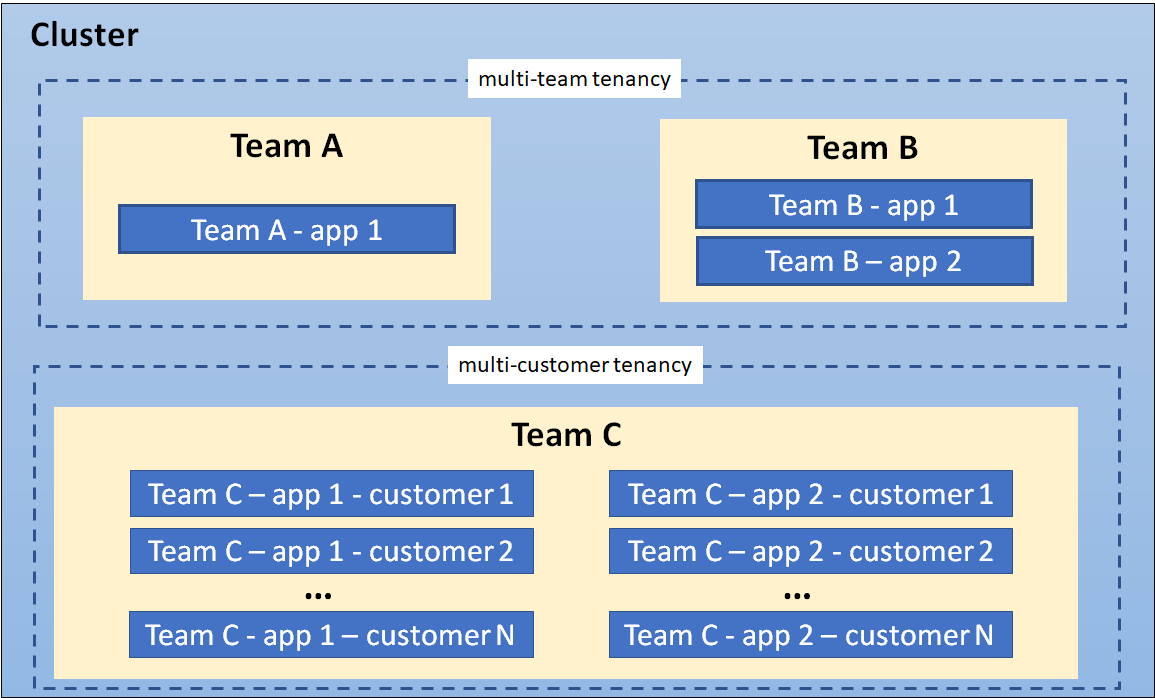

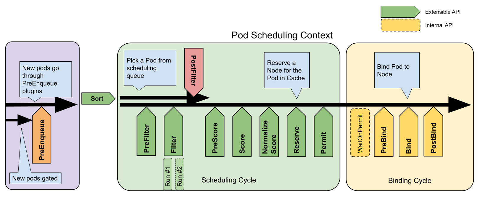

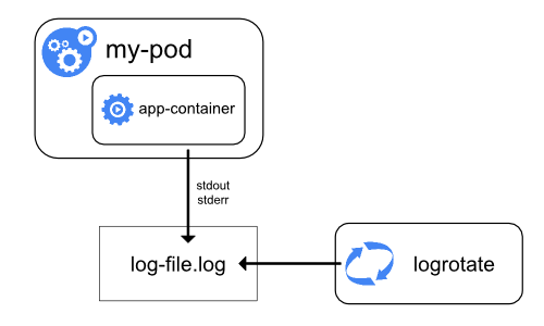
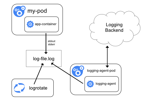
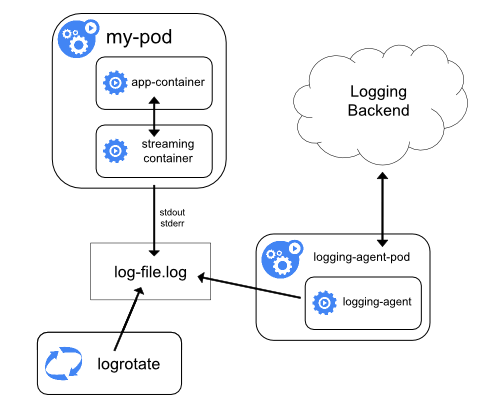
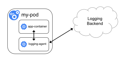
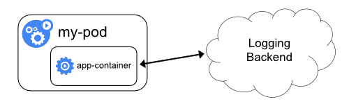
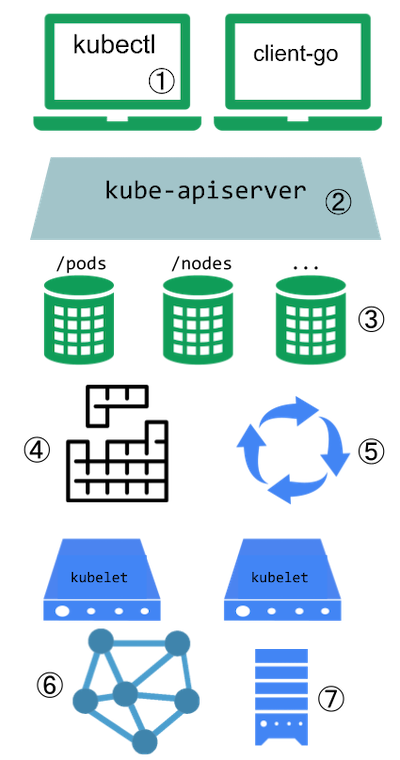

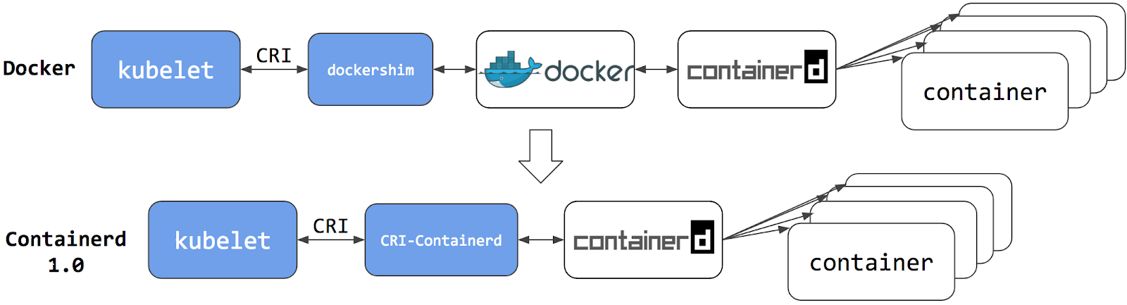

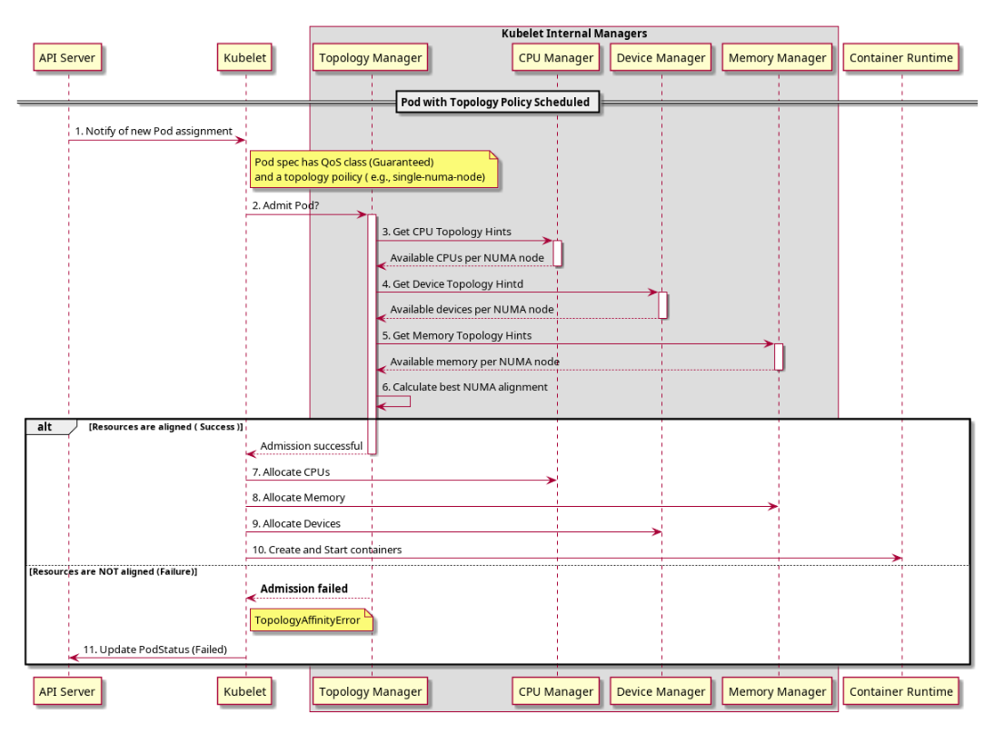
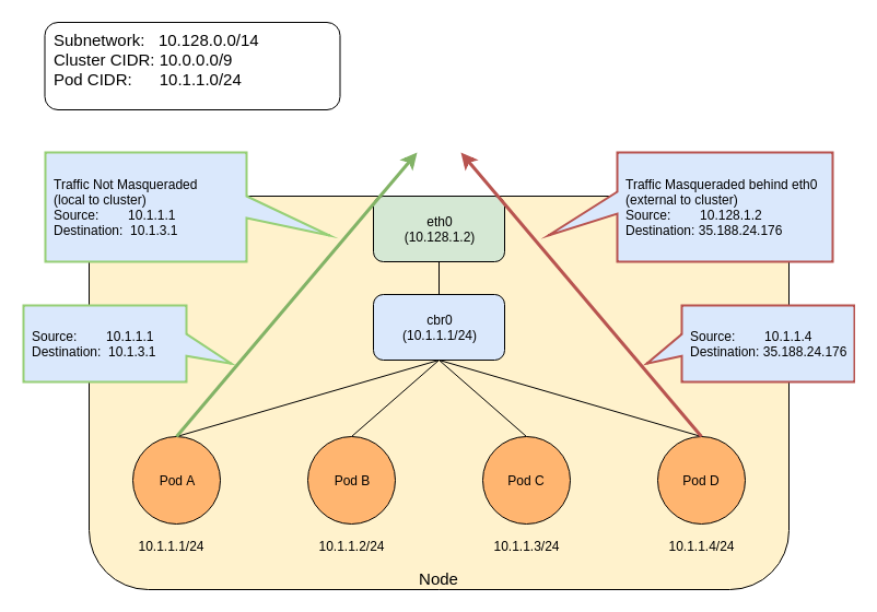


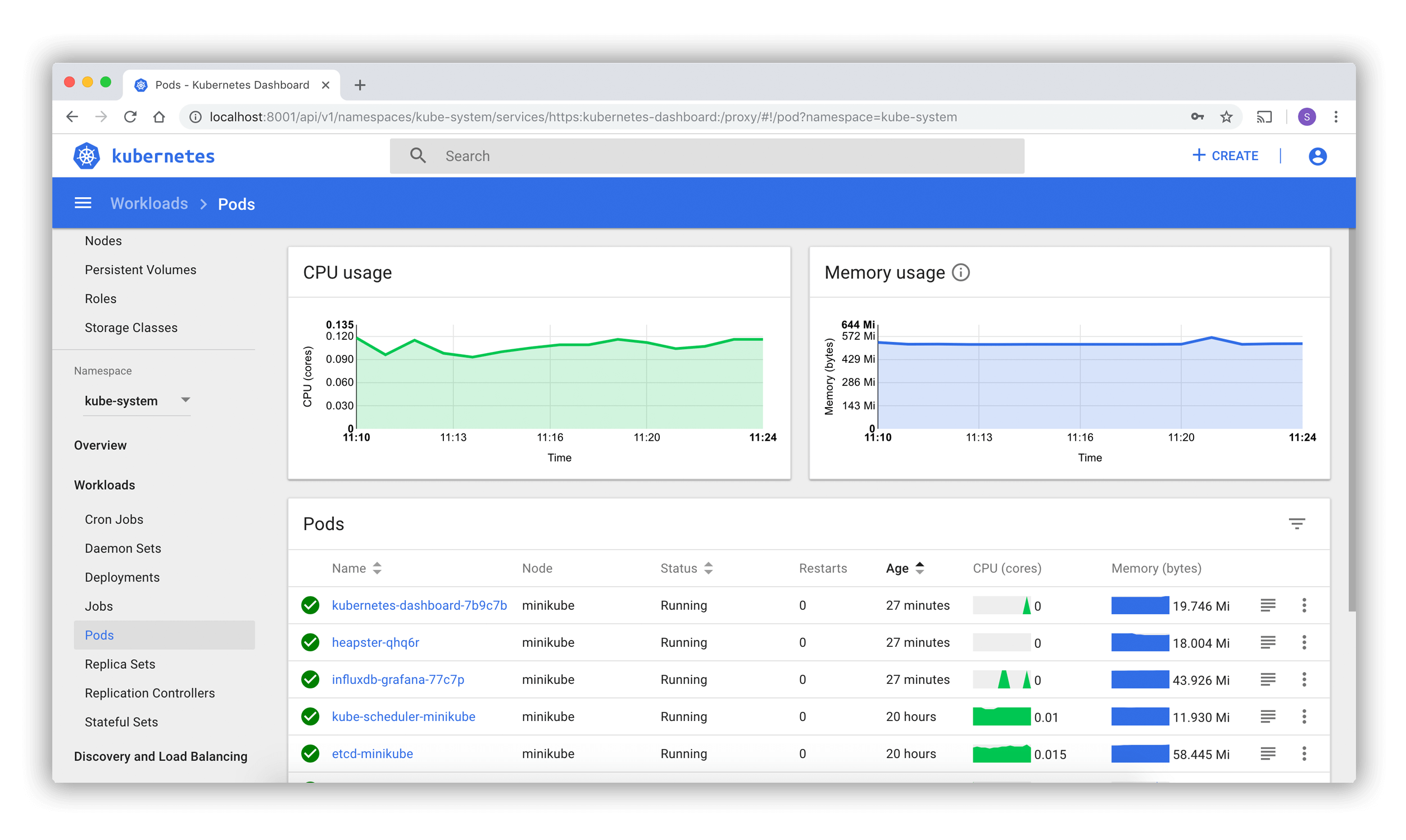
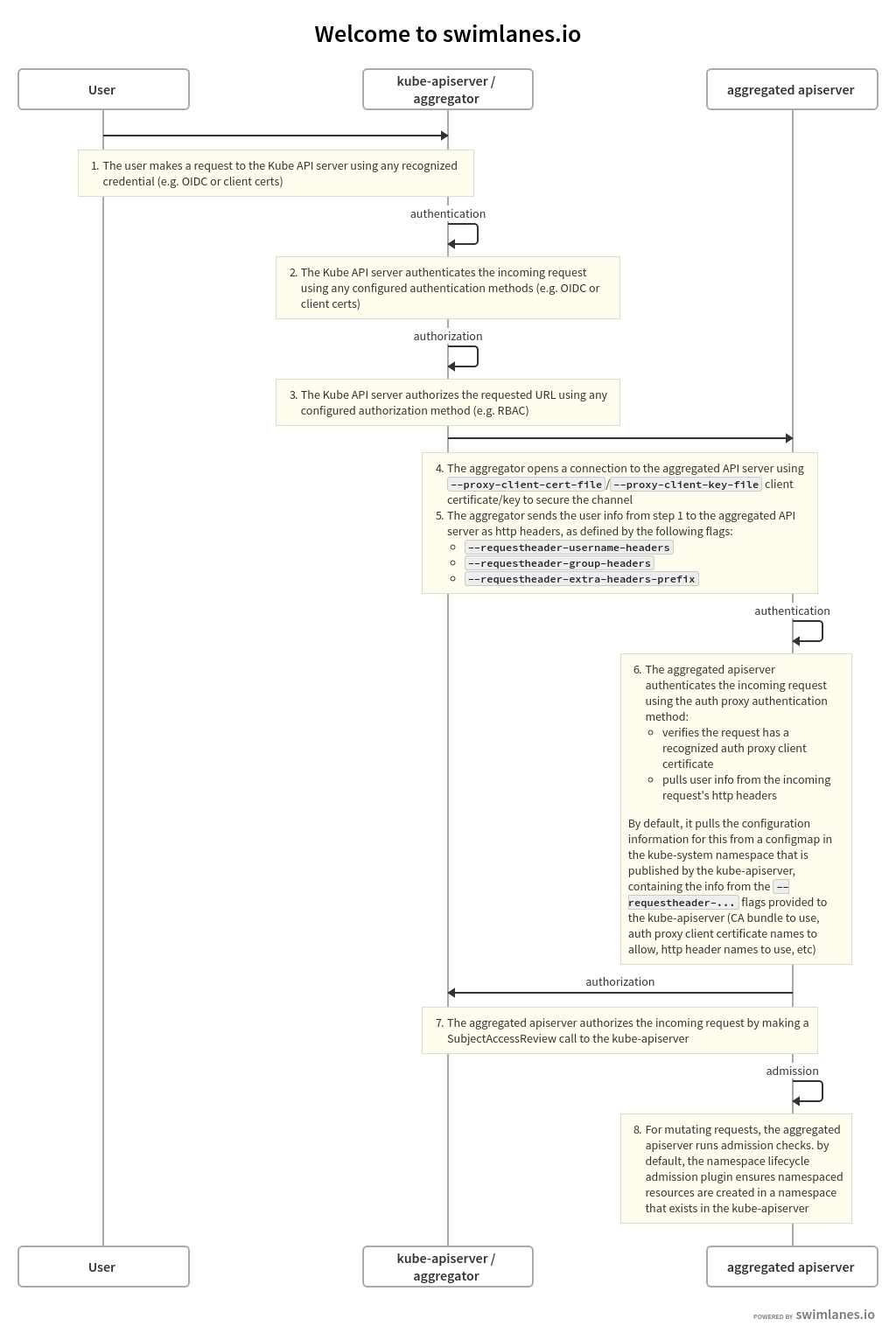


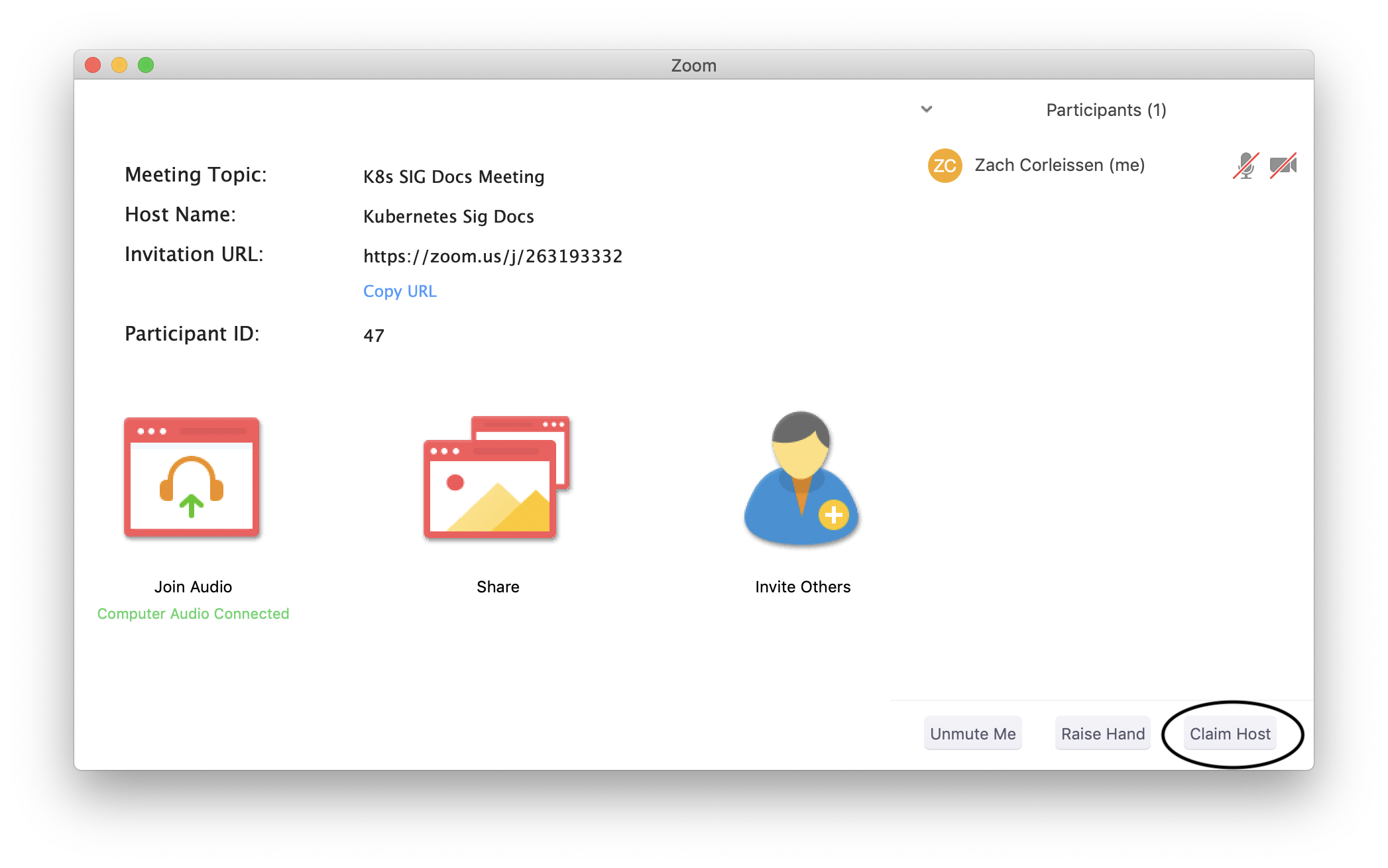
